# CompactPcl ? Serial

# CompactPCr Serial Space

Short Form Specification

![PICMG®](.picmg-cpci-s-0-short-form-spec-2023/f1a4728542c594210baf2976f92ec36d88a550decad202a93573441b5e2f614f.jpg)

Open Modular Computing Specifications

NOTE: This short form specification is a subset of the CompactPCI® Serial specification PICMG CPCI-S.0 R3.0 / R4.0 and a subset of CompactPCI® Serial Space PICMG® CPCI-S.1 R1.0.

For complete guidelines on the design of CompactPCI® Serial compliant boards and systems, the full specifications are required.

© Copyright 2017, PCI Industrial Computer Manufacturers Group. The attention of adopters is directed to the possibility that compliance with or adoption of PICMG® specifications may require use of an invention covered by patent rights. PICMG® shall not be responsible for identifying patents for which a license may be required by any PICMG® specification or for conducting legal inquiries into the legal validity or scope of those patents that are brought to its attention. PICMG® specifications are prospective and advisory only. Prospective users are responsible for protecting themselves against liability for infringement of patents.

# NOTICE:

The information contained in this document is subject to change without notice. The material in this document details a PICMG® specification in accordance with the license and notices set forth on this page. This document does not represent a commitment to implement any portion of this specification in any company's products.

WHILE THE INFORMATION IN THIS PUBLICATION IS BELIEVED TO BE ACCURATE, PICMG® MAKES NO WARRANTY OF ANY KIND, EXPRESS OR IMPLIED, WITH REGARD TO THIS MATERIAL INCLUDING, BUT NOT LIMITED TO, ANY WARRANTY OF TITLE OR OWNERSHIP, IMPLIED WARRANTY OF MERCHANTABILITY OR WARRANTY OF FITNESS FOR PARTICULAR PURPOSE OR USE.

In no event shall PICMG® be liable for errors contained herein or for indirect, incidental, special, consequential, reliance or cover damages, including loss of profits, revenue, data or use, incurred by any user or any third party. Compliance with this specification does not absolve manufacturers of equipment from the requirements of safety and regulatory agencies (UL, CSA, FCC, IEC, etc.).

# IMPORTANT NOTICE:

This document includes references to specifications, standards or other material not created by PICMG. Such referenced materials will typically have been created by organizations that operate under IPR policies with terms that vary widely, and under process controls with varying degrees of strictness and efficacy. PICMG has not made any enquiry into the nature or effectiveness of any such policies, processes or controls, and therefore ANY USE OF REFERENCED MATERIALS IS ENTIRELY AT THE RISK OF THE USER. Users should therefore make such investigations regarding referenced materials, and the organizations that have created them, as they deem appropriate.

PICMG®, ModBlox7®, AdvancedTCA®, AdvancedTCA® 300,ATCA®, ATCA® 300, AdvancedMC®, ModBlox7® Express, COM Express®, MicroTCA®, SHB Express®, and the PICMG, ModBlox7, AdvancedTCA, µTCA and ATCA logos are registered trademarks, and xTCA™, IRTM™ and the IRTM logo are trademarks of the PCI Industrial Computer Manufacturers Group. All other brand or product names may be trademarks or registered trademarks of their respective holders.

# 1 General

# 1.1 About CompactPCI® Serial

The CompactPCI Serial specification defines a modular computer system, consisting of

• A backplane
• A system slot
Up to 8 peripheral slots (more with custom backplanes)

CompactPCI® Serial defines the support of PCI Express, SATA, USB and Ethernet, concurrently. PCI Express, SATA/SATA Express and USB are arranged as a simple star architecture. Ethernet is a full mesh. Switch boards are not required. The backplane is passive.

The mechanical design is fully compatible to IEC60297-3-100 which specifies the basic dimensions of front panels, sub-racks, chassis, racks and cabinets of the 482,6 mm (19 inch) series. 3U and 6U boards are supported. For 3U cards, conductive cooling is introduced, which enables the use of boards in extreme harsh environments. The CompactPCI® Serial specification is based on Amphenol FCI AirMax proven and rugged backplane connectors.

Originally, CompactPCI® Serial only supported PCI Express up to Gen3. The updated CompactPCI® Serial Specification Revision 3 will support PCI Express Gen4, SATA Express at 16 Gb/s, 10GBASE-T and 10GBASE-KR Ethernet, and USB 3.0. To achieve higher data rates, the CPU will be equipped with the new AirMax VS High Speed connectors. This solution is fully upward and downward compatible.

Revision 4 goes even further. With the new AirMax VS connectors for all boards and the backplane, PCI Express Gen5 and higher as well as 25GBASE-KR Ethernet will be supported. The board-to-board pitch is increased to 25.4 mm (5 HP) instead of 20.32 mm (4 HP). Older boards can still be used, where the smaller front panel is extended by a bezel.

# 1.2 CompactPCI® Serial Revision History

This table shows the changes made to the CPCI-S.0 Specification

<table><tr><td>Revision</td><td>Date</td><td>Description</td></tr><tr><td>1.0</td><td>February 28, 2011</td><td>Initial release</td></tr><tr><td>2.0</td><td>February 2, 2015</td><td>Rear I/O for P6 added, further clarifications</td></tr><tr><td>3.0</td><td>planed for mid 2023</td><td>PCIE up to Gen 4, Ethernet 10KR4</td></tr><tr><td>4.0</td><td>planed for end 2023</td><td>PCIE Gen 5+, Ethernet 25KR4, 25.4 mm board-to-board pitch</td></tr></table>

# 1.3 About CompactPCI® Serial Space

CompactPCI® Serial Space is based on CompactPCI® Serialn however, some features were removed. CompactPCI Serial Space does not route USB or SATA signals over the backplane. CompactPCI Serial Space maintains the routing of PCI Express and Ethernet lines but defines these backplane links as physical connections not dedicated especially to Ethernet or PCI Express. This has the advantage that they can be used also for other transport protocols like SpaceWire, TTEthernet and EtherSpace for inter-board communication.

Like in CompactPCI® Serial, a full mesh network on the backplane is supported. All slots can have a connection to the full mesh network – a point-to-point connection from each slot to all other slots. CompactPCI® Serial Space backplane routing is similar to CompactPCI® Serial and additionally supports a second system slot. The dual star architecture improves the reliability, availability and flexibility of the system. Peripheral slot 8 is extended to be system slot B, the second system slot. This slot is identical to system slot A and can be used as peripheral or system slot. Each peripheral slot has a dedicated connection to system slot A and additionally a second point-to-point connection to system slot B.

A new introduced shelf controller can control the power supply of all boards separately. Also the shelf controller can check the status of the boards and can reset the boards individually. Two redundant CAN busses are available additionally as board management busses.

The mechanical design of CompactPCI® Serial Space is fully compatible with CompactPCI® Serial. However, the board-to-board pitch is 5HP (= 25,4 mm) only - for air cooled as well as for conduction cooled systems – which is also the case for CompactPCI® Serial Revision 4.

# 1.4 CompactPCI® Serial Architecture

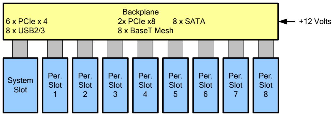
Figure 1. CompactPCI® Serial Architecture
![The diagram displays a top-level yellow rectangular block labeled **Backplane**. Inside this block, the following text is listed in three columns: *   **6 x PCIe x 4** *   **8 x USB2/3** *   **2x PCIe x8** *   **8 x BaseT Mesh** *   **8 x SATA**  On the right side, an arrow points toward the Backplane block with the label **+12 Volts**.  Below the Backplane is a row of nine blue vertical blocks connected to it by grey vertical bars. From left to right, the blue blocks are labeled: *   **System Slot** *   **Per. Slot 1** *   **Per. Slot 2** *   **Per. Slot 3** *   **Per. Slot 4** *   **Per. Slot 5** *   **Per. Slot 6** *   **Per. Slot 7** *   **Per. Slot 8**](.picmg-cpci-s-0-short-form-spec-2023/f1aeee7d9890dccd3227afbd38e2b3ece2b063e2fbc4120fa606cd7f1c97cc48.jpg)

There is a dedicated system slot which provides the system with some minimal central infrastructure functions like reset and clock supply. This means that the smallest possible CompactPCI® Serial system consists of just one single slot, the system slot.

The peripheral slots are connected via modern high-speed serial point-to-point connections. A star architecture is implemented on the backplane for PCI Express, SATA and USB. The system slot is connected to each peripheral slot separately. A switch or hub board is not required. For Ethernet, a full mesh network is implemented on the backplane. This allows any board to communicate directly with any other board separately at full speed.

A system slot card can also be used in a peripheral slot to perform multiprocessing. The simplest way of communication in this case is via Ethernet. Rear I/O is also supported. Many pins are available and high-speed data communication is supported.

# 1.5 CompactPCI® Serial Space Architecture

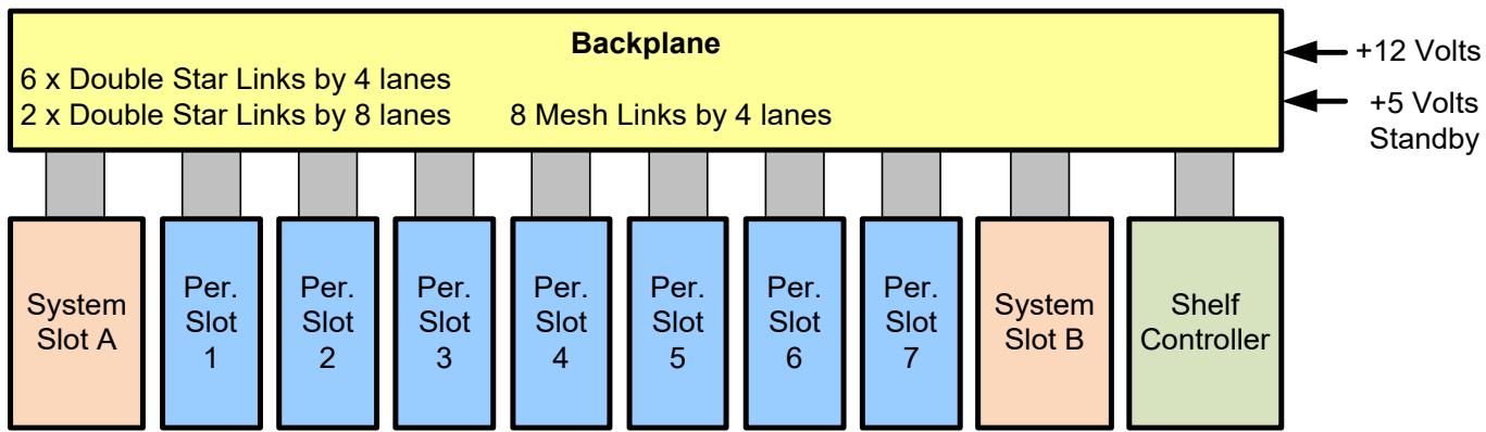
Figure 2. CompactPCI® Serial Space Architecture
![The diagram depicts a central yellow block labeled **Backplane** at the top. Inside the Backplane, the text reads: *   '6 x Double Star Links by 4 lanes' *   '2 x Double Star Links by 8 lanes' *   '8 Mesh Links by 4 lanes'  On the right side, arrows point into the Backplane labeled **+12 Volts** and **+5 Volts Standby**.  Below the Backplane, ten blocks are arranged in a horizontal row, each connected to the Backplane above by a vertical grey bar. From left to right, the blocks are labeled: 1.  **System Slot A** 2.  **Per. Slot 1** 3.  **Per. Slot 2** 4.  **Per. Slot 3** 5.  **Per. Slot 4** 6.  **Per. Slot 5** 7.  **Per. Slot 6** 8.  **Per. Slot 7** 9.  **System Slot B** 10. **Shelf Controller**](.picmg-cpci-s-0-short-form-spec-2023/b4e870f843ba11c64352c4ceb830538248a37a9eb7a2881867985d646bc5104e.jpg)

Like in CompactPCI® Serial, a full mesh network on the backplane is supported. The full mesh network is a high speed, high performance, point-to-point connection from each slot to all other slots.

A CompactPCI® Serial backplane routes PCI Express as a single star (the system slot is the center of the star). CompactPCI® Serial Space backplane is based on dual star routing and additionally supports a second system slot. This complies with the CompactPCI® Serial base specification and is fully upward compatible.

The shelf controller can control the power supply, can check the status of the boards and can reset the boards individually. Two redundant CAN busses are available additionally as board management busses. Neither the shelf controller connector nor the shelf controller itself is specified in the specification.

# 1.6 3U Mechanical Overview

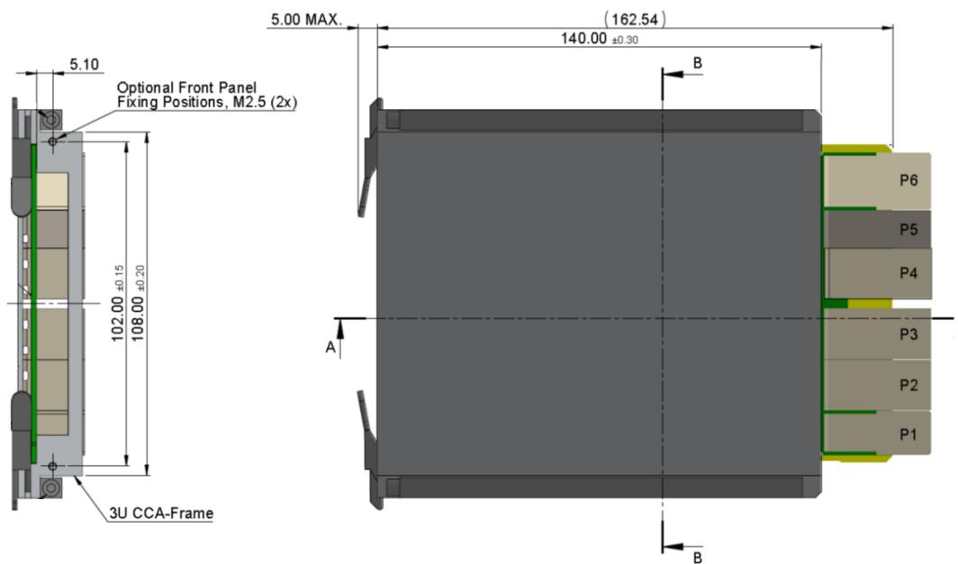
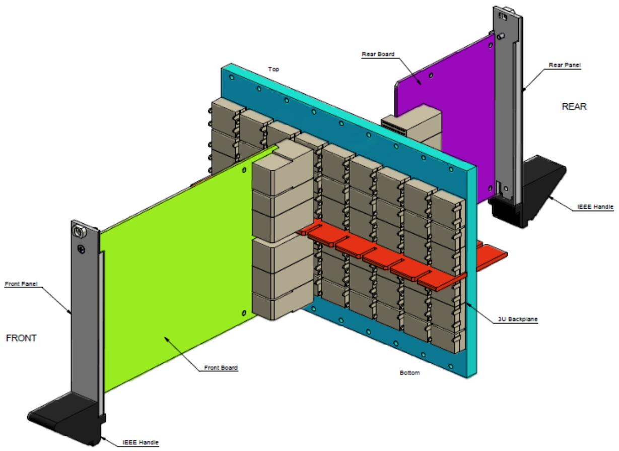
In the specification, 3U systems as well as 6U systems are defined. A passive backplane is used to connect all front and rear boards. Every board is supplied with a front and rear panel. A handle (two handles for 6U) allows the user to plug-in and to remove a board from a rack. A maximum of six discrete connectors forms a slot and the amount of connectors used can vary depending on the application. Maximum scalability and costeffectiveness is thus achieved.

Mechanical Overview 3U Example
![Top Rear Board Rear Panel REAR IEEE Handle Front Panel FRONT Front Board 3U Backplane Bottom IEEE Handle](.picmg-cpci-s-0-short-form-spec-2023/407fbce61fa4deaaea4b1e90209d5f38d2d6cdc87f9a2d3bc41f04f4b656f0f8.jpg)

# 1.7 6U Mechanical Overview

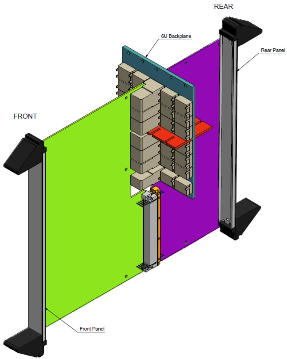
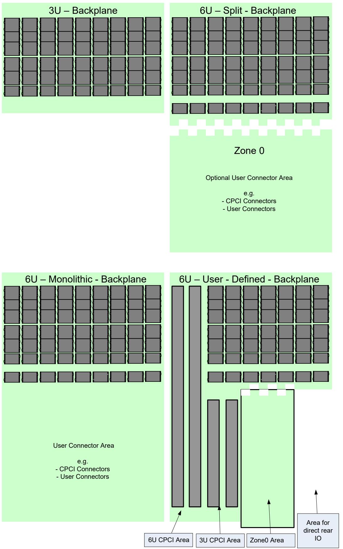
Front and rear boards are defined for the 6U form factor. Compared to a 3U system, one extra connector (J0/P0) is defined. This connector offers extra power (that will be needed in a 6U system) and also two further Ethernet connections, which can be used for system management (e.g. AMT). The backplane can be monolithic or split. Furthermore, it is possible to define a user backplane which is a mixture of both (see Figure 4 and 5).

Figure 3. Mechanical Overview 6U Example (Split-Backplane / Front view)
![REAR 6U Backplane Rear Panel FRONT Front Panel](.picmg-cpci-s-0-short-form-spec-2023/9ba36bd8681471c0ec0899d5db1ec691f9c827c34cf845c4adb678b1e0bfa424.jpg)

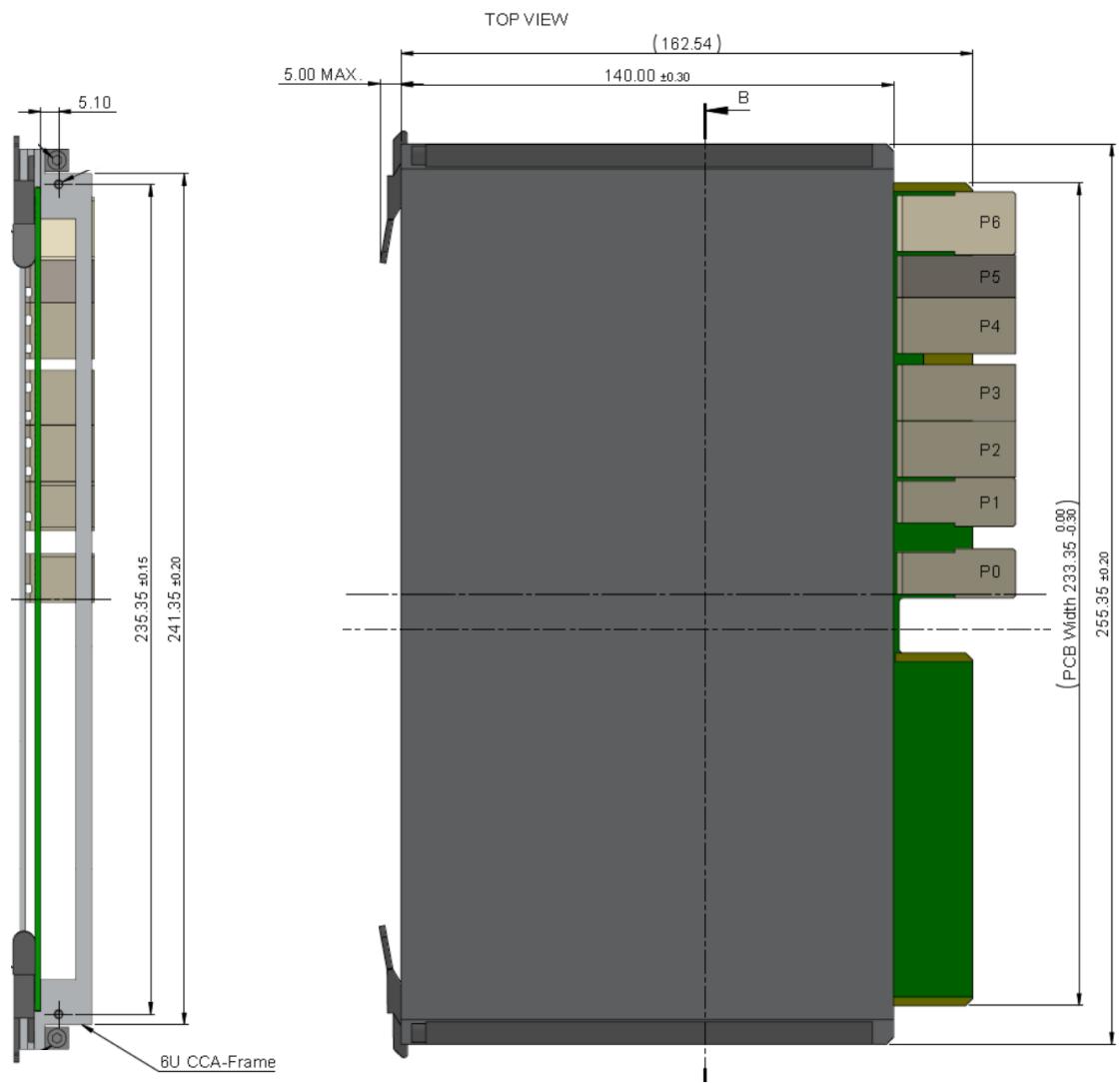
# 1.8 Conductive Cooling

Figure 4. Conductive Cooling Frames
![TOP VIEW (162.54) 5.00 MAX. 140.00 ±0.30 B 5.10 235.35 ±0.15 241.35 ±0.20 6U CCA-Frame (PCB Width 233.35 -0.30) 255.35 ±0.20 P6 P5 P4 P3 P2 P1 P0](.picmg-cpci-s-0-short-form-spec-2023/56b13d0c07259c7b4c463ddd6744f82320e8580227a689d0fb5e24c2bc4ee7d2.jpg)

![5.10 Optional Front Panel Fixing Positions, M2.5 (2x) 102.00 ±0.15 ±0.20 3U CCA-Frame 5.00 MAX. (162.54) 140.00 ±0.30 A B P6 P5 P4 P3 P2 P1 B](.picmg-cpci-s-0-short-form-spec-2023/3e209ab9c4c3ed715545506085f0ddf768a7710e31f881de34f8c5726ff76a80.jpg)

# 1.9 Backplane Examples

Figure 5. Backplane Example Drawings of 3U vs. 6U Variants
![The image displays four diagrams illustrating different backplane configurations on a light green background.  **Top Left: 3U – Backplane** This section shows a grid of ten columns by four rows of grey rectangular card slots.  **Top Right: 6U – Split - Backplane** This section shows a grid of card slots at the top. Below a jagged white divider line, the text reads: Zone 0 Optional User Connector Area e.g. - CPCI Connectors - User Connectors  **Bottom Left: 6U – Monolithic - Backplane** This section shows a full grid of card slots (three main rows plus a bottom row of smaller slots). Below the slots, the text reads: User Connector Area e.g. - CPCI Connectors - User Connectors  **Bottom Right: 6U – User - Defined - Backplane** This section shows a mixed layout with vertical slots on the left and a standard grid on the right. At the very bottom, labels with arrows point to specific zones: - Arrow pointing to the two tall vertical slots: '6U CPCI Area' - Arrow pointing to the two shorter vertical slots: '3U CPCI Area' - Arrow pointing to an outlined rectangular area: 'Zone0 Area' - Arrow pointing to the far right area: 'Area for direct rear IO'](.picmg-cpci-s-0-short-form-spec-2023/d8321fd05d6e5ba7228980eff504404756c7529aca47549e694eee05fa2e3cd7.jpg)

# Zone 0

Optional User Connector Area

e.g.

- CPCI Connectors
- User Connectors

User Connector Area

e.g.

- CPCI Connectors
- User Connectors

# 1.10 Mezzanine Board

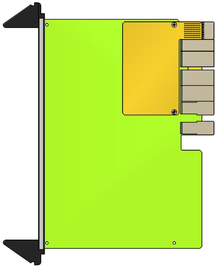
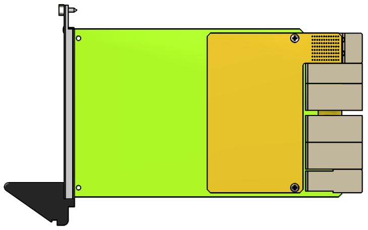
Implementation of the full mesh connection in a system can be done with a mezzanine board. Thanks to this concept, more flexibility is achieved, because the usage of the full mesh connection does not depend on the system board itself. Furthermore, different mezzanine boards can offer different mesh connections, thereby obtaining maximum scalability. If this concept is implemented, the CompactPCI® Serial board becomes a mezzanine host, and the mezzanine board can be plugged onto this host. The connector P6 is then placed on the mezzanine board and a cut-out on the mezzanine host is provided. Only the interconnection between the mezzanine host to the CompactPCI® Serial backplane will be specified within this specification. As shown in Figures 9 and 10, the mezzanine concept can be implemented within a 3U and a 6U system.

Figure 6. 3U Mezzanine Concept
![Diagram of a device casing with green and yellow casing, showing internal components and mounting points (no text or symbols)](.picmg-cpci-s-0-short-form-spec-2023/c94ab0e65aa705e24e2f05931c0f6ea5dfca6adda0aeab3b5c2840f20cee1043.jpg)

Figure 7. 6U Mezzanine Concept
![Diagram of a computer monitor layout with green base, yellow top panel, and gray connectors (no text or symbols)](.picmg-cpci-s-0-short-form-spec-2023/70f06936db9df47356fbdb6536f2bd4cd0ecc460a56ba6e682cc83591ffc13ea.jpg)

# 1.11 Connector Types

Connectors used for CompactPCI® Serial are optimized for high-speed differential signal transmission. Shielding and impedance control is maintained through the connectors. The connector is arranged in rows with 12 pins each. 12 pins are sufficient for 4 high speed signal pairs. 4 pins in a row are required for ground. The pins within the connector are not specialized however, so a pin can be used for signals (differential or single ended), for ground, as well as for the supply voltage.

For front boards, receptacle connectors are used on the backplane, and right angle headers are used on the plug-in boards. On rear boards it is vice-versa. All connector types are designed for press-fit mounting. The press-in pin length in the PCB is just 1.6 mm to minimize the stub lengths thereby enhancing the signal integrity. To realize rear I/O, a plug connector is pressed on to the back of the backplane. This mirrors the pin assignment from the front to the back side.

To connect the front boards to the backplane, four different plug types of the same connector family are used.

Table 1. Front Board Connector Types

<table><tr><td>Designator</td><td>Type</td><td>Number of Rows</td><td>Number of Walls</td><td>Usage</td></tr><tr><td>P0</td><td>A</td><td>6</td><td>4</td><td>Optional</td></tr><tr><td>P1</td><td>A</td><td>6</td><td>4</td><td>Mandatory</td></tr><tr><td>P2</td><td>B</td><td>8</td><td>2</td><td>Optional</td></tr><tr><td>P3</td><td>B</td><td>8</td><td>2</td><td>Optional</td></tr><tr><td>P4</td><td>B</td><td>8</td><td>2</td><td>Optional</td></tr><tr><td>P5</td><td>C</td><td>6</td><td>2</td><td>Optional</td></tr><tr><td>P6</td><td>D</td><td>8</td><td>4</td><td>Optional</td></tr></table>

Figure 8. 3U Connector Plug Types A, B, C and D on Front Boards
![CompactPCI® Serial 3U Front Board P6 Type D P5 Type C P4 Type B P3 Type B P2 Type B P1 Type A](.picmg-cpci-s-0-short-form-spec-2023/84d0007c6f52969a13c2cc0f836fffca65605f0c28b1fa621970c27734899556.jpg)

# 1.12 Rear Board Connector Types and Reference Designation

To connect the rear boards to the backplane, two different receptacle types of the same connector family are used.

Table 2. Rear Board Connector Types

<table><tr><td>Designator</td><td>Type</td><td>Number of Rows</td><td>Number of Walls</td><td>Usage</td></tr><tr><td>rJ2</td><td>H</td><td>6</td><td>2</td><td>Optional</td></tr><tr><td>rJ3</td><td>G</td><td>8</td><td>2</td><td>Optional</td></tr><tr><td>rJ4</td><td>G</td><td>8</td><td>2</td><td>Optional</td></tr><tr><td>rJ5</td><td>H</td><td>6</td><td>2</td><td>Optional</td></tr></table>

Figure 9. Connector Plug Types H and G on Rear Boards
![CompactPCI®Serial 3U Rear Board Type H rJ5 Type G rJ4 Type G rJ3 Type H rJ2](.picmg-cpci-s-0-short-form-spec-2023/8c8a1ea6cdaf2977da8d8d597175eb27a79873307a3f661f7191188bca7de83c.jpg)

Table 3. Rear Backplane Connector Types

<table><tr><td>Designator</td><td>Type</td><td>Number of Rows</td><td>Usage</td></tr><tr><td>rP2</td><td>J</td><td>6</td><td>Optional</td></tr><tr><td>rP3</td><td>I</td><td>8</td><td>Optional</td></tr><tr><td>rP4</td><td>I</td><td>8</td><td>Optional</td></tr><tr><td>rP5</td><td>J</td><td>6</td><td>Optional</td></tr></table>

# 1.13 ESD Protection

A CompactPCI® Serial system is equipped with an ESD strip and an ESD clip. When a board is inserted into an enclosure, the ESD strip connects with an ESD clip on the card guide which is connected to chassis ground. The ESD strip is separated into three segments to achieve a “controlled discharge”. The first segment is connected to the front panel through a 10 MOhm resistor to discharge any built-up static charge from the board or user. The resistor is used to limit the amount of discharge current. The second segment discharges the board’s ground planes as it is inserted further into the card guide, again through a 10 MOhm resistance. The final third segment has a direct connection to the front panel. This provides a discharge path as the backplane connectors engage and when the board comes to rest after being completely installed. The third segment also provides a discharge path from the front panel to chassis ground when the entire system is assembled making it safe for handling and operation. The ESD card guide clip contacts the board edge as the board is inserted in the system and provides a path for ESD energy on the board to be discharged into the chassis.

# 2 Electrical Requirements

# 2.1 Backplane Power Distribution

CompactPCI® Serial relies on a single rail +12V main power supply. +5V standby is optionally available. - 48V optional voltage is available within a 6U system only. The backplane distributes the supply voltages to the front boards. Rear boards are indirectly supplied by the corresponding front board.

Figure 10. Backplane Power Distribution Example in a CompactPCI® Serial System
![  Power Supply   +12V   +5V standby     ------------   ----   -----------     CPCI-S.0 Master   +12V   +5V standby     CPCI-S.0 Periph.   +12V   +5V standby     CPCI-S.0 Periph.   +12V   +5V standby     CPCI-S.0 Periph.   +12V   +5V standby     CPCI-S.0 Periph.   +12V   +5V standby     CPCI-S.0 Periph.   +12V   +5V standby     CPCI-S.0 Periph.  +12V   +5V standby     CPCI-S.0 Periph.  +12V   +5V standby     CPCI-S.0 Periph.  +12V   +5V standby     CPCI-S.0 Periph.  +12V   +5V standby     CPCI-S.0 Periph.  +12V   +5V standby     CPCI-S.0 Periph.  +12V(fcel)+12V   +5V standby     CPCI-S.0 Periph.  +12V   +5V standby     CPCI-S.0 Periph.  +12V   +5V standby     CPCI-S.0 Periph.  +12V   +5V standby     CPCI-S.0 Periph.  +12V   +5V standby     CPCI-S.0 Periph.  +12V   -               CPCI-S.0 Periph.  +12V   -               CPCI-S.0 Periph.  +12V   -               CPCI-S.0 Periph.  +12V   -               CPCI-S.0 Periph.  +12V   -               CPCI-S.0 Periph.  +12V   -               CPCI-S.0 Periph.  +12V(fcel)+12V   +5V standby     CPCI-S.0 Periph.  +12V   +5V standby     CPCI-S.0 Periph.  +12V   +5V standby     CPCI-S.0 Periph.  +12V   +5V standby     CPCI-S.0 Periph.  +12V   +5V standby     CPCI-S.0 Periph.  +12V   +5V standby     CPCI-S.0 Periph.  +12V   +5V standby     CPCI-S.0 Periph.  +12V   +5V standby     CPCI-S.0 Periph.  +12V   +5V standby     CPCI-S.0 Periph.  +12V   +5V stand by     CPCI-S.0 Periph.  +12V   +5V stand by     CPCI-S.0 Periph.  +12V   +5V stand by     CPCI-S.0 Periph.  +12V   +5V stand by     CPCI-S.0 Periph.  +12V   +5V stand by     CPCI-S.0 Periph.  +12V   +5V standby     CPCI-S.0 Periph.  +12V   +5V standby     CPCI-S.0 Periph.  +12V   +5V standby     CPCI-S.0 Periph.  +12V   +5V standby     CPCI-S.0 Periph.  +12V   +5V standbly     CPCI-S.0 Periph.  +12V   +5V standby     CPCI-S.0 Periph.  +12V   +5V standby     CPCI-S.0 Periph.  +12V   +5V standby     CPCI-S.0 Periph.  +12V   +5V standby     CPCI-S.0 Periph.  +12V   +5V stand bly     CPCI-S.0 Periph.  +12V   +5V stand bly     CPCI-S.0 Periph.  +12V   +5V stand bly     CPCI-S.0 Periph.  +12V   +5V stand bly     CPCI-S.0 Periph.  +12V   +5 V stand bly     CPCI-S.0 Periph.  +12 V   +5 V stand bly     CPCI-S.0 Periph.  +12 V   +5 V stand bly     CPCI-S.0 Periph.  +12 V   +5 V stand bly     CPCI-S.0 Periph.  +12 V   +5 V stand bly     CPCI-S.0 Periph.  +12 V   +5 V stand bly     CPCI-S.0 Pereph.  +12 V   +5 V stand bly     CPCI-S.0 Pereph.  +12 V   +5 V stand bly     CPCI-S.0 Pereph.  +12 V   +5 V stand bly     CPCI-S.0 Pereph.  +12 V   +5 V stand bly     CPCI-S.0 Pereph.  +12 V   +5 V stand bly     CSCI-S.0 Master   -      -               CSCI-S.0 Master   -      -               CSCI-S.0 Master   -      -               CSCI-S.0 Master   -      -               CSCI-S.0 Master   -      -               CSCI-S.0 Master   -      -               CSCI-S.0 Master   -      -               CSCI-S.0 Master   -      -                 CSCI-S.0 Master   -      -               CSCI-S.0 Master   -      -               CSCI-S.0 Master   -      -               CSCI-S.0 Master   -      -               CSCI-S.0 Master   -      -               CSCI-S.0 Master   -      -               CSCI-S.0 Master   -      -               TBI 364        -      -               TBI 364        -      -               TBI 364        -      -               TBI 364        -      -               TBI 364        -      -               TBI 364        -      -               TBI 364        -      -               TFI 364        -      -               TFI 364        -      -               TFI 364        -      -               TFI 364        -      -               TFI 364        -      -               TFI 364        -      -               TFI 364        -      N/A             TFI 364        -      N/A             TFI 364        -      N/A             TFI 364        -      N/A             TFI 364        -      N/A             TFI 364        -      N/A           TFI 364        N/A           TFI 364        N/A           TFI 364        N/A           TFI 364        N/A           TFI 364        N/A           TFI 364        N/A           TFI 364        N/A           TFI 364        N/A           TFI 364        N/A B TFI 364       ](.picmg-cpci-s-0-short-form-spec-2023/79d0b4da44727716e8e1a6d069e84c0226b5b4e20d8485b506697a164ad19b47.jpg)

Figure 11. Backplane Power Distribution Example in a CompactPCI® Serial Space System
![This diagram illustrates a power distribution system featuring a central controller and multiple output modules.  **Labeled Blocks:** *   **Left Side:** Two green blocks labeled 'Power Supply,' each containing the text '+12V' and '+5V standby.' *   **Center Left:** A tall green block labeled 'Power Controller.' *   **Top Row:** A series of 10 vertical blocks arranged horizontally. Each block is divided into three sections:     *   **Top Section (Cyan):** Labeled 'I/O.'     *   **Middle Section (Cyan):** Labeled 'CPCI-S.0 Master' for the leftmost and rightmost blocks, and 'CPCI-S.0Periph.' for the eight central blocks.     *   **Bottom Section (Green):** Labeled '+12V' and '+5V standby.'  **Connections:** *   Two arrows point from the top 'Power Supply' block into the 'Power Controller.' *   Two arrows point from the bottom 'Power Supply' block into the 'Power Controller.' *   Multiple lines originate from the right side of the 'Power Controller,' extending to the right and branching upward. These lines terminate at the bottom of each vertical block in the top row, with two arrows pointing upward into the '+12V +5V standby' section of each block.](.picmg-cpci-s-0-short-form-spec-2023/6e9407a1f003c97d27309c4a015f486fcf3c748243a80c9c5d14df5abc57d70d.jpg)

# 2.2 Power Control

The power control signals PS\_ON#, PWRBTN#, PWR\_FAIL# are routed from the system slot to a utility connector.

PS\_ON# allows a system board to remotely control the power supply in conjunction with features such as soft on/off, Wake on LAN, or wake-on-modem. The PWRBTN# signal may be used to control the power supply’s PS\_ON# signal. Furthermore it could be used to shut down the operating system etc.. Power supplies providing the PWR\_FAIL# signal show that the output voltage will leave the rated output value in short time. System boards can use this information to shut down the system in a defined way. This specification does not define details about this behavior.

# 2.3 Platform Control Signals

# 2.3.1 Reset Signals

The PRST# signal of the system slot is routed to a utility connector. The RST# output signal of the system slot is routed to all RST# input signals of the peripheral slots.

Figure 12. CompactPCI Serial Backplane Routing Reset
![Based on the provided image, here is the description of the flowchart:  **Blocks:** *   **Utility Connector:** An orange rectangular block on the left. *   **CPCI-S.0 Syst.:** A green vertical rectangular block in the center. *   **I/O:** Eight blue vertical rectangular blocks arranged in a row at the top right. *   **CPCI-S.0 Per.:** Eight green vertical rectangular blocks, located directly below each 'I/O' block.  **Connections:** *   **GND to Utility Connector:** A dashed line connects the 'Utility Connector' to a switch symbol, which is connected via another dashed line to a point labeled '**GND**'. *   **Utility Connector to CPCI-S.0 Syst.:** A solid black arrow labeled '**PRST#**' connects the 'Utility Connector' to the 'CPCI-S.0 Syst.' block. *   **CPCI-S.0 Syst. to the row of blocks:** A horizontal line labeled '**RST#**' originates from the 'CPCI-S.0 Syst.' block and branches into eight vertical upward-pointing arrows. Each arrow connects to the bottom section ('CPCI-S.0 Per.') of one of the eight blocks.](.picmg-cpci-s-0-short-form-spec-2023/9e8f2898089be4546dd35b6662c2e1950d42efb6fbb6e299c7c8a1976db7590c.jpg)

Figure 13. CompactPCI Serial Space Backplane Routing Reset

![**Labeled Blocks:** *   **Shelf Controller**: A vertical orange rectangle on the left. *   **CPCI - S.0 Syst.**: Two vertical green rectangles (one far left, one far right). *   **I/O**: Eight cyan vertical rectangles in the top row, positioned between the two green 'CPCI - S.0 Syst.' blocks. *   **CPCI - S.0 Per.**: Eight green rectangular segments at the bottom of the cyan blocks. *   **GND**: Text label at the bottom left.  **Connections:** *   **PRST#_1**: Arrow pointing upward from the **Shelf Controller** to the left **CPCI - S.0 Syst.** block. *   **RST#_1**: Arrow pointing left from the left **CPCI - S.0 Syst.** block to the **Shelf Controller**. *   **RST#_2**: Arrow pointing upward from the **Shelf Controller** to the first **I/O / CPCI - S.0 Per.** block. *   **RST#_3**: Arrow pointing upward from the **Shelf Controller** to the second **I/O / CPCI - S.0 Per.** block. *   **RST#_4**: Arrow pointing upward from the **Shelf Controller** to the third **I/O / CPCI - S.0 Per.** block. *   **RST#_5**: Arrow pointing upward from the **Shelf Controller** to the fourth **I/O / CPCI - S.0 Per.** block. *   **RST#_6**: Arrow pointing upward from the **Shelf Controller** to the fifth **I/O / CPCI - S.0 Per.** block. *   **RST#_7**: Arrow pointing upward from the **Shelf Controller** to the sixth **I/O / CPCI - S.0 Per.** block. *   **RST#_8**: Arrow pointing upward from the **Shelf Controller** to the seventh **I/O / CPCI - S.0 Per.** block. *   **RST#_9**: Arrow pointing upward from the **Shelf Controller** to the eighth **I/O / CPCI - S.0 Per.** block. *   **PRST#_9**: Arrow pointing upward from the **Shelf Controller** to the right **CPCI - S.0 Syst.** block. *   **x9**: A dotted line connecting the signal lines to **GND**.](.picmg-cpci-s-0-short-form-spec-2023/49f1c4069aa5e042143a32da880349302f08c896577de0b8cd313d56bd7a8ef8.jpg)

# 2.3.2 System Slot Detection

Every slot at the backplane provides a System Slot Identification pin (SYSEN#). The SYSEN# pin is connected to GND at the system slot and left open on peripheral slots. Boards capable of system slot support detect SYSEN# low to activate system slot functionality, e.g. RST#, PS\_ON# etc.

# 2.3.3 Geographical Addressing

Due to the fact that within CPCI-S.0, each physical SATA port always needs the same geographic address (because of SGPIO), geographical addresses do not follow the physical slot numbers, but the SATA filling order. Backplanes support the GA[3:0] geographic addressing signals for unique slot identification. The highest slot number within a CPCI-S.0 system has geographic address 0. The next lower slot number has geographic address 1 up to the first peripheral slot. Peripheral boards can use geographical addressing based on GA[0], GA[1] and GA[2]. GA[3] can be used for systems with more than 8 peripheral slots.

# 2.4 Management Interfaces

# 2.4.1 I²C System Management Bus

The I²C System Management Bus is electrically compliant to the SMBus specification. The System Management Bus I²C\_SCL and Bus I²C\_SDA signals are bussed to every slot and the utility connector.

Figure 14. System Management Bus Signal Routing
![This block diagram illustrates a bus topology connecting ten components horizontally from left to right.  **Labeled Blocks:** 1.  **Utility Connector:** A tall, vertical orange rectangle on the far left. 2.  **CPCI-S.0 Syst.:** A tall, vertical green rectangle immediately to the right of the first block. 3.  **I/O / CPCI-S.0 Per.:** Eight identical vertical blocks to the right. Each is split into a cyan top section labeled 'I/O' and a green bottom section labeled 'CPCI-S.0 Per.'.  **Connections:** *   From the bottom of every block, two vertical lines extend downward. *   Each line is labeled either **'I2C_SCL'** or **'I2C_SDA'**. *   All vertical lines connect to two parallel horizontal bus lines running across the bottom of the diagram. *   The **'I2C_SCL'** lines from all blocks connect to the upper horizontal line. *   The **'I2C_SDA'** lines from all blocks connect to the lower horizontal line. *   Black dots indicate the junction points where the vertical lines meet the horizontal buses.](.picmg-cpci-s-0-short-form-spec-2023/b96a0d6746227f6c37f31e1155995af7ce952125b04ff6bcb0b817a6ac50cc51.jpg)

# 2.4.2 Serial GPIO

The SATA\_SCL, SATA\_SL, SATA\_SDO, SATA\_SDI signals from the system slot are bussed to the respective signals on the peripheral slots.

Figure 15. Serial GPIO Signals Backplane Routing
![**Labeled Blocks:** *   One block labeled 'CPCI-S.0 Syst.' *   Eight blocks labeled 'I/O' (top section) and 'CPCI-S.0 Per.' (bottom section).  **Connections:** *   From the 'CPCI-S.0 Syst.' block, four vertical lines emerge labeled (top to bottom): 'SATA_SDI', 'SATA_SDO', 'SATA_SI', 'SATA_SCL'. *   From each 'I/O' / 'CPCI-S.0 Per.' block, four vertical lines emerge labeled (top to bottom): 'SATA_SDO', 'SATA_SDI', 'SATA_SI', 'SATA_SCL'. *   All lines connect to four common horizontal bus lines at the bottom. *   The bus lines are labeled (top to bottom) on the far right: 'SATA_SDI', 'SATA_SDO', 'SATA_SI', 'SATA_SCL'. *   The 'SATA_SDI' line from the system block connects to the 'SATA_SDI' bus line (which links to the second line of the peripheral blocks). *   The 'SATA_SDO' line from the system block connects to the 'SATA_SDO' bus line (which links to the top line of the peripheral blocks). *   The 'SATA_SI' and 'SATA_SCL' lines connect directly to their corresponding bus lines.](.picmg-cpci-s-0-short-form-spec-2023/d5781d0329f78c2120f392ccd1392142c8e85cb57a35713a37cc750bdba18b0c.jpg)

# 2.4.3 CAN bus

The CAN bus can be used as System Management Bus for CompactPCI Serial Space Systems as well. The CAN bus signals are redundant bussed to every slot and the shelf controller.

Figure 16. CAN bus Signals Backplane Routing for CompactPCI Serial Space Systems
![The image displays a block diagram featuring a 'Shelf Controller' connected to a row of vertical processing blocks via a bus.  **Labeled Blocks:** *   **Shelf Controller:** A large orange rectangle on the far left. *   **CPCI-S.O Syst.:** Two tall green rectangular blocks located at the far left and far right of the top row. *   **I/O:** Seven light blue rectangular blocks located in the middle of the top row. *   **CPCI-S.O Per.:** Seven green rectangular blocks located directly beneath each 'I/O' block.  **Connections:** *   Four horizontal lines labeled **CAN_A+**, **CAN_A-**, **CAN_B+**, and **CAN_B-** extend from the right side of the **Shelf Controller**. *   These horizontal lines run across the bottom of the diagram, connecting to vertical lines that extend upwards. *   Each of the nine vertical blocks above is connected to all four horizontal bus lines via vertical lines with upward-pointing arrowheads at their tops, indicating inputs to the blocks. *   The horizontal lines loop back at the far right end, with the bottom-most line (**CAN_B-**) running underneath the others to complete the circuit.](.picmg-cpci-s-0-short-form-spec-2023/ecbe433b66e257b0a6c2d432ed02acbc66de1eaaf76bf55a105ca93e5bafecf7.jpg)

# 2.5 High Speed Interfaces

# 2.5.1 Star and Dual Star Interconnect

CompactPCI Serial base specification defines a single star architecture for PCI-Express. CompactPCI Serial Space doubles the usage of these interconnects in a symmetrical way. Beside the system slot (A) on the left side of the system, a second system slot (B) on the right hand side of the system uses the same way of routing. All seven peripheral slots are connected to both system slots. Also, both system slots are connected between each other.

Figure 17. CompactPCI Serial Star Interconnect for PCIE
![This diagram depicts a central system connected to multiple peripheral units.  **Labeled Blocks:** *   **Top Block:** A green rectangle labeled 'CPCI Serial Syst.' *   **Bottom Blocks:** There are eight identical blocks arranged in an arc below the top block. Each block is divided into two sections:     *   A green section labeled 'CPCI Serial Per.'     *   A teal section labeled 'I/O'  **Connections:** *   Black arrows originate from a central black node beneath the 'CPCI Serial Syst.' block. *   Each arrow points outward and downward to the green 'CPCI Serial Per.' section of one of the eight bottom blocks.](.picmg-cpci-s-0-short-form-spec-2023/a5d14f0e90cc04c2ba92cb8e994db008ad52449b9e4b54db6fe9049ec292a403.jpg)

Figure 18. Serial CompactPCI Serial Dual Star Interconnect
![Based on the provided flowchart, here is an accurate and concise description of the blocks and connections:  **Labeled Blocks** *   **Left Block:** A large green rectangle labeled 'CPCI-S.0 Syst.A' containing vertical ports labeled '1_STR', '2_STR', '3_STR', '4_STR', '5_STR', '6_STR', '7_STR', and '8_STR'. *   **Right Block:** A large green rectangle labeled 'CPCI-S.0 Syst.B' containing vertical ports labeled '1_STR', '2_STR', '3_STR', '4_STR', '5_STR', '6_STR', '7_STR', and '8_STR'. *   **Top Blocks:** Seven identical vertical rectangular structures positioned above the central area. Each consists of three sections:     *   Top (Cyan): Labeled 'I/O'.     *   Middle (Green): Labeled 'CPCI-S.0 Per.'.     *   Bottom (Green): Contains vertical text '1_STR' and '2_STR'.  **Connections** The blocks are connected by a network of black and red lines running horizontally between the Left/Right blocks and the Top blocks.  *   **Black Lines:** Labeled 'STR_A-2', 'STR_A-3', 'STR_A-4', 'STR_A-5', 'STR_A-6', 'STR_A-7', and 'STR_A-8'. These lines generally connect the Left block ports (e.g., '1_STR', '3_STR') to corresponding ports on the Right block, passing through the Top blocks. *   **Red Lines:** Labeled 'STR_B-2', 'STR_B-3', 'STR_B-4', 'STR_B-5', 'STR_B-6', 'STR_B-7', and 'STR_B-8'. These lines also connect the blocks, often crossing over the black lines. *   **Additional Label:** A red label 'STR_A-B' is visible near the intersection of lines 'STR_A-3' and 'STR_B-3'.](.picmg-cpci-s-0-short-form-spec-2023/ed9fb9f6395c6ce16abc859513776af18939aa2cd98ebb9d7871eecea8b2894b.jpg)

# 2.5.2 Mesh Interconnect

The standard as well as CompactPCI Serial Space Backplane supports full mesh interconnect. Every slot is connected to every slot independently. In a standard CompactPCI Serial system, its interconnect is dedicated to Ethernet. In a Space System, the interface usage is more open and besides Ethernet, TT-Ethernet, EtherSpace and SpaceWire are also defined.

Figure 19. CompactPCI Serial Star Interconnect
![The diagram illustrates a system architecture featuring a central system connected to eight peripheral I/O units.  **Labeled Blocks:** *   **Top Center:** A green rectangle labeled 'CPCI Serial Syst.' *   **Peripheral Units (x8):** Eight identical units arranged in a semi-circle. Each unit consists of:     *   A green rectangle labeled 'CPCI Serial Per.'     *   A teal rectangle labeled 'I/O' attached to the green section.  **Connections:** *   **Central to Peripherals:** Lines connect the bottom node of the 'CPCI Serial Syst.' block to the inner node of the 'CPCI Serial Per.' section on all eight peripheral units. *   **Peripheral Mesh:** The 'CPCI Serial Per.' sections are fully interconnected with each other (a mesh topology), with lines crisscrossing between every peripheral unit. *   **Peripheral to I/O:** Each 'CPCI Serial Per.' block is physically connected to its corresponding 'I/O' block.](.picmg-cpci-s-0-short-form-spec-2023/638eaeaeca353be8efa02b8d25fee350a95f4822c56bc8afdb61d6120c8804e3.jpg)
[🔗 Link to the original document](.picmg-cpci-s-0-short-form-spec-2023/picmg-cpci-s-0-short-form-spec-2023.pdf)