# 2010 Design Engineer's Guide to OpenVPX

OpenVPX - From Concept to Specification

Transitioning to OpenVPX for Next-Generation C4ISR Systems

Putting OpenVPX to Work

Who's Who In OpenVPX

![Close-up of a 5300 Series PC with visible ports and connectors, no readable text or symbols on the device itself.](.openvpx-concept-to-specification/61b9e8ef3805c7311228634159ae8e7eafe69e51399479199e95d1cc7c9360c3.jpg)

# Making Every Shot Count with OpenVPX

![Making Every Shot Count with OpenVPX 70 OpenVPX NOW](.openvpx-concept-to-specification/5301887e55db4b5fbdb812d5aafe344244f12ca3147492345d40cec397e8580c.jpg)

# Leverage multi-vendor integration services for interoperability

Your complex applications require a top-down systems-level approach to interoperability. Mercury's Services and Systems Integration team ensures solid deployment of Ensemble™ Series OpenVPX™ solutions in your total environment, while reducing risks and introduction costs.

# Why OpenVPX

• Interoperability ensures scalable, flexible solutions
- Migration with Mercury maintains high performance
• Mercury leadership kick-starts open standards
• Extensive product line deployed and available today

![The image displays an abstract, high-contrast black and white graphic. On the right side, there is a white square set against a black background. Inside this white area, thick black curved lines radiate from the bottom right corner towards the upper left, creating a fan-like striped pattern. A white triangular shape is visible at the bottom right corner.](.openvpx-concept-to-specification/1c628b8287be06582cacefe3b72ce7e3095df7d44385fc8ee155ced55ce4381d.jpg)

MERCURY

COMPUTER SYSTEMS

Visit www.mc.com/openvpxleader

Copyright © 2010 Mercury Computer Systems, Inc. Ensemble is a trademark of Mercury Computer Systems, Inc. and OpenVPX is a trademark of VITA.

Free Info at http://info.hotims.com/28057-838

# Let the Show Begin

V PX is like a three act play. Act one was the launching of a new high density platform for critical embedded computing applications. Leveraging the wildly popular VMEbus in 3U and 6U Eurocard formats, VPX added the capability of using high speed serial switch fabric technologies such as Ethernet, PCI Express, serial RapidIO, and others, that can be configured in various backplane topologies. VPX also greatly increased the number of backplane pins to handle more data traffic and user I/O making it more effective for today's applications.

Act two was the addition of an architectural framework that manages and constrains module and backplane designs, including defining pin outs, and that sets interoperability points within VPX while maintaining full compliance. This architectural framework is referred to as OpenVPX $^{™}$ . It was recently ratified by VITA and ANSI, making it available to the general public.

The efforts of the OpenVPX (VITA 65) working group represent a significant shift in the industry. Major industry buyers came to VITA to get an architectural framework for VPX in place, and quickly. The team responded start to finish in less than 14 months, which is quite incredible given the scope of the project. Much work is still ahead as additional framework alternatives are defined to meet specific needs of new applications of the VPX technology.

Act three is the rollout of products, from boards to complete systems, that follow the family of VPX specifications. Over 30 companies have announced, or plan to announce, products based on the series of specifications that define VPX. During this act, there will be much jockeying for position as the various profiles defined in OpenVPX (ANSI/VITA65.0-2010) start to gain acceptance. Trends will emerge that point to specific serial switch fabrics, board/system sizes, interconnect topologies, and many other configuration options possible with VPX.

VPX is initially targeted at the military and aerospace markets but several other market segments have similar needs for critical embedded systems and are showing strong interest in VPX technology. These markets include: industrial, medical, communications, transportation, and research.

In a recent survey of the embedded computing industry conducted by VITA, 40% of the respondents indicated that they are designing new products with VPX now, and an additional

![Based on the provided image, here is an accurate and concise description of the flowchart:  **Labeled Blocks:** *   **Top Header:** 'Application' *   **Blue Oval (Top Left):** 'VPX' (logo), 'Modules' *   **Green Oval (Top Right):** 'VPX' (logo), 'Chassis' *   **Orange Oval (Bottom Center):** 'VPX' (logo), 'Backplane' *   **Central Text:** 'VPX' (logo), 'Open' (orange text) and 'OpenVPX' (logo), 'Architecture Framework'  **Connections and Associated Labels:** Thick dark blue lines connect the 'Modules' and 'Chassis' ovals down to the 'Backplane' oval, forming a 'V' shape. Text labels surrounding these connections include:  *   **Top Left (Near Modules):**     *   'APIs'     *   'Functional'     *   'System Management' *   **Top Right (Near Chassis):**     *   'Enclosure'     *   'Mechanical'     *   'Thermal'     *   'Power' *   **Center (Between Modules and Chassis):**     *   'Slot Thermal'     *   'Slot Mechanical'     *   'Rack'     *   'Height' *   **Bottom Left (Along the connection line):**     *   'Communication Protocol'     *   'I/O Fabric Definition'     *   'Utility Signals'     *   'System Management'     *   'Power'     *   'Connector' *   **Bottom Right (Along the connection line):**     *   'Utility Signals'     *   'System Management'     *   'Power'     *   'Mechanical'     *   'Rack'     *   'Height'](.openvpx-concept-to-specification/ab1d9f96d6a446dd886827860ecc718053614a7fc9e347b2d5abe6eb785a9bf6.jpg)

36% indicate that they intend to use VPX in future projects. This is an overwhelming vote of confidence for the technology. Suppliers are working hard to expand the product offerings, ensuring that designers will have the right commercially available products for their upcoming projects. Designers are very pleased with the performance, scalable and expandable architecture, high computational density, extended temperature, shock, and vibration capabilities, and choices of cooling schemes. They are looking forward to the long product life cycles that they have enjoyed with previous generations of technology from VITA members.

It appears that designers have plans to take advantage of the backplane topology flexibility built into the VPX specification. Designers are evenly spread between centralized (star) configurations, distributed switching (mesh or ring) configurations, and hybrid switching where numerous combinations exist, even some with parallel buses like VMEbus and PCI bus.

The VITA members working on VPX have over thirty additional working group projects underway to improve and compliment the original VPX specification. New projects will surely be introduced to the working groups as the technology matures. These companies are fully committed to ensuring that VPX is the best solution for future critical embedded computing systems.

Ray Alderman

Executive Director

VITA

# FORWARD

1 Let the Show Begin

# FEATURES

4 OpenVPX - From Concept to Specification
10 Transitioning to OpenVPX for Next-Generation C4ISR Systems
15 Putting OpenVPX to Work

19 Who's Who In OpenVPX

# PRODUCT BRIEFS

21 6U OpenVPX Radar System Upgrade
OpenVPX/VITA-65 Serial RapidIO Gen-2 Switch
6U OpenVPX Rugged Single Board Computer
6U VPX Load Board
Forced Air-Cooled Enclosure
Two-Slot OpenVPX Development Platform
IPv4/IPv6 Gigabit Ethernet Switch

![Close-up of a green printed circuit board with black components and metallic contacts (no visible text or symbols)](.openvpx-concept-to-specification/e69a345fbcc4f3aba2c29cf4cf06e27ee8bca7f1bd111c3f7c7f921ac8107692.jpg)

10

![Electronic device with green circuit board and red indicator pad, labeled '15' (no readable text or symbols beyond label)](.openvpx-concept-to-specification/bb4d9fa41925b8c94a95c791e11d966556685c46f6255c6019405f87a7127471.jpg)

![Front view of a beige electronic device with control panel and indicator lights (no visible text or symbols)](.openvpx-concept-to-specification/26d0168ffc03c88d6c9ba5ed1f32890ca90ff68c92fd97c91f8813897e3c01c9.jpg)

![Silhouette of a fighter jet against a dramatic sunset sky with smoke plumes (no text or symbols visible)](.openvpx-concept-to-specification/2b6d1903d246fa02c1c1f71e82a90e1fdbbc86d90761322be2d682d954e322b7.jpg)

# On the Cover

Initially targeted at the military and aerospace markets, OpenVPX will find new applications in a wide variety of critical embedded systems.

Photo courtesy of Pentek (Upper Saddle River, NJ).

# VPXPERT

![Three black electronic devices: a rack-mounted server, a front-mounted circuit board, and a server unit (no visible text or symbols)](.openvpx-concept-to-specification/aca617c5cb437cd5774b8fdbe88c6505f2e19dd40f0b87cd69bd912850e0094d.jpg)

![Three views of an electronic device showing internal components and circuitry (no visible text or symbols)](.openvpx-concept-to-specification/acb248b318cf7f73d0b69b2baef25b114cb9743ee4d89a8b4b342d48fca66024.jpg)

We've Earned The Title.

# X-ES

Extreme Engineering Solutions
608-833-1155 • www.x-es.com

• Development & Deployable Systems • SBCs • Mezzanines • Backplanes • Switches • Power • Storage • I/O •

![Abstract 3D geometric composition with white and black cubes arranged in a spiral pattern, no text or symbols present](.openvpx-concept-to-specification/55426ff80ae04b56d451519ca76d0bb8ed2ded07a857b87a747076df12d20819.jpg)

# Open VPX for your System Architecture Advantage.

When interoperability and open standards are musts, trust Tyco Electronics to deliver robust products and services for your OpenVPX system architecture.

As a dedicated partner with VITA, Tyco Electronics is committed to making your OpenVPX requirements a competitive advantage.

Visit us at www.te.com/ADM/NASAtech to learn more about our commitment to VITA and OpenVPX.

![The image displays the logo for 'OpenVPX'. The word 'Open' is written in orange lowercase letters, followed by 'VPX' in uppercase dark blue letters. The letter 'X' features diagonal streaks. A blue curved line swoops underneath the text, arching up and around the right side of the 'VPX'. A small 'TM' symbol appears in the top right corner.](.openvpx-concept-to-specification/a4673bc1854a573a9a77ea2bc0469031e27e63ab39dfcf09ca8972fa492bb9d2.jpg)

www.te.com/ADM

TE (logo) and Tyco Electronics are trademarks.

OpenVPX logo is a trademark of VITA.

![The image displays a logo featuring four horizontal bars stacked vertically with small gaps between them. The top two bars are blue, and the bottom two bars are orange. The left edge of each bar is cut at a diagonal angle, creating a stylized, block-like geometric shape that resembles a capital letter 'E' or 'F' against a white background.](.openvpx-concept-to-specification/eb4b04a7302c1b294c38246f2c3a0b588ebefbf263110ecef739e06450a202d1.jpg)

Tyco Electronics

Our commitment. Your advantage.

Free Info at http://info.hotims.com/28057-840

![The image displays a square, light grey button with a darker grey border. Centered within the button is a black arrow pointing to the left, resembling a 'back' icon. The button is set against a plain, light blue background.](.openvpx-concept-to-specification/d699ae28bbb3b53b097de7822940da8d5c1a520c2bfa137001e26ade82018ec2.jpg)

![The image shows a square, light grey button with a raised, 3D beveled edge. The word 'Intro' is centered on the button in a bold, black, sans-serif font. A blue bar is visible along the top edge of the image.](.openvpx-concept-to-specification/2c0759d0f85290b4d5789ae56de4e577f061ce068f0c88b009e8dead86ee8024.jpg)

![The image displays a close-up of a white, square tile or block featuring a recessed center. Inside the indentation, the text 'Cov' is printed in black, sans-serif font. On the left edge, a vertical section of a blue and white striped object is partially visible.](.openvpx-concept-to-specification/95ac85c68d67a62178b07ee8c301891f77a3076519965bb4d3adfbacb92e566d.jpg)

![A white square button with rounded corners is centered within a blue square frame, displaying the black text 'ToC'.](.openvpx-concept-to-specification/76bb75ba01233a8495b83fa91801df1ddccc2039197f52c695be7c72e37fe9f8.jpg)

![The image displays a square icon, resembling a button for a search or zoom-in function. It features a magnifying glass symbol with a black circular outline and a black plus sign (+) in the center. A thick black handle extends diagonally down to the right from the circle. The icon is set against a light grey background and is framed by a blue border on the left and top sides.](.openvpx-concept-to-specification/16c894070f5937b51d5636d9804cd6fdc3c22f7ec9e2fdf82ef5fc687dbdd5fa.jpg)

![The image displays a square button icon with beveled edges, featuring a magnifying glass symbol. Inside the lens of the magnifying glass is a horizontal minus sign.](.openvpx-concept-to-specification/1c58512585e7c385aeab5e4c96d48c203971bc65f301523e7bb756e37ebd0305.jpg)

![The image shows a square, beveled button containing a magnifying glass icon. Inside the lens of the magnifying glass is the capital letter **A**. The button is set against a white background with a blue vertical bar visible along the left edge.](.openvpx-concept-to-specification/77f62f39c75e3c03b26b5b9bfa215eb00e561d6df62ddb838b3dd9d4a1694639.jpg)

![The image displays a white square button set against a light blue background. Inside the button is a white arrow pointing to the right, outlined in black with a subtle drop shadow that creates a 3D effect. The button is framed by a thin white border, and a small portion of a dark vertical edge is visible on the far right.](.openvpx-concept-to-specification/37f8751b6a90342a7f7a2c79940650323587d41d2a8d2feffa14f71ecdd71e04.jpg)

# OpenVPX – From Concept to Specification

The OpenVPX Industry Working Group, a 28-company team founded by Mercury Computer Systems, collaborated with a common goal and accelerated the completion of a system architecture specification for open system COTS suppliers and integrators to specify, design, and build multi-vendor interoperable solutions.

# Timeline:

- January 2009 – OpenVPX Specification effort by Mercury Computer Systems begins, based on VPX embedded community's need to accelerate multi-vendor interoperable solutions.
- March 2009 – First open membership face-to-face meeting and call for membership.
- Spring/Summer 2009 – Ongoing meetings, conference calls and discussions.
- October 2009 – OpenVPX specification V1.0 completed and transition to VITA 65 working group.
- January 2010 – VITA 65 Working group completed comment resolution, balloting and ratification of the specification.
- June 2010 – ANSI VITA 65-2010 ratification of the OpenVPX System Architecture Specification.

Countless hours were spent with embedded community technical and business leaders (suppliers and integrators) to come up with a system-level architecture specification, dedicated to creating well-defined interoperability points for multivendor, 3U and 6U VPX integrated solutions. The inter-company marathon was a testament to what can be done when experts are dedicated to solving a significant industry issue for the good of the ultimate primary customer — the warfighters.

# So What?

If the following is important to your company or your customer, then OpenVPX should be important to you.

- Reduce TCO in integrated systems life cycle;
- Use of common language for simplified RFP generation;
- Choice of ecosystems to lower costs, get best-of-breed capabilities;
- Technology refresh possibilities with reduced obsolescence hurdles;
• Highly interoperable, multi-vendor integrated solutions development;
- Open standards, performance migration, and proliferation;
- Reduced risk to deployment for QRC programs;

![Exterior view of a military-style electronic device with multiple ports and connectors (no visible text or symbols)](.openvpx-concept-to-specification/6f14492e5085cdea49d26039d8010daaac21898ecccef900a8cb05dfcfd117ec.jpg)

- 1 GiGE, 10 GiGE, sRIO, PCIe gen 2.0 fabrics;
- Optimized SWaP smart processing via open architectures.

# VPX vs. OpenVPX

A board-level specification approach for VME bus technology was suitable due to its architectural simplicities, and it was logically brought forward as an approach for VPX specifications. While significant VITA standards work was in process, many technology users felt that the focus on the board-level specification(s) was not suitable for creating interoperable solutions for the complex application space that VPX technology is designed to serve. This includes a next generation of complex, rugged, integrated assets that consist of high-speed backplane fabrics and new processor technologies like multi-core x86 and GPGPUs.

In late 2008, VITA's Executive Director, Ray Alderman, and Mercury Computer's industry research determined a need for a new systems approach to specifying VPX. In January 2009 the Open VPX Industry Working Group was formed as the first step on the path forward to add system-level clarity to the specifications to accelerate the commercial benefits of VPX technology for integrated, multi-vendor systems. Available today, the ANSI-approved, OpenVPX systems architecture specification builds upon VPX technology (VITA 46 and dot specs) but does so from a top down, system engineering approach to specify interoperability points at the slot, module and backplane level.

![This diagram is a vertical flowchart consisting of three stacked blocks connected by large red arrows pointing downward.  **Top Block:** *   **Title:** The Warfighter’s Challenge to Government *   **Challenge:** Time to Actionable Information *   **Solution:** Converged Sensor Network™, Embedded Smart Processing™  **Connection:** A red arrow points from the Top Block to the Middle Block.  **Middle Block:** *   **Title:** The Government’s Challenge to the Primes *   **Challenge:** Lower TCO, SWaP, Faster to Theater *   **Solution:** Open Systems, Commercial Technology Innovation, Rapid Deployment/More Outsourcing  **Connection:** A red arrow points from the Middle Block to the Bottom Block.  **Bottom Block:** *   **Title:** The Prime’s Challenge to Suppliers *   **Challenge:** Lower Costs, Portability *   **Solution:** Open Systems, Standards-Based Subsystems](.openvpx-concept-to-specification/8b38e3f76b25405dd6fb0a0d77f721a14c5d190a35fce43a9c4323a19f4429da.jpg)

Figure 1. Cascading Challenges

# OpenVPX Taxonomy

The group created a common building block language to convey the key attributes of the OpenVPX specification. The definition of Planes, Pipes and Profiles were key taxonomy definitions allowing the user to specify a wide range of “building blocks” with a common set of intersections.

# » How do I reduce my risk when building my application solution around VPX/OpenVPX? «

# Kontron drives the latest industry standards with unparalleled technical expertise; providing you proven capabilities and minimizing your risk.

» Kontron is an active member of VITA and is committed to the development of open standards like OpenVPX
» In addition to open standards, Kontron provides in-depth board and system-level design and customization
» World's largest R&D staff in the embedded computing space provide unmatched technical support for your VPX/OpenVPX application development

# CRITICAL QUESTIONS ... ANSWERED

VX6060

6U Quad Core SBC

![Close-up of a green circuit board with multiple ports and connectors (no visible text or symbols)](.openvpx-concept-to-specification/7e818a746e83af32993a7fd3f45d0a1c37f64fa4bd22b1f790a2d617ec986627.jpg)

» Two Intel® Core™ - i7 processors with integrated DDR3 Memory Controller
» 25% improvement in performance, 60% less power

Development Systems

PowerPC and x86 solutions

![Exterior view of a black industrial machine unit with internal components (no visible text or symbols)](.openvpx-concept-to-specification/c44b4abea71b3c36f9fd66a44157787fb0057766f5d1571a3da43727f596b7dc.jpg)

» Turnkey VPX/OpenVPX platforms based on PowerPC or x86 SBCs
» Delivered with all the necessary peripheral equipment and pre-loaded software

Rugged Deployable Systems

Conduction Cooled Chassis

![Close-up of a metallic industrial control panel with buttons and a circular component (no visible text or symbols)](.openvpx-concept-to-specification/5fd0fced7fb185392ba9ac5ac0ae57f6097aa1edf550472ba3a1334a83b68760.jpg)

» Meets MIL-STD-5400 Class 1 thermal performance
» Flexible design allows for easy customized I/O

# CONTACT US

Call, Email or Visit today.

Call: 1-888-294-4558

Email: info@us.kontron.com

Visit: kontron.com/vpx

OpenVPX

# OpenVPX – From Concept to Specification

Planes: Segregated architecture boundaries for backplane and module connectivity

- Control Plane — dedicated to application software control traffic (1GE pipe).
- Data Plane — dedicated to application and external data traffic (eg: 10GigE switch fabric).
- Expansion Plane — dedicated to communication between logical controlling system element and a separate, but logically adjunct, system resource (ex : PCIe lanes between multi-core and GPGPU modules).
- Management Plane — dedicated to supervision and management of hardware resources (eg. I2C).

\- Utility Plane — dedicated to common systems services or utilities (Eg. SYSRESET, Power, Gnd, distribution, ref clocks).

Pipes: A collection of differential pairs assigned to a plane and used by slot profiles. Pipes are protocol- agnostic.

- Ultra Thin Pipe (UTP): 2 differential pairs (e.g. 1000BASE-KX Ethernet or 1X Serial RapidIO)
- Thin Pipe (TP): 4 differential pairs (e.g. 2x PCIe interfaces)
- Fat Pipe (FP): 8 differential pairs (e.g. 10GBASE-KX4, 4x PCIe)
- Double Fat Pipe (DFP):16 differential pairs (e.g. 8x PCIe interfaces)
- Quad fat Pipe (QFP): 32 differential pairs (e.g. 16x PCIe interfaces)

\- Octal Fat Pipe (OFP): 64 differential pairs (e.g. 32x PCIe interfaces)

Profiles: The OpenVPX specification uses profiles for structure and hierarchy. Three Profile types exist: Slot, Module and Backplane.

- Slot Profile: Physical mapping of ports to a slot's backplane connectors, using planes and pipes.
- Module Profile: Extends a slot profile by adding protocols, as well as thermal, power, and mechanical requirements.
- Backplane Profile: Physical backplane mapping of number of slot profiles and topology of slot interconnects.

Backplane Topologies: Different applications require different backplane

![  Category   Sub-category   Value     :---   :---   :---     Control Plane - 2 Thin pipes   Key   SE     Control Plane - 2 Thin pipes   SE   P0/J0     Control Plane - 2 Thin pipes   SE   Diff     Control Plane - 2 Thin pipes   P1/ J1   Diff     Control Plane - 2 Thin pipes   P2/ J2   Diff     Control Plane - 2 Thin pipes   Diff P3/ J3   Diff     Control Plane - 2 Thin pipes   Diff P4/ J4   Diff     Control Plane - 2 Thin pipes   Diff P5/ J5   Diff     Control Plane - 2 Thin pipes   Diff P6/ J6   Diff     User Defined   Key   SE     User Defined   SE   P0/J0     User Defined   SE   Diff     User Defined   P1/ J1   Diff     User Defined   P2/ J2   Diff     User Defined   Diff P3/ J3   Diff     User Defined   Diff P4/ J4   Diff     User Defined   Diff P5/ J5   Diff     Utility Plane - 2 Thin pipes   Key   SE     Utility Plane - 2 Thin pipes   SE   P0/J0     Utility Plane - 2 Thin pipes   SE   Diff     Utility Plane - 2 Thin pipes   P1/ J1   Diff     Utility Plane - 2 Thin pipes   P2/ J2   Diff     Utility Plane - 2 Thin pipes   Diff P3/ J3   Diff     Utility Plane - 2 Thin pipes   Diff P4/ J4   Diff     Utility Plane - 2 Thin pipes   Diff P5/ J5   Diff     Utility Plane - 2 Thin pipes   Diff P6/ J6   Diff   The chart includes a legend for 'Control Plane' and 'Data Plane'. The values are estimated based on the numerical labels above each bar.](.openvpx-concept-to-specification/12b0c648aa1fe0044a284a7bfe06ad0238c4fb1b15e4270d8c1ea4eff28c0213.jpg)

<table><tr><td rowspan="2">Module</td><td colspan="2">Data Plane</td><td>Expansion Plane</td><td colspan="2">Control Plane</td></tr><tr><td>Fat Pipe DP01</td><td>Fat Pipe DP02</td><td>EP00-EP03</td><td>UT Pipe CPUTP01</td><td>UT Pipe CPUTP02</td></tr><tr><td>MOD3-PAY-2F1F2U-1</td><td colspan="2">Serial RapidIO 1.3 at 3.125 Gbaud</td><td>PCIe Gen 1</td><td colspan="2">1000BASE-BX</td></tr><tr><td>MOD3-PAY-2F1F2U-2</td><td colspan="2">Serial RapidIO 1.3 at 3.125 Gbaud</td><td>PCIe Gen 2</td><td colspan="2">1000BASE-BX</td></tr><tr><td>MOD3-PAY-2F1F2U-4</td><td colspan="2">PCIe Gen 1</td><td>PCIe Gen 1</td><td colspan="2">1000BASE-BX</td></tr><tr><td>MOD3-PAY-2F1F2U-5</td><td colspan="2">PCIe Gen 2</td><td>PCIe Gen 2</td><td colspan="2">1000BASE-BX</td></tr><tr><td>MOD3-PAY-2F1F2U-9</td><td colspan="2">10GBASE-KX4</td><td>PCIe Gen 2</td><td colspan="2">1000BASE-BX</td></tr><tr><td>MOD3-PAY-2F1F2U-10</td><td colspan="2">Serial RapidIO 2.0 at 5.0 Gbaud</td><td>PCIe Gen 2</td><td colspan="2">1000BASE-BX</td></tr><tr><td>MOD3-PAY-2F1F2U-12</td><td colspan="2">Serial RapidIO 2.1 at 5.0 Gbaud</td><td>PCIe Gen 2</td><td colspan="2">1000BASE-BX</td></tr></table>

Figure 2. Determine the backplane profile and chassis topology required for the development chassis, and then select a standard OpenVPX reference chassis or create a custom configuration development chassis for design and integration.
![This is a block diagram illustrating a system architecture with 16 vertical columns labeled 'VPX 1' through 'VPX 16'.  **Top Headers and Grouping:** *   A note in red text states: 'Slot numbers are logical, physical slot numbers may be different'. *   Orange brackets group the columns into three sections: 'Payload Slots' (covering VPX 1–7 and VPX 10–16) and 'Switch/Management' (covering VPX 8–9).  **Rows and Connections:**  **1. Expansion Plane Row** *   **Label:** 'Expansion Plane (DFP = 8 lanes)' *   **Blocks:** 'Expan Plane' (present in all 16 columns). *   **Connections:** Red lines connect the bottom of each 'Expan Plane' block sequentially from left to right.  **2. Data Plane Row** *   **Label:** 'Data Plane (FP = 4 lanes)' *   **Blocks:** 'Data Plane' (in columns 1–7 and 10–16) and 'Data Switch' (in columns 8 and 9). *   **Connections:** Blue lines interconnect the 'Data Plane' blocks and the 'Data Switch' blocks, routing signals between the payload slots and the central switches.  **3. Control Plane Row** *   **Label:** 'Control Plane (UTP = 1 lane)' *   **Blocks:** 'Control Plane' (in columns 1–7 and 10–16) and 'Control Switch' (in columns 8 and 9). *   **Connections:** Green lines interconnect the 'Control Plane' blocks and the 'Control Switch' blocks. Some lines are solid, while dashed green lines appear on the right side.  **4. Management Plane Row** *   **Label:** 'Management Plane (IPMB)' *   **Blocks:** 'IPMC' (in columns 1–7 and 10–16) and 'ChMC' (in columns 8 and 9). *   **Connections:** Blue lines connect the bottom of each block to a thick black horizontal line with dots at the very bottom of the diagram.](.openvpx-concept-to-specification/03fabb7081a261441b2d84c56baf1fd9d8c3b12d10d6b184b70acbfef8bd53f4.jpg)

Figure 3. 16-Slot 6U Multi Plane Development Chassis Topology Wiring Diagram.

# Making Sense of

# OpenVPX™

![Close-up of a green electronic circuit board with visible traces and connectors (no text or symbols)](.openvpx-concept-to-specification/5f00297342cb1524c4cd5ac402309912d5ba252cf44a81458727fa72f123f0ef.jpg)

Fabric Switch

PMC/XMC Carrier
![Close-up of a green electronic circuit board with visible traces and components (no readable text or symbols)](.openvpx-concept-to-specification/f1337b5cb3b7bb6046d476023ceeb5c9f52580b49c12834d135d747febbb693e.jpg)

![Close-up of a computer RAM module with a green circuit board and black connectors (no visible text or symbols)](.openvpx-concept-to-specification/7cb5d5d6f4b8f1dd5babcd53feab4c009f3e27f2af75615e9115ad2e2d5e9ce0.jpg)

Storage

![Exterior view of a black industrial device with cooling fans and ventilation ducts (no visible text or symbols)](.openvpx-concept-to-specification/8187f39e22c18a0d8a62c7c638fc8ea7ed9501a8cba3f314fd0508c16b1b1df8.jpg)

ATR Platform

![Close-up of a computer motherboard with visible CPU socket and drive slots (no text or symbols)](.openvpx-concept-to-specification/6a65ad7dad70c39e4ce5edb9239141dca9f7d566f04a81518b11b6cc791421bb.jpg)

High Performance FPGA

Elma's solid foundation of core capabilities is based on decades of hardware design expertise, extensive thermal management techniques, and in-depth knowledge of all the building blocks required for an application ready platform. We leverage that experience along with the long term relationships built with best in class partners to deliver truly interoperable COTS based platforms.

Call us to find out how to navigate through the new OpenVPX standard to design the right high performance platform you need.

# Call us or visit our website for more details

www.elmasystems.com

215.956.1200

www.elma.com

510.656.3400

![The image displays a logo featuring the text 'AG TECHNICO'. The letters 'AG' are on the left in a light blue, stencil-style font. The word 'TECHNICO' is on the right in a bold, black sans-serif typeface. Behind the text is a geometric graphic of an inverted triangle; the upper section consists of horizontal blue lines, and the lower section is a thin black triangle outline.](.openvpx-concept-to-specification/290caf89e5a7d256214dc5ccd102ed53e12d5592ad016ea7f036fedb65b2fe4f.jpg)

Embedded Computing Solutions by Elma

# ELMA

# Your Solution Partner

Box Level Solutions

ATRs & Chassis Platforms

Pre-Integrated Subsystems

SystemPaks

Open VPX™

![Black industrial machine with green internal components and a handle, set against a blue background (no visible text or symbols)](.openvpx-concept-to-specification/dd57a15e2e64dcebce303bcc57e9012986244e98cee2f1654a5080d2f31eadf2.jpg)

OpenVPX Development Platform

<table><tr><td>Task</td><td>(VITA 46) or Custom COTS Approach</td><td>Typical OpenVPX Savings</td><td>Comments</td></tr><tr><td>RFP generation for System elements</td><td>Custom effortInteroperability holesNo clear way to specify system requirements</td><td>25-50% time</td><td>OpenVPX assures common language and definitionsCommunications improved on requirements creation team</td></tr><tr><td>System design</td><td>Custom effortSignificant error-prone backplane /chassis /module investigationsDifficulty in getting agreement on needed design implementation</td><td>50% time</td><td>OpenVPX establishes well-defined choicesSystem issues addressedPinouts, placements, protocols defined in OpenVPX specification</td></tr><tr><td>Development system readiness for integration</td><td>Significant iterations with vendors before lock downRoom for interpretation</td><td>33% time or 50-60% time savings, if standard development chassis chosen</td><td>OpenVPX assures common language and definitionsEstablished ecosystem of standard backplane and chassis</td></tr><tr><td>Multi-vendor hardware/system integration</td><td>Rework cyclesFinger pointingCost, schedule, performance hits due to interoperability issues</td><td>50% time</td><td>OpenVPX published common language and specifications quickly resolves conflicts</td></tr><tr><td>Risk to demonstrate readiness for initial fight-test</td><td>HighReduced qualityTechnical, management, customer, team frustration</td><td>50%+ risk reduction for integrated system goals with a clean architecture maintained</td><td>OpenVPX reduces errors early in processOverall quality improvesOverall QRC improves</td></tr></table>

topologies. OpenVPX supports Centralized Switching, Distributed Switching, and Master/Slave Topologies.

\- Centralized Switching: Uses dedicated switch modules in multiple types of switched configurations (e.g. Dual Star).

\- Distributed Switching: Full or partial mesh switching. May require switch logic on each card for larger slot count chassis (e.g. 5 slot sRIO mesh).

\- Master-Slave: Generally Master host SBC with Slave I/O cards connected by PCIe fabric. (e.g. SBC root complex connected to I/O cards via PCIe fabric.)

Using the OpenVPX specification taxonomy and the architectural building block language of connectivity, a system engineer or architect can now leverage the specification's content and rules for their unique application.

# OpenVPX Specification Decision Tree

The OpenVPX Specification (available now via ANSI and www.vita.com) can be used in developing open architecture, high-performance, embedded hardware solutions. OpenVPX-compliant solutions provide a compatible hardware platform for open embedded OS and middleware layering. As a result, as the target application is developed, the OpenVPX specification can provide a performance migration path to using open middleware capabilities at the module, chassis and intra-chassis levels.

Here is a simple, high level “recipe” for using the OpenVPX specification for application development:

1. Establish application requirements to determine technology choice.

2. Decide on VPX technology — 3U or 6U form factor for SWaP requirements.

3. Is integrated multi-module, perhaps multi-vendor and /or system management enabled chassis solution required?

a. No — (standalone module only) Use VITA 46 specification(s) if desired.

b. Yes — Use OpenVPX specification.

If yes, select slot and module payload profiles and, if switched architecture, switch module profiles that will allow assets to achieve (processing, throughput, management) application requirements.

Once this step in the solution development process has been reached, you have essentially constructed the architecture and topology of your development solution for application integration. You now have a clear template for design or for approaching suppliers for module, backplane and or chassis outsourcing from an ever-growing ecosystem and cadre of OpenVPX suppliers.

# Achieving Significant Results and Benefits

The OpenVPX Open Systems architecture specification gives developers the tools to create complex OpenVPX technology applications for mitigating risk to Quick Response Capabilities (QRC) development programs and, ultimately, deployment. The above table identifies a typical set of tasks that may

be considered for a QRC VPX technology development program, noting estimated benefits anticipated from using the OpenVPX systems specification as a clear decision making guide to development. As an early thought leader and major contributor to the OpenVPX specification content, Mercury Computer was able to use these concepts to create and deploy a major prime QRC program using OpenVPX-compliant architectures in just 10 months. When systems developers with domain expertise and proposal writers become proficient with using the specification, similar types of risk reduction and development efficiencies may be expected.

# The Journey Continues

A path to OpenVPX V1.1 is being developed to create an efficient method to augment the specification with new profiles in support of technology and market changes. Also, recommendations for user-defined pins are in discussion, which hopefully will result in further VITA 65 specification definition, but still allow for innovation. As a result, the team is already looking forward to ensuring that OpenVPX will stay current and relevant as the world of fast-moving technology continues to evolve.

This article was written by Bob Grochmal, Director, OpenVPX Program, Mercury Computer Systems, Inc. (Chelmsford, MA). For more information, contact Mr. Grochmal at rgrochmal@mc.com, or visit http://info.hotims.com/28057-450.
![Stroke of Introducing Series of Virt Now Available in VPX! COTS & Rugged Versions](.openvpx-concept-to-specification/6dad860357892c29f87e398c27f8741faa3bcd1da572b998b1774b588a67fb95.jpg)

# Stroke of Genius Introducing the NEW Cobalt Series of Virtex-6 Modules!

Unleash your inner genius with Pentek's new 71620 Cobalt™ Virtex-6 XMC module. Built to optimize high-performance, wideband, communications, SIGINT, radar, beamforming and telemetry applications, this high-speed module includes:

• Three 200 MHz 16-bit A/Ds
• Dual 800 MHz 16-bit D/As
• Intelligent chaining DMA engines
• High dynamic range
- PCI Express x8
• Dedicated memory for each I/O stream
• Secondary x8 XMC for gigabit serial I/O
- Advanced gating and triggering modes optimized for radar applications
- Multi-channel, multi-board synchronization
- GateFlow® FPGA Design Kit
- VPX, XMC, PCI, PCIe, VME/VXS, cPCI, conduction-cooled XMC

With extensive resources and new enhancements in DSP engines, block RAM, logic and clocking technology, the Virtex-6 family represents the industry's most advanced FPGAs.

Call 201-818-5900 or go to www.pentek.com/go/v6vpx for your FREE Putting FPGAs to Work in Software Radio Handbook, technical datasheets and price quotations.
![Putting FPGAs to Work for Software Radio Handbook by Roger H. Kostinger](.openvpx-concept-to-specification/7a0d46e0ac9855cad0b8c523ff9b2beb4c5df4a7cf284101f998de7dd466427f.jpg)

PENTEK

Setting the Standard for Digital Signal Processing

# Transitioning to OpenVPX for Next-Generation C4ISR Systems

VPX systems offer tremendous performance for the Mil/Aero market, including naval, airborne, and ground-based computing systems. The architecture provides an unprecedented combination of bandwidth, user IO, and rugged design, in both a 3U and 6U Eurocard format. The new OpenVPX initiative has opened up new definitions for VPX system interoperability, including defined module profiles, slot profiles, backplane & chassis configurations, secondary expansion fabrics and control planes, and higher speed fabric options.

# Command, Control, Communications, Computers, Intelligence, Surveillance and Reconnaissance (C4ISR)

C4ISR embedded computing systems have certain general needs, both today and continuing into the future. These include:

- Mission-critical reliability – For Mil/Aero applications, system failures can cost lives.
- Higher bandwidth – Weapon and intelligence gathering platforms are using more intensive digital signal processing for gathering, relaying, and processing data.
- Rugged design – Platforms need to survive the shock, vibration, and effects in aircraft, ground, and sea
![Green printed circuit board with multiple black rectangular components and gold circular connectors (no visible text or symbols)](.openvpx-concept-to-specification/f911c66eddc6a9b4c9a6558e04acd926adc108074fb7502e079859c63f14f878.jpg)

based applications.

- Stable architecture, less risk – Platforms need to last many years, even decades. Vendor support is also critical.
- Performance density – As space restrictions get tighter, the system needs options for small form factors while retaining high performance.
VPX, and later OpenVPX, were collaboratively created within VITA (VME International Trade Association) by dozens of experts in the military/aerospace community. Based on the rugged Eurocard format like VME and CompactPCI, VPX comes in both 3U and 6U standard board sizes with typically 1.0" pitch (0.80" and 1.2" pitch are also possible). VPX uses a high-speed Multi-Gig connector and offers plenty of IO in a rugged, open standard architecture. With dozens of vendors and some backwards compatibility options to VME, the architecture is stable and will be supported for years to come.

# OpenVPX for System Interoperability

If there is any fault with VPX, it was made to be very flexible. This flexibility was beneficial for customized solutions, particularly for how high-speed IO is transported throughout the system. However, it was difficult, if not impossible, to be assured that a board from one vendor would work with one from
![J0 rJ0 J1 me I/O me I/O rJ1 J2 rJ2 I/O J3 rJ3 RTM I/O J4 rJ4 RTM I/O J5 rJ5 RTM I/O J6 rJ6 RTM](.openvpx-concept-to-specification/7918ddcdaa49d6f30813f54d830d17a5adeec7ce55f24643eed572fc5102d2d9.jpg)

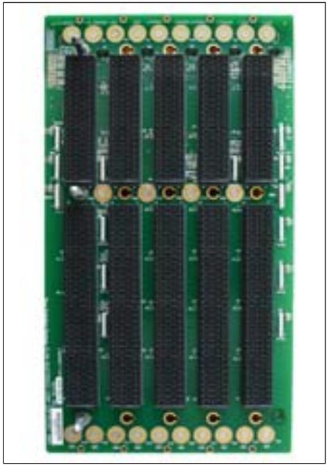
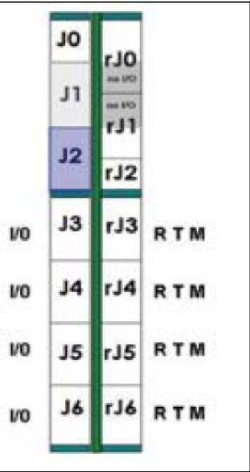
Figure 1. Figure 1a shows a standard 6U 5-slot VPX backplane and 1b shows a simple side-view diagram of how the J0-J6 connectors are used.

another vendor, along with a backplane from yet another party. Therefore, the OpenVPX initiative commenced in early 2009 with a goal of providing interoperability definitions for the VPX specification. The initiative was rolled into VITA as the VITA 65 specification, which was approved by ANSI in June 2010.

In short, OpenVPX provides definitions for backplane configurations, which are comprised of slot profiles into which various module profiles can be plugged. The module and slot profiles ensure that a vendor's VPX boards (modules) have pinouts that are interoperable within the VPX backplane slots. The backplane configuration tells the user which slot profiles are utilized, including information on the data rate, routing topology, and fabric used.

When it comes to backplane functionality, there is very little change. The new standard simply redefined two reserved P0/J0 signals Aux\_Clk (+/-) and added one P1/J1 single ended Utility signal of Maskable Reset and redefined the Res\_Bus signal to GDiscrete. The Aux\_Clk and GDiscrete pins were already bussed anyway, so the change is minimal. Also, the SysCon signal is now configurable.

Let's take a look at a standard 6U VPX 5-slot Mesh backplane and compare it to an OpenVPX version. Figure 1a shows a 6U 5-slot VPX backplane and 1b shows a side-view of how the J0-J6 connectors are used.

The standard VPX version has pinout charts for P0 and P1 sections with the P2-P6 as “undefined”. Although the P0 and P1 sections have defined pinouts, there are no details in VPX as to the kind of signals such as thin pipes, fat pipes, or ultra thin pipes. Also, the details of the utility plane are not as clear.

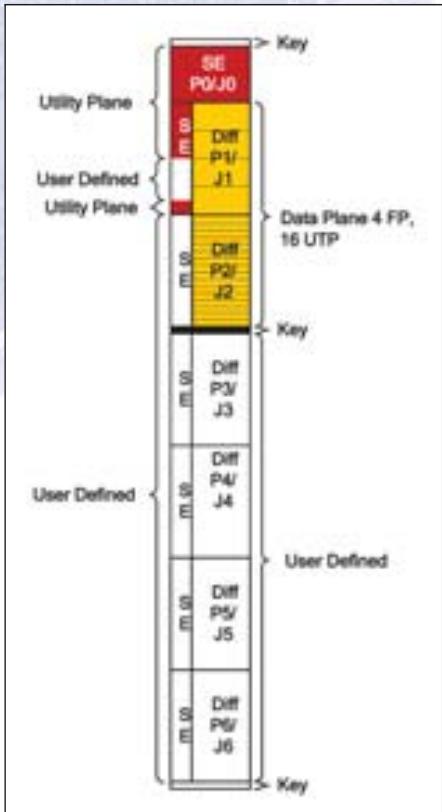
In the OpenVPX version of the same backplane, Figure 2 shows the payload slot profile. It provides more information for the data plane section (in yellow), which in this case defines 4 fat pipe lanes. Also, the utility plane sections are clearer. Although this backplane does not have a control plane, if it had one we'd also see this in the payload slot profile, along with the type of signal (thin pipes are commonly used for the control plane).

The Slot Profile that is referenced in Figure 2 gives us some details on the card plugging into the slot. For example, the slot profile number SLT6 says it's a 6U slot

# GE Intelligent Platforms
![GE Intelligent Platforms VPX Reference Guide imagination at work](.openvpx-concept-to-specification/5e3d3bebdc7074b5d59b4961db6c80463e42fe7e95159e1f3064cb57dc00777c.jpg)

# It's an open specification.

So it's only fitting that our 136-page reference guide is free.

Think of this reference book as Cliffs Notes for VPX and OpenVPX. It's that comprehensive and easy to read. It covers all the key topics, including the VITA 46 (VPX) specification, VITA 48 (VPX REDI), and VITA 65 (OpenVPX). It covers the history and rationale for VPX, its underlying principles and features, describes in detail important technical information, and illustrates the content with over 50 diagrams, charts and photos. Ordering one is a no-brainer.

Order your free copy at www.ge-ip.com/vpx

![The image displays a circular logo with a blue background. In the center, the lowercase letters 'ge' appear in a white, cursive script. Surrounding the central text are four white, curved, flame-like shapes: two positioned in the upper section and two in the lower section.](.openvpx-concept-to-specification/027d38ff91e6e806349e25e6c969aae9cc43790722b8ab27114d26180d3388fd.jpg)

imagination at work

OpenVPX

© 2010 GE Intelligent Platforms, Inc. All rights reserved. All other brands or names are property of their respective holders.

Free Info at http://info.hotims.com/28057-844 profile (a 6U board), the PER says it's a peripheral slot, 4F means it has 4 fat pipes and the 10.3.1 is where you can find details on this slot profile in the VITA 65 specification. For OpenVPX, fat pipes have 4 links (4 Tx pairs + 4 Rx pairs), thin pipes have 2 links, and ultra thin pipes have one link. The wider bands, like fat pipes, are typically used in the data plane, while the control plane will often have the thin pipe or ultra thin-pipe signals. Slot types are comprised of peripheral slots, payload slots, switch slots, or bridge slots.
![Utility Plane User Defined Utility Plane SE P0/J0 SE Diff P1/ J1 SE Diff P2/ J2 Data Plane 4 FP, 16 UTP Key Key User Defined User Defined SE Diff P3/ J3 SE Diff P4/ J4 SE Diff P5/ J5 SE Diff P6/ J6 Key](.openvpx-concept-to-specification/062704da2cf18539e632acd244c198429ea6ab0343648b91fa80924d31674193.jpg)

Figure 2. A Slot Profile of an OpenVPX (VITA 65 compliant) version of the 6U 5-slot backplane. The profile provides more details on the data signals, utility plane, and more.

The backplane profile of the backplane also provides more information. For example, this 6U 5-slot's profile is

BKP6-DIS05-11.2.16-1. The BKP6 tells us it's a 6U backplane profile. DIS05 means it's a distributed (like a mesh or ring) architecture and has 5 slots. The 11.2.16 is the section of the specification where you can find details on this backplane profile. The “-1” tells us the data rate is 3.125 Gbps (-2 means 5 Gbps and -3 means 6.250 Gbps).

The backplane profile chart in Figure 3 shows the profile name, the pitch, the corresponding slot profile for the backplane, the control plane data rate (if applicable) and the data rate of the backplane.

The slot type (like DIS05) section of the profile name is an important part of

<table><tr><td rowspan="2">Profile name</td><td colspan="2">Mechanical</td><td>Slot Profiles and Section</td><td colspan="2">Channel Gbaud Rate</td></tr><tr><td>Pitch (in)</td><td>RTM Conn</td><td>Payload</td><td>Control Plane</td><td>Data Plane</td></tr><tr><td>BKP6-DIS05-11.2.16-1</td><td>1.0</td><td>VITA 46.10</td><td>SLT6-PAY-4F-10.2.4</td><td>1.25</td><td>3.125</td></tr><tr><td>BKP6-DIS05-11.2.16-2</td><td>1.0</td><td>VITA 46.10</td><td>SLT6-PAY-4F2T-10.2.4</td><td>1.25</td><td>5.0</td></tr><tr><td>BKP6-DIS05-11.2.16-3</td><td>1.0</td><td>VITA 46.10</td><td>SLT6-PAY-4F2T-10.2.4</td><td>1.25</td><td>6.25</td></tr></table>

Figure 3. The Backplane Profile Chart tells us which OpenVPX Slot Profile(s) is used, the pitch, and data rate of the backplane.

# The new CES OpenVPX product line is here !Are you ready ?

# Board & Box Level:

- System integration
- System architecture
- Computing elements
- Avionic interfaces
- Video interfaces
- Enclosures

![Exploded view of a large electronic circuit board with internal components and connectors (no visible text or symbols)](.openvpx-concept-to-specification/22fda1b51b7508d7bd2275b79f6d02de2eca3cfe104b7a8bfcff831fae6f6cd8.jpg)

Visit our updated website: www.ces.ch

![The image displays a logo featuring the letters 'CES' in a bold, white, geometric sans-serif font. The letters are stylized with sharp angles and are set against a dark green rectangular background. The entire design is enclosed within a thin white border.](.openvpx-concept-to-specification/fc03d61fcfe9a64ecd915585fc07f2a4d1f65e1180bc630f4657ba0e84df54a1.jpg)
CREATIVE ELECTRONIC SYSTEMS

# SPEED YOUR TIME-TO-MARKET

# YOUR TOTAL SOLUTIONS PARTNER

![Military jet aircraft in flight against a clear blue sky (no visible text or markings)](.openvpx-concept-to-specification/0b25e6370ad1045c879775e6f2fd164af9e74894a4013da0620a6526db813d97.jpg)

![The image displays a rectangular, off-white plastic tray or case viewed at an angle. Inside the tray, there are black rectangular blocks or cartridges arranged at the top. Below these, there is a green rectangular tray or insert. Small circular indentations are visible near the green insert. A portion of a red circle is visible on the far right edge of the image.](.openvpx-concept-to-specification/bd8e29bc99698a125e0724aa873572ead99b1e26ec13dc7630fef8ed351c876e.jpg)

# 1 Command & Control

Single Board

Computers

VPX6-185

![The image displays a black, rectangular object, which appears to be a battery pack or similar electronic module, angled diagonally across a white background. In the upper right corner, there is a red circle containing the white number '2'.](.openvpx-concept-to-specification/20b06921cce1cc759fab8b9f8667a199d20f9b1d50653a87e68db3e400bc351b.jpg)

# 2 System Connectivity

Ethernet Routers

VPX3-685 Secure

Router

![Illustration of a mechanical device with gears and housing (no visible text or symbols)](.openvpx-concept-to-specification/760a92a1c01a84c9b899108f80358c8f8eb2d3d40a912fd53e8a6847e9877074.jpg)

# 3 Flight Control

Multi-Platform Mission

Computers

MPMC-9350 &

MPMC-9310

Do you need innovative solutions or complete integration services for high-density data processing now? From board-level products to fully integrated systems, we provide advanced technology solutions that perform under the most rugged operating conditions. Speed your time-to-market and lower your overall program development costs using our leading edge, commercial-off-the-shelf products (COTS), or modified COTS (MCOTS) and engineering services. Ask your representative about the new VPX System specification, OpenVPX $^{™}$ .

![The image shows a green printed circuit board (PCB), likely an I/O expansion card. It features a silver metal bracket along the top edge. On the right side, there are three black D-sub connectors: two larger 25-pin connectors (typically parallel ports) and one smaller 9-pin connector (typically a serial port). The board is populated with various electronic components, including black integrated circuits, capacitors, and resistors. There is white silkscreen text printed on the board, but it is too blurry to be legible. A small portion of a red circle is visible on the far right edge.](.openvpx-concept-to-specification/b000aec9d4a07a36bb86d02b322eb921d7fdcb2cc1cc91e370b36ad299fcb70f.jpg)

# 4 Graphics Display

Video Input & Output
XMC-710

![Close-up of a green printed circuit board (PCB) with visible traces and pads, no text or symbols present.](.openvpx-concept-to-specification/a0661897ea52105c4e2e0ebbded8f6b4a45f8b7096e6fac33a84b26531de4c67.jpg)

# 5 Radar Processing

Digital Signal Processors

CHAMP-AV6

![The image shows a black rectangular electronic component, appearing to be a drive bay or chassis assembly with a visible internal green circuit board. In the upper right corner, a red circle contains the white number '6'.](.openvpx-concept-to-specification/15c883cbe4994c0f4a946d05b618cfb6f8f413a768d365fd6ecc6b420c73c11d.jpg)

# 6 FPGA Processing

VPX3-450

/CURTISS WRIGHT Controls Embedded Computing

![The image displays a horizontal rectangular badge with a thick dark blue border. Inside the white center, the text 'OpenVPX' is written, with 'Open' in orange and 'VPX' in purple. A thin blue curved line sits beneath the text. On the right vertical edge, the word 'Ready' is printed in white letters against the blue background.](.openvpx-concept-to-specification/b819d690a9670aab1adab8b63ebdf89b7b5b1f1b10cf76673f15139d7d6bed9a.jpg)

sales@cwcembedded.com

ABOVE & BEYOND

cwcembedded.com

BOARDS & SYSTEMS

Free Info at http://info.hotims.com/28057-846

# Transitioning to OpenVPX

the description. The main fabric topologies are CEN for centralized, DIS for distributed, and HYB for hybrid. "Centralized" means it has a centralized switch slot and the routing could be similar to a Star topology. The DIS and CEN configurations typically have payload and switch slot types. The HYB will typically also define peripheral, bridge, and bus slot types like "VME" to account for connections to the legacy bus slots. The bridge slot does not mean an active bridge board (like a cPCI Bridge) is being used. Rather, it just refers to the fact that this VPX slot also has pinouts defined for the parallel bus (like VME).

# Future Designs for VPX/OpenVPX

There are some interesting configurations coming up in OpenVPX. They include special connections for optical connectors and another version for a RF connector interface. VITA 67 is underway to add RF connectors to the OpenVPX backplanes. Figure 4 shows the new gold connectors on a backplane.

![Essential Building Blocks... Innovative Solutions. Signal Processing HW IP & FrameWorks Development Tools Systems & Services](.openvpx-concept-to-specification/a85acc584ec9cb3bcd3b0480fca78915964413837fba42d775cc0d7fc53ceff7.jpg)

Size Weight and Power...

Today's military electronic systems require flexible state-of-the-art processing performance in a low power, compact solution that meets the demands of the extreme conditions of the battlefield. That's where BittWare's high performance signal processing FPGA solutions come in. Conduction-cooled, ruggedized, and COTS compliant OpenVPX, VME/VXS and CompactPCI boards based on Altera's Stratix family of FPGAs provide fast time to market, on-the-fly flexibility and the ability to process complex, compute-intensive algorithms in real time. BittWare military solutions for radar, sonar, SigInt

and electronic warfare provide developers the Essential Building Blocks necessary to deliver Innovative Solutions today for tomorrow's state-of-the-art military systems.

![Close-up of a green integrated circuit board with multiple gold contacts and a central chip (no visible text or symbols)](.openvpx-concept-to-specification/96576beae165f56947d32f435d65898bfc9ba69defa9958ffae64a1ff620cba7.jpg)

Based on the Altera Stratix family of FPGAs for signal processing

![BittWare SIGNAL PROCESSING SYSTEMS](.openvpx-concept-to-specification/7ab839bf8857d8472f11506cee55c386df44b900ebe8c5201015e17174c87839.jpg)

For more information, visit bittware.com

![Close-up of a green printed circuit board with multiple black components and connectors (no visible text or symbols)](.openvpx-concept-to-specification/ad63145a9b4c0ae8a41b34370ec7bca808092c27a0267f900b02aef995a748eb.jpg)

Figure 4. This photo shows two upcoming solutions in one. The gold connectors are for RF signals per the VITA 67 specification underway. Also shown is a VPX cabling solution with a shroud to secure the cables that clip into the backplane.

Another very compelling new solution for VPX is cabling systems. Compliant to the latest VITA 46 specifications, the cabling system can be used for IO to bulk-head connectors, slot-to-slot connections, and out-of-band communication. The cabling system can also be used for system development. Figure 4 also shows an example of these cables plugged into a VPX backplane. The direct cabling system also has front-plug versions, which allow testing across the backplane or full interconnect path. The metal shroud can be used in deployable systems to securely hold the cables in place and satisfy MIL-STD-810E and 901D for shock and vibration.

There are several reasons to use a cabling system in a deployed VPX platform. Many applications such as ATRs (air transport racks), may not have RTM (rear transition module) options. In some cases, the signal speeds through the RTM are not enough. In other designs, the system cannot afford to lose a slot of space to an IO slot. The VPX cabling system provides a rugged and robust alternative with a high-speed connection that is plugged directly into the MultiGig connector in single or multi-wafer formats.

OpenVPX provides definitions for VPX backplanes, modules, and chassis to ensure that the products are interoperable. The backplane configurations have been defined to show the collection of slot profiles it entails, including information on the data rate, routing topology, and fabric used. Exciting VPX/OpenVPX products have emerged that offer the performance solutions required in C4ISR systems.

This article was written by Melissa Heckman, Electrical Engineer, Elma Bustronic Corporation (Fremont, CA). For more information, contact Ms. Heckman at Melissa.heckman@elmabustronic.com, or visit http://info.hotims.com/28057-451.

# Putting OpenVPX To Work

Before the advent of OpenVPX, designers of embedded systems took advantage of the extreme connectivity offered by VPX (VITA 46), but were faced with a virtually unlimited number of possible implementations. Specific choices for the control and data channel assignments for each slot, the backplane connectivity, and serial fabrics were often made somewhat arbitrarily to suit the particular needs of the current system. Although following the general framework of VITA 46, each system tended to be so unique that the boards and backplanes designed for one system were seldom usable in other systems, even from the same vendor.

Now, OpenVPX (VITA 65) provides an effective taxonomy for describing VPX components, and also defines numerous “profiles” for boards, slots and backplanes that detail specific configurations of channels, interconnections, and fabrics. Instead of starting from scratch each time, designers can browse through these standardized profiles to find one that satisfies the objectives of each new system. By narrowing the field of configurations, these profiles boost reusability and interoperability between vendors.

# Beamforming Principles

A multichannel software radio beamforming receiver system is presented as an example that illustrates how the OpenVPX system design process works. Principles from this example can be easily applied to other systems.

Beamforming is extensively used in communications, radar, direction finding, countermeasures, weapons systems, oil and mineral exploration, and medical imaging and treatment. In essence, beamforming utilizes multiple sensors to achieve directionality of the sensor array, and also to improve the signal quality and reception range.

Beamforming achieves these benefits by judiciously adjusting the phase shift and gain of each sensor so that, when the adjusted sensor signals are combined, they add constructively. For receivers, the combination is performed by summing the adjusted signals from each sensor. For transmitters, each sensor delivers a signal that adds constructively at the destination.

![The flowchart depicts a signal processing system originating from a mobile phone icon on the left. Four parallel signal paths branch out, labeled **t1**, **t2**, **t3**, and **t4**.  Each path follows this sequence: 1.  The signal line connects to an **ear icon**. 2.  The signal enters a yellow block labeled **Gain** (newline) **Adjust** (newline) **G1**, **G2**, **G3**, or **G4**. 3.  The signal exits to a green block labeled **Phase** (newline) **Adjust** (newline) **P1**, **P2**, **P3**, or **P4**.  The outputs from all four green blocks (P1, P2, P3, P4) converge into a central circle. The output from this circle points to the right and is labeled **Beamformed** (newline) **Sum Out**, accompanied by a waveform icon.](.openvpx-concept-to-specification/5ead16c8e41bbfd6fb40692d13bd6ac5e31260d50209b0571ca969967d28815f.jpg)

Figure 1. Beamforming adjusts phase and gain of signals from each antenna in an array to compensate for different delays (tn), so that signals arriving from a particular angle relative to the array add constructively when combined in the summer.

![Based on the provided flowchart, here are the labeled blocks and their connections:  **Input Blocks (Left Column)** Four parallel input paths are shown, each consisting of: 1.  A block labeled **'200 MHz 16-bit A/D'**. 2.  Connected to a block labeled **'DDC 1 & /7 shift'**, **'DDC 2 & /7 shift'**, **'DDC 3 & /7 shift'**, or **'DDC 4 & /7 shift'**.  **Processing Blocks (Center)** The outputs from the DDC blocks feed into two main blocks: *   **'AURORA BEAMFORM SUMMATION'**: Connected via upward-pointing arrows from all four DDC blocks. *   **'PCIe X4 I/F'**: Connected via rightward lines from all four DDC blocks.  **Connections to Crossbar Switch** *   **'X4 Sum Out'**: A green arrow originates from 'AURORA BEAMFORM SUMMATION' and points to the **'CROSS BAR SWITCH'** (a vertical green bar with an 'X' at the bottom). *   **'X4 Sum In'**: A green arrow originates from the 'CROSS BAR SWITCH' and points left back into 'AURORA BEAMFORM SUMMATION'. *   An orange arrow connects the **'PCIe X4 I/F'** block to the 'CROSS BAR SWITCH'.  **VPX P1 Module (Right Column)** The 'CROSS BAR SWITCH' routes signals to the **'VPX P1'** module, which contains three sections: *   **'DP01'** (Orange box): Connected from the switch via an orange arrow labeled **'X4'**. Text next to it reads: **'PCIe X4 (Data Plane & Control Plane)'**. *   **'EP01'** (Green box): Connected from the switch via a green arrow labeled **'X4'**. Text next to it reads: **'Aurora X4 Sum OUT (Expansion Plane)'**. *   **'EP02'** (Blue box): Connected via a green arrow labeled **'X4'**. Text next to it reads: **'Aurora X4 Sum IN (Expansion Plane)'**.](.openvpx-concept-to-specification/0d1bed880c2a1d077f4f05961c1b93460e72243027393b471ae8b2a00e5a2a8c.jpg)

Figure 2. Model 5353 3U VPX Beamformer Module with four A/Ds, four DDCs, X4 PCIe interface, phase shifters and summation engine for beamforming.

# Defining System Requirements

The sensors in a software radio receiver system for beam forming are antennas arranged in a linear or two-dimensional array. The term “software” in software radio refers to the programmability of the digital signal processing functions including the digital down conversion, phase shifting, gain adjustments, summation of the received channels, and then the ultimate demodulation, decoding, and/or decryption of the acquired signal.

The example system requires sixteen antennas, each followed by an RF stage to amplify and down convert the radio frequency signal to an intermediate frequency (IF) analog signal so it can be digitized by an A/D converter. These sixteen IF signals are supplied as inputs to the system.

Each IF signal has a bandwidth of 20 MHz and is centered at 70 MHz. After A/D conversion, all sixteen channels are down converted to baseband and beamformed using gain and phase shift parameters to comply with operational objectives. The final beamformed sum is delivered as a baseband signal to a remote system control processor PC for additional processing, forwarding, or storage.

The system must operate in a limited space avionics equipment bay and must comply with typical shock, vibration, temperature, altitude, humidity, flight safety, power consumption, power supply, and EMC/EMI standards.

# Choosing the OpenVPX Payload Module for Beamforming

Since industry standard chassis are available in both 3U and 6U sizes, and both are well defined for OpenVPX, the small avionics bay requirement favors the 3U style. The next tasks are to select the appropriate 3U software radio and processor modules (boards) to perform the beamforming, define the required connections between the modules, select a 3U backplane to support those interconnections, a chassis to meet the physical and environmental requirements, and a link between the chassis and the remote system control processor PC.

For example, Pentek's Model 5353 Software Radio Beamformer is a 3U OpenVPX module featuring four 200 MHz 16-bit A/D converters and two Virtex-5 FPGAs, one for signal processing and a second one for the PCI interface. Inside the first FPGA are interfaces to the four A/D converters, four digital downconverters (DDCs) with programmable phase shift and gain, and four power meters at each DDC output. A simplified block diagram of the 5353 is shown in Figure 2.

The Model 5353 also includes a summation block that adds the DDC outputs for a four-channel beamforming sum. This block also accepts a propagated sum in signal from another module and generates a propagated sum signal out to the next module. The sum in/sum out signals use two X4 Aurora gigabit serial links connected to the VPX P1 backplane connector, each capable of moving data at 1.25 GB/sec peak.

To support the 20 MHz IF channel bandwidth with a 25% filter margin, the DDC outputs deliver complex 16-bit I+Q samples at 25 MHz, or 100 MB/sec. The propagated sum in/sum out signals also operate at 100 MB/sec and are thus easily handled by the 1.25 GB/sec X4 Aurora links.

The 5353 system interface for control and data is an X4 PCIe port, also connected to P1. Bandwidth requirements for the control and data port are dominated by delivery of the final beam-formed sum out to the control processor. This 100 MB/sec stream falls well within the 2 GB/sec peak rate of the X4 PCIe port when operating in Gen 2 mode.

A programmable, fabric-transparent crossbar switch allows free assignment of the two X4 Aurora ports and the X4 PCIe port, in any combination, to the four X4 fat pipes of P1. This flexibility allows the 5353 to accommodate various OpenVPX slot profiles and backplanes.

To accommodate 16 antennas, a total of four 4-channel 5353 modules are required. Since the summation chain requires the same data rate as each DDC, the two sum ports must simultaneously handle $100\mathrm{MB / sec}$ each. This class of signals falls under the definition of expansion plane in the OpenVPX specification.

The X4 PCIe interface for handling the data initialization, delivery of beamforming parameters is described as the control plane under OpenVPX. Final delivery of the beamformed result to the system control processor is best classified as the data plane under OpenVPX.

# Choosing the OpenVPX Backplane

OpenVPX backplanes use many different topologies named after the geometry of their interconnections, including mesh, star, leaf, and ring. Most include slots for switch modules to support reconfigurable inter-board connections, while some simply rely on dedicated wiring between the slots.

After reviewing the 3U OpenVPX backplane choices in the standard, the most appropriate for our system is the 6-Slot backplane profile BKP3-CEN06-15.2.2-1, which has five payload slots and one switch slot as shown in Figure 3.

The expansion plane fat pipes join adjacent payload slots 1 through 5 to support the sum in and sum out chaining ports between 5353 modules. One data plane fat pipe from each payload slot to the switch slot 6 supports the four X4 PCIe links we need to the control processor.

This backplane defines specific slot profiles for the two types of slots. Slots 1 through 5 use the payload slot profile SLT3-PAY-1F2F2U-14.2.2 shown in the upper right section of Figure 3. To see if we can use the Model 5353 in the payload slots, we must verify that the Model 5353 has a module profile compatible with this slot profile.

It is important to note that the backplane profiles and slot profiles do not specify any fabric or protocol for the connections. However, the backplane profile does speci-

![The diagram depicts a VPX backplane architecture divided into '5 Payload Slots' and a 'Switch Slot'.  **Left Grid Structure:** *   **Columns:** Six columns are labeled 'VPX 1', 'VPX 2', 'VPX 3', 'VPX 4', 'VPX 5', and 'VPX 6'. A red text note states: 'Slot numbers are logical, physical slot number may be different'. *   **Rows:** Vertical labels on the left read: 'Expansion Plane (FP)', 'Data Plane (FP)', 'Control Plane (UTP)', 'Management Plane (PMB)', and 'Utility Plane Includes Power'. *   **Blocks:**     *   Columns 1-5 contain blocks labeled 'Expnt Plane', 'Data Plane', 'Contl Plane', and 'PMC'.     *   Column 6 contains blocks labeled 'Expnt Plane', 'Data Switch', 'Control Switch', and 'DPMC'. *   **Connections:**     *   Red lines connect the 'Expnt Plane' blocks across columns 1-5.     *   Cyan lines connect the 'Data Plane' blocks and route into the 'Data Switch'. An arrow points right labeled 'IF'.     *   Green lines connect the 'Contl Plane' blocks and route into the 'Control Switch'. Arrows point right labeled 'TF' and 'UTP'.     *   Yellow dots/lines connect the bottom rows across all columns.  **Right Detailed Breakdowns:** *   **Top Section:** Labeled 'Payload Slots 1-5' and 'SLT3-PAY-1F2F2U-14.2.2'.     *   Grouped under 'VPX P1'.     *   Blocks: 'DP01', 'EP01-EP04', 'EP05-EP08'.     *   Labels: 'Data Plane 1 Fat Pipe', 'Expansion Plane 16 Differential Pairs', 'Control Plane 2 UTPs'. *   **Bottom Section:** Labeled 'Switch Slot 6' and 'SLT3-SWH-6F6U-14.4.1'.     *   Grouped under 'VPX P1'.     *   Blocks: 'DP01', 'DP02', 'DP03', 'DP04'.     *   Labels: 'Data Plane 1 Fat Pipe' is listed next to each block.](.openvpx-concept-to-specification/f3810a75d5c1d83a49890a787a919d666e99b6eae76ed17cafef38711381ebfc.jpg)

Figure 3. OpenVPX 3U 6-Slot Backplane BKP3-CEN06-15.2.2-n showing definition for the payload slot profiles and switch slot profiles.

![  Section   Data Plane 1 Fat Pipe   Expansion Plane 8 UTPs   Control Plane 2 UTPs   Total     :---   :---   :---   :---   :---     DP01             EP01-EP04             EP05-EP08             Control Plane 2 UTPs           VPX P1 DP01 Data Plane 1 Fat Pipe EP01-EP04 Expansion Plane 16 Differential Pairs Control Plane 2 UTPs](.openvpx-concept-to-specification/83c512a826a4db298510ee28c09d0ecc50f83083d99ee72621b7750ab87eb404.jpg)

Figure 4. Fabric definitions listed for the module Profile MOD3-PAY-1F2F2U-16.2.2-4 (for the model 5353) are completely compatible with the VPX P1 connections for payload slot profile SLT3-PAY-1F2F2U-14.2.2, defined for backpane profile BKP3-CEN06-15.2.2-1.

![The flowchart depicts a signal routing path with the following labeled blocks and connections:  **Blocks:** *   **PCIe X8 Serial Cable 4 GB/sec** (text label next to a black cable) *   **PCIe X8 Cable ReDriver** (light blue box) *   **PCI EXPRESS SWITCH** (pink box) *   **CROSS BAR SWITCH** (light green vertical bar) *   **VPX P1** (yellow box) containing sub-blocks: **DP01**, **DP02**, **DP03**, and **DP04**.  **Connections:** *   A black cable labeled **PCIe X8 Serial Cable 4 GB/sec** connects to a green connector, which links to the **PCIe X8 Cable ReDriver**. *   A double-headed arrow labeled **PCIe X8** connects the **PCIe X8 Cable ReDriver** to the **PCI EXPRESS SWITCH**. *   Four double-headed arrows connect the **PCI EXPRESS SWITCH** to the **CROSS BAR SWITCH**. Each arrow is labeled **X4** on both the left and right sides. *   Four double-headed arrows connect the **CROSS BAR SWITCH** to the **VPX P1** block. Each arrow is labeled **X4** on both sides. *   To the right of the **VPX P1** block, the paths exiting from **DP01**, **DP02**, **DP03**, and **DP04** are labeled **PCIe X4**.](.openvpx-concept-to-specification/00802e9f2c3c67cf480204efd9432843a4665b71be64461a0d8a108b096699a5.jpg)

Figure 5. Model 5308 3U VPX PCIe X8 Serial Cable Adapter with ReDriver, PCIe switch and crossbar switch. Also shown are the X8 PCIe cable, PC host adapter board, and host PC.

![A person sitting on a black bench viewing framed artworks on a green wall (no text or symbols visible)](.openvpx-concept-to-specification/57e66b7207e6272884aed17e7f368c7f6e61fed22edf750786b09f03e30638a8.jpg)

# VPX: Admire the Collection

Elma Bustronic

The VPX Collection

c. 2009

Gold, silver, PCB on canvas

![The image displays a logo with the text 'OpenVPX' centered on a light cream background. The word 'Open' is written in orange, while 'VPX' is in dark blue. Both parts of the text are in a bold, italicized sans-serif font. A dark blue curved line swoops around the right side of the text, forming an incomplete oval shape. A small 'TM' trademark symbol is visible in the upper right corner.](.openvpx-concept-to-specification/6d22a2eb0090fc810d2e365f39836a3547fd37a5e270be1bed26c76ecb7908aa.jpg)

The VPX collection depicts the variety and expertise found only at Bustronic. These masterpieces exemplify Bustronic's precision design and innovative creativity in the VPX milieu. The designer uses the full range of VPX products – from 3U, 6U, 6U Hybrid backplanes as well as unique VPX accessories such as load boards, test modules, extender boards, air baffles, and RTMs. This artist has really mastered the VPX realm. To see more, visit bustronic.com

![bus tronic](.openvpx-concept-to-specification/114667a17dbbaaeecf51f47129ca7568d2be503d48458c848799444b38162ecf.jpg)

Elma Bustronic

Tel: 510.490.7388 www.bustronic.com info@bustronic.com

Free Info at http://info.hotims.com/28057-848 fy the maximum baud rate for each gigabit serial pipe. This scheme allows a wide variety of modules to be used in a given backplane slot, each with its own particular fabric and baud rate. Of course, the baud rate of each pipe of the module must be equal to or less than the maximum baud rate specified in the backplane profile.

![Two green printed circuit boards with black insulation layers, no visible text or symbols on the boards themselves.](.openvpx-concept-to-specification/1b5d2db550bf47df91b6f67055ce7246b991c07130d564f2344d36a775bdb92d.jpg)

OpenVPX Backplanes

![Close-up of a green printed circuit board (PCB) with gold contacts and traces, no visible text or symbols.](.openvpx-concept-to-specification/2c30005c57dde60c11d2dfc122a404aab1ef7a0ec9533290e37b3f848a241579.jpg)

OpenVPX
Hybrid Backplanes

![3D rendering of a computer RAM card with visible circuitry and green base (no text or symbols)](.openvpx-concept-to-specification/09fc07cb24cfb5cccbb00d8dd4bad3d0a56b857cd76b87aa6bf893e1429b9487.jpg)

VPX Load Board &
Extender Board

![Electronic circuit board with visible components and a screen (no readable text or symbols)](.openvpx-concept-to-specification/ccb64cc947106b97a59363a4e32559fd2a14a50537b154fd24a59d2181e64465.jpg)

VPX SerDes Test Modules,
RTMs & Air Baffles

![The image features a maroon background displaying the word 'ELMA' in large, white, sans-serif capital letters.](.openvpx-concept-to-specification/baa8f7ff0ab36bfa37615efa67edeba9523f7e4461921f88abb39543315b4b81.jpg)
Your Solution Partner

Because of its programmable crossbar switch, the Model 5353 can be configured to meet the module profile MOD3-PAY-1F2F2U-16.2.2-4, which is compatible with the slot profile SLT3-PAY-1F2F2U-14.2.2. This module profile defines data, expansion and control plane fabric connections and baud rates. The backplane profile BKP3-CEN06-15.2.2-1 defines a single fat pipe (X4) on the DP01 data plane for PCIe Gen 2 that corresponds directly to the PCIe interface as shown in Figure 4.

The eight expansion plane ultra thin pipes, EP01 through EP08, are also defined as PCIe Gen 2, capable of operating at baud rates of 5 GHz. We will organize these eight pipes as two fat pipes for the two X4 Aurora ports for sum in and sum out, which need to operate at only 3.125 GHz. The two control plane ports, CPutp01 and CPutp02, are not implemented on the 5353.

# Choosing the OpenVPX Switch/Interface Module

The selected backplane also has a switch slot with profile SLT3-SWH-6F6U-14.4.1, whose VPX P1 connections are shown in the bottom right section of Figure 3. The four data plane fat pipes shown (DP01 — DP04) connect to payload slot fat pipes DP01 on slots 1 through 4.

Now we need to find a compatible switch module that can plug into slot 6 and connect these four PCIe links to the remote system control processor. Pentek's Model 5308 PCIe Cable Adapter is a 3U VPX switch module with a front panel X8 PCIe cable connector defined by the PCI-SIG PCI Express® External Cabling 1.0 Specification. Compatible PCIe host adapters are available for many different systems including PCIe cards for desktop PCs as well as avionics cockpit computers.

The 5308 features a PCIe switch that supports flexible lane bonding so that a single X4 or X8 PCIe port from the control processor PC can be split into four X4 PCIe ports to four individual PCIe endpoints. The fabric-transparent crossbar switch joins these four X4 ports to the VPX1 P1 backplane connector, fully compatible with OpenVPX module profile MOD3-SWH-4F-16.4.5-2 shown in Figure 6.

Inspection reveals that this module profile is fully compatible with the four VPX P1 fat pipes on the slot profile SLT3-SWH-6F6U-14.4.1. Further, the baud rate specified for the backplane profile BPK3-CEN06-15.2.2-1 supports the PCIe Gen 2 with baud rates up to 5 GHz.

<table><tr><td>Data Plane2 Fat Pipes</td><td>Data Plane2 Fat Pipes</td></tr><tr><td>DP01 - DP02</td><td>DP03 - DP04</td></tr><tr><td>PCIe Gen 2 per Section 5.3</td><td>PCIe Gen 2 per Section 5.3</td></tr></table>

![VPX P1 DP01 Data Plane 1 Fat Pipe DP02 Data Plane 1 Fat Pipe DP03 Data Plane 1 Fat Pipe DP04 Data Plane 1 Fat Pipe](.openvpx-concept-to-specification/650b7638b937b3c58dca87bbe7cd004cc3633c46c5a0bc0323120eb1bfb2ec92.jpg)

Figure 6. Fabric definitions listed for the module Profile MOD3-SWH-4F-16.4.5-2 (for the model 5308) are data rate compatible with the VPX P1 connections for payload slot profile SLT3-SWH-6F6U-14.4.1, defined for backpane profile BKP3-CEN06-15.2.2-1.

![Based on the provided flowchart, here is a description of the labeled blocks and connections:  **Labeled Blocks:** *   **Slot 1:** Contains '5353', 'DP01', 'EP01', 'EP02', 'PCIe X4', 'Out', 'In', and 'S'. *   **Slot 2:** Contains '5353', 'DP01', 'EP01', 'EP02', 'PCIe X4', 'Out', 'In', 'S', and 'Aurora X4'. *   **Slot 3:** Contains '5353', 'DP01', 'EP01', 'EP02', 'PCIe X4', 'Out', 'In', 'S', and 'Aurora X4'. *   **Slot 4:** Contains '5353', 'DP01', 'EP01', 'EP02', 'PCIe X4', 'Out', 'In', 'S', and 'Aurora X4'. *   **Slot 6:** Contains '5308', 'DP01', 'DP02', 'DP03', 'DP04', and 'PCIe Switch'. *   **Information Box:** Contains the text:     *   '3U VPX Backplane Profile:'     *   'Slot 1 – 4 Slot Profile:'     *   'Slot 6 Slot Profile:'     *   'Model 5353 Module Profile:'     *   'Model 5308 Module Profile:'     *   'BKP3-CEN06-15.2.2-1'     *   'SLT3-PAY-1F2F2U-14.2.2'     *   'SLT3-SWH-6F6U-14.4.1'     *   'MOD3-PAY-1F2F2U-16.2.2-4'     *   'MOD3-SWH-4F-16.4.5-2' *   **Hardware:** A computer chassis.  **Connections:** *   **Blue Line:** Labeled 'PCIe X4' between Slot 1, Slot 2, and Slot 3. It connects Slot 1 to Slot 2, Slot 2 to Slot 3, and Slot 3 to Slot 4. It continues to Slot 6, labeled 'PCIe X4', entering 'DP01'. *   **Purple Line:** Connects Slot 1 to Slot 2, Slot 2 to Slot 3, and Slot 3 to Slot 4. It continues to Slot 6, labeled 'PCIe X4', entering 'DP03'. *   **Green Line:** Connects Slot 1 to Slot 2, Slot 2 to Slot 3, and Slot 3 to Slot 4. *   **Red Line:** Connects Slot 1 to Slot 2, Slot 2 to Slot 3, and Slot 3 to Slot 4. *   **Internal Slot 6:** Arrows connect 'DP01', 'DP02', 'DP03', and 'DP04' to 'PCIe Switch'. *   **External Connection:** 'PCIe Switch' connects via a black line to a grey block. This block connects via a black line labeled 'PCIe X8 cable' to the computer chassis.](.openvpx-concept-to-specification/c4e371a081672a65669632e58207ce4e8814ed0d9748f3857cc7c6d2cffa219a.jpg)

Figure 7. Complete OpenVPX beamforming system showing four 5353's with Aurora X4 sum in/out links (red), and PCIe X4 links (blue) connected to one 5308 with PCIe X8 cable link to the PC.

The final beamforming system is shown in Figure 7, with simplified block diagrams of the four Model 5353 Beamformers and the 5308 PCIe Cable Adapter. All of the required gigabit serial links for Aurora expansion plane and PCIe data and control planes are connected by the backplane wiring.

The chart in the diagram shows the OpenVPX profiles for the backplane, the slots, and the modules that plug into those slots. Each profile is described in full detail in the specification and the system designer must ensure that the profiles are compatible.

This process of matching module profiles, slot profiles, and backplane profiles for a particular application is the key to successful system configuration under OpenVPX. Not all of the resources of each profile need to be fully implemented or utilized if the needs of the application are satisfied.

Finally, the chassis profile needs to be defined based on the environmental and physical constraints of the system. OpenVPX does not yet have specific chassis profiles defined, but it offers a complete system for specifying the size, type (rack mount, tower, etc), slot count, primary power, cooling, backplane power, and the profile name.

# Summary

OpenVPX presents a formal, well-organized system for defining all components in VPX systems, and the efforts of the working group should be applauded. Many of the figures and all of the profiles in this article were derived from the full OpenVPX VITA 65 specification, which is available from the VITA website (www.vita.com), and is definitely a worthwhile and important reference document.

A good metric for the significance of a new standard is how actively new extensions are proposed to embrace new options and new technology. As promising evidence, even before final ratification, new initiatives like VITA 66 and VITA 67 were proposed, adding both optical and RF I/O capabilities. As OpenVPX is applied to an increasing number of application systems, the need for future evolutionary capabilities will emerge. All signs point to growing adoption of OpenVPX for new programs by both the embedded systems industry and its customers.

This article was written by Rodger Hosking, Vice President, Pentek, Inc. (Saddle River, NJ). For more information, contact Mr. Hosking at Rodger@pentek.com, or visit http://info.hotims.com/28057-452.

# A directory of companies currently involved in OpenVPX

# 4DSP, Inc.

955 S Virginia Street

Suite 214

Reno, NV 89502

(800) 816-1751

sales@4dsp.com

www.4dsp.com

# Aitech Defense Systems, Inc.

19756 Prairie Street

Chatsworth, CA 91311

(888) 248-3248

sales@rugged.com

www.rugged.com

# Amphenol Backplane Systems

18 Celina Avenue

Suite 200

Nashua, NH 03063

(603) 883-5100

www.amphenol-abs.com

![The image displays a logo featuring the text 'BittWare' in a sans-serif font, with 'Bitt' in black and 'Ware' in blue. An elliptical blue line swoops over the top of the text. Below the main name, the tagline 'SIGNAL PROCESSING SYSTEMS' appears in smaller, grey, uppercase letters.](.openvpx-concept-to-specification/5c3d10c6e9ac24ff7ac4f04b58298c9f07ffafda301160bdfda4b2b95ec60f44.jpg)

# BittWare, Inc.

9 Hills Avenue

Concord, NH 03301

(603) 226-0404

sales@bittware.com

www.bittware.com

![The image displays a logo featuring the letters 'CES' in bold, white, sans-serif font against a teal background. The letters are stylized with horizontal teal cuts running through them, creating a segmented or barred appearance. The entire design is enclosed within a rounded rectangular border of the same teal color.](.openvpx-concept-to-specification/4f0326acf1f6d35cca1faf2d280f4cb5e8634075119c46772a75142a13242af5.jpg)
CREATIVE ELECTRONIC SYSTEMS

# Creative Electronic Systems SA

Avenue Eugene-

Lance 38

CH-1212 Grand Lancy 1

Geneva, Switzerland

+41 (0)22 884 51 00

ces@ces.ch

www.ces.ch

# Concurrent Technologies Inc.

6 Tower Office Park

Woburn, MA 01801

(781) 933-5900

sales@gocct.com

www.gocct.com

# Condurant Corporation

1501 S. Sunset Street

Longmont, CO 80501

(303) 485-2721

sales@conduant.com

www.conduant.com

# CSP Inc.

43 Manning Road

Billerica, MA 01821

(978) 663-7598

sales@cspi.com

www.cspi.com

![The image displays a logo or title graphic containing the following text:  *   **CURTISS** (in large red capital letters) *   **WRIGHT** (in large red capital letters below CURTISS) *   **Controls** (in black text to the right) *   **Embedded Computing** (in grey text at the bottom)  A vertical red line sits above the 'C' in Curtiss, and a horizontal red line extends from the right side of 'WRIGHT' underneath the word 'Controls'.](.openvpx-concept-to-specification/963853e3ec7ab0f5835ae4b8644b75ec4068741a4c1e1e6f75adbb9cba539602.jpg)

# Curtiss-Wright Controls Embedded Computing

333 Palladium Drive

Kanata, Ontario

K2V 1A6

Canada

(613) 599-9199

sales@cwcembedded.com

www.cwcembedded.com

# Curtiss-Wright Controls Electronic Systems

(formerly Hybricon Corporation)

151 Taylor Street

Littleton, MA 01460

(978) 952-2000

systeminfo@curtisswright.com

www.cwelectronicsystems.com

# Diversified Technology, Inc.

476 Highland Colony Parkway

P.O. Box 748

Ridgeland, MS 39157

(800) 443-2667

marketing@dtims.com

www.dtims.com

# Dynatem, Inc.

23263 Madero

Suite C

Mission Viejo, CA 92691

(800) 543-3830

sales@dynatem.com

www.dynatem.com

![The image features a logo with the red lowercase text 'bus' on the top line and 'tronic' directly below it, aligned to form the word 'bustronic'. To the right of the red text are three horizontal black bars of varying thickness. Below the logo, the text 'Elma Bustronic' appears in black, sans-serif font.](.openvpx-concept-to-specification/aed2b6641f6465c8883ffb095e1b1b1a01b554d842e308abeec96ad2398a5b62.jpg)

# Elma Bustronic Corp.

44350 Grimmer Blvd.

Fremont, CA 94538

(510) 656-3400

sales@elma.com

www.elma.com

![The image features a logo on a white background. The top line displays the word 'ELMA' in large, bold, blue capital letters with a slight drop-shadow effect. Below that, in a smaller orange font, is the tagline 'Your Solution Partner'.](.openvpx-concept-to-specification/149e83b8462d9057aeb8445884843486b6e9c75e740131fb14011175a99d91d0.jpg)

# Elma Electronic Inc. - Systems

760 Veterans Circle

Warminster, PA 18974

(215) 956-1200

sales@elma.com

www.elma.com

# Emerson Network Power

2900 South Diablo Way

Suite 190

Tempe, AZ 85282

(800) 759-1107 or (602) 438-5720

embeddedcomputingamericasales@emerson.com

www.emerson.com/embeddedcomputing

![The image displays a logo consisting of the text 'X-ES'. A large, blue, serif capital letter 'X' is positioned on the left. To its immediate right are the characters '-ES' in black, which are smaller in size than the 'X'. The background is white.](.openvpx-concept-to-specification/c7f49af66232cf9277e27edaec8601198215a2e56b37dfec00468c3229b25e1f.jpg)
Extreme Engineering Solutions

# Extreme Engineering Solutions, Inc. (X-ES)

3225 Deming Way

Suite 120

Middleton, WI 53562

(608) 833-1155

sales@xes-inc.com

www.xes-inc.com

![The image displays a circular logo featuring a white, stylized 'GE' monogram set against a solid blue background. This central blue circle is surrounded by a thin white line, followed by a wider white ring, and then a thin blue outer ring. The entire emblem is enclosed by a thin black border.](.openvpx-concept-to-specification/be9923d8dc718b1ae91e7033f6eda791e229c361246514b94f547ed3c68486ea.jpg)

# GE Intelligent Platforms

12090 South

Memorial Parkway

Huntsville, AL 35803

(800) 433-2682

keith.purtle@ge.com

www.ge-ip.com

# General Dynamics Canada

3785 Richmond Road

Ottawa, Ontario K2H 5B7

Canada

(613) 596-7000

info@gdcanada.com

www.gdcanada.com

# Hartmann Electronic

300 E. Auburn Ave.

Springfield, OH 45504

(937) 324-4422

Monika.diego@hartmann-elektronik.de

www.hartmann-electronic.com

# HDL Research Lab, Inc.

406 West Blue Bell Road

Brenham, TX 77833

(979) 836-2300

sales@hdl.cc

www.hdlresearchlab.com

# Innovative Integration, Inc.

2390-A Ward Avenue

Simi Valley, CA 93065

(805) 578-4260

sales@innovative-dsp.com

www.innovative-dsp.com

# Interface Concept

Z.I. n° 2 des Pays Bas

29510 Briec de l'Odet

France

+33 (0)2 98 57 30 30

info@interfaceconcept.com

www.interfaceconcept.com

# Juniper Networks

1194 North Mathilda Avenue

Sunnyvale, CA 94089

(888) 586-4737

www.juniper.net

![The image displays a blue, spherical logo with a glossy, gradient finish. A lighter, crescent-shaped section on the right side forms the letter 'C.' This is the logo for the telecommunications company Comcast.](.openvpx-concept-to-specification/1c2b1dab1699a1c3e18a4b5c2c8d5b145e46e35cca4d97d2ce902df33c2b305d.jpg)

# kontron

# Kontron

14118 Stowe Drive

Poway, CA 92064

(888) 294-4558

info@us.kontron.com

www.kontron.com

![The image displays a vertical graphic design featuring blue shapes on a white background. In the bottom right corner sits a solid blue triangle. Radiating outward from this corner towards the top left are five blue, triangular wedges separated by white space, creating a fan-like or burst effect.](.openvpx-concept-to-specification/5cbdc38d21ea5759c2359c32fb9c09279a830447405fbdb2d3b2941d91d71d65.jpg)

# MERCURY

COMPUTER SYSTEMS $^{TM}$

# Mercury Computer Systems, Inc.

199 Riverneck Road

Chelmsford, MA 01824

(866) 627-6951

www.mc.com

# Meritec/Joy Signal Technology

1359 West Jackson Street

Painesville, OH 44077

(888) 637-4832

info@meritec.com

www.meritec.com

# North Atlantic Industries

110 Wilbur Place

Bohemia, NY 11716

(631) 567-1100

www.naii.com

# Northrop Grumman Electronic Systems

1580-A West Nursery Road

Linthicum, MD 21090

(800) 443-9219

www.es.northropgrumman.com

# PCI-Systems Inc.

13 C Street

Suite D

Laurel, MD 20707

(301) 358-3621

sales@pcisystems.com

www.pcisystems.com

# PENTEK

Setting the Standard for Digital Signal Processing

# Pentek, Inc.

One Park Way

Upper Saddle River, NJ 07458

(201) 818-5900

info@pentek.com

www.pentek.com

# SIE Computing Solutions, Inc.

10 Mupac Drive

Brockton, MA 02301

(800) 926-8722

www.sie-cs.com

# Technobox, Inc.

140 Mount Holly Bypass

Unit 1

Lumberton, NJ 08048

(609) 267-8988

www.technobox.com

# TEK Microsystems, Inc.

300 Apollo Drive

Chelmsford, MA 01824

(978) 244-9200

www.tekmicro.com

# Themis Computer

47200 Bayside Parkway

Fremont, CA 94538

(510) 252-0870

www.themis.com

# Tracewell Systems

567 Enterprise Drive

Westerville, OH 43081

(800) 848-4525

sales@tracewell.com

www.tracewellsystems.com

![The image displays a graphic logo set against a white background. It consists of a vertical stack of eight horizontal rectangular bars. The bars alternate in color between blue and orange. Starting from the top, the sequence is blue, orange, blue, orange, blue, orange, blue, and orange. The left edges of all bars are aligned, while the right edges are staggered, creating a zig-zag pattern that generally extends further to the right towards the bottom. The overall arrangement of bars resembles a stylized letter 'E'.](.openvpx-concept-to-specification/683d43acd1ab8b63062d99acd307e744f39349e0d25151a8afac5e4e9e6bef54.jpg)

# Tyco Electronics

Our commitment. Your advantage.

# Tyco Electronics

100 Amp Drive

Harrisburg, PA 17112

(800) 522-6752

www.tycoelectronics.com

# VTI Instruments Corporation

2031 Main Street

Irvine, CA 92614

(949) 955-1894

sales@vtiinstruments.com

www.vtiinstruments.com

# Xembedded LLC

1050 Highland Drive

Suite E

Ann Arbor, MI 48108

(877) 944-1942

sales@xembedded.com

www.xembedded.com

# 6U OpenVPX Radar System Upgrade

Available in both air- and conduction-cooled configurations, the Ensemble™ 6000 Series OpenVPX HCD6410 High

Compute Density Module from Mercury Computer Systems (Chelmsford, MA) combines eight high-performance Power Architecture processor cores with various capabilities and the scalable serial RapidIO interconnect. The HCD6410 also features the

MultiCore Plus $^{®}$ software infrastructure, which allows ease of portability in an open software development environment.

# For Free Info Visit http://info.hotims.com/28057-455

# OpenVPX/VITA-65 Serial RapidIO® GEN-2 Switch

Curtiss-Wright Controls Embedded Computing (Ottawa, Ontario, Canada) has introduced the OpenVPX™/VITA-65 compliant VPX6- 6902 Serial RapidIO® (SRIO) switch card. This rugged 6U VPX board, available in both air- and conduction-cooled versions, combines Ethernet and SRIO switching in a single slot for management, control, and dataplane switching in high performance embedded military systems. Supporting both Gen-1 SRIO

![Close-up of a black electronic circuit board with visible components, set against a snowy landscape background (no text or symbols)](.openvpx-concept-to-specification/68464581f61d3d2a31f57f5db269ffd23a940cb1cfb2aa3ea4d531a366a012ed.jpg)

(1.25, 2.5, 3.125 Gbaud) and Gen-2 SRIO (5.0, 6.25 Gbaud), the VPX6-6902 enables systems integrators to quickly and easily architect small to large high-performance systems that adhere to the VITA-65 OpenVPX™ systems specification.

# For Free Info Visit http://info.hotims.com/28057-456

# 6U OpenVPX Rugged Single Board Computer

GE Intelligent Platforms (Charlottesville, VA) has announced the SBC622 rugged 6U OpenVPX-compliant single board computer. At 2.53GHz, the SBC622's Intel Core i7 processor is 30% faster than its predecessor, with up to 8 GBytes of soldered

DDR3 SDRAM with ECC and a high bandwidth 10 Gigabit Ethernet I/O fabric sub-system. Customer flexibility to configure the SBC622 according to the precise requirements of the application is delivered a two onboard PCI-X® PMC/XMC mezzanine

![Close-up of a layered electronic device with visible components (no text or symbols)](.openvpx-concept-to-specification/0376c710b5f39290e68cb5ac41f847e4b015a0b9f854bf68e1dae5a8b34d1c0c.jpg)

expansion sites. Provision for a higher degree of failsafe operation is delivered through the SBC622's onboard BIOS flash which can be optionally backed with a second flash device.

# For Free Info Visit http://info.hotims.com/28057-457

# 6U VPX Load Board

Elma Bustronic Corporation (Fremont, CA) has introduced a new 6U VPX Load Board that helps confirm the chassis meets the VITA 46/48 power specifications for VPX and aids in locating hot spots within the enclosure. The 6U VPX load card features a microcontroller-based stepped load control to 100W maximum. Go-No-Go indicators are present for 3.3V, 5V, 12V, +12V\_Aux, -12V\_Aux and 3.3V\_Aux. The rotary switch selects the voltage setting while pushing the ON switch will cycle between different power levels shown on the LED display. The set load power levels are saved in EEPROM. Other features include a power reset button (to minimum level) and a SYSRESET signal on the two test point outputs.

![Green electronic circuit board with multiple components and connectors (no visible text or symbols)](.openvpx-concept-to-specification/56b65b2c7a288eafbd9dc81d5ee637414349fa0a929debf0f10156358c9202e9.jpg)

# For Free Info Visit http://info.hotims.com/28057-458

# Forced Air-Cooled Enclosure

Extreme Engineering Solutions (X-ES) (Middleton, WI) is now shipping the XPand4200, a sub- $1/2$ ATR, forced air-cooled enclosure for conduction-cooled modules. The system measures 4.88" (W) × 6.0" (H) × 13.5" (D) and weighs 8.8 pounds. The XPand4200 has an optional removable memory module attachment that supports the XPort6191 Solid State Disk (SSD) removable storage module, with 64 GB of storage capacity. With the memory module attachment the height increases to 7.62" an

![Two black industrial electronic devices with cooling fans and heat sinks, shown from front and side views (no text or symbols visible)](.openvpx-concept-to-specification/3c62e89477e0d36f03e53518dd4d827d75fb930790a758b4a342d2ede83eb49d.jpg)

weight to 11.1 pounds. Up to six conduction-cooled, 0.8" pitch 3U VPX, 3U cPCI, or power supply modules can be configured into the XPand4200. Additionally, the XPand4200 can be configured to meet custom I/O requirements with conduction-cooled PMC / XMC modules available from X-ES or third parties.

# For Free Info Visit http://info.hotims.com/28057-459

# Two-Slot OpenVPX Development Platform

Elma Electronic Systems Division (Fremont, CA) has released a new two-slot VPX/OpenVPX test and development platform that accommodates both 3U and 6U boards via a shelf divider. The new E-

![Two identical industrial printing machines with green internal components, displayed against a gradient yellow background (no text or symbols visible)](.openvpx-concept-to-specification/ab7c164a203e52bf63547e6402a0d4fd503e26ae546ee990d243a76786abc5ec.jpg)

Frame Series enables developers to power up one or more VPX blades under test and interconnect the J1 fabric connections to emulate the user's application. The use of a standard VPX RTM (rear transition module) plugged into the back provides access to the J0, J2, J3, J4, J5 and J6 connectors, while simultaneously

accessing high-speed signals in the J1 connector, routed out the side of the backplane. Each slot's J1 "A" channel is broken out into 16 SMA connectors and the "B", "C" and "D" channels into four SATA2 cable headers (12 total per slot).

# For Free Info Visit http://info.hotims.com/28057-460

# IPv4/IPv6 Gigabit Ethernet Switch

The new Kontron (Poway, CA) Gigabit Ethernet Switch VX3910 offers 3U VPX (VITA 46.x) and OpenVPX $^{™}$ (VITA 65) platforms enterprise-class switching functionality with a total of 28 Gigabit Ethernet ports and advanced management features.

The non-blocking fully managed L2/L3 Gigabit switch, Kontron VX3910, with its 20x Gigabit ports to the backplane, offers the highest port densit for the implementation of various net-work topologies in 3U appliances. Four additional 2.5-Gigabit ports to the back-plane simplify a redundant system architecture with multiple switches with no single point of failure. The four 1000 Base-T uplinks on the front panel, one dedicated for out-of-band management, expand the range to a total of 28 ports. The new Kontron Gigabit Ethernet Switch VX3910 is available in an air-cooled version for ambient temperatures from $0^{\circ}$ C to $+55^{\circ}$ C and in a rugged conduction-cooled version for the extended temperature range from $-40^{\circ}$ C to $+85^{\circ}$ C.

![Close-up of a computer motherboard with multiple ports and connectors (no visible text or symbols)](.openvpx-concept-to-specification/a22d79ab2ed6d2bd6044066aef95b3425aa37b9873d8541fea1f3e50b6a5f483.jpg)

# For Free Info Visit http://info.hotims.com/28057-462

![This image is a low-resolution screenshot of a webpage or digital document. At the top, a header bar features a logo and the text 'SOLARWINDS' on the left, followed by a search bar and navigation icons on the right.  Below the header is a white content box. At the top of this box, the text 'SOLARWINDS' appears again, followed by the headline 'SolarWinds Acquired by Cisco'. The rest of the box contains two columns of dense, unreadable text. At the bottom of the page, there is a horizontal strip displaying logos for several companies, including 'Cisco', 'Salesforce', 'VMware', and 'SAP'.](.openvpx-concept-to-specification/56e6fefdeec716dd19a4804435fffc8a3b8ce2597b4f4fc7991891384838b5e4.jpg)

# Enabling Interoperability in High-Performance Embedded Applications - An OpenVPX System Specification Primer

With the advent of high-speed serial fabrics, the VME Parallel Bus proved insufficient for the

needs of higher performance embedded systems. VPX, also known as VITA 46, is the follow-on to the VME Specification for the next generation of high-speed interconnects for harsh environments. While advancing the state of the technology, VPX provides backwards compatibility to traditional VMEbus through the use of specialized bridges.

# Curtiss-Wright Controls Embedded Computing

http://www.techbriefs.com/wp/8360

![The image displays a low-resolution screenshot of a webpage with a white background. At the top right, there is a logo featuring red text. Below this, centered on the page, is a heading followed by a large block of text that is too blurry to read. At the bottom of the page, a navigation bar is visible containing the words 'HOME' on the left and 'CONTACT' on the right.](.openvpx-concept-to-specification/dd319d314b62dff8740876e05da5bc24651d5b3210dee4c27dc7fb603466f0d0.jpg)

# OpenVPX Backplane Profiles: Making Sense of System Interoperability For VPX

OpenVPX has opened up new definitions for VPX backplanes and systems. This includes defined

Module Profiles, Slot Profiles, backplane & chassis configurations, secondary expansion fabrics and control planes, and higher speed fabric options. Elma Bustronic will provide some clarity for the new definitions and what they entail. We'll provide an overview of the various elements involved, and include a couple of potential backplane configurations. The paper will include diagrams on module and slot profile examples, illustrate signal changes for existing VPX products, and configuration examples.

# Elma Bustronic

http://www.techbriefs.com/wp/8361

![The image displays the cover of a book or report. It features a white background with blue text and graphical elements.  At the very top, inside a blue banner, the text reads: 'Computer Networking & Internet'.  In the center of the page, the main title is written in blue font across several lines: 'OpenWPS Enables New Layers of High-Performance Fiber Technology Applications'  At the bottom right corner, there is a logo with the text 'ITC'. There is also a blue wave-like graphic running along the bottom edge. The text below the main title is too blurry to read.](.openvpx-concept-to-specification/582f95d01c55567d8620cf101fc0bfc1c5185f814fd66eca9e4af6b2e7b21d91.jpg)

# OpenVPX Enables New Levels of High-Performance Video Technology Applications

With powerful and mature video technology applications available nowadays, two typical bottlenecks still exist in actual

systems: data throughput in the gigabit/s range to support high-definition video standards, and system component interoperability due to the inner complexity of high-performance video applications. OpenVPX can reliably address both issues.

# Creative Electronic Systems (CES)

http://www.techbriefs.com/wp/8368

![Scanned text of a formal document with official seal and signature fields](.openvpx-concept-to-specification/7c1aac76d9d74ccac76fbdc6e72c1e66ec3b5a690afb454690aef60bd906a5eb.jpg)

# Enabling High-Speed Data Rates in Connectors for Commercial Aerospace and Defense Applications

A new high-speed connector system for aerospace and

defense applications builds on industry-proven technology to achieve new levels of ruggedness. By combining the designs of cutting-edge high-speed connectors with proven MIL-SPEC contacts, the new Fortis Zd connector meets the demands of emerging military applications by enabling data rates of 10 Gb/s+ while performing in military-level vibration and shock conditions.

# Tyco Electronics

http://www.techbriefs.com/wp/8362

![Scanned document page with dense text, tables, and a header of 'TCLAA' in the top right corner.](.openvpx-concept-to-specification/80fb818f87289c79acdf817bdebc93f39482db75ae076aa21754b4c29025c079.jpg)

# The Inner Workings of Solid State Flash: SLC versus MLC

Because all solid state flash products are not created equal and flash storage is finding its way into more and more embedded computing applications, system design-

ers should understand the critical tradeoffs between competing technologies when evaluating flash products. Two well-known flash storage technologies, Single Level Cell (SLC) and Multi Level Cell (MLC), offer distinct advantages depending upon a user's needs.

# Elma Electronic

http://www.techbriefs.com/wp/8363

![The image displays a vertical strip, likely a book spine or cover edge, with light blue text on a white background. The text reads:  The Internet eBooks: a Ragged History and Literature for the 21st Century  At the bottom left, there is a small blue square icon resembling a book.](.openvpx-concept-to-specification/42757e6710092e2b609d9a4f052b4295aa799ba8431363b4d469e9b49d1163d6.jpg)

# VPX: A Rugged Fabric Architecture for the 21st Century

The VMEbus architecture has served military embedded computing applications well for over a quarter of a century. Increasingly demanding applications, coupled with new tech-

nologies such as serial switched fabrics, meant that a new derivative – VITA 46, now VPX – was required that leveraged many of the familiar characteristics of the VMEbus architecture but brought new levels of performance. While introducing some elements of incompatibility with what has gone before, VPX brings substantial improvements in price/performance.

# GE Intelligent Platforms

http://www.techbriefs.com/wp/8365

![The image displays a screenshot of a webpage with a blue header bar at the top. On the left side of the header is a logo consisting of a white square with a black graphic inside, followed by white text that is illegible due to the low resolution. On the far right of the header is a white rectangular button with black text that is also illegible.  Below the header is a large image featuring a white, boxy vehicle with a large rotor mounted on top, appearing to hover or land on a brownish field. The sky in the background is a hazy brown color.  Beneath the main image is a block of blue text. The text is formatted as a paragraph but is too blurry to be read verbatim.](.openvpx-concept-to-specification/caaaacfbc033f1799c28a4f0f164b2212531b53c65569ed57db7c6cd9b3b9203.jpg)

# Deploying Ruggedized Systems in Unmanned Military Vehicles for Advanced Air-Sea-Land Applications

Over the past decade, military platforms of all types and sizes have seen a dramatic increase in the use of sophisticated

onboard electronic systems. This growing reliance on small embedded, rugged computers and complex high-speed I/O requirements for “mission computing” provides a wide range of real-time applications to support both reconnaissance and war-fighting activities on land, in the air and at sea.

# Kontron

http://www.techbriefs.com/wp/8364

![This image displays a vertical layout, likely a book cover or document page, featuring a white background. On the far left is a vertical grey bar, and on the far right is a vertical blue bar. In the center, there are several lines of text that are too blurry to be read verbatim. At the bottom center, the word 'greenleaf' appears as a logo.](.openvpx-concept-to-specification/1d321f2d849e57cbc3773610c8e216429d0f58a46068e0f65fd7b15894efe98a.jpg)

# The Advantages of OpenVPX Open Standard for VPX COTS Equipment Suppliers and System Integrators

The OpenVPX specification was created with a top-down, systems-level view of performance

and interoperability. Addressing the architectural issues required to define, implement, and deploy VPX-based systems from a broad choice of interoperable, COTS hardware building blocks from multiple suppliers. This paper presents a specification overview, as well as an application-specific example identifying the strategic benefits of the specification for embedded system development.

# Mercury Computer Systems, Inc.

http://www.techbriefs.com/wp/8366

![Scanned document page with vertical text layout, likely a formal or official form](.openvpx-concept-to-specification/506f2e71179723d524498315aa6b04eb1229d4ef00ddbbc97da072f792278678.jpg)

# New! Software Defined Radio Handbook, 8th Edition

The folks at Pentek, who wrote the book on software radio, are pleased to announce their recently released and expanded 2010 Software Radio Handbook. Now in its 8th edi-

tion, the handbook shows how DDCs and DUCs, the fundamental building blocks of SDR, can replace conventional analog receiver designs, offering significant benefits in performance, density and cost. As such, it is a useful technical reference for engineers. It's yours free, just click on the link below to download a copy.

# Pentek, Inc.

http://www.techbriefs.com/wp/8348

![The image displays a logo featuring the text 'ATLANTiS' in large, black, serif capital letters with a lowercase 'i'. Below it is the text 'FrameWork' in a smaller, black serif font. To the right of the text is a beige graphic resembling a stack of horizontal blocks or a stylized building. A thin, curved grey line sweeps underneath the text 'FrameWork' towards the right edge.](.openvpx-concept-to-specification/452672ef19b442347e7c934974f5e8020ae8d0b917e6ce3b38aa3153e1b97874.jpg)

# Simplifying Embedded FPGA Development with BittWare's ATLANTiS FrameWork Methodology

While FPGAs provide significant performance benefits, the FPGA development process can be both time-consuming and difficult. BittWare's ATLANTiS FrameWork (AFW) addresses these limitations by providing infrastructure that supports FPGA development at a higher abstraction level, enabling AFW customers to move quickly and confidently from design to deployment.

# BittWare, Inc.

http://www.techbriefs.com/wp/8367

# Embedded Technology Online

# www.embeddedtechmag.com

Feature articles, application notes, product briefs, white papers, and more.

# Read these new reports:

- Optimizing the Interoperability of Military Satellite Communications
- Ensuring Effective Thermal Design
- Achieving Embedded Software Safety With Agility

![Embedded Technology Take us what you think YPA](.openvpx-concept-to-specification/fca8506c322d813f0bbb1bf45fde6058a491189715b615f895fb06a79e487bd8.jpg)
[🔗 Link to the original document](.openvpx-concept-to-specification/openvpx-concept-to-specification.pdf)
