# -6

# PXI Express

# Software Specification

PCI EXPRESS eXtensions for Instrumentation

An Implementation of

Revision 1.4

March 20, 2020

![PXI](.pxi-6-express-software-spec-rev1-4/db07c96e8bee182944e4e4eff34379520485adf28f2b15f065193f0039863734.jpg)

Systems Alliance

# IMPORTANT INFORMATION

# Copyright

© Copyright 2005–2020 PXI Systems Alliance. All rights reserved.

This document is copyrighted by the PXI Systems Alliance. Permission is granted to reproduce and distribute this document in its entirety and without modification.

# NOTICE

The PXI Express Software Specification is authored and copyrighted by the PXI Systems Alliance. The intent of the PXI Systems Alliance is for the PXI Express Software Specification to be an open industry standard supported by a wide variety of vendors and products. Vendors and users who are interested in developing PXI-compatible products or services, as well as parties who are interested in working with the PXI Systems Alliance to further promote PXI as an open industry standard, are invited to contact the PXI Systems Alliance for further information.

The PXI Systems Alliance wants to receive your comments on this specification. Visit the PXI Systems Alliance web site at http://www.pxisa.org/ for contact information and to learn more about the PXI Systems Alliance.

The attention of adopters is directed to the possibility that compliance with or adoption of the PXI Systems Alliance specifications may require use of an invention covered by patent rights. The PXI Systems Alliance shall not be responsible for identifying patents for which a license may be required by any PXI Systems Alliance specification, or for conducting legal inquiries into the legal validity or scope of those patents that are brought to its attention. PXI Systems Alliance specifications are prospective and advisory only. Prospective users are responsible for protecting themselves against liability for infringement of patents.

The information contained in this document is subject to change without notice. The material in this document details a PXI Systems Alliance specification in accordance with the license and notices set forth on this page. This document does not represent a commitment to implement any portion of this specification in any company’s products.

The PXI Systems Alliance makes no warranty of any kind with regard to this material, including, but not limited to, the implied warranties of merchantability and fitness for a particular purpose. The PXI Systems Alliance shall not be liable for errors contained herein or for incidental or consequential damages in connection with the furnishing, performance, or use of this material.

Compliance with this specification does not absolve manufacturers of PXI equipment from the requirements of safety and regulatory agencies (UL, CSA, FCC, IEC, etc.).

# Trademarks

PXI™ is a trademarks of the PXI Systems Alliance.

PICMG™ and CompactPCI® are trademarks of the PCI Industrial Computation Manufacturers Group.

Product and company names are trademarks or trade names of their respective companies.

# PXI Express Software Specification Revision History

This section is an overview of the revision history of the PXI Express Software Specification.

# Revision 1.0, August 31, 2005

This is the first public revision of the PXI Express Software Specification.

# Revision 1.1, January 22, 2008

Added 64-bit Windows system framework. Corrected several errata.

# Revision 1.2, October 18, 2012

Added changes to system description files related to the PXI Trigger Manager described in PXI-9: PXI and PXI Express Trigger Management Specification.

Removed duplication of some sections within and between PXISA Specifications.

Clarified functioning of PXISA System Module, Peripheral Module, and Chassis Drivers.

Peripheral Module Drivers now return an AddressInfo field value that allows other software to locate the device.

Corrected errata.

# Revision 1.3, May 31, 2018

Added support for the Linux operating system.

Added support for Peripheral Module Drivers to report module slot width and connector alignment, as well as support for Multilink Peripheral Modules.

Added support to the System Module Driver API for efficient batching of SMBus operations.

Clarified versioning requirements in Services Tree.

Updates for new Windows versions.

# Revision 1.4, March 20, 2020

Addition of ControllerModuleType, SerialNumber, SubModel, and ManufacturerDesc information.

Corrected errata in spelling of PXI1BusSegment section in example Chassis Description File.

Other minor errata.

This Page Intentionally Left Blank

# Contents

# 1. Introduction

1.1 Objectives...
1.2 Intended Audience and Scope..........
1.3 Background and Terminology.. 2
1.4 Applicable Documents .. . 2

# 2. Hardware Description Files

2.1 Common File Requirements . 5

2.1.1 Version Descriptor .......

2.2 System Description Files....

2.2.1 System Description Definitions ...... 6

2.2.2 Resource Manager Descriptor ...... 7

2.2.3 System Descriptor ........ 7

2.2.4 Chassis Descriptor.......

2.2.5 Trigger Bus Descriptor....... 9

2.2.6 Trigger Bridge Descriptor ........ . 10

2.2.7 Line Mapping Specification Descriptor ...... . 10

2.2.8 Star System Timing Sets Descriptor ...... . 11

2.2.9 Star Trigger Descriptor... . 12

2.2.10 Slot Descriptors ...... . 13

2.2.10.1 System Slot Descriptor ...... . 13
2.2.10.2 Peripheral Slot Descriptor... . 16
2.2.11 System Description File Example .. . 20
2.2.11.1 Single-Chassis PXI Express System...... .. 20

2.3 Chassis Description Files .. . 24

2.3.1 Chassis Description Definitions .... . 24
2.3.2 Chassis Descriptor...... . 25
2.3.3 Trigger Bus Descriptor....... . 27
2.3.4 Trigger Bridge Descriptor ....... . 27
2.3.5 Line Mapping Specification Descriptor ....... . 28
2.3.6 Star System Timing Sets Descriptor ...... . 28
2.3.7 Star Trigger Descriptor.... . 29
2.3.8 PXI-1 Bus Segment Descriptor ....... . 29
2.3.9 Slot Descriptor...... . 30
2.3.10 Chassis Description File Examples ....... . 31

# 3. PXI Express Software Services

3.1 Overview ...... ... 35
3.2 PXI Express Components ..... ... 35
3.3 Service Types ...... .... 35

3.3.1 System Module Drivers.... .. 35
3.3.2 Chassis Drivers.... . 41
3.3.3 Peripheral Module Drivers .... . 42
3.3.4 Status Codes ..... . 49

3.4 Registration of Services ........... ..... 49

3.4.1 Services Tree ..... . 49

3.5 System Enumeration ....... .. 51

3.5.1 Resource Manager Algorithm ...... . 51
3.5.2 Determining Chassis Numbers.... . 52
3.5.3 Handling Driver Errors.... . 52

# 4. Software Frameworks and Requirements

4.1 Overview ............ ..... 55
4.2 PXI Software Compatibility ........... ..... 55
4.3 32-bit Windows System Framework.. .... 55

4.3.1 Introduction . . 55
4.3.2 System Description File Location ..... . 55
4.3.3 System Configuration File Location ...... . 55
4.3.4 Chassis Description File Path Location ....... . 56
4.3.5 Driver Software Bindings........ . 56
4.3.6 Services Tree Implementation.. . 57

4.4 64-Bit Windows System Framework . . 57

4.4.1 Introduction . .. 57
4.4.2 System Description File Location ..... . 57
4.4.3 System Configuration File Location ...... . 57
4.4.4 Chassis Description File Path Location ...... . 58
4.4.5 Driver Software Bindings...... .. 58
4.4.6 Services Tree Implementation.. .. 58

4.5 32-bit Linux System Framework . .. 59

4.5.1 Introduction . . 59
4.5.2 System Description File Location ..... . 59
4.5.3 System Configuration File Location . .. 59
4.5.4 Chassis Description File Path Location ...... . 59
4.5.5 Driver Software Bindings...... .. 59
4.5.6 Services Tree Implementation.. .. 59
4.5.7 Security of PXI Files and Interfaces ...... . 61

4.6 64-Bit Linux System Framework. .. 62

4.6.1 Introduction ..... . 62
4.6.2 System Description File Location ... . 62
4.6.3 System Configuration File Location . . 62
4.6.4 Chassis Description File Path Location ...... . 62
4.6.5 Driver Software Bindings....... . 62
4.6.6 Services Tree Implementation... . 63
4.6.7 Security of PXI Files and Interfaces ...... . 63

# Appendix: 32-Bit Windows System Framework Files

PXIExpress.h.... . 65
PXIExpressSystemModule.def ... . 70
PXIExpressChassis.def ... . 70
PXIExpressPeripheralModule.def.. . 70

# Appendix: Example Linux Services Tree INI File

Example Services Tree INI For Peripheral Module Registration .. . 71

# Tables

Table 2-1. Version Information Tag Line Descriptions ..... 5
Table 2-2. System Description File—System Tag Line Descriptions..
Table 2-3. System Description File—Chassis Tag Line Descriptions . 8
Table 2-4. System Description File—Trigger Bus Tag Line Descriptions .. .. 10
Table 2-5. System Description File—Star System Timing Sets Tag Line Descriptions.. . 11
Table 2-6. System Description File—Star Trigger Tag Line Descriptions.. . 12
Table 2-7. System Description File—System Slot Type Enumerated Values .. . 13
Table 2-8. System Description File—Peripheral Slot Type Enumerated Values... . 13

Table 2-9. System Description File—System Slot Tag Line Descriptions .. . 14

Table 2-10. System Description File—Peripheral Slot Tag Line Descriptions .. . 17

Table 2-11. Chassis Description File—Chassis Tag Line Descriptions.. .. 25

Table 2-12. Chassis Description File—Trigger Bus Tag Line Descriptions.. .. 27

Table 2-13. Chassis Description File—Star System Timing Sets Tag Line Descriptions ..... .. 28

Table 2-14. Chassis Description File—Star Trigger Tag Line Descriptions .... . 29

Table 2-15. Chassis Description File—PXI-1 Bus Segment Tag Line Descriptions ......... . 30

Table 2-16. Chassis Description File—Slot Tag Line Descriptions ........ 31

Table 3-1. Information Field Values ............ ..... 37

Table 3-2. System Module Type Values . .. 38

Table 3-3. Protocol Values ... . 39

Table 3-4. Information Field Values .... .... 45

This Page Intentionally Left Blank

# 1. Introduction

This section explains the objectives and scope of the PXI Express Software Specification. It also describes the intended audience and lists relevant terminology and documents. Note that this specification is intended to supplement the PXI Express Hardware Specification. Refer to the PXI Express Hardware Specification for general background on PXI and its electrical and mechanical requirements.

# 1.1 Objectives

The PXI Express Software Specification was created to provide a standard for software support of the new features introduced by the PXI Express Hardware Specification. PXI Express brings a rich set of new module types and backplane features. The software specification’s purposes are to describe the capabilities of PXI Express hardware components using standard hardware description files and to promote interoperability among PXI Express vendors with respect to software requirements. The software specification addresses a variety of issues, including hardware description, hardware resource management, operating system framework definition, and the incorporation of existing instrumentation software standards.

There are three major objectives for the PXI Express Software Specification. The first objective is to define a set of software interfaces for characterizing PXI Express components and their capabilities. The scope of this objective is wider than in previous PXI software specifications. This wider scope is intended to accommodate the powerful new features provided by the PXI Express Hardware Specification for PXI Express components, including Chassis self-identification, geographical addressing, and an SMBus. Interfaces in previous PXI Specifications have become more flexible. For example, while PXI-1 controllers had one PCI bus communicating with the PXI backplane, PXI Express controllers will have two or four PCI Express links communicating to the backplane. Each of those links may be routed to the switch fabric with considerable flexibility. In such a flexible system, it becomes necessary for peripheral software components to be responsible for discovering their own device locations, instead of requiring a central resource manager to infer that information from static Chassis description files. As such, the PXI Express Software Specification defines requirements for APIs to be implemented by the module vendor and the controller vendor. The specification also defines file formats, component registration mechanisms, and binary linkage to ensure interoperability of these components.

The second objective of this specification is compatibility with previous PXI software specifications. Despite the introduction of a new software architecture, the system description files generated by the resource manager will comply with the PXI Software Specification. All software interacting with PXI-1 modules in PXI-1 slots or hybrid slots will continue to function without modification. Additionally, the new module APIs defined in this specification are designed so that they can be implemented independently of the instrument drivers for those modules.

The third objective of this specification is to define standard operating system frameworks and to incorporate existing instrumentation software standards. Additional software requirements include the support of standard operating system frameworks such as Microsoft Windows and Linux, and the support of VISA instrumentation software standards maintained by the IVI Foundation.

# 1.2 Intended Audience and Scope

This specification is primarily intended for product developers interested in implementing and leveraging software features of the PXI Express platform. Hardware developers will be interested in using these software interfaces for identifying and describing the capabilities of PXI Express hardware products such as Chassis and system controller modules. Likewise, software developers and systems integrators should take advantage of these software interfaces to manage PXI Express resources, including triggers and the local bus, and to implement features such as slot identification and Chassis identification. Additionally, product developers and systems integrators should reference the operating system framework definitions to ensure system-level interoperability. Note that the definitions and requirements described in this document apply to PXI Express hardware components only (that is, hardware components defined by the PXI-5 specification). The software definitions and requirements for hardware components described by the PXI-1 specification are contained in the PXI-2 specification and are not covered by this document.

# 1.3 Background and Terminology

This section defines the acronyms and key words referred to throughout this specification. This specification uses the following acronyms:

API—Application Programming Interface
CompactPCI—PICMG 2.0 Specification
PCI—Peripheral Component Interconnect; electrical specification defined by PCISIG
PCISIG—PCI Special Interest Group
PICMG—PCI Industrial Computer Manufacturers Group
PXI—PCI eXtensions for Instrumentation
VISA—Virtual Instrument Software Architecture
VPP—VXIplug&play Specification, maintained by the IVI Foundation.

This specification uses several key words, which are defined as follows:

RULE: Rules SHALL be followed to ensure compatibility. A rule is characterized by the use of the words SHALL and SHALL NOT.

RECOMMENDATION: Recommendations consist of advice to implementers that will affect the usability of the final module. A recommendation is characterized by the use of the words SHOULD and SHOULD NOT.

PERMISSION: Permissions clarify the areas of the specification that are not specifically prohibited. Permissions reassure the reader that a certain approach is acceptable and will cause no problems. A permission is characterized by the use of the word MAY.

OBSERVATION: Observations spell out implications of rules and bring attention to things that might otherwise be overlooked. They also give the rationale behind certain rules, so that the reader understands why the rule must be followed.

MAY: A key word indicating flexibility of choice with no implied preference. This word is usually associated with a permission.

SHALL: A key word indicating a mandatory requirement. Designers SHALL implement such mandatory requirements to ensure interchangeability and to claim conformance with the specification. This word is usually associated with a rule.

SHOULD: A key word indicating flexibility of choice with a strongly preferred implementation. This word is usually associated with a recommendation.

# 1.4 Applicable Documents

This specification defines extensions to the base PCI Express and CompactPCI Express specifications referenced in this section. It is assumed that the reader has a thorough understanding of PCI and CompactPCI. The CompactPCI specification refers to several other applicable documents with which the reader may want to become familiar. This specification refers to the following documents directly:

PXI-1: PXI Hardware Specification
PXI-2: PXI Software Specification

PXI-4: PXI Module Description File Specification
PXI-5: PXI Express Hardware Specification
PXI-9: PXI and PXI Express Trigger Management Specification
VPP-4.3: The VISA Library Specification
PCI Local Bus Specification
PICMG 2.0 R3.0 CompactPCI Specification
PICMG EXP.0 R1.0 CompactPCI Express Specification

This Page Intentionally Left Blank

# 2. Hardware Description Files

This section defines the formats of the hardware description files and describes their use.

# 2.1 Common File Requirements

RULE: PXI Express Hardware description files SHALL follow the standard text file format for PXI hardware description files defined in PXI-2: PXI Software Specification, section 2.2.

# 2.1.1 Version Descriptor

PXI Express hardware description files include a version descriptor section. The version descriptor allows software to distinguish between .ini file formats as the PXI Express Software Specification evolves.

RECOMMENDATION: A hardware description file SHOULD include a single version descriptor.

RULE: A version descriptor .ini section SHALL be named “Version”.

RULE: Each version descriptor section SHALL contain one of each tag line type described in Table 2-1.

Table 2-1. Version Information Tag Line Descriptions

<table><tr><td>Tag</td><td>Valid Values</td><td>Description</td></tr><tr><td>Specification</td><td>The string “PXI-6”.</td><td>This field indicates the PXI specification version that the version descriptor applies to.</td></tr><tr><td>Major</td><td>x, where x is a positive decimal integer.</td><td>This field indicates the major version number of a version x.y, where x is the major number and y is the minor number of the PXI Express Software Specification version that this file complies with.</td></tr><tr><td>Minor</td><td>y, where y is a positive decimal integer.</td><td>This field indicates the major version number of a version x.y, where x is the major number and y is the minor number of the PXI Express Software Specification version that this file complies with.</td></tr></table>

# Version Descriptor Example

```toml
[Version]
Specification = "PXI-6"
Major = 1
Minor = 3
```

OBSERVATION: A version descriptor is useful for identifying the PXI Express Software Specification file format that a hardware description file complies with. The Specification field can be used to differentiate between hardware description files defined by PXI-2 and PXI-6.

# 2.2 System Description Files

System description files describe PXI Express systems and their components. The system module and one or more PXI Chassis that comprise a PXI Express system determine a system description. A system description enables a variety of software functionality, including geographic slot identification and trigger routing.

Chassis description files, from which much of the system description content is derived, are discussed later in this section.

# 2.2.1 System Description Definitions

To develop a system description, it is useful to define descriptors for the following PXI Express system components:

System—A PXI Express System descriptor corresponds to a physical PXI Express system. A PXI Express System is a collection of Chassis. Multiple Chassis in a system are coupled in a software-transparent manner (that is, they are coupled via PCI Express switches and other PCI-PCI bridging).

Chassis—A Chassis descriptor corresponds to a physical PXI Chassis in a system. Chassis can include trigger buses, trigger bridges, system timing sets, star triggers, and slots. Line mapping specifications may be used to identify chassis capabilities to the software.

Trigger Buses—A PXI trigger bus descriptor corresponds to a physical trigger bus in a Chassis. A trigger bus is characterized by a list of slots sharing the physical trigger bus connection. Chassis can contain multiple trigger buses.
Trigger Bridges—A PXI trigger bridge descriptor corresponds to a physical trigger bridge in a PXI chassis. Each trigger bridge descriptor represents the possible unidirectional routes that can be established between two buses; if a physical trigger bridge can be used to establish routes in either direction between these buses, two trigger bridge descriptors must represent it, one for each direction. A chassis can contain multiple trigger bridges.
Line Mapping Specifications—A line mapping specification does not represent a physical chassis component, but sets out the possible routes that a trigger bridge can establish between two adjacent trigger buses. This line mapping provides software with detailed information about the routing capabilities that the chassis supports. These routes can be established through calls made to the chassis Trigger Manager, as described in PXI-9: PXI and PXI Express Trigger Management Specification. Multiple line mappings can describe a chassis’ routing capabilities.
Star System Timing Sets—A star system timing set descriptor corresponds to the set of system timing sets contained in a PXI Express Chassis. The system timing sets for a Chassis are characterized by the system timing slot number and a mapping of system timing sets to peripheral slot numbers. A Chassis can contain multiple system timing sets.
Star Triggers—A PXI star trigger descriptor corresponds to a physical set of star triggers in a Chassis. A set of star triggers is characterized by a star trigger controller slot number and a mapping of PXI\_STAR lines (defined in the PXI Hardware Specification) to peripheral slot numbers. A Chassis can contain multiple sets of star triggers.
Slots—A PXI slot descriptor corresponds to a physical slot in a Chassis. A slot is characterized by a geographic address, a PCI logical address, local bus routings, and other special capabilities. A Chassis has multiple slots.

In addition, a Resource Manager is defined as the entity responsible for creating a PXI Express system description file. For example, the responsibilities of a Resource Manager might be accomplished by a systems integrator, or a software utility might be provided to automate the Resource Manager algorithm.

RULE: A system module manufacturer SHALL provide either a system description file for each supported system configuration or a Resource Manager utility that can manage the system description file.

RECOMMENDATION: A system module manufacturer SHOULD provide a utility that can automate the Resource Manager algorithm.

RULE: A system description file SHALL be named pxiesys.ini. Refer to the Section 4, Software Frameworks and Requirements, to determine the location of the pxiesys.ini file for a given OS platform.

RECOMMENDATION: To aid systems integrators and operators, PXI Express module configuration and driver software SHOULD use geographic addressing information, available in a PXI Express system description file, to present chassis and slot locations for PXI Express modules via a user interface.

# 2.2.2 Resource Manager Descriptor

The resource manager descriptor for the PXI Express System Description File is equivalent to the resource manager descriptor in the PXI System Description File. Refer to PXI-2: PXI Software Specification for details of this descriptor.

RULE: A Resource Manager SHALL adhere to all rules described in PXI-2: PXI Software Specification relating to the system description file resource manager descriptor.

# 2.2.3 System Descriptor

The system descriptor contains highest-level information about a PXI Express system. PXI Express systems are characterized by the Chassis that comprise the system, and the system descriptor contains a list of these Chassis.

RULE: A system description file SHALL contain one and only one system descriptor.

RULE: The system descriptor .ini section header SHALL be named “System.”

RULE: Each system descriptor section SHALL contain one of each tag line types described in Table 2-2.

Table 2-2. System Description File—System Tag Line Descriptions

<table><tr><td>Tag</td><td>Valid Values</td><td>Description</td></tr><tr><td>ChassisList</td><td>A comma-separated list of n, where n is a decimal integer such that n &gt;= 1.</td><td>This tag enumerates the Chassis in a PXI Express system.</td></tr></table>

# System Descriptor Example

```ini
# This section describes a PXI Express system with two chassis.
[System]
ChassisList = "1,2"
```

RULE: A Resource Manager SHALL derive the ChassisList tag value using the algorithm described in Section 3.5.

RULE: Multiple Chassis SHALL be uniquely numbered in the ChassisList tag.

OBSERVATION: Chassis can be numbered in an arbitrary fashion. For example, Chassis can be numbered according to their order of discovery using a depth-first PCI traversal algorithm.

# 2.2.4 Chassis Descriptor

A Chassis descriptor provides a high-level description of an individual PXI Express Chassis in a system. A Chassis descriptor contains collections of the components that comprise a Chassis, including trigger buses, system timing sets, sets of star triggers, and slots.

RULE: A system description file SHALL contain a distinct Chassis descriptor for each physical Chassis that comprises the PXI Express system.

OBSERVATION: Chassis are enumerated using a system descriptor’s ChassisList tag.

RULE: A Chassis descriptor SHALL be named “ChassisN,” where N is the Chassis number.

RULE: Where a chassis number used in the PXI Express System Description File matches a chassis number used in the PXI System Description File, the number shall refer to the same physical chassis in both System Description Files.

RULE: A Resource Manager SHALL derive Chassis numbers from the ChassisList tag of a system descriptor (see Table 2-2).

RECOMMENDATION: The Chassis number SHOULD be physically viewable on a Chassis to assist operators in locating Peripheral Modules.

RULE: Each Chassis descriptor SHALL contain one of each of tag line type described in Table 2-3.

Table 2-3. System Description File—Chassis Tag Line Descriptions

<table><tr><td>Tag</td><td>Valid Values</td><td>Description</td></tr><tr><td>Model</td><td>A string indicating the model name for this Chassis.</td><td>This tag identifies a Chassis model name.</td></tr><tr><td>Vendor</td><td>A string indicating the vendor name for this Chassis.</td><td>This tag identifies a Chassis vendor name.</td></tr><tr><td>SerialNumber</td><td>A 13-byte string specifying the backplane serial number.</td><td>Refer to the CompactPCI Express specification for details regarding the format of the serial number.</td></tr><tr><td>SlotList</td><td>A comma-separated list of n, where n is a decimal integer such that n &gt;= 1.</td><td>This tag enumerates the slots in a Chassis.</td></tr><tr><td>TriggerBusList</td><td>A comma-separated list of n, where n is a decimal integer such that n &gt;= 1.</td><td>This tag enumerates the trigger buses in a Chassis.</td></tr><tr><td>TriggerBridgeList</td><td>A comma-separated list of n, where n is a decimal integer such that n &gt;= 1.</td><td>This tag enumerates the trigger bridges in a chassis.</td></tr><tr><td>LineMappingSpecList</td><td>A comma-separated list of n, where n is a decimal integer such that n &gt;= 1.</td><td>This tag enumerates the line mapping specifications that exist for a chassis.</td></tr><tr><td>TriggerManager</td><td>A string indicating the path in the Trigger Managers portion of the services tree that indicates the trigger manager to use for the chassis.</td><td>This tag identifies where to locate trigger manager information for the chassis.</td></tr><tr><td>StarSystemTimingSetList</td><td>A comma-separated list of n, where n is a decimal integer such that n &gt;= 1.</td><td>This tag enumerates the PXI Express system timing sets in a Chassis.</td></tr><tr><td>DescriptionFile</td><td>A string indicating the filename of the chassis description file for the chassis.</td><td>This tag identifies the filename of the chassis description file. Refer to section 2.3, Chassis Description Files, for information about the location of these files.</td></tr><tr><td>StarTriggerList</td><td>A comma-separated list of n, where n is a decimal integer such that n &gt;= 1.</td><td>This tag enumerates the sets of star triggers in a Chassis.</td></tr></table>

# Chassis Descriptor Example

```toml
# This example describes an 18-slot PXI Express chassis with 12
# peripheral slots (slots 2-13), four hybrid slots (slots 14-17), and
# one PXI-1 slot (slot 18). The chassis has three trigger buses with
# two bidirectional trigger bridges that have equivalent routing
# capabilities.
[Chassis1]
Model = "ABC1234"
Vendor = "Acme"
DescriptionFile = "Acme ABC1234.ini"
SerialNumber = "000038a2e941"
SlotList = "1,2,3,4,5,6,7,8,9,10,11,12,13,14,15,16,17,18"
TriggerBusList = "1,2,3"
TriggerBridgeList = "1,2,3,4"
LineMappingSpecList = "1"
TriggerManager = "Acme\ABC1234"
StarSystemTimingSetList = "1"
StarTriggerList = "1"
```

RULE: A Resource Manager SHALL derive the nonshaded tag values in Table 2-3 from the tag values of the corresponding Chassis description file’s Chassis descriptor (see Table 2-11).

RULE: A Resource Manager SHALL set the TriggerBridgeList and LineMappingSpecList tag values to an empty list if the corresponding Chassis description file’s Chassis descriptor does not contain these tags.

RULE: A Resource Manager SHALL derive the SerialNumber tag value using the Chassis EPROM, accessed via the System Module Driver interface described in Section 3.3.1, System Module Drivers.

RULE: A Resource Manager SHALL determine the TriggerManager tag value for the chassis using the same mechanism described in PXI-2: PXI Software Specification.

OBSERVATION: The StarSystemTimingSetList tag in the chassis descriptor enumerates the list of Star System Timing Sets descriptors that exist for a particular chassis. It should be considered independent of sets of PXIe\_DSTARXn lines, which are enumerated within the Star System Timing Sets descriptors. The reuse of this name for both purposes is maintained for backward compatibility.

# 2.2.5 Trigger Bus Descriptor

A trigger bus descriptor describes an individual trigger bus in a PXI Express Chassis. A trigger bus is characterized by a list of slots that reside on the trigger bus.

RULE: A system description file SHALL contain a distinct PXI Express trigger bus descriptor for each physical PXI trigger bus in the system.

RULE: A trigger bus descriptor SHALL be named “ChassisMTriggerBusN,” where M is the Chassis number and N is the trigger bus number.

RULE: A Resource Manager SHALL derive trigger bus numbers from the TriggerBusList tag of the corresponding Chassis descriptor (see Table 2-3).

OBSERVATION: While each trigger bus number will uniquely correspond to a set of PXI Express slots, there is not necessarily a one-to-one correspondence between trigger buses and PCI bus segments.

RULE: Each trigger bus descriptor SHALL contain one of each of the tag line types described in Table 2-4.

Table 2-4. System Description File—Trigger Bus Tag Line Descriptions

<table><tr><td>Tag</td><td>Valid Values</td><td>Description</td></tr><tr><td>SlotList</td><td>A comma-separated list of n, where n is a decimal integer such that n &gt;= 1.</td><td>This tag enumerates the slots on a trigger bus.</td></tr></table>

# Trigger Bus Descriptor Example

```txt
# This example describes an 8-slot PXI Express chassis with two
# peripheral slots (slots 2-3), four hybrid slots (slots 4-7), and
# one PXI-1 slot (slots 8).
# The trigger bus spans all eight slots.
[Chassis1TriggerBus1]
SlotList = "1,2,3,4,5,6,7,8"
```

RULE: A Resource Manager SHALL derive the tag values in Table 2-4 from the tag values of the corresponding Chassis description file’s Trigger Bus descriptor (see Table 2-12).

# 2.2.6 Trigger Bridge Descriptor

The Trigger Bridge Descriptor for the PXI Express System Description File is equivalent to the Trigger Bridge Descriptor in the PXI System Description File. Refer to PXI-2: PXI Software Specification for details of this descriptor.

RULE: A Resource Manager SHALL adhere to all rules described in PXI-2: PXI Software Specification relating to the system description file trigger bridge descriptor.

# 2.2.7 Line Mapping Specification Descriptor

The Line Mapping Specification Descriptor for the PXI Express System Description File is equivalent to the Line Mapping Specification Descriptor in the PXI System Description File. Refer to PXI-2: PXI Software Specification for details of this descriptor.

RULE: A Resource Manager SHALL adhere to all rules described in PXI-2: PXI Software Specification relating to the system description file line mapping specification descriptor.

# 2.2.8 Star System Timing Sets Descriptor

A star system timing sets descriptor describes the system timing sets in a PXI Express Chassis. A star system timing sets descriptor is characterized by a system timing slot number and a mapping of system timing sets (that is, PXIe\_DSTARAn, PXIe\_DSTARBn, and PXIe\_DSTARCn) to peripheral slot numbers.

RULE: A system description file SHALL contain a distinct star system timing sets descriptor for each system timing slot in the system.

RULE: A star system timing sets descriptor SHALL be named “ChassisMStarSystemTimingSetsN,” where M is the Chassis number and N is the number for the system timing sets.

RULE: A Resource Manager SHALL derive star system timing sets descriptor numbers from the StarSystemTimingSetsList tag of the corresponding Chassis descriptor (see Table 2-3).

OBSERVATION: The StarSystemTimingSetList tag in the chassis descriptor enumerates the list of Star System Timing Sets descriptors that exist for a particular chassis. It should be considered independent of sets of PXIe\_DSTARXn lines, which are enumerated within the Star System Timing Sets descriptors. The reuse of this name for both purposes is maintained for backward compatibility.

RULE: A star system timing sets descriptor SHALL contain one of each of the tag line types described in Table 2-5.

Table 2-5. System Description File—Star System Timing Sets Tag Line Descriptions

<table><tr><td>Tag</td><td>Valid Values</td><td>Description</td></tr><tr><td>SystemTimingSlot</td><td>A decimal integer n, where n is a decimal integer such that n &gt;= 1.</td><td>This tag specifies the slot number of the system timing slot for this group of system timing sets.</td></tr><tr><td>StarSystemTimingSetn (where n is a decimal integer such that 0 &lt;= n &lt;= 16), for each possible system timing set for a given system timing module.</td><td>A decimal integer m, where m is the number of the PXI slot that connects to Star System Timing Set n.</td><td>This tag specifies the peripheral slot number corresponding to a set of PXIe_DSTARA, PXIe_DSTARB, and PXIe_DSTARC lines.</td></tr></table>

# Star System Timing Sets Descriptor Example

```ini
# This example describes an 8-slot PXI Express chassis with two
# peripheral module slots (2-3), four hybrid slots (4-7), and one
# PXI-1 slot (8).
# The system timing set controller slot is slot 4, and the system
# timing set mapping to each hybrid peripheral slot is described.
[Chassis1StarSystemTimingSets1]
SystemTimingSlot = 4
StarSystemTimingSet0 = 4
StarSystemTimingSet1 = 2
StarSystemTimingSet2 = 3
StarSystemTimingSet3 = 5
StarSystemTimingSet4 = 6
StarSystemTimingSet5 = 7
```

RULE: A Resource Manager SHALL derive the tag values in Table 2-5 from the tag values of the corresponding Chassis description file’s star system timing sets descriptor (see Table 2-14).

OBSERVATION: The star system timing sets descriptor allows configuration software to describe alternative system timing sets to slot mappings.

OBSERVATION: If a star system timing set is not routed to a PXI Express slot, the corresponding StarSystemTimingSetn tag will not be listed in the star system timing sets descriptor.

# 2.2.9 Star Trigger Descriptor

A star trigger descriptor describes an individual set of star triggers in a PXI Express Chassis. A star trigger descriptor is characterized by a star trigger controller slot number and a mapping of PXI\_STAR lines, as defined in the PXI Express Hardware Specification, to peripheral slot numbers.

RULE: A system description file SHALL contain a distinct PXI star trigger descriptor for each physical set of PXI star triggers in the system.

RULE: A star trigger descriptor SHALL be named “ChassisMStarTriggerN,” where M is the Chassis number and N is the number for the set of star triggers.

RULE: A Resource Manager SHALL derive star trigger descriptor numbers from the StarTriggerList tag of the corresponding Chassis descriptor (see Table 2-3).

RULE: Each star trigger descriptor SHALL contain one of each of the tag line types described in Table 2-6.

Table 2-6. System Description File—Star Trigger Tag Line Descriptions

<table><tr><td>Tag</td><td>Valid Values</td><td>Description</td></tr><tr><td>SystemTimingSlot</td><td>n, where n is a decimal integer such that n &gt;= 1.</td><td>This tag specifies the star trigger controller slot number for a PXI_STAR lines in a set of star triggers.</td></tr><tr><td>PXI_STARn (where n is a decimal integer such that 0 &lt;= n &lt;= 16), for each PXI star trigger line physically routed to a PXI slot</td><td>A decimal integer m, where m is the number of the PXI slot that connects to the star trigger line PXI_STARn.</td><td>This tag specifies the PXI_STAR line to slot mapping for a set of star triggers.</td></tr></table>

# Star Trigger Descriptor Example

```ini
# This example describes an 8-slot PXI Express chassis with two
# peripheral slots (slots 2-3), four hybrid slots (slots 4-7), and
# one PXI-1 slot (slots 8).
# The star trigger controller slot is slot 4.
[Chassis1StarTrigger1]
SystemTimingSlot = 4
PXI_STAR0 = 1
PXI_STAR1 = 2
PXI_STAR2 = 3
PXI_STAR3 = 5
PXI_STAR4 = 6
PXI_STAR5 = 7
PXI_STAR6 = 8
```

RULE: A Resource Manager SHALL derive the tag values in Table 2-6 from the tag values of the corresponding Chassis description file’s Star Trigger descriptor (see Table 2-14).

OBSERVATION: The star trigger descriptor allows configuration software to describe alternative star trigger line mappings.

OBSERVATION: If a star trigger line is not routed to a PXI Express slot, the corresponding PXI\_STARn tag will not be listed in the star trigger bus descriptor.

# 2.2.10 Slot Descriptors

Slot descriptors describe slots in PXI Express Chassis. PXI Express defines several slot types, including the system slot, and several types of peripheral slots.

A PXI Express Chassis’ identification EPROM describes the type of slot implemented for a given slot number. The System Description Files includes this slot type information to enable simplified access for application software. Refer to the PXI Express Hardware Specification for detailed information about the types of possible slots in a PXI Express Chassis.

The following System Slot type values are defined:

Table 2-7. System Description File—System Slot Type Enumerated Values

<table><tr><td>Valid Values</td><td>Description</td></tr><tr><td>“PXIeSystemSlot2Link”</td><td>This tag value indicates that the system slot routes two PCI Express links.</td></tr><tr><td>“PXIeSystemSlot4Link”</td><td>This tag value indicates that the system slot routes four PCI Express links.</td></tr></table>

The following Peripheral Slot type values are defined:

Table 2-8. System Description File—Peripheral Slot Type Enumerated Values

<table><tr><td>Valid Values</td><td>Description</td></tr><tr><td>“PXIePeripheralSlot”</td><td>The tag value indicates that the peripheral slot is a PXI Express peripheral slot.</td></tr><tr><td>“PXIeHybridSlot”</td><td>This tag value indicates that the peripheral slot is a PXI Express Hybrid slot.</td></tr><tr><td>“PXIeSystemTimingSlot”</td><td>This tag value indicates that the peripheral slot is a PXI Express System Timing slot.</td></tr><tr><td>“PXI-1Slot”</td><td>This tag value indicates that the peripheral slot is a PXI-1 slot.</td></tr></table>

# 2.2.10.1 System Slot Descriptor

A system slot descriptor describes the system slot in a PXI Express Chassis. A system slot descriptor is characterized by the features of the slot it describes, including manufacturer and model information for a module present in the slot, the type of Chassis slot, and PCI Express link widths for the backplane slot and peripheral module.

RULE: A system description file SHALL contain a single system slot descriptor for each physical system slot in the PXI Express system.

RULE: A system slot descriptor SHALL be named “ChassisMSlotN,” where M is the Chassis number, and N is the physical slot number.

OBSERVATION: A PXI Express system slot will always be numbered 1 for a given Chassis. Refer to the PXI Express Hardware Specification for more information.

RULE: Each system slot descriptor SHALL contain one of each of tag line types described in Table 2-9.

Table 2-9. System Description File—System Slot Tag Line Descriptions

<table><tr><td>Tag</td><td>Valid Values</td><td>Description</td></tr><tr><td>Model</td><td>A string value.</td><td>This tag identifies the model name for the PXI Express system module residing in the slot.</td></tr><tr><td>Vendor</td><td>A string value.</td><td>This tag identifies the vendor name for the PXI Express system module residing in the slot.</td></tr><tr><td>InstanceName</td><td>A string value that matches the name string returned by the corresponding System Module Driver's PXISA_SystemModule_GetName function.</td><td>This tag specifies a unique name for the System Module instance.</td></tr><tr><td>AddressInfo</td><td>A string value that matches the addressInfo string returned by the corresponding System Module Driver's PXISA_SystemModule_GetName function.</td><td>This tag specifies additional addressing info for the System Module instance. Refer to section 3.3.1, System Module Drivers, for more information about the value of the AddressInfo string.</td></tr><tr><td>SlotType</td><td>A string value corresponding to the enumerated values specified in Table 2-7.</td><td>This tag specifies the type of system slot.</td></tr><tr><td>SystemSlotLinkWidth1</td><td>n, where n is a decimal integer such that n = 1, 4, or 8.</td><td>This tag specifies the routed link width of the PCI Express Link Number 1 of the system slot.</td></tr><tr><td>SystemSlotLinkWidth2</td><td>n, where n is a decimal integer such that n = 1, 4, 8, or 16.</td><td>This tag specifies the routed link width of the PCI Express Link Number 2 of the system slot.</td></tr><tr><td>SystemSlotLinkWidth3</td><td>n, where n is a decimal integer such that n = 0, 1, 4.</td><td>This tag specifies the routed link width of the PCI Express Link Number 3 of the system slot.</td></tr><tr><td>SystemSlotLinkWidth4</td><td>n, where n is a decimal integer such that n = 0, 1, 4.</td><td>This tag specifies the routed link width of the PCI Express Link Number 4 of the system slot.</td></tr><tr><td>LocalBusRight</td><td>A valid slot descriptor. (Other).</td><td>This tag indicates how a slot routes its Local Bus pin(s) to the right.</td></tr><tr><td>ControllerModuleLinkWidth1</td><td>n, where n is a decimal integer such that n = 1, 4, or 8.</td><td>This tag specifies the maximum link width of the PCI Express Link Number 1 of the system module.</td></tr><tr><td>ControllerModuleLinkWidth2</td><td>n, where n is a decimal integer such that n = 1, 4, 8, or 16.</td><td>This tag specifies the maximum link width of the PCI Express Link Number 2 of the system module.</td></tr><tr><td>ControllerModuleLinkWidth3</td><td>n, where n is a decimal integer such that n = 0, 1, 4.</td><td>This tag specifies the maximum link width of the PCI Express Link Number 3 of the system module.</td></tr><tr><td>ControllerModuleLinkWidth4</td><td>n, where n is a decimal integer such that n = 0, 1, 4.</td><td>This tag specifies the maximum link width of the PCI Express Link Number 4 of the system module.</td></tr><tr><td>ControllerModuleType</td><td>A string value, Embedded or Remote.</td><td>This tag describes the type of the system module.</td></tr><tr><td>SerialNumber</td><td>A non-empty string.</td><td>This tag describes the serial number for the system module.</td></tr><tr><td>SubModel</td><td>A non-empty string.</td><td>This tag describes the submodel for the system module.</td></tr></table>

# System Slot Descriptor Example

```toml
# This example describes an 8-slot PXI Express chassis with two
# peripheral slots (slots 2-3), four hybrid slots (slots 4-7), and
# one PXI-1 slot (slots 8).
[Chassis1Slot1]
Model = "Example PXI Express System Model"
Vendor = "Example PXI Express System Vendor"
InstanceName = "Example PXI Express System Module, Instance Number 1"
AddressInfo = "SYSTEMMODULE::1"
SlotType = "PXIeSystemSlot2Link"
SystemSlotLinkWidth1 = 8
```

```toml
SystemSlotLinkWidth2 = 16
SystemSlotLinkWidth3 = 0
SystemSlotLinkWidth4 = 0

LocalBusRight = "Chassis1Slot2"
ControllerModuleLinkWidth1 = 1
ControllerModuleLinkWidth2 = 1
ControllerModuleLinkWidth3 = 0
ControllerModuleLinkWidth4 = 0
ControllerModuleType = "Embedded"
SubModel = "QCG3RHD1"
SerialNumber = "B8274CE2"
```

RULE: A Resource Manager SHALL derive the Model, Vendor, InstanceName, AddressInfo, ControllerType, SubModel, SerialNumber, and ControllerModuleLinkWidthn tag values using the System Module Driver interfaces defined in Section 3.3.1.

RULE: If the ControllerModuleType, Serial Number, or Submodel of a System Module is not available from its System Module Driver, a Resource Manager SHALL omit the unavailable tag(s) from the System Slot Descriptor.

RULE: A Resource Manager SHALL derive the SlotType and SystemSlotLinkWidthn tag values from the corresponding values in the PXI Express Chassis’ configuration EPROM. Refer to the CompactPCI Express specification for complete discussion of a Chassis’ backplane capability record.

OBSERVATION: A PXI Express chassis’ EPROM is accessed using the System Module Driver Interface defined in Section 3.3.1, System Module Drivers.

RULE: A Resource Manager SHALL derive the LocalBusRight tag values from the corresponding values in the PXI Express Chassis Description File.

OBSERVATION: Software can use the value of the AddressInfo tag to locate PCI and PCI Express devices on a system module, assuming such devices are exposed by the System Module Driver.

# 2.2.10.2 Peripheral Slot Descriptor

A peripheral slot descriptor describes an individual peripheral slot in a PXI Express Chassis, and the PXI Express peripheral module that occupies the slot, if one exists. A peripheral slot descriptor is characterized by the features of the slot it describes, including routing information for the slot’s local bus lines and the PCI logical address for the module.

RULE: A system description file SHALL contain a distinct peripheral slot descriptor for each physical peripheral slot in the PXI Express system.

RULE: A slot descriptor SHALL be named “ChassisMSlotN,” where M is the Chassis number, and N is the physical slot number.

RULE: A Resource Manager SHALL derive peripheral slot numbers from the SlotList tag of the corresponding Chassis descriptor (see Table 2-3).

RULE: Each slot descriptor SHALL contain one of each of nonshaded tag line type described in Table 2-10.

Table 2-10. System Description File—Peripheral Slot Tag Line Descriptions

<table><tr><td>Tag</td><td>Valid Values</td><td>Description</td></tr><tr><td>Model</td><td>A string value.</td><td>This tag identifies the model name for the PXI Express peripheral module residing in the slot.</td></tr><tr><td>Vendor</td><td>A string value.</td><td>This tag identifies the vendor name for the PXI Express peripheral module residing in the slot.</td></tr><tr><td>InstanceName</td><td>A string value that matches the name string returned by the corresponding Peripheral Module Driver's PXISA_PeripheralModule_GetName function.</td><td>This tag specifies a unique name for the Peripheral Module instance.</td></tr><tr><td>AddressInfo</td><td>A string value that matches the addressInfo string returned by the corresponding Peripheral Module Driver's PXISA_PeripheralModule_GetName function</td><td>This tag specifies additional addressing info for the Peripheral Module instance. Refer to section 3.3.3, Peripheral Module Drivers, for more information about the value of the AddressInfo string.</td></tr><tr><td>SlotType</td><td>A string value corresponding to the enumerated values specified in Table 2-8.</td><td>This tag specifies the type of PXI Express slot.</td></tr><tr><td>SystemSlotLinkOrigin1</td><td>n, where n is a decimal integer such that 0 &lt;= n &lt;= 4.</td><td>This tag specifies which System Slot Link Number this slot's Links are directly or indirectly (via Switch or Bridge) connected to.</td></tr><tr><td>SystemSlotLinkOrigin2</td><td>n, where n is a decimal integer such that 0 &lt;= n &lt;= 4.</td><td>This tag specifies which System Slot Link the Bridge originates from for Hybrid Slots and PXI-1 Slots.</td></tr><tr><td>PeripheralSlotLinkWidth1</td><td>n, where n is a decimal integer such that n = 0, 1, 4, or 8.</td><td>This tag specifies the routed link width of this slot's PCI Express Link Number 1.</td></tr><tr><td>PeripheralSlotLinkWidth2</td><td>n, where n is a decimal integer such that n = 0, 1, 4, 8, or 16.</td><td>This tag specifies the routed link width of this slot's PCI Express Link Number 2.</td></tr><tr><td>LocalBusLeft</td><td>A valid slot descriptor.A valid star trigger descriptor.(Other).</td><td>This tag indicates how a slot routes its Local Bus pin(s) to the left.</td></tr><tr><td>LocalBusRight</td><td>A valid slot descriptor.(Other).</td><td>This tag indicates how a slot routes its Local Bus pin(s) to the right.</td></tr><tr><td>PeripheralModuleLinkWidthMax</td><td>n, where n is a decimal integer such that n = 0, 1, 4, 8, or 16.</td><td>This tag specifies the maximum link width supported by the peripheral module in this slot.</td></tr><tr><td>PeripheralModuleLinkWidthNegotiated</td><td>n, where n is a decimal integer such that n = 0, 1, 4, 8, or 16.</td><td>This tag specifies the actual negotiated link width for the peripheral module in this slot.</td></tr><tr><td>PeripheralModuleOccupiedSlotList</td><td>A comma-separated list of decimal integers, where each is greater than or equal to 2.</td><td>This tag specifies the list of physical slots consumed by the peripheral module in this slot.</td></tr><tr><td>SerialNumber</td><td>A non-empty string.</td><td>This tag specifies the serial number for the peripheral module.</td></tr><tr><td>SubModel</td><td>A non-empty string.</td><td>This tag specifies the submodel for the peripheral module.</td></tr><tr><td>ManufacturerDesc</td><td>A non-empty string.</td><td>This tag specifies the manufacturer description for the peripheral module.</td></tr></table>

# Peripheral Slot Descriptor Example

```toml
# This example describes Slot 4 of an 8-slot PXI Express chassis.
# The slot is a peripheral slot that connects to a PCI
# Express switch that originates from the system slot's Link #1.
# The link width is x4, and a x1 PXI Express module is present.
[Chassis1Slot4]
Model = "Example PXI Express Model"
Vendor = "Example PXI Express Vendor"
InstanceName = "Example PXI Express Peripheral Module, Instance #1"
AddressInfo = "PXI0::2-19.0::INSTR;PXICARD2::19::0"
SlotType = "PXIePeripheralSlot"
SystemSlotLinkOrigin1 = 1
SystemSlotLinkOrigin2 = 0
PeripheralSlotLinkWidth1 = 4
PeripheralSlotLinkWidth2 = 0
LocalBusLeft = "Chassis1Slot3"
LocalBusRight = "Chassis1Slot5"
PeripheralModuleLinkWidthMax = 1
```

```toml
PeripheralModuleLinkWidthNegotiated = 1
PeripheralModuleOccupiedSlotList = "4"
SerialNumber = "ADF33E20"
SubModel = "16CH"
ManufacturerDesc = "Data Acquisition Device"
```

RULE: A Resource Manager SHALL derive the Model, Vendor, InstanceName, AddressInfo tag, SerialNumber, SubModel, and ManufacturerDesc values using the Peripheral Module Driver interfaces described in Section 3.3.3.

RULE: If the Serial Number, Submodel, or Manufacturer Description of a Peripheral Module is not available from its Peripheral Module Driver, a Resource Manager SHALL omit the unavailable tag(s) from the Peripheral Slot Descriptor.

RULE: A Resource Manager SHALL derive the SlotType, SystemSlotLinkOriginn, and PeripheralSlotLinkWidthn tag values from the corresponding values in the PXI Express Chassis’ configuration EPROM. Refer to the CompactPCI Express specification for complete discussion of a Chassis’ backplane capability record.

OBSERVATION: A PXI Express chassis’ EPROM is accessed using the System Module Driver Interface defined in Section 3.3.1, System Module Drivers.

RULE: A Resource Manager SHALL derive the LocalBusLeft and LocalBusRight tag values from the corresponding values in the PXI Express Chassis Description File.

OBSERVATION: Software can use the value of the AddressInfo tag to locate PCI and PCI Express devices on the peripheral module.

RULE: A PXI Express Resource Manager SHALL derive the PeripheralModuleLinkWidthMax, PeripheralModuleLinkWidthNegotiated, and PeripheralModuleOccupiedSlotList tag values using the Peripheral Module Driver Interface defined in Section 3.3.3, Peripheral Module Drivers.

RULE: For each Peripheral Module reported by a Peripheral Module Driver, a PXI Express Resource Manager SHALL populate the shaded tag line types in Table 2-10 in exactly one slot, where that slot matches the Slot Number field reported by the Peripheral Module Driver for that Peripheral Module.

OBSERVATION: Section 3.3.3, Peripheral Module Drivers, describes how a Multilink Peripheral Module may connect to the chassis backplane through two or more PCI Express links, in which case the Peripheral Module Driver(s) will report a separate Peripheral Module for each of these links. In accordance with the above RULE, a Resource Manager will record that information in multiple Peripheral Slot Descriptors in the System Description File. A client, such as a vendor-supplied user interface, can determine that multiple Peripheral Slot Descriptors refer to the same Multilink Peripheral Module because they have the same tag values for the Vendor, Model, and PeripheralModuleOccupiedSlotList tag lines.

OBSERVATION: While a peripheral module may physically consume multiple slots, it should be reported only once in the System Description File for each PCI Express link that connects it to the backplane. This preserves backward compatibility for clients that do not comprehend multislot modules, while the PeripheralModuleOccupiedSlotList tag line provides the necessary information to clients that consume it.

RULE: For Peripheral Modules whose Peripheral Module Drivers do not report the Occupied Slot Count and Slot Number Offset fields, a PXI Resource Manager SHALL populate the PeripheralModuleOccupiedSlotList tag line with a value of SlotNumber, where SlotNumber is the Slot Number reported by the Peripheral Module Driver.

# 2.2.11 System Description File Example

This section provides a complete example of a PXI Express System Description file.

# 2.2.11.1 Single-Chassis PXI Express System

The following example system includes a single PXI Express Chassis. The Chassis described includes peripheral slots, hybrid slots, and a single PXI-1 slot. In addition, the Chassis includes modules in each slot.

The PXI Express Chassis includes a 4-link system controller slot (slot 1), two hybrid slots (slots 2-3), a system timing slot (slot 4), and four PXI-1 slots (slots 5-8). The backplane is a 4-link configuration, routing link 1 to slot 2, link 2 to slot 3, link 3 to slot 4, and link 4 to a PCIe-to-PCI bridge that forms that bus for the hybrid and legacy slots.

Refer to the following figure for a graphical representation of the PXI Express backplane in this system, with modules overlaid in some slots. The highlighted areas over the PXI Express connectors indicate on which slots the modules connect to the backplane.
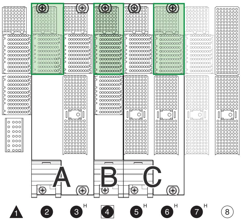
![A B C 1 2 3 4 5 6 7 8](.pxi-6-express-software-spec-rev1-4/0ae62d884c29a5a9c37f0cb3205464de803b8135706ce8f2f6174c414b0ebb61.jpg)

Figure 2-1. PXI Express Backplane

\# This section describes a PXI Express system with one 8-slot chassis. [System]

ChassisList = 1

[Chassis1]

Model = "Example 8-Slot Chassis"

Vendor = "Example Chassis Vendor"

DescriptionFile = "Example Chassis Vendor Example 8-Slot Chassis.ini"

SerialNumber = "000038a2e941"

SlotList = "1,2,3,4,5,6,7,8"

```toml
TriggerBusList = "1,2"
TriggerBridgeList = "1,2"
LineMappingSpecList = "1"
StarSystemTimingSetList = "1"
StarTriggerList = "1"

# Each trigger bus spans a subset of the eight slots.
[Chassis1TriggerBus1]
SlotList = "1,2,3,4"

[Chassis1TriggerBus2]
SlotList = "5,6,7,8"

# There is a bidirectional trigger bridge between trigger
# bus 1 and trigger bus 2
[Chassis1TriggerBridge1]
SourceTriggerBus = 1
DestinationTriggerBus = 2
LineMappingSpec = 1

[Chassis1TriggerBridge2]
SourceTriggerBus = 2
DestinationTriggerBus = 1
LineMappingSpec = 1

# The trigger bridge supports a straight-through mapping
[Chassis1LineMappingSpec1]
PXI_TRIG0 = "0"
PXI_TRIG1 = "1"
PXI_TRIG2 = "2"
PXI_TRIG3 = "3"
PXI_TRIG4 = "4"
PXI_TRIG5 = "5"
PXI_TRIG6 = "6"
PXI_TRIG7 = "7"

# The system timing slot is slot 4, and the system
# timing set mapping to each peripheral slot is described.
[Chassis1StarSystemTimingSets1]
SystemTimingSlot = 4
StarSystemTimingSet0 = 4
StarSystemTimingSet1 = 2
StarSystemTimingSet2 = 3

[Chassis1StarTrigger1]
SystemTimingSlot = 4
PXI_STAR0 = 1
PXI_STAR1 = 2
PXI_STAR2 = 3
PXI_STAR3 = 5
PXI_STAR4 = 6
PXI_STAR5 = 7
PXI_STAR6 = 8
```

```toml
[Chassis1Slot1]
Model = "Example PXI Express System Model"
Vendor = "Example PXI Express System Vendor"
InstanceName = "Example PXI Express System Module, Instance 1"
AddressInfo = "SYSTEMMODULE::1"
SlotType = "PXIeSystemSlot4Link"
SystemSlotLinkWidth1 = 4
SystemSlotLinkWidth2 = 4
SystemSlotLinkWidth3 = 4
SystemSlotLinkWidth4 = 4
LocalBusRight = "Chassis1Slot2"
ControllerModuleLinkWidth1 = 1
ControllerModuleLinkWidth2 = 1
ControllerModuleLinkWidth3 = 1
ControllerModuleLinkWidth4 = 1
ControllerModuleType = "Remote"
SerialNumber = "699CWIK"
SubModel = "16CORE"

[Chassis1Slot2]
Model = "Example PXI Express Peripheral Model A"
Vendor = "Example PXI Express Peripheral Vendor"
InstanceName = "Example PXI Express Peripheral Module A, Instance 1"
AddressInfo = "PXI0::2-15.0::INSTR"
SlotType = "PXIePeripheralSlot"
SystemSlotLinkOrigin1 = 1
SystemSlotLinkOrigin2 = 0
PeripheralSlotLinkWidth1 = 4
PeripheralSlotLinkWidth2 = 0
LocalBusLeft = "Chassis1Slot1"
LocalBusRight = "Chassis1Slot3"
PeripheralModuleLinkWidthMax = 1
PeripheralModuleLinkWidthNegotiated = 1
PeripheralModuleOccupiedSlotList = "2,3"

[Chassis1Slot3]
SlotType = "PXIeHybridSlot"
SystemSlotLinkOrigin1 = 2
SystemSlotLinkOrigin2 = 4
PeripheralSlotLinkWidth1 = 4
PeripheralSlotLinkWidth2 = 0
LocalBusLeft = "Chassis1Slot2"
LocalBusRight = "Chassis1Slot4"

[Chassis1Slot4]
Model = "Example PXI Express System Timing Model B"
Vendor = "Example PXI Express System Timing Vendor"
InstanceName = "Example PXI Express System Timing Module B, Instance 1"
AddressInfo = "PXI0::4-15.0::INSTR"
SlotType = "PXIeSystemTimingSlot"
SystemSlotLinkOrigin1 = 3
SystemSlotLinkOrigin2 = 0
PeripheralSlotLinkWidth1 = 4
PeripheralSlotLinkWidth2 = 0
```

```toml
LocalBusLeft = "Chassis1Slot3"
LocalBusRight = "Chassis1Slot5"
PeripheralModuleLinkWidthMax = 4
PeripheralModuleLinkWidthNegotiated = 1
PeripheralModuleOccupiedSlotList = "4"
SerialNumber = "ADF65E20"
SubModel = "2PROBE"
ManufacturerDesc = "Oscilloscope"
```

```toml
[Chassis1Slot5]
SlotType = "PXIeHybridSlot"
SystemSlotLinkOrigin1 = 3
SystemSlotLinkOrigin2 = 4
PeripheralSlotLinkWidth1 = 4
PeripheralSlotLinkWidth2 = 0
LocalBusLeft = "Chassis1Slot4"
LocalBusRight = "Chassis1Slot6"
```

```toml
[Chassis1Slot6]
Model = "Example PXI Express Peripheral Model C"
Vendor = "Example PXI Express Peripheral Vendor"
InstanceName = "Example PXI Express Peripheral Module C, Instance 1"
AddressInfo = "PXI0::5-15.0::INSTR"
SlotType = "PXIeHybridSlot"
SystemSlotLinkOrigin1 = 3
SystemSlotLinkOrigin2 = 4
PeripheralSlotLinkWidth1 = 4
PeripheralSlotLinkWidth2 = 0
LocalBusLeft = "Chassis1Slot5"
LocalBusRight = "Chassis1Slot7"
PeripheralModuleLinkWidthMax = 4
PeripheralModuleLinkWidthNegotiated = 4
PeripheralModuleOccupiedSlotList = "5,6"
SerialNumber = "ADF33E21"
SubModel = "8CH"
ManufacturerDesc = "Data Acquisition Device"
```

```toml
[Chassis1Slot7]
SlotType = "PXIeHybridSlot"
SystemSlotLinkOrigin1 = 3
SystemSlotLinkOrigin2 = 4
PeripheralSlotLinkWidth1 = 4
PeripheralSlotLinkWidth2 = 0
LocalBusLeft = "Chassis1Slot6"
LocalBusRight = "Chassis1Slot8"
```

```toml
[Chassis1Slot8]
SlotType = "PXI-1Slot"
SystemSlotLinkOrigin1 = 0
SystemSlotLinkOrigin2 = 4
PeripheralSlotLinkWidth1 = 0
PeripheralSlotLinkWidth2 = 0
LocalBusLeft = "Chassis1Slot7"
LocalBusRight = "None"
```

# 2.3 Chassis Description Files

Chassis description files characterize PXI Express Chassis. The primary purpose of a Chassis description file is to enumerate PXI trigger buses, system timing sets, sets of star triggers, and slots. Chassis description files are a key component in the PXI Express hardware description architecture, enabling a Resource Manager to generate a PXI Express system description.

RULE: A Chassis manufacturer SHALL provide a Chassis description file for each Chassis model produced.

RULE: A Chassis description file SHALL be named vendorDefinedText.ini, where vendorDefinedText is a vendor-defined string used to uniquely name a Chassis description file.

RULE: A chassis description file name SHALL contain the name of the chassis vendor to guarantee uniqueness versus chassis description files from other vendors.

RULE: To maximize backward compatibility, a Resource Manager SHALL be capable of reading chassis description files with any filename ending with .ini.

OBSERVATION: Chassis description file installers can copy their Chassis description files to a standard location. In addition, a PXI Express Resource Manager can use this location to identify the types of Chassis available for a PXI Express system. Refer to Section 4, Software Frameworks and Requirements, for the standard location for a given operating system.

PERMISSION: A vendor MAY place descriptors or tags in a chassis description file other than those described in this section.

OBSERVATION: The above permission may be useful to store supplemental information about a chassis that is useful for advanced vendor-specific functionality.

RECOMMENDATION: Any vendor-specific descriptors or tags in a chassis description file SHOULD be named such that they are unlikely to collide with tags or descriptors added in a future version of any PXISA specification.

OBSERVATION: The above recommendation can be accomplished by incorporating the vendor name into the descriptor or tag name.

# 2.3.1 Chassis Description Definitions

To develop a Chassis description, it is useful to define descriptors for the following Chassis components:

Chassis—A Chassis descriptor corresponds to a physical PXI Express Chassis. Chassis can include PCI bus segments, trigger buses, system timing sets, star triggers, and slots.

Trigger Buses—A PXI trigger bus descriptor corresponds to a physical trigger bus in a PXI Express Chassis. A trigger bus is characterized by a list of slots sharing the physical trigger bus connection. Chassis can contain multiple trigger buses.

Star Triggers—A PXI star trigger descriptor corresponds to a physical set of star triggers in a PXI Express Chassis. A set of star triggers is characterized by a star trigger controller slot number and a mapping of PXI\_STAR lines to peripheral slot numbers. A Chassis can contain multiple sets of star triggers.

System Timing Sets—A System Timing Set descriptor corresponds to the set of system timing sets contained in a PXI Express Chassis. The system timing sets for a Chassis are characterized by the system timing slot number and a mapping of system timing sets to peripheral slot numbers. A Chassis can contain multiple system timing sets.

Trigger Bridges—A PXI trigger bridge descriptor corresponds to a physical trigger bridge in a PXI chassis. Each trigger bridge descriptor represents the possible unidirectional routes that can be established between two buses; if a physical trigger bridge can be used to establish routes in either direction between these buses, two trigger bridge descriptors must represent it, one for each direction. A chassis can contain multiple trigger bridges.

Line Mapping Specifications—A line mapping specification does not represent a physical chassis component, but sets out the possible routes that a trigger bridge can establish between two adjacent trigger buses. This line mapping provides software with detailed information about the routing capabilities that the chassis supports. These routes can be established through calls made to the chassis Trigger Manager, as described in PXI-9: PXI and PXI Express Trigger Management Specification. Multiple line mappings can describe a chassis’ routing capabilities.

Slots–A PXI Express slot descriptor corresponds to a physical slot in a Chassis. A slot is characterized by a geographic address, a PCI logical address, local bus routings, and other special capabilities. A Chassis has multiple slots.

PXI-1 Bus Segments—A PXI-1 bus segment descriptor corresponds to physical PCI bus in a Chassis. PCI bus segments can contain slots, bridges, and other backplane devices. Multiple PCI bus segments are linked within a Chassis using PCI-PCI bridging.

# 2.3.2 Chassis Descriptor

A Chassis descriptor provides a high-level description of a PXI Express Chassis. A Chassis descriptor contains collections of the components that comprise a Chassis, including PCI bus segments, trigger buses, sets of star triggers, and slots.

RULE: A Chassis description file SHALL contain one and only one Chassis descriptor.

RULE: The Chassis descriptor section SHALL be named “Chassis.”

RULE: Each Chassis descriptor section SHALL contain one of each of the nonshaded tag line types described in Table 2-11.

RULE: The chassis descriptor section SHALL contain one of each of the shaded tag line types described in Table 2-8 if the chassis supports trigger routing as described in PXI-9: PXI and PXI Express Trigger Management Specification.

Table 2-11. Chassis Description File—Chassis Tag Line Descriptions

<table><tr><td>Tag</td><td>Valid Values</td><td>Description</td></tr><tr><td>Model</td><td>A string indicating the model of this Chassis.</td><td>This tag identifies the Chassis model name.</td></tr><tr><td>Vendor</td><td>A string indicating the vendor of this Chassis.</td><td>This tag identifies the Chassis vendor name.</td></tr><tr><td>TriggerBusList</td><td>A comma-separated list of n, where n is a decimal integer such that n &gt;= 1.</td><td>This tag enumerates the trigger buses in a Chassis.</td></tr><tr><td>TriggerBridgeList</td><td>A comma-separated list of n, where n is a decimal integer such that n &gt;= 1.</td><td>This tag enumerates the trigger bridges in a chassis.</td></tr><tr><td>LineMappingSpecList</td><td>A comma-separated list of n, where n is a decimal integer such that n &gt;= 1.</td><td>This tag enumerates the line mapping specifications that exist for a chassis.</td></tr><tr><td>StarSystemTimingSetList</td><td>A comma-separated list of n, where n is a decimal integer such that n &gt;= 1.</td><td>This tag enumerates the PXI Express system timing sets in a Chassis.</td></tr><tr><td>StarTriggerList</td><td>A comma-separated list of n, where n is a decimal integer such that n &gt;= 1.</td><td>This tag enumerates the sets of star trigger in a Chassis.</td></tr><tr><td>SlotList</td><td>A comma-separated list of n, where n is a decimal integer such that n &gt;= 1.</td><td>This tag enumerates the slots in a Chassis.</td></tr><tr><td>PXI1BusSegmentList</td><td>A comma-separated list of n, where n is a decimal integer such that 1 &lt;= n &lt;= 255.</td><td>This tag enumerates the PXI-1 bus segments in a Chassis.</td></tr></table>

# Chassis Descriptor Example

```toml
# This example describes a 10-slot PXI Express chassis with three hybrid
# peripheral slots (slots 2-4) and six PXI-1 slots (slots 5-10)
[Chassis]
Model = "Example 10-Slot Chassis"
Vendor = "PXISA"
TriggerBusList = "1,2"
TriggerBridgeList = "1,2"
LineMappingSpecList = "1"
StarSystemTimingSetList = "1"
StarTriggerList = "1"
SlotList = "1,2,3,4,5,6,7,8,9,10"
PXI1BusSegmentList = "1,2"
```

RULE: Multiple PCI bus segments SHALL be uniquely numbered in the PXI1BusSegmentList tag.

OBSERVATION: PXI-1 bus segments can be numbered in an arbitrary fashion. For example, bus segments can be numbered according to their order of discovery using a depth-first PCI traversal algorithm.

RULE: Multiple trigger buses SHALL be uniquely numbered in the TriggerBusList tag.

OBSERVATION: Trigger buses can be numbered in an arbitrary fashion. For example, a trigger bus can be sequentially numbered based on the relative order of the slots it contains.

RULE: Multiple system timing sets SHALL be uniquely numbered in the StarSystemTimingSetList tag.

RULE: Multiple trigger bridges SHALL be uniquely numbered in the TriggerBridgeList tag.

OBSERVATION: Trigger bridges can be numbered in an arbitrary fashion.

RULE: Multiple line mapping specifications SHALL be uniquely numbered in the LineMappingSpecList tag.

OBSERVATION: Line mapping specifications can be numbered in an arbitrary fashion.

RULE: Multiple sets of star triggers SHALL be uniquely numbered in the StarTriggerList tag.

OBSERVATION: Sets of star triggers can be numbered in an arbitrary fashion.

OBSERVATION: The StarSystemTimingSetList tag in the chassis descriptor enumerates the list of Star System Timing Sets descriptors that exist for a particular chassis. It should be considered independent of sets of PXIe\_DSTARXn lines, which are enumerated within the Star System Timing Sets descriptors. The reuse of this name for both purposes is maintained for backward compatibility.

RULE: PXI slots SHALL be uniquely numbered according to their corresponding physically viewable slot numbers.

# 2.3.3 Trigger Bus Descriptor

A trigger bus descriptor describes an individual trigger bus in a PXI Express Chassis. A trigger bus is characterized by a list of slots that reside on the trigger bus.

RULE: A Chassis description file SHALL contain a distinct PXI trigger bus descriptor for each physical PXI trigger bus in the Chassis.

RULE: A trigger bus descriptor SHALL be named “TriggerBusN,” where N is the trigger bus number.

RULE: Trigger bus numbers SHALL be derived from the TriggerBusList tag of the Chassis descriptor (see Table 2-11).

OBSERVATION: While each trigger bus number will uniquely correspond to a set of PXI slots, there is not necessarily a one-to-one correspondence between trigger buses and PCI bus segments.

RULE: Each trigger bus descriptor SHALL contain one of each of the tag line types described in Table 2-12.

Table 2-12. Chassis Description File—Trigger Bus Tag Line Descriptions

<table><tr><td>Tag</td><td>Valid Values</td><td>Description</td></tr><tr><td>SlotList</td><td>A comma-separated list of n, where n is a decimal integer such that n &gt;= 1.</td><td>This tag enumerates the slots on a trigger bus.</td></tr></table>

# Trigger Bus Descriptor Example

```txt
# This example describes an 8-slot PXI Express chassis with three hybrid
# peripheral slots (slots 2-4) and four PXI-1 slots (slots 5-8).
# There is one trigger bus for this chassis spanning all
# 8 slots.
[TriggerBus1]
SlotList = "1,2,3,4,5,6,7,8"
```

# 2.3.4 Trigger Bridge Descriptor

The Trigger Bridge Descriptor for the PXI Express Chassis Description File is equivalent to the Trigger Bridge Descriptor in the PXI Chassis Description File. Refer to PXI-2: PXI Software Specification for details of this descriptor.

RULE: A Resource Manager SHALL adhere to all rules described in PXI-2: PXI Software Specification relating to the chassis description file trigger bridge descriptor.

# 2.3.5 Line Mapping Specification Descriptor

The Line Mapping Specification Descriptor for the PXI Express Chassis Description File is equivalent to the Line Mapping Specification Descriptor in the PXI Chassis Description File. Refer to PXI-2: PXI Software Specification for details of this descriptor.

RULE: A Resource Manager SHALL adhere to all rules described in PXI-2: PXI Software Specification relating to the chassis description file line mapping specification descriptor.

# 2.3.6 Star System Timing Sets Descriptor

A star system timing sets descriptor describes the system timing sets in a PXI Express Chassis. A star system timing sets descriptor is characterized by a system timing slot number and a mapping of system timing sets (that is, PXIe\_DSTARAn, PXIe\_DSTARBn, and PXIe\_DSTARCn) to peripheral slot numbers.

RULE: A Chassis description file SHALL contain a distinct star system timing sets descriptor for each system timing slot in the Chassis.

RULE: A star system timing sets descriptor SHALL be named “StarSystemTimingSetsN,” where N is the number for the system timing sets.

OBSERVATION: The StarSystemTimingSetList tag in the chassis descriptor enumerates the list of Star System Timing Sets descriptors that exist for a particular chassis. It should be considered independent of sets of PXIe\_DSTARXn lines, which are enumerated within the Star System Timing Sets descriptors. The reuse of this name for both purposes is maintained for backward compatibility.

RULE: Star system timing sets descriptors SHALL be derived from the StarSystemTimingSetsList tag of the Chassis descriptor (see Table 2-11).

RULE: Each star system timing sets descriptors SHALL contain one of each of the tab line types described in Table 2-13.

Table 2-13. Chassis Description File—Star System Timing Sets Tag Line Descriptions

<table><tr><td>Tag</td><td>Valid Values</td><td>Description</td></tr><tr><td>SystemTimingSlot</td><td>A decimal integer n, where n is a decimal integer such that n &gt;= 1.</td><td>This tag specifies the slot number of the system timing slot for this group of system timing sets.</td></tr><tr><td>StarSystemTimingSetn (where n is a decimal integer such that 0 &lt;= n &lt;= 16), for each possible system timing set for a given system timing module.</td><td>A comma-separated list of m, where m is a decimal integer, corresponding to a PXI slot number, such that m &gt;= 1.</td><td>This tag specifies the peripheral slot number corresponding to a set of PXIe_DSTARA, PXIe_DSTARB, and PXIe_DSTARC lines.</td></tr></table>

# Star System Timing Sets Descriptor Example

```ini
# This example describes an 8-slot PXI Express chassis with three hybrid
# peripheral slots (slots 2-4) and four PXI-1 slots (slots 5-8).
# The system timing set controller slot is slot 2, and the system timing
# set mapping to each hybrid peripheral slot is described.
[StarSystemTimingSets1]
SystemTimingSlot = 2
StarSystemTimingSet0 = 2
StarSystemTimingSet1 = 3
StarSystemTimingSet2 = 4
```

# 2.3.7 Star Trigger Descriptor

A star trigger descriptor describes an individual set of star triggers in a PXI Express Chassis. A star trigger descriptor is characterized by a star trigger controller slot number and a mapping of PXI\_STAR lines, as defined in the PXI Hardware Specification, to peripheral slot numbers.

RULE: A Chassis description file SHALL contain a distinct PXI star trigger descriptor for each physical set of star triggers in the Chassis.

RULE: A star trigger descriptor SHALL be named “StarTriggerN,” where N is the number for the set of star triggers.

RULE: Star trigger descriptor numbers SHALL be derived from the StarTriggerList tag of the Chassis descriptor (see Table 2-11).

RULE: Each star trigger descriptor SHALL contain one of each of the tag line types described in Table 2-14.

Table 2-14. Chassis Description File—Star Trigger Tag Line Descriptions

<table><tr><td>Tag</td><td>Valid Values</td><td>Description</td></tr><tr><td>SystemTimingSlot</td><td>A decimal integer n, where n is a decimal integer such that n &gt;= 1.</td><td>This tag specifies the star trigger controller slot number for a set of star triggers.</td></tr><tr><td>PXI_STARn (where n is a decimal integer such that 0 &lt;= n &lt;= 16), for each PXI star trigger line routed to a PXI slot.</td><td>A comma-separated list of m, where m is a decimal integer, corresponding to a PXI slot number, such that m &gt;= 1.</td><td>This tag specifies the PXI_STAR line to slot number mapping for a set of star triggers.</td></tr></table>

# Star Trigger Descriptor Example

```txt
# This example describes an 8-slot PXI Express chassis with three hybrid
# peripheral slots (slots 2-4) and four PXI-1 slots (slots 5-8).
# The star trigger controller slot is slot 2, and the PXI_STAR lines
# connect to each of the chassis' peripheral slots (2-8).
[StarTrigger1]
SystemTimingSlot = 2
PXI_STAR0 = 3
PXI_STAR1 = 4
PXI_STAR2 = 5
PXI_STAR3 = 6
PXI_STAR4 = 7
PXI_STAR5 = 8
```

# 2.3.8 PXI-1 Bus Segment Descriptor

A PXI-1 bus segment descriptor characterizes a PCI bus segment containing PXI-1 slots or hybrid slots in a PXI Express Chassis. The most important aspect of a PCI bus segment descriptor is that it describes the mapping from PCI address lines (AD[31:0]) to IDSEL assignments for the segment’s slots.

RULE: A Chassis description file SHALL contain a distinct PXI-1 bus segment descriptor for each physical PCI bus segment containing PXI-1 or hybrid slots in a Chassis.

RULE: A PXI-1 bus segment descriptor SHALL be named “PXI1BusSegmentN,” where N is the PXI-1 bus segment number.

RULE: PXI-1 bus segment numbers SHALL be derived from the PXI1BusSegmentBusList tag of the Chassis descriptor (see Table 2-11).

OBSERVATION: While each PXI-1 bus segment number will uniquely correspond to a PCI bus number, the PCI bus segment number will not necessarily be equal to the corresponding PCI bus number.

RULE: Each PXI-1 bus segment descriptor SHALL contain one of each of the tag line types described in Table 2-15.

Table 2-15. Chassis Description File—PXI-1 Bus Segment Tag Line Descriptions

<table><tr><td>Tag</td><td>Valid Values</td><td>Description</td></tr><tr><td>SlotList</td><td>A comma-separated list of n, where n is a decimal integer such that n &gt;= 1.</td><td>This tag enumerates the slots on a PCI bus segment.</td></tr><tr><td>IDSELList</td><td>n, where n is a decimal integer such that 1 &lt;= n &lt;= 31.</td><td>This tag lists the PCI address line numbers (AD[31:0]) used to implement the IDSEL signals for devices on a PCI bus segment.</td></tr><tr><td>IDSELn, where n is a decimal integer corresponding to a PCI address line (AD[31:0]), for each n contained in the IDSELList</td><td>A slot descriptor. (Other.)</td><td>This tag specifies the PCI address line number (AD[31:0]) used to implement the IDSEL signal for a given slot, bridge, or backplane device on a PCI bus segment.</td></tr></table>

# PXI-1 Bus Segment Descriptor Example

```toml
# This example describes an 8-slot PXI Express chassis with three hybrid
# peripheral slots (slots 2-4) and four PXI-1 slots (slots 5-8).
[PXI1BusSegment1]
SlotList = "5,6,7,8"
IDSELList = "31,30,29,28"
IDSEL31 = "Slot5"
IDSEL30 = "Slot6"
IDSEL29 = "Slot7"
IDSEL28 = "Slot8"
```

RULE: Slots SHALL be uniquely numbered in the SlotList tag.

OBSERVATION: Slot numbers will correspond to physically-viewable slot numbers for a PCI bus segment. In addition, the SlotList will be a subset of the SlotList specified in the Chassis descriptor (see Table 2-11).

PERMISSION: A PCI bus segment descriptor MAY specify an IDSEL routing to a backplane device other than a slot or a bridge.

# 2.3.9 Slot Descriptor

A slot descriptor describes an individual slot in a PXI Express Chassis. A slot descriptor is characterized by the features of the slot it describes.

RULE: A Chassis description file SHALL contain a distinct slot descriptor for each physical slot in the Chassis.

RULE: A slot descriptor SHALL be named “SlotN,” where N is the physical slot number.

RULE: A slot number SHALL be derived from the chassis descriptor slot list (see Table 2-15).

RULE: Each slot descriptor for slots other than Slot 1 SHALL contain one of each of the nonshaded tag line types described in Table 2-16.

RULE: A slot descriptor for Slot 1 SHALL implement the LocalBusRight tag line described in Table 2-16.

OBSERVATION: Slot 1 does not implement LocalBusLeft in the chassis hardware. For more information, refer to PXI-5: PXI Express Hardware Specification.

Table 2-16. Chassis Description File—Slot Tag Line Descriptions

<table><tr><td>Tag</td><td>Valid Values</td><td>Description</td></tr><tr><td>LocalBusLeft</td><td>A valid slot descriptor.A valid star trigger descriptor.(Other.)</td><td>This tag indicates how this slot routes its local bus pin(s) to the left.</td></tr><tr><td>LocalBusRight</td><td>A valid slot descriptor.(Other.)</td><td>This tag indicates how this slot routes its local bus pins to the right.</td></tr></table>

# Slot Descriptor Examples

# PXI-1 Slot Example

\# This example describes an 8-slot PXI Express chassis with three hybrid # peripheral slots (slots 2-4) and four PXI-1 slots (slots 5-8). # The slot described is a PXI-1 slot.

```toml
[Slot4]
# This is a hybrid peripheral slot.
# Each tag line pertains only to LocalBus[6]
LocalBusLeft = "Slot3"
LocalBusRight = "Slot5"

...
[Slot5]
# This is a legacy slot. Each line
# pertains to all 13 lines of LocalBus
LocalBusLeft = "Slot6"
LocalBusRight = "Slot8"
```

OBSERVATION: In a PXI Express or Hybrid slot, Local Bus is comprised of only one pin, LocalBus[6]. For these slots, the tag lines described in Table 2-16 describe only the routing of this single pin. When a Legacy Slot’s Local Bus is routed to a neighboring PXI Express or Hybrid slot, it will indicate that Local Bus lines other than LocalBus[6] on the Legacy Slot are not connected to any electrical circuit.

# 2.3.10 Chassis Description File Examples

The following are complete examples of Chassis description files.

```toml
# This example describes an 8-slot PXI Express chassis with three hybrid
# peripheral slots (slots 2-4) and four PXI-1 slots (slots 5-8).
# The trigger bridge allows the signal from any line on either bus
# to be routed to the same line on the other bus.
[Chassis]
Model = "Example 8-Slot Chassis"
Vendor = "PXISA"
TriggerBusList = "1,2"
TriggerBridgeList = "1,2"
LineMappingSpecList = "1"
StarSystemTimingSetList = "1"
StarTriggerList = "1"
SlotList = "1,2,3,4,5,6,7,8"
PXI1BusSegmentList = "1"

# There are two trigger buses in this chassis, each spanning four slots.
[TriggerBus1]
SlotList = "1,2,3,4"

[TriggerBus2]
SlotList = "5,6,7,8"

[TriggerBridge1]
SourceTriggerBus = 1
DestinationTriggerBus = 2
LineMappingSpec = 1

[TriggerBridge2]
SourceTriggerBus = 2
DestinationTriggerBus = 1
LineMappingSpec = 1

[LineMappingSpec1]
PXI_TRIG0 = "0"
PXI_TRIG1 = "1"
PXI_TRIG2 = "2"
PXI_TRIG3 = "3"
PXI_TRIG4 = "4"
PXI_TRIG5 = "5"
PXI_TRIG6 = "6"
PXI_TRIG7 = "7"

# The system timing set controller slot is slot 2, and the system timing set
# mapping to each hybrid peripheral slot is described.
[StarSystemTimingSets1]
SystemTimingSlot = 2
StarSystemTimingSet0 = 2
StarSystemTimingSet1 = 3
StarSystemTimingSet2 = 4

# The star trigger controller slot is slot 2, and the PXI_STAR lines connect
# to each of the chassis' peripheral slots (2-8).
[StarTrigger1]
SystemTimingSlot = 2
```

```toml
PXI_STAR0 = 3
PXI_STAR1 = 4
PXI_STAR2 = 5
PXI_STAR3 = 6
PXI_STAR4 = 7
PXI_STAR5 = 8

[PXI1BusSegment1]
SlotList = "5,6,7,8"
IDSELList = "31,30,29,28"
IDSEL31 = "Slot5"
IDSEL30 = "Slot6"
IDSEL29 = "Slot7"
IDSEL28 = "Slot8"

[Slot1]
# Only the single LocalBus[6] line is available
LocalBusRight = "Slot2"

[Slot2]
# Only the single LocalBus[6] line is available
LocalBusLeft = "Slot1"
LocalBusRight = "Slot3"

[Slot3]
# Only the single LocalBus[6] line is available
LocalBusLeft = "Slot2"
LocalBusRight = "Slot4"

[Slot4]
# Only the single LocalBus[6] line is available
LocalBusLeft = "Slot3"
LocalBusRight = "Slot5"

[Slot5]
# On LocalBusLeft, only the single LocalBus[6] line is available
# On LocalBusRight, all lines are available because Slots 5,6
# are Legacy Slots
LocalBusLeft = "Slot4"
LocalBusRight = "Slot6"

[Slot6]
LocalBusLeft = "Slot5"
LocalBusRight = "Slot7"

[Slot7]
LocalBusLeft = "Slot6"
LocalBusRight = "Slot8"

[Slot8]
LocalBusLeft = "Slot7"
LocalBusRight = "None"
```

This Page Intentionally Left Blank

# 3. PXI Express Software Services

This section defines the PXI Express Software Services, their APIs, their registration, and how they interact with the PXI Express Resource Manager.

# 3.1 Overview

This section defines the services that shall be implemented for each component of the PXI Express system. It further defines how those services should be registered and how they are used by the PXI Express Resource Manager in the system.

The APIs and databases defined in this section are described in a platform-independent manner. The platform-specific details of this specification are found in Section 4, Software Frameworks and Requirements.

# 3.2 PXI Express Components

Certain PXI Express components are enumerated by the PXI Express Resource Manager by interacting with software included with those components. These components include:

System Modules
Peripheral Modules
Chassis

These components must include software to allow the PXI Express Resource Manager to gather information about the components, and to allow other software to use standard features of the components. As such, this specification imposes requirements on the software that ships with those components. This software is referred to as a driver. The driver need not be a driver as defined by the operating system involved. For the purpose of this specification, the driver for a component is that software included with the component that implements the interfaces in this specification. Note that these drivers apply only to PXI Express components (that is, components described by the PXI-5 specification) and do not apply to PXI-1 hardware components.

# 3.3 Service Types

The drivers in a PXI Express system must support the operations listed in this section. The operations are specified here by their names, input parameters, and output parameters. The asterisk (\*) is used to indicate output parameters and does not have any relation to programming language-specific datatype syntax; for language-specific datatypes, refer to the appropriate Driver Software Bindings section in Chapter 4.

Consult the appropriate software framework section in Section 4, Software Frameworks and Requirements, for calling conventions and type definitions for these operations.

# 3.3.1 System Module Drivers

A PXI Express System Module driver is responsible for:

Enumerating its System Modules.
Providing information about the attributes of each System Module.
Providing bus enumeration information about each System Module.
Providing access to the Chassis EPROMs.
Providing access to the SMBus.

RULE: A System Module driver SHALL contain the following operations.

Status PXISA\_SystemModule\_GetCount(String vendor, String model, Integer \* count) vendor: Vendor name to match.

model: Model name to match.

count: Number of System Modules found by the driver.

RULE: If a System Module driver maintains a cache of System Module names, the System Module driver SHALL update that cache when PXISA\_SystemModule\_GetCount is invoked.

RULE: A Resource Manager SHALL call PXISA\_SystemModule\_GetCount for a vendor and model before calling any other System Module driver method, for that same vendor and model, which can require the cache as described above.

PERMISSION: Except where stated otherwise, System Module driver methods other than PXISA\_SystemModule\_GetCount MAY require that PXISA\_SystemModule\_GetCount has been previously called for the same vendor and model.

RULE: A System Module driver that maintains a cache as described above SHALL implement the cache such that calling PXISA\_SystemModule\_GetCount for a given vendor and model does not invalidate any previously built cache of data for a different vendor and/or model.

OBSERVATION: The above rule is intended to prevent problems arising from cache inconsistency between multiple calls to the same method for a given vendor and model. For example, suppose the following sequence of calls occurs:

1. The Resource Manager calls PXISA\_SystemModule\_GetCount for vendor A, model X.

2. The Resource Manager calls PXISA\_SystemModule\_GetCount for vendor A, model Y.

3. The Resource Manager calls PXISA\_SystemModule\_GetName for vendor A, model X.

If step 2 destroyed the cache for model X, the system module driver may incorrectly return an error for step 3. When using a cache, maintaining a separate cache for each vendor and model prevents this problem from occurring.

RULE: PXISA\_SystemModule\_GetCount SHALL be implemented such that it can safely support multiple callers simultaneously in separate processes.

OBSERVATION: The above rule is necessary to allow several Resource Managers to check if the system contains a System Module made by their vendor, which allows them to claim ownership of the System Description File. Refer to PXI-2: PXI Software Specification for details on selection of the active Resource Manager and the Resource Manager Descriptor in the System Configuration File.

Status PXISA\_SystemModule\_GetName(String vendor, String model, Integer index, String \* name, String \* addressInfo)

vendor: Vendor name to match.

model: Model name to match.

index: Index of a System Module. This index is 1-based.

name: Unique name of a System Module.

addressInfo: Additional addressing information for the module.

RULE: The addressInfo returned by a System Module Driver SHALL return a string containing a semicolon-delimited list of address information substrings.

PERMISSION: A System Module Driver MAY expose onboard PCI devices by providing a VISA resource string of the form "PXIinterface::bus-device.function::INSTR," for each device where interface, bus, device, and function are the VISA interface number, PCI bus number, PCI device number, and PCI function number of the peripheral, respectively.

OBSERVATION: The addressInfo substring described by the above rule allows software to obtain the bus, device, and function number for a peripheral on the System Module, and to map the geographic location of that peripheral to a corresponding peripheral representation in a vendor-supplied device driver. For example, the addressInfo substring may contain the VISA address of any PCI or PCI Express functions built into a System Module,

PERMISSION: A System Module Driver MAY provide additional semicolon (';') or plus sign ('+') delimited substrings in the addressInfo field with vendor-defined content.

OBSERVATION: This specification defines only part of the AddressInfo string. Interpreting other parts of the AddressInfo string should be done only when there is knowledge of the format used. For example, software from a given vendor may interpret nonstandard strings in the AddressInfo of System Modules from that vendor.

RULE: Additional vendor-defined substrings returned in the addressInfo field SHALL be formatted such that they are easily distinguishable from any "PXIinterface::bus-device.function::INSTR" resource strings for the device.

RULE: In parsing the addressInfo string, software SHALL ignore any substring of unknown format.

OBSERVATION: The maximum length of the addressInfo field may be restricted due to limitations in a particular software framework. Take care to ensure that a specific implementation does not exceed such limitations. Refer to Chapter 4, Software Frameworks and Requirements, for details.

Status PXISA\_SystemModule\_GetInformation(String name, String addressInfo, Integer field, Variable \* value);

name: Unique name of a System Module.

addressInfo: Additional addressing information for the System Module.

field: Selector for which information field is requested.

value: Value of the information field. The datatype of this argument is dependent upon the field.

Table 3-1. Information Field Values

<table><tr><td>Field</td><td>Value Type</td><td>Value</td></tr><tr><td>0</td><td>Integer</td><td>Maximum Link 1 Width in 2 Link Mode</td></tr><tr><td>1</td><td>Integer</td><td>Maximum Link 2 Width in 2 Link Mode</td></tr><tr><td>2</td><td>Integer</td><td>Maximum Link 1 Width in 4 Link Mode</td></tr><tr><td>3</td><td>Integer</td><td>Maximum Link 2 Width in 4 Link Mode</td></tr><tr><td>4</td><td>Integer</td><td>Maximum Link 3 Width in 4 Link Mode</td></tr><tr><td>5</td><td>Integer</td><td>Maximum Link 4 Width in 4 Link Mode</td></tr><tr><td>100</td><td>Integer</td><td>Number of valid links</td></tr><tr><td>101</td><td>Integer</td><td>PCI Bus Number of Link 1</td></tr><tr><td>102</td><td>Integer</td><td>PCI Bus Number of Link 2</td></tr><tr><td>103</td><td>Integer</td><td>PCI Bus Number of Link 3 (valid for 4 link mode)</td></tr><tr><td>104</td><td>Integer</td><td>PCI Bus Number of Link 4 (valid for 4 link mode)</td></tr></table>

Table 3-1. Information Field Values

<table><tr><td>Field</td><td>Value Type</td><td>Value</td></tr><tr><td>105</td><td>Integer</td><td>Subordinate PCI Bus Number for parent bridge of the bus of Link 1</td></tr><tr><td>106</td><td>Integer</td><td>Subordinate PCI Bus Number for parent bridge of the bus of Link 2</td></tr><tr><td>107</td><td>Integer</td><td>Subordinate PCI Bus Number for parent bridge of the bus of Link 3</td></tr><tr><td>108</td><td>Integer</td><td>Subordinate PCI Bus Number for parent bridge of the bus of Link 4</td></tr><tr><td>109</td><td>Integer</td><td>System Module Type</td></tr><tr><td>200</td><td>String</td><td>Serial Number of the System Module</td></tr><tr><td>201</td><td>String</td><td>Submodel</td></tr></table>

RULE: When queried for link information, PXISA\_SystemModule\_GetInformation SHALL return information consistent with the values in the Backplane Identification EPROM for the chassis.

PERMISSION: The System Module Driver MAY return the same bus numbers for two or more links if the Backplane Identification EPROM for the chassis designates all but one of those links as disconnected from all peripheral slots.

OBSERVATION: The above rule and permission are intended to give vendors a software mechanism to support chassis with integrated System Modules, as described in PXI-5: PXI Express Hardware Specification. Some such chassis may not strictly adhere to a 2-link or 4-link mode.

PERMISSION: The System Module Driver MAY return -1 for the PCI Bus Number and Subordinate PCI Bus Number of any Link that connects to no PCI or PCI Express switch, bridge, or device.

OBSERVATION: The above PERMISSION allows a less complex software implementation to be compliant in cases where a System Module connects directly to an empty PXI Express chassis slot.

RULE: Values for the field parameter that are not shown in the table above SHALL be reserved for future use by the PXISA.

RULE: A System Module Driver SHALL report a System Module’s Type as one of the values in Table 3-2.

Table 3-2. System Module Type Values

<table><tr><td>Value</td><td>Name</td><td>Description</td></tr><tr><td>0</td><td>Embedded</td><td>A System Module acting as an independent host, running an operating system that controls the chassis and modules.</td></tr><tr><td>1</td><td>Remote</td><td>A System Module that provides connection to another host external to the chassis, which controls the chassis and modules remotely.</td></tr></table>

RULE: A System Module Driver SHALL report a System Module’s Serial Number as a nonempty vendor-defined string associated with the specific hardware unit, unique versus the Serial Number returned by any other unit of the same vendor and model, and programmed into the hardware itself.

OBSERVATION: This specification does not provide any RULE or RECOMMENDATION to guarantee unique serial numbers between vendors, or between different models sold by the same vendor. Software implementations expecting to track the serial number as a unique field must take this into account.

PERMISSION: A System Module Driver MAY return an error in response to a request for the Serial Number if the product hardware design predates the Serial Number field’s addition to this specification, such that the hardware is incapable of reporting its Serial Number.

OBSERVATION: The Serial Number field was added in version 0x00010004 of the System Module Driver interface; System Modules predating this will need to take advantage of the above PERMISSION, or support a lower version of the interface.

PERMISSION: A System Module Driver MAY implement a vendor-defined non-empty Submodel string, which provides information describing capabilities or features of the module which can vary between different units of the same System Module.

PERMISSION: A System Module Driver MAY return an error in response to requests for the Submodel of a System Module.

OBSERVATION: The Submodel field exists to allow vendors to describe a series of System Modules that have slightly different capabilities (bandwidth, performance, etc.) as being of the same model.

RULE: A System Module Driver SHALL NOT include the Vendor or Model in the value for the Submodel field.

RULE: A System Module Driver SHALL NOT return an empty string as the Submodel.

OBSERVATION: If no useful value can be provided for the Submodel, returning an error is preferable to returning an empty string or some other uninformative value.

Status PXISA\_SystemModule\_GetChassisEeprom(String name, String addressInfo, Buffer \* chassisEeprom);

name: Unique name of a System Module.

addressInfo: Additional addressing information for the System Module.

chassisEeprom: Contents of the Chassis EPROM. This buffer must be 256 bytes.

OBSERVATION: PXISA\_SystemModule\_GetChassisEeprom is implemented by accessing the SMBus. It must do so in a way that prevents any contention from other System Module Driver clients using PXISA\_SystemModule\_SMBusOperation.

Status PXISA\_SystemModule\_SMBusOperation(String name, String addressInfo, Integer protocol, Integer address, Integer command, Integer packetErrorCode, Integer writeBufferCount, Buffer writeBuffer, Integer \* readBufferCount, Buffer \* readBuffer);

name: Unique name of a System Module.

addressInfo: Additional addressing information for the System Module.

protocol: Protocol used for the SMBus operation.

Table 3-3. Protocol Values

<table><tr><td>Protocol</td><td>Value</td><td>Notes</td></tr><tr><td>Quick Command</td><td>0</td><td>The command, pec, and buffer parameters are ignored. Only the address is sent.</td></tr><tr><td>Send Byte</td><td>1</td><td>The command parameter is ignored. The first byte of the writeMessage parameter is sent.</td></tr></table>

Table 3-3. Protocol Values

<table><tr><td>Protocol</td><td>Value</td><td>Notes</td></tr><tr><td>Receive Byte</td><td>2</td><td>The command parameter is ignored. The received byte is placed into the first byte of the readMessage parameter.</td></tr><tr><td>Write Byte</td><td>3</td><td></td></tr><tr><td>Read Byte</td><td>4</td><td></td></tr><tr><td>Write Word</td><td>5</td><td></td></tr><tr><td>Read Word</td><td>6</td><td></td></tr><tr><td>Process Call</td><td>7</td><td></td></tr><tr><td>Write Block</td><td>8</td><td></td></tr><tr><td>Read Block</td><td>9</td><td></td></tr><tr><td>Initialize</td><td>10</td><td>All parameters other than name and addressinfo are ignored.</td></tr><tr><td>Finalize</td><td>11</td><td>All parameters other than name and addressinfo are ignored.</td></tr></table>

address: Address Byte sent to the device.

command: Command byte to send to the device.

packetErrorCode: Flag to specify whether to include the Packet Error Code. The value of this field should be zero (0) when the PEC should not be included, and one (1) when the PEC should be included.

writeBufferCount: Number of bytes to be written for Write Block commands.

writeBuffer: Data content of the operation.

readBufferCount: Number of bytes received for Read Block commands.

readBuffer: Data content received by the operation. This buffer must be 32 bytes.

RULE: PXISA\_SystemModule\_SMBusOperation SHALL NOT require that PXISA\_SystemModule\_GetCount has been previously called for the same vendor and model.

RULE: When a client calls PXISA\_SystemModule\_SMBusOperation to perform the Initialize protocol, the System Module Driver SHALL perform all software and hardware initialization practically possible to prepare to execute requests of the other protocols on the System Module’s SMBus, such that multiple such operations can then be executed with minimal per-operation overhead.

RULE: When a client calls PXISA\_SystemModule\_SMBusOperation to perform the Finalize protocol, the System Module Driver SHALL perform the effective inverse of a previous Initialize call, subject to the reference counting RULE below.

RULE: Calls to PXISA\_SystemModule\_SMBusOperation that perform the Initialize and Finalize protocols SHALL be reference counted, such that if multiple calls to Initialize are made, software and hardware initialization will be performed only on the first such call, and the reversal of that initialization will not be performed until a corresponding number of calls to Finalize are made.

RULE: The Initialize and Finalize protocols SHALL NOT implement any manner of bus locking or mutually exclusive access to SMBus; as the previous RULE implies, a performed Initialize call from one client does not preclude another client from subsequently using the bus.

OBSERVATION: The above RULE is not intended to preclude mutual exclusion mechanisms to be used for the duration of a single call to PXISA\_SystemModule\_SMBusOperation, which may be practically necessary for a functional implementation that complies with the following RULE.

RULE: PXISA\_SystemModule\_SMBusOperation SHALL be implemented such that it can safely support multiple callers simultaneously from the same process, and/or from different processes.

RULE: If a client calls PXISA\_SystemModule\_SMBusOperation with a protocol other than Initialize, and software and/or hardware initialization required to perform said protocol has not yet been performed, the System Module Driver SHALL perform the equivalent of the Initialize operation, perform the operation for the requested protocol, and then perform the equivalent of the Finalize operation.

OBSERVATION: The above RULE emphasizes that to a client, the Initialize and Finalize protocols are entirely optional. They are valuable only to clients that need to perform several SMBus operations in succession, and can benefit from performing driver initialization and finalization sequences just one time for that sequence of operations.

OBSERVATION: It is possible that a caller of PXISA\_SystemModule\_SMBusOperation may use the method improperly, making an Initialize request but never properly making a corresponding Finalize request. This will result in some resources being consumed longer than necessary. Typically, resources are freed automatically on process exit, but this may vary between different Software Frameworks.

RULE: PXISA\_SystemModule\_SMBusOperation SHALL function as described without any preconditions on other System Module driver methods having been called since the System Module Driver was loaded.

OBSERVATION: Software that needs to gain access to the SMBus through

PXISA\_SystemModule\_SMBusOperation can do so without accessing any other methods on the System Module Driver; once the Resource Manager has run, the name and addressInfo for the relevant System Module can be obtained from the System Description file. These can be passed directly into PXISA\_SystemModule\_SMBusOperation to perform the desired SMBus operations.

OBSERVATION: With the exception of PXISA\_SystemModule\_SMBusOperation, methods on a System Module Driver should not be accessed by any software entity other than the Resource Manager. Any information obtained by making such a call will be available in the System Description file, and clients should obtain it from there instead.

OBSERVATION: If multiple clients attempt to access the same hardware asset via SMBus, they are responsible for implementing any sharing policies the hardware requires. This API does not provide protection in such circumstances.

# 3.3.2 Chassis Drivers

A PXI Express Chassis driver is responsible for providing bus enumeration information about each Chassis. Specifically, the Chassis driver provides the bus numbers of PCI buses used in PXI-1 slots and hybrid slots. Most Chassis information is discovered not through the Chassis driver, but through the System Module driver via the EPROM. Chassis topology information is maintained in the PXI Express Chassis description file.

The operations described here return information about PXI-1 and legacy buses in a Chassis directly connected to a PCI Express to PCI bridge. These root buses are enumerated in the Chassis Description file. These buses can be characterized by the Chassis vendor name, the Chassis model name, the index of the root bus in the Chassis (as numbered in the Chassis Description file), and an instance number (for systems with multiple Chassis).

Status PXISA\_Chassis\_GetCount(String vendor, String model, Integer \* count) vendor: Vendor name to match.

model: Model name to match.

count: Number of chassis found by the driver, matching the criteria of the other parameters.

RULE: If a Chassis driver maintains a cache of PCI root buses, the Chassis driver SHALL update that cache when PXISA\_Chassis\_GetCount is invoked.

RULE: A Resource Manager SHALL call PXISA\_Chassis\_GetCount for a vendor and model before calling any other Chassis driver method, for that same vendor and model, which can require the cache as described above.

PERMISSION: Except where stated otherwise, Chassis driver methods other than

PXISA\_Chassis\_GetCount MAY require that PXISA\_Chassis\_GetCount has been previously called for the same vendor and model.

RULE: A Chassis driver that maintains a cache as described above SHALL implement the cache such that calling PXISA\_Chassis\_GetCount for a given vendor and model does not invalidate any previously built cache of data for a different vendor and/or model.

OBSERVATION: The above rule is intended to prevent problems arising from cache inconsistency between multiple calls to the same method for a given vendor and model. For example, suppose the following sequence of calls occurs:

1. The Resource Manager calls PXISA\_Chassis\_GetCount for vendor A, model X.
2. The Resource Manager calls PXISA\_Chassis\_GetCount for vendor A, model Y.
3. The Resource Manager calls PXISA\_Chassis\_GetPCIRootBusNumber for vendor A, model X.

If step 2 destroyed the cache for model X, the chassis driver may incorrectly return an error for step 3. When using a cache, maintaining a separate cache for each vendor and model prevents this problem from occurring.

Status PXISA\_Chassis\_GetPCIRootBusNumber(String vendor, String model, Integer rootIndex, Integer chassisIndex, Integer \* busNumber)

vendor: Vendor name of the Chassis.

model: Model name of the Chassis.

rootIndex: Index of the bus as given in the Chassis description file.

chassisIndex: Instance number to differentiate this bus from those found in other Chassis. This index is 1-based.

busNumber: PCI bus number of the selected bus.

OBSERVATION: A client of a chassis driver cannot assume that root PCI bus numbers corresponding to the same chassis index are necessarily in the same chassis. The client must correlate the reported bus numbers with the bus number information reported by the system module drivers in order to determine which bus numbers reside in which chassis. See Section 3.5, system enumeration, for more information.

PERMISSION: If a PXI Express chassis contains only PXI Express slots (that is, the chassis does not contain hybrid or PXI-1 slots), a chassis driver MAY be omitted.

OBSERVATION: Methods on a Chassis Driver should not be accessed by any software entity other than the Resource Manager. Any information obtained by making such a call will be available in the System Description file, and clients should obtain it from there instead.

# 3.3.3 Peripheral Module Drivers

A PXI Express Peripheral module driver is responsible for:

Enumerating its Peripheral Modules.
Providing the geographical address of each Peripheral Module.

Reporting bus enumeration information about each Peripheral Module.

Status PXISA\_PeripheralModule\_GetCount(String vendor, String model, Integer \* count)

vendor: Vendor name to match.

model: Model name to match.

pmCount: Number of Peripheral Modules found by the driver, matching the criteria of the other parameters.

RULE: If a Peripheral Module driver maintains a cache of Peripheral Module names, the Peripheral Module driver SHALL update that cache when PXISA\_PeripheralModule\_GetCount is invoked.

RULE: A Resource Manager SHALL call PXISA\_PeripheralModule\_GetCount for a vendor and model before calling any other Peripheral Module driver method, for that same vendor and model, which can require the cache as described above.

PERMISSION: Except where stated otherwise, Peripheral Module driver methods other than

PXISA\_PeripheralModule\_GetCount MAY require that PXISA\_PeripheralModule\_GetCount has been previously called for the same vendor and model.

RULE: A Peripheral Module driver that maintains a cache as described above SHALL implement the cache such that calling PXISA\_PeripheralModule\_GetCount for a given vendor and model does not invalidate any previously built cache of data for a different vendor and/or model.

OBSERVATION: The above rule is intended to prevent problems arising from cache inconsistency between multiple calls to the same method for a given vendor and model. For example, suppose the following sequence of calls occurs:

1. The Resource Manager calls PXISA\_PeripheralModule\_GetCount for vendor A, model X.

2. The Resource Manager calls PXISA\_PeripheralModule\_GetCount for vendor A, model Y.

3. The Resource Manager calls PXISA\_PeripheralModule\_GetName for vendor A, model X.

If step 2 destroyed the cache for model X, the peripheral module driver may incorrectly return an error for step 3. When using a cache, maintaining a separate cache for each vendor and model prevents this problem from occurring.

RULE: When calling PXISA\_PeripheralModule\_GetCount, exactly one Peripheral Module SHALL be returned for each PCI Express link connecting Peripheral Module hardware directly to a PXI Express chassis backplane.

OBSERVATION: The above RULE is intended to identify a technical requirement of the Peripheral Module Driver interface; specifically, in the remainder of this section a “Peripheral Module,” except where otherwise stated, shall be defined as a body of hardware connected to the backplane through a single PCI Express link. This is not intended to disallow Peripheral Module architectures that use multiple backplane links, or create any other hardware requirement. The remainder of this section provides further detail on how to handle specific cases.

Status PXISA\_PeripheralModule\_GetName(String vendor, String model, Integer index, String \* name, String \* addressInfo)

vendor: Vendor name to match.

model: Model name to match.

index: Index of a Peripheral Module. This index is 1-based.

name: Unique name of a Peripheral Module.

addressInfo: Additional addressing information for the module.

RULE: The addressInfo returned by a Peripheral Module Driver SHALL return a string containing a semicolon-delimited list of address information substrings.

RULE: At least one substring of addressInfo SHALL be the VISA resource string for the device, of the form, "PXIinterface::bus-device.function::INSTR", where interface, bus, device, and function are the VISA interface number, PCI bus number, PCI device number, and PCI function number of the peripheral, respectively.

OBSERVATION: The addressInfo substring described by the above rule allows software to obtain the bus, device, and function number for a PXI Express peripheral, and to map the geographic location of that peripheral to a corresponding peripheral representation in a vendor-supplied device driver.

OBSERVATION: A complex PXI Express device containing multiple devices or multiple functions connected to the backplane through a single PCI Express link may provide one "PXIinterface::bus-device.function::INSTR" substring for each function. For example, a valid AddressInfo string for the peripheral module in Figure 3-1 below would be “PXI0::4-1.0::INSTR;PXI0::5-2.0::INSTR”.

![Based on the provided image, here is the description of the flowchart:  **Labeled Blocks:** *   A box labeled 'Endpoint 1' with '4,1,0' underneath. *   A box labeled 'Switch'. *   An empty square box on the far right. *   A box labeled 'Endpoint 1' with '5,2,0' underneath.  **Connections:** *   A bidirectional arrow labeled 'Bus 4 (x1)' connects the 'Endpoint 1 4,1,0' block to the 'Switch' block. *   A bidirectional arrow labeled 'Bus 2 (x4)' connects the 'Switch' block to the empty square box. *   A bidirectional arrow labeled 'Bus 5 (x1)' connects the 'Switch' block to the 'Endpoint 1 5,2,0' block.](.pxi-6-express-software-spec-rev1-4/bf91b6f905fb5d1aba18b4e5bee35c76c3c81737d462b5c6d39719129e7340f9.jpg)

Figure 3-1. Example Module with Multiple PCI Express Devices

OBSERVATION: Because a Peripheral Module returned by the Peripheral Module Driver can pertain to only a single backplane link, and two backplane links cannot have the same PCI bus number, a given VISA resource string cannot be returned as part of the addressInfo for more than one Peripheral Module.

PERMISSION: A Peripheral Module Driver MAY provide additional semicolon-delimited substrings in the addressInfo field, with vendor-defined content.

OBSERVATION: This specification defines only part of the AddressInfo string. Interpreting other parts of the AddressInfo string should be done only when there is knowledge of the format used. For example, software from a given vendor may interpret nonstandard strings in the AddressInfo of Peripheral Modules from that vendor.

RULE: Additional vendor-defined substrings returned in the addressInfo field SHALL be formatted such that they are easily distinguishable from any "PXIinterface::bus-device.function::INSTR" resource strings for the device.

RULE: In parsing the addressInfo string, software SHALL ignore any substring of unknown format.

OBSERVATION: The maximum length of the addressInfo field may be restricted due to limitations in a particular software framework. Take care to ensure that a specific implementation does not exceed such limitations. Refer to Chapter 4, PXI Express Software Services, for details.

PERMISSION: A vendor’s Peripheral Module Driver(s) MAY return the same vendor-defined substring as part of the addressInfo for multiple Peripheral Modules.

OBSERVATION: The above permission may be useful when two or more Peripheral Modules can be functionally accessed using the same resource name; for example, this may be the case with a Multilink Peripheral Module, described later in this section.

Status PXISA\_PeripheralModule\_GetInformation(String name, String addressInfo, Integer field, Variable \* value);

name: Unique name of a Peripheral Module.

addressInfo: Additional addressing information for the Peripheral Module.

field: Selector for which information field is requested.

value: Value of the information field. The data type of this argument depends on the field.

Table 3-4. Information Field Values

<table><tr><td>Field</td><td>Value Type</td><td>Value</td></tr><tr><td>0</td><td>Integer</td><td>Maximum Link Width</td></tr><tr><td>100</td><td>Integer</td><td>PCI Bus Number</td></tr><tr><td>101</td><td>Integer</td><td>Negotiated Link Width</td></tr><tr><td>102</td><td>Integer</td><td>Slot Number</td></tr><tr><td>103</td><td>Integer</td><td>Occupied Slot Count</td></tr><tr><td>104</td><td>Integer</td><td>Slot Number Offset</td></tr><tr><td>200</td><td>String</td><td>Serial Number</td></tr><tr><td>201</td><td>String</td><td>Submodel</td></tr><tr><td>202</td><td>String</td><td>Manufacturer Description</td></tr></table>

OBSERVATION: Methods on a Peripheral Module Driver should not be accessed by any software entity other than the Resource Manager. Any information obtained by making such a call will be available in the System Description file, and clients should obtain it from there instead.

RECOMMENDATION: The values reported for Maximum Link Width and Negotiated Link Width SHOULD report data for the PCI Express link between the Peripheral Module and the Chassis backplane, and not for any other link that may be internal to the Peripheral Module.

OBSERVATION: The purpose of the Maximum Link Width and Negotiated Link Width fields is to help a system integrator understand how a Peripheral Module’s data throughput capabilities compares to that of each Chassis slot. This information can help a system integrator determine the optimal arrangement of Peripheral Modules in the chassis to yield the best possible system performance.

OBSERVATION: The above RECOMMENDATION is not a RULE because in some cases, there may be significant technical obstacles to obtaining the Negotiated Link Width of a Peripheral Module’s link to the Chassis Backplane. For example, the Peripheral Module may include a PCI Express switch, and the Operating System may not provide a mechanism to obtain link statistic information for the switch’s upstream link.

PERMISSION: A Peripheral Module Driver MAY return a value of -1 for the Negotiated Link Width of a Peripheral Module in the case described by the previous OBSERVATION.

OBSERVATION: As an example of the above RECOMMENDATION, the Maximum Link Width reported for the Peripheral Module shown in Figure 3-1 would be 4, the width of bus 2.

RULE: The value of the Slot Number field SHALL be the slot number as reported by the Geographic Address pins from one of the chassis slots that the Peripheral Module physically occupies.

RULE: The value of the Occupied Slot Count field SHALL be the number of chassis slots that the Peripheral Module physically occupies.

RULE: The value of the Slot Number Offset field SHALL be the number of chassis slots the Peripheral Module physically occupies that are to the left of the slot for which the Slot Number is reported.

OBSERVATION: Some peripheral modules may be wider than one slot, but the Slot Number field allows a slot number to be reported for only one of the occupied slots. The Occupied Slot Count and Slot Number Offset fields allow vendors to know the width and extent of a peripheral module, so it is possible to portray the module accurately in a vendor-specific user interface.

PERMISSION: A Peripheral Module Driver MAY return an error in response to calls for the Occupied Slot Count and Slot Number Offset fields of a single slot module.

RULE: When receiving an error in response to calls for the Occupied Slot Count, a Resource Manager SHALL assume the value of Occupied Slot Count is 1.

RULE: When receiving an error in response to calls for the Slot Number Offset, a Resource Manager SHALL assume the value of Slot Number Offset is 0.

OBSERVATION: For a single slot Peripheral Module, Occupied Slot Count is 1 and Slot Number Offset is 0.

RULE: Using the Slot Number, Occupied Slot Count, and Slot Number Offset attributes, all slots a Peripheral Module physically consumes SHALL be reported by its Peripheral Module Driver.

RULE: A Peripheral Module Driver SHALL NOT report that a Peripheral Module is consuming a slot that it is not physically occupying, except as described below for a Multilink Peripheral Module.

RULE: All of a vendor’s Peripheral Module Drivers, collectively, SHALL NOT report values for Slot Number, Occupied Slot Count, and Slot Number Offset that convey that the same chassis slot is occupied by more than one Peripheral Module, except as described below for a Multilink Peripheral Module.

OBSERVATION: A PXI Express Peripheral Module may contain multiple devices and functions communicating with the backplane via a single PCI Express link. The above RULE clarifies that such devices and functions should not be reported independently as multiple Peripheral Modules occupying the same slot(s), but as part of a single Peripheral Module exclusively occupying one or more slots. The PCI Express addresses of these devices and functions can be communicated to callers via the AddressInfo parameter for the single Peripheral Module.

OBSERVATION: Each Peripheral Module returned from a Peripheral Module Driver can report only a single Maximum Link Width, PCI Bus Number, and Negotiated Link Width, all of which pertain to a single PCI Express link to the backplane. Because of this, a vendor’s Peripheral Module Driver(s) must report exactly one Peripheral Module for each backplane link attached to that vendor’s Peripheral Module hardware, as described above in the section on PXISA\_PeripheralModule\_GetCount.

RULE: A Peripheral Module Driver SHALL report a Peripheral Module’s Serial Number as a nonempty vendor-defined string associated with the specific hardware unit, unique versus the Serial Number returned by any other unit of the same vendor and model, and programmed into the hardware itself.

OBSERVATION: This specification does not provide any RULE or RECOMMENDATION to guarantee unique serial numbers between vendors, or between different models sold by the same vendor. Software implementations expecting to track the serial number as a unique field must take this into account.

PERMISSION: A Peripheral Module Driver MAY return an error in response to a request for the Serial Number if the product hardware design predates the Serial Number field’s addition to this specification, such that the hardware is incapable of reporting its Serial Number.

OBSERVATION: The Serial Number field was added in version 0x00010004 of the Peripheral Module Driver interface; Peripheral Modules predating this will need to take advantage of the above PERMISSION, or support a lower version of the interface.

OBSERVATION: The PCI Express Specification describes a standard capability for hardware to report a product serial number. Leveraging this capability will be the most straightforward solution in many cases, especially when implementing a Peripheral Module Driver that can be reused by other Peripheral Module vendors.

OBSERVATION: The serial number capability underwent changes to its interpretation over several versions of the PCI Express specification. A Peripheral Module Driver implementation that leverages that capability should be based upon the most recent version of the PCI Express specification.

PERMISSION: A Peripheral Module Driver MAY implement a vendor-defined nonempty Submodel string, which provides information describing capabilities or features of the module that can vary between different units of the same Peripheral Module.

PERMISSION: A Peripheral Module Driver MAY return an error in response to requests for the Submodel of a Peripheral Module.

OBSERVATION: The Submodel field exists to allow vendors to describe a series of Peripheral Modules that have slightly different capabilities (bandwidth, performance, etc.) as being of the same model.

RULE: A Peripheral Module Driver SHALL NOT include the Vendor or Model in the value for the Submodel field.

RULE: A Peripheral Module Driver SHALL NOT return an empty string as the Submodel.

OBSERVATION: If no useful value can be provided for the Submodel, returning an error is preferable to returning an empty string or some other uninformative value.

RULE: Two Peripheral Modules for which the Peripheral Module Drivers return the same Vendor and Model SHALL also return the same Occupied Slot Count and Manufacturer Description, regardless of the value of Submodel.

RULE: A Peripheral Module Driver SHALL implement the Manufacturer Description to provide information about the functional nature of the Peripheral Module.

RULE: A Peripheral Module SHALL NOT include the Vendor, Model, or Submodel in the value for the Module Description field.

RULE: All Peripheral Modules with the same value of Vendor and Model SHALL have the same Manufacturer Description.

RECOMMENDATION: The Manufacturer Description field SHOULD be unencoded, and comprehensible by the user without knowledge of vendor-specific information.

OBSERVATION: The intent of the Manufacturer Description is to provide information about the high-level purpose of a Peripheral Module that are common across units of the same Model, but may not be suitable for inclusion in the model name. Examples might include “Oscilloscope,” “Function Generator,” and “Data Acquisition Module.”

RULE: A Peripheral Module SHALL NOT implement the Manufacturer Description as an empty string.

OBSERVATION: The Manufacturer Description field was added in version 0x00010004 of the Peripheral Module Driver interface, so it will not be available on modules that predate this interface version. However, unlike the Serial Number, the Manufacturer Description can be implemented without hardware changes. Consequently, a vendor may choose to update the interface version for a Peripheral Module that predates this specification in order to implement the Manufacturer Description, while continuing to return an error for the Serial Number.

The text below pertains to a case where a single physical Peripheral Module connects to a chassis backplane through multiple PCI Express links; this is known as a Multilink Peripheral Module. The characteristics that cause such a body of hardware to be considered a Multilink Peripheral Module rather than multiple single-link Peripheral Modules is left to the Module vendor. Considerations may include whether portions of the hardware are sold or marketed independently, whether they can be used independently in an application, whether the user can physically separate them without damaging the hardware, and how the vendor prefers that they be portrayed in a user interface.

PERMISSION: A vendor MAY communicate that two or more Peripheral Modules returned by the vendor’s Peripheral Module Driver(s) are part of a single Multilink Peripheral Module by returning values of Slot Number, Occupied Slot Count, and Slot Number Offset such that all of the two or more Peripheral Modules are portrayed as occupying an identical set of slots.

RULE: In the implementation of the above PERMISSION, each of said Peripheral Modules pertaining to the same Multilink Peripheral Module SHALL report its Slot Number to be the number of the slot through which it establishes its PCI Express Link to the Chassis backplane.

RULE: In the implementation of the above PERMISSION, all Peripheral Modules pertaining to said Multilink Peripheral Module SHALL have the same Vendor and Model.

OBSERVATION: A consequence of the above PERMISSION is that a PXI Resource Manager must tolerate overlap between the occupied slots of two or more Peripheral Modules, as long as they overlap completely.

OBSERVATION: A consequence of the above PERMISSION is that the slot characteristics of a particular model of Peripheral Module may vary between instances of that model.

OBSERVATION: If a vendor implements the above permission, a Resource Manager will detect multiple Peripheral Modules in different slots, but can determine by comparing the slot-related fields of those modules that they comprise a single Multilink Peripheral Module.

OBSERVATION: It is at a vendor’s discretion whether to implement the above PERMISSION for Peripheral Module hardware that connects to the backplane through multiple PCI Express links. If the vendor elects not to implement the PERMISSION and implements all RULEs in this section, clients of the System Description File will detect multiple discrete Peripheral Modules and portray them to the user as such. All relevant details about occupied slots and the throughput of PCI Express Links to the backplane will be available to clients regardless of whether the PERMISSION is implemented.

# 3.3.4 Status Codes

All of the operations defined for PXI Express System Module, Chassis, and Peripheral Module drivers return a status code.

RULE: A status code of zero (0) SHALL be used to represent a successful operation.

RULE: A negative status code SHALL be used to represent a failure. The status code negative one (–1) is reserved by this specification to represent a generic failure.

OBSERVATION: A driver may return other values to indicate a specific type of failure, as long as those values are less than negative one.

RULE: A positive status code SHALL be used to represent a warning. The status code one (1) is reserved by this specification to represent a generic warning.

OBSERVATION: A driver may return other values to indicate a specific type of warning, as long as those values are greater than one.

# 3.4 Registration of Services

The drivers implementing the PXI Express Services will be invoked by clients. Sometimes, the drivers will be invoked to discover system components. At other times, the drivers will be invoked to perform operations on components that have already been discovered. In either case, the clients need a central registry where they can find information about how to invoke the driver. This central registry is called the Services Tree.

RULE: Drivers SHALL include an installer that places references to the driver in the Services Tree, as described in this section.

# 3.4.1 Services Tree

The Services Tree is a hierarchical database of the services available in a PXI Express system. Each element in the Services Tree is either a key or an attribute.

Each key has:

One name.
One parent key (exception, the root key has no parent).
Zero or more child keys.
Zero or more attributes.

Each attribute has:

One name.
One type, which is either Integer or String.
. One value.

The root of the Services Tree is named “Services.”

The child keys of the root are called category keys. The names of the category keys are “System Modules,” “Chassis,” and “Peripheral Modules.”

The child keys of the category keys are called vendor keys. The manufacturer keys and their descendants are created by the installation software for the PXI Express drivers. The name of a vendor key is a unique string identifying the vendor of the component managed by the driver being installed.

PERMISSION: A vendor key MAY have an optional attribute named “VendorName,” whose type is string and whose value is another form of the vendor name.

RULE: The “VendorName” attribute described in the permission above SHALL NOT be used for any purpose except to provide more readable vendor name.

RULE: If the “VendorName” attribute exists multiple times under the same vendor key, all instances SHALL have the same value.

The child keys of the vendor keys are called model keys. The name of a model key is the model name of the component being installed. This name SHALL be unique for the vendor of that model.

RULE: Each model key SHALL have an attribute whose name is “Library” and whose value is the path to the library implementing the driver for that system component.

RULE: Each model key SHALL have an integer attribute whose name is “Version” and whose value is 0x00010004.

OBSERVATION: The value of the Version attribute is the major and minor version of the service interfaces defined in this chapter, where the major version is expressed in the top 16 bits, and the minor version is expressed in the lower 16 bits.

OBSERVATION: Thus far, current and past versions of this specification have provided the following as possible version numbers for the driver interfaces in this chapter: 0x00010004, 0x00010003, and 0x00010000. Any other value is invalid.

OBSERVATION: Future versions of this specification will increment the minor version number of the interface to indicate that new capabilities have been added to the interfaces, but that backward compatibility has been maintained. The major version number will be incremented only if backward compatibility with previous versions of the interface is broken. Ideally, incrementing the major version number should be avoided in future updates to this specification. If no changes have been made to the software services interfaces, the Version attribute will be unchanged.

OBSERVATION: While updates to the interface version have matched their corresponding specification versions thus far, this is done for convenience. The above RULE should be taken as the sole authority on the interface version, and the modification of the Version attribute value in the above RULE should be expected to rev independently of the revision of this specification.

OBSERVATION: A Resource Manager must use the value of the Version attribute to identify the version of the software service interface a software service complies with. For example, a new revision of this specification may add a Field value to a service interface, incrementing the minor version. A Resource Manager can detect support for the new Field value by checking the interface version for the corresponding minor version, as defined by the above RULE in the specification revision that defines the new Field value. Similarly, a Resource Manager implemented to use an interface version of 1 can check the Version attribute to ensure the major version is 1 and therefore that the software service still supports all requests it may make. If the major version of a software service is 2, a Resource Manager that does not comprehend major version 2 should not call the software service.

OBSERVATION: The above OBSERVATION also applies to clients of the software services which are not Resource Managers, namely callers of PXISA\_SystemModule\_SMBusOperation on the System Module Driver.

# 3.5 System Enumeration

A Resource Manager is defined as the entity responsible for creating the PXI system description file and PXI Express system description file. For example, the responsibilities of a Resource Manager might be accomplished by a systems integrator, or a software utility might be provided to automate the Resource Manager algorithm.

RULE: A system controller module manufacturer SHALL provide either a system description file for each supported system configuration or a Resource Manager utility that can manage the system description file.

RECOMMENDATION: A system controller module manufacturer SHOULD provide a utility that can automate the Resource Manager algorithm.

RULE: If a system controller manufacturer provides a software Resource Manager implementation, its installation software SHALL register it on the system as described in PXI-2: PXI Software Specification.

RULE: If a system controller manufacturer provides a software Resource Manager implementation, it SHALL adhere to all rules described in PXI-2: PXI Software Specification that relate to the system configuration file and conflict resolution between multiple software Resource Managers.

The PXI Express Resource Manager gathers information about the system using the Services Tree, the component drivers, and the description files specified in this specification and in the PXI Software Specification. The PXI Express Resource Manager reports this information in two files:

A PXI Express system description file as defined in this specification, describing the PXI Express features of the system.
A PXI system description file as defined in the PXI Software Specification, describing the features of the system compatible with PXI-1.

# 3.5.1 Resource Manager Algorithm

RULE: The Resource Manager SHALL execute the following algorithm:

1. For each model key in the “System Module” category key, the Resource Manager loads the installed library for that vendor and model and enumerates the System Modules.
2. For each System Module found, the Resource Manager reads the names, attributes, and Chassis EPROM.
3. For each model key in the “Peripheral Module” category key, the Resource Manager loads the installed library for that vendor and model and enumerates the peripherals.
4. For each Peripheral Module found, the Resource Manager reads the names and attributes.
5. The Resource Manager matches the System Module PCI bus numbers and PCI subordinate bus numbers to the bus numbers reported by the Peripheral Module drivers, recording which Peripheral Module is in which Chassis. (See Section 3.5.2.)
6. The Resource Manager looks up the appropriate Chassis Driver under the “Chassis” category key using the vendor name and model name from the chassis EPROM.
7. The Resource Manager matches the System Module PCI bus numbers and PCI subordinate bus numbers to PCI root buses reported by the Chassis drivers.
8. For hybrid and PXI-1 slots, the Resource Manager traverses the PCI root buses and determines the bus numbers and device numbers for each slot connected to a PCI bus.
9. The Resource Manager traverses the PCI root buses of PXI-1 Chassis, finds subordinate bridges, and determines the bus numbers and device numbers for each slot.
10. The Resource Manager uses the Trigger Managers category key to determine an appropriate Trigger Manager for each chassis. (Refer to PXI-2: PXI Software Specification.)

11. The Resource Manager writes all the information to the PXI Express and PXI system description files (pxiesys.ini, pxisys.ini).

RULE: The Resource Manager SHALL load all libraries and keep them loaded until it has performed all operations on those libraries for a run of the Resource Manager Algorithm.

OBSERVATION: The preceding rule is intended to improve performance when the same library is used for multiple components. Deferring the unloading of the library allows an implementation to increment a reference count instead of reloading the library repeatedly.

RULE: The Resource Manager SHALL ignore link information from the System Module Driver for links which, according to the Chassis Backplane Identification EPROM, do not attach to any peripheral slots.

OBSERVATION: The above rule is intended to give vendors a software mechanism that will support a Chassis with an integrated System Module, as allowed by PXI-5: PXI Express Hardware Specification. In such cases, limiting the implementation such that a 2-link or 4-link model can be imposed is unnecessarily restrictive. The vendor can work around this by leaving one or more of the links in a 2 or 4-link configuration unused by leaving them unconnected in the Backplane Description EPROM.

PERMISSION: A Resource Manager MAY execute a variation of the specified algorithm if the results and side effects would be the same as for an implementation of the specified algorithm.

# 3.5.2 Determining Chassis Numbers

In the Resource Manager algorithm above, one of the responsibilities of the Resource Manager is to determine in which Chassis a Peripheral Module is located. This is accomplished by examining the bus numbers and subordinate bus numbers of the System Modules and the bus numbers and Peripheral Modules.

According to the specifications for PCI Express, each link on the System Module connected to the Chassis will have a virtual PCI-PCI bridge associated with that link. That PCI-PCI bridge will have a bus number for the link, and a subordinate bus number indicating the most deeply nested bus number that is subordinate to that bridge. By comparing peripheral bus numbers to the bus numbers and subordinate bus numbers of the system controller, a Resource Manager can determine whether a peripheral device is a downstream of a system controller.

In a system with multiple Chassis, a system integrator may connect a Chassis to another Chassis via a cabling solution that preserves PCI semantics. In this case, there may be multiple system controllers upstream from the System Module. To handle this case, the resource manager must choose the system controller whose link is the closest to the Peripheral Module. This choice will be made by selecting the system controller link upstream from the Peripheral Module with the highest bus number.

RULE: A Resource Manager SHALL provide the user with the ability to assign arbitrary Chassis numbers.

OBSERVATION: A Chassis number is assigned to a particular physical Chassis, and the Resource Manager should handle this by binding the numbers to a set of attributes unique to that Chassis. For a PXI Express Chassis, the vendor, model, and serial number are a suitable set of attributes.

OBSERVATION: Assignment of chassis numbers, and the mechanism by which a user can manipulate chassis numbers, is dependent on the specific implementation of the active resource manager.

# 3.5.3 Handling Driver Errors

RECOMMENDATION: If a driver returns an error code, the Resource Manager SHOULD report the error to the user.

PERMISSION: If a driver returns an error code, the Resource Manager MAY handle the error or stop execution.

RULE: If a driver returns a warning, the Resource Manager SHALL proceed with the Resource Manager algorithm as if the driver had returned success.

RECOMMENDATION: A PXI Express Resource Manager SHOULD issue a diagnostic when a driver returns a warning.

PERMISSION: A PXI Express Resource Manager MAY provide additional configuration options to allow for other methods of handling errors and warnings, such as ignoring specific errors, aborting in response to specific warnings, or disabling drivers that report errors.

This Page Intentionally Left Blank

# 4. Software Frameworks and Requirements

This section discusses the framework specific details of a PXI Express system. It gives an overview of the software requirements for components in a PXI Express system, along with framework-specific definitions and bindings for the software libraries described in previous sections of this specification.

# 4.1 Overview

The PXI-2: PXI Software Specification describes the software requirements for components in a PXI system and the supported frameworks for software in PXI. This specification builds on those definitions in PXI-2 by defining the binding and linkage protocols for drivers in each software framework.

# 4.2 PXI Software Compatibility

The PXI-2: PXI Software Specification describes the software requirements for components in a PXI system and the supported frameworks for software in PXI. This specification builds on those definitions in PXI-2 by defining the binding and linkage protocols for drivers in each software framework.

RULE: PXI Express System Modules, Peripheral Modules, and Chassis SHALL comply with Chapter 3: Software Frameworks and Requirements of the specification PXI-2:PXI Software Specification.

# 4.3 32-bit Windows System Framework

# 4.3.1 Introduction

In addition to the requirements in PXI-2: PXI Software Specification, this specification describes additional requirements for driver software for PXI components.

# 4.3.2 System Description File Location

RULE: PXI Express and PXI system description files SHALL be located in the &lt;windows&gt; directory (for example, c:\windows or c:\winnt).

# 4.3.3 System Configuration File Location

RULE: The system configuration file SHALL be located in the &lt;commonappdata&gt;\PXISA\ directory.

OBSERVATION: &lt;commonappdata&gt; refers to the standard location for application data, common to all users, as defined by a given Windows operating system. At the time of this writing, &lt;commonappdata&gt; is defined as follows:

Windows XP and 2000: C:\Documents and Settings\All Users\Application Data
Windows Vista, 7, 8.1, and 10: C:\ProgramData

Vendors adding support for Windows versions not listed here must determine the appropriate directory location on that Windows version, as defined by Microsoft.

RULE: Any software creating the &lt;commonappdata&gt;\PXISA\ directory or adding files to it SHALL set the permissions of the directory and files to be writable by all system users.

# 4.3.4 Chassis Description File Path Location

RULE: A system controller module SHALL provide the following Windows registry value in the 32-bit registry for specifying a location of Chassis description files:

Key: HKEY\_LOCAL\_MACHINE\SOFTWARE\PXISA\CurrentVersion

Value: ChassisDescriptionFilePath

RULE: The ChassisDescriptionFilePath SHALL be a string value that specifies the complete path of a directory that holds Chassis description files.

RULE: Installation software for a chassis description file SHALL NOT delete or modify the ChassisDescriptionFilePath registry value if it already exists.

RULE: When creating the ChassisDescriptionFilePath registry value on a system where it did not previously exist, an installer SHALL set the value to the directory &lt;commonappdata&gt;\PXISA\Descriptions\ Chassis\, where &lt;commonappdata&gt; is described in the previous section.

OBSERVATION: Prior versions of this specification did not dictate a specific folder for the chassis description files, but allowed installers to install a registry key to point to an arbitrary directory. While the above rule was added to simplify installation and removal of software components, the registry key mechanism is maintained for backward compatibility.

# 4.3.5 Driver Software Bindings

RULE: The drivers defined in this specification SHALL be implemented as 32-bit Windows DLLs, with each operation corresponding to an exported symbol of the DLL.

A DLL implementing a driver defined by this specification is called a PXI driver DLL.

OBSERVATION: Multiple processes can load and call any driver defined in this specification simultaneously. Drivers should take this into account in the implementation.

RULE: A PXI driver DLL SHALL export all symbols by name.

OBSERVATION: DLL exported symbols can be placed in a .def file to avoid symbol decoration.

RULE: A PXI driver DLL SHALL use stdcall as the calling convention for all entry points.

RULE: A PXI driver DLL SHALL use the following C data types to represent the data types given in the function definitions.

<table><tr><td>Operation Data Type</td><td>Return Type</td><td>Input Parameter Type</td><td>Output Parameter Type</td></tr><tr><td>Integer</td><td>N/A</td><td>int32_t</td><td>int32_t *</td></tr><tr><td>Status</td><td>int32_t</td><td>N/A</td><td>N/A</td></tr><tr><td>String</td><td>N/A</td><td>const char*, pointing to a null terminated ASCII string of 256 characters or less, including the NULL terminator</td><td>char*, pointing to a caller-allocated buffer of 256 ASCII characters, including a required NULL terminator</td></tr><tr><td>Buffer</td><td>N/A</td><td>const uint8_t*; pointing to a buffer of a length specified by the operation</td><td>uint8_t*, pointing to a caller-allocated buffer of a length specified by the operation</td></tr><tr><td>Variable</td><td>N/A</td><td>N/A</td><td>void*, to be cast by the caller upon return to the appropriate type</td></tr></table>

# 4.3.6 Services Tree Implementation

The Services Tree is implemented in the Windows registry, as described in this section.

RULE: The root of the services tree SHALL be located in the 32-bit Windows registry at the following key: HKEY\_LOCAL\_MACHINE\SOFTWARE\PXISA\Services

RULE: The name of a key in the Services Tree SHALL be the key name of that key in the Windows registry. An attribute SHALL be implemented as a value in the Windows registry. The types of the Service Tree key attributes SHALL be implemented using the following registry types.

<table><tr><td>Services Tree Type</td><td>Windows Registry Type</td></tr><tr><td>Integer</td><td>DWORD (REG_DWORD)</td></tr><tr><td>String</td><td>String (REG_SZ)</td></tr></table>

# 4.4 64-Bit Windows System Framework

# 4.4.1 Introduction

In addition to the requirements in PXI-2: PXI Software Specification, this specification describes additional requirements for driver software for PXI components. This framework is designed to be wholly compatible with the 32-bit Windows System Framework defined in section 4.3 to allow 32-bit and 64-bit PXI applications to run together on the same system. Additionally, it is designed to allow the same PXI system software to run on both 32-bit and 64-bit systems.

# 4.4.2 System Description File Location

RULE: PXI Express and PXI system description files SHALL be located in the &lt;windows&gt; directory (for example, c:\windows or c:\winnt).

# 4.4.3 System Configuration File Location

RULE: The system configuration file path location SHALL be as defined for the 32-bit Windows framework in section 4.3.3.

RULE: Any software creating the %ALLUSERSAPPDATA%\PXISA\ directory or adding files to it SHALL set the permissions of the directory and files to be writable by all system users.

# 4.4.4 Chassis Description File Path Location

RULE: The chassis description file path location SHALL be as defined for the 32-bit Windows framework in section 4.3.4.

# 4.4.5 Driver Software Bindings

RULE: The drivers defined in this specification SHALL be implemented as defined in the 32-bit Windows framework in section 4.3.5.

RULE: Additionally, the System Module Driver SHALL also be implemented as a 64-bit Windows DLL.

PERMISSION: A 64-bit System Module Driver MAY be implemented such that only SMBus functionality is available, and all other operations return an error.

OBSERVATION: Because the SMBus access exposed by the System Module Driver may be needed by both 32-bit and 64-bit applications, it is necessary to have both a 32-bit System Module Driver and a 64-bit System Module Driver.

OBSERVATION: Because the operations on the System Module Driver other than the SMBus access are needed only by the Resource Manager, and the Resource Manager is 32-bit software, these operations need not be supported on a 64-bit System Module Driver.

A DLL implementing a driver defined by this specification is called a PXI driver DLL. Because all PXI driver DLLs are 32-bit DLLs, applications that use these DLLs (with the exception of System Module Driver functionality to access SMBus) must also be 32-bit applications. If a 64-bit PXI application needs to access information about the PXI system, the application must directly read the PXI system description files (pxisys.ini and pxiesys.ini).

OBSERVATION: Multiple processes can load and call any driver defined in this specification simultaneously. Drivers should take this into account in the implementation.

RULE: A 64-bit PXI driver DLL SHALL use the same C data types as 32-bit driver DLLs, as defined in section 4.3.5.

# 4.4.6 Services Tree Implementation

The Services Tree is implemented in the Windows registry, as described in this section.

RULE: The 32-bit services tree SHALL be as defined in the 32-bit Windows Framework, section 4.3.6.

RULE: The root of the 64-bit services tree SHALL be located in the 64-bit Windows registry at the following key:

HKEY\_LOCAL\_MACHINE\SOFTWARE\PXISA\Services

OBSERVATION: Because only the System Module Driver must be implemented as a 64-bit DLL, the 64-bit services tree will not contain entries for Peripheral Module Drivers or Chassis Drivers.

RULE: The name of a key in the Services Tree SHALL be the key name of that key in the Windows registry. An attribute SHALL be implemented as a value in the Windows registry. The types of the Service Tree key attributes SHALL be implemented using the following registry types.

<table><tr><td>Services Tree Type</td><td>Windows Registry Type</td></tr><tr><td>Integer</td><td>DWORD (REG_DWORD)</td></tr><tr><td>String</td><td>String (REG_SZ)</td></tr></table>

# 4.5 32-bit Linux System Framework

# 4.5.1 Introduction

In addition to the requirements in PXI-2: PXI Software Specification, this specification describes additional requirements for driver software for PXI components.

# 4.5.2 System Description File Location

RULE: PXI Express and PXI system description files SHALL be located in the /etc/pxisa/ directory.

# 4.5.3 System Configuration File Location

RULE: The system configuration file SHALL be located in the /etc/pxisa/ directory.

# 4.5.4 Chassis Description File Path Location

RULE: An installer of PXI and PXI express Chassis Description Files SHALL install them to the directory /usr/share/pxisa/chassis/.

# 4.5.5 Driver Software Bindings

RULE: The drivers defined in this specification SHALL be implemented as 32-bit Linux Shared Objects (SOs), with each operation corresponding to an exported symbol of the SO.

An SO implementing a driver defined by this specification is called a PXI driver SO.

OBSERVATION: Multiple processes can load and call any driver defined in this specification simultaneously. Drivers should take this into account in the implementation.

RULE: A PXI driver SO SHALL export all symbols by name, as an unmangled C entry point.

RULE: A PXI driver SO SHALL use the ANSI C calling convention (cdecl).

RULE: A PXI driver SO SHALL use the same C data types as 32-bit Windows driver DLLs, as defined in section 4.3.5.

# 4.5.6 Services Tree Implementation

The Services Tree is implemented in the Linux file system, as described in this section.

RULE: The root of the services tree SHALL be located in the directory &lt;platform-lib-dir&gt;/ pxisa/services/, where &lt;platform-lib-dir&gt; is the distribution-designated directory for user-accessible 32-bit libraries on the Linux distribution being supported.

OBSERVATION: Some example values for &lt;platform-lib-dir&gt; are provided below. This table is not intended to be exhaustive, nor should it be consulted as the sole authority on library locations. Implementers should be aware that the location of the library directory may vary not only from distribution to distribution, but from one version of a distribution to a different version of that same distribution. Vendors must pay close attention to determine the appropriate location on a distribution and version they choose to support, as an incorrect location will break interoperability with other vendors.

<table><tr><td>Linux Distribution</td><td>32-Bit Library Path</td></tr><tr><td>Redhat</td><td>/usr/lib/</td></tr><tr><td>Debian</td><td>/usr/lib/i386-linux-gnu/</td></tr></table>

RULE: Installers of Services Tree keys SHALL create the above directory and contained directories and files with permissions that allow all system users to read or list them.

RULE: A category key in the Services Tree SHALL be implemented as a directory in the root of the services tree, where the directory name is the name of the category key.

OBSERVATION: Considering PXI-2: PXI Software Specification, PXI-6: PXI Express Software Specification, and PXI-9: PXI and PXI Express Trigger Management Specification, the above RULE requires the existence of five category key directories: Peripheral Modules, System Modules, Chassis, Resource Managers, and Trigger Managers.

OBSERVATION: An installer for PXI software services installs only the category keys that are required to register the software services it installs.

RULE: A vendor key in the Services Tree SHALL be implemented as a directory in the relevant category key directory, where the directory name is the name of the vendor key.

Within a vendor key directory, one or more Services Tree INI files can be installed to describe the contents of the vendor key. Each Services Tree INI File will contain one or more model key descriptors to describe the model keys in the services tree.

RULE: Each model key in the Services Tree SHALL be implemented as a model key descriptor in a Services Tree INI file contained in the parent vendor key directory.

RULE: A model key descriptor SHALL have as its section header the name of the model key in the services tree.

RULE: A model key descriptor SHALL have a tag for each attribute under that key in the services tree.

PERMISSION: A vendor MAY have any number of Services Tree INI files in its vendor key directory.

PERMISSION: A vendor MAY have any number of model key descriptors in a Services Tree INI file.

PERMISSION: A vendor MAY give a Services Tree INI file any valid Linux filename ending in .ini.

OBSERVATION: A vendor may choose to ship a separate Services Tree INI file for each model of its hardware portfolio. Conversely, a vendor may want to place several model key descriptors in one file to streamline their installation and maximize performance in parsing the files. The above RULEs and PERMISSIONs allow for maximum flexibility in how a vendor implements its section of the Services Tree.

OBSERVATION: There is no relationship between the name of a Services Tree INI file and its contents.

PERMISSION: Where this specification allows a vendor to place attributes under the vendor key, a vendor MAY implement these attributes as tags within a vendor key descriptor in a Services Tree INI file.

RULE: A vendor key descriptor SHALL have the same name as the vendor key directory in which it resides.

RULE: A vendor key descriptor SHALL have a tag for each attribute under that key in the Services Tree.

OBSERVATION: Text above applying to vendor keys and model keys in the Services Tree does not apply to the contents of the Resource Managers category key, because there are no vendor keys or model keys there.

RULE: Within the Resource Managers category key directory, as described in PXI-2: PXI Software Specification, a vendor SHALL have a resource manager vendor directory, with the name of the vendor as the directory name.

OBSERVATION: The resource manager vendor directory referred to in the previous RULE is not a vendor key directory, because it does not correspond to a vendor key in the Services Tree.

RULE: Each Resource Manager name key in the Services Tree SHALL be implemented as a Resource Manager Name key descriptor in a Services Tree INI file, contained in the resource manager vendor directory for that vendor.

PERMISSION: A vendor MAY have any number of Services Tree INI files in its resource manager vendor directory.

PERMISSION: A vendor MAY have any number of resource manager name key descriptors in a Services Tree INI file.

RULE: A resource manager name key descriptor SHALL have a tag for each attribute under that key in the services tree.

OBSERVATION: Even though the definition of the Services Tree does not require a Vendor Key to group resource manager name keys, the Linux frameworks require this extra level directory hierarchy to allow a vendor to independently manage its Services Tree INI files without being concerned with unique file naming versus other vendors.

OBSERVATION: Per the RULE in PXI-2: PXI Software Specification that requires all Resource Manager name keys to contain the name of the vendor, the section header for each Resource Manager name descriptor must contain the name of the vendor, even though it resides in a resource manager vendor directory of the same name.

RULE: Services INI file tag lines representing numeric values SHALL be stored as 8-digit hexidecimal numbers, with a 0x prefix.

# 4.5.7 Security of PXI Files and Interfaces

This section defines bindings to allow enforcement of security policy on PXISA files and interfaces, in addition to those described in PXI-2: PXI Software Specification. The reader should refer to that specification for additional relevant text, and for details on the permissions notation and language used here.

RULE: Installation software for a Peripheral Module Driver, Chassis Driver, or System Module Driver SHALL set the ownership and permissions of the driver to be at least as permissive as pxisa:pxisa:440.

OBSERVATION: Some Peripheral Module Driver, Chassis Driver, or System Module Driver implementations may involve the use of a daemon, files, or other entities that can have permissions of their own. The above RULE is intended to apply solely to the shared object that exposes Driver operations described in this specification. The permissions of other vendor-specific files, processes, or other resources implementing these drivers, while relevant to security, are outside the scope of this specification.

OBSERVATION: Most functionality on the Peripheral Module Driver, Chassis Driver, and System Module Driver is read only. The one exception to this is the PXISA\_SystemModule\_SMBusOperation operation, which can perform arbitrary SMBus operations to the backplane. The permissions of 440 protect the backplane SMBus from accesses by users outside of the pxisa group, and vendors should consider the

implications of exposing this functionality to other users before relaxing the permissions on the System Module Driver in their implementation.

OBSERVATION: Restricting access to a shared library alone will not completely prevent access to underlying functionality if the interfaces used to implement that functionality are not similarly restricted. Complete protection of such functionality requires that permissions be enforced down to the user/kernel boundary, or to some other boundary beyond which arbitrary users have no access. However, this may not always be practical; for example, an implementation may be built on top of an open source driver, which has many use cases unrelated to PXI, and therefore cannot be restricted. Also, depending on the system architecture, exposure of such underlying functionality may not have any impact on security. Vendors should evaluate these factors and address them in their implementation as they see fit.

RULE: Underlying mechanisms used in the implementation of a Peripheral Module Driver, Chassis Driver, or System Module Driver SHALL have sufficiently permissive security implementation such that all callers which are members of the pxisa group will be capable of executing all of the Driver’s operations.

# 4.6 64-Bit Linux System Framework

# 4.6.1 Introduction

In addition to the requirements in PXI-2: PXI Software Specification, this specification describes additional requirements for driver software for PXI components.

# 4.6.2 System Description File Location

RULE: The system description file location SHALL be as defined for the 32-bit Linux Framework in section 4.5.2.

# 4.6.3 System Configuration File Location

RULE: The system configuration file location SHALL be as defined for the 32-bit Linux Framework in section 4.5.3.

# 4.6.4 Chassis Description File Path Location

RULE: The chassis description file path location SHALL be as defined for the 32-bit Linux framework in section 4.5.4.

# 4.6.5 Driver Software Bindings

RULE: The drivers defined in this specification SHALL be implemented as 64-bit Linux Shared Objects (SOs), with each operation corresponding to an exported symbol of the SO.

An SO implementing a driver defined by this specification is called a PXI driver SO.

OBSERVATION: It is possible for a 64-bit Linux system to run 32-bit Shared Objects. A vendor may provide 32-bit PXI driver SOs and/or a 32-bit PXI Resource Manager to be run on a 64-bit Linux system, but doing so is outside the scope of this specification, and interoperability between vendors is not guaranteed.

OBSERVATION: Multiple processes can load and call any driver defined in this specification simultaneously. Drivers should take this into account in the implementation.

RULE: A PXI driver SO SHALL export all symbols by name, as an unmangled C entry point.

RULE: A PXI driver SO SHALL use the same C data types as 32-bit Windows driver DLLs, as defined in section 4.3.5.

# 4.6.6 Services Tree Implementation

RULE: The Service Tree SHALL be as defined for the 32-bit Linux framework in section 4.5.6, except where otherwise stated below.

RULE: The root of the services tree SHALL be located in the directory &lt;platform-lib-dir&gt;/ pxisa/services/, where &lt;platform-lib-dir&gt; is the distribution-designated directory for user-accessible 64-bit libraries on the Linux distribution being supported.

OBSERVATION: Some values for &lt;platform-lib-dir&gt; are provided below. This table is not intended to be exhaustive, nor should it be consulted as the sole authority on library locations. Implementers should be aware that the location of the library directory may vary not only from distribution to distribution, but from one version of a distribution to a different version of that same distribution. Vendors must pay close attention to determine the appropriate location on a distribution and version they choose to support, as an incorrect location will break interoperability with other vendors.

<table><tr><td>Linux Distribution</td><td>64-Bit Library Path</td></tr><tr><td>Redhat</td><td>/usr/lib64/</td></tr><tr><td>Debian</td><td>/usr/lib/x86_64-linux-gnu/</td></tr></table>

# 4.6.7 Security of PXI Files and Interfaces

RULE: The Security of PXI Files and Interfaces SHALL be as defined for the 32-bit Linux framework in section 4.5.7.

This Page Intentionally Left Blank

# Appendix: 32-Bit Windows System Framework Files

PXIExpress.h
```txt
/*----*/
/*    */
/* Title : PXIExpress.h    */
/* Date : 07-06-2005    */
/* Purpose : Definitions for using PXI Express System Module, Chassis, and    */
/*    Peripheral Module drivers, compliant with revision 1.0 of the    */
/*    PXI Express Software Specification. Note that this header    */
/*    requires the use of C99 data types. The client of this file is   */
/*    required to ensure that these types are defined before including*/
/*    this file, generally by including stdint.h beforehand.    */
/*    */
```

```c
#if !defined (____pxiexpress_h____)
#define ____pxiexpress_h____
```

```txt
/*
*
/* Definitions common to PXI Express System Module, Chassis, and Peripheral */
/* Module drivers.
/*
*/
*/
```

```c
#if defined(_WIN32) && !defined(_WIN64)
#define PXISA_FUNC __stdcall
#else
#define PXISA_FUNC
#endif

typedef int32_t tPXISA_Status;
typedef int32_t tPXISA_Integer;
typedef int32_t * tPXISA_PInteger;
typedef char tPXISA_Char;
typedef tPXISA_Char const * tPXISA_StringConstant;
typedef tPXISA_Char * tPXISA_String;
typedef tPXISA_Char const * tPXISA_BufferConstant;
typedef tPXISA_Char * tPXISA_Buffer;

enum
{
    kPXISA_StringLength = 256
};

enum ePXISA_Status
{
    kPXISA_Success = 0,
```

```c
kPXISA_Error = -1,
kPXISA_Warning = 1
};
#define PXISA_Failed(Status) (kPXISA_Success > (Status))

/* ---- */
/* Definitions for PXI Express System Module drivers.    */
/* ---- */
/* PXI Express System Module GetCount function */

#define kPXISA_SystemModule_GetCount_String "PXISA_SystemModule_GetCount"

typedef tPXISA_Status (PXISA_FUNC * tPXISA_SystemModule_GetCount) (
    tPXISA_StringConstant vendor,
    tPXISA_StringConstant model,
    tPXISA:PInteger count
);

/* PXI Express System Module GetName function */

#define kPXISA_SystemModule_GetName_String "PXISA_SystemModule_GetName"

typedef tPXISA_Status (PXISA_FUNC * tPXISA_SystemModule_GetName) (
    tPXISA_StringConstant vendor,
    tPXISA_StringConstant model,
    tPXISA_Integer index,
    tPXISA_String name,
    tPXISA_String addressInfo
);

/* PXI Express System Module GetInformation function */

#define kPXISA_SystemModule_GetInformation_String
"PXISA_SystemModule_GetInformation"

enum ePXISA_SystemModule_GetInformation_Field
{
    kPXISA_SystemModule_MaximumLink1WidthIn2LinkMode = 0,
    kPXISA_SystemModule_MaximumLink2WidthIn2LinkMode = 1,
    kPXISA_SystemModule_MaximumLink1WidthIn4LinkMode = 2,
    kPXISA_SystemModule_MaximumLink2WidthIn4LinkMode = 3,
    kPXISA_SystemModule_MaximumLink3WidthIn4LinkMode = 4,
    kPXISA_SystemModule_MaximumLink4WidthIn4LinkMode = 5,

    kPXISA_SystemModule_NumberOfValidLinks = 100,
    kPXISA_SystemModule_Link1BusNumber = 101,
    kPXISA_SystemModule_Link2BusNumber = 102,
    kPXISA_SystemModule_Link3BusNumber = 103,
```

```c
kPXISA_SystemModule_Link4BusNumber = 104,
kPXISA_SystemModule_Link1BusParentBridgeSubordinateBusNumber = 105,
kPXISA_SystemModule_Link2BusParentBridgeSubordinateBusNumber = 106,
kPXISA_SystemModule_Link3BusParentBridgeSubordinateBusNumber = 107,
kPXISA_SystemModule_Link4BusParentBridgeSubordinateBusNumber = 108
};

typedef tPXISA_Status (PXISA_FUNC * tPXISA_SystemModule_GetInformation) (
    tPXISA_StringConstant name,
    tPXISA_StringConstant addressInfo,
    tPXISA_Integer field,
    tPXISA:PInteger value
);

/* PXI Express System Module GetChassisEEPROM function */

#define kPXISA_SystemModule_GetChassisEEPROM_String
"PXISA_SystemModule_GetChassisEEPROM"

enum
{
    kPXISA_ChassisEEPROM_BufferLength = 256
};

typedef tPXISA_Status (PXISA_FUNC * tPXISA_SystemModule_GetChassisEEPROM) (
    tPXISA_StringConstant name,
    tPXISA_StringConstant addressInfo,
    tPXISA_Buffer chassisEeprom
);

/* PXI Express System Module SMBusOperation function */

#define kPXISA_SystemModule_SMBusOperation_String
"PXISA_SystemModule_SMBusOperation"

enum ePXISA_SMBus_Protocol
{
    kPXISA_SMBus_QuickCommand = 0,
    kPXISA_SMBus_SendByte = 1,
    kPXISA_SMBus_ReceiveByte = 2,
    kPXISA_SMBus_WriteByte = 3,
    kPXISA_SMBus_ReadByte = 4,
    kPXISA_SMBus_WriteWord = 5,
    kPXISA_SMBus_ReadWord = 6,
    kPXISA_SMBus_ProcessCall = 7,
    kPXISA_SMBus_WriteBlock = 8,
    kPXISA_SMBus_ReadBlock = 9,
    kPXISA_SMBus_Initialize = 10,
    kPXISA_SMBus_Finalize = 11

};

enum
{
```

```c
kPXISA_SMBus_BlockBufferSize = 32
};

typedef tPXISA_Status (PXISA_FUNC* tPXISA_SystemModule_SMBusOperation) (
    tPXISA_StringConstant name,
    tPXISA_StringConstant addressInfo,
    tPXISA_Integer protocol,
    tPXISA_Integer address,
    tPXISA_Integer command,
    tPXISA_Integer packetErrorCode,
    tPXISA_Integer writeBufferCount,
    tPXISA_BufferConstant writeBuffer,
    tPXISA:PInteger readBufferCount,
    tPXISA_Buffer readBuffer
);

/*----*/
/*    */
/* Definitions for PXI Express Chassis drivers. */
/*    */
/*----
/* PXI Express Chassis GetCount function */

#define kPXISA_Chassis_GetCount_String "PXISA_Chassis_GetCount"

typedef tPXISA_Status (PXISA_FUNC * tPXISA_Chassis_GetCount) (
    tPXISA_StringConstant vendor,
    tPXISA_StringConstant model,
    tPXISA:PInteger count
);

/* PXI Express Chassis GetPCIRootBusNumber function */

#define kPXISA_Chassis_GetPCIRootBusNumber_String
"PXISA_Chassis_GetPCIRootBusNumber"

typedef tPXISA_Status (PXISA_FUNC * tPXISA_Chassis_GetPCIRootBusNumber) (
    tPXISA_StringConstant vendor,
    tPXISA_StringConstant model,
    tPXISA_Integer rootIndex,
    tPXISA_Integer chassisIndex,
    tPXISA:PInteger busNumber
);

/*----
/*    */
/* Definitions for PXI Express Peripheral Module drivers. */
/*    */
/*----
/* PXI Express Peripheral Module GetCount function */
```

```c
#define kPXISA_PeripheralModule_GetCount_String
"PXISA_PeripheralModule_GetCount"

typedef tPXISA_Status (PXISA_FUNC * tPXISA_PeripheralModule_GetCount) (
    tPXISA_StringConstant vendor,
    tPXISA_StringConstant model,
    tPXISA_PInteger count
);

/* PXI Express Peripheral Module GetName function */

#define kPXISA_PeripheralModule_GetName_String "PXISA_PeripheralModule_GetName"

typedef tPXISA_Status (PXISA_FUNC * tPXISA_PeripheralModule_GetName) (
    tPXISA_StringConstant vendor,
    tPXISA_StringConstant model,
    tPXISA_Integer index,
    tPXISA_String name,
    tPXISA_String addressInfo
);

/* PXI Express Peripheral Module GetInformation function */

#define kPXISA_PeripheralModule_GetInformation_String
"PXISA_PeripheralModule_GetInformation"

enum ePXISA_PeripheralModule_GetInformation_Field
{
    kPXISA_PeripheralModule_MaximumLinkWidth = 0,

    kPXISA_PeripheralModule_BusNumber = 100,
    kPXISA_PeripheralModule_NegotiatedLinkWidth = 101,
    kPXISA_PeripheralModule_SlotNumber = 102,
    kPXISA_PeripheralModule_OccupiedSlotCount = 103,
    kPXISA_PeripheralModule_SlotNumberOffset = 104
};

typedef tPXISA_Status (PXISA_FUNC * tPXISA_PeripheralModule_GetInformation) (
    tPXISA_StringConstant name,
    tPXISA_StringConstant addressInfo,
    tPXISA_Integer field,
    tPXISA_PInteger value
);

#endif /* #if !defined(__pxiexpress_h__) */
```

PXIExpressSystemModule.def
```ini
; Module definition file for a PXI Express System Module driver.
EXPORTS
PXISA_SystemModule_GetCount
PXISA_SystemModule_GetName
PXISA_SystemModule_GetInformation
PXISA_SystemModule_GetChassisEEPROM
PXISA_SystemModule_SMBusOperation
```

PXIExpressChassis.def
```txt
; Module definition file for a PXI Express Chassis driver.
EXPORTS
PXISA_Chassis_GetCount
PXISA_Chassis_GetPCIRootBusNumber
```

PXIExpressPeripheralModule.def
```ini
; Module definition file for a PXI Express Peripheral Module driver.
EXPORTS
PXISA_PeripheralModule_GetCount
PXISA_PeripheralModule_GetName
PXISA_PeripheralModule_GetInformation
```

# Appendix: Example Linux Services Tree INI File

# Example Services Tree INI For Peripheral Module Registration

\# On RedHat, this file would reside in the directory # /usr/lib64/pxisa/services/Peripheral Modules/PXI Vendor Non-Display Name/ # and could have any valid Linux name.

\# Example Vendor Key Descriptor to set the visible “VendorName” attribute [PXI Vendor Non-Display Name] VendorName = “PXI Vendor Name to Display”

\# Registration of the Peripheral Module model “PXI-12345” [PXI-12345] Library = “/usr/lib/PXI/PXIpmd.so” Version = 0x00010004

\# Registration of the Peripheral Module model “PXI-54321” [PXI-54321] Library = “/usr/lib/PXI/PXIpmd.so” Version = 0x00010004

This Page Intentionally Left Blank

# Tables

Table 2-1. Version Information Tag Line Descriptions ... 5

Table 2-2. System Description File—System Tag Line Descriptions..

Table 2-3. System Description File—Chassis Tag Line Descriptions . . 8

Table 2-4. System Description File—Trigger Bus Tag Line Descriptions ..... .. 10

Table 2-5. System Description File—Star System Timing Sets Tag Line Descriptions....... . 11

Table 2-6. System Description File—Star Trigger Tag Line Descriptions ..... 12

Table 2-7. System Description File—System Slot Type Enumerated Values ............... 13

Table 2-8. System Description File—Peripheral Slot Type Enumerated Values........................ . 13

Table 2-9. System Description File—System Slot Tag Line Descriptions ............. ..... 14

Table 2-10. System Description File—Peripheral Slot Tag Line Descriptions . 1 7

Table 2-11. Chassis Description File—Chassis Tag Line Descriptions..... 25

Table 2-12. Chassis Description File—Trigger Bus Tag Line Descriptions..... 27

Table 2-13. Chassis Description File—Star System Timing Sets Tag Line Descriptions .................... 28

Table 2-14. Chassis Description File—Star Trigger Tag Line Descriptions ........... 29

Table 2-15. Chassis Description File—PXI-1 Bus Segment Tag Line Descriptions .......... .. 30

Table 2-16. Chassis Description File—Slot Tag Line Descriptions .. . 31

Table 3-1. Information Field Values .... . 37

Table 3-2. System Module Type Values ... . 38

Table 3-3. Protocol Values ...... . 39

Table 3-4. Information Field Values ........ . 45
[🔗 Link to the original document](.pxi-6-express-software-spec-rev1-4/pxi-6-express-software-spec-rev1-4.pdf)
