# Understanding SOSA

Sensor Open Systems Architecture

A Resource of White Papers and Articles on SOSA

![Military tanks advancing in a grassy field under cloudy skies (no visible text or symbols)](.sosa-white-papers-ebook/968052b93f8c7faf9a94c8e2c6a3abaed8f446abb76d6dfe5a78ea921d85ff8c.jpg)

# Introduction

The SOSA™ (Sensor Open Systems Architecture) Consortium is developing common open standards for designing, building, and deploying hardware, software, and firmware components for sensor- based electronic systems used by the military. Contributing members to SOSA are U.S. government organizations including the U.S. DoD, Army, Navy, and Air Force, as well as key representatives from industry and universities. SOSA consists of a group of existing open standards that provide a flexible foundation for embedded systems used in Radar, EO/IR, SIGINT, EW, and communications. Objectives include vendor interoperability, lower procurement costs, easy technology upgrades, and longer life cycles of these mission-critical systems.

This eBook provides an overview of the SOSA standard, covering challenges, successful strategies, and illustrative examples from key companies with a focus on electronic systems for RF & Microwave applications.

SOSA

Sensor Open Systems Architecture

# Content Contributed by:

mercury

SPECTRUM CONTROL

everythingRF

piXusT TECHNOLOGIES

# INDEX

# What is SOSA?

# everythingRF

The SOSA Consortium is focusing its efforts in three 7 main areas:

Benefits of Sensor Open System Architecture (SOSA): 7

# Understanding SOSA and Its Importance for RF Designers

![The image displays a corporate logo featuring the word 'pixus' in a bold, dark blue sans-serif font. To the right of the text is a cyan blue, six-pointed star graphic composed of triangles. Below the 'us' portion of 'pixus' is the word 'TECHNOLOGIES' in cyan blue uppercase letters. At the bottom, a tagline reads 'The Power of Embedded Ingenuity' in grey text.](.sosa-white-papers-ebook/57589611ae8012507fba1d239cbe3c98cc6d9f3dae619bb605103ff7ac883f02.jpg)

Power, Fans, & Chassis Hardware Management 10

RF Interfaces 10

Higher Backplane Speeds, Higher Performance 11

Power and I/O Affects 11

Making Your Solution SOSA Aligned 12

# Why SOSA® is driving the future course of embedded military electronics

# mercury

How did DoD services respond to the OSA mandate? 14

What led to SOSA? 14

Who participates in SOSA? 15

What are the objectives and benefits of SOSA? 15

The SOSA technical standard 1.0 is here, what’s next? 15

Is SOSA here to stay? 16

# INDEX

# RF+Digital Building Blocks Open New Possibilities for Modern EW Systems

![The image features a logo on a white background. It includes an orange, abstract, wave-like line graph at the top right. Below and to the left of the graphic, the text 'SPECTRUM CONTROL' is written in dark blue, capital letters, with 'SPECTRUM' on the top line and 'CONTROL' on the bottom line.](.sosa-white-papers-ebook/2513d5f96150cd7777b04e355d5df3ecac4c39041b61dcdd9b5cb3332693c5a4.jpg)

A Company with a Rich History Pays Dividends 18

New Design and Manufacturing Technologies 18

Modular, Flexible RF+Digital Building Blocks 19

Scalable Solutions for EW Systems 19

EW Transceiver Benefits 20

VPX Modules for EW Systems 21

Plug-and-play Building Blocks for EW 22

# SOSA and VITA Working Together for Next-Gen Defense Systems

# mercury

Vita background and mission 24

Open Systems Architecture Directive and Initiatives 25

SOSA Consortium 27

Inside the SOSA Consortium 27

VITA and SOSA 28

Next Step 29

SIGNAL PROCESSING

# EDGE-READY OPEN SOLUTIONS

Leverage more than 20 years of driving and supporting open standards to introduce capabilities more quickly, affordably, and with lower risk. The innovative technologies of the Mercury Processing Platform delivers an ecosystem of SOSA aligned products from modules to integrated solutions.

Choose Mercury Systems as your SOSA technology provider.

mrcy.com/sosa

Innovation that matters?

# What is SOSA?

Sensor Open System Architecture (SOSA) is a consortium that was established to develop an open technical standard and best practices for sensors used in military and commercial electronic systems. This allows flexibility in the selection and acquisition of sensors and subsystems used to develop communication (Comms), electro-optical/infra-red (EO/IR), electronic warfare (EW), military radar, and signals intelligence (SIGINT) systems. The goal of the SOSA consortium is to enhance and accelerate the deployment of affordable, capable, interoperable sensor systems, as well as reduce the development cost of the sensor systems by creating an open architecture.

The SOSA consortium has been formed by a collaboration between government, industry, and academia. It has broad participation, commitment, and contributions from the U.S. Department of Defense (DOD) – including the Army, Navy, and Air Force – as well as industry, academia, and other government organizations.

![This flowchart, titled 'The Sensor Open Systems Architecture™ Approach: Leverage Existing Open Standards,' illustrates the structure of the SOSA (Sensor Open Systems Architecture) initiative.  **Top-Level Entities and Scope:** *   **DoD MOSA Initiative\*** (Left Circle) connects to a central text block labeled '**Applications/Scope:** SIGINT (ELINT & COMINT), Radar, Electronic Warfare, EO/IR and more'. *   **Industry Initiatives** (Right Circle) is positioned to the right.  **Government Branch (Left Side):** *   The '**DoD MOSA Initiative\***' connects downward to four circles: '**Army**', '**Navy**', '**Air Force**', and '**Intelligence**'. *   These four circles connect downward to a large box labeled '**Government Initiatives & Standards**'. Inside this box are specific standards:     *   '**FACE™ (Tri-Service)**' sits above a green block containing '**CMOSS, VICTORY, MORA FROST**'.     *   '**STANAG (NATO)**' sits above a blue block labeled '**HOST**'.     *   '**SCA (JTNC)**' sits above a dark blue block containing '**OMS UCI, COARPS, MBE-RF**'.     *   To the right of the dark blue block is a grey block labeled '**TOA, REDHAWK**'.  **Industry Branch (Right Side):** *   '**Industry Initiatives**' connects downward to a circle labeled '**Suppliers**'. *   '**Suppliers**' connects downward to a large box labeled '**Industry Standards Bodies\*\***'. Inside this box are listed organizations: '**VITA**', '**IEEE**', '**SAE International**', '**PICMG**', '**ANSI**', '**The Open Group**', and '**Wireless Innovation Forum**'.  **Bottom Ecosystem and Interconnections:** *   A double-headed arrow connects the '**Government Initiatives & Standards**' box and the '**Industry Standards Bodies\*\*\***' box. *   A large blue banner at the bottom is labeled '**SOSA Technical Standard and Ecosystem**'. *   Text inside the banner reads: '**The Open Group® SOSA Consortium contributors: Army, Navy, Air Force, Other Government Agencies, Industry, and Academia Defining Best Standards & Practices for Open Modular Sensor Systems**'. *   Double-headed arrows connect both the '**Government Initiatives & Standards**' box and the '**Industry Standards Bodies\*\*\***' box to the '**SOSA Technical Standard and Ecosystem**' banner.  **Footnotes:** *   '*In support of the US DoD MOSA Mandate memo.' *   '** Representative group. Not all associated standards are listed.'](.sosa-white-papers-ebook/31bf544f75c9036341f505808efaf907830941eb79b6d771192b13a013da44da.jpg)

Source: The Open Group's SOSA Consortium

SOSA provides guidelines for sensors used in Command, Control, Communications, Computers, Intelligence, Surveillance, and Reconnaissance (C4ISR) systems. C4ISR systems are becoming increasingly important for mission success. The networks of C4ISR collect massive amounts of data from multiple sensors, databases, and other sources worldwide. This data is fused and processed into usable information and shared securely among authorized users (war fighter) for mission success or taking important decisions based on the situation. SOSA makes development of C4ISR systems easier and can help lower their cost, as companies can now acquire hardware and software components from multiple vendors speeding up development and making upgrades significantly easier.

Participation from multiple product/component vendors leads to healthy competition for supplying quality products. This gives the customer multiple options when selecting products, which ensures quality products at an affordable cost.

The SOSA technical standard describes specification requirements and establishes guidelines for sensor product developers in the military sector. The standard incorporates specifications for hardware elements including electrical and mechanical interfaces with SOSA sensor elements. Sensor products that comply with the SOSA technical standard provide benefits such as interoperability with DoD-acquired sensor technologies, cost-effective embedded solutions, and commercial-off-the-shelf (COTS) sensor technologies that can be easily and quickly integrated, repaired, or replaced.

# The SOSA Consortium is focusing its efforts in three main areas:

Development of a non-propriety open system architecture based on DoD-relevant government or commercially available open standards for reconfigurable, evolvable, and affordable C4ISR capabilities
Creating a conformance process that will protect intellectual Property (IP) rights, and provide guidance for incorporating SOSA into the acquisition process
Lowering costs by opening competition and encouraging innovation to deliver new capabilities faster

# Benefits of Sensor Open System Architecture (SOSA):

Facilitate interoperability
Reduces system integration cost and risk
Increases commonality and reuse
Reduces sustainment and modernization cost
Enables technology transition
Supports capability evolution and mitigates obsolescence

The open architecture supports airborne, subsurface, ground, and space. The SOSA open architecture approach helps to address Department of Defense (DoD) needs for a cohesive unified set of sensor capabilities and also addresses the issues of sensor users such as affordability, versatility, and capabilities.

On SEPTEMBER 30, 2021, the open group SOSA consortium published the first technical Standard for SOSA™ Reference Architecture, Edition 1.0. This was followed by the publication of Edition 1.1 (June, 2023) and Edition 2.0 (Feb, 2024) with additional updates. The SOSA technical standard uses existing government initiatives (for example, FACE) & industry standards (for example, VITA).

SOSA is part of Open Group. The Open Group is a global consortium that enables companies to achieve their business objectives through technology standards.

# View Table of Contents

# Understanding SOSA and Its Importance for RF

# Designers

# About SOSA

The Sensor Open Standards Architecture (SOSA) consortium was started to provide more commonality across platforms for the US Air Force, Navy, and Army. Part of the effort is to bring together previously disparate efforts such as HOST, CMOSS, VICTORY, etc, into more compatible forms. The benefits to the military are the ease of integration, less training time, a more plug-n-play ecosystem, less confusion, less vendor lock, lower costs, and more. It also gives them the ability to have a more manageable innovation process and help lead designs requirements at the front end. In short, the Department of Defense is heavily pushing the implementation/adoption of the standard across the branches of the military. As the sensors are commonly utilizing RF signaling, it is important for those in the radio frequency device community to have an understanding of this significant undertaking.

From an embedded computing perspective, SOSA marries the sensor end of a system to the processing end. While embedded computing standards in the past focused more on mechanical and electrical interoperability, SOSA is the culmination of the customer’s (Tri-service community) input and their application requirements to the hardware, software and other vendors/OEMs/contractors innovative drive coming together. SOSA leverages the standards of the VMEbus International Trade Association (VITA) of 3U and 6U OpenVPX and their associated specifications that support the technology. Often the customer’s desires are not (yet) practical or the supplier community’s creative designs are not the right fit. But in the end, the ebb/flow of this process is timelier, fluid, and the community is more efficient and effective as a result. An important element of SOSA is the optical and RF sensor relaying input to the computer (or vice versa).

SOSA is leading the push for a combination of various slot profiles of plug-in boards that go into a backplane. From a chassis platform perspective, SOSA’s efforts are driving the backplane speed requirements, hotter plug-in cards which require more advanced cooling solutions, the RF and fiber interfaces which lead to new I/O solutions, and chassis management.

So, what does SOSA entail from a chassis platform vendor’s point of view? In short SOSA is a collection of SOSA aligned slot profiles.We say “aligned” because a SOSA system platform will need to go through conformance standards to become official (once the process for conformance is fully defined and available). A slot profile has a certain pinout describing what various types of signals/pins do and where they go. This includes the data plane, control plane, expansion plane, system management,

utility, power, and more. Other factors include the data rate, RF and optical pin positioning, etc. Figure 1 shows a common slot profile (with a 14.6.11 suffix) highlighting the pin allocation along with the optical/RF connector type.

![Utility Plane Ground Maintenance Port Reserved Utility Plane SE P0/J0 S E Diff P1/J1 P2/J2 Key Data Plane — 1 Fat Pipe Data Plane — 1 Ultra-Thin Pipe CLK1, Maintenance Port Control Plane — 1 Ultra-Thin Pipe Expansion Plane — 16 Pairs VITA 65 Aperture Pattern H for optical/coax Key](.sosa-white-papers-ebook/41cb251467b40a90e90f447a50bf7f4895dbbd5af6ef1cfb1e8620a3e063d401.jpg)

Figure 1: The slot profiles tell the board manufacturer what pins on the module should be allocated for which type of signal and it tells the backplane manufacturer what the slot interface entails.

This tells the backplane designer how the slot needs to be routed. That said, there are often specific routing instructions on how backplane pins are mapped. Figure 2 shows a group of SOSA aligned backplanes with various configurations and RF/optical aperture types. There is an important caveat when it comes to whether a system is SOSA aligned. At this phase in SOSA’s evolution, not all slots in a system or areas of a system need to meet the standard to be SOSA aligned. While the specification uses 12V power along with some 3.3V AUX, you can have some slots in the system that are not SOSA and use, say, 5V power as well. Also, other slots may have a profile that is not used in SOSA.

![Four-panel image of a blue circuit board with various electronic components and connectors, no visible text or symbols.](.sosa-white-papers-ebook/d7abec0dca74c7ff3d866c492c985e8be7dcba2470bcf5f853478cdd3f2c3335.jpg)

Figure 2:The various options for RF and optical interfaces bring a wealth of OpenVPX/SOSA aligned backplane configurations that are possible for 3U boards, 6U boards, and 3U/6U hybrid options.

# Power, Fans, & Chassis Hardware Management

Broader elements of the SOSA aligned enclosure includes the power supply, (optional) fans, chassis manager, and I/O interfaces. A SOSA aligned system should have a chassis manager. The chassis manager can be used to monitor the power supply and fans (if the system has fans). It can also talk to SOSA boards in the system via the system management bus on the backplanes. Depending on the features of the chassis manager, it can performance sequential power up of the cards, graceful shutdowns, etc. Utilizing a RESTful interface, the newer generation web-based API is definitely preferred to RMCP, which is still optional. While a plug-in type for the chassis manager is possible, obviously this takes up one of the backplane slots. Figure 3a. Another popular option is a mezzanine-based chassis manager that does not consume a slot. It fits behind the backplane and securely mounts to it. (See Figure 3b.)

![Front view of a black electronic device with ports and connectors (no visible text or symbols)](.sosa-white-papers-ebook/f07607d9bc7e824d212e5ea03e735714cadd39c164a1a08f53b892d6067e2ee0.jpg)

Figure3a: Chassis management is a requirement for most SOSA aligned enclosure systems. A chassis manager can come in a pluggable form, but this consumes a slot

![Blue printed circuit board with various electronic components and connectors (no visible text or symbols)](.sosa-white-papers-ebook/3f076e4e150863859d9ff41fdb66183d4b5c27769542ebd7472cfe5f591b8918.jpg)

Figure 3b: A mezzanine-based approach can reside beneath the backplane and be mounted to it, this saves slot space inside the enclosure

# RF Interfaces

A key element of the chassis is the I/O interface. SOSA has optional connector interfaces that meet the “customer” end of the performance demand. There are various options for RF, optical and hybrid interfaces from the backplane to the plug-in card. See Figure 4 for an example. On the front (or rear) panel end, there are also a variety of MIL 38999 connectors for the RF channels with contacts supporting up to 70 GHz and is designed to terminate to standard .047” and .086" semi-rigid and flexible cables (in the NanoRF version for example). There are additionally several other position counts and styles for these RF interfaces. Other times, discrete SMA interfaces will be placed on the front (or rear) panel of the enclosure. As SOSA encourages technology advancement, the types and interfaces (and of course performance capability) will likely morph over time. That said, VITA is the arbiter of maintaining and upgrading many elements of the core standard on which SOSA is based. VITA is always mindful as an organization, where possible, to maximize backwards compatibility and longevity of their standards. In fact, the VME specification is still being used in a decent number of military systems today even though the original specification was ratified nearly 40 years ago.

![Front view of a metallic industrial electronic device with multiple ports and heat sinks (no visible text or labels)](.sosa-white-papers-ebook/1ebc8af54bdf967da98bd873f94717261d9934541608e6609cb75d8e917c4273.jpg)

Figure 4: A card mat that employs “fins” to dissipate heat can be employed in a chassis, keeping the airflow on the outside of the card cage, but providing a way to cool the hotter modules in a system.

# Higher Backplane Speeds, Higher Performance

Another element of the SOSA initiative is to maximize performance. For the backplane/chassis supplier, this means faster speeds across the backplane and more advanced cooling requirements. A few years back PCIe Gen3 speeds (8 Gbaud/s) across the backplane were commonplace and 40GbE (4x lanes of \~ 10Gbaud/s) was the higher speed exception. With SOSA, 40GbE is often the lower speed option with PCIe Gen4 (16 Gbaud/s) and 100GbE (4x lanes of \~ 25Gbaud/s). These speeds require advanced routing techniques, high-grade PCB material that is more expensive, higherspeed connector options of the VPX connector, back-drilling of vias, and more. The routing challenges are exacerbated by the optical and RF connector module that may be installed in the backplane, particularly when the P2 connector (and that routing space) is consumed in a 3U OpenVPX backplane with these connectors.

While the higher speeds bring backplane routing challenges, the enclosure cooling capability is also being taxed. Many SOSA aligned boards exceed 125W in a VITA 48.2 conduction-cooled board format. Cooling these modules is often requiring creative solutions such as having airflow over the fins of a conduction-cooled card mat for a 19” MIL rugged rackmount enclosure as shown in Figure 4 or in a rugged ATR chassis. For more advanced cooling, there are options for airflow through the module (AFT), airflow over fins on the module itself (Air Flow By or AFB) and liquid cooling either through the module or through the sidewalls of the enclosure.

# Power and I/O Affects

Another change was to make the power simpler and more consistent. While there are various power input options, the power output for SOSA power supply units (PSUs) are limited to 12V, with some 3.3V AUX. In order for the PSU to meet SOSA requirements, it should have the capability to “speak” with the chassis manager via an Intelligent Platform Management Controller (IPMC).

While we have discussed the speed, cooling, and chassis management of these systems, there is a more elusive concern which can sneak up on you. With the higher performance systems and RF/optical interfaces in the chassis, the I/O space on the front (or rear) panel can often be constrained. For the MIL 38999 interfaces there are standard spacing guidelines that should be followed so that a gloved technician can access the I/O connectors. With SWaP (Size, Weight, and Power) restrictions for most systems, there is often only so much space available for the size of the enclosure. Therefore, the I/O requirements and spacing required should be closely reviewed for any design.

# Making Your Solution SOSA Aligned

SOSA is helping make the military computing system more efficient and effective by simultaneously advancing technology, but keeping a smaller subset of core options. The result is a powerful standard that maximizes re-use of a core set of modules and minimizes integration, training, and support time. It would be advisable to check out the VITA specifications that were mentioned herein and joining the SOSA consortium is open to US companies.

# View Table of Contents

everythingRF

www.everythingRF.com/ebooks

![This is a black and white QR code. It features a square grid with three large finder patterns in the top-left, top-right, and bottom-left corners. The central area consists of a dense pattern of black and white modules.](.sosa-white-papers-ebook/3c3ad984a2115c35f50814d91c675ccf55e24a709e7c73913e234170507648aa.jpg)

# Download Our e-Books

everything RF has curated a series of e-Books on various topics.

Popular e-Books

![e-Book   2023 EMC PRE-COMPLIANCE HANDBOOK SPONSORED BY ROHDE&SCHEWZE Mare data wt PUBLISHED BY everythingRF & EMC Directory](.sosa-white-papers-ebook/6317ab52d5e2924fd9d7af5c7a340e82f90f675f180ef44ac5d51c30ad299ade.jpg)

![e-Book   2023 everythingRF INTRODUCTION TO 5G REDCAP Sponsored by Anritsu advancing/total 5G REDCAP](.sosa-white-papers-ebook/d349f1d6dd578a2607f98f747c219e880b36b9a00726c80c298e814997815ef6.jpg)

![everythingRF e-Book   2024 RF FILTER DIGEST A Resource of Whitepapers and Articles Highpass Filters Lowpass Filters Band Reject Filters Bandpass Filters](.sosa-white-papers-ebook/5354dc78babe70cf155f0ac6487f6f1d5ec7dcb4f0b0451a97169b0a38d8b6a8.jpg)

![everythingRF e-Book   2024 SATELLITE & SPACE DIGEST A Resource of Whitepapers and Articles](.sosa-white-papers-ebook/add5dab3c6b4e26233f2b633a29cbf57fe1d28658b068339efe91d39566d8b7f.jpg)

SIGNAL PROCESSING

# MAXIMIZE DESIGN FLEXIBILITY WITH DIRECT RF

Discover an innovative system-on-module approach that delivers high-bandwidth conversion and processing for data acq waveform signal generation, communi and electronic warfare applications at

# FEATURES

Four 64 GSPS A/D and D/A converters

Altera™ Agilex 9 SoC FPGA

16 GB DDR4 SDRAM

100 GigE optical interfaces

FPGA design kit for custom IP developm

Explore Mercury’s SOSA™

aligned product family.

mrcy.com/sosa

![quisition, cations, the edge. pld JTAG IPMC JTAG SD CARD ACCESS Loosen screws and SLIDE OPEN CLOSE PS I2C mercury arm JTAG mercury 103 105 CLK VOXO REF LOCK mercury mercury mercury mercury mercury mercury mercury mercury mercury mercury mercury mercury mercury mercury mercury mercury mercury mercury mercury mercury mercury mercury mercury mercury mercury mercury mercury mercury mercury mercury mercury mercury mercury mercury](.sosa-white-papers-ebook/0b58bea089a83a6097d5967ddcaf487a19c6f7728edd59ce55f8d5c035833b75.jpg)

# Why SOSA® is Driving the Future Course of Embedded Military Electronics

In 2013, the U.S. Department of Defense (DoD) issued a mandate to incorporate Open Systems Architecture principles within procurement requirements for defense hardware and software. OSA requires the use of existing open standards for well-defined, modular hardware and software components that can be sourced from multiple vendors. OSA hardware platforms should be reusable for quick-reaction mission needs, feature upgrades and new technology insertion. These advantages reduce development risks and help ensure significantly longer operational lifecycles.

# How did DoD services respond to the OSA mandate?

Three U.S. services (Army, Navy and Air Force) began developing standards that embraced OSA principles to meet future procurement needs of deployed systems for their respective services. The Army’s CCDC (Combat Capabilities Development Command) developed CMOSS (C4ISR/EW Modular Open Suite of Standards), which is based on other open standards, including OpenVPX, MORA, VICTORY, REDHAWK and SCA.

NAVAIR (Naval Air Systems Command) created HOST (Hardware Open Systems Technology) for airborne and ground vehicle mission systems. It divides hardware into three tiers: 1) the platform (airframe, vehicle, etc.), 2) the system enclosure and, 3) boards, with the latter two tiers being subsets of OpenVPX.

The Air Force’s OMS (Open Mission Systems) initiative incorporates open standards, including SOA, UCI, and FACE, all for standardizing messages, command and control mission information for avionics systems.

# What led to SOSA?

While each service made significant progress in advancing OSA principles, they did so through different initiatives that often shared many common open standards like OpenVPX, and mandates tailored for service-specific platform requirements.

After recognizing this common ground, the DoD and each of the services acknowledged a strong need to promote a single, common initiative to define acquisition activities across all three armed services. In early 2017, the DoD issued an SBIR solicitation for Sensor Open Systems Architecture (SOSA) Architectural Research. This resulted in the formation of the SOSA Consortium managed by The Open Group, a large organization with strict and well-defined practices, policies and procedures for standards development efforts.

# Who participates in SOSA?

A primary mandate of the SOSA Consortium is broad participation, commitment and contribution from the DoD, Army, Navy and Air Force, as well as industry, academia and other government organizations. As of this writing, SOSA membership is headed by 11 sponsor organizations including eight from the Army, Navy and Air Force, plus three prime contractors. The 18 principal members are all prime U.S. defense contractors and 105 associate members include well-known systems integrators and major hardware and software suppliers to the defense community. Members of each of these organizations play critical roles in working groups to help develop the Technical Standards and practices.

Membership in SOSA is restricted to U.S. citizens and organizations so representatives from the armed services can present DoD-sensitive or classified requirements to promote solution strategies within the SOSA Technical Standard. For this reason, technical details of ongoing discussions in SOSA may not be disclosed to the public. However, the Standard now released to the public contains only specifications and rules, free from the underlying sensitivity.

# What are the objectives and benefits of SOSA?

Major objectives include development and adoption of open systems architecture standards for C4ISR to provide a common, multi-purpose backbone for radar, EO/IR, SIGINT, EW and countermeasure systems. The follow-on benefits of SOSA include platform affordability, rapid fielding, re-configurability, easier insertion of new technology, extended lifecycles and re-purposing of hardware, firmware and software.

The initial significant byproduct of the SOSA Technical Working Group is the SOSA Technical Standard 1.0, released in September 2021, that documents the SOSA Architecture. This is a modular system structure, with tight integration within modules for encapsulating functionality and behaviors, yet well-defined interfaces. These modules must be based on open, published standards with consensus-based influence stakeholders directing the evolution and a strict conformance validation process.

The Technical Standard, largely derived from VITA standards, defines specifications for plug-in cards, backplanes, chassis, electrical components and mechanical structures . The SOSA Conformance Policy defines processes for qualifying products against the Technical Standard. Until the award of certification, no product can claim to be SOSA conformant.

# The SOSA technical standard 1.0 is here, what’s next?

Now that SOSA 1.0 is here and products are being developed in alignment with it, the next step is establishing a conformance program. According to Patrick C. Collier, Chair of the SOSA Hardware sub-committee and Conformance standing committee, the program is underway and will include a conformance guide and verification matrices, with verification authorities (VA) who will collect information from a supplier and will measure product adherence to the standard. Verification matrices for each technical subcommittee will be defined, with subcommittee experts having a voice in what makes the most sense.

The VA, which is an independent organization, will then execute those conformance methodologies. Once the verification process is finished, the product goes to a certification body run by The Open Group. The certification body will conduct the requisite checks required to declare the product “SOSA conformant.”

# Is SOSA here to stay?

You can’t open an industry magazine or visit a website without seeing news about SOSA, open standards and their adoption. In the last year, the number of SOSA principal sponsor organizations grew by 18%, the number of principal members by 22% and the number of associate members by 23%, strongly indicating the viability of the SOSA standard.

The DoD has already issued numerous requests for proposals clearly favoring respondents that offer OSA-based solutions. Active participation in SOSA by the DoD, all three armed services, embedded industry vendors, universities and research facilities offers evidence that SOSA is well on its way to setting the future course for embedded military electronics systems.

# View Table of Contents

everythingRF

www.everythingRF.com/ebooks

![The image displays a standard two-dimensional QR code. It consists of a square grid of black and white modules. Three large, square 'finder patterns' are visible in the top-left, top-right, and bottom-left corners, each featuring a concentric square-in-square design. The remainder of the code is filled with a seemingly random pattern of black and white squares representing encoded data. There is no other text or imagery present.](.sosa-white-papers-ebook/e7283cd7217636479389c6794e91da58ce622fbdd092cdc9c5ce57873957a388.jpg)

# Download Our e-Books

everything RF has curated a series of e-Books on various topics.

Popular e-Books

![e-Book   2023 EMC PRE-COMPLIANCE HANDBOOK SPONSORED BY RONDE&SCHRARZ Mate dens nat PUBLISHED BY everythingRF & EMC Directory](.sosa-white-papers-ebook/f4c5027be79d2fa4ff6fddf2da133aea66926b079cdadf4e8b804de46e09b514.jpg)

![e-Book   2023 everythingRF INTRODUCTION TO 5G REDCAP Sponsored by Anritsu advancingbeyond 5G REDCAP](.sosa-white-papers-ebook/ee952548c1ddd2c1f69af60aca961b2d07a104b1edbd9383b33aba912e549298.jpg)

![everythingRF e-Book   2024 RF FILTER DIGEST A Resource of Whitepapers and Articles Highpass Filters Lowpass Filters Band Project Filters Bandpass Filters](.sosa-white-papers-ebook/9ba5b43f6283be9bab7d97094312041e7f720e032dab9eb7da17bb5e4c2e1560.jpg)

![everythingRF e-Book   2024 SATELLITE & SPACE DIGEST A Resource of Whitepapers and Articles](.sosa-white-papers-ebook/fd8a6bb99d4005887cd4d42b63e4af5031f444da791f37ed248e561ddd75c17c.jpg)

# RF+Digital Building Blocks Open New Possibilities for Modern EW Systems

![Futuristic digital illustration of a ship and aircraft in flight, with wireframe grid lines and aircraft in the background (no text or symbols)](.sosa-white-papers-ebook/6a6115642a7b371d06f79ba89ef54c08702b940b5c0d0c9eb2a3739528bb0db5.jpg)

The continued growth of mobile networks and advancing digital technologies are significantly impacting military and aerospace systems and operations. Enormous strain is now placed on the available RF spectrum for the command, control and communication requirements of the Department of Defense (DoD). It is also making it easier for adversaries to use hidden signals for nefarious missions.

For these reasons, a new approach needs to be taken with regard to the electromagnetic spectrum and as importantly, how the military can most effectively use it. In fact, DoD leadership has implemented an electromagnetic spectrum superiority strategy that is focused on three "Cs":

Contested environment: Adversaries have become better at jamming the spectrum. Effective countermeasures must be developed.
Congested spectrum: The spectrum is being used by many more entities, domestic and abroad, including in actual warfare as well as military training.
Constrained spectrum: Domestic and international regulations have decreased the amount of spectrum available for military access. More efficient use is necessary, as a result.

One aspect of the plan to address the three critical elements is developing advanced electronic warfare (EW) systems with high-fidelity wideband RF performance. It is necessary to ensure no signals are missed to achieve optimum spectral awareness, for offensive and countermeasure initiatives.

There are also emerging EW system design factors that require a disruptive approach and advanced technologies. Among the most critical are:

More compact EW systems: From attritables and precision munitions to unmanned vehicles and more, modern EW is becoming smaller and lighter while also meeting more complex RF threats.
Rapid deployment: There is a DoD initiative to have shorter and more cost-efficient project timelines, from concept to deployment. This is necessary in today’s battlefield, which is advancing faster than previous generations.
Open architecture: To that end, the DoD is placing greater focus on open standards, especially Sensor Open Systems Architecture (SOSA). Open environments are expected to control costs, create more design options, and make adaptability and project updates easier and more efficient.

# A Company with a Rich History Pays Dividends

While such market trends will introduce new players into EW, to effectively address the performance, size, and price demands, an established company experienced in EW is necessary. Decades of industry knowledge and leadership create a strong foundation upon which the building blocks of the future of EW systems can sit.

Spectrum Control has more than 70 years of RF and electromagnetic spectrum experience. A new executive leadership team at Spectrum Control is blending that spectrum leadership with a clear vision of addressing the new EW dynamics.

# New Design and Manufacturing Technologies

One critical element to meet today’s EW system requirements is to change how engineering is done. RF and digital engineering teams traditionally work in silos. Digital engineers are concerned with specifications, such as clock rates, speed of internal devices, storage, memory, and most importantly, software. Conversely, RF designers focus on other functions, including impedance traces, VSWR matching, and noise created by system components based on the board layout. RF engineers also are concerned with voltage, high slew rates, noise, and other factors associated with digital circuitry that can degrade RF performance.

Compounding the differing mindsets is that each design team typically wears virtual blinders. Both engineering groups are so focused on their responsibilities and concerns that they have always had a blind spot toward each other. Their eyes – and minds – only open when the RF and digital elements have to be integrated into the component or module.

The result is a design nightmare. Often, engineering teams are forced to develop a “back door” late in the process to overcome calibration and overall compatibility issues. This extra step leads to multi-month delays in development schedules and adds days to every single device that is tested. Subsequently, design costs increase and timelines slip.

A collaborative approach, such as the one implemented at Spectrum Control, eliminates all delays, added costs, and headaches associated with the traditional approach. Greater systems engineering functionality is created.

The end result of this disruptive method is innovative design and manufacturing technologies for integrated solutions that address emerging EW environments. A key advantage is that the solutions are developed based entirely on surface-mount technology (SMT), a significant departure from how the industry has historically designed modules of this type. Taking this approach adds speed and reliability to the manufacturing process and provides critical advantages in building the nextgeneration supply chains customers need post-pandemic.

# Modular, Flexible RF+Digital Building Blocks

With digital engineering teams working side-by-side with RF engineers from the start of the project, digital controls and RF functions can be developed synergistically from the onset of the design process. The resulting digital gateway into the RF domain offers multiple benefits such as a streamlined process, an efficient design path for SOSA-aligned products, and greater flexibility, testability, and extendibility.

A common software interface similar to a digital card is used to create the digital gateway into RF. A clear communications path is established by the digital gateway for a hierarchical, modular, and open approach to controlling RF components, modules, and subsystems. The result is compatible functionality, including circuitry and voltage. With such a gateway, RF engineers have a clear vision of the digital aspects, such as calibration controls and temperature compensation.

# Scalable Solutions for EW Systems

Next, a scalable architecture is created, so digital and RF designs can be right-sized for the specific project. The digital gateway facilitates a new level of software control that delivers a greater degree of RF flexibility, interoperability, and mission agility. RF controls and software can be integrated seamlessly and efficiently. Many issues and problems associated with the more traditional approach are eliminated.

Digital gateway building blocks can be used to realize more agile EW subsystems, systems, and systems-of-systems and comply with SOSA standards. Spectrum Control is using these open standard RF+ system blocks to develop the SCi Blocks (“sky blocks”) family of next-generation RF+Digital solutions that address the size, weight, power and cost (SWaP-C) and open architecture requirements of emerging military and aerospace system designs. Key innovations using Field Programmable Gate Array (FPGA) technology and 2.5D manufacturing are enabling a no-compromise improvement in digital enablement without affecting size, weight, power, or performance.

High-density, high fidelity, wideband RF solutions can be developed with the SCI Blocks architecture at three levels – System-in-Package chips (SiPs), RF-on-mezzanine, and SOSA-aligned 3U VPX modules that slide into a standard chassis/backplane. The lower levels of the architecture are designed to be used standalone and to readily integrate into the higher levels.

The SCi Blocks architecture reduces product development and bring-up activities by 50%. It is expected to translate into significant savings for customers in integration, qualification, and low-rate initial production. Table 1 outlines the performance specifications for the SCi Block wideband up/downconverter.

<table><tr><td colspan="3">Wideband Downconverter Specification</td></tr><tr><td>RF Input</td><td>20 MHz – 18 GHz</td><td></td></tr><tr><td>Instantaneous Bandwidth</td><td>2 GHz</td><td>IF output is centered at 4 GHz</td></tr><tr><td>Noise Figure</td><td>14-17 dB</td><td>Typical values are 12 dB</td></tr><tr><td>Gain</td><td>25 dB</td><td></td></tr><tr><td>OP1</td><td>14 dBm</td><td>Typical values are 18 dBm</td></tr><tr><td>OP3</td><td>25 dBm</td><td>Typical values are 28 dBm</td></tr><tr><td>Single Tone Spur Free Dynamic Range</td><td>&gt;60 dBc</td><td></td></tr><tr><td colspan="3">Wideband Upconverter Specification</td></tr><tr><td>RF output</td><td>20 MHz – 18 GHz</td><td></td></tr><tr><td>Instantaneous Bandwidth</td><td>2 GHz</td><td>IF input is centered at 4 GHz</td></tr><tr><td>Noise Figure</td><td>17 – 22 dB</td><td>Typical values are 18 dB</td></tr><tr><td>Gain</td><td>20 dB</td><td></td></tr><tr><td>OP1</td><td>14 dBm</td><td>Typical values are 16 dBm</td></tr><tr><td>OP3</td><td>25 dBm</td><td>Typical values are 26 dBm</td></tr><tr><td>Single Tone Spur Free Dynamic Range</td><td>&gt;55 dBc</td><td></td></tr></table>

Table 1: SCi Block wideband up/downconverter specifications.

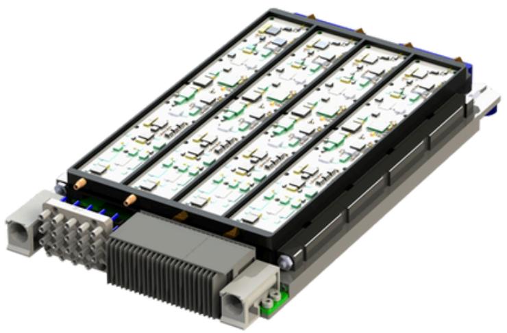
The open architecture characteristics of the RF-on-mezzanine product (figure 2) align with SOSA standards. The modularity embedded in the SCi Blocks architecture allows for various combinations of upconverters or downconverters in the 3U OpenVPX form factor to support various mission configurations. It provides repeatable, highperformance without the need for manual tuning.
![3D rendering of a multi-layer electronic device with heat sinks and LED arrays (no text or symbols visible)](.sosa-white-papers-ebook/7d6b41cdb9305be300e2515bc4f065ef62d3b2a31bab2fa9fd620b55a9d6fa3d.jpg)

Figure 2: A SOSA-aligned 3U VPX module with flexible RF-on mezzanine architecture meets the SWaP-C requirements of modern military and aerospace systems

# EW Transceiver Benefits

The benefits of SCi Blocks are seen in virtually any design, such as an EW transceiver. A transceiver can be built utilizing 4 upconverters and 4 downconverters, each covering 2 GHz of the electromagnetic spectrum for a total of 8 GHz of bidirectional frequency coverage. Two SCi Blocks modules can produce 16 GHz of both receive and transmit capabilities to an EW system such as a wideband Digital Radio Frequency Memory (DRFM).

A scalable physical architecture for the 1 GbE, 10 GbE, and 40 GbE interfaces is implemented. It enables retrofitting into currently deployed systems without changing existing system software. The system on chip (SoC) may also be used to implement Vita 49.2 messaging and data path protocols for future products.

# VPX Modules for EW Systems

VPX modules are also digitally-enabled and more importantly, SOSA-aligned. This is made possible through the incorporation of the SCi Block Manager, a higher-level control function built into every module. The Manager can be programmed to execute a variety of built-in test functions, as well as control the RF performance of the module to accommodate changes in the operating environment and mission requirements. By allowing system integrators a common command and control infrastructure for various RF circuitry, the SCi Blocks Manager lends itself to much faster system integration.

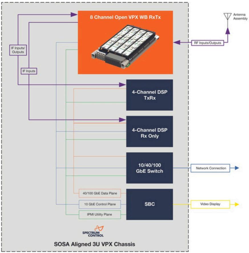
Consolidating various RF front-end features in SCi 3U Open VPX modules yields another SWaP advantage leading to a unique small form factor EW system (figure 3).
![This diagram illustrates a **SOSA Aligned 3U VPX Chassis** architecture (labeled at the bottom with a **SPECTRUM CONTROL** logo). The system is divided into an upper processing stage and a lower networking/compute stage, enclosed within a dashed border.  **Top Stage:** *   **8 Channel Open VPX WB RxTx:** An orange block at the top center.     *   Connected via a purple arrow from **RF Inputs/Outputs**.     *   Connected via a purple arrow from **IF Inputs/ Outputs**. *   **RF Inputs/Outputs:** A purple block on the right.     *   Connected via a purple arrow to **Antenna Assembly** (represented by an antenna icon).  **Input Stage:** *   **IF Inputs/ Outputs:** A small purple block on the left.     *   Connects to **IF Inputs** (a smaller purple block below it) via a downward line.     *   Connects to **8 Channel Open VPX WB RxTx** via an upward/rightward line. *   **IF Inputs:**     *   Connects via purple lines to **4-Channel DSP TxRx** and **4-Channel DSP Rx Only**.  **Vertical Stack (Blue Blocks):** Four dark blue blocks are stacked vertically on the right side: 1.  **4-Channel DSP TxRx** 2.  **4-Channel DSP Rx Only** 3.  **10/40/100 GbE Switch** 4.  **SBC**  **Interconnections:** These four blocks are interconnected by three colored lines representing different planes (identified by legend boxes at the bottom center): *   **40/100 GbE Data Plane** (orange line) *   **10 GbE Control Plane** (blue line) *   **IPMI Utility Plane** (green line)  **External Connections:** *   **10/40/100 GbE Switch:** Connects via a blue arrow to **Network Connection**. *   **SBC:** Connects via a yellow arrow to **Video Display**.](.sosa-white-papers-ebook/e7185a65813c214fac3fc4c0be03bce53c2aa062c8780b053f8052380c5d3a0b.jpg)

Figure 3: SCi Blocks small form factor EW system

The SCi Blocks module utilizes 4 downconverters for an ES receiver to provide situational awareness. Two upconverters and downconverters are paired to produce the RF front-end for a wideband DRFM. The common command and control architecture for the SCi Blocks module along with the SOSA-aligned interfaces allows for quick and easy integration with the various Digital Signal Processing (DSP) elements and single board computers (SBCs). The combination can add new EW capabilities to small platforms such as Unmanned Aerial Systems (UAS) previously unavailable due to SWaP-C constraints.

# Plug-and-play Building Blocks for EW

These examples show how the SCi Blocks architecture serves as a “plug-and-play” solution for EW platforms. Three main benefits are realized with the new design approach:

Rapid system integration: A standard digital interface allows plug-and-play solutions to be efficiently designed into EW/ISR systems, saving time and money. The creation of the digital gateway results in RF solutions that are functionality similar, so every system is more efficiently developed. The DoD initiative for shorter timelines and development cycles is met.

Faster modifications: Military and aerospace systems can be modified much faster using this approach because all that is necessary is software enhancements. Traditional RF systems also had a hardware upgrade requirement, which resulted in longer turnaround times. What had traditionally taken months, or a year, can now be done in days or weeks.

Adaptability: The ability to efficiently create modular solutions that integrate various levels of RF performance depending upon the project requirements allows for greater mission flexibility. It also expands future design approaches by reducing traditional cost and time constraints.

# Conclusion

Some estimates state that 75% of the cost of a defense project is associated with integrating components and modules. Development of SCi Blocks plug-and-play digitally-enabled RF building blocks provides the solutions to meet emerging designs in a time- and cost-efficient manner. SCi Blocks also expand EW capabilities into applications that were previously limited by SWaP-C concerns.

# View Table of Contents

everythingRF

www.everythingRF.com/ebooks

![The image displays a black and white QR code. It consists of a square grid of modules. Three position detection patterns (squares within squares) are visible in the top-left, top-right, and bottom-left corners. The remainder of the square is filled with a data pattern of black and white pixels.](.sosa-white-papers-ebook/c6bce68c8b0530e65353ec74eb7de3eb4cd673d715b41ee36c47e8935bc622d2.jpg)

# Download Our e-Books

everything RF has curated a series of e-Books on various topics.

Popular e-Books
![e-Book   2023 EMC PRE-COMPLIANCE HANDBOOK Sponsored by: RICHARD SCOWARZ PUBLISHED BY: everythingRF EMC](.sosa-white-papers-ebook/38e46c5474fc546581dc2cedbb266ffb43384373e2535ca146f50e3bd6da489f.jpg)

![e-Book   2023 everythingRF INTRODUCTION TO 5G REDCAP Sponsored by Amitsu 5G REDCAP](.sosa-white-papers-ebook/1728e1ddff11a40bffa27afc2208b6cefe532400bc934aa400bab677e06db354.jpg)

![everythingRF e-Book   2024 RF FILTER DIGEST A Resource of Whitepapers and Articles Highshare Filters Lowshare Filters Band Report Filters Bandpass Filters](.sosa-white-papers-ebook/15d849afdfd4fafe56d6c9558043802858e3f3f94c3158cf1148fd4f87c81293.jpg)

![everythingRF e-Book   2024 SATELLITE & SPACE DIGEST A Resource of Whitepapers and Articles](.sosa-white-papers-ebook/f390209aa89391955b95bd545eb33db1e34bee44b8ce45396190c05e043525d2.jpg)

SIGNAL PROCESSING

# EDGE-READY OPEN SOLUTIONS

Leverage more than 20 years of driving and supporting open standards to introduce capabilities more quickly, affordably, and with lower risk. The innovative technologies of the Mercury Processing Platform delivers an ecosystem of SOSA aligned products from modules to integrated solutions.

Choose Mercury Systems as your SOSA technology provider.

mrcy.com/sosa

Innovation that matters?

# SOSA and VITA Working Together for Next-Gen Defense Systems

The SOSA™ (Sensor Open Systems Architecture) Consortium is developing common open standards for designing, building, and deploying hardware, software, and firmware components of new military electronic systems. SOSA contributing members are U.S. government organizations including the U.S. DoD, Army, Navy, and Air Force, as well as key representatives from industry and universities.

SOSA adopts the most appropriate subsets of existing open standards to form a multi-purpose backbone of building blocks for current and future embedded systems for Radar, EO/IR, SIGINT, EW, and communications.

Objectives include vendor interoperability, lower procurement costs, easier new technology upgrades, quicker reaction to new requirements, and longer life cycles.

Because the emerging SOSA hardware standard draws primarily from OpenVPX and other related VITA standards, the new technologies, topologies, and environmental requirements critical to meeting SOSA objectives must be supported by extensions to these VITA standards.

This article is an overview of the SOSA and VITA organizations and how they interact, along with the challenges, successful strategies, and illustrative examples.
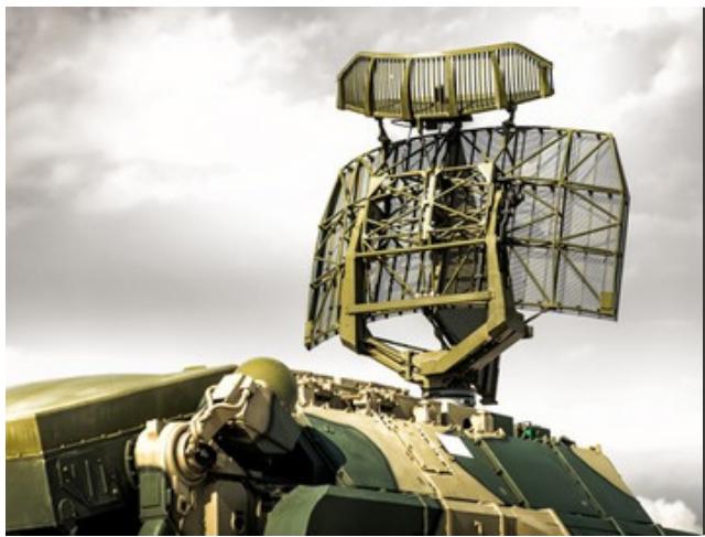
![Military radar system mounted on a vehicle under cloudy sky (no visible text or symbols)](.sosa-white-papers-ebook/4f60cde4f5c64eb924e71896efba1d9752ed95cd89b274d54de5ac8883d65df2.jpg)

# Vita background and mission

Introduced to the market in 1981, the VMEbus architecture began gaining market presence with specification development and products from Motorola and other early vendors, who
![XILINX® ZYNQ™ UltraScale™ XCZU27DR™ FFV61517A2Z1809 DF5581431A 1E-ES9819 TAIWAN PHS880.00_BT-00 LIDEAR TMUS50Y LINEAR TMUS50Y](.sosa-white-papers-ebook/6a2dc638ad3eff7c5447941476d26161c135c737cb5ab6a80dafa52227fa980c.jpg)

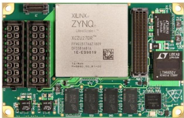
QuartzXM Model 6001 8-Channel A/D & D/A Zynq UltraScale+ RFSoC Processor eXpress Module

formed the VMEbus Manufacturers Group (now VITA) in 1983.

In 1985, VITA (VMEbus International Trade Association) was founded to promote VMEbus in worldwide markets and published its first directory of 174 vendor companies and over 2,700 product families. VMEbus soon won widespread acceptance and adoption by defense, government, research, and industrial customers.

The VITA Technical Committee, formed in 1987 to develop dozens of new extensions to VMEbus, evolved in 1994 into the present-day VITA Standards Organization (VSO) . A year earlier, VITA became an accredited standards development organization with the American National Standards Institute (ANSI) .

To overcome performance limitations of the parallel bus backplane of VMEbus, in

2003 VITA introduced the VITA 46 VPX standard to take advantage of new gigabit serial interconnect technology for 3U and 6U boards. In 2010, after widespread use, refinements, and serious interest in VPX for long-term defense programs, VITA announced the VITA 65 OpenVPX system specification, quickly ratified by ANSI.

VITA continues its strong role in promoting and developing open architecture embedded system standards, actively supporting numerous working groups in the VSO, and working with vendors and other organizations to embrace new technology and meet new market requirements.

![Person in camouflage uniform working at a desk with multiple monitors displaying data visualizations and charts (no readable text or symbols)](.sosa-white-papers-ebook/ef1f1d26bb993b6674d2f1ca6166e956bd146f2e927cdbbd6c5416cb1bacb4fd.jpg)

# Open Systems Architecture Directive and Initiatives

In May 2013, the U.S. Under Secretary of Defense issued a milestone memo mandating that all acquisition activity must incorporate DoD Open Systems Architecture (OSA) principles and practices. These include using existing or evolving open standards for well-defined modular hardware and software components that can be sourced from multiple vendors. Once proven, hardware platforms should be reusable for quickreaction mission needs, feature

upgrades, and new technology inser tion. Software architectures must be layered and extensible to permit operating system and security upgrades, and to accommodate new applications and user inter faces. These advantages reduce development risks and help ensure significantly longer operational life cycles.

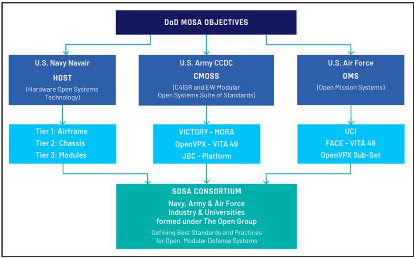
In response, each of the three primar y U.S. ser vice branches (Army, Navy, and Air Force) , began developing standards that embraced OSA principles to meet future procurement needs of deployed systems for their respective services.

The Army ’s CCDC (Combat Capabilities Development Command) in Aberdeen, MD developed CMOSS (C4ISR/EW Modular Open Suite of Standards) . These standards include OpenVPX for hardware, VICTORY to share vehicle services (like time and position) for C4ISR/EW interoperability, and MORA (Modular Open RF Architecture) to share antennas and amplifiers. It also uses REDHAWK and SCA software frameworks.

The Navy ’s NAVAIR (Naval Air Systems Command) in Patuxent River, MD created HOST (Hardware Open Systems Technology) , which initially focused on embedded processing for airborne and ground vehicle missions. Its major goal of abstracting hardware and software components aligned well with OSA concepts. HOST hardware definitions include three tiers: Tier 1 defines the deployed platform (airframe, vehicle,

UAV, etc.) , Tier 2 defines the embedded system enclosure, and Tier 3 the boards, backplanes, modules, and faceplates. Tiers 2 and 3 are subsets of OpenVPX modules and profiles. A registry of Tier 3 products offers an approved catalog of components for sharing across programs.

The Air Force’s OMS (Open Mission Systems) initiative incorporates SOA (Ser vice Oriented Architecture) for commercially developed concepts and middleware, and UCI (Universal Command and Control Inter face) , which standardizes massages and middleware for sharing command and control mission information between airborne system elements. OMS strongly embraces FACE (Future Airborne Capability Environment) , a consor tium of The Open Group that adopts open software standards for avionics systems, which gained full support of all threearmed services.
![The flowchart depicts a hierarchical structure flowing from a single top objective down to a final consortium.  **Top Block:** *   DoD MOSA OBJECTIVES  **Second Level (connected from Top Block):** *   **Left Block:** U.S. Navy Navair / HOST / (Hardware Open Systems Technology) *   **Center Block:** U.S. Army CCDC / CMoss / (C4ISR and EW Modular Open Systems Suite of Standards) *   **Right Block:** U.S. Air Force / OMS / (Open Mission Systems)  **Third Level (connected from Second Level):** *   **Left Block (connected from U.S. Navy Navair):** Tier 1: Airframe / Tier 2: Chassis / Tier 3: Modules *   **Center Block (connected from U.S. Army CCDC):** VICTORY - MORA / OpenVPX - VITA 49 / JBC - Platform *   **Right Block (connected from U.S. Air Force):** UCI / FACE - VITA 49 / OpenVPX Sub-Set  **Bottom Block (connected from Third Level):** *   SOSA CONSORTIUM / Navy, Army & Air Force Industry & Universities formed under The Open Group / Defining Best Standards and Practices for Open, Modular Defense Systems](.sosa-white-papers-ebook/46518a0a9a362330b0a02efd9eeeaf5d941daf17cff5e49b7ed475a6f6f856d2.jpg)

Figure 1: After independently developing standards in response to DoD MOSA objectives, the three services joined the SOSA Consortium to develop a unified standard.

# SOSA Consortium

While each service made significant progress in advancing OSA principles, they did so through different initiatives that often-shared common open standards, including OpenVPX and FACE. However, each initiative also included specific mandates tailored for service-specific platform requirements.

After recognizing these facts, administrators within DoD and each of the services perceived a strong need to promote a single, common initiative to define acquisition activities across all three services.

In early 2017, the DoD issued an SBIR solicitation for Sensor Open System Architecture (SOSA) Architectural Research outlining the numerous OSA initiatives and objectives for a unified solution. This resulted in the formation of the SOSA Consortium managed by The Open Group, a large organization with strict and well-defined practices, policies, and procedures for standards development efforts.

A primary mandate of the SOSA Consortium is broad participation, commitment, and contribution from DoD, Army, Navy, and Air Force, as well as industry, academia, and other government organizations. Major objectives include development and adoption of open systems architecture standards for C4ISR to provide a common, multi-purpose backbone for radar, EO/IR, SIGINT, EW and countermeasure systems. Additional objectives include platform affordability, rapid fielding, re-configurability, new technology insertion, extended life cycles, and re-purposing of hardware, firmware, and software.

# Inside the SOSA Consortium

The SOSA Consortium Organization consists of two primary groups. The Business Working Group (BWG) defines business and acquisition practices and creates guidance for acquisition programs. The Technical Working Group (TWG) is responsible for defining the SOSA Architecture, and producing the SOSA Technical Standard and SOSA Reference Design.

The SOSA Architecture presents a modular system structure, with tight integration within modules for encapsulating functionality and behaviors, and yet well-defined interfaces.

These modules must be based on open, published standards, with consensusbased influence stakeholders directing the evolution, and a strict conformance validation process. The SOSA Architecture protects IP (intellectual proper ty) within the modules to incentivize innovation and competition. The SOSA Technical Standard documents the SOSA Architecture with detailed rules and requirements drawn and adapted from a collection of open standards. The primary standards defining specifications for plugin cards, backplanes, chassis, electrical components, and mechanical structures are VITA standards.

The SOSA Conformance Policy, now being defined by the SOSA Conformance Standing Committee, will define processes for qualifying products against the Technical Standard. They include multiple conformance verification processes, a single conformance certification process, and a single SOSA certified conformant product registration process. Until the award of cer tification, no product can claim to be SOSA conformant.

Membership in SOSA is restricted to US citizens and organizations so that DoDsensitive or classified requirements can be presented by representatives from the armed services to promote solution strategies within the SOSA Technical Standard. For this reason, technical details of on-going discussions in the SOSA Technical Working Group may not be disclosed to the public. Once the standard is approved and released to the public, it will contain only specifications and rules, free from the underlying, sensitive use drivers.

# VITA and SOSA

Because VITA is so central to the SOSA hardware definition, many of the same individuals in the SOSA TWG are also active participants in the VITA Standards Organization (VSO) . Because restrictions on technical disclosures imposed on the TWG by SOSA do not apply to VSO, members of VSO must be mindful against referencing on-going SOSA technical topics in their VSO discussions and publications.

Nevertheless, the TWG does release period “snapshots” of the evolving SOSA Technical Standard that are publicly available for review, the latest being Snapshot 3 released in July 2020. While no conformance to these snapshots may be claimed, they illustrate the direction and underlying principles guiding the final standard.

In some cases, SOSA adopts only carefully selected subsets of existing VITA specifications. For example, the TWG adopted only a handful of the more than one hundred 3U and 6U OpenVPX slot and module profiles, based on an analysis that they could accommodate the majority of system requirements.

User-defined backplane pins defined in OpenVPX pose a nemesis for standardization efforts because they allow custom assignment of signals with inter face standards, directions, and voltages. Profiles with user-defined pins are being deprecated in SOSA. Instead, work is under way to assign a minimum set of specific I/O standards to each group of legacy user-defined pins for each of the OpenVPX control, data, and expansion planes.

SOSA restricts the primary VPX power supplies to +12V only, prohibiting +5V, and +3.3V. This greatly simplifies the previous OpenVPX issue of balancing among three voltages to simplify chassis power supplies and standardize the plugin cards.

Unlike most OpenVPX systems, SOSA requires hardware platform management leveraging the HOST 3.0 system management architecture, which itself is highly leveraged from VITA 46.11. A system manager module accesses all SOSA system elements for census taking, health monitoring, trouble shooting, new firmware/software upgrades, and reset/recovery operations.

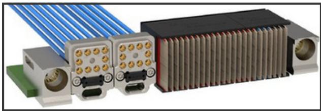
Backplane I/O for RF signals and optical inter faces in OpenVPX have gained significant traction in CMOSS, MORA, and HOST systems over the last six years, all enabled by VITA 66 and VITA 67 specifications. Eliminating front panel cable harnesses wins high scores for maintenance and reliability. Some of the latest modular backplane standards offer extremely high density and even mixed RF/optical inter faces as shown in Figure2.
![Close-up of electronic connectors with blue and gray wires, no visible text or symbols](.sosa-white-papers-ebook/5adc31593e46202612eca096a64ceaccb68d9c766ee9c1f70a6c8affe5e6d525.jpg)

Figure 2: Rear view of 3U OpenVPX Module with two VITA 67.3D backplane connectors, each with 10 coaxial RF signals and 24 optical l anes. Cour tesy by TE Connectivity.

In summary, when critical needs arise from SOSA customers (DoD services) , SOSA TWG members can promote innovation for new standards within the VSO to accommodate them, while still complying with SOSA restrictions.

# Next steps

The release of the SOSA Technical Standard 1.0 is expected to be released on September 20, 2021. In spite of the current public health crisis, web-based conferencing has replaced many face-toface meetings with regular on-going conference calls to help maintain the momentum. After its release, product vendors may begin the processes leading to full certification.

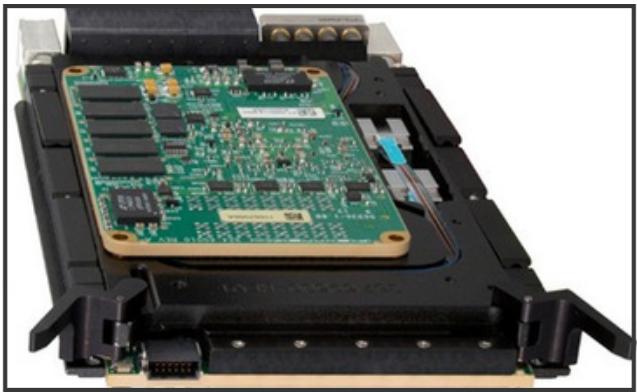
Never the less, vendors are now offering products that were “developed in alignment with SOSA” like the one shown in Figure 3. A key difference in the SOSA architecture from earlier open standards is the well-defined protection of IP, which encourages numerous examples of supplier innovation and investment.

The DoD is now issuing requests for proposals and information clearly favoring respondents that offer OSAbased solutions.
![Close-up of an electronic device's internal circuit board with visible components and connectors (no text or symbols)](.sosa-white-papers-ebook/cf12d286e51b14645cb5822760283a2dcc05b4830c5f9cac76983a9b5079238c.jpg)

Figure 3 Quartz Model 5553 : 3U VPX 8-Channel A /D and D/A Gen 3 RFSoC SOSA Aligned Processor incorporates RF and optical backplane using VITA 66 or VITA 67 connectors. The top cover has been removed to show details.

The DoD is now issuing requests for proposals and information clearly favoring respondents that offer OSAbased solutions.

The active participation in SOSA by the DoD, all three-armed services, embedded industry vendors, universities, and research facilities gives evidence of their substantial commitments of resources and personnel. These clear signals ensure that SOSA is well on its way to revolutionize the future of embedded military electronics systems.

# View Table of Contents

# Conclusion

With this, the “Understanding SOSA” e-Book comes to an end. By providing key whitepapers and articles, this resource equips readers with the knowledge and understanding necessary to navigate the complexities of SOSA implementation effectively.

SOSA Technical Standards

<table><tr><td>STANDARD EDITION</td><td>RELEASE DATE</td></tr><tr><td>SOSA 1.0</td><td>SEPTEMBER 2021</td></tr><tr><td>SOSA 1.1</td><td>JUNE 2023</td></tr><tr><td>SOSA 2.0</td><td>FEBRUARY 2024</td></tr></table>

The eBook would not have been possible without contributions from industry leaders like Mercury, Pixus Technologies and Spectrum Control.

Stay tuned for more eBooks from everything RF exploring cutting-edge technologies in the future.

# Content Contributed by:

mercury

![The image displays a logo set against a white background. At the top right, there is an orange, stylized graphic resembling a wave or an ampersand symbol. Below this graphic, the text 'SPECTRUM CONTROL' is written in bold, dark blue, uppercase sans-serif letters. The word 'SPECTRUM' appears on the top line, and 'CONTROL' is stacked directly beneath it.](.sosa-white-papers-ebook/a16485188e27fc31528ca897e545b7278323094bd40d94393736cb66181abfcd.jpg)

everythingRF

![pixus TECHNOLOGIES The Power of Embedded Ingenuity](.sosa-white-papers-ebook/6bbf18e253c0e6682c53957c5b26764242596f65db508e6e4653b8797b59f6d8.jpg)

SIGNAL PROCESSING

# MAXIMIZE DESIGN FLEXIBILITY WITH DIRECT RF

Discover an innovative system-on-module approach that delivers high-bandwidth conversion and processing for data acq waveform signal generation, communi and electronic warfare applications at

# FEATURES

Four 64 GSPS A/D and D/A converters

Altera™ Agilex 9 SoC FPGA

16 GB DDR4 SDRAM

100 GigE optical interfaces

FPGA design kit for custom IP developm

Explore Mercury’s SOSA™

aligned product family.

mrcy.com/sosa

![pld JTAG IPMC JTAG SD CARD ACCESS Loosen screws and SLIDE OPEN PS I2C mercury am JTAG Mercury mERCY PLD DONE USER VPS PDIE WIDTH 1.0 VPS PDIE WIDTH 1.0 PFGA DONE VPS EV FUSE PAMLOAD PWR ON PUMBER POWER 1 1 1 1 1 1 1 1 1 1 1 1 1 1 1 1 1 1 1 1 1 1 1 1 1 1 1 1 1 1 1 1 1 1 1 1 1 1 1 1 1 1 1 1 1 1 1 1 1 1 2 2 2 2 2 2 2 2 2 2 2 2 2 2 2 2 2 2 2 2 2 2 2 2 2 2 2 2 2 2 2 2 2 2 2 2 2 2 2 2 2](.sosa-white-papers-ebook/ea9e0aec5c05b60283cc2e585a826bfde8d15cc3fb002e28327821f96b3ffa22.jpg)
[🔗 Link to the original document](.sosa-white-papers-ebook/sosa-white-papers-ebook.pdf)