# Shift to IIoT with Intelligent Edge Solutions
Edge DAQ
— Dynamic Signal Acquisition Module
- Digitizer

# OVERVIEW
# Essentials for the Shift to IIoT
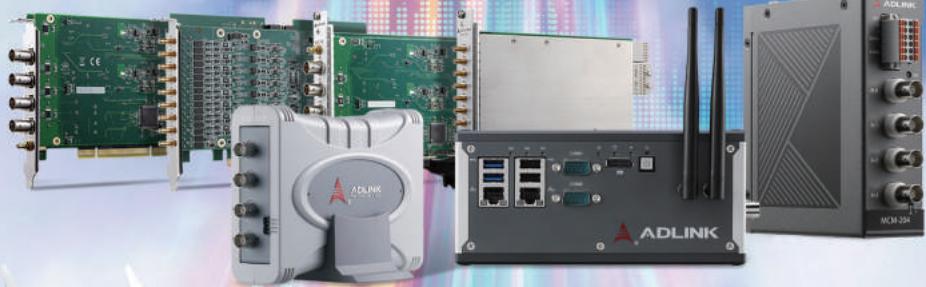
Data is critical for Industry 4.0 and IoT applications, where effective analysis hinges on sufficient data. This data acquisition in industrial automation applications aims to extract comprehensive and precise data from field devices to provide actionable insights for more accurate decision making. Primary challenges are the collection of field data and transfer to the cloud for analysis. ADLINK's easy, reliable, and intelligent DAQ solutions facilitate your IIoT applications by collecting accurate real-time data for analysis to improve production capabilities and increase operational efficiency.
# Table of Contents
DAQ Solutions Overview 1-2
New Generation All-in-One Software Solution – MAPS 3-4
Ready-to-use Edge DAQ Solutions 5-9
Audio and Vibration Measurement Modules 10-14
Collecting Field Data for Smart Manufacturing 15-20
Next-Generation Multi-Function DAQ Cards 21-24
High-Speed Digitizer for Demanding Applications 25-28
Choosing a Digital I/O Device 29
Choosing DAQ Hardware for Your Measurement 30 System
# Cloud

# New Generation
# All-in-One Software Solution – MAPS
The Measurement, Automation, and Platform Suite (MAPS) is the all-in-one device management utility for ADLINK DAQ and PXI systems. MAPS includes DAQ and PXI system software packages that help engineers accelerate measurement and automation application development while reducing overall effort.

# Easy to use utility
MAPS is an integrated platform allowing engineers to configure hardware and test functionality from a unified portal. Comprehensive software library documentation and sample code provide all necessary information for ADLINK DAQ and PXI systems development.
# Multiple programming languages and latest operation system support
MAPS supports the most popular programming languages for DAQ application development, providing SDKs for C/C++, C#, and LabVIEW so that engineers can develop applications based on their particular requirements. To further assist development, MAPS also supports the latest Windows 7, Windows 10, and Linux operating systems.


# MAPS Software Architecture
# MAPS Core
# Device Management
Device Manager (ACE)
PXI Platform
Resource Mgmt. Utility
PXI Platform
ChassisWatch Utility
DAQ/IO Module
Function Test Utility
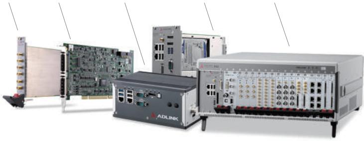
Digitizers DAQ Edge Platform PXIe Controllers PXIe/PXI Chassis
User APPs in
C/C++
User APPs in
LabVIEW
User APPs in
C#
MAPS/C
C/C++ SDK
for DAQ/IO module
MAPS/LV
LabVIEW SDK
for DAQ/IO module
MAPS/C#
C# SDK
for DAQ/IO module
Coming soon
MAPS Core -Device Runtime
PXI platform service
DAQ/IO Module Device Driver
DAQ/IO Module Runtime Library
# Easy-to-Use Navigation Utility
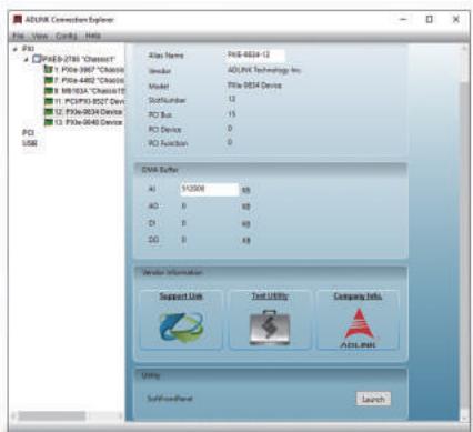
Centralized management of device configuration and drivers for ADLINK DAQ and PXI systems. No more back-and-forth to troubleshoot installation errors.
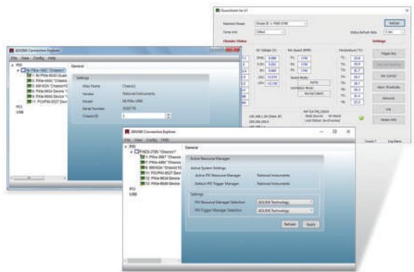
Compatible with PXI platform and module management tools from other vendors. No more barrier for PXI platforms and modules from multiple providers.
# Expand Your IIoT Applications With Ready-to-Use Edge DAQ Solutions
Technology developments and Industry 4.0 are prompting manufacturers to rethink their strategies for digital transformation. The first step in digital transformation is to acquire data from devices and equipment to understand machine conditions, production processes, and environmental parameters, and these all require sensors. With the increasing complexities of IoT applications, effectively collecting and transferring field data from sensors to IT/OT systems is the key to adding operations visibility to remote locations. ADLINK's edge DAQ solutions integrate sensor signal conditioning, data collection, network connectivity, and edge computing in one system that supports input from various sensors, thus providing a wide range of options for remote equipment monitoring and control tasks. Also, ADLINK edge DAQ solutions are designed for integration with existing infrastructure so engineers can get systems set up quickly.
Challenges and Solutions in
IIoT Monitoring and Maintenance
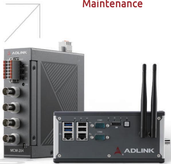
Edge DAQ Solutions
# Challenges
# Mass deployment
Large-scale remote monitoring requires the costly deployment or extension of networks with additional cables and network switches.
# Reliable operation
Long-term machine condition monitoring demands device reliability to ensure uninterrupted data collection from the sensors that monitor machine status.
# Updates and configuration
Sending personnel onsite to perform periodic manual updates for remote monitoring applications is time-consuming and costly.
# Protocol interoperability
A mix of proprietary and open-standards protocols for DAQ devices complicates interoperability, and time-consuming integration of proprietary protocols increases development time and cost.
# Data processing and connectivity
Computing power is required to process large amounts of data in the field and respond to events immediately when something goes wrong.
# Monitor a variety of devices
The Internet of Things increases the number and variety of devices to be monitored, and each has its own unique requirements, thereby expanding the monitoring scope.

# Solutions
# Daisy-chain topology
Edge DAQ devices can be daisy-chained using two embedded Ethernet ports with switching functionality to save up to 70% in deployment costs.
# Rugged and reliable design
Edge DAQ has wide-range temperature capabilities for harsh environments, and comprehensive environmental testing ensures dependable operation to save up to 90% in device replacement costs.
# Built-in web-based configuration utility
Edge DAQ has a built-in web console so engineers can perform remote updates and configuration anytime and anywhere.
# Support open-standard protocols
Edge DAQ supports TCP/IP and Modbus TCP protocols and can send field data to SCADA systems or PLCs without an extra protocol gateway to save up to 50% protocol integration costs.
# Edge computing for intelligent analysis
Edge DAQ is equipped with optimized edge computing capabilities to process data locally and supports multiple data formats.
# All-in-one Edge DAQ offerings
Edge DAQ features various I/O combinations for collecting data that can save up to 30% in hardware integration costs compared with purchasing separate hardware from different vendors.
# High-End Edge DAQ Solution

# Get Started Quickly
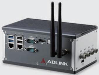
The MCM-100 series combines data collection, edge computing power, and network connectivity in a compact system. Unlike other PC-based solutions requiring additional signal conditioning devices and wiring, the MCM-100 series has built-in IEPE 2 mA excitation current source signal conditioning on each channel to reduce system setup time and effort.

Simplify Programming

all in One
High Precision

Data Connectivity
# Standalone Edge DAQ Solution
Pre-purification Unit
# Easy for Edge Mass Deployment
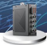
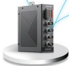
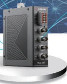
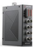
ADLINK's MCM-204 is an ultra-compact edge DAQ with an ARM Cortex-A9 processor, supports IEPE type accelerometers, microphone sensors, digital tachometers, and temperature sensors to offer complete measurement options for a wide range of monitoring applications. The MCM-204 includes a built-in web-based device management utility for easy remote configuration and edge firmware and algorithm update. The exclusive benefit of ADLINK's MCM-204 edge DAQ is customizable algorithm-based local data filtering that reduces the quantity of data transmitted to centralized or cloud-based locations.
# Cost-Effective Daisy-Chained Ethernet I/O Connection
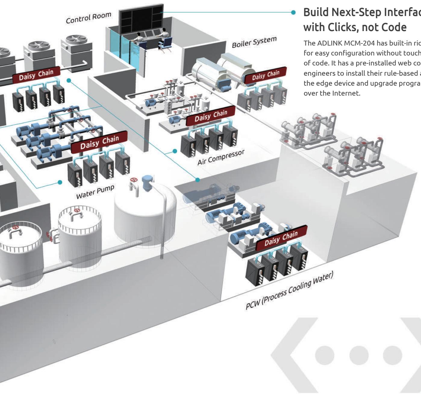
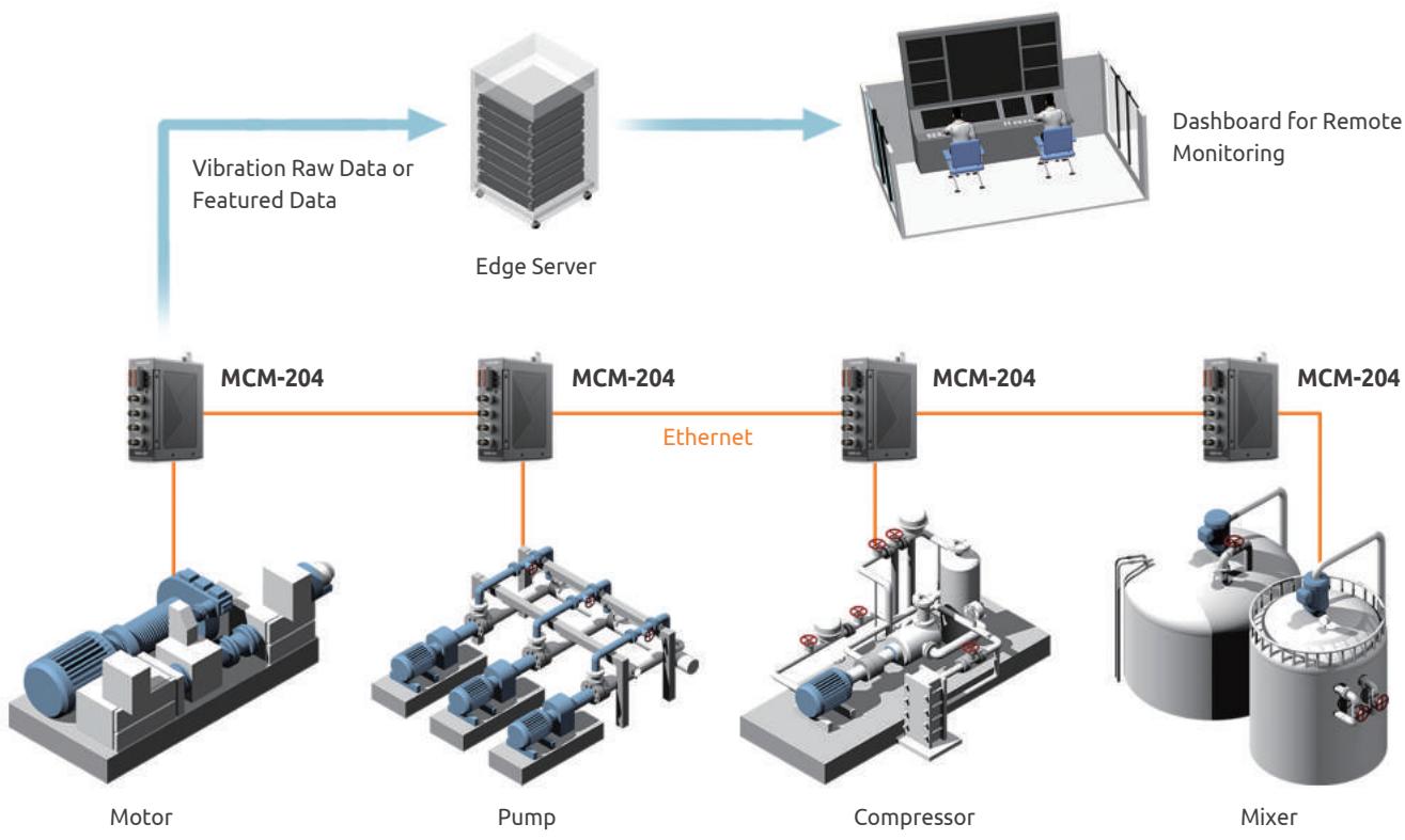
Thanks to its two embedded Ethernet switch ports, ADLINK's MCM-204 allows manufacturers to employ a daisy-chain Ethernet topology. This approach increases the expandability and installation possibilities for large-scale remote applications and lowers overall costs by reducing the need for separate Ethernet switches. The simplicity of the daisy-chain architecture makes it easy to wire and maintain. The two Ethernet ports can also serve as a backup link to ensure network redundancy and stability.
# Fast and Precise Data Acquisition
The MCM-100 series have Intel $^{\circledR}$ Atom $^{\circledR}$ x7-E3950 processors that deliver ample computing power for edge-based data acquisition, domain algorithms, and data analytics. The MCM-100 series also features a 4-channel 24-bit 128 kS/s simultaneous sampling rate for accurate machine vibration measurement.
# Real-time and Remote 24/7 Intelligent Monitoring
The MCM-100 series is an open platform and easily integrates with third-party web-based dashboards that automatically collect and analyze long-term machine condition data. This analysis of the historical data set creates advanced predictive machine learning algorithms. These algorithms can then analyze and detect causal correlations in current incoming data to precisely predict equipment abnormalities and avoid unexpected breakdowns and downtime expenses.
# Build Next-Step Interfaces with Clicks, not Code
The ADLINK MCM-204 has built-in rich data formats for easy configuration without touching a single line of code. It has a pre-installed web console to allow engineers to install their rule-based algorithms into the edge device and upgrade programs remotely over the Internet.
# Machine Condition Monitoring for the Petrochemical Industry
Application
# Challenges
The petrochemical industry produces products of tremendous value through labor-intensive and complex processes. Any unexpected equipment failure may result in a production shutdown and significant losses.
# ADLINK Solutions
Prowave, as an expert in machine vibration software solutions, collaborated with ADLINK to develop a machine condition monitoring system for a petrochemical company in Taiwan using the ADLINK MCM-204. Prowave chose the MCM-204 for its built-in RJ-45 Ethernet ports because they significantly shorten cabling time when deploying across multiple production sites. In this case, the machine condition monitoring system Prowave built with the MCM-204 harnessed the 4-channel 24-bit 128kS/s simultaneous sampling rate to collect precise machine vibration parameters and analyze data collected from on-site production equipment in real-time.
# Why ADLINK
Consistently reliable production line operation with 24/7 real-time monitoring
▶ Significantly reduced maintenance cost with preventative maintenance
▶ Ensuring labor safety by remotely monitoring the conditions of machines operating in hazardous environments
Product Used: MCM-204
# Dynamic Signal Acquisition Modules for Audio and Vibration Measurement
ADLINK's Dynamic Signal Acquisition (DSA) modules, with support for multiple bus standards, are specifically designed for audio, noise, and vibration measurement applications. Featuring up to 432 kS/s sampling rates, 24-bit resolution, and IEPE signal conditioning, the series delivers highly accurate signal acquisition and easy connection to microphone or acceleration sensors for component testing.
# Superior Performance for a Variety of Audio Testing Needs
ADLINK's DSA modules feature 24-bit resolution and high sampling rates capable of measurements detailed enough to distinguish subtle audio changes while filtering heavy bass, stereo, HiFi, and other high-end signals (noise Level < 3 $\mu$ Vrms and THD+N < 100 dB). The modules are also suitable for mechanical equipment monitoring applications in harsh environments, with high precision and dynamic measurement performance, providing accurate monitoring and measurement of activity.
Audio Testing Solution Comparison
<table> | ADLINK DSA Solution | Audio Analyzer | Sound Card |
| Price | Mid-range | Expensive | Low |
| Size | Small | Bulky | Small |
| Performance | High24-bit resolution, low distortion, and low noise.Precise measurements meet high-end audio product testing standards. | High | Poor |
| IEPE Sensor Support | YesIEPE integrated. Direct connection to microphone or acceleration sensor | Yes | No |
| Synchronization | YesSynchronous input and output trigger.Increased stability and consistency for audio loopback testing. | Yes | No |
| Analysis Software | YesAudio Analyzer software and library for audio test application. SDKs for LabVIEWTM, MATLAB®, and C/C++. | YesRich software and library support | No |
| Integration & Expandability | YesPC-based architecture integrates with other test functions. Quick completion of automated testing in the production line. | Low | Low |
| Digital Audio Testing | No | Yes | Yes |
# Direct Sensor Connection Reduces Installation and Setup Time
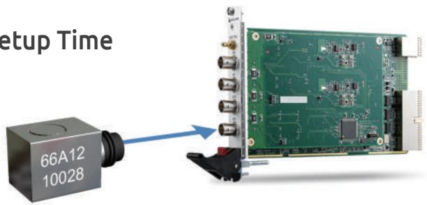
ADLINK DSA products provide a built-in IEPE excitation current source (2 to 4 mA) signal conditioning for all input/output channels. Instead of extra signal conditioning equipment and power cabling, IEPE sensors connect directly to the front panel, eliminating unnecessary equipment and additional setup time.
# Software Support Simplifies Application Development
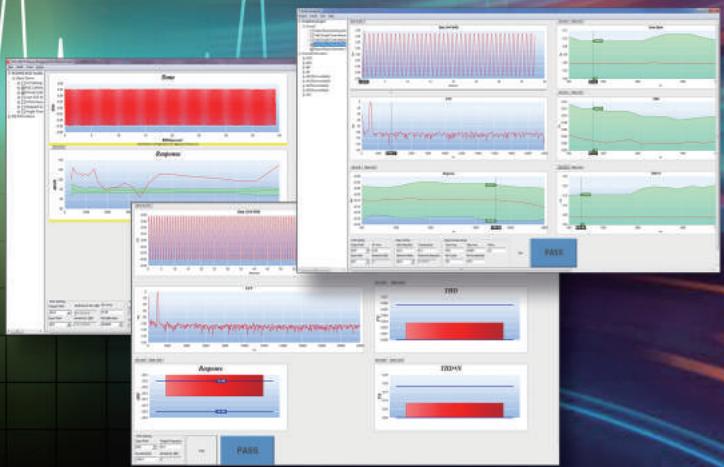
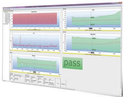
ADLINK's proprietary Audio Analyzer software accelerates audio testing of headphone jacks, microphones, speakers, and other electro-acoustic components without coding. ADLINK also provides the Audio Analyzer library for building advanced audio test applications.
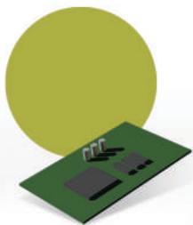
Audio Loopback Test

Vibration Test
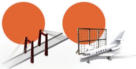
High Channel Count Measurement
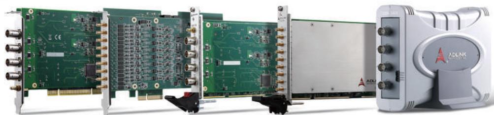
Complete Sound & Vibration Systems for PXI, PCI, and USB
# Car Navigation Audio Testing
# Application
# Challenges
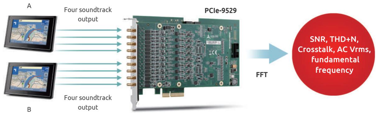
In-vehicle infotainment and navigation device manufacturers require audio testing systems that can quickly measure four audio output channels (including multiple speakers in various vehicle locations), analyzing the audio quality and identifying device defects. Previously, manufacturers have relied mainly on manual testing requiring extended testing times, utilizing expensive testing instrumentation, often with fewer output channels (usually only two), which further extends the duration of testing events.
# ADLINK Solutions
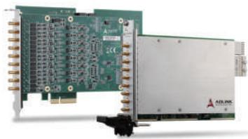
ADLINK's PCIe-9529 24-bit high-precision signal acquisition module with dynamic range up to 110 dB and eight input channels easily meets multi-channel vehicle navigation testing requirements. The PCIe-9529 measures signal-to-noise ratio (SNR), THD+N, channel crosstalk, volume, primary frequency, and other items. As shown, the PCIe-9529's eight analog input channels connect to two DUT soundtracks. Fast Fourier Transform (FFT) is used to obtain testing values, including SNR, THD+N, and dynamic range, and others, to effectively and quickly determine whether the DUT conforms to specific requirements.
# Why ADLINK
▶ Reduce testing operation costs by eliminating expensive audio analyzers
▶ Simultaneously test two 4-channel devices using the eight 24-bit analog input channels to shorten test cycles and enhance efficiency
▶ Develop audio testing systems quickly using the included C/C++, .NET, and LabVIEW SDKs
Product Used: PCIe/PXIe-9529
# High-Resolution Audio Testing for Mobile DAC
# Challenges
High-resolution audio is gaining popularity, thanks mainly to the prominence of music streaming products and services (from smartphones to most digital Hi-Fi components). Currently, commercially available sound cards are unable to satisfy the demands of high-resolution audio testing requirements. Manufacturers were looking for 24-bit high precision, low distortion, and low noise audio acquisition cards for testing.
# ADLINK Solutions
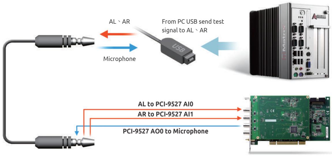
ADLINK's PCI-9527 is a 24-bit high dynamic signal acquisition card that provides an excellent audio testing solution. Two-channel simultaneous sampling analog input and two-channel simultaneous updated analog output easily meets the requirements to analyze audio quality and identify device defects. The PCI-9527 measures SNR, THD+N, crosstalk, and dynamic range to detect audio changes and quickly determine whether USB Type-C high-resolution mobile DAC conforms to specifications.
# Why ADLINK
▶ Designed for audio testing and acoustic measurement
▶ Cost-effective solution for audio testing
▶ Flexibility to meet various audio testing requirements
Product Used: PCI-9527L
# PCI-9527L
# 24-Bit High-Resolution Dynamic Signal Acquisition and Generation Module
• 24-bit Sigma-Delta ADC and DAC
- 2-ch simultaneous sampling analog input, and 2-ch simultaneous updated analog output
- 216 kS/s maximum sampling rate with software programmable rate
- Programmable input range: ±40 V, ±10 V, ±3.16 V, ±1 V, ±0.316 V
- Programmable input voltage range of ±0.5V, ±1V, ±5V, or ±10V
- Programmable output range: ±10 V, ±1 V, ±0.1 V
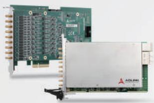
# PCIe/PXIe-9529
# 8-CH 24-Bit High-Resolution Dynamic Signal Acquisition Module
• 24-Bit sigma-delta ADC
• 8 simultaneous analog inputs
• 192 kS/s maximum sampling rate
- ±1V, and 10V input ranges, 110 dB dynamic range
• IEPE - 4mA, software configurable
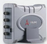
# USB-2405
# 4-CH 24-Bit 128kS/s Dynamic Signal Acquisition USB 2.0 Module (OEM version available)
• Hi-Speed USB 2.0, and USB bus powered
• 24-bit sigma-delta ADC with built-in anti-aliasing filter
- 4-CH simultaneous sampling analog input, up to 128kS/s
- Analog and digital triggering & full auto-calibration
• Supports 2mA excitation output on each analog input channel for IEPE sensor measurement
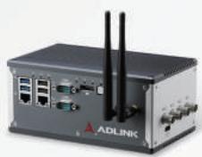
# MCM-100
# Machine Condition Monitoring Edge Platform
• Built-in 2 or 4CH, 24-bit simultaneous sampling analog inputs, up to 128kS/s
• Supports IEPE 2mA excitation current output on each analog input to drive accelerometer
- Equipped with Intel Atom® x7-E3950 processor (Quad core)
- Extremely compact with versatile I/O support
- Optional Wi-Fi k
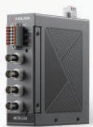
# MCM-204
# Standalone Ethernet DAQ with 4-CH AI, 24-Bit, 128 kS/s, 4-CH DI/O
- RESTful API reports machine condition to IT system
• Built-in web console for easy configuration and use as portable DAQ
• Supports custom algorithms to filter data at the edge
• Supports IEPE 4mA excitation current output on each analog input to drive accelerometer
- Two 1GbE Ethernet port for cascade
# Collecting Field Data - The First Step to Smart Manufacturing
Collecting data from the field is crucial to the operation of smart manufacturing. Data analysis can warn of anomalies before they become real problems, allowing businesses to avoid costly downtime. Sensor data can also be analyzed to gain insight into crucial trends and make well-informed, evidence-based decisions.
ADLINK offers a rich portfolio of IoT devices and systems that deliver various kinds of intelligence and data. They serve to collect data, pushing it, and sharing it with a whole network of connected devices. Historical data establishes an initial baseline for alert parameters that alert maintenance personnel to anomalies and more granular rules can be implemented as needed. Acting on these predictive maintenance insights reaps major benefits for asset longevity.

# IoT Sensor Types
# 2. Strain Gauge Sensors
# 1. Temperature Sensors

Temperature sensors measure the amount of heat energy in a source, allowing them to detect temperature changes and convert them into data. Manufacturing machinery must operate with environmental and device
temperatures within the specified tolerances.

Strain gauge sensors vary resistance with applied force. They convert force, pressure, tension, and weight into a measurable change in electrical resistance. Strain gauges are commonly used for
geotechnical monitoring to keep a constant check on structures, tunnels, and buildings.
# Recommended Products
USB-2401
4-CH 24-Bit Universal Input USB DAQ Modules
ND-6018
8-CH Thermocouple Input Module
ND-6013
3-CH RTD Input Module
# Recommended Products
USB-2401
4-CH 24-Bit Universal Input USB DAQ Modules
PCI-9524
24-Bit Precision Load Cell Input Card
# Types of Temperature Sensors
- Thermocouples - indicate current temperature with voltage - vibration resistant, low cost, highest temperature, fast response
- Resistor temperature detectors (RTD) - indicate current temperature with resistance - high temperatures, electrical noise immunity, less affected by the environment
• Thermistors - indicate current temperature with resistance - best sensitivity, low cost
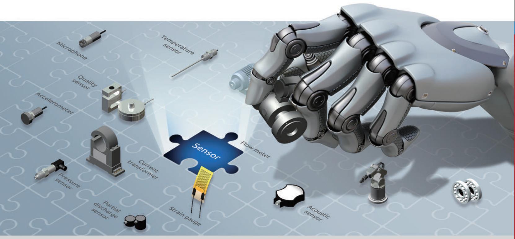
# 3. IEPE Sensors

Accelerometers are transducers used to measure the physical or measurable acceleration experienced by an object due to inertial forces and convert mechanical motion into an electrical output.
Accelerometers can measure vibration, shock, and pressure.
# Recommended Products
# PCI-9527 L
24-Bit High-Resolution Dynamic Signal Acquisition and Generation Module
# PCIe/PXIe-9529
8-CH 24-Bit High-Resolution Dynamic Signal Acquisition Module
# USB-2405
4-CH 24-Bit 128kS/s Dynamic Signal Acquisition USB 2.0 Module (OEM version available)
# MCM-100
Machine Condition Monitoring Edge Platform
# MCM-204
Standalone Ethernet DAQ with 4-ch AI, 24-bit, 128kS/s, 4-ch DI/O
# 4. Current Sensors

Current sensors detect electric current (AC or DC) in a wire and generate a signal proportional to that current. Current sensors measure the current passively, without interrupting the circuit. A wide range of applications use current sensors, including
facility management and sub-metering. They can help detect faults in machinery and prevent equipment damage.
# Recommended Products
# USB-1903
8/16-CH 16-Bit 250 kS/s Multi-Function USB DAQ Modules
# USB-2401
4-CH 24-Bit Universal Input USB DAQ Modules
# ND-6017
8-CH Analog Input Module
# Machine Condition Monitoring for Semiconductor Fabs
# Challenges
The big headache when integrating AI machine condition monitoring for predictive maintenance is how to acquire accurate data continuously from the factory floor. Our customer, a Korean semiconductor company, had used low-end DAQ modules, with a sampling rate as low as 10 S/s, in their existing facilities, but this proved insufficiently precise for implementing predictive analysis to prevent machine failure.
# ADLINK Solutions
To remedy this situation, the company deployed ADLINK high-end DAQ modules in their new facilities to collect data from the factory floor and transmit the processed data to the cloud. ADLINK USB DAQ range comprises a series of products providing analog-to-digital signal conversion with high sampling rates up to 250 kS/s and 16 or 24-bit resolution. By merging pre-processed data and factory floor data, they were able to implement AI-based preventative maintenance and significantly reduce machine downtime.
# Why ADLINK
30% reduction in equipment maintenance costs
▶ 20% increase in production efficiency
▶ Plug-and play USB interface for effortless large scale deployment
Product Used: USB-1902/1903/2401/1210
MCM-204
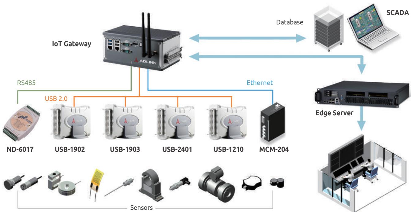
Control Room
# Accelerated Automatic Material Testing
# Challenges
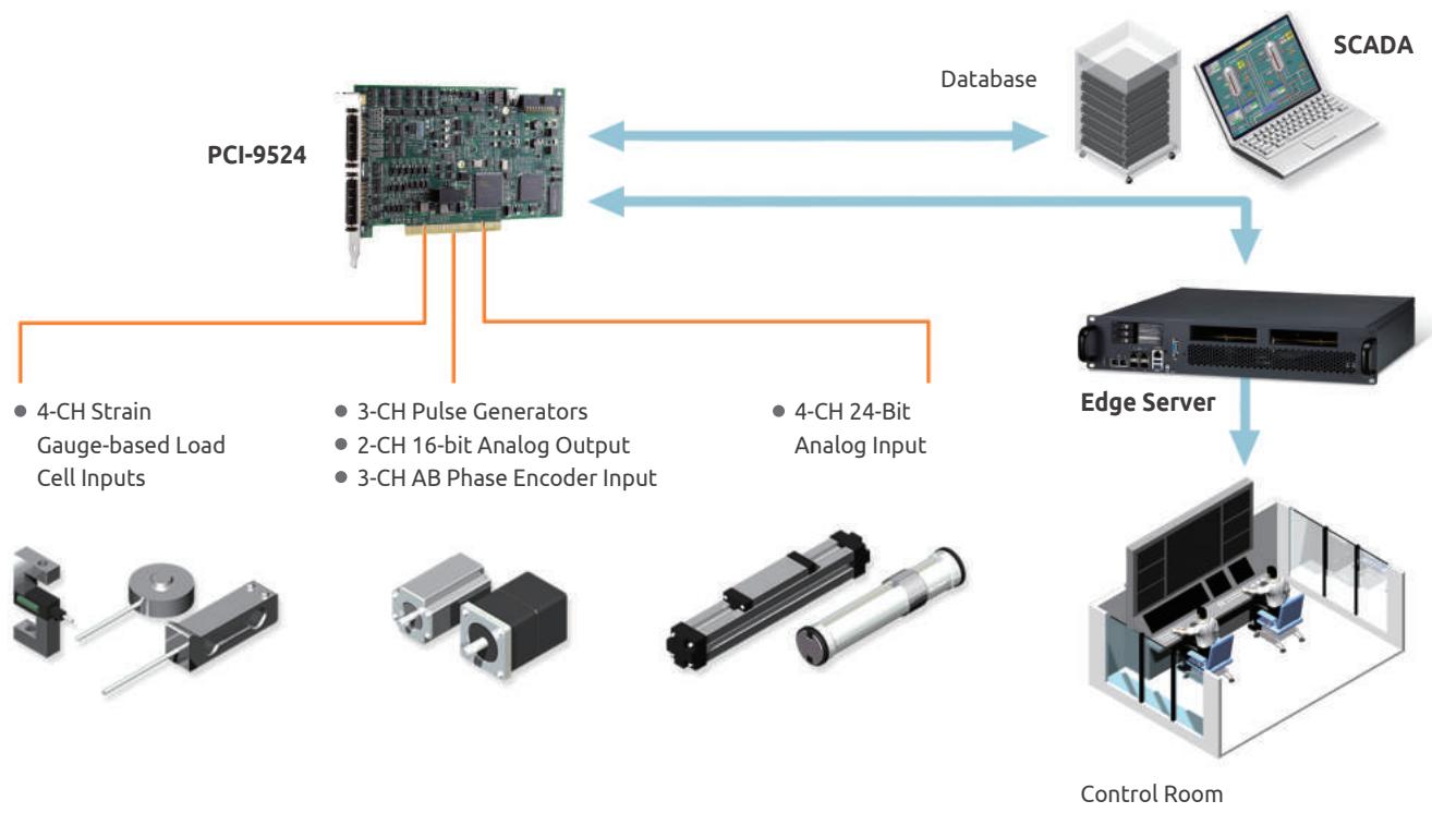
A typical automatic material testing system consists of several key functions: signal conditioning, transducer excitation, transducer measurement, LVDT measurement, and actuator control to a stepper motor or hydraulic system. To speed up system integration, material testing developers look for potential solutions combining accurate load change measurement, displacement, and motor control.
# ADLINK Solutions
The PCI-9524 offers an on-board amplifier and four load cell input channels with a selectable excitation capability of 2.5 or 10 VDC. The load cell input card is capable of transducer measurements with sensitivity of 1.0 to 4.0 mV/V and accuracy up to 200,000 counts. The 4-channel general-purpose 24-bit high-resolution analog inputs can support high accuracy LVDT measurements. The PCI-9524 features three pulse generator channels, 3-axes AB phase encoder inputs for step motor control, and two analog output channels with a 16-bit resolution for hydraulic systems control.
# Why ADLINK
PCI-9524 is an all-in-one solution for material testing systems, reducing integration costs from combining multiple subsystems
Product Used: PCI-9524
# USB-2401
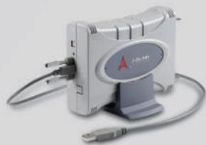
4-CH 24-Bit Universal Input USB DAQ Modules
• USB 2.0 High-Speed, USB bus powered
• 4-CH simultaneous-sampling analog input
- Built-in signal conditioning for high voltage/current/thermocouple/RTD/strain gauge/load cell measurement
- Up to 2kS/s analog input rate
- Removable screw terminal
# ND-6018
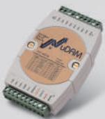
8-CH Thermocouple Input Module
• Channels: 6 Differential & 2 Single-ended
• Input Type: Thermocouple, mV, V and mA
• Thermocouple Type: J, K, T, E, R, S, B, N, C
• Voltage Range: ± 15 mV, ± 50 mV, ± 100 mV, ± 500 mV, ± 1 V, ± 2.5 V
• Current Range: ± 20 mA, Isolation Voltage: 2500 VRMS
# ND-6013
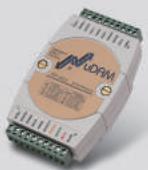
3-CH RTD Input Module
- Channels: 3
• Input Type: Pt-100, Ni-100 or Ni-120 RTD
• Isolation Voltage: 2500 VRMS
• Sampling Rate: 3 samples/sec
• Input Wiring: 2, 3 or 4 wires
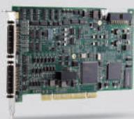
# PCI-9524
24-Bit Precision Load Cell Input Card
• 4-CH strain gauged-based transducer inputs
• Up to 30kS/s sampling rate
• Transducer input accuracy up to 1/200,000 counts at full-scale
• 4-CH 24-bit general-purpose analog input
- 3-CH PWM output, supporting single pulse and pulse train
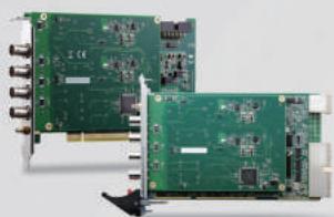
# PCI/PXI-9527
24-Bit High-Resolution Dynamic Signal Acquisition and Generation Module
• 24-Bit Sigma-Delta ADC and DAC
- 2-CH simultaneous sampling analog input, and 2-CH simultaneous updated analog output
• Supports IEPE output on each analog input, software-configurable
- 432 kS/s maximum sampling rate with software programmable rate
- Programmable input range: ±40 V, ±10 V, ±3.16 V, ±1 V, ±0.316 V, Programmable output range: ±10 V, ±1 V, ±0.1 V
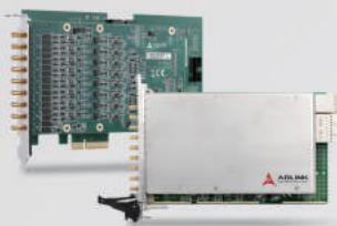
# PCIe/PXIe-9529
8-CH 24-Bit High-Resolution Dynamic Signal Acquisition Module
• 24-Bit Sigma-Delta ADC
• 8 simultaneous analog inputs
• 192 kS/s maximum sampling rate
- ±1V, and 10V input ranges, 110 dB dynamic range
• IEPE - 4mA, software configurable
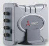
# USB-2405
4-CH 24-Bit 128kS/s Dynamic Signal Acquisition USB 2.0 Module (OEM version available)
• Hi-Speed USB 2.0, and USB bus powered
• 24-bit sigma-delta ADC with built-in anti-aliasing filter
- 4-CH simultaneous sampling analog input, up to 128kS/s
- Analog and digital triggering & full auto-calibration
• Supports 2mA excitation output on each analog input channel for IEPE sensor measurement
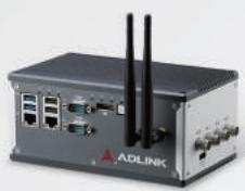
# MCM-100
Machine Condition Monitoring Edge Platform
• Built-in 2 or 4CH, 24-bit simultaneous sampling analog inputs, up to 128kS/s
• Supports IEPE 2mA excitation current output on each analog input to drive accelerometer
- Equipped with Intel Atom® x7-E3950 processor (quad-core)
- Extremely compact with versatile I/O support
- Optional Wi-Fi
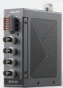
# MCM-204
Standalone Ethernet DAQ with 4-ch AI, 24-bit, 128kS/s, 4-ch DI/O
- RESTful API reports machine condition to IT system
• Built-in web console for easy configuration and use as portable DAQ
• Supports custom algorithms to filter data at the edge
• Supports IEPE 4mA excitation current output on each analog input to drive accelerometer
- Two 1Gb Ethernet port for cascade
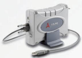
# USB-1903
8/16-CH 16-Bit 250 kS/s Multi-Function USB DAQ Modules (OEM version available)
• USB 2.0 high-speed function, USB bus power
- Removable screw-down terminal module
- Lockable USB cable for secure connectivity
- 8-CH 250 kS/s current input, 2-CH 1 MS/s voltage output
• Analog and digital triggering
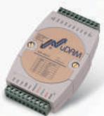
# ND-6017
8-CH Analog Input Module
• Channels: 6 Differential & 2 Single-ended
• Input Type: mV, V and mA
- Input Range: ± 150 mV, ± 500 mV, ± 1 V, ± 5 V, ± 10 V
• Current Range: ± 20 mA
• Isolation Voltage: 2500 VRMS
# Next-Generation Multi-Function DAQ Cards
ADLINK's multi-function DAQ cards are expansion cards that feature data acquisition over multiple channels and are available for PXI, cPCI, PCI, and PCIe. ADLINK DAQ cards can perform a multitude of measurements by changing the software application that reads the data.

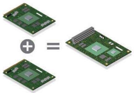
# High-Density Design
ADLINK's DAQ cards feature a high-density design with many input/outputs functions packed into each card. In the past, buying more than one card to complete system setup was the norm, but now customers can develop their applications with just one card, saving space and streamlining installation.
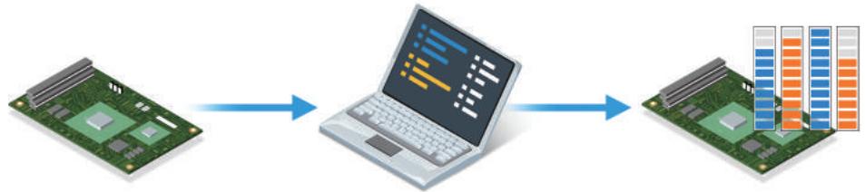
# Programmable Gain Amplifiers for Higher Analog Input Accuracy
Individually programmable gain amplifiers for each analog input channel allow compensation for different signal levels and input ranges. The customizable amplifier gain for each channel enables the input range of the incoming signal to match the full-scale range of the ADC, resulting in higher resolution and accuracy.
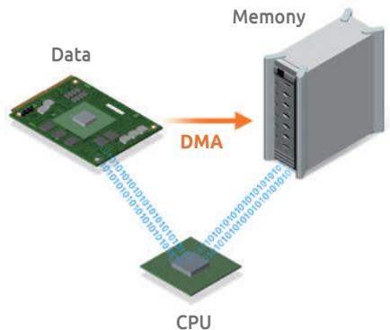
# Direct Memory Access Channels Offload CPU Utilization
Direct Memory Access (DMA) is a hardware and software technology that allows the highest rate of data transfer to and from RAM, without involving the CPU. By using DMA, the processor is no longer burdened with moving data and freed to dedicate resources to more complex processing tasks.
| Bus Type | Analog Input | Analog Output | Digital I/O | Product Name |
| No. of Channels | Max. Sampling Rate | Resolution (bit) | Note | No. of Channels | Max. Update Rate | Resolution (bit) | No. of Channels |
| USB | 16 | 250 kS/s | 16 | | | | | 8 DI & 4 DO | USB-1901 |
| USB | 16 | 250 kS/s | 16 | | 2 | 1 MS/s | 16 | 8 DI & 4 DO | USB-1902 |
| USB | 16 | 250 kS/s | 16 | | 2 | 1 MS/s | 16 | 8 DI & 4 DO | USB-1903 |
| USB | 4 | 2 MS/s | 16 | Simultaneous Sampling | | | | 8 DI & 4 DO | USB-1210 |
| USB | 4 | 2 kS/s | 24 | | | | 4 DI & 4 DO | USB-2401 |
| USB | 4 | 128 kS/s | 24 | | | | 2 GPIO | USB-2405 |
| PCI/PCIe/PXI | 4 | 2 MS/s | 14 | 2 | 1 MS/s | 12 | 24 DI & 24 DO | DAQ/DAQe-2010, PXI-2010 |
| PCI/PCIe/PXI | 4 | 500 kS/s | 16 | 2 | 1 MS/s | 12 | 24 DI & 24 DO | DAQ/DAQe-2005, PXI-2005 |
| PCI/PCIe/PXI | 4 | 250 kS/s | 16 | 2 | 1 MS/s | 12 | 24 DI & 24 DO | DAQ/DAQe-2006, PXI-2006 |
| PCI/PCIe/PXI | 96 | 3 MS/s | 12 | | | | | 24 DI & 24 DO | DAQ/DAQe-2208, PXI-2208 |
| PCI/PCIe/PXI | 64 | 3 MS/s | 12 | | 2 | 1 MS/s | 12 | 24 DI & 24 DO | DAQ/DAQe-2204, PXI-2204 |
| PCI/PCIe/PXI | 64 | 500 kS/s | 16 | | 2 | 1 MS/s | 12 | 24 DI & 24 DO | DAQ/DAQe-2205, PXI-2205 |
| PCI/PCIe/PXI | 64 | 250 kS/s | 16 | | 2 | 1 MS/s | 12 | 24 DI & 24 DO | DAQ/DAQe-2206, PXI-2206 |
| PCI/PCIe | 16 | 250 kS/s | 16 | | | | | 24 DI & 24 DO | DAQ/DAQe-2213 |
| PCI/PCIe | 16 | 250 kS/s | 16 | | 2 | 1 MS/s | 12 | 24 DI & 24 DO | DAQ/DAQe-2214 |
| PCI | 16 | 100 kS/s | 16 | | 1 | Static | 12 | 16 DI & 16 DO | PCI-9111HR(1) |
| PCI | 16 | 100 kS/s | 12 | | 2 | Static | 12 | 16 DI & 16 DO | PCI-9112 |
| PCI | 16 | 100 kS/s | 12 | | | | | 16 DI & 16 DO | PCI-9113(3) |
| PCI | 32 | 250 kS/s | 16 | | | | | | PCI-9114 Series |
| PCI | 16 | 250 kS/s | 16 | Encoder Inputs | 2 | Static | 16 | 8 DI & 4 DO | PCI-9221 |
| PCI | 16 | 250 kS/s | 16 | 2 | 1 MS/s | 16 | 16 DI & 16 DO | PCI-9222 |
| PCI | 32 | 500 kS/s | 16 | 2 | 1 MS/s | 16 | 16 DI & 16 DO | PCI-9223 |
| PCI/PCIe/PXI | 8 | 400 kS/s | 14 | | 4 | 1 MS/s | 12 | 24 DI & 24 DO | DAQ/DAQe-2501, PXI-2501 |
| PCI/PCIe/PXI | 4 | 400 kS/s | 14 | | 8 | 1 MS/s | 12 | 24 DI & 24 DO | DAQ/DAQe-2502, PXI-2502 |
| PCI | | | | | 8 | Static | 12 | 4 DI & 4 DO Isolated | PCI-6308V/6308A(2) |
| PCI/PCIe | | | | | 8 | Static | 16 | 4 DI & 4 DO Isolated | PCI/PCIe-6208V, PCI-6208A(2) |
| PCI/PCIe | | | | | 16 | Static | 16 | 4 DI & 4 DO Isolated | PCI/PCIe-6216V |
Note : (1) HR : high gain (2) PCI-6208A/6308A : current output (3) Isolated analog input
# Condition Monitoring for Screw and Bolt Forming Machine
Application
# Challenges
Equipment failure in traditional machinery causes unexpected downtime that leads to extra repair costs, lost production time, and other expenses. With continuous, repetitive operation that results in wear and tear of machine components, manufacturers must replace tooling and parts on time to avoid out-of-spec production quality and machine shutdown.
# ADLINK Solutions
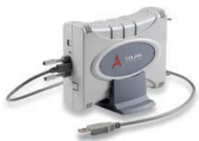
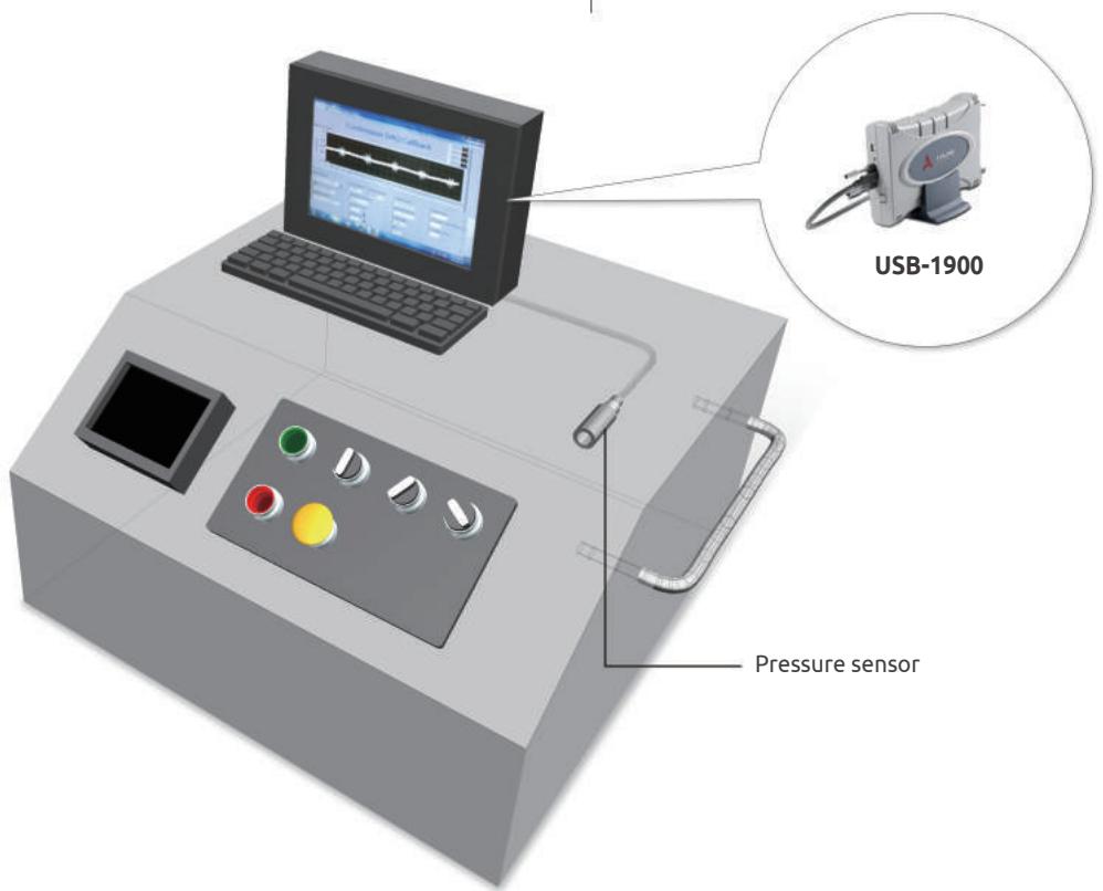
A Taiwanese screw machine production company chose the ADLINK USB-1900 series as the data acquisition device for their predictive machine failure system because it can collect accurate data from the equipment and operate in harsh environments. The ADLINK USB-1900 series has 16-channel single-ended and 8-channel differential input, 250K high sample rate, 16-bit resolution, and ±200 mV input range. It can acquire precise real-time date from the pressure sensor and capture noise changes to assess the machine health status and avoid unexpected machine shutdown.
# Why ADLINK
▶ Reliable and easy to use DAQ device to enable machine condition monitoring
▶ Various USB DAQ products for monitoring machine parameters
▶ MAPS utility for easy device configuration and application development
Product Used: USB-1900 Series
# High-Precision Measurement with Laser Displacement Sensor
Application
# Challenges
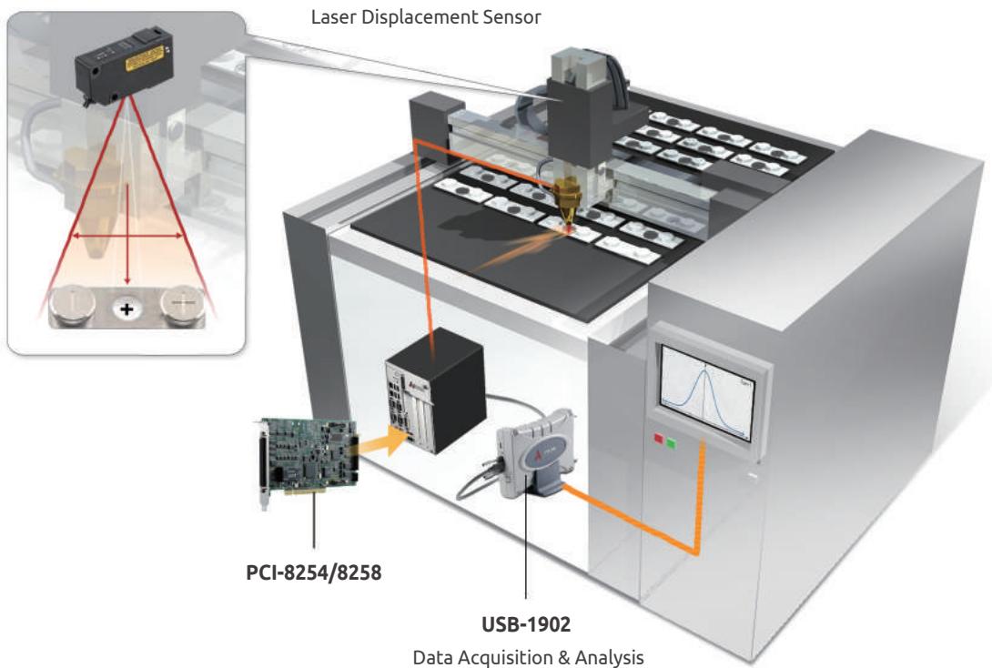
The laser displacement sensor features high-precision, high-speed, non-contact measurement of displacement, dimension, distance, and position, especially suitable for special surfaces such as lustrous metals. The laser displacement sensor keeps positioning errors at less than 1 mm, dramatically increasing the yield rate.
# ADLINK Solutions
To acquire and analyze data from the laser scanners, ADLINK's USB DAQ is an ideal solution for system integrators requiring more I/O expansion with limited PCI/PCIe availability. The USB-1902 features 16-bit resolution and a maximum 250 kS/s sampling rate, suited to a wide range of measurement requirements. With 2-meter USB cable expansion and built-in screw terminals, the USB-1902 can remain close to the displacement sensor and avoid noise coupling.
# Why ADLINK
▶ Reliable USB interface
Plug-and-play device ideal for laser displacement monitoring
Product Used: USB-1902
# High-Speed Digitizer for Demanding Test and Measurement Applications
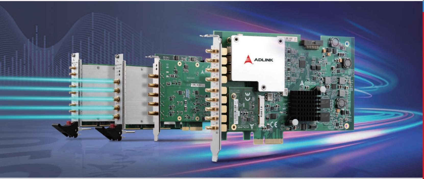
ADLINK's high-speed, high-performance digitizers with wide bandwidth and high dynamic range are available for PCIe and PXIe bus standards for quick and precise input signal acquisition. The on-board FPGA enables real-time data processing that minimizes data transfer volumes and speeds up analysis while reducing CPU load. ADLINK digitizers are used for demanding applications, including Electronic Test and Measurement (ETM), Automatic Test Equipment (ATE), and Original Equipment Manufacturer (OEM) system applications in advanced research. The wide analog bandwidth and high sampling rate provide multi-band coverage on multiple input channels. ADLINK's advanced digitizer technology boosts measurement and signal analysis capabilities with a market-leading price-performance ratio.
# Key Features
• High sampling rate with low front end distortion
• FPGA-based digital filter to reduce CPU load
- Programmable input range provides versatile configuration
• Time and voltage measurement API simplify

# Tip:
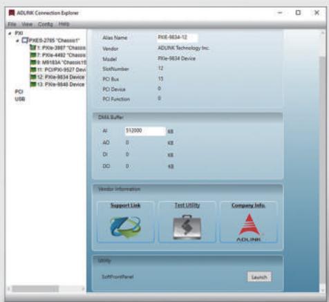
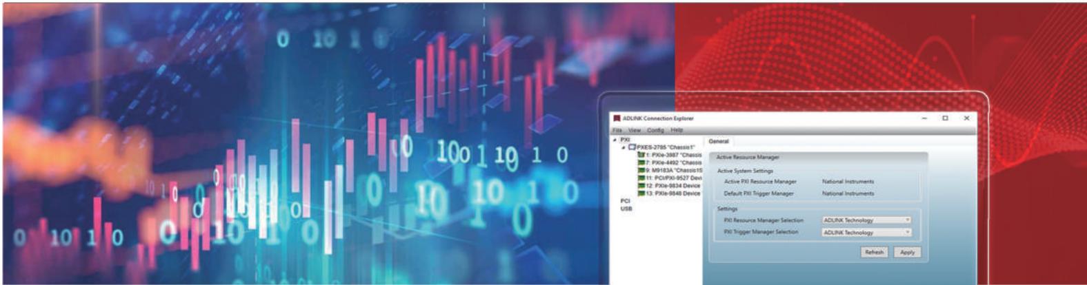
For the quickest setup, use the ADLINK MAPS central management platform for device setup and configuration. MAPS can setup ADLINK DAQ and PXIe testing and measurement devices, including digitizers, controllers, and chassis.
# Digitizer Applications
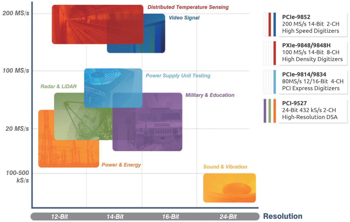
Sampling Rate
# Digitizer Application
# Partial Discharge Monitoring for Transformer
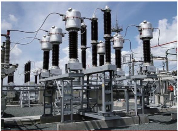
Partial discharge is often present well in advance of insulation failure under high-voltage field stress. It provides the most evident indication of defects and deterioration that lead to transformer failure. ADLINK's PCIe-9814/9834+MXC series and PXIe-9834+PXI systems detect partial discharge and provide early warning to prevent failure.
# Why ADLINK?
- Complete measurement solution (PCIe digitizer + IPC or PXIe digitizer + PXI system) shortens time-to-market
• Supports simultaneous measurement with multi-card synchronization
- Suitable for high-speed data streaming and online monitoring with PCIe
# Distributed Temperature Sensing
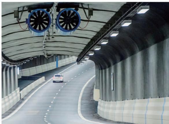
ADLINK"s PCIe-9852 is ideal for distributed temperature sensing (DTS) applications, such as measuring temperature in long and harsh environments like tunnels. DTS provides a continuous (or distributed) temperature profile along the sensing cable's length, a simpler approach than installing discrete sensors at pre-determined locations.
# Why ADLINK?
- Two simultaneous analog inputs for stokes line and anti-stokes line
- High sampling rate, high resolution, accurate temperature data, even at distances over 30 km
# Digitizer Application
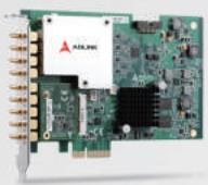
# PCIe-9814
4-CH 12-Bit 80 MS/s PCI Express Digitizer
- Up to 80 MS/s sampling, and 4 simultaneous analog inputs
• High resolution 12-bit ADC
- Up to 40 MHz bandwidth for analog input, 1 GB onboard storage memory
- Programmable input voltage range of ±0.5V, ±1V, ±5V, or ±10V
- Provide 10 or 20 MHz digital onboard filter (FPGA)
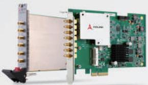
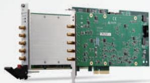
# PXle/PCIe-9834
4CH 16-Bit 80 MS/s PXI/PCI Express Digitizer
- Up to 80 MS/s sampling, and 4 simultaneous analog inputs
• High resolution 16-bit ADC
- Up to 40 MHz bandwidth for analog input, 1 GB onboard storage memory
- Programmable input voltage range of ±0.5V, ±1V, ±5V, or ±10V
- Provide 10 or 20 MHz digital onboard filter (FPGA)
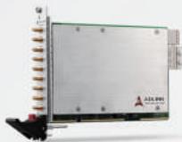
# PXle-9848
8-CH 14-bit 100 MS/s High-Speed PXI Express Digitizer
- PXI Express specification Rev. 1.0 compliant
- Up to 100 MS/s sampling rate & High resolution 14-bit ADC
- Up to 100 MHz bandwidth for analog input
- 512 MB onboard storage memory
- Programmable input voltage range of $\pm 0.2\mathrm{V}$ or $\pm 2\mathrm{V}$ , or $\pm 100\mathrm{V}$ Max (PXle-9848H)
# PXle/PCIe-9852
2-CH 14-Bit 200 MS/s High-Speed PXI/PCI Express Digitizer
- 2 simultaneously analog inputs, up to 200 MS/s sampling rate, and high resolution 14-bit ADC
- Up to 90 MHz bandwidth for analog input
• 1 GB onboard storage memory
- Programmable input voltage range of ±0.2 V, ±2 V, or ±10 V
• One external digital trigger input and one external trigger output
# Choosing a Digital I/O Device
ADLINK's digital I/O devices make it possible to monitor the status of control circuit measuring devices, relays, and operation switches.

# Recommended Products
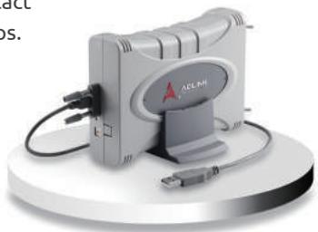
# USB Device - USB-7230/7250
The USB-7230 and USB-7250 are suitable for industrial I/O control applications requiring high voltage and overload protection. High voltage isolation protects against damage from accidental contact with external voltages and eliminates troublesome ground loops.
# Key features
- USB-powered with removable screw-down terminals for easy device connectivity
• 32-CH isolated digital I/O (USB-7230), 8-CH relay output, 8-CH isolated DI (USB-7250)
- Programmable digital filter removes unexpected glitches from input channels
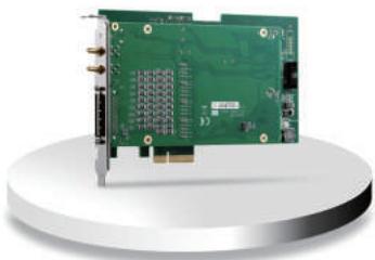
# PCIe Card - PCIe-7360
The ADLINK PCIe-7360 is a PCI Express digital I/O card, with a high-speed parallel digital data transfer interface between external device and PC, ideal for digital image data acquisition in IC testing or digital pattern generation.
# Key features
- Higher parallel data transfer rate & throughput with 8/16/24/32-CH at up to 100MHz for DI or DO
- Software selectable Programmable Logic Level
- Flexible function I/O to provide additional 8-CH function I/O to satisfy various requirements of IC testing

# How to Choose the Best DAQ Hardware for Your Measurement System
With an assortment of ADLINK data acquisition (DAQ) devices to choose from, there are a few critical questions to ask to determine the right one. Does this DAQ system match my resolution and accuracy requirements? How intuitive is the user interface for set up? How difficult is it to reconfigure for new applications? These considerations, and others, are addressed in the sections below.
# 01 Signal type
Various sensors and transducers produce input signals, including thermocouples, thermistors, RTDs, strain gauges, accelerometers, microphones, and proximity probes. The DAQ should support the sensors and transducers in the system. Multifunction DAQ devices have a fixed channel count to measure analog inputs, generate analog outputs, measure and generate digital signals, and counters. The combination of I/O options allows flexibility far beyond the capabilities of single-function DAQ devices, but be sure the device includes enough of the required types for your specific application.
# 02 Sample rate
Measured in S/s (samples per second), this is the number of samples taken every second. Higher sample rates provide a more detailed representation of input measurements and generate a closer reproduction of the full signal. Higher sampling rates also allow for better analysis of signals.
# 03 Resolution
Measured in bits, this is the number of data bits used to represent each signal sample. Typical values are 4-bit, 8-bit, 16-bit, 24-bit, and 32-bit. Although a simplistic look is that more is better, more bits also put a more considerable strain on processing hardware, but the more bits, the more precise the representation of a single sample.
# 04 Signal conditioning
Signal conditioning processes the input signal so that it is usable by the system. Input signals, typically only mV, need amplification for optimal ADC processing, while high-voltage signals need attenuation. Filtering, excitation, and linearization are also necessary for best performance, removing high-frequency noise from thermocouple measurements being one example. Many DAQ devices provide built-in signal conditioning hardware.
# 05 Device management
Device management becomes increasingly difficult as more DAQ devices are added to the measurement system setup. A central device management utility simplifies the management process by allowing universal device control from a single computer. Additionally, utilizing dropdown menus and an intuitive graphical user interface eliminates the difficulties of command-line based approaches. Fewer obstacles to setup mean quicker setup.
# WORLDWIDE OFFICES
# ADLINK Technology, Inc.
9F, No.166 Jian Yi Road, Zhonghe District
New Taipei City 235, Taiwan
新北市中和區建一路166號9樓
Tel: +886-2-8226-5877
Fax: +886-2-8226-5717
Email: service@adlinktech.com
# Ampro ADLINK Technology, Inc.
5215 Hellyer Avenue, #110 San Jose, CA 95138, USA
Tel: +1-408-360-0200
Toll Free: +1-800-966-5200 (USA only)
Fax: +1-408-360-0222
Email: info@adlinktech.com
# ADLINK Technology Singapore Pte. Ltd.
84 Genting Lane #07-02A, Axxel Innovation Centre,
Singapore 349584
Tel: +65-6844-2261
Fax: +65-6844-2263
Email: singapore@adlinktech.com
# ADLINK Technology Singapore Pte Ltd. (Indian Liaison Office)
#50-56, First Floor, Spearhead Towers
Margosa Main Road (between 16th/17th Cross)
Malleswaram, Bangalore - 560 055, India
Tel: +91-80-65605817, +91-80-42246107
Fax: +91-80-23464606
Email: india@adlinktech.com
# ADLINK Technology Japan Corporation
〒101-0045 東京都千代田区神田鍛冶町3-7-4
ユニゾ神田鍛冶町三丁目ビル4F
Unizo Kanda Kaji-cho 3 Chome Bldg. 4F,
3-7-4 Kanda Kajicho, Chiyoda-ku, Tokyo 101-0045, Japan
Tel: +81-3-4455-3722
Fax: +81-3-5209-6013
Email: japan@adlinktech.com
# ADLINK Technology, Inc. (Korean Liaison Office)
경기도 용인시 수지구 신수로 767 A동 1008호
(동천동, 분당수지유타워) (우) 16827
A-1008, U-TOWER, 767 Sinsu-ro, Suji-gu,
Yongin-si, Gyeonggi-do, Republic of Korea, 16827
Toll Free: +82-80-800-0585
Tel: +82-31-786-0585
Fax: +82-31-786-0583
Email: korea@adlinktech.com
# ADLINK Technology, Inc. (Israel Liaison Office)
SPACES OXYGEN, 62 Medinat, Ha-yehudim st
4673300, Herzliya, Israel, P.O.Box - 12960
Tel: +972-54-632-5251
Fax: +972-77-208-0230
Email: israel@adlinktech.com
# ADLINK Technology Ltd. (IoT Solutions & Technology office)
The Edge, 5th Avenue, Team Valley,
Gateshead, Tyne and Wear, NE11 0XA, United Kingdom
Tel: +44 (0)191-4979900, +44 (0)191-4979898
Email: ist\_info@adlinktech.com
# ADLINK Technology (China) Co., Ltd.
上海市浦东新区张江高科技园区芳春路300号(201203)
300 Fang Chun Rd., Zhangjiang Hi-Tech Park
Pudong New Area, Shanghai, 201203 China
Tel: +86-21-5132-8988
Fax: +86-21-5192-3588
Email: market@adlinktech.com
# ADLINK Technology Beijing
北京市海淀区上地东路1号盈创动力大厦E座801室(100085)
Rm. 801, Power Creative E, No. 1 Shang Di East Rd.
Beijing, 100085 China
Tel: +86-10-5885-8666
Fax: +86-10-5885-8626
Email: market@adlinktech.com
# ADLINK Technology Shenzhen
深圳市南山区科技园南区高新南七道数字技术园
A1栋2楼C区 (518057)
2F, C Block, Bldg. A1, Cyber-Tech Zone, Gao Xin Ave. Sec. 7
High-Tech Industrial Park S., Shenzhen, 518054 China
Tel: +86-755-2643-4858
Fax: +86-755-2664-6353
Email: market@adlinktech.com
# ADLINK Technology GmbH
Hans-Thoma-Straße 11
D-68163 Mannheim, Germany
Tel: +49 621 43214-0
Fax: +49 621 43214-30
Email: germany@adlinktech.com
Ulrichsbergerstraße 17
D-94469 Deggendorf, Germany
Tel: +49 991 290 94–10
Fax: +49 991 290 94–29
Email: germany@adlinktech.com
# ADLINK Technology, Inc. (French Liaison Office)
6 allée de Londres, Immeuble Ceylan 91940
Les Ulis, France
Tel: +33 (0) 1 60 12 35 66
Fax: +33 (0) 1 60 12 35 66
Email: france@adlinktech.com
# ADLINK Technology, Inc. (UK Liaison Office)
First Floor West Exeter House,
Chichester fields Business Park Tangmere,
West Sussex, PO20 2FU, United Kingdom
Tel: +44-1243-859677
Email: uk@adlinktech.com
[🔗 Link to the original document](.2020-daq-brochure-32p-s-eng/2020-daq-brochure-32p-s-eng.pdf)