
COM-HPC
COM Express
SMARC
OSM
Qseven
ETX
Computer on Modules
Product Brochure
COM+HPC"
CoM Express
SMARCmodule
CO) OPEN STANDARD MODULE
ETX?
# Innovation Support at Your Fingertips
# Empowering Your Success with Edge Computing Excellence
At ADLINK Technology, we believe that the foundation of innovation lies in understanding and addressing the unique needs of our customers. As a global leader in edge computing solutions, our Computer-on-Modules (COM) Business Unit is dedicated to delivering cutting-edge technology that empowers OEMs, ODMs, and equipment manufacturers to thrive in an ever-evolving market. With decades of experience supporting ODM customers, we bring unparalleled expertise to every partnership, ensuring tailored solutions that drive success. In 2025, we continue to prioritize your goals by offering strategic value, reducing complexity, and ensuring long-term reliability.
Our focus on customer-centricity drives everything we do. By mitigating business risks through robust design and scalable services, we help you navigate uncertainties with confidence. We prioritize control of intellectual property, ensuring your innovations remain yours, while our agile approach to market demands keeps you ahead of the curve. With flexible technology migration paths, optimized resource utilization, and a commitment to product security and longevity, ADLINK’s COM solutions—backed by our proven ODM support—are engineered to meet your needs today and anticipate the challenges of tomorrow.
AMDD
AMPERE
intel.
MEDIATEK
NXP
QualcoMw
TeXAS INSTRUMENTS
# Why ADLINK?
Your Partner in Addressing Critical Needs Tailored Solutions for a Competitive World
With ADLINK, you’re not just choosing a supplier—you’re partnering with a team that leverages its rich ODM expertise to put your success first. In a world where technology evolves at an unprecedented pace, ADLINK’s Computer-on-Modules (COM) Business Unit stands as your steadfast ally, committed to solving the challenges that matter most to you.
With extensive experience supporting ODM customers, we bring a deep understanding of your unique requirements, enabling us to deliver customized, high-value solutions that set you apart. Our 2025 product catalog reflects our unwavering dedication to addressing your needs with precision and foresight, ensuring every offering aligns with your goals and delivers measurable impact.
We understand that success hinges on more than just performance—it’s about trust and resilience.
That’s why ADLINK focuses on:
# Business Risks Mitigation
Our comprehensive COM portfolio and scalable ODM services reduce uncertainty, safeguarding your investments.
# Control of IP
We empower you to protect your innovations with designs that prioritize your ownership and security.

# Agility to the Market
Our powerful silicon vendor partnerships and rapid-response strategies keep you competitive in dynamic industries.
# Flexibility to Migrate Technology
Seamlessly transition to new architectures with solutions designed for adaptability.

# Resources Optimization
Maximize efficiency with tailored offerings that streamline development and deployment.
# Product Security
Robust safeguards ensure your systems remain protected in an increasingly connected world.

# Longevity
Our commitment to long-term support guarantees your solutions endure, delivering sustained value over time.
# Tailored Solutions
Our versatile capabilities enable tailored solutions and our dedicated business units across industries provide specialized expertise.
# Most Robust, Best Support
Always pioneering to empower you with the latest, cutting-edge technologies
# Table of Content
Why ADLINK
Global Carrier Design Service 6
Core Values 8
ARM SystemReady 10
Extreme Rugged 11
I-Pi Development Kits 12
Form Factor Overview 14
COM-HPC 16
COM Express 20
Type 6 Basic Size 20
Type 6 Compact Size 24
Type 7 Basic Size 30
Type 10 Mini Size 34
SMARC 38
OSM 44
Qseven 46
ETX 48
# Global Carrier Design Service

# ADLINK
# Save time and resources by opting for ADLINK's global carrier board design service!
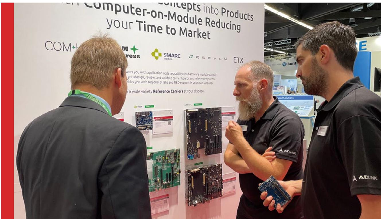
Outsourcing a carrier board design to us is fast and costeffective compared to a full custom solution. We will help you get your product to market in a minimum amount of time and for a fraction of the cost of a full design. Our local R&D teams in Germany and the US are ready to serve you in your own time zone and in your own language.
# How we can support you when designing your own carrier board?
Of course, if you decide to design your own carrier boards, we will support you where possible, this starting with the initial design phase and extending to prototype sample testing.
# Carrier Design Phase
# Get Our Carrier Reference Schematics!
We provide schematics, layout and mechanical files to our customers for all COM form factors, giving you a head start and providing a reference platform to test your carrier against later.
# Schematic Review Service
We are ready to help you review your schematics before going to the layout phase.
# Pre or Post Layout Simulation
If you’re unsure about any high speed signaling and routing lengths in your design, we can support pre layout simulation that will inform you about optimal placement or post layout simulation that will provide you with a high level of confidence that your design will function as intended.
# Carrier Prototype Verification
# BIOS Modification Service Signal Integrity Verification
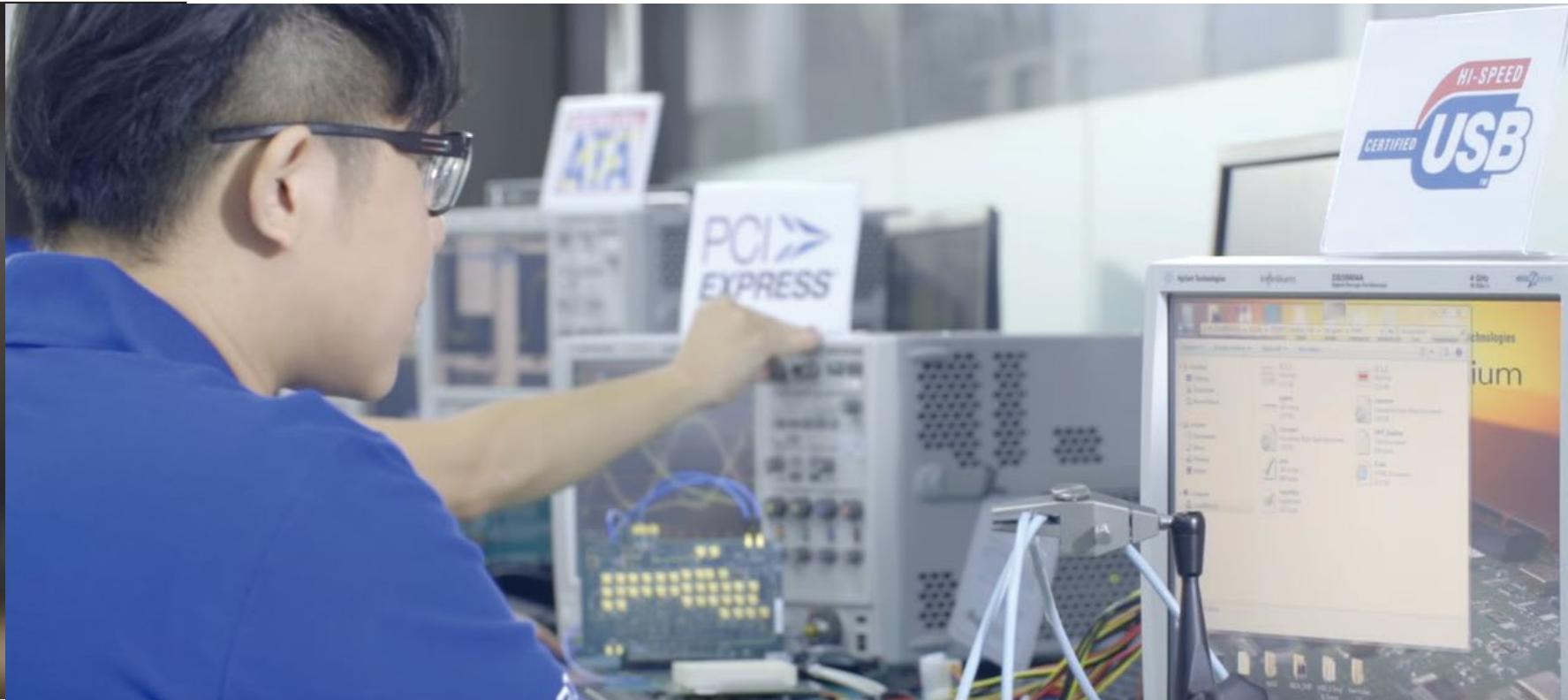
At our headquarters in Taipei, our SI lab is available to help customers with module to carrier signal quality verification. Our SI lab boasts state-of-the-art equipment that enables us to conduct cutting-edge carrier board testing.
Based on SI reports, the customer can easily consult module designer on how potential design-to-application barriers could be resolved.
# Power Sequence Verification
Even the most advanced LAB testing of your module/ carrier combination can never really cover how end users are going to operate the systems in the field. Especially unforeseen power on and power off operation can lead to hanging systems that in the worst case is not recoverable. ADLINK provides a power test procedure called “Monkey Testing” that covers testing of any possible power sequence in the field. If still any mismatches between carrier and modules are found, we can simply update the module by firmware at OS time since its power sequence is MCU controlled.
# Core Values
Innovation and reliability converge in core values, redefining excellence in edge computing solutions
# Security
Driven to safeguard client products and data free of cyberattacks and mitigate vulnerabilities, ADLINK has always been at the forefront of the latest security technologies and best-practice infrastructures, for hardware and software alike.
How? ADLINK does so by actively collaborating with a spate of security partners to accomplish its ever-evolving, all-around security mechanisms. These security attributes include, but are not limited to, the following.
| Arm | FOUNDRIES |
| SystemReady compliance Parsec security certification PSA certification | Linux microPlatform Secure for life Deployment, maintenance, OTA |
With decades of endeavor in administering foolproof security and assurance measures, ADLINK is well aware of the necessity of a developer’s application or product to be easily monitored and managed, especially remotely, for timely responses and immediate actions whenever needed.
In this regard, ADLINK is backed by partnerships with the likes of SEMA and Allxon and continues to add to its growing list of partnerships in bringing full-scale remote management and error logging functions, including:
Varied means of control across different system levels, both in-band and out-of-band
Real-time monitoring of CPU/GPU performance, memory usage, user access, power consumption, temperature, etc.
Remote control and updating of the system’s varying components, interfaces, and firmware
Collecting and retrieving system / error logs for event analysis and troubleshooting
# Software
Explore ADLINK's versatile software solutions tailored for various industries, where innovation and reliability converge in comprehensive software suite.
# Edge Computing:
Deploying AI and ML applications like eIQ, OpenVINO, Neuropilot, and Qualcomm Neuron SDK for real-time, lowlatency processing at the network edge
# Internet of Things (IoT):
Seamlessly connecting and managing IoT devices using ADLINK software, featuring NXP components and IPMI 2.0 for efficient data collection and analysis
# Embedded Computing:
Elevating embedded systems with ADLINK's tools and libraries, including SEMA and Hardware Acceleration, for streamlined development
# Industrial Automation:
Automating manufacturing processes with ADLINK's industrial automation software, optimizing operations with SEMA, OS tailoring, and adlink-meta-layer
# Transportation:
Improving safety and efficiency in transportation systems using ADLINK's specialized software — Autoware, SOAFEE, TSN, and TCC.
# Healthcare:
Enhancing healthcare delivery quality and efficiency with ADLINK's healthcare software — Slimbootloader, Hardware Acceleration, TSN, and TCC.
# Supply Chain Management

ADLINK provides the most reliable supply chain management backed by strategic part sourcing and manufacturing redundancy. Right from the design phase, ADLINK undergoes a series of meticulous part selection procedures in ensuring supply chain resilience. Adding on, ADLINK has mirrored manufacturing sites, the Taipei Manufacturing Center (TPMC) based in Taiwan and the Shanghai Operation Center based in China, which add flexibility and responsiveness in further ensuring continued supply.
# Certification and Validation
ADLINK places a strong emphasis on industrial-grade reliability for its embedded computing products.
This begins with component selection and is reinforced by inhouse certification and validation labs that conduct extensive testing, including ISO- and TUV-certified De-rating, electrical, thermal, HALT, and SI (Signal Integrity) tests, to ensure flawless performance throughout a product's lifetime in the field.

# ARM SystemReady
# Certified, ensuring generic OSs to ‘just work’ right off the shelf
With uncompromising efforts in delivering a seamless development experience, ADLINK has been an active participant in the Arm SystemReady compliance certification program since its launch in 2020.
By proactively contributing to and meeting Arm SystemReady standards, ADLINK ensures that generic off-the-shelf operating systems ‘just work’ – enabling generic operating systems, and subsequent layers of software, to work out of the box on Arm-based hardware.
ADLINK eliminates the need for custom-engineered firmware, thus significantly reducing both the cost and time to market for Arm-based hardware, including infrastructure edge and embedded IoT systems.
# arm SystemReady

# Arm SystemReady IR for embedded devices
Find ADLINK products with the Arm SystemReady IR band stamp, which ensures Arm-based embedded devices supported by mainline Linux/BSD suiting both custom and prebuilt operating system images.
For embedded Linux ecosystem
Mainline Linux support for SoC
Suiting custom (Yocto, OpenWRT, buildroot) and prebuilt (Debian, Fedora, SUSE, Ubuntu) system images
# Arm SystemReady SR for servers & workstations
Find ADLINK products with the Arm SystemReady SR band stamp, which ensures Arm-based servers or workstations to offer seamless interoperability with standard operation systems, hypervisors, and software, i.e. Windows, VMware, Linux, and BSD.
For Windows, VMware, Linux, and BSD ecosystem
Supporting old OSs to run on new hardware and vice versa
Suiting generic off-the-shelf OSs
#
#


Our Extreme Rugged boards are designed for harsh environments from the ground up. To support the extremes of shock, vibration, humidity and temperature, care is given to component selection, circuit design, PCB layout and materials, thermal solutions, enclosure design, and manufacturing process. Robust test methods, including Highly Accelerated Life Testing (HALT), ensure optimal product design phases and meet stringent requirements such as -40°C to 85°C operating temperature range, MIL-STD, shock & vibration, and long-term reliability.
# Design stage
component selection based on temperature/voltage derating and MTBF
# Validation stage
HALT, Chamber test, Shock and Vibration resistant (MIL-STD-202G) and EMC Class B
# Production stage
ETT screening process with selected CPU SKUs
# I-Pi Development Kits
The 1-stop solution to prototyping your edge, IoT innovations rapidly and conveniently

I-Pi Shop

I-Pi YouTube
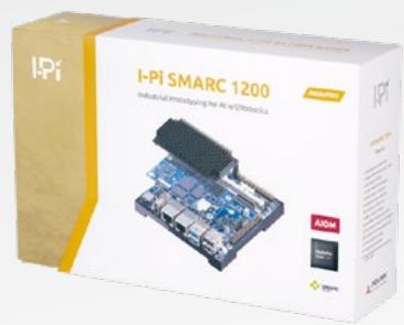
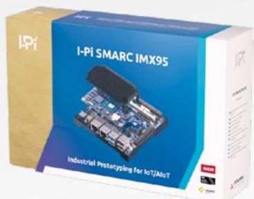
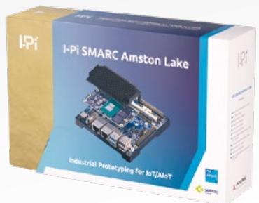
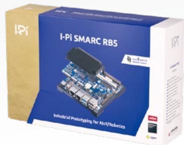
Instantaneous evaluating module capabilities for application prospects

# Instant Prototyping of Your Innovative Ideas at I-Pi
Explicitly for open-source developing, ADLINK has established its I-Pi wiki, a website and 1-stop service for any software developer, novice or professional, to transform their embedded ideas into real-life applications.
From designing to prototyping and evaluating, visit https:// www.ipi.wiki/ now to get started with the development kit of your choice delivered right to your doorsteps. Readily-

accessible online help and technical support forums are also provided on I-Pi wiki just 1 click away.
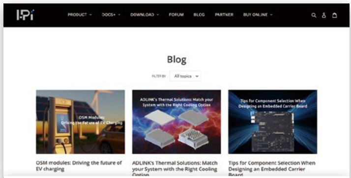
Stay posted with I-Pi blogs for the latest technology trends
Development kits currently available include I-Pi SMARC 1200, I-Pi SMARC RB5,I-Pi SMARC IMX8M Plus, I-Pi SMARC Elkhart Lake, COM Express Type 6 Raptor Lake-P, COM Express Type 6 Alder Lake-P, COM Express Type 7 Ryzen V3000, COM Express Type 10 Elkhart Lake, Ampere Altra Developer Platform, and more.

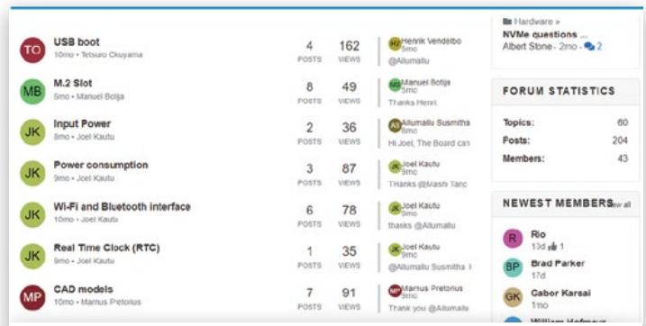
Readily accessible online help (DOCS+) and forums for on-the-spot tech support
# Starter Kits
As a worldwide leader in Computer-on-Modules, ADLINK understands the developers’ needs for affordable and comprehensive development kits.
ADLINK offers an extensive collection of Starter Kits, including for COM-HPC, COM Express, and SMARC, in aiding engineers and system integrators to reduce their products’ time to market and accelerate project schedules.
# Reference Carrier Boards
In addition to starter kits, ADLINK also offers a wide variety of Reference Carrier Boards.
Using a reference carrier board, developers can emulate the functionalities of their desired end products against the selected COMs for software development and hardware verifications instantly.
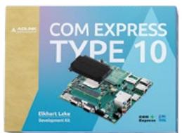
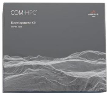
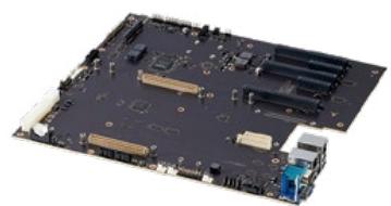
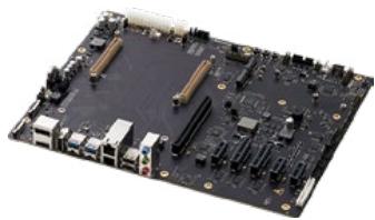
COM-HPC Server Base
COM-HPC Client Base
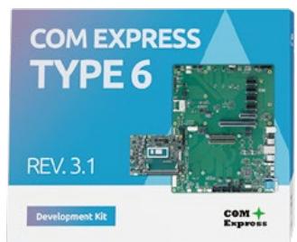
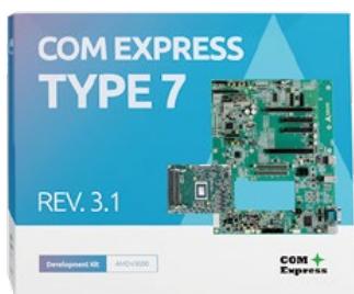
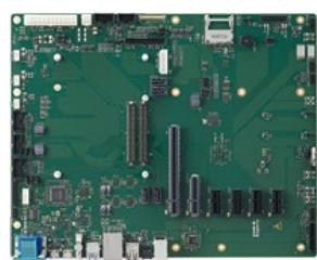

Express Base6 R3.1
I-Pi SMARC Plus carrier board
# Form Factor Overview
# Always one step ahead

# COM+HPC"
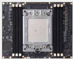
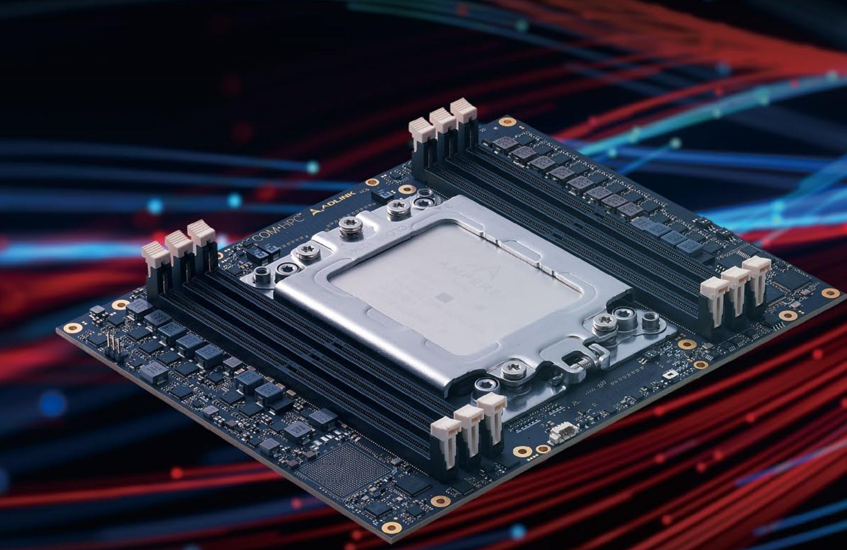
COM-HPC is the latest PICMG standard for high-performance Computer-on-Modules. It aims to drive the newest breed of embedded edge servers with(125 x 95mm) (95 x 9 limitless scalability for today and tomorrow.
COM-HPC supports up to 64 general-purpose PCIe Gen4 or Type 10 Min Gen5 lanes, eight 25GbE ports, and a maximum of four USB 4 ports. The COM-HPC specification defines six different (125 x 95mm) module sizes. The larger Size D and E (Server Type) serve next-gen headless edge servers and can accommodate up to 8 DIMMs. In contrast, the smaller Size A, B, and C (Client Type) target visually-oriented client platforms utilizing SO-Short size DIMMs or soldered onboard memory and support up to 4 (82 x 50mm) video displays. The smallest size, COM-HPC mini, is crucial for advanced embedded computer logic, serving top-hat rail PCs in building and industrial automation control cabinets, as well as portable test and measurement devices.
Server Type
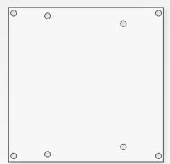
Size D
(160 x 160mm)
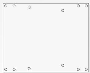
Size E
(200 x 160mm)
Client Type
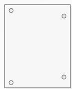
Size A
(95 x 120mm)
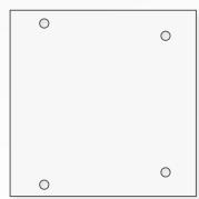
Size B
(120 x 120mm)
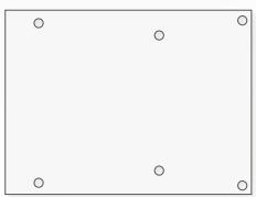
Size C
(160 x 120mm)
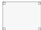
Mini
(95 x 70mm)
# CoM Express
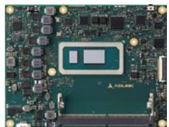
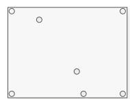
COM Express, defined by PICMG, is the most widely adopted COM standard and is based on serial interfaces including PCI Express, SATA, USB, LVDS/eDP, and DDI. It allows designers and system
integrators to utilize the latest technologies with straight offthe-shelf modules of varied sizes for their edge applications. ADLINK has heavily invested in the development and maintenance of the PICMG® COM Express® specification since its creation.
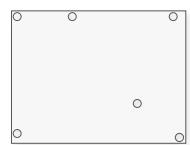
Type 6 Basic
(125 x 95mm)
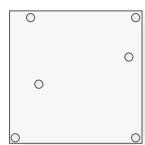
Type 6 Compact
(95 x 95mm)
Type 7 Basic
(125 x 95mm)
# Revision 3.1
COM Express
Shor(82 x
As a chair of the PICMG
subcommittee, ADLINK has helpedize
to define the COM Express COM.0(114 x 95mm) (70x70mm)
Revision 3.1. This revision upgrades
the Type 6 and 7 definitions with several new interface support, such as USB 4, PCIe Gen4 on the Type 6 and 10G CEImode Ethernet on the Type 7.

STANDARDIZATIONGROUPFOR
EMBEDDED
TECHNOLOGIES

SMARC
module
Short size
(82 x 50mm)
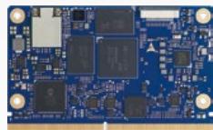
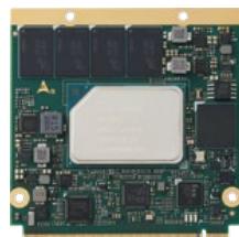
ADLINK leads in SMARC specification development, offering a compact Computer-on-Module ideal for ultra-low power ARM- and x86-based embedded applications. Featuring a versatile 314-pin edge connector, SMARC grants access to standard low-level interfaces like I²C, I²S, UART, CAN, SPI, and GPIO, alongside advanced I/O such as LVDS, HDMI, DP, eDP, GbE, USB 3.x, PCIe, and SATA. With Revision 2.1, SMARC pioneers as the first open specification for AI on Module (AIOM), supporting up to 4 MIPI CSI camera inputs and 4 GbEServer T Ethernet ports via SerDes multiplexing, facilitating seamless integration with NPU-integrated SoCs for diverse video-based and AI-vision applications.

OPEN
Client TShort si
(82 x 50m

Size BLarge size
120 x 120mm)(45 x 45mm)
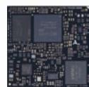
The OSM form factor represents the first Computeron-Module designed for solderable BGA mini modules, supporting both ARM and x86 designs. These modules,Mini notably smaller than previous available modules, measure(95 x 70mm) up to 45mm x 45mm, catering to the evolving needs of IoT applications by combining modular embedded computing with cost-effectiveness and compactness. With up to 662 BGA pins, the BGA design enables the implementation of numerous interfaces on a small footprint. Ideal for rugged environments, the power envelope typically stays under 15W.

Type 10 Mini Cl
(70x70mm)
Qseven® is a versatile, small Computer-on-Module standard.Large size With its 230-pin edge connector, it mainly focuses on(45 x 45mm) (120 x 120mm) (160 x 120mm)traditional low-power x86 Intel Atom® designs. Since Qseven is not able to support all modern interfaces and has only partial coverage for ARM features, there has been an eminent, accelerated migration of low-power COM projects from Qseven to SMARC.

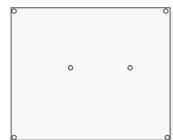
(114 x 95mm)
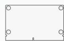
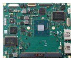
ETX®, one of the oldest Computer-on-Module specifications,Mini supports legacy interfaces such as ISA bus, Parallel ATA (IDE),Large size and PS/2 keyboard/mouse. ADLINK is highly committed to this product line and is one of the only vendors that offers customers a migration path for ETX even beyond 2025.
# COM-HPC
# The next-generation standard for highperformance computing modules
# COM +HPC

# Server Type Pin Definition
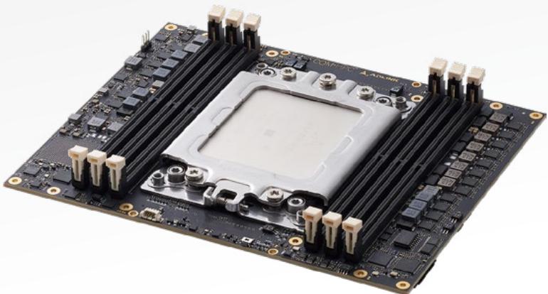
Aimed for next-gen headless edge servers, COM-HPC Server Type features up to 64 PCIe Gen4 or Gen5 lanes, eight 25GbE ports, and can accommodate up to 8 DIMM slots. Additionally, it provides the IPMB function for convenient out-of-band monitoring and management. COM-HPC Server Type is suitable for both ARM and x86 architectures.
| J1 | J2 |
| Power | 48x PCIe |
| 16x PCIePCIe_BMC/IPMB |
| 4x ETH_KR (max. 25G)1x ETH_LED_I2C |
| 8x USB 2.0 |
| 2x USB 3.X |
| 2x USB 4/3.X |
| 2x SATA |
| 1x NBASE-T (max. 10G) | 4x ETH_KR (max. 25G) |
| eSPI |
| 12x GPIO/BOOT_SPI/GPP_SPI/2x I2C/SMB/2x URAT | RSVD |
# Client Type Pin Definition
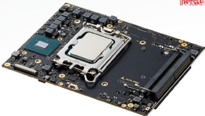
Targeting visual-oriented applications, such as medical imaging, gaming, and testing measurement, COM-HPC Client Type provides system integrators with up to four USB4 and four video displays, plus dual Ethernet, all compacted in a modest size utilizing SO-DIMMs or soldered onboard memory.
| J1 | J2 |
| Power | DDI 3 |
| 8x USB 2.0 | 2x USB 4/3.X |
| 2x USB 4/3.X | 32x PCIe |
| Audio HDA/I2S/Soundwire/DMIC |
| DDI 1 |
| DDI 2 |
| eDP/DSI |
| PCIe_BMC/IPMB |
| eSPI |
| 2x SATA | NBASE-T_1 (max. 10G) |
| 16x PCIe | 2x MIPI-CSI |
| 2x ETH_KR (max.25G) |
| PCIe Target |
| NBASE-T_0 (max. 10G) | RSVD |
# COM-HPC
COM-HPC is the latest PICMG standard introduced by PICMG to complement COM Express in response to the ever-evolving digital transformation. Providing standards for three module types – Server Type, Client Type and Mini Type– COM-HPC offers substantially higher data bandwidths for delivering superior I/O performance while featuring high-performance computing and high-speed transmission with limitless scalability.

# Mini Pin Definition
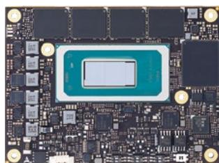
Using a single connector, reducing signal pins by half but still maintaining PCIe Gen5, USB4, DDI and Ethernet. COM-HPC Mini is vital for high-end embedded computing in applications like industrial control PCs. When combined with soldered memory and storage, it is also wellsuited for mission-critical applications.
Mini
| Power |
| 8x USB 2.0 |
| Audio HDA/I2S/Soundwire/DMIC |
| 2x DDI / 2x USB4/3.X |
| 2x USB4/3.X |
| eDP/DSI |
| eSPI |
| 12x PCIe 2x PCIe/SATA, 2x PCIe/SGMII |
| 1x NBASE-T (max. 10G) |
| 12x GPIO / SDIO /BOOT_SPI / GPP_SPI /2x 12C / SMB / 2x USART |

One-click Buy & Ship
Easy “How-to’s”
Online documentation
Forum support
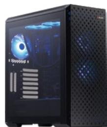
Ampere Altra
Developer Platform
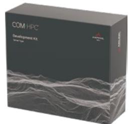
COM-HPC
Development Kits
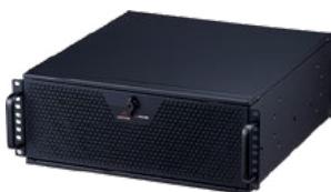
Ampere Altra
Developer Rugged
# Applications
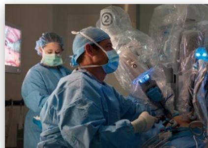
Robotic Surgery
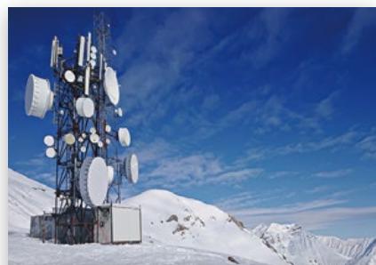
Rugged Network Communication
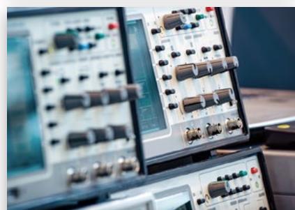
Test and Measurement
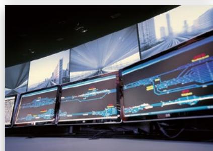
Task Consolidation
# COM-HPC Server Type
| Model Name | COM-HPC-ALT | COM-HPC-sIDH |
| COM HPC® | <img src="images/2ab70d0e78c7840d9df758d608b334d2e065bde7cf38d62371b5765f633a3a8f.jpg"/> | <img src="images/9d045e916345f99593d13650bc181114a0d6bdfc44ddcec6b18f1a327b867c22.jpg"/> |
| CPU | Ampere Altra / Altra MaxM128-26M96-28Q64-22Q32-17 | Intel® Xeon® D-2700 series (formerly "Ice Lake-D") |
| Memory | 768 GB DDR4 at 3200/2666 MT/s | 512 GB DDR4 at 3200/2666 MT/s |
| BIOS Type | TianoCore EDK II | AMI UEFI |
| Ethernet KR | Up to 4x 10GBASE-KR | Up to 8x 10GBASE-KR (25/40/100G, opt.) |
| NBASE-T Ethernet | GbE (Intel i210) | up to 2.5GbE (Intel i225, TSN opt.) |
| Remote Management | IPMB (via MMC, opt.) Dedicated PCIe_BMC lane | IPMB (via MMC, opt.)Dedicated PCIe_BMC lane |
| PCI Express | 64 PCI Express Lanes :3x PCI Express x16 Gen4 (x16, x8, x4)2x PCI Express x8 Gen4 (x8, x4, x2) | 48 PCI Express Lanes:2x PCI Express x16 Gen4 (x16, x8, x4)2x PCI Express x8 Gen3 (x8, x4, x2) |
| USB | 4x USB 3.X/2.0 | 4x USB 3.X/2.0 |
| Serial ATA | - | 2x at 6Gb/s |
| TPM | TPM 2.0 | TPM 2.0 |
| Management Bus | 2x I2C, SMBus | 2x I2C, SMBus |
| Embedded Features | EAPI/SEMA, Debug/JTAG | EAPI/SEMA, Debug/JTAG |
| Power Supply | 12 V / 5Vsb ±5% (ATX) 12V ±5% (AT) | 12V ±5% (AT) |
| Operating Temperature | Standard: 0°C to 60°C | Standard: 0°C to 60°CExtreme Rugged: -40°C to 85°C (selected SKUs) |
| Form Factor & Compatibility | PICMG COM-HPC: Rev 1.0Server Type size E: 200 x 160 mm | PICMG COM-HPC: Rev 1.0Server Type size D: 160 x 160 mm |
| OS Support | CentOS debian fedora Ubuntu yocto project | yocto project |
# COM-HPC Client Type
| Model Name | COM-HPC-cRLS | COM-HPC-mMTL |
| COM HPC® | <img src="images/fe309a741a0a9865c28cb50da1d71407c8177b4bdb7de619ac2b95b8279564d2.jpg"/> | <img src="images/bb191a10100d4402d9d4b49d295561ebe5bf53366ee027721c207acda63c8495.jpg"/> |
| CPU | 13th Gen Intel® Core® i9 /i7 /i5 /i3 series (formerly "Raptor Lake-S") | Intel Core Ultra (formerly "Meteor Lake-H/U" Ultra 7/5 |
| Chipset | R680E(ECC), Q670E/H610E(non-ECC) | - |
| Memory | 128 GB DDR5 at 4000 MT/s | 64GB LPDDR5 at 5600 MT/s |
| BIOS Type | AMI UEFI | AMI UEFI |
| Graphics Outputs | 4 independent displays3x DDI (DP/HDMI/DVI)eDP 1.4 | |
| Audio | 1x HD Audio (1x I2S, opt.) | |
| Camera | - | |
| NBASE-T Ethernet | up to 2x 2.5GbE (Intel 226, TSN opt.) | up to 2x 2.5GbE |
| USB | 4x USB3.X/2.0,4x USB2.0 | 3x USB 3.X/2.0,5x USB 2.0 up to3x USB4 (no DDI, opt.) |
| Serial ATA | - | up to 2x 6Gb/s |
| PCI Express | 38 PCI Express Lanes:PCI Express Graphic x16 Gen51x PCI Express Graphic x4 Gen46x PCI Express x1 Gen33x PCI Express x4 Gen4 (R680E/Q670E) | 2x PCIe Graphic x4 Gen48x PCIe x1 Gen4(no SATA, GbE opt.) |
| TPM | TPM 2.0 | TPM 2.0 |
| Management Bus | 2x I2C, SMBus | 2x I2C, SMBus |
| Embedded Features | EAPI/SEMA Debug/JTAG | EAPI/SEMA, Debug/JTAG Failsafe BIOS (opt.) |
| Power Supply | 12V ±5% (AT) | 8.5-20V (AT) |
| Operating Temperature | Standard: 0°C to 60°C | Standard: 0°C to 60°C |
| Form Factor & Compatibility | PICMG COM-HPC: Rev 1.0Client Type size C: 160 x 120 mm | PICMG COM-HPC R1.2Mini Type size: 95 x 70 mm |
| OS Support | yocto PROJECT | Ubuntu |
Notes:
• Extreme Rugged products are exclusively offered for specific SKUs.
• For more CPU options please refer to online data sheet or user manual.
• All specifications are subject to change without further notice.
Notes:
• VxWorks is supported by project basis.
• For more CPU options please refer to online data sheet or user manual.
• All specifications are subject to change without further notice.
# COM Express Type 6 Basic Size
Transforming your everyday edge computing
# COM Express
# Pin Definition
Type 6 Rev 3.1 Basic Size Modules
| A-B | C-D |
| 8x USB 2.0 | 4x USB 3.X |
| LVDS/eDP | |
| 4x SATA | 2x DDI/USB4 |
| 8x USB 2.0 | |
| Gigabit Ethernet | |
| LPC/eSPI | 1x DDI |
| GPIO/SDIO/SERIAL/CAN/GP SPI/I2C/HDA/SNDW | |
| PCIe Gen4 x24 |
| Power |
# Pin Definition
Type 6 Rev 3.0 Basic Size Modules
| A-B | C-D |
| 8x USB 2.0 | 4x USB 3.X |
| LVDS/eDP | |
| 4x SATA | |
| 8x USB 2.0 | |
| Gigabit Ethernet | 3x DDI |
| LPC/eSPI | |
| GPIO/SDIO/SERIAL/CAN/SPI/I2C/HDA | |
| PCIe x24 |
| Power |
# COM Express
Type 6 Basic Size
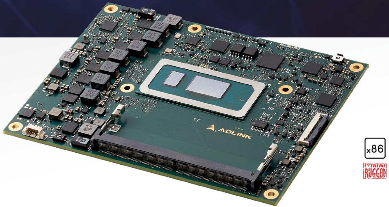
COM Express Type 6 Basic size is the most popular and widely used form factor on the market. With two COM Express connectors and pinouts closely similar to the common x86 based silicon, the Type 6 Basic size yields up to 75 watts, making it well-fitted for various embedded computing applications, including medical, gaming, test & measurement, industrial automation, and more. Topping off, its latest revision – R3.1 – has also added support for several advanced interfaces, such as PCIe Gen4 and USB4.

One-click Buy & Ship
Easy “How-to’s”
Online documentation
Forum support
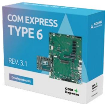
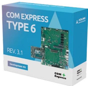
COM Express Type 6
Development Kits
# Applications

Medical
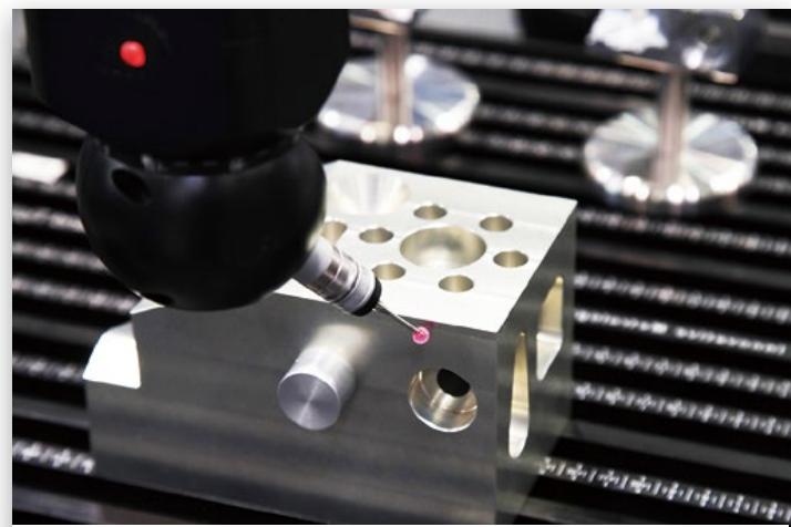
Test and Measurement
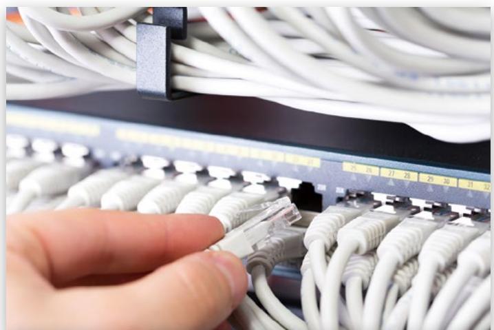
Data Communication

Gaming
# COM Express Type 6 Basic Size
| Model Name | Express-RLP | Express-ADP | Express-TL |
| COM Express | <img src="images/9a01e03725c1ec3cab0d58d814e0ab4bc65407da260cc58cb7b517e54a21a5e5.jpg"/> | <img src="images/5840502269bf3a393ea7ef04ff13a0a7c5f83b735b49c46051cf44a83fe38886.jpg"/> | <img src="images/b628dee53af3a6a4bdc7576df9eeeb02f4b07f0dd57ab756a1c631b16db5dc5c.jpg"/> |
| CPU | 13th Gen Intel® CoreTM i7 / i5 / i3 series (formerly "Raptor Lake-P") | 12th Gen Intel® CoreTM i7 / i5 / i3 series (formerly "Alder Lake-P") | 11th Gen Intel® CoreTM Intel® Xeon® W/Celeron® 6000 (formerly "Tiger Lake-H") |
| Chipset | - | - | RM590E (ECC), QM580E/HM570E (non-ECC) |
| Memory | 64 GB DDR5 at 4800MT/s | 64 GB DDR5 at 4800MT/s | 128 GB DDR4 at 3200/2666 MT/s |
| BIOS Type | AMI UEFI | AMI UEFI | AMI UEFI |
| Graphics Outputs | 4 independent displays LVDS (or eDP 1.4, opt.)2x DDI (or USB4, opt.)1x DDI (or VGA, opt.) | 4 independent displays LVDS (or eDP 1.4, opt.)2x DDI (or USB4, opt.)1x DDI (or VGA, opt.) | 4 independent displays LVDS (or eDP 1.4, opt.)2x DDI1x DDI (or VGA, opt.) |
| LAN | up to 2.5GbE (Intel i225, TSN opt.) | up to 2.5GbE (Intel i225, TSN opt.) | up to 2.5GbE (Intel i225, TSN opt.) |
| USB | 4x USB 3.X/2.0, 4x USB 2.0 | 4x USB 3.X/2.0, 4x USB 2.0 | 4x USB 3.X/2.0, 4x USB 2.0 |
| Serial ATA | 2x at 6Gb/s | 2x at 6Gb/s | 4x at 6Gb/s |
| PCI Express | PCIe Graphic x8 Gen4 (45W SKU)2x PCIe Graphic x4 Gen48x PCIe x1 Gen3 (via switch) | PCIe Graphic x8 Gen4 (45W SKU)2x PCIe Graphic x4 Gen48x PCIe x1 Gen3 (via switch) | PCIe Graphic x16 Gen4 (or 2x8 or 1x8+2x4)8x PCI Express x1 Gen3 |
| Audio | HDA | HDA | HDA |
| TPM | TPM 2.0 | TPM 2.0 | TPM 2.0 |
| Management Bus | I'C, SMBus | I'C, SMBus | I'C, SMBus |
| Embedded Features | EAPI/SEMA, Debug/JTAG Failsafe BIOS (opt.) | EAPI/SEMA, Debug/JTAG Failsafe BIOS (opt.) | EAPI/SEMA, Debug/JTAG Failsafe BIOS (opt.) |
| Power Supply | 8.5-20 V / 5Vsb ±5% (ATX)8.5-20V (AT) | 8.5-20 V / 5Vsb ±5% (ATX)8.5-20V (AT) | 8.5-20 V / 5Vsb ±5% (ATX)8.5-20V (AT) |
| Operating Temperature | Standard: 0°C to 60°CExtreme Rugged: -40°C to 85°C(standard 12V input only) | Standard: 0°C to 60°CExtreme Rugged: -40°C to 85°C(standard 12V input only) | Standard: 0°C to 60°CExtreme Rugged: -40°C to 85°C(standard 12V input only) |
| Form Factor & Compatibility | PICMG COM.0 R3.1,Type 6 Basic size: 95 x 125 mm | PICMG COM.0 R3.1,Type 6 Basic size: 95 x 125 mm | PICMG COM.0 R3.0,Type 6 Basic size: 95 x 125 mm |
| OS Support | UbuntuyoctoPROJECT | UbuntuyoctoPROJECT | yoctoPROJECT |
# Notes:
• VxWorks is supported by project basis.
• Extreme Rugged products are exclusively offered for specific SKUs.
• Optional -40°C to 85°C support: Standard product with 100% ETT screening available for selected CPU SKUs and std. 12V power supply only.
• For more CPU options please refer to online data sheet or user manual.
• All specifications are subject to change without further notice.
# COM Express Type 6 Basic Size
| Model Name | Express-CFR | Express-CF/CFE | Express-KL/KLE |
| COM Express | <img src="images/729d7c73c4364e984c8d3cfa97c8d664fe4ff3869e1bbb3a11d3502e77b4eb89.jpg"/> | <img src="images/72f8a626ee3cd59301b2a5fecb69268749232ac1097fdf2301cfdb05754a553e.jpg"/> | <img src="images/2671420f0cbd16f2af6961b7777118288b0e507234bb44c82590d96e3a52a2f0.jpg"/> |
| CPU | 9th Gen Intel® Xeon®, CoreTM, Pentium® and Celeron® Processors (formerly "Coffee Lake-H Refresh") | 8th Gen Intel CoreTM 8000 series and Intel Xeon® Processors (formerly "Coffee Lake-H") | 7th Gen Intel® CoreTM 7000 series and Intel® Xeon® Processors (formerly "Kaby Lake-H") |
| Chipset | CM246 (ECC)QM370/HM370 (non-ECC) | CM246 (ECC)QM370/HM370 (non-ECC) | CM238 (ECC)QM175/HM175 (non-ECC) |
| Memory | 96 GB DDR4 at 2400/2133 MT/s | 96 GB DDR4 at 2400/2133 MT/s (ECC for Express-CFE) | 32 GB DDR4 at 2133/1867 MT/s (ECC for Express-KLE) |
| BIOS Type | AMI UEFI | AMI UEFI | AMI UEFI |
| Graphics Outputs | 4 independent displaysLVDS (or eDP 1.4, opt.)2x DDI1x DDI (or VGA, opt.) | 4 independent displaysLVDS (or eDP 1.4, opt.)2x DDI1x DDI (or VGA, opt.) | 4 independent displaysLVDS (or eDP 1.4, opt.)2x DDI1x DDI (or VGA, opt.) |
| LAN | GbE (Intel i219) | GbE (Intel i219) | GbE (Intel i219) |
| USB | 4x USB 3.X/2.0, 4x USB 2.0 | 4x USB 3.X/2.0, 4x USB 2.0 | 4x USB 3.X/2.0, 4x USB 2.0 |
| Serial ATA | 4x at 6Gb/s | 4x at 6Gb/s | 4x at 6Gb/s |
| PCI Express | PCIe Graphic x16 Gen3(or 2x8 or 1x8+2x4)8x PCI Express x1 Gen3 | PCIe Graphic x16 Gen3(or 2x8 or 1x8+2x4)8x PCI Express x1 Gen3 | PCIe Graphic x16 Gen3(or 2x8 or 1x8+2x4)8x PCI Express x1 Gen3 |
| Audio | HDA | HDA | HDA |
| TPM | TPM 2.0 (opt.) | TPM 2.0 (opt.) | TPM 2.0 (opt.) |
| Management Bus | I2C, SMBus | I2C, SMBus | I2C, SMBus |
| Embedded Features | EAPI/SEMA, Debug/JTAGFailsafe BIOS (opt.) | EAPI/SEMA, Debug/JTAGFailsafe BIOS (opt.) | EAPI/SEMA, Debug/JTAGFailsafe BIOS (opt.) |
| Power Supply | 8.5-20 V / 5Vsb ±5% (ATX)8.5-20V (AT) | 8.5-20 V / 5Vsb ±5% (ATX)8.5-20V (AT) | 8.5-20 V / 5Vsb ±5% (ATX)8.5-20V (AT) |
| Operating Temperature | Standard: 0°C to 60°CExtreme Rugged: -40°C to 85°C(standard 12V input only) | Standard: 0°C to 60°C | Standard: 0°C to 60°CExtreme Rugged: -40°C to 85°C(standard 12V input only) |
| Form Factor & Compatibility | PICMG COM.0 R3.0,Type 6 Basic size: 95 x 125 mm | PICMG COM.0 R3.0,Type 6 Basic size: 95 x 125 mm | PICMG COM.0 R2.1,Type 6 Basic size: 95 x 125 mm |
| OS Support | yocto PROJECT | yocto PROJECT | yocto PROJECT |
# Notes:
• VxWorks is supported by project basis.
• TPM is supported by BOM option.
• Extreme Rugged products are exclusively offered for specific SKUs.
• Optional -40°C to 85°C support: Standard product with 100% ETT screening available for selected CPU SKUs and std. 12V power supply only.
• For more CPU options please refer to online data sheet or user manual.
• All specifications are subject to change without further notice.
# COM Express Type 6 Compact Size
Significantly lowered power envelopes
COM

Express

# Technical Article
Ideal Small Form Factor Choices Require Consideration of both Technical and Strategic Options
Computer-on-Modules, though small, significantly influence fields like medical imaging and production control.
Designing them demands careful consideration, including factors such as interface specificity, temperature adaptability,
and power efficiency. Choosing the ideal
small form factor is crucial yet challenging.
Our online article provides valuable insights
to assist developers in this selection
process. Explore our guide now for more.

# Pin Definition Type 6 Compact Size Modules
A-B
| 8x USB 2.0 | 4x USB 3.X |
| LVDS / eDP | 2x DDI/USB4 |
| 4x SATA |
| 8x USB 2.0 |
| Gigabit Ethernet | 1x DDI |
| LPC / eSPI |
| GPIO / SDIO / SERIAL/CAN / GP SPI / I2C / HDA / SNDW |
PCIe Gen4 x24
# COM Express
# Type 6 Compact Size
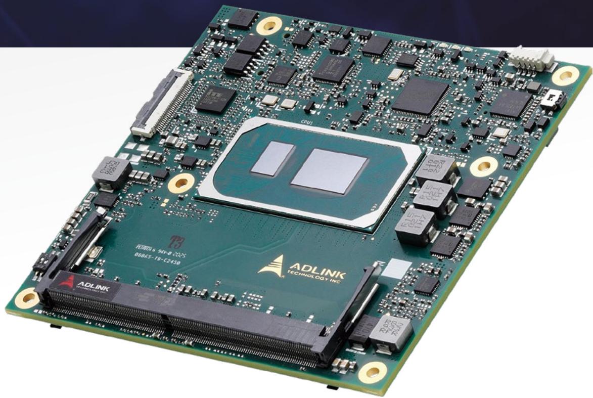
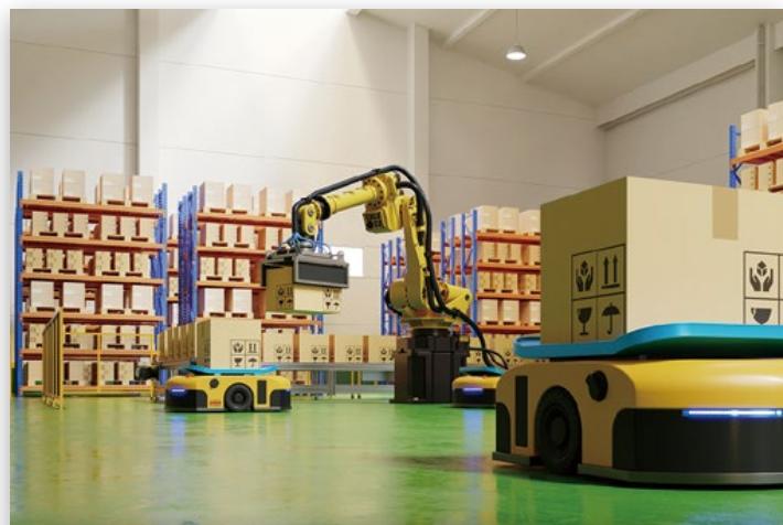
COM Express Type 6 Compact size, shorter in length than the Basic size, is ideally suited for single-chip x86 SoCs, and features proficient performance at significantly lowered power envelopes of 5 to 30 watts. COM Express Type 6 Compact size targets mid- to entry-level applications such as transportation, robotics, edge servers, industrial control, and HMIs in a spate of industries.

One-click Buy & Ship
Easy “How-to’s”
Online documentation
Forum support
COM Express Type 6
Development Kits
# Applications
Industrial Automation

Robotics

Transportation

Medical
# COM Express Type 6 Compact Size
| Model Name | cExpress-MTL | cExpress-RLP |
| COM Express | <img src="images/aca84e4859c36d02d96ad209533a931d3f9ef26e78678af575ec041dff80d741.jpg"/> | <img src="images/9da249a34455f9971597226d31088340665196fe9892e956cb57f7ead4be130d.jpg"/> |
| CPU | Intel® CoreTM Ultra Processors (formerly "Meteor Lake-H/U" Ultra 7/5) | Intel 13th Core (formerly "Raptor Lake-H/U") |
| Memory | 64 GB DDR4 at 5600 MT/s | 64GB LPDDR5 at 5600 MT/s |
| BIOS Type | AMI UEFI | AMI UEFI |
| Graphics Outputs | 4 independent displays LVDS (or eDP 1.4, opt.)2x DDI (or USB4, opt.)1x DDI (or VGA, opt.) | 4 independent displays LVDS (or eDP 1.4, opt.) 2x DDI (or USB4, opt.) 1x DDI (or VGA, opt.) |
| LAN | up to 2.5GbE (Intel i226, TSN, opt.) | up to 2.5GbE (Intel i226, TSN, opt.) |
| USB | 4x USB 3.X/2.0, 4x USB 2.0 | 4x USB 3.X/2.0, 4x USB 2.0 |
| Serial ATA | 2x at 6Gb/s | 2x at 6Gb/s |
| PCI Express | 1x PCIe Graphic x8 Gen42x PCIe Graphic x4 Gen48x PCIe x1 Gen4 (no SATA, opt.) | 1x PCIe Graphic x8 Gen4 2x PCIe Graphic x4 Gen4 8x PCIe x1 Gen4 (no SATA, opt.) |
| eMMC (opt.) | 64-256GB NVMe SSD | 256GB+ NVMe SSD |
| SD | - | - |
| Audio | HDA | HDA |
| TPM | TPM 2.0 | TPM 2.0 |
| Management Bus | I2C, SMBus | I2C, SMBus |
| Embedded Features | EAPI/SEMA, Debug/JTAG | EAPI/SEMA, Debug/JTAG Failsafe BIOS (opt.) |
| Power Supply | 8.5-20V / 5Vsb ±5% (ATX), 8.5-20V (AT) | 8.5-20V / 5Vsb ±5% (ATX), 8.5-20V (AT) |
| Operating Temperature | Standard: 0°C to 60°C | Standard: 0°C to 60°C Extreme: -40°C to 85°C |
| Form Factor & Compatibility | PICMG COM.0 R3.1Type 6 Compact size: 95 x 95 mm | PICMG COM.0 R3.1Type 6 Compact size: 95 x 95 mm |
| OS support | UbuntuyoctoPROJECT | <img src="images/333d66176025147705c88a21bae6034bed25beb727e560a1e7f17fea17397c92.jpg"/><img src="images/9db57580bfdcd1d2530d6eb83a711be553bd2e1ead584ae6b46e054fd4ba2a8d.jpg"/> <img src="images/99f07d3d6f152070a38899ca01f0b189549db046c501c8ba1a1426e0d988b603.jpg"/> |
# Notes:
• VxWorks is supported by project basis.
• TPM is supported by BOM option.
• Extreme Rugged products are exclusively offered for specific SKUs.
• Optional -40°C to 85°C support: Standard product with 100% ETT screening available for selected CPU SKUs and std. 12V power supply only.
• For more CPU options please refer to online data sheet or user manual.
• All specifications are subject to change without further notice.
# COM Express Type 6 Compact Size
| Model Name | cExpress-TL | cExpress-AR |
| COM Express | <img src="images/fcbe004dc7bff00b3dd917b039dc24f0be84d589827299932a06ac6511bdd434.jpg"/> | <img src="images/5c1b30eb6cd24111c0ec7e35b0f7af7830e2183c8dbb879a6e5d7ad9674171af.jpg"/> |
| CPU | 11th Gen Intel® CoreTM i7 /i5 /i3 series (formerly "Tiger Lake-UP3") | AMD RyzenTM Embedded V2000 series |
| Memory | 64 GB DDR4 at 3200/2666 MT/s (IBECC opt.) | 64 GB DDR4 at 3200/2666 MT/s |
| BIOS Type | AMI UEFI | AMI UEFI |
| Graphics Outputs | 4 independent displaysLVDS (or eDP 1.4, opt.)2x DDI1x DDI (or VGA, opt.) | 4 independent displaysLVDS (or eDP 1.3, opt.)2x DDI1x DDI (or VGA, opt.) |
| LAN | up to 2.5GbE (Intel i225, TSN, opt.) | GbE (Intel i225) |
| USB | 4x USB 3.X/2.0, 4x USB 2.0 | 4x USB 3.X/2.0, 4x USB 2.0 |
| Serial ATA | 2x at 6Gb/s | 2x at 6Gb/s |
| PCI Express | 1x PCIe Graphic x4 Gen44x PCIe x1 Gen3 (PCIe switch, opt.) | 1x PCIe Graphic x8 Gen36x PCIe x1 Gen3 |
| eMMC (opt.) | - | - |
| SD | - | - |
| Audio | HDA | HDA |
| TPM | TPM 2.0 (opt.) | TPM 2.0 (opt.) |
| Management Bus | I2C, SMBus | I2C, SMBus |
| Embedded Features | EAPI/SEMA, Debug/JTAGFailsafe BIOS (opt.) | EAPI/SEMA, Debug/JTAG Failsafe BIOS (opt.) |
| Power Supply | 8.5-20V / 5Vsb ±5% (ATX), 8.5-20V (AT) | 8.5-20V / 5Vsb ±5% (ATX), 8.5-20V (AT) |
| Operating Temperature | Standard: 0°C to 60°CExtreme Rugged: -40°C to 85°C (standard 12V input only) | Standard: 0°C to 60°CExtreme Rugged: -40°C to 85°C(standard 12V input only) |
| Form Factor & Compatibility | PICMG COM.0 R3.0 Type 6 Compact size: 95 x 95 mm | PICMG COM.0 R3.0 Type 6 Compact size: 95 x 95 mm |
| OS support | yocto PROJECT | yocto PROJECT |
# Notes:
• VxWorks is supported by project basis.
• TPM is supported by BOM option.
• Extreme Rugged products are exclusively offered for specific SKUs.
• Optional -40°C to 85°C support: Standard product with 100% ETT screening available for selected CPU SKUs and std. 12V power supply only.
• For more CPU options please refer to online data sheet or user manual.
• All specifications are subject to change without further notice.
# COM Express Type 6 Compact Size
| Model Name | cExpress-WL | cExpress-SL/KL | cExpress-TWL |
| COM Express | <img src="images/bbca5a56629096b19dab445b9e7beb4897f48d087e4cada0cb8cfcdd7ec57842.jpg"/> | <img src="images/ba14066c8a27c082c275cf4aa0f34c4c88ad0ac2602ec146757b09c45c9ff9b9.jpg"/> | <img src="images/55ac2cbfe6b0164f4ecf99cd7004cce81ec77427a6232a5822b9e59008399a51.jpg"/> |
| CPU | 8th Gen Intel® CoreTM i7 / i5 / i3 series (formerly "Whiskey Lake-U") | 6th Gen IntelCore. Intel® CoreTM i7 / i5 / i3 series (formerly "Skylake-U") | Intel x7000 series ATOM (formerly "Twin Lake") |
| Memory | 64 GB DDR4 at 2133/1867 MT/s | 32 GB DDR4 at 2133/1867 MT/s | 16GB LPDDR5 at 4800 MT/s |
| BIOS Type | AMI UEFI | AMI Aptio V | AMI UEFI |
| Graphics Outputs | 3 independent displays LVDS (or eDP 1.3, opt.)1x DDI1x DDI (or VGA, opt.) | LVDS(oreDP1.4)2x DDI (DP/HDMI or VGA) | 3 independent displays LVDS (or eDP 1.4, opt.) 1x DDI 1x DDI (or VGA, opt.) |
| LAN | GbE (Intel i219) | Intel® i219LM/V | up to 2.5GbE |
| USB | 4x USB 3.X/2.0, 4x USB 2.0 | 4x USB 3.X/2.0, 4x USB 2.0 | up to 4x USB 3.X/2.0, 4x USB 2.0 |
| Serial ATA | 3x at 6Gb/s | 3x at 6Gb/s | up to 2x 6Gb/s |
| PCI Express | 1x PCIe x1 Gen3 at PEG8x PCIe x1Gen3 | 5x PCIe x1 Gen3 (3965U supports Gen2)(6 PCIe x1 w/o GbE, opt.) | 8x PCIe x1 Gen3 (no SATA, GbE, opt.) |
| eMMC (opt.) | 32-64GB | - | 32-128GB EMMC |
| SD | Yes | - | - |
| Audio | HDA | HDA | HDA |
| TPM | TPM 2.0 (opt.) | TPM 2.0 (opt.) | TPM 2.0 |
| Management Bus | I2C, SMBus | I2C, SMBus | I2C, SMBus |
| Embedded Features | EAPI/SEMA, Debug/JTAG Failsafe BIOS (opt.) | EAPI/SEMA, Debug/JTAG Failsafe BIOS (opt.) | EAPI/SEMA, Debug/JTAG Failsafe BIOS (opt.) |
| Power Supply | 5-20V / 5Vsb ±5% (ATX), 5-20V (AT) | 5-20V / 5Vsb ±5% (ATX), 5-20V (AT) | 8.5-20V / 5Vsb ±5% (ATX), 8.5-20V (AT) |
| Operating Temperature | Standard: 0°C to 60°CExtreme Rugged: -40°C to 85°C(standard 12V input only) | Standard: 0°C to 60°CExtreme Rugged: -40°C to 85°C(standard 12V input only) | Standard: 0°C to 60°C |
| Form Factor & Compatibility | PICMG COM.0 R3.0 Type 6 Compact size: 95 x 95 mm | PICMG COM.0 R2.1,Type 6 Compact size: 95 x 95 mm | PICMG COM.0 R3.1Type 6 Compact size: 95 x 95 mm |
| OS support | yocto PROJECT | yocto PROJECT | Ubuntu |
Notes:
• VxWorks is supported by project basis.
• TPM is supported by BOM option.
• Extreme Rugged products are exclusively offered for specific SKUs.
• Optional -40°C to 85°C support: Standard product with 100% ETT screening available for selected CPU SKUs and std. 12V power supply only.
• For more CPU options please refer to online data sheet or user manual.
• All specifications are subject to change without further notice.
# COM Express Type 6 Compact Size
| Model Name | cExpressASL/ALN | cExpress-EL | cExpress-AL |
| COM Express | <img src="images/77d73bff08eefd7d60cff29fa3731ba5bd800e054f41168e2e7857bf65e061a6.jpg"/> | <img src="images/f6340987475bf709d1ae3d0f0273988a0fc9764791094d8925515d47b02cbfbd.jpg"/> | <img src="images/f7cd4c3a4966cf8da5ba17d7fb64784d0fc18d7b9fb321fbef1f4ea72fd1b667.jpg"/> |
| CPU | 7th Gen Intel® AtomTM, Processor N series, and CoreTM i3-N305 (formerly "Alder Lake-N") Amston Lake x7835RE/x7433RE/x7213RE/x7211RE (formerly "Amston Lake") | Intel Atom® x6000E series (formerly "Elkhart Lake") | Intel Atom E3900 series (formerly "Apollo Lake") |
| Memory | Up to 16GB LPDDR5 at 4800MT/s support IBECC | 32GB DDR4 at 3200/2666 MT/s (IBECC opt.) | 32 GB DDR4 at 2133/1867 MT/s |
| BIOS Type | AMI Aptio V | AMI UEFI | AMI UEFI |
| Graphics Outputs | 3 independent displaysLVDS (or eDP 1.4, opt.)1x DDI (or TCSS, opt.)1x DDI (or VGA, opt.) | 3 independent displaysLVDS (or eDP 1.3, opt.)1x DDI1x DDI (or VGA, opt.) | 3 independent displaysLVDS (or eDP 1.3, opt.)1x DDI1x DDI (or VGA, opt.) |
| LAN | up to 2.5GbE (Intel i226, TSN, opt.) | GbE (MaxLinear GPY) | GbE (Intel 219) |
| USB | Up to 4x USB 3.2 Gen2, 8x USB 2.0 | 2x USB 3.X/2.0, 6x USB 2.0 (USB3 hub opt.) | 4x USB 3.X/2.0, 4x USB 2.0 |
| Serial ATA | 2x at 6Gb/s | 2x at 6Gb/s | 3x at 6Gb/s |
| PCI Express | Up to 8 PCIe GEN3 x1 (on-board LAN, SATA[0:1]. Opt.) | 6x PCIe x1 Gen3 | 5x PCIe x1 Gen3 (3965U supports Gen2) (6 PCIe x1 w/o GbE, opt.) |
| eMMC (opt.) | 32-63 eMMC | 32-64 (by project) | - |
| SD | 1x MIPI-CSI camera resolution up to 4K | Yes | - |
| Audio | HDA | HDA | HDA |
| TPM | TPM 2.0 | TPM 2.0 (opt.) | TPM 2.0 (opt.) |
| Management Bus | I2C, SMBus | I2C, SMBus | I2C, SMBus |
| Embedded Features | EAPI/SEMA, Debug/JTAG Failsafe BIOS (opt.) | EAPI/SEMA, Debug/JTAGFailsafe BIOS (opt.) | EAPI/SEMA, Debug/JTAGFailsafe BIOS (opt.) |
| Power Supply | 8.5-20V / 5Vsb ±5% (ATX), 8.5-20V (AT) | 8.5-20V / 5Vsb ±5% (ATX), 8.5-20V (AT) | 5-20V / 5Vsb ±5% (ATX), 5-20V (AT) |
| Operating Temperature | Standard: 0°C to 60°CExtreme Rugged: -40°C to 85°C(Amston Lake) | Standard: 0°C to 60°CExtreme Rugged: -40°C to 85°C(standard 12V input only) | Standard: 0°C to 60°CExtreme Rugged: -40°C to 85°C(standard 12V input only) |
| Form Factor & Compatibility | PICMG COM.0 R3.1Type 6 Compact size: 95 x 95 mm | PICMG COM.0 R3.0,Type 6 Compact size: 95 x 95 mm | PICMG COM.0 R2.1,Type 6 Compact size: 95 x 95 mm |
| OS support | UbuntuyoctoPROJECT | yoctoPROJECT | yoctoPROJECT |
Notes:
• VxWorks is supported by project basis.
• TPM is supported by BOM option.
• Extreme Rugged products are exclusively offered for specific SKUs.
• Optional -40°C to 85°C support: Standard product with 100% ETT screening available for selected CPU SKUs and std. 12V power supply only.
• For more CPU options please refer to online data sheet or user manual.
• All specifications are subject to change without further notice.
# COM Express Type 7 Basic Size
Serving servers with extended operating temperatures
# COM Express
# Pin Definition
Type 7 Rev 3.1 Basic Size Modules
| A-B | C-D |
| 4x USB 2.0 | 4x USB 3.X |
| 2x SATA | |
| Gigabit Ethernet | |
| NC-SI | 4x 10G KR CEI mode |
| LPC / eSPI | |
| GPIO / SDIO / SERIAL / CAN / SPI / I2C / HDA / PCIe clock & $2^{nd}$ PCIe clock / IPMB | |
| PCIe Gen4 x32 |
| Power |
# Pin Definition
Type 7 Rev 3.0 Basic Size Modules
| A-B | C-D |
| 4x USB 2.0 | 4x USB 3.X |
| 2x SATA | |
| Gigabit Ethernet | |
| NC-SI | 4x 10G KR |
| LPC/eSPI | |
| GPIO/SDIO/SERIAL/CAN/SPI/I2C/HDA/PCIe clock & RSVD | |
| PCIe x32 |
| Power |
# COM Express
# Type 7 Basic Size
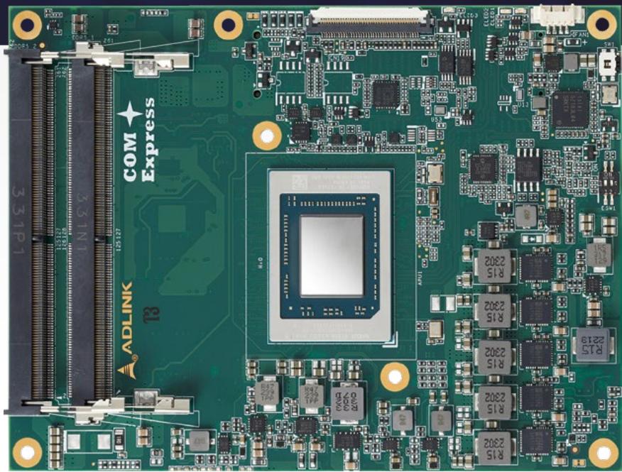
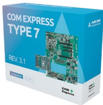
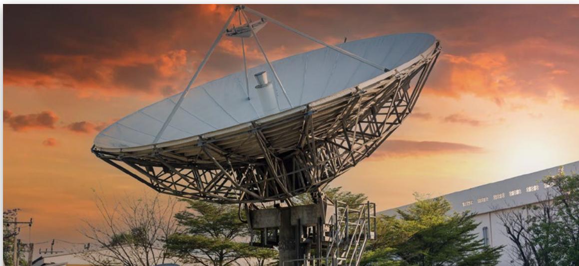
COM Express Type 7 Basic size, designed for intermediate- to high-performance headless edge servers, offers up to 32 PCIe lanes and four 10GbE ports with an extended temperature tolerance. As of late, its suitability for a wide range of rugged and embedded industrial applications has been widened further with Revision 3.1, which adds a second PCIe clock for PCIe Gen4. The range of applications for Type 7 modules is very broad, including general-purpose rugged embedded computers, mission-critical servers, SDN appliances, signal processing & data acquisition appliances, network test equipment, satellite gateways, inflight entertainment systems, and more.

One-click Buy & Ship
Easy “How-to’s”
Online documentation
Forum support
COM Express Type 7
Development Kits
# Applications
Satellite Gateway
Defense
Data Communication
# COM Express Type 7 Basic Size
| Model Name | Express-VR7 | Express-ID7 |
| COM Express | <img src="images/b77e2be41167faa09a44bc450c8704f9cb97d8b4b7a2095cc26cb60303daea45.jpg"/> | <img src="images/2521c9f0e7893290575e9394176865d1b86c6495ffd8d7a456bafb8cf99f4d7f.jpg"/> |
| CPU | AMD RyzenTM Embedded V3000 series | Intel® Xeon® D-1700 series (formerly "Ice Lake-D") |
| Memory | 64GB DDR5 at 4800 MT/s (ECC/non-ECC) | 128 GB DDR4 at 3200/2666 MT/s (ECC / non-ECC) |
| BIOS Type | AMI UEFI | AMI UEFI |
| Ethernet KR | 2x 10GBASE-KR | 4x 10GBASE-KR |
| LAN | up to 2.5GbE (Intel i226) | GbE (Intel i210, TSN opt.) |
| USB | 4x USB3.X/2.0 | 4x USB 3.X/2.0 |
| Serial ATA | 2x at 6Gb/s | 2x at 6Gb/s |
| PCI Express | 8 PCI Express Gen4 (1 x8, 2 x4),4 PCI Express Gen4 (4 x1, 2 x2, 1 x4),2 PCI Express Gen4 (1 x1, 1 x2) | PCI Express x16 Gen4 (or 2 x8 or 4 x4)PCI Express x8 Gen3 (x8, x4, x2)PCI Express x8 Gen3 (x8, x4, x2) |
| eMMC (opt.) | - | - |
| TPM | TPM 2.0 | TPM 2.0 |
| Management Bus | I2C, SMBus | I2C, SMBus |
| Embedded Features | EAPI/SEMA, Debug/JTAGFailsafe BIOS (opt.) | EAPI/SEMA, Debug/JTAGFailsafe BIOS (opt.) |
| Power Supply | 8.5-20V/5Vsb±5%(ATX)8.5-20V(AT) | 12 V / 5Vsb ±5% (ATX) 12 V (AT) |
| Operating Temperature | Standard: 0°C to 60°CExtreme Rugged: -40°C to 85°C (standard 12V input only) | Standard: 0°C to 60°CExtreme Rugged: -40°C to 85°C (standard 12V input only) |
| Form Factor & Compatibility | PICMG COM.0: Rev 3.1 Type 7Type 7 Basic size: 95 x 125 mm | PICMG COM.0 R3.1,Type 7 Basic size: 95 x 125 mm |
| OS Support | UbuntuyoctoPROJECT | yoctoPROJECT |
# COM Express Type 7 Basic Size
| Model Name | Express-BD7/BD74 | Express-DN7 |
| COM Express | <img src="images/4c638219ee160ebb36e4010b25d880e201c3250659be3b1ca9908fbdd23dc07f.jpg"/> | <img src="images/7c9d82e6283fc6fd66fee307e0de069aff6c2dd41819fb233cc6047e8a7ce646.jpg"/> |
| CPU | Intel® Xeon® D-1500 series (formerly "Broadwell-DE") | Intel® Atom® C3000 series (formerly "Denverton-NS") |
| Memory | 64 GB DDR4 at 2400/2133MT/s (ECC/non-ECC) | 96 GB DDR4 at 2400/2133 MT/s (ECC/non-ECC) |
| BIOS Type | AMI UEFI | AMI UEFI |
| Ethernet KR | 2x 10GBASE-KR | 4x 10GBASE-KR (max. 20G) |
| LAN | GbE (Intel i210) | GbE (Intel i210) |
| USB | 4x USB 3.X/2.0 | 2x USB 3.X/2.0, 2x USB 2.0 |
| Serial ATA | 2x at 6Gb/s | 2x at 6Gb/s |
| PCI Express | PCI Express x16 Gen3(or 2 x8 or 4 x4)PCI Express x8 Gen3 (x8, x4, x2)PCI Express x8Gen2(x8, x4, x2), w/o GbE | PCI Express x8 Gen3 (or 2x8 or 1x8 plus 2x4)PCI Express x8 Gen3 (x8, x4, x2), w/o GbE |
| eMMC (opt.) | - | 32-64 GB (opt.) |
| TPM | TPM 2.0 (opt.) | TPM 2.0 (opt.) |
| Management Bus | I2C, SMBus | I2C, SMBus |
| Embedded Features | EAPI/SEMA, Debug/JTAGFailsafe BIOS (opt.) | EAPI/SEMA, Debug/JTAGFailsafe BIOS (opt.) |
| Power Supply | 8.5-20V/5Vsb±5%(ATX)8.5-20V(AT) | 8.5-20 V / 5Vsb ±5% (ATX) 8.5-20V (AT) |
| Operating Temperature | Standard: 0°C to 60°CExtreme Rugged: -40°C to 85°C (standard 12V input only) | Standard: 0°C to 60°CExtreme Rugged: -40°C to 85°C (standard 12V input only) |
| Form Factor & Compatibility | PICMG COM.0 R3.0,Type 7 Basic size: 95 x 125 mm | PICMG COM.0 R3.0,Type 7 Basic size: 95 x 125 mm |
| OS Support | yocto PROJECT | yocto PROJECT |
# Notes:
• TPM is supported by BOM option.
• Extreme Rugged products are exclusively offered for specific SKUs.
• Optional -40°C to 85°C support: Standard product with 100% ETT screening available for selected CPU SKUs and std. 12V power supply only.
• For more CPU options please refer to online data sheet or user manual.
• All specifications are subject to change without further notice.
# Notes:
• TPM is supported by BOM option.
• Extreme Rugged products are exclusively offered for specific SKUs.
• Optional -40°C to 85°C support: Standard product with 100% ETT screening available for selected CPU SKUs and std. 12V power supply only.
• For more CPU options please refer to online data sheet or user manual.
• All specifications are subject to change without further notice.
# COM Express Type 10 Mini Size
Ultra-low power with soldered onboard memory
# COM Express
# COM Express Type 10 Mini Size
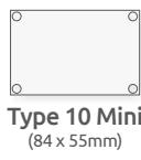
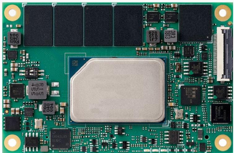
COM Express Type 10 Mini size features power envelopes of TDP 12W and lower and soldered onboard memory, yet still offering graphics display and optimized I/O capabilities needed for various technologically-advanced mobile solutions, such as handheld devices and controllers for industrial, medical, and transportation applications.

One-click Buy & Ship
Easy “How-to’s”
Online documentation
Forum support
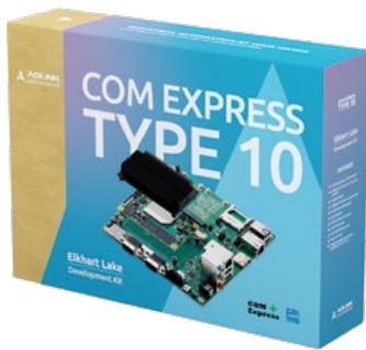
COM Express Type 10
Development Kits
# Applications

Medical Portable Ultrasound
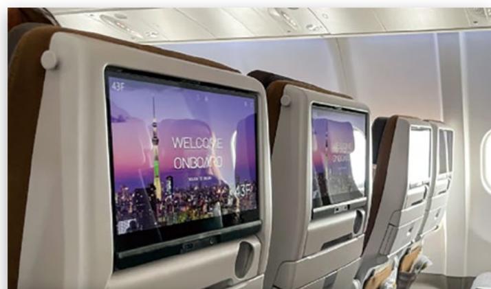
In-Vehicle / In-Flight Entertainment

# Solution Brief
Computer-on-Modules Boost Improvements in Ultrasound Technology
ADLINK's COM Express modules empower portable
workstations by integrating various data entry interfaces and remote diagnosis capabilities. Explore how these modules enhance ultrasound technology in our online solution brief for more details!

# Pin Definition for Type 10 Mini Size Modules
# A-B
8x USB 2.0
v2x USB 3.X
DDI
LVDS / eDP
4x SATA
Gigabit Ethernet
LPC / eSPI
GPIO / SDIO / UART / CAN / SPI / I²C / SMB / GP\_SPI / HDA
4x PCIe Gen4
Power
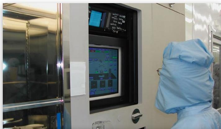
Panel Control

Industrial Automation (Portable Devices)
# COM Express Type 10 Mini Size
| Model Name | nanoX-EL |
| COM Express | <img src="images/2106bd96ac92de7b9c2a86b07fdd232ce015653334896be9106fee3a82e7cb14.jpg"/> |
| CPU | Intel Atom® x6000E series (formerly "Elkhart Lake") |
| Memory (soldered) | 16GB LPDDR4 at 4267/3200 MT/s (IBECC opt.) |
| BIOS Type | AMI UEFI |
| Graphics Outputs | 2 independent displays LVDS (or eDP 1.4, opt.) 1x DDI |
| LAN | GbE (MaxLinear GPY) |
| USB | 2x USB 3.X/2.0, 6x USB 2.0 |
| Serial ATA | 2x at 6Gb/s |
| PCI Express | 4x PCIe x1 Gen3 (x4, x2, x1) |
| eMMC (opt.) | 32-64GB |
| SD (opt.) | Yes |
| Audio | HDA |
| TPM | TPM 2.0 (opt.) |
| Management Bus | I2C, SMBus |
| Embedded Features | EAPI/SEMA, Debug/JTAG Failsafe BIOS (opt.) |
| Power Supply | 4.75-20V / 5Vsb ±5% (ATX), 4.75-20V (AT) |
| Operating Temperature | Standard: 0°C to 60°C Extreme Rugged: -40°C to 85°C (standard 12V input only) |
| Form Factor & Compatibility | PICMG COM.0 R3.0 Type 10 Mini size: 84 x 55 mm |
| OS support | yocto PROJECT |
# Notes:
• VxWorks is supported by project basis.
• TPM, eMMC are supported by BOM option.
• Optional -40°C to 85°C support: Standard product with 100% ETT screening available for selected CPU SKUs and std. 12V power supply only.
• For more CPU options please refer to online data sheet or user manual.
• All specifications are subject to change without further notice.
# COM Express Type 10 Mini Size
| Model Name | nanoX-AL | nanoX-BT |
| COM Express | <img src="images/5acb0ae654106c5c0a54e47183e041e2a2ed481d7df333f925c5138a03773f2d.jpg"/> | <img src="images/ff0f38b0f9bfc949db25d49a34713b06e4abb554928e055017eac06fc0fa8230.jpg"/> |
| CPU | Intel Atom® E3900 series (formerly "Apollo Lake") | Intel Atom® E3800 series (formerly "Bay Trail") |
| Memory (soldered) | 8 GB DDR3L at 1867/1600 MT/s | 4 GB DDR3L at 1333 MT/s |
| BIOS Type | AMI UEFI | AMI UEFI |
| Graphics Outputs | 2 independent displaysLVDS (or eDP 1.4, opt.)1x DDI | 2 independent displaysLVDS (or eDP 1.2, opt.)1x DDI |
| LAN | GbE (Intel i210) | GbE (Intel i210) |
| USB | 2x USB 3.X/2.0, 6x USB 2.0 | 1x USB 3.X/2.0, 3x USB 2.0 |
| Serial ATA | 2x at 6Gb/s | 2x at 3Gb/s |
| PCI Express | 3x PCIe x1 Gen2 (x2, x1) | 3x PCIe x1 Gen2 (4x PCIe x1, w/o GbE, opt.) |
| eMMC (opt.) | 32 GB | 32GB |
| SD (opt.) | Yes | Yes |
| Audio | HDA | HDA |
| TPM | TPM 2.0 (opt.) | TPM 1.2 (opt.) |
| Management Bus | I2C, SMBus | I2C, SMBus |
| Embedded Features | EAPI/SEMA, Debug/JTAGFailsafe BIOS (opt.) | EAPI/SEMA, Debug/JTAGFailsafe BIOS (opt.) |
| Power Supply | 4.75-20V / 5Vsb ±5% (ATX), 4.75-20V (AT) | 5-14V / 5Vsb ±5% (ATX), 5-14V (AT) |
| Operating Temperature | Standard: 0°C to 60°CExtreme Rugged: -40°C to 85°C (standard 12V input only) | Standard: 0°C to 60°CExtreme Rugged: -40°C to 85°C (standard 12V input only) |
| Form Factor & Compatibility | PICMG COM.0R3.0 Type 10 Mini size: 84 x 55 mm | PICMG COM.0R2.1 Type 10 Mini size: 84 x 55 mm |
| OS support | yocto PROJECT | yocto PROJECT |
# Notes:
• VxWorks is supported by project basis.
• TPM, eMMC are supported by BOM option.
• Optional -40°C to 85°C support: Standard product with 100% ETT screening available for selected CPU SKUs and std. 12V power supply only.
• For more CPU options please refer to online data sheet or user manual.
• All specifications are subject to change without further notice.
# SMARC

# SMARC
module
# Covering ARM / x86 ecosystems
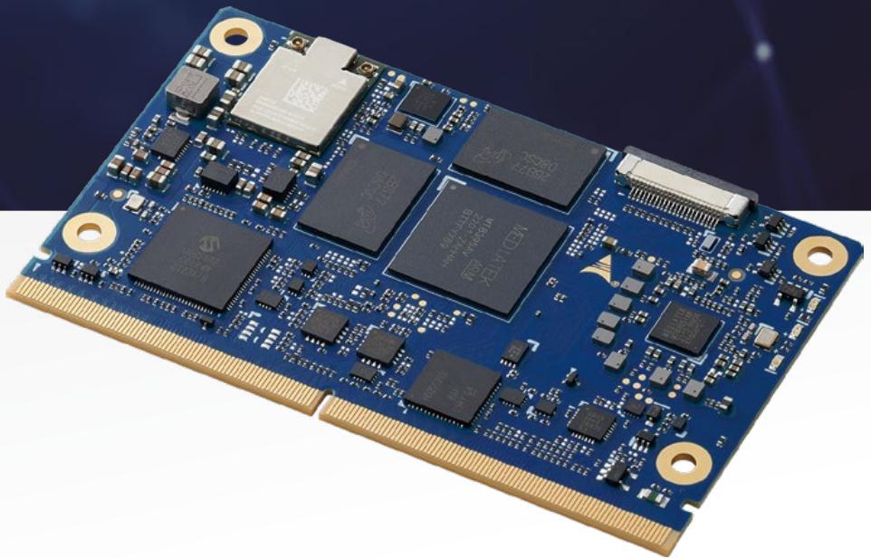
86
ARM
EYTREME RUGGED
# AIoM (AI on Module)
# AIOM

# Pin Definition for SMARC
With the latest Revision 2.1, SMARC has positioned itself as the ideal standard for scalable, low-power, siliconindependent AIoM solutions in the industrial embedded market. Over the revision, SMARC adds the support for up to 4 MIPI CSI camera inputs specifically for SoCs with integrated NPUs (Neural Processing Units) used for videobased AI solutions, such as robotic vehicles and autonomous driving. Additionally, it also allows multiplexing SerDes signals over two PCIe x1 interfaces for a total of four GbE Ethernet ports to support up to 4 GigE Vision cameras for AI vision applications.
2x LVDS / DSI / eDP
HDMI / DP++
DP++
2x MIPI CSI
HDA / I²S
1x SATA
2x GbE
2x USB 3.X/2.0 (1x OTG)
4x USB 2.0 (1x OTG)
4x PCIe
SDIO / SPI /eSPI / 5x I²C
4x UART / 2x CAN / 12x GPIO
Power
# SMARC
Short for Smart Mobility ARChitecture, the SMARC form factor is the only standard natively built for both ARM- and x86-based SoCs, allowing it to leverage the wide-ranging smart phone and tablet computer ecosystems. With 314- pins on a high-speed MXM3 connector, SMARC delivers a combination of high-performance computing, low power envelopes typically under 6W and no more than 15W, low cost, and the ability to withstand extreme environmental conditions, making it the ideal building blocks for portable and stationary embedded systems.
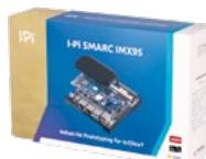
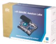
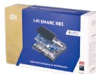
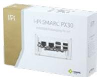
# I-Pi SMARC Development Kits

One-click Buy & Ship
Easy “How-to’s”
Online documentation
Forum support
# Applications

Drone
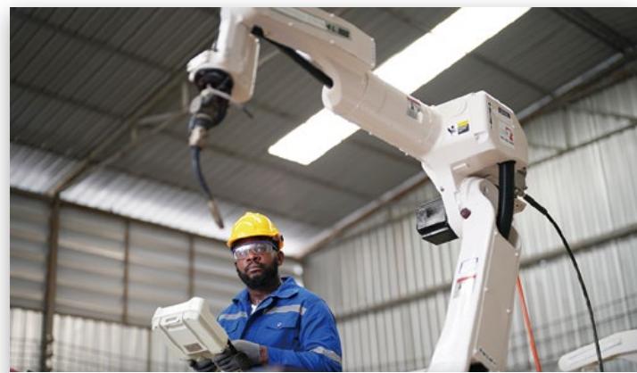
Robotics
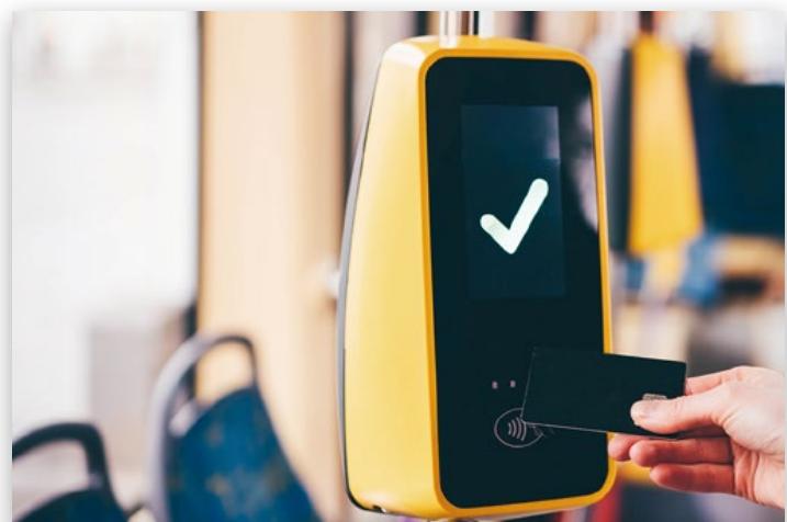
Smart City (Transportation)
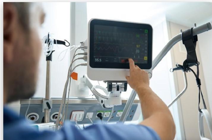
Portable Medical Devices
| Model Name | LEC-MTK-I1200 | LEC-RB5 |
| SMARC module | <img src="images/c01ad91a03b7f23571ed0df6e54478bc14dde12dee95ec66916bacad38065111.jpg"/> | <img src="images/7f5faabf44ddaa93894333f46f4b546e469465df77a4d384309cc91b0e893457.jpg"/> |
| CPU | MediaTek® Genio 1200 Octa-core CPU4x Cortex-A784x Cortex-A55 | Qualcomm® QRB5165 SoCQualcomm® KryoTM 585 Octa-core CPU8x Cortex-A77 cores |
| Memory/Storage | Up to 16 GB LPDDR4XUFS: 64/128/256GB | Up to 16 GB LPDDR5UFS: 64/128/256GB |
| Cache | L2: 256KB per core | 128KB / 256KB / 512KB |
| Boot Loader | U-Boot | U-Boot |
| Graphics Outputs | 1x HDMI1x eDP 4 lanes 2x MIPI-DSI 4 lanes | 1x HDMI1x MIPI-DSI 4 lanes |
| Camera | 2x MIPI-CSI 4 lanes 1x MIPI-CSI 2 lanes | 5x MIPI-CSI 4 lanes1x MIPI-CSI 2 lanes |
| LAN | Up to 2x GbE | Up to 2x GbE |
| USB | 2x USB 3.X,4x USB 2.0 | 2x USB 3.X,4x USB 2.0 |
| Extension ports | 4x UART2x SPI14x GPIO1x SDIO | 3x UART2x SPI14x GPIO1x SDIO |
| Audio | 1x I'S | 1x I'S |
| PCI Express | 1x PCIe x1 Gen2 | 2x PCIe x2 Gen3 |
| TPM | TPM 2.0 (opt.) | TPM 2.0 (opt.) |
| SEMA Support | Yes | Yes |
| Power Supply | 5.0 V DC±5% | 5.0 V DC±5% |
| Operating Temperature | 0°C to 60°C-40°C to 85°C (opt.) | 0°C to 60°C-20°C to 85°C (opt.) |
| Form Factor & Compatibility | SMARC short size,82 x 50 mm,SMARC specification v2.1.1 | SMARC short size,82 x 50 mm,SMARC specification v2.1.1 |
| OS Support | androidubuntuyocto project | ubuntuyocto project |
| Model Name | LEC-IMX95 | LEC-IMX8MP |
| SMARC module | <img src="images/9903d90b6d9833261819e7c8bf645b3f47834f7bed10a0ac6af4c0b7824d1e5c.jpg"/> | <img src="images/cfd1664b4c2b8c9a3d29d039e6b07211c43d56b4345064bedc33ad1d9220a80f.jpg"/> |
| CPU | NXP i.MX 95 series with 2/4/6-core Arm Cortex®-A551x Arm Cortex®-M7, 1x Arm Cortex®-M33 | NXP i.MX 8M Plus Quad, QuadLite4x Cortex-A53 cores,1x M7 core |
| Memory/Storage | Up to 8 GB LPDDR5 | Up to 8 GB LPDDR4 at 4266 MT/s eMMC: 32/64GB |
| Cache | 512KB | L2: 512KB ECC |
| Boot Loader | U-boot | U-Boot |
| Graphics Outputs | Dual Channel LVDS, HDMI or DSI | 1x HDMI 2x LVDS 1x MIPI-DSI 4 lanes |
| Camera | 2x MIPI CSI Camera (1x shared from DSI) | 1x MIPI-CSI 4 lanes 1x MIPI-CSI 2 lanes |
| LAN | 2x GbE with TSN 1x 10GbE with TSN (Option) | 2x GbE (LAN0 with TSN) |
| USB | 2x USB 3.1 4x USB 2.0 (one shared with WIFI on port 1) | 2x USB 3.X, 4x USB 2.0 (one shared with USB OTG on port 0) |
| Extension ports | 4x UART 2x SPI 14x GPIO 1x SDIO | 4x UART2x SPI14x GPIO1x SDIO |
| Audio | 1x I2S | 1x I'S |
| PCI Express | 2x PCIe x1 Gen3 (one shared with WIFI on port B) | 2x PCIe x1 Gen 2 or 1x PCIe x1 Gen 3 |
| TPM | Yes | TPM 2.0 (opt.) |
| SEMA Support | 5.0 V DC±5% | Yes |
| Power Supply | -40°C to +85°C | 5.0 V DC±5% |
| Operating Temperature | SMARC short size, 82 x 50 mm, SMARC specification v2.1 | 0°C to 60°C-40°C to 85°C (opt.) |
| Form Factor & Compatibility | SMARC short size,82 x 50 mm,SMARC specification v2.1 | SMARC short size,82 x 50 mm,SMARC specification v2.1.1 |
| OS Support | Ubuntu | androidyoctoPROJECT |
Notes:
• TPM is supported by BOM option.
• All specifications are subject to change without further notice.
Notes:
• TPM is supported by BOM option.
• All specifications are subject to change without further notice.
| Model Name | LEC-IMX8MM | LEC-ASL | LEC-ALN |
| <img src="images/a3912986b68e40342a5917705ff8c157ade264ef4abca444ba6f6ba92ca38f93.jpg"/> | New<img src="images/c0b17e64c301c6f68c2dd5d6a432a69db3e5da3529e71c4111b51fe2508a5858.jpg"/> | New<img src="images/f9ed4675c60e860e12180a46d8200f7ce03cbb14ded6b9e9e71f1a5094291f7e.jpg"/> |
| CPU | NXP i.MX 8M Mini,4x Cortex-A53 cores,1x M4 core | Intel® Atom®x7000RE / x7000C series (formerly "Amston Lake") | Intel® CoreTM i3 Processor N-seriesIntel® Atom® x7000 series (formerly "Alder Lake-N") |
| Memory/Storage | Up to 4 GB DDR4 at 4266 MT/s eMMC: 32/64/128GB | Up to 16 GB LPDDR5 Up to 128 GB eMMC | Up to 16 GB LPDDR5Up to 128 GB eMMC |
| Cache | L2: 512KB | 6MB | 6MB |
| Boot Loader | U-Boot | AMI UEFI BIOS | AMI UEFI BIOS |
| Graphics Outputs | 1x MIPI-DSI 4 lanes (or 2x LVDS via bridge) | Dual Channel LVDS, HDMI/DP++, DP++ | Dual Channel LVDS, HDMI/DP++, DP++ |
| Camera | 1x MIPI-CSI 4 lanes | 2x MIPI CSI Camera | 2x MIPI CSI Camera |
| LAN | 2x GbE | Dual 10/100/100/ 2.5 Gbit Ethernet with TSN | Dual 10/100/100/ 2.5 Gbit Ethernet with TSN |
| USB | 5x USB 2.0 (one shared with USB OTG on port 0) | 2x USB 3.26x USB 2.1 | 2x USB 3.26x USB 2.0 |
| Extension ports | 4x UART2x SPI14x GPIO1x SDIO | 1x SATA 6Gb/s4xUART2x SPI14x GPIO | 1x SATA 6Gb/s4xUART2x SPI14x GPIO |
| Audio | 1x I'S | 1x HDA | 1x HDA |
| PCI Express | 1x PCIe Gen2 | 4x PCIe x1 Gen3 (x4, x2, x1) | 4x PCIe x1 Gen3 (x4, x2, x1) |
| TPM | TPM 2.0 (opt.) | TPM 2.0 (opt.) | TPM 2.0 (opt.) |
| SEMA Support | Yes | Yes | Yes |
| Power Supply | 5.0 V DC±5% | 5.0 V DC±5% | 5.0 V DC±5% |
| Operating Temperature | 0°C to 60°C-40°C to 85°C (opt.) | -40°C to 85°C | 0°C to 60°C |
| Form Factor & Compatibility | SMARC short size,82 x 50 mm,SMARC specification v2.1.1 | SMARC short size,82 x 50 mm,SMARC specification v2.1.1 | SMARC short size,82 x 50 mm,SMARC specification v2.1.1 |
| OS Support | yocto PROJECT | Ubunitu yocto PROJECT | Ubunitu yocto PROJECT |
Notes:
• TPM is supported by BOM option.
• For more CPU options please refer to online data sheet or user manual.
• All specifications are subject to change without further notice.
| Model Name | LEC-EL | LEC-AL | LEC-PX30 |
| <img src="images/11decd2d40513dd8bc8d7c4ad2d185cb4cad129f3ecbb0f97cb5330deb6a97f6.jpg"/> | <img src="images/708ae0f474cf7762095b9a4b1c66af7979735bc15ed46a2c1b1acd8a96e3c657.jpg"/> | <img src="images/831aca9ded796d64ae5bbc7605baaf432773f79b11cac14d8c177588ab73b1b8.jpg"/> |
| CPU | Intel Atom® x6000E series (formerly "Elkhart Lake") | Intel Atom® E3900 series, Intel® Pentium® N4200, Intel® Celeron® N3350 (formerly "Apollo Lake") | Rockchip PX30 Quad-core 4x Cortex-A35 cores |
| Memory/Storage | Up to 16 GB LPDDR4 at 4266 MT/s Up to 128 GB eMMC | Up to 8 GB DDR3L at 1867 MHz Up to 64 GB eMMC | Up to 4 GB DDR3L at 1066MHz eMMC: 32/64GB |
| Cache | 1.5 MB system L2 cache 4MB LLC | L2: 2 MB | L2: 256KB |
| Boot Loader | AMI UEFI BIOS | AMI UEFI BIOS | U-Boot |
| Graphics Outputs | Dual channel LVDS 18/24-bit) HDMI/ DP++, DP++ | Dual channel LVDS (18/24-bit) HDMI/ DP++, DP++ | LVDS (or MIPI-DSI, 4-lane) |
| Camera | - | 2x MIPI CSI camera | - |
| LAN | Dual 10/100/1000/ 2.5 Gbit Ethernet with TSN | Intel® i210IT MAC/PHY 1x GbE IEEE 1588 | Up to 2x 10/100Mbps |
| USB | 2x USB 3.X host 6x USB 2.0 host | 1x USB 3.X OTG 1x USB 3.X host 1x USB 2.0 OTG 1x USB 2.0 host | 3x USB 2.0 (one shared with USB OTG on port 0) |
| Extension ports | 1x SATA 6Gb/s 4x UART 2x SPI 14x GPIO 1x SDIO | 1x SATA 6Gb/s 4x UART 2x SPI 12x GPIO 1x SDIO | 2x UART 2x SPI 12x GPIO 1x SDIO |
| Audio | 1x I'S, 1x HDA | 1x HDA | 1x I'S |
| PCI Express | 4x PCIe x1 Gen3 (x4, x2, x1) | 4x PCIe x1 Gen2 (x4, x2, x1) | - |
| TPM | TPM 2.0 (opt.) | TPM 2.0 (opt.) | TPM 2.0 (opt.) |
| SEMA Support | Yes | Yes | Yes |
| Power Supply | 5.0 V DC±5% | 5.0 V DC±5% | 3.0 V - 5.0 V DC±5% |
| Operating Temperature | 0°C to 60°C -40°C to 85°C (opt.) | 0°C to 60°C -40°C to 85°C (opt.) | 0°C to 60°C -40°C to 85°C (opt.) |
| Form Factor & Compatibility | SMARC short size, 82 x 50 mm, SMARC specification v2.1 | SMARC short size, 82 x 50 mm, SMARC specification v2.0 | SMARC short size, 82 x 50 mm, SMARC specification v2.1 |
| OS Support | Ubuntu yocto PROJECT | yocto PROJECT | android |
Notes:
• TPM is supported by BOM option.
• All specifications are subject to change without further notice.
# OSM
# Compact power, limitless potential
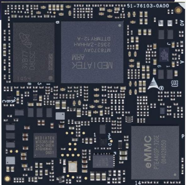


Pin Definition for OSM
| HDMI/DP++ |
| LVDS/eDP |
| MIPI-DSI |
| MIPI-CSI |
| 2x I2S |
| 1x UFS |
| 5x LAN |
| 4x USB 3.x/2.0 |
| 10x PCIe |
| 2x SDIO/3x SPI/2x I2C/4x UART/2x CAN/40x GPIO/4x PWM/2x ADC |
| Power |

# OPEN STANDARD MODULE TM
# OSM
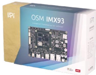
OSM (Open Standard Module) is the first Computer-on-Module for solderable BGA mini modules, accommodating ARM and x86 designs within a compact 45mm x 45mm size. With up to 662 BGA pins, it allows for multiple interfaces in a confined space, ideal for IoT applications. Maintaining a power envelope under 15W, they ensure reliable performance in rugged conditions.
The OSM specification, smaller than previous standards like Qseven and SMARC, enhances existing solutions and offers greater miniaturization and interface flexibility. OSM modules are completely machine processible during soldering, assembly and testing.
# I-Pi SMARC Development Kits

One-click Buy & Ship
Easy “How-to’s”
Online documentation
Forum support
# Applications

Robotics
# OSM
| Model Name | OSM-MTK510 | OSM-IMX93 | OSM-IMX8MP |
| <img src="images/264b60e4c03ace185e24316f6254e794cf31ead4aefccb9b758eb1f9db995d3e.jpg"/> | <img src="images/1ac9f25ea1d13cfc3a1858bd2a0956c9467bd8cb057cedb85d90d7413834016e.jpg"/> | <img src="images/d2548774808a96718e237fbb1f81768834ed7082fcc507f36c26739ccede3357.jpg"/> |
| CPU | MediaTek Genio 510 SoC(2x Arm Cortex-A78+4x Arm Cortex-A55 cores) | NXP i.MX93 series Dual core Cortex-A55 1x Cortex-M33 | NXP i.MX8M Plus series Quad core Cortex A53 with machine learning, 2.3 TOPS NPU |
| Memory/Storage | up to 8GB LPDDR4 | Up to 2GB LPDDR4, up to 128 GB eMMC | Up to 8GB LPDDR4, up to 128 GB eMMC |
| Cache | | 512KB system L2 cache | 33 KB I-cache32 KB D-cache512 KB L2 Cache |
| Boot Loader | U-boot | Uboot + device tree | Uboot + device tree |
| Graphics Outputs | HDMI/DP and eDP/DSI 4L | LVDS 4L / DSI 4L | LVDS 8L /HDMI/DSI |
| Camera | 1x MIPI CSO camera, 4 lanes | 1x MIPI CSI | 1x MIPI CSI |
| LAN | 1x Gbe RGMII | 2x RGMII with TSN | 2x RGMII 1x TSN |
| USB | 2x USB 2.0 1x USB 3.1 Gen 1 | 2x USB 2.0, 1x OTG | 3x USB 2.0, 1x USB 3.0 |
| Extension Ports | 4x UART3x SPI2x $I^{2}C$ 17x GPIO2x SDIO1x PWM | 3x UART2x SPI2x $I^{2}C$ 1x SDIO2x CAN10x GPIO | 4x UART2x SPI2x $I^{2}C$ 1x SDIO2x CAN8x GPIO |
| Audio | 1x I2S | $I^{2}S$ audio interface | $I^{2}S$ audio interface |
| PCI Express | 1x Gen 2 x1 | - | 1 lane GEN 3.0 |
| SEMA Support | yes | - | - |
| Power Supply | 5.0 V DC±5% | 5.0 V DC±5% | 5.0 V DC±5% |
| Operating Temperature | -40°C to +85°C | -40°C to 85°C | -40°C to 85°C |
| Form Factor & Compatibility | OSM Size L 45 x 45 mm | OSM Size-L, 45 x 45 mm | OSM Size-L, 45 x 45 mm |
| OS support | yoctoPROJECT | yoctoPROJECT | androidyoctoPROJECT |
Notes:
• You may add / delete some specs if necessary
# Qseven
# Where performance meets simplicity


# Pin Definition for Q7
2x LVDS / DSI / eDP
HDMI / DP++
2x MIPI CSI
HDA / I²S
2x SATA
GbE
2x USB 3.X/2.0 (1x OTG)
4x USB 2.0 (1x OTG)
4x PCIe
SDIO / SPI / LPC or GPIO
5x I²C / 2x UART or CAN
Power

コⅢ<ⅢZ
# Qseven
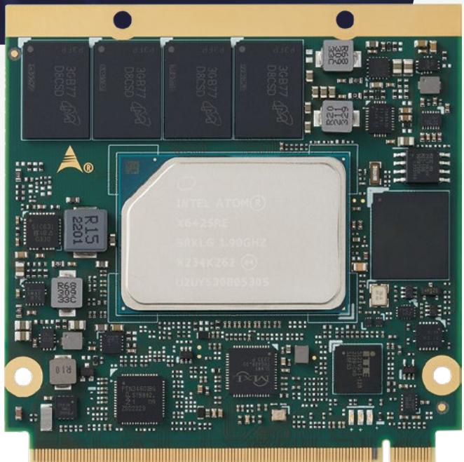
Qseven® is an off-the-shelf, multi-vendor, Computeron-Module that integrates all the core components of a typical PC packed in a slim design, to be mounted onto an application-specific carrier board. Its single ruggedized 230- pin MXM2 connector offers all the I/O interfaces necessary for mobile / ultra-mobile embedded applications, such as graphics, sound, mass storage, and networking, at power envelopes usually between 6 and 12 watts. Since its pinouts are mostly x86 x86-oriented, Qseven® is commonly built around "Atom level" x86 silicon.
# Applications

Industrial Automation (Monitoring)
# Qseven
<table>| Model Name | Q7-EL | Q7-AL | Q7-BT |
| SEVEN | <img src="images/4762c83429b2f112f6f1326141cdbdc879a2b7e6ae7a1f249746190886f0ce70.jpg"/> | <img src="images/30649a90239fd4761b5dc4e1c0d820cc275f0b3636f04788ad35c2e7114de47f.jpg"/> | <img src="images/8ca8030afdba1c044c09695cf93cd94a653fe1b559929c40ed21287579c04a11.jpg"/> |
| SoC | Intel Atom® x6000 series (formerly "Elkhart Lake") | Intel Atom® E3900 series, Pentium® N4200 or Celeron® N3350 (formerly "Apollo Lake") | Intel Atom® E3800 series (formerly codename: BayTrail) |
| Memory | Up to 16 GB LPDDR4 at 4266 MHz | Up to 8 GB LPDDR4 at 2400 MHz | Up to 4 GB DDR3L at 1066/1333 MHz |
| Cache | 1.5MB system L2 cache 4MB LLC | L2: 2 MB | 512 kB to 2 MB L2 cache |
| BIOS Type | AMI UEFI BIOS | AMI UEFI BIOS | AMI UEFI BIOS |
| Integrated Graphics | Intel® UHD Graphics for 10th Gen Intel® Processors, supports three independent displays, 4k video (up to 4096 x 2160@60fps) | 9th Gen Intel® graphics core architecture with up to 18 execution units, supports three independent displays, 4k video (up to 4096 x 2160 @60fps) | 7th Gen Intel® graphics supporting two independent displays |
| Graphics Features | DirectX 12, OpenGL 4.5, OpenCL 2.0, ES 3.2 | DirectX 12, OpenGL 4.2, OpenCL | DirectX 11.1, OpenGL 2.0, ES 3.2 |
| Camera | - | 2x MIPI CSI 2L/4L | - |
| LAN | MaxLinear® 2.5Gbit Ethernet with TSN | Intel® i210IT MAC/PHY, 1x GbE, IEEE 1588 | Intel® E3800 i210-IT 1GbE |
| USB | 2x USB 3.X 6x USB 2.0 | 2x USB 3.X 6x USB 2.0 | 1x USB3.0 6x USB 2.0 |
| Serial ATA | 2x SATA3 6Gb/s | 2x SATA 6Gb/s to carrier or 1x SATA 6Gb/s to carrier and 1x onboard SATA SSD | 2x SATA3 3 Gb/s |
| PCI Express | 4x PCIe1 Gen.3 | 3x PCIe x1 | 3x PCIe x1 Gen2 |
| eMMC (opt.) | Onboard eMMC 5.1 (16-128 GB) | Onboard eMMC 5.0 (4-64 GB) | Onboard eMMC 5.1 (4-64 GB) |
| Audio | HDA | HDA | HDA |
| SEMA | Yes | Yes | Yes |
| Power Supply | Module Input Voltage: 5.0V Power Pins:12 pins, 6A at 5V Typical IO Voltage: 3.3V | Module Input Voltage: 5.0V Power Pins: 12 pins, 6A at 5V Typical IO Voltage: 3.3V | Module Input Voltage: 5.0V Power Pins: 12 pins, 6A at 5V Typical IO Voltage: 3.3V |
| Operating Temperature | 0°C to 60°C -40°C to 85°C (opt.) | 0°C to 60°C -40°C to 85°C (opt.) | 0°C to 60°C -40°C to 85°C (opt.) |
| Form Factor & Compatibility | Qseven 2.1, Size: 70 x 70 mm | Qseven 2.1, Size: 70 x 70 mm | Qseven 2.0, Size: 70 x 70 mm |
| OS support | yocto PROJECT | yocto PROJECT | yocto PROJECT |
# Notes:
• For more CPU options please refer to online data sheet or user manual.
• All specifications are subject to change without further notice.
# ETX
# Legacy beyond 2025

# Pin Definition for ETX
X1
4x USB 2.0/1.1
32-bit PCI-bus
HD Audio
X2
8/16-bit ISA
X1
Analog VGA
Dual LVDS
PS2 MS / KB 2x UART, LPT1
X2
2x PATA
2x SATA
I²C / SMbus
10/100 Mbps Ethernet
# ETX?
# ETX
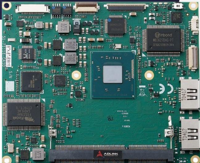
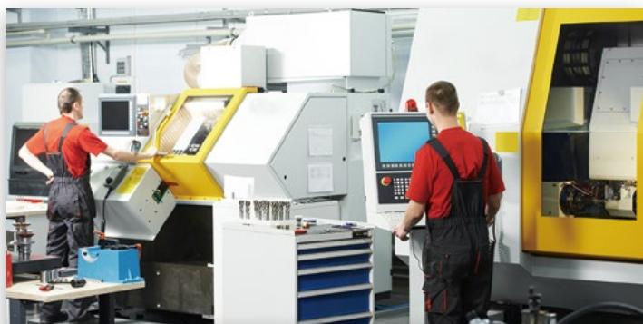
ETX® is one of the earliest successful Computer-on-Module form factors. Today it is still widely used in applications such as industrial automation, transportation and medium and low level medical appliances. While high-end Intel® Core™ applications have mostly migrated to COM Express, ETX® is still prominent in the lower power segment, mostly notably using Intel® Atom® SoCs. Specifically, customers who have heavily invested in ISA and PCI controllers or peripheral technologies still pose great demand for ETX® through the years. To this extent, ADLINK is providing long-term support for ETX® well beyond 2025.
# Applications
CNC controller
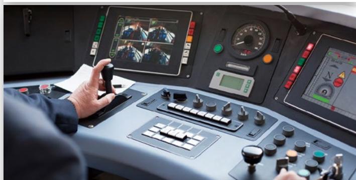
Transportation (Monitoring)
# ETX
| Model Name | ETX-BT |
| $ETX^®$ | <img src="images/4e6485690a6a16ed42ef70c0dd52166263a9d6d1d71707def09c8a17c403887d.jpg"/> |
| SoC | Intel Atom® E3800 seriesCeleron® N2930/J1900 (formerly "Bay Trail") |
| Memory | Up to 8GB DDR3L at 1333/1066MHz |
| Cache | L2: 512 kB to 2MB |
| BIOS Type | AMI Aptio EFI |
| TPM | Atmel AT97SC3204 |
| Graphics Features | LVDS, DisplayPort, VGADecode: H.264, MPEG2, MVC, VC-1, WMV9 and VP8Encode: H.264, MPEG2 and MVCDirectX 11, OCL 1.1, OGL ES Halt/2.0/1.1, OGL 3.2 |
| LAN | Intel® i211 MAC/PHY, supporting 10/100 Mbps(GbE via onboard connector) |
| USB | 4x USB 2.0 |
| PATA (IDE) | 2x |
| SATA | 2x SATA 3Gb/s |
| Audio | Integrated on E3800 SoC, Realtek ALC 262 |
| SEMA Support | Yes |
| Power Supply | 5V±5% / 5Vsb ±5% (ATX) 5V±5% (AT) |
| Operating Temperature | 0°C to 60°C-40°C to 85°C (opt.) |
| Form Factor & Compatibility | ETX 3.02 Size: 95 x 114 mm |
| OS Support | |
Notes:
• VxWorks is supported by project basis.
• All specifications are subject to change without further notice.
# Head Office
# ADLINK Technology, Inc.
No. 66, Huaya 1st Rd., Guishan District
Taoyuan City 333411, Taiwan
333411桃園市龜山區華亞一路66號
Tel: +886-3-216-5088
Fax: +886-3-328-5706
Email: service@adlinktech.com


www.adlinktech.com
# Worldwide Office
# Ampro ADLINK Technology, Inc.
6450 Via Del Oro, San Jose, CA 95119, USA
Tel: +1-408-360-0200
Toll Free: +1-800-966-5200
Fax: +1-408-360-0222
Email: info@adlinktech.com
# ADLINK Technology Korea Ltd.
767 A 1503
(医5全品E)()16827
A-1503, U-TOWER, 767 Sinsu-ro, Suji-gu, Yongin-si,
Gyeonggi-do, Republic of Korea, 16827
Toll Free: +82-80-800-0585
Tel: +82-31-786-0585
Fax: +82-31-786-0583
Email: korea@adlinktech.com
# ADLINK Technology GmbH
Hans-Thoma-Straße 8-10
68163 Mannheim, Germany
Tel: +49-621-43214-0
Fax: +49-621-43214-30
(Deggendorf) Ulrichsbergerstrasse 17, 94469
Deggendorf, Germany
Tel: +49-991-29094-10
Email: emea@adlinktech.com
# ADLINK Technology Singapore Pte, Ltd.
1008 Toa Payoh North, 07-17/18
Singapore 318996
Tel: +65-6844-2261
Fax: +65-6844-2263
Email: singapore@adlinktech.com
# ADLINK Technology (China) Co., Ltd.
上海市浦东新区张江高科技园区芳春路300号 (201203)
300 Fang Chun Rd., Zhangjiang Hi-Tech Park
Pudong New Area, Shanghai, 201203 China
Tel: +86-21-5132-8988
Fax: +86-21-5192-3588
Email: market@adlinktech.com
# ADLINK Technology, Inc. (French Liaison Office)
Bâtiment Thalès – Parc des Algorithmes,
Route de l Orme des Merisiers ,
91190 SAINT AUBIN , France
Tel:+33(0) 1-60-12-35-66
Fax:+33(0) 1-60-12-35-66
Email: france@adlinktech.com
# ADLINK Technology India Private Limited
Ground Floor, 317, Samanvitha Complex, Mayura
Street, Outer Ring Road, Byatarayanapura, Bangalore
North, Bangalore- 560092, Karnataka
Tel: +91-80-2346-4606 / +91-80-3121-3332
Fax: +91-80-2346-4606
india@adlinktech.com
# ADLINK Technology Beijing
北京市海淀区上地东路1号盈创动力大厦E座801室(100085)
Rm. 801, Power Creative E, No. 1 Shang Di East Rd.
Beijing, 100085 China
Tel: +86-10-5885-8666
Fax: +86-10-5885-8626
Email: market@adlinktech.com
# ADLINK Technology, Inc. (UK Liaison Office)
First Floor West Exeter House, Chichester Fields
Business Park Tangmere, West Sussex,
PO20 2FU, United Kingdom
Tel: +44-1243-859677
Email: UK@adlinktech.com
# ADLINK Technology Japan Corporation
101-0045 3-7-4
KDX神田駅前ビル4F
KDX Kanda Ekimae Bldg. 4F, 3-7-4 Kanda Kajicho,
Chiyoda-ku, Tokyo 101-0045, Japan
Tel: +81-3-5209-6001
Fax: +81-3-5209-6013
Email: japan@adlinktech.com
# ADLINK Technology Shenzhen
深圳市南山区科技园南区高新南七道数字技术园
A1栋2楼C区 (518057)
2F, C Block, Bldg. A1, Cyber-Tech Zone, Gao Xin Ave. Sec. 7
High-Tech Industrial Park S., Shenzhen, 518054 China
Tel: +86-755-2643-4858
Fax: +86-755-2664-6353
Email: market@adlinktech.com
# ADLINK Technology, Inc. (Israel Liaison Office)
MIXER Herzliya (Building B, 8 Floor)
3 Arik Einstein St.
4610301, Herzliya, Israel
Tel: +972-54-632-5251
israel@adlinktech.com
intel.
partner
[🔗 Link to the original document](.2025-com-catalog-web-250311/2025-com-catalog-web-250311.pdf)