ADLINK's extensive rugged portfolio delivers power, flexibility, affordability, endurance and longevity

# CompactPCI / CompactPCI Serial Enduring Performance

CompactPCI®

CompactPCI® Serial

# CompactPCI/ CompactPCI Serial Ecosystem: Diverse Solutions for Diverse Applications

CompactPCI is a capable architecture that can be the foundation of powerful, ruggedized systems in a wide range of challenging applications. Over the years, CompactPCI has evolved to include an array of different components. ADLINK is a market leader in producing many of these components in commercial off-the-shelf (COTS) packages.

# 3U/6U CompactPCI 2.0 Blades

Designed as the heart of a CompactPCI system, 3U and 6U CompactPCI processor blades are single-board computers that contain a processor, chipset, memory, I/O, and other essentials. ADLINK 3U/6U blades feature many of the latest Intel's® Core™ and Xeon® processors. ADLINK's new cPCI-6636 processor blade boasts an Intel® Xeon® E3-1505M v5 processor (Core™ i7 and Core™ i3 options are also available), up to 32GB DDR4-2133, XMC support, and up to eight USB 3.0 and four GbE ports.

The 3U cPCI-3630 highlights ADLINK's commitment to low-power CompactPCI blades. It's based on an Intel Atom® x7-E3950 processor, comes in single-slot to multi-slot (4HP/8HP/12HP) form factors, and can utilize an assortment of daughter boards for a broad range of I/O functionality. The new cPCI-3640 takes the 3U form factor a step further with integration of Intel's Atom® x6000FE Series industrial processor, which delivers $50\%$ more muti-thread performance and Intel® UHD Graphics. In the 6U category, ADLINK's new cPCI-6636 processor blade boasts an Intel® Xeon® E3-1505M v5 processor (Core™ i7 and Core™ i3 options are also available), up to 32GB DDR4-2133, XMC support, and up to eight USB 3.0 and four GbE ports. Most recently, ADLINK added the cPCI-6646, -6656, and -6660 models in its 6U lineup. These bring support for new Intel Atom x7 and 12th Gen Core processors. ADLINK optionally also offers conduction-cooled versions of select models, such as the CT-6540 variant of the cPCI-6540, an extended-temperature processor blade with 9th Gen Intel Core and Xeon processor options as well as dual PMC/XMC connectivity. For similar specs in a 3U configuration, ADLINK offers the cPCI-3520 series.

# 3U CompactPCI Serial (CPCI-S.0) Blades

Decades of development have proven the superior performance and reliability of serial interconnects. With CPCI-S.0, CompactPCI gains the ability to support more modern technologies, including USB, SATA/SAS, PCI Express, and Ethernet. Most configurations involve one system slot and up to eight peripheral slots, with hot-swap support and up to 12 Gbit/sec transmission bandwidth. Better yet, multiple system boards can operate in peripheral slots, allowing high

![Electronic circuit board with ADLINK logo and ports, no visible text or symbols on the board itself](.adlink-compactpci-brochure-enduring-performance-20220823/47c2904f82cdb87117a9ed72e89b97101ba2f87c5f02cba8a991c556e5b850e5.jpg)

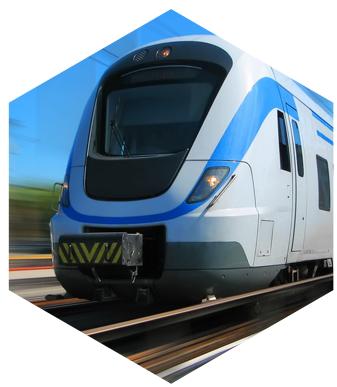
multiprocessor density for demanding applications, and full-mesh Ethernet can provide deployment resiliency with up to 10GbaseT copper connections. ADLINK brings these features and much more to its new family of 3U blades, including the cPCI-A3525, which backs 9th Gen Intel Xeon/Core i7 performance with extensive USB, SATA, and PCI Express expandability. Even greater throughput arrives in the cPCI-A3535, based on Intel's 11th Gen architecture and M12 connectivity — a key attribute for railway systems. The cPCI-A3535 integrates seamlessly with 3U peripheral boards, such as the cPCI-A3W20 (5G wireless), cPCI-A3E20 (Ethernet), and cPCI-A3MXM (GPGPU card). ADLINK even offers the ARM-based cPCI-A2ARM processor blade, with EN 50155 compliance and and optional M12 connectivity, specifically for rail platforms.

# 3U/6U Enclosures & Systems

In order to speed up time to market (TTM) and/or deployment, CompactPCI products regularly come prepackaged within a chassis for effortless rackmount installation. Prebuilt CompactPCI systems include processor blades and often feature complementary components, such as peripheral blades, power supplies, cooling, etc., providing customers with confidence that their systems are ready for immediate field action. ADLINK's 3U and 6U CompactPCI enclosure families represent unprecedented choice for end users and system integrators. Our enclosures for 3U blades are available in 3U or 4U height, while 6U blade enclosures span 1U to 9U height.

# Backplanes

Backplanes are an integral part of the CompactPCI architecture. Like blades themselves, CompactPCI backplanes come in 3U and 6U form factors and are the key to CompactPCI's exceptional bandwidth that meet many industries' needs. ADLINK showcases its comprehensive support of CompactPCI with a full range of 3U/6U backplanes. Depending on the model, backplanes use the 32-bit/33MHz or 64-bit/66MHz CompactPCI bus, can support rear I/O, and have user-selectable voltage.

# Power Supplies

Mission-critical operations cannot tolerate downtime or failure, making power supply dependability crucial piece to any CompactPCI system. ADLINK maintains an impressive array of 3U and 6U power supplies that conform to the PICMG 2.11 standard. Almost all ADLINK's power supplies are hot-swappable to ensure peak performance and high uptime. Output wattage peaks at 400W for our 6U PSUs and 250W for our 3U units. The cPS-H325/WDC is a specialty power module for railway systems that is available in 120W (fanless) or 300W (forced air) configurations.

# Peripheral Cards

Scalability is one of the key advantages CompactPCI offers, as systems integrators can tap into an architecture that gives them clear upgrade paths as situations change over time. ADLINK recognizes that CompactPCI peripheral cards help customers maximize their systems' functionality, potentially extending life cycles and eliminating the need for more expensive hardware changes. We provide a wide range of cards, including carrier boards, Ethernet cards, module and storage carriers, XMC/PMC modules, DIO modules, and more.

![Exterior view of a modern high-speed train at a station, featuring a white DB-branded bullet train on display (no signage)](.adlink-compactpci-brochure-enduring-performance-20220823/99c2e3e9fbb20f6f88aa111107d0ce9faf5f9e736eac3e8f5e3dc3dde130e30c.jpg)

# CompactPCI Serial Processor Blades / Peripheral Cards

![This image displays a green printed circuit board, likely a computer expansion card, populated with various electronic components such as black integrated circuits, capacitors, resistors, and a silver metal shield. A large red banner is superimposed diagonally across the upper left corner, featuring the word 'new' in white lowercase letters. The left edge of the board includes a metal bracket with mounting holes and small pins, while the right edge features two gold-colored ports, resembling Ethernet jacks.](.adlink-compactpci-brochure-enduring-performance-20220823/743bc8aec271ba8c410d646eb5d5a1caa3a203222d4237bd9b5c0384e31441d9.jpg)

![The image displays a green circuit board populated with a large central chip, several smaller integrated circuits, capacitors, and a row of metallic connectors on the right side. A red banner is superimposed on the top left corner, displaying the word 'new' in white lowercase letters.](.adlink-compactpci-brochure-enduring-performance-20220823/12d79ff011904ed1398d83d8d4b52cc6b7ef343d7208f1aaa1c31f78dc9c7242.jpg)

<table><tr><td colspan="2"></td><td colspan="3">3U Air-Cooled Processor Blades</td></tr><tr><td rowspan="2" colspan="2">Model Name</td><td colspan="2">cPCI-A3535</td><td rowspan="2">cPCI-A3525</td></tr><tr><td>cPCI-A3535</td><td>cPCI-A3535D</td></tr><tr><td rowspan="3">CPU and Core Logic</td><td>CPU</td><td>Intel® Xeon® W-11155MLE (formerly Tiger Lake)</td><td>Intel® Xeon® W-11155MRE (formerly Tiger Lake)</td><td>Intel® Xeon® E, 9th Gen Intel® CoreTM (formerly Coffee Lake Refresh)</td></tr><tr><td>CPU Speed (max.)</td><td>3.1 GHz</td><td>4.4 GHz</td><td>4.2 GHz</td></tr><tr><td>Chipset</td><td colspan="2">RM590E</td><td>CM246</td></tr><tr><td rowspan="2">Form Factor &amp; Bus</td><td>PICMG Spec.</td><td colspan="2">S.0 (R2.0)</td><td>S.0 (R2.0)</td></tr><tr><td>Slot width</td><td>1</td><td>2</td><td>1</td></tr><tr><td rowspan="3">Memory</td><td>DIMM Type</td><td colspan="2">DDR4-3200 SODIMM</td><td>DDR4-2666 SODIMM</td></tr><tr><td>Max. Capacity</td><td colspan="2">64GB</td><td>64GB</td></tr><tr><td>ECC Support</td><td colspan="2">Yes (optional)</td><td>Yes (optional)</td></tr><tr><td>Storage</td><td>NAND Flash</td><td colspan="2">80GB onboard</td><td>32GB/128GB onboard</td></tr><tr><td rowspan="3">Front I/O</td><td>Ethernet</td><td>1x 2.5GbE2x M12 2.5GbE</td><td>1x 2.5GbE2x M12 10GbE</td><td>2x GbE</td></tr><tr><td>USB</td><td colspan="2">1x Type A USB 3.2 Gen 11x Type C USB 3.2 Gen 1</td><td>2x USB 3.0</td></tr><tr><td>No. of Displays Support</td><td colspan="2">1x USB Type C (DP, HDMI)</td><td>2x DP</td></tr><tr><td rowspan="6">Rear I/O</td><td>Ethernet</td><td>2x GbE</td><td>4x GbE</td><td>2x GbE</td></tr><tr><td>USB 2.0</td><td colspan="2">8</td><td>8</td></tr><tr><td>USB 3.0</td><td colspan="2">2</td><td>2</td></tr><tr><td>PCI Express</td><td colspan="2">2x PCIe Gen 3 x83x PCIe Gen 3 x42x PCIe Gen 3 x1</td><td>2x PCIe Gen 3 x82x PCIe Gen 2 x41x PCIe Gen 2 x1</td></tr><tr><td>Serial ATA</td><td colspan="2">5</td><td>7</td></tr><tr><td>RAID</td><td colspan="2">Yes</td><td>No</td></tr><tr><td colspan="2">TPM</td><td colspan="2">2.0</td><td>-</td></tr></table>

![The image displays a piece of computer hardware, likely a server blade or expansion card. On the left is a silver metal bracket with a black handle for insertion. The right side features a green printed circuit board (PCB) largely covered by a silver metal shield. Visible components include chips, connectors, and a gold finger edge connector at the bottom. Text printed on the board reads '2014 Hewlett-Packard Company' and '806-58000-01'.](.adlink-compactpci-brochure-enduring-performance-20220823/0577c059049c058428466549552926fe5e71ce87a2cc6ad9ac91a03f8e9f4b3b.jpg)

# cPCI-A3H10

# 3U CompactPCI Serial 2.5" SATA Storage Carrier

• One 2.5" SATA 6Gb/s drive slot
- Status LEDs on faceplate: drive activity, hot-swap status, user-configurable
• Hot swap support
- Operating temperature: -40°C to 85°C with qualified components

# Ordering Information

\- cPCI-A3H10: 3U CompactPCI Serial 2.5" SATA storage carrier with hot-swap support, anti-shock and anti-vibration storage kit

![This image displays a server expansion card, likely a RAID controller or storage interface card. On the left side, a white metal mounting bracket with a black handle is attached. The main body is a green printed circuit board (PCB) dominated by a large, square silver heatsink in the center, which covers the primary processor. Surrounding the heatsink are various smaller chips, capacitors, and circuitry. On the far right edge, there is a gold-plated connector designed for a PCIe slot, and a small white connector is visible near the bottom right corner.](.adlink-compactpci-brochure-enduring-performance-20220823/3c2cc2a8dfac80cc844c46197da206c670532dfab7948147f32bb8526928cee3.jpg)

# cPCI-A3H20

# 3U CompactPCI Serial NVMe/SATA Storage Carrier

• One NVMe M.2 and one NVMe U.2 drive slot
• One optional SATA 6Gb/s M.2 drive slot shared space with NVMe U.2
- Status LEDs on faceplate: drive activity, hot-swap status, user-configurable
- Operating temperature: -40°C to +85°C with qualified modules
• EN50155 compliance

# cPCI-A3MXM/A4500

# 3U CompactPCI Serial MXM Carrier Card

- NVIDIA RTX™ A4500 with 5888 CUDA® cores, 46 RT Cores, and 184 Tensor Cores
• 17.66 TFLOPS peak FP32 performance
• Operating temperature: $-20^{\circ}C$ to $+60^{\circ}C$
EN50155 compliance

# cPCI-A3COM

# 4-Port RS-232/422/485 COM Card

- Four asynchronous communications ports with intelligent buffer
• Four RS-232/422/485 ports
• 2500 VDC signal to ground isolation voltage
• Auto-flow control
- Surge protectors
• EN50155 compliance

# cPCI-A3ETH

# 3U CompactPCI Serial Ethernet Card

• Four RJ-45 ports supports up to 2.5G
- Four independent Intel® i225 Ethernet controllers
- Operating temperature: -40°C to +85°C
• EN50155 compliance

![The image displays a green printed circuit board (PCB) mounted on a silver metal bracket, likely a network interface card. Attached to the left side of the bracket is a black optical transceiver module with a red latch. The board contains various electronic components, chips, and a PCIe connector at the bottom edge. Visible text printed on the board includes '41086' near the top left, '3880' near the bottom left, 'CE' in the center, 'RoHS' on the right side, 'REV' near the center right, '20' near the CE mark, and '3880' near the bottom right.](.adlink-compactpci-brochure-enduring-performance-20220823/2a50781421cd736ef6997b22d27e14e78d238308f0c4387c7be485be98b4676e.jpg)

# cPCI-A3X10

# 3U CompactPCI Serial XMC Module Carrier

- One XMC slot
- Operating temperature: -40°C to 85°C with qualified components

# Ordering Information

• cPCI-A3X10: 3U CompactPCI Serial XMC module carrier

![Close-up of a green circuit board with visible components and connectors, labeled 'cPCI-A3RF' (no other text or symbols)](.adlink-compactpci-brochure-enduring-performance-20220823/612bcf5eaa026fe54f76a763c7dcbdf47a5479d6c50da52a5512eaf63657e320.jpg)

# cPCI-A3RF

# 3U CompactPCI Serial Wireless Carrier Card

• Support one M.2 and one Mini PCIe slot for 5G or Wi-Fi module
- Up to 6 SMA antenna connectors on front panel
- Operating temperature: -40°C to +85°C with qualified modules
• EN50155 compliance

# cPCI-A3USB

# 3U CompactPCI Serial 8-Port USB 3.2/USB 3.0 Card

• Four USB 3.2 Gen 1 ports
• Four USB 3.0 ports by hub
- Operating temperature: -40°C to +85°C
• EN50155 compliance

# cPCI-A3MPCIe

# 3U CompactPCI Serial Mini PCIe Carrier Card

- Two Mini PCIe slots
- Operating temperature: -40°C to +85°C
EN50155 compliance

# 6U CompactPCI Blades

![This image features a green circuit board, likely a motherboard or expansion card, populated with various electronic components including integrated circuits, capacitors, and a blue square component. The left side displays a metal bracket with mounting holes and black plastic clips. A red diagonal banner overlaid on the upper left corner contains the text 'new' in white lowercase letters.](.adlink-compactpci-brochure-enduring-performance-20220823/fceac1205ff5645c142319d0b7b5a19e14fdcf9451e8e42c791088b0307af9bd.jpg)

![A vertical image displaying a green graphics card circuit board with various electronic components, chips, and ports visible along the left edge. A large red ribbon graphic is superimposed on the upper left corner, containing the word 'new' in white, lowercase letters.](.adlink-compactpci-brochure-enduring-performance-20220823/92b3cf3e80f1c0ce572e9e7de07e8e41f70d89034577f3d58d6ba8ff5f81878a.jpg)

![This image displays a green circuit board, oriented vertically, featuring numerous electronic components like chips, capacitors, and connectors along its left edge. A large, red diagonal banner overlays the upper left portion of the board with the word 'new' printed in white lowercase letters.](.adlink-compactpci-brochure-enduring-performance-20220823/1a3b631552cc6b0af0fe4880cbf8138f41f95e97332500abc5e40a31a8757afe.jpg)

![The image displays a green printed circuit board (PCB), likely a server motherboard, mounted vertically on a silver metal bracket. The board is oriented horizontally within the vertical frame. Key features include two large blue CPU sockets, multiple rows of black DIMM memory slots flanking the CPUs, and several silver PCIe expansion slots along the left edge. Various electronic components such as cylindrical capacitors and integrated circuits are scattered across the board. Legible text on the chips includes '88PM800' (visible on chips near the top left and bottom left), '6062', 'L4542', and 'A730'. Black cables are partially visible at the top and bottom left edges.](.adlink-compactpci-brochure-enduring-performance-20220823/309434dfcf51e063a4676f6d5c8d953c1ca6787af5d1caeed84d9eda28d25ffd.jpg)

6U Air-Cooled Processor Blades

<table><tr><td rowspan="2" colspan="2">Model Name</td><td colspan="2">cPCI-6540</td><td rowspan="2">cPCI-6640</td><td rowspan="2">cPCI-6660</td><td colspan="3">cPCI-6636</td></tr><tr><td>cPCI-6540</td><td>cPCI-6540V</td><td>cPCI-6636</td><td>cPCI-6636D</td><td>cPCI-6636DZ</td></tr><tr><td rowspan="3">CPU and Core Logic</td><td>CPU</td><td colspan="2">Intel® Xeon® E-2276ML,9th Gen Intel® CoreTM i7/i3</td><td>Intel® Xeon® E-2276ML,8th/9th Gen Intel® CoreTM i</td><td>Intel Atom® x6413E (formerly Elkhart Lake)</td><td colspan="3">Intel® Xeon® E3,6th/7th Gen Intel® CoreTM i7/i3</td></tr><tr><td>CPU Speed (max.)</td><td colspan="2">4.5 GHz</td><td>4.4 GHz</td><td>3.0 GHz</td><td colspan="3">3.7 GHz</td></tr><tr><td>Chipset</td><td colspan="2">CM246</td><td>CM246</td><td>-</td><td colspan="2">CM236</td><td>HM170</td></tr><tr><td rowspan="6">Form Factor &amp; Bus</td><td>PICMG Spec.</td><td colspan="2">2.0 (R3.0), 2.1 (R2.0), 2.9 (R1.0), 2.16 (R1.0)</td><td>2.0 (R3.0)</td><td>2.0 (R3.0), 2.1 (R2.0), 2.16 (R1.0)</td><td colspan="2">2.0 (R3.0), 2.1 (R2.0), 2.16 (R1.0)</td><td>2.0 (R3.0), 2.1 (R2.0)</td></tr><tr><td>Slot Width</td><td colspan="2">1</td><td>2</td><td>1</td><td>1</td><td>2</td><td>2</td></tr><tr><td>Host/Peripheral</td><td colspan="2">Host/Statellite</td><td>Host</td><td>Host/Statellite</td><td colspan="2">Host/Universal</td><td>Host</td></tr><tr><td>PCI Bandwidth (max.)</td><td colspan="2">64-bit/33, 66MHz</td><td>64-bit/66MHz</td><td>32-bit/33MHz</td><td colspan="3">64-bit/66MHz</td></tr><tr><td>PMC</td><td>1 (64-bit)</td><td>2 (64-bit)</td><td>1 (32-bit)</td><td>1 (PCIe x4)</td><td colspan="3">-</td></tr><tr><td>XMC</td><td>1 (PCIe x8)</td><td>2 (PCIe x8)</td><td>-</td><td>-</td><td>-</td><td>1</td><td>1</td></tr><tr><td rowspan="3">Memory</td><td>Type</td><td colspan="2">DDR4-2666</td><td>DDR4-3200</td><td>DDR4-3200</td><td colspan="3">DDR4-2133</td></tr><tr><td>Max. Capacity</td><td colspan="2">32GB soldered + 32GB SODIMM</td><td>32GB SODIMM</td><td>32GB SODIMM</td><td colspan="3">16GB soldered + 16GB SODIMM</td></tr><tr><td>ECC Support</td><td colspan="2">Yes</td><td>Yes</td><td>Yes</td><td colspan="2">Yes</td><td>No</td></tr><tr><td rowspan="2">Display</td><td>Graphics Controller</td><td colspan="2">Integrated in processor</td><td>Integrated in processor</td><td>Integrated in processor</td><td colspan="3">Integrated in processor</td></tr><tr><td>Interface</td><td colspan="2">DisplayPort, VGA</td><td>DVI-H, VGA</td><td>VGA pin header</td><td colspan="2">DVI-H, VGA</td><td>VGA</td></tr><tr><td>Ethernet</td><td>GbE port</td><td colspan="2">4 (2F+2R)</td><td>8F</td><td>4F or 2F+2R</td><td>4 (2F+2R)</td><td>4 (2F+2R)</td><td>2F</td></tr><tr><td rowspan="5">Storage</td><td>M.2 NVMe</td><td colspan="2">2242</td><td>-</td><td>-</td><td colspan="3">-</td></tr><tr><td>Serial ATA</td><td>4R</td><td>-</td><td>2F</td><td>1F (or mSATA)</td><td>2F+3R</td><td>2F+3R</td><td>3F</td></tr><tr><td>CompactFlash</td><td>-</td><td>-</td><td>-</td><td>-</td><td colspan="3">-</td></tr><tr><td>CFast</td><td>-</td><td>-</td><td>1F (optional)</td><td>-</td><td></td><td>-</td><td>-</td></tr><tr><td>Onboard Flash</td><td>-</td><td>-</td><td>-</td><td>Onboard SSD (convertable to J3)</td><td>-</td><td>-</td><td>-</td></tr><tr><td rowspan="5">I/O Ports</td><td>USB 2.0</td><td>6R</td><td>6R</td><td>-</td><td>-</td><td>6R</td><td>6R</td><td>-</td></tr><tr><td>USB 3.0</td><td>2F</td><td>1F</td><td>6F</td><td>1F</td><td></td><td>3F</td><td>8F</td></tr><tr><td>COM</td><td>1F+1R</td><td>1R</td><td>2F</td><td>1F</td><td>1F+2R</td><td>1F+2R</td><td>6F</td></tr><tr><td>PS/2 KB/MS</td><td>1R</td><td>1R</td><td>-</td><td>-</td><td>1R</td><td>1R</td><td>-</td></tr><tr><td>Rear I/O</td><td colspan="2">Yes</td><td>No</td><td>USB, HDA, PS/2, COM</td><td colspan="2">Yes</td><td>No</td></tr></table>

Note: F = Blade; R = Rear Transition Module

Chassis Compatibility

<table><tr><td rowspan="2">Chassis Model</td><td rowspan="2">cPCI Bus</td><td colspan="2">cPCI-6540</td><td colspan="2">cPCI-6640</td><td colspan="2">cPCI-6660</td><td colspan="2">cPCI-6636</td></tr><tr><td>Host</td><td>Peripheral</td><td>Host</td><td>Peripheral</td><td>Host</td><td>Peripheral</td><td>Host</td><td>Peripheral</td></tr><tr><td>cPCIS-3300BLS</td><td>N/A</td><td>✓</td><td>✓</td><td>✓</td><td>x</td><td>✓</td><td>✓</td><td>✓</td><td>✓</td></tr><tr><td>cPCIS-3330</td><td>32-bit/33MHz</td><td>✓</td><td>△</td><td>✓</td><td>x</td><td>✓</td><td>x</td><td>✓</td><td>✓</td></tr><tr><td>cPCIS-3330/64</td><td>64-bit/66MHz</td><td>✓</td><td>△</td><td>✓</td><td>x</td><td>✓</td><td>x</td><td>✓</td><td>✓</td></tr><tr><td>cPCIS-3320</td><td>64-bit/66MHz</td><td>✓</td><td>△</td><td>✓</td><td>x</td><td>✓</td><td>x</td><td>✓</td><td>✓</td></tr><tr><td>cPCIS-6130R</td><td>64-bit/66MHz</td><td>✓</td><td>△</td><td>✓</td><td>x</td><td>✓</td><td>x</td><td>✓</td><td>✓</td></tr><tr><td>cPCIS-6400U</td><td>64-bit/66MHz</td><td>✓</td><td>△</td><td>✓</td><td>x</td><td>✓</td><td>x</td><td>✓</td><td>✓</td></tr><tr><td>cPCIS-6400U/32</td><td>32-bit/33MHz</td><td>✓</td><td>△</td><td>✓</td><td>x</td><td>✓</td><td>✓</td><td>✓</td><td>✓</td></tr><tr><td>cPCIS-6400X</td><td>64-bit/66MHz</td><td>✓</td><td>△</td><td>✓</td><td>x</td><td>✓</td><td>x</td><td>✓</td><td>✓</td></tr><tr><td>cPCIS-6400X/32</td><td>32-bit/33MHz</td><td>✓</td><td>△</td><td>✓</td><td>x</td><td>✓</td><td>✓</td><td>✓</td><td>✓</td></tr><tr><td>cPCIS-6230R/6240R</td><td>32-bit/33MHz</td><td>✓</td><td>△</td><td>✓</td><td>x</td><td>✓</td><td>✓</td><td>✓</td><td>✓</td></tr><tr><td>cPCIS-6418U</td><td>64-bit/66MHz</td><td>✓</td><td>△</td><td>✓</td><td>x</td><td>✓</td><td>x</td><td>✓</td><td>✓</td></tr><tr><td>cPCIS-6230R/64</td><td>64-bit/66MHz</td><td>✓</td><td>△</td><td>✓</td><td>x</td><td>✓</td><td>x</td><td>✓</td><td>✓</td></tr><tr><td>cPCIS-6230R/64/N110</td><td>64-bit/66MHz</td><td>✓</td><td>✓</td><td>✓</td><td>x</td><td>✓</td><td>x</td><td>✓</td><td>✓</td></tr><tr><td>cPCIS-6235R</td><td>32-bit/33MHz</td><td>✓</td><td>△</td><td>✓</td><td>x</td><td>✓</td><td>✓</td><td>✓</td><td>✓</td></tr><tr><td>cPCIS-6235R/64</td><td>64-bit/66MHz</td><td>✓</td><td>△</td><td>✓</td><td>x</td><td>✓</td><td>x</td><td>✓</td><td>✓</td></tr></table>

√: Compatible, ✗: Not Supported, △: Limitation - PIM is not functional in peripheral slot with H.110

![The image displays a black rectangular electronic component, resembling a laptop keyboard assembly with a trackpad area on the right side. A red triangular banner is superimposed on the upper left corner with the white text 'new'.](.adlink-compactpci-brochure-enduring-performance-20220823/3841ad48acfea39261b44147275e70604ba4e168589f606769d2b51e63d95b3a.jpg)

6U Rugged Conduction Cooled Blade

<table><tr><td colspan="2">Model Name</td><td>CT-6540</td></tr><tr><td rowspan="3">CPU and Core Logic</td><td>CPU</td><td>Intel® CoreTM i7/i5</td></tr><tr><td>CPU Speed (max.)</td><td>4.1GHz</td></tr><tr><td>Chipset</td><td>CM246</td></tr><tr><td rowspan="6">Form Factor &amp; Bus</td><td>PICMG Spec.</td><td>2.0 (R3.0), 2.1 (R2.0), 2.9 (R1.0), 2.16 (R1.0)</td></tr><tr><td>Slot Width</td><td>1</td></tr><tr><td>Host/Peripheral</td><td>Host/Universal</td></tr><tr><td>PCI Bandwidth (max.)</td><td>64-bit/33, 66MHz</td></tr><tr><td>PMC</td><td>1 (64-bit)</td></tr><tr><td>XMC</td><td>1 (PCIe x8)</td></tr><tr><td rowspan="3">Memory</td><td>Type</td><td>DDR4-2666</td></tr><tr><td>Max. Capacity</td><td>32GB soldered</td></tr><tr><td>ECC Support</td><td>Yes</td></tr><tr><td rowspan="2">Display</td><td>Graphics Controller</td><td>Integrated in processor</td></tr><tr><td>Interface</td><td>DisplayPort, VGA</td></tr><tr><td>Ethernet</td><td>Gigabit Ethernet</td><td>2R</td></tr><tr><td rowspan="4">Storage</td><td>SATA</td><td>3R</td></tr><tr><td>CompactFlash</td><td>-</td></tr><tr><td>CFast</td><td>-</td></tr><tr><td>NAND</td><td>-</td></tr><tr><td rowspan="4">I/O</td><td>USB 2.0</td><td>6R</td></tr><tr><td>USB 3.0</td><td>-</td></tr><tr><td>Serial</td><td>2R</td></tr><tr><td>PA/2 KB/MS</td><td>2R</td></tr><tr><td rowspan="7">Other</td><td>Rear I/O</td><td>Yes</td></tr><tr><td>PCI Express</td><td>1R, x4</td></tr><tr><td>Audio</td><td>High Def.</td></tr><tr><td>GPIO</td><td>16R</td></tr><tr><td>TMDS</td><td>Yes</td></tr><tr><td>RGB</td><td>1R</td></tr><tr><td>PIM</td><td>2R</td></tr><tr><td colspan="2">Operating Temp.</td><td>-40°C to +85°C (selected CPUs)</td></tr><tr><td colspan="2">Vibration</td><td>5-500 Hz, 2g (random), operating</td></tr><tr><td colspan="2">Shock</td><td>20g/11ms half sine, operating</td></tr></table>

# 6U CompactPCI Rear Transition Modules

![The image displays a sequence of seven views of a vertical server backplane or motherboard assembly arranged horizontally against a plain white background. The hardware component consists of a green printed circuit board (PCB) housed within a silver metal chassis frame, featuring black plastic mounting lugs at the top and bottom. The sequence of images showcases different angles, including the front face of the PCB with various chips and ports, side profiles, the rear metal chassis with visible red and black wiring harnesses, and a rear view featuring a black cooling fan at the bottom. Any text or labels present on the components are illegible due to the image resolution.](.adlink-compactpci-brochure-enduring-performance-20220823/cd919622bba543914b9760d70dee260561c0b956d39fca2be81c8c51b580a9b8.jpg)

6U RTMs

<table><tr><td></td><td colspan="4">cPCI-R6000 Series</td><td rowspan="2" colspan="2">cPCI-R6210</td><td colspan="7">cPCI-R6100 Series</td><td rowspan="2" colspan="2">cPCI-R6500</td></tr><tr><td rowspan="2">Model Name</td><td colspan="2">cPCI-R6002</td><td colspan="2">cPCI-R6002D</td><td colspan="2">cPCI-R6100</td><td colspan="2">cPCI-R6110</td><td colspan="3">cPCI-R6120</td></tr><tr><td>Faceplate</td><td>Onboard</td><td>Faceplate</td><td>Onboard</td><td>Faceplate</td><td>Onboard</td><td>Faceplate</td><td>Onboard</td><td>Faceplate</td><td>Onboard</td><td>Faceplate</td><td>Onboard</td><td>Faceplate</td><td>Onboard</td><td>Faceplate</td></tr><tr><td>GbE</td><td>2</td><td></td><td>2</td><td></td><td></td><td></td><td> $4^{(4)}$ </td><td></td><td>2</td><td></td><td>2</td><td></td><td>2</td><td></td><td></td></tr><tr><td>USB 2.0</td><td>2</td><td>1 (5-pin)</td><td>4</td><td>1 (5-pin)</td><td>1</td><td>1 (5-pin)</td><td>4</td><td></td><td>4</td><td></td><td>4</td><td></td><td>1</td><td></td><td></td></tr><tr><td>USB 3.0</td><td></td><td></td><td></td><td></td><td></td><td></td><td></td><td></td><td></td><td></td><td></td><td></td><td></td><td></td><td></td></tr><tr><td>COM</td><td>1(DB-9)</td><td>1 (10-pin)(TX/RX)</td><td>1(DB-9)</td><td>1 (10-pin)(TX/RX)</td><td></td><td>1 (10-pin)(TX/RX)</td><td>1 (RJ-45)</td><td></td><td></td><td></td><td></td><td></td><td>1</td><td>1 (Tx/Rx)</td><td></td></tr><tr><td>DVI</td><td> $1 (DVI-I)^{(1)}$ </td><td></td><td>1 (DVI-I)</td><td></td><td>1 (DVI-I)</td><td></td><td>1</td><td></td><td></td><td></td><td></td><td></td><td> $2^{(5)}$ (DVI-H, DVI-D)</td><td></td><td></td></tr><tr><td>VGA</td><td></td><td></td><td></td><td></td><td></td><td></td><td>1</td><td></td><td>1</td><td></td><td>1</td><td></td><td></td><td></td><td></td></tr><tr><td>PMC</td><td></td><td></td><td></td><td></td><td></td><td>2 (PIM)</td><td></td><td></td><td></td><td></td><td></td><td></td><td></td><td></td><td></td></tr><tr><td>SATA</td><td></td><td>2 (7-pin)</td><td></td><td> $3^{(1)}$ </td><td></td><td>2 (7-pin)</td><td></td><td>2 (7-pin)</td><td></td><td> $3^{(1)(4)}$ </td><td></td><td>2</td><td></td><td>3 (7-pin)</td><td></td></tr><tr><td>CF</td><td></td><td> $1^{(1)}$ (optional)</td><td></td><td> $1^{(1)}$ (optional)</td><td></td><td></td><td></td><td> $1^{(2)}$ </td><td></td><td> $1^{(2)}$ </td><td></td><td></td><td></td><td></td><td></td></tr><tr><td>Mic-in</td><td></td><td></td><td>1</td><td></td><td></td><td></td><td></td><td></td><td></td><td></td><td></td><td></td><td></td><td rowspan="2">1 (10-pin)</td><td></td></tr><tr><td>Line-out</td><td></td><td></td><td>1</td><td></td><td></td><td></td><td></td><td></td><td></td><td></td><td></td><td></td><td></td><td></td></tr><tr><td>PS/2 KB/MS</td><td></td><td></td><td>1</td><td></td><td></td><td></td><td>1</td><td></td><td>1</td><td></td><td>1</td><td></td><td>1</td><td></td><td></td></tr><tr><td>SD</td><td></td><td></td><td></td><td></td><td></td><td></td><td></td><td>1</td><td></td><td>1</td><td></td><td></td><td></td><td></td><td></td></tr></table>

(1) Two 7-pin signal connectors onboard for external drives and one direct connector for onboard 2.5" SATA drive. Optional CompactFlash slot is supported when SATA connector adapter is replaced by CompactFlash adapter. SATA drive and CF not supported simultaneously.
(2) Converted from USB which unable to support Windows OS installation.

(3) Two GbE ports are from independent Intel® I350-AM2 Gigabit Ethernet controller on RTM

(4) Space is reserved onboard for one 2.5" SATA drive

(5) One DVI-I (digital + analog), one DVI-D (digital only) are from graphic chip on MXM module assembled on RTM

6U Processor Blade Compatibility

<table><tr><td></td><td colspan="2">cPCI-R6000 Series</td><td rowspan="2">cPCI-R6210</td><td colspan="3">cPCI-R6100 Series</td><td rowspan="2">cPCI-R6500</td></tr><tr><td>Model Name</td><td>cPCI-R6002</td><td>cPCI-R6002D</td><td>cPCI-R6100</td><td>cPCI-R6110</td><td>cPCI-R6120</td></tr><tr><td>Slot width</td><td>4HP</td><td>8HP</td><td>4HP</td><td>4HP</td><td>4HP</td><td>8HP</td><td>8HP</td></tr><tr><td>cPCI-6540</td><td>✓</td><td>✓</td><td></td><td>✓</td><td>✓</td><td>✓</td><td>✓</td></tr><tr><td>CT-6540</td><td>✓</td><td>✓</td><td></td><td>✓</td><td>✓</td><td>✓</td><td>✓</td></tr><tr><td>cPCI-6660</td><td>✓</td><td></td><td>✓</td><td></td><td></td><td></td><td>✓</td></tr><tr><td>cPCI-6636(D)</td><td>✓</td><td>✓</td><td></td><td>✓</td><td>✓</td><td>✓</td><td>✓</td></tr></table>

√: Compatible

# 3U CompactPCI Processor Blades

![A green graphics card is shown, featuring a metal bracket on the left side and a circuit board populated with various chips and capacitors. A red diagonal banner is superimposed on the upper left corner, displaying the word 'new' in white, lowercase letters.](.adlink-compactpci-brochure-enduring-performance-20220823/091b955b8dd585bb68d4fb18f39455e7dc731066b8cbc76e4ac1f5e5b9a049f4.jpg)

![The image displays a computer expansion card, likely a graphics card, oriented vertically.  **Visual Elements:** *   **Left Side:** A metal I/O bracket is visible. It features three ports: two white rectangular connectors (likely DVI) stacked vertically at the top, and a blue connector (likely VGA) below them. A black plastic component is attached to the side of the bracket. *   **PCB (Printed Circuit Board):** The main board is green.     *   **Top Section:** There is an array of eight black, rectangular chips arranged in two rows of four.     *   **Center:** A large, white square area is situated in the middle of the board.     *   **Lower Section:** Various smaller electronic components, including capacitors and chips, are scattered across the lower portion of the board. *   **Bottom Edge:** A row of gold connector pins (likely PCIe) runs along the bottom edge. *   **Right Side:** A portion of a metal bracket is visible on the far right edge.  **Text:** There is no legible text visible on the card.](.adlink-compactpci-brochure-enduring-performance-20220823/dec856d4104af706477f708c09dd6e804cb9ab7abf3010b3ea2ec54a3b69c186.jpg)

![This image displays a green printed circuit board (PCB), likely a legacy computer expansion card. On the left side, a silver metal bracket secures two external ports: an upper 9-pin serial port (DB-9) and a lower 25-pin parallel port (DB-25). A black plastic latch or clip extends from the bottom left corner. The main circuit board features a central black heatsink, surrounded by various black integrated circuits, capacitors, and other electronic components. Along the right edge, gold contact pins are visible. Faint, illegible white text is printed on the surface of the board, but no specific words are readable.](.adlink-compactpci-brochure-enduring-performance-20220823/706f3d5e7340a49f70089356e44de48dec21238a41d78c1fb8152b8ee68d3b51.jpg)

![This image displays a green printed circuit board, likely a server expansion card such as a RAID controller. Along the top edge, there are gold contact pins for a PCIe slot. On the left side, a metal bracket is attached to the board. Near the bottom left corner, a small black connector is visible. The center of the board features several black rectangular chips, including a row of four smaller chips and a larger central chip covered by a white rectangular label. To the right, there is a large black integrated circuit and a connector block. The bottom edge of the board also features a row of gold contact pins.](.adlink-compactpci-brochure-enduring-performance-20220823/dd8c4e283c390bc1c7cefd14e88bb069ecbb93d90f01b68e78637ef06ec18b54.jpg)

![The image shows the bottom interior of a laptop computer. A large silver metal plate covers the majority of the left side. On the right, a green motherboard is exposed, revealing various electronic components and chips. Near the bottom, black cooling fan and heatsink assemblies are visible. At the very top, screen hinges are present. A white sticker on the motherboard clearly displays the number '5213'. Other small labels are present but are illegible.](.adlink-compactpci-brochure-enduring-performance-20220823/cda5b386846a77cd05486fe36ba7f87cde6e785c34c330fe7bba350b816ccc2e.jpg)

3U Air-Cooled Processor Blades

<table><tr><td rowspan="2" colspan="2">Model Name</td><td colspan="5">cPCI-3640</td><td colspan="6">cPCI-3630</td><td colspan="5">cPCI-3620</td><td colspan="6">cPCI-3520</td></tr><tr><td>cPCI-3640</td><td>cPCI-3640D</td><td>cPCI-3640T</td><td>cPCI-3640S</td><td>cPCI-3640TR</td><td>cPCI-3630</td><td>cPCI-3630D</td><td>cPCI-3630T</td><td>cPCI-3630N</td><td>cPCI-3630S</td><td>cPCI-3630TR</td><td>cPCI-3620</td><td>cPCI-3620D</td><td>cPCI-3620T</td><td>cPCI-3620N</td><td>cPCI-3620S</td><td>cPCI-3520</td><td>cPCI-3520D</td><td>cPCI-3520G</td><td>cPCI-3520L</td><td>cPCI-3520S</td><td>cPCI-3520T</td></tr><tr><td rowspan="3">CPU and Core Logic</td><td>CPU</td><td colspan="5">Intel Atom® x6413E</td><td colspan="6">Intel Atom® x7-E3950, x5-E3930</td><td colspan="5">Intel Atom® E3845</td><td colspan="6">Intel® Xeon® E, 9th/8th Gen Intel® CoreTM</td></tr><tr><td>CPU Speed (max.)</td><td colspan="5">3.0 GHz</td><td colspan="6">2.0 GHz</td><td colspan="5">1.91 GHz</td><td colspan="6">4.5 GHz</td></tr><tr><td>Chipset</td><td colspan="5">-</td><td colspan="6">-</td><td colspan="5">-</td><td colspan="6">CM246</td></tr><tr><td rowspan="4">Form Factor &amp; Bus</td><td>PICMG Spec.</td><td colspan="5">2.0 (R3.0), 2.1 (R2.0)</td><td colspan="6">2.0 (R3.0), 2.1 (R2.0)</td><td colspan="5">2.0 (R3.0), 2.1 (R2.0)</td><td colspan="6">2.0 (R3.0), 2.9 (R1.0)</td></tr><tr><td>Slot width</td><td>1</td><td>2</td><td>2</td><td>2</td><td>2</td><td>1</td><td>2</td><td>2</td><td>1</td><td>2</td><td>2</td><td>1</td><td>2</td><td>2</td><td>1</td><td>2</td><td>1</td><td>2</td><td>2</td><td>2</td><td>2</td><td>2</td></tr><tr><td>Host/Peripheral</td><td colspan="5">Host/Satellite</td><td colspan="6">Host/Satellite</td><td colspan="5">Host/Satellite</td><td colspan="6">Host/Satellite</td></tr><tr><td>PCI Bandwidth (max.)</td><td colspan="5">32-bit/33MHz</td><td colspan="6">32-bit/33, 66MHz</td><td colspan="5">32-bit/33,66MHz</td><td colspan="6">32-bit/33,66MHz</td></tr><tr><td rowspan="3">Memory</td><td>Type</td><td colspan="5">DDR4-3200M</td><td colspan="6">DDR3L-1600</td><td colspan="5">DDR3L-1333</td><td colspan="6">DDR4-2666</td></tr><tr><td>Max. Capacity</td><td colspan="5">32GB soldered</td><td colspan="6">Max. 8GB soldered</td><td colspan="5">Max. 4GB soldered</td><td colspan="6">32GB soldered</td></tr><tr><td>ECC Support</td><td colspan="5">Yes</td><td colspan="6">Yes</td><td colspan="5">Yes</td><td colspan="6">Yes</td></tr><tr><td rowspan="2">Display</td><td>Graphics Controller</td><td colspan="5">Intel Atom®</td><td colspan="6">Intel Atom®</td><td colspan="5">Intel Atom®</td><td colspan="6">Integrated in processor</td></tr><tr><td>Interface</td><td>VGA</td><td>VGA</td><td>VGA</td><td>VGA</td><td>VGA</td><td>VGA</td><td>VGA</td><td>VGA</td><td>-</td><td>VGA</td><td>VGA</td><td>VGA</td><td>VGA</td><td>VGA</td><td>-</td><td>VGA</td><td>DVI-I</td><td>DVI-I</td><td>DVI-I + 2x DP</td><td>DVI-I</td><td>DVI-I</td><td>DVI-I</td></tr><tr><td>Ethernet</td><td>Gigabit Ethernet</td><td>2F (2.5GbE)</td><td>2F (2.5GbE)</td><td>4F (2x 2.5GbE, 2xM12 GbE)</td><td>2F (2.5GbE)</td><td>4F (2x 2.5GbE, 2x GbE)</td><td>2F</td><td>2F</td><td>4F (2xRJ-45, 2xM12)</td><td>-</td><td>2F</td><td>4F</td><td>2F+2R</td><td>2F+2R</td><td>4F (2xRJ-45, 2xM12)+2R</td><td>2R</td><td>2F+2R</td><td>2F+2R</td><td>2F+2R</td><td>2F+2R</td><td>4F+2R</td><td>2R</td><td>4F (2xRJ-45, 2xM12)+2R</td></tr><tr><td rowspan="4">Storage</td><td>Serial ATA</td><td>-</td><td>1F</td><td>1F</td><td>-</td><td>1F</td><td>-</td><td>1F</td><td>1R</td><td>1R</td><td>-</td><td>1R</td><td>1R</td><td>1F</td><td>1F</td><td>-</td><td>1F</td><td>3R</td><td>1F+3R</td><td>1F+3R</td><td>1F+3R</td><td>3R</td><td>1F+3R</td></tr><tr><td>mSATA</td><td colspan="5">1 (optional)</td><td colspan="6">1 (optional)</td><td colspan="5">1 (optional)</td><td colspan="5">1 (optional)</td><td></td></tr><tr><td>CFast</td><td colspan="5">1 (optional)</td><td colspan="6">1 (optional)</td><td colspan="5">-</td><td>1</td><td>1</td><td>1</td><td>1</td><td>1</td><td>1</td></tr><tr><td>NAND Flash</td><td colspan="5">40GB (optional)</td><td colspan="6">32GB (optional)</td><td>1</td><td>1 (optional)</td><td>1 (optional)</td><td>1</td><td>1 (optional)</td><td>1 (optional)</td><td>1 (optional)</td><td>1 (optional)</td><td>1 (optional)</td><td>1 (optional)</td><td>1 (optional)</td></tr><tr><td rowspan="5">I/O</td><td>I/O USB 2.0</td><td>-</td><td>2F</td><td>-</td><td>-</td><td>-</td><td>-</td><td>2F</td><td>-</td><td>-</td><td>-</td><td>-</td><td>-</td><td>2F</td><td>-</td><td>-</td><td>-</td><td>3R</td><td>2F+3R</td><td>1F+3R</td><td>1F+3R</td><td>2F+3R</td><td>3R</td></tr><tr><td>I/O USB 3.0</td><td>1F</td><td>1F</td><td>1F</td><td>1F</td><td>1F</td><td>1F</td><td>1F</td><td>1F</td><td>-</td><td>1F</td><td>1F</td><td>1F</td><td>1F</td><td>1F</td><td>-</td><td>1F</td><td>1F</td><td>1F</td><td>1F</td><td>1F</td><td>1F</td><td>1F</td></tr><tr><td>Serial</td><td>2R</td><td>1F+1R</td><td>1F+1R</td><td>2R</td><td>1F+1R</td><td>2R</td><td>1F+1R</td><td>1F+1R</td><td>2R</td><td>2R</td><td>1F+1R</td><td>2R</td><td>1F+1R</td><td>1F+1R</td><td>2R</td><td>2R</td><td>1R</td><td>1F(DB9)+1R</td><td>1F+1(10-pin)+1R</td><td>1F(DB9)+1R</td><td>1R</td><td>1F(DB9)+1R</td></tr><tr><td>PS/2 KB/MS</td><td>-</td><td>1F</td><td>-</td><td>-</td><td>-</td><td>-</td><td>1F</td><td>-</td><td>-</td><td>-</td><td>-</td><td>-</td><td>1</td><td>-</td><td>-</td><td>-</td><td>-</td><td>1</td><td>1</td><td>-</td><td>-</td><td>-</td></tr><tr><td>Audio</td><td>-</td><td>Line-in, Line-out</td><td>-</td><td>-</td><td>-</td><td>-</td><td>Line-in, Line-out</td><td>-</td><td>-</td><td>-</td><td>-</td><td>-</td><td>Line-in, Line-out</td><td>-</td><td>-</td><td>-</td><td>-</td><td>Line-in, Line-out</td><td>-</td><td>-</td><td>-</td><td>-</td></tr><tr><td colspan="2">Compatible RTM</td><td colspan="5">cPCI-R3610 (50mm), cPCI-R3610T (80mm)</td><td colspan="6">cPCI-R3610 (50mm), cPCI-R3610T (80mm)</td><td colspan="5">cPCI-R3610 (50mm), cPCI-R3610T (80mm)</td><td colspan="6">cPCI-R3P00 (50mm), cPCI-R3P00T (80mm)</td></tr></table>

Note: F = Blade; R = Rear Transition Module

3U Rugged Conduction Cooled Blades

<table><tr><td colspan="2">Model Name</td><td>CT-3620</td></tr><tr><td rowspan="3">CPU and Core Logic</td><td>CPU</td><td>Intel Atom® E3845</td></tr><tr><td>CPU Speed (max.)</td><td>1.9GHz</td></tr><tr><td>Chipset</td><td>-</td></tr><tr><td rowspan="5">Form Factor &amp; Bus</td><td>PICMG Spec.</td><td>2.0 (R3.0), 2.1 (R2.0)</td></tr><tr><td>Form Factor</td><td>3U</td></tr><tr><td>Slot width</td><td>1</td></tr><tr><td>Host/ Peripheral</td><td>Host/Satellite</td></tr><tr><td>PCI Bandwidth (max.)</td><td>32-bit/33, 66MHz</td></tr><tr><td rowspan="3">Memory</td><td>Type</td><td>DDR3L-1333</td></tr><tr><td>Max. Capacity</td><td>4GB</td></tr><tr><td>ECC Support</td><td>Yes</td></tr><tr><td rowspan="2">Display</td><td>Graphics Controller</td><td>Integrated in processor</td></tr><tr><td>Interface</td><td>VGA (rear I/O)</td></tr><tr><td>Ethernet</td><td>Gigabit Ethernet</td><td>2R</td></tr><tr><td rowspan="4">Storage</td><td>SATA</td><td>1R</td></tr><tr><td>CompactFlash</td><td>-</td></tr><tr><td>CFast</td><td>-</td></tr><tr><td>NAND Flash</td><td>32GB</td></tr><tr><td rowspan="3">I/O</td><td>USB 2.0</td><td>1R</td></tr><tr><td>Serial</td><td>2R</td></tr><tr><td>PS/2 KB/MS</td><td>-</td></tr><tr><td rowspan="3">Other</td><td>PCI Express</td><td>PCIe x1, 1R</td></tr><tr><td>Audio</td><td>-</td></tr><tr><td>GPIO</td><td>-</td></tr><tr><td colspan="2">Operating Temp.</td><td>-40°C to +85°C</td></tr><tr><td colspan="2">Vibration</td><td>5-2000Hz, 12g rms, operating</td></tr><tr><td colspan="2">Shock</td><td>40g/11ms half sine, operating</td></tr><tr><td colspan="2">RTM</td><td>cPCI-R3610 (50mm), cPCI-R3610T (80mm)</td></tr></table>

# 6U CompactPCI Chassis

![A black server chassis with a silver front panel is shown in a side profile view. The front features metal latching handles on the left and right sides. On the far right edge of the chassis, small red and green indicator lights and ports are visible. The device rests on a white surface.](.adlink-compactpci-brochure-enduring-performance-20220823/de25e68caffefe727d7fcecf622925686898fb5383bf0a07607c420584cbe0c9.jpg)

![The image displays a black, rack-mountable server chassis viewed from a slightly angled front-right perspective. The unit features a solid black top panel. Below this, the middle section contains what appear to be drive bays or expansion slots, each equipped with a silver handle or latch mechanism on the left and right sides. The lower portion of the front face is dominated by a large, perforated grille, likely serving as a ventilation intake. Black mounting rails are visible on the far left and right edges of the chassis against a white background.](.adlink-compactpci-brochure-enduring-performance-20220823/cf3a5c369f9ced9bea7a89baa2e1a1a66e1593cdcb91f0206d298c5bf7ea8505.jpg)

![This image shows a black server chassis or storage enclosure, viewed from a three-quarter angle. The front panel features a row of drive bays, some with silver faceplates and others as blanking panels. Below the drive bays is a vented section with a grid pattern. A latch or handle is visible along the top front edge, and the side panel also features ventilation holes.](.adlink-compactpci-brochure-enduring-performance-20220823/4a7429243be0dc84ddac7c1969e94188c9e54794e984674c02204a86abdee1a4.jpg)

![This image displays a black, rack-mountable electronic device, likely a server or network switch. On the left side, a vertical stack of four modules is visible, each featuring small red and green indicators and tiny, illegible labels. The majority of the front face is covered by a large, solid white panel secured by four screws at its corners. A black carrying handle is attached to the far left edge of the chassis.](.adlink-compactpci-brochure-enduring-performance-20220823/2133d2ee8ff82db3dbbd1bc41e02cb607c1a7c8850b81d24bfff462f8e902ac0.jpg)

6U CompactPCI Chassis

<table><tr><td colspan="2">Model Name</td><td>cPCIS-6130R Series</td><td>cPCIS-6235R Series</td><td>cPCIS-6230R/6240R Series</td><td>cPCIS-6418U Series</td></tr><tr><td rowspan="4">Form Factor</td><td>19&quot; Rackmount</td><td>Yes</td><td>Yes</td><td>Yes</td><td>Yes</td></tr><tr><td>Mounting</td><td>Rackmount</td><td>Rackmount</td><td>Rackmount</td><td>Rackmount</td></tr><tr><td>Height</td><td>1U</td><td>2U</td><td>2U</td><td>4U</td></tr><tr><td>Board Orientation</td><td>Horizontal</td><td>Horizontal</td><td>Horizontal</td><td>Horizontal</td></tr><tr><td rowspan="8">Backplane</td><td>Total Slots</td><td>2</td><td>3/4</td><td>3/4</td><td>8</td></tr><tr><td>Total Segment</td><td>1</td><td>1</td><td>1</td><td>1</td></tr><tr><td>System Slot</td><td>1</td><td>1</td><td>1</td><td>1</td></tr><tr><td>Peripheral Slot</td><td>1</td><td>2</td><td>2/3</td><td>7</td></tr><tr><td>Fabric Slot</td><td>--</td><td>--</td><td>--</td><td>--</td></tr><tr><td>32-bit/64-bit PCI Bus</td><td>64</td><td>32/64</td><td>32/64</td><td>64</td></tr><tr><td>CMM Slots</td><td>--</td><td>--</td><td>--</td><td>--</td></tr><tr><td>Additional Feature</td><td>H.110/Non H.110</td><td>H.110/Non H.110</td><td>H.110/Non H.110</td><td>H.110/Non H.110</td></tr><tr><td rowspan="2">Power Supply</td><td>Redundant PSU</td><td>--</td><td>ATX 300W x 2</td><td>--</td><td>cPCI 250W x 3</td></tr><tr><td>Non-redundant PSU</td><td>ATX 200W</td><td>--</td><td>ATX 300W</td><td>--</td></tr><tr><td rowspan="4">Alarms</td><td>Fan Status</td><td>--</td><td>Yes</td><td>--</td><td>Yes</td></tr><tr><td>Over Temperature</td><td>--</td><td>Yes</td><td>--</td><td>Yes</td></tr><tr><td>Voltages Status</td><td>--</td><td>Yes</td><td>--</td><td>Yes</td></tr><tr><td>Web Access Module</td><td>--</td><td>--</td><td>--</td><td>Optional</td></tr><tr><td rowspan="3">Others</td><td>SLIM TYPE SATA DVD ROM</td><td>--</td><td>--</td><td>--</td><td>Yes</td></tr><tr><td>SATA Drive Bays</td><td>--</td><td>--</td><td>3.5&quot;/2.5&quot;</td><td>--</td></tr><tr><td>Operating Temperature</td><td>0°C to 55°C</td><td>0°C to 55°C</td><td>0°C to 55°C</td><td>0°C to 55°C</td></tr></table>

![The image displays a black, rack-mountable server chassis. On the front left panel, the 'Supermicro' logo is visible in white text above a column of buttons and LED indicators. In the center of the unit, there is a drive bay with a horizontal handle; inside, a white label with red lines is visible. On the top right edge of the chassis, several ports are visible. The right side of the unit features a grid of ventilation holes.](.adlink-compactpci-brochure-enduring-performance-20220823/65b0a34529b115e39be119316cd0b18948f2c9502e41ce261dfae21a9a81e8e0.jpg)

![This image shows a black, rack-mounted electronic device, likely a data acquisition system or server unit. It features a carrying handle along the top edge. The front panel is populated with several vertical modules on the left side. Three distinct modules are visible, each having a white faceplate with red and black markings; the word 'ATMEL' is printed vertically on the left edge of these modules. To the right of these modules is a digital display screen showing a graph with red lines. Below the screen is a white panel with faint, illegible labels. On the far right of the front panel is a large, black button featuring the Atmel logo—a white triangle with a black 'A' inside—and the text 'ATMEL' printed below it. Ventilation grilles are visible on the right side of the chassis.](.adlink-compactpci-brochure-enduring-performance-20220823/963285e62ba318a9d7eb594bee3f5bc637d0691fd130b07cb6a1e0a94d361933.jpg)

![This image displays a black, rack-mounted electronic enclosure or chassis. On the far left, there is a large vertical handle attached to the side. The front face features three large, vertical white panels with a grid-like texture occupying the left-center portion. To the right of these panels is a vertical column of smaller components: the top section consists of four small, white rectangular modules stacked one above the other, and below them are two black rectangular components. A thin dark strip runs across the very top edge, containing small indicator lights. The unit has mounting flanges on the sides for installation.](.adlink-compactpci-brochure-enduring-performance-20220823/48d6a8e83f579b34e19f0d2947d0085afc5e6ba20a97ff086a5bc615c51fc6a7.jpg)

![The image displays a black, rack-mountable server unit. On the upper left corner of the front panel, the text 'MITSUBISHI' is visible above the text 'LARGE SERVER'. A black handle is attached to the left edge of the front panel. The main face of the unit features four vertical white strips, likely covering drive bays, aligned vertically on the left side. To the right of these strips is a dark, recessed rectangular panel. Below this dark panel, near the bottom right, there are four small circular indicators or ports with small, illegible labels next to them. The right side of the chassis features mounting ears with screw holes.](.adlink-compactpci-brochure-enduring-performance-20220823/8a58472ad508b28f40994b407247da3bc9327ff1bf98d89f13d121ed8d001bff.jpg)

![The image displays a black telecommunications chassis, likely a base station, with a handle on the left side. At the top left, the text 'AIR' and 'telekom' is visible. Along the top right edge, the text 'RF OUTPUT' is repeated six times. Inside the chassis, numerous vertical modules are installed, many labeled with 'M2895'. One module on the right features the red Ericsson logo, and a label with the word 'Warning' is visible on a module in the lower left.](.adlink-compactpci-brochure-enduring-performance-20220823/ffc33b514728ebd1705b928a457bfe950ec0dbe5a5436171b14fdb10010a5a56.jpg)

<table><tr><td colspan="2">Model Name</td><td>cPCIS-6400X Series</td><td>cPCIS-6400U Series</td><td>cPCIS-3320 Series</td><td>cPCIS-3330 Series</td><td>cPCIS-3300BLS Series</td></tr><tr><td rowspan="4">Form Factor</td><td>19&quot; Rackmount</td><td>Yes</td><td>Yes</td><td>Yes</td><td>Yes</td><td>Yes</td></tr><tr><td>Mounting</td><td>Rackmount</td><td>Rackmount</td><td>Rackmount</td><td>Rackmount</td><td>Rackmount</td></tr><tr><td>Height</td><td>4U</td><td>4U</td><td>9U</td><td>9U</td><td>9U</td></tr><tr><td>Board Orientation</td><td>Horizontal</td><td>Horizontal</td><td>Vertical</td><td>Vertical</td><td>Vertical</td></tr><tr><td rowspan="8">Backplane</td><td>Total Slots</td><td>5</td><td>5</td><td>13</td><td>8</td><td>14</td></tr><tr><td>Total Segment</td><td>1</td><td>1</td><td>2</td><td>1</td><td>1</td></tr><tr><td>System Slot</td><td>1</td><td>1</td><td>2</td><td>1</td><td>12</td></tr><tr><td>Peripheral Slot</td><td>4</td><td>4</td><td>11</td><td>7</td><td>--</td></tr><tr><td>Fabric Slot</td><td>--</td><td>--</td><td>--</td><td>--</td><td>2</td></tr><tr><td>32-bit/64-bit PCI Bus</td><td>32/64</td><td>32/64</td><td>64</td><td>32/64</td><td>--</td></tr><tr><td>CMM Slots</td><td>--</td><td>--</td><td>Optional</td><td>--</td><td>Optional</td></tr><tr><td>Additional Feature</td><td>H.110</td><td>H.110</td><td>H.110</td><td>H.110</td><td>2.16</td></tr><tr><td rowspan="2">Power supply</td><td>Redundant PSU</td><td>--</td><td>cPCI 250W x 3</td><td>cPCI 250W x 4</td><td>cPCI 250W x 4</td><td>cPCI 400W x 3</td></tr><tr><td>Non-redundant PSU</td><td>ATX 400W</td><td>--</td><td>--</td><td>--</td><td>--</td></tr><tr><td rowspan="4">Alarms</td><td>Fan Status</td><td>Yes</td><td>Yes</td><td>Yes</td><td>Yes</td><td>Yes</td></tr><tr><td>Over Temperature</td><td>Yes</td><td>Yes</td><td>Yes</td><td>Yes</td><td>Yes</td></tr><tr><td>Voltages Status</td><td>Yes</td><td>Yes</td><td>Yes</td><td>Yes</td><td>Yes</td></tr><tr><td>Web Access Module</td><td>--</td><td>Optional</td><td>--</td><td>--</td><td>--</td></tr><tr><td rowspan="3">Others</td><td>SLIM TYPE SATA DVD ROM</td><td>Yes</td><td>Yes</td><td>--</td><td>Yes</td><td>--</td></tr><tr><td>SATA Drive Bay</td><td>3.5&quot;</td><td>3.5&quot;</td><td>3.5&quot;</td><td>3.5&quot;</td><td>--</td></tr><tr><td>Operating Temperature</td><td>0°C to 55°C</td><td>0°C to 55°C</td><td>0°C to 55°C</td><td>0°C to 55°C</td><td>0°C to 55°C</td></tr></table>

# 3U CompactPCI/Serial Chassis

![The image shows a silver, rectangular server chassis or network appliance, likely designed for rack mounting. It features black handles on the left and right sides. The front panel is divided into a control section on the left and a solid metal panel on the right.  Visible text labels near the ports and buttons on the left side of the front panel include: *   **PWR** (near the power input) *   **SYS** (near a button) *   **RESET** (near a button) *   **LINK** (next to a network port) *   **ACT** (next to a network port) *   **100** (below the network ports)  The bottom of the chassis features a perforated ventilation grille.](.adlink-compactpci-brochure-enduring-performance-20220823/2ef3e3f37ef95e715676eac1e728bbec232c4ca89a69a076fb7d21dc8c9f08f9.jpg)

![The image shows a silver, rectangular electronic device, likely a server chassis or network appliance, positioned in a rack-mount configuration. A large black handle is attached to the left side of the unit. The front face features a series of six vertical rectangular panels, possibly blanking plates or drive covers. To the right of these panels is a control area containing a vertical column of small indicator lights, toggle switches, and small white labels. Along the bottom edge runs a horizontal ventilation grille with slats. In the bottom right corner, three black, circular components are visible. The device has a metallic, industrial appearance.](.adlink-compactpci-brochure-enduring-performance-20220823/87dc43557eee63950a7fe577b4bdb602ec008139ca07cacc9aa4e062fa21156e.jpg)

![The image shows a front view of a digital oscilloscope. The device has a silver and black casing. The central LCD screen displays a graph with a sine wave and grid lines. Below the screen are rows of control knobs and buttons. On the right side of the front panel, there are input connectors. Four large BNC connectors are labeled '1', '2', '3', '4'. To their right, three smaller BNC connectors are labeled 'TRIG', 'EXT IN', 'EXT OUT'. On the far right, two small push buttons are labeled 'CAL', 'PULSE'. On the screen, the numbers '1', '2', '3', '4' are visible along the left edge.](.adlink-compactpci-brochure-enduring-performance-20220823/07c2dc09411f6d63d64521effb208265d64502c56929434ee74bfb4b965b8efc.jpg)

![This image displays a front view of a silver server chassis, likely an IBM system. It features two large black handles on the left and right sides. The front panel consists of a small black component on the far left, five vertical drive bays or blade slots in the center, and a control panel on the right displaying a red 'IBM' logo and status indicators. Ventilation grilles run along the bottom edge of the unit.](.adlink-compactpci-brochure-enduring-performance-20220823/3fe6394a569aedf91a6c7f298da4ca4b00f7a72acf08abe0fd7549922f8ccb37.jpg)

![A high-angle shot of a white, rectangular electronic chassis or enclosure. The front panel displays a series of vertical slots, likely for circuit cards, along with small red and black labels and connectors. A vertical label reading 'RFS' is visible on the front face. The top surface features horizontal ribbing, likely for ventilation.](.adlink-compactpci-brochure-enduring-performance-20220823/8894d2e1f8cc4dc7ba4f6ddc4e1f8fb44eb44a8043ace006902c0d393d4db2ee.jpg)

![The image displays a grey, rectangular piece of telecommunications hardware, likely an Optical Line Terminal (OLT) chassis, angled to show its front and top surface. The front panel is divided into two distinct sections. The left section consists of a large module bay featuring 16 vertical slots for line cards, arranged in a grid-like fashion with small labels at the top of each slot. The right section contains interface modules: two white cards are positioned at the top, while four black optical modules with fiber optic connectors are arranged in a row below them. The text 'H3C' is printed in black on the lower left corner of the front face. The top of the device is a flat, metallic grey cover.](.adlink-compactpci-brochure-enduring-performance-20220823/1540a548e834b5740a0bfb30c6ba05100d0dcfadaa16100e373785f5f3235e8e.jpg)

3U CompactPCI Chassis

<table><tr><td colspan="2">Model Name</td><td>cPCIS-2630/2830</td><td>cPCIS-(ET)2632/2832</td><td>cPCIS-2633/2833</td><td>cPCIS-2642/2842</td><td>cPCIS-ET1100/1100A</td><td>cPCIS-ET1102/ET1102R/1102</td></tr><tr><td rowspan="5">Form Factor</td><td>CPCI-S.0</td><td>-</td><td>-</td><td>-</td><td>-</td><td>-</td><td>-</td></tr><tr><td>Width</td><td>19&quot;, 84HP</td><td>19&quot;, 84HP</td><td>19&quot;, 84HP</td><td>19&quot;, 84HP</td><td>19&quot;, 84HP</td><td>19&quot;, 84HP</td></tr><tr><td>Desktop</td><td>Y</td><td>Y</td><td>Y</td><td>Y</td><td>Y</td><td>Y</td></tr><tr><td>Rackmount</td><td>Y</td><td>Y</td><td>Y</td><td>Y</td><td>Y</td><td>Y</td></tr><tr><td>Height</td><td>4U</td><td>4U</td><td>4U</td><td>4U</td><td>3U</td><td>3U</td></tr><tr><td rowspan="5">Backplane</td><td>Total System</td><td>1</td><td>1</td><td>1</td><td>2</td><td>1</td><td>1</td></tr><tr><td>Total Slot</td><td>8</td><td>8</td><td>13</td><td>12</td><td>8</td><td>8</td></tr><tr><td>System Slot</td><td>1</td><td>1</td><td>1</td><td>x2</td><td>1</td><td>1</td></tr><tr><td>Peripheral Slot</td><td>7</td><td>7</td><td>12</td><td>5 x2</td><td>7</td><td>7</td></tr><tr><td>PCI Bus</td><td>32bit/33MHz</td><td>32bit/33MHz</td><td>32bit/33MHz</td><td>32bit/33MHz</td><td>32bit/33MHz</td><td>32bit/33MHz</td></tr><tr><td rowspan="2">Power Supply</td><td>Redundant PSU</td><td>-</td><td> $250 W \times 2^{(1)(2)}$ </td><td> $250 W \times 3^{(1)}$ </td><td>-</td><td>-</td><td> $250 W \times 2^{(1,2)}$ </td></tr><tr><td>Non-redundant PSU</td><td>400 W (ATX)</td><td>-</td><td>-</td><td> $250 W \times 2^{(1)}$ </td><td>400 W (ATX)</td><td>-</td></tr><tr><td rowspan="2">Alarms</td><td>Fan Status</td><td>Y</td><td>Y</td><td>Y</td><td>Y</td><td>-</td><td>-</td></tr><tr><td>Over Temp.</td><td>Y</td><td>Y</td><td>Y</td><td>Y</td><td>-</td><td>-</td></tr><tr><td rowspan="2">Rear I/O</td><td>Depth</td><td>50 mm/80 mm</td><td> $50 mm^{(3)}$ </td><td>50 mm/80 mm</td><td>50 mm/80 mm</td><td> $50 mm^{(3)}$ </td><td> $50 mm^{(3)}$ </td></tr><tr><td>Implementation</td><td>Optional</td><td>Optional</td><td>Optional</td><td>Optional</td><td>Optional</td><td>Optional</td></tr><tr><td colspan="2">Operating Temperature</td><td>0°C to 60°C</td><td>-20°C to 70°C</td><td>0°C to 60°C</td><td>0°C to 60°C</td><td>-20°C to 70°C</td><td>-20°C to 70°C</td></tr></table>

![The image displays a silver computer server, identified as a Dell PowerEdge 2650. On the left face, there are four vertical drive bays labeled with the numbers '1', '2', '3', and '4' above them. On the front face to the right, the 'Dell' logo is printed in red, with the text 'PowerEdge' below it in black. Underneath 'PowerEdge', the model number '2650' is visible. On the far right edge, a white label repeats the text 'Dell' and 'PowerEdge'. At the bottom right, there are black rectangular drive slots.](.adlink-compactpci-brochure-enduring-performance-20220823/40f1cf96842c7985ae469825bd6e663eedfd0648447e0f20a929120a2e809b2d.jpg)

![The image displays a server chassis with a large grey, vented cover on top. The front panel features drive bays on the left side and vertical slots containing black components towards the right. Vertical strips with buttons and indicator lights are visible near the drive bays and on the right side. Red labels with white text read 'IBM'. Below this, smaller black text reads 'Server' and 'Netfinity 5000'.](.adlink-compactpci-brochure-enduring-performance-20220823/0b12315463f8d363b7d2463b4e86803bb9120455c2b59be0c6ee5202141b02ef.jpg)

![This image displays a piece of laboratory equipment, specifically a hot air sterilizer, standing on four small black feet. The device has a metallic silver body with a white front panel.  A large glass door with a vertical silver handle covers the main chamber. Through the glass, metal shelves are visible, holding various glass bottles and flasks.  On the right side of the unit is a control panel. The legible text on this panel reads: **HOT AIR STERILIZER** **MODEL NO.: HP-30A** **INPUT: AC 220V 50/60Hz 10A**  Below this text block, there are several analog gauges and toggle switches, though their specific labels are too small to read clearly.](.adlink-compactpci-brochure-enduring-performance-20220823/31f6bf11df4a0ce513492a897b16e8755761cd08f307f5f1457e2b4ba016a5af.jpg)

![The image displays a white, rectangular electronic device, likely an APC Smart-UPS unit, resting on a black surface against a dark background. On the left side, a black handle is attached. The front face is dominated by a series of vertical ventilation slots. To the left of these slots, there are small indicators or switches colored red, black, and green. On the right side of the front panel, a label is visible with the text 'APC' in red letters above the text 'Smart-UPS' in black letters. A small black rectangular component protrudes from the bottom right corner.](.adlink-compactpci-brochure-enduring-performance-20220823/0ca737966ecc30208e0bcf688e785ab012ed7648cf3ec4d84023211430c49387.jpg)

![This image displays a white, rectangular electronic chassis, likely a server or telecommunications rack unit. It features black handles on the far left and right sides. The front panel includes a vertical black strip with small red and green indicator lights on the left. The center is dominated by a large, white panel with vertical ridges. To the right of this panel, the text 'ALC100' is printed in red. Below the main panels, two black cylindrical components stand upright near the bottom edge. A white lid covers the top of the unit, and a black base is visible underneath.](.adlink-compactpci-brochure-enduring-performance-20220823/13aa618c94d55b623575acc5d84d99956ef444b4bbf3d6f1456564da227092ae.jpg)

<table><tr><td colspan="2">Model Name</td><td>cPCIS-3048</td><td>cPCIS-1202/1202R</td><td>cPCIS-2501</td><td>cPCIS-A3091(R)</td><td>cPCIS-A3092(R)</td></tr><tr><td rowspan="5">Form Factor</td><td>CPCI-S.0</td><td>-</td><td>-</td><td>-</td><td>Y</td><td>Y</td></tr><tr><td>Width</td><td>48HP</td><td>19&quot;, 84HP</td><td>40HP</td><td>19&quot;, 84HP</td><td>19&quot;, 84HP</td></tr><tr><td>Desktop</td><td>Y</td><td>Y</td><td>Y</td><td>Y</td><td>Y</td></tr><tr><td>Rackmount</td><td>-</td><td>Y</td><td>-</td><td>Y</td><td>Y</td></tr><tr><td>Height</td><td>3U</td><td>3U</td><td>4U</td><td>4U</td><td>4U</td></tr><tr><td rowspan="5">Backplane</td><td>Total System</td><td>1</td><td>2</td><td>1</td><td>1</td><td>1</td></tr><tr><td>Total Slot</td><td>7</td><td>12</td><td>6</td><td>9</td><td>9</td></tr><tr><td>System Slot</td><td>1</td><td>1 x2</td><td>1</td><td>1</td><td>1</td></tr><tr><td>Peripheral Slot</td><td>5</td><td>5 x2</td><td>5</td><td>8</td><td>8</td></tr><tr><td>PCI Bus</td><td>32bit/33MHz</td><td>32bit/33MHz</td><td>32bit/33MHz</td><td>-</td><td>-</td></tr><tr><td rowspan="2">Power Supply</td><td>Redundant PSU</td><td>250 W x2</td><td>-</td><td>-</td><td>-</td><td>-</td></tr><tr><td>Non-redundant PSU</td><td>-</td><td>250 W x2(1)</td><td>250 W(1)</td><td>300 W(1)</td><td>300 W x 2(1)</td></tr><tr><td rowspan="2">Alarms</td><td>Fan Status</td><td>-</td><td>-</td><td>Y</td><td>Y</td><td>Y</td></tr><tr><td>Over Temp.</td><td>-</td><td>-</td><td>-</td><td>Y</td><td>Y</td></tr><tr><td rowspan="2">Rear I/O</td><td>Depth</td><td>50 mm (3)</td><td>50 mm (3)</td><td>-</td><td>Y</td><td>Y</td></tr><tr><td>Implementation</td><td>Optional</td><td>Optional</td><td>-</td><td>Optional</td><td>Optional</td></tr><tr><td colspan="2">Operating Temperature</td><td>0°C to 60°C</td><td>0°C to 60°C</td><td>0°C to 60°C</td><td>-20°C to 70°C</td><td>-20°C to 70°C</td></tr></table>

(1) PICMG 2.11 compliant CompactPCI power supply.
(2) Supports -20°C to +70°C with at least 400LFM (2 m/s) cooling fans(-20°C to +50°C at full load with 400LFM air flow and power efficiency will be derated linearly to 50% at +70°C).
(3) 80 mm depth RTM can be supported upon request.

# CompactPCI Peripheral Cards

cPCI-3E20

![This image displays a green printed circuit board (PCB), likely a PCIe expansion card, angled slightly against a white background. On the left edge, a metal I/O bracket features four vertical coaxial connectors, resembling BNC ports. Below the bracket, a black connector block is attached with red and black wires. The circuit board is populated with various electronic components, including several black integrated circuits (chips), small silver capacitors, and a large, square, gold-colored metal shield covering a central component. Small white markings are visible on the board but are too small to read.](.adlink-compactpci-brochure-enduring-performance-20220823/c9300b41cc8af64db51cd04457e3487aeadea0d29792de33a542a991b4b6034d.jpg)

# 3U CompactPCI 4-Port M12 Gigabit Ethernet Card

• PICMG 2.0 R3.0 compliant
• Supports 32bit/33MHz CompactPCI bus
- Four M12 10/100/1000BASE-T ports on faceplate with isolation 1500V AC
- Four independent Intel® i210IT Gigabit Ethernet controllers
- Operating temperature: $-40^{\circ}\mathrm{C} \sim +85^{\circ}\mathrm{C}$
- OS support: Windows $^{\textregistered}$ 10
EN50155 compliance
• Safety: UL 94V-0 and EN45545

# Ordering Information

\- cPCI-3E20: 3U cPCI four port M12 LAN card, two ports switchable to rear, EN 50155 Compliance

![This image displays a rectangular electronic module, likely a network switch component, featuring a green printed circuit board (PCB). The board is populated with several large black integrated circuit chips and smaller electronic components. Along the top edge, a row of gold contact fingers runs horizontally for insertion into a slot. On the far left edge, a metal bracket and a vertical column of ports are visible. A black plastic latch mechanism with a red element is attached to the bottom left corner.  The text 'Cisco Systems' is visible printed in white on the upper right portion of the green circuit board and also appears on the gold connector strip at the top.](.adlink-compactpci-brochure-enduring-performance-20220823/5770cf8a930931cb823c5856139315dcd302748c62c8f43d4e8b05ff41d63a80.jpg)

![This image shows a computer expansion card featuring a green circuit board and a metal mounting bracket on the left side. The bracket includes two gold coaxial connectors, a 9-pin serial port, and a black latch. A white label on the board reads 'PCIe x4 to 4x Serial' followed by 'Part Number: 10019'. Below a barcode on the label, the text 'PN: 10019' is visible.](.adlink-compactpci-brochure-enduring-performance-20220823/e54e2093750252d0f7ffc32dfaf578807ddc8a3703528fd8db4eed8c3f5bcf9c.jpg)

cPCI-3W20-HW

# 3U CompactPCI Mini PCIe Carrier Card

• PICMG 2.0 R3.0 compliant
• Supports 32bit/33MHz CompactPCI bus
• Support one Mini-PCIe slot for LTE module (HUAWEI LTE module)
- Two SMA antenna connectors on front panel
• One DB-9 connector on front panel for PA control
- Operating Temperature: -40°C \~ +85°C
EN50155 compliance

# Ordering Information

• cPCI-3W20-HW: 3U CompactPCI Mini PCIe carrier board

![This image displays a computer expansion card, likely a multi-port serial card, set against a white background.  *   **Bracket and Ports:** On the left, a silver metal bracket features three vertically stacked D-sub connectors. From top to bottom, they appear to be a DB-9 connector, a wider DB-25 connector, and another DB-9 connector. *   **Tool:** Resting below the bracket is a black screwdriver with a red collar near the tip. *   **Circuit Board:** The main body is a green printed circuit board (PCB). It is populated with various electronic components, including a large, square, gold-colored integrated circuit (BGA package) in the center. Smaller black chips, cylindrical capacitors, and resistors are scattered around the board. *   **Cabling:** A ribbon cable with red and white stripes connects a small black module mounted near the top left of the bracket to the main board. *   **Connector:** On the far right edge, a gold-plated connector interface is visible for inserting the card into a motherboard slot.](.adlink-compactpci-brochure-enduring-performance-20220823/69e0b5829922e42ed74cbe32dcb58314246d01bbba73c734295d2182dedba90d.jpg)

cPCI-3E10/3E12

# 3U CompactPCI 2/4-Port Gigabit Ethernet Card

• PICMG 2.0 R3.0 compliant
• Supports 32bit/33MHz, 66bit/64MHz CompactPCI bus
• 3U 4HP form factor, 100mmx160mm (LxW)
- Two or four RJ-45 10/100/1000BASE-T ports on front panel
• Intel i210 Gigabit Ethernet controllers
- Two LAN ports switchable to rear (cPCI-3E10 only)
• OS support: Windows 10

# Ordering Information

- cPCI-3E10: 3U cPCI four port RJ-45 LAN card, two ports switchable to rear, EN 50155 Compliance
• cPCI-3E12: 3U cPCI two port RJ-45 LAN card
• cPCI-R3E10: RTM for cPCI-3E10 with two RJ-45 LAN ports in 50mm depth
• cPCI-R3E10T: RTM for cPCI-3E10 with two RJ-45 LAN ports in 80mm depth

cPCI-3C10-MVB

![The image displays a green printed circuit board (PCB) mounted on a silver metal bracket against a white background. The bracket, positioned on the left, features several D-sub connectors along its edge, including what appear to be DB9 and DB25 ports. Wires, including black and red ones, connect the bracket assembly to the circuit board. A small black device with a red toggle switch hangs from the bottom left of the bracket. The PCB contains various electronic components, capacitors, and a large gold-colored square shield or heatsink in the center. White silkscreen markings are visible on the board, specifically '000' near the bottom left corner, '44' near the top right, and '12' near the top left.](.adlink-compactpci-brochure-enduring-performance-20220823/69e0b5829922e42ed74cbe32dcb58314246d01bbba73c734295d2182dedba90d.jpg)

# 3U CompactPCI Mini PCIe Carrier Card for MVB

• PICMG 2.0 R3.0 compliant
• Supports 32bit/33MHz CompactPCI bus
• Support one Mini PCIe slot for Duagan MVB module D017M
- Two DB-9 connectors on front panel.
- Operating Temperature: -40°C \~ +85°C
• EMC: EN55022, IEC1000-4-2, IEC1000-4-4

# Ordering Information

• cPCI-3C10-MVB: 3U CompactPCI Mini PCIe carrier board

![This image displays a green printed circuit board (PCB) expansion card, characterized by a metal mounting bracket on the left side and gold connector fingers on the right edge. A black plastic latch mechanism is visible at the bottom left. The board is populated with various electronic components, including multiple integrated circuits (chips), capacitors, and resistors. White silkscreen text designates component locations across the board. A white label near the top right reads 'P/N: 100-01815-01 REV A'. A 'CE' certification logo is printed near the top edge of the board.](.adlink-compactpci-brochure-enduring-performance-20220823/d7bae7f0e87076f33af4951af51d3cffe41749808a6d7fa1d25181c5d71a10d9.jpg)

cPCI-3548

# 3U CompactPCI 8 ports Serial Communication Card

• PICMG 2.0 R3.0 compliant
• Supports 32bit/33MHz CompactPCI bus
• 16C550A compatible serial communication controller
• Eight asynchronous communications ports with intelligent buffer
• Eight RS-232/422/485 ports
• 2500 VDC signal to ground isolation voltage
• Auto-flow control
- Change mode by dip switch
- Plug-and-play, IRQ & I/O address automatically assigned by PCI BIOS, shared IRQ
- Surge protectors
• Rugged DB37 connector

# Ordering Information

\- cPCI-3548: Isolated 8-port RS-422/RS-485 serial communications module, EN 50155 Compliance

![This image displays a National Instruments data acquisition card, specifically the NI-6221 model. On the left is a silver metal faceplate featuring two silver BNC connectors. White text next to the top connector reads 'AI' and next to the bottom connector reads 'AO'. Below the connectors is a black component with a red button or switch.  The main section is a green printed circuit board (PCB) populated with various electronic components. These include a large black integrated circuit chip near the center, a silver metal shield or connector housing, and numerous smaller surface-mount components like capacitors and resistors. The text 'NI-6221' is printed in white near the bottom left edge of the board, and the 'NI' logo is visible near the bottom right.](.adlink-compactpci-brochure-enduring-performance-20220823/3e4f5cecbc61df1c1b8d25be35d8d44fd5e20560e1951564068c1cbf002f170a.jpg)

cPCI-3W10

# 3U CompactPCI Mini PCI, Mini PCIe Carrier Board

• Supports 32-bit, 33/66MHz CompactPCI bus
• One Mini PCI and one Mini PCIe socket
• One SIM card socket

# Ordering Information

• cPCI-3W10: 3U CompactPCI Mini PCI, Mini PCIe Carrier Board

![This image displays a vertical view of a green printed circuit board (PCB), likely a server expansion card such as a RAID controller. On the left side is a silver metal mounting bracket with a black plastic adapter attached at the bottom. The board features a dense array of components, including a grid of smaller black rectangular chips near the top, a single rectangular chip below them, and two larger square integrated circuits near the bottom right. A row of gold connector pins runs along the right edge. A small white label with illegible text is visible near the bottom center of the board.](.adlink-compactpci-brochure-enduring-performance-20220823/1c0e71bb033b1605fc34d0622f526f0c99d1e8d7f44b2c7be9098fddad4c837f.jpg)

![This image shows a side profile of a green printed circuit board (PCB) module, likely a network interface card for telecommunications equipment.  **Visual Elements:** *   **Left Side:** A silver metal bracket is attached to the left edge of the board. It has circular mounting holes near the top. A black plastic handle extends from the bottom of this bracket. *   **Center:** The main body is a large green circuit board populated with various electronic components, including integrated circuits and surface-mounted devices. *   **Right Side:** A silver metal faceplate covers the right edge of the board. Two white fiber optic cables (LC connectors) are plugged into vertical ports on this faceplate. *   **Text:** On the upper portion of the right metal faceplate, white text is visible reading '**2880**' on the top line and '**CISCO**' below it. There are also small, illegible labels near the top right corner and bottom right corner of the metal faceplate.](.adlink-compactpci-brochure-enduring-performance-20220823/b3701b540149767d9f5e72676296526b0e19d782a5575e36857ca198a743493d.jpg)

cPCI-7300

# 32-CH 80 MB/s High-Speed

# Digital I/O Module

- Multiple I/O port configurations: 16-CH DI & 16-CH DO, 32-CH DI, or 32-CH DO
• Up to 80MB/s transfer rate
- Scatter-gather DMA
• On-board 32k words FIFO

# Ordering Information

• cPCI-7300: 32-CH 80 MB/s High-Speed Digital I/O Module

![This is a vertical image of a green printed circuit board (PCB) mounted in a silver metal bracket. On the left side, the metal bracket features screw holes and a black plastic connector protruding from the bottom. The surface of the board is populated with numerous black rectangular integrated circuits arranged in rows, along with a larger square chip near the bottom right. Silkscreen text labels, including 'CN1,' 'CN2,' and 'CN3,' are visible near connector pads on the right side of the board. The object is set against a plain white background.](.adlink-compactpci-brochure-enduring-performance-20220823/0f4f7c373e0387bafd780ab0fa6b2c56370ec50d9ab8998b17242ca811cfdf03.jpg)

cPCI-7432/7433/7434

# 64-CH Isolated Digital I/O Modules

5000VRMS
- Sink current up to 500mA on each isolated output
• Rear I/O available on cPCI-7432R, 7433R, 7434R

# Ordering Information

• cPCI-7432: 32-CH isolated DI & 32-CH isolated DO card
• cPCI-7433: 64-CH isolated DI card
• cPCI-7434: 64-CH isolated DO card
• cPCI-7434P: 64-CH isolated DO card with source current transistor

cPCI-9116

![The image displays a computer expansion card, likely a PCIe (Peripheral Component Interconnect Express) card, mounted on a metal bracket.  **Components:** *   **Left Side:** A gold-plated PCIe connector edge connector is visible on the left edge of the green circuit board. A vertical metal bracket is attached to the top. At the bottom of the bracket, a black plastic latch or clip mechanism is visible. *   **Circuit Board:** The green PCB is populated with electronic components:     *   **Integrated Circuits:** Several black chips are visible, including a large one near the bottom right, one near the top center, and a smaller one near the top left.     *   **Connectors:** A blue pin header connector is located near the top center. A white connector is near the top right edge.     *   **Passive Components:** Rows of black rectangular components (likely capacitors) are arranged on the left side. *   **Labels:**     *   A red rectangular sticker is located in the lower-center area.     *   A white sticker is near the top right edge.     *   A small white sticker is near the top left corner.  **Text:** The text on the labels is too small and blurry to be read verbatim.](.adlink-compactpci-brochure-enduring-performance-20220823/4b7dc0fa0cd3a2960e9ebf10c09345fb0e7ea11d558d419bec34c3e5e7d663cf.jpg)

# 64-CH 16-bit 250kS/s Multi-Function DAQ Card

• 16-bit A/D and sampling rate up to 250kS/s
• On-board 1k-sample A/D FIFO
• Programmable gains of x1, x2, x4, x8
• 512-configuration channel-gain queue

# Ordering Information

• cPCI-9116: 64-CH 16-bit 250kS/s multi-function DAQ card

cPCI-8301

# 3U CompactPCI Single 64-bit

# PMC Carrier Board

• PICMG 2.0 32,64-bit/33,66 MHz cPCI bus
• Supports one single-size 32,64-bit/33,66 MHz PMC site in 4HP width
• Universal V(I/O) decided by backplane
• Comprehensive EMC shielding

# Ordering Information

• cPCI-8301: 3U cPCI single PMC slot carrier board
• cPCI-8301/6U: 6U cPCI single PMC slot carrier board

![The image displays a green printed circuit board (PCB), appearing to be an industrial control module or PLC card. On the left side, a vertical silver metal bracket is mounted, holding two green terminal blocks with black screw terminals. Below this bracket, a small black connector is attached. The main board features various electronic components, including a large black square chip on the right side and a multi-pin connector strip along the far right edge. In the top right corner of the board, the text 'CE' is clearly visible. Faint text near the top edge appears to read 'Motion,' though it is indistinct.](.adlink-compactpci-brochure-enduring-performance-20220823/095bf37fc12b3a1a6c2247aae75fbcfb81c2721c0a821f3f3572b90f4a1ac562.jpg)

cPCI-7841

# Dual-port Isolated CAN Interface Cards

PICMG 2.0 Rev 2.1
• Dual-independent CAN network operation
- Up to 1 Mbps programmable transfer rate
• 16 MHz CAN controller frequency
• 2500 VRMS optical isolation
- Direct memory mapping to the CAN controllers
- Powerful master interface for CAN bus protocols
• Rear I/O available on cPCI-7841R

# Ordering Information

• cPCI-7841: Dual-port isolated CAN interface card
• cPCI-7841R: Dual-port isolated CAN interface card with rear I/O support

![The image displays a vertical, side-profile view of a green printed circuit board (PCB), appearing to be a computer expansion card. On the left edge, a silver metal bracket is attached, featuring a connector housing and a black mounting bracket at the very bottom. The surface of the board is densely populated with numerous electronic components, including various integrated circuits, resistors, and capacitors. A large, square black microchip is visible on the lower right section. The background is plain white, and no legible text is visible on the components.](.adlink-compactpci-brochure-enduring-performance-20220823/cb2df8ed4c26209b860cbcf947eda89b720fa5641f91778bb52f69fa2ce9c0ff.jpg)

cPCI-6208/6216

# 8/16-CH 16-bit Analog Output Modules

• Bipolar analog output range
• 4-CH TTL DI and 4-CH TTL DO
- Rear I/O available

# Ordering Information

• cPCI-6208V-GL: 8-CH 16-bit voltage output module
• cPCI-6216V-GL: 16-CH 16-bit voltage output module

[Non-Text]

[Non-Text]

# CompactPCI | Enduring Performance

![Benefitting from decades of research and development,](.adlink-compactpci-brochure-enduring-performance-20220823/67c2e5723b4cf7ff7ccdd9f83004546a07c87a468a305876ba3a45fe243221cc.jpg)

Benefitting from decades of research and development, CompactPCI has emerged as an outstanding platform across a range of industries. The CompactPCI architecture perfectly suits mission-critical situations that demand resilience and high performance. ADLINK is dedicated to offering a robust portfolio of cost-effective, cutting-edge CompactPCI solutions for today's applications and years into the future.

In the most severe environments, CompactPCI shines brightest. Standard hardware is typically designed for home or office use, which means climate-controlled spaces and narrow operating temperature ranges. Outside of these parameters, failure can quickly go from possibility to reality. From the hottest places on Earth to the bleak expanse of outer space, CompactPCI endures where other solutions falter.

![Close-up of a green printed circuit board with various electronic components and connectors (no visible text or symbols)](.adlink-compactpci-brochure-enduring-performance-20220823/4ccabb9dc921b3db2581863490ddff5242906cf74fe08ab1b1d4b7f0a446a04d.jpg)

At ADLINK, we strive to be at the forefront of innovation. Our commitment to building best-of-breed products for many demanding verticals makes us an industry leader. When we support a particular technology, we are fully committed investing resources and joining relevant industry consortia.

As such, ADLINK is an executive member of the PCI Industrial Computer Manufacturers Group (PICMG) consortium, which initially introduced CompactPCI in 1999. By participating in PICMG, we are able to contribute expertise that guides future CompactPCI development and helps us position the architecture as a top choice in extreme rugged environments. ADLINK envisions CompactPCI as a viable technology for another decade or longer.

ADLINK puts its CompactPCI vision Into action by sourcing only the highest caliber components thanks to partnerships with other industry leaders, including Intel. Our alliance with Intel means that ADLINK CompactPCI products have access to the most advanced processor technologies, including Intel®

Core™, Xeon®, and Atom® processors. ADLINK also owns and has full control of its manufacturing facilities, based in our Asia headquarters. Incorporating top-tier hardware into our own manufacturing capabilities lets ADLINK create products with exceptional life spans.

In addition to developing a selection of best-in-class CompactPCI solutions, ADLINK also focuses on affordability. We are determined to meet customers' needs while minimizing costs. Our team rapidly responds to technical support requests, and our eRMA service issues fast replacements that minimize downtime. ADLINK presents a flexible upgrade paths and long life cycles across our entire CompactPCI line.

![Industrial bottling line with automated machinery and blue-lit containers (no visible text or symbols)](.adlink-compactpci-brochure-enduring-performance-20220823/fc086de0894c53c9b22422ad1873b0621f121c612e385f7bc68fb9248947f015.jpg)

# The CompactPCI Advantage

CompactPCI meets application demands spanning many vertical markets, including industrial, military, aerospace, transportation, and communications. The CompactPCI architecture shares its DNA with the parallel PCI bus, which for many years was the main data bus for computers across all sectors. Peripheral Component Interconnect (PCI) boasts compatibility with hundreds of processor, chipsets and thousands of peripheral chips. CompactPCI, in turn, can take advantage of affordable silicon, a rich software ecosystem, and an open architecture that encourages innovation.

There are distinct benefits that distinguish CompactPCI from other architectures. First, CompactPCI is available in dual form factors — 3U and 6U Eurocard — giving it broad plug-and-play compatibility with other devices. Further, CompactPCI's 3U/6U flexibility give users and integrators the freedom to combine select CompactPCI components with complementary off-the-

shelf hardware. The CompactPCI standard reserves pins to allow for the addition of rear I/O to adapt to the requirements of the intended application.

Hot swap capability is another hallmark feature of CompactPCI. Boards can be swapped into and out of systems without turning off power. This is especially advantageous in military, aerospace, and transportation applications where downtime cannot be tolerated.

Additional CompactPCI benefits include extreme scalability, ruggedization, and longevity. CompactPCI systems can consist of a single board or an elaborate redundant configuration with multiple peripheral boards. They also consume less power than comparable alternatives, and by using a simpler interconnect (bussed vs. point to point) deployment, maintenance and support can be significantly faster.

# CompactPCI / Compact Serial: Facts in Brief

Rather than being a consumer solution adapted for industrial and other rugged use-case scenarios, CompactPCI originated as an architecture developed specifically for demanding applications. It brings together PCI signaling and protocols with a Eurocard-type connector. Standard CompactPCI boards (often referred to as "blades") are available in 3U or 6U form factors and utilize a passive backplane for interconnections. CompactPCI uses high-density 2mm pin-and-socket connectors. Manufacturers can design backplanes for 3.3V or 5V VIO operation.

As defined by PICMG, 3U CompactPCI processor blades have a 220-pins on two connectors for all power, ground, and 32/64-bit PCI signaling. A key benefit of 3U CompactPCI is that 32-bit and 64-bit blades can be plugged in together on a single 64-bit backplane.

The larger 6U specification puts even greater capabilities at customers' fingertips. A 6U CompactPCI blade can have up to three additional connectors with a total of 315 pins to handle diverse needs. Hybrid backplanes allow a 6U CompactPCI blade to bridge to other buses, such as VME or ISA. A hybrid backplane

relies on a CompactPCI processor and high-speed peripheral section and can expand I/O via the other buses. To achieve greater interoperability, the PICMG introduced subsidiary specifications with pinouts to bridge to VME-64, SCSA, and HMVIP.

PCI-to-PCI bridge chips unlock CompactPCI's full potential by extending the bus in 8-slot increments. When necessary, system integrators can build CompactPCI systems with 16, 24, or 32 slots.

CompactPCI Serial (CPCI-S.0) keeps evolving to accommodate new technologies and market needs. For example, uses including machine vision analysis, real-time signal processing, and artificial analysis/machine learning (AI/ML) algorithms now involve large, highly parellized workloads that benefit greatly from general-purpose GPU (GPGPU) acceleration. CPCI-S.0 can enable such tasks with a serial carrier board, MXM GPGPU module, and a serial processor board like ADLINK's cPCI-A3525 (see below). CompactPCI remains tough enough for any environment, but that doesn't hold the standard back from meeting today's most demanding requirements.

CompactPCI Milestones

<table><tr><td>PICMG#</td><td>Name</td><td>Date</td></tr><tr><td>PICMG 2.0</td><td>CompactPCI Base Specification</td><td>10/1/1999</td></tr><tr><td>PICMG 2.1</td><td>CompactPCI Hot Swap</td><td>1/17/2001</td></tr><tr><td>PICMG 2.2</td><td>VME64x on CompactPCI</td><td>8/7/1998</td></tr><tr><td>PICMG 2.3</td><td>PMC Module on CompactPCI</td><td>8/7/1998</td></tr><tr><td>PICMG 2.4</td><td>IP Module on CompactPCI</td><td>8/7/1998</td></tr><tr><td>PICMG 2.5</td><td>CompactPCI Computer Telephony Specification</td><td>4/3/1998</td></tr><tr><td>PICMG 2.7</td><td>6U CompactPCI Dual System Slot</td><td>3/23/2001</td></tr><tr><td>PICMG 2.9</td><td>CompactPCI System Management</td><td>2/2/2000</td></tr><tr><td>PICMG 2.10</td><td>CompactPCI Mechanical Keying – Boards &amp; Backplanes</td><td>10/1/1999</td></tr><tr><td>PICMG 2.11</td><td>CompactPCI Power Interface</td><td>10/1/1999</td></tr><tr><td>PICMG 2.12</td><td>Hot Swap Infrastructure Interface</td><td>5/23/2000</td></tr><tr><td>PICMG 2.14</td><td>CompactPCI Multicomputing</td><td>9/16/2000</td></tr><tr><td>PICMG 2.15</td><td>PCI Telecom Mezzanine for CompactPCI</td><td>4/11/2001</td></tr><tr><td>PICMG 2.16</td><td>CompactPCI Packet Switching Interconnect</td><td>9/5/2001</td></tr><tr><td>PICMG 2.17</td><td>CompactPCI Starfabric Interconnect</td><td>5/20/2002</td></tr><tr><td>PICMG 2.18</td><td>CompactPCI Serial Rapid I/O Interconnect</td><td>6/18/2004</td></tr><tr><td>PICMG 2.20</td><td>CompactPCI Serial Mesh Interconnect</td><td>10/21/2002</td></tr><tr><td>PICMG 2.30</td><td>CompactPCI Plus IO</td><td>11/11/2009</td></tr><tr><td>PICMG CPCI-S</td><td>CompactPCI Serial</td><td>3/2/2011</td></tr><tr><td>PICMG EXP.0</td><td>CompactPCI Express</td><td>3/22/2013</td></tr></table>

# Rugged Products with the Long Life Cycles Key Markets Need

Requirements for cutting-edge computing, ample bandwidth, and outstanding durability in the harshest environments has only increased. To meet these needs, manufacturers like ADLINK, experienced in ruggedized embedded solutions, can be trusted to deliver optimized solutions for defense, energy, transportation, industrial, and many other sectors. A long lifecycle (even up to 10 to 15 years) is desirable and often essential in these markets. ADLINK possesses the know-how to manage product lifecycles with best practices in supply chain management, including component sourcing and inventory management.

# Factory Automation

# Overview

Factories and manufacturing plants must also face the realities of an increasingly interconnected and fast-paced global economy. Those that don't adapt and fall behind the technology curve risk decreased profits, dwindling market share, and unsatisfied customers. As a result, the Internet of Things-fueled transition to “Industry 4.0” continues at a breakneck pace as manufacturers deploy efficiency-boosting artificial intelligence algorithms and robotics throughout their systems and applications. Machine vision (MV), which often employs cameras and recognition systems for manufacturing quality control purposes, is an increasingly common use for these technologies.

ADLINK positions its industrial products to meet manufacturers' unique computing needs. We understand the extreme operating conditions many industries face on the factory floor and have tailored our roster of systems, platforms, and components to match. As a prominent supplier of open platform-based automation equipment, ADLINK's 3U and 6U CompactPCI plug-in blades are high-performance and cost-effective for industrial automation requirements. Our blades deliver scalable processing, easy expandability, and extensive software support. The ease with which CompactPCI can accommodate multiprocessing and GPGPU acceleration makes this standard particularly appropriate for Industry 4.0 needs.

# In the Field

A large bottler approached ADLINK with a need for an update to the existing CompactPCI-based bottling solution it had on its production floor. Bottling environments tend to exhibit high vibration and ambient temperatures, so the client wanted to retain the reliability of CompactPCI and improve it with ADLINK's Extreme Rugged engineering. The bottler wanted to migrate to CompactPCI Serial to take advantage of faster interconnects and higher scalability.

Both companies decided that a 3U solution built around ADLINK's cPCI-A3525 processor blade equipped with Intel's Xeon® E-2276ML and 32GB of DDR4 memory would be an ideal fit for the bottler's MV application. The blade's two PCIe x8 Gen 3 and two PCIe x4 Gen 3 connections would enable all the high-performance expansion in storage and AI acceleration needed for years to come. The solution also incorporated a 24V power supply module with an EtherCAT slave connection, a 5-port switch blade with a hot spare, and up to two 4-port frame grabbers capable of supporting up to eight GigE cameras from each processor blade. ADLINK used its ODM capabilities to modify front-panel indicators and internal BIOS functionality specifically for the bottler's application while also extending operating temperature support up to $85^{\circ}\mathrm{C}$ . The bottler deployed ADLINK's cPCI-S.0 solution on schedule, within budget, and with full MV functionality as well as access to ADLINK's extended lifecycle support.

# Power & Energy

# Overview

In the Alaskan wilderness, some oil pipeline infrastructure may be accessible for only one or two months out of the year. Nevertheless, brutal conditions with high winds and deeply frigid temperatures, possibly interspersed with earthquakes and other natural events, strain pipeline equipment 24/7 throughout the year. In this environment, computing equipment needs to monitor and log operations without fail. Some amount of computation and analysis may be required at this extreme edge of the network, but priorities tend to focus on absolute dependability.

Similarly demanding conditions might be found in the damp jungle around a geothermal vent, in the scorching heat of a desert solar farm, or in the wind- and rain-buffeted isolation of an offshore rig. Around the world, power and energy infrastructure requires compact, efficient computing solutions that are easy to service and able to run reliably for years at a time. Any interruption to logging and communication could cascade into broader failure that impacts the facility's production.

Desirable attributes in a power and energy edge computing solution include:

• Extended product lifecycles
- Resistance to malfunction caused by power anomalies
• Security against unauthorized data or communication access
- Tolerance for extreme temperatures (and possibly humidity and dust)
• Tolerance for shock and vibration

Solutions based on solid state componentry, with engineering and validation for extreme ruggedness, can supply these qualities. Moreover, no system design standard has a longer or better history of delivering these attributes in ways that address modern applications than CompactPCI.

# In the Field

Power and energy computing solutions can overlap considerably with similar products in the defense sector. For example, it's not unusual to find energy computing platforms derived from COTS air transport rack (ATR, commonly known as "black box") solutions deployed in military aircraft. Such designs are purpose-built to withstand environmental extremes while maintaining constant computing functionality.

CompactPCI-based ATR implementations can provide both convection and conduction cooling. This helps lower power requirements while increasing solid-state reliability. At the same time, cPCI solutions allow power and energy systems to integrate multiprocessing and GPGPU acceleration, so users can deploy multiple applications, if needed, and perform advanced computing at the edge. This can be particularly beneficial if communications are sporadic or unpredictable.

# Railway Transportation

# Overview

The nature of mass transit, particularly railways, puts a tremendous strain on computer systems and can be a vexing challenge for embedded designers. Continuous operation for up to 100,000 hours, use in often unforgiving environmental conditions, and extreme vibration are just some of the issues with which technology in the transportation industry must contend. Regulatory requirements constrain system design further, and passenger comfort and safety are also important.

ADLINK's CompactPCI rugged transportation solutions tackle all of these challenges. Our railway systems are EN 50155 compliant and meet global railway industry requirements for onboard train management and wayside control systems, remote video surveillance and monitoring, broadband Internet access systems, and a broad range of passenger information and entertainment systems. Our support for COTS and open systems is evident in our CompactPCI systems for railways and transportation, as ADLINK maintains an extensive selection of high-speed, scalable, and low-cost products.

# In the Field

As an example of ADLINK's formidable expertise in rail and transportation, consider the automatic train operation (ATO) solution the company provided for one state-owned Asian organization focused on innovative railway technology research and development. As an ATO, the system was subject to round-the-clock vibration, which in turn required ruggedized design from the CPU board to device connections to mechanical fixtures that would keep add-on modules secure.

ADLINK built the 19" rackmount solution around its 3U cPCI-3615D processor board, which uses a fanless dual-core Intel Atom processor. The blade mounts within ADLINK's cPCIS-2642 dual 3U enclosure with two 6-slot backplanes, two cPS-H325/AC power modules, and the cPCI-3E10 quad-port Gigabit Ethernet card. The dual subsystem design provides redundant, fail-safe design. ADLINK added more value through its ODM capabilities when it modified its COTS blades to customize I/O ports specifically for this customer's mission-critical application requirements. These factors, combined with the client's longstanding prior successes with ADLINK, explain why the organization selected ADLINK for its next-generation railway solution platform.

# Defense

# Overview

Armed forces regularly operate in environments hostile to electronics, as well as harsh weather conditions. Defense groups require computer systems that can withstand more punishment than typical home or office settings. Further, combat situations demand precision and cannot tolerate system failures. CompactPCI plays a role in many military systems, especially avionics. For example, the U.S. Army Common Avionics Architecture System (CAAS) relies on CompactPCI for its Chinook and Black Hawk helicopters avionics systems. Elsewhere, CompactPCI has been adopted in the field in submarines, battleships, unmanned ground vehicles (UGV) and unmanned aerial vehicles (UAV), and radar.

The 3U CPCI form factor is ideal for defense systems that require smaller footprints while maintaining performance. CompactPCI's modular architecture and support for redundant designs gives system integrators the flexibility to optimize and give systems the reliability that competing platforms may lack. Developers regularly cite CompactPCI's low cost and low power use as key motivators for implementing CompactPCI-based solutions, and the PICMG standard (created in part with ADLINK's support and input) includes IPMI-based system management that allows issues to be identified and addressed without compromising overall system stability.

# In the Field

Maintaining command and control on a battlefield often relies on the many high-performance elements within a Ground Theater Air Control System (GTACS). Modern GTACS solutions must accommodate encryption, real-time signal analysis, and the potentially extreme temperature, shock, and vibration conditions of field deployment. When a United States defense agency needed a capable GTACS as performant as it was dependable, it turned to cPCI standard-based components in a rugged 3U ADLINK enclosure.

ADLINK's cPCIS-2633/R chassis provided the defense group with exactly the needed mix of durability, support, field serviceability, and value. The 3U enclosure supported a system slot and 12 peripheral card slots, accompanied by a 2+1 hot-swappable 500W+250W CompactPCI power supply configuration. The cPCIS-2633/R uses a filtered, forced-air cooling design and hot-swappable fan support for quick field maintenance. The defense group also selected ADLINK's quad-core cPCI-3510BL processor blade as well as ADLINK SSD and CompactPCI rear transition module (RTM) components. As a complete solution, the defense agency's new ADLINK-based GTACS provided the speed, reliability, extended lifecycle, and global support its application required.
![Close-up of a mechanical assembly with a transparent component mounted on a tool, set against a blurred industrial background (no visible text or symbols)](.adlink-compactpci-brochure-enduring-performance-20220823/d1aedad50d6a458eee2eba5d7b33717f968ef85ab22958582e12fef910ba8433.jpg)

![Industrial robotic arm in a factory setting, no visible text or symbols on machinery or background](.adlink-compactpci-brochure-enduring-performance-20220823/6eef3f8c229b12e557ebd0fa81bcf5cd2345327c0578397d418c2d823b03852c.jpg)

![Military helicopter in flight against a clear sky (no visible text or markings)](.adlink-compactpci-brochure-enduring-performance-20220823/2deaef8cfaca462d15dc7a523059e918534f0cccecc7f6190f531df40df4dc4a.jpg)

![Modern high-speed train in motion, blue and white design with no visible text or symbols](.adlink-compactpci-brochure-enduring-performance-20220823/21439c04ffb90180ce63c7504809f67aaf2291f8e142f4313ce067c03804d893.jpg)

![Front view of a beige military armored vehicle under a partly cloudy sky (no visible text or symbols)](.adlink-compactpci-brochure-enduring-performance-20220823/d3653181297e03a1d0e204d2be16549a93c40e2890f83033a5078a77d53b87b4.jpg)

![Exterior view of a telescope dish against a dark sky (no visible text or symbols)](.adlink-compactpci-brochure-enduring-performance-20220823/f5cfcd5b799a8710b3430cd1767d39f91be5eef5cc0e193e01638711023ea54c.jpg)

![Close-up of a laser cutting machine with visible sparks flying, no text or symbols present](.adlink-compactpci-brochure-enduring-performance-20220823/b5f6d7c7700ab5bce18edcb43d8995a9956fa7042c90aeeef1aa7ab88ba5529b.jpg)

![Yellow drilling rig in a desert environment under clear sky (no visible text or symbols)](.adlink-compactpci-brochure-enduring-performance-20220823/aaad8a0543ab1148080da5ccfc494daf537412568e828a35041c6beba3f1c383.jpg)

![High-speed train on railway tracks with industrial buildings in the background (no visible text or symbols)](.adlink-compactpci-brochure-enduring-performance-20220823/84dd73951d9869b2e9f33b5c7219b394c4c6fbc6e7b09897571a06692c76ae1b.jpg)

![ADLINK & CompactPCI:](.adlink-compactpci-brochure-enduring-performance-20220823/864df79421959191ea7355d4d2c7ce3c2fde23817f648f51aaadf053b582f49a.jpg)

# ADLINK & CompactPCI: Consistent, Relentless Leadership

As CompactPCI remains positioned to be one of the premiere technologies throughout vertical industries for years to come, ADLINK has worked with determination not only to manufacture exceptional CompactPCI solutions but also steer the architecture itself toward a long-lasting future in the industry. To that end, ADLINK is an executive member of the PICMG consortium, which is responsible for maintaining and advancing the CompactPCI standard. ADLINK also leads the field with the integration of computing, ruggedized designs, and industrial I/O.


![The image displays a graphic illustration on a plain white background featuring mechanical symbols. On the left, there is a red, articulated robotic arm or linkage mechanism composed of segments connected by circular joints, terminating in a hexagonal shape that resembles a wrench or gripper. To the right of this red structure are two grey gears: a smaller gear positioned slightly above and to the left of a larger gear.](.adlink-compactpci-brochure-enduring-performance-20220823/45a817af45316f945a48d61ae744b79f2df508f0d14fd8eee1016890da5c9081.jpg)

![The image shows a simple, stylized icon resembling a microchip or processor against a white background. In the center is a white square with a thin grey border, containing a smaller, solid red square. Extending outward from the four sides of the central square are grey, angular lines that resemble connection pins or circuit traces.](.adlink-compactpci-brochure-enduring-performance-20220823/eecb77530161f695eb9787eb384128577304fe2a91341bdaa07a43120c2dcccc.jpg)

![Exterior view of a water tower with white smoke against a blue sky (no signage or text visible)](.adlink-compactpci-brochure-enduring-performance-20220823/c2cca7af4b7b84d16874edc53162c204f1aebae62b96331fdd3bc0181b94eb36.jpg)

![A vertical graphic illustration of a light bulb icon. The bulb's glass portion is outlined in red with a crown-like red filament design inside, while the screw base at the bottom is colored grey.](.adlink-compactpci-brochure-enduring-performance-20220823/a2df28730d8bf839106a0039fe25f0f0daead0d6aa26877446cc50bf62bb965e.jpg)

![The image displays a graphic of a gray sphere with a grid pattern resembling a globe. Superimposed on the sphere are six red circles with white centers, positioned at various points around and inside the grid, suggesting network nodes. The background is white.](.adlink-compactpci-brochure-enduring-performance-20220823/be00e694053eb917cc4ae3fbf38dd7efd00db545807394a72895cbd41ec4bd17.jpg)

# ADLINK CompactPCI Innovation

In our mission to be the top CompactPCI supplier, ADLINK has leveraged our in-house engineering and design, as well as our wholly owned manufacturing facilities. We have strict control over production, system integration, and field support, giving customers an unparalleled experience throughout their CompactPCI solution's life cycle. We also endeavor to keep costs low while presenting customization options and system integration services

# ADLINK's comprehensive CompactPCI strategy encompasses an exceptional set of value-added benefits, including:

# Open Industrial Standard & Architecture

• Multiple vendors for vertical solutions
- Mix and Match, Plug and Play with more than 30 CompactPCI data acquisition and add-on cards
- Extensive OS & software support including Linux, QNX, VxWorks and Windows for system development
• PCI software transparent

# Flexible Configuration

• Multiple system configurations
- 19" rack mount, benchtop, and portable models available
- Backward compatibility ensures easy and seamless upgrades

# High Availability

• Mission critical applications
• Fault resilient & hot swappable modules

# Easy I/O Access

• Front and rear I/O options
- Broad I/O options via a wide range of daughter boards and rear transition modules (RTMs)
- Easy maintenance
• Lower Mean Time To Repair (MTTR)

# Ruggedized & Modular

• Eurocard form factor
• Excellent shock and vibration characteristics
• Smart cooling system, allows operating temperature range as wide as $-40^{\circ}C$ to $85^{\circ}C$
• Optional in-house conformal coating
• 4-way positive retention

# Longevity

• Minimum 7-year life cycle
- Extended life cycle service to enable long life cycle customer programs

# Ease of Doing Business

• Local sales and technical support
• Fast and flexible customization service
• Superior ODM capability enables complex projects

# Head Office

# ADLINK Technology, Inc.

No. 66, Huaya 1st Road, Guishan District

Taoyuan City 333411, Taiwan

Tel: +886-3-216-5088

f in 📷 www.adlinktech.com

# Worldwide Offices

# Ampro ADLINK Technology, Inc.

6450 Via Del Oro, San Jose, CA 95119-1208, USA

Tel: +1-408-360-0200

Toll Free: +1-800-966-5200 (USA only)

Fax: +1-408-600-1189

Email: info@adlinktech.com

# ADLINK Technology (China) Co., Ltd.

上海市浦东新区张江高科技园区芳春路300号(201203)

300 Fang Chun Rd., Zhangjiang Hi-Tech Park

Pudong New Area, Shanghai, 201203 China

Tel: +86-21-5132-8988

Fax: +86-21-5192-3588

Email: market@adlinktech.com

# ADLINK Technology Beijing

北京市海淀区上地东路1号盈创动力大厦E座801室(100085)

Rm. 801, Power Creative E, No. 1 Shang Di East

Rd. Beijing, 100085 China

Tel: +86-10-5885-8666

Fax: +86-10-5885-8626

Email: market@adlinktech.com

# ADLINK Technology Shenzhen

深圳市南山区科技园南区高新南七道数字技术园A1栋2楼C区(518057)

2F, C Block, Bldg. A1, Cyber-Tech Zone, Gao Xin

Ave. Sec. 7 High-Tech Industrial Park S.,

Shenzhen, 518054 China

Tel: +86-755-2643-4858

Fax: +86-755-2664-6353

Email: market@adlinktech.com

# ADLINK Technology Singapore Pte Ltd.

1008 Toa Payoh North, 07-17/18

Singapore 318996

Tel: +65-6844-2261

Fax: +65-6844-2263

Email: singapore@adlinktech.com

# ADLINK Technology Singapore Pte Ltd. (Indian Liaison Office)

#50-56, First Floor, Spearhead Towers

Margosa Main Road (between 16th/17th Cross)

Malleswaram, Bangalore - 560 055, India

Tel: +91-80-42246107, +91-80-23464606

Fax: +91-80-23464606

Email: india@adlinktech.com

# ADLINK Technology Japan Corporation

〒101-0045 東京都千代田区神田鍛冶町3-7-4

ユニゾ神田鍛冶町三丁目ビル4F

Unizo Kanda Kaji-cho 3 Chome Bldg. 4F,

3-7-4 Kanda Kajicho, Chiyoda-ku,

Tokyo 101-0045, Japan

Tel: +81-3-5209-6001

Fax: +81-3-5209-6013

Email: japan@adlinktech.com

# ADLINK Technology Korea Ltd.

경기도 용인시 수지구 신수로 767 A동 1503호

(동천동,분당수지유타워)(우)16827

A-1503, U-TOWER, 767 Sinsu-ro, Suji-gu,

Yongin-si, Gyeonggi-do, Republic of Korea, 16827

Toll Free: +82-80-800-0585

Tel: +82-31-786-0585

Fax: +82-31-786-0583

Email: korea@adlinktech.com

# ADLINK Technology, Inc. (Israel Liaison Office)

MIXER Herzliya (Building B, 9 Floor)

3 Arik Einstein st., Zip code 4610301

Herzliya, Israel, P.O.Box - 351

Tel: +972-54-632-5251

Fax: +972-77-208-0230

Email: israel@adlinktech.com

# ADLINK Technology GmbH

Hans-Thoma-Straße 11

D-68163 Mannheim, Germany

Tel: +49 621 43214-0

Fax: +49 621 43214-30

Email: germany@adlinktech.com

# ADLINK Technology SARL (French Liaison Office)

Bâtiment Thalès - Parc des Algorithmes,

Route de l'Orme des Merisiers,

91190 SAINT AUBIN, France

Tel: +33 (0) 1 60 12 35 66

Fax: +33 (0) 1 60 12 35 66

Email: france@adlinktech.com

# ADLINK Technology, Inc. (UK Liaison Office)

First Floor West Exeter House,

Chichester fields Business Park Tangmere,

West Sussex, PO20 2FU, United Kingdom

Tel: +44-1243-859677

Email: uk@adlinktech.com

intel

partner

Titanium

IoT Solutions

![The image displays the NVIDIA logo, a black stylized eye shape. The background is split vertically down the middle; the left half is black, causing the left portion of the logo to blend into it, while the right half is bright lime green, clearly revealing the right portion of the logo.](.adlink-compactpci-brochure-enduring-performance-20220823/1c109053b346f4696d13eaef974815fef20b72411eb7808d9cdf7865e082f973.jpg)

NVIDIA

PREFERRED

PARTNER
[🔗 Link to the original document](.adlink-compactpci-brochure-enduring-performance-20220823/adlink-compactpci-brochure-enduring-performance-20220823.pdf)

[🔗 Link to the original document](.adlink-compactpci-brochure-enduring-performance-20220823/adlink-compactpci-brochure-enduring-performance-20220823.md)

[🔗 Link to the original document](.adlink-compactpci-brochure-enduring-performance-20220823/adlink-compactpci-brochure-enduring-performance-20220823.md)