# LEC-IMX937

SMARC 2.2 Short-Size Module with NXP i.MX937 Series

![The image features a blue oval tilted slightly to the left. Inside the oval, the word 'Preliminary' appears in white, bold, sans-serif text. A thin white curved line is visible near the bottom edge of the oval.](.20260429-2bc284be-671/0464ec265f312d86912344a615e3a1dc4ba3b195d0c1c2b1b4384eab8e46aab4.jpg)

# Features

• NXP i.MX937 series with quad-core Arm Cortex-A55
• 1× Arm Cortex-M7 core (Flex domain) and 1× Cortex-M33 core (low-power real-time domain)
• Integrated NPU delivering up to 2 eTOPS
• SMARC revision 2.2 compliant
• LVDS, DSI, and HDMI graphics output interfaces (BOM option)

Rugged operating temperature option: -40°C to +85°C (standard SKU: consumer temperature)
• 15-year product availability
• Dual CAN bus
• USB 2.0 interfaces
Dual Gigabit Ethernet ports with TSN
• I2S audio codec interface

Specifications

<table><tr><td rowspan="4">Core System</td><td>SoC</td><td>NXP i.MX937 series with quad-core ARM Cortex-A551x ARM Cortex-M7 core (flex domain)1x ARM Cortex-M33 (low power real-time domain)TrustZone technology support with ARMv8 Cryptography ExtensionsEdgelock secure enclaveNeural Processing Unit (2 TOPS)</td></tr><tr><td>Memory</td><td>2, 4, and 8 GB LPDDR5</td></tr><tr><td>L2 Cache</td><td>Per core: &gt;32 KB I-cache, 32 KB D-cache, 64 KB L2 cacheUnified: &gt;512 KB L3 cache</td></tr><tr><td>Security</td><td>Cryptographic ServicesMultiple key stores and multiple users supportedKey types: AES-128/192/256, ECC 256/384Key import, creation, derivation, update, and deletionSCA-hardened asymmetric public-key cryptography:- RSA up to 4096 bits- Elliptic Curve up to P-512 (NIST curves)- Brainpool P-384 / P-512SCA-hardened symmetric cryptography:- AES 128/192/256- Modes: GCM, ECB, CBC, CTR, CCM, XCBC-MAC, KTS (256)</td></tr></table>

Note: “Build option””indicates an alternative BOM configuration to support additional or alternative functions that are not available on the standard product. Be aware that these “build option” part numbers will need to be newly created and this will result in production lead times.

Specifications

<table><tr><td rowspan="7">Video</td><td>GPU Core</td><td>Arm® MaliTM G310</td></tr><tr><td>GPU Feature Support</td><td>Arm Mali-G310 GPU3D GPU supporting 32 GFLOPsOpenGL® ES 3.2Vulkan ® 1.3OpenCL 3.0</td></tr><tr><td>VPU Feature Support</td><td>1080p30 H.264 encode and 1080p60 H.265 and H.264 decode1× JPEG encoder1× JPEG decoder</td></tr><tr><td>HDMI</td><td>HDMI 2.0a (bom option)</td></tr><tr><td>MIPI DSI</td><td>1× 350 MHz MIPI-DSI (1 x4 lanes, or 2 x2 lanes, 2.5 Gbps per lane)</td></tr><tr><td>LVDS</td><td>2× 1080p60 LVDS TX (2×4 lanes or 1×8 lanes)</td></tr><tr><td>Camera</td><td>MIPI CSI RX InterfaceCompatible with the MIPI Alliance interface specification v1.0Up to 4 data lanes, 1.0 Gbps maximum data rate per laneSupports MIPI-HS and MIPI-LP modes</td></tr><tr><td rowspan="2">System Storage</td><td>SDIO</td><td>1× SDIO (4-bit), compatible with SD/SDIO standards up to version 3.0</td></tr><tr><td>eMMC</td><td>2, 64, or 128 GB (build option)Compatible with eMMC specifications 4.41, 4.51, 5.0, and 5.1</td></tr><tr><td rowspan="2">TPM</td><td>Chipset</td><td>Infineon</td></tr><tr><td>Type</td><td>TPM 2.0 (SPI based)</td></tr><tr><td>Debug Header</td><td></td><td>30-pin multipurpose flat cable connector for use with optional DB-30 debug moduleProvides JTAG, UART, and power test pointsIncludes diagnostic LEDs, power, reset, and boot configuration</td></tr><tr><td>Audio</td><td>Audio Codec</td><td>I2S audio codec (located on the carrier)</td></tr><tr><td>Audio</td><td>Primary LANSecondary LAN</td><td>MAC 10/100/1000 Ethernet port with Time Sensitive NetworkingMAC 10/100/1000 Ethernet port with Time Sensitive Networking</td></tr><tr><td>WirelessCommunication</td><td>Wi-FiBluetooth</td><td>IEEE 802.11 2×2 MIMO Wi-Fi (AX/AC/A/B/G/N) (BOM option)Bluetooth 5.3 compliant</td></tr><tr><td>Extension Busses</td><td>USB</td><td>6x USB 2.0 (1x OTG)</td></tr><tr><td rowspan="7">Environmental</td><td>UART</td><td>4 UART interfaces SER1 , 2 (CTS/RTS) / SER0,3 (TX/RX/CTS/RTS)</td></tr><tr><td>CAN</td><td>2 CAN 2.0B only, or mixed CAN 2.0B and CAN FD mode, with a data bit rate of up to 8 Mbps</td></tr><tr><td>SPI</td><td>2x SPI</td></tr><tr><td>I2S</td><td>2 IS interfaces with audio resolution from 16-bit to 32-bit and sample rate up to 192 kHz (see audio codec support)</td></tr><tr><td>I2C</td><td>Four I2C interfaces- Support for 7-bit and 10-bit address mode- Software programmable clock frequency of 100 kbit/s in standard-mode, 400 kbit/s in the Fast-mode or 1 Mbit/s in fast-mode Plus</td></tr><tr><td>GPIO</td><td>14x GPIO with interrupt, one GPIO with PWM</td></tr><tr><td>PCIe</td><td>1x PCIe single lane Gen3</td></tr></table>

Note: “Build option””indicates an alternative BOM configuration to support additional or alternative functions that are not available on the standard product. Be aware that these “build option” part numbers will need to be newly created and this will result in production lead times.

Specifications

<table><tr><td>Power</td><td>Input</td><td>5Vdc +/- 5%</td></tr><tr><td rowspan="6">Mechanical and Environmental</td><td>Form Factor</td><td>SGET SMARC Specifications 2.2</td></tr><tr><td>Dimension</td><td>SMARC short size module 82 mm x 50 mm</td></tr><tr><td>Operating Temperature</td><td>Standard: 0°C to +60°CRugged: -40°C to +85°C (optional)</td></tr><tr><td>Humidity</td><td>5-90% RH operating, non-condensing5-95% RH storage (and operating with conformal coating)</td></tr><tr><td>Shock and Vibration</td><td>IEC 60068-2-64 and IEC-60068-2-27, MIL-STD-202 F, Method 213B, Table 213-I, Condition A and Method 214A, Table 214-I, Condition D</td></tr><tr><td>HALT</td><td>Thermal Stress, Vibration Stress, Thermal Shock and Combined Test</td></tr><tr><td rowspan="2">Operating Systems</td><td>Standard Support</td><td>Yocto Linux BSP, Android (project based)</td></tr><tr><td>Extended Support (BSP)</td><td>Vxworks</td></tr></table>

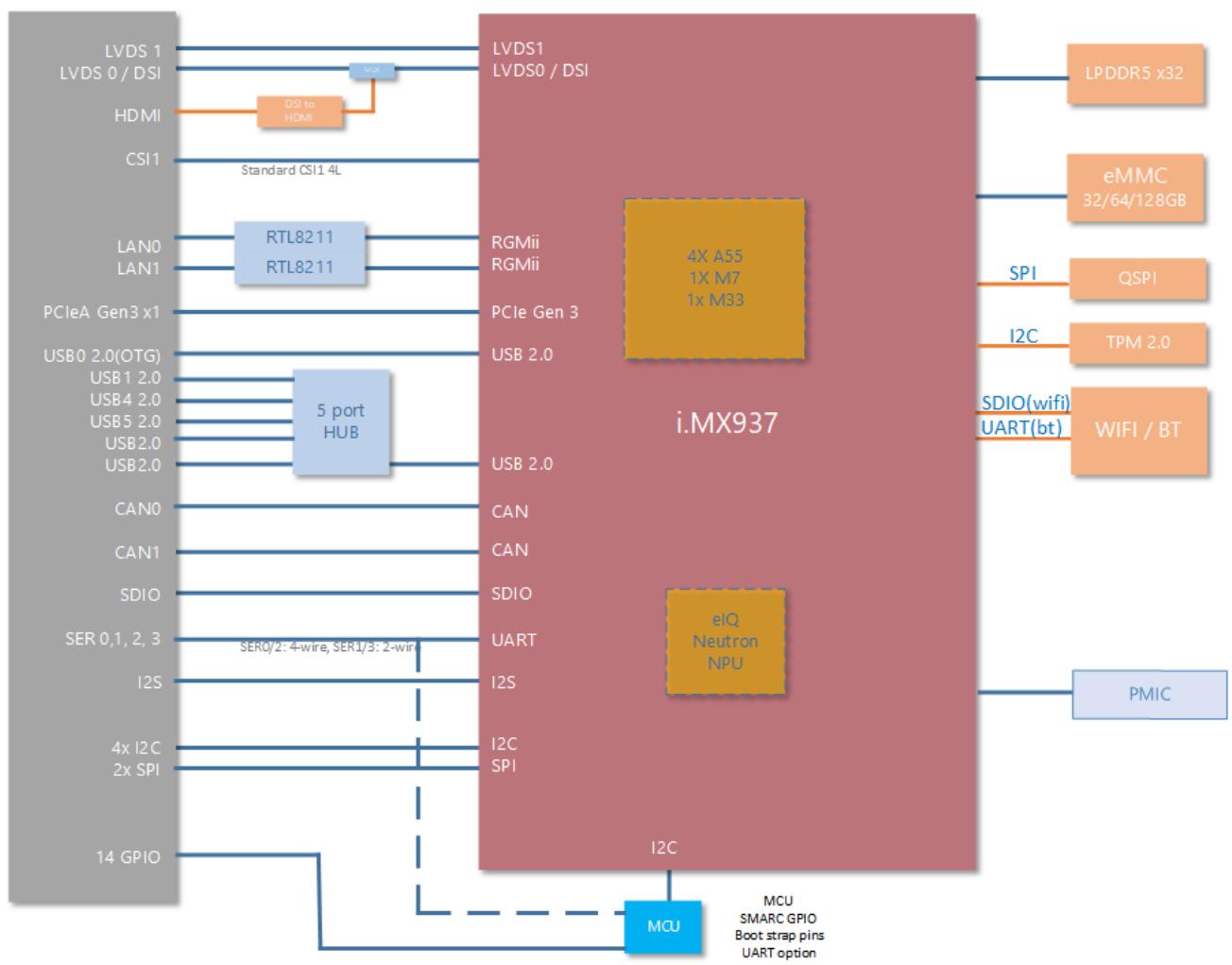
Block diagram
![Based on the provided block diagram, here is the accurate and concise description of the labeled blocks and connections:\n\n**Labeled Blocks:**\n\n*   **Left Interface Column (Grey Block):**\n    *   LVDS 1\n    *   LVDS 0 / DSI\n    *   HDMI\n    *   CSI1\n    *   LAN0\n    *   LAN1\n    *   PCIeA Gen3 x1\n    *   USB0 2.0(OTG)\n    *   USB1 2.0\n    *   USB4 2.0\n    *   USB5 2.0\n    *   USB2.0\n    *   USB2.0\n    *   CAN0\n    *   CAN1\n    *   SDIO\n    *   SER 0,1,2,3\n    *   I2S\n    *   4x I2C\n    *   2x SPI\n    *   14 GPIO\n\n*   **Intermediary Blocks (Left/Center):**\n    *   DSI to HDMI (Orange)\n    *   DSI (Small Blue)\n    *   RTL8211 (Stacked Blue)\n    *   5 port HUB (Blue)\n\n*   **Central Processor Block (Reddish):**\n    *   i.MX937\n    *   4X A55\n    *   1X M7\n    *   1x M33 (Gold Box)\n    *   eIQ\n    *   Neutron\n    *   NPU (Gold Box)\n    *   Interface Labels (Right Edge): LVDS1, LVDS0 / DSI, RGMii, RGMii, PCIe Gen 3, USB 2.0, CAN, CAN, SDIO, UART, I2S, I2C, SPI, I2C (Bottom)\n\n*   **Right Peripherals Column (Orange/Blue):**\n    *   LPDDR5 x32\n    *   eMMC\n    *   32/64/128GB\n    *   QSPI\n    *   TPM 2.0\n    *   SDIO(wifi)\n    *   UART(bt)\n    *   WIFI / BT\n    *   PMIC\n\n*   **Bottom Block (Blue):**\n    *   MCU\n    *   MCU\n    *   SMARC GPIO\n    *   Boot strap pins\n    *   UART option\n\n*   **Floating Text Labels:**\n    *   Standard CSI1 4L\n    *   SER0/2: 4-wire, SER1/3: 2-wire\n\n**Connections:**\n\n*   **LVDS/DSI/HDMI:** 'LVDS 1' and 'LVDS 0 / DSI' connect to a 'DSI' block. 'HDMI' connects to a 'DSI to HDMI' block. These route to the main block's 'LVDS1' and 'LVDS0 / DSI' ports.\n*   **Camera:** 'CSI1' connects via the text 'Standard CSI1 4L' to the main processor block.\n*   **LAN:** 'LAN0' and 'LAN1' connect to stacked 'RTL8211' blocks, which connect to the main block's 'RGMii' ports.\n*   **PCIe:** 'PCIeA Gen3 x1' connects directly to 'PCIe Gen 3'.\n*   **USB:** 'USB0 2.0(OTG)', 'USB1 2.0', 'USB4 2.0', 'USB5 2.0', and 'USB2.0' connect to a '5 port HUB', which connects to 'USB 2.0'.\n*   **CAN/SDIO/Serial:** 'CAN0' and 'CAN1' connect to 'CAN' ports. 'SDIO' connects to 'SDIO'. 'SER 0,1,2,3' connects to 'UART' (labeled 'SER0/2: 4-wire, SER1/3: 2-wire').\n*   **Audio/Buses:** 'I2S' connects to 'I2S'. '4x I2C' connects to 'I2C'. '2x SPI' connects to 'SPI'.\n*   **Memory/Storage:** The main block connects to 'LPDDR5 x32' and 'eMMC / 32/64/128GB'.\n*   **Peripherals:** The main block's 'SPI' connects to 'QSPI'. The main block's 'I2C' connects to 'TPM 2.0'. The main block connects to 'WIFI / BT' via lines labeled 'SDIO(wifi)' and 'UART(bt)'. The main block connects to 'PMIC'.\n*   **GPIO/MCU:** '14 GPIO' connects to the 'MCU'. The bottom 'I2C' of the main block connects to the 'MCU'. Dashed lines connect the UART/I2S/I2C area of the main block to the 'MCU'.](.20260429-2bc284be-671/f8f234a9e4212452970bd4a0a18cae723750e2e9bdf92991dd75cc7edb698539.jpg)

Note: “Build option” indicates an alternative BOM configuration to support additional or alternative functions that are not available on the standard product. Be aware that these “build option” part numbers will need to be newly created and this will result in production lead times.

Ordering Information

<table><tr><td>Module</td><td>Description / Configuration</td></tr><tr><td>LEC-IMX937-4G-32G-CT</td><td>SMARC 2.2 short size module with quad-core NXP i.MX937, 4 GB LPDDR5, 32 GB eMMC, 0°C to 60°C</td></tr><tr><td>LEC-IMX937-4G-32G-ER</td><td>SMARC 2.2 short size module with quad-core NXP i.MX937, 4 GB LPDDR5, 32 GB eMMC, -40°C to 85°C</td></tr></table>
[🔗 Link to the original document](.20260429-2bc284be-671/20260429-2bc284be-671.pdf)