# Fanless Railway Onboard Data Collection System

# DCS-RAPL

# Datasheet

Preliminary

![Front view of a black electronic device with multiple Ethernet ports and connectors (no visible text or labels)](.datasheet-dcs-rapl-preliminary-20220623/8663ac03dd9b1ee6455caab972a6f6b045e4707b4d608969115a32974f22a5aa.jpg)

# Features

• Intel Atom® x5-E3930 processor, up to 1.8GHz
• 4GB DDR3L memory (up to 8GB optional)
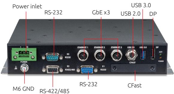
• 3x M12 GbE, 3x DB-9 Serial ports, 2x USB and 1x lockable DP port
• Power input voltage: 24VDC, 36VDC, 72VDC and 110VDC
• EN 50155 S2 interruption
• EN 50155 operating temperature OT3 ST1, -25°C to 70°C
• Storage: eMMC 5.0, 1x external accessible CFast slot

Specifications

<table><tr><td rowspan="4">System</td><td>Processor</td><td>Intel Atom $^{\textregistered}$  x5-E3930 Processor, 2C/2T, 2M L2 Cache Base frequency 1.30GHz, Burst 1.8GHz. TDP 6.5W</td></tr><tr><td>Memory</td><td>1x 204-pin DDR3L SODIMM socket, up to 8GB RAMEquipped with 4GB RAM by default</td></tr><tr><td>Storage</td><td>1x 32GB eMMC 5.01x CFast slot, externally accessible with cover</td></tr><tr><td>BIOS</td><td>UEFI BIOS</td></tr><tr><td rowspan="5">Front Panel I/O Interfaces</td><td>Ethernet</td><td>3x 10/100/1000BASE-T Ethernet ports via M12 X-coded, based on Intel $^{\textregistered}$  I210-IT, withstands 1KVrms isolation</td></tr><tr><td>USB 2.0</td><td>1x USB 2.0 port via M8 connector, withstands 1000Vrms isolation(supports Full Speed only)</td></tr><tr><td>USB 3.0</td><td>1x type A USB 3.0, 1600mA</td></tr><tr><td>Serial Port</td><td>1x DB-9 RS-232 full, baud rate up to 38400bps, withstand 1K VAC rms,male connector for maintenance1x DB-9 RS-232 serial port, withstand 1KVrms isolation, male connector1x DB-9 RS-422/485 serial port, withstand 1KVrms isolation, femaleconnector</td></tr><tr><td>DP</td><td>1x DisplayPort with latch lock</td></tr></table>

Specifications

<table><tr><td rowspan="5">Power</td><td>Power Connector</td><td>1 x 3-pin screw terminal</td></tr><tr><td>Ground</td><td>Shell ground: M6 bolt with nut</td></tr><tr><td>Power Supply</td><td>+24V/+36V/+72V/+110VDC nominal power input2KV isolationEN 50155 Interruption of voltage supply: Class S2 C1</td></tr><tr><td>Power Consumption</td><td>22W full loading (Ubuntu 18.04.3 LTS)</td></tr><tr><td>Connector isolation</td><td>Pressure: input to mechanical max. 2000VDC RMSInput to output max. 1500 VDC RMSRS-232/422/485/USB 2.0 to mechanical max 1000VAC RMS</td></tr><tr><td rowspan="4">Mechanical</td><td>Dimensions</td><td>230.4mm x 190.7mm x 44.20mm (WxDxH)</td></tr><tr><td>Weight</td><td>2.2kg</td></tr><tr><td>Mounting</td><td>Wall mount</td></tr><tr><td>IP</td><td>IP40</td></tr><tr><td rowspan="9">Environment</td><td>Operating Temp</td><td>-25°C to +70°C, EN 50155 class OT3 ST1</td></tr><tr><td>Storage Temp</td><td>-30°C to +85°C</td></tr><tr><td>Operating Humidity</td><td>10% to 90% non-condensing</td></tr><tr><td>Storage Humidity</td><td>5% to 95% non-condensing</td></tr><tr><td>Vibration</td><td>EN 50155 standard, method EN 61373: 2010, Category 1 Class B</td></tr><tr><td>Shock</td><td>EN 50155 standard, method EN 61373: 2010, Category 1 Class B</td></tr><tr><td>EMI/EMS</td><td>EN 50155, EN 50121-3-2:2016</td></tr><tr><td>Fire &amp; Smoke</td><td>EN 45545-2 HL3</td></tr><tr><td>MTBF</td><td>302,345 hrs. (Telcordia Issue 4, GB, GC)</td></tr><tr><td>Operation System</td><td>OS</td><td>Linux Ubuntu 18.04 LTS, 64-bit</td></tr><tr><td>Others</td><td>LED Indicators</td><td>2x power LEDs on front panelPower-on (Orange)Operating (Green)</td></tr></table>

Mechanical Layout

![Power inlet\nRS-232\nGbE x3\nUSB 3.0\nUSB 2.0\nDP\nPOWER\nM6 GND\nRS-422/485\nRS-232\nCFast](.datasheet-dcs-rapl-preliminary-20220623/c04350600084ded45b43c377cb3a6aced189d9bbf3dc48be522de1192079e52e.jpg)

# DC Power Input connector

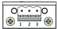
![The image is a black and white line drawing of a cassette tape. It depicts the upper section of the tape casing, featuring two circular holes and a central rectangular window containing a wavy line (representing the tape) and three small squares. Below the window are horizontal lines indicating a label area. At the bottom, there are two circular spools with cross-hairs inside them, and the numbers '1 2 3' are printed in the center beneath the spools.](.datasheet-dcs-rapl-preliminary-20220623/fe2e62ff2e188436b434873306cf682278c3945ec60a1ea35e12ec9ed0d2a233.jpg)

<table><tr><td>Pin</td><td>Signal</td></tr><tr><td>1</td><td>(+)</td></tr><tr><td>2</td><td>(-)</td></tr><tr><td>3</td><td>Chassis</td></tr></table>

# RS-232 (DB9 Male)

![The image displays a schematic diagram of a connector housing, shaped like a trapezoid. Inside the shape are nine black dots arranged in three rows of three. The number '1' is positioned above the top-left dot, and '5' is above the top-right dot. The number '6' is positioned below the bottom-left dot, and '9' is below the bottom-right dot. To the right of the diagram, the text 'Male' is written.](.datasheet-dcs-rapl-preliminary-20220623/d9314691c0c21c36b00316281a1fa8ea6c0b20644eeaddb5cb2d09ddd86df488.jpg)

<table><tr><td>Pin</td><td>Signal Name</td></tr><tr><td>1</td><td>DCD</td></tr><tr><td>2</td><td>RXD</td></tr><tr><td>3</td><td>TXD</td></tr><tr><td>4</td><td>DTR</td></tr><tr><td>5</td><td>GND</td></tr><tr><td>6</td><td>DSR</td></tr><tr><td>7</td><td>RTS</td></tr><tr><td>8</td><td>CTS</td></tr><tr><td>9</td><td>RI</td></tr></table>

# M8 A code USB

![The image displays a technical line drawing of a circular component with four concentric rings. Four numbered labels with pointer lines indicate specific parts from the outermost layer inward:\n\n*   **1** points to the outermost ring.\n*   **2** points to the second ring from the outside.\n*   **3** points to the third ring from the outside.\n*   **4** points to the innermost ring.\n\nInside the innermost ring (labeled 4), there are four small circles arranged in a square pattern.](.datasheet-dcs-rapl-preliminary-20220623/ee9bc519f2964d0eec011d2146d42dbd04983500e93bf3fe0f6f26a8f65ec401.jpg)

<table><tr><td>Pin</td><td>Signal Name</td></tr><tr><td>1</td><td>VCC</td></tr><tr><td>2</td><td>CN</td></tr><tr><td>3</td><td>CP</td></tr><tr><td>4</td><td>GND</td></tr></table>

# RS-422/RS-485(DB9 Female)

![The image shows a diagram of a connector or terminal block with a trapezoidal outline. Inside the outline are two rows of six circular dots each. At the corners outside the outline are the numbers: '5' at the top left, '1' at the top right, '9' at the bottom left, and '6' at the bottom right.](.datasheet-dcs-rapl-preliminary-20220623/06902f2e628eaceb35bc7bf3eaa1f89252b58a062bd70fd17b5d2cb2b68056f5.jpg)
DB-9Female

<table><tr><td>Pin</td><td>RS-422</td><td>RS-485</td></tr><tr><td>1</td><td></td><td></td></tr><tr><td>2</td><td>RX+</td><td></td></tr><tr><td>3</td><td></td><td></td></tr><tr><td>4</td><td>TX+</td><td>D+</td></tr><tr><td>5</td><td>GND</td><td>GND</td></tr><tr><td>6</td><td>RX-</td><td></td></tr><tr><td>7</td><td></td><td></td></tr><tr><td>8</td><td>TX-</td><td>D-</td></tr><tr><td>9</td><td></td><td></td></tr></table>

# RS-232 (DB9 Male)

![The image shows a schematic diagram of a 9-pin connector housing. Inside a trapezoidal outline, there are nine black dots arranged in a 3x3 grid. The number '1' is positioned above the top-left corner, and '5' is above the top-right corner. Below the housing, the number '6' is on the left and '9' is on the right. To the right of the connector, the word 'Male' is written in black text.](.datasheet-dcs-rapl-preliminary-20220623/c7196b965f441e92e560291f602a4385e392c6a76825f6b1532318a0d2a72c4e.jpg)

<table><tr><td>1</td><td></td></tr><tr><td>2</td><td>RXDs</td></tr><tr><td>3</td><td>TXDs</td></tr><tr><td>4</td><td></td></tr><tr><td>5</td><td>GND</td></tr><tr><td>6</td><td></td></tr><tr><td>7</td><td>RTS</td></tr><tr><td>8</td><td>CTS</td></tr><tr><td>9</td><td></td></tr></table>

# M12 X code Ethernet (1\~3)

![The image displays a technical line drawing of a circular flange or plate. A central cross-shaped structure divides the circle into four quadrants, featuring slots within its arms. Surrounding this center is an outer ring containing eight oval slots arranged in pairs within each quadrant. Each outer slot is labeled with a two-digit number.\n\nThe numbers visible are arranged as follows:\n- **Top Left Quadrant:** 02 (upper) and 01 (lower)\n- **Top Right Quadrant:** 03 (upper) and 04 (lower)\n- **Bottom Right Quadrant:** 05 (upper) and 06 (lower)\n- **Bottom Left Quadrant:** 08 (upper) and 07 (lower)](.datasheet-dcs-rapl-preliminary-20220623/5db1f82e7217c12783268c9fa4b738466b0d8bfc5e2d2afe67d13cd527ceb03e.jpg)
Pin Assignments

<table><tr><td>1</td><td>MDO0P</td></tr><tr><td>2</td><td>MDO0N</td></tr><tr><td>3</td><td>MDO1P</td></tr><tr><td>4</td><td>MDO1N</td></tr><tr><td>5</td><td>MDO3P</td></tr><tr><td>6</td><td>MDO3N</td></tr><tr><td>7</td><td>MDO2N</td></tr><tr><td>8</td><td>MDO2P</td></tr></table>

# Mechanical Drawing

![This image is a technical line drawing displaying the dimensions and layout of a rectangular electronic device, with text in the top right corner reading '(unit: mm)'.\n\nThe image features four distinct views:\n1.  **Top Left:** A top-down view (or mounting plate) showing circular mounting holes. Vertical dimensions on the left are labeled '190.70' and an inner bracket measurement of '111'. Horizontal dimensions at the bottom are '241.60' and '254.40'.\n2.  **Middle Right:** An isometric perspective view showing the top surface with mounting holes and the side panel containing various ports (including audio jacks and USB ports).\n3.  **Bottom Left:** A rear panel view detailing connectivity ports such as serial, VGA, audio, USB, and Ethernet. Horizontal dimension at the top is '230.40'. Vertical dimensions on the right are '44.20' and '47.20'.\n4.  **Bottom Right:** A side profile view of the device.](.datasheet-dcs-rapl-preliminary-20220623/46b925c89e0faef570f9b63acdc7c55bc13f1e0f728d8ee693d12d5c0cd46bf7.jpg)
(unit: mm)

# Ordering Information

DCS-RAPL/3930/M4, CC

Data collection system with Atom x5-E3930, 4GB DDR4, 3x M12 Ethernet, 1x RS-422/485, additional serial ports, 1x M8 USB 2.0 port, 1x USB 3.0 Type A, 1x DP, 1x CFast slot, conformal coating

# Optional Accessory

Power mating connector

3-pin female terminal block w/o flange ( ADLINK P/N: 20-C1F0C-0030)
[🔗 Link to the original document](.datasheet-dcs-rapl-preliminary-20220623/datasheet-dcs-rapl-preliminary-20220623.pdf)