# PICMG Backplanes

# PICMG® 1.3 Backplanes
![Green printed circuit board with multiple electronic components and connectors (no visible text or symbols)](.ebp-d3s1-datasheet-en-2/0899c815eea016591faaae6b2d96dc48ad2d9551e0a11ba1384ca7afd76b9617.jpg)

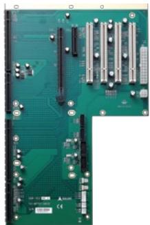
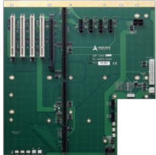
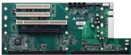
EBP-5E1

<table><tr><td>PCI-E® x16</td><td>1</td><td>PICMG®</td><td>1</td></tr><tr><td>PCI-E® x4</td><td></td><td>AT</td><td></td></tr><tr><td>PCI-XTM</td><td>1</td><td>ATX</td><td>Yes</td></tr><tr><td>PCITM</td><td>2</td><td>Segments</td><td>1</td></tr><tr><td>Dimensions</td><td colspan="3">153 mm x 330 mm</td></tr></table>

![Green printed circuit board with multiple slots and connectors (no visible text or symbols)](.ebp-d3s1-datasheet-en-2/3220a4d0f8bc19ebbc0e32e3fd454e76ae76d40094f23f6541b6645482260ee4.jpg)

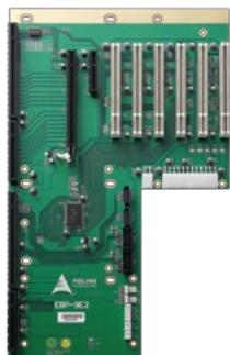
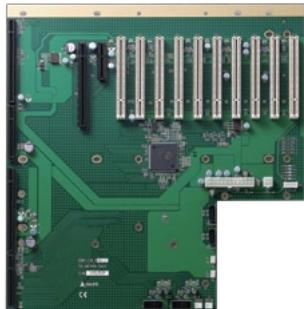
EBP-7E2

<table><tr><td>PCI-E® x16</td><td>1</td><td>PICMG®</td><td>1</td></tr><tr><td>PCI-E® x4</td><td>1</td><td>AT</td><td></td></tr><tr><td>PCI-XTM</td><td></td><td>ATX</td><td>Yes</td></tr><tr><td>PCI $^{TM}$ </td><td>4</td><td>Segments</td><td>1</td></tr><tr><td>Dimensions</td><td colspan="3">328 mm x 206 mm</td></tr></table>

![Green printed circuit board with multiple RAM slots and connectors (no visible text or symbols)](.ebp-d3s1-datasheet-en-2/85c026393c4e050a6a2c856bb9edd43f6bece70a482aadd8c393f3317c692e0f.jpg)

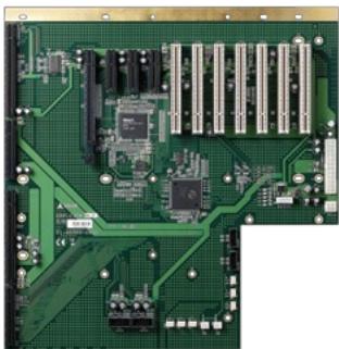
EBP-9E2

<table><tr><td>PCI-E® x16</td><td>1</td><td>PICMG®</td><td>1</td></tr><tr><td>PCI-E® x4</td><td>1</td><td>AT</td><td></td></tr><tr><td>PCI-XTM</td><td></td><td>ATX</td><td>Yes</td></tr><tr><td>PCITM</td><td>6</td><td>Segments</td><td>1</td></tr><tr><td>Dimensions</td><td colspan="3">328 mm x 206 mm</td></tr></table>

![Green printed circuit board with various electronic components and connectors (no visible text or symbols)](.ebp-d3s1-datasheet-en-2/f45bf3d3b76939b3922b09186c3cf89554b294c4eeeb7c3fd640d67371d1eca4.jpg)

![Green printed circuit board with multiple connectors and modules (no visible text or symbols)](.ebp-d3s1-datasheet-en-2/dcd6015b7d8a659ae992f41f67c3a372938d0b097051f73874ff85780480daff.jpg)

![Close-up of a green printed circuit board (PCB) with visible traces and pads, no text or symbols present.](.ebp-d3s1-datasheet-en-2/1b7dc42ff4a0d8d2ed052216b670a24fd7672fc5d67dbe3e37522d1c3640cba6.jpg)

![Close-up of a green printed circuit board with various electronic components and connectors (no visible text or symbols)](.ebp-d3s1-datasheet-en-2/e45e5aa7a7a6405c1ff78c18434e013313e346c6e27d072bf2a9e40fea49cdd3.jpg)

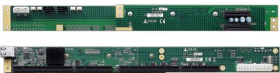
EBP-D3E1

<table><tr><td>PCI-E® x16</td><td></td><td>PICMG®</td><td>1</td></tr><tr><td>PCI-E® x4</td><td>1</td><td>AT</td><td></td></tr><tr><td>PCI-XTM</td><td></td><td>ATX</td><td>Yes</td></tr><tr><td>PCI $^{TM}$ </td><td></td><td>Segments</td><td>1</td></tr><tr><td>Dimensions</td><td colspan="3">331 mm x 39 mm</td></tr></table>

EBP-D3S1

<table><tr><td>PCI-E® x16</td><td></td><td>PICMG®</td><td>1</td></tr><tr><td>PCI-E® x4</td><td></td><td>AT</td><td></td></tr><tr><td>PCI-XTM</td><td></td><td>ATX</td><td>Yes</td></tr><tr><td>PCITM</td><td>1</td><td>Segments</td><td>1</td></tr><tr><td>Dimensions</td><td colspan="3">331 mm x 39 mm</td></tr></table>

# PICMG Backplanes

![Two views of a green printed circuit board with visible components and connectors (no readable text or symbols)](.ebp-d3s1-datasheet-en-2/ea8c5d7b127a20e88c035e73edbc87e758ee4f77ebc89888a50bc2e8ae9bb91d.jpg)

EBP-1UX4

<table><tr><td>PCI-E® x16</td><td></td><td>PICMG®</td><td>1</td></tr><tr><td>PCI-E® x4</td><td>2</td><td>AT</td><td></td></tr><tr><td>PCI-XTM</td><td></td><td>ATX</td><td>Yes</td></tr><tr><td>PCITM</td><td>4</td><td>Segments</td><td>1</td></tr><tr><td>Dimensions</td><td colspan="3">414 mm x 39 mm</td></tr></table>

![Two views of a green printed circuit board with visible components and connectors (no readable text or symbols)](.ebp-d3s1-datasheet-en-2/3e446878e626374c7eeb7e6b10a7d5e30ec77e335d57bdeb40a676562647014c.jpg)

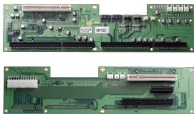
EBP-D5E2

<table><tr><td>PCI-E® x16</td><td>1</td><td>PICMG®</td><td>1</td></tr><tr><td>PCI-E® x4</td><td>1</td><td>AT</td><td></td></tr><tr><td>PCI-XTM</td><td></td><td>ATX</td><td>Yes</td></tr><tr><td>PCITM</td><td>2</td><td>Segments</td><td>1</td></tr><tr><td>Dimensions</td><td colspan="3">331 mm x 84 mm</td></tr></table>

![Green printed circuit board with various electronic components and connectors (no visible text or symbols)](.ebp-d3s1-datasheet-en-2/c0c3d21777c9d5c633342609d2c8895ef3e42486f4153dc4108330eb0dfe6f91.jpg)

EBP-10E5

<table><tr><td>PCI-E® x16</td><td>1</td><td>PICMG®</td><td>1</td></tr><tr><td>PCI-E® x4</td><td></td><td>AT</td><td></td></tr><tr><td>PCI-E® x1</td><td>4</td><td>ATX</td><td>Yes</td></tr><tr><td>PCI $^{\text{TM}}$ </td><td>4</td><td>Segments</td><td>1</td></tr><tr><td>Dimensions</td><td colspan="3">330 mm x 318 mm</td></tr></table>

![Green printed circuit board with multiple RAM slots and connectors (no visible text or symbols)](.ebp-d3s1-datasheet-en-2/f1c4454e0f1e90d9aa94c6b77544cf8ffa8dcea4b91ee3293f1c134becc33824.jpg)

EBP-13E2

<table><tr><td>PCI-E® x16</td><td>1</td><td>PICMG®</td><td>1</td></tr><tr><td>PCI-E® x4</td><td>1</td><td>AT</td><td></td></tr><tr><td>PCI-XTM</td><td></td><td>ATX</td><td>Yes</td></tr><tr><td>PCITM</td><td>10</td><td>Segments</td><td>1</td></tr><tr><td>Dimensions</td><td colspan="3">330mm x 318mm</td></tr></table>

![Green printed circuit board with integrated circuits and connectors (no visible text or symbols)](.ebp-d3s1-datasheet-en-2/f7bda48956ccff1f1aaa18bbbd24fe74fe057bb789a5be30ff3d548c174d412d.jpg)

EBP-13E4

<table><tr><td>PCI-E® x16</td><td>1</td><td>PICMG®</td><td>1</td></tr><tr><td>PCI-E® x4</td><td>3</td><td>AT</td><td></td></tr><tr><td>PCI-XTM</td><td></td><td>ATX</td><td>Yes</td></tr><tr><td>PCITM</td><td>7</td><td>Segments</td><td>1</td></tr><tr><td>Dimensions</td><td colspan="3">330 mm x 318 mm</td></tr></table>

![Close-up of a green printed circuit board with visible traces and connectors (no text or symbols)](.ebp-d3s1-datasheet-en-2/6b452979bcd73b6ffbf6fc73184935186777cb96d6f435ced7f309bbb9f48fdc.jpg)

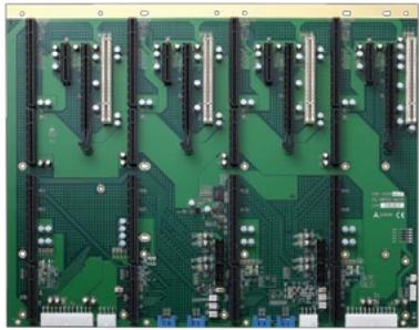
EBP-16Q8

<table><tr><td>PCI-E® x16</td><td>4</td><td>PICMG®</td><td>4</td></tr><tr><td>PCI-E® x4</td><td>4</td><td>AT</td><td></td></tr><tr><td>PCI-XTM</td><td></td><td>ATX</td><td>Yes</td></tr><tr><td>PCITM</td><td>4</td><td>Segments</td><td>4</td></tr><tr><td>Dimensions</td><td colspan="3">328 mm x 416 mm</td></tr></table>

# PICMG Backplanes

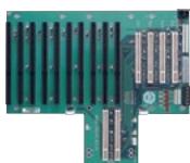
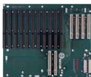
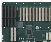
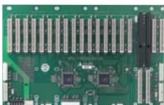
PICMG® 1.0
Backplanes

![The image displays a green printed circuit board, likely a RAID controller card. On the left edge, four circular metallic connectors are stacked vertically. Along the bottom edge, there is a long row of 14 white plastic connectors. On the right side of the board, the text 'ADAPTEC' is printed above 'RAID' next to a triangular logo. On the bottom right corner, printed on the white connector housing, the text reads 'TECHNOLOGIES' above 'SAS 1064'. Circuit traces are visible across the surface, and a small white rectangular sticker is located in the center.](.ebp-d3s1-datasheet-en-2/65f396178a4ef05fc1a359f63ba2b9c34e3524dca62130fec669f46150a30397.jpg)

![This image shows a green printed circuit board (PCB) featuring various electronic components and connectors.\n\n**Left Side:**\n*   A large white multi-pin connector is located at the top left.\n*   Below it are various surface-mounted components, including capacitors and integrated circuits.\n*   The text 'AD4010' is printed in white near this connector.\n\n**Right Side:**\n*   There are four long, white 40-pin IDE connectors arranged in two columns.\n*   The top pair of connectors is labeled 'IDE1' and 'IDE2'.\n*   The bottom pair of connectors is labeled 'IDE3' and 'IDE4'.](.ebp-d3s1-datasheet-en-2/3af0685a88c8facfe0e9422fa65fe59498fbf9ccb0df65b9ea6510e8a8961ac4.jpg)

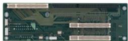
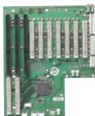
HPCI-D3S2

<table><tr><td>PICMG®</td><td>1</td><td>AT</td><td></td></tr><tr><td> $PCI^{TM}$ </td><td>2</td><td>ATX</td><td>Yes</td></tr><tr><td>ISA</td><td></td><td>Segments</td><td>1</td></tr><tr><td>Dimensions</td><td colspan="3">261 mm x 39 mm</td></tr></table>

![This image displays a green printed circuit board (PCB) featuring several expansion slots. On the left side, there are slots with exposed gold contacts; the top slot is labeled 'PCIe x16' and a shorter slot below it is labeled 'PCIe x1'. Near the bottom left edge, the text 'PCIe x1' appears again. On the right side, three white expansion slots are stacked vertically and labeled 'PCI'. Circular mounting holes are visible at the top corners, and a small red LED is present near the bottom left area.](.ebp-d3s1-datasheet-en-2/f2fa99f7c8f377d9b8cd6fd9111d5a1183baa1cc63c47b2a0fa251598dce0c37.jpg)

![This image displays a close-up view of a green printed circuit board (PCB) populated with electronic components. Four white pin headers are arranged vertically on the left side. To the right, there are three black integrated circuit chips and several small surface-mount resistors.\n\nThe text printed on the board includes:\n- **361** in the top left corner.\n- The letter **K** next to each of the four pin headers.\n- **B509 250** near the top right area.\n- **U1**, **U2**, and **U3** labeling the integrated circuits.\n- **R6**, **R5**, **R4**, **R3**, **R2**, and **R1** labeling the resistors.\n- **B509 250** and **B509** printed vertically along the far right edge.](.ebp-d3s1-datasheet-en-2/e45967a0c6f568d389c2c03d0af366cc7e72966c8d3e5a3bac2955daa1f8c46f.jpg)

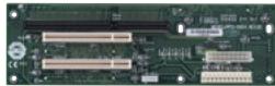
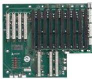
HPCI-D6S4

<table><tr><td>PICMG®</td><td>1</td><td>AT</td><td>Yes</td></tr><tr><td>PCI $^{\text{TM}}$ </td><td>4</td><td>ATX</td><td>Yes</td></tr><tr><td>ISA</td><td>1</td><td>Segments</td><td>1</td></tr><tr><td>Dimensions</td><td colspan="3">261 mm x 79.6 mm</td></tr></table>

![Circuit board photo with visible component labels and connection points](.ebp-d3s1-datasheet-en-2/20b4a5e4579068023fb7a507f1666d863adde70510d47a26dff55f0bf92b355e.jpg)

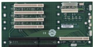
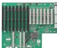
HPCI-6S4

<table><tr><td>PICMG®</td><td>1</td><td>AT</td><td>Yes</td></tr><tr><td>PCITM</td><td>4</td><td>ATX</td><td>Yes</td></tr><tr><td>ISA</td><td>1</td><td>Segments</td><td>1</td></tr><tr><td>Dimensions</td><td colspan="3">264.2 mm x 132.7 mm</td></tr></table>

![This is a close-up image of a green printed circuit board (PCB). The board features several connector slots arranged in rows. On the left side, there are four vertical riser card connectors. In the center, there are two rows of six vertical connectors each. To the right of the center rows is a single vertical connector. Near the bottom right corner, there is a row of eight horizontal pins.\n\nThe text on the board, printed in white, reads:\n2012\n3-152-294-12\nMADE IN JAPAN](.ebp-d3s1-datasheet-en-2/96ba76f4328e657a08f23fb47543c059d5e769afd5b3cbe5469e25e07a65504e.jpg)

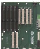
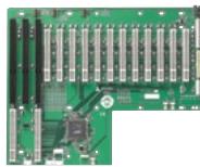
HPCI-8S4

<table><tr><td>PICMG®</td><td>2</td><td>AT</td><td>Yes</td></tr><tr><td>PCITM</td><td>4</td><td>ATX</td><td>Yes</td></tr><tr><td>ISA</td><td>4</td><td>Segments</td><td>1</td></tr><tr><td>Dimensions</td><td colspan="3">264.2 mm x 218 mm</td></tr></table>

![The image displays a section of a green printed circuit board (PCB). On the left side, there is a vertical black connector with multiple pins. In the upper right quadrant, four silver rectangular components are arranged in a row. Above these components is the text '200-1516-002'. Below the individual components are the numbers '01', '02', '03', and '04'. In the lower left area, a black integrated circuit chip is visible, accompanied by the text '200-1516-002' printed next to it. Other black chips and white circuit traces are scattered across the board.](.ebp-d3s1-datasheet-en-2/a547a8aff5dbe94ef1ef6ade3053858138c1667fa21a7cdf647bdefcb6cb1724.jpg)

HPCI-9S7U

<table><tr><td>PICMG®</td><td>2</td><td>AT</td><td>Yes</td></tr><tr><td>PCI $^{\text{TM}}$ </td><td>7</td><td>ATX</td><td>Yes</td></tr><tr><td>ISA</td><td>2</td><td>Segments</td><td>1</td></tr><tr><td>Dimensions</td><td colspan="3">213.4 mm x 259.1 mm</td></tr></table>

![This image displays a green printed circuit board (PCB). On the left side, there are five vertical card-edge connectors with visible gold contacts. On the bottom right, there are two similar vertical connectors. The upper right section features a block of black integrated circuits arranged in two rows. White text on the board reads '170061' in large characters. Below that, smaller text reads 'PCB 170061' and '0706'. A white circular sticker with a recycling symbol logo is located near the text on the left side.](.ebp-d3s1-datasheet-en-2/c6536bf046ea59bf25687797fb268bcf0ea5cd0e809b4f15dcae6c8a278fb526.jpg)

HPCI-13S4LU

<table><tr><td>PICMG®</td><td>3</td><td>AT</td><td>Yes</td></tr><tr><td>PCITM</td><td>4</td><td>ATX</td><td>Yes</td></tr><tr><td>ISA</td><td>9</td><td>Segments</td><td>1</td></tr><tr><td>Dimensions</td><td colspan="3">314.7 mm x 259 mm</td></tr></table>

![The image displays a green printed circuit board (PCB). On the left side, there are six vertical black slots, likely SIMM slots, arranged in a column. To the right of these slots, there are two columns of white rectangular surface-mount components, followed by two additional columns of similar white components further to the right. In the lower center area, a large black square integrated circuit chip is visible. In the bottom left, there are two vertical white components. Near the bottom right corner, the text 'IBM' is printed in white.](.ebp-d3s1-datasheet-en-2/dfa72d7279d968f46ec90f85b08e559ab07260b427295cf30c4c76c03ffb467b.jpg)

HPCI-14S7U

<table><tr><td>PICMG®</td><td>3</td><td>AT</td><td>Yes</td></tr><tr><td>PCITM</td><td>7</td><td>ATX</td><td>Yes</td></tr><tr><td>ISA</td><td>7</td><td>Segments</td><td>1</td></tr><tr><td>Dimensions</td><td colspan="3">314.7 mm x 259.1 mm</td></tr></table>

![The image displays a green printed circuit board (PCB), appearing to be a server memory module (DIMM), set against a white background.\n\n**Right Side:** A long, rectangular connector runs along the right edge, featuring rows of metallic contacts or pins (likely gold-plated fingers) designed to plug into a socket.\n\n**Top/Center:** Extending from the connector towards the left are multiple parallel rows of silver, rectangular surface-mount capacitors (likely tantalum capacitors).\n\n**Left Side:** Several black integrated circuit chips, likely DRAM modules, are visible near the top left corner.\n\n**Bottom Center:** A square integrated circuit with a ball grid array (BGA) package is mounted centrally near the bottom.\n\n**Other Details:** The board has an L-shaped cutout in the bottom right corner. Small traces and other minor components are visible across the green surface. There is no legible text visible on the board.](.ebp-d3s1-datasheet-en-2/0675e6d39707353d317d15d3797fbe38594fe80ddef0e370379fbaab7cb8facc.jpg)

HPCI-14S12U

<table><tr><td>PICMG®</td><td>2</td><td>AT</td><td>Yes</td></tr><tr><td>PCITM</td><td>12</td><td>ATX</td><td>Yes</td></tr><tr><td>ISA</td><td>2</td><td>Segments</td><td>1</td></tr><tr><td>Dimensions</td><td colspan="3">314.7 mm x 259 mm</td></tr></table>

![The image displays a section of a green printed circuit board (PCB) against a white background. On the left side, a large array of black rectangular components is arranged in vertical columns. To the right, there are smaller white rectangular components and integrated circuits. Small blue and red surface-mount components are visible near the top right edge. At the bottom, two vertical connector slots, resembling PCIe slots, extend downwards.](.ebp-d3s1-datasheet-en-2/c9310b7eabb0cfcb482f029561160899366145611e0e9488bc1f848f6e3adc28.jpg)

HPCI-14S/ATX

<table><tr><td>PICMG®</td><td>2</td><td>AT</td><td>Yes</td></tr><tr><td>PCITM</td><td>4</td><td>ATX</td><td>Yes</td></tr><tr><td>ISA</td><td>9</td><td>Segments</td><td>1</td></tr><tr><td>Dimensions</td><td colspan="3">312 mm x 265 mm</td></tr></table>

![The image displays a close-up section of a green printed circuit board (PCB). The upper left features a large grid of black rectangular chips, likely memory modules. To the right, there are sets of gold-plated connector pins and sockets. White text labels 'P01' and 'P02' are visible near specific connector areas, with 'P01' located near a vertical socket at the bottom center and 'P02' near pins on the right side. Intricate copper traces and solder pads are visible across the board's surface.](.ebp-d3s1-datasheet-en-2/ec2d718f0f5b936a7bea747c316d86d424ae189d35cadb48896aac29041bebef.jpg)

HPCI-15S

<table><tr><td>PICMG®</td><td>2</td><td>AT</td><td>Yes</td></tr><tr><td>PCITM</td><td>4</td><td>ATX</td><td>Yes</td></tr><tr><td>ISA</td><td>10</td><td>Segments</td><td>1</td></tr><tr><td>Dimensions</td><td colspan="3">317 mm x 264.2 mm</td></tr></table>

![This image shows a green server motherboard. On the left side, there are four vertical banks of black memory slots. The upper right section contains a long row of beige PCIe expansion slots. In the lower center, a square CPU socket with a retention bracket is visible. Surrounding the bottom area are various white pin headers and connectors. The text '501435-001' is printed horizontally near the bottom right corner and vertically along the bottom left edge. A small white certification sticker is located near the center right, but its text is illegible.](.ebp-d3s1-datasheet-en-2/62cad3378bb443c566861887d571fc9b68984ef606bda78fdf53f0d84bb2e4a1.jpg)

HPCI-15S10

<table><tr><td>PICMG®</td><td>2</td><td>AT</td><td>Yes</td></tr><tr><td>PCI $^{\text{TM}}$ </td><td>10</td><td>ATX</td><td>Yes</td></tr><tr><td>ISA</td><td>4</td><td>Segments</td><td>1</td></tr><tr><td>Dimensions</td><td colspan="3">317 mm x 264.2 mm</td></tr></table>

![This image displays a green printed circuit board. The upper portion features two rows of silver expansion connectors running horizontally. To the right of these is a vertical black connector. The center of the board contains several square integrated circuits and other surface-mounted components. At the bottom left is a white D-sub connector, and to its right is a long white connector with multiple pins. Faint white text on the board surface includes 'IBM,' '1986,' and 'USA.'](.ebp-d3s1-datasheet-en-2/f381438d728b8696a0dd2ad948d6fbdea4e17240d95e3f302d7223215249a744.jpg)

HPCI-19S18A

<table><tr><td>PICMG®</td><td>2</td><td>AT</td><td>Yes</td></tr><tr><td>PCI $^{\text{TM}}$ </td><td>18</td><td>ATX</td><td>Yes</td></tr><tr><td>ISA</td><td>1</td><td>Segments</td><td>1</td></tr><tr><td>Dimensions</td><td colspan="3">415.3 mm x 264.2 mm</td></tr></table>
[🔗 Link to the original document](.ebp-d3s1-datasheet-en-2/ebp-d3s1-datasheet-en-2.pdf)