![The image displays four distinct computer hardware setups arranged vertically against a white background. Each setup consists of a black computer chassis connected via a cable to an expansion card.\n\n1.  **Top:** A compact black chassis with ventilation slots. A cable connects it to a small expansion card. The text '**ECS-8582-4S**' appears below it in blue.\n2.  **Second:** A black chassis, slightly larger than the first. A cable connects it to a blue expansion card. The text '**PCES-8581-4S**' appears below it in blue.\n3.  **Third:** A greyish-black chassis. A cable connects it to a blue expansion card. The text '**PCES-8581-4L**' appears below it in blue.\n4.  **Bottom:** A larger, wider chassis featuring a handle on the left side. A cable connects it to a blue expansion card. The text '**PCES-8581-I3S**' appears below it in blue.](.ecs-8582-4s-datasheet-4/f967cf9338417323e1fba12a36ca48e939f6c6c2491e0d5a4eb335d2b5a10a4f.jpg)

# Features

PCI Express-based control of PCI - PCES-8581-4S/13S
■ ExpressCard-based control of PCI - ECS-8582-4S
■ High-speed PCI Express x1 interface
■ Compatible with 5 V and 3.3 V PCI signaling
■ 32-bit/33 MHz PCI interface support
■ PCES-8581-4S/ECS-8582-4S expand four half-size PCI slots in a shoebox size wallmount chassis with built-in 200 W power supply
■ PCES-8581-4L expands four full-size PCI slots in a wall-mount chassis with built-in 200W power supply
■ PCES-8581-13S expands 13 full-size PCI slots in a 19" rack-mount chassis with built-in 400 W power supply
■ PCES-8581-13S-RED expands 13 full-length PCI slots in a 19" rack-mount chassis with built-in 400W redundant power supply
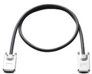
■ Extension distance of up to 7 meters (extension cables at 1 M, 3 M, and 7 M)
■ Comprehensive hardware and software transparency
■ Compliant with

- ExpressCard™ Standard Release 1.2
- PCI Express $^{\textregistered}$ Base Specification Rev. 1.0a
• PCI-to-PCI Bridge Architecture Specification, Revision 1.2
• PCI Local Bus Specification, Revision 3.0

# Introduction

Harnessing the bandwidth potential of the PCI Express, these latest smart expansion systems enable compuers with a PCI Express slot to remotely manage and control up to 13 PCI devices seven meters away, using the high-speed PCI Express interface. Offering up to 13 (PCES-8581-13S) or four PCI slots (PCES-8581-4S/4L, ECS-8582-4S), these expansion systems operate in 32-bit/33 MHz configuration and come with complete end-to-end hardware and software transparency for the host system. Hardware devices installed in the expansion system behave and work as if these are directly installed into the host system, requiring no additional drivers or software installation. The host system may be separated from the expansion system at up to seven meters using high-quality shielded twisted copper cables. The robust and reliable PCI expansion-to-PCI expansion systems are suited for portable test and measurement applications with high-density I/O requirement and in hazardous industrial control and automation environments.

# Controlling PCI™ Remotely via the PCI Express® Interface

Most commercial desktop PCs of today are equipped with only one or two PCI slots. For users and applications requiring control of multiple PCI devices from one PC system, this limitation causes great difficulty when searching for and deciding on a suitable computer system. With the ADLINK PCES-8581-13S expansion system, users can easily expand their system and conveniently accommodate 13 PCI devices or more.

For rugged applications where the PC system is subjected to a hazardous environment, valuable components such as the CPU and hard disk drive are easily damaged. To protect these valuable IT investments, the PCES-8581-13S and the PCES-8581-4S/4L PCI Express-to-PCI expansion system can be controlled remotely at up to 7 meters from the host PC using a high-speed and well-shielded cable. While the host PC system is installed at a safe distance from the rugged environment, the remote expansion system is designed to withstand extreme temperatures or high vibration. On the other hand, if your PCI devices require less electromagnetic interference, you may also use the PCI Express-to-PCI expansion system to isolate high frequency interferences from the CPU, memory, or North/Southbridge chips. These expansion systems also allow close installation of your DAQ and/or control cards with the DUT (Device Under Test) for a more compact and space-saving test and measurement environment.

# The ExpressCard-to-PCI expansion technology

The ECS-8582-4S expansion system consists of an EC-8560 installed in the laptop computer, a RK-8005 expansion chassis with pre-installed backplane and PCI-8565 expansion card to accommodate PCI $^{™}$ cards, and a cable to connect them. The EC-8560 is an ExpressCard/34 module that re-drives the PCI Express $^{®}$ signal and transmits it through the cable. On the other side, the PCI-8565 installed in the expansion chassis equalizes the signal and works as a PCI Express-to-PCI bridge to accommodate four 32-bit/33 MHz PCI $^{™}$ slots. Operating with full 132 MB/s PCI $^{™}$ bandwidth, the ECS-8582-4S delivers an easy solution for bus expansion without any sacrifice of performance.

Note:

Due to the BIOS design, some laptop computers may be limited by system resource allocation for external PCI $^{™}$ devices. ADLINK tests various laptop computers for compatibility with the ECS-8582-4S. Please visit the ADLINK website or contact us for compatibility information.

![This diagram on a light green background features a silver laptop at the top and a black computer tower at the bottom. A large green arrow points from the laptop to the tower. A speech bubble next to the tower reads, 'Connect your laptop to up to four PCI cards'. Below the tower, the text 'Expand PCI connectivity from a laptop computer' is displayed.](.ecs-8582-4s-datasheet-4/16024a4a5f8f0316ed0bbf3d8312e6b06fc70ab676ab352198e3d4bc0a57d69d.jpg)

![This image is a diagram illustrating the adaptability of computer hardware for different environments. On the left, a standard black desktop tower and monitor are depicted. Green arrows point from this setup to specialized hardware on the right.\n\nThe top section features a beige oval label with the text 'High/Low temperature Environment' pointing to a rugged black computer tower.\n\nThe bottom section features a beige oval label with the text 'Shock/Vibration Environment' pointing to a low-profile, rack-mount style black computer chassis. A small peripheral component with a connecting cable is visible near the bottom right corner.](.ecs-8582-4s-datasheet-4/fb08d476c5df7985c2803e198612ea1b2038387d6d8a520a61e9b03bd06922a4.jpg)
Separate your PC system and PCI devices, protect your PC system from hazardous environments.

![The image shows a computer expansion card featuring a black plastic housing on the left with a metal D-sub connector and mounting screws. The card itself has a label with diagonal grey and yellow stripes displaying the text 'ADLINK' next to a red triangle logo, followed by the model number 'EC-8560' in large orange letters. Below this, black text reads 'RS232/RS422/RS485' and '14-Meter Isolation Card'.](.ecs-8582-4s-datasheet-4/2b76f9884cb011b5990c8be731ab915241c9288f85ad6cb72f953409a4cb14f7.jpg)
EC-8560

![Exterior view of a black industrial control unit with ventilation grilles and control panel (no visible text or symbols)](.ecs-8582-4s-datasheet-4/9e972157f416ffd0ef802e8e81aaa5803287f9877038c1c518de05a6d1533b5b.jpg)

RK-8005

![Close-up of a blue PCI card with visible circuitry and connectors (no readable text or symbols)](.ecs-8582-4s-datasheet-4/d40be0c2b4feb82388a2afa0387094559f46c72c5dffca80b180953e6b6c4db1.jpg)

PCIe-8560

![Exterior view of a black server rack unit with ventilation slots and a small logo (no visible text or symbols)](.ecs-8582-4s-datasheet-4/9df33414df3271d8561f127bb63733d089cc5311e1375bee72672d376cffdf55.jpg)

RK-8014

Specifications

<table><tr><td>■ EC-8560</td><td>ExpressCardTM Standard Release 1.2 compliantPCI Express® Base Specification Rev. 1.0a compliantPCI Express® x1 link with 250 MB/s data throughputDimension: ExpressCard/34 (108 mm (W) x 34 mm (H))Power requirements:Device+3.3 VEC-8560210 mA</td></tr><tr><td>■ PCIe-8560</td><td>PCI Express Base Specifications Rev. 1.0a compliantPCI Express x1 link with 250 MB/s data throughputDimension: Low-profile PCI Express card (69 mm (H) x 87 mm(W))Power requirements:Device+3.3 VPCIe-8560210 mA</td></tr><tr><td>■ PCI-8565</td><td>PCI-to-PCI Bridge Architecture Specifications Rev. 1.2 compliantPCITM Local Bus Specifications Rev. 3.0 compliantSupports 5 V and 3.3 V PCITM busDimensions: Low-profile PCITM add-on card (64 mm (H) x 120 mm (W))Power requirements:Device+3.3 VPCI-8565720 mA</td></tr><tr><td>■ RK-8005/8005L</td><td>Dimensions:- RK-8005: 122 mm (W) x 195 mm (H) x 259 mm (D),for half-sized PCI cards-RK-8005L: 122 mm (W) x 195 mm (H) x 420 mm (D),for full-sized PCI cardsWeight: 3.2Kg (7.04 lb) for RK-8005, 4.5Kg (9.9 lb) for RK-8005LBackplane: Five 32-bit/33 MHz half-sized PCITM slots- 1 slot for expansion card- 4 slots available for PCITM cardsPower supply:- Input voltage: 85 VAC to 265 VAC- Output: 200 WCooling: One 37.5 CFM ball bearing fan (80 mm)</td></tr><tr><td>■ RK-8014</td><td>Dimensions: 483.5 mm (W) x 177 mm (H) x 448.5 mm (D)Weight: 12 Kg (26.4 lb)Backplane: 14 x 32-bit/33 MHz full-sized PCI slots- 1 slot for expansion card- 13 slots available for PCI cardsPower supply:- Input voltage: 85 VAC to 265 VAC with auto-switching- Output: 400 WCooling: Two 88 CFM ball bearing fan (120 mm)</td></tr><tr><td>■ ACL-EXPRESS-1/-3/-7</td><td>Length: 1 M, 3 M, 7 M</td></tr></table>

PCIe/EC-to-PCI Expansion Systems

# General Specifications

- Operating temperature: $0^{\circ}\mathrm{C}$ to $50^{\circ}\mathrm{C}$
• Storage temperature: -20°C to 80°C
• Relative humidity: 10% to 90%, non-condensing

# Ordering Information

# ECS-8582-4S

Includes One EC-8560, One RK-8005, and One ACL-EXPRESS-3 Cable

# PCES-8581-4L

4-Slot PCIe-to-PCI Expansion System for Full-Size PCI Cards. Includes One PCIe-8560, One RK-8005L (full-length PCI slot) and One ACL-EXPRESS-3 Cable

# PCES-8581-4S

Includes One PCIe-8560, One RK-8005, and One ACL-EXPRESS-3 Cable

# PCES-8581-13S-RED

13-Slot PCIe-to-PCI Expansion System with 400W Redundant Power Supply. Includes One PCIe-8560, One RK-8014 with 400W Redundant Power Supply, and One ACL-EXPRESS-3 Cable

# PCES-8581-13S

Includes One PCIe-8560, One RK-8014, and One ACL-EXPRESS-3 Cable

# ACL-EXPRESS-I

Optional I M Expansion Cable

# ACL-EXPRESS-3

Optional 3 M Expansion Cable

# ACL-EXPRESS-7

Optional 7 M Expansion Cable
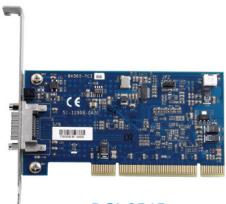
![Blue electronic circuit board with various components and connectors (no readable text or symbols)](.ecs-8582-4s-datasheet-4/4cee6dcd1fcd2df58a0af3fa3d7c9a6f71bf422fda3b897dcff4c4e7afe2c47c.jpg)

PCI-8565

![The image features a black cable looped into a circle, terminating in identical silver and white connectors at each end, set against a plain white background.](.ecs-8582-4s-datasheet-4/2225805f855d9d74ab5c91734c3e394ba8d5892695f1473aee26208506c6081b.jpg)
ACL-EXPRESS-1/-3/-7

<table><tr><td rowspan="2">System Model</td><td rowspan="2">Host Bus Type</td><td rowspan="2">Expansion Bus Type</td><td rowspan="2">Slots No.</td><td colspan="4">Expansion System Includes</td><td rowspan="2">Cable Option</td></tr><tr><td>Card (Host)</td><td>Card (Remote)</td><td>Expansion Chassis</td><td>Accessory</td></tr><tr><td>ECS-8582-4S</td><td>ExpressCard</td><td>PCI</td><td>4</td><td>EC-8560</td><td>PCI-8565</td><td>RK-8005</td><td>ACL-EXPRESS-3</td><td>ACL-EXPRESS-1/-7</td></tr><tr><td>PCES-8581-4S</td><td>PCI Express</td><td>PCI</td><td>4</td><td>PCIe-8560</td><td>PCI-8565</td><td>RK-8005</td><td>ACL-EXPRESS-3</td><td>ACL-EXPRESS-1/-7</td></tr><tr><td>PCES-8581-4L</td><td>PCI Express</td><td>PCI</td><td>4</td><td>PCIe-8560</td><td>PCI-8565</td><td>RK-8005L</td><td>ACL-EXPRESS-3</td><td>ACL-EXPRESS-1/-7</td></tr><tr><td>PCES-8581-13S/-13S-RED</td><td>PCI Express</td><td>PCI</td><td>13</td><td>PCIe-8560</td><td>PCI-8565</td><td>RK-8014</td><td>ACL-EXPRESS-3</td><td>ACL-EXPRESS-1/-7</td></tr></table>
[🔗 Link to the original document](.ecs-8582-4s-datasheet-4/ecs-8582-4s-datasheet-4.pdf)