![Abstract 3D rendering of a red sphere on a textured gray surface with wavy patterns and a partial red logo 'High' in the corner (no readable text or symbols)](.euresysgrablinkquickpackcfapcie-datasheet-3/0165721adf91df6de18915019f1d1b6e114397ee6df6599bb988ae6270e65653.jpg)

# GRABLINK series

h-speed digital Camera Link image acquisition boards

![This image displays three green computer expansion cards (circuit boards) arranged horizontally against a light blue background.\n\n**Top Logos:**\n*   Top Left: 'ADR TECHNOLOGIES' inside a circular border.\n*   Top Center: 'CAMERA Link REGISTERED PRODUCT'.\n*   Top Right: 'PoCL SafePower'.\n\n**The Cards (Left to Right):**\n1.  **Left Card:** Labeled at the bottom 'GRABLINK Avenue™'. It features a metal bracket with two D-sub connectors.\n2.  **Middle Card:** Labeled at the bottom 'GRABLINK Express™'. It features a metal bracket with two large connectors and a smaller one. A 'PCI EXPRESS' logo is positioned below it.\n3.  **Right Card:** Labeled at the bottom 'NEW GRABLINK Quickpack CFA PCIe™' (with 'NEW' in red). It features a metal bracket with two connectors. A 'PCI EXPRESS' logo is positioned below it.\n\nAll three boards bear the text 'EURESYS' and 'Link' on their circuitry.](.euresysgrablinkquickpackcfapcie-datasheet-3/dbf1b0de4fd843d604b76ed599cde7427d825a02cc156fc2f18b2ac0e0a941f5.jpg)

ADR

Link CAMERA

REGISTERED PRODUCT

PoCL

SafePower

GRABLINKTM series

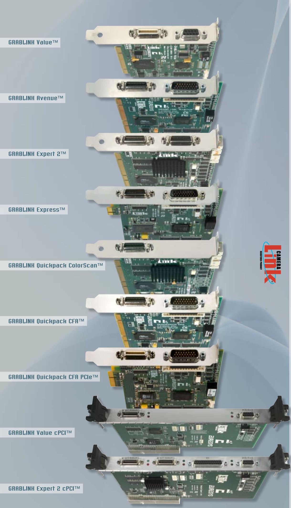
GRABLINK ValueTM - GRABLINK Value cPCITM - GRABLINK AvenueTM - GRABLINK ExpressTM

GRABLINK Expert 2TM - GRABLINK Expert 2 cPCITM - GRABLINK Quickpack ColorScanTM

GRABLINK Quickpack CFATM - GRABLINK Quickpack CFA PCIeTM

www.euresys.comwww.euresys.com

info@euresys.cominfo@euresys.com

© Copyright 2008 Euresys s.a. Belgium. Euresys® is a registred trademark of Euresys s.a. Belgium.

Other product and company names listed are trademarks or trade names of their respective manufacturers.

Euresys reserves the right to modify product specifications and price without previous notice.

![The image displays a logo consisting of several geometric shapes, primarily parallelograms and a square, arranged in a slanted, ascending formation from left to right against a white background. The shapes are colored in blue (in varying shades), green, and red. There is no text present in the image.](.euresysgrablinkquickpackcfapcie-datasheet-3/cd5e007a3a44a9439e759e84f38438868c48112c8bcd87fa3b43224f7e5d5b20.jpg)

![The image displays a geometric logo resembling the letter 'L' constructed from rectangular blocks in various shades of blue.\n\n*   **Top Horizontal Section:** This part consists of three segments arranged horizontally. From left to right, they are a medium blue block, a light blue block, and a very pale blue or white block.\n*   **Vertical Left Section:** Below the leftmost segment of the top row, there is a vertical column composed of two stacked blocks. The upper block is dark blue, and the lower block is a darker shade of blue (navy).\n*   **Bottom Right Section:** Extending to the right from the bottom of the vertical column is a single medium blue rectangular block.](.euresysgrablinkquickpackcfapcie-datasheet-3/18ac341da164bda46c3796d4daadc898ff219ef2ee288374c9ffe48b824b28b3.jpg)

EURESYS

Excellenceinvision

Th e G R A B L I N KTM s e r i e s C o m p a r i s o n C h a r t

<table><tr><td rowspan="2"></td><td colspan="7">NEW</td><td colspan="2">NEW</td></tr><tr><td>GRABLINK Value</td><td>GRABLINK Value cPCI</td><td>GRABLINK Avenue</td><td>GRABLINK Express</td><td>GRABLINK Expert 2</td><td>GRABLINK Expert 2 cPCI</td><td>GRABLINK Quickpack ColorScan</td><td>GRABLINK Quickpack CFA</td><td>GRABLINK Quickpack CFA PCIe</td></tr><tr><td>Form factor</td><td>32-bit, 33 MHz PCI Full height, half length</td><td>64-bit, 66 MHz cPCI 6U/4HP</td><td>64-bit, 66 MHz PCI Full height, half length</td><td>x1 PCI Express Full height, half length</td><td>64-bit, 66 MHz PCI Full height, half length</td><td>64-bit, 66 MHz cPCI 6U/4HP</td><td>64-bit, 66 MHz PCI Full height, half length</td><td>64-bit, 66 MHz PCI Full height, half length</td><td>x4 PCI Express Full height, half length</td></tr><tr><td>Camera Link configuration</td><td>Base</td><td>Base</td><td>Base</td><td>Base PoCL Safe Power</td><td>Base, dual-Base, Medium</td><td>Base, dual-Base, Medium</td><td>Base</td><td>Base</td><td>Base PoCL Safe Power</td></tr><tr><td>Tap demultiplexing incl. tap reversal</td><td>√</td><td>√</td><td>√</td><td>√</td><td>√</td><td>√</td><td>√</td><td>√</td><td>√</td></tr><tr><td>Max. pixel-clock frequency</td><td>24 bits @ 60 MHz</td><td>24 bits @ 60 MHz</td><td>24 bits @ 85 MHz</td><td>24 bits @ 85 MHz</td><td>48 bits @ 60 MHz</td><td>48 bits @ 60 MHz</td><td>24 bits @ 60 MHz</td><td>24 bits @ 85 MHz</td><td>24 bits @ 85 MHz</td></tr><tr><td>Gray scale</td><td>√</td><td>√</td><td>√</td><td>√</td><td>√</td><td>√</td><td>-</td><td>-</td><td>-</td></tr><tr><td>Color</td><td>√</td><td>√</td><td>√</td><td>√</td><td>√</td><td>√</td><td>√</td><td>√</td><td>√</td></tr><tr><td>Area scan</td><td>√</td><td>√</td><td>√</td><td>√</td><td>√</td><td>√</td><td>-</td><td>√</td><td>√</td></tr><tr><td>Line scan</td><td>√</td><td>√</td><td>ADB</td><td>ADB</td><td>√</td><td>√</td><td>√</td><td>-</td><td>-</td></tr><tr><td>Max. delivery bandwidth</td><td>90 MB/s</td><td>90 MB/s</td><td>240 MB/s</td><td>180 MB/s</td><td>240 MB/s</td><td>240 MB/s</td><td>240 MB/s</td><td>240 MB/s</td><td>320 MB/s</td></tr><tr><td>On-board memory</td><td>8-MB</td><td>8-MB</td><td>32-MB</td><td>32-MB</td><td>16-MB</td><td>16-MB</td><td>128-MB</td><td>128-MB</td><td>128-MB</td></tr><tr><td>Pre-processing - Input images - Pre-processing functions -Max. processing rate</td><td>LUTs 3x (8-bit x 8-bit) for R, G, B</td><td>LUTs 3x (8-bit x 8-bit) for R, G, B</td><td>-</td><td>-</td><td>-</td><td>-</td><td>For color line-scan inspection 3 x 8-bit Scan delay compensation Shading correction LUTs 3x (8-bit x 8-bit) for R, G, B White balance Up to 50MPixels/s</td><td>For color area-scan inspection 8-bit, 10-bit or 12-bit Bayer decoding Luminance blender LUTs 4x (16-bit x 16-bit) for R, G, B, Y Automatic white balance Up to 80MPixels/s</td><td>For color area-scan inspection 8-bit, 10-bit or 12-bit Bayer decoding Luminance blender LUTs 4x (16-bit x 16-bit) for R, G, B, Y Automatic white balance Up to 80MPixels/s</td></tr><tr><td>I/O electrical style -system functions-</td><td>4 externally</td><td>4 externally</td><td>9 internally &amp; externally</td><td>9 internally &amp; externally</td><td>26 on an I/O board</td><td>26 externally</td><td>2 externally</td><td>9 internally &amp; externally</td><td>9 internally &amp; externally</td></tr><tr><td>Isol. multi-mode bidirectional I/O* &amp; Isol. 5V power supply -IN (Trigger/Line trigger) OUT (Strobe)-</td><td>2</td><td>2</td><td>2</td><td>2</td><td>4</td><td>4</td><td>2</td><td>2</td><td>2</td></tr><tr><td>Non-isol. TTL input -Trigger/Line trigger-</td><td>1</td><td>1</td><td>-</td><td>-</td><td>3</td><td>3</td><td>-</td><td>-</td><td>-</td></tr><tr><td>Non-isol. TTL output -Strobe-</td><td>1</td><td>1</td><td>-</td><td>-</td><td>3</td><td>3</td><td>-</td><td>-</td><td>-</td></tr><tr><td>Non-isol. bidirectional CMOS I/O</td><td>-</td><td>-</td><td>-</td><td>-</td><td>16</td><td>16</td><td>-</td><td>-</td><td>-</td></tr><tr><td>Non-isol. universal differential input** -Trigger/Line-</td><td>-</td><td>-</td><td>2</td><td>2</td><td>-</td><td>-</td><td>-</td><td>2</td><td>2</td></tr><tr><td>Isol. contact output -Strobe-</td><td>-</td><td>-</td><td>1</td><td>1</td><td>-</td><td>-</td><td>-</td><td>1</td><td>1</td></tr><tr><td>Non-isol. bidirectional TTL I/O -Trigger/Line trigger-</td><td>-</td><td>-</td><td>4</td><td>4</td><td>-</td><td>-</td><td>-</td><td>4</td><td>4</td></tr><tr><td>5V Power supply</td><td>√</td><td>√</td><td>√</td><td>√</td><td>√ (2)</td><td>√ (2)</td><td>√</td><td>√</td><td>√</td></tr><tr><td>12V Power supply</td><td>√</td><td>√</td><td>√</td><td>√</td><td>√</td><td>√</td><td>√</td><td>√</td><td>√</td></tr></table>

![GRABLINH Value™\nGRABLINH Avenue™\nGRABLINH Expert 2™\nGRABLINH Express™\nGRABLINH Quickpack ColorScan™\nGRABLINH Quickpack CFA™\nGRABLINH Quickpack CFA PCIe™\nGRABLINH Value cPCI™\nGRABLINH Expert 2 cPCI™](.euresysgrablinkquickpackcfapcie-datasheet-3/da0f5b48ffd5e783ccf7965840dce64773ea89657d84b11b771c3e991819cf67.jpg)

GRABLINKTM ser

![EURESYS™\nExcellence in vision](.euresysgrablinkquickpackcfapcie-datasheet-3/265f18692e735ee48e7f5d237f097b31085ae627402a790f4a2fd714ad9017ff.jpg)

# High- performance LINE-SCAN and AREA-SCAN Applications

# Flexible and reliable LINE-SCAN acquisition
![Industrial machine with rollers and mechanical components (no visible text or symbols)](.euresysgrablinkquickpackcfapcie-datasheet-3/93c45b3bf45e9d2421d9ca54267e029a30bbd7ae657a0a1e869b21c54bb87127.jpg)

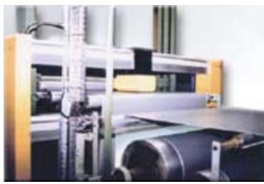
Camera modes The Grablink series interfaces to state-of-the-art Camera Link line-scan cameras with line rate and exposure control. Free running cameras are supported as well.

Continuous web scanning The «web mode» allows inspecting a continuously moving surface without losing a single line.

Successive object scanning In «page mode», a Grablink acquires a set of consecutive lines constituting a 2D image. The acquisition starts when the object enters the camera field of view, as signaled by an external trigger.

Motion encoder When the observed web or object moves at a variable speed, the frame grabber imposes a camera scanning rate derived from a motion encoder. This guarantees a fixed pixel aspect ratio. Perfect square pixels are achievable. A built-in rate converter of the Grablink boards defines any ratio between the camera scanning rate and the encoder pulse rate with 1/1000 resolution. Thus, an off-the-shelf encoder can serve several applications. The exposure control feature guarantees a constant sensitivity despite the speed variation.

# ADR TechnologyTM\*

Simple and reliable LINE-SCAN acquisition with constant lighting sensitivity and line rate

In many applications, a line-scan camera has to be operated at a constant cycling rate in order to maintain a constant sensitivity. The Grablink Avenue and the Grablink Express implement ADR\*, a unique downweb resampling feature, yielding a defined aspect ratio irrespective of web speed variations, even without an electronic shutter on the camera.

A built-in rate converter accommodates an off-the-shelf motion encoder to control the line acquisition process, enabling any programmable aspect ratio, including perfect square pixels.

ADR\* makes the most of the line-scan camera, as the sensitivity is not impaired by the shuttering.

AD TM

Download the “About ADR Technology” flyer from our web site: www.euresys.com.

# Full support of AREA-SCAN acquisition
![Close-up of a black mechanical device mounted on a keyboard, with no visible text or symbols.](.euresysgrablinkquickpackcfapcie-datasheet-3/81f326e73b8afa261a57e1695bd746271a47e7b1b35d16afddc920f11e53ef17.jpg)

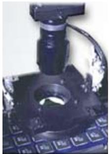
Camera modes Features such as asynchronous reset, exposure control, strobe lighting often required in industrial applications are available on the Grablink series. The synchronous mode is also supported.

Trigger and exposure control An external signal can be sent to the frame grabber to trigger the acquisition. The Grablink series is capable of consistently controlling the exposure time and the illumination.

Camera tap structure For any tap structure, a Grablink delivers a re-ordered bitmap image to the PC memory. Tap-reversal is supported. With the multiplex tap technique, several taps are interleaved over Camera Link as long as the combined data rate remains below the pixel clock frequency specified for the board.

# Main Features

Acquisition:
Up to 24-bit / 48-bit at maximum 85 MHz
Camera Link configurations: Base, dual Base or Medium
Support of LINE-SCAN and AREA-SCAN cameras
Multiple taps, tap reversal, tap multiplex
• Large on-board memory
Asynchronous reset, exposure control and I/O lines -trigger & strobe-
. Camera Link serial line configurable as an additional PC COM port
. MultiCam drivers for Windows® and Linux

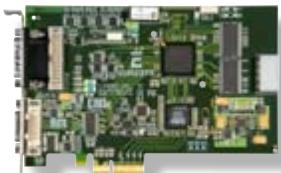
The Grablink series is a range of high-speed PCI, PCI Express and Compact PCI frame grabbers for line-scan or area-scan digital Camera Link cameras. State-of-the-art cameras are easily connected with off-the-shelf Camera Link compliant cables. The Grablink series is ideal for industrial applications such as inspection of high-speed moving objects, web inspection or high-resolution acquisition.


![Close-up of a circuit board with visible traces and pads, tinted in blue (no text or symbols)](.euresysgrablinkquickpackcfapcie-datasheet-3/94a99c41b25360b3dc225f63105fb92b455fb8fc1d2c51e3a3914d1d62f11a8b.jpg)

![Bhargy 12.18\n### ### ### ### 8 13/04\n### ### ### ### ### 8 13/04\n### ### ### ### ### 8 13/04\n### ### ### ### ### 8 13/04\n### ### ### ### ### 8 13/04](.euresysgrablinkquickpackcfapcie-datasheet-3/c1c416aa5aac3f037750bf305391b4db96319f798eba81ac47eb27939755599b.jpg)

![Close-up of fresh red chili peppers and a green chili pepper (no text or symbols visible)](.euresysgrablinkquickpackcfapcie-datasheet-3/933eee17166e45726aa7ec0744aa38c74854ce09c5375446171df6d977d31bae.jpg)

# Serial control of camera

The Grablink series supports the Camera Link pseudo RS-232 serial line. The application software can use the Camera Link API functions to control the camera. Alternatively, the serial line can be configured as an additional PC COM port ensuring interoperability with existing camera control software.

# Bus mastering

All Euresys frame grabbers are PCI bus mastering agents that directly store the acquired images into the PC physical memory without CPU involvement. As a unique feature, a Euresys board automatically recovers the scatter-gather virtual memory mapping to present the data as a regular bitmap image in a user allocated memory buffer.

# Windows Of Interest (WOI) support

The Grablink series seamlessly support the acquisition of a WOI rather than a full image.

# Interfaced cameras

The Grablink series interfaces an impressive choice of different cameras.

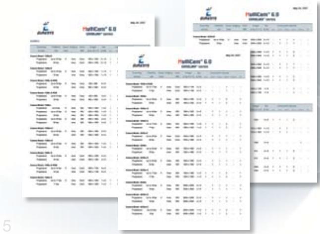
An up-to-date list is available on the Interfacing Cameras page on www.euresys.com.
![The image displays three overlapping white documents, likely price lists or catalogs, set against a light grey background.\n\n**Header Information (visible on the documents):**\n*   **Logo:** 'Aubert' with a blue bird icon.\n*   **Title:** 'HeliCare® 6.9'\n*   **Subtitle:** 'UNIQUE VALUES'\n*   **Date:** 'May 01, 2021' (visible on the rightmost document).\n\n**Table Content:**\nThe documents contain tables listing products and pricing details. The visible text in the rows includes:\n*   'HeliCare 6.9'\n*   'HeliCare 6.9 PRO'\n*   'HeliCare 6.9 PLUS'\n*   'HeliCare 6.9 PRO PLUS'\n*   A series of rows with percentages: '10%', '20%', '30%', '40%', '50%', '60%', '70%', '80%', '90%', '100%'.\n\n**Other Elements:**\n*   A large, faint number '5' is visible in the bottom left corner.](.euresysgrablinkquickpackcfapcie-datasheet-3/21b4e4e6077e20561aa257bdedab65950fd5fe5ce741a639e091b5abaf6b089c.jpg)

![The image features a logo resembling a capital letter 'C' constructed from rectangular blocks in various shades of blue. At the upper right, there are small accent squares in green and red against a white background.](.euresysgrablinkquickpackcfapcie-datasheet-3/f26efd5f2e4362b9ea61c239ce44ee7e919812df2d0374bf7c2e08be8a640868.jpg)

![Green printed circuit board with various electronic components and connectors (no readable text or symbols)](.euresysgrablinkquickpackcfapcie-datasheet-3/b2b400049df93c0c3be32014cdcb4592842e8766a28a9756d4bee8b7a68bbd3b.jpg)

# GRABLINK ValueT

Cost-effective Camera Link acquisition

Base configuration -24-bit at 60 MHz-

8-MB on-board memory

Form factors: Conventional PCI	 32-bit 33 MHz bus

Compact PCI 6U/4HP 64-bit 66 MHz bus

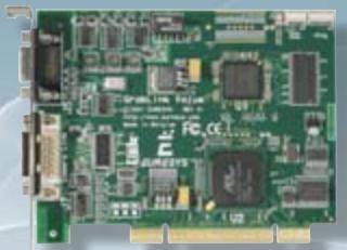
The Grablink Value is an affordable Camera Link frame grabber for cost-effective industrial applications. The Grablink Value is recommended for single-camera systems.

Support of the Base configuration

<table><tr><td rowspan="2" colspan="2">CAMERA COMPATIBILITY</td><td colspan="2">Monochrome or Bayer</td><td>Color RGB</td></tr><tr><td>single-tap</td><td>dual-tap</td><td>single-tap</td></tr><tr><td colspan="2">Tap configuration</td><td>Base_1T8, Base_1T10, Base_1T12, Base_1T14, Base_1T16</td><td>Base_2T8, Base_2T10, Base_2T12</td><td>Base_1T24</td></tr><tr><td>Camera Link configuration</td><td>Base</td><td>1 tap x (8-10-12-14-16 bits)</td><td>2 taps x (8-10-12 bits)</td><td>1 tap x (24 bits)</td></tr></table>

# 4 I/O lines available on an external DB9 connector

# I/O electrical style

- 2 isolated multi-mode bidirectional I/O and associated isolated 5V power supply
• Input: isolated TTL, isolated 12V
• Output: isolated TTL, isolated open collector, isolated Open Emittor
- 1 non-isolated TTL input
- 1 non-isolated TTL output
- 5V and 12V power supplies

# I/O electrical style and function

- TTL trigger or page trigger input
- Opto-isolated trigger or page trigger input
- TTL strobe output
- Opto-isolated strobe output
- TTL line trigger or encoder input
- Opto-isolated line trigger or encoder input
![Green printed circuit board with various electronic components and connectors (no readable text or symbols)](.euresysgrablinkquickpackcfapcie-datasheet-3/9120714f8992740bb772388c9098a31d33f150840fea500cc5edb5433f1c361a.jpg)

# GRABLINK AvenueTM

Ultra-fast Camera Link acquisition

![This image features a logo set against a solid light blue background. Large, vertical letters spelling 'ADR' dominate the left side, colored in a gradient of dark to medium blue. Curving around the right side of the 'R' are the smaller, blue capital letters 'TECHNOLOGY.' A small 'TM' symbol is positioned near the top right of the 'R.'](.euresysgrablinkquickpackcfapcie-datasheet-3/6a70722326aac433e801e9b1eff607e31e3be66b5d8223cc47b4389165360351.jpg)

Base configuration -up to 24-bit at 85 MHz-

Full support of AREA-SCAN cameras -asynchronous reset and exposure control-

Simple and reliable LINE-SCAN acquisition -ADR Technology™-

32-MB on-board memory

Form factors: Conventional PCI 64-bit, 66 MHz bus, 3V/5V signaling

The Grablink Avenue is an ultra-fast PCI frame grabber for line-scan or area-scan digital Camera Link cameras. Grablink Avenue is a high-performance 64-bit, 66 MHz PCI bus board acquiring images from one camera in the Camera Link Base configuration. This board acquires the 24-bit data, with any tap structure, at the maximum speed of 85 MHz allowing to be interfaced to the fastest cameras.

Support of the Base configuration

<table><tr><td rowspan="2" colspan="2">CAMERA COMPATIBILITY</td><td colspan="3">Monochrome or Bayer</td><td>Color RGB</td></tr><tr><td>single-tap</td><td>dual-tap</td><td>quad-tap</td><td>single-tap</td></tr><tr><td colspan="2">Tap configuration</td><td>Base_1T8, Base_1T10, Base_1T12, Base_1T14, Base_1T16</td><td>Base_2T8, Base_2T10, Base_2T12, Base_2T14B2, Base_2T16B2</td><td>Base_4T8B2</td><td>Base_1T24, Base_1T24B3, Base_1T30B2, Base_1T36B2, Base_1T36B3, Base_1T42B2, Base_1T42B3, Base_1T48B2, Base_1T48B3</td></tr><tr><td rowspan="2">Camera Link configuration</td><td>Base</td><td>1 tap x (8-10-12-14-16 bits)</td><td>2 taps x (8-10-12 bits)</td><td>-</td><td>1 tap x (24 bits)</td></tr><tr><td>Extended Base*</td><td>-</td><td>2 taps x (14-16 bits)</td><td>4 taps x (8 bits)</td><td>1 tap x (24-30-36-42-48 bits)</td></tr></table>

\*Multiplex tap

# 9 various I/O lines available on an external HD26 connector and on an internal 26-pin header connector

# I/O electrical style

- 2 isolated multi-mode bidirectional I/O and associated isolated 5V power supply
• Input: isolated TTL, isolated 12V
• Output: isolated TTL, isolated open collector, isolated open emittor
- 2 non-isolated universal differential inputs (LVDS and more)
- 1 isolated contact output
- 4 non-isolated bidirectional TTL I/O
- 5V and 12V power supplies

# I/O electrical style and function

- TTL trigger or page trigger input
- LVDS trigger or page trigger input
- Opto-isolated trigger or page trigger input
- TTL strobe output
- Opto-isolated strobe output
- Fast opto-isolated strobe output
- TTL line trigger or encoder input
- Opto-isolated line trigger or encoder input

![Close-up of a green printed circuit board with various electronic components and connectors (no readable text or symbols)](.euresysgrablinkquickpackcfapcie-datasheet-3/2595e75e9906a240cccfd549936db56a5b30513815f8179cd78575b33b5703c4.jpg)

# GRABLINK ExpressTM

![The image displays a logo featuring the large, capital letters 'ADR' arranged vertically. These letters have a blue gradient, transitioning from a darker blue at the bottom to a lighter blue-grey at the top. Curving around the right side of the letters is the word 'TECHNOLOGY' in smaller blue capital letters. A small 'TM' symbol is visible near the top right edge.](.euresysgrablinkquickpackcfapcie-datasheet-3/68047f393d601d7785f2aad6ad3e4212482ffdf4c8786add5b5b7ba74f1451a2.jpg)

Cutting-edge PCI Express Camera Link acquisition

Base Camera Link 1.2 configuration -24-bit at 85 MHz-

-Power over Camera Link compliant -PoCL-

Full support of AREA-SCAN cameras -Asynchronous reset and exposure control-

Simple and reliable LINE-SCAN acquisition -ADR Technology™-

32-MB on-board memory

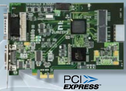
Form factors: PCI Express Full-height, half-length, x1

The Grablink Express is at the cutting-edge of the Camera Link technology through the compliance with the new standard 1.2 including PoCL - Power over Camera Link-. It allows a single Camera Link cable to supply power to the camera, on top of transferring high-speed images and controlling the camera. The Grablink Express PoCL frame grabber interfaces the smallest and fastest cameras on the market while still being safely compatible with cables and cameras from the previous Camera Link standards.

# Support of Camera Link 1.2 Base configuration -including PoCL-

The Grablink Express supports the same type of cameras as the Grablink Avenue -see the chart on page 6-.

![The image displays a logo featuring the text 'PoCL'. The letters 'P' and 'o' are black, while the letters 'C' and 'L' are red. All characters use a serif typeface. A thin, blue elliptical ring circles the text, passing behind the 'P' and the 'C'.](.euresysgrablinkquickpackcfapcie-datasheet-3/f607f93c8285ea11bf384e5bb8d9bb66ecfcd8476c785240d559ea48b1a39ba9.jpg)

The Power over Camera Link standard specifies how to supply power to the camera through the Camera Link connector without losing backward compatibility with the previous Camera Link standard.

\- Conventional and PoCL cameras and cables supported

\- “SafePower” feature

\- Over-Current Protection and Over-Voltage Protection circuits

9 various external and internal I/O lines identical to the Grablink Avenue I/O lines

\*Patent pending
![Close-up of a green printed circuit board with integrated circuits and connectors (no visible text or symbols)](.euresysgrablinkquickpackcfapcie-datasheet-3/a602bd67cf89151f4c6c302696af528c0184ab048ba8bd819ebece53673de191.jpg)

# GRABLINK Expert 2TM

High-performance Camera Link acquisition

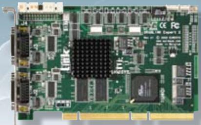
Dual Base or Medium configurations -48-bit at 60 MHz-

16-MB on-board memory

Form factors: 	Conventional PCI	 64-bit 66 MHz bus

Compact PCI 6U/4HP, 64-bit 66 MHz bus

The Grablink Expert 2 is a Camera Link frame grabber for demanding industrial applications.

Support of dual Base or Medium configurations

<table><tr><td rowspan="2" colspan="2">CAMERA COMPATIBILITY</td><td colspan="3">Monochrome or Bayer</td><td colspan="2">Color RGB</td></tr><tr><td>single-tap</td><td>dual-tap</td><td>quad-tap</td><td>single-tap</td><td>dual-tap</td></tr><tr><td colspan="2">Tap configuration</td><td>Base_1T8, Base_1T10, Base_1T12, Base_1T14, Base_1T16</td><td>Base_2T8, Base_2T10, Base_2T12, Medium_2T14, Medium_2T16</td><td>Medium_4T8, Medium_4T10, Medium_4T12</td><td>Base_1T24, Medium_1T30, Medium_1T36, Medium_1T42, Medium_1T48</td><td>Medium_2T24</td></tr><tr><td rowspan="2">Camera Link configuration</td><td>Base</td><td>1 tap x (8-10-12-14-16 bits)</td><td>2 taps x (8-10-12 bits)</td><td>-</td><td>1 tap x (24 bits)</td><td>-</td></tr><tr><td>Medium</td><td>-</td><td>2 taps x (14-16 bits)</td><td>4 taps x (8-10-12 bits)</td><td>1 tap x (30-36-42-48 bits)</td><td>2 tap x (24 bits)</td></tr></table>

# Multiple Windows Of Interest (WOI) support

With some specific CMOS cameras, the Grablink Expert 2 supports their possible feature of acquiring up to 16 WOI in the image, with overlapping of the windows.

# 26 I/O lines
![The image displays a green printed circuit board (PCB) oriented vertically. A large, rectangular purple connector runs vertically down the center-left portion of the board. The surface of the green PCB features a repeating grid pattern of the text 'SUN.' Additionally, the word 'SUN' is printed vertically near the top left edge, vertically alongside the purple connector, and near the bottom right corner. Small black electronic components and surface-mount devices are visible near the top right and bottom left edges. A white label is present at the top left, but its specific text is illegible.](.euresysgrablinkquickpackcfapcie-datasheet-3/5c250829a1c6395102f0d1bf04018720ed2be6f06eda76a7319da5007051e910.jpg)

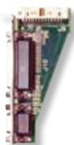
The Grablink Expert 2 is delivered with an auxiliary I/O board implementing the trigger and strobe facilities. On the Grablink Expert 2 cPCI, the two I/O connectors are located directly on the front panel.

# I/O electrical style

- 4 isolated multi-mode bidirectional I/Os and associated isolated 5V power supply
• Input: isolated TTL, isolated 12V
• Output: isolated TTL, isolated open collector, isolated open emittor
- 3 non-isolated TTL inputs and 3 similar outputs
- 16 non-isolated bidirectional CMOS I/Os
- 5V and 12V power supplies

# I/O electrical style and function

- TTL trigger or page trigger input
- Opto-isolated trigger or page trigger input
- TTL strobe output
- Opto-isolated strobe output
- TTL line trigger or encoder input
- Opto-isolated line trigger or encoder input

![The image displays a vertical, pixelated graphic resembling a lowercase letter 'e,' constructed from rectangular blocks of varying colors.\n\nAt the top left, there is a small green square. Directly below it is a small blue square. Extending to the right from this blue square is a long, horizontal blue rectangle. Above the right end of this blue rectangle is a small red square, and to the right of the rectangle (below the red square) is a small white square.\n\nBelow the left end of the blue rectangle is a vertical column composed of light blue and white blocks. At the very bottom, extending from the base of this vertical column, is a thick, blue horizontal rectangle. The overall design uses a palette of blues, green, red, and white.](.euresysgrablinkquickpackcfapcie-datasheet-3/a6eaf2117a79e97089c56749c517e85979c6283216855e27012283b943fa8073.jpg)

![8347 5151\nPrice: 6742 0085'\n6 P OFFICE\n8347 5151\nPrice: 6742 0085'\n8347 5151\nPrice: 6742 0085'\n8347 5151\nPrice: 6742 0085'\n8347 5151\nPrice: 6742 0085'\n8347 5151\nPrice: 6742 0085'\n8347 5131\nPrice: 6742 0085'\n8347 5131\nPrice: 6742 0085'\n8347 5131\nPrice: 6742 0085'\n8347 5131\nPrice: 6742 0085'\n8347 5131\nPrice: 6792 0085'\n8347 5131\nPrice: 6792 0085'\n8347 5131\nPrice: 6792 0085'\n8347 5131\nPrice: 6792 0085'\n8347 5131\nPrice: 6792 0085'\nE Express Package Service\nE Broadcast Party\nPackaging](.euresysgrablinkquickpackcfapcie-datasheet-3/68623a72b8f7016b8c3807183d63693a2949a29039c4335bd66c492d9fec55ce.jpg)

# GRABLINK Quickpack ColorScan M

High-resolution Camera Link image acquisition and pre-processing for color LINE-SCAN inspection

Image pre-processing accelerated by the FPGA -up to 50MPixels/s-

Scan-delay compensation

Shading correction

Look-up table transformation

White balance

Base configuration 24-bit at up to 60 MHz

Output formats RGB 24- and 32-bit packed

RGB 24-bit planar

128 MB on-board memory

Form factor: Conventional PCI 64-bit 66 MHz

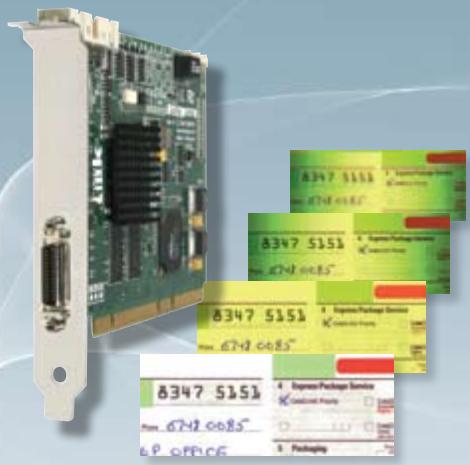
The Grablink Quickpack ColorScan provides on its FPGA the accelerated image pre-processing functions necessary for color scanning applications. Color document scanning or PCB inspections are then considerably eased and accelerated providing on the fly enhanced images ready for further processing.

# Image pre-processing functions accelerated by the FPGA

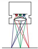
• Scan-delay compensation A trilinear color camera captures the luminance information at three light wavelength ranges from three distinct locations. A gap between these lines analyzed in red, green and blue is resulting due to the sensor geometry and the optical arrangement. The scan-delay compensation offered in the Grablink Quickpack ColorScan gathers the color information coming from three different locations in order to reconstruct consistent RGB information.
![The image is a schematic diagram illustrating the superposition of colored light beams. At the top, a rectangular outline features an opening containing three small colored circles: red, green, and blue. Lines of corresponding colors emerge from these circles and travel downwards. The beams cross over each other in the central region. At the bottom, the lines terminate at five distinct points along a horizontal line, demonstrating additive color mixing: the far left and far right points show the overlap of red and blue (magenta), the inner left and inner right points show the overlap of green with red (yellow) and green with blue (cyan) respectively, and the central point shows the overlap of all three colors (white).](.euresysgrablinkquickpackcfapcie-datasheet-3/dab740ca33710245036d1b149b0172e86de830e0f4b948b3a16e384829505dd3.jpg)

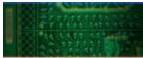
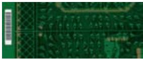
• On the fly shading correction on the three color components After the calibration phase, the six profiles are compiled into the frame grabber hardware to correct the distortions. This correction is handled applying a multiplicative -gain- and an additive -offset- correction to each pixel issued in the scanned signal. This processing drastically improves the quality of the acquired images facilitating the application processing.
• Three 8-bit x 8-bit Look-up Table Transformer for the R the G and the B components They include the following setup methods: exhaustive definition of the transformation law, parametric shaping of the transformation law through a few intuitive controls, white balance by RGB gain correction implemented as special transformation laws.
• White balance correcting for RGB channel imbalance This imbalance can be due to differences in sensitivity of sensors, to the illumination system and to the optical filter. After calibration, a correcting gain is applied to each color channel to compensate for unbalanced R, G and B components.
![The image displays a close-up, low-resolution view of a green printed circuit board (PCB). Lighter green traces run horizontally and vertically across the board. A grid of small, dark, rectangular surface-mount components is visible in the center. On the far left, a larger, vertical rectangular shape is present. The image is framed by a thin blue line at the top and a thin red line at the bottom. No text is visible.](.euresysgrablinkquickpackcfapcie-datasheet-3/4ad6aff881feb62f8641a13a1f6e465c64de92ac7cbcb37c78a850a95c8c80b3.jpg)
Raw acquired image

![The image displays a close-up, low-resolution view of a green printed circuit board (PCB). The board features a dense grid of small, rectangular copper pads and traces running horizontally and vertically. On the far left edge, there is a vertical rectangular area with horizontal lines, resembling a connector footprint or a silkscreen label area. The majority of the visible board surface is covered in the grid pattern. No legible text is visible on the board due to the blur and resolution.](.euresysgrablinkquickpackcfapcie-datasheet-3/a05a207086455ee6bece8848cc22442b1930d3eddab10b544f79d0e596774c3b.jpg)
Scan-delay compensated

![This image displays a close-up section of a green printed circuit board. On the far left edge, a vertical connector with gold contact pins is visible. The remainder of the board features a grid of small circular copper pads and traces running horizontally and vertically across the green solder mask. A larger circular pad is visible in the bottom right corner. There is no readable text visible in the image.](.euresysgrablinkquickpackcfapcie-datasheet-3/15877b2835ec215240165472cf58682d1024a9e2360bf691a17c5af313d183c6.jpg)
Scan-delay compensated and shading corrected image
![This image displays a close-up view of a green printed circuit board (PCB). On the far left edge, a white vertical label featuring a barcode is attached. The majority of the image shows the green substrate of the board, which is covered in intricate copper traces and small rectangular connection pads. The image is somewhat dimly lit and grainy.](.euresysgrablinkquickpackcfapcie-datasheet-3/58ec6b510b1800f72e85c464e16769c4764b982a48bab12af6b79fa64e8ddf4b.jpg)
Scan-delay compensated, shading corrected and white balanced image

# Image acquisition and transfer

• Support of Base configuration for RGB LINE-SCAN camera

Two kinds of RGB imagers are supported: trilinear and 3-CCD. Only RGB single-tap with Base\_1T24 tap configuration is supported.

• Downweb resampling feature for shutterless cameras

Most high-resolution color line-scan cameras have no electronic shutter capability. Consequently, they have to be operated at a constant cycling rate in order to maintain a constant sensitivity. The Grablink Quickpack ColorScan implements a unique downweb resampling feature yielding a defined aspect ratio irrespective of web speed variations. A built-in rate converter accommodates an off-the-shelf motion encoder to control the line acquisition process, enabling any programmable aspect ratio, including perfect square pixels.

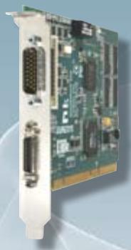
# 2 I/O lines available externally on a DB-9 connector

# I/O electrical style

- 2 isolated multi-mode bidirectional I/Os and associated isolated 5V power supply
• Input: isolated TTL, isolated 12V
• Output: isolated TTL, isolated open collector, isolated open emittor
- 5V and 12V power supplies

# I/O electrical style and function

- TTL trigger or page trigger input
- Opto-isolated trigger or page trigger input
- TTL strobe output
- Opto-isolated strobe output
- TTL line trigger or encoder input
- Opto-isolated line trigger or encoder input
![Close-up of a green circuit board with visible I/O ports and connectors (no text or symbols)](.euresysgrablinkquickpackcfapcie-datasheet-3/9ed96701a080f241de1532e01b527e8e8f16adc88d5b7648b1c6b61e1409f744.jpg)

# GRABLINK Quickpack CFATM boards

Camera Link image acquisition and pre-processing for color AREA-SCAN inspection

Image pre-processing accelerated by the FPGA on 8-bit, 10-bit or 12-bit input images -up to 80MPixels/s-

Bayer Pattern decoder

Luminance blender

Base configuration 24-bit at up to 85 MHz

128 MB on-board memory

White balance operator

Four LUT operators

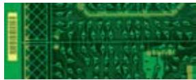
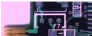
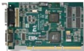
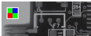
The Grablink Quickpack CFA -Color Filter Array- offers a set of dedicated on-board preprocessing functions to speed up image processing for applications such as PCB, food or pharmaceutical inspection without loading the host CPU.

# Image pre-processing functions accelerated by the FPGA

All operators are compatible with 8-, 10- and 12-bit input images.

• A Bayer Pattern decoder computes the R,G and B components of the image
• An automatic white balance operator

- The white balance parameters can be specified by the user or computed automatically from the image.
- They can be computed continuously (on each image) or once only (under user control).
- Moreover, they can be computed from automatically selected white pixels in the image, or from a user-specified region of interest.

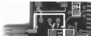
• A luminance blender computes the Y component of the image
• Four 16-bit x 16-bit LUT operators on R, G, B and Y channels

# Image acquisition and transfer

• Support of Base configuration for AREA-SCAN single or dual-tap cameras

\- Bayer pattern color

\- Also compatible with monochrome and RGB cameras

As a Base Camera Link configuration board, the Grablink Quickpack CFA supports the same type of cameras as the Grablink Avenue -see the chart on page 6-

• 9 various I/O lines available on external and internal connectors, similarly to the Grablink Avenue -page 6-
• Output format

- 8-, 10-, 12- and 16-bit components (R, G, B and Y)
- A wide range of formats is available in the following classes:

• monochrome
• Bayer CFA
• three packed R G B components
• three planar R G B components
![The image displays a close-up, grayscale view of a computer motherboard circuit board. In the upper-left corner, the Microsoft logo is visible, consisting of four colored squares: red, green, blue, and yellow. The circuit board features intricate silver traces and small electronic components. A rectangular area on the right is labeled '24'. Near the center, the text 'F7' is printed next to a circular pad or mounting hole. The right side of the image is cropped.](.euresysgrablinkquickpackcfapcie-datasheet-3/560c895def89fb6a608d481687119815b8b9ad848f5c606c8f5ac08fa5c6b319.jpg)
Raw image

![The image shows a close-up of a green printed circuit board (PCB) featuring copper traces and solder pads. White silkscreen markings outline component positions, with 'C5' visible in the upper right and 'F7' centered. A flexible flat cable connector with gold contacts is attached along the left edge. The background is a blurred pink surface.](.euresysgrablinkquickpackcfapcie-datasheet-3/01a13a30ab593288ecd9d7e640d1959ab1165ce55f774a13713284b96a12fc41.jpg)
Bayer pattern decoder

• four packed R G B a components
• four packed R G B Y components
• three packed R G B components + Y component
• three planar R G B components + Y component
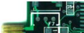
![The image displays a close-up section of a green printed circuit board (PCB). White silkscreen markings are visible, including the letter 'L' near the top left and the alphanumeric code 'F7' in the center. To the right, the number '03' appears inside a rectangular outline. The board features copper traces and solder pads, including a rectangular footprint beneath the 'F7' label, and a gold-plated connector edge is visible on the far left.](.euresysgrablinkquickpackcfapcie-datasheet-3/848ee8e58377d4c61eecd75b26d1d8713e32a861f03acfd03f8227bd77a46020.jpg)
White balance

![This is a close-up, black-and-white image of a printed circuit board (PCB) featuring white silkscreen markings. The visible text includes 'F7' located centrally near two circular pads and 'C54' printed inside a rectangular outline in the upper right corner. White traces connect various rectangular outlines and circular pads across the dark board surface.](.euresysgrablinkquickpackcfapcie-datasheet-3/89c4f80c7617711d3b3780fb43f496da755fb3c1978bc35da9d58dc5928836f6.jpg)
Luminance blender

![Close-up of a green printed circuit board (PCB) with various electronic components and connectors, no visible text or symbols.](.euresysgrablinkquickpackcfapcie-datasheet-3/a4a0c1a5ffd27affadd8d97cc7e0bfdfefcf9fc1f6ff5449515d6d4b31fc543c.jpg)

![Close-up of a green printed circuit board with various electronic components (no visible text or symbols)](.euresysgrablinkquickpackcfapcie-datasheet-3/976e4df55703369fc2959419768d5c9202d8d83d50fa24852568ba9562113ebf.jpg)

# GRABLINK Quickpack CFA

Form factor: Conventional PCI Image Resolution

64-bit, 66 MHz, 3V/5V signaling Up to 4096 by 4096

# GRABLINK Quickpack CFA PCIe

NEW

PoCL Safe Power compliant -see on page 7-

Form factor: PCI Express Full-height, half-length, x4

Image Resolution Up to 7616 x 4096

Trigger decimation: it controls the acquisition rate from an electrical signal by setting a programmable decimation factor.

# Software support

# MultiCamTM Drivers
![MultiCam fo\nMultiCam fo\nC, C++, .NE](.euresysgrablinkquickpackcfapcie-datasheet-3/111116bac59d5d7eecbe7cf00be5ea0163c96ba291d839ef00e83f731c733650.jpg)

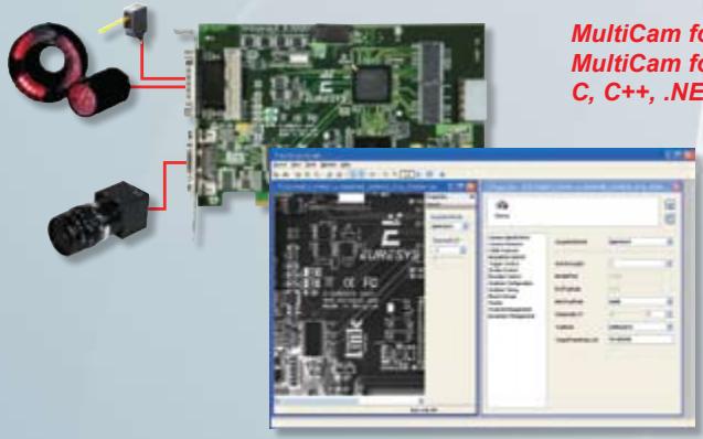
or Microsoft Windows 2000®, XP®, Server 2003® and Vista® or Linux Suse Linux Enterprise Server 10 T classes and ActiveX controls

The MultiCam driver enables the consistent control of several Euresys frame grabbers, using an arbitrary number of cameras, from one or several software applications. MultiCam allows defining channels linking cameras to buffers in the PC memory.

The MultiCam channel identifies all parameters ruling the acquisition process from a camera. Every camera feature, such as its type, resolution or image format, is described and controlled through simple parameters, considerably easing the camera control task. For each channel-controlled camera, a set of dedicated parameters is created from a CAM file.

Euresys delivers pre-defined files for many popular cameras; still the user can customize his CAM files.

An up-to-date list is available on the Interfacing Cameras page of the Euresys web site.

MultiCam™ IDEs

<table><tr><td>LANGUAGE</td><td>Using ...</td><td>OS</td><td>Environment</td></tr><tr><td rowspan="4">C++</td><td rowspan="3">C API</td><td rowspan="2">Windows®</td><td>MS Visual Studio®</td></tr><tr><td>Borland C++ Builder®</td></tr><tr><td>Linux</td><td>gcc</td></tr><tr><td>DirectShow filters</td><td>Windows®</td><td>MS Visual Studio®</td></tr><tr><td rowspan="2">Pascal</td><td>ActiveX controls</td><td>Windows®</td><td>Borland Delphi®</td></tr><tr><td>Pascal API</td><td>Windows®</td><td>Borland Delphi®</td></tr><tr><td>Visual Basic</td><td>ActiveX controls</td><td>Windows®</td><td>MS Visual Studio®</td></tr><tr><td>Visual Basic .NET</td><td>.NET objects</td><td>Windows®</td><td>MS Visual Studio®</td></tr><tr><td>C#</td><td>.NET objects</td><td>Windows®</td><td>MS Visual Studio®</td></tr></table>

# Ordering Information

ORDER CODE

<table><tr><td>1191</td><td>GRABLINK Value</td></tr><tr><td>1194</td><td>GRABLINK Value cPCI</td></tr><tr><td>1198</td><td>GRABLINK Avenue</td></tr><tr><td>1621</td><td>GRABLINK Express</td></tr></table>

DESIGNATION

ORDER CODE
DESIGNATION

<table><tr><td>1197</td><td>GRABLINK Expert 2</td></tr><tr><td>1196</td><td>GRABLINK Expert 2 cPCI</td></tr><tr><td>1501</td><td>GRABLINK Quickpack ColorScan</td></tr><tr><td>1503</td><td>GRABLINK Quickpack CFA</td></tr><tr><td>6009</td><td>GRABLINK Quickpack CFA PCIe</td></tr></table>

America, Euresys Inc.

500 Park Boulevard, suite 525, Itasca, Illinois 60143

Toll free: 1-866-EURESYS - Phone: 630-250-2300 - Fax: 630-250-2301

Asia, Euresys Pte. Ltd.

627A Aljunied Road, #08-09 BizTech Centre, Singapore 389842

Phone: +65 6748 0085 - Fax: +65 6841 2137

Japan, Euresys s.a. Japan Representative Office

AIOS Hiroo Building 8F, Hiroo 1-11-2, Shibuya-ku, Tokyo 150-0012

Phone: +81 3 5447-1256 - Fax: +81 3 5447-0529

Europe, Euresys s.a., Corporate Headquarters

14, Avenue du Pré-Aily, B-4031 Angleur, Belgium

Phone: +32 4 367 72 88 - Fax: +32 4 367 74 66

![The image displays a pixelated, block-style graphic on a light gray-blue background. It depicts a large, stylized letter 'L' constructed from various shades of blue squares and rectangles. At the top of the composition, there are two small squares: a green one on the left and a red one on the right. The rest of the 'L' shape is formed by blue blocks of varying sizes and shades. There is no text in the image.](.euresysgrablinkquickpackcfapcie-datasheet-3/dff3d72545a5a0e9edb2c74a25d84d0a8d1671699ee43c1818e9d069aa07c5d9.jpg)

EURESYS Excellence in vision

www.euresys.com

info@euresys.com

Your distributor
[🔗 Link to the original document](.euresysgrablinkquickpackcfapcie-datasheet-3/euresysgrablinkquickpackcfapcie-datasheet-3.pdf)