# Express-DN7

COM Express Basic Size Type 7 Module with Intel Atom® C3000 SoC

# Features

● Intel Atom® Processor C3000 SoC (up to 16 cores), supports full virtualization (VT-d/VT-x)
● Up to 48GB ECC DDR4 memory at max. 2400MHz (and non-ECC supported)
● Up to 2x PCIe x8 Gen3 for flexible expansion
● Up to 4x 10GBASE-KR ports
● IEEE 1588 Precision Time Protocol (PTP) support for real-time applications
● Extreme Rugged operating temperature range: -40°C to +85°C (build option for eTEMP SKUs)
● Supports Smart Embedded Management Agent (SEMA) functions
![Close-up of a green printed circuit board with integrated circuits and connectors (no readable text or symbols)](.express-dn7-datasheet-20200828/6877c4493be6d6f9423727392b1e96109b84fa6176ac34b5e0947628b4e9383d.jpg)

# Specifications

# ● Core System

# CPU

Intel Atom® Processor C3000 SoC, 14nm (formerly codename: “Denverton-NS”)

Atom® C3808 2.0GHz 12MB, 25W (12C/2133MHz, eTEMP)

Atom® C3708 1.7GHz 16MB, 17W (8C/2133MHz, eTEMP)

Atom® C3508 1.6GHz 8MB, 12W (4C/1866MHz, eTEMP)

Atom® C3308 1.6/2.1GHz 4MB, 10W (2C/1866MHz, eTEMP)

Atom® C3958 2.0GHz 16MB, 31W (16C/2400MHz, by request)

Atom® C3858 2.0GHz 12MB, 25W (12C/2400MHz, by request)

Atom® C3758 2.2GHz 16MB, 25W (8C/2400MHz, by request)

Atom® C3558 2.2GHz 8MB, 16W (4C/2133MHz, by request)

Atom® C3538 2.1GHz 8MB, 15W (4C/2133MHz, by request)

Atom® C3338 1.5/2.2GHz 4MB, 9W (2C/1866MHz, by request)

Supports: Intel® Quick Assist Technology (Crypto and Compression accelerator), Intel® VT (including VT-x, VT-d, VT-x with Extended Page Tables), Intel® Turbo Boost Technology 2.0, Intel® SSE4.2, Intel® 64 Architecture, Intel® ISA compatibility, Intel® Execute Disable Bit, Intel® OS Guard, Intel® Secure Key, Intel® AES-NI, Intel® Security Hash Algorithm Extensions (SHA-1, SHA-256)

Note: Availability of features may vary between SoC SKUs

# Memory

Up to dual channel 2400/2133/1866 MHz DDR4 ECC (or non-ECC), up to 48GB in three SODIMM sockets

Notes: Memory frequency & capacity depends on SKUs; 3rd SO-DIMM supported by build option.

# Embedded BIOS

AMI EFI with CMOS backup in 16MB SPI BIOS

# Cache

16MB for C3708/C3958/C3758, 12MB for C3808/C3858, 8MB for C3508/ C3558/C3538, 4MB for C3308/C3338

# Expansion Busses

Up to 1 PCI Express x8 Gen3; CD connector (lanes 16-23 x8, x4, x2 (or x1), four controllers)

Up to 1 PCI Express x8 Gen3; AB & CD connector, lanes 0-7 (x8, x4, x2 (or x1), four controllers, dependent on GbE support)

LPC bus, SMBus (system) , I2 C (user)

Note: PCI Express ports dependent on SoC SKU

# SEMA Board Controller

Supports voltage/current monitoring, power sequence debug support, AT/ATX mode control, logistics and forensic information, flat panel control, general purpose I2 C, failsafe BIOS (dual BIOS ), watchdog timer and fan control

# Debug Headers

40-pin multipurpose flat cable connector for use with DB-40 debug module providing BIOS POST code LED, BMC access, SPI BIOS flashing, power testpoints, debug LEDs

MIPI60 header for debug of CPU (build option)

# ● 10G Ethernet

# Intel® MAC/PHY

Intel® 10G Ethernet Controller integrated in SoC (two controllers)

# 10G Interface

Up to 4x 10GBASE-KR (bandwidth dependent on SoC SKU)

# ● Ethernet

# Intel® MAC/PHY

Intel® i210

# Interface

10/100/1000 GbE connection

# NC-SI

NC-SI supported on AB connector, connected to GbE controller

# Specifications

# ● Multi I/O and Storage

# USB

Up to 2x USB 3.0/2.0 (USB 0,1), 2x USB 2.0 (USB 2,3)

Note: USB ports dependent on SoC SKU

# SATA

Up to 2x SATA 6Gb/s (SATA 0,1)

Note: SATA ports dependent on SoC SKU

# Serial

2 UART ports with console redirection

# GPIO/SD

4 GPO and 4 GPI (GPI with interrupt)

# eMMC

eMMC 5.0 (build option)

8GB/16GB/32GB/64GB

As storage device

# ● Super I/O

Supported on carrier if needed (standard support for W83627DHG-P)

# ● TPM (build option)

Chipset: Infineon

Type: TPM 2.0

# ● Power

Standard Input: ATX = 12V±5% / 5Vsb ±5% or AT = 12V±5%

Wide Input: ATX = 8.5-20 V / 5Vsb ±5% or AT = 8.5-20V

Management: ACPI 5.0 compliant, Smart Battery support

Power States: C1-C6, S0, S1, S4, S5 , S5 ECO mode

(Wake-on-USB S4, WOL S4/S5)

ECO mode: Supports deep S5 mode for power saving

# ● Mechanical and Environmental

Form Factor: PICMG COM.0, Rev 3.0 Type 7

Dimension: Basic size: 125 mm x 95 mm

# Operating Temperature

Standard: 0°C to 60°C

Extreme Rugged: -45°C to +85°C (optional by project basis, only for eTEMP SKUs)

# Humidity

5-90% RH operating, non-condensing

5-95% RH storage (and operating with conformal coating)

# Shock and Vibration

IEC 60068-2-64 and IEC-60068-2-27

MIL-STD-202F, Method 213B, Table 213-I, Condition A and Method 214A, Table 214-I, Condition D

# HALT

Thermal Stress, Vibration Stress, Thermal Shock and Combined Test

# ● Operating Systems

# Standard Support

Windows Server 2012/2016 64-bit, Yocto Linux 64-bit)

# Extended Support (BSP)

Yocto Linux 64-bit

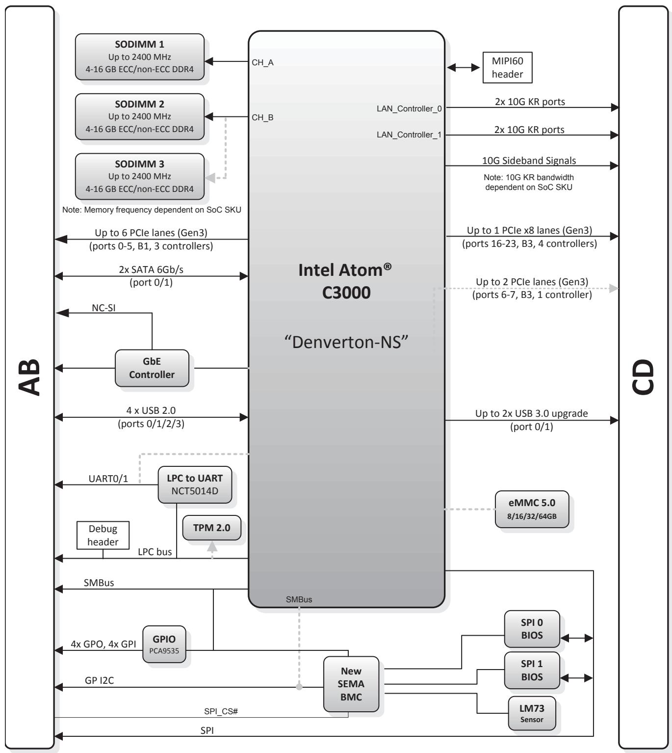
Functional Diagram
![Based on the provided image, here is the accurate and concise description of the flowchart/block diagram:\n\n**Central Block:**\n*   **Intel Atom® C3000**\n*   **'Denverton-NS'**\n\n**Left Column (Labeled 'AB'):**\n*   **SODIMM 1** (Up to 2400 MHz, 4-16 GB ECC/non-ECC DDR4)\n*   **SODIMM 2** (Up to 2400 MHz, 4-16 GB ECC/non-ECC DDR4)\n*   **SODIMM 3** (Up to 2400 MHz, 4-16 GB ECC/non-ECC DDR4)\n*   **Note: Memory frequency dependent on SoC SKU**\n*   **GbE Controller**\n*   **NC-SI**\n*   **LPC to UART NCT5014D**\n*   **UART0/1**\n*   **TPM 2.0**\n*   **Debug header**\n*   **LPC bus**\n*   **GPIO PCA9535**\n*   **4x GPO, 4x GPI**\n*   **GP I2C**\n*   **SMBus**\n*   **Up to 6 PCIe lanes (Gen3) (ports 0-5, B1, 3 controllers)**\n*   **2x SATA 6Gb/s (port 0/1)**\n*   **4 x USB 2.0 (ports 0/1/2/3)**\n\n**Right Column (Labeled 'CD'):**\n*   **MIPI60 header**\n*   **LAN_Controller_0**\n*   **2x 10G KR ports**\n*   **LAN_Controller_1**\n*   **10G Sideband Signals**\n*   **Note: 10G KR bandwidth dependent on SoC SKU**\n*   **Up to 1 PCIe x8 lanes (Gen3) (ports 16-23, B3, 4 controllers)**\n*   **Up to 2 PCIe lanes (Gen3) (ports 6-7, B3, 1 controller)**\n*   **Up to 2x USB 3.0 upgrade (port 0/1)**\n*   **eMMC 5.0 8/16/32/64GB**\n*   **New SEMA BMC**\n*   **SPI 0 BIOS**\n*   **SPI 1 BIOS**\n*   **LM73 Sensor**\n*   **SPI_CS#**\n*   **SPI**\n\n**Connections:**\n*   **Memory:** SODIMM 1 connects to **CH_A**. SODIMM 2 connects to **CH_B**. SODIMM 3 connects via a dotted line.\n*   **Left-Side I/O:** **Up to 6 PCIe lanes (Gen3)...**, **2x SATA 6Gb/s...**, and **4 x USB 2.0...** connect the left edge to the central block. The **GbE Controller** connects to the central block (left side) and outputs **NC-SI** to the left edge. **LPC to UART NCT5014D** connects to **UART0/1** on the left edge. **Debug header**, **TPM 2.0**, and **LPC to UART NCT5014D** are interconnected via the **LPC bus**. **GPIO PCA9535** connects to **4x GPO, 4x GPI** on the left edge. **GP I2C** connects the left edge to **New SEMA BMC**. **SMBus** connects the left edge to the central block.\n*   **Right-Side I/O:** **MIPI60 header** connects via a double arrow to the central block. **LAN_Controller_0** and **LAN_Controller_1** connect to **2x 10G KR ports**. **10G Sideband Signals** connects to the right edge. **Up to 1 PCIe x8 lanes...** and **Up to 2x USB 3.0 upgrade...** connect to the right edge. **Up to 2 PCIe lanes...** connects via a dotted arrow to the right edge. **eMMC 5.0...** connects via a dotted line to the central block.\n*   **Bottom/Management:** **New SEMA BMC** connects to **SPI 0 BIOS**, **SPI 1 BIOS**, and **LM73 Sensor**. **New SEMA BMC** connects via a dotted line to the bottom of the central block. **SPI_CS#** and **SPI** lines run along the bottom connecting **New SEMA BMC** to the BIOS blocks.](.express-dn7-datasheet-20200828/6f55c157b893b06490d39e35c9585a271cbc437a95207fc6af022034c2891b2d.jpg)

# Ordering Information

# ● Express-DN7-C3808

Basic size COM Express Type 7 module with Intel Atom® C3808, 12C (eTEMP)

# ● Express-DN7-C3708

Basic size COM Express Type 7 module with Intel Atom C3708, 8C (eTEMP)

# Express-DN7-C3508

Basic size COM Express Type 7 module with Intel Atom® C3508, 4C (eTEMP)

# ● Express-DN7-C3308

Basic size COM Express Type 7 module with Intel Atom® C3308, 2C (eTEMP)

# ● Express-DN7-C3958

Basic size COM Express Type 7 module with Intel Atom® C3958, 16C

# ● Express-DN7-C3858

Basic size COM Express Type 7 module with Intel Atom® C3858, 12C

# Express-DN7-C3758

Basic size COM Express Type 7 module with Intel Atom C3758, 8C

# Express-DN7-C3558

Basic size COM Express Type 7 module with Intel Atom C3558, 4C

# Express-DN7-C3538

Basic size COM Express Type 7 module with Intel Atom® C3538, 4C

# . Express-DN7-C3338

Basic size COM Express Type 7 module with Intel Atom® C3338, 2C

Note: C3958, C3858, C3758, C3558, C3538, C3338 support by project basis

# Accessories

# Heat Spreaders

# ● HTS-DN7-B

Heatspreader for Express-DN7 with threaded standoffs for bottom mounting

# ● HTS-DN7-BT

Heatspreader for Express-DN7 with through hole standoffs for top mounting

# Passive Heatsinks

# ● THS-DN7-BL

Low profile heatsink for Express-DN7 with threaded standoffs for bottom mounting

# ● THS-DN7-BTL

Low profile heatsink for Express-DN7 with through hole standoffs for top mounting

# THSH-DN7-BL

High profile heatsink for Express-DN7 with threaded standoffs for bottom mounting

# Active Heatsink

# ● THSF-DN7-BL

High profile heatsink with fan for Express-DN7 with threaded standoffs for bottom mounting

# Starter Kit

# ● Starterkit

COM Express Type 7 Starter Kit Plus-Full Fiber COM Express Type 7 Starter Kit Plus-Full Copper

Note: Two starter kits are available: one supporting SPF+ and one supporting 10GBASE-T

10G BASE-KR Support

<table><tr><td></td><td>C3808</td><td>C3708</td><td>C3508</td><td>C3308</td></tr><tr><td>LAN Controller 0 (Gb/s)</td><td colspan="2">102.51</td><td colspan="2">2.51</td></tr><tr><td>LAN Controller 1 (Gb/s)</td><td colspan="2">102.51</td><td colspan="2">2.51</td></tr></table>

<table><tr><td></td><td>C3958</td><td>C3858</td><td>C3758</td><td>C3558</td><td>C3538</td><td>C3338</td></tr><tr><td>LAN Controller 0 (Gb/s)</td><td></td><td></td><td>102.51</td><td></td><td></td><td>2.51</td></tr><tr><td>LAN Controller 1 (Gb/s)</td><td></td><td>102.51</td><td></td><td></td><td>2.51</td><td></td></tr></table>

Combined throughput on all four ports is 20Gb/s

10GBASE-KR ports 0,1 are from LAN Controller 0

10GBASE-KR ports 2,4 are from LAN Controller 1

# Notes:

\* All specifications are subject to change without further notice.
\* “Build option” indicates an alternative BOM configuration to support additional or alternative functions that are not available on the standard product.

Please contact our sales representatives.

\* All modules above support to connect to optical PHY as default. connect to copper PHY is by project basis

# I/O support on different SOCs

compliant with PICMG definition

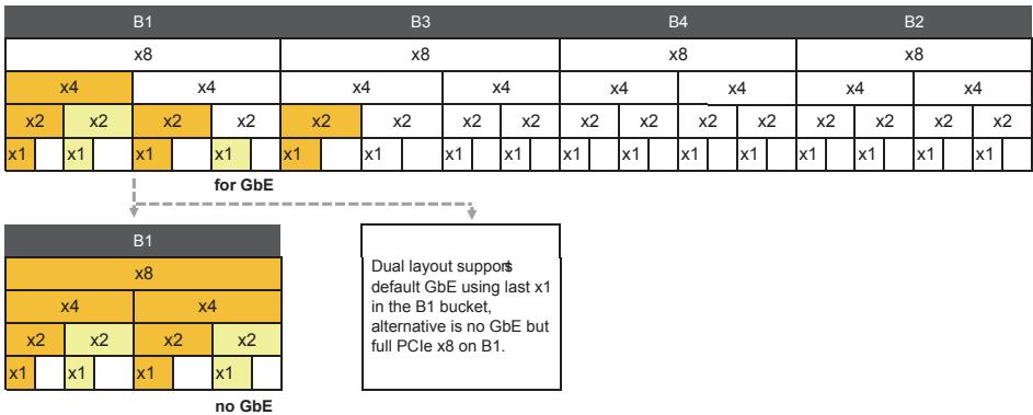
"Type7 module may supports more x1 root hubs in bucket one (B1).

It's expected that future generation products may limit the number of available root hubs on bucket one (B1) to 2.

C3808, C3708, C3958, C3858, C3758

20 HSIO, 2CH DDR4, max. 48 GB DDR4
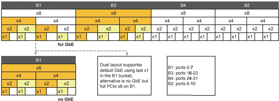
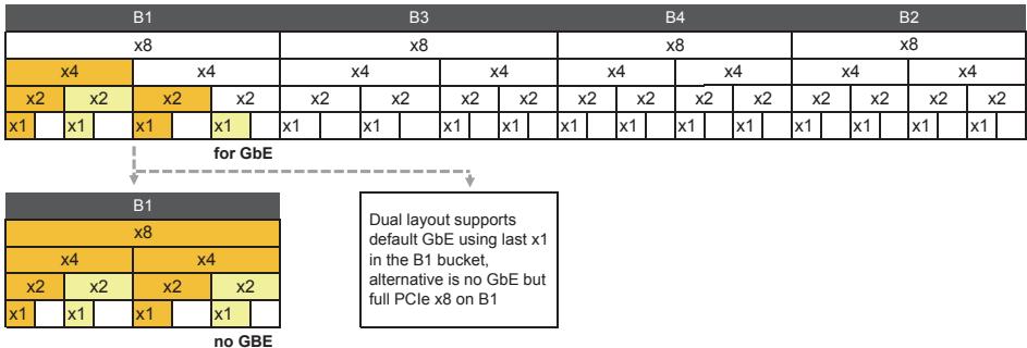
![The image displays a block diagram illustrating a layout for PCIe lanes and port assignments.\n\n**Main Layout (Top Row)**\nThe diagram features a horizontal strip divided into four main sections labeled **B1**, **B3**, **B4**, and **B2** in dark grey headers. Each section contains a hierarchical breakdown of blocks labeled **x8**, **x4**, **x2**, and **x1**:\n\n*   **B1 Section:** Contains an **x8** block. Below it are two **x4** blocks (one orange, one white). Below that are four **x2** blocks (orange, yellow, orange, white). The bottom row consists of eight **x1** blocks.\n*   **B3 Section:** Contains an **x8** block. Below it are two **x4** blocks (both orange). Below that are four **x2** blocks (orange, yellow, orange, yellow). The bottom row consists of eight **x1** blocks.\n*   **B4 Section:** Contains an **x8** block. Below it are two **x4** blocks (both white). Below that are four **x2** blocks (all white). The bottom row consists of eight **x1** blocks (all white).\n*   **B2 Section:** Contains an **x8** block. Below it are two **x4** blocks (both white). Below that are four **x2** blocks (all white). The bottom row consists of eight **x1** blocks (all white).\n\n**Connections and Bottom Diagrams**\n*   A dashed arrow originates from the **B1** section of the top diagram and points downwards, labeled with the text **for GbE**.\n*   Below this arrow is a smaller block diagram labeled **B1**. It shows a breakdown of **x8** (orange), **x4** (orange, white), **x2** (orange, yellow, orange, yellow), and **x1** blocks. Below this diagram is the text **no GbE**.\n\n**Information Boxes (Bottom Right)**\n*   **Middle Box:** Contains the text: 'Dual layout supports default GbE using last x1 in the B1 bucket, alternative is no GbE but full PCIe x8 on B1.'\n*   **Right Box:** Lists port assignments:\n    *   **B1: ports 0-7**\n    *   **B3: ports 16-23**\n    *   **B4: ports 24-31**\n    *   **B2: ports 8-15**](.express-dn7-datasheet-20200828/e77733dbeebb3ab55b20b102862d2c6d2fb6bdf66791e9049030402e70372d0e.jpg)

![The image displays three rectangular legend boxes arranged horizontally.\n- The left box has a dark grey header with the text 'SATA' and a white box below it containing the numbers '0 1'.\n- The middle box has a grey header with the text 'USB 3.0 upgrade' and a white box below it containing the numbers '0 1 2 3'.\n- The right box has a grey header with the text 'USB 2.0' and a white box below it containing the numbers '0 1 2 3'.](.express-dn7-datasheet-20200828/5204615907bf4d9981a77f02fba00abed9d3032ee2471107ee677ec6772daf51.jpg)

C3558, C3538

12 HSIO, 2CH DDR4, max. 48 GB DDR4
![The flowchart consists of a large grid diagram at the top, a smaller grid diagram at the bottom left, and a text box at the bottom right.\n\n**Top Grid:**\n- **Columns:** The top row is divided into four columns labeled **B1**, **B3**, **B4**, and **B2**.\n- **Rows:** Below the column headers, each column contains the following hierarchical structure:\n    - A row labeled **x8**.\n    - A row divided into two blocks labeled **x4**.\n    - A row divided into four blocks labeled **x2**.\n    - A bottom row divided into four blocks labeled **x1**.\n- The grid repeats this structure for each column (B1, B3, B4, B2).\n\n**Connections and Bottom Section:**\n- A **dashed arrow** originates from the bottom of the **B1** column in the top grid and points downwards to the bottom-left grid.\n- The text **for GbE** is written above this arrow.\n- **Bottom-Left Grid:** This is a zoomed-in view of the **B1** column structure from the top grid, showing labels **B1**, **x8**, **x4**, **x2**, and **x1**. Below this grid, the text **no GbE** is written.\n- **Text Box:** To the right of the bottom-left grid, a box contains the text: 'Dual layout support default GbE using last x1 in the B1 bucket, alternative is no GbE but full PCIe x8 on B1.'](.express-dn7-datasheet-20200828/aafa270d402723763f622fe18184cb51e40e11c92d696a5d1e5f9b541fa325db.jpg)

![The image shows three rectangular labels arranged horizontally. From left to right:\n\n1.  The first label has a grey top section with the text '**SATA**' and a yellow bottom section with the numbers '**0 1**'.\n2.  The middle label has a white top section with the text '**USB 3.0 upgrade**' and a white bottom section with the numbers '**0 1 2 3**'.\n3.  The right label has a yellow top section with the text '**USB 2.0**' and a white bottom section with the numbers '**0 1 2 3**'.](.express-dn7-datasheet-20200828/79a7dd7b434e8b8d5fb2e57aebf1a867030854bd9b33aca7feb300ea4a3a3cdf.jpg)

10 HSIO, 1CH DDR4, max. 16 GB DDR4

![**Labeled Blocks:**\n\n*   **Top Header Row:** 'B1', 'B3', 'B4', 'B2'\n*   **Sub-Header Row:** 'x8' (under each header)\n*   **Top Grid Rows:**\n    *   Row 1: 'x4' (blocks under each header)\n    *   Row 2: 'x2' (blocks under each header)\n    *   Row 3: 'x1' (blocks under each header)\n*   **Middle Text:** 'for GbE'\n*   **Bottom Left Block:**\n    *   Header: 'B1'\n    *   Row 1: 'x8'\n    *   Row 2: 'x4' (repeated twice)\n    *   Row 3: 'x2' (repeated four times)\n    *   Row 4: 'x1' (repeated four times)\n*   **Bottom Left Text:** 'no GBE'\n*   **Bottom Right Text Box:** 'Dual layout supports default GbE using last x1 in the B1 bucket, alternative is no GbE but full PCIe x8 on B1'\n\n**Connections:**\n\n*   A dashed arrow points downward from the top grid to the text 'for GbE'.\n*   From 'for GbE', dashed arrows split and point to:\n    1.  The bottom-left block labeled 'B1'.\n    2.  The bottom-right text box.](.express-dn7-datasheet-20200828/4397f203f3b36e1797a4976d4e7e7fe8c96b19a02bb4af8e149281aba19a697a.jpg)

![The image displays a chart with three columns comparing drive interfaces.\n\n*   **Left Column:** The header is yellow and reads '**SATA**'. Below it is a grid where the bottom row is yellow and contains the text '**0 1**'.\n*   **Middle Column:** The header reads '**USB 3.0 upgrade**'. Below it is a grid where the bottom row is blue and contains the text '**0 1 2 3**'.\n*   **Right Column:** The header is orange and reads '**USB 2.0**'. Below it is a grid where the bottom row is yellow and contains the text '**0 1 2 3**'.](.express-dn7-datasheet-20200828/d512492ab5ce429db709af260930a3775757a598cf45c0b4d966be9c6385f174.jpg)

C3508

8 HSIO2CH DDR4max. 48 GB DDR4

<table><tr><td colspan="7">B1</td><td colspan="7">B3</td><td colspan="6">B4</td><td colspan="6">B2</td><td></td></tr><tr><td colspan="7">x8</td><td colspan="7">x8</td><td colspan="6">x8</td><td colspan="6">x8</td><td></td></tr><tr><td colspan="3">x4</td><td colspan="4">x4</td><td colspan="4">x4</td><td colspan="3">x4</td><td colspan="3">x4</td><td colspan="3">x4</td><td colspan="3">x4</td><td colspan="3">x4</td><td></td></tr><tr><td>x2</td><td></td><td>x2</td><td colspan="2">x2</td><td colspan="2">x2</td><td colspan="2">x2</td><td colspan="2">x2</td><td colspan="2">x2</td><td>x2</td><td>x2</td><td></td><td>x2</td><td></td><td>x2</td><td></td><td>x2</td><td></td><td>x2</td><td></td><td>x2</td><td></td><td>x2</td></tr><tr><td>x1</td><td></td><td>x1</td><td></td><td>x1</td><td></td><td>x1</td><td></td><td>x1</td><td></td><td>x1</td><td></td><td>x1</td><td></td><td>x1</td><td></td><td>x1</td><td></td><td>x1</td><td></td><td>x1</td><td></td><td>x1</td><td></td><td>x1</td><td></td><td>x1</td></tr></table>

![The image displays a diagram of three distinct connector groups arranged horizontally:\n\n*   **Left:** A dark grey header reads 'SATA' above two yellow blocks labeled '0' and '1'.\n*   **Center:** A dark grey header reads 'USB 3.0 upgrade' above four white blocks labeled '0', '1', '2', and '3'.\n*   **Right:** A dark grey header reads 'USB 2.0' above four yellow blocks labeled '0', '1', '2', and '3'.](.express-dn7-datasheet-20200828/cfe434325d71d18e4d854c4f800289825b95c052027fcf42ea28697fa82aaab3.jpg)
for GbE

C3308

6 HSIO, 1CH DDR4, max. 16 GB DDR4

<table><tr><td colspan="7">B1</td><td colspan="7">B3</td><td colspan="6">B4</td><td colspan="6">B2</td><td></td></tr><tr><td colspan="7">x8</td><td colspan="7">x8</td><td colspan="6">x8</td><td colspan="6">x8</td><td></td></tr><tr><td colspan="3">x4</td><td colspan="4">x4</td><td colspan="4">x4</td><td colspan="3">x4</td><td colspan="3">x4</td><td colspan="3">x4</td><td colspan="3">x4</td><td colspan="3">x4</td><td></td></tr><tr><td>x2</td><td></td><td>x2</td><td colspan="2">x2</td><td>x2</td><td></td><td>x2</td><td></td><td>x2</td><td></td><td>x2</td><td></td><td>x2</td><td>x2</td><td></td><td>x2</td><td></td><td>x2</td><td></td><td>x2</td><td></td><td>x2</td><td></td><td>x2</td><td></td><td>x2</td></tr><tr><td>x1</td><td></td><td>x1</td><td></td><td>x1</td><td></td><td>x1</td><td></td><td>x1</td><td></td><td></td><td>x1</td><td></td><td>x1</td><td></td><td>x1</td><td></td><td>x1</td><td></td><td>x1</td><td></td><td>x1</td><td></td><td>x1</td><td></td><td>x1</td><td></td></tr></table>

![The image displays three horizontal rectangular blocks arranged side-by-side, each containing text:\n\n**First Block (Left):**\n*   Header: **SATA** (white text on a dark background)\n*   Body: **0 1** (black text on a white background)\n\n**Second Block (Middle):**\n*   Header: **USB 3.0 upgrade** (black text on a white background)\n*   Body: **0 1 2 3** (black text on a white background)\n\n**Third Block (Right):**\n*   Header: **USB 2.0** (black text on a dark background)\n*   Body: **0 1 2 3** (white text on a yellow/orange background)](.express-dn7-datasheet-20200828/d1fdb7187f710c96c854c06cf98cf1d25499508e1349ac3bcf4b5422116818ef.jpg)
for GbE
[🔗 Link to the original document](.express-dn7-datasheet-20200828/express-dn7-datasheet-20200828.pdf)