# I-Pi OSM-IMX93

I-Pi OSM Development Kit based on NXP®

i.MX 93 dual-core Arm® Cortex-A55 & M33

![Product photo of an OSM IMX93 electronic device with circuit board, capacitors, and connectors (no visible text or symbols)](.i-pi-osm-imx93-datasheet-251128/8ea1142ff14f78cf29dae4a23a052e291e891db44a9ef55deab3e2ce2dff5c1a.jpg)

# Features

• OSM Base 3.5 carrier
OSM-IMX93 module powered by NXP® i.MX 93 with dual-core Arm® Cortex-A55 & Cortex-M33
• In-SoC Arm Ethos-U65 microNPU
• 2GB LPDDR4L soldered, 32GB eMMC

• LVDS, HDMI graphic outputs
Dual GbE (1 TSN capable), dual CAN bus, USB 2.0, USB 2.0 OTG
• Rugged operating temperature (optional): -40°C to +85°C

Specifications

<table><tr><td rowspan="6">Core System</td><td>SoC</td><td>NXP® i.MX93 with dual core Arm Cortex-A55 &amp; M33</td></tr><tr><td>NPU</td><td>Arm® EthosTM U-65 microNPU</td></tr><tr><td>Architecture</td><td>2x ARM Cortex-A55 + 1x Cortex M33</td></tr><tr><td>Memory</td><td>2GB LPDDR4</td></tr><tr><td>L2 Cache</td><td>32GB eMMC</td></tr><tr><td>Security</td><td>Arm® TrustZone® EdgeLock® secure enclave</td></tr><tr><td rowspan="4">Video</td><td>GPU Core</td><td>PXP 2D accelerator</td></tr><tr><td>HDMI</td><td>1x HDMI interface, via a DSI-to-HDMI bridge on the carrier</td></tr><tr><td>LVDS</td><td>1x LVDS interface, 4 lanes</td></tr><tr><td>Camera</td><td>1x 22-pin CSI connector, with 2 lanes available</td></tr><tr><td>Audio</td><td>Codec</td><td>TI TLV320AIC3106</td></tr><tr><td>Ethernet</td><td>LAN</td><td>2x GbE (1x TSN capable)</td></tr></table>

Note: “Build option””indicates an alternative BOM configuration to support additional or alternative functions that are not available on the standard product. Be aware that these “build option” part numbers will need to be newly created and this will result in production lead times.

Specifications

<table><tr><td rowspan="11">Connectors/Headers</td><td>Display</td><td>1x HDMI1x LVDS</td></tr><tr><td>Audio</td><td>1x 3.5mm audio jack</td></tr><tr><td>Network</td><td>2x RJ45</td></tr><tr><td>USB</td><td>2x USB 2.0 host, 1x USB 2.0 OTG</td></tr><tr><td>SD Card Slot</td><td>1x microSD</td></tr><tr><td>UART</td><td>3x UART on the header</td></tr><tr><td>SPI</td><td>2x SPI on the header</td></tr><tr><td>I2C</td><td>2x I2C on the header</td></tr><tr><td>GPIO</td><td>14x GPIO on header</td></tr><tr><td>PWM/ADC</td><td>4x PWM / 2x ADC on header</td></tr><tr><td>CAN</td><td>2x CAN header</td></tr><tr><td rowspan="2">Power</td><td>Input</td><td>15 to 30 VDC (Adapter: 19VDC)</td></tr><tr><td>Connector</td><td>DC Jack</td></tr><tr><td rowspan="5">Mechanical</td><td>Form Factor</td><td>3.5&quot; standard</td></tr><tr><td>Dimension</td><td>146 x 102mm</td></tr><tr><td>Operating Temperature</td><td>Standard: 0°C to 60°CRugged: -40°C to 85°C (optional)</td></tr><tr><td>Humidity</td><td>5-90% RH operating, non-condensing5-95% RH storage (and operating with conformal coating)</td></tr><tr><td>Shock and Vibration</td><td>IEC 60068-2-64 and IEC-60068-2-27, MIL-STD-202 F, Method 213B, Table 213-I, Condition A and Method 214A, Table 214-I, Condition D</td></tr><tr><td rowspan="2">Operating Systems</td><td>Standard Support</td><td>Yocto Linux BSP</td></tr><tr><td>Extended Support (BSP)</td><td>Foundries.IO</td></tr></table>

Ordering Information

<table><tr><td>Part Name</td><td>Description/Configuration</td></tr><tr><td>OSM-iMX93-2G-32G-CT</td><td>OSM module L size with Dual Core NXP i.MX93, 2 GB LPDDR4, 32 GB eMMC, 0°C to 70°C</td></tr><tr><td>OSM-iMX93-2G-32G-ER</td><td>OSM module L size with Dual Core NXP i.MX93, 2 GB LPDDR4, 32 GB eMMC, -40°C to 85°C</td></tr><tr><td>I-Pi OSM-iMX93-2G-32G</td><td>I-Pi OSM Prototype Kit with OSM-iMX93-2G-32G-CT, EU/US 110/220V to 19V Adapter, USB debug cable)</td></tr><tr><td colspan="2">Note: Non-listed configurations available upon request.</td></tr></table>

Note: “Build option””indicates an alternative BOM configuration to support additional or alternative functions that are not available on the standard product. Be aware that these “build option” part numbers will need to be newly created and this will result in production lead times.

# Specifications
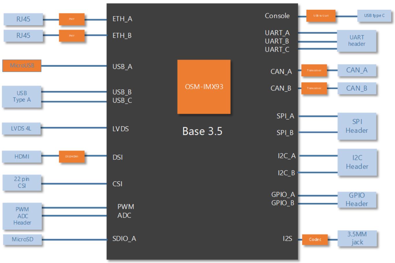
![The diagram features a central dark grey block labeled **Base 3.5** containing an orange square labeled **OSM-IMX93**. Various ports and headers connect to this central block from the left and right sides.\n\n**Left Side Connections:**\n*   **RJ45** connects via an orange **PHY** block to **ETH_A**.\n*   **RJ45** connects via an orange **PHY** block to **ETH_B**.\n*   **MicroUSB** connects directly to **USB_A**.\n*   **USB Type A** connects to both **USB_B** and **USB_C**.\n*   **LVDS 4L** connects directly to **LVDS**.\n*   **HDMI** connects via an orange **DSI HDMI** block to **DSI**.\n*   **22 pin CSI** connects directly to **CSI**.\n*   **PWM ADC Header** connects to both **PWM** and **ADC**.\n*   **MicroSD** connects directly to **SDIO_A**.\n\n**Right Side Connections:**\n*   **Console** connects via an orange **USB to Uart** block to **USB type C**.\n*   **UART_A**, **UART_B**, and **UART_C** connect to **UART header**.\n*   **CAN_A** connects via an orange **Transceiver** block to **CAN_A**.\n*   **CAN_B** connects via an orange **Transceiver** block to **CAN_B**.\n*   **SPI_A** and **SPI_B** connect to **SPI Header**.\n*   **I2C_A** and **I2C_B** connect to **I2C Header**.\n*   **GPIO_A** and **GPIO_B** connect to **GPIO Header**.\n*   **I2S** connects via an orange **Code c** block to **3.5MM jack**.](.i-pi-osm-imx93-datasheet-251128/413443f4df120a1a07a996425be7c1f23f966462623f2f13f382b0627e07276a.jpg)

Note: “Build option””indicates an alternative BOM configuration to support additional or alternative functions that are not available on the standard product. Be aware that these “build option” part numbers will need to be newly created and this will result in production lead times.
[🔗 Link to the original document](.i-pi-osm-imx93-datasheet-251128/i-pi-osm-imx93-datasheet-251128.pdf)
