# LEC-MTK-I1200

# SMARC 2.1 Short Size Module with

# MediaTek MediaTek MT8195 SoC

![Close-up of a blue printed circuit board with various electronic components and connectors (no readable text or symbols)](.lec-mtk-i1200-datasheet-260421/c92bc396e4e7fe04c1b49b195d52fb321ba9b5211f9d59d4721840ec47635e7f.jpg)

# Features

• 8-core Arm Cortex -A78 x4 + Cortex-A55 x4
• 5 TOPS APU
• SMARC revision 2.1.1 compliant
• Up to 8GB LPDDR4X
• DSI up to 1080P
• HDMI up to 4K/60Hz

1x onboard UFS up to 256 GB
Dual GbE Ethernet ports
3x CSI interfaces
USB3/USB2 interfaces
10 year product availability

Specifications

<table><tr><td rowspan="4">Processor &amp; System</td><td>CPU</td><td>MT8195 Octa-core CPU: 4x A78 @ 2.2GHz + 4x A55 @ 2.0GHz</td></tr><tr><td>Memory</td><td>4 or 8 GB LPDDR4X</td></tr><tr><td>Cache</td><td>256KB L2 per CPU core (2MB unified L3)</td></tr><tr><td>Security</td><td>TPM 2.0 module</td></tr><tr><td rowspan="5">Video</td><td>GPU Core</td><td>Five-core Arm Mali-G57 GPU – Dual 4K @ 60 fps</td></tr><tr><td>GPU Feature Support</td><td>3D graphic accelerator capable of processing 17600M pixel/sec @ 880MHzSupport for OpenGL ES 3.2/2.0/1.1, Vulkan 1.1/1.0, OpenCL 2.2</td></tr><tr><td>HDMI/DP</td><td>HDMI 2.0b 4K @ 60Hz or DisplayPort</td></tr><tr><td>eDP</td><td>4 Lane eDP</td></tr><tr><td>DSI</td><td>2x 4 Lane DSI, maximum resolution 4K p60 with 24-bit RGB</td></tr></table>

Note: “Build option””indicates an alternative BOM configuration to support additional or alternative functions that are not available on the standard product. Be aware that these “build option” part numbers will need to be newly created and this will result in production lead times.

Specifications

<table><tr><td>Camera</td><td>CSI</td><td>3x MIPI CS, 1x 2Lane, 2x 4 lane</td></tr><tr><td rowspan="3">System Storage</td><td>SDIO</td><td>1x SDIO (4-bit) compatible with SD/SDIO standard, up to version 3.0</td></tr><tr><td>UFS</td><td>32, 64, 128, or 256 GB (build option)</td></tr><tr><td></td><td>Compatible with UFS gear 2.1</td></tr><tr><td>Debug Header</td><td></td><td>30-pin multipurpose flat cable connector for use with optional DB-30 debug module. Provides JTAG, UART, boot select</td></tr><tr><td>Audio</td><td>Audio Codec</td><td>I2S audio codec located on the carrier</td></tr><tr><td rowspan="2">Dual Ethernet</td><td>Primary LAN</td><td>10/100/1000 Gbps Ethernet</td></tr><tr><td>Secondary LAN</td><td>10/100/1000 Gbps Ethernet</td></tr><tr><td rowspan="2">Wireless</td><td>Wi-Fi</td><td>IEEE 802.11 2X2 MU-MIMO ac/a/b/g/n</td></tr><tr><td>Bluetooth</td><td>Bluetooth 5.0</td></tr><tr><td rowspan="8">Extension Busses</td><td>USB</td><td>2x USB 3.0, 4x USB 2.0</td></tr><tr><td>UART</td><td>Three UART interfaces: SER1 and SER 3 (CTS/RTS), and SER0 (TX/RX/CTS/RTS)</td></tr><tr><td>CAN</td><td>1x CAN2.0B only or mixed CAN2.0B data bit rate up to 8Mbps</td></tr><tr><td>SPI</td><td>2x SPI</td></tr><tr><td>I2S</td><td>1x I2S interface with audio resolution from 16-bits to 32-bits and sample rate up to 192kHz (see Audio Codec support)</td></tr><tr><td>I2C</td><td>4x I2C interfaces</td></tr><tr><td>GPIO</td><td>14x GPIO with interrupt, one GPIO with PWM</td></tr><tr><td>PCIe</td><td>1x PCIe x2 Gen3, 1x PCIe Gen 2</td></tr><tr><td>Power</td><td>Input</td><td>5Vdc +/- 5%</td></tr><tr><td colspan="2">Mechanical and Environmental Form Factor</td><td>SGET SMARC Specifications 2.1.1</td></tr><tr><td rowspan="7"></td><td>Dimension</td><td>SMARC short size module 82 mm x 50 mm</td></tr><tr><td>Operating Temperature</td><td>Standard: 0°C to 60°C</td></tr><tr><td></td><td>Rugged: -40°C to 85°C (optional)</td></tr><tr><td>Humidity</td><td>5-90% RH operating, non-condensing</td></tr><tr><td></td><td>5-95% RH storage (and operating with conformal coating)</td></tr><tr><td>Shock and Vibration</td><td>IEC 60068-2-64 and IEC-60068-2-27, MIL-STD-202 F, Method 213B, Table 213-I, Condition A and Method 214A, Table 214-I, Condition D</td></tr><tr><td>HALT</td><td>Thermal Stress, Vibration Stress, Thermal Shock and Combined Test</td></tr><tr><td>Operating Systems</td><td>Standard Support</td><td>Canonical Ubuntu, Yocto Linux</td></tr></table>

Ordering Information

<table><tr><td>Part name</td><td>Description/Configuration</td></tr><tr><td>LEC-MTK-I1200-2G-32G-CT</td><td>SMARC 2.1 Short Size Module with MediaTek Genio 1200 platform, 2 GB LPDDR4, 32 GB eMMC, 0°C to 60°C</td></tr><tr><td>LEC-MTK-I1200-4G-32G-CT</td><td>SMARC 2.1 Short Size Module with MediaTek Genio 1200 platform, 4 GB LPDDR4, 32 GB eMMC, 0°C to 60°C</td></tr><tr><td>LEC-MTK-I1200-8G-64G-CT</td><td>SMARC 2.1 Short Size Module with MediaTek Genio 1200 platform, 8 GB LPDDR4, 64 GB eMMC, 0°C to 60°C</td></tr><tr><td>LEC-MTK-I1200-2G-32G-ER</td><td>SMARC 2.1 Short Size Module with MediaTek Genio 1200 platform, 2 GB LPDDR4, 32 GB eMMC, -40°C to 85°C</td></tr><tr><td>LEC-MTK-I1200-4G-32G-ER</td><td>SMARC 2.1 Short Size Module with MediaTek Genio 1200 platform, 4 GB LPDDR4, 32 GB eMMC, -40°C to 85°C</td></tr><tr><td>LEC-MTK-I1200-8G-64G-ER</td><td>SMARC 2.1 Short Size Module with MediaTek Genio 1200 platform, 8 GB LPDDR4, 64 GB eMMC, -40°C to 85°C</td></tr><tr><td>LEC-MTK-I1200-2G-32G-BW-CT</td><td>SMARC 2.1 Short Size Module with MediaTek Genio 1200 platform, 2 GB LPDDR4, 32 GB eMMC, AC Wi-Fi BT 5.1, 0°C to 60°C</td></tr><tr><td>LEC-MTK-I1200-4G-32G-BW-CT</td><td>SMARC 2.1 Short Size Module with MediaTek Genio 1200 platform, 4 GB LPDDR4, 32 GB eMMC, AC Wi-Fi BT 5.1, 0°C to 60°C</td></tr><tr><td>LEC-MTK-I1200-8G-64G-BW-CT</td><td>SMARC 2.1 Short Size Module with MediaTek Genio 1200 platform, 8 GB LPDDR4, 64 GB eMMC, AC Wi-Fi BT 5.1, 0°C to 60°C</td></tr><tr><td>LEC-MTK-I1200-2G-32G-BW-ER</td><td>SMARC 2.1 Short Size Module with MediaTek Genio 1200 platform, 2 GB LPDDR4, 32 GB eMMC, Wi-Fi BT 5.1, -40°C to 85°C</td></tr><tr><td>LEC-MTK-I1200-4G-32G-BW-ER</td><td>SMARC 2.1 Short Size Module with MediaTek Genio 1200 platform, 4 GB LPDDR4, 32 GB eMMC, Wi-Fi BT 5.1, -40°C to 85°C</td></tr><tr><td>LEC-MTK-I1200-8G-64G-BW-ER</td><td>SMARC 2.1 Short Size Module with MediaTek Genio 1200 platform, 8 GB LPDDR4, 64 GB eMMC, AC Wi-Fi BT 5.1, -40°C to 85°C</td></tr></table>

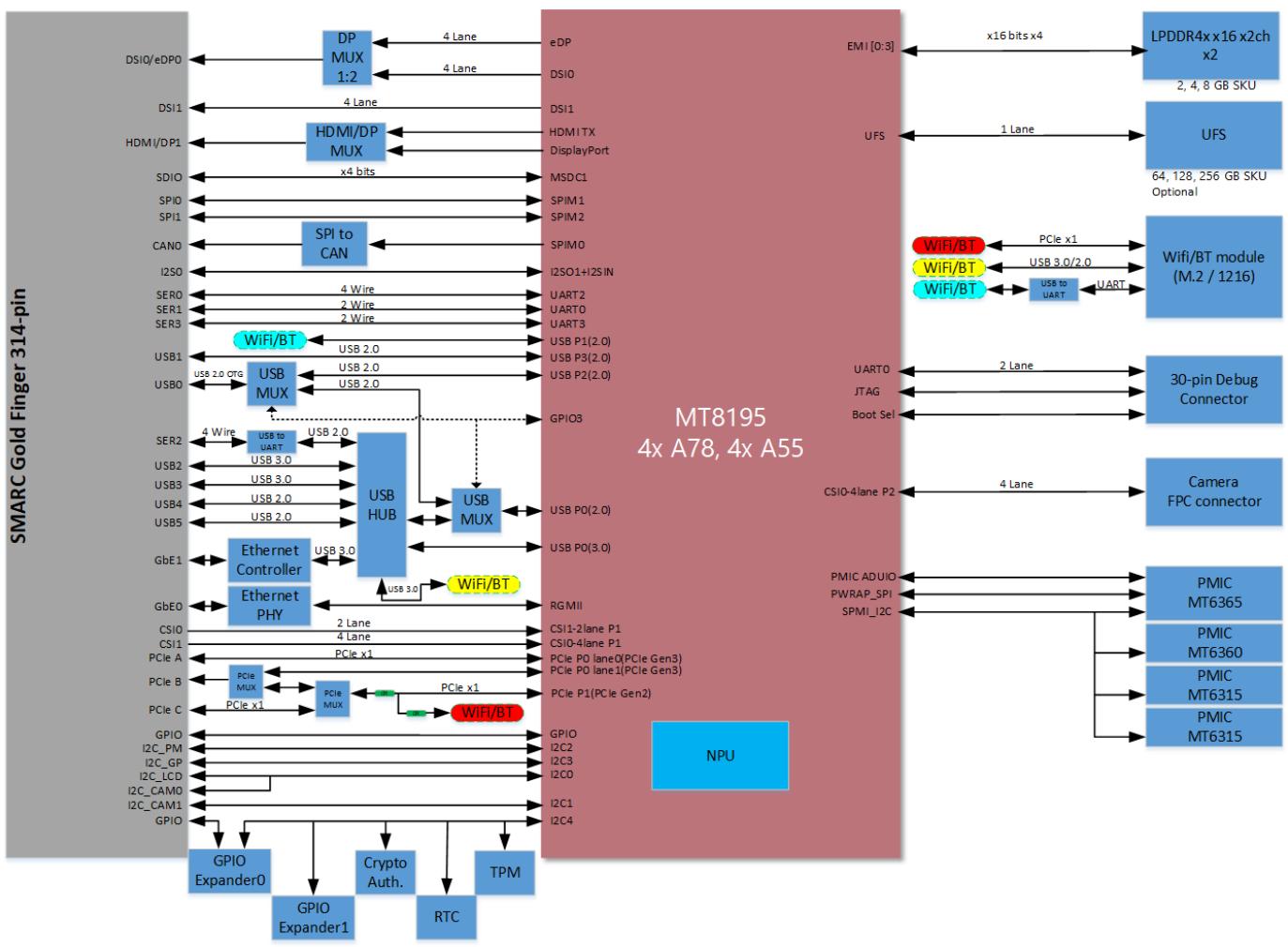
# Block Diagram

![This block diagram illustrates the interface connections for the **MT8195** system-on-chip (labeled 'MT8195 4x A78, 4x A55' in a large red block), which includes an **NPU**. The diagram maps connections between the SoC, a **SMARC Gold Finger 314-pin** connector (gray block on the left), and various external components and peripherals (blue blocks on the right and bottom).\n\n**Central Processor (MT8195):**\nThe central red block contains the **NPU** and serves as the hub for all connections.\n\n**Left Side (SMARC Gold Finger 314-pin):**\nThis gray block lists interface pins such as **DSI0/eDP0**, **DSI1**, **HDMI/DP1**, **SDIO**, **SPI0**, **SPI1**, **CAN0**, **I2S0**, **SER0**, **SER1**, **SER3**, **USB1**, **USB0**, **SER2**, **USB2**, **USB3**, **USB4**, **USB5**, **GbE1**, **GbE0**, **CSIO**, **CSI1**, **PCIe A**, **PCIe B**, **PCIe C**, **GPIO**, **I2C_PM**, **I2C_GP**, **I2C_LCD**, **I2C_CAM0**, and **I2C_CAM1**.\n\n**Right Side (External Peripherals):**\n*   **LPDDR4x x16 x2ch x2** (labeled '2, 4, 8 GB SKU')\n*   **UFS** (labeled '64, 128, 256 GB SKU Optional')\n*   **Wifi/BT module (M.2 / 1216)**\n*   **30-pin Debug Connector**\n*   **Camera FPC connector**\n*   **PMIC Cluster**: Includes **PMIC MT6365**, **PMIC MT6360**, and two **PMIC MT6315** blocks.\n\n**Intermediate Blocks & Connections:**\n*   **Display:**\n    *   **DSI0/eDP0** connects to **DP MUX 1:2**, which routes to **eDP** (4 Lane) and **DSI0** (4 Lane) on the MT8195 side.\n    *   **DSI1** connects directly to the MT8195 side.\n    *   **HDMI/DP1** connects to **HDMI/DP MUX**, which routes to **HDMI1 TX** and **DisplayPort** on the MT8195 side.\n*   **Storage/Serial:**\n    *   **SDIO** connects to **MSDC1** on the MT8195 side.\n    *   **SPI0** and **SPI1** connect to **SPI0** and **SPI1** on the MT8195 side respectively.\n    *   **CAN0** connects to **SPI to CAN**, which connects to **SPI0** on the MT8195 side.\n*   **Audio/Serial:**\n    *   **I2S0** connects to **I2S01+I2S IN** on the MT8195 side.\n    *   **SER0**, **SER1**, and **SER3** connect via **4 Wire**, **2 Wire**, and **2 Wire** respectively to **UART0** and **UART3** on the MT8195 side.\n*   **USB/Ethernet:**\n    *   **USB1** connects to a blue **WiFi/BT** oval and **USB MUX**.\n    *   **USB0** connects to **USB MUX**.\n    *   **USB MUX** connects to **USB P1(2.0)**, **USB P3(2.0)**, and **USB P2(2.0)** on the MT8195 side.\n    *   **SER2** connects to **USB to UART**, which outputs **USB 3.0** to the **USB HUB**.\n    *   **USB2**, **USB3**, **USB4**, and **USB5** connect to the **USB HUB**.\n    *   The **USB HUB** connects to the **USB MUX** and the **Ethernet Controller**.\n    *   **GbE1** and **GbE0** connect to the **Ethernet Controller** and **Ethernet PHY**.\n    *   The Ethernet block connects via **RGMII** to the MT8195 side.\n*   **Camera/PCIe:**\n    *   **CSIO** and **CSI1** connect via **2 Lane** and **4 Lane** respectively to **CSI1-2lane P1** and **CSI0-4lane P1** on the MT8195 side.\n    *   **PCIe A**, **PCIe B**, and **PCIe C** connect to **PCIe MUX**, which outputs **PCIe x1** to the MT8195 side.\n*   **GPIO/I2C:**\n    *   **GPIO**, **I2C_PM**, **I2C_GP**, **I2C_LCD**, **I2C_CAM0**, and **I2C_CAM1** connect to the MT8195 side.\n    *   **GPIO**, **I2C2**, **I2C3**, **I2C0**, **I2C1**, and **I2C4** (from MT8195 side) connect to bottom blocks: **GPIO Expander0**, **GPIO Expander1**, **Crypto Auth.**, **TPM**, and **RTC**.\n\n**Right-Side Peripheral Connections:**\n*   **EMI (0:3)** connects via **16 bits x4** to **LPDDR4x**.\n*   **UFS** connects via **1 Lane** to the **UFS** block.\n*   **PCIe x1**, **USB 3.0/2.0**, and **UART** connect to the **Wifi/BT module**. (Note: **WiFi/BT** labels in red, yellow, and blue ovals are near these connections).\n*   **UART0** (2 Lane), **JTAG**, and **Boot Sel** connect to the **30-pin Debug Connector**.\n*   **CSI0-4lane P2** connects via **4 Lane** to the **Camera FPC connector**.\n*   **PMIC ADUIO**, **PWRAP_SPI**, and **SPMI_I2C** connect to the **PMIC** cluster.](.lec-mtk-i1200-datasheet-260421/ff5d2c4e1ca980db4585266f3223a2c10ba340e47bef2f84e8d2983ce1ffa970.jpg)

Note: “Build option””indicates an alternative BOM configuration to support additional or alternative functions that are not available on the standard product. Be aware that these “build option” part numbers will need to be newly created and this will result in production lead times.
[🔗 Link to the original document](.lec-mtk-i1200-datasheet-260421/lec-mtk-i1200-datasheet-260421.pdf)