
# Introduction
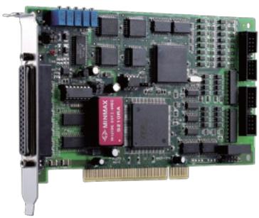
ADLINK’s PCI-9114 series are 32-CH, 16-bit, high-resolution multi-function DAQ cards. The PCI-9114 device features flexible configurations on analog input. The devices are divided into 2 kinds: normal gain version and high gain version. Both versions provide 4 programmable input ranges for bipolar and unipolar inputs. The A/D on the PCI-9114DG device features a sampling rate of 100 kS/s with resolution at 16 bits, while PCI-9114A-DG/HG device features a sampling rate of up to 250 kS/s with resolution at 16 bits. The device supports automatic analog input scanning, and offers a differential mode for 8-CH analog inputs and maximum noise elimination, as well as single-ended modes for16-CH analog inputs.
The PCI-9114 also features 1-CH 16-bit general-purpose timer/counter, 16-CH TTL isolated digital inputs and 16-CH TTL isolated digital outputs. ADLINK PCI-9114 delivers cost-effective and reliable data acquisition capabilities and is ideal for a broad variety of applications.
# Features
■ Supports a 32-bit 5 V PCI bus
■ 16-bit A/D resolution
■ Up to 100 kS/s sampling rate (PCI-9114DG)
■ Up to 250 kS/s sampling rate (PCI-9114A-DG and PCI-9114A-HG)
■ 32-CH single-ended or 16-CH differential analog inputs
■ Bipolar or unipolar analog input ranges
■ Onboard 1 k-sample A/D FIFO
■ Programmable gains:
• x1, x2, x4, x8 (PCI-9114DG and PCI-9114A-DG)
• x1, x10, x100 (PCI-9114A-HG)
■ Automatic analog inputs scanning
■ 16-CH isolated digital inputs and 16-CH isolated digital outputs
■ 2500 VRMS optical isolation for digital inputs and outputs
■ 1-CH 16-bit general-purpose timer/counter
■ +12 V and -12 V power available on the 37-pin D-sub connector
■ Onboard resettable fuses for power output protection
■ Compact, half-size PCB
■ Operating Systems
• Windows 7/Vista/XP/2000/2003 Server
• Linux
Recommended Software
• AD-Logger
• VB.NET/VC.NET/VB/VC++/BCB/Delphi
• DAQBench
■ Drivers Support
• DAQPilot for LabVIEW™
• DAQ-MTLB for MATLABR
• PCIS-DASK for Windows
• PCIS-DASK/X for Linux

# Specifications
# Analog Input
■ Number of channels: 32 single-ended or 16 differential
■ Resolution: 16 bits
■ Conversion time:
· 10 μs (PCI-9114DG)
· 4 μs (PCI-9114A-DG & PCI-9114A-HG)
■ Maximum sampling rate
| Device | Sampling rate |
| PCI-9114DG | 100 kS/s |
| PCI-9114A-DGPCI-9114A-HG | 250 kS/s |
■ Input ranges (software programmable)
| Device | Gain | Input Range |
| PCI-9114DG | 1 | ±10 V |
| 2 | ±5 V |
| PCI-9114A-DG | 4 | ±2.5 V |
| 8 | ±1.25 V |
| PCI-9114A-HG | 1 | ±10 V |
| 10 | ±1 V |
| 100 | ±0.1 V |
■ Accuracy
| Device | Gain | Input Range |
| PCI-9114DG | 1 | 0.01% of FSR ± 1 LSB |
| PCI-9114A-DG | 2,4 | 0.02% of FSR ± 1 LSB |
| 8 | 0.04% of FSR ± 1 LSB |
| PCI-9114A-HG | 1, 10 | 0.01% of FSR ± 1 LSB |
| 100 | 0.02% of FSR ± 1 LSB |
■ Input coupling: DC
■ Overvoltage protection: continuous ±35 V
■ Input impedance: 1 GΩ
■ Trigger modes: software, pacer, and external trigger (5 V/TTL compatible)
■ FIFO buffer size: 1 k samples
■ Data transfers: polling, interrupt
# Isolated Digital Input
■ Number of channels: 16
■ Maximum input range: 24 V, non-polarity
■ Digital logic levels
- 0 - 24 V, non-polarity
- Input high voltage: 5 - 24 V
- Input low voltage: 0 - 1.5 V
■ Input resistance: 2.4 KΩ @ 0.5 W
■ Isolation voltage: 2500 VRMS
■ Data transfers: programmed I/O
# Isolated Digital Output
■ Number of channels: 16
■ Output type: open emitter Darlington transistors
■ Sink current
· 350 mA for one channel @ 100% duty
· 260 mA for all channels @ 10% duty
■ Power dissipation: Max. 1.47 W per chip (8 DO channels)
■ Supply voltage: 5-35 V
■ Isolation voltage: 2500 VRMS
■ Data transfers: programmed I/O
# Power Output
Output voltage: +12 V and -12 V
■ Resettable fuse protection: 500 mA
# General-Purpose Timer/Counter
■ Number of channels: 1
■ Resolution: 16 bits
■ Compatibility: 5 V/TTL
■ Base clock available: 2 MHz, external clock to 2 MHz
# General Specifications
■ I/O connector
· 37-pin D-sub female
· 20-pin ribbon male x 2
■ Operating temperature: 0˚C to 55˚C
■ Storage temperature: -20˚C to 80˚C
■ Relative humidity: 5% to 95%, non-condensing
■ Power requirements
| +5 V | +12 V |
| 600 mA typical | 100 mA typical |
■ Dimensions (not including connectors)
175 mm x 107 mm
# Terminal Boards & Cables
■ DIN-37D-01\*
Terminal Board with One 37-pin D-sub
Connector and DIN-Rail Mounting
■ DIN-20P-01\*
Terminal Board with One 20-pin Ribbon
Connector and DIN-Rail Mounting
■ ACLD-9137-01
General-Purpose Terminal Board with One 37-pin D-sub Male Connector
■ ACLD-9188-01\*
General-Purpose Terminal Board with Two 20- pin Ribbon Connectors and One 37-pin D-sub Connector
\* Cables are not included. For information on mating cables, refer to P2-61/62

# Ordering Information
■ PCI-9114DG
32-CH 16-Bit 100 kS/s Normal-Gain Multi-Function DAQ Card
■ PCI-9114A-DG
32-CH 16-Bit 250 kS/s Normal-Gain Multi-Function DAQ Card
■ PCI-9114A-HG
32-CH 16-Bit 250 kS/s High-Gain Multi-Function DAQ Card
# Pin Assignment
| CN1 | CN2 |
| DI_0 | 1 | 2 | DI_8 |
| DI_1 | 3 | 4 | DI_9 |
| +12Vout | 1 | 20 | GND | DI_2 | 5 | 6 | DI_10 |
| -12Vout | 2 | 21 | (AIL15) AI31 | DI_3 | 7 | 8 | DI_11 |
| AI15 (AIH15) | 3 | 22 | (AIL14) AI30 | DI_4 | 9 | 10 | DI_12 |
| AI14 (AIH14) | 4 | 23 | (AIL13) AI29 | DI_5 | 11 | 12 | DI_13 |
| AI13 (AIH13) | 5 | 24 | (AIL12) AI28 | DI_6 | 13 | 14 | DI_14 |
| AI12 (AIH12) | 6 | 25 | (AIL11) AI27 | DI_7 | 15 | 16 | DI_15 |
| AI11 (AIH11) | 7 | 26 | (AIL10) AI26 | EICOM1 | 17 | 18 | EICOM3 |
| AI10 (AIH10) | 8 | 27 | (AIL9) AI25 | EICOM2 | 19 | 20 | EICOM4 |
| AI9 (AIH9) | 9 | 28 | (AIL8) AI24 | | | | |
| AI8 (AIH8) | 10 | 29 | AGND | CN3 |
| AGND | 11 | 30 | (AIL7) AI23 | DO_0 | 1 | 2 | DO_8 |
| AI7 (AIH7) | 12 | 31 | (AIL6) AI22 | DO_1 | 3 | 4 | DO_9 |
| AI6 (AIH6) | 13 | 32 | (AIL5) AI21 | DO_2 | 5 | 6 | DO_10 |
| AI5 (AIH5) | 14 | 33 | (AIL4) AI20 | DO_3 | 7 | 8 | DO_11 |
| AI4 (AIH4) | 15 | 34 | (AIL3) AI19 | DO_4 | 9 | 10 | DO_12 |
| AI3 (AIH3) | 16 | 35 | (AIL2) AI18 | DO_5 | 11 | 12 | DO_13 |
| AI2 (AIH2) | 17 | 36 | (AIL1) AI17 | DO_6 | 13 | 14 | DO_14 |
| AI1 (AIH1) | 18 | 37 | (AILO) AI16 | DO_7 | 15 | 16 | DO_15 |
| AI0 (AIH0) | 19 | | | EOGND | 17 | 18 | EOGND |
| | | | VDD | 19 | 20 | VDD |
[🔗 Link to the original document](.pci-9114series-datasheet-en-1/pci-9114series-datasheet-en-1.pdf)