# aCMM-2000

aTCA Management Module

User's Manual

Manual Rev. 2.01

Revision Date: June 11, 2008

Part No: 50-1G003-1000

![The image displays a black circle containing a white recycling symbol, specifically the Mobius loop. The symbol is composed of three arrows arranged in a triangular formation, chasing each other. Each arrow is white with black horizontal stripes or cutouts near its tail end, giving the arrows a stylized, three-dimensional ribbon appearance.](.acmm-2000-50-1g003-1000-201/38e8b81280a150f88cc1af148ffd8b20d6ed90f50a15758a553a581ff671097f.jpg)
Recycled Paper

Revision History

<table><tr><td>Revision</td><td>Release Date</td><td>Description of Change(s)</td></tr><tr><td>2.00</td><td>2007/02/12</td><td>Initial Release</td></tr><tr><td>2.01</td><td>2008/06/11</td><td>Correct address</td></tr></table>

# Copyright 2007 ADLINK TECHNOLOGY INC.

All Rights Reserved.

The information in this document is subject to change without prior notice in order to improve reliability, design, and function and does not represent a commitment on the part of the manufacturer.

In no event will the manufacturer be liable for direct, indirect, special, incidental, or consequential damages arising out of the use or inability to use the product or documentation, even if advised of the possibility of such damages.

This document contains proprietary information protected by copyright. All rights are reserved. No part of this manual may be reproduced by any mechanical, electronic, or other means in any form without prior written permission of the manufacturer.

# Trademarks

Microsoft $^{®}$ , Windows $^{®}$ NT, Windows $^{®}$ 98, Windows $^{®}$ 2000, Windows $^{®}$ XP are registered trademarks of Microsoft Corporation.

Product names mentioned herein are used for identification purposes only and may be trademarks and/or registered trademarks of their respective companies.

# CAUTION

![The image displays a standard warning symbol consisting of a yellow equilateral triangle with a thick black border. Centered inside the triangle is a vertical red exclamation mark. The sign is positioned against a white background, flanked by thin black vertical bars on the far left and right edges.](.acmm-2000-50-1g003-1000-201/02591eefed9a315a1e36c4ae52b933eaf2662a8aeb3fc0feafacf744de27b61a.jpg)

RISK OF EXPLOSION IF BATTERY IS REPLACED BY AN INCORRECT TYPE. DISPOSE OF USED BATTERIES ACCORDING TO THE INSTRUCTIONS.

# Getting service

Customer satisfaction is our top priority. Contact us should you require any service or assistance.

# ADLINK TECHNOLOGY INC.

Web Site http://www.adlinktech.com

Sales & Service service@adlinktech.com

Telephone No. +886-2-8226-5877

Fax No. +886-2-8226-5717

Mailing Address 9F No. 166 Jian Yi Road, Chungho City,

Taipei Hsien 235, Taiwan

# ADLINK TECHNOLOGY AMERICA, INC.

Sales & Service info@adlinktech.com

Toll-Free +1-866-4-ADLINK (235465)

Fax No. +1-949-727-2099

Mailing Address 8900 Research Drive, Irvine,

CA 92618, USA

# ADLINK TECHNOLOGY EUROPEAN SALES OFFICE

Sales & Service emea@adlinktech.com

Toll-Free +49-211-4955552

Fax No. +49-211-4955557

Mailing Address Nord Carree 3, 40477 Düsseldorf, Germany

# ADLINK TECHNOLOGY SINGAPORE PTE LTD

Sales & Service singapore@adlinktech.com

Telephone No. +65-6844-2261

Fax No. +65-6844-2263

Mailing Address 84 Genting Lane #07-02A,

Cityneon Design Center, Singapore 349584

# ADLINK TECHNOLOGY INDIA LIAISON OFFICE

Sales & Service india@adlinktech.com

Telephone No. +91-80-57605817

Fax No. +91-80-26671806

Mailing Address No. 1357, Ground Floor, "Anupama",

Aurobindo Marg JP Nagar (Ph-1)

Bangalore - 560078

# ADLINK TECHNOLOGY BEIJING

<table><tr><td>Sales &amp; Service</td><td>market@adlinkchina.com.cn</td></tr><tr><td>Telephone No.</td><td>+82-2-20570565</td></tr><tr><td>Fax No.</td><td>+82-2-20570563</td></tr><tr><td>Mailing Address</td><td>4F, Kostech Building, 262-2,Yangjae-Dong, Seocho-Gu,Seoul, 137-130, South Korea</td></tr></table>

# ADLINK TECHNOLOGY BEIJING

<table><tr><td>Sales &amp; Service</td><td>market@adlinkchina.com.cn</td></tr><tr><td>Telephone No.</td><td>+86-10-5885-8666</td></tr><tr><td>Fax No.</td><td>+86-10-5885-8625</td></tr><tr><td>Mailing Address</td><td>Room 801, Building E, Yingchuangdongli Plaza, No.1 Shangdidonglu, Haidian District, Beijing, China</td></tr></table>

# ADLINK TECHNOLOGY SHANGHAI

<table><tr><td>Sales &amp; Service</td><td>market@adlinkchina.com.cn</td></tr><tr><td>Telephone No.</td><td>+86-21-6495-5210</td></tr><tr><td>Fax No.</td><td>+86-21-5450-0414</td></tr><tr><td>Mailing Address</td><td>Floor 4, Bldg. 39, Caoheting Science and Technology Park, No.333 Qinjiang Road, Shanghai, China</td></tr></table>

# ADLINK TECHNOLOGY SHENZHEN

<table><tr><td>Sales &amp; Service</td><td>market@adlinkchina.com.cn</td></tr><tr><td>Telephone No.</td><td>+86-755-2643-4858</td></tr><tr><td>Fax No.</td><td>+86-755-2664-6353</td></tr><tr><td>Mailing Address</td><td>C Block, 2nd Floor, Building A1,Cyber-tech Zone, Gaoxin Ave. 7.S,High-tech Industrial Park S.,Nanshan District, Shenzhen,Guangdong Province, China</td></tr></table>

# Using this manual

# Audience and scope

This manual provides you with basic information about the premium ADLINK aTCA shelf manager you selected. It also describes and illustrates how to install the module to the aTCA chassis. This manual is intended for hardware engineers and/or system integrators with basic knowledge of aTCA-based computer configurations.

# How this manual is organized

This manual is organized as follows:

Chapter 1 Introduction: This section introduces the shelf management module features, specifications, and package contents.

Chapter 2 Hardware Information: This chapter presents the module block diagram, layout, and pin assignments of connectors and switch.

Chapter 3 Getting Started: This part provides instructions on how to install the shelf management module to an aTCA chassis.

Chapter 4 Configuration: This chapter tells you how to access and configure the shelf management module using the Shelf Manager, Command Reference, or Web Interface.

Appendix: The Appendix contains information on the Intelligent Platform Management Interface for ATCA implementation.

Warranty Policy: This presents the ADLINK Warranty Policy terms and coverages.

# Conventions

Take note of the following conventions used throughout the manual to make sure that you perform certain tasks and instructions properly.

NOTE Additional information, aids, and tips that help you perform specific tasks.

IMPORTANT Critical information that you MUST know and instructions that you MUST perform to complete a task.

WARNING Information to prevent physical injury, data loss, component damage, program corruption etc. when trying to complete a specific task.

This page intentionally left blank.

# List of Figures ...... xi

# 1 Introduction ...... 1

1.1 Features.... 2
1.2 Specifications.... 3
1.3 Package contents 4

# 2 Hardware Information 5

2.1 Block Diagram 5
2.2 Board Layout 6
2.3 Front Panel 7

I/O Ports and Control Buttons 7

LED indicators 8

2.4 I/O Port and Switch Pin Assignments 9

LAN1/LAN2 ports (CN4/CN5) 9

COM port RJ-45 (CN2) 9

TELCO alarm port (CN11) 10

LAN redirection switch (SWX1) 10

# 3 Getting Started 11

3.1 Installing the aCMM-2000.... 11
3.2 Accessing the aCMM-2000.... 15

Serial Connection 15

LAN Connection 16

# 4 Configuration.... 17

4.1 Shelf Manager 17

Logging-in 17

Setting the Clock 17

4.2 Command Reference.... 18

Activate 19

Alarm 20

Board 21

Boardreset 23

Deactivate 23

Exit/Quit 24

FAN 24

FRU 25

FRUData 26

FRUinfo 27

Getfanlevel 29

GetIPMBstate 30

Getlanconfig 32

IPMC 35

Minfanlevel 37

Sel 38

Sensordata 40

Setfanlevel 41

setlanconfig 41

Shelf 42

shmstatus 46

ShowUnhealthy 47

switchover 48

Terminate 49

version 50

4.3 Web Interface.... 51

IPM Sentry Web Interface 51

Starting the Web Interface 51

# Appendix A 53

A.1 Overview of Intelligent Platform Management in ATCA..... 53

A.2 Features of IPM Sentry Shelf Manager.... 54

A.3 Support for Dual Redundant Operation 55

A.4 IPM Sentry ShMM Shelf Management Mezzanines ..... 57

# Warranty Policy 59

# List of Figures

Figure 2-1: Block Diagram 5

Figure 2-2: Mechanical Drawing 6

Figure A-1: IPMI in ATCA Overview 53

Figure A-2: IPM Sentry Shelf Manager Redundancy Support..... 55

This page intentionally left blank.

# 1 Introduction

The aCMM-2000 is a high-performance management module for ADLINK aTCA chassis and is based on the powerful ShMM-500 core module from Pigeon Point System. The aCMM-2000 comes with a UART and two LAN ports for external connectivity and management. Using the off-board I2C buses, aCMM-2000 intelligent accesses external FRUs and fan board data as well as monitor environment status to adjust the fan rotation. The aCMM-200 also manages all blades installed in the aTCA chassis. To provide uninterrupted monitoring and management, the aCMM-2000 supports redundant and hotswap operations.

The aCMM-2000 comes with the IPM Sentry Shelf Manager — a shelf-level management solution for AdvancedTCA $^{®}$ (ATCA) products. The IPM Sentry ShMM, when coupled with a corresponding carrier board, provides the necessary hardware to run the Shelf Manager within an ATCA shelf. The IPM Sentry Shelf Manager is adaptable to manage CompactPCI and CompactTCA platforms, when available.

![aCMM-2000](.acmm-2000-50-1g003-1000-201/703f857c8aea5d9f35a7ef6dcd927bd706c50c1a0995dcbb83ab5a2fccca6548.jpg)

# 1.1 Features

▶ Compliant with PICMG 3.0 R2.0 (including ECN-3.0-2.0-001 for ShMC cross-connects)
▶ Compliant with IPMI v1.5, document revision 1.1, plus relevant errata
▶ Supports dual-redundant and hot-swap operations
▶ Dual-LAN ports and a serial console for remote management
▶ Comes with web-based and command-line interfaces
▶ Supports RMCP protocol
▶ Integrated auto fan speed control
▶ TELCO alarm DB-15 connector for customized alarm systems

# 1.2 Specifications

<table><tr><td>Form factor</td><td>ADLINK aTCA-8505 chassis management module</td></tr><tr><td>Dimensions</td><td>292.12 mm x 173.39 mm</td></tr><tr><td>Chipset/Controller</td><td>AMD Alchemy Au1550</td></tr><tr><td>Memory</td><td>• 128 MB SDRAM host memory• 64 MB flash memory</td></tr><tr><td>External management</td><td>• Dual-Fast Ethernet LAN• Serial port</td></tr><tr><td>Power requirements</td><td>48 V DC</td></tr></table>

# 1.3 Package contents

Before unpacking, check the shipping carton for any damage. If the shipping carton and/or contents are damaged, inform your dealer immediately. Retain the shipping carton and packing materials for inspection. Obtain authorization from the dealer before returning any product to ADLINK.

# CAUTION

The acCMM-2000 must be protected from static discharge and physical shock. Never remove any of the socketed parts except at a static-free workstation. Use the anti-static bag shipped with the product to handle the board. Wear a grounded wrist strap when installing and/or servicing.

Check if the following items are included in the package.

▶ aCMM-2000 shelf manager module
▶ RJ-45 to DB9 cable
▶ User's manual

# 2 Hardware Information

This chapter provides information on the aCMM-2000 layout, hardware components, and connector pin assignments.

# 2.1 Block Diagram

The block diagram shows the aCMM-2000 operating flow and supported interfaces.

![**Labeled Blocks:**\n*   ShMM\n*   UART\n*   Hotswap\n*   Ethernet +2\n*   Relay\n*   Redundant LED\n*   LED Indicator\n*   Telco\n*   Alarm Quit Button\n*   IPMI & Injector\n*   Test Header\n*   Battery\n*   USB\n*   Redundancy\n*   Ethernet +2\n*   bus SWITCH sn74CB3345\n*   8 bit GPIO PCA9554\n*   Hardware Address\n*   Off board IIC\n*   IPMA, IPMB\n*   16 bit GPIO PCA9535\n*   Relays VU1=LU=4.0V\n*   De-bounce Filter\n*   HW Monitor AS11026\n*   Thermal\n*   FROM SC1103: 5V LDO US1090: 3.3V\n*   DC Converter 48V to 12V\n*   Power\n\n**Text Labels (Sections and Signal Lines):**\n*   Front Panel\n*   Rear Connector\n*   5V, 3.3V Detect\n*   12V Detect\n*   PIM Detect\n*   PMW\n*   Board Power\n\n**Connections:**\n*   **ShMM** connects to UART, Hotswap, Ethernet +2, Relay, IPMI & Injector, Test Header, USB, Redundancy, Ethernet +2, and bus SWITCH sn74CB3345.\n*   **Relay** connects to Ethernet +2, Redundant LED, and bus SWITCH sn74CB3345.\n*   **16 bit GPIO PCA9535** connects to LED Indicator, Relays VU1=LU=4.0V, bus SWITCH sn74CB3345, and HW Monitor AS11026.\n*   **Relays VU1=LU=4.0V** connects to Telco.\n*   **Alarm Quit Button** connects to De-bounce Filter, which connects to 16 bit GPIO PCA9535.\n*   **IPMI & Injector** connects to ShMM, Test Header, and Battery.\n*   **8 bit GPIO PCA9554** connects to Hardware Address, Off board IIC, and bus SWITCH sn74CB3345.\n*   **HW Monitor AS11026** connects to Thermal and receives connections via signal lines labeled 5V, 3.3V Detect, 12V Detect, and PIM Detect.\n*   **FROM SC1103: 5V LDO US1090: 3.3V** receives the 5V, 3.3V Detect signal and connects to Board Power.\n*   **DC Converter 48V to 12V** receives the 12V Detect and PIM Detect signals, and connects to Power and PMW.](.acmm-2000-50-1g003-1000-201/07c072f8f11ac3f4f33b085d791ccd6c55fe9fc0587cbe946f0daf9ca1de1fa0.jpg)

Figure 2-1: Block Diagram

# 2.2 Board Layout

The illustration shows the aCMM-2000 layout including the front and rear panel direction for chassis installation.

![Front panel\n270.3\n266.21\n254.47\n251.3\n248.12\n165.91\n149.92\n139.92\n123.92\n22.86\n13.7\n0\n5.08\n5.08\n4.69\n40.36\n56.995\n75.445\n93.8\n115.01\n121.09\n133.81\n139.37\n276.7\n271.34\n270.44\n268.47\n264.57\nRear panel](.acmm-2000-50-1g003-1000-201/18f2f380c4b79226df33ca0ffc9560f8b172d73b3c3b0a740feade3430e9e7e0.jpg)

Figure 2-2: Mechanical Drawing

# 2.3 Front Panel

# I/O Ports and Control Buttons

![1\n2\n3\n4\n5\n6](.acmm-2000-50-1g003-1000-201/156b582abd69b706b1e1f904b6a36bb2a588a72d5f1d67d82f0c3117aac25b15.jpg)

1. COM port. Connects a notebook or a personal computer using the bundled RJ-45 to DB9 cable.
2. LAN1 port. Connects a notebook or personal computer-using an RJ-45 cable (direct connection) or through a network switch or hub.
3. LAN2 port. Connects a notebook or a personal computer using an RJ-45 cable (direct connection) or through a network switch or hub.
4. TELCO port. Connects a customized telecom equipment.
5. Hotswap LED. Lights up when the aCMM-2000 handle is pulled out and the module is ready for hotswap; blinks when the aCMM-2000 is not ready for hotswap operation.
6. Reset button. Resets the aCMM-2000 module.

LED indicators
![1\n2\n3\n4\n5\n6](.acmm-2000-50-1g003-1000-201/314e7e48a64c3147652aa9cadd6d52ac667b04fb05b45755e0a01f4af601c8cc.jpg)

1. Critical Alarm LED. Behaves based on programming customizations. ADLINK may program this LED according to customer requirements.
2. Major Alarm LED. Behaves based on programming customizations. ADLINK may program this LED according to customer requirements.
3. Minor Alarm LED. Behaves based on programming customizations. ADLINK may program this LED according to customer requirements.
4. Activity LED. Tells whether the aCMM-2000 module is in active or backup mode.

<table><tr><td>Status</td><td>Color</td><td>Description</td></tr><tr><td>On</td><td rowspan="2">Green</td><td>Active Mode</td></tr><tr><td>Blinking</td><td>Backup Mode</td></tr></table>

5. Speed LED (Green). Tells the speed of the LAN port. Refer to the table below.
6. Activity/Link (Orange). Tells whether data is being transferred to or from the module. Refer to the table below.

<table><tr><td>Description</td><td>Green LED</td><td>Orange LED</td></tr><tr><td>10 Mbps speed</td><td>OFF</td><td>ON</td></tr><tr><td>100 Mbps speed</td><td>ON</td><td>ON</td></tr><tr><td>Data transfer</td><td>—</td><td>Blinking</td></tr></table>

# 2.4 I/O Port and Switch Pin Assignments

LAN1/LAN2 ports (CN4/CN5)

<table><tr><td>Pin</td><td>10Base-T/100Base-TX</td></tr><tr><td>1</td><td>TX+</td></tr><tr><td>2</td><td>TX-</td></tr><tr><td>3</td><td>RX+</td></tr><tr><td>4</td><td>No connection</td></tr><tr><td>5</td><td>No connection</td></tr><tr><td>6</td><td>RX-</td></tr><tr><td>7</td><td>No connection</td></tr><tr><td>8</td><td>No connection</td></tr></table>

COM port RJ-45 (CN2)

<table><tr><td>Pin</td><td>Name</td><td>Description</td></tr><tr><td>1</td><td>DCD</td><td>Data Carrier Detect</td></tr><tr><td>2</td><td>RXD</td><td>Receive Data</td></tr><tr><td>3</td><td>TXD</td><td>Transmit Data</td></tr><tr><td>4</td><td>DTR</td><td>Data Terminal Ready</td></tr><tr><td>5</td><td>GND</td><td>Signal Common</td></tr><tr><td>6</td><td>DSR</td><td>Data Set Ready</td></tr><tr><td>7</td><td>RTS</td><td>Request to Send</td></tr><tr><td>8</td><td>CTS</td><td>Clear to Send</td></tr><tr><td>9</td><td>RI</td><td>Ring Indictor</td></tr></table>

TELCO alarm port (CN11)

<table><tr><td>Pin#</td><td>Function</td><td>Description</td><td>Signal Level</td></tr><tr><td>1</td><td>MNRRES +</td><td>Minor Reset +</td><td>-48V DC, 12mA</td></tr><tr><td>2</td><td>MNRRES -</td><td>Minor Reset -</td><td>-48V DC, 12mA</td></tr><tr><td>3</td><td>MJRRES +</td><td>Major Reset +</td><td>-48V DC, 12mA</td></tr><tr><td>4</td><td>MJRRES -</td><td>Major Reset -</td><td>-48V DC, 12mA</td></tr><tr><td>5</td><td>CRTALRM_NO</td><td>Critical Alarm NO</td><td>72V DC, 1A or 30VA</td></tr><tr><td>6</td><td>CRTALRM_NC</td><td>Critical Alarm NC</td><td>72V DC, 1A or 30VA</td></tr><tr><td>7</td><td>CRTALRM_COM</td><td>Critical Alarm COM</td><td>72V DC, 1A or 30VA</td></tr><tr><td>8</td><td>MNALRM_NO</td><td>Minor Alarm NO</td><td>72V DC, 1A or 30VA</td></tr><tr><td>9</td><td>MNALRM_NC</td><td>Minor Alarm NC</td><td>72V DC, 1A or 30VA</td></tr><tr><td>10</td><td>MNALRM_COM</td><td>Minor Alarm COM</td><td>72V DC, 1A or 30VA</td></tr><tr><td>11</td><td>MJRALRM_NO</td><td>Major Alarm NO</td><td>72V DC, 1A or 30VA</td></tr><tr><td>12</td><td>MJRALRM_NC</td><td>Major Alarm NC</td><td>72V DC, 1A or 30VA</td></tr><tr><td>13</td><td>MJRALRM_COM</td><td>Major Alarm COM</td><td>72V DC, 1A or 30VA</td></tr><tr><td>14</td><td>PWRALM_NO</td><td>Power Alarm NO</td><td>72V DC, 1A or 30VA</td></tr><tr><td>15</td><td>PWRALM_COM</td><td>Power Alarm COM</td><td>72V DC, 1A or 30VA</td></tr></table>

LAN redirection switch (SWX1)

<table><tr><td>Jumper</td><td>Status</td><td>Description</td></tr><tr><td rowspan="2">1</td><td>ON</td><td>LAN1 to front panel</td></tr><tr><td>OFF</td><td>LAN1 to backplane</td></tr><tr><td rowspan="2">2</td><td>ON</td><td>LAN2 to front panel</td></tr><tr><td>OFF</td><td>LAN2 to backplane</td></tr></table>

# 3 Getting Started

This chapter provides information on how to install the aCMM-2000 motherboard to an aTCA chassis. The following instructions were done using the ADLINK aTCA-8505 chassis.

# 3.1 Installing the aCMM-2000

The aCMM-2000 fits the shelf management module slot found in aTCA chassis. You may install a single aCMM-2000 module or two aCMM-2000 modules for redundancy. The aCMM-2000 facilitates tool-less installation with the built-in retention screws and handle.

# NOTE

When installing only one module, install in ShMM slot 1. Carefully hold the module on its edges and do not force the module into the slot to avoid component damage.

To install the aCMM-2000:

1. Locate the shelf management module slot.

![Front view of a black server rack unit with a red circle highlighting a component (no visible text or labels)](.acmm-2000-50-1g003-1000-201/8aaa9abe83c8ebd48753a6b45905e1adb5c72990add773476265ff737c883f52.jpg)

2. Pull the module's handle outward.

3. Insert the aCMM-2000 module to the slot with the rear end first.

![Close-up of a black server rack with an open circuit board and a red arrow pointing to it, showing internal components (no text or symbols visible)](.acmm-2000-50-1g003-1000-201/3724e385429f3f679c59fb7dfcc8cfc50b6f3d3926698b4aaeb9328480f1a9e1.jpg)

4. Push the module to the slot until the metal tacks are inserted into the chassis holes.

![Metal tacks](.acmm-2000-50-1g003-1000-201/545174a6e09e958872c64e484bc976442215ff0ec66f050d5761c4d90039fdc0.jpg)

5. Push the handle inward to set the module in place.

![Hand inserting a device into a black SMC2 rack, with a red arrow pointing to the component (no visible text or symbols)](.acmm-2000-50-1g003-1000-201/baaf48880a24ae82dcac9d2580e9bd2c8d2062ddde7d1f6a2f80ada2c5ab8bca.jpg)

6. Tighten the retention screws on both sides of the module to secure.

![Close-up of a server rack with a hand adjusting a cable connector (no visible text or symbols)](.acmm-2000-50-1g003-1000-201/13504bb483d95caf4b8dfd6a2077649ee8dc56361fcc58aef4dce1edb3d09762.jpg)

The aCMM-2000 powers up instantly and the ACT LED lights up green. When two aCMM-2000 modules are installed, the ACT LED of the backup module blinks.

# To remove the aCMM-2000:

1. Loosen the retention screws on both sides of the module.

![Close-up of a server rack with two red circles highlighting a component, no visible text or symbols](.acmm-2000-50-1g003-1000-201/6878b325279afb7bd5e74e5d04087e562a089537a8e3419968d7080430dc1393.jpg)

2. Pull the module handle outward until the card disengages from the chassis.
3. Pull the module out from the slot, then set aside.

![Close-up of an electronic device showing a green circuit board being inserted into a black rack, with red arrows pointing to specific components (no text or symbols visible)](.acmm-2000-50-1g003-1000-201/8758f5c08917b70037d760a08d2bcb5303ad11c0b696a5d5dab234aab5ea221a.jpg)

# 3.2 Accessing the aCMM-2000

After installing the module to an ATCA chassis, here are some suggested management configurations to access the aCMM-2000.

# Serial Connection

You may use the bundled RJ-45 to DB9 cable to connect the aCMM-2000 serially to a notebook or a personal computer. Refer to the illustration below.

![Host computer\nRJ-45 to DB9 cable](.acmm-2000-50-1g003-1000-201/7e32696f24a49235c306631e2171220f632cb7c43a9b411c4f0e680a06cbd251.jpg)

By default, the aCMM-2000 COM port has the following settings:

<table><tr><td>Type</td><td>RS232 (COMx)</td></tr><tr><td>Baud Rate</td><td>115200bps</td></tr><tr><td>Data Bits</td><td>8</td></tr><tr><td>Parity</td><td>None</td></tr><tr><td>Stop Bits</td><td>1</td></tr><tr><td>Flow Control</td><td>None</td></tr></table>

# LAN Connection

With Fast Ethernet bandwidth, you may connect the aCMM-2000 directly to a notebook or PC using an RJ-45 cable or to a network switch or router for high-speed remote management. Refer to the illustrations below.

![Host computer\nRJ-45 cable](.acmm-2000-50-1g003-1000-201/0c1b1fd95ad06952439b4d31c7f88205c810eb56971696dc4f96be9d944a599d.jpg)

![Host computer\nSwitch/Hub\nRJ-45](.acmm-2000-50-1g003-1000-201/d5e4836ac5a6d3c7360bf70bde6de1e58c9dc8d01be65760cdc02f56f0c6c84c.jpg)

By default, the LAN1 port has the following settings:

<table><tr><td>IP</td><td>172.16.13.201</td></tr><tr><td>Login name</td><td>root</td></tr><tr><td>Password</td><td>None</td></tr></table>

# 4 Configuration

This chapter provides information on how to access and configure the aCMM-2000 using Shelf Manager, Command Reference, or Web Interface.

# 4.1 Shelf Manager

# Logging-in

After turning the aCMM-2000 on, you are prompted to login. Log in as user:root. By default, no password shall be requested. Refer to the screen capture below for details:

```txt
login: root
BusyBox v0.60.5 (2005.05.07-17:27+0000) Built-in shell (msh)
# ls
bin    dev    etc    lib    mnt
proc    sbin    tmp    usr    var
##
```

# Setting the Clock

During initial boot, you must set the clock and initialize the module. The clock is set to January 1, 1970. The date can be accessed and configured using serial console. To set the date, type in the correct date using the date application. The format for the date command is MMDDHHMMSSYYYY, where:

▶ MM - Month
▶ DD - Day
▶ HH - Hour (use 24-hour clock)
▶ MM - Minute
▶ SS - Second
▶ YYYY - Year

For example:

\# date 04291628002003

Tue Apr 29 16:28:00 UTC 2003

# 4.2 Command Reference

This section summarizes the details of individual CLI commands and provides the syntax and usage of each available commands. The CLI supports both AdvancedTCA and CompactPCI shelf contexts.

For your convenience, key types of shelf components can be referenced in the following way as an alternative to a reference notation based on the IPMB address and numerical FRU identifier.

# Activate

# Syntax

```txt
activate &lt;IPMB-address&gt; &lt;FRU-id&gt;
activate board &lt;N&gt;
activate shm &lt;N&gt;
```

# Purpose

Sends the IPMI command Set FRU Activation (Activate FRU) to the specified FRU. The FRU is specified using the IPMB address of the owning IPM controller and the FRU device ID. FRU device ID 0 designates the IPM controller proper in PICMG 3.0 contexts. In PICMG 2.x contexts, the Shelf Manager emulates this command in the best possible way for each specific type of FRU.

In the PICMG 3.0 context, this command is primarily useful for those FRUs that were not listed in the power management table in the Shelf FRU Information, or for which the “Shelf Manager Controlled Activation” attribute is set to FALSE. These FRUs are not automatically activated by the Shelf Manager and stay in the state M2. The Shelf Manager automatically activates other FRUs once they reach state M2. Attempting to activate a FRU that is not in state M2 does nothing.

# Example

To activate the IPM controller proper at address 9C.

```txt
# clia activate 9c 0
IPM Sentry Shelf Manager Command Line Interpreter
Command issued via IPMB, status = 0 (0x0)
Command executed successfully
```

# Alarm

# Syntax

alarm [clear | minor | major | critical]

# Purpose

Provides access to the TELCO alarm outputs. The minor, major, and critical parameters allow you to set the corresponding alarm output. These actions are cumulative, that is, after the commands clia alarm minor and clia alarm major, both minor and major alarms will be set. The action clear clears the minor and major alarm outputs. Critical alarm output cannot be cleared.

Command invocation without parameters will return the status of TELCO alarm outputs.

# Example

\# clia alarm
IPM Sentry Shelf Manager Command Line Interpreter
alarm mask: 0x00

\# clia alarm major
IPM Sentry Shelf Manager Command Line Interpreter
Returned completion code: 0

\# clia alarm clear
IPM Sentry Shelf Manager Command Line Interpreter
Returned completion code: 0

# Board

# Syntax

board [-v] [&lt;physical-slot-address&gt;]

# Purpose

The physical address should be specified as a decimal number. For PICMG 3.0 systems, the correspondence between physical addresses and IPMB addresses is specified in the Shelf FRU Information. If the Shelf FRU information does not contain an address table, the following mapping table (mapping of logical slot numbers) is used.

<table><tr><td>Slot Number</td><td>IPMB Address</td></tr><tr><td>1</td><td>82</td></tr><tr><td>2</td><td>84</td></tr><tr><td>3</td><td>86</td></tr><tr><td>4</td><td>88</td></tr><tr><td>5</td><td>8A</td></tr><tr><td>6</td><td>8C</td></tr><tr><td>7</td><td>8E</td></tr><tr><td>8</td><td>90</td></tr><tr><td>9</td><td>92</td></tr><tr><td>10</td><td>94</td></tr><tr><td>11</td><td>96</td></tr><tr><td>12</td><td>98</td></tr><tr><td>13</td><td>9A</td></tr><tr><td>14</td><td>9C</td></tr><tr><td>15</td><td>9E</td></tr><tr><td>16</td><td>A0</td></tr></table>

Below is the ADLINK aTCA-8505 mapping table for your reference:

<table><tr><td>Slot</td><td>Slot Number</td><td>IPMB address</td></tr><tr><td>NODE5</td><td>5</td><td>8A</td></tr><tr><td>NODE4</td><td>4</td><td>88</td></tr><tr><td>NODE3</td><td>3</td><td>86</td></tr><tr><td>HUB2</td><td>2</td><td>84</td></tr><tr><td>HUB1</td><td>1</td><td>82</td></tr></table>

# Example

To get standard information on all boards installed in the system (where only the boards in physical slots 1 and 14 are present):

\# clia board
IPM Sentry Shelf Manager Command Line Interpreter
Physical Slot # 1

82: Entity: (0xd0, 0x0) Maximum FRU device ID: 0x08
PICMG Version 2.0
Hot Swap State: M4 (Active), Previous: M3 (Activation In Process), Last State Change Cause: Normal State Change (0x0)

82: FRU # 0
Entity: (0xd0, 0x0)
Hot Swap State: M4 (Active), Previous: M3
(Activation In Process), Last State Change
Cause: Normal State Change (0x0)
Device ID String: "IPM Sentry 6"
Physical Slot # 3

86: Entity: (0xd0, 0x0) Maximum FRU device ID: 0x08
PICMG Version 2.0
Hot Swap State: M4 (Active), Previous: M3 (Activation In Process), Last State Change Cause: Normal State Change (0x0)

86: FRU # 0
Entity: (0xd0, 0x0)
Hot Swap State: M4 (Active), Previous: M3
(Activation In Process), Last State Change
Cause: Normal State Change (0x0)
Device ID String: "IPM Sentry 6"

# Boardreset

# Syntax

boardreset &lt;physical-slot-address&gt;

# Purpose

Resets the board in the specified physical slot and sends it the IPMI command FRU Control (Cold Reset).

# Example

To reset the board in physical slot 14 (IPMB address 9C, FRU 0):

\# clia boardreset 3
IPM Sentry Shelf Manager Command Line Interpreter Board 3 reset, status returned

# Deactivate

# Syntax

deactivate &lt;IPMB-address&gt; &lt;FRU-id&gt;
deactivate board &lt;N&gt;

# Purpose

Sends the IPMI command Set FRU Activation (Deactivate FRU) to the specified FRU. The FRU is specified using the IPMB address of the owning IPM controller and the FRU device ID. FRU device ID 0 designates the IPM controller proper in PICMG 3.0 contexts. In PICMG 2.x contexts, the Shelf Manager emulates this command in the best possible way for each specific type of FRU. Attempting to deactivate an already inactive FRU is void.

# Example

To deactivate the IPM controller proper at address 9C:

\# clia deactivate 9c 0
IPM Sentry Shelf Manager Command Line Interpreter
Command issued via IPMB, status = 0 (0x0)
Command executed successfully

# Exit/Quit

# Syntax

exit | quit

# Purpose

The exit or quit command exits the CLI interactive mode (entered by issuing clia without parameters). This command may also be issued on the backup Shelf Manager.

# Example

CLI> exit

# FAN

# Syntax

fans [-v] [&lt;IPMB-address&gt; [&lt;FRU-device-ID&gt;]

# Purpose

Shows information about the specified fan FRUs. If FRU device ID is omitted, the command shows information about all fan FRUs controlled by the IPM controller at the specified address. If the IPMB address is also omitted, the command shows information about all fan FRUs known to the Shelf Manager. The following information is shown:

▶ IPMB address and FRU device ID
▶ Minimum Speed Level
▶ Maximum Speed Level
▶ Maximum Sustained Speed Level
▶ Current Level (the pair of Override and Local Control levels if both are available)

# Example

To get the fan information about all fan FRUs at IPMB address 9C:

\# clia fans

# FRU

# Syntax

```rust
fru [-v] [&lt;addr&gt; [id=&lt;fru_id&gt; |
    type=&lt;site_type&gt;]] | [type=&lt;site_type&gt; [/
    &lt;site_number&gt;]]
fru board &lt;N&gt;
```

# Purpose

Shows information about a specific FRU. If the FRU device ID is omitted, the command shows information about all FRUs controlled by the IPM controller at the specified address. If the IPMB address is also omitted, the command shows information about all FRUs known to the Shelf Manager.

Information including current hot swap state, previous hot swap state, and cause of the last state change for the FRU may be accessed. The hot swap states M0-M7 are defined in the PICMG 3.0 specification as follows:

▶ M0 – Not Installed
▶ M1 – Inactive
▶ M2 – Activation Request
▶ M3 – Activation in Progress
▶ M4 – FRU Active
▶ M5 – Deactivation Request
▶ M6 – Deactivation in Progress
▶ M7 – Communication Lost

# FRUData

# Syntax

frudata [&lt;addr&gt; [&lt;fru\_id&gt; [&lt;block\_offset&gt;]]]

# Purpose

This command provides access to the FRU Information in raw format. Depending on the command format, this is used to read or write the FRU Information. In the read format, the command takes an optional 32-byte block number. In the write format it requires a byte offset parameter. You can modify up to 65535 bytes of FRU Information. This command can also be issued on the backup Shelf Manager. In this case, FRU Information is only displayed for FRUs that are local to the backup Shelf Manager.

# Examples

```txt
# clia frudata
IPM Sentry Shelf Manager Command Line Interpreter

20: FRU # 0 Failure status: 203 (0xcb)
Requested data not present
20: FRU # 1 Raw FRU Info Data
FRU Info size: 529
20: FRU # 2 Failure status: 203 (0xcb)
Requested data not present
82: FRU # 0 Raw FRU Info Data
FRU Info size: 160
9c: FRU # 0 Raw FRU Info Data
FRU Info size: 160
fc: FRU # 0 Raw FRU Info Data
FRU Info size: 160
fe: FRU # 0 Raw FRU Info Data
FRU Info size: 160

# clia frudata 20 1 0
IPM Sentry Shelf Manager Command Line Interpreter
20: FRU # 1 Block # 0 Raw FRU Info Data
FRU Info size: 529
01 00 01 05 0E 18 00 D3 01 04 01 02 55 AA 83
55
AA 55 C1 00 00 00 00 00 00 00 00 00 00 00
00
#
```

# FRUinfo

# Syntax

```txt
fruinfo [-v] [-x]&lt;addr&gt; &lt;fru_id&gt;
&lt;addr&gt; &lt;fru id&gt; can be replaced by the following:
board &lt;N&gt;
```

# Purpose

Shows the FRU Information in a user-friendly format. This command can also be issued on the backup Shelf Manager. In this case, FRU Information is only shown for FRUs that are local to the backup Shelf Manager.

# Examples

```txt
# clia fruinfo 20 1
IPM Sentry Shelf Manager Command Line Interpreter
```

```python
20: FRU # 1, FRU Info
Common Header: Format Version = 1
Chassis Info Area:
Version = 1
Chassis Type = (1)
Chassis Part Number = 0x55 0xAA
Chassis Serial Number = 5I:5
```

```txt
Board Info Area:
Version = 1
Language Code = 25
Mfg Date/Time = Jun 16 15:37:00
2011 (8129737 minutes since 1996)
Board Manufacturer = Pigeon Point Systems
Board Product Name = Shelf Manager
Board Serial Number = PPS0000000
Board Part Number = A
FRU Programmer File ID =
```

```txt
Product Info Area:
    Version = 1
    Language Code = 25
    Manufacturer Name = Pigeon Point
    Systems
    Product Name = Shelf Manager
```

```ini
Product Part / Model# = 000000
Product Version = Rev. 1.00
Product Serial Number = PPS0000000
Asset Tag = FRU Programmer File ID =
Multi Record Area:
Record Type = Management Access
Record
Version = 2
Sub-Record Type: Component Name (0x05)
PICMG Address Table Record (ID=0x10)
Version = 1
PICMG Backplane Point-to-Point Connectivity
Record (ID=0x04)
Version = 0
PICMG Shelf Power Distribution Record
(ID=0x11)
Version = 0
PICMG Shelf Activation And Power Management
Record (ID=0x12)
Version = 1
```

# Getfanlevel

# Syntax

getfanlevel &lt;IPMB-address&gt; &lt;FRU-device-ID&gt;

# Purpose

Shows the current level of the fan controlled by the FRU specified in the command parameters.

# Example

To get the fan level for the fan residing at FRU #3 at IPMB address 0x20:

\# clia getfanlevel 20 3

# GetIPMBstate

# Syntax

```txt
getipmbstate &lt;IPMB-address&gt; [ &lt;link&gt; ] (in radial IPMB-0 environment)
getipmbstate &lt;IPMB-address&gt; (in bused IPMB-0 environment)
```

# Purpose

Shows the current state of IPMB-0 on the target IPM Controller. The state is taken from the sensor data provided by the IPMB Link sensor on the target IPMC (sensor type F1). Information about buses A and B is printed.

The command works differently in bused and radial environments. In a bused environment or in a radial environment, if the target IPMC is not an IPMB hub, the argument &lt;link&gt; is not used. Information about the state of IPMB-A and IPMB-B on the target IPM controller is shown.

In the radial environment, if the target IPM Controller is an IPMB hub, the command works as follows:

If &lt;link&gt; is omitted, the command prints information about the state of all radial IPMB links. The state is taken from the sensor data of the multiple IPMB link sensors on the IPM controller.
▶ If the &lt;link&gt; is present, the command prints information about the specific radial IPMB link (1 to 95). The state of the link is taken from the state of the corresponding IPMB link sensor on the IPM controller.

In both cases, information about the state of both IPMB-A and IPMB-B is shown.

This command can also be issued on the backup Shelf Manager; in that case, the current state of IPMB-0 is only reported for IPM controllers that are local to the backup Shelf Manager.

# Example

To show the current state of IPMB-0 on the IPMC at IPMB address 92h:

```txt
# clia getipmbstate 92
IPM Sentry Shelf Manager Command Line Interpreter
    92: LUN: 0, Sensor # 1 ("IPMB LINK")
Bus Status: 0x8 (IPMB-A Enabled, IPMB-B Enabled)
IPMB A State: 0x8 (LocalControl, No failure)
IPMB B State: 0x8 (LocalControl, No failure)
```

# Getlanconfig

# Syntax

```txt
getlanconfig &lt;channel&gt; [ &lt;parameter-name&gt; [ &lt;additional-parameters&gt; ] ] |
getlanconfig &lt;channel&gt; [ &lt;parameter-number&gt; [ &lt;additional-parameters&gt; ] ]
```

# Purpose

Shows the value of the specified LAN configuration parameter on the specified channel. If no configuration parameter name or number is specified, all configuration parameters for the specified channel are shown.

The following table lists names and numbers of LAN configuration parameters supported by the getlanconfig command:

<table><tr><td>Parameter Name</td><td>No.</td><td>Description</td></tr><tr><td>auth_support</td><td>1</td><td>An 8-bit value that contains authentication types support flags for the LAN channel.</td></tr><tr><td>auth_enables</td><td>2</td><td>Five 8-bit values that contain authentication types enable flags for Callback, User, Operator, Administrator, and OEM privilege levels for the LAN channel.</td></tr><tr><td>ip</td><td>3</td><td>A string value that contains the IP address assigned to the LAN channel in dotted decimal notation (e.g. 192.168.0.15).</td></tr><tr><td>ip_source</td><td>4</td><td>A value that encodes the source of the assigned IP address.</td></tr><tr><td>mac</td><td>5</td><td>A string value that contains the MAC address assigned to the LAN channel as 6 hexadecimal byte values delimited by ‘:’ symbols (e.g. 00:A0:24:C6:18:2F).</td></tr><tr><td>subnet_mask</td><td>6</td><td>A string value that contains the subnet mask assigned to the LAN channel in dotted decimal notation (e.g. 255.255.255.0).</td></tr><tr><td>ipv4_hdr_param</td><td>7</td><td>Three 8-bit values that contain various IPv4 header parameters for sending RMCP packets:Time-to-liveIP header flags (bits [7:5])Precedence (bits [7;5]) and type of service (bits [4:1])</td></tr><tr><td>pri_rmcp_port</td><td>8</td><td>A 16-bit value that contains the primary RMCP port number (the port used for regular RMCP communication).</td></tr><tr><td>sec_rmcp_port</td><td>9</td><td>A 16-bit value that contains the secondary RMCP port number. (the port used for secure RMCP communication).</td></tr><tr><td>arp_control</td><td>10</td><td>Two flags that control ARP behavior on the LAN channel: Enable responding to ARP requests Enable sending Gratuitous ARPs</td></tr><tr><td>arp_interval</td><td>11</td><td>The Gratuitous ARP interval in seconds, in fixed-point format (potentially including a fractional part).</td></tr><tr><td>dft_gw_ip</td><td>12</td><td>A string value that contains the IP address of the default gateway in dotted decimal notation.</td></tr><tr><td>dft_gw_mac</td><td>13</td><td>A string value that contains the MAC address of the default gateway as 6 hexadecimal byte values delimited by ‘::’ symbols.</td></tr><tr><td>backup_gw_ip</td><td>14</td><td>A string value that contains the IP address of the backup gateway in dotted decimal notation.</td></tr><tr><td>backup_gw_mac</td><td>15</td><td>A string value that contains the MAC address of the backup gateway as 6 hexadecimal byte values delimited by ‘::’ symbols.</td></tr><tr><td>community</td><td>16</td><td>A string value (up to 18 symbols) that is put into the “Community String” field in PET Traps.</td></tr></table>

# Example

To get and show the whole LAN parameter table for channel 1:
```txt
# clia getlanconfig 1
Authentication Type Support: 0x15 ( None MD5 Straight Password/Key )
Authentication Type Enables: 0x00
User level: 0x15 ( None MD5 Straight Password/Key )
Operator level: 0x15 ( None MD5 Straight Password/Key )
Administrator level: 0x15 ( None MD5 Straight Password/Key )
OEM level: 0x00
IP Address: 172.16.2.203
IP Address Source: Static Address (Manually Configured) (01)
MAC Address: 90:91:91:91:91:91
Subnet Mask: 255.255.255.0
IPv4 Header Parameters: 0x40:0x40:0x10
Primary RMCP Port Number: 0x026f
Secondary RMCP Port Number: 0x0298
BMC-generated ARP Control: 02
Enable BMC-generated Gratuitous Response
Gratuitous ARP Interval: 2.0 seconds
Default Gateway Address: 0.0.0.0
Default Gateway MAC Address: N/A
Backup Gateway Address: 0.0.0.0
Backup MAC Address: N/A
Community String: "public"
Number of Destinations: 16
```

# IPMC

# Syntax

```txt
ipmc [-v] [&lt;IPMB-address&gt;]
ipmc board &lt;N&gt;
```

# Purpose

Shows information about the IPM controller at the specified address, or about all IPM controllers known to the Shelf Manager, if IPMB-address is omitted.

The following information is shown for the IPM controller in standard mode:

▶ IPMB address of the controller as two hexadecimal digits
▶ Entity ID and Entity Instance for the IPM controller
▶ Maximum possible FRU device ID for the IPM controller
▶ PICMG extension version. This version should be 2.0 for PICMG 3.0-compliant IPM controllers.

Information on current hot swap state, previous hot swap state, and cause of the last state change for FRU device 0 of the IPM controller (which represents the IPM controller itself) may also be accessed. The hot swap states M0-M7 are defined in the PICMG 3.0 specification as follows:

▶ M0 – Not Installed
▶ M1 – Inactive
▶ M2 – Activation Request
▶ M3 – Activation in Progress
▶ M4 – FRU Active
▶ M5 – Deactivation Request
▶ M6 – Deactivation in Progress
▶ M7 – Communication Lost

# Examples

To get information about the IPM controller at address 9C:

```txt
# clia ipmc 88
IPM Sentry Shelf Manager Command Line Interpreter
88: Entity: (0xd0, 0x0) Maximum FRU device ID: 0x08
PICMG Version 2.0
Hot Swap State: M4 (Active), Previous: M3 (Activation In Process), Last State Change Cause: Normal State Change (0x0)
#
```

To get verbose information about the IPM controller at address 9C:

```txt
# clia ipmc -v 88
IPM Sentry Shelf Manager Command Line Interpreter
88: Entity: (0xd0, 0x0) Maximum FRU device ID:
0x08
PICMG Version 2.0
Hot Swap State: M4 (Active), Previous: M3
(Activation In Process), Last State Change
Cause: Normal State Change (0x0)
Device ID: 0x00, Revision: 0, Firmware: 1.01,
IPMI ver 1.5
Manufacturer ID: 00315a (PICMG), Product ID:
0000, Auxiliary Rev: 01ac10ac
Device ID String: "IPM Sentry 6"
Global Initialization: 0x0, Power State
Notification: 0x0, Device Capabilities: 0x29
Controller provides Device SDRs
Supported features: 0x29
"Sensor Device" "FRU Inventory Device"
"IPMB Event Generator"
```

# Minfanlevel

# Syntax

minfanlevel [&lt;level&gt;]

# Purpose

Shows or sets the minimum fan level. Under normal conditions, the cooling management algorithm gradually decreases the level for the fans in the system while thermal conditions stay normal. However the cooling management algorithm will not decrease the fan level below the minimum level specified by the configuration parameter MIN\_FAN\_LEVEL, or by this command.

The default value for the minimum fan level is 1. Setting the minimum fan level to a higher value does not prevent the fan level from being set below that value via the command clia setfanlevel or via the ATCA command SetFanLevel submitted over RMCP. The minimum fan level affects only the automatic management of the fan level by the cooling management facility.

This command without parameters shows the current minimum fan level. This command with an integer parameter sets the minimum fan level to the value of the parameter.

# Example

\# clia minfanlevel 3
IPM Sentry Shelf Manager Command Line Interpreter
Minimal Fan Level is set to 3

\# clia minfanlevel
IPM Sentry Shelf Manager Command Line Interpreter
Minimal Fan Level is 3

# Sel

# Syntax

```txt
sel [-v] [ &lt;IPMB-address&gt; [&lt;record-count&gt; [starting-entry] ] ]
sel clear [ &lt;IPMB-address&gt; ]
sel info [ &lt;IPMB-address&gt; ]
&lt;IPMB addr&gt; can be replaced by the "board &lt;N&gt;" or "shm &lt;N&gt;" abbreviations
```

# Purpose

Shows the contents of the SEL on the specified IPM Controller (by default, at IPMB address 20h). The optional parameter &lt;record-count&gt; could be specified to indicate how many records from the record number &lt;starting-entry&gt; in the SEL are shown. The optional parameter &lt;starting-entry&gt; is the entry number of the first SEL record to print relative to the beginning of the SEL. Both &lt;record-count&gt; and &lt;starting-entry&gt; must be within the range from 1 to the total number of records in the SEL. The default value of the optional parameter &lt;starting-entry&gt; is 1. The &lt;starting-entry&gt; is independent of the RecordID field of the SEL record.

# Examples

```txt
# clia sel info
IPM Sentry Shelf Manager Command Line Interpreter

20: SEL version: 1.5
Number of log entries: 43
Free space: 15680 bytes
Last addition timestamp: Nov 19 17:12:47 2003
Last erase timestamp: Oct 31 23:59:59 2003
Supported operations: 0x0f

#
# clia sel 20 5
IPM Sentry Shelf Manager Command Line Interpreter

0x0027: Event: at Nov 19 17:12:42 2003;
from:(0x9c,0,0); sensor:(0xf0,0);
event:0x6f(asserted): HotSwap: FRU 0 M4->M6,
Cause=0x1
```

```asm
0x0028: Event: at Nov 19 17:12:42 2003;
from:(0x9c,0,0); sensor:(0xf0,0);
event:0x6f(asserted): HotSwap: FRU 0 M6->M1,
Cause=0x0

0x0029: Event: at Nov 19 17:12:46 2003;
from:(0x9c,0,0); sensor:(0xf0,0);
event:0x6f(asserted): HotSwap: FRU 0 M1->M2,
Cause=0x2

0x002A: Event: at Nov 19 17:12:46 2003;
from:(0x9c,0,0); sensor:(0xf0,0);
event:0x6f(asserted): HotSwap: FRU 0 M2->M3,
Cause=0x1

0x002B: Event: at Nov 19 17:12:47 2003;
from:(0x9c,0,0); sensor:(0xf0,0);
event:0x6f(asserted): HotSwap: FRU 0 M3->M4,
Cause=0x0
#
```

```txt
# clia sel b4 5
IPM Sentry Shelf Manager Command Line Interpreter

0x00A4: Event: at Nov 19 01:24:25 2003;
    from:(0x20,0,0); sensor:(0x02,4);
    event:0x1(asserted): "Lower Non-Critical",
    Threshold: 0xb3, Reading: 0xb3
0x00B8: Event: at Nov 19 00:04:11 2003;
    from:(0x20,0,0); sensor:(0x02,4);
    event:0x1(asserted): "Lower Non-Critical",
    Threshold: 0xb3, Reading: 0xb3
0x00CC: Event: at Nov 19 00:36:32 2003;
    from:(0x20,0,0); sensor:(0x02,7);
    event:0x1(asserted): "Lower Non-Critical",
    Threshold: 0xae, Reading: 0x94
0x00E0: Event: at Nov 19 00:36:32 2003;
    from:(0x20,0,0); sensor:(0x02,7);
    event:0x1(asserted): "Lower Critical",
    Threshold: 0xac, Reading: 0x94
0x00F4: Event: at Nov 19 00:02:37 2003;
    from:(0x20,0,0); sensor:(0x01,2);
    event:0x1(asserted): "Upper Critical",
    Threshold: 0x13, Reading: 0x1c
```

# Sensordata

# Syntax

```txt
sensordata [ &lt;IPMB-address&gt; [&lt;sensor-name&gt; |
    [&lt;lun&gt;:]&lt;sensor-number&gt; ] ]
sensordata [-v] board &lt;N&gt; [&lt;sensor-name&gt; |
    [&lt;lun&gt;:]&lt;sensor-number&gt; ] ]
sensordata [-v] shm &lt;N&gt; [&lt;sensor-name&gt; |
    [&lt;lun&gt;:]&lt;sensor-number&gt; ] ]
```

# Purpose

Shows the actual value of the specified sensor(s) for a threshold-based sensor, or the currently asserted states of a discrete sensor. The target sensor is selected by its IPM controller's IPMB address and by sensor number or by sensor name (device ID string from the sensor SDR, enclosed in double quotes). If neither sensor name nor sensor number is specified, values of all sensors on the specified IPM controller are shown. If no parameters are specified, values of all known sensors are shown.

This command allows you to qualify the sensor number with the Logical Unit Number (LUN) if the target controller supports sensors on multiple LUNs. If the LUN is omitted, information about sensors with the specified sensor number on all LUNs is shown. &lt;Lun&gt; can take the value 0, 1, or 3 (LUN 2 is reserved.)

# Examples

To get sensor data values for a discrete (Hot Swap) sensor (#0) on IPM controller 9C.:

```txt
# clia sensordata 9c 0
IPM Sentry Shelf Manager Command Line Interpreter
9c: LUN: 0, Sensor # 0 ("FRU 0 HOT_SWAP")
Type: Discrete (0x6f), "Hot Swap" (0xf0)
Status: 0xc0
All event messages enabled from this
sensor
Sensor scanning enabled
Initial update completed
Sensor reading: 0x00
Current State Mask 0x0010
```

# Setfanlevel

# Syntax

```txt
setfanlevel &lt;IPMB-address&gt; &lt;FRU-device-ID&gt;
    &lt;level&gt;
```

# Purpose

Sets the new level for the fan controlled by the FRU specified in the command parameters.

# Example

Set fan level for the fan residing at FRU #2 at IPMB address 0x20 to 5.

```txt
# clia setfanlevel 20 3 5
IPM Sentry Shelf Manager Command Line Interpreter
20: FRU # 3 Set Fan Level to: 5
#
```

# setlanconfig

# Syntax

```txt
setlanconfig &lt;channel&gt; &lt;parameter-name&gt;
    &lt;additional-parameters&gt; |
setlanconfig &lt;channel&gt; &lt;parameter-number&gt;
    &lt;additional-parameters&gt;
```

# Purpose

Sets the value of the specified LAN configuration parameter on the specified channel. The channel number, the configuration parameter name or number, and the parameter value should be explicitly specified.

The following table lists names and numbers of LAN configuration parameters supported by the "setlanconfig" command:

# Shelf

# Syntax

```xml
shelf &lt;subcommand&gt;
```

The following sub-commands are supported.
```txt
address_table
cooling_state
fans_state
power_distribution
power_management
pci_connectivity
ha_connectivity
h110_connectivity
point-to-point_connectivity
MaxCurrent [feed] &lt;Amps&gt;
MinVoltage [feed] &lt;Volts&gt;
Activation &lt;addr&gt; &lt;fru_id&gt; 1|0
Deactivation &lt;addr&gt; &lt;fru_id&gt; 1|0
BDSelGrounded &lt;slot number&gt; 1|0
    1 means Enabled, 0 means Disabled
PwrCapability &lt;addr&gt; &lt;fru_id&gt; &lt;Watts&gt;
PwrDelay &lt;addr&gt; &lt;fru_id&gt; &lt;10ths_of_second&gt;
Allowance &lt;seconds&gt;
PwrReorder &lt;addr1&gt; &lt;fru_id1&gt; before|after &lt;addr2&gt;
    &lt;fru_id2&gt;
info_refresh
info_force_update
```

# Purpose

Shows key Shelf FRU information plus selected current operating data for the shelf, and allows modifying some fields in the Shelf FRU information. The type of the information this command shows or modifies is specified in the command parameter.

The following subsection describes the syntax of the shelf command for different command applications.

# Displaying Shelf FRU Information

# Syntax

```txt
shelf [cooling_state | fans_state | address_table | power_distribution | power_management | pci_connectivity | ha_connectivity | h110_connectivity | point-to-point_connectivity]
```

# Purpose

This syntax of the command shelf shows key Shelf FRU information plus selected current operating data for the shelf. The type of the information this command shows is specified in the command parameter. The following table lists the parameters supported by the shelf command:

<table><tr><td>Command Parameter</td><td>Provided Information</td></tr><tr><td>cooling_state (abbreviated as cs)</td><td>Shows the current cooling state of the shelf:Normal – all temperature sensors show normal operating temperature.Minor Alert – at least one temperature sensor is in minor alert state. None of the sensors is in major or critical alert state.Major Alert – at least one temperature sensor is in major alert state. None of the sensors is in critical alert state.Critical Alert – at least one temperature sensor is in critical alert state.</td></tr><tr><td>fans_state (abbreviated as fs)</td><td>Shows the current state of the fan tachometers in the shelf:Normal – all fan tachometer sensors show normal operating speed.Minor Alert – at least one fan tachometer sensor is in minor alert state. None of the sensors is in major or critical alert state.Major Alert – at least one fan tachometer sensor is in major alert state. None of the sensors is in critical alert state.Critical Alert – at least one fan tachometer sensor is in critical alert state.</td></tr><tr><td>address_table (abbreviated to at)</td><td>Shows the Address Table record in the Shelf FRU Info. The following information is provided:• Shelf Address (shown according to its type)• List of address table entries, showing Hardware Address, Site Type, and Site Number for each of them.</td></tr><tr><td>power_distribution (abbreviated as pd)</td><td>The following information is provided for each of the power feeds (mostly from the Shelf Power Distribution record of the Shelf FRU Information):• Maximum External Available Current• Maximum Internal Current• Minimum Expected Operating Voltage• Actual Power Available• Currently Used Power• List of FRUs connected to the feed, showing Hardware Address and FRU Device ID for each of them</td></tr><tr><td>power_management (abbreviated as pm)</td><td>The Shelf Power Management record in the Shelf FRU Info. This record contains a list of FRU Power Descriptors. For each descriptor the following information is provided:• Hardware Address• FRU Device ID• Maximum FRU Power Capability• Shelf Manager Controlled Activation• Delay Before Next Power On</td></tr><tr><td>pci_connectivity (abbreviated as pcic)</td><td>The Shelf PCI Connectivity record in the Shelf FRU Info. The following information is provided:• PCI Slot Descriptor• IDSEL Connection• Segment ID• Extended PCI Slot Descriptor• Geographic Address• Interface Number• System Slot Capable</td></tr><tr><td>ha_connectivity (abbreviated as ha)</td><td>The Shelf HAConnectivity record in the Shelf FRU Info. The following information is provided:• Radial Connectivity Support</td></tr><tr><td>h110_connectivity (abbreviated as h110c)</td><td>The Shelf H110 Connectivity record in the Shelf FRU Info. The following information is provided:• Geographic Address• Segment ID</td></tr><tr><td>point-to-point_connectivity (abbreviated as ppc)</td><td>The Shelf Point-to-Point Connectivity record in the Shelf FRU Info. The following information is provided:• Channel Type• Channel Count• Slot/ Hw Address• Channel Descriptor</td></tr></table>

# Example

To get a shelf fan tachometer status (verbose).

```txt
# clia shelf -v fans_state
IPM Sentry Shelf Manager Command Line Interpreter
Fans state: "Major Alert"
Sensor(s) at this state: (0x7e,10) (0x7e,11)
(0x7e,12) (0x7e,13) (0x7e,14) (0x7e,15)
(0x7e,16) (0x7e,17)
```

# shmstatus

# Syntax

shmstatus

# Purpose

Returns the Shelf Manager status in redundant active or backup configurations. In verbose mode, this command reports more detailed information including Shelf FRU Info status, RMCP interface status, and state of the backup Shelf Manager (if the Shelf Manager being queried is the active one). The ready for operation flag is a parameter that shows as Yes:

▶ on the active Shelf Manager if it finds valid Shelf FRU Info and successfully initializes its RMCP interface.
▶ on the backup Shelf Manager if it successfully received the redundancy state information from the active Shelf Manager.

# Example

\# clia shmstatus -v

IPM Sentry Shelf Manager Command Line Interpreter

Shelf Manager status: "Active"

# ShowUnhealthy

# Syntax

showunhealthy

# Purpose

Shows the list of FRUs that appear to have a problem. In the PICMG 3.0 context, this list includes FRUs for which the cause of last hot swap state change is Communication Lost, Communication lost due to local failure, or Unexpected deactivation. In CompactPCI shelves, this command checks Board, Fan Tray, and Power Supply healthy status bits as well.

For each FRU, the following information are shown:

▶ IPMB address and FRU device ID
▶ Current hot swap state
▶ Previous hot swap state
▶ Cause of the last state change

# Example

To show the list of unhealthy components in the system:

\# clia showunhealthy
IPM Sentry Shelf Manager Command Line Interpreter

There are no unhealthy components in the shelf.

# switchover

# Syntax

switchover

# Purpose

Initiates switchover of redundant Shelf Manager instances. This command can be executed on either the active or the backup instance of the Shelf Manager.

# Examples

To initiate the switchover from either the active or backup instance:

\# clia switchover
This Shelf Manager is now active, but is shutting down to trigger a switchover.

\#

# Terminate

# Syntax

terminate [-reboot]

# Purpose

Terminates the Shelf Manager. This command also causes the ShMM to unconditionally reboot if the option -reboot is specified.

If the option -reboot is omitted, this command terminates the Shelf Manager without rebooting the ShMM, if this variant is supported by the ShMM on which the command is executed. Currently, no-reboot variant of the command is supported on the aCMM-2000.

If the ShMM does not support terminating the Shelf Manager without reboot, the ShMM is rebooted.

# Examples

To terminate the Shelf Manager on aCMM-2000 without rebooting the ShMM:

\# clia terminate
Terminating the Shelf Manager.

\#

# version

# Syntax

version

# Purpose

Shows the version information for the Shelf Manager software. This command can also be issued on the backup Shelf Manager.

# Example

\# clia version
IPM Sentry Shelf Manager Command Line Interpreter

IPM Sentry Shelf Manager ver. 2.3-pre5
IPM Sentry is a trademark of Pigeon Point Systems.
Copyright (c) 2002-2006 Pigeon Point Systems
Build date/time: January 12 2006 16:39:37
All rights reserved #

# 4.3 Web Interface

# IPM Sentry Web Interface

The web interface can be used to communicate with intelligent shelf management controllers, boards, and with the Shelf Manager itself remotely over the network via a web browser. The web interface is based on the Command Line Interface (CLI) and is essentially a front-end to the CLI.

In redundant configurations, the external IP address is always maintained by the active Shelf Manager and is switched over to the backup Shelf Manager when the general switchover takes place. Therefore, the client always communicates to the active Shelf Manager via the web interface in redundant configurations.

# Starting the Web Interface

Before using the web interface, check if the module meets the following requirements:

▶ one of the ethernet interfaces should be configured and up
▶ the web server boa must be running
▶ the Shelf Manager software (shelfman) must be running

To use the Web interface, launch any web browser (Internet Explorer, or Netscape), then point it to URL http://&lt;Shelf-Manager-IP-Address&gt;. For redundant Shelf Manager instances in a single shelf, the IP address should be the one exported outside the shelf and used for RMCP access to the Shelf Manager (instances). For example, if the Shelf Manager IP address is 192.168.1.204, the URL is http://192.168.1.204. The main page shows up in the browser and provides a menu.

To fill a field of a web form with a parameter value that includes the space symbol, you must enclose the value in backslashed quotes. For example, sensor Local Temp should be entered as \Local Temp\ in the field "Sensor Name or LUN:Sensor #:" on the page Set Sensor Hysteresis.

The main page contains a list of links to other pages, each of which corresponds to one of the commands available through the web interface. These commands and the corresponding pages are described in detail in subsequent sections. The documentation relating to the command line interface can also be very helpful as the web interface provides the same functionality via a web browser.

# Appendix A

# A.1 Overview of Intelligent Platform Management in ATCA

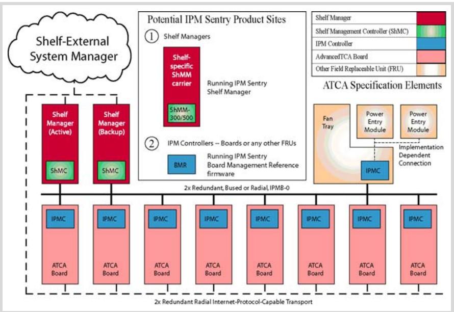
The IPM Sentry products are the first Intelligent Platform Management building blocks designed from the ground up for modular platforms like AdvancedTCA, wherein there is a strong focus on a dynamic population of Field Replaceable Units (FRUs) and maximum service availability. The Intelligent Platform Management Interface (IPMI) specification provides a solid foundation for the management of such platforms but requires significant extension to support them well.
![**Labeled Blocks:**\n\n*   **Cloud:** 'Shelf-External System Manager'\n*   **Shelf Managers (Left):** Two red blocks labeled 'Shelf Manager (Active)' and 'Shelf Manager (Backup)'. Each contains a green square labeled 'ShMC'.\n*   **Potential IPM Sentry Product Sites (Top Center):**\n    *   Label '1 Shelf Managers' pointing to a red block labeled 'Shelf-specific ShMM carrier' containing a green block 'ShMM-300/500'. Text next to it reads 'Running IPM Sentry Shelf Manager'.\n    *   Label '2 IPM Controllers – Boards or any other FRUs' pointing to a blue block labeled 'BMR'. Text next to it reads 'Running IPM Sentry Board Management Reference firmware'.\n*   **ATCA Specification Elements (Top Right):**\n    *   Legend listing color codes: 'Shelf Manager', 'Shelf Management Controller (ShMC)', 'IPM Controller', 'AdvancedTCA Board', 'Other Field Replaceable Unit (FRU)'.\n    *   Diagram showing a large orange square labeled 'Fan Tray'. Inside/overlaid are two orange rectangles labeled 'Power Entry Module' and a blue square labeled 'IPMC'. Text reads 'Implementation Dependent Connection'.\n*   **Bus Line:** Text label '2x Redundant, Bussed or Radial,IPMB-0'.\n*   **ATCA Boards (Bottom Row):** Eight identical vertical blocks. Each contains a blue square at the top labeled 'IPMC' and a pink rectangle below labeled 'ATCA Board'.\n*   **Bottom Transport Line:** Text label '2x Redundant Radial Internet-Protocol-Capable Transport'.\n\n**Connections:**\n\n*   Dashed lines connect 'Shelf-External System Manager' to both 'Shelf Manager (Active)' and 'Shelf Manager (Backup)'.\n*   Solid lines connect 'Shelf Manager (Active)' and 'Shelf Manager (Backup)' down to the horizontal line labeled '2x Redundant, Bussed or Radial,IPMB-0'.\n*   This horizontal bus line connects to the top of the row of 'ATCA Board' blocks.\n*   Dashed lines connect the bottom of the 'ATCA Board' blocks to the text '2x Redundant Radial Internet-Protocol-Capable Transport'.](.acmm-2000-50-1g003-1000-201/193154b3fb207a20c920ced6055c53f0ba60f1f73f621083168696c8ac03f3e4.jpg)

Figure A-1: IPMI in ATCA Overview

The illustration above shows the logical elements of an example AdvancedTCA shelf, identified in terms of ATCA specification and potential sites for incorporation of IPM Sentry products.

# A.2 Features of IPM Sentry Shelf Manager

Executes on the ShMM, a compact SODIMM form-factor module, installed on a suitable carrier board for the shelf.
▶ Conforms to the AdvancedTCA specification.
Monitors activities within the shelf via the ATCA-specified dual redundant Intelligent Platform Management Bus (IPMB).
- Accepts and logs events posted by any intelligent FRU in the shelf (reflecting exceptions in temperatures, voltages, etc.); posts alerts outside the shelf based on configurable IPMI Platform Event Filters.
▶ Supports hot swapping of Field Replaceable Units (FRUs), while maintaining full management visibility.
▶ Interfaces to standard “Telco Alarm” infrastructures, via ShMM carrier-implemented dry contact relays.
▶ Supports redundant Shelf Manager instances for high availability.
▶ Integrates a watchdog timer, which resets the ShMM if not periodically strobed; such resets automatically trigger a switchover to the backup ShMM, if configured.
▶ Includes battery-backed real-time clock for time-stamping events.
- Implements a rich set of shelf-external interfaces accessible over Ethernet, including Remote Management Control Protocol (RMCP, required by AdvancedTCA), command line, web browser, Simple Network Management Protocol (SNMP).

# A.3 Support for Dual Redundant Operation

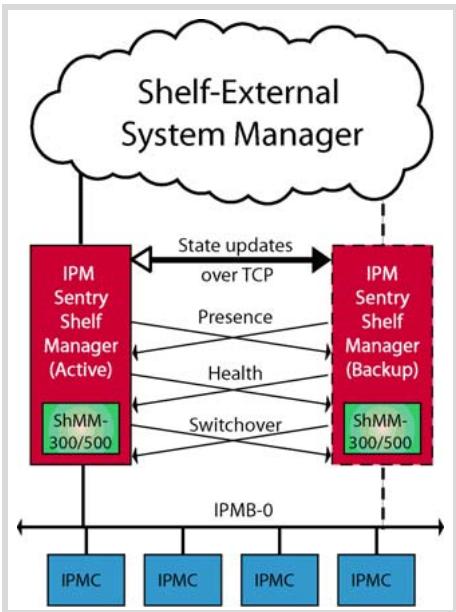
The IPM Sentry Shelf Manager can be configured with active/backup instances to maximize availability. Figure A-2 shows how both instances are accessible to the System Manager, with only the active instance interacting at any given time. Similarly, only the active instance communicates over IPMB-0 with the IPM Controller population in the shelf. The two instances communicate over TCP/IP, with the active instance posting incremental state updates to the backup. As a result, the backup can quickly step into the active role if necessary.
![**Labeled Blocks:**\n\n*   **Cloud:** 'Shelf-External System Manager'\n*   **Red Box (Left):** 'IPM Sentry Shelf Manager (Active)' containing a green box labeled 'ShMM-300/500'\n*   **Red Box (Right):** 'IPM Sentry Shelf Manager (Backup)' containing a green box labeled 'ShMM-300/500'\n*   **Blue Boxes (Bottom Row):** Four boxes labeled 'IPMC'\n\n**Connections:**\n\n*   **Shelf-External System Manager to Active Manager:** A solid vertical line connects the cloud to the 'IPM Sentry Shelf Manager (Active)' block.\n*   **Shelf-External System Manager to Backup Manager:** A dashed vertical line connects the cloud to the 'IPM Sentry Shelf Manager (Backup)' block.\n*   **Between Active and Backup Managers:**\n    *   A double-headed arrow labeled 'State updates over TCP' connects the top sections of the two red boxes.\n    *   Bidirectional arrows labeled 'Presence' connect the lower sections of the two red boxes.\n    *   Bidirectional arrows labeled 'Health' connect the lower sections of the two red boxes.\n    *   Bidirectional arrows labeled 'Switchover' connect the lower sections of the two red boxes (specifically aligned with the 'ShMM-300/500' blocks).\n*   **To IPMB-0 Bus:**\n    *   A solid vertical line drops from the 'IPM Sentry Shelf Manager (Active)' block.\n    *   A dashed vertical line drops from the 'IPM Sentry Shelf Manager (Backup)' block.\n    *   Both lines connect to a horizontal line labeled 'IPMB-0'.\n*   **IPMB-0 to IPMCs:** The horizontal 'IPMB-0' line connects to the tops of all four 'IPMC' boxes.](.acmm-2000-50-1g003-1000-201/006d3ca4bb3990be1c44947d612901cc781aaf40b72864a1e9cde193d1ca3330.jpg)

Figure A-2: IPM Sentry Shelf Manager Redundancy Support

Three cross-connected signals between the two Shelf Manager instances enhance their coordination:

▶ Presence: each Shelf Manager instance knows whether the other instance is present in the shelf.
▶ Health: each instance knows whether the other instance considers itself “healthy.”
▶ Switchover: the backup instance can force a switchover if necessary.

# A.4 IPM Sentry ShMM Shelf Management Mezzanines

The IPM Sentry Shelf Manager executes on the ShMM a small (67.60 mm x 50.80 mm) Shelf Management Mezzanine that conforms to the Small Outline Dual Inline Memory Module (SODIMM) specification.

<table><tr><td>Feature</td><td>ShMM-500</td></tr><tr><td>CPU</td><td>AMD Alchemy Au1550</td></tr><tr><td>Processor core(s)</td><td>333 Mhz MIPS-32</td></tr><tr><td>SDRAM</td><td>128 Mbytes</td></tr><tr><td>Flash</td><td>64 Mbytes</td></tr><tr><td>Ethernet</td><td>Dual 10/100 Mbit</td></tr><tr><td>Serial</td><td>Two, one with modem controls</td></tr><tr><td>Universal Serial Bus (USB)</td><td>Host and device ports</td></tr><tr><td>Duplex IPMB-0</td><td>Yes</td></tr><tr><td>Real-time clock, optionally battery backed on ShMM carrier</td><td>Yes</td></tr><tr><td>General Purpose I/O signals</td><td>Nine</td></tr><tr><td>Shelf Manager redundancy and hot swap interface, with on-board CPLD assist</td><td>Yes</td></tr><tr><td>High speed interface(s) to on-carrier devices</td><td>Multiple ports supporting either SPI or SMBus</td></tr><tr><td>JTAG interface for processor debug and flash programming</td><td>Yes</td></tr></table>

This page intentionally left blank.

# Warranty Policy

Thank you for choosing ADLINK. To understand your rights and enjoy all the after-sales services we offer, please read the following carefully.

1. Before using ADLINK's products please read the user manual and follow the instructions exactly. When sending in damaged products for repair, please attach an RMA application form which can be downloaded from: http://rma.adlinktech.com/policy/.

2. All ADLINK products come with a limited two-year guarantee, one year for products bought in China:

The warranty period starts on the day the product is shipped from ADLINK's factory.
▶ Peripherals and third-party products not manufactured by ADLINK will be covered by the original manufacturers' warranty.
For products containing storage devices (hard drives, flash cards, etc.), please back up your data before sending them for repair. ADLINK is not responsible for loss of data.
▶ Please ensure the use of properly licensed software with our systems. ADLINK does not condone the use of pirated software and will not service systems using such software. ADLINK will not be held legally responsible for products shipped with unlicensed software installed by the user.
For general repairs, please do not include peripheral accessories. If peripherals need to be included, be certain to specify which items you sent on the RMA Request & Confirmation Form. ADLINK is not responsible for items not listed on the RMA Request & Confirmation Form.

3. Our repair service is not covered by ADLINK's guarantee in the following situations:

▶ Damage caused by not following instructions in the User's Manual.
▶ Damage caused by carelessness on the user's part during product transportation.
▶ Damage caused by fire, earthquakes, floods, lightening, pollution, other acts of God, and/or incorrect usage of voltage transformers.
▶ Damage caused by unsuitable storage environments (i.e. high temperatures, high humidity, or volatile chemicals).
▶ Damage caused by leakage of battery fluid during or after change of batteries by customer/user.
▶ Damage from improper repair by unauthorized ADLINK technicians.
▶ Products with altered and/or damaged serial numbers are not entitled to our service.
▶ This warranty is not transferable or extendible.
▶ Other categories not protected under our warranty.

4. Customers are responsible for shipping costs to transport damaged products to ADLINK.

If you have any further questions, please email our FAE staff: service@adlinktech.com.
[🔗 Link to the original document](.acmm-2000-50-1g003-1000-201/acmm-2000-50-1g003-1000-201.pdf)
