# ADi-SA2X-CF

# Infotainment Box PC

# User's Manual

![Front view of a black ATX PWR network device with labeled ports and connectors (no readable text beyond labels)](.adi-sa2x-cf-50m-00023-1000-10/06fc1f03c909b4ddb8fc7fa230401cd0e77a33e36f6cd84edfbadc1955fb17f0.jpg)

Manual Rev.: 1.0

Revision Date: June 9, 2021

Part Number: 50M-00023-1000

ADLINK confidential content – available only with NDA!

# Copyright

© Copyright 2021 ADLINK Technology, Incorporated. All rights reserved. This document contains proprietary information protected by copyright. No part of this manual may be reproduced by any mechanical, electronic, or other means in any form without prior written permission of the manufacturer.

# Disclaimer

Information in this document is provided in connection with ADLINK products. No license, express or implied, by estoppel or otherwise, to any intellectual property rights is granted by this document. Except as provided in ADLINK's Terms and Conditions of Sale for such products, ADLINK assumes no liability whatsoever, and ADLINK disclaims any express or implied warranty, relating to sale and/or use of ADLINK products including liability or warranties relating to fitness for a particular purpose, merchantability, or infringement of any patent, copyright or other intellectual property right. If you intend to use ADLINK products in or as medical devices, you are solely responsible for all required regulatory compliance, including, without limitation, Title 21 of the CFR (US), Directive 2007/47/EC (EU), and ISO 13485 & 14971, if any. ADLINK may make changes to specifications and product descriptions at any time, without notice.

# Trademarks

Product names mentioned herein are used for identification purposes only and may be trademarks and/or registered trademarks of their respective companies.

Revision History

<table><tr><td>Revision</td><td>Description of Changes</td><td>Date</td></tr><tr><td>1.0</td><td>Initial release</td><td>June 9, 2021</td></tr></table>

# Table of Contents

List of Tables ...... v

List of Figures ...... vii

Important Safety Instructions.... xi

# 1 Overview.... 1

1.1 ADi-SA2X-CF Features 1

1.2 Rear Panel Descriptions.... 2

1.3 Specifications 4

1.3.1 Power Consumption 4

1.3.2 Input Voltage Range 5

1.3.3 Inrush Current 5

1.3.4 Thermal Specifications.... 5

1.3.5 Temperature and Humidity....6

1.3.6 Shock and Vibration 6

1.3.7 Mechanical Characteristics 6

1.4 Product Identification Label 7

1.5 ADi-SA2X-CF Physical Dimensions 8

1.6 Manual References 9

1.7 Standards and Directives 10

1.7.1 FCC Compliance Statement.... 11

# 2 Interfaces.... 13

2.1 DC IN Connector 13

2.2 Connectors available via the ADi-BSEC Board.... 13

2.3 WLAN Connector 13

2.4 SPEAKER Connector.... 14

2.5 +12 V DC OUT Power Connector 14

2.6 ATX PWR Connector 15

2.7 Connectors Available via the Mini-ITX Motherboard 15

# 3 Installation.... 17

3.1 Safety 17

3.2 ADi-SA2X-CF Setup.... 17

3.2.1 Setup Considerations.... 17

3.3 Mounting Brackets / Supports de montage 18

3.3.1 L-Type Brackets / Supports en L.... 19

3.3.2 Z-Type Brackets 21

3.3.3 VESA Bracket 23

3.4 Protective Earthing.... 25

3.5 Connecting Peripheral Devices 25

3.6 Initial Start-Up 26

3.7 Shutting Down the ADi-SA2X-CF 26

3.8 Replacement of Internal Components.... 27
3.8.1 Intrusion Monitoring 27
3.8.2 Tools Required 27
3.8.3 ADi-SA2X-CF Optional Storage Installation Procedure 27
3.8.3.1 Replacing the Storage Drives on the ADi-SA2X-CF 28
3.8.3.2 Removal of Storage Drives 28
3.8.3.3 Installation of Storage Drives 28

# A Optional Boards and Accessories 29

A.1 ADLINK Motherboards 29
A.2 ADLINK Boards 29
A.3 Graphics Cards 29
A.4 Power Supplies 30
A.5 Software Utilities 30
A.6 Storage Devices.... 30
A.7 Accessories.... 31

# B Getting Service.... 33

# List of Tables

Table 1-1: Rear Panel IO Descriptions.... 2

Table 1-2: System Configuration for Current Consumption Test .... 4

Table 1-3: System Power Requirements [24 V DC].... 4

Table 1-4: Input Voltage....5

Table 1-5: System Ambient Temperature Limits.... 5

Table 1-6: Temperature and Humidity Requirements....6

Table 1-7: Shock and Vibration Requirements....6

Table 1-8: Mechanical Characteristics ...... 6

Table 1-9: Manual References....9

Table 1-10: Standards and Directives.... 10

Table 2-1: DC IN Connector Pinout .... 13

Table 2-2: WLAN Connector Pinout.... 13

Table 2-3: SPEAKER Connector Pinout 14

Table 2-4: +12 V DC OUT Power Con. Pinout.... 14

Table 2-5: ATX PWR Connector Pinout.... 15

Table 3-1: Initial Start-Up 26

Table A-1: ADLINK Motherboards 29

Table A-2: ADLINK Boards.... 29

Table A-3: Graphics Cards 29

Table A-4: Power Supplies 30

Table A-5: Software Utility Options.... 30

Table A-6: Storage Device Options 30

Table A-7: Box Options 31

This page is intentionally left blank.

# List of Figures

Figure 1-1: ADi-SA2X-CF Rear Panel 2

Figure 1-2: Product Identification Label....7

Figure 1-3: ADi-SA2X-CF Physical Dimensions....8

Figure 2-1: DC IN Connector.... 13

Figure 2-2: WLAN Connector 13

Figure 2-3: SPEAKER Connector 14

Figure 2-4: +12 V DC OUT Power Con. 14

Figure 2-5: ATX PWR Connector 15

Figure 3-1: L-Type Mounting Bracket Dimensions.... 19

Figure 3-2: L-Type Mounting Bracket.... 20

Figure 3-3: Mounting Holes for L-Type Brackets on the ADi-SA2X-CF.... 20

Figure 3-4: Z-Type Mounting Bracket Dimensions.... 21

Figure 3-5: Z-Type Mounting Bracket.... 21

Figure 3-6: Mounting Holes for Z-Type Brackets on the ADi-SA2X-CF 22

Figure 3-7: VESA Mounting Bracket Dimensions.... 23

Figure 3-8: VESA Mounting Bracket 24

Figure 3-9: Mounting Holes for the VESA Bracket on the ADi-SA2X-CF 24

Figure 3-10: Earthing Nut on the ADi-SA2X-CF 25

Figure 3-11: ADi-SA2X-CF with Storage Drives, Brackets, and Security Screws.... 28

This page is intentionally left blank.

# Audience

This manual provides reference only for computer design engineers, including but not limited to hardware and software designers and applications engineers. ADLINK Technology, Inc. assumes you are qualified to design and implement prototype computer equipment.

# Environmental Responsibility

ADLINK is committed to fulfill its social responsibility to global environmental preservation through compliance with the European Union's Restriction of Hazardous Substances (RoHS 2) directive and Waste Electrical and Electronic Equipment (WEEE) directive. Environmental protection is a top priority for ADLINK. We have enforced measures to ensure that our products, manufacturing processes, components, and raw materials have as little impact on the environment as possible. When products are at their end of life, our customers are encouraged to dispose of them in accordance with the product disposal and/or recovery programs prescribed by their nation or company.

![Symbol of a trash bin crossed with a diagonal line and a horizontal bar below (no text or labels)](.adi-sa2x-cf-50m-00023-1000-10/62e76edc5303b85403ca0e0e02a4b63056376738a3d14dfcf31a98a7e24aae5b.jpg)

# Battery

Please dispose of used batteries according to the manufacturer's instructions and the local regulations.

![The image displays a black line drawing of a wheeled trash bin that has been crossed out with a large 'X' extending from corner to corner. The bin features a lid with a handle on top, a small rectangular detail on the upper side, and a wheel visible at the bottom right corner.](.adi-sa2x-cf-50m-00023-1000-10/eb93bc5099c299a0f1dab863b68406e52c72c5e1b039511b1a8a1a4a24d5ecf8.jpg)

![The image features a black-and-white graphic. At the top, there is a square outline containing the universal recycling symbol, which consists of three arrows chasing each other in a triangular cycle. Directly below the square, the text 'Li-ion' is printed in a bold, black, sans-serif font.](.adi-sa2x-cf-50m-00023-1000-10/08fb51f5801dbf97ccaa85b8c1a2cbf7b37a924e5e1159370b40f53bb4f4cfb6.jpg)

![This image features a black and white circular logo. The word 'RECYCLE' is arched along the top edge. In the center, the letters 'RBRC' appear above a graphic of a battery surrounded by a recycling loop. Below the battery graphic is the text 'Li-ion'. Along the bottom edge is the phone number '1.800.822.8837'.](.adi-sa2x-cf-50m-00023-1000-10/8f016f28ab40a6d29419ac18aa3a2a18c80d8abd90bc552c2fbaf45bc67fde60.jpg)

![The image displays a black and white graphic containing a symbol and text.  **Symbol:** At the top is a stylized black square logo. It is composed of four interlocking, curved shapes resembling the letter 'S' arranged in a square formation. These shapes create a continuous, pinwheel-like design with an 'X' shape formed by the negative space (white background) in the center.  **Text:** Below the symbol is a line of Traditional Chinese text: **廢電池請回收**  (This translates to 'Waste batteries please recycle' or 'Please recycle used batteries.')](.adi-sa2x-cf-50m-00023-1000-10/d45f2dfb752756c0e0da95d5905f57381aafd17b5843d4508bc5acebe797e887.jpg)

# Preventing Electrostatic Discharge (ESD)

# NOTICE

# Electrostatic Discharge (ESD)

This equipment contains components which are sensitive to static electricity and can be easily damaged by improper handling.

Follow the instructions below when handling ESD-sensitive components:

▶ Before handling ESD-sensitive components, touch a grounded, unpainted metal surface to discharge any static electricity.
▶ Use a complete anti-static service kit (or an equivalent) consisting of a static-dissipating work surface, a chassis clip lead, and a wrist or ankle strap.
▶ Use conductive service tools.
▶ Hold ESD-sensitive components by their edges. Avoid contact with board components or connector pins.
▶ Store ESD-sensitive components in anti-static packaging.

Failure to comply with the instructions above could result in damage to ESD-sensitive components.

# Safety Symbols

The following symbols define hazard identifications and notices that may appear in this manual:

# DANGER

DANGER indicates a hazardous situation which, if not avoided, will result in death or serious injury.

# WARNING

WARNING indicates a hazardous situation which, if not avoided, could result in death or serious injury.

# CAUTION

CAUTION indicates a hazardous situation which, if not avoided, could result in minor or moderate injury.

# NOTICE

NOTICE indicates a property damage message.

# Symboles de sécurité

Les symboles suivants indiquent un danger identifié et des avertissements pouvant être signalés dans ce manuel :

# DANGER

DANGER indique une situation dangereuse qui, si elle n'est pas évitée, entraîne la mort ou des blessures graves.

# AVERTISSEMENT

AVERTISSEMENT indique une situation dangereuse qui, si elle n'est pas évitée, peut entraîner la mort ou des blessures graves.

# ATTENTION

ATTENTION indique une situation dangereuse qui, si elle n'est pas évitée, peut entraîner des blessures légères ou peu importantes.

# AVIS

AVIS indique un dommage matériel.

# Important Safety Instructions

For user safety, please read and follow all safety instructions and safety messages in this manual and on the associated equipment before handling/operating the equipment.

▶ Read these safety instructions carefully
▶ Keep the User's Manual for future reference
▶ Read the Specifications section of this manual for detailed information on the recommended operating environment
The device can be operated at an ambient temperature of $50^{\circ}$ C
▶ When installing/mounting or uninstalling/removing device; or when removal of a chassis cover is required for user servicing:
▶ Turn off power and unplug any power cords/cables
▶ Reinstall all chassis covers before restoring power

▶ To avoid electrical shock and/or damage to device:

▶ Keep device away from water or liquid sources
▶ Keep device away from high heat or humidity
▶ Keep device properly ventilated (do not block or cover ventilation openings)
▶ Always use recommended voltage and power source settings
▶ Always install and operate the device near an easily accessible electrical outlet
▶ Secure the power cord (do not place any object on/over the power cord)
▶ Only install/attach and operate device on stable surfaces and/or recommended mountings. The power cord must be connected to a socket or outlet with a ground connection.

▶ If the device will not be used for long periods of time, turn off and unplug from its power source

▶ Never attempt to repair the device, which should only be serviced by qualified technical personnel using suitable tools

▶ A UL-approved Lithium-type battery may be provided for uninterrupted backup or emergency power.

Risk of explosion if battery is replaced with one of an incorrect type; please dispose of used batteries appropriately.

▶ The device must be serviced by authorized technicians when:

▶ The power cord or plug is damaged
▶ Liquid has entered the device interior
The device has been exposed to high humidity and/or moisture
The device is not functioning or does not function according to the User's Manual
The device has been dropped and/or damaged and/or shows obvious signs of breakage

▶ Disconnect the power supply cord before loosening the thumbscrews and always fasten the thumbscrews with a screwdriver before starting the system up

It is recommended that the device be installed only in a server room or computer room where access is:

▶ Restricted to qualified service personnel or users familiar with restrictions applied to the location, reasons therefor, and any precautions required
▶ Only afforded by the use of a tool or lock and key, or other means of security, and controlled by the authority responsible for the location

# WARNING

Failure to comply with the instructions above could result in serious injury. ADLINK rejects all liability for damages resulting from failure to comply with safety requirements whether specifically addressed in this manual or not.

# Consignes de sécurité importantes

Afin que la sécurité de l'utilisateur soit respectée, lire et suivre toutes les consignes et tous les messages de sécurité indiqués dans ce manuel et sur l'appareil avant de manipuler/de faire fonctionner ce dernier.

▶ Lire ces consignes de sécurité attentivement.
▶ Conserver le manuel pour pouvoir le consulter de nouveau ultérieurement.
▶ Lire le chapitre Caractéristiques de ce manuel pour obtenir des informations plus précises sur l'environnement d'exploitation recommandé.
L'appareil peut être utilisé à une température ambiante de 50 °C.
Lors de l'installation/du montage ou de la désinstallation/de la dépose de l'appareil, ou lorsque la dépose d'un couvercle de châssis est nécessaire pour l'entretien :
▶ Éteindre l'appareil et débrancher tous les cordons/câbles d'alimentation.
▶ Remettre tous les couvercles de châssis avant de rebrancher l'alimentation

▶ Afin d'éviter de s'électrocuter et/ou d'endommager l'appareil :

▶ Éloigner l'appareil des points d'eau ou de toute source de liquide.
▶ Éloigner l'appareil de fortes sources de chaleur ou de l'humidité.
Faire en sorte que l'appareil soit bien ventilé (ne pas bloquer ni couvrir les ouvertures de ventilation).
- Toujours se conformer aux paramètres de tension et de source d'alimentation recommandés.
▶ Toujours installer et utiliser l'appareil à proximité d'une prise électrique facilement accessible.
S'assurer que le câble d'alimentation est installé en toute sécurité (ne pas placer des objets sur/par-dessus le câble)
- Installer/fixer et faire fonctionner l'appareil uniquement sur une surface stable et/ou avec les supports recommandés. Le cordon d'alimentation doit être branché sur une prise raccordée à la terre.

Si l'appareil n'est pas utilisé pendant longtemps, l'éteindre et le débrancher de la source d'alimentation.

▶ Ne jamais tenter de réparer l'appareil. Les réparations doivent être réalisées exclusivement par des techniciens qualifiés utilisant les outils appropriés.

Une batterie de type lithium homologuée UL peut être fournie en tant qu'alimentation de secours ou d'urgence pour ne pas interrompre le fonctionnement.

# Risque d'explosion si la batterie est remplacée par un type batterie inapproprié. Les batteries usagées doivent être mises au rebut de manière appropriée.

L'appareil doit être réparé par des techniciens qualifiés si :

▶ la prise ou le câble d'alimentation est endommagé ;
▶ du liquide a pénétré dans l'appareil ;
▶ l'appareil a été exposé à une forte humidité ;
l'appareil ne fonctionne pas conformément au manuel de l'utilisateur ;
l'appareil est tombé et/ou a été endommagé et/ou semble visiblement cassé ;

Débrancher le câble d'alimentation avant de desserrer les vis à oreilles et fixer toujours ces dernières avec un tournevis avant de mettre le système en marche.

Il est recommandé d'installer l'appareil uniquement dans une salle de serveur ou une salle informatique dont l'accès est :

Réservé au personnel de service qualifié ou aux utilisateurs connaissant les restrictions appliquées à l'emplacement, les raisons de celles-ci et toutes les précautions requises.
▶ Uniquement autorisé via l'utilisation d'un outil ou d'une serrure et d'une clé, ou d'un autre moyen de sécurité, et contrôlé par les autorités responsables de l'emplacement.

# ⚠ AVERTISSEMENT

Ne pas respecter les consignes susmentionnées peut entraîner des blessures graves. ADLINK rejette toute responsabilité pour les dommages résultant du non-respect des consignes de sécurité, qu'elles soient spécifiquement abordées dans ce manuel ou non.

# 1 Overview

# 1.1 ADi-SA2X-CF Features

The ADi-SA2X-CF is a high-performance, all-in-one industrial box PC product family based on the Mini-ITX embedded computer architecture. It has been designed to deliver multiple hardware and software security options that target gaming and retail applications.

Main features of the ADi-SA2X-CF include:

▶ Low-power consumption
▶ High-performance CPUs
▶ Support for one high-performance low-profile PEG card
▶ Multi-independent display support (up to 7x)
▶ Support for external field-removable storage devices (2x SSD/CFast/SATA DOM with power supply via pin 7)
▶ Optional intelligent infotainment USB I/O controller hub
▶ Optional intelligent infotainment SECURITY & NVRAM PCI Express card
▶ Optional audio amplifier (Class D)
▶ Various power supply options
▶ Intelligent middleware
▶ Smart system management option

The ADi-SA2X-CF products are intended for:

▶ Class III/II, VLT/SBG, AWP, SWP/SWoP slot machines
▶ Multiplayer table games and player tracking
▶ Casino signage controller and lottery
▶ Amusement/entertainment and arcade gaming
▶ POS/POI, kiosk, self-service solutions
▶ Intelligent Vending Machines (IVMs)
▶ Digital Signage (DS)

ADi-SA2X-CF models feature rugged computer motherboards available with varieties of processors and memory. An optional operating system (OS) can be pre-loaded onto an optional internal storage device (2x SSD/CFast/SATA DOM). Just use a USB memory device to load the application software and the system is ready for operation.

# 1.2 Rear Panel Descriptions

The following figure and table provide information about the user interfaces on the rear panel of the ADi-SA2X-CF unit.

Figure 1-1: ADi-SA2X-CF Rear Panel
![ADi-BSEC Add-On Security Board (Optional) Eyelet ADi-BAMP Audio Amplifier (Optional) Removable Storage L WLAN H ADi-BSEC Add-On Security Board (Optional) WLAN SPEAKER M +12V OUT N V 12 V DC / 2 A OUT ATX PWR O P Q R S T U HDD PWR ARM PIC FS2 FS1 RESET POWER WLAN COM 4 COM 3 COM 2 COM 1 USB 1-2 USB 3-4 DP DP DP USB 5-8 LAN 1 SURROUND CENTER OUT MINI-ITX Motherboard I/O Panel SPDIF MIC](.adi-sa2x-cf-50m-00023-1000-10/3c5526cf8906c3119506254ebece2b9dc94f38a338f9b8861168cf9b6cb6e9a8.jpg)

Table 1-1: Rear Panel IO Descriptions

<table><tr><td>Pos.</td><td>Component</td><td>Description</td></tr><tr><td>A</td><td>+9–36 V DC IN</td><td>3-pin power-in connector (MOLEX)</td></tr><tr><td>B</td><td>Security Lock</td><td>Heavy-duty, 2-position 12 mm CAM lock; key may be withdrawn in both positions</td></tr><tr><td>C</td><td>SATA / PWR / ARM / PIC LEDs</td><td>4 LEDs for indicating SATA, Power, ARM, and PIC statusSATA (yellow): indicates SATA interface activity on SSD/SATA DOMPWR (red): indicates normal operationARM (blinking green): indicates that the ADi-BIOG card (discontinued) is installed and the ARM controller is operatingPIC (blinking green): indicates that the ADi-BSEC is installed and the PIC controller is operating</td></tr><tr><td>D</td><td>FS2</td><td>Switch button to trigger customer-specific events</td></tr><tr><td>E</td><td>FS1</td><td>Switch button to trigger customer-specific events</td></tr><tr><td>F</td><td>RESET</td><td>Switch button for box PC reset on the mainboard</td></tr><tr><td>G</td><td>POWER</td><td>6-pin, right-angle, non-latched push-button power switch with blue LED indicator for turning on the systemNote: If the system hangs, depressing the button for 5 seconds powers down the system.</td></tr><tr><td>H</td><td>Kensington Security Slot</td><td>Metal-reinforced anti-theft slot for attaching lock-and-cable security device</td></tr><tr><td>I</td><td>SERIAL (FPGA)(optional)</td><td>14-pin, Micro-Fit, right-angle serial port connector(from optional ADi-BSEC board)</td></tr><tr><td>J</td><td>INT (PIC)(optional)</td><td>8-pin, Micro-Fit, right-angle intrusion connector(via the optional ADi-BSEC board)</td></tr><tr><td>K</td><td>FEATURE (FPGA)(optional)</td><td>10-pin, Micro-Fit, feature connector(via the optional ADi-BSEC board)</td></tr><tr><td>L</td><td>WLAN (optional)</td><td>Two male SMA RF jacks for Wi-Fi (optional)</td></tr><tr><td>M</td><td>SPEAKER (optional)</td><td>6-pin, Micro-Fit, right-angle speaker connector(via the optional ADi-BAMP / ADi-BAMP-G2 amplifier board)</td></tr><tr><td>N</td><td>+12 V DC OUT (optional)</td><td>4-pin, Micro-Fit, right-angle +12 V DC OUT / 2 A connector</td></tr><tr><td>O</td><td>ATX PWR(optional)</td><td>14-pin, ATX power connector.Note: An ADLINK adapter cable P/N 30-21011-0000 must be used to connect a standard 24-pin ATX power supply to the ADi-SA2X-CF.</td></tr><tr><td>P</td><td>DP (DisplayPort)</td><td>AmITX-CF-G: 1 DisplayPortAmITX-KB-G: 1 DisplayPortAmITX-SL-G: 1 DisplayPortAmITX-HL-G: 1 DisplayPort</td></tr><tr><td>Q</td><td>USB 1-2 and DP (connector combination)</td><td>2x USB 3.0DisplayPort connector</td></tr><tr><td>R</td><td>USB 3-4 and DP (connector combination)</td><td>AmITX-KB-G-G370/ADi-Ax: 2x USB 3.0AmITX-KB-G-H310/ADi-Ax: 2x USB 3.0AmITX-KB-G-G170/ADi-Ax: 2x USB 3.0AmITX-KB-G-H110/ADi-Ax: 2x USB 3.0AmITX-SL-G-Q170/ADi-Ax: 2x USB 3.0AmITX-SL-G-H110/ADi-Ax: 2x USB 3.0AmITX-HL-G-Q87/ADi-Ax: 2x USB 3.0AmITX-HL-G-H81/ADi-Ax: 2x USB 2.0DisplayPort connector</td></tr><tr><td>S</td><td>USB 5-8</td><td>Four-stack, USB 2.0, standard, A-type, high-rise connector</td></tr><tr><td>T</td><td>LAN1 and LAN2</td><td>Two-stack, RJ45 Ethernet connector (10/100/1000 MBit)</td></tr><tr><td>U</td><td>Audio Jack</td><td>Six-port audio jack:SURROUNDCENTERSPDIFINOUTMIC</td></tr><tr><td>V</td><td>Earthing Nut</td><td>System ground (bolt M4)</td></tr><tr><td>W</td><td>COM 4</td><td>3 DB9 serial COM port connector (RS-232)</td></tr><tr><td>X</td><td>COM 3</td><td>3 DB9 serial COM port connector (RS-232)</td></tr><tr><td>Y</td><td>COM 2</td><td>3 DB9 serial COM port connector (RS-232)</td></tr><tr><td>Z</td><td>COM 1</td><td>Black Color: 1 DB9 serial COM port connector (RS-232/422/485)Blue Color: 1 DB9 serial COM port connector (2x CCTalk / RS-232; AmITX-CF-G only)</td></tr></table>

# 1.3 Specifications

This section defines the power consumption, operating and storage temperature, humidity, shock, vibration, and mechanical characteristics of the system.

Further technical specifications can be found in the datasheet and the user manual of the AmITX-CF-G motherboard, which are available for download on the http://www.adlinktech.com website.

# 1.3.1 Power Consumption

Table 1-3 provides the power consumption with external 24 V DC power supply of an exemplary system configuration with the conditions listed in Table 1-2.

Table 1-2: System Configuration for Current Consumption Test

<table><tr><td>Component</td><td>Device</td></tr><tr><td>System Board</td><td>AmITX-KB-G-Q370</td></tr><tr><td>Processor</td><td>Intel® CoreTM i5-9500E Processor (6C, 3.0/4.2GHz, 9M, 65W TDP)</td></tr><tr><td>Memory Slot 1</td><td>Transcend DDR4-2400 SO-DIMM 8GB</td></tr><tr><td>Memory Slot 2</td><td>Transcend DDR4-2400 SO-DIMM 8GB</td></tr><tr><td>Onboard Graphics</td><td>Intel® UHD Graphics 630</td></tr><tr><td>PCIe Graphics</td><td>Nvidia P1000</td></tr><tr><td>SSD</td><td>Innodisk 2.5&quot;SATA 3TG6-P</td></tr><tr><td>Audio</td><td>Realtek ALS888 HD Audio (onboard)</td></tr><tr><td>LAN 1</td><td>Realtek RTL8111G Ethernet controller</td></tr><tr><td>LAN 2</td><td>Realtek RTL8111G Ethernet controller</td></tr><tr><td>USB 3.0</td><td>4x PassMark 3.0 USB loopback</td></tr><tr><td>USB 2.0</td><td>4x PassMark 3.0 USB loopback</td></tr><tr><td>iAMP output</td><td>ADi-BAMP integrated audio amplifier with 4 Ω load resistor</td></tr><tr><td>DC output</td><td>16 Ω load resistor</td></tr><tr><td>GLI gaming equipment</td><td>ADi-BACC-G2F, ADI-BSEC</td></tr></table>

Table 1-3: System Power Requirements [24 V DC]

<table><tr><td rowspan="2">Item</td><td colspan="2">BIOS PSS Support Enabled</td><td colspan="2">BIOS PSS Support Disabled</td></tr><tr><td>Current [A]</td><td>Power [W]</td><td>Current [A]</td><td>Power [W]</td></tr><tr><td>Windows 10 (Idle)</td><td>1.06</td><td>25.33</td><td>1.14</td><td>27.24</td></tr><tr><td>Windows 10 (Typical)</td><td>6.2</td><td>148.18</td><td>5.8</td><td>138.62</td></tr><tr><td>Windows 10 (Max. load)</td><td>8.2</td><td>195.98</td><td>7.3</td><td>174.47</td></tr></table>

As power consumption is depending on system configuration and attached accessories, ADLINK is not able to provide individual power consumption information within this manual. Please contact ADLINK technical support for further information.

# 1.3.2 Input Voltage Range

The following table indicates the input voltage for the ADi-SA2X-CF.

Table 1-4: Input Voltage

<table><tr><td>Parameter</td><td>Description</td></tr><tr><td rowspan="2">DC input</td><td>+9–36 V DC via the 3-pin DC IN connector and the optional ADi-BDC1</td></tr><tr><td>ATX or +12 V DC ± 5 % via the 14-pin ATX-style connector and an optional adapter cable</td></tr><tr><td>AC input</td><td>100–240 VAC / 50–60 Hz via the optional ADi-SPSU</td></tr></table>

# 1.3.3 Inrush Current

When using 24 V DC input voltage, an inrush current of 8.2 A is needed from the power supply.

# 1.3.4 Thermal Specifications

The following table defines the system ambient temperature requirements of the ADi-SA2X-CF with regards to each CPU model.

Table 1-5: System Ambient Temperature Limits

<table><tr><td>CPU</td><td>TDP (W)</td><td>System Ambient Temperature (°C)</td></tr><tr><td colspan="3">Embedded 9th Gen.Intel® CoreTM i7/i5/i3 and Pentium®/Celeron® Processor, LGA 1151 socket:</td></tr><tr><td>Intel® Core i7-9700E Processor, 8C, 2.6/4.4GHz, 12M</td><td>65</td><td rowspan="6">50</td></tr><tr><td>Intel® Core i7-9700TE Processor, 8C, 1.8/3.8GHz, 12M</td><td>35</td></tr><tr><td>Intel® Core i5-9500E Processor, 6C, 3.0/4.2GHz, 9M</td><td>65</td></tr><tr><td>Intel® Core i5-9500TE Processor, 6C, 2.2/3.6GHz, 9M</td><td>35</td></tr><tr><td>Intel® Core i3-9100E Processor, 4C, 3.1/3.7GHz, 6M</td><td>65</td></tr><tr><td>Intel® Core i3-9100TE Processor, 4C, 2.2/3.2GHz, 6M</td><td>35</td></tr><tr><td colspan="3">Embedded 8th Gen. Intel® CoreTM i7/i5/i3 and Pentium®/Celeron® Processor, LGA 1151 socket:</td></tr><tr><td>Intel® Core i7-8700E Processor, 6C, 3.2/4.6GHz, 12M</td><td>65</td><td rowspan="10">50</td></tr><tr><td>Intel® Core i7-8700T Processor, 6C, 2.4/4.0GHz, 12M</td><td>35</td></tr><tr><td>Intel® Core i5-8500E Processor, 6C, 3.0/4.1GHz, 9M</td><td>65</td></tr><tr><td>Intel® Core i5-8500T Processor, 6C, 2.1/3.5GHz, 9M</td><td>35</td></tr><tr><td>Intel® Core i5-8100E Processor, 4C, 3.6GHz, 6M</td><td>65</td></tr><tr><td>Intel® Core i5-8100T Processor, 4C, 3.1GHz, 6M</td><td>35</td></tr><tr><td>Intel® Pentium® Gold G5400 Processor, 2C, 3.7GHz, 4M</td><td>58</td></tr><tr><td>Intel® Pentium® Gold G5400T Processor, 2C, 3.1GHz, 4M</td><td>35</td></tr><tr><td>Intel® Celeron® G4900 Processor, 2C, 3.1GHz, 2M</td><td>54</td></tr><tr><td>Intel® Celeron® G4900T Processor, 2C, 2.9GHz, 2M</td><td>35</td></tr></table>

# 1.3.5 Temperature and Humidity

The following table provides the most efficient operating and storage temperature as well as humidity ranges required for the ADi-SA2X-CF. The values are valid for CPUs up to 65 W.

Table 1-6: Temperature and Humidity Requirements

<table><tr><td colspan="2">Temperature</td><td colspan="2">Humidity</td></tr><tr><td>Operating (System Ambient)</td><td>Storage</td><td>Operating</td><td>Non-Operating</td></tr><tr><td>0 °C to +50 °C (+32 °F to +122 °F)</td><td>-20 °C to +70 °C (-4 °F to +158 °F)</td><td>85 % relative humidity, non-condensing @ +50 °C (122 °F)HT / H % hum. -&gt; 50 °C (122 °F) / 50 - 85 %LT / 0 % hum. -&gt; 0°C (32 °F) / 0 %HT / L % hum. -&gt; 50 °C (122 °F) / 10 %</td><td>85 % relative humidity, non-condensing</td></tr></table>

# NOTICE

# Condensation damage!

Avoid continuous changes from a cold to a warm environment as this may cause condensation inside the chassis. Failure to comply with this instruction may result in damage to the ADi-SA2X-CF.

# 1.3.6 Shock and Vibration

The following table provides the most efficient operating shock and vibration ranges for the ADi-SA2X-CF.

Table 1-7: Shock and Vibration Requirements

<table><tr><td>Parameter</td><td>Description</td></tr><tr><td>Shock</td><td>Operating, 20 G, half sine 11 ms duration (w/ optional CFast or SSD)</td></tr><tr><td>Vibration</td><td>Operating, 1 Grms, 5-500 Hz, 3 axes (w/ optional CFast or SSD)</td></tr></table>

# 1.3.7 Mechanical Characteristics

The following table indicates the mechanical characteristics of the ADi-SA2X-CF.

Table 1-8: Mechanical Characteristics

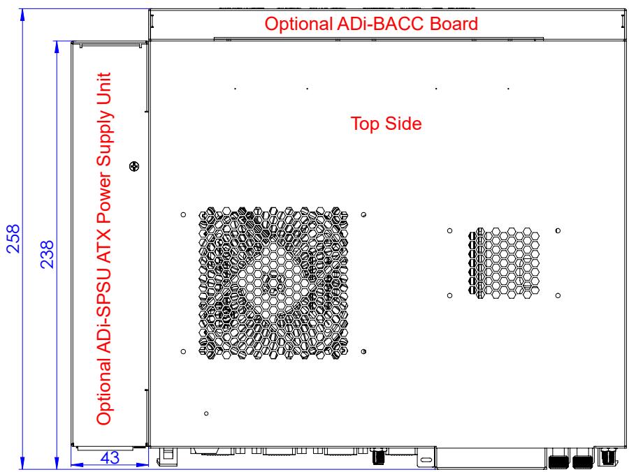
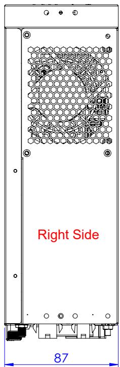
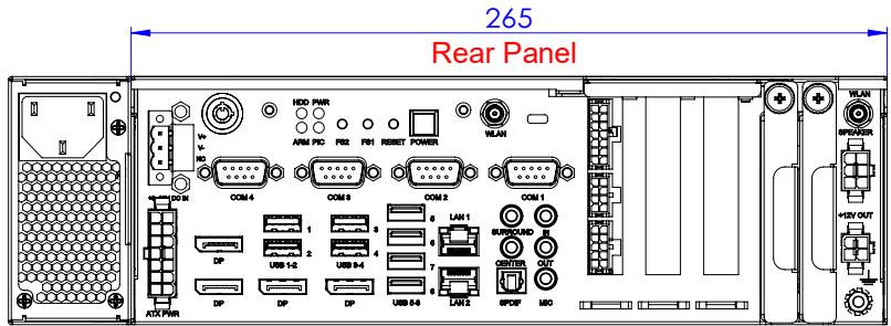
<table><tr><td>Parameter</td><td colspan="3">Description</td></tr><tr><td rowspan="3">Dimensions of the ADi-SA2X-CF</td><td>Width</td><td>Height</td><td>Depth</td></tr><tr><td>308 mm / 12.12 inches with ADi-SPSU</td><td>87 mm / 3.42 inches</td><td>258 mm / 10.15 inches with ADi-BACC</td></tr><tr><td>265 mm / 10.43 inches without ADi-SPSU</td><td>87 mm / 3.42 inches</td><td>238 mm / 9.37 inches without ADi-BACC</td></tr><tr><td>Mounting</td><td colspan="3">via a pair of L-type brackets, or a pair of Z-type brackets</td></tr><tr><td>Mounting clearance</td><td colspan="3">50 mm / 1.96 inches top/left/right from cooling vents</td></tr><tr><td>Weight</td><td colspan="3">approx. 3.5 kg / 7.71 lb without power supply or optional components</td></tr></table>

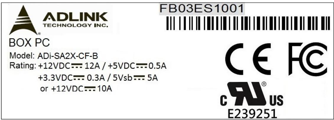
# 1.4 Product Identification Label

The ADi-SA2X-CF is supplied with an identification label attached to the chassis. The identification label contains the following information:

▶ Model: indicates the system model
▶ Rating: indicates the permissible input voltage for the system
▶ Bar code: indicates the ADLINK serial number of the ADi-SA2X-CF in a bar code format
▶ Serial number: indicates the ADLINK serial number of the ADi-SA2X-CF, e.g. FB03ES1001 (located above the bar code)

The following figure shows an example of a product identification label for the ADi-SA2X-CF.

Figure 1-2: Product Identification Label
![ADLINK TECHNOLOGY INC. FB03ES1001 BOX PC Model: ADi-SA2X-CF-B Rating: +12VDC--- 12A / +5VDC--- 0.5A +3.3VDC--- 0.3A / 5Vsb--- 5A or +12VDC--- 10A CE FC CR US E239251](.adi-sa2x-cf-50m-00023-1000-10/507c2b1a22ef0ee26d70ee81511cddbd3c807369499b72c468fc02ee6304b19d.jpg)

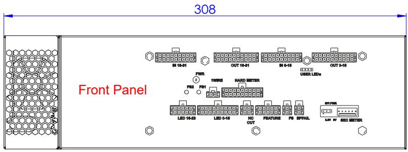
# 1.5 ADi-SA2X-CF Physical Dimensions

The following figure defines the physical dimensions of the ADi-SA2X-CF.

Note: All dimensions are indicated in millimeters.

Figure 1-3: ADi-SA2X-CF Physical Dimensions
![308 Front Panel IN 16-31 OUT 16-31 IN 5-16 OUT 5-16 PWR 1WIRE HARD METER F02 F01 USER LEDs LED 16-33 LED 5-18 NO OUT FEATURE PS SIPHAL IN PEAR LAV IV SEC METER](.adi-sa2x-cf-50m-00023-1000-10/a44f695cc44584e010b749ba96b9d4065bdcaa57846d86487d9f1c2b60298144.jpg)

![Optional ADi-BACC Board 258 238 Top Side Optional ADi-SPSU ATX Power Supply Unit 43](.adi-sa2x-cf-50m-00023-1000-10/03cafffee5b45cd26d4b77d7f3483ef77c47cc8a45c351e8f0dbaa952b7688af.jpg)

![Right Side 87](.adi-sa2x-cf-50m-00023-1000-10/549317022de1a07a8d596b1350f21539c549bdeb623c9526f96b2a8072a7b179.jpg)

![265 Rear Panel HDD PWR ARM PC PSS F81 RESET POWER WLAN COM 4 COM 8 COM 3 COM 1 1 2 3 4 5 LAN 1 SUNROUND CENTER LAN 2 BPOP MCC ATC PWR +INV OUT](.adi-sa2x-cf-50m-00023-1000-10/709dbdb7dfff585ae538d8a36a21dcb223bada7176c8969703769e4deafb5ad6.jpg)

# 1.6 Manual References

The following table lists additional infotainment platform manuals which are in relation with the ADi-SA2X-CF.

Table 1-9: Manual References

<table><tr><td>Document</td><td>Description</td></tr><tr><td>AmITX-CF-G User&#x27;s Manual</td><td>This document provides detailed information on the AmITX-CF-G, Mini-ITX motherboard and is located on the ADLINK Industrial Motherboards and SBCs web page at http://www.adlinktech.com.</td></tr><tr><td>ADi-BSEC User&#x27;s Manual</td><td>This document describes the features of the optional add-on gaming and retail and security controller board available for the ADi-SA2X-CF with non-disclosure agreement.</td></tr><tr><td>ADi-BACC User&#x27;s Manual</td><td>This document describes the features of ADi-BACC Gaming and Retail Extension I/O Board available with non-disclosure agreement.</td></tr><tr><td>ADi-BSDK User&#x27;s Manual</td><td>This document describes the features of ADi-BSDK Intelligent Backplane demonstrator with non-disclosure agreement.</td></tr><tr><td>ADi-Accessories User&#x27;s Manual</td><td>This document describes the features of the optional audio Amplifier, wide-range DC/DC converter and other accessories available for the ADi-SA2X-CF with non-disclosure agreement.</td></tr><tr><td>ADiAPI Software Manual</td><td>This document describes the features of the optional ADiAPI service and utility (used for controlling peripheral devices) available for the ADi-SA2X-CF with non-disclosure agreement.</td></tr><tr><td>ADiAPI Console Software Manual</td><td>This document describes the layout and functions of the ADiAPI console, a graphical user interface (GUI) client tool for connection to the ADLINK ADiAPI software. This document is available with non-disclosure agreement.</td></tr><tr><td>ADiDLL Software Manual</td><td>This document describes the features of the ADiDLL middleware (used for controlling optional add-on devices) available for the ADi-SA2X-CF with non-disclosure agreement.</td></tr><tr><td>SEMA® Software Manual</td><td>This document describes the features of the optional SEMA® utility (Smart Embedded Management Agent; used for system control and failure protection) available for the ADi-SA2X-CF with non-disclosure agreement.</td></tr></table>

Note: Some infotainment motherboards may have slightly different configurations than the generic infotainment motherboard. Please contact the ADLINK Technical Support for further information.

# 1.7 Standards and Directives

The ADi-SA2X-CF complies with the requirements of the following standards and directives:

Table 1-10: Standards and Directives

<table><tr><td>Type</td><td>Aspect</td><td>Standard / Directive</td></tr><tr><td rowspan="4">CE</td><td rowspan="2">Electrical Safety</td><td>EN 60950-1General Product Safety Directive (GPSD) 2001/95/ECLow Voltage Directive (LVD) 2014/35/EU</td></tr><tr><td>EN 62368-1Low Voltage Directive (LVD): 2014/35/EUGeneral Product Safety Directive (GPSD) 2001/95/EC</td></tr><tr><td>EMC</td><td>Electromagnetic Compatibility (EMC) Directive 2014/30/EU</td></tr><tr><td>CE Marking</td><td>CE Directive 93/68/EEC</td></tr><tr><td>Safety</td><td>CBUL/cUL</td><td>IEC 60950-1IEC 62368-1UL 62368-1CSA C22.2 No. 62368-1-14UL 60950-1/CSA C22.2 No 60950-1-07</td></tr><tr><td rowspan="2">EMC</td><td>Emission</td><td>FCC Part 15 Class A (see Section 1.7.1)IC ICES-003EN 55022EN 61000-3-2EN 61000-3-3</td></tr><tr><td>Immunity</td><td>EN 55024IEC 61000-4-2, +/-4 KV contact dischargeIEC 61000-4-2, +/-8 KV air dischargeIEC 61000-4-3, Level 2IEC 61000-4-4, Level 2IEC 61000-4-5, Level 3IEC 61000-4-6, Level 2IEC 61000-4-11, Level 2</td></tr><tr><td>Mechanical</td><td>Mechanical Dimensions</td><td>IEEE 1101.10</td></tr><tr><td rowspan="7">Environmental</td><td>WEEE</td><td>Directive 2012/19/EUWaste electrical and electronic equipment</td></tr><tr><td>RoHS 2</td><td>Directive 2011/65/EURestriction of the use of certain hazardous substances in electrical and electronic equipment</td></tr><tr><td>Climatic Humidity</td><td>IEC 60068-2-30Operating: 85 % RH @ +50 °C, non-condensingNon-Operating: 85 % RH @ +70 °C, non-condensing</td></tr><tr><td>Operating Vibration</td><td>IEC 60068-2-6,MIL-STD-202F Method 214A, Table 214-I Condition DIEC 60068-2-64</td></tr><tr><td>Shock</td><td>MIL-STD-202F Method 213B, Table 213-I Condition A</td></tr><tr><td>Drop</td><td>ISTA-1A (ASTM D5276 - 98)</td></tr><tr><td>Ingress Protection</td><td>IP20 acc. to IEC 60529</td></tr></table>

# 1.7.1 FCC Compliance Statement

This equipment has been tested and found to comply with the limits for a Class A digital device. These limits are designed to provide reasonable protection against harmful interference when the equipment is operated in a commercial environment. This equipment generates, uses, and can radiate radio frequency energy and, if not installed and used in accordance with the instruction manual, may cause harmful interference to radio communications. Operation of this equipment in a residential area is likely to cause harmful interference in which case the user will be required to correct the interference at his own expense.

This device complies with Part 15 of the FCC Rules. Operation is subject to the following two conditions: (1) this device may not cause harmful interference, and (2) this device must accept any interference received, including interference that may cause undesired operation.

Any changes or modifications not expressly approved by the party responsible for compliance could void the user's authority to operate this equipment.

この装置は, クラスA 情報技術装置です。この装置を家庭環境で使用すると電波妨害を引き起こすことがあります。この場合には使用者が適切な対策を講ずるよう要求されることがあります。

This page is intentionally left blank.

# 2 Interfaces

This chapter details the functional designs of the ADi-SA2X-CF user interfaces available on the rear panel. Refer to Section 1.2 for the location and technical specifications of the ADi-SA2X-CF interfaces.

# 2.1 DC IN Connector

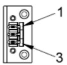
The ADi-SA2X-CF provides a 3-pin, 5.08 mm terminal block, power-in connector (Dinkle 2EHDP-03P). Refer to Figure 1-1, position A, for the location of the DC IN connector.

Cable mating connector: Dinkle: 20-72F04-1030

Figure 2-1: DC IN Connector
![The image displays a technical line drawing of a rectangular component. It features four circular mounting holes, two on the left side and two on the right side. In the center, there is a vertical column of stacked rectangular blocks. A pointer labeled '1' indicates the upper portion of this central column, and a pointer labeled '3' indicates the lower portion.](.adi-sa2x-cf-50m-00023-1000-10/6c7d5ffd5f9e8a170da983cb43e93b543b2ba76aff9097acae92bd1ad316805e.jpg)

Table 2-1: DC IN Connector Pinout

<table><tr><td>Pin</td><td>Signal</td></tr><tr><td>1</td><td>V+</td></tr><tr><td>2</td><td>V-</td></tr><tr><td>3</td><td>NC</td></tr></table>

# NOTICE

# Risk of damage!

The DC IN connector has an input voltage range of +9–36 V DC. Do not connect any DC voltages exceeding this range to the ADi-SA2X-CF via this connector. Failure to comply with this instruction could result in damage to the ADi-SA2X-CF. The ADi-SA2X-CF must be supplied by an IEC or UL certified power supply or DC source. Please contact ADLINK for further information or assistance.

# AVIS

# Risque d'endommagement !

La plage de tension d'entrée du connecteur CC IN est de +9-36 V. Ne pas connecter à l'ADi-SA2X-CF via ce connecteur des tensions CC dépassant cette plage. Ne pas respecter cette consigne pourrait endommager l'ADi-SA2X-CF. L'ADi-SA2X-CF doit être alimenté par une alimentation électrique ou une alimentation en courant continu certifiée IEC ou UL. Besoin d'une assistance supplémentaire ? Contacter ADLINK pour obtenir de plus amples informations.

# 2.2 Connectors available via the ADi-BSEC Board

The SERIAL (FPGA), INT (PIC), COM and FEATURE (FPGA) connectors are available via the ADi-BSEC board. Refer to the ADi-BSEC user manual for information about these connectors. This manual can be downloaded from the http://www.adlinktech.com website.

Refer to Figure 1-1, positions I, J, and K for the location of these connectors.

# 2.3 WLAN Connector

The ADi-SA2X-CF provides two optional 1-pin, 1/4-36 UNS-2A, WLAN antenna connectors (SMA RF jacks) for Wi-Fi. Refer to Figure 1-1, position L, for the location of the WLAN connector.

Figure 2-2: WLAN Connector
![This is a black-and-white technical line drawing of a horizontal mechanical assembly. The central component is a long, cylindrical section featuring a repeating corrugated or spring-like pattern. On the left side, a rectangular block is attached to the cylinder. On the right side, a more complex housing or valve mechanism is shown, containing internal components. A dashed horizontal centerline runs through the middle of the entire object. There is no text visible in the image.](.adi-sa2x-cf-50m-00023-1000-10/a4c08e7d1b71515ef0423a23d364ca776805df05fa84fe2776bdc01ec6f40633.jpg)

Table 2-2: WLAN Connector Pinout

<table><tr><td>Pin</td><td>Signal</td></tr><tr><td>1</td><td>WLAN Signal</td></tr></table>

# 2.4 SPEAKER Connector

The ADi-SA2X-CF provides an optional 6-pin, 4.2 mm, Micro-Fit, right-angle speaker connector (ECI 5015H 2\*3P) via the optional ADi-BAMP amplifier board. Refer to Figure 1-1, position M, for the location of the SPEAKER connector.

Cable mating connector: Molex: 39-01-2065

Figure 2-3: SPEAKER Connector
![The image displays a schematic diagram of a rectangular connector, likely a D-subminiature connector. The central object features a grid of six square pin openings arranged in two columns and three rows. There are small rectangular locking tabs on the left and right sides, as well as larger rectangular features on the top and bottom edges.  Surrounding the connector are four numbers indicating pin positions: *   **3** is positioned at the top left. *   **1** is positioned at the bottom left. *   **6** is positioned at the top right. *   **4** is positioned at the bottom right.](.adi-sa2x-cf-50m-00023-1000-10/200abe2a7061babdc27828662beefa2f422b9ab288634efb25183502d218fa8f.jpg)

Table 2-3: SPEAKER Connector Pinout

<table><tr><td>Pin</td><td>Signal</td><td>Pin</td><td>Signal</td></tr><tr><td>1</td><td>SPEAKER L+</td><td>4</td><td>SPEAKER L-</td></tr><tr><td>2</td><td>SPEAKER R+</td><td>5</td><td>SPEAKER R-</td></tr><tr><td>3</td><td>NC / Woofer +</td><td>6</td><td>NC / Woofer -</td></tr></table>

Note: If a ADi-BAMP-G3 board is installed in the ADi-SA2X-CF, pins 3 and 6 support the woofer function.

# 2.5 +12 V DC OUT Power Connector

The ADi-SA2X-CF provides an optional 4-pin, 4.2 mm, Micro-Fit, right-angle +12 V DC OUT / 2 A power connector (ECI 5015H-2\*2P). Refer to Figure 1-1, position N, for the location of the +12 V OUT DC power connector. This connector is only available via the ADi-BDC1 board.

Cable mating connector: Molex: 39-01-2045

Figure 2-4: +12 V DC OUT Power Con.
![The image displays a technical diagram featuring the numbers **2**, **4**, **1**, and **3** positioned at the corners: **2** is top-left, **4** is top-right, **1** is bottom-left, and **3** is bottom-right. In the center is a line drawing of a connector or plug, depicted as a square frame enclosing four smaller squares arranged in a grid, with rectangular shapes extending from the top, bottom, and right sides.](.adi-sa2x-cf-50m-00023-1000-10/0e673f559186a68dd1bb2ffcc524970ea1b863373bec8796d7aa8e9360609c86.jpg)

Table 2-4: +12 V DC OUT Power Con. Pinout

<table><tr><td>Pin</td><td>Signal</td><td>Pin</td><td>Signal</td></tr><tr><td>1</td><td>GND</td><td>3</td><td>+12 V OUT*</td></tr><tr><td>2</td><td>GND</td><td>4</td><td>+12 V OUT*</td></tr></table>

\* The output voltage tolerance is ± 5 %.

# NOTICE

# Risk of damage!

The maximum allowed current available is 2 A (1 A per pin). Do not draw more current than 2 A (1 A per pin) via this connector. Failure to comply with this instruction may result in damage to the +12 V DC OUT power connector.

# 2.6 ATX PWR Connector

The ADi-SA2X-CF provides an optional 14-pin, ATX-style power connector. Refer to Figure 1-1, position O, for the location of the ATX power connector.

Cable mating connector: Molex: 39-01-2145

Note: An ADLINK adapter cable P/N 30-21011-0000 must be used to connect a standard 24-pin ATX power supply to the ATX PWR connector.

Figure 2-5: ATX PWR Connector
![8 1 14 7](.adi-sa2x-cf-50m-00023-1000-10/73aa4bb9171a95038403c7821cb806cc3d2b7b6d4d776a460944a58f8a744647.jpg)

Table 2-5: ATX PWR Connector Pinout

<table><tr><td>Pin</td><td>Signal</td><td>Pin</td><td>Signal</td></tr><tr><td>1</td><td>+5 V Standby</td><td>8</td><td>Power OK</td></tr><tr><td>2</td><td>GND</td><td>9</td><td>PS_ON</td></tr><tr><td>3</td><td>GND</td><td>10</td><td>+12 V</td></tr><tr><td>4</td><td>GND</td><td>11</td><td>+12 V</td></tr><tr><td>5</td><td>GND</td><td>12</td><td>+12 V</td></tr><tr><td>6</td><td>GND</td><td>13</td><td>+12 V</td></tr><tr><td>7</td><td>3.3 V</td><td>14</td><td>+5 V</td></tr></table>

# 2.7 Connectors Available via the Mini-ITX Motherboard

The DisplayPort, USB, Ethernet, COM and audio connectors are available via the Mini-ITX motherboard. Refer to the user manual of the Mini-TIX motherboard for information about these connectors. This manual can be downloaded from the http://www.adlinktech.com website.

Refer to Figure 1-1, positions P – U and W – Z for the location of these connectors.

This page is intentionally left blank.

# 3 Installation

# 3.1 Safety

The ADi-SA2X-CF may only be installed, maintained and operated by suitably qualified personnel familiar with ADi-SA2X-CF and the applicable safety requirements.

# WARNING

# Electric Shock Hazard!

All personnel involved in the installation, maintenance and operation of the ADi-SA2X-CF must observe the safety requirements indicated in Section "Important Safety Instructions" and the current applicable legal requirements for carrying out electrical works safely. Failure to comply with this instruction could result in serious injury.

# ⚠ AVERTISSEMENT

# Risque d'électrocution !

Tout membre du personnel impliqué dans l'installation, la maintenance et le fonctionnement de l'ADi-SA2X-CF doit respecter les exigences de sécurité indiquées dans la section "Consignes de sécurité importantes" et les exigences légales en vigueur afin que les travaux électriques soient réalisés en toute sécurité.

Ne pas respecter ces consignes pourrait entraîner des blessures graves.

Prior to performing any installation procedures or operations on the ADi-SA2X-CF, ensure that the environmental conditions and the electrical specifications of the mains power supply comply with the technical specifications of the ADi-SA2X-CF indicated in this manual.

# 3.2 ADi-SA2X-CF Setup

To set up the ADi-SA2X-CF, follow the setup steps in this section in the order listed. Skip any steps that do not apply to the application.

1. Unpack the contents of the shipping box and locate the contents list.
After unpacking the ADi-SA2X-CF, the shipping box should be retained for future use in case the product must be returned to the manufacturer.
2. Verify the contents of the shipping box against the contents list provided with the ADi-SA2X-CF. If anything is missing or damaged, please call the nearest sales representative. Refer to Appendix A or the ADLINK website at http://www.adlinktech.com for contact information.
3. Obtain support documentation.
Refer to Section 1.6 for information on related documentation.
4. Select workbench location.
The workbench location should be a flat clean surface for setup and operation (including the connection of any external peripherals and optional devices).
Ensure that sufficient airflow clearance exists around the complete enclosure. Refer to Section 3.3 for information about mounting the ADi-SA2X-CF.

# 3.2.1 Setup Considerations

The following peripheral devices and connections are needed to power on and boot the ADi-SA2X-CF:

▶ Peripherals (user-provided):
▶ USB keyboard
▶ USB mouse
▶ Monitor with DisplayPort

Note: The items listed above are not available from ADLINK.

▶ Connections:

▶ Ethernet (LAN) connections

▶ USB device connections

# 3.3 Mounting Brackets / Supports de montage

There are three mounting methods available for the ADi-SA2X-CF:

▶ via a pair of L-type brackets
▶ via a pair of Z-type brackets (for use with ADi-SPSU)
▶ via a VESA bracket compliant with VESA75/ VESA100/ VESA200.

L'ADi-SA2X-CF peut être monté selon trois méthodes :

▶ avec une paire de supports en L
- avec une paire de supports en Z (à utiliser avec l'ADi-SPSU)
▶ avec un support VESA compatible avec VESA75/VESA100/VESA200.

The mounting brackets are optionally available and delivered with appropriate mounting screws to fixate the brackets to the ADi-SA2X-CF.

Les supports de montage sont disponibles en option et livrés avec les vis de montage appropriées permettant de fixer les supports à l'ADi-SA2X-CF.

Between the upper and lower surfaces of the encasement and other devices, there must be a minimum clearance of 50 mm. In no event may the chassis ventilation holes be obstructed. Sufficient ambient airflow to and from the chassis must be guaranteed at all times.

Four screws are required to fixate the brackets. Screws type: M4, length of each screw: 6mm..

# NOTICE

# Risk of damage!

The air temperature inside the enclosure could rise above the specified operating temperature limits if the airflow through the cooling vents is restricted.

Ensure that sufficient clearance (at least 50 mm to each direction except for the base) exists around the cooling vents for unrestricted airflow.

Failure to comply with this instruction may result in damage to the ADi-SA2X-CF.

Un espace d'au moins 50 mm entre les surfaces supérieures et inférieures du boîtier et les autres dispositifs est requis. Les orifices de ventilation du boîtier ne doivent jamais être obstrués. Un flux d'air ambiant suffisant vers et depuis le boîtier doit être constamment garanti.

4 vis sont requises pour fixer les supports. Type de vis : M4, longueur de chaque vis : 6 mm..

# AVIS

# Risque d'endommagement !

La température de l'air à l'intérieur du boîtier est susceptible de dépasser les limites de température de fonctionnement spécifiées si le flux d'air passant par les orifices de refroidissement est limité.

Veiller à conserver un espace suffisant (au moins 50 mm dans chaque direction, sauf pour la base) autour des orifices de refroidissement pour que la circulation de l'air ne soit pas entravée.

Ne pas respecter cette consigne peut endommager l'ADi-SA2X-CF.

# 3.3.1 L-Type Brackets / Supports en L

The following figure defines the physical dimensions of the L-type mounting brackets.

L'illustration suivante définit les dimensions des supports de montage en L.

Note: All dimensions are indicated in millimeters.

Remarque : toutes les dimensions sont mentionnées en millimètres.

Figure 3-1: L-Type Mounting Bracket Dimensions
Illustration 3-1: dimensions des supports de montage en L
![18 R6 5 225 ② 21 ±0.1 11.5 C B 145 185 A 201 219 ① 225 ±0.1 ③ 15.5 ±0.1 A B C 5 8](.adi-sa2x-cf-50m-00023-1000-10/e7ea98b88e72a40fd0359695673fcedaa89fce0df91281fd02b1799e50ef4ae0.jpg)

The following figure illustrates an L-type mounting bracket and the mounting holes for mounting the bracket to the ADi-SA2X-CF.

L'illustration suivante présente un support de montage en L et les trous de fixation pour le montage du support sur ADi-SA2X-CF.

Figure 3-2: L-Type Mounting Bracket
Illustration 3-2 : supports de montage en L
![Mounting Hole trou de montage Mounting Hole trou de montage](.adi-sa2x-cf-50m-00023-1000-10/f02ebe868dfccaec48db66c98a50627cacb92b18d058df44b15b7f535048c91c.jpg)

The mounting brackets are installed on the left and right sides of the chassis. The following figure illustrates the mounting holes on the right chassis side.

Les supports de montage sont installés sur les côtés gauche et droit du boîtier. L'illustration suivante présente les trous de montage sur le côté droit du châssis.

Figure 3-3: Mounting Holes for L-Type Brackets on the ADi-SA2X-CF
Illustration 3-3 : trous de montage des supports en L sur l'ADi-SA2X-CF
![Mounting Hole trou de montage Mounting Hole trou de montage](.adi-sa2x-cf-50m-00023-1000-10/002f43ff5bfbadeb1e854721af6b48389899d4a48aea45095cdf82c5228eb8b9.jpg)

# 3.3.2 Z-Type Brackets

The following figure defines the physical dimensions of the Z-type mounting brackets.

Note: All dimensions are indicated in millimeters.

Figure 3-4: Z-Type Mounting Bracket Dimensions
![195 9.5 145 185 ① 225 ±0.1 ② 11.5 ±0.1](.adi-sa2x-cf-50m-00023-1000-10/20e32568f0af5048d4b5ad33183348f5519d23c4d6c6b66d38df8d59900afd61.jpg)

The following figure illustrates a Z-type mounting bracket and the mounting holes for mounting the bracket to the ADi-SA2X-CF.

Figure 3-5: Z-Type Mounting Bracket
![Mounting Hole Mounting Hole](.adi-sa2x-cf-50m-00023-1000-10/c2be47f43d2100512d8b89b417b94021dcd1a07d2c7e4e221093589f761cc554.jpg)

The mounting brackets are installed on the bottom of the chassis. The following figure illustrates the mounting holes on the bottom of the chassis.

Figure 3-6: Mounting Holes for Z-Type Brackets on the ADi-SA2X-CF
![Mounting Hole Mounting Hole Mounting Hole Mounting Hole](.adi-sa2x-cf-50m-00023-1000-10/3be223687b8c05ac3e555c379e01c259c8f3e753a4a7a1450fb6de1bf5e27a06.jpg)

# 3.3.3 VESA Bracket

The following figure defines the physical dimensions of the VESA bracket compliant with VESA75/VESA100/VESA200.

Note: All dimensions are indicated in millimeters.

Figure 3-7: VESA Mounting Bracket Dimensions
![①270 ±0.1 200 Ø3.5 X4 100 75 ②195 ±0.1 200 75 100 200 250.6 B](.adi-sa2x-cf-50m-00023-1000-10/e4ac1c0d95a56316f6e57fbeedb4bd093a53840305763f87ea505716496de1ea.jpg)

![φM4 ③13 ±0.1](.adi-sa2x-cf-50m-00023-1000-10/e692c531c7129e7728b9dfa3a9a370e966c2aa1390a1596d6716565970871f7e.jpg)

The following figure illustrates a VESA bracket and the mounting holes for mounting the bracket to the ADi-SA2X-CF.

Figure 3-8: VESA Mounting Bracket
![Mounting Hole Mounting Hole Mounting Hole Mounting Hole](.adi-sa2x-cf-50m-00023-1000-10/3284c1cfd5cd2dc88d4ab53a41107136be4aff52913b3d7c5b2f262ebf42ab4b.jpg)

The mounting brackets are installed on the bottom of the chassis. The following figure illustrates the mounting holes on the bottom of the chassis.

Figure 3-9: Mounting Holes for the VESA Bracket on the ADi-SA2X-CF
![Mounting Hole Mounting Hole Mounting Hole Mounting Hole](.adi-sa2x-cf-50m-00023-1000-10/afb55860b682dc974d4fcd56388644d102623633f81af5bfc04185d6ec743c94.jpg)

# 3.4 Protective Earthing

The ADi-SA2X-CF provides an earthing nut on the rear I/O panel for connection to earth. When installing the ADi-SA2X-CF, earthing should be established before making any electrical connections.

The following figure shows the location of the earthing nut on the ADi-SA2X-CF.

Figure 3-10: Earthing Nut on the ADi-SA2X-CF
![HDD PWR ARM PIC PS2 PS1 REMIT POWER WLAN +16V DO M COM4 COM8 COM2 COM1 DP USB 1-2 USB 3-4 5 LAN CENTER DP DP DP USB 5-6 LAN SURROUND OUT ATX PWR EARthing Nut WLAN SPAPER +16V OUT SPDIF MIC](.adi-sa2x-cf-50m-00023-1000-10/643af29607686f89035ad5187e7e1fd916832d73e1d7887480ea99fd51cc0610.jpg)

# 3.5 Connecting Peripheral Devices

To connect peripheral devices to the ADi-SA2X-CF, proceed as follows:

1. Connect the necessary cables to the corresponding connectors on the ADi-SA2X-CF rear I/O panel. Refer to Section 1.2 for location and description of the connectors before making connections or powering on the ADi-SA2X-CF.
2. Connect the USB keyboard, the USB mouse, and the monitor to the corresponding connectors on the rear I/O panel.

# 3.6 Initial Start-Up

To apply power to the ADi-SA2X-CF, ensure that the safety requirements are met and proceed as follows:

Table 3-1: Initial Start-Up

<table><tr><td>Step</td><td>Description</td></tr><tr><td>1. Apply power to the ADi-SA2X-CF</td><td>Connect the peripheral devices such as monitor, mouse, etc. to the ADi-SA2X-CF.Apply power to the peripheral devicesConnect the power to the ADi-SA2X-CF via one of the following methods:DC IN connector:AT mode: connect a +9V–36 V DC power adapter;the system will power on automatically;there is no need to press the POWER buttonATX connector:ATX mode: connect an ATX PSU power adapter and press the POWER button to power on the systemAT mode: connect a 12 V DC power adapter;the system will power on automatically;there is no need to press the POWER buttonADi-SPSU:ATX mode: connect an AC power cord and press the POWER button to power on the systemAT mode: connect an AC power cord;the system will power on automatically;there is no need to press the POWER button</td></tr><tr><td>2. Verify that the ADi-SA2X-CF correctly powers on</td><td>Press thekey at the prompt during POST to enter the BIOS Setup before the operating system loads.Use BIOS Setup during the initial boot to set the desired options (such as time and date).POST should complete successfully before the system starts loading the operating system. For Linux operating systems, the boot loader will appear first displaying the name and version of the OS.</td></tr><tr><td>3. Initiate the Operating System (OS)</td><td>A prompt should appear indicating that the OS is loading or has loaded.To log into the OS, use root for the admin name and software as the password. To log in as a normal user, use software for the name and the password.Refer to the appropriate OS manual for further information.</td></tr></table>

Note: Use one of the USB ports to connect an external Solid State Drive (SSD) to the ADi-SA2X-CF.

# 3.7 Shutting Down the ADi-SA2X-CF

To shut down the ADi-SA2X-CF, proceed as follows:

▶ AT mode:

1. Initiate a shut-down sequence through the OS.
2. Disconnect the power cable from the DC IN power connector / ATX POWER / AC connector on the rear I/O panel to turn of power.

▶ ATX mode:

1. Initiate a shut-down sequence through the OS, or hold down the power button on the rear panel for 4-6 seconds to turn off power.

# 3.8 Replacement of Internal Components

This section discusses the secure storage drive options inside the ADi-SA2X-CF enclosure. These components are defined in Appendix A. Storage drives allow the user to install an OS and store data.

# 3.8.1 Intrusion Monitoring

ADI-SA2X-CF is equipped with intrusion switches for the mass storages. Each removal of a mass storage will be internally monitored.

# 3.8.2 Tools Required

Use the following tools to remove and install all components into or out of the ADi-SA2X-CF enclosure:

▶ Hex screwdriver set (conductive)
Anti-static service kit

# 3.8.3 ADi-SA2X-CF Optional Storage Installation Procedure

The following procedures describe how to remove and install the ADi-SA2X-CF optional storage components.

# NOTICE

# ESD-Sensitive Devices!

Components in the ADi-SA2X-CF are sensitive to static electricity and can be easily damaged by improper handling. Proceed as follows when handling internal components of the ADi-SA2X-CF:

▶ Before handling ESD-sensitive components, touch a grounded, unpainted metal surface to discharge any static electricity.
▶ Use a complete anti-static service kit (or an equivalent) consisting of a static-dissipating work surface, a chassis clip lead, and a wrist or ankle strap.
▶ Use conductive service tools.
▶ Hold ESD-sensitive components by their edges. Avoid contact with board components or connector pins.
- Store ESD-sensitive components in anti-static packaging.

Failure to comply with the instructions above could result in damage to internal ESD-sensitive components.

# 3.8.3.1 Replacing the Storage Drives on the ADi-SA2X-CF

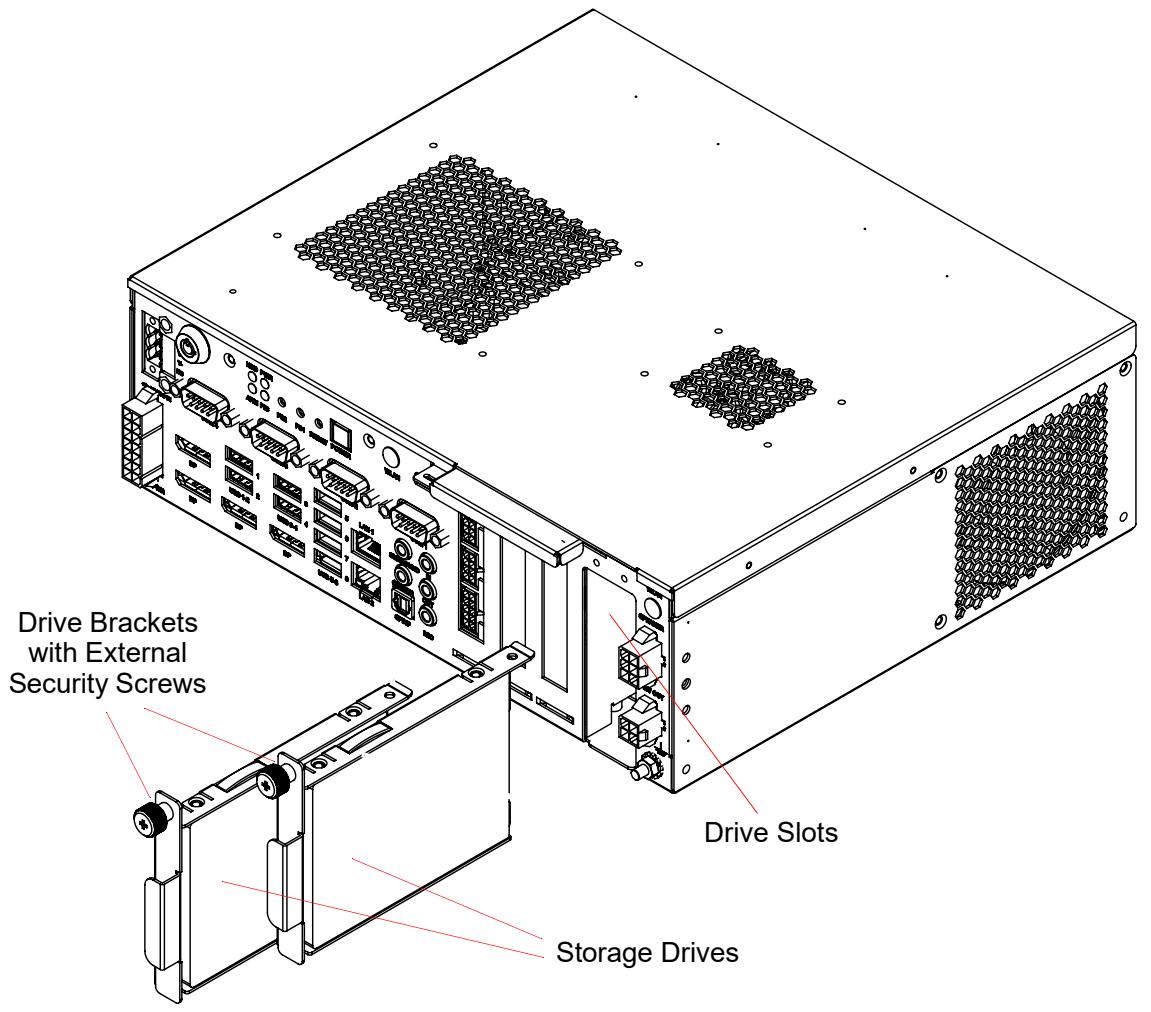
The storage drives are accessible from the rear I/O panel of the enclosure through the secure drive slots as shown in the following figure.

Figure 3-11: ADi-SA2X-CF with Storage Drives, Brackets, and Security Screws
![Drive Brackets with External Security Screws Drive Slots Storage Drives](.adi-sa2x-cf-50m-00023-1000-10/77b417f3050dc04314283b07680326662f8b959f111b114ce89fdc40d934cbc3.jpg)

# 3.8.3.2 Removal of Storage Drives

To remove the storage drives from the drive slots of the ADi-SA2X-CF, proceed as follows:

1. Shut down the system as described earlier in Section 3.7.
2. OPTIONAL Step: Depending on configuration, the drive slots may be fixed with an additional security screw inside the chassis. To get access to this screw, remove the top cover of the chassis by unlocking it and pulling it backwards to the rear panel.
3. Unfasten the external security screws at the top of the drive slots as shown in Figure 3-11.
4. Remove the storage drives with brackets from the drive slots.

# 3.8.3.3 Installation of Storage Drives

To install the drives into the drive slots of the ADi-SA2X-CF, proceed as follows:

1. Assemble the storage drives and brackets and install them into the secure drive slots as shown in Figure 3-11 ensuring that the drives are fully seated in their connectors.
2. Tighten the external security screws ensuring that the drive brackets are properly aligned with the slot openings.
3. OPTIONAL Step: Insert the security screw inside the chassis and tighten it firmly. Refit the top cover of the chassis and lock it.

# A Optional Boards and Accessories

This appendix defines the optional boards and accessories available for ADi-SA2X-CF platforms. The following bullets list the categories of optional devices and accessories described in this appendix.

▶ ADLINK motherboards
▶ ADLINK boards
▶ Graphics cards
▶ Power supplies
▶ Software utilities
▶ Storage devices
▶ Accessories

# A.1 ADLINK Motherboards

The following table lists the optional ADLINK motherboards available for the ADi-SA2X-CF.

Table A-1: ADLINK Motherboards

<table><tr><td>Model</td><td>Description</td></tr><tr><td>AmITX-CF-G-Q370</td><td>Mini-ITX with Intel processor (Coffee Lake, SEMA, 3x displays); w/ mini-PCIe / mSATA connector and M.2 connector</td></tr><tr><td>AmITX-CF-G-H110</td><td>Mini-ITX with Intel processor (Coffee Lake, SEMA, 2x displays); w/ mini-PCIe / mSATA connector and M.2 connector</td></tr></table>

# A.2 ADLINK Boards

The following table lists the optional ADLINK boards available for the ADi-SA2X-CF.

Table A-2: ADLINK Boards

<table><tr><td>Model</td><td>Description</td></tr><tr><td>ADi-BACC-G2</td><td>Gaming and Retail Extension I/O Board</td></tr><tr><td>ADi-BSEC</td><td>Intelligent Infotainment SECURITY &amp; NVRAM/SRAM PCI Express Card</td></tr><tr><td>ADi-BSDK</td><td>ADLINK Software Development Kit (buttons and light board)</td></tr><tr><td>ADi-BAMP</td><td>2x 12-15 W Audio Amplifier (Class D)</td></tr><tr><td>ADi-BAMP-G2</td><td>2.1 CH Class-D audio amplifier▶ 4 Ω and 8 Ω speaker support▶ 2 X 18 Watts for L or R Channel and 1x 20 Watts for woofer</td></tr></table>

# A.3 Graphics Cards

The following table lists the optional graphics cards available for the ADi-SA2X-CF.

Table A-3: Graphics Cards

<table><tr><td>Model</td><td>Description</td></tr><tr><td>nVIDIA Quadro P620</td><td>4x mDP, low-profile, PEG card, with cooler and fan</td></tr><tr><td>nVIDIA Quadro P1000</td><td>4x mDP, low-profile, PEG card, with cooler and fan</td></tr><tr><td>nVIDIA Quadro T1000</td><td>4x mDP, low-profile, PEG card, with cooler and fan</td></tr><tr><td>nVIDIA Quadro T600</td><td>4x mDP, low-profile, PEG card, with cooler and fan</td></tr></table>

# A.4 Power Supplies

The following table lists the optional power supplies available for the ADi-SA2X-CF.

Table A-4: Power Supplies

<table><tr><td>Model</td><td>Description</td></tr><tr><td>DC-in via 3-pin connector</td><td>a. via ADi-BDC1 to support +9–36 V DC wire range voltage supportb. 24V/7.5A AC/DC 180W adapter</td></tr><tr><td>DC-in via 14-pin ATX connector</td><td>a. support for standard ATX PSUb. support for 12 V DC in AC/DC adapter</td></tr><tr><td>AC-in</td><td>via ADi-SPSU (FSP250W)</td></tr><tr><td>ADi-BDC1</td><td>ADLINK +9–36 V DC / 150 W, wide-range, DC/DC converter board</td></tr><tr><td>AC/DC power adapter</td><td>External 24V/180W AC/DC adapter (on request)</td></tr><tr><td>ATX power supply unit</td><td>External ATX PSU or ADLINK AC/DC 120/180 W 12 V adapter (on request)</td></tr></table>

# A.5 Software Utilities

The following table lists the optional software utilities available for the ADi-SA2X-CF.

Table A-5: Software Utility Options

<table><tr><td>Model</td><td>Description</td></tr><tr><td>ADiAPI (Windows 32/64)</td><td>Intelligent infotainment service and utility (Windows 32- / 64-bit)</td></tr><tr><td>ADiAPI (Linux 64)</td><td>Intelligent infotainment service and utility (Linux 64 bit)</td></tr><tr><td>ADiDLL (Windows 32/64)</td><td>Infotainment driver layer, raw mode (Windows 32- / 64-bit)</td></tr><tr><td>ADiDLL (Linux 32/64)</td><td>Infotainment driver layer, raw mode (Linux 32- / 64-bit)</td></tr><tr><td>SEMA®</td><td>Smart System Management Agent</td></tr><tr><td>Windows</td><td>Microsoft operating system</td></tr><tr><td>Linux</td><td>Linux operating system Ubuntu</td></tr></table>

# A.6 Storage Devices

The following table lists the optional storage devices available for the ADi-SA2X-CF.

Table A-6: Storage Device Options

<table><tr><td>Model</td><td>Description</td></tr><tr><td>SSD</td><td>Solid State Drive</td></tr><tr><td>CFast Card</td><td>CFast memory card</td></tr><tr><td>SATA DOM</td><td>SATA Disk-on-Module</td></tr></table>

# A.7 Accessories

The following table lists the optional accessories available for the ADi-SA2X-CF.

Table A-7: Box Options

<table><tr><td>Model</td><td>Description</td></tr><tr><td>WLAN</td><td>Wireless Local Area Network connector (on request)</td></tr><tr><td>ADi-SGLI Cover</td><td>ADLINK cable and connector covers (on request)</td></tr><tr><td>ADi-BSEC Cable Kit</td><td>Cables to connect the ADi-BSEC to peripheral devices for engineering purposes (on request)</td></tr><tr><td>Box PC Cable Kit</td><td>Cables to connect the rear panel interfaces on the ADi-SA2X-CF to external devices (on request)</td></tr><tr><td>ADi-BACC-G2 Cable Kit</td><td>Cables to connect the ADi-BACC-G2 to peripheral devices for engineering purposes (on request)</td></tr><tr><td>ADi-BSDK Cable Kit</td><td>Special cables for the Board Software Development Kit (on request)</td></tr><tr><td rowspan="11">Miscellaneous</td><td>External fan filter pair (on request)</td></tr><tr><td>PC enclosure color coating (on request)</td></tr><tr><td>L- type mounting bracket pair (on request)</td></tr><tr><td>Z-type mounting bracket pair for use with ADi-SPSU (on request)</td></tr><tr><td>VESA mounting bracket (on request)</td></tr><tr><td>External mating power connector (on request)</td></tr><tr><td>ADLINK power adapter cable (24-pin ATX to 14-pin power input)</td></tr><tr><td>mDP-to-DP active adapter for low-profile PEG card</td></tr><tr><td>mDP-to-DVI-I active adapter for low-profile PEG card</td></tr><tr><td>mDP-to-HDMI active adapter for low-profile PEG card</td></tr><tr><td>mDP-to-VGA active adapter for low-profile PEG card</td></tr></table>

This page is intentionally left blank.

# B Getting Service

Ask an Expert: http://askanexpert.adlinktech.com

ADLINK Technology, Inc.

9F, No.166 Jian Yi Road, Zhonghe District

New Taipei City 235, Taiwan

Tel: +886-2-8226-5877

Fax: +886-2-8226-5717

E-mail: service@adlinktech.com

Ampro ADLINK Technology, Inc.

5215 Hellyer Avenue, #110

San Jose, CA 95138, USA

Tel: +1-408-360-0200

Toll Free:+1-800-966-5200 (USA only)

Fax: +1-408-360-0222

E-mail: info@adlinktech.com

ADLINK Technology (China) Co., Ltd.

300 Fang Chun Rd., Zhangjiang Hi-Tech Park

Pudong New Area, Shanghai, 201203 China

Tel: +86-21-5132-8988

Fax: +86-21-5132-3588

E-mail: market@adlinktech.com

ADLINK Technology GmbH

Hans-Thoma-Straße 11

D-68163 Mannheim, Germany

Tel: +49-621-43214-0

Fax: +49-621 43214-30

E-mail: emea@adlinktech.com

Please visit the Contact page at www.adlinktech.com for information on how to contact the nearest ADLINK regional office.

This page is intentionally left blank.
[🔗 Link to the original document](.adi-sa2x-cf-50m-00023-1000-10/adi-sa2x-cf-50m-00023-1000-10.pdf)