# APS Function Library

# Vesion：2.1

Build Date： 6.28.2022

www.adlinktech.com

# Support Products：

DPAC-1000 DPAC-3000

PCI-8392(H)

PCI-8253/56

PCI-8144

AMP-104C

PCI(e)-7856

MNET-4XMO MNET-4XMO-(C)

MNET-1XMO

HSL-4XMO HSL-DIO

PCI-8102/PCI-C154(+)

PCI-8154/8158 PCIe-8154/8158

EMX-100

PCI-8254/58 / AMP-204/8C

PCIe-833x

ECAT-4XMO/ECAT-4XMO-MT ECAT-TRG4/ECAT-TRG4-MT

AMP-304C

PCIe-8364RS

# Contents

# SUPPORT PRODUCTS： .............

# CONTENTS ....... .... 3

# INTRODUCTION . .. ..20

# 1. PROGRAMMING LIBRARY ........ ...23

# 2. LIST OF ALL FUNCTIONS .... ..24

LIST OF ALL FUNCTIONS FOR DPAC-1000 .. .. .... 24

LIST OF ALL FUNCTIONS FOR DPAC-3000 . . 26

LIST OF ALL FUNCTIONS FOR PCI-8392(H) . . 29

LIST OF ALL FUNCTIONS FOR PCI-8253/56...... .... 34

LIST OF ALL FUNCTIONS FOR PCI-8144 . . 40

LIST OF ALL FUNCTIONS FOR AMP-104C ..... ...... 42

LIST OF ALL FUNCTIONS FOR PCI(E)-7856 . .. 45

LIST OF ALL FUNCTIONS FOR MNET-4XMO . . 48

LIST OF ALL FUNCTIONS FOR MNET-4XMO-C ..... .... 52

LIST OF ALL FUNCTIONS FOR MNET-1XMO . . 57

LIST OF ALL FUNCTIONS FOR HSL-4XMO . . 60

LIST OF ALL FUNCTIONS FOR HSL-DIO ..... ...... 63

LIST OF ALL FUNCTIONS FOR PCI-8102 / PCI-C154(+) .. .... 64

LIST OF ALL FUNCTIONS FOR PCI-8154/8158... ...... 69

LIST OF ALL FUNCTIONS FOR PCIE-8154/8158 .. ..... 74

LIST OF ALL FUNCTIONS FOR EMX-100 . .. 78

LIST OF ALL FUNCTIONS FOR PCI-8254/58 / AMP-204/8C . ..... 81

LIST OF ALL FUNCTIONS FOR PCIE-833X .. . 92

LIST OF ALL FUNCTIONS FOR ECAT-4XMO / ECAT-4XMO-MT.. . 102

LIST OF ALL FUNCTIONS FOR ECAT-TRG4 / ECAT-TRG4-MT..... ..... 105

LIST OF ALL FUNCTIONS FOR AMP-304C . . 107

LIST OF ALL FUNCTIONS FOR PCIE-8364RS..... ..... 112

# 3. SYSTEM AND INITIALIZATION... ..121

APS\_INITIAL ....... ..... 121

APS\_CLOSE.. .. 126

APS\_VERSION....... ..... 127

APS\_DEVICE\_DRIVER\_VERSION... . 128

APS\_GET\_AXIS\_INFO.. . 129

APS\_GET\_CARD\_NAME.. . 132

APS\_DISABLE\_DEVICE ..... ..... 133

APS\_SET\_BOARD\_PARAM . .. 134

APS\_GET\_BOARD\_PARAM....... ..... 135

APS\_SET\_AXIS\_PARAM... .. 136

APS\_GET\_AXIS\_PARAM ... . 137

APS\_SET\_AXIS\_PARAM\_F...... ..... 138

APS\_GET\_AXIS\_PARAM\_F .... .. 139

APS\_GET\_SYSTEM\_TIMER ......... ..... 140

APS\_GET\_DEVICE\_INFO ....... ..... 141

APS\_GET\_FIRST\_AXISID ......... ..... 142

APS\_SAVE\_PARAMETER\_TO\_FLASH..... ..... 143

APS\_LOAD\_PARAMETER\_FROM\_FLASH... .. 144

APS\_LOAD\_PARAMETER\_FROM\_DEFAULT ......... ..... 145

APS\_SET\_SECURITY\_KEY ...... ..... 146

APS\_CHECK\_SECURITY\_KEY .... .. 147

APS\_RESET\_SECURITY\_KEY ...... ..... 149

APS\_SAVE\_PARAM\_TO\_FILE....... ..... 150

APS\_LOAD\_PARAM\_FROM\_FILE ...... ..... 152

APS\_REGISTER\_EMX...... .... 154

APS\_GET\_DEVICEIP.. .. 155

APS\_RESET\_EMX\_ALARM........ ..... 156

APS\_GET\_CURR\_SYS\_CTRL\_MODE...... .... 157

APS\_GET\_MSG\_SIZE . .. 158

APS\_GET\_MSG\_DATA....... ..... 159

APS\_LOAD\_CONFIG\_FROM\_FILE...... ..... 161

# 4. SSCNET FUNCTION . ...163

APS\_START\_SSCNET ...... ..... 163

APS\_STOP\_SSCNET....... ..... 165

APS\_GET\_SSCNET\_SERVO\_PARAM....... .... 167

APS\_SET\_SSCNET\_SERVO\_PARAM .......... ..... 169

APS\_GET\_SSCNET\_SERVO\_ALARM ...... .... 171

APS\_RESET\_SSCNET\_SERVO\_ALARM . .. 173

APS\_SAVE\_SSCNET\_SERVO\_PARAM ........ ..... 174

APS\_GET\_SSCNET\_SERVO\_ABS\_POSITION . . 175

APS\_SAVE\_SSCNET\_SERVO\_ABS\_POSITION......... .... 177

APS\_LOAD\_SSCNET\_SERVO\_ABS\_POSITION...... ..... 179

APS\_GET\_SSCNET\_LINK\_STATUS ... .. 181

APS\_SET\_SSCNET\_SERVO\_MONITOR\_SRC ....... ..... 183

APS\_GET\_SSCNET\_SERVO\_MONITOR\_SRC.. .. 185

APS\_GET\_SSCNET\_SERVO\_MONITOR\_DATA .......... ..... 187

# 5. MOTION IO AND MOTION STATUS...... ....189

APS\_MOTION\_STATUS....... ..... 189

APS\_MOTION\_STATUS\_ASYNC .. . 191

APS\_MOTION\_IO\_STATUS ... . 192

APS\_MOTION\_IO\_STATUS\_ASYNC ........ ..... 193

APS\_SET\_SERVO\_ON... .. 194

APS\_GET\_POSITION .. .. 195

APS\_SET\_POSITION... .. 196

APS\_GET\_COMMAND.. . 197

APS\_SET\_COMMAND . .. 198

APS\_GET\_COMMAND\_VELOCITY... .. 199

APS\_GET\_FEEDBACK\_VELOCITY ... .. 200

APS\_GET\_ERROR\_POSITION... .. 201

APS\_GET\_TARGET\_POSITION ... .. 202

APS\_GET\_POSITION\_F ... .. 203

APS\_GET\_POSITION\_F\_ASYNC .. .. 204

APS\_SET\_POSITION\_F... .. 205

APS\_GET\_COMMAND\_F .. .. 206

APS\_GET\_COMMAND\_F\_ASYNC.. .. 207

APS\_SET\_COMMAND\_F ... .. 208

APS\_GET\_TARGET\_POSITION\_F..... .. 209

APS\_GET\_ERROR\_POSITION\_F .. .. 210

APS\_GET\_COMMAND\_VELOCITY\_F ... .. 211

APS\_GET\_FEEDBACK\_VELOCITY\_F... .. 212

APS\_GET\_MQ\_FREE\_SPACE.. . 213

APS\_GET\_MQ\_USAGE .. .. 214

APS\_GET\_STOP\_CODE.. .. 215

APS\_GET\_ENCODER ... . 217

APS\_GET\_COMMAND\_COUNTER .. .. 218

APS\_RESET\_COMMAND\_COUNTER ... . 219

APS\_GET\_LAST\_ERROR... . 220

APS\_GET\_AXIS\_LATCH\_DATA.. . 222

# 6. SINGLE AXIS MOTION..... .223

APS\_RELATIVE\_MOVE.. . 223

APS\_ABSOLUTE\_MOVE . . 225

APS\_VELOCITY\_MOVE ..... .... 227

APS\_HOME\_MOVE.... .. 229

APS\_STOP\_MOVE ..... ..... 244

APS\_EMG\_STOP ... .. 245

APS\_RELATIVE\_MOVE2.. .. 246

APS\_ABSOLUTE\_MOVE2 ... ..... 247

APS\_HOME\_MOVE2 . .. 248

APS\_SPEED\_OVERRIDE...... .... 249

APS\_RELATIVE\_MOVE\_OVRD ....... ..... 250

APS\_ABSOLUTE\_MOVE\_OVRD........ .... 252

APS\_HOME\_ESCAPE ..... .... 254

# 7. MULTI-AXES MOVE TRIGGER & STOP......... ...256

APS\_MOVE\_TRIGGER........ ..... 256

APS\_STOP\_MOVE\_MULTI....... ..... 258

APS\_EMG\_STOP\_MULTI......... ..... 260

# 8. JOG MOVE ..... ..262

APS\_SET\_JOG\_PARAM....... ..... 262

APS\_GET\_JOG\_PARAM ....... ..... 264

APS\_JOG\_MODE\_SWITCH .......... ..... 266

APS\_JOG\_START...... ..... 267

# 9. INTERPOLATION..... ..270

APS\_ABSOLUTE\_LINEAR\_MOVE ...... ..... 270

APS\_RELATIVE\_LINEAR\_MOVE .. . 273

APS\_ABSOLUTE\_ARC\_MOVE ........ ..... 275

APS\_RELATIVE\_ARC\_MOVE ..... ..... 278

APS\_ABSOLUTE\_ARC\_MOVE\_3PE.. .. 281

APS\_RELATIVE\_ARC\_MOVE\_3PE ...... .... 283

APS\_ABSOLUTE\_HELIX\_MOVE .. .. 285

APS\_RELATIVE\_HELIX\_MOVE ........ .... 288

APS\_ABSOLUTE\_HELICAL\_MOVE..... .... 291

APS\_RELATIVE\_HELICAL\_MOVE .. .. 293

# 10. ADVANCED SINGLE MOVE & INTERPOLATION... ..295

APS\_PTP ......... .... 295

APS\_PTP\_V ...... .... 298

APS\_PTP\_ALL.. . 302

APS\_VEL ........ .... 306

APS\_VEL\_ALL..... .... 309

APS\_LINE . .. 312

APS\_LINE\_V ...... ..... 316

APS\_LINE\_ALL.. .. 320

APS\_ARC2\_CA .. . 324

APS\_ARC2\_CA\_V ....... .... 328

APS\_ARC2\_CA\_ALL. .. 332

APS\_ARC2\_CE.. .. 336

APS\_ARC2\_CE\_V...... ..... 340

APS\_ARC2\_CE\_ALL ... .. 344

APS\_ARC3\_CA ....... ..... 348

APS\_ARC3\_CA\_V ..... .. 351

APS\_ARC3\_CA\_ALL. .. 354

APS\_ARC3\_CE...... .... 357

APS\_ARC3\_CE\_V.... .. 360

APS\_ARC3\_CE\_ALL ...... ..... 363

APS\_SPIRAL\_CA... .. 366

APS\_SPIRAL\_CA\_V......... .... 369

APS\_SPIRAL\_CA\_ALL ..... ..... 372

APS\_SPIRAL\_CE ... .. 375

APS\_SPIRAL\_CE\_V .......... .... 380

APS\_SPIRAL\_CE\_ALL ...... ..... 385

# 11. INTERRUPT....... ....390

APS\_INT\_ENABLE..... ..... 390

APS\_SET\_INT\_FACTOR.. .. 392

APS\_GET\_INT\_FACTOR ......... ..... 395

APS\_WAIT\_SINGLE\_INT ...... ..... 396

APS\_WAIT\_MULTIPLE\_INT........ .... 398

APS\_WAIT\_ERROR\_INT...... ..... 400

APS\_RESET\_INT........ ...... 402

APS\_SET\_INT ...... ..... 404

APS\_SET\_INT\_FACTORH .. .. 406

APS\_INT\_NO\_TO\_HANDLE ....... ...... 408

APS\_REGISTER\_INT\_CALLBACK .. .. 410

APS\_SET\_FIELD\_BUS\_INT\_FACTOR\_MOTION .......... ...... 413

APS\_GET\_FIELD\_BUS\_INT\_FACTOR\_MOTION....... ...... 415

APS\_SET\_FIELD\_BUS\_INT\_FACTOR\_ERROR... .. 416

APS\_GET\_FIELD\_BUS\_INT\_FACTOR\_ERROR ....... ...... 418

APS\_RESET\_FIELD\_BUS\_INT\_MOTION . .. 419

APS\_WAIT\_FIELD\_BUS\_ERROR\_INT\_MOTION ... .. 421

APS\_SET\_FIELD\_BUS\_INT\_FACTOR\_DI.. .. 423

APS\_GET\_FIELD\_BUS\_INT\_FACTOR\_DI . . 425

# 12. SAMPLING...... .....426

APS\_SET\_SAMPLING\_PARAM... .. 426

APS\_GET\_SAMPLING\_PARAM ... .. 427

APS\_WAIT\_TRIGGER\_SAMPLING... .. 428

APS\_WAIT\_TRIGGER\_SAMPLING\_ASYNC .. ... 430

APS\_GET\_SAMPLING\_COUNT... .. 432

APS\_STOP\_WAIT\_SAMPLING . .. 433

APS\_AUTO\_SAMPLING.. .. 434

APS\_GET\_SAMPLING\_DATA.. .. 436

APS\_SET\_SAMPLING\_PARAM\_EX... ... 438

APS\_GET\_SAMPLING\_PARAM\_EX .. .. 441

APS\_WAIT\_TRIGGER\_SAMPLING\_EX.. .. 442

APS\_WAIT\_TRIGGER\_SAMPLING\_ASYNC\_EX .. .. 444

APS\_GET\_SAMPLING\_DATA\_EX... .. 446

APS\_SET\_SAMPLING\_PARAM\_ADVANCED . . 449

APS\_GET\_SAMPLING\_PARAM\_ ADVANCED... ... 452

APS\_WAIT\_TRIGGER\_SAMPLING\_ADVANCED .. .. 453

APS\_WAIT\_TRIGGER\_SAMPLING\_ASYNC\_ADVANCED.. .. 455

APS\_GET\_SAMPLING\_DATA\_ADVANCED .. .. 458

# 13. DIO & AIO ...... ...461

APS\_SET\_FIELD\_BUS\_D\_CHANNEL\_OUTPUT.. .. 461

APS\_GET\_FIELD\_BUS\_D\_CHANNEL\_OUTPUT ... ... 463

APS\_GET\_FIELD\_BUS\_D\_CHANNEL\_INPUT ... .. 465

APS\_SET\_FIELD\_BUS\_D\_PORT\_OUTPUT .. .. 467

APS\_GET\_FIELD\_BUS\_D\_PORT\_INPUT... ... 469

APS\_GET\_FIELD\_BUS\_D\_PORT\_OUTPUT.. .. 471

APS\_WRITE\_D\_OUTPUT... .. 473

APS\_READ\_D\_OUTPUT ... .. 475

APS\_READ\_D\_INPUT... .. 477

APS\_WRITE\_D\_CHANNEL\_OUTPUT ... ... 479

APS\_READ\_D\_CHANNEL\_OUTPUT... .. 481

APS\_READ\_D\_CHANNEL\_INPUT .. .. 483

APS\_READ\_A\_INPUT\_VALUE.. .. 485

APS\_READ\_A\_INPUT\_DATA.. . 487

APS\_WRITE\_A\_OUTPUT\_VALUE .. .. 488

APS\_WRITE\_A\_OUTPUT\_DATA.. .. 490

# 14. POINT TABLE MOTION ...492

APS\_SET\_POINT\_TABLE ... .. 492

APS\_GET\_POINT\_TABLE... ... 495

APS\_SET\_POINT\_TABLE\_EX .. .. 497

APS\_GET\_POINT\_TABLE\_EX.. .. 500

APS\_POINT\_TABLE\_MOVE.. .. 503

APS\_GET\_RUNNING\_POINT\_INDEX ... .. 506

APS\_GET\_START\_POINT\_INDEX... .. 508

APS\_GET\_END\_POINT\_INDEX ... .. 510

APS\_SET\_TABLE\_MOVE\_PAUSE.. .. 512

APS\_SET\_TABLE\_MOVE\_EX\_PAUSE.. .. 514

APS\_SET\_TABLE\_MOVE\_EX\_ROLLBACK.. .. 516

APS\_SET\_TABLE\_MOVE\_EX\_RESUME .. .. 518

APS\_SET\_TABLE\_MOVE\_REPEAT .. . 520

APS\_SET\_POINT\_TABLE\_MODE2 .. .. 522

APS\_SET\_POINT\_TABLE2 . . 524

APS\_POINT\_TABLE\_CONTINUOUS\_MOVE2.. . 527

APS\_POINT\_TABLE\_SINGLE\_MOVE2.. .. 529

APS\_GET\_RUNNING\_POINT\_INDEX2 . .. 531

APS\_POINT\_TABLE\_STATUS2. .. 532

APS\_SET\_POINT\_TABLE3 . .. 534

APS\_POINT\_TABLE\_MOVE3.. .. 537

APS\_SET\_POINT\_TABLE\_PARAM3.. .. 539

APS\_SET\_FEEDER\_GROUP ...... .... 541

APS\_GET\_FEEDER\_GROUP... .. 543

APS\_FREE\_FEEDER\_GROUP . .. 544

APS\_RESET\_FEEDER\_BUFFER . .. 545

APS\_SET\_FEEDER\_POINT\_2D . . 546

APS\_SET\_FEEDER\_POINT\_2D\_EX .. . 548

APS\_START\_FEEDER\_MOVE .. .. 550

APS\_GET\_FEEDER\_STATUS . . 551

APS\_GET\_FEEDER\_RUNNING\_INDEX .. .. 553

APS\_GET\_FEEDER\_FEED\_INDEX... .. 554

APS\_SET\_FEEDER\_EX\_PAUSE .. .. 555

APS\_SET\_FEEDER\_EX\_ROLLBACK .. .. 556

APS\_SET\_FEEDER\_EX\_RESUME . . 558

# 15. ADVANCED POINT TABLE ...... ..559

APS\_PT\_ENABLE..... .... 559

APS\_PT\_DISABLE ....... .... 562

APS\_GET\_PT\_INFO .. .. 563

APS\_PT\_SET\_VS ... .. 565

APS\_PT\_GET\_VS ....... .... 567

APS\_PT\_START... .. 568

APS\_PT\_STOP ... .. 569

APS\_GET\_PT\_STATUS....... .... 570

APS\_RESET\_PT\_BUFFER .. . 572

APS\_PT\_ROLL\_BACK ........ .... 574

APS\_PT\_GET\_ERROR... .. 576

APS\_PT\_DWELL. .. 578

APS\_PT\_LINE ....... .... 580

APS\_PT\_ARC2\_CA ...... .... 582

APS\_PT\_ARC2\_CE ... . 584

APS\_PT\_ARC3\_CA ........ .... 587

APS\_PT\_ARC3\_CE ...... .... 590

APS\_PT\_SPIRAL\_CA........ .... 592

APS\_PT\_SPIRAL\_CE...... .... 594

APS\_PT\_EXT\_SET\_DO\_CH.. .. 596

APS\_PT\_EXT\_SET\_TABLE\_NO ....... .... 598

APS\_PT\_SET\_ABSOLUTE... .. 600

APS\_PT\_SET\_RELATIVE . .. 601

APS\_PT\_SET\_TRANS\_BUFFERED ......... ..... 602

APS\_PT\_SET\_TRANS\_INP . .. 603

APS\_PT\_SET\_TRANS\_BLEND\_DEC...... ..... 604

APS\_PT\_SET\_TRANS\_BLEND\_DIST .. .. 606

APS\_PT\_SET\_TRANS\_BLEND\_PCNT ........ ..... 608

APS\_PT\_SET\_ACC ... .. 610

APS\_PT\_SET\_DEC .. .. 612

APS\_PT\_SET\_ACC\_DEC...... ..... 614

APS\_PT\_SET\_S... .. 616

APS\_PT\_SET\_VM....... ..... 618

APS\_PT\_SET\_VE ... .. 620

# 16. FIELD BUS FUNCTIONS..... ..622

APS\_SET\_FIELD\_BUS\_PARAM ....... ..... 622

APS\_GET\_FIELD\_BUS\_PARAM... .. 623

APS\_SCAN\_FIELD\_BUS..... ..... 624

APS\_START\_FIELD\_BUS.... .. 626

APS\_STOP\_FIELD\_BUS .. .. 629

APS\_FIELD\_BUS\_D\_SET\_OUTPUT ....... ..... 631

APS\_FIELD\_BUS\_D\_GET\_OUTPUT... .. 633

APS\_FIELD\_BUS\_D\_GET\_INPUT........ ..... 635

APS\_FIELD\_BUS\_D\_SET\_OUTPUT\_EX ...... .... 637

APS\_FIELD\_BUS\_D\_GET\_OUTPUT\_EX........ ..... 639

APS\_FIELD\_BUS\_D\_GET\_INPUT\_EX ...... ..... 641

APS\_SET\_FIELD\_BUS\_SLAVE\_PARAM .... .. 643

APS\_GET\_FIELD\_BUS\_SLAVE\_PARAM ........ ..... 645

APS\_SET\_FIELD\_BUS\_A\_OUTPUT ....... ..... 647

APS\_GET\_FIELD\_BUS\_A\_OUTPUT... .. 649

APS\_GET\_FIELD\_BUS\_A\_INPUT....... ..... 651

APS\_GET\_SLAVE\_CONNECT\_QUALITY ....... ..... 653

APS\_GET\_SLAVE\_ONLINE\_STATUS ........ ..... 655

APS\_GET\_FIELD\_BUS\_MASTER\_STATUS ....... ..... 658

APS\_GET\_FIELD\_BUS\_LAST\_SCAN\_INFO ... .. 660

APS\_GET\_FIELD\_BUS\_MASTER\_TYPE....... ..... 662

APS\_GET\_FIELD\_BUS\_SLAVE\_TYPE ...... ..... 663

APS\_GET\_FIELD\_BUS\_SLAVE\_NAME... .. 665

APS\_GET\_FIELD\_BUS\_SLAVE\_FIRST\_AXISNO....... .... 667

APS\_GET\_FIELD\_BUS\_DEVICE\_INFO....... ..... 669

APS\_GET\_FIELD\_BUS\_MODULE\_INFO... .. 671

APS\_RESET\_FIELD\_BUS\_ALARM ....... ..... 673

APS\_GET\_FIELD\_BUS\_ALARM ... ... 674

APS\_GET\_FIELD\_BUS\_PDO... .. 675

APS\_SET\_FIELD\_BUS\_PDO ...... ..... 677

APS\_GET\_FIELD\_BUS\_PDO\_OFFSET ... ... 679

APS\_GET\_FIELD\_BUS\_SDO ...... ..... 681

APS\_SET\_FIELD\_BUS\_SDO...... ..... 683

APS\_SET\_FIELD\_BUS\_OD\_DATA... .. 685

APS\_GET\_FIELD\_BUS\_OD\_DATA ....... ..... 687

APS\_GET\_FIELD\_BUS\_OD\_MODULE\_INFO... .. 689

APS\_GET\_FIELD\_BUS\_MODULE\_MAP........ ..... 691

APS\_SET\_FIELD\_BUS\_MODULE\_MAP ...... ..... 694

APS\_GET\_FIELD\_BUS\_SLAVE\_STATE.. .. 696

APS\_SET\_FIELD\_BUS\_SLAVE\_STATE .. 698

APS\_GET\_FIELD\_BUS\_ESC\_REGISTER . .. 700

APS\_SET\_FIELD\_BUS\_ESC\_REGISTER.. ... 702

APS\_GET\_SYSTEM\_LOADING... .. 704

APS\_GET\_FIELD\_BUS\_ANALYSIS\_TOPOLOGY .. .. 705

APS\_GET\_FIELD\_BUS\_LOSS\_PACKAGE .. .. 707

APS\_SET\_DRIVE\_INPUT\_MAPPING... .. 709

APS\_SET\_TRIGGER\_OUTPUT\_MAPPING... ... 710

# 17. GEAR / GANTRY FUNCTIONS ....... ...711

APS\_SET\_GANTRY\_PARAM ... .. 711

APS\_GET\_GANTRY\_PARAM .. .. 712

APS\_SET\_GANTRY\_AXIS ... .. 713

APS\_GET\_GANTRY\_AXIS .. ... 715

APS\_GET\_GANTRY\_ERROR . .. 717

APS\_GET\_ENCODER ... .. 718

APS\_GET\_LATCH\_EVENT ... .. 719

APS\_GET\_LATCH\_COUNTER.. .. 720

APS\_START\_GEAR.. .. 722

APS\_GET\_GEAR\_STATUS ... ... 723

APS\_GET\_GANTRY\_NUMBER .. .. 724

APS\_GET\_GANTRY\_INFO... .. 725

APS\_GET\_GANTRY\_DEVIATION... .. 726

# 18. COMPARE TRIGGER.... .727

APS\_SET\_TRIGGER\_PARAM .. .. 727

APS\_GET\_TRIGGER\_PARAM.. .. 729

APS\_SET\_TRIGGER\_LINEAR... .. 731

APS\_SET\_TRIGGER\_TABLE . .. 733

APS\_SET\_TRIGGER\_MANUAL ... ... 735

APS\_SET\_TRIGGER\_MANUAL\_S... .. 736

APS\_GET\_TRIGGER\_TABLE\_CMP... .. 737

APS\_GET\_TRIGGER\_LINEAR\_CMP .. ... 738

APS\_GET\_TRIGGER\_COUNT .. .. 739

APS\_RESET\_TRIGGER\_COUNT ... .. 740

APS\_ENABLE\_TRIGGER\_FIFO\_CMP.. .. 741

APS\_GET\_TRIGGER\_FIFO\_CMP... .. 743

APS\_GET\_TRIGGER\_FIFO\_STATUS.. .. 744

APS\_SET\_TRIGGER\_FIFO\_DATA ....... ..... 745

APS\_START\_TIMER.... ... 747

APS\_GET\_TIMER\_COUNTER...... ..... 748

APS\_SET\_TIMER\_COUNTER .. ... 750

APS\_START\_TRIGGER\_TIMER ... .. 752

APS\_GET\_TRIGGER\_TIMER\_COUNTER....... .... 753

APS\_SET\_MULTI\_TRIGGER\_TABLE... ... 754

APS\_GET\_MULTI\_TRIGGER\_TABLE\_CMP ........ ..... 762

APS\_SET\_TRIGGER\_TABLE\_DATA ...... ..... 765

APS\_GET\_TRIGGER\_TABLE\_STATUS....... ..... 766

APS\_GET\_TRIGGER\_CMP\_VALUE ...... .... 767

APS\_ENABLE\_TRIGGER\_TABLE... ... 768

APS\_RESET\_TRIGGER\_TABLE........ ..... 769

APS\_SET\_TRIGGER\_TABLE\_DATA\_EX...... ..... 770

APS\_GET\_TRIGGER\_TABLE\_REMAIN\_COUNT... ... 772

APS\_GET\_TRIGGER\_LINEAR\_REMAIN\_COUNT ...... .... 773

APS\_SET\_TRIGGER\_ENCODER\_COUNTER...... ..... 774

APS\_GET\_TRIGGER\_ENCODER\_COUNTER ....... ..... 775

# 19. PROGRAM DOWNLOAD . ...777

APS\_LOAD\_VMC\_PROGRAM......... .... 777

APS\_SAVE\_VMC\_PROGRAM ......... .... 778

APS\_SET\_TASK\_MODE.. .. 779

APS\_GET\_TASK\_MODE ....... ..... 780

APS\_START\_TASK ..... ..... 782

APS\_GET\_TASK\_INFO . .. 784

APS\_GET\_TASK\_MSG ....... ..... 786

# 20. MANUAL PULSE GENERATOR FUNCTIONS........... .... .......788

APS\_MANUAL\_PULSER\_START ....... ..... 788

APS\_MANUAL\_PULSER\_VELOCITY\_MOVE .. .. 791

APS\_MANUAL\_PULSER\_RELATIVE\_MOVE ...... ..... 793

APS\_MANUAL\_PULSER\_HOME\_MOVE ..... .... 795

APS\_GET\_PULSER\_COUNTER ........ ..... 796

APS\_SET\_PULSER\_COUNTER ....... ..... 797

# 21. PITCH ERROR COMPENSATION FUNCTIONS ........... ..............798

APS\_SET\_PITCH\_TABLE........ ..... 798

APS\_GET\_PITCH\_TABLE ....... .... 804

APS\_START\_PITCH\_COMP . . 805

# 22. DPAC SYSTEM FUNCTIONS..... .....806

APS\_RESCAN\_CF.... ..... 806

APS\_GET\_BATTERY\_STATUS........ .... 807

APS\_GET\_DISPLAY\_DATA .. .. 808

APS\_SET\_DISPLAY\_DATA... . 809

APS\_GET\_BUTTON\_STATUS ........ ..... 810

# 23. NON-VOLATILE RAM . .... ..812

APS\_SET\_NV\_RAM ........ ..... 812

APS\_GET\_NV\_RAM.. . 814

APS\_CLEAR\_NV\_RAM... .. 816

# 24. FIELD BUS COMPARE TRIGGER ... ..817

APS\_SET\_FIELD\_BUS\_TRIGGER\_PARAM ......... ..... 817

APS\_GET\_FIELD\_BUS\_TRIGGER\_PARAM... .. 819

APS\_SET\_FIELD\_BUS\_TRIGGER\_LINEAR.. . 821

APS\_SET\_FIELD\_BUS\_TRIGGER\_TABLE....... ..... 824

APS\_SET\_FIELD\_BUS\_TRIGGER\_MANUAL . .. 827

APS\_SET\_FIELD\_BUS\_TRIGGER\_MANUAL\_S.. . 829

APS\_GET\_FIELD\_BUS\_TRIGGER\_TABLE\_CMP . .. 831

APS\_GET\_FIELD\_BUS\_TRIGGER\_LINEAR\_CMP .. .. 833

APS\_GET\_FIELD\_BUS\_TRIGGER\_COUNT......... ..... 835

APS\_RESET\_FIELD\_BUS\_TRIGGER\_COUNT . .. 837

APS\_GET\_FIELD\_BUS\_LINEAR\_CMP\_REMAIN\_COUNT . .. 839

APS\_GET\_FIELD\_BUS\_TABLE\_CMP\_REMAIN\_COUNT........... ..... 841

APS\_GET\_FIELD\_BUS\_ENCODER .. . 843

APS\_SET\_FIELD\_BUS\_ENCODER... . 845

APS\_GET\_FIELD\_BUS\_TIMER\_COUNTER........ ..... 847

APS\_SET\_FIELD\_BUS\_TIMER\_COUNTER .. . 848

APS\_SET\_FIELD\_BUS\_MULTI\_TRIGGER\_TABLE ........ .... 849

APS\_GET\_FIELD\_BUS\_MULTI\_TRIGGER\_TABLE\_CMP... .. 853

APS\_GET\_FIELD\_BUS\_MULTI\_TABLE\_CMP\_REMAIN\_COUNT . .. 855

# 25. FIELD BUS POSITION LATCH FUNCTIONS .. ...856

APS\_GET\_FIELD\_BUS\_LTC\_FIFO\_POINT ... .. 859

APS\_SET\_FIELD\_BUS\_LTC\_FIFO\_PARAM .. .. 861

APS\_GET\_FIELD\_BUS\_LTC\_FIFO\_PARAM... . 862

APS\_RESET\_FIELD\_BUS\_LTC\_FIFO... .. 863

APS\_GET\_FIELD\_BUS\_LTC\_FIFO\_USAGE . .. 864

APS\_GET\_FIELD\_BUS\_LTC\_FIFO\_FREE\_SPACE.. .. 865

APS\_GET\_FIELD\_BUS\_LTC\_FIFO\_STATUS . .. 866

# 26. WATCH DOG TIMER ...... ...868

APS\_WDT\_START.. .. 868

APS\_WDT\_GET\_TIMEOUT\_PERIOD... .. 869

APS\_WDT\_RESET\_COUNTER . .. 870

APS\_WDT\_GET\_COUNTER... .. 871

APS\_WDT\_SET\_ACTION\_EVENT... .. 872

APS\_WDT\_GET\_ACTION\_EVENT ... .. 874

# 27. VAO/PWM FUNCTIONS ( LASER FUNCTION )..... ...876

APS\_SET\_VAO\_PARAM... .. 876

APS\_GET\_VAO\_PARAM ... .. 877

APS\_SET\_VAO\_TABLE.. .. 878

APS\_SET\_VAO\_PARAM\_EX.. . 881

APS\_GET\_VAO\_PARAM\_EX .. .. 886

APS\_SWITCH\_VAO\_TABLE .. .. 888

APS\_START\_VAO ... .. 890

APS\_GET\_VAO\_STATUS ... .. 892

APS\_CHECK\_VAO\_PARAM.. . 894

APS\_SET\_PWM\_ON ... .. 896

APS\_SET\_PWM\_WIDTH ... .. 898

APS\_SET\_PWM\_FREQUENCY.. . 900

APS\_GET\_PWM\_WIDTH.... .. 902

APS\_GET\_PWM\_FREQUENCY ... . 904

# 28. CIRCULAR LIMIT FUNCTIONS ..... ..906

APS\_SET\_CIRCULAR\_LIMIT ... .. 906

APS\_GET\_CIRCULAR\_LIMIT..... .... 908

# 29. SIMULTANEOUS MOVE FUNCTIONS ... ..909

APS\_SET\_ABSOLUTE\_SIMULTANEOUS\_MOVE.. .. 909

APS\_SET\_RELATIVE\_SIMULTANEOUS\_MOVE . . 911

APS\_START\_SIMULTANEOUS\_MOVE.. .. 913

APS\_STOP\_SIMULTANEOUS\_MOVE ... .. 915

# 30. SINGLE LATCH FUNCTIONS ... ..917

APS\_MANUAL\_LATCH2.. .. 917

APS\_GET\_LATCH\_DATA2 . . 918

# 31. MULTI-LATCH FUNCTIONS....... .....920

APS\_SET\_LTC\_COUNTER ...... .... 920

APS\_GET\_LTC\_COUNTER....... .... 921

APS\_SET\_LTC\_FIFO\_PARAM . . 922

APS\_GET\_LTC\_FIFO\_PARAM.. . 924

APS\_MANUAL\_LATCH........ .... 926

APS\_ENABLE\_LTC\_FIFO... . 927

APS\_RESET\_LTC\_FIFO.. . 929

APS\_GET\_LTC\_FIFO\_DATA ......... ..... 930

APS\_GET\_LTC\_FIFO\_USAGE.. . 931

APS\_GET\_LTC\_FIFO\_FREE\_SPACE ....... .... 933

APS\_GET\_LTC\_FIFO\_STATUS... .. 935

APS\_GET\_LTC\_FIFO\_POINT . . 938

# 32. RING COUNTER FUNCTIONS ... ...941

APS\_SET\_RING\_COUNTER ........ .... 941

APS\_GET\_RING\_COUNTER... . 943

# 33. SPEED PROFILE CALCULATION .... ..944

APS\_RELATIVE\_MOVE\_PROFILE ........ .... 944

APS\_ABSOLUTE\_MOVE\_PROFILE.. . 946

APS\_CHECK\_MOTION\_PROFILE\_EMX........ .... 948

# 34. BACKLASH FUNCTIONS.... ...950

APS\_SET\_BACKLASH\_EN .. . 950

APS\_GET\_BACKLASH\_EN... . 953

# 35. 2-D COMPENSATION ............ .....955

APS\_SET\_2D\_COMPENSATION\_TABLE . . 955

APS\_GET\_2D\_COMPENSATION\_TABLE . 959

APS\_START\_2D\_COMPENSATION .. .. 960

APS\_ABSOLUTE\_LINEAR\_MOVE\_2D\_COMPENSATION.. .. 961

APS\_GET\_2D\_COMPENSATION\_COMMAND\_POSITION.. .. 962

# 36. SINGLE AXIS TORQUE MOTION .... ...964

APS\_TORQUE\_MOVE.. . 964

APS\_GET\_TORQUE\_COMMAND... .. 968

APS\_GET\_ACTUAL\_TORQUE.. . 969

APS\_SET\_COMMAND\_CONTROL\_MODE.. . 970

APS\_GET\_COMMAND\_CONTROL\_MODE ...... .... 972

# 37. DIAGNOSTIC FUNCTION ....... ...974

APS\_GET\_FIELD\_BUS\_FRAME\_LOSS\_DIAGNOSTIC...... ..... 974

APS\_RESET\_FIELD\_BUS\_FRAME\_LOSS\_DIAGNOSTIC .. .. 976

APS\_GET\_FIELD\_BUS\_SLAVE\_CONNECTING\_DIAGNOSTIC.. . 977

# 38. TABLE DEFINITION........ ....980

A. BOARD PARAMETER TABLE . . 980

DPAC-1000 board parameter table . .. ..... 980

DPAC-3000 board parameter table .... ... 983

PCI-8392(H) board parameter table .... ..... 985

PCI-8253/56 board parameter table.... ... 986

PCI(e)-7856 board parameter table.. .. 989

EMX-100 board parameter table .... ..... 990

PCI-8254/58 / AMP-204/8C board parameter table.... ... 991

PCIe-833x board parameter table... .... 994

AMP-304C board parameter table.... ... 998

PCIe-8364RS board parameter table .. . 1002

B. AXIS PARAMETER TABLE ........ ...... 1005

PCI-8392(H) Axis parameter table .... .. 1005

PCI-8253/56 Axis parameter table.. . 1009

PCI-8144 Axis parameter table ... ..... 1016

AMP-104C Axis parameter table.. . 1018

MNET-4XMO-(C) Axis parameter table... . 1021

MNET-1XMO Axis parameter table.. . 1027

HSL-4XMO Axis parameter table . . 1033

PCI(e)-8154/8158, PCI-8102/PCI-C154(+) Axis parameter table...... .... 1038

EMX-100 Axis parameter table .. . 1050

PCI-8254/58 / AMP-204/8C Axis parameter table.. . 1055

PCIe-833x Axis parameter table..... ..... 1064

ECAT-4XMO/ECAT-4XMO-MT Axis parameter table... ..... 1076

AMP-304C Axis parameter table.... .. 1084

PCIe-8364RS Axis parameter table ..... .. 1093

Pulse output mode table.. . 1098

C. SAMPLING PARAMETER TABLE ....... ...... 1099

Sampling parameter table for PCI-8392(H), PCI-8253/56, MNET-4XMO, PCI-8254/58 / AMP-204/8C, PCIe-833x and

PCIe-8364RS. . 1099

# D. SAMPLING SOURCE TABLE .. . 1100

Sampling source table for PCI-8392(H) .. . 1100

PCI-8253/56 sampling source table .. .. 1101

MNET-4XMO sampling source table. . 1102

PCI-8254/58 / AMP-204/8C sampling source table ..... ..... 1103

PCIe-833x sampling source table . . 1105

ECAT-4XMO/ECAT-4XMO-MT and PCIe-8364RS sampling source table...... ..... 1106

# E. MOTION IO STATUS AND MOTION STATUS DEFINITIONS... . 1109

PCI-8392(H) motion IO status table . . 1109

PCI-8253/56 motion IO status table ...... ..... 1109

MNET-4XMO-(C)/1XMO,HSL-4XMO,PCI(e)-8154/8158, PCI-8102/PCI-C154(+), AMP-304C motion IO status table . 1109

PCI-8144 & AMP-104C motion IO status table ..... ...... 1110

Motion IO status description table .. . 1110

EMX-100 motion IO status table.... ..... 1111

EMX-100 Motion IO status description table .. . 1111

PCI-8254/58 / AMP-204/8C motion IO status table.. . 1112

PCI-8254/58 / AMP-204/8C Motion IO status description table..... ..... 1112

PCIe-833x motion IO status table . . 1112

PCIe-833x Motion IO status description table.. . 1113

PCIe-8364RS motion IO status table ..... ..... 1113

PCIe-8364RS Motion IO status description table .... ... 1114

# F. MOTION STATUS DEFINITION TABLE ....... ........ 1116

PCI-8392(H), 8253/56 Motion status definition table.. ..... 1116

MNET-4XMO-(C), HSL-4XMO, PCI(e)-8154/8158, PCI-8102 /PCI-C154(+), AMP-304C Motion status definition table . 1116

1XMO Motion status definition table . . 1117

PCI-8144 & AMP-104C Motion status definition table.. . 1117

Motion Status Description Table.... ..... 1117

EMX-100 Motion status definition table.. . 1118

EMX-100 Motion Status Description Table ..... ..... 1119

PCI-8254/58 / AMP-204/8C Motion status definition table.. . 1120

PCI-8254/58 / AMP-204/8C Motion Status Description Table. . 1120

PCIe-833x Motion status definition table ....... .. 1122

PCIe-833x Motion Status Description Table.. . 1122

PCIe-8364RS Motion status definition table . . 1124

PCIe-8364RS Motion Status Description Table..... ..... 1124

# G. INTERRUPT FACTOR TABLE.. . 1126

H. FIELD BUS PARAMETER TABLE . . 1164

I. GANTRY PARAMETERS TABLE ....... ...... 1166

J. TRIGGER PARAMETER TABLE.. . 1167

PCI-8253/56 Trigger parameter table.. . 1167

MNET-4XMO-C Trigger parameter table ..... ...... 1170

HSL-4XMO Trigger parameter table . 1175

DB-8150 Trigger parameter table..... ..... 1178

PCI – C154(+) Trigger parameter table ....... ..... 1182

EMX-100 Trigger parameter table ... . 1187

PCI-8254/58 / AMP-204/8C Trigger parameter table..... ...... 1190

ECAT-4XMO/ECAT-4XMO-MT, ECAT-TRG4/ECAT-TRG4-MT Trigger parameter table . . 1195

AMP-304C Trigger parameter table. . 1203

PCIe-8364RS Trigger parameter table ..... .. 1212

K. LATCH PARAMETER TABLE. . 1217

PCI-C154(+) Latch parameter table.. . 1217

PCI-8254/58 / AMP-204/8C Latch parameter table.. .. 1218

AMP-104C Latch parameter table . . 1219

ECAT-4XMO/ECAT-4XMO-MT, ECAT-TRG4/ECAT-TRG4-MT Latch parameter table ..... .. 1220

AMP-304C Latch parameter table . . 1221

PCIe-8364RS Latch parameter table . . 1223

L. DEVICE INFORMATION TABLE.. . 1224

M. FIELD BUS SLAVE PARAMETER TABLE.. . 1231

N. DPAC DISPLAY INDEX TABLE...... ...... 1233

O. DPAC BUTTON STATUS TABLE ..... .. 1235

P. SSCNET SERVO MONITOR SOURCE TABLE. . 1236

Q. VAO PARAMETER TABLE...... ...... 1238

39. APS FUNCTIONS RETURN CODE.. .1241

A. APS ERROR CODE TABLE....... ...... 1241

B. DSP MOTION KERNEL ERROR CODE..... ..... 1245

C. ETHERCAT MASTER ERROR CODE........ ...... 1249

D. PROFINET MASTER ERROR CODE. . 1251

40. APPLICATION NOTE..... .1255

AMP-304C COMPARE, TRIGGER, LATCH... . 1255

PCIE-833X IO MAPPING... . 1256

# Introduction

APS means “Automation Product Software”. APS library provides users a uniform interface to access all of ADLINK products which support it. It can cover many automation fields especially in machine automation. The most important component in machine automation is motion control. APS library was first born with motion control which co-working components such as system platform management, field bus communication function, general digital input/output, general analog input/output and various counter/timer supports are all built-in components in APS. The APS library will be an all-in-one solution in automation field of ADLINK products.

The benefits of using this library are

A. Hardware independent
B. OS independent
C. Programming style consistent

The first benefit is hardware independent. In the past, each product has its own software function set. Every time users want to add or remove different kinds of product even for the same purpose, they must re-program their software to fit it. Most of time, they must restudy new function usage. That’s a big effort to users in development and maintenance. It’s also not easy to achieve on time development. Now, if users use APS library, they can take APS library as their middle layer of software. It is easy to re-use their own software component which is interfacing with APS without taking care different kinds of same purpose product. That’s the meaning of hardware independent.

The second benefit is OS independent. We will continuously research and develop new operating system supports. The standard package of APS supports Microsoft Windows series like Windows 7/10 and coming new Windows OS. No matter it is 32-bit or 64-bit and no matter platform is single core or multi-cores (SMP), it guarantees all functions running in every OS identically so users don’t need to worry about it. It saves much time for users to focus on their machine design. For non-Windows OS, APS also has plan to support it. This benefit can help users on product positioning from low-end to high-end machine.

The third benefit is programming style consistent. APS library makes different type of applications like motion control, I/O control and communication to have the same programming style. No matter the motor is stepper or servo, no matter it is distributed or centralized topology, APS library has the same style in programming and also in parameters definitions. APS library also provides various programming language interface and examples for users like ANSI C/C++, Microsoft Visual C/C++, Visual Basic, C#, Visual Basic.NET and Borland Delphi, C/C++ builder and so on. It satisfies different users and purposes on machine development. APS library also provides a visual user interface under Windows system to test all functions of product. This software is based on APS library. In other words, any product supports APS library, the utility also supports them. The utility is called “MotionCreatorPro2” or newer version. It is good to software programmer and system setup people because users don’t even need to write any code before verifying the control results and hardware function. It is a good way from product testing to system development and debug.

APS library is not only a library. It is a total package ADLINK wants to provide. It includes various kinds of OS device drivers, dynamic or static link library, many kinds of programming language interface, visualization utility, version control information, rich document, long time support and one-step installation software. It supports most of ADLINK automation products especially in machine control field. By using this library, users can reduce development time and no worry about PC’s CPU and operating system changes.

The following diagram is about APS library’s position.

User’s Aplication or middle software

MCPro2 or

ADLINK utility

C#

C/C++

VB.NET

3rd party runtime IDE

like SoftPLC, Labviw

APS library in DLL/static LIB/OCX format

OS and hardware dependent device driver

PC’s CPU and extension bus (ISA, PCI, PCI express, USB, Ethernet, COM…)

Windows 32/64-bit

Windows embedded

Linux 32/64-bit

VxWorks

RTX on Windows

3rd Party Runtime

ADLINK hardware supports APS library

# 1. Programming Library

APS supports many kinds of programming language. The header file of APS library contents function declarations, type definitions and constant variable definitions. The following is the example of C/C++ library. Others please refer to installed header file of corresponding languages.

The function prototype and some common data type are declared in APS168.h. We suggest you to use these data types in your application programs for compatibility. The following table shows the data type’s name and the numeric range.

<table><tr><td>Type Name</td><td>C/C++ Data types</td><td>Description</td><td>Range</td></tr><tr><td>U8</td><td>unsigned char</td><td>8-bit ASCII character</td><td>0 to 255</td></tr><tr><td>I16</td><td>Short</td><td>16-bit signed integer</td><td>-32768 to 32767</td></tr><tr><td>U16</td><td>unsigned short</td><td>16-bit unsigned integer</td><td>0 to 65535</td></tr><tr><td>I32</td><td>long</td><td>32-bit signed long integer</td><td>-2147483648 to 2147483647</td></tr><tr><td>U32</td><td>unsigned long</td><td>32-bit unsigned long integer</td><td>0 to 4294967295</td></tr><tr><td>F32</td><td>Float</td><td>32-bit single-precision floating-point</td><td>-3.402823E38 to 3.402823E38</td></tr><tr><td>F64</td><td>double</td><td>64-bit double-precision floating-point</td><td>-1.797683134862315E308 to 1.797683134862315E309</td></tr><tr><td>Boolean</td><td>Char</td><td>Boolean logic value</td><td>TRUE, FALSE</td></tr></table>

The naming rule of APS library is full-name of purpose.

In a ‘C’ programming environment：

APS\_{purpose\_name}.

e.g. APS\_initial(), APS\_get\_position(), APS\_relative\_move()

# 2. List of all functions

List of all functions for DPAC-1000

<table><tr><td>Sec.</td><td>Function name</td><td>Descriptions</td></tr><tr><td rowspan="10">3</td><td colspan="2">System and Initialization</td></tr><tr><td>APS_initial</td><td>Device initialization</td></tr><tr><td>APS_close</td><td>Device close</td></tr><tr><td>APS_version</td><td>Get the version of the library</td></tr><tr><td>APS_device_driver_version</td><td>Get the driver's version of devices</td></tr><tr><td>APS_get_card_name</td><td>Get card index</td></tr><tr><td>APS_set_board_param</td><td>Set board parameter</td></tr><tr><td>APS_get_board_param</td><td>Get board parameter</td></tr><tr><td>APS_get_device_info</td><td>Get device information</td></tr><tr><td>APS_load_param_from_file</td><td>Load parameters from file</td></tr><tr><td rowspan="10">11</td><td colspan="2">Interrupt</td></tr><tr><td>APS_int_enable</td><td>Interrupt main switch</td></tr><tr><td>APS_set_int_factor</td><td>Enable/Disable interrupt factor and get interrupt handle.</td></tr><tr><td>APS_get_int_factor</td><td>Get interrupt factor enable or disable</td></tr><tr><td>APS_wait_single_int</td><td>Wait single interrupt event</td></tr><tr><td>APS_wait_multiple_int</td><td>Wait multiple interrupt events</td></tr><tr><td>APS_reset_int</td><td>Reset interrupt event to non-signaled state.</td></tr><tr><td>APS_set_int</td><td>Set interrupt event to signaled state.</td></tr><tr><td>APS_set_int_factorH</td><td>Enable/Disable interrupt factor and get interrupt handle.(Win32)</td></tr><tr><td>APS_register_int_callback</td><td>Register interrupt callback function</td></tr><tr><td rowspan="4">13</td><td colspan="2">DIO &amp; AIO</td></tr><tr><td>APS_write_d_output</td><td>Set digital output value</td></tr><tr><td>APS_read_d_output</td><td>Read digital output value</td></tr><tr><td>APS_read_d_input</td><td>Read digital input value</td></tr><tr><td>20</td><td colspan="2">Manual Pulse Generator functions</td></tr><tr><td rowspan="2"></td><td>APS_get_pulser_counter</td><td>Get pulse input counter</td></tr><tr><td>APS_set_pulser_counter</td><td>Set pulse input counter</td></tr><tr><td rowspan="6">22</td><td colspan="2">DPAC System functions</td></tr><tr><td>APS_rescan_CF</td><td>Rescan DPAC Slave CF slot</td></tr><tr><td>APS_get_battery_status</td><td>Get DPAC SRAM Battery status</td></tr><tr><td>APS_get_display_data</td><td>Get 7-Segment LED Data</td></tr><tr><td>APS_set_display_data</td><td>Set 7-Segment LED Data</td></tr><tr><td>APS_set_display_data</td><td>Get the Push Button Input Status</td></tr><tr><td rowspan="4">23</td><td colspan="2">Non-Volatile RAM</td></tr><tr><td>APS_set_nv_ram</td><td>Set RAM data</td></tr><tr><td>APS_get_nv_ram</td><td>Get RAM data</td></tr><tr><td>APS_clear_nv_ram</td><td>Clear RAM data</td></tr><tr><td rowspan="7">38</td><td colspan="2">Table definition</td></tr><tr><td colspan="2">DPAC-1000 board parameter table</td></tr><tr><td colspan="2">DPAC-1000 Interrupt Item Definition Table</td></tr><tr><td colspan="2">Device information table</td></tr><tr><td colspan="2">DPAC display index table</td></tr><tr><td colspan="2">DPAC button status table</td></tr><tr><td colspan="2">APS Functions Return Code</td></tr></table>

List of all functions for DPAC-3000

<table><tr><td>Sec.</td><td>Function name</td><td>Descriptions</td></tr><tr><td rowspan="11">3</td><td colspan="2">System and Initialization</td></tr><tr><td>APS_initial</td><td>Device initialization</td></tr><tr><td>APS_close</td><td>Device close</td></tr><tr><td>APS_version</td><td>Get the version of the library</td></tr><tr><td>APS_device_driver_version</td><td>Get the driver's version of devices</td></tr><tr><td>APS_get_card_name</td><td>Get card index</td></tr><tr><td>APS_get_axis_info</td><td>Get the information of the specified axis</td></tr><tr><td>APS_set_board_param</td><td>Set board parameter</td></tr><tr><td>APS_get_board_param</td><td>Get board parameter</td></tr><tr><td>APS_get_device_info</td><td>Get device information</td></tr><tr><td>APS_load_param_from_file</td><td>Load parameters from file</td></tr><tr><td rowspan="10">11</td><td colspan="2">Interrupt</td></tr><tr><td>APS_int_enable</td><td>Interrupt main switch</td></tr><tr><td>APS_set_int_factor</td><td>Enable/Disable interrupt factor and get interrupt handle.</td></tr><tr><td>APS_get_int_factor</td><td>Get interrupt factor enable or disable</td></tr><tr><td>APS_wait_single_int</td><td>Wait single interrupt event</td></tr><tr><td>APS_wait_multiple_int</td><td>Wait multiple interrupt events</td></tr><tr><td>APS_reset_int</td><td>Reset interrupt event to non-signaled state.</td></tr><tr><td>APS_set_int</td><td>Set interrupt event to signaled state.</td></tr><tr><td>APS_set_int_factorH</td><td>Enable/Disable interrupt factor and get interrupt handle.(Win32)</td></tr><tr><td>APS_register_int_callback</td><td>Register interrupt callback function</td></tr><tr><td rowspan="4">13</td><td colspan="2">DIO &amp; AIO</td></tr><tr><td>APS_write_d_output</td><td>Set digital output value</td></tr><tr><td>APS_read_d_output</td><td>Read digital output value</td></tr><tr><td>APS_read_d_input</td><td>Read digital input value</td></tr><tr><td rowspan="2">16</td><td colspan="2">Field bus functions</td></tr><tr><td>APS_set_field_bus_param</td><td>Set field bus related parameters</td></tr><tr><td rowspan="19"></td><td>APS_get_field_bus_param</td><td>Get field bus related parameters</td></tr><tr><td>APS_start_field_bus</td><td>Start the network of specified field bus</td></tr><tr><td>APS_stop_field_bus</td><td>Stop the network of specified field bus</td></tr><tr><td>APS_field_bus_d_set_output</td><td>Set field bus digital output</td></tr><tr><td>APS_field_bus_d_get_output</td><td>Get field bus digital output</td></tr><tr><td>APS_field_bus_d_get_input</td><td>Get field bus digital input</td></tr><tr><td>APS_set_field_bus_slave_param</td><td>Set parameter to field bus slave module</td></tr><tr><td>APS_get_field_bus_slave_param</td><td>Get parameter from field bus slave module</td></tr><tr><td>APS_set_field_bus_a_output</td><td>Set field bus analog output</td></tr><tr><td>APS_get_field_bus_a_output</td><td>Get field bus analog output</td></tr><tr><td>APS_get_field_bus_a_input</td><td>Get field bus analog input</td></tr><tr><td>APS_get_slave_connect_quality</td><td>Get the connected quality of slave</td></tr><tr><td>APS_get_slave_online_status</td><td>Get the online status of slave</td></tr><tr><td>APS_get_field_bus_last_scan_info</td><td>Get fieldbus info after system scanning.</td></tr><tr><td>APS_get_field_bus_master_type</td><td>Get master type of the fieldbus</td></tr><tr><td>APS_get_field_bus_slave_type</td><td>Get slave type on the fieldbus</td></tr><tr><td>APS_get_field_bus_slave_name</td><td>Get slave name on the fieldbus</td></tr><tr><td>APS_get_field_bus_slave_first_axisno</td><td>Get first axis of the slave module</td></tr><tr><td>APS_get_field_bus_device_info</td><td>Get device information on a specified field bus</td></tr><tr><td rowspan="3">20</td><td colspan="2">Manual Pulse Generator functions</td></tr><tr><td>APS_get_pulser_counter</td><td>Get pulse input counter</td></tr><tr><td>APS_set_pulser_counter</td><td>Set pulse input counter</td></tr><tr><td rowspan="6">22</td><td colspan="2">DPAC System functions</td></tr><tr><td>APS_rescan_CF</td><td>Rescan DPAC Slave CF slot</td></tr><tr><td>APS_get_battery_status</td><td>Get DPAC SRAM Battery status</td></tr><tr><td>APS_get_display_data</td><td>Get 7-Segment LED Data</td></tr><tr><td>APS_set_display_data</td><td>Set 7-Segment LED Data</td></tr><tr><td>APS_set_display_data</td><td>Get the Push Button Input Status</td></tr><tr><td rowspan="3">23</td><td colspan="2">Non-Volatile RAM</td></tr><tr><td>APS_set_nv_ram</td><td>Set RAM data</td></tr><tr><td>APS_get_nv_ram</td><td>Get RAM data</td></tr><tr><td></td><td>APS_clear_nv_ram</td><td>Clear RAM data</td></tr><tr><td rowspan="8">38</td><td colspan="2">Table definition</td></tr><tr><td colspan="2">DPAC-3000 board parameter table</td></tr><tr><td colspan="2">Field bus parameter table</td></tr><tr><td colspan="2">DPAC-3000 Interrupt Item Definition Table</td></tr><tr><td colspan="2">Device information table</td></tr><tr><td colspan="2">DPAC display index table</td></tr><tr><td colspan="2">DPAC button status table</td></tr><tr><td colspan="2">APS Functions Return Code</td></tr></table>

List of all functions for PCI-8392(H)

<table><tr><td>Sec.</td><td>Function name</td><td>Descriptions</td></tr><tr><td rowspan="17">3</td><td colspan="2">System and Initialization</td></tr><tr><td>APS_initial</td><td>Device initialization</td></tr><tr><td>APS_close</td><td>Device close</td></tr><tr><td>APS_version</td><td>Get the version of the library</td></tr><tr><td>APS_device_driver_version</td><td>Get the driver's version of devices</td></tr><tr><td>APS_get_axis_info</td><td>Get the information of the specified axis</td></tr><tr><td>APS_get_card_name</td><td>Get card index</td></tr><tr><td>APS_set_board_param</td><td>Set board parameter</td></tr><tr><td>APS_get_board_param</td><td>Get board parameter</td></tr><tr><td>APS_set_axis_param</td><td>Set axis parameter</td></tr><tr><td>APS_get_axis_param</td><td>Get axis parameter</td></tr><tr><td>APS_get_system_timer</td><td>Get system timer counter</td></tr><tr><td>APS_get_device_info</td><td>Get device information</td></tr><tr><td>APS_save_parameter_to_flash</td><td>Save system &amp; axes parameters to flash</td></tr><tr><td>APS_load_parameter_from_flash</td><td>Load system &amp; axes parameters from flash</td></tr><tr><td>APS_load_parameter_from_default</td><td>Load system &amp; axes parameters by default value.</td></tr><tr><td>APS_load_param_from_file</td><td>Load parameters from file</td></tr><tr><td rowspan="10">4</td><td colspan="2">SSCNET function</td></tr><tr><td>APS_start_sscnet</td><td>Start the network of SSCNET</td></tr><tr><td>APS_stop_sscnet</td><td>Stop the network of SSCNET</td></tr><tr><td>APS_get_sscnet_servo_param</td><td>Read current servo parameter value</td></tr><tr><td>APS_set_sscnet_servo_param</td><td>Set servo parameter</td></tr><tr><td>APS_get_sscnet_servo_alarm</td><td>Get current servo alarm information</td></tr><tr><td>APS_reset_sscnet_servo_alarm</td><td>Servo alarm reset</td></tr><tr><td>APS_save_sscnet_servo_param</td><td>Save servo parameter to flash ROM</td></tr><tr><td>APS_get_sscnet_servo_abs_position</td><td>Get absolute reference position from servo driver</td></tr><tr><td>APS_save_sscnet_servo_abs_position</td><td>Save absolute reference position to flash</td></tr><tr><td rowspan="6"></td><td></td><td>ROM</td></tr><tr><td>APS_load_sscnet_servo_abs_position</td><td>Load absolute reference position from flash ROM</td></tr><tr><td>APS_get_sscnet_link_status</td><td>Get SSCNET link status</td></tr><tr><td>APS_set_sscnet_servo_monitor_src</td><td>Set servo monitor data source</td></tr><tr><td>APS_get_sscnet_servo_monitor_src</td><td>Get servo monitor data source</td></tr><tr><td>APS_get_sscnet_servo_monitor_data</td><td>Get servo monitor data</td></tr><tr><td rowspan="12">5</td><td colspan="2">Motion IO and motion status</td></tr><tr><td>APS_motion_status</td><td>Return motion status</td></tr><tr><td>APS_motion_io_status</td><td>Return motion IO status</td></tr><tr><td>APS_set_servo_on</td><td>Set servo ON/OFF</td></tr><tr><td>APS_get_position</td><td>Get feedback position</td></tr><tr><td>APS_set_position</td><td>Set feedback position</td></tr><tr><td>APS_get_command</td><td>Get command position</td></tr><tr><td>APS_set_command</td><td>Set command position</td></tr><tr><td>APS_get_command_velocity</td><td>Get command velocity</td></tr><tr><td>APS_get_feedback_velocity</td><td>Get feedback velocity</td></tr><tr><td>APS_get_error_position</td><td>Get error position</td></tr><tr><td>APS_get_target_position</td><td>Get target position</td></tr><tr><td rowspan="10">6</td><td colspan="2">Single axis motion</td></tr><tr><td>APS_relative_move</td><td>Begin a relative distance move</td></tr><tr><td>APS_absolute_move</td><td>Begin a absolute position move</td></tr><tr><td>APS_velocity_move</td><td>Begin a velocity move</td></tr><tr><td>APS_home_move</td><td>Begin a home move</td></tr><tr><td>APS_stop_move</td><td>Stop move</td></tr><tr><td>APS_emg_stop</td><td>Emergency stop</td></tr><tr><td>APS_relative_move2</td><td>Begin a relative distance move with speed profile</td></tr><tr><td>APS_absolute_move2</td><td>Begin a absolute position move with speed profile</td></tr><tr><td>APS_home_move2</td><td>Begin a home move with speed profile</td></tr><tr><td>8</td><td colspan="2">Jog move</td></tr><tr><td rowspan="4"></td><td>APS_set_jog_param</td><td>Set Jog parameters</td></tr><tr><td>APS_get_jog_param</td><td>Get Jog parameters</td></tr><tr><td>APS_jog_mode_switch</td><td>Enable / Disable jog move</td></tr><tr><td>APS_jog_start</td><td>Start / stop jog move</td></tr><tr><td rowspan="5">9</td><td colspan="2">Interpolation</td></tr><tr><td>APS_absolute_linear_move</td><td>Begin an absolute position linear interpolation</td></tr><tr><td>APS_relative_linear_move</td><td>Begin a relative distance linear interpolation</td></tr><tr><td>APS_absolute_arc_move</td><td>Begin an absolute position circular interpolation</td></tr><tr><td>APS_relative_arc_move</td><td>Begin a relative distance circular interpolation</td></tr><tr><td rowspan="10">11</td><td colspan="2">Interrupt</td></tr><tr><td>APS_int_enable</td><td>Interrupt main switch</td></tr><tr><td>APS_set_int_factor</td><td>Enable/Disable interrupt factor and get interrupt handle.</td></tr><tr><td>APS_get_int_factor</td><td>Get interrupt factor enable or disable</td></tr><tr><td>APS_wait_single_int</td><td>Wait single interrupt event</td></tr><tr><td>APS_wait_multiple_int</td><td>Wait multiple interrupt events</td></tr><tr><td>APS_reset_int</td><td>Reset interrupt event to non-signaled state.</td></tr><tr><td>APS_set_int</td><td>Set interrupt event to signaled state.</td></tr><tr><td>APS_set_int_factorH</td><td>Enable/Disable interrupt factor and get interrupt handle.(Win32)</td></tr><tr><td>APS_register_int_callback</td><td>Register interrupt callback function</td></tr><tr><td rowspan="7">12</td><td colspan="2">Sampling</td></tr><tr><td>APS_set_sampling_param</td><td>Set sampling parameter.</td></tr><tr><td>APS_get_sampling_param</td><td>Get sampling parameter.</td></tr><tr><td>APS_wait_trigger_sampling</td><td>Waiting for sample data.</td></tr><tr><td>APS_wait_trigger_sampling_async</td><td>Waiting for sample data asynchronously</td></tr><tr><td>APS_get_sampling_count</td><td>Get sampled data count</td></tr><tr><td>APS_stop_wait_sampling</td><td>Force stop wait sampling</td></tr><tr><td rowspan="2">14</td><td colspan="2">Point table motion</td></tr><tr><td>APS_set_point_table</td><td>Set point table move parameters</td></tr><tr><td rowspan="9"></td><td>APS_get_point_table</td><td>Get point table move parameters</td></tr><tr><td>APS_set_point_table_ex</td><td>Set point table move parameters with entend option</td></tr><tr><td>APS_get_point_table_ex</td><td>Get point table move parameters with entend option</td></tr><tr><td>APS_point_table_move</td><td>Start a point table move</td></tr><tr><td>APS_get_running_point_index</td><td>Get current point move index when axis is perform a point move</td></tr><tr><td>APS_get_start_point_index</td><td>Get the first point move index when axis is perform a point move</td></tr><tr><td>APS_get_end_point_index</td><td>Get the last point move index when axis is perform a point move</td></tr><tr><td>APS_set_table_move_pause</td><td>Pause point table move</td></tr><tr><td>APS_set_table_move_repeat</td><td>Set point table move repeat</td></tr><tr><td rowspan="19">16</td><td colspan="2">Field bus functions</td></tr><tr><td>APS_set_field_bus_param</td><td>Set field bus related parameters</td></tr><tr><td>APS_get_field_bus_param</td><td>Get field bus related parameters</td></tr><tr><td>APS_start_field_bus</td><td>Start the network of specified field bus</td></tr><tr><td>APS_stop_field_bus</td><td>Stop the network of specified field bus</td></tr><tr><td>APS_field_bus_d_set_output</td><td>Set field bus digital output</td></tr><tr><td>APS_field_bus_d_get_output</td><td>Get field bus digital output</td></tr><tr><td>APS_field_bus_d_get_input</td><td>Get field bus digital input</td></tr><tr><td>APS_set_field_bus_slave_param</td><td>Set parameter to field bus slave module</td></tr><tr><td>APS_get_field_bus_slave_param</td><td>Get parameter from field bus slave module</td></tr><tr><td>APS_set_field_bus_a_output</td><td>Set field bus analog output</td></tr><tr><td>APS_get_field_bus_a_output</td><td>Get field bus analog output</td></tr><tr><td>APS_get_field_bus_a_input</td><td>Get field bus analog input</td></tr><tr><td>APS_get_slave_connect_quality</td><td>Get the connected quality of slave</td></tr><tr><td>APS_get_slave_online_status</td><td>Get the online status of slave</td></tr><tr><td>APS_get_field_bus_last_scan_info</td><td>Get fieldbus info after system scanning.</td></tr><tr><td>APS_get_field_bus_master_type</td><td>Get master type of the fieldbus</td></tr><tr><td>APS_get_field_bus_slave_type</td><td>Get slave type on the fieldbus</td></tr><tr><td>APS_get_field_bus_slave_name</td><td>Get slave name on the fieldbus</td></tr><tr><td rowspan="2"></td><td>APS_get_field_bus_slave_first_axisno</td><td>Get first axis of the slave module</td></tr><tr><td>APS_get_field_bus_device_info</td><td>Get device information on a specified field bus</td></tr><tr><td rowspan="6">17</td><td colspan="2">Gear / Gantry functions</td></tr><tr><td>APS_set_gantry_param</td><td>Set gantry function related parameter</td></tr><tr><td>APS_get_gantry_param</td><td>Get gantry function related parameter</td></tr><tr><td>APS_set_gantry_axis</td><td>Set two axes in a gantry group</td></tr><tr><td>APS_get_gantry_axis</td><td>Get which axes in a gantry group</td></tr><tr><td>APS_get_gantry_error</td><td>Get gantry axes deviation error</td></tr><tr><td rowspan="14">38</td><td colspan="2">Table definition</td></tr><tr><td colspan="2">PCI-8392(H) board parameter table</td></tr><tr><td colspan="2">PCI-8392(H) Axis parameter table</td></tr><tr><td colspan="2">Sampling parameter table for PCI-8392(H), PCI-8253/56, MNET-4XMO, PCI-8254/58 / AMP-204/8C, PCIe-833x and PCIe-8364RS</td></tr><tr><td colspan="2">Sampling source table for PCI-8392(H)</td></tr><tr><td colspan="2">PCI-8392(H) motion IO status table</td></tr><tr><td colspan="2">PCI-8392(H), 8253/56 Motion status definition table</td></tr><tr><td colspan="2">PCI-8392(H) Interrupt Item Definition Table</td></tr><tr><td colspan="2">Field bus parameter table</td></tr><tr><td colspan="2">Gantry parameters table</td></tr><tr><td colspan="2">Device information table</td></tr><tr><td colspan="2">Field bus slave parameter table</td></tr><tr><td colspan="2">SSCNET servo monitor source table</td></tr><tr><td colspan="2">APS Functions Return Code</td></tr></table>

List of all functions for PCI-8253/56

<table><tr><td>Sec.</td><td>Function name</td><td>Descriptions</td></tr><tr><td rowspan="17">3</td><td colspan="2">System and Initialization</td></tr><tr><td>APS_initial</td><td>Device initialization</td></tr><tr><td>APS_close</td><td>Device close</td></tr><tr><td>APS_version</td><td>Get the version of the library</td></tr><tr><td>APS_device_driver_version</td><td>Get the driver's version of devices</td></tr><tr><td>APS_get_axis_info</td><td>Get the information of the specified axis</td></tr><tr><td>APS_get_card_name</td><td>Get card index</td></tr><tr><td>APS_set_board_param</td><td>Set board parameter</td></tr><tr><td>APS_get_board_param</td><td>Get board parameter</td></tr><tr><td>APS_set_axis_param</td><td>Set axis parameter</td></tr><tr><td>APS_get_axis_param</td><td>Get axis parameter</td></tr><tr><td>APS_get_system_timer</td><td>Get system timer counter</td></tr><tr><td>APS_get_device_info</td><td>Get device information</td></tr><tr><td>APS_save_parameter_to_flash</td><td>Save system &amp; axes parameters to flash</td></tr><tr><td>APS_load_parameter_from_flash</td><td>Load system &amp; axes parameters from flash</td></tr><tr><td>APS_load_parameter_from_default</td><td>Load system &amp; axes parameters by default value.</td></tr><tr><td>APS_load_param_from_file</td><td>Load parameters from file</td></tr><tr><td rowspan="11">5</td><td colspan="2">Motion IO and motion status</td></tr><tr><td>APS_motion_status</td><td>Return motion status</td></tr><tr><td>APS_motion_io_status</td><td>Return motion IO status</td></tr><tr><td>APS_set_servo_on</td><td>Set servo ON/OFF</td></tr><tr><td>APS_get_position</td><td>Get feedback position</td></tr><tr><td>APS_set_position</td><td>Set feedback position</td></tr><tr><td>APS_get_command</td><td>Get command position</td></tr><tr><td>APS_set_command</td><td>Set command position</td></tr><tr><td>APS_get_command_velocity</td><td>Get command velocity</td></tr><tr><td>APS_get_feedback_velocity</td><td>Get feedback velocity</td></tr><tr><td>APS_get_error_position</td><td>Get error position</td></tr><tr><td></td><td>APS_get_target_position</td><td>Get target position</td></tr><tr><td rowspan="10">6</td><td colspan="2">Single axis motion</td></tr><tr><td>APS_relative_move</td><td>Begin a relative distance move</td></tr><tr><td>APS_absolute_move</td><td>Begin a absolute position move</td></tr><tr><td>APS_velocity_move</td><td>Begin a velocity move</td></tr><tr><td>APS_home_move</td><td>Begin a home move</td></tr><tr><td>APS_stop_move</td><td>Stop move</td></tr><tr><td>APS_emg_stop</td><td>Emergency stop</td></tr><tr><td>APS_relative_move2</td><td>Begin a relative distance move with speed profile</td></tr><tr><td>APS_absolute_move2</td><td>Begin a absolute position move with speed profile</td></tr><tr><td>APS_home_move2</td><td>Begin a home move with speed profile</td></tr><tr><td rowspan="5">8</td><td colspan="2">Jog move</td></tr><tr><td>APS_set_jog_param</td><td>Set Jog parameters</td></tr><tr><td>APS_get_jog_param</td><td>Get Jog parameters</td></tr><tr><td>APS_jog_mode_switch</td><td>Enable / Disable jog move</td></tr><tr><td>APS_jog_start</td><td>Start / stop jog move</td></tr><tr><td rowspan="9">9</td><td colspan="2">Interpolation</td></tr><tr><td>APS_absolute_linear_move</td><td>Begin an absolute position linear interpolation</td></tr><tr><td>APS_relative_linear_move</td><td>Begin a relative distance linear interpolation</td></tr><tr><td>APS_absolute_arc_move</td><td>Begin an absolute position circular interpolation</td></tr><tr><td>APS_relative_arc_move</td><td>Begin a relative distance circular interpolation</td></tr><tr><td>APS_absolute_arc_move_3pe</td><td>Begin a absolute position circular interpolation by pass and end point method</td></tr><tr><td>APS_relative_arc_move_3pe</td><td>Begin a relative distance circular interpolation by pass and end point method</td></tr><tr><td>APS_absolute_helix_move</td><td>Begin a absolute position helical interpolation</td></tr><tr><td>APS_relative_helix_move</td><td>Begin a relative distance helical interpolation</td></tr><tr><td rowspan="10">11</td><td colspan="2">Interrupt</td></tr><tr><td>APS_int_enable</td><td>Interrupt main switch</td></tr><tr><td>APS_set_int_factor</td><td>Enable/Disable interrupt factor and get interrupt handle.</td></tr><tr><td>APS_get_int_factor</td><td>Get interrupt factor enable or disable</td></tr><tr><td>APS_wait_single_int</td><td>Wait single interrupt event</td></tr><tr><td>APS_wait_multiple_int</td><td>Wait multiple interrupt events</td></tr><tr><td>APS_reset_int</td><td>Reset interrupt event to non-signaled state.</td></tr><tr><td>APS_set_int</td><td>Set interrupt event to signaled state.</td></tr><tr><td>APS_set_int_factorH</td><td>Enable/Disable interrupt factor and get interrupt handle.(Win32)</td></tr><tr><td>APS_register_int_callback</td><td>Register interrupt callback function</td></tr><tr><td rowspan="7">12</td><td colspan="2">Sampling</td></tr><tr><td>APS_set_sampling_param</td><td>Set sampling parameter.</td></tr><tr><td>APS_get_sampling_param</td><td>Get sampling parameter.</td></tr><tr><td>APS_wait_trigger_sampling</td><td>Waiting for sample data.</td></tr><tr><td>APS_wait_trigger_sampling_async</td><td>Waiting for sample data asynchronously</td></tr><tr><td>APS_get_sampling_count</td><td>Get sampled data count</td></tr><tr><td>APS_stop_wait_sampling</td><td>Force stop wait sampling</td></tr><tr><td rowspan="8">13</td><td colspan="2">DIO &amp; AIO</td></tr><tr><td>APS_write_d_output</td><td>Set digital output value</td></tr><tr><td>APS_read_d_output</td><td>Read digital output value</td></tr><tr><td>APS_read_d_input</td><td>Read digital input value</td></tr><tr><td>APS_read_a_input_value</td><td>Read back analog input value by volt</td></tr><tr><td>APS_read_a_input_data</td><td>Read back analog input raw data</td></tr><tr><td>APS_write_a_output_value</td><td>Set analog output value by volt</td></tr><tr><td>APS_write_a_output_data</td><td>Set analog output value by raw data</td></tr><tr><td rowspan="5">14</td><td colspan="2">Point table motion</td></tr><tr><td>APS_set_point_table</td><td>Set point table move parameters</td></tr><tr><td>APS_get_point_table</td><td>Get point table move parameters</td></tr><tr><td>APS_point_table_move</td><td>Start a point table move</td></tr><tr><td>APS_get_running_point_index</td><td>Get current point move index when axis isperform a point move</td></tr><tr><td rowspan="7"></td><td>APS_get_start_point_index</td><td>Get the first point move index when axis is perform a point move</td></tr><tr><td>APS_get_end_point_index</td><td>Get the last point move index when axis is perform a point move</td></tr><tr><td>APS_set_table_move_pause</td><td>Pause point table move</td></tr><tr><td>APS_set_table_move_ex_pause</td><td>Decelerate to stop move and control I/O</td></tr><tr><td>APS_set_table_move_ex_rollback</td><td>Rollback to starting position of current point index</td></tr><tr><td>APS_set_table_move_ex_resume</td><td>Re-start point table move and keep I/O status</td></tr><tr><td>APS_set_table_move_repeat</td><td>Set point table move repeat</td></tr><tr><td rowspan="9">17</td><td colspan="2">Gear / Gantry functions</td></tr><tr><td>APS_set_gantry_param</td><td>Set gantry function related parameter</td></tr><tr><td>APS_get_gantry_param</td><td>Get gantry function related parameter</td></tr><tr><td>APS_set_gantry_axis</td><td>Set two axes in a gantry group</td></tr><tr><td>APS_get_gantry_axis</td><td>Get which axes in a gantry group</td></tr><tr><td>APS_get_gantry_error</td><td>Get gantry axes deviation error</td></tr><tr><td>APS_get_encoder</td><td>Get encoder( Be used for compensation of gantry home return)</td></tr><tr><td>APS_get_latch_event</td><td>Get latch event by axis( Be used for compensation of gantry home return)</td></tr><tr><td>APS_get_latch_counter</td><td>Get latch counter by axis( Be used for compensation of gantry home return)</td></tr><tr><td rowspan="9">18</td><td colspan="2">Compare trigger</td></tr><tr><td>APS_set_trigger_param</td><td>Set compare trigger related parameter</td></tr><tr><td>APS_get_trigger_param</td><td>Get compare trigger related parameter</td></tr><tr><td>APS_set_trigger_linear</td><td>Set linear comparing function</td></tr><tr><td>APS_set_trigger_table</td><td>Set table comparing function</td></tr><tr><td>APS_set_trigger_manual</td><td>Manual output trigger</td></tr><tr><td>APS_set_trigger_manual_s</td><td>Manual output trigger synchronously</td></tr><tr><td>APS_get_trigger_table_cmp</td><td>Get current table comparing value</td></tr><tr><td>APS_get_trigger_linear_cmp</td><td>Get current linear comparing value</td></tr><tr><td rowspan="2"></td><td>APS_get_trigger_count</td><td>Get triggered count.</td></tr><tr><td>APS_reset_trigger_count</td><td>Reset triggered count.</td></tr><tr><td rowspan="2">20</td><td colspan="2">Manual Pulse Generator functions</td></tr><tr><td>APS_get_pulser_counter</td><td>Get pluse input counter</td></tr><tr><td rowspan="15">27</td><td colspan="2">VAO/PWM functions ( Laser function )</td></tr><tr><td>APS_set_vao_param</td><td>Set parameter to VAO table</td></tr><tr><td>APS_get_vao_param</td><td>Get parameter of VAO table</td></tr><tr><td>APS_set_vao_table</td><td>Set VAO table</td></tr><tr><td>APS_switch_vao_table</td><td>Switch to specified VAO table</td></tr><tr><td>APS_start_vao</td><td>Enable VAO output channel</td></tr><tr><td>APS_get_vao_status</td><td>Get VAO status</td></tr><tr><td>APS_check_vao_param</td><td>Check parameters setting of specified VAO table</td></tr><tr><td>APS_set_vao_param_ex</td><td>Set table parameters via VAO structure</td></tr><tr><td>APS_get_vao_param_ex</td><td>Get table parameters via VAO structure</td></tr><tr><td>APS_set_pwm_on</td><td>Start to output PWM signal</td></tr><tr><td>APS_set_pwm_width</td><td>Set pulse width to a PWM channel</td></tr><tr><td>APS_set_pwm_frequency</td><td>Set pulse frequency to a PWM channel</td></tr><tr><td>APS_get_pwm_width</td><td>Get pulse width from a PWM channel</td></tr><tr><td>APS_get_pwm_frequency</td><td>Get pulse frequency from a PWM channel</td></tr><tr><td rowspan="11">38</td><td colspan="2">Table definition</td></tr><tr><td colspan="2">PCI-8253/56 board parameter table</td></tr><tr><td colspan="2">PCI-8253/56 Axis parameter table</td></tr><tr><td colspan="2">Sampling parameter table for PCI-8392(H), PCI-8253/56, MNET-4XMO, PCI-8254/58 / AMP-204/8C, PCIe-833x and PCIe-8364RS</td></tr><tr><td colspan="2">PCI-8253/56 sampling source table</td></tr><tr><td colspan="2">PCI-8253/56 motion IO status table</td></tr><tr><td colspan="2">PCI-8392(H), 8253/56 Motion status definition table</td></tr><tr><td colspan="2">PCI-8253/56 Interrupt Item Definition Table</td></tr><tr><td colspan="2">Gantry parameters table</td></tr><tr><td colspan="2">PCI-8253/56 Trigger parameter table</td></tr><tr><td colspan="2">Device information table</td></tr><tr><td rowspan="2"></td><td colspan="2">VAO parameter table</td></tr><tr><td colspan="2">APS Functions Return Code</td></tr></table>

List of all functions for PCI-8144

<table><tr><td>Sec.</td><td>Function name</td><td>Descriptions</td></tr><tr><td rowspan="14">3</td><td colspan="2">System and Initialization</td></tr><tr><td>APS_initial</td><td>Device initialization</td></tr><tr><td>APS_close</td><td>Device close</td></tr><tr><td>APS_version</td><td>Get the version of the library</td></tr><tr><td>APS_device_driver_version</td><td>Get the driver's version of devices</td></tr><tr><td>APS_get_axis_info</td><td>Get the information of the specified axis</td></tr><tr><td>APS_get_card_name</td><td>Get card index</td></tr><tr><td>APS_set_axis_param</td><td>Set axis parameter</td></tr><tr><td>APS_get_axis_param</td><td>Get axis parameter</td></tr><tr><td>APS_get_device_info</td><td>Get device information</td></tr><tr><td>APS_set_security_key</td><td>Set security password</td></tr><tr><td>APS_check_security_key</td><td>Varify security password</td></tr><tr><td>APS_reset_security_key</td><td>Reset security password</td></tr><tr><td>APS_load_param_from_file</td><td>Load parameters from file</td></tr><tr><td rowspan="6">5</td><td colspan="2">Motion IO and motion status</td></tr><tr><td>APS_motion_status</td><td>Return motion status</td></tr><tr><td>APS_motion_io_status</td><td>Return motion IO status</td></tr><tr><td>APS_get_command</td><td>Get command position</td></tr><tr><td>APS_set_command</td><td>Set command position</td></tr><tr><td>APS_get_command_velocity</td><td>Get command velocity</td></tr><tr><td rowspan="6">6</td><td colspan="2">Single axis motion</td></tr><tr><td>APS_relative_move</td><td>Begin a relative distance move</td></tr><tr><td>APS_velocity_move</td><td>Begin a velocity move</td></tr><tr><td>APS_home_move</td><td>Begin a home move</td></tr><tr><td>APS_stop_move</td><td>Stop move</td></tr><tr><td>APS_emg_stop</td><td>Emergency stop</td></tr><tr><td rowspan="3">11</td><td colspan="2">Interrupt</td></tr><tr><td>APS_int_enable</td><td>Interrupt main switch</td></tr><tr><td>APS_set_int_factor</td><td>Enable/Disable interrupt factor and getinterrupt handle.</td></tr><tr><td rowspan="7"></td><td>APS_get_int_factor</td><td>Get interrupt factor enable or disable</td></tr><tr><td>APS_wait_single_int</td><td>Wait single interrupt event</td></tr><tr><td>APS_wait_multiple_int</td><td>Wait multiple interrupt events</td></tr><tr><td>APS_reset_int</td><td>Reset interrupt event to non-signaled state.</td></tr><tr><td>APS_set_int</td><td>Set interrupt event to signaled state.</td></tr><tr><td>APS_set_int_factorH</td><td>Enable/Disable interrupt factor and get interrupt handle.(Win32)</td></tr><tr><td>APS_register_int_callback</td><td>Register interrupt callback function</td></tr><tr><td rowspan="4">13</td><td colspan="2">DIO &amp; AIO</td></tr><tr><td>APS_write_d_output</td><td>Set digital output value</td></tr><tr><td>APS_read_d_output</td><td>Read digital output value</td></tr><tr><td>APS_read_d_input</td><td>Read digital input value</td></tr><tr><td rowspan="4">23</td><td colspan="2">Non-Volatile RAM</td></tr><tr><td>APS_set_nv_ram</td><td>Set RAM data</td></tr><tr><td>APS_get_nv_ram</td><td>Get RAM data</td></tr><tr><td>APS_clear_nv_ram</td><td>Clear RAM data</td></tr><tr><td rowspan="7">38</td><td colspan="2">Table definition</td></tr><tr><td colspan="2">PCI-8144 Axis parameter table</td></tr><tr><td colspan="2">PCI-8144 &amp; AMP-104C motion IO status table</td></tr><tr><td colspan="2">PCI-8144 &amp; AMP-104C Motion status definition table</td></tr><tr><td colspan="2">PCI-8144 Interrupt Item Definition Table</td></tr><tr><td colspan="2">Device information table</td></tr><tr><td colspan="2">APS Functions Return Code</td></tr></table>

List of all functions for AMP-104C

<table><tr><td>Sec.</td><td>Function name</td><td>Descriptions</td></tr><tr><td rowspan="14">3</td><td colspan="2">System and Initialization</td></tr><tr><td>APS_initial</td><td>Device initialization</td></tr><tr><td>APS_close</td><td>Device close</td></tr><tr><td>APS_version</td><td>Get the version of the library</td></tr><tr><td>APS_device_driver_version</td><td>Get the driver's version of devices</td></tr><tr><td>APS_get_axis_info</td><td>Get the information of the specified axis</td></tr><tr><td>APS_get_card_name</td><td>Get card index</td></tr><tr><td>APS_set_axis_param</td><td>Set axis parameter</td></tr><tr><td>APS_get_axis_param</td><td>Get axis parameter</td></tr><tr><td>APS_get_device_info</td><td>Get device information</td></tr><tr><td>APS_set_security_key</td><td>Set security password</td></tr><tr><td>APS_check_security_key</td><td>Varify security password</td></tr><tr><td>APS_reset_security_key</td><td>Reset security password</td></tr><tr><td>APS_load_param_from_file</td><td>Load parameters from file</td></tr><tr><td rowspan="7">5</td><td colspan="2">Motion IO and motion status</td></tr><tr><td>APS_motion_status</td><td>Return motion status</td></tr><tr><td>APS_motion_io_status</td><td>Return motion IO status</td></tr><tr><td>APS_get_command</td><td>Get command position</td></tr><tr><td>APS_set_command</td><td>Set command position</td></tr><tr><td>APS_get_command_velocity</td><td>Get command velocity</td></tr><tr><td>APS_get_encoder</td><td>Get raw feedback counter</td></tr><tr><td rowspan="7">6</td><td colspan="2">Single axis motion</td></tr><tr><td>APS_relative_move</td><td>Begin a relative distance move</td></tr><tr><td>APS_absolute_move</td><td>Begin a absolute position move</td></tr><tr><td>APS_velocity_move</td><td>Begin a velocity move</td></tr><tr><td>APS_home_move</td><td>Begin a home move</td></tr><tr><td>APS_stop_move</td><td>Stop move</td></tr><tr><td>APS_emg_stop</td><td>Emergency stop</td></tr><tr><td>9</td><td colspan="2">Interpolation</td></tr><tr><td rowspan="2"></td><td>APS_absolute_linear_move</td><td>Begin an absolute position linear interpolation</td></tr><tr><td>APS_relative_linear_move</td><td>Begin a relative distance linear interpolation</td></tr><tr><td rowspan="10">11</td><td colspan="2">Interrupt</td></tr><tr><td>APS_int_enable</td><td>Interrupt main switch</td></tr><tr><td>APS_set_int_factor</td><td>Enable/Disable interrupt factor and get interrupt handle.</td></tr><tr><td>APS_get_int_factor</td><td>Get interrupt factor enable or disable</td></tr><tr><td>APS_wait_single_int</td><td>Wait single interrupt event</td></tr><tr><td>APS_wait_multiple_int</td><td>Wait multiple interrupt events</td></tr><tr><td>APS_reset_int</td><td>Reset interrupt event to non-signaled state.</td></tr><tr><td>APS_set_int</td><td>Set interrupt event to signaled state.</td></tr><tr><td>APS_set_int_factorH</td><td>Enable/Disable interrupt factor and get interrupt handle.(Win32)</td></tr><tr><td>APS_register_int_callback</td><td>Register interrupt callback function</td></tr><tr><td rowspan="4">13</td><td colspan="2">DIO &amp; AIO</td></tr><tr><td>APS_write_d_output</td><td>Set digital output value</td></tr><tr><td>APS_read_d_output</td><td>Read digital output value</td></tr><tr><td>APS_read_d_input</td><td>Read digital input value</td></tr><tr><td rowspan="8">31</td><td colspan="2">Multi-latch functions</td></tr><tr><td>APS_get_ltc_fifo_point</td><td>Get latch point array</td></tr><tr><td>APS_set_ltc_fifo_param</td><td>Set latch parameter value</td></tr><tr><td>APS_get_ltc_fifo_param</td><td>Get latch parameter value</td></tr><tr><td>APS_reset_ltc_fifo</td><td>Reset latch queue and fifo</td></tr><tr><td>APS_get_ltc_fifo_usage</td><td>Get latch queue used space</td></tr><tr><td>APS_get_ltc_fifo_free_space</td><td>Get latch queue free space</td></tr><tr><td>APS_get_ltc_fifo_status</td><td>Get latch queue and fifo status</td></tr><tr><td rowspan="5">38</td><td colspan="2">Table definition</td></tr><tr><td colspan="2">AMP-104C Axis parameter table</td></tr><tr><td colspan="2">PCI-8144 &amp; AMP-104C motion IO status table</td></tr><tr><td colspan="2">PCI-8144 &amp; AMP-104C Motion status definition table</td></tr><tr><td colspan="2">AMP-104C Interrupt Item Definition Table</td></tr><tr><td rowspan="3"></td><td colspan="2">AMP-104C Latch parameter table</td></tr><tr><td colspan="2">Device information table</td></tr><tr><td colspan="2">APS Functions Return Code</td></tr></table>

List of all functions for PCI(e)-7856

<table><tr><td>Sec.</td><td>Function name</td><td>Descriptions</td></tr><tr><td rowspan="12">3</td><td colspan="2">System and Initialization</td></tr><tr><td>APS_initial</td><td>Device initialization</td></tr><tr><td>APS_close</td><td>Device close</td></tr><tr><td>APS_version</td><td>Get the version of the library</td></tr><tr><td>APS_device_driver_version</td><td>Get the driver's version of devices</td></tr><tr><td>APS_get_axis_info</td><td>Get the information of the specified axis</td></tr><tr><td>APS_get_card_name</td><td>Get card index</td></tr><tr><td>APS_set_board_param</td><td>Set board parameter</td></tr><tr><td>APS_get_board_param</td><td>Get board parameter</td></tr><tr><td>APS_get_device_info</td><td>Get device information</td></tr><tr><td>APS_save_param_to_file</td><td>Save parameters to file</td></tr><tr><td>APS_load_param_from_file</td><td>Load parameters from file</td></tr><tr><td rowspan="10">11</td><td colspan="2">Interrupt</td></tr><tr><td>APS_int_enable</td><td>Interrupt main switch</td></tr><tr><td>APS_set_int_factor</td><td>Enable/Disable interrupt factor and get interrupt handle.</td></tr><tr><td>APS_get_int_factor</td><td>Get interrupt factor enable or disable</td></tr><tr><td>APS_wait_single_int</td><td>Wait single interrupt event</td></tr><tr><td>APS_wait_multiple_int</td><td>Wait multiple interrupt events</td></tr><tr><td>APS_reset_int</td><td>Reset interrupt event to non-signaled state.</td></tr><tr><td>APS_set_int</td><td>Set interrupt event to signaled state.</td></tr><tr><td>APS_set_int_factorH</td><td>Enable/Disable interrupt factor and get interrupt handle.(Win32)</td></tr><tr><td>APS_register_int_callback</td><td>Register interrupt callback function</td></tr><tr><td rowspan="5">16</td><td colspan="2">Field bus functions</td></tr><tr><td>APS_set_field_bus_param</td><td>Set field bus related parameters</td></tr><tr><td>APS_get_field_bus_param</td><td>Get field bus related parameters</td></tr><tr><td>APS_start_field_bus</td><td>Start the network of specified field bus</td></tr><tr><td>APS_stop_field_bus</td><td>Stop the network of specified field bus</td></tr><tr><td rowspan="19"></td><td>APS_field_bus_d_set_output</td><td>Set field bus digital output</td></tr><tr><td>APS_field_bus_d_get_output</td><td>Get field bus digital output</td></tr><tr><td>APS_field_bus_d_get_input</td><td>Get field bus digital input</td></tr><tr><td>APS_set_field_bus_slave_param</td><td>Set parameter to field bus slave module</td></tr><tr><td>APS_get_field_bus_slave_param</td><td>Get parameter from field bus slave module</td></tr><tr><td>APS_set_field_bus_a_output</td><td>Set field bus analog output</td></tr><tr><td>APS_get_field_bus_a_output</td><td>Get field bus analog output</td></tr><tr><td>APS_get_field_bus_a_input</td><td>Get field bus analog input</td></tr><tr><td>APS_get_slave_connect_quality</td><td>Get the connected quality of slave</td></tr><tr><td>APS_get_slave_online_status</td><td>Get the online status of slave</td></tr><tr><td>APS_get_field_bus_last_scan_info</td><td>Get fieldbus info after system scanning.</td></tr><tr><td>APS_get_field_bus_master_type</td><td>Get master type of the fieldbus</td></tr><tr><td>APS_get_field_bus_slave_type</td><td>Get slave type on the fieldbus</td></tr><tr><td>APS_get_field_bus_slave_name</td><td>Get slave name on the fieldbus</td></tr><tr><td>APS_get_field_bus_slave_first_axisno</td><td>Get first axis of the slave module</td></tr><tr><td>APS_get_field_bus_device_info</td><td>Get device information on a specified field bus</td></tr><tr><td>APS_field_bus_d_set_output_ex</td><td>Set field bus digital output for 64 bit DIO operation</td></tr><tr><td>APS_field_bus_d_get_output_ex</td><td>Get field bus digital output for 64 bit DIO operation</td></tr><tr><td>APS_field_bus_d_get_input_ex</td><td>Get field bus digital input for 64 bit DIO operation</td></tr><tr><td rowspan="4">23</td><td colspan="2">Non-Volatile RAM</td></tr><tr><td>APS_set_nv_ram</td><td>Set RAM data</td></tr><tr><td>APS_get_nv_ram</td><td>Get RAM data</td></tr><tr><td>APS_clear_nv_ram</td><td>Clear RAM data</td></tr><tr><td rowspan="5">38</td><td colspan="2">Table definition</td></tr><tr><td colspan="2">PCI(e)-7856 board parameter table</td></tr><tr><td colspan="2">Field bus parameter table</td></tr><tr><td colspan="2">PCI(e)-7856 Interrupt Item Definition Table</td></tr><tr><td colspan="2">Device information table</td></tr></table>

APS Functions Return Code

List of all functions for MNET-4XMO

<table><tr><td>Sec.</td><td>Function name</td><td>Descriptions</td></tr><tr><td rowspan="6">3</td><td colspan="2">System and Initialization</td></tr><tr><td>APS_get_axis_info</td><td>Get the information of the specified axis</td></tr><tr><td>APS_set_axis_param</td><td>Set axis parameter</td></tr><tr><td>APS_get_axis_param</td><td>Get axis parameter</td></tr><tr><td>APS_save_param_to_file</td><td>Save parameters to file</td></tr><tr><td>APS_load_param_from_file</td><td>Load parameters from file</td></tr><tr><td rowspan="18">5</td><td colspan="2">Motion IO and motion status</td></tr><tr><td>APS_motion_status</td><td>Return motion status</td></tr><tr><td>APS_motion_io_status</td><td>Return motion IO status</td></tr><tr><td>APS_set_servo_on</td><td>Set servo ON/OFF</td></tr><tr><td>APS_get_position</td><td>Get feedback position</td></tr><tr><td>APS_set_position</td><td>Set feedback position</td></tr><tr><td>APS_get_command</td><td>Get command position</td></tr><tr><td>APS_set_command</td><td>Set command position</td></tr><tr><td>APS_get_command_velocity</td><td>Get command velocity</td></tr><tr><td>APS_get_error_position</td><td>Get error position</td></tr><tr><td>APS_get_target_position</td><td>Get target position</td></tr><tr><td>APS_get_position_f</td><td>Get feedback position by double</td></tr><tr><td>APS_set_position_f</td><td>Set feedback position by double</td></tr><tr><td>APS_get_command_f</td><td>Get command position by double</td></tr><tr><td>APS_set_command_f</td><td>Set command position by double</td></tr><tr><td>APS_get_command_velocity_f</td><td>Get command velocity by double</td></tr><tr><td>APS_get_error_position_f</td><td>Get error position by double</td></tr><tr><td>APS_get_target_position_f</td><td>Get target position by double</td></tr><tr><td rowspan="5">6</td><td colspan="2">Single axis motion</td></tr><tr><td>APS_relative_move</td><td>Begin a relative distance move</td></tr><tr><td>APS_absolute_move</td><td>Begin a absolute position move</td></tr><tr><td>APS_velocity_move</td><td>Begin a velocity move</td></tr><tr><td>APS_home_move</td><td>Begin a home move</td></tr><tr><td rowspan="3"></td><td>APS_stop_move</td><td>Stop move</td></tr><tr><td>APS_emg_stop</td><td>Emergency stop</td></tr><tr><td>APS_home_escape</td><td>Leave home switch</td></tr><tr><td rowspan="5">9</td><td colspan="2">Interpolation</td></tr><tr><td>APS_absolute_linear_move</td><td>Begin an absolute position linear interpolation</td></tr><tr><td>APS_relative_linear_move</td><td>Begin a relative distance linear interpolation</td></tr><tr><td>APS_absolute_arc_move</td><td>Begin an absolute position circular interpolation</td></tr><tr><td>APS_relative_arc_move</td><td>Begin a relative distance circular interpolation</td></tr><tr><td rowspan="13">11</td><td colspan="2">Interrupt</td></tr><tr><td>APS_int_enable</td><td>Interrupt main switch</td></tr><tr><td>APS_reset_field_bus_int_motion</td><td>Reset interrupt status of axes for MotionNet series.</td></tr><tr><td>APS_set_field_bus_int_factor_motion</td><td>Enable/Disable motion interrupt factor and get interrupt handle for MotionNet series.</td></tr><tr><td>APS_get_field_bus_int_factor_motion</td><td>Get motion interrupt factor enable or disable for MotionNet series.</td></tr><tr><td>APS_set_field_bus_int_factor_error</td><td>Enable/Disable error interrupt factor and get interrupt handle for MotionNet series.</td></tr><tr><td>APS_get_field_bus_int_factor_error</td><td>Get error interrupt factor status for MotionNet series.</td></tr><tr><td>APS_wait_single_int</td><td>Wait single interrupt event</td></tr><tr><td>APS_wait_multiple_int</td><td>Wait multiple interrupt events</td></tr><tr><td>APS_reset_int</td><td>Reset interrupt event to non-signaled state.</td></tr><tr><td>APS_set_int</td><td>Set interrupt event to signaled state.</td></tr><tr><td>APS_int_no_to_handle</td><td>Convert interrupt event number to interrupt handle.(Win32)</td></tr><tr><td>APS_wait_field_bus_error_int_motion</td><td>Wait error interrupt event for MotionNet series.</td></tr><tr><td rowspan="3">12</td><td colspan="2">Sampling</td></tr><tr><td>APS_set_sampling_param</td><td>Set sampling parameter.</td></tr><tr><td>APS_get_sampling_param</td><td>Get sampling parameter.</td></tr><tr><td rowspan="4"></td><td>APS_wait_trigger_sampling</td><td>Waiting for sample data.</td></tr><tr><td>APS_wait_trigger_sampling_async</td><td>Waiting for sample data asynchronously</td></tr><tr><td>APS_get_sampling_count</td><td>Get sampled data count</td></tr><tr><td>APS_stop_wait_sampling</td><td>Force stop wait sampling</td></tr><tr><td rowspan="15">16</td><td colspan="2">Field bus functions</td></tr><tr><td>APS_set_field_bus_param</td><td>Set field bus related parameters</td></tr><tr><td>APS_get_field_bus_param</td><td>Get field bus related parameters</td></tr><tr><td>APS_start_field_bus</td><td>Start the network of specified field bus</td></tr><tr><td>APS_stop_field_bus</td><td>Stop the network of specified field bus</td></tr><tr><td>APS_field_bus_d_set_output</td><td>Set field bus digital output</td></tr><tr><td>APS_field_bus_d_get_output</td><td>Get field bus digital output</td></tr><tr><td>APS_field_bus_d_get_input</td><td>Get field bus digital input</td></tr><tr><td>APS_get_slave_online_status</td><td>Get the online status of slave</td></tr><tr><td>APS_get_field_bus_last_scan_info</td><td>Get fieldbus info after system scanning.</td></tr><tr><td>APS_get_field_bus_master_type</td><td>Get master type of the fieldbus</td></tr><tr><td>APS_get_field_bus_slave_type</td><td>Get slave type on the fieldbus</td></tr><tr><td>APS_get_field_bus_slave_name</td><td>Get slave name on the fieldbus</td></tr><tr><td>APS_get_field_bus_slave_first_axisno</td><td>Get first axis of the slave module</td></tr><tr><td>APS_get_field_bus_device_info</td><td>Get device information on a specified field bus</td></tr><tr><td rowspan="5">29</td><td colspan="2">Simultaneous move functions</td></tr><tr><td>APS_set_relative_simultaneous_move</td><td>Setup a relative simultaneous move</td></tr><tr><td>APS_set_absolute_simultaneous_move</td><td>Setup a absolute simultaneous move</td></tr><tr><td>APS_start_simultaneous_move</td><td>Begin a simultaneous move</td></tr><tr><td>APS_stop_simultaneous_move</td><td>Stop a simultaneous move</td></tr><tr><td rowspan="3">30</td><td colspan="2">Single latch functions</td></tr><tr><td>APS_manual_latch2</td><td>Manual latch for a axis</td></tr><tr><td>APS_get_latch_data2</td><td>Get latch data for a axis</td></tr><tr><td rowspan="3">38</td><td colspan="2">Table definition</td></tr><tr><td colspan="2">MNET-4XMO-(C) Axis parameter table</td></tr><tr><td colspan="2">MNET-4XMO-(C)/1XMO,HSL-4XMO,PCI(e)-8154/8158, PCI-8102/PCI-C154(+), AMP-304C motion IO status table</td></tr><tr><td rowspan="5"></td><td colspan="2">MNET-4XMO-(C), HSL-4XMO, PCI(e)-8154/8158, PCI-8102 /PCI-C154(+), AMP-304CMotion status definition table</td></tr><tr><td colspan="2">MotionNet Interrupt Item Definition Table</td></tr><tr><td colspan="2">Field bus parameter table</td></tr><tr><td colspan="2">Device information table</td></tr><tr><td colspan="2">APS Functions Return Code</td></tr></table>

List of all functions for MNET-4XMO-C

<table><tr><td>Sec.</td><td>Function name</td><td>Descriptions</td></tr><tr><td rowspan="6">3</td><td colspan="2">System and Initialization</td></tr><tr><td>APS_get_axis_info</td><td>Get the information of the specified axis</td></tr><tr><td>APS_set_axis_param</td><td>Set axis parameter</td></tr><tr><td>APS_get_axis_param</td><td>Get axis parameter</td></tr><tr><td>APS_save_param_to_file</td><td>Save parameters to file</td></tr><tr><td>APS_load_param_from_file</td><td>Load parameters from file</td></tr><tr><td rowspan="17">5</td><td colspan="2">Motion IO and motion status</td></tr><tr><td>APS_motion_status</td><td>Return motion status</td></tr><tr><td>APS_motion_io_status</td><td>Return motion IO status</td></tr><tr><td>APS_set_servo_on</td><td>Set servo ON/OFF</td></tr><tr><td>APS_get_position</td><td>Get feedback position</td></tr><tr><td>APS_set_position</td><td>Set feedback position</td></tr><tr><td>APS_get_command</td><td>Get command position</td></tr><tr><td>APS_set_command</td><td>Set command position</td></tr><tr><td>APS_get_command_velocity</td><td>Get command velocity</td></tr><tr><td>APS_get_error_position</td><td>Get error position</td></tr><tr><td>APS_get_target_position</td><td>Get target position</td></tr><tr><td>APS_get_position_f</td><td>Get feedback position by double</td></tr><tr><td>APS_set_position_f</td><td>Set feedback position by double</td></tr><tr><td>APS_get_command_f</td><td>Get command position by double</td></tr><tr><td>APS_set_command_f</td><td>Set command position by double</td></tr><tr><td>APS_get_command_velocity_f</td><td>Get command velocity by double</td></tr><tr><td>APS_get_error_position_f</td><td>Get error position by double</td></tr><tr><td rowspan="6">6</td><td colspan="2">Single axis motion</td></tr><tr><td>APS_relative_move</td><td>Begin a relative distance move</td></tr><tr><td>APS_absolute_move</td><td>Begin a absolute position move</td></tr><tr><td>APS_velocity_move</td><td>Begin a velocity move</td></tr><tr><td>APS_home_move</td><td>Begin a home move</td></tr><tr><td>APS_stop_move</td><td>Stop move</td></tr><tr><td rowspan="2"></td><td>APS_emg_stop</td><td>Emergency stop</td></tr><tr><td>APS_home_escape</td><td>Leave home switch</td></tr><tr><td rowspan="5">9</td><td colspan="2">Interpolation</td></tr><tr><td>APS_absolute_linear_move</td><td>Begin an absolute position linear interpolation</td></tr><tr><td>APS_relative_linear_move</td><td>Begin a relative distance linear interpolation</td></tr><tr><td>APS_absolute_arc_move</td><td>Begin an absolute position circular interpolation</td></tr><tr><td>APS_relative_arc_move</td><td>Begin a relative distance circular interpolation</td></tr><tr><td rowspan="13">11</td><td colspan="2">Interrupt</td></tr><tr><td>APS_int_enable</td><td>Interrupt main switch</td></tr><tr><td>APS_reset_field_bus_int_motion</td><td>Reset interrupt status of axes for MotionNet series.</td></tr><tr><td>APS_set_field_bus_int_factor_motion</td><td>Enable/Disable motion interrupt factor and get interrupt handle for MotionNet series.</td></tr><tr><td>APS_get_field_bus_int_factor_motion</td><td>Get motion interrupt factor enable or disable for MotionNet series.</td></tr><tr><td>APS_set_field_bus_int_factor_error</td><td>Enable/Disable error interrupt factor and get interrupt handle for MotionNet series.</td></tr><tr><td>APS_get_field_bus_int_factor_error</td><td>Get error interrupt factor status for MotionNet series.</td></tr><tr><td>APS_wait_single_int</td><td>Wait single interrupt event</td></tr><tr><td>APS_wait_multiple_int</td><td>Wait multiple interrupt events</td></tr><tr><td>APS_reset_int</td><td>Reset interrupt event to non-signaled state.</td></tr><tr><td>APS_set_int</td><td>Set interrupt event to signaled state.</td></tr><tr><td>APS_int_no_to_handle</td><td>Convert interrupt event number to interrupt handle.(Win32)</td></tr><tr><td>APS_wait_field_bus_error_int_motion</td><td>Wait error interrupt event for MotionNet series.</td></tr><tr><td rowspan="4">12</td><td colspan="2">Sampling</td></tr><tr><td>APS_set_sampling_param</td><td>Set sampling parameter.</td></tr><tr><td>APS_get_sampling_param</td><td>Get sampling parameter.</td></tr><tr><td>APS_wait_trigger_sampling</td><td>Waiting for sample data.</td></tr><tr><td rowspan="3"></td><td>APS_wait_trigger_sampling_async</td><td>Waiting for sample data asynchronously</td></tr><tr><td>APS_get_sampling_count</td><td>Get sampled data count</td></tr><tr><td>APS_stop_wait_sampling</td><td>Force stop wait sampling</td></tr><tr><td rowspan="7">14</td><td colspan="2">Point table motion</td></tr><tr><td>APS_set_point_table_mode2</td><td>Set point table mode</td></tr><tr><td>APS_set_point_table2</td><td>Set point table</td></tr><tr><td>APS_point_table_continuous_move2</td><td>Start a point table continuous move</td></tr><tr><td>APS_point_table_single_move2</td><td>Start a point table single move</td></tr><tr><td>APS_get_running_point_index2</td><td>Get current point move index when axis is perform a point move</td></tr><tr><td>APS_point_table_status2</td><td>Get point table stauts</td></tr><tr><td rowspan="15">16</td><td colspan="2">Field bus functions</td></tr><tr><td>APS_set_field_bus_param</td><td>Set field bus related parameters</td></tr><tr><td>APS_get_field_bus_param</td><td>Get field bus related parameters</td></tr><tr><td>APS_start_field_bus</td><td>Start the network of specified field bus</td></tr><tr><td>APS_stop_field_bus</td><td>Stop the network of specified field bus</td></tr><tr><td>APS_field_bus_d_set_output</td><td>Set field bus digital output</td></tr><tr><td>APS_field_bus_d_get_output</td><td>Get field bus digital output</td></tr><tr><td>APS_field_bus_d_get_input</td><td>Get field bus digital input</td></tr><tr><td>APS_get_slave_online_status</td><td>Get the online status of slave</td></tr><tr><td>APS_get_field_bus_last_scan_info</td><td>Get fieldbus info after system scanning.</td></tr><tr><td>APS_get_field_bus_master_type</td><td>Get master type of the fieldbus</td></tr><tr><td>APS_get_field_bus_slave_type</td><td>Get slave type on the fieldbus</td></tr><tr><td>APS_get_field_bus_slave_name</td><td>Get slave name on the fieldbus</td></tr><tr><td>APS_get_field_bus_slave_first_axisno</td><td>Get first axis of the slave module</td></tr><tr><td>APS_get_field_bus_device_info</td><td>Get device information on a specified field bus</td></tr><tr><td rowspan="5">24</td><td colspan="2">Field bus compare trigger</td></tr><tr><td>APS_set_field_bus_trigger_param</td><td>Set compare trigger related parameter</td></tr><tr><td>APS_get_field_bus_trigger_param</td><td>Get compare trigger related parameter</td></tr><tr><td>APS_set_field_bus_trigger_linear</td><td>Set linear comparing function</td></tr><tr><td>APS_set_field_bus_trigger_table</td><td>Set table comparing function</td></tr><tr><td rowspan="10"></td><td>APS_set_field_bus_trigger_manual</td><td>Manual output trigger</td></tr><tr><td>APS_set_field_bus_trigger_manual_s</td><td>Manual output trigger synchronously</td></tr><tr><td>APS_get_field_bus_trigger_table_cmp</td><td>Get current table comparing value</td></tr><tr><td>APS_get_field_bus_trigger_linear_cmp</td><td>Get current linear comparing value</td></tr><tr><td>APS_get_field_bus_trigger_count</td><td>Get triggered count.</td></tr><tr><td>APS_reset_field_bus_trigger_count</td><td>Reset triggered count.</td></tr><tr><td>APS_get_field_bus_linear_cmp_remain_count</td><td>Get remaining counter of linear comparator</td></tr><tr><td>APS_get_field_bus_table_cmp_remain_count</td><td>Get remaining counter of table comparator</td></tr><tr><td>APS_get_field_bus_encoder</td><td>Get encoder counter</td></tr><tr><td>APS_set_field_bus_encoder</td><td>Set encoder counter</td></tr><tr><td rowspan="5">29</td><td colspan="2">Simultaneous move functions</td></tr><tr><td>APS_set_relative_simultaneous_move</td><td>Setup a relative simultaneous move</td></tr><tr><td>APS_set_absolute_simultaneous_move</td><td>Setup a absolute simultaneous move</td></tr><tr><td>APS_start_simultaneous_move</td><td>Begin a simultaneous move</td></tr><tr><td>APS_stop_simultaneous_move</td><td>Stop a simultaneous move</td></tr><tr><td rowspan="3">30</td><td colspan="2">Single latch functions</td></tr><tr><td>APS_manual_latch2</td><td>Manual latch for a axis</td></tr><tr><td>APS_get_latch_data2</td><td>Get latch data for a axis</td></tr><tr><td rowspan="9">38</td><td colspan="2">Table definition</td></tr><tr><td colspan="2">MNET-4XMO-(C) Axis parameter table</td></tr><tr><td colspan="2">MNET-4XMO-(C)/1XMO,HSL-4XMO,PCI(e)-8154/8158, PCI-8102/PCI-C154(+), AMP-304C motion IO status table</td></tr><tr><td colspan="2">MNET-4XMO-(C), HSL-4XMO, PCI(e)-8154/8158, PCI-8102 /PCI-C154(+), AMP-304C Motion status definition table</td></tr><tr><td colspan="2">MotionNet Interrupt Item Definition Table</td></tr><tr><td colspan="2">Field bus parameter table</td></tr><tr><td colspan="2">MNET-4XMO-C Trigger parameter table</td></tr><tr><td colspan="2">Device information table</td></tr><tr><td colspan="2">APS Functions Return Code</td></tr></table>

List of all functions for MNET-1XMO

<table><tr><td>Sec.</td><td>Function name</td><td>Descriptions</td></tr><tr><td rowspan="6">3</td><td colspan="2">System and Initialization</td></tr><tr><td>APS_get_axis_info</td><td>Get the information of the specified axis</td></tr><tr><td>APS_set_axis_param</td><td>Set axis parameter</td></tr><tr><td>APS_get_axis_param</td><td>Get axis parameter</td></tr><tr><td>APS_save_param_to_file</td><td>Save parameters to file</td></tr><tr><td>APS_load_param_from_file</td><td>Load parameters from file</td></tr><tr><td rowspan="18">5</td><td colspan="2">Motion IO and motion status</td></tr><tr><td>APS_motion_status</td><td>Return motion status</td></tr><tr><td>APS_motion_io_status</td><td>Return motion IO status</td></tr><tr><td>APS_set_servo_on</td><td>Set servo ON/OFF</td></tr><tr><td>APS_get_position</td><td>Get feedback position</td></tr><tr><td>APS_set_position</td><td>Set feedback position</td></tr><tr><td>APS_get_command</td><td>Get command position</td></tr><tr><td>APS_set_command</td><td>Set command position</td></tr><tr><td>APS_get_command_velocity</td><td>Get command velocity</td></tr><tr><td>APS_get_error_position</td><td>Get error position</td></tr><tr><td>APS_get_target_position</td><td>Get target position</td></tr><tr><td>APS_get_position_f</td><td>Get feedback position by double</td></tr><tr><td>APS_set_position_f</td><td>Set feedback position by double</td></tr><tr><td>APS_get_command_f</td><td>Get command position by double</td></tr><tr><td>APS_set_command_f</td><td>Set command position by double</td></tr><tr><td>APS_get_command_velocity_f</td><td>Get command velocity by double</td></tr><tr><td>APS_get_error_position_f</td><td>Get error position by double</td></tr><tr><td>APS_get_target_position_f</td><td>Get target position by double</td></tr><tr><td rowspan="5">6</td><td colspan="2">Single axis motion</td></tr><tr><td>APS_relative_move</td><td>Begin a relative distance move</td></tr><tr><td>APS_absolute_move</td><td>Begin a absolute position move</td></tr><tr><td>APS_velocity_move</td><td>Begin a velocity move</td></tr><tr><td>APS_home_move</td><td>Begin a home move</td></tr><tr><td rowspan="6"></td><td>APS_stop_move</td><td>Stop move</td></tr><tr><td>APS_emg_stop</td><td>Emergency stop</td></tr><tr><td>APS_speed_override</td><td>Change speed on the fly</td></tr><tr><td>APS_relative_move_ovrd</td><td>Begin a relative distance move or override it with new distance and speed</td></tr><tr><td>APS_absolute_move_ovrd</td><td>Begin an absolute position move or override it with new position and speed</td></tr><tr><td>APS_home_escape</td><td>Leave home switch</td></tr><tr><td rowspan="13">11</td><td colspan="2">Interrupt</td></tr><tr><td>APS_int_enable</td><td>Interrupt main switch</td></tr><tr><td>APS_reset_field_bus_int_motion</td><td>Reset interrupt status of axes for MotionNet series.</td></tr><tr><td>APS_set_field_bus_int_factor_motion</td><td>Enable/Disable motion interrupt factor and get interrupt handle for MotionNet series.</td></tr><tr><td>APS_get_field_bus_int_factor_motion</td><td>Get motion interrupt factor enable or disable for MotionNet series.</td></tr><tr><td>APS_set_field_bus_int_factor_error</td><td>Enable/Disable error interrupt factor and get interrupt handle for MotionNet series.</td></tr><tr><td>APS_get_field_bus_int_factor_error</td><td>Get error interrupt factor status for MotionNet series.</td></tr><tr><td>APS_wait_single_int</td><td>Wait single interrupt event</td></tr><tr><td>APS_wait_multiple_int</td><td>Wait multiple interrupt events</td></tr><tr><td>APS_reset_int</td><td>Reset interrupt event to non-signaled state.</td></tr><tr><td>APS_set_int</td><td>Set interrupt event to signaled state.</td></tr><tr><td>APS_int_no_to_handle</td><td>Convert interrupt event number to interrupt handle.(Win32)</td></tr><tr><td>APS_wait_field_bus_error_int_motion</td><td>Wait error interrupt event for MotionNet series.</td></tr><tr><td rowspan="5">16</td><td colspan="2">Field bus functions</td></tr><tr><td>APS_set_field_bus_param</td><td>Set field bus related parameters</td></tr><tr><td>APS_get_field_bus_param</td><td>Get field bus related parameters</td></tr><tr><td>APS_start_field_bus</td><td>Start the network of specified field bus</td></tr><tr><td>APS_stop_field_bus</td><td>Stop the network of specified field bus</td></tr><tr><td rowspan="8"></td><td>APS_field_bus_d_set_output</td><td>Set field bus digital output</td></tr><tr><td>APS_field_bus_d_get_output</td><td>Get field bus digital output</td></tr><tr><td>APS_get_slave_online_status</td><td>Get the online status of slave</td></tr><tr><td>APS_get_field_bus_last_scan_info</td><td>Get fieldbus info after system scanning.</td></tr><tr><td>APS_get_field_bus_master_type</td><td>Get master type of the fieldbus</td></tr><tr><td>APS_get_field_bus_slave_type</td><td>Get slave type on the fieldbus</td></tr><tr><td>APS_get_field_bus_slave_name</td><td>Get slave name on the fieldbus</td></tr><tr><td>APS_get_field_bus_slave_first_axisno</td><td>Get first axis of the slave module</td></tr><tr><td rowspan="3">30</td><td colspan="2">Single latch functions</td></tr><tr><td>APS_manual_latch2</td><td>Manual latch for a axis</td></tr><tr><td>APS_get_latch_data2</td><td>Get latch data for a axis</td></tr><tr><td rowspan="7">38</td><td colspan="2">Table definition</td></tr><tr><td colspan="2">MNET-1XMO Axis parameter table</td></tr><tr><td colspan="2">MNET-4XMO-(C)/1XMO,HSL-4XMO,PCI(e)-8154/8158, PCI-8102/PCI-C154(+), AMP-304C motion IO status table</td></tr><tr><td colspan="2">1XMO Motion status definition table</td></tr><tr><td colspan="2">MotionNet Interrupt Item Definition Table</td></tr><tr><td colspan="2">Field bus parameter table</td></tr><tr><td colspan="2">APS Functions Return Code</td></tr></table>

List of all functions for HSL-4XMO

<table><tr><td>Sec.</td><td>Function name</td><td>Descriptions</td></tr><tr><td rowspan="5">3</td><td colspan="2">System and Initialization</td></tr><tr><td>APS_get_axis_info</td><td>Get the information of the specified axis</td></tr><tr><td>APS_set_axis_param</td><td>Set axis parameter</td></tr><tr><td>APS_get_axis_param</td><td>Get axis parameter</td></tr><tr><td>APS_load_param_from_file</td><td>Load parameters from file</td></tr><tr><td rowspan="11">5</td><td colspan="2">Motion IO and motion status</td></tr><tr><td>APS_motion_status</td><td>Return motion status</td></tr><tr><td>APS_motion_io_status</td><td>Return motion IO status</td></tr><tr><td>APS_set_servo_on</td><td>Set servo ON/OFF</td></tr><tr><td>APS_get_position</td><td>Get feedback position</td></tr><tr><td>APS_set_position</td><td>Set feedback position</td></tr><tr><td>APS_get_command</td><td>Get command position</td></tr><tr><td>APS_set_command</td><td>Set command position</td></tr><tr><td>APS_get_command_velocity</td><td>Get command velocity</td></tr><tr><td>APS_get_error_position</td><td>Get error position</td></tr><tr><td>APS_get_target_position</td><td>Get target position</td></tr><tr><td rowspan="7">6</td><td colspan="2">Single axis motion</td></tr><tr><td>APS_relative_move</td><td>Begin a relative distance move</td></tr><tr><td>APS_absolute_move</td><td>Begin a absolute position move</td></tr><tr><td>APS_velocity_move</td><td>Begin a velocity move</td></tr><tr><td>APS_home_move</td><td>Begin a home move</td></tr><tr><td>APS_stop_move</td><td>Stop move</td></tr><tr><td>APS_emg_stop</td><td>Emergency stop</td></tr><tr><td rowspan="4">9</td><td colspan="2">Interpolation</td></tr><tr><td>APS_absolute_linear_move</td><td>Begin an absolute position linear interpolation</td></tr><tr><td>APS_relative_linear_move</td><td>Begin a relative distance linear interpolation</td></tr><tr><td>APS_absolute_arc_move</td><td>Begin an absolute position circular interpolation</td></tr><tr><td></td><td>APS_relative_arc_move</td><td>Begin a relative distance circular interpolation</td></tr><tr><td rowspan="4">14</td><td colspan="2">Point table motion</td></tr><tr><td>APS_set_point_table3</td><td>Set point table</td></tr><tr><td>APS_point_table_move3</td><td>Start a point table single move</td></tr><tr><td>APS_set_point_table_param3</td><td>Set speed parameter</td></tr><tr><td rowspan="15">16</td><td colspan="2">Field bus functions</td></tr><tr><td>APS_set_field_bus_param</td><td>Set field bus related parameters</td></tr><tr><td>APS_get_field_bus_param</td><td>Get field bus related parameters</td></tr><tr><td>APS_start_field_bus</td><td>Start the network of specified field bus</td></tr><tr><td>APS_stop_field_bus</td><td>Stop the network of specified field bus</td></tr><tr><td>APS_field_bus_d_set_output</td><td>Set field bus digital output</td></tr><tr><td>APS_field_bus_d_get_output</td><td>Get field bus digital output</td></tr><tr><td>APS_field_bus_d_get_input</td><td>Get field bus digital input</td></tr><tr><td>APS_get_slave_online_status</td><td>Get the online status of slave</td></tr><tr><td>APS_get_field_bus_last_scan_info</td><td>Get fieldbus info after system scanning.</td></tr><tr><td>APS_get_field_bus_master_type</td><td>Get master type of the fieldbus</td></tr><tr><td>APS_get_field_bus_slave_type</td><td>Get slave type on the fieldbus</td></tr><tr><td>APS_get_field_bus_slave_name</td><td>Get slave name on the fieldbus</td></tr><tr><td>APS_get_field_bus_slave_first_axisno</td><td>Get first axis of the slave module</td></tr><tr><td>APS_get_field_bus_device_info</td><td>Get device information on a specified field bus</td></tr><tr><td rowspan="7">24</td><td colspan="2">Field bus compare trigger</td></tr><tr><td>APS_set_field_bus_trigger_param</td><td>Set compare trigger related parameter</td></tr><tr><td>APS_get_field_bus_trigger_param</td><td>Get compare trigger related parameter</td></tr><tr><td>APS_set_field_bus_trigger_linear</td><td>Set linear comparing function</td></tr><tr><td>APS_set_field_bus_trigger_table</td><td>Set table comparing function</td></tr><tr><td>APS_get_field_bus_trigger_table_cmp</td><td>Get current table comparing value</td></tr><tr><td>APS_get_field_bus_trigger_linear_cmp</td><td>Get current linear comparing value</td></tr><tr><td rowspan="3">38</td><td colspan="2">Table definition</td></tr><tr><td colspan="2">HSL-4XMO Axis parameter table</td></tr><tr><td colspan="2">MNET-4XMO-(C)/1XMO,HSL-4XMO,PCI(e)-8154/8158, PCI-8102/PCI-C154(+), AMP-304C</td></tr><tr><td rowspan="6"></td><td colspan="2">motion IO status table</td></tr><tr><td colspan="2">MNET-4XMO-(C), HSL-4XMO, PCI(e)-8154/8158, PCI-8102 /PCI-C154(+), AMP-304CMotion status definition table</td></tr><tr><td colspan="2">Field bus parameter table</td></tr><tr><td colspan="2">HSL-4XMO Trigger parameter table</td></tr><tr><td colspan="2">Device information table</td></tr><tr><td colspan="2">APS Functions Return Code</td></tr></table>

List of all functions for HSL-DIO

<table><tr><td>Sec.</td><td>Function name</td><td>Descriptions</td></tr><tr><td rowspan="8">11</td><td colspan="2">Interrupt</td></tr><tr><td>APS_int_enable</td><td>Interrupt main switch</td></tr><tr><td>APS_set_field_bus_int_factor_di</td><td>Assign DI interrupt bits and get interrupt handle for HSL series.</td></tr><tr><td>APS_get_field_bus_int_factor_di</td><td>Get DI interrupt bits assigned</td></tr><tr><td>APS_wait_single_int</td><td>Wait single interrupt event</td></tr><tr><td>APS_wait_multiple_int</td><td>Wait multiple interrupt events</td></tr><tr><td>APS_reset_int</td><td>Reset interrupt event to non-signaled state.</td></tr><tr><td>APS_set_int</td><td>Set interrupt event to signaled state.</td></tr><tr><td rowspan="13">16</td><td colspan="2">Field bus functions</td></tr><tr><td>APS_set_field_bus_param</td><td>Set field bus related parameters</td></tr><tr><td>APS_get_field_bus_param</td><td>Get field bus related parameters</td></tr><tr><td>APS_start_field_bus</td><td>Start the network of specified field bus</td></tr><tr><td>APS_stop_field_bus</td><td>Stop the network of specified field bus</td></tr><tr><td>APS_field_bus_d_set_output</td><td>Set field bus digital output</td></tr><tr><td>APS_field_bus_d_get_output</td><td>Get field bus digital output</td></tr><tr><td>APS_field_bus_d_get_input</td><td>Get field bus digital input</td></tr><tr><td>APS_get_slave_online_status</td><td>Get the online status of slave</td></tr><tr><td>APS_get_field_bus_last_scan_info</td><td>Get fieldbus info after system scanning.</td></tr><tr><td>APS_get_field_bus_master_type</td><td>Get master type of the fieldbus</td></tr><tr><td>APS_get_field_bus_slave_type</td><td>Get slave type on the fieldbus</td></tr><tr><td>APS_get_field_bus_slave_name</td><td>Get slave name on the fieldbus</td></tr><tr><td rowspan="3">38</td><td colspan="2">Table definition</td></tr><tr><td colspan="2">Field bus parameter table</td></tr><tr><td colspan="2">APS Functions Return Code</td></tr></table>

List of all functions for PCI-8102 / PCI-C154(+)

<table><tr><td>Sec.</td><td>Function name</td><td>Descriptions</td></tr><tr><td rowspan="11">3</td><td colspan="2">System and Initialization</td></tr><tr><td>APS_initial</td><td>Device initialization</td></tr><tr><td>APS_close</td><td>Device close</td></tr><tr><td>APS_version</td><td>Get the version of the library</td></tr><tr><td>APS_device_driver_version</td><td>Get the driver's version of devices</td></tr><tr><td>APS_get_axis_info</td><td>Get the information of the specified axis</td></tr><tr><td>APS_get_card_name</td><td>Get card index</td></tr><tr><td>APS_set_axis_param</td><td>Set axis parameter</td></tr><tr><td>APS_get_axis_param</td><td>Get axis parameter</td></tr><tr><td>APS_get_device_info</td><td>Get device information</td></tr><tr><td>APS_load_param_from_file</td><td>Load parameters from file</td></tr><tr><td rowspan="18">5</td><td colspan="2">Motion IO and motion status</td></tr><tr><td>APS_motion_status</td><td>Return motion status</td></tr><tr><td>APS_motion_io_status</td><td>Return motion IO status</td></tr><tr><td>APS_set_servo_on</td><td>Set servo ON/OFF</td></tr><tr><td>APS_get_position</td><td>Get feedback position</td></tr><tr><td>APS_set_position</td><td>Set feedback position</td></tr><tr><td>APS_get_command</td><td>Get command position</td></tr><tr><td>APS_set_command</td><td>Set command position</td></tr><tr><td>APS_get_command_velocity</td><td>Get command velocity</td></tr><tr><td>APS_get_error_position</td><td>Get error position</td></tr><tr><td>APS_get_target_position</td><td>Get target position</td></tr><tr><td>APS_get_position_f</td><td>Get feedback position by double</td></tr><tr><td>APS_set_position_f</td><td>Set feedback position by double</td></tr><tr><td>APS_get_command_f</td><td>Get command position by double</td></tr><tr><td>APS_set_command_f</td><td>Set command position by double</td></tr><tr><td>APS_get_command_velocity_f</td><td>Get command velocity by double</td></tr><tr><td>APS_get_error_position_f</td><td>Get error position by double</td></tr><tr><td>APS_get_target_position_f</td><td>Get target position by double</td></tr><tr><td rowspan="11">6</td><td colspan="2">Single axis motion</td></tr><tr><td>APS_relative_move</td><td>Begin a relative distance move</td></tr><tr><td>APS_absolute_move</td><td>Begin a absolute position move</td></tr><tr><td>APS_velocity_move</td><td>Begin a velocity move</td></tr><tr><td>APS_home_move</td><td>Begin a home move</td></tr><tr><td>APS_stop_move</td><td>Stop move</td></tr><tr><td>APS_emg_stop</td><td>Emergency stop</td></tr><tr><td>APS_speed_override</td><td>Change speed on the fly (PCI-C154+ only)</td></tr><tr><td>APS_relative_move_ovrd</td><td>Begin a relative distance move or override it with new distance and speed (PCI-C154+ only)</td></tr><tr><td>APS_absolute_move_ovrd</td><td>Begin an absolute position move or override it with new position and speed (PCI-C154+ only)</td></tr><tr><td>APS_home_escape</td><td>Leave home switch</td></tr><tr><td rowspan="5">9</td><td colspan="2">Interpolation</td></tr><tr><td>APS_absolute_linear_move</td><td>Begin an absolute position linear interpolation</td></tr><tr><td>APS_relative_linear_move</td><td>Begin a relative distance linear interpolation</td></tr><tr><td>APS_absolute_arc_move</td><td>Begin an absolute position circular interpolation</td></tr><tr><td>APS_relative_arc_move</td><td>Begin a relative distance circular interpolation</td></tr><tr><td rowspan="9">11</td><td colspan="2">Interrupt</td></tr><tr><td>APS_int_enable</td><td>Interrupt main switch</td></tr><tr><td>APS_set_int_factor</td><td>Enable/Disable interrupt factor and get interrupt handle.</td></tr><tr><td>APS_get_int_factor</td><td>Get interrupt factor enable or disable</td></tr><tr><td>APS_wait_single_int</td><td>Wait single interrupt event</td></tr><tr><td>APS_wait_multiple_int</td><td>Wait multiple interrupt events</td></tr><tr><td>APS_wait_error_int</td><td>Wait error interrupts( Non-mask )</td></tr><tr><td>APS_reset_int</td><td>Reset interrupt event to non-signaled state.</td></tr><tr><td>APS_set_int</td><td>Set interrupt event to signaled state.</td></tr><tr><td rowspan="3"></td><td>APS_set_int_factorH</td><td>Enable/Disable interrupt factor and get interrupt handle.(Win32)</td></tr><tr><td>APS_int_no_to_handle</td><td>Convert interrupt event number to interrupt handle.(Win32)</td></tr><tr><td>APS_register_int_callback</td><td>Register interrupt callback function</td></tr><tr><td rowspan="4">13</td><td colspan="2">DIO &amp; AIO</td></tr><tr><td>APS_write_d_output</td><td>Set digital output value</td></tr><tr><td>APS_read_d_output</td><td>Read digital output value</td></tr><tr><td>APS_read_d_input</td><td>Read digital input value</td></tr><tr><td rowspan="19">18</td><td colspan="2">Compare trigger</td></tr><tr><td>APS_set_trigger_param</td><td>Set trigger parameters</td></tr><tr><td>APS_get_trigger_param</td><td>Get compare trigger related parameter</td></tr><tr><td>APS_reset_trigger_count</td><td>Reset trigger counter</td></tr><tr><td>APS_get_trigger_count</td><td>Get trigger counter</td></tr><tr><td>APS_enable_trigger_fifo_cmp</td><td>Enable trigger fifo comparator</td></tr><tr><td>APS_get_trigger_fifo_cmp</td><td>Get trigger fifo comparator</td></tr><tr><td>APS_get_trigger_fifo_status</td><td>Get trigger fifo status</td></tr><tr><td>APS_set_trigger_fifo_data</td><td>Set trigger fifo data</td></tr><tr><td>APS_set_trigger_linear</td><td>Set trigger linear comparator</td></tr><tr><td>APS_get_trigger_linear_cmp</td><td>Get trigger linear comparator</td></tr><tr><td>APS_set_trigger_manual</td><td>Set trigger manual</td></tr><tr><td>APS_set_trigger_manual_s</td><td>Manual output trigger synchronously</td></tr><tr><td>APS_start_timer</td><td>Start timer(simulate for encoder)</td></tr><tr><td>APS_get_timer_counter</td><td>Get timer count value(simulate for encoder)</td></tr><tr><td>APS_set_timer_counter</td><td>Set timer count value(simulate for encoder)</td></tr><tr><td>APS_start_trigger_timer</td><td>Start timer(generate trigger signal)</td></tr><tr><td>APS_get_trigger_timer_counter</td><td>Get timer count value(generate trigger signal)</td></tr><tr><td>APS_set_trigger_encoder_counter</td><td>Set trigger encoder counter</td></tr><tr><td></td><td>APS_get_trigger_encoder_counter</td><td>Get trigger encoder counter</td></tr><tr><td rowspan="5">20</td><td colspan="2">Manual Pulse Generator functions</td></tr><tr><td>APS_manual_pulser_start</td><td>Enable/Disable PA/PB input</td></tr><tr><td>APS_manual_pulser_velocity_move</td><td>Begin a pulser velocity move</td></tr><tr><td>APS_manual_pulser_relative_move</td><td>Begin a pulser relative distance move</td></tr><tr><td>APS_manual_pulser_home_move</td><td>Begin a pulser home move</td></tr><tr><td rowspan="5">29</td><td colspan="2">Simultaneous move functions (PCI-C154+ only)</td></tr><tr><td>APS_set_relative_simultaneous_move</td><td>Setup a relative simultaneous move</td></tr><tr><td>APS_set_absolute_simultaneous_move</td><td>Setup a absolute simultaneous move</td></tr><tr><td>APS_start_simultaneous_move</td><td>Begin a simultaneous move</td></tr><tr><td>APS_stop_simultaneous_move</td><td>Stop a simultaneous move</td></tr><tr><td rowspan="3">30</td><td colspan="2">Single latch functions</td></tr><tr><td>APS_manual_latch2</td><td>Manual latch for a axis</td></tr><tr><td>APS_get_latch_data2</td><td>Get latch data for a axis</td></tr><tr><td rowspan="12">31</td><td colspan="2">Multi-latch functions</td></tr><tr><td>APS_set_ltc_counter</td><td>Set latch counter</td></tr><tr><td>APS_get_ltc_counter</td><td>Get latch data for a axis</td></tr><tr><td>APS_set_ltc_fifo_param</td><td>Set latch parameter</td></tr><tr><td>APS_get_ltc_fifo_param</td><td>Get latch parameter</td></tr><tr><td>APS_manual_latch</td><td>Latch data manually and synchronously.</td></tr><tr><td>APS_enable_ltc_fifo</td><td>Enable/Disable ltc fifo</td></tr><tr><td>APS_reset_ltc_fifo</td><td>Reset ltc fifo</td></tr><tr><td>APS_get_ltc_fifo_data</td><td>Get one latch data from fifo</td></tr><tr><td>APS_get_ltc_fifo_usage</td><td>Get usage of latch fifo</td></tr><tr><td>APS_get_ltc_fifo_free_space</td><td>Get free space of latch fifo</td></tr><tr><td>APS_get_ltc_fifo_status</td><td>Get fifo status</td></tr><tr><td rowspan="3">33</td><td colspan="2">Speed Profile Calculation</td></tr><tr><td>APS_relative_move_profile</td><td>Get relative speed profile</td></tr><tr><td>APS_absolute_move_profile</td><td>Get absolute speed profile</td></tr><tr><td rowspan="3">38</td><td colspan="2">Table definition</td></tr><tr><td colspan="2">PCI(e)-8154/8158, PCI-8102/PCI-C154(+) Axis parameter table</td></tr><tr><td colspan="2">MNET-4XMO-(C)/1XMO,HSL-4XMO,PCI(e)-8154/8158, PCI-8102/PCI-C154(+), AMP-304C</td></tr><tr><td rowspan="7"></td><td colspan="2">motion IO status table</td></tr><tr><td colspan="2">MNET-4XMO-(C), HSL-4XMO, PCI(e)-8154/8158, PCI-8102 /PCI-C154(+), AMP-304CMotion status definition table</td></tr><tr><td colspan="2">PCI(e)-8154/8158, PCI-8102 Interrupt Item Definition Table / PCI-C154(+) Interrupt ItemDefinition Table</td></tr><tr><td colspan="2">PCI - C154(+) Trigger parameter table(PCI-C154+ only)</td></tr><tr><td colspan="2">PCI-C154(+) Latch parameter table(PCI-C154+ only)</td></tr><tr><td colspan="2">Device information table</td></tr><tr><td colspan="2">APS Functions Return Code</td></tr></table>

List of all functions for PCI-8154/8158

<table><tr><td>Sec.</td><td>Function name</td><td>Descriptions</td></tr><tr><td rowspan="14">3</td><td colspan="2">System and Initialization</td></tr><tr><td>APS_initial</td><td>Device initialization</td></tr><tr><td>APS_close</td><td>Device close</td></tr><tr><td>APS_version</td><td>Get the version of the library</td></tr><tr><td>APS_device_driver_version</td><td>Get the driver's version of devices</td></tr><tr><td>APS_get_axis_info</td><td>Get the information of the specified axis</td></tr><tr><td>APS_get_card_name</td><td>Get card index</td></tr><tr><td>APS_set_axis_param</td><td>Set axis parameter</td></tr><tr><td>APS_get_axis_param</td><td>Get axis parameter</td></tr><tr><td>APS_get_device_info</td><td>Get device information</td></tr><tr><td>APS_set_security_key</td><td>Set security password</td></tr><tr><td>APS_check_security_key</td><td>Varify security password</td></tr><tr><td>APS_reset_security_key</td><td>Reset security password</td></tr><tr><td>APS_load_param_from_file</td><td>Load parameters from file</td></tr><tr><td rowspan="15">5</td><td colspan="2">Motion IO and motion status</td></tr><tr><td>APS_motion_status</td><td>Return motion status</td></tr><tr><td>APS_motion_io_status</td><td>Return motion IO status</td></tr><tr><td>APS_set_servo_on</td><td>Set servo ON/OFF</td></tr><tr><td>APS_get_position</td><td>Get feedback position</td></tr><tr><td>APS_set_position</td><td>Set feedback position</td></tr><tr><td>APS_get_command</td><td>Get command position</td></tr><tr><td>APS_set_command</td><td>Set command position</td></tr><tr><td>APS_get_command_velocity</td><td>Get command velocity</td></tr><tr><td>APS_get_error_position</td><td>Get error position</td></tr><tr><td>APS_get_target_position</td><td>Get target position</td></tr><tr><td>APS_get_position_f</td><td>Get feedback position by double</td></tr><tr><td>APS_set_position_f</td><td>Set feedback position by double</td></tr><tr><td>APS_get_command_f</td><td>Get command position by double</td></tr><tr><td>APS_set_command_f</td><td>Set command position by double</td></tr><tr><td rowspan="3"></td><td>APS_get_command_velocity_f</td><td>Get command velocity by double</td></tr><tr><td>APS_get_error_position_f</td><td>Get error position by double</td></tr><tr><td>APS_get_target_position_f</td><td>Get target position by double</td></tr><tr><td rowspan="11">6</td><td colspan="2">Single axis motion</td></tr><tr><td>APS_relative_move</td><td>Begin a relative distance move</td></tr><tr><td>APS_absolute_move</td><td>Begin a absolute position move</td></tr><tr><td>APS_velocity_move</td><td>Begin a velocity move</td></tr><tr><td>APS_home_move</td><td>Begin a home move</td></tr><tr><td>APS_stop_move</td><td>Stop move</td></tr><tr><td>APS_emg_stop</td><td>Emergency stop</td></tr><tr><td>APS_speed_override</td><td>Change speed on the fly</td></tr><tr><td>APS_relative_move_ovrd</td><td>Begin a relative distance move or override it with new distance and speed</td></tr><tr><td>APS_absolute_move_ovrd</td><td>Begin an absolute position move or override it with new position and speed</td></tr><tr><td>APS_home_escape</td><td>Leave home switch</td></tr><tr><td rowspan="7">9</td><td colspan="2">Interpolation</td></tr><tr><td>APS_absolute_linear_move</td><td>Begin an absolute position linear interpolation</td></tr><tr><td>APS_relative_linear_move</td><td>Begin a relative distance linear interpolation</td></tr><tr><td>APS_absolute_arc_move</td><td>Begin an absolute position circular interpolation</td></tr><tr><td>APS_relative_arc_move</td><td>Begin a relative distance circular interpolation</td></tr><tr><td>APS_absolute_helical_move</td><td>Begin an absolute position helical interpolation</td></tr><tr><td>APS_relative_helical_move</td><td>Begin a relative distance helical interpolation</td></tr><tr><td rowspan="6">10</td><td colspan="2">Advanced single move &amp; interpolation</td></tr><tr><td>APS_ptp_v</td><td>Begin a single move with Vm profile</td></tr><tr><td>APS_ptp_all</td><td>Begin a single move with all profile</td></tr><tr><td>APS_vel</td><td>Begin a velocity move</td></tr><tr><td>APS_vel_all</td><td>Begin a velocity move with all profile</td></tr><tr><td>APS_line</td><td>Begin a line move</td></tr><tr><td rowspan="11"></td><td>APS_line_v</td><td>Begin a line move with Vm profile</td></tr><tr><td>APS_line_all</td><td>Begin a line move with all profile</td></tr><tr><td>APS_arc2_ca</td><td>Begin an Arc2 move of angle type</td></tr><tr><td>APS_arc2_ca_v</td><td>Begin an Arc2 move of angle type with Vm profile</td></tr><tr><td>APS_arc2_ca_all</td><td>Begin an Arc2 move of angle type with all profile</td></tr><tr><td>APS_arc2_ce</td><td>Begin an Arc2 move of end position</td></tr><tr><td>APS_arc2_ce_v</td><td>Begin an Arc2 move of end position with Vm profile</td></tr><tr><td>APS_arc2_ce_all</td><td>Begin an Arc2 move of end position with all profile</td></tr><tr><td>APS_spiral_ce</td><td>Begin a 3D spiral-helix move of end position</td></tr><tr><td>APS_spiral_ce_v</td><td>Begin a 3D spiral-helix move of end position with Vm profile</td></tr><tr><td>APS_spiral_ce_all</td><td>Begin a 3D spiral-helix move of end position with all profile</td></tr><tr><td rowspan="12">11</td><td colspan="2">Interrupt</td></tr><tr><td>APS_int_enable</td><td>Interrupt main switch</td></tr><tr><td>APS_set_int_factor</td><td>Enable/Disable interrupt factor and get interrupt handle.</td></tr><tr><td>APS_get_int_factor</td><td>Get interrupt factor enable or disable</td></tr><tr><td>APS_wait_single_int</td><td>Wait single interrupt event</td></tr><tr><td>APS_wait_multiple_int</td><td>Wait multiple interrupt events</td></tr><tr><td>APS_wait_error_int</td><td>Wait error interrupts( Non-mask )</td></tr><tr><td>APS_reset_int</td><td>Reset interrupt event to non-signaled state.</td></tr><tr><td>APS_set_int</td><td>Set interrupt event to signaled state.</td></tr><tr><td>APS_set_int_factorH</td><td>Enable/Disable interrupt factor and get interrupt handle.(Win32)</td></tr><tr><td>APS_int_no_to_handle</td><td>Convert interrupt event number to interrupt handle.(Win32)</td></tr><tr><td>APS_register_int_callback</td><td>Register interrupt callback function</td></tr><tr><td rowspan="4">13</td><td colspan="2">DIO &amp; AIO</td></tr><tr><td>APS_write_d_output</td><td>Set digital output value</td></tr><tr><td>APS_read_d_output</td><td>Read digital output value</td></tr><tr><td>APS_read_d_input</td><td>Read digital input value</td></tr><tr><td rowspan="13">18</td><td colspan="2">Compare trigger (only DB-8150)</td></tr><tr><td>APS_set_trigger_param</td><td>Set trigger parameters</td></tr><tr><td>APS_get_trigger_param</td><td>Get compare trigger related parameter</td></tr><tr><td>APS_reset_trigger_count</td><td>Reset trigger counter</td></tr><tr><td>APS_get_trigger_count</td><td>Get trigger counter</td></tr><tr><td>APS_enable_trigger_fifo_cmp</td><td>Enable trigger fifo comparator</td></tr><tr><td>APS_get_trigger_fifo_cmp</td><td>Get trigger fifo comparator</td></tr><tr><td>APS_get_trigger_fifo_status</td><td>Get trigger fifo status</td></tr><tr><td>APS_set_trigger_fifo_data</td><td>Set trigger fifo data</td></tr><tr><td>APS_set_trigger_linear</td><td>Set trigger linear comparator</td></tr><tr><td>APS_get_trigger_linear_cmp</td><td>Get trigger linear comparator</td></tr><tr><td>APS_set_trigger_manual</td><td>Set trigger manual</td></tr><tr><td>APS_start_timer</td><td>Start timer(simulate for encoder)</td></tr><tr><td rowspan="5">29</td><td colspan="2">Simultaneous move functions</td></tr><tr><td>APS_set_relative_simultaneous_move</td><td>Setup a relative simultaneous move</td></tr><tr><td>APS_set_absolute_simultaneous_move</td><td>Setup a absolute simultaneous move</td></tr><tr><td>APS_start_simultaneous_move</td><td>Begin a simultaneous move</td></tr><tr><td>APS_stop_simultaneous_move</td><td>Stop a simultaneous move</td></tr><tr><td rowspan="3">30</td><td colspan="2">Single latch functions</td></tr><tr><td>APS_manual_latch2</td><td>Manual latch for a axis</td></tr><tr><td>APS_get_latch_data2</td><td>Get latch data for a axis</td></tr><tr><td rowspan="3">32</td><td colspan="2">Ring counter functions</td></tr><tr><td>APS_set_ring_counter</td><td>Enable ring counter function</td></tr><tr><td>APS_get_ring_counter</td><td>Get limitation value of ring counter</td></tr><tr><td rowspan="3">38</td><td colspan="2">Table definition</td></tr><tr><td colspan="2">PCI(e)-8154/8158, PCI-8102/PCI-C154(+) Axis parameter table</td></tr><tr><td colspan="2">MNET-4XMO-(C)/1XMO,HSL-4XMO,PCI(e)-8154/8158, PCI-8102/PCI-C154(+), AMP-304C motion IO status table</td></tr><tr><td rowspan="5"></td><td colspan="2">MNET-4XMO-(C), HSL-4XMO, PCI(e)-8154/8158, PCI-8102 /PCI-C154(+), AMP-304CMotion status definition table</td></tr><tr><td colspan="2">PCI(e)-8154/8158, PCI-8102 Interrupt Item Definition Table / PCI-C154(+) Interrupt ItemDefinition Table</td></tr><tr><td colspan="2">DB-8150 interrupt factors definition of Items(only DB-8150)</td></tr><tr><td colspan="2">Device information table</td></tr><tr><td colspan="2">APS Functions Return Code</td></tr></table>

List of all functions for PCIe-8154/8158

<table><tr><td>Sec.</td><td>Function name</td><td>Descriptions</td></tr><tr><td rowspan="13">3</td><td colspan="2">System and Initialization</td></tr><tr><td>APS_initial</td><td>Device initialization</td></tr><tr><td>APS_close</td><td>Device close</td></tr><tr><td>APS_version</td><td>Get the version of the library</td></tr><tr><td>APS_device_driver_version</td><td>Get the driver's version of devices</td></tr><tr><td>APS_get_axis_info</td><td>Get the information of the specified axis</td></tr><tr><td>APS_get_card_name</td><td>Get card index</td></tr><tr><td>APS_set_axis_param</td><td>Set axis parameter</td></tr><tr><td>APS_get_axis_param</td><td>Get axis parameter</td></tr><tr><td>APS_set_axis_param_f</td><td>Set axis parameter by double</td></tr><tr><td>APS_get_axis_param_f</td><td>Get axis parameter by double</td></tr><tr><td>APS_get_device_info</td><td>Get device information</td></tr><tr><td>APS_load_param_from_file</td><td>Load parameters from file</td></tr><tr><td rowspan="16">5</td><td colspan="2">Motion IO and motion status</td></tr><tr><td>APS_motion_status</td><td>Return motion status</td></tr><tr><td>APS_motion_io_status</td><td>Return motion IO status</td></tr><tr><td>APS_set_servo_on</td><td>Set servo ON/OFF</td></tr><tr><td>APS_get_position</td><td>Get feedback position</td></tr><tr><td>APS_set_position</td><td>Set feedback position</td></tr><tr><td>APS_get_command</td><td>Get command position</td></tr><tr><td>APS_set_command</td><td>Set command position</td></tr><tr><td>APS_get_command_velocity</td><td>Get command velocity</td></tr><tr><td>APS_get_error_position</td><td>Get error position</td></tr><tr><td>APS_get_target_position</td><td>Get target position</td></tr><tr><td>APS_get_position_f</td><td>Get feedback position by double</td></tr><tr><td>APS_set_position_f</td><td>Set feedback position by double</td></tr><tr><td>APS_get_command_f</td><td>Get command position by double</td></tr><tr><td>APS_set_command_f</td><td>Set command position by double</td></tr><tr><td>APS_get_command_velocity_f</td><td>Get command velocity by double</td></tr><tr><td rowspan="2"></td><td>APS_get_error_position_f</td><td>Get error position by double</td></tr><tr><td>APS_get_target_position_f</td><td>Get target position by double</td></tr><tr><td rowspan="11">6</td><td colspan="2">Single axis motion</td></tr><tr><td>APS_relative_move</td><td>Begin a relative distance move</td></tr><tr><td>APS_absolute_move</td><td>Begin a absolute position move</td></tr><tr><td>APS_velocity_move</td><td>Begin a velocity move</td></tr><tr><td>APS_home_move</td><td>Begin a home move</td></tr><tr><td>APS_stop_move</td><td>Stop move</td></tr><tr><td>APS_emg_stop</td><td>Emergency stop</td></tr><tr><td>APS_speed_override</td><td>Change speed on the fly</td></tr><tr><td>APS_relative_move_ovrd</td><td>Begin a relative distance move or override it with new distance and speed</td></tr><tr><td>APS_absolute_move_ovrd</td><td>Begin an absolute position move or override it with new position and speed</td></tr><tr><td>APS_home_escape</td><td>Leave home switch</td></tr><tr><td rowspan="7">9</td><td colspan="2">Interpolation</td></tr><tr><td>APS_absolute_linear_move</td><td>Begin an absolute position linear interpolation</td></tr><tr><td>APS_relative_linear_move</td><td>Begin a relative distance linear interpolation</td></tr><tr><td>APS_absolute_arc_move</td><td>Begin an absolute position circular interpolation</td></tr><tr><td>APS_relative_arc_move</td><td>Begin a relative distance circular interpolation</td></tr><tr><td>APS_absolute_helical_move</td><td>Begin an absolute position helical interpolation</td></tr><tr><td>APS_relative_helical_move</td><td>Begin a relative distance helical interpolation</td></tr><tr><td rowspan="7">10</td><td colspan="2">Advanced single move &amp; interpolation</td></tr><tr><td>APS_ptp_v</td><td>Begin a single move with Vm profile</td></tr><tr><td>APS_ptp_all</td><td>Begin a single move with all profile</td></tr><tr><td>APS_vel</td><td>Begin a velocity move</td></tr><tr><td>APS_vel_all</td><td>Begin a velocity move with all profile</td></tr><tr><td>APS_line</td><td>Begin a line move</td></tr><tr><td>APS_line_v</td><td>Begin a line move with Vm profile</td></tr><tr><td rowspan="10"></td><td>APS_line_all</td><td>Begin a line move with all profile</td></tr><tr><td>APS_arc2_ca</td><td>Begin an Arc2 move of angle type</td></tr><tr><td>APS_arc2_ca_v</td><td>Begin an Arc2 move of angle type with Vm profile</td></tr><tr><td>APS_arc2_ca_all</td><td>Begin an Arc2 move of angle type with all profile</td></tr><tr><td>APS_arc2_ce</td><td>Begin an Arc2 move of end position</td></tr><tr><td>APS_arc2_ce_v</td><td>Begin an Arc2 move of end position with Vm profile</td></tr><tr><td>APS_arc2_ce_all</td><td>Begin an Arc2 move of end position with all profile</td></tr><tr><td>APS_spiral_ce</td><td>Begin a 3D spiral-helix move of end position</td></tr><tr><td>APS_spiral_ce_v</td><td>Begin a 3D spiral-helix move of end position with Vm profile</td></tr><tr><td>APS_spiral_ce_all</td><td>Begin a 3D spiral-helix move of end position with all profile</td></tr><tr><td rowspan="12">11</td><td colspan="2">Interrupt</td></tr><tr><td>APS_int_enable</td><td>Interrupt main switch</td></tr><tr><td>APS_set_int_factor</td><td>Enable/Disable interrupt factor and get interrupt handle.</td></tr><tr><td>APS_get_int_factor</td><td>Get interrupt factor enable or disable</td></tr><tr><td>APS_wait_single_int</td><td>Wait single interrupt event</td></tr><tr><td>APS_wait_multiple_int</td><td>Wait multiple interrupt events</td></tr><tr><td>APS_wait_error_int</td><td>Wait error interrupts( Non-mask )</td></tr><tr><td>APS_reset_int</td><td>Reset interrupt event to non-signaled state.</td></tr><tr><td>APS_set_int</td><td>Set interrupt event to signaled state.</td></tr><tr><td>APS_set_int_factorH</td><td>Enable/Disable interrupt factor and get interrupt handle.(Win32)</td></tr><tr><td>APS_int_no_to_handle</td><td>Convert interrupt event number to interrupt handle.(Win32)</td></tr><tr><td>APS_register_int_callback</td><td>Register interrupt callback function</td></tr><tr><td>13</td><td colspan="2">DIO &amp; AIO</td></tr><tr><td rowspan="6"></td><td>APS_write_d_output</td><td>Set digital output value</td></tr><tr><td>APS_read_d_output</td><td>Read digital output value</td></tr><tr><td>APS_read_d_input</td><td>Read digital input value</td></tr><tr><td>APS_write_d_channel_output</td><td>Set digital output value by channel</td></tr><tr><td>APS_read_d_channel_output</td><td>Read digital output value by channel</td></tr><tr><td>APS_read_d_channel_input</td><td>Read digital input value by channel</td></tr><tr><td rowspan="5">20</td><td colspan="2">Manual Pulse Generator functions</td></tr><tr><td>APS_manual_pulser_start</td><td>Enable/Disable PA/PB input</td></tr><tr><td>APS_manual_pulser_velocity_move</td><td>Begin a pulser velocity move</td></tr><tr><td>APS_manual_pulser_relative_move</td><td>Begin a pulser relative distance move</td></tr><tr><td>APS_manual_pulser_home_move</td><td>Begin a pulser home move</td></tr><tr><td rowspan="5">29</td><td colspan="2">Simultaneous move functions</td></tr><tr><td>APS_set_relative_simultaneous_move</td><td>Setup a relative simultaneous move</td></tr><tr><td>APS_set_absolute_simultaneous_move</td><td>Setup a absolute simultaneous move</td></tr><tr><td>APS_start_simultaneous_move</td><td>Begin a simultaneous move</td></tr><tr><td>APS_stop_simultaneous_move</td><td>Stop a simultaneous move</td></tr><tr><td rowspan="3">30</td><td colspan="2">Single latch functions</td></tr><tr><td>APS_manual_latch2</td><td>Manual latch for a axis</td></tr><tr><td>APS_get_latch_data2</td><td>Get latch data for a axis</td></tr><tr><td rowspan="7">38</td><td colspan="2">Table definition</td></tr><tr><td colspan="2">PCI(e)-8154/8158, PCI-8102/PCI-C154(+) Axis parameter table</td></tr><tr><td colspan="2">MNET-4XMO-(C)/1XMO,HSL-4XMO,PCI(e)-8154/8158, PCI-8102/PCI-C154(+), AMP-304C motion IO status table</td></tr><tr><td colspan="2">MNET-4XMO-(C), HSL-4XMO, PCI(e)-8154/8158, PCI-8102 /PCI-C154(+), AMP-304C Motion status definition table</td></tr><tr><td colspan="2">PCI(e)-8154/8158, PCI-8102 Interrupt Item Definition Table / PCI-C154(+) Interrupt Item Definition Table</td></tr><tr><td colspan="2">Device information table</td></tr><tr><td colspan="2">APS Functions Return Code</td></tr></table>

List of all functions for EMX-100

<table><tr><td>Sec.</td><td>Function name</td><td>Descriptions</td></tr><tr><td rowspan="17">3</td><td colspan="2">System and Initialization</td></tr><tr><td>APS_initial</td><td>Device initialization</td></tr><tr><td>APS_close</td><td>Device close</td></tr><tr><td>APS_version</td><td>Get the version of the library</td></tr><tr><td>APS_get_axis_info</td><td>Get the information of the specified axis</td></tr><tr><td>APS_get_card_name</td><td>Get card index</td></tr><tr><td>APS_set_board_param</td><td>Set board parameter</td></tr><tr><td>APS_get_board_param</td><td>Get board parameter</td></tr><tr><td>APS_set_axis_param</td><td>Set axis parameter</td></tr><tr><td>APS_get_axis_param</td><td>Get axis parameter</td></tr><tr><td>APS_get_device_info</td><td>Get device information</td></tr><tr><td>APS_get_first_axisId</td><td>Get first axis id of the card</td></tr><tr><td>APS_load_parameter_from_default</td><td>Load system &amp; axes parameters by default value</td></tr><tr><td>APS_load_param_from_file</td><td>Load parameters from file</td></tr><tr><td>APS_register_emx</td><td>Register EMX in library</td></tr><tr><td>APS_get_deviceIP</td><td>Get Device IP</td></tr><tr><td>APS_reset_emx_alarm</td><td>Reset the alarm signal of device</td></tr><tr><td rowspan="11">5</td><td colspan="2">Motion IO and motion status</td></tr><tr><td>APS_motion_status</td><td>Return motion status</td></tr><tr><td>APS_motion_io_status</td><td>Return motion IO status</td></tr><tr><td>APS_set_servo_on</td><td>Set servo ON/OFF</td></tr><tr><td>APS_get_position</td><td>Get feedback position</td></tr><tr><td>APS_set_position</td><td>Set feedback position</td></tr><tr><td>APS_get_command</td><td>Get command position</td></tr><tr><td>APS_set_command</td><td>Set command position</td></tr><tr><td>APS_get_error_position</td><td>Get error position</td></tr><tr><td>APS_get_target_position</td><td>Get target position</td></tr><tr><td>APS_get_command_velocity</td><td>Get command velocity</td></tr><tr><td></td><td>APS_get_feedback_velocity</td><td>Get feedback velocity</td></tr><tr><td rowspan="7">6</td><td colspan="2">Single axis motion</td></tr><tr><td>APS_relative_move</td><td>Begin a relative distance move</td></tr><tr><td>APS_absolute_move</td><td>Begin a absolute position move</td></tr><tr><td>APS_velocity_move</td><td>Begin a velocity move</td></tr><tr><td>APS_home_move</td><td>Begin a home move</td></tr><tr><td>APS_stop_move</td><td>Stop move</td></tr><tr><td>APS_emg_stop</td><td>Emergency stop</td></tr><tr><td rowspan="2">8</td><td colspan="2">Jog move</td></tr><tr><td>APS_jog_start</td><td>Start / stop jog move</td></tr><tr><td rowspan="3">9</td><td colspan="2">Interpolation</td></tr><tr><td>APS_absolute_linear_move</td><td>Begin an absolute position linear interpolation</td></tr><tr><td>APS_relative_linear_move</td><td>Begin a relative distance linear interpolation</td></tr><tr><td rowspan="6">13</td><td colspan="2">DIO &amp; AIO</td></tr><tr><td>APS_write_d_output</td><td>Set digital output value</td></tr><tr><td>APS_read_d_output</td><td>Read digital output value</td></tr><tr><td>APS_read_d_input</td><td>Read digital input value</td></tr><tr><td>APS_write_d_channel_output</td><td>Set digital output value by channel</td></tr><tr><td>APS_read_d_channel_output</td><td>Read digital output value by channel</td></tr><tr><td rowspan="5">18</td><td colspan="2">Compare trigger</td></tr><tr><td>APS_set_trigger_param</td><td>Set compare trigger related parameter</td></tr><tr><td>APS_get_trigger_param</td><td>Get compare trigger related parameter</td></tr><tr><td>APS_get_trigger_count</td><td>Get triggered count</td></tr><tr><td>APS_reset_trigger_count</td><td>Reset triggered count</td></tr><tr><td rowspan="2">33</td><td colspan="2">Speed Profile Calculation</td></tr><tr><td>APS_check_motion_profile_emx</td><td>Get relative speed profile</td></tr><tr><td rowspan="5">38</td><td colspan="2">Table definition</td></tr><tr><td colspan="2">EMX-100 board parameter table</td></tr><tr><td colspan="2">EMX-100 Axis parameter table</td></tr><tr><td colspan="2">EMX-100 motion IO status table</td></tr><tr><td colspan="2">EMX-100 Motion status definition table</td></tr><tr><td rowspan="3"></td><td colspan="2">EMX-100 Trigger parameter table</td></tr><tr><td colspan="2">Device information table</td></tr><tr><td colspan="2">APS Functions Return Code</td></tr></table>

List of all functions for PCI-8254/58 / AMP-204/8C

<table><tr><td>Sec.</td><td>Function name</td><td>Descriptions</td></tr><tr><td rowspan="22">3</td><td colspan="2">System and Initialization</td></tr><tr><td>APS_initial</td><td>Device initialization</td></tr><tr><td>APS_close</td><td>Device close</td></tr><tr><td>APS_version</td><td>Get the version of the library</td></tr><tr><td>APS_device_driver_version</td><td>Get the driver's version of devices</td></tr><tr><td>APS_get_axis_info</td><td>Get the information of the specified axis</td></tr><tr><td>APS_get_card_name</td><td>Get card index</td></tr><tr><td>APS_disable_device</td><td>Disable cards</td></tr><tr><td>APS_set_board_param</td><td>Set board parameter</td></tr><tr><td>APS_get_board_param</td><td>Get board parameter</td></tr><tr><td>APS_set_axis_param</td><td>Set axis parameter</td></tr><tr><td>APS_get_axis_param</td><td>Get axis parameter</td></tr><tr><td>APS_set_axis_param_f</td><td>Set axis parameter by double</td></tr><tr><td>APS_get_axis_param_f</td><td>Get axis parameter by double</td></tr><tr><td>APS_get_system_timer</td><td>Get system timer counter</td></tr><tr><td>APS_get_device_info</td><td>Get device information</td></tr><tr><td>APS_get_first_axisId</td><td>Get first axis id of the card</td></tr><tr><td>APS_save_parameter_to_flash</td><td>Save system &amp; axes parameters to flash</td></tr><tr><td>APS_load_parameter_from_flash</td><td>Load system &amp; axes parameters from flash</td></tr><tr><td>APS_load_parameter_from_default</td><td>Load system &amp; axes parameters by default value</td></tr><tr><td>APS_load_param_from_file</td><td>Load parameters from file</td></tr><tr><td>APS_get_curr_sys_ctrl_mode</td><td>Get current system control mode</td></tr><tr><td rowspan="6">5</td><td colspan="2">Motion IO and motion status</td></tr><tr><td>APS_motion_status</td><td>Return motion status</td></tr><tr><td>APS_motion_io_status</td><td>Return motion IO status</td></tr><tr><td>APS_set_servo_on</td><td>Set servo ON/OFF</td></tr><tr><td>APS_get_position</td><td>Get feedback position</td></tr><tr><td>APS_set_position</td><td>Set feedback position</td></tr><tr><td rowspan="20"></td><td>APS_get_command</td><td>Get command position</td></tr><tr><td>APS_set_command</td><td>Set command position</td></tr><tr><td>APS_get_command_velocity</td><td>Get command velocity</td></tr><tr><td>APS_get_feedback_velocity</td><td>Get feedback velocity</td></tr><tr><td>APS_get_error_position</td><td>Get error position</td></tr><tr><td>APS_get_target_position</td><td>Get target position</td></tr><tr><td>APS_get_position_f</td><td>Get feedback position by double</td></tr><tr><td>APS_set_position_f</td><td>Set feedback position by double</td></tr><tr><td>APS_get_command_f</td><td>Get command position by double</td></tr><tr><td>APS_set_command_f</td><td>Set command position by double</td></tr><tr><td>APS_get_error_position_f</td><td>Get error position by double</td></tr><tr><td>APS_get_target_position_f</td><td>Get target position by double</td></tr><tr><td>APS_get_command_velocity_f</td><td>Get command velocity by double</td></tr><tr><td>APS_get_feedback_velocity_f</td><td>Get feedback velocity by double</td></tr><tr><td>APS_get_mq_free_space</td><td>Get free space of motion queue</td></tr><tr><td>APS_get_mq_usage</td><td>Get usage of motion queue</td></tr><tr><td>APS_get_stop_code</td><td>Get stop code</td></tr><tr><td>APS_get_encoder</td><td>Get raw feedback counter</td></tr><tr><td>APS_get_command_counter</td><td>Get raw command counter</td></tr><tr><td>APS_get_axis_latch_data</td><td>Get ORG/EZ latch data</td></tr><tr><td rowspan="7">6</td><td colspan="2">Single axis motion</td></tr><tr><td>APS_relative_move</td><td>Begin a relative distance move</td></tr><tr><td>APS_absolute_move</td><td>Begin a absolute position move</td></tr><tr><td>APS_velocity_move</td><td>Begin a velocity move</td></tr><tr><td>APS_home_move</td><td>Begin a home move</td></tr><tr><td>APS_stop_move</td><td>Stop move</td></tr><tr><td>APS_emg_stop</td><td>Emergency stop</td></tr><tr><td rowspan="4">7</td><td colspan="2">Multi-axes move trigger &amp; stop</td></tr><tr><td>APS_move_trigger</td><td>Send a trigger to sync all waiting moves</td></tr><tr><td>APS_stop_move_multi</td><td>Multi-axes stop move</td></tr><tr><td>APS_emg_stop_multi</td><td>Multi-axes emg stop move</td></tr><tr><td rowspan="2">8</td><td colspan="2">Jog move</td></tr><tr><td>APS_jog_start</td><td>Start / stop jog move</td></tr><tr><td rowspan="5">9</td><td colspan="2">Interpolation</td></tr><tr><td>APS_absolute_linear_move</td><td>Begin an absolute position linear interpolation</td></tr><tr><td>APS_relative_linear_move</td><td>Begin a relative distance linear interpolation</td></tr><tr><td>APS_absolute_arc_move</td><td>Begin an absolute position circular interpolation</td></tr><tr><td>APS_relative_arc_move</td><td>Begin a relative distance circular interpolation</td></tr><tr><td rowspan="18">10</td><td colspan="2">Advanced single move &amp; interpolation</td></tr><tr><td>APS_ptp</td><td>Begin a single move</td></tr><tr><td>APS_ptp_v</td><td>Begin a single move with Vm profile</td></tr><tr><td>APS_ptp_all</td><td>Begin a single move with all profile</td></tr><tr><td>APS_vel</td><td>Begin a velocity move</td></tr><tr><td>APS_vel_all</td><td>Begin a velocity move with all profile</td></tr><tr><td>APS_line</td><td>Begin a line move</td></tr><tr><td>APS_line_v</td><td>Begin a line move with Vm profile</td></tr><tr><td>APS_line_all</td><td>Begin a line move with all profile</td></tr><tr><td>APS_arc2_ca</td><td>Begin an Arc2 move of angle type</td></tr><tr><td>APS_arc2_ca_v</td><td>Begin an Arc2 move of angle type with Vm profile</td></tr><tr><td>APS_arc2_ca_all</td><td>Begin an Arc2 move of angle type with all profile</td></tr><tr><td>APS_arc2_ce</td><td>Begin an Arc2 move of end position</td></tr><tr><td>APS_arc2_ce_v</td><td>Begin an Arc2 move of end position with Vm profile</td></tr><tr><td>APS_arc2_ce_all</td><td>Begin an Arc2 move of end position with all profile</td></tr><tr><td>APS_arc3_ca</td><td>Begin an Arc3 move of angle type</td></tr><tr><td>APS_arc3_ca_v</td><td>Begin an Arc3 move of angle type with Vm profile</td></tr><tr><td>APS_arc3_ca_all</td><td>Begin an Arc3 move of angle type with allprofile</td></tr><tr><td rowspan="9"></td><td>APS_arc3_ce</td><td>Begin an Arc3 move of end position</td></tr><tr><td>APS_arc3_ce_v</td><td>Begin an Arc3 move of end position with Vm profile</td></tr><tr><td>APS_arc3_ce_all</td><td>Begin an Arc3 move of end position with all profile</td></tr><tr><td>APS_spiral_ca</td><td>Begin a 3D spiral-helix move of angle type</td></tr><tr><td>APS_spiral_ca_v</td><td>Begin a 3D spiral-helix move of angle type with Vm profile</td></tr><tr><td>APS_spiral_ca_all</td><td>Begin a 3D spiral-helix move of angle type with all profile</td></tr><tr><td>APS_spiral_ce</td><td>Begin a 3D spiral-helix move of end position</td></tr><tr><td>APS_spiral_ce_v</td><td>Begin a 3D spiral-helix move of end position with Vm profile</td></tr><tr><td>APS_spiral_ce_all</td><td>Begin a 3D spiral-helix move of end position with all profile</td></tr><tr><td rowspan="11">11</td><td colspan="2">Interrupt</td></tr><tr><td>APS_int_enable</td><td>Interrupt main switch</td></tr><tr><td>APS_set_int_factor</td><td>Enable/Disable interrupt factor and get interrupt handle.</td></tr><tr><td>APS_get_int_factor</td><td>Get interrupt factor enable or disable</td></tr><tr><td>APS_wait_single_int</td><td>Wait single interrupt event</td></tr><tr><td>APS_wait_multiple_int</td><td>Wait multiple interrupt events</td></tr><tr><td>APS_reset_int</td><td>Reset interrupt event to non-signaled state.</td></tr><tr><td>APS_set_int</td><td>Set interrupt event to signaled state.</td></tr><tr><td>APS_set_int_factorH</td><td>Enable/Disable interrupt factor and get interrupt handle.(Win32)</td></tr><tr><td>APS_int_no_to_handle</td><td>Convert interrupt event number to interrupt handle.(Win32)</td></tr><tr><td>APS_register_int_callback</td><td>Register interrupt callback function</td></tr><tr><td rowspan="3">12</td><td colspan="2">Sampling</td></tr><tr><td>APS_set_sampling_param</td><td>Set sampling parameter.</td></tr><tr><td>APS_get_sampling_param</td><td>Get sampling parameter.</td></tr><tr><td rowspan="11"></td><td>APS_wait_trigger_sampling</td><td>Waiting for sample data.</td></tr><tr><td>APS_wait_trigger_sampling_async</td><td>Waiting for sample data asynchronously</td></tr><tr><td>APS_get_sampling_count</td><td>Get sampled data count</td></tr><tr><td>APS_stop_wait_sampling</td><td>Force stop wait sampling</td></tr><tr><td>APS_auto_sampling</td><td>Start/Stop auto sampling</td></tr><tr><td>APS_get_sampling_data</td><td>Get sampling data in auto sampling mode by 4 Channels.</td></tr><tr><td>APS_set_sampling_param_ex</td><td>Set sampling parameter by structure. It is an extension to 8 channels.</td></tr><tr><td>APS_get_sampling_param_ex</td><td>Get sampling parameter by structure. It is an extension to 8 channels.</td></tr><tr><td>APS_wait_trigger_sampling_ex</td><td>Waiting for sample data. It is an extension to 8 channels.</td></tr><tr><td>APS_wait_trigger_sampling_async_ex</td><td>Waiting for sample data asynchronously. It is an extension to 8 channels.</td></tr><tr><td>APS_get_sampling_data_ex</td><td>Get sampling data in auto sampling mode. It is an extension to 8 channels.</td></tr><tr><td rowspan="8">13</td><td colspan="2">DIO &amp; AIO</td></tr><tr><td>APS_write_d_output</td><td>Set digital output value</td></tr><tr><td>APS_read_d_output</td><td>Read digital output value</td></tr><tr><td>APS_read_d_input</td><td>Read digital input value</td></tr><tr><td>APS_write_d_channel_output</td><td>Set digital output value by channel</td></tr><tr><td>APS_read_d_channel_output</td><td>Read digital output value by channel</td></tr><tr><td>APS_read_a_input_value(*1)</td><td>Read back analog input value by volt</td></tr><tr><td>APS_write_a_output_value(*1)</td><td>Set analog output value by volt</td></tr><tr><td rowspan="7">14</td><td colspan="2">Point table motion</td></tr><tr><td>APS_set_feeder_group</td><td>Set axes into a feeder group</td></tr><tr><td>APS_get_feeder_group</td><td>Return the configuration in one feeder group</td></tr><tr><td>APS_free_feeder_group</td><td>Free a feeder group and it's resources</td></tr><tr><td>APS_reset_feeder_buffer</td><td>Reset the feeder's point buffer</td></tr><tr><td>APS_set_feeder_point_2D</td><td>Add a point into feeder's buffer</td></tr><tr><td>APS_set_feeder_point_2D_ex</td><td>Add a point into feeder's buffer</td></tr><tr><td rowspan="7"></td><td>APS_start_feeder_move</td><td>Start point table move and feed points.</td></tr><tr><td>APS_get_feeder_status</td><td>Get feeder status</td></tr><tr><td>APS_get_feeder_running_index</td><td>Get which point is in operation.</td></tr><tr><td>APS_get_feeder_feed_index</td><td>Get which point is set into point table.</td></tr><tr><td>APS_set_feeder_ex_pause</td><td>Motion paused(stopped) and feeder paused</td></tr><tr><td>APS_set_feeder_ex_rollback</td><td>Move back to the starting position of paused index</td></tr><tr><td>APS_set_feeder_ex_resume</td><td>Resume the point-table move</td></tr><tr><td rowspan="19">15</td><td colspan="2">Advanced Point table</td></tr><tr><td>APS_pt_enable</td><td>Enable point table.</td></tr><tr><td>APS_pt_disable</td><td>Disable point table.</td></tr><tr><td>APS_get_pt_info</td><td>Get information of point table.</td></tr><tr><td>APS_pt_set_vs</td><td>Set configuration of Vs to point table</td></tr><tr><td>APS_pt_get_vs</td><td>Get configuration of Vs in the point table</td></tr><tr><td>APS_pt_start</td><td>Set control command to point table</td></tr><tr><td>APS_pt_stop</td><td>Stop point table</td></tr><tr><td>APS_get_pt_status</td><td>Get status of point table</td></tr><tr><td>APS_reset_pt_buffer</td><td>Reset buffer of point table</td></tr><tr><td>APS_pt_roll_back</td><td>Rollback to previous point</td></tr><tr><td>APS_pt_get_error</td><td>Get error code of point table</td></tr><tr><td>APS_pt_dwell</td><td>Push a dwell move into point buffer of point table.</td></tr><tr><td>APS_pt_line</td><td>Push a line move into point buffer of point table.</td></tr><tr><td>APS_pt_arc2_ca</td><td>Push a 2d arc move into point buffer of point table.</td></tr><tr><td>APS_pt_arc2_ce</td><td>Push a 2d arc move into point buffer of point table.</td></tr><tr><td>APS_pt_arc3_ca</td><td>Push a 3d arc move into point buffer of point table.</td></tr><tr><td>APS_pt_arc3_ce</td><td>Push a 3d arc move into point buffer of point table.</td></tr><tr><td>APS_pt_spiral_ca</td><td>Push a helical move into point buffer of</td></tr><tr><td rowspan="16"></td><td></td><td>point table.</td></tr><tr><td>APS_pt_spiral_ce</td><td>Push a helical move into point buffer of point table.</td></tr><tr><td>APS_pt_ext_set_do_ch</td><td>Set Do extension command into command buffer. Command buffer is active when pushing a move into point table.</td></tr><tr><td>APS_pt_set_absolute</td><td>Set absolute profile into profile buffer.</td></tr><tr><td>APS_pt_set_relative</td><td>Set relative profile into profile buffer.</td></tr><tr><td>APS_pt_set_trans_buffered</td><td>Set transition to buffer mode in profile buffer.</td></tr><tr><td>APS_pt_set_trans_inp</td><td>Set transition to in-position mode in profile buffer.</td></tr><tr><td>APS_pt_set_trans_blend_dec</td><td>Set transition to blending mode with deceleration in profile buffer.</td></tr><tr><td>APS_pt_set_trans_blend_dist</td><td>Set transition to blending mode with residue distant in profile buffer.</td></tr><tr><td>APS_pt_set_trans_blend_pcnt</td><td>Set transition to blending mode with residue distant percetange in profile buffer.</td></tr><tr><td>APS_pt_set_acc</td><td>Set acceleration profile into profile buffer.</td></tr><tr><td>APS_pt_set_dec</td><td>Set deceleration profile into profile buffer.</td></tr><tr><td>APS_pt_set_acc_dec</td><td>Set acceleration / deceleration profile into profile buffer</td></tr><tr><td>APS_pt_set_s</td><td>Set S-factor profile into profile buffer.</td></tr><tr><td>APS_pt_set_vm</td><td>Set maximum velocity profile into profile buffer.</td></tr><tr><td>APS_pt_set_ve</td><td>Set end velocity profile into profile buffer.</td></tr><tr><td rowspan="3">17</td><td colspan="2">Gear / Gantry functions</td></tr><tr><td>APS_start_gear</td><td>Enable/Disable a specified gear mode</td></tr><tr><td>APS_get_gear_status</td><td>Get gear status</td></tr><tr><td rowspan="5">18</td><td colspan="2">Compare trigger</td></tr><tr><td>APS_set_trigger_param</td><td>Set compare trigger related parameter</td></tr><tr><td>APS_get_trigger_param</td><td>Get compare trigger related parameter</td></tr><tr><td>APS_set_trigger_linear</td><td>Set linear comparing function</td></tr><tr><td>APS_set_trigger_table</td><td>Set table comparing function</td></tr><tr><td rowspan="15"></td><td>APS_set_trigger_manual</td><td>Manual output trigger</td></tr><tr><td>APS_set_trigger_manual_s</td><td>Manual output trigger synchronously</td></tr><tr><td>APS_get_trigger_table_cmp</td><td>Get current table comparing value</td></tr><tr><td>APS_get_trigger_linear_cmp</td><td>Get current linear comparing value</td></tr><tr><td>APS_get_trigger_count</td><td>Get triggered count</td></tr><tr><td>APS_reset_trigger_count</td><td>Reset triggered count</td></tr><tr><td>APS_get_timer_counter</td><td>Get timer count</td></tr><tr><td>APS_set_timer_counter</td><td>Set timer count</td></tr><tr><td>APS_set_multi_trigger_table</td><td>Set table comparing function</td></tr><tr><td>APS_get_multi_trigger_table_cmp</td><td>Get current table comparing value</td></tr><tr><td>APS_set_trigger_table_data</td><td>Set table compator data (Fast table compare trigger function)</td></tr><tr><td>APS_get_trigger_table_status</td><td>Get table comparator status (Fast table compare trigger function)</td></tr><tr><td>APS_get_trigger_cmp_value</td><td>Get table comparator value (Fast table compare trigger function)</td></tr><tr><td>APS_enable_trigger_table</td><td>Enable table comparator (Fast table compare trigger function)</td></tr><tr><td>APS_reset_trigger_table</td><td>Reset table comparator (Fast table compare trigger function)</td></tr><tr><td rowspan="8">19</td><td colspan="2">Program download(*1)</td></tr><tr><td>APS_load_vmc_program</td><td>Load VMC file to task memory</td></tr><tr><td>APS_save_vmc_program</td><td>Save to VMC file from task memory</td></tr><tr><td>APS_set_task_mode</td><td>Set task run mode</td></tr><tr><td>APS_get_task_mode</td><td>Get task run mode</td></tr><tr><td>APS_start_task</td><td>Start task control command</td></tr><tr><td>APS_get_task_info</td><td>Get task information</td></tr><tr><td>APS_get_task_msg</td><td>Get message of all tasks</td></tr><tr><td rowspan="3">20</td><td colspan="2">Manual Pulse Generator functions</td></tr><tr><td>APS_manual_pulser_start</td><td>Start manual pulser operation</td></tr><tr><td>APS_manual_pulser_velocity_move</td><td>Start velocity move in manual pulser operation</td></tr><tr><td>21</td><td colspan="2">Pitch error compensation functions</td></tr><tr><td rowspan="3"></td><td>APS_set_pitch_table</td><td>Set configurations and data of pitch error compensation table</td></tr><tr><td>APS_get_pitch_table</td><td>Get configurations and data of pitch error compensation table</td></tr><tr><td>APS_start_pitch_comp</td><td>Start pitch error compensation</td></tr><tr><td rowspan="7">26</td><td colspan="2">Watch dog timer</td></tr><tr><td>APS_wdt_start</td><td>Start / Stop watch dog timer</td></tr><tr><td>APS_wdt_get_timeout_period</td><td>Get a timeout period of watch dog timer</td></tr><tr><td>APS_wdt_reset_counter</td><td>Reset counter of watch dog timer</td></tr><tr><td>APS_wdt_get_counter</td><td>Get counter of watch dog timer</td></tr><tr><td>APS_wdt_set_action_event</td><td>Set action event of watch dog timer</td></tr><tr><td>APS_wdt_get_action_event</td><td>Get action event of watch dog timer</td></tr><tr><td rowspan="15">27</td><td colspan="2">VAO/PWM functions ( Laser function )</td></tr><tr><td>APS_set_vao_param</td><td>Set parameter to VAO table</td></tr><tr><td>APS_get_vao_param</td><td>Get parameter of VAO table</td></tr><tr><td>APS_set_vao_table</td><td>Set VAO table</td></tr><tr><td>APS_switch_vao_table</td><td>Switch to specified VAO table</td></tr><tr><td>APS_start_vao</td><td>Enable VAO output channel</td></tr><tr><td>APS_get_vao_status</td><td>Get VAO status</td></tr><tr><td>APS_check_vao_param</td><td>Check parameters setting of specified VAO table</td></tr><tr><td>APS_set_vao_param_ex</td><td>Set table parameters via VAO structure</td></tr><tr><td>APS_get_vao_param_ex</td><td>Get table parameters via VAO structure</td></tr><tr><td>APS_set_pwm_on</td><td>Start to output PWM signal</td></tr><tr><td>APS_set_pwm_width</td><td>Set pulse width to a PWM channel</td></tr><tr><td>APS_set_pwm_frequency</td><td>Set pulse frequency to a PWM channel</td></tr><tr><td>APS_get_pwm_width</td><td>Get pulse width from a PWM channel</td></tr><tr><td>APS_get_pwm_frequency</td><td>Get pulse frequency from a PWM channel</td></tr><tr><td rowspan="3">28</td><td colspan="2">Circular limit functions</td></tr><tr><td>APS_set_circular_limit</td><td>Set circular limit configurations</td></tr><tr><td>APS_get_circular_limit</td><td>Get circular limit configurations</td></tr><tr><td>31</td><td colspan="2">Multi-latch functions</td></tr><tr><td rowspan="8"></td><td>APS_enable_ltc_fifo</td><td>Enable position latch process</td></tr><tr><td>APS_get_ltc_fifo_point</td><td>Get latch point array</td></tr><tr><td>APS_set_ltc_fifo_param</td><td>Set latch parameter value</td></tr><tr><td>APS_get_ltc_fifo_param</td><td>Get latch parameter value</td></tr><tr><td>APS_reset_ltc_fifo</td><td>Reset latch queue and fifo</td></tr><tr><td>APS_get_ltc_fifo_usage</td><td>Get latch queue used space</td></tr><tr><td>APS_get_ltc_fifo_free_space</td><td>Get latch queue free space</td></tr><tr><td>APS_get_ltc_fifo_status</td><td>Get latch queue and fifo status</td></tr><tr><td rowspan="3">34</td><td colspan="2">Backlash functions</td></tr><tr><td>APS_set_backlash_en</td><td>Enable/Disable backlash</td></tr><tr><td>APS_get_backlash_en</td><td>Check backlash is enabled / disabled</td></tr><tr><td rowspan="6">35</td><td colspan="2">2-D compensation</td></tr><tr><td>APS_set_2d_compensation_table</td><td>Create 2D compensation table</td></tr><tr><td>APS_get_2d_compensation_table</td><td>Get 2D compensation table configuration</td></tr><tr><td>APS_start_2d_compensation</td><td>Start or stop 2D compensation table</td></tr><tr><td>APS_absolute_linear_move_2d_compensation</td><td>2D absolute linear interpolation</td></tr><tr><td>APS_get_2d_compensation_command_position</td><td>Get command and feedback position</td></tr><tr><td rowspan="12">38</td><td colspan="2">Table definition</td></tr><tr><td colspan="2">PCI-8254/58 / AMP-204/8C board parameter table</td></tr><tr><td colspan="2">PCI-8254/58 / AMP-204/8C Axis parameter table</td></tr><tr><td colspan="2">Sampling parameter table for PCI-8392(H), PCI-8253/56, MNET-4XMO, PCI-8254/58 / AMP-204/8C, PCIe-833x and PCIe-8364RS</td></tr><tr><td colspan="2">PCI-8254/58 / AMP-204/8C sampling source table</td></tr><tr><td colspan="2">PCI-8254/58 / AMP-204/8C motion IO status table</td></tr><tr><td colspan="2">PCI-8254/58 / AMP-204/8C Motion status definition table</td></tr><tr><td colspan="2">PCI-8254/58 / AMP-204/8C Interrupt Item Definition Table</td></tr><tr><td colspan="2">PCI-8254/58 / AMP-204/8C Trigger parameter table</td></tr><tr><td colspan="2">PCI-8254/58 / AMP-204/8C Latch parameter table</td></tr><tr><td colspan="2">Device information table</td></tr><tr><td colspan="2">VAO parameter table</td></tr><tr><td></td><td colspan="2">APS Functions Return Code</td></tr></table>

\*1. AMP series don’t support this feature.

List of all functions for PCIe-833x

<table><tr><td>Sec.</td><td>Function name</td><td>Descriptions</td></tr><tr><td rowspan="20">3</td><td colspan="2">System and Initialization</td></tr><tr><td>APS_initial</td><td>Device initialization</td></tr><tr><td>APS_close</td><td>Device close</td></tr><tr><td>APS_version</td><td>Get the version of the library</td></tr><tr><td>APS_device_driver_version</td><td>Get the driver's version of devices</td></tr><tr><td>APS_get_axis_info</td><td>Get the information of the specified axis</td></tr><tr><td>APS_get_card_name</td><td>Get card index</td></tr><tr><td>APS_disable_device</td><td>Disable cards</td></tr><tr><td>APS_set_board_param</td><td>Set board parameter</td></tr><tr><td>APS_get_board_param</td><td>Get board parameter</td></tr><tr><td>APS_set_axis_param</td><td>Set axis parameter</td></tr><tr><td>APS_get_axis_param</td><td>Get axis parameter</td></tr><tr><td>APS_set_axis_param_f</td><td>Set axis parameter by double</td></tr><tr><td>APS_get_axis_param_f</td><td>Get axis parameter by double</td></tr><tr><td>APS_get_system_timer</td><td>Get system timer counter</td></tr><tr><td>APS_get_device_info</td><td>Get device information</td></tr><tr><td>APS_save_parameter_to_flash</td><td>Save system &amp; axes parameters to flash</td></tr><tr><td>APS_load_parameter_from_flash</td><td>Load system &amp; axes parameters from flash</td></tr><tr><td>APS_load_parameter_from_default</td><td>Load system &amp; axes parameters by default value.</td></tr><tr><td>APS_load_config_from_file</td><td>load configure file to card. Each card would have different function with option argument</td></tr><tr><td rowspan="5">5</td><td colspan="2">Motion IO and motion status</td></tr><tr><td>APS_motion_status</td><td>Return motion status</td></tr><tr><td>APS_motion_status_async</td><td>Retrun motion status in asynchronous mode</td></tr><tr><td>APS_motion_io_status</td><td>Return motion IO status</td></tr><tr><td>APS_motion_io_status_async</td><td>Return motion IO status in asynchronous mode</td></tr><tr><td rowspan="18"></td><td>APS_set_servo_on</td><td>Set servo ON/OFF</td></tr><tr><td>APS_get_position_f</td><td>Get feedback position by double</td></tr><tr><td>APS_get_position_f_async</td><td>Get feedback position by double in asynchronous mode</td></tr><tr><td>APS_set_position_f</td><td>Set feedback position by double</td></tr><tr><td>APS_get_command_f</td><td>Get command position by double</td></tr><tr><td>APS_get_command_f_async</td><td>Get command position by double in asynchronous mode</td></tr><tr><td>APS_set_command_f</td><td>Set command position by double</td></tr><tr><td>APS_get_error_position_f</td><td>Get error position by double</td></tr><tr><td>APS_get_target_position_f</td><td>Get target position by double</td></tr><tr><td>APS_get_command_velocity_f</td><td>Get command velocity by double</td></tr><tr><td>APS_get_feedback_velocity_f</td><td>Get feedback velocity by double</td></tr><tr><td>APS_get_mq_free_space</td><td>Get free space of motion queue</td></tr><tr><td>APS_get_mq_usage</td><td>Get usage of motion queue</td></tr><tr><td>APS_get_stop_code</td><td>Get stop code</td></tr><tr><td>APS_get_encoder</td><td>Get raw feedback counter</td></tr><tr><td>APS_get_command_counter</td><td>Get raw command counter</td></tr><tr><td>APS_reset_command_counter</td><td>Reset raw command counter</td></tr><tr><td>APS_get_last_error</td><td>Get last moving function error code in asynchronous mode</td></tr><tr><td rowspan="4">6</td><td colspan="2">Single axis motion</td></tr><tr><td>APS_home_move</td><td>Begin a home move</td></tr><tr><td>APS_stop_move</td><td>Stop move</td></tr><tr><td>APS_emg_stop</td><td>Emergency stop</td></tr><tr><td rowspan="4">7</td><td colspan="2">Multi-axes move trigger &amp; stop</td></tr><tr><td>APS_move_trigger</td><td>Send a trigger to sync all waiting moves</td></tr><tr><td>APS_stop_move_multi</td><td>Multi-axes stop move</td></tr><tr><td>APS_emg_stop_multi</td><td>Multi-axes emg stop move</td></tr><tr><td rowspan="2">8</td><td colspan="2">Jog move</td></tr><tr><td>APS_jog_start</td><td>Start / stop jog move</td></tr><tr><td>10</td><td colspan="2">Advanced single move &amp; interpolation</td></tr><tr><td rowspan="24"></td><td>APS_ptp</td><td>Begin a single move</td></tr><tr><td>APS_ptp_v</td><td>Begin a single move with Vm profile</td></tr><tr><td>APS_ptp_all</td><td>Begin a single move with all profile</td></tr><tr><td>APS_vel</td><td>Begin a velocity move</td></tr><tr><td>APS_vel_all</td><td>Begin a velocity move with all profile</td></tr><tr><td>APS_line</td><td>Begin a line move</td></tr><tr><td>APS_line_v</td><td>Begin a line move with Vm profile</td></tr><tr><td>APS_line_all</td><td>Begin a line move with all profile</td></tr><tr><td>APS_arc2_ca</td><td>Begin an Arc2 move of angle type</td></tr><tr><td>APS_arc2_ca_v</td><td>Begin an Arc2 move of angle type with Vm profile</td></tr><tr><td>APS_arc2_ca_all</td><td>Begin an Arc2 move of angle type with all profile</td></tr><tr><td>APS_arc2_ce</td><td>Begin an Arc2 move of end position</td></tr><tr><td>APS_arc2_ce_v</td><td>Begin an Arc2 move of end position with Vm profile</td></tr><tr><td>APS_arc2_ce_all</td><td>Begin an Arc2 move of end position with all profile</td></tr><tr><td>APS_arc3_ca</td><td>Begin an Arc3 move of angle type</td></tr><tr><td>APS_arc3_ca_v</td><td>Begin an Arc3 move of angle type with Vm profile</td></tr><tr><td>APS_arc3_ca_all</td><td>Begin an Arc3 move of angle type with all profile</td></tr><tr><td>APS_arc3_ce</td><td>Begin an Arc3 move of end position</td></tr><tr><td>APS_arc3_ce_v</td><td>Begin an Arc3 move of end position with Vm profile</td></tr><tr><td>APS_arc3_ce_all</td><td>Begin an Arc3 move of end position with all profile</td></tr><tr><td>APS_spiral_ca</td><td>Begin a 3D spiral-helix move of angle type</td></tr><tr><td>APS_spiral_ca_v</td><td>Begin a 3D spiral-helix move of angle type with Vm profile</td></tr><tr><td>APS_spiral_ca_all</td><td>Begin a 3D spiral-helix move of angle type with all profile</td></tr><tr><td>APS_spiral_ce</td><td>Begin a 3D spiral-helix move of end position</td></tr><tr><td rowspan="2"></td><td>APS_spiral_ce_v</td><td>Begin a 3D spiral-helix move of end position with Vm profile</td></tr><tr><td>APS_spiral_ce_all</td><td>Begin a 3D spiral-helix move of end position with all profile</td></tr><tr><td rowspan="11">11</td><td colspan="2">Interrupt</td></tr><tr><td>APS_int_enable</td><td>Interrupt main switch</td></tr><tr><td>APS_set_int_factor</td><td>Enable/Disable interrupt factor and get interrupt handle.</td></tr><tr><td>APS_get_int_factor</td><td>Get interrupt factor enable or disable</td></tr><tr><td>APS_wait_single_int</td><td>Wait single interrupt event</td></tr><tr><td>APS_wait_multiple_int</td><td>Wait multiple interrupt events</td></tr><tr><td>APS_reset_int</td><td>Reset interrupt event to non-signaled state.</td></tr><tr><td>APS_set_int</td><td>Set interrupt event to signaled state.</td></tr><tr><td>APS_set_int_factorH</td><td>Enable/Disable interrupt factor and get interrupt handle.(Win32)</td></tr><tr><td>APS_int_no_to_handle</td><td>Convert interrupt event number to interrupt handle.(Win32)</td></tr><tr><td>APS_register_int_callback</td><td>Register interrupt callback function</td></tr><tr><td rowspan="12">12</td><td colspan="2">Sampling</td></tr><tr><td>APS_set_sampling_param</td><td>Set sampling parameter.</td></tr><tr><td>APS_get_sampling_param</td><td>Get sampling parameter.</td></tr><tr><td>APS_wait_trigger_sampling</td><td>Waiting for sample data.</td></tr><tr><td>APS_wait_trigger_sampling_async</td><td>Waiting for sample data asynchronously</td></tr><tr><td>APS_get_sampling_count</td><td>Get sampled data count</td></tr><tr><td>APS_stop_wait_sampling</td><td>Force stop wait sampling</td></tr><tr><td>APS_auto_sampling</td><td>Start/Stop auto sampling</td></tr><tr><td>APS_get_sampling_data</td><td>Get sampling data in auto sampling mode by 4 Channels.</td></tr><tr><td>APS_set_sampling_param_ex</td><td>Set sampling parameter by structure. It is an extension to 8 channels.</td></tr><tr><td>APS_get_sampling_param_ex</td><td>Get sampling parameter by structure. It is an extension to 8 channels.</td></tr><tr><td>APS_wait_trigger_sampling_ex</td><td>Waiting for sample data. It is an extension to8 channels.</td></tr><tr><td rowspan="7"></td><td>APS_wait_trigger_sampling_async_ex</td><td>Waiting for sample data asynchronously. It is an extension to 8 channels.</td></tr><tr><td>APS_get_sampling_data_ex</td><td>Get sampling data in auto sampling mode. It is an extension to 8 channels.</td></tr><tr><td>APS_set_sampling_param_advanced</td><td>Set sampling parameter by structure. It is an extension to 16 channels.</td></tr><tr><td>APS_get_sampling_param_advanced</td><td>Get sampling parameter by structure. It is an extension to 16 channels.</td></tr><tr><td>APS_wait_trigger_sampling_advanced</td><td>Waiting for sample data. It is an extension to 16 channels.</td></tr><tr><td>APS_wait_trigger_sampling_async_advanced</td><td>Waiting for sample data asynchronously. It is an extension to 16 channels.</td></tr><tr><td>APS_get_sampling_data_advanced</td><td>Get sampling data in auto sampling mode. It is an extension to 16 channels.</td></tr><tr><td rowspan="13">13</td><td colspan="2">DIO &amp; AIO</td></tr><tr><td>APS_set_field_bus_d_channel_output</td><td>Set field bus digital output by channel</td></tr><tr><td>APS_get_field_bus_d_channel_output</td><td>Get field bus digital output by channel</td></tr><tr><td>APS_get_field_bus_d_channel_input</td><td>Get field bus digital input by channel</td></tr><tr><td>APS_set_field_bus_d_port_output</td><td>Set field bus digital output by port</td></tr><tr><td>APS_get_field_bus_d_port_input</td><td>Get field bus digital input by port</td></tr><tr><td>APS_get_field_bus_d_port_output</td><td>Get field bus digital output by port</td></tr><tr><td>APS_write_d_output</td><td>Set digital output value</td></tr><tr><td>APS_read_d_output</td><td>Read digital output value</td></tr><tr><td>APS_read_d_input</td><td>Read digital input value</td></tr><tr><td>APS_write_d_channel_output</td><td>Set digital output value by channel</td></tr><tr><td>APS_read_d_channel_output</td><td>Read digital output value by channel</td></tr><tr><td>APS_read_d_channel_input</td><td>Read digital input value by channel</td></tr><tr><td rowspan="5">15</td><td colspan="2">Advanced Point table</td></tr><tr><td>APS_pt_enable</td><td>Enable point table.</td></tr><tr><td>APS_pt_disable</td><td>Disable point table.</td></tr><tr><td>APS_get_pt_info</td><td>Get information of point table.</td></tr><tr><td>APS_pt_set_vs</td><td>Set configuration of Vs to point table</td></tr><tr><td rowspan="21"></td><td>APS_pt_get_vs</td><td>Get configuration of Vs in the point table</td></tr><tr><td>APS_pt_start</td><td>Set control command to point table</td></tr><tr><td>APS_pt_stop</td><td>Stop point table</td></tr><tr><td>APS_get_pt_status</td><td>Get status of point table</td></tr><tr><td>APS_reset_pt_buffer</td><td>Reset buffer of point table</td></tr><tr><td>APS_pt_roll_back</td><td>Rollback to previous point</td></tr><tr><td>APS_pt_dwell</td><td>Push a dwell move into point buffer of point table.</td></tr><tr><td>APS_pt_line</td><td>Push a line move into point buffer of point table.</td></tr><tr><td>APS_pt_arc2_ca</td><td>Push a 2d arc move into point buffer of point table.</td></tr><tr><td>APS_pt_arc2_ce</td><td>Push a 2d arc move into point buffer of point table.</td></tr><tr><td>APS_pt_arc3_ca</td><td>Push a 3d arc move into point buffer of point table.</td></tr><tr><td>APS_pt_arc3_ce</td><td>Push a 3d arc move into point buffer of point table.</td></tr><tr><td>APS_pt_spiral_ca</td><td>Push a helical move into point buffer of point table.</td></tr><tr><td>APS_pt_spiral_ce</td><td>Push a helical move into point buffer of point table.</td></tr><tr><td>APS_pt_ext_set_do_ch</td><td>Control digital output within advanced point-table in EPS-6000 slave</td></tr><tr><td>APS_pt_set_absolute</td><td>Set absolute profile into profile buffer.</td></tr><tr><td>APS_pt_set_relative</td><td>Set relative profile into profile buffer.</td></tr><tr><td>APS_pt_set_trans_buffered</td><td>Set transition to buffer mode in profile buffer.</td></tr><tr><td>APS_pt_set_trans_inp</td><td>Set transition to in-position mode in profile buffer.</td></tr><tr><td>APS_pt_set_trans_blend_dec</td><td>Set transition to blending mode with deceleration in profile buffer.</td></tr><tr><td>APS_pt_set_trans_blend_dist</td><td>Set transition to blending mode with residue distant in profile buffer.</td></tr><tr><td rowspan="7"></td><td>APS_pt_set_trans_blend_pcnt</td><td>Set transition to blending mode with residue distant percetange in profile buffer.</td></tr><tr><td>APS_pt_set_acc</td><td>Set acceleration profile into profile buffer.</td></tr><tr><td>APS_pt_set_dec</td><td>Set deceleration profile into profile buffer.</td></tr><tr><td>APS_pt_set_acc_dec</td><td>Set acceleration / deceleration profile into profile buffer</td></tr><tr><td>APS_pt_set_s</td><td>Set S-factor profile into profile buffer.</td></tr><tr><td>APS_pt_set_vm</td><td>Set maximum velocity profile into profile buffer.</td></tr><tr><td>APS_pt_set_ve</td><td>Set end velocity profile into profile buffer.</td></tr><tr><td rowspan="22">16</td><td colspan="2">Field bus functions</td></tr><tr><td>APS_scan_field_bus</td><td>Scan field bus and generate ENI file</td></tr><tr><td>APS_start_field_bus</td><td>Start the network of specified field bus</td></tr><tr><td>APS_stop_field_bus</td><td>Stop the network of specified field bus</td></tr><tr><td>APS_set_field_bus_a_output</td><td>Set field bus analog output</td></tr><tr><td>APS_get_field_bus_a_output</td><td>Get field bus analog output</td></tr><tr><td>APS_get_field_bus_a_input</td><td>Get field bus analog input</td></tr><tr><td>APS_get_field_bus_master_status</td><td>Get field bus master status</td></tr><tr><td>APS_get_slave_online_status</td><td>Get the status of slave</td></tr><tr><td>APS_get_field_bus_last_scan_info</td><td>Get fieldbus info after system scanning.</td></tr><tr><td>APS_get_field_bus_module_info</td><td>Get slave information</td></tr><tr><td>APS_reset_field_bus_alarm</td><td>Reset the alarm signal of slave</td></tr><tr><td>APS_get_field_bus_alarm</td><td>Get alarm code of slave</td></tr><tr><td>APS_get_field_bus_pdo</td><td>Get value from PDO memory</td></tr><tr><td>APS_set_field_bus_pdo</td><td>Set value to PDO memory</td></tr><tr><td>APS_get_field_bus_pdo_offset</td><td>Get PDO information</td></tr><tr><td>APS_get_field_bus_sdo</td><td>Get SDO data from slave</td></tr><tr><td>APS_set_field_bus_sdo</td><td>Set SDO data to slave</td></tr><tr><td>APS_set_field_bus_od_data</td><td>Set EtherCAT OD raw data</td></tr><tr><td>APS_get_field_bus_od_data</td><td>Get EtherCAT OD raw data</td></tr><tr><td>APS_get_field_bus_od_module_info</td><td>Get EtherCAT slave information</td></tr><tr><td>APS_get_field_bus_module_map</td><td>Get mapped slave ID in manual ID mode</td></tr><tr><td rowspan="8"></td><td>APS_set_field_bus_module_map</td><td>Set mapped slave ID in manual ID mode</td></tr><tr><td>APS_get_field_bus_slave_state</td><td>Get the status of slave's state machine</td></tr><tr><td>APS_set_field_bus_slave_state</td><td>Set the status of slave's state machine</td></tr><tr><td>APS_get_field_bus_ESC_register</td><td>Get EtherCAT Slave Controller register</td></tr><tr><td>APS_set_field_bus_ESC_register</td><td>Set EtherCAT Slave Controller register</td></tr><tr><td>APS_get_system_loading</td><td>Get system loop loading</td></tr><tr><td>APS_get_field_bus_analysis_topology</td><td>Get current and past topology then analysis</td></tr><tr><td>APS_get_field_bus_loss_package</td><td>Get the loss of EtherCAT frame count on receive bus direction.</td></tr><tr><td rowspan="6">17</td><td colspan="2">Gear / Gantry functions</td></tr><tr><td>APS_start_gear</td><td>Enable/Disable a specified gear mode</td></tr><tr><td>APS_get_gear_status</td><td>Get gear status</td></tr><tr><td>APS_get_gantry_number</td><td>Get number of this master's corresponding slaves</td></tr><tr><td>APS_get_gantry_info</td><td>Get slave axis ID array</td></tr><tr><td>APS_get_gantry_deviation</td><td>Get position deviation between master and slaves</td></tr><tr><td rowspan="3">20</td><td colspan="2">Manual Pulse Generator functions</td></tr><tr><td>APS_manual_pulser_start</td><td>Start manual pulser operation</td></tr><tr><td>APS_manual_pulser_velocity_move</td><td>Start velocity move in manual pulser operation</td></tr><tr><td rowspan="7">26</td><td colspan="2">Watch dog timer</td></tr><tr><td>APS_wdt_start</td><td>Start / Stop watch dog timer</td></tr><tr><td>APS_wdt_get_timeout_period</td><td>Get a timeout period of watch dog timer</td></tr><tr><td>APS_wdt_reset_counter</td><td>Reset counter of watch dog timer</td></tr><tr><td>APS_wdt_get_counter</td><td>Get counter of watch dog timer</td></tr><tr><td>APS_wdt_set_action_event</td><td>Set action event of watch dog timer</td></tr><tr><td>APS_wdt_get_action_event</td><td>Get action event of watch dog timer</td></tr><tr><td rowspan="3">28</td><td colspan="2">Circular limit functions</td></tr><tr><td>APS_set_circular_limit</td><td>Set circular limit configurations</td></tr><tr><td>APS_get_circular_limit</td><td>Get circular limit configurations</td></tr><tr><td>34</td><td colspan="2">Backlash functions</td></tr><tr><td rowspan="2"></td><td>APS_set_backlash_en</td><td>Enable/Disable backlash</td></tr><tr><td>APS_get_backlash_en</td><td>Check backlash is enabled / disabled</td></tr><tr><td rowspan="6">35</td><td colspan="2">2-D compensation</td></tr><tr><td>APS_set_2d_compensation_table</td><td>Create 2D compensation table</td></tr><tr><td>APS_get_2d_compensation_table</td><td>Get 2D compensation table configuration</td></tr><tr><td>APS_start_2d_compensation</td><td>Start or stop 2D compensation table</td></tr><tr><td>APS_absolute_linear_move_2d_compensation</td><td>2D absolute linear interpolation</td></tr><tr><td>APS_get_2d_compensation_command_position</td><td>Get command and feedback position</td></tr><tr><td rowspan="6">36</td><td colspan="2">Single axis torque motion</td></tr><tr><td>APS_torque_move</td><td>Start torque operation</td></tr><tr><td>APS_get_torque_command</td><td>Get command torque value back</td></tr><tr><td>APS_get_actual_torque</td><td>Get actual torque value</td></tr><tr><td>APS_set_command_control_mode</td><td>Set the command control mode of axis</td></tr><tr><td>APS_get_command_control_mode</td><td>Get the command control mode of axis</td></tr><tr><td rowspan="4">37</td><td colspan="2">Diagnostic function</td></tr><tr><td>APS_get_field_bus_frame_loss_diagnostics</td><td>Get the diagnostic result of continuous frame loss</td></tr><tr><td>APS_reset_field_bus_frame_loss_diagnostics</td><td>Reset frame loss diagnostic result</td></tr><tr><td>APS_get_field_bus_slave_connecting_diagnostics</td><td>Get the diagnostic result of connecting</td></tr><tr><td rowspan="9">38</td><td colspan="2">Table definition</td></tr><tr><td colspan="2">PCIe-833x board parameter table</td></tr><tr><td colspan="2">PCIe-833x Axis parameter table</td></tr><tr><td colspan="2">Sampling parameter table for PCI-8392(H), PCI-8253/56, MNET-4XMO, PCI-8254/58 / AMP-204/8C, PCIe-833x and PCIe-8364RS</td></tr><tr><td colspan="2">PCIe-833x sampling source table</td></tr><tr><td colspan="2">PCIe-833x motion IO status table</td></tr><tr><td colspan="2">PCIe-833x Motion status definition table</td></tr><tr><td colspan="2">PCIe-833x Interrupt Item Definition Table</td></tr><tr><td colspan="2">Device information table</td></tr><tr><td rowspan="2"></td><td colspan="2">APS Functions Return Code</td></tr><tr><td colspan="2">PCIe-833x IO mapping</td></tr></table>

List of all functions for ECAT-4XMO / ECAT-4XMO-MT

<table><tr><td>Sec.</td><td>Function name</td><td>Descriptions</td></tr><tr><td rowspan="2">3</td><td colspan="2">System and Initialization</td></tr><tr><td colspan="2">Use with PCIe-833x</td></tr><tr><td rowspan="2">5</td><td colspan="2">Motion IO and motion status</td></tr><tr><td colspan="2">Use with PCIe-833x</td></tr><tr><td rowspan="2">6</td><td colspan="2">Single axis motion</td></tr><tr><td colspan="2">Use with PCIe-833x</td></tr><tr><td rowspan="2">7</td><td colspan="2">Multi-axes move trigger &amp; stop</td></tr><tr><td colspan="2">Use with PCIe-833x</td></tr><tr><td rowspan="2">8</td><td colspan="2">Jog move</td></tr><tr><td colspan="2">Use with PCIe-833x</td></tr><tr><td rowspan="2">10</td><td colspan="2">Advanced single move &amp; interpolation</td></tr><tr><td colspan="2">Use with PCIe-833x</td></tr><tr><td rowspan="2">12</td><td colspan="2">Sampling</td></tr><tr><td colspan="2">Use with PCIe-833x</td></tr><tr><td rowspan="2">13</td><td colspan="2">DIO &amp; AIO</td></tr><tr><td colspan="2">Use with PCIe-833x</td></tr><tr><td rowspan="2">15</td><td colspan="2">Advanced Point table</td></tr><tr><td colspan="2">Use with PCIe-833x</td></tr><tr><td rowspan="2">16</td><td colspan="2">Field bus functions</td></tr><tr><td colspan="2">Use with PCIe-833x</td></tr><tr><td rowspan="2">17</td><td colspan="2">Gear / Gantry functions</td></tr><tr><td colspan="2">Use with PCIe-833x</td></tr><tr><td rowspan="2">20</td><td colspan="2">Manual Pulse Generator functions</td></tr><tr><td colspan="2">Use with PCIe-833x</td></tr><tr><td rowspan="5">24</td><td colspan="2">Field bus compare trigger</td></tr><tr><td>APS_set_field_bus_trigger_param</td><td>Set compare trigger related parameter</td></tr><tr><td>APS_get_field_bus_trigger_param</td><td>Get compare trigger related parameter</td></tr><tr><td>APS_set_field_bus_trigger_linear</td><td>Set linear comparing function</td></tr><tr><td>APS_set_field_bus_trigger_table</td><td>Set table comparing function</td></tr><tr><td rowspan="14"></td><td>APS_set_field_bus_trigger_manual</td><td>Manual output trigger</td></tr><tr><td>APS_set_field_bus_trigger_manual_s</td><td>Manual output trigger synchronously</td></tr><tr><td>APS_get_field_bus_trigger_table_cmp</td><td>Get current table comparing value</td></tr><tr><td>APS_get_field_bus_trigger_linear_cmp</td><td>Get current linear comparing value</td></tr><tr><td>APS_get_field_bus_trigger_count</td><td>Get triggered count.</td></tr><tr><td>APS_reset_field_bus_trigger_count</td><td>Reset triggered count.</td></tr><tr><td>APS_get_field_bus_linear_cmp_remain_count</td><td>Get remaining counter of linear comparator</td></tr><tr><td>APS_get_field_bus_table_cmp_remain_count</td><td>Get remaining counter of table comparator</td></tr><tr><td>APS_get_field_bus_encoder</td><td>Get encoder counter</td></tr><tr><td>APS_get_field_bus_timer_counter</td><td>Get timer count.</td></tr><tr><td>APS_set_field_bus_timer_counter</td><td>Set timer count.</td></tr><tr><td>APS_set_field_bus_multi_trigger_table</td><td>Set multi-dimension table comparing function.(ECAT-4XMO-MT support only)</td></tr><tr><td>APS_get_field_bus_multi_trigger_table_cmp</td><td>Get current multi-dimension table comparing value. (ECAT-4XMO-MT support only)</td></tr><tr><td>APS_get_field_bus_multi_table_cmp_remain_count</td><td>Get remaining counter of multi-dimension table comparator. (ECAT-4XMO-MT support only)</td></tr><tr><td rowspan="8">25</td><td colspan="2">Field bus position latch functions</td></tr><tr><td>APS_get_field_bus_ltc_fifo_point</td><td>Get latch point array.</td></tr><tr><td>APS_set_field_bus_ltc_fifo_param</td><td>Set latch parameter value.</td></tr><tr><td>APS_get_field_bus_ltc_fifo_param</td><td>Get latch parameter value.</td></tr><tr><td>APS_reset_field_bus_ltc_fifo</td><td>Reset latch queue and fifo.</td></tr><tr><td>APS_get_field_bus_ltc_fifo_usage</td><td>Get latch queue used space.</td></tr><tr><td>APS_get_field_bus_ltc_fifo_free_space</td><td>Get latch queue free space.</td></tr><tr><td>APS_get_field_bus_ltc_fifo_status</td><td>Get latch queue and fifo status.</td></tr><tr><td rowspan="2">28</td><td colspan="2">Circular limit functions</td></tr><tr><td colspan="2">Use with PCIe-833x</td></tr><tr><td rowspan="2">35</td><td colspan="2">2-D compensation</td></tr><tr><td colspan="2">Use with PCIe-833x</td></tr><tr><td rowspan="4">38</td><td colspan="2">Table definition</td></tr><tr><td colspan="2">ECAT-4XMO/ECAT-4XMO-MT, ECAT-TRG4/ECAT-TRG4-MT Trigger parameter table</td></tr><tr><td colspan="2">ECAT-4XMO/ECAT-4XMO-MT, ECAT-TRG4/ECAT-TRG4-MT Latch parameter table</td></tr><tr><td colspan="2">APS Functions Return Code</td></tr></table>

List of all functions for ECAT-TRG4 / ECAT-TRG4-MT

<table><tr><td>Sec.</td><td>Function name</td><td>Descriptions</td></tr><tr><td rowspan="2">13</td><td colspan="2">DIO &amp; AIO</td></tr><tr><td colspan="2">Use with PCIe-833x</td></tr><tr><td rowspan="2">16</td><td colspan="2">Field bus functions</td></tr><tr><td colspan="2">Use with PCIe-833x</td></tr><tr><td rowspan="19">24</td><td colspan="2">Field bus compare trigger</td></tr><tr><td>APS_set_field_bus_trigger_param</td><td>Set compare trigger related parameter</td></tr><tr><td>APS_get_field_bus_trigger_param</td><td>Get compare trigger related parameter</td></tr><tr><td>APS_set_field_bus_trigger_linear</td><td>Set linear comparing function</td></tr><tr><td>APS_set_field_bus_trigger_table</td><td>Set table comparing function</td></tr><tr><td>APS_set_field_bus_trigger_manual</td><td>Manual output trigger</td></tr><tr><td>APS_set_field_bus_trigger_manual_s</td><td>Manual output trigger synchronously</td></tr><tr><td>APS_get_field_bus_trigger_table_cmp</td><td>Get current table comparing value</td></tr><tr><td>APS_get_field_bus_trigger_linear_cmp</td><td>Get current linear comparing value</td></tr><tr><td>APS_get_field_bus_trigger_count</td><td>Get triggered count.</td></tr><tr><td>APS_reset_field_bus_trigger_count</td><td>Reset triggered count.</td></tr><tr><td>APS_get_field_bus_linear_cmp_remain_count</td><td>Get remaining counter of linear comparator</td></tr><tr><td>APS_get_field_bus_table_cmp_remain_count</td><td>Get remaining counter of table comparator</td></tr><tr><td>APS_get_field_bus_encoder</td><td>Get encoder counter</td></tr><tr><td>APS_get_field_bus_timer_counter</td><td>Get timer count.</td></tr><tr><td>APS_set_field_bus_timer_counter</td><td>Set timer count.</td></tr><tr><td>APS_set_field_bus_multi_trigger_table</td><td>Set multi-dimension table comparing function.(ECAT-TRG4-MT support only)</td></tr><tr><td>APS_get_field_bus_multi_trigger_table_cmp</td><td>Get current multi-dimension table comparing value. (ECAT-TRG4-MT support only)</td></tr><tr><td>APS_get_field_bus_multi_table_cmp_remain_count</td><td>Get remaining counter of multi-dimension table comparator. (ECAT-TRG4-MT supportonly)</td></tr><tr><td rowspan="8">25</td><td colspan="2">Field bus position latch functions</td></tr><tr><td>APS_get_field_bus_ltc_fifo_point</td><td>Get latch point array.</td></tr><tr><td>APS_set_field_bus_ltc_fifo_param</td><td>Set latch parameter value.</td></tr><tr><td>APS_get_field_bus_ltc_fifo_param</td><td>Get latch parameter value.</td></tr><tr><td>APS_reset_field_bus_ltc_fifo</td><td>Reset latch queue and fifo.</td></tr><tr><td>APS_get_field_bus_ltc_fifo_usage</td><td>Get latch queue used space.</td></tr><tr><td>APS_get_field_bus_ltc_fifo_free_space</td><td>Get latch queue free space.</td></tr><tr><td>APS_get_field_bus_ltc_fifo_status</td><td>Get latch queue and fifo status.</td></tr><tr><td rowspan="4">38</td><td colspan="2">Table definition</td></tr><tr><td colspan="2">ECAT-4XMO/ECAT-4XMO-MT, ECAT-TRG4/ECAT-TRG4-MT Trigger parameter table</td></tr><tr><td colspan="2">ECAT-4XMO/ECAT-4XMO-MT, ECAT-TRG4/ECAT-TRG4-MT Latch parameter table</td></tr><tr><td colspan="2">APS Functions Return Code</td></tr></table>

List of all functions for AMP-304C

<table><tr><td>Sec.</td><td>Function name</td><td>Descriptions</td></tr><tr><td rowspan="16">3</td><td colspan="2">System and Initialization</td></tr><tr><td>APS_initial</td><td>Device initialization</td></tr><tr><td>APS_close</td><td>Device close</td></tr><tr><td>APS_version</td><td>Get the version of the library</td></tr><tr><td>APS_device_driver_version</td><td>Get the driver's version of devices</td></tr><tr><td>APS_get_axis_info</td><td>Get the information of the specified axis</td></tr><tr><td>APS_get_card_name</td><td>Get card index</td></tr><tr><td>APS_set_board_param</td><td>Set board parameter</td></tr><tr><td>APS_get_board_param</td><td>Get board parameter</td></tr><tr><td>APS_set_axis_param</td><td>Set axis parameter</td></tr><tr><td>APS_get_axis_param</td><td>Get axis parameter</td></tr><tr><td>APS_get_device_info</td><td>Get device information</td></tr><tr><td>APS_load_param_from_file</td><td>Load parameters from file</td></tr><tr><td>APS_set_security_key</td><td>Set security password</td></tr><tr><td>APS_check_security_key</td><td>Varify security password</td></tr><tr><td>APS_reset_security_key</td><td>Reset security password</td></tr><tr><td rowspan="11">5</td><td colspan="2">Motion IO and motion status</td></tr><tr><td>APS_motion_status</td><td>Return motion status</td></tr><tr><td>APS_motion_io_status</td><td>Return motion IO status</td></tr><tr><td>APS_set_servo_on</td><td>Set servo ON/OFF</td></tr><tr><td>APS_get_position</td><td>Get feedback position</td></tr><tr><td>APS_set_position</td><td>Set feedback position</td></tr><tr><td>APS_get_command</td><td>Get command position</td></tr><tr><td>APS_set_command</td><td>Set command position</td></tr><tr><td>APS_get_command_velocity</td><td>Get command velocity</td></tr><tr><td>APS_get_error_position</td><td>Get error position</td></tr><tr><td>APS_get_target_position</td><td>Get target position</td></tr><tr><td rowspan="2">6</td><td colspan="2">Single axis motion</td></tr><tr><td>APS_relative_move</td><td>Begin a relative distance move</td></tr><tr><td rowspan="9"></td><td>APS_absolute_move</td><td>Begin a absolute position move</td></tr><tr><td>APS_velocity_move</td><td>Begin a velocity move</td></tr><tr><td>APS_home_move</td><td>Begin a home move</td></tr><tr><td>APS_stop_move</td><td>Stop move</td></tr><tr><td>APS_emg_stop</td><td>Emergency stop</td></tr><tr><td>APS_speed_override</td><td>Change speed on the fly</td></tr><tr><td>APS_relative_move_ovrd</td><td>Begin a relative distance move or override it with new distance and speed</td></tr><tr><td>APS_absolute_move_ovrd</td><td>Begin an absolute position move or override it with new position and speed</td></tr><tr><td>APS_home_escape</td><td>Leave home switch</td></tr><tr><td rowspan="7">9</td><td colspan="2">Interpolation</td></tr><tr><td>APS_absolute_linear_move</td><td>Begin an absolute position linear interpolation</td></tr><tr><td>APS_relative_linear_move</td><td>Begin a relative distance linear interpolation</td></tr><tr><td>APS_absolute_arc_move</td><td>Begin an absolute position circular interpolation</td></tr><tr><td>APS_relative_arc_move</td><td>Begin a relative distance circular interpolation</td></tr><tr><td>APS_absolute_helical_move</td><td>Begin an absolute position helical interpolation</td></tr><tr><td>APS_relative_helical_move</td><td>Begin a relative distance helical interpolation</td></tr><tr><td rowspan="10">10</td><td colspan="2">Advanced single move &amp; interpolation</td></tr><tr><td>APS_ptp_v</td><td>Begin a single move with Vm profile</td></tr><tr><td>APS_ptp_all</td><td>Begin a single move with all profile</td></tr><tr><td>APS_vel</td><td>Begin a velocity move</td></tr><tr><td>APS_vel_all</td><td>Begin a velocity move with all profile</td></tr><tr><td>APS_line</td><td>Begin a line move</td></tr><tr><td>APS_line_v</td><td>Begin a line move with Vm profile</td></tr><tr><td>APS_line_all</td><td>Begin a line move with all profile</td></tr><tr><td>APS_arc2_ca</td><td>Begin an Arc2 move of angle type</td></tr><tr><td>APS_arc2_ca_v</td><td>Begin an Arc2 move of angle type with Vm profile</td></tr><tr><td rowspan="7"></td><td>APS_arc2_ca_all</td><td>Begin an Arc2 move of angle type with all profile</td></tr><tr><td>APS_arc2_ce</td><td>Begin an Arc2 move of end position</td></tr><tr><td>APS_arc2_ce_v</td><td>Begin an Arc2 move of end position with Vm profile</td></tr><tr><td>APS_arc2_ce_all</td><td>Begin an Arc2 move of end position with all profile</td></tr><tr><td>APS_spiral_ce</td><td>Begin a 3D spiral-helix move of end position</td></tr><tr><td>APS_spiral_ce_v</td><td>Begin a 3D spiral-helix move of end position with Vm profile</td></tr><tr><td>APS_spiral_ce_all</td><td>Begin a 3D spiral-helix move of end position with all profile</td></tr><tr><td rowspan="12">11</td><td colspan="2">Interrupt</td></tr><tr><td>APS_int_enable</td><td>Interrupt main switch</td></tr><tr><td>APS_set_int_factor</td><td>Enable/Disable interrupt factor and get interrupt handle.</td></tr><tr><td>APS_get_int_factor</td><td>Get interrupt factor enable or disable</td></tr><tr><td>APS_wait_single_int</td><td>Wait single interrupt event</td></tr><tr><td>APS_wait_multiple_int</td><td>Wait multiple interrupt events</td></tr><tr><td>APS_wait_error_int</td><td>Wait error interrupts( Non-mask )</td></tr><tr><td>APS_reset_int</td><td>Reset interrupt event to non-signaled state.</td></tr><tr><td>APS_set_int</td><td>Set interrupt event to signaled state.</td></tr><tr><td>APS_set_int_factorH</td><td>Enable/Disable interrupt factor and get interrupt handle.(Win32)</td></tr><tr><td>APS_int_no_to_handle</td><td>Convert interrupt event number to interrupt handle.(Win32)</td></tr><tr><td>APS_register_int_callback</td><td>Register interrupt callback function</td></tr><tr><td rowspan="5">13</td><td colspan="2">DIO &amp; AIO</td></tr><tr><td>APS_write_d_output</td><td>Set digital output value</td></tr><tr><td>APS_read_d_output</td><td>Read digital output value</td></tr><tr><td>APS_read_d_input</td><td>Read digital input value</td></tr><tr><td>APS_write_d_channel_output</td><td>Set digital output value by channel</td></tr><tr><td rowspan="2"></td><td>APS_read_d_channel_output</td><td>Read digital output value by channel</td></tr><tr><td>APS_read_d_channel_input</td><td>Read digital input value by channel</td></tr><tr><td rowspan="15">18</td><td colspan="2">Compare trigger</td></tr><tr><td>APS_set_trigger_param</td><td>Set trigger parameters</td></tr><tr><td>APS_get_trigger_param</td><td>Get compare trigger related parameter</td></tr><tr><td>APS_set_trigger_linear</td><td>Set trigger linear comparator</td></tr><tr><td>APS_get_trigger_linear_cmp</td><td>Get trigger linear comparator</td></tr><tr><td>APS_set_trigger_table_data_ex</td><td>Set table comparator data and output bit into FIFO</td></tr><tr><td>APS_set_trigger_manual</td><td>Set trigger manual</td></tr><tr><td>APS_set_trigger_manual_s</td><td>Manual output trigger synchronously</td></tr><tr><td>APS_get_trigger_table_cmp</td><td>Get current table comparing value</td></tr><tr><td>APS_get_timer_counter</td><td>Get timer count value(simulate for encoder)</td></tr><tr><td>APS_set_timer_counter</td><td>Set timer count value(simulate for encoder)</td></tr><tr><td>APS_reset_trigger_count</td><td>Reset trigger counter</td></tr><tr><td>APS_get_trigger_count</td><td>Get trigger counter</td></tr><tr><td>APS_get_trigger_table_remain_count</td><td>Get remaining counter of table comparator</td></tr><tr><td>APS_get_trigger_linear_remain_count</td><td>Get remaining counter of linear comparator</td></tr><tr><td rowspan="5">20</td><td colspan="2">Manual Pulse Generator functions</td></tr><tr><td>APS_manual_pulser_start</td><td>Enable/Disable PA/PB input</td></tr><tr><td>APS_manual_pulser_velocity_move</td><td>Begin a pulser velocity move</td></tr><tr><td>APS_manual_pulser_relative_move</td><td>Begin a pulser relative distance move</td></tr><tr><td>APS_manual_pulser_home_move</td><td>Begin a pulser home move</td></tr><tr><td rowspan="5">29</td><td colspan="2">Simultaneous move functions</td></tr><tr><td>APS_set_relative_simultaneous_move</td><td>Setup a relative simultaneous move</td></tr><tr><td>APS_set_absolute_simultaneous_move</td><td>Setup a absolute simultaneous move</td></tr><tr><td>APS_start_simultaneous_move</td><td>Begin a simultaneous move</td></tr><tr><td>APS_stop_simultaneous_move</td><td>Stop a simultaneous move</td></tr><tr><td rowspan="2">31</td><td colspan="2">Multi-latch functions</td></tr><tr><td>APS_set_ltc_fifo_param</td><td>Set latch parameter</td></tr><tr><td rowspan="6"></td><td>APS_get_ltc_fifo_param</td><td>Get latch parameter</td></tr><tr><td>APS_reset_ltc_fifo</td><td>Reset ltc fifo</td></tr><tr><td>APS_get_ltc_fifo_point</td><td>Get latch point array</td></tr><tr><td>APS_get_ltc_fifo_usage</td><td>Get usage of latch fifo</td></tr><tr><td>APS_get_ltc_fifo_free_space</td><td>Get free space of latch fifo</td></tr><tr><td>APS_get_ltc_fifo_status</td><td>Get fifo status</td></tr><tr><td rowspan="3">33</td><td colspan="2">Speed Profile Calculation</td></tr><tr><td>APS_relative_move_profile</td><td>Get relative speed profile</td></tr><tr><td>APS_absolute_move_profile</td><td>Get absolute speed profile</td></tr><tr><td rowspan="10">38</td><td colspan="2">Table definition</td></tr><tr><td colspan="2">AMP-304C board parameter table</td></tr><tr><td colspan="2">AMP-304C Axis parameter table</td></tr><tr><td colspan="2">MNET-4XMO-(C)/1XMO,HSL-4XMO,PCI(e)-8154/8158, PCI-8102/PCI-C154(+), AMP-304C motion IO status table</td></tr><tr><td colspan="2">MNET-4XMO-(C), HSL-4XMO, PCI(e)-8154/8158, PCI-8102 /PCI-C154(+), AMP-304C Motion status definition table</td></tr><tr><td colspan="2">AMP-304C Interrupt Item Definition Table</td></tr><tr><td colspan="2">AMP-304C Trigger parameter table</td></tr><tr><td colspan="2">AMP-304C Latch parameter table</td></tr><tr><td colspan="2">Device information table</td></tr><tr><td colspan="2">APS Functions Return Code</td></tr></table>

List of all functions for PCIe-8364RS

<table><tr><td>Sec.</td><td>Function name</td><td>Descriptions</td></tr><tr><td rowspan="22">3</td><td colspan="2">System and Initialization</td></tr><tr><td>APS_initial</td><td>Device initialization</td></tr><tr><td>APS_close</td><td>Device close</td></tr><tr><td>APS_version</td><td>Get the version of the library</td></tr><tr><td>APS_device_driver_version</td><td>Get the driver's version of devices</td></tr><tr><td>APS_get_axis_info</td><td>Get the information of the specified axis</td></tr><tr><td>APS_get_card_name</td><td>Get card index</td></tr><tr><td>APS_disable_device</td><td>Disable cards</td></tr><tr><td>APS_set_board_param</td><td>Set board parameter</td></tr><tr><td>APS_get_board_param</td><td>Get board parameter</td></tr><tr><td>APS_set_axis_param</td><td>Set axis parameter</td></tr><tr><td>APS_get_axis_param</td><td>Get axis parameter</td></tr><tr><td>APS_set_axis_param_f</td><td>Set axis parameter by double</td></tr><tr><td>APS_get_axis_param_f</td><td>Get axis parameter by double</td></tr><tr><td>APS_get_system_timer</td><td>Get system timer counter</td></tr><tr><td>APS_get_device_info</td><td>Get device information</td></tr><tr><td>APS_save_parameter_to_flash</td><td>Save system &amp; axes parameters to flash</td></tr><tr><td>APS_load_parameter_from_flash</td><td>Load system &amp; axes parameters from flash</td></tr><tr><td>APS_load_parameter_from_default</td><td>Load system &amp; axes parameters by default value.</td></tr><tr><td>APS_load_param_from_file</td><td>Load parameters from file</td></tr><tr><td>APS_get_msg_size</td><td>Get message queue size</td></tr><tr><td>APS_get_msg_data</td><td>Get message queue data</td></tr><tr><td rowspan="6">5</td><td colspan="2">Motion IO and motion status</td></tr><tr><td>APS_motion_status</td><td>Return motion status</td></tr><tr><td>APS_motion_io_status</td><td>Return motion IO status</td></tr><tr><td>APS_set_servo_on</td><td>Set servo ON/OFF</td></tr><tr><td>APS_get_position_f</td><td>Get feedback position by double</td></tr><tr><td>APS_set_position_f</td><td>Set feedback position by double</td></tr><tr><td rowspan="11"></td><td>APS_get_command_f</td><td>Get command position by double</td></tr><tr><td>APS_set_command_f</td><td>Set command position by double</td></tr><tr><td>APS_get_target_position_f</td><td>Get target position by double</td></tr><tr><td>APS_get_error_position_f</td><td>Get error position by double</td></tr><tr><td>APS_get_command_velocity_f</td><td>Get command velocity by double</td></tr><tr><td>APS_get_feedback_velocity_f</td><td>Get feedback velocity by double</td></tr><tr><td>APS_get_mq_free_space</td><td>Get free space of motion queue</td></tr><tr><td>APS_get_mq_usage</td><td>Get usage of motion queue</td></tr><tr><td>APS_get_stop_code</td><td>Get stop code</td></tr><tr><td>APS_get_encoder</td><td>Get raw feedback counter</td></tr><tr><td>APS_get_command_counter</td><td>Get raw command counter</td></tr><tr><td rowspan="4">6</td><td colspan="2">Single axis motion</td></tr><tr><td>APS_home_move</td><td>Begin a home move</td></tr><tr><td>APS_stop_move</td><td>Stop move</td></tr><tr><td>APS_emg_stop</td><td>Emergency stop</td></tr><tr><td rowspan="4">7</td><td colspan="2">Multi-axes move trigger &amp; stop</td></tr><tr><td>APS_move_trigger</td><td>Send a trigger to sync all waiting moves</td></tr><tr><td>APS_stop_move_multi</td><td>Multi-axes stop move</td></tr><tr><td>APS_emg_stop_multi</td><td>Multi-axes emg stop move</td></tr><tr><td rowspan="2">8</td><td colspan="2">Jog move</td></tr><tr><td>APS_jog_start</td><td>Start / stop jog move</td></tr><tr><td rowspan="10">10</td><td colspan="2">Advanced single move &amp; interpolation</td></tr><tr><td>APS_ptp</td><td>Begin a single move</td></tr><tr><td>APS_ptp_v</td><td>Begin a single move with Vm profile</td></tr><tr><td>APS_ptp_all</td><td>Begin a single move with all profile</td></tr><tr><td>APS_vel</td><td>Begin a velocity move</td></tr><tr><td>APS_vel_all</td><td>Begin a velocity move with all profile</td></tr><tr><td>APS_line</td><td>Begin a line move</td></tr><tr><td>APS_line_v</td><td>Begin a line move with Vm profile</td></tr><tr><td>APS_line_all</td><td>Begin a line move with all profile</td></tr><tr><td>APS_arc2_ca</td><td>Begin an Arc2 move of angle type</td></tr><tr><td rowspan="17"></td><td>APS_arc2_ca_v</td><td>Begin an Arc2 move of angle type with Vm profile</td></tr><tr><td>APS_arc2_ca_all</td><td>Begin an Arc2 move of angle type with all profile</td></tr><tr><td>APS_arc2_ce</td><td>Begin an Arc2 move of end position</td></tr><tr><td>APS_arc2_ce_v</td><td>Begin an Arc2 move of end position with Vm profile</td></tr><tr><td>APS_arc2_ce_all</td><td>Begin an Arc2 move of end position with all profile</td></tr><tr><td>APS_arc3_ca</td><td>Begin an Arc3 move of angle type</td></tr><tr><td>APS_arc3_ca_v</td><td>Begin an Arc3 move of angle type with Vm profile</td></tr><tr><td>APS_arc3_ca_all</td><td>Begin an Arc3 move of angle type with all profile</td></tr><tr><td>APS_arc3_ce</td><td>Begin an Arc3 move of end position</td></tr><tr><td>APS_arc3_ce_v</td><td>Begin an Arc3 move of end position with Vm profile</td></tr><tr><td>APS_arc3_ce_all</td><td>Begin an Arc3 move of end position with all profile</td></tr><tr><td>APS_spiral_ca</td><td>Begin a 3D spiral-helix move of angle type</td></tr><tr><td>APS_spiral_ca_v</td><td>Begin a 3D spiral-helix move of angle type with Vm profile</td></tr><tr><td>APS_spiral_ca_all</td><td>Begin a 3D spiral-helix move of angle type with all profile</td></tr><tr><td>APS_spiral_ce</td><td>Begin a 3D spiral-helix move of end position</td></tr><tr><td>APS_spiral_ce_v</td><td>Begin a 3D spiral-helix move of end position with Vm profile</td></tr><tr><td>APS_spiral_ce_all</td><td>Begin a 3D spiral-helix move of end position with all profile</td></tr><tr><td rowspan="4">11</td><td colspan="2">Interrupt</td></tr><tr><td>APS_int_enable</td><td>Interrupt main switch</td></tr><tr><td>APS_set_int_factor</td><td>Enable/Disable interrupt factor and get interrupt handle.</td></tr><tr><td>APS_get_int_factor</td><td>Get interrupt factor enable or disable</td></tr><tr><td rowspan="6"></td><td>APS_wait_single_int</td><td>Wait single interrupt event</td></tr><tr><td>APS_wait_multiple_int</td><td>Wait multiple interrupt events</td></tr><tr><td>APS_reset_int</td><td>Reset interrupt event to non-signaled state.</td></tr><tr><td>APS_set_int</td><td>Set interrupt event to signaled state.</td></tr><tr><td>APS_set_int_factorH</td><td>Enable/Disable interrupt factor and get interrupt handle.(Win32)</td></tr><tr><td>APS_int_no_to_handle</td><td>Convert interrupt event number to interrupt handle.(Win32)</td></tr><tr><td rowspan="14">12</td><td colspan="2">Sampling</td></tr><tr><td>APS_set_sampling_param</td><td>Set sampling parameter.</td></tr><tr><td>APS_get_sampling_param</td><td>Get sampling parameter.</td></tr><tr><td>APS_wait_trigger_sampling</td><td>Waiting for sample data.</td></tr><tr><td>APS_wait_trigger_sampling_async</td><td>Waiting for sample data asynchronously</td></tr><tr><td>APS_get_sampling_count</td><td>Get sampled data count</td></tr><tr><td>APS_stop_wait_sampling</td><td>Force stop wait sampling</td></tr><tr><td>APS_auto_sampling</td><td>Start/Stop auto sampling</td></tr><tr><td>APS_get_sampling_data</td><td>Get sampling data in auto sampling mode by 4 Channels.</td></tr><tr><td>APS_set_sampling_param_ex</td><td>Set sampling parameter by structure. It is an extension to 8 channels.</td></tr><tr><td>APS_get_sampling_param_ex</td><td>Get sampling parameter by structure. It is an extension to 8 channels.</td></tr><tr><td>APS_wait_trigger_sampling_ex</td><td>Waiting for sample data. It is an extension to 8 channels.</td></tr><tr><td>APS_wait_trigger_sampling_async_ex</td><td>Waiting for sample data asynchronously. It is an extension to 8 channels.</td></tr><tr><td>APS_get_sampling_data_ex</td><td>Get sampling data in auto sampling mode. It is an extension to 8 channels.</td></tr><tr><td rowspan="5">13</td><td colspan="2">DIO &amp; AIO</td></tr><tr><td>APS_set_field_bus_d_channel_output</td><td>Set field bus digital output by channel</td></tr><tr><td>APS_get_field_bus_d_channel_output</td><td>Get field bus digital output by channel</td></tr><tr><td>APS_get_field_bus_d_channel_input</td><td>Get field bus digital input by channel</td></tr><tr><td>APS_set_field_bus_d_port_output</td><td>Set field bus digital output by port</td></tr><tr><td rowspan="8"></td><td>APS_get_field_bus_d_port_input</td><td>Get field bus digital input by port</td></tr><tr><td>APS_get_field_bus_d_port_output</td><td>Get field bus digital output by port</td></tr><tr><td>APS_write_d_output</td><td>Set digital output value</td></tr><tr><td>APS_read_d_output</td><td>Read digital output value</td></tr><tr><td>APS_read_d_input</td><td>Read digital input value</td></tr><tr><td>APS_write_d_channel_output</td><td>Set digital output value by channel</td></tr><tr><td>APS_read_d_channel_output</td><td>Read digital output value by channel</td></tr><tr><td>APS_read_d_channel_input</td><td>Read digital input value by channel</td></tr><tr><td rowspan="18">15</td><td colspan="2">Advanced Point table</td></tr><tr><td>APS_pt_enable</td><td>Enable point table.</td></tr><tr><td>APS_pt_disable</td><td>Disable point table.</td></tr><tr><td>APS_get_pt_info</td><td>Get information of point table.</td></tr><tr><td>APS_pt_set_vs</td><td>Set configuration of Vs to point table</td></tr><tr><td>APS_pt_get_vs</td><td>Get configuration of Vs in the point table</td></tr><tr><td>APS_pt_start</td><td>Set control command to point table</td></tr><tr><td>APS_pt_stop</td><td>Stop point table</td></tr><tr><td>APS_get_pt_status</td><td>Get status of point table</td></tr><tr><td>APS_reset_pt_buffer</td><td>Reset buffer of point table</td></tr><tr><td>APS_pt_roll_back</td><td>Rollback to previous point</td></tr><tr><td>APS_pt_dwell</td><td>Push a dwell move into point buffer of point table.</td></tr><tr><td>APS_pt_line</td><td>Push a line move into point buffer of point table.</td></tr><tr><td>APS_pt_arc2_ca</td><td>Push a 2d arc move into point buffer of point table.</td></tr><tr><td>APS_pt_arc2_ce</td><td>Push a 2d arc move into point buffer of point table.</td></tr><tr><td>APS_pt_arc3_ca</td><td>Push a 3d arc move into point buffer of point table.</td></tr><tr><td>APS_pt_arc3_ce</td><td>Push a 3d arc move into point buffer of point table.</td></tr><tr><td>APS_pt_spiral_ca</td><td>Push a helical move into point buffer of point table.</td></tr><tr><td rowspan="15"></td><td>APS_pt_spiral_ce</td><td>Push a helical move into point buffer of point table.</td></tr><tr><td>APS_pt_ext_set_do_ch</td><td>Control digital output within advanced point-table in slave</td></tr><tr><td>APS_pt_set_absolute</td><td>Set absolute profile into profile buffer.</td></tr><tr><td>APS_pt_set_relative</td><td>Set relative profile into profile buffer.</td></tr><tr><td>APS_pt_set_trans_buffered</td><td>Set transition to buffer mode in profile buffer.</td></tr><tr><td>APS_pt_set_trans_inp</td><td>Set transition to in-position mode in profile buffer.</td></tr><tr><td>APS_pt_set_trans_blend_dec</td><td>Set transition to blending mode with deceleration in profile buffer.</td></tr><tr><td>APS_pt_set_trans_blend_dist</td><td>Set transition to blending mode with residue distant in profile buffer.</td></tr><tr><td>APS_pt_set_trans_blend_pcnt</td><td>Set transition to blending mode with residue distant percetange in profile buffer.</td></tr><tr><td>APS_pt_set_acc</td><td>Set acceleration profile into profile buffer.</td></tr><tr><td>APS_pt_set_dec</td><td>Set deceleration profile into profile buffer.</td></tr><tr><td>APS_pt_set_acc_dec</td><td>Set acceleration / deceleration profile into profile buffer</td></tr><tr><td>APS_pt_set_s</td><td>Set S-factor profile into profile buffer.</td></tr><tr><td>APS_pt_set_vm</td><td>Set maximum velocity profile into profile buffer.</td></tr><tr><td>APS_pt_set_ve</td><td>Set end velocity profile into profile buffer.</td></tr><tr><td rowspan="9">16</td><td colspan="2">Field bus functions</td></tr><tr><td>APS_start_field_bus</td><td>Start the network of specified field bus</td></tr><tr><td>APS_stop_field_bus</td><td>Stop the network of specified field bus</td></tr><tr><td>APS_set_field_bus_a_output</td><td>Set field bus analog output</td></tr><tr><td>APS_get_field_bus_a_output</td><td>Get field bus analog output</td></tr><tr><td>APS_get_field_bus_a_input</td><td>Get field bus analog input</td></tr><tr><td>APS_get_field_bus_master_status</td><td>Get field bus master status</td></tr><tr><td>APS_get_field_bus_last_scan_info</td><td>Get fieldbus info after system scanning.</td></tr><tr><td>APS_get_field_bus_module_info</td><td>Get slave information</td></tr><tr><td rowspan="7"></td><td>APS_reset_field_bus_alarm</td><td>Reset the alarm signal of slave</td></tr><tr><td>APS_get_field_bus_alarm</td><td>Get alarm code of slave</td></tr><tr><td>APS_get_field_bus_module_map</td><td>Get mapped slave ID in manual ID mode</td></tr><tr><td>APS_get_field_bus_slave_state</td><td>Get the status of slave's state machine</td></tr><tr><td>APS_get_system_loading</td><td>Get system loop loading</td></tr><tr><td>APS_set_drive_input_mapping</td><td>Set drive input mapping</td></tr><tr><td>APS_set_trigger_output_mapping</td><td>Set trigger output mapping</td></tr><tr><td rowspan="6">17</td><td colspan="2">Gear / Gantry functions</td></tr><tr><td>APS_start_gear</td><td>Enable/Disable a specified gear mode</td></tr><tr><td>APS_get_gear_status</td><td>Get gear status</td></tr><tr><td>APS_get_gantry_number</td><td>Get number of this master's corresponding slaves</td></tr><tr><td>APS_get_gantry_info</td><td>Get slave axis ID array</td></tr><tr><td>APS_get_gantry_deviation</td><td>Get position deviation between master and slaves</td></tr><tr><td rowspan="15">18</td><td colspan="2">Compare trigger</td></tr><tr><td>APS_set_trigger_param</td><td>Set compare trigger related parameter</td></tr><tr><td>APS_get_trigger_param</td><td>Get compare trigger related parameter</td></tr><tr><td>APS_set_trigger_linear</td><td>Set linear comparing function</td></tr><tr><td>APS_set_trigger_table</td><td>Set table comparing function</td></tr><tr><td>APS_set_trigger_manual</td><td>Manual output trigger</td></tr><tr><td>APS_set_trigger_manual_s</td><td>Manual output trigger synchronously</td></tr><tr><td>APS_get_trigger_table_cmp</td><td>Get current table comparing value</td></tr><tr><td>APS_get_trigger_linear_cmp</td><td>Get current linear comparing value</td></tr><tr><td>APS_get_trigger_count</td><td>Get triggered count</td></tr><tr><td>APS_reset_trigger_count</td><td>Reset triggered count</td></tr><tr><td>APS_get_timer_counter</td><td>Get timer count</td></tr><tr><td>APS_set_timer_counter</td><td>Set timer count</td></tr><tr><td>APS_get_trigger_table_remain_count</td><td>Get remaining counter of table comparator</td></tr><tr><td>APS_get_trigger_linear_remain_count</td><td>Get remaining counter of linear comparator</td></tr><tr><td rowspan="2">20</td><td colspan="2">Manual Pulse Generator functions</td></tr><tr><td>APS_manual_pulser_start</td><td>Start manual pulser operation</td></tr><tr><td></td><td>APS_manual_pulser_velocity_move</td><td>Start velocity move in manual pulser operation</td></tr><tr><td rowspan="7">26</td><td colspan="2">Watch dog timer</td></tr><tr><td>APS_wdt_start</td><td>Start / Stop watch dog timer</td></tr><tr><td>APS_wdt_get_timeout_period</td><td>Get a timeout period of watch dog timer</td></tr><tr><td>APS_wdt_reset_counter</td><td>Reset counter of watch dog timer</td></tr><tr><td>APS_wdt_get_counter</td><td>Get counter of watch dog timer</td></tr><tr><td>APS_wdt_set_action_event</td><td>Set action event of watch dog timer</td></tr><tr><td>APS_wdt_get_action_event</td><td>Get action event of watch dog timer</td></tr><tr><td rowspan="8">31</td><td colspan="2">Multi-latch functions</td></tr><tr><td>APS_set_ltc_fifo_param</td><td>Set latch parameter value</td></tr><tr><td>APS_get_ltc_fifo_param</td><td>Get latch parameter value</td></tr><tr><td>APS_reset_ltc_fifo</td><td>Reset latch queue and fifo</td></tr><tr><td>APS_get_ltc_fifo_usage</td><td>Get latch queue used space</td></tr><tr><td>APS_get_ltc_fifo_free_space</td><td>Get latch queue free space</td></tr><tr><td>APS_get_ltc_fifo_status</td><td>Get latch queue and fifo status</td></tr><tr><td>APS_get_ltc_fifo_point</td><td>Get latch point array</td></tr><tr><td rowspan="3">34</td><td colspan="2">Backlash functions</td></tr><tr><td>APS_set_backlash_en</td><td>Enable/Disable backlash</td></tr><tr><td>APS_get_backlash_en</td><td>Check backlash is enabled / disabled</td></tr><tr><td rowspan="11">38</td><td colspan="2">Table definition</td></tr><tr><td colspan="2">PCIe-8364RS board parameter table</td></tr><tr><td colspan="2">PCIe-8364RS Axis parameter table</td></tr><tr><td colspan="2">Sampling parameter table for PCI-8392(H), PCI-8253/56, MNET-4XMO, PCI-8254/58 / AMP-204/8C, PCIe-833x and PCIe-8364RS</td></tr><tr><td colspan="2">ECAT-4XMO/ECAT-4XMO-MT and PCIe-8364RS sampling source table</td></tr><tr><td colspan="2">PCIe-8364RS motion IO status table</td></tr><tr><td colspan="2">PCIe-8364RS Motion status definition table</td></tr><tr><td colspan="2">PCIe-8364RS Interrupt Item Definition Table</td></tr><tr><td colspan="2">PCIe-8364RS Trigger parameter table</td></tr><tr><td colspan="2">PCIe-8364RS Latch parameter table</td></tr><tr><td colspan="2">Device information table</td></tr></table>

APS Functions Return Code

# 3. System and Initialization

# APS\_initial

Support Products： PCI-8253/56, PCI-8392 (H), DPAC-1000, DPAC-3000, PCI-8144,PCI(e)-7856, PCI(e)- 8154/8158, PCI-8102/ PCI-C154(+), EMX-100, PCI-8254/58 / AMP-204/8C, PCIe-833x, AMP-104C, AMP-304C, PCIe-8364RS

# Descriptions：

This function is used to initialize all products on local controller supported by APS function library. It allocates system hardware resources for each board including I/O address, memory address, IRQ and DMA if needed. It retrieves a board ID for each board which is assigned by on-board switch or operating system. The board ID is a unique number for the board in the system. It is used for any other APS functions to access corresponding hardware.

If users choose on-board switch (Mode = manual ID) initial mode and there are some boards don’t support this feature in the system, the board ID of these boards will be arranged after the boards having on-board switch automatically. The card ID (dip-switch) cannot be set the same when you used “manual-ID” or the function will return error.

For EMX-100：

NOTE：

(1) After EMX series product’s power on or reconnection is completed, it is suggested to execute APS\_initial() 20 seconds later.
(2) Before using APS\_initial(), user has to register EMX series product in APS library using APS\_register\_emx().

# Syntax：

C/C++：

I32 FNTYPE APS\_initial(I32 \*BoardID\_InBits, I32 Mode);

Visual Basic：

APS\_initial (BoardID\_InBits As Long, ByVal Mode As Long) As Long

# Parameters：

I32 \* BoardID\_InBits： Card ID information in bit format.

Example： If the value of BoardID\_InBits is 0x11 which means that there are 2 cards in your system and those card‘s ID are 0 and 4.

I32 Mode：

<table><tr><td>Bit 0</td><td>Enable the On board dip switch (SW1) to decide the Card ID. [0 : By system assigned, 1 : By dip switch]</td></tr><tr><td>Bit 1</td><td>Parallel type axis indexing mode0 : auto mode (default)1 : fixed mode</td></tr><tr><td>Bit 2</td><td>Serial type axis indexing mode For PCIe-833x, PCIe-8364RS: [Note 1]0 : auto mode (default)1 : fixed mode</td></tr><tr><td>Bit 4Bit 5</td><td>Option of load system &amp; axes parameters method.For PCI-8253/6 and PCI-8392(H)(00B) 0 : load according to boot mode setting in each board parameter.(01B) 1 : load from default for all boards(02B) 2 : load from flash for all boardsFor PCI-8254/58 / AMP-204/8C and PCIe-833x, PCIe-8364RS(00B) 0 : Do nothing, parameters keep current value.(01B) 1 : Load from default(02B) 2 : Load from flash(*1)</td></tr><tr><td>Bit 6</td><td>Option to select system mode. (PCI(e)-7856 Only)(0) – Polling mode. (Not support motion interrupt)(1)– Interrupt mode. (Support motion interrupt)</td></tr><tr><td>Bit 9</td><td>Option to select behavior of MDN bit of motion status. (PCI-8254/58 / AMP-204/8C and PCIe-833x, PCIe-8364RS) only0 : MDN turns on when CSTP or ASTP occurs. (default)1 : MDN turns on when CSTP occurs.</td></tr><tr><td>Bit 10</td><td>Field bus Slave ID number setting.( PCIe-833x, PCIe-8364RS Only) [Note 1]0 : The slave ID number be auto assigned by system. (start from zero)1 : The slave ID number be manual assigned by user setting.</td></tr><tr><td>Bit 11</td><td>Endow advanced single move &amp; interpolation moving interface with asynchronous ability( PCIe-833x only ). Refer [Note 2] for more details.0 : Asynchronous mode disable. (Default setting)1 : Asynchronous mode enable.</td></tr><tr><td>Others</td><td>Reserved(set it to 0)</td></tr></table>

Return Values：

I32 Error code： Please refer to APS Functions Return Code.

Example：
```c
I32 ret; // return value
I32 BoardID_InBits;
I32 Mode = 0; //By system assigned
For EMX-100 : ret = APS_register_emx(1, 0); // Register EMX series products in APS library
ret = APS_initial(&BoardID_InBits, Mode);
...// Do something
ret = APS_close(); //Close all cards in the system
```
See also：

```cmake
For EMX-100 : APS_register_emx()
APS_close();APS_get_axis_info()
```
For PCIe-833X, PCIe-8364RS：
[Note 1]

As follows is the usage of manual slave ID number setting：

[Step 1] for 833x

Use MotionCreatorPro 2 (MCP2) utility program to set the manual slave ID number into each online slave. After that, close MCP2 and turn off the power of all online slaves.

[Step 1] for 8364RS

The manual slave ID is pared by Device Name, which is set by SIEMENS software. The naming rule is “dxxxx”, which xxxx is 4 digits with leading zeros. The range is from d0000 to d9999. Please make sure these device name are unique in the same system.

[Step 2]

Turn on the power of all online slaves.

According to the [TABLE 1], user can select relationship mapping between slave ID and axis ID by the parameter “I32 Mode” in APS\_initial().

[Step 3]

Execute APS\_start\_field\_bus() to start communication. Then the relationship mapping between slave ID and axis ID will be indicated by [TABLE 1]. Now, user can indicate slave ID or axis ID to control each online slave.

[TABLE 1]

<table><tr><td></td><td>Slave ID</td><td>Axis ID</td></tr><tr><td>[Selection 1]I32 Mode = 0x0(bit 10 = 0, bit 2 = 0)</td><td>Assigned by system (start from zero)Example :Slave ID : 0,1,2,3...</td><td>Assigned by system (start from zero)Example :Axis ID : 0,1,2,3...</td></tr><tr><td>[Selection 2]I32 Mode = 0x400(bit 10 = 1, bit 2 = 0)</td><td>Assigned by user&#x27;s setting (by MCP2 utility)Example :Slave ID : 100,200,300,400...</td><td>Assigned by parameter &quot;I32 Starting_Axis_ID&quot; in APS_start_field_bus()Example :I32 Starting_Axis_ID = 1000;Axis ID :1000,1001,1002,1003...</td></tr><tr><td>[Selection 3]I32 Mode = 0x404(bit 10 = 1, bit 2 = 1)</td><td>Assigned by user&#x27;s setting (by MCP2 utility)Example :Slave ID : 100,200,300,400...</td><td>Refer to slave ID.For detail, please refer to example [TABLE 2].</td></tr></table>

[TABLE 2]

<table><tr><td>Slave ID (Assigned by user&#x27;s setting)</td><td>Numbers of axis</td><td>Axis ID</td></tr><tr><td>100</td><td>1</td><td>100</td></tr><tr><td>200</td><td>2</td><td>200,201</td></tr><tr><td>300</td><td>3</td><td>300,301,302</td></tr><tr><td>400</td><td>1</td><td>400</td></tr></table>

# [Note 2]

a. Advanced single move & interpolation API can execution asynchronous function call through ASYNCALL argument when bit 11 set to “1”.
b. The position and status of axis must read by API listed as below：

APS\_get\_command\_f\_async
APS\_get\_position\_f\_async
APS\_motion\_status\_async
APS\_motion\_io\_status\_async

c. If it’s needed to know whether the command is success or not when using asynchronous motion, please refer to the returned value of Bit 23(ASYNCERR) by APS\_motion\_status\_async and to the last returned value by APS\_get\_last\_error.
d. Asynchronous API can be executed when asynchronous API mode enabled only.
e. Synchronous API can not be executed when asynchronous API mode enabed.
f. Illstration for comparing synchronous API mode and asynchronous API mode.

![This block diagram illustrates a three-tier communication structure involving software and hardware components.\n\n**Labeled Blocks:**\n*   **Top:** User's program\n*   **Middle:** APS DLL\n*   **Bottom:** Card\n\n**Connections:**\n*   **Arrow ①:** Points downward from 'User's program' to 'APS DLL'.\n*   **Arrow ④:** Points upward from 'APS DLL' to 'User's program'.\n*   **Arrow ②:** Points downward from 'APS DLL' to 'Card'.\n*   **Arrow ③:** Points upward from 'Card' to 'APS DLL'.](.aps-functionlibrary-v2-1/fa9d332920a1788030fec527d2e3522d59077ea0264a82680c1b90aebd023df3.jpg)

![**Labeled Blocks:**\n*   User's program\n*   APS DLL\n*   Buffer\n*   Card\n\n**Connections:**\n*   **User's program** to **APS DLL**: An arrow labeled **(1)** points downward.\n*   **APS DLL** to **User's program**: An arrow labeled **(4)** points upward.\n*   **APS DLL** to **Buffer**: An arrow labeled **(2)** points downward.\n*   **Buffer** to **APS DLL**: An arrow labeled **(3)** points upward.\n*   **Buffer** to **Card**: An arrow points downward.\n*   **Card** to **Buffer**: An arrow points upward.](.aps-functionlibrary-v2-1/d233b3c1b5b3a78c2f785c1984236aba7968f7f41fc75e15cf56da243d51e63d.jpg)

<table><tr><td colspan="2">Synchronous API function call flow</td><td colspan="2">Asynchronous API function call flow</td></tr><tr><td>1</td><td>Sync API function call</td><td>(1)</td><td>Async API function call</td></tr><tr><td>2</td><td>Hardware access</td><td>(2)</td><td>Buffer access</td></tr><tr><td>3</td><td>Hardware echo result</td><td>(3)</td><td>Buffer echo directly</td></tr><tr><td>4</td><td>Function call finish</td><td>(4)</td><td>Function call finish</td></tr></table>

# APS\_close

Support Products： PCI-8253/56, PCI-8392 (H), DPAC-1000, DPAC-3000, PCI-8144, PCI(e)-7856, PCI(e)- 8154/8158, PCI-8102/ PCI-C154(+), EMX-100, PCI-8254/58 / AMP-204/8C, PCIe-833x, AMP-104C, AMP-304C, PCIe-8364RS

# Descriptions：

This function is used to close all resources allocated by APS library. The resources include system hardware resource like I/O address, memory address, IRQ and DMA. It also deletes some objects, handles or memory allocated by APS library.

# Syntax：

C/C++：

I32 FNTYPE APS\_close()

Visual Basic：

APS\_close() As Long

# Parameters：

No parameter.

# Return Values：

I32 Error code： Please refer to APS Functions Return Code.

# Example：

```c
I32 ret; // return value
I32 BoardID_InBits;
I32 Mode = 0; // By system assigned
For EMX-100 : ret = APS_register_emx(1, 0); // Register EMX series products in APS library
ret = APS_initial(&BoardID_InBits, Mode);
```

```txt
...// Do something
ret = APS_close(); //Close all cards in the system
```

# See also：

```cmake
APS_initial()
```

# APS\_version

Support Products ： PCI-8253/56, PCI-8392 (H), DPAC-1000, DPAC-3000, PCI-8144, PCI(e)-7856, PCI(e)-8154/8158, PCI-8102/ PCI-C154(+), EMX-100, PCI-8254/58 / AMP-204/8C , PCIe-833x, AMP-104C, AMP-304C,PCIe-8364RS

Descriptions ：

This function is used to get APS library (DLL) version information.

Syntax：

C/C++：

I32 FNTYPE APS\_version();

Visual Basic：

APS\_version() As Long

Parameters：

No Parameters

Return Values：

Return library (DLL) version.

Example：

I32 version;

version = APS\_version();

See also：

# APS\_device\_driver\_version

Support Products ： PCI-8253/56, PCI-8392 (H), DPAC-1000, DPAC-3000, PCI-8144, PCI(e)-7856, PCI(e)-8154/8158, PCI-8102/ PCI-C154(+), PCI-8254/58 / AMP-204/8C , PCIe-833x, AMP-104C, AMP-304C, PCIe-8364RS

# Descriptions ：

This function is used to get device driver version information of one board. The version information is the same for one type of board in system.

# Syntax：

C/C++

I32 FNTYPE APS\_device\_driver\_version( I32 Board\_ID )

Visual Basic：

APS\_device\_driver\_version( ByVal Board\_ID As Long ) As Long

# Parameters：

I32 Board\_ID： ID of the target controller. It’s retrieved by successful call to APS\_initial().

# Return Values：

Positive value： The device driver version number,

Negative value： Error code： Please refer to error code table.

# Example：

I32 version;

//Get device driver version of board 0

version = APS\_device\_driver\_version( 0 );

See also：

# APS\_get\_axis\_info

Support Products： PCI-8253/56, PCI-8392 (H) , DPAC-3000 , PCI-8144, PCI(e)-7856, MNET-4XMO-(C), MNET-1XMO, HSL-4XMO, PCI(e)-8154/8158, PCI-8102/ PCI-C154(+), EMX-100, PCI-8254/58, PCI-8254/58 / AMP-204/8C, PCIe-833x, AMP-104C, ECAT-4XMO, ECAT-4XMO-MT, AMP-304C, PCIe-8364RS

# Descriptions：

This function is used to get information of one axis. The information includes attached board ID, serial port ID, serial module ID and module type. There are two categories for axis ID index： parallel and serial types. PCI-8254/58 and PCI-8392 SSCNET 3 are parallel type axis. MNET-4XMO-(C) and HSL-4XMO are serial type axis.

The parallel type axis ID indexing rule is according to the board ID. The formula is：

Axis ID = Board ID x Maximum number of axis within one board + Axis No

The Axis No parameter is the axis number within the board. The Maximum number of axis within one board parameter is an inside system variable of APS library. If APS system is running under auto mode, the value depends on board type. If APS system is running under fixed mode, the default value is 64. If the system has some boards without axes, it still counts the formula when indexing under fixed mode. Fixed mode is useful for users to remove/add some boards from system without rearranging axis index.

For example, a user has two boards： PCI-8392 and PCI-8258 .

<table><tr><td></td><td>PCI-8392 (ID=0), 8-axis</td><td>PCI-8258 (ID=1), 8-axis</td></tr><tr><td>Auto Mode</td><td>Axis ID ranges 0~7</td><td>Axis ID ranges 8~15</td></tr><tr><td>Fixed Mode</td><td>Axis ID ranges 0~7</td><td>Axis ID ranges 64~72</td></tr></table>

If the board ID is not continuous,

<table><tr><td></td><td>PCI-8392 (ID=0), 8-axis</td><td>PCI-8258 (ID=3), 8-axis</td></tr><tr><td>Auto Mode</td><td>Axis ID ranges 0~7</td><td>Axis ID ranges 8~15</td></tr><tr><td>Fixed Mode</td><td>Axis ID ranges 0~7</td><td>Axis ID ranges 192~200</td></tr></table>

The serial type axis ID indexing rule is according to the module ID and assigned with a starting axis ID first. The formula of serial port axis would be：

Axis ID = Module ID x Maximum number of axis within one module + Starting Axis ID of port + Axis No

The Axis No parameter is the axis number within the module. The Maximum number of axis within this module parameter is an inside port variable of APS library. If APS field bus system is running under auto mode, the value depends on module type. If APS field bus system is running under fixed mode, the default value is 4. Starting Axis ID of port parameter is the starting axis ID of one port assigned by users when field bus starts. The default value is 0. In fixed mode, if the port has some modules without axis, it still counts the formula when indexing. Fixed mode is useful for users to remove/add some modules from system without rearranging axis index of other modules

For example, a user has 2 MNET modules on PCI(e)-7856 with board ID=0

<table><tr><td></td><td>MNET-J3 (ID=0)</td><td>MNET-4XMO (ID=1), 4-axis</td></tr><tr><td>Auto Mode</td><td>Axis ID ranges 0 only</td><td>Axis ID ranges 1~4</td></tr><tr><td>Fixed Mode</td><td>Axis ID ranges 0~3</td><td>Axis ID ranges 4~7</td></tr></table>

If the module ID is not continuous,

<table><tr><td></td><td>MNET-J3 (ID=0)</td><td>MNET-4XMO (ID=2), 4-axis</td></tr><tr><td>Auto Mode</td><td>Axis ID ranges 0 only</td><td>Axis ID ranges 1~4</td></tr><tr><td>Fixed Mode</td><td>Axis ID ranges 0~3</td><td>Axis ID ranges 8~11</td></tr></table>

For EMX-100, PCIe-833x and PCIe-8364RS, this function is used to get information of specified axis. The information includes corresponding board ID, number of axis on board, number of bus and auto slave ID.

# Syntax：

C/C++：

I32 FNTYPE APS\_get\_axis\_info( I32 Axis\_ID, I32 \*Board\_ID, I32 \*Axis\_No, I32 \*Port\_ID, I32 \*Module\_ID );

Visual Basic：

APS\_get\_axis\_info(ByVal Axis\_ID As Long, Board\_ID As Long, Axis\_No As Long, Port\_ID As Long, Module\_ID As Long) As Long

# Parameters：

I32 Axis\_ID： The Axis ID from 0 to 65535
I32 \*Board\_ID： The returned board ID for the Axis ID. Range is from 0 to 31.
I32 \*Axis\_No： The axis number within the board. Range is from 0 to maximum number of axis within this module.
I32 \*Port\_ID： The returned field bus port ID of board for the axis. Range is from 0 to 15. \*Port\_ID=-1 means no serial port exists.

For PCI(e)-7856, HSL field bus is Port ID 0 and MNET field bus is Port ID 1.

I32 \*Module\_ID： The returned module ID of port for the axis. Range is from 0\~65535. \*Module\_ID=-1 means no serial port exists.

For High Speed Link(HSL) type field bus, the range of module number is 1 to 63. Note： In HSL, the Module\_ID is the first id occupied by the module.

For MNET field bus, Range is from 0\~63.

For EMX-100, PCIe-8364RS and PCIe-833x：

I32 Axis\_ID： The axis ID. That support auto axis ID and manual axis ID simultaneously.
In manual axis ID, the input range is from 1000 to 655357.
I32 \*Board\_ID： Return the corresponding board ID.
I32 \*Axis\_No： Return the corresponding number of axis on board.

I32 \*Port\_ID： Return the corresponding number of bus.
I32 \*Module\_ID： Return the corresponding auto slave ID.

# Return Values：

I32 Error code： Please refer to APS Functions Return Code.

# Example：

I32 Axis\_ID = 0;
I32 Board\_ID, Axis\_No, Port\_ID, Module\_ID;

//According to axis id, get related information APS\_get\_axis\_info( Axis\_ID, & Board\_ID, &Axis\_No, &Port\_ID, &Module\_ID );

# See also：

APS\_start\_field\_bus();APS\_initial()

# APS\_get\_card\_name

Support Products： PCI-8253/56, PCI-8392 (H) , DPAC-1000,DPAC-3000 , PCI-8144, PCI(e)-7856, PCI(e)- 8154/8158, PCI-8102/ PCI-C154(+), EMX-100 , PCI-8254/58 / AMP-204/8C , PCIe-833x, AMP-104C, AMP-304C, PCIe-8364RS

# Descriptions：

This function is used to get card name. After executing APS\_initial(), user could get each board’s name by passing specified board id.

# Syntax：

C/C++：

I32 FNTYPE APS\_get\_card\_name ( I32 Board\_ID, I32 \*CardName );

Visual Basic：

APS\_get\_card\_name (ByVal Board\_ID As Long, CardName As Long) As Long

# Parameters：

I32 Board\_ID： The Board’s ID from 0 to 31.

I32 \* CardName： Board’s name of specified board id.

<table><tr><td>0 : PCI_8392,</td><td>1 : PCI_825x,</td><td>2 : PCI_8154,</td><td>3 : PCI_785X</td></tr><tr><td>4 : PCI_8158,</td><td>5 : PCI_7856,</td><td>6 : ISA_DPAC1000,</td><td>7 : ISA_DPAC3000,</td></tr><tr><td>8 : PCI_8144,</td><td>9 : PCI_8258,</td><td>10 : PCI_8102,</td><td>11 : PCI_V8258,</td></tr><tr><td>12 : PCI_V8254,</td><td>13 : PCI_8158A,</td><td>14 : PCI_20408C,</td><td>15 : PCI_8353,</td></tr><tr><td>16 : PCI_8392F,</td><td>17 : PCI_C154,</td><td>18 : PCI_C154_PLUS,</td><td>19 : PCI_8353_RTX,</td></tr><tr><td>20 : PCIe_8338,</td><td>21 : PCIe_8154,</td><td>22 : PCIE_8158,</td><td>23 : ENET_EMX100,</td></tr><tr><td>24 : PCIe_8334,</td><td>26 : PCIe-8331,</td><td>27 : PCIE_7856,</td><td>28 : AMP-104C,</td></tr><tr><td>29 : AMP_304C,</td><td>30 : Reserved,</td><td>31 : Reserved,</td><td>32 : PCIe-8364RS</td></tr></table>

# Return Values：

I32 Error code： Please refer to APS Functions Return Code.

# Example：

I32 CardName;

//Board id is 0. Get board’s name

APS\_get\_card\_name ( 0, & CardName);

# See also：

# APS\_disable\_device

Support Products： PCI-8254/58 / AMP-204/8C , PCIe-833x, PCIe-8364RS

# Descriptions ：

This function could disable specified board via its name. It is used to ignore the disabling device during initialization.

# Syntax：

```txt
C/C++ :
```

I32 FNTYPE APS\_disable\_device( I32 DeviceName );

Visual Basic：

APS\_disable\_device( ByVal DeviceName As Long ) As Long

# Parameters：

I32 DeviceName ： Specify a device name.

0： PCI\_8392, 1： PCI\_825x, 2： PCI\_8154, 3： PCI\_785X
4： PCI\_8158, 5： PCI\_7856, 6： ISA\_DPAC1000, 7： ISA\_DPAC3000
8： PCI\_8144, 9： PCI\_825458, 10： PCI\_8102, 11： PCI\_V8258
12： PCI\_V8254, 13： PCI\_8158A, 14： PCI\_20408C, 15： PCI\_8353
16： PCI\_8392F, 17： PCI\_C154, 18： PCI\_C154\_PLUS, 19： PCI\_8353\_RTX
20： PCIe\_8338, 21： PCIe\_8154, 22： PCIE\_8158, 23： ENET\_EMX100,
24： PCIe\_833425：PCIe\_8332, 26：PCIE\_8331, 27：PCIE\_7856, 32： PCIe-8364RS

# Return Values：

I32 Error code： Please refer to APS Functions Return Code.

# Example：

I32 BoardID\_InBits;

//Disable PCI-8258

APS\_disable\_device( 9 );

//Initial all card, but PCI\_8258

APS\_initial( &BoardID\_InBits, 0 );

# See also：

# APS\_set\_board\_param

Support Products： PCI-8253/56, PCI-8392 (H), DPAC-1000, DPAC-3000, PCI(e)-7856, EMX-100 , PCI-8254/58 / AMP-204/8C , PCIe-833x, AMP-304C, PCIe-8364RS

# Descriptions：

This function is used to set all kinds of parameter which has relationship with a board. Please refer to the board parameter table for the definition and detail descriptions.

# Syntax：

C/C++

I32 FNTYPE APS\_set\_board\_param( I32 Board\_ID, I32 BOD\_Param\_No, I32 BOD\_Param );

Visual Basic：

APS\_set\_board\_param (ByVal Board\_ID As Long, ByVal BOD\_Param\_No As Long, ByVal BOD\_Param As Long)

As Long

# Parameters：

I32 Board\_ID： The Board’s ID from 0 to 31.

I32 BOD\_Param\_No： Board parameter number. Please refer the board parameter table for definition.

I32 BOD\_Param： Board parameter value. Refer to the board parameter table for detail.

# Return Values：

I32 Error code： Please refer to APS Functions Return Code.

# Example：

//Board id is 0. Set EMG logic to 1.

APS\_set\_board\_param( 0, 0x00, 1 );

# See also：

APS\_get\_board\_param()

# APS\_get\_board\_param

Support Products： PCI-8253/56, PCI-8392 (H), DPAC-1000, DPAC-3000, PCI(e)-7856, EMX-100 , PCIe-833x, AMP-304C, PCIe-8364RS

# Descriptions：

This function is used to get all kinds of parameter which has relationship with a board. Please refer to the board parameter table for the definition and detail descriptions.

# Syntax：

C/C++：

I32 FNTYPE APS\_get\_board\_param( I32 Board\_ID, I32 BOD\_Param\_No, I32 \*BOD\_Param );

Visual Basic：

APS\_get\_board\_param (ByVal Board\_ID As Long, ByVal BOD\_Param\_No As Long, BOD\_Param As Long) As Long

# Parameters：

I32 Board\_ID： The Board’s ID from 0 to 31.

I32 BOD\_Param\_No： Board parameter number. Please refer the board parameter table for definition.

I32 \*BOD\_Param： The returned board parameter value. Refer to board parameter table.

# Return Values：

I32 Error code： Please refer to APS Functions Return Code.

# Example：

I32 paramVal;

//Board id is 0. Get EMG logic.

APS\_get\_board\_param( 0, 0x00, & paramVal );

# See also：

APS\_set\_board\_param()

# APS\_set\_axis\_param

Support Products： PCI-8253/56, PCI-8392 (H), PCI-8144, MNET-4XMO-(C), MNET-1XMO, HSL-4XMO, PCI(e)- 8154/8158, PCI-8102/ PCI-C154(+), EMX-100 , PCI-8254/58 / AMP-204/8C, PCIe-833x, AMP-104C, ECAT-4XMO, ECAT-4XMO-MT, AMP-304C, PCIe-8364RS

# Descriptions：

This function is used to set all kinds of parameter of one axis. The parameters include run mode, acceleration rate, deceleration rate, Jerk, motion I/O logic and so on. Please refer to the axis parameter table for the definition and detail descriptions.

# Syntax：

C/C++

I32 FNTYPE APS\_set\_axis\_param( I32 Axis\_ID, I32 AXS\_Param\_No, I32 AXS\_Param );

Visual Basic：

APS\_set\_axis\_param(ByVal Axis\_ID As Long, ByVal AXS\_Param\_No As Long, ByVal AXS\_Param As Long) As Long

# Parameters：

I32 Axis\_ID： The Axis ID from 0 to 65535.

I32 AXS\_Param\_No： Axis parameter number from 0 to 65535. Each parameter is defined by a unique symbolin 3\~6 characters .Refer to axis parameter table.

I32 AXS\_Param： Axis parameter value. Refer to axis parameter table

# Return Values：

I32 Error code： Please refer to APS Functions Return Code.

# Example：

//Axis id is 0. Set EL logic to 1

APS\_set\_axis\_param ( 0, 0x00, 1 );

# See also：

APS\_get\_axis\_param()

# APS\_get\_axis\_param

Support Products： PCI-8253/56, PCI-8392 (H), PCI-8144, MNET-4XMO-(C), MNET-1XMO, HSL-4XMO, PCI(e)- 8154/8158, PCI-8102/ PCI-C154(+), EMX-100 , PCI-8254/58 / AMP-204/8C, PCIe-833x, AMP-104C, ECAT-4XMO, ECAT-4XMO-MT, AMP-304C, PCIe-8364RS

# Descriptions：

This function is used to get all kinds of parameter of one axis. The parameters include run mode, acceleration rate, deceleration rate, Jerk, motion I/O logic and so on. Please refer to the axis parameter table for the definition and detail descriptions.

# Syntax：

C/C++：

I32 FNTYPE APS\_get\_axis\_param( I32 Axis\_ID, I32 AXS\_Param\_No, I32 \*AXS\_Param );

Visual Basic：

APS\_get\_axis\_param (ByVal Axis\_ID As Long, ByVal AXS\_Param\_No As Long, AXS\_Param As Long) As Long

# Parameters：

I32 Axis\_ID： The Axis ID from 0 to 65535.

I32 AXS\_Param\_No： Axis parameter number from 0 to 65535. Each parameter is defined by a unique symbolin 3\~6 characters .Refer to axis parameter table.

I32 \*AXS\_Param： Axis parameter value. Refer to axis parameter table

# Return Values：

I32 Error code： Please refer to APS Functions Return Code.

# Example：

I32 paramVal;

//Axis id is 0. Get EL logic

APS\_get\_axis\_param ( 0, 0x00, &paramVal );

# See also：

APS\_set\_axis\_param()

# APS\_set\_axis\_param\_f

Support Products ： PCIe-8154/8158, PCI-8254/58 / AMP-204/8C, PCIe-833x, ECAT-4XMO, ECAT-4XMO-MT,PCIe-8364RS

# Descriptions：

This function is used to set parameters by double. Those double parameters include acceleration rate, deceleration rate, Jerk and so on. Please refer to the axis parameter table for the definition and detailed descriptions.

# Syntax：

C/C++

I32 FNTYPE APS\_set\_axis\_param\_f( I32 Axis\_ID, I32 AXS\_Param\_No, F64 AXS\_Param );

Visual Basic：

APS\_set\_axis\_param\_f(ByVal Axis\_ID As Long, ByVal AXS\_Param\_No As Long, ByVal AXS\_Param As Double) As Long

# Parameters：

I32 Axis\_ID： The Axis ID from 0 to 65535.

I32 AXS\_Param\_No： Axis parameter number from 0 to 65535. Each parameter is defined by a unique symbolin 3\~6 characters .Refer to axis parameter table.

F64 AXS\_Param： Axis parameter value. (F64 type) Refer to axis parameter table.

# Return Values：

I32 Error code： Please refer to APS Functions Return Code.

# Example：

//Axis id is 0. Set acceleration to 100000.0

APS\_set\_axis\_param\_f ( 0, 0x13, 100000.0 );

# See also：

APS\_get\_axis\_param\_f();APS\_set\_axis\_param();APS\_get\_axis\_param()

# APS\_get\_axis\_param\_f

Support Products ： PCIe-8154/8158, PCI-8254/58 / AMP-204/8C , PCIe-833x, ECAT-4XMO, ECAT-4XMO-MT,PCIe-8364RS

# Descriptions：

This function is used to get axis parameters by flaot. The double parameters include acceleration rate, deceleration rate, Jerk and so on. Please refer to the axis parameter table for the definition and detailed descriptions.

# Syntax：

C/C++：

I32 FNTYPE APS\_get\_axis\_param\_f( I32 Axis\_ID, I32 AXS\_Param\_No, F64 \*AXS\_Param );

Visual Basic：

APS\_get\_axis\_param\_f(ByVal Axis\_ID As Long, ByVal AXS\_Param\_No As Long, AXS\_Param As Double) As Long

# Parameters：

I32 Axis\_ID： The Axis ID from 0 to 65535.

I32 AXS\_Param\_No： Axis parameter number from 0 to 65535. Each parameter is defined by a unique symbolin 3\~6 characters .Refer to axis parameter table.

F64 \*AXS\_Param： Axis parameter value. (F64 type) Refer to axis parameter table

# Return Values：

I32 Error code： Please refer to APS Functions Return Code.

# Example：

F64 paramVal;

//Axis id is 0. Get acceleration

APS\_get\_axis\_param\_f ( 0, 0x13, &paramVal );

# See also：

APS\_set\_axis\_param\_f();APS\_set\_axis\_param();APS\_get\_axis\_param()

# APS\_get\_system\_timer

Support Products： PCI-8253/56, PCI-8392 (H), PCI-8254/58 / AMP-204/8C , PCIe-833x, PCIe-8364RS

# Descriptions：

This function is used to get system timer counter.The counter will count up every cycle time after system is ready. Users can use this function to check if the system is under control or not.

# Syntax：

C/C++：

I32 FNTYPE APS\_get\_system\_timer( I32 Board\_ID, I32 \*Timer );

Visual Basic：

APS\_get\_system\_timer( ByVal Board\_ID As Long, Timer As Long ) As Long

# Parameters：

I32 Board\_ID： The Board’s ID from 0 to 31.

I32 \*Timer： return system timer.

# Return Values：

I32 Error code： Please refer to APS Functions Return Code.

# Example：

I32 timer;

//Get system timer of board id 0

APS\_get\_system\_timer( 0, &timer );

See also：

# APS\_get\_device\_info

Support Products： PCI-8253/56, PCI-8392 (H), DPAC-1000, DPAC-3000, PCI-8144, PCI(e)-7856, PCI(e)- 8154/8158, PCI-8102/ PCI-C154(+), EMX-100 , PCI-8254/58 / AMP-204/8C , PCIe-833x, AMP-104C, AMP-304C, PCIe-8364RS

# Descriptions：

This function is used to get specified device (board) information. The information includes driver version, firmware version, PCB version and so on. Refer to device information table.

# Syntax：

C/C++

I32 FNTYPE APS\_get\_device\_info( I32 Board\_ID, I32 Info\_No, I32 \*Info );

Visual Basic：

APS\_get\_device\_info( ByVal Board\_ID As Long, ByVal Info\_No As Long, Info As Long ) As Long

# Parameters：

I32 Board\_ID： The Board’s ID from 0 to 31.

I32 Info\_No： Reference to device information table.

I32 \*Info： Reference to device information table.

# Return Values：

I32 Error code： Please refer to APS Functions Return Code.

# Example：

I32 ret;

I32 Info;

ret = APS\_get\_device\_info( 0, 1, &Info );

if( ret != ERR\_NoError )

{

//Show device information.

}

See also：

# APS\_get\_first\_axisId

Support Products： EMX-100, PCI-8254/58 / AMP-204/8C

# Descriptions：

This function is used to get first axis id of specified board.

# Syntax：

C/C++：

I32 FNTYPE APS\_get\_first\_axisId( I32 Board\_ID, I32 \*StartAxisID, I32 \*TotalAxisNum );

Visual Basic：

APS\_get\_first\_axisId (ByVal Board\_ID As Long, StartAxisID As Long, TotalAxisNum As Long) As Long

# Parameters：

I32 Board\_ID： The Board’s ID from 0 to 31.

I32 \* StartAxisID： First aixs id of specified board id.

I32 \* TotalAxisNum： Total axes on specidied board id

# Return Values：

I32 Error code： Please refer to APS Functions Return Code.

# Example：

I32 StartAxisID;

I32 TotalAxisNum;

//Board id is 0. Get axis info

APS\_get\_first\_axisId ( 0, & StartAxisID, & TotalAxisNum );

# See also：

# APS\_save\_parameter\_to\_flash

Support Products： PCI-8253/56, PCI-8392 (H) , PCI-8254/58 / AMP-204/8C , PCIe-833x, ECAT-4XMO, ECAT-4XMO-MT, PCIe-8364RS

# Descriptions：

This function is used to save system parameters and axes parameters to flash. User must set parameters to board then use this function to save all parameters of board to flash.

# Syntax：

C/C++：

I32 FNTYPE APS\_save\_parameter\_to\_flash( I32 Board\_ID );

Visual Basic：

APS\_save\_parameter\_to\_flash( ByVal Board\_ID As Long)As Long

# Parameters：

I32 Board\_ID： The Board’s ID from 0 to 31.

# Return Values：

I32 Error code： Please refer to APS Functions Return Code.

# Example：

I32 ret;

ret = APS\_set\_board\_param ( 0 ,0x0,1); //set EMG LOGIC inverse

ret = APS\_save\_parameter\_to\_flash ( 0 );//save board and axis parameter to flash

if( ret == ERR\_NoError )

// Save parameters success.

# See also：

APS\_load\_parameter\_from\_flash(); APS\_load\_parameter\_from\_default()

# APS\_load\_parameter\_from\_flash

Support Products： PCI-8253/56, PCI-8392 (H) , PCI-8254/58 / AMP-204/8C , PCIe-833x, ECAT-4XMO, ECAT-4XMO-MT, PCIe-8364RS

# Descriptions：

Load system parameters and axes parameters from flash.

# Syntax：

```txt
C/C++ :
```

I32 FNTYPE APS\_load\_parameter\_from\_flash( I32 Board\_ID );

Visual Basic：

APS\_load\_parameter\_from\_flash(ByVal Board\_ID As Long) As Long

# Parameters：

I32 Board\_ID： The Board’s ID from 0 to 31.

# Return Values：

I32 Error code： Please refer to APS Functions Return Code.

# Example：

I32 ret;

ret = APS\_load\_parameter\_from\_flash ( 0 );

if( ret == ERR\_NoError )

// Load parameters success.

# See also：

APS\_save\_parameter\_to\_flash(); APS\_load\_parameter\_from\_default()

# APS\_load\_parameter\_from\_default

Support Products： PCI-8253/56, PCI-8392(H), EMX-100, PCIe-833x, ECAT-4XMO, ECAT-4XMO-MT, PCIe-8364RS

# Descriptions：

Load default setting to system parameters & axes parameters.

# Syntax：

C/C++：

I32 FNTYPE APS\_load\_parameter\_from\_default( I32 Board\_ID );

Visual Basic：

APS\_load\_parameter\_from\_default( ByVal Board\_ID As Long )As Long

# Parameters：

I32 Board\_ID： The Board’s ID from 0 to 31.

# Return Values：

I32 Error code： Please refer to APS Functions Return Code.

# Example：

I32 ret;

ret = APS\_load\_parameter\_from\_default( 0 );

if( ret == ERR\_NoError )

// Load parameters success.

# See also：

APS\_save\_parameter\_to\_flash(); APS\_load\_parameter\_from\_flash()

# APS\_set\_security\_key

Support Products： PCI-8144, PCI-8154/58, AMP-104C, AMP-304C

# Descriptions：

This function is used to set a security code (16 bits) to EEPROM on controller. Therefore, the security code will never be clear when power is turned off.

Do not use this function frequently. EEPROM ganrentee access 1,000,000 times

# Syntax：

C/C++：

I32 FNTYPE APS\_set\_security\_key( I32 Board\_ID, I32 OldPassword, I32 NewPassword );

Visual Basic：

APS\_set\_security\_key(ByVal Board\_ID As Long, ByVal OldPassword As Long, ByVal NewPassword As Long )As Long

# Parameters：

I32 Board\_ID： The Board’s ID from 0 to 31.

I32 OldPassword： Current (Old) password stored in EEPROM. (16 bits)

I32 NewPassword： New password to replace old password. (16 bits)

# Return Values：

I32 Error code： Please refer to APS Functions Return Code.

# Example：

I32 Ret;

I32 OldPassword = 0x1234;

I32 NewPassword = 0x5678;

Ret = APS\_set\_security\_key(0, OldPassword, NewPassword );

// Check Ret…

# See also：

APS\_check\_security\_key(); APS\_reset\_security\_key()

# APS\_check\_security\_key

Support Products： PCI-8144, PCI-8154/58, AMP-104C, AMP-304C

# Descriptions：

This function is used to verify the security code which users stored in EEPROM by “APS\_set\_security\_key()”.

# Syntax：

```txt
C/C++ :
```

I32 FNTYPE APS\_check\_security\_key( I32 Board\_ID, I32 Password );

Visual Basic：

APS\_check\_security\_key( ByVal Board\_ID As Long, ByVal Password As Long ) As Long

# Parameters：

I32 Board\_ID： The Board’s ID from 0 to 31.

I32 Password： 16 bits password.

# Return Values：

I32 Error code： Please refer to APS Functions Return Code.

# Example：

I32 Ret;

I32 OldPassword = 0x1234;

I32 NewPassword = 0x5678;

Ret = APS\_set\_security\_key(0, OldPassword, NewPassword );

// Check Ret…

Ret = APS\_check\_security\_key(0, NewPassword );

If( Ret == ERR\_NoError )

```txt
{
    // Password checking pass.
} else
{
    // Password checking failed
}
```

# See also：

APS\_set\_security\_key(); APS\_reset\_security\_key()

# APS\_reset\_security\_key

Support Products： PCI-8144, PCI-8154/58, AMP-104C, AMP-304C

# Descriptions：

This function is used to reset the security code which stored in EEPROM to default value. The default security code is 0x0000.

# Syntax：

C/C++：

I32 FNTYPE APS\_reset\_security\_key( I32 Board\_ID );

Visual Basic：

APS\_reset\_security\_key( ByVal Board\_ID As Long) As Long

# Parameters：

I32 Board\_ID： The Board’s ID from 0 to 31.

# Return Values：

I32 Error code： Please refer to APS Functions Return Code.

# Example：

I32 Ret;

Ret = APS\_reset\_security\_key( 0 );

If( Ret == ERR\_NoError ) // Security key reset success.

# See also：

APS\_set\_security\_key(); APS\_check\_security\_key()

# APS\_save\_param\_to\_file

Support Products： PCI(e)-7856, MNET-4XMO-(C), MNET-1XMO

# Descriptions：

This function is used to save axis parameters and board parameters to XML file. When user specifies an existing XML file, those parameters overwrite the specified file. When user inputs a NULL file, the system automatically creates a new XML file and save those parameters to it.

For fieldbus motion series, all axes parameters of different slaves on this fieldbus are saved to xml file. If the quality of communication is unstable, it returns ERR\_TimeOut.

Note： Another dynamic dll named “ApsXmlParser.dll” is called when using this function. The dll will be installed into system document after installing SDK.

Note： If user inputs a NULL file, the default name of created XML file is “MotionNetParam.xml” for MotionNet series.

# Syntax：

C/C++：

I32 FNTYPE APS\_save\_param\_to\_file( I32 Board\_ID, const char \*pXMLFile );

Visual Basic：

APS\_save\_param\_to\_file( ByVal Board\_ID As Long , pXMLFile As String ) As Long

# Parameters：

const char \*pXMLFile： Specified an existing XML file which created by MCPro2.exe. Otherwise, input a null file to create automatically a new XML file.

# Return Values：

I32 Error code： Please refer to APS Functions Return Code.

# Example：

I32 Ret;

I32 BoardID\_InBits;

I32 Mode = 0; //By system assigned

I32 BoardID = 0;

APS\_initial( &BoardID\_InBits, Mode);

//Input an existing file, then overwrite it.

Ret = APS\_save\_param\_to\_file( BoardID ,“C：＼＼WINDOWS＼＼system32＼＼ApsParameters.xml”);

//Otherwise, Input a NULL file to create a new XML file.

Ret = APS\_save\_param\_to\_file( BoardID, NULL );

If( Ret != ERR\_NoError )

{ //Error – save parameters to file.}

See also：

APS\_get\_axis\_param(); APS\_get\_board\_param()

# APS\_load\_param\_from\_file

Support Products： All products.

# Descriptions：

This function is used to load all parameters which are recoded in the input file (XML file).

You can use Motion Creator Pro2 utility to create or modify a XML files.

This function will process the XML file with following functions.

APS\_set\_axis\_param()

APS\_set\_board\_param()

APS\_set\_axis\_param\_f() (PCIe-8154/8158 and PCI-8254/58 / AMP-204/8C)

When it process an unrecognized parameter or a wrong parameter, the load process will be stopped immediately and return an error. So that the other parameters which after the unrecognized parameter will not be set into the devices. Therefore you must check the file validly before you load into your system.

# Syntax：

C/C++：

I32 FNTYPE APS\_load\_param\_from\_file( const char \*pXMLFile );

Visual Basic：

APS\_load\_param\_from\_file( pXMLFile As String ) As Long

# Parameters：

const char \*pXMLFile： Specified a XML file which created by MCPro2.exe.

# Return Values：

I32 Error code： Please refer to APS Functions Return Code.

# Example：

I32 Ret;
I32 BoardID\_InBits;
I32 Mode = 0; //By system assigned

APS\_initial( &BoardID\_InBits, Mode);

Ret = APS\_load\_param\_from\_file( “C：＼＼WINDOWS＼＼system32＼＼ApsParameters.xml” );

If( Ret != ERR\_NoError )

{ //Error load parameters from file.}

See also：

APS\_set\_axis\_param(); APS\_set\_board\_param()

# APS\_register\_emx

Support Products ： EMX-100

# Descriptions：

This function is used for user to register EMX series product in APS library before starting the initialization process using APS\_initial().

# Syntax：

```txt
C/C++ :
```

I32 FNTYPE APS\_register\_emx(I32 emx\_online, I32 option);

Visual Basic：

APS\_register\_emx (emx\_online As Long, option As Long) As Long

# Parameters：

I32 emx\_online： 0： Don’t use EMX product; 1： Use EMX product

I32 option： reserved

# Return Values：

I32 Error code： Please refer to APS Functions Return Code.

# Example：

ret = APS\_register\_emx( 1, 0); // Register EMX series products in APS library

ret = APS\_initial( &BoardID\_InBits, Mode);

…// Do something

ret = APS\_close(); //Close all cards in the system

# See also：

APS\_initial()

# APS\_get\_deviceIP

Support Products： EMX-100

# Descriptions：

This function is used to get device ip. After executing APS\_initial(), user could get each board’s ip by passing specified board id.

# Syntax：

```txt
C/C++ :
```

I32 FNTYPE APS\_get\_deviceIP(I32 Board\_ID, char\*\* ipAddress);

Visual Basic：

APS\_get\_deviceIP (ByVal Board\_ID As Integer, ByRef options As String) As Integer

# Parameters：

I32 Board\_ID： The Board’s ID from 0 to 31.

Char\*\* ipAddress： To get EMX ip

# Return Values：

I32 Error code： Please refer to APS Functions Return Code.

# Example：

I32 Ret;

char\*\* ip = (char\*\*)malloc(sizeof(char\*));

ret = APS\_get\_deviceIP(Board\_ID, ip);

See also：

# APS\_reset\_emx\_alarm

Support Products： EMX-100

# Descriptions：

When servo drives occured alarm, and alarm severity is not critical you can reset the alarm signal by this function..

# Syntax：

C/C++：

I32 FNTYPE APS\_reset\_emx\_alarm(I32 Axis\_ID);

Visual Basic：

APS\_reset\_emx\_alarm (ByVal Axis\_ID As Integer) As Integer

# Parameters：

I32 Axis\_ID： Number of axis.

# Return Values：

I32 Error code： Please refer to APS Functions Return Code.

# Example：

I32 ret;

I32 Axis\_ID = 0;

ret = APS\_reset\_emx\_alarm( Axis\_ID);

if( ret != ERR\_NoError )

{

printf(“Reset alarm successful.＼n”);

}

See also：

# APS\_get\_curr\_sys\_ctrl\_mode

Support Products： PCI-8254/58 / AMP-204/8C

# Descriptions：

This function is used to get current control mode in FPGA. There are three kinds of control mode. One is pulse mode, another is analog mode and the other is step mode. User could get control mode of specified axis.

# Syntax：

```txt
C/C++ :
```

I32 FNTYPE APS\_get\_curr\_sys\_ctrl\_mode(I32 Axis\_ID, I32 \* Mode);

Visual Basic：

APS\_get\_curr\_sys\_ctrl\_mode(ByVal Axis\_ID As Long, Mode As Long) As Long

# Parameters：

I32 Axis\_ID：The Axis ID from 0 to 65535.

I32 \* Mode： Control mode：

0： pulse mode

1： analog mode

2： step mode

# Return Values：

I32 Error code： Please refer to APS Functions Return Code.

# Example：

```txt
I32 Mode = 0;
```

//Get control mode of each axix

APS\_get\_curr\_sys\_ctrl\_mode( Axis\_ID, &Mode );

# See also：

# APS\_get\_msg\_size

Support Products： PCIe-8364RS

# Descriptions：

This function is used to get the size of message queues.

# Syntax：

```txt
C/C++ :
```

I32 FNTYPE APS\_get\_msg\_size(U32 Board\_ID, I32 ArraySize, I32\* MsgQueueSizeArr);

Visual Basic：

APS\_get\_msg\_size (ByVal Board\_ID As , ByVal ArraySize As Long, ByRef MsgQueueStsArr As Long) As Integer

# Parameters：

I32 Board\_ID： The Board’s ID from 0 to 31.

I32 ArraySize： Size of MsgQueueSizeArr. For 8364RS, ArraySize is 6.

I32 \* MsgQueueSizeArr： return the array of each message queue size.

# Return Values：

I32 Error code： Please refer to APS Functions Return Code.

# Example：

```matlab
132 ret = 0;
132 boardID = 0;
132 ArraySize = 6;
132 MsgQueueStsArr[6];
ret = APS_get_msg_size(boardID, ArraySize, &MsgQueueStsArr[0]);
for (size_t i = 0; i &lt; ArraySize; i++)
    printf("Message_queue[%zu] size = %d \ n", i, MsgQueueStsArr[i]);
```

# See also：

APS\_get\_msg\_data

# APS\_get\_msg\_data

Support Products： PCIe-8364RS

# Descriptions：

This function is used to get string data of message queues.

# Syntax：

```txt
C/C++ :
```

I32 FNTYPE APS\_get\_msg\_data(I32 Board\_ID, I32 MsgNo, I32 MsgNum, I32 MsgSize, I32\* ActualMsgNum, char\* MsgQueueArr);

Visual Basic：

APS\_get\_msg\_data (ByVal Board\_ID As Integer, ByVal MsgNo As Integer, ByVal MsgNum As Integer, ByVal MsgSize As Integer, ByRef ActualMsgNum As Integer, &lt;Out&gt; ByVal MsgQueueArr As Char(,)) As Integer

# Parameters：

I32 Board\_ID： The Board’s ID from 0 to 31.

I32 MsgNo： Specify the no. of message queue. For 8364RS, it is 0 to 5.

I32 MsgNum： Specify the max number of messages. For 8364RS, it is 1 to 50.

I32 MsgSize： Specify the max number of characters in one message. For 8364RS, it is 256.

I32\* ActualMsgNum： Actual number of messages geted.

char\* MsgQueueArr： The content of Message queue.

# Return Values：

I32 Error code： Please refer to APS Functions Return Code.

# Example：

```c
#define MSG_NUM (50)
#define MSG_SIZE (256)
132 ret = 0;
132 boardID = 0;
132 ArraySize = 6;
132 MsgQueueStsArr[6];
char Msg(MSG_NUM)[MSG_SIZE];
132 ActualMsgNum = 0;
132 isClear = 0;
do
{
```

```c
Sleep(100);
ret = APS_get_msg_size(boardID, ArraySize, &MsgQueueStsArr[0]);
isClear = 1;
for (size_t useStateArrayIndex = 0; useStateArrayIndex &lt; 6; useStateArrayIndex++)
{
    if (MsgQueueStsArr CensusArrayIndex] != 0) {
    isClear = 0;
    break;
    }
}
if (isClear == 1) break;
for (size_t queueNoIndex = 0; queueNoIndex &lt; 6; queueNoIndex++)
{
    ret = APS_get_msg_data(boardID, queueNoIndex, MSG_NUM, MSG_SIZE, &ActualMsgNum, &Msg[0][0]);
    if (ActualMsgNum != 0) {
    for (size_t i = 0; i &lt; ActualMsgNum; i++)
    {
    printf("%s \ n", &Msg[i][0]);
    }
    }
}
while (true);
```

See also：

APS\_get\_msg\_size

# APS\_load\_config\_from\_file

Support Products： PCIe-833x

Descriptions：

This function is used to load configure file to card. Each card would have different function with option argument.

Syntax：

```txt
C/C++ :
```

I32 FNTYPE APS\_load\_config\_from\_file(I32 Board\_ID, const char \* FilePath, I32 Option);

Visual Basic：

APS\_load\_config\_from\_file (ByVal Board\_ID As Integer, ByRef FilePath As String, ByVal Option As Integer) As Integer

# Parameters：

For PCIe-833x：

I32 Board\_ID： The Board’s ID from 0 to 31.

const char\* pFilePath： Specify the path of the configuration file.

I32 Option：Loading configure file option

0：Load IO mapping configure file created by MCP2.exe. Detail information about creating IO mapping configure, please refer to PCIe-833x IO mapping.Usage flow chart diagram like below:

![Based on the provided image, here is the accurate and concise description of the flowchart:\n\n**Labeled Blocks:**\n*   APS initial\n*   Scan fieldbus\n*   Start fieldbus\n*   Default map\n*   * Online apply by MCP2 IO-mapping page and save config file\n*   * Using APS_load_config_from_file\n*   DIO, AIO control\n\n**Connections:**\n1.  **Start** (red circle) flows to **APS initial**.\n2.  **APS initial** flows to **Scan fieldbus**.\n3.  **Scan fieldbus** flows to **Start fieldbus**.\n4.  **Start fieldbus** flows to the decision diamond **Default map**.\n5.  From **Default map**:\n    *   Path **N** leads to the block containing '* Online apply by MCP2 IO-mapping page and save config file' and '* Using APS_load_config_from_file'.\n    *   Path **Y** leads to **DIO, AIO control**.\n6.  The block containing the online apply/config lines flows into **DIO, AIO control**.\n7.  **DIO, AIO control** flows to the **End** (red circle).](.aps-functionlibrary-v2-1/bee880637324d7dd81768ba646229921b350f9b941f48bc62188ffc742f8ff56.jpg)

1： Reserved

# Return Values：

I32 Error code： Please refer to APS Functions Return Code.

# Example：

For PCIe-833x：

I32 Board\_ID = 0, ret = 0, Option = 0;

const char\* filename = “C://Users//user//Desktop//iomapping\_dio.csv”

ret = APS\_load\_config\_from\_file ( Board\_ID, filename, Option);

See also：

# 4. SSCNET function

# APS\_start\_sscnet

Support Products： PCI-8392(H)

# Descriptions：

This function is used to start SSCNET networking. Once it is started, the SSCNET will start to search the servo drivers connected to the network. It returns axis connecting status inside the bit of the 32-bit value. This function will hold until SSCNET communication established when users issue the function.

Some SSCNET parameter should be set before start the network such as SSCNET cycle time and so on. Please refer to the SSCNET parameter table for the detail description.

# Syntax：

C/C++：

I32 FNTYPE APS\_start\_sscnet( I32 Board\_ID, I32 \*AxisFound\_InBits );

Visual Basic：

APS\_start\_sscnet (ByVal Board\_ID As Long, AxisFound\_InBits As Long) As Long

# Parameters：

I32 Board\_ID： ID of the target controller. It’s retrieved by successful call to APS\_initial().

I32 \*AxisFound\_InBits： The returned connected axis in bit.

Eg. AxisFound\_InBits = 0x111 means Axis switch index： 0, 4 and 8 are connected on line.

# Return Values：

I32 Error code： Please refer to APS Functions Return Code.

# Example：

#include “APS168.h”

I32 AxisFound\_InBits;

I32 ret;

// Set SSCNET relative parameter befor start sscnet.

// Start sscnet.

```c
Ret = APS_start_sscnet(0, &AxisFound_InBits);
if(ret == ERR_NoError)
{
    // Servo control...
}
// Stop sscnet.
Ret = APS_stop_sscnet(0);
```
See also：
APS\_stop\_sscnet ();APS\_set\_board\_param(); APS\_get\_board\_param()

# APS\_stop\_sscnet

Support Products： PCI-8392(H)

# Descriptions：

This function is used to stop SSCNET networking. Once it is stopped, the SSCNET will stop communicating the servo drivers and all servo drivers will be free running after that.

# Syntax：

```txt
C/C++ :
```

I32 FNTYPE APS\_stop\_sscnet( I32 Board\_ID );

Visual Basic：

APS\_stop\_sscnet (ByVal Board\_ID As Long) As Long

# Parameters：

I32 Board\_ID： ID of the target controller. It’s retrieved by successful call to APS\_initial().

# Return Values：

I32 Error code： Please refer to APS Functions Return Code.

# Example：

```c
#include "APS168.h"

I32 AxisFound_InBits;
I32 ret;

// Set SSCNET relative parameter before start sscnet.

// Start sscnet.
Ret = APS_start_sscnet(0, &AxisFound_InBits);
if( ret == ERR_NoError )
{
    // Servo control...
}

// Stop sscnet.
Ret = APS_stop_sscnet(0);
```

See also：

APS\_start\_sscnet()

# APS\_get\_sscnet\_servo\_param

Support Products： PCI-8392(H)

# Descriptions：

This function is used to get servo parameters from servo driver. User can read two servo parameters at once. It also can read only one parameter using Para\_No1. If users set Para\_No2 = 0, Para\_dat2 can be set to null.

This function is valid only after SSCNET network is started.

Never try to change parameters which is manufacturer setting.

The definition of servo parameter, please refer to Mitsubishi J3B manual.

# Syntax：

C/C++：

I32 FNTYPE APS\_get\_sscnet\_servo\_param( I32 Axis\_ID, I32 Para\_No1, I32 \*Para\_Dat1, I32 Para\_No2, I32

\*Para\_Dat2 );

Visual Basic：

APS\_get\_sscnet\_servo\_param(ByVal Axis\_ID As Long, ByVal Para\_No1 As Long, Para\_Dat1 As Long, ByVal

Para\_No2 As Long, Para\_Dat2 As Long) As Long

# Parameters：

I32 Axis\_ID： The Axis ID from 0 to 65535.

I32 Para\_No1： Servo parameter Number. The parameter meaning, please refer to the manual of servo driver.

Format ： 0 x 0 N XX

N ： PA ： 0, PB ： 1, PC ： 2, PD ： 3

XX： parameter number.

Eg. 0x0107： PB07, 0x000A： PA10, 0x020F

I32 \*Para\_Dat1：

I32 Para\_No2： Servo parameter Number. The parameter meaning, please refer to the manual of servo driver.

Format ： 0 x 0 N XX

N ： PA ： 0, PB ： 1, PC ： 2, PD ： 3

XX： parameter number.

Eg. 0x0107： PB07, 0x000A： PA10, 0x020F

I32 \*Para\_Dat2： Pointer of I32 variable. When Para\_No2 is set to 0, The Para\_Dat2 could be set to null (0).

# Return Values：

I32 Error code： Please refer to APS Functions Return Code.

Example：
```c
#include "APS168.h"
I32 AxisFound_InBits;
I32 ret;
I32 Para_Dat1, Para_Dat2;

// Set SSCNET relative parameter before start sscnet.

// Start sscnet.
Ret = APS_start_sscnet(0, &AxisFound_InBits);
if(ret == ERR_NoError)
{
    // This function is used only when network is established.
    Ret = APS_get_sscnet_servo_param(0, 0x0107, &Para_Dat1, 0x0108, &Para_Dat2);
}
```

See also：
```python
APS_set_sscnet_servo_param()
```

# APS\_set\_sscnet\_servo\_param

Support Products： PCI-8392(H)

# Descriptions：

This function is used to set servo parameters to servo driver. User can write two servo parameters at once. It also can write only one parameter using Para\_No1. If users set Para\_No2 = 0, Para\_dat2 is meaningless.

This function is valid only after SSCNET network is started.

Some servo parameters change is not allowed after network is started. User should restart the network to make it active.

The definition of servo parameter, please refer to Mitsubishi J3B manual.

# Syntax：

```txt
C/C++ :
```

I32 FNTYPE APS\_set\_sscnet\_servo\_param( I32 Axis\_ID, I32 Para\_No1, I32 Para\_Dat1, I32 Para\_No2, I32

Para\_Dat2 );

Visual Basic：

APS\_set\_sscnet\_servo\_param(ByVal Axis\_ID As Long, ByVal Para\_No1 As Long, ByVal Para\_Dat1 As Long, ByVal Para\_No2 As Long, ByVal Para\_Dat2 As Long) As Long

# Parameters：

I32 Axis\_ID： The Axis ID from 0 to 65535.

I32 Para\_No1： Servo parameter Number. The parameter meaning, please refer to the manual of servo driver.

Format ： 0 x 0 N XX

N ： PA ： 0, PB ： 1, PC ： 2, PD ： 3

XX： parameter number.

Eg. 0x0107： PB07, 0x000A： PA10, 0x020F

I32 Para\_Dat1：

I32 Para\_No2： Servo parameter Number. The parameter meaning, please refer to the manual of servo driver.

Format ： 0 x 0 N XX

N ： PA ： 0, PB ： 1, PC ： 2, PD ： 3

XX： parameter number.

Eg. 0x0107： PB07, 0x000A： PA10, 0x020F

I32 Para\_Dat2： Servo parameter data. When Para\_No2 is set to 0, The Para\_Dat2 could be set to null (0).

# Return Values：

I32 Error code： Please refer to APS Functions Return Code.

Example：
```c
#include "APS168.h"
I32 AxisFound_InBits;
I32 ret;

// Set SSCNET relative parameter before start sscnet.

// Start sscnet.
Ret = APS_start_sscnet(0, &AxisFound_InBits);
if(ret == ERR_NoError)
{
    // This function is used only when network is established.
    Ret = APS_set_sscnet_servo_param(0, 0x0009, 13, 0, 0);
    // Check ret for function return success...
}
```

See also：
```txt
APS_get_sscnet_servo_param()
```

# APS\_get\_sscnet\_servo\_alarm

Support Products： PCI-8392(H)

# Descriptions：

This function is used to get alarm number when servo alarm occurs. The alarm information includes alarm number and alarm detail. Please refer to servo driver manual for the detail description.

When servo alarm occurred, user should use this function before reset alarm otherwise the alarm information will be reset.

# Syntax：

C/C++：

I32 FNTYPE APS\_get\_sscnet\_servo\_alarm( I32 Axis\_ID, I32 \*Alarm\_No, I32 \*Alarm\_Detail );

Visual Basic：

APS\_get\_sscnet\_servo\_alarm(ByVal Axis\_ID As Long, Alarm\_No As Long, Alarm\_Detail As Long) As Long

# Parameters：

I32 Axis\_ID： The Axis ID from 0 to 65535.

I32 \*Alarm\_No： Alarm number. Please refer to servo driver manual.

I32 \*Alarm\_Detail： Alarm detail. Please refer to servo driver manual.

# Return Values：

I32 Error code： Please refer to APS Functions Return Code.

# Example：

I32 Alarm\_No;

I32 Alarm\_Detail;

…//Alarm occurred!

APS\_get\_sscnet\_servo\_alarm(Axis\_ID, &Alarm\_No, &Alarm\_Detail ); //Get alarm operation171i

…//Remove the alarm cause

APS\_reset\_sscnet\_servo\_alarm(Axis\_ID ); //Reset servo alarm

See also：

APS\_reset\_sscnet\_servo\_alarm()

# APS\_reset\_sscnet\_servo\_alarm

Support Products： PCI-8392(H)

# Descriptions：

When servo alarm occurs, servo motor will stop moving. After the alarm condition passed, this function can help to clear alarm and reset servo.

# Syntax：

C/C++：

I32 FNTYPE APS\_reset\_sscnet\_servo\_alarm( I32 Axis\_ID );

Visual Basic：

APS\_reset\_sscnet\_servo\_alarm(ByVal Axis\_ID As Long) As Long

# Parameters：

I32 Axis\_ID： The Axis ID from 0 to 65535.

# Return Values：

I32 Error code： Please refer to APS Functions Return Code.

# Example：

I32 Alarm\_No;

I32 Alarm\_Detail;

…//Alarm occurred!

APS\_get\_sscnet\_servo\_alarm(Axis\_ID, &Alarm\_No, &Alarm\_Detail ); //Get alarm operation173i

…//Remove the alarm cause

APS\_reset\_sscnet\_servo\_alarm(Axis\_ID ); //Reset servo alarm...

# See also：

APS\_get\_sscnet\_servo\_alarm()

# APS\_save\_sscnet\_servo\_param

Support Products： PCI-8392(H)

# Descriptions：

This function is used to save servo parameters from SDRAM to flash memory on the controller card.

When system (Controller) is power on, it copies servo parameters from flash or from default table to SDRAM.

The servo parameters will be transferred to servo drivers when SSCNET network is established. Users can choose the other mode from axis parameters which servo drivers remain its settings when network is established. The parameter is remained default if the Axis is null (The axis ID doesn’t be used).

Servo parameters of all axes (16 axes) will be saved at once when you issue this function. You cannot save every servo driver’s parameter separately.

# Syntax：

C/C++：

I32 FNTYPE APS\_save\_sscnet\_servo\_param( I32 Board\_ID );

Visual Basic：

APS\_save\_sscnet\_servo\_param(ByVal Board\_ID as Long) As Long

# Parameters：

I32 Board\_ID： ID of the target controller. It’s retrieved by successful call to APS\_initial().

# Return Values：

I32 Error code： Please refer to APS Functions Return Code.

# Example：

// Config servo parameter

// APS\_set\_sscnet\_servo\_param …

APS\_save\_sscnet\_servo\_param( Board\_ID ); //Save servo parameter to flash.

# See also：

APS\_set\_sscnet\_servo\_param(); APS\_get\_sscnet\_servo\_param()

# APS\_get\_sscnet\_servo\_abs\_position

Support Products： PCI-8392(H)

# Descriptions：

This function is used to get absolute position from SSCNET servo driver. This function can be issued only when SSCNET network is started. Normally, in order to establish ABS position system, users must perform a home return operation first then users must issue this function to get absolute position from servo driver. In the meantime, controller will copy the absolute position of servo drive to axis parameters. Finally, users can use APS\_save\_sscnet\_servo\_abs\_position() to save all axes’ ABS information on flash memory for next time use.

&lt;table&gt;<tr><td>Axis parameter define</td></tr><tr><td>PRA_SSC_SERVO_ABS_CYC_CNT</td></tr><tr><td>PRA_SSC_SERVO_ABS_RES_CNT</td></tr></table>

The details of axis parameter please refer to axis parameter table.

# Syntax：

C/C++：

I32 FNTYPE APS\_get\_sscnet\_servo\_abs\_position( I32 Axis\_ID, I32 \*Cyc\_Cnt, I32 \*Res\_Cnt );

Visual Basic：

APS\_get\_sscnet\_servo\_abs\_position( ByVal Axis\_ID As Long, Cyc\_Cnt As Long, Res\_Cnt As Long ) As Long

# Parameters：

I32 Axis\_ID： The Axis ID from 0 to 65535.

I32 \*Cyc\_Cnt： Cycle counter of servo driver

I32 \*Res\_Cnt： Resolution counter of servo driver.

# Return Values：

I32 Error code： Please refer to APS Functions Return Code.

# Example：

//1. Initial card and start SSCNET network

//2. Perform a home return operation

Ret = APS\_get\_sscnet\_servo\_abs\_position( Axis\_ID, Cyc\_Cnt, Res\_Cnt );

// Record the abs. position data for next homing operation.

# See also：

APS\_save\_sscnet\_servo\_abs\_position();APS\_load\_sscnet\_servo\_abs\_position();

APS\_set\_axis\_param();APS\_get\_axis\_param()

# APS\_save\_sscnet\_servo\_abs\_position

Support Products： PCI-8392(H)

# Descriptions：

This function is used to save absolute position from axis parameter to flash memory. Normally, in order to establish absolute position system, users must do home procedure first. Then use ”APS\_get\_sscnet\_servo\_abs\_position” function to get the absolute position from driver. Finally, users must call this function to save all absolute position of axes to flash memory for next time use.

Notice that servo parameters of all axes (16 axes) will be saved at once when users issue this function. You cannot save each servo driver separately.

<table><tr><td>Axis parameter define</td></tr><tr><td>PRA_SSC_SERVO_ABS_CYC_CNT</td></tr><tr><td>PRA_SSC_SERVO_ABS_RES_CNT</td></tr></table>

# Syntax：

C/C++：

I32 FNTYPE APS\_save\_sscnet\_servo\_abs\_position( I32 Board\_ID );

Visual Basic：

APS\_save\_sscnet\_servo\_abs\_position( ByVal Board\_ID As Long) As Long

# Parameters：

I32 Board\_ID： ID of the target controller. It’s retrieved by successful call to APS\_initial().

# Return Values：

I32 Error code： Please refer to APS Functions Return Code.

# Example：

```txt
//1. Initial card and start SSCNET network
//2. Perform home return operations.
//3. Get abs position for servo drivers.
For(Axis_ID = 0; Axis_ID &lt; 16; Axis_ID++) {
    Ret = APS_get_sscnet_servo_abs_position( Axis_ID, Cyc_Cnt, Res_Cnt );
}
Ret = APS_save_sscnet_servo_abs_position( Board_ID ); //Save all abs. position to flash memory.
...
```

# See also：

APS\_get\_sscnet\_servo\_abs\_position();APS\_load\_sscnet\_servo\_abs\_position(); APS\_set\_axis\_param();

APS\_get\_axis\_param()

# APS\_load\_sscnet\_servo\_abs\_position

Support Products： PCI-8392(H)

# Descriptions：

This function is used to load servo absolute position from flash memory to axis parameter. If user has never saved servo absolute position, calling this function will return error.

User can load all ABS position at once by specified function perameter “Option” for convenient purpose. Refer to parameter description.

Normally, if users want to use ABS position system, they will use this function to load ABS information from flash to axis parameters before SSCNET network is established. Also need to set ABS position system enable in axis parameter before SSCNET network is established.

# Syntax：

C/C++：

I32 FNTYPE APS\_load\_sscnet\_servo\_abs\_position( I32 Axis\_ID, I32 Option, I32 \*Cyc\_Cnt, I32 \*Res\_Cnt );

Visual Basic：

APS\_load\_sscnet\_servo\_abs\_position( ByVal Axis\_ID As Long, ByVal Option As Long, Cyc\_Cnt As Long, Res\_Cnt As Long) As Long

# Parameters：

I32 Axis\_ID： The Axis ID from 0 to 65535

I32 Option： Load option.

0： Load one axis’ ABS position to axis parameter

1： Load all axes’ ABS positions to axes parameters.

I32 \*Cyc\_Cnt： Get cycle counter from flash memory. Set this parameter 0 to ignore.

I32 \*Res\_Cnt： Get resolution counter from flash memory. Set this parameter 0 to ingnor.

# Return Values：

I32 Error code： Please refer to APS Functions Return Code.

# Example：

//1. Initial card

//2. load abs. position from flash memory.

Ret = APS\_load\_sscnet\_servo\_abs\_position(Axis\_ID, 1, 0 ,0); //Option = 1 load all axes

APS\_set\_axis\_param( Axis\_ID, PRA\_SSC\_SERVO\_ABS\_POS\_OPT, 1 ); //Enable abs. position system.

APS\_start\_sscnet( Board\_ID, &AxisFound\_InBits ); //Start SSCNET network.

// Go to home position by absolute move function.

# See also：

APS\_get\_sscnet\_servo\_abs\_position();APS\_save\_sscnet\_servo\_abs\_position();

APS\_set\_axis\_param();APS\_get\_axis\_param()

# APS\_get\_sscnet\_link\_status

Support Products： PCI-8392(H)

# Descriptions：

This function is used to get SSCNET link staus. You can easily use this function to check SSCNET connection is linked or not.

# Syntax：

```txt
C/C++ :
```

I32 FNTYPE APS\_get\_sscnet\_link\_status( I32 Board\_ID, I32 \*Link\_Status );

Visual Basic：

APS\_get\_sscnet\_link\_status( ByVal Board\_ID As Long, Link\_Status As Long ) As Long

# Parameters：

I32 Board\_ID： Board ID, zero base parameter.

I32 \*Link\_Status： Link status.

Return 1 ： SSCNET is linked

Return 0 ： SSCNET is not linked.

# Return Values：

I32 Error code： Please refer to APS Functions Return Code.

# Example：

#include “APS168.h”

#include “ErrorCodeDef.h”

I32 link; //Get SSCNET link status.

I32 err;

// Start SSCNET.

//Check SSCNET link status.

```c
Do{
    err = APS_get_sscnet_link_status(0, &link);
    if (link == 0)
    {
    // Connection is broken.
    Break;
    }
} while (err == ERR_NoError)
```

See also：

# APS\_set\_sscnet\_servo\_monitor\_src

Support Products： PCI-8392(H)

# Descriptions：

This function is used to set the source of each servo monitor channel.

In SSCNETIII controller, each axis has 4 channels which can be used to monitor SSCNET servo driver status. You could change monitor source by this function. The monitor sources please refer SSCNET servo monitor source table. In addition, you can get monitor data by

“APS get sscnet servo monitor data()”.

This function is valid when SSCNET communication is connected.

# Syntax：

C/C++：

I32 FNTYPE APS\_set\_sscnet\_servo\_monitor\_src( I32 Axis\_ID, I32 Mon\_No, I32 Mon\_Src );

Visual Basic：

APS\_set\_sscnet\_servo\_monitor\_src( ByVal Axis\_ID As Long, ByVal Mon\_No As Long, ByVal Mon\_Src As Long ) As Long

# Parameters：

I32 Axis\_ID： The Axis ID from 0 to 65535.

I32 Mon\_No： Monitor channel number. 0\~3 refer to channel 0 \~ channel 3.

I32 Mon\_Src： Monitor source number. Please refer to SSCNET servo monitor source table.

# Return Values：

I32 Error code： Please refer to APS Functions Return Code.

# Example：

#include “APS168.h”

#include “ErrorCodeDef.h”

// Initial APSLibrary and start SSCNET first.

{

I32 ret;

I32 Axis\_ID = 0;

ret = APS\_set\_sscnet\_servo\_monitor\_src( Axis\_ID, 0, 1 ); //Set channel 0, source = 1.

```txt
//Check ret.
Ret = APS_set_sscnet_servo_monitor_src( Axis_ID, 1, 2 ); //Set channel 1, source = 2.
//Check ret.
}
```

See also：
```cmake
APS_get_sscnet_servo_monitor_src(); APS_get_sscnet_servo_monitor_data()
```

# APS\_get\_sscnet\_servo\_monitor\_src

Support Products： PCI-8392(H)

# Descriptions：

This function is used to get the source of each servo monitor channel.

In SSCNETIII controller, each axis has 4 channels which can be used to monitor SSCNET servo driver status. You could get monitor source by this function. The monitor sources please refer SSCNET servo monitor source table.

This function is valid when SSCNET communication is connected.

# Syntax：

```txt
C/C++ :
```

I32 FNTYPE APS\_get\_sscnet\_servo\_monitor\_src( I32 Axis\_ID, I32 Mon\_No, I32 \*Mon\_Src );

Visual Basic：

APS\_get\_sscnet\_servo\_monitor\_src( ByVal Axis\_ID As Long, Mon\_No As Long, ByVal Mon\_Src As Long ) As Long

# Parameters：

I32 Axis\_ID： The Axis ID from 0 to 65535.

I32 Mon\_No： Monitor channel number. 0\~3 refer to channel 0 \~ channel 3.

I32 \*Mon\_Src： Return monitor source number. Please refer to SSCNET servo monitor source table.

# Return Values：

I32 Error code： Please refer to APS Functions Return Code.

# Example：

#include “APS168.h”

#include “ErrorCodeDef.h”

// Initial APSLibrary and start SSCNET first.

```rust
{
    I32 ret;
    I32 Axis_ID = 0;
    I32 Mon_Src;

    ret = APS_get_sscnet_servo_monitor_src( Axis_ID, 0, &Mon_Src );
    //Check ret.
```

```rust
Ret = APS_get_sscnet_servo_monitor_src(Axis_ID, 1, &Mon_Src); //Check ret.
```

See also：
```cmake
APS_set_sscnet_servo_monitor_src();APS_get_sscnet_servo_monitor_data()
```

# APS\_get\_sscnet\_servo\_monitor\_data

Support Products： PCI-8392(H)

# Descriptions：

This function is used to get sscnet servo monitor data. This function can be used only when SSCNET is connected.

In SSCNETIII controller, each axis has 4 channels which can be used to monitor SSCNET servo driver status. You can use this function to get all (4 channels) monitor data at once. In addition, you could change monitor source by the function “ APS\_set\_sscnet\_servo\_monitor\_src()”. Monitor sources please refer SSCNET servo monitor source table.

# Syntax：

```txt
C/C++ :
```

I32 FNTYPE APS\_get\_sscnet\_servo\_monitor\_data( I32 Axis\_ID, I32 Arr\_Size, I32 \*Data\_Arr );

```txt
Visual Basic :
```

APS\_get\_sscnet\_servo\_monitor\_data( ByVal Axis\_ID As Long, ByVal Arr\_Size As Long, Data\_Arr As Long ) As Long

# Parameters：

I32 Axis\_ID： The Axis ID from 0 to 65535.

I32 Arr\_Size： Specifiy data array size. Min：1 \~ Max：4.

I32 \*Data\_Arr： Get monitor data array. The array size is according to “Arr\_Size”.

# Return Values：

I32 Error code： Please refer to APS Functions Return Code.

# Example：

#include “APS168.h”

#include “ErrorCodeDef.h”

// Initial APSLibrary and start SSCNET first. {

I32 Axis\_ID = 0; //Axis ID

I32 Data\_Arr[4]; //Total 4 channels

I32 ret; //Return code.

// Get SSCNET monitor data.

```rust
Ret = APS_get_sscnet_servo_monitor_data(Axis_ID, 4, Data_Arr);
if( ret == ERR_NoError )
    {    //Show Data_Arr[];
    }
}
```

See also：

APS\_set\_sscnet\_servo\_monitor\_src();APS\_get\_sscnet\_servo\_monitor\_src();

# 5. Motion IO and motion status

# APS\_motion\_status

Support Products： PCI-8253/56, PCI-8392(H) , PCI-8144, MNET-4XMO-(C), MNET-1XMO, HSL-4XMO, PCI(e)- 8154/8158, PCI-8102/ PCI-C154(+), EMX-100 , PCI-8254/58 / AMP-204/8C , PCIe-833x, AMP-104C, ECAT-4XMO, ECAT-4XMO-MT, AMP-304C, PCIe-8364RS

# Descriptions：

This function is used to get one axis’ motion status. The status includes running, normal stop, abnormal stop by reasons, in waiting other axis, follow status, in some modes, in accelerating or decelerating and so on. Status can be more than two such like mode and running. Users need to use this function to check whether the ‘Fire-andforget’ function is done in polling system. In event driven system, users can use interrupt event functions.

Please refer to the motion status table for detail description.

# Syntax：

C/C++：

I32 FNTYPE APS\_motion\_status( I32 Axis\_ID );

Visual Basic：

APS\_motion\_status (ByVal Axis\_ID As Long) As Long

# Parameters：

I32 Axis\_ID：The Axis ID from 0 to 65535

# Return Values：

Positive value：

The value of motion status. Please refer to motion status bit number definition table for the value meaning

Negative value：

Error Code： Please refer to error code table.

# Example：

I32 MotionStatus;

MotionStatus = APS\_motion\_status( Axis\_ID ); //Get Motion status

See also：

APS\_motion\_io\_status();

# APS\_motion\_status\_async

Support Products： PCIe-833x

# Descriptions：

This function is used to get one axis’ motion status. The status includes running, normal stop, abnormal stop by reasons, in waiting other axis, follow status, in some modes, in accelerating or decelerating and so on. Status can be more than two such like mode and running. Users need to use this function to check whether the ‘Fire-andforget’ function is done in polling system. In even driven system, users can use interrupt event functions.

Please refer to the motion status table for detail description.

# Syntax：

C/C++：

I32 FNTYPE APS\_motion\_status\_async( I32 Axis\_ID );

Visual Basic：

APS\_motion\_status\_async( ByVal Axis\_ID As Long ) As Long

# Parameters：

I32 Axis\_ID：The Axis ID from 0 to 65535

# Return Values：

Positive value：

The value of motion status. Please refer to motion status bit number definition table for the value meaning

Negative value：

Error Code： Please refer to error code table.

# Example：

I32 MotionStatus;

I32 ret = 0, boardIDInBit = 0;

ret = APS\_initial( &boardIDInBit, 0x800 ) // Bit 11 must be “1”.

MotionStatus = APS\_motion\_status\_async( Axis\_ID ); //Get Motion status

# See also：

APS\_motion\_io\_status\_async

APS\_get\_position\_async

APS\_get\_command\_async

# APS\_motion\_io\_status

Support Products： PCI-8253/56, PCI-8392(H) , PCI-8144, MNET-4XMO-(C), MNET-1XMO, HSL-4XMO, PCI(e)- 8154/8158, PCI-8102/ PCI-C154(+), EMX-100 , PCI-8254/58 / AMP-204/8C , PCIe-833x, AMP-104C, ECAT-4XMO, ECAT-4XMO-MT, AMP-304C, PCIe-8364RS

# Descriptions：

This function is used to get one axis’ motion I/O information like ORG, PEL, MEL, SVON, INP and so on. These statuses are connected to external switched or servo drivers.

Please refer to the motion IO status table for detail description.

# Syntax：

C/C++：

I32 FNTYPE APS\_motion\_io\_status( I32 Axis\_ID );

Visual Basic：

APS\_motion\_io\_status (ByVal Axis\_ID As Long) As Long

# Parameters：

I32 Axis\_ID： The Axis ID from 0 to 65535

# Return Values：

Positive value：

The value of motion IO status, please refer to motion IO status bit number definition table for the value meaning

Negative value：

Error Code： Please refers to error code table.

# Example：

I32 MotionIO;

MotionIO = APS\_motion\_io\_status(Axis\_ID ); //Get Motion IO status

# See also：

APS\_motion\_status ();

# APS\_motion\_io\_status\_async

Support Products： PCIe-833x

# Descriptions：

This function is used to get one axis’ motion I/O information like ORG, PEL, MEL, SVON, INP and so on. These statuses are connected to external switched or servo drivers.

Please refer to the motion IO status table for detail description.

# Syntax：

C/C++：

I32 FNTYPE APS\_motion\_io\_status\_async( I32 Axis\_ID );

Visual Basic：

APS\_motion\_io\_status\_async( ByVal Axis\_ID As Long ) As Long

# Parameters：

I32 Axis\_ID： The Axis ID from 0 to 65535

# Return Values：

Positive value：

The value of motion IO status, please refer to motion IO status bit number definition table for the value meaning

Negative value：

Error Code： Please refers to error code table.

# Example：

I32 MotionIO;

I32 ret = 0, boardIDInBit = 0;

ret = APS\_initial( &boardIDInBit, 0x800 ) // Bit 11 must be “1”.

MotionIO = APS\_motion\_io\_status\_async( Axis\_ID ); //Get Motion IO status

# See also：

APS\_motion\_status\_async

APS\_get\_position\_async

APS\_get\_command\_async

# APS\_set\_servo\_on

Support Products： PCI-8253/56, PCI-8392(H) , MNET-4XMO-(C), MNET-1XMO, HSL-4XMO, PCI(e)-8154/8158, PCI-8102/ PCI-C154(+), EMX-100 , PCI-8254/58 / AMP-204/8C , PCIe-833x, ECAT-4XMO, ECAT-4XMO-MT, AMP-304C, PCIe-8364RS

# Descriptions：

This function is used to command servo driver of specified axis to starts controlling its servomotor. Then motion function could be applied on this axis.

# Syntax：

C/C++：

I32 FNTYPE APS\_set\_servo\_on( I32 Axis\_ID, I32 Servo\_on );

Visual Basic：

APS\_set\_servo\_on (ByVal Axis\_ID As Long, ByVal ServoOn As Long) As Long

# Parameters：

I32 Axis\_ID： The Axis ID from 0 to 65535

I32 Servo\_on：

0： Servo OFF, 1： Servo ON

# Return Values：

I32 Error code： Please refer to APS Functions Return Code.

# Example：

…//Initialization

APS\_set\_servo\_on( Axis\_ID, 1 ); // Set servo ON

… //Motion action

APS\_set\_servo\_on(Axis\_ID, 0); //Set servo OFF

…//Release

# See also：

# APS\_get\_position

Support Products： PCI-8253/56, PCI-8392(H) , MNET-4XMO-(C), MNET-1XMO, HSL-4XMO, PCI(e)-8154/8158, PCI-8102/ PCI-C154(+), EMX-100 , PCI-8254/58 / AMP-204/8C, AMP-304C

# Descriptions：

This function is used to get the position counter of one axis. The counter is in unit of pulse.

# Syntax：

C/C++：

I32 FNTYPE APS\_get\_position( I32 Axis\_ID, I32 \*Position );

Visual Basic：

APS\_get\_position (ByVal Axis\_ID As Long, Position As Long) As Long

# Parameters：

I32 Axis\_ID： The Axis ID from 0 to 65535.

I32 \*Position： Feedback position. Unit in pulse

# Return Values：

I32 Error code： Please refer to APS Functions Return Code.

# Example：

I32 Position;

APS\_get\_position(Axis\_ID, &Position ); //Get feedback position

# See also：

APS\_get\_command(); APS\_set\_position(); APS\_set\_command()

# APS\_set\_position

Support Products： PCI-8253/56, PCI-8392(H) , MNET-4XMO-(C), MNET-1XMO, HSL-4XMO, PCI(e)-8154/8158, PCI-8102/ PCI-C154(+), EMX-100 , PCI-8254/58 / AMP-204/8C, AMP-304C

# Descriptions：

This function is used to set the position counter of one axis. The counter is in unit of pulse. It assigns a new position at instance but the motor will not move due to this function.

# Syntax：

C/C++：

I32 FNTYPE APS\_set\_position(I32 Axis\_ID, I32 Position);

Visual Basic：

APS\_set\_position (ByVal Axis\_ID As Long, ByVal Position As Long) As Long

# Parameters：

I32 Axis\_ID： The Axis ID from 0 to 65535.

I32 Position： Set feedback position. Unit in pulse.

# Return Values：

I32 Error code： Please refer to APS Functions Return Code.

# Example：

APS\_set\_position(Axis\_ID, 0 ); // Set feedback position to zero

# See also：

APS\_get\_position(); APS\_get\_command(); APS\_set\_command()

# APS\_get\_command

Support Products： PCI-8253/56, PCI-8392(H) , PCI-8144, MNET-4XMO-(C), MNET-1XMO, HSL-4XMO, PCI(e)- 8154/8158, PCI-8102/ PCI-C154(+), EMX-100 , PCI-8254/58 / AMP-204/8C, AMP-104C, AMP-304C

# Descriptions：

This function is used to get the command counter of one axis. The counter is in unit of pulse.

# Syntax：

C/C++：

I32 FNTYPE APS\_get\_command( I32 Axis\_ID, I32 \*Command );

Visual Basic：

APS\_get\_command (ByVal Axis\_ID As Long, Command As Long) As Long

# Parameters：

I32 Axis\_ID： The Axis ID from 0 to 65535.

I32 \*Command： Command position. Unit in pulse.

# Return Values：

I32 Error code： Please refer to APS Functions Return Code.

# Example：

I32 Command ;

APS\_get\_command(Axis\_ID, &Command ); //Get command position.

…//

# See also：

APS\_get\_position(); APS\_set\_position(); APS\_set\_command()

# APS\_set\_command

Support Products： PCI-8253/56, PCI-8392(H) , PCI-8144, MNET-4XMO-(C), MNET-1XMO, HSL-4XMO, PCI(e)- 8154/8158, PCI-8102/ PCI-C154(+), EMX-100 , PCI-8254/58 / AMP-204/8C, AMP-104C, AMP-304C

# Descriptions：

This function is used to set the command counter of one axis. The counter is in unit of pulse. It assigns a new command counter at instance but the motor will not move due to this function.

# Syntax：

C/C++：

I32 FNTYPE APS\_set\_command(I32 Axis\_ID, I32 Command);

Visual Basic：

APS\_set\_command (ByVal Axis\_ID As Long, ByVal Command As Long) As Long

# Parameters：

I32 Axis\_ID： The Axis ID from 0 to 65535.

I32 Command： Position command. Unit in pulse.

# Return Values：

I32 Error code： Please refer to APS Functions Return Code.

# Example：

…//

APS\_set\_command(Axis\_ID, 0); //Set command position to zero.

# See also：

APS\_get\_position(); APS\_get\_command(); APS\_set\_position();

# APS\_get\_command\_velocity

Support Products： PCI-8253/56, PCI-8392(H) , PCI-8144, MNET-4XMO-(C), MNET-1XMO, HSL-4XMO, PCI(e)- 8154/8158, PCI-8102/ PCI-C154(+), EMX-100 , PCI-8254/58 / AMP-204/8C, AMP-104C, AMP-304C

# Descriptions：

This function is used to get command velocity. The minimum value depends on speed calculation resolution of system.

# Syntax：

C/C++：

I32 FNTYPE APS\_get\_command\_velocity(I32 Axis\_ID, I32 \*Velocity );

Visual Basic：

APS\_get\_command\_velocity(ByVal Axis\_ID As Long, Velocity As Long ) As Long

# Parameters：

I32 Axis\_ID： The Axis ID from 0 to 65535.

I32 \*Velocity： Return command velocity. Unit： pps

# Return Values：

I32 Error code： Please refer to APS Functions Return Code.

# Example：

I32 ret;

I32 Axis\_ID = 0;

I32 Velocity;

ret = APS\_get\_command\_velocity ( Axis\_ID, &Velocity);

```txt
if( ret == ERR_NoError )
{
    //Velocity
}
```

# See also：

APS\_get\_position(); APS\_get\_command();APS\_get\_feedback\_velocity()

# APS\_get\_feedback\_velocity

Support Products： PCI-8253/56, PCI-8392(H) , EMX-100 , PCI-8254/58 / AMP-204/8C

# Descriptions：

This function is used to get feedback velocity. The minimum value depends on speed calculation resolution of system.

# Syntax：

```txt
C/C++ :
```

I32 FNTYPE APS\_get\_feedback\_velocity(I32 Axis\_ID, I32 \*Velocity);

Visual Basic：

APS\_get\_feedback\_velocity(ByVal Axis\_ID As Long, Velocity As Long ) As Long

# Parameters：

I32 Axis\_ID： The Axis ID from 0 to 65535.

I32 \*Velocity： Return feedback velocity. Unit： pps

# Return Values：

I32 Error code： Please refer to APS Functions Return Code.

# Example：

I32 ret;

I32 Axis\_ID = 0;

I32 Velocity;

ret = APS\_get\_feedback\_velocity( Axis\_ID, &Velocity);

if( ret == ERR\_NoError )

{

//Velocity

}

# See also：

APS\_get\_position(); APS\_get\_command(); APS\_get\_command\_velocity ();

# APS\_get\_error\_position

Support Products： PCI-8253/56, PCI-8392(H) , MNET-4XMO-(C), MNET-1XMO, HSL-4XMO, PCI(e)-8154/8158, PCI-8102/ PCI-C154(+), EMX-100 , PCI-8254/58 / AMP-204/8C, AMP-304C

# Descriptions：

This function is used to get error position value. This value is defined as command minus feedback position

# Syntax：

C/C++：

I32 FNTYPE APS\_get\_error\_position( I32 Axis\_ID, I32 \*Err\_Pos );

Visual Basic：

APS\_get\_error\_position( ByVal Axis\_ID As Long, Err\_Pos As Long ) As Long

# Parameters：

I32 Axis\_ID： The Axis ID from 0 to 65535.

I32 \*Err\_Pos： Return error position.

# Return Values：

I32 Error code： Please refer to APS Functions Return Code.

# Example：

I32 ret;

I32 Axis\_ID = 0;

I32 Err\_Pos;

ret = APS\_get\_error\_position(Axis\_ID, &Err\_Pos );

if( ret == ERR\_NoError )

//Show error position.

# See also：

APS\_get\_position();APS\_get\_command();APS\_get\_command\_velocity ();APS\_get\_feedback\_velocity()

# APS\_get\_target\_position

Support Products： PCI-8253/56, PCI-8392(H) , MNET-4XMO-(C), MNET-1XMO, HSL-4XMO, PCI(e)-8154/8158, PCI-8102/ PCI-C154(+), EMX-100 , PCI-8254/58 / AMP-204/8C, AMP-304C

# Descriptions：

This function is used to get target position record. In linear positioning mode, the value is target position. In circular positioning mode, the value is the same as command. In velocity and jog mode, the value is the same as command.

For EMX-100：

This function is used to get single axis target position of point-to-point move and linear move. And target position will not be updated when using Jog move, Velocity move, and Home move.

# Syntax：

C/C++：

I32 FNTYPE APS\_get\_target\_position( I32 Axis\_ID, I32 \*Targ\_Pos );

Visual Basic：

APS\_get\_target\_position(ByVal Axis\_ID As Long, Targ\_Pos As Long ) As Long

# Parameters：

I32 Axis\_ID： The Axis ID from 0 to 65535.

I32 \*Targ\_Pos： Return target position.

# Return Values：

I32 Error code： Please refer to APS Functions Return Code.

# Example：

I32 ret;

I32 Axis\_ID = 0;

I32 Targ\_Pos;

ret = APS\_get\_target\_position(Axis\_ID, &Targ\_Pos );

if( ret == ERR\_NoError )

//Show target position.

# See also：

APS\_get\_position();APS\_get\_command();APS\_get\_command\_velocity ();APS\_get\_feedback\_velocity()

# APS\_get\_position\_f

Support Products： MNET-4XMO-(C), MNET-1XMO, PCI(e)-8154/8158, PCI-8102/58A , PCI-8254/58 / AMP-204/8C , PCIe-833x, ECAT-4XMO, ECAT-4XMO-MT, PCIe-8364RS

# Descriptions：

This function is used to get the position counter of one axis by double. The counter is in unit of pulse.

# Syntax：

C/C++：

I32 FNTYPE APS\_get\_position\_f( I32 Axis\_ID, F64 \*Position );

Visual Basic：

APS\_get\_position\_f(ByVal Axis\_ID As Long, Position As Double) As Long

# Parameters：

I32 Axis\_ID： The Axis ID from 0 to 65535.

F64 \*Position： Feedback position. Unit in pulse

# Return Values：

I32 Error code： Please refer to APS Functions Return Code.

# Example：

F64 Position;

APS\_get\_position\_f(Axis\_ID, &Position ); //Get feedback position

# See also：

APS\_get\_command\_f(); APS\_set\_position\_f(); APS\_set\_command\_f()

# APS\_get\_position\_f\_async

Support Products： PCIe-833x

# Descriptions：

This function is used to get the position counter of one axis by double. The counter is in unit of pulse.

# Syntax：

```txt
C/C++ :
```

I32 FNTYPE APS\_get\_position\_f\_async( I32 Axis\_ID, F64 \*Position );

Visual Basic：

APS\_get\_position\_f\_async( ByVal Axis\_ID As Long, Position As Double ) As Long

# Parameters：

I32 Axis\_ID： The Axis ID from 0 to 65535.

F64 \*Position： Feedback position. Unit in pulse

# Return Values：

I32 Error code： Please refer to APS Functions Return Code.

# Example：

```txt
F64 Position;
```

```javascript
132 ret = 0, boardIDInBit = 0;
```

ret = APS\_initial( &boardIDInBit, 0x800 ) // Bit 11 must be “1”.

APS\_get\_position\_f\_async( Axis\_ID, &Position ); //Get feedback position

# See also：

APS\_get\_command\_f\_async

APS\_motion\_status\_async

APS\_motion\_io\_status\_async

# APS\_set\_position\_f

Support Products： MNET-4XMO-(C), MNET-1XMO, PCI(e)-8154/8158, PCI-8102/58A , PCI-8254/58 / AMP-204/8C , PCIe-833x, ECAT-4XMO, ECAT-4XMO-MT, PCIe-8364RS

# Descriptions：

This function is used to set the position counter of one axis by double. The counter is in unit of pulse. It assigns a new position at instance but the motor will not move due to this function.

# Syntax：

C/C++：

I32 FNTYPE APS\_set\_position\_f(I32 Axis\_ID, F64 Position);

Visual Basic：

APS\_set\_position\_f(ByVal Axis\_ID As Long, ByVal Position As Double) As Long

# Parameters：

I32 Axis\_ID： The Axis ID from 0 to 65535.

F64 Position： Set feedback position. Unit in pulse.

# Return Values：

I32 Error code： Please refer to APS Functions Return Code.

# Example：

APS\_set\_position\_f(Axis\_ID, 0.0 ); // Set feedback position to zero

# See also：

APS\_get\_position\_f(); APS\_get\_command\_f(); APS\_set\_command\_f()

# APS\_get\_command\_f

Support Products： MNET-4XMO-(C), MNET-1XMO, PCI(e)-8154/8158, PCI-8102/58A , PCI-8254/58 / AMP-204/8C , PCIe-833x, ECAT-4XMO, ECAT-4XMO-MT, PCIe-8364RS

# Descriptions：

This function is used to get the command counter of one axis by double. The counter is in unit of pulse.

# Syntax：

C/C++：

I32 FNTYPE APS\_get\_command\_f( I32 Axis\_ID, F64 \*Command );

Visual Basic：

APS\_get\_command\_f(ByVal Axis\_ID As Long, Command As Double) As Long

# Parameters：

I32 Axis\_ID： The Axis ID from 0 to 65535.

F64 \*Command： Command position. Unit in pulse.

# Return Values：

I32 Error code： Please refer to APS Functions Return Code.

# Example：

F64 Command ;

APS\_get\_command\_f(Axis\_ID, &Command ); //Get command position by double …//

# See also：

APS\_get\_position\_f(); APS\_set\_position\_f(); APS\_set\_command\_f()

# APS\_get\_command\_f\_async

Support Products： PCIe-833x

# Descriptions：

This function is used to get the command counter of one axis by double. The counter is in unit of pulse.

# Syntax：

```txt
C/C++ :
```

I32 FNTYPE APS\_get\_command\_f\_async( I32 Axis\_ID, F64 \*Command );

Visual Basic：

APS\_get\_command\_f\_async( ByVal Axis\_ID As Long, Command As Double ) As Long

# Parameters：

I32 Axis\_ID： The Axis ID from 0 to 65535.

F64 \*Command： Command position. Unit in pulse.

# Return Values：

I32 Error code： Please refer to APS Functions Return Code.

# Example：

F64 Command ;

I32 ret = 0, boardIDInBit = 0;

ret = APS\_initial( &boardIDInBit, 0x800 ) // Bit 11 must be “1”.

APS\_get\_command\_f\_async( Axis\_ID, &Command ); //Get command position by double

# See also：

APS\_get\_position\_f\_async

APS\_motion\_status\_async

APS\_motion\_io\_status\_async

# APS\_set\_command\_f

Support Products： MNET-4XMO-(C), MNET-1XMO, PCI(e)-8154/8158, PCI-8102/58A, PCI-8254/58 / AMP-204/8C , PCIe-833x, ECAT-4XMO, ECAT-4XMO-MT, PCIe-8364RS

# Descriptions：

This function is used to set the command counter of one axis by double. The counter is in unit of pulse. It assigns a new command counter at instance but the motor will not move due to this function.

# Syntax：

C/C++：

I32 FNTYPE APS\_set\_command\_f(I32 Axis\_ID, F64 Command);

Visual Basic：

APS\_set\_command\_f(ByVal Axis\_ID As Long, ByVal Command Double) As Long

# Parameters：

I32 Axis\_ID： The Axis ID from 0 to 65535.

F64 Command： Position command. Unit in pulse.

# Return Values：

I32 Error code： Please refer to APS Functions Return Code.

# Example：

…//

APS\_set\_command\_f(Axis\_ID, 0.0); //Set command position to zero.

# See also：

APS\_get\_position\_f(); APS\_get\_command\_f(); APS\_set\_position\_f();

# APS\_get\_target\_position\_f

Support Products： MNET-4XMO-(C), MNET-1XMO, PCI(e)-8154/8158, PCI-8102/58A, PCI-8254/58 / AMP-204/8C , PCIe-833x, ECAT-4XMO, ECAT-4XMO-MT, PCIe-8364RS

# Descriptions：

This function is used to get target position record by double. In linear positioning mode, the value is target position. In circular positioning mode, the value is the same as command. In velocity and jog mode, the value is the same as command.

# Syntax：

C/C++：

I32 FNTYPE APS\_get\_target\_position\_f( I32 Axis\_ID, F64 \*Targ\_Pos );

Visual Basic：

APS\_get\_target\_position\_f(ByVal Axis\_ID As Long, Targ\_Pos As Double ) As Long

# Parameters：

I32 Axis\_ID： The Axis ID from 0 to 65535.

F64 \*Targ\_Pos： Return target position.

# Return Values：

I32 Error code： Please refer to APS Functions Return Code.

# Example：

I32 ret;

I32 Axis\_ID = 0;

F64 Targ\_Pos;

ret = APS\_get\_target\_position\_f(Axis\_ID, &Targ\_Pos );

if( ret == ERR\_NoError )

//Show target position.

# See also：

APS\_get\_position\_f();APS\_get\_command\_f();APS\_get\_command\_velocity\_f ();APS\_get\_feedback\_velocityf()

# APS\_get\_error\_position\_f

Support Products： MNET-4XMO-(C), MNET-1XMO, PCI(e)-8154/8158, PCI-8102/58A, PCI-8254/58 / AMP-204/8C , PCIe-833x, ECAT-4XMO, ECAT-4XMO-MT, PCIe-8364RS

# Descriptions：

This function is used to get error position record by double. This value is defined as command minus feedback position.

# Syntax：

C/C++：

I32 FNTYPE APS\_get\_error\_position\_f( I32 Axis\_ID, F64 \*Err\_Pos );

Visual Basic：

APS\_get\_error\_position\_f(ByVal Axis\_ID As Long, Err\_Pos As Double ) As Long

# Parameters：

I32 Axis\_ID： The Axis ID from 0 to 65535.

F64 \*Err\_Pos： Return error position.

# Return Values：

I32 Error code： Please refer to APS Functions Return Code.

# Example：

I32 ret;

I32 Axis\_ID = 0;

F64 Err\_Pos;

ret = APS\_get\_error\_position\_f(Axis\_ID, &Err\_Pos );

if( ret == ERR\_NoError )

//Show error position.

# See also：

APS\_get\_position\_f();APS\_get\_command\_f();APS\_get\_command\_velocity\_f();APS\_get\_feedback\_velocityf();APS\_g et\_target\_position\_f

# APS\_get\_command\_velocity\_f

Support Products： MNET-4XMO-(C), MNET-1XMO, PCI(e)-8154/8158, PCI-8102/58A, PCI-8254/58 / AMP-204/8C , PCIe-833x, ECAT-4XMO, ECAT-4XMO-MT, PCIe-8364RS

# Descriptions：

This function is used to get command velocity by double. The minimum value depends on speed calculation resolution of system.

# Syntax：

C/C++：

I32 FNTYPE APS\_get\_command\_velocity\_f(I32 Axis\_ID, F64 \*Velocity );

Visual Basic：

APS\_get\_command\_velocity\_f(ByVal Axis\_ID As Long, Velocity As Double ) As Long

# Parameters：

I32 Axis\_ID： The Axis ID from 0 to 65535.

F64 \*Velocity： Return command velocity. Unit： pps

# Return Values：

I32 Error code： Please refer to APS Functions Return Code.

# Example：

I32 ret;

I32 Axis\_ID = 0;

F64 Velocity;

ret = APS\_get\_command\_velocity\_f ( Axis\_ID, &Velocity);

```txt
if( ret == ERR_NoError )
{
    //Velocity
}
```

# See also：

APS\_get\_position\_f(); APS\_get\_command\_f();APS\_get\_feedback\_velocityf()

# APS\_get\_feedback\_velocity\_f

Support Products： PCI-8254/58 / AMP-204/8C , PCIe-833x, ECAT-4XMO, ECAT-4XMO-MT, PCIe-8364RS

# Descriptions：

This function is used to get feedback velocity by double. The minimum value depends on speed calculation resolution of system.

# Syntax：

```txt
C/C++ :
```

I32 FNTYPE APS\_get\_feedback\_velocity\_f(I32 Axis\_ID, F64 \*Velocity );

Visual Basic：

APS\_get\_feedback\_velocity\_f(ByVal Axis\_ID As Long, Velocity As Double ) As Long

# Parameters：

I32 Axis\_ID： The Axis ID from 0 to 65535.

F64 \*Velocity： Return feedback velocity. Unit： pps

# Return Values：

I32 Error code： Please refer to APS Functions Return Code.

# Example：

I32 ret;

```txt
132 Axis_ID = 0;
```

F64 Velocity;

```txt
ret = APS_get_feedback_velocity_f (Axis_ID, &Velocity);
```

```txt
if( ret == ERR_NoError )
```

```txt
{}
```

# See also：

APS\_get\_position\_f(); APS\_get\_command\_f();APS\_get\_command\_velocityf()

# APS\_get\_mq\_free\_space

Support Products： PCI-8254/58 / AMP-204/8C , PCIe-833x, ECAT-4XMO, ECAT-4XMO-MT, PCIe-8364RS

# Descriptions：

This function is used to get current free space of motion queue.

Each axis has own motion queue (FIFO) to buffer the motion commands.

# Syntax：

C/C++：

I32 FNTYPE APS\_get\_mq\_free\_space( I32 Axis\_ID, I32 \*Sapce );

Visual Basic：

APS\_get\_mq\_free\_sapce (ByVal Axis\_ID As Long, Sapce As Long) As Long

# Parameters：

I32 Axis\_ID： The Axis ID from 0 to 65535.

I32 \*Sapce： Free space of motion queue of specified axis.

# Return Values：

I32 Error code： Please refer to APS Functions Return Code.

# Example：

I32 Space;

APS\_get\_mq\_free\_space(Axis\_ID, &Space ); //Get free space of motion queue …//

# See also：

APS\_get\_mq\_usage();

# APS\_get\_mq\_usage

Support Products： PCI-8254/58 / AMP-204/8C , PCIe-833x, ECAT-4XMO, ECAT-4XMO-MT, PCIe-8364RS

# Descriptions：

This function is used to get current usage from motion queue.

Each axis has own motion queue (FIFO) to buffer the motion commands.

# Syntax：

C/C++：

I32 FNTYPE APS\_get\_mq\_usage( I32 Axis\_ID, I32 \*Usage );

Visual Basic：

APS\_get\_mq\_usage(ByVal Axis\_ID As Long, Usage As Long) As Long

# Parameters：

I32 Axis\_ID： The Axis ID from 0 to 65535.

I32 \*Usage： The usage of motion queue of specified axis.

# Return Values：

I32 Error code： Please refer to APS Functions Return Code.

# Example：

I32 Usage;

APS\_get\_mq\_free\_space(Axis\_ID, &Usage ); //Get usage of motion queue …//

# See also：

APS\_get\_mq\_free\_space();

# APS\_get\_stop\_code

Support Products： PCI-8254/58 / AMP-204/8C , PCIe-833x, ECAT-4XMO, ECAT-4XMO-MT, PCIe-8364RS

# Descriptions：

This function is used to get stop code. The stop code is a stop reason for an axis when a move is stopping. The possible stop code is shown in following table. If axis performs a PTP move of single axis and stops normally, you will get a stop code belong to STOP\_NORMAL.

&lt;table&gt;<tr><td>Symbol</td><td>Code</td><td>Description</td></tr><tr><td>STOP_NORMAL</td><td>0</td><td>Stop normally</td></tr><tr><td>STOP_EMG</td><td>1</td><td>Stop when EMG is turn ON</td></tr><tr><td>STOP_ALM</td><td>2</td><td>Stop when ALM is turn ON</td></tr><tr><td>STOP_SVNO</td><td>3</td><td>Stop when servo is turn-OFF</td></tr><tr><td>STOP_PEL</td><td>4</td><td>Stop by PEL signal turn ON</td></tr><tr><td>STOP_MEL</td><td>5</td><td>Stop by MEL signal turn ON</td></tr><tr><td>STOP_SPEL</td><td>6</td><td>Stop by soft-limit condition – plus end limit</td></tr><tr><td>STOP_SMEL</td><td>7</td><td>Stop by soft-limit condition – minus end limit</td></tr><tr><td>STOP_USER_EMG</td><td>8</td><td>EMG stop by user</td></tr><tr><td>STOP_USER</td><td>9</td><td>Stop by user</td></tr><tr><td>STOP_GAN_L1</td><td>10</td><td>Stop by E-Gear gantry protect level 1 condition is met.</td></tr><tr><td>STOP_GAN_L2</td><td>11</td><td>Stop by E-Gear gantry protect level 2 condition is met</td></tr><tr><td>STOP_GEAR_SLAVE</td><td>12</td><td>Stop because gear slave axis</td></tr><tr><td>STOP_ERROR_LEVEL</td><td>13</td><td>Error position check level</td></tr><tr><td>STOP_DI</td><td>14</td><td>DI</td></tr><tr><td>STOP_SCL</td><td>15</td><td>Circular limit</td></tr><tr><td>STOP_SLAVE_DISCONNECT</td><td>16</td><td>Slave Disconnection</td></tr><tr><td>STOP_ERROR_ECAT_HOME</td><td>17</td><td>Stop by EtherCAT home error.</td></tr></table>

Note： If motion is multi-axes motion (Interpolation), the stop code is only updated on the reference axis. Other axes keep previous stop code.

# Syntax：

C/C++：

I32 FNTYPE APS\_get\_stop\_code( I32 Axis\_ID, I32 \*Code );

Visual Basic：

APS\_get\_stop\_code(ByVal Axis\_ID As Long, Code As Long) As Long

# Parameters：

I32 Axis\_ID： The Axis ID from 0 to 65535.
I32 \* Code： Stop code (stop reason).

# Return Values：

I32 Error code： Please refer to APS Functions Return Code.

# Example：

I32 Code;

I32 Axis\_ID;

APS\_get\_stop\_code(Axis\_ID, &Code ); //Get stop code …//

# See also：

# APS\_get\_encoder

Support Products： PCI-8254/58 / AMP-204/8C, PCIe-833x, ECAT-4XMO, ECAT-4XMO-MT, AMP-104C, PCIe-8364RS

# Descriptions：

This function is used to get raw encoder counter of one axis. It is read only and applied to debug or monitor raw counter.

For PCIe-833x series products, this value is mapping to ECAT PDO actual position value (OD 0x6064).

# Syntax：

C/C++：

I32 FNTYPE APS\_get\_encoder( I32 Axis\_ID, I32 \*Encoder );

Visual Basic：

APS\_get\_encoder(ByVal Axis\_ID As Long, Encoder As Long) As Long

# Parameters：

I32 Axis\_ID： The Axis ID from 0 to 65535.

I32 \*Encoder： Raw encoder counter. Unit in pulse.

# Return Values：

I32 Error code： Please refer to APS Functions Return Code.

# Example：

I32 Encoder;

APS\_get\_encoder(Axis\_ID, &Encoder ); //Get raw encoder counter.

…//

See also：

# APS\_get\_command\_counter

Support Products： PCI-8254/58 / AMP-204/8C, PCIe-833x, ECAT-4XMO, ECAT-4XMO-MT, PCIe-8364RS

# Descriptions：

This function is used to get raw command counter of one axis. It is read only and applied to debug or monitor raw counter.

For PCIe-833x series products, this value is mapping to ECAT PDO target position (OD 0x607A).

# Syntax：

C/C++：

I32 FNTYPE APS\_get\_command\_counter( I32 Axis\_ID, I32 \*Counter);

Visual Basic：

APS\_get\_command\_counter(ByVal Axis\_ID As Long, Counter As Long) As Long

# Parameters：

I32 Axis\_ID： The Axis ID from 0 to 65535.

I32 \*Counter： Raw command counter. Unit in pulse.

# Return Values：

I32 Error code： Please refer to APS Functions Return Code.

# Example：

I32 Counter;

APS\_get\_command\_counter(Axis\_ID, & Counter ); //Get raw command counter …//

See also：

# APS\_reset\_command\_counter

Support Products： PCIe-833x, ECAT-4XMO, ECAT-4XMO-MT

# Descriptions：

This function is used to reset raw command counter (copy raw encoder counter to raw command counter) of one axis.

# Syntax：

C/C++：

I32 APS\_ reset \_command\_counter( I32 Axis\_ID);

Visual Basic：

APS\_ reset \_command\_counter(ByVal Axis\_ID As Long) As Long

# Parameters：

I32 Axis\_ID： The Axis ID from 0 to 65535.

# Return Values：

I32 Error code： Please refer to APS Functions Return Code.

# Example：

I32 Counter;

APS\_ reset \_command\_counter(Axis\_ID, & Counter ); //Reset raw command counter …//

See also：

# APS\_get\_last\_error

Support Products： PCIe-833x

# Descriptions：

This function is used to get last moving function error code by each axis when using asynchronous mode. The last moving function must be series of advanced single move & interpolation API.

# Syntax：

```txt
C/C++ :
```

I32 APS\_get\_last\_error( I32 Axis\_ID, I32 \*ErrorCode );

Visual Basic：

APS\_get\_last\_error( ByVal Axis\_ID As Integer, ByRef ErrorCode As Integer ) As Integer

# Parameters：

I32 Axis\_ID： The Axis ID from 0 to 65535.

I32 \*ErrorCode： Function error code value.

# Return Values：

I32 Error code： Please refer to APS Functions Return Code.

# Example：

```javascript
132 ret = 0, boardIDInBit = 0, errorCode = 0, sts = 0;
```

// Enable asynchronous API mode

```txt
ret = APS_initial(&boardIDInBit, 0x800);
```

// Executing asynchronous move API

ASYNCALL argu;

```javascript
argu.u8_asyncMode = 1;
```

```c
ret = APS_ptp(Axis_ID, 0, 10000.0, &argu);
```

// Refer ASYNCERR bit in motion status for checking asynchronous call function error

sts = APS\_get\_motion\_status\_async( AXIS\_ID );

if( sts & ASYNCERR )

{

```txt
// Get last executing error
ret = APS_get_last_error( AXIS_ID, &errorCode );
}
```

See also：

# APS\_get\_axis\_latch\_data

Support Products： PCI-8254/58 / AMP-204/8C,

# Descriptions：

Users can use this function to get latch data from the input signal belongs to an axis, such has ORG and EZ. This function’s behavior for getting latch data is read clear which means when users call this function, the latched data will be retrieved and latch counter will be clear to zero for next latch. When users know there is a data latched, users can call this function to get the most update latch data from motor encoder.

# Syntax：

C/C++：

I32 FNTYPE APS\_get\_axis\_latch\_data(I32 Axis\_ID, I32 latch\_channel, I32 \*latch\_data)

Visual Basic：

APS\_get\_axis\_latch\_data(ByVal Axis\_ID As Long, ByVal latch\_data As Long, latch\_data As Long) As Long

# Parameters：

I32 Axis\_ID： The Axis ID from 0 to maximum axis number in one system.

I32 latch\_channel： for channel selection： 0 for ORG and 1 for EZ

I32 \*latch\_data： a data pointer to get motor encoder latch data

# Return Values：

I32 Error code： Please refer to APS Functions Return Code.

# Example：

See also：

# 6. Single axis motion

# APS\_relative\_move

Support Products： PCI-8253/56, PCI-8392(H) , PCI-8144, MNET-4XMO-(C), MNET-1XMO, HSL-4XMO, PCI(e)- 8154/8158, PCI-8102/ PCI-C154(+), EMX-100, PCI-8254/58 / AMP-204/8C, AMP-104C, AMP-304C

# Descriptions：

This function is used to start a single axis relative motion. Although there is maximum speed setting in function parameter, the traveling distance and accelerating rate may not be enough due to user’s setting to reach the maximum speed. The speed profile’s acceleration and deceleration rate and curve are set by axis parameter function.

This function is ‘fire-and-forget’ type. That means user’s program or procedure will not be pended during axis traveling. Users must use motion status checking function or interrupt event waiting function to wait it done.

For PCI-8253/56, PCI-8392(H), PCI-8254/58 / AMP-204/8C , users can start a new move command including stop command to override the previous one during the axis traveling. The axis will be switched to new command immediately according to new setting of target position, new speed.

This command can’t be overridden by other motion modes like Jog, home, manual pulse generation, contour motion. Users must stop axis motion before switching to those modes mentioned above.

For EMX-100 , this function is used for single axis point-to-point motion using relative position. Two speed profile parameters distance and maximum velocity are given by user, and other parameters like start velocity, acceleration rate, deceleration rate and s-factor are configurable by axis parameter table. The actual command velocity may not reach maximum velocity due to small traveling distance or accelerating rate are given.

This function uses ‘fire-and-forget’ mode to avoid blocking user’s program or procedure during axis traveling. Users can read motion status MDN to check the motion is completed (MDN = 1) or not (MDN = 0). Except stop command, users CAN NOT start any new move command before previous motion is completed.

# Syntax：

$$
C / C + +:
$$

I32 FNTYPE APS\_relative\_move( I32 Axis\_ID, I32 Distance, I32 Max\_Speed );

Visual Basic：

APS\_relative\_move (ByVal Axis\_ID As Long, ByVal Distance As Long, ByVal Max\_Speed As Long) As Long

# Parameters：

I32 Axis\_ID： The Axis ID from 0 to 65535.

I32 Distance： Relative distance. Unit is pulse.

I32 Max\_Speed： The maximum speed of this move profile. Unit： pulse/sec.

For EMX-100： I32 Max\_Speed： The maximum speed of this move profile, its range is 1 \~ 8,000,000 (Unit： pulse/sec).

# Return Values：

I32 Error code： Please refer to APS Functions Return Code.

# Example：

APS\_set\_axis\_param(Axis\_ID, PRA\_ACC, 1000000 ); //Set acceleration rate

APS\_set\_axis\_param(Axis\_ID, PRA\_DEC, 1000000 ); //Set deceleration rate

//Execute a relative move.

APS\_relative\_move( Axis\_ID, 10000, 10000 );

# See also：

APS\_relative\_move();APS\_absolute\_move();APS\_velocity\_move();APS\_home\_move(); APS\_stop\_move();

APS\_emg\_stop()

# APS\_absolute\_move

Support Products： PCI-8253/56, PCI-8392(H) , MNET-4XMO-(C), MNET-1XMO, HSL-4XMO, PCI(e)-8154/8158, PCI-8102/ PCI-C154(+), EMX-100, PCI-8254/58 / AMP-204/8C, AMP-104C, AMP-304C

# Descriptions：

This function is used to start a single axis absolute positioning motion. Although there is maximum speed setting in function parameter, the traveling distance and accelerating rate may not be enough due to user’s setting to reach the maximum speed. The speed profile’s acceleration and deceleration rate and curve are set by axis parameter function.

This function is ‘fire-and-forget’ type. That means user’s program or procedure will not be pended during axis traveling. Users must use motion status checking function or interrupt event waiting function to wait it done.

For PCI-8253/56, PCI-8392(H) , PCI-8254/58 / AMP-204/8C , users can start a new move command including stop command to override the previous one during the axis traveling. The axis will be switched to new command immediately according to new setting of target position, new speed.

This command can’t be overridden by other motion modes like Jog, home, manual pulse generation, contour motion. Users must stop axis motion before switching to those modes mentioned above.

For EMX-100 , this function is used for single axis point-to-point motion using absolute position. Two speed profile parameters distance and maximum velocity are given by user, and other parameters like start velocity, acceleration rate, deceleration rate and s-factor are configurable by axis parameter table. The actual command velocity may not reach maximum velocity due to small traveling distance or accelerating rate are given.

This function uses ‘fire-and-forget’ mode to avoid blocking user’s program or procedure during axis traveling. Users can read motion status MDN to check the motion is completed (MDN = 1) or not (MDN = 0). Except stop command, users CAN NOT start any new move command before previous motion is completed.

# Syntax：

C/C++：

I32 FNTYPE APS\_absolute\_move( I32 Axis\_ID, I32 Position, I32 Max\_Speed );

Visual Basic：

APS\_absolute\_move (ByVal Axis\_ID As Long, ByVal Position As Long, ByVal Max\_Speed As Long) As Long

# Parameters：

I32 Axis\_ID： The Axis ID from 0 to 65535.

I32 Position： Absolute command position. Unit is pulse.

I32 Max\_Speed： The maximum speed of this move profile. Unit： pulse/sec

For EMX-100： I32 Max\_Speed： The maximum speed of this move profile, and its range is 1 \~ 8,000,000 (Unit： pulse/sec)

# Return Values：

I32 Error code： Please refer to APS Functions Return Code.

# Example：

APS\_set\_axis\_param(Axis\_ID, PRA\_ACC, 1000000 ); //Set acceleration rate APS\_set\_axis\_param(Axis\_ID, PRA\_DEC, 1000000 ); //Set deceleration rate //Execute an absolute move APS\_absolute\_move( Axis\_ID, 10000, 10000 );

# See also：

APS\_relative\_move();APS\_absolute\_move();APS\_home\_move();APS\_stop\_move(); APS\_emg\_stop()

# APS\_velocity\_move

Support Products： PCI-8253/56, PCI-8392(H) , PCI-8144, MNET-4XMO-(C), MNET-1XMO, HSL-4XMO, PCI(e)- 8154/8158, PCI-8102/ PCI-C154(+), EMX-100, PCI-8254/58 / AMP-204/8C, AMP-104C, AMP-304C

# Descriptions：

This function is used to start a velocity move. The axis will stop when users issue stop move command. The speed profile’s acceleration and deceleration rate and curve are set by axis parameter function.

This function is ‘fire-and-forget’ type. That means user’s program or procedure will not be pended during axis traveling. Users must use motion status checking function or interrupt event waiting function to wait it done after axis is stopped by command or abnormal situation.

For PCI-8253/56, PCI-8392(H), PCI-8254/58 / AMP-204/8C, users can start a new move command including stop command to override the previous one during the axis traveling. The axis will be switched to new command immediately according to new setting of target position, new speed.

This command can’t be overridden by other motion modes like Jog, home, manual pulse generation, contour motion. Users must stop axis motion before switching to those modes mentioned above.

The velocity move is one kind of positioning control. The controller will try to make feedback position to catch up command position. That means if the axis is stopped, the controller will control axis’s position to command because it is in position closed loop mode.

For EMX-100 , this function is used for single axis velocity move. The speed profile parameter maximum velocity is given by user, and other parameters like start velocity, acceleration rate, deceleration rate and s-factor are configurable by axis parameter table. The axis will reach the maximum velocity first and move continuously (MDN = 0) until the stop move command is issued (MDN = 1).

# Syntax：

C/C++：

I32 FNTYPE APS\_velocity\_move( I32 Axis\_ID, I32 Max\_Speed );

Visual Basic：

APS\_velocity\_move (ByVal Axis\_ID As Long, ByVal Max\_Speed As Long) As Long

# Parameters：

I32 Axis\_ID： The Axis ID from 0 to 65535.

I32 Max\_Speed： The maximum speed of this move profile. Unit： pulse/sec

For EMX-100： I32 Max\_Speed： The maximum speed of this move profile, and its range is 1 \~ 8,000,000

(Unit： pulse/sec)

# Return Values：

I32 Error code： Please refer to APS Functions Return Code.

# Example：

APS\_set\_axis\_param(Axis\_ID, PRA\_ACC, 1000000 ); //Set acceleration rate APS\_set\_axis\_param(Axis\_ID, PRA\_DEC, 1000000 ); //Set deceleration rate APS\_velocity\_move(Axis\_ID, Max\_Speed ); //Start velocity move APS\_stop\_move(Axis\_ID); //Stop velocity move

# See also：

APS\_relative\_move(); APS\_absolute\_move(); APS\_velocity\_move(); APS\_home\_move(); APS\_stop\_move(); APS\_emg\_stop()

# APS\_home\_move

Support Products： PCI-8253/56, PCI-8392(H), PCI-8144, MNET-4XMO-(C), MNET-1XMO, HSL-4XMO, PCI(e)- 8154/8158, PCI-8102/PCI-C154(+), EMX-100, PCI-8254/58 / AMP-204/8C, PCIe-833x, AMP-104C, ECAT-4XMO, ECAT-4XMO-MT, AMP-304C, PCIe-8364RS

# Descriptions：

This function is used to start a HOME (ORG or DOG) position of the axis. There are several modes which can be selected by axis parameter setting functions. After it is done, the position of the axis will be renew base on the physical location of HOME.

This function is ‘fire-and-forget’ type. That means user’s program or procedure will not be pended during axis traveling. Users must use motion status checking function or interrupt event waiting function to wait it done.

Users needn’t to write a home sequence to accomplish homing. All the sequences are controlled inside the board without CPU resource.

# Note：

1. Home parameters are depended on the type of procucts; please refer to “axis parameter table” below.
2. Some products haven’t “Home ACC”, “Home VS” and “Home Curve” parameters; they are decided by “PRA\_ACC”, “PRA\_VS” and “PRA\_CURVE” respectively. Please refer to “axis parameter table” below.

# Syntax：

C/C++：

I32 FNTYPE APS\_home\_move( I32 Axis\_ID );

Visual Basic：

APS\_home\_move (ByVal Axis\_ID As Long) As Long

# Parameters：

I32 Axis\_ID： The Axis ID from 0 to 65535.

# Return Values：

I32 Error code： Please refer to APS Functions Return Code.

# Example1：

Below example is for PCI-8253/6

//Set homing parameters

APS\_set\_axis\_param( Axis\_ID, PRA\_HOME\_MODE, 0 ); //Set home mode

APS\_set\_axis\_param( Axis\_ID, PRA\_HOME\_DIR, 1 ); //Set home direction

APS\_set\_axis\_param( Axis\_ID, PRA\_HOME\_CURVE, 0 ); //Set acceleration paten (T-curve)

APS\_set\_axis\_param( Axis\_ID, PRA\_HOME\_ACC, 1000000 ); //Set homing acceleration rate

APS\_set\_axis\_param( Axis\_ID, PRA\_HOME\_VS, 0 ); //Set homing start velocity

APS\_set\_axis\_param( Axis\_ID, PRA\_HOME\_VM, 2000000 ); //Set homing maximum velocity.

APS\_set\_axis\_param( Axis\_ID, PRA\_HOME\_VO, 200000 ); //Set homing

APS\_home\_move(Axis\_ID ); //Start homing

…//Check homing done(Motion done)

# Example2：

Below example is for MNET-4XMO, MNET-4XMO-C and PCI(e)-8154/8

//Set homing parameters

APS\_set\_axis\_param( Axis\_ID, PRA\_HOME\_MODE, 0 ); //Set home mode

APS\_set\_axis\_param( Axis\_ID, PRA\_HOME\_DIR, 1 ); //Set home direction

APS\_set\_axis\_param(Axis\_ID, PRA\_CURVE, 0 );// Set acceleration paten (T-curve)

APS\_set\_axis\_param(Axis\_ID, PRA\_ACC, 1000000 ); //Set homing acceleration rate

APS\_set\_axis\_param(Axis\_ID, PRA\_VS , 0 );//Set homing start velocity. \*1

APS\_set\_axis\_param( Axis\_ID, PRA\_HOME\_VM, 2000000 ); //Set homing maximum velocity.

APS\_set\_axis\_param( Axis\_ID, PRA\_HOME\_VO, 200000 ); //Set homing FA velocity. \*1

APS\_home\_move(Axis\_ID ); //Start homing

…//Check homing done(Motion done)

# Example3：

Below example is for PCI-8254/58 / AMP-204/8C and PCIe-833x

//Set homing parameters

APS\_set\_axis\_param( Axis\_ID, PRA\_HOME\_MODE, 0 ); //Set home mode

APS\_set\_axis\_param( Axis\_ID, PRA\_HOME\_DIR, 1 ); //Set home direction

APS\_set\_axis\_param\_f( Axis\_ID, PRA\_HOME\_CURVE, 0.5 ); //Set s-factor to 0.5

APS\_set\_axis\_param\_f( Axis\_ID, PRA\_HOME\_ACC, 100000.0 ); //Set homing acceleration rate

APS\_set\_axis\_param\_f( Axis\_ID, PRA\_HOME\_VM, 2000000.0 ); //Set homing maximum velocity.

APS\_set\_axis\_param\_f( Axis\_ID, PRA\_HOME\_VO, 200000.0 ); //Set homing leave home velocity

APS\_home\_move(Axis\_ID ); //Start homing

…//Check homing done(Motion done)

# Example4：

Below example is for PCI-8144 / AMP-104C

//Set homing parameters

APS\_set\_axis\_param( Axis\_ID, PRA\_HOME\_MODE, 0 ); //Set home mode

APS\_set\_axis\_param( Axis\_ID, PRA\_HOME\_DIR, 1 ); //Set home direction

APS\_set\_axis\_param( Axis\_ID, PRA\_SD\_EN , 1 ); // Enable slow down when SD input is turned ON.

APS\_set\_axis\_param(Axis\_ID, PRA\_ACC, 1000 ); //Set homing acceleration rate

APS\_set\_axis\_param( Axis\_ID, PRA\_HOME\_VM, 1000.0 ); //Set homing maximum velocity.

APS\_set\_axis\_param( Axis\_ID, PRA\_HOME\_DOWN\_COUNTER, 10.0 ); //Set Homing down counter.

APS\_home\_move(Axis\_ID ); //Start homing

…//Check homing done(Motion done)

# See also：

APS\_set\_axis\_param(); APS\_get\_axis\_param(); APS\_stop\_move(); APS\_emg\_stop()

\*1： This value must be smaller than PRA\_HOME\_VM

PCIe-833x home mode scheme：

![**Title:** Home mode 0, Positive, EZA\n\n**Labeled Blocks:**\n*   **MEL:** A gray vertical bar on the far left containing the label 'Speed' three times.\n*   **OR:** A gray vertical bar in the center, intersected by a vertical red dashed line.\n*   **PEL:** A gray vertical bar on the far right.\n*   **Case A:** A yellow box in the upper right area.\n*   **Case B:** A yellow box in the middle right area.\n*   **Case C:** A yellow box in the lower middle right area.\n\n**Text Labels:**\n*   **disable:** Located near the top left, bolded.\n*   **- VM:** Located above 'disable' with an arrow pointing left.\n*   **V:** Located near the top velocity profile path.\n*   **Initial Home position position:** Located in the center-left area (text is stacked).\n*   **VM:** Located within the central hexagonal shape (top, middle, bottom).\n*   **V:** Located within the central hexagonal shape (middle).\n*   **Home position:** Located in the lower left area.\n*   **Initial position:** Located in the lower right area.\n*   **- VM:** Located in the lower right area with dashed arrows.\n*   **VM:** Located at the bottom right corner near the PEL bar.\n\n**Connections:**\n*   **Disable:** Dotted arrows point from the 'disable' label and the area below it towards the left 'MEL' bar.\n*   **Top Path:** A solid line originates at a dot, moves up-right, travels right, moves down-right, travels right, and ends at the central red dashed line.\n*   **Initial Home position position:** Dotted arrows point from this text towards the left and upwards.\n*   **Central Shape:** A hexagonal shape is connected to the red dashed line and a dot to its right. Dotted arrows point from this shape left and up.\n*   **Initial position:** Dotted arrows point from this text to specific dots on the horizontal line.\n*   **- VM (Bottom Right):** Dashed arrows point from this text towards the right 'PEL' bar.\n*   **Bottom Path:** A solid line connects the bottom-left area (near 'Home position') across the bottom to the 'VM' label at the far right.](.aps-functionlibrary-v2-1/3421869eb459cfc5056637fceb95c65f9e7c4174526ae6b85c4805490d8271f4.jpg)

VM ： Maximum velocity VO ： Homing velocity

Figure 2 Home mode 0(ORG), positive direction, EZA disable
![The image displays a diagram titled '**Home mode 0, Negative, EZA**'. It is organized into three vertical columns labeled **ME**, **OR**, and **PEL** at the top.\n\n**Left Column (ME):**\n*   Contains the text '**Speed**', '**disable**', and three yellow-highlighted boxes labeled '**Case**', '**Case B**', and '**Case C**'.\n*   A graph shows a line starting at a dot, going down to a point labeled '**VM**', and extending horizontally to the right across the bottom.\n*   Text '**Speed**' appears lower down.\n\n**Middle Column (OR):**\n*   Contains three trapezoidal/hexagonal speed profile loops, each labeled with '**V**' and '**VM**'.\n*   A red dashed vertical line runs through the right side of this column.\n*   **Top Loop:** Dotted lines labeled '**Home**' and '**position**' point to its left vertex.\n*   **Bottom Loop:** A dotted line labeled '**Home position**' points to its right vertex.\n*   Text '**VM**' appears near the red line.\n\n**Right Column (PEL):**\n*   Contains two dots.\n*   The top dot is connected by a dashed line labeled '**VM**' to the top vertex of the top loop in the **OR** column.\n*   The lower dot has a dotted arrow pointing to it from the text '**Initial position**'.\n\n**Connections and Annotations:**\n*   Dotted arrows labeled '**Initial position**' point from the **PEL** column and the '**Case C**' area towards the start of the middle loop in the **OR** column.\n*   A dashed line labeled '**VM**' (near '**Case C**') points towards the same start point of the middle loop in the **OR** column.\n\n**Bottom Text:**\n*   '**VM : Maximum velocity**'\n*   '**MO velocity**'\n*   '**Homing velocity**'\n*   '**velocity**' (at the very bottom center)](.aps-functionlibrary-v2-1/fab6dca63809759cbe3633f9fcb1cfbc36d7635e745bc7edb60e40b248a0f4d6.jpg)

Figure 3 Home mode 0(ORG), negative direction, EZA disable

Home mode 0, Positive, EZA
![The diagram illustrates a flowchart with three primary vertical gray blocks labeled **ME**, **OR**, and **PEL**.\n\n**Top Section:**\n- A signal line labeled **EZ** with a pulse pattern extends to the right.\n- The word **enable** appears above a yellow box labeled **Case**.\n- A dashed arrow points to the right from **Case**.\n\n**Left Block (ME):**\n- Contains the label **Speed** twice.\n- A dashed arrow points downwards and leftwards from a node.\n- A solid arrow points to the right from a node towards **VM** in the **OR** block.\n\n**Middle Block (OR):**\n- Contains two stacked hexagonal structures.\n- **Top Hexagon:** Labeled **VM** (top-left, top-right) and **V** (bottom-left, bottom-right) with arrows indicating a cycle.\n- **Bottom Hexagon:** Labeled **VM** (top-left, top-right) and **V** (bottom-left, bottom-right) with arrows indicating a cycle.\n- Dotted lines labeled **Home position** point to nodes in the top hexagon and the bottom section.\n- Dotted lines labeled **Initial position** point to nodes.\n\n**Right Block (PEL):**\n- Contains the label **VM** at the bottom right.\n\n**Bottom Section & Connections:**\n- A yellow box labeled **Initial position Case B and**.\n- Three nodes are labeled via dotted lines as **Initial position**.\n- Dashed arrows point to the right from these nodes.\n- One dashed arrow points to **VM** in the bottom hexagon of **OR**.\n- One dashed arrow points to **VM** in the **PEL** block.\n- Solid lines connect **VM** in the **OR** block to **VM** in the **PEL** block.](.aps-functionlibrary-v2-1/a81e6bdb4aa1d79e8fe0aaa089b94e06b4849a27833fc5efa42364a9eb5f8dff.jpg)

VM ： Maximum velocity VO ： Homing velocity

Figure 4 Home mode 0(ORG), positive direction, EZA enable, EZ\_DIR disable
![**Header:**\n*   'Home mode 0, Negative, EZA' with an arrow pointing left.\n*   'EZ' (label for a signal waveform with square pulses).\n\n**Left Block (ME):**\n*   **Labels:** 'ME' (top), 'enable' (large text), 'Case A' (highlighted yellow), 'Speed'.\n*   **Bottom Section:** 'Speed', 'VM' (dashed), 'Initial position' (text with dotted arrows pointing to dots), 'VM position' (bottom left).\n\n**Middle Block (OR):**\n*   **Labels:** 'OR' (top), 'VM', 'VO', 'Home', 'Case B and C' (highlighted yellow), 'position', 'VM', 'V'.\n*   **Vertical Lines:** A blue dashed line on the left side; a red dashed line on the right side.\n*   **Upper Path:** A zig-zag path starts below 'VM', goes down-left, up-right to 'VM', down-right to 'VO', and up-right crossing the red dashed line.\n*   **Lower Path:** A zig-zag path starts below 'Home', goes down-left to 'V', up-right to 'VM', down-left (dashed) to 'V', right to 'V', and up-right crossing the red dashed line.\n\n**Right Block (PEL):**\n*   **Labels:** 'PEL' (top), 'VM' (dashed).\n*   **Content:** A dot connected by dotted lines to 'Initial position'.\n\n**Connections:**\n*   **From Upper Path (Middle Block):** After crossing the red dashed line, the path goes left to a dot, then up-right, then down-right to a dot. From this dot, a dashed line labeled 'VM' goes left. Dotted lines point from this dot to 'Initial position'. A dashed line connects this dot to the dot in the 'PEL' block.\n*   **From Lower Path (Middle Block):** The path continues up-right after crossing the red dashed line.\n*   **From Left Block (ME):** Dashed lines connect 'VM' to dots. Dotted arrows point to 'Initial position'.](.aps-functionlibrary-v2-1/22bf47f2a4d2cab708519d5c110fb1187fee43c36ab47e034717b32e2cb84f74.jpg)

VM ： Maximum velocity VO ： Homing velocity

Figure 5 Home mode 0(ORG), negative direction, EZA enable, EZ\_DIR disable

Home mode 0, Positive, EZA enable,
![**Blocks:**\n*   Three vertical gray blocks: **MEL** (left), **ORG** (center), and **PEL** (right).\n\n**Text Labels:**\n*   Top: **EZ**, **EZDIR = 1** (in red), **Case** (in a yellow box).\n*   Left Side: **Speed** (appears twice), **Initial position**, **Home position** (bottom left).\n*   Center/Graph Area: **VM**, **VO** (appearing multiple times), **Home position** (top right), **Case B and C** (in a yellow box), **Initial position** (middle right), **VM** (bottom right).\n\n**Connections and Paths:**\n*   **Top Path:** A dashed arrow originates near the **MEL** block. A solid black profile moves right, labeled with segments **VM** and **VO**. A green profile loops around the lower portion of this path. A dotted line points to the text **Home position**.\n*   **Middle Path:** Under the label **Case B and C**, a black triangular profile moves up to **VM** and down towards the red dashed line bordering the **ORG** block. A green profile loops below it.\n*   **Bottom Path:** To the right, a path enters the **PEL** block. It includes dashed lines labeled **VM** and dotted lines pointing to **Initial position**. A solid black line connects the bottom area to the **PEL** block, labeled **VM**.](.aps-functionlibrary-v2-1/70c6474b02d667310451c34a9581a075bfc2ded18f3646ec41bd0331a1a5623d.jpg)

VM ： Maximum velocity VO ： Homing velocity

Figure 6 Home mode 0(ORG), positive direction, EZA enable, EZ\_DIR enable
![**Labeled Blocks:**\n\n*   **Top Header:** 'Home mode 0, Negative, EZA enable,' and 'EZ'\n*   **Left Column:** 'ME', 'EZDIR = 1', 'Case A', 'Speed', 'VM', 'Initial position', 'VM position'\n*   **Middle Column:** 'OR', 'Case B', 'Home position', 'VO', 'VM', 'V'\n*   **Right Column:** 'PEL', 'VM', 'Initial position'\n\n**Connections:**\n\n*   **Dotted Lines:**\n    *   An arrow connects 'Home position' to the 'OR' column.\n    *   An arrow connects 'Initial position' (bottom left) to the 'OR' column.\n    *   An arrow connects 'Initial position' (bottom right) to the 'VM' label in the 'OR' column.\n    *   A dotted line connects the 'VM' label (bottom left) to a dot.\n*   **Solid Black Lines:**\n    *   A path starts at a dot near 'Speed' (left), goes down to 'VM position', moves right across the bottom, and goes up to a dashed 'VM' segment.\n    *   A hexagonal path is located in the 'OR' column, labeled 'VO' at the bottom vertex.\n    *   Another path in the 'OR' column connects the 'VO' vertex upwards and rightwards.\n*   **Green Lines:**\n    *   A shape in the 'OR' column is labeled 'VM'.\n*   **Vertical Lines:**\n    *   A red dashed vertical line runs through the 'OR' column.\n    *   A blue dashed vertical line runs between the 'OR' and 'PEL' columns.\n*   **Dashed Lines:**\n    *   A dashed line connects two dots in the 'PEL' column.](.aps-functionlibrary-v2-1/3e7f79c97e9825562f3b5528339695c32fc47e0e3a4ed138b915db1d5fb1bfc3.jpg)

VM ： Maximum velocity VO ： Homing velocity

Figure 7 Home mode 0(ORG), negative direction, EZA enable, EZ\_DIR enable

Home mode 1, Positive, EZA
![The flowchart depicts a comparison of two scenarios, **Case A** and **Case B**, illustrating speed profiles between a block labeled **ME** (left) and a block labeled **PEL** (right).\n\n**Blocks and Labels:**\n*   **ME**: A gray box on the left containing two instances of the label **Speed**.\n*   **PEL**: A gray box on the right containing speed profile shapes.\n*   **Case A**: A yellow box labeling the top section.\n*   **Case B**: A yellow box labeling the bottom section.\n*   **disable**: Text with a strikethrough, appearing in the top section.\n*   **VM**: A label at a vertex in both the top and bottom sections.\n*   **V**: A label inside the top trapezoid in **PEL**.\n*   **VC**: A label inside the bottom trapezoid in **PEL**.\n*   **Initial position**: Text with a dotted arrow pointing to a black dot on the horizontal axis near **ME**.\n*   **Home position**: Text with a dotted arrow pointing to the area where the horizontal axis intersects a vertical red dashed line in **PEL**.\n\n**Connections and Paths:**\n*   **Case A (Top Section):**\n    *   A dashed line connects the **ME** area to the text **disable**.\n    *   A dashed arrow points from **disable** to a switch symbol (a black dot on a line with a diagonal cross).\n    *   A diagonal solid line connects the switch to a vertex labeled **VM**.\n    *   A solid horizontal line extends from **VM** to the right, entering **PEL** and dropping down into a trapezoidal shape labeled **V**.\n    *   A vertical red dashed line runs through the **PEL** box.\n\n*   **Case B (Bottom Section):**\n    *   A solid horizontal line extends from the area below **Case B** into **PEL**.\n    *   This line enters a complex trapezoidal shape within **PEL**.\n    *   The shape features a top vertex labeled **VM**, a middle section labeled **VC**, and a bottom vertex labeled **VM**. The lines form a path rising to the top **VM**, dipping, rising again, and dipping to the bottom **VM**.\n    *   A black dot marks the end of this path on the far right.](.aps-functionlibrary-v2-1/282899bd4b27990f48289abb342a316f83f1a100989dfec27c9d8916e90a13b6.jpg)

VM ： Maximum velocity VO ： Homing velocity

Figure 8 Home mode 1(EL), positive direction, EZA disable
Home mode 1, Negative, EZA
![Based on the provided image, here is the accurate and concise description of the flowchart/block diagram:\n\n**Labeled Blocks:**\n*   **MEL**: A grey vertical rectangle on the far left.\n*   **PEL**: A grey vertical rectangle on the far right.\n*   **Case A**: A yellow rectangle in the upper right section.\n*   **Case B**: A yellow rectangle in the lower right section.\n\n**Connections, Lines, and Text Labels:**\n*   **Case A Section:**\n    *   A solid line originates from the top of the **MEL** block, extends right, and is labeled **'disable'** with a left-pointing arrow. It then slopes downward to a black dot on a horizontal axis.\n    *   To the left of this slope, the text **'Speed'** appears. Below the slope, the text **'V'** appears.\n    *   To the right, a dashed line labeled **'VM'** slopes downward to a second black dot on the horizontal axis.\n    *   The text **'Initial position'** has a dotted arrow pointing to the second (rightmost) dot.\n    *   The text **'Home position'** has a dotted line pointing to a vertical red dashed line that runs through the **MEL** block and the horizontal axis.\n\n*   **Case B Section:**\n    *   A trapezoidal profile is depicted.\n    *   The top vertex is labeled **'VM'**.\n    *   The left ascending edge is labeled **'Speed'**.\n    *   The bottom vertex is labeled **'VO'**.\n    *   The right ascending edge rises to a point labeled **'VM'** (at the bottom right).\n    *   The vertical red dashed line intersects the right ascending edge of this profile.](.aps-functionlibrary-v2-1/8b8895f3deaae76930be45b38c063d07d70f48f165eae173f46a124b91064e1b.jpg)

VM ： Maximum velocity VO ： Homing velocity

Figure 9 Home mode 1(EL), negative direction, EZA disable

Home mode 1, Positive, EZA
![Based on the provided image, here is the description of the flowchart/block diagram:\n\n**Labeled Blocks and Text:**\n*   **Left Column:** A grey box labeled **MEL** containing the text **Speed** with a dashed arrow pointing to a dot. Below it, another instance of **Speed** appears.\n*   **Top Section:** A yellow box labeled **Case A**. A dashed line labeled **enable** with an arrow pointing right. A feedback loop at the top labeled **EZ**.\n*   **Right Column:** A grey box labeled **PEL**.\n*   **Path Labels:** The text **VM** appears above the top horizontal path and below the bottom horizontal path. The letter **V** appears near trapezoidal shapes on the paths.\n*   **Annotations:**\n    *   **Initial position**: A dotted arrow pointing to a dot on the top path.\n    *   **Home**: A dotted arrow pointing to the space between the blue and red vertical dotted lines.\n    *   **position VM**: A dotted arrow pointing to the bottom horizontal line of the lower path.\n    *   **Case B**: A yellow box.\n    *   **Initial position**: A dotted arrow pointing to the final dot of the lower path.\n\n**Connections and Flow:**\n*   **Top Path (Case A):** The flow begins at the **enable** dashed line, moving up through a trapezoid labeled **V**. It then travels right along a line labeled **VM** to the **PEL** box. At **PEL**, the path descends through a **V** trapezoid, travels left across the bottom section, ascends through a **V** trapezoid, and returns to the **enable** level.\n*   **Bottom Path (Case B):** Starting below **Case B**, the path moves through a trapezoid labeled **V**, travels right along a bottom line labeled **VM** to the **PEL** box (marked by a red dotted line). At **PEL**, the path ascends through a trapezoid labeled **VM**, travels right through a trapezoid labeled **V**, descends through a trapezoid labeled **VM**, and ends at a dot.\n*   **Vertical Dividers:** A blue dotted vertical line runs through the center, and a red dotted vertical line runs through the right side (PEL section).](.aps-functionlibrary-v2-1/2216faf5d39784314cd7619146c6c2649998f2363d8bc8cfe2b9d763e30a2adf.jpg)

VM ： Maximum velocity VO ： Homing velocity

Figure 10 Home mode 1(EL), positive direction, EZA enable
Home mode 1, Negative, EZA
![The image displays a diagram comparing two motion profiles, labeled as 'Case A' and 'Case B', plotted along a vertical axis labeled 'Speed'. The plot area is bounded by gray vertical bars labeled 'MEL' on the left and 'PEL' on the right.\n\n**Labeled Blocks and Text:**\n*   **MEL** (Left gray bar)\n*   **PEL** (Right gray bar)\n*   **Case A** (Yellow highlight box)\n*   **Case B** (Yellow highlight box)\n*   **Speed** (Label on the vertical axis, appearing twice)\n*   **enable** (Large black text overlaid in the top section)\n*   **VM** (Label appearing in both sections)\n*   **VO** (Label appearing in both sections)\n*   **Initial position** (Text with dotted arrows pointing to specific points)\n*   **Home position** (Text with a dotted arrow)\n*   **EZ** (Label at the top right)\n\n**Connections and Structure:**\n\n**Case A (Top Section):**\n*   A solid black line starts near the 'MEL' bar, moves upward, then downward past a label 'VO'.\n*   A dashed line connects a point on this first shape to a second point further right.\n*   A label 'VM' appears above the dashed line.\n*   A vertical blue dotted line labeled 'EZ' (with a left-pointing arrow) crosses the diagram.\n*   To the right of the blue line, a trapezoid-like shape peaks at a label 'VO'.\n*   Dotted arrows from the text 'Initial position' point to the vertices of these shapes.\n\n**Case B (Bottom Section):**\n*   A solid black line starts at a black dot labeled 'Initial position'.\n*   The line moves upward past a label 'VM', then downward past a label 'VO'.\n*   The line extends horizontally to the right, labeled 'VM' at the beginning and middle of the flat section.\n*   The line then moves downward to a vertex labeled 'VO'.\n*   A dotted arrow from the text 'Home position' points to the rightmost vertex.](.aps-functionlibrary-v2-1/88f223eed0090de75bb5a6995beaa642033d79700fa87462c7d55c0b427cba90.jpg)

VM ： Maximum velocity VO ： Homing velocity

Figure 11 Home mode 1(EL), negative direction, EZA enable

Home mode 2, Positive
![This diagram illustrates two motion profiles (Case A and Case B) along a vertical axis labeled 'Speed' between two columns labeled 'MEL' and 'PEL'.\n\n**Top Section (Case A):**\n*   **Blocks/Labels:** 'MEL', 'EZ', 'Case A', 'Speed' (dashed arrow), 'VM', 'Initial position', 'Home position', 'VO', 'PEL'.\n*   **Connections:**\n    *   A horizontal line labeled 'EZ' with a downward pulse points rightward.\n    *   A dashed arrow labeled 'Speed' points to a trapezoidal trajectory.\n    *   The trajectory starts at a dot connected by a dotted line labeled 'Initial position'.\n    *   The trajectory rises to a plateau labeled 'VM', stays horizontal, and descends.\n    *   A vertical dotted line intersects the descending slope.\n    *   At the bottom of the descent is a small hexagon. A dotted arrow labeled 'Home position' points to this hexagon, and the label 'VO' appears below it.\n\n**Bottom Section (Case B):**\n*   **Blocks/Labels:** 'Case B', 'Speed', 'VM' (appears three times), 'Home position', 'VO'.\n*   **Connections:**\n    *   A trajectory starts low, rises to a peak labeled 'VM', and descends to a hexagon.\n    *   A dotted arrow labeled 'Home position' points to this hexagon, and the label 'VO' appears below it.\n    *   The trajectory rises again to a plateau labeled 'VM', stays horizontal, and descends.\n    *   The label 'VM' appears at the bottom right corner.](.aps-functionlibrary-v2-1/c6f6692f902d83bb8263dd1a4fc2a0a9dc921f92c4a9c292ae81e2b985a2ee8f.jpg)

VM ： Maximum velocity VO ： Homing velocity

Figure 12 Home mode 2(EZ), position direction
![The diagram illustrates a motion profile or flow between two vertical boundaries, labeled 'MEL' (left) and 'PEL' (right).\n\n**Labeled Blocks and Text:**\n*   **Left Boundary:** A grey vertical rectangle labeled 'MEL' and 'Speed'.\n*   **Right Boundary:** A grey vertical rectangle labeled 'PEL'.\n*   **Top Section:** Text 'Home mode 2,' with a left-pointing arrow, 'Negative', 'EZ', and a yellow box labeled 'Case A'.\n*   **Bottom Section:** A yellow box labeled 'Case B', small text 'Speed', and labels 'VM', 'VO'.\n*   **Right Side:** Labels 'VM', 'Initial', 'Initial position', and 'Home position'.\n*   **Center/Bottom:** Labels 'VO', 'VM', 'VM', 'VM'.\n\n**Connections and Paths:**\n*   **Case A (Top):**\n    *   A thick black line starts below 'Negative', goes down-right, then horizontal left to a vertex labeled 'VO'.\n    *   From 'VO', a dotted arrow points up-right.\n    *   The path continues horizontal right, then down-left to a dot labeled 'Initial'.\n    *   From 'Initial', a dotted arrow points down-left.\n    *   A dashed line labeled 'VM' connects the upper path to the 'PEL' boundary.\n    *   A dotted arrow connects the 'PEL' boundary to 'Home position'.\n*   **Case B (Bottom):**\n    *   Dashed lines labeled 'VM' and dotted lines labeled 'Initial' point to a dot on the left axis (under 'Speed').\n    *   A thick black line forms a closed loop: Starts at the left dot, goes down to a label 'VM', horizontal right, up-right to a label 'VM', up-left to a label 'VO', and horizontal left back to the start dot.\n    *   A dotted arrow connects the bottom 'VO' up-right towards 'Home position'.](.aps-functionlibrary-v2-1/f0f5fae7499f4f6d9a3912476c6ea485e20a610c6925f363585e979aa3809382.jpg)

VM ： Maximum velocity VO ： Homing velocity

Figure 13 Home mode 2(EZ), negative direction

Home mode 3, Positive
![Initial position\nHome position\nVelocity\nTorque limit value\nTorque actual value](.aps-functionlibrary-v2-1/f4debf30be676fc40b22054213af85051911c42a8f6db56a1ea1172f2b05fe8d.jpg)

Figure 14 Home mode 3(torque), positive direction

Home mode 3, Negative
![Home\nposition\nInitial\nposition\nVelocity\nTorque limit\nvalue](.aps-functionlibrary-v2-1/23c6ac7f88b92b7b7166492c77643f82d5e617ff6ba736248119b19f5dd6b971.jpg)

Figure 15 Home mode 3(torque), negative direction

Home mode 4, Positive

ORG-> immediately stop

![Based on the provided image, here is an accurate and concise description of the flowchart/block diagram:\n\n**Structure and Columns**\nThe diagram is divided into three vertical columns labeled at the top: **MEL**, **ORG**, and **PEL**. The vertical axis on the left is labeled **Speed** (repeated for each row).\n\n**Legend (Bottom)**\n*   **VM : Maximum velocity**\n*   **VO : Homing velocity(FA)**\n\n**Case A (Top Row)**\n*   **Labels:** **Case A**, **VM**, **VO** (appearing twice near the profile peaks), **Initial position**, **Home position**.\n*   **Connections:**\n    *   A dashed arrow points from **Initial position** to a start dot.\n    *   A dashed line labeled **VM** ascends.\n    *   A solid line forms a trapezoid shape.\n    *   Inside the **ORG** column, a rectangular box contains the text **VO**.\n    *   Dotted arrows point from **Initial position** and **Home position** to the profile.\n\n**Case B (Middle Row)**\n*   **Labels:** **Case B**, **VM** (appearing twice), **VO** (appearing twice), **Home position**, **Initial position**, **ORG offset** (in blue).\n*   **Connections:**\n    *   A solid hexagonal profile is drawn.\n    *   Inside the **ORG** column, a rectangular box contains the text **VO**.\n    *   Dotted arrows point from **Home position** (to the start) and **Initial position** (to a dot on the far right).\n    *   Blue arrows point outward (left and right) with the blue text **ORG offset**.\n\n**Case C (Bottom Row)**\n*   **Labels:** **Case C**, **VM** (appearing twice), **Home position**, **Initial position**, **ORG offset** (in blue).\n*   **Connections:**\n    *   A solid profile exists to the left of the red dashed line. Inside the **ORG** column, a small box is visible.\n    *   Dotted arrows point from **Home position** to the solid profile.\n    *   Blue arrows point outward with the blue text **ORG offset**.\n    *   To the right of the red dashed line, there is a dashed profile rising and falling.\n    *   Dashed lines labeled **VM** indicate the ascent.\n    *   Dotted arrows point from **Initial position** to the start and end of the dashed section.\n    *   The text **VM** appears at the bottom right corner.](.aps-functionlibrary-v2-1/f715577c3d5b2aa8fa2091c7e99dfa727f61c42952b187ddaaeb9bf7931f1147.jpg)

Home mode 4(ORG, immediately stop), positive direction

Home mode 4, Negative

ORG-> immediately stop

![The diagram is organized into three vertical columns labeled **MEL**, **ORG**, and **PEL**. It illustrates three scenarios labeled **Case A**, **Case B**, and **Case C**.\n\n**Blocks and Labels:**\n*   **MEL Column:** Contains the headers 'MEL' and 'Speed', and the highlighted blocks 'Case A', 'Case B', and 'Case C'.\n*   **ORG Column:** Contains the header 'ORG'. It features hexagonal shapes in each case.\n    *   **Case A Shape:** Labeled 'VM' at the top vertex and 'VO' inside.\n    *   **Case B Shape:** Labeled 'VM' at the top vertex and 'VO' inside.\n    *   **Case C Shape:** Labeled 'VM' at the bottom vertex and 'VO' inside.\n*   **PEL Column:** Contains the header 'PEL'.\n*   **Footer:** Contains the text 'VM : Maximum velocity' and 'VO : Homing velocity(FA)'.\n\n**Connections:**\n*   **Case A:**\n    *   A dashed line connects a point labeled **'Initial position'** (in the PEL column) to the top vertex of the ORG shape.\n    *   A solid arrow points downward inside the ORG shape.\n    *   A vertical red dotted line separates the ORG and PEL columns.\n*   **Case B:**\n    *   A dotted line labeled **'Home position'** points to the ORG shape.\n    *   A dotted line labeled **'Initial position'** points to a black dot in the ORG column.\n*   **Case C:**\n    *   A dashed line labeled **'Initial position'** points to a black dot.\n    *   A dotted line labeled **'Home position'** points to the ORG shape.\n    *   Text **'ORG offset'** appears below the shape with blue arrows pointing left and right.](.aps-functionlibrary-v2-1/7bfb22e273871632b3356167c27869a78f6cf078a58d4fa68d548e69b50b0734.jpg)

Home mode 4(ORG, immediately stop), negative direction

Home mode 5, Positive ORG-> EZ -> immediately stop
![Based on the provided image, here is an accurate and concise description of the flowchart/block diagram:\n\n**Main Blocks (Vertical Columns):**\n*   **MEL** (Left)\n*   **ORG** (Center)\n*   **PEL** (Right)\n\n**Top Element:**\n*   A waveform labeled **EZ** at the very top.\n\n**Diagram Content (Organized by Rows/Scenarios):**\n\n*   **Top Row (Case A):**\n    *   **Blocks:** Speed, **VM**, **VO**.\n    *   **Connections:** Dotted arrows point from **Initial position** to the start of the profile and from **Home position** to the profile ramp. Vertical blue dotted and red dashed lines run through the **ORG** column.\n\n*   **Middle Row (Case B):**\n    *   **Blocks:** Speed, **VM**, **VO**, **ORG offset**.\n    *   **Connections:** Dotted arrows point from **Initial position** and **Home position** to the profile. Blue arrows indicate the **ORG offset**. A yellow box labels this section **Case B**.\n\n*   **Bottom Row (Case C):**\n    *   **Blocks:** Speed, **Home position**, **ORG offset**, **VM**.\n    *   **Connections:** Dotted arrows point from **Home position** to the profile. Blue arrows indicate the **ORG offset**. On the right side, dotted lines labeled **VM** point towards a dot in the **PEL** column. A yellow box labels this section **Case C**. A final **VM** label is at the bottom right.](.aps-functionlibrary-v2-1/195a4a5efce3b317eb362b4f1bdec6b31a7e9d2b15eefedd5a4d9ed27b66f4f0.jpg)

VM: Maximum velocityVO : Homing velocity(FA)

Home mode 5(ORG+EZ, immediately stop), positive direction

Home mode 5, Negative ORG-> EZ -> immediately stop
![Based on the provided image, here is an accurate and concise description of the flowchart/block diagram, listing all labeled blocks and connections verbatim:\n\n**Main Vertical Columns:**\n*   **MEL** (Left column)\n*   **ORG** (Middle column)\n*   **PEL** (Right column)\n\n**Top Element:**\n*   A square waveform arrow labeled **EZ**\n\n**Labels and Blocks within the Diagram:**\n*   **Case A** (Yellow highlight in MEL column)\n*   **Speed** (Under Case A)\n*   **Case B** (Yellow highlight in MEL column)\n*   **Speed** (Under Case B)\n*   **Case C** (Yellow highlight in MEL column)\n*   **Speed** (Under Case C)\n*   **VO** (Appears in ORG column next to Case A and Case B)\n*   **VM** (Appears in ORG column next to Case A, Case B, and Case C)\n*   **Home position** (Appears twice: once pointing to a dot in the ORG column next to Case B, and once pointing to a dot in the ORG column next to Case C)\n*   **Initial position** (Appears twice: once pointing to a dot in the PEL column next to Case A, and once pointing to a dot in the MEL column next to Case C)\n*   **ORG offset** (Appears twice in the ORG column with blue arrows pointing left)\n\n**Connections and Layout:**\n*   The diagram is organized into three rows corresponding to **Case A**, **Case B**, and **Case C**.\n*   **Dotted lines** connect text labels (**Home position**, **Initial position**) to specific dots on the speed profile graphs.\n*   **Dashed lines** connect the speed profiles between columns (e.g., connecting the **PEL** column profile to the **ORG** column profile in **Case A**, and showing a profile within the **MEL** column in **Case C**).\n*   Blue arrows next to **ORG offset** point towards the left.](.aps-functionlibrary-v2-1/04a52ac7312afe13dedd14246f2edf7129ee63eb47709c0c050d4ddc296356ef.jpg)

VM: Maximum velocityVO : Homing velocity(FA) EZA :EZ count

Home mode 5(ORG+EZ, immediately stop), negative direction

Home mode 6, Positive

EL-> Reverse -> EZ-> immediately stop

![The diagram features two vertical grey blocks: a left block labeled **MEL** (containing the text **Speed** twice) and a right block labeled **PEL** (containing **VM** and **VO**).\n\n**Case A** (yellow box) depicts a speed profile starting from a dot on the **MEL** block. A dashed line ascends and extends right to the label **VM**. A solid line connects back down, ramps up to the **VM** level, moves horizontally right, ramps down to a step labeled **VO**, and continues horizontally. Dotted arrows indicate **Initial position** pointing to the start dot and the bottom corner of the ramp. Another dotted arrow indicates **Home position** pointing to a vertical blue dashed line.\n\n**Case B** (yellow box) depicts a profile starting low on the **MEL** block and moving right, ending with a small trapezoidal shape near the **PEL** block labeled **VO**. A dotted arrow indicates **Home position** pointing to the bottom corner of this shape.\n\nAt the top right, a vertical blue dashed line is labeled **EZ**, aligned with a pulse waveform. A red dashed line runs vertically through the **PEL** block.](.aps-functionlibrary-v2-1/a4907fbc91ab1b93d07de4403ef1156d78bc2f0a778b263107a99e455503c10a.jpg)

VM: Maximum velocity VO : Homing velocity

Home mode 6(EL+EZ, immediately stop), positive direction

Home mode 6, Negative

EL-> Reverse -> EZ-> immediately stop

![The diagram displays a speed profile comparison with two main vertical blocks and two graphs.\n\n**Blocks and Labels:**\n*   **Left Block:** A tall grey vertical rectangle labeled 'MEL' at the top. Inside, the word 'Speed' appears twice, aligned with the upper and lower graphs.\n*   **Right Block:** A tall grey vertical rectangle labeled 'PEL' at the top.\n*   **Top Right:** A label 'EZ' with an arrow pointing to the right.\n\n**Graphs (Speed Profiles):**\n*   **Upper Graph (Case A):** Labeled 'Case A' in a yellow box. A solid black line begins at 'MEL', ramps up, maintains a constant speed labeled 'VM', ramps down, maintains a lower constant speed labeled 'VO', ramps up, maintains a constant speed, and ramps down to a dot. From this dot, a dashed black line labeled 'VM' extends upwards to the right towards the 'PEL' block.\n*   **Lower Graph (Case B):** Labeled 'Case B' in a yellow box. A solid black line begins at 'MEL', ramps down, maintains a constant speed labeled 'VO', ramps up, and maintains a high constant speed across the rest of the diagram.\n\n**Annotations and Connections:**\n*   **Vertical Lines:** Two vertical blue dotted lines run through the upper graph. Two orange ovals encircle these lines.\n*   **'VO':** The label 'VO' appears below the middle horizontal segment of the upper graph and below the middle horizontal segment of the lower graph.\n*   **'VM':** The label 'VM' appears above the top horizontal segment of the upper graph and above the dashed line connecting the upper graph to 'PEL'.\n*   **'Initial position':** This text is centered with two dotted arrows: one pointing left to the dot where the solid upper line ends, and one pointing right to a dot near the 'PEL' block.\n*   **'Home position':** This text has a dotted arrow pointing to the rightmost blue dotted line.](.aps-functionlibrary-v2-1/06867d2fe74d03adf7847aae58c709a677cb7d6d16f507f2b58b2632907e693d.jpg)

VM : Maximum velocity VO : Homing velocity
EZA : EZ count set 1

Home mode 6(EL+EZ, immediately stop), negative direction

Home mode 7, positive
![Based on the provided image, here is an accurate and concise description of the flowchart/block diagram:\n\n**Vertical Blocks:**\n*   **MEL:** A vertical grey column on the far left.\n*   **ORG:** A vertical grey column in the middle. Its left edge is marked by a red dotted line.\n*   **PEL:** A vertical grey column on the far right.\n\n**Top Section (Case A):**\n*   **Labels:** 'Case A' (in a yellow box), 'VM' (above a solid line), 'Speed' (top left), 'Home position' (top right), and 'Initial position' (below the top horizontal line).\n*   **Connections:**\n    *   A dashed line extends from a dot on the horizontal axis up and to the left.\n    *   A dashed line extends rightward from that upper point.\n    *   A solid line extends rightward (labeled 'VM').\n    *   A solid line extends up and to the right, ending at the 'ORG' column.\n    *   A dotted arrow points from the 'Initial position' label toward a dot on the horizontal axis.\n    *   A dotted arrow points from the 'Home position' label toward the 'ORG' column.\n\n**Bottom Section (Case B and C):**\n*   **Labels:** 'Case B and C' (in a yellow box), 'Speed' (bottom left), 'VM' (appears three times: once near the bottom left junction, once above a dashed line in the middle, and once near the 'PEL' column), 'Home position' (bottom left), and 'Initial position' (bottom right).\n*   **Connections:**\n    *   A dotted arrow points from the 'Home position' label toward a junction point.\n    *   A solid line goes down from the 'ORG' column.\n    *   A solid line goes up and to the left.\n    *   A solid line goes down and to the right.\n    *   A dashed line goes down and to the right from the bottom of the 'ORG' column.\n    *   A solid line goes up and to the right.\n    *   A dashed line goes rightward (labeled 'VM').\n    *   A dashed line goes down and to the right.\n    *   Three dotted arrows point from the 'Initial position' label toward three distinct dots on the horizontal axis.\n    *   A solid line goes up and to the right, ending at the 'PEL' column.\n    *   A solid line runs along the bottom edge to the right.\n    *   A solid line goes up and to the right, ending at the 'PEL' column.](.aps-functionlibrary-v2-1/8297e2c37ce796913a592b7be65ac4fbe4b4042bb9f5c5865eca9d7c00987b4a.jpg)

VM : Maximum velocity

Home mode 7(ORG, immediately stop), positive direction

Home mode 7, negative
![Based on the provided image, here is an accurate and concise description of the flowchart/block diagram:\n\n**Labeled Blocks and Regions:**\n*   **MEL**: Vertical grey column on the left.\n*   **ORG**: Vertical grey column in the center.\n*   **PEL**: Vertical grey column on the right.\n*   **Case A**: Yellow box in the upper right quadrant.\n*   **Case B and C**: Yellow box in the lower right quadrant.\n*   **VM**: Text label appearing in multiple locations.\n*   **Speed**: Text label appearing inside the **MEL** and **PEL** columns.\n*   **Home position**: Text label appearing twice.\n*   **Initial position**: Text label appearing twice (in the top and bottom sections).\n\n**Connections and Layout:**\nA vertical red dashed line separates the **ORG** column from the space to its right. The diagram is divided into two main scenarios:\n\n**1. Top Section (Case A):**\n*   **Case A** is labeled in a yellow box.\n*   **VM** labels a dashed horizontal line near the top right.\n*   **Speed** is written inside the **PEL** column.\n*   **Home position** points via a dotted arrow to the red dashed vertical line.\n*   **Initial position** points via a dotted arrow to a black dot.\n*   Solid lines connect the dashed **VM** line to the **Initial position** dot and the **ORG** boundary.\n\n**2. Bottom Section (Case B and C):**\n*   **Case B and C** is labeled in a yellow box.\n*   **Speed** is written inside the **MEL** column.\n*   **VM** labels a dashed line and a solid horizontal line in the left section.\n*   **Initial position** has dotted arrows pointing to three black dots: one in the white space to the left of **ORG**, one inside the **ORG** column, and one further left.\n*   **Home position** points via a dotted arrow to the red dashed vertical line.\n*   Solid lines depict a trajectory starting in the **MEL** column, moving horizontally (labeled **VM**), passing through the **ORG** column, and interacting with the red boundary.](.aps-functionlibrary-v2-1/4c2e2744db3a06be0a60fbc489339287eda20f461e629560c9914a9d271253a1.jpg)

VM : Maximum velocity

Home mode 7(ORG, immediately stop), negative direction

Home mode 8, Positive
![The diagram features two vertical gray blocks labeled **MEL** on the left and **PEL** on the right.\n\n**Case A (Top Section):**\n*   **Labels:** Inside **MEL**, there is a label **Speed**. A yellow box is labeled **Case A**. The text **VM** appears above the center. A dotted line points from **Initial position** to a black dot on a horizontal line inside **MEL**.\n*   **Connections:**\n    *   A dashed line goes from the top **Speed** area diagonally up-right to **VM**, with an arrow pointing to **VM**.\n    *   A solid horizontal line extends from the **Initial position** dot to the right.\n    *   From a black dot on this horizontal line, a solid line goes diagonally up to **VM**.\n    *   From **VM**, a solid line goes horizontally right into **PEL**.\n    *   The horizontal line from **Initial position** continues horizontally right into **PEL**.\n    *   Arrows indicate flow into **PEL** on both the upper track (from **VM**) and the middle track.\n    *   A dotted line points from **Home position** to a vertical red dashed line inside **PEL**.\n\n**Case B (Bottom Section):**\n*   **Labels:** Inside **MEL**, there is a second label **Speed**. A yellow box is labeled **Case B**. The text **VM** appears twice on the right side (once near the red dashed line, once below it). A dotted line points from **Home position** to the red dashed line area.\n*   **Connections:**\n    *   A solid horizontal line extends from the bottom **Speed** area into **PEL**.\n    *   Inside **PEL**, near the red dashed line, there is a path: an arrow points down-right from the middle horizontal line, followed by an arrow pointing left along a bottom segment, and then an arrow pointing down-right to a black dot on the bottom horizontal line.\n    *   The text **VM** is positioned near the red dashed line and again near the bottom horizontal line.](.aps-functionlibrary-v2-1/b604f0b87621e59e58d649763028476e482d76420d6ceb8a468371881dac43a5.jpg)

VM : Maximum velocity
Home mode 8(EL, immediately stop), positive direction

Home mode 8, Negative
![Based on the provided image, here is an accurate and concise description of the flowchart/block diagram:\n\n**Main Blocks and Labels:**\n*   **Left Block:** A grey vertical rectangle labeled **'MEL'**.\n*   **Right Block:** A grey vertical rectangle labeled **'PEL'**. Inside this block, the word **'Speed'** appears twice (once near the top, once near the bottom).\n*   **Yellow Boxes:** Two yellow boxes containing the text **'Case A'** (top right) and **'Case B'** (middle right).\n*   **Other Text Labels:**\n    *   **'VM'** appears three times (once at the top center, twice in the bottom-left area).\n    *   **'Home position'** is centered.\n    *   **'Initial position'** is centered to the right.\n\n**Connections and Paths:**\n*   **Top Section (Case A):**\n    *   A solid horizontal line extends from the MEL box to the right, ending at a point labeled **'VM'**.\n    *   From this **'VM'** point, a solid diagonal line goes down and left to a black dot.\n    *   A dashed horizontal line extends from the **'VM'** point to the right towards the PEL box.\n    *   A dashed diagonal line goes from the right side down to a black dot on the middle horizontal line.\n*   **Middle Section:**\n    *   A solid horizontal line runs across the diagram.\n    *   Two black dots are on this line. Dotted arrows from the text **'Initial position'** point to both of these dots (one on the left/center, one on the right near PEL).\n*   **Bottom Left Section (Case B):**\n    *   A vertical red dashed line runs through the MEL box.\n    *   A black dot is on the far left edge of the MEL box.\n    *   A series of solid lines form a zigzag shape:\n        *   From the left black dot, a line goes down and right to a point labeled **'VM'** (bottom).\n        *   From there, a line goes horizontally right.\n        *   From the end of that segment, a line goes up and right to the red dashed vertical line.\n        *   From the red dashed line, a line goes up and left to a point labeled **'VM'** (middle).\n        *   From this upper **'VM'** point, a line goes down and right to the middle horizontal line.\n    *   Dotted arrows from the text **'Home position'** point to the junction on the middle horizontal line and to the bottom **'VM'** label.](.aps-functionlibrary-v2-1/3a8f14b067ac3df5ca84552dc3f2b3c5267c79f6e3a5b068e794e8ee20f82509.jpg)

VM : Maximum velocity
Home mode 8(EL, immediately stop), negative direction

# APS\_stop\_move

Support Products： PCI-8253/56, PCI-8392(H) , PCI-8144, MNET-4XMO-(C), MNET-1XMO, HSL-4XMO, PCI(e)- 8154/8158, PCI-8102/PCI-C154(+), EMX-100, PCI-8254/58 / AMP-204/8C , PCIe-833x, AMP-104C, ECAT-4XMO, ECAT-4XMO-MT, AMP-304C, PCIe-8364RS

# Descriptions：

This function is used to stop single or multiple axes motion at once. It can stop single axis homing, positioning and speed moving. It also can stop multiple axes interpolation motion when users place one of axis ID which is relative to interpolation moving. The deceleration profile is set by axis parameter function which is different from normal deceleration setting. The deceleration parameter is different from normal move profile. It can be set individually.

The stop function can’t be overridden by other functions.

# Syntax：

C/C++：

I32 FNTYPE APS\_stop\_move(I32 Axis\_ID);

Visual Basic：

APS\_stop\_move (ByVal Axis\_ID As Long) As Long

# Parameters：

I32 Axis\_ID： The Axis ID from 0 to 65535.

# Return Values：

I32 Error code： Please refer to APS Functions Return Code.

# Example：

// APS\_absolute\_move(Axis\_ID, Position, Max\_Speed );

// APS\_home\_move(Axis\_ID ); //Home move

APS\_stop\_move(Axis\_ID); //Stop move

# See also：

APS\_emg\_stop()

# APS\_emg\_stop

Support Products： PCI-8253/56, PCI-8392(H) , PCI-8144, MNET-4XMO-(C), MNET-1XMO, HSL-4XMO, PCI(e)- 8154/8158, PCI-8102/PCI-C154(+), EMX-100, PCI-8254/58 / AMP-204/8C , PCIe-833x, AMP-104C, ECAT-4XMO, ECAT-4XMO-MT, AMP-304C, PCIe-8364RS

# Descriptions：

This function is used to stop single or multiple axes motion immediately. It can stop single axis homing, positioning and speed moving. It also can stop multiple axes interpolation motion when users place one of axis ID which is relative to interpolation moving. Because the stop function will stop axis accidentally, it will generate an abnormal stop interrupt event rather than normal stop event if interrupt factor is set. The motion status will also be set to an abnormal stop status. The abnormal stop status or event will be clear by next motion command. This function has no deceleration profile.

# Syntax：

C/C++：

I32 FNTYPE APS\_emg\_stop(I32 Axis\_ID);

Visual Basic：

APS\_emg\_stop (ByVal Axis\_ID As Long) As Long

# Parameters：

I32 Axis\_ID： The Axis ID from 0 to 65535.

# Return Values：

I32 Error code： Please refer to APS Functions Return Code.

# Example：

```c
// APS_absolute_move(Axis_ID, Position, Max_Speed);
// APS_home_move(Axis_ID); //Home move
...
APS_emg_stop (Axis_ID); //EMG stop
```

# See also：

APS\_stop\_move()

# APS\_relative\_move2

Support Products： PCI-8253/56, PCI-8392(H)

# Descriptions：

This function is used to start a relative distance move. The ability of this function is similar with

“APS\_relative\_move()” function. The different between these two functions is that this function is issued with speed profile within one system cycle. The system cycle means on handshage time with controller from Host PC.

# Syntax：

C/C++：

I32 FNTYPE APS\_relative\_move2( I32 Axis\_ID, I32 Distance, I32 Start\_Speed, I32 Max\_Speed, I32 End\_Speed, I32 Acc\_Rate, I32 Dec\_Rate );

Visual Basic：

APS\_relative\_move2( ByVal Axis\_ID As Long, ByVal Distance As Long, ByVal Start\_Speed As Long, ByVal Max\_Speed As Long, ByVal End\_Speed As Long, ByVal Acc\_Rate As Long, ByVal Dec\_Rate As Long ) As Long

# Parameters：

I32 Axis\_ID： The Axis ID from 0 to 65535.

I32 Distance： Relative distance. Unit is pulse.

I32 Start\_Speed： The starting speed of this move profile. Unit： pulse/sec

I32 Max\_Speed： The maximum speed of this move profile. Unit： pulse/sec.

I32 End\_Speed： The end speed of this move profile. Unit： pulse/sec

I32 Acc\_Rate： Acceleration rate. Pulse/(sec2)

I32 Dec\_Rate： Deceleration rate. Pulse/(sec2)

# Return Values：

I32 Error code： Please refer to APS Functions Return Code.

# Example：

# See also：

APS\_relative\_move()

# APS\_absolute\_move2

Support Products： PCI-8253/56, PCI-8392(H)

# Descriptions：

This function is used to start an absolute position move. The ability of this function is similar with

“APS\_absolute\_move()” function. The different between these two functions is that this function is called with speed profile parameters and this function only take one system cycle to pass parameters. The system cycle means on handshage time with controller from Host PC.

# Syntax：

C/C++：

I32 FNTYPE APS\_absolute\_move2( I32 Axis\_ID, I32 Position, I32 Start\_Speed, I32 Max\_Speed, I32 End\_Speed, I32 Acc\_Rate, I32 Dec\_Rate );

Visual Basic：

APS\_absolute\_move2( ByVal Axis\_ID As Long, ByVal Position As Long, ByVal Start\_Speed As Long, ByVal Max\_Speed As Long, ByVal End\_Speed As Long, ByVal Acc\_Rate As Long, I32 Dec\_Rate As Long) As Long

# Parameters：

I32 Axis\_ID： The Axis ID from 0 to 65535.

I32 Position： The absolute position. Unit： pulse

I32 Start\_Speed： The starting speed of this move profile. Unit： pulse/sec

I32 Max\_Speed： The maximum speed of this move profile. Unit： pulse/sec.

I32 End\_Speed： The end speed of this move profile. Unit： pulse/sec

I32 Acc\_Rate： Acceleration rate. Unit： pulse/sec2

I32 Dec\_Rate： Deceleration rate. Unit： pulse/sec2

# Return Values：

I32 Error code： Please refer to APS Functions Return Code.

# Example：

# See also：

APS\_absolute\_move()

# APS\_home\_move2

Support Products： PCI-8253/56, PCI-8392(H)

# Descriptions：

This function is used to start a home move operation. The ability of this function is similar with

“APS\_home\_move()” function. The different between these two functions is that this function is called with speed profile parameters and this function only take one system cycle to pass parameters.

The system cycle means on handshage time with controller from Host PC.

# Syntax：

C/C++：

I32 FNTYPE APS\_home\_move2( I32 Axis\_ID, I32 Dir, I32 Acc, I32 Start\_Speed, I32 Max\_Speed, I32 ORG\_Speed ); Visual Basic：

APS\_home\_move2( ByVal Axis\_ID As Long, ByVal Dir As Long, ByVal Acc As Long, ByVal Start\_Speed As Long, ByVal Max\_Speed As Long, ByVal ORG\_Speed As Long) As Long

# Parameters：

I32 Axis\_ID： The Axis ID from 0 to 65535.

I32 Dir： Homing direction.

0： positive direction (default)

1： negative direction

I32 Acc： Home move acceleration/Deceleration rate. Unit： pulse/sec2

I32 Start\_Speed： Homing start velocity. Unit pulse/sec

I32 Max\_Speed： Homing maximum velocity. Unit： pulse/sec.

I32 ORG\_Speed： Homing leave home velocity. Unit： pulse/sec.

# Return Values：

I32 Error code： Please refer to APS Functions Return Code.

# Example：

# See also：

APS\_home\_move()

# APS\_speed\_override

Support Products ： MNET-1XMO, MNET-4XMO, MNET-4XMO-C, PCI(e)-8154/58, PCI-C154(+), AMP-304C

# Descriptions ：

During the axis traveling, users can change a new move speed to override the previous motion. The axis will be switched to new speed immediately.

Note： If original distant is not enough to override to new speed, it will return ERR\_DistantNotEnough.

Note： If new speed is the same as current moving speed, it will return ERR\_ParametersInvalid.

# Syntax：

C/C++：

I32 FNTYPE APS\_speed\_override( I32 Axis\_ID, I32 Max\_Speed );

Visual Basic：

APS\_speed\_override (ByVal Axis\_ID As Long, ByVal Max\_Speed As Long) As Long

# Parameters：

I32 Axis\_ID： The Axis ID from 0 to 65535.

I32 Max\_Speed： The maximum speed to override previous motion.

# Return Values：

I32 Error code： Please refer to APS Functions Return Code.

# Example：

I32 Distance;

I32 Max\_Speed;

I32 New\_Speed;

I32 ret;

APS\_relative\_move(Axis\_ID, Distance, Max\_Speed ); //Start relative move //Speed override

ret = APS\_speed\_override(Axis\_ID, New\_Speed ); //Change to new speed

# See also：

# APS\_relative\_move\_ovrd

Support Products ： MNET-1XMO, MNET-4XMO, MNET-4XMO-C, PCI(e)-8154/58, PCI-C154(+), AMP-304C

# Descriptions ：

Begin a relative distance：

This function is used to start a single axis relative motion. Although there is maximum speed setting in function parameter, the traveling distance and accelerating rate may not be enough due to user’s setting to reach the maximum speed. The speed profile’s acceleration and deceleration rate and curve are set by axis parameter function.

# Override during the axis traveling：

During the axis traveling, users can start a new move command to override the previous one. The axis will be switched to new command immediately according to new setting of new distance, new speed.

Notice that if new distance is not enough to override to new speed, it will return ERR\_DistantNotEnough.

Notice that, new distance was reference to command counter when overriding regardless of the setting of the axis parameter PRA\_FEEDBACK\_SRC.

# Syntax：

C/C++：

I32 FNTYPE APS\_ relative\_move\_ovrd ( I32 Axis\_ID, I32 Distance, I32 Max\_Speed );

Visual Basic：

APS\_ relative\_move\_ovrd (ByVal Axis\_ID As Long, ByVal Distance As Long , ByVal Max\_Speed As Long) As Long

# Parameters：

I32 Axis\_ID： The Axis ID from 0 to 65535.

I32 Distance： Relative distance. Unit is pulse.

I32 Max\_Speed： The maximum speed of this move profile. Unit： pulse/sec.

# Return Values：

I32 Error code： Please refer to APS Functions Return Code.

# Example：

I32 Distance;

I32 Max\_Speed;

I32 New\_Distance：

I32 New\_Speed;

I32 ret;

```c
// Begin a relative distance
Ret = APS_relative_move_ovrd(Axis_ID, Distance, Max_Speed);
// Override during the axis traveling
ret = APS_relative_move_ovrd(Axis_ID, New_Distance, New_Speed);
...
```

See also：

# APS\_absolute\_move\_ovrd

Support Products ： MNET-1XMO, MNET-4XMO, MNET-4XMO-C, PCI(e)-8154/58, PCI-C154(+), AMP-304C

# Descriptions ：

Begin an absolute position move：

This function is used to start a single axis absolute positioning motion. Although there is maximum speed setting in function parameter, the traveling distance and accelerating rate may not be enough due to user’s setting to reach the maximum speed. The speed profile’s acceleration and deceleration rate and curve are set by axis parameter function.

# Override during the axis traveling：

During the axis traveling, users can start a new move command to override the previous one. The axis will be switched to new command immediately according to new setting of absolute position, new speed.

Notice that if new position is not enough to override to new speed, it will return ERR\_DistantNotEnough.

Notice that, new position was reference to command counter when overriding regardless of the setting of the axis parameter PRA\_FEEDBACK\_SRC.

# Syntax：

C/C++：

I32 FNTYPE APS\_absolute\_move\_ovrd ( I32 Axis\_ID, I32 Position, I32 Max\_Speed );

Visual Basic：

APS\_absolute\_move\_ovrd (ByVal Axis\_ID As Long, ByVal Position As Long , ByVal Max\_Speed As Long) As Long

# Parameters：

I32 Axis\_ID： The Axis ID from 0 to 65535.

I32 Position： Absolute position. Unit is pulse.

I32 Max\_Speed： The maximum speed of this move profile. Unit： pulse/sec.

# Return Values：

I32 Error code： Please refer to APS Functions Return Code.

# Example：

I32 Position;

I32 Max\_Speed;

I32 New\_Position：

I32 New\_Speed;

I32 ret;

// Begin an absolute position move

Ret = APS\_absolute\_move\_ovrd (Axis\_ID, Position, Max\_Speed );

// Override during the axis traveling

ret = APS\_absolute\_move\_ovrd (Axis\_ID, New\_Position, New\_Speed );

See also：

# APS\_home\_escape

Support Products：MNET-4XMO-(C), MNET-1XMO, PCI(e)-8154/8158, PCI-8102/PCI-C154(+), AMP-304C

# Descriptions：

This function is used to leave HOME (ORG) position.

Note：

1. Home parameters are depended on the type of procucts; please refer to “axis parameter table” below.
2. Some products haven’t “Home ACC”, “Home VS” and “Home Curve” parameters; they are decided by “PRA\_ACC”, “PRA\_VS” and “PRA\_CURVE” respectively. Please refer to “axis parameter table” below.

# Syntax：

C/C++：

I32 FNTYPE APS\_home\_escape( I32 Axis\_ID );

Visual Basic：

APS\_home\_escape (ByVal Axis\_ID As Long) As Long

# Parameters：

I32 Axis\_ID： The Axis ID from 0 to 65535.

# Return Values：

I32 Error code： Please refer to APS Functions Return Code.

# Example：

//Set homing parameters

APS\_set\_axis\_param( Axis\_ID, PRA\_HOME\_DIR, 1 ); //Set home direction

APS\_set\_axis\_param( Axis\_ID, PRA\_HOME\_CURVE, 0 ); //Set acceleration paten (T-curve)

APS\_set\_axis\_param( Axis\_ID, PRA\_HOME\_ACC, 10000 ); //Set homing acceleration rate

APS\_set\_axis\_param( Axis\_ID, PRA\_HOME\_VS, 0 ); //Set homing start velocity

APS\_set\_axis\_param( Axis\_ID, PRA\_HOME\_VM, 10000 ); //Set homing maximum velocity.

APS\_home\_escape(Axis\_ID ); //Escape home

…//Check homing done(Motion done)

# See also：

APS\_set\_axis\_param(); APS\_get\_axis\_param(); APS\_stop\_move(); APS\_emg\_stop()

# 7. Multi-axes move trigger & stop

# APS\_move\_trigger

Support Products： PCI-8254/58 / AMP-204/8C, PCIe-833x, ECAT-4XMO, ECAT-4XMO-MT, PCIe-8364RS

# Descriptions：

The function is used to send a trigger to sync all waiting moves. Refer to chapter advanced single move & interpolation. User could set bit 8 of Option parameter by invoking advanced motion functions, so this move will set to waiting state.

# Syntax：

C/C++

I32 FNTYPE APS\_move\_trigger( I32 Dimension, I32 \*Axis\_ID\_Array );

Visual Basic：

APS\_move\_trigger(ByVal Dimension As Long, Axis\_ID\_Array As Long ) As Long

# Parameters：

I32 Dimension： The dimension of simultaneous axes.

I32 \*Axis\_ID\_Array： The axis ID array from 0 to 65535.

# Return Values：

I32 Error code： Please refer to APS Functions Return Code.

# Example：

I32 Axis\_ID\_Array[2] = { axis\_id0, axis\_id1 };

//Bit 8 set to 1. Be a waiting state.

I32 opt = 0x0100; //absolute, wait trigger, Aborting mode

ASYNCALL \*wait = NULL;

//An absolute move to position 10000 in wating state

APS\_ptp( axis\_id0, opt, 10000, wait );

APS\_ptp( axis\_id1, opt, 10000, wait );

// send a trigger to sync all waiting moves

APS\_move\_trigger( 2, Axis\_ID\_Array );

// Stop a simultaneous move

APS\_stop\_move\_multi ( 2, Axis\_ID\_Array );

See also：

APS\_stop\_move\_multi()

# APS\_stop\_move\_multi

Support Products： PCI-8254/58 / AMP-204/8C, PCIe-833x, ECAT-4XMO, ECAT-4XMO-MT, PCIe-8364RS

# Descriptions：

This function is used to stop multiple axes motion at the same time. Generally speaking, it is used to stop synchronized move. The deceleration profile, defined to be PRA\_SD\_DEC, is set by invoking APS\_set\_axis\_param\_f(). User could refer to axis parameter table for the details.

# Syntax：

C/C++：

I32 FNTYPE APS\_stop\_move\_multi ( I32 Dimension, I32 \*Axis\_ID\_Array );

Visual Basic：

APS\_stop\_move\_multi (ByVal Dimension As Long, Axis\_ID\_Array As Long) As Long

# Parameters：

I32 Dimension： The dimension of stopped axes.

I32 \*Axis\_ID\_Array： The axis ID array from 0 to 65535.

# Return Values：

I32 Error code： Please refer to APS Functions Return Code.

# Example：

I32 Axis\_ID\_Array[2] = { axis\_id0, axis\_id1 };

//Bit 8 set to 1. Be a waiting state.

I32 opt = 0x0100; //absolute, wait trigger, Aborting mode

ASYNCALL \*wait = NULL;

//An absolute move to position 10000 in wating state

APS\_ptp( axis\_id0, opt, 10000, wait );

APS\_ptp( axis\_id1, opt, 10000, wait );

// send a trigger to sync all waiting moves

APS\_move\_trigger( 2, Axis\_ID\_Array );

// Stop a simultaneous move

APS\_stop\_move\_multi ( 2, Axis\_ID\_Array );

See also：

APS\_move\_trigger()

# APS\_emg\_stop\_multi

Support Products： PCI-8254/58 / AMP-204/8C, PCIe-833x, ECAT-4XMO, ECAT-4XMO-MT, PCIe-8364RS

# Descriptions：

This function is used to stop immediately multiple axes motion at the same time. Because the stop function will stop axis accidentally, it will generate an abnormal stop interrupt event rather than normal stop event if interrupt factor is set. The motion status will also be set to an abnormal stop status. The abnormal stop status or event will be clear by next motion command. This function has no deceleration profile.

# Syntax：

```txt
C/C++ :
```

I32 FNTYPE APS\_emg\_stop\_multi ( I32 Dimension, I32 \*Axis\_ID\_Array );

Visual Basic：

APS\_emg\_stop\_multi (ByVal Dimension As Long, Axis\_ID\_Array As Long) As Long

# Parameters：

I32 Dimension： The dimension of stopped axes.

I32 \*Axis\_ID\_Array： The axis ID array from 0 to 65535.

# Return Values：

I32 Error code： Please refer to APS Functions Return Code.

# Example：

I32 Axis\_ID\_Array[2] = { axis\_id0, axis\_id1 };

//Bit 8 set to 1. Be a waiting state.

I32 opt = 0x0100; //absolute, wait trigger, Aborting mode

ASYNCALL \*wait = NULL;

//An absolute move to position 10000 in wating state

APS\_ptp( axis\_id0, opt, 10000, wait );

APS\_ptp( axis\_id1, opt, 10000, wait );

// send a trigger to sync all waiting moves

APS\_move\_trigger( 2, Axis\_ID\_Array );

// Emg stop a simultaneous move

APS\_emg \_stop\_multi ( 2, Axis\_ID\_Array );

See also：

APS\_move\_trigger()

# 8. Jog move

# APS\_set\_jog\_param

Support Products： PCI-8253/56, PCI-8392(H)

# Descriptions：

This function is used to set jog move relative parameters. The parameters are also available in axis parameter table.

# Syntax：

```txt
C/C++ :
```

I32 FNTYPE APS\_set\_jog\_param( I32 Axis\_ID, JOG\_DATA \*pStr\_Jog, I32 Mask );

Visual Basic：

APS\_set\_jog\_param( ByVal Axis\_ID As Long, pStr\_Jog As JOG\_DATA, ByVal Mask As Long ) As Long

# Parameters：

I32 Axis\_ID： The Axis ID from 0 to 65535.

JOG\_DATA \*pStr\_Jog： Structure of jog move parameters. Define in “type\_def.h” typedef struct {

I16 i16\_jogMode; // Jog mode. 0：Free running mode, 1：Step mode

I16 i16\_dir; // Jog direction. 0：positive, 1：negative direction

I16 i16\_accType; // Acceleration and Deceleration pattern 0： T-curve, 1： S-curve

I32 i32\_acc; // Acceleration rate ( pulse / sec2 )

I32 i32\_dec; // Deceleration rate ( pulse / sec2 )

I32 i32\_maxSpeed; // A Positive value, maximum velocity. ( pulse / s )

I32 i32\_offset; // A Positive value, step offset. For step jog mode. (pulse)

I32 i32\_delayTime; // Delay time, For step jog mode. ( range： 0 \~ 65535 millisecond, align by cycle time) } JOG\_DATA;

I32 Mask： Mask parameter setting. Bit format, set 0 will be masked.

<table><tr><td>Mask item</td><td>Mask bit number</td></tr><tr><td>Acceleration rate (i32_acc)</td><td>0</td></tr><tr><td>Deceleration rate(i32_dec)</td><td>1</td></tr><tr><td>Maximum velocity (i32_maxSpeed)</td><td>2</td></tr><tr><td>Step offset (i32_offset)</td><td>3</td></tr><tr><td>Delay time (i32_delayTime)</td><td>4</td></tr><tr><td>Jog mode (i16_jog mode)</td><td>5</td></tr><tr><td>Jog direction (i16_direction)</td><td>6</td></tr><tr><td>Jog acceleration/deceleration pattern</td><td>7</td></tr></table>

# Return Values：

I32 Error code： Please refer to APS Functions Return Code.

# Example：

#include “type\_def.h”

#include “APS168.h”

// Initial cards first…

I32 ret;

JOG\_DATA jog;

jog.i16\_jogMode = 1; //Mask = 0x20

jog.i16\_dir = 0; //Mask = 0x40

ret = APS\_set\_jog\_param( Axis\_ID, &jog, 0x20 | 0x40 );

if( ret != 0 ) //Error

# See also：

APS\_set\_axis\_param(),APS\_get\_axis\_param(),APS\_get\_jog\_param()

# APS\_get\_jog\_param

Support Products： PCI-8253/56, PCI-8392(H)

# Descriptions：

This function is used to get jog move relative parameters.

# Syntax：

```txt
C/C++ :
```

I32 FNTYPE APS\_get\_jog\_param( I32 Axis\_ID, JOG\_DATA \*pStr\_Jog );

Visual Basic：

APS\_get\_jog\_param( ByVal Axis\_ID As Long, pStr\_Jog As JOG\_DATA) As Long

# Parameters：

I32 Axis\_ID： The Axis ID from 0 to 65535.

JOG\_DATA \*pStr\_Jog： Structure of jog move parameters. Define in “type\_def.h” typedef struct {

I16 i16\_jogMode; // Jog mode. 0：Free running mode, 1：Step mode

I16 i16\_dir; // Jog direction. 0：positive, 1：negative direction

I16 i16\_accType; // Acceleration and Deceleration pattern 0： T-curve, 1： S-curve

I32 i32\_acc; // Acceleration rate ( pulse / sec2 )

I32 i32\_dec; // Deceleration rate ( pulse / sec2 )

I32 i32\_maxSpeed; // A Positive value, maximum velocity. ( pulse / s )

I32 i32\_offset; // A Positive value, step offset. For step jog mode. (pulse)

I32 i32\_delayTime; // Delay time, For step jog mode. ( range： 0 \~ 65535 millisecond, align by cycle time) } JOG\_DATA;

# Return Values：

I32 Error code： Please refer to APS Functions Return Code.

# Example：

#include “type\_def.h”

#include “APS168.h”

// Initial cards first…

I32 ret;

JOG\_DATA jog;

ret = APS\_get\_jog\_param( Axis\_ID, &jog );

if( ret != 0 ) //Error

See also：

APS\_set\_axis\_param();APS\_get\_axis\_param();APS\_set\_jog\_param()

# APS\_jog\_mode\_switch

Support Products： PCI-8253/56, PCI-8392(H)

# Descriptions：

This function is used to switch specified axis to jog mode. When the axis is in jog mode, it cannot accept other move command except stop command.

Users must enable jog move mode before perform jog move.

# Syntax：

C/C++：

I32 FNTYPE APS\_jog\_mode\_switch( I32 Axis\_ID, I32 Turn\_No );

Visual Basic：

APS\_jog\_mode\_switch( ByVal Axis\_ID As Long, ByVal Turn\_No As Long ) As Long

# Parameters：

I32 Axis\_ID： The Axis ID from 0 to 65535.

I32 Turn\_No： 0：Disable jog mode, 1：Enable jog mode.

# Return Values：

I32 Error code： Please refer to APS Functions Return Code.

# Example：

// Configure jog move parameter.

Ret = APS\_jog\_mode\_switch(Axis\_ID, 1 ); //Turn on jog move mode.

// perform jog move …(APS\_jog\_start)

ret = APS\_jog\_mode\_switch(Axis\_ID, 0 ); //Turn off jog move mode.

// perform other move commands

# See also：

APS\_set\_jog\_param(); APS\_get\_jog\_param();APS\_jog\_start()

# APS\_jog\_start

Support Products： PCI-8253/56, PCI-8392(H), EMX-100 , PCI-8254/58 / AMP-204/8C, PCIe-833x, ECAT-4XMO, ECAT-4XMO-MT, PCIe-8364RS

# Descriptions：

This function is used to start / stop a jog move. Before start a jog move, you must enable the axis to jog mode.

For EMX-100 , this function is used to start / stop a jog move. The axis parameters shown below are used to configure speed profile of Jog motion.It only support s-factor = 0 (T-Curve).

<table><tr><td>Symbol define</td><td>ParamNo</td><td>Description</td></tr><tr><td>PRA_JG_DIR</td><td>0x41</td><td>(I32) Jog move direction[0 : Positive direction, 1 : Negative direction]</td></tr><tr><td>PRA_JG_ACC</td><td>0x43</td><td>Jog move acceleration</td></tr><tr><td>PRA_JG_VM</td><td>0x45</td><td>Jog move max velocity</td></tr><tr><td>PRA_JG_STOP</td><td>0x4C</td><td>Jog stop mode</td></tr></table>

For PCI-8254/58 / AMP-204/8C and PCIe-833x, ECAT-4XMO, ECAT-4XMO-MT,following parameters are shown to configure Jog parameter： The details refer to axis parameter table.

<table><tr><td>Symbol define</td><td>ParamNo</td><td>Description</td></tr><tr><td>PRA_JG_MODE</td><td>0x40</td><td>(I32) Jog mode [0 : Continuous mode, 1 : Step mode]</td></tr><tr><td>PRA_JG_DIR</td><td>0x41</td><td>(I32) Jog move direction[0 : Positive direction, 1 : Negative direction]</td></tr><tr><td>PRA_JG_SF</td><td>0x42</td><td>(F64) Jog S factor [ 0 ~ 1 ]</td></tr><tr><td>PRA_JG_ACC</td><td>0x43</td><td>(F64) Jog move acceleration [ value &gt; 0 ]</td></tr><tr><td>PRA_JG_DEC</td><td>0x44</td><td>(F64) Jog move deceleration [ value &gt; 0 ]</td></tr><tr><td>PRA_JG_VM</td><td>0x45</td><td>(F64) Jog move max velocity [ value &gt; 0 ]</td></tr><tr><td>PRA_JG_OFFSET</td><td>0x46</td><td>(F64) Jog offset, for step mode [ value &gt;= 0 ]</td></tr><tr><td>PRA_JG_DELAY</td><td>0x47</td><td>(I32) Jog delay, for step mode, 267microsecond [ 0 ~ 10,000,000 ]</td></tr><tr><td>PRA_JG_MAP_DI_EN</td><td>0x48</td><td>(I32) Enable Digital input map to jog command signal</td></tr><tr><td>PRA_JG_P_JOG_DI</td><td>0x49</td><td>(I32) Mapping configuration for positive jog and digital input.</td></tr><tr><td>PRA_JG_N_JOG_DI</td><td>0x4A</td><td>(I32) Mapping configuration for negative jog and digital input.</td></tr><tr><td>PRA_JG_JOG_DI</td><td>0x4B</td><td>(I32) Mapping configuration for jog and digital input.</td></tr></table>

# Syntax：

C/C++：

I32 FNTYPE APS\_jog\_start( I32 Axis\_ID, I32 STA\_On );

Visual Basic：

APS\_jog\_start( ByVal Axis\_ID As Long, ByVal STA\_On As Long) As Long

# Parameters：

I32 Axis\_ID： The Axis ID from 0 to 65535.

I32 STA\_On： 1：STA signal on, 0：STA signal off.

# Return Values：

I32 Error code： Please refer to APS Functions Return Code.

# Example1：

Below example is for PCI-8253/56, PCI-8392(H)

// Configure jog move parameter.

Ret = APS\_jog\_mode\_switch(Axis\_ID, 1 ); //Turn on jog move mode.

// perform jog move …(APS\_jog\_start)

APS\_jog\_start( Axis\_ID,1 ); //STA signal ON

APS\_jog\_start(Axis\_ID, 0); //STA signal OFF

ret = APS\_jog\_mode\_switch(Axis\_ID, 0 ); //Turn off jog move mode.

// perform other move commands

# Example2：

Below example is for EMX-100

// Configure jog move parameter.

APS\_set\_axis\_param( Axis\_ID, PRA\_JG\_DIR, 1 ); //Set jog to negative direction

APS\_set\_axis\_param( Axis\_ID, PRA\_JG\_ACC, 100000 ); //Set jog move acceleration

// perform jog move …(APS\_jog\_start)

APS\_jog\_start( Axis\_ID,1 ); //STA signal ON

APS\_jog\_start(Axis\_ID, 0); //STA signal OFF

# Example3：

Below example is for PCI-8254/58 / AMP-204/8C or PCIe-833x, ECAT-4XMO, ECAT-4XMO-MT

// Configure jog move parameter.

APS\_set\_axis\_param( Axis\_ID, PRA\_JG\_MODE, 0 ); //Set to continuous mode

APS\_set\_axis\_param( Axis\_ID, PRA\_JG\_DIR, 1 ); //Set jog to negative direction

APS\_set\_axis\_param\_f( Axis\_ID, PRA\_JG\_ACC, 100000.0 ); //Set jog move acceleration

// perform jog move …(APS\_jog\_start)

APS\_jog\_start( Axis\_ID,1 ); //STA signal ON

APS\_jog\_start(Axis\_ID, 0); //STA signal OFF

# See also：

APS\_set\_jog\_param(); APS\_get\_jog\_param(); APS\_jog\_mode\_switch();

# 9. Interpolation

# APS\_absolute\_linear\_move

Support Products： PCI-8253/56,PCI-8392(H) , MNET-4XMO-(C),HSL-4XMO,PCI(e)-8154/8158, PCI-8102/PCI-C154(+), EMX-100, PCI-8254/58 / AMP-204/8C, AMP-104C, AMP-304C

# Descriptions：

This function is used to start an absolute linear interpolation positioning motion. Although there is maximum speed setting in function parameter, the traveling distance and accelerating rate may not be enough due to user’s setting to reach the maximum speed. The speed profile’s acceleration and deceleration rate and curve are set by axis parameter function. Because the speed parameter is in vector direction, this function will take the master axis’s acceleration and deceleration time constant to calculate. The master axis is the minimum axis number that user perform an interpolation.

This function is ‘fire-and-forget’ type. That means user’s program or procedure will not be pended during axis traveling. Users must use motion status checking function or interrupt event waiting function to wait it done. During the axis traveling, users can start a new move command including stop command to override the previous one. The axis will be switched to new command immediately according to new setting of target position, new speed.

The overridden command must have the same dimension and axis ID of previous one. These two commands can’t be overridden by other motion modes like home operation. Users must stop axis motion before switching to those modes mentioned above.

Note： The axes specified in Axis\_ID\_Array must be of the same card.

For EMX-100 , this function is used for linear interpolation positioning motion using absolute postion. It only supports two axes motion at the same time with the same device. The master axis is defined as the first axis ID that user gives for interpolation. Two speed profile parameters travel distance and maximum velocity are given by user, and other parameters like start velocity, acceleration rate, deceleration rate and s-factor are configurable by master axis’s parameter table. The actual command velocity may not reach maximum velocity due to small traveling distance or accelerating rate are given.

This function uses ‘fire-and-forget’ mode to avoid blocking user’s program or procedure during axis traveling. Users can read motion status MDN to check the motion is completed (MDN = 1) or not (MDN = 0). Except stop command, users CAN NOT start any new move command before previous motion is completed.

Note： The axes specified in Axis\_ID\_Array must be of the same card.

Syntax：
C/C++ :
I32 FNTYPE APS_absolute_linear_move( I32 Dimension, I32 *Axis_ID_Array, I32 *Position_Array, I32 Max_Linear_Speed );
Visual Basic :
APS_absolute_linear_move( ByVal Dimension As Long, Axis_ID_Array As Long, Position_Array As Long, ByVal Max_Linear_Speed As Long ) As Long

Parameters：
I32 Dimension : The dimension of interpolation axes. (2~4 axes)
I32 *Axis_ID_Array : The axis ID array from 0 to 65535.
For EMX-100 : I32 *Axis_ID_Array : The Axis ID array from 0 to 65535. First element of array is master and puts it in ascending order. For instance Axis_ID_Array[2] = {1,3} or Axis_ID_Array[2] = {0,3} or Axis_ID_Array[2] = {0,1} or Axis_ID_Array[2] = {2,3}

I32 *Position_Array : Absolute position array. (unit : pulse)
I32 Max_Linear_Speed : Maximum linear interpolation speed (unit : pulse/sec)
For EMX-100 : I32 Max_Linear_Speed : Maximum linear interpolation speed; Its range is 1 ~ 8,000,000
(Unit : pulse/sec)

Return Values：
I32 Error code : Please refer to APS Functions Return Code.

Example：
//...Initial card
I32 Dimension = 4;
I32 Master_Axis_ID = 1; //Master axis
I32 Axis_ID_Array[4] = {1, 2, 3, 4}; //Axis ID 1 is master axis.
I32 Position_Array [4] = {10000, 20000, 30000, 40000};
I32 Max_Linear_Speed = 10000;
I32 Ret;
APS_set_axis_param(Master_Axis_ID, PRA_CURVE, 0); //Set T-curve
APS_set_axis_param(Master_Axis_ID, PRA_ACC, 100000); //Set acceleration
APS_set_axis_param(Master_Axis_ID, PRA_DEC, 100000); //Set deceleration

Ret = APS_absolute_linear_move ( Dimension, Axis_ID_Array, Position_Array, Max_Linear_Speed ); ...
See also：

APS\_relative\_linear\_move()

# APS\_relative\_linear\_move

Support Products： PCI-8253/56, PCI-8392(H), MNET-4XMO-(C),HSL-4XMO, PCI(e)-8154/8158, PCI-8102/PCI-C154(+), EMX-100 , PCI-8254/58 / AMP-204/8C, AMP-104C, AMP-304C

# Descriptions：

This function is used to start a relative linear interpolation positioning motion. Although there is maximum speed setting in function parameter, the traveling distance and accelerating rate may not be enough due to user’s setting to reach the maximum speed. The speed profile’s acceleration and deceleration rate and curve are set by axis parameter function. Because the speed parameter is in vector direction, this function will take the master axis’s acceleration and deceleration time constant to calculate. The master axis is the minimum axis number that user perform an interpolation.

This function is ‘fire-and-forget’ type. That means user’s program or procedure will not be pended during axis traveling. Users must use motion status checking function or interrupt event waiting function to wait it done.

During the axis traveling, users can start a new move command including stop command to override the previous one. The axis will be switched to new command immediately according to new setting of target position, new speed.

The overridden command must have the same dimension and axis ID of previous one. These two commands can’t be overridden by other motion modes like home operation. Users must stop axis motion before switching to those modes mentioned above.

Note： The axes specified in Axis\_ID\_Array must be of the same card.

For EMX-100 , this function is used for linear interpolation positioning motion using relative postion.It only supports two axes motion at the same time with the same device. The master axis is defined as the first axis ID that user gives for interpolation. Two speed profile parameters travel distance and maximum velocity are given by user, and other parameters like start velocity, acceleration rate, deceleration rate and s-factor are configurable by master axis’s parameter table. The actual command 273velocity may not reach maximum velocity due to small traveling distance or accelerating rate are given.

This function uses ‘fire-and-forget’ mode to avoid blocking user’s program or procedure during axis traveling. Users can read motion status MDN to check the motion is completed (MDN = 1) or not (MDN = 0). Except stop command, users CAN NOT start any new move command before previous motion is completed.

Note： The axes specified in Axis\_ID\_Array must be of the same card.

Syntax：

C/C++：

I32 FNTYPE APS\_relative\_linear\_move( I32 Dimension, I32 \*Axis\_ID\_Array, I32 \*Distance\_Array, I32

Max\_Linear\_Speed );

Visual Basic：

APS\_relative\_linear\_move( ByVal Dimension As Long, Axis\_ID\_Array As Long, Distance\_Array As Long, ByVal

Max\_Linear\_Speed As Long) As Long

# Parameters：

I32 Dimension： The dimension of interpolation axes. (2\~4 axes)

I32 \*Axis\_ID\_Array： The Axis ID array from 0 to 65535.

For EMX-100： The Axis ID array from 0 to 65535. First element of array is master and puts it in ascending order. For instance Axis\_ID\_Array[2] = {1,3} or Axis\_ID\_Array[2] = {2,3} or Axis\_ID\_Array[2] = {0,1}

I32 \*Distance\_Array： Relative distance array. (unit： pulse)

I32 Max\_Linear\_Speed： Maximum linear interpolation speed (unit： pulse/sec)

For EMX-100： I32 Max\_Linear\_Speed： Maximum linear interpolation speed; Its range is 1 \~ 8,000,000

(Unit： pulse/sec)

# Return Values：

I32 Error code： Please refer to APS Functions Return Code.

# Example：

//…Initial card

I32 Dimension = 4;

I32 Master\_Axis\_ID = 0;

I32 Axis\_ID\_Array[4] = {0, 1, 2, 3}; //Axis ID 0 is master axis.

I32 Distance\_Array[4] = {10000, 20000, 30000, 40000 };

I32 Max\_Linear\_Speed = 10000;

I32 Ret;

APS\_set\_axis\_param( Master\_Axis\_ID, PRA\_CURVE, 1 ); //Set S-curve

APS\_set\_axis\_param( Master\_Axis\_ID, PRA\_ACC, 100000 ); //Set acceleration

APS\_set\_axis\_param( Master\_Axis\_ID, PRA\_DEC, 100000 ); //Set deceleration

Ret = APS\_relative\_linear\_move( Dimension, Axis\_ID\_Array, Distance\_Array, Max\_Linear\_Speed );

# See also：

APS\_relative\_linear\_move();APS\_set\_axis\_param();

# APS\_absolute\_arc\_move

Support Products： PCI-8253/56, PCI-8392(H) , MNET-4XMO-(C) , HSL-4XMO, PCI(e)-8154/8158, PCI-8102/PCI-C154(+), PCI-8254/58 / AMP-204/8C, AMP-304C

# Descriptions：

This function is used to start an absolute circular interpolation positioning motion. User must specify absolute center position and traveling angle for circular interpolation. The speed profile’s acceleration and deceleration rate are set by axis parameter function. The following axis parameter should be setting before you calling this function.

PRA\_CURVE

PRA\_ACC

PRA\_DEC

PRA\_VS

PRA\_VE

The details of parameters please refer the axis parameter table.

<table><tr><td>Symbol define</td><td>ParamNo</td><td>Description</td></tr><tr><td>PRA_SF</td><td>0x20</td><td>Move S-factor</td></tr><tr><td>PRA_ACC</td><td>0x21</td><td>Acceleration rate</td></tr><tr><td>PRA_DEC</td><td>0x22</td><td>Deceleration rate</td></tr><tr><td>PRA_VS</td><td>0x23</td><td>Start velocity</td></tr><tr><td>PRA_VM</td><td>0x24</td><td>Maximum velocity</td></tr><tr><td>PRA_VE</td><td>0x25</td><td>End velocity</td></tr></table>

Although there is maximum speed setting in function parameter, the traveling distance and accelerating rate may not be enough due to user’s setting to reach the maximum speed. Because the speed parameter is in vector direction (Tangent to the circular), this function will take the master axis’s acceleration and deceleration time constant to calculate. The master axis is the minimum axis number that user perform an interpolation. For example, Axis ID 2 and 3 are performing a circular interpolation. The Axis ID 2 is the master axis.

This function is ‘fire-and-forget’ type. That means user’s program or procedure will not be pended during axis traveling. Users must use motion status checking function or interrupt event waiting function to wait it done. The motion status “circular interpolation signal (CIP)” of each axis performing a circular interpolation will be turn on when command is started and will be turned off at command is finished. If circular interpolation is stop normally, the normal stop signal (NSTP) will be turned on. On the contrary, if circular interpolation is stopped abnormally (such as ALM, EMG, SEMG and so on is turned on), abnormal stop signal (ASTP) will be turned on.

During the axis traveling, users can start a new move command including stop command to override the previous one (The dimension and Axis\_ID\_Array must be the same). The axis will be switched to new command immediately according to new setting of target center position, new speed profile.

This command can’t be overridden by other motion modes like home operation. Users must stop axis motion before switching to those modes mentioned above.

Note： The 2 axes specified in Axis\_ID\_Array must be of the same card.

# Syntax：

```txt
C/C++ :
```

I32 FNTYPE APS\_absolute\_arc\_move( I32 Dimension, I32 \*Axis\_ID\_Array, I32 \*Center\_Pos\_Array, I32

Max\_Arc\_Speed, I32 Angle );

Visual Basic：

APS\_absolute\_arc\_move( ByVal Dimension As Long, Axis\_ID\_Array As Long, Center\_Pos\_Array As Long, ByVal Max\_Arc\_Speed As Long, ByVal Angle As Long )As Long

# Parameters：

I32 Dimension： The dimension of interpolation axes. (The maximum dimensions refer to product specification)

I32 \*Axis\_ID\_Array： The Axis ID array from 0 to 65535.

I32 \*Center\_Pos\_Array： Absolute circular center position. Unit： pulse.

I32 Max\_Arc\_Speed： Maximum circular interpolation speed (Circular tangent speed). Unit： pulse/sec

I32 Angle： Travel angle. Value range： -360 \~360 degree. Positive for counterclockwise.

# Return Values：

I32 Error code： Please refer to APS Functions Return Code.

# Example：

I32 Dimension = 2;

I32 Axis\_ID\_Array[2] = { 2, 4 }; //Axis\_ID 2 is the master axis.

I32 Master\_Axis\_ID = 2; //Axis\_ID 2 is the master axis.

I32 Center\_Pos\_Array[2] = {100000, 0};

I32 Max\_Arc\_Speed = 10000; // pulse/sec

I32 Angle = -180; // clockwise 180 degree.

I32 Ret; //Return code.

```txt
//...
```

APS\_set\_axis\_param( Master\_Axis\_ID, PRA\_CURVE, 1 ); //Set S-curve

APS\_set\_axis\_param( Master\_Axis\_ID, PRA\_ACC, 100000 ); //Set acceleration

APS\_set\_axis\_param( Master\_Axis\_ID, PRA\_DEC, 100000 ); //Set deceleration

Ret = APS\_absolute\_arc\_move( Dimension, Axis\_ID\_Array, Center\_Pos\_Array, Max\_Arc\_Speed, Angle ); //Perform a circular interpolation

# See also：

APS\_relative\_arc\_move();APS\_set\_axis\_param();APS\_get\_axis\_param (); APS\_motion\_status();APS\_stop\_move();APS\_emg\_stop()

# APS\_relative\_arc\_move

Support Products： PCI-8253/56, PCI-8392(H) , MNET-4XMO-(C) , HSL-4XMO, PCI(e)-8154/8158, PCI-8102/PCI-C154(+), PCI-8254/58 / AMP-204/8C, AMP-304C

# Descriptions：

This function is used to start an relative circular interpolation positioning motion. User must specified a center position relative current commend position and traveling angle for circular interpolation. The speed profile’s acceleration and deceleration rate and curve are set by axis parameter function. The following axis parameter should be setting before you calling this function.

PRA\_CURVE

PRA\_ACC

PRA\_DEC

PRA\_VS

PRA\_VE

The details of parameters please refer the axis parameter table.

<table><tr><td>Symbol define</td><td>ParamNo</td><td>Description</td></tr><tr><td>PRA_SF</td><td>0x20</td><td>Move S-factor</td></tr><tr><td>PRA_ACC</td><td>0x21</td><td>Acceleration rate</td></tr><tr><td>PRA_DEC</td><td>0x22</td><td>Deceleration rate</td></tr><tr><td>PRA_VS</td><td>0x23</td><td>Start velocity</td></tr><tr><td>PRA_VM</td><td>0x24</td><td>Maximum velocity</td></tr><tr><td>PRA_VE</td><td>0x25</td><td>End velocity</td></tr></table>

Although there is maximum speed setting in function parameter, the traveling distance and accelerating rate may not be enough due to user’s setting to reach the maximum speed. Because the speed parameter is in vector direction(tangent to the circular), this function will take the master axis’s acceleration and deceleration time constant to calculate. The master axis is the minimum axis number that user perform an interpolation. For example, Axis ID 2 and 3 are performing a circular interpolation. Therefore, the Axis ID 2 is the master axis.

This function is ‘fire-and-forget’ type. That means user’s program or procedure will not be pended during axis traveling. Users must use motion status checking function or interrupt event waiting function to wait it done. Motion status： in circular interpolation signal (CIP) will be turn on when it start and will be turn off at command is finished. If circular interpolation is stop normally, the normal stop signal (NSTP) will be turn on. On the contrary, circular interpolation is stopped abnormally ( ALM, EMG, SEMG, and so on), abnormal stop signal (ASTP) will be turn on.

During the axis traveling, users can start a new move command including stop command to override the previous one (The dimension and Axis\_ID\_Array must be the same). The axis will be switched to new command immediately according to new setting of target center position, new speed profile.

This command can’t be overridden by other motion modes like home operation. Users must stop axis motion before switching to those modes mentioned above.

Note： The 2 axes specified in Axis\_ID\_Array must be of the same card.

# Syntax：

C/C++：

I32 FNTYPE APS\_relative\_arc\_move( I32 Dimension, I32 \*Axis\_ID\_Array, I32 \*Center\_Offset\_Array, I32 Max\_Arc\_Speed, I32 Angle );

Visual Basic：

APS\_relative\_arc\_move( ByVal Dimension As Long, Axis\_ID\_Array As Long, Center\_Offset\_Array As Long, ByVal Max\_Arc\_Speed As Long, ByVal Angle As Long ) As Long

# Parameters：

I32 Dimension： The dimension of interpolation axes. (The maximum dimensions refer to product specification)
I32 \*Axis\_ID\_Array： The Axis ID array from 0 to 65535.
I32 \*Center\_Offset\_Array： circular center position relative to current command position. Unit： pulse
I32 Max\_Arc\_Speed： Maximum circular interpolation speed (Circular tangent speed). Unit： pulse/sec
I32 Angle： Travel angle. Value range： -360 \~360 degree. Positive for counterclockwise.

# Return Values：

I32 Error code： Please refer to APS Functions Return Code.

# Example：

I32 Dimension = 2;
I32 Axis\_ID\_Array[2] = { 1, 3}; //Axis\_ID 1 is the master axis.
I32 Master\_Axis\_ID = 1; //Axis\_ID 1 is the master axis.
I32 Center\_Offset\_Array [2] = {300000, 0};
I32 Max\_Arc\_Speed = 20000; // pulse/sec
I32 Angle = 90; // counterclockwise 90 degree.
I32 Ret; //Return code.

//…

APS\_set\_axis\_param( Master\_Axis\_ID, PRA\_CURVE, 1 ); //Set S-curve

APS\_set\_axis\_param( Master\_Axis\_ID, PRA\_ACC, 100000 ); //Set acceleration

APS\_set\_axis\_param( Master\_Axis\_ID, PRA\_DEC, 100000 ); //Set deceleration

Ret = APS\_relative\_arc\_move( Dimension, Axis\_ID\_Array, Center\_Offset\_Array, Max\_Arc\_Speed, Angle ); //Perform a circular interpolation

# See also：

APS\_absolute\_arc\_move ();APS\_set\_axis\_param ();APS\_get\_axis\_param (); APS\_motion\_status(); APS\_stop\_move();APS\_emg\_stop()

# APS\_absolute\_arc\_move\_3pe

Support Products： PCI-8253/56

# Descriptions：

This function is used to start an absolute circular interpolation positioning motion. User must specify absolute pass position and end position for circular interpolation. The speed profile’s acceleration and deceleration rate are set by axis parameter function. The following axis parameter should be setting before you calling this function.

PRA\_CURVE

PRA\_ACC

PRA\_DEC

PRA\_VS

PRA\_VE

The details of parameters please refer the axis parameter table.

Although there is maximum speed setting in function parameter, the traveling distance and accelerating rate may not be enough due to user’s setting to reach the maximum speed. Because the speed parameter is in vector direction (Tangent to the circular), this function will take the master axis’s acceleration and deceleration time constant to calculate. The master axis is the minimum axis number that user perform an interpolation. For example, Axis ID 2 and 3 are performing a circular interpolation. The Axis ID 2 is the master axis.

This function is ‘fire-and-forget’ type. That means user’s program or procedure will not be pended during axis traveling. Users must use motion status checking function or interrupt event waiting function to wait it done. The motion status “circular interpolation signal (CIP)” of each axis performing a circular interpolation will be turn on when command is started and will be turned off at command is finished. If circular interpolation is stop normally, the normal stop signal (NSTP) will be turned on. On the contrary, if circular interpolation is stopped abnormally (such as ALM, EMG, SEMG and so on is turned on), abnormal stop signal (ASTP) will be turned on.

During the axis traveling, users can start a new move command including stop command to override the previous one (The dimension and Axis\_ID\_Array must be the same). The axis will be switched to new command immediately according to new setting of target center position, new speed profile.

This command can’t be overridden by other motion modes like home operation. Users must stop axis motion before switching to those modes mentioned above.

# Note：

1. This mode support 2D and 3D circular interpolation motion.
2. The 2 or 3 axes specified in Axis\_ID\_Array must be of the same card.
3. Circular interpolation by pass and end point mode do not support full circle.

# Syntax：

```txt
C/C++ :
```

I32 FNTYPE APS\_absolute\_arc\_move\_3pe( I32 Dimension, I32 \*Axis\_ID\_Array, I32 \*Pass\_Pos\_Array, I32

\*End\_Pos\_Array, I32 Max\_Arc\_Speed );

Visual Basic：

APS\_absolute\_arc\_move\_3pe( ByVal Dimension As Long, Axis\_ID\_Array As Long, Pass\_Pos\_Array As Long,

End\_Pos\_Array As Long, ByVal Max\_Arc\_Speed As Long )As Long

# Parameters：

I32 Dimension： The dimension of interpolation axes. (The maximum dimension is support to 3D)

I32 \*Axis\_ID\_Array： The Axis ID array from 0 to 65535.

I32 \*Pass\_Pos\_Array： Absolute pass position. Unit： pulse.

I32 \*End\_Pos\_Array： Absolute end position. Unit： pulse.

I32 Max\_Arc\_Speed： Maximum circular interpolation speed (Circular tangent speed). Unit： pulse/sec

# Return Values：

I32 Error code： Please refer to APS Functions Return Code.

# Example：

I32 Dimension = 3;

I32 Axis\_ID\_Array[3] = { 2, 3, 4 }; //Axis\_ID 2 is the master axis.

I32 Master\_Axis\_ID = 2; //Axis\_ID 2 is the master axis.

I32 Pass\_Pos\_Array[3] = {50000, 50000, 50000};

I32 End\_Pos\_Array[3] = {100000, 100000, 0}

I32 Max\_Arc\_Speed = 400000; // pulse/sec

I32 Ret; //Return code.

```txt
//...
```

APS\_set\_axis\_param( Master\_Axis\_ID, PRA\_CURVE, 1 ); //Set S-curve

APS\_set\_axis\_param( Master\_Axis\_ID, PRA\_ACC, 1000000 ); //Set acceleration

APS\_set\_axis\_param( Master\_Axis\_ID, PRA\_DEC, 1000000 ); //Set deceleration

Ret = APS\_absolute\_arc\_move\_3pe( Dimension, Axis\_ID\_Array, Pass\_Pos\_Array, End\_Pos\_Array,

Max\_Arc\_Speed ); //Perform a circular interpolation

# See also：

APS\_absolute\_arc\_move();APS\_relative\_arc\_move();APS\_relative\_arc\_move\_3pe();

APS\_set\_axis\_param();APS\_get\_axis\_param();APS\_motion\_status();APS\_stop\_move(); APS\_emg\_stop()

# APS\_relative\_arc\_move\_3pe

Support Products： PCI-8253/56

# Descriptions：

This function is used to start a relative circular interpolation positioning motion. User must specify pass position and end position relative current commend position for circular interpolation. The speed profile’s acceleration and deceleration rate and curve are set by axis parameter function. The following axis parameter should be setting before you calling this function.

PRA\_CURVE

PRA\_ACC

PRA\_DEC

PRA\_VS

PRA\_VE

The details of parameters please refer the axis parameter table.

Although there is maximum speed setting in function parameter, the traveling distance and accelerating rate may not be enough due to user’s setting to reach the maximum speed. Because the speed parameter is in vector direction (tangent to the circular), this function will take the master axis’s acceleration and deceleration time constant to calculate. The master axis is the minimum axis number that user perform an interpolation. For example, Axis ID 2 and 3 are performing a circular interpolation. Therefore, the Axis ID 2 is the master axis.

This function is ‘fire-and-forget’ type. That means user’s program or procedure will not be pended during axis traveling. Users must use motion status checking function or interrupt event waiting function to wait it done.

Motion status： in circular interpolation signal (CIP) will be turn on when it start and will be turn off at command is finished. If circular interpolation is stop normally, the normal stop signal (NSTP) will be turn on. On the contrary, circular interpolation is stopped abnormally ( ALM, EMG, SEMG, and so on), abnormal stop signal (ASTP) will be turn on.

During the axis traveling, users can start a new move command including stop command to override the previous one (The dimension and Axis\_ID\_Array must be the same). The axis will be switched to new command immediately according to new setting of target center position, new speed profile.

This command can’t be overridden by other motion modes like home operation. Users must stop axis motion before switching to those modes mentioned above.

# Note：

1. This mode support 2D and 3D circular interpolation motion.
2. The 2 or 3 axes specified in Axis\_ID\_Array must be of the same card.
3. Circular interpolation by pass and end point mode do not support full circle.

# Syntax：

```txt
C/C++ :
```

I32 FNTYPE APS\_relative\_arc\_move\_3pe( I32 Dimension, I32 \*Axis\_ID\_Array, I32 \*Pass\_PosOffset\_Array, I32

\*End\_PosOffset\_Array, I32 Max\_Arc\_Speed );

Visual Basic：

APS\_relative\_arc\_move\_3pe( ByVal Dimension As Long, Axis\_ID\_Array As Long, Pass\_PosOffset\_Array As Long,

End\_PosOffset\_Array As Long, ByVal Max\_Arc\_Speed As Long ) As Long

# Parameters：

I32 Dimension： The dimension of interpolation axes. (The maximum dimension is support to 3D).

I32 \*Axis\_ID\_Array： The Axis ID array from 0 to 65535.

I32 \*Pass\_PosOffset\_Array： circular pass position relative to current command position. Unit： pulse

I32 \*End\_PosOffset\_Array： circular end position relative to current command position. Unit： pulse

I32 Max\_Arc\_Speed： Maximum circular interpolation speed (Circular tangent speed). Unit： pulse/sec

# Return Values：

I32 Error code： Please refer to APS Functions Return Code.

# Example：

I32 Dimension = 3;

I32 Axis\_ID\_Array[3] = { 0, 1, 2}; //Axis\_ID 0 is the master axis.

I32 Master\_Axis\_ID = 0; //Axis\_ID 0 is the master axis.

I32 Pass\_PosOffset\_Array [3] = {50000, 50000, 50000};

I32 End\_PosOffset\_Array[3] = {50000, 50000, -50000};

I32 Max\_Arc\_Speed = 200000; // pulse/sec

I32 Ret; //Return code.

```txt
//...
```

APS\_set\_axis\_param( Master\_Axis\_ID, PRA\_CURVE, 1 ); //Set S-curve

APS\_set\_axis\_param( Master\_Axis\_ID, PRA\_ACC, 1000000 ); //Set acceleration

APS\_set\_axis\_param( Master\_Axis\_ID, PRA\_DEC, 1000000 ); //Set deceleration

Ret = APS\_relative\_arc\_move\_3pe( Dimension, Axis\_ID\_Array, Pass\_PosOffset\_Array, End\_PosOffset\_Array,

Max\_Arc\_Speed ); //Perform a circular interpolation

# See also：

APS\_relative\_arc\_move();APS\_absolute\_arc\_move();APS\_absolute\_arc\_move\_3pe();

APS\_set\_axis\_param();APS\_get\_axis\_param();APS\_motion\_status();APS\_stop\_move();APS\_emg\_stop()

# APS\_absolute\_helix\_move

Support Products： PCI-8253/56

# Descriptions：

This function is used to start an absolute helical interpolation positioning motion. User must specify absolute circle center position (2D), pitch length, total screw height, and move direction for helical interpolation. The speed profile’s acceleration and deceleration rate are set by axis parameter function. The following axis parameter should be setting before you calling this function.

PRA\_CURVE

PRA\_ACC

PRA\_DEC

PRA\_VS

PRA\_VE

The details of parameters please refer the axis parameter table.

Although there is maximum speed setting in function parameter, the traveling distance and accelerating rate may not be enough due to user’s setting to reach the maximum speed. Because the speed parameter is in vector direction (Tangent to the circular), this function will take the master axis’s acceleration and deceleration time constant to calculate. The master axis is the minimum axis number that user perform an interpolation. For example, Axis ID 2 and 3 are performing a circular interpolation and synchronized linear travel in axis ID 4. The Axis ID 2 is the master axis.

This function is ‘fire-and-forget’ type. That means user’s program or procedure will not be pended during axis traveling. If helical interpolation is stop normally, the normal stop signal (NSTP) will be turned on. On the contrary, if helical interpolation is stopped abnormally (such as ALM, EMG, SEMG and so on is turned on), abnormal stop signal (ASTP) will be turned on.

During the axis traveling, users can start a new move command including stop command to override the previous one (The dimension and Axis\_ID\_Array must be the same). The axis will be switched to new command immediately according to new setting of target center position, new speed profile.

This command can’t be overridden by other motion modes like home operation. Users must stop axis motion before switching to those modes mentioned above.

# Note：

1. Helical interpolation just supports 3D coordinate space.
2. The last axis number in Axis ID array must be linear axis.
3. Circle center position just support 2D

# Syntax：

C/C++：

I32 FNTYPE APS\_absolute\_helix\_move( I32 Dimension, I32 \*Axis\_ID\_Array, I32 \*Center\_Pos\_Array, I32

Max\_Arc\_Speed, I32 Pitch, I32 TotalHeight, I32 CwOrCcw );

Visual Basic：

APS\_absolute\_helix\_move( ByVal Dimension As Long, Axis\_ID\_Array As Long, Center\_Pos\_Array As Long, ByVal

Max\_Arc\_Speed As Long, ByVal Pitch As Long, ByVal TotalHeight As Long, ByVal CwOrCcw As Long )As Long

# Parameters：

I32 Dimension： The dimension of interpolation axes. (Just support 3D)
I32 \*Axis\_ID\_Array： The Axis ID array from 0 to 65535.
I32 \*Center\_Pos\_Array： Absolute pass position. Unit： pulse.
I32 Max\_Arc\_Speed： Maximum circular interpolation speed (Circular tangent speed). Unit： pulse/sec
I32 Pitch： The pitch of helix. Unit： pulse
I32 TotalHeight： The depth of helix. Unit： pulse
I32 CwOrCcw： Move direction
CwOrCcw = 0 --- Clockwise
CwOrCcw = 1---- Counterclockwise

# Return Values：

I32 Error code： Please refer to APS Functions Return Code.

# Example：

I32 Dimension = 3;
I32 Axis\_ID\_Array[3] = { 2, 3, 4 }; //Axis\_ID 2 is the master axis.
I32 Master\_Axis\_ID = 2; //Axis\_ID 2 is the master axis.
I32 Center\_Pos\_Array[2] = {50000, 0};
I32 Max\_Arc\_Speed = 400000; // pulse/sec
I32 Pitch = 2500;
I32 TotalHeight = 5000;
I32 CwOrCcw = 1; // Counterclockwise
I32 Ret; //Return code.

//…

APS\_set\_axis\_param( Master\_Axis\_ID, PRA\_CURVE, 1 ); //Set S-curve

APS\_set\_axis\_param( Master\_Axis\_ID, PRA\_ACC, 1000000 ); //Set acceleration

APS\_set\_axis\_param( Master\_Axis\_ID, PRA\_DEC, 1000000 ); //Set deceleration

Ret = APS\_absolute\_helix\_move ( Dimension, Axis\_ID\_Array, Center\_Pos\_Array, Max\_Arc\_Speed , Pitch,

TotalHeight, CwOrCcw ); //Perform a helical interpolation

# See also：

APS\_relative\_helix\_move();APS\_set\_axis\_param ();APS\_get\_axis\_param (); APS\_motion\_status();APS\_stop\_move(), APS\_emg\_stop()

# APS\_relative\_helix\_move

Support Products： PCI-8253/56

# Descriptions：

This function is used to start a relative helical interpolation positioning motion. User must specify circle center position (2D) relative current command position, pitch length, total screw height, and move direction for helical interpolation. The speed profile’s acceleration and deceleration rate and curve are set by axis parameter function. The following axis parameter should be setting before you calling this function.

PRA\_CURVE

PRA\_ACC

PRA\_DEC

PRA\_VS

PRA\_VE

The details of parameters please refer the axis parameter table.

Although there is maximum speed setting in function parameter, the traveling distance and accelerating rate may not be enough due to user’s setting to reach the maximum speed. Because the speed parameter is in vector direction (Tangent to the circular), this function will take the master axis’s acceleration and deceleration time constant to calculate. The master axis is the minimum axis number that user perform an interpolation. For example, Axis ID 2 and 3 are performing a circular interpolation and synchronized linear travel in axis ID 4. The Axis ID 2 is the master axis.

This function is ‘fire-and-forget’ type. That means user’s program or procedure will not be pended during axis traveling. If helical interpolation is stop normally, the normal stop signal (NSTP) will be turned on. On the contrary, if helical interpolation is stopped abnormally (such as ALM, EMG, SEMG and so on is turned on), abnormal stop signal (ASTP) will be turned on.

During the axis traveling, users can start a new move command including stop command to override the previous one (The dimension and Axis\_ID\_Array must be the same). The axis will be switched to new command immediately according to new setting of target center position, new speed profile.

This command can’t be overridden by other motion modes like home operation. Users must stop axis motion before switching to those modes mentioned above.

# Note：

1. Helical interpolation just supports 3D coordinate space.
2. The last axis number in Axis ID array must be linear axis.
3. Circle center position just support 2D

# Syntax：

```txt
C/C++ :
```

I32 FNTYPE APS\_relative\_helix\_move( I32 Dimension, I32 \*Axis\_ID\_Array, I32 \*Center\_PosOffset\_Array, I32

Max\_Arc\_Speed, I32 Pitch, I32 TotalHeight, I32 CwOrCcw );

Visual Basic：

APS\_relative\_helix\_move( ByVal Dimension As Long, Axis\_ID\_Array As Long, Center\_PosOffset\_Array As Long, ByVal Max\_Arc\_Speed As Long, ByVal Pitch As Long, ByVal TotalHeight As Long, ByVal CwOrCcw As Long )As Long

# Parameters：

I32 Dimension： The dimension of interpolation axes. (Just support 3D)
I32 \*Axis\_ID\_Array： The Axis ID array from 0 to 65535.
I32 \*Center\_PosOffset\_Array： Circular center position relative to current command position. Unit：pulse
I32 Max\_Arc\_Speed： Maximum circular interpolation speed (Circular tangent speed). Unit： pulse/sec
I32 Pitch： The pitch of helix. Unit： pulse
I32 TotalHeight： The depth of helix. Unit： pulse
I32 CwOrCcw： Move direction

$$
\mathrm{CwOrCcw} = 0 \dashrightarrow \text {   Clockwise   }
$$

$$
\text { CwOrCcw } = 1 -- - - \rightarrow \text { Counterclockwise }
$$

# Return Values：

I32 Error code： Please refer to APS Functions Return Code.

# Example：

I32 Dimension = 3;
I32 Axis\_ID\_Array[3] = { 2, 3, 4 }; //Axis\_ID 2 is the master axis.
I32 Master\_Axis\_ID = 2; //Axis\_ID 2 is the master axis.
I32 Center\_PosOffset\_Array[2] = {50000, 0};
I32 Max\_Arc\_Speed = 400000; // pulse/sec
I32 Pitch = 2500;
I32 TotalHeight = 5000;
I32 CwOrCcw = 1; // Counterclockwise
I32 Ret; //Return code.

//…

APS\_set\_axis\_param( Master\_Axis\_ID, PRA\_CURVE, 1 ); //Set S-curve

APS\_set\_axis\_param( Master\_Axis\_ID, PRA\_ACC, 1000000 ); //Set acceleration

APS\_set\_axis\_param( Master\_Axis\_ID, PRA\_DEC, 1000000 ); //Set deceleration

Ret = APS\_absolute\_helix\_move ( Dimension, Axis\_ID\_Array, Center\_PosOffset\_Array, Max\_Arc\_Speed , Pitch,

TotalHeight, CwOrCcw ); //Perform a helical interpolation

# See also：

APS\_absolute\_helix\_move();APS\_set\_axis\_param();

APS\_get\_axis\_param();APS\_motion\_status();APS\_stop\_move();APS\_emg\_stop()

# APS\_absolute\_helical\_move

Support Products： PCI(e)-8154/8158, AMP-304C

# Descriptions：

This function is used to start an absolute helical interpolation positioning motion. User must specify absolute circle center position (2D), absolute end position, pitch, and move direction for helical interpolation. The speed profile’s acceleration and deceleration rate are set by axis parameter function. The following axis parameter should be setting before you calling this function.

PRA\_CURVE

PRA\_ACC

PRA\_DEC

PRA\_VS

PRA\_VE

The details of parameters please refer the axis parameter table.

Although there is maximum speed setting in function parameter, the traveling distance and accelerating rate may not be enough due to user’s setting to reach the maximum speed. Because the speed parameter is in vector direction (Tangent to the circular), this function will take the master axis’s acceleration and deceleration time constant to calculate. The master axis is the minimum axis number that user perform an interpolation. For example, Axis ID 0 and 1 are performing a circular interpolation and synchronized linear travel in axis ID 2. The Axis ID 0 is the master axis.

This function is ‘fire-and-forget’ type. That means user’s program or procedure will not be pended during axis traveling. If helical interpolation is stop normally, the normal stop signal (NSTP) will be turned on. On the contrary, if helical interpolation is stopped abnormally (such as ALM, EMG, SEMG and so on is turned on), abnormal stop signal (ASTP) will be turned on.

# Syntax：

C/C++：

I16 APS\_absolute\_helical\_move( I32 \*Axis\_ID\_Array, I32 \*Center\_Pos\_Array, I32 \*End\_Pos\_Array, I32 Pitch, I32 Dir, I32 Max\_Speed );

Visual Basic：

APS\_absolute\_helical\_move( Axis\_ID\_Array As Long, Center\_Pos\_Array As

Long, End\_Pos\_Array As Long, ByVal Pitch As Long, ByVal Dir As Long, ByVal Max\_Speed As Long )As Long

# Parameters：

I32 \*Axis\_ID\_Array： The Axis ID array. Each helical set needs 4 axes, for example, PCIe-8154 needs axis 0\~3, and PCIe-8158 need 0\~3 or 4\~7.
I32 \*Center\_Pos\_Array： Absolute center position. Unit： pulse.
I32 \*End\_Pos\_Array： Absolute end position. Unit： pulse.
I32 Max\_Speed： Maximum circular interpolation speed (Circular tangent speed). Unit： pulse/sec
I32 Pitch： The pitch of helical. Unit： pulse
I32 Dir： Move direction

```txt
Dir = 0 ---    Clockwise
Dir = 1----    Counterclockwise
```

Example：
```c
I32 AxisArray[4] = {0, 1, 2, 3}; //Set axis ID. In this example, axis 0&1 run circular interpolation, axis 2 runs vertical direction, and axis 3 is virtual axis for internal calculation.

I32 Center_Pos_Array[2] = {1000, 2000}; //Set center position to move (unit: pulse)

I32 End_Pos_Array[2] = {2000, 4000}; // Set end position to move (unit: pulse)

I32 MaxVel = 5000; //Set maximum velocity in units of pulse per second

I32 Pitch = 500; //Set pitch length

I32 Dir = 0; //Set direction clockwise

for (int i = 0; i &lt; total_axis; i++)

{
    APS_set_axis_param(i, PRA_CURVE, 0); //Set T-curve
    APS_set_axis_param(i, PRA_ACC, 50000); //Set acceleration
    APS_set_axis_param(i, PRA_DEC, 50000); //Set deceleration
    APS_set_axis_param(i, PRA_VS, 0); //Set start velocity
}

APS_absolute_helical_move (AxisArray, Center_Pos_Array, End_Pos_Array, Pitch, Dir, MaxVel);
```

See also：
```cmake
APS_relative_helical_move();APS_set_axis_param();
APS_get_axis_param();APS_motion_status();APS_stop_move();APS_emg_stop()
```

# APS\_relative\_helical\_move

Support Products： PCI(e)-8154/8158, AMP-304C

# Descriptions：

This function is used to start a relative helical interpolation positioning motion. User must specify circle center offset position (2D), circle end offset position, pitch, and move direction for helical interpolation. The speed profile’s acceleration and deceleration rate are set by axis parameter function. The following axis parameter should be setting before you calling this function.

PRA\_CURVE

PRA\_ACC

PRA\_DEC

PRA\_VS

PRA\_VE

The details of parameters please refer the axis parameter table.

Although there is maximum speed setting in function parameter, the traveling distance and accelerating rate may not be enough due to user’s setting to reach the maximum speed. Because the speed parameter is in vector direction (Tangent to the circular), this function will take the master axis’s acceleration and deceleration time constant to calculate. The master axis is the minimum axis number that user perform an interpolation. For example, Axis ID 0 and 1 are performing a circular interpolation and synchronized linear travel in axis ID 2. The Axis ID 0 is the master axis.

This function is ‘fire-and-forget’ type. That means user’s program or procedure will not be pended during axis traveling. If helical interpolation is stop normally, the normal stop signal (NSTP) will be turned on. On the contrary, if helical interpolation is stopped abnormally (such as ALM, EMG, SEMG and so on is turned on), abnormal stop signal (ASTP) will be turned on.

# Syntax：

C/C++：

I16 APS\_relative\_helical\_move( I32 \*Axis\_ID\_Array, I32 \*Center\_Offset\_Array, I32 \*End\_Offset\_Array, I32 Pitch, I32 Dir, I32 Max\_Speed );

Visual Basic：

APS\_relative\_helical\_move( Axis\_ID\_Array As Long, Center\_Offset\_Array As

Long, End\_Offset\_Array As Long, ByVal Pitch As Long, ByVal Dir As Long, ByVal Max\_Speed As Long )As Long

# Parameters：

I32 \*Axis\_ID\_Array： The Axis ID array. Each helical set needs 4 axes, for example, PCIe-8154 needs axis 0\~3, and PCIe-8158 need 0\~3 or 4\~7.
I32 \*Center\_Offset\_Array： Relative center offset position. Unit： pulse.
I32 \*End\_Offset\_Array： Relative end offset position. Unit： pulse.
I32 Max\_Speed： Maximum circular interpolation speed (Circular tangent speed). Unit： pulse/sec
I32 Pitch： The pitch of helical. Unit： pulse
I32 Dir： Move direction

```txt
Dir = 0 ---    Clockwise
Dir = 1----    Counterclockwise
```

# Example：

```c
I32 AxisArray[4] = {0, 1, 2, 3}; //Set axis ID. In this example, axis 0&1 run circular interpolation, axis 2 runs vertical direction, and axis 3 is virtual axis for internal calculation.

I32 Center_Offset_Array[2] = {1000, 2000}; //Set center position to move (unit: pulse)

I32 End_Offset_Array[2] = {2000, 4000}; // Set end position to move (unit: pulse)

I32 MaxVel = 5000; //Set maximum velocity in units of pulse per second

I32 Pitch = 500; //Set pitch length

I32 Dir = 0; //Set direction clockwise

for (int i = 0; i &lt; total_axis; i++)
{
    APS_set_axis_param(i, PRA_CURVE, 0); //Set T-curve
    APS_set_axis_param(i, PRA_ACC, 50000); //Set acceleration
    APS_set_axis_param(i, PRA_DEC, 50000); //Set deceleration
    APS_set_axis_param(i, PRA_VS, 0); //Set start velocity
}

APS_relative_helical_move (AxisArray, Center_Offset_Array, End_Offset_Array, Pitch, Dir, MaxVel);
```

# See also：

APS\_absolute\_helical\_move();APS\_set\_axis\_param ();APS\_get\_axis\_param ();

APS\_motion\_status();APS\_stop\_move();APS\_emg\_stop()

# 10.Advanced single move & interpolation

# APS\_ptp

Support Products： PCI-8254/58 / AMP-204/8C , PCIe-833x, ECAT-4XMO, ECAT-4XMO-MT, PCIe-8364RS

# Descriptions：

This function is used to execute a single move by axis. No any suffix represents that no any motion profile is necessary to perform a single move. Other motion profiles are set in axis parameters. User could refer to axis parameter table for the details.

# Syntax：

C/C++：

I32 FNTYPE APS\_ptp( I32 Axis\_ID, I32 Option, F64 Position, ASYNCALL \*Wait);

Visual Basic：

APS\_ptp(ByVal Axis\_ID As Long, ByVal Option As Long, ByVal Position As Double, Wait As ASYNCALL) As Long

# Parameters：

I32 Axis\_ID： The Axis ID from 0 to 65535.

I32 Option： A bit set specifies the option, which could enable specified parameters and functions.

&lt;table&gt;<tr><td>7</td><td>6</td><td>5</td><td>4</td><td>3</td><td>2</td><td>1</td><td>Bit : 0</td></tr><tr><td></td><td></td><td></td><td></td><td></td><td></td><td></td><td>Absolute(0) / Relative(1)</td></tr><tr><td>15</td><td>14</td><td>13</td><td>12</td><td>11</td><td>10</td><td>9</td><td>8</td></tr><tr><td colspan="4">Buffer mode</td><td></td><td></td><td>Force Abort</td><td>Wait trigger</td></tr></table>

Bit 0： 1：Relative move, 0：Absolute move

Bit 1\~7： Reserved for future, set to 0.

Bit 8： Set a move to waiting state. This axis will not move until triggered.

Bit 9： This bit is used to assign profile abort behavior when different direction or insufficient decelerating distance happened.

0： Profile will change smoothly. (Default value)

1： Profile will change immediately.

Bit 10 \~11： Reserved for future, set to 0.

Bit 12\~15： Buffer mode：

0000b(0)： Aborting

0001b(1)： Buffered

0010b(2)： Blending low

0011b(3)： Blending previous

0100b(4)： Blending next

0101b(5)： Blending high

Bit 16\~： Reserved for future, set to 0.

F64 Position： A value specifies how many position/distance to move.

For PCI-8254/58 / AMP-204/8C：

ASYNCALL \*Wait： A pointer to ASYNCALL structure. Note： It is reserved for future.

Passing it with NULL defines a waiting call.

If it is a valid pointer, the call is non-waiting and the functions returns immediately.

For PCIe-833x, ECAT-4XMO, ECAT-4XMO-MT：

ASYNCALL \*Wait： A pointer to ASYNCALL structure. Passing it with NULL defines a waiting call(Synchronous call). If it is a valid pointer, the variable “u8\_asyncMode” in ASYNCALL structure is equal to 1 and asynchronous mode is enabled by APS\_initial, then the call is nonwaiting(Asynchronous call) and the functions returns immediately.

# Return Values：

I32 Error code： Please refer to APS Functions Return Code.

# Example：

I32 opt = 0x1000; //absolute, not wait trigger, Buffered mode

ASYNCALL \*wait = NULL; //A waiting call

//An absolute move to position 10000

APS\_ptp( Axis\_ID, opt, 10000, wait );

# Example for asynchronous move API call(PCIe-833x only)：

I32 ret = 0, boardIDInBit = 0, option = 0;

I32 Axis\_ID = 0;

F64 Pos = 10000.0;

ASYNCALL argu;

// Enable asynchronous mode. Bit 11 set to “1”

ret = APS\_initial( &boardIDInBit, 0x800 );

APS\_set\_axis\_param\_f( Axis\_ID, PRA\_SF, 0.5 ); //Set S-curve

APS\_set\_axis\_param\_f( Axis\_ID, PRA\_ACC, 50000.0 ); //Set acceleration

APS\_set\_axis\_param\_f( Axis\_ID, PRA\_DEC, 50000.0 ); //Set deceleration APS\_set\_axis\_param\_f( Axis\_ID, PRA\_VM, 10000.0 ); // Set maximum speed

// Executing asynchronous move API argu.u8\_asyncMode = 1; ret = APS\_ptp( Axis\_ID, option, Pos, &argu );

See also：

# APS\_ptp\_v

Support Products： PCI(e)-8154/58, PCI-8254/58 / AMP-204/8C , PCIe-833x, ECAT-4XMO, ECAT-4XMO-MT,AMP-304C, PCIe-8364RS

# Descriptions：

This function is used to execute a single move by axis. The \_v suffix represents that only one motion profile, that is Vm, is necessary to perform a single move. Other motion profiles are set in axis parameters. User could refer to axis parameter table for the details.

# Syntax：

C/C++：

I32 FNTYPE APS\_ptp\_v( I32 Axis\_ID, I32 Option, F64 Position, F64 Vm, ASYNCALL \*Wait);

Visual Basic：

APS\_ptp\_v(ByVal Axis\_ID As Long, ByVal Option As Long, ByVal Position As Double, ByVal Vm As Double, Wait As ASYNCALL) As Long

# Parameters：

I32 Axis\_ID： The Axis ID from 0 to 65535.

I32 Option： A bit set specifies the option, which could enable specified parameters and functions.

For PCI(e)-8154/58, AMP-304C：

<table><tr><td>7</td><td>6</td><td>5</td><td>4</td><td>3</td><td>2</td><td>1</td><td>0</td></tr><tr><td></td><td></td><td></td><td></td><td></td><td></td><td></td><td>Absolute(0) / Relative(1)</td></tr><tr><td>15</td><td>14</td><td>13</td><td>12</td><td>11</td><td>10</td><td>9</td><td>8</td></tr><tr><td colspan="4">Buffer mode</td><td></td><td></td><td></td><td></td></tr></table>

Bit 0： 1：Relative move, 0：Absolute move

Bit 1\~11： Reserved for future, set to 0.

Bit12\~15： Buffer mode：

0000b(0)： Aborting, would start position move, or override old movement with new position and speed while in motion.

00001b()： Buffered. Note： It is reserved for future.

F64 Position： A value specifies how many position/distance to move.

F64 Vm： A value specifies the maximum velocity.

ASYNCALL \*Wait： A pointer to ASYNCALL structure. Note： It is reserved for future.

Passing it with NULL defines a waiting call.

If it is a valid pointer, the call is non-waiting and the functions returns immediately.

For PCI-8254/58 / AMP-204/8C：

<table><tr><td>7</td><td>6</td><td>5</td><td>4</td><td>3</td><td>2</td><td>1</td><td>Bit : 0</td></tr><tr><td></td><td></td><td></td><td></td><td></td><td></td><td></td><td>Absolute(0) / Relative(1)</td></tr><tr><td>15</td><td>14</td><td>13</td><td>12</td><td>11</td><td>10</td><td>9</td><td>8</td></tr><tr><td colspan="4">Buffer mode</td><td></td><td></td><td>Force Abort</td><td>Wait trigger</td></tr></table>

Bit 0： 1：Relative move, 0：Absolute move

Bit 1\~7： Reserved for future, set to 0.

Bit 8： Set a move to waiting state. This axis will not move until triggered.

Bit 9： This bit is used to assign profile abort behavior when different direction or insufficient decelerating distance happened.

0： Profile will change smoothly. (Default value)

1： Profile will change immediately.

Bit 10\~11： Reserved for future, set to 0.

Bit 12\~15： Buffer mode：

0000b(0)： Aborting

0001b(1)： Buffered

0010b(2)： Blending low

0011b(3)： Blending previous

0100b(4)： Blending next

0101b(5)： Blending high

Bit 16\~： Reserved for future, set to 0.

F64 Position： A value specifies how many position/distance to move.

F64 Vm： A value specifies the maximum velocity.

ASYNCALL \*Wait： A pointer to ASYNCALL structure. Note： It is reserved for future.

Passing it with NULL defines a waiting call.

If it is a valid pointer, the call is non-waiting and the functions returns immediately.

For PCIe-833x, ECAT-4XMO, ECAT-4XMO-MT ：

<table><tr><td>7</td><td>6</td><td>5</td><td>4</td><td>3</td><td>2</td><td>1</td><td>Bit : 0</td></tr><tr><td></td><td></td><td></td><td></td><td></td><td></td><td></td><td>Absolute(0) / Relative(1)</td></tr><tr><td>15</td><td>14</td><td>13</td><td>12</td><td>11</td><td>10</td><td>9</td><td>8</td></tr><tr><td colspan="4">Buffer mode</td><td></td><td></td><td></td><td>Wait trigger</td></tr></table>

Bit 0： 1：Relative move, 0：Absolute move

Bit 1\~7： Reserved for future, set to 0.

Bit 8： Set a move to waiting state. This axis will not move until triggered.

Bit 9\~11： Reserved for future, set to 0.

Bit 12\~15： Buffer mode：

0000b(0)： Aborting

0001b(1)： Buffered

0010b(2)： Blending low

0011b(3)： Blending previous

0100b(4)： Blending next

0101b(5)： Blending high

Bit 16\~： Reserved for future, set to 0.

F64 Position： A value specifies how many position/distance to move.

F64 Vm： A value specifies the maximum velocity.

ASYNCALL \*Wait： A pointer to ASYNCALL structure. Passing it with NULL defines a waiting call(Synchronous call). If it is a valid pointer, the variable “u8\_asyncMode” in ASYNCALL structure is equal to 1 and asynchronous mode is enabled by APS\_initial, then the call is nonwaiting(Asynchronous call) and the functions returns immediately.

# Return Values：

I32 Error code： Please refer to APS Functions Return Code.

# Example：

I32 opt = 0x1000; //absolute, aborting mode

ASYNCALL \*wait = NULL; //A waiting call

//An absolute move to position(10000) with Vm(100000)

APS\_ptp\_v ( Axis\_ID, opt, 10000, 100000, wait );

# Example for asynchronous move API call(PCIe-833x only)：

I32 ret = 0, boardIDInBit = 0, option = 0;

I32 Axis\_ID = 0;

F64 Pos = 10000.0, Vm = 10000.0;

ASYNCALL argu;

// Enable asynchronous mode. Bit 11 set to “1”

ret = APS\_initial( &boardIDInBit, 0x800 );

APS\_set\_axis\_param\_f( Axis\_ID, PRA\_SF, 0.5 ); //Set S-curve

APS\_set\_axis\_param\_f( Axis\_ID, PRA\_ACC, 50000.0 ); //Set acceleration

APS\_set\_axis\_param\_f( Axis\_ID, PRA\_DEC, 50000.0 ); //Set deceleration

// Executing asynchronous move API

argu.u8\_asyncMode = 1;

ret = APS\_ptp\_v( Axis\_ID, option, Pos, Vm, &argu );

# See also：

APS\_relative\_move();APS\_absolute\_move();APS\_relative\_move\_ovrd();APS\_absolute\_move\_ovrd()

# APS\_ptp\_all

Support Products： PCI(e)-8154/58, PCI-8254/58 / AMP-204/8C , PCIe-833x, ECAT-4XMO, ECAT-4XMO-MT,AMP-304C, PCIe-8364RS

# Descriptions：

This function is used to execute a single move. The \_all suffix represents that all motion profiles, including Vs, Vm, Ve, Acc, Dec and SFac, are necessary to perform a single move.

# Syntax：

C/C++：

I32 FNTYPE APS\_ptp\_all( I32 Axis\_ID, I32 Option, F64 Position, F64 Vs, F64 Vm, F64 Ve, F64 Acc, F64 Dec, F64 Sfac, ASYNCALL \*Wait);

Visual Basic：

APS\_ptp\_all(ByVal Axis\_ID As Long, ByVal Option As Long, ByVal Position As Double, ByVal Vs As Double, ByVal Vm As Double, ByVal Ve As Double, ByVal Acc As Double, ByVal Dec As Double, ByVal Sfac As Double, Wait As ASYNCALL) As Long

# Parameters：

I32 Axis\_ID： The Axis ID from 0 to 65535.
I32 Option： A bit set specifies the option, which could enable specified parameters and functions.

For PCI(e)-8154/58, AMP-304C：

<table><tr><td>7</td><td>6</td><td>5</td><td>4</td><td>3</td><td>2</td><td>1</td><td>0</td></tr><tr><td></td><td></td><td></td><td></td><td></td><td></td><td></td><td>Absolute(0) / Relative(1)</td></tr><tr><td>15</td><td>14</td><td>13</td><td>12</td><td>11</td><td>10</td><td>9</td><td>8</td></tr><tr><td colspan="4">Buffer mode</td><td></td><td></td><td></td><td></td></tr></table>

Bit 0： 1：Relative move, 0：Absolute move

Bit 1\~11： Reserved for future, set to 0.

Bit12\~15： Buffer mode：

0000b(0)： Aborting, would start position move, or override old movement with new position and speed while in motion.

00001b()： Buffered. Note： It is reserved for future.

F64 Position： A value specifies how many position/distance to move.

F64 Vs： A value specifies the starting velocity.

F64 Vm： A value specifies the maximum velocity.

F64 Ve： A value specifies the ending velocity.

F64 Acc： A value specifies the acceleration.

F64 Dec： A value specifies the deceleration.

F64 Sfac： A value specifies the s factor.

ASYNCALL \*Wait： A pointer to ASYNCALL structure. Note： It is reserved for future. Passing it with NULL defines a waiting call. If it is a valid pointer, the call is non-waiting and the functions returns immediately.

For PCI-8254/58 / AMP-204/8C：

<table><tr><td>7</td><td>6</td><td>5</td><td>4</td><td>3</td><td>2</td><td>1</td><td>Bit : 0</td></tr><tr><td></td><td></td><td></td><td></td><td></td><td></td><td></td><td>Absolute(0) / Relative(1)</td></tr><tr><td>15</td><td>14</td><td>13</td><td>12</td><td>11</td><td>10</td><td>9</td><td>8</td></tr><tr><td colspan="4">Buffer mode</td><td></td><td></td><td>Force Abort</td><td>Wait trigger</td></tr></table>

Bit 0： 1：Relative move, 0：Absolute move

Bit 1\~7： Reserved for future, set to 0.

Bit 8： Set a move to waiting state. This axis will not move until triggered.

Bit 9： This bit is used to assign profile abort behavior when different direction or insufficient decelerating distance happened.

0： Profile will change smoothly. (Default value)

1： Profile will change immediately.

Bit 10\~11： Reserved for future, set to 0.

Bit 12\~15： Buffer mode：

0000b(0)： Aborting

0001b(1)： Buffered

0010b(2)： Blending low

0011b(3)： Blending previous

0100b(4)： Blending next

0101b(5)： Blending high

Bit 16\~： Reserved for future, set to 0.

F64 Position： A value specifies how many position/distance to move.

F64 Vs： A value specifies the starting velocity.

F64 Vm： A value specifies the maximum velocity.

F64 Ve： A value specifies the ending velocity.

F64 Acc： A value specifies the acceleration.

F64 Dec： A value specifies the deceleration.

F64 SFac： A value specifies the s factor.

ASYNCALL \*Wait： A pointer to ASYNCALL structure. Note： It is reserved for future.

Passing it with NULL defines a waiting call.

If it is a valid pointer, the call is non-waiting and the functions returns immediately.

For PCIe-833x, ECAT-4XMO, ECAT-4XMO-MT ：

<table><tr><td>7</td><td>6</td><td>5</td><td>4</td><td>3</td><td>2</td><td>1</td><td>Bit : 0</td></tr><tr><td></td><td></td><td></td><td></td><td></td><td></td><td></td><td>Absolute(0) / Relative(1)</td></tr><tr><td>15</td><td>14</td><td>13</td><td>12</td><td>11</td><td>10</td><td>9</td><td>8</td></tr><tr><td colspan="4">Buffer mode</td><td></td><td></td><td></td><td>Wait trigger</td></tr></table>

Bit 0： 1：Relative move, 0：Absolute move

Bit 1\~7： Reserved for future, set to 0.

Bit 8： Set a move to waiting state. This axis will not move until triggered.

Bit 9\~11： Reserved for future, set to 0.

Bit 12\~15： Buffer mode：

0000b(0)： Aborting

0001b(1)： Buffered

0010b(2)： Blending low

0011b(3)： Blending previous

0100b(4)： Blending next

0101b(5)： Blending high

Bit 16\~： Reserved for future, set to 0.

F64 Position： A value specifies how many position/distance to move.

F64 Vs： A value specifies the starting velocity.

F64 Vm： A value specifies the maximum velocity.

F64 Ve： A value specifies the ending velocity.

F64 Acc： A value specifies the acceleration.

F64 Dec： A value specifies the deceleration.

F64 Sfac： A value specifies the s factor.

ASYNCALL \*Wait： A pointer to ASYNCALL structure. Passing it with NULL defines a waiting

call(Synchronous call). If it is a valid pointer, the variable “u8\_asyncMode” in ASYNCALL

structure is equal to 1 and asynchronous mode is enabled by APS\_initial, then the call is nonwaiting(Asynchronous call) and the functions returns immediately.

# Return Values：

I32 Error code： Please refer to APS Functions Return Code.

# Example：

I32 opt = 0x1000; //absolute, aborting mode

ASYNCALL \*wait = NULL; //A waiting call

//An absolute move to position(10000) with Vs(10), Vm(100000), Ve(20), Acc/Dec(200000), Sfac(0.5)

APS\_ptp\_all( Axis\_ID, opt, 10000, 10, 100000, 20, 200000, 200000, 0.5, wait );

Example for asynchronous move API call(PCIe-833x only)：
```txt
I32 ret = 0, boardIDInBit = 0, option = 0;
I32 Axis_ID = 0;
F64 Pos = 10000.0;
F64 Vs = 0.0, Vm = 10000.0, Ve = 0.0, Acc = 50000.0, Dec = 50000.0, Sf = 0.5; ASYNCALL argu;
```

```rust
// Enable asynchronous mode. Bit 11 set to "1"
ret = APS_initial( &boardIDInBit, 0x800 );
.....
// Executing asynchronous move API
argu.u8_asyncMode = 1;
ret = APS_ptp_all( Axis_ID, option, Pos, Vs, Vm, Ve, Acc, Dec, Sf, &argu );
```

See also：
```cmake
APS_relative_move();APS_absolute_move();APS_relative_move_ovrd();APS_absolute_move_ovrd();APS_ptp_v()
```

# APS\_vel

Support Products： PCI(e)-8154/58, PCI-8254/58 / AMP-204/8C, PCIe-833x, ECAT-4XMO, ECAT-4XMO-MT,AMP-304C, PCIe-8364RS

# Descriptions：

This function is used to execute a velocity move with Vm. No any suffix represents that no any motion profile is necessary to perform a velocity move. Other motion profiles are set in axis parameters. User could refer to axis parameter table for the details.

# Syntax：

$$
C / C + +:
$$

I32 FNTYPE APS\_vel( I32 Axis\_ID, I32 Option, F64 Vm, ASYNCALL \*Wait);

Visual Basic：

APS\_vel(ByVal Axis\_ID As Long, ByVal Option As Long, ByVal Vm As Double, Wait As ASYNCALL) As Long

# Parameters：

I32 Axis\_ID： The Axis ID from 0 to 65535.

I32 Option： A bit set specifies the option, which could enable specified parameters and functions.

For PCI(e)-8154/58, AMP-304C：

<table><tr><td>7</td><td>6</td><td>5</td><td>4</td><td>3</td><td>2</td><td>1</td><td>0</td></tr><tr><td></td><td></td><td></td><td></td><td></td><td></td><td></td><td>0 : Positive /1 : Negative</td></tr><tr><td>15</td><td>14</td><td>13</td><td>12</td><td>11</td><td>10</td><td>9</td><td>8</td></tr><tr><td></td><td></td><td></td><td></td><td></td><td></td><td></td><td></td></tr></table>

Bit 0： 0： Positive direction, 1： Negative direction

Bit 1\~15： Reserved for future, set to 0.

F64 Vm： A value specifies the maximum velocity.

ASYNCALL \*Wait： A pointer to ASYNCALL structure. Note： It is reserved for future.Passing it with NULL defines a waiting call. If it is a valid pointer, the call is non-waiting and the functions returns immediately.

For PCI-8254/58 / AMP-204/8C：

<table><tr><td>7</td><td>6</td><td>5</td><td>4</td><td>3</td><td>2</td><td>1</td><td>Bit : 0</td></tr><tr><td></td><td></td><td></td><td></td><td></td><td></td><td></td><td>0 : Positive /1 : Negative</td></tr><tr><td>15</td><td>14</td><td>13</td><td>12</td><td>11</td><td>10</td><td>9Force Abort</td><td>8Wait trigger</td></tr></table>

Bit 0： 0： Positive direction, 1： Negative direction

Bit 1\~7： Reserved for future, set to 0.

Bit 8： Set a move to waiting state. This axis will not move until triggered.

Bit 9： This bit is used to assign profile abort behavior when different direction happened.

0： Profile will change smoothly. (Default value)

1： Profile will change immediately.

Bit 10\~： Reserved for future, set to 0.

F64 Vm： A value specifies the maximum velocity.

ASYNCALL \*Wait： A pointer to ASYNCALL structure. Note： It is reserved for future.

Passing it with NULL defines a waiting call.

If it is a valid pointer, the call is non-waiting and the functions returns immediately.

For PCIe-833x, ECAT-4XMO, ECAT-4XMO-MT ：

<table><tr><td>7</td><td>6</td><td>5</td><td>4</td><td>3</td><td>2</td><td>1</td><td>Bit : 0</td></tr><tr><td></td><td></td><td></td><td></td><td></td><td></td><td></td><td>0 : Positive /1 : Negative</td></tr><tr><td>15</td><td>14</td><td>13</td><td>12</td><td>11</td><td>10</td><td>9</td><td>8</td></tr><tr><td></td><td></td><td></td><td></td><td></td><td></td><td></td><td>Wait trigger</td></tr></table>

Bit 0： 0： Positive direction, 1： Negative direction

Bit 1\~7： Reserved for future, set to 0.

Bit 8： Set a move to waiting state. This axis will not move until triggered.

Bit 9\~： Reserved for future, set to 0.

F64 Vm： A value specifies the maximum velocity.

ASYNCALL \*Wait： A pointer to ASYNCALL structure. Passing it with NULL defines a waiting

call(Synchronous call). If it is a valid pointer, the variable “u8\_asyncMode” in ASYNCALL

structure is equal to 1 and asynchronous mode is enabled by APS\_initial, then the call is nonwaiting(Asynchronous call) and the functions returns immediately.

# Return Values：

I32 Error code： Please refer to APS Functions Return Code.

# Example：

I32 opt = 0; // Positive direction, not wait trigger

ASYNCALL \*wait = NULL; //A waiting call

//Execute a velocity move with Vm(10000).

APS\_vel( Axis\_ID, opt, 10000, wait );

Example for asynchronous move API call(PCIe-833x only)：
```txt
I32 ret = 0, boardIDInBit = 0, option = 0;
I32 Axis_ID = 0;
F64 Vm = 10000.0;
ASYNCALL argu;
```

```txt
// Enable asynchronous mode. Bit 11 set to "1"
ret = APS_initial(&boardIDInBit, 0x800);
```

```c
APS_set_axis_param_f( Axis_ID, PRA_SF, 0.5 ); //Set S-curve
APS_set_axis_param_f( Axis_ID, PRA_ACC, 50000.0 ); //Set acceleration
APS_set_axis_param_f( Axis_ID, PRA_DEC, 50000.0 ); //Set deceleration
```

```txt
// Executing asynchronous move API
argu.u8_asyncMode = 1;
ret = APS_vel(Axis_ID, option, Vm, &argu);
```

See also：
```cmake
APS_velocity_move()
```

# APS\_vel\_all

Support Products： PCI(e)-8154/58, PCI-8254/58 / AMP-204/8C, PCIe-833x, ECAT-4XMO, ECAT-4XMO-MT,AMP-304C, PCIe-8364RS

# Descriptions：

This function is used to execute a velocity move. The \_all suffix represents that all motion profiles, including Position, Vs, Vm, Acc and Sfac, are necessary to perform a velocity move

# Syntax：

C/C++：

I32 FNTYPE APS\_vel\_all( I32 Axis\_ID, I32 Option, F64 Vs, F64 Vm, F64 Ve, F64 Acc, F64 Dec, F64 Sfac, ASYNCALL \*Wait);

Visual Basic：

APS\_vel\_all(ByVal Axis\_ID As Long, ByVal Option As Long, ByVal Vs As Double, ByVal Vm As Double, ByVal Ve As Double, ByVal Acc As Double, ByVal Dec As Double, ByVal Sfac As Double, Wait As ASYNCALL) As Long

# Parameters：

I32 Axis\_ID： The Axis ID from 0 to 65535.

I32 Option： A bit set specifies the option, which could enable specified parameters and functions.

For PCI(e)-8154/58, AMP-304C：

<table><tr><td>7</td><td>6</td><td>5</td><td>4</td><td>3</td><td>2</td><td>1</td><td>0</td></tr><tr><td></td><td></td><td></td><td></td><td></td><td></td><td></td><td>0 : Positive /1 : Negative</td></tr><tr><td>15</td><td>14</td><td>13</td><td>12</td><td>11</td><td>10</td><td>9</td><td>8</td></tr><tr><td></td><td></td><td></td><td></td><td></td><td></td><td></td><td></td></tr></table>

Bit 0： 0： Positive direction, 1： Negative direction

Bit 1\~15： Reserved for future, set to 0.

F64 Vs： A value specifies the starting velocity.

F64 Vm： A value specifies the maximum velocity.

F64 Ve： A value specifies the ending velocity.

F64 Acc： A value specifies the acceleration.

F64 Dec： A value specifies the deceleration.

F64 Sfac： A value specifies the s factor.

ASYNCALL \*Wait： A pointer to ASYNCALL structure. Note： It is reserved for future. Passing it with NULL defines a waiting call. If it is a valid pointer, the call is non-waiting and the functions returns immediately.

For PCI-8254/58 / AMP-204/8C：

<table><tr><td>7</td><td>6</td><td>5</td><td>4</td><td>3</td><td>2</td><td>1</td><td>Bit : 0</td></tr><tr><td></td><td></td><td></td><td></td><td></td><td></td><td></td><td>0 : Positive /1 : Negative</td></tr><tr><td>15</td><td>14</td><td>13</td><td>12</td><td>11</td><td>10</td><td>9</td><td>8</td></tr><tr><td></td><td></td><td></td><td></td><td></td><td></td><td>Force Abort</td><td>Wait trigger</td></tr></table>

Bit 0： 0： Positive direction, 1： Negative direction

Bit 1\~7： Reserved for future, set to 0.

Bit 8： Set a move to waiting state. This axis will not move until triggered.

Bit 9： This bit is used to assign profile abort behavior when different direction happened.

0： Profile will change smoothly. (Default value)

1： Profile will change immediately.

Bit 10\~： Reserved for future, set to 0.

F64 Vs： A value specifies the starting velocity.

F64 Vm： A value specifies the maximum velocity.

F64 Ve： A value specifies the ending velocity.

F64 Acc： A value specifies the acceleration.

F64 Dec： A value specifies the deceleration.

F64 SFac： A value specifies the s factor.

ASYNCALL \*Wait： A pointer to ASYNCALL structure. Note： It is reserved for future.

Passing it with NULL defines a waiting call.

If it is a valid pointer, the call is non-waiting and the functions returns immediately.

For PCIe-833x, ECAT-4XMO, ECAT-4XMO-MT ：

<table><tr><td>7</td><td>6</td><td>5</td><td>4</td><td>3</td><td>2</td><td>1</td><td>Bit : 0</td></tr><tr><td></td><td></td><td></td><td></td><td></td><td></td><td></td><td>0 : Positive /1 : Negative</td></tr><tr><td>15</td><td>14</td><td>13</td><td>12</td><td>11</td><td>10</td><td>9</td><td>8</td></tr><tr><td></td><td></td><td></td><td></td><td></td><td></td><td></td><td>Wait trigger</td></tr></table>

Bit 0： 0： Positive direction, 1： Negative direction

Bit 1\~7： Reserved for future, set to 0.

Bit 8： Set a move to waiting state. This axis will not move until triggered.

Bit 9\~： Reserved for future, set to 0.

F64 Vs： A value specifies the starting velocity.

F64 Vm： A value specifies the maximum velocity.

F64 Ve： A value specifies the ending velocity.

F64 Acc： A value specifies the acceleration.

F64 Dec： A value specifies the deceleration.

F64 Sfac： A value specifies the s factor.

ASYNCALL \*Wait： A pointer to ASYNCALL structure. Passing it with NULL defines a waiting call(Synchronous call). If it is a valid pointer, the variable “u8\_asyncMode” in ASYNCALL structure is equal to 1 and asynchronous mode is enabled by APS\_initial, then the call is nonwaiting(Asynchronous call) and the functions returns immediately.

# Return Values：

I32 Error code： Please refer to APS Functions Return Code.

# Example：

I32 opt = 0; // Positive direction, not wait trigger

ASYNCALL \*wait = NULL; //A waiting call

//Execute a velocity move with Vs(10), Vm(100000), Ve(20), Acc/Dec(200000), Sfac(0.5)

APS\_vel\_all( Axis\_ID, opt, 10, 100000, 20, 200000, 200000, 0.5, wait );

# Example for asynchronous move API call(PCIe-833x only)：

I32 ret = 0, boardIDInBit = 0, option = 0;

I32 Axis\_ID = 0;

F64 Vs = 0.0, Vm = 10000.0, Ve = 0.0, Acc = 50000.0, Dec = 50000.0, Sf = 0.5;

ASYNCALL argu;

// Enable asynchronous mode. Bit 11 set to “1”

ret = APS\_initial( &boardIDInBit, 0x800 );

// Executing asynchronous move API

argu.u8\_asyncMode = 1;

ret = APS\_vel\_all( Axis\_ID, option, Vs, Vm, Ve, Acc, Dec, Sf, &argu );

# See also：

APS\_velocity\_move(); APS\_vel()

# APS\_line

Support Products： PCI(e)-8154/58 , PCI-8254/58 / AMP-204/8C, PCIe-833x, ECAT-4XMO, ECAT-4XMO-MT,AMP-304C, PCIe-8364RS

# Descriptions：

This function is used to execute a line interpolation. No any suffix represents that no any motion profile is necessary to perform a line interpolation. Other motion profiles are set in axis parameters. User could refer to axis parameter table for the details.

# Syntax：

C/C++：

I32 FNTYPE APS\_line( I32 Dimension, I32 \*Axis\_ID\_Array, I32 Option, F64 \*PositionArray, F64 \*TransPara, ASYNCALL \*Wait);

Visual Basic：

APS\_line (ByVal Dimension As Long, Axis\_ID\_Array As Long, ByVal Option As Long, PositionArray As Double, TransPara As Double, Wait As ASYNCALL) As Long

# Parameters：

I32 Dimension： A value specifies axes dimension. Range is from 2 to 4.
I32 \*Axis\_ID\_Array： A pointer indicates the starting address of axes array.

Note： The axes specified in Axis\_ID\_Array must be of the same card.

I32 Option： A bit set specifies the option, which could enable specified parameters and functions.

For PCI(e)-8154/58：

<table><tr><td>7</td><td>6</td><td>5</td><td>4</td><td>3</td><td>2</td><td>1</td><td>0</td></tr><tr><td></td><td></td><td></td><td></td><td></td><td></td><td></td><td>Absolute(0) / Relative(1)</td></tr><tr><td>15</td><td>14</td><td>13</td><td>12</td><td>11</td><td>10</td><td>9</td><td>8</td></tr><tr><td></td><td></td><td></td><td></td><td></td><td></td><td></td><td></td></tr></table>

Bit 0： 1：Relative move, 0：Absolute move

Bit 1\~15： Reserved for future, set to 0.

F64 \*PositionArray： A pointer indicates the starting address of position array.

F64 \*TransPara： A pointer indicates the starting address of transfer parameters.

Note： It is reserved for future.

ASYNCALL \*Wait： A pointer to ASYNCALL structure. Note： It is reserved for future.

For PCI-8254/58 / AMP-204/8C and PCIe-833x, ECAT-4XMO, ECAT-4XMO-MT：

<table><tr><td>7</td><td>6</td><td>5</td><td>4</td><td>3</td><td>2</td><td>1</td><td>Bit : 0</td></tr><tr><td></td><td></td><td></td><td></td><td></td><td></td><td></td><td>Absolute(0) / Relative(1)</td></tr><tr><td>15</td><td>14</td><td>13</td><td>12</td><td>11</td><td>10</td><td>9</td><td>8</td></tr><tr><td colspan="4">Buffer mode</td><td></td><td></td><td></td><td>Wait trigger</td></tr></table>

Bit 0： 1：Relative move, 0：Absolute move

Bit 1\~7： Reserved for future, set to 0.

Bit 8： Set a move to waiting state. This axis will not move until triggered.

Bit 9\~11： Reserved for future, set to 0.

Bit 12\~15： Buffer mode：

0000b(0)： Aborting – stop and blend (TransPara\_0 as deceleration. [dec >0 ], if dec &lt;= 0, kernel takes new coming deceleration. )

0001b(1)： Aborting – force abort

0010b(2)： Aborting – stop then go (TransPara\_0 as deceleration. [dec &gt;0 ] , if dec &lt;= 0, kernel takes new coming deceleration. )

0011b(3)： Buffered

0100b(4)： Blending – Deceleration event

0101b(5)： Blending – Residue distance (TransPara\_0 as residue distance &gt;= 0.0 )

0110b(6)： Blending – Residue distance in travel distance’s percentage (TransPara\_0 as residue distance % value range： 0.0 \~ 1.0 )

Bit 16\~： Reserved for future, set to 0.

F64 \*PositionArray： A pointer indicates the starting address of position array.

F64 \*TransPara： A pointer indicates the starting address of transfer parameters.

For PCI-8254/58 / AMP-204/8C

ASYNCALL \*Wait： A pointer to ASYNCALL structure. Note： It is reserved for future.

Passing it with NULL defines a waiting call. If it is a valid pointer, the call is non-waiting and the functions returns immediately.

For PCIe-833x only.

ASYNCALL \*Wait： A pointer to ASYNCALL structure. Passing it with NULL defines a waiting call(Synchronous call). If it is a valid pointer, the variable “u8\_asyncMode” in ASYNCALL structure is equal to 1 and asynchronous mode is enabled by APS\_initial, then the call is nonwaiting(Asynchronous call) and the functions returns immediately.

# Return Values：

I32 Error code： Please refer to APS Functions Return Code.

# Example1：

Below example is for PCI(e)-8154/58

```c
I32 opt = 0; //absolute
I32 Dimension = 4;
I32 Master_Axis_ID = 0;
I32 Axis_ID_Array[4] = {0, 1, 2, 3}; //Axis ID 0 is master axis.
I32 Distance_Array[4] = {10000, 20000, 30000, 40000};
I32 Max_Linear_Speed = 10000;
I32 Ret;
F64 TransPara = 0;
ASYNCALL *wait = NULL;
```

```c
APS_set_axis_param( Master_Axis_ID, PRA_CURVE, 1 ); //Set S-curve
APS_set_axis_param( Master_Axis_ID, PRA_ACC, 100000 ); //Set acceleration
APS_set_axis_param( Master_Axis_ID, PRA_DEC, 100000 ); //Set deceleration
```

```txt
//Execute a line move
Ret = APS_line ( Dimension, Axis_ID_Array, opt, PositionArray, &TransPara, wait );
```

# Example2：

```txt
Below example is for PCI-8254/58 / AMP-204/8C or PCIe-833x I32 opt = 0x3000; //absolute, not wait trigger, Buffered mode F64 TransPara = 0; //don't care in buffered mode ASYNCALL *wait = NULL; //A waiting call
```

```c
//Execute a line move
APS_line ( Dimension, Axis_ID_Array, opt, PositionArray, &TransPara, wait );
```

Example3： For asynchronous move API call(PCIe-833x only)
```c
I32 ret = 0, boardIDInBit = 0, option = 0;
I32 Dimension = 2;
I32 Master_Axis_ID = 0;
I32 Axis_ID_Array[2] = {0, 1}; //Axis ID 0 is master axis.
I32 Distance_Array[2] = {10000.0, 20000.0};
ASYNCALL argu;
// Enable asynchronous mode. Bit 11 set to "1"
ret = APS_initial( &boardIDInBit, 0x800 );
....
APS_set_axis_param_f( Master_Axis_ID, PRA_SF, 0.5 ); //Set S-curve
APS_set_axis_param_f( Master_Axis_ID, PRA_ACC, 50000.0 ); //Set acceleration
```

APS\_set\_axis\_param\_f( Master\_Axis\_ID, PRA\_DEC, 50000.0 ); //Set deceleration

APS\_set\_axis\_param\_f( Master\_Axis\_ID, PRA\_VM, 10000.0 ); // Set maximum speed

// Executing asynchronous move API

argu.u8\_asyncMode = 1;

ret = APS\_line( Dimension, Axis\_ID\_Array, option, Distance\_Array, &TransPara, &argu );

See also：

APS\_relative\_linear\_move();APS\_absolute\_linear\_move()

# APS\_line\_v

Support Products： PCI(e)-8154/58 , PCI-8254/58 / AMP-204/8C , PCIe-833x, ECAT-4XMO, ECAT-4XMO-MT,AMP-304C, PCIe-8364RS

# Descriptions：

This function is used to execute a line interpolation. The \_v suffix represents that only one motion profile, that is Vm, is necessary to perform a line interpolation. Other motion profiles are set in axis parameters. User could refer to axis parameter table for the details.

# Syntax：

C/C++：

I32 FNTYPE APS\_line\_v( I32 Dimension, I32 \*Axis\_ID\_Array, I32 Option, F64 \*PositionArray, F64 \*TransPara, F64 Vm, ASYNCALL \*Wait);

Visual Basic：

APS\_line (ByVal Dimension As Long, Axis\_ID\_Array As Long, ByVal Option As Long, PositionArray As Double, TransPara As Double, ByVal Vm As Double, Wait As ASYNCALL) As Long

# Parameters：

For PCI(e)-8154/58：

I32 Dimension： A value specifies axes dimension. Range is from 2 to 4.

I32 \*Axis\_ID\_Array： A pointer indicates the starting address of axes array.

Note： The axes specified in Axis\_ID\_Array must be of the same card.

I32 Option： A bit set specifies the option, which could enable specified parameters and functions.

<table><tr><td>7</td><td>6</td><td>5</td><td>4</td><td>3</td><td>2</td><td>1</td><td>0</td></tr><tr><td></td><td></td><td></td><td></td><td></td><td></td><td></td><td>Absolute(0) / Relative(1)</td></tr><tr><td>15</td><td>14</td><td>13</td><td>12</td><td>11</td><td>10</td><td>9</td><td>8</td></tr><tr><td></td><td></td><td></td><td></td><td></td><td></td><td></td><td></td></tr></table>

Bit 0： 1：Relative move, 0：Absolute move

Bit 1\~15： Reserved for future, set to 0.

F64 \*PositionArray： A pointer indicates the starting address of position array.

F64 \*TransPara： A pointer indicates the starting address of transfer parameters.

Note： It is reserved for future.

F64 Vm： A value specifies the maximum velocity.

ASYNCALL \*Wait： A pointer to ASYNCALL structure. Note： It is reserved for future.

For PCI-8254/58 / AMP-204/8C and PCIe-833x, ECAT-4XMO, ECAT-4XMO-MT：

I32 Dimension： A value specifies axes dimension. Range is from 2 to 6.
I32 \*Axis\_ID\_Array： A pointer indicates the starting address of axes array.
I32 Option： A bit set specifies the option, which could enable specified parameters and functions.

<table><tr><td>7</td><td>6</td><td>5</td><td>4</td><td>3</td><td>2</td><td>1</td><td>Bit : 0</td></tr><tr><td></td><td></td><td></td><td></td><td></td><td></td><td></td><td>Absolute(0) / Relative(1)</td></tr><tr><td>15</td><td>14</td><td>13</td><td>12</td><td>11</td><td>10</td><td>9</td><td>8</td></tr><tr><td colspan="4">Buffer mode</td><td></td><td></td><td></td><td>Wait trigger</td></tr></table>

Bit 0： 1：Relative move, 0：Absolute move

Bit 1\~7： Reserved for future, set to 0.

Bit 8： Set a move to waiting state. This axis will not move until triggered.

Bit 9\~11： Reserved for future, set to 0.

Bit 12\~15： Buffer mode：

0000b(0)： Aborting – stop and blend (TransPara\_0 as deceleration. [dec >0 ], if dec &lt;= 0, kernel takes new coming deceleration. )

0001b(1)： Aborting – force abort

0010b(2)： Aborting – stop then go (TransPara\_0 as deceleration. [dec &gt;0 ] , if dec &lt;= 0, kernel takes new coming deceleration. )

0011b(3)： Buffered

0100b(4)： Blending – Deceleration event

0101b(5)： Blending – Residue distance (TransPara\_0 as residue distance &gt;= 0.0 )

0110b(6)： Blending – Residue distance in travel distance’s percentage (TransPara\_0 as residue distance % value range： 0.0 \~ 1.0 )

Bit 16\~： Reserved for future, set to 0.

F64 \*PositionArray： A pointer indicates the starting address of position array.

F64 \*TransPara： A pointer indicates the starting address of transfer parameters.

F64 Vm： A value specifies the maximum velocity.

For PCI-8254/58 / AMP-204/8C

ASYNCALL \*Wait： A pointer to ASYNCALL structure. Note： It is reserved for future.

Passing it with NULL defines a waiting call. If it is a valid pointer, the call is non-waiting and the functions returns immediately.

For PCIe-833x only.

ASYNCALL \*Wait： A pointer to ASYNCALL structure. Passing it with NULL defines a waiting

call(Synchronous call). If it is a valid pointer, the variable “u8\_asyncMode” in ASYNCALL structure is equal to 1 and asynchronous mode is enabled by APS\_initial, then the call is nonwaiting(Asynchronous call) and the functions returns immediately.

# Return Values：

I32 Error code： Please refer to APS Functions Return Code.

Example1：
```c
Below example is for PCI(e)-8154/58
I32 opt = 0; //absolute
I32 Dimension = 4;
I32 Master_Axis_ID = 0;
I32 Axis_ID_Array[4] = {0, 1, 2, 3}; //Axis ID 0 is master axis.
F64 Distance_Array[4] = {10000, 20000, 30000, 40000};
F64 Max_Linear_Speed = 10000;
I32 Ret;
F64 TransPara = 0;
ASYNCALL *wait = NULL;
```

```c
APS_set_axis_param( Master_Axis_ID, PRA_CURVE, 1 ); //Set S-curve
APS_set_axis_param( Master_Axis_ID, PRA_ACC, 100000 ); //Set acceleration
APS_set_axis_param( Master_Axis_ID, PRA_DEC, 100000 ); //Set deceleration
```

//Execute a line move
```c
Ret = APS_line_v (Dimension, Axis_ID_Array, opt, PositionArray, &TransPara, Max_Linear_Speed, wait);
```

Example2：
```c
Below example is for PCI-8254/58 / AMP-204/8C or PCIe-833x, ECAT-4XMO, ECAT-4XMO-MT
I32 opt = 0x3000; //absolute, not wait trigger, Buffered mode
F64 TransPara = 0; //don't care in buffered mode
ASYNCALL *wait = NULL; //A waiting call
```

//Execute a line move with Vm(10000)
```txt
APS_line_v( Dimension, Axis_ID_Array, opt, PositionArray, &TransPara, 10000, wait );
```

Example3： For asynchronous move API call(PCIe-833x only)
```javascript
I32 ret = 0, boardIDInBit = 0, option = 0;
I32 Dimension = 2;
I32 Master_Axis_ID = 0;
I32 Axis_ID_Array[2] = {0, 1}; //Axis ID 0 is master axis.
I32 Distance_Array[2] = {10000.0, 20000.0};
```

ASYNCALL argu;

F64 Vm = 10000.0;

// Enable asynchronous mode. Bit 11 set to “1”

ret = APS\_initial( &boardIDInBit, 0x800 );

APS\_set\_axis\_param\_f( Master\_Axis\_ID, PRA\_SF, 0.5 ); //Set S-curve

APS\_set\_axis\_param\_f( Master\_Axis\_ID, PRA\_ACC, 50000.0 ); //Set acceleration

APS\_set\_axis\_param\_f( Master\_Axis\_ID, PRA\_DEC, 50000.0 ); //Set deceleration

// Executing asynchronous move API

argu.u8\_asyncMode = 1;

ret = APS\_line\_v( Dimension, Axis\_ID\_Array, option, Distance\_Array, &TransPara, Vm, &argu );

# See also：

APS\_relative\_linear\_move();APS\_absolute\_linear\_move();APS\_line()

# APS\_line\_all

Support Products： PCI(e)-8154/58, PCI-8254/58 / AMP-204/8C , PCIe-833x, ECAT-4XMO, ECAT-4XMO-MT,AMP-304C, PCIe-8364RS

# Descriptions：

This function is used to execute a line interpolation. The \_all suffix represents that all motion profiles, including Vs, Vm, Ve, Acc, Dec and SFac, are necessary to perform a line interpolation.

# Syntax：

C/C++：

I32 FNTYPE APS\_line\_all( I32 Dimension, I32 \*Axis\_ID\_Array, I32 Option, F64 \*PositionArray, F64 \*TransPara, F64 Vs, F64 Vm, F64 Ve, F64 Acc,F64 Dec, F64 SFac, ASYNCALL \*Wait);

Visual Basic：

APS\_line\_all(ByVal Dimension As Long, Axis\_ID\_Array As Long, ByVal Option As Long, PositionArray As Double, TransPara As Double, ByVal Vs As Double, ByVal Vm As Double, ByVal Ve As Double, ByVal Acc As Double, ByVal Dec As Double, ByVal SFac As Double, Wait As ASYNCALL) As Long

# Parameters：

For PCI(e)-8154/58, AMP-304C：

I32 Dimension： A value specifies axes dimension. Range is from 2 to 4.

I32 \*Axis\_ID\_Array： A pointer indicates the starting address of axes array. Note： The axes specified inAxis\_ID\_Array must be of the same card.

I32 Option： A bit set specifies the option, which could enable specified parameters and functions.

<table><tr><td>7</td><td>6</td><td>5</td><td>4</td><td>3</td><td>2</td><td>1</td><td>0</td></tr><tr><td></td><td></td><td></td><td></td><td></td><td></td><td></td><td>Absolute(0) / Relative(1)</td></tr><tr><td>15</td><td>14</td><td>13</td><td>12</td><td>11</td><td>10</td><td>9</td><td>8</td></tr><tr><td></td><td></td><td></td><td></td><td></td><td></td><td></td><td></td></tr></table>

Bit 0： 1：Relative move, 0：Absolute move

Bit 1\~15： Reserved for future, set to 0.

F64 \*PositionArray： A pointer indicates the starting address of position array.

F64 \*TransPara： A pointer indicates the starting address of transfer parameters.

# Note： It is reserved for future.

F64 Vs： A value specifies the starting velocity.

F64 Vm： A value specifies the maximum velocity.

F64 Ve： A value specifies the ending velocity.

F64 Acc： A value specifies the acceleration.

F64 Dec： A value specifies the deceleration.

F64 SFac： A value specifies the s factor.

ASYNCALL \*Wait： A pointer to ASYNCALL structure. Note： It is reserved for future.

For PCI-8254/58 / AMP-204/8C and PCIe-833x, ECAT-4XMO, ECAT-4XMO-MT：

I32 Dimension： A value specifies axes dimension. Range is from 2 to 6.

I32 \*Axis\_ID\_Array： A pointer indicates the starting address of axes array.

I32 Option： A bit set specifies the option, which could enable specified parameters and functions.

<table><tr><td>7</td><td>6</td><td>5</td><td>4</td><td>3</td><td>2</td><td>1</td><td>Bit : 0</td></tr><tr><td></td><td></td><td></td><td></td><td></td><td></td><td></td><td>Absolute(0) / Relative(1)</td></tr><tr><td>15</td><td>14</td><td>13</td><td>12</td><td>11</td><td>10</td><td>9</td><td>8</td></tr><tr><td colspan="4">Buffer mode</td><td></td><td></td><td></td><td>Wait trigger</td></tr></table>

Bit 0： 1：Relative move, 0：Absolute move

Bit 1\~7： Reserved for future, set to 0.

Bit 8： Set a move to waiting state. This axis will not move until triggered.

Bit 9\~11： Reserved for future, set to 0.

Bit 12\~15： Buffer mode：

0000b(0)： Aborting – stop and blend (TransPara\_0 as deceleration. [dec >0 ], if dec &lt;= 0, kernel takes new coming deceleration. )

0001b(1)： Aborting – force abort

0010b(2)： Aborting – stop then go (TransPara\_0 as deceleration. [dec &gt;0 ] , if dec &lt;= 0, kernel takes new coming deceleration. )

0011b(3)： Buffered

0100b(4)： Blending – Deceleration event

0101b(5)： Blending – Residue distance (TransPara\_0 as residue distance &gt;= 0.0 )

0110b(6)： Blending – Residue distance in travel distance’s percentage (TransPara\_0 as residue distance % value range： 0.0 \~ 1.0 )

Bit 16\~： Reserved for future, set to 0.

F64 \*PositionArray： A pointer indicates the starting address of position array.

F64 \*TransPara： A pointer indicates the starting address of transfer parameters.

F64 Vs： A value specifies the starting velocity.

F64 Vm： A value specifies the maximum velocity.

F64 Ve： A value specifies the ending velocity.

F64 Acc： A value specifies the acceleration.

F64 Dec： A value specifies the deceleration.

F64 SFac： A value specifies the s factor.

For PCI-8254/58 / AMP-204/8C

ASYNCALL \*Wait： A pointer to ASYNCALL structure. Note： It is reserved for future.

Passing it with NULL defines a waiting call. If it is a valid pointer, the call is non-waiting and the functions returns immediately.

For PCIe-833x only

ASYNCALL \*Wait： A pointer to ASYNCALL structure. Passing it with NULL defines a waiting

call(Synchronous call). If it is a valid pointer, the variable “u8\_asyncMode” in ASYNCALL

structure is equal to 1 and asynchronous mode is enabled by APS\_initial, then the call is nonwaiting(Asynchronous call) and the functions returns immediately.

# Return Values：

I32 Error code： Please refer to APS Functions Return Code.

# Example1：

Below example is for PCI(e)-8154/58

I32 opt = 0; //absolute

I32 Dimension = 4;

I32 Master\_Axis\_ID = 0;

I32 Axis\_ID\_Array[4] = {0, 1, 2, 3}; //Axis ID 0 is master axis.

F64 Distance\_Array[4] = {10000, 20000, 30000, 40000 };

I32 Ret;

F64 TransPara = 0;

ASYNCALL \*wait = NULL;

APS\_set\_axis\_param( Master\_Axis\_ID, PRA\_CURVE, 1 ); //Set S-curve

APS\_set\_axis\_param( Master\_Axis\_ID, PRA\_ACC, 100000 ); //Set acceleration

APS\_set\_axis\_param( Master\_Axis\_ID, PRA\_DEC, 100000 ); //Set deceleration

//Execute a line move

//Execute a line move with Vs(10), Vm(100000), Ve(20), Acc/Dec(200000), SFac(0.5) APS\_line\_all( Dimension,

Axis\_ID\_Array, opt, PositionArray, &TransPara, 10, 100000, 20, 200000, 200000, 0.5, wait );

# Example2：

Below example is for PCI-8254/58 / AMP-204/8C or PCIe-833x, ECAT-4XMO, ECAT-4XMO-MT

I32 opt = 0x3000; //absolute, not wait trigger, Buffered mode

F64 TransPara = 0; //don’t care in buffered mode

ASYNCALL \*wait = NULL; //A waiting call

//Execute a line move with Vs(10), Vm(100000), Ve(20), Acc/Dec(200000), SFac(0.5)

APS\_line\_all( Dimension, Axis\_ID\_Array, opt, PositionArray, &TransPara, 10, 100000, 20, 200000, 200000, 0.5, wait );

Example3： For asynchronous move API call(PCIe-833x only)
```c
I32 ret = 0, boardIDInBit = 0, option = 0;
I32 Dimension = 2;
I32 Master_Axis_ID = 0;
I32 Axis_ID_Array[2] = {0, 1}; //Axis ID 0 is master axis.
I32 Distance_Array[2] = {10000.0, 20000.0};
F64 Vs = 0.0, Vm = 10000.0, Ve = 0.0, Acc = 50000.0, Dec = 50000.0, Sf = 0.5; ASYNCALL argu;
```

```c
// Enable asynchronous mode. Bit 11 set to "1"
ret = APS_initial( &boardIDInBit, 0x800 );
.....
// Executing asynchronous move API
argu.u8_asyncMode = 1;
ret = APS_line_all( Dimension, Axis_ID_Array, option, Distance_Array, &TransPara, Vs, Vm, Ve, Acc, Dec, Sf, &argu );
```

See also：
```cmake
APS_relative_linear_move(); APS_absolute_linear_move(); APS_line()
```

# APS\_arc2\_ca

Support Products： PCI(e)-8154/58 , PCI-8254/58 / AMP-204/8C , PCIe-833x, ECAT-4XMO, ECAT-4XMO-MT,AMP-304C, PCIe-8364RS

# Descriptions：

This function is used to execute a 2D arc interpolation of angle type, named \_arc2\_ca. It follows with center position and angle. Current position and center position arguments would decide radius of arc.No any suffix represents that no any motion profile is necessary to perform a 2D arc interpolation. Other motion profiles are set in axis parameters. User could refer to axis parameter table for the details.

# Syntax：

C/C++：

I32 FNTYPE APS\_arc2\_ca( I32 \*Axis\_ID\_Array, I32 Option, F64 \*CenterArray, F64 Angle, F64 \*TransPara, ASYNCALL \*Wait );

Visual Basic：

APS\_arc2\_ca( Axis\_ID\_Array As Long, ByVal Option As Long, CenterArray As Double, ByVal Angle As Double, TransPara As Double, Wait As ASYNCALL) As Long

# Parameters：

For PCI(e)-8154/58, AMP-304C：

I32 \*Axis\_ID\_Array： A pointer indicates the starting address of axes array.

Note： The axes specified in Axis\_ID\_Array must be of the same card.

I32 Option： A bit set specifies the option, which could enable specified parameters and functions.

<table><tr><td>7</td><td>6</td><td>5</td><td>4</td><td>3</td><td>2</td><td>1</td><td>0</td></tr><tr><td></td><td></td><td></td><td></td><td></td><td></td><td></td><td>Absolute(0) / Relative(1)</td></tr><tr><td>15</td><td>14</td><td>13</td><td>12</td><td>11</td><td>10</td><td>9</td><td>8</td></tr><tr><td></td><td></td><td></td><td></td><td></td><td></td><td></td><td></td></tr></table>

Bit 0： 1：Relative move, 0：Absolute move

Bit 1\~15： Reserved for future, set to 0.

F64 \*CenterArray： A pointer indicates the starting address of center array.

F64 Angle： A value specifies the angle. Unit in radian. Range is -2\*PI \~ 2\*PI. Positive value is counterclockwise, negative value is clockwise.

F64 \*TransPara： A pointer indicates the starting address of transfer parameters.

Note： It is reserved for future.

ASYNCALL \*Wait： A pointer to ASYNCALL structure. Note： It is reserved for future.

For PCI-8254/58 / AMP-204/8C and PCIe-833x, ECAT-4XMO, ECAT-4XMO-MT：

I32 \*Axis\_ID\_Array： A pointer indicates the starting address of axes array.

I32 Option： A bit set specifies the option, which could enable specified parameters and functions.

<table><tr><td>7</td><td>6</td><td>5</td><td>4</td><td>3</td><td>2</td><td>1</td><td>Bit : 0</td></tr><tr><td></td><td></td><td></td><td></td><td></td><td></td><td></td><td>Absolute(0) / Relative(1)</td></tr><tr><td>15</td><td>14</td><td>13</td><td>12</td><td>11</td><td>10</td><td>9</td><td>8</td></tr><tr><td colspan="4">Buffer mode</td><td></td><td></td><td></td><td>Wait trigger</td></tr></table>

Bit 0： 1：Relative move, 0：Absolute move

Bit 1\~7： Reserved for future, set to 0.

Bit 8： Set a move to waiting state. This axis will not move until triggered.

Bit 9\~11： Reserved for future, set to 0.

Bit 12\~15： Buffer mode：

0000b(0)： Aborting – stop and blend (TransPara\_0 as deceleration. [dec >0 ], if dec &lt;= 0, kernel takes new coming deceleration. )

0001b(1)： Aborting – force abort

0010b(2)： Reserved. Note： if setting to mode 2, it will return error code.

0011b(3)： Buffered

0100b(4)： Blending – Deceleration event

0101b(5)： Blending – Residue distance (TransPara\_0 as residue distance &gt;= 0.0 )

0110b(6)： Blending – Residue distance in travel distance’s percentage (TransPara\_0 as residue distance % value range： 0.0 \~ 1.0 )

Bit 16\~： Reserved for future, set to 0.

F64 \*CenterArray： A pointer indicates the starting address of center array.

F64 Angle： A value specifies the angle. Unit in radian.

F64 \*TransPara： A pointer indicates the starting address of transfer parameters.

For PCI-8254/58 / AMP-204/8C

ASYNCALL \*Wait： A pointer to ASYNCALL structure. Note： It is reserved for future.

Passing it with NULL defines a waiting call. If it is a valid pointer, the call is non-waiting and the functions returns immediately.

For PCIe-833x only

ASYNCALL \*Wait： A pointer to ASYNCALL structure. Passing it with NULL defines a waiting call(Synchronous call). If it is a valid pointer, the variable “u8\_asyncMode” in ASYNCALL structure is equal to 1 and asynchronous mode is enabled by APS\_initial, then the call is nonwaiting(Asynchronous call) and the functions returns immediately.

Return Values：

I32 Error code： Please refer to APS Functions Return Code.

Example：
```c
I32 opt = 0; //absolute
I32 Master_Axis_ID = 0;
I32 Axis_ID_Array[2] = {0, 1}; //Axis ID 0 is master axis.
F64 Center_Pos_Array[2] = {100000, 0};
F64 Angle = -180 * (2PI / 360); // clockwise 180 degree.
I32 Ret;
F64 TransPara = 0;
ASYNCALL *wait = NULL;
```

```c
APS_set_axis_param( Master_Axis_ID, PRA_CURVE, 1 ); //Set S-curve
APS_set_axis_param( Master_Axis_ID, PRA_ACC, 100000 ); //Set acceleration
APS_set_axis_param( Master_Axis_ID, PRA_DEC, 100000 ); //Set deceleration
```

```rust
//Execute a arc move
APS_arc2_ca (Axis_ID_Array, opt, Center_Pos_Array, Angle, &TransPara, wait);
```

Example： For asynchronous move API call(PCIe-833x only)
```javascript
I32 ret = 0, boardIDInBit = 0, option = 0;
I32 Master_Axis_ID = 0;
I32 Axis_ID_Array[2] = {0, 1}; //Axis ID 0 is master axis.
F64 Center_Pos_Array[2] = {10000, 0};
F64 Angle = 180 * (2PI / 360);
F64 TransPara = 0;
ASYNCALL argu;
```

```txt
// Enable asynchronous mode. Bit 11 set to "1"
ret = APS_initial(&boardIDInBit, 0x800);
```

```c
APS_set_axis_param_f( Master_Axis_ID, PRA_SF, 0.5 ); //Set S-curve
APS_set_axis_param_f( Master_Axis_ID, PRA_ACC, 50000.0 ); //Set acceleration
APS_set_axis_param_f( Master_Axis_ID, PRA_DEC, 50000.0 ); //Set deceleration
APS_set_axis_param_f( Master_Axis_ID, PRA_VM, 10000.0 ); // Maximum speed
```

```txt
// Executing asynchronous move API
argu.u8_asyncMode = 1;
```

APS\_arc2\_ca( Axis\_ID\_Array, option, Center\_Pos\_Array, Angle, &TransPara, &argu );

See also：

APS\_relative\_arc\_move(); APS\_absolute\_arc\_move()

# APS\_arc2\_ca\_v

Support Products： PCI(e)-8154/58 , PCI-8254/58 / AMP-204/8C , PCIe-833x, ECAT-4XMO, ECAT-4XMO-MT,AMP-304C, PCIe-8364RS

# Descriptions：

This function is used to execute a 2D arc interpolation of angle type, named \_arc2\_ca. It follows with center position and angle. Current position and center position arguments would decide radius of arc.The \_v suffix represents that only one motion profile, that is Vm, is necessary to perform a 2D arc interpolation.Other motion profiles are set in axis parameters. User could refer to axis parameter table for the details.

# Syntax：

C/C++：

I32 FNTYPE APS\_arc2\_ca\_v( I32 \*Axis\_ID\_Array, I32 Option, F64 \*CenterArray, F64 Angle, F64 \*TransPara, F64 Vm, ASYNCALL \*Wait );

Visual Basic：

APS\_arc2\_ca\_v( Axis\_ID\_Array As Long, ByVal Option As Long, CenterArray As Double, ByVal Angle As Double, TransPara As Double, ByVal Vm As Double, Wait As ASYNCALL) As Long

# Parameters：

For PCI(e)-8154/58, AMP-304C：

I32 \*Axis\_ID\_Array： A pointer indicates the starting address of axes array.

Note： The axes specified in Axis\_ID\_Array must be of the same card.

I32 Option： A bit set specifies the option, which could enable specified parameters and functions.

<table><tr><td>7</td><td>6</td><td>5</td><td>4</td><td>3</td><td>2</td><td>1</td><td>0</td></tr><tr><td></td><td></td><td></td><td></td><td></td><td></td><td></td><td>Absolute(0) / Relative(1)</td></tr><tr><td>15</td><td>14</td><td>13</td><td>12</td><td>11</td><td>10</td><td>9</td><td>8</td></tr><tr><td></td><td></td><td></td><td></td><td></td><td></td><td></td><td></td></tr></table>

Bit 0： 1：Relative move, 0：Absolute move

Bit 1\~15： Reserved for future, set to 0.

F64 \*CenterArray： A pointer indicates the starting address of center array.

F64 Angle： A value specifies the angle. Unit in radian. Range is -2\*PI \~ 2\*PI. Positive value is counterclockwise, negative value is clockwise.

F64 \*TransPara： A pointer indicates the starting address of transfer parameters.

Note： It is reserved for future.

F64 Vm： A value specifies the maximum velocity.

ASYNCALL \*Wait： A pointer to ASYNCALL structure. Note： It is reserved for future.

For PCI-8254/58 / AMP-204/8C and PCIe-833x, ECAT-4XMO, ECAT-4XMO-MT：

I32 \*Axis\_ID\_Array： A pointer indicates the starting address of axes array.

I32 Option： A bit set specifies the option, which could enable specified parameters and functions.

<table><tr><td>7</td><td>6</td><td>5</td><td>4</td><td>3</td><td>2</td><td>1</td><td>Bit : 0</td></tr><tr><td></td><td></td><td></td><td></td><td></td><td></td><td></td><td>Absolute(0) / Relative(1)</td></tr><tr><td>15</td><td>14</td><td>13</td><td>12</td><td>11</td><td>10</td><td>9</td><td>8</td></tr><tr><td colspan="4">Buffer mode</td><td></td><td></td><td></td><td>Wait trigger</td></tr></table>

Bit 0： 1：Relative move, 0：Absolute move

Bit 1\~7： Reserved for future, set to 0.

Bit 8： Set a move to waiting state. This axis will not move until triggered.

Bit 9\~11： Reserved for future, set to 0.

Bit 12\~15： Buffer mode：

0000b(0)： Aborting – stop and blend (TransPara\_0 as deceleration. [dec >0 ], if dec &lt;= 0, kernel takes new coming deceleration. )

0001b(1)： Aborting – force abort

0010b(2)： Reserved. Note： if setting to mode 2, it will return error code.

0011b(3)： Buffered

0100b(4)： Blending – Deceleration event

0101b(5)： Blending – Residue distance (TransPara\_0 as residue distance &gt;= 0.0 )

0110b(6)： Blending – Residue distance in travel distance’s percentage

(TransPara\_0 as residue distance % value range： 0.0 \~ 1.0 )

Bit 16\~： Reserved for future, set to 0.

F64 \*CenterArray： A pointer indicates the starting address of center array.

F64 Angle： A value specifies the angle. Unit in radian.

F64 \*TransPara： A pointer indicates the starting address of transfer parameters.

F64 Vm： A value specifies the maximum velocity.

For PCI-8254/58 / AMP-204/8C

ASYNCALL \*Wait： A pointer to ASYNCALL structure. Note： It is reserved for future.

Passing it with NULL defines a waiting call. If it is a valid pointer, the call is non-waiting and the functions returns immediately.

For PCIe-833x only

ASYNCALL \*Wait： A pointer to ASYNCALL structure. Passing it with NULL defines a waiting call(Synchronous call). If it is a valid pointer, the variable “u8\_asyncMode” in ASYNCALL structure is equal to 1 and asynchronous mode is enabled by APS\_initial, then the call is nonwaiting(Asynchronous call) and the functions returns immediately.

# Return Values：

I32 Error code： Please refer to APS Functions Return Code.

# Example：

I32 opt = 0; //absolute

I32 Master\_Axis\_ID = 0;

I32 Axis\_ID\_Array[2] = {0, 1}; //Axis ID 0 is master axis.

F64 Center\_Pos\_Array[2] = {100000, 0};

F64 Angle = -180 \* (2\*PI / 360); // clockwise 180 degree.

F64 Speed = 10000.0;

I32 Ret;

F64 TransPara = 0;

ASYNCALL \*wait = NULL;

APS\_set\_axis\_param( Master\_Axis\_ID, PRA\_CURVE, 1 ); //Set S-curve

APS\_set\_axis\_param( Master\_Axis\_ID, PRA\_ACC, 100000 ); //Set acceleration

APS\_set\_axis\_param( Master\_Axis\_ID, PRA\_DEC, 100000 ); //Set deceleration

//Execute a arc move

APS\_arc2\_ca\_v (Axis\_ID\_Array, opt, Center\_Pos\_Array, Angle, &TransPara, Speed ,wait );

# Example： For asynchronous move API call(PCIe-833x only)

I32 ret = 0, boardIDInBit = 0, option = 0;

I32 Master\_Axis\_ID = 0;

I32 Axis\_ID\_Array[2] = {0, 1}; //Axis ID 0 is master axis.

F64 Center\_Pos\_Array[2] = {10000, 0};

F64 Angle = 180 \* (2\*PI / 360);

F64 Vm = 10000.0;

F64 TransPara = 0;

ASYNCALL argu;

// Enable asynchronous mode. Bit 11 set to “1”

ret = APS\_initial( &boardIDInBit, 0x800 );

APS\_set\_axis\_param\_f( Master\_Axis\_ID, PRA\_SF, 0.5 ); //Set S-curve

APS\_set\_axis\_param\_f( Master\_Axis\_ID, PRA\_ACC, 50000.0 ); //Set acceleration

APS\_set\_axis\_param\_f( Master\_Axis\_ID, PRA\_DEC, 50000.0 ); //Set deceleration

// Executing asynchronous move API

```c
argu.u8_asyncMode = 1;
ret = APS_arc2_ca_v( Axis_ID_Array, option, Center_Pos_Array, Angle, &TransPara, Vm, &argu );
```

See also：
```txt
APS_relative_arc_move();APS_absolute_arc_move();APS_arc2_ca()
```

# APS\_arc2\_ca\_all

Support Products： PCI(e)-8154/58 , PCI-8254/58 / AMP-204/8C , PCIe-833x, ECAT-4XMO, ECAT-4XMO-MT,AMP-304C, PCIe-8364RS

# Descriptions：

This function is used to execute a 2D arc interpolation of angle type, named \_arc2\_ca. It follows with center position and angle. Current position and center position arguments would decide radius of arc.The \_all suffix represents that all motion profiles, including Vs, Vm, Ve, Acc, Dec and SFac, are necessary to perform a 2D arc interpolation.

# Syntax：

C/C++：

I32 FNTYPE APS\_arc2\_ca\_all( I32 \*Axis\_ID\_Array, I32 Option, F64 \*CenterArray, F64 Angle, F64 \*TransPara, F64 Vs, F64 Vm, F64 Ve, F64 Acc,F64 Dec, F64 SFac, ASYNCALL \*Wait );

Visual Basic：

APS\_arc2\_ca\_all( Axis\_ID\_Array As Long, ByVal Option As Long, CenterArray As Double, ByVal Angle As Double, TransPara As Double, ByVal Vs As Double, ByVal Vm As Double, ByVal Ve As Double, ByVal Acc As Double, ByVal Dec As Double, ByVal SFac As Double, Wait As ASYNCALL) As Long

# Parameters：

For PCI(e)-8154/58, AMP-304C：

I32 \*Axis\_ID\_Array： A pointer indicates the starting address of axes array.

Note： The axes specified in Axis\_ID\_Array must be of the same card.

I32 Option： A bit set specifies the option, which could enable specified parameters and functions.

<table><tr><td>7</td><td>6</td><td>5</td><td>4</td><td>3</td><td>2</td><td>1</td><td>0</td></tr><tr><td></td><td></td><td></td><td></td><td></td><td></td><td></td><td>Absolute(0) / Relative(1)</td></tr><tr><td>15</td><td>14</td><td>13</td><td>12</td><td>11</td><td>10</td><td>9</td><td>8</td></tr><tr><td></td><td></td><td></td><td></td><td></td><td></td><td></td><td></td></tr></table>

Bit 0： 1：Relative move, 0：Absolute move

Bit 1\~15： Reserved for future, set to 0.

F64 \*CenterArray： A pointer indicates the starting address of center array.

F64 Angle： A value specifies the angle. Unit in radian. Range is -2\*PI \~ 2\*PI. Positive value is counterclockwise, negative value is clockwise.

F64 \*TransPara： A pointer indicates the starting address of transfer parameters. Note： It is reserved for future.

F64 Vs： A value specifies the starting velocity.

F64 Vm： A value specifies the maximum velocity.

F64 Ve： A value specifies the ending velocity.

F64 Acc： A value specifies the acceleration.

F64 Dec： A value specifies the deceleration.

F64 SFac： A value specifies the s factor.

ASYNCALL \*Wait： A pointer to ASYNCALL structure. Note： It is reserved for future.

For PCI-8254/58 / AMP-204/8C and PCIe-833x, ECAT-4XMO, ECAT-4XMO-MT：

I32 \*Axis\_ID\_Array： A pointer indicates the starting address of axes array.

I32 Option： A bit set specifies the option, which could enable specified parameters and functions.

<table><tr><td>7</td><td>6</td><td>5</td><td>4</td><td>3</td><td>2</td><td>1</td><td>Bit : 0</td></tr><tr><td></td><td></td><td></td><td></td><td></td><td></td><td></td><td>Absolute(0) / Relative(1)</td></tr><tr><td>15</td><td>14</td><td>13</td><td>12</td><td>11</td><td>10</td><td>9</td><td>8</td></tr><tr><td colspan="4">Buffer mode</td><td></td><td></td><td></td><td>Wait trigger</td></tr></table>

Bit 0： 1：Relative move, 0：Absolute move

Bit 1\~7： Reserved for future, set to 0.

Bit 8： Set a move to waiting state. This axis will not move until triggered.

Bit 9\~11： Reserved for future, set to 0.

Bit 12\~15： Buffer mode：

0000b(0)： Aborting – stop and blend (TransPara\_0 as deceleration. [dec >0 ], if dec &lt;= 0, kernel takes new coming deceleration. )

0001b(1)： Aborting – force abort

0010b(2)： Reserved. Note： if setting to mode 2, it will return error code.

0011b(3)： Buffered

0100b(4)： Blending – Deceleration event

0101b(5)： Blending – Residue distance (TransPara\_0 as residue distance &gt;= 0.0 )

0110b(6)： Blending – Residue distance in travel distance’s percentage (TransPara\_0 as residue distance % value range： 0.0 \~ 1.0 )

Bit 16\~： Reserved for future, set to 0.

F64 \*CenterArray： A pointer indicates the starting address of center array.

F64 Angle： A value specifies the angle. Unit in radian.

F64 \*TransPara： A pointer indicates the starting address of transfer parameters.

F64 Vs： A value specifies the starting velocity.

F64 Vm： A value specifies the maximum velocity.

F64 Ve： A value specifies the ending velocity.

F64 Acc： A value specifies the acceleration.

F64 Dec： A value specifies the deceleration.

F64 SFac： A value specifies the s factor.

For PCI-8254/58 / AMP-204/8C

ASYNCALL \*Wait： A pointer to ASYNCALL structure. Note： It is reserved for future.

Passing it with NULL defines a waiting call. If it is a valid pointer, the call is non-waiting and the functions returns immediately.

For PCIe-833x only

ASYNCALL \*Wait： A pointer to ASYNCALL structure. Passing it with NULL defines a waiting

call(Synchronous call). If it is a valid pointer, the variable “u8\_asyncMode” in ASYNCALL structure is equal to 1 and asynchronous mode is enabled by APS\_initial, then the call is nonwaiting(Asynchronous call) and the functions returns immediately.

# Return Values：

I32 Error code： Please refer to APS Functions Return Code.

# Example：

I32 opt = 0; //absolute

I32 Master\_Axis\_ID = 0;

I32 Axis\_ID\_Array[2] = {0, 1}; //Axis ID 0 is master axis.

F64 Center\_Pos\_Array[2] = {100000, 0};

F64 Angle = -180 \* (2\*PI / 360); // clockwise 180 degree.

I32 Ret;

F64 TransPara = 0;

ASYNCALL \*wait = NULL;

APS\_set\_axis\_param( Master\_Axis\_ID, PRA\_CURVE, 1 ); //Set S-curve

APS\_set\_axis\_param( Master\_Axis\_ID, PRA\_ACC, 100000 ); //Set acceleration

APS\_set\_axis\_param( Master\_Axis\_ID, PRA\_DEC, 100000 ); //Set deceleration

//Execute a arc move with Vs(10), Vm(100000), Ve(20), Acc/Dec(200000), SFac(0.5)

APS\_arc2\_ca\_all (Axis\_ID\_Array, opt, Center\_Pos\_Array, Angle, &TransPara, 10, 100000, 20, 200000, 200000, 0.5, wait );

# Example： For asynchronous move API call(PCIe-833x only)

I32 ret = 0, boardIDInBit = 0, option = 0;

I32 Master\_Axis\_ID = 0;

I32 Axis\_ID\_Array[2] = {0, 1}; //Axis ID 0 is master axis.

F64 Center\_Pos\_Array[2] = {10000, 0};

```matlab
F64 Angle = 180 * (2*PI / 360);
F64 Vs = 0.0, Vm = 10000.0. Ve = 0.0, Acc = 50000.0, Dec = 50000.0, Sf = 0.5;
F64 TransPara = 0;
ASYNCALL argu;
```

```txt
// Enable asynchronous mode. Bit 11 set to "1"
ret = APS_initial(&boardIDInBit, 0x800);
```

```txt
// Executing asynchronous move API
argu.u8_asyncMode = 1;
ret = APS_arc2_ca_all( Axis_ID_Array, option, Center_Pos_Array, Angle, &TransPara, Vs, Vm, Ve, Acc, Dec, Sf, &argu );
```

See also：

APS\_relative\_arc\_move();APS\_absolute\_arc\_move();APS\_arc2\_ca()

# APS\_arc2\_ce

Support Products： PCI-8254/58 / AMP-204/8C , PCIe-833x, ECAT-4XMO, ECAT-4XMO-MT, PCI(e)-8154/58,AMP-304C, PCIe-8364RS

# Descriptions：

This function is used to execute a 2D arc interpolation of end position type, named \_arc2\_ce. It follows with center position, end position and Dir. No any suffix represents that no any motion profile is necessary to perform a 2D arc interpolation. Other motion profiles are set in axis parameters. User could refer to axis parameter table for the details.

# Syntax：

C/C++：

I32 FNTYPE APS\_arc2\_ce( I32 \*Axis\_ID\_Array, I32 Option, F64 \*CenterArray, F64 \*EndArray, I16 Dir, F64

\*TransPara, ASYNCALL \*Wait );

Visual Basic：

I32 FNTYPE APS\_arc2\_ce( Axis\_ID\_Array As Long, ByVal Option As Long, CenterArray As Double, EndArray As Double, ByVal Dir As Short, TransPara As Double, Wait As ASYNCALL) As Long

# Parameters：

For PCI(e)-8154/58, AMP-304C：

I32 \*Axis\_ID\_Array： A pointer indicates the starting address of axes array.

Note： The axes specified in Axis\_ID\_Array must be of the same card.

I32 Option： A bit set specifies the option, which could enable specified parameters and functions.

<table><tr><td>7</td><td>6</td><td>5</td><td>4</td><td>3</td><td>2</td><td>1</td><td>0</td></tr><tr><td></td><td></td><td></td><td></td><td></td><td></td><td></td><td>Absolute(0) / Relative(1)</td></tr><tr><td>15</td><td>14</td><td>13</td><td>12</td><td>11</td><td>10</td><td>9</td><td>8</td></tr><tr><td></td><td></td><td></td><td></td><td></td><td></td><td></td><td></td></tr></table>

Bit 0： 1：Relative move, 0：Absolute move

Bit 1\~15： Reserved for future, set to 0.

F64 \*CenterArray： A pointer indicates the starting address of center array.

F64 \*EndArray： A pointer indicates the starting address of end array.

I16 Dir： A value specifies the rotate direction. If dir set 1 means Dir=1 and rotate in positive direction,when dir set &lt;=0 means Dir=-1 and rotate in negative direction. The total rotate $a n g / e = t h e t a + D i r \chi _ { \normalfont P I _ { \prime } }$ where theta is the angle of two vectors： center to start and center to end.

F64 \*TransPara： A pointer indicates the starting address of transfer parameters.

Note： It is reserved for future.

ASYNCALL \*Wait： A pointer to ASYNCALL structure. Note： It is reserved for future.

For PCI-8254/58 / AMP-204/8C and PCIe-833x, ECAT-4XMO, ECAT-4XMO-MT：

I32 \*Axis\_ID\_Array： A pointer indicates the starting address of axes array.

I32 Option： A bit set specifies the option, which could enable specified parameters and functions.

&lt;table&gt;<tr><td>7</td><td>6</td><td>5</td><td>4</td><td>3</td><td>2</td><td>1</td><td>Bit : 0</td></tr><tr><td></td><td></td><td></td><td></td><td></td><td></td><td></td><td>Absolute(0) / Relative(1)</td></tr><tr><td>15</td><td>14</td><td>13</td><td>12</td><td>11</td><td>10</td><td>9</td><td>8</td></tr><tr><td colspan="4">Buffer mode</td><td></td><td></td><td></td><td>Wait trigger</td></tr></table>

Bit 0： 1：Relative move, 0：Absolute move

Bit 1\~7： Reserved for future, set to 0.

Bit 8： Set a move to waiting state. This axis will not move until triggered.

Bit 9\~11： Reserved for future, set to 0.

Bit 12\~15： Buffer mode：

0000b(0)： Aborting – stop and blend (TransPara\_0 as deceleration. [dec >0 ], if dec &lt;= 0, kernel takes new coming deceleration. )

0001b(1)： Aborting – force abort

0010b(2)： Reserved. Note： if setting to mode 2, it will return error code.

0011b(3)： Buffered

0100b(4)： Blending – Deceleration event

0101b(5)： Blending – Residue distance (TransPara\_0 as residue distance &gt;= 0.0 )

0110b(6)： Blending – Residue distance in travel distance’s percentage( TransPara\_0 as residuedistance % value range： 0.0 \~ 1.0 )

Bit 16\~： Reserved for future, set to 0.

F64 \*CenterArray： A pointer indicates the starting address of center array.

F64 \*EndArray： A pointer indicates the starting address of end array.

I16 Dir： A value specifies the rotate direction. If dir set 0 means rotate in positive direction, dir = -1 rotate in negative direction. The total rotate angle = theta + Dir x 2PI, where theta is the angle of two vectors： center to start and center to end.

For PCI-8254/58 / AMP-204/8C

F64 \*TransPara： A pointer indicates the starting address of transfer parameters.

ASYNCALL \*Wait： A pointer to ASYNCALL structure. Note： It is reserved for future.

Passing it with NULL defines a waiting call. If it is a valid pointer, the call is non-waiting and the functions returns immediately.

For PCIe-833x only

ASYNCALL \*Wait： A pointer to ASYNCALL structure. Passing it with NULL defines a waiting call(Synchronous call). If it is a valid pointer, the variable “u8\_asyncMode” in ASYNCALL structure is equal to 1 and asynchronous mode is enabled by APS\_initial, then the call is nonwaiting(Asynchronous call) and the functions returns immediately.

# Return Values：

I32 Error code： Please refer to APS Functions Return Code.

# Example：

```c
I32 opt = 0; //absolute
I32 Dir = 1; // Counter clockwise
I32 Master_Axis_ID = 0;
I32 Axis_ID_Array[2] = {0, 1}; //Axis ID 0 is master axis.
F64 Center_Pos_Array[2] = {0, 0};
//Start point set(100000,0)
F64 End_Pos_Array [2] = {0, 100000};
I32 Ret;
F64 TransPara = 0;
ASYNCALL *wait = NULL;
```

```c
APS_set_axis_param( Master_Axis_ID, PRA_CURVE, 1 ); //Set S-curve
APS_set_axis_param( Master_Axis_ID, PRA_ACC, 100000 ); //Set acceleration
APS_set_axis_param( Master_Axis_ID, PRA_DEC, 100000 ); //Set deceleration
//Execute a arc move
APS_arc2_ce (Axis_ID_Array, opt, Center_Pos_Array, End_Pos_Array, Dir , &TransPara, wait );
```

# Example： For asynchronous move API call(PCIe-833x only)

```c
I32 ret = 0, boardIDInBit = 0, option = 0;
I32 Dir = 0;
I32 Master_Axis_ID = 0;
I32 Axis_ID_Array[2] = {0, 1}; //Axis ID 0 is master axis.
F64 Center_Pos_Array[2] = {10000, 0};
F64 End_Pos_Array[2] = {10000, 10000};
F64 TransPara = 0;
ASYNCALL argu;
```

```txt
// Enable asynchronous mode. Bit 11 set to "1"
ret = APS_initial(&boardIDInBit, 0x800);
```

```c
APS_set_axis_param_f( Master_Axis_ID, PRA_SF, 0.5 ); //Set S-curve
APS_set_axis_param_f( Master_Axis_ID, PRA_ACC, 50000.0 ); //Set acceleration
APS_set_axis_param_f( Master_Axis_ID, PRA_DEC, 50000.0 ); //Set deceleration
APS_set_axis_param_f( Master_Axis_ID, PRA_VM, 10000.0 ); // Set maximum speed
```

```txt
// Executing asynchronous move API
argu.u8_asyncMode = 1;
ret = APS_arc2_ce( Axis_ID_Array, option, Center_Pos_Array, End_Pos_Array, Dir, &TransPara, &argu );
```

See also：

# APS\_arc2\_ce\_v

Support Products： PCI-8254/58 / AMP-204/8C , PCIe-833x, ECAT-4XMO, ECAT-4XMO-MT PCI(e)-8154/58,AMP-304C, PCIe-8364RS

# Descriptions：

This function is used to execute a 2D arc interpolation of end position type, named \_arc2\_ce. It follows with center position, end position and Dir. The \_v suffix represents that only one motion profile, that is Vm, is necessary to perform a 2D arc interpolation. Other motion profiles are set in axis parameters. User could refer to axis parameter table for the details.

# Syntax：

C/C++：

I32 FNTYPE APS\_arc2\_ce\_v( I32 \*Axis\_ID\_Array, I32 Option, F64 \*CenterArray, F64 \*EndArray, I16 Dir, F64 \*TransPara, F64 Vm, ASYNCALL \*Wait );

Visual Basic：

APS\_arc2\_ce\_v( Axis\_ID\_Array As Long, ByVal Option As Long, CenterArray As Double, EndArray As Double, ByVal Dir As Short, TransPara As Double, ByVal Vm As Double, Wait As ASYNCALL) As Long

# Parameters：

For PCI(e)-8154/58, AMP-304C：

I32 \*Axis\_ID\_Array： A pointer indicates the starting address of axes array.

Note： The axes specified in Axis\_ID\_Array must be of the same card.

I32 Option： A bit set specifies the option, which could enable specified parameters and functions.

<table><tr><td>7</td><td>6</td><td>5</td><td>4</td><td>3</td><td>2</td><td>1</td><td>0</td></tr><tr><td></td><td></td><td></td><td></td><td></td><td></td><td></td><td>Absolute(0) / Relative(1)</td></tr><tr><td>15</td><td>14</td><td>13</td><td>12</td><td>11</td><td>10</td><td>9</td><td>8</td></tr><tr><td></td><td></td><td></td><td></td><td></td><td></td><td></td><td></td></tr></table>

Bit 0： 1：Relative move, 0：Absolute move

Bit 1\~15： Reserved for future, set to 0.

F64 \*CenterArray： A pointer indicates the starting address of center array.

F64 \*EndArray： A pointer indicates the starting address of end array.

I16 Dir： A value specifies the rotate direction. If dir set 1 means Dir=1 and rotate in positive direction,when dir set &lt;=0 means Dir=-1 and rotate in negative direction. The total rotate $a n g / e = t h e t a + D i r \chi _ { \normalfont P I _ { \prime } }$ where theta is the angle of two vectors： center to start and center to end.

F64 \*TransPara： A pointer indicates the starting address of transfer parameters.

Note： It is reserved for future.

F64 Vm： A value specifies the maximum velocity.

ASYNCALL \*Wait： A pointer to ASYNCALL structure. Note： It is reserved for future.

For PCI-8254/58 / AMP-204/8C and PCIe-833x, ECAT-4XMO, ECAT-4XMO-MT：

I32 \*Axis\_ID\_Array： A pointer indicates the starting address of axes array.

I32 Option： A bit set specifies the option, which could enable specified parameters and functions.

&lt;table&gt;<tr><td>7</td><td>6</td><td>5</td><td>4</td><td>3</td><td>2</td><td>1</td><td>Bit : 0</td></tr><tr><td></td><td></td><td></td><td></td><td></td><td></td><td></td><td>Absolute(0) / Relative(1)</td></tr><tr><td>15</td><td>14</td><td>13</td><td>12</td><td>11</td><td>10</td><td>9</td><td>8</td></tr><tr><td colspan="4">Buffer mode</td><td></td><td></td><td></td><td>Wait trigger</td></tr></table>

Bit 0： 1：Relative move, 0：Absolute move

Bit 1\~7： Reserved for future, set to 0.

Bit 8： Set a move to waiting state. This axis will not move until triggered.

Bit 9\~11： Reserved for future, set to 0.

Bit 12\~15： Buffer mode：

0000b(0)： Aborting – stop and blend (TransPara\_0 as deceleration. [dec >0 ], if dec &lt;= 0, kernel takes new coming deceleration. )

0001b(1)： Aborting – force abort

0010b(2)： Reserved. Note： if setting to mode 2, it will return error code.

0011b(3)： Buffered

0100b(4)： Blending – Deceleration event

0101b(5)： Blending – Residue distance (TransPara\_0 as residue distance &gt;= 0.0 )

0110b(6)： Blending – Residue distance in travel distance’s percentage( TransPara\_0 as residue

distance % value range： 0.0 \~ 1.0 )

Bit 16\~： Reserved for future, set to 0.

F64 \*CenterArray： A pointer indicates the starting address of center array.

F64 \*EndArray： A pointer indicates the starting address of end array.

I16 Dir： A value specifies the rotate direction. If dir set 0 means rotate in positive direction, dir = -1 rotate in negative direction. The total rotate angle = theta + Dir x 2PI, where theta is the angle of two vectors： center to start and center to end.

F64 \*TransPara： A pointer indicates the starting address of transfer parameters.

F64 Vm： A value specifies the maximum velocity.

For PCI-8254/58 / AMP-204/8C

ASYNCALL \*Wait： A pointer to ASYNCALL structure. Note： It is reserved for future.

Passing it with NULL defines a waiting call. If it is a valid pointer, the call is non-waiting and the functions returns immediately.

For PCIe-833x only

ASYNCALL \*Wait： A pointer to ASYNCALL structure. Passing it with NULL defines a waiting

call(Synchronous call). If it is a valid pointer, the variable “u8\_asyncMode” in ASYNCALL

structure is equal to 1 and asynchronous mode is enabled by APS\_initial, then the call is non-

waiting(Asynchronous call) and the functions returns immediately.

# Return Values：

I32 Error code： Please refer to APS Functions Return Code.

# Example：

I32 opt = 0; //absolute

I32 Dir = 1; // Counter clockwise

I32 Master\_Axis\_ID = 0;

I32 Axis\_ID\_Array[2] = {0, 1}; //Axis ID 0 is master axis.

F64 Center\_Pos\_Array[2] = {0, 0};

//Start point set(100000,0)

F64 End\_Pos\_Array [2] = {0, 100000};

F64 Speed = 10000.0;

I32 Ret;

F64 TransPara = 0;

ASYNCALL \*wait = NULL;

APS\_set\_axis\_param( Master\_Axis\_ID, PRA\_CURVE, 1 ); //Set S-curve

APS\_set\_axis\_param( Master\_Axis\_ID, PRA\_ACC, 100000 ); //Set acceleration

APS\_set\_axis\_param( Master\_Axis\_ID, PRA\_DEC, 100000 ); //Set deceleration

//Execute a arc move

APS\_arc2\_ce\_v (Axis\_ID\_Array, opt, Center\_Pos\_Array, Angle, &TransPara, Speed ,wait );

# Example： For asynchronous move API call(PCIe-833x only)

I32 ret = 0, boardIDInBit = 0, option = 0;

I32 Dir = 0;

I32 Master\_Axis\_ID = 0;

I32 Axis\_ID\_Array[2] = {0, 1}; //Axis ID 0 is master axis.

F64 Center\_Pos\_Array[2] = {10000, 0};

F64 End\_Pos\_Array [2] = {10000, 10000};

F64 Vm = 10000.0;

F64 TransPara = 0;

ASYNCALL argu;

```txt
// Enable asynchronous mode. Bit 11 set to "1"
ret = APS_initial(&boardIDInBit, 0x800);
```

```txt
APS_set_axis_param_f( Master_Axis_ID, PRA_SF, 0.5 ); //Set S-curve
APS_set_axis_param_f( Master_Axis_ID, PRA_ACC, 50000.0 ); //Set acceleration
APS_set_axis_param_f( Master_Axis_ID, PRA_DEC, 50000.0 ); //Set deceleration
```

```c
// Executing asynchronous move API
argu.u8_asyncMode = 1;
ret = APS_arc2_ce_v( Axis_ID_Array, option, Center_Pos_Array, End_Pos_Array, &TransPara, Vm, &argu );
```

See also：

# APS\_arc2\_ce\_all

Support Products： PCI-8254/58 / AMP-204/8C , PCIe-833x, ECAT-4XMO, ECAT-4XMO-MT PCI(e)-8154/58,AMP-304C, PCIe-8364RS

# Descriptions：

This function is used to execute a 2D arc interpolation of end position type, named \_arc2\_ce. It follows with center position, end position and Dir. The \_all suffix represents that all motion profiles, including Vs, Vm, Ve, Acc, Dec and SFac, are necessary to perform a 2D arc interpolation.

# Syntax：

$$
C / C + +:
$$

I32 FNTYPE APS\_arc2\_ce\_all( I32 \*Axis\_ID\_Array, I32 Option, F64 \*CenterArray, F64 \*EndArray, I16 Dir, F64 \*TransPara, F64 Vs, F64 Vm, F64 Ve, F64 Acc,F64 Dec, F64 SFac, ASYNCALL \*Wait );

Visual Basic：

APS\_arc2\_ce\_all( Axis\_ID\_Array As Long, ByVal Option As Long, CenterArray As Double, EndArray As Double, ByVal Dir As Short, TransPara As Double, ByVal Vs As Double, ByVal Vm As Double, ByVal Ve As Double, ByVal Acc As Double, ByVal Dec As Double, ByVal SFac As Double, Wait As ASYNCALL) As Long

# Parameters：

For PCI(e)-8154/58, AMP-304C：

I32 \*Axis\_ID\_Array： A pointer indicates the starting address of axes array.

Note： The axes specified in Axis\_ID\_Array must be of the same card.

I32 Option： A bit set specifies the option, which could enable specified parameters and functions.

<table><tr><td>7</td><td>6</td><td>5</td><td>4</td><td>3</td><td>2</td><td>1</td><td>0</td></tr><tr><td></td><td></td><td></td><td></td><td></td><td></td><td></td><td>Absolute(0) / Relative(1)</td></tr><tr><td>15</td><td>14</td><td>13</td><td>12</td><td>11</td><td>10</td><td>9</td><td>8</td></tr><tr><td></td><td></td><td></td><td></td><td></td><td></td><td></td><td></td></tr></table>

Bit 0： 1：Relative move, 0：Absolute move

Bit 1\~15： Reserved for future, set to 0.

F64 \*CenterArray： A pointer indicates the starting address of center array.

F64 \*EndArray： A pointer indicates the starting address of end array.

I16 Dir： A value specifies the rotate direction. If dir set 1 means Dir=1 and rotate in positive direction,when dir set &lt;=0 means Dir=-1 and rotate in negative direction. The total rotate $a n g / e = t h e t a + D i r \chi _ { \normalfont P I _ { \prime } }$ where theta is the angle of two vectors： center to start and center to end.

F64 \*TransPara： A pointer indicates the starting address of transfer parameters.

Note： It is reserved for future.

F64 Vs： A value specifies the starting velocity.

F64 Vm： A value specifies the maximum velocity.

F64 Ve： A value specifies the ending velocity.

F64 Acc： A value specifies the acceleration.

F64 Dec： A value specifies the deceleration.

F64 SFac： A value specifies the s factor.

ASYNCALL \*Wait： A pointer to ASYNCALL structure. Note： It is reserved for future.

For PCI-8254/58 / AMP-204/8C and PCIe-833x, ECAT-4XMO, ECAT-4XMO-MT：

I32 \*Axis\_ID\_Array： A pointer indicates the starting address of axes array.

I32 Option： A bit set specifies the option, which could enable specified parameters and functions.

&lt;table&gt;<tr><td>7</td><td>6</td><td>5</td><td>4</td><td>3</td><td>2</td><td>1</td><td>Bit : 0</td></tr><tr><td></td><td></td><td></td><td></td><td></td><td></td><td></td><td>Absolute(0) / Relative(1)</td></tr><tr><td>15</td><td>14</td><td>13</td><td>12</td><td>11</td><td>10</td><td>9</td><td>8</td></tr><tr><td colspan="4">Buffer mode</td><td></td><td></td><td></td><td>Wait trigger</td></tr></table>

Bit 0： 1：Relative move, 0：Absolute move

Bit 1\~7： Reserved for future, set to 0.

Bit 8： Set a move to waiting state. This axis will not move until triggered.

Bit 9\~11： Reserved for future, set to 0.

Bit 12\~15： Buffer mode：

0000b(0)： Aborting – stop and blend (TransPara\_0 as deceleration. [dec >0 ], if dec &lt;= 0, kernel takes new coming deceleration. )

0001b(1)： Aborting – force abort

0010b(2)： Reserved. Note： if setting to mode 2, it will return error code.

0011b(3)： Buffered

0100b(4)： Blending – Deceleration event

0101b(5)： Blending – Residue distance (TransPara\_0 as residue distance &gt;= 0.0 )

0110b(6)： Blending – Residue distance in travel distance’s percentage( TransPara\_0 as residuedistance % value range： 0.0 \~ 1.0 )

Bit 16\~： Reserved for future, set to 0.

F64 \*CenterArray： A pointer indicates the starting address of center array.

F64 \*EndArray： A pointer indicates the starting address of end array.

I16 Dir： A value specifies the rotate direction. If dir set 0 means rotate in positive direction, dir = -1 rotate in negative direction. The total rotate angle = theta + Dir x 2PI, where theta is the angle of two vectors： center to start and center to end.

F64 \*TransPara： A pointer indicates the starting address of transfer parameters.

F64 Vs： A value specifies the starting velocity.

F64 Vm： A value specifies the maximum velocity.

F64 Ve： A value specifies the ending velocity.

F64 Acc： A value specifies the acceleration.

F64 Dec： A value specifies the deceleration.

F64 SFac： A value specifies the s factor.

For PCI-8254/58 / AMP-204/8C

ASYNCALL \*Wait： A pointer to ASYNCALL structure. Note： It is reserved for future.

Passing it with NULL defines a waiting call. If it is a valid pointer, the call is non-waiting and the functions returns immediately.

For PCIe-833x only

ASYNCALL \*Wait： A pointer to ASYNCALL structure. Passing it with NULL defines a waiting

call(Synchronous call). If it is a valid pointer, the variable “u8\_asyncMode” in ASYNCALL

structure is equal to 1 and asynchronous mode is enabled by APS\_initial, then the call is nonwaiting(Asynchronous call) and the functions returns immediately.

# Return Values：

I32 Error code： Please refer to APS Functions Return Code.

# Example：

I32 opt = 0; //absolute

I32 Dir = 1; // Counter clockwise

I32 Master\_Axis\_ID = 0;

I32 Axis\_ID\_Array[2] = {0, 1}; //Axis ID 0 is master axis.

F64 Center\_Pos\_Array[2] = {0, 0};

//Start point set(100000,0)

F64 End\_Pos\_Array [2] = {0, 100000};

I32 Ret;

F64 TransPara = 0;

ASYNCALL \*wait = NULL;

APS\_set\_axis\_param( Master\_Axis\_ID, PRA\_CURVE, 1 ); //Set S-curve

APS\_set\_axis\_param( Master\_Axis\_ID, PRA\_ACC, 100000 ); //Set acceleration

APS\_set\_axis\_param( Master\_Axis\_ID, PRA\_DEC, 100000 ); //Set deceleration

//Execute a arc move with Vs(10), Vm(100000), Ve(20), Acc/Dec(200000), SFac(0.5)

APS\_arc2\_ce\_all (Axis\_ID\_Array, opt, Center\_Pos\_Array, Angle, &TransPara, 10, 100000, 20, 200000, 200000, 0.5, wait );

Example： For asynchronous move API call(PCIe-833x only)

```c
I32 ret = 0, boardIDInBit = 0, option = 0;
I32 Dir = 0;
I32 Master_Axis_ID = 0;
I32 Axis_ID_Array[2] = {0, 1}; //Axis ID 0 is master axis.
F64 Center_Pos_Array[2] = {10000, 0};
F64 End_Pos_Array[2] = {10000, 10000};
F64 Vs = 0.0, Vm = 10000.0, Ve = 0.0, Acc = 50000.0, Dec = 50000.0, Sf = 0.5;
F64 TransPara = 0;
ASYNCALL argu;
```

```txt
// Enable asynchronous mode. Bit 11 set to "1"
ret = APS_initial(&boardIDInBit, 0x800);
```

```c
// Executing asynchronous move API
argu.u8_asyncMode = 1;
ret = APS_arc2_ce_all( Axis_ID_Array, option, Center_Pos_Array, End_Pos_Array, &TransPara, Vs, Vm, Ve, Acc, Dec, Sf, &argu );
```

See also：

# APS\_arc3\_ca

Support Products： PCI-8254/58 / AMP-204/8C , PCIe-833x, ECAT-4XMO, ECAT-4XMO-MT, PCIe-8364RS

# Descriptions：

This function is used to execute a 3D arc interpolation of angle type, named \_arc3\_ca. It follows with angle, center position and normal vector. No any suffix represents that no any motion profile is necessary to perform a 3D arc interpolation. Other motion profiles are set in axis parameters. User could refer to axis parameter table for the details.

# Syntax：

```txt
C/C++ :
```

I32 FNTYPE APS\_arc3\_ca( I32 \*Axis\_ID\_Array, I32 Option, F64 \*CenterArray, F64 \*NormalArray, F64 Angle, F64 \*TransPara, ASYNCALL \*Wait );

Visual Basic：

APS\_arc3\_ca( Axis\_ID\_Array As Long, ByVal Option As Long, CenterArray As Double, NormalArray As Double, ByVal Angle As Double, TransPara As Double, Wait As ASYNCALL) As Long

# Parameters：

I32 \*Axis\_ID\_Array： A pointer indicates the starting address of axes array.
I32 Option： A bit set specifies the option, which could enable specified parameters and functions.

<table><tr><td>7</td><td>6</td><td>5</td><td>4</td><td>3</td><td>2</td><td>1</td><td>Bit : 0</td></tr><tr><td></td><td></td><td></td><td></td><td></td><td></td><td></td><td>Absolute(0) / Relative(1)</td></tr><tr><td>15</td><td>14</td><td>13</td><td>12</td><td>11</td><td>10</td><td>9</td><td>8</td></tr><tr><td colspan="4">Buffer mode</td><td></td><td></td><td></td><td>Wait trigger</td></tr></table>

Bit 0： 1：Relative move, 0：Absolute move

Bit 1\~7： Reserved for future, set to 0.

Bit 8： Set a move to waiting state. This axis will not move until triggered.

Bit 9\~11： Reserved for future, set to 0.

Bit 12\~15： Buffer mode：

0000b(0)： Aborting – stop and blend (TransPara\_0 as deceleration. [dec >0 ], if dec &lt;= 0, kernel takes new coming deceleration. )

0001b(1)： Aborting – force abort

0010b(2)： Reserved. Note： if setting to mode 2, it will return error code.

0011b(3)： Buffered

0100b(4)： Blending – Deceleration event

0101b(5)： Blending – Residue distance (TransPara\_0 as residue distance &gt;= 0.0 )

0110b(6)： Blending – Residue distance in travel distance’s percentage (TransPara\_0 as residue distance % value range： 0.0 \~ 1.0 )

Bit 16\~： Reserved for future, set to 0.

F64 \*CenterArray： A pointer indicates the starting address of center array.

F64 \* NormalArray： A pointer indicates the starting address of normal vector array.

F64 Angle： A value specifies the angle. Unit in radian.

F64 \*TransPara： A pointer indicates the starting address of transfer parameters.

For PCI-8254/58 / AMP-204/8C

ASYNCALL \*Wait： A pointer to ASYNCALL structure. Note： It is reserved for future.

Passing it with NULL defines a waiting call. If it is a valid pointer, the call is non-waiting and the functions returns immediately.

For PCIe-833x only

ASYNCALL \*Wait： A pointer to ASYNCALL structure. Passing it with NULL defines a waiting

call(Synchronous call). If it is a valid pointer, the variable “u8\_asyncMode” in ASYNCALL

structure is equal to 1 and asynchronous mode is enabled by APS\_initial, then the call is nonwaiting(Asynchronous call) and the functions returns immediately.

# Return Values：

I32 Error code： Please refer to APS Functions Return Code.

# Example：

Example： For asynchronous move API call(PCIe-833x only)
```c
I32 ret = 0, boardIDInBit = 0, option = 0;
I32 Master_Axis_ID = 0;
I32 Axis_ID_Array[3] = {0, 1, 2}; //Axis ID 0 is master axis.
F64 Center_Pos_Array[3] = {10000.0, 10000.0, 0.0};
F64 NormalVec[3] = {0, 0, 1};
F64 Angle = 180 * (2*PI / 360);
F64 TransPara = 0;
ASYNCALL argu;
```

```txt
// Enable asynchronous mode. Bit 11 set to "1"
```

```txt
ret = APS_initial(&boardIDInBit, 0x800);
```

```txt
APS_set_axis_param_f(Master_Axis_ID, PRA_SF, 0.5); //Set S-curve
```

```c
APS_set_axis_param_f(Master_Axis_ID, PRA_ACC, 50000.0); //Set acceleration
```

```c
APS_set_axis_param_f(Master_Axis_ID, PRA_DEC, 50000.0); //Set deceleration
```

APS\_set\_axis\_param\_f( Master\_Axis\_ID, PRA\_VM, 10000.0 ); //Set maximum speed

// Executing asynchronous move API

argu.u8\_asyncMode = 1;

ret = APS\_arc3\_ca( Axis\_ID\_Array, option, Center\_Pos\_Array, NormalVec, Angle,

&TransPara, &argu );

See also：

# APS\_arc3\_ca\_v

Support Products： PCI-8254/58 / AMP-204/8C , PCIe-833x, ECAT-4XMO, ECAT-4XMO-MT, PCIe-8364RS

# Descriptions：

This function is used to execute a 3D arc interpolation of angle type, named \_arc3\_ca. It follows with angle, center position and normal vector. The \_v suffix represents that only one motion profile, that is Vm, is necessary to perform a 3D arc interpolation. Other motion profiles are set in axis parameters. User could refer to axis parameter table for the details.

# Syntax：

```txt
C/C++ :
```

I32 FNTYPE APS\_arc3\_ca\_v( I32 \*Axis\_ID\_Array, I32 Option, F64 \*CenterArray, F64 \*NormalArray, F64 Angle, F64 \*TransPara, F64 Vm, ASYNCALL \*Wait );

Visual Basic：

APS\_arc3\_ca\_v( Axis\_ID\_Array As Long, ByVal Option As Long, CenterArray As Double, NormalArray As Double, ByVal Angle As Double, TransPara As Double, ByVal Vm As Double, Wait As ASYNCALL) As Long

# Parameters：

I32 \*Axis\_ID\_Array： A pointer indicates the starting address of axes array.
I32 Option： A bit set specifies the option, which could enable specified parameters and functions.

<table><tr><td>7</td><td>6</td><td>5</td><td>4</td><td>3</td><td>2</td><td>1</td><td>Bit : 0</td></tr><tr><td></td><td></td><td></td><td></td><td></td><td></td><td></td><td>Absolute(0) / Relative(1)</td></tr><tr><td>15</td><td>14</td><td>13</td><td>12</td><td>11</td><td>10</td><td>9</td><td>8</td></tr><tr><td colspan="4">Buffer mode</td><td></td><td></td><td></td><td>Wait trigger</td></tr></table>

Bit 0： 1：Relative move, 0：Absolute move

Bit 1\~7： Reserved for future, set to 0.

Bit 8： Set a move to waiting state. This axis will not move until triggered.

Bit 9\~11： Reserved for future, set to 0.

Bit 12\~15： Buffer mode：

0000b(0)： Aborting – stop and blend (TransPara\_0 as deceleration. [dec >0 ], if dec &lt;= 0, kernel takes new coming deceleration. )

0001b(1)： Aborting – force abort

0010b(2)： Reserved. Note： if setting to mode 2, it will return error code.

0011b(3)： Buffered

0100b(4)： Blending – Deceleration event

0101b(5)： Blending – Residue distance (TransPara\_0 as residue distance &gt;= 0.0 )

0110b(6)： Blending – Residue distance in travel distance’s percentage (TransPara\_0 as residue distance % value range： 0.0 \~ 1.0 )

Bit 16\~： Reserved for future, set to 0.

F64 \*CenterArray： A pointer indicates the starting address of center array.

F64 \* NormalArray： A pointer indicates the starting address of normal vector array.

F64 Angle： A value specifies the angle. Unit in radian.

F64 \*TransPara： A pointer indicates the starting address of transfer parameters.

F64 Vm： A value specifies the maximum velocity.

For PCI-8254/58 / AMP-204/8C

ASYNCALL \*Wait： A pointer to ASYNCALL structure. Note： It is reserved for future.

Passing it with NULL defines a waiting call. If it is a valid pointer, the call is non-waiting and the functions returns immediately.

For PCIe-833x only

ASYNCALL \*Wait： A pointer to ASYNCALL structure. Passing it with NULL defines a waiting

call(Synchronous call). If it is a valid pointer, the variable “u8\_asyncMode” in ASYNCALL

structure is equal to 1 and asynchronous mode is enabled by APS\_initial, then the call is nonwaiting(Asynchronous call) and the functions returns immediately.

# Return Values：

I32 Error code： Please refer to APS Functions Return Code.

# Example：

Example： For asynchronous move API call(PCIe-833x only)

I32 ret = 0, boardIDInBit = 0, option = 0;

I32 Master\_Axis\_ID = 0;

I32 Axis\_ID\_Array[3] = {0, 1, 2}; //Axis ID 0 is master axis.

F64 Center\_Pos\_Array[3] = {10000.0, 10000.0, 0.0};

F64 NormalVec[3] = {0, 0, 1};

F64 Angle = 180 \* (2\*PI / 360);

F64 Vm = 10000.0;

F64 TransPara = 0;

ASYNCALL argu;

// Enable asynchronous mode. Bit 11 set to “1”

ret = APS\_initial( &boardIDInBit, 0x800 );

```txt
APS_set_axis_param_f( Master_Axis_ID, PRA_SF, 0.5 ); //Set S-curve
APS_set_axis_param_f( Master_Axis_ID, PRA_ACC, 50000.0 ); //Set acceleration
APS_set_axis_param_f( Master_Axis_ID, PRA_DEC, 50000.0 ); //Set deceleration
```

```txt
// Executing asynchronous move API
argu.u8_asyncMode = 1;
ret = APS_arc3_ca_v( Axis_ID_Array, option, Center_Pos_Array, NormalVec, Angle, &TransPara, Vm, &argu );
```

See also：

# APS\_arc3\_ca\_all

Support Products： PCI-8254/58 / AMP-204/8C , PCIe-833x, ECAT-4XMO, ECAT-4XMO-MT, PCIe-8364RS

# Descriptions：

This function is used to execute a 3D arc interpolation of angle type, named \_arc3\_ca. It follows with angle, center position and normal vector. The \_all suffix represents that all motion profiles, including Vs, Vm, Ve, Acc, Dec and SFac, are necessary to perform a 3D arc interpolation.

# Syntax：

```txt
C/C++ :
```

I32 FNTYPE APS\_arc3\_ca\_all( I32 \*Axis\_ID\_Array, I32 Option, F64 \*CenterArray, F64 \*NormalArray, F64 Angle, F64 \*TransPara, F64 Vs, F64 Vm, F64 Ve, F64 Acc,F64 Dec, F64 SFac, ASYNCALL \*Wait );

Visual Basic：

APS\_arc3\_ca\_all( Axis\_ID\_Array As Long, ByVal Option As Long, CenterArray As Double, NormalArray As Double, ByVal Angle As Double, TransPara As Double, ByVal Vs As Double, ByVal Vm As Double, ByVal Ve As Double, ByVal Acc As Double, ByVal Dec As Double, ByVal SFac As Double, Wait As ASYNCALL) As Long

# Parameters：

I32 \*Axis\_ID\_Array： A pointer indicates the starting address of axes array.
I32 Option： A bit set specifies the option, which could enable specified parameters and functions.

<table><tr><td>7</td><td>6</td><td>5</td><td>4</td><td>3</td><td>2</td><td>1</td><td>Bit : 0</td></tr><tr><td></td><td></td><td></td><td></td><td></td><td></td><td></td><td>Absolute(0) / Relative(1)</td></tr><tr><td>15</td><td>14</td><td>13</td><td>12</td><td>11</td><td>10</td><td>9</td><td>8</td></tr><tr><td colspan="4">Buffer mode</td><td></td><td></td><td></td><td>Wait trigger</td></tr></table>

Bit 0： 1：Relative move, 0：Absolute move

Bit 1\~7： Reserved for future, set to 0.

Bit 8： Set a move to waiting state. This axis will not move until triggered.

Bit 9\~11： Reserved for future, set to 0.

Bit 12\~15： Buffer mode：

0000b(0)： Aborting – stop and blend (TransPara\_0 as deceleration. [dec >0 ], if dec &lt;= 0, kernel takes new coming deceleration. )

0001b(1)： Aborting – force abort

0010b(2)： Reserved. Note： if setting to mode 2, it will return error code.

0011b(3)： Buffered

0100b(4)： Blending – Deceleration event

0101b(5)： Blending – Residue distance (TransPara\_0 as residue distance &gt;= 0.0 )

0110b(6)： Blending – Residue distance in travel distance’s percentage (TransPara\_0 as residue distance % value range： 0.0 \~ 1.0 )

Bit 16\~： Reserved for future, set to 0.

F64 \*CenterArray： A pointer indicates the starting address of center array.

F64 \*NormalArray： A pointer indicates the starting address of normal vector array.

F64 Angle： A value specifies the angle. Unit in radian.

F64 \*TransPara： A pointer indicates the starting address of transfer parameters.

F64 Vs： A value specifies the starting velocity.

F64 Vm： A value specifies the maximum velocity.

F64 Ve： A value specifies the ending velocity.

F64 Acc： A value specifies the acceleration.

F64 Dec： A value specifies the deceleration.

F64 SFac： A value specifies the s factor.

For PCI-8254/58 / AMP-204/8C

ASYNCALL \*Wait： A pointer to ASYNCALL structure. Note： It is reserved for future.

Passing it with NULL defines a waiting call. If it is a valid pointer, the call is non-waiting and the functions returns immediately.

For PCIe-833x only

ASYNCALL \*Wait： A pointer to ASYNCALL structure. Passing it with NULL defines a waiting

call(Synchronous call). If it is a valid pointer, the variable “u8\_asyncMode” in ASYNCALL

structure is equal to 1 and asynchronous mode is enabled by APS\_initial, then the call is nonwaiting(Asynchronous call) and the functions returns immediately.

# Return Values：

I32 Error code： Please refer to APS Functions Return Code.

# Example：

Example： For asynchronous move API call(PCIe-833x only)

I32 ret = 0, boardIDInBit = 0, option = 0;

I32 Master\_Axis\_ID = 0;

I32 Axis\_ID\_Array[3] = {0, 1, 2}; //Axis ID 0 is master axis.

F64 Center\_Pos\_Array[3] = {10000.0, 10000.0, 0.0};

F64 NormalVec[3] = {0, 0, 1};

F64 Angle = 180 \* (2\*PI / 360);

F64 Vs = 0.0, Vm = 10000.0, Ve = 0.0, Acc = 50000.0, Dec = 50000.0, Sf = 0.5;

F64 TransPara = 0;

ASYNCALL argu;

// Enable asynchronous mode. Bit 11 set to “1”

ret = APS\_initial( &boardIDInBit, 0x800 );

// Executing asynchronous move API

argu.u8\_asyncMode = 1;

ret = APS\_arc3\_ca\_all( Axis\_ID\_Array, option, Center\_Pos\_Array, NormalVec, Angle, &TransPara, Vs, Vm, Ve, Acc,

Dec, Sf, &argu );

See also：

# APS\_arc3\_ce

Support Products： PCI-8254/58 / AMP-204/8C , PCIe-833x, ECAT-4XMO, ECAT-4XMO-MT, PCIe-8364RS

# Descriptions：

This function is used to execute a 3D arc interpolation of end position type, named \_arc3\_ce. It follows with center position, end position and Dir. No any suffix represents that no any motion profile is necessary to perform a 3D arc interpolation. Other motion profiles are set in axis parameters. User could refer to axis parameter table for the details.

# Syntax：

```txt
C/C++ :
```

I32 FNTYPE APS\_arc3\_ce( I32 \*Axis\_ID\_Array, I32 Option, F64 \*CenterArray, F64 \*EndArray, I16 Dir, F64 \*TransPara, ASYNCALL \*Wait );

Visual Basic：

I32 FNTYPE APS\_arc3\_ce( Axis\_ID\_Array As Long, ByVal Option As Long, CenterArray As Double, EndArray As Double, ByVal Dir As Short, TransPara As Double, Wait As ASYNCALL) As Long

# Parameters：

I32 \*Axis\_ID\_Array： A pointer indicates the starting address of axes array.
I32 Option： A bit set specifies the option, which could enable specified parameters and functions.

<table><tr><td>7</td><td>6</td><td>5</td><td>4</td><td>3</td><td>2</td><td>1</td><td>Bit : 0</td></tr><tr><td></td><td></td><td></td><td></td><td></td><td></td><td></td><td>Absolute(0) / Relative(1)</td></tr><tr><td>15</td><td>14</td><td>13</td><td>12</td><td>11</td><td>10</td><td>9</td><td>8</td></tr><tr><td colspan="4">Buffer mode</td><td></td><td></td><td></td><td>Wait trigger</td></tr></table>

Bit 0： 1：Relative move, 0：Absolute move

Bit 1\~7： Reserved for future, set to 0.

Bit 8： Set a move to waiting state. This axis will not move until triggered.

Bit 9\~11： Reserved for future, set to 0.

Bit 12\~15： Buffer mode：

0000b(0)： Aborting – stop and blend (TransPara\_0 as deceleration. [dec >0 ], if dec &lt;= 0, kernel takes new coming deceleration. )

0001b(1)： Aborting – force abort

0010b(2)： Reserved. Note： if setting to mode 2, it will return error code.

0011b(3)： Buffered

0100b(4)： Blending – Deceleration event

0101b(5)： Blending – Residue distance (TransPara\_0 as residue distance &gt;= 0.0 )

0110b(6)： Blending – Residue distance in travel distance’s percentage( TransPara\_0 as residuedistance % value range： 0.0 \~ 1.0 )

Bit 16\~： Reserved for future, set to 0.

F64 \*CenterArray： A pointer indicates the starting address of center array.

F64 \*EndArray： A pointer indicates the starting address of end array.

I16 Dir： A value specifies the rotate direction. If dir set 0 means rotate in positive direction, dir = -1 rotate in negative direction. The total rotate angle = theta + Dir x 2PI, where theta is the angle of two vectors： center to start and center to end.

F64 \*TransPara： A pointer indicates the starting address of transfer parameters.

For PCI-8254/58 / AMP-204/8C

ASYNCALL \*Wait： A pointer to ASYNCALL structure. Note： It is reserved for future.

Passing it with NULL defines a waiting call. If it is a valid pointer, the call is non-waiting and the functions returns immediately.

For PCIe-833x only

ASYNCALL \*Wait： A pointer to ASYNCALL structure. Passing it with NULL defines a waiting

call(Synchronous call). If it is a valid pointer, the variable “u8\_asyncMode” in ASYNCALL

structure is equal to 1 and asynchronous mode is enabled by APS\_initial, then the call is nonwaiting(Asynchronous call) and the functions returns immediately.

# Return Values：

I32 Error code： Please refer to APS Functions Return Code.

# Example：

Example： For asynchronous move API call(PCIe-833x only)

I32 ret = 0, boardIDInBit = 0, option = 0;

I32 Dir = 0;

I32 Master\_Axis\_ID = 0;

I32 Axis\_ID\_Array[3] = {0, 1, 2}; //Axis ID 0 is master axis.

F64 Center\_Pos\_Array[3] = {10000.0, 10000.0, 0.0};

F64 End\_Pos\_Array[3] = {10000.0, 10000.0, 10000.0 \* 1.414};

F64 TransPara = 0;

ASYNCALL argu;

// Enable asynchronous mode. Bit 11 set to “1”

ret = APS\_initial( &boardIDInBit, 0x800 );

```c
APS_set_axis_param_f( Master_Axis_ID, PRA_SF, 0.5 ); //Set S-curve
APS_set_axis_param_f( Master_Axis_ID, PRA_ACC, 50000.0 ); //Set acceleration
APS_set_axis_param_f( Master_Axis_ID, PRA_DEC, 50000.0 ); //Set deceleration
APS_set_axis_param_f( Master_Axis_ID, PRA_VM, 10000.0 ); // Set maximum speed
```

```txt
// Executing asynchronous move API
argu.u8_asyncMode = 1;
ret = APS_arc3_ce( Axis_ID_Array, option, Center_Pos_Array, End_Pos_Array, Dir, &TransPara, &argu );
```

See also：

# APS\_arc3\_ce\_v

Support Products： PCI-8254/58 / AMP-204/8C , PCIe-833x, ECAT-4XMO, ECAT-4XMO-MT, PCIe-8364RS

# Descriptions：

This function is used to execute a 3D arc interpolation of end position type, named \_arc3\_ce. It follows with center position, end position and Dir. The \_v suffix represents that only one motion profile, that is Vm, is necessary to perform a 3D arc interpolation. Other motion profiles are set in axis parameters. User could refer to axis parameter table for the details.

# Syntax：

$$
C / C + +:
$$

I32 FNTYPE APS\_arc3\_ce\_v( I32 \*Axis\_ID\_Array, I32 Option, F64 \*CenterArray, F64 \*EndArray, I16 Dir, F64 \*TransPara, F64 Vm, ASYNCALL \*Wait );

Visual Basic：

APS\_arc3\_ce\_v( Axis\_ID\_Array As Long, ByVal Option As Long, CenterArray As Double, EndArray As Double, ByVal Dir As Short, TransPara As Double, ByVal Vm As Double, Wait As ASYNCALL) As Long

# Parameters：

I32 \*Axis\_ID\_Array： A pointer indicates the starting address of axes array.
I32 Option： A bit set specifies the option, which could enable specified parameters and functions.

<table><tr><td>7</td><td>6</td><td>5</td><td>4</td><td>3</td><td>2</td><td>1</td><td>Bit : 0</td></tr><tr><td></td><td></td><td></td><td></td><td></td><td></td><td></td><td>Absolute(0) / Relative(1)</td></tr><tr><td>15</td><td>14</td><td>13</td><td>12</td><td>11</td><td>10</td><td>9</td><td>8</td></tr><tr><td colspan="4">Buffer mode</td><td></td><td></td><td></td><td>Wait trigger</td></tr></table>

Bit 0： 1：Relative move, 0：Absolute move

Bit 1\~7： Reserved for future, set to 0.

Bit 8： Set a move to waiting state. This axis will not move until triggered.

Bit 9\~11： Reserved for future, set to 0.

Bit 12\~15： Buffer mode：

0000b(0)： Aborting – stop and blend (TransPara\_0 as deceleration. [dec >0 ], if dec &lt;= 0, kernel takes new coming deceleration. )

0001b(1)： Aborting – force abort

0010b(2)： Reserved. Note： if setting to mode 2, it will return error code.

0011b(3)： Buffered

0100b(4)： Blending – Deceleration event

0101b(5)： Blending – Residue distance (TransPara\_0 as residue distance &gt;= 0.0 )

0110b(6)： Blending – Residue distance in travel distance’s percentage( TransPara\_0 as residuedistance % value range： 0.0 \~ 1.0 )

Bit 16\~： Reserved for future, set to 0.

F64 \*CenterArray： A pointer indicates the starting address of center array.

F64 \*EndArray： A pointer indicates the starting address of end array.

I16 Dir： A value specifies the rotate direction. If dir set 0 means rotate in positive direction, dir = -1 rotate in negative direction. The total rotate angle = theta + Dir x 2PI, where theta is the angle of two vectors： center to start and center to end.

F64 \*TransPara： A pointer indicates the starting address of transfer parameters.

F64 Vm： A value specifies the maximum velocity.

For PCI-8254/58 / AMP-204/8C

ASYNCALL \*Wait： A pointer to ASYNCALL structure. Note： It is reserved for future.

Passing it with NULL defines a waiting call. If it is a valid pointer, the call is non-waiting and the functions returns immediately.

For PCIe-833x only

ASYNCALL \*Wait： A pointer to ASYNCALL structure. Passing it with NULL defines a waiting

call(Synchronous call). If it is a valid pointer, the variable “u8\_asyncMode” in ASYNCALL

structure is equal to 1 and asynchronous mode is enabled by APS\_initial, then the call is nonwaiting(Asynchronous call) and the functions returns immediately.

# Return Values：

I32 Error code： Please refer to APS Functions Return Code.

# Example：

Example： For asynchronous move API call(PCIe-833x only)
```c
I32 ret = 0, boardIDInBit = 0, option = 0;
I32 Dir = 0;
I32 Master_Axis_ID = 0;
I32 Axis_ID_Array[3] = {0, 1, 2}; //Axis ID 0 is master axis.
F64 Center_Pos_Array[3] = {10000.0, 10000.0, 0.0};
F64 End_Pos_Array[3] = {10000.0, 10000.0, 10000.0 * 1.414};
F64 Vm = 10000.0;
F64 TransPara = 0;
ASYNCALL argu;
// Enable asynchronous mode. Bit 11 set to "1"
ret = APS_initial(&boardIDInBit, 0x800);
```

APS\_set\_axis\_param\_f( Master\_Axis\_ID, PRA\_SF, 0.5 ); //Set S-curve

APS\_set\_axis\_param\_f( Master\_Axis\_ID, PRA\_ACC, 50000.0 ); //Set acceleration

APS\_set\_axis\_param\_f( Master\_Axis\_ID, PRA\_DEC, 50000.0 ); //Set deceleration

// Executing asynchronous move API

argu.u8\_asyncMode = 1;

ret = APS\_arc3\_ce\_v( Axis\_ID\_Array, option, Center\_Pos\_Array, End\_Pos\_Array, Dir, &TransPara, Vm, &argu );

See also：

# APS\_arc3\_ce\_all

Support Products： PCI-8254/58 / AMP-204/8C , PCIe-833x, ECAT-4XMO, ECAT-4XMO-MT, PCIe-8364RS

# Descriptions：

This function is used to execute a 3D arc interpolation of end position type, named \_arc3\_ce. It follows with center position, end position and Dir. The \_all suffix represents that all motion profiles, including Vs, Vm, Ve, Acc, Dec and SFac, are necessary to perform a 3D arc interpolation.

# Syntax：

```txt
C/C++ :
```

I32 FNTYPE APS\_arc3\_ce\_all( I32 \*Axis\_ID\_Array, I32 Option, F64 \*CenterArray, F64 \*EndArray, I16 Dir, F64

\*TransPara, F64 Vs, F64 Vm, F64 Ve, F64 Acc,F64 Dec, F64 SFac, ASYNCALL \*Wait );

Visual Basic：

APS\_arc3\_ce\_all( Axis\_ID\_Array As Long, ByVal Option As Long, CenterArray As Double, EndArray As Double, ByVal Dir As Short, TransPara As Double, ByVal Vs As Double, ByVal Vm As Double, ByVal Ve As Double, ByVal Acc As Double, ByVal Dec As Double, ByVal SFac As Double, Wait As ASYNCALL) As Long

# Parameters：

I32 \*Axis\_ID\_Array： A pointer indicates the starting address of axes array.
I32 Option： A bit set specifies the option, which could enable specified parameters and functions.

<table><tr><td>7</td><td>6</td><td>5</td><td>4</td><td>3</td><td>2</td><td>1</td><td>Bit : 0</td></tr><tr><td></td><td></td><td></td><td></td><td></td><td></td><td></td><td>Absolute(0) / Relative(1)</td></tr><tr><td>15</td><td>14</td><td>13</td><td>12</td><td>11</td><td>10</td><td>9</td><td>8</td></tr><tr><td colspan="4">Buffer mode</td><td></td><td></td><td></td><td>Wait trigger</td></tr></table>

Bit 0： 1：Relative move, 0：Absolute move

Bit 1\~7： Reserved for future, set to 0.

Bit 8： Set a move to waiting state. This axis will not move until triggered.

Bit 9\~11： Reserved for future, set to 0.

Bit 12\~15： Buffer mode：

0000b(0)： Aborting – stop and blend (TransPara\_0 as deceleration. [dec >0 ], if dec &lt;= 0, kernel takes new coming deceleration. )

0001b(1)： Aborting – force abort

0010b(2)： Reserved. Note： if setting to mode 2, it will return error code.

0011b(3)： Buffered

0100b(4)： Blending – Deceleration event

0101b(5)： Blending – Residue distance (TransPara\_0 as residue distance &gt;= 0.0 )

0110b(6)： Blending – Residue distance in travel distance’s percentage( TransPara\_0 as residuedistance % value range： 0.0 \~ 1.0 )

Bit 16\~： Reserved for future, set to 0.

F64 \*CenterArray： A pointer indicates the starting address of center array.

F64 \*EndArray： A pointer indicates the starting address of end array.

I16 Dir： A value specifies the rotate direction. If dir set 0 means rotate in positive direction, dir = -1 rotate in negative direction. The total rotate angle = theta + Dir x 2PI, where theta is the angle of two vectors： center to start and center to end.

F64 \*TransPara： A pointer indicates the starting address of transfer parameters.

F64 Vs： A value specifies the starting velocity.

F64 Vm： A value specifies the maximum velocity.

F64 Ve： A value specifies the ending velocity.

F64 Acc： A value specifies the acceleration.

F64 Dec： A value specifies the deceleration.

F64 SFac： A value specifies the s factor.

For PCI-8254/58 / AMP-204/8C

ASYNCALL \*Wait： A pointer to ASYNCALL structure. Note： It is reserved for future.

Passing it with NULL defines a waiting call. If it is a valid pointer, the call is non-waiting and the functions returns immediately.

For PCIe-833x only

ASYNCALL \*Wait： A pointer to ASYNCALL structure. Passing it with NULL defines a waiting call(Synchronous call). If it is a valid pointer, the variable “u8\_asyncMode” in ASYNCALL structure is equal to 1 and asynchronous mode is enabled by APS\_initial, then the call is nonwaiting(Asynchronous call) and the functions returns immediately.

# Return Values：

I32 Error code： Please refer to APS Functions Return Code.

# Example：

Example： For asynchronous move API call(PCIe-833x only)

I32 ret = 0, boardIDInBit = 0, option = 0;

I32 Dir = 0;

I32 Master\_Axis\_ID = 0;

I32 Axis\_ID\_Array[3] = {0, 1, 2}; //Axis ID 0 is master axis.

F64 Center\_Pos\_Array[3] = {10000.0, 10000.0, 0.0};

F64 End\_Pos\_Array[3] = {10000.0, 10000.0, 10000.0 \* 1.414};

F64 Vs = 0.0, Vm = 10000.0, Ve = 0.0, Acc = 50000.0, Dec = 50000.0, Sf = 0.5;

F64 TransPara = 0;

ASYNCALL argu;

// Enable asynchronous mode. Bit 11 set to “1”

ret = APS\_initial( &boardIDInBit, 0x800 );

// Executing asynchronous move API

argu.u8\_asyncMode = 1;

ret = APS\_arc3\_ce\_all( Axis\_ID\_Array, option, Center\_Pos\_Array, End\_Pos\_Array, Dir, &TransPara, Vs, Vm, Ve,

Acc, Dec, Sf, &argu );

See also：

# APS\_spiral\_ca

Support Products： PCI-8254/58 / AMP-204/8C , PCIe-833x, ECAT-4XMO, ECAT-4XMO-MT, PCIe-8364RS

# Descriptions：

This function is used to execute a 3D spiral-helix interpolation of angle type, named \_spiral\_ca. It follows with angle, center position, normal vector, DeltaH and FinalR. No any suffix represents that no any motion profile is necessary to perform a 3D spiral-helix interpolation. Other motion profiles are set in axis parameters. User could refer to axis parameter table for the details.

# Syntax：

```txt
C/C++ :
```

I32 FNTYPE APS\_spiral\_ca( I32 \*Axis\_ID\_Array, I32 Option, F64 \*CenterArray, F64 \*NormalArray, F64 Angle, F64 DeltaH, F64 FinalR, F64 \*TransPara, ASYNCALL \*Wait );

Visual Basic：

APS\_ spiral\_ca( Axis\_ID\_Array As Long, ByVal Option As Long, CenterArray As Double, NormalArray As Double, ByVal Angle As Double, ByVal DeltaH As Double, ByVal FinalR As Double, TransPara As Double, Wait As ASYNCALL) As Long

# Parameters：

I32 \*Axis\_ID\_Array： A pointer indicates the starting address of axes array.
I32 Option： A bit set specifies the option, which could enable specified parameters and functions.

<table><tr><td>7</td><td>6</td><td>5</td><td>4</td><td>3</td><td>2</td><td>1</td><td>Bit : 0</td></tr><tr><td></td><td></td><td></td><td></td><td></td><td></td><td></td><td>Absolute(0) / Relative(1)</td></tr><tr><td>15</td><td>14</td><td>13</td><td>12</td><td>11</td><td>10</td><td>9</td><td>8</td></tr><tr><td colspan="4">Buffer mode</td><td></td><td></td><td></td><td>Wait trigger</td></tr></table>

Bit 0： 1：Relative move, 0：Absolute move

Bit 1\~7： Reserved for future, set to 0.

Bit 8： Set a move to waiting state. This axis will not move until triggered.

Bit 9\~11： Reserved for future, set to 0.

Bit 12\~15： Buffer mode：

0000b(0)： Aborting – stop and blend (TransPara\_0 as deceleration. [dec >0 ], if dec &lt;= 0, kernel takes new coming deceleration. )

0001b(1)： Aborting – force abort

0010b(2)： Reserved. Note： if setting to mode 2, it will return error code.

0011b(3)： Buffered

0100b(4)： Blending – Deceleration event

0101b(5)： Blending – Residue distance (TransPara\_0 as residue distance &gt;= 0.0 )

0110b(6)： Blending – Residue distance in travel distance’s percentage (TransPara\_0 as residue distance % value range： 0.0 \~ 1.0 )

Bit 16\~： Reserved for future, set to 0.

F64 \*CenterArray： A pointer indicates the starting address of center array.

F64 \*NormalArray： A pointer indicates the starting address of normal vector array.

F64 Angle： A value specifies the angle. Unit in radian.

F64 DeltaH： A value specifies the height.

F64 FinalR： A value specifies the distant from end position to normal vector.

F64 \*TransPara： A pointer indicates the starting address of transfer parameters.

For PCI-8254/58 / AMP-204/8C

ASYNCALL \*Wait： A pointer to ASYNCALL structure. Note： It is reserved for future.

Passing it with NULL defines a waiting call. If it is a valid pointer, the call is non-waiting and the functions returns immediately.

For PCIe-833x only

ASYNCALL \*Wait： A pointer to ASYNCALL structure. Passing it with NULL defines a waiting

call(Synchronous call). If it is a valid pointer, the variable “u8\_asyncMode” in ASYNCALL structure is equal to 1 and asynchronous mode is enabled by APS\_initial, then the call is nonwaiting(Asynchronous call) and the functions returns immediately.

# Return Values：

I32 Error code： Please refer to APS Functions Return Code.

# Example：

Example： For asynchronous move API call(PCIe-833x only)
```c
I32 ret = 0, boardIDInBit = 0, option = 0;
I32 Master_Axis_ID = 0;
I32 Axis_ID_Array[3] = {0, 1, 2}; //Axis ID 0 is master axis.
F64 Center_Pos_Array[3] = {10000.0, 10000.0, 0.0};
F64 NorVector[3] = {0, 0, 1};
F64 Angel = (720.0 * PI / 180.0);
F64 DeltaH = 500.0, FinalR = 200.0;
F64 TransPara = 0;
ASYNCALL argu;
// Enable asynchronous mode. Bit 11 set to "1"
ret = APS_initial(&boardIDInBit, 0x800);
```

```c
APS_set_axis_param_f( Master_Axis_ID, PRA_SF, 0.5 ); //Set S-curve
APS_set_axis_param_f( Master_Axis_ID, PRA_ACC, 50000.0 ); //Set acceleration
APS_set_axis_param_f( Master_Axis_ID, PRA_DEC, 50000.0 ); //Set deceleration
APS_set_axis_param_f( Master_Axis_ID, PRA_VM, 10000.0 ); // Set maximum speed
```

```txt
// Executing asynchronous move API
argu.u8_asyncMode = 1;
ret = APS_spiral_ca(Axis_ID_Array, option, Center_Pos_Array, NorVector, Angel, DeltaH, FinalR, &TransPara, &argu);
```

See also：

# APS\_spiral\_ca\_v

Support Products： PCI-8254/58 / AMP-204/8C , PCIe-833x

# Descriptions：

This function is used to execute a 3D spiral-helix interpolation of angle type, named \_spiral\_ca. It follows with angle, center position, normal vector, DeltaH and FinalR. The \_v suffix represents that only one motion profile, that is Vm, is necessary to perform a 3D spiral-helix interpolation. Other motion profiles are set in axis parameters. User could refer to axis parameter table for the details.

# Syntax：

```txt
C/C++ :
```

I32 FNTYPE APS\_spiral\_ca\_v( I32 \*Axis\_ID\_Array, I32 Option, F64 \*CenterArray, F64 \*NormalArray, F64 Angle, F64 DeltaH, F64 FinalR, F64 \*TransPara, F64 Vm, ASYNCALL \*Wait );

Visual Basic：

APS\_spiral\_ca\_v( Axis\_ID\_Array As Long, ByVal Option As Long, CenterArray As Double, NormalArray As Double, ByVal Angle As Double, ByVal DeltaH As Double, ByVal FinalR As Double, TransPara As Double, ByVal Vm As Double, Wait As ASYNCALL) As Long

# Parameters：

I32 \*Axis\_ID\_Array： A pointer indicates the starting address of axes array.
I32 Option： A bit set specifies the option, which could enable specified parameters and functions.

<table><tr><td>7</td><td>6</td><td>5</td><td>4</td><td>3</td><td>2</td><td>1</td><td>Bit : 0</td></tr><tr><td></td><td></td><td></td><td></td><td></td><td></td><td></td><td>Absolute(0) / Relative(1)</td></tr><tr><td>15</td><td>14</td><td>13</td><td>12</td><td>11</td><td>10</td><td>9</td><td>8</td></tr><tr><td colspan="4">Buffer mode</td><td></td><td></td><td></td><td>Wait trigger</td></tr></table>

Bit 0： 1：Relative move, 0：Absolute move

Bit 1\~7： Reserved for future, set to 0.

Bit 8： Set a move to waiting state. This axis will not move until triggered.

Bit 9\~11： Reserved for future, set to 0.

Bit 12\~15： Buffer mode：

0000b(0)： Aborting – stop and blend (TransPara\_0 as deceleration. [dec >0 ], if dec &lt;= 0, kernel takes new coming deceleration. )

0001b(1)： Aborting – force abort

0010b(2)： Reserved. Note： if setting to mode 2, it will return error code.

0011b(3)： Buffered

0100b(4)： Blending – Deceleration event

0101b(5)： Blending – Residue distance (TransPara\_0 as residue distance &gt;= 0.0 )

0110b(6)： Blending – Residue distance in travel distance’s percentage (TransPara\_0 as residue distance % value range： 0.0 \~ 1.0 )

Bit 16\~： Reserved for future, set to 0.

F64 \*CenterArray： A pointer indicates the starting address of center array.

F64 \*NormalArray： A pointer indicates the starting address of normal vector array.

F64 Angle： A value specifies the angle. Unit in radian.

F64 DeltaH： A value specifies the height.

F64 FinalR： A value specifies the distant from end position to normal vector.

F64 \*TransPara： A pointer indicates the starting address of transfer parameters.

F64 Vm： A value specifies the maximum velocity.

For PCI-8254/58 / AMP-204/8C

ASYNCALL \*Wait： A pointer to ASYNCALL structure. Note： It is reserved for future.

Passing it with NULL defines a waiting call. If it is a valid pointer, the call is non-waiting and the functions returns immediately.

For PCIe-833x only

ASYNCALL \*Wait： A pointer to ASYNCALL structure. Passing it with NULL defines a waiting

call(Synchronous call). If it is a valid pointer, the variable “u8\_asyncMode” in ASYNCALL

structure is equal to 1 and asynchronous mode is enabled by APS\_initial, then the call is nonwaiting(Asynchronous call) and the functions returns immediately.

# Return Values：

I32 Error code： Please refer to APS Functions Return Code.

# Example：

Example： For asynchronous move API call(PCIe-833x only)

I32 ret = 0, boardIDInBit = 0, option = 0;

I32 Master\_Axis\_ID = 0;

I32 Axis\_ID\_Array[3] = {0, 1, 2}; //Axis ID 0 is master axis.

F64 Center\_Pos\_Array[3] = {10000.0, 10000.0, 0.0};

F64 NorVector[3] = {0, 0, 1};

F64 Angel = ( 720.0 \* PI / 180.0 );

F64 DeltaH = 500.0, FinalR = 200.0, Vm = 10000.0;

F64 TransPara = 0;

ASYNCALL argu;

// Enable asynchronous mode. Bit 11 set to “1”

```txt
ret = APS_initial(&boardIDInBit, 0x800);
```

```txt
APS_set_axis_param_f( Master_Axis_ID, PRA_SF, 0.5 ); //Set S-curve
APS_set_axis_param_f( Master_Axis_ID, PRA_ACC, 50000.0 ); //Set acceleration
APS_set_axis_param_f( Master_Axis_ID, PRA_DEC, 50000.0 ); //Set deceleration
```

```txt
// Executing asynchronous move API
argu.u8_asyncMode = 1;
ret = APS_spiral_ca_v( Axis_ID_Array, option, Center_Pos_Array, NorVector, Angel, DeltaH, FinalR, &TransPara, Vm, &argu );
```

See also：

# APS\_spiral\_ca\_all

Support Products： PCI-8254/58 / AMP-204/8C , PCIe-833x, ECAT-4XMO, ECAT-4XMO-MT, PCIe-8364RS

# Descriptions：

This function is used to execute a 3D spiral-helix interpolation of angle type, named \_spiral\_ca. It follows with angle, center position, normal vector, DeltaH and FinalR. The \_all suffix represents that all motion profiles, including Vs, Vm, Ve, Acc, Dec and SFac, are necessary to perform a 3D spiral-helix interpolation.

# Syntax：

```txt
C/C++ :
```

I32 FNTYPE APS\_spiral\_ca\_all( I32 \*Axis\_ID\_Array, I32 Option, F64 \*CenterArray, F64 \*NormalArray, F64 Angle, F64 DeltaH, F64 FinalR, F64 \*TransPara, F64 Vs, F64 Vm, F64 Ve, F64 Acc,F64 Dec, F64 SFac, ASYNCALL \*Wait ); Visual Basic：

APS\_spiral\_ca\_all( Axis\_ID\_Array As Long, ByVal Option As Long, CenterArray As Double, NormalArray As Double, ByVal Angle As Double, F64 DeltaH, F64 FinalR, TransPara As Double, ByVal Vs As Double, ByVal Vm As Double, ByVal Ve As Double, ByVal Acc As Double, ByVal Dec As Double, ByVal SFac As Double, Wait As ASYNCALL) As Long

# Parameters：

I32 \*Axis\_ID\_Array： A pointer indicates the starting address of axes array.
I32 Option： A bit set specifies the option, which could enable specified parameters and functions.

<table><tr><td>7</td><td>6</td><td>5</td><td>4</td><td>3</td><td>2</td><td>1</td><td>Bit : 0</td></tr><tr><td></td><td></td><td></td><td></td><td></td><td></td><td></td><td>Absolute(0) / Relative(1)</td></tr><tr><td>15</td><td>14</td><td>13</td><td>12</td><td>11</td><td>10</td><td>9</td><td>8</td></tr><tr><td colspan="4">Buffer mode</td><td></td><td></td><td></td><td>Wait trigger</td></tr></table>

Bit 0： 1：Relative move, 0：Absolute move

Bit 1\~7： Reserved for future, set to 0.

Bit 8： Set a move to waiting state. This axis will not move until triggered.

Bit 9\~11： Reserved for future, set to 0.

Bit 12\~15： Buffer mode：

0000b(0)： Aborting – stop and blend (TransPara\_0 as deceleration. [dec >0 ], if dec &lt;= 0, kernel takes new coming deceleration. )

0001b(1)： Aborting – force abort

0010b(2)： Reserved. Note： if setting to mode 2, it will return error code.

0011b(3)： Buffered

0100b(4)： Blending – Deceleration event

0101b(5)： Blending – Residue distance (TransPara\_0 as residue distance &gt;= 0.0 )

0110b(6)： Blending – Residue distance in travel distance’s percentage (TransPara\_0 as residue distance % value range： 0.0 \~ 1.0 )

Bit 16\~： Reserved for future, set to 0.

F64 \*CenterArray： A pointer indicates the starting address of center array.

F64 \*NormalArray： A pointer indicates the starting address of normal vector array.

F64 Angle： A value specifies the angle. Unit in radian.

F64 DeltaH： A value specifies the height.

F64 FinalR： A value specifies the distant from end position to normal vector.

F64 \*TransPara： A pointer indicates the starting address of transfer parameters.

F64 Vs： A value specifies the starting velocity.

F64 Vm： A value specifies the maximum velocity.

F64 Ve： A value specifies the ending velocity.

F64 Acc： A value specifies the acceleration.

F64 Dec： A value specifies the deceleration.

F64 SFac： A value specifies the s factor.

For PCI-8254/58 / AMP-204/8C

ASYNCALL \*Wait： A pointer to ASYNCALL structure. Note： It is reserved for future.

Passing it with NULL defines a waiting call. If it is a valid pointer, the call is non-waiting and the functions returns immediately.

For PCIe-833x only

ASYNCALL \*Wait： A pointer to ASYNCALL structure. Passing it with NULL defines a waiting call(Synchronous call). If it is a valid pointer, the variable “u8\_asyncMode” in ASYNCALL structure is equal to 1 and asynchronous mode is enabled by APS\_initial, then the call is nonwaiting(Asynchronous call) and the functions returns immediately.

# Return Values：

I32 Error code： Please refer to APS Functions Return Code.

# Example：

Example： For asynchronous move API call(PCIe-833x only)

I32 ret = 0, boardIDInBit = 0, option = 0;

I32 Master\_Axis\_ID = 0;

I32 Axis\_ID\_Array[3] = {0, 1, 2}; //Axis ID 0 is master axis.

F64 Center\_Pos\_Array[3] = {10000.0, 10000.0, 0.0};

F64 NorVector[3] = {0, 0, 1};

F64 Angel = ( 720.0 \* PI / 180.0 );

```matlab
F64 DeltaH = 500.0, FinalR = 200.0;
F64 Vs = 0.0, Vm = 10000.0, Ve = 0.0, Acc = 50000.0, Dec = 50000.0, Sf = 0.5;
F64 TransPara = 0;
ASYNCALL argu;
```

```txt
// Enable asynchronous mode. Bit 11 set to "1"
ret = APS_initial(&boardIDInBit, 0x800);
```

```rust
// Executing asynchronous move API
argu.u8_asyncMode = 1;
ret = APS_spiral_ca_all( Axis_ID_Array, option, Center_Pos_Array, NorVector, Angel, DeltaH, FinalR, &TransPara, Vs, Vm, Ve, Acc, Dec, Sf, &argu );
```

See also：

# APS\_spiral\_ce

Support Products： PCI(e)-8154/58 , PCI-8254/58 / AMP-204/8C, PCIe-833x, ECAT-4XMO, ECAT-4XMO-MT,AMP-304C, PCIe-8364RS

# Descriptions：

This function is used to execute a 3D spiral-helix interpolation of end position type, named \_spiral\_ce. It follows with center position, normal vector, end position and Dir. No any suffix represents that no any motion profile is necessary to perform a 3D spiral-helix interpolation. Other motion profiles are set in axis parameters. User could refer to axis parameter table for the details.

Base on PCI(e)-8154/58, AMP-304C, this function support 1 fixed radius circular interpolation and synchronized linear travel in normal axis. The rotate angle is the theta of two vectors： center to start and center to end. Unlike PCIe–8338 and PCI-8254/58 with soft motion base, the circular interpolation angle range only has -360∘to 360 ∘. That means spiral curve only has 1 pitch, just like helical curve.

Note ： Due to 8154/58 limit, 4th / 8th axis operation will be a dummy motion and it can’t be used for any other puspose. This axis need to be set servo-off. If not, it will return ERR\_InServoOnState(-48)

e.g.

PCI(e)-8154, choose {0,1,2} be APS\_spiral\_ce\_v(), axis 3 operation is always a dummy motion and it cannot be added into \*Axis\_ID\_Array.

PCI(e)-8158, choose {4,5,6} be APS\_spiral\_ce\_v(), axis 7 operation is always a dummy motion and it cannot be added into \*Axis\_ID\_Array.

# Syntax：

C/C++：

I32 FNTYPE APS\_spiral\_ce( I32 \*Axis\_ID\_Array, I32 Option, F64 \*CenterArray, F64 \*NormalArray, F64 \*EndArray, I16 Dir, F64 \*TransPara, ASYNCALL \*Wait );

Visual Basic：

I32 FNTYPE APS\_spiral\_ce( Axis\_ID\_Array As Long, ByVal Option As Long, CenterArray As Double, NormalArray As Double, EndArray As Double, ByVal Dir As Short, TransPara As Double, Wait As ASYNCALL) As Long

# Parameters：

For PCI(e)-8154/58, AMP-304C：

I32 \*Axis\_ID\_Array： A pointer indicates the starting address of axes array.

Note： The axes specified in Axis\_ID\_Array must be of the same card.

I32 Option： A bit set specifies the option, which could enable specified parameters and functions.

<table><tr><td>7</td><td>6</td><td>5</td><td>4</td><td>3</td><td>2</td><td>1</td><td>0</td></tr><tr><td></td><td></td><td></td><td></td><td></td><td></td><td></td><td>Absolute(0) / Relative(1)</td></tr><tr><td>15</td><td>14</td><td>13</td><td>12</td><td>11</td><td>10</td><td>9</td><td>8</td></tr><tr><td></td><td></td><td></td><td></td><td></td><td></td><td></td><td></td></tr></table>

Bit 0： 1：Relative move, 0：Absolute move

Bit 1\~15： Reserved for future, set to 0.

F64 \*CenterArray： A pointer indicates the starting address of center array.

F64 \*NormalArray： A pointer indicates the starting address of the normal vector array.

F64 \*EndArray： A pointer indicates the starting address of end array.

I16 Dir： A value specifies the rotate direction. If Dir >= 0 means rotate in positive direction(counterclockwise), Dir &lt;= -1 (clockwise) rotate in negative direction.

F64 \*TransPara： A pointer indicates the starting address of transfer parameters. Note： It is reserved for future.

ASYNCALL \*Wait： A pointer to ASYNCALL structure. Note： It is reserved for future.

For PCI-8254/58 / AMP-204/8C and PCIe-833x, ECAT-4XMO, ECAT-4XMO-MT：

I32 \*Axis\_ID\_Array： A pointer indicates the starting address of axes array.

I32 Option： A bit set specifies the option, which could enable specified parameters and functions.

&lt;table&gt;<tr><td>7</td><td>6</td><td>5</td><td>4</td><td>3</td><td>2</td><td>1</td><td>Bit : 0</td></tr><tr><td></td><td></td><td></td><td></td><td></td><td></td><td></td><td>Absolute(0) / Relative(1)</td></tr><tr><td>15</td><td>14</td><td>13</td><td>12</td><td>11</td><td>10</td><td>9</td><td>8</td></tr><tr><td colspan="4">Buffer mode</td><td></td><td></td><td></td><td>Wait trigger</td></tr></table>

Bit 0： 1：Relative move, 0：Absolute move

Bit 1\~7： Reserved for future, set to 0.

Bit 8： Set a move to waiting state. This axis will not move until triggered.

Bit 9\~11： Reserved for future, set to 0.

Bit 12\~15： Buffer mode：

0000b(0)： Aborting – stop and blend (TransPara\_0 as deceleration. [dec >0 ], if dec &lt;= 0, kernel takes new coming deceleration. )

0001b(1)： Aborting – force abort

0010b(2)： Reserved. Note： if setting to mode 2, it will return error code.

0011b(3)： Buffered

0100b(4)： Blending – Deceleration event

0101b(5)： Blending – Residue distance (TransPara\_0 as residue distance &gt;= 0.0 )

0110b(6)： Blending – Residue distance in travel distance’s percentage( TransPara\_0 as residuedistance % value range： 0.0 \~ 1.0 )

Bit 16\~： Reserved for future, set to 0.

F64 \*CenterArray： A pointer indicates the starting address of center array.

F64 \*NormalArray： A pointer indicates the starting address of the normal vector array.

F64 \*EndArray： A pointer indicates the starting address of end array.

I16 Dir： A value specifies the rotate direction. If dir set 0 means rotate in positive direction, dir = -1 rotate in negative direction. The total rotate angle = theta + Dir x 2PI, where theta is the angle of two vectors： center to start and center to end.

F64 \*TransPara： A pointer indicates the starting address of transfer parameters.

For PCI-8254/58 / AMP-204/8C

ASYNCALL \*Wait： A pointer to ASYNCALL structure. Note： It is reserved for future.

Passing it with NULL defines a waiting call. If it is a valid pointer, the call is non-waiting and the functions returns immediately.

For PCIe-833x only

ASYNCALL \*Wait： A pointer to ASYNCALL structure. Passing it with NULL defines a waiting

call(Synchronous call). If it is a valid pointer, the variable “u8\_asyncMode” in ASYNCALL

structure is equal to 1 and asynchronous mode is enabled by APS\_initial, then the call is nonwaiting(Asynchronous call) and the functions returns immediately.

# Return Values：

I32 Error code： Please refer to APS Functions Return Code.

# Example：

Below example is for PCI(e)-8154/58

I32 opt = 1; //relative mode

I32 Axis\_ID\_Array[3] = {0, 1, 2};

F64 NormalArray[3] = { 0, 1, 0 }; // choose axis 1 is vertical axis

F64 Center\_Pos\_Array[2] = {10000, 0, 20000};

F64 End\_Pos\_array[2] = {20000, 20000, 40000};

// height = End\_Pos\_array[1] - Center\_Pos\_Array[1]

I16 Dir = 1; // rotate counterclockwise

F64 TransPara = 0;

ASYNCALL \*wait = NULL;

APS\_set\_axis\_param( Master\_Axis\_ID, PRA\_CURVE, 1 ); //Set S-curve

APS\_set\_axis\_param( Master\_Axis\_ID, PRA\_ACC, 100000 ); //Set acceleration

APS\_set\_axis\_param( Master\_Axis\_ID, PRA\_DEC, 100000 ); //Set deceleration

APS\_spiral\_ce (

Axis\_ID\_Array

// I32 \*Axis\_ID\_Array

, opt // I32 Option

, Center\_Pos\_Array // F64 \* CenterArray

, NormalArray // F64 \* NormalArray

, End\_Pos\_array // F64 \* Enday

, Dir // I16 Dir

, &TransPara // reserved

, wait ); // reserved

Description：

Initial：

Start point： 0, 0, 0

Input：

Option： 1( Relative)

Center point (relative to start point)： 10000, 0, 20000

Normal vector： 0, 1, 0 (to positive y-axis)

End point： 20000, 20000, 40000

Output：

Theta： 180∘, counterclockwise

R： sqrt(10000\*10000 + 20000\*20000)

Height = 20000

![| x     | y     |\n|-------|-------|\n| 0     | 0     |\n| 10000 | 20000 |\n| 30000 | 20000 |\n| 35000 | 15000 |\n| 40000 | 10000 |\n| 45000 | 5000  |\n| 50000 | 0     |](.aps-functionlibrary-v2-1/9fcac9ebe023fafed98e60e5f5399b523360156f91d4a6d4e66ae2d10a0aca3b.jpg)

XZ plane

![| x      | y     |\n| ------ | ----- |\n| 0      | 0     |\n| 5000   | 2500  |\n| 10000  | 5000  |\n| 15000  | 7500  |\n| 20000  | 10000 |\n| 25000  | 12500 |\n| 30000  | 15000 |\n| 35000  | 17500 |](.aps-functionlibrary-v2-1/1abd4fe052f74823fe7f19c0565f5de08feae815ec6f41707a6936d24ab95fe4.jpg)

XY plane

![| x      | y      |\n| ------ | ------ |\n| 0      | 0      |\n| 10000  | 25000  |\n| 20000  | 25000  |\n| 30000  | 25000  |\n| 40000  | 25000  |](.aps-functionlibrary-v2-1/5e4bcfd406c7b279c15c1c469697ccc79ace3d0414db349138bb5fec2998b846.jpg)

3D view

Example： For asynchronous move API call(PCIe-833x only)
```c
I32 ret = 0, boardIDInBit = 0, option = 0;
I32 Dir = 0;
I32 Master_Axis_ID = 0;
I32 Axis_ID_Array[3] = {0, 1, 2}; //Axis ID 0 is master axis.
F64 Center_Pos_Array[3] = {10000.0, 10000.0, 0.0};
F64 NorVector[3] = {0, 0, 1};
F64 End_Pos_Array[3] = {10000.0, 20000.0, 100000.0};
F64 TransPara = 0;
ASYNCALL argu;
```

```txt
// Enable asynchronous mode. Bit 11 set to "1"
ret = APS_initial(&boardIDInBit, 0x800);
```

```c
APS_set_axis_param_f( Master_Axis_ID, PRA_SF, 0.5 ); //Set S-curve
APS_set_axis_param_f( Master_Axis_ID, PRA_ACC, 50000.0 ); //Set acceleration
APS_set_axis_param_f( Master_Axis_ID, PRA_DEC, 50000.0 ); //Set deceleration
APS_set_axis_param_f( Master_Axis_ID, PRA_VM, 10000.0 ); // Set maximum speed
```

```c
// Executing asynchronous move API
argu.u8_asyncMode = 1;
ret = APS_spiral_ce( Axis_ID_Array, option, Center_Pos_Array, NorVector, End_Pos_Array, Dir, &TransPara, &argu );
```

See also：
```txt
APS_absolute_helical_move();APS_relative_helical_move()
```

# APS\_spiral\_ce\_v

Support Products： PCI(e)-8154/58 , PCI-8254/58 / AMP-204/8C, PCIe-833x, ECAT-4XMO, ECAT-4XMO-MT,AMP-304C, PCIe-8364RS

# Descriptions：

This function is used to execute a 3D spiral-helix interpolation of end position type, named \_spiral\_ce. It follows with center position, normal vector, end position and Dir. The \_v suffix represents that only one motion profile, that is Vm, is necessary to perform a 3D spiral-helix interpolation. Other motion profiles are set in axis parameters. User could refer to axis parameter table for the details.

Base on PCI(e)-8154/58, AMP-304C, this function support 1 fixed radius circular interpolation and synchronized linear travel in normal axis. The rotate angle is the theta of two vectors： center to start and center to end. Unlike PCIe–8338 and PCI-8254/58 with soft motion base, the circular interpolation angle range only has -360∘to 360 ∘. That means spiral curve only has 1 pitch, just like helical curve.

Note ： Due to 8154/58 limit, 4th / 8th axis operation will be a dummy motion and it can’t be used for any other puspose. This axis need to be set servo-off. If not, it will return ERR\_InServoOnState(-48)

e.g.

PCI(e)-8154, choose {0,1,2} be APS\_spiral\_ce\_v(), axis 3 operation is always a dummy motion and it cannot be added into \*Axis\_ID\_Array.

PCI(e)-8158, choose {4,5,6} be APS\_spiral\_ce\_v(), axis 7 operation is always a dummy motion and it cannot be added into \*Axis\_ID\_Array.

Syntax：

C/C++：

I32 FNTYPE APS\_spiral\_ce\_v( I32 \*Axis\_ID\_Array, I32 Option, F64 \*CenterArray, F64 \*NormalArray, F64 \*EndArray, I16 Dir, F64 \*TransPara, F64 Vm, ASYNCALL \*Wait );

Visual Basic：

APS\_spiral\_ce\_v( Axis\_ID\_Array As Long, ByVal Option As Long, CenterArray As Double, NormalArray As Double, EndArray As Double, ByVal Dir As Short, TransPara As Double, ByVal Vm As Double, Wait As ASYNCALL) As Long

# Parameters：

For PCI(e)-8154/58, AMP-304C：

I32 \*Axis\_ID\_Array： A pointer indicates the starting address of axes array.

Note： The axes specified in Axis\_ID\_Array must be of the same card.

I32 Option： A bit set specifies the option, which could enable specified parameters and functions.

<table><tr><td>7</td><td>6</td><td>5</td><td>4</td><td>3</td><td>2</td><td>1</td><td>0</td></tr><tr><td></td><td></td><td></td><td></td><td></td><td></td><td></td><td>Absolute(0) /</td></tr><tr><td></td><td></td><td></td><td></td><td></td><td></td><td></td><td>Relative(1)</td></tr><tr><td>15</td><td>14</td><td>13</td><td>12</td><td>11</td><td>10</td><td>9</td><td>8</td></tr><tr><td></td><td></td><td></td><td></td><td></td><td></td><td></td><td></td></tr></table>

Bit 0： 1：Relative move, 0：Absolute move

Bit 1\~15： Reserved for future, set to 0.

F64 \*CenterArray： A pointer indicates the starting address of center array.

F64 \*NormalArray： A pointer indicates the starting address of the normal vector array.

F64 \*EndArray： A pointer indicates the starting address of end array.

I16 Dir： A value specifies the rotate direction. If Dir >= 0 means rotate in positive direction(counterclockwise),

Dir &lt;= -1 (clockwise) rotate in negative direction.

F64 \*TransPara： A pointer indicates the starting address of transfer parameters. Note： It is reserved for future.

F64 Vm： A value specifies the maximum velocity.

ASYNCALL \*Wait： A pointer to ASYNCALL structure. Note： It is reserved for future.

For PCI-8254/58 / AMP-204/8C and PCIe-833x, ECAT-4XMO, ECAT-4XMO-MT：

I32 \*Axis\_ID\_Array： A pointer indicates the starting address of axes array.

I32 Option： A bit set specifies the option, which could enable specified parameters and functions.

&lt;table&gt;<tr><td>7</td><td>6</td><td>5</td><td>4</td><td>3</td><td>2</td><td>1</td><td>Bit : 0</td></tr><tr><td></td><td></td><td></td><td></td><td></td><td></td><td></td><td>Absolute(0) / Relative(1)</td></tr><tr><td>15</td><td>14</td><td>13</td><td>12</td><td>11</td><td>10</td><td>9</td><td>8</td></tr><tr><td colspan="4">Buffer mode</td><td></td><td></td><td></td><td>Wait trigger</td></tr></table>

Bit 0： 1：Relative move, 0：Absolute move

Bit 1\~7： Reserved for future, set to 0.

Bit 8： Set a move to waiting state. This axis will not move until triggered.

Bit 9\~11： Reserved for future, set to 0.

Bit 12\~15： Buffer mode：

0000b(0)： Aborting – stop and blend (TransPara\_0 as deceleration. [dec >0 ], if dec &lt;= 0, kernel takes new coming deceleration. )

0001b(1)： Aborting – force abort

0010b(2)： Reserved. Note： if setting to mode 2, it will return error code.

0011b(3)： Buffered

0100b(4)： Blending – Deceleration event

0101b(5)： Blending – Residue distance (TransPara\_0 as residue distance &gt;= 0.0 )

0110b(6)： Blending – Residue distance in travel distance’s percentage( TransPara\_0 as residuedistance % value range： 0.0 \~ 1.0 )

Bit 16\~： Reserved for future, set to 0.

F64 \*CenterArray： A pointer indicates the starting address of center array.

F64 \*NormalArray： A pointer indicates the starting address of the normal vector array.

F64 \*EndArray： A pointer indicates the starting address of end array.

I16 Dir： A value specifies the rotate direction. If dir set 0 means rotate in positive direction, dir = -1 rotate in negative direction. The total rotate angle = theta + Dir x 2PI, where theta is the angle of two vectors： center to start and center to end.

F64 \*TransPara： A pointer indicates the starting address of transfer parameters.

F64 Vm： A value specifies the maximum velocity.

For PCI-8254/58 / AMP-204/8C

ASYNCALL \*Wait： A pointer to ASYNCALL structure. Note： It is reserved for future.

Passing it with NULL defines a waiting call. If it is a valid pointer, the call is non-waiting and the functions returns immediately.

For PCIe-833x only

ASYNCALL \*Wait： A pointer to ASYNCALL structure. Passing it with NULL defines a waiting

call(Synchronous call). If it is a valid pointer, the variable “u8\_asyncMode” in ASYNCALL

structure is equal to 1 and asynchronous mode is enabled by APS\_initial, then the call is nonwaiting(Asynchronous call) and the functions returns immediately.

# Return Values：

I32 Error code： Please refer to APS Functions Return Code.

# Example：

Below example is for PCI(e)-8154/58

I32 opt = 1; //relative mode

I32 Axis\_ID\_Array[3] = {0, 1, 2};

F64 NormalArray[3] = { 0, 1, 0 }; // choose axis 1 is vertical axis

F64 Center\_Pos\_Array[2] = {10000, 0, 20000};

F64 End\_Pos\_array[2] = {20000, 20000, 40000};

I16 Dir = 1; // rotate counterclockwise

F64 TransPara = 0;

F64 Vm = 10000;

ASYNCALL \*wait = NULL;

APS\_set\_axis\_param( Master\_Axis\_ID, PRA\_CURVE, 1 ); //Set S-curve

APS\_set\_axis\_param( Master\_Axis\_ID, PRA\_ACC, 100000 ); //Set acceleration

APS\_set\_axis\_param( Master\_Axis\_ID, PRA\_DEC, 100000 ); //Set deceleration

APS\_spiral\_ce\_v (

```txt
Axis_ID_Array    // I32 *Axis_ID_Array
, opt    // I32 Option
, Center_Pos_Array    // F64 * CenterArray
, NormalArray    // F64 * NormalArray
, End_Pos_array    // F64 * Enday
, Dir    // I16 Dir
, &TransPara    // reserved
, Vm    // Vm
, wait );    // reserved
```

Example： For asynchronous move API call(PCIe-833x only)
```c
I32 ret = 0, boardIDInBit = 0, option = 0;
I32 Dir = 0;
I32 Master_Axis_ID = 0;
I32 Axis_ID_Array[3] = {0, 1, 2}; //Axis ID 0 is master axis.
F64 Center_Pos_Array[3] = {10000.0, 10000.0, 0.0};
F64 NorVector[3] = {0, 0, 1};
F64 End_Pos_Array[3] = {10000.0, 20000.0, 100000.0};
F64 Vm = 10000.0;
F64 TransPara = 0;
ASYNCALL argu;
```

```txt
// Enable asynchronous mode. Bit 11 set to "1"
ret = APS_initial(&boardIDInBit, 0x800);
```

```txt
APS_set_axis_param_f( Master_Axis_ID, PRA_SF, 0.5 ); //Set S-curve
APS_set_axis_param_f( Master_Axis_ID, PRA_ACC, 50000.0 ); //Set acceleration
APS_set_axis_param_f( Master_Axis_ID, PRA_DEC, 50000.0 ); //Set deceleration
```

```txt
// Executing asynchronous move API
argu.u8_asyncMode = 1;
ret = APS_spiral_ce_v( Axis_ID_Array, option, Center_Pos_Array, NorVector, End_Pos_Array, Dir, &TransPara, Vm, &argu );
```

See also：
```txt
APS_absolute_helical_move();APS_relative_helical_move();APS_spiral_ce()
```

# APS\_spiral\_ce\_all

Support Products： PCI(e)-8154/58 , PCI-8254/58 / AMP-204/8C, PCIe-833x, ECAT-4XMO, ECAT-4XMO-MT,AMP-304C, PCIe-8364RS

# Descriptions：

This function is used to execute a 3D spiral-helix interpolation of end position type, named \_spiral\_ce. It follows with center position, normal vector, end position and Dir. The \_all suffix represents that all motion profiles, including Vs, Vm, Ve, Acc, Dec and SFac, is necessary to perform a 3D spiral-helix interpolation. Other motion profiles are set in axis parameters. User could refer to axis parameter table for the details.

Base on PCI(e)-8154/58, AMP-304C, this function support 1 fixed radius circular interpolation and synchronized linear travel in normal axis. The rotate angle is the theta of two vectors： center to start and center to end. Unlike PCIe–8338 and PCI-8254/58 with soft motion base, the circular interpolation angle range only has -360∘to 360 ∘. That means spiral curve only has 1 pitch, just like helical curve.

Note ： Due to 8154/58 limit, 4th / 8th axis operation will be a dummy motion and it can’t be used for any other puspose. This axis need to be set servo-off. If not, it will return ERR\_InServoOnState(-48)

e.g.

PCI(e)-8154, choose {0,1,2} be APS\_spiral\_ce\_v(), axis 3 operation is always a dummy motion and it cannot be added into \*Axis\_ID\_Array.

PCI(e)-8158, choose {4,5,6} be APS\_spiral\_ce\_v(), axis 7 operation is always a dummy motion and it cannot be added into \*Axis\_ID\_Array.

Syntax：

C/C++：

I32 FNTYPE APS\_spiral\_ce\_all( I32 \*Axis\_ID\_Array, I32 Option, F64 \*CenterArray, F64 \*NormalArray, F64 \*EndArray, I16 Dir, F64 \*TransPara, F64 Vs, F64 Vm, F64 Ve, F64 Acc,F64 Dec, F64 SFac, ASYNCALL \*Wait ); Visual Basic：

APS\_spiral\_ce\_all( Axis\_ID\_Array As Long, ByVal Option As Long, CenterArray As Double, NormalArray As Double, EndArray As Double, ByVal Dir As Short, TransPara As Double, ByVal Vs As Double, ByVal Vm As Double, ByVal Ve As Double, ByVal Acc As Double, ByVal Dec As Double, ByVal SFac As Double, Wait As ASYNCALL) As Long

# Parameters：

For PCI(e)-8154/58, AMP-304C：

I32 \*Axis\_ID\_Array： A pointer indicates the starting address of axes array.

Note： The axes specified in Axis\_ID\_Array must be of the same card.

I32 Option： A bit set specifies the option, which could enable specified parameters and functions.

<table><tr><td>7</td><td>6</td><td>5</td><td>4</td><td>3</td><td>2</td><td>1</td><td>0</td></tr><tr><td></td><td></td><td></td><td></td><td></td><td></td><td></td><td>Absolute(0) /</td></tr><tr><td></td><td></td><td></td><td></td><td></td><td></td><td></td><td>Relative(1)</td></tr><tr><td>15</td><td>14</td><td>13</td><td>12</td><td>11</td><td>10</td><td>9</td><td>8</td></tr><tr><td></td><td></td><td></td><td></td><td></td><td></td><td></td><td></td></tr></table>

Bit 0： 1：Relative move, 0：Absolute move

Bit 1\~15： Reserved for future, set to 0.

F64 \*CenterArray： A pointer indicates the starting address of center array.

F64 \*NormalArray： A pointer indicates the starting address of the normal vector array.

F64 \*EndArray： A pointer indicates the starting address of end array.

I16 Dir： A value specifies the rotate direction. If Dir >= 0 means rotate in positive direction(counterclockwise),

Dir &lt;= -1 (clockwise) rotate in negative direction.

F64 \*TransPara： A pointer indicates the starting address of transfer parameters. Note： It is reserved for future.

F64 Vs： A value specifies the starting velocity.

F64 Vm： A value specifies the maximum velocity.

F64 Ve： A value specifies the ending velocity.

F64 Acc： A value specifies the acceleration.

F64 Dec： A value specifies the deceleration.

F64 SFac： A value specifies the s factor.

ASYNCALL \*Wait： A pointer to ASYNCALL structure. Note： It is reserved for future.

For PCI-8254/58 / AMP-204/8C and PCIe-833x, ECAT-4XMO, ECAT-4XMO-MT：

I32 \*Axis\_ID\_Array： A pointer indicates the starting address of axes array.

I32 Option： A bit set specifies the option, which could enable specified parameters and functions.

&lt;table&gt;<tr><td>7</td><td>6</td><td>5</td><td>4</td><td>3</td><td>2</td><td>1</td><td>Bit : 0</td></tr><tr><td></td><td></td><td></td><td></td><td></td><td></td><td></td><td>Absolute(0) / Relative(1)</td></tr><tr><td>15</td><td>14</td><td>13</td><td>12</td><td>11</td><td>10</td><td>9</td><td>8</td></tr><tr><td colspan="4">Buffer mode</td><td></td><td></td><td></td><td>Wait trigger</td></tr></table>

Bit 0： 1：Relative move, 0：Absolute move

Bit 1\~7： Reserved for future, set to 0.

Bit 8： Set a move to waiting state. This axis will not move until triggered.

Bit 9\~11： Reserved for future, set to 0.

Bit 12\~15： Buffer mode：

0000b(0)： Aborting – stop and blend (TransPara\_0 as deceleration. [dec >0 ], if dec &lt;= 0, kernel takes new coming deceleration. )

0001b(1)： Aborting – force abort

0010b(2)： Reserved. Note： if setting to mode 2, it will return error code.

0011b(3)： Buffered

0100b(4)： Blending – Deceleration event

0101b(5)： Blending – Residue distance (TransPara\_0 as residue distance &gt;= 0.0 )

0110b(6)： Blending – Residue distance in travel distance’s percentage( TransPara\_0 as residue

distance % value range： 0.0 \~ 1.0 )

Bit 16\~： Reserved for future, set to 0.

F64 \*CenterArray： A pointer indicates the starting address of center array.

F64 \*NormalArray： A pointer indicates the starting address of the normal vector array.

F64 \*EndArray： A pointer indicates the starting address of end array.

I16 Dir： A value specifies the rotate direction. If dir set 0 means rotate in positive direction, dir = -1 rotate in negative direction. The total rotate angle = theta + Dir x 2PI, where theta is the angle of two vectors： center to start and center to end.

F64 \*TransPara： A pointer indicates the starting address of transfer parameters.

F64 Vs： A value specifies the starting velocity.

F64 Vm： A value specifies the maximum velocity.

F64 Ve： A value specifies the ending velocity.

F64 Acc： A value specifies the acceleration.

F64 Dec： A value specifies the deceleration.

F64 SFac： A value specifies the s factor.

For PCI-8254/58 / AMP-204/8C

ASYNCALL \*Wait： A pointer to ASYNCALL structure. Note： It is reserved for future.

Passing it with NULL defines a waiting call. If it is a valid pointer, the call is non-waiting and the functions returns immediately.

For PCIe-833x only

ASYNCALL \*Wait： A pointer to ASYNCALL structure. Passing it with NULL defines a waiting call(Synchronous call). If it is a valid pointer, the variable “u8\_asyncMode” in ASYNCALL structure is equal to 1 and asynchronous mode is enabled by APS\_initial, then the call is nonwaiting(Asynchronous call) and the functions returns immediately.

# Return Values：

I32 Error code： Please refer to APS Functions Return Code.

# Example：

Below example is for PCI(e)-8154/58

I32 opt = 1; //relative mode

I32 Axis\_ID\_Array[3] = {0, 1, 2};

F64 NormalArray[3] = { 0, 1, 0 }; // choose axis 1 is vertical axis

F64 Center\_Pos\_Array[2] = {10000, 0, 20000};

F64 End\_Pos\_array[2] = {20000, 20000, 40000};

I16 Dir = 1; // rotate counterclockwise

F64 TransPara = 0;

ASYNCALL \*wait = NULL;

APS\_set\_axis\_param( Master\_Axis\_ID, PRA\_CURVE, 1 ); //Set S-curve

APS\_set\_axis\_param( Master\_Axis\_ID, PRA\_ACC, 100000 ); //Set acceleration

APS\_set\_axis\_param( Master\_Axis\_ID, PRA\_DEC, 100000 ); //Set deceleration

APS\_spiral\_ce\_all (
```c
Axis_ID_Array // I32 *Axis_ID_Array
, opt // I32 Option
, Center_Pos_Array // F64 * CenterArray
, NormalArray // F64 * NormalArray
, End_Pos_array // F64 * Enday
, Dir // I16 Dir
, &TransPara // reserved
, 0 // Vs
, 10000 // Vm
, 0 // Ve
, 11111 // Acc
, 11111 // Dec
, Sfac // 1, S-curve
, wait ); // reserved
```

Example： For asynchronous move API call(PCIe-833x only)
```c
I32 ret = 0, boardIDInBit = 0, option = 0;
I32 Dir = 0;
I32 Master_Axis_ID = 0;
I32 Axis_ID_Array[3] = {0, 1, 2}; //Axis ID 0 is master axis.
F64 Center_Pos_Array[3] = {10000.0, 10000.0, 0.0};
F64 NorVector[3] = {0, 0, 1};
F64 End_Pos_Array[3] = {10000.0, 20000.0, 100000.0};
F64 Vs = 0.0, Vm = 10000.0, Ve = 0.0, Acc = 50000.0, Dec = 50000.0, Sf = 0.5;
F64 TransPara = 0;
ASYNCALL argu;
```

// Enable asynchronous mode. Bit 11 set to “1”

ret = APS\_initial( &boardIDInBit, 0x800 );

// Executing asynchronous move API

argu.u8\_asyncMode = 1;

ret = APS\_spiral\_ce\_all( Axis\_ID\_Array, option, Center\_Pos\_Array, NorVector,

End\_Pos\_Array, Dir, &TransPara, Vs, Vm, Ve, Acc, Dec, Sf, &argu );

See also：

APS\_absolute\_helical\_move();APS\_relative\_helical\_move(); APS\_spiral\_ce()

# 11.Interrupt

# APS\_int\_enable

Support Products： PCI-8253/56, PCI-8392(H), DPAC-1000, DPAC-3000, PCI-8144, PCI(e)-7856, PCI(e)- 8154/8158, PCI-8102/PCI-C154(+), PCI-8254/58 / AMP-204/8C , PCIe-833x, AMP-104C, AMP-304C, PCIe-8364RS

# Descriptions：

This function is used to enable/disable interrupt of one board to host computer. It is a hardware main switch of this board. Once it is disabled, host computer will not received any hardware interrupt even the interrupt factor is enabled. Users must enable this function before using any interrupt relative functions and disable this function when users do not use interrupt anymore.

# Syntax：

C/C++：

I32 FNTYPE APS\_int\_enable( I32 Board\_ID, I32 Enable );

Visual Basic：

APS\_int\_enable (ByVal Board\_ID As Long, ByVal Enable As Long) As Long

# Parameters：

I32 Board\_ID： ID of the target controller. It’s retrieved by successful call to APS\_initial().

I32 Enable： Enable/Disable interrupt.

0： Disable. 1： Enable

# Return Values：

I32 Error code： Please refer to APS Functions Return Code.

# Example：

I32 Int\_No; //Interrupt number

I32 returnCode; // function return code

Int\_No = APS\_set\_int\_factor( Board\_ID, Item\_No, Factor\_No, 1 ); //Enable the interrupt factor

APS\_int\_enable( Board\_ID, 1 ); //Enable the interrupt main switch

returnCode = APS\_wait\_single\_int( Int\_No, Time\_Out ); //Wait interrupt

if( returnCode == ERR\_NoError )

{ //Interrupt occurred

```txt
APS_reset_int(Int_No);
...//Do something
}
```

APS\_set\_int\_factor( Board\_ID, Item\_No, Factor\_No, 0 ); //Disable the interrupt factor

APS\_int\_enable( Board\_ID, 0 ); //Disable the interrupt main switch

# See also：

APS\_set\_int\_factor(); APS\_get\_int\_factor();APS\_wait\_single\_int();APS\_wait\_multiple\_int(); APS\_reset\_int();

APS\_set\_int();

# APS\_set\_int\_factor

Support Products ： PCI-8253/56, PCI-8392(H), DPAC-1000, DPAC-3000, PCI-8144, PCI(e)-7856, PCI(e)-8154/8158, PCI-8102/PCI-C154(+), PCI-8254/58 / AMP-204/8C , PCIe-833x, AMP-104C, AMP-304C, PCIe-8364RS

# Descriptions ：

This function is used to turn on/off the interrupt factor bit. If it is turned on, the function will return a notification event for this bit and return an I32 type event number. Users can wait this event by assigning corresponding event number into a wait function. The event number is unique in one system but it is not a event handler. It is just a virtual number of event APS converts.

The interrupt factor definition, please refer to the interrupt factor table.

# Syntax：

C/C++：

I32 FNTYPE APS\_set\_int\_factor( I32 Board\_ID, I32 Item\_No, I32 Factor\_No, I32 Enable );

Visual Basic：

APS\_set\_int\_factor (ByVal Board\_ID As Long, ByVal Item\_No As Long, ByVal Factor\_No As Long, ByVal Enable As Long) As Long

# Parameters：

I32 Board\_ID： ID of the target controller. It’s retrieved by successful call to APS\_initial().

I32 Item\_No： Interrupt factor table item number. Refer to interrupt factor table.

I32 Factor\_No： Factor number of one item. Refer to interrupt factor table.

I32 Enable： Enable interrupt factor. 0： Disable; 1：Enable

# Return Values：

When：

[Enable = 1] ： Enable the interrupt factor

Return positive value： I32 Interrupt event number.

Return negative value： I32 Error code： Please refer to APS Functions Return Code.

[Enable = 0] ： Disable the interrupt factor

Return I32 Error code： Please refer to APS Functions Return Code.

Example1：
```txt
&lt;Set axis 2 NSTP interrupt of PCI-8392 or PCI-8253/56&gt;
```

```txt
I32 Int_No; //Interrupt number
```

```javascript
I32 returnCode; // function return code
```

```c
Int_No = APS_set_int_factor( Board_ID, Item_No=2, Factor_No=BIT12, 1 ); //Enable the interrupt factor
APS_int_enable( Board_ID, 1 ); //Enable the interrupt main switch
returnCode = APS_wait_single_int( Int_No, Time_Out ); //Wait interrupt
if( returnCode == ERR_NoError )
{ //Interrupt occurred
    APS_reset_int( Int_No );
    ...//Do something
}
```

```txt
APS_set_int_factor( Board_ID, Item_No, Factor_No, 0 ); //Disable the interrupt factor
```

```txt
APS_int_enable( Board_ID, 0 ); //Disable the interrupt main switch
```

Example2：
```txt
&lt;Set axis 2 IMDN interrupt of PCI-8254/58
```

```txt
I32 Int_No; //Interrupt number
```

```javascript
I32 returnCode; // function return code
```

```txt
Int_No = APS_set_int_factor(Board_ID, Item_No=2, Factor_No=BIT12, 1); //Enable the interrupt factor
```

```c
APS_int_enable( Board_ID, 1 ); //Enable the interrupt main switch
```

```c
returnCode = APS_wait_single_int(Int_No, Time_Out); //Wait interrupt
```

```txt
if( returnCode == ERR_NoError )
```

```javascript
{ //Interrupt occurred
```

```txt
APS_reset_int(Int_No);
```

```txt
...//Do something
```

```txt
APS_set_int_factor( Board_ID, Item_No, Factor_No, 0 ); //Disable the interrupt factor
```

```txt
APS_int_enable( Board_ID, 0 ); //Disable the interrupt main switch
```

Example 3：
```txt
&lt;Set IMDN interrupt by "Axis_ID" of PCIe-833x when using manual slave ID&gt;
```

```txt
I32 Int_No; //Interrupt number
```

```javascript
I32 returnCode; // function return code
I32 boardID, axisNo, portID, moduleID;
```

```javascript
// Step 1 => Get axis number.
returnCode = APS_get_axis_info( Axis_ID, &boardID, &axisNo, &portID, &moduleID );
```

```txt
// Step 2 => Set IMDN interrupt factor for specific axis.
Int_No = APS_set_int_factor(boardID, axisNo, Factor_No=BIT12, 1);
```

```txt
// Step 3 => Enable interrupt main switch.
APS_int_enable( boardID, 1 );
```

```c
// Step 4 => Wait interrupt
returnCode = APS_wait_single_int( Int_No, Time_Out );
if( returnCode == ERR_NoError )
{ //Interrupt occurred
    APS_reset_int( Int_No );
    ...//Do something
}
```

```c
APS_set_int_factor( boardID, axisNo, Factor_No, 0 ); //Disable the interrupt factor
APS_int_enable( boardID, 0 ); //Disable the interrupt main switch
```

# See also：

```cmake
APS_int_enable();APS_get_int_factor();APS_wait_single_int();APS_wait_multiple_int();APS_reset_int();APS_set_int()
```

# See also：

```cmake
APS_int_enable();APS_get_int_factor();APS_wait_single_int();APS_wait_multiple_int();APS_reset_int();APS_set_int();APS_get_axis_info()
```

# APS\_get\_int\_factor

Support Products ： PCI-8253/56, PCI-8392(H), DPAC-1000, DPAC-3000, PCI-8144, PCI(e)-7856, PCI(e)-8154/8158, PCI-8102/PCI-C154(+), PCI-8254/58 / AMP-204/8C, PCIe-833x, AMP-104C, AMP-304C, PCIe-8364RS

# Descriptions ：

This function is used to get the setting of interrupt factor.

# Syntax：

C/C++：

I32 FNTYPE APS\_get\_int\_factor( I32 Board\_ID, I32 Item\_No, I32 Factor\_No, I32 \*Enable );

Visual Basic：

APS\_get\_int\_factor (ByVal Board\_ID As Long, ByVal Item\_No As Long, ByVal Factor\_No As Long, Enable As Long) As Long

# Parameters：

I32 Board\_ID： ID of the target controller. It’s retrieved by successful call to APS\_initial().
I32 Item\_No： Interrupt factor table item number. Refer to interrupt factor table.
I32 Factor\_No： Factor number of one item. Refer to interrupt factor table.
I32 \*Enable： Return enable or disable. 0： Disable, 1：Enable.

# Return Values：

I32 Error code： Please refer to APS Functions Return Code.

# Example：

```matlab
I32 ReturnCode;
I32 Enable;
ReturnCode = APS_get_int_factor( Board_ID, Item_No, Factor_No, &Enable );
...
```

# See also：

APS\_int\_enable();APS\_set\_int\_factor();APS\_wait\_single\_int();APS\_wait\_multiple\_int(); APS\_reset\_int(); APS\_set\_int()

# APS\_wait\_single\_int

Support Products： PCI-8253/56, PCI-8392(H), DPAC-1000, DPAC-3000, PCI-8144, PCI(e)-7856, PCI(e)- 8154/8158, PCI-8102/PCI-C154(+), PCI-8254/58 / AMP-204/8C, PCIe-833x, AMP-104C, AMP-304C, PCIe-8364RS

# Descriptions：

When the user enabled the interrupt function for specified factors by “APS\_set\_int\_factor”, it could use this function to wait a specific interrupt. When this function was running, the process would never stop until the event was be triggered or the function was time out. This function returns when one of the following occurs：

1. The specified interrupt factor is in the signaled state.
2. The time-out interval elapses.

This function checks the current state of the specified interrupt factor. If the state is non-signaled, the calling thread enters the wait state. It uses no processor time while waiting for the INT state to become signaled or the time-out interval to elapse.

When the interrupt is occurred and the wait function is return. User should use APS\_reset\_int () to reset the interrupt by themselves. If user does not reset the interrupt, the wait function will pass immediately next time.

# Syntax：

C/C++：

I32 FNTYPE APS\_wait\_single\_int( I32 Int\_No, I32 Time\_Out );

Visual Basic：

APS\_wait\_single\_int (ByVal Int\_No As Long, ByVal Time\_Out As Long) As Long

# Parameters：

I32 Int\_No： Interrupt event number. Get from APS\_set\_int\_factor() function.
I32 Time\_Out： Wait timeout time. Unit is milli-second. If value is set -1, the function’s time-out interval never elapses (infinite). If Time Out is zero, the function tests the interrupt’s state and returns immediately.

# Return Values：

ERR\_NoError(0)： The event is wait success.

I32 Error code： Please refer to APS Functions Return Code.

# Example：

I32 Int\_No; //Interrupt number

I32 returnCode; // function return code

Int\_No = APS\_set\_int\_factor( Board\_ID, Item\_No, Factor\_No, 1 ); //Enable the interrupt factor

APS\_int\_enable( Board\_ID, 1 ); //Enable the interrupt main switch

```c
returnCode = APS_wait_single_int( Int_No, Time_Out ); //Wait interrupt
if( returnCode == ERR_NoError )
{ //Interrupt occurred
    APS_reset_int( Int_No );
    ...//Do something
}
```

APS\_set\_int\_factor( Board\_ID, Item\_No, Factor\_No, 0 ); //Disable the interrupt factor

APS\_int\_enable( Board\_ID, 0 ); //Disable the interrupt main switch

# See also：

APS\_int\_enable();APS\_set\_int\_factor();APS\_get\_int\_factor();APS\_wait\_multiple\_int(); APS\_reset\_int(); APS\_set\_int()

# APS\_wait\_multiple\_int

Support Products： PCI-8253/56, PCI-8392(H), DPAC-1000, DPAC-3000, PCI-8144, PCI(e)-7856, PCI(e)- 8154/8158, PCI-8102/PCI-C154(+), PCI-8254/58 / AMP-204/8C, PCIe-833x, AMP-104C, AMP-304C, PCIe-8364RS

# Descriptions：

When the user enabled the interrupt function for specified factors by “APS\_set\_int\_factor()”, users could use this function to wait specific interrupts. When this function was running, the process would never stop until the event was be triggered or the function was time out. This function returns when one of the following occurs：

1. Either any one or all of the interrupt factors are in the signaled state.
2. The time-out interval elapses.

This function checks the current state of the specified interrupt factor. If the state is non-signaled, the calling thread enters the wait state. It uses no processor time while waiting for the INT state to become signaled or the time-out interval to elapse.

Users must use APS\_reset\_int() to reset the events themselves before wait the events next time.

# Syntax：

C/C++：

I32 FNTYPE APS\_wait\_multiple\_int( I32 Int\_Count, I32 \*Int\_No\_Array, I32 Wait\_All, I32 Time\_Out );

Visual Basic：

APS\_wait\_multiple\_int (ByVal Int\_Count As Long, Int\_No\_Array As Long, ByVal Wait\_All As Long, ByVal Time\_Out As Long) As Long

# Parameters：

I32 Int\_Count： Specifies the number of Interrupt. The maximum number of factors is 64.
I32 \*Int\_No\_Array： Interrupt event number array. Get from APS\_set\_int\_factor() function.
I32 Wait\_All： Wait option.

FALSE： (0) The function returns when the state of any one of the events in the array is signaled.

TRUE： (1) The function returns when the state of all events in the array is signaled.

I32 Time\_Out： Wait timeout time. Unit is milli-second. If value is set -1, the function’s time-out interval never elapses (infinite).

# Return Values：

Postive value： (Int\_Count – 1)： The events are wait success.

If Wait\_All is FALSE (0), the return value indicates that the state of all specified objects is signaled.

If Wait\_All is FALSE(0), the return value indicates the array index of the object that satisfied the wait. If more than one event became operation during the call, this is the array index of the operation object with the smallest index value of all the operation objects.

Negative value： I32 Error code： Please refer to APS Functions Return Code.

# Example：

I32 Int\_No[2]; //Interrupt number

I32 returnCode; // function return code

Int\_No[0] = APS\_set\_int\_factor( Board\_ID, Item\_No1, Factor\_No1, 1 ); //Enable the interrupt factor

Int\_No[1] = APS\_set\_int\_factor( Board\_ID, Item\_No2, Factor\_No2, 1 ); //Enable the interrupt factor

APS\_int\_enable( Board\_ID, 1 ); //Enable the interrupt main switch

returnCode = APS\_wait\_multiple\_int( 2, Int\_No, 1, Time\_Out ); //Wait multiple interrupts, (wait all) if( returnCode >= ERR\_NoError )

{ //Interrupts occurred

APS\_reset\_int( Int\_No[0] );

APS\_reset\_int( Int\_No[1] );

…//Do something

}

APS\_set\_int\_factor( Board\_ID, Item\_No1, Factor\_No1, 0 ); //Disable the interrupt factor

APS\_set\_int\_factor( Board\_ID, Item\_No2, Factor\_No2, 0 ); //Disable the interrupt factor

APS\_int\_enable( Board\_ID, 0 ); //Disable the interrupt main switch

# See also：

APS\_int\_enable(); APS\_set\_int\_factor();APS\_get\_int\_factor();APS\_wait\_single\_int(); APS\_reset\_int(); APS\_set\_int()

# APS\_wait\_error\_int

Support Products： PCI(e)-8154/8158, PCI-8102/PCI-C154(+), AMP-304C

# Descriptions：

Users could use this function to wait error interrupts. When this function was running, the process would never stop until the event was be triggered or the function was time out. This function returns when one of the following occurs：

1. Either any one or all of the error interrupts are in the signaled state.
2. The time-out interval elapses.

This function checks the current state of the error interrupts. If the state is non-signaled, the calling thread enters the wait state. It uses no processor time while waiting for the INT state to become signaled or the timeout interval to elapse.

When the error interrupt is occurred and the wait function is return.

# Syntax：

I32 FNTYPE APS\_wait\_error\_int( I32 Board\_ID, I32 Item\_No, I32 Time\_Out ); APS\_wait\_single\_int (ByVal Board\_ID As Long, ByVal Item\_No As Long, ByVal Time\_Out As Long) As Long

# Parameters：

I32 Board\_ID： ID of the target controller. It’s retrieved by successful call to APS\_initial().
I32 Item\_No： Interrupt factor table item number. Refer to interrupt factor table.
I32 Time\_Out： Wait timeout time. Unit in mini-second. If value is set -1, the function’s time-out interval never elapses (infinite). If Time Out is zero, the function tests the interrupt’s state and returns immediately.

# Return Values：

When：

```ini
[Enable = 1] : Enable the interrupt
Return positive value : I32 Error interrupt event number or Time_Out.
Return negative value : I32 Error code : Please refer to APS Functions Return Code.
[Enable = 0] : Disable the interrupt
I32 Error code : Please refer to APS Functions Return Code.
```

# Example：

I32 returnCode; // function return code

APS\_int\_enable( Board\_ID, 1 ); //Enable the interrupt main switch returnCode = APS\_wait\_ error\_int(Board\_ID , Item\_No, Time\_Out ); //Wait error interrupt

```txt
if( returnCode >= 0 )
{
    //Interrupts occurred or Time_Out
    //Do something
}
APS_int_enable( Board_ID, 0 ); //Disable the interrupt main switch
```

# See also：

APS\_int\_enable();APS\_set\_int\_factor();APS\_get\_int\_factor();APS\_wait\_single\_int(); APS\_wait\_multiple\_int(); APS\_reset\_int(); APS\_set\_int()

# APS\_reset\_int

Support Products ： PCI-8253/56, PCI-8392(H), DPAC-1000, DPAC-3000, PCI-8144, PCI(e)-7856, PCI(e)-8154/8158, PCI-8102/PCI-C154(+), PCI-8254/58 / AMP-204/8C , PCIe-833x, AMP-104C, AMP-304C, PCIe-8364RS

# Descriptions ：

This function is used to reset singled event to non-singled state.

# Syntax：

C/C++：

I32 FNTYPE APS\_reset\_int( I32 Int\_No );

Visual Basic：

APS\_reset\_int (ByVal Int\_No As Long) As Long

# Parameters：

I32 Int\_No： Interrupt event number. Get from APS\_set\_int\_factor() function.

# Return Values：

I32 Error code： Please refer to APS Functions Return Code.

# Example：

I32 Int\_No; //Interrupt number

I32 returnCode; // function return code

```c
Int_No = APS_set_int_factor( Board_ID, Item_No, Factor_No, 1 ); //Enable the interrupt factor
APS_int_enable( Board_ID, 1 ); //Enable the interrupt main switch
returnCode = APS_wait_single_int( Int_No, Time_Out ); //Wait interrupt
if( returnCode == ERR_NoError )
{ //Interrupt occurred
    APS_reset_int( Int_No );
    ...//Do something
}
```

APS\_set\_int\_factor( Board\_ID, Item\_No, Factor\_No, 0 ); //Disable the interrupt factor

APS\_int\_enable( Board\_ID, 0 ); //Disable the interrupt main switch

# See also：

APS\_int\_enable();APS\_set\_int\_factor();APS\_get\_int\_factor();APS\_wait\_single\_int(); APS\_wait\_multiple\_int(); APS\_set\_int()

# APS\_set\_int

Support Products ： PCI-8253/56, PCI-8392(H), DPAC-1000, DPAC-3000, PCI-8144, PCI(e)-7856, PCI(e)-8154/8158, PCI-8102/PCI-C154(+), PCI-8254/58 / AMP-204/8C , PCIe-833x, AMP-104C, AMP-304C, PCIe-8364RS

# Descriptions ：

This function is used to signal the specified event interrupt. The wait function will return (pass) when this function is set.

# Syntax：

C/C++：

I32 FNTYPE APS\_set\_int( I32 Int\_No );

Visual Basic：

APS\_set\_int (ByVal Int\_No As Long) As Long

# Parameters：

I32 Int\_No： Interrupt event number. Get from APS\_set\_int\_factor() function.

# Return Values：

I32 Error code： Please refer to APS Functions Return Code.

# Example：

I32 Int\_No; //Interrupt number

I32 returnCode; // function return code

Int\_No = APS\_set\_int\_factor( Board\_ID, Item\_No, Factor\_No, 1 ); //Enable the interrupt factor APS\_int\_enable( Board\_ID, 1 ); //Enable the interrupt main switch

APS\_set\_int(Int\_No ); //Signaled interrupt event.

returnCode = APS\_wait\_single\_int( Int\_No, Time\_Out ); //Wait function will pass immediately if( returnCode == ERR\_NoError )

{ //Interrupt occurred APS\_reset\_int( Int\_No ); …//Do something }

APS\_set\_int\_factor( Board\_ID, Item\_No, Factor\_No, 0 ); //Disable the interrupt factor

APS\_int\_enable( Board\_ID, 0 ); //Disable the interrupt main switch

# See also：

APS\_int\_enable();APS\_set\_int\_factor();APS\_get\_int\_factor();APS\_wait\_single\_int(); APS\_wait\_multiple\_int();

APS\_reset\_int()

# APS\_set\_int\_factorH

Support Products ： PCI-8253/56, PCI-8392(H), DPAC-1000, DPAC-3000, PCI-8144, PCI(e)-7856, PCI(e)-8154/8158, PCI-8102/PCI-C154(+), PCI-8254/58 / AMP-204/8C , PCIe-833x, AMP-104C, AMP-304C, PCIe-8364RS

# Descriptions ：

This function is used to turn on/off the interrupt factor bit. If it is turned on, the function will return a notification event for this bit and return a HANDLE type (define in windows.h) event handle. Users can use this handle directly with win32 API functions. The event number is unique in one system.

The interrupt factor definition, please refer to the interrupt factor table.

# Syntax：

```txt
C/C++ :
```

HANDLE APS\_set\_int\_factorH( I32 Board\_ID, I32 Item\_No, I32 Factor\_No, I32 Enable );

```txt
Visual Basic :
```

APS\_set\_int\_factorH (ByVal Board\_ID As Long, ByVal Item\_No As Long, ByVal Factor\_No As Long, ByVal Enable As Long) As Long

# Parameters：

I32 Board\_ID： ID of the target controller. It’s retrieved by successful call to APS\_initial().

I32 Item\_No： Interrupt factor table item number. Refer to interrupt factor table.

I32 Factor\_No： Factor number of one item. Refer to interrupt factor table.

I32 Enable： Enable interrupt factor. 0： Disable; 1：Enable

# Return Values：

When：

[Enable = 1] ： Enable the interrupt factor Return win32 event handle if function success, or return null(0) for failed.

[Enable = 0] ： Disable the interrupt factorReturn null(0).

# Example：

#include &lt;windows.h&gt;

HANDLE hInt; //Interrupt handle

DWORD returnCode; // function return code

hInt = APS\_set\_int\_factorH( Board\_ID, Item\_No, Factor\_No, 1 ); //Enable the interrupt factor

```txt
APS_int_enable( Board_ID, 1 ); //Enable the interrupt main switch returnCode = WaitForSingleObject( hInt, 1000 );
```

```solidity
if( returnCode == WAIT_OBJECT_0 )
{ //Interrupt occurred
    ResetEvent (hInt ); //Win32 SDK function
    ...//Do something
}
```

```c
APS_set_int_factor( Board_ID, Item_No, Factor_No, 0 ); //Disable the interrupt factor
APS_int_enable( Board_ID, 0 ); //Disable the interrupt main switch
```

# See also：

APS\_int\_enable();APS\_get\_int\_factor();APS\_wait\_single\_int();APS\_wait\_multiple\_int(); APS\_reset\_int(); APS\_set\_int()

# APS\_int\_no\_to\_handle

Support Products ： PCI-8253/56, PCI-8392(H), DPAC-1000, DPAC-3000, PCI-8144, PCI(e)-7856, PCI(e)-8154/8158, PCI-8102/PCI-C154(+), PCI-8254/58 / AMP-204/8C , PCIe-833x, AMP-304C, PCIe-8364RS

# Descriptions ：

This function is used to convert interrupt number to a HANDLE type (define in windows.h) event handle. User could get an I32 type event number by APS\_set\_factor(), then convert this number to a HANDLE.

# Syntax：

C/C++：

HANDLE APS\_int\_no\_to\_handle( I32 Int\_No );

Visual Basic：

APS\_int\_no\_to\_handle( ByVal Int\_No As Long ) As Long

# Parameters：

I32 Int\_No： Interrupt event number. Get from APS\_set\_int\_factor() function.

# Return Values：

Return win32 event handle.

# Example：

#include &lt;windows.h&gt;

HANDLE hInt; //Interrupt handle

I32 Int\_No;

DWORD returnCode; // function return code

Int\_No = APS\_set\_int\_factor( Board\_ID, Item\_No, Factor\_No, 1 ); //Enable the interrupt factor hInt = APS\_int\_no\_to\_handle( Int\_No ); //Convert to a handle.

APS\_int\_enable( Board\_ID, 1 ); //Enable the interrupt main switch

returnCode = WaitForSingleObject( hInt, 1000 );

if( returnCode == WAIT\_OBJECT\_0 )

{ //Interrupt occurred

ResetEvent (hInt ); //Win32 SDK function

…//Do something

}

APS\_set\_int\_factor( Board\_ID, Item\_No, Factor\_No, 0 ); //Disable the interrupt factor

APS\_int\_enable( Board\_ID, 0 ); //Disable the interrupt main switch

# See also：

APS\_int\_enable(); APS\_set\_int\_factor(); APS\_set\_field\_bus\_int\_factor\_motion ()

# APS\_register\_int\_callback

Support Products： PCI-8253/56, PCI-8392(H), DPAC-1000, DPAC-3000, PCI-8144, PCI(e)-7856, PCI(e)- 8154/8158, PCI-8102/PCI-C154(+), PCI-8254/58 / AMP-204/8C, PCIe-833x, AMP-104C, AMP-304C

# Descriptions：

This function is used to register specified callback function. APS library will call registered function after assigned interrupt factor occur. When the interrupt is occurred and the callback function is called, user doesn’t use reset function to reset the interrupt by themselves.

# Syntax：

```txt
C/C++ :
```

I32 APS\_register\_int\_callback( I32 ISR\_No, I32 Board\_ID, I32 Item\_No, I32 Factor\_No, callback SuccessHandler, callback FailHandler, I32 Action );

Visual Basic :

APS\_register\_int\_callback( ByVal ISR\_No As Integer, ByVal Board\_ID As Integer, ByVal Item\_No As Integer, ByVal Factor\_No As Integer, ByVal SuccessHanler As callback\_func, ByVal FailHandler As callback\_func, ByVal Action As Integer ) As Integer

# Parameters：

I32 ISR\_No ： 0 \~ 3, Once time only could register 1 interrupt & ISR function

I32 Board\_ID ： ID of the target controller. It’s retrieved by successful call to APS\_initial().

I32 Item\_No ： Interrupt factor table item number. Refer to interrupt factor table.

I32 Factor\_No ： Factor number of one item. Refer to interrupt factor table.

callback SuccessHandler ： Interrupt success ISR

callback FailHandler ： Interrupt fail ISR.

I32 Action ：

0 ： Stop register & interrupt

1 ： Start register & interrupt

2 ： Change callback function to a new one

# Return Values：

ERR\_NoError(0)： The event is wait success.

I32 Error code： Please refer to APS Functions Return Code.

# Example：

```c
// Successful callback function
void _SuccessfulISR()
{
    // Do something for successful called
    .....
}
// Failure callback function
void _ErrorISR()
{
    // Do something for failure called
    .....
}
I32 ret = 0;
I32 INT_ITEM = 3;    // For Axis 3
I32 INT_FACTOR = 9; // For IVM( In maximum velocity )
I32 ISR_No = 0;    // ISR number
ret = APS_int_enable( boardID, 1 );
ret = APS_register_int_callback( ISR_No, boardID, INT_ITEM, INT_FACTOR, _SuccessfulISR, _ErrorISR, 1 );
if( ret != 0 )
{
    printf("ISR %d ,ret fail, return code is %d \ n", ISR_No, ret );
}
......
......
// Disable callback function
ret = APS_register_int_callback( ISR_No, boardID, INT_ITEM, INT_FACTOR, NULL, NULL, 0 );
if( ret != 0 )
{
    printf("Stop register interrupt ISR %d, ret = %d \ n", ISR_No, ret );
}
ret = APS_int_enable( boardID, 0 );
```

# C# Example：

// Global variable declaration static APS168.callback\_func successInstance, failInstance;

private static void success\_handlerFunc()

```txt
{
    Console.WriteLine("Enter ISR success!!!!");
    // Do something for successful called
    ...
}

private static void fail_handlefunc()
{
    Console.WriteLine("Error");
    // Do something for failure called
    ......
}

Int32 ret = 0;
Int32 ISR_No = 0;
Int32 Board_ID = 0;
Int32 action = 1;

ret = APS168.APS_int_enable(Board_ID, 1);
Console.WriteLine("Board_ID ID : " + Board_ID.ToString() + " interrupt enable, error code : " + ret.ToString());
successInstance = success_handlerFunc;
failInstance = fail_handlefunc;
ret = APS168.APS_register_int_callback(ISR_No, Board_ID, 0, 9, successInstance, failInstance, action);
```

See also：

APS\_int\_enable()

# APS\_set\_field\_bus\_int\_factor\_motion

Support Products ： PCI(e)-7856, MNET-4XMO-(C), MNET-1XMO

# Descriptions ：

This function is used to turn on/off the interrupt factor bit on MNET products. If it is turned on, the function will return a notification event for this bit and return an I32 type event number. Users can wait this event by assigning corresponding event number into a wait function. The event number is unique in one system but it is not an event handler. It is just a virtual number of event APS converts.

The MotionNet motion interrupt factor definition, please refer to the interrupt factor table.

Note that be sure to set to interrupt mode, bit 6 set to 1, by calling APS\_initial().

Note that you should call this function after starting field bus. Be sure all axes of the MENT field bus were built by calling APS\_start\_field\_bus(). Then, user can set interrupt factor to specialized axis by using this function.

Otherwise, error code returns.

# Syntax：

C/C++：

I32 FNTYPE APS\_set\_field\_bus\_int\_factor\_motion( I32 Axis\_ID, I32 Factor\_No, I32 Enable );

Visual Basic：

APS\_set\_field\_bus\_int\_factor\_motion ( ByVal Axis\_ID As Long, ByVal Factor\_No As Long, ByVal Enable As Long) As Long

# Parameters：

I32 Axis\_ID： Specialized axis of MNET system.

I32 Factor\_No： Factor number of axes. Refer to interrupt factor table.

I32 Enable： Enable interrupt factor. 0： Disable; 1：Enable

# Return Values：

When：

[Enable = 1] ： Enable the interrupt factor

Return positive value： I32 Interrupt event number.

Return negative value： I32 Error code： Please refer to APS Functions Return Code.

[Enable = 0] ： Disable the interrupt factor

Return I32 Error code： Please refer to APS Functions Return Code.

# Example：

&lt;Set axis 1000 INSTP (BIT 0) interrupt ON MotionNet field bus on PCI(e)-7856 &gt;

I32 Axis\_ID = 1000; //MNET’s axis

I32 returnCode; // function return code

//Enable the interrupt factor

Int\_No = APS\_set\_field\_bus\_int\_factor\_motion ( Board\_ID, Axis\_ID, Factor\_No=0, 1 );

APS\_int\_enable( Board\_ID, 1 ); //Enable the interrupt main switch

//Reset interrupt status of the axis

APS\_reset\_field\_bus\_int\_motion ( Axis\_ID );

returnCode = APS\_wait\_single\_int( Int\_No, Time\_Out ); //Wait interrupt

if( returnCode == ERR\_NoError )

{ //Interrupt occurred

APS\_reset\_int( Int\_No );

…//Do something

APS\_set\_field\_bus\_int\_factor\_motion ( Axis\_ID, Factor\_No, 0 ); //Disable the interrupt factor

APS\_int\_enable( Board\_ID, 0 ); //Disable the interrupt main switch

# See also：

APS\_int\_enable();APS\_get\_field\_bus\_int\_factor\_motion();APS\_wait\_single\_int(); APS\_wait\_multiple\_int();

APS\_reset\_int(); APS\_set\_int()

# APS\_get\_field\_bus\_int\_factor\_motion

Support Products ： PCI(e)-7856, MNET-4XMO-(C), MNET-1XMO

# Descriptions ：

This function is used to get the setting of interrupt factor.

Note that you should call this function after starting field bus. Be sure all axes of the port were built by calling APS\_start\_field\_bus(). Then, user can get interrupt factor from specialized axis by using this function. Otherwise, error code returns.

# Syntax：

C/C++：

I32 FNTYPE APS\_get\_field\_bus\_int\_factor\_motion( I32 Axis\_ID, I32 Factor\_No, I32 \*Enable );

Visual Basic：

APS\_get\_field\_bus\_int\_factor\_motion ( ByVal Axis\_ID As Long, ByVal Factor\_No As Long, Enable As Long) As Long

# Parameters：

I32 Axis\_ID： Specialized axis of MNET system.

I32 Factor\_No： Factor number of axes. Refer to interrupt factor table.

I32 \*Enable： Return enable or disable. 0： Disable, 1：Enable.

# Return Values：

I32 Error code： Please refer to APS Functions Return Code.

# Example：

I32 ReturnCode;

I32 Enable;

ReturnCode = APS\_get\_field\_bus\_int\_factor\_motion ( Axis\_ID, Factor\_No, &Enable );

# See also：

APS\_int\_enable();APS\_set\_field\_bus\_int\_factor\_motion();APS\_wait\_single\_int(); APS\_wait\_multiple\_int();

APS\_reset\_int(); APS\_set\_int()

# APS\_set\_field\_bus\_int\_factor\_error

Support Products ： PCI(e)-7856, MNET-4XMO-(C), MNET-1XMO

# Descriptions ：

This function is used to turn on/off the error interrupt factor bit on MNET products. If it is turned on, the function will return a notification event for this bit and return an I32 type event number. Users can wait this event by assigning corresponding event number into a wait function. The event number is unique in one system but it is not an event handler. It is just a virtual number of event APS converts.

The MotionNet error interrupt factor definition, please refer to the interrupt factor table.

# Note that all default error factors are turned on.

Note that be sure to set to interrupt mode, bit 6 set to 1, by calling APS\_initial().

Note that you should call this function after starting field bus. Be sure all axes of the MENT field bus were built by calling APS\_start\_field\_bus(). Then, user can set interrupt factor to specialized axis by using this function.

Otherwise, error code returns.

# Syntax：

C/C++：

I32 FNTYPE APS\_set\_field\_bus\_int\_factor\_error( I32 Axis\_ID, I32 Factor\_No, I32 Enable );

Visual Basic：

APS\_set\_field\_bus\_int\_factor\_error( ByVal Axis\_ID As Long, ByVal Factor\_No As Long, ByVal Enable As Long) As Long

# Parameters：

I32 Axis\_ID： Specialized axis of MNET system.

I32 Factor\_No： Factor number of axes. Refer to error interrupt factor table.

I32 Enable： Enable interrupt factor. 0： Disable; 1：Enable

# Return Values：

When：

[Enable = 1] ： Enable the error interrupt factor

Return positive value： I32 Interrupt event number.

Return negative value： I32 Error code： Please refer to APS Functions Return Code.

[Enable = 0] ： Disable the error interrupt factor

Return I32 Error code： Please refer to APS Functions Return Code.

# Example：

&lt;Set axis 1000 EPEL (BIT 5) error interrupt ON MotionNet field bus on PCI(e)-7856 &gt;

I32 Axis\_ID = 1000; //MNET’s axis

I32 returnCode; // function return code

//Enable the interrupt factor

Int\_No = APS\_set\_field\_bus\_int\_factor\_error ( Board\_ID, Axis\_ID, Factor\_No=5, 1 );

APS\_int\_enable( Board\_ID, 1 ); //Enable the interrupt main switch

//Reset interrupt status of the axis

APS\_reset\_field\_bus\_int\_motion ( Axis\_ID );

returnCode = APS\_wait\_single\_int( Int\_No, Time\_Out ); //Wait interrupt

if( returnCode == ERR\_NoError )

{ //Interrupt occurred

APS\_reset\_int( Int\_No );

…//Do something

APS\_set\_field\_bus\_int\_factor\_error ( Axis\_ID, Factor\_No, 0 ); //Disable the error interrupt factor

APS\_int\_enable( Board\_ID, 0 ); //Disable the interrupt main switch

# See also：

APS\_int\_enable();APS\_set\_field\_bus\_int\_factor\_motion();APS\_get\_field\_bus\_int\_factor\_motion();

APS\_wait\_single\_int();APS\_wait\_multiple\_int();APS\_reset\_int();APS\_set\_int(); APS\_get\_field\_bus\_int\_factor\_error();

APS\_wait\_field\_bus\_error\_int\_motion()

# APS\_get\_field\_bus\_int\_factor\_error

Support Products ： PCI(e)-7856, MNET-4XMO-(C), MNET-1XMO

# Descriptions ：

This function is used to get the setting of error interrupt factor.

# Note that all default error factors are turned on.

Note that you should call this function after starting field bus. Be sure all axes of the port were built by calling APS\_start\_field\_bus(). Then, user can get error interrupt factor from specialized axis by using this function. Otherwise, error code returns.

# Syntax：

```txt
C/C++ :
```

I32 FNTYPE APS\_get\_field\_bus\_int\_factor\_error ( I32 Axis\_ID, I32 Factor\_No, I32 \*Enable );

Visual Basic：

APS\_get\_field\_bus\_int\_factor\_error ( ByVal Axis\_ID As Long, ByVal Factor\_No As Long, Enable As Long) As Long

# Parameters：

I32 Axis\_ID： Specialized axis of MNET system.
I32 Factor\_No： Factor number of axes. Refer to error interrupt factor table.
I32 \*Enable： Return enable or disable. 0： Disable, 1：Enable.

# Return Values：

I32 Error code： Please refer to APS Functions Return Code.

# Example：

```txt
I32 ReturnCode;
I32 Enable;
ReturnCode = APS_get_field_bus_int_factor_error (Axis_ID, Factor_No, &Enable);
...
```

# See also：

APS\_int\_enable();APS\_set\_field\_bus\_int\_factor\_motion();APS\_get\_field\_bus\_int\_factor\_motion(); APS\_wait\_single\_int();APS\_wait\_multiple\_int();APS\_reset\_int();APS\_set\_int(); APS\_get\_field\_bus\_int\_factor\_error (); APS\_wait\_field\_bus\_error\_int\_motion()

# APS\_reset\_field\_bus\_int\_motion

Support Products ： PCI(e)-7856, MNET-4XMO-(C), MNET-1XMO

# Descriptions ：

This function is used to reset interrupt status of axes.

After the user enabled the interrupt function by “APS\_int\_enable()”, users should use this function to reset interrupt status which remain in slave modules.

Residual interrupt status in slave modules will cause unexpected procedure such as breaking the interrupt mechanism. Be sure to reset those interrupt status of axes after user enabled the interrupt function.

# Syntax：

C/C++：

I32 FNTYPE APS\_reset\_field\_bus\_int\_motion ( I32 Axis\_ID );

Visual Basic：

APS\_reset\_field\_bus\_int\_motion ( ByVal Axis\_ID As Long ) As Long

# Parameters：

I32 Axis\_ID： Specialized axis of MNET system.

I32 Time\_Out： Wait timeout time. Unit is milli-second. If value is set -1, the function’s time-out interval never elapses (infinite).

# Return Values：

Postive value： (Int\_Count – 1)： The events are wait success.

The return value indicates the index of the error events that satisfied the wait. If more than one event became operation during the call, this is the array index of the signaled events with the smallest index value of all the signaled events.

Negative value： I32 Error code： Please refer to APS Functions Return Code.

# Example：

.. set factor by axis

APS\_int\_enable( Board\_ID, 1 ); //Enable the interrupt main switch

//Reset interrupt status of the axis

APS\_reset\_field\_bus\_int\_motion ( Axis\_ID );

.. Wait event

See also：

APS\_int\_enable();APS\_set\_field\_bus\_int\_factor\_motion();APS\_get\_field\_bus\_int\_factor\_motion()

# APS\_wait\_field\_bus\_error\_int\_motion

Support Products ： PCI(e)-7856, MNET-4XMO-(C), MNET-1XMO

# Descriptions ：

This function is used to wait error interrupt event.

When the user enabled the interrupt function by “APS\_int\_enable()”, users could use this function to wait error interrupts. When this function was running, the process would never stop until the event was be triggered or the function was time out. This function returns when one of the following occurs：

1. Any one of the error interrupt factors is in the signaled state.
2. The time-out interval elapses.

This function checks the current state of the error interrupt factors. If the state is non-signaled, the calling thread enters the wait state. It uses no processor time while waiting for the INT state to become signaled or the time-out interval to elapse.

If any one of the error interrupts is triggered, the event will be automatically reset by system.

The MotionNet error interrupt factor definition, please refer to the interrupt factor table.

Note that all default error factors are turned on.

Note that “APS\_set\_field\_bus\_int\_factor\_error( )” could turn off the error interrupt factor bit.

# Syntax：

C/C++：

I32 FNTYPE APS\_wait\_field\_bus\_error\_int\_motion( I32 Axis\_ID, I32 Time\_Out );

Visual Basic：

APS\_wait\_field\_bus\_error\_int\_motion ( ByVal Axis\_ID As Long, ByVal Time\_Out As Long) As Long

# Parameters：

I32 Axis\_ID： Specialized axis of MNET system.

I32 Time\_Out： Wait timeout time. Unit is milli-second. If value is set -1, the function’s time-out interval never elapses (infinite).

# Return Values：

Postive value： The events are wait success.

The return value indicates the index of the error events that satisfied the wait. If more than one event became operation during the call, this is the array index of the signaled events with the smallest index value of all the signaled events.

Negative value： I32 Error code： Please refer to APS Functions Return Code.

# Example：

I32 ReturnCode;

I32 Time\_Out = 1000;(means 1000 ms)

ReturnCode = APS\_wait\_field\_bus\_error\_int\_motion ( Axis\_ID, Time\_Out );

# See also：

APS\_int\_enable();APS\_set\_field\_bus\_int\_factor\_error();APS\_get\_field\_bus\_int\_factor\_error();

APS\_reset\_field\_bus\_int\_motion()

# APS\_set\_field\_bus\_int\_factor\_di

Support Products： PCI(e)-7856

# Descriptions：

This function is used to assign the HSL DI interrupt bits and return an I32 type event number for a HSL DI module. When the states of bits assigned are changed( no matter 1 to 0, or 0 to 1 ), you can wait the interrupt event via the event number. The event number is unique in one system but it is not an event handler. It is just a virtual number of event APS converts.

Please note that one DIO module has only one event number.

# Syntax：

```txt
C/C++ :
```

APS\_set\_field\_bus\_int\_factor\_di ( I32 Board\_ID, I32 BUS\_No, I32 MOD\_No, I32 bitsOfCheck );

Visual Basic：

APS\_set\_field\_bus\_int\_factor\_di ( ByVal Board\_ID As Long, ByVal BUS\_No As Long, ByVal MOD\_No As Long, ByVal bitsOfCheck As Long ) As Long

# Parameters：

I32 Board\_ID： ID of the target controller. It’s retrieved by successful call to APS\_initial().

I32 BUS\_No： Field bus number. Value： 0\~1, In PCI(e)-7856, this value must be 0.

I32 MOD\_No： The first id occupied by HSL slave module. It can’t be 0.

I32 bitsOfCheck： This parameter is used with bit-formated. This operation assigns the bits which can cause diinterrupt in a slave module. If slave module has more than 16 bits input, the high word is for bit16\~31 and low word is for bit0\~15.

Please note that the next bitsOfCheck override the previous bitsOfCheck.

# Return Values：

Return positive value： I32 Interrupt event number.

Return negative value： I32 Error code： Please refer to APS Functions Return Code.

Negative value： I32 Error code： Please refer to APS Functions Return Code.

# Example：

In following case, thedi interrupt occurs when any of bits on the DI32 slave module are changed. The module occupies id 1.

I32 Module\_No = 1;

I32 BUS\_No = 0;

I32 IntNo; //int number

I32 returnCode; // function return code

```c
132 bitsOfCheck = 0xffffffff;
//1. Enable int
APS_int_enable( Board_ID, Enable );
```

```c
//2. Interrupt factor setting
IntNo = APS_set_field_bus_int_factor_di (Board_ID, BUS_No, MOD_No, bitsOfCheck);
```

```c
//3. Wait int
returnCode = APS_wait_single_int( IntNo, 10000 ); //Wait for 10 sec.
If( ret == 0 ) //receive interrupt
{
    ....// do something
}
//clear int
APS_reset_int( IntNo );
```

# See also：

APS\_int\_enable();APS\_get\_field\_bus\_int\_factor\_di();APS\_wait\_single\_int(); APS\_wait\_multiple\_int(); APS\_reset\_int(); APS\_set\_int()

# APS\_get\_field\_bus\_int\_factor\_di

Support Products： PCI(e)-7856

# Descriptions：

This function is used to get the setting of DI interrupt bits.

# Syntax：

```txt
C/C++ :
```

I32 FNTYPE APS\_get\_field\_bus\_int\_factor\_di( I32 Board\_ID, I32 BUS\_No, I32 MOD\_No, I32 \*bitsOfCheck );

```txt
Visual Basic :
```

APS\_get\_field\_bus\_int\_factor\_di ( ByVal Board\_ID As Long, ByVal BUS\_No, ByVal MOD\_No As Long, ByRef bitsOfCheck As Long ) As Long

# Parameters：

I32 Board\_ID： ID of the target controller. It’s retrieved by successful call to APS\_initial().
I32 BUS\_No： Field bus number. Value： 0\~1, In PCI(e)-7856, this value must be 0.
I32 MOD\_No： The first id occupied by HSL slave module. It can’t be 0.
I32 \*bitsOfCheck： Return di interrupt bits.

# Return Values：

I32 Error code： Please refer to APS Functions Return Code.

# Example：

I32 ReturnCode;
I32 bitsOfCheck;

ReturnCode = APS\_get\_field\_bus\_int\_factor\_di ( Board\_ID, BUS\_No, MOD\_No, &bitsOfCheck);

# See also：

APS\_int\_enable();APS\_set\_field\_bus\_int\_factor\_di();APS\_wait\_single\_int(); APS\_wait\_multiple\_int(); APS\_reset\_int(); APS\_set\_int()

# 12.Sampling

# APS\_set\_sampling\_param

Support Products： PCI-8253/56, PCI-8392(H), MNET-4XMO , PCI-8254/58 / AMP-204/8C, PCIe-833x, ECAT-4XMO, ECAT-4XMO-MT, PCIe-8364RS

# Descriptions：

This function is used to set sampling parameters such as sampling rate, sampling channel source and so on.

Please refer to the sampling parameters table for the definition and detail descriptions.

On PCI-8253/56 and PCI-8392(H) and PCI-8254/58 / AMP-204/8C and PCIe-833x, sampling function is only for the boards have DSP or CPU inside. It is for real-time issue. The sampling functions garantees each sampled point are record under hard realtime environment.

On MNET-4XMO, sampling function is based on the system timer. So, the system state would affect the accuracy of sampling data. According to our test, the higher sampling rate you set the worse accuracy you get.

# Syntax：

C/C++：

I32 FNTYPE APS\_set\_sampling\_param( I32 Board\_ID, I32 Param\_No, I32 Param\_Dat );

Visual Basic：

APS\_set\_sampling\_param( ByVal Board\_ID As Long, ByVal ParaNum As Long, ByVal ParaDat As Long ) As Long

# Parameters：

I32 Board\_ID： ID of the target controller. It’s retrieved by successful call to APS\_initial().

I32 Param\_No： Specified sampling parameter number, refer to sampling parameters table for definition.

I32 Param\_Dat： The corresponding parameter value of sampling number. Refer to the sampling table.

# Return Values：

I32 Error code： Please refer to APS Functions Return Code.

# Example：

//... initial card.

I32 Ret = APS\_set\_sampling\_param( Board\_ID, SAMP\_PA\_RATE, 2 ); //Set sampling rate

# See also：

APS\_get\_sampling\_param();APS\_wait\_trigger\_sampling()

# APS\_get\_sampling\_param

Support Products： PCI-8253/56, PCI-8392(H), MNET-4XMO, PCI-8254/58 / AMP-204/8C, PCI-8254/58 / AMP-204/8C, PCIe-833x, ECAT-4XMO, ECAT-4XMO-MT, PCIe-8364RS

# Descriptions：

This function is used to get sampling parameters such as sampling rate, sampling channel source and so on. Please refer to the sampling parameters table for the definition and detail descriptions.

# Syntax：

C/C++：

I32 FNTYPE APS\_get\_sampling\_param( I32 Board\_ID, I32 ParaNum, I32 \*ParaDat );

Visual Basic：

APS\_get\_sampling\_param( ByVal Board\_ID As Long, ByVal ParaNum As Long, ParaDat As Long ) As Long

# Parameters：

I32 Board\_ID： ID of the target controller. It’s retrieved by successful call to APS\_initial().

I32 ParaNum： Sampling parameter number. Refer to the sampling parameters table.

I32 \*ParaDat： Return sampling parameter value. Refer to the sampling parameters table.

# Return Values：

I32 Error code： Please refer to APS Functions Return Code.

# Example：

I32 ParaDat：

Ret = APS\_set\_sampling\_param( Board\_ID, SAMP\_PA\_EDGE, & ParaDat ); //Get trigger edge …

# See also：

APS\_set\_sampling\_param();APS\_wait\_trigger\_sampling()

# APS\_wait\_trigger\_sampling

Support Products： PCI-8253/56, PCI-8392(H), MNET-4XMO, PCI-8254/58 / AMP-204/8C, PCIe-833x, ECAT-4XMO, ECAT-4XMO-MT, PCIe-8364RS

# Descriptions：

This function is used to sample data from controller. When the function is issued, the program stating to sample the information and put the data to the internal buffer. Until the trigger signal is turned on, program fetched a mass of data which size is pre-trigger length from internal buffer to the user’s data buffer and continuous sample the data until reach the length that users designated. In other hand, if the timeout time is reached and the trigger signal does not raised, this function will be timeout and return an error message.

Use APS\_stop\_wait\_sampling to forced stop the wait sampling

Caution：

APS\_wait\_trigger\_sampling and APS\_wait\_trigger\_sampling\_async and APS\_auto\_sampling functions cannot be used at the same time.

# Syntax：

C/C++：

I32 FNTYPE APS\_wait\_trigger\_sampling( I32 Board\_ID, I32 Length, I32 PreTrgLen, I32 TimeOutMs, STR\_SAMP\_DATA\_4CH \*DataArr );

Visual Basic：

APS\_wait\_trigger\_sampling(ByValBoard\_ID As Long, ByVal Length As Long, ByVal PreTrgLen As Long, ByVal TimeOutMs As Long, DataArr As STR\_SAMP\_DATA\_4CH ) As Long

# Parameters：

I32 Board\_ID： ID of the target controller. It’s retrieved by successful call to APS\_initial().

I32 Length： The number of sampling data. (array size)

I32 PreTrgLen： Pre-trigger length.

I32 TimeOutMs： Timeout time. Unit is millisecond.

STR\_SAMP\_DATA\_4CH \*DataArr： Get sampling data structure array. Array size must be larger than the parameter “Length”.

# Return Values：

I32 Error code： Please refer to APS Functions Return Code.

# Example：

//... initial card.

```lisp
APS_set_sampling_param( Board_ID, SAMP_PA_RATE, 2 ); //Set sampling rate
APS_set_sampling_param( Board_ID, SAMP_PA_EDGE, 0 ); //Set trigger edge (rising edge)
APS_set_sampling_param( Board_ID, SAMP_PA_LEVEL, 1 ); //Set trigger level (1)
APS_set_sampling_param( Board_ID, SAMP_PA_TRIGCH, 0 ); //Set trigger channel (channel 0)
APS_set_sampling_param( Board_ID, SAMP_PA_SRC_CH0, SAMP_CMD_VEL ); //Set channel_0 sampling source.
APS_set_sampling_param( Board_ID, SAMP_PA_SRC_CH1, SAMP_MIO_INP ); //Set channel_1 sampling source.
I32 Length = 1024; //Total sampling data array size.
I32 PreTrgLen = 100; //The number of pre-trigger points
STR_SAMP_DATA_4CH DataArr[1024];
I32 TimeOutMs = 10000; //10 second timeout
Ret = APS_wait_trigger_sampling( Board_ID, Length, PreTrgLen, TimeOutMs, DataArr );
If( Ret == ERR_NoError )
{ //Sampling succeeded
    // DataArr are ready to used.
}
```

# See also：

APS\_set\_sampling\_param(); APS\_get\_sampling\_param(); APS\_stop\_wait\_sampling()

# APS\_wait\_trigger\_sampling\_async

Support Products： PCI-8253/56, PCI-8392(H), MNET-4XMO, PCI-8254/58 / AMP-204/8C, PCIe-833x, ECAT-4XMO, ECAT-4XMO-MT, PCIe-8364RS

# Descriptions：

This function is used to sample data from controller. This function will return immediately. And create a background thread to sampling the data.

Use APS\_get\_sampling\_count function to get the count of data be sampled. When the sampled count reachs data length, it means sampling finish. If sample count = -1, it means wait failed.

Use APS\_stop\_wait\_sampling to forced stop the asynchronous wait sampling. The sampling count than will become -1.

# Caution：

APS\_wait\_trigger\_sampling and APS\_wait\_trigger\_sampling\_async and APS\_auto\_sampling functions cannot be used at the same time.

# Syntax：

C/C++：

I32 FNTYPE APS\_wait\_trigger\_sampling\_async( I32 Board\_ID, I32 Length, I32 PreTrgLen, I32 TimeOutMs, STR\_SAMP\_DATA\_4CH \*DataArr );

Visual Basic：

APS\_wait\_trigger\_sampling\_async(ByVal Board\_ID As Long, ByVal Length As Long, ByVal PreTrgLen As Long, ByVal TimeOutMs As Long, DataArr As STR\_SAMP\_DATA\_4CH )As Long

# Parameters：

I32 Board\_ID： ID of the target controller. It’s retrieved by successful call to APS\_initial().

I32 Length： The number of sampling data. (array size)

I32 PreTrgLen： Pre-trigger length.

I32 TimeOutMs： Timeout time. Unit is millisecond.

STR\_SAMP\_DATA\_4CH \*DataArr： Get sampling data structure array. Array size must be larger than the parameter “Length”.

# Return Values：

I32 Error code： Please refer to APS Functions Return Code.

# Example：

//... initial card.

APS\_set\_sampling\_param( Board\_ID, SAMP\_PA\_RATE, 2 ); //Set sampling rate

APS\_set\_sampling\_param( Board\_ID, SAMP\_PA\_EDGE, 0 ); //Set trigger edge (rising edge)

APS\_set\_sampling\_param( Board\_ID, SAMP\_PA\_LEVEL, 1 ); //Set trigger level ( 1)

APS\_set\_sampling\_param( Board\_ID, SAMP\_PA\_TRIGCH, 0 ); //Set trigger channel (channel 0)

APS\_set\_sampling\_param( Board\_ID, SAMP\_PA\_SRC\_CH0, SAMP\_CMD\_VEL ); //Set channel\_0 sampling source.

APS\_set\_sampling\_param( Board\_ID, SAMP\_PA\_SRC\_CH1, SAMP\_MIO\_INP ); //Set channel\_1 sampling source.

//Start a asynchronous wait sampling.

I32 Length = 1024; //Total sampling data array size.

I32 PreTrgLen = 100; //The number of pre-trigger points

STR\_SAMP\_DATA\_4CH DataArr[1024];

I32 TimeOutMs = 10000; //10 second timeout

I32 Ret;

Ret =APS\_wait\_trigger\_sampling\_async( Board\_ID, Length, PreTrgLen, TimeOutMs, DataArr );

```c
if( Ret != ERR_NoError )
{
    //Show error message
} else
{
    while( count &lt; Length )
    {
    APS_get_sampling_count( Board_ID, &count );
    If( count == -1 )
    {
    //Sampling failed,
    // Break program.;
    }

    If( ForceStop )
    {
    APS_stop_wait_sampling(Board_ID);
    }
    }
    If( count == Length )
    {    //Sampling succeeded
    // DataArr are ready to used.
    }
}
```

See also：

APS\_get\_sampling\_count(); APS\_wait\_trigger\_sampling(); APS\_stop\_wait\_sampling()

# APS\_get\_sampling\_count

Support Products： PCI-8253/56, PCI-8392(H), MNET-4XMO, PCI-8254/58 / AMP-204/8C , PCIe-833x, ECAT-4XMO, ECAT-4XMO-MT, PCIe-8364RS

# Descriptions：

This function is used to get asynchronous wait sampling dat count.

In the first way, start a trigger sampling operation using APS\_wait\_trigger\_sampling\_async, user need to get sampling count to check the operation is finish success or failed.

In the second way, start a sampling operation using APS\_auto\_sampling, user could get sampling count.

# Syntax：

C/C++：

I32 FNTYPE APS\_get\_sampling\_count( I32 Board\_ID, I32 \*SampCnt );

Visual Basic：

APS\_get\_sampling\_count(ByVal Board\_ID As Long, SampCnt As Long) As Long

# Parameters：

I32 Board\_ID： ID of the target controller. It’s retrieved by successful call to APS\_initial().

I32 \*SampCnt： Return sampled data count. If return -1 mean sampling failed.

# Return Values：

I32 Error code： Please refer to APS Functions Return Code.

# Example：

Refer to APS\_wait\_trigger\_sampling\_async example.

# See also：

APS\_set\_sampling\_param();APS\_get\_sampling\_param();APS\_stop\_wait\_sampling(); APS\_wait\_trigger\_sampling(); APS\_wait\_trigger\_sampling\_async()

# APS\_stop\_wait\_sampling

Support Products： PCI-8253/56, PCI-8392(H), MNET-4XMO, PCI-8254/58 / AMP-204/8C , PCIe-833x, ECAT-4XMO, ECAT-4XMO-MT, PCIe-8364RS

# Descriptions：

This function is used to forced stop APS\_wait\_trigger\_sampling and APS\_wait\_trigger\_sampling\_asnyc function.

# Syntax：

C/C++：

I32 FNTYPE APS\_stop\_wait\_sampling( I32 Board\_ID );

Visual Basic：

APS\_stop\_wait\_sampling(ByVal Board\_ID As Long) As Long

# Parameters：

I32 Board\_ID： ID of the target controller. It’s retrieved by successful call to APS\_initial().

# Return Values：

I32 Error code： Please refer to APS Functions Return Code.

# Example：

Refer to APS\_wait\_trigger\_sampling\_asnyc example

# See also：

APS\_wait\_trigger\_sampling(); APS\_wait\_trigger\_sampling\_async()

# APS\_auto\_sampling

Support Products： PCI-8254/58 / AMP-204/8C , PCIe-833x, ECAT-4XMO, ECAT-4XMO-MT, PCIe-8364RS

# Descriptions：

This function is used to implement auto sampling operation. It creates a background thread to sample data.

User could use APS\_get\_sampling\_data / APS\_get\_sampling\_data\_ex to get sampling data and monitor internal buffer status. Four states of the buffer could be monitored, that includes “STOP”, “WORK”, “EMPTY” and “FULL” states.

Use APS\_get\_sampling\_count function to get the count of data be sampled. If sample count = -1, it means that auto sampling has already stopped.

After enabling, a thread of sampling data start to run and an internal buffer is also built to store sampling data. This buffer is finite space including up to 65535 sampling data, user needs to continuously get sampling data using APS\_get\_sampling\_data(). It is necessary to continuously consume those data of the buffer, and the buffer could be reused to store more sampling data.

Generally speaking, the buffer is always in WORK state. It means that it is impossible to miss any sampling data and the polling frequency of getting data in user side is just suitable.

There is a chance of losing sampling data if the internal buffer is full of data, sampled from DSP side. In FULL state, for example, the sequential sampling data from DSP may be thrown until user gets buffer data to consume parts of data of the buffer.

On the other hand, if the internal buffer is in EMPTY status, it means that getting data from the buffer is faster than sampling from DSP side. User could eliminate frequency of getting data, changing polling timer to slower one. It would increase your CPU performance to do other things.

Caution： These is a set of API functions for auto sampling, including APS\_auto\_sampling() and APS\_get\_sampling\_data() / APS\_get\_sampling\_data\_ex(). Don’t mix with other trigger functions like APS\_wait\_trigger\_sampling(), APS\_wait\_trigger\_sampling\_async() and APS\_stop\_wait\_sampling().

# Syntax：

C/C++：

I32 FNTYPE APS\_auto\_sampling( I32 Board\_ID, I32 StartStop );

Visual Basic：

APS\_auto\_sampling (ByVal Board\_ID As Long, ByVal StartStop As Long )As Long

# Parameters：

I32 Board\_ID： ID of the target controller. It’s retrieved by successful call to APS\_initial().

I32 StartStop： 1： Start auto sampling, 0： Stop auto sampling.

# Return Values：

I32 Error code： Please refer to APS Functions Return Code.

# Example：

APS\_set\_sampling\_param( Board\_ID, SAMP\_PA\_RATE, 1 ); //Set sampling rate

APS\_set\_sampling\_param( Board\_ID, SAMP\_PA\_SRC\_CH0, SAMP\_CMD\_VEL ); //Set channel\_0 sampling source.

APS\_set\_sampling\_param( Board\_ID, SAMP\_PA\_SRC\_CH1, SAMP\_MIO\_INP ); //Set channel\_1 sampling source.

//Start auto sampling.

STR\_SAMP\_DATA\_4CH DataArr[500]; //Be the same size with length

I32 ret;

I32 length = 500; //User specifies a length to get data

I32 retLength = 0; //Physical length of returned data

I32 status; //Monitor buffer state

I32 start = 1;

APS\_auto\_sampling( Board\_ID, start ); //Auto sampling start processing

```lisp
timer(10ms)
{
    if( start == 1 )
    {
    Length = 500; //User specifies a length to get data
    APS_get_sampling_data(Board_ID, &length, DataArr, &status ); //return physical length
    // Monitor buffer status
    if(status == 1 ) //buffer is in "WORK" state
    {
    //get data – returned length depends on remain data in buffer
    }
    else if(status == 2 ) //buffer is full
    {
    //get data
    //Sampling data may be lost
    }
    else if(status == 3 ) //buffer is empty
    {
    // get no data – returned length is 0
    }

    For( i=0; i&lt;length; i++ )
    {
    // DataArr are ready to used.
    }
    }
}
```

APS\_auto\_sampling( Board\_ID, 0 ); //Stop auto sampling

See also：

APS\_get\_sampling\_data(); APS\_get\_sampling\_count()

# APS\_get\_sampling\_data

Support Products： PCI-8254/58 / AMP-204/8C, PCIe-833x, ECAT-4XMO, ECAT-4XMO-MT, PCIe-8364RS

# Descriptions：

This function is used to sample data after starting auto sampling. It is also used to monitor sampling status.

Refer to Aps\_auto\_sampling() for details. Four states are defined below：

&lt;table&gt;<tr><td>State</td><td>Description</td></tr><tr><td>STOP (0)</td><td>Auto sampling stopped</td></tr><tr><td>WORK (1)</td><td>Auto sampling started</td></tr><tr><td>FULL (2)</td><td>The internal buffer is full. It is a caution for lost sampling data.Because buffer is full of data, newer sampling data are automatically thrown until user consumes parts of data from buffer.</td></tr><tr><td>EMPTY (3)</td><td>The internal buffer is empty. Returned length must be zero and get no data</td></tr></table>

Caution： These is a set of API functions for auto sampling, including Aps\_auto\_sampling() and APS\_get\_sampling\_data(). Don’t mix with other trigger functions like APS\_wait\_trigger\_sampling,

APS\_wait\_trigger\_sampling\_async and APS\_stop\_wait\_sampling.

# Syntax：

C/C++：

I32 FNTYPE APS\_get\_sampling\_data( I32 Board\_ID, I32 \*Length, STR\_SAMP\_DATA\_4CH \*DataArr, I32 \*Status );

Visual Basic：

APS\_get\_sampling\_data(ByVal Board\_ID As Long, Length As Long, DataArr As STR\_SAMP\_DATA\_4CH, Status As Long )As Long

# Parameters：

I32 Board\_ID： ID of the target controller. It’s retrieved by successful call to APS\_initial().

I32 \*Length： Bi-direction. User need to specify a maximum size to get data, usually the same with array size of “DataArr”. Returned length is physical size of get back sampling data.

STR\_SAMP\_DATA\_4CH \*DataArr： Get sampling data structure array. Array size must be equal with or larger than the parameter “\*Length”.

I32 \*Status： The buffer state. 0： STOP state, 1： WORK state, 2： EMPTY state, 3： FULL state.

# Return Values：

I32 Error code： Please refer to APS Functions Return Code.

# Example：

//... initial card.

APS\_set\_sampling\_param( Board\_ID, SAMP\_PA\_RATE, 1 ); //Set sampling rate

APS\_set\_sampling\_param( Board\_ID, SAMP\_PA\_SRC\_CH0, SAMP\_CMD\_VEL ); //Set channel\_0 sampling source.

APS\_set\_sampling\_param( Board\_ID, SAMP\_PA\_SRC\_CH1, SAMP\_MIO\_INP ); //Set channel\_1 sampling source.

//Start auto sampling.

STR\_SAMP\_DATA\_4CH DataArr[500]; //Be the same size with length

I32 ret;

I32 length = 500; //User specifies a length to get data

I32 retLength = 0; //Physical length of returned data

I32 status; //Monitor buffer state

I32 start = 1;

APS\_auto\_sampling( Board\_ID, start ); //Auto sampling start processing

```c
Timer(10ms)
{
    If( start == 1 )
    {
    Length = 500; //User specifies a length to get data
    APS_get_sampling_data(Board_ID, &length, DataArr, &status ); //return physical length //Monitor buffer status
    If(status == 1 ) //buffer is in "WORK" state
    {
    //get data – returned length depends on remain data in buffer
    }
    Else if(status == 2 ) //buffer is full
    {
    //get data
    //some sampling data may be lost
    }
    Else if(status == 3 ) //buffer is empty
    {
    // get no data – returned length is 0
    }

    For( i=0; i&lt;length; i++ )
    {
    // DataArr are ready to used.
    }
    }
}
APS_auto_sampling( Board_ID, 0 ); //Stop auto sampling
```

# See also：

APS\_auto\_sampling(); APS\_get\_sampling\_count()

# APS\_set\_sampling\_param\_ex

Support Products： PCI-8254/58 / AMP-204/8C, PCIe-833x, ECAT-4XMO, ECAT-4XMO-MT, PCIe-8364RS

# Descriptions：

This function is used to set sampling parameters at once such as sampling rate, sampling channel source and so on. The related parameters of 8 channels are structured by SAMP\_PARAM. There are common settings including sampling rate, sampling edge, sampling level and sampling channel in SAMP\_PARAM structure. There are also other settings by channel, including sampling source & axis in SAMP\_PARAM structure.

Sampling function is only for the boards have DSP inside. It is for real-time issue. The sampling functions guarantees each sampled point are record under hard realtime environment.

# Syntax：

```txt
C/C++ :
```

I32 FNTYPE APS\_set\_sampling\_param\_ex( I32 Board\_ID, SAMP\_PARAM \*Param );

Visual Basic：

APS\_set\_sampling\_param\_ex (ByVal Board\_ID As Long, ByRef Param As SAMP\_PARAM) As Long

# Parameters：

I32 Board\_ID： ID of the target controller. It’s retrieved by successful call to APS\_initial().

SAMP\_PARAM \*Param： A structure for setting sampling parameters

typedef struct \_SAMP\_PARAM

{

I32 rate; //Sampling rate [ 1 \~ 65535 times of cycle]

I32 edge; //Trigger edge [ 0： Rising edge, 1： Faling edge ]

I32 level; //Trigger level [ -214743648 \~ 2147483647 ]

I32 trigCh; //Trigger channel [ 0 \~ 7 ]

I32 sourceByCh[8][2]; //Sampling source by channel, named sourceByCh[a][b],

//a： Specify a Channel. Total channels are 8 to be configured.

//b： 0： Sampling source, refer to following table 1： Sampling axis

//Sampling source： F64 data occupies two channels, I32 data occupies one channel.

}

SAMP\_PARAM, \*PSAMP\_PARAM;

&lt;table&gt;<tr><td>Source</td><td>Symbol Define</td><td>Data type</td><td>Value range</td></tr><tr><td>0x00</td><td>SAMP_SRC_COM_POS</td><td>I32</td><td>command position</td></tr><tr><td>0x01</td><td>SAMP_SRC_FBK_POS</td><td>I32</td><td>feedback position</td></tr><tr><td>0x02</td><td>SAMP_SRC_CMD_VEL</td><td>I32</td><td>command velocity</td></tr><tr><td>0x03</td><td>SAMP_SRC_FBK_VEL</td><td>I32</td><td>feedback velocity</td></tr><tr><td>0x04</td><td>SAMP_SRC_MIO</td><td>I32</td><td>motion IO</td></tr><tr><td>0x05</td><td>SAMP_SRC_MSTS</td><td>I32</td><td>motion status</td></tr><tr><td>0x06</td><td>SAMP_SRC_MSTS_ACC</td><td>I32</td><td>motion status acc</td></tr><tr><td>0x07</td><td>SAMP_SRC_MSTS_MV</td><td>I32</td><td>motion status at max velocity</td></tr><tr><td>0x08</td><td>SAMP_SRC_MSTS_DEC</td><td>I32</td><td>motion status at dec</td></tr><tr><td>0x09</td><td>SAMP_SRC_MSTS_CSTP</td><td>I32</td><td>motion status CSTP</td></tr><tr><td>0x0A</td><td>SAMP_SRC_MSTS_MDN</td><td>I32</td><td>motion status MDN</td></tr><tr><td>0x0B</td><td>SAMP_SRC_MIO_INP</td><td>I32</td><td>motion status INP</td></tr><tr><td>0x0D</td><td>SAMP_SRC_MIO_ORG</td><td>I32</td><td>motion status OGR</td></tr><tr><td>0x20</td><td>SAMP_SRC_CONTROL_VOL</td><td>I32</td><td>Control command voltage</td></tr><tr><td>0x22</td><td>SAMP_SRC_ENCODER_RAW</td><td>I32</td><td>Encoder raw data</td></tr><tr><td>0x23</td><td>SAMP_SRC_ERR_POS</td><td>I32</td><td>Error position</td></tr><tr><td>0x10</td><td>SAMP_SRC_COM_POS_F64</td><td>F64</td><td>Command position</td></tr><tr><td>0x11</td><td>SAMP_SRC_FBK_POS_F64</td><td>F64</td><td>Feedback position</td></tr><tr><td>0x12</td><td>SAMP_SRC_CMD_VEL_F64</td><td>F64</td><td>Command velocity</td></tr><tr><td>0x13</td><td>SAMP_SRC_FBK_VEL_F64</td><td>F64</td><td>Feedback velocity</td></tr><tr><td>0x14</td><td>SAMP_SRC_CONTROL_VOL_F64</td><td>F64</td><td>Control command voltage</td></tr><tr><td>0x15</td><td>SAMP_SRC_ERR_POS_F64</td><td>F64</td><td>Error position</td></tr></table>

# Return Values：

I32 Error code： Please refer to APS Functions Return Code.

# Example：

SAMP\_PARAM Param;

Param.rate = 1; // Sampling rate

Param.edge = 0; // Rising edge

Param.level = 1000; // Trigger level

Param.trigCh = 0; //Channel 0

Param.sourceByCh[0][0] = 0; //Set command position(I32) to sampling source of channel 0

Param.sourceByCh[0][1] = 1; //Set axis 1 to sampling source of channel 0

Param.sourceByCh[1][0] = 1; //Set feedback position(I32) to sampling source of channel 1

Param.sourceByCh[1][1] = 0; //Set axis 0 to sampling source of channel 1

//….set other channels including channel 0 to channel 7

I32 Ret = APS\_set\_sampling\_param\_ex( Board\_ID, &Param ); //Set sampling parameters

# See also：

APS\_get\_sampling\_param\_ex(); APS\_wait\_trigger\_sampling\_ex()

# APS\_get\_sampling\_param\_ex

Support Products： PCI-8254/58 / AMP-204/8C , PCIe-833x, ECAT-4XMO, ECAT-4XMO-MT, PCIe-8364RS

# Descriptions：

This function is used to get sampling parameters at once such as sampling rate, sampling channel source and so on. Refer to APS\_set\_sampling\_param\_ex().

# Syntax：

C/C++：

I32 FNTYPE APS\_get\_sampling\_param\_ex( I32 Board\_ID, SAMP\_PARAM \*Param );

Visual Basic：

APS\_get\_sampling\_param\_ex (ByVal Board\_ID As Long, ByRef Param As SAMP\_PARAM) As Long

# Parameters：

I32 Board\_ID： ID of the target controller. It’s retrieved by successful call to APS\_initial().

SAMP\_PARAM \*Param： A structure for setting sampling parameters

# Return Values：

I32 Error code： Please refer to APS Functions Return Code.

# Example：

SAMP\_PARAM Param;

Ret = APS\_get\_sampling\_param\_ex( Board\_ID, &Param); //Get all paramters

# See also：

APS\_set\_sampling\_param\_ex();APS\_wait\_trigger\_sampling\_ex()

# APS\_wait\_trigger\_sampling\_ex

Support Products： PCI-8254/58 / AMP-204/8C , PCIe-833x, ECAT-4XMO, ECAT-4XMO-MT, PCIe-8364RS

# Descriptions：

This function is used to sample data from controller. When the function is issued, the program stating to sample the information and put the data to the internal buffer. Until the trigger signal is turned on, program fetched a mass of data which size is pre-trigger length from internal buffer to the user’s data buffer and continuous sample the data until reach the length that users designated. In other hand, if the timeout time is reached and the trigger signal does not raised, this function will be timeout and return an error message.

Use APS\_stop\_wait\_sampling to forced stop the wait sampling.

Caution：

APS\_wait\_trigger\_sampling\_ex, APS\_wait\_trigger\_sampling\_async\_ex and APS\_auto\_sampling\_ex functions cannot be used at the same time.

Syntax：

C/C++：

I32 FNTYPE APS\_wait\_trigger\_sampling\_ex( I32 Board\_ID, I32 Length, I32 PreTrgLen, I32 TimeOutMs, STR\_SAMP\_DATA\_8CH \*DataArr );

Visual Basic：

APS\_wait\_trigger\_sampling\_ex(ByValBoard\_ID As Long, ByVal Length As Long, ByVal PreTrgLen As Long, ByVal TimeOutMs As Long, DataArr As STR\_SAMP\_DATA\_8CH ) As Long

# Parameters：

I32 Board\_ID： ID of the target controller. It’s retrieved by successful call to APS\_initial().

I32 Length： The number of sampling data. (array size)

I32 PreTrgLen： Pre-trigger length.

I32 TimeOutMs： Timeout time. Unit is millisecond.

STR\_SAMP\_DATA\_8CH \*DataArr： Get sampling data structure array. Array size must be larger than the parameter “Length”.

# Return Values：

I32 Error code： Please refer to APS Functions Return Code.

# Example：

//... initial card.

SAMP\_PARAM Param;

```javascript
Param.rate = 1; // Sampling rate
Param.edge = 0; // Rising edge
Param.level = 1000; // Trigger level
Param.trigCh = 0; // Channel 0
Param.sourceByCh[0][0] = 1; // Set axis 1 to sampling source of channel 0
Param.sourceByCh[0][1] = 0; // Set command position(I32) to sampling source of channel 0
Param.sourceByCh[1][0] = 0; // Set axis 0 to sampling source of channel 1
Param.sourceByCh[1][1] = 1; // Set feedback position(I32) to sampling source of channel 1
// .... set other channels including channel 0 to channel 7
```

```txt
I32 Ret = APS_set_sampling_param_ex( Board_ID, &Param ); //Set sampling parameters
```

```txt
I32 Length = 1024; //Total sampling data array size.
I32 PreTrgLen = 100; //The number of pre-trigger points
STR_SAMP_DATA_8CH DataArr[1024];
I32 TimeOutMs = 10000; //10 second timeout
```

```c
Ret = APS_wait_trigger_sampling_ex( Board_ID, Length, PreTrgLen, TimeOutMs, &DataArr );
If( Ret == ERR_NoError )
{ //Sampling succeeded
    // DataArr are ready to used.
}
```

```txt
See also :
APS_set_sampling_param_ex(); APS_get_sampling_param_ex(); APS_stop_wait_sampling_ex()
```

# APS\_wait\_trigger\_sampling\_async\_ex

Support Products： PCI-8254/58 / AMP-204/8C , PCIe-833x, ECAT-4XMO, ECAT-4XMO-MT, PCIe-8364RS

# Descriptions：

This function is used to sample data from controller. This function will return immediately. And create a background thread to sampling the data.

Use APS\_get\_sampling\_count function to get the count of data be sampled. When the sampled count reachs data length, it means sampling finish. If sample count = -1, it means wait failed.

Use APS\_stop\_wait\_sampling to forced stop the asynchronous wait sampling. The sampling count than will become -1.

Caution：

APS\_wait\_trigger\_sampling\_ex, APS\_wait\_trigger\_sampling\_async\_ex and APS\_auto\_sampling\_ex functions cannot be used at the same time.

# Syntax：

C/C++：

I32 FNTYPE APS\_wait\_trigger\_sampling\_async\_ex( I32 Board\_ID, I32 Length, I32 PreTrgLen, I32 TimeOutMs, STR\_SAMP\_DATA\_8CH \*DataArr );

Visual Basic：

APS\_wait\_trigger\_sampling\_async\_ex(ByVal Board\_ID As Long, ByVal Length As Long, ByVal PreTrgLen As Long, ByVal TimeOutMs As Long, DataArr As STR\_SAMP\_DATA\_8CH )As Long

# Parameters：

I32 Board\_ID： ID of the target controller. It’s retrieved by successful call to APS\_initial().

I32 Length： The number of sampling data. (array size)

I32 PreTrgLen： Pre-trigger length.

I32 TimeOutMs： Timeout time. Unit is millisecond.

STR\_SAMP\_DATA\_8CH \*DataArr： Get sampling data structure array. Array size must be larger than the parameter “Length”.

# Return Values：

I32 Error code： Please refer to APS Functions Return Code.

# Example：

//... initial card.

SAMP\_PARAM Param;

```javascript
Param.rate = 1; // Sampling rate
Param.edge = 0; // Rising edge
Param.level = 1000; // Trigger level
Param.trigCh = 0; // Channel 0
Param.sourceByCh[0][0] = 1; // Set axis 1 to sampling source of channel 0
Param.sourceByCh[0][1] = 0; // Set command position(I32) to sampling source of channel 0
Param.sourceByCh[1][0] = 0; // Set axis 0 to sampling source of channel 1
Param.sourceByCh[1][1] = 1; // Set feedback position(I32) to sampling source of channel 1
// .... set other channels including channel 0 to channel 7
```

I32 Ret = APS\_set\_sampling\_param\_ex( Board\_ID, &Param ); //Set sampling parameters
```c
//Start a asynchronous wait sampling.
I32 Length = 1024; //Total sampling data array size.
I32 PreTrgLen = 100; //The number of pre-trigger points
STR_SAMP_DATA_8CH DataArr[1024];
I32 TimeOutMs = 10000; //10 second timeout
I32 Ret;
```

Ret =APS\_wait\_trigger\_sampling\_async\_ex( Board\_ID, Length, PreTrgLen, TimeOutMs, DataArr );
```txt
if( Ret != ERR_NoError )
{
    //Show error message
} else
{
    while( count &lt; Length )
    {
    APS_get_sampling_count( Board_ID, &count );
    If( count == -1 )
    {
    //Sampling failed,
    // Break program.;
    }

    If( ForceStop )
    {
    APS_stop_wait_sampling(Board_ID);
    }
    }
    If( count == Length )
    { //Sampling succeeded
    // DataArr are ready to used.
    }
}
```

# See also：

APS\_get\_sampling\_count(); APS\_wait\_trigger\_sampling\_ex(); APS\_stop\_wait\_sampling

# APS\_get\_sampling\_data\_ex

Support Products： PCI-8254/58 / AMP-204/8C , PCIe-833x, ECAT-4XMO, ECAT-4XMO-MT, PCIe-8364RS

# Descriptions：

This function is used to sample data after starting auto sampling. It is also used to monitor sampling status.

Refer to APS\_auto\_sampling() for details. Four states are defined below：

&lt;table&gt;<tr><td>State</td><td>Description</td></tr><tr><td>STOP (0)</td><td>Auto sampling stopped</td></tr><tr><td>WORK (1)</td><td>Auto sampling started</td></tr><tr><td>EMPTY (2)</td><td>The internal buffer is empty. Returned length must be zero and get no data</td></tr><tr><td>FULL (3)</td><td>The internal buffer is full. It is a caution for lost sampling data. Because buffer is full of data, newer sampling data are automatically thrown until user consumes parts of data from buffer.</td></tr></table>

Caution： These is a set of API functions for auto sampling, including APS\_auto\_sampling() and APS\_get\_sampling\_data\_ex(). Don’t mix with other trigger functions like APS\_wait\_trigger\_sampling\_ex, APS\_wait\_trigger\_sampling\_async\_ex and APS\_stop\_wait\_sampling.

# Syntax：

C/C++：

I32 FNTYPE APS\_get\_sampling\_data\_ex( I32 Board\_ID, I32 \*Length, STR\_SAMP\_DATA\_8CH \*DataArr, I32

\*Status );

Visual Basic：

APS\_get\_sampling\_data\_ex(ByVal Board\_ID As Long, Length As Long, DataArr As STR\_SAMP\_DATA\_8CH, Status

As Long )As Long

# Parameters：

I32 Board\_ID： ID of the target controller. It’s retrieved by successful call to APS\_initial().

I32 \*Length： Bi-direction. User need to specify a maximum size to get data, usually the same with array size of “DataArr”. Returned length is physical size of get back sampling data.

STR\_SAMP\_DATA\_8CH \*DataArr： Get sampling data structure array. Array size must be equal with or larger than the parameter “\*Length”.

I32 \*Status： The buffer state. 0： STOP state, 1： WORK state, 2： EMPTY state, 3： FULL state.

# Return Values：

I32 Error code： Please refer to APS Functions Return Code.

# Example：

//... initial card.

SAMP\_PARAM Param;

Param.rate = 1; // Sampling rate

Param.edge = 0; // Rising edge

Param.level = 1000; // Trigger level

Param.trigCh = 0; //Channel 0

Param.sourceByCh[0][0] = 1; //Set axis 1 to sampling source of channel 0

Param.sourceByCh[0][1] = 0; //Set command position(I32) to sampling source of channel 0

Param.sourceByCh[1][0] = 0; //Set axis 0 to sampling source of channel 1

Param.sourceByCh[1][1] = 1; //Set feedback position(I32) to sampling source of channel 1

//….set other channels including channel 0 to channel 7

I32 Ret = APS\_set\_sampling\_param\_ex( Board\_ID, &Param ); //Set sampling parameters

//Start auto sampling.

STR\_SAMP\_DATA\_8CH DataArr[500]; //Be the same size with length

I32 ret;

I32 length = 500; //User specifies a length to get data

I32 retLength = 0; //Physical length of returned data

I32 status; //Monitor buffer state

I32 start = 1;

APS\_auto\_sampling( Board\_ID, start ); //Auto sampling start processing

```c
Timer(10ms)
{
    If( start == 1 )
    {
    Length = 500; //User specifies a length to get data
    APS_get_sampling_data_ex(Board_ID, &length, DataArr, &status ); //return physical length //Monitor buffer status
    If(status == 1 ) //buffer is in "WORK" state
    {
    //get data – returned length depends on remain data in buffer
    }
    Else if(status == 2 ) //buffer is full
    {
    //get data
    //some sampling data may be lost
    }
    Else if(status == 3 ) //buffer is empty
    {
```

```c
// get no data – returned length is 0
}
For( i=0; i&lt;length; i++ )
{
    // DataArr are ready to used.
    }
}
APS_auto_sampling( Board_ID, 0 ); //Stop auto sampling
```

See also：
```txt
APS_auto_sampling(); APS_get_sampling_count()
```

# APS\_set\_sampling\_param\_advanced

Support Products： PCIe-833x, ECAT-4XMO, ECAT-4XMO-MT

# Descriptions：

This function is used to set advanced sampling parameters at once such as sampling rate, sampling channel source and so on. The related parameters of 16 channels are structured by SAMP\_PARAM\_ADV. There are common settings including sampling rate, sampling edge, sampling level and sampling channel in SAMP\_PARAM\_ADV structure. There are also other settings by channel, including sampling source & axis in SAMP\_PARAM\_ADV structure.

Sampling function is only for the boards have DSP inside. It is for real-time issue. The sampling functions guarantees each sampled point are record under hard realtime environment.

# Syntax：

```txt
C/C++ :
```

I32 FNTYPE APS\_set\_sampling\_param\_advanced( I32 Board\_ID, SAMP\_PARAM\_ADV \*Param );

Visual Basic：

APS\_set\_sampling\_param\_advanced( ByVal Board\_ID As Long, ByRef Param As SAMP\_PARAM\_ADV ) As Long

# Parameters：

I32 Board\_ID： ID of the target controller. It’s retrieved by successful call to APS\_initial().

SAMP\_PARAM\_ADV \*Param： A structure for setting sampling parameters

typedef struct \_SAMP\_PARAM\_ADV

{

I32 rate; //Sampling rate [ 1 \~ 65535 times of cycle]

I32 edge; //Trigger edge [ 0： Rising edge, 1： Faling edge ]

I32 level; //Trigger level [ -214743648 \~ 2147483647 ]

I32 trigCh; //Trigger channel [ 0 \~ 15 ]

I32 sourceByCh[16][2];

//Sampling source by channel, named sourceByCh[a][b],

//a： Specify a Channel. Total channels are 16 to be configured.

//b： 0： Sampling source, refer to following table 1： Sampling axis

//Sampling source： F64 data occupies two channels, I32 data occupies one channel.

}

SAMP\_PARAM\_ADV, \*PSAMP\_PARAM\_ADV;

&lt;table&gt;<tr><td>Source</td><td>Symbol Define</td><td>Data type</td><td>Value range</td></tr><tr><td>0x00</td><td>SAMP_SRC_COM_POS</td><td>I32</td><td>command position</td></tr><tr><td>0x01</td><td>SAMP_SRC_FBK_POS</td><td>I32</td><td>feedback position</td></tr><tr><td>0x02</td><td>SAMP_SRC_CMD_VEL</td><td>I32</td><td>command velocity</td></tr><tr><td>0x03</td><td>SAMP_SRC_FBK_VEL</td><td>I32</td><td>feedback velocity</td></tr><tr><td>0x04</td><td>SAMP_SRC_MIO</td><td>I32</td><td>motion IO</td></tr><tr><td>0x05</td><td>SAMP_SRC_MSTS</td><td>I32</td><td>motion status</td></tr><tr><td>0x06</td><td>SAMP_SRC_MSTS_ACC</td><td>I32</td><td>motion status acc</td></tr><tr><td>0x07</td><td>SAMP_SRC_MSTS_MV</td><td>I32</td><td>motion status at max velocity</td></tr><tr><td>0x08</td><td>SAMP_SRC_MSTS_DEC</td><td>I32</td><td>motion status at dec</td></tr><tr><td>0x09</td><td>SAMP_SRC_MSTS_CSTP</td><td>I32</td><td>motion status CSTP</td></tr><tr><td>0x0A</td><td>SAMP_SRC_MSTS_MDN</td><td>I32</td><td>motion status MDN</td></tr><tr><td>0x0B</td><td>SAMP_SRC_MIO_INP</td><td>I32</td><td>motion status INP</td></tr><tr><td>0x0D</td><td>SAMP_SRC_MIO_ORG</td><td>I32</td><td>motion status OGR</td></tr><tr><td>0x20</td><td>SAMP_SRC_CONTROL_VOL</td><td>I32</td><td>Control command voltage</td></tr><tr><td>0x22</td><td>SAMP_SRC_ENCODER_RAW</td><td>I32</td><td>Encoder raw data</td></tr><tr><td>0x23</td><td>SAMP_SRC_ERR_POS</td><td>I32</td><td>Error position</td></tr></table>

# Return Values：

I32 Error code： Please refer to APS Functions Return Code.

# Example：

```txt
SAMP_PARAM_ADV Param;
Param.rate = 1; // Sampling rate
Param.edge = 0; // Rising edge
Param.level = 1000; // Trigger level
Param.trigCh = 0; //Channel 0
Param.sourceByCh[0][0] = 1; //Set axis 1 to sampling source of channel 0
Param.sourceByCh[0][1] = 0; //Set command position(I32) to sampling source of channel 0
Param.sourceByCh[1][0] = 0; //Set axis 0 to sampling source of channel 1
Param.sourceByCh[1][1] = 1; //Set feedback position(I32) to sampling source of channel 1
//.....set other channels including channel 0 to channel 15
```

```txt
I32 Ret = APS_set_sampling_param_advanced( Board_ID, &Param ); //Set sampling parameters ...
```

# See also：

APS\_get\_sampling\_param\_advanced(); APS\_wait\_trigger\_sampling\_ advanced ()

# APS\_get\_sampling\_param\_ advanced

Support Products： PCIe-833x, ECAT-4XMO, ECAT-4XMO-MT

# Descriptions：

This function is used to get advanced sampling parameters at once such as sampling rate, sampling channel source and so on. Refer to APS\_set\_sampling\_param\_advanced ().

# Syntax：

C/C++：

I32 FNTYPE APS\_get\_sampling\_param\_ advanced( I32 Board\_ID, SAMP\_PARAM\_ADV \*Param );

Visual Basic：

APS\_get\_sampling\_param\_ advanced( ByVal Board\_ID As Long, ByRef Param As SAMP\_PARAM\_ADV ) As Long

# Parameters：

I32 Board\_ID： ID of the target controller. It’s retrieved by successful call to APS\_initial().

SAMP\_PARAM\_ADV \*Param： A structure for setting advanced sampling parameters

# Return Values：

I32 Error code： Please refer to APS Functions Return Code.

# Example：

SAMP\_PARAM\_ADV Param;

Ret = APS\_get\_sampling\_param\_advanced( Board\_ID, &Param); //Get all paramters

# See also：

APS\_set\_sampling\_param\_advanced();APS\_wait\_trigger\_sampling\_advanced()

# APS\_wait\_trigger\_sampling\_advanced

Support Products： PCIe-833x, ECAT-4XMO, ECAT-4XMO-MT

# Descriptions：

This function is used to sample data from controller. When the function is issued, the program stating to sample the information and put the data to the internal buffer. Until the trigger signal is turned on, program fetched a mass of data which size is pre-trigger length from internal buffer to the user’s data buffer and continuous sample the data until reach the length that users designated. In other hand, if the timeout time is reached and the trigger signal does not raised, this function will be timeout and return an error message.

Use APS\_stop\_wait\_sampling to forced stop the wait sampling.

Caution：

APS\_wait\_trigger\_sampling\_advanced, APS\_wait\_trigger\_sampling\_async\_advanced and APS\_auto\_sampling functions cannot be used at the same time.

Syntax：

C/C++：

I32 FNTYPE APS\_wait\_trigger\_sampling\_advanced( I32 Board\_ID, I32 Length, I32 PreTrgLen, I32 TimeOutMs, STR\_SAMP\_DATA\_ADV \*DataArr );

Visual Basic：

APS\_wait\_trigger\_sampling\_advanced( ByValBoard\_ID As Long, ByVal Length As Long, ByVal PreTrgLen As Long, ByVal TimeOutMs As Long, DataArr As STR\_SAMP\_DATA\_ADV ) As Long

# Parameters：

I32 Board\_ID： ID of the target controller. It’s retrieved by successful call to APS\_initial().

I32 Length： The number of sampling data. (array size)

I32 PreTrgLen： Pre-trigger length.

I32 TimeOutMs： Timeout time. Unit is millisecond.

STR\_SAMP\_DATA\_ADV \*DataArr： Get advanced sampling data structure array. Array size must be larger than the parameter “Length”.

# Return Values：

I32 Error code： Please refer to APS Functions Return Code.

# Example：

//... initial card.

SAMP\_PARAM\_ADV Param;
```javascript
Param.rate = 1; // Sampling rate
Param.edge = 0; // Rising edge
Param.level = 1000; // Trigger level
Param.trigCh = 0; // Channel 0
Param.sourceByCh[0][0] = 1; // Set axis 1 to sampling source of channel 0
Param.sourceByCh[0][1] = 0; // Set command position(I32) to sampling source of channel 0
Param.sourceByCh[1][0] = 0; // Set axis 0 to sampling source of channel 1
Param.sourceByCh[1][1] = 1; // Set feedback position(I32) to sampling source of channel 1
//.....set other channels including channel 0 to channel 15
```

```objectivec
// Set advanced sampling parameters
I32 Ret = APS_set_sampling_param_advanced( Board_ID, &Param );
I32 Length = 1024; //Total sampling data array size.
I32 PreTrgLen = 100; //The number of pre-trigger points
STR_SAMP_DATA_ADV DataArr[1024];
I32 TimeOutMs = 10000; //10 second timeout
```

```txt
Ret = APS_wait_trigger_sampling_advanced( Board_ID, Length, PreTrgLen, TimeOutMs, &DataArr );
If( Ret == ERR_NoError )
{ //Sampling succeeded
    // DataArr are ready to used.
}
```

See also：
```cmake
APS_set_sampling_param_advanced(); APS_get_sampling_param_advanced(); APS_stop_wait_sampling_advanced()
```

# APS\_wait\_trigger\_sampling\_async\_advanced

Support Products： PCIe-833x, ECAT-4XMO, ECAT-4XMO-MT

# Descriptions：

This function is used to sample data from controller. This function will return immediately. And create a background thread to sampling the data.

Use APS\_get\_sampling\_count function to get the count of data be sampled. When the sampled count reachs data length, it means sampling finish. If sample count = -1, it means wait failed.

Use APS\_stop\_wait\_sampling to forced stop the asynchronous wait sampling. The sampling count than will become -1.

Caution：

APS\_wait\_trigger\_sampling\_advanced, APS\_wait\_trigger\_sampling\_async\_advanced and APS\_auto\_sampling functions cannot be used at the same time.

# Syntax：

C/C++：

I32 FNTYPE APS\_wait\_trigger\_sampling\_async\_advanced( I32 Board\_ID, I32 Length, I32 PreTrgLen, I32

TimeOutMs, STR\_SAMP\_DATA\_ADV \*DataArr );

Visual Basic：

APS\_wait\_trigger\_sampling\_async\_advanced( ByVal Board\_ID As Long, ByVal Length As Long, ByVal PreTrgLen As Long, ByVal TimeOutMs As Long, DataArr As STR\_SAMP\_DATA\_ADV ) As Long

# Parameters：

I32 Board\_ID： ID of the target controller. It’s retrieved by successful call to APS\_initial().

I32 Length： The number of sampling data. (array size)

I32 PreTrgLen： Pre-trigger length.

I32 TimeOutMs： Timeout time. Unit is millisecond.

STR\_SAMP\_DATA\_ADV \*DataArr： Get advanced sampling data structure array. Array size must be larger than the parameter “Length”.

# Return Values：

I32 Error code： Please refer to APS Functions Return Code.

# Example：

//... initial card.

SAMP\_PARAM\_ADV Param;
```javascript
Param.rate = 1; // Sampling rate
Param.edge = 0; // Rising edge
Param.level = 1000; // Trigger level
Param.trigCh = 0; // Channel 0
Param.sourceByCh[0][0] = 1; // Set axis 1 to sampling source of channel 0
Param.sourceByCh[0][1] = 0; // Set command position(I32) to sampling source of channel 0
Param.sourceByCh[1][0] = 0; // Set axis 0 to sampling source of channel 1
Param.sourceByCh[1][1] = 1; // Set feedback position(I32) to sampling source of channel 1
//.....set other channels including channel 0 to channel 15
```

```txt
// Set advanced sampling parameters
I32 Ret = APS_set_sampling_param_advanced( Board_ID, &Param );
//Start a asynchronous wait sampling.
I32 Length = 1024; //Total sampling data array size.
I32 PreTrgLen = 100; //The number of pre-trigger points
STR_SAMP_DATA_ADV DataArr[1024];
I32 TimeOutMs = 10000; //10 second timeout
I32 Ret;
```

Ret =APS\_wait\_trigger\_sampling\_async\_advanced( Board\_ID, Length, PreTrgLen, TimeOutMs, DataArr );
```txt
if( Ret != ERR_NoError )
{
    //Show error message
} else
{
    while( count &lt; Length )
    {
    APS_get_sampling_count( Board_ID, &count );
    If( count == -1 )
    {
    //Sampling failed,
    // Break program.;
    }

    If( ForceStop )
    {
    APS_stop_wait_sampling(Board_ID);
    }
    }
    If( count == Length )
    { //Sampling succeeded
    // DataArr are ready to used.
    }
}
```
See also：

APS\_get\_sampling\_count(); APS\_wait\_trigger\_sampling\_advanced(); APS\_stop\_wait\_sampling

# APS\_get\_sampling\_data\_advanced

Support Products： PCIe-833x, ECAT-4XMO, ECAT-4XMO-MT

# Descriptions：

This function is used to sample data after starting auto sampling. It is also used to monitor sampling status.

Refer to APS\_auto\_sampling() for details. Four states are defined below：

&lt;table&gt;<tr><td>State</td><td>Description</td></tr><tr><td>STOP (0)</td><td>Auto sampling stopped</td></tr><tr><td>WORK (1)</td><td>Auto sampling started</td></tr><tr><td>EMPTY (2)</td><td>The internal buffer is empty. Returned length must be zero and get no data</td></tr><tr><td>FULL (3)</td><td>The internal buffer is full. It is a caution for lost sampling data. Because buffer is full of data, newer sampling data are automatically thrown until user consumes parts of data from buffer.</td></tr></table>

Caution： These is a set of API functions for auto sampling, including APS\_auto\_sampling() and

APS\_get\_sampling\_data\_advanced(). Don’t mix with other trigger functions like

APS\_wait\_trigger\_sampling\_advanced, APS\_wait\_trigger\_sampling\_async\_advanced and

APS\_stop\_wait\_sampling.

# Syntax：

C/C++：

I32 FNTYPE APS\_get\_sampling\_data\_advanced( I32 Board\_ID, I32 \*Length, STR\_SAMP\_DATA\_ADV \*DataArr, I32 \*Status );

Visual Basic：

APS\_get\_sampling\_data\_advanced( ByVal Board\_ID As Long, Length As Long, DataArr As

STR\_SAMP\_DATA\_ADV, Status As Long ) As Long

# Parameters：

I32 Board\_ID： ID of the target controller. It’s retrieved by successful call to APS\_initial().

I32 \*Length： Bi-direction. User need to specify a maximum size to get data, usually the same with array size of “DataArr”. Returned length is physical size of get back sampling data.

STR\_SAMP\_DATA\_ADV \*DataArr： Get advanced sampling data structure array. Array size must be equal with or larger than the parameter “\*Length”.

I32 \*Status： The buffer state. 0： STOP state, 1： WORK state, 2： EMPTY state, 3： FULL state.

# Return Values：

I32 Error code： Please refer to APS Functions Return Code.

# Example：

//... initial card.

SAMP\_PARAM\_ADV Param;

Param.rate = 1; // Sampling rate

Param.edge = 0; // Rising edge

Param.level = 1000; // Trigger level

Param.trigCh = 0; //Channel 0

Param.sourceByCh[0][0] = 1; //Set axis 1 to sampling source of channel 0

Param.sourceByCh[0][1] = 0; //Set command position(I32) to sampling source of channel 0

Param.sourceByCh[1][0] = 0; //Set axis 0 to sampling source of channel 1

Param.sourceByCh[1][1] = 1; //Set feedback position(I32) to sampling source of channel 1

//….set other channels including channel 0 to channel 15

//Set advanced sampling parameters

I32 Ret = APS\_set\_sampling\_param\_advanced( Board\_ID, &Param );

//Start auto sampling.

STR\_SAMP\_DATA\_ADV DataArr[500]; //Be the same size with length

I32 ret;

I32 length = 500; //User specifies a length to get data

I32 retLength = 0; //Physical length of returned data

I32 status; //Monitor buffer state

I32 start = 1;

APS\_auto\_sampling( Board\_ID, start ); //Auto sampling start processing

```txt
Timer(10ms)
{
    If( start == 1 )
    {
    // User specifies a length to get data
    Length = 500;

    // Return physical length
    APS_get_sampling_data_advanced(Board_ID, &length, DataArr, &status);

    // Monitor buffer status
    If(status == 1) // buffer is in "WORK" state
    {
    // get data – returned length depends on remain data in buffer
    }
    Else if(status == 2) // buffer is full
```

```c
{
    // get data
    // some sampling data may be lost
}
Else if(status == 3) // buffer is empty
{
    // get no data – returned length is 0
}

For( i=0; i&lt;length; i++ )
{
    // DataArr are ready to used.
    }
}
APS_auto_sampling( Board_ID, 0 ); // Stop auto sampling
```

See also：

APS\_auto\_sampling(); APS\_get\_sampling\_count()

# 13.DIO & AIO

# APS\_set\_field\_bus\_d\_channel\_output

Support Products： PCIe-833x, ECAT-4XMO, ECAT-4XMO-MT , ECAT-TRG4, ECAT-TRG4-MT, PCIe-8364RS

# Descriptions：

This function is use to set field bus digital output by channel.

For PCIe-833x, this API only support ADLINK’s slave or module like below table.

&lt;table&gt;<tr><td>Vendor</td><td>Slave series</td><td>Module</td></tr><tr><td>ADLINK</td><td>EU series</td><td>EU-2008, EU-2108, EU-2016, EU-2116</td></tr><tr><td>ADLINK</td><td>EPS series</td><td>EPS-2032, EPS-2132, EPS-2308</td></tr><tr><td>ADLINK</td><td>ECAT-4XMO, ECAT-TRG4,ECAT-4XMO-MT, ECAT-TRG4-MT</td><td>N/A</td></tr></table>

If user needs to control other vendor slave via this API, please refer to PCIe-833x IO mapping and create configuration file. After calling APS\_load\_config\_from\_file API with configuration file created by IO mapping, user can operate this API.

# Syntax：

C/C++：

I32 FNTYPE APS\_set\_field\_bus\_d\_channel\_output( I32 Board\_ID, I32 BUS\_No, I32 MOD\_No, I32 Ch\_No, I32 DO\_Value );

Visual Basic：

APS\_set\_field\_bus\_d\_channel\_output (ByVal Board\_ID As Long, ByVal BUS\_No As Long, ByVal MOD\_No As Long, ByVal Ch\_No As Long, ByVal DO\_Value As Long) As Long

# Parameters：

I32 Board\_ID： ID of the target controller. It’s retrieved by successful call to APS\_initial().

I32 BUS\_No： The index of field bus (only support index 0)

I32 MOD\_No： The index of slave device. (start from 0)

I32 Ch\_No： The index of digital output channel. (start from 0)

I32 DO\_Value： The value of digital output.

# Return Values：

I32 Error code： Please refer to APS Functions Return Code.

Example：

See also：

# APS\_get\_field\_bus\_d\_channel\_output

Support Products： PCIe-833x, ECAT-4XMO, ECAT-4XMO-MT , ECAT-TRG4, ECAT-TRG4-MT, PCIe-8364RS

# Descriptions：

This function is use to get field bus digital output by channel.

For PCIe-833x, this API only support ADLINK’s slave or module like below table.

<table><tr><td>Vendor</td><td>Slave series</td><td>Module</td></tr><tr><td>ADLINK</td><td>EU series</td><td>EU-2008, EU-2108, EU-2016, EU-2116</td></tr><tr><td>ADLINK</td><td>EPS series</td><td>EPS-2032, EPS-2132, EPS-2308</td></tr><tr><td>ADLINK</td><td>ECAT-4XMO, ECAT-TRG4,ECAT-4XMO-MT, ECAT-TRG4-MT</td><td>N/A</td></tr></table>

If user needs to control other vendor slave via this API, please refer to PCIe-833x IO mapping and create configuration file. After calling APS\_load\_config\_from\_file API with configuration file created by IO mapping, user can operate this API.

# Syntax：

C/C++：

I32 FNTYPE APS\_get\_field\_bus\_d\_channel\_output( I32 Board\_ID, I32 BUS\_No, I32 MOD\_No, I32 Ch\_No, I32

\*DO\_Value );

Visual Basic：

APS\_get\_field\_bus\_d\_channel\_output(ByVal Board\_ID As Long, ByVal BUS\_No As Long, ByVal MOD\_No As Long, ByVal Ch\_No As Long, ByRef DO\_Value As Long) As Long

# Parameters：

I32 Board\_ID： ID of the target controller. It’s retrieved by successful call to APS\_initial().

I32 BUS\_No： The index of field bus (only support index 0)

I32 MOD\_No： The index of slave device. (start from 0)

I32 Ch\_No： The index of digital output channel. (start from 0)

I32 DO\_Value： Return the value of digital output.

# Return Values：

I32 Error code： Please refer to APS Functions Return Code.

# Example：

See also：

# APS\_get\_field\_bus\_d\_channel\_input

Support Products： PCIe-833x, ECAT-4XMO, ECAT-4XMO-MT , ECAT-TRG4, ECAT-TRG4-MT, PCIe-8364RS

# Descriptions：

This function is use to get field bus digital input by channel.

For PCIe-833x, this API only support ADLINK’s slave or module like below table.

<table><tr><td>Vendor</td><td>Slave series</td><td>Module</td></tr><tr><td>ADLINK</td><td>EU series</td><td>EU-1008, EU-1108, EU-1016, EU-1116</td></tr><tr><td>ADLINK</td><td>EPS series</td><td>EPS-1132, EPS-1032</td></tr><tr><td>ADLINK</td><td>ECAT-4XMO, ECAT-TRG4,ECAT-4XMO-MT, ECAT-TRG4-MT</td><td>N/A</td></tr></table>

If user needs to control other vendor slave via this API, please refer to PCIe-833x IO mapping and create configuration file. After calling APS\_load\_config\_from\_file API with configuration file created by IO mapping, user can operate this API.

# Syntax：

C/C++：

I32 FNTYPE APS\_get\_field\_bus\_d\_channel\_input( I32 Board\_ID, I32 BUS\_No, I32 MOD\_No, I32 Ch\_No, I32

\*DI\_Value );

Visual Basic：

APS\_get\_field\_bus\_d\_channel\_input (ByVal Board\_ID As Long, ByVal BUS\_No As Long, ByVal MOD\_No As Long, ByVal Ch\_No As Long, ByRef DI\_Value As Long) As Long

# Parameters：

I32 Board\_ID： ID of the target controller. It’s retrieved by successful call to APS\_initial().

I32 BUS\_No： The index of field bus (only support index 0)

I32 MOD\_No： The index of slave device. (start from 0)

I32 Ch\_No： The index of digital output channel. (start from 0)

I32 \*DI\_Value： Return the value of digital input.

# Return Values：

I32 Error code： Please refer to APS Functions Return Code.

# Example：

See also：

# APS\_set\_field\_bus\_d\_port\_output

Support Products： PCIe-833x, ECAT-4XMO, ECAT-4XMO-MT , ECAT-TRG4, ECAT-TRG4-MT, PCIe-8364RS

# Descriptions：

This function is use to set field bus digital output by port

For PCIe-833x, this API only support ADLINK’s slave or module like below table.

<table><tr><td>Vendor</td><td>Slave series</td><td>Module</td></tr><tr><td>ADLINK</td><td>EU series</td><td>EU-2008, EU-2108, EU-2016, EU-2116</td></tr><tr><td>ADLINK</td><td>EPS series</td><td>EPS-2032, EPS-2132, EPS-2308</td></tr><tr><td>ADLINK</td><td>ECAT-4XMO, ECAT-TRG4,ECAT-4XMO-MT, ECAT-TRG4-MT</td><td>N/A</td></tr></table>

If user needs to control other vendor slave via this API, please refer to PCIe-833x IO mapping and create configuration file. After calling APS\_load\_config\_from\_file API with configuration file created by IO mapping, user can operate this API.

# Syntax：

C/C++：

I32 FNTYPE APS\_set\_field\_bus\_d\_port\_output( I32 Board\_ID, I32 BUS\_No, I32 MOD\_No, I32 Port\_No, U32

DO\_Value );

Visual Basic：

APS\_set\_field\_bus\_d\_port\_output (ByVal Board\_ID As Long, ByVal BUS\_No As Long, ByVal MOD\_No As Long, ByVal Port\_No As Long, ByVal DO\_Value As UInteger) As Long

# Parameters：

I32 Board\_ID： ID of the target controller. It’s retrieved by successful call to APS\_initial().

I32 BUS\_No： The index of field bus (only support index 0)

I32 MOD\_No： The index of slave device. (start from 0)

I32 Port\_No： The index of digital output port. (start from 0)

U32 DO\_Value： Set the value of digital output.

# Return Values：

I32 Error code： Please refer to APS Functions Return Code.

# Example：

See also：

# APS\_get\_field\_bus\_d\_port\_input

Support Products： PCIe-833x, ECAT-4XMO, ECAT-4XMO-MT , ECAT-TRG4, ECAT-TRG4-MT, PCIe-8364RS

# Descriptions：

This function is use to get field bus digital output by port.

For PCIe-833x, this API only support ADLINK’s slave or module like below table.

<table><tr><td>Vendor</td><td>Slave series</td><td>Module</td></tr><tr><td>ADLINK</td><td>EU series</td><td>EU-1008, EU-1108, EU-1016, EU-1116</td></tr><tr><td>ADLINK</td><td>EPS series</td><td>EPS-1132, EPS-1032</td></tr><tr><td>ADLINK</td><td>ECAT-4XMO, ECAT-TRG4,ECAT-4XMO-MT, ECAT-TRG4-MT</td><td>N/A</td></tr></table>

If user needs to control other vendor slave via this API, please refer to PCIe-833x IO mapping and create configuration file. After calling APS\_load\_config\_from\_file API with configuration file created by IO mapping, user can operate this API.

# Syntax：

C/C++：

I32 FNTYPE APS\_get\_field\_bus\_d\_port\_input( I32 Board\_ID, I32 BUS\_No, I32 MOD\_No, I32 Port\_No, U32

\*DI\_Value );

Visual Basic：

APS\_get\_field\_bus\_d\_port\_input(ByVal Board\_ID As Long, ByVal BUS\_No As Long, ByVal MOD\_No As Long, ByVal Port\_No As Long, ByRef DI\_Value As UInteger) As Long

# Parameters：

I32 Board\_ID： ID of the target controller. It’s retrieved by successful call to APS\_initial().

I32 BUS\_No： The index of field bus (only support index 0)

I32 MOD\_No： The index of slave device. (start from 0)

I32 Port\_No： The index of digital output port. (start from 0)

U32 \*DI\_Value： Return the value of digital input.

# Return Values：

I32 Error code： Please refer to APS Functions Return Code.

# Example：

See also：

# APS\_get\_field\_bus\_d\_port\_output

Support Products： PCIe-833x, ECAT-4XMO, ECAT-4XMO-MT , ECAT-TRG4, ECAT-TRG4-MT, PCIe-8364RS

# Descriptions：

This function is use to get field bus digital output by port.

For PCIe-833x, this API only support ADLINK’s slave or module like below table.

<table><tr><td>Vendor</td><td>Slave series</td><td>Module</td></tr><tr><td>ADLINK</td><td>EU series</td><td>EU-2008, EU-2108, EU-2016, EU-2116</td></tr><tr><td>ADLINK</td><td>EPS series</td><td>EPS-2032, EPS-2132, EPS-2308</td></tr><tr><td>ADLINK</td><td>ECAT-4XMO, ECAT-TRG4,ECAT-4XMO-MT, ECAT-TRG4-MT</td><td>N/A</td></tr></table>

If user needs to control other vendor slave via this API, please refer to PCIe-833x IO mapping and create configuration file. After calling APS\_load\_config\_from\_file API with configuration file created by IO mapping, user can operate this API.

# Syntax：

C/C++：

I32 FNTYPE APS\_get\_field\_bus\_d\_port\_output( I32 Board\_ID, I32 BUS\_No, I32 MOD\_No, I32 Port\_No, U32

\*DO\_Value );

Visual Basic：

APS\_get\_field\_bus\_d\_port\_output (ByVal Board\_ID As Long, ByVal BUS\_No As Long, ByVal MOD\_No As Long,

ByVal Port\_No As Long, ByRef DO\_Value As UInteger) As Long

# Parameters：

I32 Board\_ID： ID of the target controller. It’s retrieved by successful call to APS\_initial().

I32 BUS\_No： The index of field bus (only support index 0)

I32 MOD\_No： The index of slave device. (start from 0)

I32 Port\_No： The index of digital output port. (start from 0)

U32 \*DO\_Value： Return the value of digital output.

# Return Values：

I32 Error code： Please refer to APS Functions Return Code.

# Example：

See also：

# APS\_write\_d\_output

Support Products： PCI-8253/56, DPAC-1000, DPAC-3000, PCI-8144, PCI(e)-8154/8158, PCI-8102/PCI-C154(+), EMX-100, PCI-8254/58 / AMP-204/8C , PCIe-833x, AMP-104C, ECAT-4XMO, ECAT-4XMO-MT , ECAT-TRG4, ECAT-TRG4-MT, AMP-304C, PCIe-8364RS

# Descriptions：

This function is use to access on board general purpose digital output. If the channels are more than 32, users must assign a group number to access more I/O.

The PCI-8256 has 8 (PCI-8253 has 4, DPAC-1000, DPAC-3000 has 4, PCI(e)-8154 has 4, PCI(e)-8158 has 8, PCI-8102 has 2,PCI-C154(+) has 4 multi-function DO) output channels, user can assign group number to be constant 0.

The PCI-8102 has 16 (PCIe-8154/8158, PCI-C154(+) has 16 channel extension DO)output channels, user can assign group number to be constant 1.

The PCI-8254/58 / AMP-204/8C has 24 output channels, user can assign group number to be constant 0.

DO channel definition bit map1：

<table><tr><td colspan="16">Products: PCI-8254/58 / AMP-204/8C</td></tr><tr><td>15</td><td>14</td><td>13</td><td>12</td><td>11</td><td>10</td><td>9</td><td>8</td><td>7</td><td>6</td><td>5</td><td>4</td><td>3</td><td>2</td><td>1</td><td>0</td></tr><tr><td>TTL7</td><td>TTL6</td><td>TTL5</td><td>TTL4</td><td>TTL3</td><td>TTL2</td><td>TTL1</td><td>TTL0</td><td>DO7</td><td>DO6</td><td>DO5</td><td>DO4</td><td>DO3</td><td>DO2</td><td>DO1</td><td>DO0</td></tr><tr><td>31</td><td>30</td><td>29</td><td>28</td><td>27</td><td>26</td><td>25</td><td>24</td><td>23</td><td>22</td><td>21</td><td>20</td><td>19</td><td>18</td><td>17</td><td>16</td></tr><tr><td></td><td></td><td></td><td></td><td></td><td></td><td></td><td></td><td>TTL15</td><td>TTL14</td><td>TTL13</td><td>TTL12</td><td>TTL11</td><td>TTL10</td><td>TTL9</td><td>TTL8</td></tr></table>

The AMP-104C has 12 channel with isolated DO, user assign group number to be constant 0.

Furthermore the AMP-104C has 15 channel with TTL DO, user assign group number to be constant 1.

The AMP-304C has 16 channel with isolated DO and 16 channel with TTL DO, user assign group number to be constant 0.

DO channel definition bit map2：

<table><tr><td colspan="16">Products : AMP-304C</td></tr><tr><td>15</td><td>14</td><td>13</td><td>12</td><td>11</td><td>10</td><td>9</td><td>8</td><td>7</td><td>6</td><td>5</td><td>4</td><td>3</td><td>2</td><td>1</td><td>0</td></tr><tr><td>DO15</td><td>DO14</td><td>DO13</td><td>DO12</td><td>DO11</td><td>DO10</td><td>DO9</td><td>DO8</td><td>DO7</td><td>DO6</td><td>DO5</td><td>DO4</td><td>DO3</td><td>DO2</td><td>DO1</td><td>DO0</td></tr><tr><td>31</td><td>30</td><td>29</td><td>28</td><td>27</td><td>26</td><td>25</td><td>24</td><td>23</td><td>22</td><td>21</td><td>20</td><td>19</td><td>18</td><td>17</td><td>16</td></tr><tr><td>TTL15</td><td>TTL14</td><td>TTL13</td><td>TTL12</td><td>TTL11</td><td>TTL10</td><td>TTL9</td><td>TTL8</td><td>TTL7</td><td>TTL6</td><td>TTL5</td><td>TTL4</td><td>TTL3</td><td>TTL2</td><td>TTL1</td><td>TTL0</td></tr></table>

# Syntax：

C/C++：

I32 FNTYPE APS\_write\_d\_output(I32 Board\_ID, I32 DO\_Group, I32 DO\_Data);

Visual Basic：

APS\_write\_d\_output (ByVal Board\_ID As Long, ByVal DO\_Grout As Long, ByVal DO\_Data as Long) As Long;

# Parameters：

I32 Board\_ID： ID of the target controller. It’s retrieved by successful call to APS\_initial().

I32 DO\_Group： The digit output group number. (only support group index 0 )

I32 DO\_Data： The digit output data (Data type is bit type).

For EMX-100：

I32 Board\_ID： ID of the target controller. It’s retrieved by successful call to APS\_initial().

I32 DO\_Group： The digit output group number. (group index 0 \~ index1 )

I32 DO\_Data： The digit output data (group 0 data length is 8 bit, group 1 data length is 6 bit)

# Return Values：

I32 Error code： Please refer to APS Functions Return Code.

# Example：

I32 DO\_Group = 0; // If DO channel less than 32

I32 DO\_Data = 0x000F; // Assign bit 0,1,2,3 output.

I32 returnCode; // Function return code

returnCode = APS\_write\_d\_output( Board\_ID, DO\_Group, DO\_Data );

if( returnCode != 0 )

return MessageBox( “Set digit output function failed” );

# See also：

APS\_read\_d\_input()

# APS\_read\_d\_output

Support Products： PCI-8253/56, DPAC-1000, DPAC-3000, PCI-8144, PCI(e)-8154/8158, PCI-8102/PCI-C154(+), EMX-100, PCI-8254/58 / AMP-204/8C, PCIe-833x, AMP-104C, ECAT-4XMO, ECAT-4XMO-MT , ECAT-TRG4, ECAT-TRG4-MT, AMP-304C, PCIe-8364RS

# Descriptions：

This function is use to get on board general purpose digital output. If the channels are more than 32, users must assign a group number to access more I/O.

The PCI-8256 has 8 (PCI-8253 has 4, DPAC-1000, DPAC-3000 has 4, PCI(e)-8154 has 4, PCI(e)-8158 has 8, PCI-8102 has 2, PCI-C154(+) has 4 multi-function DO) output channels, user can assign group number to be constant 0.

The PCI-8102 has 16 (PCIe-8154/8158, PCI-C154(+) has 16 channel extension DO) output channels, user can assign group number to be constant 1.

The PCI-8254/58 / AMP-204/8C has 24 output channels, user can assign group number to be constant 0. Please refer to APS\_write\_d\_output to find DO channel definition bit map1.

The AMP-104C has 12 channel with isolated DO, user can assign group number to be constant 0.

Furthermore the AMP-104C has 15 channel with TTL DO, user can assign group number to be constant 1.

The AMP-304C has 16 channel with isolated DO and 16 channel with TTL DO, user assign group number to be constant 0. Please refer to APS\_write\_d\_output to find DO channel definition bit map2.

# Syntax：

C/C++：

I32 FNTYPE APS\_read\_d\_output(I32 Board\_ID, I32 DO\_Group, I32 \*DO\_Data);

Visual Basic：

APS\_read\_d\_output (ByVal Board\_ID As Long, ByVal DO\_Grout As Long, DO\_Data as Long) As Long;

# Parameters：

I32 Board\_ID： ID of the target controller. It’s retrieved by successful call to APS\_initial().

I32 DO\_Group： The digit output group number. (only support group index 0)

I32 \*DO\_Data： The digit output data (Data type is bit type).

For EMX-100：

I32 Board\_ID： ID of the target controller. It’s retrieved by successful call to APS\_initial().

I32 DO\_Group： The digit output group number. (group index 0 \~ index1)

I32 \*DO\_Data： The digit output data (group 0 data length is 8 bit, group 1 data length is 6 bit).

# Return Values：

I32 Error code： Please refer to APS Functions Return Code.

Example：

See also：

APS\_write\_d\_output()

# APS\_read\_d\_input

Support Products： PCI-8253/56, DPAC-1000, DPAC-3000, PCI-8144, PCI(e)-8154/8158, PCI-8102/PCI-C154(+),EMX-100 , PCI-8254/58 / AMP-204/8C, PCIe-833x, AMP-104C, ECAT-4XMO, ECAT-4XMO-MT , ECAT-TRG4, ECAT-TRG4-MT, AMP-304C, PCIe-8364RS

# Descriptions：

This function is use to get on board general purpose digital input. If the channels are more than 32, users must assign a group number to access more I/O.

The PCI-8256 has 8 (PCI-8253 has 4, DPAC-1000, DPAC-3000 has 4, PCI(e)-8154 has 4, PCI(e)-8158 has 8, PCI-8102 has 4 , PCI-C154(+) has 4 multi-function DO) input channels, user can assign group number to be constant 0.

The PCI-8102 has 16 (PCIe-8154/8158, PCI-C154(+) has 16 channel extension DO) input channels, user can assign group number to be constant 1.

The PCI-8254/58 / AMP-204/8C has 24 input channels, user can assign group number to be constant 0.

DI channel definition bit map1：

<table><tr><td>15</td><td>14</td><td>13</td><td>12</td><td>11</td><td>10</td><td>9</td><td>8</td><td>7</td><td>6</td><td>5</td><td>4</td><td>3</td><td>2</td><td>1</td><td>0</td></tr><tr><td>TTL7</td><td>TTL6</td><td>TTL5</td><td>TTL4</td><td>TTL3</td><td>TTL2</td><td>TTL1</td><td>TTL0</td><td>DI7</td><td>DI6</td><td>DI5</td><td>DI4</td><td>DI3</td><td>DI2</td><td>DI1</td><td>DI0</td></tr><tr><td>31</td><td>30</td><td>29</td><td>28</td><td>27</td><td>26</td><td>25</td><td>24</td><td>23</td><td>22</td><td>21</td><td>20</td><td>19</td><td>18</td><td>17</td><td>16</td></tr><tr><td></td><td></td><td></td><td></td><td></td><td></td><td></td><td></td><td>TTL15</td><td>TTL14</td><td>TTL13</td><td>TTL12</td><td>TTL11</td><td>TTL10</td><td>TTL9</td><td>TTL8</td></tr></table>

The AMP-104C has 16 channel with isolated DI, user can assign group number to be constant 0.

Furthermore the AMP-104C has 16 channel with TTL DI, user can assign group number to be constant 1.

The AMP-304C has 16 channel with isolated DI and 16 channel with TTL DI, user assign group number to be constant 0.

DI channel definition bit map2：

<table><tr><td>15</td><td>14</td><td>13</td><td>12</td><td>11</td><td>10</td><td>9</td><td>8</td><td>7</td><td>6</td><td>5</td><td>4</td><td>3</td><td>2</td><td>1</td><td>0</td></tr><tr><td>DI15</td><td>DI14</td><td>DI13</td><td>DI12</td><td>DI11</td><td>DI10</td><td>DI9</td><td>DI8</td><td>DI7</td><td>DI6</td><td>DI5</td><td>DI4</td><td>DI3</td><td>DI2</td><td>DI1</td><td>DI0</td></tr><tr><td>31</td><td>30</td><td>29</td><td>28</td><td>27</td><td>26</td><td>25</td><td>24</td><td>23</td><td>22</td><td>21</td><td>20</td><td>19</td><td>18</td><td>17</td><td>16</td></tr><tr><td>TTL15</td><td>TTL14</td><td>TTL13</td><td>TTL12</td><td>TTL11</td><td>TTL10</td><td>TTL9</td><td>TTL8</td><td>TTL7</td><td>TTL6</td><td>TTL5</td><td>TTL4</td><td>TTL3</td><td>TTL2</td><td>TTL1</td><td>TTL0</td></tr></table>

# Syntax：

$$
C / C + +:
$$

I32 FNTYPE APS\_read\_d\_input(I32 Board\_ID, I32 DI\_Group, I32 \*DI\_Data);

Visual Basic：

APS\_read\_d\_input (ByVal Board\_ID As Long, ByVal DI\_Grout As Long, DI\_Data as Long) As Long;

# Parameters：

I32 Board\_ID： ID of the target controller. It’s retrieved by successful call to APS\_initial().

I32 DI\_Group： The digit input group number. (Only support group index 0)
I32 \*DI\_Data： The returned digit input data

For EMX-100：

I32 Board\_ID： ID of the target controller. It’s retrieved by successful call to APS\_initial().
I32 DI\_Group： The digit input group number. (group index 0 \~ index3)
I32 \*DI\_Data： The returned digit input data (every group Data length is 8 bit)

# Return Values：

I32 Error code： Please refer to APS Functions Return Code.

# Example：

Below example is for PCI-8254/58 / AMP-204/8C

I32 DI\_Group = 0; // If DI channel less than 32

I32 DI\_Data = 0; // Di data

I32 returnCode; // Function return code

returnCode = APS\_read\_d\_ input( Board\_ID, DI\_Group, &DI\_Data ); if( returnCode != 0 )

MessageBox( “Get digit input function failed” );

# See also：

APS\_write\_d\_output()

# APS\_write\_d\_channel\_output

Support Products： PCIe-8154/8158, PCI-C154(+), EMX-100, PCI-8254/58 / AMP-204/8C, PCIe-833x, ECAT-4XMO, ECAT-4XMO-MT , ECAT-TRG4, ECAT-TRG4-MT, AMP-304C, PCIe-8364RS

# Descriptions：

This function is use to access on board general purpose digital output by channel.

The PCIe-8154/8158, PCI-C154(+) has 16 channel extension DO output channels, user can assign group number to be constant 1.

The PCI-8254/58 / AMP-204/8C has 24 output channels in the group number 0. Please refer to

APS\_write\_d\_output to find DO channel definition bit map1.

The AMP-304C has 16 channel with isolated DO and 16 channel with TTL DO, user assign group number to be constant 0. Please refer to APS\_write\_d\_output to find DO channel definition bit map2.

# Syntax：

C/C++：

I32 FNTYPE APS\_write\_d\_channel\_output(I32 Board\_ID, I32 DO\_Group, I32 Ch\_No, I32 DO\_Data);

Visual Basic：

APS\_write\_d\_channel\_output (ByVal Board\_ID As Long, ByVal DO\_Group As Long, ByVal Ch\_No As Long, ByVal DO\_Data as Long) As Long;

# Parameters：

I32 Board\_ID： ID of the target controller. It’s retrieved by successful call to APS\_initial().

I32 DO\_Group： The digit output group number.

I32 Ch\_No： The digit output channel.

I32 DO\_Data： The digit output data (Data type is bit type).

For EMX-100：

I32 Board\_ID： ID of the target controller. It’s retrieved by successful call to APS\_initial().

I32 DO\_Group： The digit output group number. (only support group index 0)

I32 Ch\_No： The digit output channel (range is 0\~13)

I32 DO\_Data： The digit output data by channel (0\~1).

For PCI-8254/58 / AMP-204/8C：

I32 Board\_ID： ID of the target controller. It’s retrieved by successful call to APS\_initial().

I32 DO\_Group： The digit output group number. Set to 0 on PCI-8254/8.

I32 Ch\_No： The digit output channel(0\~23)

I32 DO\_Data： The digit output data by channel (0\~1).

# Return Values：

I32 Error code： Please refer to APS Functions Return Code.

# Example1：

Below example is for PCI(e)-8154/58

I32 DO\_Group = 1; // If DO channel less than 32

I32 DO\_Data =1;

I32 returnCode; // Function return code

I32 Ch\_No = 0; // Assign bit 0 output.

returnCode = APS\_write\_d\_output( Board\_ID, DO\_Group, Ch\_No, DO\_Data );

if( returnCode != 0 )

return MessageBox( “Set digit output function failed” );

# Example2：

Below example is for PCI-8254/58 / AMP-204/8C

I32 returnCode; // Function return code

//Turn on Do output channel 3 in group number 0

returnCode = APS\_write\_d\_channel\_output( Board\_ID, 0, 3, 1 );

if( returnCode != 0 )

MessageBox( “Set digit channel output function failed” );

# See also：

APS\_read\_d\_channel\_input()

# APS\_read\_d\_channel\_output

Support Products： PCIe-8154/8158, PCI-C154(+), EMX-100, PCI-8254/58 / AMP-204/8C , PCIe-833x, ECAT-4XMO, ECAT-4XMO-MT , ECAT-TRG4, ECAT-TRG4-MT, AMP-304C, PCIe-8364RS

# Descriptions：

This function is used to access on board general purpose digital output by channel. If those channels are more than 32, users must assign a group number to access more I/O.

The PCIe-8154/8158, PCI-C154(+) has 16 channel extension DO output channels, user can assign group number to be constant 1.

The PCI-8254/58 / AMP-204/8C has 24 output channels in the group number 0. Please refer to

APS\_write\_d\_output to find DO channel definition bit map1.

The AMP-304C has 16 channel with isolated DO and 16 channel with TTL DO, user assign group number to be constant 0. Please refer to APS\_write\_d\_output to find DO channel definition bit map2.

# Syntax：

C/C++：

I32 FNTYPE APS\_read\_d\_channel\_output(I32 Board\_ID, I32 DO\_Group, I32 Ch\_No, I32 \*DO\_Data);

Visual Basic：

APS\_read\_d\_channel\_output (ByVal Board\_ID As Long, ByVal DO\_Grout As Long, ByVal Ch\_No As Long, DO\_Data As Long) As Long;

# Parameters：

I32 Board\_ID： ID of the target controller. It’s retrieved by successful call to APS\_initial().
I32 DO\_Group： The digit output group number. (only support group index 0)
I32 Ch\_No： The digit output channel.
I32 \*DO\_Data： The digit output data (Data type is bit type).

For EMX-100：

I32 Board\_ID： ID of the target controller. It’s retrieved by successful call to APS\_initial().

I32 DO\_Group： The digit output group number. (only support group index 0)

I32 Ch\_No： The digit output channel (range is 0\~13)

I32 \*DO\_Data： The digit output data (0,1)

For PCI-8254/58 / AMP-204/8C：

I32 Board\_ID： ID of the target controller. It’s retrieved by successful call to APS\_initial().

I32 DO\_Group： The digit output group number. Set to 0 on PCI-8254/8.

I32 Ch\_No： The digit output channel(0\~23)

I32 \*DO\_Data： The digit output data

# Return Values：

I32 Error code： Please refer to APS Functions Return Code.

# Example：

Below example is for PCI-8254/58 / AMP-204/8C

I32 DO\_Data = 0; // Do data

I32 returnCode; // Function return code

//Get status of Do output channel 3 in group number 0

returnCode = APS\_read\_d\_channel\_output( Board\_ID, 0, 3, &DO\_Data );

if( returnCode != 0 )

MessageBox( “Get digit channel output function failed” );

# See also：

APS\_write\_d\_channel\_output()

# APS\_read\_d\_channel\_input

Support Products： PCIe-8154/8158, PCI-C154(+),EMX-100 , PCIe-833x, ECAT-4XMO, ECAT-4XMO-MT , ECAT-TRG4, ECAT-TRG4-MT, AMP-304C, PCIe-8364RS

# Descriptions：

This function is used to access on board general purpose digital input by channel.

The PCIe-8154/8158, PCI-C154(+) has 16 channel extension DI input channels, user can assign group number to be constant 1. Please refer to APS\_read\_d\_input to find DI channel definition bit map1. The AMP-304C has 16 channel with isolated DI and 16 channel with TTL DI, user assign group number to be constant 0. Please refer to APS\_read\_d\_input to find DI channel definition bit map2.

# Syntax：

C/C++：

I32 FNTYPE APS\_read\_d\_channel\_input(I32 Board\_ID, I32 DI\_Group, I32 Ch\_No, I32 \*DI\_Data);

Visual Basic：

APS\_read\_d\_channel\_input (ByVal Board\_ID As Long, ByVal DI\_Grout As Long, ByVal Ch\_No As Long, DI\_Data as Long) As Long;

# Parameters：

I32 Board\_ID： ID of the target controller. It’s retrieved by successful call to APS\_initial().
I32 DI\_Group： The digit input group number. (only support group index 0)
I32 Ch\_No： The digit input channel.
I32 \*DI\_Data： The returned digit input data

For EMX-100：

I32 Board\_ID： ID of the target controller. It’s retrieved by successful call to APS\_initial().
I32 DI\_Group： The digit output group number. (only support group index 0)
I32 Ch\_No： The digit output channel (range is 0\~31)
I32 \*DI\_Data： The digit output data (0,1)

# Return Values：

I32 Error code： Please refer to APS Functions Return Code.

# Example：

# See also：

APS\_write\_d\_channel\_output()

# APS\_read\_a\_input\_value

Support Products： PCI-8253/56 , PCI-8254/58 / AMP-204/8C

# Descriptions：

There are two kinds of function for analog input. One is converted data. It could be voltage or current value. The other is raw data. It is relative to bit resolution of hardware design. This function is used to get on board general purpose analog input value of one axis, and the analog input value unit is volt. The conversion is one inside APS library according to hardware specifications and settings.

Notice： AMP series don’t support this function.

# Syntax：

C/C++：

I32 FNTYPE APS\_read\_a\_input\_value(I32 Board\_ID, I32 Channel\_No, F64 \*Convert\_Data);

Visual Basic：

APS\_read\_a\_input\_value (ByVal Board\_ID As Long, ByVal Channel\_No As Long, Convert\_Data as Double) As Long;

# Parameters：

I32 Board\_ID： ID of the target controller. It’s retrieved by successful call to APS\_initial().

I32 Channel\_No： The channel number. Range is from 0 to 65535.

F64 \*Convert\_Data： The returned converted analog data. Unit is volt and range is -10V to 10V.

# Return Values：

I32 Error code： Please refer to APS Functions Return Code.

# Example：

Below example is for PCI-8254/58 / AMP-204/8C

I32 Board\_ID = 0;

I32 Channel\_No = 0;

F64 Convert\_Data = 0.0;

I32 returnCode; // Function return code

returnCode = APS\_read\_a\_input\_value( Board\_ID, Channel\_No, & Convert\_Data ); if( returnCode != 0 )

MessageBox( “Get analog input function failed” );

# See also：

APS\_read\_a\_input\_data()

# APS\_read\_a\_input\_data

Support Products： PCI-8253/56

# Descriptions：

There are two kinds of function for analog input. One is converted data. It could be voltage or current value. The other is raw data. It is relative to bit resolution of hardware design. This function is used to get on board general purpose analog input raw data of one axis.

# Syntax：

```txt
C/C++ :
```

I32 FNTYPE APS\_read\_a\_input\_data(I32 Board\_ID, I32 Channel\_No, I32 \*Raw\_Data);

Visual Basic：

APS\_read\_a\_input\_data (ByVal Board\_ID As Long, ByVal Channel\_No As Long, Raw\_Data as Long) As Long;

# Parameters：

I32 Board\_ID： ID of the target controller. It’s retrieved by successful call to APS\_initial().

I32 Channel\_No： The channel number. Range is from 0 to 65535.

I32 \*Raw\_Data： The returned raw data of analog channel. Raw data definition：

\*Raw\_Data = -32768 => its mean -10V

\*Raw\_Data = 0 => its mean 0V

\*Raw\_Data = 32767 => its mean 10V

# Return Values：

I32 Error code： Please refer to APS Functions Return Code.

# Example：

See also：

APS\_read\_a\_input\_value()

# APS\_write\_a\_output\_value

Support Products： PCI-8253/56, PCI-8254/58 / AMP-204/8C

# Descriptions：

There are two kinds of function for analog output. One is converted data. It could be voltage or current value.

The other is raw data. It is relative to bit resolution of hardware design.

This function is used to access on board general purpose analog output raw data of one axis and the analog output value unit is volt. Please make sure axis servo on signal is turn off relative to channel number before use analog output function.

Notice： AMP series don’t support this function.

# Syntax：

```txt
C/C++ :
```

I32 FNTYPE APS\_write\_a\_output\_value(I32 Board\_ID, I32 Channel\_No, F64 Convert\_Data);

Visual Basic：

APS\_write\_a\_output\_value (ByVal Board\_ID As Long, ByVal Channel\_No As Long, ByVal Convert\_Data as Double) As Long;

# Parameters：

I32 Board\_ID： ID of the target controller. It’s retrieved by successful call to APS\_initial().

I32 Channel\_No： The channel number. Range is from 0 to 65535.

F64 Convert\_Data： The converted analog data to be output. Unit is volt and range is -10V to 10V

# Return Values：

I32 Error code： Please refer to APS Functions Return Code.

# Example1：

Below example is for PCI-8253/56

I32 Channel\_No = 1; // Assign channel 1 to be output channel

F32 Convert\_Data;

I32 returnCode; // Function return code

While( 1 )

// From -10 …… +10 step 0.1

Convert\_Data = -10.0;

do

```c
{
    APS_write_a_output_value( Board_ID, Channel_No, Convert_Data );
    Sleep(10);
    Convert_Data += 0.1;
} while ( Convert_Data &lt; 10.0 )
}
```

Example2：
```txt
Below example is for PCI-8254/58 / AMP-204/8C
I32 Channel_No = 1; // Assign channel 1 to be output channel
F32 Convert_Data = 5.2; // Output 5.2 volt
I32 returnCode; // Function return code

returnCode = APS_write_a_output_value( Board_ID, Channel_No, Convert_Data );
if( returnCode != 0 )
    MessageBox( "Write analog output function failed" );
```

See also：
```cmake
APS_write_a_output_data()
```

# APS\_write\_a\_output\_data

Support Products： PCI-8253/56

# Descriptions：

There are two kinds of function for analog output. One is converted data. It could be voltage or current value. The other is raw data. It is relative to bit resolution of hardware design. This function is used to access on board general purpose analog output raw data of one axis. Please make sure axis servo on signal is turn off relative to channel number before use analog output function.

# Syntax：

```txt
C/C++ :
```

I32 FNTYPE APS\_write\_a\_output\_data(I32 Board\_ID, I32 Channel\_No, I32 Raw\_Data);

Visual Basic：

APS\_write\_a\_output\_data (ByVal Board\_ID As Long, ByVal Channel\_No As Long, ByVal Raw\_Data as Long) As Long

# Parameters：

I32 Board\_ID： ID of the target controller. It’s retrieved by successful call to APS\_initial().

I32 Channel\_No： The channel number. Range is from 0 to 65535.

I32 Raw\_Data： The raw analog data to be output. Raw data definition as below

Raw\_Data = -32768 =&gt; its mean -10V

Raw\_Data = 0 => its mean 0V

Raw\_Data = 32767 => its mean 10V

# Return Values：

I32 Error code： Please refer to APS Functions Return Code.

# Example：

I32 Channel\_No = 2; // Assign channel 1 to be output channel

I32 Raw\_Data;

I32 returnCode; // Function return code

While( 1 )

{

// From -10 …… +10 step 1 bit

Raw\_Data = -32768;

```c
do
{
    APS_write_a_output_Raw_Data( Board_ID, Channel_No, Raw_Data );
    Sleep(10);
    Raw_Data += 1;
} while(Raw_Data &lt; 0x7FFF)
}
See also :
APS_write_a_output_value()
```

# 14.Point table motion

# APS\_set\_point\_table

Support Products： PCI-8253/56, PCI-8392(H)

# Descriptions：

This function is used to set a set of point table parameters to specified axis. The point table defined in APS is not only a point table but also an instruction table. Users can link a move sequence by using this point table.

The sequence can be used to different speed parameters and curve parameters. It can be assigned ending operation for next movement.

The maximum point can be downloaded to on board memory once refers to product specifications. By setting repeat movement, users can make dynamic loading regardless point quatity limitations.

# Syntax：

```txt
C/C++ :
```

I32 FNTYPE APS\_set\_point\_table( I32 Axis\_ID, I32 Index, POINT\_DATA \*Point );

Visual Basic：

APS\_set\_point\_table( ByVal Axis\_ID As Long, ByVal Index As Long, Point As POINT\_DATA ) As Long

# Parameters：

I32 Axis\_ID： The Axis ID from 0 to 65535.

I32 Index： Specified point index to be set. Range

POINT\_DATA \*Point： Structure of point table parameters. Define in “type\_def.h”

```txt
typedef struct
{
```

I32 i32\_pos; //(Center)Position data (could be relative or absolute value) (pulse)

I16 i16\_accType; //Acceleration pattern 0： T curve, 1：S curve

I16 i16\_decType; // Deceleration pattern 0： T curve, 1：S curve

I32 i32\_acc; //Acceleration rate ( pulse / sec2)

I32 i32\_dec; //Deceleration rate ( pulse / sec2 )

I32 i32\_initSpeed; //Start velocity ( pulse / s )

I32 i32\_maxSpeed; //Maximum velocity ( pulse / s )

I32 i32\_endSpeed; //End velocity ( pulse / s )

I32 i32\_angle; //Arc move angle ( degree, -360 \~ 360 )

U32 u32\_dwell; //dwell times ( unit： ms ) \* Divided by system cycle time.

I32 i32\_opt; //Point move option. (\*)

} POINT\_DATA;

(\*) Point move option： i32\_opt

&lt;table&gt;<tr><td>7</td><td>6</td><td>5</td><td>4</td><td>3</td><td>2</td><td>1</td><td>Bit : 0</td></tr><tr><td>-</td><td>-</td><td>Last point</td><td>Finish condition</td><td>Table_Ctrl</td><td>Linear/Arc</td><td>-</td><td>Absolute/Relative</td></tr><tr><td>15</td><td>14</td><td>13</td><td>12</td><td>11</td><td>10</td><td>9</td><td>Bit : 8</td></tr><tr><td>Table_No</td><td>Table_No</td><td>Table_No</td><td>Do_Ch</td><td>Do_Ch</td><td>Do_Ch</td><td>Do_OnOff</td><td>Do_En</td></tr></table>

Bit 0： 1：Relative move, 0：Absolute move

Bit 2： 1：Arc move, 0：Linear move

Bit 3： 1： Enable VAO table switching control (when it is enabled, the setting table is effective of bit13 to bit

15), 0： Disable

Bit 4： 1：INP ON(In position signal), 0：CSTP ON(command stop signal)

Bit 5： 1： Last point index. 0： Not Last point index. (if this bit is turned on, point table move will stop after this point.)

Bit 8： 1： Enable Do, 0： Disable Do

Bit 9： 1： Set Do on(set to 1), 0： Set Do off(set to 0)

Bit 10\~12： Select a Do channel (0 \~ 7)

Bit 13\~15： Select a table number from 0 to 7. It is effective when bit 3 is enabled. When point table is running on this point, it will automatically switch to specified VAO table.

# Return Values：

I32 Error code： Please refer to APS Functions Return Code.

# Example：

#include “type\_def.h”

#include “APS\_define.h”

#include “APS168.h”

#include “ErrorCodeDef.h”

I32 ret;

POINT\_DATA Point;

Point.i32\_pos = 10000; //(Center)Position data (could be relative or absolute value) (pulse)

Point.i16\_accType = 1; //Acceleration pattern 0： T curve, 1：S curve

//Set point data to card memory.

Ret = APS\_set\_point\_table(Axis\_ID, 0, &Point );

if( ret != ERR\_NoError )

```swift
{ //Error (C)
}
```

See also：
```cmake
APS_get_point_table();APS_point_table_move();APS_get_next_point_index();APS_get_start_point_index();APS_get_end_point_index()
```

# APS\_get\_point\_table

Support Products： PCI-8253/56, PCI-8392(H)

# Descriptions：

This function is used to get a set of point table parameters to specified axis.

# Syntax：

```txt
C/C++ :
```

I32 FNTYPE APS\_get\_point\_table( I32 Axis\_ID, I32 Index, POINT\_DATA \*Point );

Visual Basic：

APS\_get\_point\_table( ByVal Axis\_ID As Long, ByVal Index As Long, Point As POINT\_DATA ) As Long

# Parameters：

I32 Axis\_ID： The Axis ID from 0 to 65535.

I32 Index： Specified point index to be set. Range

POINT\_DATA \*Point： Structure of point table parameters. Define in “type\_def.h”

```txt
typedef struct
{
```

I32 i32\_pos; //(Center)Position data (could be relative or absolute value) (pulse)

I16 i16\_accType; //Acceleration pattern 0： T curve, 1：S curve

I16 i16\_decType; // Deceleration pattern 0： T curve, 1：S curve

I32 i32\_acc; //Acceleration rate ( pulse / sec2)

I32 i32\_dec; //Deceleration rate ( pulse / sec2 )

I32 i32\_initSpeed; //Start velocity ( pulse / s )

I32 i32\_maxSpeed; //Maximum velocity ( pulse / s )

I32 i32\_endSpeed; //End velocity ( pulse / s )

I32 i32\_angle; //Arc move angle ( degree, -360 \~ 360 )

U32 u32\_dwell; //dwell times ( unit： ms ) \* Divided by system cycle time.

I32 i32\_opt; //Point move option. (\*)

} POINT\_DATA;

(\*) Point move option： i32 opt

<table><tr><td>7</td><td>6</td><td>5</td><td>4</td><td>3</td><td>2</td><td>1</td><td>Bit : 0</td></tr><tr><td>-</td><td>-</td><td>Last point</td><td>Finish condition</td><td>-</td><td>Linear/Arc</td><td>-</td><td>Absolute/Relative</td></tr><tr><td>15</td><td>14</td><td>13</td><td>12</td><td>11</td><td>10</td><td>9</td><td>Bit : 8</td></tr><tr><td></td><td></td><td></td><td>Do_Ch</td><td>Do_Ch</td><td>Do_Ch</td><td>Do_OnOff</td><td>Do_En</td></tr></table>

Bit 0： 1：Relative move, 0：Absolute move

Bit 2： 1：Arc move, 0：Linear move

Bit 4： 1：INP ON(In position signal), 0：CSTP ON(command stop signal)

Bit 5： 1： Last point index. 0： Not Last point index. (if this bit is turned on, point table move will stop after this point.)

Bit 8： 1： Enable Do, 0： Disable Do

Bit 9： 1： Set Do on(set to 1), 0： Set Do off(set to 0)

Bit 10\~12： Do channel( 0 \~ 7 )

# Return Values：

I32 Error code： Please refer to APS Functions Return Code.

# Example：

#include “type\_def.h”

#include “APS\_define.h”

#include “APS168.h”

#include “ErrorCodeDef.h”

//... initial card.

I32 ret ;

POINT\_DATA Point;

ret =APS\_get\_point\_table( Axis\_ID, 0, &Point );

if( ret != ERR\_NoError )

{

//Error.

}

# See also：

APS\_set\_point\_table();APS\_point\_table\_move();APS\_get\_next\_point\_index();

APS\_get\_start\_point\_index();APS\_get\_end\_point\_index()

# APS\_set\_point\_table\_ex

Support Products： PCI-8392(H)

# Descriptions：

This function is used to set a set of point table parameters with entend option to specified axis. The point table defined in APS is not only a point table but also an instruction table. Users can link a move sequence by using this point table. The sequence can be used to different speed parameters and curve parameters. It can be assigned ending operation for next movement.

The maximum point can be downloaded to on board memory once refers to product specifications. By setting repeat movement, users can make dynamic loading regardless point quatity limitations.

As depicts in APS\_set\_point\_table, linear ad arc move are support. Helical move is additionally support by APS\_set\_point\_table\_ex with the extend option.

Multi-dimension move is support by setting entend option, which allows user change move dimension of move in a series of point moves.

# Syntax：

```txt
C/C++ :
```

I32 FNTYPE APS\_set\_point\_table\_ex( I32 Axis\_ID, I32 Index, POINT\_DATA\_EX \*Point );

Visual Basic：

APS\_set\_point\_table\_ex (ByVal Axis\_ID As Integer, ByVal Index As Integer, ByRef Point As POINT\_DATA\_EX) As Integer

# Parameters：

I32 Axis\_ID： The Axis ID from 0 to 65535.

I32 Index： Specified point index to be set.

POINT\_DATA\_EX \*Point： Structure of point table parameters. Define in “type\_def.h”

```txt
typedef struct
{
```

I32 i32\_pos; //(Center)Position data (could be relative or absolute value) (pulse)

I16 i16\_accType; //Acceleration pattern 0： T curve, 1：S curve

I16 i16\_decType; // Deceleration pattern 0： T curve, 1：S curve

I32 i32\_acc; //Acceleration rate ( pulse / sec 2 )

I32 i32\_dec; //Deceleration rate ( pulse / sec 2 )

I32 i32\_initSpeed; //Start velocity ( pulse / s )

I32 i32\_maxSpeed; //Maximum velocity ( pulse / s )

I32 i32\_endSpeed; //End velocity ( pulse / s )

I32 i32\_angle; //Arc move angle ( degree, -360 \~ 360 )

U32 u32\_dwell; //dwell times ( unit： ms ) \*Divided by system cycle time.

I32 i32\_opt; //Point move option. (\*)

I32 i32\_pitch; // pitch for helical move

I32 i32\_totalheight; // total hight

I16 i16\_cw; // cw or ccw

I16 i16\_opt\_ext; // option extend (\*\*)

} POINT\_DATA\_EX;

(\*) Point move option： i32\_opt

<table><tr><td>7</td><td>6</td><td>5</td><td>4</td><td>3</td><td>2</td><td>1</td><td>Bit : 0</td></tr><tr><td>-</td><td>-</td><td>Last point</td><td>Finish condition</td><td>-</td><td>Linear/Arc</td><td>-</td><td>Absolute/Relative</td></tr><tr><td>15</td><td>14</td><td>13</td><td>12</td><td>11</td><td>10</td><td>9</td><td>Bit : 8</td></tr><tr><td>-</td><td>-</td><td>-</td><td>-</td><td>-</td><td>-</td><td>-</td><td>-</td></tr></table>

Bit 0： 1：Relative move, 0：Absolute move

Bit 2： 1：Arc move, 0：Linear move

Bit 3： 1： Enable VAO table switching control (when it is enabled, the setting table is effective of bit13 to bit

15), 0： Disable

Bit 4： 1：INP ON(In position signal), 0：CSTP ON(command stop signal)

Bit 5： 1： Last point index. 0： Not Last point index. (if this bit is turned on, point table move will stop after this point.)

Bit 8\~15： Reserved.

(\*\*) Point move option： i16 opt ext

<table><tr><td>7</td><td>6</td><td>5</td><td>4</td><td>3</td><td>2</td><td>1</td><td>Bit : 0</td></tr><tr><td>u</td><td>z</td><td>y</td><td>x</td><td>-</td><td>-</td><td>-</td><td>Helical</td></tr><tr><td>15</td><td>14</td><td>13</td><td>12</td><td>11</td><td>10</td><td>9</td><td>Bit : 8</td></tr><tr><td>-</td><td>-</td><td>-</td><td>-</td><td>-</td><td>-</td><td>-</td><td>-</td></tr></table>

Bit 0： 1： helical move, 0： linear or arc move

If Bit 0 is 1, the motion type is helical move.

If Bit 0 is 0, the motion type is defined by Bit 2 of i32 opt.

Bit 4： 1： 1st axis move, 0： 1st axis not move

Bit 5： 1： 2nd axis move, 0： 2nd axis not move

Bit 6： 1： 3rd axis move, 0： 3rd axis not move

Bit 7： 1： 4th axis move, 0： 4th axis not move

# Return Values：

I32 Error code： Please refer to APS Functions Return Code.

Example：
```c
#include "type_def.h"
#include "APS_define.h"
#include "APS168.h"
#include "ErrorCodeDef.h"
```

```c
I32 ret;
POINT_DATA_EX Point;
```

```txt
Point.i32_pos = 10000;    //(Center)Position data (could be relative or absolute value) (pulse)
Point.i16_accType = 1; //Acceleration pattern 0 : T curve, 1 : S curve
...
//Set point data to card memory.
Ret = APS_set_point_table_ex(Axis_ID, 0, &Point);
if( ret != ERR_NoError )
{ //Error (C)
}
```

See also：
```cmake
APS_set_point_table();APS_get_point_table();APS_get_point_table_ex();APS_point_table_move();APS_get_next_point_index();APS_get_start_point_index();APS_get_end_point_index()
```

# APS\_get\_point\_table\_ex

Support Products： PCI-8392(H)

# Descriptions：

This function is used to get a set of point table parameters with entend option to specified axis.

# Syntax：

```txt
C/C++ :
```

I32 FNTYPE APS\_get\_point\_table\_ex( I32 Axis\_ID, I32 Index, POINT\_DATA\_EX \*Point );

```txt
Visual Basic :
```

APS\_get\_point\_table\_ex (ByVal Axis\_ID As Integer, ByVal Index As Integer, ByRef Point As POINT\_DATA\_EX) As Integer

# Parameters：

I32 Axis\_ID： The Axis ID from 0 to 65535.

I32 Index： Specified point index to be set.

POINT\_DATA\_EX \*Point： Structure of point table parameters. Define in “type\_def.h”

```txt
typedef struct
{
```

I32 i32\_pos; //(Center)Position data (could be relative or absolute value) (pulse)

I16 i16\_accType; //Acceleration pattern 0： T curve, 1：S curve

I16 i16\_decType; // Deceleration pattern 0： T curve, 1：S curve

I32 i32\_acc; //Acceleration rate ( pulse / sec 2 )

I32 i32\_dec; //Deceleration rate ( pulse / sec 2 )

I32 i32\_initSpeed; //Start velocity ( pulse / s )

I32 i32\_maxSpeed; //Maximum velocity ( pulse / s )

I32 i32\_endSpeed; //End velocity ( pulse / s )

I32 i32\_angle; //Arc move angle ( degree, -360 \~ 360 )

U32 u32\_dwell; //dwell times ( unit： ms ) \*Divided by system cycle time.

I32 i32\_opt; //Point move option. (\*)

I32 i32\_pitch; // pitch for helical move

I32 i32\_totalheight; // total hight

I16 i16\_cw; // cw or ccw

I16 i16\_opt\_ext; // option extend (\*\*)

```txt
} POINT_DATA_EX;
```

(\*) Point move option： i32 opt

<table><tr><td>7</td><td>6</td><td>5</td><td>4</td><td>3</td><td>2</td><td>1</td><td>Bit : 0</td></tr><tr><td>-</td><td>-</td><td>Last point</td><td>Finish condition</td><td>-</td><td>Linear/Arc</td><td>-</td><td>Absolute/Relative</td></tr><tr><td>15</td><td>14</td><td>13</td><td>12</td><td>11</td><td>10</td><td>9</td><td>Bit : 8</td></tr><tr><td>-</td><td>-</td><td>-</td><td>-</td><td>-</td><td>-</td><td>-</td><td>-</td></tr></table>

Bit 0： 1：Relative move, 0：Absolute move

Bit 2： 1：Arc move, 0：Linear move

Bit 3： 1： Enable VAO table switching control (when it is enabled, the setting table is effective of bit13 to bit

15), 0： Disable

Bit 4： 1：INP ON(In position signal), 0：CSTP ON(command stop signal)

Bit 5： 1： Last point index. 0： Not Last point index. (if this bit is turned on, point table move will stop after this point.)

Bit 8\~15： Reserved.

(\*\*) Point move option： i16 opt ext

<table><tr><td>7</td><td>6</td><td>5</td><td>4</td><td>3</td><td>2</td><td>1</td><td>Bit : 0</td></tr><tr><td>u</td><td>z</td><td>Y</td><td>x</td><td>-</td><td>-</td><td>-</td><td>Helical</td></tr><tr><td>15</td><td>14</td><td>13</td><td>12</td><td>11</td><td>10</td><td>9</td><td>Bit : 8</td></tr><tr><td>-</td><td>-</td><td>-</td><td>-</td><td>-</td><td>-</td><td>-</td><td>-</td></tr></table>

Bit 0： 1： helical move, 0： linear or arc move

If Bit 0 is 1, the motion type is helical move.

If Bit 0 is 0, the motion type is defined by Bit 2 of i32 opt.

Bit 4： 1： 1st axis move, 0： 1st axis not move

Bit 5： 1： 2nd axis move, 0： 2nd axis not move

Bit 6： 1： 3rd axis move, 0： 3rd axis not move

Bit 7： 1： 4th axis move, 0： 4th axis not move

# Return Values：

I32 Error code： Please refer to APS Functions Return Code.

# Example：

#include “type\_def.h”

#include “APS\_define.h”

```c
#include "APS168.h"
#include "ErrorCodeDef.h"
```

```txt
//... initial card.
I32 ret;
POINT_DATA_EX Point;
ret = APS_get_point_table_ex( Axis_ID, 0, &Point );
if( ret != ERR_NoError )
{
    //Error.
}
```

# See also：

APS\_set\_point\_table();APS\_get\_point\_table();APS\_set\_point\_table\_ex();APS\_point\_table\_move();APS\_get\_next\_poi nt\_index();APS\_get\_start\_point\_index();APS\_get\_end\_point\_index()

# APS\_point\_table\_move

Support Products： PCI-8253/56, PCI-8392(H)

# Descriptions：

This function is used to start a point table move. When point table move is started, the system will take the point parameters one by one from “StartIndex” to “EndIndex”. Therefore user must specified the point parameters to point table before perform point table move.

When the axis is in point table moving, user cannot perform others move until point table move is finish.

User could use stop\_move, emg\_stop, function to forced stop point table move.

<table><tr><td colspan="3">Relative motion status description</td></tr><tr><td>PMV</td><td>Point table move state</td><td>(Control axis) ON : in point table move state</td></tr><tr><td>PDW</td><td>Point table Dwell state</td><td>(Control axis) ON : in point table dwell state</td></tr><tr><td>PPS</td><td>Point table pause state</td><td>(Control axis) ON : in point table pause state</td></tr><tr><td>SLV</td><td>Slave axis move state</td><td>(Slave axis) ON : in slave axis move state</td></tr></table>

Reference axis： The first axis in axis array. User can specify it.

Control axis： The minimum axis ID will be the control axis.

Slave axis： Other axes except control axis.

For example：

Ex1.

I32 AxisArray[4] = {3, 1, 2, 4 };

Control axis is ID= 1.

Reference axis is ID = 3.

Slave axes are ID = 2, 3, 4

Ex2.

I32 AxisArray[3] = { 1, 2, 4 };

Control axis is ID= 1.

Reference axis is ID = 1.

Slave axes are ID = 2, 4

Syntax：
```csv
C/C++ :
I32 FNTYPE APS_point_table_move( I32 Dimension, I32 *Axis_ID_Array, I32 StartIndex, I32 EndIndex );
Visual Basic :
APS_point_table_move( ByVal Dimension As Long, Axis_ID_Array As Long, ByVal StartIndex As Long, ByVal EndIndex As Long) As Long
```

Parameters：
```txt
I32 Dimension : Dimension of axis array. (Linear move : 1 ~ 4), (Arc move : 2)
I32 *Axis_ID_Array : Axis ID array.
I32 StartIndex : The first running point index.
I32 EndIndex : The end of point index .
&lt;Ex&gt;
StartIndex = 3, EndIndex = 5.
The running sequence will be 3 -> 4 -> 5
```

Return Values：
```txt
I32 Error code : Please refer to APS Functions Return Code.
```

Example：
```c
#include "type_def.h"
#include "APS_define.h"
#include "APS168.h"
#include "ErrorCodeDef.h"
```

```c
I32 ret;
POINT_DATA Point;
I32 Axis_ID_Array;
```

```c
Point.i32_pos = 10000;    //(Center)Position data (could be relative or absolute value) (pulse)
Point.i16_accType = 1; //Acceleration pattern 0 : T curve, 1 : S curve
...
//Set point data to card memory.
Ret = APS_set_point_table(Axis_ID, 0, &Point);
...
if( ret != ERR_NoError )
{ //Error (C)
```

}

// Start a point table move.

Axis\_ID\_Array = Axis\_ID;

ret = APS\_point\_table\_move( 1, &Axis\_ID\_Array, 0 , 3 );

# See also：

APS\_set\_point\_table();APS\_get\_point\_table();APS\_point\_table\_move();APS\_get\_next\_point\_index();APS\_get\_start\_ point\_index();APS\_get\_end\_point\_index()

# APS\_get\_running\_point\_index

Support Products： PCI-8253/56, PCI-8392(H)

# Descriptions：

This function is used to get the running point index when the axis is performing a point table move. For example, if the system is running index 3, this function will return index = 3.

If the operation is running at the last point, this function will return the “end point index”.

Note： When system’s state is at beginning, the default value is -1.

# Syntax：

```txt
C/C++ :
```

I32 FNTYPE APS\_get\_running\_point\_index( I32 Axis\_ID, I32 \*Index );

Visual Basic：

APS\_get\_running\_point\_index( ByVal Axis\_ID As Long, Index As Long) As Long

# Parameters：

I32 Axis\_ID： The Axis ID from 0 to 65535.

I32 \*Index： return running point index.

# Return Values：

I32 Error code： Please refer to APS Functions Return Code.

# Example：

#include “type\_def.h”

#include “APS\_define.h”

#include “APS168.h”

#include “ErrorCodeDef.h”

//... initial card.

//…start network

I32 Index;

I32 ret = APS\_get\_running\_point\_index ( Axis\_ID, &Index );

If( ret != ERR\_NoError )

{ //Error (C)

}

# See also：

APS\_set\_point\_table();APS\_get\_point\_table();APS\_point\_table\_move();APS\_get\_start\_point\_index();APS\_get\_end\_ point\_index()

# APS\_get\_start\_point\_index

Support Products： PCI-8253/56, PCI-8392(H)

# Descriptions：

This function is used to get the first point index when the axis is performing a point table move.

# Syntax：

```txt
C/C++ :
```

I32 FNTYPE APS\_get\_start\_point\_index( I32 Axis\_ID, I32 \*Index );

Visual Basic：

APS\_get\_start\_point\_index( ByVal Axis\_ID As Long, Index As Long ) As Long

# Parameters：

I32 Axis\_ID： The Axis ID from 0 to 65535.

I32 \*Index： return the first running point index.

# Return Values：

I32 Error code： Please refer to APS Functions Return Code.

# Example：

#include “type\_def.h”

#include “APS\_define.h”

#include “APS168.h”

#include “ErrorCodeDef.h”

//... initial card.

//…start network

I32 Index;

I32 ret = APS\_get\_start\_point\_index ( Axis\_ID, &Index );

If( ret != ERR\_NoError )

{ //Error (C)

}

# See also：

APS\_set\_point\_table();APS\_get\_point\_table();APS\_point\_table\_move();APS\_get\_next\_point\_index();APS\_get\_end\_ point\_index()

# APS\_get\_end\_point\_index

Support Products： PCI-8253/56, PCI-8392(H)

# Descriptions：

This function is used to get the end of point index when the axis is performing a point table move.

# Syntax：

```txt
C/C++ :
```

I32 FNTYPE APS\_get\_end\_point\_index( I32 Axis\_ID, I32 \*Index );

Visual Basic：

APS\_get\_end\_point\_index( ByVal Axis\_ID As Long, Index As Long) As Long

# Parameters：

I32 Axis\_ID： The Axis ID from 0 to 65535.

I32 \*Index： return the end of running point index.

# Return Values：

I32 Error code： Please refer to APS Functions Return Code.

# Example：

#include “type\_def.h”

#include “APS\_define.h”

#include “APS168.h”

#include “ErrorCodeDef.h”

//... initial card.

//…start network

I32 Index;

I32 ret = APS\_get\_end\_point\_index( Axis\_ID, &Index );

If( ret != ERR\_NoError )

{ //Error (C)}

# See also：

APS\_set\_point\_table();APS\_get\_point\_table();APS\_point\_table\_move();APS\_get\_next\_point\_index();APS\_get\_start\_ point\_index()

# APS\_set\_table\_move\_pause

Support Products： PCI-8253/56, PCI-8392(H)

# Descriptions：

This function is used to pauses the point table move. When pause command is issued, it will not stop current point but stop at next point index starting position.

# Syntax：

```txt
C/C++ :
```

I32 FNTYPE APS\_set\_table\_move\_pause( I32 Axis\_ID, I32 Pause\_en );

Visual Basic：

APS\_set\_table\_move\_pause(ByVal Axis\_ID As Long, ByVal Pause\_en As Long ) As Long

# Parameters：

I32 Axis\_ID： The Axis ID from 0 to 65535.

I32 Pause\_en：

1： Pause. 0： Not pause.

# Return Values：

I32 Error code： Please refer to APS Functions Return Code.

# Example：

#include “type\_def.h”

#include “APS\_define.h”

#include “APS168.h”

#include “ErrorCodeDef.h”

//... initial card.

//…start network

I32 Index;

I32 ret = APS\_set\_table\_move\_pause ( Axis\_ID, 1 ); //Pause point table move

If( ret != ERR\_NoError )

{ //Error (C)

}

# See also：

# APS\_set\_table\_move\_ex\_pause

Support Products： PCI-8253/56

# Descriptions：

This function is used to pauses move when running point table. When pause command is issued, it will decelerate to stop and control I/O. Other parameters included deceleration rate and I/O setting, could be configured by APS\_set\_axis\_para().

Differences between APS\_set\_table\_move\_ex\_pause() and APS\_set\_table\_move\_pause()：

<table><tr><td>Functiondescriptions</td><td>APS_set_table_move_ex_pause()</td><td>APS_set_table_move_pause()</td></tr><tr><td>Motion status</td><td>NSTP(CSTP, INP)</td><td>PPS</td></tr><tr><td>Descriptions</td><td>Deceleration to stop &amp; control I/O</td><td>Stop at next point index starting position.</td></tr><tr><td>Rollback</td><td>APS_set_table_move_ex_rollback()</td><td>N/A</td></tr><tr><td>Resume</td><td>APS_set_table_move_ex_resume()</td><td>APS_set_table_move_pause()</td></tr></table>

I/O could be controlled, such as disabling laser, while poiont table is pausing or normally stopping. Turning on/off specified I/O is configured in axis parameter table via APS\_set\_axis\_para().

I/O setting in axis parameter table：

<table><tr><td>NO.</td><td>Define</td><td>Description</td><td>Value</td><td>Default</td></tr><tr><td>32h(50)</td><td>PRA_PT_STP_DO_EN</td><td>Enable Do when point table stopping/pausing</td><td>0 : Disable1 : Enable</td><td>0</td></tr><tr><td>33h(51)</td><td>PRA_PT_STP_DO</td><td>Set Do value when Point table normally stopping/pausing</td><td>0 : Set to 01 : Set to 1</td><td>0</td></tr></table>

Syntax：

$$
C / C + +:
$$

I32 FNTYPE APS\_set\_table\_move\_ex\_pause( I32 Axis\_ID );

Visual Basic：

APS\_set\_table\_move\_ex\_pause(ByVal Axis\_ID As Long, ByVal Pause\_en As Long ) As Long

Parameters：

I32 Axis\_ID： The Axis ID from 0 to 65535.

Return Values：

I32 Error code： Please refer to APS Functions Return Code.

Example：
```c
#include "type_def.h"
#include "APS_define.h"
#include "APS168.h"
#include "ErrorCodeDef.h"
```

```c
//... initial card.
// Pre-Configure parameters
// Enable Do when point table stopping/pausing
I32 ret = APS_set_axis_para( Axis_ID, 0x32, 1 );
// Set Do value to 1 (such as turning on laser) when Point table normally stopping/pausing
I32 ret = APS_set_axis_para( Axis_ID, 0x33, 1 );
```

```txt
//... move point table
I32 ret = APS_set_table_move_ex_pause(Axis_ID);
    //Stop point table move and control I/O.
If(ret != ERR_NoError)
{ //Error(C)
}
```

See also： APS\_set\_table\_move\_ex\_rollback();APS\_set\_table\_move\_ex\_resume();APS\_set\_axis\_para()

# APS\_set\_table\_move\_ex\_rollback

Support Products： PCI-8253/56

# Descriptions：

This function is used to rollback motion when point table paused. This function is used to rollback to starting position of the current index. Other parameters included start velocity, acceleration rate and deceleration rate could be configured by APS\_set\_axis\_para().

Notice that this function will be used after APS\_set\_table\_move\_ex\_pause() was called. Otherwise, it is possible to move to unexpected position.

# Syntax：

```txt
C/C++ :
```

I32 FNTYPE APS\_set\_table\_move\_ex\_rollback( I32 Axis\_ID, I32 Max\_Speed );

Visual Basic：

APS\_set\_table\_move\_ex\_rollback( ByVal Axis\_ID As Long, ByVal Max\_Speed As Long ) As Long

# Parameters：

I32 Axis\_ID： The Axis ID from 0 to 65535.

I32 Max\_Speed： Maximum linear/circular interpolation speed. Unit： pulse/sec.

# Return Values：

I32 Error code： Please refer to APS Functions Return Code.

# Example：

#include “type\_def.h”

#include “APS\_define.h”

#include “APS168.h”

#include “ErrorCodeDef.h”

//... initial card.

//… move point table, and pause it

I32 ret = APS\_set\_table\_move\_ex\_rollback ( Axis\_ID, Max\_Speed );

// Rollback move.

If( ret != ERR\_NoError )

{ //Error (C)

}

See also：

APS\_set\_table\_move\_ex\_pause();APS\_set\_table\_move\_ex\_resume()

# APS\_set\_table\_move\_ex\_resume

Support Products： PCI-8253/56

# Descriptions：

This function is used to resume move from current index to end index when point table paused. When resume command is issued, it will re-start point table move. When passing through the pause position, it will keep I/O status.

Notice that this function will be used after APS\_set\_table\_move\_ex\_rollback() was called. Otherwise, it is possible to move to unexpected position.

Difference between APS\_set\_table\_move\_ex\_resume() and APS\_set\_table\_move\_pause()：

<table><tr><td>Functiondescriptions</td><td>APS_set_table_move_ex_resume()</td><td>APS_set_table_move_pause() (when resuming move)</td></tr><tr><td>Motion status</td><td>PMV, SLV</td><td>PMV, SLV</td></tr><tr><td>Descriptions</td><td>Resume move from current index to end index.</td><td>Resume move from next index to end index.</td></tr><tr><td>Pause</td><td>APS_set_table_move_ex_pause()</td><td>APS_set_table_move_pause() (when pausing move)</td></tr></table>

# Syntax：

C/C++：

I32 FNTYPE APS\_set\_table\_move\_ex\_resume( I32 Axis\_ID );

Visual Basic：

APS\_set\_table\_move\_ex\_resume(ByVal Axis\_ID As Long ) As Long

# Parameters：

I32 Axis\_ID： The Axis ID from 0 to 65535.

# Return Values：

I32 Error code： Please refer to APS Functions Return Code.

# Example：

#include “type\_def.h”

#include “APS\_define.h”

#include “APS168.h”

#include “ErrorCodeDef.h”

//... initial card.

//… move point table,

//…Pause it, then rollback.

I32 ret = APS\_set\_table\_move\_ex\_resume( Axis\_ID );

// Re-start point table move and keep I/O status.

If( ret != ERR\_NoError )

{ //Error (C)

}

# See also：

APS\_set\_table\_move\_ex\_pause();APS\_set\_table\_move\_ex\_rollback()

# APS\_set\_table\_move\_repeat

Support Products： PCI-8253/56, PCI-8392(H)

# Descriptions：

This function is used to set point table move repeat. When repeat function is enabled, it will repeat the point move until repeat function is disabled or stop function is issued.

# Syntax：

```txt
C/C++ :
```

I32 FNTYPE APS\_set\_table\_move\_repeat ( I32 Axis\_ID, I32 Repeat\_en );

Visual Basic：

APS\_set\_table\_move\_repeat (ByVal Axis\_ID As Long, ByVal Repeat\_en As Long ) As Long

# Parameters：

I32 Axis\_ID： The Axis ID from 0 to 65535.

I32 Repeat\_en：

1： Repeat. 0： Not repeat.

# Return Values：

I32 Error code： Please refer to APS Functions Return Code.

# Example：

#include “type\_def.h”

#include “APS\_define.h”

#include “APS168.h”

#include “ErrorCodeDef.h”

//... initial card.

//…start network

I32 Index;

I32 ret = APS\_set\_table\_move\_repeat ( Axis\_ID, 1 ); // Repeat point table move

If( ret != ERR\_NoError )

{ //Error (C)

}

# See also：

# APS\_set\_point\_table\_mode2

Support Products： MNET-4XMO-C

# Descriptions：

This function is used to select a point table mode. There are two modes for point table： Single (Fast Index move) mode and Continuous (Path move) mode. Only one mode can be selected on a specified slave module at the same time. User should call this function to choose mode before using other point table functions.

# For Single Mode – Fast Index Move (mode = 0)：

It provides a fast way to start a move. Because MNET is using communication way to send/receive command and data, the access time depends on the network speed and the amount of data. It provides a fast way to let users to preset known data on SRAM. It can save much time on communication only by a point index command.

# For Continuous Mode – Path Move (mode = 1)：

It not only can make path locus running continuously without host PC’s control but also can make path speed continuously by auto calculating from our software.

Users only need to give maximum speed and target position data and don’t need to take care of starting speed for intercommand speed’s continuity. This is so called auto speed profile feature.

A dwell move can be a part of path move. Dwell move means a certain time of axis still.

There is only one limitation for these piecewise point data： The distance for each segment must be long enough to support the time from current speed to be accelerated or decelerated to target maximum speed. Or it will return ERR\_DistantEnough.

# Syntax：

C/C++：

I32 FNTYPE APS\_set\_point\_table\_mode2 ( I32 Axis\_ID, I32 Mode );

Visual Basic：

APS\_set\_point\_table\_mode2 (ByVal Axis\_ID As Long , ByVal Mode As Long ) As Long

# Parameters：

I32 Axis\_ID： The Axis ID from 0 to 65535.

For MENT-4XMO-C： Axis\_ID on the specified slave module.

I32 Mode： Specified point table mode. (Default is 0)

0： Single Mode (Fast Index Move)

1： Continuous Mode (Path Move)

# Return Values：

I32 Error code： Please refer to APS Functions Return Code.

# Example：

#include “type\_def.h”

#include “APS\_define.h”

#include “APS168.h”

#include “ErrorCodeDef.h”

I32 ret;

I32 Axis\_ID = 1000;

ret = APS\_set\_point\_table\_mode2 (Axis\_ID, 1); //Set to continuous mode //... Set other point table functions

# See also：

# APS\_set\_point\_table2

Support Products： MNET-4XMO-C

# Descriptions：

This function is used to set a set of point table parameters. The point table defined in APS is not only a point table but also an instruction table. Users can implement a move according to this point table. The table content can be used to different speed parameters.

For Single Mode – Fast Index Move (mode = 0)：

When point table is running on single mode, the maximum number of points is 1024. It supports absolute and relative move for 1-axis motion. Notice that it only supports relative move for linear and arc muti-interpolation motion. It also supports dwell move. The point 0 to point N are not necessary in the same dimension and axis.

For Continuous Mode – Path Move (mode = 1)：

When point table is running on continuous mode, the maximum number of points is 1,048,560. The SRAM buffer can preset 2048 points for 1-axis path single motion. If users need interpolation, 1024 points for 2-axis or 682 points for 3-axis or 512 points for 4-axis are possible includes circular motion. The circular motion is only for 2-axis setting. Notice that point 0 to point N are necessary in the same dimension and axis.

The starting speed, acceleration and deceleration rate are fixed from the beginning setting for whole path move. Please pre-set those value before path move.

Note： When point table is running on continuous mode, be sure to set each Point from index 0 to N in order.

Note： It will cause point table to re-initialize when setting Point to index 0,

# Syntax：

C/C++：

I32 FNTYPE APS\_set\_point\_table2 ( I32 Dimension, I32 \*Axis\_ID\_Array, I32 Index, POINT\_DATA2 \*Point );Visual Basic：

APS\_set\_point\_table2 (ByVal Dimension As Long , Axis\_ID\_Array As Long, ByVal Index As Long, Point As POINT\_DATA2 ) As Long

# Parameters：

I32 Dimension： Dimension of axis array. (Linear & Dwell move ：1 \~ 4), (Arc move： 2)

I32 \*Axis\_ID\_Array： Axis ID array on specified slave module

I32 Index： Specified point index to be set.

POINT\_DATA2 \*Point： Structure of point table parameters. Define in “type\_def.h” typedef struct

{

```c
I32 i32_pos[16];    // (Center) Position data (could be relative or absolute value) (pulse)
I32 i32_initSpeed;    // Start velocity (Only available for single mode) ( pulse / s )
I32 i32_maxSpeed;    // Maximum velocity ( pulse / s )
I32 i32_angle;    // Arc move angle ( degree, -360 ~ 360 )
U32 u32_dwell;    // dwell times ( unit : ms )
I32 i32_opt;    // Point move option. (*)
OINT_DATA2;
```

(\*) Point move option： i32\_opt

<table><tr><td>7</td><td>6</td><td>5</td><td>4</td><td>3</td><td>2</td><td>1</td><td>Bit : 0</td></tr><tr><td>-</td><td>-</td><td>Last point</td><td>Finish condition</td><td>-</td><td>Linear/Arc</td><td>-</td><td>Absolute/Relative</td></tr></table>

Bit 0： 1：Relative move, 0：Absolute move

Bit 2： 1：Arc move, 0：Linear move

Bit 4： 1：INP ON(In position signal), 0：CSTP ON(command stop signal)

Bit 5： 1： Last point index. 0： Not Last point index. (if this bit is turned on, point table move will stop after this point.) It is only available for continuous mode.

# Return Values：

I32 Error code： Please refer to APS Functions Return Code.

# Example：

#include “type\_def.h”

#include “APS\_define.h”

#include “APS168.h”

#include “ErrorCodeDef.h”

I32 ret;

I32 Dimension = 2; // Interpolation for 2-axes.

I32 Axis\_ID\_Array[2] = { 1000, 1001 };

POINT\_DATA2 Point;

…pre-set starting speed, acceleration and deceleration rate..

Point.i32\_pos[0] = 10000; //(Center)Position data (could be relative or absolute value) (pulse)

Point.i32\_pos[1] = 20000; //(Center)Position data (could be relative or absolute value) (pulse)

Point.i32\_maxSpeed = 10000; //Maximum velocity ( pulse / s )

Point.i32\_opt = 0; // Absolute, Linear, CSTP ON, Not Last point index

//Set point data to on-board SRAM.

Ret = APS\_set\_point\_table2 (Dimension, Axis\_ID\_Array, 0, &Point ); //Index 0

//... set index in order.

If( ret != ERR\_NoError )

{ //Error (C)

}

See also：

# APS\_point\_table\_continuous\_move2

Support Products： MNET-4XMO-C

# Descriptions：

User must set point table to continuous mode with APS\_set\_point\_table\_mode2() before using this function. This function is used to start a point table continuous move. When point table move is started, the system will take the point parameters one by one from “0” to “LastPoint”. Therefore user must specify the point parameters to point table before perform point table move.

User could use stop\_move, emg\_stop, function to forced stop point table move.

# Syntax：

```txt
C/C++ :
```

I32 FNTYPE APS\_point\_table\_continuous\_move2( I32 Dimension, I32 \*Axis\_ID\_Array );

Visual Basic：

APS\_point\_table\_continuous\_move2( ByVal Dimension As Long, Axis\_ID\_Array As Long) As Long

# Parameters：

I32 Dimension： Dimension of axis array. (Linear & Dwell move ：1 \~ 4), (Arc move： 2)

I32 \*Axis\_ID\_Array： Axis ID array on specified slave module

# Return Values：

I32 Error code： Please refer to APS Functions Return Code.

# Example：

#include “type\_def.h”

#include “APS\_define.h”

#include “APS168.h”

#include “ErrorCodeDef.h”

I32 ret;

I32 Dimension = 2; // Interpolation for 2-axes.

I32 Axis\_ID\_Array[2] = { 1000, 1001 };

I32 Index = 0;

POINT\_DATA2 Point;

I32 PointTableStatus;

…pre-set starting speed, acceleration and deceleration rate..

```txt
Point.i32_pos[0] = 10000;    // (Center) Position data (could be relative or absolute value) (pulse)
Point.i32_pos[1] = 20000;    // (Center) Position data (could be relative or absolute value) (pulse)
Point.i32_maxSpeed = 10000;    // Maximum velocity    ( pulse / s )
Point.i32_opt = 0; // Absolute, Linear, CSTP ON, Not Last point index
```

```txt
//Set point data to on-board SRAM.
Ret = APS_set_point_table2 (Dimension, Axis_ID_Array, 0, &Point); //Index 0
Index++;
//...Preset Point(index) in order.
If( ret != ERR_NoError )
{ //Error (C)
}
```

```c
ret = APS_set_point_table_mode2 (Axis_ID, 1); //Set to continuous mode
```

```c
// Start a point table continuous move.
Ret = APS_point_table_continuous_move2 (Dimension, Axis_ID_Array );
...
//Check point table status & Re-load Point(index) in order
ret = APS_point_table_status2( Axis_ID_Array[0], &PointTableStatus );
if( PointTableStatus == 1 ) //SRAM is not full
{
    // Reload Point
    ret = APS_set_point_table2 (Dimension, Axis_ID_Array, 0, &Point ); //Index 0
    Index++;
} else
{
    //Cant Reload Point
}
```

See also：

# APS\_point\_table\_single\_move2

Support Products： MNET-4XMO-C

# Descriptions：

User must set point table to single mode with APS\_set\_point\_table\_mode2() before using this function. This function is used to start a point table single move. When point table move is started, the system will perform a single move according to specified index. Therefore user must specify the point parameters to point table before perform point table move.

User could use stop\_move, emg\_stop, function to forced stop point table move.

# Syntax：

```txt
C/C++ :
```

I32 FNTYPE APS\_point\_table\_single\_move2 ( I32 Axis\_ID, I32 Index );

Visual Basic：

APS\_point\_table\_single\_move2 ( ByVal Axis\_ID As Long, ByVal Index As Long) As Long

# Parameters：

I32 Axis\_ID： The Axis ID from 0 to 65535.

For MENT-4XMO-C： Axis\_ID on the specified slave module.

I32 Index： Specify point index to move.

# Return Values：

I32 Error code： Please refer to APS Functions Return Code.

# Example：

#include “type\_def.h”

#include “APS\_define.h”

#include “APS168.h”

#include “ErrorCodeDef.h”

I32 ret;

I32 Dimension = 2; // Interpolation for 2-axes.

I32 Axis\_ID\_Array[2] = { 1000, 1001 };

POINT\_DATA2 Point;

…pre-set acceleration and deceleration rate..

Point.i32\_pos[0] = 10000; //(Center)Position data (could be relative or absolute value) (pulse)

Point.i32\_pos[1] = 20000; //(Center)Position data (could be relative or absolute value) (pulse)

Point.i32\_initSpeed = 0; //Start velocity (Only available for single mode) ( pulse / s )

Point.i32\_maxSpeed = 10000; //Maximum velocity ( pulse / s )

Point.i32\_opt = 1; // Relative, Linear, CSTP ON, Not Last point index

ret = APS\_set\_point\_table\_mode2 (Axis\_ID, 0); //Set to single mode

//Set point data to on-board SRAM.

Ret = APS\_set\_point\_table2 (Dimension, Axis\_ID\_Array, 0, &Point ); //Set index 0

if( ret != ERR\_NoError )

{ //Error (C)

}

// Start a point table single move.

Ret = APS\_point\_table\_single\_move2 (Axis\_ID\_Array[0], 0 ); //Move index 0

See also：

# APS\_get\_running\_point\_index2

Support Products： MNET-4XMO-C

# Descriptions：

This function is used to get the running point index when performing a point table move. For example, if the system is running index 3, this function will return index = 3.

If the operation is running at the last point, this function will return the “last point index”.

# Syntax：

```txt
C/C++ :
```

I32 FNTYPE APS\_get\_running\_point\_index( I32 Axis\_ID, I32 \*Index );

Visual Basic：

APS\_get\_running\_point\_index( ByVal Axis\_ID As Long, Index As Long) As Long

# Parameters：

I32 Axis\_ID： The Axis ID from 0 to 65535.

For MENT-4XMO-C： Axis\_ID on the specified slave module.

I32 \*Index： return running point index.

# Return Values：

I32 Error code： Please refer to APS Functions Return Code.

# Example：

#include “type\_def.h”

#include “APS\_define.h”

#include “APS168.h”

#include “ErrorCodeDef.h”

//... initial card.

//…start network

I32 Index;

I32 ret = APS\_get\_running\_point\_index2 ( Axis\_ID, &Index );

If( ret != ERR\_NoError )

{ //Error (C)}

See also：

# APS\_point\_table\_status2

Support Products： MNET-4XMO-C

# Descriptions：

MNET-4XMO-C provides one dedicated on-board SRAM to store point data and makes continuous path move standalone possible. This function is used to get SRAM status when performing a point table continuous move. User can reload point table when SRAM is not full.

# Syntax：

```txt
C/C++ :
```

I32 FNTYPE APS\_point\_table\_status2( I32 Axis\_ID, I32 \*Status );

Visual Basic：

APS\_point\_table\_status2( ByVal Axis\_ID As Long, Status As Long) As Long

# Parameters：

I32 Axis\_ID： The Axis ID from 0 to 65535.

For MENT-4XMO-C： Axis\_ID on the specified slave module.

I32 \*Status： get SRAM status for point table.

0： SRAM is full.

1： SRAM is not full.

# Return Values：

I32 Error code： Please refer to APS Functions Return Code.

# Example：

#include “type\_def.h”

#include “APS\_define.h”

#include “APS168.h”

#include “ErrorCodeDef.h”

//... initial card.

//…start network

I32 Status;

I32 ret = APS\_point\_table\_status2 ( Axis\_ID, &Status );

If( ret != ERR\_NoError )

{ //Error (C)}

See also：

# APS\_set\_point\_table3

Support Products： HSL-4XMO

# Descriptions：

This function is used to set a set of point table parameters. The point table defined in APS is not only a point table but also an instruction table. Users can implement a move according to this point table. The table content can be used to different speed parameters.

The point table can store totally 2000 points (from 0 to 1999). Users can use the structure variable POINT\_DATA3 provided by us to set data for each point. The POINT\_DATA3 structure variable includes five components： position, max speed, end position, direction, and command function. It has to be noticed that the number of axis and the axes in axis array on each point must be equal under one movement. Move types are decided by command function and it must meet the number of axis ateach point set by user.

The starting speed, acceleration and deceleration rate are fixed from the beginning setting for whole path move. Please pre-set those value before path move via APS\_set\_point\_table\_param3 function..

Note： There are some notes in setting point table listed below：

1. Starting velocity must be smaller than max velocity.
2. The table has two points at least.
3. When previous point is arc move, the max velocity in next point must bigger the previous point.
4. Final point can‘t be a arc move.
5. The axis must be unique in axis array.
6. The axis in axis array must be in the same module.
7. The number of axis and axes number in axis array at each point must be equal under one movement.

# Syntax：

C/C++：

I32 FNTYPE APS\_set\_point\_table3( I32 Dimension, I32 \*Axis\_ID\_Array, I32 Index, POINT\_DATA3 \*Point );

Visual Basic：

APS\_set\_point\_table3 (ByVal Dimension As Long, Axis\_ID\_Array As Long, ByVal Index As Long, Point As POINT\_DATA2 ) As Long

# Parameters：

I32 Dimension： Dimension of axis array. (Line move：1 \~ 4), (Arc move： 2)

I32 \*Axis\_ID\_Array： Axis ID array on specified slave module

I32 Index： Specified point index to be set.

POINT\_DATA3 \*Point： Structure of point table parameters. Define in “type\_def.h”

typedef struct

{

I32 i32\_pos[4]; //(Center)Position data (could be relative or absolute value) (pulse)

I32 i32\_maxSpeed; //Maximum velocity ( pulse / s )

I32 i32\_endPos[2] //For arc move

I32 i32\_dir; //For arc move

I32 i32\_opt; //Point move option. (\*)

} POINT\_DATA3;

(\*) Point move option： i32\_opt

<table><tr><td>Value</td><td>Move Type</td><td>Value</td><td>Move Type</td><td>Value</td><td>Move Type</td></tr><tr><td>0</td><td>start_tr_move</td><td>7</td><td>start_sa_line2</td><td>14</td><td>start_sr_line3</td></tr><tr><td>1</td><td>start_ta_move-</td><td>8</td><td>start_tr_arc2</td><td>15</td><td>start_sa_line3</td></tr><tr><td>2</td><td>start_sr_move</td><td>9</td><td>start_ta_arc2</td><td>16</td><td>start_sa_line3</td></tr><tr><td>3</td><td>start_sa_move</td><td>10</td><td>start_sr_arc2</td><td>17</td><td>start_ta_line4</td></tr><tr><td>4</td><td>start_tr_line2</td><td>11</td><td>start_sa_arc2</td><td>18</td><td>start_sr_line4</td></tr><tr><td>5</td><td>start_ta_line2</td><td>12</td><td>start_tr_line3</td><td>19</td><td>start_sa_line4</td></tr><tr><td>6</td><td>start_sr_line2</td><td>13</td><td>start_ta_line3</td><td></td><td></td></tr></table>

# Return Values：

I32 Error code： Please refer to APS Functions Return Code.

# Example：

#include “type\_def.h”

#include “APS\_define.h”

#include “APS168.h”

#include “ErrorCodeDef.h”

I32 ret;

I32 Dimension = 2; // Interpolation for 2-axes.

I32 Axis\_ID\_Array[2] = { 0, 1};

POINT\_DATA3 Point;

…pre-set starting speed, acceleration and deceleration rate..

Point.i32\_pos[0] = 10000; //(Center)Position data (could be relative or absolute value) (pulse)

Point.i32\_pos[1] = 20000; //(Center)Position data (could be relative or absolute value) (pulse)

Point.i32\_maxSpeed = 10000; //Maximum velocity ( pulse / s )

Point.i32\_opt = 0; // Absolute, Linear, Not Last point index

See also：

APS\_point\_table\_move3(); APS\_set\_point\_table\_param3()

# APS\_point\_table\_move3

Support Products： HSL-4XMO

# Descriptions：

This function is used to start a point table move. When point table move is started, the system will take the point parameters one by one from “StartIndex” to “EndIndex”. Therefore user must specify the point parameters to point table before perform point table move.

When the axis is in point table moving, user cannot perform others move until point table move is finish.

User could uses stop\_move, emg\_stop, function to forced stop point table move.

# Syntax：

```txt
C/C++ :
```

I32 FNTYPE APS\_point\_table\_move3 (I32 Dimension, I32 \*Axis\_ID\_Array, I32 StartIndex, I32 EndIndex)

```txt
Visual Basic :
```

APS\_point\_table\_move3 ( ByVal Dimension As Long, Axis\_ID\_Array As Long, StartIndex As Long, EndIndex As Long) As Long

# Parameters：

I32 Dimension： Dimension of axis array. (Linear & Dwell move： 1 \~ 4), (Arc move： 2)

I32 \*Axis\_ID\_Array： Axis ID array on specified slave module

# Note：

1. The number of axis and axes number in axis array must be equal the axis array in the point.
2. The axis in axis array must be in the same module.

# Return Values：

I32 Error code： Please refer to APS Functions Return Code.

# Example：

#include “type\_def.h”

#include “APS\_define.h”

#include “APS168.h”

#include “ErrorCodeDef.h”

I32 ret;

I32 index;

```c
I32 Dimension = 2; // Interpolation for 2-axes.
I32 Axis_ID_Array[2] = {0, 1};
I32 StartIndex = 0;
I32 EndIndex = 1;
POINT_DATA3 Point;
```

…pre-set starting speed, acceleration and deceleration rate..

```txt
Point.i32_pos[0] = 10000;    // (Center) Position data (could be relative or absolute value) (pulse)
Point.i32_pos[1] = 20000;    // (Center) Position data (could be relative or absolute value) (pulse)
Point.i32_maxSpeed = 10000;    // Maximum velocity    ( pulse / s )
Point.i32_opt = 4; // start_tr_line2
Index = 0;
ret = APS_set_point_table3 (Dimension, Axis_ID_Array, index, &Point ); // Index 0
```

```txt
Point.i32_pos[0] = 20000;    //(Center)Position data (could be relative or absolute value) (pulse)
Point.i32_pos[1] = 10000;    //(Center)Position data (could be relative or absolute value) (pulse)
Point.i32_maxSpeed = 10000;    //Maximum velocity    ( pulse / s )
Point.i32_opt = 6; // start_sr_line2
Index = 1;
ret = APS_set_point_table3 (Dimension, Axis_ID_Array, index, &Point ); //Index 1
```

```c
ret = APS_point_table_move3(Dimension, Axis_ID_Array, 0, 1)
```

# See also：

APS\_set\_point\_table3(); APS\_set\_point\_table\_param3()

# APS\_set\_point\_table\_param3

Support Products： HSL-4XMO

# Descriptions：

This function is used to set the speed parameter for point table move including start velocity, acceleration, deceleration, scrve acceleration, and scrve deceleration. The numbers of each parameter are the same with axis parameter used by APS\_set\_axis\_param. Users can refer to axis parameter table to set the speed parameter.

# Syntax：

```txt
C/C++ :
```

I32 FNTYPE APS\_set\_point\_table\_param3 (I32 FirstAxid, I32 ParaNum, I32 ParaDat );

Visual Basic：

APS\_set\_point\_table\_param3 ( ByVal FirstAxid As Long, ParaNum As Long, ParaDat As Long ) As Long;

# Parameters：

I32 FirstAxid： The first axis in axis array set by APS\_set\_point\_table3 function.

I32 ParaNum： The axis parameter please refer to axis table.

# Return Values：

I32 Error code： Please refer to APS Functions Return Code.

# Example：

#include “type\_def.h”

#include “APS\_define.h”

#include “APS168.h”

#include “ErrorCodeDef.h”

I32 ret;

I32 index;

I32 Dimension = 2; // Interpolation for 2-axes.

I32 Axis\_ID\_Array[2] = { 0, 1};

I32 StartIndex = 0;

I32 EndIndex = 1;

POINT\_DATA3 Point;

…pre-set starting speed, acceleration and deceleration rate..

Point.i32\_pos[0] = 10000; //(Center)Position data (could be relative or absolute value) (pulse)

Point.i32\_pos[1] = 20000; //(Center)Position data (could be relative or absolute value) (pulse)

Point.i32\_maxSpeed = 10000; //Maximum velocity ( pulse / s )

Point.i32\_opt = 4; // start\_tr\_line2

Index = 0;

ret = APS\_set\_point\_table3 (Dimension, Axis\_ID\_Array, index, &Point ); //Index 0

Point.i32\_pos[0] = 20000; //(Center)Position data (could be relative or absolute value) (pulse)

Point.i32\_pos[1] = 10000; //(Center)Position data (could be relative or absolute value) (pulse)

Point.i32\_maxSpeed = 10000; //Maximum velocity ( pulse / s )

Point.i32\_opt = 6; // start\_sr\_line2

Index = 1;

ret = APS\_set\_point\_table3 (Dimension, Axis\_ID\_Array, index, &Point ); //Index 1

ret = APS\_set\_point\_table\_param3 ( 0, PRA\_ACC, 50000 ); //Set acceleration for point table move

ret = APS\_set\_point\_table\_param3 ( 0, PRA\_DEC, 50000 ); //Set deceleration for point table move

ret = APS\_set\_point\_table\_param3 ( 0, PRA\_VS, 100 ); //Set start velocity for point table move.

Ret = APS\_set\_point\_table\_param3 ( 0, PRA\_SACC, 5000 ); //Set scurve acceleration for point table move

ret = APS\_set\_point\_table\_param3 ( 0, PRA\_SDEC, 50000); //Set scurve deceleration for point table

ret = APS\_point\_table\_move3( Dimension, Axis\_ID\_Array, 0, 1 )

# See also：

APS\_set\_point\_table3(); APS\_point\_table\_move3()

# APS\_set\_feeder\_group

Support Products： PCI-8253/56, PCI-8392(H) , PCI-8254/58 / AMP-204/8C

# Descriptions：

This function is used to set axes into a feeder group. Before you used any other feeder function, you should assign some axes to a feeder group. When you no longer use the feeder, you should free the group by APS\_free\_feeder\_group() function

Note：

The current feeder only support two dimension axis ID group.

# Syntax：

C/C++：

I32 FNTYPE APS\_set\_feeder\_group( I32 GroupId, I32 Dimension, I32 \*Axis\_ID\_Array );

Visual Basic：

APS\_set\_feeder\_group(ByVal GroupId As Long, ByVal Dimension As Long, Axis\_ID\_Array As Long) As Long

# Parameters：

I32 GroupId： Group ID. Value range： 0\~1.

I32 Dimension： The dimension of the axis ID array. Value range： 1\~4

I32 \*Axis\_ID\_Array： The Axis ID array from 0 to 65535. The array size must match the axis dimension. The axis-ID in Axis\_ID\_Array[0] represent as the control axis which must the minimum ID number in the array.

# Return Values：

I32 Error code： Please refer to APS Functions Return Code.

# Example：

#include “APS168.h”

#include “ErrorCodeDef.h”

I32 ret; // Return code

I32 groupId = 0; // Feeder group ID [0,1]

I32 runIdx; // Which index of data is in operation

I32 fedIdx; // How much data is loaded into feeder module.

I32 msts; // Motion status

I32 dim = 2; // Group dimension

I32 ax[2] = { 0, 1,}; // Axes ID array

PNT\_DATA\_2D\* pPnt = NULL; // Pointer of PNT\_DATA\_2D

ret = APS\_set\_feeder\_group( groupId, dim, ax );

if( ret != ERR\_NoError ){ //Exception handling }

```c
ret = APS_reset_feeder_buffer(groupId );
```

```c
ret = APS_set_feeder_point_2D(groupId, pPnt, cnt, 1); //or APS_set_feeder_point_2D_F64() if( ret != ERR_NoError ) { //Exception handling }
```

```txt
// Start feeder and point table move
ret = APS_start_feeder_move( groupId );
if( ret != ERR_NoError ) { //Exception handling }
```

```c
// Check whether the end of the point table move procedure
{
    ret = APS_get_feeder_running_index(groupId, &runIdx);
    if( ret != ERR_NoError ) break;
    ret = APS_get_feeder_feed_index(groupId, &fedIdx);
    if( ret != ERR_NoError ) break;
    msts = APS_motion_status(ax [0]);
    // Check motion status.
}while( runIdx != ( fedIdx -1 ) );
```

```c
ret = APS_free_feeder_group(groupId);
if( ret != ERR_NoError ) { //Exception handling }
```

# See also：

I32 FNTYPE APS\_get\_feeder\_group( I32 GroupId, I32 \*Dimension, I32 \*Axis\_ID\_Array );
I32 FNTYPE APS\_free\_feeder\_group( I32 GroupId );
I32 FNTYPE APS\_reset\_feeder\_buffer( I32 GroupId );
I32 FNTYPE APS\_set\_feeder\_point\_2D ( I32 GroupId, POINT\_DATA\_2D\* PtArray, I32 Size, I32 LastFlag );
I32 FNTYPE APS\_start\_feeder\_move( I32 GroupId );
I32 FNTYPE APS\_get\_feeder\_running\_index( I32 GroupId, I32 \*Index );
I32 FNTYPE APS\_get\_feeder\_feed\_index( I32 GroutId, I32 \*Index );

# APS\_get\_feeder\_group

Support Products： PCI-8253/56, PCI-8392(H) , PCI-8254/58 / AMP-204/8C

# Descriptions：

This function is used to get the configuration of a specified feeder. The configuration include group dimension and which axis IDs in group.

# Syntax：

C/C++：

I32 FNTYPE APS\_get\_feeder\_group( I32 GroupId, I32 \*Dimension, I32 \*Axis\_ID\_Array );

Visual Basic：

APS\_get\_feeder\_group (ByVal GroupId As Long, Dimension As Long, Axis\_ID\_Array As Long) As Long

# Parameters：

I32 GroupId： Group ID. Value range： 0\~1.

I32 \*Dimension： Return group axes dimension. Possible return value [0\~4].

I32 \*Axis\_ID\_Array： Return the Axis ID from 0 to 65535. Please give a array of constant size 4.

# Return Values：

I32 Error code： Please refer to APS Functions Return Code.

# Example：

Refer to the example of APS\_set\_feeder\_group()

# See also：

I32 FNTYPE APS\_set\_feeder\_group( I32 GroupId, I32 Dimension, I32 \*Axis\_ID\_Array );
I32 FNTYPE APS\_free\_feeder\_group( I32 GroupId );
I32 FNTYPE APS\_reset\_feeder\_buffer( I32 GroupId );
I32 FNTYPE APS\_set\_feeder\_point\_2D( I32 GroupId, POINT\_DATA\_2D\* PtArray, I32 Size, I32 LastFlag );
I32 FNTYPE APS\_start\_feeder\_move( I32 GroupId );
I32 FNTYPE APS\_get\_feeder\_running\_index( I32 GroupId, I32 \*Index );
I32 FNTYPE APS\_get\_feeder\_feed\_index( I32 GroutId, I32 \*Index );

# APS\_free\_feeder\_group

Support Products： PCI-8253/56, PCI-8392(H) , PCI-8254/58 / AMP-204/8C

# Descriptions：

This function is used to free the axes from the feeder and free its resources. When you no long to use the feeder, you must use this function to release the resources or it will keep the resources until the process be terminated.

# Syntax：

C/C++：

I32 FNTYPE APS\_free\_feeder\_group( I32 GroupId );

Visual Basic：

APS\_free\_feeder\_group( ByVal GroupId As Long) As Long

# Parameters：

I32 GroupId： Group ID. Value range： 0\~1.

# Return Values：

I32 Error code： Please refer to APS Functions Return Code.

# Example：

Refer to the example of APS set feeder group()

# See also：

I32 FNTYPE APS\_set\_feeder\_group( I32 GroupId, I32 Dimension, I32 \*Axis\_ID\_Array );
I32 FNTYPE APS\_get\_feeder\_group( I32 GroupId, I32 \*Dimension, I32 \*Axis\_ID\_Array );
I32 FNTYPE APS\_reset\_feeder\_buffer( I32 GroupId );
I32 FNTYPE APS\_set\_feeder\_point\_2D( I32 GroupId, POINT\_DATA\_2D\* PtArray, I32 Size, I32 LastFlag );
I32 FNTYPE APS\_start\_feeder\_move( I32 GroupId );
I32 FNTYPE APS\_get\_feeder\_running\_index( I32 GroupId, I32 \*Index );
I32 FNTYPE APS\_get\_feeder\_feed\_index( I32 GroutId, I32 \*Index );

# APS\_reset\_feeder\_buffer

Support Products： PCI-8253/56, PCI-8392(H) , PCI-8254/58 / AMP-204/8C

# Descriptions：

This function is used to reset the 2D point table data buffer of a feeder.

Note：

1. When feeder is loading the data to controller, you cannot use this function to reset the feeder buffer.
2. When issue the APS set feeder point [n]D() and the LastFlag is set. Use this function to reset the buffer and clear LastFlag.

# Syntax：

C/C++：

I32 FNTYPE APS\_reset\_feeder\_buffer( I32 GroupId );

Visual Basic：

APS\_reset\_feeder\_buffer ( ByVal GroupId As Long) As Long

# Parameters：

I32 GroupId： Group ID. Value range： 0\~1.

# Return Values：

I32 Error code： Please refer to APS Functions Return Code.

# Example：

Refer to the example of APS set feeder group()

# See also：

I32 FNTYPE APS\_set\_feeder\_group( I32 GroupId, I32 Dimension, I32 \*Axis\_ID\_Array );
I32 FNTYPE APS\_get\_feeder\_group( I32 GroupId, I32 \*Dimension, I32 \*Axis\_ID\_Array );
I32 FNTYPE APS\_free\_feeder\_group( I32 GroupId );
I32 FNTYPE APS\_set\_feeder\_point\_2D( I32 GroupId, POINT\_DATA\_2D\* PtArray, I32 Size, I32 LastFlag );
I32 FNTYPE APS\_start\_feeder\_move( I32 GroupId );
I32 FNTYPE APS\_get\_feeder\_running\_index( I32 GroupId, I32 \*Index );
I32 FNTYPE APS\_get\_feeder\_feed\_index( I32 GroutId, I32 \*Index );

# APS\_set\_feeder\_point\_2D

Support Products： PCI-8253/56, PCI-8392(H) , PCI-8254/58 / AMP-204/8C

# Descriptions：

This function is used to set two dimension trajectory data into the buffer of a feeder. The parameter“LastFlag”must be set when the last piece of trajectory data is set. After “LastFlag”is be set, the function “APS\_start\_feeder\_move()”can be execute. When “LastFlag”is set, the trajectory data cannot be set into buffer until APS reset feeder buffer() is called.

# Syntax：

```txt
C/C++ :
```

I32 FNTYPE APS\_set\_feeder\_point\_2D( I32 GroupId, PNT\_DATA\_2D \* PtArray, I32 Size, I32 LastFlag );Visual Basic：

APS\_set\_feeder\_point\_2D ( ByVal GroupId As Long, PtArray As PNT\_DATA\_2D, ByVal Size As Long, ByVal LastFlag As Long ) As Long

# Parameters：

I32 GroupId： Group ID. Value range： 0\~1.
PNT\_DATA\_2D\* PtArray： Two dimension trajectory information array.
I32 Size： PNT\_DATA\_2D array size. Value must large than 0. (Size > 0)
I32 LastFlag： Last point data flag. To notice the feeder the point array is the last one for feeder.

0： Not the last one

1： Last one.

# Return Values：

I32 Error code： Please refer to APS Functions Return Code.

# Example：

Refer to the example of APS set feeder group()

# See also：

I32 FNTYPE APS\_set\_feeder\_group( I32 GroupId, I32 Dimension, I32 \*Axis\_ID\_Array );
I32 FNTYPE APS\_get\_feeder\_group( I32 GroupId, I32 \*Dimension, I32 \*Axis\_ID\_Array );
I32 FNTYPE APS\_free\_feeder\_group( I32 GroupId );
I32 FNTYPE APS\_reset\_feeder\_buffer( I32 GroupId );
I32 FNTYPE APS\_start\_feeder\_move( I32 GroupId );
I32 FNTYPE APS\_get\_feeder\_running\_index( I32 GroupId, I32 \*Index );

I32 FNTYPE APS\_get\_feeder\_feed\_index( I32 GroutId, I32 \*Index );

# APS\_set\_feeder\_point\_2D\_ex

Support Products： PCI-8254/58 / AMP-204/8C

# Descriptions：

This function is used to set two dimension trajectory data into the buffer of a feeder. The parameter“LastFlag”must be set when the last piece of trajectory data is set. After “LastFlag”is be set, the function “APS\_start\_feeder\_move()”can be execute. When “LastFlag”is set, the trajectory data cannot be set into buffer until APS reset feeder buffer() is called.

Caution：

APS\_set\_feeder\_point\_2D\_ex() and APS\_set\_feeder\_point\_2D() functions cannot be used at the same time. APS\_set\_feeder\_point\_2D\_ex() is used by F64 type, and APS\_set\_feeder\_point\_2D() is used by I32 type.

# Syntax：

C/C++：

I32 FNTYPE APS\_set\_feeder\_point\_2D\_ex( I32 GroupId, PNT\_DATA\_2D\_F64 \* PtArray, I32 Size, I32 LastFlag );

Visual Basic：

APS\_set\_feeder\_point\_2D\_ex( ByVal GroupId As Long, PtArray As PNT\_DATA\_2D\_F64, ByVal Size As Long, ByVal LastFlag As Long ) As Long

# Parameters：

I32 GroupId： Group ID. Value range： 0\~1.

PNT\_DATA\_2D\_F64\* PtArray： Two dimension trajectory information array.

I32 Size： PNT\_DATA\_2D\_F64 array size. Value must large than 0. (Size > 0)

I32 LastFlag： Last point data flag. To notice the feeder the point array is the last one for feeder.

0： Not the last one

1： Last one.

# Return Values：

I32 Error code： Please refer to APS Functions Return Code.

# Example：

Refer to the example of APS\_set\_feeder\_group()

# See also：

I32 FNTYPE APS\_set\_feeder\_group( I32 GroupId, I32 Dimension, I32 \*Axis\_ID\_Array );

I32 FNTYPE APS\_get\_feeder\_group( I32 GroupId, I32 \*Dimension, I32 \*Axis\_ID\_Array );

I32 FNTYPE APS\_free\_feeder\_group( I32 GroupId );
I32 FNTYPE APS\_reset\_feeder\_buffer( I32 GroupId );
I32 FNTYPE APS\_start\_feeder\_move( I32 GroupId );
I32 FNTYPE APS\_get\_feeder\_running\_index( I32 GroupId, I32 \*Index );
I32 FNTYPE APS\_get\_feeder\_feed\_index( I32 GroutId, I32 \*Index );

# APS\_start\_feeder\_move

Support Products： PCI-8253/56, PCI-8392(H) , PCI-8254/58 / AMP-204/8C

# Descriptions：

The following items will be executed when this function is issued.

1 Load points into controller (Point table).

2 Start point table move.

This function will fail when the parameter “LastFlag”of function APS\_set\_feeder\_point\_[n]D() does not be set.

# Syntax：

C/C++：

I32 FNTYPE APS\_start\_feeder\_move( I32 GroupId );

Visual Basic：

APS\_start\_feeder\_move ( ByVal GroupId As Long ) As Long

# Parameters：

I32 GroupId： Group ID. Value range： 0\~1.

# Return Values：

I32 Error code： Please refer to APS Functions Return Code.

# Example：

Refer to the example of APS\_set\_feeder\_group()

# See also：

I32 FNTYPE APS\_set\_feeder\_group( I32 GroupId, I32 Dimension, I32 \*Axis\_ID\_Array );
I32 FNTYPE APS\_get\_feeder\_group( I32 GroupId, I32 \*Dimension, I32 \*Axis\_ID\_Array );
I32 FNTYPE APS\_free\_feeder\_group( I32 GroupId );
I32 FNTYPE APS\_reset\_feeder\_buffer( I32 GroupId );
I32 FNTYPE APS\_set\_feeder\_point\_2D ( I32 GroupId, PNT\_DATA\_2D \* PtArray, I32 Size, I32 LastFlag );
I32 FNTYPE APS\_get\_feeder\_running\_index( I32 GroupId, I32 \*Index );
I32 FNTYPE APS\_get\_feeder\_feed\_index( I32 GroutId, I32 \*Index );

# APS\_get\_feeder\_status

Support Products： PCI-8254/58 / AMP-204/8C

# Descriptions：

User could monitor status of a feeder, including feeder states and feeder error code.

There are three states of a feeder as following：

0： Feeder\_Stop： Feeder is stopped.
1： Feeder\_Run： Feeder is running.
2： Feeder\_Pause： Feeder is paused by APS\_set\_feeder\_ex\_pause().

Error code refers to APS Functions Return Code.

# Syntax：

C/C++：

I32 FNTYPE APS\_get\_feeder\_status( I32 GroupId, I32 \*State, I32 \*ErrCode );

Visual Basic：

APS\_get\_feeder\_status( ByVal GroupId As Long, State As Long, ErrCode As Long ) As Long

# Parameters：

I32 GroupId： Group ID. Value range： 0\~1.
I32 \*State： State of a feeder

0： Feeder\_Stop： Feeder is stopped.
1： Feeder\_Run： Feeder is running.
2： Feeder\_Pause： Feeder is paused.

I32 \*ErrCode： runtime error code of a feeder. Refer to APS Functions Return Code.

# Return Values：

I32 Error code： Please refer to APS Functions Return Code.

# Example：

I32 state = 0;

I32 errorCode = 0;

I32 ret = 0;

//Get feeder status

ret = APS\_get\_feeder\_status( 0, &state, &errorCode );

See also：

APS\_start\_feeder\_move()

# APS\_get\_feeder\_running\_index

Support Products： PCI-8253/56, PCI-8392(H) , PCI-8254/58 / AMP-204/8C

# Descriptions：

This function is used to observe which buffer index currently the controller being processed. The index of the buffer is the array index you feed to buffer.

This function is similar with APS get running point index(), but the different is the order of the index.

APS\_get\_running\_point\_index) return point table index which order by point table itself in operation ram;

APS\_get\_feeder\_running\_index() return buffer index which order by feeder's bufer in host's ram.

# Syntax：

C/C++：

I32 FNTYPE APS\_get\_feeder\_running\_index( I32 GroupId, I32 \*Index );

Visual Basic：

APS\_get\_feeder\_running\_index ( ByVal GroupId As Long, Index As Long ) As Long

# Parameters：

I32 GroupId： Group ID. Value range： 0\~1.

I32 \*Index： Return which point is in operation.

# Return Values：

I32 Error code： Please refer to APS Functions Return Code.

# Example：

Refer to the example of APS\_set\_feeder\_group()

# See also：

I32 FNTYPE APS\_set\_feeder\_group( I32 GroupId, I32 Dimension, I32 \*Axis\_ID\_Array );
I32 FNTYPE APS\_get\_feeder\_group( I32 GroupId, I32 \*Dimension, I32 \*Axis\_ID\_Array );
I32 FNTYPE APS\_free\_feeder\_group( I32 GroupId );
I32 FNTYPE APS\_reset\_feeder\_buffer( I32 GroupId );
I32 FNTYPE APS\_set\_feeder\_point\_2D ( I32 GroupId, PNT\_DATA\_2D \* PtArray, I32 Size, I32 LastFlag );
I32 FNTYPE APS\_start\_feeder\_move( I32 GroupId );
I32 FNTYPE APS\_get\_feeder\_feed\_index( I32 GroutId, I32 \*Index );

# APS\_get\_feeder\_feed\_index

Support Products： PCI-8253/56, PCI-8392(H) , PCI-8254/58 / AMP-204/8C

# Descriptions：

This function will return which the latest buffer index in feeder is loaded into controller.

# Syntax：

C/C++：

I32 FNTYPE APS\_get\_feeder\_feed\_index( I32 GroutId, I32 \*Index );

Visual Basic：

APS\_get\_feeder\_feed\_index ( ByVal GroupId As Long, Index As Long ) As Long

# Parameters：

I32 GroupId： Group ID. Value range： 0\~1.

I32 \*Index： Return which buffer index is load into controller.

# Return Values：

I32 Error code： Please refer to APS Functions Return Code.

# Example：

Refer to the example of APS set feeder group()

# See also：

I32 FNTYPE APS\_set\_feeder\_group( I32 GroupId, I32 Dimension, I32 \*Axis\_ID\_Array );
I32 FNTYPE APS\_get\_feeder\_group( I32 GroupId, I32 \*Dimension, I32 \*Axis\_ID\_Array );
I32 FNTYPE APS\_free\_feeder\_group( I32 GroupId );
I32 FNTYPE APS\_reset\_feeder\_buffer( I32 GroupId );
I32 FNTYPE APS\_set\_feeder\_point\_2D( I32 GroupId, PNT\_DATA\_2D \* PtArray, I32 Size, I32 LastFlag );
I32 FNTYPE APS\_start\_feeder\_move( I32 GroupId );
I32 FNTYPE APS\_get\_feeder\_running\_index( I32 GroupId, I32 \*Index );

# APS\_set\_feeder\_ex\_pause

Support Products： PCI-8253/56 , PCI-8254/58 / AMP-204/8C

# Descriptions：

This function is used to pauses move when running point table. When pause command is issued, it will decelerate to stop and turn off I/O. The feeder also will be paused at the same time.

# Syntax：

```txt
C/C++ :
```

I32 FNTYPE APS\_set\_feeder\_ex\_pause( I32 GroupId );

Visual Basic：

APS\_set\_feeder\_ex\_pause ( ByVal GroupId As Long ) As Long

# Parameters：

I32 GroupId： Group ID. Value range： 0\~1.

# Return Values：

I32 Error code： Please refer to APS Functions Return Code.

# Example：

#include “APS168.h”

#include “ErrorCodeDef.h”

//When push pause button on user interface.

I32 ret;

I32 groupId = 0;

ret = APS\_set\_feeder\_ex\_pause( groupId );

if( ret != ERR\_NoError ) {//Exception handling }

// Check the motion status has stopped.

# See also：

I32 FNTYPE APS\_set\_feeder\_ex\_pause( I32 GroupId );

I32 FNTYPE APS\_set\_feeder\_ex\_rollback( I32 GroupId, I32 Max\_Speed );

I32 FNTYPE APS\_set\_feeder\_ex\_resume( I32 GroupId );

# APS\_set\_feeder\_ex\_rollback

Support Products： PCI-8253/56 , PCI-8254/58 / AMP-204/8C

# Descriptions：

This function is used to let the group of axes back to the last point position which is paused by

APS\_set\_feeder\_ex\_pause().

This function can ONLY be called after APS set feeder ex pause(). The behavior is not defined when this function is be used in other situation.

# Syntax：

C/C++：

I32 FNTYPE APS\_set\_feeder\_ex\_rollback( I32 GroupId, I32 Max\_Speed );

Visual Basic：

APS\_set\_feeder\_ex\_rollback( ByVal GroupId As Long, ByVal Max\_Speed As Long ) As Long

# Parameters：

I32 GroupId： Group ID. Value range： 0\~1.

I32 Max\_Speed： Maximum linear interpolation speed. Value > 0, Unit： pulse/sec.

# Return Values：

I32 Error code： Please refer to APS Functions Return Code.

# Example：

#include “APS168.h”

#include “ErrorCodeDef.h”

//When push“Go back”button on user interface.

I32 ret;

I32 groupId = 0;

I32 max\_speed = 5000; // Pulse/sec

ret = APS\_set\_feeder\_ex\_rollback( groupId, max\_speed );

if( ret != ERR\_NoError ) {//Exception handling }

// Check the motion status has done.

# See also：

I32 FNTYPE APS\_set\_feeder\_ex\_pause( I32 GroupId );
I32 FNTYPE APS\_set\_feeder\_ex\_resume( I32 GroupId );

# APS\_set\_feeder\_ex\_resume

Support Products： PCI-8253/56 , PCI-8254/58 / AMP-204/8C

# Descriptions：

This function is used to resume move from paused feeder running index. When passing through the pause position, it will keep I/O status.

This function can ONLY be called after APS set table move ex rollback(). The behavior is not defined when this function is be used in other situation.

# Syntax：

```txt
C/C++ :
```

I32 FNTYPE APS\_set\_feeder\_ex\_resume ( I32 GroupId );

Visual Basic：

APS\_set\_feeder\_ex\_resume ( ByVal GroupId As Long ) As Long

# Parameters：

I32 GroupId： Group ID. Value range： 0\~1.

# Return Values：

I32 Error code： Please refer to APS Functions Return Code.

# Example：

#include “APS168.h”

#include “ErrorCodeDef.h”

//When push“Resume”button on user interface.

I32 ret;

I32 groupId = 0;

ret = APS\_set\_feeder\_ex\_resume ( groupId );

if( ret != ERR\_NoError ) {//Exception handling }

// Check the motion status has started.

# See also：

I32 FNTYPE APS\_set\_feeder\_ex\_pause( I32 GroupId );

I32 FNTYPE APS\_set\_feeder\_ex\_rollback( I32 GroupId, I32 Max\_Speed );

# 15.Advanced Point table

# APS\_pt\_enable

Support Products： PCI-8254/58 / AMP-204/8C, PCIe-833x, ECAT-4XMO, ECAT-4XMO-MT, PCIe-8364RS

# Descriptions：

This function is used to enable a point table. User could set related axes of board to specified point table. In a specified board, it is forbidden to set repeat axis to point table.

Note： Don’t invoke Pt functions with Feeder fuctions at the same time. They are exclusive.

# Syntax：

C/C++：

I32 FNTYPE APS\_pt\_enable( I32 Board\_ID, I32 PtbId, I32 Dimension, I32 \*AxisArr );

Visual Basic：

APS\_pt\_enable (ByVal Board\_ID As Long, ByVal PtbId As Long, ByVal Dimension As Long, ByVal AxisArr() As Long) As Long

# Parameters：

For PCI-8254/58 / AMP-204/8C：

I32 Board\_ID： ID of the target controller. It’s retrieved by successful call to APS\_initial().

I32 PtbId： the point table id is from 0 to 1.

I32 Dimension：

I32 \*AxisArr： the axis array of a specified board is from 0 to N.

For PCI-8254, it is from 0 to 3.

For PCI-8258, it is from 0 to 7.

For PCIe-833x, ECAT-4XMO, ECAT-4XMO-MT ：

I32 Board\_ID： ID of the target controller. It’s retrieved by successful call to APS\_initial().

I32 PtbId： the point table id is from 0 to 1.

I32 Dimension： The number of the axis’s dimension.

I32 \*AxisArr： the axis array of a specified board is from 0 to (N-1). The N is actual total axis numbers in topology in a specified board when not using EtherCAT manual slave ID. In other words, axis array will be “axis id” array when using EtherCAT manual slave ID. E.g.

<table><tr><td>Mode in APS_initial</td><td>Slave ID and axis number</td><td>AxisArr assign value</td></tr><tr><td>Auto card ID(Bit 0 = 0)AxisNo auto mode(Bit 1 = 0)Fieldbus Slave Axis No auto mode(Bit 2 = 0)Fieldbus Slave No auto mode(Bit 10 = 0)Mode = 0x0000</td><td>Slave 0- Axis 0Slave 1- Axis 1</td><td>AxisArr[0] = 0;AxisArr[1] = 1;</td></tr><tr><td>Manual card ID(Bit 0 = 1). Card ID = 15.AxisNo fixed mode(Bit 1 = 1)Fieldbus Slave Axis No auto mode(Bit 2 = 0)Fieldbus Slave No auto mode(Bit 10 = 0)Mode = 0x0003</td><td>Slave 0- Axis 960(15 * 64 + 0)Slave 1- Axis 961(15 * 64 + 1)</td><td>AxisArr[0] = 0;AxisArr[1] = 1;</td></tr><tr><td>Auto card ID(Bit 0 = 0).AxisNo auto mode(Bit 1 = 0)Fieldbus Slave Axis No auto mode(Bit 2 = 0)Fieldbus Slave No fixed mode(Bit 10 = 1)Mode = 0x0400</td><td>Slave 1000- Axis 5555Slave 2000- Axis 5556*StartAxisID set to &quot;5555&quot;</td><td>AxisArr[0] = 5555;AxisArr[1] = 5556;</td></tr><tr><td>Auto card ID(Bit 0 = 0).AxisNo auto mode(Bit 1 = 0)Fieldbus Slave Axis No fixed mode(Bit 2 = 1)Fieldbus Slave No fixed mode(Bit 10 = 1)Mode = 0x0404</td><td>Slave 1000- Axis 1000Slave 2000- Axis 2000</td><td>AxisArr[0] = 1000;AxisArr[1] = 2000;</td></tr><tr><td>Manual card ID(Bit 0 = 1). Card ID = 15.AxisNo auto mode(Bit 1 = 0)Fieldbus Slave Axis No fixed mode(Bit 2 = 1)Fieldbus Slave No fixed mode(Bit 10 = 1)Mode = 0x0405</td><td>Slave 1000- Axis 1000Slave 2000- Axis 2000</td><td>AxisArr[0] = 1000;AxisArr[1] = 2000;</td></tr></table>

# Return Values：

I32 Error code： Please refer to APS Functions Return Code.

# Example：

I32 ret;

I32 Board\_ID = 0;
I32 PtbId = 0; //Point table 0
I32 Dimension = 2; //2D Dimension
I32 AxisArr[2] = { 0, 1 }; //Set Axis 0 & Axis 1 to point table 0
//Enable point table 0 to 2d dimension with aixs 0 and axis 1.
ret = APS\_pt\_enable(Board\_ID , PtbId, Dimension, & AxisArr ); //Enable point table 0

See also：

# APS\_pt\_disable

Support Products： PCI-8254/58 / AMP-204/8C , PCIe-833x, ECAT-4XMO, ECAT-4XMO-MT, PCIe-8364RS

# Descriptions：

This function is used to disable a point table.

Note： Don’t invoke Pt functions with Feeder fuctions at the same time. They are exclusive.

# Syntax：

```txt
C/C++ :
```

I32 FNTYPE APS\_pt\_disable ( I32 Board\_ID, I32 PtbId );

Visual Basic：

APS\_pt\_disable (ByVal Board\_ID As Long, ByVal PtbId As Long) As Long

# Parameters：

I32 Board\_ID： ID of the target controller. It’s retrieved by successful call to APS\_initial().

I32 PtbId： the point table id is from 0 to 1.

# Return Values：

I32 Error code： Please refer to APS Functions Return Code.

# Example：

I32 ret;

I32 Board\_ID = 0;

I32 PtbId = 0; //Point table 0

//Disable

ret = APS\_pt\_disable(Board\_ID , PtbId ); //Disable point table 0

See also：

# APS\_get\_pt\_info

Support Products： PCI-8254/58 / AMP-204/8C , PCIe-833x, ECAT-4XMO, ECAT-4XMO-MT, PCIe-8364RS

# Descriptions：

This function is used to get information of point table. User could get information of dimension and axis array. If point table is disabled, the return information of dimension is defined to 0.

Note： Don’t invoke Pt functions with Feeder fuctions at the same time. They are exclusive.

# Syntax：

```txt
C/C++ :
```

I32 FNTYPE APS\_get\_pt\_info( I32 Board\_ID, I32 PtbId, PPTINFO Info );

Visual Basic：

APS\_get\_pt\_info (ByVal Board\_ID As Long, ByVal PtbId As Long, ByRef Info As PTINFO) As Long

# Parameters：

I32 Board\_ID： ID of the target controller. It’s retrieved by successful call to APS\_initial().

I32 PtbId： the point table id is from 0 to 1.

PPTINFO Info： A structure pointer for getting information of point table

typedef struct

{

I32 Dimension; //How many dimension in spcfied point table

I32 AxisArr[6]; //Axis array of point talbe. Maximun to 6 axes depended on dimension.

} PTINFO, \*PPTINFO;

# Return Values：

I32 Error code： Please refer to APS Functions Return Code.

# Example：

I32 ret;

I32 Board\_ID = 0;

I32 PtbId = 0; //Point table 0

PTINFO Info;

//Enable point table 0 to 2d dimension with aixs 0 and axis 1.

ret = APS\_get\_pt\_info(Board\_ID , PtbId, &Info ); //Get information of point table 0

See also：

# APS\_pt\_set\_vs

Support Products： PCI-8254/58 / AMP-204/8C , PCIe-833x, ECAT-4XMO, ECAT-4XMO-MT, PCIe-8364RS

# Descriptions：

This function is used to set started speed (Vs) to point table. When point table is moving, Vs is only applicated to first point.

Note： Don’t invoke Pt functions with Feeder fuctions at the same time. They are exclusive.

# Syntax：

C/C++：

I32 FNTYPE APS\_pt\_set\_vs( I32 Board\_ID, I32 PtbId, F64 Vs );

Visual Basic：

APS\_pt\_set\_vs (ByVal Board\_ID As Long, ByVal PtbId As Long, ByVal Vs As Double) As Long

# Parameters：

I32 Board\_ID： ID of the target controller. It’s retrieved by successful call to APS\_initial().

I32 PtbId： the point table id is from 0 to 1.

F64 Vs： The started speed of point table.

# Return Values：

I32 Error code： Please refer to APS Functions Return Code.

# Example：

I32 ret;

I32 Board\_ID = 0;

I32 PtbId = 0; //Point table 0

F64 Vs = 100.0;

//Enable point table 0 to 2d dimension with aixs 0 and axis 1.

//Configure Vs to point table 0

ret = APS\_pt\_set\_vs(Board\_ID , PtbId, Vs );

See also：

# APS\_pt\_get\_vs

Support Products： PCI-8254/58 / AMP-204/8C , PCIe-833x, ECAT-4XMO, ECAT-4XMO-MT, PCIe-8364RS

# Descriptions：

This function is used to get started speed (Vs) of point table.

Note： Don’t invoke Pt functions with Feeder fuctions at the same time. They are exclusive.

# Syntax：

C/C++：

I32 FNTYPE APS\_pt\_get\_vs( I32 Board\_ID, I32 PtbId, F64 \*Vs );

Visual Basic：

APS\_pt\_get\_vs (ByVal Board\_ID As Long, ByVal PtbId As Long, ByRef Vs As Double) As Long

# Parameters：

I32 Board\_ID： ID of the target controller. It’s retrieved by successful call to APS\_initial().

I32 PtbId： the point table id is from 0 to 1.

F64 \*Vs： The started speed of point table.

# Return Values：

I32 Error code： Please refer to APS Functions Return Code.

# Example：

I32 ret;

I32 Board\_ID = 0;

I32 PtbId = 0; //Point table 0

F64 Vs;

//Enable point table 0 to 2d dimension with aixs 0 and axis 1.

//Get vs of point table 0

ret = APS\_pt\_get\_vs(Board\_ID , PtbId, &Vs );

# See also：

# APS\_pt\_start

Support Products： PCI-8254/58 / AMP-204/8C , PCIe-833x, ECAT-4XMO, ECAT-4XMO-MT, PCIe-8364RS

# Descriptions：

This function is used to start point table.

Note： It is necessary to invoke APS\_pt\_enable() first to enable point table. Otherwise, it will be return error code.

Note： Don’t invoke Pt functions with Feeder fuctions at the same time. They are exclusive.

# Syntax：

C/C++：

I32 FNTYPE APS\_pt\_start( I32 Board\_ID, I32 PtbId );

Visual Basic：

APS\_pt\_start (ByVal Board\_ID As Long, ByVal PtbId As Long) As Long

# Parameters：

I32 Board\_ID： ID of the target controller. It’s retrieved by successful call to APS\_initial().

I32 PtbId： the point table id is from 0 to 1.

# Return Values：

I32 Error code： Please refer to APS Functions Return Code.

# Example：

I32 ret;

I32 Board\_ID = 0;

I32 PtbId = 0; //Point table 0

//Enable point table 0 to 2d dimension with aixs 0 and axis 1.

//Configure Vs to point table 0, Push point to point table

//Start point table to move

ret = APS\_pt\_start(Board\_ID , PtbId );

# See also：

# APS\_pt\_stop

Support Products： PCI-8254/58 / AMP-204/8C , PCIe-833x, ECAT-4XMO, ECAT-4XMO-MT, PCIe-8364RS

# Descriptions：

This function is used to stop point table.

Note： It is necessary to invoke APS\_pt\_enable() first to enable point table. Otherwise, it will be return error code.

Note： Don’t invoke Pt functions with Feeder fuctions at the same time. They are exclusive.

# Syntax：

C/C++：

I32 FNTYPE APS\_pt\_stop( I32 Board\_ID, I32 PtbId );

Visual Basic：

APS\_pt\_stop (ByVal Board\_ID As Long, ByVal PtbId As Long) As Long

# Parameters：

I32 Board\_ID： ID of the target controller. It’s retrieved by successful call to APS\_initial().

I32 PtbId： the point table id is from 0 to 1.

# Return Values：

I32 Error code： Please refer to APS Functions Return Code.

# Example：

I32 ret;

I32 Board\_ID = 0;

I32 PtbId = 0; //Point table 0

//Stop point table to move

ret = APS\_pt\_stop(Board\_ID , PtbId );

# See also：

# APS\_get\_pt\_status

Support Products： PCI-8254/58 / AMP-204/8C , PCIe-833x, ECAT-4XMO, ECAT-4XMO-MT, PCIe-8364RS

# Descriptions：

This function is used to get status of point table. There are information including the state of point table, the point buffer status, the usage and free space of point buffer, and the running counts. The detail is described as follows：

- The state includes START and STOP states of point table.
- The buffer status includes FULL or EMPTY status of point buffer.
- The usage space is a counter of comsuming buffer size.
- The free space is a counter of remaining buffer size.
- The running count means how many points are executed after point table is enabled.

There is a pre-defined fixed size buffer in a point table(See Note). User could push a specified move, including line move, arc move, or helical move, into the buffer. Then, user could monitor status of point table for buffer status & running status. If buffer is not full, user could push more moves in to buffer. If buffer is already full, invoking Sleep() for a while to wait points to be comsumed.

Note： It is necessary to invoke APS\_pt\_enable() first to enable point table. Otherwise, it will be return error code.

Note： Don’t invoke Pt functions with Feeder fuctions at the same time. They are exclusive.

Note : Pre-defined fixed size buffer for different product:

For PCI-8254/58, AMP-204/8C is “2000”.

For PCIe-833x is “2000”.

For PCIe-8364RS is “50”.

# Syntax：

C/C++：

I32 FNTYPE APS\_get\_pt\_status( I32 Board\_ID, I32 PtbId, PPTSTS Status );

Visual Basic：

APS\_get\_pt\_status (ByVal Board\_ID As Long, ByVal PtbId As Long, ByRef Status As PTSTS) As Long

# Parameters：

I32 Board\_ID： ID of the target controller. It’s retrieved by successful call to APS\_initial().

I32 PtbId： the point table id is from 0 to 1.

PPTSTS Status： The status of point table

typedef struct

```txt
{
    U16 BitSts; //b0 : Is PT work? [1 : working, 0 : Stopped]
    //b1 : Is point buffer full? [1 : full, 0 : not full]
    //b2 : Is point buffer empty? [1 : empty, 0 : not empty]
    //b3, b4, b5 : Reserved for future, Don't care.
    U16 PntBufFreeSpace; // Free space of point buffer
    U16 PntBufUsageSpace; //Usage space of point buffer
    U32 RunningCnt; //How many points be executed after point table is enabled
} PTSTS, *PPTSTS;
```

# Return Values：

I32 Error code： Please refer to APS Functions Return Code.

# Example：

```txt
I32 ret;
I32 Board_ID = 0;
I32 Ptbld = 0; //Point table 0
PTSTS Status;
```

```txt
//Enable point table 0 to 2d dimension with aixs 0 and axis 1.
//Get status of point table 0
ret = APS_get_pt_status(Board_ID, PtbId, &Status);
.....
```

# See also：

# APS\_reset\_pt\_buffer

Support Products： PCI-8254/58 / AMP-204/8C , PCIe-833x, ECAT-4XMO, ECAT-4XMO-MT, PCIe-8364RS

# Descriptions：

This function is used to reset some buffers of point table. There are three buffers in the point table, including a move buffer, a command buffer, and a profile buffer.

The move buffer could queue fixed size moves(See Note).

The command buffer could control Do with a move.

The profile buffer could change speed profile with a move, including Acc, Dec, S-factor, Vm, Ve and so on.

Note： It is necessary to invoke APS\_pt\_enable() first to enable point table. Otherwise, it will be return error code.

Note： Don’t invoke Pt functions with Feeder fuctions at the same time. They are exclusive.

Note : Pre-defined fixed size buffer for different product:

For PCI-8254/58, AMP-204/8C is “2000”.

For PCIe-833x is “2000”.

For PCIe-8364RS is “50”.

# Syntax：

C/C++：

I32 FNTYPE APS\_reset\_pt\_buffer( I32 Board\_ID, I32 PtbId );

Visual Basic：

APS\_reset\_pt\_buffer (ByVal Board\_ID As Long, ByVal PtbId As Long) As Long

# Parameters：

I32 Board\_ID： ID of the target controller. It’s retrieved by successful call to APS\_initial().

I32 PtbId： the point table id is from 0 to 1.

# Return Values：

I32 Error code： Please refer to APS Functions Return Code.

# Example：

I32 ret;

I32 Board\_ID = 0;

I32 PtbId = 0; //Point table 0

//Enable point table 0 to 2d dimension with aixs 0 and axis 1.

//Reset buffer of point table 0

ret = APS\_reset\_pt\_buffer(Board\_ID , PtbId );

See also：

# APS\_pt\_roll\_back

Support Products： PCI-8254/58 / AMP-204/8C , PCIe-833x, ECAT-4XMO, ECAT-4XMO-MT, PCIe-8364RS

# Descriptions：

This function is used to rollback to previous point. After invoking APS\_pt\_stop() to pause point table, user could rollback point table back to previous point. Then, re-start point table to execute unfinished moves by invoking APS\_pt\_start().

Note： It is necessary to invoke APS\_pt\_enable() first to enable point table. Otherwise, it will be return error code.

Note： Don’t invoke Pt functions with Feeder fuctions at the same time. They are exclusive.

# Syntax：

C/C++：

I32 FNTYPE APS\_pt\_roll\_back( I32 Board\_ID, I32 PtbId, F64 Max\_Speed );

Visual Basic：

APS\_pt\_roll\_back (ByVal Board\_ID As Long, ByVal PtbId As Long, ByVal Max\_Speed As Double) As Long

# Parameters：

I32 Board\_ID： ID of the target controller. It’s retrieved by successful call to APS\_initial().

I32 PtbId： the point table id is from 0 to 1.

F64 Max\_Speed： Max speed by float.

# Return Values：

I32 Error code： Please refer to APS Functions Return Code.

# Example：

I32 ret;

I32 Board\_ID = 0;

I32 PtbId = 0; //Point table 0

F64 Max\_Speed = 10000.0;

//Enable point table 0 to 2d dimension with aixs 0 and axis 1.

//Push points into point table.

//Start point table. Then, pause point table.

//Rollback to previous point

ret = APS\_pt\_roll\_back( Board\_ID, PtbId, Max\_Speed );

//Then, restart point table.

See also：

# APS\_pt\_get\_error

Support Products： PCI-8254/58 / AMP-204/8C

# Descriptions：

This function is used to get error code of point table. If point table has error in operation, error code will be recorded. Error code will be reset when re-eanbling point table. Error code refers to “ErrorCodeDef.h” to get physical meanings.

Note： It is necessary to invoke APS\_pt\_enable() first to enable point table. Otherwise, it will be return error code.

Note： Don’t invoke Pt functions with Feeder fuctions at the same time. They are exclusive.

# Syntax：

C/C++：

I32 FNTYPE APS\_pt\_get\_error ( I32 Board\_ID, I32 PtbId, I32 \*ErrCode );

Visual Basic：

APS\_pt\_get\_error (ByVal Board\_ID As Long, ByVal PtbId As Long, ByRef ErrCode As Long) As Long

# Parameters：

I32 Board\_ID： ID of the target controller. It’s retrieved by successful call to APS\_initial().

I32 PtbId： the point table id is from 0 to 1.

I32 \*ErrCode： Error code of running point table.

# Return Values：

I32 Error code： Please refer to APS Functions Return Code.

# Example：

I32 ret;

I32 Board\_ID = 0;

I32 PtbId = 0; //Point table 0

I32 ErrCode = 0;

//Enable point table 0 to 2d dimension with aixs 0 and axis 1.

//Get error code of running point table

ret = APS\_get\_pt\_error(Board\_ID , PtbId, &ErrCode );

See also：

# APS\_pt\_dwell

Support Products： PCI-8254/58 / AMP-204/8C , PCIe-833x, ECAT-4XMO, ECAT-4XMO-MT, PCIe-8364RS

# Descriptions：

This function is used to push a dwell move into point buffer. Point buffer can used to pre-stored points in a point table(See Note). User could monitor usage / free space of point buffer to push moves.

Note： It is necessary to invoke APS\_pt\_enable() first to enable point table. Otherwise, it will be return error code.

Note： Don’t invoke Pt functions with Feeder fuctions at the same time. They are exclusive.

Note : Pre-defined fixed size buffer for different product:

For PCI-8254/58, AMP-204/8C is “2000”.

For PCIe-833x is “2000”.

For PCIe-8364RS is “50”.

# Syntax：

C/C++：

I32 FNTYPE APS\_pt\_dwell( I32 Board\_ID, I32 PtbId, PPTDWL Prof, PPTSTS Status );

Visual Basic：

APS\_pt\_dwell (ByVal Board\_ID As Long, ByVal PtbId As Long, ByRef Prof As PTDWL, ByRef Status As PTSTS) As Long

# Parameters：

I32 Board\_ID： ID of the target controller. It’s retrieved by successful call to APS\_initial().

I32 PtbId： the point table id is from 0 to 1.

PPTDWL Prof： The profile of dwell move

```c
typedef struct
{
    F64 DwTime; //Set dwell time, unit is ms.
} PTDWL, *PPTDWL;
```

PPTSTS Status： The status of point table

```txt
typedef struct
{
    U16 BitSts; //b0 : Is PT work? [1 : working, 0 : Stopped]
    //b1 : Is point buffer full? [1 : full, 0 : not full]
    //b2 : Is point buffer empty? [1 : empty, 0 : not empty]
    //b3, b4, b5 : Reserved for future. Don't care.
```

//b6\~： Be always 0

```txt
U16 PntBufFreeSpace; // Free space of point buffer
U16 PntBufUsageSpace; // Usage space of point buffer
U32 RunningCnt; // How many points be executed after point table is enabled } PTSTS, *PPTSTS;
```

# Return Values：

```txt
I32 Error code : Please refer to APS Functions Return Code.
```

# Example：

```txt
I32 ret;
I32 Board_ID = 0;
I32 Ptbld = 0; //Point table 0
PTDWL Prof;
PTSTS Status;
```

```c
//Enable point table 0 to 2d dimension with aixs 0 and axis 1.
//Get status of point table 0
ret = APS_get_pt_status(Board_ID, Ptbld, &Status);
if (!( Status.BitSts & 0x02 ) ) //Point buffer is not full
{
    //Push move into point buffer
    Prof. DwTime = 100; //100ms
    ret = APS_pt_dwell( Board_ID, Ptbld, &Prof, &Status );
}
//Start point table move
APS_pt_start( Board_ID, Ptbld, 0 );
```

See also：

# APS\_pt\_line

Support Products： PCI-8254/58 / AMP-204/8C , PCIe-833x, ECAT-4XMO, ECAT-4XMO-MT, PCIe-8364RS

# Descriptions：

This function is used to push a line move into point buffer. Point buffer can used to pre-stored points in a point table(See Note). User could monitor usage / free space of point buffer to push moves.

Note： It is necessary to invoke APS\_pt\_enable() first to enable point table. Otherwise, it will be return error code.

Note： Don’t invoke Pt functions with Feeder fuctions at the same time. They are exclusive.

Note : Pre-defined fixed size buffer for different product:

For PCI-8254/58, AMP-204/8C is “2000”.

For PCIe-833x is “2000”.

For PCIe-8364RS is “50”.

# Syntax：

C/C++：

I32 FNTYPE APS\_pt\_line( I32 Board\_ID, I32 PtbId, PPTLINE Prof, PPTSTS Status );

Visual Basic：

APS\_pt\_line (ByVal Board\_ID As Long, ByVal PtbId As Long, ByRef Prof As PTLINE, ByRef Status As PTSTS) As Long

# Parameters：

I32 Board\_ID： ID of the target controller. It’s retrieved by successful call to APS\_initial().

I32 PtbId： the point table id is from 0 to 1.

PPTLINE Prof： The profile of line move

```c
typedef struct
{
    I32 Dim; //dimension
    F64 Pos[6]; //position array for line move
} PTLINE, *PPTLINE;
```

PPTSTS Status： The status of point table

```txt
typedef struct
{
    U16 BitSts; //b0 : Is PT work? [1 : working, 0 : Stopped]
    //b1 : Is point buffer full? [1 : full, 0 : not full]
    //b2 : Is point buffer empty? [1 : empty, 0 : not empty]
```

//b3, b4, b5： Reserved for future. Don’t care.

//b6\~： Be always 0

U16 PntBufFreeSpace; // Free space of point buffer

U16 PntBufUsageSpace; //Usage space of point buffer

U32 RunningCnt; //How many points be executed after point table is enabled } PTSTS, \*PPTSTS;

# Return Values：

I32 Error code： Please refer to APS Functions Return Code.

# Example：

I32 ret;

I32 Board\_ID = 0;

I32 PtbId = 0; //Point table 0

PTLINE Prof;

PTSTS Status;

//Enable point table 0 to 2d dimension with aixs 0 and axis 1.

//Get status of point table 0

ret = APS\_get\_pt\_status(Board\_ID , PtbId, &Status );

if ( !( Status.BitSts & 0x02 ) ) //Point buffer is not full

{

//Push move into point buffer

Prof.Dim = 2;

Prof.Pos[0] = 10000;

Prof.Pos[1] = 10000;

ret = APS\_pt\_line( Board\_ID, PtbId, &Prof, &Status );

}

//Start point table move

APS\_pt\_start( Board\_ID, PtbId, 0 );

# See also：

# APS\_pt\_arc2\_ca

Support Products： PCI-8254/58 / AMP-204/8C , PCIe-833x, ECAT-4XMO, ECAT-4XMO-MT, PCIe-8364RS

# Descriptions：

This function is used to push a 2d arc move with angle into point buffer. Point buffer can used to pre-stored points in a point table(See Note). User could monitor usage / free space of point buffer to push moves.

Note： It is necessary to invoke APS\_pt\_enable() first to enable point table. Otherwise, it will be return error code.

Note： Don’t invoke Pt functions with Feeder fuctions at the same time. They are exclusive.

Note : Pre-defined fixed size buffer for different product:

For PCI-8254/58, AMP-204/8C is “2000”.

For PCIe-833x is “2000”.

For PCIe-8364RS is “50”.

# Syntax：

C/C++：

I32 FNTYPE APS\_pt\_arc2\_ca( I32 Board\_ID, I32 PtbId, PPTA2CA Prof, PPTSTS Status );

Visual Basic：

APS\_pt\_arc2\_ca (ByVal Board\_ID As Long, ByVal PtbId As Long, ByRef Prof As PTA2CA, ByRef Status As PTSTS) As Long

# Parameters：

I32 Board\_ID： ID of the target controller. It’s retrieved by successful call to APS\_initial().

I32 PtbId： the point table id is from 0 to 1.

PPTA2CA Prof： The profile of arc move

```c
typedef struct
{
    U8 Index[2]; // [0 ~ dimension of point table] Which axis index in point table
    F64 Center[2]; // Center position
    F64 Angle; // Angle, unit is radian
} PTA2CA, *PPTA2CA;
```

PPTSTS Status： The status of point table

```txt
typedef struct
{
    U16 BitSts; //b0 : Is PT work? [1 : working, 0 : Stopped]
    //b1 : Is point buffer full? [1 : full, 0 : not full]
```

//b2： Is point buffer empty? [1：empty, 0：not empty]

//b3, b4, b5： Reserved for future. Don’t care.

//b6\~： Be always 0

U16 PntBufFreeSpace; // Free space of point buffer

U16 PntBufUsageSpace; //Usage space of point buffer

U32 RunningCnt; //How many points be executed after point table is enabled } PTSTS, \*PPTSTS;

# Return Values：

I32 Error code： Please refer to APS Functions Return Code.

# Example：

I32 ret;

I32 Board\_ID = 0;

I32 PtbId = 0; //Point table 0

PTA2CA Prof;

PTSTS Status;

//Enable point table 0 to 2d dimension with aixs 0 and axis 1.

//Get status of point table 0

ret = APS\_get\_pt\_status(Board\_ID , PtbId, &Status );

if ( !( Status.BitSts & 0x02 ) ) //Point buffer is not full

{

//Push move into point buffer

Prof.Index[0] = 0; //pick dimension 0

Prof.Index[1] = 1; //pick dimension 1

Prof.Center[0] = 10000;

Prof.Center[1] = 10000;

Prof.Angle = 3.14159265;

ret = APS\_pt\_arc2\_ca( Board\_ID, PtbId, &Prof, &Status );

}

//Start point table move

APS\_pt\_start( Board\_ID, PtbId );

# See also：

# APS\_pt\_arc2\_ce

Support Products： PCI-8254/58 / AMP-204/8C , PCIe-833x, ECAT-4XMO, ECAT-4XMO-MT, PCIe-8364RS

# Descriptions：

This function is used to push a 2d arc move with end position into point buffer. Point buffer can used to prestored points in a point table(See Note). User could monitor usage / free space of point buffer to push moves.

Note： It is necessary to invoke APS\_pt\_enable() first to enable point table. Otherwise, it will be return error code.

Note： Don’t invoke Pt functions with Feeder fuctions at the same time. They are exclusive.

Note : Pre-defined fixed size buffer for different product:

For PCI-8254/58, AMP-204/8C is “2000”.

For PCIe-833x is “2000”.

For PCIe-8364RS is “50”.

# Syntax：

C/C++：

I32 FNTYPE APS\_pt\_arc2\_ce( I32 Board\_ID, I32 PtbId, PPTA2CE Prof, PPTSTS Status );

Visual Basic：

APS\_pt\_arc2\_ce (ByVal Board\_ID As Long, ByVal PtbId As Long, ByRef Prof As PTA2CE, ByRef Status As PTSTS)

As Long

# Parameters：

I32 Board\_ID： ID of the target controller. It’s retrieved by successful call to APS\_initial().

I32 PtbId： the point table id is from 0 to 1.

PPTA2CE Prof： The profile of arc move

```c
typedef struct
{
    U8 Index[2]; // [0 ~ dimension of point table] Which axis index in point table
    F64 Center[2]; // Center position
    F64 End[2]; // End position
    I16 Dir; // A value specifies the rotate direction, If Dir set 0 means rotate in positive direction, dir = -1 rotate in negative direction.
} PTA2CE, *PPTA2CE;
```

PPTSTS Status： The status of point table

```txt
typedef struct
{
```

```txt
U16 BitSts; //b0 : Is PT work? [1 : working, 0 : Stopped]
//b1 : Is point buffer full? [1 : full, 0 : not full]
//b2 : Is point buffer empty? [1 : empty, 0 : not empty]
//b3, b4, b5 : Reserved for future. Don't care.
//b6~ : Be always 0
U16 PntBufFreeSpace; // Free space of point buffer
U16 PntBufUsageSpace; //Usage space of point buffer
U32 RunningCnt; //How many points be executed after point table is enabled
} PTSTS, *PPTSTS;
```

# Return Values：

I32 Error code： Please refer to APS Functions Return Code.

# Example：

```txt
I32 ret;
I32 Board_ID = 0;
I32 Ptbld = 0; //Point table 0
PTA2CE Prof;
PTSTS Status;
```

```txt
//Enable point table 0 to 2d dimension with aixs 0 and axis 1.
//Get status of point table 0
ret = APS_get_pt_status(Board_ID, Ptbld, &Status);
if (!( Status.BitSts & 0x02 ) ) //Point buffer is not full
{
    //Push move into point buffer
    Prof.Index[0] = 0; //pick dimension 0
    Prof.Index[1] = 1; //pick dimension 1
    Prof.Center[0] = 10000;
    Prof.Center[1] = 10000;
    Prof.End[0] = 0;
    Prof.End[1] = 0;
    Prof.Dir = 0; //Positvie direction
    ret = APS_pt_arc2_ce( Board_ID, Ptbld, &Prof, &Status );
}

//Start point table move
APS_pt_start( Board_ID, Ptbld );
```

See also：

# APS\_pt\_arc3\_ca

Support Products： PCI-8254/58 / AMP-204/8C, ECAT-4XMO, ECAT-4XMO-MT, PCIe-8364RS

# Descriptions：

This function is used to push a 3d arc move with angle into point buffer. Point buffer can used to pre-stored points in a point table(See Note). User could monitor usage / free space of point buffer to push moves.

Note： It is necessary to invoke APS\_pt\_enable() first to enable point table. Otherwise, it will be return error code.

Note： Don’t invoke Pt functions with Feeder fuctions at the same time. They are exclusive.

Note : Pre-defined fixed size buffer for different product:

For PCI-8254/58, AMP-204/8C is “2000”.

For PCIe-833x is “2000”.

For PCIe-8364RS is “50”.

# Syntax：

C/C++：

I32 FNTYPE APS\_pt\_arc3\_ca( I32 Board\_ID, I32 PtbId, PPTA3CA Prof, PPTSTS Status );

Visual Basic：

APS\_pt\_arc3\_ca (ByVal Board\_ID As Long, ByVal PtbId As Long, ByRef Prof As PTA3CA, ByRef Status As PTSTS)

As Long

# Parameters：

I32 Board\_ID： ID of the target controller. It’s retrieved by successful call to APS\_initial().

I32 PtbId： the point table id is from 0 to 1.

PPTA2CA Prof： The profile of 3d arc move with angle

```c
typedef struct
{
    U8 Index[3]; // [0 ~ dimension of point table] Which axis index in point table
    F64 Center[3]; // Center position
    F64 Noraml[3]; // Normal vector
    F64 Angle; // Angle, unit is radian
} PTA3CA, *PPTA3CA;
```

PPTSTS Status： The status of point table

```txt
typedef struct
{
    U16 BitSts; //b0 : Is PT work? [1 : working, 0 : Stopped]
```

```txt
//b1 : Is point buffer full? [1 : full, 0 : not full]
//b2 : Is point buffer empty? [1 : empty, 0 : not empty]
//b3, b4, b5 : Reserved for future. Don't care.
//b6~ : Be always 0
Space; // Free space of point buffer
eSpace; //Usage space of point buffer
t; //How many points be executed after point table is enabled
```

# Return Values：

```txt
I32 Error code : Please refer to APS Functions Return Code.
```

# Example：

```txt
I32 ret;
I32 Board_ID = 0;
I32 Ptbld = 0; //Point table 0
PTA3CA Prof;
PTSTS Status;
```

```c
//Enable point table 0 to 2d dimension with aixs 0 and axis 1.
//Get status of point table 0
ret = APS_get_pt_status(Board_ID, Ptbld, &Status);
if (!( Status.BitSts & 0x02 ) ) //Point buffer is not full
{
    //Push move into point buffer
    Prof.Index[0] = 0; //pick dimension index 0
    Prof.Index[1] = 1; //pick dimension index 1
    Prof.Index[2] = 2; //pick dimension index 2
    Prof.Center[0] = 10000;
    Prof.Center[1] = 10000;
    Prof.Center[2] = 10000;
    Prof.Normal[0] = 0;
    Prof.Normal[1] = 0;
    Prof.Normal[2] = 1;
    Prof.Angle = 3.14159265; //In radian
    ret = APS_pt_arc3_ca( Board_ID, Ptbld, &Prof, &Status );
}
```

//Start point table move

APS\_pt\_start( Board\_ID, PtbId );

See also：

# APS\_pt\_arc3\_ce

Support Products： PCI-8254/58 / AMP-204/8C , PCIe-833x, ECAT-4XMO, ECAT-4XMO-MT, PCIe-8364RS

# Descriptions：

This function is used to push a 3d arc move with end position into point buffer. Point buffer can used to prestored points in a point table(See Note). User could monitor usage / free space of point buffer to push moves.

Note： It is necessary to invoke APS\_pt\_enable() first to enable point table. Otherwise, it will be return error code.

Note： Don’t invoke Pt functions with Feeder fuctions at the same time. They are exclusive.

Note : Pre-defined fixed size buffer for different product:

For PCI-8254/58, AMP-204/8C is “2000”.

For PCIe-833x is “2000”.

For PCIe-8364RS is “50”.

# Syntax：

C/C++：

I32 FNTYPE APS\_pt\_arc3\_ce( I32 Board\_ID, I32 PtbId, PPTA3CE Prof, PPTSTS Status );

Visual Basic：

APS\_pt\_arc3\_ce (ByVal Board\_ID As Long, ByVal PtbId As Long, ByRef Prof As PTA3CE, ByRef Status As PTSTS)

As Long

# Parameters：

I32 Board\_ID： ID of the target controller. It’s retrieved by successful call to APS\_initial().

I32 PtbId： the point table id is from 0 to 1.

PPTA3CE Prof： The profile of 3d arc move with end position

```txt
typedef struct
{
    U8    Index[3]; // [0 ~ dimension of point table] Which axis index in point table
    F64    Center[3]; // Center position
    F64    End[3]; // End position
    I16    Dir; // A value specifies the rotate direction, If Dir set 0 means rotate in positive direction, dir = -1 rotate in negative direction.
```

} PTA3CE, \*PPTA3CE;

PPTSTS Status： The status of point table

typedef struct {

```rust
U16 BitSts; //b0 : Is PT work? [1 : working, 0 : Stopped]
//b1 : Is point buffer full? [1 : full, 0 : not full]
//b2 : Is point buffer empty? [1 : empty, 0 : not empty]
//b3, b4, b5 : Reserved for future. Don't care.
//b6~ : Be always 0
U16 PntBufFreeSpace; // Free space of point buffer
U16 PntBufUsageSpace; //Usage space of point buffer
U32 RunningCnt; //How many points be executed after point table is enabled TS, *PPTSTS;
```

# Return Values：

I32 Error code： Please refer to APS Functions Return Code.

# Example：

Refer to APS\_pt\_arc3\_ca().

# See also：

# APS\_pt\_spiral\_ca

Support Products： PCI-8254/58 / AMP-204/8C , PCIe-833x, ECAT-4XMO, ECAT-4XMO-MT, PCIe-8364RS

# Descriptions：

This function is used to push a helical move with angle into point buffer. Point buffer can used to pre-stored points in a point table(See Note). User could monitor usage / free space of point buffer to push moves.

Note： It is necessary to invoke APS\_pt\_enable() first to enable point table. Otherwise, it will be return error code.

Note： Don’t invoke Pt functions with Feeder fuctions at the same time. They are exclusive.

Note : Pre-defined fixed size buffer for different product:

For PCI-8254/58, AMP-204/8C is “2000”.

For PCIe-833x is “2000”.

For PCIe-8364RS is “50”.

# Syntax：

C/C++：

I32 FNTYPE APS\_pt\_spiral\_ca( I32 Board\_ID, I32 PtbId, PPTHCA Prof, PPTSTS Status );

Visual Basic：

APS\_pt\_spiral\_ca (ByVal Board\_ID As Long, ByVal PtbId As Long, ByRef Prof As PTHCA, ByRef Status As PTSTS)

As Long

# Parameters：

I32 Board\_ID： ID of the target controller. It’s retrieved by successful call to APS\_initial().

I32 PtbId： the point table id is from 0 to 1.

PPTHCA Prof： The profile of helical move with angle

typedef struct {

U8 Index[3]; //[0 \~ dimension of point table] Which axis index in point table

F64 Center[3]; //Center position

F64 Noraml[3]; //Normal vector

F64 Angle; //Angle, unit is radian

F64 DeltaH; //The height of helical move, User unit,

F64 FinalR; //The distant from end position to normal vector, User unit

} PTHCA, \*PPTHCA;

PPTSTS Status： The status of point table

typedef struct

```txt
{
    U16 BitSts; //b0 : Is PT work? [1 : working, 0 : Stopped]
    //b1 : Is point buffer full? [1 : full, 0 : not full]
    //b2 : Is point buffer empty? [1 : empty, 0 : not empty]
    //b3, b4, b5 : Reserved for future. Don't care.
    //b6~ : Be always 0
    U16 PntBufFreeSpace; // Free space of point buffer
    U16 PntBufUsageSpace; //Usage space of point buffer
    U32 RunningCnt; //How many points be executed after point table is enabled
} PTSTS, *PPTSTS;
```

# Return Values：

I32 Error code： Please refer to APS Functions Return Code.

# Example：

Refer to APS\_pt\_arc3\_ca().

# See also：

# APS\_pt\_spiral\_ce

Support Products： PCI-8254/58 / AMP-204/8C , PCIe-833x, ECAT-4XMO, ECAT-4XMO-MT, PCIe-8364RS

# Descriptions：

This function is used to push a helical move with end position into point buffer. Point buffer can used to prestored points in a point table(See Note). User could monitor usage / free space of point buffer to push moves.

Note： It is necessary to invoke APS\_pt\_enable() first to enable point table. Otherwise, it will be return error code.

Note： Don’t invoke Pt functions with Feeder fuctions at the same time. They are exclusive.

Note : Pre-defined fixed size buffer for different product:

For PCI-8254/58, AMP-204/8C is “2000”.

For PCIe-833x is “2000”.

For PCIe-8364RS is “50”.

# Syntax：

C/C++：

I32 FNTYPE APS\_pt\_spiral\_ce( I32 Board\_ID, I32 PtbId, PPTHCE Prof, PPTSTS Status );

Visual Basic：

APS\_pt\_spiral\_ce (ByVal Board\_ID As Long, ByVal PtbId As Long, ByRef Prof As PTHCE, ByRef Status As PTSTS)

As Long

# Parameters：

I32 Board\_ID： ID of the target controller. It’s retrieved by successful call to APS\_initial().

I32 PtbId： the point table id is from 0 to 1.

PPTHCE Prof： The profile of helical move with end position

typedef struct {

U8 Index[3]; //[0 \~ dimension of point table] Which axis index in point table

F64 Center[3]; //Center positioi

F64 Noraml[3]; //Normal vector

F64 End[3]; //End position

I16 Dir; //A value specifies the rotate direction, If Dir set 0 means rotate in positive direction, dir = -1 rotate in negative direction.

} PTHCE, \*PPTHCE;

PPTSTS Status： The status of point table

typedef struct

```txt
{
    U16 BitSts; //b0 : Is PT work? [1 : working, 0 : Stopped]
    //b1 : Is point buffer full? [1 : full, 0 : not full]
    //b2 : Is point buffer empty? [1 : empty, 0 : not empty]
    //b3, b4, b5 : Reserved for future. Don't care.
    //b6~ : Be always 0
    U16 PntBufFreeSpace; // Free space of point buffer
    U16 PntBufUsageSpace; //Usage space of point buffer
    U32 RunningCnt; //How many points be executed after point table is enabled
} PTSTS, *PPTSTS;
```

# Return Values：

I32 Error code： Please refer to APS Functions Return Code.

# Example：

Refer to APS\_pt\_arc3\_ca().

# See also：

# APS\_pt\_ext\_set\_do\_ch

Support Products： PCI-8254/58 / AMP-204/8C , PCIe-833x, PCIe-8364RS

# Descriptions：

For PCI-8254/58 / AMP-204/8C , this function is used to set do extension command into command buffer. Command buffer is active when pushing a move into point table. After pushing a move, command buffer will be automatically cleared. User could write up to 7 commands into command buffer. Then, pushing a move into point table will take those commands into point table together. Now, do command is supported. Other commands are reserved for future.

Note： It is necessary to invoke APS\_pt\_enable() first to enable point table. Otherwise, it will be return error code.

Note： Don’t invoke Pt functions with Feeder fuctions at the same time. They are exclusive.

For PCIe-833x , this function only support a ADLINK EPS-6000 slave within digital output module in topology and this slave should be placed at the first position in topology. This function is used to control digital output when execute advanced point-table function. User can use this API to control digital output when the command position reach to the target position.

For PCIe-8364, this function has been test only SIEMENS ET200 with digital output module. For this function, it is required using board parameter PRB\_PT0\_MOD\_NO and PRB\_PT1\_MOD\_NO to set module no. to specify which module in topology is used for DO control of point table. Only support first 8 channels in the first DO submodule of specified module. The board parameter PRB\_IO\_ACCESS\_SEL (0x16) should be 0. This function is used to control digital output when execute advanced point-table function. User can use this API to control digital output when the command position reach to the target position.

# Syntax：

C/C++：

I32 FNTYPE APS\_pt\_ext\_set\_do\_ch( I32 Board\_ID, I32 PtbId, I32 Channel, I32 OnOff );

Visual Basic：

APS\_pt\_ext\_set\_do\_ch (ByVal Board\_ID As Long, ByVal PtbId As Long, ByVal Channel As Long, ByVal OnOff As Long) As Long

# Parameters：

For PCI-8254/58 / AMP-204/8C：

I32 Board\_ID： ID of the target controller. It’s retrieved by successful call to APS\_initial().

I32 PtbId： the point table id is from 0 to 1.

I32 Channel： Do channel

I32 OnOff： Do on/off. 1： On, 0： Off.

For PCIe-833x, PCIe-8364RS ：
I32 Board\_ID： ID of the target controller. It’s retrieved by successful call to APS\_initial().
I32 PtbId： the point table id is from 0 to 1.
I32 Channel： the channel number of digital output module.
I32 OnOff： 0： set digital output value to 0.

1： set digital output value to 1.

# Return Values：

I32 Error code： Please refer to APS Functions Return Code.

# Example：

I32 ret;
I32 Board\_ID = 0;
I32 PtbId = 0; //Point table 0

//Enable point table 0 to 2d dimension with aixs 0 and axis 1.

//Set do extension command to command buffer //Set do channel 0 to turn on

ret = APS\_pt\_ext\_set\_do\_ch( Board\_ID, PtbId, 0, 1 );

//Push a move into point buffer

See also：

# APS\_pt\_ext\_set\_table\_no

Support Products： PCI-8254/58 / AMP-204/8C

# Descriptions：

This function is used to set VAO table No. extension command into command buffer. Command buffer is active when pushing a move into point table. After pushing a move, command buffer will be automatically cleared. User could write up to 7 commands into command buffer. Then, pushing a move into point table will take those commands into point table together. Now, table No. command is supported. Other commands are reserved for future.

Note： It is necessary to invoke APS\_pt\_enable() first to enable point table. Otherwise, it will be return error code.

Note： Don’t invoke Pt functions with Feeder fuctions at the same time. They are exclusive.

# Syntax：

C/C++：

I32 FNTYPE APS\_pt\_ext\_set\_table\_no( I32 Board\_ID, I32 PtbId, I32 CtrlNo, I32 TableNo );

Visual Basic：

APS\_pt\_ext\_set\_table\_no (ByVal Board\_ID As Long, ByVal PtbId As Long, ByVal CtrlNo As Long, ByVal TableNo As Long) As Long

# Parameters：

I32 Board\_ID： ID of the target controller. It’s retrieved by successful call to APS\_initial().

I32 PtbId： the point table id is from 0 to 1.

I32 CtrlNo： Control No. is from 0 to 1.

I32 TableNo： VAO Table No. is from -1 to 7.

# Return Values：

I32 Error code： Please refer to APS Functions Return Code.

# Example：

I32 ret;

I32 Board\_ID = 0;

I32 PtbId = 0; //Point table 0

//Enable point table 0 to 2d dimension with aixs 0 and axis 1.

//Set table No. extension command to command buffer //Set VAO table No. to 0, and set control No. to 0 ret = APS\_pt\_ext\_set\_table\_no( Board\_ID, PtbId, 0, 0 ); //Push a move into point buffer

See also：

# APS\_pt\_set\_absolute

# Descriptions：

This function is used to set absolute profile into profile buffer. Profile buffer is active when pushing a move into point table. User usually sets profile all together in the beginning after enabling point table. If user wants to change some profile, user could modify them before pushing a move into point buffer. On the contrary, if user doesn’t want to modify profile, the same profile will be automatically maintained for following moves.

Note： It is necessary to invoke APS\_pt\_enable() first to enable point table. Otherwise, it will be return error code.

Note： Don’t invoke Pt functions with Feeder fuctions at the same time. They are exclusive.

# Syntax：

C/C++：

I32 FNTYPE APS\_pt\_set\_absolute ( I32 Board\_ID, I32 PtbId );

Visual Basic：

APS\_pt\_set\_absolute (ByVal Board\_ID As Long, ByVal PtbId As Long) As Long

# Parameters：

I32 Board\_ID： ID of the target controller. It’s retrieved by successful call to APS\_initial().

I32 PtbId： the point table id is from 0 to 1.

# Return Values：

I32 Error code： Please refer to APS Functions Return Code.

# Example：

I32 ret;

I32 Board\_ID = 0;

I32 PtbId = 0; //Point table 0

//Enable point table 0 to 2d dimension with aixs 0 and axis 1.

//Set absolute profile to profilr buffer

ret = APS\_pt\_set\_absolute ( Board\_ID, PtbId );

//Push a move into point buffer

# See also：

# APS\_pt\_set\_relative

Support Products： PCI-8254/58 / AMP-204/8C, PCIe-833x, ECAT-4XMO, ECAT-4XMO-MT, PCIe-8364RS

# Descriptions：

This function is used to set relative profile into profile buffer. Profile buffer is active when pushing a move into point table. User usually sets profile all together in the beginning after enabling point table. If user wants to change some profile, user could modify them before pushing a move into point buffer. On the contrary, if user doesn’t want to modify profile, the same profile will be automatically maintained for following moves.

Note： It is necessary to invoke APS\_pt\_enable() first to enable point table. Otherwise, it will be return error code.

Note： Don’t invoke Pt functions with Feeder fuctions at the same time. They are exclusive.

# Syntax：

C/C++：

I32 FNTYPE APS\_pt\_set\_relative ( I32 Board\_ID, I32 PtbId );

Visual Basic：

APS\_pt\_set\_relative (ByVal Board\_ID As Long, ByVal PtbId As Long) As Long

# Parameters：

I32 Board\_ID： ID of the target controller. It’s retrieved by successful call to APS\_initial().

I32 PtbId： the point table id is from 0 to 1.

# Return Values：

I32 Error code： Please refer to APS Functions Return Code.

# Example：

I32 ret;

I32 Board\_ID = 0;

I32 PtbId = 0; //Point table 0

//Enable point table 0 to 2d dimension with aixs 0 and axis 1.

//Set relative profile to profilr buffer

ret = APS\_pt\_set\_relative ( Board\_ID, PtbId );

//Push a move into point buffer

# See also：

# APS\_pt\_set\_trans\_buffered

Support Products： PCI-8254/58 / AMP-204/8C, PCIe-833x, ECAT-4XMO, ECAT-4XMO-MT, PCIe-8364RS

# Descriptions：

This function is used to set transition to buffer mode in profile buffer. Profile buffer is active when pushing a move into point table. User usually sets profile all together in the beginning after enabling point table. If user wants to change some profile, user could modify them before pushing a move into point buffer. On the contrary, if user doesn’t want to modify profile, the same profile will be automatically maintained for following moves.

Note： It is necessary to invoke APS\_pt\_enable() first to enable point table. Otherwise, it will be return error code.

Note： Don’t invoke Pt functions with Feeder fuctions at the same time. They are exclusive.

# Syntax：

C/C++：

I32 FNTYPE APS\_pt\_set\_trans\_buffered( I32 Board\_ID, I32 PtbId );

Visual Basic：

APS\_pt\_set\_trans\_buffered (ByVal Board\_ID As Long, ByVal PtbId As Long) As Long

# Parameters：

I32 Board\_ID： ID of the target controller. It’s retrieved by successful call to APS\_initial().

I32 PtbId： the point table id is from 0 to 1.

# Return Values：

I32 Error code： Please refer to APS Functions Return Code.

# Example：

I32 ret;

I32 Board\_ID = 0;

I32 PtbId = 0; //Point table 0

//Enable point table 0 to 2d dimension with aixs 0 and axis 1.

// Set to buffered mode

ret = APS\_pt\_set\_trans\_buffered( Board\_ID, PtbId );

//Push a move into point buffer

# See also：

# APS\_pt\_set\_trans\_inp

Support Products： PCI-8254/58 / AMP-204/8C, PCIe-833x, ECAT-4XMO, ECAT-4XMO-MT, PCIe-8364RS

# Descriptions：

This function is used to set transition to in-position mode in profile buffer. Profile buffer is active when pushing a move into point table. User usually sets profile all together in the beginning after enabling point table. If user wants to change some profile, user could modify them before pushing a move into point buffer. On the contrary, if user doesn’t want to modify profile, the same profile will be automatically maintained for following moves.

Note： It is necessary to invoke APS\_pt\_enable() first to enable point table. Otherwise, it will be return error code.

Note： Don’t invoke Pt functions with Feeder fuctions at the same time. They are exclusive.

# Syntax：

C/C++：

I32 FNTYPE APS\_pt\_set\_trans\_inp( I32 Board\_ID, I32 PtbId );

Visual Basic：

APS\_pt\_set\_trans\_inp (ByVal Board\_ID As Long, ByVal PtbId As Long) As Long

# Parameters：

I32 Board\_ID： ID of the target controller. It’s retrieved by successful call to APS\_initial().

I32 PtbId： the point table id is from 0 to 1.

# Return Values：

I32 Error code： Please refer to APS Functions Return Code.

# Example：

I32 ret;

I32 Board\_ID = 0;

I32 PtbId = 0; //Point table 0

//Enable point table 0 to 2d dimension with aixs 0 and axis 1.

// Set to in-position mode

ret = APS\_pt\_set\_trans\_inp( Board\_ID, PtbId );

//Push a move into point buffer

# See also：

# APS\_pt\_set\_trans\_blend\_dec

Support Products： PCI-8254/58 / AMP-204/8C, PCIe-833x, ECAT-4XMO, ECAT-4XMO-MT, PCIe-8364RS

# Descriptions：

This function is used to set transition to blending mode with deceleration in profile buffer. Profile buffer is active when pushing a move into point table. User usually sets profile all together in the beginning after enabling point table. If user wants to change some profile, user could modify them before pushing a move into point buffer. On the contrary, if user doesn’t want to modify profile, the same profile will be automatically maintained for following moves.

Note： It is necessary to invoke APS\_pt\_enable() first to enable point table. Otherwise, it will be return error code.

Note： Don’t invoke Pt functions with Feeder fuctions at the same time. They are exclusive.

# Syntax：

C/C++：

I32 FNTYPE APS\_pt\_set\_trans\_blend\_dec( I32 Board\_ID, I32 PtbId, F64 Bp );

Visual Basic：

APS\_pt\_set\_trans\_blend\_dec (ByVal Board\_ID As Long, ByVal PtbId As Long, ByVal Bp As Double) As Long

# Parameters：

I32 Board\_ID： ID of the target controller. It’s retrieved by successful call to APS\_initial().

I32 PtbId： the point table id is from 0 to 1.

F64 Bp： Deceleration rate. [ Bp > 0, unit/s^2 ]

# Return Values：

I32 Error code： Please refer to APS Functions Return Code.

# Example：

I32 ret;

I32 Board\_ID = 0;

I32 PtbId = 0; //Point table 0

//Enable point table 0 to 2d dimension with aixs 0 and axis 1.

// Set to blending mode with deceleration.

ret = APS\_pt\_set\_trans\_blend\_dec( Board\_ID, PtbId, 10000 );

//Push a move into point buffer

See also：

# APS\_pt\_set\_trans\_blend\_dist

Support Products： PCI-8254/58 / AMP-204/8C, PCIe-833x, ECAT-4XMO, ECAT-4XMO-MT, PCIe-8364RS

# Descriptions：

This function is used to set transition to blending mode with residue distant in profile buffer. Profile buffer is active when pushing a move into point table. User usually sets profile all together in the beginning after enabling point table. If user wants to change some profile, user could modify them before pushing a move into point buffer. On the contrary, if user doesn’t want to modify profile, the same profile will be automatically maintained for following moves.

Note： It is necessary to invoke APS\_pt\_enable() first to enable point table. Otherwise, it will be return error code.

Note： Don’t invoke Pt functions with Feeder fuctions at the same time. They are exclusive.

# Syntax：

C/C++：

I32 FNTYPE APS\_pt\_set\_trans\_blend\_dist( I32 Board\_ID, I32 PtbId, F64 Bp );

Visual Basic：

APS\_pt\_set\_trans\_blend\_dist (ByVal Board\_ID As Long, ByVal PtbId As Long, ByVal Bp As Double) As Long

# Parameters：

I32 Board\_ID： ID of the target controller. It’s retrieved by successful call to APS\_initial().

I32 PtbId： the point table id is from 0 to 1.

F64 Bp： Residue distance. Unit is user unit, generally is pulse. [ Bp >= 0 ]

# Return Values：

I32 Error code： Please refer to APS Functions Return Code.

# Example：

I32 ret;

I32 Board\_ID = 0;

I32 PtbId = 0; //Point table 0

//Enable point table 0 to 2d dimension with aixs 0 and axis 1.

// Set to blending mode with residue distant.

ret = APS\_pt\_set\_trans\_blend\_dist( Board\_ID, PtbId, 100 );

//Push a move into point buffer

See also：

# APS\_pt\_set\_trans\_blend\_pcnt

Support Products： PCI-8254/58 / AMP-204/8C, PCIe-833x, ECAT-4XMO, ECAT-4XMO-MT, PCIe-8364RS

# Descriptions：

This function is used to set transition to blending mode with residue distant percentage in profile buffer. Profile buffer is active when pushing a move into point table. User usually sets profile all together in the beginning after enabling point table. If user wants to change some profile, user could modify them before pushing a move into point buffer. On the contrary, if user doesn’t want to modify profile, the same profile will be automatically maintained for following moves.

Note： It is necessary to invoke APS\_pt\_enable() first to enable point table. Otherwise, it will be return error code.

Note： Don’t invoke Pt functions with Feeder fuctions at the same time. They are exclusive.

# Syntax：

C/C++：

I32 FNTYPE APS\_pt\_set\_trans\_blend\_pcnt( I32 Board\_ID, I32 PtbId, F64 Bp );

Visual Basic：

APS\_pt\_set\_trans\_blend\_pcnt (ByVal Board\_ID As Long, ByVal PtbId As Long, ByVal Bp As Double) As Long

# Parameters：

I32 Board\_ID： ID of the target controller. It’s retrieved by successful call to APS\_initial().

I32 PtbId： the point table id is from 0 to 1.

F64 Bp： Residue distance in travel distance’s percentage. Unit is %. [ Bp： 0.0 \~ 1.0 ]

# Return Values：

I32 Error code： Please refer to APS Functions Return Code.

# Example：

I32 ret;

I32 Board\_ID = 0;

I32 PtbId = 0; //Point table 0

//Enable point table 0 to 2d dimension with aixs 0 and axis 1.

// Set to blending mode with residue distant percentage

ret = APS\_pt\_set\_trans\_blend\_pcnt( Board\_ID, PtbId, 0.05 );

//Push a move into point buffer

See also：

# APS\_pt\_set\_acc

Support Products： PCI-8254/58 / AMP-204/8C, PCIe-833x, ECAT-4XMO, ECAT-4XMO-MT, PCIe-8364RS

# Descriptions：

This function is used to set acceleration profile into profile buffer. Profile buffer is active when pushing a move into point table. User usually sets profile all together in the beginning after enabling point table. If user wants to change some profile, user could modify them before pushing a move into point buffer. On the contrary, if user doesn’t want to modify profile, the same profile will be automatically maintained for following moves.

Note： It is necessary to invoke APS\_pt\_enable() first to enable point table. Otherwise, it will be return error code.

Note： Don’t invoke Pt functions with Feeder fuctions at the same time. They are exclusive.

# Syntax：

C/C++：

I32 FNTYPE APS\_pt\_set\_acc( I32 Board\_ID, I32 PtbId, F64 Acc );

Visual Basic：

APS\_pt\_set\_acc (ByVal Board\_ID As Long, ByVal PtbId As Long, ByVal Acc As Double) As Long

# Parameters：

I32 Board\_ID： ID of the target controller. It’s retrieved by successful call to APS\_initial().

I32 PtbId： the point table id is from 0 to 1.

F64 Acc： Acceleration rate. [unit/s^2, > 0 ]

# Return Values：

I32 Error code： Please refer to APS Functions Return Code.

# Example：

I32 ret;

I32 Board\_ID = 0;

I32 PtbId = 0; //Point table 0

//Enable point table 0 to 2d dimension with aixs 0 and axis 1.

//Set acceleration to 10000

ret = APS\_pt\_set\_acc( Board\_ID, PtbId, 10000 );

//Push a move into point buffer

See also：

# APS\_pt\_set\_dec

Support Products： PCI-8254/58 / AMP-204/8C, PCIe-833x, ECAT-4XMO, ECAT-4XMO-MT, PCIe-8364RS

# Descriptions：

This function is used to set deceleration profile into profile buffer. Profile buffer is active when pushing a move into point table. User usually sets profile all together in the beginning after enabling point table. If user wants to change some profile, user could modify them before pushing a move into point buffer. On the contrary, if user doesn’t want to modify profile, the same profile will be automatically maintained for following moves.

Note： It is necessary to invoke APS\_pt\_enable() first to enable point table. Otherwise, it will be return error code.

Note： Don’t invoke Pt functions with Feeder fuctions at the same time. They are exclusive.

# Syntax：

C/C++：

I32 FNTYPE APS\_pt\_set\_dec( I32 Board\_ID, I32 PtbId, F64 Dec );

Visual Basic：

APS\_pt\_set\_dec (ByVal Board\_ID As Long, ByVal PtbId As Long, ByVal Dec As Double) As Long

# Parameters：

I32 Board\_ID： ID of the target controller. It’s retrieved by successful call to APS\_initial().

I32 PtbId： the point table id is from 0 to 1.

F64 Dec： Deceleration rate. [unit/s^2, > 0 ]

# Return Values：

I32 Error code： Please refer to APS Functions Return Code.

# Example：

I32 ret;

I32 Board\_ID = 0;

I32 PtbId = 0; //Point table 0

//Enable point table 0 to 2d dimension with aixs 0 and axis 1.

//Set deceleration to 10000

ret = APS\_pt\_set\_dec( Board\_ID, PtbId, 10000 );

//Push a move into point buffer

See also：

# APS\_pt\_set\_acc\_dec

Support Products： PCI-8254/58 / AMP-204/8C, PCIe-833x, ECAT-4XMO, ECAT-4XMO-MT, PCIe-8364RS

# Descriptions：

This function is used to set acceleration and deceleration profile into profile buffer. Profile buffer is active when pushing a move into point table. User usually sets profile all together in the beginning after enabling point table. If user wants to change some profile, user could modify them before pushing a move into point buffer. On the contrary, if user doesn’t want to modify profile, the same profile will be automatically maintained for following moves.

Note： It is necessary to invoke APS\_pt\_enable() first to enable point table. Otherwise, it will be return error code.

Note： Don’t invoke Pt functions with Feeder fuctions at the same time. They are exclusive.

# Syntax：

C/C++：

I32 FNTYPE APS\_pt\_set\_acc\_dec( I32 Board\_ID, I32 PtbId, F64 AccDec );

Visual Basic：

APS\_pt\_set\_acc\_dec (ByVal Board\_ID As Long, ByVal PtbId As Long, ByVal AccDec As Double) As Long

# Parameters：

I32 Board\_ID： ID of the target controller. It’s retrieved by successful call to APS\_initial().

I32 PtbId： the point table id is from 0 to 1.

F64 AccDec： Acceleration/deceleration rate. [unit/s^2, > 0 ]

# Return Values：

I32 Error code： Please refer to APS Functions Return Code.

# Example：

I32 ret;

I32 Board\_ID = 0;

I32 PtbId = 0; //Point table 0

//Enable point table 0 to 2d dimension with aixs 0 and axis 1.

//Set acceleration / deceleration to 10000

ret = APS\_pt\_set\_acc\_dec( Board\_ID, PtbId, 10000 );

//Push a move into point buffer

See also：

# APS\_pt\_set\_s

Support Products： PCI-8254/58 / AMP-204/8C, PCIe-833x, ECAT-4XMO, ECAT-4XMO-MT, PCIe-8364RS

# Descriptions：

This function is used to set S-factor profile into profile buffer. Profile buffer is active when pushing a move into point table. User usually sets profile all together in the beginning after enabling point table. If user wants to change some profile, user could modify them before pushing a move into point buffer. On the contrary, if user doesn’t want to modify profile, the same profile will be automatically maintained for following moves.

Note： It is necessary to invoke APS\_pt\_enable() first to enable point table. Otherwise, it will be return error code.

Note： Don’t invoke Pt functions with Feeder fuctions at the same time. They are exclusive.

# Syntax：

C/C++：

I32 FNTYPE APS\_pt\_set\_s( I32 Board\_ID, I32 PtbId, F64 Sf );

Visual Basic：

APS\_pt\_set\_s (ByVal Board\_ID As Long, ByVal PtbId As Long, ByVal Sf As Double) As Long

# Parameters：

I32 Board\_ID： ID of the target controller. It’s retrieved by successful call to APS\_initial().

I32 PtbId： the point table id is from 0 to 1.

F64 Sf： s-factor [ 0 \~ 1 ]

# Return Values：

I32 Error code： Please refer to APS Functions Return Code.

# Example：

I32 ret;

I32 Board\_ID = 0;

I32 PtbId = 0; //Point table 0

//Enable point table 0 to 2d dimension with aixs 0 and axis 1.

//Set s-factor to 0.5

ret = APS\_pt\_set\_s( Board\_ID, PtbId, 0.5 );

//Push a move into point buffer

See also：

# APS\_pt\_set\_vm

Support Products： PCI-8254/58 / AMP-204/8C, PCIe-833x, ECAT-4XMO, ECAT-4XMO-MT, PCIe-8364RS

# Descriptions：

This function is used to set maximum velocity profile into profile buffer. Profile buffer is active when pushing a move into point table. User usually sets profile all together in the beginning after enabling point table. If user wants to change some profile, user could modify them before pushing a move into point buffer. On the contrary, if user doesn’t want to modify profile, the same profile will be automatically maintained for following moves.

Note： It is necessary to invoke APS\_pt\_enable() first to enable point table. Otherwise, it will be return error code.

Note： Don’t invoke Pt functions with Feeder fuctions at the same time. They are exclusive.

# Syntax：

C/C++：

I32 FNTYPE APS\_pt\_set\_vm( I32 Board\_ID, I32 PtbId, F64 Vm );

Visual Basic：

APS\_pt\_set\_vm (ByVal Board\_ID As Long, ByVal PtbId As Long, ByVal Vm As Double) As Long

# Parameters：

I32 Board\_ID： ID of the target controller. It’s retrieved by successful call to APS\_initial().

I32 PtbId： the point table id is from 0 to 1.

F64 Vm ： Max. velocity [Vm >= 0 ]

# Return Values：

I32 Error code： Please refer to APS Functions Return Code.

# Example：

I32 ret;

I32 Board\_ID = 0;

I32 PtbId = 0; //Point table 0

//Enable point table 0 to 2d dimension with aixs 0 and axis 1.

//Set Vm to 10000

ret = APS\_pt\_set\_vm( Board\_ID, PtbId, 10000 );

//Push a move into point buffer

See also：

# APS\_pt\_set\_ve

Support Products： PCI-8254/58 / AMP-204/8C, PCIe-833x, ECAT-4XMO, ECAT-4XMO-MT, PCIe-8364RS

# Descriptions：

This function is used to set end velocity profile into profile buffer. Profile buffer is active when pushing a move into point table. User usually sets profile all together in the beginning after enabling point table. If user wants to change some profile, user could modify them before pushing a move into point buffer. On the contrary, if user doesn’t want to modify profile, the same profile will be automatically maintained for following moves.

Note： It is necessary to invoke APS\_pt\_enable() first to enable point table. Otherwise, it will be return error code.

Note： Don’t invoke Pt functions with Feeder fuctions at the same time. They are exclusive.

# Syntax：

C/C++：

I32 FNTYPE APS\_pt\_set\_ve( I32 Board\_ID, I32 PtbId, F64 Ve );

Visual Basic：

APS\_pt\_set\_ve (ByVal Board\_ID As Long, ByVal PtbId As Long, ByVal Ve As Double) As Long

# Parameters：

I32 Board\_ID： ID of the target controller. It’s retrieved by successful call to APS\_initial().

I32 PtbId： the point table id is from 0 to 1.

F64 Ve： end velocity [Ve >= 0 ]

# Return Values：

I32 Error code： Please refer to APS Functions Return Code.

# Example：

I32 ret;

I32 Board\_ID = 0;

I32 PtbId = 0; //Point table 0

//Enable point table 0 to 2d dimension with aixs 0 and axis 1.

//Set Ve to 100

ret = APS\_pt\_set\_ve( Board\_ID, PtbId, 100 );

//Push a move into point buffer

See also：

# 16.Field bus functions

# APS\_set\_field\_bus\_param

Support Products： PCI-8392H, DPAC-3000, PCI(e)-7856, MNET-4XMO-(C), MNET-1XMO, HSL-4XMO, HSL-DIO

# Descriptions：

This function is used to set field bus system parameters. Users must use this function before starting field bus communication. Otherwise, the field bus will be started by default. For parameter details, you can refer to field bus parameter table.

The field bus is a kind of serial network bus using in industrial field. The most popular one is CAN bus.

# Syntax：

C/C++：

I32 FNTYPE APS\_set\_field\_bus\_param( I32 Board\_ID, I32 BUS\_No, I32 BUS\_Param\_No, I32 BUS\_Param );

Visual Basic：

APS\_set\_field\_bus\_param( ByVal Board\_ID As Long, ByVal BUS\_No As Long, ByVal BUS\_Param\_No As Long,

ByVal BUS\_Param As Long)As Long

# Parameters：

I32 Board\_ID： ID of the target controller. It’s retrieved by successful call to APS\_initial().

I32 BUS\_No： Field bus number.(Port number) value： 0\~1

I32 BUS\_Param\_No： Field bus parameter number, Refer to table 622peration622

I32 BUS\_Param： Field bus parameter data. Refer to table definition.

# Return Values：

I32 Error code： Please refer to APS Functions Return Code.

# Example：

# See also：

APS\_get\_field\_bus\_param();APS\_start\_field\_bus()

# APS\_get\_field\_bus\_param

Support Products： PCI-8392H, DPAC-3000, PCI(e)-7856, MNET-4XMO-(C), MNET-1XMO, HSL-4XMO, HSL-DIO

# Descriptions：

This function is used to get field bus system parameters. Please refer to field bus parameter table.

# Syntax：

C/C++：

I32 FNTYPE APS\_get\_field\_bus\_param( I32 Board\_ID, I32 BUS\_No, I32 BUS\_Param\_No, I32 \*BUS\_Param );

Visual Basic：

APS\_get\_field\_bus\_param( ByVal Board\_ID As Long, ByVal BUS\_No As Long, ByVal BUS\_Param\_No As Long,

BUS\_Param As Long ) As Long

# Parameters：

I32 Board\_ID： ID of the target controller. It’s retrieved by successful call to APS\_initial().

I32 BUS\_No： Field bus number.(Port number) value： 0\~1

I32 BUS\_Param\_No： Field bus parameter number, Refer to table 623peration623

I32 \*BUS\_Param： Return field bus parameter data. Refer to table definition.

# Return Values：

I32 Error code： Please refer to APS Functions Return Code.

# Example：

# See also：

APS\_set\_field\_bus\_param()

# APS\_scan\_field\_bus

Support Products： PCIe-833x

# Descriptions：

This function is used to scan field bus and generate ENI file. In the first time to use, user should call this function before use APS\_start\_field\_bus() .

# Syntax：

C/C++：

I32 FNTYPE APS\_scan\_field\_bus( I32 Board\_ID, I32 BUS\_No )

Visual Basic：

APS\_scan\_field\_bus (ByVal Board\_ID As Long, ByVal BUS\_No As Long) As Long

# Parameters：

I32 Board\_ID： ID of the target controller. It’s retrieved by successful call to APS\_initial().

I32 BUS\_No： Field bus number.(Port number) value： only support number 0.

# Return Values：

I32 Error code： Please refer to APS Functions Return Code.

# Example：

# CASE 1：

For first time to use PCIe-833x (The ENI file doesn’t exist)

APS\_scan\_field\_bus( 0, 0 ); // scan field bus and generate ENI file firstly

APS\_start\_field\_bus( 0, 0, 0 ); // start field bus communication

Field bus operation…

Do something….

APS\_stop\_field\_bus( 0, 0 ); // stop field bus communication

# CASE 2：

The ENI file does exist and the topology does not change.

APS\_start\_field\_bus( 0, 0, 0 ); // start field bus communication

Field bus operation…

Do something….

APS\_stop\_field\_bus( 0, 0 ); // stop field bus communication

# CASE 3：

The ENI file does exist and the topology does change.

APS\_scan\_field\_bus( 0, 0 ); // scan field bus and generate new ENI file firstly

APS\_start\_field\_bus( 0, 0, 0 ); // start field bus communication

Field bus operation…

Do something….

APS\_stop\_field\_bus( 0, 0 ); // stop field bus communication

# See also：

APS\_start\_field\_bus(); APS\_stop\_field\_bus()

Note： Before ENI generation process, this function will remove EniBuilderForCpp.log and ADLINK\_Config2.xml respectively. If ENI generation process successes, user can find the ADLINK\_Config2.xml (ENI file) in ENI folder for connecting EtherCAT network. Otherwise, this function will return an error code and user can refer the EniBuilderForCpp.log for details.

# APS\_start\_field\_bus

Support Products： PCI-8392H, DPAC-3000, PCI(e)-7856, MNET-4XMO-(C), MNET-1XMO, HSL-4XMO, HSL-DIO, PCIe-833x, ECAT-4XMO, ECAT-4XMO-MT , ECAT-TRG4, ECAT-TRG4-MT, PCIe-8364RS

# Descriptions：

This function is used to start field bus communication. Once it is started, it will search all modules connected to the port. Because there could be motion slaves on the port, users should assign a starting axis ID when using this function. All axes of the port will start axis ID arrangement from the starting axis ID.

You should call this function before using field bus even you have only I/O slaves on the port.

Notice that because the slaves are automatically searched, some slaves may be lost due to communication quality. Users must check all the slaves are found and types are correct before field bus opertation.

APS\_stop\_field\_bus() must be called at the end of filed bus operation.

For PCIe-833x, ECAT-4XMO, ECAT-4XMO-MT , ECAT-TRG4, ECAT-TRG4-MT , this function is used to start field bus communication. Once it is started, it will search all modules connected to the port. User should call this function before using field bus.

APS\_stop\_field\_bus() must be called at the end of filed bus operation.

In the first time to use PCIe-833x, user should call APS\_scan\_field\_bus() before use APS\_start\_field\_bus() .

# Syntax：

C/C++：

I32 FNTYPE APS\_start\_field\_bus( I32 Board\_ID, I32 BUS\_No, I32 Starting\_Axis\_ID );

Visual Basic：

APS\_start\_field\_bus( ByVal Board\_ID As Long, ByVal BUS\_No As Long, ByVal Starting\_Axis\_ID As Long ) As Long

# Parameters：

I32 Board\_ID： ID of the target controller. It’s retrieved by successful call to APS\_initial().

I32 BUS\_No： Field bus number.(Port number) value： 0\~1

For PCI(e)-7856, HSL field bus is Bus\_No 0 and MNET field bus is Bus\_No 1.

I32 Starting\_Axis\_ID： Starting axis ID number of this field bus number.

For PCIe-833x or ECAT-4XMO, ECAT-4XMO-MT , ECAT-TRG4, ECAT-TRG4-MT：

I32 Board\_ID： ID of the target controller. It’s retrieved by successful call to APS\_initial().

I32 BUS\_No： Field bus number.(Port number) value： only support number 0.

I32 Starting\_Axis\_ID： Don’t care.

# Return Values：

I32 Error code： Please refer to APS Functions Return Code.

# Example1：

I32 ret; //Return error code.

I32 boardId = 0;

I32 busNum = 0; //Bus number.

I32 startingAxisId = 1000; //Startin axis ID of the filed bus.

Ret = APS\_start\_field\_bus( boardId, busNum, startingAxisId );

// Field bus operation…

APS\_stop\_field\_bus(boardId, busNum ); //Stop field bus.

# Example2：

# CASE 1：

For first time to use PCIe-833x (The ENI file doesn’t exist)

APS\_scan\_field\_bus( 0, 0 ); // scan field bus and generate ENI file firstly

APS\_start\_field\_bus( 0, 0, 0 ); // start field bus communication

Field bus operation…

Do something….

APS\_stop\_field\_bus( 0, 0 ); // stop field bus communication

# CASE 2：

The ENI file does exist and the topology does not change.

APS\_start\_field\_bus( 0, 0, 0 ); // start field bus communication

Field bus operation…

Do something….

APS\_stop\_field\_bus( 0, 0 ); // stop field bus communication

# CASE 3：

The ENI file does exist and the topology does change.

APS\_scan\_field\_bus( 0, 0 ); // scan field bus and generate new ENI file firstly

APS\_start\_field\_bus( 0, 0, 0 ); // start field bus communication

Field bus operation…

Do something….

APS\_stop\_field\_bus( 0, 0 ); // stop field bus communication

See also：

APS\_stop\_field\_bus()

# APS\_stop\_field\_bus

Support Products： PCI-8392H, DPAC-3000, PCI(e)-7856, MNET-4XMO-(C), MNET-1XMO, HSL-4XMO, HSL-DIO , PCIe-833x, ECAT-4XMO, ECAT-4XMO-MT , ECAT-TRG4, ECAT-TRG4-MT, PCIe-8364RS

# Descriptions：

This function is used to stop field bus communication and release its resource.

This function must be called at end of process, if user ever used APS\_start\_field\_bus() to start network.

# Syntax：

C/C++：

I32 FNTYPE APS\_stop\_field\_bus( I32 Board\_ID, I32 BUS\_No );

Visual Basic：

APS\_stop\_field\_bus( ByVal Board\_ID As Long, ByVal BUS\_No As Long) As Long

# Parameters：

I32 Board\_ID： ID of the target controller. It’s retrieved by successful call to APS\_initial().

I32 BUS\_No： Field bus number.(Port number) value： 0\~1

For PCI(e)-7856, HSL field bus is Bus\_No 0 and MNET field bus is Bus\_No 1

For PCIe-833x or ECAT-4XMO, ECAT-4XMO-MT , ECAT-TRG4, ECAT-TRG4-MT,I32 BUS\_No： Field busnumber.(Port number) value： only support number 0.

# Return Values：

I32 Error code： Please refer to APS Functions Return Code.

# Example1：

I32 ret; //Return error code.

I32 boardId = 0;

I32 busNum = 0; //Bus number.

I32 startingAxisId = 1000; //Startin axis ID of the filed bus.

Ret = APS\_start\_field\_bus(boardId, busNum, startingAxisId );

// Field bus operation…

APS\_stop\_field\_bus(boardId, busNum ); //Stop field bus.

# Example2：

# CASE 1：

For first time to use PCIe-833x (The ENI file doesn’t exist)

APS\_scan\_field\_bus( 0, 0 ); // scan field bus and generate ENI file firstly

APS\_start\_field\_bus( 0, 0, 0 ); // start field bus communication

Field bus operation…

Do something….

APS\_stop\_field\_bus( 0, 0 ); // stop field bus communication

# CASE 2：

The ENI file does exist and the topology does not change.

APS\_start\_field\_bus( 0, 0, 0 ); // start field bus communication

Field bus operation…

Do something….

APS\_stop\_field\_bus( 0, 0 ); // stop field bus communication

# CASE 3：

The ENI file does exist and the topology does change.

APS\_scan\_field\_bus( 0, 0 ); // scan field bus and generate new ENI file firstly

APS\_start\_field\_bus( 0, 0, 0 ); // start field bus communication

Field bus operation…

Do something….

APS\_stop\_field\_bus( 0, 0 ); // stop field bus communication

# See also：

APS\_start\_field\_bus()

# APS\_field\_bus\_d\_set\_output

Support Products： PCI-8392H, DPAC-3000, PCI(e)-7856, MNET-4XMO-(C) , MNET-1XMO , HSL-4XMO, HSL-DIO

# Descriptions：

This function is used to set field bus digital output on slave modules. The maximum data length of one module ID is 32-bit. If the module ID has fewer channels than 32, the higher bit must be remained zero when outputting. The read back data of higher bit will be zero

Notice： For HSL\_DI56DO32\_FCN module, users should call APS\_field\_bus\_d\_set\_output\_ex() for 64 bits DIO operation.

# Syntax：

C/C++：

I32 FNTYPE APS\_field\_bus\_d\_set\_output( I32 Board\_ID, I32 BUS\_No, I32 MOD\_No, I32 DO\_Value );

Visual Basic：

APS\_field\_bus\_d\_set\_output( ByVal Board\_ID As Long, ByVal BUS\_No As Long, ByVal MOD\_No As Long, ByVal DO\_Value As Long )As Long

# Parameters：

I32 Board\_ID： ID of the target controller. It’s retrieved by successful call to APS\_initial().

I32 BUS\_No： Field bus number.(Port number) value： 0\~1

I32 MOD\_No： Module number.

For High Speed Link(HSL) type field bus, the range of module number is 1 to 63. Note： In HSL, the MOD\_No is the first id occupied by the module.

For MNET type field bus, the range of module number is 0 to 63.

I32 DO\_Value： Digital output value. In bit format. Bit 0 corresponding to digital output channel 0 and the rest may be deduced by analogy.

For MNET-4XMO the definitions of DO bits are as follows. The default value is 0xff.

<table><tr><td>Bit7</td><td>Bit6</td><td>Bit5</td><td>Bit4</td><td>Bit3</td><td>Bit2</td><td>Bit1</td><td>Bit0</td></tr><tr><td>IOIF4.Do2</td><td>IOIF3.Do2</td><td>IOIF2.Do2</td><td>IOIF1.Do2</td><td>IOIF4.Do1</td><td>IOIF3.Do1</td><td>IOIF2.Do1</td><td>IOIF1.Do1</td></tr></table>

For MNET-4XMO-C and HSL-4XMO, the definitions of DO bits are as follows. The default value is 0xf.

<table><tr><td>Bit3</td><td>Bit2</td><td>Bit1</td><td>Bit0</td></tr><tr><td>IOIF4.Do1</td><td>IOIF3.Do1</td><td>IOIF2.Do1</td><td>IOIF1.Do1</td></tr></table>

For MNET-1XMO the definitions of DO bits are as follows. The default value is 0x0.

<table><tr><td>Bit3</td><td>Bit2</td><td>Bit1</td><td>Bit0</td></tr><tr><td>N/A</td><td>SZST</td><td>STL</td><td>AlmReset</td></tr><tr><td></td><td>0(Low)1(High)</td><td>0(Low)1(High)</td><td>0(Low)1(High)</td></tr></table>

# Return Values：

I32 Error code： Please refer to APS Functions Return Code.

# Example：

I32 ret; //return error code.
I32 boardId = 0;
I32 busNum = 0;
I32 moduleNum = 0;
I32 DO\_Value = 0;

//Start Field bus first.

// ret = APS\_start\_field\_bus( boardId, busNum, startingAxisId );

DO\_Value = 0xF;

ret = APS\_field\_bus\_d\_set\_output(boardId, busNum,, moduleNum, DO\_Value );

# See also：

APS\_field\_bus\_d\_get\_output()

# APS\_field\_bus\_d\_get\_output

Support Products： PCI-8392H, DPAC-3000, PCI(e)-7856, MNET-4XMO-(C) , MNET-1XMO, HSL-4XMO, HSL-DIO

# Descriptions：

This function is used to get field bus digital output on slave modules. Some module ID can’t be read back the output information. Please check each module’s hardware specification. The maximum data length of one module ID is 32-bit. If the module ID has fewer channels than 32, the higher bit must be remained zero when outputting. The read back data of higher bit will be zero.

Notice： For HSL\_DI56DO32\_FCN module, users should call APS\_field\_bus\_d\_get\_output\_ex() for 64 bits DIO operation.

# Syntax：

C/C++：

I32 FNTYPE APS\_field\_bus\_d\_get\_output( I32 Board\_ID, I32 BUS\_No, I32 MOD\_No, I32 \*DO\_Value );

Visual Basic：

APS\_field\_bus\_d\_get\_output( ByVal Board\_ID As Long, ByVal BUS\_No As Long, ByVal MOD\_No As Long, DO\_Value As Long ) As Long

# Parameters：

I32 Board\_ID： ID of the target controller. It’s retrieved by successful call to APS\_initial().

I32 BUS\_No： Field bus number.(Port number) value： 0\~1

I32 MOD\_No： Module number.

For High Speed Link(HSL) type field bus, the range of module number is 1 to 63. Note： In HSL, the Module\_No is the first id occupied by the module.

For MNET type field bus, the range of module number is 0 to 63.

I32 \*DO\_Value： Return digital output value. Bit 0 corresponding to digital output channel 0 and the rest may be deduced by analogy.

For MNET-4XMO, the definitions of DO bits are as follows. The default value is 0xff.

<table><tr><td>Bit7</td><td>Bit6</td><td>Bit5</td><td>Bit4</td><td>Bit3</td><td>Bit2</td><td>Bit1</td><td>Bit0</td></tr><tr><td>IOIF4.Do2</td><td>IOIF3.Do2</td><td>IOIF2.Do2</td><td>IOIF1.Do2</td><td>IOIF4.Do1</td><td>IOIF3.Do1</td><td>IOIF2.Do1</td><td>IOIF1.Do1</td></tr></table>

For MNET-4XMO-C and HSL-4XMO, the definitions of DO bits are as follows. The default value is 0xf.

<table><tr><td>Bit3</td><td>Bit2</td><td>Bit1</td><td>Bit0</td></tr><tr><td>IOIF4.Do1</td><td>IOIF3.Do1</td><td>IOIF2.Do1</td><td>IOIF1.Do1</td></tr></table>

For MNET-1XMO the definitions of DO bits are as follows. The default value is 0x0.

<table><tr><td>Bit3</td><td>Bit2</td><td>Bit1</td><td>Bit0</td></tr><tr><td>N/A</td><td>SZST0(Low)1(High)</td><td>STL0(Low)1(High)</td><td>AlmReset0(Low)1(High)</td></tr></table>

# Return Values：

I32 Error code： Please refer to APS Functions Return Code.

# Example：

I32 ret; //return error code.
I32 boardId = 0;
I32 busNum = 0;
I32 moduleNum = 0;
I32 DO\_Value = 0;

//Start Field bus first.

// ret = APS\_start\_field\_bus( boardId, busNum, startingAxisId );

ret = APS\_field\_bus\_d\_get\_output(boardId, busNum, moduleNum, &DO\_Value );

# See also：

APS\_field\_bus\_d\_set\_output()

# APS\_field\_bus\_d\_get\_input

Support Products： PCI-8392H, DPAC-3000, PCI(e)-7856, MNET-4XMO-(C), HSL-4XMO, HSL-DIO

# Descriptions：

This function is used to get input data from field bus digital input on slave modules. The maximum data length of one module ID is 32-bit. If the module ID has fewer channels than 32, the higher bit must be remained zero.

Notice： For HSL\_DI56DO32\_FCN module, users should call APS\_field\_bus\_d\_get\_input\_ex() for 64 bits DIO operation.

# Syntax：

C/C++：

I32 FNTYPE APS\_field\_bus\_d\_get\_input( I32 Board\_ID, I32 BUS\_No, I32 MOD\_No, I32 \*DI\_Value );

Visual Basic：

APS\_field\_bus\_d\_get\_input( ByVal Board\_ID As Long, ByVal BUS\_No As Long, ByVal MOD\_No As Long, DI\_Value As Long ) As Long

# Parameters：

I32 Board\_ID： ID of the target controller. It’s retrieved by successful call to APS\_initial().

I32 BUS\_No： Field bus number.(Port number) value： 0\~1

I32 MOD\_No： Module number.

For High Speed Link(HSL) type field bus, the range of module number is 1 to 63. Note： In HSL, the Module\_No is the first id occupied by the module.

For MNET type field bus, the range of module number is 0 to 63.

I32 \*DI\_Value： Return digital input value.

For MNET-4XMO, the definitions of DI bits are as follows.

<table><tr><td>Bit7</td><td>Bit6</td><td>Bit5</td><td>Bit4</td><td>Bit3</td><td>Bit2</td><td>Bit1</td><td>Bit0</td></tr><tr><td>IOIF4.Di2</td><td>IOIF3.Di2</td><td>IOIF2.Di2</td><td>IOIF1.Di2</td><td>IOIF4.Di1</td><td>IOIF3.Di1</td><td>IOIF2.Di1</td><td>IOIF1.Di1</td></tr></table>

For MNET-4XMO-C and 4XMO, the definitions of DI bits are as follows.

<table><tr><td>Bit3</td><td>Bit2</td><td>Bit1</td><td>Bit0</td></tr><tr><td>IOIF4.Di1</td><td>IOIF3.Di1</td><td>IOIF2.Di1</td><td>IOIF1.Di1</td></tr></table>

For MNET-1XMO the definitions of DI bits are as follows.

<table><tr><td>Bit3</td><td>Bit2</td><td>Bit1</td><td>Bit0</td></tr><tr><td>N/A</td><td>N/A</td><td>N/A</td><td>STLOV</td></tr></table>

# Return Values：

I32 Error code： Please refer to APS Functions Return Code.

Example：
```javascript
132 ret; //return error code.
132 boardId = 0;
132 busNum = 0;
132 moduleNum = 0;
132 DI_Value = 0;
```

//Start Field bus first.
```txt
// ret = APS_start_field_bus( boardId, busNum, startingAxisId );
ret = APS_field_bus_d_get_input( boardId, busNum,, moduleNum, &DI_Value );
```

See also：
```cmake
APS_field_bus_d_set_output();APS_field_bus_d_get_output()
```

# APS\_field\_bus\_d\_set\_output\_ex

Support Products： PCI(e)-7856

# Descriptions：

This function is used to set field bus digital output on slave modules for 64 bit DIO operation. The maximum data length of one module ID is 64-bit. If the module ID has fewer channels than 64, the higher bit must be remained zero when outputting. The read back data of higher bit will be zero.

Notice： Only be available on HSL\_DI56DO32\_FCN module for 64bit DIO operation.

# Syntax：

C/C++：

I32 FNTYPE APS\_field\_bus\_d\_set\_output\_ex( I32 Board\_ID, I32 BUS\_No, I32 MOD\_No , DO\_DATA\_EX DO\_Value );

# Parameters：

I32 Board\_ID： ID of the target controller. It’s retrieved by successful call to APS\_initial().

I32 BUS\_No： Field bus number.(Port number) value： 0\~1

I32 MOD\_No： Module number.

For High Speed Link(HSL) type field bus, the range of module number is 1 to 63. Note： In HSL, the MOD\_No is the first id occupied by the module.

For MNET type field bus, the range of module number is 0 to 63.

DO\_DATA\_EX DO\_Value： Digital output value. In bit format. Bit 0 corresponding to digital output channel 0 and the rest may be deduced by analogy. The definition of its structure is shown below：

typedef struct

```txt
{
    U32 Do_ValueL; //bit[0~31]
    U32 Do_ValueH; //bit[32~63]
} DO_DATA_EX, *PDO_DATA_EX;
```

# Return Values：

I32 Error code： Please refer to APS Functions Return Code.

# Example：

```txt
132 ret; //return error code.
132 boardId = 0;
132 busNum = 0;
```

```javascript
I32 moduleNum = 0;
DO_DATA_EX DO_Value = {0, 0};
```

```c
//Start Field bus first.
// ret = APS_start_field_bus( 638 boardId, busNum, startingAxisId );
DO_Value. Do_ValueL = 0x0F; // Turn on bit 0 ~ 3
DO_Value. Do_ValueH = 0x00;
ret = APS_field_bus_d_set_output_ex(638boardId, busNum,, moduleNum, DO_Value );
```

See also：
```txt
APS_field_bus_d_get_output_ex()
```

# APS\_field\_bus\_d\_get\_output\_ex

Support Products： PCI(e)-7856

# Descriptions：

This function is used to get field bus digital output on slave modules for 64 bit DIO operation. The maximum data length of one module ID is 64-bit. If the module ID has fewer channels than 64, the higher bit must be remained zero when outputting. The read back data of higher bit will be zero.

Notice： Only be available on HSL\_DI56DO32\_FCN module for 64bit DIO operation.

# Syntax：

C/C++：

I32 FNTYPE APS\_field\_bus\_d\_get\_output\_ex( I32 Board\_ID, I32 BUS\_No, I32 MOD\_No, DO\_DATA\_EX \*DO\_Value );

# Parameters：

I32 Board\_ID： ID of the target controller. It’s retrieved by successful call to APS\_initial().

I32 BUS\_No： Field bus number.(Port number) value： 0\~1

I32 MOD\_No： Module number.

For High Speed Link(HSL) type field bus, the range of module number is 1 to 63. Note： In HSL, the Module\_No is the first id occupied by the module.

For MNET type field bus, the range of module number is 0 to 63.

DO\_DATA\_EX \*DO\_Value： Return digital output value. Bit 0 corresponding to digital output channel 0 and the rest may be deduced by analogy. The definition of its structure is shown below：

typedef struct

```txt
{
    U32 Do_ValueL; //bit[0~31]
    U32 Do_ValueH; //bit[32~63]
} DO_DATA_EX, *PDO_DATA_EX;
```

# Return Values：

I32 Error code： Please refer to APS Functions Return Code.

# Example：

```javascript
I32 ret; //return error code.
I32 boardId = 0;
I32 busNum = 0;
```

```javascript
I32 moduleNum = 0;
DO_DATA_EX DO_Value = {0, 0};
```

```c
//Start Field bus first.
// ret = APS_start_field_bus(640 boardId, busNum, startingAxisId);
```

```c
ret = APS_field_bus_d_get_output_ex(640boardId, busNum, moduleNum, &DO_Value);
```

# See also：

```txt
APS_field_bus_d_set_output_ex()
```

# APS\_field\_bus\_d\_get\_input\_ex

Support Products： PCI(e)-7856

# Descriptions：

This function is used to get input data from field bus digital input on slave modules for 64 bit DIO operation. The maximum data length of one module ID is 64-bit. If the module ID has fewer channels than 64, the higher bit must be remained zero.

Notice： Only be available on HSL\_DI56DO32\_FCN module for 64bit DIO operation.

# Syntax：

C/C++：

I32 FNTYPE APS\_field\_bus\_d\_get\_input\_ex( I32 Board\_ID, I32 BUS\_No, I32 MOD\_No, DI\_DATA\_EX \*DI\_Value );

# Parameters：

I32 Board\_ID： ID of the target controller. It’s retrieved by successful call to APS\_initial().
I32 BUS\_No： Field bus number.(Port number) value： 0\~1
I32 MOD\_No： Module number.

For High Speed Link(HSL) type field bus, the range of module number is 1 to 63. Note： In HSL, the Module\_No is the first id occupied by the module.

For MNET type field bus, the range of module number is 0 to 63.

I32 \*DI\_Value： Return digital input value. Bit 0 corresponding to digital input channel 0 and the rest may be deduced by analogy. The definition of its structure is shown below：

typedef struct

```txt
{
    U32 Di_ValueL; //bit[0~31]
    U32 Di_ValueH; //bit[32~63]
} DI_DATA_EX, *PDI_DATA_EX;
```

# Return Values：

I32 Error code： Please refer to APS Functions Return Code.

# Example：

```txt
I32 ret; //return error code.
I32 boardId = 0;
I32 busNum = 0;
I32 moduleNum = 0;
```

```txt
DI_DATA_EX DI_Value = {0, 0};
```

//Start Field bus first.

ret = APS\_start\_field\_bus( boardId, busNum, startingAxisId );

//Get 64 bit DI data

ret = APS\_field\_bus\_d\_get\_input\_ex(642boardId, busNum, moduleNum, &DI\_Value );

# See also：

APS\_field\_bus\_d\_set\_output\_ex(); APS\_field\_bus\_d\_get\_output\_ex()

# APS\_set\_field\_bus\_slave\_param

Support Products： PCI-8392H, DPAC-3000, PCI(e)-7856

# Descriptions：

This function is used to set field bus slave parameter.

Some parameters are for slave module itself and some are for channels of slave. It is depend on inputparameter “I32 Ch\_no”. When you set -1 to Ch\_no, it means you set parameter to specified module (module layer parameter). Otherwise you set channel number to CH\_no to set parameter to specified channel The detail of field bus slave parameters, please refer to slave parameter table.

# Syntax：

C/C++：

I32 FNTYPE APS\_set\_field\_bus\_slave\_param( I32 Board\_ID, I32 BUS\_No, I32 MOD\_No, I32 Ch\_No, I32 ParaNum, I32 ParaDat );

Visual Basic：

APS\_set\_field\_bus\_slave\_param( ByVal Board\_ID As Long, ByVal BUS\_No As Long, ByVal MOD\_No As Long, ByVal Ch\_No As Long, ByVal ParaNum As Long, ByVal ParaDat As Long ) As Long

# Parameters：

I32 Board\_ID： ID of the target controller. It’s retrieved by successful call to APS\_initial().
I32 BUS\_No： Field bus number.(Port number) value： 0\~1
I32 MOD\_No： Slave Module number.

For HSL slave module, depend on slave ID ： 1 \~ 63. Note： In HSL, the Module\_No is the

first id occupied by the module.

I32 Ch\_No： Channel number. If set this parameter to -1 mean set slave parameter.

-1 ： Set parameter to specified slave module number.
0 \~ ： Set parameter to specified channel number ( AIO channel , DIO channel etc.)

I32 ParaNum： Slave / Channel parameter number.

Refer to fieldbus slave parameter definition table.

I32 ParaDat： Slave / Channel parameter data.

Refer to fieldbus slave parameter definition table.

# Return Values：

I32 Error code： Please refer to APS Functions Return Code.

# Example：

See also：

APS\_get\_field\_bus\_slave\_param()

# APS\_get\_field\_bus\_slave\_param

Support Products： PCI-8392H, DPAC-3000, PCI(e)-7856

# Descriptions：

This function is used to get field bus slave parameter.

Some parameters are for slave module itself and some are for channels of slave. It is depened on inputparameter “I32 Ch\_no”. When you set -1 to Ch\_no, it means you set parameter to specified module. Otherwise you set channel number to CH\_no to set parameter to specified channel.

The detail of field bus slave parameters, please refer to slave parameter table.

# Syntax：

C/C++：

I32 FNTYPE APS\_get\_field\_bus\_slave\_param( I32 Board\_ID, I32 BUS\_No, I32 MOD\_No, I32 Ch\_No, I32 ParaNum, I32 \*ParaDat );

Visual Basic：

APS\_get\_field\_bus\_slave\_param( I32 Board\_ID, I32 BUS\_No, I32 MOD\_No, I32 Ch\_No, I32 ParaNum, I32 \*ParaDat );

# Parameters：

I32 Board\_ID： ID of the target controller. It’s retrieved by successful call to APS\_initial().
I32 BUS\_No： Field bus number.(Port number) value： 0\~1
I32 MOD\_No： Slave Module number.

For HSL slave module, depend on slave ID ： 1 \~ 63. Note： In HSL, the Module\_No is the

first id occupied by the module.

I32 Ch\_No： Channel number. If set this parameter to -1 mean set slave parameter.

-1 ： Set parameter to specified slave module number.
0 \~ ： Set parameter to specified channel number ( AIO channel , DIO channel etc.)

I32 ParaNum： Slave / Channel parameter number.

Refer to fieldbus slave parameter definition table.

I32 \*ParaDat： Return Slave / Channel parameter data.

Refer to fieldbus slave parameter definition table.

# Return Values：

I32 Error code： Please refer to APS Functions Return Code.

# Example：

See also：

APS\_set\_field\_bus\_slave\_param()

# APS\_set\_field\_bus\_a\_output

Support Products： PCI-8392(H) , DPAC-3000, PCI(e)-7856, PCIe-833x, PCIe-8364RS

# Descriptions：

This function is used to set analog type of field bus salve analog output value. The conversion from digital value to floating point value is according to hardware specifications and built-in in APS.

For PCIe-833x, this API only support ADLINK’s slave or module like below table.

<table><tr><td>Vendor</td><td>Slave series</td><td>Module</td></tr><tr><td>ADLINK</td><td>EU series</td><td>EU-4104, EU-4304</td></tr><tr><td>ADLINK</td><td>EPS series</td><td>EPS-4008</td></tr></table>

If user needs to control other vendor slave via this API, please refer to PCIe-833x IO mapping and create configuration file. After calling APS\_load\_config\_from\_file API with configuration file created by IO mapping, user can operate this API.

# Syntax：

C/C++：

I32 FNTYPE APS\_set\_field\_bus\_a\_output( I32 Board\_ID, I32 BUS\_No, I32 MOD\_No, I32 Ch\_No, F64 AO\_Value ); Visual Basic：

APS\_set\_field\_bus\_a\_output( ByVal Board\_ID As Long, ByVal BUS\_No As Long, ByVal MOD\_No As Long, ByVal Ch\_No As Long, ByVal AO\_Value As Double ) As Long

# Parameters：

I32 Board\_ID： ID of the target controller. It’s retrieved by successful call to APS\_initial().
I32 BUS\_No： Field bus number.(Port number) value： 0\~1
I32 MOD\_No： Slave Module number.

For HSL slave module, depend on slave ID ： 1 \~ 63. Note： In HSL, the Module\_No is the

first id occupied by the module.

I32 Ch\_No： Channel number. Value range 0 \~ n ( n = max. channel number – 1 )

F64 AO\_Value： Analog output. Unit of value is depended on slave type. [V] for voltage / [A] for current.

For PCIe-833x ：

I32 Board\_ID： ID of the target controller. It’s retrieved by successful call to APS\_initial().
I32 BUS\_No： Field bus number. (only support index 0)
I32 MOD\_No： The index of slave device (start from 0)
I32 Ch\_No： Channel number. (start from 0)
F64 AO\_Value： Analog output. Unit of value is depended on slave type. [V] for voltage / [A] for current.

# Return Values：

I32 Error code： Please refer to APS Functions Return Code.

Example：

# See also：

APS\_get\_field\_bus\_a\_output( ); APS\_get\_field\_bus\_a\_input()

# APS\_get\_field\_bus\_a\_output

Support Products： PCI-8392(H) , DPAC-3000, PCI(e)-7856, PCIe-833x, PCIe-8364RS

# Descriptions：

This function is used to get analog output of analog type field bus salve. The conversion from digital value to floating point value is according to hardware specifications and built-in in APS.

For PCIe-833x, this API only support ADLINK’s slave or module like below table.

<table><tr><td>Vendor</td><td>Slave series</td><td>Module</td></tr><tr><td>ADLINK</td><td>EU series</td><td>EU-4104, EU-4304</td></tr><tr><td>ADLINK</td><td>EPS series</td><td>EPS-4008</td></tr></table>

If user needs to control other vendor slave via this API, please refer to PCIe-833x IO mapping and create configuration file. After calling APS\_load\_config\_from\_file API with configuration file created by IO mapping, user can operate this API.

# Syntax：

C/C++：

I32 FNTYPE APS\_get\_field\_bus\_a\_output( I32 Board\_ID, I32 BUS\_No, I32 MOD\_No, I32 Ch\_No, F64 \*AO\_Value );Visual Basic：

APS\_get\_field\_bus\_a\_output(ByVal Board\_ID As Long, ByVal BUS\_No As Long, ByVal MOD\_No As Long, ByVal Ch\_No As Long, AO\_Value As Double ) As Long

# Parameters：

I32 Board\_ID： ID of the target controller. It’s retrieved by successful call to APS\_initial().
I32 BUS\_No： Field bus number.(Port number) value： 0\~1
I32 MOD\_No： Slave Module number.

For HSL slave module, depend on slave ID ： 1 \~ 63. Note： In HSL, the Module\_No is thefirst id occupied by the module.

I32 Ch\_No： Channel number. Value range 0 \~ n ( n = max. channel number – 1 )

F64 \*AO\_Value： Return analog output. Unit of value is depended on slave type. [V] for voltage / [A] for current.

# Return Values：

I32 Error code： Please refer to APS Functions Return Code.

# Example：

See also：

APS\_set\_field\_bus\_a\_output(); APS\_get\_field\_bus\_a\_input()

# APS\_get\_field\_bus\_a\_input

Support Products： PCI-8392(H) , DPAC-3000, PCI(e)-7856 , PCIe-833x, PCIe-8364RS

# Descriptions：

This function is used to get analog input of analog type field bus salve. The conversion from digital value to floating point value is according to hardware specifications and built-in in APS.

For PCIe-833x, this API only support ADLINK’s slave or module like below table.

<table><tr><td>Vendor</td><td>Slave series</td><td>Module</td></tr><tr><td>ADLINK</td><td>EU series</td><td>EU-3104, EU-3304</td></tr><tr><td>ADLINK</td><td>EPS series</td><td>EPS-3032, EPS-3216, EPS-3504</td></tr></table>

If user needs to control other vendor slave via this API, please refer to PCIe-833x IO mapping and create configuration file. After calling APS\_load\_config\_from\_file API with configuration file created by IO mapping, user can operate this API.

# Syntax：

C/C++：

I32 FNTYPE APS\_get\_field\_bus\_a\_input( I32 Board\_ID, I32 BUS\_No, I32 MOD\_No, I32 Ch\_No, F64 \*AI\_Value ); Visual Basic：

APS\_get\_field\_bus\_a\_input(ByVal Board\_ID As Long, ByVal BUS\_No As Long, ByVal MOD\_No As Long, ByVal Ch\_No As Long, AI\_Value As Double) As Long

# Parameters：

I32 Board\_ID： ID of the target controller. It’s retrieved by successful call to APS\_initial().
I32 BUS\_No： Field bus number.(Port number) value： 0\~1
I32 MOD\_No： Slave Module number.

For HSL slave module, depend on slave ID ： 1 \~ 63. Note： In HSL, the Module\_No is thefirst id occupied by the module.

I32 Ch\_No： Channel number. Value range 0 \~ n ( n = max. channel number – 1 )

F64 \*AI\_Value： Return analog input. Unit of value is depended on slave type. [V] for voltage / [A] for current.

For PCIe-833x：

I32 Board\_ID： ID of the target controller. It’s retrieved by successful call to APS\_initial().

I32 BUS\_No： Field bus number. (only support index 0)

I32 MOD\_No： The index of slave device (start from 0)

I32 Ch\_No： Channel number.

F64 \*AI\_Value： Return analog input. Unit of value is depended on slave type. [V] for voltage / [A] for current.

# Return Values：

I32 Error code： Please refer to APS Functions Return Code.

Example：

# See also：

APS\_set\_field\_bus\_a\_output(); APS\_get\_field\_bus\_a\_output( )

# APS\_get\_slave\_connect\_quality

Support Products： PCI-8392(H), DPAC-3000, PCI(e)-7856

# Descriptions：

This function is used to get the connected quality of slave.

After starting to scan slave module, this function can be used to check if any error of communication occurred. This result only shows the status at the moment when executing, not showing the status in the history. User can set the checking degree by PRF\_CHKERRCNT\_LAYER parameter. The range of return value is according to the number of id occupied by the module.

It must be remained again that this function just shows the quality of connection at this moment.

Note： This function supports HSL bus.

Note： This function doesn’t support MotionNet bus.

# Syntax：

C/C++：

I32 FNTYPE APS\_get\_slave\_connect\_quality( I32 Board\_ID, I32 BUS\_No, I32 MOD\_No, I32 \*Sts\_data );

Visual Basic：

APS\_get\_slave\_connect\_quality (ByVal Board\_ID As Long, ByVal BUS\_No As Long, ByVal MOD\_No As Long, ByRef Sts\_data As Long);

# Parameters：

I32 Board\_ID： ID of the target controller. It’s retrieved by successful call to APS\_initial().

I32 BUS\_No： Field bus number.(Port number) value： 0\~1. This function only supports HSL bus now.

I32 MOD\_No： Slave Module number.

For HSL slave module, depend on slave ID ： 1 \~ 63. Note： In HSL, the Module\_No is the first id occupied by the module.

I32 \*Sts\_data ： Return status value. The return value is bit form. Each bit decriebes the communication status for each id respectively. Zero is normal, one is abnormal.

For example：

HSL module may occupy id more than one. You can recognize the state of each id via the retun value. However, if the return value is bigger than zero, it means that the communication isn’t stable in the module.

0x00(0)： All id is normal.

0x01(1)： The first id is abnormal.

0x05(5)： The first and the third ids are abnormal.

0x0f(15) ： All ids are abnormal

# Return Values：

I32 Error code： Please refer to APS Functions Return Code.

# Example for HSL bus：

```txt
//If the module occupies 4 ids.
I32 ret; //return error code.
I32 boardId = 0;
I32 busNum = 0;
I32 moduleNum = 1;
I32 Sts_data = 0;
I32 bus_param = 5;
I32 startingAxisId = 0;
//Start Field bus first.
Ret = APS_start_field_bus(boardId, busNum, startingAxisId);
ret = APS_set_field_bus_param (boardId, busNum, PRF_CHKERRCNT_LAYER, bus_param);
ret = APS_get_slave_connect_quality(boardId, busNum, moduleNum, &Sts_data);
//if Sts_data is 5, it means that first and third ids are abnormal.
```

# See also：

APS\_get\_slave\_online\_status()

# APS\_get\_slave\_online\_status

Support Products： PCI-8392(H) , DPAC-3000, PCI(e)-7856, MNET-4XMO-(C), MNET-1XMO, HSL-4XMO, HSL-DIO , PCIe-833x, ECAT-4XMO, ECAT-4XMO-MT , ECAT-TRG4, ECAT-TRG4-MT

# Descriptions：

This function is used to get the status of online.

After starting to scan slave module, this function can be used to check if the slave module is online or offline.

It must be noted that this function just shows the status of communication at this moment.

Note： This function supports both HSL & MotionNet bus.

Note： For the HSL bus, the range of return value is according to the number of bit occupied by the module.

For PCIe-833x or ECAT-4XMO, ECAT-4XMO-MT , ECAT-TRG4, ECAT-TRG4-MT , this function is used to get the status of slave. This function should be executed after starting field bus.

# Syntax：

C/C++：

I32 FNTYPE APS\_get\_slave\_online\_status ( I32 Board\_ID, I32 BUS\_No, I32 MOD\_No, I32 \* Live );

Visual Basic：

APS\_get\_slave\_online\_status (ByVal Board\_ID As Long, ByVal BUS\_No As Long, ByVal MOD\_No As Long, ByRef Live);

# Parameters：

I32 Board\_ID： ID of the target controller. It’s retrieved by successful call to APS\_initial().
I32 BUS\_No： Field bus number.(Port number) value： 0\~1
I32 MOD\_No： Slave Module number.

For HSL slave module, depend on slave ID ： 1 \~ 63.

Note： In HSL, the Module\_No is the first id occupied by the module.

For MNET slave module, depend on slave ID ： 0 \~ 63

I32 \* Live ： Return status value. The return value is bit form. Each bit decriebes the status for each id respectively. 0 is offline, 1 is online

Example for HSL bus：

HSL module may occupy id more than one. You can recognize the state of each id via the retun value.

0x00(0)： All ids are offline

0x01(1)： The first id is online

0x05(5)： The first and the third ids are online

0x0f(15) ： All ids are online

Example for Mnet bus：

User could identify communication error for specific SlaveId by invoking this function at this moment. If a communication error occurs for a specific SlaveId on three consecutive communication cycles, it will issue a communication error.

0x00(0)： This id is offline. That is, this id issues a communication error.

0x01(1)： This id is online. That is, the communication of this id is good.

For PCIe-833x ：

I32 Board\_ID： ID of the target controller. It’s retrieved by successful call to APS\_initial().

I32 BUS\_No： Field bus number.(Port number) only support number 0.

I32 MOD\_No： The number ID of slave.

I32 \*Live ： Return the status of slave by bits definitions.

As follows are bits definitions：

Bit 0：

0： Slave Absense 1： Slave Presence

Bit 1：

0： Not Bus Scan 1： Bus Scan

Bit 2：

0： Not Initial 1： Initial

Bit 3：

0： Not PreOP 1： PreOP

Bit 4：

0： Not SafeOP 1： SafeOP

Bit 5：

0： Not OP 1： OP

# Return Values：

I32 Error code： Please refer to APS Functions Return Code.

# Example

Below example is for HSL bus：

//If the module occupies 4 ids.

I32 ret; //return error code.

I32 boardId = 0;

I32 busNum = 0; //HSL bus number

I32 moduleNum = 1;

I32 on\_line = 0;

I32 bus\_param = 5;

I32 startingAxisId = 0;

//Start Field bus first.

Ret = APS\_start\_field\_bus(boardId, busNum, startingAxisId );

ret = APS\_get\_slave\_online\_status (boardId, busNum, moduleNum, & on\_line );

//if on\_line is 5, it means that first and third ids are online.

# Example2：

Below example is for MotionNet bus：

I32 ret; //return error code.

I32 boardId = 0;

I32 busNum = 1; //MotionNet Bus number

I32 moduleNo = 10;

I32 on\_line = 0;

//Start Field bus..

//Check if communication has error for specific ModuleId at this moment.

Ret = APS\_get\_slave\_online\_status (boardId, busNum, moduleNo, & on\_line );

# Example3：

Below example is for PCIe-833x

I32 ret;

I32 Board\_ID = 0;

I32 BUS\_No = 0;

I32 MOD\_No = 0;

I32 Live = 0;

ret = APS\_get\_slave\_online\_status ( Board\_ID, BUS\_No, MOD\_No, &Live );

if( ret == ERR\_NoError )

```txt
{
    if (Live & 0x1)
    printf("This slave is present. \n");
    else
    printf("This slave is absent. \n");
}
```

# See also：

APS\_get\_slave\_connect\_quality()

# APS\_get\_field\_bus\_master\_status

Support Products： PCIe-833x, PCIe-8364RS

# Descriptions：

For PCIe-833x：

To Get field bus master status such INIT state、SAFEOP state and OP state in the EtherCAT definition.

For PCIe-8364RS：

To Get field bus master status.

# Syntax：

C/C++：

I32 FNTYPE APS\_get\_field\_bus\_master\_status( I32 Board\_ID, I32 BUS\_No, U32 \*Status )

Visual Basic：

APS\_get\_field\_bus\_master\_status (ByVal Board\_ID As Long, ByVal BUS\_No As Long, ByRef Status As Long) As Long

# Parameters：

I32 Board\_ID： ID of the target controller. It’s retrieved by successful call to APS\_initial().

I32 BUS\_No： Field bus number.(Port number) value： only support number 0.

U32 \*Status： Return status of the field bus master.

For PCIe-833x：

The status of the field bus master are as follows：

EC\_STATE\_NOT\_RDY (0x0000)

EC\_STATE\_RDY (0x0001)

EC\_STATE\_BUS\_SCAN (0x0002)

EC\_STATE\_INIT (0x0003)

EC\_STATE\_PREOP (0x0004)

EC\_STATE\_SAFEOP (0x0005)

EC\_STATE\_OP (0x0006)

For PCIe-8364RS：

<table><tr><td>Value</td><td>Definition</td></tr><tr><td>0</td><td>OFFLINE mode (Stop), it is not possible to transfer IO data, data records, or alarms in this mode.</td></tr><tr><td>1</td><td>Reserved</td></tr><tr><td>2</td><td>OPERATE mode, in this mode, the current IO data is transferred.</td></tr></table>

# Return Values：

I32 Error code： Please refer to APS Functions Return Code.

Example：

See also：

# APS\_get\_field\_bus\_last\_scan\_info

Support Products： PCI-8392(H) , DPAC-3000, PCI(e)-7856, MNET-4XMO-(C), MNET-1XMO, HSL-4XMO, HSL-DIO , PCIe-833x, PCIe-8364RS

# Descriptions：

This function is used to get the fieldbus info after system scanning. Please refer to the fieldbus Info table.

# Syntax：

C/C++：

I32 FNTYPE APS\_get\_field\_bus\_last\_scan\_info ( I32 Board\_ID, I32 BUS\_No, I32 \* Info\_Array, I32 Array\_Size, I32 \*Info\_Count );

Visual Basic：

APS\_get\_field\_bus\_last\_scan\_info (ByVal Board\_ID As Long, ByVal BUS\_No As Long, ByRef Info\_Array As Long, ByVal Array\_Size As Long, ByRef Info\_Count As Long);

# Parameters：

For MNET：

I32 Board\_ID： ID of the target controller. It’s retrieved by successful call to APS\_initial().

I32 BUS\_No： Field bus number.(Port number) value： 0\~1

I32 \* Info\_Array： return scanning info. Refer to fieldbus Info table.

I32 Array\_Size： The array size which user want to get.

I32 \* Info\_Count： return the actual size.

For MNET fieldbus info table

<table><tr><td>Array Index</td><td>Return scanning fieldbus Info</td></tr><tr><td>0</td><td>Total numbers of Slaves after scanning.</td></tr><tr><td>1</td><td>Total numbers of axes after scanning.</td></tr></table>

For PCIe-833x：

I32 Board\_ID： ID of the target controller. It’s retrieved by successful call to APS\_initial().

I32 BUS\_No： Field bus number.(Port number) only support number 0.

I32 \* Info\_Array： return scanning info. Refer to fieldbus Info table.

I32 Array\_Size： The array size which user want to get.

I32 \* Info\_Count： return the actual size.

For PCIe-833x fieldbus info table

<table><tr><td>Array Index</td><td>Return scanning fieldbus Info</td></tr><tr><td>0</td><td>Total numbers of Slaves after scanning.</td></tr><tr><td>1</td><td>Not support.</td></tr></table>

# Return Values：

I32 Error code： Please refer to APS Functions Return Code.

# Example1：

```c
Below example is for MNET
132 ret;
132 Info_Array[2];
132 Info_Count;
ret = APS_get_field_bus_last_scan_info(0, 1, & Info_Array, 2, & Info_Count);
if(ret != ERR_NoError)
{
    //Get fieldbus info
}
```

# Example2：

```c
Below example is for PCIe-833x
I32 ret;
I32 Info_Array[1];
I32 Info_Count;
I32 Slave_Count;
ret = APS_get_field_bus_last_scan_info (0, 1, & Info_Array, 1, & Info_Count);
if( ret == ERR_NoError )
{
    //To get how many slaves number in the fieldbus
    Slave_Count = Info_Array[0];
}
```

# See also：

# APS\_get\_field\_bus\_master\_type

Support Products： PCI-8392(H) , DPAC-3000, PCI(e)-7856, MNET-4XMO-(C), MNET-1XMO, HSL-4XMO, HSL-DIO

# Descriptions：

This function is used to get the master type of the fieldbus.

# Syntax：

```txt
C/C++ :
```

I32 FNTYPE APS\_get\_field\_bus\_master\_type( I32 Board\_ID, I32 BUS\_No, I32 \*BUS\_Type );

Visual Basic：

APS\_get\_field\_bus\_master\_type(ByVal Board\_ID As Long, ByVal BUS\_No As Long, ByRef BUS\_Type As Long);

# Parameters：

I32 Board\_ID： ID of the target controller. It’s retrieved by successful call to APS\_initial().

I32 BUS\_No： Field bus number.(Port number) value： 0\~1

I32 \* BUS\_Type： Return .

0 ： Reserved

1 ： HSL

2 ： MNET

# Return Values：

I32 Error code： Please refer to APS Functions Return Code.

# Example：

I32 ret;

I32 BUS\_Type;

ret = APS\_get\_field\_bus\_master\_type ( 0, 1, & BUS\_Type );

if( ret != ERR\_NoError )

{

// get the master type of the fieldbus

}

# See also：

# APS\_get\_field\_bus\_slave\_type

Support Products： PCI-8392(H) , DPAC-3000, PCI(e)-7856, MNET-4XMO-(C), MNET-1XMO, HSL-4XMO, HSL-DIO

# Descriptions：

This function is used to get the slave type on the fieldbus.

# Syntax：

```txt
C/C++ :
```

I32 FNTYPE APS\_get\_field\_bus\_slave\_type( I32 Board\_ID, I32 BUS\_No, I32 MOD\_No, I32 \*MOD\_Type );

Visual Basic：

APS\_get\_field\_bus\_slave\_type(ByVal Board\_ID As Long, ByVal BUS\_No As Long, ByVal MOD\_No As Long , ByRef MOD\_Type As Long);

# Parameters：

I32 Board\_ID： ID of the target controller. It’s retrieved by successful call to APS\_initial().

I32 BUS\_No： Field bus number.(Port number) value： 0\~1

I32 MOD\_No： Slave Module number.

For HSL slave module, depend on slave ID ： 1 \~ 63. In HSL, the Module\_No is the first id occupied by the module.

For MNET slave module, depend on slave ID ： 0 \~ 63

I32 \* MOD\_Type： Return .

```txt
0 : Reserved
1 : HSL
2 : MNET
```

# Return Values：

I32 Error code： Please refer to APS Functions Return Code.

# Example：

I32 ret;

I32 MOD\_Type;

ret = APS\_get\_field\_bus\_slave\_type ( 0, 1, 10, & MOD\_Type );

if( ret != ERR\_NoError )

{

// get the slave type on the fieldbus

}

See also：

# APS\_get\_field\_bus\_slave\_name

Support Products： PCI-8392(H) , DPAC-3000 , PCI(e)-7856, MNET-4XMO-(C), MNET-1XMO, HSL-4XMO, HSL-DIO

# Descriptions：

This function is used to get the slave name on the fieldbus.

# Syntax：

```txt
C/C++ :
```

I32 FNTYPE APS\_get\_field\_bus\_slave\_name( I32 Board\_ID, I32 BUS\_No, I32 MOD\_No, I32 \*MOD\_Name);

Visual Basic：

APS\_get\_field\_bus\_slave\_name (ByVal Board\_ID As Long, ByVal BUS\_No As Long, ByVal MOD\_No As Long , ByRef MOD\_Type As Long);

# Parameters：

I32 Board\_ID： ID of the target controller. It’s retrieved by successful call to APS\_initial().

I32 BUS\_No： Field bus number.(Port number) value： 0\~1

I32 MOD\_No： Slave Module number.

For HSL slave module, depend on slave ID ： 1 \~ 63. In HSL, the Module\_No is the first id occupied by the module.

For MNET slave module, depend on slave ID ： 0 \~ 63

I32 \* MOD\_ Name： Return module name.

0x000： UNKNOWN

0x100： HSL\_DI32

0x101： HSL\_DO32

0x102： HSL\_DI16DO16

0x103： HSL\_AO4

0x104： HSL\_AI16AO2VV

0x105： HSL\_AI16AO2\_AV

0x106： HSL\_DI16UL

0x107： HSL\_DI16RO8

0x108： HSL 4XMO

0x109： HSL\_DI16\_UCT

0x10A： HSL\_DO16\_UCT

0x10B： HSL\_DI8DO8

0x10C： HSL\_DI56DO32\_FCN

0x200： MNET\_1XMO

0x201： MENT-4XMO

0x202： MENT-4XMO-C

# Return Values：

I32 Error code： Please refer to APS Functions Return Code.

# Example：

```c
I32 ret;
I32 MOD_Name;
ret = APS_get_field_bus_slave_type (0, 1, 10, & MOD_Name);
if( ret != ERR_NoError )
{
    // get the slave name on the fieldbus
}
```

# See also：

# APS\_get\_field\_bus\_slave\_first\_axisno

Support Products： PCI-8392(H) , DPAC-3000 , PCI(e)-7856, MNET-4XMO-(C), MNET-1XMO, HSL-4XMO

# Descriptions：

This function is used to get first axis of the slave module. After starting to scan slave module, this function can be used to get what axisID is allocated to the slave module.

# Syntax：

```txt
C/C++ :
```

I32 FNTYPE APS\_get\_field\_bus\_slave\_first\_axisno ( I32 Board\_ID, I32 BUS\_No, I32 MOD\_No, I32 \*AxisNo, I32 \*Totalaxes);

Visual Basic：

APS\_get\_field\_bus\_slave\_first\_axisno (ByVal Board\_ID As Long, ByVal BUS\_No As Long, ByVal MOD\_No As Long , ByRef AxisNo As Long, ByRef TotalAxes As Long);

# Parameters：

I32 Board\_ID： ID of the target controller. It’s retrieved by successful call to APS\_initial().

I32 BUS\_No： Field bus number.(Port number) value： 0\~1

I32 MOD\_No： Slave Module number.

For HSL slave module, depend on slave ID ： 1 \~ 63. In HSL, the Module\_No is the first id occupied by the module.

For MNET slave module, depend on slave ID ： 0 \~ 63

I32 \*AxisNo： return first axis of the slave module.

I32 \*TotalAxes： return total axes of this module

# Return Values：

I32 Error code： Please refer to APS Functions Return Code.

# Example：

I32 ret;

I32 AxisID;

I32 Totalaxes;

ret = APS\_get\_field\_bus\_slave\_first\_axisno ( 0, 1, 10, & AxisID,& Totalaxes );

if( ret != ERR\_NoError )

{

// get first axis of the slave module

}

See also：

# APS\_get\_field\_bus\_device\_info

Support Products： PCI-8392(H) , DPAC-3000 , PCI(e)-7856, MNET-4XMO-(C), HSL-4XMO

# Descriptions：

This function is used to get specified device (Slave) information. The information includes firmware version, PCB version and so on. Refer to device information table.

# Syntax：

```txt
C/C++
```

I32 FNTYPE APS\_get\_field\_bus\_device\_info( I32 Board\_ID, I32 BUS\_No, I32 MOD\_No, I32 Info\_No, I32 \*Info ); Visual Basic：

APS\_get\_field\_bus\_device\_info ( ByVal Board\_ID As Long, ByVal BUS\_No As Long , ByVal MOD\_No As Long , ByVal Info\_No As Long, Info As Long ) As Long

# Parameters：

I32 Board\_ID： The Board’s ID from 0 to 31.

I32 BUS\_No： Field bus number.(Port number) value： 0\~1

I32 MOD\_No： Slave Module number.

For HSL slave module, depend on slave ID ： 1 \~ 63. In HSL, the Module\_No is the first id occupied by the module.

For MNET slave module, depend on slave ID ： 0 \~ 63

I32 Info\_No： Reference to device information table.

I32 \*Info： Reference to device information table.

# Return Values：

I32 Error code： Please refer to APS Functions Return Code.

# Example：

```txt
I32 Board_ID = 0;
```

```txt
I32 BUS_No = 1;
```

```txt
132 MOD_No = 0;
```

```txt
132 ret;
```

```txt
132 Info;
```

```txt
ret = APS_get_field_bus_device_info (Board_ID, BUS_No, MOD_No, 0x20, &Info);
```

```txt
if( ret != ERR_NoError )
```

```scss
{
    //Show device information.
```

}

See also：

# APS\_get\_field\_bus\_module\_info

Support Products： PCIe-833x, ECAT-4XMO, ECAT-4XMO-MT , ECAT-TRG4, ECAT-TRG4-MT, PCIe-8364RS

# Descriptions：

This function is used to get the slave device information after system starting. You can use this function to get such as vendorID、product code、Total Axis number、IO number etc.,

# Syntax：

```txt
C/C++ :
```

I32 FNTYPE APS\_get\_field\_bus\_module\_info(I32 Board\_ID, I32 BUS\_No, I32 MOD\_No, PEC\_MODULE\_INFO Module\_info );

Visual Basic：

APS\_get\_field\_bus\_module\_info (ByVal Board\_ID As Long, ByVal BUS\_No As Long, ByVal MOD\_No As Long, ByRef Module\_info As EC\_MODULE\_INFO) As Long

# Parameters：

I32 Board\_ID： ID of the target controller. It’s retrieved by successful call to APS\_initial().

I32 BUS\_No： Field bus number.(Port number) only support number 0.

I32 MOD\_No： slave number (start from number 0)

PEC\_MODULE\_INFO Module\_info ： structure of slave information.

For detail of the members parameters as below：

I32 VendorID： the vender ID number of slave.

I32 ProductCode： the product number of slave.

I32 RevisionNo： the revision number of slave.

I32 TotalAxisNum： the total axes of slave.

I32 Axis\_ID[64]： the axis ID number of auto slave ID mode.

I32 Axis\_ID\_manual[64]： the axis ID number of manual slave ID mode.

I32 All\_ModuleType[32]： the sub module ID by sequence.

I32 DI\_ModuleNum： the number of digital input module in slave.

I32 DI\_ModuleType[32]： the type of digital input module in slave.

I32 DO\_ModuleNum： the number of digital output module in slave.

I32 DO\_ModuleType[32]： the type of digital output module in slave.

I32 AI\_ModuleNum： the number of analog input module in slave.

I32 AI\_ModuleType[32]： the type of analog input module in slave.

I32 AO\_ModuleNum： the number of analog output module in slave.

I32 AO\_ModuleType[32]： the type of analog output module in slave.

Char Name[128]： Reserve.

Return Values：
```txt
I32 Error code : Please refer to APS Functions Return Code.
```

Example：
```c
132 ret;
132 Board_ID = 0;
132 BUS_No = 0;
132 MOD_No = 0;
EC_MODULE_INFO Module_info;
ret = APS_get_field_bus_module_info(Board_ID, BUS_No, MOD_No, &Module_info);
if( ret == ERR_NoError )
{
    printf("Vendor ID is : 0x%x.\n", Module_info.VendorID);
    printf("Total axis number is : %d.\n", Module_info.TotalAxisNum);
}
```
See also：

# APS\_reset\_field\_bus\_alarm

Support Products： PCIe-833x, ECAT-4XMO, ECAT-4XMO-MT , ECAT-TRG4, ECAT-TRG4-MT, PCIe-8364RS

# Descriptions：

When servo drives occured alarm, and alarm severity is not critical you can reset the alarm signal by this function.

# Syntax：

C/C++：

I32 FNTYPE APS\_reset\_field\_bus\_alarm( I32 Axis\_ID );

Visual Basic：

APS\_reset\_field\_bus\_alarm (ByVal Axis\_ID As Long) As Long

# Parameters：

I32 Axis\_ID： Number of axis.

# Return Values：

I32 Error code： Please refer to APS Functions Return Code.

# Example：

I32 ret;

I32 Axis\_ID = 0;

ret = APS\_reset\_field\_bus\_alarm( Axis\_ID);

if( ret == ERR\_NoError )

{

printf(“Reset alarm successful.＼n”);

}

See also：

# APS\_get\_field\_bus\_alarm

Support Products： PCIe-833x, ECAT-4XMO, ECAT-4XMO-MT , ECAT-TRG4, ECAT-TRG4-MT, PCIe-8364RS

# Descriptions：

For PCIe-833x, ECAT-4XMO, ECAT-4XMO-MT , ECAT-TRG4, ECAT-TRG4-MT,

When servo drives occured alarm, you can get alarm code by calling this function which to get value in

OD(Error code,0x603F).The alarm code definition depends on each vendor of servo drive, you may reference to vendor’s servo drive manual.

For PCIe-8364RS,

When servo drives occured alarm, you can get alarm code by calling this function.The alarm code definition depends on each vendor of servo drive, you may reference to vendor’s servo drive manual.

# Syntax：

C/C++：

I32 FNTYPE APS\_get\_field\_bus\_alarm( I32 Axis\_ID, U32 \*AlarmCode );

Visual Basic：

APS\_get\_field\_bus\_alarm (ByVal Axis\_ID As Long, ByRef AlarmCode As UInteger) As Long

# Parameters：

I32 Axis\_ID： Number of axis.

U32 \*AlarmCode： return alarm status from slave.

# Return Values：

I32 Error code： Please refer to APS Functions Return Code.

# Example：

I32 ret;

I32 Axis\_ID = 0;

U32 AlarmCode;

ret = APS\_get\_field\_bus\_alarm( Axis\_ID, &AlarmCode );

if( ret == ERR\_NoError )

{

printf(“Display alarm code= %d＼n”, AlarmCode);

}

See also：

# APS\_get\_field\_bus\_pdo

Support Products： PCIe-833x, ECAT-4XMO, ECAT-4XMO-MT , ECAT-TRG4, ECAT-TRG4-MT

# Descriptions：

This is the lowest level function which you can directely get value from EtherCAT PDO memory and align to EtherCAT cycle time.

# Syntax：

```txt
C/C++ :
```

I32 FNTYPE APS\_get\_field\_bus\_pdo( I32 Board\_ID, I32 BUS\_No, U16 ByteOffset, U16 Size, U32 \*Value );

Visual Basic：

APS\_get\_field\_bus\_pdo (ByVal Board\_ID As Long, ByVal BUS\_No As Long, ByVal ByteOffset As Long, ByVal Size As Long, ByRef Value As Long) As Long

# Parameters：

I32 Board\_ID： ID of the target controller. It’s retrieved by successful call to APS\_initial().

I32 BUS\_No： Field bus number.(Port number) only support number 0.

U16 ByteOffset： The offset address of specific PDO data, unit is byte.

U16 Size： The size value of PDO data, unit is byte.

U32 \*Value： Return the value of PDO data.

# Return Values：

I32 Error code： Please refer to APS Functions Return Code.

# Example：

I32 ret;

I32 Board\_ID = 0;

I32 BUS\_No = 0;

U16 ByteOffset = 16;//the OD offset of PDO is 16 bytes

U16 Size = 4;//to get 4 bytes data back

U32 Value = 0;

ret=APS\_get\_field\_bus\_pdo(Board\_ID, BUS\_No, ByteOffset, Size, &Value )

if( ret == ERR\_NoError )

{

printf(“Display PDO value= %d＼n”, Value);

}

See also：

# APS\_set\_field\_bus\_pdo

Support Products： PCIe-833x, ECAT-4XMO, ECAT-4XMO-MT , ECAT-TRG4, ECAT-TRG4-MT

# Descriptions：

This is the lowest level function which you can directely set value to EtherCAT PDO memory and align to EtherCAT cycle time.

# Syntax：

```txt
C/C++ :
```

I32 FNTYPE APS\_set\_field\_bus\_pdo( I32 Board\_ID, I32 BUS\_No, U16 ByteOffset, U16 Size, U32 Value );

Visual Basic：

APS\_set\_field\_bus\_pdo(ByVal Board\_ID As Long, ByVal BUS\_No As Long, ByVal ByteOffset As Long, ByVal Size

As Long, ByVal Value As Long) As Long

# Parameters：

I32 Board\_ID： ID of the target controller. It’s retrieved by successful call to APS\_initial().

I32 BUS\_No： Field bus number.(Port number) only support number 0.

U16 ByteOffset： The offset address of specific PDO data, unit is byte.

U16 Size： The size value of PDO data, unit is byte.

U32 Value： The value set to the PDO.

# Return Values：

I32 Error code： Please refer to APS Functions Return Code.

# Example：

I32 ret;

I32 Board\_ID = 0;

I32 BUS\_No = 0;

U16 ByteOffset = 16;//the OD offset of PDO is 16 bytes

U16 Size = 4;//to set 4 bytes data

U32 Value = 65535;

ret=APS\_set\_field\_bus\_pdo(Board\_ID, BUS\_No, ByteOffset, Size, Value )

if( ret == ERR\_NoError )

{

printf(“Set data to PDO value successful＼n”);

}

See also：

# APS\_get\_field\_bus\_pdo\_offset

Support Products： PCIe-833x, ECAT-4XMO, ECAT-4XMO-MT , ECAT-TRG4, ECAT-TRG4-MT

# Descriptions：

This is the lowest level function which you can directely get information from all EtherCAT PDO, like numbers, datatype, size, index and name.

# Syntax：

```txt
C/C++ :
```

I32 FNTYPE APS\_get\_field\_bus\_pdo\_offset( I32 Board\_ID, I32 BUS\_No, I32 MOD\_No, PPDO\_OFFSET \*PPTx, U32 \*NumOfTx, PPDO\_OFFSET \*PPRx, U32 \*NumOfRx);

Visual Basic：

APS\_get\_field\_bus\_pdo\_offset (ByVal Board\_ID As Long, ByVal BUS\_No As Long, ByVal MOD\_No As Long, ByRef PPTx As IntPtr, ByRef NumOfTx As UInteger, ByRef PPRx As IntPtr, ByRef NumOfRx As UInteger) As Long

# Parameters：

I32 Board\_ID： ID of the target controller. It’s retrieved by successful call to APS\_initial().

I32 BUS\_No： Field bus number.(Port number) only support number 0.

I32 MOD\_No： slave number (start from number 0)

PPDO\_OFFSET \*PPTx： Return information of Tx PDO

U32 \*NumOfTx： Number of slave PDO Tx

PPDO\_OFFSET\* PPRx： Return information of Rx PDO

U32 \*NumOfRx： Number of slave PDO Rx

# typedef struct

```txt
{
```

U16 DataType; The type of PDO data.

U32 ByteSize; The size of PDO data, unit is byte.

U32 ByteOffset; The offset address of specific PDO data, unit is byte.

U32 Index; The index of PDO object

U8 NameArr[128]; The name of PDO object

} PDO\_OFFSET, \*PPDO\_OFFSET;

# Return Values：

I32 Error code： Please refer to APS Functions Return Code.

# Example：

I32 ret;

I32 Board\_ID = 0;

I32 BUS\_No = 0;

I32 MOD\_No= 0;

PPDO\_OFFSET PPTx;

PPDO\_OFFSET PPRx;

U32 Tx\_cnt, Rx\_cnt;

I32 i;

```txt
ret = APS_get_field_bus_pdo_offset(Board_ID, BUS_No, MOD_No, &PPTx, &Tx_cnt, &PPRx, &Rx_cnt);
```

```txt
if(ret == ERR_NoError)
{
    // load data from PPDO_OFFSET struct
    for(i=0;i++;i&lt;Tx_cnt)
    {
    printf("DataType : %d \n",(PPTx+i)-&gt; DataType)
    printf("ByteSize : %d \n",(PPTx+i)->ByteSize)
    printf("ByteOffset : %d \n",(PPTx+i)->ByteOffset)
    printf("Name : %s \n",(PPTx+i)->NameArr)
    }
    for(i=0;i++;i&lt;Rx_cnt)
    {
    printf("DataType : %d \n",(PPRx+i)-&gt; DataType)
    printf("ByteSize : %d \n",(PPRx+i)->ByteSize)
    printf("ByteOffset : %d \n",(PPRx+i)->ByteOffset)
    printf("Name : %s \n",(PPRx+i)->NameArr)
    }
}
```

See also：

# APS\_get\_field\_bus\_sdo

Support Products： PCIe-833x, ECAT-4XMO, ECAT-4XMO-MT , ECAT-TRG4, ECAT-TRG4-MT

# Descriptions：

Use this function to get OD data from specific slave by SDO method.

# Syntax：

C/C++：

I32 FNTYPE APS\_get\_field\_bus\_sdo( I32 Board\_ID, I32 BUS\_No, I32 MOD\_No, U16 ODIndex, U16 ODSubIndex,U8 \*Data, U32 DataLen, U32 \*OutDatalen, U32 Timeout, U32 Flags );

Visual Basic：

APS\_get\_field\_bus\_sdo (ByVal Board\_ID As Long, ByVal BUS\_No As Long, ByVal MOD\_No As Long, ByVal ODIndex As UShort, ByVal ODSubIndex As UShort, ByRef Data As Byte, ByVal DataLen As UInteger, ByRef OutDatalen As UInteger, ByVal Timeout As UInteger, ByVal Flags As UInteger) As Long

# Parameters：

I32 Board\_ID： ID of the target controller. It’s retrieved by successful call to APS\_initial().

I32 BUS\_No： Field bus number.(Port number) only support number 0.

I32 MOD\_No： slave number (start from number 0).

U16 ODIndex： The index of object dictionary.

U16 ODSubIndex： The sub index of object dictionary.

U8 \*Data： Return the data value of specific OD.

U32 DataLen： The data length of specific OD, unit is byte.

U32 \*OutDatalen： Return the actual data length of specific OD, unit is byte.

U32 Timeout： The maximum waiting time to get data from slave, unit is ms.

U32 Flags： reserve to 0.

# Return Values：

I32 Error code： Please refer to APS Functions Return Code.

Example：
```c
I32 ret;
I32 Board_ID = 0;
I32 BUS_No = 0;
I32 MOD_No = 0;
U16 ODIndex = 0x60fd;
U16 ODSubIndex = 0;
U8 Data = 0;
U32 DataLen = 4;
U32 OutDatalen = 0;
U32 Timeout = 5000;
U32 Flags = 0;
ret= APS_get_field_bus_sdo( Board_ID,
BUS_No,
MOD_No,
ODIndex,
ODSubIndex,
&Data,
DataLen,
&OutDatalen,
Timeout,
Flags
);
```

```txt
if( ret == ERR_NoError )
{
    printf("The OD data value = %d \ n",Data);
}
```
See also：

# APS\_set\_field\_bus\_sdo

Support Products： PCIe-833x, ECAT-4XMO, ECAT-4XMO-MT , ECAT-TRG4, ECAT-TRG4-MT

# Descriptions：

Use this function to set OD data to specific slave by SDO method.

# Syntax：

```txt
C/C++ :
```

I32 FNTYPE APS\_set\_field\_bus\_sdo( I32 Board\_ID, I32 BUS\_No, I32 MOD\_No, U16 ODIndex, U16 ODSubIndex, U8 \*Data, U32 DataLen, U32 Timeout, U32 Flags );

Visual Basic：

APS\_set\_field\_bus\_sdo (ByVal Board\_ID As Long, ByVal BUS\_No As Long, ByVal MOD\_No As Long, ByVal ODIndex As UShort, ByVal ODSubIndex As UShort, ByRef Data As Byte, ByVal DataLen As UInteger, ByVal Timeout As UInteger, ByVal Flags As UInteger) As Long

# Parameters：

I32 Board\_ID： ID of the target controller. It’s retrieved by successful call to APS\_initial().

I32 BUS\_No： Field bus number.(Port number) only support number 0.

I32 MOD\_No： slave number (start from number 0).

U16 ODIndex： The index of object dictionary.

U16 ODSubIndex： The sub index of object dictionary.

U8 \*Dta： The data value of specific OD.

U32 DataLen： The data length of specific OD, unit is byte.

U32 Timeout： The maximum waiting time to get data from slave, unit is ms.

U32 Flags： reserve to 0.

# Return Values：

I32 Error code： Please refer to APS Functions Return Code.

# Example：

I32 ret;

I32 Board\_ID = 0;

I32 BUS\_No = 0;

I32 MOD\_No= 0;

U16 ODIndex = 0x60fe;

U16 ODSubIndex = 1;

U8 Data = 256;

```txt
U32 DataLen = 4;
U32 Timeout = 5000;
U32 Flags = 0;
ret= APS_set_field_bus_sdo( Board_ID,
    BUS_No,
    MOD_No,
    ODIndex,
    ODSubIndex,
    &Data,
    DataLen,
    Timeout,
    Flags
);
```

```c
if( ret == ERR_NoError )
{
    printf("Set OD data to slave successful \ n");
}
```

See also：

# APS\_set\_field\_bus\_od\_data

Support Products： PCIe-833x, ECAT-4XMO, ECAT-4XMO-MT , ECAT-TRG4, ECAT-TRG4-MT

# Descriptions：

This function is used to set EtherCAT OD data in PDO by operates specific slave device.

# Syntax：

```txt
C/C++ :
```

I32 FNTYPE APS\_set\_field\_bus\_od\_data( I32 Board\_ID, I32 BUS\_No, I32 MOD\_No, I32 SubMOD\_No, I32 ODIndex, U32 RawData );

Visual Basic：

APS\_set\_field\_bus\_od\_data (ByVal Board\_ID As Long, ByVal BUS\_No As Long, ByVal MOD\_No As Long, ByVal SubMOD\_No As Long, ByVal ODIndex As Long, ByVal RawData As UInteger) As Long

# Parameters：

I32 Board\_ID： ID of the target controller. It’s retrieved by successful call to APS\_initial().
I32 BUS\_No： Field bus number.(Port number) only support number 0.
I32 MOD\_No： The number ID of slave.
I32 SubMOD\_No：The sub module in one slave.
I32 ODIndex： The EtherCAT OD data index.
U32 RawData： The EtherCAT OD data

# Return Values：

I32 Error code： Please refer to APS Functions Return Code.

# Example：

I32 ret;

I32 Board\_ID = 0;

I32 BUS\_No = 0;

I32 MOD\_No = 0;

I32 SubMOD\_No = 0;

I32 ODIndex = 0;

U32 ODValue = 2048;

ret = APS\_set\_field\_bus\_od\_data(Board\_ID, BUS\_No, MOD\_No, SubMOD\_No,ODIndex, ODValue);

# See also：

# APS\_get\_field\_bus\_od\_data

Support Products： PCIe-833x, ECAT-4XMO, ECAT-4XMO-MT , ECAT-TRG4, ECAT-TRG4-MT

# Descriptions：

This function is used to get EtherCAT OD data in PDO by operates specific slave device.

# Syntax：

```txt
C/C++ :
```

I32 FNTYPE APS\_get\_field\_bus\_od\_data( I32 Board\_ID, I32 BUS\_No, I32 MOD\_No, I32 SubMOD\_No, I32 ODIndex, U32 \*RawData );

Visual Basic：

APS\_get\_field\_bus\_od\_data (ByVal Board\_ID As Long, ByVal BUS\_No As Long, ByVal MOD\_No As Long, ByVal SubMOD\_No As Long, ByVal ODIndex As Long, ByRef RawData As UInteger) As Long

# Parameters：

I32 Board\_ID： ID of the target controller. It’s retrieved by successful call to APS\_initial().
I32 BUS\_No： Field bus number.(Port number) only support number 0.
I32 MOD\_No： The number ID of slave.
I32 SubMOD\_No： The sub module in one slave.
I32 ODIndex： The EtherCAT OD data index.
U32 \*RawData： Return the EtherCAT OD data

# Return Values：

I32 Error code： Please refer to APS Functions Return Code.

# Example：

```txt
I32 ret;
I32 Board_ID = 0;
I32 BUS_No = 0;
I32 MOD_No = 0;
I32 SubMOD_No = 0;
I32 ODIndex = 0;
U32 RawData ;
```

```c
ret = APS_get_field_bus_od_data( Board_ID, BUS_No, MOD_No, SubMOD_No, ODIndex, &RawData );
if( ret == ERR_NoError )
{
```

```solidity
printf("OD value is = %d \n", RawData);
}
```

See also：

# APS\_get\_field\_bus\_od\_module\_info

Support Products： PCIe-833x, ECAT-4XMO, ECAT-4XMO-MT , ECAT-TRG4, ECAT-TRG4-MT

# Descriptions：

This function is used to get EtherCAT slave information such as vendorID、product code and module ID.

# Syntax：

```txt
C/C++ :
```

I32 FNTYPE APS\_get\_field\_bus\_od\_module\_info( I32 Board\_ID, I32 BUS\_No, I32 MOD\_No, PEC\_Sub\_MODULE\_INFO Sub\_Module\_info );

Visual Basic：

APS\_get\_field\_bus\_od\_module\_info (ByVal Board\_ID As Long, ByVal BUS\_No As Long, ByVal MOD\_No As Long, ByRef Sub\_Module\_info As EC\_Sub\_MODULE\_INFO) As Long

# Parameters：

I32 Board\_ID： ID of the target controller. It’s retrieved by successful call to APS\_initial().

I32 BUS\_No： Field bus number.(Port number) only support number 0.

I32 MOD\_No： The number ID of slave.The define of struct EC\_Sub\_MODULE\_INFO as follows：

I32 VendorID： The vendor ID number of slave

I32 ProductCode：The ProductCode number of slave

I32 RevisionNo： The RevisionNo number of slave

I32 TotalSubModuleNum：The maximum sub module number of slave

I32 SubModuleID[32]：The ID number array of sub module

# Return Values：

I32 Error code： Please refer to APS Functions Return Code.

# Example：

```txt
132 ret;
```

```txt
132 Board_ID = 0;
```

```txt
I32 BUS_No = 0;
```

```txt
132 MOD_No = 0;
```

```txt
EC_Sub_MODULE_INFO Sub_Module_info;
```

```javascript
132 i = 0;
```

```txt
ret = APS_get_field_bus_od_module_info( Board_ID, BUS_No, MOD_No, &Sub_Module_info );
```

```txt
if( ret == ERR_NoError )
```

```txt
{
    for (i = 0; i &lt; Sub_Module_info.TotalSubModuleNum; i++)
    {
    if (Sub_Module_info.SubModuleID[i] != 0)
    printf("SubModuleID is = 0x%x \ n", Sub_Module_info.SubModuleID[i]);
    }
}
```

See also：

# APS\_get\_field\_bus\_module\_map

Support Products： PCIe-833x, ECAT-4XMO, ECAT-4XMO-MT , ECAT-TRG4, ECAT-TRG4-MT, PCIe-8364RS

# Descriptions：

This function is used to get total mapped Slave ID when using manual ID mode.

Figure 1 is an example to illustrate slave ID representation in auto mode and manual ID mode. First, user can use APS\_get\_field\_bus\_last\_scan\_info0 to get how manyslaves exists in EtherCAT network now.Here it is assumed 40 slaves are used. Second, user will get an actual mapped slave ID array by this function. In this array, the array index denotes the slave ID in auto mode and the array value denotes the slave ID in manual ID mode. For example, if user's array MOD\_No\_Arr get MOD\_No\_Arr[0] = 100, MOD\_No\_Arr[1] = 200, ... and MOD\_No\_Arr[39] = 4000 by this function, it shows the array index 0, 1, ... 39 are slave ID in auto mode, and the array value 1 00, 200, ... 4000 are slave ID in manual ID mode.

![The diagram depicts a hierarchical structure centered around a network connection.\n\n**Top Component:**\n*   A block labeled **'PCIe-8338'**.\n*   A double-headed arrow connects this block downwards to the top of a large dashed rectangular box.\n\n**The Network:**\n*   The dashed box is labeled on the right side as **'EtherCAT network'**.\n*   Inside this box is a vertical stack of blocks labeled as slaves on the left.\n\n**Slaves and Connections:**\n*   **Slave 1**: The top block inside the network. It contains the text:\n    *   '(1)Auto mode slave ID = 0'\n    *   '(2)Manual ID mode Slave ID = 100'\n*   A double-headed arrow connects **Slave 1** to **Slave 2**.\n*   **Slave 2**: The second block down. It contains the text:\n    *   '(1)Auto mode slave ID = 1'\n    *   '(2)Manual ID mode Slave ID = 200'\n*   A double-headed arrow connects **Slave 2** to the bottom block, separated by vertical ellipses ('...').\n*   **Slave 40**: The bottom block. It contains the text:\n    *   '(1)Auto mode slave ID = 39'\n    *   '(2)Manual ID mode Slave ID = 4000'](.aps-functionlibrary-v2-1/85d26015e0be6ad9b24ac3f41dd9a5af8dfed4ddbd54259644b354ae26aeece6.jpg)

Figure 1 Representation of slave IDs in auto mode and manual ID mode

There are two ways can be used to get manual slave ID value back.

1. Reading the value from Configured Station Alias register.
2. Reading the value from AL Control procedure.( Mostly used to get the setting value of ID-selector. E.g.

Rotary- or DIP-switch)

Users can assign board parameter PRB\_MANUAL\_SLAVE\_ID\_SRC\_1ST\_GROUP and PRB\_MANUAL\_SLAVE\_ID\_SRC\_2ND\_GROUP value to define the source of manual slave ID. For example： If user have four slaves as below

&lt;table&gt;<tr><td>Slave NO(Auto ID)</td><td>The value of SII from Configured Sataion Alias</td><td>The value of ID-Selector from AL Control procedure.</td></tr><tr><td>0</td><td>100</td><td>11</td></tr><tr><td>1</td><td>200</td><td>22</td></tr><tr><td>2</td><td>300</td><td>33</td></tr><tr><td>3</td><td>400</td><td>44</td></tr></table>

If board parameter PRB\_MANUAL\_SLAVE\_ID\_SRC\_1ST\_GROUP setting value is 0x0000, the API get back value will be as below：

<table><tr><td>Slave NO(Auto ID)</td><td>Manual slave ID</td></tr><tr><td>0</td><td>100</td></tr><tr><td>1</td><td>200</td></tr><tr><td>2</td><td>300</td></tr><tr><td>3</td><td>400</td></tr></table>

If setting value is 0x0005, the API get back value will be as below：

<table><tr><td>Slave NO(Auto ID)</td><td>Manual slave ID</td></tr><tr><td>0</td><td>11</td></tr><tr><td>1</td><td>200</td></tr><tr><td>2</td><td>33</td></tr><tr><td>3</td><td>400</td></tr></table>

# Syntax：

C/C++：

I32 APS\_get\_field\_bus\_module\_map( I32 Board\_ID, I32 BUS\_No, U32 \*MOD\_No\_Arr, U32 Size );

Visual Basic：

APS\_get\_field\_bus\_module\_map(ByVal Board\_ID As Long, ByVal BUS\_No As Long, MOD\_No\_Arr As Int, ByVal Size As Int);

# Parameters：

I32 Board\_ID： ID of the target controller. It’s retrieved by successful call to APS\_initial().

I32 BUS\_No： Field bus number.(Port number) only support number 0.

U32\* MOD\_No\_Arr： Mapped slave ID array in manual ID mode

U32 Size： Total slaves exist in EtherCAT network

# Return Values：

I32 Error code： Please refer to APS Functions Return Code.

Example：
```c
I32 ret;
I32 Board_ID = 0;
I32 BUS_No = 0;
U32 * MOD_No_Arr = NULL;
U32 Size = 0;
//if total slave number are 5, Size = 5;
MOD_No_Arr = (U32 *) malloc( sizeof(U32) * Size );
ret = APS_get_field_bus_module_map ( Board_ID, BUS_No, MOD_No_Arr, Size );
```

See also：
```cmake
APS_get_field_bus_last_scan_info()
```

# APS\_set\_field\_bus\_module\_map

Support Products： PCIe-833x, ECAT-4XMO, ECAT-4XMO-MT , ECAT-TRG4, ECAT-TRG4-MT

# Descriptions：

This function is used to set mapped slave ID in manual slave ID mode. The setting value will be set by master in the SII Configured Station Alias, and the slave needs a power cycle to load the new value.

# Syntax：

```txt
C/C++ :
```

I32 FNTYPE APS\_set\_field\_bus\_module\_map ( I32 Board\_ID, I32 BUS\_No, U32\* MOD\_No\_Arr, U32 Size);

Visual Basic：

APS\_set\_field\_bus\_module\_map (ByVal Board\_ID As Long, ByVal Bus\_No As Long, ByVal MOD\_No\_Arr() As

UInteger, ByVal Size As UInteger) As Long

# Parameters：

I32 Board\_ID： ID of the target controller. It’s retrieved by successful call to APS\_initial().

I32 BUS\_No： Field bus number.(Port number) only support number 0.

U32 \*MOD\_No\_Arr： Mapped slave ID array in manual slave ID mode.

U32 Size： Total slave number exists in field bus network.

# Return Values：

I32 Error code： Please refer to APS Functions Return Code.

# Example：

I32 ret;

I32 Board\_ID = 0;

I32 BUS\_No = 0;

U32 \* MOD\_No\_Arr = NULL;

U32 Size = 0;

//if total slave number are 5, Size = 5;

MOD\_No\_Arr = (U32 \*) malloc( sizeof(U32) \* Size );

MOD\_No\_Arr[0] = 111; // first slave of topology manual ID is 111

MOD\_No\_Arr[1] = 222; // second slave of topology manual ID is 222

MOD\_No\_Arr[2] = 333; // third slave of topology manual ID is 333

MOD\_No\_Arr[3] = 444; // fourth slave of topology manual ID is 444

MOD\_No\_Arr[4] = 555; // fifth slave of topology manual ID is 555

ret = APS\_set\_field\_bus\_module\_map ( Board\_ID, BUS\_No, MOD\_No\_Arr, Size );

See also：

# APS\_get\_field\_bus\_slave\_state

Support Products： PCIe-833x, ECAT-4XMO, ECAT-4XMO-MT , ECAT-TRG4, ECAT-TRG4-MT, PCIe-8364RS

# Descriptions：

This function is used to get the status of slave's state machine.

# Syntax：

```txt
C/C++ :
```

I32 FNTYPE APS\_get\_field\_bus\_slave\_state (I32 Board\_ID, I32 BUS\_No, I32 MOD\_No, I32 \*State);

```txt
Visual Basic :
```

APS\_get\_field\_bus\_slave\_state (ByVal Board\_ID As Long, ByVal BUS\_No As Long, ByVal MOD\_No As Long, ByRef State As Long) As Long

# Parameters：

I32 Board\_ID： ID of the target controller. It’s retrieved by successful call to APS\_initial().

I32 BUS\_No： Field bus number.(Port number) only support number 0.

I32 MOD\_No： The number ID of slave.

I32 \*State： the status of slave's state machine.

For PCIe-833x, ECAT-4XMO, ECAT-4XMO-MT , ECAT-TRG4, ECAT-TRG4-MT

<table><tr><td>value</td><td>State define</td></tr><tr><td>3</td><td>EC_STATE_INIT</td></tr><tr><td>4</td><td>EC_STATE_PREOP</td></tr><tr><td>5</td><td>EC_STATE_SAFEOP</td></tr><tr><td>6</td><td>EC_STATE_OP</td></tr></table>

For PCIe-8364RS

<table><tr><td>value</td><td>State define</td></tr><tr><td>1</td><td>Online</td></tr><tr><td>3</td><td>Offline</td></tr></table>

# Return Values：

I32 Error code： Please refer to APS Functions Return Code.

# Example：

I32 ret;

I32 Board\_ID = 0;

I32 BUS\_No = 0;

I32 MOD\_No = 0;

I32 State = 0;

ret = APS\_get\_field\_bus\_slave\_state (Board\_ID,BUS\_No,MOD\_No, &State);

// Please refer APS\_set\_field\_bus\_slave\_state of state table.

See also：

APS\_set\_field\_bus\_slave\_state()

# APS\_set\_field\_bus\_slave\_state

Support Products： PCIe-833x, ECAT-4XMO, ECAT-4XMO-MT , ECAT-TRG4, ECAT-TRG4-MT

# Descriptions：

This function is used to set the status of slave's state machine.

# Syntax：

```txt
C/C++ :
```

I32 FNTYPE APS\_set\_field\_bus\_slave\_state( I32 Board\_ID, I32 BUS\_No, I32 MOD\_No, I32 State);

```txt
Visual Basic :
```

APS\_set\_field\_bus\_slave\_state (ByVal Board\_ID As Long, ByVal BUS\_No As Long, ByVal MOD\_No As Long, ByVal State As Long) As Long

# Parameters：

I32 Board\_ID： ID of the target controller. It’s retrieved by successful call to APS\_initial().
I32 BUS\_No： Field bus number.(Port number) only support number 0.
I32 MOD\_No： The number ID of slave.
I32 State： The status of slave's state machine.

<table><tr><td>value</td><td>State define</td></tr><tr><td>3</td><td>EC_STATE_INIT</td></tr><tr><td>4</td><td>EC_STATE_PREOP</td></tr><tr><td>5</td><td>EC_STATE_SAFEOP</td></tr><tr><td>6</td><td>EC_STATE_OP</td></tr></table>

# Return Values：

I32 Error code： Please refer to APS Functions Return Code.

# Example：

I32 ret;

I32 Board\_ID = 0;

I32 BUS\_No = 0;

I32 MOD\_No = 0;

I32 State = 0 ;

State = 5 ; //Safe Op mode

ret = APS\_set\_field\_bus\_slave\_state ( Board\_ID, BUS\_No, MOD\_No, State);

# See also：

# APS\_get\_field\_bus\_ESC\_register

Support Products： PCIe-833x, ECAT-4XMO, ECAT-4XMO-MT , ECAT-TRG4, ECAT-TRG4-MT

# Descriptions：

This function is used to get EtherCAT slave controller(ESC) register.

# Syntax：

```txt
C/C++ :
```

I32 FNTYPE APS\_get\_field\_bus\_ESC\_register( I32 Board\_ID, I32 BUS\_No, I32 MOD\_No, I32 RegOffset, I32 DataSize, I32 \*DataValue );

Visual Basic：

APS\_get\_field\_bus\_ESC\_register (ByVal Board\_ID As Long, ByVal BUS\_No As Long, ByVal MOD\_No As Long, ByVal RegOffset As Long, ByVal DataSize As Long, ByRef DataValue As UInteger) As Long

# Parameters：

I32 Board\_ID： ID of the target controller. It’s retrieved by successful call to APS\_initial().

I32 BUS\_No： Field bus number (Port number) that only supports number 0.

I32 MOD\_No： The number ID of slave.

I32 RegOffset： The address offset of ESC register.

I32 DataSize： The length of ESC register, unit is byte. Its range should be between 1 and 8 bytes.

I32 \*DataValue： Get ESC data buffer. If range is over 4 bytes, need two dimension I32 array to operate.

# Return Values：

I32 Error code： Please refer to APS Functions Return Code.

# Example：

I32 ret;

I32 Board\_ID = 0;

I32 BUS\_No = 0;

I32 MOD\_No = 0;

I32 RegOffset = 0x920;

I32 DataSize = 8;

I32 GetDataValue[2];

ret = APS\_get\_field\_bus\_ESC\_register (Board\_ID, BUS\_No, MOD\_No, RegOffset, DataSize, &GetDataValue);

# See also：

APS\_set\_field\_bus\_ESC\_register()

# APS\_set\_field\_bus\_ESC\_register

Support Products： PCIe-833x, ECAT-4XMO, ECAT-4XMO-MT , ECAT-TRG4, ECAT-TRG4-MT

# Descriptions：

This function is used to set EtherCAT slave controller(ESC) register.

# Syntax：

```txt
C/C++ :
```

I32 FNTYPE APS\_set\_field\_bus\_ESC\_Register( I32 Board\_ID, I32 BUS\_No, I32 MOD\_No, I32 RegOffset, I32 DataSize, I32 \*DataValue );

Visual Basic：

APS\_set\_field\_bus\_ESC\_register (ByVal Board\_ID As Long, ByVal BUS\_No As Long, ByVal MOD\_No As Long, ByVal RegOffset As Long, ByVal DataSize As Long, ByRef DataValue As UInteger) As Long

# Parameters：

I32 Board\_ID： ID of the target controller. It’s retrieved by successful call to APS\_initial().

I32 BUS\_No： Field bus number (Port number) that only supports number 0.

I32 MOD\_No： The number ID of slave.

I32 RegOffset： The address offset of ESC register.

I32 DataSize： The length of ESC register, unit is byte. It's range should be between 1 and 8 bytes.

I32 \*DataValue： Get ESC data buffer. If range is over 4 bytes, need two dimension I32 array to operate.

# Return Values：

I32 Error code： Please refer to APS Functions Return Code.

# Example：

I32 ret;

I32 Board\_ID = 0;

I32 BUS\_No = 0;

I32 MOD\_No = 0;

I32 RegOffset = 0x300;

I32 DataSize = 1;

I32 DataValue = 0;

ret = APS\_set\_field\_bus\_ESC\_register (Board\_ID, BUS\_No, MOD\_No, RegOffset, DataSize, &DataValue);

# See also：

APS\_get\_field\_bus\_ESC\_register ()

# APS\_get\_system\_loading

Support Products： PCIe-833x, PCIe-8364RS

# Descriptions：

This function is used to get system loop loading.

# Syntax：

```txt
C/C++ :
```

I32 FNTYPE APS\_get\_system\_loading(I32 Board\_ID, F64\* Loading1, F64\* Loading2, F64\* Loading3, F64\* Loading4); Visual Basic：

APS\_get\_system\_loading (ByVal Board\_ID As Long, ByRef Loading1 As Double, ByRef Loading2 As Double, ByRef Loading3 As Double, ByRef Loading4 As Double) As Long

# Parameters：

I32 Board\_ID： ID of the target controller. It’s retrieved by successful call to APS\_initial().
F64\* Loading1： Calculate PCIe-8334/8 motion loop cosume time loading, unit is %.
F64\* Loading2： Calculate PCIe-8334/8 EtherCAT loop cosume time loading, unit is %.
F64\* Loading3： Reserve.
F64\* Loading4： Reserve.

# Return Values：

I32 Error code： Please refer to APS Functions Return Code.

# Example：

I32 ret;

F64 motion\_loading;

F64 ECAT\_loading;

F64 no\_data1, no\_data2;

ret = APS\_get\_system\_loading (Board\_ID, &motion\_loading, &ECAT\_loading, &no\_data1, &no\_data2);

# See also：

# APS\_get\_field\_bus\_analysis\_topology

Support Products： PCIe-833x, ECAT-4XMO, ECAT-4XMO-MT , ECAT-TRG4, ECAT-TRG4-MT

# Descriptions：

This function is used to analysis current and past slave topology when APS\_start\_filed\_bus API retrun -4013 or – 4043 error. The analysis condition includes vendor ID, product code, revision number and sub-module ID with slave. If topology chanes between scan file bus and start field bus process, API will return error slave number for user reference.

# Syntax：

```txt
C/C++ :
```

I32 FNTYPE APS\_get\_field\_bus\_analysis\_topology( I32 Board\_ID, I32 BUS\_No, I32

\*Error\_Slave\_No,PEC\_MODULE\_INFO Current\_slave\_info,I32 \*Current\_slave\_num,PEC\_MODULE\_INFO

Past\_slave\_info,I32 \* Past\_slave\_num);

Visual Basic：

APS\_get\_field\_bus\_analysis\_topology (ByVal Board\_ID As Long, ByVal Bus\_No As Long, ByRef Error\_Slave\_No As Long, ByRef Current\_slave\_info As EC\_Sub\_MODULE\_INFO, ByRef Current\_slave\_num As Long, ByRef

Past\_slave\_info As EC\_Sub\_MODULE\_INFO, ByRef Past\_slave\_num As Long) As Long

# Parameters：

I32 Board\_ID： ID of the target controller. It’s retrieved by successful call to APS\_initial().

I32 BUS\_No： Field bus number (Port number) that only supports number 0.

I32\* Error\_Slave\_No： Error slave number with auto slave ID mode.If Error\_Slave\_No = 0, there is no error, past slaves and current slaves are the same. If return 1, the current slave 1 is different from past slave 1. If return 5, the current slave 5 is different from past slave 5.

PEC\_MODULE\_INFO Current\_slave\_info ：

Structure of slave information with current topology. For detail of the members parameters as below：

I32 VendorID： The vender ID number of slave.

I32 ProductCode： The product code of slave.

I32 RevisionNo： The revision number of slave.

I32 TotalAxisNum： Reserved.

I32 Axis\_ID[64]： Reserved.

I32 Axis\_ID\_manual[64]： Reserved.

I32 All\_ModuleType[32]： The sub module ID by sequence.

I32 DI\_ModuleNum： Reserved.

I32 DI\_ModuleType[32]： Reserved.

I32 DO\_ModuleNum： Reserved.

I32 DO\_ModuleType[32]： Reserved.

I32 AI\_ModuleNum： Reserved.

I32 AI\_ModuleType[32]： Reserved.

I32 AO\_ModuleNum： Reserved.

I32 AO\_ModuleType[32]： Reserved.

Char Name[128]： Reserved.

I32 \*Current\_slave\_num ： Slave numbers of current topology.

PEC\_MODULE\_INFO Past\_slave\_info ： Structure of slave information with past topology.

I32 \* Past\_slave\_num ： Slave numbers of past topology.

# Return Values：

I32 Error code： Please refer to APS Functions Return Code.

# Example：

I32 BoardID = 0;

I32 BusNo = 0 ;

I32 Error\_Slave\_No = 0;

I32 Current\_slave\_num =0 ;

I32 Past\_slave\_num =0;

EC\_MODULE\_INFO Current\_slave\_info[64] = {0};

EC\_MODULE\_INFO Past\_slave\_info[64] = {0};

ret = APS\_get\_field\_bus\_analysis\_topology( BoardID,BusNo,

&Error\_Slave\_No,Current\_slave\_info,&Current\_slave\_num,Past\_slave\_info,&Past\_slave\_num);

# See also：

# APS\_get\_field\_bus\_loss\_package

Support Products： PCIe-833x

# Descriptions：

This function is used to get the loss of EtherCAT frame count on receive bus direction. The count behavior is shows below：

![| Time Segment | Value |\n| ------------ | ----- |\n| Start        | 0     |\n| OK           | Low   |\n| Mid          | High  |\n| End          | High  |](.aps-functionlibrary-v2-1/9486ed66340f629ef730be5c671757256036d58873958f14efbaeacc3fa3ef60.jpg)

If system detect frame losing that the frame loss count will increase one by every EtherCAT loop timing. The frame loss count will decrese until zero when system getting frame normally.

# Syntax：

C/C++：

I32 FNTYPE APS\_get\_field\_bus\_loss\_package (I32 Board\_ID, I32 BUS\_No,I32 \*Loss\_Count);

Visual Basic：

APS\_get\_field\_bus\_loss\_package (ByVal Board\_ID As Integer, ByVal BUS\_No As Integer, ByRef Loss\_Count As Integer) As Integer

# Parameters：

I32 Board\_ID： ID of the target controller. It’s retrieved by successful call to APS\_initial().

I32 BUS\_No： Field bus number (Port number) that only supports number 0.

I32 \*Loss\_Count： The count value of package loss.

# Return Values：

I32 Error code： Please refer to APS Functions Return Code.

# Example：

I32 ret;

I32 BoardID = 0;

I32 BusNo = 0;

I32 lossCount = 0;

```c
ret = APS_get_field_bus_loss_package( Board_ID, BusNo, & lossCount );
// Stop X, Y and Z moving when loss package count bigger than 10.
if( lossCount >= 10 )
{
    ret = APS_emg_stop( X );
    ret = APS_emg_stop( Y );
    ret = APS_emg_stop( Z );
}
```

See also：

# APS\_set\_drive\_input\_mapping

Support Products： PCIe-8364RS

# Descriptions：

This function is used to send the configuration CSV file of drive input mapping, which created by MCPro2.exe.

# Syntax：

```txt
C/C++ :
```

I32 FNTYPE APS\_set\_drive\_input\_mapping(I32 Board\_ID, I32 BUS\_No, const char\* pFilePath, I32 option);

```txt
Visual Basic :
```

APS\_set\_drive\_input\_mapping (ByVal Board\_ID As Integer, ByVal Bus\_No As Integer, ByVal pFilePath As String, ByVal \_option As Integer) As Integer

# Parameters：

I32 Board\_ID： The Board’s ID from 0 to 31.

I32 BUS\_No： The index of field bus (only support index 0).

const char\* pFilePath： Specify the path of the configuration CSV file for drive input mapping, which created by MCPro2.exe. Note： the configuration file is located in APS installation path＼PCIe-8364RS＼

DriveInputMap＼PCIe-8364RSCardNo(x)IOMapping.csv

I32 option： Reserved.

# Return Values：

I32 Error code： Please refer to APS Functions Return Code.

# Example：

```txt
ret = APS_set_drive_input_mapping(boardId, 0, "C:\\Program Files (x86)\\ADLINK\\PCIe-8364RS\\ProfiNet\\DriveInputMap\\PCIe-8364RSCardNo(0)IOMapping.csv", 0);
```

See also：

# APS\_set\_trigger\_output\_mapping

Support Products： PCIe-8364RS

# Descriptions：

This function is used to send the configuration CSV file of trigger output mapping, which created by MCPro2.exe.

# Syntax：

```txt
C/C++ :
```

I32 FNTYPE APS\_set\_trigger\_output\_mapping(I32 Board\_ID, I32 BUS\_No, const char\* pFilePath, I32 option);

```txt
Visual Basic :
```

APS\_set\_trigger\_output\_mapping Lib "APS168.dll" (ByVal Board\_ID As Integer, ByVal Bus\_No As Integer, ByVal pFilePath As String, ByVal \_option As Integer) As Integer

# Parameters：

I32 Board\_ID： The Board’s ID from 0 to 31.

I32 BUS\_No： The index of field bus (only support index 0).

const char\* pFilePath： Specify the path of the configuration CSV file for trigger output mapping, which created by MCPro2.exe. Note： the configuration file is located in APS installation path＼PCIe-8364RS＼ TriggerOutputMap＼ PCIe-8364RSCardNo(x)TrgIOMapping.csv

I32 option： Reserved.

# Return Values：

I32 Error code： Please refer to APS Functions Return Code.

# Example：

```txt
ret = APS_set_trigger_output_mapping(boardId, 0, "C:\\Program Files (x86)\\ADLINK\\PCIe-8364RS\\ProfiNet\\DriveInputMap\\PCIe-8364RSCardNo(0)TrgIOMapping.csv", 0);
```

# See also：

# 17.Gear / Gantry functions

# APS\_set\_gantry\_param

Support Products： PCI-8253/56, PCI-8392(H)

# Descriptions：

This function is used to set parameters to a specified gantry group.

The parameter number and the corresponding parameter data, please refer to the Gantry parameters table.

# Syntax：

C/C++：

I32 FNTYPE APS\_set\_gantry\_param( I32 Board\_ID, I32 GroupNum, I32 ParaNum, I32 ParaDat );

Visual Basic：

APS\_set\_gantry\_param( ByVal Board\_ID As Long, ByVal GroupNum As Long, ByVal ParaNum As Long, I32

ParaDat As Long) As Long

# Parameters：

I32 Board\_ID： ID of the target controller. It’s retrieved by successful call to APS\_initial().

I32 GroupNum： Specified a gantry group number.

I32 ParaNum： Parameter number. Please refer to Gantry parameters table.

I32 ParaDat： Parameter data. Please refer to Gantry parameters table.

# Return Values：

I32 Error code： Please refer to APS Functions Return Code.

# Example：

I32 ret; //return error code.

I32 boardId = 0;

# See also：

APS\_get\_gantry\_param();APS\_set\_gantry\_axis();APS\_get\_gantry\_axis()

# APS\_get\_gantry\_param

Support Products： PCI-8253/56, PCI-8392(H)

# Descriptions：

This function is used to get parameters from a specified gantry group.

The parameter number and the corresponding parameter data, please refer to the Gantry parameters table.

# Syntax：

C/C++：

I32 FNTYPE APS\_get\_gantry\_param( I32 Board\_ID, I32 GroupNum, I32 ParaNum, I32 \*ParaDat );

Visual Basic：

APS\_get\_gantry\_param( ByVal Board\_ID As Long, ByVal GroupNum As Long, ByVal ParaNum As Long, ParaDat As Long) As Long

# Parameters：

I32 Board\_ID： ID of the target controller. It’s retrieved by successful call to APS\_initial().
I32 GroupNum： Specified a gantry group number.
I32 ParaNum： Specified a parameter number. Please refer to Gantry parameters table.
I32 \*ParaDat： Return a parameter data. Please refer to Gantry parameters table.

# Return Values：

I32 Error code： Please refer to APS Functions Return Code.

# Example：

I32 ret; //return error code.
I32 boardId = 0;

# See also：

APS\_set\_gantry\_param(); APS\_set\_gantry\_axis();APS\_get\_gantry\_axis()

# APS\_set\_gantry\_axis

Support Products： PCI-8253/56, PCI-8392(H)

# Descriptions：

This function is used to specify any two axes into a gantry group. Once the gantry mode of this group is enabled, those two axes will have gantry behavior. You can’t change gantry axis setting when gantry mode is enabled.

# Syntax：

```txt
C/C++ :
```

I32 FNTYPE APS\_set\_gantry\_axis( I32 Board\_ID, I32 GroupNum, I32 Master\_Axis\_ID, I32 Slave\_Axis\_ID );

Visual Basic：

APS\_set\_gantry\_axis(ByValBoard\_ID As Long, ByVal GroupNum As Long, ByVal Master\_Axis\_ID As Long, ByVal Slave\_Axis\_ID As Long) As Long

# Parameters：

I32 Board\_ID： ID of the target controller. It’s retrieved by successful call to APS\_initial().
I32 GroupNum： Specified a gantry group number. The maximum group number refers to specification.
I32 Master\_Axis\_ID： Specified an axis ID as a gantry master axis.
I32 Slave\_Axis\_ID： Specified an axis ID as a gantry slave axis.

# Return Values：

I32 Error code： Please refer to APS Functions Return Code.

# Example：

I32 ret; //return error code.
I32 boardId = 0;
I32 GroupNum = 0;
I32 Master\_Axis\_ID = 0, Slave\_Axis\_ID = 1;

//Gantry mode muse be disable before you set the gantry axes.

Ret = APS\_set\_gantry\_axis(Board\_ID, GroupNum, Master\_Axis\_ID, Slave\_Axis\_ID );

if( ret != ERR\_NoError )

//…check error code.

Ret = APS\_get\_gantry\_axis(Board\_ID, GroupNum, &Master\_Axis\_ID, &Slave\_Axis\_ID );

if( ret != ERR\_NoError )

//…check error code.

See also：

APS\_get\_gantry\_axis(); APS\_set\_gantry\_param(); APS\_get\_gantry\_param()

# APS\_get\_gantry\_axis

Support Products： PCI-8253/56, PCI-8392(H)

# Descriptions：

This function is used to get gantry master axis ID and slave axis ID in a specify gantry group.

# Syntax：

```txt
C/C++ :
```

I32 FNTYPE APS\_get\_gantry\_axis( I32 Board\_ID, I32 GroupNum, I32 \*Master\_Axis\_ID, I32 \*Slave\_Axis\_ID );

```txt
Visual Basic :
```

APS\_get\_gantry\_axis(ByVal Board\_ID As Long, ByVal GroupNum As Long, Master\_Axis\_ID As Long,

```txt
Slave_Axis_ID As Long ) As Long
```

# Parameters：

I32 Board\_ID： ID of the target controller. It’s retrieved by successful call to APS\_initial().
I32 GroupNum： Specified a gantry group number.
I32 \*Master\_Axis\_ID： Return the master axis ID in a specify gantry group.
I32 \*Slave\_Axis\_ID： Return the slave axis ID in a specify gantry group.

# Return Values：

I32 Error code： Please refer to APS Functions Return Code.

# Example：

```txt
I32 ret; //return error code.
I32 boardId = 0;
I32 GroupNum = 0;
I32 Master_Axis_ID = 0, Slave_Axis_ID = 1;
```

//Gantry mode muse be disable before you set the gantry axes.

Ret = APS\_set\_gantry\_axis(Board\_ID, GroupNum, Master\_Axis\_ID, Slave\_Axis\_ID );

```txt
if( ret != ERR_NoError )
```

//…check error code.

Ret = APS\_get\_gantry\_axis(Board\_ID, GroupNum, &Master\_Axis\_ID, &Slave\_Axis\_ID );

```txt
if( ret != ERR_NoError )
```

//…check error code.

See also：

APS\_set\_gantry\_axis(); APS\_set\_gantry\_param(); APS\_get\_gantry\_param()

# APS\_get\_gantry\_error

Support Products： PCI-8253/56, PCI-8392(H)

# Descriptions：

This function is used to get gantry axes deviation error.

Deviation error = Master axis feedback position – Slave axis feedback position

# Syntax：

```txt
C/C++ :
```

I32 FNTYPE APS\_get\_gantry\_error( I32 Board\_ID, I32 GroupNum, I32 \*GentryError );

Visual Basic：

APS\_get\_gantry\_error (ByVal Board\_ID As Long, ByVal GroupNum As Long, GentryError As Long ) As Long

# Parameters：

I32 Board\_ID： ID of the target controller. It’s retrieved by successful call to APS\_initial().

I32 GroupNum： Specified a gantry group number.

I32 \*GentryError： Return gantry axes deviation error.

# Return Values：

I32 Error code： Please refer to APS Functions Return Code.

# Example：

```javascript
132 ret; //return error code.
132 boardId = 0;
132 GroupNum = 0;
132 GentryError;
```

ret = APS\_get\_gantry\_error(boardId, GroupNum, &GentryError );

```txt
if( ret == ERR_NoError)
    // Display GantryError
```

# See also：

APS\_set\_gantry\_axis(); APS\_set\_gantry\_param(); APS\_get\_gantry\_param()

# APS\_get\_encoder

Support Products： PCI-8253/56

# Descriptions：

This function is used to get encoder counter of one axis. The counter is in unit of pulse. Generally speaking, it is used for compensation of gantry home return.

# Syntax：

C/C++：

I32 FNTYPE APS\_get\_encoder( I32 Axis\_ID, I32 \*Encoder );

Visual Basic：

APS\_get\_encoder(ByVal Axis\_ID As Long, Encoder As Long) As Long

# Parameters：

I32 Axis\_ID： The Axis ID from 0 to 65535.

I32 \*Encoder： Encoder counter. Unit in pulse.

# Return Values：

I32 Error code： Please refer to APS Functions Return Code.

# Example：

I32 Encoder;

APS\_get\_encoder(Axis\_ID, &Encoder ); //Get encoder counter.

…//

# See also：

APS\_ get\_latch\_event(); APS\_get\_latch\_counter()

# APS\_get\_latch\_event

Support Products： PCI-8253/56

# Descriptions：

This function is used to get latch event. There are two sources including Ez and Org signal latch. If a latch is occurring, the event turns on. User could clear the latch event by invoking APS\_get\_latch\_counter().

Generally speaking, it is used for compensation of gantry home return.

# Syntax：

```txt
C/C++ :
```

I32 FNTYPE APS\_get\_latch\_event( I32 Axis\_ID, I32 Src, I32 \*Event );

Visual Basic：

APS\_get\_latch\_event(ByVal Axis\_ID As Long, ByVal Src As Long, Event As Long) As Long

# Parameters：

I32 Axis\_ID： The Axis ID from 0 to 65535.

I32 Src： Specify a latch source.

0： Ez latch, 1： Org latch.

I32 \*Event： latch event.

0： No any latch occurred. 1： A latch occurred.

# Return Values：

I32 Error code： Please refer to APS Functions Return Code.

# Example：

I32 Event, latchCounter;

I32 SrcOrg = 1; //Specify Org

```rust
APS_get_latch_event(Axis_ID, SrcOrg, &Event); //Get ORG latch event
If( Event == 1 ) //ORG is latched
{    //Reset latch event & Read latch counter
    APS_get_latch_counter(Axis_ID, SrcOrg, &latchCounter);
}
```

# See also：

APS\_get\_latch\_counter(); APS\_get\_encoder()

# APS\_get\_latch\_counter

Support Products： PCI-8253/56

# Descriptions：

This function is used to get latch counter. There are two sources including Ez and Org signal latch. If a latch is occurring, the event turns on and the encoder counter is latched. User could get latch counter and reset (turn off) the event by invoking this function.

Generally speaking, it is used for compensation of gantry home return.

# Syntax：

```txt
C/C++ :
```

I32 FNTYPE APS\_get\_latch\_counter( I32 Axis\_ID, I32 Src, I32 \*Counter );

Visual Basic：

APS\_get\_latch\_counter( ByVal Axis\_ID As Long, ByVal Src As Long, Counter As Long) As Long

# Parameters：

I32 Axis\_ID： The Axis ID from 0 to 65535.

I32 Src： Specify a latch source.

0： Ez latch, 1： Org latch.

I32 \*Counter： Latch counter.

# Return Values：

I32 Error code： Please refer to APS Functions Return Code.

# Example：

I32 Event, latchCounter;

I32 SrcOrg = 1; //Specify Org

```c
APS_get_latch_event(Axis_ID, SrcOrg, &Event); //Get ORG latch event
If( Event == 1 ) //ORG is latched
{
    //Reset latch event & Read latch counter
    APS_get_latch_counter(Axis_ID, SrcOrg, &latchCounter);
}
```

See also：

APS\_set\_latch\_event(); APS\_get\_encoder()

# APS\_start\_gear

Support Products： PCI-8254/58 / AMP-204/8C , PCIe-833x, ECAT-4XMO, ECAT-4XMO-MT, PCIe-8364RS

# Descriptions：

This function is used to enable a specified gear mode. Two gear modes, including stardard and gantry, are available for specified application.

# Syntax：

C/C++：

I32 FNTYPE APS\_start\_gear (I32 Axis\_ID, I32 Mode);

Visual Basic：

APS\_start\_gear (ByVal Axis\_ID As Long, ByVal Mode As Long) As Long

# Parameters：

I32 Axis\_ID： The Axis ID from 0 to 65535.

I32 Mode： Gear mode.

0： Disable, 1： Standard mode, 2： Gantry mode.

# Return Values：

I32 Error code： Please refer to APS Functions Return Code.

# Example：

…//

APS\_start\_gear(Axis\_ID, 0); //Disable gear.

…//

APS\_start\_gear(Axis\_ID, 1); //Enable a standard gear mode.

# See also：

APS\_get\_gear\_status()

# APS\_get\_gear\_status

Support Products： PCI-8254/58 / AMP-204/8C, PCIe-833x, ECAT-4XMO, ECAT-4XMO-MT, PCIe-8364RS

# Descriptions：

This function is used to get status of gear applicaiton.

# Syntax：

C/C++：

I32 FNTYPE APS\_get\_gear\_status( I32 Axis\_ID, I32 \*Status );

Visual Basic：

APS\_get\_gear\_status(ByVal Axis\_ID As Long, Status As Long) As Long

# Parameters：

I32 Axis\_ID： The Axis ID from 0 to 65535.

I32 \*Status： Gear status.

0： In disabling status.

1： In enabling status of standard mode.

2： In enabling status of gantry mode.

# Return Values：

I32 Error code： Please refer to APS Functions Return Code.

# Example：

I32 Status;

APS\_get\_gear\_status(Axis\_ID, &Status ); //Get Gear status …//

# See also：

APS\_start\_gear()

# APS\_get\_gantry\_number

Support Products： PCIe-833x, ECAT-4XMO, ECAT-4XMO-MT, PCIe-8364RS

Descriptions：

This function is used to get the total number of this master's corresponding slaves in gantry mode.User need to use axis parameters PRA\_EGEAR\_MASTER (0x65) and PRA\_EGEAR\_SOURCE (0x66) and APS\_set\_axis\_param() function to specify master and corresponding slaves and use APS\_start\_gear() to enable gantry mode.

Then user can use these functions APS\_get\_gantry\_number() to get total number of slaves and APS\_get\_gantry\_info() to get slave axis ID array.

Syntax：

C/C++：

I32 APS\_get\_gantry\_number(I32 MasterAxisID, I32 \*SlaveAxisIDSize );

Visual Basic：

APS\_get\_gantry\_number(ByVal MasterAxisID As Long, SlaveAxisIDSize As Long) As Long

Parameters：

I32 MasterAxisID： Master axis ID; The Axis ID is from 0 to 65535.

I32\* SlaveAxisIDSize： Total number of this master's corresponding slaves

Return Values：

I32 Error code： Please refer to APS Functions Return Code.

Example：

See also：

APS\_get\_gantry\_info()

# APS\_get\_gantry\_info

Support Products： PCIe-833x, ECAT-4XMO, ECAT-4XMO-MT, PCIe-8364RS

# Descriptions：

This function is used to get slave axis ID array in gantry mode. Please refer the description of APS\_get\_gantry\_number() for details.

# Syntax：

C/C++：

I32 APS\_get\_gantry\_info (I32 MasterAxisID, I32 SlaveAxisIDSize, I32 \*SlaveAxisIDArray );

Visual Basic：

APS\_get\_gantry\_info (ByVal MasterAxisID As Long, ByVal SlaveAxisIDSize As Long, SlaveAxisIDArray As Long ) As Long

# Parameters：

I32 MasterAxisID： Master axis ID; The Axis ID is from 0 to 65535.
I32 SlaveAxisIDSize： Total number of slaves
I32\* SlaveAxisIDArray： Slave axis ID array

# Return Values：

I32 Error code： Please refer to APS Functions Return Code.

# Example：

# See also：

APS\_get\_gantry\_number()

# APS\_get\_gantry\_deviation

Support Products： PCIe-833x, ECAT-4XMO, ECAT-4XMO-MT, PCIe-8364RS

# Descriptions：

This function is used to get position deviation between master and slaves. This function is implemented in ASYNC mode.

# Syntax：

C/C++：

I32 APS\_get\_gantry\_deviation (I32 MasterAxisID, I32 SlaveAxisIDSize, I32 \*SlaveAxisIDArray, F64 \*DeviationArray ); Visual Basic：

APS\_get\_gantry\_deviation (ByVal MasterAxisID As Long, ByVal SlaveAxisIDSize As Long, SlaveAxisIDArray As Long, DeviationArray As Long ) As Long

# Parameters：

I32 MasterAxisID： Master axis ID; The Axis ID is from 0 to 65535.

I32 SlaveAxisIDSize： Total number of slaves

I32\* SlaveAxisIDArray： Slave axis ID array

F64\* DeviationArray： Position deviation array between master and slave

# Return Values：

I32 Error code： Please refer to APS Functions Return Code.

# Example：

See also：

# 18.Compare trigger

# APS\_set\_trigger\_param

Support Products： PCI-8253/56,PCI-C154(+), PCI-8154/8158(DB-8150), EMX-100, PCI-8254/58 / AMP-204/8C,AMP-304C, PCIe-8364RS

# Descriptions：

This function is used to set comparing trigger related parameters. All definitions of trigger parameters are described in trigger parameter table.

You can also get parameter setting using “APS\_get\_trigger\_param()” function.

# Syntax：

C/C++：

I32 FNTYPE APS\_set\_trigger\_param( I32 Board\_ID, I32 Param\_No, I32 Param\_Val );

Visual Basic：

APS\_set\_trigger\_param(ByVal Board\_ID As Long, ByVal Param\_No As Long, ByVal Param\_Val As Long) As Long

# Parameters：

I32 Board\_ID： ID of the target controller. It’s retrieved by successful call to APS\_initial().

I32 Param\_No： Parameter number. Refer to trigger parameter table.

I32 Param\_Val： Parameter value. Refer to trigger parameter table.

# Return Values：

I32 Error code： Please refer to APS Functions Return Code.

# Example1：

Refer to example of “APS\_set\_trigger\_linear”, “APS\_set\_trigger\_table”

# Example2：

Below example is for EMX-100

I32 BoardId = 0;

APS\_set\_trigger\_param(BoardId, TGR0\_CMP\_ENC, 0 ); // Set axis 0 to compare command position

# Example3：

Below example is for PCI-8254/58 / AMP-204/8C

I32 BoardId = 0;

APS\_set\_trigger\_param(BoardId, 0x0, 0 ); //Set linear compare source

See also：

APS\_get\_trigger\_param()

# APS\_get\_trigger\_param

Support Products： PCI-8253/56,PCI-C154(+), PCI-8154/8158(DB-8150), EMX-100 , PCI-8254/58 / AMP-204/8C,AMP-304C, PCIe-8364RS

# Descriptions：

This function is used to get comparing trigger related parameters. All definitions of trigger parameters are described in trigger parameter table.

You can also set parameter using “APS\_set\_trigger\_param()” function.

# Syntax：

C/C++：

I32 FNTYPE APS\_get\_trigger\_param( I32 Board\_ID, I32 Param\_No, I32 \*Param\_Val );

Visual Basic：

APS\_get\_trigger\_param(ByVal Board\_ID As Long, ByVal Param\_No As Long, Param\_Val As Long) As Long

# Parameters：

I32 Board\_ID： ID of the target controller. It’s retrieved by successful call to APS\_initial().

I32 Param\_No： Parameter number. Refer to trigger parameter table.

I32 Param\_Val： Return parameter value. Refer to trigger parameter table.

# Return Values：

I32 Error code： Please refer to APS Functions Return Code.

# Example1：

Below example is for EMX-100

I32 BoardId = 0;

I32 Param\_Val = 0;

APS\_get\_trigger\_param(BoardId, TGR0\_CMP\_ENC, &Param\_Val );

# Example2：

Below example is for PCI-8254/58 / AMP-204/8C

I32 BoardId = 0;

I32 Param\_Val = 0;

APS\_get\_trigger\_param(BoardId, 0x0, &Param\_Val ); //Get linear compare source

See also：

APS\_set\_trigger\_param()

# APS\_set\_trigger\_linear

Support Products： PCI-8253/56,PCI-C154(+), PCI-8154/8158(DB-8150) , PCI-8254/58 / AMP-204/8C, AMP-304C, PCIe-8364RS

# Descriptions：

This function is used to set linear comparing function.

When the linear trigger operation is completed, the total compared point will be：

Total compared point number = RepeatTimes. ( StartPoint as first trigger point)

# Syntax：

```txt
C/C++ :
```

I32 FNTYPE APS\_set\_trigger\_linear( I32 Board\_ID, I32 LCmpCh, I32 StartPoint, I32 RepeatTimes, I32 Interval );Visual Basic：

APS\_set\_trigger\_linear(ByVal Board\_ID As Long, ByVal LCmpCh As Long, ByVal StartPoint As Long, ByVal RepeatTimes As Long, ByVal Interval As Long ) As Long

# Parameters：

I32 Board\_ID： ID of the target controller. It’s retrieved by successful call to APS\_initial().
I32 LCmpCh： Linear compare set channel. Zero base.

For PCI-8254/58 / AMP-204/8C, I32 LCmpCh： Linear compare set channel. Zero base. Range is from 0 to 3.

I32 StartPoint： Start linear trigger point.
I32 RepeatTimes： Trigger repeat times.
I32 Interval： Trigger interval.

For PCI-8253/56, Interval： 24bit unsigned value.

For PCI-8254/58 / AMP-204/8C, I32 Interval： Trigger interval. ( -16777215 \~ 16777215, unit is pulse )

# Return Values：

I32 Error code： Please refer to APS Functions Return Code.

# Example：

```txt
132 BoardId = 0;
```

APS\_set\_trigger\_param(BoardId, 0x0, 0 ); //Set linear compare source

APS\_set\_trigger\_param(BoardId, 0x10, 0 ); //Set LCMP0 as TRG0’s source

APS\_set\_trigger\_linear(BoardId, 0, 100, 49999, 10 ); //Set LCMP0 linear compare algorithm.

// Start point = 100, RepeatTimes = 49999, Interval = 10.

APS\_set\_trigger\_param(BoardId, 0x04, 1 ); //Enable LCMP0

// Trigger operation.

APS\_set\_trigger\_param( 0, 0x04, 0 ); //Disable LCMP0

For AMP-304C
```txt
ret = APS_set_trigger_param(boardID, TGR_LCMP0_SRC, 0);
//set linear comparator 0 source to be counter 0
ret = APS_set_trigger_param(boardID, TGR_TRGO_SRC, 1&lt;&lt;4);
//Enable Bit 4 : LCMP0 as TRGO source
ret = APS_set_trigger_param(boardID, TGR_TRGO_TGL, 0); //0 : pulse, 1 : toggle
ret = APS_set_trigger_param(boardID, TGR_TRGO_PWD, 1000);
//set TRGO pulse width 1000*8ns = 8000ns
ret = APS_set_board_param(boardID, PRB_GPDO_SEL_C0, 1); //set DO0 as trigger output
ret = APS_set_trigger_param(boardID, TGR_TRGO_MAP, 1);
//set DO0 as trigger output pin
ret = APS_set_trigger_param(boardID, TGR_TRG_EN, 1); //start TRGO
ret = APS_set_trigger_linear(boardID, cmpIndex, 300, 10, 500); //start linear compare
```

# See also：

APS\_set\_trigger\_table()

# APS\_set\_trigger\_table

Support Products： PCI-8253/56 , PCI-8254/58 / AMP-204/8C, PCIe-8364RS

# Descriptions：

This function is used to configure the specified comparing table.

# Syntax：

```txt
C/C++ :
```

I32 FNTYPE APS\_set\_trigger\_table( I32 Board\_ID, I32 TCmpCh, I32 \*DataArr, I32 ArraySize );

```txt
Visual Basic :
```

APS\_set\_trigger\_table( ByVal Board\_ID As Long, ByVal TCmpCh As Long, DataArr As Long, ByVal ArraySize As Long) As Long

# Parameters：

I32 Board\_ID： ID of the target controller. It’s retrieved by successful call to APS\_initial().
I32 TCmpCh： Specified comparing table number. Zero base.

For PCI-8253/56, there two comparing table.

For PCI-8254/58 / AMP-204/8C, I32 TCmpCh： Specified comparing table number. Zero base. Range is from 0 to 3.

I32 \*DataArr： Comparing data array.
I32 ArraySize The size of comparing data array. Please refer to product’s specification.

# Return Values：

I32 Error code： Please refer to APS Functions Return Code.

# Example：

#define POINTS 1000

I32 ret;

I32 data[POINTS];

I32 i;

for( i = 0; i &lt; POINTS; i++ )

data[i] = 10 + (C) \* 10;

APS\_set\_trigger\_param(BoardId, 0x2, 0 ); //Set encoder counter 0 as TCMP0’s source.

APS\_set\_trigger\_param(BoardId, 0x10, 4 ); //Set TCMP0 as TRG0’s source

ret = APS\_set\_trigger\_table( 0, 0, data, POINTS );

APS\_set\_trigger\_param(BoardId, 0x06, 1 ); //Enable TCMP0

// Trigger operation…

//When finish the trigger operation.

APS\_set\_trigger\_param(BoardId, 0x06, 0 ); //Enable TCMP0

See also：

APS\_set\_trigger\_linear()

# APS\_set\_trigger\_manual

Support Products： PCI-8253/56,PCI-C154(+), PCI-8154/8158(DB-8150) , PCI-8254/58 / AMP-204/8C, AMP-304C, PCIe-8364RS

# Descriptions：

This function is used to forced output a trigger at specified trigger output channel.

# Syntax：

```txt
C/C++ :
```

I32 FNTYPE APS\_set\_trigger\_manual( I32 Board\_ID, I32 TrgCh );

Visual Basic：

APS\_set\_trigger\_manual( ByVal Board\_ID As Long, ByVal TrgCh As Long) As Long

# Parameters：

I32 Board\_ID： ID of the target controller. It’s retrieved by successful call to APS\_initial().

I32 TrgCh： Trigger output channel (TRG) number. Zero based.

For PCI-8254/58 / AMP-204/8C, I32 TrgCh： Trigger output channel (TRG) number. Zero based. Range is from 0 to 3.

# Return Values：

I32 Error code： Please refer to APS Functions Return Code.

# Example：

I32 Board\_ID = 0;

I32 ret;

ret = APS\_set\_trigger\_manual( Board\_ID, 1); //TRG1

# See also：

APS\_set\_trigger\_manual\_s()

# APS\_set\_trigger\_manual\_s

Support Products： PCI-8253/56/58A/PCI-C154(+), PCI-8254/58 / AMP-204/8C, AMP-304C, PCIe-8364RS

# Descriptions：

This function is used to forced to output a trigger pulse. It is designed to output one or more channels of trigger synchronously and manually.

# Syntax：

```txt
C/C++ :
```

I32 FNTYPE APS\_set\_trigger\_manual\_s( I32 Board\_ID, I32 TrgChInBit );

Visual Basic：

APS\_set\_trigger\_manual\_s( ByValBoard\_ID As Long, ByValTrgChInBit As Long) As Long

# Parameters：

I32 Board\_ID： ID of the target controller. It’s retrieved by successful call to APS\_initial().

# Return Values：

I32 Error code： Please refer to APS Functions Return Code.

# Example：

I32 ret;

ret = APS\_set\_trigger\_manual\_s( 0, 0xF ); //4 channels output trigger simultaneously.

Ret = APS\_set\_trigger\_manual\_s( 0, 0x2 ); //TRG1 outputs trigger.

Ret = APS\_set\_trigger\_manual\_s( 0, 0x3 ); //TRG0 and TRG1 output trigger simultaneously.

```txt
//...
```

# See also：

APS\_set\_trigger\_manual()

# APS\_get\_trigger\_table\_cmp

Support Products： PCI-8253/56 , PCI-8254/58 / AMP-204/8C, AMP-304C, PCIe-8364RS

# Descriptions：

This function is used to get current comparing value in the specified table comparator.

# Syntax：

```txt
C/C++ :
```

I32 FNTYPE APS\_get\_trigger\_table\_cmp( I32 Board\_ID, I32 TCmpCh, I32 \*CmpVal );

Visual Basic：

APS\_get\_trigger\_table\_cmp(ByVal Board\_ID As Long, ByVal TCmpCh As Long, CmpVal As Long ) As Long

# Parameters：

I32 Board\_ID： ID of the target controller. It’s retrieved by successful call to APS\_initial().
I32 TCmpCh： Specified the table comparator channel number. Zero base.

For PCI-8254/58 / AMP-204/8C, I32 TCmpCh： Specified the table comparator channel number. Zero base. Range is from 0 to 3.

I32 \*CmpVal： Return the current comparing value in the comparator.

# Return Values：

I32 Error code： Please refer to APS Functions Return Code.

# Example：

I32 ret;

I32 CmpVal;

ret = APS\_get\_trigger\_table\_cmp ( 0, 0, &CmpVal );

If( ret != ERR\_NoError )

{ // Error, show message.

}

# See also：

APS\_get\_trigger\_linear\_cmp()

# APS\_get\_trigger\_linear\_cmp

Support Products： PCI-8253/56,PCI-C154(+), PCI-8154/8158(DB-8150) , PCI-8254/58 / AMP-204/8C, AMP-304C, PCIe-8364RS

# Descriptions：

This function is used to get current comparing value in the specified linear comparator.

# Syntax：

```txt
C/C++ :
```

I32 FNTYPE APS\_get\_trigger\_linear\_cmp( I32 Board\_ID, I32 LCmpCh, I32 \*CmpVal );

Visual Basic：

APS\_get\_trigger\_linear\_cmp(ByVal Board\_ID As Long, ByVal LCmpCh As Long, CmpVal As Long ) As Long

# Parameters：

I32 Board\_ID： ID of the target controller. It’s retrieved by successful call to APS\_initial().
I32 LCmpCh： Specified the linear comparator channel number. Zero base.

For PCI-8254/58 / AMP-204/8C, I32 LCmpCh： Specified the linear comparator channel number. Zero base. Range is from 0 to 3.

I32 \*CmpVal： Return the current comparing value in the comparator.

# Return Values：

I32 Error code： Please refer to APS Functions Return Code.

# Example：

I32 ret;

I32 CmpVal;

ret = APS\_get\_trigger\_linear\_cmp( 0, 0, &CmpVal );

If( ret != ERR\_NoError )

{ // Error, show message.

}

# See also：

APS\_get\_trigger\_table\_cmp()

# APS\_get\_trigger\_count

Support Products： PCI-8253/56, PCI-C154(+), PCI-8154/8158(DB-8150), EMX-100 , PCI-8254/58 / AMP-204/8C, AMP-304C, PCIe-8364RS

# Descriptions：

This function is used to get the triggered counter value. This value means total triggered pulses from last counter reset. It is useful to check compared times.

# Syntax：

```txt
C/C++ :
```

I32 FNTYPE APS\_get\_trigger\_count( I32 Board\_ID, I32 TrgCh, I32 \*TrgCnt );

Visual Basic：

APS\_get\_trigger\_count(ByVal Board\_ID As Long, ByVal TrgCh As Long, TrgCnt As Long) As Long

# Parameters：

I32 Board\_ID： ID of the target controller. It’s retrieved by successful call to APS\_initial().
I32 TrgCh： Specified trigger output counter channel number. Zero base.

For PCI-8254/58 / AMP-204/8C, I32 TrgCh： Specified trigger output counter channel number. Zero base. Range is from 0 to 3.

For EMX-100： I32 TrgCh： Specified trigger output counter channel number (0 or 1) of device.

I32 \*TrgCnt： Return trigger counter value.

# Return Values：

I32 Error code： Please refer to APS Functions Return Code.

# Example：

I32 Ret;

I32 TrgCnt;

Ret = APS\_get\_trigger\_count( 0, 0, &TrgCnt );

If( ret != ERR\_NoError )

{ // Error, show message. }

# See also：

APS\_reset\_trigger\_count()

# APS\_reset\_trigger\_count

Support Products： PCI-8253/56,PCI-C154(+), PCI-8154/8158(DB-8150), EMX-100 , PCI-8254/58 / AMP-204/8C,AMP-304C, PCIe-8364RS

# Descriptions：

This function is used to reset the triggered counter to zero.

# Syntax：

```txt
C/C++ :
```

I32 FNTYPE APS\_reset\_trigger\_count( I32 Board\_ID, I32 TrgCh );

Visual Basic：

APS\_reset\_trigger\_count( ByVal Board\_ID As Long, ByVal TrgCh As Long ) As Long

# Parameters：

I32 Board\_ID： ID of the target controller. It’s retrieved by successful call to APS\_initial().

I32 TrgCh： Trigger counter channel number. Zero based.

For EMX-100： I32 TrgCh： Trigger counter channel number(0 or 1) of device.

For PCI-8254/58 / AMP-204/8C, I32 TrgCh： Trigger counter channel number. Zero based. Range is from 0 to 3.

# Return Values：

I32 Error code： Please refer to APS Functions Return Code.

# Example：

I32 ret;

ret = APS\_reset\_trigger\_count( 0, 0 );

ret = APS\_reset\_trigger\_count( 0, 1 );

ret = APS\_reset\_trigger\_count( 0, 2 );

ret = APS\_reset\_trigger\_count( 0, 3 );

# See also：

APS\_get\_trigger\_count()

# APS\_enable\_trigger\_fifo\_cmp

Support Products： PCI-C154(+), PCI-8154/8158(DB-8150) , PCI-8254/58 / AMP-204/8C

# Descriptions：

This function is used to enable/disable fifo comparator. When user disable the fifo comparator , the fifo data will be reset.

# Syntax：

```txt
C/C++ :
```

I32 FNTYPE APS\_enable\_trigger\_fifo\_cmp( I32 Board\_ID, I32 FCmpCh, I32 Enable );

Visual Basic：

APS\_enable\_trigger\_fifo\_cmp (ByVal Board\_ID As Long, ByVal FCmpCh As Long, ByVal Enable As Long) As Long

# Parameters：

I32 Board\_ID： ID of the target controller. It’s retrieved by successful call to APS\_initial().
I32 FCmpCh： The specified channel number. (Only support channel 0 in DB-8150)
I32 Enable： Enable/Disable fifo comparator.

0： Disable fifo comparator

1： Enable fifo comparator

Note： Before start FIFO comparing,user must enable fifo comparator first.

# Return Values：

I32 Error code： Please refer to APS Functions Return Code.

# Example：

I32 Board\_ID = 0;
I32 FCmpCh = 0;
I32 Enable = 1 // Enable fifo comparator.
I32 ret = 0;
I32 DataArr[3]={1000,2000,3000};
I32 ArraySize=3;
I32 ShiftFlag = 1; //Auto shift one data to FIFO comparator

ret = APS\_set\_trigger\_fifo\_data(Board\_ID, FCmpCh, DataArr, ArraySize, ShiftFlag );

ret = APS\_enable\_trigger\_fifo\_cmp(Board\_ID, FCmpCh, Enable );

# See also：

# APS\_get\_trigger\_fifo\_cmp

Support Products： PCI-C154(+), PCI-8154/8158(DB-8150)

# Descriptions：

This function is used to get the current comparing data from FIFO comparator.

# Syntax：

```txt
C/C++ :
```

I32 FNTYPE APS\_get\_trigger\_fifo\_cmp( I32 Board\_ID, I32 FCmpCh, I32 \*CmpVal );

Visual Basic：

APS\_get\_trigger\_fifo\_cmp (ByVal Board\_ID As Long, ByVal FCmpCh As Long, \*CmpVal As Long) As Long

# Parameters：

I32 Board\_ID： ID of the target controller. It’s retrieved by successful call to APS\_initial().
I32 FCmpCh： The specified channel number. (Only support channel 0 in DB-8150)
I32 \*CmpVal： The current comparing data in comparator.

# Return Values：

I32 Error code： Please refer to APS Functions Return Code.

# Example：

```txt
I32 Board_ID = 0;
I32 FCmpCh = 0;
I32 CmpVal = 0
I32 ret = 0;
ret = APS_get_trigger_fifo_cmp(Board_ID, FCmpCh, &CmpVal);
```

# See also：

# APS\_get\_trigger\_fifo\_status

Support Products： PCI-C154(+), PCI-8154/8158(DB-8150)

# Descriptions：

Get the current status of fifo data.

# Syntax：

```txt
C/C++ :
```

I32 FNTYPE APS\_get\_trigger\_fifo\_status( I32 Board\_ID, I32 FCmpCh, I32 \*FifoSts );

Visual Basic：

APS\_get\_trigger\_fifo\_status (ByVal Board\_ID As Long, ByVal FCmpCh As Long, FifoSts As Long) As Long

# Parameters：

I32 Board\_ID： ID of the target controller. It’s retrieved by successful call to APS\_initial().
I32 FCmpCh： The specified channel number. (Only support channel 0 in DB-8150)
I32 \* FifoSts： The current status of fifo data.

Bit0=0： not empty , Bit0=1： empty

Bit1=0： not full , Bit1=1; full

Bit2=0： equal or greater than the preset level,

Bit2=1： below the preset level

Other bits be reserved

# Return Values：

I32 Error code： Please refer to APS Functions Return Code.

# Example：

I32 Board\_ID = 0;

I32 FCmpCh = 0;

I32 FifoSts = 0

I32 ret = 0;

ret = APS\_get\_trigger\_fifo\_status(Board\_ID, FCmpCh, & FifoSts);

# See also：

# APS\_set\_trigger\_fifo\_data

Support Products： PCI-C154(+), PCI-8154/8158(DB-8150)

# Descriptions：

This function is used to set comparing data array to the FIFO. The capacity of FIFO is 2097151.

When the status of FIFO is full, the data cannot be set into FIFO. This function won’t check the FIFO status.

When using this function, you should also enable fifo comparator by“APS\_enable\_trigger\_fifo\_cmp” function.

# Syntax：

```txt
C/C++ :
```

I32 FNTYPE APS\_set\_trigger\_fifo\_data( I32 Board\_ID, I32 FCmpCh, I32 \*DataArr, I32 ArraySize, I32 ShiftFlag );

Visual Basic：

APS\_set\_trigger\_fifo\_data (ByVal Board\_ID As Long, ByVal FCmpCh As Long, DataArr As Long, ByVal ArraySize As Long, ByVal ShiftFlag As Long ) As Long

# Parameters：

I32 Board\_ID： ID of the target controller. It’s retrieved by successful call to APS\_initial().
I32 FCmpCh： The specified channel number. (Only support channel 0 in DB-8150)
I32 \*DataArr ： The index pointer of FIFO’s data array.
I32 ArraySize ： The size of FIFO data array. (1 – 1026)
I32 ShiftFlag ： Auto shift one FIFO data to comparator.

0： Disable auto shift one FIFO data to comparator.

1： Enable auto shift one FIFO data to comparator.

Note： Before start FIFO comparing, user must enable auto shift one FIFO data to comparator first.

# Return Values：

I32 Error code： Please refer to APS Functions Return Code.

# Example：

I32 Board\_ID = 0;
I32 FCmpCh = 0;
I32 DataArr ={1000,2000,3000}
I32 ArraySize = 3;
I32 Enable = 1; // Start FIFO comparing

I32 ret = 0;

I32 ShiftFlag = 1; // Enable auto shift one data to FIFO comparator

ret = APS\_set\_trigger\_fifo\_data(Board\_ID, FCmpCh, DataArr, ArraySize, ShiftFlag );

ret = APS\_enable\_trigger\_fifo\_cmp(Board\_ID, FCmpCh, Enable );

Note ： Please do set trigger fifo data first then enable fifo comparator ,the comparator will trigger interrupt normally.

See also：

# APS\_start\_timer

Support Products： PCI-C154(+), PCI-8154/8158(DB-8150)

# Descriptions：

In PCI-C154(+), this function is used to Start / Stop timer 8. The timer 8 is used to simulate for encoder, that is used to be comparator source.

# Syntax：

C/C++：

32 FNTYPE APS\_start\_timer( I32 Board\_ID, I32 TrgCh, I32 Start );

Visual Basic：

APS\_start\_timer (ByVal Board\_ID As Long, ByVal TrgCh As Long, ByVal Start As Long ) As Long

# Parameters：

I32 Board\_ID： ID of the target controller. It’s retrieved by successful call to APS\_initial().
I32 TrgCh： The specified channel number. ( In PCI-C154(+)： only support CH0 )
I32 Start： start/stop timer

0： stop timer

1： start timer

# Return Values：

I32 Error code： Please refer to APS Functions Return Code.

# Example：

I32 Board\_ID = 0;

I32 TrgCh = 0;

I32 Start = 1 // start timer

I32 ret = 0;

ret = APS\_start\_timer(Board\_ID, TrgCh, Start );

# See also：

# APS\_get\_timer\_counter

Support Products： PCI-C154(+), PCI-8254/58 / AMP-204/8C, AMP-304C, PCIe-8364RS

# Descriptions：

This function is used to get the timer counter value.

In PCI-C154(+), this function is used to get timer 8 count value. The timer 8 is used to simulate for encoder, that is used to be comparator source.

# Syntax：

C/C++：

I32 FNTYPE APS\_get\_timer\_counter (I32 Board\_ID, I32 TmrCh, I32 \*Cnt);

Visual Basic：

APS\_get\_timer\_counter( ByVal Board\_ID As Long, ByVal TmrCh As Long, Cnt As Long )As Long

# Parameters：

For PCI-C154(+)：

I32 Board\_ID： ID of the target controller. It’s retrieved by successful call to APS\_initial().

I32 TmrCh： The specified channel number. (In C154(+)： only support CH0 )

I32 \*Cnt： Get timer count value.

For PCI-8254/58 / AMP-204/8C：

I32 Board\_ID： ID of the target controller. It’s retrieved by successful call to APS\_initial().

I32 TmrCh： Specified timer channel number. Zero base.

Only channel 0 is available.

I32 \*TmrCnt： Return timer counter value.

# Return Values：

I32 Error code： Please refer to APS Functions Return Code.

# Example1：

Below example is for PCI-C154(+)

I32 ret = 0;

I32 Board\_ID = 0;

I32 TmrCh = 0;

I32 Cnt = 0;

ret = APS\_get\_timer\_counter ( Board\_ID, TmrCh, &Cnt );

Example2：
```txt
Below example is for PCI-8254/58 / AMP-204/8C
I32 Ret;
I32 TmrCnt;
Ret = APS_get_timer_counter( 0, 0, &TmrCnt ); //Get counter from timer channel 0
If( ret != ERR_NoError )
{ // Error, show message.
}
```

See also：
```cmake
APS_set_timer_counter()
```

# APS\_set\_timer\_counter

Support Products： PCI-C154(+), PCI-8254/58 / AMP-204/8C, AMP-304C, PCIe-8364RS

# Descriptions：

This function is used to set timer counter.

For PCI-C154(+), this function is used to set timer 8 count value. The timer 8 is used to simulate for encoder, that is used to be comparator source.

# Syntax：

C/C++：

I32 FNTYPE APS\_set\_timer\_counter ( I32 Board\_ID, I32 TmrCh, I32 Cnt );

Visual Basic：

APS\_set\_timer\_counter( ByVal Board\_ID As Long, ByVal TmrCh As Long, ByVal Cnt As Long )As Long

# Parameters：

For PCI-C154(+)：

I32 Board\_ID： ID of the target controller. It’s retrieved by successful call to APS\_initial().

I32 TmrCh： The specified channel number. (In PCI-C154(+)： only support CH0)

I32 Cnt： Set timer count value.

For PCI-8254/58 / AMP-204/8C：

I32 Board\_ID： ID of the target controller. It’s retrieved by successful call to APS\_initial().

I32 TmrCh： Timer counter channel number. Zero based.

Only one channel is available in PCI-8258.

I32 TmrCnt： Specify timer counter value.

# Return Values：

I32 Error code： Please refer to APS Functions Return Code.

# Example1：

Below example is for PCI-C154(+)

I32 ret = 0;

I32 Board\_ID = 0;

I32 TmrCh = 0;

I32 Cnt = 0;

ret = APS\_set\_timer\_counter ( Board\_ID, TmrCh, Cnt );

# Example2：

Below example is for PCI-8254/58 / AMP-204/8C I32 ret;

//set timer counter channel 0 to 100

ret = APS\_set\_timer\_counter( 0, 0, 100 );

# See also：

APS\_get\_timer\_counter()

# APS\_start\_trigger\_timer

Support Products： PCI-C154(+)

# Descriptions：

This function is used to start/stop timers that generate trigger signal periodically

# Syntax：

```txt
C/C++ :
```

I32 FNTYPE APS\_start\_trigger\_timer ( I32 Board\_ID, I32 TrgCh, I32 Start );

Visual Basic：

APS\_start\_trigger\_timer ( ByVal Board\_ID As Long, ByVal TrgCh As Long, ByVal Start As Long )As Long

# Parameters：

I32 Board\_ID： ID of the target controller. It’s retrieved by successful call to APS\_initial().

I32 TrgCh： The specified channel number.

In PCI-C154(+)： Support CH0 \~ CH3

I32 Start： Start=1; Start timer

Start=0; Stop timer

# Return Values：

I32 Error code： Please refer to APS Functions Return Code.

# Example：

```txt
132 ret = 0;
```

```txt
I32 Board_ID = 0;
```

```javascript
I32 TrgCh = 0;
```

```txt
I32 Start = 1; // Start timer
```

```txt
ret = APS_set_timer_counter (Board_ID, TrgCh, Start);
```

```txt
......
```

```txt
Start = 0; // Stop timer
```

```txt
ret = APS_set_timer_counter (Board_ID, TrgCh, Start);
```

# See also：

APS\_get\_trigger\_timer\_counter()

# APS\_get\_trigger\_timer\_counter

Support Products： PCI-C154(+)

# Descriptions：

This function is used to get trigger timer count value that generate trigger signal periodically.

# Syntax：

```txt
C/C++ :
```

I32 FNTYPE APS\_get\_trigger\_timer\_counter ( I32 Board\_ID, I32 TmrCh, I32 \*TmrCnt );

Visual Basic：

APS\_get\_trigger\_timer\_counter ( ByVal Board\_ID As Long, ByVal TmrCh As Long, TmrCnt As Long )As Long

# Parameters：

I32 Board\_ID： ID of the target controller. It’s retrieved by successful call to APS\_initial().

I32 TmrCh： The specified channel number.

In PCI-C154(+)： Support CH0 \~ CH3 )

I32 \*TmrCnt： Get trigger timer count value.

# Return Values：

I32 Error code： Please refer to APS Functions Return Code.

# Example：

```javascript
132 ret=0;
```

```txt
132 Board_ID = 0;
```

```txt
132 TmrCh = 0;
```

```javascript
132 TmrCnt=0;
```

ret = APS\_get\_trigger\_timer\_counter ( Board\_ID, TmrCh, &TmrCnt );

# See also：

APS\_start\_trigger\_timer()

# APS\_set\_multi\_trigger\_table

Support Products： PCI-8254/58 / AMP-204/8C

# Descriptions：

This function is used to push data in table (FIFO) for comparing. There are four comparators designed for multidimension comparing application. The comparing points are pushed in the queue initially. User can use trigger parameter to select comparator source from encoder 0\~7. Specify arbitrary trigger channel to generate PWM is allowed. Once the point is compared, the specified trigger channel will generate one PWM signal and its corresponding counter will add 1 simultaneously.

![Based on the provided image, here is the description of the flowchart:\n\n**Left Section:**\n*   A large vertical block labeled **Queue** on the far left. An arrow extends from it to the right, feeding into the next section.\n\n**Middle-Left Section (Comparison Inputs):**\n*   Four blocks arranged vertically: **MCMP0**, **MCMP1**, **MCMP2**, and **MCMP3**.\n*   Each block receives input from the **Queue** block.\n*   Above each MCMP block is a gray source block with an arrow pointing downward into it:\n    *   **TGR_MCMP0_SRC** points to **MCMP0**.\n    *   **TGR_MCMP1_SRC** points to **MCMP1**.\n    *   **TGR_MCMP2_SRC** points to **MCMP2**.\n    *   **TGR_MCMP3_SRC** points to **MCMP3**.\n*   Arrows extending from the right side of these blocks feed into the central block.\n\n**Center Section:**\n*   A single block labeled **Compare** receives inputs from the MCMP section.\n\n**Right Section (Trigger Outputs):**\n*   A single arrow extends from **Compare** to the right, splitting into a vertical connection that inputs into four blocks arranged vertically: **Trigger output0**, **Trigger output1**, **Trigger output2**, and **Trigger output3**.\n*   Above each trigger block is a gray source block with an arrow pointing downward into it:\n    *   **TGR_TRG0_SRC** points to **Trigger output0**.\n    *   **TGR_TRG1_SRC** points to **Trigger output1**.\n    *   **TGR_TRG2_SRC** points to **Trigger output2**.\n    *   **TGR_TRG3_SRC** points to **Trigger output3**.\n*   To the right of each trigger block is an arrow pointing to a square wave signal symbol.](.aps-functionlibrary-v2-1/e1c068fb4e4fb7df216da303d9d6f55fce951b2bc5cfae39e7d198a369d6b834.jpg)

Comparator Configuration：

&lt;table&gt;<tr><td>Dimension</td><td>Configuration</td></tr><tr><td>2</td><td>Select source in trigger parameter TGR_MCMP0_SRC / TGR_MCMP1_SRC</td></tr><tr><td>3</td><td>Select source in trigger parameter TGR_MCMP0_SRC / TGR_MCMP1_SRC / TGR_MCMP2_SRC</td></tr><tr><td>4</td><td>Select source in trigger parameter TGR_MCMP0_SRC / TGR_MCMP1_SRC / TGR_MCMP2_SRC / TGR_MCMP3_SRC</td></tr></table>

Trigger Output Configuration

<table><tr><td>Channel</td><td>Configuration</td></tr><tr><td>0</td><td>Set bit 6 in trigger parameter TGR_TRG0_SRC</td></tr><tr><td>1</td><td>Set bit 6 in trigger parameter TGR_TRG1_SRC</td></tr><tr><td>2</td><td>Set bit 6 in trigger parameter TGR_TRG2_SRC</td></tr><tr><td>3</td><td>Set bit 6 in trigger parameter TGR_TRG3_SRC</td></tr></table>

Syntax：
```c
C/C++ :
I32 FNTYPE APS_set_multi_trigger_table( I32 Board_ID, I32 Dimension, MCMP_POINT *Point, I32 PointSize, I32 Window );
Visual Basic :
APS_set_multi_trigger_table(ByVal Board_ID As Long, ByVal Dimension As Long, ByVal DataArr() As MCMP_POINT, ByVal ArraySize As Long, ByVal Window As Long) As Long
```

Parameters：
```txt
I32 Board_ID : ID of the target controller. It's retrieved by successful call to APS_initial().
I32 Dimention : 2~4 dimension
MCMP_POINT *Point : Point array used for comparator. See description below for details.
```

```c
// Multi-dimension comparator
typedef struct
{
    F64 axisX; // x axis data for multi-dimension comparator 0
    F64 axisY; // y axis data for multi-dimension comparator 1
    F64 axisZ; // z axis data for multi-dimension comparator 2
    F64 axisU; // u axis data for multi-dimension comparator 3
    U32 chInBit; // pwm output channel in bit format
}MCMP_POINT;
```

```txt
132 PointSize : The size of point array.
132 Window : Specify comparing range
```

Return Values：
```txt
I32 Error code : Please refer to APS Functions Return Code.
```
Example：

```txt
1. void main()
2. {
3. I32 ret = 0;
4. U32 i = 0;
5. I32 BoardID_InBits;
6. I32 BoardID = 0;
7. I32 Mode = 0; //By system assigned
8. I32 msts; // Motion status
9. MCMP_POINT DataArr[10000];
```

```c
10. I32 data = 0;
11. U32 totalPoint = 5000;
12. U32 window = 10;
13. U32 dimension = 2;
14. I32 Axis_ID_Array[2] = {0, 1};
15. I32 Distance_Array[2] = {1100, 2200};
16. I32 Max_Linear_Speed = 20000;
17. MCMP_POINT Point;
18. printf(" \ n");
19. // ***************************
20. // Initialization
21. // ***************************
22. ret = APS_initial( &BoardID_InBits, Mode);
23. if(ret)
24. {
25. printf("APS initial fail \ n");
26. goto TEST_END;
27. }
28. printf("APS version = %d \ n", (I32)APS_version());
29. // ***************************
30. // Set trigger parameter
31. // ***************************
32. // Set comparator source : encode 0 for comparator 0 and encoder 1 for comparator 1
33. ret = APS_set_trigger_param( BoardID, TGR_MCMP0_SRC, 0 );
34. if(ret)
35. {
36. printf("APS_set_trigger_param fail \ n");
37. goto TEST_END;
38. }
39. ret = APS_set_trigger_param( BoardID, TGR_MCMP1_SRC, 1 );
40. if(ret)
41. {
42. printf("APS_set_trigger_param fail \ n");
43. goto TEST_END;
44. }
45.
46. // Set PWM output channel 0
47. ret = APS_set_trigger_param( BoardID, TGR_TRG0_SRC, 0x40 );
```

```txt
48. if(ret)
49. {
50. printf("APS_set_trigger_param fail \ n");
51. goto TEST_END;
52. }
53.
54. // Set PWM output channel 1
55. ret = APS_set_trigger_param(BoardID, TGR_TRG1_SRC, 0x40);
56. if(ret)
57. {
58. printf("APS_set_trigger_param fail \ n");
59. goto TEST_END;
60. }
61.
62. ret = APS_set_trigger_param(BoardID, TGR_TRG_EN, 0xF);
63. ret = APS_set_trigger_param(BoardID, TGR_TRG2_SRC, 0x40);
64. ret = APS_set_trigger_param(BoardID, TGR_TRG3_SRC, 0x40);
65.
66. // Enable all trigger output channel
67. ret = APS_set_trigger_param(BoardID, TGR_TRG_EN, 0xF);
68.
69. // ***************************
70. // Reset and read trigger count
71. // ***************************
72. // Reset PWM channel 0 trigger count
73. ret = APS_reset_trigger_count(BoardID, 0);
74. ret = APS_reset_trigger_count(BoardID, 1);
75. ret = APS_reset_trigger_count(BoardID, 2);
76. ret = APS_reset_trigger_count(BoardID, 3);
77. if(ret)
78. {
79. printf("APS_reset_trigger_count fail \ n");
80. goto TEST_END;
81. }
82.
83. // ***************************
84. // Set servo on
85. // ***************************
```

```c
86.
87. // Set axes servo ON
88. ret = APS_set_servo_on(0, 1);
89. if(ret)
90. {
91. printf("Servo on fail \ n");
92. goto TEST_END;
93. }
94. ret = APS_set_servo_on(1, 1);
95. if(ret)
96. {
97. printf("Servo on fail \ n");
98. goto TEST_END;
99. }
100.
101. // Reset command
102. ret = APS_set_command(0, 0);
103. if(ret)
104. {
105. printf("APS_set_command fail \ n");
106. goto TEST_END;
107. }
108. ret = APS_set_command(1, 0);
109. if(ret)
110. {
111. printf("APS_set_command fail \ n");
112. goto TEST_END;
113. }
114.
115. // ***************************
116. // Set compare points
117. // ***************************
118.
119. // Prepare compare points
120. for(i=0; i&lt;totalPoint; i++)
121. {
122. DataArr[i].axisX = i * 10 + 10;
123. DataArr[i].axisY = i * 20 + 20;
```

```txt
124. DataArr[i].axisZ = 0;
125. DataArr[i].axisU = 0;
126. DataArr[i].chInBit = 0xF;
127. }
128.
129. // Set compare points into queue
130. ret = APS_set_multi_trigger_table( BoardID, dimension, DataArr, totalPoint, window );
131. if(ret)
132. {
133. printf("APS_set_multi_trigger_table fail \ n");
134. goto TEST_END;
135. }
136.
137. // Check comparator data
138. ret = APS_get_multi_trigger_table_cmp( BoardID, dimension, &Point );
139. if(ret)
140. {
141. printf("APS_get_trigger_table_cmp fail \ n");
142. goto TEST_END;
143. }
144. printf("Point in comparator : axisX = %f axisY = %f \ n", Point.axisX, Point.axisY );
145.
146. // ***************************
147. // Start motor and read status
148. // ***************************
149.
150. // Start interpolation
151. ret = APS_relative_linear_move( dimension, Axis_ID_Array, Distance_Array, Max_Linear_Speed );
152. if(ret)
153. {
154. printf("APS_relative_linear_move fail \ n");
155. goto TEST_END;
156. }
157.
158. // Check CSTP
159. while(1)
160. {
161. F64 data1, data2;
```

```c
162. I32 data3, data4, data6, data7;
163. U32 data5 = 0;
164. U32 data8;
165. msts = APS_motion_status(0);
166.
167. //ret = APSI_8258_read_fpga( 0, 1, 0x37c, &data5 );
168. APS_get_trigger_count( BoardID, 0, &data3 );
169. APS_get_trigger_count( BoardID, 1, &data4 );
170. APS_get_trigger_count( BoardID, 2, &data6 );
171. APS_get_trigger_count( BoardID, 3, &data7 );
172. APS_get_position_f( 0, &data1 );
173. APS_get_position_f( 1, &data2 );
174. printf("fbk0 = %f fbk1 = %f cnt0 = %d cnt1 = %d cnt2 = %d cnt3 = %d ch = 0x%x \ n", data1, data2, data3, data4, data6, data7, data5);
175. if( msts & 0x1 )
176. break;
177. Sleep(10);
178. }
179.
180. // ***************************
181. // Read final PWM count
182. // ***************************
183. // Check PWM channel 0 trigger counter
184. ret = APS_get_trigger_count( BoardID, 0, &data );
185. if(ret)
186. {
187. printf("APS_get_trigger_count fail \ n");
188. goto TEST_END;
189. }
190. printf("Final pwm count 0 = %d \ n", data );
191.
192. // Check PWM channel 1 trigger counter
193. ret = APS_get_trigger_count( BoardID, 1, &data );
194. if(ret)
195. {
196. printf("APS_get_trigger_count fail \ n");
197. goto TEST_END;
198. }
```

```c
199. printf("Final pwm count 1 = %d \ n", data);
200.
201. // Check PWM channel 2 trigger counter
202.    ret = APS_get_trigger_count( BoardID, 2, &data );
203.    if(ret)
204.    {
205.    printf("APS_get_trigger_count fail \ n");
206.    goto TEST_END;
207.    }
208.    printf("Final pwm count 2 = %d \ n", data );
209.
210. // Check PWM channel 3 trigger counter
211. ret = APS_get_trigger_count( BoardID, 3, &data );
212. if(ret)
213. {
214. printf("APS_get_trigger_count fail \ n");
215. goto TEST_END;
216. }
217. printf("Final pwm count 3 = %d \ n", data );
218.
219. TEST_END :
220.
221. // Set axes servo off
222.    ret = APS_set_servo_on( 0, 0 );
223.    ret = APS_set_servo_on( 1, 0 );
224.    ret = APS_close();
225.    system("PAUSE");
226.    }
```

# APS\_get\_multi\_trigger\_table\_cmp

Support Products： PCI-8254/58 / AMP-204/8C

# Descriptions：

This function is used to get current comparing value in the specified table comparator.

# Syntax：

```txt
C/C++ :
```

I32 FNTYPE APS\_get\_trigger\_table\_cmp( I32 Board\_ID, I32 Dimension, MCMP\_POINT \*Point );

Visual Basic：

APS\_get\_trigger\_table\_cmp (ByVal Board\_ID As Long, ByVal TCmpCh As Long, ByRef CmpVal As Long) As Long

# Parameters：

I32 Board\_ID： ID of the target controller. It’s retrieved by successful call to APS\_initial().

I32 Dimension： 2\~4 dimension

MCMP\_POINT \*Point： Return the current comparing value in comparator. See type\_define.h for details.

# Return Values：

I32 Error code： Please refer to APS Functions Return Code.

Example：
```c
1. I32 FreeSize = 0;
2. I32 FifoSts = 0
3. I32 Data = 0;
4. I32 DataArr[1000];
5. U32 PowerPoint=0;
6. U32 residualPoint=0;
7. U32 totalPoint = 500;
8.
9. // Enable table compare trigger
10. ret = APS_enable_trigger_table(0, 0, 1);
11.
12. // Reset FIFO compare data
13. ret = APS_reset_trigger_table(0, 0);
14.
15. // Generate compare data
16. for(i=0; i&lt;totalPoint; i++)
17. DataArr[i] = i * 100 + 100;
```

```c
18.
19. while(1)
20. {
21. // Get residual data size
22. residualPoint = totalPoint - PowerPoint;
23.
24. // Get FIFO status
25. ret = APS_get_trigger_table_status( 0, 0, &FreeSize, &FifoSts );
26.
27. // Get current FIFO compare data
28. APS_get_trigger_cmp_value( 0, 0, &Data );
29.
30. // // Set compare data to FIFO
31. if(FreeSize &gt;= 40)
32. {
33. if(residualPoint >= 40)
34. {
35. ret = APS_set_trigger_table_data( 0, 0, &DataArr[usedPoint], 40 );
36. if(ret == 0)
37. PowerPoint += 40;
38. }
39. else
40. {
41. ret = APS_set_trigger_table_data( 0, 0, &DataArr[usedPoint], residualPoint );
42. if(ret == 0)
43. PowerPoint += residualPoint;
44. }
45. }
46. else
47. {
48. if(FreeSize >= residualPoint)
49. {
50. ret = APS_set_trigger_table_data( 0, 0, &DataArr[usedPoint], residualPoint );
51. if(ret == 0)
52. PowerPoint += residualPoint;
53. }
54. else
55. {
```

```rust
56. ret = APS_set_trigger_table_data(0, 0, &DataArr[usedPoint], FreeSize);
57. if(ret == 0)
58. PowerPoint += FreeSize;
59. }
60. }
61.
62. // Complete set compare data to FIFO
63. if(usedPoint == totalPoint)
64. break;
65.
66. Sleep(1);
67. }
```

# APS\_set\_trigger\_table\_data

Below example is for PCI-8254/58 / AMP-204/8C

# Descriptions：

This function is belong to fast table compare trigger function and it is used to set comparing data to comparing table. The size of comparing data is constrainted by the FIFO free size, and its maximum value is 40.

# Syntax：

C/C++：

I32 FNTYPE APS\_set\_trigger\_table\_data( I32 Board\_ID, I32 TCmpCh, I32 \*DataArr, I32 ArraySize );

# Parameters：

I32 Board\_ID： ID of the target controller. It’s retrieved by successful call to APS\_initial().
I32 TCmpCh： Specified comparing table number. Zero base. Range is from 0 to 3.
I32 \*DataArr： Comparing data array.
I32 ArraySize The size of comparing data array. Its range is 1\~40.

# Return Values：

I32 Error code： Please refer to APS Functions Return Code.

# Example：

# See also：

APS\_set\_trigger\_table\_data();APS\_get\_trigger\_table\_status();APS\_get\_trigger\_cmp\_value(); APS\_enable\_trigger\_table();APS\_reset\_trigger\_table()

# APS\_get\_trigger\_table\_status

Below example is for PCI-8254/58 / AMP-204/8C

# Descriptions：

This function is belong to fast table compare trigger function and it is used to get the FIFO status of table comparator.

# Syntax：

```txt
C/C++ :
```

I32 FNTYPE APS\_get\_trigger\_table\_status( I32 Board\_ID, I32 TCmpCh, I32 \*FreeSpace, I32 \*FifoSts );

# Parameters：

I32 Board\_ID： ID of the target controller. It’s retrieved by successful call to APS\_initial().
I32 TCmpCh： Specified comparing table number. Zero base. Range is from 0 to 3.
I32 \*FreeSpace： The free size of FIFO. The total free size is 1254.
I32 \*FifoSts： The FIFO status： bit 0 = 1 indicates FIFO is full and bit 1 = 1 indicates FIFO is empty.

# Return Values：

I32 Error code： Please refer to APS Functions Return Code.

# Example：

# See also：

APS\_set\_trigger\_table\_data();APS\_get\_trigger\_table\_status();APS\_get\_trigger\_cmp\_value(); APS\_enable\_trigger\_table();APS\_reset\_trigger\_table()

# APS\_get\_trigger\_cmp\_value

Below example is for PCI-8254/58 / AMP-204/8C

# Descriptions：

This function is belong to fast table compare trigger function and it is used to get the current comparing value of table comparator.

# Syntax：

C/C++：

I32 FNTYPE APS\_get\_trigger\_cmp\_value( I32 Board\_ID, I32 TCmpCh, I32 \*CmpVal );

# Parameters：

I32 Board\_ID： ID of the target controller. It’s retrieved by successful call to APS\_initial().
I32 TCmpCh： Specified comparing table number. Zero base. Range is from 0 to 3.
I32 \*CmpVal： The current coparing value of table comparator.

# Return Values：

I32 Error code： Please refer to APS Functions Return Code.

# Example：

# See also：

APS\_set\_trigger\_table\_data();APS\_get\_trigger\_table\_status();APS\_get\_trigger\_cmp\_value(); APS\_enable\_trigger\_table();APS\_reset\_trigger\_table()

# APS\_enable\_trigger\_table

Below example is for PCI-8254/58 / AMP-204/8C

# Descriptions：

This function is belong to fast table compare trigger function and it is used to enable the table comparator.

# Syntax：

```txt
C/C++ :
```

I32 FNTYPE APS\_enable\_trigger\_table( I32 Board\_ID, I32 TCmpCh, I32 Enable );

# Parameters：

I32 Board\_ID： ID of the target controller. It’s retrieved by successful call to APS\_initial().
I32 TCmpCh： Specified comparing table number. Zero base. Range is from 0 to 3.
I32 Enable： Set Enable = 1 to begin table comparator.

# Return Values：

I32 Error code： Please refer to APS Functions Return Code.

# Example：

# See also：

APS\_set\_trigger\_table\_data();APS\_get\_trigger\_table\_status();APS\_get\_trigger\_cmp\_value(); APS\_enable\_trigger\_table();APS\_reset\_trigger\_table()

# APS\_reset\_trigger\_table

Support Products： PCI-8254/58 / AMP-204/8C

# Descriptions：

This function is belong to fast table compare trigger function and it used to reset the FIFO of table comparator.

# Syntax：

C/C++：

I32 FNTYPE APS\_reset\_trigger\_table( I32 Board\_ID, I32 TCmpCh );

# Parameters：

I32 Board\_ID： ID of the target controller. It’s retrieved by successful call to APS\_initial().

I32 TCmpCh： Specified comparing table number. Zero base. Range is from 0 to 3.

# Return Values：

I32 Error code： Please refer to APS Functions Return Code.

# Example：

# See also：

APS\_set\_trigger\_table\_data();APS\_get\_trigger\_table\_status();APS\_get\_trigger\_cmp\_value();

APS\_enable\_trigger\_table();APS\_reset\_trigger\_table()

# APS\_set\_trigger\_table\_data\_ex

Support Products： AMP-304C

# Descriptions：

This function is used to configure the specified comparing table. Table allow position point setting and different digital output.The comparing table would be consumed while comparing matched point. If any compare/trigger setting be changed, need to configure the specified comparing table.

# Syntax：

```txt
C/C++ :
```

I32 FNTYPE APS\_set\_trigger\_table\_data\_ex(I32 Board\_ID, I32 TCmpCh, TCMP\_EX\_POINT\* TcmpDataArr, I32 ArraySize, I32 Option);

# Parameters：

I32 Board\_ID： ID of the target controller. It’s retrieved by successful call to APS\_initial().
I32 TCmpCh： Specified comparing table number. Zero base. Range is from 0 to 3.

TCMP\_EX\_POINT\* TcmpDataArr： Comparing data structure array. The define of TCMP\_EX\_POINT is shown below.

For AMP-304C：

typedef struct

{

I32 outputPinInBit; // Trigger output mapping

F64 position\_f64; // Reserved for future use

I32 position\_I32; // Compared position data

}TCMP\_EX\_POINT;

outputPinInBit defined by bit：

<table><tr><td>15</td><td>14</td><td>13</td><td>12</td><td>11</td><td>10</td><td>9</td><td>8</td><td>7</td><td>6</td><td>5</td><td>4</td><td>3</td><td>2</td><td>1</td><td>0</td></tr><tr><td>CMP3</td><td>CMP2</td><td>CMP1</td><td>CMP0</td><td>TTLDO3</td><td>TTLDO2</td><td>TTLDO1</td><td>TTLDO0</td><td>DO7</td><td>DO6</td><td>DO5</td><td>DO4</td><td>DO3</td><td>DO2</td><td>DO1</td><td>DO0</td></tr><tr><td>31</td><td>30</td><td>29</td><td>28</td><td>27</td><td>26</td><td>25</td><td>24</td><td>23</td><td>22</td><td>21</td><td>20</td><td>19</td><td>18</td><td>17</td><td>16</td></tr><tr><td></td><td></td><td></td><td></td><td></td><td></td><td></td><td></td><td></td><td></td><td></td><td></td><td>SD3</td><td>SD2</td><td>SD1</td><td>SD0</td></tr></table>

I32 ArraySize： The size of comparing data and output bit array (TcmpDataArr). Its range is 1\~ unlimited or 1\~255, depend on TGR\_TCMPx\_REUSE parameter setting. If TGR\_TCMPx\_REUSE set 1 to enable reuse function, ArraySize maximum size is 255.

I32 Option： 0000’b ： compare trigger output follow outputPinInBit of TcmpDataArr[0].

0001’b ： compare trigger output follow outputPinInBit of TCMP\_EX\_POINT setting. It could set different outputPinInBit by each point.

# Return Values：

I32 Error code： Please refer to APS Functions Return Code.

# Example：

```c
TCMP_EX_POINT points[10];
for (size_t i = 0; i &lt; 10; i++)
{
    points[i].position_132 = (i+1) * 100;
    points[i].outputPinInBit = 1 &lt;&lt; 12; //set CMP0 as output
}
ret = APS_set_trigger_table_data_ex(boardID, 0, points, 10, 1);
//set option 1 to follow outputPinInBit setting of each compare point
```

# See also：

# APS\_get\_trigger\_table\_remain\_count

Support Products： AMP-304C, PCIe-8364RS

# Descriptions：

This function is used to get remaining counter of table comparator.

# Syntax：

```txt
C/C++ :
```

I32 FNTYPE APS\_get\_trigger\_table\_remain\_count ( I32 Board\_ID, I32 TCmpCh, I32 \*Cnt );

# Parameters：

I32 Board\_ID： ID of the target controller. It’s retrieved by successful call to APS\_initial().
I32 TCmpCh： Specified the table comparator channel number. For AMP-304C, range is from 0 to 3. For PCIe-8364RS, range is from 0 to 1.
I32 \*Cnt： Remaining count value.

# Return Values：

I32 Error code： Please refer to APS Functions Return Code.

# Example：

```c
132 boardID = 0;
132 tableChannel = 0;
132 remainCount = 0;
ret = APS_get_trigger_table_remain_count(boardID, tableChannel, & remainCount);
printf("The remain count of table comparator is : %d \n", remainCount);
```

# See also：

# APS\_get\_trigger\_linear\_remain\_count

Support Products： AMP-304C, PCIe-8364RS

# Descriptions：

This function is used to get remaining counter of linear comparator.

# Syntax：

```txt
C/C++ :
```

I32 FNTYPE APS\_get\_field\_bus\_linear\_cmp\_remain\_count( I32 Board\_ID, I32 LCmpCh, I32 \*Cnt );

# Parameters：

I32 Board\_ID： ID of the target controller. It’s retrieved by successful call to APS\_initial().
I32 LCmpCh： Specified the table comparator channel number. For AMP-304C, range is from 0 to 3. For PCIe-8364RS, range is from 0 to 1.
I32 \*Cnt： Remaining count value.

# Return Values：

I32 Error code： Please refer to APS Functions Return Code.

# Example：

```c
132 boardID = 0;
132 linearChannel = 0;
132 remainCount = 0;
ret = APS_get_trigger_linear_remain_count(boardID, linearChannel, & remainCount);
printf("The remain count of linear comparator is : %d \ n", remainCount);
```

# See also：

# APS\_set\_trigger\_encoder\_counter

Support Products： PCI-C154(+)

# Descriptions：

This function is used to set trigger encoder counter.

# Syntax：

```txt
C/C++ :
```

I32 FNTYPE APS\_set\_trigger\_encoder\_counter ( I32 Board\_ID, I32 TrgCh, I32 TrgCnt );

# Parameters：

I32 Board\_ID：ID of the target controller. It’s retrieved by successful call to APS\_initial().
I32 TrgCh：The specified channel number.
In PCI-C154(+)： Support CH0 \~ CH3 )
I32 TrgCnt： Set trigger encoder count value.

# Return Values：

I32 Error code： Please refer to APS Functions Return Code.

# Example：

```c
I32 ret=0;
I32 Board_ID = 0;
I32 TrgCh = 0;
I32 TrgCnt = 0;
ret = APS_set_trigger_encoder_counter (Board_ID, TrgCh, TrgCnt);
```

# See also：

APS\_get\_trigger\_encoder\_counter()

# APS\_get\_trigger\_encoder\_counter

Support Products： PCI-C154(+)

# Descriptions：

This function is used to get the trigger encoder counter value.

# Syntax：

```txt
C/C++ :
```

I32 FNTYPE APS\_get\_trigger\_encoder\_counter ( I32 Board\_ID, I32 TrgCh, I32 \*TrgCnt );

# Parameters：

I32 Board\_ID：ID of the target controller. It’s retrieved by successful call to APS\_initial().
I32 TrgCh：The specified channel number.
In PCI-C154(+)： Support CH0 \~ CH3 )
I32 \*TrgCnt： Get trigger encoder count value.

# Return Values：

I32 Error code： Please refer to APS Functions Return Code.

# Example：

```c
I32 ret=0;
I32 Board_ID = 0;
I32 TrgCh = 0;
I32 TrgCnt = 0;
ret = APS_get_trigger_encoder_counter (Board_ID, TrgCh, &TrgCnt);
```

# See also：

APS\_set\_trigger\_encoder\_counter()

# 19.Program download

# APS\_load\_vmc\_program

Support Products： PCI-8254/58 / AMP-204/8C

Descriptions：

This function is used to get VMC file to task memory.

Notice： AMP series don’t support this function.

Syntax：

C/C++：

I32 FNTYPE APS\_load\_vmc\_program ( I32 Board\_ID, I32 TaskNum, const char \*pFile, I32 Password);

Visual Basic：

APS\_load\_vmc\_program (ByVal Board\_ID As Long, ByVal TaskNum As Long, pFile As String, ByVal Password As Long) As Long

Parameters：

I32 Board\_ID： ID of the target controller. It’s retrieved by successful call to APS\_initial().

I32 TaskNum： Specify a task number from 0 to 7.

I32 \*pFile： Specified a VMC file which created by MCPro2.exe.

I32 Password： Input a specified password for security.

Return Values：

I32 Error code： Please refer to APS Functions Return Code.

Example：

I32 ret = 0;

I32 boardId = 0;

I32 taskNum = 0;

//Load a VMC file named “BubbleSort.txt” to specified task.

ret = APS\_load\_vmc\_program( boardId, taskNum, “BubbleSort.txt”, 0 );

See also：

APS\_save\_vmc\_program()

# APS\_save\_vmc\_program

Support Products： PCI-8254/58 / AMP-204/8C

# Descriptions：

This function is used to save task program from task memory to VMC file.

Notice： AMP series don’t support this function.

# Syntax：

C/C++：

I32 FNTYPE APS\_save\_vmc\_program( I32 Board\_ID, I32 TaskNum, const char \*pFile, I32 Password);

Visual Basic：

APS\_save\_vmc\_program (ByVal Board\_ID As Long, ByVal TaskNum As Long, pFile As String, ByVal Password As Long) As Long

# Parameters：

I32 Board\_ID： ID of the target controller. It’s retrieved by successful call to APS\_initial().
I32 TaskNum： Specify a task number from 0 to 7.
I32 \*pFile： Specify a VMC file to save.
I32 Password： Input a specified password for security.

# Return Values：

I32 Error code： Please refer to APS Functions Return Code.

# Example：

I32 ret = 0;
I32 boardId = 0;
I32 taskNum = 0;

//Save task program to a VMC file named “BubbleSort.txt” .

ret = APS\_save\_vmc\_program( boardId, taskNum, “BubbleSort.txt”, 0 );

# See also：

APS\_load\_vmc\_program()

# APS\_set\_task\_mode

Support Products： PCI-8254/58 / AMP-204/8C

# Descriptions：

This function is used to set task run mode.

Notice： AMP series don’t support this function.

# Syntax：

C/C++：

I32 FNTYPE APS\_set\_task\_mode( I32 Board\_ID, I32 TaskNum, U8 Mode, U16 LastIP );

Visual Basic：

APS\_set\_task\_mode (ByVal Board\_ID As Long, ByVal TaskNum As Long, ByVal Mode As Byte, ByVal LastIP As Long) As Long

# Parameters：

I32 Board\_ID： ID of the target controller. It’s retrieved by successful call to APS\_initial().

I32 TaskNum： Specify a task number from 0 to 7.

U8 Mode： Two run mode to set.

0： Normal mode. 1： Repeat mode.

U16 LastIP： Last instruction offset. It is only available in repeat mode.

# Return Values：

I32 Error code： Please refer to APS Functions Return Code.

# Example：

I32 ret = 0;

I32 boardId = 0;

I32 taskNum = 0;

U16 lastIP = 0;

//Set task 0 to normal mode. IP is igonored in normal mode.

ret = APS\_set\_task\_mode ( boardId, taskNum, 0, &lastIP );

# See also：

APS\_get\_task\_mode ()

# APS\_get\_task\_mode

Support Products： PCI-8254/58 / AMP-204/8C

# Descriptions：

This function is used to get task run mode.

Notice： AMP series don’t support this function.

# Syntax：

```txt
C/C++ :
```

I32 FNTYPE APS\_get\_task\_mode( I32 Board\_ID, I32 TaskNum, U8 \*Mode, U16 \*LastIP );

Visual Basic：

APS\_get\_task\_mode (ByVal Board\_ID As Long, ByVal TaskNum As Long, Mode As Byte, ByVal LastIP As Long) As Long

# Parameters：

I32 Board\_ID： ID of the target controller. It’s retrieved by successful call to APS\_initial().

I32 TaskNum： Specify a task number from 0 to 7.

U8 \*Mode： Two run mode.

0： Normal mode. 1： Repeat mode.

U16 \*LastIP： Last instruction offset. It is only available in repeat mode.

# Return Values：

I32 Error code： Please refer to APS Functions Return Code.

# Example：

I32 ret = 0;

I32 boardId = 0;

I32 taskNum = 0;

U8 mode = 0;

U16 lastIP = 0;

//Get run mode from task 0. IP is igonored in normal mode.

ret = APS\_get\_task\_mode ( boardId, taskNum, &mode, &lastIP);

# See also：

APS\_set\_task\_mode ()

# APS\_start\_task

Support Products： PCI-8254/58 / AMP-204/8C

Descriptions：

This function is used to start task control command.

Notice： AMP series don’t support this function.

Syntax：

C/C++：

I32 FNTYPE APS\_start\_task( I32 Board\_ID, I32 TaskNum, I32 CtrlCmd );

Visual Basic：

APS\_start\_task (ByVal Board\_ID As Long, ByVal TaskNum As Long, ByVal CtrlCmd As Long ) As Long

# Parameters：

I32 Board\_ID： ID of the target controller. It’s retrieved by successful call to APS\_initial().
I32 TaskNum： Specify a task number from 0 to 7.
I32 CtrlCmd： Control command.

0： TSK\_RESET. Reset task. (Not start Program)
1： TSK\_RESTART. Restart task. (Start program at the same time)
2： TSK\_STOP. Stop Program.
3： TSK\_RUN. Start program.
4： TSK\_STEP. Step(Run) one instrucation. Then stop.
5： TSK\_STEP\_P. Run until parallel bit == 0

# Return Values：

I32 Error code： Please refer to APS Functions Return Code.

# Example：

I32 ret = 0;
I32 boardId = 0;
I32 taskNum = 0;
I32 CtrlCmd = 3;

//Run the program of task 0

ret = APS\_start\_task ( boardId, taskNum, CtrlCmd );

See also：

APS\_get\_task\_info(); APS\_get\_task\_msg()

# APS\_get\_task\_info

Support Products： PCI-8254/58 / AMP-204/8C

Descriptions：

This function is used to get task information.

Notice： AMP series don’t support this function.

Syntax：

C/C++：

I32 FNTYPE APS\_get\_task\_info( I32 Board\_ID, I32 TaskNum, TSK\_INFO \*Info );

Visual Basic：

APS\_get\_task\_info (ByVal Board\_ID As Long, ByVal TaskNum As Long, pFile As String, ByRef Info As TSK\_INFO)

As Long

# Parameters：

I32 Board\_ID： ID of the target controller. It’s retrieved by successful call to APS\_initial().

I32 TaskNum： Specify a task number from 0 to 7.

TSK\_INFO \*Info： Task information.

```rust
typedef struct _TSK_INFO
{
    U16 State; //Task state : 0 : Stop, 1 : Run, 2 : Step, 3 : Step_p 4 : ??U16 RunTimeErr; //runtime error code when state is in ERROR state.
    U16 IP; //Register IP
    U16 SP; //Register SP
    U16 BP; //Register BP
    U16 MsgQueueSts; //Message queue status, refer to following definition
} TSK_INFO, *PTSK_INFO;
```

U16 MsgQueueSts： ( Note： All tasks share only one massage queue. )

&lt;table&gt;<tr><td>BitNum</td><td>Status description</td></tr><tr><td>0</td><td>MPU_MSG_EMPTY : Message queue empty</td></tr><tr><td>1</td><td>MPU_MSG_FULL : Queue full</td></tr><tr><td>2</td><td>MPU_MSG_NOT_EMPTY</td></tr><tr><td>3~15</td><td>Reserved. 0</td></tr></table>

# Return Values：

I32 Error code： Please refer to APS Functions Return Code.

# Example：

I32 ret = 0;

I32 boardId = 0;

I32 taskNum = 0;

TSK\_INFO info;

//Get information of task 0

ret = APS\_get\_task\_info( boardId, taskNum, &info );

# See also：

APS\_start\_task(); APS\_get\_task\_msg()

# APS\_get\_task\_msg

Support Products： PCI-8254/58 / AMP-204/8C

# Descriptions：

This function is used to get task message. All tasks share only one message queue. This is useful for debug. User could output some debug string to message queue.

![The diagram is a block diagram enclosed within a light blue square labeled **MPU**. Inside the box, there are yellow rectangular blocks on the left side: two at the top labeled **Task #1**, followed by a vertical dotted line, and a bottom block labeled **Task #N**. On the right side is a green cylinder labeled **Message queue**. Black arrows point from each task block toward the **Message queue**, indicating data flow. Additionally, a pink curved arrow enters the top right corner of the MPU box.](.aps-functionlibrary-v2-1/c56c3aae2e458466fb2a3ae727e6b28dd63e29302bd8b22fe8182191bcb8da4b.jpg)

Notice： AMP series don’t support this function.

# Syntax：

```txt
C/C++ :
```

I32 FNTYPE APS\_get\_task\_msg( I32 Board\_ID, U16 \*QueueSts, U16 \*ActualSize, U8 \*CharArr );

```txt
Visual Basic :
```

APS\_get\_task\_msg (ByVal Board\_ID As Long, ByRef QueueSts As UShort, ByRef ActualSize As UShort, ByRef CharArr As Byte) As Long

# Parameters：

I32 Board\_ID： ID of the target controller. It’s retrieved by successful call to APS\_initial().

U16 \*QueueSts： Message queue status. Refer to following chart.

U16 \*ActualSize： Actual return message size. [0\~128]

U8 \*CharArr： Return char message. Maximum array size is 128 bytes.( U8 CharArr[ n = 128 ] )

It depends on ActualSize, if n > = ActualSize, data is meaningless and could be ignored.

QueueSts definition：

<table><tr><td>BitNum</td><td>Status description</td></tr><tr><td>0</td><td>MPU_MSG_EMPTY : Message queue empty</td></tr><tr><td>1</td><td>MPU_MSG_FULL : Queue full</td></tr><tr><td>2</td><td>MPU_MSG_NOT_EMPTY</td></tr><tr><td>3~15</td><td>Reserved. 0</td></tr></table>

# Return Values：

I32 Error code： Please refer to APS Functions Return Code.

# Example：

I32 ret = 0;

I32 boardId = 0;

U16 queueSts = 0;

U16 actualSize = 0;

U8 charArr[128];

//Get message of all tasks

ret = APS\_get\_task\_msg(boardId, &queueSts, actualSize, &charArr );;

# See also：

APS\_start\_task(); APS\_get\_task\_info()

# 20.Manual Pulse Generator functions

# APS\_manual\_pulser\_start

Support Products： PCIe-8154/58, PCI-C154(+), PCI-8254/58 / AMP-204/8C , PCIe-833x, ECAT-4XMO, ECAT-4XMO-MT, AMP-304C, PCIe-8364RS

# Descriptions：

For PCIe-8154/58, PCI-C154(+), AMP-304C, this function is used to enable/disable PA/PB input. When disabling manual pulser, the pulse signal inputted from PA/PB pin is ignored.

For PCI-C154+, default setting is enabling mode.

For PCI-8254/58 / AMP-204/8C , this function is used to start manual pulser operation. It supports one set PA/PB pin to connect handy manual pulse generator and decoder for single axis position control. The decoder allows the input signal type from PA and PB pins being plus and minus pulses (CW/CCW), OUT/DIR, or 90 degrees phase difference signals (AB phase) respectively. User should select correct input signal type based on the specification of handy manual pulser generator carefully. If necessary, inversing PA and PB signals or changing counting direction are also allowed. These setting can be configured by axis parameters.

After issuing “enable” command, the manual pulser operation will keep waiting to receive new input signals and then move motor immediately. The bit 29 of motion status is able to indicate the manual pulser operation is enabled or disabled. Befor using this function, user should use APS\_manual\_pulser\_velocity\_move() to specify which axis and its maximum velocity. For safety consideration, this pulser operation will terminate immediately when

1. The “disable” command is issued by user.
2. The motion IO such that PEL/MEL, ALM, and EMG are triggered.

For PCIe-833x, ECAT-4XMO, ECAT-4XMO-MT and PCIe-8364RS, this function is used to start manual pulser operation. It supports one set PA/PB pin to connect handy manual pulse generator and decoder for single axis position control. The decoder allows the input signal type from PA and PB pins being plus and minus pulses (CW/CCW), OUT/DIR, or 90 degrees phase difference signals (AB phase) respectively. User should select correct input signal type based on the specification of handy manual pulser generator carefully. If necessary, inversing PA and PB signals or changing counting direction are also allowed. These setting can be configured by axis parameters.

After issuing “enable” command, the manual pulser operation will keep waiting to receive new input signals and then move motor immediately. The bit 29 of motion status is able to indicate the manual pulser operation i s enabled or disabled. Befor using this function, user should use APS\_manual\_pulser\_velocity\_move() to specify which axis and its maximum velocity. For safety consideration, this pulser operation will terminate immediately when

1. The “disable” command is issued by user.
2. The motion IO such that PEL/MEL, ALM, and EMG are triggered.

For PCI-8254/58 / AMP-204/8C / PCIe-833x, ECAT-4XMO, ECAT-4XMO-MT and PCIe-8364RS, this function must disable and enable again while any one axis parameter related pulser has been modified.

NOTE: Before call APS\_manual\_pulser\_start to enable pulser, pleaser make sure the the motion IO such that PEL/MEL, ALM, and EMG are all 0. Otherwise, pulser operation cannot be enabled.

# Syntax：

```txt
C/C++ :
```

I32 FNTYPE APS\_manual\_pulser\_start ( I32 Board\_ID, I32 Enable );

Visual Basic：

APS\_ manual\_pulser\_start ( ByVal Board\_ID As Long, ByVal Enable As Long) As Long

# Parameters：

For PCIe-8154/58, PCI-C154(+), AMP-304C：

I32 Board\_ID： ID of the target controller. It’s retrieved by successful call to APS\_initial().

I32 Enable： Enable/disable PA/PB input. 0： disable, 1： enable.

For PCI-8254/58 / AMP-204/8C or PCIe-833x, ECAT-4XMO, ECAT-4XMO-MT：

I32 Board\_ID： ID of the target controller. It’s retrieved by successful call to APS\_initial ().

I32 Enable： Enable pulser operation.

1： enable manual pulser operation

0： disable manual pulser operation

# Return Values：

I32 Error code： Please refer to APS Functions Return Code.

# Example1：

Below example is for PCIe-8154/58, PCI-C154(+)

I32 ret;

ret = APS\_manual\_pulser\_start (0, 1 ); //enable pulser input.

# Example2：

Below example is for PCI-8254/58 / AMP-204/8C or PCIe-833x, ECAT-4XMO, ECAT-4XMO-MT ret = APS\_manual\_pulser\_start( BoardID, 0 ); // Disable pulser process

```c
ret = APS_set_axis_param(Axis, PRA_PSR_IPT_MODE, 2);
// Set input mode : 0 : 1xAB; 2 : 4xAB
ret = APS_set_axis_param(Axis, PRA_PSR_IPT_LOGIC, 0);
// Set logic : 0 : InvPA = 0, InvPB = 0
ret = APS_set_axis_param(Axis, PRA_PSR_IPT_DIR, 0);
// Set direction : 0 : InvPA = 0, InvPB = 0
```

```c
ret = APS_set_axis_param_f( Axis, PRA_PSR_RATIO_VALUE, 1 ); // Set ratio
ret = APS_set_axis_param_f( Axis, PRA_PSR_ACC, 123456 ); // Set acceleration
ret = APS_set_axis_param_f( Axis, PRA_PSR_JERK, 12345678 ); // Set jerk
```

```c
ret = APS_manual_pulser_velocity_move( Axis, 12345 ); // Start velocity move
ret = APS_manual_pulser_start( BoardID, 1 ); // Enable pulser
```

```c
// If reset pulser related parameter....
ret = APS_manual_pulser_start(BoardID, 0); // Disable pulser process
ret = APS_set_axis_param_f(Axis, PRA_PSR_RATIO_VALUE, 2); // Reset ratio
ret = APS_manual_pulser_start(BoarID, 1); // Re-Enable pulser process
```

# See also：

APS\_manual\_pulser\_velocity\_move()

# APS\_manual\_pulser\_velocity\_move

Support Products： PCIe-8154/58, PCI-C154(+), PCI-8254/58 / AMP-204/8C , PCIe-833x, ECAT-4XMO, ECAT-4XMO-MT, AMP-304C, PCIe-8364RS

# Descriptions：

For PCIe-8154/58, PCI-C154(+), AMP-304C, this function is used to start a pulser velocity move. The axis will output one pulse when receiving one pulse from pulser input with default value, user can set the ratio between output and input pulse via axis parameter 164h and 165h. The axis could stop pulser function when users issue a stop move command.

User could specify a limited speed to pulser function. For example, if SpeedLimit is set to be 100 pps, then the axis would move at fastest 100 pps, even the input pulser signal rate is more than 100 pps.

When a pulser move function is issued, there are some situations of motion status as below：

1. When pulser function is issued, bit 29(PAPB) of motion status will turn on. It means to wait the signal from PA/PB input.
2.When continuous signal is inputted from PA/PB pin, bit 10(VS) of motion status will turn on. It means the axis output pulse according pulser input by user’s specified speed.
3.When a stop move command is issued, the axis will stop pulser function, and bit 29(PAPB) of motion status will turn off as well.

For PCI-8254/58 / AMP-204/8C and PCIe-833x or ECAT-4XMO, ECAT-4XMO-MT, this function will start velocity move in manual pulser operation.

# Syntax：

For PCIe-8154/58, PCI-C154(+)：

C/C++：

I32 FNTYPE APS\_manual\_pulser\_velocity\_move( I32 Axis\_ID, F64 SpeedLimit );

Visual Basic：

APS\_manual\_pulser\_velocity\_move ( ByVal Axis\_ID As Long, ByVal SpeedLimit As Double) As Long

For PCI-8254/58 / AMP-204/8C：

I32 FNTYPE APS\_manual\_pulser\_velocity\_move (I32 Axis\_ID, F64 MaxVelocity)

APS\_manual\_pulser\_velocity\_move ( ByVal Axis\_ID As Long, ByVal MaxVelocity As Double) As Long

# Parameters：

For PCIe-8154/58, PCI-C154(+), AMP-304C：

I32 Axis\_ID： The Axis ID from 0 to 65535.

I32 SpeedLimit： The maximum limited speed of this move profile. Unit： pulse/sec

For PCI-8254/58 / AMP-204/8C or PCIe-833x, ECAT-4XMO, ECAT-4XMO-MT：

I32 Axis\_ID： Axis number 0\~7

F64 MaxVelocity： Maximum speed in manual pulser operation. It’s value should be larger than zero.

# Return Values：

I32 Error code： Please refer to APS Functions Return Code.

# Example1：

Below example is for PCIe-8154/58, PCI-C154(+), AMP-304C

I32 ret;

ret = APS\_manual\_pulser\_start (0, 1 ); //enable pulser input.

ret =APS\_manual\_pulser\_velocity\_move (Axis\_ID, 1000 ); // Begin a pulser velocity move

// To stop manual pulser

ret = APS\_manual\_pulser\_start( 0, 0 ); // Disable pulser

ret = APS\_stop\_move(Axis\_ID); //motion status bit 29(PAPB) will be off

# Example2：

Below example is for PCI-8254/58 / AMP-204/8C or PCIe-833x, ECAT-4XMO, ECAT-4XMO-MT：

ret = APS\_manual\_pulser\_start( BoardID, 0 ); // Disable pulser process

ret = APS\_set\_axis\_param( Axis, PRA\_PSR\_IPT\_MODE, 2 );

// Set input mode： 0： 1xAB; 2： 4xAB

ret = APS\_set\_axis\_param( Axis, PRA\_PSR\_IPT\_LOGIC, 0 );

//Set logic： 0： InvPA = 0, InvPB = 0

ret = APS\_set\_axis\_param( Axis, PRA\_PSR\_IPT\_DIR, 0 );

// Set direction： 0： InvPA = 0, InvPB = 0

ret = APS\_set\_axis\_param\_f( Axis, PRA\_PSR\_RATIO\_VALUE, 1 ); // Set ratio

ret = APS\_set\_axis\_param\_f( Axis, PRA\_PSR\_ACC, 123456 ); // Set acceleration

ret = APS\_set\_axis\_param\_f( Axis, PRA\_PSR\_JERK, 12345678 ); // Set jerk

ret = APS\_manual\_pulser\_velocity\_move( Axis, 12345 ); // Start velocity move

ret = APS\_manual\_pulser\_start( BoardID, 1 ); // Enable pulser

# See also：

APS\_manual\_pulser\_start()

# APS\_manual\_pulser\_relative\_move

Support Products： PCIe-8154/58, PCI-C154(+), AMP-304C

# Descriptions：

This function is used to start a pulser relative move. The axis will output one pulse when receiving one pulse from pulser input with default value, user can set the ratio between output and input pulse via axis parameter 164h and 165h. The axis could stop pulser function when users issue a stop move command.

User could specify a limited speed to pulser function. For example, if SpeedLimit is set to be 100 pps, then the axis would move at fastest 100 pps, even the input pulser signal rate is more than 100 pps.

When a pulser move function is issued, there are some situations of motion status as below：

1. When pulser function is issued, bit 29(PAPB) of motion status will turn on. It means to wait the signal from PA/PB input.
2.When continuous signal is inputted from PA/PB pin, bit 10(VS) of motion status will turn on. It means the axis output pulse according pulser input by user’s specified speed.
3.When a stop move command is issued, the axis will stop pulser function, and bit 29(PAPB) of motion status will turn off as well.

# Syntax：

C/C++：

I32 FNTYPE APS\_manual\_pulser\_relative\_move( I32 Axis\_ID, F64 Distance, F64 SpeedLimit );

Visual Basic：

APS\_manual\_pulser\_relative\_move ( ByVal Axis\_ID As Long, ByVal Distance As Double, ByVal SpeedLimit As Double) As Long

# Parameters：

I32 Axis\_ID： The Axis ID from 0 to 65535.

I32 Distance： Relative distance. Unit is pulse.

I32 SpeedLimit： The maximum limited speed of this move profile. Unit： pulse/sec.

# Return Values：

I32 Error code： Please refer to APS Functions Return Code.

# Example：

I32 ret;

ret = APS\_manual\_pulser\_start (0, 1 ); //enable pulser input.

ret =APS\_manual\_pulser\_relative\_move (Axis\_ID, 100, 1000 ); // Begin a pulser relative move

// To stop manual pulser

ret = APS\_manual\_pulser\_start( 0, 0 ); // Disable pulser

ret = APS\_stop\_move(Axis\_ID); //motion status bit 29(PAPB) will be off

# APS\_manual\_pulser\_home\_move

Support Products： PCIe-8154/58, PCI-C154(+), AMP-304C

# Descriptions：

This function is used to start a pulser home move. The axis will output one pulse when receiving one pulse from pulser input with default value, user can set the ratio between output and input pulse via Axis Parameter 164h and 165h. The axis could stop pulser function when users issue a stop move command.

For pulser home function, user would refer to axis parameter table to set a specified home type (166h) & home limited speed (167h).

User could specify a limited speed to pulser function. For example, if SpeedLimit is set to be 100 pps, then the axis would move at fastest 100 pps, even the input pulser signal rate is more than 100 pps.

When a pulser move function is issued, there are some situations of motion status as below：

1. When pulser function is issued, bit 29(PAPB) of motion status will turn on. It means to wait the signal from PA/PB input.

2. When continuous signal is inputted from PA/PB pin, bit 10(VS) of motion status will turn on. It means the axis output pulse according pulser input by user’s specified speed.

# Syntax：

C/C++：

I32 FNTYPE APS\_manual\_pulser\_home\_move( I32 Axis\_ID );

Visual Basic：

APS\_manual\_pulser\_home\_move ( ByVal Axis\_ID As Long ) As Long

# Parameters：

I32 Axis\_ID： The Axis ID from 0 to 65535.

# Return Values：

I32 Error code： Please refer to APS Functions Return Code.

# Example：

I32 ret;

ret = APS\_manual\_pulser\_start (0, 1 ); //enable pulser input.

ret =APS\_manual\_pulser\_home\_move (Axis\_ID ); // Begin a pulser home move

# APS\_get\_pulser\_counter

Support Products： PCI-8253/56, DPAC-1000, DPAC-3000

# Descriptions：

This function is used to get the counter value of pulser. Pulser is a short term of manual pulse generator. It is a device for manually generating industrial counter pulses. The device sometime calls “hand wheel”.

# Syntax：

```txt
C/C++ :
```

I32 FNTYPE APS\_get\_pulser\_counter( I32 Board\_ID, I32 \*Counter );

Visual Basic：

APS\_get\_pulser\_counter( ByVal Board\_ID As Long, Counter As Long) As Long

# Parameters：

I32 Board\_ID： ID of the target controller. It’s retrieved by successful call to APS\_initial().

I32 \*Counter： Return the value of pulser counter.

# Return Values：

I32 Error code： Please refer to APS Functions Return Code.

# Example：

I32 ret;

I32 Counter;

```c
ret = APS_get_pulser_counter(0, &Counter);
```

```txt
if( ret == ERR_NoError )
```

//Show counter value.

# APS\_set\_pulser\_counter

Support Products： DPAC-1000, DPAC-3000

# Descriptions：

For DPAC, This function is used to set input pulses counter’s numbers.

# Syntax：

C/C++：

I32 FNTYPE APS\_set\_pulser\_counter ( I32 Board\_ID, I32 Counter);

Visual Basic：

APS\_set\_pulser\_counter ( ByVal Board\_ID As Long, ByVal Counter As Long) As Long

# Parameters：

I32 Board\_ID： ID of the target controller. It’s retrieved by successful call to APS\_initial().

I32 Counter： Input pulses counter’s numbers.

# Return Values：

I32 Error code： Please refer to APS Functions Return Code.

# Example：

I32 ret;

I32 Counter;

Counter = 0; //Set Input pulses counter=0

ret = APS\_set\_pulser\_counter (0, Counter );

if( ret == ERR\_NoError )

//Show counter value.

# See also：

APS\_get\_pls\_iptcounter()

# 21.Pitch error compensation functions

# APS\_set\_pitch\_table

Support Products： PCI-8254/58 / AMP-204/8C, PCIe-833x

# Description：

Figure 1 introduces two coordinate systems in softmotion based cards： one is user coordinate, and the other is motor coordinate. Specifying arbitrary values for command position and feedback position in user coordinate are allowed here. Usually, after machine returns to its home position, both of them will be set to zero immediately. On the other hand, user is forbidden to change command counter and encoder counter in motor coordinate since they are used for servo loop control. It is noticed that the data type of these two coordinate are double and integer respectively. The process of pitch error compensation is introduced in Figure 1 now. Its input is current command position, and its output obtained from a look-up table is error compensation. The actual value of command counter will be the resultant of command position and pitch error compensation.

![**Labeled Blocks:**\n*   Pitch Error Compensation (F64)\n*   Command Position (F64)\n*   Command Counter(I32)\n*   Servo Loop Control\n*   Motor\n*   Feedback Position (F64)\n*   Encoder Counter(I32)\n*   User Coordinate\n*   Motor Coordinate\n\n**Connections:**\n*   An arrow extends upward from **Command Position (F64)** to **Pitch Error Compensation (F64)**.\n*   An arrow extends rightward from **Command Position (F64)** to a summation node (+).\n*   An arrow extends downward from **Pitch Error Compensation (F64)** to the summation node (+).\n*   An arrow extends rightward from the summation node (+) to **Command Counter(I32)**.\n*   An arrow extends rightward from **Command Counter(I32)** to **Servo Loop Control**.\n*   A bidirectional arrow connects **Servo Loop Control** and **Motor**.\n*   An arrow extends leftward from **Servo Loop Control** to **Encoder Counter(I32)**.\n*   An arrow extends leftward from **Encoder Counter(I32)** to **Feedback Position (F64)**.\n*   The label **User Coordinate** is positioned below **Feedback Position (F64)**.\n*   The label **Motor Coordinate** is positioned below **Encoder Counter(I32)**.](.aps-functionlibrary-v2-1/7b5b77f566775a6dea73ae0705398d01ae6b8cb21b88fe23e0341a28a987e101.jpg)

Figure 1
Diagram of Single Axis Coordinate Systems

The pitch error compensation data is used for each compensation position at the intervals specified for each axis. The origin of compensation is the home position that the machine is returned. The compensation data is signed value and it is set with respect to home position (usually, compensation data at home position is zero). In order to perform pitch error compensation, it is also necessary to set configurations such that minimum position, interval of compensation position, and total points. A pitch error compensation table can be built successfully based on these configurations and compensation data. There are two types of compensation methods for user： constant type and linear type. After finishing all settings above, user can enable the pitch error compensation via APS function. It should be noticed that if the machine stroke exceeds the specified range on either the positive direction or the negative direction, the pitch error compensation does not apply beyond the range, so the compensation value will be zero. The unit used in pitch error compensation is pulse (count). Figure 2 is an example of pitch error compensation table. The solid line and dashed line denotes the two compensation types. User specifies minimum position, interval, and total points are 0, 100, and 5. So the maximum position will be 500. And the compensation data at each compensation position are 0, 1, 2, -1, and 1. There is no compensation if command position is outside the range from 0 to 500. After machine returns home position (command position is zero), the error compensation is also zero.

![| Command position | Constant Type | Linear Type |\n| ---------------- | ------------- | ----------- |\n| 0                | 0             | 0           |\n| 100              | 1             | 1           |\n| 180              | 2             | 2           |\n| 280              | 2             | -1          |\n| 380              | -1            | 1           |\n| 480              | 1             | 0           |](.aps-functionlibrary-v2-1/e064f87cc719cea4f118c3517191fb085383f80c977dcabeb36bc41bf460039e.jpg)

Figure 2 Pitch error compensation table

Table 1 shows the results of using pitch error compensation table in Figure 2. For example, if command position is set to 150.0, for constant compensation type the command counter will be 151; on the contrary, for linear compensation type, the command counter will be 152. This is due to truncation error.

<table><tr><td></td><td>Command position(F64)</td><td>0.0</td><td>50.0</td><td>100.0</td><td>150.0</td><td>200.0</td><td>250.0</td><td>300.0</td><td>350.0</td><td>400.0</td><td>450.0</td><td>500.0</td></tr><tr><td rowspan="2">Constant compensation</td><td>Error Compensation (F64)</td><td>0.0</td><td>0.0</td><td>1.0</td><td>1.0</td><td>2.0</td><td>2.0</td><td>-1.0</td><td>-1.0</td><td>1.0</td><td>1.0</td><td>0.0</td></tr><tr><td>Command counter(I32)</td><td>0</td><td>50</td><td>101</td><td>151</td><td>202</td><td>252</td><td>299</td><td>349</td><td>401</td><td>451</td><td>500</td></tr><tr><td rowspan="2">Linear compensation</td><td>Error Compensation (F64)</td><td>0.0</td><td>0.5</td><td>1.0</td><td>1.5</td><td>2.0</td><td>0.5</td><td>-1.0</td><td>0.0</td><td>1.0</td><td>0.5</td><td>0.0</td></tr><tr><td>Command counter (I32)</td><td>0</td><td>51</td><td>101</td><td>152</td><td>202</td><td>251</td><td>299</td><td>350</td><td>401</td><td>451</td><td>500</td></tr></table>

Table 1 Results using different compensation method

# Syntax：

```txt
C/C++ :
```

I32 FNTYPE APS\_set\_pitch\_table( I32 Axis\_ID, I32 Comp\_Type, I32 Total\_Points, I32 MinPosition, U32 Interval, I32

```txt
*Comp_Data);
```

Visual Basic：

APS\_set\_pitch\_table (ByVal Axis\_ID As Long, ByVal Comp\_Type As Long, ByVal Total\_Points As Long, ByVal

MinPosition As Long, ByVal Interval As UInteger, ByVal Comp\_Data() As UInteger) As Long

# Parameters：

I32 Axis\_ID： The Axis ID from 0 to 65535

I32 Comp\_Type： Compensation type; 0： Constant compensation; 1： Linear compensation

I32 Total\_Points： Total amounts of compensation data; Maximum value is 500.

I32 MinPosition： Minimum position in pitch error compensation table

U32 Interval： Interval between two compensation points in pitch error compensation table

I32 \*Comp\_Data： Compensation data in pitch error compensation table

# Return Values：

I32 Error code： Please refer to APS Functions Return Code.

Example：
```txt
1. void main()
2. {
3. I32 ret; // function return
4. I32 BoardID_InBits; // for initialization
5. I32 Axis_ID = 0; // axis ID
6. I32 MotionStatus; // motion status in bits
7. I32 Comp_Data[5] = {0, 1, 2, -1, 1}; // pitch error compensation data
8. I32 CommandPosition; // command position
9. I32 CommandCount; // command counter
10. I32 Comp_Type = 0; // compensation type
11. I32 Total_Points = 5; // total points
12. I32 MinPosition = 0; // minimum command position
13. U32 Interval = 100; // interval
14. I32 i;
15.
```

16. printf("/\* Start pitch error compensation demo \*/ ＼n");

17.

18. // Initialization

19. ret = APS\_initial( &BoardID\_InBits, 0 );

20. if(ret)

21. {

22. printf("APS library initial fail! ＼n");

23. goto END\_PROGRAM;

24. }

25.

26. // Set servo on

27. ret = APS\_set\_servo\_on( Axis\_ID, 1 );

28. if(ret)

29. {

30. printf("Set servo on fail! ＼n");

31. goto END\_PROGRAM;

32. }

33.

34. // Get current command position and command counter

35. APS\_get\_command(Axis\_ID, &CommandPosition );

36. APS\_get\_command\_counter(Axis\_ID, &CommandCount );

37. printf("Command position = %d Command count = %d ＼n",CommandPosition, CommandCount );

39. // Start home process

40. printf("Return to home position... ＼n");

41. ret = APS\_home\_move( Axis\_ID );

42. if(ret)

43. {

44. printf("Start home fail! ＼n");

45. goto END\_PROGRAM;

46. }

47.

48. // Check home is done

49. do{

50. MotionStatus = APS\_motion\_status( Axis\_ID ); //Get Motion status

51. }while ( ( MotionStatus>>5 & 0x1 ) == 0 );

52.

53. // Get command position and command counter at home position

```txt
54. APS_get_command(Axis_ID, &CommandPosition);
55. APS_get_command_counter(Axis_ID, &CommandCount);
56. printf("Command position = %d Command count = %d \n",CommandPosition, CommandCount);
57.
58. // Set pitch error compensation table
59. ret = APS_set_pitch_table( Axis_ID, Comp_Type, Total_Points, MinPosition, Interval, Comp_Data);
60. if(ret)
61. {
62. printf("Set pitch error compensation data and configuration fail! \n");
63. goto END_PROGRAM;
64. }
65.
66. // Start pitch error compensation
67. ret = APS_start_pitch_comp( Axis_ID, 1 );
68. if(ret)
69. {
70. printf("Start pitch error compensation fail! \n");
71. goto END_PROGRAM;
72. }
73.
74. // Start PTP to test pitch error compensation
75. for( i=0; i&lt;Total_Points; i++ )
76. {
77. ret = APS_absolute_move( Axis_ID, 100+i*100, 10000 );
78. if(ret)
79. {
80. printf("Start PTP fail! \n");
81. goto END_PROGRAM;
82. }
83.
84. // Check PTP is done
85. do{
86. MotionStatus = APS_motion_status( Axis_ID ); //Get Motion status
87. }while ( ( MotionStatus&gt;>5 & 0x1 ) == 0 );
88.
89. // Get command position and command counter
90. APS_get_command(Axis_ID, &CommandPosition );
91. APS_get_command_counter(Axis_ID, &CommandCount );
```

```c
92. printf("Command position = %d Command count = %d \n",CommandPosition, CommandCount);
93. }
94.
95. // Set servo off
96. ret = APS_set_servo_on( Axis_ID, 0 );
97. if(ret)
98. {
99. printf("Set servo off fail! \n");
100. goto END_PROGRAM;
101. }
102.
103. // Stop pitch error compensation
104. ret = APS_start_pitch_comp( Axis_ID, 0 );
105. if(ret)
106. {
107. printf("Stop pitch error compensation fail! \n");
108. goto END_PROGRAM;
109. }
110.
111. END_PROGRAM :
112. printf("* Stop pitch error compensation demo */ \n");
113. system("pause");
```

See also：

APS\_get\_pitch\_table();APS\_start\_pitch\_comp()

# APS\_get\_pitch\_table

Support Products： PCI-8254/58 / AMP-204/8C, PCIe-833x

# Description：

Get configurations and data of pitch error compensation table

# Syntax：

C/C++：

I32 FNTYPE APS\_get\_pitch\_table( I32 Axis\_ID, I32 \*Comp\_Type, I32 \*Total\_Points, I32 \*MinPosition, U32 \*Interval, I32 \*Comp\_Data);

Visual Basic：

APS\_get\_pitch\_table (ByVal Axis\_ID As Long, ByRef Comp\_Type As Long, ByRef Total\_Points As Long, ByRef MinPosition As Long, ByRef Interval As UInteger, ByRef Comp\_Data As UInteger) As Long

# Parameters：

I32 Axis\_ID：The Axis ID from 0 to 65535

I32 \*Comp\_Type： Compensation type; 0： Constant compensation; 1： Linear compensation

I32 \*Total\_Points： Amounts of compensation data

I32 \*MinPosition： Minimum position in pitch error compensation table

U32 \*Interval： Interval between two compensation points in pitch error compensation table

I32 \*Comp\_Data： Compensation data in pitch error compensation table

# Return Values：

I32 Error code： Please refer to APS Functions Return Code.

# Example：

See sample program in APS\_set\_pitch\_table

# See also：

APS\_set\_pitch\_table();APS\_start\_pitch\_comp()

# APS\_start\_pitch\_comp

Support Products： PCI-8254/58 / AMP-204/8C, PCIe-833x

# Description：

Start pitch error compensation table

# Syntax：

C/C++：

I32 FNTYPE APS\_start\_pitch\_comp( I32 Axis\_ID, I32 Enable );

Visual Basic：

APS\_start\_pitch\_comp (ByVal Axis\_ID As Long, ByVal Enable As Long) As Long

# Parameters：

I32 Axis\_ID： The Axis ID from 0 to 65535

I32 Enable： 0： Disable error compensation： 1： Enable error compensation

# Return Values：

I32 Error code： Please refer to APS Functions Return Code.

# Example：

See sample program in APS\_set\_pitch\_table

# See also：

APS\_set\_pitch\_table();APS\_get\_pitch\_table()

# 22.DPAC System functions

# APS\_rescan\_CF

Support Products： DPAC-1000, DPAC-3000

# Descriptions：

This function is used to rescan DPAC external slave CF slot. When system is started into Windows, the rightdown corner has an icon to manage removable devices like USB flash. If users remove DPAC’s external CF which is an USB device from the management icon, there is not possible to re-scan it by un-plug and plug CF card from external CF slot. Users must call this function to activate the re-scan.

# Syntax：

C/C++：

I32 FNTYPE APS\_rescan\_CF ( I32 Board\_ID );

Visual Basic：

APS\_rescan\_CF ( ByVal Board\_ID As Long ) As Long

# Parameters：

I32 Board\_ID： The Board’s ID from 0 to 31.

# Return Values：

I32 Error code： Please refer to APS Functions Return Code.

# Example：

```c
132 ret;
ret = APS_rescan_CF(0);
if(ret != ERR_NoError)
{
    // Error, show message.
}
```

See also：

# APS\_get\_battery\_status

Support Products： DPAC-1000, DPAC-3000

# Descriptions：

This function is used to get DPAC SRAM battery status. There is a SRAM on DPAC which is for users to store in a very fast way. The SRAM can be a non-volatile storage if the battery is installed on DPAC. Users can use this function to know the status of the battery. Notice that if there is no battery installed on DPAC, this function will return you battery high status but actually SRAM has no function for non-volatile storage. Please check the bettery exists first.

# Syntax：

C/C++：

I32 FNTYPE APS\_get\_battery\_status( I32 Board\_ID, I32 \*Battery\_status);

Visual Basic：

APS\_get\_battery\_status( ByVal Board\_ID As Long, Battery\_status As Long ) As Long

# Parameters：

I32 Board\_ID： The Board’s ID from 0 to 31.

I32 \*Battery\_status： 1： Normal, 0： Low.

# Return Values：

I32 Error code： Please refer to APS Functions Return Code.

# Example：

I32 ret;

I32 Battery\_status;

ret = APS\_get\_battery\_status ( 0, &Battery\_status );

if( ret == ERR\_NoError )

{

//Show Battery status.

}

See also：

# APS\_get\_display\_data

Support Products： DPAC-1000, DPAC-3000

# Descriptions：

This function is used to get 7-Segment LED’s data. There are five digits on DPAC LED. Each digit can display one character. If the character is a number, it can display one character and an additional dot sign too.

# Syntax：

```txt
C/C++ :
```

I32 FNTYPE APS\_get\_display\_data( I32 Board\_ID, I32 displayDigit, I32 \*displayIndex);

Visual Basic：

APS\_get\_display\_data ( ByVal Board\_ID As Long, ByVal displayDigit As Long, displayIndex As Long ) As Long

# Parameters：

I32 Board\_ID： The Board’s ID from 0 to 31.

I32 displayDigit： 7-Segment No. (1\~5)

I32 \* displayIndex： Reference to DPAC display index table.

# Return Values：

I32 Error code： Please refer to APS Functions Return Code.

# Example：

I32 ret;

I32 displayNum;

ret = APS\_get\_display\_data( 0, 1, &displayNum );

if( ret == ERR\_NoError )

{

// The displayNum variable shows digit one’s display number

}

# See also：

APS\_set\_display\_data();DPAC diplay index table()

# APS\_set\_display\_data

Support Products： DPAC-1000, DPAC-3000

# Descriptions：

This function is used to set 7-Segment LED’s data and display. There are five digits on DPAC LED. Each digit can display one character. If the character is a number, it can display one character and an additional dot sign too.

# Syntax：

```txt
C/C++ :
```

I32 FNTYPE APS\_set\_display\_data( I32 Board\_ID, I32 displayDigit, I32 displayIndex);

Visual Basic：

APS\_set\_display\_data ( ByVal Board\_ID As Long, ByVal displayDigit As Long, ByVal displayIndex As Long ) As Long

# Parameters：

I32 Board\_ID： The Board’s ID from 0 to 31.

I32 displayDigit： 7-Segment No. (1\~5)

I32 displayIndex： Reference to displayIndex table.

# Return Values：

I32 Error code： Please refer to APS Functions Return Code.

# Example：

I32 ret;

I32 displayNum;

```txt
displayNum=0x01;
ret = APS_set_display_data(0, 1, displayNum); // It will display '1' on first digit of LEDs
if(ret != ERR_NoError)
{
    // Error, show message.
}
```

# See also：

APS\_get\_display\_data()

# APS\_get\_button\_status

Support Products： DPAC-1000, DPAC-3000

# Descriptions：

This function is used to get push button Istatus of DPAC. There are 4 buttons on DPAC. Each button is click type. That means when you release the pushing, the button will be back to its original position.

# Syntax：

```txt
C/C++ :
```

I32 FNTYPE APS\_get\_button\_status ( I32 Board\_ID, I32 \*buttonstatus);

Visual Basic：

APS\_get\_button\_status ( ByVal Board\_ID As Long, buttonstatus As Long ) As Long

# Parameters：

I32 Board\_ID： The Board’s ID from 0 to 31.

I32 \*buttonstatus： Reference to buttonstatus table.

# Return Values：

I32 Error code： Please refer to APS Functions Return Code.

# Example：

I32 ret;

I32 buttonstatus;

ret = APS\_get\_button\_status ( 0, &buttonstatus );

if( ret == ERR\_NoError )

```txt
{
    //Show button status.
}
Else
{
    "check B3 ON/OFF"
```

1) Read button status

2) To get a new button status by ‘NOT’ button status

3) Maps B3 to Bit# by “Bit#=(4 – B#)’. We get Bit1.

4) Use Bit1 (0010b) to ‘AND’ new button status

5) If the result is zero, it means B3 is not pushed.
6) If the result is non-zero, it means B3 is pushed. }

See also：

DPAC push button status table()

# 23.Non-Volatile RAM

# APS\_set\_nv\_ram

Support Products： DPAC-1000, DPAC-3000, PCI-8144, PCI(e)-7856

# Descriptions：

This function is used to write a value to NVRAM. NVRAM means non-volatile memory. It can store user’s data permanently even system power is off.

PCI-8144 uses EEPROM as NVRAM. It ganrentee 1,000,000 times write access.

# Syntax：

C/C++：

I32 FNTYPE APS\_set\_nv\_ram( I32 Board\_ID, I32 RamNo, I32 DataWidth, I32 Offset, I32 Data );

Visual Basic：

APS\_set\_nv\_ram ( ByVal Board\_ID As Long, ByVal RamNo As Long, ByVal DataWidth As Long, ByVal Offset As Long, ByVal Data As Long) As Long

# Parameters：

I32 Board\_ID： ID of the target controller. It’s retrieved by successful call to APS\_initial().
I32 RamNo： RamNo=0(DPAC,PCI(e)-7856)
I32 DataWidth： 0： RW\_WIDTH\_8; 1： RW\_WIDTH\_16; 2： RW\_WIDTH\_32(PCI(e)-7856 Only)
I32 Offset： The Offset from 0x0000 to 0x75FF(DPAC).; The Offset from 0x0000 to 0x7FFF(PCI(e)-7856)
I32 Data： DataWidth： 0 The Data from -128 to 127.; (DPAC,PCI(e)-7856)

DataWidth： 1 The Data from -32768 to 32767.; (DPAC,PCI(e)-7856)

DataWidth： 2 The Data from -2147483648 to 2147483647.; (PCI(e)-7856 Only)

# Return Values：

I32 Error code： Please refer to APS Functions Return Code.

# Example：

I32 ret;

I16 Data;

Data=0x5168;

ret = APS\_set\_nv\_ram (0, 0, 1, 0x1000,Data );

//Write RAM (offset =0x1000) value=0x5168. DataWidth： 1

```txt
if( ret != ERR_NoError )
{
    // Error, show message.
}
```

See also：

APS\_get\_nv\_ram()

# APS\_get\_nv\_ram

Support Products： DPAC-1000, DPAC-3000, PCI-8144, PCI(e)-7856

# Descriptions：

This function is used to read a value from NVRAM. NVRAM means non-volatile memory. It can store user’s data permanently. It means even system power is off, the data is still in the memory. Next time when system is recovered, users can get the data by this function.

# Syntax：

C/C++：

I32 FNTYPE APS\_get\_nv\_ram( I32 Board\_ID, I32 RamNo, I32 DataWidth, I32 Offset, I32 \*Data );

Visual Basic：

APS\_get\_nv\_ram ( ByVal Board\_ID As Long, ByVal RamNo As Long, ByVal DataWidth As Long, ByVal Offset As Long, Data As Long) As Long

# Parameters：

I32 Board\_ID： ID of the target controller. It’s retrieved by successful call to APS\_initial().
I32 RamNo： RamNo=0(DPAC,PCI(e)-7856)
I32 DataWidth： 0： RW\_WIDTH\_8; 1： RW\_WIDTH\_16; 2： RW\_WIDTH\_32(PCI(e)-7856 Only)
I32 Offset： The Offset from 0x0000 to 0x75FF(DPAC).; The Offset from 0x0000 to 0x7FFF(PCI(e)-7856)
I32 \*Data： DataWidth： 0 The Data from -128 to 127.; (DPAC,PCI(e)-7856)

DataWidth： 1 The Data from -32768 to 32767.; (DPAC,PCI(e)-7856)

DataWidth： 2 The Data from -2147483648 to 2147483647.; (PCI(e)-7856 Only)

# Return Values：

I32 Error code： Please refer to APS Functions Return Code.

# Example：

I32 ret;

I32 Data;

ret = APS\_get\_nv\_ram (0, 0, 1, 0x1000,&Data );

if( ret == ERR\_NoError )

//Show RAM (offset =0x1000) DataWidth： 1 value.

# See also：

APS\_set\_nv\_ram()

# APS\_clear\_nv\_ram

Support Products： DPAC-1000, DPAC-3000, PCI-8144, PCI(e)-7856

# Descriptions：

This function is used to clear all values on NVRAM. NVRAM means non-volatile memory. It can store user’s data permanently even system power is off. Once this function is issued, all data stored in this memory will be clear.

PCI-8144 uses EEPROM as NVRAM. It ganrentee 1,000,000 times write access.

# Syntax：

C/C++：

I32 FNTYPE APS\_clear\_nv\_ram( I32 Board\_ID, I32 RamNo );

Visual Basic：

APS\_clear\_nv\_ram ( ByVal Board\_ID As Long, ByVal RamNo As Long) As Long

# Parameters：

I32 Board\_ID： ID of the target controller. It’s retrieved by successful call to APS\_initial().

I32 RamNo： RamNo=0(DPAC,PCI(e)-7856)

# Return Values：

I32 Error code： Please refer to APS Functions Return Code.

# Example：

```c
132 ret;
ret = APS_clear_nv_ram(0, 0); //Clear RamNo=0 data
if(ret != ERR_NoError)
{
    // Error, show message.
}
```

# See also：

APS\_set\_nv\_ram();APS\_get\_nv\_ram();APS\_clear\_nv\_ram()

# 24.Field bus compare trigger

# APS\_set\_field\_bus\_trigger\_param

Support Products： MNET-4XMO-C, HSL-4XMO, ECAT-4XMO, ECAT-4XMO-MT, ECAT-TRG4, ECAT-TRG4-MT

# Descriptions：

This function is used to set comparing trigger related parameters. All definitions of trigger parameters are described in trigger parameter table.

You can also get parameter setting using “APS\_get\_field\_bus\_trigger\_param ()” function.

# Syntax：

C/C++：

I32 FNTYPE APS\_set\_field\_bus\_trigger\_param( I32 Board\_ID, I32 BUS\_No, I32 MOD\_No, I32 Param\_No, I32 Param\_Val );

Visual Basic：

APS\_set\_field\_bus\_trigger\_param (ByVal Board\_ID As Long, ByVal BUS\_No As Long, ByVal MOD\_No As Long, ByVal Param\_No As Long, ByVal Param\_Val As Long) As Long

# Parameters：

For MNET-4XMO-C, HSL-4XMO：

I32 Board\_ID： ID of the target controller. It’s retrieved by successful call to APS\_initial().
I32 BUS\_No： Field bus number.(Port number) value： 0\~1
I32 MOD\_No： Module number.

For HSL field bus, the range fo module number is 1 to 63. In HSL, the Module\_No is the first id occupied by the module.

For MNET field bus, the range of module number is 0 to 63.

I32 Param\_No： Parameter number. Refer to trigger parameter table.
I32 Param\_Val： Parameter value. Refer to trigger parameter table.

For ECAT-4XMO, ECAT-4XMO-MT, ECAT-TRG4, ECAT-TRG4-MT：

I32 Board\_ID： ID of the target controller. It’s retrieved by successful call to APS\_initial().
I32 BUS\_No： The index of field bus (only support index 0).
I32 MOD\_No： The index of slave device. (start from 0).
I32 Param\_No： Parameter number. Refer to trigger parameter table.
I32 Param\_Val： Parameter value. Refer to trigger parameter table.

# Return Values：

I32 Error code： Please refer to APS Functions Return Code.

# Example：

Below example is for MNET-4XMO-C, HSL-4XMO：

Refer to example of “APS\_set\_field\_bus\_trigger\_linear”, “APS\_set\_field\_bus\_trigger\_table”

Below example is for ECAT-4XMO, ECAT-4XMO-MT , ECAT-TRG4, ECAT-TRG4-MT：

I32 BoardId = 0, BusNo = 0, ModNo = 0;

APS\_set\_field\_bus\_trigger\_param (BoardId, BusNo, ModNo, 0x0, 0 ); //Set linear compare source

# See also：

APS\_get\_field\_bus\_trigger\_param()

# APS\_get\_field\_bus\_trigger\_param

Support Products： MNET-4XMO-C, HSL-4XMO, ECAT-4XMO, ECAT-4XMO-MT , ECAT-TRG4, ECAT-TRG4- MT

# Descriptions：

This function is used to get comparing trigger related parameters. All definitions of trigger parameters are described in trigger parameter table.

You can also set parameter using “APS\_set\_field\_bus\_trigger\_param()” function.

# Syntax：

C/C++：

I32 FNTYPE APS\_get\_field\_bus\_trigger\_param( I32 Board\_ID, I32 BUS\_No, I32 MOD\_No, I32 Param\_No, I32 \*Param\_Val );

Visual Basic：

APS\_get\_field\_bus\_trigger\_param(ByVal Board\_ID As Long, ByVal BUS\_No As Long, ByVal MOD\_No As Long, ByVal Param\_No As Long, Param\_Val As Long) As Long

# Parameters：

For MNET-4XMO-C, HSL-4XMO：

I32 Board\_ID： ID of the target controller. It’s retrieved by successful call to APS\_initial().

I32 BUS\_No： Field bus number.(Port number) value： 0\~1

I32 MOD\_No： Module number.

For HSL field bus, the range of module number is 1 to 63. In HSL, the Module\_No is the first id occupied by the module.

For MNET field bus, the range of module number is 0 to 63.

I32 Param\_No： Parameter number. Refer to trigger parameter table.

I32 Param\_Val： Return parameter value. Refer to trigger parameter table.

For ECAT-4XMO, ECAT-4XMO-MT, ECAT-TRG4, ECAT-TRG4-MT：

I32 Board\_ID： ID of the target controller. It’s retrieved by successful call to APS\_initial().

I32 BUS\_No： The index of field bus (only support index 0).

I32 MOD\_No： The index of slave device. (start from 0).

I32 Param\_No： Parameter number. Refer to trigger parameter table.

I32 Param\_Val： Return parameter value. Refer to trigger parameter table.

# Return Values：

I32 Error code： Please refer to APS Functions Return Code.

# Example：

Below example is for ECAT-4XMO, ECAT-4XMO-MT, ECAT-TRG4, ECAT-TRG4-MT：

I32 BoardId = 0, BusNo = 0, ModNo = 0;

I32 Param\_Val = 0;

APS\_get\_field\_bus\_trigger\_param (BoardId, BusNo, ModNo, 0x0, &Param\_Val ); //Get linear compare source

# See also：

APS\_set\_field\_bus\_trigger\_param()

# APS\_set\_field\_bus\_trigger\_linear

Support Products： MNET-4XMO-C, HSL-4XMO, ECAT-4XMO, ECAT-4XMO-MT , ECAT-TRG4, ECAT-TRG4- MT

# Descriptions：

This function is used to set linear comparing function.

When the linear trigger operation is completed, the total compared point will be：

For MNET-4XMO-C, Total compared point number = RepeatTimes.

For ECAT-4XMO, ECAT-4XMO-MT , ECAT-TRG4, ECAT-TRG4-MT： Total compared point number = RepeatTimes. ( StartPoint as first trigger point)If any compare/trigger setting be changed, need to use this function again.

# Syntax：

C/C++：

I32 FNTYPE APS\_set\_field\_bus\_trigger\_linear( I32 Board\_ID, I32 BUS\_No, I32 MOD\_No, I32 LCmpCh, I32 StartPoint, I32 RepeatTimes, I32 Interval );

Visual Basic：

APS\_set\_field\_bus\_trigger\_linear(ByVal Board\_ID As Long, ByVal BUS\_No As Long, ByVal MOD\_No As Long, ByVal LCmpCh As Long, ByVal StartPoint As Long, ByVal RepeatTimes As Long, ByVal Interval As Long ) As Long

# Parameters：

For MNET-4XMO-C, HSL-4XMO：

I32 Board\_ID： ID of the target controller. It’s retrieved by successful call to APS\_initial().

I32 BUS\_No： Field bus number.(Port number) value： 0\~1

I32 MOD\_No： Module number.

For HSL field bus, the range of module number is 1 to 63. In HSL, the Module\_No is the first id occupied by the module.

For MNET field bus, the range of module number is 0 to 63.

I32 LCmpCh： Linear compare set channel.

For MNET-4XMO-C, the range of LCmpCh is 0 to 4. ( LCmpCh 0\~3 is used for general comparator, and LCmpCh 4 is used for high speed comparator. )

I32 StartPoint： Start linear trigger point.

I32 RepeatTimes： Trigger repeat times.

For MNET\_4XMO-C, Interval： 31bit unsigned value. (Value： 1 \~ 0x7fffffff )

I32 Interval： Trigger interval.

For ECAT-4XMO, ECAT-4XMO-MT, ECAT-TRG4, ECAT-TRG4-MT：

I32 Board\_ID： ID of the target controller. It’s retrieved by successful call to APS\_initial().

I32 BUS\_No： The index of field bus (only support index 0).

I32 MOD\_No： The index of slave device. (start from 0).

I32 LCmpCh： Specified the linear comparator channel number. Zero base. Range is from 0 to 3.

I32 StartPoint： Start linear trigger point.

I32 RepeatTimes： Trigger repeat times.

I32 Interval： Trigger interval.

# Return Values：

I32 Error code： Please refer to APS Functions Return Code.

# Example：

Below example is for MNET-4XMO-C, HSL-4XMO：

I32 BoardId = 0, Bus\_No = 1, Mod\_No = 0

APS\_set\_field\_bus\_trigger\_param(BoardId, Bus\_No, Mod\_No, 0x0, 1 ); //Set CMP0 as linear type

APS\_set\_field\_bus\_trigger\_param(BoardId, Bus\_No, Mod\_No, 0x10, 1 ); //Set CMP0 as TRG0’s source

APS\_set\_field\_bus\_trigger\_linear(BoardId, Bus\_No, Mod\_No, 0, 1000, 100000, 100 ); //Set CMP0 linear compare algorithm.

// Start point = 1000, RepeatTimes = 100000, Interval = 100.

APS\_set\_field\_bus\_trigger\_param(BoardId, Bus\_No, Mod\_No, 0x04, 1 ); //Enable CMP0

// Trigger operation…

# //When finish the trigger operation.

APS\_set\_field\_bus\_trigger\_param(BoardId, Bus\_No, Mod\_No, 0x04, 0 ); //Disable CMP0

Below example is for ECAT-4XMO, ECAT-4XMO-MT：

I32 BoardId = 0, Bus\_No = 0, Mod\_No = 0

APS\_set\_field\_bus\_trigger\_param( BoardId, Bus\_No, Mod\_No, 0x0, 0 ); //Set linear compare source

APS\_set\_field\_bus\_trigger\_param( BoardId, Bus\_No, Mod\_No, 0x10, 1 ); //Set LCMP0 as TRG0’s source

// Set LCMP0 linear compare algorithm. Start point = 1000, RepeatTimes = 100000, Interval = 100.

APS\_set\_field\_bus\_trigger\_linear(BoardId, Bus\_No, Mod\_No, 0, 1000, 100000, 100 );

Below example is for ECAT-TRG4, ECAT-TRG4-MT：

I32 BoardId = 0, Bus\_No = 0, Mod\_No = 0

APS\_set\_field\_bus\_trigger\_param( BoardId, Bus\_No, Mod\_No, 0x0, 0 ); //Set linear compare source

APS\_set\_field\_bus\_trigger\_param( BoardId, Bus\_No, Mod\_No, 0x10, 1 ); //Set LCMP0 as TRG0’s source

APS\_set\_field\_bus\_trigger\_param( BoardId, Bus\_No, Mod\_No, 0x50, 5 ); //Set external source from which Axis ID = 5

// Set LCMP0 linear compare algorithm. Start point = 1000, RepeatTimes = 100000, Interval = 100.

APS\_set\_field\_bus\_trigger\_linear(BoardId, Bus\_No, Mod\_No, 0, 1000, 100000, 100 );

See also：

APS\_set\_field\_bus\_trigger\_table()

# APS\_set\_field\_bus\_trigger\_table

Support Products： MNET-4XMO-C, HSL-4XMO, ECAT-4XMO, ECAT-4XMO-MT, ECAT-TRG4, ECAT-TRG4-MT

# Descriptions：

This function is used to configure the specified comparing table.

For ECAT-4XMO, ECAT-4XMO-MT, ECAT-TRG4, ECAT-TRG4-MT：

The comparing table would be consumed while comparing matched point. If any compare/trigger setting be changed, need to configure the specified comparing table.

# Syntax：

```txt
C/C++ :
```

I32 FNTYPE APS\_set\_field\_bus\_trigger\_table( I32 Board\_ID, I32 BUS\_No, I32 MOD\_No, I32 TCmpCh, I32

\*DataArr, I32 ArraySize );

Visual Basic：

APS\_set\_field\_bus\_trigger\_table( ByVal Board\_ID As Long, ByVal BUS\_No As Long, ByVal MOD\_No, ByVal

TCmpCh As Long, DataArr As Long, ByVal ArraySize As Long) As Long

# Parameters：

For MNET-4XMO-C, HSL-4XMO：

I32 Board\_ID： ID of the target controller. It’s retrieved by successful call to APS\_initial().

I32 BUS\_No： Field bus number.(Port number) value： 0\~1

I32 MOD\_No： Module number.

For HSL field bus, the range of module number is 1 to 63. In HSL, the Module\_No is the first id occupied by the module.

For MNET field bus, the range of module number is 0 to 63.

I32 TCmpCh： Specified comparing table number.

For MNET-4XMO-C, the range of TCmpCh is 0 to 3. (TCmpCh 0\~3 is used for general comparator.)

I32 \*DataArr： Comparing data array.

I32 ArraySize： Size of comparing data array.

For MNET-4XMO-C, the maximum size of each channel = 8192.

For ECAT-4XMO, ECAT-4XMO-MT, ECAT-TRG4, ECAT-TRG4-MT：

I32 Board\_ID： ID of the target controller. It’s retrieved by successful call to APS\_initial().

I32 BUS\_No： The index of field bus (only support index 0).

I32 MOD\_No： The index of slave device. (start from 0).

I32 TCmpCh： Specified the table comparator channel number. Zero base.Range is from 0 to 3(MT version only support 0 and 1).

I32 \*DataArr： Comparing data array.

I32 ArraySize： The size of comparing data array. Please refer to product’s specification.

# Return Values：

I32 Error code： Please refer to APS Functions Return Code.

# Example：

Below example is for MNET-4XMO-C, HSL-4XMO：

#define POINTS 5000

I32 BoardId = 0;

I32 Bus\_No = 1;

I32 Mod\_No = 0;

I32 ret;

I32 data[POINTS];

I32 i;

for( i = 0; i &lt; POINTS; i++ )

$$
\text { data[i] } = 1 0 + (i * 1 0);
$$

APS\_set\_field\_bus\_trigger\_param(BoardId, Bus\_No, Mod\_No, 0x0, 0 ); //Set CMP0 as table type

APS\_set\_field\_bus\_trigger\_param(BoardId, Bus\_No, Mod\_No, 0x10, 1 ); //Set CMP0 as TRG0’s source

ret = APS\_set\_field\_bus\_trigger\_table(BoardId, Bus\_No, Mod\_No, 0, data, POINTS );

APS\_set\_field\_bus\_trigger\_param(BoardId, Bus\_No, Mod\_No, 0x04, 1 ); //Enable CMP0

# // Trigger operation…

# //When finish the trigger operation.

APS\_set\_field\_bus\_trigger\_param(BoardId, Bus\_No, Mod\_No, 0x04, 0 ); //Disable CMP0

Below example is for ECAT-4XMO, ECAT-4XMO-MT：

#define POINTS 5000

I32 BoardId = 0, Bus\_No = 0, Mod\_No = 0, ret = 0, i = 0;

I32 data[POINTS];

for( i = 0; i &lt; POINTS; i++ )

$$
\text { data } [ i ] = 1 0 + (i * 1 0);
$$

// Set encoder counter 0 as TCMP0’s source.

APS\_set\_field\_bus\_trigger\_param( BoardId, Bus\_No, Mod\_No, 0x2, 0 );

// Set TCMP0 as TRG0’s source.

APS\_set\_field\_bus\_trigger\_param( BoardId, Bus\_No, Mod\_No, 0x10, 4 );

// Set TCMP0 compare direction to bi-direction

APS\_set\_field\_bus\_trigger\_param( BoardId, Bus\_No, Mod\_No, 0x4, 2 );

// Start table compare.

```txt
ret = APS_set_field_bus_trigger_table(BoardId, Bus_No, Mod_No, 0, data, POINTS);
```
Below example is for ECAT-TRG4, ECAT-TRG4-MT ：

#define POINTS 5000
```c
I32 BoardId = 0, Bus_No = 0, Mod_No = 0, ret = 0, i = 0;
I32 data[POINTS];
```

for( i = 0; i &lt; POINTS; i++ )
```javascript
data[i] = 10 + (i * 10);
```
// Set encoder counter 0 as TCMP0’s source.
APS\_set\_field\_bus\_trigger\_param( BoardId, Bus\_No, Mod\_No, 0x2, 0 );
// Set TCMP0 as TRG0’s source.
APS\_set\_field\_bus\_trigger\_param( BoardId, Bus\_No, Mod\_No, 0x10, 4 );
// Set TCMP0 compare direction to bi-direction
APS\_set\_field\_bus\_trigger\_param( BoardId, Bus\_No, Mod\_No, 0x4, 2 );
//Set external source from which Axis ID = 5
APS\_set\_field\_bus\_trigger\_param( BoardId, Bus\_No, Mod\_No, 0x50, 5 );
// Start table compare.
ret = APS\_set\_field\_bus\_trigger\_table( BoardId, Bus\_No, Mod\_No, 0, data, POINTS );

# See also：

APS\_set\_field\_bus\_trigger\_linear()

# APS\_set\_field\_bus\_trigger\_manual

Support Products： MNET-4XMO-C, ECAT-4XMO, ECAT-4XMO-MT, ECAT-TRG4, ECAT-TRG4-MT

# Descriptions：

This function is used to forced output a trigger at specified trigger output channel.

# Syntax：

C/C++：

I32 FNTYPE APS\_set\_field\_bus\_trigger\_manual( I32 Board\_ID, I32 BUS\_No, I32 MOD\_No, I32 TrgCh );

Visual Basic：

APS\_set\_field\_bus\_trigger\_manual( ByVal Board\_ID As Long, ByVal BUS\_No As Long, ByVal MOD\_No, ByVal TrgCh As Long) As Long

# Parameters：

For MNET-4XMO-C, HSL-4XMO：

I32 Board\_ID： ID of the target controller. It’s retrieved by successful call to APS\_initial().

I32 BUS\_No： Field bus number.(Port number) value： 0\~1

I32 MOD\_No： Module number.

For MNET field bus, the range of module number is 0 to 63.

I32 TrgCh： Trigger output channel (TRG) number. Zero based.

For MNET-4XMO-C, the range of TrgCh is 0 to 3.

For ECAT-4XMO, ECAT-4XMO-MT, ECAT-TRG4, ECAT-TRG4-MT：

I32 Board\_ID： ID of the target controller. It’s retrieved by successful call to APS\_initial().

I32 BUS\_No： The index of field bus (only support index 0).

I32 MOD\_No： The index of slave device. (start from 0).

I32 TrgCh： Trigger output channel (TRG) number. Zero based. Range is from 0 to 3.

# Return Values：

I32 Error code： Please refer to APS Functions Return Code.

Example：
Below example is for MNET-4XMO-C, HSL-4XMO：
```c
I32 BoardId = 0;
I32 Bus_No = 1;
I32 Mod_No = 0;
I32 ret;
ret = APS_set_field_bus_trigger_manual(BoardId, Bus_No, Mod_No, 0); //TRG0
```

Below example is for ECAT-4XMO, ECAT-4XMO-MT, ECAT-TRG4, ECAT-TRG4-MT：
```c
I32 BoardId = 0, Bus_No = 0, Mod_No = 0;
I32 ret;
ret = APS_set_field_bus_trigger_manual(BoardId, Bus_No, Mod_No, 0); //TRG0
```
See also：
APS\_set\_field\_bus\_trigger\_manual\_s()

# APS\_set\_field\_bus\_trigger\_manual\_s

Support Products： MNET-4XMO-C, ECAT-4XMO, ECAT-4XMO-MT , ECAT-TRG4, ECAT-TRG4-MT

# Descriptions：

This function is used to forced output a trigger.

By this function, all output channels output trigger synchronously is possible.

# Syntax：

C/C++：

I32 FNTYPE APS\_set\_field\_bus\_trigger\_manual\_s( I32 Board\_ID, I32 BUS\_No, I32 MOD\_No, I32 TrgChInBit );

Visual Basic：

APS\_set\_field\_bus\_trigger\_manual\_s( ByValBoard\_ID As Long, ByVal BUS\_No As Long, ByVal MOD\_No,

ByValTrgChInBit As Long) As Long

# Parameters：

For MNET-4XMO-C, HSL-4XMO：

I32 Board\_ID： ID of the target controller. It’s retrieved by successful call to APS\_initial().

I32 BUS\_No： Field bus number.(Port number) value： 0\~1

I32 MOD\_No： Module number.

For MNET field bus, the range of module number is 0 to 63.

I32 TrgChInBit： 1： Output trigger, 0： Don’t output trigger

For MNET-4XMO-C ： Bit0： TRG0, Bit1： TRG1, Bit2： TRG2, Bit3： TRG3

For ECAT-4XMO, ECAT-4XMO-MT, ECAT-TRG4, ECAT-TRG4-MT：

I32 Board\_ID： ID of the target controller. It’s retrieved by successful call to APS\_initial().

I32 BUS\_No： The index of field bus (only support index 0).

I32 MOD\_No： The index of slave device. (start from 0).

I32 TrgChInBit： Assign trigger channel by bit define. Define as bellows：

Bit0： TRG0, Bit1： TRG1, Bit2： TRG2, Bit3： TRG3

# Return Values：

I32 Error code： Please refer to APS Functions Return Code.

Example：
```c
Below example is for MNET-4XMO-C, HSL-4XMO:

I32 BoardId = 0;

I32 Bus_No = 1;

I32 Mod_No = 0;

I32 ret;

ret = APS_set_field_bus_trigger_manual_s(BoardId, Bus_No, Mod_No, 0xF ); //4 channels output trigger simultaneously.

ret = APS_set_field_bus_trigger_manual_s(BoardId, Bus_No, Mod_No, 0x2 ); //TRG1 outputs trigger.

ret = APS_set_field_bus_trigger_manual_s(0, 0x3 ); //TRG0 and TRG1 output trigger simultaneously. //...
```

Below example is for ECAT-4XMO, ECAT-4XMO-MT, ECAT-TRG4, ECAT-TRG4-MT：
```c
I32 BoardId = 0, Bus_No = 0, Mod_No = 0, ret = 0;
// 4 channels output trigger simultaneously.
ret = APS_set_field_bus_trigger_manual_s(BoardId, Bus_No, Mod_No, 0xF);
// TRG1 outputs trigger.
ret = APS_set_field_bus_trigger_manual_s(BoardId, Bus_No, Mod_No, 0x2);
// TRG0 and TRG1 output trigger simultaneously.
ret = APS_set_field_bus_trigger_manual_s(BoardId, Bus_No, Mod_No, 0x3);
```

See also：
```cmake
APS_set_field_bus_trigger_manual()
```

# APS\_get\_field\_bus\_trigger\_table\_cmp

Support Products： MNET-4XMO-C, HSL-4XMO, ECAT-4XMO, ECAT-4XMO-MT, ECAT-TRG4, ECAT-TRG4-MT

# Descriptions：

This function is used to get current comparing value in the specified table comparator.

# Syntax：

C/C++：

I32 FNTYPE APS\_get\_field\_bus\_trigger\_table\_cmp( I32 Board\_ID, I32 BUS\_No, I32 MOD\_No, I32 TCmpCh, I32 \*CmpVal );

Visual Basic：

APS\_get\_field\_bus\_trigger\_table\_cmp(ByVal Board\_ID As Long, ByVal BUS\_No As Long, ByVal MOD\_No, ByVal TCmpCh As Long, CmpVal As Long ) As Long

# Parameters：

For MNET-4XMO-C, HSL-4XMO：

I32 Board\_ID： ID of the target controller. It’s retrieved by successful call to APS\_initial().
I32 BUS\_No： Field bus number.(Port number) value： 0\~1
I32 MOD\_No： Module number.

For HSL field bus, the range of module number is 1 to 63. In HSL, the Module\_No is the first id occupied by the module.

For MNET field bus, the range of module number is 0 to 63.

I32 TCmpCh： Specified the table comparator channel number. Zero base.

For MNET-4XMO-C, the range of TCmpCh is 0 to 3. (TCmpCh 0\~3 is used for general comparator.)

I32 \*CmpVal： Return the current comparing value in the comparator.

For ECAT-4XMO, ECAT-4XMO-MT, ECAT-TRG4, ECAT-TRG4-MT：

I32 Board\_ID： ID of the target controller. It’s retrieved by successful call to APS\_initial().
I32 BUS\_No： The index of field bus (only support index 0).
I32 MOD\_No： The index of slave device. (start from 0).
I32 TCmpCh： Specified the table comparator channel number. Zero base. Range is from 0 to 3(MT version only support 0 and 1).
I32 \*CmpVal： Return the current comparing value in the comparator.

# Return Values：

I32 Error code： Please refer to APS Functions Return Code.

Example：
```txt
Below example is for MNET-4XMO-C, HSL-4XMO :
I32 BoardId = 0;
I32 Bus_No = 1;
I32 Mod_No = 0;
I32 ret;
I32 CmpVal;
ret = APS_get_field_bus_trigger_table_cmp (BoardId, Bus_No, Mod_No, 0, &CmpVal);
If( ret != ERR_NoError )
{ // Error, show message. }
```

```txt
Below example is for ECAT-4XMO, ECAT-4XMO-MT, ECAT-TRG4, ECAT-TRG4-MT : I32 BoardId = 0, Bus_No = 0, Mod_No = 0, ret = 0, CmpVal = 0; // Get TCMP0 current compare point. ret = APS_get_field_bus_trigger_table_cmp(BoardId, Bus_No, Mod_No, 0, &CmpVal); If(ret != ERR_NoError) { // Error, show message. }
```

See also：
```cmake
APS_get_field_bus_trigger_linear_cmp()
```

# APS\_get\_field\_bus\_trigger\_linear\_cmp

Support Products： MNET-4XMO-C, HSL-4XMO, ECAT-4XMO, ECAT-4XMO-MT , ECAT-TRG4, ECAT-TRG4- MT

# Descriptions：

This function is used to get current comparing value in the specified linear comparator.

# Syntax：

C/C++：

I32 FNTYPE APS\_get\_field\_bus\_trigger\_linear\_cmp( I32 Board\_ID, I32 BUS\_No, I32 MOD\_No, I32 LCmpCh, I32 \*CmpVal );

Visual Basic：

APS\_get\_field\_bus\_trigger\_linear\_cmp(ByVal Board\_ID As Long, ByVal BUS\_No As Long, ByVal MOD\_No, ByVal LCmpCh As Long, CmpVal As Long ) As Long

# Parameters：

For MNET-4XMO-C, HSL-4XMO：

I32 Board\_ID： ID of the target controller. It’s retrieved by successful call to APS\_initial().
I32 BUS\_No： Field bus number.(Port number) value： 0\~1
I32 MOD\_No： Module number.

For HSL field bus, the range of module number is 1 to 63. In HSL, the Module\_No is the first id occupied by the module.

For MNET field bus, the range of module number is 0 to 63.

I32 LCmpCh： Specified the linear comparator channel number. Zero base.
For MNET-4XMO-C, the range of LCmpCh is 0 to 4. ( LCmpCh 0\~3 is used for general comparator, and LCmpCh 4 is used for high speed comparator. )
I32 \*CmpVal： Return the current comparing value in the comparator.

For ECAT-4XMO, ECAT-4XMO-MT, ECAT-TRG4, ECAT-TRG4-MT：

I32 Board\_ID： ID of the target controller. It’s retrieved by successful call to APS\_initial().
I32 BUS\_No： The index of field bus (only support index 0).
I32 MOD\_No： The index of slave device. (start from 0).
I32 LCmpCh： Specified the linear comparator channel number. Zero base. Range is from 0 to 3.
I32 \*CmpVal： Return the current comparing value in the comparator.

# Return Values：

I32 Error code： Please refer to APS Functions Return Code.

Example：
```txt
Below example is for MNET-4XMO-C, HSL-4XMO :
I32 BoardId = 0;
I32 Bus_No = 1;
I32 Mod_No = 0;
I32 ret;
I32 CmpVal;
ret = APS_get_field_bus_trigger_linear_cmp(BoardId, Bus_No, Mod_No, 0, &CmpVal);
If( ret != ERR_NoError )
{ // Error, show message. }
```

```c
Below example is for ECAT-4XMO, ECAT-4XMO-MT, ECAT-TRG4, ECAT-TRG4-MT : I32 BoardId = 0, Bus_No = 0, Mod_No = 0, ret = 0, CmpVal = 0; // Get LCMP0 current compare point. Ret = APS_get_field_bus_trigger_linear_cmp(BoardId, Bus_No, Mod_No, 0, &CmpVal); If( ret != ERR_NoError ) { // Error, show message.}
```

See also：
```cmake
APS_get_field_bus_trigger_table_cmp()
```

# APS\_get\_field\_bus\_trigger\_count

Support Products： MNET-4XMO-C, ECAT-4XMO, ECAT-4XMO-MT, ECAT-TRG4, ECAT-TRG4-MT

# Descriptions：

For MNET-4XMO-C, HSL-4XMO：

This function is used to get the triggered counter.

You can use this function to check how many trigger pulse be output.

Using APS\_reset\_field\_bus\_trigger\_count() to reset the counter to zero.

For ECAT-4XMO, ECAT-4XMO-MT, ECAT-TRG4, ECAT-TRG4-MT：

This function is used to get the triggered counter value.

This value means total triggered pulses from last counter reset.

It is useful to check compared times.

# Syntax：

C/C++：

I32 FNTYPE APS\_get\_field\_bus\_trigger\_count( I32 Board\_ID, I32 BUS\_No, I32 MOD\_No, I32 TrgCh, I32 \*TrgCnt ); Visual Basic：

APS\_get\_field\_bus\_trigger\_count(ByVal Board\_ID As Long, ByVal BUS\_No As Long, ByVal MOD\_No, ByVal TrgCh As Long, TrgCnt As Long) As Long

# Parameters：

For MNET-4XMO-C, HSL-4XMO：

I32 Board\_ID： ID of the target controller. It’s retrieved by successful call to APS\_initial().

I32 BUS\_No： Field bus number.(Port number) value： 0\~1

I32 MOD\_No： Module number.

For MNET field bus, the range of module number is 0 to 63.

I32 TrgCh： Specified trigger output counter channel number. Zero base.

For MNET-4XMO-C, the range of TrgCh is 0 to 3.

I32 \*TrgCnt： Return trigger counter value.

For ECAT-4XMO, ECAT-4XMO-MT, ECAT-TRG4, ECAT-TRG4-MT：

I32 Board\_ID： ID of the target controller. It’s retrieved by successful call to APS\_initial().

I32 BUS\_No： The index of field bus (only support index 0).

I32 MOD\_No： The index of slave device. (start from 0).

I32 TrgCh： Specified trigger output counter channel number. Zero base. Range is from 0 to 3.

I32 \*TrgCnt： Return trigger counter value.

# Return Values：

I32 Error code： Please refer to APS Functions Return Code.

# Example：

Below example is for MNET-4XMO-C, HSL-4XMO：

I32 BoardId = 0;

I32 Bus\_No = 1;

I32 Mod\_No = 0;

I32 Ret;

I32 TrgCnt;

Ret = APS\_get\_field\_bus\_trigger\_count(BoardId, Bus\_No, Mod\_No, 0, &TrgCnt );

If( ret != ERR\_NoError )

{ // Error, show message.}

Below example is for ECAT-4XMO, ECAT-4XMO-MT, ECAT-TRG4, ECAT-TRG4-MT：

I32 BoardId = 0, Bus\_No = 0, Mod\_No = 0, ret = 0, TrgCnt = 0;

// Get TRG0 current trigger count.

Ret = APS\_get\_field\_bus\_trigger\_count( BoardId, Bus\_No, Mod\_No, 0, &TrgCnt );

If( ret != ERR\_NoError )

{// Error, show message.}

# See also：

APS\_reset\_field\_bus\_trigger\_count()

# APS\_reset\_field\_bus\_trigger\_count

Support Products： MNET-4XMO-C, ECAT-4XMO, ECAT-4XMO-MT, ECAT-TRG4, ECAT-TRG4-MT

# Descriptions：

This function is used to reset the triggered counter to zero.

# Syntax：

C/C++：

I32 FNTYPE APS\_reset\_field\_bus\_trigger\_count( I32 Board\_ID, I32 BUS\_No, I32 MOD\_No, I32 TrgCh );

Visual Basic：

APS\_reset\_field\_bus\_trigger\_count( ByVal Board\_ID As Long, ByVal BUS\_No As Long, ByVal MOD\_No, ByVal TrgCh As Long ) As Long

# Parameters：

For MNET-4XMO-C, HSL-4XMO：

I32 Board\_ID： ID of the target controller. It’s retrieved by successful call to APS\_initial().

I32 BUS\_No： Field bus number.(Port number) value： 0\~1

I32 MOD\_No： Module number.

For MNET field bus, the range of module number is 0 to 63.

I32 TrgCh： Trigger counter channel number. Zero based.

For MNET-4XMO-C, the range of TrgCh is 0 to 3.

For ECAT-4XMO, ECAT-4XMO-MT, ECAT-TRG4, ECAT-TRG4-MT：

I32 Board\_ID： ID of the target controller. It’s retrieved by successful call to APS\_initial().

I32 BUS\_No： The index of field bus (only support index 0).

I32 MOD\_No： The index of slave device. (start from 0).

I32 TrgCh： Specified trigger output counter channel number. Zero base. Range is from 0 to 3.

# Return Values：

I32 Error code： Please refer to APS Functions Return Code.

Example：
```matlab
Below example is for MNET-4XMO-C, HSL-4XMO :
I32 BoardId = 0;
I32 Bus_No = 1;
I32 Mod_No = 0;
I32 ret;
ret = APS_reset_field_bus_trigger_count(BoardId, Bus_No, Mod_No, 0);
ret = APS_reset_field_bus_trigger_count(BoardId, Bus_No, Mod_No, 1);
ret = APS_reset_field_bus_trigger_count(BoardId, Bus_No, Mod_No, 2);
ret = APS_reset_field_bus_trigger_count(BoardId, Bus_No, Mod_No, 3);
...
Below example is for ECAT-4XMO, ECAT-4XMO-MT, ECAT-TRG4, ECAT-TRG4-MT :
I32 BoardId = 0, Bus_No = 0, Mod_No = 0, ret = 0;
ret = APS_reset_field_bus_trigger_count(BoardId, Bus_No, Mod_No, 0);
ret = APS_reset_field_bus_trigger_count(BoardId, Bus_No, Mod_No, 1);
ret = APS_reset_field_bus_trigger_count(BoardId, Bus_No, Mod_No, 2);
ret = APS_reset_field_bus_trigger_count(BoardId, Bus_No, Mod_No, 3);
```

See also：
```cmake
APS_get_field_bus_trigger_count()
```

# APS\_get\_field\_bus\_linear\_cmp\_remain\_count

Support Products： MNET-4XMO-C, ECAT-4XMO, ECAT-4XMO-MT, ECAT-TRG4, ECAT-TRG4-MT

# Descriptions：

This function is used to get remaining counter of linear comparator.

# Syntax：

C/C++：

I32 FNTYPE APS\_get\_field\_bus\_linear\_cmp\_remain\_count( I32 Board\_ID, I32 BUS\_No, I32 MOD\_No, I32 LCmpCh, I32 \*Cnt );

Visual Basic：

APS\_get\_field\_bus\_linear\_cmp\_remain\_count ( ByVal Board\_ID As Long, ByVal BUS\_No As Long, ByVal MOD\_No, ByVal LCmpCh As Long, Cnt As Long ) As Long

# Parameters：

For MNET-4XMO-C, HSL-4XMO：

I32 Board\_ID： ID of the target controller. It’s retrieved by successful call to APS\_initial().

I32 BUS\_No： Field bus number.(Port number) value： 0\~1

I32 MOD\_No： Module number.

For MNET field bus, the range of module number is 0 to 63.

I32 LCmpCh： Specified the linear comparator channel number. Zero base.

For MNET-4XMO-C, the range of LCmpCh is 0 to 4. ( LCmpCh 0\~3 is used for general comparator, and LCmpCh 4 is used for high speed comparator. )

I32 \*Cnt： Remaining counter.

For ECAT-4XMO, ECAT-4XMO-MT, ECAT-TRG4, ECAT-TRG4-MT：

I32 Board\_ID： ID of the target controller. It’s retrieved by successful call to APS\_initial().

I32 BUS\_No： The index of field bus (only support index 0).

I32 MOD\_No： The index of slave device. (start from 0).

I32 LCmpCh： Specified the linear comparator channel number. Zero base. Range is from 0 to 3.

I32 Cnt： Remaining count value.

# Return Values：

I32 Error code： Please refer to APS Functions Return Code.

Example：
```c
Below example is for MNET-4XMO-C, HSL-4XMO :
I32 BoardId = 0;
I32 Bus_No = 1;
I32 Mod_No = 0;
I32 ret;
I32 Cnt;
ret = APS_get_field_bus_linear_cmp_remain_count (BoardId, Bus_No, Mod_No, 0, &Cnt);
If( ret != ERR_NoError )
{ // Error, show message. }
```

Below example is for ECAT-4XMO, ECAT-4XMO-MT, ECAT-TRG4, ECAT-TRG4-MT：
```c
132 BoardId = 0, Bus_No = 0, Mod_No = 0, ret = 0, Cnt = 0;
// Get LCMP0 remain count.
ret = APS_get_field_bus_linear_cmp_remain_count (BoardId, Bus_No, Mod_No, 0, &Cnt);
If( ret != ERR_NoError )
{ // Error, show message. }
```

See also：
```txt
APS_get_field_bus_table_cmp_remain_count()
```

# APS\_get\_field\_bus\_table\_cmp\_remain\_count

Support Products： MNET-4XMO-C, ECAT-4XMO, ECAT-4XMO-MT, ECAT-TRG4, ECAT-TRG4-MT

# Descriptions：

This function is used to get remaining counter of table comparator.

# Syntax：

C/C++：

I32 FNTYPE APS\_get\_field\_bus\_table\_cmp\_remain\_count( I32 Board\_ID, I32 BUS\_No, I32 MOD\_No, I32 TCmpCh, I32 \*Cnt );

Visual Basic：

APS\_get\_field\_bus\_table\_cmp\_remain\_count ( ByVal Board\_ID As Long, ByVal BUS\_No As Long, ByVal MOD\_No, ByVal TCmpCh As Long, Cnt As Long ) As Long

# Parameters：

For MNET-4XMO-C, HSL-4XMO：

I32 Board\_ID： ID of the target controller. It’s retrieved by successful call to APS\_initial().

I32 BUS\_No： Field bus number.(Port number) value： 0\~1

I32 MOD\_No： Module number.

For MNET field bus, the range of module number is 0 to 63.

I32 TCmpCh： Specified the table comparator channel number. Zero base.

For MNET-4XMO-C, the range of TCmpCh is 0 to 3. (TCmpCh 0\~3 is used for general comparator.)

I32 \*Cnt： Remaining counter.

For ECAT-4XMO, ECAT-4XMO-MT, ECAT-TRG4, ECAT-TRG4-MT：

I32 Board\_ID： ID of the target controller. It’s retrieved by successful call to APS\_initial().

I32 BUS\_No： The index of field bus (only support index 0).

I32 MOD\_No： The index of slave device. (start from 0).

I32 TCmpCh： Specified the table comparator channel number. Zero base. Range is from 0 to 3(MT version only support 0 and 1).

I32 Cnt： Remaining count value.

# Return Values：

I32 Error code： Please refer to APS Functions Return Code.

Example：
```c
Below example is for MNET-4XMO-C, HSL-4XMO :
I32 BoardId = 0;
I32 Bus_No = 1;
I32 Mod_No = 0;
I32 ret;
I32 Cnt;
ret = APS_get_field_bus_table_cmp_remain_count (BoardId, Bus_No, Mod_No, 0, &Cnt);
If( ret != ERR_NoError )
{ // Error, show message. }
```

Below example is for ECAT-4XMO, ECAT-4XMO-MT, ECAT-TRG4, ECAT-TRG4-MT：
```c
132 BoardId = 0, Bus_No = 0, Mod_No = 0, ret = 0, Cnt = 0;
// Get TCMP0 remain count.
ret = APS_get_field_bus_table_cmp_remain_count (BoardId, Bus_No, Mod_No, 0, &Cnt);
If( ret != ERR_NoError )
{ // Error, show message. }
```

See also：
```cmake
APS_get_field_bus_linear_cmp_remain_count()
```

# APS\_get\_field\_bus\_encoder

Support Products： MNET-4XMO-C, ECAT-4XMO, ECAT-4XMO-MT, ECAT-TRG4, ECAT-TRG4-MT

# Descriptions：

This function is used to get encoder count

# Syntax：

C/C++：

I32 FNTYPE APS\_get\_field\_bus\_encoder( I32 Board\_ID, I32 BUS\_No, I32 MOD\_No, I32 EncCh, I32 \*EncCnt );

Visual Basic：

APS\_get\_field\_bus\_encoder ( ByVal Board\_ID As Long, ByVal BUS\_No As Long, ByVal MOD\_No, ByVal EncCh As Long, EncCnt As Long ) As Long

# Parameters：

For MNET-4XMO-C, HSL-4XMO：

I32 Board\_ID： ID of the target controller. It’s retrieved by successful call to APS\_initial().

I32 BUS\_No： Field bus number.(Port number) value： 0\~1

I32 MOD\_No： Module number.

For MNET field bus, the range of module number is 0 to 63.

I32 EncCh： Specified the encoder channel number. Zero base.

For MNET-4XMO-C, the range of EncCh is 0 to 4. (EncCh 0\~3 is used for general comparator, and LCmpCh 4 is used for high speed comparator. )

I32 \* EncCnt： Encoder count.

For ECAT-4XMO, ECAT-4XMO-MT, ECAT-TRG4, ECAT-TRG4-MT：

I32 Board\_ID： ID of the target controller. It’s retrieved by successful call to APS\_initial().

I32 BUS\_No： The index of field bus (only support index 0).

I32 MOD\_No： The index of slave device. (start from 0).

I32 EncCh： Specified the encoder channel number. Zero base. Range is from 0 to 3.

I32 EncCnt： Encoder count.

# Return Values：

I32 Error code： Please refer to APS Functions Return Code.

Example：
```c
Below example is for MNET-4XMO-C, HSL-4XMO :
I32 BoardId = 0;
I32 Bus_No = 1;
I32 Mod_No = 0;
I32 ret;
I32 EncCnt;
ret = APS_get_field_bus_encoder (BoardId, Bus_No, Mod_No, 0, & EncCnt);
If( ret != ERR_NoError )
{ // Error, show message. }
```

```c
Below example is for ECAT-4XMO, ECAT-4XMO-MT, ECAT-TRG4, ECAT-TRG4-MT : 132 BoardId = 0, Bus_No = 0, Mod_No = 0, ret = 0, EncCnt = 0; // Get Encoder 0 count. ret = APS_get_field_bus_encoder( BoardId, Bus_No, Mod_No, 0, &EncCnt ); If( ret != ERR_NoError ) { // Error, show message. }
```

See also：
```cmake
APS_set_field_bus_encoder()
```

# APS\_set\_field\_bus\_encoder

Support Products： MNET-4XMO-C

# Descriptions：

This function is used to set encoder count

# Syntax：

```txt
C/C++ :
```

I32 FNTYPE APS\_set\_field\_bus\_encoder( I32 Board\_ID, I32 BUS\_No, I32 MOD\_No, I32 EncCh, I32 EncCnt );

```txt
Visual Basic :
```

APS\_set\_field\_bus\_encoder ( ByVal Board\_ID As Long, ByVal BUS\_No As Long, ByVal MOD\_No, ByVal EncCh As Long, ByVal EncCnt As Long ) As Long

# Parameters：

I32 Board\_ID： ID of the target controller. It’s retrieved by successful call to APS\_initial().
I32 BUS\_No： Field bus number.(Port number) value： 0\~1
I32 MOD\_No： Module number.

For MNET field bus, the range of module number is 0 to 63.

I32 EncCh： Specified the encoder channel number. Zero base.

For MNET-4XMO-C, the range of EncCh is 0 to 4. (EncCh 0\~3 is used for general comparator, and LCmpCh 4 is used for high speed comparator. )

I32 EncCnt： Encoder count.

# Return Values：

I32 Error code： Please refer to APS Functions Return Code.

# Example：

I32 BoardId = 0;

I32 Bus\_No = 1;

I32 Mod\_No = 0;

I32 ret;

ret = APS\_set\_field\_bus\_encoder (BoardId, Bus\_No, Mod\_No, 0, 0);

If( ret != ERR\_NoError )

{ // Error, show message.

}

See also：

APS\_set\_field\_bus\_encoder()

# APS\_get\_field\_bus\_timer\_counter

Support Products： ECAT-4XMO, ECAT-4XMO-MT, ECAT-TRG4, ECAT-TRG4-MT

# Descriptions：

This function is used to get the timer counter value.

# Syntax：

```txt
C/C++ :
```

I32 APS\_get\_field\_bus\_timer\_counter( I32 Board\_ID, I32 BUS\_No, I32 MOD\_No, I32 TmrCh, I32 \*TmrCnt );

```txt
Visual Basic :
```

APS\_get\_field\_bus\_timer\_counter (ByVal Board\_ID As Integer, ByVal BUS\_No As Integer, ByVal MOD\_No As Integer, ByVal TmrCh As Integer, ByRef TmrCnt As Integer) As Integer

# Parameters：

I32 Board\_ID： ID of the target controller. It’s retrieved by successful call to APS\_initial().
I32 BUS\_No： The index of field bus (only support index 0).
I32 MOD\_No： The index of slave device. (start from 0).
I32 TmrCh： The channel of timer. (only support index 0 now)
I32 \*TmrCnt： Return timer counter value.

# Return Values：

I32 error code. Refer to error code table.

# Example：

```c
132 BoardId = 0, Bus_No = 0, Mod_No = 0, ret = 0, TmrCnt = 0;
// Get Timer count value.
ret = APS_get_field_bus_timer_counter(BoardId, Bus_No, Mod_No, &TmrCnt);
If( ret != ERR_NoError )
{ // Error, show message. }
```

# See also：

APS\_set\_field\_bus\_timer\_counter();

# APS\_set\_field\_bus\_timer\_counter

Support Products： ECAT-4XMO, ECAT-4XMO-MT, ECAT-TRG4, ECAT-TRG4-MT

# Descriptions：

This function is used to set timer count value. The timer is used to simulate for encoder, and be comparator source.

# Syntax：

```txt
C/C++ :
```

I32 APS\_set\_field\_bus\_timer\_counter( I32 Board\_ID, I32 BUS\_No, I32 MOD\_No, I32 TmrCh, I32 TmrCnt);

Visual Basic：

APS\_set\_field\_bus\_timer\_counter (ByVal Board\_ID As Integer, ByVal BUS\_No As Integer, ByVal MOD\_No As Integer, ByVal TmrCh As Integer, ByVal TmrCnt As Integer) As Integer

# Parameters：

I32 Board\_ID： ID of the target controller. It’s retrieved by successful call to APS\_initial().
I32 BUS\_No： The index of field bus (only support index 0).
I32 MOD\_No： The index of slave device. (start from 0).
I32 TmrCh： The channel of timer. (only support index 0 now)
I32 TmrCnt： Specify timer counter value.

# Return Values：

I32 error code. Refer to error code table.

# Example：

```c
132 BoardId = 0, Bus_No = 0, Mod_No = 0, ret = 0;
// Set timer counter.
ret = APS_set_field_bus_timer_counter(BoardId, Bus_No, Mod_No, 0, 100);
If( ret != ERR_NoError )
{ // Error, show message. }
```

# See also：

APS\_get\_field\_bus\_timer\_counter()

# APS\_set\_field\_bus\_multi\_trigger\_table

Support Products： ECAT-4XMO-MT, ECAT-TRG4-MT

# Descriptions：

This function is used to push data in table (FIFO) for comparing. There are two comparators designed for multidimension comparing application. The comparing points are pushed in the queue initially. User can use trigger parameter to select comparator source from encoder number. Specify arbitrary trigger channel to generate PWM is allowed. Once the point is compared, the specified trigger channel will generate one PWM signal and its corresponding counter will add 1 simultaneously.

![Based on the provided image, here is the accurate description of the flowchart:\n\n**Labeled Blocks:**\n*   Queue\n*   TGR_MCMP0_SRC\n*   MCMP0\n*   TGR_MCMP1 SRC\n*   MCMP1\n*   Compare\n*   TGR_TRG0_SRC\n*   Trigger output 0\n*   TGR_TRG1_SRC\n*   Trigger output 1\n*   TGR_TRG2_SRC\n*   Trigger output 2\n*   TGR_TRG3_SRC\n*   Trigger output 3\n\n**Connections:**\n*   The **Queue** block splits into two paths.\n*   The top path connects to **MCMP0**, which also receives an input from **TGR_MCMP0_SRC**.\n*   The bottom path connects to **MCMP1**, which also receives an input from **TGR_MCMP1 SRC**.\n*   Both **MCMP0** and **MCMP1** feed into the **Compare** block.\n*   The **Compare** block splits into four separate paths.\n*   These paths connect sequentially to **Trigger output 0**, **Trigger output 1**, **Trigger output 2**, and **Trigger output 3**.\n*   Each Trigger output block receives an additional input from a corresponding source block:\n    *   **TGR_TRG0_SRC** connects to **Trigger output 0**.\n    *   **TGR_TRG1_SRC** connects to **Trigger output 1**.\n    *   **TGR_TRG2_SRC** connects to **Trigger output 2**.\n    *   **TGR_TRG3_SRC** connects to **Trigger output 3**.\n*   Each **Trigger output** block (0 through 3) has an arrow pointing to a square wave symbol.](.aps-functionlibrary-v2-1/95f0ff97819d4a12af069cf746ffbe405f554dde878e7775fe482c5738973061.jpg)

Comparator Configuration：

&lt;table&gt;<tr><td>Dimension</td><td>Configuration</td></tr><tr><td>2</td><td>Select source in trigger parameter TGR_MCMP0_SRC / TGR_MCMP1_SRC</td></tr></table>

Trigger Output Configuration

<table><tr><td>Channel</td><td>Configuration</td></tr><tr><td>0</td><td>Set bit 6 in trigger parameter TGR_TRG0_SRC</td></tr><tr><td>1</td><td>Set bit 6 in trigger parameter TGR_TRG1_SRC</td></tr><tr><td>2</td><td>Set bit 6 in trigger parameter TGR_TRG2_SRC</td></tr><tr><td>3</td><td>Set bit 6 in trigger parameter TGR_TRG3_SRC</td></tr></table>

# Syntax：

C/C++：
```txt
I32 FNTYPE APS_set_field_bus_multi_trigger_table( I32 Board_ID, I32 BUS_No, I32 MOD_No, I32 MTCmpCh, I32 Dimension, MCMP_POINT *DataArray, I32 ArraySize , I32 Window );
Visual Basic :
APS_set_field_bus_multi_trigger_table( ByVal Board_ID As Long, ByVal BUS_No As Long, ByVal MOD_No As Long, ByVal MTCmpCh As Long, ByVal Dimension As Long, ByVal DataArr() As MCMP_POINT, ByVal ArraySize As Long, ByVal Window As Long) As Long
```

Parameters：
```txt
For ECAT-4XMO-MT, ECAT-TRG4-MT:

I32 Board_ID : ID of the target controller. It's retrieved by successful call to APS_initial().

I32 BUS_No : Field bus number.(Port number) value : 0~1

I32 MOD_No : Module number.

I32 MTCmpCh : Specified the multi-dimension table comparator channel number.(Support "0" only)

I32 Dimention : Dimension assign.(Support "2" only)

MCMP_POINT *DataArray : Point array used for comparator. See description below for details.
```

```c
// Multi-dimension comparator
typedef struct
{
    F64 axisX; // x axis data for multi-dimension comparator 0
    F64 axisY; // y axis data for multi-dimension comparator 1
    F64 axisZ; // z axis data for multi-dimension comparator 2(Not support)
    F64 axisU; // u axis data for multi-dimension comparator 3(Not support)
    U32 chInBit; // pwm output channel in bit format
}MCMP_POINT;
```

```txt
132 ArraySize : The size of point array.
132 Window : Specify comparing range
```

Return Values：
```txt
I32 Error code : Please refer to APS Functions Return Code.
```

Example：
```c
Below example is for ECAT-4XMO-MT, ECAT-TRG4-MT : #define POINTS 500
I32 BoardId = 0, Bus_No = 0, Mod_No = 0, ret = 0, i = 0;
I32 MTTableCh = 0, MT_Dimension = 2, MT_Window = 10;
MCMP_POINT data[POINTS];
```

```txt
// Disable all CMP
```

```c
for( i = 0; i &lt; 4; i++ )
    APS_set_field_bus_trigger_param(BoardId, Bus_No, Mod_No, TGR_TRG0_SRC + i, 0 );
// Enable trigger output
APS_set_field_bus_trigger_param(BoardId, Bus_No, Mod_No, TGR_TRG_EN, 0xF );
// Set multi-dimension table compare source: Timer counter
APS_set_field_bus_trigger_param(BoardId, Bus_No, Mod_No, TGR_MCMP0_SRC, 4 );
APS_set_field_bus_trigger_param(BoardId, Bus_No, Mod_No, TGR_MCMP1_SRC, 4 );
// Set trigger output source to be bit 6 MCMP.
for( i = 0; i &lt; 4; i++ )
    APS_set_field_bus_trigger_param(BoardId, Bus_No, Mod_No, TGR_TRG0_SRC + i, 0x40 );
// Setting compare point value
for( i = 0; i &lt; POINTS; i++ )
{
    data[i].axisX = (i + 1) * 100;
    data[i].axisY = (i + 1) * 100;
    data[i].axisZ = 0.0;
    data[i].axisU = 0.0;
    data[i].chInBit = 0xF;
}

// Start multi-dimension table compare.
ret = APS_set_field_bus_multi_trigger_table(BoardId, Bus_No, Mod_No, MTTableCh, MT_Dimension, data, POINTS, MT_Window);

Below example is for ECAT-TRG4, ECAT-TRG4-MT :
#define POINTS 500
I32 BoardId = 0, Bus_No = 0, Mod_No = 0, ret = 0, i = 0;
I32 MTTableCh = 0, MT_Dimension = 2, MT_Window = 10;
MCMP_POINT data[POINTS];
// Disable all CMP
for( i = 0; i &lt; 4; i++ )
    APS_set_field_bus_trigger_param(BoardId, Bus_No, Mod_No, TGR_TRG0_SRC + i, 0 );
// Enable trigger output
APS_set_field_bus_trigger_param(BoardId, Bus_No, Mod_No, TGR_TRG_EN, 0xF );
// Set multi-dimension table compare source:
// MCMP0 source is encoder 0, MCMP1 source is encoder 1.
APS_set_field_bus_trigger_param(BoardId, Bus_No, Mod_No, TGR_MCMP0_SRC, 0 );
APS_set_field_bus_trigger_param(BoardId, Bus_No, Mod_No, TGR_MCMP1_SRC, 1);
```

```c
// Set trigger output source to be bit 6 MCMP.
for( i = 0; i &lt; 4; i++ )
    APS_set_field_bus_trigger_param(BoardId, Bus_No, Mod_No, TGR_TRGO_SRC + i, 0x40 );
// Setting compare point value
for( i = 0; i &lt; POINTS; i++ )
{
    data[i].axisX = (i + 1) * 100;
    data[i].axisY = (i + 1) * 100;
    data[i].axisZ = 0.0;
    data[i].axisU = 0.0;
    data[i].chInBit = 0xF;
}
// Set external encoder source from which Axis ID
// Encoder 0 source Axis ID is 5, Encoder 1 source Axis ID is 8.
APS_set_field_bus_trigger_param(BoardId, Bus_No, Mod_No, TGR_CMP_EXTENC0_SRC, 5 );
APS_set_field_bus_trigger_param(BoardId, Bus_No, Mod_No, TGR_CMP_EXTENC1_SRC, 8 );
// Start multi-dimension table compare.
ret = APS_set_field_bus_multi_trigger_table(BoardId, Bus_No, Mod_No, MTTableCh, MT_Dimension, data, POINTS );
```

# See also：

APS\_get\_field\_bus\_multi\_trigger\_table\_cmp()

# APS\_get\_field\_bus\_multi\_trigger\_table\_cmp

Support Products： ECAT-4XMO-MT, ECAT-TRG4-MT

# Descriptions：

This function is used to get current comparing value in the specified multi-dimension table comparator.

# Syntax：

```txt
C/C++ :
```

I32 FNTYPE APS\_get\_field\_bus\_multi\_trigger\_table\_cmp( I32 Board\_ID, I32 BUS\_No, I32 MOD\_No, I32 MTCmpCh, I32 Dimension, MCMP\_POINT \*CmpVal );

Visual Basic：

APS\_get\_field\_bus\_multi\_trigger\_table\_cmp( ByVal Board\_ID As Long, ByVal BUS\_No As Long, ByVal MOD\_No As Long, ByVal MTCmpCh As Long, ByVal Dimension As Long, ByRef CmpVal As MCMP\_POINT ) As Long

# Parameters：

For ECAT-4XMO-MT, ECAT-TRG4-MT：

I32 Board\_ID： ID of the target controller. It’s retrieved by successful call to APS\_initial().

I32 BUS\_No： Field bus number.(Port number) value： 0\~1

I32 MOD\_No： Module number.

I32 MTCmpCh： Specified the multi-dimension table comparator channel number.(Support “0” only)

I32 Dimention： Dimension assign.(Support “2” only)

MCMP\_POINT \*CmpVal： Return the current comparing value in comparator. See description below for details.

```c
// Multi-dimension comparator
typedef struct
{
    F64 axisX; // x axis data for multi-dimension comparator 0
    F64 axisY; // y axis data for multi-dimension comparator 1
    F64 axisZ; // z axis data for multi-dimension comparator 2(Not support)
    F64 axisU; // u axis data for multi-dimension comparator 3(Not support)
    U32 chInBit; // pwm output channel in bit format
}MCMP_POINT;
```

# Return Values：

I32 error code. Refer to error code table.

Example：
```c
For ECAT-4XMO-MT, ECAT-TRG4-MT:
I32 BoardId = 0, Bus_No = 0, Mod_No = 0, MTCmpCh = 0, ret = 0,
MCMP_POINT CmpVal;
// Get MTCMP0 current compare point.
ret = APS_get_field_bus_multi_trigger_table_cmp(BoardId, Bus_No, Mod_No, MTCmpCh, &CmpVal);
If(ret != ERR_NoError)
{ // Error, show message. }
```

See also：
```txt
APS_set_field_bus_multi_trigger_table()
```

# APS\_get\_field\_bus\_multi\_table\_cmp\_remain\_count

Support Products： ECAT-4XMO-MT, ECAT-TRG4-MT

# Descriptions：

This function is used to get remaining counter of multi-dimension comparator.

# Syntax：

```txt
C/C++ :
```

I32 FNTYPE APS\_get\_field\_bus\_multi\_table\_cmp\_remain\_count( I32 Board\_ID, I32 BUS\_No, I32 MOD\_No, I32 MTCmpCh, I32 \*Cnt );

Visual Basic：

APS\_get\_field\_bus\_multi\_table\_cmp\_remain\_count ( ByVal Board\_ID As Long, ByVal BUS\_No As Long, ByVal MOD\_No, ByVal MTCmpCh As Long, ByRef Cnt As Long ) As Long

# Parameters：

For ECAT-4XMO-MT, ECAT-TRG4-MT：

I32 Board\_ID： ID of the target controller. It’s retrieved by successful call to APS\_initial().
I32 BUS\_No： The index of field bus (only support index 0).
I32 MOD\_No： The index of slave device. (start from 0).
I32 MTCmpCh： Specified the multi-dimension table comparator channel number. (Support “0” only).
I32 Cnt： Remaining count value.

# Return Values：

I32 error code. Refer to error code table.

# Example：

For ECAT-4XMO-MT, ECAT-TRG4-MT：

I32 BoardId = 0, Bus\_No = 0, Mod\_No = 0, ret = 0, Cnt = 0;

I32 MTCmpCh = 0;

// Get MTCMP0 remain count.

ret = APS\_get\_field\_bus\_multi\_table\_cmp\_remain\_count ( BoardId, Bus\_No, Mod\_No, MTCmpCh, &Cnt );

If( ret != ERR\_NoError )

{ // Error, show message. }

# See also：

APS\_set\_field\_bus\_multi\_trigger\_table()

# 25.Field bus position latch functions

# Latch process Descriptions：

There are 4 position latch channels and each of them has hardware FIFO and software FIFO. User has to select the trigger source and encoder number for latch channel. Trigger source can be LTC, which is hardware digital input signals, or PWM pulse out module. The rising, falling or both edge trigger modes are also supported here. Before enable latch process, these setting must be set refer from “Latch parameter table”. Then set LTC\_EN (0x13) to enable latch process

![The flowchart illustrates a data acquisition pipeline with four parallel channels, organized into regions labeled 'DSP' and 'FPGA'. The data flow moves from right to left.\n\n**Labeled Blocks:**\n*   **User Application** (Leftmost block)\n*   **Buffer** blocks: 'Buffer 0', 'Buffer 1', 'Buffer 2', 'Buffer 3'\n*   **Software FIFO** blocks: 'Software FIFO 0', 'Software FIFO 1', 'Software FIFO 2', 'Software FIFO 3'\n*   **Hardware FIFO** blocks: 'Hardware FIFO 0', 'Hardware FIFO 1', 'Hardware FIFO 2', 'Hardware FIFO 3'\n*   **Position latch** blocks: 'Position latch Channel 0', 'Position latch Channel 1', 'Position latch Channel 2', 'Position latch Channel 3'\n*   **Inputs:** 'Source' and 'Encoder' (appearing four times on the far right)\n\n**Connections:**\n*   **Inputs to FPGA:** Arrows point from 'Source' and 'Encoder' into each corresponding 'Position latch Channel' block.\n*   **FPGA to FPGA:** Arrows point left from each 'Position latch Channel' block to its corresponding 'Hardware FIFO' block.\n*   **FPGA to DSP:** Arrows point left from each 'Hardware FIFO' block to its corresponding 'Software FIFO' block.\n*   **DSP to Application:** Arrows point left from each 'Software FIFO' block to its corresponding 'Buffer' block.\n*   **DSP to User:** Arrows point left from each 'Buffer' block into the 'User Application' block.\n\n**Groupings:**\n*   The 'Software FIFO' and 'Buffer' columns are enclosed within a dashed box labeled **DSP**.\n*   The 'Hardware FIFO' and 'Position latch' columns are enclosed within a dashed box labeled **FPGA**.](.aps-functionlibrary-v2-1/dc109f4a9027b68db49cde46473a24b713c1c0f141c1ee9169478062ac265c10.jpg)

After enable position latch process, user can get software FIFO state and information from other functions. It can help user manage its program flow and calculation.

When the latch event occurs, the latched data will immediately be stored into hardware FIFO, which space is 255. This data will then be cyclically moved to software FIFO, which space is 5000.

Between user application and software FIFO, there are buffers to place point temporarily, so that user can get this data with software layer API.

If any latch parameter be revised, fieldbus disconnection or power off, operators need to set LTC\_EN (0x13) disable latch process and enable it again.

# Latch process enable ECAT-4XMO, ECAT-4XMO-MT example：

I32 Board\_ID = 0, BUS\_NO = 0, ret = 0, MOD\_NO = 1, FLtcCh = 0, Param\_No = 0, Param\_Val = 0, FLtcCh = 0;

Param\_No = LTC\_EN;

Param\_Val = 0;

ret = APS\_set\_field\_bus\_ltc\_fifo\_param(Board\_ID,BUS\_NO,MOD\_NO,FLtcCh,Param\_No,Param\_Val);

ret = APS\_reset\_field\_bus\_ltc\_fifo(Board\_ID,BUS\_NO,MOD\_NO,FLtcCh);

Param\_No = LTC\_IPT;

Param\_Val = 5; // bit 0, bit 2 set means 2 ltc source

ret = APS\_set\_field\_bus\_ltc\_fifo\_param(Board\_ID,BUS\_NO,MOD\_NO,FLtcCh,Param\_No,Param\_Val);

Param\_No = LTC\_ENC;

```txt
Param_Val = 0;
ret = APS_set_field_bus_ltc_fifo_param(Board_ID,BUS_NO,MOD_NO,FLtcCh,Param_No,Param_Val);
Param_No = LTC_LOGIC;
Param_Val = 1;
ret = APS_set_field_bus_ltc_fifo_param(Board_ID,BUS_NO,MOD_NO,FLtcCh,Param_No,Param_Val);
Param_No = LTC_EN;
Param_Val = 1;
ret = APS_set_field_bus_ltc_fifo_param(Board_ID,BUS_NO,MOD_NO,FLtcCh,Param_No,Param_Val);
If( ret != ERR_NoError )
{ // Error, show message.
}
```

Latch process enable ECAT-TRG4, ECAT-TRG4-MT example：
```c
I32 Board_ID = 0, BUS_NO = 0, ret = 0, MOD_NO = 1, FLtcCh = 0, Param_No = 0, Param_Val = 0, Axis_ID = 5;
FLtcCh = 0;
Param_No = LTC_EN;
Param_Val = 0;
ret = APS_set_field_bus_ltc_fifo_param(Board_ID,BUS_NO,MOD_NO,FLtcCh,Param_No,Param_Val);
ret = APS_reset_field_bus_ltc_fifo(Board_ID,BUS_NO,MOD_NO,FLtcCh);
```

```c
Param_No = LTC_IPT;
Param_Val = 5;    //    bit 0, bit 2 set means 2 ltc source
ret = APS_set_field_bus_ltc_fifo_param(Board_ID,BUS_NO,MOD_NO,FLtcCh,Param_No,Param_Val);
Param_No = LTC_ENC;
Param_Val = 0;
ret = APS_set_field_bus_ltc_fifo_param(Board_ID,BUS_NO,MOD_NO,FLtcCh,Param_No,Param_Val);
Param_No = LTC_LOGIC;
Param_Val = 1;
ret = APS_set_field_bus_ltc_fifo_param(Board_ID,BUS_NO,MOD_NO,FLtcCh,Param_No,Param_Val);
```

```txt
Param_No = LTC_EXTENC_SRC;
Param_Val = Axis_ID;
ret = APS_set_field_bus_ltc_fifo_param(Board_ID, BUS_NO, MOD_NO, FLtcCh, Param_No, Param_Val);
Param_No = LTC_EN;
Param_Val = 1;
ret = APS_set_field_bus_ltc_fifo_param(Board_ID, BUS_NO, MOD_NO, FLtcCh, Param_No, Param_Val);
```

```c
If( ret != ERR_NoError )
{ // Error, show message.
}
```

See also：
```txt
APS_set_field_bus_ltc_fifo_param(), APS_get_field_bus_ltc_fifo_param(), APS_reset_field_bus_ltc_fifo()
```

# APS\_get\_field\_bus\_ltc\_fifo\_point

Support Products： ECAT-4XMO, ECAT-4XMO-MT , ECAT-TRG4, ECAT-TRG4-MT

# Descriptions：

This function is used to get latch point. Each latch point will include position in user coordinate and corresponding trigger source. The maximum latch point array size is 1.

# Syntax：

```txt
C/C++ :
```

I32 APS\_get\_field\_bus\_ltc\_fifo\_point (I32 Board\_ID, I32 BUS\_No, I32 MOD\_No, I32 FLtcCh, I32 \*ArraySize, LATCH\_POINT \*LatchPoint);

Visual Basic：

APS\_get\_field\_bus\_ltc\_fifo\_point (ByVal Board\_ID As Integer, ByVal BUS\_No As Integer, ByVal MOD\_No As Integer, ByVal FLtcCh As Integer, ByRef ArraySize As Integer, ByRef LatchPoint As LATCH\_POINT) As Integer

# Parameters：

I32 Board\_ID： ID of the target controller. It’s retrieved by successful call to APS\_initial().
I32 BUS\_No： The index of field bus (only support index 0).
I32 MOD\_No： The index of slave device. (start from 0).
I32 FLtcCh： Specified the latch channel number. Zero base. Range is from 0 to 3.
I32 \*ArraySize： The size of latch point array, maximum value is 1.

```c
typedef struct {
    F64 position;
    I32 ltcSrcInBit;
} LATCH_POINT;
```

# Struct members：

F64 position： Latched position from specified encoder

I32 ltcSrcInBit： bit 0\~3 means source from digital input signal 0\~3; bit 8\~11 means source from PWM output channel 0\~3.

# Return Values：

I32 Error code： Please refer to APS Functions Return Code.

Example：
```c
//After enable latch process
// Thread 1 polling status,
I32 ret = 0, usage = 0;
I32 Board_ID = 0, BUS_NO = 0, ret = 0, MOD_NO = 1, FLtcCh = 0
I32 flag = 0;
While(1)
{
    ret = APS_get_field_bus_ltc_fifo_usage(Board_ID,BUS_NO,MOD_NO,FLtcCh, &usage)
    If(usage &gt;= 1)
    {
    flag = 1;
    }
    else
    {
    flag = 0;
    }
}
//----
// Thread 2 judge flag to get point
I32 Board_ID = 0, BUS_NO = 0, ret = 0, MOD_NO = 1, FLtcCh = 0, size = 0;
LATCH_POINT pt;
```

```txt
if(flag == 1)
{
    ret = APS_get_field_bus_ltc_fifo_point(Board_ID, BUS_NO, MOD_NO, FLtcCh, &size, &pt);
    If( ret != ERR_NoError )
    { // Error, show message.
    }
}
```

See also：
```prolog
APS_get_field_bus_ltc_fifo_usage(), APS_get_field_bus_ltc_fifo_status().
```

# APS\_set\_field\_bus\_ltc\_fifo\_param

Support Products： ECAT-4XMO, ECAT-4XMO-MT , ECAT-TRG4, ECAT-TRG4-MT

# Descriptions：

This function is used to set latch parameter value into Latch parameter table.

# Syntax：

```txt
C/C++ :
```

I32 APS\_set\_field\_bus\_ltc\_fifo\_param (I32 Board\_ID, I32 BUS\_No, I32 MOD\_No, I32 FLtcCh, I32 Param\_No, I32 Param\_Val);

Visual Basic：

APS\_set\_field\_bus\_ltc\_fifo\_param (ByVal Board\_ID As Integer, ByVal BUS\_No As Integer, ByVal MOD\_No As Integer, ByVal FLtcCh As Integer, ByVal Param\_No As Integer, ByVal param\_val As Integer) As Integer

# Parameters：

I32 Board\_ID： ID of the target controller. It’s retrieved by successful call to APS\_initial ().

I32 BUS\_No： The index of field bus (only support index 0).

I32 MOD\_No： The index of slave device. (Start from 0).

I32 FLtcCh： Specified the latch channel number. Zero base. Range is from 0 to 3.

I32 Param\_No： Parameter number. Refer to latch parameter table.

I32 Param\_Val： Parameter value. Refer to latch parameter table.

# Return Values：

I32 Error code： Please refer to APS Functions Return Code.

# Example：

I32 Board\_ID = 0, BUS\_NO = 0, ret = 0, MOD\_NO = 1, FLtcCh = 0;

I32 Param\_Val = 0, Param\_No = 0;

Param\_No = LTC\_IPT;

Param\_Val = 5; // bit 0, bit 2 set

ret = APS\_set\_field\_bus\_ltc\_fifo\_param(Board\_ID,BUS\_NO,MOD\_NO,FLtcCh,Param\_No,Param\_Val); // set input trigger source is which source

# See also：

APS\_get\_field\_bus\_ltc\_fifo\_param()

# APS\_get\_field\_bus\_ltc\_fifo\_param

Support Products： ECAT-4XMO, ECAT-4XMO-MT , ECAT-TRG4, ECAT-TRG4-MT

# Descriptions：

This function is used to get latch parameter value into Latch parameter table.

# Syntax：

```txt
C/C++ :
```

I32 APS\_get\_field\_bus\_ltc\_fifo\_param (I32 Board\_ID, I32 BUS\_No, I32 MOD\_No, I32 FLtcCh, I32 Param\_No, I32 \*Param\_Val);

Visual Basic：

APS\_set\_field\_bus\_ltc\_fifo\_param (ByVal Board\_ID As Integer, ByVal BUS\_No As Integer, ByVal MOD\_No As Integer, ByVal FLtcCh As Integer, ByVal Param\_No As Integer, ByRef param\_val As Integer) As Integer

# Parameters：

I32 Board\_ID： ID of the target controller. It’s retrieved by successful call to APS\_initial ().
I32 BUS\_No： The index of field bus (only support index 0).
I32 MOD\_No： The index of slave device. (Start from 0).
I32 FLtcCh： Specified the latch channel number. Zero base. Range is from 0 to 3.
I32 Param\_No： Parameter number. Refer to latch parameter table.
I32 \*Param\_Val： Parameter value. Refer to latch parameter table.

# Return Values：

I32 Error code： Please refer to APS Functions Return Code.

# Example：

```c
I32 Board_ID = 0, BUS_NO = 0, ret = 0, MOD_NO = 1, FLtcCh = 0;
I32 Param_Val = 0, Param_No = 0;
Param_No = LTC_IPT;
Param_Val = 0;
ret=APS_get_field_bus_ltc_fifo_param(Board_ID,BUS_NO,MOD_NO,FLtcCh,Param_No,&Param_Val);
// get input trigger source is which source
```

# See also：

APS\_set\_field\_bus\_ltc\_fifo\_param()

# APS\_reset\_field\_bus\_ltc\_fifo

Support Products： ECAT-4XMO, ECAT-4XMO-MT , ECAT-TRG4, ECAT-TRG4-MT

# Descriptions：

This function is used before starting position latch to reset or clear buffer and both FIFO that has been introduced in position patch introduction. It is noticed that the position latch is also cleared simultaneously.

# Syntax：

```txt
C/C++ :
```

I32 APS\_reset\_field\_bus\_ltc\_fifo (I32 Board\_ID, I32 BUS\_No, I32 MOD\_No, I32 FLtcCh);

Visual Basic：

APS\_reset\_field\_bus\_ltc\_fifo (ByVal Board\_ID As Integer, ByVal BUS\_No As Integer, ByVal MOD\_No As Integer, ByVal FLtcCh As Integer) As Integer

# Parameters：

I32 Board\_ID： ID of the target controller. It’s retrieved by successful call to APS\_initial ().

I32 BUS\_No： The index of field bus (only support index 0).

I32 MOD\_No： The index of slave device. (Start from 0).

I32 FLtcCh： Specified the latch channel number. Zero base. Range is from 0 to 3.

# Return Values：

I32 Error code： Please refer to APS Functions Return Code.

# Example：

```c
I32 Board_ID = 0, BUS_NO = 0, ret = 0, MOD_NO = 1, FLtcCh = 0;
ret = APS_reset_field_bus_ltc_fifo(Board_ID,BUS_NO,MOD_NO,FLtcCh); //Reset latch fifo
```

# See also：

APS\_get\_field\_bus\_ltc\_fifo\_status().

# APS\_get\_field\_bus\_ltc\_fifo\_usage

Support Products： ECAT-4XMO, ECAT-4XMO-MT , ECAT-TRG4, ECAT-TRG4-MT

# Descriptions：

This function is used to get the latch buffer and FIFO used space which is introduced in position patch introduction.

# Syntax：

```txt
C/C++ :
```

I32 APS\_get\_field\_bus\_ltc\_fifo\_usage (I32 Board\_ID, I32 BUS\_No, I32 MOD\_No, I32 FLtcCh , I32 \*Usage); Visual Basic：

APS\_get\_field\_bus\_ltc\_fifo\_usage (ByVal Board\_ID As Integer, ByVal BUS\_No As Integer, ByVal MOD\_No As Integer, ByVal FLtcCh As Integer, ByRef Usage As Integer) As Integer

# Parameters：

I32 Board\_ID： ID of the target controller. It’s retrieved by successful call to APS\_initial().
I32 BUS\_No： The index of field bus (only support index 0).
I32 MOD\_No： The index of slave device. (Start from 0).
I32 FLtcCh： Specified the latch channel number. Zero base. Range is from 0 to 3.
I32 \*Usage： Software FIFO and hardware FIFO used space. The maximum value is 5255

# Return Values：

I32 Error code： Please refer to APS Functions Return Code.

# Example：

```c
// After enable latch process
I32 Board_ID = 0, BUS_NO = 0, ret = 0, MOD_NO = 1, FLtcCh = 0, usage = 0;
ret = APS_get_field_bus_ltc_fifo_usage (Board_ID,BUS_NO,MOD_NO,FLtcCh, & usage);
If( ret != ERR_NoError )
{ // Error, show message.
}
```

# See also：

APS\_get\_filed\_bus\_ltc\_fifo\_point(),APS\_get\_field\_bus\_ltc\_fifo\_free\_space(),APS\_get\_field\_bus\_ltc\_fifo\_status().

# APS\_get\_field\_bus\_ltc\_fifo\_free\_space

Support Products： ECAT-4XMO, ECAT-4XMO-MT , ECAT-TRG4, ECAT-TRG4-MT

# Descriptions：

This function is used to get the latch buffer and FIFO free space which is introduced in position patch introduction.

# Syntax：

```txt
C/C++ :
```

I32 APS\_get\_field\_bus\_ltc\_fifo\_free\_space (I32 Board\_ID, I32 BUS\_No, I32 MOD\_No, I32 FLtcCh , I32 \*

FreeSpace);

Visual Basic：

APS\_get\_field\_bus\_ltc\_fifo\_free\_space (ByVal Board\_ID As Integer, ByVal BUS\_No As Integer, ByVal MOD\_No As Integer, ByVal FLtcCh As Integer, ByRef FreeSpace As Integer) As Integer

# Parameters：

I32 Board\_ID： ID of the target controller. It’s retrieved by successful call to APS\_initial ().
I32 BUS\_No： The index of field bus (only support index 0).
I32 MOD\_No： The index of slave device. (Start from 0).
I32 FLtcCh： Specified the latch channel number. Zero base. Range is from 0 to 3.
I32 \* FreeSpace： Software FIFO and hardware FIFO free space. The value is 5255 – usage which is from APS\_get\_field\_bus\_ltc\_fifo\_usage ().

# Return Values：

I32 Error code： Please refer to APS Functions Return Code.

# Example：

// After enable latch process

I32 Board\_ID = 0, BUS\_NO = 0, ret = 0, MOD\_NO = 1, FLtcCh = 0, freespace = 0;

ret = APS\_get\_field\_bus\_ltc\_fifo\_ free\_space (Board\_ID,BUS\_NO,MOD\_NO,FLtcCh, & freespace);

If( ret != ERR\_NoError )

{ // Error, show message.

}

# See also：

APS\_get\_filed\_bus\_ltc\_fifo\_point(),APS\_get\_field\_bus\_ltc\_fifo\_usage(),APS\_get\_field\_bus\_ltc\_fifo\_status().

# APS\_get\_field\_bus\_ltc\_fifo\_status

Support Products： ECAT-4XMO, ECAT-4XMO-MT , ECAT-TRG4, ECAT-TRG4-MT

# Descriptions：

This function can return the status of buffer, software and hardware FIFO, and usually used to prevent application fail (E.g., FIFO overflow).

# Syntax ：

```txt
C/C++ :
```

I32 APS\_get\_field\_bus\_ltc\_fifo\_status (I32 Board\_ID, I32 BUS\_No, I32 MOD\_No, I32 FLtcCh , I32 \* Status); Visual Basic：

APS\_get\_field\_bus\_ltc\_fifo\_status (ByVal Board\_ID As Integer, ByVal BUS\_No As Integer, ByVal MOD\_No As Integer, ByVal FLtcCh As Integer, ByRef Status As Integer) As Integer

# Parameters：

I32 Board\_ID： ID of the target controller. It’s retrieved by successful call to APS\_initial ().

I32 BUS\_No： The index of field bus (only support index 0).

I32 MOD\_No： The index of slave device. (Start from 0).

I32 FLtcCh： Specified the latch channel number. Zero base. Range is from 0 to 3.

I32 \* Status： the bit define of status as follows：

In FIFO mode (LTC parameter ： LTC\_FIFO\_MODE = 0)

Bit 0 = 0： Hardware FIFO is not empty; 1： Hardware FIFO is empty.

Bit 1 = 0： Hardware FIFO is not full; 1： Hardware FIFO is full.

Bit 2 = X, not used

Bit 3 = 0： Hardware FIFO is not overflow; 1： Hardware FIFO is overflow.

Bit 4 = 0： Software FIFO is not empty; 1： Software FIFO is empty.

Bit 5 = 0： Software FIFO is not full; 1： Software FIFO is full.

Bit 6 = 0： Software FIFO is not overflow; 1： Software FIFO is overflow

Bit 7 = 0： Buffer is not full; 1： Buffer is full.

In Single point mode (LTC parameter ： LTC\_FIFO\_MODE = 1)

Bit 0\~6 = X： not used

Bit 7 = 0： Buffer is not full; 1： Buffer is full.

Noted, once bit 3 or bit 6 be set 1, these status won’t be clear to be 0 only if user manually reset FIFO by APS\_reset\_field\_bus\_ltc\_fifo().

# Return Values：

I32 Error code： Please refer to APS Functions Return Code.

# Example：

```c
I32 Board_ID = 0, BUS_NO = 0, ret = 0, MOD_NO = 1, FLtcCh = 0, status = 0;
ret = APS_get_field_bus_ltc_fifo_status (Board_ID,BUS_NO,MOD_NO,FLtcCh, & status);
If( ret != ERR_NoError )
{ // Error, show message. }
```

# See also：

```prolog
APS_get_filed_bus_ltc_fifo_point(), APS_get_field_bus_ltc_fifo_free_space(), APS_get_field_bus_ltc_fifo_usage(), APS_reset_field_bus_ltc_fifo().
```

# 26.Watch dog timer

# APS\_wdt\_start

Support Products： PCI-8254/58 / AMP-204/8C , PCIe-833x, PCIe-8364RS

# Descriptions：

This function is used to start / stop watch dog timer.

# Syntax：

C/C++：

I32 FNTYPE APS\_wdt\_start( I32 Board\_ID, I32 TimerNo, I32 TimeOut );

Visual Basic：

APS\_wdt\_start (ByVal Board\_ID As Long, ByVal TimerNo As Long, ByVal TimeOut As Long) As Long

# Parameters：

I32 Board\_ID： ID of the target controller. It’s retrieved by successful call to APS\_initial().

I32 TimerNo： Specify a timer number.

In PCI-8254/58 or PCIe-833x, Timer No is 0.

I32 TimeOut：

Set 0 to diable watch dog timer.

Set a value by N(1 \~ 100) to enable watch dog timer.

TimeOut = N \* 100 ms

# Return Values：

I32 Error code： Please refer to APS Functions Return Code.

# Example：

I32 ret = 0;

I32 boardId = 0;

//Enable watch dog timer, TimeOut is 2 sec.

ret = APS\_wdt\_start( boardId, 0, 20 );

# See also：

# APS\_wdt\_get\_timeout\_period

Support Products： PCI-8254/58 / AMP-204/8C , PCIe-833x, PCIe-8364RS

# Descriptions：

This function is used to get a timeout period of watch dog timer. If timeout period is 0, watch dog timer is disabled. If timeout period is not 0, watch dog timer is enabled.

# Syntax：

```txt
C/C++ :
```

I32 FNTYPE APS\_wdt\_get\_timeout\_period( I32 Board\_ID, I32 TimerNo, I32 \*TimeOut );

Visual Basic：

APS\_wdt\_get\_timeout\_period(ByVal Board\_ID As Long, ByVal TimerNo As Long, TimeOut As Long) As Long

# Parameters：

I32 Board\_ID： ID of the target controller. It’s retrieved by successful call to APS\_initial().

I32 TimerNo： Specify a timer number.

In PCI-8254/58 or PCIe-833x, Timer No is 0.

I32 TimeOut：

0 means that watch dog timer is disabled.

A value N(1 \~ 100) means that watch dog timer is enabled.

TimeOut = N \* 100 ms

# Return Values：

I32 Error code： Please refer to APS Functions Return Code.

# Example：

I32 ret = 0;

I32 boardId = 0;

I32 timeOut = 0;

// Get a timeout period of watch dog timer

ret = APS\_wdt\_get\_timeout\_period ( boardId, 0, &timeOut );

# See also：

# APS\_wdt\_reset\_counter

Support Products： PCI-8254/58 / AMP-204/8C , PCIe-833x, PCIe-8364RS

# Descriptions：

This function is reset counter of watch dog timer to 0. The counter adds one count every DSP cycle. When the watch dog timer is enabled, user could periodly reset the counter of watch dog timer to advoid trigger action event.

# Syntax：

C/C++：

I32 FNTYPE APS\_wdt\_reset\_counter( I32 Board\_ID, I32 TimerNo );

Visual Basic：

APS\_wdt\_reset\_counter (ByVal Board\_ID As Long, ByVal TimerNo As Long) As Long

# Parameters：

I32 Board\_ID： ID of the target controller. It’s retrieved by successful call to APS\_initial().

I32 TimerNo： Specify a timer number.

In PCI-8254/58 or PCIe-833x, Timer No is 0.

# Return Values：

I32 Error code： Please refer to APS Functions Return Code.

# Example：

I32 ret = 0;

I32 boardId = 0;

//Reset the counter of watch dog timer

ret = APS\_wdt\_reset\_counter ( boardId, 0);

# See also：

# APS\_wdt\_get\_counter

Support Products： PCI-8254/58 / AMP-204/8C , PCIe-833x, PCIe-8364RS

# Descriptions：

This function is used to get counter of watch dog timer. If enabled, the counter adds one count every DSP cycle. If disabled, the counter shows zero.

# Syntax：

C/C++：

I32 FNTYPE APS\_wdt\_get\_counter( I32 Board\_ID, I32 TimerNo, I32 \*Counter );

Visual Basic：

APS\_wdt\_get\_counter (ByVal Board\_ID As Long, ByVal TimerNo As Long, Counter As Long) As Long

# Parameters：

I32 Board\_ID： ID of the target controller. It’s retrieved by successful call to APS\_initial().

I32 TimerNo： Specify a timer number.

In PCI-8254/58 or PCIe-833x, Timer No is 0.

For PCI-8253/56 ：

I32 Counter： If enabled, the counter adds one count every DSP cycle. If disabled, the counter shows zero.

For PCIe-833x ：

I32 Counter： If enabled, the counter adds one count every system cycle time. If disabled, the counter shows zero.

# Return Values：

I32 Error code： Please refer to APS Functions Return Code.

# Example：

I32 ret = 0;

I32 boardId = 0;

I32 Counter = 0;

// Get the counter of watch dog timer

ret = APS\_wdt\_get\_counter ( boardId, 0, &Counter );

# See also：

# APS\_wdt\_set\_action\_event

Support Products： PCI-8254/58 / AMP-204/8C , PCIe-833x, PCIe-8364RS

# Descriptions：

This function is used to set action event of watch dog timer. If time out, action event will be triggered.

# Syntax：

C/C++：

I32 FNTYPE APS\_wdt\_set\_action\_event( I32 Board\_ID, I32 TimerNo, I32 EventByBit );

Visual Basic：

APS\_wdt\_set\_action\_event (ByVal Board\_ID As Long, ByVal TimerNo As Long, ByVal EventByBit As Long) As Long

# Parameters：

I32 Board\_ID： ID of the target controller. It’s retrieved by successful call to APS\_initial().

I32 TimerNo： Specify a timer number.

In PCI-8254/58 or PCIe-833x, Timer No is 0.

For PCI-8253/56 ：

I32 EventByBit： Set events

Bit0： Motor servo off

Bit1： Digital output off

Bit2： PWM off

For PCIe-833x ：

I32 EventByBit： Set events

Bit0： All axes invoke EMG stop function

Bit1： All digital output of slaves are turned off

Bit2： All digital output of slaves are turned on

Bit3： All axes invoke servo off function

For PCIe-8364RS :

I32 EventByBit: Set events

Bit0: All axes invoke EMG stop function

Bit1: All digital output of slaves are turned off

Bit2: All digital output of slaves are turned on

Bit3: All axes invoke servo off function

# Return Values：

I32 Error code： Please refer to APS Functions Return Code.

# Example：

I32 ret = 0;

I32 boardId = 0;

//Set action event. If time out, motor servo turns off.

ret = APS\_wdt\_set\_action\_event( boardId, 0, 1);

See also：

# APS\_wdt\_get\_action\_event

Support Products： PCI-8254/58 / AMP-204/8C , PCIe-833x, PCIe-8364RS

# Descriptions：

This function is used to get action event of watch dog timer.

# Syntax：

```txt
C/C++ :
```

I32 FNTYPE APS\_wdt\_get\_action\_event( I32 Board\_ID, I32 TimerNo, I32 \*EventByBit );

Visual Basic：

APS\_wdt\_get\_action\_event (ByVal Board\_ID As Long, ByVal TimerNo As Long, EventByBit As Long) As Long

# Parameters：

I32 Board\_ID： ID of the target controller. It’s retrieved by successful call to APS\_initial().

I32 TimerNo： Specify a timer number.

In PCI-8254/58 or PCIe-833x, Timer No is 0.

For PCI-8253/56 ：

I32 \*EventByBit： Get events

Bit0： Motor servo off

Bit1： Digital output off

Bit2： PWM off

For PCIe-833x ：

I32 \*EventByBit： Get events

Bit0： All axes invoke EMG stop function

Bit1： All digital output of slaves are turned off

Bit2： All digital output of slaves are turned on

Bit3： All axes invoke servo off function

# Return Values：

I32 Error code： Please refer to APS Functions Return Code.

# Example：

I32 ret = 0;

I32 boardId = 0;

I32 EventByBit = 0;

// Get action event of watch dog timer

ret = APS\_wdt\_get\_action\_event( boardId, 0, &EventByBit );

See also：

# 27.VAO/PWM functions ( Laser function )

# APS\_set\_vao\_param

Support Products： PCI-8253/56, PCI-8254/58 / AMP-204/8C

# Descriptions：

The VAO module is a laser control application. It provides analog output and PWM signal according to corresponding linear speed.

This function is used to set VAO related parameters. All definitions of VAO parameters are described in VAO parameter table.

You can also get VAO parameter setting using “APS\_get\_vao\_param ()” function.

# Syntax：

C/C++：

I32 FNTYPE APS\_set\_vao\_param( I32 Board\_ID, I32 Param\_No, I32 Param\_Val );

Visual Basic：

APS\_set\_vao\_param (ByVal Board\_ID As Long, ByVal Param\_No As Long, ByVal Param\_Val As Long) As Long

# Parameters：

I32 Board\_ID： ID of the target controller. It’s retrieved by successful call to APS\_initial().

I32 Param\_No： Parameter number. Refer to VAO parameter table.

I32 Param\_Val： Parameter value. Refer to VAO parameter table.

# Return Values：

I32 Error code： Please refer to APS Functions Return Code.

# Example：

I32 ret;

//Set output type of voltage mode to VAO table 0

ret = APS\_set\_vao\_param(Board\_ID, 0x00, 1);

# See also：

APS\_get\_vao\_param()

# APS\_get\_vao\_param

Support Products： PCI-8253/56, PCI-8254/58 / AMP-204/8C

# Descriptions：

The VAO module is a laser control application. It provides analog output and PWM signal according to corresponding linear speed.

This function is used to get VAO related parameters. All definitions of VAO parameters are described in VAO parameter table.

You can also set VAO parameter using “APS\_set\_vao\_param()” function.

# Syntax：

C/C++：

I32 FNTYPE APS\_get\_vao\_param( I32 Board\_ID, I32 Param\_No, I32 \*Param\_Val );

Visual Basic：

APS\_get\_vao\_param(ByVal Board\_ID As Long, ByVal Param\_No As Long, Param\_Val As Long) As Long

# Parameters：

I32 Board\_ID： ID of the target controller. It’s retrieved by successful call to APS\_initial().

I32 Param\_No： Parameter number. Refer to VAO parameter table.

I32 Param\_Val： Return parameter value. Refer to VAO parameter table.

# Return Values：

I32 Error code： Please refer to APS Functions Return Code.

# Example：

I32 ret;

I32 Output\_Type;

//Get output type of VAO table 0

ret = APS\_set\_vao\_param(Board\_ID, 0x00, &Output\_Type );

# See also：

APS\_set\_vao\_param()

# APS\_set\_vao\_table

Support Products： PCI-8253/56, PCI-8254/58 / AMP-204/8C

# Descriptions：

This function is used to set a set of VAO table. Users can implement a VAO application according to this table. User configures related minimum velocity, velocity interval, total points, and mapping output value for laser application. Therefore, “Velocity to Power” mapping lookup table will be built.

Notice that the mapping output value will be checked according to VAO output type when executing

APS\_check\_vao\_param(). If the mapping output value is invalid, it returns “ERR\_ParametersInvalid”.

For example, if output type was set to voltage mode, the mapping output voltage cant large than 10000 mV.

The range of the mapping output value is described as below：

For PCI-8253/56：

<table><tr><td>Output type (0~3)</td><td>Output Range(範圍)</td></tr><tr><td>0: Voltage</td><td>0 ~ 10000 mvUnit: 1 mv</td></tr><tr><td>1: PWM mode</td><td>0 ~ 2000(0.0% ~ 100%)Unit: 0.05%</td></tr><tr><td>2: PWM frequency mode with fixed width</td><td>1 ~ 25M HzUnit: 1 Hz</td></tr><tr><td>3: PWM frequency mode with fixed duty cycle</td><td>1 ~ 25M HzUnit: 1 Hz</td></tr></table>

For PCI-8254/58 / AMP-204/8C：

<table><tr><td>Output type (0~3)</td><td>Output Range</td></tr><tr><td>0 : Voltage</td><td>0 ~ 10000 mvUnit : 1 mv</td></tr><tr><td>1 : PWM mode</td><td>0 ~ 2000(0.0% ~ 100%)Unit : 0.05%</td></tr><tr><td>2 : PWM frequency mode with fixed width</td><td>3 ~ 50M HzUnit : 1 Hz</td></tr><tr><td>3 : PWM frequency mode with fixed duty cycle</td><td>3 ~ 50M HzUnit : 1 Hz</td></tr></table>

# Syntax：

```txt
C/C++ :
```

I32 FNTYPE APS\_set\_vao\_table( I32 Board\_ID, I32 Table\_No, I32 MinVelocity, I32 VelInterval, I32 TotalPoints, I32

\*MappingDataArray );

Visual Basic：

APS\_set\_vao\_table ( ByVal Board\_ID As Long , ByVal Table\_No As Long, ByVal MinVelocity As Long, ByVal

VelInterval As Long, ByVal TotalPoints As Long, MappingDataArray As Long ) As Long

# Parameters：

I32 Board\_ID： ID of the target controller. It’s retrieved by successful call to APS\_initial().
I32 Table\_No： VAO table number. Range is 0 \~ 7.
I32 MinVelocity： Minimum linear speed.
I32 VelInterval： Speed interval.
I32 TotalPoints ： Total points. Range is 1 \~ 32.
I32 \*MappingDataArray： Output data array.

# Return Values：

I32 Error code： Please refer to APS Functions Return Code.

# Example：

I32 ret;
I32 Minimum\_Velocity;
I32 Velocity\_Interval;
I32 TotalPoints = 32;
I32 OutputVoltageData[32];

//Configure linear speed

//1st speed： 10000, 2nd speed： 20000, ….., 32th speed： 320000

Minimum\_Velocity = 10000;

Velocity\_Interval = 10000;

TotalPoints = 32;

//Configure mapping output voltage

OutputVoltageData[0] = 500; // 1st voltage： 500 mv

OutputVoltageData[1] = 600; // 2nd voltage： 600 mv

OutputVoltageData[31] = 8600; // 32th voltage： 8600 mv

//Set mapping table of Vao table 0

Ret = APS\_set\_vao\_table( Board\_ID, 0, MinVelocity, VelInterval, TotalPoints, OutputVoltageData );

See also：

APS\_set\_vao\_param(); APS\_get\_vao\_param(); APS\_switch\_vao\_table( ); APS\_start\_vao()

# APS\_set\_vao\_param\_ex

Support Products： PCI-8253/56 , PCI-8254/58 / AMP-204/8C

# Descriptions：

This function is used to set parameters via VAO structure. This is a extension of APS\_set\_vao\_param() and APS\_set\_vao\_table(). By invoking APS\_set\_vao\_param\_ex(), user could set all parameters via VAO structure at once. By invoking APS\_set\_vao\_param(), user could set a specified parameter one by one.

This function is also used to set mapping table to replace APS\_set\_vao\_table().User could configure related minimum velocity, velocity interval, total points, and mapping output value for laser application. Then, “Velocity to Power” mapping lookup table will be built.

Notice that both functions of APS\_set\_vao\_param() and APS\_set\_vao\_table() could be replaced by APS\_set\_vao\_param\_ex(). This is an option between them.

# Syntax：

```txt
C/C++ :
```

I32 FNTYPE APS\_set\_vao\_param\_ex( I32 Board\_ID, I32 Table\_No, VAO\_DATA\* VaoData );

Visual Basic：

APS\_set\_vao\_param\_ex (ByVal Board\_ID As Integer, ByVal Table\_No As Integer, ByRef VaoData As VAO\_DATA) As Integer

# Parameters：

I32 Board\_ID： ID of the target controller. It’s retrieved by successful call to APS\_initial().

I32 Table\_No： VAO table number. Range is 0 \~ 7.

VAO\_DATA \*VaoData： Vao structure for setting all parameters.

Typedef struct \_VAO\_DATA

{

//Parameters

I32 outputType; //Output type, [0, 3]

I32 inputType; //Input type, [0, 1]

I32 config; //PWM configuration according to output type

I32 inputSrc; //Input source by axis, [0, 0xf]

//Mapping table

I32 minVel; //Minimum linear speed, [ positive ]

I32 VelInterval; //Speed interval, [ positive ]

I32 totalPoints; //Total points, [1, 32]

I32 mappingDataArr[32]; //mapping data array

}

VAO\_DATA, \*PVAO\_DATA;

For PCI-8253/56：

VAO\_DATA structure definition for setting VAO parameters

<table><tr><td>Variable name</td><td>Description</td><td>Value</td></tr><tr><td>outputType</td><td>Table output type (*1)</td><td>0 : Voltage1 : PWM mode2 : PWM frequency mode with fixed width3. PWM frequency mode with fixed duty cycle</td></tr><tr><td>inputType</td><td>Table input type</td><td>0 : Feedback speed1 : Command speed</td></tr><tr><td>config</td><td>Configure PWM according to output type.</td><td>a. Mode 0 – Don’t careb. Mode 1 – set a fixed frequency(1 ~ 25M Hz)c. Mode 2 – set a fixed Pulse Width(40 ~ 335544340 ns)d. Mode 3 – set a fixed duty cycle :N * 0.05 %. (N : 1 ~ 2000)</td></tr><tr><td>inputSrc</td><td>Specify axisID for VAO table.( linear speed on multi- axes )(*2)</td><td>Bit0 : Axis 0 OnBit1 : Axis 1 OnBit2 : Axis 2 OnBit3 : Axis 3 On</td></tr></table>

(\*1) ： PCI-8253 don’t support voltage mode.

(\*2)： PCI-8253 supports 3 axes. Bit 0, bit 1 and bit 2 are available.

VAO\_DATA structure definition for setting VAO mapping table

<table><tr><td>Variable name</td><td>Description</td><td>Value</td></tr><tr><td>minVel</td><td>Minimum linear speed</td><td>positive</td></tr><tr><td>velInterval</td><td>Speed interval</td><td>positive</td></tr><tr><td>totalPoints</td><td>Total points</td><td>1 ~ 32</td></tr><tr><td>mappingDataArr</td><td>mapping data array</td><td>Refer to following chart</td></tr></table>

The mapping data of VAO\_DATA structure will be checked according to VAO output type. If the mapping data is invalid, it returns “ERR\_ParametersInvalid”.

For example, if output type was set to voltage mode, the mapping output voltage cant large than 10000 mV.

The range of mapping data is described as below：

<table><tr><td>Output type (0~3)</td><td>Output Range of mapping data</td></tr><tr><td>0 : Voltage</td><td>0 ~ 10000 mvUnit : 1 mv</td></tr><tr><td>1 : PWM mode</td><td>0 ~ 2000(0.0% ~ 100%)Unit : 0.05%</td></tr><tr><td>2 : PWM frequency mode with fixed width</td><td>1 ~ 25M HzUnit : 1 Hz</td></tr><tr><td>3 : PWM frequency mode with fixed duty cycle</td><td>1 ~ 25M HzUnit : 1 Hz</td></tr></table>

For PCI-8254/58 / AMP-204/8C：

VAO\_DATA structure definition for setting VAO parameters

<table><tr><td>Variable name</td><td>Description</td><td>Value</td></tr><tr><td>outputType</td><td>Table output type</td><td>0 : Voltage1 : PWM mode2 : PWM frequency mode with fixed width3. PWM frequency mode with fixed duty cycle</td></tr><tr><td>inputType</td><td>Table input type</td><td>0 : Feedback speed1 : Command speed</td></tr><tr><td>config</td><td>Configure PWM according to output type.</td><td>a. Mode 0 – Don’t careb. Mode 1 – set a fixed frequency(3 ~ 50M Hz)c. Mode 2 – set a fixed Pulse Width(20 ~ 335544300 ns)d. Mode 3 – set a fixed duty cycle :N * 0.05 %. (N : 1 ~ 2000)</td></tr><tr><td>inputSrc</td><td>Specify axisID for VAO table.( linear speed on multi- axes )</td><td>Bit0 : Axis 0 OnBit1 : Axis 1 OnBit2 : Axis 2 OnBit3 : Axis 3 On</td></tr></table>

VAO\_DATA structure definition for setting VAO mapping table

<table><tr><td>Variable name</td><td>Description</td><td>Value</td></tr><tr><td>minVel</td><td>Minimum linear speed</td><td>positive</td></tr><tr><td>velInterval</td><td>Speed interval</td><td>positive</td></tr><tr><td>totalPoints</td><td>Total points</td><td>1 ~ 32</td></tr><tr><td>mappingDataArr</td><td>mapping data array</td><td>Refer to following chart</td></tr></table>

The mapping data of VAO\_DATA structure will be checked according to VAO output type. If the mapping data is invalid, it returns “ERR\_ParametersInvalid”.

For example, if output type was set to voltage mode, the mapping output voltage cant large than 10000 mV.

The range of mapping data is described as below：

<table><tr><td>Output type (0~3)</td><td>Output Range of mapping data</td></tr><tr><td>0 : Voltage(Reserved)</td><td>0 ~ 10000 mvUnit : 1 mv</td></tr><tr><td>1 : PWM mode</td><td>0 ~ 2000(0.0% ~ 100%)Unit : 0.05%</td></tr><tr><td>2 : PWM frequency mode with fixed width</td><td>3 ~ 50M HzUnit : 1 Hz</td></tr><tr><td>3 : PWM frequency mode with fixed duty cycle</td><td>3 ~ 50M HzUnit : 1 Hz</td></tr></table>

# Return Values：

I32 Error code： Please refer to APS Functions Return Code.

# Example：

I32 ret;

VAO\_DATA VaoData;

VaoData. outputType = 1; // PWM mode

VaoData. inputType = 0; //Feedback speed

VaoData. Config = 1000; // set a fixed frequency of PWM mode, 1000hz

VaoData. inputSrc = 0x03; //axis 0 & axis 1

VaoData. minVel = 1000; // Minimum linear speed

VaoData. velInterval = 100; //Speed interval

VaoData. totalPoints = 2; //Two points

//10% \~ 15% of PWM mode

VaoData. mappingDataArr[0] = 200;

VaoData. mappingDataArr[1] = 300;

//Set parameters to table 0

ret = APS\_set\_vao\_param\_ex(Board\_ID, 0, &VaoData);

# See also：

APS\_get\_vao\_param\_ex(); APS\_switch\_vao\_table(); APS\_start\_vao()

# APS\_get\_vao\_param\_ex

Support Products： PCI-8253/56 , PCI-8254/58 / AMP-204/8C

# Descriptions：

This function is used to get parameters via VAO structure.

Refer to APS\_set\_vao\_param\_ex() for details.

# Syntax：

```txt
C/C++ :
```

I32 FNTYPE APS\_get\_vao\_param\_ex( I32 Board\_ID, I32 Table\_No, VAO\_DATA\* VaoData );

Visual Basic：

APS\_get\_vao\_param\_ex (ByVal Board\_ID As Integer, ByVal Table\_No As Integer, ByRef VaoData As VAO\_DATA)

As Integer

# Parameters：

I32 Board\_ID： ID of the target controller. It’s retrieved by successful call to APS\_initial().

I32 Table\_No： VAO table number. Range is 0 \~ 7.

VAO\_DATA \*VaoData： Vao structure for setting all parameters. Refer to APS\_set\_vao\_param\_ex() for more details.

Typedef struct \_VAO\_DATA

```asm
{
    //Parameters
    I32 outputType; //Output type, [0, 3]
    I32 inputType; //Input type, [0, 1]
    I32 config; //PWM configuration according to output type
    I32 inputSrc; //Input source by axis, [0, 0xf]

    //Mapping table
    I32 minVel; //Minimum linear speed, [ positive ]
    I32 VellInterval; //Speed interval, [ positive ]
    I32 totalPoints; //Total points, [1, 32]
    I32 *mappingDataArr; //mapping data array
}

VAO_DATA, *PVAO_DATA;
```

# Return Values：

I32 Error code： Please refer to APS Functions Return Code.

# Example：

I32 ret;

VAO\_DATA VaoData;

//Get VAO param structure of VAO table 0

ret = APS\_get\_vao\_param\_ex(Board\_ID, 0, &VaoData );

# See also：

APS\_set\_vao\_param\_ex(); APS\_start\_vao()

# APS\_switch\_vao\_table

Support Products： PCI-8253/56

# Descriptions：

The VAO module is a laser control application. It provides analog output and PWM signal according to corresponding linear speed.

This function is used to switch to specified VAO table as following figure. There are up to 8 tables to be configurated. User could switch to each table among them. Only one table is active at the same time.

![Based on the provided flowchart, here is the accurate description of the blocks and connections:\n\n**Blocks and Text:**\n\n*   **Top Section Title:** 'Vao Table Component'\n*   **Circles (Tables):**\n    *   'Table 0'\n    *   'Table 1'\n    *   'Table 2'\n    *   'Table 3'\n    *   'Table N' (contains the text 'Up to 8 Tables')\n*   **Instruction Text:** 'Switch among tables. Only one table is active at the same time.'\n*   **Function Library Text (Top Right):**\n    *   'Function lib:'\n    *   'APS_set_vao_param'\n    *   'APS_set_vao_table'\n    *   'APS_switch_vao_table'\n    *   'APS_get_vao_status'\n    *   'APS_set_vao_param_ex'\n*   **Bottom Section Title:** 'Vao Output Component'\n*   **Process Box:**\n    *   '1. Enable Vao output'\n    *   '2. Set PWM width'\n    *   '3. Set PWM frequency'\n*   **Function Library Text (Bottom Right):**\n    *   'Function lib:'\n    *   'APS_start_vao'\n*   **Output Labels:** 'PWM 0' and 'PWM 1'\n\n**Connections:**\n\n*   **Table Selection:** A solid arrow originates from the 'Table 0' circle and points downwards. A dashed arrow originates from the 'Table 3' circle and points downwards. These arrows indicate the switching mechanism described in the text and converge to point towards the process box in the lower section.\n*   **Output Generation:** Two arrows originate from the bottom of the process box ('1. Enable Vao output...'). One arrow points to 'PWM 0' and the other points to 'PWM 1'.](.aps-functionlibrary-v2-1/d9a42cb57e0d99d319d2121abd46c49f4ade04d98f367348cec51e944e8a4fed.jpg)

Notice that if point table is running on this point, it will automatically switch to the specified table by setting “opt” variable. Refer to APS\_set\_point\_table(). In the other way, user also could manually switch to specified table by APS\_switch\_vao\_table().

# Syntax：

C/C++：

I32 FNTYPE APS\_switch\_vao\_table( I32 Board\_ID, I32 Table\_No );

Visual Basic：

APS\_switch\_vao\_table(ByVal Board\_ID As Long, ByVal Table\_No As Long) As Long

# Parameters：

I32 Board\_ID： ID of the target controller. It’s retrieved by successful call to APS\_initial().
I32 Table\_No： VAO table number.

0 \~ 7： Table number.

-1： Disable all tables.

# Return Values：

I32 Error code： Please refer to APS Functions Return Code.

# Example：

I32 ret;

ret = APS\_switch\_vao\_table( Board\_ID, 0 ); //Swtich to table 0

# See also：

APS\_set\_vao\_param(); APS\_get\_vao\_param(); APS\_set\_vao\_table (); APS\_start\_vao()

# APS\_start\_vao

Support Products： PCI-8253/56 , PCI-8254/58 / AMP-204/8C

# Descriptions：

The VAO module is a laser control application. It provides analog output and PWM signal according to corresponding linear speed.

This function is used to enable VAO output channel as following figure. When VAO Output is enabling, analog voltage or PWM signal will output continuously according to corresponding linear speed.

User could also use APS\_start\_vao() to disable VAO output channel.

![This diagram is divided into two sections by a horizontal line: the 'Vao Table Component' at the top and the 'Vao Output Component' at the bottom.\n\n**Top Section: Vao Table Component**\n*   **Blocks:** Five circles are arranged horizontally labeled 'Table 0', 'Table 1', 'Table 2', 'Table 3', and 'Table N' (which includes the text 'Up to 8 Tables').\n*   **Text:** Below the circles is the text: 'Switch among tables. Only one table is active at the same time.'\n*   **Function Library:** To the right is a list under 'Function lib:':\n    *   APS_set_vao_param\n    *   APS_set_vao_table\n    *   APS_switch_vao_table\n    *   APS_get_vao_status\n    *   APS_set_vao_param_ex\n*   **Connections:** A solid arrow originates from 'Table 0' and a dashed arrow originates from 'Table 3'. Both arrows converge and point downward into the section below.\n\n**Bottom Section: Vao Output Component**\n*   **Blocks:** A large rectangular box contains the text:\n    *   1. Enable Vao output\n    *   2. Set PWM width\n    *   3. Set PWM frequency\n*   **Function Library:** To the right of the box is 'Function lib: APS_start_vao'.\n*   **Connections:** Two arrows originate from the bottom of the large rectangular box pointing downward to 'PWM 0' and 'PWM 1'.](.aps-functionlibrary-v2-1/2d982d96b95463393cdce133fb59cfb7ecaa9b1dffa8214bff5dfb4b194eb240.jpg)

# Syntax：

$$
C / C + +:
$$

I32 FNTYPE APS\_start\_vao( I32 Board\_ID, I32 Output\_Ch, I32 Enable );

Visual Basic：

APS\_start\_vao (ByVal Board\_ID As Long, ByVal Output\_Ch As Long, ByVal Enable As Long) As Long

# Parameters：

For PCI-8253/56：

I32 Board\_ID： ID of the target controller. It’s retrieved by successful call to APS\_initial().
I32 Output\_Ch： PWM or Analog channel. Range is 0 \~ 1.

0： PWM channel 0 or Aout 4

1： PWM channel 1 or Aout 5

I32 Enable： Enable specified channel to output PWM/Voltage.

0： Disable. 1： Enable

For PCI-8254/58 / AMP-204/8C：

I32 Board\_ID： ID of the target controller. It’s retrieved by successful call to APS\_initial().
I32 Output\_Ch： PWM or Analog channel. Range is 0 \~ 5.

0： PWM channel 0
1： PWM channel 1
2： PWM channel 2 (only 8258)
3： PWM channel 3 (only 8258)
4： Analog output 3 (Pulse mode)
5： Analog output 7 (Pulse mode)

I32 Enable： Enable specified channel to output PWM/Voltage.

0： Disable. 1： Enable

# Return Values：

I32 Error code： Please refer to APS Functions Return Code.

# Example：

I32 ret;

ret = APS\_start\_vao( Board\_ID, 0, 1 ); // Enable PWM channel 0 to output

# See also：

APS\_set\_vao\_param();APS\_get\_vao\_param(); APS\_set\_vao\_table ();APS\_switch\_vao\_table()

# APS\_get\_vao\_status

Support Products： PCI-8253/56 , PCI-8254/58 / AMP-204/8C

# Descriptions：

This function is used to get VAO status. User could monitor which table is active and which PWM is enabling as following figure.

![The diagram illustrates a system architecture divided into two horizontal sections.\n\n**Vao Table Component**\nThe top section contains five circular blocks labeled sequentially:\n*   **Table 0**\n*   **Table 1**\n*   **Table 2**\n*   **Table 3**\n*   **Table N** (subtext: **Up to 8 Tables**)\n\nBetween the circles and the bottom section, text reads: 'Switch among tables. Only one table is active at the same time.' To the right, a library list is provided:\n**Function lib:**\n**APS_set_vao_param**\n**APS_set_vao_table**\n**APS_switch_vao_table**\n**APS_get_vao_status**\n**APS_set_vao_param_ex**\n\n**Vao Output Component**\nA single downward arrow connects the top section to the lower section, labeled 'Vao Output Component.' This area features a rectangular block containing three steps:\n**1. Enable Vao output**\n**2. Set PWM width**\n**3. Set PWM frequency**\n\nTo the right of the block, the text reads: 'Function lib: APS_start_vao'. Finally, two downward arrows extend from the rectangular block to the output labels **PWM 0** and **PWM 1**.](.aps-functionlibrary-v2-1/347715a57c121b48f6b8e6ba95d69995410a30298710082fb02104fe7a1e72c0.jpg)

# Syntax：

C/C++：

I32 FNTYPE APS\_get\_vao\_status( I32 Board\_ID, I32 \*Status );

Visual Basic：

APS\_get\_vao\_status (ByVal Board\_ID As Long, Status As Long) As Long

# Parameters：

I32 Board\_ID： ID of the target controller. It’s retrieved by successful call to APS\_initial().

I32 \*Status： Get VAO status by bit.

Bit 0\~7： Table 0\~7 is active.

Bit 8\~15： Reserved

Bit 16： PWM 0 or Analog 4 is enabling.

Bit 17： PWM 1 or Analog 5 is enabling.

Bit 18\~： Reserved

# Return Values：

I32 Error code： Please refer to APS Functions Return Code.

# Example：

I32 ret;

I32 status;

//Get VAO status.

Ret = APS\_get\_vao\_status(Board\_ID, &status );

See also：

APS\_start\_vao( ); APS\_switch\_vao\_table( ); APS\_start\_vao

# APS\_check\_vao\_param

Support Products： PCI-8253/56 , PCI-8254/58 / AMP-204/8C

# Descriptions：

This function is used to check table parameters of specidied VAO table.

# Syntax：

```txt
C/C++ :
```

I32 FNTYPE APS\_check\_vao\_param( I32 Board\_ID, I32 Table\_No, I32 \*Status );

Visual Basic：

APS\_check\_vao\_param (ByVal Board\_ID As Long, ByVal Table\_No As Long, Status As Long) As Long

# Parameters：

I32 Board\_ID： ID of the target controller. It’s retrieved by successful call to APS\_initial().
I32 Table\_No： VAO table number. Range is 0 \~ 7.
I32 \*Status： The checking status of parameters. Refer to VAO parameter table definition.

0： No any parameters error

1： Parameter of table input type is out of range. (VAO\_TABLE\_ INPUT \_TYPE)
2： Parameter of table output type is out of range. (VAO\_TABLE\_OUTPUT\_TYPE)
3： Parameter of table input source is out of range. (VAO\_TABLE\_SRC)
4： Parameter of table pwm perationion is out of range.(VAO\_TABLE\_PWM\_CONFIG)
5： Mapping table data is out of range. ( Refer to APS\_set\_vao\_table() )

# Return Values：

I32 Error code： Please refer to APS Functions Return Code.

# Example：

I32 ret;

I32 Sts;

// Check parameters setting of specified VAO table

// Check parameters setting of VAO table 0

ret = APS\_check\_vao\_param (Board\_ID, 0, & Sts );

See also：

APS\_set\_vao\_param(); APS\_set\_vao\_table()

# APS\_set\_pwm\_on

Support Products： PCI-8253/56 , PCI-8254/58 / AMP-204/8C

# Descriptions：

This function is used to output PWM signal. It is applied to activate laser, trigger, etc. There are two PWM channels which are TRG1 and TRG2 on main connector

Note that the PWM output (TRG) is used by two function APIs, that are APS\_set\_pwm\_on() and APS\_start\_vao() . Don’t mix using them at the same time. Be sure that only one of them is enabled, specified PWM channel could rightly work.

# Syntax：

```txt
C/C++ :
```

I32 FNTYPE APS\_set\_pwm\_on( I32 Board\_ID, I32 PWM \_Ch, I32 PWM\_On );

Visual Basic：

APS\_set\_pwm\_on( ByVal Board\_ID As Long , ByVal PWM\_Ch As Long , ByVal PWM\_On As Long ) As Long

# Parameters：

I32 Board\_ID： ID of the target controller. It’s retrieved by successful call to APS\_initial().
I32 PWM\_Ch： PWM output channel (TRG) number. Zero based. Range is from 0 to 1.
I32 PWM\_On： 0： PWM OFF, 1： PWM ON

# Return Values：

I32 Error code： Please refer to APS Functions Return Code.

# Example：

```txt
I32 ret;
I32 PWM_Ch = 0; //TRG 0 is used
I32 Width = 2000 ns; //Pulse width is 2 us.
I32 Frequency = 10000 Hz; //pulse frequency is 10K Hz.
```

```txt
// Set pulse width to PWM channel 0
ret = APS_set_pwm_width( Board_ID, PWM_Ch, Width );
// Set pulse frequency to PWM channel 0
ret = APS_set_pwm_frequency( Board_ID, PWM_Ch, Frequency );
// Output PWM signal to activate laser
ret = APS_set_pwm_on ( Board_ID, PWM_Ch, 1 );
```

// Stop outputting PWM signal

Ret = APS\_set\_pwm\_on ( Board\_ID, PWM\_Ch, 0 );

See also：

APS\_set\_pwm\_width();APS\_set\_pwm\_frequency();APS\_get\_pwm\_width(); APS\_get\_pwm\_frequency()

# APS\_set\_pwm\_width

Support Products： PCI-8253/56 , PCI-8254/58 / AMP-204/8C

# Descriptions：

This function is used to set pulse width to specialized PWM channel.

For PCI-8253/56 ：

Note that the range of pulse width is form 40 to 335544340. The unit is nano-second. The resolution of pulse width is 20 ns.

For PCI-8254/58 / AMP-204/8C：

Note that the range of pulse width is form 20 to 335544300. The unit is nano-second. The resolution of pulse width is 20 ns.

# Syntax：

C/C++：

I32 FNTYPE APS\_set\_pwm\_width( I32 Board\_ID, I32 PWM \_Ch, I32 Width );

Visual Basic：

I32 FNTYPE APS\_set\_pwm\_width( ByVal Board\_ID As Long , ByVal PWM\_Ch As Long , ByVal Width As Long ) As Long

# Parameters：

For PCI-8253/56 ：

I32 Board\_ID： ID of the target controller. It’s retrieved by successful call to APS\_initial().

I32 PWM\_Ch： PWM output channel (TRG) number. Zero based. Range is from 0 to 1.

I32 Width： Pulse width. Unit： ns. Range is from 40 to 335544340.

For PCI-8254/58 / AMP-204/8C：

I32 Board\_ID： ID of the target controller. It’s retrieved by successful call to APS\_initial().

I32 PWM\_Ch： PWM output channel (TRG) number. Zero based. Range is from 0 to 1.

I32 Width： Pulse width. Unit： ns. Range is from 20 to 335544300.

# Return Values：

I32 Error code： Please refer to APS Functions Return Code.

# Example：

I32 ret;

I32 PWM\_Ch = 0; // TRG 0 is used.

I32 Width = 2000 ns; //Pulse width is 2 us.

// Set pulse width to PWM channel 0

ret = APS\_set\_pwm\_width( Board\_ID, PWM\_Ch, Width );

# See also：

APS\_set\_pwm\_on(); APS\_set\_pwm\_frequency(); APS\_get\_pwm\_width(); APS\_get\_pwm\_frequency()

# APS\_set\_pwm\_frequency

Support Products： PCI-8253/56, PCI-8254/58 / AMP-204/8C

# Descriptions：

This function is used to set pulse frequency to specialized PWM channel.

For PCI-8253/56：

Note that the range of pulse frequency is form 1 to 25000000. The unit is Hz.

It may have slightly offset between actual output frequency and the frequency you set.

The actual frequency is according to following formula：

$$
\text { Frequency } = \frac {1 0 0 , 0 0 0 , 0 0 0}{2 \times N + 4}
$$

N： 0 \~ 2147483647 (a positive 32 bit value)

For example, User could set the frequency = 10005 Hz to the card by this function.

In side the function, It get the N = 4988 from the formula and send it to the controller, and the actual frequency output from the PWM will be 10000 Hz (According above formula).

For PCI-8254/58 / AMP-204/8C：

Note that the range of pulse frequency is form 3 to 50,000,000. The unit is Hz.

It may have slightly offset between actual output frequency and the frequency you set.

The actual frequency is according to following formula：

$$
\text { Frequency } = \frac {1 , 0 0 0 , 0 0 0 , 0 0 0}{2 0 \times N}
$$

N： 0 \~ 16777215 (a positive 32 bit value)

For example, User could set the frequency = 10005 Hz to the card by this function.

In side the function, It get the N = 5000 from the formula and send it to the controller, and the actual frequency output from the PWM will be 10000 Hz (According above formula).

# Syntax：

$$
C / C + +:
$$

I32 FNTYPE APS\_set\_pwm\_frequency( I32 Board\_ID, I32 PWM \_Ch, I32 Frequency );

Visual Basic：

APS\_set\_pwm\_frequency( ByVal Board\_ID As Long , ByVal PWM\_Ch As Long , ByVal Frequency As Long ) As Long

# Parameters：

For PCI-8253/56：

I32 Board\_ID： ID of the target controller. It’s retrieved by successful call to APS\_initial().
I32 PWM\_Ch： PWM output channel (TRG) number. Zero based. Range is from 0 to 1.
I32 Frequency： Pulse frequency. Unit： Hz. Range is from 1 to 25000000.

For PCI-8254/58 / AMP-204/8C：

I32 Board\_ID： ID of the target controller. It’s retrieved by successful call to APS\_initial().
I32 PWM\_Ch： PWM output channel (TRG) number. Zero based. Range is from 0 to 1.
I32 Frequency： Pulse frequency. Unit： Hz. Range is from 3 to 50000000.

# Return Values：

I32 Error code： Please refer to APS Functions Return Code.

# Example：

I32 ret;
I32 PWM\_Ch = 0; // TRG 0 is used.
I32 Frequency = 10000 Hz; //Pulse frequency is 10k Hz.

// Set pulse frequency to PWM channel 0 ret = APS\_set\_pwm\_ frequency( Board\_ID, PWM\_Ch, Frequency);

# See also：

APS\_set\_pwm\_on(); APS\_set\_pwm\_width(); APS\_get\_pwm\_width(); APS\_get\_pwm\_frequency()

# APS\_get\_pwm\_width

Support Products： PCI-8253/56 , PCI-8254/58 / AMP-204/8C

# Descriptions：

This function is used to get pulse width from specialized PWM channel.

# Syntax：

```txt
C/C++ :
```

I32 FNTYPE APS\_get\_pwm\_width( I32 Board\_ID, I32 PWM \_Ch, I32 \*Width );

Visual Basic：

I32 FNTYPE APS\_get\_pwm\_width( ByVal Board\_ID As Long , ByVal PWM\_Ch As Long , Width As Long ) As Long

# Parameters：

```txt
For PCI-8253/56 :
```

I32 Board\_ID： ID of the target controller. It’s retrieved by successful call to APS\_initial().

I32 PWM\_Ch： PWM output channel (TRG) number. Zero based. Range is from 0 to 1.

I32 Width： Pulse width. Unit： ns. Range is from 40 to 335544340.

```txt
For PCI-8254/58 / AMP-204/8C :
```

I32 Board\_ID： ID of the target controller. It’s retrieved by successful call to APS\_initial().

I32 PWM\_Ch： PWM output channel (TRG) number. Zero based. Range is from 0 to 1.

I32 Width： Pulse width. Unit： ns. Range is from 20 to 335544300.

# Return Values：

I32 Error code： Please refer to APS Functions Return Code.

# Example：

I32 ret;

I32 PWM\_Ch = 0; // TRG 0 is used.

I32 Width;

// Get pulse width from PWM channel 0

ret = APS\_get\_pwm\_width( Board\_ID, PWM\_Ch, &Width );

See also：

APS\_set\_pwm\_on(); APS\_set\_pwm\_width(); APS\_set\_pwm\_frequency(); APS\_get\_pwm\_frequency()

# APS\_get\_pwm\_frequency

Support Products： PCI-8253/56 , PCI-8254/58 / AMP-204/8C

# Descriptions：

This function is used to get pulse frequency from specialized PWM channel.

# Syntax：

```txt
C/C++ :
```

I32 FNTYPE APS\_get\_pwm\_frequency( I32 Board\_ID, I32 PWM \_Ch, I32 \*Frequency );

Visual Basic：

APS\_get\_pwm\_frequency( ByVal Board\_ID As Long , ByVal PWM\_Ch As Long , Frequency As Long ) As Long

# Parameters：

For PCI-8253/56：

I32 Board\_ID： ID of the target controller. It’s retrieved by successful call to APS\_initial().

I32 PWM\_Ch： PWM output channel (TRG) number. Zero based. Range is from 0 to 1.

I32 Frequency： Pulse frequency. Unit： Hz. Range is from 1 to 25000000.

For PCI-8254/58 / AMP-204/8C：

I32 Board\_ID： ID of the target controller. It’s retrieved by successful call to APS\_initial().

I32 PWM\_Ch： PWM output channel (TRG) number. Zero based. Range is from 0 to 1.

I32 Frequency： Pulse frequency. Unit： Hz. Range is from 3 to 50000000.

# Return Values：

I32 Error code： Please refer to APS Functions Return Code.

# Example：

I32 ret;

I32 PWM\_Ch = 0; // TRG 0 is used.

I32 Frequency;

// Get pulse frequency from PWM channel 0

ret = APS\_get\_pwm\_ frequency( Board\_ID, PWM\_Ch, &Frequency);

See also：

APS\_set\_pwm\_on(); APS\_set\_pwm\_frequency(); APS\_set\_pwm\_width(); APS\_get\_pwm\_width()

# 28.Circular limit functions

# APS\_set\_circular\_limit

Support Products： PCI-8254/58 / AMP-204/8C , PCIe-833x, ECAT-4XMO, ECAT-4XMO-MT

Descriptions：

Set configuration for circular limit.

Syntax：

C/C++：

I32 FNTYPE APS\_set\_circular\_limit (I32 Axis\_A, I32 Axis\_B, F64 Center\_A, F64 Center\_B, F64 Radius, I32

Stop\_Mode, I32 Enable);

Visual Basic：

APS\_set\_circular\_limit (ByVal Axis\_ID\_A As Integer, ByVal Axis\_ID\_B As Integer, ByVal Center\_A As Double, ByVal Center\_B As Double, ByVal Radius As Double, ByVal Stop\_mode As Integer, ByVal Enable As Integer) As Integer

Parameters：

I32 Axis\_A： axis ID 0\~7

I32 Axis\_B： axis ID 0\~7

F64 Center\_A： Center position of Axis\_A.

F64 Center\_B： Center position of Axis\_B.

F64 Radius： Distance between circular limit boundary and center.

I32 Stop\_Mode： Only Axis\_A and Axis\_B stop or all axes stop when circular limit is triggered.

I32 Enable： 0： Disable circular limit; 1： Enable circular limit

Return Values：

I32 Error code： Please refer to APS Functions Return Code.

Example：

ret = APS\_initial( &BoardID, 0 );

// Set servo on

ret = APS\_set\_servo\_on( 0, 1 );

ret = APS\_set\_servo\_on( 1, 1 );

// Set command

```c
ret = APS_set_command(0, 0);
ret = APS_set_command(1, 0);
```

```txt
// Enable circular limit
ret = APS_set_circular_limit(0, 1, 0, 0, 100, 1, 1);
```

```c
// Set interrupt
Int_No = APS_set_int_factor(0, 0, 17, 1); //Enable the interrupt factor
APS_int_enable(0, 1); //Enable the interrupt main switch
// Start move
ret = APS_relative_move(0, 500, 1000);
```

```cpp
// Wait interrupt
returnCode = APS_wait_single_int( Int_No, -1 );
if( returnCode == ERR_NoError )
{ //Interrupt occurred
    APS_reset_int( Int_No );
}
```

```c
// Disable circular limit
ret = APS_set_circular_limit(0, 1, 0, 0, 100, 1, 0);
```

See also：

APS\_get\_circular\_limit()

# APS\_get\_circular\_limit

Support Products： PCI-8254/58 / AMP-204/8C , PCIe-833x, ECAT-4XMO, ECAT-4XMO-MT

# Descriptions：

Get configuration for circular limit.

# Syntax：

C/C++：

I32 FNTYPE APS\_get\_circular\_limit (I32 Axis\_A, I32 Axis\_B, F64 \*Center\_A, F64 \*Center\_B, F64 \*Radius, I32

\*Stop\_Mode, I32 \*Enable);

Visual Basic：

APS\_get\_circular\_limit (ByVal Axis\_ID\_A As Integer, ByVal Axis\_ID\_B As Integer, ByRef Center\_A As Double, ByRef

Center\_B As Double, ByRef Radius As Double, ByRef Stop\_mode As Integer, ByRef Enable As Integer) As Integer

# Parameters：

I32 Axis\_A： axis ID 0\~7

I32 Axis\_B： axis ID 0\~7

F64 \*Center\_A： Center position of Axis\_A.

F64 \*Center\_B： Center position of Axis\_B.

F64 \*Radius： Distance between circular limit boundary and center.

I32 \*Stop\_Mode： Only Axis\_A and Axis\_B stop or all axes stop when circular limit is triggered.

I32 \*Enable： 0： Disable circular limit; 1： Enable circular limit

# Return Values：

I32 Error code： Please refer to APS Functions Return Code.

# Example：

# See also：

APS\_set\_circular\_limit()

# 29.Simultaneous move functions

# APS\_set\_absolute\_simultaneous\_move

Support Products： MNET-4XMO-(C), PCIe-8154/8158, PCI-C154(+), AMP-304C

# Descriptions：

The function is used to setup an absolute simultaneous move. User could setup specified axes to implement simultaneous move. The parameters of Distance\_Array and Max\_Speed\_Array are applied to specified axes. After that, user could invoke “APS\_start\_simultaneous\_move()/APS\_stop\_simultaneous\_move()” to start/stop simultaneous operation for starting/stopping specified axes at the same time.

Note： The axes specified in Axis\_ID\_Array must be of the same card/module.

# Syntax：

C/C++：

I32 FNTYPE APS\_set\_absolute\_simultaneous\_move( I32 Dimension, I32 \*Axis\_ID\_Array, I32 \*Position\_Array, I32 \*Max\_Speed\_Array );

Visual Basic：

APS\_set\_absolute\_simultaneous\_move ( ByVal Dimension As Long, Axis\_ID\_Array As Long, Position\_Array As Long, Max\_Speed\_Array As Long ) As Long

# Parameters：

I32 Dimension： The dimension of simultaneous axes. (1\~4 axes)

I32 \*Axis\_ID\_Array： The axis ID array from 0 to 65535.

I32 Position\_Array： Absolute position array. (unit： pulse)

I32 Max\_Speed\_Array： Maximum speed array. (unit： pulse/sec)

# Return Values：

I32 Error code： Please refer to APS Functions Return Code.

# Example：

//…Initial card

I32 Dimension = 4;

I32 Axis\_ID\_Array[4] = { 0, 1, 2, 3};

I32 Position\_Array = {10000, 10000, 10000, 10000};

I32 Max\_Speed\_Array = {10000, 10000, 10000, 10000};

I32 Ret;

```c
// Setup a absolute simultaneous move
Ret = APS_set_absolute_simultaneous_move (Dimension, Axis_ID_Array, Position_Array, Max_Speed_Array);
// Start a simultaneous move
Ret = APS_start_simultaneous_move( Axis_ID_Array[0] );
...
// Stop a simultaneous move
Ret = APS_stop_simultaneous_move( Axis_ID_Array[0] );
```

# See also：

APS\_set\_relative\_simultaneous\_move();APS\_start\_simultaneous\_move(); APS\_stop\_simultaneous\_move()

# APS\_set\_relative\_simultaneous\_move

Support Products： MNET-4XMO-(C), PCIe-8154/8158, PCI-C154(+), AMP-304C

# Descriptions：

The function is used to setup a relative simultaneous move. User could setup specified axes to implement simultaneous move. The parameters of Distance\_Array and Max\_Speed\_Array are applied to specified axes. After that, user could invoke “APS\_start\_simultaneous\_move()/APS\_stop\_simultaneous\_move()” to start/stop a simultaneous operation for starting/stopping specified axes at the same time.

Note： The axes specified in Axis\_ID\_Array must be of the same card/module.

# Syntax：

```txt
C/C++ :
```

I32 FNTYPE APS\_set\_relative\_simultaneous\_move( I32 Dimension, I32 \*Axis\_ID\_Array, I32 \*Distance\_Array, I32 \*Max\_Speed\_Array );

Visual Basic：

APS\_set\_relative\_simultaneous\_move ( ByVal Dimension As Long, Axis\_ID\_Array As Long, Distance\_Array As Long, Max\_Speed\_Array As Long ) As Long

# Parameters：

I32 Dimension： The dimension of simultaneous axes. (1\~4 axes)
I32 \*Axis\_ID\_Array： The axis ID array from 0 to 65535.
I32 Distance\_Array： Relative distance array. (unit： pulse)
I32 Max\_Speed\_Array： Maximum speed array. (unit： pulse/sec)

# Return Values：

I32 Error code： Please refer to APS Functions Return Code.

# Example：

```txt
//...Initial card
```

I32 Dimension = 4;
I32 Axis\_ID\_Array[4] = { 0, 1, 2, 3};
I32 Distance\_Array = {10000, 10000, 10000, 10000};
I32 Max\_Speed\_Array = {10000, 10000, 10000, 10000};
I32 Ret;

// Setup a relative simultaneous move

Ret = APS\_set\_relative\_simultaneous\_move ( Dimension, Axis\_ID\_Array, Distance\_Array, Max\_Speed\_Array );

// Start a simultaneous move

Ret = APS\_start\_simultaneous\_move( Axis\_ID\_Array[0] );

// Stop a simultaneous move

Ret = APS\_stop\_simultaneous\_move( Axis\_ID\_Array[0] );

# See also：

APS\_set\_absolute\_simultaneous\_move();APS\_start\_simultaneous\_move();APS\_stop\_simultaneous\_move()

# APS\_start\_simultaneous\_move

Support Products： MNET-4XMO-(C), PCIe-8154/8158, PCI-C154(+), AMP-304C

# Descriptions：

The function is used to start a simultaneous operation for starting specified axes at the same time.

# Syntax：

```txt
C/C++
```

I32 FNTYPE APS\_start\_simultaneous\_move ( I32 Axis\_ID );

Visual Basic：

APS\_start\_simultaneous\_move ( ByVal Axis\_ID As Long ) As Long

# Parameters：

I32 Axis\_ID： Specify first axis of simultaneous axes. The Axis ID is from 0 to 65535.

# Return Values：

I32 Error code： Please refer to APS Functions Return Code.

# Example：

```txt
//...Initial card
```

I32 Dimension = 4;

I32 Axis\_ID\_Array[4] = { 0, 1, 2, 3};

I32 Distance\_Array = {10000, 10000, 10000, 10000};

I32 Max\_Speed\_Array = {10000, 10000, 10000, 10000};

I32 Ret;

```txt
// Setup a relative simultaneous move
```

Ret = APS\_set\_relative\_simultaneous\_move ( Dimension, Axis\_ID\_Array, Distance\_Array, Max\_Speed\_Array );

// Start a simultaneous move

Ret = APS\_start\_simultaneous\_move( Axis\_ID\_Array[0] );

// Stop a simultaneous move

Ret = APS\_stop\_simultaneous\_move( Axis\_ID\_Array[0] );

See also：

APS\_set\_absolute\_simultaneous\_move();APS\_set\_relative\_simultaneous\_move(); APS\_stop\_simultaneous\_move()

# APS\_stop\_simultaneous\_move

Support Products： MNET-4XMO-(C), PCIe-8154/8158, PCI-C154(+), AMP-304C

# Descriptions：

The function is used to stop a simultaneous operation for stopping specified axes at the same time.

# Syntax：

```txt
C/C++
```

I32 FNTYPE APS\_stop\_simultaneous\_move ( I32 Axis\_ID );

Visual Basic：

APS\_stop\_simultaneous\_move ( ByVal Axis\_ID As Long ) As Long

# Parameters：

I32 Axis\_ID： Specify first axis of simultaneous axes. The Axis ID is from 0 to 65535.

# Return Values：

I32 Error code： Please refer to APS Functions Return Code.

# Example：

```txt
//...Initial card
```

```txt
132 Dimension = 4;
```

```c
I32 Axis_ID_Array[4] = {0, 1, 2, 3};
```

```javascript
I32 Distance_Array = {10000, 10000, 10000, 10000};
```

```javascript
I32 Max_Speed_Array = {10000, 10000, 10000, 10000};
```

```txt
132 Ret;
```

```txt
// Setup a relative simultaneous move
```

```txt
Ret = APS_set_relative_simultaneous_move ( Dimension, Axis_ID_Array, Distance_Array, Max_Speed_Array );
```

```txt
// Start a simultaneous move
```

```txt
Ret = APS_start_simultaneous_move(Axis_ID_Array[0]);
```

```txt
...
```

```txt
// Stop a simultaneous move
```

```txt
Ret = APS_stop_simultaneous_move( Axis_ID_Array[0] );
```

# See also：

APS\_set\_absolute\_simultaneous\_move();APS\_set\_relative\_simultaneous\_move();

APS\_start\_simultaneous\_move()

# 30.Single latch functions

# APS\_manual\_latch2

Support Products：MNET-4XMO-(C), MNET-1XMO, PCI(e)-8154/8158, PCI-8102/PCI-C154(+)

# Descriptions：

The function is used to produce a manual latch signal.

# Syntax：

C/C++：

I32 FNTYPE APS\_manual\_latch2( I32 Axis\_ID );

Visual Basic：

APS\_manual\_latch2 ( ByVal Axis\_ID As Long ) As Long

# Parameters：

I32 Axis\_ID： The axis ID array from 0 to 65535.

# Return Values：

I32 Error code： Please refer to APS Functions Return Code.

# Example：

I32 axisID = 0;

I32 ret = 0;

I32 LatchData = 0;

ret = APS\_manual\_latch2( axisID );

//latch data is command counter

ret = APS\_get\_latch\_data2( axisID, 0, &LatchData );

# See also：

APS\_get\_latch\_data2()

# APS\_get\_latch\_data2

Support Products： MNET-4XMO(C), MNET-1XMO, PCI(e)-8154/8158, PCI-8102/PCI-C154(+)

# Descriptions：

The function is used to get latch data. There are two methods to latch data. One is input signal from physical latch pin. The other is internal latch signal from manual latch. There are four kinds of data including that user could latch. They are：

1. Command counter (Command position)
2. Feedback counter (Feedback position)
3. Error counter ( Error position ) / current speed
4. General-purpose counter

# Syntax：

C/C++：

I32 FNTYPE APS\_get\_latch\_data2( I32 Axis\_ID, I32 LatchNum, I32 \*LatchData );

Visual Basic：

APS\_get\_latch\_data2 ( ByVal Axis\_ID As Long ) As Long

# Parameters：

I32 Axis\_ID： The axis ID array from 0 to 65535.

I32 LatchNum：

0： Command counter
1： Feedback counter
2： Error counter / Current speed (via axis parameter 22Dh PRA\_LATCH\_DATA\_SPD )
3： General-purpose counter

I32 \*LatchData： Latch data

# Return Values：

I32 Error code： Please refer to APS Functions Return Code.

# Example：

I32 axisID = 0;

I32 ret = 0;

I32 LatchData = 0;

```lisp
ret = APS_manual_latch2(axisID);
//latch data is command counter
ret = APS_get_latch_data2(axisID, 0, &LatchData);
```

See also：

APS\_manual\_latch2()

# 31.Multi-latch functions

# APS\_set\_ltc\_counter

Support Products： PCI-C154(+)

Descriptions：

The function is used to set encoder counter value.

Syntax：

C/C++：

I32 FNTYPE APS\_set\_ltc\_counter ( I32 Board\_ID, I32 LtcCh, I32 CntValue );

Visual Basic：

APS\_set\_ltc\_counter ( ByVal Board\_ID As Long, ByVal LtcCh As Long, ByVal CntValue As Long ) As Long

Parameters：

I32 Board\_ID： ID of the target controller. It’s retrieved by successful call to APS\_initial().

I32 LtcCh： The specified channel number.

I32 CntValue： The encoder (counter) value.

Return Values：

I32 Error code： Please refer to APS Functions Return Code.

Example：

I32 Board\_ID = 0;

I32 ret = 0;

//Set latch counter 0 to 100

ret = APS\_set\_ltc\_counter ( Board\_ID, 0, 100 );

See also：

APS\_get\_ltc\_counter ()

# APS\_get\_ltc\_counter

Support Products： PCI-C154(+)

Descriptions：

The function is used to get encoder counter value.

# Syntax：

```txt
C/C++ :
```

I32 FNTYPE APS\_get\_latch\_counter ( I32 Board\_ID, I32 LtcCh, I32 \*CntValue );

Visual Basic：

APS\_get\_latch\_counter ( ByVal Board\_ID As Long, ByVal LtcCh As Long, CntValue As Long ) As Long

# Parameters：

I32 Board\_ID： ID of the target controller. It’s retrieved by successful call to APS\_initial().

I32 LtcCh： The specified channel number.

I32 CntValue： The encoder (counter) value.

# Return Values：

I32 Error code： Please refer to APS Functions Return Code.

# Example：

```txt
I32 Board_ID = 0;
```

```txt
132 ret = 0;
```

```txt
132 CntValue= 0;
```

//Get counter value from latch counter 0

ret = APS\_get\_ltc\_counter ( Board\_ID, 0, &CntValue );

# See also：

APS\_set\_ltc\_counter ()

# APS\_set\_ltc\_fifo\_param

Support Products： PCI-C154(+), PCI-8254/58 / AMP-204/8C, AMP-104C, AMP-304C, PCIe-8364RS

# Descriptions：

This function is used to set all kinds of latch parameter. Please refer to the latch parameter table for the definition and detail descriptions.

# Syntax：

C/C++

I32 FNTYPE APS\_set\_ltc\_fifo\_param( I32 Board\_ID, I32 FLtcCh, I32 Param\_No, I32 Param\_Val );

Visual Basic：

APS\_set\_ltc\_fifo\_param (ByVal Board\_ID As Long, ByVal FLtcCh As Long, ByVal Param\_No As Long, ByVal Param\_Val As Long ) As Long

# Parameters：

For PCI-C154(+)/AMP-104C：

I32 Board\_ID： The Board’s ID from 0 to 31.

I32 FLtcCh： The specified latch channel.

I32 Param\_No： Latch parameter number. Please refer the latch parameter table for definition.

I32 Param\_Val： Latch parameter value. Refer to the latch parameter table for detail.

For PCI-8254/58 / AMP-204/8C, AMP-304C：

I32 Board\_ID： ID of the target controller. It’s retrieved by successful call to APS\_initial().

I32 FLtcCh： The range of latch channel is 0\~3

I32 Param\_No： Latch parameter number; Please refer the latch parameter table for definition.

I32 Param\_Val： Latch parameter value. Refer to the latch parameter table for detail.

# Return Values：

I32 Error code： Please refer to APS Functions Return Code.

# Example：

I32 Board\_ID = 0;

I32 ret = 0;

//Set encoder input mode(0x00) to 4xAB-Phase(4) in channel 0

ret = APS\_set\_ltc\_fifo\_param ( Board\_ID, 0, 0, 4 );

See also：

APS\_get\_ltc\_fifo\_param ()

# APS\_get\_ltc\_fifo\_param

Support Products： PCI-C154(+), PCI-8254/58 / AMP-204/8C, AMP-104C, AMP-304C, PCIe-8364RS

# Descriptions：

This function is used to get all kinds of latch parameter. Please refer to the latch parameter table for the definition and detail descriptions.

# Syntax：

C/C++：

I32 FNTYPE APS\_get\_ltc\_fifo\_param( I32 Board\_ID, I32 FLtcCh, I32 Param\_No, I32 \*Param\_Val );

Visual Basic：

APS\_get\_ltc\_fifo\_param (ByVal Board\_ID As Long, ByVal FLtcCh As Long, ByVal Param\_No As Long, Param\_Val As Long) As Long

# Parameters：

For PCI-C154(+)/ AMP-104C：

I32 Board\_ID： The Board’s ID from 0 to 31.

I32 FLtcCh： The specified latch channel.

I32 Param\_No： Latch parameter number. Please refer the latch parameter table for definition.

I32 \*Param\_Val： Latch parameter value. Refer to the latch parameter table for detail.

For PCI-8254/58 / AMP-204/8C：

I32 Board\_ID： ID of the target controller. It’s retrieved by successful call to APS\_initial().

I32 FLtcCh： The range of latch channel is 0\~3

I32 Param\_No： Latch parameter number; Please refer the latch parameter table for definition.

I32 Param\_Val： Latch parameter value. Refer to the latch parameter table for detail.

# Return Values：

I32 Error code： Please refer to APS Functions Return Code.

# Example：

I32 Board\_ID = 0;

I32 ret = 0;

I32 Param\_Val = 0;

//Get encoder input mode(0x00) in channel 0

ret = APS\_get\_ltc\_fifo\_param ( Board\_ID, 0, 0, &Param\_Val );

See also：

APS\_set\_ltc\_fifo\_param ()

# APS\_manual\_latch

Support Products： PCI-C154(+)

# Descriptions：

This function is used to latch data manually. It is designed to latch one or more channels synchronously.

# Syntax：

```txt
C/C++ :
```

I32 FNTYPE APS\_manual\_latch ( I32 Board\_ID, I32 LtcChInBit );

Visual Basic：

APS\_manual\_latch ( ByVal Board\_ID As Long, ByVal LtcChInBit As Long) As Long

# Parameters：

I32 Board\_ID： ID of the target controller. It’s retrieved by successful call to APS\_initial().

I32 LtcChInBit： The specified latch channel by bit.

Bit 0： Channel 0, Bit 1： Channel 1, …, Bit 8： Channel 8

# Return Values：

I32 Error code： Please refer to APS Functions Return Code.

# Example：

I32 ret;

//Latch data of channel 0 \~ 3 synchronously.

ret = APS\_manual\_latch( Board\_ID, 0xf );

# See also：

# APS\_enable\_ltc\_fifo

Support Products： PCI-C154(+), PCI-8254/58 / AMP-204/8C

# Descriptions：

For PCI-C154(+) , this function is used to enable/disable latch fifo. Once it is disabled, Latch pin will ignore any latch signal. Users must enable this function before using any latch relative functions and disable this function when users do not use latch anymore. The latch fifo can store up to 258 (PCI-C154+)pieces of latch data, user could monitor fifo status and get latch data.

For PCI-8254/58 / AMP-204/8C , this function is used to enable position latch process. Figure 1 shows the position latch module architecture. There are four position latch channels and each of them has dedicated FIFO and queue. User has to specify the trigger source and encoder no. for position latch channel. The trigger source can be digital input signals or PWM pulse out. The rising, falling or both edge trigger modes are also supported here. These setting can be configured by the latch parameter table.

![This block diagram illustrates a data processing pipeline flowing from right to left, involving hardware components (FPGA, DSP) and a software application.\n\n**Labeled Blocks:**\n*   **Leftmost Block:** A large beige rectangle labeled **'User Application'**.\n*   **DSP Section (Left Dashed Box):** Labeled **'DSP'** at the bottom. It contains four blocks stacked vertically:\n    *   **'Queue 0'**\n    *   **'Queue 1'**\n    *   **'Queue 2'**\n    *   **'Queue 3'**\n*   **FPGA Section (Right Dashed Box):** Labeled **'FPGA'** at the bottom. It contains two columns of blocks:\n    *   **FIFO Column:** **'FIFO 0'**, **'FIFO 1'**, **'FIFO 2'**, **'FIFO 3'** (stacked vertically).\n    *   **Position Latch Column:** **'Position latch Ch0'**, **'Position latch Ch1'**, **'Position latch Ch2'**, **'Position latch Ch3'** (stacked vertically).\n\n**Connections and Inputs:**\n*   **Inputs:** To the right of the FPGA section, each 'Position latch' block receives two inputs labeled **'Source'** (accompanied by a square wave symbol) and **'Encoder'**.\n*   **Data Flow:** Arrows indicate a leftward flow of data:\n    *   From **'Position latch'** blocks to their corresponding **'FIFO'** blocks.\n    *   From **'FIFO'** blocks to their corresponding **'Queue'** blocks.\n    *   From the **'Queue'** blocks to the **'User Application'** block.\n*   **Labels:**\n    *   A yellow highlighted box labeled **'1 ms'** sits between the FIFO and Queue columns.\n    *   A yellow highlighted box labeled **')=1 ms'** sits on the connection line between the Queues and the User Application.](.aps-functionlibrary-v2-1/64003a48ddce2289ec31ee14c5b9994038d51c9d9fddee601a8852a824f32d18.jpg)

Figure 1 Position latch architecture

# Syntax：

C/C++：

I32 FNTYPE APS\_enable\_ltc\_fifo( I32 Board\_ID, I32 FLtcCh, I32 Enable );

Visual Basic：

APS\_enable\_ltc\_fifo (ByVal Board\_ID As Long, ByVal FLtcCh As Long, ByVal Enable As Long) As Long

# Parameters：

For PCI-C154(+)：

I32 Board\_ID： ID of the target controller. It’s retrieved by successful call to APS\_initial().

I32 FLtcCh： The specified latch channel from 0 to 3.
I32 Enable： Enable/Disable latch fifo.

0： Disable. 1： Enable

For PCI-8254/58 / AMP-204/8C：

I32 Board\_ID： ID of the target controller. It’s retrieved by successful call to APS\_initial().

I32 FLtcCh： The range of latch channel is 0\~3

I32 Enable： 0： Disable; 1： Enable

# Return Values：

I32 Error code： Please refer to APS Functions Return Code.

# Example：

I32 ret;

//Enable latch fifo channel 0

ret = APS\_enable\_ltc\_fifo( BoardID, 0, 0 ); // Disable position latch

ret = APS\_reset\_ltc\_fifo( BoardID, 0 ); // Reset position latch queue

ret = APS\_set\_ltc\_fifo\_param(BoardID, 0, LTC\_IPT, 0xFFF ); // Set input source

ret = APS\_set\_ltc\_fifo\_param(BoardID, 0, LTC\_ENC, 0 ); // Set EncoderNo

ret = APS\_set\_ltc\_fifo\_param(BoardID, 0, LTC\_LOGIC, 0 ); // Set Logic

ret = APS\_enable\_ltc\_fifo( BoardID, 0, 1 ); // Start position latch

# See also：

APS\_set\_ltc\_fifo\_param(); APS\_get\_ltc\_fifo\_param(); APS\_reset\_ltc\_fifo()

# APS\_reset\_ltc\_fifo

Support Products： PCI-C154(+), PCI-8254/58 / AMP-204/8C, AMP-104C, AMP-304C, PCIe-8364RS

# Descriptions：

For PCI-C154(+)/AMP-104C , this function is used to reset latch fifo. Latch fifo will clear all data, and the status of fifo is in empty status.

For PCI-8254/58 / AMP-204/8C , this function is used before starting position latch to reset or clear both Queue and FIFO that has been introduced in APS\_enable\_ltc\_fifo. It is noticed that the position latch is also cleared simutaneously.

# Syntax：

C/C++：

I32 FNTYPE APS\_reset\_ltc\_fifo( I32 Board\_ID, I32 FLtcCh );

Visual Basic：

APS\_reset\_ltc\_fifo ( ByVal Board\_ID As Long, ByVal FLtcCh As Long ) As Long

# Parameters：

For PCI-C154(+)：

I32 Board\_ID： ID of the target controller. It’s retrieved by successful call to APS\_initial().

I32 FLtcCh： The specified latch channel.

For PCI-8254/58 / AMP-204/8C：

I32 Board\_ID： ID of the target controller. It’s retrieved by successful call to APS\_initial().

I32 FLtcCh： The range of latch channel is 0\~3

# Return Values：

I32 Error code： Please refer to APS Functions Return Code.

# Example：

I32 ret;

//Reset latch fifo channel 0

ret = APS\_reset\_ltc\_fifo ( Board\_ID, 0 );

# See also：

# APS\_get\_ltc\_fifo\_data

Support Products： PCI-C154(+)

# Descriptions：

This function is used to get one latch data from fifo.

# Syntax：

```txt
C/C++ :
```

I32 FNTYPE APS\_get\_ltc\_fifo\_data( I32 Board\_ID, I32 FLtcCh, I32 Data );

Visual Basic：

APS\_get\_ltc\_fifo\_data (ByVal Board\_ID As Long, ByVal FLtcCh As Long, Data As Long ) As Long

# Parameters：

I32 Board\_ID： The Board’s ID from 0 to 31.

I32 FLtcCh： The specified latch channel.

I32 Data： Get latch data stored in fifo.

# Return Values：

I32 Error code： Please refer to APS Functions Return Code.

# Example：

```txt
I32 Board_ID = 0;
```

I32 ret = 0;

I32 data= 0;

//Get data from latch fifo channel 0

ret = APS\_get\_ltc\_fifo\_data ( Board\_ID, 0, & data );

See also：

# APS\_get\_ltc\_fifo\_usage

Support Products： PCI-C154(+), PCI-8254/58 / AMP-204/8C, AMP-104C, AMP-304C, PCIe-8364RS

# Descriptions：

For PCI-C154(+) ,this function is used to get usage of latch fifo. The usage means how many fifo spaces is already used. The range of fifo usage is from 0 to 258 (PCI-C154+).

The range of fifo usage is from 0 to 255 (AMP-104C).

For PCI-8254/58 / AMP-204/8C,this function is used to get the latch queue used space which is introduced in APS\_enable\_ltc\_fifo.

# Syntax：

C/C++：

I32 FNTYPE APS\_get\_ltc\_fifo\_usage( I32 Board\_ID, I32 FLtcCh, I32 Usage );

Visual Basic：

APS\_get\_ltc\_fifo\_usage (ByVal Board\_ID As Long, ByVal FLtcCh As Long, Usage As Long ) As Long

# Parameters：

For PCI-C154(+)/AMP-104C ：

I32 Board\_ID： The Board’s ID from 0 to 31.

I32 FLtcCh： The specified latch channel from 0 \~ 3.

I32 Usage： Get usage of latch fifo.

For PCI-8254/58 / AMP-204/8C：

I32 Board\_ID： ID of the target controller. It’s retrieved by successful call to APS\_initial().

I32 FLtcCh： The range of latch channel is 0\~3

I32 \*Usage： Queue used space

# Return Values：

I32 Error code： Please refer to APS Functions Return Code.

# Example：

I32 Board\_ID = 0;

I32 ret = 0;

I32 usage = 0;

//Get usage of latch fifo channel 0

ret = APS\_get\_ltc\_fifo\_usage ( Board\_ID, 0, &usage );

See also：

# APS\_get\_ltc\_fifo\_free\_space

Support Products： PCI-C154(+), PCI-8254/58 / AMP-204/8C, AMP-104C, AMP-304C, PCIe-8364RS

# Descriptions：

For PCI-C154(+)/AMP-104C , this function is used to get free space of latch fifo. The range of free space is from 0 to 258(PCI-C154+). The free space means remaining space to store data in fifo.

For PCI-8254/58 / AMP-204/8C , this function is used to get latch queue used space which is introduced in APS\_enable\_ltc\_fifo.

# Syntax：

C/C++：

I32 FNTYPE APS\_get\_ltc\_fifo\_free\_space( I32 Board\_ID, I32 FLtcCh, I32 \*FreeSpace );

Visual Basic：

APS\_get\_ltc\_fifo\_free\_space (ByVal Board\_ID As Long, ByVal FLtcCh As Long, FreeSpace As Long ) As Long

# Parameters：

For PCI-C154(+) ：

I32 Board\_ID： The Board’s ID from 0 to 31.

I32 FLtcCh： The specified latch channel.

I32 FreeSpace： Get free space of latch fifo.

For PCI(e)-8154/58：

I32 Board\_ID： ID of the target controller. It’s retrieved by successful call to APS\_initial().

I32 FLtcCh： The range of latch channel is 0\~3

I32 \* FreeSpace： Queue free space

# Return Values：

I32 Error code： Please refer to APS Functions Return Code.

# Example：

I32 Board\_ID = 0;

I32 ret = 0;

I32 space = 0;

//Get free space of latch fifo channel 0

ret = APS\_get\_ltc\_fifo\_free\_space ( Board\_ID, 0, &space );

See also：

# APS\_get\_ltc\_fifo\_status

Support Products： PCI-C154(+), PCI-8254/58 / AMP-204/8C, AMP-104C, AMP-304C, PCIe-8364RS

# Descriptions：

This function is used to get latch queue and fifo status. User could monitor fifo status including empty, full, level and overflow status.

# Syntax：

```txt
C/C++ :
```

I32 FNTYPE APS\_get\_ltc\_fifo\_status( I32 Board\_ID, I32 FLtcCh, I32 Status );

Visual Basic：

APS\_get\_ltc\_fifo\_status (ByVal Board\_ID As Long, ByVal FLtcCh As Long, Status As Long ) As Long

# Parameters：

```txt
For PCI-C154(+) :
```

I32 Board\_ID： The Board’s ID from 0 to 31.
I32 FLtcCh： The specified latch channel from 0 to 3.
I32 Status： Get status of latch fifo.

Bit0 0： Not empty, 1： Empty

Bit1 0： Not full, 1： Full

Bit2 0： Under high level, 1： Above high level

```txt
For AMP-104C :
```

I32 Board\_ID： The Board’s ID from 0 to 31.
I32 FLtcCh： The specified latch channel from 0 to 3.
I32 Status： Get status of latch fifo.

Bit0 0： FIFO is not empty, 1： FIFO is Empty

Bit1 0： FIFO is not full, 1： FIFO is full

Bit2 0： FIFO is not overflow, 1： FIFO is Overflow

```txt
For AMP-304C :
```

I32 Board\_ID： The Board’s ID from 0 to 31.
I32 FLtcCh： The specified latch channel from 0 to 3.
I32 Status： Get status of latch fifo.

In FIFO mode (LTC parameter ： LTC\_FIFO\_MODE = 0)

Bit0 0： FIFO is not empty, 1： FIFO is Empty

Bit1 0： FIFO is not full, 1： FIFO is full

Bit2 0： FIFO is not overflow, 1： FIFO is Overflow

In Single point mode (LTC parameter ： LTC\_FIFO\_MODE = 1)

Bit 0 = X： not used

Bit 1 = 0： FIFO is not full; 1： FIFO is full.

Bit 2 = X： not used

For PCI-8254/58 / AMP-204/8C：

I32 Board\_ID： ID of the target controller. It’s retrieved by successful call to APS\_initial().

I32 FLtcCh： The range of latch channel is 0\~3

I32 \* Status： the bit define of status is

Bit0 = 0： FIFO is not empty, 1： FIFO is Empty (cyclic update)

Bit1 = 0： FIFO is not full, 1： FIFO is full (cyclic update)

Bit2 = X

Bit3 = 0： FIFO is not overflow, 1： FIFO is Overflow (clear by reset Queue and FIFO)

Bit4 = 0： Queue is not empty, 1： Queue is empty (cyclic update)

Bit5 = 0： Queue is not full, 1： Queue is full (cyclic update)

Bit6 = 0： Queue is not overflow, 1： Queue is overflow (clear by reset Queue and FIFO)

For PCIe-8364RS:

I32 Board\_ID: ID of the target controller. It’s retrieved by successful call to APS\_initial().

I32 FLtcCh: The range of latch channel is 0\~1

I32 \* Status: the bit define of status is

In FIFO mode (LTC parameter : LTC\_FIFO\_MODE = 0)

Bit0 = 0: FIFO is not empty, 1: FIFO is empty

Bit1 = 0: FIFO is not full, 1: FIFO is full

Bit2 = 0: FIFO is not overflow, 1: FIFO is overflow (clear by APS\_reset\_ltc\_fifo)

In Single point mode (LTC parameter : LTC\_FIFO\_MODE = 1)

Bit0 = 0: FIFO is not empty, 1: FIFO is empty

Bit1 = 0: FIFO is not full, 1: FIFO is full

Bit2 = X: not used(always 0)

# Return Values：

I32 Error code： Please refer to APS Functions Return Code.

# Example：

I32 Board\_ID = 0;

I32 ret = 0;

I32 status = 0;

//Get status of latch fifo channel 0

ret = APS\_get\_ltc\_fifo\_free\_status ( Board\_ID, 0, &status );

See also：

APS\_reset\_ltc\_fifo

# APS\_get\_ltc\_fifo\_point

Support Products： PCI-8254/58 / AMP-204/8C, AMP-104C, AMP-304C, PCIe-8364RS

# Descriptions：

This function is used to get latch point array. Each latch point will include position in user coordinate and corresponding trigger source. The maximum latch point array size is 16.

# Syntax：

```txt
C/C++ :
```

I32 FNTYPE APS\_get\_ltc\_fifo\_point( I32 Board\_ID, I32 FLtcCh, I32 \*ArraySize, LATCH\_POINT \*LatchPoint ) APS\_get\_ltc\_fifo\_point (ByVal Board\_ID As Integer, ByVal FLtcCh As Integer, ByRef ArraySize As Integer, ByRef LatchPoint As LATCH\_POINT) As Integer

# Parameters：

I32 Board\_ID： ID of the target controller. It’s retrieved by successful call to APS\_initial(). I32 FLtcCh： The range of latch channel is 0\~3 I32 \* ArraySize： The size of latch point array; the maximum value of ArraySize is less than 255. LATCH\_POINT \* LatchPoint： Latched point array. The define of LATCH\_POINT is shown below. For PCI-8254/58 / AMP-204/8C：

```c
typedef struct
{
    F64 position; // Latched position
    I32 ltcSrcInBit; // Latch source : bit 0~7 : DI; bit 8~11 : trigger channel
} LATCH_POINT;
For AMP-104C :
typedef struct
{
    F64 position; // Latched position
    I32 ltcSrcInBit; // Latch source : bit 0~3 : SISC isolated DI; bit 4~7 : TTL
} LATCH_POINT;
For AMP-304C :
typedef struct
{
```

F64 position; // Latched position

I32 ltcSrcInBit; // Latch source bits： bit 0\~3： SISC isolated DI4\~7; bit 4\~7： TTL DI0\~3; bit 8\~11：LTC0\~3; bit 12\~15： PWM 0\~3} LATCH\_POINT;

Members：

For PCI-8254/58 / AMP-204/8C：

position

Latched position

ltcSrcInBit

(1) bit 0\~7： Digital input signal
(2) bit 8\~11： trigger channel

For AMP-104C：

position

Latched position

ltcSrcInBit

(1) bit 0\~3： Digital input signal
(2) bit 4\~7： trigger channel

For AMP-304C：

position

Latched position

ltcSrcInBit

(1) bit 0\~3： Digital input signal 4\~7
(2) bit 4\~7： TTL Digital input signal 0\~3
(3) bit 8\~11： Latch input signal 0\~3
(4) bit 12\~15： trigger channel 0\~3

Return Values：

I32 Error code： Please refer to APS Functions Return Code.

Example：

I32 I32 Board\_ID =0;
I32 FLtcCh： The specified latch channel from 0 to 3.
LATCH\_POINT LatchPoint[255];// Maximum latch FIFO size are 255.
I32 ArraySize = 0;
APS\_get\_ltc\_fifo\_point( BoardID, 0, &ArraySize, LatchPoint );
```c
if(ArraySize){
    for(i=0; i&lt;ArraySize; i++)
    {
    printf("%f \ n", LatchPoint[i].position);
    }
```

}

See also：

APS\_set\_ltc\_fifo\_param(); APS\_get\_ltc\_fifo\_param(); APS\_enable\_ltc\_fifo()

# 32.Ring counter functions

# APS\_set\_ring\_counter

Support Products： PCI-8154/58

# Descriptions：

This function is used to set ring counter limitation value and enable ring counter function. When enable the ring counter function, the command and feedback counters will be operated as a ring counter.

When the ring counter limitation value be set to zero, the ring counter function will be disabled. For example, in Figure 1, when the ring counter limitation value( I32 RingVal ) is set to 4, the command and feedback counters will count up until counter’s value that is equal to four, then the command and feedback counters will be reset to zero and repeat above behavior. Relatively, in Figure 2, when the ring counter limitation value( I32 RingVal ) is set to four, the command and feedback counters will count down until counter’s value that is equal to zero, then the command and feedback counters will be reset to four and repeat above behavior

![Direction : Positive\nCommand Pulse Out\nCommand Counter\n(Initial value = 0)\nor\nFeedback Counter\n(Initial value = 0)\n0 1 2 3 4 0 1 2 3 4 0\nReset counter value\nReset counter value\nFigure 1\nTime](.aps-functionlibrary-v2-1/f19f1d5c76aa70c8e0646d00b4528bf6061a9b9355ed9e8a48a81f6269128b4f.jpg)

![| Phase | Value |\n|-------|-------|\n| Command Pulse Out | 4 |\n| Command Counter (Initial value = 4) or Feedback Counter (Initial value = 4) | 3 |\n| Feedback Counter | 2 |\n| Feedback Counter | 1 |\n| Feedback Counter | 0 |\n| Feedback Counter | 4 |\n| Feedback Counter | 3 |\n| Feedback Counter | 2 |\n| Feedback Counter | 1 |\n| Feedback Counter | 0 |\n| Feedback Counter | 4 |](.aps-functionlibrary-v2-1/8ec9fb5562aa59479d38f935574f2c3b593e51ea3ee30e5062c283daf1fb2a3d.jpg)

# Syntax：

$$
C / C + +:
$$

I32 FNTYPE APS\_set\_ring\_counter( I32 AxisNo, I32 RingVal )

Visual Basic：

APS\_set\_ring\_counter (ByVal AxisNo As Long, ByVal RingVal As Long) As Long

# Parameters：

I32 AxisNo： The index of axis.

I32 RingVal： The limitation value of ring counter.( 0 &lt; RingVal&lt; 134217727 ) If RingVal equal to zero means disable ring counter function

# Return Values：

I32 Error code： Please refer to APS Functions Return Code.

# Example：

```txt
I32 AxisNo = 0; //Set axis ID
I32 RingVal = 1000; //Set the limitation value of ring counter
F64 Dist = 3000; //Set the relative distance to move (unit: pulse)
F64 MaxVel = 1000; //Set maximum velocity in units of pulse per second
APS_set_ring_counter(AxisNo, RingVal); //Enable ring counter function
APS_relative_move(AxisNo, Dist, MaxVel); //Start relative move
......
APS_set_ring_counter(AxisNo, 0); //Disable ring counter function
```

# See also：

APS\_get\_ring\_counter ()

# APS\_get\_ring\_counter

Support Products： PCI-8154/58

# Descriptions：

This function is used to get limitation value of ring counter.

# Syntax：

```txt
C/C++ :
```

I32 FNTYPE APS\_get\_ring\_counter( I32 AxisNo, I32 \*RingVal )

Visual Basic：

APS\_get\_ring\_counter (ByVal AxisNo As Long, RingVal As Long) As Long

# Parameters：

I32 AxisNo： The index of axis.

I32 \*RingVal： Get the limitation value of ring counter.( 0 &lt; RingVal&lt; 134217727 )

# Return Values：

I32 Error code： Please refer to APS Functions Return Code.

# Example：

I32 AxisNo = 0; //Set axis ID

I32 RingVal = 1000; //Set the limitation value of ring counter

F64 Dist = 3000; //Set the relative distance to move (unit： pulse)

F64 StrVel = 0; //Set starting velocity of a velocity profile in units of pulse per second

F64 MaxVel = 1000; //Set maximum velocity in units of pulse per second

APS\_set\_ring\_counter(AxisNo, RingVal ); //Enable ring counter function

APS\_relative\_move(AxisNo, Dist, MaxVel); //Start relative move

APS\_get\_ring\_counter(AxisNo, &RingVal ); //Get limitation value of ring counter

# See also：

APS\_set\_ring\_counter ()

# 33.Speed Profile Calculation

# APS\_relative\_move\_profile

Support Products： PCI-C154(+), AMP-304C

# Descriptions：

This function is used to get relative move speed profile. By this function, user can get the actual speed profile before motion. Therefore user needs to set speed pattern curve by aixs parameter PRA\_CURVE(0x20) and start velocity by PRA\_VS(0x23) for calculation profile.

# Syntax：

C/C++：

I32 FNTYPE APS\_relative\_move\_profile( I32 Axis\_ID, I32 Distance, I32 Max\_Speed, I32 \*StrVel, I32 \*MaxVel, F64 \*Tacc, F64 \*Tdec, F64 \*Tconst )

Visual Basic：

APS\_relative\_move\_profile(ByVal Axis\_ID As Long, ByVal Distance As Long, ByVal Max\_Speed As Long, StrVel As Long, MaxVel As Long, Tacc As Double, Tdec As Double, Tconst As Double ) As Long

# Parameters：

I32 Axis\_ID： The Axis ID from 0 to 65535.

I32 Distance： Relative distance. Unit ： pulse.

I32 Max\_Speed： The maximum speed of this move profile. Unit： pulse/sec.

I32 \* StrVel： Starting velocity. Unit： pulse/sec.

I32 \* MaxVel： The maximum speed of this move profile. Unit： pulse/sec.

F64 \* Tacc： Acceleration time by calculation. Unit： sec

F64 \* Tdec： Deceleration time by calculation. Unit： sec

F64 \* Tconst： Constant speed time(maximum speed). Unit： sec

# Return Values：

I32 Error code： Please refer to APS Functions Return Code.

# Example：

I32 Axis\_ID = 0;

I32 ret = 0;

I32 Distance = 100000;

I32 Max\_Speed = 10000;

```c
I32 StrVel = 0, MaxVel = 0;
F64 Tacc = 0, Tdec = 0, Tconst = 0;
ret = APS_set_axis_param( Axis_ID, PRA_VS, 1000 ); // start velocity
ret = APS_set_axis_param( Axis_ID, PRA_CURVE, 0 ); // T curve
Ret = APS_relative_move_profile( Axis_ID, Distance, Max_Speed, &StrVel, &MaxVel, &Tacc, &Tdec, &Tconst );
```

See also：

# APS\_absolute\_move\_profile

Support Products： PCI-C154(+), AMP-304C

# Descriptions：

This function is used to get absolute move speed profile. By this function, user can get the actual speed profile before motion. Therefore user needs to set speed pattern curve by aixs parameter PRA\_CURVE(0x20) and start velocity by PRA\_VS(0x23) for calculation profile.

# Syntax：

```txt
C/C++ :
```

I32 FNTYPE APS\_absolute\_move\_profile( I32 Axis\_ID, I32 Position, I32 Max\_Speed, I32 \*StrVel, I32 \*MaxVel, F64 \*Tacc, F64 \*Tdec, F64 \*Tconst )

Visual Basic：

APS\_relative\_move\_profile(ByVal Axis\_ID As Long, ByVal position As Long, ByVal Max\_Speed As Long, StrVel As Long, MaxVel As Long, Tacc As Double, Tdec As Double, Tconst As Double ) As Long

# Parameters：

I32 Axis\_ID： The Axis ID from 0 to 65535.

I32 Position： Absolute command position. Unit is pulse.

I32 Max\_Speed： The maximum speed of this move profile. Unit： pulse/sec.

I32 \* StrVel： Starting velocity. Unit： pulse/sec.

I32 \* MaxVel： The maximum speed of this move profile. Unit： pulse/sec.

F64 \* Tacc： Acceleration time by calculation. Unit： sec

F64 \* Tdec： Deceleration time by calculation. Unit： sec

F64 \* Tconst： Constant speed time(maximum speed). Unit： sec

# Return Values：

I32 Error code： Please refer to APS Functions Return Code.

# Example：

I32 Axis\_ID = 0;

I32 ret = 0;

I32 Position = 100000;

I32 Max\_Speed = 10000;

I32 StrVel =0,MaxVel=0;

F64 Tacc=0, Tdec=0, Tconst=0;

ret = APS\_set\_axis\_param( Axis\_ID, PRA\_VS, 1000 ); // start velocity

ret = APS\_set\_axis\_param( Axis\_ID, PRA\_CURVE, 1 ); // S curve

Ret = APS\_absolute\_move\_profile( Axis\_ID, Position, Max\_Speed, &StrVel, &MaxVel, &Tacc, &Tdec, &Tconst );

See also：

# APS\_check\_motion\_profile\_emx

Support Products： EMX-100

# Descriptions：

This function is used to get relative move speed profile. By this function, user can get the actual speed profile before motion. If calculated minimum distance is less than user expect, the controller will automatically calculate new dec, Vmax parameters that can refer Speed profile criteria.

# Syntax：

```txt
C/C++ :
```

I32 FNTYPE APS\_check\_motion\_pfofile\_emx( I32 Axis\_ID, Speed\_profile \*profile\_input, Speed\_profile

\*profile\_output, I32 \*MinDis);

Visual Basic：

APS\_check\_motion\_pfofile\_emx(ByVal Axis\_ID As Long, ByRef profile\_input As Speed\_profile, ByRef Param\_Val As Speed\_profile, ByRef MinDis As Long) As Long

# Parameters：

I32 Axis\_ID： The Axis ID from 0 to 65535.

Speed\_profile profile\_input： structure of input speed profile information.

Speed\_profile profile\_output： structure of output speed profile information.

I32 MinDis： The minimum distance by controller calculation user configuration input speed profile.

# Return Values：

I32 Error code： Please refer to APS Functions Return Code.

# Example：

I32 Axis\_ID = 0, MinDis = 0;

Speed\_profile Inputprofile;

Speed\_profile Outputprofile;

Inputprofile.Acc = 1000000;

Inputprofile.Dec = 1000000;

Inputprofile.Vmax = 1000000;

Inputprofile.VS = 1000;

Inputprofile.s\_factor = 10;

ret = APS\_check\_motion\_profile\_emx(Axis\_ID,&Inputprofile,&Outputprofile,&MinDis);

# See also：

# 34.Backlash functions

# APS\_set\_backlash\_en

Support Products： PCI-8254/58 / AMP-204/8C, PCIe-833x, PCIe-8364RS

# Descriptions：

This function is used to enable or disable backlash function. The backlash compensation is applied to that commanded axis movement by superimposition as the direction of axis movement is reversed. Users should configure the axis parameters PRA\_BKL\_DIST and PRA\_BKL\_CNSP prior to enable backlash. The former denotes the backlash compensation value, and the latter denotes the backlash compensation increment value every cycle. If this function is already enabled, it is not allowed to enable again. If user set Enable as 2, the output velocity will be limited by axis parameter PRA\_VM (0x24). The motion status bit 27 is used to indicate backlash compensation is in operation or not.

The tables below show two backlash Enable mode examples： The backlash axis parameters are both 1000. The Direction denotes the motion status DIRbit,1forpositive,and Ofor negative.And the Command and Position denote the command position and feedback position in user coordinate respectively. The Encoder denotes the encoder values of motor coordinate. It is supposed backlash is enabled after setting Servo ON, then run the point-to-point function step by step, and the backlash compensation is effected when the Direction is reversed. The Command is return value of APS\_get\_command(f) .

The Position is return value of APS\_get\_position(f).

The Encoder is return value of APS\_get\_encoder(f), it is mapping to PDO actual position value for PCIe-833x series product.

Note：During backlash enable motion process, user can’t dynamically switch Enable mode from 1 -&gt; 2 or 2 -> 1. It is allowed Enable mode 1 -> 0 -> 2 or 2 -> 0 -> 1.

Table 1 An Example of setting Enable as 1： user coordinate position is NOT aligned

<table><tr><td>Step</td><td>Description</td><td>Direction</td><td>Command</td><td>Position</td><td>Encoder</td><td>Note</td></tr><tr><td>1</td><td>Initial condition</td><td>Positive</td><td>0</td><td>0</td><td>0</td><td>Servo ON</td></tr><tr><td>2</td><td>Forward 1000 pulse</td><td>Positive</td><td>1000</td><td>1000</td><td>1000</td><td></td></tr><tr><td>3</td><td>Forward 1000 pulse</td><td>Positive</td><td>2000</td><td>2000</td><td>2000</td><td></td></tr><tr><td>4</td><td>Backward 1000 pulse</td><td>Negative</td><td>1000</td><td>0</td><td>0</td><td>Backlash compensation</td></tr><tr><td>5</td><td>Backward 1000 pulse</td><td>Negative</td><td>0</td><td>-1000</td><td>-1000</td><td></td></tr><tr><td>6</td><td>Backward 1000 pulse</td><td>Negative</td><td>-1000</td><td>-2000</td><td>-2000</td><td></td></tr><tr><td>7</td><td>Forward 1000 pulse</td><td>Positive</td><td>0</td><td>0</td><td>0</td><td>Backlash compensation</td></tr><tr><td>4</td><td>Backward 1000 pulse</td><td>Negative</td><td>1000</td><td>1000</td><td>0</td><td>Backlash compensation</td></tr><tr><td>5</td><td>Backward 1000 pulse</td><td>Negative</td><td>0</td><td>0</td><td>-1000</td><td></td></tr><tr><td>6</td><td>Backward 1000 pulse</td><td>Negative</td><td>-1000</td><td>-1000</td><td>-2000</td><td></td></tr><tr><td>7</td><td>Forward 1000 pulse</td><td>Positive</td><td>0</td><td>0</td><td>0</td><td>Backlash compensation</td></tr></table>

Table 2 An Example of setting Enable as 2： user coordinate position is aligned

# Syntax：

C/C++：

I32 FNTYPE APS\_set\_backlash\_en ( I32 Axis\_ID, I32 Enable );

Visual Basic：

APS\_set\_backlash\_en (ByVal Board\_ID As Integer, ByVal Enable As Integer) As Integer

# Parameters：

I32 Axis\_ID： The Axis ID from 0 to 65535.

I32 Enable： see description below

<table><tr><td>Enable</td><td>Description</td></tr><tr><td>0</td><td>Disable backlash compensation</td></tr><tr><td>1</td><td>a. Enable backlash compensationb. User coordinate position is NOT alignedc. The motion status bit 27 is used to indicate backlash compensation is in operation (=0) or not (=1).</td></tr><tr><td>2</td><td>a. Enable backlash compensationb. User coordinate position is alignedc. Output velocity is limited by axis parameter PRA_VM (0x24)d. The motion status bit 27 is used to indicate backlash compensation is in operation (=0) or not (=1).</td></tr></table>

# Return Values：

I32 Error code： Please refer to APS Functions Return Code.

Example：

See also：

# APS\_get\_backlash\_en

Support Products： PCI-8254/58 / AMP-204/8C, PCIe-833x, PCIe-8364RS

# Descriptions：

This function is used to check backlash is enabled or disabled.

# Syntax：

C/C++：

I32 FNTYPE APS\_get\_backlash\_en( I32 Axis\_ID, I32 \*Enable );

Visual Basic：

APS\_get\_backlash\_en (ByVal Board\_ID As Integer, ByRef Enable As Integer) As Integer

# Parameters：

I32 Axis\_ID： The Axis ID from 0 to 65535.

I32 \*Enable： see description below

<table><tr><td>Enable</td><td>Description</td></tr><tr><td>0</td><td>Disable backlash compensation</td></tr><tr><td>1</td><td>a. Enable backlash compensationb. User coordinate position is NOT alignedc. The motion status bit 27 is used to indicate backlash compensation is in operation (=0) or not (=1).</td></tr><tr><td>2</td><td>a. Enable backlash compensationb. User coordinate position is alignedc. Output velocity is limited by axis parameter PRA_VM (0x24)d. The motion status bit 27 is used to indicate backlash compensation is in operation (=0) or not (=1).</td></tr></table>

# Return Values：

I32 Error code： Please refer to APS Functions Return Code.

Example：

See also：

# 35.2-D compensation

# APS\_set\_2d\_compensation\_table

Support Products： PCI-8254/58 / AMP-204/8C , PCIe-833x, ECAT-4XMO, ECAT-4XMO-MT

# Descriptions：

This function is used to create 2D compensation table. Figure 1 shows the architecture of 2D compensation table. User can plan motion in user coordinate. When running linear interpolation function, the user coordinate target position will be modified by 2D compensation table. When motion is finished, user can get user coordinate command/position.

User need to give this function AxisID, total point number, start position, interval, and compensation data. It defines array index 0 for Axis X and array index 1 for Axis Y. It is not allowed to give zero or negative value to total point number and interval. A memory to save compensation data will be created internally based on given total point numbers. And this memory will be released when disabling table compensation function.

Figure 2 is an example of how to give function parameters. It gives start position (0 0), interval (10 10), and total point number (3 3). The dxi and $\mathsf { d y } _ { j }$ denote the compensation value for Axis X and Axis Y respectively, and the comp\_data\_x and comp\_data\_y are 1-D compensation data array.

Figure 3 shows the given comp. data should obey monotone principle, that is, $( \mathsf { x } _ { { \boldsymbol { i } } } + \mathsf { d } \mathsf { x } _ { { \boldsymbol { i } } } ) \leq ( \mathsf { x } _ { { \boldsymbol { i } } + { \boldsymbol { \jmath } } } + \mathsf { d } \mathsf { x } _ { { \boldsymbol { i } } + { \boldsymbol { \jmath } } } )$ and $( \mathsf { y } _ { j } +$ $\mathsf { d y } _ { j } ) \leq ( \mathsf { y } _ { j + 1 } + \mathsf { d y } _ { j + 1 } )$ . The ${ \mathsf { d } } \mathsf { x } _ { { \boldsymbol { j } } }$ and dyjdenote the compensation value and the $\mathsf { X } _ { j }$ and $\mathsf { y } _ { j }$ are the position of four points in compensation table. This function will return error code when giving improper comp. data.

![This diagram illustrates a data flow across three vertical sections labeled 'User program (windows)', 'APS library side (windows)', and 'DSP kernel side'.\n\n**Labeled Blocks:**\n*   '2D compensation table'\n*   'APS linear interpolation function'\n*   'APS get command APS get position (Axis X)'\n*   'APS get command APS get position (Axis Y)'\n*   'DSP'\n\n**Connections:**\n*   Inputs 'User coordinate Target posits', 'Set comp. data', and 'Set Axis XY mapping' all point to the '2D compensation table'.\n*   The '2D compensation table' outputs 'Modified Target posits' to the 'APS linear interpolation function'.\n*   The 'APS linear interpolation function' connects to the 'DSP'.\n*   The 'DSP' connects to both 'APS get command APS get position (Axis X)' and 'APS get command APS get position (Axis Y)'.\n*   These two 'APS get...' blocks connect back to the '2D compensation table' via a path labeled 'Modified command/feedback posits'.\n*   Finally, the '2D compensation table' outputs to 'User coordinate command/feedback posits'.](.aps-functionlibrary-v2-1/1680f511fe63df58cd1655044940f482df264ba77b4bf8e5fcbf4a22753163b6.jpg)

Figure 1 2-D compensation table schematic diagram

![The image displays a coordinate grid diagram with a 2x2 arrangement of squares, surrounded by coordinate labels and grouped by blue curly braces.\n\n**Labeled Blocks (Coordinates):**\n*   **Inner Quadrants:** `(dx3,dy3)` (top-left), `(dx4,dy4)` (top-right), `(dx0,dy0)` (bottom-left), and `(dx1,dy1)` (bottom-right).\n*   **Outer Boundaries:** `(dx6,dy6)` (top-left corner), `(dx7,dy7)` (top-center), `(dx8,dy8)` (top-right corner), `(dx5,dy5)` (right-center), and `(dx2,dy2)` (bottom-right corner).\n*   **Start Point:** A blue dot at the bottom-left corner labeled `(start_pos(0), start_pos(1))`.\n\n**Connections and Groupings (Blue Brackets):**\n*   **`Total_point(1)`**: A vertical bracket on the far left spanning the height of the top two quadrants.\n*   **`interval(1)`**: A vertical bracket nested next to `Total_point(1)`, spanning the height of the top-left quadrant.\n*   **`interval(0)`**: A horizontal bracket underneath the bottom-right quadrant.\n*   **`Total_point(0)`**: A horizontal bracket at the very bottom spanning the entire width from the start point to the right edge.](.aps-functionlibrary-v2-1/a000531f452f03c97511fdfe0a6e556436653d29580983bcc71e25218145ec24.jpg)

$$
\text { comp\_data\_x } [ i ] = \mathrm{dx} _ {i}, \text { and } i = 0 \sim 8
$$

$$
\text { comp\_data\_y } [ j ] = \mathrm{dx} _ {j}, \text { and } j = 0 \sim 8
$$

Figure 2 Example of 2-D compensation table configuration
![(x₂,y₂) (x₃,y₃)\n(x₀,y₀) (x₁,y₁)\n→\n(x₂+dx₂,y₂+dy₂) (x₃+dx₃,y₃+dy₃)\n(x₀+dx₀,y₀+dy₀) (x₁+dx₁,y₁+dy₁)](.aps-functionlibrary-v2-1/bfc28bf38e9acc8c08f253b289a83d923e39ef131eda6beac182239b1ae00f7a.jpg)

(1) Proper comp. data
![(x₂,y₂) (x₃,y₃)\n(x₀,y₀) (x₁,y₁)\n(x₂+dx₂,y₂+dy₂) (x₃+dx₃,y₃+dy₃)\n(x₀+dx₀,y₀+dy₀) (x₁+dx₁,y₁+dy₁)](.aps-functionlibrary-v2-1/1f1ae5dbaf91b919a8863573602ab37e1e27e5a10af36bbba595f53a32c631f8.jpg)

(2) Improper comp. data (line intersect)
Figure 3 Influence of choosing improper comp. data

# Syntax：

$$
C / C + +:
$$

I32 APS\_set\_2d\_compensation\_table(I32 \*AxisIdArray, U32 CompType, U32 \*TotalPointArray, F64 \*StartPosArray,

F64 \*IntervalArray, F64 \*CompDataArrayX, F64 \*CompDataArrayY)

Visual Basic：

APS\_set\_2d\_compensation\_table (ByVal AxisIdArray() As Integer, ByVal CompType As UInteger, ByVal TotalPointArray() As UInteger, ByVal StartPosArray() As Double, ByVal IntervalArray() As Double, ByVal CompDataArrayX() As Double, ByRef CompDataArrayY() As Double) As Integer

# Parameters：

I32 \*AxisIdArray： Axis ID array; array size is 2; range from 0 to 65535.
U32 CompType： Error compensation method (reserved)
U32 \*TotalPointArray： total point number array; array size is 2
F64 \*StartPosArray： start position array; array size is 2
F64 \*IntervalArray： interval array; array size is 2; (interval value > 0.0)
F64 \*CompDataArrayX： Axis X compensation data array; array size > (TotalPointArray[0] \* TotalPointArray[1] )
F64 \*CompDataArrayY： Axis X compensation data array; array size > (TotalPointArray[0] \* TotalPointArray[1] )

# Return Values：

I32 Error code： Please refer to APS Functions Return Code.

Example：
```c
I32 ret = 0; // error code
I32 CompType = 0; // compensation method
U32 TotalPointArray[2] = {4,4}; // total point
F64 StartPosArray[2] = {-100,-100}; // start position
F64 IntervalArray[2] = {100,100}; // interval
F64 CompDataArrayX[20]; // Axis X compensation data
F64 CompDataArrayY[20]; // Axis Y compensation data
F64 Position_Array[2] = {-100,-40}; // target position for linear interpolation
F64 Max_Linear_Speed = 10; // max speed for linear interpolation
F64 CommandX, CommandY, PositionX, PositionY; // user coordinate command position and feedback position
I32 Axis_ID_Array[2] = {0, 1}; // Axis X and Axis Y

// Example of compensation data for test
for(int i=1; i&lt;16; i++)
{
    CompDataArrayX[i] = i;
    CompDataArrayY[i] = 15-i;
}

// Create 2D compensation table
ret = APS_set_2d_compensation_table( Axis_ID_Array, CompType, TotalPointArray, StartPosArray, IntervalArray, CompDataArrayX, CompDataArrayY);
```

```c
// Enable 2D compensation table
ret = APS_start_2d_compensation(Axis_ID_Array[0], 1);

// Linear interpolation
ret = APS_absolute_linear_move_2d_compensation(Axis_ID_Array, Position_Array, Max_Linear_Speed);

// Get user coordinate command position and feedback position
ret = APS_get_2d_compensation_command_position(Axis_ID_Array[0], &CommandX, &CommandY, &PositionX, &PositionY);
```

# APS\_get\_2d\_compensation\_table

Support Products： PCI-8254/58 / AMP-204/8C , PCIe-833x, ECAT-4XMO, ECAT-4XMO-MT

# Descriptions：

This function is used to get 2D compensation table configuration.

# Syntax：

C/C++：

I32 APS\_get\_2d\_compensation\_table(I32 \*AxisIdArray, U32 \*CompType, U32 \*TotalPointArray, F64 \*StartPosArray, F64 \*IntervalArray, F64 \*CompDataArrayX, F64 \*CompDataArrayY)

Visual Basic：

APS\_get\_2d\_compensation\_table (ByVal AxisIdArray() As Integer, ByRef CompType As UInteger, ByVal TotalPointArray() As UInteger, ByVal StartPosArray() As Double, ByVal IntervalArray() As Double, ByVal CompDataArrayX() As Double, ByRef CompDataArrayY() As Double) As Integer

# Parameters：

I32 \*AxisIdArray： Axis ID array; array size is 2; range from 0 to 65535.

U32 \*CompType： Error compensation method (reserved)

U32 \*TotalPointArray： total point number array; array size is 2

F64 \*StartPosArray： start position array; array size is 2

F64 \*IntervalArray： interval array; array size is 2; (interval value &gt; 0.0)

F64 \*CompDataArrayX： Axis X compensation data array; array size > (TotalPointArray[0] \* TotalPointArray[1] )

F64 \*CompDataArrayY： Axis X compensation data array; array size > (TotalPointArray[0] \* TotalPointArray[1] )

# Return Values：

I32 Error code： Please refer to APS Functions Return Code.

Example：

# APS\_start\_2d\_compensation

Support Products： PCI-8254/58 / AMP-204/8C , PCIe-833x

# Descriptions：

This function is used to start or stop 2D compensation table. It is noticed that the memory created for saving compensation data will be released when disabling 2D compensation function.

This function should be enabled before running APS absolute linear move 2d compensation() or APS\_get\_2d\_compensation\_command\_position0

# Syntax：

C/C++：

I32 APS\_start\_2d\_compensation( I32 Axis\_ID, I32 Enable )

Visual Basic：

APS\_start\_2d\_compensation (ByVal Axis\_ID As Integer, ByVal Enable As Integer) As Integer

# Parameters：

I32 Axis\_ID： Axis ID of Axis X; range from 0 to 65535.

I32 Enable： Enable/disable 2D compensation table

# Return Values：

I32 Error code： Please refer to APS Functions Return Code.

# Example：

# APS\_absolute\_linear\_move\_2d\_compensation

Support Products： PCI-8254/58 / AMP-204/8C , PCIe-833x, ECAT-4XMO, ECAT-4XMO-MT

# Descriptions：

This function is used to start an absolute linear interpolation positioning motion. The target position will be modified by 2D compensation table.

# Syntax：

C/C++：

I32 APS\_absolute\_linear\_move\_2d\_compensation( I32 \*Axis\_ID\_Array, F64 \*Position\_Array, F64Max\_Linear\_Speed )

Visual Basic：

APS\_absolute\_linear\_move\_2d\_compensation (ByVal Axis\_ID\_Array() As Integer, ByVal Position\_Array() As Double, ByVal Max\_Linear\_Speed As Double) As Integer

# Parameters：

I32 \*Axis\_ID\_Array： Axis ID array; array size is 2; from 0 to 65535.

F64 \*Position\_Array： Absolute position array; array size is 2 (unit： pulse)

F64 Max\_Linear\_Speed： Maximum linear interpolation speed (unit： pulse/sec)

# Return Values：

I32 Error code： Please refer to APS Functions Return Code.

Example：

# APS\_get\_2d\_compensation\_command\_position

Support Products： PCI-8254/58 / AMP-204/8C , PCIe-833x, ECAT-4XMO, ECAT-4XMO-MT

# Descriptions：

This function is used to get the command position and feedback position of one axis by double. The unit is pulse.The figure below explains the relationship between compensated position

(APS get command f()andAPS get position f())and user coordinate position

(APS\_get\_2d\_compensation\_command\_position ()).

![This diagram depicts a central processing component and its data flow:\n\n*   **Central Block:** A large vertical blue rectangle labeled **'2D compensation table'**.\n*   **Inputs (Right Side):** Two functions, **'APS_get_command_f()'** and **'APS_get_position_f()'**, are shown with a red arrow pointing toward the central block, indicating they provide input to the table.\n*   **Output (Left Side):** A function labeled **'APS_get_2d_compensation_command_position()'** is shown with a red arrow pointing away from the central block, indicating it retrieves data from the table.](.aps-functionlibrary-v2-1/d53a8fcb92bc2959efbfe61cb8f9554e938d5f47b3fa4442a688a0fd42b92c31.jpg)

# Syntax：

C/C++：

I32 APS\_get\_2d\_compensation\_command\_position( I32 Axis\_ID, F64 \*CommandX, F64 \*CommandY, F64 \*PositionX, F64 \*PositionY )

Visual Basic：

APS\_get\_2d\_compensation\_command\_position (ByVal Axis\_ID As Integer, ByRef CommandX As Double, ByRef CommandY As Double, ByRef PositionX As Double, ByRef PositionY As Double) As Integer

# Parameters：

I32 Axis\_ID： Axis ID of Axis X; range from 0 to 65535.

F64 \*CommandX： Axis X user coordinate command position. Unit in pulse.

F64 \*CommandY： Axis Y user coordinate command position. Unit in pulse.

F64 \*PositionX： Axis X user coordinate feedback position. Unit in pulse.

F64 \*PositionY： Axis Y user coordinate feedback position. Unit in pulse.

# Return Values：

I32 Error code： Please refer to APS Functions Return Code.

# Example：

Note：

If the compensation position definition interval is too large. There will be deviation in the numerical calculation results.For Example：

CaseA： There is a point in the 2d plane with 1% deformation in the X and Y.

Use APS\_get\_2d\_compensation\_command\_position get end position is{ 8000.25321439075, 8000.25321439075}.

```txt
uint[] totalPointArray = new uint[2] { 2, 2 };
double[] startPosArray = new double[2] { 0, 0 };
double[] intervalArray = new double[2] { 10000, 10000 };
double[] compArrayX = new double[4] { 0, 0, 0, 100 };
double[] compArrayY = new double[4] { 0, 0, 0, 100 };
double[] posArray = new double[2] {8000, 8000};
APS168.APS_absolute_linear_move_2d_compensation(axisArray, posArray, 2000);
```

CaseB： There is a point in the 2d plane with 10% deformation in the X and Y.

Use APS\_get\_2d\_compensation\_command\_position get end position is { 8023.06115702479, 8023.06115702479}.

```javascript
uint[] totalPointArray = new uint[2] { 2, 2 };
double[] startPosArray = new double[2] { 0, 0 };
double[] intervalArray = new double[2] { 10000, 10000 };
double[] compArrayX = new double[4] { 0, 0, 0, 1000 };
double[] compArrayY = new double[4] { 0, 0, 0, 1000 };
double[] posArray = new double[2] {8000, 8000};
APS168.APS_absolute_linear_move_2d_compensation(axisArray, posArray, 2000);
```

CaseC： There is a point in the 2d plane with 20% deformation in the X and Y.

Use APS\_get\_2d\_compensation\_command\_position get end position is { 8083.91111111111, 8083.91111111111}.

```javascript
uint[] totalPointArray = new uint[2] { 2, 2 };
double[] startPosArray = new double[2] { 0, 0 };
double[] intervalArray = new double[2] { 10000, 10000 };
double[] compArrayX = new double[4] { 0, 0, 0, 2000 };
double[] compArrayY = new double[4] { 0, 0, 0, 2000 };
double[] posArray = new double[2] {8000, 8000};
APS168.APS_absolute_linear_move_2d_compensation(axisArray, posArray, 2000);
```

# 36.Single axis torque motion

# APS\_torque\_move

Support Products： PCIe-833x

# Descriptions：

The function will proceed motion of torque for single axis. Through the function, it can operate profile generator in ADLINK SOFTMOTION and generate torque profile needed to complete torque operation. When torque operation begins, it also can confirm if inputting torque has reached the maximum by TM(Bit 7) in Motion status. The used case of function is illustrates as below.

![| Time (ms) | Torque (0.1%) |\n| --------- | ------------- |\n| Start     | 0             |\n| Peak      | 35%           |\n| End       | 0             |](.aps-functionlibrary-v2-1/5af6fa15f1d41ccafd11c0db672a7e0263e142e605e1b247ca7c17ece8b7ffa2.jpg)

# NOTICE：

a. Servo driver must support torque mode in order to use the torque control function. There are six PDO informations must be included in the PDO map.

Mode of operation(0x6060)
- Mode of operation display(0x6061)
- Position actual value object(0x6064)
Target Position object(0x607A)

Target Torque object(0x6071)
- Torque actual value object(0x6077)

b. Axis can’t execute related function of position moving when operating mode in CST mode.
c. Do not support using torque move dynamically when servo axis still running.

Before using this function, it must be understood that the mode of operation in Servo driver can be operated normally only under CST mode. In other words, it’s needed to switch mode through

APS\_set\_command\_control\_mode function. Suggested standard operating procedure is showed as below.

![Based on the provided flowchart, here is the accurate description of the labeled blocks and their connections:\n\n**Sequential Steps:**\n1.  **Start Node**: The process begins with a black circle.\n2.  **Axis servo on**: Connected downward from the start node. (Corresponding API: `APS_set_servo_on`)\n3.  **Axis parameter setting for torque control 'PRA_TRQ_STP_TIME(0x301)' 'PRA_INIT_TRQ(0x302)'**: Connected downward from the previous block. (Corresponding API: `APS_set_axis_param`)\n4.  **Change mode of operation to 'CST' mode**: Connected downward from the previous block. (Corresponding API: `APS_set_command_control_mode`)\n5.  **Check mode of operation setting value**: Connected downward from the previous block. (Corresponding API: `APS_get_command_control_mode`)\n\n**Decision Point:**\n6.  **= 1(CST)**: A yellow diamond connected downward from the check block.\n    *   **YES Connection**: Proceeds downward to the block **Start torque move** (Corresponding API: `APS_torque_move`). From this block, an arrow leads to the **End Node** (black circle).\n    *   **NO Connection**: Proceeds left to the block **Error code check**. From this block, a red line leads downward and then right to the **End Node** (black circle).](.aps-functionlibrary-v2-1/a7d41aaee4f252e59f521d0216940179d437eda547e5a7227f415ff2a337c9cd.jpg)

Syntax：

$$
C / C + +:
$$

APS\_torque\_move( I32 AxisID, I16 TorqueValue, U32 Slope, U16 Option, ASYNCALL \*Wait )

# Visual Basic :

APS\_torque\_move( ByVal Axis\_ID As Long, ByVal TorqueValue As Integer, ByVal Slope As Long, ByVal Option As Long, ByRef Wait As ASYNCALL) As Long

# Parameters：

I32 Axis\_ID： The Axis ID from 0 to 65535.

I16 TorqueValue： The torque that the axis will apply. Unit is 0.1%.

U32 Slope： Assign specific value for reaching target torque. Choosing by reach time or slope value according to “Option” argument define.

U16 Option： A bit set specifies the option.

Bit0： Define the type of reach target torque.

0 = By slope input. Slope unit is 0.1%/sec.

1 = By reach time input. Reach time unit is millisecond. (Minimum is 1ms)

ASYNCALL \*Wait： A pointer to ASYNCALL structure. Note： It is reserved for future.

# Return Values：

I32 Error code： Please refer to APS Functions Return Code.

Example：
```c
// Initial procedure
ret = APS_initial( &BoardID_InBits, 0 );
ret = APS_scan_field_bus( BoardID, BusNo);
ret = APS_start_field_bus( BoardID, BusNo, StartAxisID);

// Axis initial
ret = APS_set_servo_on( AxisID, 1 );
ret = APS_set_axis_param( AxisID, PRA_TRQ_STP_TIME, 10 ); // Torque stop time is 10ms
ret = APS_get_actual_torque( AxisID, &torque );
ret = APS_set_axis_param( AxisID, PRA_INIT_TRQ, torque ); // Initial torque output from actual torque
ret = APS_set_command_control_mode( AxisID, 1 ); // Change command mode to CST
ret = APS_get_command_control_mode( AxisID, &mode );
If( mode != 1 ) // Mode change failed.
.....
// Start torque move. Assign output torque to be 30%, reach time is 50ms.
ret = APS_torque_move( AxisID, 300, 50, 1, NULL );
while( true )
{
    sts = APS_get_motion_status( AxisID);
```

```txt
if( sts& MTS_TM ) // At maximum torque
{
    // Check position
    ret = APS_get_position_f( AxisID, &pos);
    if( pos >= TargetPos)
    break;
}
```

See also：
```txt
APS_set_command_control_mode
```

```txt
APS_motion_status
```

```txt
APS_stop_move
```

```txt
APS_emg_stop
```

# APS\_get\_torque\_command

Support Products： PCIe-833x

# Descriptions：

This function is used to get command torque value.

# Syntax：

```txt
C/C++:
```

APS\_get\_torque\_command( I32 AxisID, I32 \*TorqueCmd )

Visual Basic :

APS\_get\_torque\_command( ByVal Axis\_ID As Long, ByRef TorqueCmd As Long ) As Integer

# Parameters：

I32 Axis\_ID： The Axis ID from 0 to 65535.

I32 \*TorqueCmd： Command torque in unit of 0.1%.

# Return Values：

I32 Error code： Please refer to APS Functions Return Code.

# Example：

```c
// Start torque move. Assign output torque to be 30%, reach time is 50ms.
ret = APS_torque_move( AxisID, 300, 50, 1, NULL );
// Monitor torque in timer procedure.
ret = APS_get_torque_command( AxisID, &TrqCmd );
.....
```

# See also：

APS\_set\_command\_control\_mode

APS\_get\_actual\_torque

# APS\_get\_actual\_torque

Support Products： PCIe-833x

# Descriptions：

This function is used to get actual torque value from device.

# Syntax：

C/C++：

I32 FNTYPE APS\_get\_actual\_torque( I32 Axis\_ID, I32 \*Torque )

Visual Basic：

APS\_get\_actual\_torque(ByVal Axis\_ID As Integer, ByRef Torque As Integer) As Integer

# Parameters：

I32 Axis\_ID： The Axis ID from 0 to 65535.

I32 \*Torque： The actual torque value from device.

# Return Values：

I32 Error code： Please refer to APS Functions Return Code.

# Example：

# See also：

APS\_get\_torque\_command

# APS\_set\_command\_control\_mode

Support Products： PCIe-833x

# Descriptions：

This function is used to set the command control mode of axis to cyclic synchronous position (CSP)mode or cyclic synchronous torque(CST) mode. Please notice the information showed below：

a. The connected axes are set to CSP mode automatically after servo on procedure.
b. The bit 7 “TM” in motion status will be meaningful when command control mode switch to CST mode successfully.
c. Behavior that servo driver, provided by different vendor, processes dynamic switch of operation mode will not be not the same. Before mode switching, suggest confirming the status of axis is stopped or it can result in failed switch.

# Syntax：

```txt
C/C++:
```

I32 APS\_set\_command\_control\_mode( I32 AxisID, U8 Mode )

Visual Basic :

APS\_set\_command\_control\_mode( ByVal Axis\_ID As Long, ByVal Mode As Byte ) As Integer

# Parameters：

I32 Axis\_ID： The Axis ID from 0 to 65535.

U8 Mode： The command control mode setting value. The value meaning shows below：

0 = CSP mode.

1 = CST mode.

# Return Values：

I32 Error code： Please refer to APS Functions Return Code.

# Example：

```c
// Initial procedure
ret = APS_initial(&BoardID_InBits, 0);
ret = APS_scan_field_bus(BoardID, BusNo);
ret = APS_start_field_bus(BoardID, BusNo, StartAxisID);
// Axis initial and switch command mode to CST.
```

```txt
ret = APS_set_servo_on( AxisID, 1 );
ret = APS_set_axis_param( AxisID, PRA_TRQ_STP_TIME, 10 ); // Torque stop time is 10ms
ret = APS_get_actual_torque( AxisID, &torque );
ret = APS_set_axis_param( AxisID, PRA_INIT_TRQ, torque ); // Initial torque output from actual torque
ret = APS_set_command_control_mode( AxisID, 1 ); // Change command mode to CST
ret = APS_get_command_control_mode( AxisID, &mode );
If( mode != 1 ) // Mode change failed.
....
```

See also：

APS\_get\_command\_control\_mode

# APS\_get\_command\_control\_mode

Support Products： PCIe-833x

# Descriptions：

This function is used to get the command control mode of axis.

# Syntax：

```txt
C/C++:
```

I32 APS\_get\_command\_control\_mode( I32 AxisID, U8 \*Mode )

Visual Basic :

APS\_get\_command\_control\_mode( ByVal Axis\_ID As Long, ByRef Mode As Byte ) As Integer

# Parameters：

I32 Axis\_ID： The Axis ID from 0 to 65535.

U8 \*Mode： The value of command control mode of the axis. The value meaning shows below：

```txt
0 = CSP mode.
```

```txt
1 = CST mode.
```

255 = The mode of operation not be assigned.

# Return Values：

I32 Error code： Please refer to APS Functions Return Code.

Example：
```c
// CST operation procedure
APS_torque_move( AxisID, 150, 100, 1, NULL );
......
// Prepare switch to CSP mode
APS_set_command_control_mode( AxisID,, 0 ); // Change command mode to CSP
APS_get_command_control_mode( AxisID,, &mode );
If( mode != 1 )
// Mode change failed.
.....
// Executing absolute move to ready point. If target point is 3500
APS_ptp( AxisID, 0, 3500, NULL );
while( true )
{
    sts= APS_get_motion_status( AxisID);
```

```lisp
sts= ( sts>> NSTP ) & 1; // Get motion done bit
APS_get_command( AxisID, &TgtCmd); // Get command position
if( sts&& ( TgtCmd== 3500 ) ) // Check axis stop
{
    // Axis stop
    break;
}
```

See also：

APS\_set\_command\_control\_mode

# 37.Diagnostic function

# APS\_get\_field\_bus\_frame\_loss\_diagnostic

Support Products： PCIe-833x

# Descriptions：

The function is used to confirm if EtherCAT Master was under continuous frame losing situation. When the setting value of board parameter PRB\_ECAT\_CONTI\_FRAME\_LOSS\_CNT is more than zero, the diagnosis mechanism of frame loss will begin, getting the result through the API. Due to the design by status latch, the diagnosis resulted value to ture represents the situation of frame loss has happened before. Then, the user must reset diagnosing result through APS\_reset\_field\_bus\_frame\_loss\_diagnostic. After that, it will execute normally and lead to a new result. The used case of function is illustrates as below.

![| Event Type                     | Description                     |\n| ------------------------------ | -------------------------------- |\n| Ex: Setting is '3'              | Initiation of '3'               |\n| Diagnostic result               | Red rectangular pulses           |\n| Reset frame loss diagnostic      | Green vertical pulses           |\n| User's program loop update timing | Black vertical pulses           |](.aps-functionlibrary-v2-1/0e5570a3523c084fb2280c2e86bff5ad41188e896f9551b2519001a6c5a1d3d7.jpg)

# Syntax：

$$
C / C + +:
$$

I32 APS\_get\_field\_bus\_frame\_loss\_diagnostic( I32 Board\_ID, I32 BUS\_No, I32 \*Result );

Visual Basic :

APS\_get\_field\_bus\_frame\_loss\_diagnostic( ByVal Board\_ID As Integer, ByVal BUS\_No As Integer, ByRef Result As Integer ) As Integer

# Parameters：

I32 Board\_ID： ID of the target controller. It’s retrieved by successful call to APS\_initial().
I32 BUS\_No： Field bus number.(Port number) only support number 0.

I32 \*Result： The diagnostic result of continuous frame loss.

0 = Continuous frame loss counter does not exceed the set value.

1 = Continuous frame loss counter has exceeded the set value.

# Return Values：

I32 Error code： Please refer to APS Functions Return Code.

Example：
```solidity
// Enable frame loss diagnostic function and set continuous frame loss count to 10
APS_set_board_param( BoardID, PRB_ECAT_CONTI_FRAME_LOSS_CNT, 10 );
......
......
// In timer loop procedure
TimerLoop()
{
    // Check frame loss diagnostic result
    APS_get_field_bus_frame_loss_diagnostics( BoardID, BusNo, &Result );
    If( Result == 1 ) // Continuous frame loss counter has exceeded the setting value
    {
    // Corresponding procedure
    ...
    // Reset frame loss diagnostic result
    APS_reset_field_bus_frame_loss_diagnostics( BoardID, BusNo);
    }
}
```

# See also：

APS\_set\_board\_param

APS\_get\_board\_param

APS\_reset\_field\_bus\_frame\_loss\_diagnostic

# APS\_reset\_field\_bus\_frame\_loss\_diagnostic

Support Products： PCIe-833x

# Descriptions：

This function is used to reset frame loss diagnostic result. Because the continuous frame loss diagnosis result is designed as a latch signal, it must be reset by user before the diagnosis can be performed again.

# Syntax：

```txt
C/C++:
```

I32 APS\_reset\_field\_bus\_frame\_loss\_diagnostic( I32 Board\_ID, I32 BUS\_No );

Visual Basic :

APS\_reset\_field\_bus\_frame\_loss\_diagnostic( ByVal Board\_ID As Integer, ByVal BUS\_No As Integer ) As Integer

# Parameters：

I32 Board\_ID： ID of the target controller. It’s retrieved by successful call to APS\_initial().

I32 BUS\_No： Field bus number.(Port number) only support number 0.

# Return Values：

I32 Error code： Please refer to APS Functions Return Code.

# See also：

APS\_get\_field\_bus\_frame\_loss\_diagnostic

# APS\_get\_field\_bus\_slave\_connecting\_diagnostic

Support Products： PCIe-833x

# Descriptions：

This function is used to confirm whether the connecting slave is in the connecting state. The used cases of function are illustrates as below.

a. All slaves are in connecting.

![Based on the image provided, here is the accurate description of the flowchart:\n\n**Labeled Blocks:**\n*   **PCIe-833X** (Left side)\n*   **Slave 0 (Connecting)** (Bottom row, left)\n*   **Slave 1 (Connecting)** (Bottom row, center)\n*   **Slave 2 (Connecting)** (Bottom row, right)\n\n**Connections:**\n*   A line extends from the right side of the **PCIe-833X** block.\n*   This line connects to a horizontal distribution line.\n*   Three separate vertical lines drop down from this horizontal line to connect to the top of each slave block (**Slave 0**, **Slave 1**, and **Slave 2**).\n\n**Additional Text:**\n*   Located at the top center: `*Result = “0”`\n*   Located below the result text: `*NumOfDisconnect = “0”`](.aps-functionlibrary-v2-1/520450a056fce05ff75fe12f88f4efb73cc2696de5a89bcc6d28bf3cc25dcab1.jpg)

b. Not all slaves are in connecting.

![**Labeled Blocks:**\n*   'PCle-833X'\n*   'Slave 0 (Connecting)'\n*   'Slave 1 (Disconnecting)'\n*   'Slave 2 (Disconnecting)'\n\n**Connections:**\n*   A line connects 'PCle-833X' to 'Slave 0 (Connecting)'.\n*   A line connects 'Slave 0 (Connecting)' to 'Slave 1 (Disconnecting)', which is crossed out by a large red 'X'.\n*   A line connects 'Slave 1 (Disconnecting)' to 'Slave 2 (Disconnecting)'.\n\n**Result Text:**\n*   *Result = “1”\n*   *NumOfDisconnect = “2”\n*   **DisconnectIDArray = “(1, 2)”](.aps-functionlibrary-v2-1/2464575cf71a73b786733e32db3589b7dcf58c19e6da794cc715b8c0e0c3aa7c.jpg)

# Syntax：

$$
C / C + +:
$$

I32 APS\_get\_field\_bus\_slave\_connecting\_diagnostic( I32 Board\_ID, I32 BUS\_No, I32 \*Result, U16

\*NumOfDisconnect, I32 \*\*DisconnectIDArray );

Visual Basic :

APS\_get\_field\_bus\_slave\_connecting\_diagnostic ( ByVal Board\_ID As Integer, ByVal BUS\_No As Integer, ByRef Result As Integer, ByRef NumOfDisconnect As UShort, ByRef DisconnectIDArray As IntPrt ) As Integer

# Parameters：

I32 Board\_ID： ID of the target controller. It’s retrieved by successful call to APS\_initial().

I32 BUS\_No： Field bus number.(Port number) only support number 0.

I32 \*Result： Result of diagnostic.

0 = Connecting slaves are all in connecting state.

1 = Connecting slaves are not all in connecting state.

U16 \*NumOfDisconnect： The number of disconnecting slave.

I32 \*\*DisconnectIDArray： Array of disconnecting slave id number.

# Return Values：

I32 Error code： Please refer to APS Functions Return Code.

# Example：

C/C++ sample code
```txt
// Diconnecting slave id array declaration
const U8 TOTAL_CONNECT_SLAVES = 8; // The number of total connecting slaves
I32 *DisconnectIDArray = (I32 *)malloc(sizeof(I32) * TOTAL_CONNECT_SLAVES );
......
......
// In timer loop procedure
TimerLoop()
{
    // Check slave connecting diagnostic result
    APS_get_field_bus_slave_connecting_diagnostic( BoardID, BusNo, &Result, &NumOfDisconnect, &DisconnectIDArray );
    If( Result == 1 ) // Not all slaves are in connecting state
    {
    // Corresponding procedure
    ...
    // Show disconnecting slave id
    For( i = 0; i &lt; NumOfDisconnect; i++ )
    {
    printf( "Disconnecting slave ID : %d \ n", DisconnectIDArray[i] );
    }
    }
}
```

C# sample code
```javascript
// Diconnecting slave id array declaration
IntPtr DisconnectIDArray = IntPtr.Zero;
Int32[] SlaveIDAry;
```

```txt
......
......
// In timer loop procedure
TimerLoop()
{
    // Check slave connecting diagnostic result
    APS168.APS_get_field_bus_slave_connecting_diagnostics( BoardID, BusNo, ref Result, ref NumOfDisconnect, ref DisconnectIDArray );
    If( Result == 1 ) // Not all slaves are in connecting state
    {
    // Corresponding procedure
    ...
    // Show disconnecting slave id
    SlaveIDAny = new Int32[NumOfDisconnect];
    Marshal.Copy( DisconnectIDArray, SlaveIDAny, 0, NumOfDisconnect );
    For( i = 0; i &lt; NumOfDisconnect; i++ )
    {
    MessageBox.Show( "Disconnecting slave ID : " + SlaveIDAny[i].ToString() );
    }
    }
}
```

# 38.Table definition

# A. Board Parameter table

DPAC-1000 board parameter table

&lt;table&gt;<tr><td colspan="5">DPAC-1000 board parameter table</td></tr><tr><td>NO.</td><td>Define</td><td>Description</td><td>Parameter data meaning</td><td>Default</td></tr><tr><td>10h</td><td>PRB_WDT0_VALUE</td><td>WDT time out value.</td><td>0 : Disable WDTN : 1~255Start watch dog timer from N and down count. Down count period is WDT0_UNIT. When timer counter reaches zero (time out), WDT_ACTION will happen.</td><td>0</td></tr><tr><td>11h</td><td>PRB_WDT0_COUNTER</td><td>Restart WDT counting or get current WDT counter value</td><td>Set any value to restart WDT counter from WDT0_VALUEGet command to get current WDT counter.</td><td>0</td></tr><tr><td>12h</td><td>PRB_WDT0_UNIT</td><td>WDT counter down count period's unit</td><td>0 : reserved1 : second2 : minute</td><td>0</td></tr><tr><td>13h</td><td>PRB_WDT0_ACTION</td><td>WDT time out action</td><td>0 : system reboot</td><td>0</td></tr><tr><td>20h</td><td>PRB_TMR0_BASE</td><td>Set TMR0 base unit clock</td><td>0~4095 : TMR ValueTimer period = ( 40 + (512 / 8.25) *TMR_value ) us.Hardware interrupt will be generated when each time out.To disable timer function, you must disable timer interrupt.</td><td>0</td></tr><tr><td>21h</td><td>PRB_TMR0_VALUE</td><td>Get/Set timer0 value</td><td>32-bit unsigned value.The counter increase one everytime when timer interrupt happens</td><td>0</td></tr><tr><td>30h</td><td>PRB_SYS_TMP_MONITOR</td><td>Get system temperature monitor data</td><td>8-bit signed value.The unit is degree of C</td><td>0</td></tr><tr><td>31h</td><td>PRB_CPU_TMP_MONITOR</td><td>Get CPU temperature monitor data</td><td>8-bit signed value.The unit is degree of C</td><td>0</td></tr><tr><td>32h</td><td>PRB_AUX_TMP_MONITOR</td><td>Get AUX temperature monitor data</td><td>8-bit signed value.The unit is degree of C</td><td>0</td></tr><tr><td>40h</td><td>PRB_UART_MULTIPLIER</td><td>Set UART Multiplier</td><td>0 : x1 mode.If baud rate setting is 115200, the real baud rate is 115200.1 : x8 modeIf baud rate setting is 115200, the real baud rate is 115200*8 = 921600.</td><td>0</td></tr><tr><td>90h</td><td>PRB_PSR_MODE</td><td>Set manual pulser generator (MPG) input mode</td><td>0 : OUT/DIR1 : CW/CCW2 : 1x AB phase3 : 2x AB phase4 : 4x AB phase</td><td>4</td></tr><tr><td>91h</td><td>PRB_PSR_EA_LOGIC</td><td>Set EA signal logic</td><td>0 : EA is not inverted1 : EA is inverted</td><td>0</td></tr><tr><td>92h</td><td>PRB_PSR_EB_LOGIC</td><td>Set EB signal logic</td><td>0 : EB is not inverted1 : EB is inverted</td><td>0</td></tr><tr><td>10001h</td><td>PRB_DPAC_DISPLAY_MODE</td><td>DPAC Display mode</td><td>0 : User Define Mode1 : Demo Mode</td><td>1</td></tr><tr><td>10002h</td><td>PRB_DPAC_DI_MODE</td><td>Set DI pin modes</td><td>0 : GPIO mode1 : MPG input mode</td><td>0</td></tr></table>

DPAC-3000 board parameter table

<table><tr><td colspan="5">DPAC-3000 board parameter table</td></tr><tr><td>NO.</td><td>Define</td><td>Description</td><td>Parameter data meaning</td><td>Default</td></tr><tr><td>10h</td><td>PRB_WDT0_VALUE</td><td>WDT time out value.</td><td>0 : Disable WDTN : 1~255Start watch dog timer from N and down count.Down count period is WDT0_UNIT. When timer counter reaches zero (time out), WDT_ACTION will happen.</td><td>0</td></tr><tr><td>11h</td><td>PRB_WDT0_COUNTER</td><td>Restart WDT counting or get current WDT counter value</td><td>Set any value to restart WDT counter from WDT0_VALUEGet command to get current WDT counter.</td><td>0</td></tr><tr><td>12h</td><td>PRB_WDT0_UNIT</td><td>WDT counter down count period's unit</td><td>0 : reserved1 : second2 : minute</td><td>0</td></tr><tr><td>13h</td><td>PRB_WDT0_ACTION</td><td>WDT time out action</td><td>0 : system reboot</td><td>0</td></tr><tr><td>20h</td><td>PRB_TMR0_BASE</td><td>Set TMR0 base unit clock</td><td>0~4095 : TMR ValueTimer period = ( 40 + (512 / 8.25) *TMR_value ) us.Hardware interrupt will be generated when each time out.To disable timer function, you must disable timer interrupt.</td><td>0</td></tr><tr><td>21h</td><td>PRB_TMR0_VALUE</td><td>Get/Set timer0 value</td><td>32-bit unsigned value.The counter increase one everytime when timer interrupt happens</td><td>0</td></tr><tr><td>30h</td><td>PRB_SYS_TMP_MONITOR</td><td>Get system temperature monitor data</td><td>8-bit signed value. The unit is degree of C</td><td>0</td></tr><tr><td>31h</td><td>PRB_CPU_TMP_MONITOR</td><td>Get CPU temperature monitor data</td><td>8-bit signed value. The unit is degree of C</td><td>0</td></tr><tr><td>32h</td><td>PRB_AUX_TMP_MONITOR</td><td>Get AUX temperature monitor data</td><td>8-bit signed value. The unit is degree of C</td><td>0</td></tr><tr><td>40h</td><td>PRB_UART_MULTIPLIER</td><td>Set UART Multiplier</td><td>0 : x1 mode. If baud rate setting is 115200, the real baud rate is 115200. 1 : x8 mode If baud rate setting is 115200, the real baud rate is 115200*8 = 921600.</td><td>0</td></tr><tr><td>90h</td><td>PRB_PSR_MODE</td><td>Set manual pulser generator (MPG) input mode</td><td>0 : OUT/DIR 1 : CW/CCW 2 : 1x AB phase 3 : 2x AB phase 4 : 4x AB phase</td><td>4</td></tr><tr><td>91h</td><td>PRB_PSR_EA_LOGIC</td><td>Set EA signal logic</td><td>0 : EA is not inverted 1 : EA is inverted</td><td>0</td></tr><tr><td>92h</td><td>PRB_PSR_EB_LOGIC</td><td>Set EB signal logic</td><td>0 : EB is not inverted 1 : EB is inverted</td><td>0</td></tr><tr><td>10001h</td><td>PRB_DPAC_DISPLAY_MODE</td><td>DPAC Display mode</td><td>0 : User Define Mode 1 : Demo Mode</td><td>1</td></tr><tr><td>10002 h</td><td>PRB_DPAC_DI_MODE</td><td>Set DI pin modes</td><td>0 : GPIO mode 1 : MPG input mode</td><td>0</td></tr></table>

PCI-8392(H) board parameter table

<table><tr><td colspan="5">PCI-8392(H) Board parameter table</td></tr><tr><td>NO.</td><td>Define</td><td>Description</td><td>Parameter data meaning</td><td>Default</td></tr><tr><td>00h</td><td>PRB_EMG_LOGIC</td><td>EMG logic setting</td><td>0: Normal close1: Normal open</td><td>0</td></tr><tr><td>10h</td><td>PRB_WDTO_VALUE</td><td>WDT time out value. (*1)Set 0 to disable watch dog.Set a positive value to enable watch dog function.When watch dog timer is enabled, wdt counter will count down per SSCNET cycle. Once WDT counter reaches zero (time out), SSCNET network will be stopped.</td><td>0: Disable WDT N(1~2147483647) (31 bits)</td><td>0</td></tr><tr><td>11h</td><td>PRB_WDTO_COUNTER</td><td>Restart WDT counting or get current WDT counter value. (*1)</td><td>Set any value to restart WDT counter from WDTO_VALUE Get command to get current WDT counter.</td><td>0</td></tr><tr><td>10000h</td><td>PRB_SSC_CYCLE_TIME</td><td>SSCNET 3 communication cycle time setting</td><td>0: 0.888ms1: 0.444msThis value must be decided before start SSCNET communication</td><td>0</td></tr></table>

(\*1) This parameter will not be saved to non-volatile memory (flash) when issue “APS\_save\_parameter\_to\_flash”

PCI-8253/56 board parameter table

<table><tr><td colspan="5">PCI-8253/56 Board parameter table</td></tr><tr><td>NO.</td><td>Define</td><td>Description</td><td>Parameter data meaning</td><td>Default</td></tr><tr><td>00h</td><td>PRB_EMG_LOGIC</td><td>EMG logic setting</td><td>0 : Normal close1 : Normal open</td><td>0</td></tr><tr><td>10h</td><td>PRB_WDT0_VALUE</td><td>WDT time out value. (*1)Set 0 to disable watch dog.Set a positive value to enable watch dog function. When timer counter reaches zero (time out), servo signal will be turned off.</td><td>0 : Disable WDTN : 1~2147483647 (31 bits)Start watch dog timer from N and down count. Down count period is cycle time.</td><td>0</td></tr><tr><td>11h</td><td>PRB_WDT0_COUNTER</td><td>Restart WDT counting or get current WDT counter value.(*1)</td><td>Set any value to restart WDT counter from WDT0_VALUEGet command to get current WDT counter.</td><td>0</td></tr><tr><td>80h</td><td>PRB_DENOMINATOR</td><td>Denominator</td><td>1~ 2147483647Floating point type parameters will be divided by this value as its real value.</td><td>10,000</td></tr><tr><td>90h</td><td>PRB_PSR_MODE</td><td>Set manual pulser generator (MPG) input mode</td><td>0 : OUT/DIR1 : CW/CCW2 : 1x AB phase3 : 2x AB phase4 : 4x AB phase</td><td>4</td></tr><tr><td>100h</td><td>PRB_BOOT_SETTING</td><td>The data source of axis and system parameters when DSP boots. DSP will reboot when power on or PCI bus reset.</td><td>0 : default table1 : Flash ROM</td><td>0</td></tr><tr><td>110h</td><td>PRB_PWM0_MAP_DO</td><td>Enable the mapping between PWM0 &amp;Do. Specify a Do channel to map PWM0. Select its mapping logic between PWM0 &amp; Do.</td><td>-1 : Disable mappingPositive number : Enable mappingBit0~7 : Specify a Do channel.Bit8 : Select logic. Set to 1 : Turning on Do maps enabling PWM0. Turning off Do maps disabling PWM0. Set to 0 : Turning on Do maps disabling PWM0. Turning off Do maps enabling PWM0.</td><td>-1</td></tr><tr><td>111h</td><td>PRB_PWM1_MAP_DO</td><td>Enable the mapping between PWM1 &amp; Do. Specify a Do channel to map PWM1. Select its mapping logic between PWM1 &amp; Do.</td><td>-1 : Disable mappingPositive number : Enable mappingBit0~7 : Specify a Do channel.Bit8 : Select logic. Set to 1 : Turning on Do maps enabling PWM1. Turning off Do maps disabling PWM1. Set to 0 : Turning on Do maps disabling PWM1. Turning off Do maps enabling PWM1.</td><td>-1</td></tr><tr><td>112h</td><td>PRB_PWM2_MAP_DO</td><td>Enable the mapping between PWM2 &amp; Do. Specify a Do channel to map PWM2. Select its mapping logic between PWM2 &amp; Do.</td><td>-1 : Disable mappingPositive number : Enable mappingBit0~7 : Specify a Do channel.Bit8 : Select logic. Set to 1 : Turning on Do maps enabling PWM2. Turning off Do maps disabling PWM2. Set to 0 : Turning on Do maps disabling PWM2. Turning off Do maps enabling PWM2.</td><td>-1</td></tr><tr><td>113h</td><td>PRB_PWM3_MAP_DO</td><td>Enable the mapping between PWM3 &amp; Do. Specify a Dochannel to map PWM3. Select its mapping logic between PWM3 &amp; Do.</td><td>-1 : Disable mappingPositive number : Enable mappingBit0~7 : Specify a Do channel.Bit8 : Select logic. Set to 1 : Turning on Do maps enabling PWM3. Turning off Do maps disabling PWM3. Set to 0 : Turning on Do maps disabling PWM3. Turning off Do maps enabling PWM3.</td><td>-1</td></tr></table>

(\*1) This parameter will not be saved to non-volatile memory (flash) when issue “APS\_save\_parameter\_to\_flash”

PCI(e)-7856 board parameter table

<table><tr><td colspan="5">PCI(e)-7856 board parameter table</td></tr><tr><td>NO.</td><td>Define</td><td>Description</td><td>Parameter data meaning</td><td>Default</td></tr><tr><td>20h</td><td>PRB_TMR0_BASE</td><td>Set TMR base unit clock</td><td>0~127 : TMR ValueTimer period =((TMR_value + 2) * 0.1)ms.Hardware interrupt will be generated when each time out.To disable timer function, you must disable timer interrupt.</td><td>0</td></tr></table>

EMX-100 board parameter table

<table><tr><td colspan="5">EMX-100 Board parameter table</td></tr><tr><td>NO.</td><td>Define</td><td>Description</td><td>Parameter data meaning</td><td>Default</td></tr><tr><td>51h(81)</td><td>PRB_DISCONNET_HANDLING</td><td>Set handling method for servo when network is disconnected</td><td>0: Stop1: Servo off</td><td>0</td></tr></table>

PCI-8254/58 / AMP-204/8C board parameter table

<table><tr><td colspan="5">PCI-8254/58 / AMP-204/8C Board parameter table</td></tr><tr><td>NO.</td><td>Define</td><td>Description</td><td>Parameter data meaning</td><td>Default</td></tr><tr><td>00h</td><td>PRB_EMG_LOGIC</td><td>EMG Logic</td><td>0 : Not inverse1 : Inverse</td><td>0</td></tr><tr><td>14h</td><td>PRB_DO_LOGIC</td><td>DO logic</td><td>0 : no invert; 1 : invert</td><td>0</td></tr><tr><td>15h</td><td>PRB_DI_LOGIC</td><td>DI logic</td><td>0 : no invert; 1 : invert</td><td>0</td></tr><tr><td>101h</td><td>PRS_EMG_MODE</td><td>EMG condition mode</td><td>0 (EMO) : Servo off directly1 (EMS) : Emergency stop without servo off2 : Ignore all emergence handling but still update FPGA EMG status to motion IO status3 : Ignore all emergence handling and stop to update FPGA EMG status to motion IO status</td><td>0</td></tr><tr><td>110h</td><td>PRB_PWM0_MAP_DO</td><td>Enable the mapping between PWM0 &amp; Do.Specify a Do channel to map PWM0. Select its mapping logic between PWM0 &amp; Do.NOTE : When disabling this parameter, the PWM output of VAO table may also be disabled.</td><td>-1 : Disable mappingPositive number : Enable mappingBit0~7 : Specify a Do channel.Bit8 : Select logic. Set to 1 : Turning on Do maps enabling PWM0. Turning off Do maps disabling PWM0.Set to 0 : Turning on Do maps disabling PWM0.Turning off Do maps enabling PWM0.</td><td>-1</td></tr><tr><td>111h</td><td>PRB_PWM1_MAP_DO</td><td>Enable the mapping between PWM1 &amp; Do.Specify a Do channel to map PWM1. Select its mapping logic between PWM1 &amp; Do.NOTE: When disabling this parameter, the PWM output of VAO table may also be disabled.</td><td>-1 : Disable mappingPositive number : Enable mappingBit0~7: Specify a Do channel.Bit8: Select logic. Set to 1: Turning on Do maps enabling PWM1. Turning off Do maps disabling PWM1.Set to 0: Turning on Do maps disabling PWM1.Turning off Do maps enabling PWM1.</td><td>-1</td></tr><tr><td>112h</td><td>PRB_PWM2_MAP_DO</td><td>Enable the mapping between PWM2 &amp; Do.Specify a Do channel to map PWM2. Select its mapping logic between PWM2 &amp; Do.NOTE: When disabling this parameter, the PWM output of VAO table may also be disabled.</td><td>-1: Disable mappingPositive number: Enable mappingBit0~7: Specify a Do channel.Bit8: Select logic. Set to 1: Turning on Do maps enabling PWM2. Turning off Do maps disabling PWM2.Set to 0: Turning on Do maps disabling PWM2.Turning off Do maps enabling PWM2.</td><td>-1</td></tr><tr><td>113h</td><td>PRB_PWM3_MAP_DO</td><td>Enable the mapping between PWM3 &amp; Do.Specify a Do channel to map PWM3. Select its mapping logic between PWM3 &amp; Do.NOTE: When disabling thisparameter, the PWM output of VAO table may also be disabled.</td><td>-1: Disable mappingPositive number: Enable mappingBit0~7: Specify a Do channel.Bit8: Select logic. Set to 1: Turning on Do maps enabling PWM3. Turning off Do maps disabling PWM3.Set to 0: Turning on Do maps disabling PWM3.Turning off Do maps enabling PWM3.</td><td>-1</td></tr></table>

PCIe-833x board parameter table

<table><tr><td colspan="5">PCIe-833x Board parameter table</td></tr><tr><td>NO.</td><td>Define</td><td>Description</td><td>Parameter data meaning</td><td>Defau lt</td></tr><tr><td>00h</td><td>PRB_EMG_LOGIC</td><td>EMG Logic</td><td>0 : Not inverse1 : Inverse</td><td>0</td></tr><tr><td>14h</td><td>PRB_DO_LOGIC</td><td>DO logic</td><td>0 : no invert; 1 : invert</td><td>0</td></tr><tr><td>15h</td><td>PRB_DI_LOGIC</td><td>DI logic</td><td>0 : no invert; 1 : invert</td><td>0</td></tr><tr><td>16h</td><td>PRB_IO_ACCESS_SEL</td><td>IO access selection</td><td>0 : Mode 01 : Reserved2 : Mode 23 : Mode 3(*Note 1)</td><td>0</td></tr><tr><td>17h</td><td>PRB_ECAT_SYNC_MODE</td><td>EtherCAT synchronization mode selection</td><td>0 : DC mode (Default)1 : Free run</td><td>0</td></tr><tr><td>18h</td><td>PRB_OP_RETRY_COUNT</td><td>EtherCAT retry OP state count.</td><td></td><td>0</td></tr><tr><td>19h</td><td>PRB_ECAT_SERVO_ON_MODE</td><td>EtherCAT servo on mode selection</td><td>0 : Standard mode(Default)1 : Fast mode, no check status word</td><td>0</td></tr><tr><td>1Ah</td><td>PRB_ECAT_SERVO_ON_NO_RESET_ALARM</td><td>EtherCAT servo on bypass reset alarm</td><td>0 : No bypass reset alarm while servo on (Default)1 : Bypass reset alarm while servo on</td><td>0</td></tr><tr><td>20h</td><td>PRB_ECAT_SYNC_OFFSET</td><td>EtherCAT synchronization offset percentage value for DC mode.</td><td>Unit : Percenet Value range from 10 to 90.</td><td>66</td></tr><tr><td>21h</td><td>PRB_MANUAL_SLAVE_ID_SRC_1ST_GROUP</td><td>Setting manual slave ID source by bit format. First group is mean “slave 0 toslave 31" by auto slave id arrange.</td><td>0 : Read manual slave id from the value of SII fromConfigured Station Alias.1: Read manual slave id from AL status code by using AL control procedure(*Note 3)</td><td>0</td></tr><tr><td>22h</td><td>PRB_MANUAL_SLAVE_ID_SRC_2ND_GROUP</td><td>Setting manual slave ID source by bit format.Second group is mean "slave 32 to slave 63" by auto slave id arrange.</td><td>0: Read manual slave id from the value of SII from Configured Station Alias.1: Read manual slave id from AL status code by using AL control procedure(*Note 3)</td><td>0</td></tr><tr><td>23h</td><td>PRB_ECAT_CONTI_FRAME_LOSS_CNT</td><td>Set the number of consecutive frame loss.Refer toAPS_get_field_bus_frame_loss_diagnosticfor more details.</td><td>0: Function disable(default value)1~255: The number fo consecutive frame loss.</td><td>0</td></tr><tr><td>101h</td><td>PRB_EMG_MODE</td><td>EMG condition mode</td><td>0 (EMO): Servo off directly1 (EMS): Emergency stop without servo off</td><td>0</td></tr><tr><td>104h</td><td>PRB_ECAT_RESTORE_OUTPUT</td><td>Keeps status for EtherCAT DIO/AIO slave device.</td><td>0: Don't keep the status.1: Keep the status. (Default)(*Note 2)</td><td>1</td></tr><tr><td>0x105</td><td>PRB_DI_EMG_FILTER_ENABLE</td><td>Switch setting for on-board DI and EMG signal filter.</td><td>0: disable1: enable</td><td>1</td></tr></table>

<table><tr><td>0x106</td><td>PRB_DI_EMG_FILTER_RANGE</td><td>Pulse-width setting for on-board DI and EMG signal filter. If the pulse-width of input signal is less than setting value of this parameter, the input signal will be cut-off.</td><td>0 : 5 uSec.1 : 10 uSec.2 : 20 uSec.3 : 40 uSec.4 : 80 uSec5 : 160 uSec</td><td>0</td></tr><tr><td>0x107</td><td>PRB_PULSER_FILTER_RANGE</td><td>Pulse-width setting for on-board pulser signal filter. If the pulse-width of input signal is less than setting value of this parameter, the input signal will be cut-off.(The filter is always enable)</td><td>0 : 5 uSec.1 : 10 uSec.2 : 20 uSec.3 : 40 uSec.4 : 80 uSec5 : 160 uSec</td><td>0</td></tr><tr><td>0x108</td><td>PRB_PULSER_FILTER_ENABLE</td><td>Pulser filter switch.</td><td>Pulser filter switch.0 : Disable1 : Enable</td><td>1</td></tr><tr><td>0x109</td><td>PRB_ECAT_AUTO_RECOVERY</td><td>EtherCAT auto recovery function</td><td>0 : Disable1 : Enable</td><td>1</td></tr></table>

Note 1：
The [TABLE 1] as shown below that be used to identify the corresponding behavior and consumption time of APIs in each selection setting of the parameter PRB\_IO\_ACCESS\_SEL (0x16).

[TABLE 1]

<table><tr><td></td><td>PRB_IO_ACCESS_SEL(0x16) = 0</td><td>PRB_IO_ACCESS_SEL(0x16) = 2</td><td>PRB_IO_ACCESS_SEL(0x16) = 3</td></tr><tr><td>APS_set_field_bus_d_channel_output</td><td>Mode :Synchronous</td><td>Mode :Synchronous</td><td>Mode :Asynchronous</td></tr><tr><td>APS_get_field_bus_d_channel_output</td><td>Mode :Synchronous</td><td>Mode :Asynchronous</td><td>Mode :Asynchronous</td></tr><tr><td>APS_get_field_bus_d_channel_input</td><td>Mode :Synchronous</td><td>Mode :Asynchronous</td><td>Mode :Asynchronous</td></tr><tr><td></td><td>PRB_IO_ACCESS_SEL(0x16) = 0</td><td>PRB_IO_ACCESS_SEL(0x16) = 2</td><td>PRB_IO_ACCESS_SEL(0x16) = 3</td></tr><tr><td>APS_set_field_bus_d_port_output</td><td>Mode :Synchronous</td><td>Mode :Synchronous</td><td>Mode :Asynchronous</td></tr><tr><td>APS_get_field_bus_d_port_input</td><td>Mode :Synchronous</td><td>Mode :Asynchronous</td><td>Mode :Asynchronous</td></tr><tr><td>APS_get_field_bus_d_port_output</td><td>Mode :Synchronous</td><td>Mode :Asynchronous</td><td>Mode :Asynchronous</td></tr><tr><td></td><td>PRB_IO_ACCESS_SEL(0x16) = 0</td><td>PRB_IO_ACCESS_SEL(0x16) = 2</td><td>PRB_IO_ACCESS_SEL(0x16) = 3</td></tr><tr><td>APS_get_field_bus_a_input</td><td>Mode :Synchronous</td><td>Mode :Synchronous</td><td>Mode :Synchronous</td></tr><tr><td>APS_set_field_bus_a_output</td><td>Mode :Synchronous</td><td>Mode :Synchronous</td><td>Mode :Synchronous</td></tr><tr><td>APS_get_field_bus_a_output</td><td>Mode :Synchronous</td><td>Mode :Synchronous</td><td>Mode :Synchronous</td></tr></table>

# Note 2：

This parameter PRB\_ECAT\_RESTORE\_OUTPUT doesn’t support EU-6000 DO modules by HW limitation.

# Note 3：

Please make sure which mode can be supported in product manual about EtherCAT slave. More technical

details please refer to ETG.1020 S (R) V1.3.0. Related API are APS\_set\_field\_bus\_module\_map and

APS\_get\_field\_bus\_module\_map.

Note 1：
If DI is selected as CLR and the command/position value is reset by CLR, the value of counter for compare trigger and multi-latch functions may not be the same as current command/postion. Please set PRA\_CNT\_SRC again before using compare trigger and multi-latch functions.
Note 2：
The actual filter width may increase due to the rising time of photo-coupler.
AMP-304C board parameter table

<table><tr><td colspan="5">AMP-304C Board parameter table</td></tr><tr><td>NO.</td><td>Define</td><td>Description</td><td>Parameter data meaning</td><td>Default</td></tr><tr><td>0x60</td><td>PRB_GPDO_SEL_C0</td><td>Select channel 0 DO/CMP Output mode</td><td>0 : DO1 : CMP</td><td>0</td></tr><tr><td>0x61</td><td>PRB_GPDO_SEL_C1</td><td>Select channel 1 DO/CMP Output mode</td><td>0 : DO1 : CMP</td><td>0</td></tr><tr><td>0x62</td><td>PRB_GPDO_SEL_C2</td><td>Select channel 2 DO/CMP Output mode</td><td>0 : DO1 : CMP</td><td>0</td></tr><tr><td>0x63</td><td>PRB_GPDO_SEL_C3</td><td>Select channel 3 DO/CMP Output mode</td><td>0 : DO1 : CMP</td><td>0</td></tr><tr><td>0x64</td><td>PRB_GPDO_SEL_C4</td><td>Select channel 4 DO/CMP Output mode</td><td>0 : DO1 : CMP</td><td>0</td></tr><tr><td>0x65</td><td>PRB_GPDO_SEL_C5</td><td>Select channel 5 DO/CMP Output mode</td><td>0 : DO1 : CMP</td><td>0</td></tr><tr><td>0x66</td><td>PRB_GPDO_SEL_C6</td><td>Select channel 6 DO/CMP Output mode</td><td>0 : DO1 : CMP</td><td>0</td></tr><tr><td>0x67</td><td>PRB_GPDO_SEL_C7</td><td>Select channel 7 DO/CMP Output mode</td><td>0 : DO1 : CMP</td><td>0</td></tr><tr><td>0x70</td><td>PRB_GPDI_SEL_C0</td><td>Select channel 0 DI/EMG input source</td><td>0 : DI01 : EMG0</td><td>0</td></tr><tr><td>0x71</td><td>PRB_GPDI_SEL_C1</td><td>Select channel 1 DI/EMG input source</td><td>0 : DI11 : EMG1</td><td>0</td></tr><tr><td>0x72</td><td>PRB_GPDI_SEL_C2</td><td>Select channel 2 DI/EMG input source</td><td>0 : DI21 : EMG2</td><td>0</td></tr><tr><td>0x73</td><td>PRB_GPDI_SEL_C3</td><td>Select channel 3 DI/EMG input source</td><td>0 : DI31 : EMG3</td><td>0</td></tr><tr><td>0x74</td><td>PRB_GPDI_SEL_C4</td><td>Select channel 4 DI input source</td><td>0 : DI41 : SD02 : Slow LTC03 :PCS0(Reserved)4 : CLR0 (*Note 1)</td><td>0</td></tr><tr><td>0x75</td><td>PRB_GPDI_SEL_C5</td><td>Select channel 5 DI input source</td><td>0 : DI51 : SD12 : Slow LTC13 : PCS1(Reserved)4 : CLR1 (*Note 1)</td><td>0</td></tr><tr><td>0x76</td><td>PRB_GPDI_SEL_C6</td><td>Select channel 6 DI input source</td><td>0 : DI61 : SD22 : Slow LTC23 :PCS2(Reserved)4 : CLR2 (*Note 1)</td><td>0</td></tr><tr><td>0x77</td><td>PRB_GPDI_SEL_C7</td><td>Select channel 7 DI input source</td><td>0 : DI71 : SD32 : Slow LTC33 :PCS3(Reserved)4 : CLR3 (*Note 1)</td><td>0</td></tr><tr><td>0x80</td><td>PRB_GPDI_LOGIC_C0</td><td>Inverse DI input signal channel 0</td><td>0 : NOT inverse1 : Inverse</td><td>0</td></tr><tr><td>0x81</td><td>PRB_GPDI_LOGIC_C1</td><td>Inverse DI input signal channel 1</td><td>0 : NOT inverse1 : Inverse</td><td>0</td></tr><tr><td>0x82</td><td>PRB_GPDI_LOGIC_C2</td><td>Inverse DI input signal channel 2</td><td>0 : NOT inverse1 : Inverse</td><td>0</td></tr><tr><td>0x83</td><td>PRB_GPDI_LOGIC_C3</td><td>Inverse DI input signal channel 3</td><td>0 : NOT inverse1 : Inverse</td><td>0</td></tr><tr><td>0x84</td><td>PRB_GPDI_LOGIC_C4</td><td>Inverse DI input signal channel 4</td><td>0 : NOT inverse1 : Inverse</td><td>0</td></tr><tr><td>0x85</td><td>PRB_GPDI_LOGIC_C5</td><td>Inverse DI input signal channel 5</td><td>0 : NOT inverse1 : Inverse</td><td>0</td></tr><tr><td>0x86</td><td>PRB_GPDI_LOGIC_C6</td><td>Inverse DI input signal channel 6</td><td>0 : NOT inverse1 : Inverse</td><td>0</td></tr><tr><td>0x87</td><td>PRB_GPDI_LOGIC_C7</td><td>Inverse DI input signal channel 7</td><td>0 : NOT inverse1 : Inverse</td><td>0</td></tr><tr><td>0x90</td><td>PRB_GPDI_FILTER_EN_C0</td><td>Enable GPDI filter channel 0</td><td>0 : Disable1 : Enable</td><td>0</td></tr><tr><td>0x91</td><td>PRB_GPDI_FILTER_EN_C1</td><td>Enable GPDI filter channel 1</td><td>0 : Disable1 : Enable</td><td>0</td></tr><tr><td>0x92</td><td>PRB_GPDI_FILTER_EN_C2</td><td>Enable GPDI filter channel 2</td><td>0 : Disable1 : Enable</td><td>0</td></tr><tr><td>0x93</td><td>PRB_GPDI_FILTER_EN_C3</td><td>Enable GPDI filter channel 3</td><td>0 : Disable1 : Enable</td><td>0</td></tr><tr><td>0x94</td><td>PRB_GPDI_FILTER_EN_C4</td><td>Enable GPDI filter channel 4</td><td>0 : Disable1 : Enable</td><td>0</td></tr><tr><td>0x95</td><td>PRB_GPDI_FILTER_EN_C5</td><td>Enable GPDI filter channel 5</td><td>0 : Disable1 : Enable</td><td>0</td></tr><tr><td>0x96</td><td>PRB_GPDI_FILTER_EN_C6</td><td>Enable GPDI filter channel 6</td><td>0 : Disable1 : Enable</td><td>0</td></tr><tr><td>0x97</td><td>PRB_GPDI_FILTER_EN_C7</td><td>Enable GPDI filter channel 7</td><td>0 : Disable1 : Enable</td><td>0</td></tr><tr><td>0xB0</td><td>PRB_LTC_FILTER_EN_C0</td><td>Enable LTC0 input filter</td><td>0 : Disable1 : Enable</td><td>0</td></tr><tr><td>0xB1</td><td>PRB_LTC_FILTER_EN_C1</td><td>Enable LTC1 input filter</td><td>0 : Disable1 : Enable</td><td>0</td></tr><tr><td>0xB2</td><td>PRB_LTC_FILTER_EN_C2</td><td>Enable LTC2 input filter</td><td>0 : Disable1 : Enable</td><td>0</td></tr><tr><td>0xB3</td><td>PRB_LTC_FILTER_EN_C3</td><td>Enable LTC3 input filter</td><td>0 : Disable1 : Enable</td><td>0</td></tr><tr><td>0xC0</td><td>PRB_GPDI_FILTER_WIDTH_C0</td><td>GPDI channel 0 input pulse width lower than 8*(256*n + 77)ns will be ignored. (*Note 2)</td><td>n=0~255</td><td>129</td></tr><tr><td>0xC1</td><td>PRB_GPDI_FILTER_WIDTH_C1</td><td>GPDI channel 1 input pulse width lower than 8*(256*n+ 77)ns will be ignored. (*Note 2)</td><td>n=0~255</td><td>129</td></tr><tr><td>0xC2</td><td>PRB_GPDI_FILTER_WIDTH_C2</td><td>GPDI channel 2 input pulse width lower than 8*(256*n + 77)ns will be ignored. (*Note 2)</td><td>n=0~255</td><td>129</td></tr><tr><td>0xC3</td><td>PRB_GPDI_FILTER_WIDTH_C3</td><td>GPDI channel 3 input pulse width lower than 8*(256*n + 77)ns will be ignored. (*Note 2)</td><td>n=0~255</td><td>129</td></tr><tr><td>0xC4</td><td>PRB_GPDI_FILTER_WIDTH_C4</td><td>GPDI channel 4 input pulse width lower than 8*(256*n + 77)ns will be ignored. (*Note 2)</td><td>n=0~255</td><td>129</td></tr><tr><td>0xC5</td><td>PRB_GPDI_FILTER_WIDTH_C5</td><td>GPDI channel 5 input pulse width lower than 8*(256*n + 77)ns will be ignored. (*Note 2)</td><td>n=0~255</td><td>129</td></tr><tr><td>0xC6</td><td>PRB_GPDI_FILTER_WIDTH_C6</td><td>GPDI channel 6 input pulse width lower than 8*(256*n + 77)ns will be ignored. (*Note 2)</td><td>n=0~255</td><td>129</td></tr><tr><td>0xC7</td><td>PRB_GPDI_FILTER_WIDTH_C7</td><td>GPDI channel 7 input pulse width lower than 8*(256*n + 77)ns will be ignored. (*Note 2)</td><td>n=0~255</td><td>129</td></tr><tr><td>0xE0</td><td>PRB_LTC_FILTER_WIDTH_C0</td><td>LTC0 input pulse width lower than 8*(256*n + 77)ns will be ignored. (*Note 2)</td><td>n=0~255</td><td>129</td></tr><tr><td>0xE1</td><td>PRB_LTC_FILTER_WIDTH_C1</td><td>LTC1 input pulse width lower than 8*(256*n + 77)ns will be ignored. (*Note 2)</td><td>n=0~255</td><td>129</td></tr><tr><td>0xE2</td><td>PRB_LTC_FILTER_WIDTH_C2</td><td>LTC2 input pulse width lower than 8*(256*n + 77)ns will be ignored. (*Note 2)</td><td>n=0~255</td><td>129</td></tr><tr><td>0xE3</td><td>PRB_LTC_FILTER_WIDTH_C3</td><td>LTC3 input pulse width lower than 8*(256*n + 77)ns will be ignored. (*Note 2)</td><td>n=0~255</td><td>129</td></tr><tr><td>0x100</td><td>PRB_TTL_DO_SEL_C0</td><td>Select channel 0 TTL DO/CMP Output mode</td><td>0 : TTL DO1 : TTL CMP</td><td>0</td></tr><tr><td>0x101</td><td>PRB_TTL_DO_SEL_C1</td><td>Select channel 1 TTL DO/CMP Output mode</td><td>0 : TTL DO1 : TTL CMP</td><td>0</td></tr><tr><td>0x102</td><td>PRB_TTL_DO_SEL_C2</td><td>Select channel 2 TTL DO/CMP Output mode</td><td>0 : TTL DO1 : TTL CMP</td><td>0</td></tr><tr><td>0x103</td><td>PRB_TTL_DO_SEL_C3</td><td>Select channel 3 TTL DO/CMP Output mode</td><td>0 : TTL DO1 : TTL CMP</td><td>0</td></tr><tr><td>0x110</td><td>PRB_TTL_DI_SEL_C0</td><td>TTL DI0 selection</td><td>0 : TTL DI1 : TTL LTC</td><td>0</td></tr><tr><td>0x111</td><td>PRB_TTL_DI_SEL_C1</td><td>TTL DI1 selection</td><td>0 : TTL DI1 : TTL LTC</td><td>0</td></tr><tr><td>0x112</td><td>PRB_TTL_DI_SEL_C2</td><td>TTL DI2 selection</td><td>0 : TTL DI1 : TTL LTC</td><td>0</td></tr><tr><td>0x113</td><td>PRB_TTL_DI_SEL_C3</td><td>TTL DI3 selection</td><td>0 : TTL DI1 : TTL LTC</td><td>0</td></tr></table>

PCIe-8364RS board parameter table

<table><tr><td colspan="5">PCIe-8364RS Board parameter table</td></tr><tr><td>NO.</td><td>Define</td><td>Description</td><td>Parameter data meaning</td><td>Default</td></tr><tr><td>0x00</td><td>PRB_EMG_LOGIC</td><td>EMG Logic</td><td>0 : Not inverse1 : Inverse</td><td>0</td></tr><tr><td>0x14</td><td>PRB_DO_LOGIC</td><td>DO logic</td><td>0 : Not inverse1 : Inverse</td><td>0</td></tr><tr><td>0x15</td><td>PRB_DI_LOGIC</td><td>DI logic</td><td>0 : Not inverse1 : Inverse</td><td>0</td></tr><tr><td>0x16</td><td>PRB_IO_ACCESS_SEL</td><td>IO access selection</td><td>0 : Mode 01 : Reserved2 : Reserved3 : Mode 3(*Note 1)</td><td>0</td></tr><tr><td>0x1C</td><td>PRB_PT0_MOD_NO</td><td>Set module(slave) no. to specify which module in topology is used for the DO control of point table 0</td><td>0~max. module amount in topology(*Note 2)</td><td>0</td></tr><tr><td>0x1D</td><td>PRB_PT1_MOD_NO</td><td>Set module(slave) no. to specify which module in topology is used for the DO control of point table 1</td><td>0~max. module amount in topology(*Note 2)</td><td>1</td></tr><tr><td>0x101</td><td>PRB_EMG_MODE</td><td>EMG condition mode</td><td>0 (EMO) : Servo off directly1 (EMS) : Emergency stop without servo off</td><td>0</td></tr><tr><td>0x105</td><td>PRB_DI_EMG_FILTER_ENABLE</td><td>Switch setting for on-board DI and EMG signal filter.</td><td>0 : disable1 : enable</td><td>1</td></tr><tr><td>0x106</td><td>PRB_DI_EMG_FILTER_RANGE</td><td>Pulse-width setting for on-board DI and EMG signal filter. If the pulse-width of input signal is less than setting value of this parameter, the input signal will be cut-off.</td><td>For DI0 : 5 uSec.1 : 10 uSec.2 : 20 uSec.3 : 40 uSec.4 : 80 uSec5 : 160 uSecFor EMG0 : 45 uSec.1 : 50 uSec.2 : 60 uSec.3 : 80 uSec.4 : 120 uSec5 : 200 uSec</td><td>0</td></tr><tr><td>0x107</td><td>PRB_PULSER_FILTER_RANGE</td><td>Pulse-width setting for on-board pulser signal filter. If the pulse-width of input signal is less than settingvalue of this parameter, the input signal will be cut-off. (The filter is always enable)</td><td>0 : 5 uSec.1 : 10 uSec.2 : 20 uSec.3 : 40 uSec.4 : 80 uSec5 : 160 uSec</td><td>0</td></tr><tr><td>0x108</td><td>PRB_PULSER_FILTER_ENABLE</td><td>Pulser filter switch.</td><td>Pulser filter switch.0 : Disable1 : Enable</td><td>1</td></tr></table>

This parameter PRB\_IO\_ACCESS\_SEL (0x16) will activate after APS\_start\_field\_bus. That means you have to set PRB\_IO\_ACCESS\_SEL before APS\_start\_field\_bus.

The following APIs can be set synchronous(Mode 0)/asynchronous(Mode 3) by PRB\_IO\_ACCESS\_SEL (0x16).

APS\_set\_field\_bus\_d\_channel\_output
APS\_get\_field\_bus\_d\_channel\_output
APS\_get\_field\_bus\_d\_channel\_input
APS\_set\_field\_bus\_d\_port\_output
APS\_get\_field\_bus\_d\_port\_output
APS\_get\_field\_bus\_d\_port\_input
APS\_set\_field\_bus\_a\_output
APS\_get\_field\_bus\_a\_output
APS\_get\_field\_bus\_a\_input

For asynchronous(Mode 3), DI/DO, AI/AO support max. channels and ports are as follows:

Support max. 4096 DI channels or 256 DI ports (2 byte per port)
Support max. 4096 DO channels or 256 DO ports (2 byte per port)
Support max. 384 AI channels (2 byte per channel)
Support max. 320 AO channels (2 byte per channel)

# Note 2：

For example, set “0” denotes the first slave in topology. Only support first 8 channels in the first DO sub-moduls of specified slave. Currently, SIEMENS ET200 has been tested.

# B. Axis Parameter table

(\*1)： Do not set any parameter data.
(\*2)： Reset to default value when start network.
PCI-8392(H) Axis parameter table
(\*3)： Some SSCNET axis parameters will be rest to default value when you start SSCNET network.

<table><tr><td colspan="5">PCI-8392(H) Axis parameter table</td></tr><tr><td>NO. (Dec.)</td><td>Define</td><td>Description</td><td>Value</td><td>Default</td></tr><tr><td>00h (0)</td><td>PRA_EL_LOGIC</td><td>PEL/MEL input logic</td><td>0 : Not inverse1 : Inverse</td><td>0</td></tr><tr><td>01h (1)</td><td>PRA_ORG_LOGIC</td><td>ORG input logic</td><td>0 : Not inverse1 : Inverse</td><td>0</td></tr><tr><td>02h (2)</td><td>PRA_EL_MODE</td><td>The mode of stop when end limit ON</td><td>0 : Deceleration stop1 : Stop immediately</td><td>0</td></tr><tr><td>03h (3)</td><td>PRA_MDN_CONDI</td><td>Motion done condition(Affective with motion stats NSTP bit)</td><td>0 : Control command done (default)1 : Command done with INP2 : Command done with ZSP3 : Command done with INP &amp; ZSP4 : Command done with soft INP</td><td>0</td></tr><tr><td>04h (4)~06h(6)</td><td>Reserved</td><td>Reserved</td><td>Reserved</td><td></td></tr><tr><td>07h(7)</td><td>PRA_STP_DEC</td><td>Stop deceleration rate for APS_stop();</td><td>Unit : pulse/sec $^{2}$ </td><td>100,000,000</td></tr><tr><td>08h(8)</td><td>PRA_SPEL_EN</td><td>Set Encoder event mode.</td><td>0 : Disable1 : Encoder event2 : Soft-Limit (SPEL)</td><td>0</td></tr><tr><td>09h(9)</td><td>PRA_SMEL_EN</td><td>Set Encoder event mode.</td><td>0 : Disable1 : Encoder event2 : Soft-Limit (SMEL)</td><td>0</td></tr><tr><td>0Ah(10)</td><td>PRA_EFB_POS0</td><td>SPEL / EFB position 0</td><td>Unit : pulse. (I32 value)</td><td>100,000</td></tr><tr><td>0Bh(11)</td><td>PRA_EFB_POS1</td><td>SMEL / EFB position 1</td><td>Unit : pulse. (I32 value)</td><td>-100,000</td></tr><tr><td>0Ch(12)</td><td>PRA_EFB_CONDI0</td><td>Encoder compare condition. Feedback position &gt;= or &lt;= EFB pos0</td><td>0: Great equal (&gt;=)1: Less equal (&lt;=)</td><td>0</td></tr><tr><td>0Dh(13)</td><td>PRA_EFB_CONDI1</td><td>Encoder compare condition. Feedback position &gt;= or &lt;= EFB pos1</td><td>0: Great equal (&gt;=)1: Less equal (&lt;=)</td><td>1</td></tr><tr><td>0Eh(14)</td><td>PRA_EFB_SRC0</td><td>Encoder event pos0 comparing counter source.</td><td>0: Feedback position1: Command position</td><td>0</td></tr><tr><td>0Fh(15)</td><td>PRA_EFB_SRC1</td><td>Encoder event pos0 comparing counter source.</td><td>0: Feedback position1: Command position</td><td>0</td></tr><tr><td>10h (16)</td><td>PRA_HOME_MODE</td><td>Home mode setting</td><td>0: home mode 1</td><td>0</td></tr><tr><td>11h (17)</td><td>PRA_HOME_DIR</td><td>Homing direction</td><td>0: positive direction1: negative direction</td><td>0</td></tr><tr><td>12h (18)</td><td>PRA_HOME_CURVE</td><td>Home move acceleration / Deceleration speed pattern</td><td>0: T-curve1: S-curve</td><td>0</td></tr><tr><td>13h (19)</td><td>PRA_HOME_ACC</td><td>Home move acceleration/Deceleration rate</td><td>Unit: pulse/sec $^{2}$ </td><td>22,520,000</td></tr><tr><td>14h (20)</td><td>PRA_HOME_VS</td><td>Homing start velocity</td><td>Unit: pulse/sec</td><td>0</td></tr><tr><td>15h (21)</td><td>PRA_HOME_VM</td><td>Homing maximum velocity</td><td>Unit: pulse/sec</td><td>225,200</td></tr><tr><td>16h (22)</td><td>Reserved (*1)</td><td></td><td></td><td></td></tr><tr><td>17h (23)</td><td>Reserved (*1)</td><td></td><td></td><td></td></tr><tr><td>18h (24)</td><td>PRA_HOME_EZC</td><td>Enable EZ signal alignment</td><td>0: Disable1: Enable</td><td>0</td></tr><tr><td>19h (25)</td><td>PRA_HOME_VO</td><td>Homing leave home velocity</td><td>Unit: pulse/sec</td><td>112,600</td></tr><tr><td>1Ah-1Fh</td><td>Reserved</td><td></td><td></td><td></td></tr><tr><td>20h (32)</td><td>PRA_CURVE</td><td>Acceleration / Deceleration speed pattern</td><td>0: T-Curve1: S-Curve</td><td>0</td></tr><tr><td>21h (33)</td><td>PRA_ACC</td><td>Acceleration rate</td><td>Unit: pulse/sec $^{2}$ </td><td>10,000,000</td></tr><tr><td>22h (34)</td><td>PRA_DEC</td><td>Deceleration rate</td><td>Unit: pulse/sec $^{2}$ </td><td>10,000,000</td></tr><tr><td>23h (35)</td><td>PRA_VS</td><td>Start velocity</td><td>Unit: pulse/sec</td><td>0</td></tr><tr><td>24h (36)</td><td>Reserved</td><td></td><td></td><td></td></tr><tr><td>25h (37)</td><td>PRA_VE</td><td>End velocity</td><td>Unit: pulse/sec</td><td>0</td></tr><tr><td>26h~2Fh</td><td>Reserved</td><td></td><td></td><td></td></tr><tr><td>30h</td><td>Reserved</td><td></td><td></td><td></td></tr><tr><td>31h</td><td>Reserved</td><td></td><td></td><td></td></tr><tr><td>32h~3Fh</td><td>Reserved</td><td></td><td></td><td></td></tr><tr><td>40h (64)</td><td>PRA_JG_MODE</td><td>Jog mode</td><td>0: Free mode1: step mode</td><td>0</td></tr><tr><td>41h (65)</td><td>PRA_JG_DIR</td><td>Jog move direction</td><td>0: Positive direction1: negative direction</td><td>0</td></tr><tr><td>42h (66)</td><td>PRA_JG_CURVE</td><td>Jog speed pattern</td><td>0: T-curve1 : S-curve</td><td>0</td></tr><tr><td>43h (67)</td><td>PRA_JG_ACC</td><td>Acceleration rate</td><td>Unit : pulse/sec $^{2}$ </td><td>10,000,000</td></tr><tr><td>44h (68)</td><td>PRA_JG_DEC</td><td>Deceleration rate</td><td>Unit : pulse/sec $^{2}$ </td><td>10,000,000</td></tr><tr><td>45h (69)</td><td>PRA_JG_VM</td><td>Max. velocity</td><td>Unit : pulse/sec</td><td>1,000,000</td></tr><tr><td>46h (70)</td><td>PRA_JG_STEP</td><td>Step offset</td><td>Unit : pulse (For step mode)</td><td>1,000</td></tr><tr><td>47h (71)</td><td>PRA_JG_DELAY</td><td>Delay time</td><td>Unit : ms (cycle time alignment)(For step mode)</td><td>500</td></tr><tr><td>50h(80)</td><td>PRA_MDN_DELAY</td><td>Motion done delay cycle(Affective with motion stats NSTP bit )The motion status NSTP bit will be turn on after specified delay cycle, when motion done condition is met.</td><td>Unit : system cycle time.</td><td>0</td></tr><tr><td>51h(81)</td><td>PRA_SINP_WDW</td><td>Soft INP window setting(Affective with motion I/O status INP bit). The motion I/O status INP bit will turn on when position into soft INP range and over INP stable cycle. The INP range define is as belowINP range = (Target + window_setting) to (Target – window_setting). This function can be used by set PRA_MDM_CONDI parameter to command with soft INP.</td><td>Unit : pulseValue = 1 ~2147483647</td><td>200</td></tr><tr><td>52h(82)</td><td>PRA_SINP_STBL</td><td>Soft INP stable cycle(Affective with motion I/O status INP bit). The value decides how many cycles will turn on INP bit after position into soft INP range continuity.</td><td>Unit : system cycle timeValue = 1 ~2147483647</td><td>100</td></tr><tr><td>82h(130)</td><td>PRA_MAX_E_LIMIT</td><td>Max encoder count. $2^{value}$ = encoder count limit(*5)</td><td>Unit : pulse0 means rollover mode, other number means ring counter value and enable ring counter mode.</td><td>0</td></tr><tr><td>10000h</td><td>PRA_SSC_SERVO_PARAM_SRC</td><td>Select servo parameter source when start SSCNET</td><td>0 : Do not update1 : Default value.2 : Flash memory</td><td>0</td></tr><tr><td>10001h</td><td>PRA_SSC_SERVO_ABS_POS_OPT</td><td>Enable absolute position system.</td><td>0 : Disable.1 : Enable absolute position system</td><td>0</td></tr><tr><td>10002h</td><td>PRA_SSC_SERVO_ABS_CYC_CNT</td><td>Absolute cycle counter of servo driver</td><td>0 ~ 65535 (16 bit)</td><td>0</td></tr><tr><td>10003h</td><td>PRA_SSC_SERVO_ABS_RES_CNT</td><td>Absolute resolution counter of servo driver</td><td>0~262143 (18bit)</td><td>0</td></tr><tr><td>10004h</td><td>PRA_SSC_TORQUE_LIMIT_P</td><td>Positive torque limit value (0.1%) (*4)</td><td>0~32767</td><td>3,000</td></tr><tr><td>10005h</td><td>PRA_SSC_TORQUE_LIMIT_N</td><td>Negative torque limit value (0.1%) (*4)</td><td>0~32767</td><td>3,000</td></tr><tr><td>10006h</td><td>PRA_SSC_TORQUE_CTRL</td><td>Torque control enable (*3)</td><td>0 : Disable,( Control with motor max. torque)1 : Enable,( Control with torque limit value)</td><td>0</td></tr><tr><td>10007h</td><td>PRA_SSC_RESOLUTION</td><td>E-gear factor $2^{Value} = \text{resolution} (*5)$ </td><td>Value = 12~18</td><td>18(resolution = 262144)</td></tr><tr><td>10008h</td><td>PRA_SSC_GMR</td><td>E-gear factor molecular(*6)</td><td>Value = 1~1000000</td><td>1</td></tr><tr><td>10009h</td><td>PRA_SSC_GDR</td><td>E-gear factor denominator(*6)</td><td>Value = 1~1000000</td><td>1</td></tr></table>

(\*4) 0.1% Set 1000 mean 100%
(\*5)： This parameter is valid after re-start SSCNET network.
(\*6)： This parameter is valid when PRA\_SSC\_RESOLUTION ==18 and after re-start SSCNET network.

$$
\frac {1}{1 0} &lt;   \frac {P R A \_ S S C \_ G M R}{P R A \_ S S C \_ G D R} &lt;   2 0 0 0
$$

PCI-8253/56 Axis parameter table

&lt;table&gt;<tr><td colspan="5">PCI-8253/56 axis parameter table.</td></tr><tr><td>NO.</td><td>Define</td><td>Description</td><td>Value</td><td>Default</td></tr><tr><td>00h</td><td>PRA_EL_LOGIC</td><td>PEL/MEL input logic</td><td>0 : Not inverse1 : Inverse</td><td>0</td></tr><tr><td>01h</td><td>PRA_ORG_LOGIC</td><td>ORG input logic</td><td>0 : Not inverse1 : Inverse</td><td>0</td></tr><tr><td>02h</td><td>PRA_EL_MODE</td><td>The mode of stop when end limit ON</td><td>0 : Deceleration stop1 : Stop immediately</td><td>1</td></tr><tr><td>03h</td><td>PRA_MDM_CONDI</td><td>Motion done condition(Affective with motion stats NSTP bit)</td><td>0 : Control command done1 : Command done with INP2 : Command done with ZSP3 : Command done with INP &amp; ZSP4 : Command done with soft INP</td><td>0</td></tr><tr><td>04h</td><td>PRA_ALM_LOGIC</td><td>Set ALM logic</td><td>0 : Low active1 : High active</td><td>0</td></tr><tr><td>05h</td><td>PRA_ZSP_LOGIC</td><td>Set ZSP logic</td><td>0 : Low active1 : High active</td><td>1</td></tr><tr><td>06h</td><td>PRA_EZ_LOGIC</td><td>Set EZ logic</td><td>0 : Low active1 : High active</td><td>0</td></tr><tr><td>07h</td><td>PRA_STP_DEC</td><td>Stop deceleration rate for APS_stop();</td><td>Unit : pulse/sec $^{2}$ </td><td>100,000,000</td></tr><tr><td>08h</td><td>PRA_SPEL_EN</td><td>Set Encoder event mode.</td><td>0 : Disable1 : Encoder event2 : Soft-Limit (SPEL)</td><td>0</td></tr><tr><td>09h(9)</td><td>PRA_SMEL_EN</td><td>Set Encoder event mode.</td><td>0 : Disable1 : Encoder event2 : Soft-Limit (SMEL)</td><td>0</td></tr><tr><td>0Ah(10)</td><td>PRA_EFB_POSO</td><td>SPEL / EFB position 0</td><td>Unit : pulse.(I32 value)</td><td>100,000</td></tr><tr><td>0Bh(11)</td><td>PRA_EFB_POS1</td><td>SMEL / EFB position 1</td><td>Unit : pulse. (I32 value)</td><td>-100,000</td></tr><tr><td>0Ch(12)</td><td>PRA_EFB_CONDI0</td><td>Encoder compare condition. Feedback position &gt;= or &lt;= EFB pos0</td><td>0 : Great equal ( &gt;= )1 : Less equal ( &lt;= )</td><td>0</td></tr><tr><td>0Dh(13)</td><td>PRA_EFB_CONDI1</td><td>Encoder compare condition. Feedback position &gt;= or &lt;= EFB pos1</td><td>0 : Great equal ( &gt;= )1 : Less equal ( &lt;= )</td><td>1</td></tr><tr><td>0Eh(14)</td><td>PRA_EFB_SRC0</td><td>Encoder event pos0 comparing counter source.</td><td>0 : Feedback position1 : Command position</td><td>0</td></tr><tr><td>0Fh(15)</td><td>PRA_EFB_SRC1</td><td>Encoder event pos0 comparing counter source.</td><td>0 : Feedback position1 : Command position</td><td>0</td></tr><tr><td>10h (16)</td><td>PRA_HOME_MODE</td><td>Home mode setting</td><td>0 : home mode 1 (ORG)1 : home mode 2 (EL)2 : home mode 3 (EZ)</td><td>0</td></tr><tr><td>11h (17)</td><td>PRA_HOME_DIR</td><td>Homing direction</td><td>0 : positive direction1 : negative direction</td><td>0</td></tr><tr><td>12h (18)</td><td>PRA_HOME_CURVE</td><td>Home move acceleration / Deceleration speed pattern</td><td>0 : T-curve1 : S-curve</td><td>0</td></tr><tr><td>13h (19)</td><td>PRA_HOME_ACC</td><td>Home move acceleration/Deceleration rate</td><td>Unit : pulse/sec $^{2}$ </td><td>22,520,000</td></tr><tr><td>14h (20)</td><td>PRA_HOME_VS</td><td>Homing start velocity</td><td>Unit pulse/sec</td><td>0</td></tr><tr><td>15h (21)</td><td>PRA_HOME_VM</td><td>Homing maximum velocity</td><td>Unit : pulse/sec</td><td>225,200</td></tr><tr><td>16h (22)</td><td>Reserved</td><td>(*1)</td><td></td><td></td></tr><tr><td>17h (23)</td><td>Reserved</td><td>(*1)</td><td></td><td></td></tr><tr><td>18h (24)</td><td>PRA_HOME_EZA</td><td>EZ alignment enable</td><td>0 : Not enable1 : Enable</td><td>0</td></tr><tr><td>19h (25)</td><td>PRA_HOME_VO</td><td>Homing leave home velocity</td><td>Unit : pulse/sec</td><td>112,600</td></tr><tr><td>1Ah-1Fh</td><td>Reserved</td><td>(*1)</td><td></td><td></td></tr><tr><td>20h(32)</td><td>PRA_CURVE</td><td>Acceleration / Deceleration speed pattern</td><td>0 : T-Curve1 : S-Curve</td><td>0</td></tr><tr><td>21h(33)</td><td>PRA_ACC</td><td>Acceleration rate</td><td>Unit : pulse/sec2</td><td>10,000,000</td></tr><tr><td>22h(34)</td><td>PRA_DEC</td><td>Deceleration rate</td><td>Unit : pulse/sec2</td><td>10,000,000</td></tr><tr><td>23h(35)</td><td>PRA_VS</td><td>Start velocity</td><td>Unit : pulse/sec</td><td>0</td></tr><tr><td>24h(36)</td><td>Reserved</td><td>(*1)</td><td></td><td></td></tr><tr><td>25h(37)</td><td>PRA_VE</td><td>End velocity</td><td>Unit : pulse/sec</td><td>0</td></tr><tr><td>30h(48)</td><td>Reserved</td><td>(*1)</td><td></td><td></td></tr><tr><td>31h(49)</td><td>Reserved</td><td>(*1)</td><td></td><td></td></tr><tr><td>32h(50)</td><td>PRA_PT_STP_DO_EN</td><td>Enable Do when point table stopping/pausing</td><td>0 : Disable1 : Enable</td><td>0</td></tr><tr><td>33h(51)</td><td>PRA_PT_STP_DO</td><td>Set Do value when Point table stopping</td><td>0 : Set to 01 : Set to 1</td><td>0</td></tr><tr><td>34h(52)</td><td>PRA_PWM_OFF</td><td>Disable the specified PWM output when ASTP input signal is active.</td><td>0 : Disable. No action when ASTP is active.1 : PWM_CH0 output will be disabled when ASTP is active.2 : PWM_CH1 output will be disabled when ASTP is active.</td><td>0</td></tr><tr><td>35h(53)</td><td>PRA_DO_OFF</td><td>Set Do value when ASTP input signal is active.</td><td>0 : Disable. No action when ASTP is active.Bit0~3 : select DO channel.Bit8 : Set Do output value when ASTP is active.(*5)</td><td>0</td></tr><tr><td>40h(64)</td><td>PRA_JG_MODE</td><td>Jog mode</td><td>0 : Free mode1 : step mode</td><td>0</td></tr><tr><td>41h(65)</td><td>PRA_JG_DIR</td><td>Jog move direction</td><td>0 : Positive direction1 : negative direction</td><td>0</td></tr><tr><td>42h(66)</td><td>PRA_JG_CURVE</td><td>Jog speed pattern</td><td>0 : T-curve1 : S-curve</td><td>0</td></tr><tr><td>43h(67)</td><td>PRA_JG_ACC</td><td>Acceleration rate</td><td>Unit : pulse/sec2</td><td>10,000,000</td></tr><tr><td>44h(68)</td><td>PRA_JG_DEC</td><td>Deceleration rate</td><td>Unit : pulse/sec2</td><td>10,000,000</td></tr><tr><td>45h(69)</td><td>PRA_JG_VM</td><td>Max. velocity</td><td>Unit : pulse/sec</td><td>10,000</td></tr><tr><td>46h(70)</td><td>PRA_JG_STEP</td><td>Step offset</td><td>Unit : pulse (For step mode)</td><td>1,000</td></tr><tr><td>47h(71)</td><td>PRA_JG_DELAY</td><td>Delay time</td><td>Unit : ms (cycle time alignment) (For step mode)</td><td>800</td></tr><tr><td>50h(80)</td><td>PRA_MDN_DELAY</td><td>Motion done delay cycle (Affective with motion stats NSTP bit)The motion status NSTP bit will be turn on after specified delay cycle, when motion done condition is met.</td><td>Unit : system cycle time.</td><td>0</td></tr><tr><td>51h(81)</td><td>PRA_SINP_WDW</td><td>Soft INP window setting (Affective with motion I/O status INP bit). The motion I/O status INP bit will turn on when position into soft INP range and over INP stable cycle. The INP range define is as below INP range = (Target + window_setting) to (Target - window_setting). This function can be used by set PRA_MDM_CONDI parameter to command with soft INP.</td><td>Unit : pulse Value = 1 ~ 2147483647</td><td>200</td></tr><tr><td>52h(82)</td><td>PRA_SINP_STBL</td><td>Soft INP stable cycle (Affective with motion I/O status INP bit). The value decides how many cycles will turn on INP bit after position into soft INP range continuity.</td><td>Unit : system cycle timeValue = 1~ 2147483647</td><td>100</td></tr><tr><td></td><td></td><td></td><td></td><td></td></tr><tr><td>80h(128)</td><td>PRA_PLS_IPT_MODE</td><td>Pulse input mode</td><td>0 : OUT/DIR1 : CW/CCW2 : 1x AB phase3 : 2x AB phase4 : 4x AB phase(default)</td><td>4</td></tr><tr><td>81h(129)</td><td>Reserved</td><td>(*1)</td><td></td><td></td></tr><tr><td>82h(130)</td><td>PRA_MAX_E_LIMIT</td><td>Max encoder count</td><td>Unit : pulse0 means rollover mode, other number means ring countervalue and enable ring counter mode</td><td>0</td></tr><tr><td>83h(131)</td><td>PRA_ENC_FILTER</td><td>Encoder filter</td><td>0 : Disable filter(Default)1 : Enable filter(Neglect signal that smaller than 80ns)</td><td>0</td></tr><tr><td>84h(132)</td><td>PRA_EGEAR</td><td>E-Gear factor = Motor Encoder resolution(112h) / Value</td><td>Value = 1 ~ Motor Encoder resolution.</td><td>40,000</td></tr><tr><td>90h(144)</td><td>PRA_KP_GAIN</td><td>PID controller Kp gain (*2, *3)</td><td>Floating number</td><td>500</td></tr><tr><td>91h(145)</td><td>PRA_KI_GAIN</td><td>PID controller Ki gain(*2, *3)</td><td>Floating number</td><td>0</td></tr><tr><td>92h(146)</td><td>PRA_KD_GAIN</td><td>PID controller Kd gain (*2, *3)</td><td>Floating number</td><td>0</td></tr><tr><td>93h(147)</td><td>PRA_KFF_GAIN</td><td>Feed forward Kff gain (*2, *3)</td><td>Floating number</td><td>0</td></tr><tr><td>94h(148)</td><td>PRA_KVGTY_GAIN</td><td>Gantry Kgty gain (*2, *3)</td><td>Floating number</td><td>0</td></tr><tr><td>95h(149)</td><td>PRA_KPGTY_GAIN</td><td>Gantry Kpgty gain (*2, *3)</td><td>Floating number</td><td>0</td></tr><tr><td>96h(150)</td><td>PRA_IKP_GAIN</td><td>PID controller Kp gain in torque mode(*2, *3)</td><td>Floating number</td><td>10</td></tr><tr><td>97h(151)</td><td>PRA_IKI_GAIN</td><td>PID controller Ki gain in torque mode(*2, *3)</td><td>Floating number</td><td>0</td></tr><tr><td>98h(152)</td><td>PRA_IKD_GAIN</td><td>PID controller Kd gain in torque mod(*2, *3)</td><td>Floating number</td><td>0</td></tr><tr><td>99h(153)</td><td>PRA_IKFF_GAIN</td><td>Feed forward Kff gain in torque mode (*2, *3)</td><td>Floating number</td><td>0</td></tr><tr><td>100h(256)</td><td>PRA_M_INTERFACE</td><td>Motion interface</td><td>0 : Analog motion</td><td>0</td></tr><tr><td></td><td></td><td></td><td></td><td></td></tr><tr><td>110h(272)</td><td>PRA_M_VOL_RANGE</td><td>Motor voltage input range (*3, *4)</td><td>Input value means ± (Value) volt</td><td>10</td></tr><tr><td>111h(273)</td><td>PRA_M_MAX_SPEED D</td><td>Motor maximum speed (*3, *4)</td><td>Unit : RPS or mm / s</td><td>100 RPS</td></tr><tr><td>112h(274)</td><td>PRA_M_ENC_RES</td><td>Motor encoder resolution (*3, *4)</td><td>Unit : Pulse / rev or Pulse / mm</td><td>*40,000 Pulse / rev</td></tr><tr><td></td><td></td><td></td><td></td><td></td></tr><tr><td>120h(288)</td><td>PRA_V_OFFSET</td><td>Voltage offset (*2, *3)</td><td>Unit : volt</td><td>0</td></tr><tr><td>121h(289)</td><td>PRA_DZ_LOW</td><td>Dead zone lower side (*2, *3)</td><td>Unit : volt</td><td>0</td></tr><tr><td>122h(290)</td><td>PRA_DZ_UP</td><td>Dead zone upper side (*2, *3)</td><td>Unit : volt</td><td>0</td></tr><tr><td>123h(291)</td><td>PRA_SAT_LIMIT</td><td>Voltage saturation output limit (*2, *3)</td><td>Unit : volt</td><td>100000</td></tr><tr><td>124h(292)</td><td>PRA_ERR_C_LEVEL</td><td>Error counter check level</td><td>If set to 0, it means do not check error. Other value means error check then stop level</td><td>90000</td></tr><tr><td>125h(293)</td><td>PRA_V_INVERSE</td><td>Voltage output inverse</td><td>0 : Not inverse, 1 : Inverse</td><td>0</td></tr><tr><td>126h(294)</td><td>PRA_DZ_VAL</td><td>Assign dead band output value(*2, *3)</td><td>Unit : volt</td><td>0</td></tr><tr><td>127h(295)</td><td>PRA_IW_MAX</td><td>Integral windup upper limit value</td><td>Unit : Pulse(Value must input positive value)</td><td>45000</td></tr><tr><td>128h(296)</td><td>PRA_IW_MIN</td><td>Integral windup lower limit value</td><td>Unit : Pulse(Value must input positive value)</td><td>45000</td></tr><tr><td>129h(297)</td><td>PRA_BKL_DIST</td><td>Use this parameter to define backlash length. If set to zero then backlash compensate function will be closed.</td><td>Unit : Pulse</td><td>0</td></tr><tr><td>12Ah(298)</td><td>PRA_BKL_CNSP</td><td>This parameter will define backlash compensate consumption value. Because backlash compensate machine will consume pulse every cycle until backlash distance use up. And user must make sure initial state in motion direction before use backlash function (Direction initial state is negative, so usermove positive will trigger backlash compensate machine output pulse).</td><td>Unit : Pulse</td><td>0</td></tr><tr><td></td><td></td><td></td><td></td><td></td></tr><tr><td>130h(304)</td><td>PRA_PSR_LINK</td><td>Connect pulser</td><td>0: Disable, 1: Enable</td><td>0</td></tr><tr><td>131h(305)</td><td>PRA_PSR_RATIO</td><td>Pulser ratio</td><td>Value = 1 ~ 2147483647</td><td>1</td></tr><tr><td></td><td></td><td></td><td></td><td></td></tr><tr><td>140h(320)</td><td>PRA_DA_TYPE</td><td>DAC output type</td><td>0: Differential output1: Single output</td><td>0</td></tr><tr><td>141h(321)</td><td>PRA_CONTROL_MODE</td><td>Closed loop control mode (*3)</td><td>0: Velocity control loop1: Torque control loop</td><td>0</td></tr></table>

\*1： Do not set any parameter data.
\*2： Change unit by setting system parameter 80h, if user want to change unit in program, remember re-set parameter after set system parameter 80h.
\*3： Please give a correct value before use analog motion interface.
\*4： This parameter is used to calculate a ratio that speed unit change to voltage unit
\*5： Parameter value detail description

<table><tr><td>7</td><td>6</td><td>5</td><td>4</td><td>3</td><td>2</td><td>1</td><td>Bit : 0</td></tr><tr><td>-</td><td>-</td><td>-</td><td>-</td><td colspan="4">1~8 : DO_CH0~ DO_CH7</td></tr><tr><td>15</td><td>14</td><td>13</td><td>12</td><td>11</td><td>10</td><td>9</td><td>Bit : 8</td></tr><tr><td>-</td><td>-</td><td>-</td><td>-</td><td>-</td><td>-</td><td>-</td><td>ON/OFF</td></tr></table>

PCI-8144 Axis parameter table

<table><tr><td colspan="5">PCI-8144 axis parameter table.</td></tr><tr><td>NO.</td><td>Define</td><td>Description</td><td>Value</td><td>Default</td></tr><tr><td>00h</td><td>PRA_EL_LOGIC</td><td>Limit input logic</td><td>0 : positive logic1 : negative logic</td><td>1</td></tr><tr><td>11h</td><td>PRA_HOME_DIR</td><td>Homing direction</td><td>0 : positive direction1 : negative direction</td><td>0</td></tr><tr><td>15h</td><td>PRA_HOME_VM</td><td>Homing maximum velocity</td><td>Unit : pulse/sec</td><td>1000</td></tr><tr><td>1Ah</td><td>PRA_ORG_STP</td><td>Motion stop when ORG input is turned ON.</td><td>0 : Disable1 : Enable</td><td>1</td></tr><tr><td></td><td></td><td></td><td></td><td></td></tr><tr><td>20h</td><td>PRA_CURVE</td><td>Acceleration / Deceleration speed patternChange this parameter will affect motion parameters include PRA_ACC</td><td>0 : T-curve1 : S-curve</td><td>0</td></tr><tr><td>21h</td><td>PRA_ACC</td><td>Acceleration rate / Deceleration rate.If ACC = 0, Axis feed as start velocityIf ACC &lt; 0, Axis feed as max velocity</td><td>Unit : pulse/s^2</td><td>99903</td></tr><tr><td>22h</td><td>Reserved</td><td></td><td></td><td></td></tr><tr><td>23h</td><td>PRA_VS</td><td>Strart velocity</td><td>Unit : pulse/s</td><td>10</td></tr><tr><td></td><td></td><td></td><td></td><td></td></tr><tr><td>81h</td><td>PRA_PLS_OPT_MODE</td><td>Pulse output style (mode) selection. (logic)</td><td>0 = CW/CCW1 = CW/CCW(logic inverse)2 = OUT/DIR3 = OUT/DIR(logic inverse)</td><td>0</td></tr><tr><td></td><td></td><td></td><td></td><td></td></tr><tr><td>212h</td><td>PRA_SD_EN</td><td>Enable slow down when SD input is turned ON.</td><td>0 : Disable1 : Enable</td><td>0</td></tr><tr><td>240h</td><td>PRA_SPD_LIMIT</td><td>Posibile Maximum axis operation speed.Change this parameter will affect other motion parameters include PRA_ACC, PRA_VS</td><td>Unit : pulse/sec</td><td>409550</td></tr><tr><td>10000h</td><td>PRA_CMD_CNT_EN</td><td>Enable soft command counter.</td><td>0 : Disable1 : Enable</td><td>0</td></tr><tr><td>10001h</td><td>PRA_MIO_SEN</td><td>Motion I/O : ORG, EL, STP input sensitivity setting.</td><td>0 : High sensitivity1 : Low sensitivity</td><td>0</td></tr><tr><td>10002h</td><td>PRA_START_STA</td><td>Start(Trigger) motion via external input pin STA.</td><td>0 : Disable1 : Enable</td><td>0</td></tr><tr><td>10003h</td><td>PRA_SPEED_CHN</td><td>(Set only )Set change speed command.</td><td>1 : Change speed to start velocity0 : Change speed to max. speed.</td><td>0</td></tr></table>

AMP-104C Axis parameter table

<table><tr><td colspan="5">AMP-104C axis parameter table.</td></tr><tr><td>NO.</td><td>Define</td><td>Description</td><td>Value</td><td>Default</td></tr><tr><td>00h(0)</td><td>PRA_EL_LOGIC</td><td>Limit input logic</td><td>0 : positive logic1 : negative logic</td><td>1</td></tr><tr><td>10h(16)</td><td>PRA_HOME_MODE</td><td>Home mode setting</td><td>0 : Home mode 0 (ORG + SD)1 : Home mode 1 (ORG + high constant speed)2 : Home mode 2 (ORG+ high constant speed+ down counter)*(1)</td><td>0</td></tr><tr><td>11h(17)</td><td>PRA_HOME_DIR</td><td>Homing direction</td><td>0 : positive direction1 : negative direction</td><td>0</td></tr><tr><td>15h(21)</td><td>PRA_HOME_VM</td><td>Homing maximum velocity</td><td>Unit : pulse/sec</td><td>1000</td></tr><tr><td>1Ah(26)</td><td>PRA_ORG_STP</td><td>Motion stop when ORG input is turned ON.</td><td>0 : Disable1 : Enable</td><td>1</td></tr><tr><td>1Fh(31)</td><td>PRA_HOME_DOWN_CO UNTER</td><td>Homing down counter.</td><td>Unit : pulse0 ~ 16777215*(2)</td><td>0</td></tr><tr><td>20h(32)</td><td>PRA_CURVE</td><td>Acceleration / Deceleration speed patternChange this parameter will affect motion parameters include PRA_ACC</td><td>0 : T-curve1 : S-curve</td><td>0</td></tr><tr><td>21h(33)</td><td>PRA_ACC</td><td>Acceleration rate / Deceleration rate.If ACC = 0, Axis feed as start velocityIf ACC &lt; 0, Axis feed as max velocity</td><td>Unit : pulse/s^2</td><td>99984</td></tr><tr><td>23h(35)</td><td>PRA_VS</td><td>Strart velocity</td><td>Unit : pulse/s</td><td>50</td></tr><tr><td>80h(128)</td><td>PRA_PLS_IPT_MODE</td><td>Pulse input mode</td><td>0: OUT/DIR1: CW/CCW2: 1x AB phase3: 2x AB phase4: 4x AB phase</td><td>1</td></tr><tr><td>81h(129)</td><td>PRA_PLS_OPT_MODE</td><td>Pulse output style (mode) selection. (logic)</td><td>0 = CW/CCW (mode 0)1 = CW/CCW (mode 1)2 = OUT/DIR (mode 0)3 = OUT/DIR (mode 3)Please refer toPulse outputtablefor details</td><td>2</td></tr><tr><td>212h(530)</td><td>PRA_SD_EN</td><td>Enable slow down when SD input is turned ON.</td><td>0: Disable1: Enable</td><td>1</td></tr><tr><td>240h(576)</td><td>PRA_SPD_LIMIT</td><td>Posibile Maximum axis operation speed.Change this parameter will affect other motion parameters include PRA_ACC, PRA_VS.This configuration value is between 960 ~ 4914600.</td><td>Unit: pulse/sec</td><td>409550</td></tr><tr><td>10000h(65536)</td><td>PRA_CMD_CNT_EN</td><td>Enable soft command counter.</td><td>0: Disable1: Enable</td><td>1</td></tr><tr><td>10001h(65537)</td><td>PRA_MIO_SEN</td><td>Motion I/O: ORG, EL, STP input sensitivity setting.</td><td>0: High sensitivity (no filter)1: Low sensitivity (with fileter)</td><td>0</td></tr><tr><td>10002h(65538)</td><td>PRA_START_STA</td><td>Start(Trigger) motion via external input pin STA.</td><td>0: Disable1: Enable</td><td>0</td></tr><tr><td>10003h(65539)</td><td>PRA_SPEED_CHN</td><td>(Set only)Set change speed command.</td><td>1: Change speed to start velocity0: Change speed to max. speed.</td><td>0</td></tr></table>

\*(1)
If user choose home mode 0,please make sure PRA\_ACC > 0 and PRA\_SD\_EN enable . Otherwise when start home move that will return ERR\_FunctionNotAvailable error(-13).

If user choose home mode 1,please make sure PRA\_ACC &lt; 0 and PRA\_SD\_EN disable. Otherwise when start home move that will return ERR\_FunctionNotAvailable error(-13).

If user choose home mode 2,please make sure PRA\_ACC &lt; 0 ,PRA\_SD\_EN disable and

PRA\_HOME\_DOWN\_COUNTER &gt; 0 . Otherwise when start home move that will return

ERR\_FunctionNotAvailable error(-13).

\*(2)

This counuter will decrease (pulse number)when motor starts motion. Until counter equals zero the motor will stop motion. That is in order to prevent from endless operation that caused by breakage of origin switch.

MNET-4XMO-(C) Axis parameter table

<table><tr><td colspan="5">MNET-4XMO-(C) axis parameter table.</td></tr><tr><td>NO.</td><td>Define</td><td>Description</td><td>Value</td><td>Default</td></tr><tr><td>00h (0)</td><td>PRA_EL_LOGIC</td><td>PEL/MEL input logic</td><td>0 : Not inverse1 : Inverse</td><td>0</td></tr><tr><td>01h (1)</td><td>PRA_ORG_LOGIC</td><td>ORG input logic</td><td>0 : Active low1 : Active high</td><td>0</td></tr><tr><td>02h (2)</td><td>PRA_EL_MODE</td><td>The mode of stop when end limit ON</td><td>0 : Deceleration stop1 : Stop immediately</td><td>0</td></tr><tr><td>03h (3)</td><td>PRA_MDN_CONDI</td><td>Motion done condition( Affective with motion stats NSTP bit)</td><td>0 : Control command done (default)1 : Command done with INP</td><td>0</td></tr><tr><td>04h (4)</td><td>PRA_ALM_LOGIC</td><td>Set ALM Logic</td><td>0 : Active low1 : Active high</td><td>0</td></tr><tr><td>05h(5)</td><td>Reserved</td><td></td><td></td><td></td></tr><tr><td>06h(6)</td><td>PRA_EZ_LOGIC</td><td>Set EZ Logic</td><td>0 : Falling edge1 : Rising edge</td><td>0</td></tr><tr><td>07h(7)</td><td>Reserved</td><td></td><td></td><td></td></tr><tr><td>08h</td><td>PRA_SPEL_EN</td><td>Set Encoder event mode. (*3,)</td><td>0 : Disable1 : Reserved2 : Soft-Limit (SPEL)Note : mode 1 is reserved. If set, return error.</td><td>0</td></tr><tr><td>09h(9)</td><td>PRA_SMEL_EN</td><td>Set Encoder event mode. (*3,)</td><td>0 : Disable1 : Reserved2 : Soft-Limit (SMEL)Note : mode 1 is reserved. If set, return error.</td><td>0</td></tr><tr><td>0Ah(10)</td><td>PRA_EFB_POSO</td><td>SPEL / EFB position 0 (*3,)</td><td>Unit : pulse. (I32 value)(28-bit signed)</td><td>100,000</td></tr><tr><td>0Bh(11)</td><td>PRA_EFB_POS1</td><td>SMEL / EFB position 1 (*3,)</td><td>Unit : pulse. (I32 value)(28-bit signed)</td><td>-100,000</td></tr><tr><td>0Ch(12)</td><td>Reserved</td><td></td><td></td><td></td></tr><tr><td>0Dh(13)</td><td>Reserved</td><td></td><td></td><td></td></tr><tr><td>0Eh(14)</td><td>Reserved</td><td></td><td></td><td></td></tr><tr><td>0Fh(15)</td><td>Reserved</td><td></td><td></td><td></td></tr><tr><td>10h (16)</td><td>PRA_HOME_MODE</td><td>Home mode setting</td><td>Home search - 0( $1^{st}$  mode) to  $12(13^{th}$  mode)Home move - 20( $1^{st}$  mode) to  $32(13^{th}$  mode)Note: Home search (6 to 8) is reserved. If set, return error.</td><td>0</td></tr><tr><td>11h (17)</td><td>PRA_HOME_DIR</td><td>Homing direction</td><td>0: positive direction1: negative direction</td><td>0</td></tr><tr><td>12h (18)</td><td>Reserved</td><td></td><td></td><td></td></tr><tr><td>13h (19)</td><td>Reserved</td><td></td><td></td><td></td></tr><tr><td>14h (20)</td><td>Reserved</td><td></td><td></td><td></td></tr><tr><td>15h (21)</td><td>PRA_HOME_VM</td><td>Homing maximum velocity</td><td>Unit: pulse/sec</td><td>10000</td></tr><tr><td>16h (22)</td><td>Reserved</td><td></td><td></td><td></td></tr><tr><td>17h (23)</td><td>Reserved</td><td></td><td></td><td></td></tr><tr><td>18h (24)</td><td>PRA_HOME_EZA</td><td>Specify the EZ count up value</td><td>0000(1stcount) to 1111(16thcount)</td><td>0</td></tr><tr><td>19h (25)</td><td>PRA_HOME_VO</td><td>Homing leave home velocity – Specify FA speed</td><td>Unit: pulse/sec</td><td>152</td></tr><tr><td>1Ah</td><td>PRA_HOME_OFFSET</td><td>Homing leave home distance – Specify ORG offset</td><td>Unit: pulse</td><td>100</td></tr><tr><td>1Bh-1Fh</td><td>Reserved</td><td></td><td></td><td></td></tr><tr><td>20h (32)</td><td>PRA_CURVE</td><td>Acceleration / Deceleration speed pattern(*4)</td><td>0: T-Curve1: S-Curve</td><td>0</td></tr><tr><td>21h (33)</td><td>PRA_ACC</td><td>Acceleration rate</td><td>Unit: pulse/sec $^{2}$ </td><td>1000000</td></tr><tr><td>22h (34)</td><td>PRA_DEC</td><td>Deceleration rate</td><td>Unit: pulse/sec $^{2}$ </td><td>1000000</td></tr><tr><td>23h (35)</td><td>PRA_VS</td><td>Start velocity</td><td>Unit: pulse/sec</td><td>152</td></tr><tr><td>24h~26 h</td><td>Reserved</td><td></td><td></td><td></td></tr><tr><td>28h</td><td>PRA_ACC_SR</td><td>S curve ratio in acceleration.(*4)</td><td>Unit: Milli%. Value = 1 ~ 100,000</td><td>100,000</td></tr><tr><td>29h</td><td>PRA_DEC_SR</td><td>S curve ratio in deceleration(*4)</td><td>Unit: Milli%. Value = 1 ~ 100,000</td><td>100,000</td></tr><tr><td>2Ah~50 h</td><td>Reserved</td><td></td><td></td><td></td></tr><tr><td>53h(83)</td><td>PRA_SERVO_LOGIC</td><td>SERVO output logic</td><td>0: Active low1: Active high</td><td>0</td></tr><tr><td>80h(128)</td><td>PRA_PLS_IPT_MODE</td><td>Pulse input mode</td><td>0: A/B X11: A/B X22: A/B X43: CW/CCW</td><td>0</td></tr><tr><td>81h(129)</td><td>PRA_PLS_OPT_MODE</td><td>Pulse output mode</td><td>0: OUT/DIR (AL,H+)1: OUT/DIR (AH,H+)2: OUT/DIR (AL,L+)3: OUT/DIR (AH,L+)4: CW/CCW (AH)5: CW/CCW (AL)6: AB (Out Leading)7: AB (Out Lagging)</td><td>0</td></tr><tr><td>84h(132)</td><td>PRA_EGEAR</td><td>E-Gear factor = Motor Encoderresolution(112h) / Value (*1,)</td><td>Value = 1 ~ Motor Encoder resolution.</td><td>40,000</td></tr><tr><td>112h(274)</td><td>PRA_M_ENC_RES</td><td>Motor encoder resolution (*1,)</td><td>Unit: Pulse / rev or Pulse / mm</td><td>40,000</td></tr><tr><td>200h(512)</td><td>PRA_PLS_IPT_LOGIC</td><td>Pulse input logic</td><td>0: don not reverse counting direction1: reverse counting direction</td><td>0</td></tr><tr><td>201h(513)</td><td>PRA_FEEDBACK_SRC</td><td>Select feedback source</td><td>0: Ext. Encoder modeExt. Encoder counter &amp; Absolute mode reference to Encoder counter.1: Stepper modeExt. Command counter &amp; Absolute mode reference to Command counter.2: ACServo modeExt. Encoder counter &amp; Absolute mode reference to Command counter.</td><td>0</td></tr><tr><td></td><td></td><td></td><td></td><td></td></tr><tr><td>210h(528)</td><td>PRA_ALM_MODE</td><td>ALM mode setting</td><td>0: Immediate stop1: Slow down then stop</td><td>0</td></tr><tr><td>211h(529)</td><td>PRA_INP_LOGIC</td><td>INP input logic</td><td>0: Active low1: Active high</td><td>0</td></tr><tr><td>212h(530)</td><td>PRA_SD_EN</td><td>Enable SD. (*2)</td><td>0: Disable1: Enable</td><td>0</td></tr><tr><td>213h(531)</td><td>PRA_SD_MODE</td><td>SD mode setting</td><td>0: Only slow down1: Slow down and stop</td><td>0</td></tr><tr><td>214h(532)</td><td>PRA_SD_LOGIC</td><td>SD input logic</td><td>0: Active low1: Active high</td><td>0</td></tr><tr><td>215h(533)</td><td>PRA_SD_LATCH</td><td>Latch SD input</td><td>0: Disable latch function1: Enable latch function</td><td>0</td></tr><tr><td>216h(534)</td><td>PRA_ERC_MODE</td><td>ERC mode setting</td><td>0: disable1: output ERC when stopped by EL, ALM, or EMG input2: output ERC when complete home return3: both 1 and 2</td><td>3</td></tr><tr><td>217h(535)</td><td>PRA_ERC_LOGIC</td><td>ERC output logic</td><td>0: Active low1: Active high</td><td>0</td></tr><tr><td>218h(536)</td><td>PRA_ERC_LEN</td><td>Pulse width of ERC setting</td><td>0: 12 us1: 102 us2: 409 us3: 1.6 ms4: 13 ms5: 52 ms6: 104 ms7: Level Output</td><td>3</td></tr><tr><td>219h(537)</td><td>Reserved</td><td></td><td></td><td></td></tr><tr><td>21Ah(538)</td><td>Reserved</td><td></td><td></td><td></td></tr><tr><td>21B(539)</td><td>PRA_PLS_IPT_FLT</td><td>EA/EB Filter Enable</td><td>0: Disable1: Enable</td><td>1</td></tr><tr><td>21C</td><td>Reserved</td><td></td><td></td><td></td></tr><tr><td>21D</td><td>PRA_LTC_LOGIC</td><td>LTC input logic</td><td>0: Falling edge1: Rising edge</td><td>0</td></tr><tr><td>21E</td><td>PRA_IO_FILTER</td><td>Apply a filter to the PEL, MEL, SD, ORG, ALM, INP inputs.When a filter is applied, signal pulses shorter than 4 micro-second is ignored.</td><td>0: Don't apply a filter1: Apply a filter</td><td>1</td></tr><tr><td>21F~220</td><td>Reserved</td><td></td><td></td><td></td></tr><tr><td>221</td><td>PRA_COMPENSATION_PULSE</td><td>A backlash or slip correction amount</td><td>0 to 4095</td><td>0</td></tr><tr><td>222</td><td>PRA_COMPENSATION_MODE</td><td>Backlash or slip mode setting</td><td>0: Disable1: Backlash correction2: Slip correction</td><td>0</td></tr><tr><td>223</td><td>PRA_LTC_SRC</td><td>Select latch source</td><td>0: LTC pin1: ORG pin2: GCMP ON</td><td>0</td></tr><tr><td>224</td><td>PRA_LTC_DEST</td><td>Select latch target</td><td>0: Command counter1: Position counter</td><td>0</td></tr><tr><td>225</td><td>PRA_LTC_DATA</td><td>Get latch data (Read only)</td><td>Pulse(28-bit signed)</td><td>0</td></tr><tr><td>226</td><td>PRA_GCMP_EN</td><td>General comparator enable &amp; set method</td><td>0: DisableOther: Enable1: data = cmp counter(regardless of counting direction)</td><td>0</td></tr><tr><td></td><td></td><td></td><td>2 : data=cmp counter (while counting up)3 : data=cmp counter (while counting down)4 : data&gt;cmp counter5 : data&lt;cmp counter</td><td></td></tr><tr><td>227</td><td>PRA_GCMP_POS</td><td>General comparator position</td><td>Pulse (28-bit signed)</td><td>0</td></tr><tr><td>228</td><td>PRA_GCMP_SRC</td><td>Select general comparator source</td><td>0 : Command counter1 : Position counter</td><td>0</td></tr><tr><td>229</td><td>PRA_GCMP_ACTION</td><td>Select action when GCMP are met.</td><td>0 : Do nothing1 : Immediate stop2 : Deceleration stop</td><td>0</td></tr><tr><td>22A</td><td>PRA_GCMP_STS</td><td>Check if GCMP is met (Read only)</td><td>0 : Not meet1 : meet</td><td>0</td></tr><tr><td>22B</td><td>PRA_VIBSUP_RT</td><td>Supress vibration - Reverse Time</td><td>Unit : 1.6 us (16-bit unsigned)</td><td>0</td></tr><tr><td>22C</td><td>PRA_VIBSUP_FT</td><td>Supress vibration - Forward Time</td><td>Unit : 1.6 us (16-bit unsigned)</td><td>0</td></tr><tr><td>22D</td><td>PRA_LATCH_DATA_SPD</td><td>Choose latch data of error position or current speed for latch No.2</td><td>0 : Latch error position1 : Latch current speed</td><td>0</td></tr><tr><td>22E~230</td><td>Reserved</td><td></td><td></td><td></td></tr><tr><td>231</td><td>PRA_GPDI_SEL</td><td>Select gpio input - DI / LTC / SD. (*2)</td><td>0 : DI1 : LTC2 : SD</td><td>0</td></tr><tr><td>232</td><td>Reserved</td><td></td><td></td><td></td></tr><tr><td>233(563)</td><td>PRA_RDY_LOGIC</td><td>RDY input logic</td><td>0 : Active high1 : Active low</td><td>0</td></tr><tr><td>234h~23Fh</td><td>Reserved</td><td></td><td></td><td></td></tr><tr><td>240h(576)</td><td>PRA_SPD_LIMIT</td><td>Set Fixed Speed</td><td>Unit : pulse/sec</td><td>9999847</td></tr><tr><td>241h(577)</td><td>PRA_MAX_ACCDEC</td><td>Get max acceleration/deceleration which is limited by fixed speed. (Read only) (*5)</td><td>Unit : pulse/sec $^{2}$ </td><td>572204589</td></tr><tr><td>242h(578)</td><td>PRA_MIN_ACCDEC</td><td>Get minimum acceleration/deceleration which is limited by fixed speed. (Read only) (*5)</td><td>Unit : pulse/sec $^{2}$ </td><td>17462</td></tr><tr><td>260h(608)</td><td>PRA_SYNC_STOP_MODE</td><td>Set stop mode when stopping simultaneous move</td><td>0 : Immediate stop1 : Deceleration stop</td><td>0</td></tr></table>

\*1： This parameter is used to calculate a move ratio. It is only effective when PRA\_FEEDBACK\_SRC was set to 0 or 2.
\*2： When PRA\_GPDI\_SEL set to DI/LTC, PRA\_SD\_EN automatically set to disable. Before PRA\_SD\_EN set to enable, be sure that PRA\_GPDI\_SEL set to SD mode.
\*3： When positive or negative software limit is selected, command counter is used as the comparison counter. The comparison method is mentioned as follows：

(EFB position 0 &lt; command counter) for positive software limit, (EFB position 1 &gt; command counter) for negative software limit.

\*4： If PRA\_ACC\_SR and PRA\_DEC\_SR are set to 100,000, it represents the curve profile is pure S curve. If PRA\_ACC\_SR or PRA\_DEC\_SR is not equal to 100,000, it represents the curve profile is S curve with linear range.

The formula is listed as below：

PRA\_ACC\_SR =

2Svacc / (MaxV – StrV ) \* 100,000 milli%
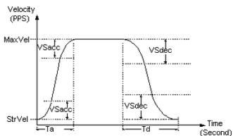
![| Time (Second) | Velocity (PPS) |\n| ------------- | -------------- |\n| Ta            | MaxVel         |\n| Ta            | StrVel         |\n| Td            | MaxVel         |\n| Td            | StrVel         |](.aps-functionlibrary-v2-1/d92099c38df18bc302ea315d375f8376e03ad1216aa69a76c0bceaa8316a7ada.jpg)

PRA\_DEC\_SR =

2Svacc / (MaxV – StrV ) \* 100,000 milli%

\*5： According to (\*4), when the curve profile is set to S curve with linear range, the PRA\_MAX\_ACCDEC and PRA\_MIN\_ACCDEC are always return 0. The PRA\_MAX\_ACCDEC and PRA\_MIN\_ACCDEC are only available in T and pure S curve mode.

MNET-1XMO Axis parameter table

<table><tr><td colspan="5">MNET-1XMO axis parameter table.</td></tr><tr><td>NO.</td><td>Define</td><td>Description</td><td>Value</td><td>Default</td></tr><tr><td>00h (0)</td><td>Reserved</td><td></td><td></td><td></td></tr><tr><td>01h (1)</td><td>PRA_ORG_LOGIC</td><td>ORG input logic</td><td>0 : Active low1 : Active high</td><td>0</td></tr><tr><td>02h (2)</td><td>PRA_EL_MODE</td><td>The mode of stop when end limit ON</td><td>0 : Deceleration stop1 : Stop immediately</td><td>0</td></tr><tr><td>03h (3)</td><td>PRA_MDN_CONDI</td><td>Motion done condition( Affective with motion stats NSTP bit)</td><td>0 : Control command done (default)1 : Command done with INP</td><td>0</td></tr><tr><td>04h (4)</td><td>PRA_ALM_LOGIC</td><td>Set ALM Logic</td><td>0 : Active low1 : Active high</td><td>1</td></tr><tr><td>05h(5)</td><td>Reserved</td><td></td><td></td><td></td></tr><tr><td>06h(6)</td><td>PRA_EZ_LOGIC</td><td>Set EZ Logic</td><td>0 : Falling edge1 : Rising edge</td><td>0</td></tr><tr><td>07h(7)</td><td>Reserved</td><td></td><td></td><td></td></tr><tr><td>08h</td><td>PRA_SPEL_EN</td><td>Set Encoder event mode. (*2,)</td><td>0 : Disable1 : Reserved2 : Soft-Limit (SPEL)</td><td>0</td></tr><tr><td>09h(9)</td><td>PRA_SMEL_EN</td><td>Set Encoder event mode. (*2,)</td><td>0 : Disable1 : Reserved2 : Soft-Limit (SMEL)</td><td>0</td></tr><tr><td>0Ah(10)</td><td>PRA_EFB_POSO</td><td>SPEL / EFB position 0 (*2,)</td><td>Unit : pulse. (I32 value)(28-bit signed)</td><td>100,000</td></tr><tr><td>0Bh(11)</td><td>PRA_EFB_POS1</td><td>SMEL / EFB position 1 (*2,)</td><td>Unit : pulse. (I32 value)(28-bit signed)</td><td>-100,000</td></tr><tr><td>0Ch(12)</td><td>Reserved</td><td></td><td></td><td></td></tr><tr><td>0Dh(13)</td><td>Reserved</td><td></td><td></td><td></td></tr><tr><td>0Eh(14)</td><td>Reserved</td><td></td><td></td><td></td></tr><tr><td>0Fh(15)</td><td>Reserved</td><td></td><td></td><td></td></tr><tr><td>10h (16)</td><td>PRA_HOME_MODE</td><td>Home mode setting</td><td>Home search - 0(1stmode) to 12(13thmode)Home move - 20(1stmode) to 32(13thmode)Note : Home search (6 to 8) is reserved. If set, return error.</td><td>0</td></tr><tr><td>11h (17)</td><td>PRA_HOME_DIR</td><td>Homing direction</td><td>0 : positive direction1 : negative direction</td><td>0</td></tr><tr><td>12h (18)</td><td>Reserved</td><td></td><td></td><td></td></tr><tr><td>13h (19)</td><td>Reserved</td><td></td><td></td><td></td></tr><tr><td>14h (20)</td><td>Reserved</td><td></td><td></td><td></td></tr><tr><td>15h (21)</td><td>PRA_HOME_VM</td><td>Homing maximum velocity</td><td>Unit: pulse/sec</td><td>10000</td></tr><tr><td>16h (22)</td><td>Reserved</td><td></td><td></td><td></td></tr><tr><td>17h (23)</td><td>Reserved</td><td></td><td></td><td></td></tr><tr><td>18h (24)</td><td>PRA_HOME_EZA</td><td>Specify the EZ count up value</td><td>0000(1stcount) to 1111(16thcount)</td><td>0</td></tr><tr><td>19h (25)</td><td>PRA_HOME_VO</td><td>Homing leave home velocity – Specify FA speed</td><td>Unit: pulse/sec</td><td>0</td></tr><tr><td>1Ah</td><td>PRA_HOME_OFFSET</td><td>Homing leave home distance – Specify ORG offset</td><td>Unit: pulse</td><td>100</td></tr><tr><td>1Bh-1Fh</td><td>Reserved</td><td></td><td></td><td></td></tr><tr><td>20h (32)</td><td>PRA_CURVE</td><td>Acceleration / Deceleration speed pattern</td><td>0: T-Curve1: S-Curve</td><td>0</td></tr><tr><td>21h (33)</td><td>PRA_ACC</td><td>Acceleration rate</td><td>Unit: pulse/sec $^{2}$ </td><td>1000000</td></tr><tr><td>22h (34)</td><td>PRA_DEC</td><td>Deceleration rate</td><td>Unit: pulse/sec $^{2}$ </td><td>1000000</td></tr><tr><td>23h (35)</td><td>PRA_VS</td><td>Start velocity</td><td>Unit: pulse/sec</td><td>66</td></tr><tr><td>24h ~ 27h</td><td>Reserved</td><td></td><td></td><td></td></tr><tr><td>28h</td><td>PRA_ACC_SR</td><td>S curve ratio in acceleration.(*4)</td><td>Unit: Milli %.Value = 1 ~ 100,000</td><td>100,000</td></tr><tr><td>29h</td><td>PRA_DEC_SR</td><td>S curve ratio in deceleration(*4)</td><td>Unit: Milli %.Value = 1 ~ 100,000</td><td>100,000</td></tr><tr><td>2Ah~50 h</td><td>Reserved</td><td></td><td></td><td></td></tr><tr><td>53h(83)</td><td>PRA_SERVO_LOGIC</td><td>SERVO output logic</td><td>0: Active low1: Active high</td><td>0</td></tr><tr><td>80h(128)</td><td>PRA_PLS_IPT_MODE</td><td>Pulse input mode</td><td>0: A/B X11: A/B X22: A/B X43: CW/CCW</td><td>0</td></tr><tr><td>81h(129)</td><td>PRA_PLS_OPT_MODE</td><td>Pulse output mode</td><td>0: OUT/DIR (AL,H+)1: OUT/DIR (AH,H+)2: OUT/DIR (AL,L+)3: OUT/DIR (AH,L+)4: CW/CCW (AH)5: CW/CCW (AL)6: AB (Out Leading)7: AB (Out Lagging)</td><td>0</td></tr><tr><td>84h(132)</td><td>PRA_EGEAR</td><td>E-Gear factor = Motor Encoder resolution(112h) / Value (*1,)</td><td>Value = 1 ~ Motor Encoder resolution.</td><td>40,000</td></tr><tr><td>112h(274 )</td><td>PRA_M_ENC_RES</td><td>Motor encoder resolution (*1,)</td><td>Unit: Pulse / rev or Pulse / mm</td><td>40,000</td></tr><tr><td>200h(512 )</td><td>PRA_PLS_IPT_LOGIC</td><td>Pulse input logic</td><td>0: don not reverse EA/EB counting1: reverse EA/EB counting</td><td>0</td></tr><tr><td>201h(513)</td><td>PRA_FEEDBACK_SRC</td><td>Select feedback source</td><td>0: Ext. Encoder modeExt. Encoder counter &amp; Absolute mode reference to Encoder counter.1: Stepper modeExt. Command counter &amp; Absolute mode reference to Command counter.2: ACServo modeExt. Encoder counter &amp; Absolute mode reference to Command counter.</td><td>0</td></tr><tr><td></td><td></td><td></td><td></td><td></td></tr><tr><td>210h(528)</td><td>PRA_ALM_MODE</td><td>ALM mode setting</td><td>0: Immediate stop1: Slow down then stop</td><td>0</td></tr><tr><td>211h(529)</td><td>PRA_INP_LOGIC</td><td>INP input logic</td><td>0: Active low1: Active high</td><td>0</td></tr><tr><td>212h(530)</td><td>PRA_SD_EN</td><td>Enable SD</td><td>0: Disable1: Enable</td><td>0</td></tr><tr><td>213h(531)</td><td>PRA_SD_MODE</td><td>SD mode setting</td><td>0: Only slow down1: Slow down and stop</td><td>0</td></tr><tr><td>214h(532)</td><td>PRA_SD_LOGIC</td><td>SD input logic</td><td>0: Active low1: Active high</td><td>0</td></tr><tr><td>215h(533)</td><td>PRA_SD_LATCH</td><td>Latch SD input</td><td>0: Disable latch function1: Enable latch function</td><td>0</td></tr><tr><td>216h(534)</td><td>PRA_ERC_MODE</td><td>ERC mode setting</td><td>0: disable1: output ERC when stopped by EL, ALM, or EMG input2: output ERC when complete home return3: both 1 and 2</td><td>3</td></tr><tr><td>217h(535)</td><td>PRA_ERC_LOGIC</td><td>ERC output logic</td><td>0: Active low1: Active high</td><td>0</td></tr><tr><td>218h(536)</td><td>PRA_ERC_LEN</td><td>Pulse width of ERC setting</td><td>0: 12 us1: 102 us2: 409 us3: 1.6 ms4: 13 ms5: 52 ms6: 104 ms7: Level Output</td><td>3</td></tr><tr><td>219h(537)</td><td>Reserved</td><td></td><td></td><td></td></tr><tr><td>21Ah(538)</td><td>Reserved</td><td></td><td></td><td></td></tr><tr><td>21Bh(539)</td><td>PRA_PLS_IPT_FLT</td><td>EA/EB Filter Enable</td><td>0: Disable1: Enable</td><td>1</td></tr><tr><td>21Ch~21Dh</td><td>Reserved</td><td></td><td></td><td></td></tr><tr><td>21Eh</td><td>PRA_IO_FILTER</td><td>Apply a filter to the PEL, MEL, SD, ORG, ALM, INP inputs.When a filter is applied, signal pulses shorter than 4 micro-second is ignored.</td><td>0: Don't apply a filter1: Apply a filter</td><td>1</td></tr><tr><td>21Fh~220h</td><td>Reserved</td><td></td><td></td><td></td></tr><tr><td>221h</td><td>PRA_COMPENSATION_PULSE</td><td>A backlash correction amount</td><td>0 to 4095</td><td>0</td></tr><tr><td>222h</td><td>PRA_COMPENSATION_MODE</td><td>Backlash mode setting</td><td>0: Disable1: Backlash correction</td><td>0</td></tr><tr><td>223h~225h</td><td>Reserved</td><td></td><td></td><td></td></tr><tr><td>226h</td><td>PRA_GCMP_EN</td><td>General comparator enable &amp; set method(*3)</td><td>0: DisableOther: Enable1: data = cmp counter(regardless of counting direction)2: data=cmp counter(while counting up)3: data=cmp counter(while counting down)4: data&gt;cmp counter5: data&lt;cmp counter</td><td>0</td></tr><tr><td>227h</td><td>PRA_GCMP_POS</td><td>General comparator position(*3)</td><td>Pulse(28-bit signed)</td><td>0</td></tr><tr><td>228h</td><td>PRA_GCMP_SRC</td><td>Select general comparator source(*3)</td><td>0: Command counter1: Position counter</td><td>0</td></tr><tr><td>229h</td><td>PRA_GCMP_ACTION</td><td>Select action when GCMP are met.(*3)</td><td>0 : Do nothing1 : Immediate stop2 : Deceleration stop</td><td>0</td></tr><tr><td>22Ah</td><td>PRA_GCMP_STS</td><td>Check if GCMP is met (Read only)</td><td>0 : Not meet1 : meet</td><td>0</td></tr><tr><td>22Bh</td><td>PRA_VIBSUP_RT</td><td>Supress vibration - Reverse Time</td><td>Unit : 1.6 us(16-bit unsigned)</td><td>0</td></tr><tr><td>22Ch</td><td>PRA_VIBSUP_FT</td><td>Supress vibration - Forward Time</td><td>Unit : 1.6 us(16-bit unsigned)</td><td>0</td></tr><tr><td>22Dh</td><td>PRA_LATCH_DATA_SPD</td><td>Choose latch data of error position or current speed for latch No.2</td><td>0 : Latch error position1 : Latch current speed</td><td>0</td></tr><tr><td>22F~23F</td><td>Reserved</td><td></td><td></td><td></td></tr><tr><td>240h(576)</td><td>PRA_SPD_LIMIT</td><td>Set Fixed Speed</td><td>Unit : pulse/sec</td><td>6666666</td></tr><tr><td>241h(577)</td><td>PRA_MAX_ACCDEC</td><td>Get max acceleration/deceleration on which is limited by fixed speed. (Read only)</td><td>Unit : pulse/sec $^{2}$ </td><td>166666666</td></tr><tr><td>242h(578)</td><td>PRA_MIN_ACCDEC</td><td>Get minimum acceleration/deceleration on which is limited by fixed speed. (Read only)</td><td>Unit : pulse/sec $^{2}$ </td><td>5086</td></tr></table>

\*1： This parameter is used to calculate a move ratio. It is only effective when PRA\_FEEDBACK\_SRC was set to 0 or 2.
\*2： When positive or negative software limit is selected, command counter is used as the comparison counter. The comparison method is mentioned as follows：

(EFB position 0 &lt; command counter) for positive software limit, (EFB position 1 &gt; command counter) for negative software limit.

\*3 : This describe how to using MNET-1XMO comparator output. Because MNET-1XMO has no unique compare trigger function. If user needs to use the comparator and output the pulse, please using GCMP related axis parameter.

MNET-1XMO comparator output Example :

# CN3 (mechanical input/output, power supply connector)

Connects mechanical system Input/Output signals and control power for the board.

<table><tr><td>Pin</td><td>Name</td><td>I/O</td><td>Function</td></tr><tr><td>1</td><td>PEL</td><td>I</td><td>Positive end limit</td></tr><tr><td>2</td><td>MEL</td><td>I</td><td>Negative end limit</td></tr><tr><td>3</td><td>SD/CPP</td><td>I/O</td><td>Slowdown input / comparator output (+)</td></tr><tr><td>4</td><td>ORG</td><td>I</td><td>Zero position input</td></tr><tr><td>5</td><td>EMGI</td><td>I</td><td>Emergency stop input</td></tr><tr><td>6</td><td>CPN</td><td>O</td><td>Comparator output (-)</td></tr><tr><td>7</td><td>24V</td><td>I</td><td>24 VDC Power source</td></tr><tr><td>8</td><td>GND</td><td>I</td><td>Ground</td></tr><tr><td>9</td><td>GND</td><td>I</td><td>Ground</td></tr><tr><td>10</td><td>FG</td><td>-</td><td>Frame ground</td></tr></table>

Note: The signal directions refer to the signalflow direction relative to the board: ""= Input and "O"= Output.

// .... After APS initial and MNET start fieldbus

I32 AxisNo = 0; // GCMP corresponding axis

I32 ret = 0;

ret = APS\_set\_command(AxisNo, 0);

ret = APS\_set\_axis\_param(AxisNo, PRA\_GCMP\_EN, 1); // data = cmp counter (regardless of counting direction)

ret = APS\_set\_axis\_param(AxisNo, PRA\_GCMP\_POS, 10000); // comparator counter set 10000

ret = APS\_set\_axis\_param(AxisNo, PRA\_GCMP\_SRC, 0); // comparator counter reference command counter

ret = APS\_set\_axis\_param(AxisNo, PRA\_GCMP\_ACTION, 1); // comparator meet, this axis stop immediately

ret = APS\_velocity\_move(AxisNo, 500);

//

// While command reach 10000, this axis will stop and comparator output high.

HSL-4XMO Axis parameter table

<table><tr><td colspan="5">HSL-4XMO axis parameter table.</td></tr><tr><td>NO.</td><td>Define</td><td>Description</td><td>Value</td><td>Default</td></tr><tr><td>00h (0)</td><td>PRA_EL_LOGIC</td><td>PEL/MEL input logic</td><td>0 : Not inverse1 : Inverse</td><td>0</td></tr><tr><td>01h (1)</td><td>PRA_ORG_LOGIC</td><td>ORG input logic</td><td>0 : Active low1 : Active high</td><td>0</td></tr><tr><td>02h (2)</td><td>PRA_EL_MODE</td><td>The mode of stop when end limit ON</td><td>0 : Deceleration stop1 : Stop immediately</td><td>0</td></tr><tr><td>03h (3)</td><td>Reserved</td><td></td><td></td><td></td></tr><tr><td>04h (4)</td><td>PRA_ALM_LOGIC</td><td>Set ALM Logic</td><td>0 : Active low1 : Active high</td><td>0</td></tr><tr><td>05h(5)</td><td>Reserved</td><td></td><td></td><td></td></tr><tr><td>06h(6)</td><td>PRA_EZ_LOGIC</td><td>Set EZ Logic</td><td>0 : Falling edge1 : Rising edge</td><td>0</td></tr><tr><td>07h(7)</td><td>Reserved</td><td></td><td></td><td></td></tr><tr><td>08h</td><td>PRA_SPEL_EN</td><td>Set Encoder event mode.</td><td>0 : Disable1 : Reserved2 : Soft-Limit (SPEL)</td><td>0</td></tr><tr><td>09h(9)</td><td>PRA_SMEL_EN</td><td>Set Encoder event mode.</td><td>0 : Disable1 : Reserved2 : Soft-Limit (SMEL)</td><td>0</td></tr><tr><td>0Ah(10)</td><td>PRA_EFB_POS0</td><td>SPEL / EFB position 0</td><td>Unit : pulse. (I32 value)Range : -10^8 ~ 10^8</td><td>100,000</td></tr><tr><td>0Bh(11)</td><td>PRA_EFB_POS1</td><td>SMEL / EFB position 1</td><td>Unit : pulse. (I32 value)Range : -10^8 ~ 10^8</td><td>-100,000</td></tr><tr><td>0Ch(12)</td><td>Reserved</td><td></td><td></td><td></td></tr><tr><td>0Dh(13)</td><td>Reserved</td><td></td><td></td><td></td></tr><tr><td>0Eh(14)</td><td>Reserved</td><td></td><td></td><td></td></tr><tr><td>0Fh(15)</td><td>Reserved</td><td></td><td></td><td></td></tr><tr><td>10h (16)</td><td>PRA_HOME_MODE</td><td>Home mode setting</td><td>Home search - 0(1stmode) to 12(13thmode)Home move - 20(1stmode) to 32(13thmode)Note : Home search (6 to 8) is reserved. If set, return error.</td><td>0</td></tr><tr><td>11h (17)</td><td>Reserved</td><td></td><td></td><td></td></tr><tr><td>12h (18)</td><td>Reserved</td><td></td><td></td><td></td></tr><tr><td>13h (19)</td><td>Reserved</td><td></td><td></td><td></td></tr><tr><td>14h (20)</td><td>Reserved</td><td></td><td></td><td></td></tr><tr><td>15h (21)</td><td>PRA_HOME_VM</td><td>Homing maximum velocity</td><td>Unit : pulse/sec</td><td>10000</td></tr><tr><td>16h (22)</td><td>Reserved</td><td></td><td></td><td></td></tr><tr><td>17h (23)</td><td>Reserved</td><td></td><td></td><td></td></tr><tr><td>18h (24)</td><td>PRA_HOME_EZA</td><td>Specify the EZ count up value</td><td>0000(1stcount) to 1111(16thcount)</td><td>0</td></tr><tr><td>19h (25)</td><td>PRA_HOME_VO</td><td>Homing leave home velocity – Specify FA speed</td><td>Unit : pulse/sec</td><td>100</td></tr><tr><td>1Ah</td><td>PRA_HOME_OFFSET</td><td>Homing leave home distance – Specify ORG offset</td><td>Unit : pulse</td><td>100</td></tr><tr><td>1Bh-1Fh</td><td>Reserved</td><td></td><td></td><td></td></tr><tr><td>20h (32)</td><td>PRA_CURVE</td><td>Acceleration / Deceleration speed pattern</td><td>0 : T-Curve1 : S-Curve</td><td>0</td></tr><tr><td>21h (33)</td><td>PRA_ACC</td><td>Acceleration rate</td><td>Unit : pulse/sec $^{2}$ </td><td>1000000</td></tr><tr><td>22h (34)</td><td>PRA_DEC</td><td>Deceleration rate</td><td>Unit : pulse/sec $^{2}$ </td><td>1000000</td></tr><tr><td>23h (35)</td><td>PRA_VS</td><td>Start velocity</td><td>Unit : pulse/sec</td><td>100</td></tr><tr><td>24h~50 h</td><td>Reserved</td><td></td><td></td><td></td></tr><tr><td>53h(83)</td><td>PRA_SERVO_LOGIC</td><td>SERVO output logic</td><td>0 : Active low1 : Active high</td><td>0</td></tr><tr><td>80h(128)</td><td>PRA_PLS_IPT_MODE</td><td>Pulse input mode</td><td>0 : A/B X11 : A/B X22 : A/B X43 : CW/CCW</td><td>0</td></tr><tr><td>81h(129)</td><td>PRA_PLS_OPT_MODE</td><td>Pulse output mode</td><td>0 : OUT/DIR (AL,H+)1 : OUT/DIR (AH,H+)2 : OUT/DIR (AL,L+)3 : OUT/DIR (AH,L+)4 : CW/CCW (AH)5 : CW/CCW (AL)</td><td>0</td></tr><tr><td>84h(132)</td><td>PRA_EGEAR</td><td>E-Gear factor = Motor Encoder resolution(112h) / Value (*1,)</td><td>Value = 1 ~ Motor Encoder resolution.</td><td>40,000</td></tr><tr><td>112h(274 )</td><td>PRA_M_ENC_RES</td><td>Motor encoder resolution (*1,)</td><td>Unit : Pulse / rev or Pulse / mm</td><td>40,000</td></tr><tr><td>200h(512 )</td><td>PRA_PLS_IPT_LOGIC</td><td>Pulse input logic</td><td>0 : don not reverse EA/EB counting1 : reverse EA/EB counting</td><td>0</td></tr><tr><td>201h(513 )</td><td>PRA_FEEDBACK_SRC</td><td>Select feedback source</td><td>0 : Encoder counter &amp; Absolute mode reference to Encoder counter.1 : Command counter &amp; Absolute mode reference to Command counter.2 : Encoder counter &amp; Absolute mode reference to Command counter.</td><td>0</td></tr><tr><td>210h(528)</td><td>PRA_ALM_MODE</td><td>ALM mode setting</td><td>0: Immediate stop1: Slow down then stop</td><td>0</td></tr><tr><td>211h(529)</td><td>PRA_INP_LOGIC</td><td>INP input logic</td><td>0: Active low1: Active high</td><td>0</td></tr><tr><td>212h(530)</td><td>PRA_SD_EN</td><td>Enable SD. (*2)</td><td>0: Disable1: Enable</td><td>0</td></tr><tr><td>213h(531)</td><td>PRA_SD_MODE</td><td>SD mode setting</td><td>0: Only slow down1: Slow down and stop</td><td>0</td></tr><tr><td>214h(532)</td><td>PRA_SD_LOGIC</td><td>SD input logic</td><td>0: Active low1: Active high</td><td>0</td></tr><tr><td>215h(533)</td><td>PRA_SD_LATCH</td><td>Latch SD input</td><td>0: Disable latch function1: Enable latch function</td><td>0</td></tr><tr><td>216h(534)</td><td>PRA_ERC_MODE</td><td>ERC mode setting</td><td>0: disable1: output ERC when stopped by EL, ALM, or EMG input2: output ERC when complete home return3: both 1 and 2</td><td>3</td></tr><tr><td>217h(535)</td><td>PRA_ERC_LOGIC</td><td>ERC output logic</td><td>0: Active low1: Active high</td><td>0</td></tr><tr><td>218h(536)</td><td>PRA_ERC_LEN</td><td>Pulse width of ERC setting</td><td>0: 12 us1: 102 us2: 409 us3: 1.6 ms4: 13 ms5: 52 ms6: 104 ms7: Level Output</td><td>3</td></tr><tr><td>219h(537)</td><td>Reserved</td><td></td><td></td><td></td></tr><tr><td>21Ah(538)</td><td>Reserved</td><td></td><td></td><td></td></tr><tr><td>21Bh(539)</td><td>Reserved</td><td></td><td></td><td></td></tr><tr><td>21Ch</td><td>Reserved</td><td></td><td></td><td></td></tr><tr><td>21Dh</td><td>PRA_LTC_LOGIC</td><td>LTC input logic</td><td>0: Falling edge1: Rising edge</td><td>0</td></tr><tr><td>21Eh~220h</td><td>Reserved</td><td></td><td></td><td></td></tr><tr><td>221h</td><td>PRA_COMPENSATION_PULSE</td><td>A backlash or slip correction amount</td><td>0 to 4095</td><td>0</td></tr><tr><td>222h</td><td>PRA_COMPENSATION_MODE</td><td>Backlash or slip mode setting</td><td>0: Disable1: Backlash correction2: Slip correction</td><td>0</td></tr><tr><td>223h</td><td>PRA_LTC_SRC</td><td>Select latch source</td><td>0: LTC pin1: ORG pin2: GCMP ON</td><td>0</td></tr><tr><td>224h</td><td>PRA_LTC_DEST</td><td>Select latch target</td><td>0: Command counter1: Position counter</td><td>0</td></tr><tr><td>225h</td><td>PRA_LTC_DATA</td><td>Get latch data (Read only)</td><td>Pulse(28-bit signed)</td><td>0</td></tr><tr><td>226h</td><td>PRA_GCMP_EN</td><td>General comparator enable &amp; set method</td><td>0: DisableOther: Enable1: data = cmp counter(regardless of counting direction)2: data=cmp counter(while counting up)3: data=cmp counter(while counting down)4: data&gt;cmp counter5: data0</td><td>0</td></tr><tr><td>227h</td><td>PRA_GCMP_POS</td><td>Set/Get general comparator position</td><td>Pulse(28-bit signed)</td><td>0</td></tr><tr><td>228h</td><td>PRA_GCMP_SRC</td><td>Select general comparator source</td><td>0: Command counter1: Position counter</td><td>0</td></tr><tr><td>229h</td><td>PRA_GCMP_ACTION</td><td>Select action when GCMP are met.</td><td>0: Do nothing1: Immediate stop2: Deceleration stop</td><td>0</td></tr><tr><td>22Ah</td><td>PRA_GCMP_STS</td><td>Check if GCMP is met (Read only)</td><td>0: Not meet1: meet</td><td>0</td></tr><tr><td>22Bh</td><td>PRA_VIBSUP_RT</td><td>Supress vibration – Reverse Time</td><td>Unit : 1.6 us(16-bit unsigned)</td><td>0</td></tr><tr><td>22Ch</td><td>PRA_VIBSUP_FT</td><td>Supress vibration – Forward Time</td><td>Unit : 1.6 us(16-bit unsigned)</td><td>0</td></tr><tr><td>22Dh~22Fh</td><td>Reserved</td><td></td><td></td><td></td></tr><tr><td>230h</td><td>Reserved</td><td></td><td></td><td></td></tr><tr><td>231h</td><td>PRA_GPDI_SEL</td><td>Select gpio input – DI / LTC / SD. (*2)</td><td>0 : LTC1 : SD</td><td>0</td></tr><tr><td>232h</td><td>Reserved</td><td></td><td></td><td></td></tr><tr><td>233h(563)</td><td>PRA_RDY_LOGIC</td><td>RDY input logic</td><td>0 : Active high1 : Active low</td><td>0</td></tr><tr><td>234h~23Fh</td><td>Reserved</td><td></td><td></td><td></td></tr><tr><td>240h(576)</td><td>PRA_SPD_LIMIT</td><td>Set Fixed Speed</td><td>Unit : pulse/sec</td><td>6553500</td></tr><tr><td>241h(577)</td><td>PRA_MAX_ACCDEC</td><td>Get max acceleration/deceleration which is limited by fixed speed.(Read only)</td><td>Unit : pulse/sec $^{2}$ </td><td>245760000</td></tr><tr><td>242h(578)</td><td>PRA_MIN_ACCDEC</td><td>Get minimum acceleration/deceleration which is limited by fixed speed.(Read only)</td><td>Unit : pulse/sec $^{2}$ </td><td>7500</td></tr></table>

\*1： This parameter is used to calculate a move ratio. It is only effective when PRA\_FEEDBACK\_SRC set to 0.
\*2： When PRA\_GPDI\_SEL set to DI/LTC, PRA\_SD\_EN automatically set to disable. Before PRA\_SD\_EN set to enable, be sure that PRA\_GPDI\_SEL set to SD mode.

PCI(e)-8154/8158, PCI-8102/PCI-C154(+) Axis parameter table

<table><tr><td colspan="5">PCI(e)-8154/8158, PCI-8102/PCI-C154(+) axis parameter table</td></tr><tr><td>NO.</td><td>Define</td><td>Description</td><td>Value</td><td>Default</td></tr><tr><td>00h (0)</td><td>PRA_EL_LOGIC</td><td>PEL/MEL input logic</td><td>0 : Not inverse1 : Inverse</td><td>0</td></tr><tr><td>01h (1)</td><td>PRA_ORG_LOGIC</td><td>ORG input logic</td><td>0 : Active low1 : Active high</td><td>0</td></tr><tr><td>02h (2)</td><td>PRA_EL_MODE</td><td>The mode of stop when end limit(include soft-limit) ON.Deceleration profile is given according to PRA_DEC</td><td>0 : Deceleration stop1 : Stop immediately</td><td>0</td></tr><tr><td>03h (3)</td><td>PRA_MDN_CONDI</td><td>Motion done condition(Affective with motion stats NSTP bit)</td><td>0 : Control command done (default)1 : Command done with INP</td><td>0</td></tr><tr><td>04h (4)</td><td>PRA_ALM_LOGIC</td><td>Set ALM Logic</td><td>0 : Active low1 : Active high</td><td>0</td></tr><tr><td>05h(5)</td><td>Reserved</td><td></td><td></td><td></td></tr><tr><td>06h(6)</td><td>PRA_EZ_LOGIC</td><td>Set EZ Logic</td><td>0 : Falling edge1 : Rising edge</td><td>0</td></tr><tr><td>07h(7)</td><td>Reserved</td><td></td><td></td><td></td></tr><tr><td>08h</td><td>PRA_SPEL_EN</td><td>Set Encoder event mode. (*3,)</td><td>0 : Disable1 : Reserved2 : Soft-Limit (SPEL)Note : mode 1 is reserved. If set, return error.</td><td>0</td></tr><tr><td>09h(9)</td><td>PRA_SMEL_EN</td><td>Set Encoder event mode. (*3,)</td><td>0 : Disable1 : Reserved2 : Soft-Limit (SMEL)Note : mode 1 is reserved. If set, return error.</td><td>0</td></tr><tr><td>0Ah(10)</td><td>PRA_EFB_POS0</td><td>SPEL / EFB position 0 (*3,)</td><td>Unit : pulse. (I32 value)(28-bit signed)</td><td>100,000</td></tr><tr><td>0Bh(11)</td><td>PRA_EFB_POS1</td><td>SMEL / EFB position 1 (*3,)</td><td>Unit : pulse. (I32 value)(28-bit signed)</td><td>-100,000</td></tr><tr><td>0Ch(12)</td><td>Reserved</td><td></td><td></td><td></td></tr><tr><td>0Dh(13)</td><td>Reserved</td><td></td><td></td><td></td></tr><tr><td>0Eh(14)</td><td>Reserved</td><td></td><td></td><td></td></tr><tr><td>0Fh(15)</td><td>Reserved</td><td></td><td></td><td></td></tr><tr><td>10h (16)</td><td>PRA_HOME_MODE</td><td>Home mode setting</td><td>Home search - 0( $1^{st}$  mode) to  $12(13^{th}$  mode)Home move - 20(1stmode) to 32(13thmode)Note: Home search (6 to 8) is reserved. If set, return error.</td><td>0</td></tr><tr><td>11h (17)</td><td>PRA_HOME_DIR</td><td>Homing direction</td><td>0: positive direction1: negative direction</td><td>0</td></tr><tr><td>12h (18)</td><td>Reserved</td><td></td><td></td><td></td></tr><tr><td>13h (19)</td><td>Reserved</td><td></td><td></td><td></td></tr><tr><td>14h (20)</td><td>Reserved</td><td></td><td></td><td></td></tr><tr><td>15h (21)</td><td>PRA_HOME_VM</td><td>Homing maximum velocity</td><td>Unit: pulse/sec</td><td>10000</td></tr><tr><td>16h (22)</td><td>Reserved</td><td></td><td></td><td></td></tr><tr><td>17h (23)</td><td>Reserved</td><td></td><td></td><td></td></tr><tr><td>18h (24)</td><td>PRA_HOME_EZA</td><td>Specify the EZ count up value</td><td>0000(1stcount) to 1111(16thcount)</td><td>0</td></tr><tr><td>19h (25)</td><td>PRA_HOME_VO</td><td>Homing leave home velocity - Specify FA speed</td><td>Unit: pulse/sec</td><td>100</td></tr><tr><td>1Ah</td><td>PRA_HOME_OFFSET</td><td>Homing leave home distance - Specify ORG offset</td><td>Unit: pulse</td><td>100</td></tr><tr><td>1Bh-1Fh</td><td>Reserved</td><td></td><td></td><td></td></tr><tr><td>20h (32)</td><td>PRA_CURVE</td><td>Acceleration / Deceleration speed pattern</td><td>[0.0~1.0]0: T-Curve1: S-Curve0.0~1.0: SL-Curve(*7,)</td><td>0</td></tr><tr><td>21h (33)</td><td>PRA_ACC</td><td>Acceleration rate</td><td>Unit: pulse/sec2(*7,)</td><td>1000000</td></tr><tr><td>22h (34)</td><td>PRA_DEC</td><td>Deceleration rate</td><td>Unit: pulse/sec2(*7,)</td><td>1000000</td></tr><tr><td>23h (35)</td><td>PRA_VS</td><td>Start velocity</td><td>Unit: pulse/sec(*7,)</td><td>100</td></tr><tr><td>24h~27h</td><td>Reserved</td><td></td><td></td><td></td></tr><tr><td>28h</td><td>Reserved</td><td></td><td></td><td></td></tr><tr><td>29h</td><td>Reserved</td><td></td><td></td><td></td></tr><tr><td>2Ah ~ 50h</td><td>Reserved</td><td></td><td></td><td></td></tr><tr><td></td><td></td><td></td><td></td><td></td></tr><tr><td>53h(83)</td><td>PRA_SERVO_LOGIC</td><td>SERVO output logic</td><td>0: Active low1: Active high</td><td>0</td></tr><tr><td>80h(128)</td><td>PRA_PLS_IPT_MODE</td><td>Pulse input mode</td><td>0: A/B X11: A/B X22: A/B X43: CW/CCW</td><td>0</td></tr><tr><td>81h(129)</td><td>PRA_PLS_OPT_MODE</td><td>Pulse output mode</td><td>0: OUT/DIR (AL,H+)1: OUT/DIR (AH,H+)2: OUT/DIR (AL,L+)3: OUT/DIR (AH,L+)4: CW/CCW (AH)5: CW/CCW (AL)6: AB (Out Leading)7: AB (Out Lagging)</td><td>0</td></tr><tr><td>84h(132)</td><td>PRA_EGEAR</td><td>E-Gear factor = Motor Encoder resolution(112h) / Value (*1,)</td><td>Value = 1 ~ Motor Encoder resolution.</td><td>40,000</td></tr><tr><td>112h(274)</td><td>PRA_M_ENC_RES</td><td>Motor encoder resolution (*1,)</td><td>Unit : Pulse / rev or Pulse / mm</td><td>40,000</td></tr><tr><td>160h(352)</td><td>PRA_PSR_IPT_MODE</td><td>Setting of manual pulser input mode from PA and PB pins</td><td>ipt_mode=0, 1X AB phase type pulse input.ipt_mode=1, 2X AB phase type pulse input.ipt_mode=2, 4X AB phase type pulse input.ipt_mode=3,CW/CCW type pulse input.</td><td>0</td></tr><tr><td>161h(353)</td><td>Reserved</td><td></td><td></td><td></td></tr><tr><td>162h(354)</td><td>PRA_PSR_IPT_DIR</td><td>Reverse the moving direction from pulse direction</td><td>Inverse =0, no inverse Inverse =1, Reverse moving direction</td><td>0</td></tr><tr><td>163h(355)</td><td>PRA_PSR_RATIO_VALUE</td><td>reserved</td><td></td><td>0</td></tr><tr><td>164h(356)</td><td>PRA_PSR_PDV</td><td>Set manual pulser ratio for actual output pulse rate. The formula for pulser output rate is (1) When PDV = 1~2047, PMG = 0~31Output Pulse Count = Input Pulser Count x (PMG + 1) x PDV / 2048(2) When PDV = 0, PMG = 0~31Output Pulse Count = Input Pulser Count x (PMG + 1)</td><td>PDV = 0~2047</td><td>0</td></tr><tr><td>165h(357)</td><td>PRA_PSR_PMG</td><td>Refer to description of PRA_PSR_PDV</td><td>PMG = 0~31</td><td>0</td></tr><tr><td>166h(358)</td><td>PRA_PSR_HOME_TYPE</td><td>Specified home move type</td><td>HomeType =0,CommandOrigin.(that means axis stops when command counter becomes '0')HomeType =1,Feedback Origin.(that means axis stops when feedback counter becomes '0')</td><td>0</td></tr><tr><td>167h(359)</td><td>PRA_PSR_HOME_SPD</td><td>The maximum speed in pulser home move.</td><td>Unit: pulse/sec</td><td>1000</td></tr><tr><td>168h~169h</td><td>Reserved</td><td></td><td></td><td></td></tr><tr><td>200h(512)</td><td>PRA_PLS_IPT_LOGIC</td><td>Pulse input logic</td><td>0: don not reverse counting direction1: reverse counting direction</td><td>0</td></tr><tr><td>201h(513)</td><td>PRA_FEEDBACK_SRC</td><td>Select feedback source</td><td>0: Ext. Encoder modeExt. Encoder counter &amp; Absolute mode reference to Encoder counter.1: Stepper modeExt. Command counter &amp; Absolute mode reference to Command counter.2: ACServo modeExt. Encoder counter &amp; Absolute mode reference to Command counter.</td><td>0</td></tr><tr><td></td><td>Reserved</td><td></td><td></td><td></td></tr><tr><td>210h(528)</td><td>PRA_ALM_MODE</td><td>ALM mode setting</td><td>0: Immediate stop1: Slow down then stop</td><td>0</td></tr><tr><td>211h(529)</td><td>PRA_INP_LOGIC</td><td>INP input logic</td><td>0: Active low1: Active high</td><td>0</td></tr><tr><td>212h(530)</td><td>PRA_SD_EN</td><td>Enable SD. (*2)</td><td>0: Disable1: Enable</td><td>0</td></tr><tr><td>213h(531)</td><td>PRA_SD_MODE</td><td>SD mode setting</td><td>0: Only slow down1: Slow down and stop</td><td>0</td></tr><tr><td>214h(532)</td><td>PRA_SD_LOGIC</td><td>SD input logic</td><td>0: Active low1: Active high</td><td>0</td></tr><tr><td>215h(533)</td><td>PRA_SD_LATCH</td><td>Latch SD input</td><td>0 : Disable latch function1 : Enable latch function</td><td>0</td></tr><tr><td>216h(534)</td><td>PRA_ERC_MODE</td><td>ERC mode setting</td><td>0 : disable1 : output ERC when stopped by EL, ALM, or EMG input2 : output ERC when complete home return3 : both 1 and 2</td><td>3</td></tr><tr><td>217h(535)</td><td>PRA_ERC_LOGIC</td><td>ERC output logic</td><td>0 : Active low1 : Active high</td><td>0</td></tr><tr><td>218h(536)</td><td>PRA_ERC_LEN</td><td>Pulse width of ERC setting</td><td>0 : 12 us1 : 102 us2 : 409 us3 : 1.6 ms4 : 13 ms5 : 52 ms6 : 104 ms7 : Level Output</td><td>3</td></tr><tr><td>219h(537)</td><td>PRA_RESET_COUNTER</td><td>Reset counter's value to zero when home moving be completed.</td><td>By bit setting :Bit0 : Reset counter1 (command position)0 : disable1 : enableBit1 : Reset counter2 (mechanical position)0 : disable1 : enableBit2 : Reset counter3 (deflection position)0 : disable1 : enable</td><td>15</td></tr><tr><td>21Ah(538)</td><td>Reserved</td><td></td><td></td><td></td></tr><tr><td>21Bh(539)</td><td>PRA_PLS_IPT_FLT</td><td>EA/EB Filter Enable.When a filter is applied, pulse input less than 3 CLK signal cycle long is ignored.</td><td>0 : Disable1 : Enable</td><td>1</td></tr><tr><td>21Ch(540)</td><td>Reserved</td><td></td><td></td><td></td></tr><tr><td>21Dh(541)</td><td>PRA_LTC_LOGIC</td><td>LTC input logicFor single latch functions use</td><td>0 : Falling edge1 : Rising edge</td><td>0</td></tr><tr><td>21Eh(542)</td><td>PRA_IO_FILTER</td><td>Apply a filter to the PEL, MEL, SD, ORG, ALM, INP inputs. (*6)</td><td>0 : Don't apply a filter1 : Apply a filter</td><td>1</td></tr><tr><td>21F~220</td><td>Reserved</td><td></td><td></td><td></td></tr><tr><td>221h(545)</td><td>PRA_COMPENSATION_PULSE</td><td>A backlash or slip correction amount</td><td>0 to 4095</td><td>0</td></tr><tr><td>222h(546)</td><td>PRA_COMPENSATION_MODE</td><td>suppre or slip mode setting</td><td>0 : Disable1 : Backlash correction2 : Slip correction</td><td>0</td></tr><tr><td>223h(547)</td><td>PRA_LTC_SRC</td><td>Select latch source For single latch functions use</td><td>0 : LTC pin1 : ORG pin2 : GCMP ON</td><td>0</td></tr><tr><td>224h(548)</td><td>PRA_LTC_DEST</td><td>Select latch target</td><td>0 : Command counter1 : Position counter</td><td>0</td></tr><tr><td>225h(549)</td><td>PRA_LTC_DATA</td><td>Get latch data (Read only)</td><td>Pulse(28-bit signed)</td><td>0</td></tr><tr><td>226h(550)</td><td>PRA_GCMP_EN</td><td>General comparator enable &amp; set method</td><td>0 : DisableOther : Enable1 : data = cmp counter(regardless of counting direction)2 : data=cmp counter(while counting up)3 : data=cmp counter(while counting down)4 : data&gt;cmp counter5 : data&lt;cmp counter</td><td>0</td></tr><tr><td>227h(551)</td><td>PRA_GCMP_POS</td><td>General comparator position data</td><td>Pulse (28-bit signed)</td><td>0</td></tr><tr><td>228h(552)</td><td>PRA_GCMP_SRC</td><td>Select general comparator source</td><td>0 : Command counter1 : Position counter</td><td>0</td></tr><tr><td>229h(553)</td><td>PRA_GCMP_ACTION</td><td>Select action when GCMP are met.</td><td>0 : Do nothing1 : Immediate stop2 : Deceleration stop</td><td>0</td></tr><tr><td>22Ah(554)</td><td>PRA_GCMP_STS</td><td>Check if GCMP is met (Read only)</td><td>0 : Not meet1 : meet</td><td>0</td></tr><tr><td>22Bh(555)</td><td>PRA_VIBSUP_RT</td><td>Supress vibration - Reverse Time</td><td>Unit : 1.6 us (16-bit unsigned)</td><td>0</td></tr><tr><td>22C(556)</td><td>PRA_VIBSUP_FT</td><td>Supress vibration - Forward Time</td><td>Unit : 1.6 us (16-bit unsigned)</td><td>0</td></tr><tr><td>22Dh(557)</td><td>PRA_LATCH_DATA_SPD</td><td>Choose latch data of error position or current speed for APS_get_latch_data2 , LatchNum = 2</td><td>0 : Latch error position1 : Latch current speed</td><td>0</td></tr><tr><td>22E~22F</td><td>Reserved</td><td></td><td></td><td></td></tr><tr><td>230h(560) (8154/8158 Only)</td><td>PRA_GPDO_SEL</td><td>Select DO/CMP Output mode</td><td>0 : DO1 : CMP</td><td>0</td></tr><tr><td>231(561) (8154/8158/ PCI-C154 (+) Only)</td><td>PRA_GPDI_SEL</td><td>Select gpio input - DI / LTC / SD / PCS / CLR / EMG. (*2)</td><td>0 : DI (Active-Low)1 : LTC2 : SD3 : PCS4 : CLR5 : EMG</td><td>0</td></tr><tr><td>231(561) (8102 Only)</td><td>PRA_GPDI_SEL</td><td>Select gpio input - CLR / LTC / SD / PCS.</td><td>0 : CLR1 : LTC2 : SD3 : PCS</td><td>0</td></tr><tr><td>232h(562)</td><td>PRA_GPDI_LOGIC</td><td>Select gpio input logic</td><td>0 : Active-Low1 : Active-High</td><td>0</td></tr><tr><td>233(563)</td><td>PRA_RDY_LOGIC</td><td>RDY input logic</td><td>0 : Active high1 : Active low</td><td>0</td></tr><tr><td>234(564)(Only for PCI-C154(+))</td><td>PRA_DI_FILTER_WIDTH</td><td>DI filter width(*4)</td><td>0 : 2660 nS1 : 10340 nS2 : 33380 nS3 : 94820 nS4 : 194660 nS5 : 993380 nS</td><td>5</td></tr><tr><td>235(565)(Only for PCI-C154(+))</td><td>PRA_DI_FILTER_EN</td><td>DI filter enable</td><td>0 : Disable1 : Enable</td><td>1</td></tr><tr><td>236h~23Fh</td><td>Reserved</td><td></td><td></td><td></td></tr><tr><td>240h(576)</td><td>PRA_SPD_LIMIT</td><td>Set Fixed Speed</td><td>Unit : pulse/sec</td><td>6553500</td></tr><tr><td>241h(577)</td><td>PRA_MAX_ACCDEC</td><td>Get max acceleration/deceleration which is limited by fixed speed.(Read only)</td><td>Unit : pulse/sec $^{2}$ </td><td>245760000</td></tr><tr><td>242h(578)</td><td>PRA_MIN_ACCDEC</td><td>Get minimum acceleration/deceleration which is limited by fixed speed. (Read only)</td><td>Unit : pulse/sec $^{2}$ </td><td>7500</td></tr><tr><td>250h(592)</td><td>PRA_CONTI_MODE</td><td>Continuous Move Mode (*5)</td><td>0 : Disable1 : Enable</td><td>0</td></tr><tr><td>251h(593)</td><td>PRA_CONTI_BUFF</td><td>Continuous Buffer (Read only)(*5)</td><td>0 : Empty1 : Full(8102)1~3 : Buffer(8154/58/PCI-C154+)</td><td>0</td></tr><tr><td>270h(624)</td><td>PRA_TCMP_EN</td><td>Trigger comparator enable &amp; set method</td><td>0 : DisableOther : Enable1 : position data = cmp counter(regardless of counting direction)2 : position data = cmp counter(while counting up)3 : position data = cmp counter (while counting down)4 : position data &gt; cmp counter5 : position data &lt; cmp counter</td><td>0</td></tr><tr><td>271h(625)</td><td>PRA_TCMP_POS</td><td>Trigger comparator position data</td><td>Pulse (28-bit signed)</td><td>0</td></tr><tr><td>272h(626)</td><td>PRA_TCMP_SRC</td><td>Select trigger comparator source</td><td>0 : Command counter1 : Position counter</td><td>0</td></tr><tr><td>273h(627)</td><td>PRA_TCMP_STS</td><td>Check if TCMP is met (Read only)</td><td>0 : Not meet1 : meet</td><td>0</td></tr><tr><td>274h(628)</td><td>PRA_TCMP_LOGIC</td><td>Set TCMP signal logic</td><td>0 : Negative logic1 : Positive logic</td><td>1</td></tr><tr><td>275h(629)</td><td>PRA_TCMP_ACTION</td><td>Select action when TCMP are met.</td><td>0 : Do nothing1 : Immediate stop2 : Deceleration stop</td><td>0</td></tr><tr><td>280h(640)</td><td>PRA_ECMP_EN</td><td>Error comparator enable &amp; set method</td><td>0 : Disable , Others Enable.1 : comparator position data = Error counter value (regardless of counting direction),4 : comparator position data &gt; Error counter value5 : comparator position data &lt; Error counter value</td><td>0</td></tr><tr><td>281h(641)</td><td>PRA_ECMP_POS</td><td>Error comparator absolute position data.</td><td>Pulse : 0 ~ 32767</td><td>0</td></tr><tr><td>283h(643)</td><td>PRA_ECMP_ACTION</td><td>Select action when ECMP are met.</td><td>0 : Do nothing1 : Immediate stop2 : Decelerationstop</td><td>0</td></tr><tr><td>284h(644)</td><td>PRA_ECMP_STS</td><td>Check if ECMP is met (Read only)</td><td>0 : Not meet1 : meet*If meet,please reset error counter via axis parameterPRA_ERR_COUNTER, then change this meet status to 0 automatically.</td><td>0</td></tr><tr><td>290h(656)</td><td>PRA_ERR_COUNTER</td><td>Error counter value.</td><td>Pulse : -32768 ~ 32767(16-bit )</td><td>0</td></tr><tr><td>2A0h(672)</td><td>PRA_PCS_EN</td><td>Enable PCS</td><td>0 : Disable1 : Positioning for the number of pulses stored in the PRMV, starting from the time at which the PCS input signal is turned ON</td><td>0</td></tr><tr><td>2A1h(673)</td><td>PRA_PCS_LOGIC</td><td>PCS logic</td><td>0 : Active low1 : Active high</td><td>0</td></tr></table>

\*1： This parameter is used to calculate a move ratio. It is only effective when PRA\_FEEDBACK\_SRC was set to 0 or 2.
\*2： When PRA\_GPDI\_SEL set to other mode such as DI/LTC, PRA\_SD\_EN automatically set to disable. Before PRA\_SD\_EN set to enable, be sure that PRA\_GPDI\_SEL set to SD mode.
\*3： When positive or negative software limit is selected, command counter is used as the comparison counter. The comparison method is mentioned as follows：

(EFB position 0 &lt; command counter) for positive software limit, (EFB position 1 &gt; command counter) for negative software limit.

\*4：When we set value 0 ,the DI filter width is 2660 ns(nano second).In other words the cut off frequency is

$\frac{1}{10^{-9} \times 2660 \times 2} = 187970 \mathrm{~Hz} \frac{1}{10^{-9} \times 2660 \times 2} = 187970 \mathrm{~Hz} \frac{1}{10^{-9} \times 2660 \times 2} = 187970 \mathrm{~Hz} \frac{1}{10^{-9} \times 2660 \times 2} = 187900 \mathrm{~Hz} \frac{1}{10^{-9} \times 2660 \times 2} = 187970 \mathrm{~Hz}$

\*5：Continuous Move Mode usage：

Continuous motion between different numbers of axes is not allowed.

I32 AxisNo = 0;// Axis ID

I32 Buffer = 0; //Using buffer number

I32 ContinuousMoveCount = 0; // Continuous motion executive number

ret = APS\_set\_axis\_param(AxisNo, PRA\_ACC, 100000); //Set acc

ret = APS\_set\_axis\_param(AxisNo, PRA\_DEC, 100000); //Set dec

ret = APS\_set\_axis\_param(AxisNo, PRA\_VS, 100000); //Set start velocity

ret = APS\_set\_axis\_param(AxisNo, PRA CONTI MODE, 1); //enable continuous move

while(ISR==1)

```c
{
    ret = APS_get_axis_param(AxisNo, PRA_CONTI_BUFF, & Buffer); // get using buffer number if (Buffer &lt; 3)
    {
    ret = APS_relative_move(AxisNo, ContinuousMoveCount, 100000);
    if (ContinuousMoveCount == 1000) {
    ISR = 0;
    ContinuousMoveCount = 0;
    while (Buffer) {
    ret = APS_get_axis_param(AxisNo, PRA_CONTI_BUFF, & Buffer);
    }
    }
    else {
    ContinuousMoveCount++;
    }
    }
}
```

}

Note ： Continuous motion between different numbers of axes is not allowed.

\*6： When the filter is applied, signal pulses shorter than cases below is ignored. PCIe-8154/58：

(1) SD= 1.667ms
(2) EL=ORG= 1.79us
(3) ALM=INP= 1.43us

PCI-C154+：

(1) SD= 1.667ms
(2) EL=ORG= 16us
(3) ALM=INP= 1.43us

\*7： Those parameter can set/get parameter by F64 type.

EMX-100 Axis parameter table

&lt;table&gt;<tr><td colspan="5">EMX-100 axis parameter table</td><td></td></tr><tr><td>NO.</td><td>Define</td><td>Description</td><td>Value</td><td>Default</td><td>Type</td></tr><tr><td>00h (0)</td><td>PRA_EL_LOGIC</td><td>PEL/MEL input logic</td><td>0 : not invert1 : invert</td><td>0</td><td>I32</td></tr><tr><td>01h (1)</td><td>PRA_ORG_LOGIC</td><td>ORG input logic</td><td>0 : not invert1 : invert</td><td>0</td><td>I32</td></tr><tr><td>02h (2)</td><td>PRA_EL_MODE</td><td>Stop mode when EL turns on.</td><td>0 : Deceleration stop1 : Stopimmediately (*1)</td><td>0</td><td>I32</td></tr><tr><td>04h (4)</td><td>PRA_ALM_LOGIC</td><td>Set ALM Logic</td><td>0 : not invert1 : invert</td><td>0</td><td>I32</td></tr><tr><td>06h(6)</td><td>PRA_EZ_LOGIC</td><td>Set EZ Logic</td><td>0 : not invert1 : invert</td><td>0</td><td>I32</td></tr><tr><td>0Ah (10)</td><td>PRA_SPEL_POS</td><td>Soft-end-limit for positive end</td><td>Unit : pulse</td><td>100000</td><td>I32</td></tr><tr><td>0Bh (11)</td><td>PRA_SMEL_POS</td><td>Soft-end-limit for negative end</td><td>Unit : pulse</td><td>-100000</td><td>I32</td></tr><tr><td>10h (16)</td><td>PRA_HOME_MODE</td><td>Home mode setting</td><td>0 : home mode01 : home mode 12 : home mode216 : home mode16</td><td>0</td><td>I32</td></tr><tr><td>11h (17)</td><td>PRA_HOME_DIR</td><td>Homing direction</td><td>0 : positive direction1 : negative direction</td><td>0</td><td>I32</td></tr><tr><td>13h (19)</td><td>PRA_HOME_ACC</td><td>Home move acceleration / Deceleration rate(*2)</td><td>range 1 ~500,000,000(Unit : pulse/sec2)</td><td>10000</td><td>I32</td></tr><tr><td>14h (20)</td><td>PRA_HOME_VS</td><td>Homing start velocity(*2)</td><td>range 1 ~4,000,000(Unit: pulse/sec)</td><td>1</td><td>I32</td></tr><tr><td>15h (21)</td><td>PRA_HOME_VM</td><td>Homing maximum velocity (*2)</td><td>range 1 ~ 4,000,000(Unit: pulse/sec)</td><td>1000</td><td>I32</td></tr><tr><td>18h (24)</td><td>PRA_HOME_EZA</td><td>EZ alignment enable</td><td>0: Not enable1: Enable</td><td>0</td><td>I32</td></tr><tr><td>19h (25)</td><td>PRA_HOME_VO</td><td>Homing leave home velocity (*2)</td><td>range 1 ~ 4,000,000(Unit: pulse/sec)</td><td>200</td><td>I32</td></tr><tr><td>1D (29)</td><td>PRA_HOME_EZ_DIR</td><td>Homing EZ direction</td><td>0: positive direction1: negative direction</td><td>0</td><td>I32</td></tr><tr><td>1Eh(30)</td><td>PRA_HOME_SEARCH_TARGET</td><td>Home move search target *It onlys supports home mode 1 and 2</td><td>0: ORG1: EL</td><td>0</td><td>I32</td></tr><tr><td>20h (32)</td><td>PRA_SF</td><td>Move acceleration / deceleration speed pattern (*2)</td><td>[0~10]0: T curve10: S curve</td><td>0</td><td>I32</td></tr><tr><td>21h (33)</td><td>PRA_ACC</td><td>Acceleration rate (*2)</td><td>range 1~ 500,000,000(Unit: pulse/sec2)</td><td>10000000</td><td>I32</td></tr><tr><td>22h (34)</td><td>PRA_DEC</td><td>Deceleration rate (*2)</td><td>range 1~ 500,000,000(Unit: pulse/sec2)</td><td>10000000</td><td>I32</td></tr><tr><td>23h (35)</td><td>PRA_VS</td><td>Start velocity (*2)</td><td>range 1~ 4,000,000 (Unit: pulse/sec)</td><td>1</td><td>I32</td></tr><tr><td>41h (65)</td><td>PRA_JG_DIR</td><td>Jog move direction</td><td>0: Positive direction1: Negative direction</td><td>0</td><td>I32</td></tr><tr><td>43h (67)</td><td>PRA_JG_ACC</td><td>Jog move acceleration (*2)</td><td>range 1~ 500,000,000(Unit : pulse/sec2)</td><td>2000</td><td>I32</td></tr><tr><td>45h (69)</td><td>PRA_JG_VM</td><td>Jog move max velocity (*2)</td><td>range 1~4,000,000 (Unit : pulse/sec)</td><td>1000</td><td>I32</td></tr><tr><td>4Ch(76)</td><td>PRA_JG_STOP</td><td>Jog stop mode (*2)</td><td>0 : Deceleration stop1 : stop immediately</td><td>1</td><td>I32</td></tr><tr><td>53h(83)</td><td>PRA_SERVO_LOGIC</td><td>SERVO output logic</td><td>0 : Active low1 : Active high</td><td>0</td><td>I32</td></tr><tr><td>80h (128)</td><td>PRA_PLS_IPT_MODE</td><td>Pulse input mode (encoder type)</td><td>0 : AB pulse &amp; 1 edge evaluation1 : AB pulse &amp; 2 edge evaluation2 : AB pulse &amp; 4 edge evaluation3 : pulse+ &amp; pulse- (CW &amp; CCW)</td><td>0</td><td>I32</td></tr><tr><td>81h (129)</td><td>PRA_PLS_OPT_MODE</td><td>Pulse output mode</td><td>0 : pulse+ &amp; pulse- (CW &amp; CCW)1 : pulse &amp; direction2 : AB phase &amp; 4 edge evaluation3 : AB phase &amp; 2 edge evaluation</td><td>0</td><td>I32</td></tr><tr><td>87h(135)</td><td>PRA_PLS_IPT_PIN_DIR</td><td>Set DIR of encoder</td><td>0 : not inverse1 : inverse</td><td>0</td><td>I32</td></tr><tr><td>88h(136)</td><td>PRA_PLS_OPT_PIN_DIR</td><td>Set DIR signal when AB phase and CW/CCW</td><td>0 : not inverse1 : inverse</td><td>0</td><td>I32</td></tr><tr><td>89h(137)</td><td>PRA_RST_OPT_CHG_DIO</td><td>Set RST output mode</td><td>0 : Reset alarm Mode1 : Output high Mode2: Output low Mode</td><td>0</td><td>I32</td></tr><tr><td>B0h(176)</td><td>PRA_SOFT_EL_EN</td><td>Software EL enable</td><td>0: Disable1: Enable</td><td>0</td><td>I32</td></tr><tr><td>B1h(177)</td><td>PRA_SOFT_EL_SRC</td><td>Select to compare encoder or command position for software limit (EL)</td><td>0: command position1: encoder</td><td>0</td><td>I32</td></tr><tr><td>B2h(178)</td><td>PRA_PLS_IPT_NEG_DRIVE</td><td>Set negative driving by inverting encoder EA and EB signals</td><td>0: Positive driving1: Negative driving</td><td>0</td><td>I32</td></tr><tr><td>B3h(179)</td><td>PRA_PLS_OPT_NEG_DRIVE</td><td>Set negative driving by inverting pusle out signals</td><td>0: Positive driving1: Negative driving</td><td>0</td><td>I32</td></tr><tr><td>B4h(180)</td><td>PRA_PLS_OPT_DIR</td><td>Set DIR signal to determine positive or negative motion when PRA_PLS_OPT_MODE is pulse &amp; direction type</td><td>0: positive motion if DIR is low, and vice versa1: positive motion if DIR is high, and vice versa</td><td>1</td><td>I32</td></tr><tr><td>B5h(181)</td><td>PRA_TRIG_VEL_PREVENTION_EN</td><td>Enable triangle velocity profile prevention</td><td>0: disable prevention1: enable prevention</td><td>0</td><td>I32</td></tr><tr><td>201h(513)</td><td>PRA_FEEDBACK_SRC</td><td>Select feedback source</td><td>0: command position1: encoder</td><td>0</td><td>I32</td></tr><tr><td>211h(529)</td><td>PRA_INP_LOGIC</td><td>INP input logic</td><td>0: not invert1: invert</td><td>0</td><td>I32</td></tr><tr><td>233h(563)</td><td>PRA_RDY_LOGIC</td><td>RDY input logic</td><td>0: not invert1: invert</td><td>0</td><td>I32</td></tr></table>

(\*1)Deceleration stop rule：

(1-1) S-factor =0, deceleration starts with specified dec, when speed reaches Vmax, the motion stops.
(1-2) S-factor ≠ 0, there are 2 cases, depending on when the deceleration stop is commanded, as shown below：
(Ⅰ). During the acceleration(red section as below figure)： The acceleration starts(or continues) to decrese to zero, then the deceleration starts with specified dec and S factor, the motion stops when the speed reaches VS. (Note that in order to keep the speed curve smooth, the speed is not decreased immediatly.)
(Ⅱ). After reaching the maximum speed (③ or blue section as below figure 1)： The deceleration starts (or continues) with specified DC and S factor, and the motion stops when the speed reaches VS.

![| Time Segment | Description                          |\n| ------------ | ------------------------------------- |\n| Start        | ①Request for Deceleration Stop          |\n| Peak         | Decrease the Acceleration value           |\n| End          | Deceleration starts when Acceleration becomes 0 |](.aps-functionlibrary-v2-1/da89771d1d9f2c4fc784312d7d82be17f992f24a3c0421464b6daae639024848.jpg)

Figure 1 (\*2)Speed profile criteria

<table><tr><td>S-factor</td><td>Dec</td><td>VS</td><td>DIS(pulse)</td></tr><tr><td>S = 0</td><td>Dec &gt; Acc*Vmax / 8000000</td><td>VS ≥ AC $\frac{1}{2}$ </td><td>DIS &gt; 2*(DAC+DDE)</td></tr><tr><td>10 &gt; S &gt; 0</td><td>Any value by user configure</td><td>VS ≥ AC $\frac{1}{2}$ </td><td>DIS &gt; (DAC+DDE)</td></tr><tr><td>S = 10</td><td>Any value by user configure</td><td>VS≥0.1*AC*(Dec-VS)( - $\frac{1}{2}$ )</td><td>DIS &gt; (DAC+DDE)</td></tr></table>

DIS ： Distance of motion
DAC ： Distance of accelerating from VS to Vmax (red section of figure 3)
DDE ： Distance of deceleration from Vmax to VS (blue section of figure 3)
Note ： When distance can’t meet criteria, controller will automatically start decelerating earlier and velocity will not reach Vmax. Here are two cases as below：
(a) When S = 0, as shown in Fig. 2, the acceleration stops earlier, a trapezoidal form is made so that DIS = 2 \* (DAC+DDE).
(b) When S > 0, as shown in Fig. 3, to keep a smooth speed curve, the acceleration stops increasing when the number of output pulses is more than 1/12 of the total pulses. In this case, S will be set to 1, DEC will be set equal to ACC.

![Speed\nAccelerating\nStop\nDAC DAC+\nDCC DDC\ntime](.aps-functionlibrary-v2-1/d5c479fd30cbc262d24e6423e68f54f9ed262fbdfd4caa998f29ec6f1c7893a4.jpg)

Figure2

![| Time | Speed | Acceleration | Deceleration |\n|------|-------|--------------|--------------|\n| t    | 1     | 0            | 0            |\n| 1    | 2     | 0            | 0            |\n| 3    | 2     | 0            | 0            |\n| 3    | 1     | 0            | 0            |](.aps-functionlibrary-v2-1/1eb9f76e58f701a3c6dd27f32733069b2d6e41d9234ef9643858a3e7c35b7ea0.jpg)

Figure 3

PCI-8254/58 / AMP-204/8C Axis parameter table

<table><tr><td colspan="5">PCI-8254/58 / AMP-204/8C axis parameter table</td><td></td></tr><tr><td>NO.</td><td>Define</td><td>Description</td><td>Value</td><td>Default</td><td>Type</td></tr><tr><td>00h (0)</td><td>PRA_EL_LOGIC</td><td>PEL/MEL input logic</td><td>0 : Not inverse1 : Inverse</td><td>0</td><td>I32</td></tr><tr><td>01h (1)</td><td>PRA_ORG_LOGIC</td><td>ORG input logic</td><td>0 : Not inverse1 : Inverse</td><td>0</td><td>I32</td></tr><tr><td>02h (2)</td><td>PRA_EL_MODE</td><td>Stop mode when EL turns on.Note : Deceleration profile is given according to PRA_SD_DEC.</td><td>0 : Deceleration stop1 : Stop immediately</td><td>0</td><td>I32</td></tr><tr><td>03h (3)</td><td>PRA_MDM_CONDI</td><td>Motion done condition( Affective with motion stats NSTP bit)</td><td>0 : Command done;1 : Command done with INP</td><td>0</td><td>I32</td></tr><tr><td>04h (4)</td><td>PRA_ALM_LOGIC</td><td>Set ALM logic</td><td>0 : Low active1 : High active</td><td>0</td><td>I32</td></tr><tr><td>06h (6)</td><td>PRA_EZ_LOGIC</td><td>Set EZ logic</td><td>0 : Low active1 : High active</td><td>0</td><td>I32</td></tr><tr><td>07h (7)</td><td>PRA_SD_DEC</td><td>Stop deceleration including EL stop, stop function and multi-stop().</td><td>Unit : pulse/sec2</td><td>100000000.0</td><td>F64</td></tr><tr><td>08h (8)</td><td>PRA_SPEL_EN</td><td>Soft PEL enable</td><td>0 : Disable1 : Reserved2 : Soft-Limit(SPEL)</td><td>0</td><td>I32</td></tr><tr><td>09h (9)</td><td>PRA_SMEL_EN</td><td>Soft MEL enable</td><td>0 : Disable1: Reserved2: Soft-Limit (SMEL)</td><td>0</td><td>I32</td></tr><tr><td>0Ah (10)</td><td>PRA_SPEL_POS</td><td>Soft-end-limit for positive end [F64]</td><td>Unit: pulse</td><td>100000.0</td><td>F64</td></tr><tr><td>0Bh (11)</td><td>PRA_SMEL_POS</td><td>Soft-end-limit for negative end [F64]</td><td>Unit: pulse</td><td>-100000.0</td><td>F64</td></tr><tr><td></td><td></td><td></td><td></td><td></td><td></td></tr><tr><td>10h (16)</td><td>PRA_HOME_MODE</td><td>Home mode setting</td><td>0: home mode 1 (ORG)1: home mode 2 (EL)2: home mode 3 (EZ)3 ~ 6 :Reserved7: home mode 7(ORG, immediately stop)8: home mode 8(EL, immediately stop)</td><td>0</td><td>I32</td></tr><tr><td>11h (17)</td><td>PRA_HOME_DIR</td><td>Homing direction</td><td>0: positive direction1: negative direction</td><td>0</td><td>I32</td></tr><tr><td>12h (18)</td><td>PRA_HOME_CURVE</td><td>Home move acceleration / deceleration speed pattern</td><td>[0.0 ~ 1.0]0: T curve1: S curve</td><td>0.5</td><td>F64</td></tr><tr><td>13h (19)</td><td>PRA_HOME_ACC</td><td>Home move acceleration / Deceleration rate</td><td>Unit: pulse/sec2</td><td>10000.0</td><td>F64</td></tr><tr><td>14h (20)</td><td>PRA_HOME_VS</td><td>Homing starting velocity</td><td>Unit: pulse/sec</td><td>0.0</td><td>F64</td></tr><tr><td>15h (21)</td><td>PRA_HOME_VM</td><td>Homing maximum velocity</td><td>Unit: pulse/sec</td><td>1000.0</td><td>F64</td></tr><tr><td>16h (22)</td><td>Reserved</td><td></td><td></td><td></td><td></td></tr><tr><td>17h (23)</td><td>PRA_HOME_SHIFT</td><td>The distance shift from EZ, EL, ORG signal.</td><td>Unit: pulse</td><td>0.0</td><td>F64</td></tr><tr><td>18h (24)</td><td>PRA_HOME_EZA</td><td>EZ alignment enable</td><td>0: Not enable1: Enable</td><td>0</td><td>I32</td></tr><tr><td>19h (25)</td><td>PRA_HOME_VO</td><td>Homing leave home velocity</td><td>Unit: pulse/sec</td><td>0.0</td><td>F64</td></tr><tr><td>1A (26)</td><td>Reserved</td><td></td><td></td><td></td><td></td></tr><tr><td>1B (27)</td><td>PRA_HOME_POS</td><td>User defined position after homing.</td><td>Unit : pulse</td><td>0.0</td><td>F64</td></tr><tr><td></td><td></td><td></td><td></td><td></td><td></td></tr><tr><td>20h (32)</td><td>PRA_SF</td><td>move acceleration / deceleration speed pattern</td><td>[ 0.0 ~ 1.0 ]0 : T curve1 : S curve</td><td>0.0</td><td>F64</td></tr><tr><td>21h (33)</td><td>PRA_ACC</td><td>Acceleration rate</td><td>Unit : pulse/sec2</td><td>10000000.0</td><td>F64</td></tr><tr><td>22h (34)</td><td>PRA_DEC</td><td>Deceleration rate</td><td>Unit : pulse/sec2</td><td>10000000.0</td><td>F64</td></tr><tr><td>23h (35)</td><td>PRA_VS</td><td>Start velocity</td><td>Unit : pulse/sec</td><td>0.0</td><td>F64</td></tr><tr><td>24h (36)</td><td>PRA_VM</td><td>Maximum velocity</td><td>Unit : pulse/sec</td><td>1000.0</td><td>F64</td></tr><tr><td>25h (37)</td><td>PRA_VE</td><td>End velocity</td><td>Unit : pulse/sec</td><td>0.0</td><td>F64</td></tr><tr><td></td><td></td><td></td><td></td><td></td><td></td></tr><tr><td>2Ah (42)</td><td>PRA_PRE_EVENT_DIST</td><td>Pre-event distance</td><td>Unit : pulse</td><td>0.0</td><td>F64</td></tr><tr><td>2Bh (43)</td><td>PRA_POST_EVENT_DIST</td><td>Post-event distance</td><td>Unit : pulse</td><td>0.0</td><td>F64</td></tr><tr><td></td><td></td><td></td><td></td><td></td><td></td></tr><tr><td>32h(50)</td><td>PRA_PT_STP_DO_EN</td><td>Enable Do when point table stopping/pausing</td><td>0 : Disable1 : Enable</td><td>0</td><td>I32</td></tr><tr><td>33h(51)</td><td>PRA_PT_STP_DO</td><td>Set Do value when Point table stopping</td><td>0 : Set to 01 : Set to 1</td><td>0</td><td>I32</td></tr><tr><td>34h(52)</td><td>PRA_PWM_OFF</td><td>Disable the specified PWM output when ASTP input signal is active.</td><td>0 : Disable. No action when ASTP is active.1 : PWM_CH0 output will be disabled when ASTP is active.2 : PWM_CH1 output will be disabled when ASTP is active.</td><td>0</td><td>I32</td></tr><tr><td>35h(53)</td><td>PRA_DO_OFF</td><td>Set Do value when ASTP input signal is active.</td><td>0 : Disable. No action when ASTP is active.Bit0~3 : select DO channel.Bit8 : Set Do output valuewhen ASTP is active. (*1)</td><td>0</td><td>I32</td></tr><tr><td></td><td></td><td></td><td></td><td></td><td></td></tr><tr><td>40h (64)</td><td>PRA_JG_MODE</td><td>Jog mode</td><td>0 : Continuous mode, 1 : Step mode</td><td>0</td><td>I32</td></tr><tr><td>41h (65)</td><td>PRA_JG_DIR</td><td>Jog move direction</td><td>0 : Positive direction 1 : Negative direction</td><td>0</td><td>I32</td></tr><tr><td>42h (66)</td><td>PRA_JG_SF</td><td>Jog move acceleration / deceleration speed pattern</td><td>0 ~ 1</td><td>0.0</td><td>F64</td></tr><tr><td>43h (67)</td><td>PRA_JG_ACC</td><td>Jog move acceleration</td><td>value &gt; 0</td><td>2000.0</td><td>F64</td></tr><tr><td>44h (68)</td><td>PRA_JG_DEC</td><td>Jog move deceleration</td><td>value &gt; 0</td><td>2000.0</td><td>F64</td></tr><tr><td>45h (69)</td><td>PRA_JG_VM</td><td>Jog move max velocity</td><td>value &gt; 0</td><td>1000.0</td><td>F64</td></tr><tr><td>46h (70)</td><td>PRA_JG_OFFSET</td><td>Jog offset, for step mode</td><td>value &gt;= 0</td><td>1000.0</td><td>F64</td></tr><tr><td>47h (71)</td><td>PRA_JG_DELAY</td><td>Jog delay, for step mode, microsecnod</td><td>0 ~ 10,000,000 microsecnod</td><td>500000</td><td>I32</td></tr><tr><td>48h (72)</td><td>PRA_JG_MAP_DI_EN</td><td>(Enable Digital input map to jog command signal</td><td>1 : Enable 0 : Disable Bit 0 : Active for PRA_JG_P_JOG_DI Bit 1 : Active for PRA_JG_N_JOG_DI Bit 2 : Active for PRA_JG_JOG_DI</td><td>0</td><td>I32</td></tr><tr><td>49h (73)</td><td>PRA_JG_P_JOG_DI</td><td>(I32) Mapping configuration for positive jog and digital input.</td><td>DI Channel 0 ~ 23</td><td>0</td><td>I32</td></tr><tr><td>4Ah (74)</td><td>PRA_JG_N_JOG_DI</td><td>(I32) Mapping configuration for negative jog and digital input.</td><td>DI Channel 0 ~ 23</td><td>1</td><td>I32</td></tr><tr><td>4Bh (75)</td><td>PRA_JG_JOG_DI</td><td>(I32) Mapping configuration for jog and digital input.</td><td>DI Channel 0 ~ 23</td><td>2</td><td>I32</td></tr><tr><td></td><td></td><td></td><td></td><td></td><td></td></tr><tr><td>51h (81)</td><td>PRA_SINP_WDW</td><td>Soft-INP window, unit (pulse count)</td><td>0 : Disable 1~2147483647 : Enable INP window</td><td>0</td><td>I32</td></tr><tr><td>52h (82)</td><td>PRA_SINP_STBT</td><td>Soft-INP stable time, unit (mill-second)</td><td>[0~10000] ms</td><td>0</td><td>I32</td></tr><tr><td></td><td></td><td></td><td></td><td></td><td></td></tr><tr><td>61h (97)</td><td>PRA_GEAR_ENGAGE_RATE</td><td>Gear engage rate unit = 1 / sec,[&gt;= 0.0](*) When cycle time changed,this parameter must be reset.(Cycle time = 1ms )</td><td></td><td>1000.0</td><td>F64</td></tr><tr><td>62h (98)</td><td>PRA_GEAR_RATIO</td><td>Gear ratio</td><td>[-10000.0 ~10000.0 ]</td><td>1.0</td><td>F64</td></tr><tr><td>63h (99)</td><td>PRA_GANTRY_PROTECT_1</td><td>E-gear gantry mode protection level 1 [ &gt;= 0.0 ]| fbk_master - fbk_slave | &gt;= value, sd-stop motion</td><td>0.0 : disable gantry error check.&gt;0.0 : Enable gantry error check.</td><td>0.0</td><td>F64</td></tr><tr><td>64h (100)</td><td>PRA_GANTRY_PROTECT_2</td><td>E-gear gantry mode protection level 2 [ &gt;= 0.0 ]| fbk_master - fbk_slave | &gt;= value, both servo-off</td><td>0.0 : disable gantry error check.&gt;0.0 : Enable gantry error check,</td><td>0.0</td><td>F64</td></tr><tr><td>65h(101)</td><td>PRA_EGEAR_MASTER</td><td>Select gearing master axis</td><td>Axisid : Specified a existed axis ID from 0 to 65535 virtual axisid :0x7fffffff</td><td>0x7fffffff</td><td>I32</td></tr><tr><td>66h(102)</td><td>PRA_EGEAR_SOURCE</td><td>Select gearing master source</td><td>0 : command position deviation1 : feedback position deviation</td><td>0</td><td>I32</td></tr><tr><td>80h (128)</td><td>PRA_PLS_IPT_MODE</td><td>Pulse input mode</td><td>0 :DEC_OUT_DIR_MODE01 :DEC_CW_CCW_MODE02 : DEC_1XAB3 : DEC_2XAB4 : DEC_4XAB5 :DEC_OUT_DIR_MODE16 :DEC_OUT_DIR_MODE27 :DEC_OUT_DIR_MODE38 :DEC_CW_CCW_MODE1</td><td>0</td><td>I32</td></tr><tr><td>81h (129)</td><td>PRA_PLS_OPT_MODE</td><td>Pulse output mode</td><td>0x00 :OUT/DIR(Mode 1)0x01 :CW/CCW(Mode 1)0x02 : 4X A/BPhase(Mode 0)0x05 : (*2)OUT/DIR(Mode 0)0x06 : (*2)OUT/DIR(Mode 3)0x07 : (*2)OUT/DIR(Mode 2)0x08 : (*2)CW/CCW(Mode 0)0x09 : (*2) 4X A/BPhase(Mode 1)Mode is base on differential signal.Please refer toPulse output tablefor details.</td><td>0</td><td>I32</td></tr><tr><td>83h (131)</td><td>PRA_ENCODER_FILTER</td><td>Encoder filter</td><td></td><td>0</td><td>I32</td></tr><tr><td>85h (133)</td><td>PRA_ENCODER_DIR</td><td>Encoder direction</td><td></td><td>0</td><td>I32</td></tr><tr><td>86h (134)</td><td>PRA_POS_UNIT_FACTOR</td><td></td><td></td><td>1</td><td>F64</td></tr><tr><td>88h (136)</td><td>PRA_MOVE_RATIO</td><td>Move ratio</td><td></td><td>1.0</td><td>F64</td></tr><tr><td>90h (144)</td><td>PRA_KP_GAIN(*2)</td><td>PID controller Kp gain</td><td></td><td>0</td><td>I32</td></tr><tr><td>91h (145)</td><td>PRA_KI_GAIN(*2)</td><td>PID controller Ki gain</td><td></td><td>0</td><td>I32</td></tr><tr><td>92h (146)</td><td>PRA_KD_GAIN(*2)</td><td>PID controller Kd gain</td><td></td><td>0</td><td>I32</td></tr><tr><td>93h (147)</td><td>PRA_KVFF_GAIN(*2)</td><td>Velocity feed-forward gain</td><td></td><td>0</td><td>I32</td></tr><tr><td>9Ah (154)</td><td>PRA_KAFF_GAIN(*2)</td><td>Acceleration feedforward gain</td><td></td><td>0</td><td>I32</td></tr><tr><td>9Bh(155)</td><td>PRA_KP_SHIFT(*2)</td><td>Proportional control result shift</td><td>&gt;0 : left shift;&lt;0 : right shift;=0 : no shift; $[31 \sim -31]$ </td><td>-5</td><td>I32</td></tr><tr><td>9Ch(156)</td><td>PRA_KI_SHIFT(*2)</td><td>Integral control result shift</td><td>&gt;0 : left shift;&lt;0 : right shift;=0 : no shift; $[31 \sim -31]$ </td><td>-15</td><td>I32</td></tr><tr><td>9Dh(157)</td><td>PRA_KD_SHIFT(*2)</td><td>Derivative control result shift</td><td>&gt;0 : left shift;&lt;0 : right shift;=0 : no shift; $[31 \sim -31]$ </td><td>0</td><td>I32</td></tr><tr><td>9Eh(158)</td><td>PRA_KVFF_SHIFT(*2)</td><td>Velocity feed-forward control result shift</td><td>&gt;0 : left shift;&lt;0 : right shift;=0 : no shift; $[31 \sim -31]$ </td><td>0</td><td>I32</td></tr><tr><td>9Fh(159)</td><td>PRA_KAFF_SHIFT(*2)</td><td>Acceleration feed-forward control result shift</td><td>&gt;0 : left shift;&lt;0 : right shift;=0 : no shift; $[31 \sim -31]$ </td><td>0</td><td>I32</td></tr><tr><td>A0h(160)</td><td>PRA_PID_SHIFT(*2)</td><td>PID control result shift</td><td>&gt;0 : left shift;&lt;0 : right shift;=0 : no shift; $[31 \sim -31]$ </td><td>-5</td><td>I32</td></tr><tr><td></td><td></td><td></td><td></td><td></td><td></td></tr><tr><td>120h(288)</td><td>PRA_SERVO_V_BIAS(*2)</td><td>Servo voltage offset</td><td></td><td>0</td><td>F64</td></tr><tr><td>123h (291)</td><td>PRA_SERVO_V_LIMIT(*2)</td><td>Voltage saturation output limit</td><td></td><td>10.0</td><td>F64</td></tr><tr><td>124h(292)</td><td>PRA_ERR_POS_LEVEL</td><td>Error counter check level</td><td></td><td>90000</td><td>F64</td></tr><tr><td>125h(293)</td><td>PRA_SERVO_V_INVERSE(*2)</td><td>Control voltage inverse,</td><td>1 : inverse. 0 : Not inverse</td><td>0</td><td></td></tr><tr><td>129h(297)</td><td>PRA_BKL_DIST</td><td>Backlash compensation value</td><td></td><td>0.0</td><td>F64</td></tr><tr><td>12Ah(298)</td><td>PRA_BKL_CNSP</td><td>Backlash compensation increment value every cycle</td><td></td><td>0.0</td><td>F64</td></tr><tr><td>12Bh(299)</td><td>PRA_INTEGRAL_LIMIT(*2)</td><td>Integral limit</td><td></td><td>2147483647</td><td>I32</td></tr><tr><td></td><td></td><td></td><td></td><td></td><td></td></tr><tr><td>132h(306)</td><td>PRA_BIQUAD0_A1(*2)</td><td>Biquad filter0 coefficient A1</td><td></td><td>0</td><td>F64</td></tr><tr><td>133h(307)</td><td>PRA_BIQUAD0_A2(*2)</td><td>Biquad filter0 coefficient A2</td><td></td><td>0</td><td>F64</td></tr><tr><td>134h(308)</td><td>PRA_BIQUAD0_B0(*2)</td><td>Biquad filter0 coefficient B0</td><td></td><td>1</td><td>F64</td></tr><tr><td>135h(309)</td><td>PRA_BIQUAD0_B1(*2)</td><td>Biquad filter0 coefficient B1</td><td></td><td>0</td><td>F64</td></tr><tr><td>136h (310)</td><td>PRA_BIQUAD0_B2(*2)</td><td>Biquad filter0 coefficient B2</td><td></td><td>0</td><td>F64</td></tr><tr><td>137h (311)</td><td>PRA_BIQUAD0_DIV(*2)</td><td>Biquad filter0 coefficient DIVDER</td><td></td><td>1</td><td>F64</td></tr><tr><td>138h (312)</td><td>PRA_BIQUAD1_A1(*2)</td><td>Biquad filter1 coefficient A1</td><td></td><td>0</td><td>F64</td></tr><tr><td>139h (313)</td><td>PRA_BIQUAD1_A2(*2)</td><td>Biquad filter1 coefficient A2</td><td></td><td>0</td><td>F64</td></tr><tr><td>13Ah(314)</td><td>PRA_BIQUAD1_B0(*2)</td><td>Biquad filter1 coefficient B0</td><td></td><td>1</td><td>F64</td></tr><tr><td>13Bh (315)</td><td>PRA_BIQUAD1_B1(*2)</td><td>Biquad filter1 coefficient B1</td><td></td><td>0</td><td>F64</td></tr><tr><td>13Ch(316)</td><td>PRA_BIQUAD1_B2(*2)</td><td>Biquad filter1 coefficient B2</td><td></td><td>0</td><td>F64</td></tr><tr><td>13Dh(317)</td><td>PRA_BIQUAD1_DIV(*2)</td><td>Biquad filter1 coefficient DIVDER</td><td></td><td>1</td><td>F64</td></tr><tr><td></td><td></td><td></td><td></td><td></td><td></td></tr><tr><td>160h(352)</td><td>PRA_PSR_IPT_MODE</td><td>Pulser input mode</td><td>0 : 1xAB;1 : 2xAB;2 : 4xAB3 : CW/CCW4: OUT/DIR mode;</td><td>0</td><td>I32</td></tr><tr><td>161h(353)</td><td>PRA_PSR_IPT_LOGIC</td><td>Pulser EA and EB logic</td><td>0: EAinv = 0,EBinv = 01: EAinv = 0,EBinv = 12: EAinv = 1,EBinv = 03: EAinv = 1,EBinv = 1</td><td>0</td><td>I32</td></tr><tr><td>162h(354)</td><td>PRA_PSR_IPT_DIR</td><td>Pulser input direction</td><td>0: not inverse;1: inverse</td><td>0</td><td>I32</td></tr><tr><td>163h(355)</td><td>PRA_PSR_RATIO_VALUE</td><td>Pulser ratio</td><td>Non zero value</td><td>1</td><td>F64</td></tr><tr><td>168h(360)</td><td>PRA_PSR_ACC</td><td>Pulser acceleration</td><td>Unit: pulse/sec2</td><td>1000000</td><td>F64</td></tr><tr><td>169h(361)</td><td>PRA_PSR_JERK</td><td>Pulser jerk</td><td>Unit: pulse/sec3</td><td>1000000000</td><td>F64</td></tr><tr><td></td><td></td><td></td><td></td><td></td><td></td></tr><tr><td>211h (529)</td><td>PRA_INP_LOGIC</td><td>Set inp logic</td><td>0: Low active1: High active</td><td>0</td><td>I32</td></tr></table>

\*1： Parameter value detail description

<table><tr><td>7</td><td>6</td><td>5</td><td>4</td><td>3</td><td>2</td><td>1</td><td>Bit : 0</td></tr><tr><td>-</td><td>-</td><td>-</td><td>-</td><td colspan="4">1~8 : DO_CH0~ DO_CH7</td></tr><tr><td>15</td><td>14</td><td>13</td><td>12</td><td>11</td><td>10</td><td>9</td><td>Bit : 8</td></tr><tr><td>-</td><td>-</td><td>-</td><td>-</td><td>-</td><td>-</td><td>-</td><td>ON/OFF</td></tr></table>

\*2： Compatible DSP and FPGA version support only. After version will be supported too.
DSP version： 2021051301.
FPGA version： 0xFC361800

PCIe-833x Axis parameter table

<table><tr><td colspan="5">PCIe-833x axis parameter table</td><td></td></tr><tr><td>NO.</td><td>Define</td><td>Description</td><td>Value</td><td>Default</td><td>Type</td></tr><tr><td>02h (2)</td><td>PRA_EL_MODE</td><td>Stop mode when EL turns on. Note : Deceleration profile is given according to PRA_SD_DEC.</td><td>0 : Deceleration stop1 : Stop immediately</td><td>0</td><td>I32</td></tr><tr><td>03h (3)</td><td>PRA_MDM_CONDI</td><td>Motion done condition (Affective with motion stats NSTP bit)</td><td>0 : Command done;1 : Command done with INP</td><td>0</td><td>I32</td></tr><tr><td>07h (7)</td><td>PRA_SD_DEC</td><td>Stop deceleration including EL stop, stop function and multi-stop().</td><td>Unit : pulse/sec2</td><td>100000000.0</td><td>F64</td></tr><tr><td>08h (8)</td><td>PRA_SPEL_EN</td><td>Soft PEL enable</td><td>0 : Disable1 : Reserved2 : Soft-Limit (SPEL)</td><td>0</td><td>I32</td></tr><tr><td>09h (9)</td><td>PRA_SMEL_EN</td><td>Soft MEL enable</td><td>0 : Disable1 : Reserved2 : Soft-Limit (SMEL)</td><td>0</td><td>I32</td></tr><tr><td>0Ah (10)</td><td>PRA_SPEL_POS</td><td>Soft-end-limit for positive end [ F64 ]</td><td>Unit : pulse</td><td>100000.0</td><td>F64</td></tr><tr><td>0Bh (11)</td><td>PRA_SMEL_POS</td><td>Soft-end-limit for negative end [ F64 ]</td><td>Unit : pulse</td><td>-100000.0</td><td>F64</td></tr><tr><td>10h (16)</td><td>PRA_HOME_MODE</td><td>Home mode setting *If user uses EtherCAT home mode, please be sure to configure other four parameters PRA_HOME_ACC, PRA_HOME_VM, PRA_HOME_VO, PRA_HOME_SHIFT. Except these four parameters as above, other homeparameters did not matter with the EtherCA servo home move.</td><td>0 : home mode 0 (ORG)1 : home mode 1 (EL)2 : home mode 2 (EZ)3 : home mode 3 (Torque)4 : home mode 4 (ORG, immediately stop)5 : home mode 5 (ORG+EZ,immediately stop)6: home mode 6 (EL+EZ, immediately stop)7: home mode 7 (ORG, immediately stop)8: home mode 8 (EL, immediately stop)----About EhterCAT servo home modes, please refer to *(1) for detail mapping table description.</td><td>0</td><td>I32</td></tr><tr><td>11h (17)</td><td>PRA_HOME_DIR</td><td>Homing direction</td><td>0: positive direction1: negative direction</td><td>0</td><td>I32</td></tr><tr><td>12h (18)</td><td>PRA_HOME_CURVE</td><td>Home move acceleration / deceleration speed pattern</td><td>[0.0 ~ 1.0]0: T curve1: S curve</td><td>0.5</td><td>F64</td></tr><tr><td>13h (19)</td><td>PRA_HOME_ACC</td><td>Home move acceleration / Deceleration rateNote: If IF user uses EtherCAT home mode, the value type will change to U32.</td><td>Unit: pulse/sec2</td><td>10000.0</td><td>F64</td></tr><tr><td>14h (20)</td><td>PRA_HOME_VS</td><td>Homing starting velocity</td><td>Unit: pulse/sec</td><td>0.0</td><td>F64</td></tr><tr><td>15h (21)</td><td>PRA_HOME_VM</td><td>Homing maximum velocityNote: If IF user uses EtherCAT home mode, the value will be mapping to CiA402 Home speed (0x6099) sub-index 1 and data type will change to U32.</td><td>Unit: pulse/sec</td><td>1000.0</td><td>F64</td></tr><tr><td>16h (22)</td><td>Reserved</td><td></td><td></td><td></td><td></td></tr><tr><td>17h (23)</td><td>PRA_HOME_SHIFT</td><td>The distance shift from EZ, EL, ORG signal. Note: IF user uses EtherCAT home mode, this parameter usage is different from home mode 0 to 3. Please refer to *(2) description. Furthermore the value type will change to U32, please input U32 type value.</td><td>Unit: pulse</td><td>0.0</td><td>F64</td></tr><tr><td>18h (24)</td><td>PRA_HOME_EZA</td><td>In diffenert home mode have different meaning. Mode 0~3: EZ alignment enable Mode 4~6: EZ pulses counter</td><td>Mode 0~3 0: Not enable 1: Enable Mode 4~6: Counter 0 ~ 15</td><td>0</td><td>I32</td></tr><tr><td>19h (25)</td><td>PRA_HOME_VO</td><td>Homing leave home velocity Note: If IF user uses EtherCAT home mode, the value will be mapping to CiA402 Home speed (0x6099) sub-index 2 and data type will change to U32.</td><td>Unit: pulse/sec</td><td>200</td><td>F64</td></tr><tr><td>1Ah(26)</td><td>PRA_HOME_OFFSET</td><td>Homing leave ORG once distance</td><td>Unit: pulse</td><td>0</td><td>F64</td></tr><tr><td>1Bh(27)</td><td>PRA_HOME_POS</td><td>User defined position after homing.</td><td>Unit: pulse</td><td>0.0</td><td>F64</td></tr><tr><td>1Ch(28)</td><td>PRA_HOME_TORQ UE</td><td>Torque-Limit value setting for home move. About the definition and unit in this parameter, please refer to CiA 402 Object-Dictionary (index: 0x6077) in EtherCAT servo driver user manual.</td><td>Range: 0~32767</td><td>10</td><td>I32</td></tr><tr><td>1Dh (29)</td><td>PRA_HOME_EZ_DIR</td><td>Select EZ searching direction in home mode 0(ORG)</td><td>0: Original EZ searching direction (default);1: Opposite EZ searching direction</td><td>0</td><td>I32</td></tr><tr><td>20h (32)</td><td>PRA_SF</td><td>move acceleration / deceleration speed pattern</td><td>[0.0 ~ 1.0]0: T curve1: S curve</td><td>0.0</td><td>F64</td></tr><tr><td>21h (33)</td><td>PRA_ACC</td><td>Acceleration rate</td><td>Unit: pulse/sec2</td><td>10000000.0</td><td>F64</td></tr><tr><td>22h (34)</td><td>PRA_DEC</td><td>Deceleration rate</td><td>Unit: pulse/sec2</td><td>10000000.0</td><td>F64</td></tr><tr><td>23h (35)</td><td>PRA_VS</td><td>Start velocity</td><td>Unit: pulse/sec</td><td>0.0</td><td>F64</td></tr><tr><td>24h (36)</td><td>PRA_VM</td><td>Maximum velocity</td><td>Unit: pulse/sec</td><td>1000.0</td><td>F64</td></tr><tr><td>25h (37)</td><td>PRA_VE</td><td>End velocity</td><td>Unit: pulse/sec</td><td>0.0</td><td>F64</td></tr><tr><td>2Ah (42)</td><td>PRA_PRE_EVENT_DIST</td><td>Pre-event distance</td><td>Unit: pulse</td><td>0.0</td><td>F64</td></tr><tr><td>2Bh (43)</td><td>PRA_POST_EVENT_DIST</td><td>Post-event distance</td><td>Unit: pulse</td><td>0.0</td><td>F64</td></tr><tr><td>3Ah (58)</td><td>PRA_GPIO_SEL_SRC</td><td>The source of GPIO. See *(3) for more details.</td><td>0: Source from on board digital input.1: Source from field bus digital input.</td><td>0</td><td>I32</td></tr><tr><td>3Bh (59)</td><td>PRA_GPIO_SEL_MAP</td><td>The mapping of GPIO channel.- Manual slave ID will be supported.- Slave ID will be used when PRA_GPIO_SEL_SRC parameter set to "1".</td><td>Bit0 ~ Bit7: Channel number.Bit8 ~ Bit24: Slave ID assign.</td><td>0</td><td>I32</td></tr><tr><td>3Ch (60)</td><td>PRA_GPIO_SEL_ACTION</td><td>GPIO selecting action definition. See *(3) for more details.</td><td>0: Emergency stop.1: Deceleration stop.2: Latch slow down to start velocity.3: Slow down to start velocity.</td><td>0</td><td>I32</td></tr><tr><td>3Dh (61)</td><td>PRA_GPIO_SEL_LOGIC</td><td>GPIO selecting action logic.</td><td>0: Action will be executed when source of DI is in "0" status.1: Action will be executed when source of DI is in "1" status.</td><td>1</td><td>I32</td></tr><tr><td>3Eh (62)</td><td>PRA_GPIO_SEL_EN</td><td>GPIO selecting action function enable.</td><td>0: Function disable.1: Function enable.</td><td>0</td><td>I32</td></tr><tr><td>40h (64)</td><td>PRA_JG_MODE</td><td>Jog mode</td><td>0: Continuous mode,1: Step mode</td><td>0</td><td>I32</td></tr><tr><td>41h (65)</td><td>PRA_JG_DIR</td><td>Jog move direction</td><td>0: Positive direction1: Negative direction</td><td>0</td><td>I32</td></tr><tr><td>42h (66)</td><td>PRA_JG_SF</td><td>Jog move acceleration / deceleration speed pattern</td><td>0 ~ 1</td><td>0.0</td><td>F64</td></tr><tr><td>43h (67)</td><td>PRA_JG_ACC</td><td>Jog move acceleration</td><td>value &gt; 0</td><td>2000.0</td><td>F64</td></tr><tr><td>44h (68)</td><td>PRA_JG_DEC</td><td>Jog move deceleration</td><td>value &gt; 0</td><td>2000.0</td><td>F64</td></tr><tr><td>45h (69)</td><td>PRA_JG_VM</td><td>Jog move max velocity</td><td>value &gt; 0</td><td>1000.0</td><td>F64</td></tr><tr><td>46h (70)</td><td>PRA_JG_OFFSET</td><td>Jog offset, for step mode</td><td>value &gt;= 0</td><td>1000.0</td><td>F64</td></tr><tr><td>47h (71)</td><td>PRA_JG_DELAY</td><td>Jog delay, for step mode,microsecnod</td><td>0 ~ 10,000,000 microsecnod</td><td>500000</td><td>I32</td></tr><tr><td>48h (72)</td><td>PRA_JG_MAP_DI_EN</td><td>(Enable Digital input map to jog command signal</td><td>1 : Enable0 : DisableBit 0 : Active forPRA_JG_P_JOG_DI Bit 1 : Active forPRA_JG_N_JOG_DI Bit 2 : Active forPRA_JG_JOG_DI</td><td>0</td><td>I32</td></tr><tr><td>49h (73)</td><td>PRA_JG_P_JOG_DI</td><td>(I32) Mapping configuration for positive jog and digital input.</td><td>DI Channel0 ~ 3</td><td>0</td><td>I32</td></tr><tr><td>4Ah (74)</td><td>PRA_JG_N_JOG_DI</td><td>(I32) Mapping configuration for negative jog and digital input.</td><td>DI Channel0 ~ 3</td><td>1</td><td>I32</td></tr><tr><td>4Bh (75)</td><td>PRA_JG_JOG_DI</td><td>(I32) Mapping configuration for jog and digital input.</td><td>DI Channel0 ~ 3</td><td>2</td><td>I32</td></tr><tr><td>51h (81)</td><td>PRA_SINP_WDW</td><td>Soft-INP window, unit (pulse count)</td><td>0 : Disable1~2147483647 : Enable INP window</td><td>0</td><td>I32</td></tr><tr><td>52h (82)</td><td>PRA_SINP_STBL</td><td>Soft-INP stable time, unit (milli-second)</td><td>[0~10000] ms</td><td>0</td><td>I32</td></tr><tr><td>61h (97)</td><td>PRA_GEAR_ENGAGE_RATE</td><td>Gear engage rate unit = 1 / sec, [&gt;= 0.0](*) When cycle time changed, this parameter must be reset.(Cycle time = 1ms )</td><td></td><td>1000.0</td><td>F64</td></tr><tr><td>62h (98)</td><td>PRA_GEAR_RATIO</td><td>Gear ratio</td><td>[-10000.0 ~ 10000.0 ]</td><td>1.0</td><td>F64</td></tr><tr><td>63h (99)</td><td>PRA_GANTRY_PROTECT_1</td><td>E-gear gantry mode protection level 1 [ &gt;= 0.0 ] | fbk_master - fbk_slave | &gt;= value, sd-stop motion</td><td>0.0 : disable gantry error check.&gt;0.0: Enable gantry error check.</td><td>0.0</td><td>F64</td></tr><tr><td>64h (100)</td><td>PRA_GANTRY_PROTECT_2</td><td>E-gear gantry mode protection level 2 [ &gt;= 0.0 ] | fbk_master - fbk_slave | &gt;= value, both servo-off</td><td>0.0: disable gantry error check. &gt;0.0: Enable gantry error check,</td><td>0.0</td><td>F64</td></tr><tr><td>65h(101)</td><td>PRA_EGEAR_MASTER</td><td>Select gearing master axis</td><td>Axisid : Specified a existed axis ID from 0 to 65535 virtual axisid : 0x7fffffff</td><td>0x7fffffff</td><td>I32</td></tr><tr><td>66h(102)</td><td>PRA_EGEAR_SOURCE</td><td>Select gearing master source</td><td>0: command position deviation 1: feedback position deviation</td><td>0</td><td>I32</td></tr><tr><td>86h (134)</td><td>PRA_POS_UNIT_FACTOR</td><td>1) The user expected command multiplied by PRA_POS_UNIT_FACTOR equals actual command pulse output. 2) The actual encoder pulse divided by PRA_POS_UNIT_FACTOR equals feedback pulse.</td><td></td><td>1</td><td>F64</td></tr><tr><td>88h (136)</td><td>PRA_MOVE_RATIO</td><td>Move ratio</td><td></td><td>1.0</td><td>F64</td></tr><tr><td>8Fh (143)</td><td>PRA_ABSENC_FIXOFFSET</td><td>The offset between machine coordinates and user's is always keeping "FIXED" value even though field bus reconnect or PC cold boot.See *(4) for more details.</td><td>0: Disable function. Others: Fix offset setting values.</td><td>0</td><td>I32</td></tr><tr><td>124h (292)</td><td>PRA_ERR_C_LEVEL</td><td>Error counter check level</td><td></td><td>0</td><td>F64</td></tr><tr><td>129h(297)</td><td>PRA_BKL_DIST</td><td>Total distance to compensate backlash</td><td></td><td>0.0</td><td>F64</td></tr><tr><td>12Ah(298)</td><td>PRA_BKL_CNSP</td><td>This value will compensate backlash every cycle until being equal to total distance</td><td></td><td>0.0</td><td>F64</td></tr><tr><td>144h(324)</td><td>PRA_CMD_PSF</td><td>Command Reshaping Path Smooth Factor</td><td>20~1000: cut-off frequency(rad/sec)0: disable</td><td>0</td><td>F64</td></tr><tr><td>160h(352)</td><td>PRA_PSR_IPT_MODE</td><td>Pulser input mode</td><td>0: 1xAB;1: 2xAB;2: 4xAB3: CW/CCW4: OUT/DIR</td><td>0</td><td>I32</td></tr><tr><td>161h(353)</td><td>PRA_PSR_IPT_LOGIC</td><td>Pulser EA and EB logic</td><td>0: EAinv = 0,EBinv = 01: EAinv = 0,EBinv = 12: EAinv = 1,EBinv = 03: EAinv = 1,EBinv = 1</td><td>0</td><td>I32</td></tr><tr><td>162h(354)</td><td>PRA_PSR_IPT_DIR</td><td>Pulser input direction</td><td>0: not inverse;1: inverse</td><td>0</td><td>I32</td></tr><tr><td>163h(355)</td><td>PRA_PSR_RATIO_VALUE</td><td>Pulser ratio</td><td>Non zero value</td><td>1</td><td>F64</td></tr><tr><td>168h(360)</td><td>PRA_PSR_ACC</td><td>Pulser acceleration</td><td>Unit: pulse/sec2</td><td>1000000</td><td>F64</td></tr><tr><td>169h(361)</td><td>PRA_PSR_JERK</td><td>Pulser jerk</td><td>Unit: pulse/sec3</td><td>1000000000</td><td>F64</td></tr><tr><td>300h(768)</td><td>PRA_INIT_TRQ</td><td>The initial torque value when command mode switch to CST mode.</td><td>Unit: 0.1%</td><td>0</td><td>I32</td></tr><tr><td>301h(769)</td><td>PRA_TRQ_STP_TIME</td><td>Torque stop time setting value</td><td>Unit: 1 msSetting value equal to 0means "stop immediately".</td><td>0</td><td>I32</td></tr><tr><td>302h(770)</td><td>PRA_MODE_CHANGE_STABLE_CNT</td><td>Stable count value when operation mode change to CSP mode. It will cause error code -9(Timeout) condition when setting value is too small. Because the jitter of servo driver is over stable count value.</td><td>Unit: 1 pulse</td><td>100</td><td>I32</td></tr></table>

\*(1) APS & CiA402 home mode mapping table：

<table><tr><td colspan="3">DATA DESCRIPTION</td><td>CiA 402 Object 6098 h : Homing method</td></tr><tr><td>APS mode value</td><td>CiA402 Value</td><td colspan="2">Description</td></tr><tr><td>872 ... 999</td><td>-128 .. -1</td><td colspan="2">manufacturer specific</td></tr><tr><td>1000</td><td>0</td><td colspan="2">No homing operation required</td></tr><tr><td>1001 .. 1035</td><td>1..35</td><td colspan="2">Methods 1 to 35 (see the functional description)</td></tr><tr><td>1036 .. 1127</td><td>36 .. 127</td><td colspan="2">reserved</td></tr></table>

ADLINK provides user interface to use EtherCAT CiA402 standard 35 types servo home but there are some conditions could happen.

 CiA 402 defines 35 types of home mode, but vendor’s servo drive only supports less than 35 types. That could make users can’t access all of them.
 Some home mode behavior defined by CiA 402 is different from vendor’s. Because vendor maybe does not follow all CiA402 home behaviors.

In words, users should refer to vendor's specfication guideline before using EtherCAT servo home mode.

\*(2) Home shift of EtherCAT servo home mode：

If user use EtherCA servo home mode, the parameter PRA\_HOME\_SHIFT (0x17) will be mapped to CiA402 object 0x607C Home Offset So this is different from home mode 0 \~ 3. Furthermore, the same home offset 0x607C, there could be also different define of these vendors. Take YASKAWA and PANASONIC for examples as below talbe (2-1). Set these two servo drives EtherCAT home mode (0x6098) 1033( CiA home mode 33 search EZ) and home offset (0x607C) 10000. Before home starting, the actual position (0x6064) of them is in 3000. When finish homing, the he actual position (0x6064) is different. The YASKAWA is the same with CiA402 define, but PANASONIC has it’s own difne as below chart (2-2).

<table><tr><td>Vendor</td><td>Home offset</td><td>0x6064 (Before home)</td><td>0x6064 (Home finish)</td></tr><tr><td>YASKAWA</td><td>10000</td><td>3000</td><td>13000</td></tr><tr><td>PANASONIC</td><td>10000</td><td>3000</td><td>10000</td></tr></table>

(2-1)

·原点位置检出后，此位置作为基准初始化下述的对象(预置)。

PANASONIC

6062h(Position demand value) = 6064h(Position actual value） = 607Ch(Home offset) 6063h(Position actual internal value) = 6OFCh(Position demand internal value) = 0

(2-2)

\*(3) Details for GPIO selecting action function

Limitation :

- Axis choose single GPIO channel only.
- ADLINK EtherCAT GPIO slave module support only.

Details for PRA\_GPIO\_SEL\_SRC parameter :

\- Board parameter “PRB\_IO\_ACCESS\_SEL” setting must be 2 or 3 when setting value is “1” (Field bus digital input).

Details for PRA\_GPIO\_SEL\_ACTION parameter :

\- Emergency stop

![VM\nDI signal OFF ON OFF](.aps-functionlibrary-v2-1/b4d6807c32729f0b66d06f400c9964ee462e380f30789918eb956cedddeb0729.jpg)

\- Deceleration stop. Stop by axis parameter “PRA\_SD\_DEC” setting.

![The image is a graph illustrating a velocity profile triggered by a digital input signal.\n\n**Axes and Labels:**\n*   The vertical axis is labeled **VM**.\n*   The horizontal axis at the bottom is labeled **DI signal**. Below this label are three states: **OFF**, **ON** (enclosed in a box), and **OFF**.\n\n**Graph Line:**\n*   The blue line remains horizontal at the **VM** level while the DI signal is **OFF**.\n*   When the DI signal switches to **ON**, the line begins a linear descent, sloping downwards until it reaches zero.\n*   Dashed vertical lines drop down from the graph to indicate the timing of the signal change.\n\n**Annotation:**\n*   An orange arrow points to the beginning of the downward slope.\n*   The text accompanying the arrow reads: **Start decelerate to 0 by axis parameter “PRA_SD_DEC” setting**](.aps-functionlibrary-v2-1/f41f384697c73096641dc9ab4a7b06a85eac28e51e468c94387d07fa5611af9d.jpg)

\- Latch slow down to start velocity. Axis will decelerate to start velocity by axis parameter “PRA\_ACC” setting when DI activating. Even if the DI signal non-activate, the axis will not accelerate to maximum velocity.

![| DI signal | VS  |\n| --------- | --- |\n| OFF       | 0   |\n| ON        | 0   |\n| OFF       | )0  |](.aps-functionlibrary-v2-1/70d71559cced8479cd1934687e4c4ab7174cac6d9e944dfcf3e37d5bf5775a59.jpg)

Start velocity will determine by axis parameter “PRA\_VS” setting.

\- Slow down to start velocity. Axis will decelerate to start velocity by axis parameter “PRA\_ACC” setting when DI activating. If DI signal non-activate after decelerating finish, the axis will accelerate to the maximum velocity by axis parameter “PRA\_ACC” setting.

![This image is a velocity graph with a vertical axis labeled 'VM' and 'VS' and a horizontal axis labeled 'DI signal' showing states 'OFF,' 'ON,' and 'OFF.' A blue line represents velocity, starting at 'VM,' dropping to 'VS' when the signal is 'ON,' and returning to 'VM' when the signal goes 'OFF.'\n\nTwo text annotations with orange arrows explain the transitions:\n1. Pointing to the initial drop: 'Start decelerate to start velocity by axis parameter “PRA_ACC” setting.'\n2. Pointing to the final rise: 'Start accelerate to maximum velocity by axis parameter “PRA_ACC” setting.'](.aps-functionlibrary-v2-1/2502f757e217b4a20d3258605a5d98aff6169254e8654170348fae62bb43f72c.jpg)

Start velocity will determine by axis parameter “PRA\_VS” setting.

Maximum velocity will determine by axis parameter “PRA\_VM” setting.

\*(4) Details for absolute encoder fix offset setting：

Calculation：

User’s coordinates = ( Autual position(OD：0x6064) - PRA\_ABSENC\_FIXOFFSET setting ) / PRA\_POS\_UNIT\_FACTOR setting.

Limitaion：

a. The value will working when using servo on API.
b. CAN NOT use API as below after servo on when “PRA\_ABSENC\_FIXOFFSET” is not equal to 0.

\- APS\_set\_command\_f.

\- APS\_set\_position\_f.

\- APS\_home\_move.

c. CAN NOT set “PRA\_ABSENC\_FIXOFFSET” parameter after servo on.

d. Must use “APS\_save\_parameter\_to\_flash” API after finishing parameter vaule setting. The setting value will bel loaded from flash after PC cold boot by APS\_initial argurment.

ECAT-4XMO/ECAT-4XMO-MT Axis parameter table

<table><tr><td colspan="5">ECAT-4XMO/ECAT-4XMO-MT axis parameter table</td><td></td></tr><tr><td>NO.</td><td>Define</td><td>Description</td><td>Value</td><td>Default</td><td>Type</td></tr><tr><td>02h (2)</td><td>PRA_EL_MODE</td><td>Stop mode when EL turns on. Note : Deceleration profile is given according to PRA_SD_DEC.</td><td>0 : Deceleration stop1 : Stop immediately</td><td>0</td><td>I32</td></tr><tr><td>03h (3)</td><td>PRA_MDM_CONDI</td><td>Motion done condition (Affective with motion stats NSTP bit)</td><td>0 : Command done;1 : Command done with INP</td><td>0</td><td>I32</td></tr><tr><td>07h (7)</td><td>PRA_SD_DEC</td><td>Stop deceleration including EL stop, stop function and multi-stop().</td><td>Unit : pulse/sec2</td><td>100000000.0</td><td>F64</td></tr><tr><td>08h (8)</td><td>PRA_SPEL_EN</td><td>Soft PEL enable</td><td>0 : Disable1 : Reserved2 : Soft-Limit (SPEL)</td><td>0</td><td>I32</td></tr><tr><td>09h (9)</td><td>PRA_SMEL_EN</td><td>Soft MEL enable</td><td>0 : Disable1 : Reserved2 : Soft-Limit (SMEL)</td><td>0</td><td>I32</td></tr><tr><td>0Ah (10)</td><td>PRA_SPEL_POS</td><td>Soft-end-limit for positive end [ F64 ]</td><td>Unit : pulse</td><td>100000.0</td><td>F64</td></tr><tr><td>0Bh (11)</td><td>PRA_SMEL_POS</td><td>Soft-end-limit for negative end [ F64 ]</td><td>Unit : pulse</td><td>-100000.0</td><td>F64</td></tr><tr><td>10h (16)</td><td>PRA_HOME_MODE</td><td>Home mode setting</td><td>0 : home mode 0 (ORG)1 : home mode 1 (EL)2 : home mode 2 (EZ)3 : home mode 3 (Torque)4 : home mode 4 (ORG, immediately stop)5 : home mode 5 (ORG+EZ,immediately stop)6: home mode 6 (EL+EZ, immediately stop)7: home mode 7(ORG, immediately stop)8: home mode 8 (EL, immediately stop)</td><td>0</td><td>I32</td></tr><tr><td>11h (17)</td><td>PRA_HOME_DIR</td><td>Homing direction</td><td>0: positive direction1: negative direction</td><td>0</td><td>I32</td></tr><tr><td>12h (18)</td><td>PRA_HOME_CURVE</td><td>Home move acceleration / deceleration speed pattern</td><td>[0.0 ~ 1.0]0: T curve1: S curve</td><td>0.5</td><td>F64</td></tr><tr><td>13h (19)</td><td>PRA_HOME_ACC</td><td>Home move acceleration / Deceleration rateNote: If IF user uses EtherCAT home mode, the value type will change to U32.</td><td>Unit: pulse/sec2</td><td>10000.0</td><td>F64</td></tr><tr><td>14h (20)</td><td>PRA_HOME_VS</td><td>Homing starting velocity</td><td>Unit: pulse/sec</td><td>0.0</td><td>F64</td></tr><tr><td>15h (21)</td><td>PRA_HOME_VM</td><td>Homing maximum velocityNote: If IF user uses EtherCAT home mode, the value will be mapping to CiA402 Home speed (0x6099) sub-index 1 and data type will change to U32.</td><td>Unit: pulse/sec</td><td>1000.0</td><td>F64</td></tr><tr><td>16h (22)</td><td>Reserved</td><td></td><td></td><td></td><td></td></tr><tr><td>17h (23)</td><td>PRA_HOME_SHIFT</td><td>The distance shift from EZ, EL, ORG signal.Note: IF user uses EtherCAT home mode, this parameter usage is different from home mode 0 to 3.Please refer to *(2) description. Furthermore the value type will change to U32, please input U32 type value.</td><td>Unit: pulse</td><td>0.0</td><td>F64</td></tr><tr><td>18h (24)</td><td>PRA_HOME_EZA</td><td>In differenert home mode have different meaning. Mode 0~3 : EZ alignment enable Mode 4~6 : EZ pulses counter</td><td>Mode 0~3 0: Not enable 1: Enable Mode 4~6 : Counter 0 ~ 15</td><td>0</td><td>I32</td></tr><tr><td>19h (25)</td><td>PRA_HOME_VO</td><td>Homing leave home velocity Note: If IF user uses EtherCAT home mode, the value will be mapping to CiA402 Home speed (0x6099) sub-index 2 and data type will change to U32.</td><td>Unit: pulse/sec</td><td>200</td><td>F64</td></tr><tr><td>1Ah(26)</td><td>PRA_HOME_OFFSET</td><td>Homing leave ORG once distance</td><td>Unit: pulse</td><td>0</td><td>F64</td></tr><tr><td>1Bh(27)</td><td>PRA_HOME_POS</td><td>User defined position after homing.</td><td>Unit: pulse</td><td>0.0</td><td>F64</td></tr><tr><td>1Ch(28)</td><td>PRA_HOME_TORQUE</td><td>Torque-Limit value setting for home move. About the definition and unit in this parameter, please refer to CiA 402 Object-Dictionary (index: 0x6077) in EtherCAT servo driver user manual.</td><td>Range: 0~32767</td><td>10</td><td>I32</td></tr><tr><td>1Dh (29)</td><td>PRA_HOME_EZ_DIR</td><td>Select EZ searching direction in home mode 0(ORG)</td><td>0: Original EZ searching direction (default); 1: Opposite EZ searching direction</td><td>0</td><td>I32</td></tr><tr><td>20h (32)</td><td>PRA_SF</td><td>move acceleration / deceleration speed pattern</td><td>[0.0 ~ 1.0] 0: T curve 1: S curve</td><td>0.0</td><td>F64</td></tr><tr><td>21h (33)</td><td>PRA_ACC</td><td>Acceleration rate</td><td>Unit : pulse/sec2</td><td>10000000.0</td><td>F64</td></tr><tr><td>22h (34)</td><td>PRA_DEC</td><td>Deceleration rate</td><td>Unit : pulse/sec2</td><td>10000000.0</td><td>F64</td></tr><tr><td>23h (35)</td><td>PRA_VS</td><td>Start velocity</td><td>Unit : pulse/sec</td><td>0.0</td><td>F64</td></tr><tr><td>24h (36)</td><td>PRA_VM</td><td>Maximum velocity</td><td>Unit : pulse/sec</td><td>1000.0</td><td>F64</td></tr><tr><td>25h (37)</td><td>PRA_VE</td><td>End velocity</td><td>Unit : pulse/sec</td><td>0.0</td><td>F64</td></tr><tr><td>2Ah (42)</td><td>PRA_PRE_EVENT_DIST</td><td>Pre-event distance</td><td>Unit : pulse</td><td>0.0</td><td>F64</td></tr><tr><td>2Bh (43)</td><td>PRA_POST_EVENT_DIST</td><td>Post-event distance</td><td>Unit : pulse</td><td>0.0</td><td>F64</td></tr><tr><td>40h (64)</td><td>PRA_JG_MODE</td><td>Jog mode</td><td>0 : Continuous mode, 1 : Step mode</td><td>0</td><td>I32</td></tr><tr><td>41h (65)</td><td>PRA_JG_DIR</td><td>Jog move direction</td><td>0 : Positive direction 1 : Negative direction</td><td>0</td><td>I32</td></tr><tr><td>42h (66)</td><td>PRA_JG_SF</td><td>Jog move acceleration / deceleration speed pattern</td><td>0 ~ 1</td><td>0.0</td><td>F64</td></tr><tr><td>43h (67)</td><td>PRA_JG_ACC</td><td>Jog move acceleration</td><td>value &gt; 0</td><td>2000.0</td><td>F64</td></tr><tr><td>44h (68)</td><td>PRA_JG_DEC</td><td>Jog move deceleration</td><td>value &gt; 0</td><td>2000.0</td><td>F64</td></tr><tr><td>45h (69)</td><td>PRA_JG_VM</td><td>Jog move max velocity</td><td>value &gt; 0</td><td>1000.0</td><td>F64</td></tr><tr><td>46h (70)</td><td>PRA_JG_OFFSET</td><td>Jog offset, for step mode</td><td>value &gt;= 0</td><td>1000.0</td><td>F64</td></tr><tr><td>47h (71)</td><td>PRA_JG_DELAY</td><td>Jog delay, for step mode, microsecnod</td><td>0 ~ 10,000,000 microsecnod</td><td>500000</td><td>I32</td></tr><tr><td>48h (72)</td><td>PRA_JG_MAP_DI_EN</td><td>(Enable Digital input map to jog command signal</td><td>1 : Enable 0 : Disable Bit 0 : Active for PRA_JG_P_JOG_DI Bit 1 : Active for PRA_JG_N_JOG_DIBit 2: Active for PRA_JG_JOG_DI</td><td>0</td><td>I32</td></tr><tr><td>49h (73)</td><td>PRA_JG_P_JOG_DI</td><td>(I32) Mapping configuration for positive jog and digital input.</td><td>DI Channel 0 ~ 3</td><td>0</td><td>I32</td></tr><tr><td>4Ah (74)</td><td>PRA_JG_N_JOG_DI</td><td>(I32) Mapping configuration for negative jog and digital input.</td><td>DI Channel 0 ~ 3</td><td>1</td><td>I32</td></tr><tr><td>4Bh (75)</td><td>PRA_JG_JOG_DI</td><td>(I32) Mapping configuration for jog and digital input.</td><td>DI Channel 0 ~ 3</td><td>2</td><td>I32</td></tr><tr><td>51h (81)</td><td>PRA_SINP_WDW</td><td>Soft-INP window, unit (pulse count)</td><td>0: Disable 1~2147483647: Enable INP window</td><td>0</td><td>I32</td></tr><tr><td>52h (82)</td><td>PRA_SINP_STBL</td><td>Soft-INP stable time, unit (milli-second)</td><td>[0~10000] ms</td><td>0</td><td>I32</td></tr><tr><td>61h (97)</td><td>PRA_GEAR_ENGAGE_RATE</td><td>Gear engage rate unit = 1 / sec, [&gt;= 0.0] (*) When cycle time changed, this parameter must be reset. (Cycle time = 1ms)</td><td></td><td>1000.0</td><td>F64</td></tr><tr><td>62h (98)</td><td>PRA_GEAR_RATIO</td><td>Gear ratio</td><td>[-10000.0 ~ 10000.0]</td><td>1.0</td><td>F64</td></tr><tr><td>63h (99)</td><td>PRA_GANTRY_PROTECT_1</td><td>E-gear gantry mode protection level 1 [ &gt;= 0.0 ] | fbk_master - fbk_slave | &gt;= value, sd-stop motion</td><td>0.0: disable gantry error check. &gt;0.0: Enable gantry error check.</td><td>0.0</td><td>F64</td></tr><tr><td>64h (100)</td><td>PRA_GANTRY_PROTECT_2</td><td>E-gear gantry mode protection level 2 [ &gt;= 0.0 ] | fbk_master - fbk_slave | &gt;= value, both servo-off</td><td>0.0: disable gantry error check. &gt;0.0: Enable gantry error check,</td><td>0.0</td><td>F64</td></tr><tr><td>65h(101)</td><td>PRA_EGEAR_MASTER</td><td>Select gearing master axis</td><td>Axisid : Specified a existed axis ID from 0 to 65535 virtual axisid : 0x7ffffff</td><td>0x7ffffff</td><td>I32</td></tr><tr><td>66h(102)</td><td>PRA_EGEAR_SOURCE</td><td>Select gearing master source</td><td>0 : command position deviation1 : feedback position deviation</td><td>0</td><td>I32</td></tr><tr><td>86h (134)</td><td>PRA_POS_UNIT_FACTOR</td><td>1) The user expected command multiplied by PRA_POS_UNIT_FACTOR equals actual command pulse output.2) The actual encoder pulse divided by PRA_POS_UNIT_FACTOR equals feedback pulse.</td><td></td><td>1</td><td>F64</td></tr><tr><td>88h (136)</td><td>PRA_MOVE_RATIO</td><td>Move ratio</td><td></td><td>1.0</td><td>F64</td></tr><tr><td>124h (292)</td><td>PRA_ERR_C_LEVEL</td><td>Error counter check level</td><td></td><td>0</td><td>F64</td></tr><tr><td>129h(297)</td><td>PRA_BKL_DIST</td><td>Total distance to compensate backlash</td><td></td><td>0.0</td><td>F64</td></tr><tr><td>12Ah(298)</td><td>PRA_BKL_CNSP</td><td>This value will compensate backlash every cycle until being equal to total distance</td><td></td><td>0.0</td><td>F64</td></tr><tr><td>144h(324)</td><td>PRA_CMD_PSF</td><td>Command Reshaping Path Smooth Factor</td><td>20~1000 : cut-off frequency (rad/sec)0 : disable</td><td>0</td><td>F64</td></tr><tr><td>160h(352)</td><td>PRA_PSR_IPT_MODE</td><td>Pulser input mode</td><td>0 : 1xAB;1 : 2xAB;2 : 4xAB3 : CW/CCW4 : OUT/DIR</td><td>0</td><td>I32</td></tr><tr><td>161h(353)</td><td>PRA_PSR_IPT_LOGIC</td><td>Pulser EA and EB logic</td><td>0 : EAinv = 0,EBinv = 01 : EAinv = 0,EBinv = 12 : EAinv = 1,EBinv = 03 : EAinv = 1,EBinv = 1</td><td>0</td><td>I32</td></tr><tr><td>162h(354)</td><td>PRA_PSR_IPT_DIR</td><td>Pulser input direction</td><td>0 : not inverse;1 : inverse</td><td>0</td><td>I32</td></tr><tr><td>163h(355)</td><td>PRA_PSR_RATIO_VALUE</td><td>Pulser ratio</td><td>Non zero value</td><td>1</td><td>F64</td></tr><tr><td>168h(360)</td><td>PRA_PSR_ACC</td><td>Pulser acceleration</td><td>Unit :pulse/sec2</td><td>1000000</td><td>F64</td></tr><tr><td>169h(361)</td><td>PRA_PSR_JERK</td><td>Pulser jerk</td><td>Unit :pulse/sec3</td><td>1000000000</td><td>F64</td></tr></table>

\*(1) APS & CiA402 home mode mapping table：

<table><tr><td colspan="3">DATA DESCRIPTION</td><td>CiA 402 Object 6098 h : Homing method</td></tr><tr><td>APS mode value</td><td>CiA402 Value</td><td colspan="2">Description</td></tr><tr><td>872 ... 999</td><td>-128 .. -1</td><td colspan="2">manufacturer specific</td></tr><tr><td>1000</td><td>0</td><td colspan="2">No homing operation required</td></tr><tr><td>1001 .. 1035</td><td>1..35</td><td colspan="2">Methods 1 to 35 (see the functional description)</td></tr><tr><td>1036 .. 1127</td><td>36 .. 127</td><td colspan="2">reserved</td></tr></table>

ADLINK provides user interface to use EtherCAT CiA402 standard 35 types servo home but there are some conditions could happen.

 CiA 402 defines 35 types of home mode, but vendor’s servo drive only supports less than 35 types. That could make users can’t access all of them.
 Some home mode behavior defined by CiA 402 is different from vendor’s. Because vendor maybe does not follow all CiA402 home behaviors.

In words, users should refer to vendor's specfication guideline before using EtherCAT servo home mode.

\*(2) Home shift of EtherCAT servo home mode：

If user use EtherCA servo home mode, the parameter PRA\_HOME\_SHIFT (0x17) will be mapped to CiA402 object 0x607C Home Offset So this is different from home mode 0 \~ 3. Furthermore, the same home offset 0x607C, there could be also different define of these vendors. Take YASKAWA and PANASONIC for examples as below talbe (2-1). Set these two servo drives EtherCAT home mode (0x6098) 1033( CiA home mode 33 search EZ) and home offset (0x607C) 10000. Before home starting, the actual position (0x6064) of them is in 3000. When finish homing, the he actual position (0x6064) is different. The YASKAWA is the same with CiA402 define, but PANASONIC has it’s own difne as below chart (2-2).

<table><tr><td>Vendor</td><td>Home offset</td><td>0x6064 (Before home)</td><td>0x6064 (Home finish)</td></tr><tr><td>YASKAWA</td><td>10000</td><td>3000</td><td>13000</td></tr><tr><td>PANASONIC</td><td>10000</td><td>3000</td><td>10000</td></tr></table>

(2-1)

·原点位置检出后，此位置作为基准初始化下述的对象(预置)。

PANASONIC

6062h(Position demand value) = 6064h(Position actual value） = 607Ch(Home offset) 6063h(Position actual internal value) = 6OFCh(Position demand internal value) = 0

(2-2)

AMP-304C Axis parameter table

<table><tr><td colspan="5">AMP-304C axis parameter table</td></tr><tr><td>NO.</td><td>Define</td><td>Description</td><td>Value</td><td>Default</td></tr><tr><td>00h (0)</td><td>PRA_EL_LOGIC</td><td>PEL/MEL input logic</td><td>0 : Not inverse1 : Inverse</td><td>0</td></tr><tr><td>01h (1)</td><td>PRA_ORG_LOGIC</td><td>ORG input logic</td><td>0 : Active low1 : Active high</td><td>0</td></tr><tr><td>02h (2)</td><td>PRA_EL_MODE</td><td>The mode of stop when end limit(include soft-limit) ON.Deceleration profile is given according to PRA_DEC</td><td>0 : Deceleration stop1 : Stop immediately</td><td>0</td></tr><tr><td>03h (3)</td><td>PRA_MDN_CONDI</td><td>Motion done condition( Affective with motion stats NSTP bit)</td><td>0 : Control command done (default)1 : Command done with INP</td><td>0</td></tr><tr><td>04h (4)</td><td>PRA_ALM_LOGIC</td><td>Set ALM Logic</td><td>0 : Active low1 : Active high</td><td>0</td></tr><tr><td>05h(5)</td><td>Reserved</td><td></td><td></td><td></td></tr><tr><td>06h(6)</td><td>PRA_EZ_LOGIC</td><td>Set EZ Logic</td><td>0 : Falling edge1 : Rising edge</td><td>0</td></tr><tr><td>07h(7)</td><td>Reserved</td><td></td><td></td><td></td></tr><tr><td>08h</td><td>PRA_SPEL_EN</td><td>Set Encoder event mode. (*3,)</td><td>0 : Disable1 : Reserved2 : Soft-Limit (SPEL)Note : mode 1 is reserved. If set, return error.</td><td>0</td></tr><tr><td>09h(9)</td><td>PRA_SMEL_EN</td><td>Set Encoder event mode. (*3,)</td><td>0 : Disable1 : Reserved2 : Soft-Limit (SMEL)Note : mode 1 is reserved. If set, return error.</td><td>0</td></tr><tr><td>0Ah(10)</td><td>PRA_EFB_POS0</td><td>SPEL / EFB position 0 (*3,)</td><td>Unit : pulse. (I32 value)(28-bit signed)</td><td>100,000</td></tr><tr><td>0Bh(11)</td><td>PRA_EFB_POS1</td><td>SMEL / EFB position 1 (*3,)</td><td>Unit : pulse. (I32 value)(28-bit signed)</td><td>-100,000</td></tr><tr><td>0Ch(12)</td><td>Reserved</td><td></td><td></td><td></td></tr><tr><td>0Dh(13)</td><td>Reserved</td><td></td><td></td><td></td></tr><tr><td>0Eh(14)</td><td>Reserved</td><td></td><td></td><td></td></tr><tr><td>0Fh(15)</td><td>Reserved</td><td></td><td></td><td></td></tr><tr><td>10h (16)</td><td>PRA_HOME_MODE</td><td>Home mode setting</td><td>Home search - 0( $1^{st}$  mode) to  $12(13^{th}$  mode)Home move - 20(1stmode) to 32(13thmode)Note: Home search (6 to 8) is reserved. If set, return error.</td><td>0</td></tr><tr><td>11h (17)</td><td>PRA_HOME_DIR</td><td>Homing direction</td><td>0: positive direction1: negative direction</td><td>0</td></tr><tr><td>12h (18)</td><td>Reserved</td><td></td><td></td><td></td></tr><tr><td>13h (19)</td><td>Reserved</td><td></td><td></td><td></td></tr><tr><td>14h (20)</td><td>Reserved</td><td></td><td></td><td></td></tr><tr><td>15h (21)</td><td>PRA_HOME_VM</td><td>Homing maximum velocity</td><td>Unit: pulse/sec</td><td>10000</td></tr><tr><td>16h (22)</td><td>Reserved</td><td></td><td></td><td></td></tr><tr><td>17h (23)</td><td>Reserved</td><td></td><td></td><td></td></tr><tr><td>18h (24)</td><td>PRA_HOME_EZA</td><td>Specify the EZ count up value</td><td>0000(1stcount) to 1111(16thcount)</td><td>0</td></tr><tr><td>19h (25)</td><td>PRA_HOME_VO</td><td>Homing leave home velocity - Specify FA speed</td><td>Unit: pulse/sec</td><td>114</td></tr><tr><td>1Ah</td><td>PRA_HOME_OFFSET</td><td>Homing leave home distance - Specify ORG offset</td><td>Unit: pulse</td><td>100</td></tr><tr><td>1Bh-1Fh</td><td>Reserved</td><td></td><td></td><td></td></tr><tr><td>20h (32)</td><td>PRA_CURVE</td><td>Acceleration / Deceleration speed pattern</td><td>0: T-Curve1: S-Curve</td><td>0</td></tr><tr><td>21h (33)</td><td>PRA_ACC</td><td>Acceleration rate</td><td>Unit: pulse/sec $^{2}$ </td><td>1000357</td></tr><tr><td>22h (34)</td><td>PRA_DEC</td><td>Deceleration rate</td><td>Unit: pulse/sec $^{2}$ </td><td>1000357</td></tr><tr><td>23h (35)</td><td>PRA_VS</td><td>Start velocity</td><td>Unit: pulse/sec</td><td>114</td></tr><tr><td>24h~28h</td><td>Reserved</td><td></td><td></td><td></td></tr><tr><td>29h</td><td>Reserved</td><td></td><td></td><td></td></tr><tr><td>2Ah ~ 50h</td><td>Reserved</td><td></td><td></td><td></td></tr><tr><td>53h(83)</td><td>PRA_SERVO_LOGIC</td><td>SERVO output logic</td><td>0: Active low1: Active high</td><td>0</td></tr><tr><td>80h(128)</td><td>PRA_PLS_IPT_MODE</td><td>Pulse input mode</td><td>0: A/B X11: A/B X22: A/B X43: CW/CCW</td><td>0</td></tr><tr><td>81h(129)</td><td>PRA_PLS_OPT_MODE</td><td>Pulse output mode</td><td>0: OUT/DIR (mode 3)1: OUT/DIR (mode 2)2: OUT/DIR (mode 1)3: OUT/DIR (mode 0)4: CW/CCW (mode 1)5: CW/CCW (mode 0)6: AB (mode 0)7: AB (mode 1)Mode is base on differential signal. Please refer to Pulse output table for details</td><td>0</td></tr><tr><td>84h(132)</td><td>PRA_EGEAR</td><td>E-Gear factor = Motor Encoder resolution(112h) / Value (*1)</td><td>Value = 1 ~ Motor Encoder resolution.</td><td>40,000</td></tr><tr><td>112h(274)</td><td>PRA_M_ENC_RES</td><td>Motor encoder resolution (*1)</td><td>Unit: Pulse / rev or Pulse / mm</td><td>40,000</td></tr><tr><td>160h(352)</td><td>PRA_PSR_IPT_MODE</td><td>Setting of manual pulser input mode from PA and PB pins</td><td>ipt_mode=0, 1X AB phase type pulse input. ipt_mode=1, 2X AB phase type pulse input. ipt_mode=2, 4X AB phase type pulse input. ipt_mode=3, CW/CCW type pulse input.</td><td>0</td></tr><tr><td>161h(353)</td><td>Reserved</td><td></td><td></td><td></td></tr><tr><td>162h(354)</td><td>PRA_PSR_IPT_DIR</td><td>Reverse the moving direction from pulse direction</td><td>Inverse =0, no inverse Inverse =1, Reverse moving direction</td><td>0</td></tr><tr><td>163h(355)</td><td>PRA_PSR_RATIO_VALUE</td><td>reserved</td><td></td><td>0</td></tr><tr><td>164h(356)</td><td>PRA_PSR_PDV</td><td>Set manual pulser ratio for actual output pulse rate. The formula for pulser output rate is (1) When PDV = 1~2047, PMG = 0~31 Output Pulse Count = Input Pulser Count x (PMG + 1) x PDV / 2048 (2) When PDV = 0, PMG = 0~31Output Pulse Count = Input Pulser Count x (PMG + 1)</td><td>PDV = 0~2047</td><td>0</td></tr><tr><td>165h(357)</td><td>PRA_PSR_PMG</td><td>Refer to description of PRA_PSR_PDV</td><td>PMG = 0~31</td><td>0</td></tr><tr><td>166h(358)</td><td>PRA_PSR_HOME_TYPE</td><td>Specified home move type</td><td>HomeType =0, Command Origin.(that means axis stops when command counter becomes '0') HomeType =1, Feedback Origin.(that means axis stops when feedback counter becomes '0')</td><td>0</td></tr><tr><td>167h(359)</td><td>PRA_PSR_HOME_SPD</td><td>The maximum speed in pulser home move.</td><td>Unit: pulse/sec</td><td>1000</td></tr><tr><td>168h~169h</td><td>Reserved</td><td></td><td></td><td></td></tr><tr><td>200h(512)</td><td>PRA_PLS_IPT_LOGIC</td><td>Pulse input logic</td><td>0: don not reverse counting direction 1: reverse counting direction</td><td>0</td></tr><tr><td>201h(513)</td><td>PRA_FEEDBACK_SRC</td><td>Select feedback source</td><td>0: Ext. Encoder mode Ext. Encoder counter &amp; Absolute mode reference to Encoder counter. 1: Stepper mode Ext. Command counter &amp; Absolute mode reference to Command counter. 2: ACServo mode Ext. Encoder counter &amp; Absolute mode reference to Command counter.</td><td>0</td></tr><tr><td></td><td>Reserved</td><td></td><td></td><td></td></tr><tr><td>210h(528)</td><td>PRA_ALM_MODE</td><td>ALM mode setting</td><td>0: Immediate stop 1: Slow down then stop</td><td>0</td></tr><tr><td>211h(529)</td><td>PRA_INP_LOGIC</td><td>INP input logic</td><td>0: Active low 1: Active high</td><td>0</td></tr><tr><td>212h(530)</td><td>PRA_SD_EN</td><td>Enable SD. (*2)</td><td>0 : Disable1 : Enable</td><td>0</td></tr><tr><td>213h(531)</td><td>PRA_SD_MODE</td><td>SD mode setting</td><td>0 : Only slow down1 : Slow down and stop</td><td>0</td></tr><tr><td>214h(532)</td><td>PRA_SD_LOGIC</td><td>SD input logic</td><td>0 : Active low1 : Active high</td><td>0</td></tr><tr><td>215h(533)</td><td>PRA_SD_LATCH</td><td>Latch SD input</td><td>0 : Disable latch function1 : Enable latch function</td><td>0</td></tr><tr><td>216h(534)</td><td>PRA_ERC_MODE</td><td>ERC mode setting</td><td>0 : disable1 : output ERC when stopped by EL, ALM, or EMG input2 : output ERC when complete home return3 : both 1 and 2</td><td>3</td></tr><tr><td>217h(535)</td><td>PRA_ERC_LOGIC</td><td>ERC output logic</td><td>0 : Active low1 : Active high</td><td>0</td></tr><tr><td>218h(536)</td><td>PRA_ERC_LEN</td><td>Pulse width of ERC setting</td><td>0 : 8 us1 : 67 us2 : 270 us3 : 1 ms4 : 8.6 ms5 : 34 ms6 : 69 ms7 : Level Output (*2)</td><td>3</td></tr><tr><td>219h(537)</td><td>PRA_RESET_COUNTER</td><td>Reset counter's value to zero when home moving be completed.</td><td>By bit setting :Bit0 : Reset counter1 (command position)0 : disable1 : enableBit1 : Reset counter2 (mechanical position)0 : disable1 : enableBit2 : Reset counter3 (deflection position)0 : disable1 : enable</td><td>15</td></tr><tr><td>21Ah(538)</td><td>Reserved</td><td></td><td></td><td></td></tr><tr><td>21Bh(539)</td><td>PRA_PLS_IPT_FLT</td><td>EA/EB Filter Enable.When a filter is applied, pulse input less than 3 CLK signal cycle long is ignored.</td><td>0 : Disable1 : Enable</td><td>1</td></tr><tr><td>21Ch(540)</td><td>Reserved</td><td></td><td></td><td></td></tr><tr><td>21Eh(542)</td><td>PRA_IO_FILTER</td><td>Apply a filter to the PEL, MEL, SD, ORG, ALM, INP inputs. (*6)</td><td>0 : Don't apply a filter1 : Apply a filter</td><td>1</td></tr><tr><td>21F~220</td><td>Reserved</td><td></td><td></td><td></td></tr><tr><td>221h(545)</td><td>PRA_COMPENSATION_PULSE</td><td>A backlash or slip correction amount</td><td>0 to 4095</td><td>0</td></tr><tr><td>222h(546)</td><td>PRA_COMPENSATION_MODE</td><td>suppre or slip mode setting</td><td>0 : Disable1 : Backlash correction2 : Slip correction</td><td>0</td></tr><tr><td>226h(550)</td><td>PRA_GCMP_EN</td><td>General comparator enable &amp; set method</td><td>0 : DisableOther : Enable1 : data = cmp counter(regardless of counting direction)2 : data=cmp counter(while counting up)3 : data=cmp counter(while counting down)4 : data&gt;cmp counter5 : data0</td><td>0</td></tr><tr><td>227h(551)</td><td>PRA_GCMP_POS</td><td>General comparator position data</td><td>Pulse(28-bit signed)</td><td>0</td></tr><tr><td>228h(552)</td><td>PRA_GCMP_SRC</td><td>Select general comparator source</td><td>0 : Command counter1 : Position counter</td><td>0</td></tr><tr><td>229h(553)</td><td>PRA_GCMP_ACTION</td><td>Select action whenGCMP are met.</td><td>0 : Do nothing1: Immediate stop2: Decelerationstop</td><td>0</td></tr><tr><td>22Ah(554)</td><td>PRA_GCMP_STS</td><td>Check if GCMP is met (Read only)</td><td>0: Not meet1: meet</td><td>0</td></tr><tr><td>22Bh(555)</td><td>PRA_VIBSUP_RT</td><td>Supress vibration - Reverse Time</td><td>Unit: 1.6 us (16-bit unsigned)</td><td>0</td></tr><tr><td>22C(556)</td><td>PRA_VIBSUP_FT</td><td>Supress vibration - Forward Time</td><td>Unit: 1.6 us (16-bit unsigned)</td><td>0</td></tr><tr><td>22E~22F</td><td>Reserved</td><td></td><td></td><td></td></tr><tr><td>233h(563)</td><td>PRA_RDY_LOGIC</td><td>RDY input logic</td><td>0: Active high1: Active low</td><td>0</td></tr><tr><td>236h(566)</td><td>PRA_RDY_SEL</td><td>RDY input selection</td><td>0: DI8~111: RDY0~3</td><td>1</td></tr><tr><td>237h(567)</td><td>PRA_INP_SEL</td><td>INP input selection</td><td>0: DI12~151: INP0~3</td><td>1</td></tr><tr><td>238h(568)</td><td>PRA_SVON_SEL</td><td>SVON output selection</td><td>0: DO8~111: SVON0~3</td><td>1</td></tr><tr><td>239h(569)</td><td>PRA_ERC_SEL</td><td>ERC output selection</td><td>0: DO12~151: ERC0~3</td><td>1</td></tr><tr><td>240h(576)</td><td>PRA_SPD_LIMIT</td><td>Set Fixed Speed</td><td>Unit: pulse/sec</td><td>6553500</td></tr><tr><td>241h(577)</td><td>PRA_MAX_ACCDEC</td><td>Get max acceleration/deceleration which is limited by fixed speed. (Read only)</td><td>Unit: pulse/sec $^{2}$ </td><td>429153442</td></tr><tr><td>242h(578)</td><td>PRA_MIN_ACCDEC</td><td>Get minimum acceleration/deceleration which is limited by fixed speed. (Read only)</td><td>Unit: pulse/sec $^{2}$ </td><td>13096</td></tr><tr><td>250h(592)</td><td>PRA_CONTI_MODE</td><td>Continuous Move Mode (*5)</td><td>0: Disable1: Enable</td><td>0</td></tr><tr><td>251h(593)</td><td>PRA_CONTI_BUFF</td><td>Continuous Buffer (Read only)(*5)</td><td>0: Empty1~3: Buffer</td><td>0</td></tr><tr><td>252h~27Fh</td><td>Reserved</td><td></td><td></td><td></td></tr><tr><td>280h(640)</td><td>PRA_ECMP_EN</td><td>Error comparator enable &amp; set method</td><td>0: Disable, Others Enable.1: comparator position data = Error counter value(regardless of counting direction),2: Reserved3: Reserved4: comparator position data &gt; Error counter value5: comparator position data &lt; Error counter value</td><td>0</td></tr><tr><td>281h(641)</td><td>PRA_ECMP_POS</td><td>Error comparator absolute position data.</td><td>Pulse: 0 ~ 32767</td><td>0</td></tr><tr><td>283h(643)</td><td>PRA_ECMP_ACTION</td><td>Select action when ECMP are met.</td><td>0: Do nothing1: Immediate stop2: Deceleration stop</td><td>0</td></tr><tr><td>284h(644)</td><td>PRA_ECMP_STS</td><td>Check if ECMP is met (Read only)</td><td>0: Not meet1: meet*If meet,please reset error counter via axis parameterPRA_ERR_COUNTER, then change this meet status to 0 automatically.</td><td>0</td></tr><tr><td>290h(656)</td><td>PRA_ERR_COUNTER</td><td>Error counter value.</td><td>Pulse: -32768 ~ 32767(16-bit)</td><td>0</td></tr><tr><td>2A0h(672)</td><td>PRA_PCS_EN</td><td>Reserved</td><td></td><td>0</td></tr><tr><td>2A1h(673)</td><td>PRA_PCS_LOGIC</td><td>Reserved</td><td></td><td>0</td></tr><tr><td>2B0h(688)</td><td>PRA_CNT_SRC</td><td>Counter source selection for compare, trigger, latch functions.</td><td>0: select external encoder as counter source1: select internal command as counter source</td><td>0</td></tr></table>

\*1： This parameter is used to calculate a move ratio. It is only effective when PRA\_FEEDBACK\_SRC was set to 0 or 2.

\*2： The actual pulse width of ERC will be slightly deviation due to external load/voltage.

PCIe-8364RS Axis parameter table

<table><tr><td colspan="5">PCIe-8364RS axis parameter table</td><td></td></tr><tr><td>NO.</td><td>Define</td><td>Description</td><td>Value</td><td>Default</td><td>Type</td></tr><tr><td>02h (2)</td><td>PRA_EL_MODE</td><td>Stop mode when EL turns on. Note : Deceleration profile is given according to PRA_SD_DEC.</td><td>0 : Deceleration stop1 : Stop immediately</td><td>0</td><td>I32</td></tr><tr><td>03h (3)</td><td>PRA_MDM_CONDI</td><td>Motion done condition (Affective with motion stats NSTP bit)</td><td>0 : Command done;1 : Command done with INP</td><td>0</td><td>I32</td></tr><tr><td>07h (7)</td><td>PRA_SD_DEC</td><td>Stop deceleration including EL stop, stop function and multi-stop().</td><td>Unit : pulse/sec2</td><td>100000000.0</td><td>F64</td></tr><tr><td>08h (8)</td><td>PRA_SPEL_EN</td><td>Soft PEL enable</td><td>0 : Disable1 : Reserved2 : Soft-Limit (SPEL)</td><td>0</td><td>I32</td></tr><tr><td>09h (9)</td><td>PRA_SMEL_EN</td><td>Soft MEL enable</td><td>0 : Disable1 : Reserved2 : Soft-Limit (SMEL)</td><td>0</td><td>I32</td></tr><tr><td>0Ah (10)</td><td>PRA_SPEL_POS</td><td>Soft-end-limit for positive end [ F64 ]</td><td>Unit : pulse</td><td>100000.0</td><td>F64</td></tr><tr><td>0Bh (11)</td><td>PRA_SMEL_POS</td><td>Soft-end-limit for negative end [ F64 ]</td><td>Unit : pulse</td><td>-100000.0</td><td>F64</td></tr><tr><td>10h (16)</td><td>PRA_HOME_MODE</td><td>Home mode setting*If user uses home mode, please be sure to configure other four parametersPRA_HOME_ACC,PRA_HOME_VM,PRA_HOME_VO,PRA_HOME_SHIFT. Except these four parameters as above, other homeparameters did not matter with the servo home move.</td><td>0 : home mode 0 (ORG)1 : home mode 1 (EL)</td><td>0</td><td>I32</td></tr><tr><td>11h (17)</td><td>PRA_HOME_DIR</td><td>Homing direction</td><td>0 : positive direction1 : negative direction</td><td>0</td><td>I32</td></tr><tr><td>12h (18)</td><td>PRA_HOME_CURVE</td><td>Home move acceleration / deceleration speed pattern</td><td>[ 0.0 ~ 1.0 ]0 : T curve1 : S curve</td><td>0.5</td><td>F64</td></tr><tr><td>13h (19)</td><td>PRA_HOME_ACC</td><td>Home move acceleration / Deceleration rate</td><td>Unit : pulse/sec2</td><td>10000.0</td><td>F64</td></tr><tr><td>14h (20)</td><td>PRA_HOME_VS</td><td>Homing starting velocity</td><td>Unit : pulse/sec</td><td>0.0</td><td>F64</td></tr><tr><td>15h (21)</td><td>PRA_HOME_VM</td><td>Velocity for searching EL/ORG signal for Home move</td><td>Unit : pulse/sec</td><td>1000.0</td><td>F64</td></tr><tr><td>17h (23)</td><td>PRA_HOME_SHIFT</td><td>The distance shift from EL, ORG signal.</td><td>Unit : pulse</td><td>0.0</td><td>F64</td></tr><tr><td>19h (25)</td><td>PRA_HOME_VO</td><td>Velocity for moving to final origin position</td><td>Unit : pulse/sec</td><td>200</td><td>F64</td></tr><tr><td>1Bh(27)</td><td>PRA_HOME_POS</td><td>User defined position after homing.</td><td>Unit : pulse</td><td>0.0</td><td>F64</td></tr><tr><td>20h (32)</td><td>PRA_SF</td><td>move acceleration / deceleration speed pattern</td><td>[ 0.0 ~ 1.0 ]0 : T curve1 : S curve</td><td>0.0</td><td>F64</td></tr><tr><td>21h (33)</td><td>PRA_ACC</td><td>Acceleration rate</td><td>Unit : pulse/sec2</td><td>10000000.0</td><td>F64</td></tr><tr><td>22h (34)</td><td>PRA_DEC</td><td>Deceleration rate</td><td>Unit : pulse/sec2</td><td>10000000.0</td><td>F64</td></tr><tr><td>23h (35)</td><td>PRA_VS</td><td>Start velocity</td><td>Unit : pulse/sec</td><td>0.0</td><td>F64</td></tr><tr><td>24h (36)</td><td>PRA_VM</td><td>Maximum velocity</td><td>Unit : pulse/sec</td><td>1000.0</td><td>F64</td></tr><tr><td>25h (37)</td><td>PRA_VE</td><td>End velocity</td><td>Unit : pulse/sec</td><td>0.0</td><td>F64</td></tr><tr><td>2Ah (42)</td><td>PRA_PRE_EVENT_DIST</td><td>Pre-event distance</td><td>Unit : pulse</td><td>0.0</td><td>F64</td></tr><tr><td>2Bh (43)</td><td>PRA_POST_EVENT_DIST</td><td>Post-event distance</td><td>Unit : pulse</td><td>0.0</td><td>F64</td></tr><tr><td>40h (64)</td><td>PRA_JG_MODE</td><td>Jog mode</td><td>0 : Continuous mode,1 : Step mode</td><td>0</td><td>I32</td></tr><tr><td>41h (65)</td><td>PRA_JG_DIR</td><td>Jog move direction</td><td>0 : Positive direction1 : Negative direction</td><td>0</td><td>I32</td></tr><tr><td>42h (66)</td><td>PRA_JG_SF</td><td>Jog move acceleration / deceleration speed pattern</td><td>0 ~ 1</td><td>0.0</td><td>F64</td></tr><tr><td>43h (67)</td><td>PRA_JG_ACC</td><td>Jog move acceleration</td><td>value &gt; 0</td><td>2000.0</td><td>F64</td></tr><tr><td>44h (68)</td><td>PRA_JG_DEC</td><td>Jog move deceleration</td><td>value &gt; 0</td><td>2000.0</td><td>F64</td></tr><tr><td>45h (69)</td><td>PRA_JG_VM</td><td>Jog move max velocity</td><td>value &gt; 0</td><td>1000.0</td><td>F64</td></tr><tr><td>46h (70)</td><td>PRA_JG_OFFSET</td><td>Jog offset, for step mode</td><td>value &gt;= 0</td><td>1000.0</td><td>F64</td></tr><tr><td>47h (71)</td><td>PRA_JG_DELAY</td><td>Jog delay, for step mode, microsecnod</td><td>0 ~ 10,000,000 microsecnod</td><td>500000</td><td>I32</td></tr><tr><td>48h (72)</td><td>PRA_JG_MAP_DI_EN</td><td>(Enable Digital input map to jog command signal</td><td>1 : Enable0 : DisableBit 0 : Active forPRA_JG_P_JOG_DI Bit 1 : Active forPRA_JG_N_JOG_DI Bit 2 : Active forPRA_JG_JOG_DI</td><td>0</td><td>I32</td></tr><tr><td>49h (73)</td><td>PRA_JG_P_JOG_DI</td><td>(I32) Mapping configuration for positive jog and digital input.</td><td>DI Channel0 ~ 3</td><td>0</td><td>I32</td></tr><tr><td>4Ah (74)</td><td>PRA_JG_N_JOG_DI</td><td>(I32) Mapping configuration for negative jog and digital input.</td><td>DI Channel0 ~ 3</td><td>1</td><td>I32</td></tr><tr><td>4Bh (75)</td><td>PRA_JG_JOG_DI</td><td>(I32) Mapping configuration for jog and digital input.</td><td>DI Channel0 ~ 3</td><td>2</td><td>I32</td></tr><tr><td>51h (81)</td><td>PRA_SINP_WDW</td><td>Soft-INP window, unit (pulse count)</td><td>0 : Disable1~2147483647 : Enable INP window</td><td>0</td><td>I32</td></tr><tr><td>52h (82)</td><td>PRA_SINP_STBL</td><td>Soft-INP stable time, unit (milli-second)</td><td>[0~10000] ms</td><td>0</td><td>I32</td></tr><tr><td>61h (97)</td><td>PRA_GEAR_ENGAGE_RATE</td><td>Gear engage rate unit = 1 / sec, [&gt;= 0.0](*) When cycle time changed, this parameter must be reset.(Cycle time = 1ms )</td><td></td><td>1000.0</td><td>F64</td></tr><tr><td>62h (98)</td><td>PRA_GEAR_RATIO</td><td>Gear ratio</td><td>[-10000.0 ~ 10000.0 ]</td><td>1.0</td><td>F64</td></tr><tr><td>63h (99)</td><td>PRA_GANTRY_PROTECT_1</td><td>E-gear gantry mode protection level 1 [ &gt;= 0.0 ] | fbk_master - fbk_slave | &gt;= value, sd-stop motion</td><td>0.0 : disable gantry error check.&gt;0.0 : Enable gantry error check.</td><td>0.0</td><td>F64</td></tr><tr><td>64h (100)</td><td>PRA_GANTRY_PROTECT_2</td><td>E-gear gantry mode protection level 2 [ &gt;= 0.0 ] | fbk_master - fbk_slave | &gt;= value, both servo-off</td><td>0.0 : disable gantry error check.&gt;0.0 : Enable gantry error check,</td><td>0.0</td><td>F64</td></tr><tr><td>65h(101)</td><td>PRA_EGEAR_MASTER</td><td>Select gearing master axis</td><td>Axisid : Specified a existed axis ID from 0 to 65535 virtual axisid : 0x7fffffff</td><td>0x7fffffff</td><td>I32</td></tr><tr><td>66h(102)</td><td>PRA_EGEAR_SOURCE</td><td>Select gearing master source</td><td>0 : command position deviation1 : feedback position deviation</td><td>0</td><td>I32</td></tr><tr><td>86h (134)</td><td>PRA_POS_UNIT_FACTOR</td><td>1) The user expected command multiplied by PRA_POS_UNIT_FACTORequals actual command pulse output.2) The actual encoder pulse divided byPRA_POS_UNIT_FACTORequals feedback pulse.</td><td></td><td>1</td><td>F64</td></tr><tr><td>88h (136)</td><td>PRA_MOVE_RATIO</td><td>Move ratio</td><td></td><td>1.0</td><td>F64</td></tr><tr><td>90h (144)</td><td>PRA_KP_GAIN</td><td>SIEMENS PROFIDrive profileDSC mode KP gain(*1)</td><td></td><td>10.0</td><td>F64</td></tr><tr><td>124h (292)</td><td>PRA_ERR_C_LEVEL</td><td>Error counter check level</td><td></td><td>0</td><td>F64</td></tr><tr><td>129h(297)</td><td>PRA_BKL_DIST</td><td>Total distance to compensate backlash</td><td></td><td>0.0</td><td>F64</td></tr><tr><td>12Ah(298)</td><td>PRA_BKL_CNSP</td><td>This value will compensate backlash every cycle until being equal to total distance</td><td></td><td>0.0</td><td>F64</td></tr><tr><td>144h(324)</td><td>PRA_CMD_PSF</td><td>Command Reshaping Path Smooth Factor</td><td>20~1000: cut-off frequency(rad/sec)0: disable</td><td>0</td><td>F64</td></tr><tr><td>160h(352)</td><td>PRA_PSR_IPT_MODE</td><td>Pulser input mode</td><td>0: 1xAB;1: 2xAB;2: 4xAB3: CW/CCW4: OUT/DIR</td><td>0</td><td>I32</td></tr><tr><td>161h(353)</td><td>PRA_PSR_IPT_LOGIC</td><td>Pulser EA and EB logic</td><td>0: EAinv = 0,EBinv = 01: EAinv = 0,EBinv = 12: EAinv = 1,EBinv = 03: EAinv = 1,EBinv = 1</td><td>0</td><td>I32</td></tr><tr><td>162h(354)</td><td>PRA_PSR_IPT_DIR</td><td>Pulser input direction</td><td>0: not inverse;1: inverse</td><td>0</td><td>I32</td></tr><tr><td>163h(355)</td><td>PRA_PSR_RATIO_VALUE</td><td>Pulser ratio</td><td>Non zero value</td><td>1</td><td>F64</td></tr><tr><td>168h(360)</td><td>PRA_PSR_ACC</td><td>Pulser acceleration</td><td>Unit : pulse/sec2</td><td>1000000</td><td>F64</td></tr><tr><td>169h(361)</td><td>PRA_PSR_JERK</td><td>Pulser jerk</td><td>Unit : pulse/sec3</td><td>10000000 00</td><td>F64</td></tr></table>

\*1： Refer to the SIEMENS document for the detailed of DSC mode： https：
//support.industry.siemens.com/cs/document/109766462/simatic-s7-1500-s7-1500-s7-1500t-axis-functions-v5-
0-in-tia-portal-v16?dti=0&lc=en-WW

Pulse output mode table

<table><tr><td rowspan="2">Mode</td><td colspan="2">Positive direction</td><td colspan="2">Negative direction</td></tr><tr><td>OUT output</td><td>DIR output</td><td>OUT output</td><td>DIR output</td></tr><tr><td>OUT/DIR (mode 0)</td><td>&lt;img src="images/ddefb47b030d4cd7cf941c311468fdbc55b0868d1bf8a7519724e1783c0b45e5.jpg"/&gt;</td><td>High</td><td>&lt;img src="images/38fc514e67bbb7f04401239127dd674868617b33c2ebcee0e517c5569760ec8e.jpg"/&gt;</td><td>Low</td></tr><tr><td>OUT/DIR (mode 1)</td><td>&lt;img src="images/f2990b231dbbb5470b14777cffc00e76e33090517f9cb8ce11c2cdd34e1857c7.jpg"/&gt;</td><td>High</td><td>&lt;img src="images/72e46d02c39ebd52a32b7da2aaf7c773587c61460d7736732eef3be6714c6a06.jpg"/&gt;</td><td>Low</td></tr><tr><td>OUT/DIR (mode 2)</td><td>&lt;img src="images/50a7cfe3ad4f942e425a0ccb5ee6de975ee7f3d0f4890aea245d01e380aed58e.jpg"/&gt;</td><td>Low</td><td>&lt;img src="images/1ffe2031a0c9266c746b0106729a57a7682fbc69bb5a5a3759ad0cd877b97941.jpg"/&gt;</td><td>High</td></tr><tr><td>OUT/DIR (mode 3)</td><td>&lt;img src="images/6bb512b72297d39c1329a5b418ae1f7d63681932308a1f75aafff46db41c3d83.jpg"/&gt;</td><td>Low</td><td>&lt;img src="images/7ddd3fd6fae4147fa9c954e1def456697c1ffa8f0db8dafb142ab2e4dde8183e.jpg"/&gt;</td><td>High</td></tr><tr><td>CW/CCW (mode 0)</td><td>&lt;img src="images/50a7cfe3ad4f942e425a0ccb5ee6de975ee7f3d0f4890aea245d01e380aed58e.jpg"/&gt;</td><td>High</td><td>&lt;img src="images/9f32978156d221c3b73ba4127ec03960292e5e3fc068ebcf324eba989e8bd725.jpg"/&gt;</td><td></td></tr><tr><td>CW/CCW (mode 1)</td><td>&lt;img src="images/3d73e5d30950b8fd8884c7c3a93a794a47854ff749e9aee8d0de6eefbcb5c231.jpg"/&gt;</td><td>Low</td><td>&lt;img src="images/b7a4c695341e40f5805857681da20c65785a384cfa0a9c9eae6baa9af34244f1.jpg"/&gt;</td><td></td></tr><tr><td rowspan="2">AB (mode 0)</td><td>&lt;img src="images/d4c21b4b464ef81674bad096f4d5981b74822993292ff59f594ffc6db8be5645.jpg"/&gt;</td><td></td><td>&lt;img src="images/20e58e98ec3fa963a00aa7a9bacc83abac32a39fb8b26ce2cd4e6006a58da897.jpg"/&gt;</td><td></td></tr><tr><td>&lt;img src="images/f0e0bf94cab7bd68c62bcc5416836fded55ec99a77a8f52880539e5b33b112a2.jpg"/&gt;</td><td></td><td>&lt;img src="images/43bed171898ca0c32a741ccdb65ac851473457cac7f5eda58abfea3a0b56d2e7.jpg"/&gt;</td><td></td></tr><tr><td rowspan="2">AB (mode 1)</td><td>&lt;img src="images/81a36eebc69e84d7b2e7b80c3642920d55d5534eccd050ed3c8fe91201dd92cc.jpg"/&gt;</td><td></td><td>&lt;img src="images/f677efe8574c6c5a660be511c01a10bb6f68f4491bb55832d20e39ce63962ba4.jpg"/&gt;</td><td></td></tr><tr><td>&lt;img src="images/0421a1e16d1224dc8c4f080053c632637bb93dae869d8ddecd01634fc72772b6.jpg"/&gt;</td><td></td><td>&lt;img src="images/6bbf68910d804220d36e99e8ebfdad5044138440f384cc9ebabdac7ab230ac69.jpg"/&gt;</td><td></td></tr></table>

\* OUT/DIR ： Common pulse mode
\* CW/CW ： 2-pulse mode
\* AB ： 90˚ phase difference modes

# C. Sampling parameter table

Sampling parameter table for PCI-8392(H), PCI-8253/56, MNET-4XMO, PCI-8254/58 / AMP-204/8C, PCIe-833x and PCIe-8364RS

<table><tr><td colspan="5">Sampling parameter table</td></tr><tr><td>Para NO.</td><td>Define</td><td>Description</td><td>Parameter data value.</td><td>Default</td></tr><tr><td rowspan="2">00h</td><td rowspan="2">SAMP_PA_RATE</td><td>Sampling rate(cycle), (depended on cycle time) For 8392 and 8253/6</td><td>1~65535(times of cycle)</td><td>1</td></tr><tr><td>Sampling rate(ms), (depended on OS Timer) For MNET-4XMO</td><td>1~5</td><td>1</td></tr><tr><td>02h</td><td>SAMP_PA_EDGE</td><td>Edge triggered</td><td>0: Rising edge, 1: fading edge</td><td>0</td></tr><tr><td>03h</td><td>SAMP_PA_LEVEL</td><td>Triggered level</td><td>(I32) -2147483648 to 2147483647</td><td>0</td></tr><tr><td>05h</td><td>SAMP_PA_TRIGCH</td><td>Trigger channel</td><td>0 ~ 3 (Ch0~Ch3)</td><td>0</td></tr><tr><td>10h</td><td>SAMP_PA_SRC_CH0</td><td>Sampling source of Channel 0</td><td>Refer to sampling source table.(*1, *2)</td><td>0</td></tr><tr><td>11h</td><td>SAMP_PA_SRC_CH1</td><td>Sampling source of Channel 1</td><td>Refer to sampling source table.(*1, *2)</td><td>0</td></tr><tr><td>12h</td><td>SAMP_PA_SRC_CH2</td><td>Sampling source of Channel 2</td><td>Refer to sampling source table.(*1, *2)</td><td>0</td></tr><tr><td>13h</td><td>SAMP_PA_SRC_CH3</td><td>Sampling source of Channel 3</td><td>Refer to sampling source table.(*1, *2)</td><td>0</td></tr></table>

(\*1), In PCI-8392, PCI-8253/56 and MNET-4XMO, this parameter must also involve the information of axis id. Four bytes data is needed for this parameter . The first two bytes is the information of including axis id / channel id / Vao id, and the low two bytes is the type of sampling source. EX： Axis id = 150 (96h), choose source is SAMP\_FBK\_POS (01h). Then set parameter value is 0x00960001.

(\*2), In PCI-8254/58, AMP-204/8C, PCIe-833x , the parameter must also involve the information of axis id. Two bytes data is needed for this parameter. The first byte is the type of sampling source, and the second byte is the information of including axis id / channel id / Vao id. EX： Axis id = 150 (96h), choose source is SAMP\_FBK\_POS (01h). Then set parameter value is 0x9601.

# D. Sampling source table

Sampling source table for PCI-8392(H)
(\*1) Monitor data is according to monitor data source setting. Please refer to SSCNET servo monitor source table.

<table><tr><td colspan="5">PCI-8392(H) sampling source table</td></tr><tr><td>Source</td><td>Symbol Define</td><td>Description</td><td>Value range</td><td>Note</td></tr><tr><td>00h</td><td>SAMP_COM_POS</td><td>Command position (pulse)</td><td>I32 value</td><td></td></tr><tr><td>01h</td><td>SAMP_FBK_POS</td><td>Feedback position (pulse)</td><td>I32 value</td><td></td></tr><tr><td>02h</td><td>SAMP_CMD_VEL</td><td>Command velocity (pps)</td><td>I32 value</td><td></td></tr><tr><td>03h</td><td>SAMP_FBK_VEL</td><td>Feedback velocity (pps)</td><td>I32 value</td><td></td></tr><tr><td>04h</td><td>SAMP_MIO</td><td>motion IO status (Same as Get motion IO function)</td><td>I32 value (bit format)</td><td></td></tr><tr><td>05h</td><td>SAMP_MSTS</td><td>Motion status (Same as Get motion status function)</td><td>I32 value (bit format)</td><td></td></tr><tr><td>06h</td><td>SAMP_MSTS_ACC</td><td>Motion status at acceleration (Command velocity)</td><td>0: Not at acceleration1: At acceleration</td><td></td></tr><tr><td>07h</td><td>SAMP_MSTS_MV</td><td>Motion status at max velocity (Command velocity)</td><td>0: Not at max. velocity1: At max. velocity</td><td></td></tr><tr><td>08h</td><td>SAMP_MSTS_DEC</td><td>Motion status at deceleration (Command velocity)</td><td>0: Not at deceleration1: At deceleration</td><td></td></tr><tr><td>09h</td><td>SAMP_MSTS_CSTP</td><td>Motion status command stop (CSTP)</td><td>0: CSTP status ON1: CSTP status OFF</td><td></td></tr><tr><td>0Ah</td><td>SAMP_MSTS_NSTP</td><td>Motion status normal stop (NSTP)</td><td>0: NSTP status ON1: NSTP status OFF</td><td></td></tr><tr><td>0Bh</td><td>SAMP_MIO_INP</td><td>Motion status in position (INP)</td><td>0: INP status ON1: INP status OFF</td><td></td></tr><tr><td>0Ch</td><td>SAMP_MIO_ZERO</td><td>Motion status zero (ZERO)</td><td>0: ZERO status ON1: ZERO status OFF</td><td></td></tr><tr><td>0Dh</td><td>SAMP_MIO_ORG</td><td>Motion status ORG status</td><td>0: OGR status ON1: OGR status OFF</td><td></td></tr><tr><td></td><td></td><td></td><td></td><td></td></tr><tr><td>10h</td><td>SAMP_SSC_MON_0</td><td>SSCNET servo monitor 0</td><td>I32 value</td><td>(*1)</td></tr><tr><td>11h</td><td>SAMP_SSC_MON_1</td><td>SSCNET servo monitor 1</td><td>I32 value</td><td>(*1)</td></tr><tr><td>12h</td><td>SAMP_SSC_MON_2</td><td>SSCNET servo monitor 2</td><td>I32 value</td><td>(*1)</td></tr><tr><td>13h</td><td>SAMP_SSC_MON_3</td><td>SSCNET servo monitor 3</td><td>I32 value</td><td>(*1)</td></tr><tr><td></td><td></td><td></td><td></td><td></td></tr><tr><td>20h</td><td>Reserved</td><td></td><td></td><td></td></tr><tr><td>21h</td><td>SAMP_GTY_DEVIATION</td><td>Gantry deviation between master and slave encoder raw data</td><td>I32 value</td><td></td></tr><tr><td>22h</td><td>Reserved</td><td></td><td></td><td></td></tr><tr><td>23h</td><td>SAMP_ERROR_COUNTER</td><td>Error counter data</td><td>I32 value</td><td></td></tr></table>

PCI-8253/56 sampling source table

<table><tr><td colspan="5">PCI-8253/56 sampling source table</td></tr><tr><td>Source</td><td>Symbol Define</td><td>Description</td><td>Value range</td><td>Note</td></tr><tr><td>00h</td><td>SAMP_COM_POS</td><td>Command position (pulse)</td><td>I32 value</td><td></td></tr><tr><td>01h</td><td>SAMP_FBK_POS</td><td>Feedback position (pulse)</td><td>I32 value</td><td></td></tr><tr><td>02h</td><td>SAMP_CMD_VEL</td><td>Command velocity (pps)</td><td>I32 value</td><td></td></tr><tr><td>03h</td><td>SAMP_FBK_VEL</td><td>Feedback velocity (pps)</td><td>I32 value</td><td></td></tr><tr><td>04h</td><td>SAMP_MIO</td><td>motion IO status (Same as Get motion IO function)</td><td>I32 value (bit format)</td><td></td></tr><tr><td>05h</td><td>SAMP_MSTS</td><td>Motion status (Same as Get motion status function)</td><td>I32 value (bit format)</td><td></td></tr><tr><td>06h</td><td>SAMP_MSTS_ACC</td><td>Motion status at acceleration (Command velocity)</td><td>0: Not at acceleration1: At acceleration</td><td></td></tr><tr><td>07h</td><td>SAMP_MSTS_MV</td><td>Motion status at max velocity (Command velocity)</td><td>0: Not at max. velocity1: At max. velocity</td><td></td></tr><tr><td>08h</td><td>SAMP_MSTS_DEC</td><td>Motion status at deceleration (Command velocity)</td><td>0: Not at deceleration1: At deceleration</td><td></td></tr><tr><td>09h</td><td>SAMP_MSTS_CSTP</td><td>Motion status command stop (CSTP)</td><td>0: CSTP status ON1: CSTP status OFF</td><td></td></tr><tr><td>0Ah</td><td>SAMP_MSTS_NSTP</td><td>Motion status normal stop (NSTP)</td><td>0: NSTP status ON1: NSTP status OFF</td><td></td></tr><tr><td>0Bh</td><td>SAMP_MIO_INP</td><td>Motion status in position (INP)</td><td>0: INP status ON1: INP status OFF</td><td></td></tr><tr><td>0Ch</td><td>SAMP_MIO_ZERO</td><td>Motion status zero (ZERO)</td><td>0: ZERO status ON1: ZERO status OFF</td><td></td></tr><tr><td>0Dh</td><td>SAMP_MIO_ORG</td><td>Motion status ORG status</td><td>0: OGR status ON1: OGR status OFF</td><td></td></tr><tr><td>20h</td><td>SAMP_CONTROL_VOL</td><td>Control voltage</td><td>I32 value</td><td></td></tr><tr><td>21h</td><td>SAMP_GTY_DEVIATION</td><td>Gantry deviation between master and slave encoder raw data</td><td>I32 value</td><td></td></tr><tr><td>22h</td><td>SAMP_ENCODER_RAW</td><td>Encoder raw data</td><td>I32 value</td><td></td></tr><tr><td>23h</td><td>SAMP_ERROR_COUNTER</td><td>Error counter data</td><td>I32 value</td><td></td></tr></table>

MNET-4XMO sampling source table

<table><tr><td colspan="5">MNET-4XMO sampling source table</td></tr><tr><td>Source</td><td>Symbol Define</td><td>Description</td><td>Value range</td><td>Note</td></tr><tr><td>00h</td><td>SAMP_COM_POS</td><td>Command position (pulse)</td><td>I32 value</td><td></td></tr><tr><td>01h</td><td>SAMP_FBK_POS</td><td>Feedback position (pulse)</td><td>I32 value</td><td></td></tr><tr><td>02h</td><td>SAMP_CMD_VEL</td><td>Command velocity (pps)</td><td>I32 value</td><td></td></tr></table>

PCI-8254/58 / AMP-204/8C sampling source table

<table><tr><td colspan="6">PCI-8254/58 / AMP-204/8C sampling source table</td></tr><tr><td>Source</td><td>Symbol Define</td><td>Description</td><td>Value range</td><td>type</td><td>Referred id</td></tr><tr><td>0x00</td><td>SAMP_COM_POS</td><td>command position</td><td>I32 value</td><td>I32</td><td>Axis id</td></tr><tr><td>0x01</td><td>SAMP_FBK_POS</td><td>feedback position</td><td>I32 value</td><td>I32</td><td>Axis id</td></tr><tr><td>0x02</td><td>SAMP_CMD_VEL</td><td>command velocity</td><td>I32 value</td><td>I32</td><td>Axis id</td></tr><tr><td>0x03</td><td>SAMP_FBK_VEL</td><td>feedback velocity</td><td>I32 value</td><td>I32</td><td>Axis id</td></tr><tr><td>0x04</td><td>SAMP_MIO</td><td>motion IO</td><td>I32 value (bit format)</td><td>I32</td><td>Axis id</td></tr><tr><td>0x05</td><td>SAMP_MSTS</td><td>motion status</td><td>I32 value (bit format)</td><td>I32</td><td>Axis id</td></tr><tr><td>0x06</td><td>SAMP_MSTS_ACC</td><td>motion status acc</td><td>0 : Not at acceleration1 : At acceleration</td><td>I32</td><td>Axis id</td></tr><tr><td>0x07</td><td>SAMP_MSTS_MV</td><td>motion status at max velocity</td><td>0 : Not at max. velocity1 : At max. velocity</td><td>I32</td><td>Axis id</td></tr><tr><td>0x08</td><td>SAMP_MSTS_DEC</td><td>motion status at dec</td><td>0 : Not at deceleration1 : At deceleration</td><td>I32</td><td>Axis id</td></tr><tr><td>0x09</td><td>SAMP_MSTS_CSTP</td><td>motion status CSTP</td><td>0 : CSTP status ON1 : CSTP status OFF</td><td>I32</td><td>Axis id</td></tr><tr><td>0x0A</td><td>SAMP_MSTS_MDN</td><td>motion status MDN</td><td>0 : NSTP status ON1 : NSTP status OFF</td><td>I32</td><td>Axis id</td></tr><tr><td>0x0B</td><td>SAMP_MIO_INP</td><td>motion status INP</td><td>0 : INP status ON1 : INP status OFF</td><td>I32</td><td>Axis id</td></tr><tr><td>0x0D</td><td>SAMP_MIO_ORG</td><td>motion status OGR</td><td>0 : OGR status ON1 : OGRstatus OFF</td><td>I32</td><td>Axis id</td></tr><tr><td>0x20</td><td>SAMP_CONTROL_VO L</td><td>Control command voltage</td><td>I32 value</td><td>I32</td><td>Axis id</td></tr><tr><td>0x21</td><td>SAMP_GTY_DEVIATIO N</td><td>Gantry deviation</td><td>I32 value</td><td>I32</td><td>Axis id</td></tr><tr><td>0x22</td><td>SAMP_ENCODER_RAW</td><td>Encoder raw data</td><td>I32 value</td><td>I32</td><td>Axis id</td></tr><tr><td>0x23</td><td>SAMP_ERROR_POS</td><td>Error position</td><td>I32 value</td><td>I32</td><td>Axis id</td></tr><tr><td>0x24</td><td>SAMP_PTBUFF_RUN_INDEX</td><td>Point table running index</td><td>I32 value</td><td>I32</td><td>Table id 0~1</td></tr><tr><td>0x10</td><td>SAMP_COM_POS_F6 4</td><td>Command position</td><td>F64 value</td><td>F64</td><td>Axis id</td></tr><tr><td>0x11</td><td>SAMP_FBK_POS_F64</td><td>Feedback position</td><td>F64 value</td><td>F64</td><td>Axis id</td></tr><tr><td>0x12</td><td>SAMP_CMD_VEL_F64</td><td>Command velocity</td><td>F64 value</td><td>F64</td><td>Axis id</td></tr><tr><td>0x13</td><td>SAMP_FBK_VEL_F64</td><td>Feedback velocity</td><td>F64 value</td><td>F64</td><td>Axis id</td></tr><tr><td>0x14</td><td>SAMP_CONTROL_VO L_F64</td><td>Control command voltage</td><td>F64 value</td><td>F64</td><td>Axis id</td></tr><tr><td>0x15</td><td>SAMP_ERR_POS_F64</td><td>Error position</td><td>F64 value</td><td>F64</td><td>Axis id</td></tr><tr><td>0x18</td><td>SAMP_PWM_FREQUE NCY_F64</td><td>PWM frequency (Hz)</td><td>F64 value</td><td>F64</td><td>PWM CH id</td></tr><tr><td>0x19</td><td>SAMP_PWM_DUTY_C YCLE_F64</td><td>PWM duty cycle (%)</td><td>F64 value</td><td>F64</td><td>PWM CH id</td></tr><tr><td>0x1A</td><td>SAMP_PWM_WIDTH_F64</td><td>PWM width (ns)</td><td>F64 value</td><td>F64</td><td>PWM CH id</td></tr><tr><td>0x1B</td><td>SAMP_VAO_COMP_V EL_F64</td><td>Composed velocity for Laser power control (pps)</td><td>F64 value</td><td>F64</td><td>VAO id</td></tr><tr><td>0x1C</td><td>SAMP_PTBUFF_COM P_VEL_F64</td><td>Composed velocity of point table</td><td>F64 value</td><td>F64</td><td>Table id 0~1</td></tr><tr><td>0x1D</td><td>SAMP_PTBUFF_COM P_ACC_F64</td><td>Composed acceleration of point table</td><td>F64 value</td><td>F64</td><td>Table id 0~1</td></tr></table>

PCIe-833x sampling source table

<table><tr><td colspan="6">PCIe-833x and PCIe-8364RS sampling source table</td></tr><tr><td>Source</td><td>Symbol Define</td><td>Description</td><td>Value range</td><td>type</td><td>Referred id</td></tr><tr><td>0x00</td><td>SAMP_COM_POS</td><td>command position</td><td>I32 value</td><td>I32</td><td>Axis id</td></tr><tr><td>0x01</td><td>SAMP_FBK_POS</td><td>feedback position</td><td>I32 value</td><td>I32</td><td>Axis id</td></tr><tr><td>0x02</td><td>SAMP_CMD_VEL</td><td>command velocity</td><td>I32 value</td><td>I32</td><td>Axis id</td></tr><tr><td>0x03</td><td>SAMP_FBK_VEL</td><td>feedback velocity</td><td>I32 value</td><td>I32</td><td>Axis id</td></tr><tr><td>0x04</td><td>SAMP_MIO</td><td>motion IO</td><td>I32 value (bit format)</td><td>I32</td><td>Axis id</td></tr><tr><td>0x05</td><td>SAMP_MSTS</td><td>motion status</td><td>I32 value (bit format)</td><td>I32</td><td>Axis id</td></tr><tr><td>0x06</td><td>SAMP_MSTS_ACC</td><td>motion status acc</td><td>0 : Not at acceleration1 : At acceleration</td><td>I32</td><td>Axis id</td></tr><tr><td>0x07</td><td>SAMP_MSTS_MV</td><td>motion status at max velocity</td><td>0 : Not at max. velocity1 : At max. velocity</td><td>I32</td><td>Axis id</td></tr><tr><td>0x08</td><td>SAMP_MSTS_DEC</td><td>motion status at dec</td><td>0 : Not at deceleration1 : At deceleration</td><td>I32</td><td>Axis id</td></tr><tr><td>0x09</td><td>SAMP_MSTS_CSTP</td><td>motion status CSTP</td><td>0 : CSTP status ON1 : CSTP status OFF</td><td>I32</td><td>Axis id</td></tr><tr><td>0x0A</td><td>SAMP_MSTS_MDN</td><td>motion status MDN</td><td>0 : NSTP status ON1 : NSTP status OFF</td><td>I32</td><td>Axis id</td></tr><tr><td>0x0B</td><td>SAMP_MIO_INP</td><td>motion status INP</td><td>0 : INP status ON1 : INP status OFF</td><td>I32</td><td>Axis id</td></tr><tr><td>0x0D</td><td>SAMP_MIO_ORG</td><td>motion status OGR</td><td>0: OGR status ON1: OGR status OFF</td><td>I32</td><td>Axis id</td></tr><tr><td>0x21</td><td>SAMP_GTY_DEVIATION</td><td>Gantry deviation</td><td>I32 value</td><td>I32</td><td>Axis id</td></tr><tr><td>0x22</td><td>SAMP_ENCODER_RAW</td><td>Encoder raw data</td><td>I32 value</td><td>I32</td><td>Axis id</td></tr><tr><td>0x23</td><td>SAMP_ERROR_POS</td><td>Error position</td><td>I32 value</td><td>I32</td><td>Axis id</td></tr><tr><td>0x24</td><td>SAMP_PTBUFF_RUN_INDEX</td><td>Point table running index</td><td>I32 value</td><td>I32</td><td>Table id 0~1</td></tr><tr><td>0x25</td><td>SAMP_CMD_TRQ</td><td>Command torque in CST mode</td><td>I16 value</td><td>I16</td><td>Axis id</td></tr><tr><td>0x26</td><td>SAMP_FBK_TRQ</td><td>Actual torque</td><td>I16 value</td><td>I16</td><td>Axis id</td></tr><tr><td>0x10</td><td>SAMP_COM_POS_F64</td><td>Command position</td><td>F64 value</td><td>F64</td><td>Axis id</td></tr><tr><td>0x11</td><td>SAMP_FBK_POS_F64</td><td>Feedback position</td><td>F64 value</td><td>F64</td><td>Axis id</td></tr><tr><td>0x12</td><td>SAMP_CMD_VEL_F64</td><td>Command velocity</td><td>F64 value</td><td>F64</td><td>Axis id</td></tr><tr><td>0x13</td><td>SAMP_FBK_VEL_F64</td><td>Feedback velocity</td><td>F64 value</td><td>F64</td><td>Axis id</td></tr><tr><td>0x15</td><td>SAMP_ERR_POS_F64</td><td>Error position</td><td>F64 value</td><td>F64</td><td>Axis id</td></tr><tr><td>0x1C</td><td>SAMP_PTBUFF_COMP_VEL_F64</td><td>Composed velocity of point table</td><td>F64 value</td><td>F64</td><td>Table id 0~1</td></tr><tr><td>0x1D</td><td>SAMP_PTBUFF_COMP_ACC_F64</td><td>Composed acceleration of point table</td><td>F64 value</td><td>F64</td><td>Table id 0~1</td></tr></table>

ECAT-4XMO/ECAT-4XMO-MT and PCIe-8364RS sampling source table

<table><tr><td colspan="6">ECAT-4XMO/ECAT-4XMO-MT and PCIe-8364RS sampling source table</td></tr><tr><td>Source</td><td>Symbol Define</td><td>Description</td><td>Value range</td><td>type</td><td>Referred id</td></tr><tr><td>0x00</td><td>SAMP_COM_POS</td><td>command position</td><td>I32 value</td><td>I32</td><td>Axis id</td></tr><tr><td>0x01</td><td>SAMP_FBK_POS</td><td>feedback position</td><td>I32 value</td><td>I32</td><td>Axis id</td></tr><tr><td>0x02</td><td>SAMP_CMD_VEL</td><td>command velocity</td><td>I32 value</td><td>I32</td><td>Axis id</td></tr><tr><td>0x03</td><td>SAMP_FBK_VEL</td><td>feedback velocity</td><td>I32 value</td><td>I32</td><td>Axis id</td></tr><tr><td>0x04</td><td>SAMP_MIO</td><td>motion IO</td><td>I32 value (bit format)</td><td>I32</td><td>Axis id</td></tr><tr><td>0x05</td><td>SAMP_MSTS</td><td>motion status</td><td>I32 value (bit format)</td><td>I32</td><td>Axis id</td></tr><tr><td>0x06</td><td>SAMP_MSTS_ACC</td><td>motion status acc</td><td>0 : Not at acceleration1 : At acceleration</td><td>I32</td><td>Axis id</td></tr><tr><td>0x07</td><td>SAMP_MSTS_MV</td><td>motion status at max velocity</td><td>0 : Not at max. velocity1 : At max. velocity</td><td>I32</td><td>Axis id</td></tr><tr><td>0x08</td><td>SAMP_MSTS_DEC</td><td>motion status at dec</td><td>0 : Not at deceleration1 : At deceleration</td><td>I32</td><td>Axis id</td></tr><tr><td>0x09</td><td>SAMP_MSTS_CSTP</td><td>motion status CSTP</td><td>0 : CSTP status ON1 : CSTP status OFF</td><td>I32</td><td>Axis id</td></tr><tr><td>0x0A</td><td>SAMP_MSTS_MDN</td><td>motion status MDN</td><td>0 : NSTP status ON1 : NSTP status OFF</td><td>I32</td><td>Axis id</td></tr><tr><td>0x0B</td><td>SAMP_MIO_INP</td><td>motion status INP</td><td>0 : INP status ON1 : INP status OFF</td><td>I32</td><td>Axis id</td></tr><tr><td>0x0D</td><td>SAMP_MIO_ORG</td><td>motion status OGR</td><td>0 : OGR status ON1 : OGR status OFF</td><td>I32</td><td>Axis id</td></tr><tr><td>0x21</td><td>SAMP_GTY_DEVIATION</td><td>Gantry deviation</td><td>I32 value</td><td>I32</td><td>Axis id</td></tr><tr><td>0x22</td><td>SAMP_ENCODER_RAW</td><td>Encoder raw data</td><td>I32 value</td><td>I32</td><td>Axis id</td></tr><tr><td>0x23</td><td>SAMP_ERROR_POS</td><td>Error position</td><td>I32 value</td><td>I32</td><td>Axis id</td></tr><tr><td>0x24</td><td>SAMP_PTBUFF_RUN_INDEX</td><td>Point table running index</td><td>I32 value</td><td>I32</td><td>Table id 0~1</td></tr><tr><td>0x10</td><td>SAMP_COM_POS_F64</td><td>Command position</td><td>F64 value</td><td>F64</td><td>Axis id</td></tr><tr><td>0x11</td><td>SAMP_FBK_POS_F64</td><td>Feedback position</td><td>F64 value</td><td>F64</td><td>Axis id</td></tr><tr><td>0x12</td><td>SAMP_CMD_VEL_F64</td><td>Command velocity</td><td>F64 value</td><td>F64</td><td>Axis id</td></tr><tr><td>0x13</td><td>SAMP_FBK_VEL_F64</td><td>Feedback velocity</td><td>F64 value</td><td>F64</td><td>Axis id</td></tr><tr><td>0x15</td><td>SAMP_ERR_POS_F64</td><td>Error position</td><td>F64 value</td><td>F64</td><td>Axis id</td></tr><tr><td>0x1C</td><td>SAMP_PTBUFF_COMP_VEL_F64</td><td>Composed velocity of point table</td><td>F64 value</td><td>F64</td><td>Table id 0~1</td></tr><tr><td>0x1D</td><td>SAMP_PTBUFF_COMP_ACC_F64</td><td>Composed acceleration of point table</td><td>F64 value</td><td>F64</td><td>Table id 0~1</td></tr></table>

# E. Motion IO status and motion status definitions

PCI-8392(H) motion IO status table

<table><tr><td colspan="9">PCI-8392(H) motion IO status table</td></tr><tr><td>Bit No</td><td>7</td><td>6</td><td>5</td><td>4</td><td>3</td><td>2</td><td>1</td><td>0</td></tr><tr><td></td><td>SVON</td><td>INP</td><td>EZ</td><td>EMG</td><td>ORG</td><td>MEL</td><td>PEL</td><td>ALM</td></tr><tr><td>Bit No</td><td>15</td><td>14</td><td>13</td><td>12</td><td>11</td><td>10</td><td>9</td><td>8</td></tr><tr><td></td><td></td><td>ABSL</td><td>TLC</td><td>SMEL</td><td>SPEL</td><td>ZSP</td><td>WARN</td><td>RDY</td></tr></table>

PCI-8253/56 motion IO status table

<table><tr><td colspan="9">PCI-8253/56 motion IO status table</td></tr><tr><td>Bit No</td><td>7</td><td>6</td><td>5</td><td>4</td><td>3</td><td>2</td><td>1</td><td>0</td></tr><tr><td></td><td>SVON</td><td>INP</td><td>EZ</td><td>EMG</td><td>ORG</td><td>MEL</td><td>PEL</td><td>ALM</td></tr><tr><td>Bit No</td><td>15</td><td>14</td><td>13</td><td>12</td><td>11</td><td>10</td><td>9</td><td>8</td></tr><tr><td></td><td></td><td></td><td></td><td>SMEL</td><td>SPEL</td><td>ZSP</td><td>WARN</td><td>RDY</td></tr></table>

MNET-4XMO-(C)/1XMO,HSL-4XMO,PCI(e)-8154/8158, PCI-8102/PCI-C154(+),

AMP-304C motion IO status table

<table><tr><td colspan="9">MNET-4XMO-(C)/1MXO, HSL-4XMO motion IO status table</td></tr><tr><td>Bit No</td><td>7</td><td>6</td><td>5</td><td>4</td><td>3</td><td>2</td><td>1</td><td>0</td></tr><tr><td></td><td>SVON</td><td>INP</td><td>EZ</td><td>EMG</td><td>ORG</td><td>MEL</td><td>PEL</td><td>ALM</td></tr><tr><td>Bit No</td><td>15</td><td>14</td><td>13</td><td>12</td><td>11</td><td>10</td><td>9</td><td>8</td></tr><tr><td></td><td></td><td></td><td></td><td></td><td></td><td></td><td></td><td>RDY</td></tr></table>

PCI-8144 & AMP-104C motion IO status table

<table><tr><td colspan="9">PCI-8144 &amp; AMP-104C motion IO status table</td></tr><tr><td>Bit No</td><td>7</td><td>6</td><td>5</td><td>4</td><td>3</td><td>2</td><td>1</td><td>0</td></tr><tr><td></td><td>--</td><td>--</td><td>--</td><td>EMG(STP)</td><td>ORG</td><td>MEL</td><td>PEL</td><td>--</td></tr><tr><td>Bit No</td><td>15</td><td>14</td><td>13</td><td>12</td><td>11</td><td>10</td><td>9</td><td>8</td></tr><tr><td></td><td>STA</td><td>--</td><td>--</td><td>--</td><td>--</td><td>--</td><td>--</td><td>--</td></tr><tr><td>Bit No</td><td>23</td><td>22</td><td>21</td><td>20</td><td>19</td><td>18</td><td>17</td><td>16</td></tr><tr><td></td><td>--</td><td>--</td><td>--</td><td>--</td><td>--</td><td>--</td><td>MSD</td><td>PSD</td></tr></table>

Motion IO status description table

<table><tr><td colspan="3">Motion IO status description table</td></tr><tr><td>Bit</td><td>Define</td><td>Description</td></tr><tr><td>0</td><td>ALM</td><td>Servo alarm</td></tr><tr><td>1</td><td>PEL</td><td>Plus end limit</td></tr><tr><td>2</td><td>MEL</td><td>Minus end limit</td></tr><tr><td>3</td><td>ORG</td><td>Original position sensor( home sensor )</td></tr><tr><td>4</td><td>EMG</td><td>EMG sensor</td></tr><tr><td>5</td><td>EZ</td><td>EZ passed</td></tr><tr><td>6</td><td>INP</td><td>In position</td></tr><tr><td>7</td><td>SVON</td><td>Servo ON</td></tr><tr><td>8</td><td>RDY</td><td>Ready</td></tr><tr><td>9</td><td>WARN</td><td>Warning</td></tr><tr><td>10</td><td>ZSP</td><td>Zero speed, The zero speed output range setting, please refer to the manual of servo driver.</td></tr><tr><td>11</td><td>SPEL</td><td>Software plus end limit</td></tr><tr><td>12</td><td>SMEL</td><td>Software minus end limit</td></tr><tr><td>13</td><td>TLC</td><td>Torque is limited by torque limit value. (When torque control is turned ON )</td></tr><tr><td>14</td><td>ABSL</td><td>Absolute position lost</td></tr><tr><td>15</td><td>STA</td><td>External start signal</td></tr><tr><td>16</td><td>PSD</td><td>Positive slow down signal input</td></tr><tr><td>17</td><td>MSD</td><td>Negative slow down signal input</td></tr></table>

EMX-100 motion IO status table

<table><tr><td colspan="9">EMX-100 motion IO status table</td></tr><tr><td>Bit No</td><td>7</td><td>6</td><td>5</td><td>4</td><td>3</td><td>2</td><td>1</td><td>0</td></tr><tr><td></td><td>SVON</td><td>INP</td><td>EZ</td><td>EMG</td><td>ORG</td><td>MEL</td><td>PEL</td><td>ALM</td></tr><tr><td>Bit No</td><td>15</td><td>14</td><td>13</td><td>12</td><td>11</td><td>10</td><td>9</td><td>8</td></tr><tr><td></td><td>--</td><td>--</td><td>--</td><td>--</td><td>--</td><td>--</td><td>--</td><td>RDY</td></tr><tr><td>Bit No</td><td>23</td><td>22</td><td>21</td><td>20</td><td>19</td><td>18</td><td>17</td><td>16</td></tr><tr><td></td><td>--</td><td>--</td><td>--</td><td>--</td><td>--</td><td>--</td><td>--</td><td>--</td></tr><tr><td>Bit No</td><td>31</td><td>30</td><td>29</td><td>28</td><td>27</td><td>26</td><td>25</td><td>24</td></tr><tr><td></td><td>--</td><td>--</td><td>--</td><td>--</td><td>--</td><td>--</td><td>--</td><td>--</td></tr></table>

EMX-100 Motion IO status description table

<table><tr><td colspan="3">Motion IO status description table</td></tr><tr><td>Bit</td><td>Define</td><td>Description</td></tr><tr><td>0</td><td>ALM</td><td>Servo alarm</td></tr><tr><td>1</td><td>PEL</td><td>Plus end limit</td></tr><tr><td>2</td><td>MEL</td><td>Minus end limit</td></tr><tr><td>3</td><td>ORG</td><td>Original position sensor( home sensor )</td></tr><tr><td>4</td><td>EMG</td><td>EMG sensor</td></tr><tr><td>5</td><td>EZ</td><td>EZ passed</td></tr><tr><td>6</td><td>INP</td><td>In position</td></tr><tr><td>7</td><td>SVON</td><td>Servo ON</td></tr><tr><td>8</td><td>RDY</td><td>Servo Ready</td></tr><tr><td>25~31</td><td>Reserved</td><td>Reserved, always be 0</td></tr></table>

PCI-8254/58 / AMP-204/8C motion IO status table

<table><tr><td colspan="9">PCI-8254/58 motion IO status table</td></tr><tr><td>Bit No</td><td>7</td><td>6</td><td>5</td><td>4</td><td>3</td><td>2</td><td>1</td><td>0</td></tr><tr><td></td><td>SVON</td><td>INP</td><td>EZ</td><td>EMG</td><td>ORG</td><td>MEL</td><td>PEL</td><td>ALM</td></tr><tr><td>Bit No</td><td>15</td><td>14</td><td>13</td><td>12</td><td>11</td><td>10</td><td>9</td><td>8</td></tr><tr><td></td><td></td><td></td><td></td><td>SMEL</td><td>SPEL</td><td>SCL</td><td></td><td></td></tr></table>

PCI-8254/58 / AMP-204/8C Motion IO status description table

<table><tr><td colspan="3">Motion IO status description table</td></tr><tr><td>Bit</td><td>Define</td><td>Description</td></tr><tr><td>0</td><td>ALM</td><td>Servo alarm</td></tr><tr><td>1</td><td>PEL</td><td>Plus end limit</td></tr><tr><td>2</td><td>MEL</td><td>Minus end limit</td></tr><tr><td>3</td><td>ORG</td><td>Original position sensor( home sensor )</td></tr><tr><td>4</td><td>EMG</td><td>EMG sensor</td></tr><tr><td>5</td><td>EZ</td><td>EZ passed</td></tr><tr><td>6</td><td>INP</td><td>In position</td></tr><tr><td>7</td><td>SVON</td><td>Servo ON</td></tr><tr><td>8~9</td><td>Reserved</td><td>Reserved, always be 0</td></tr><tr><td>10</td><td>SCL</td><td>Software circular limit</td></tr><tr><td>11</td><td>SPEL</td><td>Software plus end limit</td></tr><tr><td>12</td><td>SMEL</td><td>Software minus end limit</td></tr><tr><td>13~</td><td>Reserved</td><td>Reserved, always be 0</td></tr></table>

PCIe-833x motion IO status table

<table><tr><td colspan="9">PCIe-833x motion IO status table</td></tr><tr><td>Bit No</td><td>7</td><td>6</td><td>5</td><td>4</td><td>3</td><td>2</td><td>1</td><td>0</td></tr><tr><td></td><td>SVON</td><td>INP</td><td>EZ</td><td>EMG</td><td>ORG</td><td>MEL</td><td>PEL</td><td>ALM</td></tr><tr><td>Bit No</td><td>15</td><td>14</td><td>13</td><td>12</td><td>11</td><td>10</td><td>9</td><td>8</td></tr><tr><td></td><td></td><td></td><td></td><td>SMEL</td><td>SPEL</td><td>SCL</td><td></td><td>RDY</td></tr><tr><td>Bit No</td><td>23</td><td>22</td><td>21</td><td>20</td><td>19</td><td>18</td><td>17</td><td>16</td></tr><tr><td></td><td></td><td></td><td></td><td></td><td></td><td></td><td></td><td></td></tr><tr><td>Bit No</td><td>31</td><td>30</td><td>29</td><td>28</td><td>27</td><td>26</td><td>25</td><td>24</td></tr><tr><td></td><td></td><td></td><td></td><td></td><td></td><td></td><td></td><td>OP</td></tr></table>

PCIe-833x Motion IO status description table

<table><tr><td colspan="3">Motion IO status description table</td></tr><tr><td>Bit</td><td>Define</td><td>Description</td></tr><tr><td>0</td><td>ALM</td><td>Servo alarm</td></tr><tr><td>1</td><td>PEL</td><td>Plus end limit</td></tr><tr><td>2</td><td>MEL</td><td>Minus end limit</td></tr><tr><td>3</td><td>ORG</td><td>Original position sensor( home sensor )</td></tr><tr><td>4</td><td>EMG</td><td>EMG sensor</td></tr><tr><td>5</td><td>EZ</td><td>EZ passed</td></tr><tr><td>6</td><td>INP</td><td>In position</td></tr><tr><td>7</td><td>SVON</td><td>Servo ON</td></tr><tr><td>8</td><td>RDY</td><td>Ready</td></tr><tr><td>9</td><td>Reserved</td><td>Reserved, always be 0</td></tr><tr><td>10</td><td>SCL</td><td>Software circular limit</td></tr><tr><td>11</td><td>SPEL</td><td>Software plus end limit</td></tr><tr><td>12</td><td>SMEL</td><td>Software minus end limit</td></tr><tr><td>13~23</td><td>Reserved</td><td>Reserved, always be 0</td></tr><tr><td>24</td><td>OP</td><td>0 : EtherCAT slave is offline1 : EtherCAT slave is online</td></tr><tr><td>25~31</td><td>Reserved</td><td>Reserved, always be 0</td></tr></table>

PCIe-8364RS motion IO status table

<table><tr><td colspan="9">PCIe-8364RS motion IO status table</td></tr><tr><td>Bit No</td><td>7</td><td>6</td><td>5</td><td>4</td><td>3</td><td>2</td><td>1</td><td>0</td></tr><tr><td></td><td>SVON</td><td>INP</td><td></td><td>EMG</td><td>ORG</td><td>MEL</td><td>PEL</td><td>ALM</td></tr><tr><td>Bit No</td><td>15</td><td>14</td><td>13</td><td>12</td><td>11</td><td>10</td><td>9</td><td>8</td></tr><tr><td></td><td></td><td></td><td></td><td>SMEL</td><td>SPEL</td><td>SCL</td><td></td><td></td></tr><tr><td>Bit No</td><td>23</td><td>22</td><td>21</td><td>20</td><td>19</td><td>18</td><td>17</td><td>16</td></tr><tr><td></td><td></td><td></td><td></td><td></td><td></td><td></td><td></td><td></td></tr><tr><td>Bit No</td><td>31</td><td>30</td><td>29</td><td>28</td><td>27</td><td>26</td><td>25</td><td>24</td></tr><tr><td></td><td></td><td></td><td></td><td></td><td></td><td></td><td></td><td>OP</td></tr></table>

PCIe-8364RS Motion IO status description table

<table><tr><td colspan="3">Motion IO status description table</td></tr><tr><td>Bit</td><td>Define</td><td>Description</td></tr><tr><td>0</td><td>ALM</td><td>Servo alarm coming from the Status Word 1 (ZSW1) bit 3 of telegram</td></tr><tr><td>1</td><td>PEL</td><td>Plus end limit</td></tr><tr><td>2</td><td>MEL</td><td>Minus end limit</td></tr><tr><td>3</td><td>ORG</td><td>Original position sensor( home sensor )</td></tr><tr><td>4</td><td>EMG</td><td>EMG sensor</td></tr><tr><td>5</td><td>Reserved</td><td>Reserved, always be 0</td></tr><tr><td>6</td><td>INP</td><td>In position. Note : Only support Soft-INP. Please refer to PRA_SINP_WDW and PRA_SINP_STBL.</td></tr><tr><td>7</td><td>SVON</td><td>0 : Servo OFF status since the state of PROFIDrive state machine is not on S4 Opeartion state1 : Servo ON status since the state of PROFIDrive state machine is on S4 Opeartion state</td></tr><tr><td>8</td><td>Reserved</td><td>Reserved, always be 0</td></tr><tr><td>9</td><td>Reserved</td><td>Reserved, always be 0</td></tr><tr><td>10</td><td>SCL</td><td>Software circular limit</td></tr><tr><td>11</td><td>SPEL</td><td>Software plus end limit</td></tr><tr><td>12</td><td>SMEL</td><td>Software minus end limit</td></tr><tr><td>13~23</td><td>Reserved</td><td>Reserved, always be 0</td></tr><tr><td>24</td><td>OP</td><td>0 : slave is offline1 : slave is online</td></tr><tr><td>25~31</td><td>Reserved</td><td>Reserved, always be 0</td></tr></table>

# F. Motion status definition table

PCI-8392(H), 8253/56 Motion status definition table

<table><tr><td colspan="9">Motion status definition table</td></tr><tr><td>BitNo</td><td>7</td><td>6</td><td>5</td><td>4</td><td>3</td><td>2</td><td>1</td><td>0</td></tr><tr><td></td><td>SMV</td><td>HMV</td><td>NSTP</td><td>DIR</td><td>DEC</td><td>ACC</td><td>VM</td><td>CSTP</td></tr><tr><td>BitNo</td><td>15</td><td>14</td><td>13</td><td>12</td><td>11</td><td>10</td><td>9</td><td>8</td></tr><tr><td></td><td>JOG</td><td>SLV</td><td>PPS</td><td>PDW</td><td>PMV</td><td>VS</td><td>CIP</td><td>LIP</td></tr><tr><td>BitNo</td><td>23</td><td>22</td><td>21</td><td>20</td><td>19</td><td>18</td><td>17</td><td>16</td></tr><tr><td></td><td>ECES</td><td>MELS</td><td>PELS</td><td>WANS</td><td>ALMS</td><td>EMGS</td><td>SVONS</td><td>ASTP</td></tr><tr><td>BitNo</td><td>31</td><td>30</td><td>29</td><td>28</td><td>27</td><td>26</td><td>25</td><td>24</td></tr><tr><td></td><td>--</td><td>--</td><td>PAPB</td><td>GTM</td><td>GDCES</td><td>STPOA</td><td>SMELS</td><td>SPELS</td></tr></table>

MNET-4XMO-(C), HSL-4XMO, PCI(e)-8154/8158, PCI-8102 /PCI-C154(+), AMP-

304C Motion status definition table

<table><tr><td colspan="9">Motion status definition table</td></tr><tr><td>BitNo</td><td>7</td><td>6</td><td>5</td><td>4</td><td>3</td><td>2</td><td>1</td><td>0</td></tr><tr><td></td><td>SMV</td><td>HMV</td><td>NSTP</td><td>--</td><td>DEC</td><td>ACC</td><td>VM</td><td>CSTP</td></tr><tr><td>BitNo</td><td>15</td><td>14</td><td>13</td><td>12</td><td>11</td><td>10</td><td>9</td><td>8</td></tr><tr><td></td><td>--</td><td>--</td><td>--</td><td>--</td><td>--</td><td>VS</td><td>CIP</td><td>LIP</td></tr><tr><td>BitNo</td><td>23</td><td>22</td><td>21</td><td>20</td><td>19</td><td>18</td><td>17</td><td>16</td></tr><tr><td></td><td>--</td><td>MELS</td><td>PELS</td><td>--</td><td>ALMS</td><td>EMGS</td><td>--</td><td>ASTP</td></tr><tr><td>BitNo</td><td>31</td><td>30</td><td>29</td><td>28</td><td>27</td><td>26</td><td>25</td><td>24</td></tr><tr><td></td><td>--</td><td>--</td><td>PAPB(PCI-C154+only)</td><td>--</td><td>--</td><td>--</td><td>SMELS</td><td>SPELS</td></tr></table>

1XMO Motion status definition table

<table><tr><td colspan="9">Motion status definition table</td></tr><tr><td>BitNo</td><td>7</td><td>6</td><td>5</td><td>4</td><td>3</td><td>2</td><td>1</td><td>0</td></tr><tr><td></td><td>SMV</td><td>HMV</td><td>NSTP</td><td>--</td><td>DEC</td><td>ACC</td><td>VM</td><td>CSTP</td></tr><tr><td>BitNo</td><td>15</td><td>14</td><td>13</td><td>12</td><td>11</td><td>10</td><td>9</td><td>8</td></tr><tr><td></td><td>--</td><td>--</td><td>--</td><td>--</td><td>--</td><td>VS</td><td>--</td><td>--</td></tr><tr><td>BitNo</td><td>23</td><td>22</td><td>21</td><td>20</td><td>19</td><td>18</td><td>17</td><td>16</td></tr><tr><td></td><td>--</td><td>MELS</td><td>PELS</td><td>--</td><td>ALMS</td><td>EMGS</td><td>--</td><td>ASTP</td></tr><tr><td>BitNo</td><td>31</td><td>30</td><td>29</td><td>28</td><td>27</td><td>26</td><td>25</td><td>24</td></tr><tr><td></td><td>--</td><td>--</td><td>--</td><td>--</td><td>--</td><td>--</td><td>SMELS</td><td>SPELS</td></tr></table>

PCI-8144 & AMP-104C Motion status definition table

<table><tr><td colspan="9">Motion status definition table</td></tr><tr><td>BitNo</td><td>7</td><td>6</td><td>5</td><td>4</td><td>3</td><td>2</td><td>1</td><td>0</td></tr><tr><td></td><td>--</td><td>HMV</td><td>--</td><td>DIR</td><td>DEC</td><td>ACC</td><td>--</td><td>CSTP</td></tr><tr><td>BitNo</td><td>15</td><td>14</td><td>13</td><td>12</td><td>11</td><td>10</td><td>9</td><td>8</td></tr><tr><td></td><td>--</td><td>--</td><td>--</td><td>--</td><td>--</td><td>--</td><td>--</td><td>--</td></tr><tr><td>BitNo</td><td>23</td><td>22</td><td>21</td><td>20</td><td>19</td><td>18</td><td>17</td><td>16</td></tr><tr><td></td><td>--</td><td>--</td><td>--</td><td>--</td><td>--</td><td>--</td><td>--</td><td>--</td></tr><tr><td>BitNo</td><td>31</td><td>30</td><td>29</td><td>28</td><td>27</td><td>26</td><td>25</td><td>24</td></tr><tr><td></td><td>--</td><td>--</td><td>--</td><td>--</td><td>--</td><td>--</td><td>--</td><td>--</td></tr></table>

Motion Status Description Table

<table><tr><td colspan="3">Motion Status Description Table</td></tr><tr><td>Bit</td><td>Define</td><td>Description</td></tr><tr><td>0</td><td>CSTP</td><td>Command stopped</td></tr><tr><td>1</td><td>VM</td><td>At maximum velocity</td></tr><tr><td>2</td><td>ACC</td><td>At acceleration</td></tr><tr><td>3</td><td>DEC</td><td>At deceleration</td></tr><tr><td>4</td><td>DIR</td><td>Move direction. 1 : Positive direction, 0 : Negative direction</td></tr><tr><td>5</td><td>NSTP</td><td>Normal stop(Motion done)</td></tr><tr><td>6</td><td>HMV</td><td>In homing</td></tr><tr><td>7</td><td>SMV</td><td>Single axis move( relative, absolute, velocity move)</td></tr><tr><td>8</td><td>LIP</td><td>Linear interpolation</td></tr><tr><td>9</td><td>CIP</td><td>Circular interpolation</td></tr><tr><td>10</td><td>VS</td><td>At start velocity</td></tr><tr><td>11</td><td>PMV</td><td>Point table move</td></tr><tr><td>12</td><td>PDW</td><td>Point table dwell move</td></tr><tr><td>13</td><td>PPS</td><td>Point table pause state</td></tr><tr><td>14</td><td>SLV</td><td>Slave axis move</td></tr><tr><td>15</td><td>JOG</td><td>Jog move</td></tr><tr><td>16</td><td>ASTP</td><td>Abnormal stop</td></tr><tr><td>17</td><td>SVONS</td><td>Servo off stopped</td></tr><tr><td>18</td><td>EMGS</td><td>EMG / SEMG stopped</td></tr><tr><td>19</td><td>ALMS</td><td>Alarm stop</td></tr><tr><td>20</td><td>WANS</td><td>Warn stopped</td></tr><tr><td>21</td><td>PELS</td><td>PEL stopped</td></tr><tr><td>22</td><td>MELS</td><td>MEL stopped</td></tr><tr><td>23</td><td>ECES</td><td>Error counter check level reaches and stopped</td></tr><tr><td>24</td><td>SPELS</td><td>SPEL stopped</td></tr><tr><td>25</td><td>SMELS</td><td>SMEL stopped</td></tr><tr><td>26</td><td>STPOA</td><td>Stop by others axes</td></tr><tr><td>27</td><td>GDCES</td><td>Gantry deviation error level reaches and stopped</td></tr><tr><td>28</td><td>GTM</td><td>Gantry mode</td></tr><tr><td>29</td><td>PAPB</td><td>Wait for PA/PB Input</td></tr><tr><td>30</td><td>--</td><td>Reserved</td></tr></table>

EMX-100 Motion status definition table

<table><tr><td colspan="9">Motion status definition table</td></tr><tr><td>BitNo</td><td>7</td><td>6</td><td>5</td><td>4</td><td>3</td><td>2</td><td>1</td><td>0</td></tr><tr><td></td><td>--</td><td>--</td><td>MDN</td><td>--</td><td>--</td><td>--</td><td>--</td><td>--</td></tr><tr><td>BitNo</td><td>15</td><td>14</td><td>13</td><td>12</td><td>11</td><td>10</td><td>9</td><td>8</td></tr><tr><td></td><td>--</td><td>--</td><td>--</td><td>--</td><td>--</td><td>--</td><td>--</td><td>--</td></tr><tr><td>BitNo</td><td>23</td><td>22</td><td>21</td><td>20</td><td>19</td><td>18</td><td>17</td><td>16</td></tr><tr><td></td><td>--</td><td>MELS</td><td>PELS</td><td>--</td><td>ALMS</td><td>EMGS</td><td>--</td><td>--</td></tr><tr><td>BitNo</td><td>31</td><td>30</td><td>29</td><td>28</td><td>27</td><td>26</td><td>25</td><td>24</td></tr><tr><td></td><td>--</td><td>ORGS</td><td>HMES</td><td>EZS</td><td>--</td><td>--</td><td>SMELS</td><td>SPELS</td></tr></table>

EMX-100 Motion Status Description Table

<table><tr><td colspan="3">Motion Status Description Table</td></tr><tr><td>Bit</td><td>Define</td><td>Description</td></tr><tr><td>...</td><td>Reserved</td><td>Reserved, always be 0</td></tr><tr><td>5</td><td>MDN</td><td>Motion is stopped; 0: In motion, 1: motion done ( It could be abnormal stop)</td></tr><tr><td>...</td><td>Reserved</td><td>Reserved, always be 0</td></tr><tr><td>18</td><td>EMGS</td><td>EMG stopped</td></tr><tr><td>19</td><td>ALMS</td><td>Alarm stop</td></tr><tr><td>...</td><td>Reserved</td><td>Reserved, always be 0</td></tr><tr><td>21</td><td>PELS</td><td>PEL stopped</td></tr><tr><td>22</td><td>MELS</td><td>MEL stopped</td></tr><tr><td>...</td><td>Reserved</td><td>Reserved, always be 0</td></tr><tr><td>24</td><td>SPELS</td><td>SPEL stopped</td></tr><tr><td>25</td><td>SMELS</td><td>SMEL stopped</td></tr><tr><td>...</td><td>Reserved</td><td>Reserved, always be 0</td></tr><tr><td>28</td><td>EZS</td><td>EZ stopped</td></tr><tr><td>29</td><td>HMES</td><td>Home error stopped. If PRA_HOME_EZA enables with HOME_VO velocity before searching EZ signal the EZ signal already triggered.</td></tr><tr><td>30</td><td>ORGS</td><td>ORG stopped</td></tr></table>

PCI-8254/58 / AMP-204/8C Motion status definition table

<table><tr><td colspan="9">Motion status definition table</td></tr><tr><td>BitNo</td><td>7</td><td>6</td><td>5</td><td>4</td><td>3</td><td>2</td><td>1</td><td>0</td></tr><tr><td></td><td>--</td><td>HMV</td><td>MDN</td><td>DIR</td><td>DEC</td><td>ACC</td><td>VM</td><td>CSTP</td></tr><tr><td>BitNo</td><td>15</td><td>14</td><td>13</td><td>12</td><td>11</td><td>10</td><td>9</td><td>8</td></tr><tr><td></td><td>JOG</td><td>--</td><td>--</td><td>--</td><td>PTB</td><td>WAIT</td><td>--</td><td>--</td></tr><tr><td>BitNo</td><td>23</td><td>22</td><td>21</td><td>20</td><td>19</td><td>18</td><td>17</td><td>16</td></tr><tr><td></td><td>--</td><td>--</td><td>--</td><td>--</td><td>POSTD</td><td>PRED</td><td>BLD</td><td>ASTP</td></tr><tr><td>BitNo</td><td>31</td><td>30</td><td>29</td><td>28</td><td>27</td><td>26</td><td>25</td><td>24</td></tr><tr><td></td><td>--</td><td>--</td><td>--</td><td>GER</td><td>BACKLASH</td><td>--</td><td>--</td><td>--</td></tr></table>

PCI-8254/58 / AMP-204/8C Motion Status Description Table

<table><tr><td colspan="3">Motion Status Description Table</td></tr><tr><td>Bit</td><td>Define</td><td>Description</td></tr><tr><td>0</td><td>CSTP</td><td>Command stopped (But it could be in motion)</td></tr><tr><td>1</td><td>VM</td><td>In maximum velocity</td></tr><tr><td>2</td><td>ACC</td><td>In acceleration</td></tr><tr><td>3</td><td>DEC</td><td>In deceleration</td></tr><tr><td>4</td><td>DIR</td><td>Move direction. 1 : Positive direction, 0 : Negative direction</td></tr><tr><td>5</td><td>MDN</td><td>Motion done. 0 : In motion, 1 : Motion done ( It could be abnormal stop)</td></tr><tr><td>6</td><td>HMV</td><td>In homing</td></tr><tr><td>...</td><td>Reserved</td><td>Reserved, always be 0</td></tr><tr><td>10</td><td>WAIT</td><td>Axis is in waiting state. ( Wait move trigger )</td></tr><tr><td>11</td><td>PTB</td><td>Axis is in point buffer moving. ( When this bit on, MDN and ASTP will be cleared )</td></tr><tr><td>...</td><td>Reserved</td><td>Reserved, always be 0</td></tr><tr><td>15</td><td>JOG</td><td>In jogging</td></tr><tr><td>16</td><td>ASTP</td><td>0 : Stop normally, 1 : abnormal stop, When axis in motion, this bit will be clear.</td></tr><tr><td>17</td><td>BLD</td><td>Axis (Axes) in blending moving</td></tr><tr><td>18</td><td>PRED</td><td>Pre-distance event, 1 : event arrived. The event will be clear when axis start moving</td></tr><tr><td>19</td><td>POSTD</td><td>Post-distance event. 1 : event arrived. The event will be clear when axis start moving</td></tr><tr><td>...</td><td>Reserved</td><td>Reserved, always be 0</td></tr><tr><td>27</td><td>BACKLASH</td><td>0 : In operation; 1 : IDLE</td></tr><tr><td>28</td><td>GER</td><td>1 : In geared ( This axis as slave axis and it follow a master specified in axis parameter.)</td></tr><tr><td>29-31</td><td>Reserved</td><td>Reserved, always be 0</td></tr></table>

PCIe-833x Motion status definition table

<table><tr><td colspan="9">Motion status definition table</td></tr><tr><td>BitNo</td><td>7</td><td>6</td><td>5</td><td>4</td><td>3</td><td>2</td><td>1</td><td>0</td></tr><tr><td></td><td>TM</td><td>HMV</td><td>MDN</td><td>DIR</td><td>DEC</td><td>ACC</td><td>VM</td><td>CSTP</td></tr><tr><td>BitNo</td><td>15</td><td>14</td><td>13</td><td>12</td><td>11</td><td>10</td><td>9</td><td>8</td></tr><tr><td></td><td>JOG</td><td>--</td><td>--</td><td>--</td><td>PTB</td><td>WAIT</td><td>--</td><td>--</td></tr><tr><td>BitNo</td><td>23</td><td>22</td><td>21</td><td>20</td><td>19</td><td>18</td><td>17</td><td>16</td></tr><tr><td></td><td>ASYNCERR</td><td>--</td><td>--</td><td>--</td><td>POSTD</td><td>PRED</td><td>BLD</td><td>ASTP</td></tr><tr><td>BitNo</td><td>31</td><td>30</td><td>29</td><td>28</td><td>27</td><td>26</td><td>25</td><td>24</td></tr><tr><td></td><td>--</td><td>GRY</td><td>PSR</td><td>GER</td><td>BACKLASH</td><td>--</td><td>--</td><td>--</td></tr></table>

Note
PCIe-833x Motion Status Description Table
(1)： IF user uses EtherCAT home mode, the motion status is avaliabe for MDN, HMV and ASTP.

<table><tr><td colspan="3">Motion Status Description Table</td></tr><tr><td>Bit</td><td>Define</td><td>Description</td></tr><tr><td>0</td><td>CSTP</td><td>Command stopped (But it could be in motion)</td></tr><tr><td>1</td><td>VM</td><td>In maximum velocity</td></tr><tr><td>2</td><td>ACC</td><td>In acceleration</td></tr><tr><td>3</td><td>DEC</td><td>In deceleration</td></tr><tr><td>4</td><td>DIR</td><td>Move direction. 1 : Positive direction, 0 : Negative direction</td></tr><tr><td>5</td><td>MDN</td><td>Motion done. 0 : In motion, 1 : Motion done ( It could be abnormal stop)</td></tr><tr><td>6</td><td>HMV</td><td>In homing</td></tr><tr><td>7</td><td>TM</td><td>In maximum torque ( See Note (3) )</td></tr><tr><td>...</td><td>Reserved</td><td>Reserved, always be 0</td></tr><tr><td>10</td><td>WAIT</td><td>Axis is in waiting state. ( Wait move trigger )</td></tr><tr><td>11</td><td>PTB</td><td>Axis is in point buffer moving. ( When this bit on, MDN and ASTP will be cleared )</td></tr><tr><td>...</td><td>Reserved</td><td>Reserved, always be 0</td></tr><tr><td>15</td><td>JOG</td><td>In jogging</td></tr><tr><td>16</td><td>ASTP</td><td>0 : Stop normally, 1 : abnormal stop, When axis in motion, this bit will be clear.</td></tr><tr><td>17</td><td>BLD</td><td>Axis (Axes) in blending moving (Only for interpolation move usage)</td></tr><tr><td>18</td><td>PRED</td><td>Pre-distance event, 1 : event arrived. The event will be clear when axis start moving</td></tr><tr><td>19</td><td>POSTD</td><td>Post-distance event. 1: event arrived. The event will be clear when axis start moving</td></tr><tr><td>...</td><td>Reserved</td><td>Reserved, always be 0</td></tr><tr><td>23</td><td>ASYNCERR</td><td>Checking the result of asynchronous move API execution. ( See Note (4) )0: The result of last asynchronous move API execution is successful.1: The result of last asynchronous move API execution is failed.</td></tr><tr><td>27</td><td>BACKLASH</td><td>0: In operation; 1: IDLE</td></tr><tr><td>28</td><td>GER</td><td>1: In geared ( This axis as slave axis and it follow a master specified in axis parameter.)</td></tr><tr><td>29</td><td>PSR</td><td>Pulser function status. 0: Disable, 1: Enable</td></tr><tr><td>30</td><td>GRY</td><td>1: When gantry mode is enabled, this axis is master and his motion status bit 30 (GRY) will be turned on.0: When gantry mode is disable, turning this axis's motion status bit 30 (GRY) off will depends on his other slaves are in gantry mode or not.</td></tr></table>

(2)： IF user uses EtherCAT home mode and error happened with process, the ASTP bit will be on.
(3)： The bit will be activated when operation mode is in “CST” mode. Please refer to
APS\_set\_command\_control\_mode API description for more details.
(4)： The bit will be activated when using APS\_motion\_status\_async API to get status. Get the execution error code by using APS\_get\_last\_error API when the bit status is 1.

PCIe-8364RS Motion status definition table

<table><tr><td colspan="9">Motion status definition table</td></tr><tr><td>BitNo</td><td>7</td><td>6</td><td>5</td><td>4</td><td>3</td><td>2</td><td>1</td><td>0</td></tr><tr><td></td><td></td><td>HMV</td><td>MDN</td><td>DIR</td><td>DEC</td><td>ACC</td><td>VM</td><td>CSTP</td></tr><tr><td>BitNo</td><td>15</td><td>14</td><td>13</td><td>12</td><td>11</td><td>10</td><td>9</td><td>8</td></tr><tr><td></td><td>JOG</td><td>--</td><td>--</td><td>--</td><td>PTB</td><td>WAIT</td><td>--</td><td>--</td></tr><tr><td>BitNo</td><td>23</td><td>22</td><td>21</td><td>20</td><td>19</td><td>18</td><td>17</td><td>16</td></tr><tr><td></td><td>--</td><td>--</td><td>--</td><td>--</td><td>POSTD</td><td>PRED</td><td>BLD</td><td>ASTP</td></tr><tr><td>BitNo</td><td>31</td><td>30</td><td>29</td><td>28</td><td>27</td><td>26</td><td>25</td><td>24</td></tr><tr><td></td><td>--</td><td>GRY</td><td>PSR</td><td>GER</td><td>BACKLASH</td><td>--</td><td>--</td><td>--</td></tr></table>

PCIe-8364RS Motion Status Description Table

<table><tr><td colspan="3">Motion Status Description Table</td></tr><tr><td>Bit</td><td>Define</td><td>Description</td></tr><tr><td>0</td><td>CSTP</td><td>Command stopped (But it could be in motion)</td></tr><tr><td>1</td><td>VM</td><td>In maximum velocity</td></tr><tr><td>2</td><td>ACC</td><td>In acceleration</td></tr><tr><td>3</td><td>DEC</td><td>In deceleration</td></tr><tr><td>4</td><td>DIR</td><td>Move direction. 1 : Positive direction, 0 : Negative direction</td></tr><tr><td>5</td><td>MDN</td><td>Motion done. 0 : In motion, 1 : Motion done ( It could be abnormal stop)</td></tr><tr><td>6</td><td>HMV</td><td>In homing</td></tr><tr><td>...</td><td>Reserved</td><td>Reserved, always be 0</td></tr><tr><td>10</td><td>WAIT</td><td>Axis is in waiting state. ( Wait move trigger )</td></tr><tr><td>11</td><td>PTB</td><td>Axis is in point buffer moving. ( When this bit on, MDN and ASTP will be cleared )</td></tr><tr><td>...</td><td>Reserved</td><td>Reserved, always be 0</td></tr><tr><td>15</td><td>JOG</td><td>In jogging</td></tr><tr><td>16</td><td>ASTP</td><td>0 : Stop normally, 1 : abnormal stop, When axis in motion, this bit will be clear.</td></tr><tr><td>17</td><td>BLD</td><td>Axis (Axes) in blending moving (Only for interpolation move usage)</td></tr><tr><td>18</td><td>PRED</td><td>Pre-distance event, 1 : event arrived. The event will be clear when axis start moving</td></tr><tr><td>19</td><td>POSTD</td><td>Post-distance event. 1 : event arrived. The event will be clear when axis start moving</td></tr><tr><td>...</td><td>Reserved</td><td>Reserved, always be 0</td></tr><tr><td>27</td><td>BACKLASH</td><td>0 : In operation; 1 : IDLE</td></tr><tr><td>28</td><td>GER</td><td>1 : In geared ( This axis as slave axis and it follow a master specified in axis parameter.)</td></tr><tr><td>29</td><td>PSR</td><td>Pulser function status. 0 : Disable, 1 : Enable</td></tr><tr><td>30</td><td>GRY</td><td>1 : When gantry mode is enabled, this axis is master and his motion status bit 30 (GRY) will be turned on.0 : When gantry mode is disable, turning this axis's motion status bit 30 (GRY) off will depends on his other slaves are in gantry mode or not.</td></tr></table>

# G. Interrupt factor table

PCI-8392(H) Interrupt Item Definition Table

<table><tr><td colspan="3">PCI-8392(H) Interrupt Item Definition Table</td></tr><tr><td>Item</td><td>Description</td><td></td></tr><tr><td>0</td><td>Axis 0 interrupt factors</td><td></td></tr><tr><td>1</td><td>Axis 1 interrupt factors</td><td></td></tr><tr><td>...</td><td>...</td><td></td></tr><tr><td>15</td><td>Axis 15 interrupt factors</td><td></td></tr><tr><td>16</td><td>System interrupt factors</td><td></td></tr></table>

PCl-8392(H) Axes interrupt factors definition of Item 0\~15

<table><tr><td colspan="9">PCI-8392(H) Axes interrupt factors definition of Item 0~15</td></tr><tr><td>BitNo</td><td>7</td><td>6</td><td>5</td><td>4</td><td>3</td><td>2</td><td>1</td><td>0</td></tr><tr><td></td><td>IZERO</td><td>IWARN</td><td>IINP</td><td>IEZ</td><td>IORG</td><td>IMEL</td><td>IPEL</td><td>IALM</td></tr><tr><td>BitNo</td><td>15</td><td>14</td><td>13</td><td>12</td><td>11</td><td>10</td><td>9</td><td>8</td></tr><tr><td></td><td>ISPEL</td><td>ITLC</td><td>IASTP</td><td>INSTP</td><td>IDEC</td><td>IACC</td><td>IVM</td><td>ICSTP</td></tr><tr><td>BitNo</td><td>23</td><td>22</td><td>21</td><td>20</td><td>19</td><td>18</td><td>17</td><td>16</td></tr><tr><td></td><td>--</td><td>--</td><td>--</td><td>--</td><td>--</td><td>--</td><td>--</td><td>ISMEL</td></tr><tr><td>BitNo</td><td>31</td><td>30</td><td>29</td><td>28</td><td>27</td><td>26</td><td>25</td><td>24</td></tr><tr><td></td><td>--</td><td>--</td><td>--</td><td>-</td><td>--</td><td>--</td><td>--</td><td>--</td></tr></table>

PCl-8392(H) Axes interrupt factors description table

<table><tr><td colspan="4">PCI-8392(H) Axes interrupt factors description</td></tr><tr><td>NO.</td><td>Define</td><td>Interrupt condition description</td><td>Note</td></tr><tr><td>0</td><td>IALM</td><td>Servo alarm signal turn ON</td><td></td></tr><tr><td>1</td><td>IPEL</td><td>Plus end limit switch is turn ON</td><td></td></tr><tr><td>2</td><td>IMEL</td><td>Minus (Negative) end limit switch turn ON</td><td></td></tr><tr><td>3</td><td>IORG</td><td>Home switch turn ON</td><td></td></tr><tr><td>4</td><td>IEZ / IEZP</td><td>EZ passed signal turn ON</td><td>(1)</td></tr><tr><td>5</td><td>IINP</td><td>In position signal turn ON</td><td></td></tr><tr><td>6</td><td>IWARN</td><td>Servo warning ON</td><td></td></tr><tr><td>7</td><td>IZSP</td><td>Zero speed</td><td></td></tr><tr><td>8</td><td>ICSTP</td><td>Command stop</td><td>(2)</td></tr><tr><td>9</td><td>IVM</td><td>In maximum velocity</td><td></td></tr><tr><td>10</td><td>IACC</td><td>In acceleration</td><td></td></tr><tr><td>11</td><td>IDEC</td><td>In deceleration</td><td></td></tr><tr><td>12</td><td>INSTP</td><td>Normal stop(Motion done)</td><td>(2)</td></tr><tr><td>13</td><td>IASTP</td><td>Abnormal stop</td><td></td></tr><tr><td>14</td><td>ITLC</td><td>Torque limit control is turn ON</td><td></td></tr><tr><td>15</td><td>ISPEL</td><td>SPEL turn ON</td><td></td></tr><tr><td>16</td><td>ISMEL</td><td>SMEL turn ON</td><td></td></tr><tr><td>17~</td><td>Reserved</td><td></td><td></td></tr></table>

(1), In SSCNET system, When zero position signal(EZ) from servo driver is ON, EZP bit will ON even if EZ is turn OFF.
(2), INSTP： Axis is stopped normally. If axis is stopped abnormally such as emergency stop and Limit switch on stop etc, this interrupt factor will not be triggered. All motion action including home move which can be waited motion done by this interrupt factor.

Users can set normal stop (motion done) condition by set axis parameter function.

CSTP： Motion command is stopped, but the axis could be still in motion.

PCl-8392(H) System interrupt factors definition of item 16

<table><tr><td colspan="9">PCI-8392(H) System interrupt factors definition of item 16</td></tr><tr><td>BitNo</td><td>7</td><td>6</td><td>5</td><td>4</td><td>3</td><td>2</td><td>1</td><td>0</td></tr><tr><td></td><td></td><td></td><td></td><td></td><td></td><td></td><td></td><td>ILNK</td></tr><tr><td>BitNo</td><td>15</td><td>14</td><td>13</td><td>12</td><td>11</td><td>10</td><td>9</td><td>8</td></tr><tr><td></td><td></td><td></td><td></td><td></td><td></td><td></td><td></td><td></td></tr><tr><td>BitNo</td><td>23</td><td>22</td><td>21</td><td>20</td><td>19</td><td>18</td><td>17</td><td>16</td></tr><tr><td></td><td></td><td></td><td></td><td></td><td></td><td></td><td></td><td></td></tr><tr><td>BitNo</td><td>31</td><td>30</td><td>29</td><td>28</td><td>27</td><td>26</td><td>25</td><td>24</td></tr><tr><td></td><td></td><td></td><td></td><td></td><td></td><td></td><td></td><td></td></tr></table>

PCI-8392(H) System interrupt factors description table

<table><tr><td colspan="4">PCI-8392(H) System interrupt factors description</td></tr><tr><td>NO.</td><td>Define</td><td>Interrupt condition description</td><td>Note</td></tr><tr><td>0</td><td>ILNK</td><td>When SSCNET Link status 1-&gt;0</td><td></td></tr></table>

PCI-8253/56 Interrupt Item Definition Table

<table><tr><td colspan="3">PCI-8253/56 Interrupt Item Definition Table</td></tr><tr><td>Item</td><td>Description</td><td></td></tr><tr><td>0</td><td>Axis 0 interrupt factors</td><td></td></tr><tr><td>1</td><td>Axis 1 interrupt factors</td><td></td></tr><tr><td>...</td><td>...</td><td></td></tr><tr><td>5</td><td>Axis 5 interrupt factors</td><td></td></tr></table>

PCl-8253/56 Axes interrupt factors definition of Item 0\~5

<table><tr><td colspan="9">PCI-8253/56 Axes interrupt factors definition of Item 0~5</td></tr><tr><td>BitNo</td><td>7</td><td>6</td><td>5</td><td>4</td><td>3</td><td>2</td><td>1</td><td>0</td></tr><tr><td></td><td>IZERO</td><td>IWARN</td><td>IINP</td><td>IEZ</td><td>IORG</td><td>IMEL</td><td>IPEL</td><td>IALM</td></tr><tr><td>BitNo</td><td>15</td><td>14</td><td>13</td><td>12</td><td>11</td><td>10</td><td>9</td><td>8</td></tr><tr><td></td><td>ISPEL</td><td>ITLC</td><td>IASTP</td><td>INSTP</td><td>IDEC</td><td>IACC</td><td>IVM</td><td>ICSTP</td></tr><tr><td>BitNo</td><td>23</td><td>22</td><td>21</td><td>20</td><td>19</td><td>18</td><td>17</td><td>16</td></tr><tr><td></td><td>--</td><td>--</td><td>--</td><td>--</td><td>--</td><td>--</td><td>--</td><td>ISMEL</td></tr><tr><td>BitNo</td><td>31</td><td>30</td><td>29</td><td>28</td><td>27</td><td>26</td><td>25</td><td>24</td></tr><tr><td></td><td>--</td><td>--</td><td>--</td><td>-</td><td>--</td><td>--</td><td>--</td><td>--</td></tr></table>

PCl-8253/56 Axes interrupt factors description table

<table><tr><td colspan="4">PCI-8253/56 Axes interrupt factors description table</td></tr><tr><td>NO.</td><td>Define</td><td>Interrupt condition description</td><td>Note</td></tr><tr><td>0</td><td>IALM</td><td>Servo alarm signal turn ON</td><td></td></tr><tr><td>1</td><td>IPEL</td><td>Plus end limit switch is turn ON</td><td></td></tr><tr><td>2</td><td>IMEL</td><td>Minus (Negative) end limit switch turn ON</td><td></td></tr><tr><td>3</td><td>IORG</td><td>Home switch turn ON</td><td></td></tr><tr><td>4</td><td>IEZ</td><td>EZ signal turn ON</td><td></td></tr><tr><td>5</td><td>IINP</td><td>In position signal turn ON</td><td></td></tr><tr><td>6</td><td>IWARN</td><td>Servo warning ON</td><td></td></tr><tr><td>7</td><td>IZSP</td><td>Zero speed</td><td></td></tr><tr><td>8</td><td>ICSTP</td><td>Command stop</td><td>(1)</td></tr><tr><td>9</td><td>IVM</td><td>In maximum velocity</td><td></td></tr><tr><td>10</td><td>IACC</td><td>In acceleration</td><td></td></tr><tr><td>11</td><td>IDEC</td><td>In deceleration</td><td></td></tr><tr><td>12</td><td>INSTP</td><td>Normal stop(Motion done)</td><td>(1)</td></tr><tr><td>13</td><td>IASTP</td><td>Abnormal stop</td><td></td></tr><tr><td>14</td><td>ITLC</td><td>Torque limit control is turn ON</td><td></td></tr><tr><td>15</td><td>ISPEL</td><td>SPEL turn ON</td><td></td></tr><tr><td>16</td><td>ISMEL</td><td>SMEL turn ON</td><td></td></tr><tr><td>17~</td><td>Reserved</td><td></td><td></td></tr></table>

(1), INSTP： Axis is stopped normally. If axis is stopped abnormally such as emergency stop and Limit switch on stop etc, this interrupt factor will not be triggered. All motion action including home move which can be waited motion done by this interrupt factor.

Users can set normal stop (motion done) condition by set axis parameter function.

CSTP： Motion command is stopped, but the axis could be still in motion.

# DPAC-1000 Interrupt Item Definition Table

DPAC-1000 Interrupt factor Item definition table

<table><tr><td colspan="3">Interrupt factor Item definition table</td></tr><tr><td>Item</td><td>Description</td><td></td></tr><tr><td>0</td><td>CPLD Interrupt</td><td></td></tr></table>

DPAC-1000 CPLD Interrupt factor definition of Item 0

<table><tr><td colspan="9">DPAC-1000 CPLD Interrupt factor definition of Item 0</td></tr><tr><td>BitNo</td><td>7</td><td>6</td><td>5</td><td>4</td><td>3</td><td>2</td><td>1</td><td>0</td></tr><tr><td></td><td>--</td><td>--</td><td>--</td><td>--</td><td>--</td><td>--</td><td>--</td><td>Timer</td></tr><tr><td>BitNo</td><td>15</td><td>14</td><td>13</td><td>12</td><td>11</td><td>10</td><td>9</td><td>8</td></tr><tr><td></td><td>--</td><td>--</td><td>--</td><td>--</td><td>--</td><td>--</td><td>--</td><td>--</td></tr><tr><td>BitNo</td><td>23</td><td>22</td><td>21</td><td>20</td><td>19</td><td>18</td><td>17</td><td>16</td></tr><tr><td></td><td>--</td><td>--</td><td>--</td><td>--</td><td>--</td><td>--</td><td>--</td><td>--</td></tr><tr><td>BitNo</td><td>31</td><td>30</td><td>29</td><td>28</td><td>27</td><td>26</td><td>25</td><td>24</td></tr><tr><td></td><td>--</td><td>--</td><td>--</td><td>--</td><td>--</td><td>--</td><td>--</td><td>--</td></tr></table>

# DPAC-3000 Interrupt Item Definition Table

DPAC-30o0 Interrupt factor Item definition table

<table><tr><td colspan="3">Interrupt factor Item definition table</td></tr><tr><td>Item</td><td>Description</td><td></td></tr><tr><td>0</td><td>CPLD Interrupt</td><td></td></tr><tr><td>1</td><td>HSL Interrupt</td><td></td></tr></table>

DPAC-3000 CPLD Interrupt factor definition of Item 0

<table><tr><td colspan="9">DPAC-3000 CPLD Interrupt factor definition of Item 0</td></tr><tr><td>BitNo</td><td>7</td><td>6</td><td>5</td><td>4</td><td>3</td><td>2</td><td>1</td><td>0</td></tr><tr><td></td><td>--</td><td>--</td><td>--</td><td>--</td><td>--</td><td>--</td><td>--</td><td>Timer</td></tr><tr><td>BitNo</td><td>15</td><td>14</td><td>13</td><td>12</td><td>11</td><td>10</td><td>9</td><td>8</td></tr><tr><td></td><td>--</td><td>--</td><td>--</td><td>--</td><td>--</td><td>--</td><td>--</td><td>--</td></tr><tr><td>BitNo</td><td>23</td><td>22</td><td>21</td><td>20</td><td>19</td><td>18</td><td>17</td><td>16</td></tr><tr><td></td><td>--</td><td>--</td><td>--</td><td>--</td><td>--</td><td>--</td><td>--</td><td>--</td></tr><tr><td>BitNo</td><td>31</td><td>30</td><td>29</td><td>28</td><td>27</td><td>26</td><td>25</td><td>24</td></tr><tr><td></td><td>--</td><td>--</td><td>--</td><td>--</td><td>--</td><td>--</td><td>--</td><td>--</td></tr></table>

DPAC-3000 HSL Interrupt factor definition of Item 1

<table><tr><td colspan="9">DPAC-3000 HSL Interrupt factor definition of Item 1</td></tr><tr><td>BitNo</td><td>7</td><td>6</td><td>5</td><td>4</td><td>3</td><td>2</td><td>1</td><td>0</td></tr><tr><td></td><td>--</td><td>--</td><td>--</td><td>--</td><td>--</td><td>--</td><td>--</td><td>DI</td></tr><tr><td>BitNo</td><td>15</td><td>14</td><td>13</td><td>12</td><td>11</td><td>10</td><td>9</td><td>8</td></tr><tr><td></td><td>--</td><td>--</td><td>--</td><td>--</td><td>--</td><td>--</td><td>--</td><td>--</td></tr><tr><td></td><td>23</td><td>22</td><td>21</td><td>20</td><td>19</td><td>18</td><td>17</td><td>16</td></tr><tr><td></td><td>--</td><td>--</td><td>--</td><td>--</td><td>--</td><td>--</td><td>--</td><td>----</td></tr><tr><td></td><td>31</td><td>30</td><td>29</td><td>28</td><td>27</td><td>26</td><td>25</td><td>24</td></tr><tr><td></td><td>--</td><td>--</td><td>--</td><td>--</td><td>--</td><td>--</td><td>--</td><td>--</td></tr></table>

# PCI(e)-7856 Interrupt Item Definition Table

PC(e)-7856 Interrupt factor Item definition table

<table><tr><td colspan="3">Interrupt factor Item definition table</td></tr><tr><td>Item</td><td>Description</td><td></td></tr><tr><td>0</td><td>CPLD / FPGA Interrupt</td><td></td></tr></table>

※ PCI-7856 using CPLD interface, PCIe-7856 using FPGA interface.

PCI(e)-7856 CPLD / FPGA Interrupt factor definition of Item 0

<table><tr><td colspan="9">PCI(e)-7856 CPLD / FPGA Interrupt factor definition of Item 0</td></tr><tr><td>BitNo</td><td>7</td><td>6</td><td>5</td><td>4</td><td>3</td><td>2</td><td>1</td><td>0</td></tr><tr><td></td><td>--</td><td>--</td><td>--</td><td>--</td><td>--</td><td>--</td><td>--</td><td>Timer</td></tr><tr><td>BitNo</td><td>15</td><td>14</td><td>13</td><td>12</td><td>11</td><td>10</td><td>9</td><td>8</td></tr><tr><td></td><td>--</td><td>--</td><td>--</td><td>--</td><td>--</td><td>--</td><td>--</td><td>--</td></tr><tr><td>BitNo</td><td>23</td><td>22</td><td>21</td><td>20</td><td>19</td><td>18</td><td>17</td><td>16</td></tr><tr><td></td><td>--</td><td>--</td><td>--</td><td>--</td><td>--</td><td>--</td><td>--</td><td>--</td></tr><tr><td>BitNo</td><td>31</td><td>30</td><td>29</td><td>28</td><td>27</td><td>26</td><td>25</td><td>24</td></tr><tr><td></td><td>--</td><td>--</td><td>--</td><td>--</td><td>--</td><td>--</td><td>--</td><td>--</td></tr></table>

# PCI-8144 Interrupt Item Definition Table

PCl-8144 Interrupt factor Item definition table

<table><tr><td colspan="3">PCI-8144Interrupt factor Item definition table</td></tr><tr><td>Item</td><td>Description</td><td></td></tr><tr><td>0</td><td>Axis0 Motion interrupt</td><td></td></tr><tr><td>1</td><td>Axis1 Motion interrupt</td><td></td></tr><tr><td>2</td><td>Axis2 Motion interrupt</td><td></td></tr><tr><td>3</td><td>Axis3 Motion interrupt</td><td></td></tr><tr><td>4</td><td>Digital input interrupt (Falling edge)</td><td></td></tr><tr><td>5</td><td>Digital input interrupt (Rising edge)</td><td></td></tr></table>

PCl-8144 Axes interrupt factors definition of Item 0\~3

<table><tr><td colspan="9">PCI-8144 Axes interrupt factors definition of Item 0~3</td></tr><tr><td>BitNo</td><td>7</td><td>6</td><td>5</td><td>4</td><td>3</td><td>2</td><td>1</td><td>0</td></tr><tr><td></td><td>--</td><td>--</td><td>--</td><td>--</td><td>--</td><td>--</td><td>--</td><td>ICSTP</td></tr></table>

PCl-8144 Axes interrupt factors description table

<table><tr><td colspan="4">PCI-8144 Axes interrupt factors description table</td></tr><tr><td>NO.</td><td>Define</td><td>Interrupt condition description</td><td>Note</td></tr><tr><td>0</td><td>ICSTP</td><td>Motion command output stop interrupt C</td><td></td></tr></table>

PCl-8144 Digital interrupt factors definition of item 4

<table><tr><td colspan="9">PCI-8144 System interrupt factors definition of item</td></tr><tr><td>BitNo</td><td>7</td><td>6</td><td>5</td><td>4</td><td>3</td><td>2</td><td>1</td><td>0</td></tr><tr><td></td><td>DI7_F</td><td>DI6_F</td><td>DI5_F</td><td>DI4_F</td><td>DI3_F</td><td>DI2_F</td><td>DI1_F</td><td>DI0_F</td></tr></table>

PCl-8144 Digital interrupt factors item 4 description table

<table><tr><td colspan="4">PCI-8144 System interrupt factors description</td></tr><tr><td>NO.</td><td>Define</td><td>Interrupt condition description</td><td>Note</td></tr><tr><td>0</td><td>Din_F</td><td>Digital input Channl NO.n falling edge interrupt</td><td></td></tr></table>

PCl-8144 Digital interrupt factors definition of item 5

<table><tr><td colspan="9">PCI-8144 System interrupt factors definition of item 16</td></tr><tr><td>BitNo</td><td>7</td><td>6</td><td>5</td><td>4</td><td>3</td><td>2</td><td>1</td><td>0</td></tr><tr><td></td><td>DI7_R</td><td>DI6_R</td><td>DI5_R</td><td>DI4_r</td><td>DI3_R</td><td>DI2_R</td><td>DI1_R</td><td>DI0_R</td></tr></table>

PCl-8144 Digital interrupt factors item 5 description table

<table><tr><td colspan="4">PCI-8144 System interrupt factors description</td></tr><tr><td>NO.</td><td>Define</td><td>Interrupt condition description</td><td>Note</td></tr><tr><td>0</td><td>Din_R</td><td>Digital input Channl NO.n Rising edge interrupt</td><td></td></tr></table>

# AMP-104C Interrupt Item Definition Table

AMP-104C Interrupt factor Item definition

<table><tr><td colspan="3">AMP-104C Interrupt factor Item definition table</td></tr><tr><td>Item</td><td>Description</td><td></td></tr><tr><td>0</td><td>Axis0 Motion interrupt</td><td></td></tr><tr><td>1</td><td>Axis1 Motion interrupt</td><td></td></tr><tr><td>2</td><td>Axis2 Motion interrupt</td><td></td></tr><tr><td>3</td><td>Axis3 Motion interrupt</td><td></td></tr><tr><td>4</td><td>Digital input interrupt channel 0 ~ 7 (Falling edge)</td><td></td></tr><tr><td>5</td><td>Digital input interrupt channel 0 ~ 7 (Rising edge)</td><td></td></tr><tr><td>6</td><td>Digital input interrupt channel 8 ~ 15 (Falling edge)</td><td></td></tr><tr><td>7</td><td>Digital input interrupt channel 8 ~ 15 (Rising edge)</td><td></td></tr><tr><td>8</td><td>TTL Digital input interrupt channel 0 ~ 3 (Falling edge)</td><td></td></tr><tr><td>9</td><td>TTL Digital input interrupt channel 0 ~ 3 (Rising edge)</td><td></td></tr></table>

AMP-104C Axes interrupt factors definition of Item 0\~3

<table><tr><td colspan="9">AMP-104C Axes interrupt factors definition of Item 0~3</td></tr><tr><td>BitNo</td><td>7</td><td>6</td><td>5</td><td>4</td><td>3</td><td>2</td><td>1</td><td>0</td></tr><tr><td></td><td>--</td><td>--</td><td>--</td><td>--</td><td>--</td><td>--</td><td>--</td><td>ICSTP</td></tr></table>

AMP-104C Axes interrupt factors description table

<table><tr><td colspan="4">AMP-104C Axes interrupt factors description table</td></tr><tr><td>NO.</td><td>Define</td><td>Interrupt condition description</td><td>Note</td></tr><tr><td>0</td><td>ICSTP</td><td>Motion command output stop interrupt C</td><td></td></tr></table>

AMP-104C Digital interrupt channel 0 \~ 7 factors definition of item 4

<table><tr><td colspan="9">AMP-104C System interrupt factors definition of item 4</td></tr><tr><td>BitNo</td><td>7</td><td>6</td><td>5</td><td>4</td><td>3</td><td>2</td><td>1</td><td>0</td></tr><tr><td></td><td>DI7_F</td><td>DI6_F</td><td>DI5_F</td><td>DI4_F</td><td>DI3_F</td><td>DI2_F</td><td>DI1_F</td><td>DI0_F</td></tr></table>

AMP-104C Digital interrupt channel 0\~ 7 factors item 4 description table

<table><tr><td colspan="4">AMP-104C System interrupt factors description</td></tr><tr><td>NO.</td><td>Define</td><td>Interrupt condition description</td><td>Note</td></tr><tr><td>0</td><td>DIn_F</td><td>Digital input Channl NO.n falling edge interrupt</td><td></td></tr></table>

AMP-104C Digital interrupt channel 0\~ 7 factors definition of item 5

<table><tr><td colspan="9">AMP-104C System interrupt factors definition of item 5</td></tr><tr><td>BitNo</td><td>7</td><td>6</td><td>5</td><td>4</td><td>3</td><td>2</td><td>1</td><td>0</td></tr><tr><td></td><td>DI7_R</td><td>DI6_R</td><td>DI5_R</td><td>DI4_R</td><td>DI3_R</td><td>DI2_R</td><td>DI1_R</td><td>DI0_R</td></tr></table>

AMP-104C Digital interrupt factors item 5 description table

<table><tr><td colspan="4">AMP-104C System interrupt factors description</td></tr><tr><td>NO.</td><td>Define</td><td>Interrupt condition description</td><td>Note</td></tr><tr><td>0</td><td>DIn_R</td><td>Digital input Channl NO.n Rising edge interrupt</td><td></td></tr></table>

AMP-104C Digital interrupt channel 8 \~15 factors definition of item 6

<table><tr><td colspan="9">AMP-104C System interrupt factors definition of item 6</td></tr><tr><td>BitNo</td><td>7</td><td>6</td><td>5</td><td>4</td><td>3</td><td>2</td><td>1</td><td>0</td></tr><tr><td></td><td>DI15_F</td><td>DI14_F</td><td>DI13_F</td><td>DI12_F</td><td>DI11_F</td><td>DI10_F</td><td>DI9_F</td><td>DI8_F</td></tr></table>

AMP-104C Digital interrupt channel 8\~15 factors item 6 description table

<table><tr><td colspan="4">AMP-104C System interrupt factors description</td></tr><tr><td>NO.</td><td>Define</td><td>Interrupt condition description</td><td>Note</td></tr><tr><td>0</td><td>DIn_F</td><td>Digital input Channl NO.n falling edge interrupt</td><td></td></tr></table>

AMP-104C Digital interrupt channel 8\~15 factors definition of item 7

<table><tr><td colspan="9">AMP-104C System interrupt factors definition of item 7</td></tr><tr><td>BitNo</td><td>7</td><td>6</td><td>5</td><td>4</td><td>3</td><td>2</td><td>1</td><td>0</td></tr><tr><td></td><td>DI15_R</td><td>DI14_R</td><td>DI13_R</td><td>DI12_R</td><td>DI11_R</td><td>DI10_R</td><td>DI9_R</td><td>DI8_R</td></tr></table>

AMP-104C Digital interrupt factors item 7 description table

<table><tr><td colspan="4">AMP-104C System interrupt factors description</td></tr><tr><td>NO.</td><td>Define</td><td>Interrupt condition description</td><td>Note</td></tr><tr><td>0</td><td>DIn_R</td><td>Digital input Channl NO.n Rising edge interrupt</td><td></td></tr></table>

AMP-104C TTL Digital interrupt channel 0\~ 3 factors definition of item 8

<table><tr><td colspan="9">AMP-104C System interrupt factors definition of item 8</td></tr><tr><td>BitNo</td><td>7</td><td>6</td><td>5</td><td>4</td><td>3</td><td>2</td><td>1</td><td>0</td></tr><tr><td></td><td></td><td></td><td></td><td></td><td>DI3_F</td><td>DI2_F</td><td>DI1_F</td><td>DI0_F</td></tr></table>

AMP-104C TTL Digital interrupt channel 0\~3 factors item 8 description table

<table><tr><td colspan="4">AMP-104C System interrupt factors description</td></tr><tr><td>NO.</td><td>Define</td><td>Interrupt condition description</td><td>Note</td></tr><tr><td>0</td><td>DIn_F</td><td>Digital input Channl NO.n falling edge interrupt</td><td></td></tr></table>

AMP-104C TTL Digital interrupt channel 0 \~3 factors definition of item 9

<table><tr><td colspan="9">AMP-104C System interrupt factors definition of item 9</td></tr><tr><td>BitNo</td><td>7</td><td>6</td><td>5</td><td>4</td><td>3</td><td>2</td><td>1</td><td>0</td></tr><tr><td></td><td></td><td></td><td></td><td></td><td>DI3_R</td><td>DI2_R</td><td>DI1_R</td><td>DI0_R</td></tr></table>

AMP-104CTTL Digital interrupt factors item9 description table

<table><tr><td colspan="4">AMP-104C System interrupt factors description</td></tr><tr><td>NO.</td><td>Define</td><td>Interrupt condition description</td><td>Note</td></tr><tr><td>0</td><td>DIn_R</td><td>Digital input Channl NO.n Rising edge interrupt</td><td></td></tr></table>

# MotionNet Interrupt Item Definition Table

MotionNet Axis Motion Interupt factor definition(4XMO(-C))

( MNET-4XMO/ MNET-4XMO-C )

<table><tr><td colspan="9">4XMO(C) Axes motion interrupt factor definition</td></tr><tr><td>BitNo</td><td>7</td><td>6</td><td>5</td><td>4</td><td>3</td><td>2</td><td>1</td><td>0</td></tr><tr><td></td><td>IDECE</td><td>IDECS</td><td>IACCE</td><td>IACCS</td><td>(*)</td><td>(*)</td><td>(*)</td><td>INSTP</td></tr><tr><td>BitNo</td><td>15</td><td>14</td><td>13</td><td>12</td><td>11</td><td>10</td><td>9</td><td>8</td></tr><tr><td></td><td>IORGC</td><td>(*)</td><td>ICLRC</td><td>(*)</td><td>ICOMP4</td><td>(*)</td><td>ISMEL</td><td>ISPEL</td></tr><tr><td>BitNo</td><td>23</td><td>22</td><td>21</td><td>20</td><td>19</td><td>18</td><td>17</td><td>16</td></tr><tr><td></td><td>--</td><td>--</td><td>--</td><td>--</td><td>(*)</td><td>(*)</td><td>(*)</td><td>ISD</td></tr><tr><td>BitNo</td><td>31</td><td>30</td><td>29</td><td>28</td><td>27</td><td>26</td><td>25</td><td>24</td></tr><tr><td></td><td>--</td><td>--</td><td>--</td><td>--</td><td>--</td><td>--</td><td>--</td><td>--</td></tr></table>

\*： Reserved.

MotionNet Axes motion interrupt factors description table

( MNET-4XMO/ MNET-4XMO-C )

<table><tr><td colspan="4">4XMO(C) Axes motion interrupt factors description table</td></tr><tr><td>NO.</td><td>Define</td><td>Interrupt condition description</td><td>Note</td></tr><tr><td>0</td><td>INSTP</td><td>Normal stop</td><td></td></tr><tr><td>1</td><td>Reserved</td><td>Reserved</td><td></td></tr><tr><td>2</td><td>Reserved</td><td>Reserved</td><td></td></tr><tr><td>3</td><td>Reserved</td><td>Reserved</td><td></td></tr><tr><td>4</td><td>IACCS</td><td>Acceleration Start</td><td></td></tr><tr><td>5</td><td>IACCE</td><td>Acceleration End</td><td></td></tr><tr><td>6</td><td>IDECS</td><td>Deceleration Start</td><td></td></tr><tr><td>7</td><td>IDECE</td><td>Deceleration End</td><td></td></tr><tr><td>8</td><td>ISPEL</td><td>+soft limit</td><td></td></tr><tr><td>9</td><td>ISMEL</td><td>-soft limit</td><td></td></tr><tr><td>10</td><td>Reserved</td><td>Reserved</td><td></td></tr><tr><td>11</td><td>ICOMP4</td><td>General comparator is ON</td><td></td></tr><tr><td>12</td><td>Reserved</td><td>Reserved</td><td></td></tr><tr><td>13</td><td>ICLRC</td><td>Counter is reset by CLR input</td><td></td></tr><tr><td>14</td><td>Reserved</td><td>Reserved</td><td></td></tr><tr><td>15</td><td>IORGC</td><td>Counter is latched by ORG input</td><td></td></tr><tr><td>16</td><td>ISD</td><td>SD input turns on</td><td></td></tr><tr><td>17</td><td>Reserved</td><td>Reserved</td><td></td></tr><tr><td>18</td><td>Reserved</td><td>Reserved</td><td></td></tr><tr><td>19</td><td>Reserved</td><td>Reserved</td><td></td></tr><tr><td>20~</td><td>Reserved</td><td>Reserved(Always set to 0)</td><td></td></tr></table>

# MotionNet Axis Motion Interrupt factor definition(1XMO)

( MNET-1XMO )

<table><tr><td colspan="9">1XMO Axes motion interrupt factor definition</td></tr><tr><td>BitNo</td><td>7</td><td>6</td><td>5</td><td>4</td><td>3</td><td>2</td><td>1</td><td>0</td></tr><tr><td></td><td>ICOMP</td><td>ISMEL</td><td>ISPEL</td><td>IDECE</td><td>IDECS</td><td>IACCE</td><td>IACCS</td><td>INSTP</td></tr><tr><td>BitNo</td><td>15</td><td>14</td><td>13</td><td>12</td><td>11</td><td>10</td><td>9</td><td>8</td></tr><tr><td></td><td>--</td><td>--</td><td>--</td><td>(*)</td><td>ISD</td><td>IORGC</td><td>(*)</td><td>ICLRC</td></tr><tr><td>BitNo</td><td>23</td><td>22</td><td>21</td><td>20</td><td>19</td><td>18</td><td>17</td><td>16</td></tr><tr><td></td><td>--</td><td>--</td><td>--</td><td>--</td><td>--</td><td>--</td><td>--</td><td>--</td></tr><tr><td>BitNo</td><td>31</td><td>30</td><td>29</td><td>28</td><td>27</td><td>26</td><td>25</td><td>24</td></tr><tr><td></td><td>--</td><td>--</td><td>--</td><td>--</td><td>--</td><td>--</td><td>--</td><td>--</td></tr></table>

\*： Reserved.

# MotionNet Axes motion interrupt factors description table

( MNET-1XMO )

<table><tr><td colspan="4">1XMO Axes motion interrupt factors description table</td></tr><tr><td>NO.</td><td>Define</td><td>Interrupt condition description</td><td>Note</td></tr><tr><td>0</td><td>INSTP</td><td>Normal stop</td><td></td></tr><tr><td>1</td><td>IACCS</td><td>Acceleration Start</td><td></td></tr><tr><td>2</td><td>IACCE</td><td>Acceleration End</td><td></td></tr><tr><td>3</td><td>IDECS</td><td>Deceleration Start</td><td></td></tr><tr><td>4</td><td>IDECE</td><td>Deceleration End</td><td></td></tr><tr><td>5</td><td>ISPEL</td><td>+soft limit</td><td></td></tr><tr><td>6</td><td>ISMEL</td><td>-soft limit</td><td></td></tr><tr><td>7</td><td>ICOMP</td><td>General comparator is ON</td><td></td></tr><tr><td>8</td><td>ICLRC</td><td>Counter is reset by CLR input</td><td></td></tr><tr><td>9</td><td>Reserved</td><td>Reserved</td><td></td></tr><tr><td>10</td><td>IORGC</td><td>Counter is latched by ORG input</td><td></td></tr><tr><td>11</td><td>ISD</td><td>SD input turns on</td><td></td></tr><tr><td>12</td><td>Reserved</td><td>Reserved</td><td></td></tr><tr><td>13~</td><td>Reserved</td><td>Reserved(Always set to 0)</td><td></td></tr></table>

# MotionNet Axis Error Interrupt factor definition(4XMO(-C))

( MNET-4XMO/ MNET-4XMO-C )

<table><tr><td colspan="9">4XMO(C) Axes error interrupt factor definition</td></tr><tr><td>BitNo</td><td>7</td><td>6</td><td>5</td><td>4</td><td>3</td><td>2</td><td>1</td><td>0</td></tr><tr><td></td><td>EALM</td><td>EMEL</td><td>EPEL</td><td>(*)</td><td>EGCM</td><td>(*)</td><td>ENSL</td><td>EPSL</td></tr><tr><td>BitNo</td><td>15</td><td>14</td><td>13</td><td>12</td><td>11</td><td>10</td><td>9</td><td>8</td></tr><tr><td></td><td>EPCO</td><td>EPBO</td><td>ESIP</td><td>(*)</td><td>(*)</td><td>ESD</td><td>EEMG</td><td>(*)</td></tr><tr><td>BitNo</td><td>23</td><td>22</td><td>21</td><td>20</td><td>19</td><td>18</td><td>17</td><td>16</td></tr><tr><td></td><td>--</td><td>--</td><td>--</td><td>--</td><td>--</td><td>--</td><td>EPAB</td><td>EEAB</td></tr><tr><td>BitNo</td><td>31</td><td>30</td><td>29</td><td>28</td><td>27</td><td>26</td><td>25</td><td>24</td></tr><tr><td></td><td>--</td><td>--</td><td>--</td><td>--</td><td>--</td><td>--</td><td>--</td><td>--</td></tr></table>

\*： Reserved.

# MotionNet Axes error interrupt factors description table

( MNET-4XMO/ MNET-4XMO-C )

Note that all default error factors are turned on.

<table><tr><td colspan="4">4XMO(C) Axes error interrupt factors description table</td></tr><tr><td>NO.</td><td>Define</td><td>Interrupt condition description</td><td>Note</td></tr><tr><td>0</td><td>EPSL</td><td>+Soft limit is ON and axis is stopped</td><td></td></tr><tr><td>1</td><td>ENSL</td><td>-Soft limit is ON and axis is stopped</td><td></td></tr><tr><td>2</td><td>Reserved</td><td></td><td></td></tr><tr><td>3</td><td>EGCM</td><td>General comparator is ON and axis is stopped</td><td></td></tr><tr><td>4</td><td>Reserved</td><td></td><td></td></tr><tr><td>5</td><td>EPEL</td><td>+End limit is on and axis is stopped</td><td></td></tr><tr><td>6</td><td>EMEL</td><td>-End limit is on and axis is stopped</td><td></td></tr><tr><td>7</td><td>EALM</td><td>ALM is happened and axis is stopped</td><td></td></tr><tr><td>8</td><td>Reserved</td><td></td><td></td></tr><tr><td>9</td><td>EEMG</td><td>EMG is on and axis is stopped</td><td></td></tr><tr><td>10</td><td>ESD</td><td>SD input is on and axis is slowed down to stop</td><td></td></tr><tr><td>11</td><td>Reserved</td><td></td><td></td></tr><tr><td>12</td><td>Reserved</td><td></td><td></td></tr><tr><td>13</td><td>ESIP</td><td>Axis is stopped from other axis's error stop</td><td></td></tr><tr><td>14</td><td>EPBO</td><td>Pulse input buffer overflow and stop</td><td></td></tr><tr><td>15</td><td>EPCO</td><td>Interpolation counter overflow</td><td></td></tr><tr><td>16</td><td>EEAB</td><td>Encoder input signal error but axis is not stopped</td><td></td></tr><tr><td>17</td><td>EPAB</td><td>Pulse input signal error but axis is not stopped</td><td></td></tr><tr><td>18~</td><td>Reserved</td><td>Reserved(Always set to 0)</td><td></td></tr></table>

# MotionNet Axis Error Interrupt factor definition(1XMO)

( MNET-1XMO )

<table><tr><td colspan="9">1XMO Axes error interrupt factor definition</td></tr><tr><td>BitNo</td><td>7</td><td>6</td><td>5</td><td>4</td><td>3</td><td>2</td><td>1</td><td>0</td></tr><tr><td></td><td>EEMG</td><td>(*)</td><td>EALM</td><td>EMEL</td><td>EPEL</td><td>EGCM</td><td>ENSL</td><td>EPSL</td></tr><tr><td>BitNo</td><td>15</td><td>14</td><td>13</td><td>12</td><td>11</td><td>10</td><td>9</td><td>8</td></tr><tr><td></td><td>--</td><td>EPAB</td><td>EEAB</td><td>ESOR</td><td>(*)</td><td>ESTN</td><td>EPBO</td><td>ESD</td></tr><tr><td>BitNo</td><td>23</td><td>22</td><td>21</td><td>20</td><td>19</td><td>18</td><td>17</td><td>16</td></tr><tr><td></td><td>--</td><td>--</td><td>--</td><td>--</td><td>--</td><td>--</td><td>--</td><td>--</td></tr><tr><td>BitNo</td><td>31</td><td>30</td><td>29</td><td>28</td><td>27</td><td>26</td><td>25</td><td>24</td></tr><tr><td></td><td>--</td><td>--</td><td>--</td><td>--</td><td>--</td><td>--</td><td>--</td><td>--</td></tr></table>

\*： Reserved.

# MotionNet Axes error interrupt factors description table

( MNET-1XMO )

Note that all default error factors are turned on.

<table><tr><td colspan="4">1XMO Axes interrupt factors description table</td></tr><tr><td>NO.</td><td>Define</td><td>Interrupt condition description</td><td>Note</td></tr><tr><td>0</td><td>EPSL</td><td>+Soft limit is ON and axis is stopped</td><td></td></tr><tr><td>1</td><td>ENSL</td><td>-Soft limit is ON and axis is stopped</td><td></td></tr><tr><td>2</td><td>EGCM</td><td>General comparator is ON and axis is stopped</td><td></td></tr><tr><td>3</td><td>EPEL</td><td>+End limit is on and axis is stopped</td><td></td></tr><tr><td>4</td><td>EMEL</td><td>-End limit is on and axis is stopped</td><td></td></tr><tr><td>5</td><td>EALM</td><td>ALM is happened and axis is stopped</td><td></td></tr><tr><td>6</td><td>Reserved</td><td></td><td></td></tr><tr><td>7</td><td>EEMG</td><td>EMG is on and axis is stopped</td><td></td></tr><tr><td>8</td><td>ESD</td><td>SD input is on and axis is slowed down to stop</td><td></td></tr><tr><td>9</td><td>EPBO</td><td>Pulse input buffer overflow and stop</td><td></td></tr><tr><td>10</td><td>ESTN</td><td>Stopped by a communication error</td><td></td></tr><tr><td>11</td><td>Reserved</td><td>Reserved(Always set to 0)</td><td></td></tr><tr><td>12</td><td>ESOR</td><td>Position override could not be executed</td><td></td></tr><tr><td>13</td><td>EEAB</td><td>Encoder input signal error but axis is not stopped</td><td></td></tr><tr><td>14</td><td>EPAB</td><td>Pulse input signal error but axis is not stopped</td><td></td></tr><tr><td>15~</td><td>Reserved</td><td>Reserved(Always set to 0)</td><td></td></tr></table>

# PCI(e)-8154/8158, PCI-8102 Interrupt Item Definition Table

PC(e)-8154 Interrupt factor Item definition table

<table><tr><td colspan="3">Interrupt factor Item definition table</td></tr><tr><td>Item</td><td>Description</td><td></td></tr><tr><td>0</td><td>Axis0 Error interrupt</td><td></td></tr><tr><td>1</td><td>Axis0 Motion interrupt</td><td></td></tr><tr><td>...</td><td></td><td></td></tr><tr><td>6</td><td>Axis3 Error interrupt</td><td></td></tr><tr><td>7</td><td>Axis3 Motion interrupt</td><td></td></tr><tr><td>......</td><td></td><td></td></tr><tr><td>9</td><td>DB-8150 interrupt</td><td></td></tr></table>

PCl(e)-8158 Interrupt factor Item definition table

<table><tr><td colspan="3">Interrupt factor Item definition table</td></tr><tr><td>Item</td><td>Description</td><td></td></tr><tr><td>0</td><td>Axis0 Error interrupt</td><td></td></tr><tr><td>1</td><td>Axis0 Motion interrupt</td><td></td></tr><tr><td>...</td><td></td><td></td></tr><tr><td>14</td><td>Axis7 Error interrupt</td><td></td></tr><tr><td>15</td><td>Axis7 Motion interrupt</td><td></td></tr><tr><td>....</td><td></td><td></td></tr><tr><td>17</td><td>DB-8150 interrupt</td><td></td></tr></table>

PCl-8102 Interrupt factor Item definition table

<table><tr><td colspan="3">Interrupt factor Item definition table</td></tr><tr><td>Item</td><td>Description</td><td></td></tr><tr><td>0</td><td>Axis0 Error interrupt</td><td></td></tr><tr><td>1</td><td>Axis0 Motion interrupt</td><td></td></tr><tr><td>2</td><td>Axis1 Error interrupt</td><td></td></tr><tr><td>3</td><td>Axis1 Motion interrupt</td><td></td></tr><tr><td>4</td><td>GPIO interrupt factors</td><td></td></tr></table>

DB-8150 interrupt factors definition of Items

<table><tr><td>7</td><td>6</td><td>5</td><td>4</td><td>3</td><td>2</td><td>1</td><td>0</td></tr><tr><td>EZ1</td><td>EZ0</td><td>DI1</td><td>DI0</td><td>L1fin</td><td>L0fin</td><td>PWM1</td><td>PWM0</td></tr><tr><td>15</td><td>14</td><td>13</td><td>12</td><td>11</td><td>10</td><td>9</td><td>8</td></tr><tr><td>--</td><td>--</td><td>--</td><td>--</td><td>--</td><td>FIFO_full</td><td>FIFO_low</td><td>FIFO_empty</td></tr><tr><td>23</td><td>22</td><td>21</td><td>20</td><td>19</td><td>18</td><td>17</td><td>16</td></tr><tr><td>--</td><td>--</td><td>--</td><td>--</td><td>--</td><td>--</td><td>--</td><td>--</td></tr><tr><td>31</td><td>30</td><td>29</td><td>28</td><td>27</td><td>26</td><td>25</td><td>24</td></tr><tr><td>--</td><td>--</td><td>--</td><td>--</td><td>--</td><td>--</td><td>--</td><td>--</td></tr></table>

DB-8150 interrupt factors description table

<table><tr><td colspan="4">DB-8150 interrupt factors description table</td></tr><tr><td>NO.</td><td>Define</td><td>Interrupt condition description</td><td>Note</td></tr><tr><td>0</td><td>PWM0</td><td>PWM0 Trigger Out Event</td><td></td></tr><tr><td>1</td><td>PWM1</td><td>PWM1 Trigger Out Event</td><td></td></tr><tr><td>2</td><td>L0fin</td><td>LinearFunction0 Finish Event</td><td></td></tr><tr><td>3</td><td>L1fin</td><td>LinearFunction1 Finish Event</td><td></td></tr><tr><td>4</td><td>DI0</td><td>DI0 Edge Occur</td><td></td></tr><tr><td>5</td><td>DI1</td><td>DI1 Edge Occur</td><td></td></tr><tr><td>6</td><td>EZ0</td><td>EZ0 Edge Occur</td><td></td></tr><tr><td>7</td><td>EZ1</td><td>EZ1 Edge Occur</td><td></td></tr><tr><td>8</td><td>FIFO_empty</td><td>FIFO Empty event</td><td></td></tr><tr><td>9</td><td>FIFO_low</td><td>FIFO Low event</td><td></td></tr><tr><td>10</td><td>FIFO_full</td><td>FIFO Full event</td><td></td></tr><tr><td>11~31</td><td>Reserved</td><td>Reserved</td><td></td></tr></table>

PCl(e)-8154/8158, PCl-8102 Axes motion interrupt factors definition of Items

<table><tr><td>7</td><td>6</td><td>5</td><td>4</td><td>3</td><td>2</td><td>1</td><td>0</td></tr><tr><td>IDECE</td><td>IDECS</td><td>IACCE</td><td>IACCS</td><td>--</td><td>IWCOR2</td><td>INCBS</td><td>INSTP</td></tr><tr><td>15</td><td>14</td><td>13</td><td>12</td><td>11</td><td>10</td><td>9</td><td>8</td></tr><tr><td>IORGC</td><td>--</td><td>ICLRC</td><td>ICOMP5</td><td>ICOMP4</td><td>ICOMP3</td><td>ISMEL</td><td>ISPEL</td></tr><tr><td>23</td><td>22</td><td>21</td><td>20</td><td>19</td><td>18</td><td>17</td><td>16</td></tr><tr><td>--</td><td>--</td><td>--</td><td>--</td><td>ICSTA</td><td>--</td><td>--</td><td>ISD</td></tr><tr><td>31</td><td>30</td><td>29</td><td>28</td><td>27</td><td>26</td><td>25</td><td>24</td></tr><tr><td>--</td><td>--</td><td>--</td><td>--</td><td>--</td><td>--</td><td>--</td><td>--</td></tr></table>

PCI(e)-8154/8158, PCl-8102 Axes motion interrupt factors description table

PCI(e)-8154/8158, PCI-8102 Axes motion interrupt factors description table

<table><tr><td>NO.</td><td>Define</td><td>Interrupt condition description</td><td>Note</td></tr><tr><td>0</td><td>INSTP</td><td>Normal stop</td><td></td></tr><tr><td>1</td><td>INCBS</td><td>Next command in buffer starts</td><td></td></tr><tr><td>2</td><td>IWCOR2</td><td>Command pre-register 2 is empty and new command</td><td></td></tr><tr><td>3</td><td>Reserved</td><td>Reserved</td><td></td></tr><tr><td>4</td><td>IACCS</td><td>Acceleration Start</td><td></td></tr><tr><td>5</td><td>IACCE</td><td>Acceleration End</td><td></td></tr><tr><td>6</td><td>IDECS</td><td>Deceleration Start</td><td></td></tr><tr><td>7</td><td>IDECE</td><td>Deceleration End</td><td></td></tr><tr><td>8</td><td>ISPEL</td><td>+soft limit</td><td></td></tr><tr><td>9</td><td>ISMEL</td><td>-soft limit</td><td></td></tr><tr><td>10</td><td>ICOMP3</td><td>Error comparator or comparator 3 is ON</td><td></td></tr><tr><td>11</td><td>ICOMP4</td><td>General comparator is ON</td><td></td></tr><tr><td>12</td><td>ICOMP5</td><td>Trigger comparator or comparator 5 is ON</td><td></td></tr><tr><td>13</td><td>ICLRC</td><td>Counter is reset by CLR input</td><td></td></tr><tr><td>14</td><td>Reserved</td><td>Reserved</td><td></td></tr><tr><td>15</td><td>IORGC</td><td>Counter is latched by ORG input</td><td></td></tr><tr><td>16</td><td>ISD</td><td>SD input turns on</td><td></td></tr><tr><td>17</td><td>Reserved</td><td>Reserved</td><td></td></tr><tr><td>18</td><td>Reserved</td><td>Reserved</td><td></td></tr><tr><td>19</td><td>ICSTA</td><td>CSTA input or APS_start_simultaneous_move turn on</td><td></td></tr><tr><td>20~</td><td>Reserved</td><td>Reserved(Always set to 0)</td><td></td></tr></table>

# PC(e)-8154/8158, PCl-8102 Axes error interrupt definition of Items : (Return Code)

The error interrupt sources are non-maskable but the error number of situation could be get from APS\_wait\_error\_int( )’s return code if it is not timeout.

<table><tr><td>Return Code</td><td>Interrupt condition description</td><td>Note</td></tr><tr><td>0</td><td>+Soft Limit is on and axis is stopped</td><td></td></tr><tr><td>1</td><td>-Soft Limit is on and axis is stopped</td><td></td></tr><tr><td>2</td><td>Error Comparator or comparator 3 is ON and axis is stopped</td><td></td></tr><tr><td>3</td><td>General Comparator is on and axis is stopped</td><td></td></tr><tr><td>4</td><td>Trigger Comparator or comparator 5 is ON and axis is stopped</td><td></td></tr><tr><td>5</td><td>+End Limit is on and axis is stopped</td><td></td></tr><tr><td>6</td><td>-End Limit is on and axis is stopped</td><td></td></tr><tr><td>7</td><td>ALM is happened and axis is stop</td><td></td></tr><tr><td>8</td><td>CSTP is ON or APS_stop_simultaneous_move is on and axis is stopped</td><td></td></tr><tr><td>9</td><td>CEMG is on and axis is stopped</td><td></td></tr><tr><td>10</td><td>SD input is on and axis is slowed down to stop</td><td></td></tr><tr><td>11</td><td>Reserved</td><td></td></tr><tr><td>12</td><td>Interpolation operation error and stop</td><td></td></tr><tr><td>13</td><td>Axis is stopped from other axis's error stop</td><td></td></tr><tr><td>14</td><td>Pulse input buffer overflow and stop</td><td></td></tr><tr><td>15</td><td>Interpolation counter overflow</td><td></td></tr><tr><td>16</td><td>Encoder input signal error but axis is not stopped</td><td></td></tr><tr><td>17</td><td>Pulse input signal error but axis is not stopped</td><td></td></tr><tr><td>18~</td><td>Reserved</td><td></td></tr></table>

PCI-8102 GPlO interrupt factors definition of Items

<table><tr><td>7</td><td>6</td><td>5</td><td>4</td><td>3</td><td>2</td><td>1</td><td>0</td></tr><tr><td>DI3Raising</td><td>DI2Raising</td><td>DI1Raising</td><td>DIORaising</td><td>DI3Falling</td><td>DI2Falling</td><td>DI1Falling</td><td>DIOFalling</td></tr><tr><td>15</td><td>14</td><td>13</td><td>12</td><td>11</td><td>10</td><td>9</td><td>8</td></tr><tr><td>--</td><td>--</td><td>--</td><td>--</td><td>--</td><td>--</td><td>--</td><td>--</td></tr><tr><td>23</td><td>22</td><td>21</td><td>20</td><td>19</td><td>18</td><td>17</td><td>16</td></tr><tr><td>--</td><td>--</td><td>--</td><td>--</td><td>--</td><td>--</td><td>--</td><td>--</td></tr><tr><td>31</td><td>30</td><td>29</td><td>28</td><td>27</td><td>26</td><td>25</td><td>24</td></tr><tr><td>--</td><td>--</td><td>--</td><td>--</td><td>--</td><td>--</td><td>--</td><td>--</td></tr></table>

PCI-8102 GPlO interrupt factors description table

<table><tr><td colspan="4">PCI-8102 GPIO interrupt factors description table</td></tr><tr><td>NO.</td><td>Define</td><td>Interrupt condition description</td><td>Note</td></tr><tr><td>0</td><td>DIO Falling</td><td>DIO Falling Edge</td><td></td></tr><tr><td>1</td><td>DI1 Falling</td><td>DI1 Falling Edge</td><td></td></tr><tr><td>2</td><td>DI2 Falling</td><td>DI2 Falling Edge</td><td></td></tr><tr><td>3</td><td>DI3 Falling</td><td>DI3 Falling Edge</td><td></td></tr><tr><td>4</td><td>DIO Raising</td><td>DI0 Raising Edge</td><td></td></tr><tr><td>5</td><td>DI1 Raising</td><td>DI1 Raising Edge</td><td></td></tr><tr><td>6</td><td>DI2 Raising</td><td>DI2 Raising Edge</td><td></td></tr><tr><td>7</td><td>DI3 Raising</td><td>DI3 Raising Edge</td><td></td></tr><tr><td>8~</td><td>Reserved</td><td>Reserved</td><td></td></tr></table>

# PCI-C154(+) Interrupt Item Definition Table

PCI-C154(+) Interrupt factor Item definition table

<table><tr><td colspan="3">Interrupt factor Item definition table</td></tr><tr><td>Item</td><td>Description</td><td></td></tr><tr><td>0</td><td>Axis0 Error interrupt</td><td></td></tr><tr><td>1</td><td>Axis0 Motion interrupt</td><td></td></tr><tr><td>...</td><td></td><td></td></tr><tr><td>6</td><td>Axis3 Error interrupt</td><td></td></tr><tr><td>7</td><td>Axis3 Motion interrupt</td><td></td></tr><tr><td>8</td><td>Latch/Compare channel 0 interrupt</td><td></td></tr><tr><td>...</td><td></td><td></td></tr><tr><td>11</td><td>Latch/Compare channel 3 interrupt</td><td></td></tr></table>

PCI-C154(+) Axes motion interrupt factors definition of Items

<table><tr><td>7</td><td>6</td><td>5</td><td>4</td><td>3</td><td>2</td><td>1</td><td>0</td></tr><tr><td>IDECE</td><td>IDECS</td><td>IACCE</td><td>IACCS</td><td>--</td><td>IWCOR2</td><td>INCBS</td><td>INSTP</td></tr><tr><td>15</td><td>14</td><td>13</td><td>12</td><td>11</td><td>10</td><td>9</td><td>8</td></tr><tr><td>IORGC</td><td>--</td><td>ICLRC</td><td>ICOMP5</td><td>ICOMP4</td><td>ICOMP3</td><td>ISMEL</td><td>ISPEL</td></tr><tr><td>23</td><td>22</td><td>21</td><td>20</td><td>19</td><td>18</td><td>17</td><td>16</td></tr><tr><td>--</td><td>--</td><td>--</td><td>--</td><td>ICSTA</td><td>--</td><td>--</td><td>ISD</td></tr><tr><td>31</td><td>30</td><td>29</td><td>28</td><td>27</td><td>26</td><td>25</td><td>24</td></tr><tr><td>--</td><td>--</td><td>--</td><td>--</td><td>--</td><td>--</td><td>--</td><td>--</td></tr></table>

PCl-C154(+) Axes motion interrupt factors description table

<table><tr><td colspan="4">PCI-C154(+) Axes motion interrupt factors description table</td></tr><tr><td>NO.</td><td>Define</td><td>Interrupt condition description</td><td>Note</td></tr><tr><td>0</td><td>INSTP</td><td>Normal stop</td><td></td></tr><tr><td>1</td><td>INCBS</td><td>Next command in buffer starts</td><td></td></tr><tr><td>2</td><td>IWCOR2</td><td>Command pre-register 2 is empty and new command to write.</td><td></td></tr><tr><td>3</td><td>Reserved</td><td>Reserved</td><td></td></tr><tr><td>4</td><td>IACCS</td><td>Acceleration Start</td><td></td></tr><tr><td>5</td><td>IACCE</td><td>Acceleration End</td><td></td></tr><tr><td>6</td><td>IDECS</td><td>Deceleration Start</td><td></td></tr><tr><td>7</td><td>IDECE</td><td>Deceleration End</td><td></td></tr><tr><td>8</td><td>ISPEL</td><td>+soft limit</td><td></td></tr><tr><td>9</td><td>ISMEL</td><td>-soft limit</td><td></td></tr><tr><td>10</td><td>ICOMP3</td><td>Error comparator is ON</td><td></td></tr><tr><td>11</td><td>ICOMP4</td><td>General comparator is ON</td><td></td></tr><tr><td>12</td><td>ICOMP5</td><td>Trigger comparator is ON</td><td></td></tr><tr><td>13</td><td>ICLRC</td><td>Counter is reset by CLR input</td><td></td></tr><tr><td>14</td><td>Reserved</td><td>Reserved</td><td></td></tr><tr><td>15</td><td>IORGC</td><td>Counter is latched by ORG input</td><td></td></tr><tr><td>16</td><td>ISD</td><td>SD input turns on</td><td></td></tr><tr><td>17~18</td><td>Reserved</td><td>Reserved</td><td></td></tr><tr><td>19</td><td>ICSTA</td><td>CSTA input or APS_start_simultaneous_move turn on</td><td></td></tr><tr><td>20~31</td><td>Reserved</td><td>Reserved(Always set to 0)</td><td></td></tr></table>

# PCl-C154(+) Axes error interrupt definition of Items : (Return Code)

The error interrupt sources are non-maskable but the error number of situation could be get from APS\_wait\_error\_int( )’s return code if it is not timeout.

<table><tr><td>Return Code</td><td>Interrupt condition description</td><td>Note</td></tr><tr><td>0</td><td>+Soft Limit is on and axis is stopped</td><td></td></tr><tr><td>1</td><td>-Soft Limit is on and axis is stopped</td><td></td></tr><tr><td>2</td><td>Error Comparator is on and axis is stopped</td><td></td></tr><tr><td>3</td><td>General Comparator is on and axis is stopped</td><td></td></tr><tr><td>4</td><td>Trigger Comparator is on and axis is stopped</td><td></td></tr><tr><td>5</td><td>+End Limit is on and axis is stopped</td><td></td></tr><tr><td>6</td><td>-End Limit is on and axis is stopped</td><td></td></tr><tr><td>7</td><td>ALM is happened and axis is stop</td><td></td></tr><tr><td>8</td><td>CSTP is ON or APS_stop_simultaneous_move is on and axis is stopped</td><td></td></tr><tr><td>9</td><td>CEMG is on and axis is stopped</td><td></td></tr><tr><td>10</td><td>SD input is on and axis is slowed down to stop</td><td></td></tr><tr><td>11</td><td>Reserved</td><td></td></tr><tr><td>12</td><td>Interpolation operation error and stop</td><td></td></tr><tr><td>13</td><td>Axis is stopped from other axis's error stop</td><td></td></tr><tr><td>14</td><td>Pulser input buffer overflow and stop</td><td></td></tr><tr><td>15</td><td>Interpolation counter overflow</td><td></td></tr><tr><td>16</td><td>Encoder input signal error but axis is not stopped</td><td></td></tr><tr><td>17</td><td>Pulser input signal error but axis is not stopped</td><td></td></tr><tr><td>18~</td><td>Reserved</td><td></td></tr></table>

PCI-C154(+) Latch/Compare interrupt factors definition of Items

<table><tr><td>7</td><td>6</td><td>5</td><td>4</td><td>3</td><td>2</td><td>1</td><td>0</td></tr><tr><td>CMPE</td><td>CMPF</td><td>PWMO</td><td>LINF</td><td>LTCFO</td><td>LTCFL</td><td>LTCFE</td><td>LTCFF</td></tr><tr><td>15</td><td>14</td><td>13</td><td>12</td><td>11</td><td>10</td><td>9</td><td>8</td></tr><tr><td>--</td><td>--</td><td>--</td><td>--</td><td>--</td><td>--</td><td>CMPEO</td><td>CMPL</td></tr><tr><td>23</td><td>22</td><td>21</td><td>20</td><td>19</td><td>18</td><td>17</td><td>16</td></tr><tr><td>--</td><td>--</td><td>--</td><td>--</td><td>--</td><td>--</td><td>--</td><td>--</td></tr><tr><td>31</td><td>30</td><td>29</td><td>28</td><td>27</td><td>26</td><td>25</td><td>24</td></tr><tr><td>--</td><td>--</td><td>--</td><td>--</td><td>--</td><td>--</td><td>--</td><td>--</td></tr></table>

PCl-C154(+) Latch/Compare interrupt factors description table

<table><tr><td colspan="4">PCI-C154+ Latch/Compare interrupt factors description table</td></tr><tr><td>NO.</td><td>Define</td><td>Interrupt condition description</td><td>Note</td></tr><tr><td>0</td><td>LTCFF</td><td>Latch fifo is in full state</td><td></td></tr><tr><td>1</td><td>LTCFE</td><td>Latch fifo is in empty state</td><td></td></tr><tr><td>2</td><td>LTCFL</td><td>Latch fifo is above level state (Be equal to or greater than level)</td><td></td></tr><tr><td>3</td><td>LTCFO</td><td>Latch fifo is in overflow state</td><td></td></tr><tr><td>4</td><td>LINF</td><td>Linear comparator is finished.</td><td></td></tr><tr><td>5</td><td>PWMO</td><td>PWM signal overlaps</td><td></td></tr><tr><td>6</td><td>CMPF</td><td>Comparator is in full state</td><td></td></tr><tr><td>7</td><td>CMPE</td><td>comparator fifo is in empty state</td><td></td></tr><tr><td>8</td><td>CMPL</td><td>comparator fifo is below level state (Be equal to or less than level)</td><td></td></tr><tr><td>9</td><td>CMPU</td><td>comparator fifo is in underflow state</td><td></td></tr><tr><td>10~31</td><td>Reserved</td><td>Reserved(Always set to 0)</td><td></td></tr></table>

# PCI-8254/58 / AMP-204/8C Interrupt Item Definition Table

PCI-8254/58 /AMP-204/8C Interrupt factor Item definition table

<table><tr><td colspan="3">Interrupt Item Definition Table</td></tr><tr><td>Item No.</td><td>Description</td><td></td></tr><tr><td>0~7</td><td>Axes interruptsFor PCI-8254, Item is from 0 to 3. (4~7 is reserved.)For PCI-8254, Item is from 0 to 7.</td><td></td></tr><tr><td>8</td><td>System interrupts</td><td></td></tr><tr><td>9</td><td>DI – Rising edge interrupts</td><td></td></tr><tr><td>10</td><td>DI- Falling edge interrupts</td><td></td></tr></table>

# PCl-8254/58 /AMP-204/8C Axes interrupt factors definition of Item0\~7

PCI-8254/AMP-204C Axes interrupt factors definition of Item 0\~3

PCI-8258/AMP-208C Axes interrupt factors definition of Item 0\~7

(\*1)IMDN： All motion action including home move which can be waited motion done by this interrupt factor.
Users can set normal stop (motion done) condition by set axis parameter function.
(\*2)ICSTP： Motion command is stopped, but the axis could be still in motion.

<table><tr><td colspan="4">Axes interrupt factors description table</td></tr><tr><td>Factor No.</td><td>Define</td><td>Interrupt condition description</td><td>Note</td></tr><tr><td>0</td><td>IALM</td><td>Servo alarm signal turn ON</td><td></td></tr><tr><td>1</td><td>IPEL</td><td>Plus end limit switch turn ON</td><td></td></tr><tr><td>2</td><td>IMEL</td><td>Minus end limit switch turn ON</td><td></td></tr><tr><td>3</td><td>IORG</td><td>Home switch turn ON</td><td></td></tr><tr><td>4</td><td>IEZ</td><td>EZ passed signal turn ON</td><td></td></tr><tr><td>5</td><td>IINP</td><td>In position</td><td></td></tr><tr><td>6</td><td>IEMG</td><td>EMG signal turn ON</td><td></td></tr><tr><td>7</td><td>Reserved</td><td>Reserved, always be 0</td><td></td></tr><tr><td>8</td><td>ICSTP</td><td>Command stop</td><td>(*2)</td></tr><tr><td>9</td><td>IVM</td><td>In maximum velocity</td><td></td></tr><tr><td>10</td><td>IACC</td><td>In acceleration</td><td></td></tr><tr><td>11</td><td>IDEC</td><td>In deceleration</td><td></td></tr><tr><td>12</td><td>IMDN</td><td>Motion done</td><td>(*1)</td></tr><tr><td>13</td><td>IASTP</td><td>Abnormal stop</td><td></td></tr><tr><td>14</td><td>Reserved</td><td>Reserved, always be 0</td><td></td></tr><tr><td>15</td><td>ISPEL</td><td>In positive soft limit</td><td></td></tr><tr><td>16</td><td>ISMEL</td><td>In minus soft limit</td><td></td></tr><tr><td>17</td><td>ISCL</td><td>In soft circular limit</td><td></td></tr><tr><td>18</td><td>IPTB1</td><td>P(V)T buffer 1/4 empty (free size &gt;250)</td><td></td></tr><tr><td>19</td><td>IPTB2</td><td>P(V)T buffer 1/2 empty (free size &gt;500)</td><td></td></tr><tr><td>20</td><td>IPTB3</td><td>P(V)T buffer empty (free size = 1000)</td><td></td></tr><tr><td>21~</td><td>Reserved</td><td>Reserved, always be 0</td><td></td></tr></table>

PCl-8254/58 /AMP-204/8C System interrupt factors definition of Item 8

<table><tr><td colspan="4">System interrupt factors description table</td></tr><tr><td>Factor No.</td><td>Define</td><td>Interrupt condition description</td><td>Note</td></tr><tr><td>0</td><td>IEMG</td><td>Hardware emergency stop</td><td></td></tr><tr><td>1</td><td>ILCF0</td><td>Hardware linear comparator 0 finish event</td><td></td></tr><tr><td>2</td><td>ILCF1</td><td>Hardware linear comparator 1 finish event</td><td></td></tr><tr><td>3</td><td>IFCF0</td><td>hardware FIFO comparator 0 finish event</td><td></td></tr><tr><td>4</td><td>IFCF1</td><td>hardware FIFO comparator 1 finish event</td><td></td></tr><tr><td>5</td><td>Reserved</td><td>Reserved</td><td></td></tr></table>

PCl-8254/58 /AMP-204/8C Dl-Rising edge interrupt factors definition of Item 9

<table><tr><td colspan="4">DI interrupt factors description table</td></tr><tr><td>Factor No.</td><td>Define</td><td>Interrupt condition description</td><td>Note</td></tr><tr><td>0 ~ 7</td><td>DI0~DI7</td><td>DI0 ~ 7 rising edge event</td><td></td></tr><tr><td>8 ~ 23</td><td>TTL0~TTL15</td><td>TTL0 ~ 15 rising edge event</td><td></td></tr><tr><td>24</td><td>Reserved</td><td>Reserved</td><td></td></tr></table>

PCl-8254/58 /AMP-204/8C Dl-Falling edge interrupt factors definition of Item 10

<table><tr><td colspan="4">DI interrupt factors description table</td></tr><tr><td>Factor No.</td><td>Define</td><td>Interrupt condition description</td><td>Note</td></tr><tr><td>0 ~ 7</td><td>DI0~DI7</td><td>DI0 ~ 7 falling edge event</td><td></td></tr><tr><td>8 ~ 23</td><td>TTL0~TTL15</td><td>TTL0 ~ 15 falling edge event</td><td></td></tr><tr><td>24</td><td>Reserved</td><td>Reserved</td><td></td></tr></table>

# PCIe-833x Interrupt Item Definition Table

PCle-8332 Interrupt Item Definition Table

<table><tr><td colspan="3">Interrupt Item Definition Table</td></tr><tr><td>Item No.</td><td>Description</td><td></td></tr><tr><td>0~15</td><td>Axes interrupts (16 axes)</td><td></td></tr><tr><td>64</td><td>System interrupts</td><td></td></tr><tr><td>65</td><td>DI – Rising edge interrupts</td><td></td></tr><tr><td>66</td><td>DI- Falling edge interrupts</td><td></td></tr></table>

PCle-8334 Interrupt Item Definition Table

<table><tr><td colspan="3">Interrupt Item Definition Table</td></tr><tr><td>Item No.</td><td>Description</td><td></td></tr><tr><td>0~31</td><td>Axes interrupts (32 axes)</td><td></td></tr><tr><td>64</td><td>System interrupts</td><td></td></tr><tr><td>65</td><td>DI – Rising edge interrupts</td><td></td></tr><tr><td>66</td><td>DI- Falling edge interrupts</td><td></td></tr></table>

PCle-8338 Interrupt Item Definition Table

<table><tr><td colspan="3">Interrupt Item Definition Table</td></tr><tr><td>Item No.</td><td>Description</td><td></td></tr><tr><td>0~63</td><td>Axes interrupts (64 axes)</td><td></td></tr><tr><td>64</td><td>System interrupts</td><td></td></tr><tr><td>65</td><td>DI – Rising edge interrupts</td><td></td></tr><tr><td>66</td><td>DI- Falling edge interrupts</td><td></td></tr></table>

(\*1)IMDN： All motion action including home move which can be waited motion done by this interrupt factor.
Users can set normal stop (motion done) condition by set axis parameter function.
(\*2)ICSTP： Motion command is stopped, but the axis could be still in motion.
PCle-8332 Axes interrupt factors definition of Item 0\~15

<table><tr><td colspan="4">interrupt factors description table</td></tr><tr><td>Factor No.</td><td>Define</td><td>Interrupt condition description</td><td>Note</td></tr><tr><td>0</td><td>IALM</td><td>Servo alarm signal turn ON</td><td></td></tr><tr><td>1</td><td>IPEL</td><td>Plus end limit switch turn ON</td><td></td></tr><tr><td>2</td><td>IMEL</td><td>Minus end limit switch turn ON</td><td></td></tr><tr><td>3</td><td>IORG</td><td>Home switch turn ON</td><td></td></tr><tr><td>4</td><td>Reserved</td><td>Reserved</td><td></td></tr><tr><td>5</td><td>IINP</td><td>In position</td><td></td></tr><tr><td>6</td><td>IEMG</td><td>EMG signal turn ON</td><td></td></tr><tr><td>7</td><td>Reserved</td><td>Reserved, always be 0</td><td></td></tr><tr><td>8</td><td>ICSTP</td><td>Command stop</td><td>(*2)</td></tr><tr><td>9</td><td>IVM</td><td>In maximum velocity</td><td></td></tr><tr><td>10</td><td>IACC</td><td>In acceleration</td><td></td></tr><tr><td>11</td><td>IDEC</td><td>In deceleration</td><td></td></tr><tr><td>12</td><td>IMDN</td><td>Motion done</td><td>(*1)</td></tr><tr><td>13</td><td>IASTP</td><td>Abnormal stop</td><td></td></tr><tr><td>14</td><td>Reserved</td><td>Reserved, always be 0</td><td></td></tr><tr><td>15</td><td>ISPEL</td><td>In positive soft limit</td><td></td></tr><tr><td>16</td><td>ISMEL</td><td>In minus soft limit</td><td></td></tr><tr><td>17</td><td>ISCL</td><td>In soft circular limit</td><td></td></tr><tr><td>18</td><td>IPTB1</td><td>P(V)T buffer 1/4 empty (free size &gt;25)</td><td></td></tr><tr><td>19</td><td>IPTB2</td><td>P(V)T buffer 1/2 empty (free size &gt;50)</td><td></td></tr><tr><td>20</td><td>IPTB3</td><td>P(V)T buffer empty (free size = 100)</td><td></td></tr><tr><td>21~</td><td>Reserved</td><td>Reserved, always be 0</td><td></td></tr></table>

(\*1)IMDN： All motion action including home move which can be waited motion done by this interrupt factor.
Users can set normal stop (motion done) condition by set axis parameter function.
(\*2)ICSTP： Motion command is stopped, but the axis could be still in motion.
PCle-8334 Axes interrupt factors definition of Item 0\~31

<table><tr><td colspan="4">Axes interrupt factors description table</td></tr><tr><td>Factor No.</td><td>Define</td><td>Interrupt condition description</td><td>Note</td></tr><tr><td>0</td><td>IALM</td><td>Servo alarm signal turn ON</td><td></td></tr><tr><td>1</td><td>IPEL</td><td>Plus end limit switch turn ON</td><td></td></tr><tr><td>2</td><td>IMEL</td><td>Minus end limit switch turn ON</td><td></td></tr><tr><td>3</td><td>IORG</td><td>Home switch turn ON</td><td></td></tr><tr><td>4</td><td>Reserved</td><td>Reserved</td><td></td></tr><tr><td>5</td><td>IINP</td><td>In position</td><td></td></tr><tr><td>6</td><td>IEMG</td><td>EMG signal turn ON</td><td></td></tr><tr><td>7</td><td>Reserved</td><td>Reserved, always be 0</td><td></td></tr><tr><td>8</td><td>ICSTP</td><td>Command stop</td><td>(*2)</td></tr><tr><td>9</td><td>IVM</td><td>In maximum velocity</td><td></td></tr><tr><td>10</td><td>IACC</td><td>In acceleration</td><td></td></tr><tr><td>11</td><td>IDEC</td><td>In deceleration</td><td></td></tr><tr><td>12</td><td>IMDN</td><td>Motion done</td><td>(*1)</td></tr><tr><td>13</td><td>IASTP</td><td>Abnormal stop</td><td></td></tr><tr><td>14</td><td>Reserved</td><td>Reserved, always be 0</td><td></td></tr><tr><td>15</td><td>ISPEL</td><td>In positive soft limit</td><td></td></tr><tr><td>16</td><td>ISMEL</td><td>In minus soft limit</td><td></td></tr><tr><td>17</td><td>ISCL</td><td>In soft circular limit</td><td></td></tr><tr><td>18</td><td>IPTB1</td><td>P(V)T buffer 1/4 empty (free size &gt;25)</td><td></td></tr><tr><td>19</td><td>IPTB2</td><td>P(V)T buffer 1/2 empty (free size &gt;50)</td><td></td></tr><tr><td>20</td><td>IPTB3</td><td>P(V)T buffer empty (free size = 100)</td><td></td></tr><tr><td>21~</td><td>Reserved</td><td>Reserved, always be 0</td><td></td></tr></table>

PCle-8338 Axes interrupt factors definition of Item 0\~63

<table><tr><td colspan="4">PCIe-8338 Axes interrupt factors description table</td></tr><tr><td>Factor No.</td><td>Define</td><td>Interrupt condition description</td><td>Note</td></tr><tr><td>0</td><td>IALM</td><td>Servo alarm signal turn ON</td><td></td></tr><tr><td>1</td><td>IPEL</td><td>Plus end limit switch turn ON</td><td></td></tr><tr><td>2</td><td>IMEL</td><td>Minus end limit switch turn ON</td><td></td></tr><tr><td>3</td><td>IORG</td><td>Home switch turn ON</td><td></td></tr><tr><td>4</td><td>Reserved</td><td>Reserved</td><td></td></tr><tr><td>5</td><td>IINP</td><td>In position</td><td></td></tr><tr><td>6</td><td>IEMG</td><td>EMG signal turn ON</td><td></td></tr><tr><td>7</td><td>Reserved</td><td>Reserved, always be 0</td><td></td></tr><tr><td>8</td><td>ICSTP</td><td>Command stop</td><td>(*2)</td></tr><tr><td>9</td><td>IVM</td><td>In maximum velocity</td><td></td></tr><tr><td>10</td><td>IACC</td><td>In acceleration</td><td></td></tr><tr><td>11</td><td>IDEC</td><td>In deceleration</td><td></td></tr><tr><td>12</td><td>IMDN</td><td>Motion done</td><td>(*1)</td></tr><tr><td>13</td><td>IASTP</td><td>Abnormal stop</td><td></td></tr><tr><td>14</td><td>Reserved</td><td>Reserved, always be 0</td><td></td></tr><tr><td>15</td><td>ISPEL</td><td>In positive soft limit</td><td></td></tr><tr><td>16</td><td>ISMEL</td><td>In minus soft limit</td><td></td></tr><tr><td>17</td><td>ISCL</td><td>In soft circular limit</td><td></td></tr><tr><td>18</td><td>IPTB1</td><td>P(V)T buffer 1/4 empty (free size &gt;25)</td><td></td></tr><tr><td>19</td><td>IPTB2</td><td>P(V)T buffer 1/2 empty (free size &gt;50)</td><td></td></tr><tr><td>20</td><td>IPTB3</td><td>P(V)T buffer empty (free size = 100)</td><td></td></tr><tr><td>21~</td><td>Reserved</td><td>Reserved, always be 0</td><td></td></tr></table>

(\*1)IMDN： All motion action including home move which can be waited motion done by this interrupt factor. Users can set normal stop (motion done) condition by set axis parameter function.

(\*2)ICSTP： Motion command is stopped, but the axis could be still in motion.

PCle-833x System interrupt factors definition of Item 64

<table><tr><td colspan="4">System interrupt factors description table</td></tr><tr><td>Factor No.</td><td>Define</td><td>Interrupt condition description</td><td>Note</td></tr><tr><td>0</td><td>IEMG</td><td>Hardware emergency stop</td><td></td></tr><tr><td>1</td><td>IDISCONNECT</td><td>One of connecting slave disconnect.</td><td>(*1)</td></tr></table>

(\*1)IDISCONNECT： Kernel supported after version “2020091701”.

PCle-833x Dl-Rising edge interrupt factors definition of Item 65

<table><tr><td colspan="4">DI interrupt factors description table</td></tr><tr><td>Factor No.</td><td>Define</td><td>Interrupt condition description</td><td>Note</td></tr><tr><td>0 ~ 3</td><td>DI0~DI3</td><td>DI0 ~ 3 rising edge event</td><td></td></tr></table>

PCle-833x Dl-Falling edge interrupt factors definition of Item 66

<table><tr><td colspan="4">DI interrupt factors description table</td></tr><tr><td>Factor No.</td><td>Define</td><td>Interrupt condition description</td><td>Note</td></tr><tr><td>0 ~ 3</td><td>DI0~DI3</td><td>DI0 ~ 3 falling edge event</td><td></td></tr></table>

# AMP-304C Interrupt Item Definition Table

AMP-304C Interrupt factor Item definition table

<table><tr><td colspan="3">Interrupt factor Item definition table</td></tr><tr><td>Item</td><td>Description</td><td></td></tr><tr><td>0</td><td>Axis0 Error interrupt</td><td></td></tr><tr><td>1</td><td>Axis0 Motion interrupt</td><td></td></tr><tr><td>2</td><td>Axis1 Error interrupt</td><td></td></tr><tr><td>3</td><td>Axis1 Motion interrupt</td><td></td></tr><tr><td>4</td><td>Axis2 Error interrupt</td><td></td></tr><tr><td>5</td><td>Axis2 Motion interrupt</td><td></td></tr><tr><td>6</td><td>Axis3 Error interrupt</td><td></td></tr><tr><td>7</td><td>Axis3 Motion interrupt</td><td></td></tr><tr><td>8</td><td>Latch/Compare channel 0 interrupt</td><td></td></tr><tr><td>9</td><td>Latch/Compare channel 1 interrupt</td><td></td></tr><tr><td>10</td><td>Latch/Compare channel 2 interrupt</td><td></td></tr><tr><td>11</td><td>Latch/Compare channel 3 interrupt</td><td></td></tr><tr><td>12</td><td>Digital input interrupt channel 0 ~ 15 (Falling edge)</td><td></td></tr><tr><td>13</td><td>Digital input interrupt channel 0 ~ 15 (Rising edge)</td><td></td></tr><tr><td>14</td><td>TTL Digital input interrupt channel 0 ~ 3 (Falling edge)</td><td></td></tr><tr><td>15</td><td>TTL Digital input interrupt channel 0 ~ 3 (Rising edge)</td><td></td></tr></table>

AMP-304C Axes motion interrupt factors definition of Items

<table><tr><td>7</td><td>6</td><td>5</td><td>4</td><td>3</td><td>2</td><td>1</td><td>0</td></tr><tr><td>IDECE</td><td>IDECS</td><td>IACCE</td><td>IACCS</td><td>--</td><td>IWCOR2</td><td>INCBS</td><td>INSTP</td></tr><tr><td>15</td><td>14</td><td>13</td><td>12</td><td>11</td><td>10</td><td>9</td><td>8</td></tr><tr><td>IORGC</td><td>--</td><td>ICLRC</td><td>--</td><td>ICOMP4</td><td>ICOMP3</td><td>ISMEL</td><td>ISPEL</td></tr><tr><td>23</td><td>22</td><td>21</td><td>20</td><td>19</td><td>18</td><td>17</td><td>16</td></tr><tr><td>--</td><td>--</td><td>--</td><td>--</td><td>ICSTA</td><td>--</td><td>--</td><td>ISD</td></tr><tr><td>31</td><td>30</td><td>29</td><td>28</td><td>27</td><td>26</td><td>25</td><td>24</td></tr><tr><td>--</td><td>--</td><td>--</td><td>--</td><td>--</td><td>--</td><td>--</td><td>--</td></tr></table>

AMP-304C Axes motion interrupt factors description table

<table><tr><td colspan="4">AMP-304C Axes motion interrupt factors description table</td></tr><tr><td>NO.</td><td>Define</td><td>Interrupt condition description</td><td>Note</td></tr><tr><td>0</td><td>INSTP</td><td>Normal stop</td><td></td></tr><tr><td>1</td><td>INCBS</td><td>Next command in buffer starts</td><td></td></tr><tr><td>2</td><td>IWCOR2</td><td>Command pre-register 2 is empty and new command to write.</td><td></td></tr><tr><td>3</td><td>Reserved</td><td>Reserved</td><td></td></tr><tr><td>4</td><td>IACCS</td><td>Acceleration Start</td><td></td></tr><tr><td>5</td><td>IACCE</td><td>Acceleration End</td><td></td></tr><tr><td>6</td><td>IDECS</td><td>Deceleration Start</td><td></td></tr><tr><td>7</td><td>IDECE</td><td>Deceleration End</td><td></td></tr><tr><td>8</td><td>ISPEL</td><td>+soft limit</td><td></td></tr><tr><td>9</td><td>ISMEL</td><td>-soft limit</td><td></td></tr><tr><td>10</td><td>ICOMP3</td><td>Error comparator is ON</td><td></td></tr><tr><td>11</td><td>ICOMP4</td><td>General comparator is ON</td><td></td></tr><tr><td>12</td><td>Reserved</td><td>Reserved</td><td></td></tr><tr><td>13</td><td>ICLRC</td><td>Counter is reset by CLR input</td><td></td></tr><tr><td>14</td><td>Reserved</td><td>Reserved</td><td></td></tr><tr><td>15</td><td>IORGC</td><td>Counter is latched by ORG input</td><td></td></tr><tr><td>16</td><td>ISD</td><td>SD input turns on</td><td></td></tr><tr><td>17~18</td><td>Reserved</td><td>Reserved</td><td></td></tr><tr><td>19</td><td>ICSTA</td><td>CSTA input or APS_start_simultaneous_move turn on</td><td></td></tr><tr><td>20~31</td><td>Reserved</td><td>Reserved(Always set to 0)</td><td></td></tr></table>

# AMP-304C Axes error interrupt definition of Items : (Return Code)

The error interrupt sources are non-maskable but the error number of situation could be get from APS\_wait\_error\_int( )’s return code if it is not timeout.

<table><tr><td>Return Code</td><td>Interrupt condition description</td><td>Note</td></tr><tr><td>0</td><td>+Soft Limit is on and axis is stopped</td><td></td></tr><tr><td>1</td><td>-Soft Limit is on and axis is stopped</td><td></td></tr><tr><td>2</td><td>Error Comparator is on and axis is stopped</td><td></td></tr><tr><td>3</td><td>General Comparator is on and axis is stopped</td><td></td></tr><tr><td>4</td><td>Reserved</td><td></td></tr><tr><td>5</td><td>+End Limit is on and axis is stopped</td><td></td></tr><tr><td>6</td><td>-End Limit is on and axis is stopped</td><td></td></tr><tr><td>7</td><td>ALM is happened and axis is stop</td><td></td></tr><tr><td>8</td><td>CSTP is ON or APS_stop_simultaneous_move is on and axis is stopped</td><td></td></tr><tr><td>9</td><td>CEMG is on and axis is stopped</td><td></td></tr><tr><td>10</td><td>SD input is on and axis is slowed down to stop</td><td></td></tr><tr><td>11</td><td>Reserved</td><td></td></tr><tr><td>12</td><td>Interpolation operation error and stop</td><td></td></tr><tr><td>13</td><td>Axis is stopped from other axis's error stop</td><td></td></tr><tr><td>14</td><td>Pulser input buffer overflow and stop</td><td></td></tr><tr><td>15</td><td>Interpolation counter overflow</td><td></td></tr><tr><td>16</td><td>Encoder input signal error but axis is not stopped</td><td></td></tr><tr><td>17</td><td>Pulser input signal error but axis is not stopped</td><td></td></tr><tr><td>18~</td><td>Reserved</td><td></td></tr></table>

AMP-304C Latch/Compare interrupt factors definition of Items

<table><tr><td>7</td><td>6</td><td>5</td><td>4</td><td>3</td><td>2</td><td>1</td><td>0</td></tr><tr><td>CMPE</td><td>CMPF</td><td>PWMO</td><td>LINF</td><td>LTCFO</td><td>LTCFL</td><td>LTCFE</td><td>LTCFF</td></tr><tr><td>15</td><td>14</td><td>13</td><td>12</td><td>11</td><td>10</td><td>9</td><td>8</td></tr><tr><td>--</td><td>--</td><td>--</td><td>--</td><td>--</td><td>--</td><td>--</td><td>CMPL</td></tr><tr><td>23</td><td>22</td><td>21</td><td>20</td><td>19</td><td>18</td><td>17</td><td>16</td></tr><tr><td>--</td><td>--</td><td>--</td><td>--</td><td>--</td><td>--</td><td>--</td><td>--</td></tr><tr><td>31</td><td>30</td><td>29</td><td>28</td><td>27</td><td>26</td><td>25</td><td>24</td></tr><tr><td>--</td><td>--</td><td>--</td><td>--</td><td>--</td><td>--</td><td>--</td><td>--</td></tr></table>

AMP-304C Latch/Compare interrupt factors description table

<table><tr><td colspan="4">AMP-304C Latch/Compare interrupt factors description table</td></tr><tr><td>NO.</td><td>Define</td><td>Interrupt condition description</td><td>Note</td></tr><tr><td>0</td><td>LTCFF</td><td>Latch fifo is in full state</td><td></td></tr><tr><td>1</td><td>LTCFE</td><td>Latch fifo is in empty state</td><td></td></tr><tr><td>2</td><td>LTCFL</td><td>Latch fifo is above level state. (Be equal to or greater than level)Refer to LTC_FIFO_LEVEL parameter</td><td></td></tr><tr><td>3</td><td>LTCFO</td><td>Latch fifo is in overflow state</td><td></td></tr><tr><td>4</td><td>LINF</td><td>Linear comparator is finished.</td><td></td></tr><tr><td>5</td><td>PWMO</td><td>PWM signal overlaps. Previous PWM or compare output still in high state, but nextPWM signal triggered would cause this interrupt. Refer to TGR_TRGx_PWD parameter</td><td></td></tr><tr><td>6</td><td>CMPF</td><td>Comparator is in full state</td><td></td></tr><tr><td>7</td><td>CMPE</td><td>comparator fifo is in empty state</td><td></td></tr><tr><td>8</td><td>CMPL</td><td>Comparator fifo is below level state. (Be equal to or less than level)Refer to TGR_TCMPx_LEVEL parameter</td><td></td></tr><tr><td>9 ~31</td><td>Reserved</td><td>Reserved(Always set to 0)</td><td></td></tr></table>

AMP-304C Digital interrupt channel 0\~15 factors definition of item 12

<table><tr><td colspan="9">AMP-104C System interrupt factors definition of item 4</td></tr><tr><td>BitNo</td><td>7</td><td>6</td><td>5</td><td>4</td><td>3</td><td>2</td><td>1</td><td>0</td></tr><tr><td></td><td>DI7_F</td><td>DI6_F</td><td>DI5_F</td><td>DI4_F</td><td>DI3_F</td><td>DI2_F</td><td>DI1_F</td><td>DI0_F</td></tr><tr><td>BitNo</td><td>15</td><td>14</td><td>13</td><td>12</td><td>11</td><td>10</td><td>9</td><td>8</td></tr><tr><td></td><td>DI15_F</td><td>DI14_F</td><td>DI13_F</td><td>DI12_F</td><td>DI11_F</td><td>DI10_F</td><td>DI9_F</td><td>DI8_F</td></tr></table>

AMP-304C Digital interrupt channel 0\~ 15 factors item 12 description table

<table><tr><td colspan="4">AMP-104C System interrupt factors description</td></tr><tr><td>NO.</td><td>Define</td><td>Interrupt condition description</td><td>Note</td></tr><tr><td>0~15</td><td>DIn_F</td><td>Digital input Channl NO.n falling edge interrupt</td><td></td></tr></table>

AMP-304C Digital interrupt channel 0\~ 15 factors definition of item 13

<table><tr><td colspan="9">AMP-304C System interrupt factors definition of item 13</td></tr><tr><td>BitNo</td><td>7</td><td>6</td><td>5</td><td>4</td><td>3</td><td>2</td><td>1</td><td>0</td></tr><tr><td></td><td>DI7_R</td><td>DI6_R</td><td>DI5_R</td><td>DI4_R</td><td>DI3_R</td><td>DI2_R</td><td>DI1_R</td><td>DI0_R</td></tr><tr><td>BitNo</td><td>15</td><td>14</td><td>13</td><td>12</td><td>11</td><td>10</td><td>9</td><td>8</td></tr><tr><td></td><td>DI15_R</td><td>DI14_R</td><td>DI13_R</td><td>DI12_R</td><td>DI11_R</td><td>DI10_R</td><td>DI9_R</td><td>DI8_R</td></tr></table>

AMP-304C Digital interrupt factors item 13 description table

<table><tr><td colspan="4">AMP-304C System interrupt factors description</td></tr><tr><td>NO.</td><td>Define</td><td>Interrupt condition description</td><td>Note</td></tr><tr><td>0~15</td><td>DIn_R</td><td>Digital input Channl NO.n Rising edge interrupt</td><td></td></tr></table>

AMP-304C TTL Digital interrupt channel 0\~ 3 factors definition of item 14

<table><tr><td>AMP-304C System interrupt factors definition of item 14</td></tr></table>

<table><tr><td>BitNo</td><td>7</td><td>6</td><td>5</td><td>4</td><td>3</td><td>2</td><td>1</td><td>0</td></tr><tr><td></td><td></td><td></td><td></td><td></td><td>DI3_F</td><td>DI2_F</td><td>DI1_F</td><td>DI0_F</td></tr></table>

AMP-304C TTL Digital interrupt channel O\~ 3 factors item 14 description table

<table><tr><td colspan="4">AMP-304C System interrupt factors description</td></tr><tr><td>NO.</td><td>Define</td><td>Interrupt condition description</td><td>Note</td></tr><tr><td>0~3</td><td>DIn_F</td><td>Digital input Channl NO.n falling edge interrupt</td><td></td></tr><tr><td>4~15</td><td>Reserved</td><td></td><td></td></tr></table>

AMP-304C TTL Digital interrupt channel 0 \~3 factors definition of item 15

<table><tr><td colspan="9">AMP-304C System interrupt factors definition of item 15</td></tr><tr><td>BitNo</td><td>7</td><td>6</td><td>5</td><td>4</td><td>3</td><td>2</td><td>1</td><td>0</td></tr><tr><td></td><td></td><td></td><td></td><td></td><td>DI3_R</td><td>DI2_R</td><td>DI1_R</td><td>DI0_R</td></tr></table>

AMP-304C TTL Digital interrupt factors item 15 description table

<table><tr><td colspan="4">AMP-304C System interrupt factors description</td></tr><tr><td>NO.</td><td>Define</td><td>Interrupt condition description</td><td>Note</td></tr><tr><td>0~3</td><td>DIn_R</td><td>Digital input Channl NO.n Rising edge interrupt</td><td></td></tr><tr><td>4~15</td><td>Reserved</td><td></td><td></td></tr></table>

PCIe-8364RS Interrupt Item Definition Table

<table><tr><td colspan="3">Interrupt Item Definition Table</td></tr><tr><td>Item No.</td><td>Description</td><td>Note</td></tr><tr><td>0~31</td><td>Axes interrupts (32 axes)</td><td></td></tr><tr><td>64</td><td>System interrupts</td><td></td></tr><tr><td>65</td><td>DI - Rising edge interrupts</td><td></td></tr><tr><td>66</td><td>DI - Falling edge interrupts</td><td></td></tr></table>

PCle-8364RS Axes interrupt factors definition of Item 0\~31

<table><tr><td colspan="4">Axes interrupt factors description table</td></tr><tr><td>Factor No.</td><td>Define</td><td>Interrupt condition description</td><td>Note</td></tr><tr><td>0</td><td>IALM</td><td>Servo alarm signal turn ON</td><td></td></tr><tr><td>1</td><td>IPEL</td><td>Plus end limit switch turn ON</td><td></td></tr><tr><td>2</td><td>IMEL</td><td>Minus end limit switch turn ON</td><td></td></tr><tr><td>3</td><td>IORG</td><td>Home switch turn ON</td><td></td></tr><tr><td>4</td><td>Reserved</td><td>Reserved</td><td></td></tr><tr><td>5</td><td>IINP</td><td>In position</td><td></td></tr><tr><td>6</td><td>IEMG</td><td>EMG signal turn ON</td><td></td></tr><tr><td>7</td><td>Reserved</td><td>Reserved, always be 0</td><td></td></tr><tr><td>8</td><td>ICSTP</td><td>Command stop</td><td>(*2)</td></tr><tr><td>9</td><td>IVM</td><td>In maximum velocity</td><td></td></tr><tr><td>10</td><td>IACC</td><td>In acceleration</td><td></td></tr><tr><td>11</td><td>IDEC</td><td>In deceleration</td><td></td></tr><tr><td>12</td><td>IMDN</td><td>Motion done</td><td>(*1)</td></tr><tr><td>13</td><td>IASTP</td><td>Abnormal stop</td><td></td></tr><tr><td>14</td><td>Reserved</td><td>Reserved, always be 0</td><td></td></tr><tr><td>15</td><td>ISPEL</td><td>In positive soft limit</td><td></td></tr><tr><td>16</td><td>ISMEL</td><td>In minus soft limit</td><td></td></tr><tr><td>17</td><td>ISCL</td><td>In soft circular limit</td><td></td></tr><tr><td>18</td><td>IPTB1</td><td>P(V)T buffer 1/4 empty (free size &gt;25)</td><td></td></tr><tr><td>19</td><td>IPTB2</td><td>P(V)T buffer 1/2 empty (free size &gt;50)</td><td></td></tr><tr><td>20</td><td>IPTB3</td><td>P(V)T buffer empty (free size = 100)</td><td></td></tr><tr><td>21~</td><td>Reserved</td><td>Reserved, always be 0</td><td></td></tr></table>

(\*1)IMDN： All motion action including home move which can be waited motion done by this interrupt factor. Users can set normal stop (motion done) condition by set axis parameter function.

(\*2)ICSTP： Motion command is stopped, but the axis could be still in motion.

PCle-8364RS System interrupt factors definition of Item 64

<table><tr><td colspan="4">System interrupt factors description table</td></tr><tr><td>Factor No.</td><td>Define</td><td>Interrupt condition description</td><td>Note</td></tr><tr><td>0</td><td>IEMG</td><td>Hardware emergency stop</td><td></td></tr><tr><td>1</td><td>IDISCONNECT</td><td>One of connecting slave disconnect.</td><td></td></tr></table>

PCle-8364RS Dl-Rising edge interrupt factors definition of Item 65

<table><tr><td colspan="4">DI interrupt factors description table</td></tr><tr><td>Factor No.</td><td>Define</td><td>Interrupt condition description</td><td>Note</td></tr><tr><td>0 ~ 7</td><td>DI0~DI7</td><td>DI0 ~ 7 rising edge event</td><td></td></tr></table>

PCle-8364RS Dl-Falling edge interrupt factors definition of Item 66

<table><tr><td colspan="4">DI interrupt factors description table</td></tr><tr><td>Factor No.</td><td>Define</td><td>Interrupt condition description</td><td>Note</td></tr><tr><td>0 ~ 7</td><td>DI0~DI7</td><td>DI0 ~ 7 falling edge event</td><td></td></tr></table>

H. Field bus parameter table

<table><tr><td colspan="5">PCI-8392H HSL parameter table</td></tr><tr><td>NO.</td><td>Define</td><td>Description</td><td>Value</td><td>Default</td></tr><tr><td>00h</td><td>PRF_COMMUNICATION_TYPE</td><td>FiledBusCommunicationType</td><td>0 : Half duplex1 : Full duplex</td><td>1</td></tr><tr><td>01h</td><td>PRF_TRANSFER_RATE</td><td>Network transfer rate.</td><td>1 : 3 Mbps2 : 6 Mbps3 : 12 Mbps</td><td>2</td></tr><tr><td>02h</td><td>PRF_HUB_NUMBER</td><td>Total hub number.</td><td>0~7</td><td>0</td></tr><tr><td>03h</td><td>PRF_INITIAL_TYPE</td><td>Reset digital output to zero or not when connect the slave modules.</td><td>0 : Reset digital output to zero.1 : Depend on slave state.</td><td>0</td></tr><tr><td>04h</td><td>PRF_CHKERRCNT_LAYER</td><td>Set the degree of checking error count</td><td>1~7</td><td>7</td></tr></table>

<table><tr><td colspan="5">PCI(e)-7856 MNET parameter table</td></tr><tr><td>NO.</td><td>Define</td><td>Description</td><td>Value</td><td>Default</td></tr><tr><td>00h</td><td>Reserved</td><td></td><td></td><td></td></tr><tr><td>01h</td><td>PRF_TRANSFER_RATE</td><td>Network transfer rate.</td><td>0 : 2.5Mbps1 : 5 Mbps2 : 10 Mbps3 : 20 Mbps</td><td>3</td></tr><tr><td>02h~04h</td><td>Reserved</td><td></td><td></td><td></td></tr><tr><td>05h</td><td>PRF_RESEND_CNT</td><td>Set MNET command resend counts</td><td>0 ~ 1000</td><td>0</td></tr></table>

<table><tr><td colspan="5">PCI(e)-7856 HSL parameter table</td></tr><tr><td>NO.</td><td>Define</td><td>Description</td><td>Value</td><td>Default</td></tr><tr><td>00h</td><td>PRF_COMMUNICATION_TYPE</td><td>FiledBusCommunicationType</td><td>0 : Half duplex1 : Full duplex</td><td>1</td></tr><tr><td>01h</td><td>PRF_TRANSFER_RATE</td><td>Network transfer rate.</td><td>1 : 3 Mbps2 : 6 Mbps3 : 12 Mbps</td><td>2</td></tr><tr><td>02h</td><td>PRF_HUB_NUMBER</td><td>Total hub number.</td><td>0~7</td><td>0</td></tr><tr><td>03h</td><td>PRF_INITIAL_TYPE</td><td>Reset digital output to zero or not when connect the slave modules.</td><td>0 : Reset digital output to zero.1 : Depend on slave state.</td><td>0</td></tr><tr><td>04h</td><td>PRF_CHKERRCNT_LAYER</td><td>Set the degree of checking error count</td><td>1~7</td><td>7</td></tr></table>

<table><tr><td colspan="5">DPAC-3000 MNET parameter table</td></tr><tr><td>NO.</td><td>Define</td><td>Description</td><td>Value</td><td>Default</td></tr><tr><td>00h</td><td>Reserved</td><td></td><td></td><td></td></tr><tr><td>01h</td><td>PRF_TRANSFER_RATE</td><td>Network transfer rate.</td><td>0 : 2.5Mbps1 : 5 Mbps2 : 10 Mbps3 : 20 Mbps</td><td>3</td></tr><tr><td>02h~</td><td>Reserved</td><td></td><td></td><td></td></tr></table>

<table><tr><td colspan="5">DPAC-3000 HSL parameter table</td></tr><tr><td>NO.</td><td>Define</td><td>Description</td><td>Value</td><td>Default</td></tr><tr><td>00h</td><td>PRF_COMMUNICATION_TYPE</td><td>FiledBusCommunicationType</td><td>0 : Half duplex1 : Full duplex</td><td>1</td></tr><tr><td>01h</td><td>PRF_TRANSFER_RATE</td><td>Network transfer rate.</td><td>1 : 3 Mbps2 : 6 Mbps3 : 12 Mbps</td><td>2</td></tr><tr><td>02h</td><td>PRF_HUB_NUMBER</td><td>Total hub number.</td><td>0~7</td><td>0</td></tr><tr><td>03h</td><td>PRF_INITIAL_TYPE</td><td>Reset digital output to zero or not when connect the slave modules.</td><td>0 : Reset digital output to zero.1 : Depend on slave state.</td><td>0</td></tr><tr><td>04h</td><td>PRF_CHKERRCNT_LAYER</td><td>Set the degree of checking error count</td><td>1~7</td><td>7</td></tr></table>

# I. Gantry parameters table

<table><tr><td colspan="5">PCI-8253/56 Gantry parameters table</td></tr><tr><td>Para NO.</td><td>Define</td><td>Description</td><td>Parameter data value.</td><td>Default</td></tr><tr><td>00h</td><td>GANTRY_MODE</td><td>Enable/Disable gantry relation.</td><td>0 : Disable1 : Enable</td><td>0</td></tr><tr><td>01h</td><td>GENTRY_DEVIATION</td><td>Set eviation protection. If deviation is over this setting, axis will be servo off.</td><td>Positive I32 value.</td><td>8,000</td></tr><tr><td>02h</td><td>GENTRY_DEVIATION_STP</td><td>Set deviation protection. If deviation is over this setting, axis will be stopped.</td><td>Positive I32 value.</td><td>5,000</td></tr></table>

<table><tr><td colspan="5">PCI-8392(H) Gantry parameters table</td></tr><tr><td>Para NO.</td><td>Define</td><td>Description</td><td>Parameter data value.</td><td>Default</td></tr><tr><td>00h</td><td>GANTRY_MODE</td><td>Enable/Disable gantry relation.</td><td>0 : Disable1 : Enable</td><td>0</td></tr><tr><td>01h</td><td>GENTRY_DEVIATION</td><td>Set deviation protection. If deviation is over this setting, axis will be servo off.</td><td>Positive I32 value.</td><td>8,000</td></tr><tr><td>02h</td><td>GENTRY_DEVIATION_STP</td><td>Set deviation protection. If deviation is over this setting, axis will be stopped.</td><td>Positive I32 value.</td><td>5,000</td></tr></table>

# J. Trigger parameter table

PCI-8253/56 Trigger parameter table
\*1： PCI-8256 only.

<table><tr><td>NO</td><td>Define</td><td>Description</td><td>Value</td><td>Default :</td></tr><tr><td>0x00</td><td>TG_LCMP0_SRC</td><td>Linear compare 0 (LCMP0) source</td><td>0 ~ 5 : Encoder counter 0~5</td><td>0</td></tr><tr><td>0x01</td><td>TG_LCMP1_SRC</td><td>Linear compare 1 (LCMP1) source</td><td>0 ~ 5 : Encoder counter 0~5</td><td>2</td></tr><tr><td>0x02</td><td>TG_TCMP0_SRC</td><td>Table compare 0 (TCMP0) source</td><td>0 ~ 5 : Encoder counter 0~5</td><td>1</td></tr><tr><td>0x03</td><td>TG_TCMP1_SRC</td><td>Table compare 1 (TCMP1) source</td><td>0 ~ 5 : Encoder counter 0~5</td><td>4</td></tr><tr><td>0x04</td><td>TG_LCMP0_EN</td><td>Linear compare 0 (LCMP0) enable</td><td>0 : Disable, 1 : Enable</td><td>0</td></tr><tr><td>0x05</td><td>TG_LCMP1_EN</td><td>Linear compare 1 (LCMP1) enable</td><td>0 : Disable, 1 : Enable</td><td>0</td></tr><tr><td>0x06</td><td>TG_TCMP0_EN</td><td>Table compare 0 (TCMP0) enable</td><td>0 : Disable, 1 : Enable</td><td>0</td></tr><tr><td>0x07</td><td>TG_TCMP1_EN</td><td>Table compare 1 (TCMP1) enable</td><td>0 : Disable, 1 : Enable</td><td>0</td></tr><tr><td>0x10</td><td>TG_TRG0_SRC</td><td>Trigger output 0 (TRG0) source</td><td>0 : None 1 : LCMP0 (Default) 2 : LCMP1 4 : FCMP0 8 : FCMP1 16 : TMR</td><td>1</td></tr><tr><td>0x11</td><td>TG_TRG1_SRC</td><td>Trigger output 1 (TRG1) source</td><td>0 : None 1 : LCMP0 2 : LCMP1 4 : FCMP0 (Default) 8 : FCMP1 16 : TMR</td><td>4</td></tr><tr><td>0x12</td><td>TG_TRG2_SRC</td><td>Trigger output 2 (TRG2) source (*1)</td><td>0 : None1 : LCMP02 : LCMP1 (Default)4 : FCMP08 : FCMP116 : TMR</td><td>2</td></tr><tr><td>0x13</td><td>TG_TRG3_SRC</td><td>Trigger output 3 (TRG3) source (*1)</td><td>0 : None1 : LCMP02 : LCMP14 : FCMP08 : FCMP1 (Default)16 : TMR</td><td>8</td></tr><tr><td>0x14</td><td>TG_TRG0_PWD</td><td>TRG0 pulse width</td><td>Pulse Width = ( N+ 2) *20 ns24 bit value. 0~ 16777215</td><td>0 (40 ns)</td></tr><tr><td>0x15</td><td>TG_TRG1_PWD</td><td>TRG1 pulse width</td><td>Pulse Width = ( N+ 2) *20 ns24 bit value. 0~ 16777215</td><td>0 (40 ns)</td></tr><tr><td>0x16</td><td>TG_TRG2_PWD</td><td>TRG2 pulse width (*1)</td><td>Pulse Width = ( N+ 2) *20 ns24 bit value. 0~ 16777215</td><td>0 (40 ns)</td></tr><tr><td>0x17</td><td>TG_TRG3_PWD</td><td>TRG3 pulse width (*1)</td><td>Pulse Width = ( N+ 2) *20 ns24 bit value. 0~ 16777215</td><td>0 (40 ns)</td></tr><tr><td>0x18</td><td>TG_TRG0_CFG</td><td>TRG 0 configuration</td><td>Bit 0 : Pulse logic inverse.Bit 1 : pulse (0) / toggle (1)Bit 2~31 : Reserved (set 0)</td><td>0</td></tr><tr><td>0x19</td><td>TG_TRG1_CFG</td><td>TRG 1 configuration</td><td>Bit 0 : Pulse logic inverse.Bit 1 : pulse (0) / toggle (1)Bit 2~31 : Reserved (set 0)</td><td>0</td></tr><tr><td>0x1A</td><td>TG_TRG2_CFG</td><td>TRG 2 configuration (*1)</td><td>Bit 0 : Pulse logic inverse.Bit 1: pulse (0) / toggle(1)Bit 2~31: Reserved (set 0)</td><td>0</td></tr><tr><td>0x1B</td><td>TG_TRG3_CFG</td><td>TRG 3 configuration (*1)</td><td>Bit 0: Pulse logic inverse.Bit 1: pulse (0) / toggle(1)Bit 2~31: Reserved (set 0)</td><td>0</td></tr><tr><td>0x20</td><td>TMR_ITV</td><td>Timer Interval</td><td>Timer Interval = (N+2)*20 ns 28 bit value. 0~268435455</td><td>0 (40 ns)</td></tr><tr><td>0x21</td><td>TMR_EN</td><td>Timer enable</td><td>0: Disable, 1: Enable</td><td>0</td></tr></table>

MNET-4XMO-C Trigger parameter table

<table><tr><td>NO</td><td>Define</td><td>Description</td><td>Value</td><td>Default</td></tr><tr><td>0x00</td><td>TG_CMP0_SRC</td><td>Compare 0 source</td><td>0 : Command counter1 : Position counter</td><td>0</td></tr><tr><td>0x01</td><td>TG_CMP1_SRC</td><td>Compare 1 source</td><td>0 : Command counter1 : Position counter</td><td>0</td></tr><tr><td>0x02</td><td>TG_CMP2_SRC</td><td>Compare 2 source</td><td>0 : Command counter1 : Position counter</td><td>0</td></tr><tr><td>0x03</td><td>TG_CMP3_SRC</td><td>Compare 3 source</td><td>0 : Comand counter1 : Position counter</td><td>0</td></tr><tr><td>0x04</td><td>TG_CMP0_EN</td><td>Compare 0 enable</td><td>0 : DisableOther : Enable.1 : data = cmp counter(regardless of counting direction)2 : data = cmp counter(while counting up)3 : data = cmp counter(while counting down)4 : data &gt; cmp counter5 : data &lt; cmp counter</td><td>0</td></tr><tr><td>0x05</td><td>TG_CMP1_EN</td><td>Compare 1 enable</td><td>0 : DisableOther : Enable.1 : data = cmp counter(regardless of counting direction)2 : data = cmp counter(while counting up)3 : data = cmp counter(while counting down)4 : data &gt; cmp counter5 : data &lt; cmp counter</td><td>0</td></tr><tr><td>0x06</td><td>TG_CMP2_EN</td><td>Compare 2 enable</td><td>0 : DisableOther : Enable.1 : data = cmp counter(regardless of counting direction)2 : data = cmp counter (while counting up)3 : data = cmp counter (while counting down)4 : data &gt; cmp counter5 : data &lt; cmp counter</td><td>0</td></tr><tr><td>0x07</td><td>TG_CMP3_EN</td><td>Compare 3 enable</td><td>0 : DisableOther : Enable.1 : data = cmp counter (regardless of counting direction)2 : data = cmp counter (while counting up)3 : data = cmp counter (while counting down)4 : data &gt; cmp counter5 : data &lt; cmp counter</td><td>0</td></tr><tr><td>0x08</td><td>TG_CMP0_TYPE</td><td>Compare 0 type</td><td>0 : Table, 1 : Linear</td><td>0</td></tr><tr><td>0x09</td><td>TG_CMP1_TYPE</td><td>Compare 1 type</td><td>0 : Table, 1 : Linear</td><td>0</td></tr><tr><td>0x0A</td><td>TG_CMP2_TYPE</td><td>Compare 2 type</td><td>0 : Table, 1 : Linear</td><td>0</td></tr><tr><td>0x0B</td><td>TG_CMP3_TYPE</td><td>Compare 3 type</td><td>0 : Table, 1 : Linear</td><td>0</td></tr><tr><td>0x0C</td><td>TG_CMPH_EN</td><td>Compare H enable</td><td>0 : Disable, 1 : Enable</td><td>0</td></tr><tr><td>0x0D</td><td>TG_CMPH_DIR_EN</td><td>Compare H direction enable</td><td>0 : Disable, 1 : Enable</td><td>0</td></tr><tr><td>0x0E</td><td>TG_CMPH_DIR</td><td>Compare H direction</td><td>0 : Positive direction,1 : Negative direction.</td><td>0</td></tr><tr><td>0x10</td><td>TG_TRG0_SRC</td><td>Trigger output 0 (TRG0) source</td><td>Bit 0 : CMP 0Bit 1 : CMP 1Bit 2 : CMP 2Bit 3 : CMP 3Bit 4 : CMP HValue : 0x00 ~ 0x1f</td><td>1</td></tr><tr><td>0x11</td><td>TG_TRG1_SRC</td><td>Trigger output 1 (TRG1) source</td><td>Bit 0 : CMP 0Bit 1 : CMP 1Bit 2 : CMP 2Bit 3 : CMP 3Bit 4 : CMP HValue : 0x00 ~ 0x1f</td><td>2</td></tr><tr><td>0x12</td><td>TG_TRG2_SRC</td><td>Trigger output 2 (TRG2) source</td><td>Bit 0 : CMP 0Bit 1 : CMP 1Bit 2 : CMP 2Bit 3 : CMP 3Bit 4 : CMP HValue : 0x00 ~ 0x1f</td><td>4</td></tr><tr><td>0x13</td><td>TG_TRG3_SRC</td><td>Trigger output 3 (TRG3) source</td><td>Bit 0 : CMP 0Bit 1 : CMP 1Bit 2 : CMP 2Bit 3 : CMP 3Bit 4 : CMP HValue : 0x00 ~ 0x1f</td><td>8</td></tr><tr><td>0x14</td><td>TG_TRG0_PWD</td><td>TRG0 pulse width</td><td>Pulse Width = (N+5) * 10 nsValue : 0x05 ~ 0x7ffffffThe value smaller than 0x05 is treated as 0x05.</td><td>5 (100 ns)</td></tr><tr><td>0x15</td><td>TG_TRG1_PWD</td><td>TRG1 pulse width</td><td>Pulse Width = (N+5) * 10 nsValue : 0x05 ~ 0x7ffffffThe value smaller than 0x05 is treated as 0x05.</td><td>5 (100 ns)</td></tr><tr><td>0x16</td><td>TG_TRG2_PWD</td><td>TRG2 pulse width</td><td>Pulse Width = (N+5) * 10 nsValue : 0x05 ~ 0x7ffffffThe value smaller than 0x05 is treated as 0x05.</td><td>5 (100 ns)</td></tr><tr><td>0x17</td><td>TG_TRG3_PWD</td><td>TRG3 pulse width</td><td>Pulse Width = (N+5) * 10 nsValue : 0x05 ~ 0x7ffffffThe value smaller than 0x05 is treated as 0x05.</td><td>5 (100 ns)</td></tr><tr><td>0x18</td><td>TG_TRG0_CFG</td><td>TRG 0 configuration</td><td>Bit 0 : Pulse logic inverse.Not Inverse (0) / Inverse (1)Bit 1~2: pulse (0) / toggle (1) / ByPass (2) / Disable (3)Bit 3~31: Reserved (set 0)</td><td>0</td></tr><tr><td>0x19</td><td>TG_TRG1_CFG</td><td>TRG 1 configuration</td><td>Bit 0: Pulse logic inverse.Not Inverse (0) / Inverse (1)Bit 1~2: pulse (0) / toggle (1) / ByPass (2) / Disable (3)Bit 3~31: Reserved (set 0)</td><td>0</td></tr><tr><td>0x1A</td><td>TG_TRG2_CFG</td><td>TRG 2 configuration</td><td>Bit 0: Pulse logic inverse.Not Inverse (0) / Inverse (1)Bit 1~2: pulse (0) / toggle (1) / ByPass (2) / Disable (3)Bit 3~31: Reserved (set 0)</td><td>0</td></tr><tr><td>0x1B</td><td>TG_TRG3_CFG</td><td>TRG 3 configuration</td><td>Bit 0: Pulse logic inverse.Not Inverse (0) / Inverse (1)Bit 1~2: pulse (0) / toggle (1) / ByPass (2) / Disable (3)Bit 3~31: Reserved (set 0)</td><td>0</td></tr><tr><td>0x20</td><td>TG_ENCH_CFG</td><td>Encoder H configuration</td><td>Bit 0: Filter Enable. 1: Enable, 0: Disable.Bit 1: Counter Direction Inverse. 0: Not Inverse, 1: Inverse.Bit 2~4 : Decoder mode. 0x00 : OUT/DIR, 0x01 : CW/CCW, 0x02 : 1XAB, 0x03 : 2XAB, 0x04 : 4XAB.</td><td>0</td></tr></table>

HSL-4XMO Trigger parameter table

<table><tr><td>NO</td><td>Define</td><td>Description</td><td>Value</td><td>Default :</td></tr><tr><td>0x00</td><td>TG_CMP0_SRC</td><td>Compare 0 source</td><td>0 : Command counter1 : Position counter</td><td>0</td></tr><tr><td>0x01</td><td>TG_CMP1_SRC</td><td>Compare 1 source</td><td>0 : Command counter1 : Position counter</td><td>0</td></tr><tr><td>0x02</td><td>TG_CMP2_SRC</td><td>Compare 2 source</td><td>0 : Command counter1 : Position counter</td><td>0</td></tr><tr><td>0x03</td><td>TG_CMP3_SRC</td><td>Compare 3 source</td><td>0 : Comand counter1 : Position counter</td><td>0</td></tr><tr><td>0x04</td><td>TG_CMP0_EN</td><td>Compare 0 enable</td><td>0 : DisableOther : Enable.1 : data = cmp counter(regardless of counting direction)2 : data = cmp counter(while counting up)3 : data = cmp counter(while counting down)4 : data &gt; cmp counter5 : data &lt; cmp counter</td><td>0</td></tr><tr><td>0x05</td><td>TG_CMP1_EN</td><td>Compare 1 enable</td><td>0 : DisableOther : Enable.1 : data = cmp counter(regardless of counting direction)2 : data = cmp counter(while counting up)3 : data = cmp counter(while counting down)4 : data &gt; cmp counter5 : data &lt; cmp counter</td><td>0</td></tr><tr><td>0x06</td><td>TG_CMP2_EN</td><td>Compare 2 enable</td><td>0 : DisableOther : Enable.1 : data = cmp counter(regardless of counting direction)2 : data = cmp counter (while counting up)3 : data = cmp counter (while counting down)4 : data &gt; cmp counter5 : data &lt; cmp counter</td><td>0</td></tr><tr><td>0x07</td><td>TG_CMP3_EN</td><td>Compare 3 enable</td><td>0 : DisableOther : Enable.1 : data = cmp counter (regardless of counting direction)2 : data = cmp counter (while counting up)3 : data = cmp counter (while counting down)4 : data &gt; cmp counter5 : data &lt; cmp counter</td><td>0</td></tr><tr><td>0x08</td><td>Reserve</td><td></td><td></td><td></td></tr><tr><td>0x09</td><td>Reserve</td><td></td><td></td><td></td></tr><tr><td>0x0A</td><td>Reserve</td><td></td><td></td><td></td></tr><tr><td>0x0B</td><td>Reserve</td><td></td><td></td><td></td></tr><tr><td>0x0C</td><td>Reserve</td><td></td><td></td><td></td></tr><tr><td>0x0D</td><td>Reserve</td><td></td><td></td><td></td></tr><tr><td>0x0E</td><td>Reserve</td><td></td><td></td><td></td></tr><tr><td>0x10</td><td>Reserve</td><td></td><td></td><td></td></tr><tr><td>0x11</td><td>Reserve</td><td></td><td></td><td></td></tr><tr><td>0x12</td><td>Reserve</td><td></td><td></td><td></td></tr><tr><td>0x13</td><td>Reserve</td><td></td><td></td><td></td></tr><tr><td>0x14</td><td>Reserve</td><td></td><td></td><td></td></tr><tr><td>0x15</td><td>Reserve</td><td></td><td></td><td></td></tr><tr><td>0x16</td><td>Reserve</td><td></td><td></td><td></td></tr><tr><td>0x17</td><td>Reserve</td><td></td><td></td><td></td></tr><tr><td>0x18</td><td>TG_TRG0_CFG</td><td>TRG 0 configuration</td><td>Not Inverse (0) / Inverse (1)</td><td>0</td></tr><tr><td>0x19</td><td>TG_TRG1_CFG</td><td>TRG 1 configuration</td><td>Not Inverse (0) / Inverse (1)</td><td>0</td></tr><tr><td>0x1A</td><td>TG_TRG2_CFG</td><td>TRG 2 configuration</td><td>Not Inverse (0) / Inverse (1)</td><td>0</td></tr><tr><td>0x1B</td><td>TG_TRG3_CFG</td><td>TRG 3 configuration</td><td>Not Inverse (0) / Inverse (1)</td><td>0</td></tr><tr><td>0x21</td><td>TG_CMP0_DIR</td><td>Compare 0 direction</td><td>0 : Positive direction,1 : Negative direction.</td><td>0</td></tr><tr><td>0x22</td><td>TG_CMP1_DIR</td><td>Compare 1 direction</td><td>0 : Positive direction,1 : Negative direction.</td><td>0</td></tr><tr><td>0x23</td><td>TG_CMP2_DIR</td><td>Compare 2 direction</td><td>0 : Positive direction,1 : Negative direction.</td><td>0</td></tr><tr><td>0x24</td><td>TG_CMP3_DIR</td><td>Compare 3 direction</td><td>0 : Positive direction,1 : Negative direction.</td><td>0</td></tr></table>

DB-8150 Trigger parameter table

<table><tr><td>NO</td><td colspan="2">Define</td><td colspan="2">Description</td><td colspan="4">Value</td><td>Default :</td></tr><tr><td>0x00</td><td colspan="2">TG_PWM0_PULSE_WIDTH</td><td colspan="2">Set PWM pulse width (CH0)</td><td colspan="4">1~65535Note :Pulse Width(nsec) = Parameter * 100 + 85</td><td>0x3E7(999)(100usec)</td></tr><tr><td>0x01</td><td colspan="2">TG_PWM1_PULSE_WIDTH</td><td colspan="2">Set PWM pulse width (CH1)</td><td colspan="4">1~65535Note :Pulse Width(nsec) = Parameter * 100 + 85</td><td>0x3E7(999)(100usec)</td></tr><tr><td>0x02</td><td colspan="2">TG_PWM0_MODE</td><td colspan="2">Select the pulse output or level switch output (CH0)</td><td colspan="4">0 : Pulse output1 : Level switch output (toggle output)</td><td>0</td></tr><tr><td>0x03</td><td colspan="2">TG_PWM1_MODE</td><td colspan="2">Select the pulse output or level switch output (CH1)</td><td colspan="4">0 : Pulse output1 : Level switch output (toggle output)</td><td>0</td></tr><tr><td>0x04</td><td colspan="2">TG_TIMER0_INTERVAL</td><td colspan="2">Set Timer interval (CH0)</td><td colspan="4">0~1073741823Note :Timer cycle time(nsec) = (interval + 5) * 25</td><td>0(125nsec)</td></tr><tr><td>0x05</td><td colspan="2">TG_TIMER1_INTERVAL</td><td colspan="2">Set Timer interval (CH1)</td><td colspan="4">0~1073741823Note :Timer cycle time(nsec) = (interval + 5) * 25</td><td>0(125nsec)</td></tr><tr><td>0x06</td><td colspan="2">TG_ENC0_CNT_DIR</td><td colspan="2">Set Encoder count direction (CH0)</td><td colspan="4">0 : Not inverse1 : Inverse</td><td>0</td></tr><tr><td>0x07</td><td colspan="2">TG_ENC1_CNT_DIR</td><td colspan="2">Set Encoder count direction (CH1)</td><td colspan="4">0 : Not inverse1 : Inverse</td><td>0</td></tr><tr><td>0x08</td><td colspan="2">TG_IPT0_MODE</td><td colspan="2">Set pulse input mode (CH0)</td><td colspan="4">0 : OUT/DIR1 : CW/CCW2 : 1x AB-Phase3 : 2x AB-Phase4 : 4x AB-Phase</td><td>0</td></tr><tr><td>0x09</td><td colspan="2">TG_IPT1_MODE</td><td colspan="2">Set pulse input mode (CH1)</td><td colspan="4">0 : OUT/DIR1 : CW/CCW2 : 1x AB-Phase3 : 2x AB-Phase</td><td>0</td></tr><tr><td></td><td colspan="2"></td><td colspan="2"></td><td colspan="4">4 : 4x AB-Phase</td><td></td></tr><tr><td>0x0A</td><td colspan="2">TG_EZ0_CLEAR_EN</td><td colspan="2">Enable EZ clear (CH0)</td><td colspan="4">0 : Disable1 : Enable</td><td>0</td></tr><tr><td>0x0B</td><td colspan="2">TG_EZ1_CLEAR_EN</td><td colspan="2">Enable EZ clear (CH1)</td><td colspan="4">0 : Disable1 : Enable</td><td>0</td></tr><tr><td>0x0C</td><td colspan="2">TG_EZ0_CLEAR_LOGIC</td><td colspan="2">Clear logic setting (CH0)</td><td colspan="4">0 : Falling edge1 : Rising edge</td><td>0</td></tr><tr><td>0x0D</td><td colspan="2">TG_EZ1_CLEAR_LOGIC</td><td colspan="2">Clear logic setting (CH1)</td><td colspan="4">0 : Falling edge1 : Rising edge</td><td>0</td></tr><tr><td>0x0E</td><td colspan="2">TG_CNT0_SOURCE</td><td colspan="2">Set counter's source (CH0)</td><td colspan="4">0 : Encoder0(Carrier Board EA/B 0)1 : Encoder1(Carrier Board EA/B 1)2 : Encoder2(Daughter Board DEA/B 2)3 : Encoder3(Daughter Board DEA/B 3)4 : Timer05 : Timer1</td><td>0x2</td></tr><tr><td>0x0F</td><td colspan="2">TG_CNT1_SOURCE</td><td colspan="2">Set counter's source (CH1)</td><td colspan="4">0 : Encoder0(Carrier Board EA/B 0)1 : Encoder1(Carrier Board EA/B 1)2 : Encoder2(Daughter Board DEA/B 2)3 : Encoder3(Daughter Board DEA/B 3)4 : Timer05 : Timer1</td><td>0x3</td></tr><tr><td>0x10</td><td colspan="2">TG_FTR0_EN</td><td colspan="2">Filter enable (CH0)</td><td colspan="4">0 : Disable1 : Enable</td><td>0</td></tr><tr><td>0x11</td><td colspan="2">TG_FTR1_EN</td><td colspan="2">Filter enable (CH1)</td><td colspan="4">0 : Disable1 : Enable</td><td>0</td></tr><tr><td>0x12</td><td colspan="2">TG_DI_LATCH0_EN</td><td colspan="2">Enable DI LATCH (CH0)</td><td colspan="4">0 : Disable</td><td>0</td></tr><tr><td></td><td colspan="2"></td><td colspan="2"></td><td colspan="4">1 : Enable</td><td></td></tr><tr><td>0x13</td><td colspan="2">TG_DI_LATCH1_EN</td><td colspan="2">Enable DI LATCH (CH1)</td><td colspan="4">0 : Disable1 : Enable</td><td>0</td></tr><tr><td>0x14</td><td colspan="2">TG_DI_LATCH0_EDGE</td><td colspan="2">Set DI LATCH condition (CH0)</td><td colspan="4">0 : DI falling edge to latch1 : DI Rising edge to latch</td><td>0</td></tr><tr><td>0x15</td><td colspan="2">TG_DI_LATCH1_EDGE</td><td colspan="2">Set DI LATCH condition (CH1)</td><td colspan="4">0 : DI falling edge to latch1 : DI Rising edge to latch</td><td>0</td></tr><tr><td>0x16</td><td colspan="2">TG_DI_LATCH0_VALUE</td><td colspan="2">Get DI Latch Value (CH0)</td><td colspan="4"></td><td></td></tr><tr><td>0x17</td><td colspan="2">TG_DI_LATCH1_VALUE</td><td colspan="2">Get DI Latch Value (CH1)</td><td colspan="4"></td><td></td></tr><tr><td>0x18</td><td colspan="2">TG_TRGOUT_MAP</td><td colspan="2">Set Trigger Out Mapping</td><td colspan="4">0~65535(Bit16~Bit31 reserved)*Note(1)</td><td>0x9</td></tr><tr><td>0x19</td><td colspan="2">TG_TRGOUT_LOGIC</td><td colspan="2">Set Trigger Out Logic</td><td colspan="4">0~255(Bit8~Bit31 reserved)*Note(2)</td><td>0</td></tr><tr><td>0x1A</td><td colspan="2">TG_FIFO_LEVEL</td><td colspan="2">Set/Get FIFO size Level</td><td colspan="4">0 : level=0 (empty)1 : level=1/42 : level=1/2 (default)3 : level=3/4Note :Only Support CH0</td><td>0</td></tr><tr><td>0x1B</td><td colspan="2">TG_PWM0_SOURCE</td><td colspan="2">Set PWM Source (CH0)</td><td colspan="4">Bit 0 : Timer0 : Disable1 : EnableBit 1 : Linear comparator0 : Disable1 : EnableBit 2 : FIFO comparator0 : Disable1 : EnableOther bits reserved</td><td>0x4(FIFO comparator)</td></tr><tr><td></td><td colspan="2"></td><td colspan="2"></td><td colspan="4">Note :FIFO comparator OnlySupport CH0</td><td></td></tr><tr><td>0x1C</td><td colspan="2">TG_PWM1_SOURCE</td><td colspan="2">Set PWM Source (CH1)</td><td colspan="4">Bit 0: Timer0: Disable1: EnableBit 1: Linear comparator0: Disable1: EnableBit 2: FIFO comparator0: Disable1: EnableOther bits reservedNote :FIFO comparator OnlySupport CH0</td><td>0x4(FIFO comparator)</td></tr><tr><td colspan="10">*Note(1)</td></tr><tr><td>Bit</td><td>7</td><td>6</td><td>5</td><td>4</td><td>3</td><td>2</td><td>1</td><td colspan="2">0</td></tr><tr><td>Function</td><td>TRG3b</td><td>TRG3a</td><td>TRG2b</td><td>TRG2a</td><td>TRG1b</td><td>TRG1a</td><td>TRG0b</td><td colspan="2">TRG0a</td></tr><tr><td>Bit</td><td>15</td><td>14</td><td>13</td><td>12</td><td>11</td><td>10</td><td>9</td><td colspan="2">8</td></tr><tr><td>Function</td><td>TRG7b</td><td>TRG7a</td><td>TRG6b</td><td>TRG6a</td><td>TRG5b</td><td>TRG5a</td><td>TRG4b</td><td colspan="2">TRG4a</td></tr><tr><td colspan="10">The DB-8150 has 8 trigger output pins and 2 channel of PWM.By this function, the trigger output pins can be mapped with 2 channel of PWM.The symbol TRG0 ~ TRG7 representing pin0~pin7 of trigger output pins.The "a" symbol represent PWM0.The "b" symbol represent PWM1.For example :TRG0a=1 represent the PWM0 signal will be output by trigger output pin0.TRG0a=0 represent the PWM0 signal will not be output by trigger output pin0.if TRG0a and TRG0b are set to 1 at the same time,the pin0 will output signal by PWM0 and PWM1 making OR operator.</td></tr><tr><td colspan="10">*Note(2)</td></tr><tr><td>Bit</td><td>7</td><td>6</td><td>5</td><td>4</td><td>3</td><td>2</td><td>1</td><td colspan="2">0</td></tr><tr><td>Function</td><td>TRGInv7</td><td>TRGInv6</td><td>TRGInv5</td><td>TRGInv4</td><td>TRGInv3</td><td>TRGInv2</td><td>TRGInv1</td><td colspan="2">TRGInv0</td></tr><tr><td colspan="10">This parameter is used to set the logic of trigger output signal.For example :TRGInv0=1 represent the trigger output signal will be inversed by pin0.</td></tr></table>

TRGInv0=0 represent the trigger output signal will not be inversed by pin0.

PCI – C154(+) Trigger parameter table

<table><tr><td>NO</td><td>Define</td><td>Description</td><td>Value</td><td>Default :</td></tr><tr><td>0x00</td><td>TIG_ENC_IPT_MODE0</td><td>Encoder pulse input mode (CH0)</td><td>0 : OUT/DIR(EA = Out, EB = Dir)1 : CW/CCW(EA = CW, EB = CCW)2 : 1x AB-Phase03 : 2x AB-Phase4 : 4x AB-Phase</td><td>4</td></tr><tr><td>0x01</td><td>TIG_ENC_IPT_MODE1</td><td>Encoder pulse input mode (CH1)</td><td>0 : OUT/DIR(EA = Out, EB = Dir)1 : CW/CCW(EA = CW, EB = CCW)2 : 1x AB-Phase03 : 2x AB-Phase4 : 4x AB-Phase</td><td>4</td></tr><tr><td>0x02</td><td>TIG_ENC_IPT_MODE2</td><td>Encoder pulse input mode (CH2)</td><td>0 : OUT/DIR(EA = Out, EB = Dir)1 : CW/CCW(EA = CW, EB = CCW)2 : 1x AB-Phase03 : 2x AB-Phase4 : 4x AB-Phase</td><td>4</td></tr><tr><td>0x03</td><td>TIG_ENC_IPT_MODE3</td><td>Encoder pulse input mode (CH3)</td><td>0 : OUT/DIR(EA = Out, EB = Dir)1 : CW/CCW(EA = CW, EB = CCW)2 : 1x AB-Phase03 : 2x AB-Phase4 : 4x AB-Phase</td><td>4</td></tr><tr><td>0x08</td><td>TIG_ENC_EA_INV0</td><td>Invert EA encoder signal (CH0) Note(3)</td><td>1 : Inverse0 : Not Inverse</td><td>0</td></tr><tr><td>0x09</td><td>TIG_ENC_EA_INV1</td><td>Invert EA encoder signal (CH1) Note(3)</td><td>1 : Inverse0 : Not Inverse</td><td>0</td></tr><tr><td>0x0A</td><td>TIG_ENC_EA_INV2</td><td>Invert EA encoder signal (CH2) Note(3)</td><td>1 : Inverse0 : Not Inverse</td><td>0</td></tr><tr><td>0x0B</td><td>TIG_ENC_EA_INV3</td><td>Invert EA encoder signal (CH3) Note(3)</td><td>1 : Inverse0 : Not Inverse</td><td>0</td></tr><tr><td>0x10</td><td>TIG_ENC_EB_INV0</td><td>Invert EB encoder signal (CH0) Note(3)</td><td>1 : Inverse0 : Not Inverse</td><td>0</td></tr><tr><td>0x11</td><td>TIG_ENC_EB_INV1</td><td>Invert EB encoder signal (CH1) Note(3)</td><td>1 : Inverse0 : Not Inverse</td><td>0</td></tr><tr><td>0x12</td><td>TIG_ENC_EB_INV2</td><td>Invert EB encoder signal (CH2) Note(3)</td><td>1 : Inverse0 : Not Inverse</td><td>0</td></tr><tr><td>0x13</td><td>TIG_ENC_EB_INV3</td><td>Invert EB encoder signal (CH3) Note(3)</td><td>1 : Inverse0 : Not Inverse</td><td>0</td></tr><tr><td>0x28</td><td>TIG_ENC_SIGNAL_FILITER_EN0</td><td>CH0 encoder signalLow-Pass filter(Cutoff(3db)Frequency: 5MHz )</td><td>1 : Enable0 : Disable</td><td>1</td></tr><tr><td>0x29</td><td>TIG_ENC_SIGNAL_FILITER_EN1</td><td>CH1 encoder signalLow-Pass filter(Cutoff(3db)Frequency: 5MHz )</td><td>1 : Enable0 : Disable</td><td>1</td></tr><tr><td>0x2A</td><td>TIG_ENC_SIGNAL_FILITER_EN2</td><td>CH2 encoder signalLow-Pass filter(Cutoff(3db)Frequency: 5MHz )</td><td>1 : Enable0 : Disable</td><td>1</td></tr><tr><td>0x2B</td><td>TIG_ENC_SIGNAL_FILITER_EN3</td><td>CH3 encoder signalLow-Pass filter(Cutoff(3db)Frequency: 5MHz )</td><td>1 : Enable0 : Disable</td><td>1</td></tr><tr><td>0x30</td><td>TIG_TIMER8_DIR</td><td>Timer8 directionNote (1)</td><td>0 : Positive count1 : Negative count</td><td>0</td></tr><tr><td>0x31</td><td>TIG_TIMER8_ITV</td><td>Timer8 IntervalNote (1)</td><td>Timer8 Interval (sec)= Value * 30nS</td><td>0</td></tr><tr><td>0x32</td><td>TIG_CMP0_SRC</td><td>Compare CH0 source</td><td>0 : Encoder counter01 : Timer 8 counterNote(1)</td><td>0</td></tr><tr><td>0x33</td><td>TIG_CMP1_SRC</td><td>Compare CH1 source</td><td>0 : Encoder counter11 : Timer 8 counter Note(1)</td><td>0</td></tr><tr><td>0x34</td><td>TIG_CMP2_SRC</td><td>Compare CH2 source</td><td>0 : Encoder counter 21 : Timer 8 counter Note(1)</td><td>0</td></tr><tr><td>0x35</td><td>TIG_CMP3_SRC</td><td>Compare CH3 source</td><td>0 : Encoder counter 31 : Timer 8 counter Note(1)</td><td>0</td></tr><tr><td>0x42</td><td>TIG_TRGOUT0_MAP</td><td>Trigger Output Pin (CH0) Mapping</td><td>0 : Output_Pin_01 : Output_Pin_12 : Output_Pin_23 : Output_Pin_3</td><td>0</td></tr><tr><td>0x43</td><td>TIG_TRGOUT1_MAP</td><td>Trigger Output Pin (CH1) Mapping</td><td>0 : Output_Pin_01 : Output_Pin_12 : Output_Pin_23 : Output_Pin_3</td><td>0</td></tr><tr><td>0x44</td><td>TIG_TRGOUT2_MAP</td><td>Trigger Output Pin (CH2) Mapping</td><td>0 : Output_Pin_01 : Output_Pin_12 : Output_Pin_23 : Output_Pin_3</td><td>0</td></tr><tr><td>0x45</td><td>TIG_TRGOUT3_MAP</td><td>Trigger Output Pin (CH3) Mapping</td><td>0 : Output_Pin_01 : Output_Pin_12 : Output_Pin_23 : Output_Pin_3</td><td>0</td></tr><tr><td>0x4A</td><td>TIG_TRGOUT0_LOGIC</td><td>Trigger Output Pin (CH0) Logic</td><td>0 : Not inverse1 : Inverse</td><td>0</td></tr><tr><td>0x4B</td><td>TIG_TRGOUT1_LOGIC</td><td>Trigger Output Pin (CH1) Logic</td><td>0 : Not inverse1 : Inverse</td><td>0</td></tr><tr><td>0x4C</td><td>TIG_TRGOUT2_LOGIC</td><td>Trigger Output Pin (CH2) Logic</td><td>0 : Not inverse1 : Inverse</td><td>0</td></tr><tr><td>0x4D</td><td>TIG_TRGOUT3_LOGIC</td><td>Trigger Output Pin (CH3) Logic</td><td>0 : Not inverse1 : Inverse</td><td>0</td></tr><tr><td>0x52</td><td>TIG_PWM0_PULSE_WIDTH</td><td>PWM pulse width (CH0)</td><td>PWM pulse width (sec) = Value * 480nS + 60nSValue range : 1~8191</td><td>2</td></tr><tr><td>0x53</td><td>TIG_PWM1_PULSE_WIDTH</td><td>PWM pulse width (CH1)</td><td>PWM pulse width (sec) = Value * 480nS + 60nSValue range : 1~8191</td><td>2</td></tr><tr><td>0x54</td><td>TIG_PWM2_PULSE_WIDTH</td><td>PWM pulse width (CH2)</td><td>PWM pulse width (sec) = Value * 480nS + 60nSValue range : 1~8191</td><td>2</td></tr><tr><td>0x55</td><td>TIG_PWM3_PULSE_WIDTH</td><td>PWM pulse width (CH3)</td><td>PWM pulse width (sec) = Value * 480nS + 60nSValue range : 1~8191</td><td>2</td></tr><tr><td>0x5A</td><td>TIG_PWM0_MODE</td><td>Select the pulse output or level switch output (CH0)</td><td>0: Pulse output1: Level switch output (toggle output)</td><td>0</td></tr><tr><td>0x5B</td><td>TIG_PWM1_MODE</td><td>Select the pulse output or level switch output (CH1)</td><td>0: Pulse output1: Level switch output (toggle output)</td><td>0</td></tr><tr><td>0x5C</td><td>TIG_PWM2_MODE</td><td>Select the pulse output or level switch output (CH2)</td><td>0: Pulse output1: Level switch output (toggle output)</td><td>0</td></tr><tr><td>0x5D</td><td>TIG_PWM3_MODE</td><td>Select the pulse output or level switch output (CH3)</td><td>0: Pulse output1: Level switch output (toggle output)</td><td>0</td></tr><tr><td>0x62</td><td>TIG_TIMER0_ITV</td><td>Timer0 Interval (Write Only) Note(2)</td><td>Timer0 Interval Value(sec)= Value * 30nS</td><td>0</td></tr><tr><td>0x63</td><td>TIG_TIMER1_ITV</td><td>Timer1 Interval (Write Only) Note(2)</td><td>Timer1 Interval Value(sec)= Value * 30nS</td><td>0</td></tr><tr><td>0x64</td><td>TIG_TIMER2_ITV</td><td>Timer2 Interval (Write Only) Note(2)</td><td>Timer2 Interval Value(sec)= Value * 30nS</td><td>0</td></tr><tr><td>0x65</td><td>TIG_TIMER3_ITV</td><td>Timer3 Interval (Write Only) Note(2)</td><td>Timer3 Interval Value(sec)= Value * 30nS</td><td>0</td></tr><tr><td>0x6A</td><td>TIG_FIFO_LEVEL0</td><td>FIFO Comparator (CH0) Level</td><td>FIFO Comparator (CH0) Level Value (0~1023)</td><td>0</td></tr><tr><td>0x6B</td><td>TIG_FIFO_LEVEL1</td><td>FIFO Comparator (CH1) Level</td><td>FIFO Comparator (CH1) Level Value (0~1023)</td><td>0</td></tr><tr><td>0x6C</td><td>TIG_FIFO_LEVEL2</td><td>FIFO Comparator (CH2) Level</td><td>FIFO Comparator (CH2) Level Value (0~1023)</td><td>0</td></tr><tr><td>0x6D</td><td>TIG_FIFO_LEVEL3</td><td>FIFO Comparator (CH3) Level</td><td>FIFO Comparator (CH3) Level Value (0~1023)</td><td>0</td></tr><tr><td>0x72</td><td>TIG_OUTPUT_EN0</td><td>Trigger output pin enable (CH0)</td><td>0 : Disable1 : Enable</td><td>1</td></tr><tr><td>0x73</td><td>TIG_OUTPUT_EN1</td><td>Trigger output pin enable (CH1)</td><td>0 : Disable1 : Enable</td><td>1</td></tr><tr><td>0x74</td><td>TIG_OUTPUT_EN2</td><td>Trigger output pin enable (CH2)</td><td>0 : Disable1 : Enable</td><td>1</td></tr><tr><td>0x75</td><td>TIG_OUTPUT_EN3</td><td>Trigger output pin enable (CH3)</td><td>0 : Disable1 : Enable</td><td>1</td></tr></table>

Note (1) The timer 8 is used to simulate for encoder. It is used to be comparator source for 4 channels.

Note (2) Timer 0 \~ 3 are used to generate trigger signal periodically.

Note (3) When user change EA/EB logic once, the encoder counter will count once.

EMX-100 Trigger parameter table

<table><tr><td>NO</td><td>Define</td><td>Description</td><td>Value</td><td>Default :</td></tr><tr><td>0x00</td><td>TGR0_CMP_SRC</td><td>Set axis 0 compare source using encoder or command position</td><td>0 :command position1 : encoder</td><td>1</td></tr><tr><td>0x01</td><td>TGR1_CMP_SRC</td><td>Set axis 1 compare source using encoder or command position</td><td>0 :command position1 : encoder</td><td>1</td></tr><tr><td>0x02</td><td>TGR0_CMP_COND</td><td>Set axis 0 compare condition</td><td>0 : lager than &amp; equal (&gt;=)1 : large than(&gt;)2 : equal (=)3 : less than(&lt;)</td><td>2</td></tr><tr><td>0x03</td><td>TGR1_CMP_COND</td><td>Set axis 1 compare condition</td><td>0 : lager than &amp; equal (&gt;=)1 : large than(&gt;)2 : equal (=)3 : less than(&lt;)</td><td>2</td></tr><tr><td>0x04</td><td>TGR0_CMP_VALUE</td><td>Set axis 0 single comparator value or linear comparator start point by compare trigger mode</td><td>Integer value</td><td>100</td></tr><tr><td>0x05</td><td>TGR1_CMP_VALUE</td><td>Set axis 1 single comparator value or linear comparator start point by compare trigger mode</td><td>Integer value</td><td>100</td></tr><tr><td>0x06</td><td>TGR0_PULSE_WIDTH</td><td>Set axis 0 output pulse width</td><td>0 : 64 usec,1 : 256 usec,2 : 1 MSec</td><td>0</td></tr><tr><td>0x07</td><td>TGR1_PULSE_WIDTH</td><td>Set axis 1 output pulse width</td><td>0 : 64 usec,1 : 256 usec,2 : 1 MSec</td><td>0</td></tr><tr><td>0x08</td><td>TGR0_PULSE_LOGIC</td><td>Set axis 0 pulse output logic</td><td>0 : Active low1 : Active high</td><td>0</td></tr><tr><td>0x09</td><td>TGR1_PULSE_LOGIC</td><td>Set axis 1 pulse output logic</td><td>0 : Active low1 : Active high</td><td>0</td></tr><tr><td>0x0A</td><td>TGR0_CMP_EN</td><td>Enable axis 0 compare trigger function; The output signal is generated via TRG1 pin when compare condition is TRUE</td><td>0 : disable1 : enable</td><td>0</td></tr><tr><td>0x0B</td><td>TGR1_CMP_EN</td><td>Enable axis 1 compare trigger function; The output signal is generated via TRG2 pin when compare condition is TRUE</td><td>0 : disable1 : enable</td><td>0</td></tr><tr><td>0x0C</td><td>TGR0_CMP_MODE</td><td>Set axis 0 compare trigger mode</td><td>0 : single compare1 : linear comapre</td><td>0</td></tr><tr><td>0x0D</td><td>TGR1_CMP_MODE</td><td>Set axis 1 compare trigger mode</td><td>0 : single compare1 : linear comapre</td><td>0</td></tr><tr><td>0x0E</td><td>TGR0_LCMP_INTER</td><td>Set axis 0 linear compare tigger inverval (pulse)</td><td>Integer value</td><td>0</td></tr><tr><td>0x0F</td><td>TGR1_LCMP_INTER</td><td>Set axis 1 linear compare tigger inverval (pulse)</td><td>Integer value</td><td>0</td></tr><tr><td>0x10</td><td>TGR0_LCMP_RETIME</td><td>Set axis 0 linear compare tigger repeat times</td><td>Integer value</td><td>0</td></tr><tr><td>0x11</td><td>TGR1_LCMP_RETIME</td><td>Set axis 1 linear compare tigger repeat times</td><td>Integer value</td><td>0</td></tr></table>

Note 1： Here is a simple example as below. The real trigger count includes start point. Trigger count = Repeat time + 1

Linear compare trigger ,for instance Source = 1 (command), Condition = 1(large than)

Start point = 1000, Interval = 100 pulse, Active high,Pulse width = 1ms, Repeat time = 9

![| Time Segment | Pulse Label                     |\n| ------------ | ------------------------------- |\n| Start        | 1 ms                            |\n| End          | 1900 pulse                      |\n| Trigger      | 10 (include start point)       |](.aps-functionlibrary-v2-1/88ccbde5dba36728a95f0d979125fd025bed89703a05b124225992437dc77544.jpg)

Note 2： When finish all triggering point, user must configure and enable again for functioning it.

Note 3： The maximum compare trigger frequency supports 500 Hz, if user configure maximum speed 4M pps,the interval should be large than 8000(4000000/500) pulse

PCI-8254/58 / AMP-204/8C Trigger parameter table

<table><tr><td>NO</td><td>Define</td><td>Description</td><td>Value</td><td>Default :</td></tr><tr><td>0x00</td><td>TGR_LCMP0_SRC</td><td>Linear compare 0 (LCMP0) source</td><td>0 ~ 7 : Encoder counter0~78 : Timer 0 counter9 : Disable</td><td>9</td></tr><tr><td>0x01</td><td>TGR_LCMP1_SRC</td><td>Linear compare 1 (LCMP1) source</td><td>0 ~ 7 : Encoder counter0~78 : Timer 0 counter9 : Disable</td><td>9</td></tr><tr><td>0x02</td><td>TGR_TCMP0_SRC</td><td>Table compare 0 (TCMP0) source</td><td>0 ~ 7 : Encoder counter0~78 : Timer 0 counter9 : Disable</td><td>9</td></tr><tr><td>0x03</td><td>TGR_TCMP1_SRC</td><td>Table compare 1 (TCMP1) source</td><td>0 ~ 7 : Encoder counter0~78 : Timer 0 counter9 : Disable</td><td>9</td></tr><tr><td>0x04</td><td>TGR_TCMP0_DIR</td><td>Table compare 0 (TCMP0) direction</td><td>0 : Negative direction1 : Positive direction2 : Bi-direction(No direction)</td><td>0</td></tr><tr><td>0x05</td><td>TGR_TCMP1_DIR</td><td>Table compare 1 (TCMP1) direction</td><td>0 : Negative direction1 : Positive direction2 : Bi-direction(No direction)</td><td>0</td></tr><tr><td>0x06</td><td>TGR_TRG_EN</td><td>TRG 0 ~ 3 enable by bitNOTE : This parameter is also controlled by board parameter "PWMx map DO" and "VAO table" functions.</td><td>Bit x : (0 : disable, 1 : enable)Bit 0 : TRG0 enableBit 1 : TRG1 enableBit 2 : TRG2 enableBit 3 : TRG3 enable</td><td>0</td></tr><tr><td>0x10</td><td>TGR_TRG0_SRC</td><td>Trigger output 0 (TRG0) sourceNote : OR multi-sources, then output to TRG0 )</td><td>Bit x : (1 : On, 0 : Off )Bit 0 : Manual0Bit 1 : ReservedBit 2 : FCMP0Bit 3 : FCMP1Bit 4 : LCMP0Bit 5 : LCMP1Bit 6 : MCMPBit 7 : FCMP2Bit 8 : FCMP3Bit 9 LCMP2Bit 10 LCMP3</td><td>0</td></tr><tr><td>0x11</td><td>TGR_TRG1_SRC</td><td>Trigger output 1 (TRG1) sourceNote : OR multi-sources, then output to TRG0 )</td><td>Bit x : (1 : On, 0 : Off)Bit 0 : Manual0Bit 1 : ReservedBit 2 : FCMP0Bit 3 : FCMP1Bit 4 : LCMP0Bit 5 : LCMP1Bit 6 : MCMPBit 7 : FCMP2Bit 8 : FCMP3Bit 9 LCMP2Bit 10 LCMP3</td><td>0</td></tr><tr><td>0x12</td><td>TGR_TRG2_SRC</td><td>Trigger output 2 (TRG2) sourceNote : OR multi-sources, then output to TRG0 )</td><td>Bit x : (1 : On, 0 : Off)Bit 0 : Manual0Bit 1 : ReservedBit 2 : FCMP0Bit 3 : FCMP1Bit 4 : LCMP0Bit 5 : LCMP1Bit 6 : MCMPBit 7 : FCMP2Bit 8 : FCMP3Bit 9 LCMP2Bit 10 LCMPC3</td><td>0</td></tr><tr><td>0x13</td><td>TGR_TRG3_SRC</td><td>Trigger output 3 (TRG3) sourceNote : OR multi-sources, then output to TRG0 )</td><td>Bit x : (1 : On, 0 : Off)Bit 0 : Manual0Bit 1 : ReservedBit 2 : FCMP0Bit 3 : FCMP1Bit 4 : LCMP0Bit 5 : LCMP1Bit 6 : MCMPBit 7 : FCMP2Bit 8 : FCMP3Bit 9 LCMP2Bit 10 LCMP3</td><td>0</td></tr><tr><td>0x14</td><td>TGR_TRG0_PWD</td><td>TRG0 pulse width</td><td>Pulse Width = (N-1)*20nsN = 2 ~ 0xfffff</td><td>11</td></tr><tr><td>0x15</td><td>TGR_TRG1_PWD</td><td>TRG1 pulse width</td><td>Pulse Width = (N-1)*20nsN = 2 ~ 0xfffff</td><td>11</td></tr><tr><td>0x16</td><td>TGR_TRG2_PWD</td><td>TRG2 pulse width</td><td>Pulse Width = (N-1)*20nsN = 2 ~ 0xfffff</td><td>11</td></tr><tr><td>0x17</td><td>TGR_TRG3_PWD</td><td>TRG3 pulse width</td><td>Pulse Width = (N-1)*20nsN = 2 ~ 0xfffff</td><td>11</td></tr><tr><td>0x18</td><td>TGR_TRG0_LOGIC</td><td>TRG 0 logic</td><td>0 : Not inverse1 : Inverse</td><td>0</td></tr><tr><td>0x19</td><td>TGR_TRG1_LOGIC</td><td>TRG 1 logic</td><td>0 : Not inverse1 : Inverse</td><td>0</td></tr><tr><td>0x1A</td><td>TGR_TRG2_LOGIC</td><td>TRG 2 logic</td><td>0 : Not inverse1 : Inverse</td><td>0</td></tr><tr><td>0x1B</td><td>TGR_TRG3_LOGIC</td><td>TRG 3 logic</td><td>0 : Not inverse1 : Inverse</td><td>0</td></tr><tr><td>0x1C</td><td>TGR_TRG0_TGL</td><td>TRG 0 toggle mode</td><td>0 : Pulse out1 : Toggle out</td><td>0</td></tr><tr><td>0x1D</td><td>TGR_TRG1_TGL</td><td>TRG 1 toggle mode</td><td>0 : Pulse out1 : Toggle out</td><td>0</td></tr><tr><td>0x1E</td><td>TGR_TRG2_TGL</td><td>TRG 2 toggle mode</td><td>0 : Pulse out1 : Toggle out</td><td>0</td></tr><tr><td>0x1F</td><td>TGR_TRG3_TGL</td><td>TRG 3 toggle mode</td><td>0 : Pulse out1 : Toggle out</td><td>0</td></tr><tr><td>0x20</td><td>TIMR_ITV</td><td>Timer Interval</td><td>Timer Interval = N * 100 nsN = 1~ 53687091</td><td>1(100 ns)</td></tr><tr><td>0x21</td><td>TIMR_DIR</td><td>Timer direction</td><td>0 : Positive count1 : Negative count</td><td>0</td></tr><tr><td>0x22</td><td>TIMR_RING_EN</td><td>Enable timer counter to be as Ring counter</td><td>0 : Disable(0x7ffffff+1→0x80000000)(0x80000001-1→0x80000000)1 : Enable(0x7ffffff+1→0x00000000)(0x00000000-1→0x7ffffff)</td><td>0</td></tr><tr><td>0x23</td><td>TIMR_EN</td><td>Timer enable</td><td>0: Disable, 1: Enable</td><td>0</td></tr><tr><td>0x30</td><td>TGR_MCMP0_SRC</td><td>Multi-axis comparator 0(MCMP0) source</td><td>0~7: Encoder counter0~78: Timer 0 counter9: Disable</td><td>9</td></tr><tr><td>0x31</td><td>TGR_MCMP1_SRC</td><td>Multi-axis comparator 1(MCMP1) source</td><td>0~7: Encoder counter0~78: Timer 0 counter9: Disable</td><td>9</td></tr><tr><td>0x32</td><td>TGR_MCMP2_SRC</td><td>Multi-axis comparator 2(MCMP2) source</td><td>0~7: Encoder counter0~78: Timer 0 counter9: Disable</td><td>9</td></tr><tr><td>0x33</td><td>TGR_MCMP3_SRC</td><td>Multi-axis comparator 3(MCMP3) source</td><td>0~7: Encoder counter0~78: Timer 0 counter9: Disable</td><td>9</td></tr><tr><td>0x34</td><td>TGR_MCMP_MODE</td><td>Mode to decide when multi-axis comparator can trigger PWM</td><td>0: original mode:when motor reaches boundary defined by window1: precision mode:when motor is inside boundary defined by window and the position deviation relative to compared point is shortest</td><td>0</td></tr><tr><td>0x35</td><td>TGR_TRG0_TOGGLE_MODE</td><td>Enable this mode to allow user to set the status of the trigger out pin. NOTE:This mode will affect other FPGA modules such that Compare trigger.</td><td>0: disable1: enable</td><td>0</td></tr><tr><td>0x36</td><td>TGR_TRG1_TOGGLE_MODE</td><td>Same as above</td><td>0: disable1: enable</td><td>0</td></tr><tr><td>0x37</td><td>TGR_TRG2_TOGGLE_MODE</td><td>Same as above</td><td>0: disable1: enable</td><td>0</td></tr><tr><td>0x38</td><td>TGR_TRG3_TOGGLE_MODE</td><td>Same as above</td><td>0 : disable1 : enable</td><td>0</td></tr><tr><td>0x39</td><td>TGR_TRG0_TOGGLE_STATUS</td><td>Write and read the Toggle output status</td><td>0 : output low1 : output high</td><td>0</td></tr><tr><td>0x3A</td><td>TGR_TRG1_TOGGLE_STATUS</td><td>Same as above</td><td>0 : output low1 : output high</td><td>0</td></tr><tr><td>0x3B</td><td>TGR_TRG2_TOGGLE_STATUS</td><td>Same as above</td><td>0 : output low1 : output high</td><td>0</td></tr><tr><td>0x3C</td><td>TGR_TRG3_TOGGLE_STATUS</td><td>Same as above</td><td>0 : output low1 : output high</td><td>0</td></tr><tr><td>0x40</td><td>TGR_TCMP2_SRC</td><td>Table compare 2 (TCMP2) source</td><td>0 ~ 7 : Encoder counter0~78 : Timer 0 counter9 : Disable</td><td>9</td></tr><tr><td>0x41</td><td>TGR_TCMP3_SRC</td><td>Table compare 3 (TCMP3) source</td><td>0 ~ 7 : Encoder counter0~78 : Timer 0 counter9 : Disable</td><td>9</td></tr><tr><td>0x42</td><td>TGR_TCMP2_DIR</td><td>Table compare 2 (TCMP2) direction</td><td>0 : Negative direction1 : Positive direction2 : Bi-direction(No direction)</td><td>0</td></tr><tr><td>0x43</td><td>TGR_TCMP3_DIR</td><td>Table compare 3 (TCMP3) direction</td><td>0 : Negative direction1 : Positive direction2 : Bi-direction(No direction)</td><td>0</td></tr><tr><td>0x44</td><td>TGR_LCMP2_SRC</td><td>Linear compare 2 (LCMP2) source</td><td>0 ~ 7 : Encoder counter0~78 : Timer 0 counter9 : Disable</td><td>9</td></tr><tr><td>0x45</td><td>TGR_LCMP3_SRC</td><td>Linear compare 3 (LCMP3) source</td><td>0 ~ 7 : Encoder counter0~78 : Timer 0 counter9 : Disable</td><td>9</td></tr></table>

# ECAT-4XMO/ECAT-4XMO-MT, ECAT-TRG4/ECAT-TRG4-MT Trigger parameter

table

<table><tr><td>NO</td><td>Define</td><td>Description</td><td>Value</td><td>Default :</td></tr><tr><td>0x00</td><td>TGR_LCMP0_SRC</td><td>Linear compare 0 (LCMP0) source</td><td>0 ~ 3 : Encoder counter0~34 : Timer 0 counter5 : Disable</td><td>0</td></tr><tr><td>0x01</td><td>TGR_LCMP1_SRC</td><td>Linear compare 1 (LCMP1) source</td><td>0 ~ 3 : Encoder counter0~34 : Timer 0 counter5 : Disable</td><td>0</td></tr><tr><td>0x02</td><td>TGR_TCMP0_SRC</td><td>Table compare 0 (TCMP0) source</td><td>0 ~ 3 : Encoder counter0~34 : Timer 0 counter5 : Disable</td><td>0</td></tr><tr><td>0x03</td><td>TGR_TCMP1_SRC</td><td>Table compare 1 (TCMP1) source</td><td>0 ~ 3 : Encoder counter0~34 : Timer 0 counter5 : Disable</td><td>0</td></tr><tr><td>0x04</td><td>TGR_TCMP0_DIR</td><td>Table compare 0 (TCMP0) direction</td><td>0 : Negative direction1 : Positive direction2 : Bi-direction(No direction)</td><td>2</td></tr><tr><td>0x05</td><td>TGR_TCMP1_DIR</td><td>Table compare 1 (TCMP1) direction</td><td>0 : Negative direction1 : Positive direction2 : Bi-direction(No direction)</td><td>2</td></tr><tr><td>0x06</td><td>TGR_TRG_EN</td><td>TRG 0 ~ 3 enable by bit</td><td>Bit x : (0 : disable, 1 : enable)Bit 0 : TRG0 enable,PWM pulse out0 enable.Bit 1 : TRG1 enable, PWM pulse out1 enable.Bit 2 : TRG2 enable,PWM pulse out2 enable.Bit 3: TRG3 enable, PWM pulse out3 enable.</td><td>0</td></tr><tr><td>0x07</td><td>TGR_TCMP0_REUSE</td><td>Table compare 0 (TCMP0) compare data reuse function enable.</td><td>0: Disable reuse function.1: Enable reuse function.NOTE: Must make sure comparison is not running before using.</td><td>0</td></tr><tr><td>0x08</td><td>TGR_TCMP1_REUSE</td><td>Table compare 1(TCMP1) compare data reuse function enable.</td><td>0: Disable reuse function.1: Enable reuse function.NOTE: Must make sure comparison is not running before using.</td><td>0</td></tr><tr><td>0x09</td><td>TGR_TCMP0_TRANSFER_DONE</td><td>Table compare 0(TCMP0) data transfer done status.</td><td>-1: Not in using.0: Transfer not finish.1: Transfer finish.Be attention: Transfer finish status is read clear status. Status will be "-1" -&gt; "0"... data transfer... -&gt; "1" (By user program read) -&gt; "-1".</td><td>-1</td></tr><tr><td>0x0A</td><td>TGR_TCMP1_TRANSFER_DONE</td><td>Table compare 1(TCMP1) data transfer done status.</td><td>-1: Not in using.0: Transfer not finish.1: Transfer finish.Be attention: Transfer finish status is read clear status. Status will be "-1" -&gt; "0"... data transfer... -&gt; "1" (By user program read) -&gt; "-1".</td><td>-1</td></tr><tr><td>0x0D</td><td>TGR_MTCMP0_TRANSFER_DONE(MT product support only)</td><td>Multi table compare 0(MTCMP0) data transfer done status.</td><td>-1: Not in using.0: Transfer not finish.1: Transfer finish.Be attention: Transfer finish status is read clear status. Status will be "-1"--&gt; "0"... data transfer... -&gt; "1" (By user program read) -&gt; "-1".</td><td>-1</td></tr><tr><td>0x10</td><td>TGR_TRG0_SRC</td><td>Trigger output 0(TRG0) sourceNote: OR multi-sources, then output to TRG0)</td><td>Bit x: (1: On, 0: Off)Bit 0: Manual0Bit 1: ReservedBit 2: TCMP0Bit 3: TCMP1Bit 4: LCMP0Bit 5: LCMP1Bit 6: MCMP(MT product support only)Bit 7: TCMP2Bit 8: TCMP3Bit 9: LCMP2Bit 10: LCMP3</td><td>0</td></tr><tr><td>0x11</td><td>TGR_TRG1_SRC</td><td>Trigger output 1 (TRG1) sourceNote: OR multi-sources, then output to TRG0)</td><td>Bit x: (1: On, 0: Off)Bit 0: Manual0Bit 1: ReservedBit 2: TCMP0Bit 3: TCMP1Bit 4: LCMP0Bit 5: LCMP1Bit 6: MCMP(MT product support only)Bit 7: TCMP2Bit 8: TCMP3Bit 9: LCMPP2Bit 10: LCMP3</td><td>0</td></tr><tr><td>0x12</td><td>TGR_TRG2_SRC</td><td>Trigger output 2(TRG2) sourceNote: OR multi-sources, then output to TRG0)</td><td>Bit x : (1 : On, 0 : Off)Bit 0 : Manual0Bit 1 : ReservedBit 2 : TCMP0Bit 3 : TCMP1Bit 4 : LCMP0Bit 5 : LCMP1Bit 6 : MCMP(MT product support only)Bit 7 : TCMP2Bit 8 : TCMP3Bit 9 : LCMP2Bit 10 : LCMP3</td><td>0</td></tr><tr><td>0x13</td><td>TGR_TRG3_SRC</td><td>Trigger output 3(TRG3) sourceNote: OR multi-sources, then output to TRG0)</td><td>Bit x : (1 : On, 0 : Off)Bit 0 : Manual0Bit 1 : ReservedBit 2 : TCMP0Bit 3 : TCMP1Bit 4 : LCMP0Bit 5 : LCMP1Bit 6 : MCMP(MT product support only)Bit 7 : TCMP2Bit 8 : TCMP3Bit 9 : LCMPP2Bit 10 : LCMP3</td><td>0</td></tr><tr><td>0x14</td><td>TGR_TRG0_PWD</td><td>TRG0 pulse width</td><td>Pulse Width = (N-1)*20nsN = 2 ~ 0xfffff</td><td>11</td></tr><tr><td>0x15</td><td>TGR_TRG1_PWD</td><td>TRG1 pulse width</td><td>Pulse Width = (N-1)*20nsN = 2 ~ 0xfffff</td><td>11</td></tr><tr><td>0x16</td><td>TGR_TRG2_PWD</td><td>TRG2 pulse width</td><td>Pulse Width = (N-1)*20nsN = 2 ~ 0xfffff</td><td>11</td></tr><tr><td>0x17</td><td>TGR_TRG3_PWD</td><td>TRG3 pulse width</td><td>Pulse Width = (N-1)*20nsN = 2 ~ 0xfffff</td><td>11</td></tr><tr><td>0x18</td><td>TGR_TRG0_LOGIC</td><td>TRG 0 logic</td><td>0 : Not inverse1 : Inverse</td><td>0</td></tr><tr><td>0x19</td><td>TGR_TRG1_LOGIC</td><td>TRG 1 logic</td><td>0 : Not inverse1 : Inverse</td><td>0</td></tr><tr><td>0x1A</td><td>TGR_TRG2_LOGIC</td><td>TRG 2 logic</td><td>0: Not inverse1: Inverse</td><td>0</td></tr><tr><td>0x1B</td><td>TGR_TRG3_LOGIC</td><td>TRG 3 logic</td><td>0: Not inverse1: Inverse</td><td>0</td></tr><tr><td>0x1C</td><td>TGR_TRG0_TGL</td><td>TRG 0 toggle mode</td><td>0: Pulse out1: Toggle out</td><td>0</td></tr><tr><td>0x1D</td><td>TGR_TRG1_TGL</td><td>TRG 1 toggle mode</td><td>0: Pulse out1: Toggle out</td><td>0</td></tr><tr><td>0x1E</td><td>TGR_TRG2_TGL</td><td>TRG 2 toggle mode</td><td>0: Pulse out1: Toggle out</td><td>0</td></tr><tr><td>0x1F</td><td>TGR_TRG3_TGL</td><td>TRG 3 toggle mode</td><td>0: Pulse out1: Toggle out</td><td>0</td></tr><tr><td>0x20</td><td>TIMR_ITV</td><td>Timer Interval</td><td>Timer Interval = N * 40 nsN = 1~ 107374182</td><td>1(40 ns)</td></tr><tr><td>0x21</td><td>TIMR_DIR</td><td>Timer direction</td><td>0: Positive count1: Negative count</td><td>0</td></tr><tr><td>0x22</td><td>TIMR_RING_EN</td><td>Enable timer counter to be as Ring counter</td><td>0: Disable(0x7fffffff+1→0x80000000) (0x80000001-1→0x80000000)1: Enable(0x7fffffff+1→0x00000000)(0x00000000-1→0x7ffffff)</td><td>0</td></tr><tr><td>0x23</td><td>TIMR_EN</td><td>Timer enable</td><td>0: Disable, 1: Enable</td><td>0</td></tr><tr><td>0x30</td><td>TGR_MCMP0_SRC(MT product support only)</td><td>Multi-axis comparator0 (MCMP0) source</td><td>0 ~ 3: Encoder counter0~34: Timer 0 counter5: Disable</td><td>0</td></tr><tr><td>0x31</td><td>TGR_MCMP1_SRC(MT product support only)</td><td>Multi-axis comparator1 (MCMP1) source</td><td>0 ~ 3: Encoder counter0~34: Timer 0 counter5: Disable</td><td>0</td></tr><tr><td>0x34</td><td>TGR_MCMP_MODE(MT product support only)</td><td>Mode to decide when multi-axis comparator can trigger PWM</td><td>0: original mode:when motor reaches boundary defined by window1: precision mode: when motor is inside boundary defined by window and the position deviation relative to compared point is shortest</td><td>0</td></tr><tr><td>0x40</td><td>TGR_TCMP2_SRC(MT product DO NOT support)</td><td>Table compare 2(TCMP2) source</td><td>0 ~ 3: Encoder counter0~34: Timer 0 counter5: Disable</td><td>0</td></tr><tr><td>0x41</td><td>TGR_TCMP3_SRC(MT product DO NOT support)</td><td>Table compare 3(TCMP3) source</td><td>0 ~ 3: Encoder counter0~34: Timer 0 counter5: Disable</td><td>0</td></tr><tr><td>0x42</td><td>TGR_TCMP2_DIR(MT product DO NOT support)</td><td>Table compare 2(TCMP2) direction</td><td>0: Negative direction1: Positive direction2: Bi-direction(No direction)</td><td>2</td></tr><tr><td>0x43</td><td>TGR_TCMP3_DIR(MT product DO NOT support)</td><td>Table compare 3(TCMP3) direction</td><td>0: Negative direction1: Positive direction2: Bi-direction(No direction)</td><td>2</td></tr><tr><td>0x44</td><td>TGR_LCMP2_SRC</td><td>Linear compare 2(LCMP2) source</td><td>0 ~ 3: Encoder counter0~34: Timer 0 counter5: Disable</td><td>0</td></tr><tr><td>0x45</td><td>TGR_LCMP3_SRC</td><td>Linear compare 3(LCMP3) source</td><td>0 ~ 3: Encoder counter0~34: Timer 0 counter5: Disable</td><td>0</td></tr><tr><td>0x46</td><td>TGR_TCMP2_REUSE(MT product DO NOT support)</td><td>Table compare 2(TCMP2) compare data reuse function enable.</td><td>0: Disable reuse function.1: Enable reuse function.NOTE: Must make sure comparison is not running before using.</td><td>0</td></tr><tr><td>0x47</td><td>TGR_TCMP3_REUSE(MT product DO NOT support)</td><td>Table compare 3(TCMP3) compare data reuse function enable.</td><td>0: Disable reuse function.1: Enable reuse function.NOTE: Must make sure comparison is not running before using.</td><td>0</td></tr><tr><td>0x48</td><td>TGR_TCMP2_TRANSFER_DONE(MT product DO NOT support)</td><td>Table compare 2(TCMP2) data transfer done status.</td><td>-1: Not in using.0: Transfer not finish.1: Transfer finish.Be attention: Transfer finish status is read clear status. Status will be "-1" -&gt; "0"... data transfer... -&gt; "1" (By user program read) -&gt; "-1".</td><td>-1</td></tr><tr><td>0x49</td><td>TGR_TCMP3_TRANSFER_DONE(MT product DO NOT support)</td><td>Table compare 2(TCMP3) data transfer done status.</td><td>-1: Not in using.0: Transfer not finish.1: Transfer finish.Be attention: Transfer finish status is read clear status. Status will be "-1" -&gt; "0"... data transfer... -&gt; "1" (By user program read) -&gt; "-1".</td><td>-1</td></tr><tr><td>0x50</td><td>TGR_CMP_EXTENC0_SRC</td><td>Set external encoder 0 source Axis ID. Only could set on same 833x master card slave servo motor has encoder pulse output function(ECAT-TRG4/ECAT-TRG4-MT only)</td><td>0 ~ 65535: Axis ID</td><td>0</td></tr><tr><td>0x51</td><td>TGR_CMP_EXTENC1 SRC</td><td>Set external encoder 1 source Axis ID. Only could set on same 833x master card slave servo motor has encoder pulse output function (ECAT-TRG4/ECAT-TRG4-MT only)</td><td>0 ~ 65535 : Axis ID</td><td>0</td></tr><tr><td>0x52</td><td>TGR_CMP_EXTENC2 SRC</td><td>Set external encoder 2 source Axis ID. Only could set on same 833x master card slave servo motor has encoder pulse output function (ECAT-TRG4/ECAT-TRG4-MT only)</td><td>0 ~ 65535 : Axis ID</td><td>0</td></tr><tr><td>0x53</td><td>TGR_CMP_EXTENC3 SRC</td><td>Set external encoder 3 source Axis ID. Only could set on same 833x master card slave servo motor has encoder pulse output function (ECAT-TRG4/ECAT-TRG4-MT only)</td><td>0 ~ 65535 : Axis ID</td><td>0</td></tr></table>

AMP-304C Trigger parameter table

<table><tr><td>NO</td><td>Define</td><td>Description</td><td>Value</td><td>Default :</td></tr><tr><td>0x00</td><td>TGR_LCMP0_SRC</td><td>Linear compare 0 (LCMP0) source</td><td>0 ~ 3 : Pulse counter0~38 : Timer 0 counter9 : Disable</td><td>9</td></tr><tr><td>0x01</td><td>TGR_LCMP1_SRC</td><td>Linear compare 1 (LCMP1) source</td><td>0 ~ 3 : Pulse counter0~38 : Timer 0 counter9 : Disable</td><td>9</td></tr><tr><td>0x02</td><td>TGR_TCMP0_SRC</td><td>Table compare 0 (TCMP0) source</td><td>0 ~ 3 : Pulse counter0~38 : Timer 0 counter9 : Disable</td><td>9</td></tr><tr><td>0x03</td><td>TGR_TCMP1_SRC</td><td>Table compare 1 (TCMP1) source</td><td>0 ~ 3 : Pulse counter0~38 : Timer 0 counter9 : Disable</td><td>9</td></tr><tr><td>0x04</td><td>TGR_TCMP0_DIR</td><td>Table compare 0 (TCMP0) direction</td><td>0 : Negative direction1 : Positive direction2 : Bi-direction(No direction)</td><td>1</td></tr><tr><td>0x05</td><td>TGR_TCMP1_DIR</td><td>Table compare 1 (TCMP1) direction</td><td>0 : Negative direction1 : Positive direction2 : Bi-direction(No direction)</td><td>1</td></tr><tr><td>0x06</td><td>TGR_TRG_EN</td><td>TRG 0 ~ 3 enable by bit</td><td>Bit x : (0 : disable, 1 : enable)Bit 0 : TRG0 enable,PWM pulse out0 enable.Bit 1 : TRG1 enable, PWM pulse out1 enable.Bit 2 : TRG2 enable,PWM pulse out2 enable.Bit 3 : TRG3 enable,PWM pulse out3 enable.(Note 2)</td><td>0</td></tr><tr><td>0x07</td><td>TGR_TCMP0_REUSE</td><td>Table compare 0(TCMP0) compare data reuse function enable.</td><td>0: Disable reuse function.1: Enable reuse function.NOTE: Must make sure comparison is not running before using.</td><td>0</td></tr><tr><td>0x08</td><td>TGR_TCMP1_REUSE</td><td>Table compare 1(TCMP1) compare data reuse function enable.</td><td>0: Disable reuse function.1: Enable reuse function.NOTE: Must make sure comparison is not running before using.</td><td>0</td></tr><tr><td>0x09</td><td>TGR_TCMP0_TRANSFER_DONE</td><td>Table compare 0(TCMP0) data transfer done status.</td><td>-1: Not in using.0: Transfer not finish.1: Transfer finish.Be attention: Transfer finish status is read clear status. Status will be "-1" -&gt; "0"... data transfer... -&gt; "1" (By user program read) -&gt; "-1".</td><td>-1</td></tr><tr><td>0x0A</td><td>TGR_TCMP1_TRANSFER_DONE</td><td>Table compare 1(TCMP1) data transfer done status.</td><td>-1: Not in using.0: Transfer not finish.1: Transfer finish.Be attention: Transfer finish status is read clear status. Status will be "-1" -&gt; "0"... data transfer... -&gt; "1" (By user program read) -&gt; "-1".</td><td>-1</td></tr><tr><td>0x10</td><td>TGR_TRG0_SRC</td><td>Trigger output 0(TRG0) sourceNote: OR multi-sources, then output to TRG0)</td><td>Bit x: (1: On, 0: Off)Bit 0: Manual0Bit 1: ReservedBit 2: ReservedBit 3: ReservedBit 4 : LCMP0Bit 5 : LCMP1Bit 6 : ReservedBit 7 : ReservedBit 8 : LCMP2Bit 9 : LCMP3</td><td>0</td></tr><tr><td>0x11</td><td>TGR_TRG1_SRC</td><td>Trigger output 1 (TRG1) sourceNote : OR multi-sources, then output to TRG1 )</td><td>Bit x : (1 : On, 0 : Off )Bit 0 : Manual0Bit 1 : ReservedBit 2 : ReservedBit 3 : ReservedBit 4 : LCMP0Bit 5 : LCMP1Bit 6 : ReservedBit 7 : ReservedBit 8 : LCMP2Bit 9 : LCMP3</td><td>0</td></tr><tr><td>0x12</td><td>TGR_TRG2_SRC</td><td>Trigger output 2 (TRG2) sourceNote : OR multi-sources, then output to TRG2 )</td><td>Bit x : (1 : On, 0 : Off )Bit 0 : Manual0Bit 1 : ReservedBit 2 : ReservedBit 3 : ReservedBit 4 : LCMP0Bit 5 : LCMP1Bit 6 : ReservedBit 7 : ReservedBit 8 : LCMP2Bit 9 : LCMP3</td><td>0</td></tr><tr><td>0x13</td><td>TGR_TRG3_SRC</td><td>Trigger output 3 (TRG3) sourceNote : OR multi-sources, then output to TRG3 )</td><td>Bit x : (1 : On, 0 : Off )Bit 0 : Manual0Bit 1 : ReservedBit 2 : ReservedBit 3 : ReservedBit 4 : LCMP0Bit 5 : LCMP1Bit 6 : ReservedBit 7 : ReservedBit 8 : LCMP2Bit 9 : LCMP3</td><td>0</td></tr><tr><td>0x14</td><td>TGR_TRG0_PWD</td><td>TRG0 pulse width</td><td>Pulse Width = N*8nsN = 1 ~ 16777214(0xfffffe)Maximum is 0.134217712 seconds</td><td>17</td></tr><tr><td>0x15</td><td>TGR_TRG1_PWD</td><td>TRG1 pulse width</td><td>Pulse Width = N*8nsN = 1 ~ 16777214(0xfffffe)Maximum is 0.134217712 seconds</td><td>17</td></tr><tr><td>0x16</td><td>TGR_TRG2_PWD</td><td>TRG2 pulse width</td><td>Pulse Width = N*8nsN = 1 ~ 16777214(0xfffffe)Maximum is 0.134217712 seconds</td><td>17</td></tr><tr><td>0x17</td><td>TGR_TRG3_PWD</td><td>TRG3 pulse width</td><td>Pulse Width = N*8nsN = 1 ~ 16777214(0xfffffe)Maximum is 0.134217712 seconds</td><td>17</td></tr><tr><td>0x18</td><td>TGR_TRG0_LOGIC</td><td>TRG0 logic</td><td>0 : Not inverse1 : Inverse</td><td>0</td></tr><tr><td>0x19</td><td>TGR_TRG1_LOGIC</td><td>TRG1 logic</td><td>0 : Not inverse1 : Inverse</td><td>0</td></tr><tr><td>0x1A</td><td>TGR_TRG2_LOGIC</td><td>TRG2 logic</td><td>0 : Not inverse1 : Inverse</td><td>0</td></tr><tr><td>0x1B</td><td>TGR_TRG3_LOGIC</td><td>TRG3 logic</td><td>0 : Not inverse1 : Inverse</td><td>0</td></tr><tr><td>0x1C</td><td>TGR_TRG0_TGL</td><td>TRG0 toggle mode</td><td>0 : Pulse out1 : Toggle out</td><td>0</td></tr><tr><td>0x1D</td><td>TGR_TRG1_TGL</td><td>TRG1 toggle mode</td><td>0 : Pulse out1 : Toggle out</td><td>0</td></tr><tr><td>0x1E</td><td>TGR_TRG2_TGL</td><td>TRG2 toggle mode</td><td>0 : Pulse out1 : Toggle out</td><td>0</td></tr><tr><td>0x1F</td><td>TGR_TRG3_TGL</td><td>TRG3 toggle mode</td><td>0: Pulse out1: Toggle out</td><td>0</td></tr><tr><td>0x20</td><td>TIMR_ITV</td><td>Timer Interval</td><td>Timer Interval = (N+2)*8nsN = 0~268435455(0xffffff)</td><td>0</td></tr><tr><td>0x21</td><td>TIMR_DIR</td><td>Timer direction</td><td>0: Positive count1: Negative count</td><td>0</td></tr><tr><td>0x22</td><td>TIMR_RING_EN</td><td>Enable timer counter to be as Ring counter</td><td>0: Disable(0x7fffffff+1→0x80000000) (0x80000001-1→0x80000000)1: Enable(0x7fffffff+1→0x00000000)(0x00000000-1→0x7fffffff)</td><td>0</td></tr><tr><td>0x23</td><td>TIMR_EN</td><td>Timer enable</td><td>0: Disable, 1: Enable</td><td>0</td></tr><tr><td>0x40</td><td>TGR_TCMP2_SRC</td><td>Table compare 2(TCMP2) source</td><td>0 ~ 3: Pulse counter0~38: Timer 0 counter9: Disable</td><td>9</td></tr><tr><td>0x41</td><td>TGR_TCMP3_SRC</td><td>Table compare 3(TCMP3) source</td><td>0 ~ 3: Pulse counter0~38: Timer 0 counter9: Disable</td><td>9</td></tr><tr><td>0x42</td><td>TGR_TCMP2_DIR</td><td>Table compare 2(TCMP2) direction</td><td>0: Negative direction1: Positive direction2: Bi-direction(No direction)</td><td>1</td></tr><tr><td>0x43</td><td>TGR_TCMP3_DIR</td><td>Table compare 3(TCMP3) direction</td><td>0: Negative direction1: Positive direction2: Bi-direction(No direction)</td><td>1</td></tr><tr><td>0x44</td><td>TGR_LCMP2_SRC</td><td>Linear compare 2(LCMP2) source</td><td>0 ~ 3: Pulse counter0~38: Timer 0 counter9: Disable</td><td>9</td></tr><tr><td>0x45</td><td>TGR_LCMP3_SRC</td><td>Linear compare 3 (LCMP3) source</td><td>0 ~ 3 : Pulse counter0~38 : Timer 0 counter9 : Disable</td><td>9</td></tr><tr><td>0x46</td><td>TGR_TCMP2_REUSE</td><td>Table compare 2 (TCMP2) compare data reuse function enable.</td><td>0 : Disable reuse function.1 : Enable reuse function.NOTE : Must make sure comparison is not running before using.</td><td>0</td></tr><tr><td>0x47</td><td>TGR_TCMP3_REUSE</td><td>Table compare 3(TCMP3) compare data reuse function enable.</td><td>0 : Disable reuse function.1 : Enable reuse function.NOTE : Must make sure comparison is not running before using.</td><td>0</td></tr><tr><td>0x48</td><td>TGR_TCMP2_TRANSFER_DONE</td><td>Table compare 2(TCMP2) data transfer done status.</td><td>-1 : Not in using.0 : Transfer not finish.1 : Transfer finish.Be attention : Transfer finish status is read clear status. Status will be "-1" -&gt; "0"... data transfer... -&gt; "1" (By user program read) -&gt; "-1".</td><td>-1</td></tr><tr><td>0x49</td><td>TGR_TCMP3_TRANSFER_DONE</td><td>Table compare 2(TCMP3) data transfer done status.</td><td>-1 : Not in using.0 : Transfer not finish.1 : Transfer finish.Be attention : Transfer finish status is read clear status. Status will be "-1" -&gt; "0"... data transfer... -&gt; "1" (By user program read) -&gt; "-1".</td><td>-1</td></tr><tr><td>0x50~0x53</td><td>Reserved</td><td></td><td></td><td></td></tr><tr><td>0x54</td><td>TGR_TRG0_MAP</td><td>Trigger0 output could map to other DO, TTL DO, CMP in bits</td><td>bit 0~7 : Isolated DO 0~7 bit 8~11 : TTL DO 0~3 bit 12~15 : CMP 0~3 bit 16~19 : SD signal axis 0~3 (Note 1)</td><td>0</td></tr><tr><td>0x55</td><td>TGR_TRG1_MAP</td><td>Trigger1 output could map to other DO, TTL DO, CMP in bits</td><td>bit 0~7 : Isolated DO 0~7 bit 8~11 : TTL DO 0~3 bit 12~15 : CMP 0~3 bit 16~19 : SD signal axis 0~3 (Note 1)</td><td>0</td></tr><tr><td>0x56</td><td>TGR_TRG2_MAP</td><td>Trigger2 output could map to other DO, TTL DO, CMP in bits</td><td>bit 0~7 : Isolated DO 0~7 bit 8~11 : TTL DO 0~3 bit 12~15 : CMP 0~3 bit 16~19 : SD signal axis 0~3 (Note 1)</td><td>0</td></tr><tr><td>0x57</td><td>TGR_TRG3_MAP</td><td>Trigger3 output could map to other DO, TTL DO, CMP in bits</td><td>bit 0~7 : Isolated DO 0~7 bit 8~11 : TTL DO 0~3 bit 12~15 : CMP 0~3 bit 16~19 : SD signal axis 0~3 (Note 1)</td><td>0</td></tr><tr><td>0xA0</td><td>TGR_TCMP0_LEVEL</td><td>Table comparator 0 low level value, set for TCMPL interrupt factor. Please refer to Latch/Compare interrupt factor 8</td><td>0 ~ 255</td><td>0</td></tr><tr><td>0xA1</td><td>TGR_TCMP1_LEVEL</td><td>Table comparator 1 low level value, set for TCMPL interrupt factor. Please refer to Latch/Compare interrupt factor 8</td><td>0 ~ 255</td><td>0</td></tr><tr><td>0xA2</td><td>TGR_TCMP2_LEVEL</td><td>Table comparator 2 low level value, set forTCMPL interrupt factor. Please refer to Latch/Compare interrupt factor 8</td><td>0 ~ 255</td><td>0</td></tr><tr><td>0xA3</td><td>TGR_TCMP3_LEVEL</td><td>Table comparator 3 low level value, set for TCMPL interrupt factor. Please refer to Latch/Compare interrupt factor 8</td><td>0 ~ 255</td><td>0</td></tr><tr><td>0xB0</td><td>TGR_TRG_STATUS</td><td>Read trigger output status (Read only)</td><td>bit 0~7 : Isolated DO 0~7 bit 8~11 : TTL DO 0~3 bit 12~15 : CMP 0~3 bit 16~19 : SD signal axis 0~3</td><td>0</td></tr><tr><td>0xC0</td><td>TGR_TRG0_RESET_OUTPUT</td><td>Reset TRG0 output which is configured by TGR_TRG0_MAP</td><td>Set 1 to reset output. It will automatically go back to 0</td><td>0</td></tr><tr><td>0xC1</td><td>TGR_TRG1_RESET_OUTPUT</td><td>Reset TRG1 output which is configured by TGR_TRG1_MAP</td><td>Set 1 to reset output. It will automatically go back to 0</td><td>0</td></tr><tr><td>0xC2</td><td>TGR_TRG2_RESET_OUTPUT</td><td>Reset TRG2 output which is configured by TGR_TRG2_MAP</td><td>Set 1 to reset output. It will automatically go back to 0</td><td>0</td></tr><tr><td>0xC3</td><td>TGR_TRG3_RESET_OUTPUT</td><td>Reset TRG3 output which is configured by TGR_TRG3_MAP</td><td>Set 1 to reset output. It will automatically go back to 0</td><td>0</td></tr></table>

Note 1： Each output bit would be controlled by only ONE trigger channel. If set output bits are overlapped by other trigger channels. Other trigger channels’ output bits ,which is overlapped, will be override to 0. For instance, TGR\_TRG1\_MAP is 13 (1101 in binary). Now, set TGR\_TRG0\_MAP to be 5 (0101 in binary), then TGR\_TRG1\_MAP will be override to 8 (1000 in binary).
Note 2： The following parameters, TGR\_TRG0\_PWD\~TGR\_TRG3\_PWD, TGR\_TRG0\_LOGIC\~TGR\_TRG3\_LOGIC, TGR\_TRG0\_TGL\~TGR\_TRG3\_TGL,
TGR\_TRG0\_MAP\~TGR\_TRG3\_MAP, only can be set while this trigger channel enabled, otherwise will return ERR\_FunctionNotAvailable error(-13).
If this trigger channel disabled, it will also reset trigger output. It is the same as TGR\_TRGx\_RESET\_OUTPUT.

PCIe-8364RS Trigger parameter table

<table><tr><td>NO</td><td>Define</td><td>Description</td><td>Value</td><td>Default :</td></tr><tr><td>0x00</td><td>TGR_LCMP0_SRC</td><td>Linear compare 0 (LCMP0) source</td><td>0 ~ 1 : External Encoder counter 0~12 : Timer 0 counter3 : Disable</td><td>3</td></tr><tr><td>0x01</td><td>TGR_LCMP1_SRC</td><td>Linear compare 1 (LCMP1) source</td><td>0 ~ 1 : External Encoder counter 0~12 : Timer 0 counter3 : Disable</td><td>3</td></tr><tr><td>0x02</td><td>TGR_TCMP0_SRC</td><td>Table compare 0 (TCMP0) source</td><td>0 ~ 1 : External Encoder counter 0~12 : Timer 0 counter3 : Disable</td><td>3</td></tr><tr><td>0x03</td><td>TGR_TCMP1_SRC</td><td>Table compare 1 (TCMP1) source</td><td>0 ~ 1 : External Encoder counter 0~12 : Timer 0 counter3 : Disable</td><td>3</td></tr><tr><td>0x04</td><td>TGR_TCMP0_DIR</td><td>Table compare 0 (TCMP0) direction</td><td>0 : Negative direction1 : Positive direction2 : Bi-direction(No direction)</td><td>1</td></tr><tr><td>0x05</td><td>TGR_TCMP1_DIR</td><td>Table compare 1 (TCMP1) direction</td><td>0 : Negative direction1 : Positive direction2 : Bi-direction(No direction)</td><td>1</td></tr><tr><td>0x06</td><td>TGR_TRG_EN</td><td>TRG 0 ~ 1 enable by bit</td><td>Bit x : (0 : disable, 1 : enable)Bit 0 : TRG0 enable,PWM pulse out0 enable.Bit 1 : TRG1 enable, PWM pulse out1 enable.</td><td>0</td></tr><tr><td>0x07</td><td>TGR_TCMP0_REUSE</td><td>Table compare 0(TCMP0) compare data reuse function enable.</td><td>0: Disable reuse function.1: Enable reuse function.NOTE: Must make sure comparison is not running before using.</td><td>0</td></tr><tr><td>0x08</td><td>TGR_TCMP1_REUSE</td><td>Table compare 1(TCMP1) compare data reuse function enable.</td><td>0: Disable reuse function.1: Enable reuse function.NOTE: Must make sure comparison is not running before using.</td><td>0</td></tr><tr><td>0x09</td><td>TGR_TCMP0_TRANSFER_DONE</td><td>Table compare 0(TCMP0) data transfer done status.</td><td>-1: Not in using.0: Transfer not finish.1: Transfer finish.Be attention: Transfer finish status is read clear status. Status will be "-1" -&gt; "0"... data transfer... -&gt; "1" (By user program read) -&gt; "-1".</td><td>-1</td></tr><tr><td>0x0A</td><td>TGR_TCMP1_TRANSFER_DONE</td><td>Table compare 1(TCMP1) data transfer done status</td><td>-1: Not in using.0: Transfer not finish.1: Transfer finish.Be attention: Transfer finish status is read clear status. Status will be "-1" -&gt; "0"... data transfer... -&gt; "1" (By user program read) -&gt; "-1".</td><td>-1</td></tr><tr><td>0x10</td><td>TGR_TRG0_SRC</td><td>Trigger output 0(TRG0) sourceNote: OR multi-sources, then output to TRG0)</td><td>Bit x: (1: On, 0: Off)Bit 0: Manual0Bit 1: ReservedBit 2: TCMP0Bit 3: TCMP1Bit 4: LCMP0Bit 5 : LCMP1</td><td>0</td></tr><tr><td>0x11</td><td>TGR_TRG1_SRC</td><td>Trigger output 1 (TRG1) sourceNote : OR multi-sources, then output to TRG0 )</td><td>Bit x : (1 : On, 0 : Off)Bit 0 : Manual0Bit 1 : ReservedBit 2 : TCMP0Bit 3 : TCMP1Bit 4 : LCMP0Bit 5 : LCMP1</td><td>0</td></tr><tr><td>0x14</td><td>TGR_TRG0_PWD</td><td>TRG0 pulse width</td><td>Pulse Width = N*15.3nsN = 1~16777214(0xfffffe)</td><td>11</td></tr><tr><td>0x15</td><td>TGR_TRG1_PWD</td><td>TRG1 pulse width</td><td>Pulse Width = N*15.3nsN = 1~16777214(0xfffffe)</td><td>11</td></tr><tr><td>0x18</td><td>TGR_TRG0_LOGIC</td><td>TRG 0 logic</td><td>0 : Not inverse1 : Inverse</td><td>0</td></tr><tr><td>0x19</td><td>TGR_TRG1_LOGIC</td><td>TRG 1 logic</td><td>0 : Not inverse1 : Inverse</td><td>0</td></tr><tr><td>0x1C</td><td>TGR_TRG0_TGL</td><td>TRG 0 toggle mode</td><td>0 : Pulse out1 : Toggle out</td><td>0</td></tr><tr><td>0x1D</td><td>TGR_TRG1_TGL</td><td>TRG 1 toggle mode</td><td>0 : Pulse out1 : Toggle out</td><td>0</td></tr><tr><td>0x20</td><td>TIMR_ITV</td><td>Timer Interval</td><td>Timer Interval = N * 15.3nsN = 2~ 268435457</td><td>2(30ns)</td></tr><tr><td>0x21</td><td>TIMR_DIR</td><td>Timer direction</td><td>0 : Positive count1 : Negative count</td><td>0</td></tr><tr><td>0x22</td><td>TIMR_RING_EN</td><td>Enable timer counter to be as Ring counter</td><td>0 : Disable(0x7ffffff+1→0x80000000) (0x80000001-1→0x80000000)1 : Enable(0x7ffffff+1→0x00000000)(0x00000000-1→0x7ffffff)</td><td>0</td></tr><tr><td>0x23</td><td>TIMR_EN</td><td>Timer enable</td><td>0 : Disable, 1 : Enable</td><td>0</td></tr><tr><td>0x40</td><td>TGR_TCMP2_SRC</td><td>Table compare 2(TCMP2) source</td><td>0 ~ 65535 : Axis ID(Note 1)</td><td>0</td></tr><tr><td>0x41</td><td>TGR_TCMP3_SRC</td><td>Table compare 3 (TCMP3) source</td><td>0 ~ 65535 : Axis ID (Note 1)</td><td>0</td></tr><tr><td>0x42</td><td>TGR_TCMP2_DIR</td><td>Table compare 2 (TCMP2) direction</td><td>0 : Negative direction1 : Positive direction</td><td>1</td></tr><tr><td>0x43</td><td>TGR_TCMP3_DIR</td><td>Table compare 3 (TCMP3) direction</td><td>0 : Negative direction1 : Positive direction</td><td>1</td></tr><tr><td>0x54</td><td>TGR_TRG0_MAP</td><td>Trigger0 output could map to other DO in bits</td><td>bit 0~7 : Isolated DO 0~7 (Note 2)</td><td>0</td></tr><tr><td>0x55</td><td>TGR_TRG1_MAP</td><td>Trigger1 output could map to other DO in bits</td><td>bit 0~7 : Isolated DO 0~7 (Note 2)</td><td>0</td></tr><tr><td>0x62</td><td>TGR_TCMP4_SRC</td><td>Table compare 4 (TCMP4) source</td><td>0 ~ 65535 : Axis ID (Note 1)</td><td>0</td></tr><tr><td>0x63</td><td>TGR_TCMP5_SRC</td><td>Table compare 5 (TCMP5) source</td><td>0 ~ 65535 : Axis ID (Note 1)</td><td>0</td></tr><tr><td>0x66</td><td>TGR_TCMP4_DIR</td><td>Table compare 4 (TCMP4) direction</td><td>0 : Negative direction1 : Positive direction</td><td>1</td></tr><tr><td>0x67</td><td>TGR_TCMP5_DIR</td><td>Table compare 5 (TCMP5) direction</td><td>0 : Negative direction1 : Positive direction</td><td>1</td></tr><tr><td>0x68</td><td>TGR_EXTENC0_VALUE</td><td>Set/Get external encoder 0 value</td><td>-2147483648 (-231) through 2147483647 (231 - 1)</td><td>0</td></tr><tr><td>0x69</td><td>TGR_EXTENC1_VALUE</td><td>Set/Get external encoder 1 value</td><td>-2147483648 (-231) through 2147483647 (231 - 1)</td><td>0</td></tr><tr><td>0x6A</td><td>TGR_EXTENC0_MODE</td><td>Set/Get external encoder 0 mode</td><td>0 : OUT/DIR mode 01 : CW/CCW mode 02 : 1XAB mode 03 : 2XAB mode 04 : 4XAB mode 05 : OUT/DIR mode 16 : OUT/DIR mode 27 : OUT/DIR mode 38 : CW/CCW mode 1</td><td>0</td></tr><tr><td>0x6B</td><td>TGR_EXTENC1_MODE</td><td>Set/Get external encoder 1 mode</td><td>0 : OUT/DIR mode 01 : CW/CCW mode 02 : 1XAB mode 03:2XAB mode 04:4XAB mode 05:OUT/DIR mode 16:OUT/DIR mode 27:OUT/DIR mode 38:CW/CCW mode 1</td><td>0</td></tr><tr><td>0x6C</td><td>TGR_EXTENC0_FILTER_EN</td><td>Set/Get external encoder 0 filter enable</td><td>0: disable1: enable</td><td>0</td></tr><tr><td>0x6D</td><td>TGR_EXTENC1_FILTER_EN</td><td>Set/Get external encoder 1 filter enable</td><td>0: disable1: enable</td><td>0</td></tr><tr><td>0x6E</td><td>TGR_EXTENC0_DIR</td><td>Set/Get external encoder 0 direction</td><td>0: Not inverse1: Inverse</td><td>0</td></tr><tr><td>0x6F</td><td>TGR_EXTENC1_DIR</td><td>Set/Get external encoder 1 direction</td><td>0: Not inverse1: Inverse</td><td>0</td></tr><tr><td>0x70</td><td>TGR_TCMP4_TRANSFER_DONE</td><td>Table compare 4(TCMP4) data transfer done status</td><td>-1: Not in using.0: Transfer not finish.1: Transfer finish.Be attention: Transfer finish status is read clear status. Status will be "-1" -&gt; "0"... data transfer... -&gt; "1" (By user program read) -&gt; "-1".</td><td>-1</td></tr><tr><td>0x71</td><td>TGR_TCMP5_TRANSFER_DONE</td><td>Table compare 5(TCMP5) data transfer done status</td><td>-1: Not in using.0: Transfer not finish.1: Transfer finish.Be attention: Transfer finish status is read clear status. Status will be "-1" -&gt; "0"... data transfer... -&gt; "1" (By user program read) -&gt; "-1".</td><td>-1</td></tr></table>

Note 1： TCMP2 to TCMP5 are implement for ProfiNet Slaves. The compare cycle time is depends on ProfiNet cycle time. The output mode only supports toggle mode. Output bits are configured by
APS\_set\_trigger\_output\_mapping.
Note 2： Each output bit would be controlled by only ONE trigger channel. If set output bits are overlapped by other trigger channels. Other trigger channels’ output bits ,which is overlapped, will be override to 0. For

instance, TGR\_TRG1\_MAP is 15 (1101 in binary). Now, set TGR\_TRG0\_MAP to be 5 (0101 in binary), then

TGR\_TRG1\_MAP will be override to 8 (1000 in binary). If the DO channel is set to trigger output, the DO output will be disabled.

# K. Latch parameter table

PCI-C154(+) Latch parameter table

<table><tr><td colspan="5">PCI-C154(+) Latch parameter table</td></tr><tr><td>NO</td><td>Define</td><td>Description</td><td>Value</td><td>Default :</td></tr><tr><td>0x00</td><td>LTC_ENC_IPT_MODE</td><td>Encoder pulse input mode</td><td>0 : OUT/DIR(EA = Out, EB = Dir)1 : CW/CCW(EA = CW, EB = CCW)2 : 1x AB-Phase03 : 2x AB-Phase4 : 4x AB-Phase</td><td>4</td></tr><tr><td>0x01</td><td>LTC_ENC_EA_INV</td><td>Invert EA encoder signal</td><td>1 : Inverse0 : Not Inverse</td><td>0</td></tr><tr><td>0x02</td><td>LTC_ENC_EB_INV</td><td>Invert EB encoder signal</td><td>1 : Inverse0 : Not Inverse</td><td>0</td></tr><tr><td>0x05</td><td>LTC_ENC_SIGNAL_FLT_EN</td><td>Encoder signal Low-Pass filter ( Cutoff(3db)Frequency : 10MHz )</td><td>1 : Enable0 : Disable</td><td>1</td></tr><tr><td>0x06</td><td>LTC_FIFO_HIGH_LEVEL</td><td>Latch fifo high Level</td><td>0 ~ 255</td><td>0</td></tr><tr><td>0x07</td><td>LTC_SIGNAL_FLT_EN</td><td>Latch signal filter</td><td>1 : Enable0 : Disable</td><td>1</td></tr><tr><td>0x08</td><td>LTC_SIGNAL_TRIG_LOGIC</td><td>Latch signal trigger logic</td><td>1 : Rising active0 : Falling active</td><td>0</td></tr></table>

PCI-8254/58 / AMP-204/8C Latch parameter table

<table><tr><td colspan="5">PCI-8254/58 / AMP-204/8C Latch parameter table</td></tr><tr><td>NO</td><td>Define</td><td>Description</td><td>Value</td><td>Default :</td></tr><tr><td>0x10</td><td>LTC_IPT</td><td>Latch source</td><td>Source to trigger the position latch : bit 0~7 : TTL0~TTL7 Digital input signals; bit 8~11 : PWM pulse out</td><td>0</td></tr><tr><td>0x11</td><td>LTC_ENC</td><td>Latch encoder</td><td>Determine which encoder is latched when latch source is triggered; The range of encoder no. is 0~7</td><td>0</td></tr><tr><td>0x12</td><td>LTC_LOGIC</td><td>Latch logic</td><td>Support three kinds of logic modes to trigger the latch process : 0 : Only RisingEdge 1 : Only FallingEdge 2 : Both RisingEdge and FallingEdge</td><td>0</td></tr></table>

AMP-104C Latch parameter table

<table><tr><td colspan="5">AMP-104C Latch parameter table</td></tr><tr><td>NO</td><td>Define</td><td>Description</td><td>Value</td><td>Default</td></tr><tr><td>0x10</td><td>LTC_IPT</td><td>Latch source</td><td>Enable or disable Source to trigger the position latch :bit 0~3 : SCSI 68 pin DI0 ~ DI3 signalsbit 4~7 : TTL DI0 ~ DI3 signals bit set 1 -&gt; enablebit set 0 -&gt; disableFor instance, value = 0x6 -&gt; DI1 and DI2 eanble and select these as source, others disable.</td><td>0</td></tr><tr><td>0x11</td><td>LTC_ENC</td><td>Latch encoder</td><td>Determine which encoder is latched when latch source is triggered; The range of encoder no. is 0~3</td><td>0</td></tr><tr><td>0x12</td><td>LTC_LOGIC</td><td>Latch logic</td><td>Support three kinds of logic modes to trigger the latch process :0 : Only RisingEdge1 : Only FallingEdge2 : Both RisingEdge and FallingEdge</td><td>0</td></tr></table>

# ECAT-4XMO/ECAT-4XMO-MT, ECAT-TRG4/ECAT-TRG4-MT Latch parameter

table

<table><tr><td colspan="5">ECAT-4XMO/ECAT-4XMO-MT, ECAT-TRG4/ECAT-TRG4-MT Latch parameter table</td></tr><tr><td>NO</td><td>Define</td><td>Description</td><td>Value</td><td>Default :</td></tr><tr><td>0x10</td><td>LTC_IPT</td><td>Latch source</td><td>Source to trigger the position latch :bit 0~3 : Axis 0~3 digital input "LTC"; bit 8~11 : PWM pulse out 0~3, refer to TGR_TRG_EN setting</td><td>0</td></tr><tr><td>0x11</td><td>LTC_ENC</td><td>Latch encoder</td><td>Determine which encoder is latched when latch source is triggered; The range of encoder no. is 0~3</td><td>0</td></tr><tr><td>0x12</td><td>LTC_LOGIC</td><td>Latch logic</td><td>Support three kinds of logic modes to trigger the latch process :0 : Rising edge.1 : Falling edge.2 : Both rising and falling edge.</td><td>0</td></tr><tr><td>0x13</td><td>LTC_EN</td><td>Latch flow enable</td><td>Enable position latch process, refer to Field bus position latch functions.0 : Disable, 1 : Enable*This parameter would not store at device.</td><td>0</td></tr><tr><td>0x14</td><td>LTC_FIFO_MODE</td><td>Latch single point</td><td>Bit 0~3 : latch channel mode0 : Latch point using FIFO mode.1 : Latch point using single point mode. New point will replace old point.LTC_FIFO_MODE = 0xF -&gt; latch0~3 using single point mode</td><td>0</td></tr><tr><td>0x15</td><td>LTC_EXTENC_SRC</td><td>Latch external encoder sourceAxis ID. Onlycould set on same 833x master card slave servo motor has encoder pulse output function (ECAT-TRG4/ECAT-TRG4-MT only)</td><td>0 ~ 65535 : Axis ID</td><td>0</td></tr></table>

AMP-304C Latch parameter table

<table><tr><td colspan="5">AMP-304C Latch parameter table</td></tr><tr><td>NO</td><td>Define</td><td>Description</td><td>Value</td><td>Default :</td></tr><tr><td>0x10</td><td>LTC_IPT</td><td>Latch source</td><td>Source to trigger the position latch :Bit 0~3 : DI4~DI7Bit 4~7 : TTL DI0~TTL DI3Bit 8~11 : LTC0~LTC3Bit 12~15 : PWM pulse out 0~3 (refer to TGR_TRG_EN setting)</td><td>0</td></tr><tr><td>0x11</td><td>LTC_ENC</td><td>Latch encoder</td><td>Determine which counter is latched when latch source is triggered; The range of counter no. is 0~3</td><td>0</td></tr><tr><td>0x12</td><td>LTC_LOGIC</td><td>Latch logic</td><td>Enable rising/falling edge to trigger the latch. Bit x : (0 : disable, 1 : enable)Refer to Latch logic bit define</td><td>0</td></tr><tr><td>0x14</td><td>LTC_FIFO_MODE</td><td>Latch single point</td><td>0 : Latch point using FIFO mode. 1 : Latch point using single point mode. New point will replace old point.</td><td>0</td></tr><tr><td>0x16</td><td>LTC_GET_DATA_SIZE</td><td>When using APS_get_ltc_fifo_point, this parameter is used to decide the maximum datasize eachrequest. That means, it would effect *ArraySize maximum value that get by APS_get_ltc_fifo_point.</td><td>1~255</td><td>255</td></tr><tr><td>0x17</td><td>LTC_FIFO_LEVEL</td><td>Latch fifo high level, set for LTCFL interrupt factor, using this parameter please refer to Latch/Compare channel interrupt factor 2</td><td>0 ~ 255</td><td>0</td></tr></table>

Latch logic bit

define：

<table><tr><td>0</td><td>Falling edge DI4</td><td>8</td><td>Falling edge LTC0</td><td>16</td><td>Rising edge DI4</td><td>24</td><td>Rising edge LTC0</td></tr><tr><td>1</td><td>Falling edge DI5</td><td>9</td><td>Falling edge LTC1</td><td>17</td><td>Rising edge DI5</td><td>25</td><td>Rising edge LTC1</td></tr><tr><td>2</td><td>Falling edge DI6</td><td>10</td><td>Falling edge LTC2</td><td>18</td><td>Rising edge DI6</td><td>26</td><td>Rising edge LTC2</td></tr><tr><td>3</td><td>Falling edge DI7</td><td>11</td><td>Falling edge LTC3</td><td>19</td><td>Rising edge DI7</td><td>27</td><td>Rising edge LTC3</td></tr><tr><td>4</td><td>Falling edge TTL DI0</td><td>12</td><td>Falling edge TRG0(PWM0)</td><td>20</td><td>Rising edge TTL DI0</td><td>28</td><td>Rising edge TRG0(PWM0)</td></tr><tr><td>5</td><td>Falling edge TTL DI1</td><td>13</td><td>Falling edge TRG1(PWM1)</td><td>21</td><td>Rising edge TTL DI1</td><td>29</td><td>Rising edge TRG1(PWM1)</td></tr><tr><td>6</td><td>Falling edge TTL DI2</td><td>14</td><td>Falling edge TRG2(PWM2)</td><td>22</td><td>Rising edge TTL DI2</td><td>30</td><td>Rising edge TRG2(PWM2)</td></tr><tr><td>7</td><td>Falling edge TTL DI3</td><td>15</td><td>Falling edge TRG3(PWM3)</td><td>23</td><td>Rising edge TTL DI3</td><td>31</td><td>Rising edge TRG3(PWM3)</td></tr></table>

PCIe-8364RS Latch parameter table

<table><tr><td colspan="5">PCIe-8364RS Latch parameter table</td></tr><tr><td>NO</td><td>Define</td><td>Description</td><td>Value</td><td>Default :</td></tr><tr><td>0x10</td><td>LTC_IPT</td><td>Latch source</td><td>Source to trigger the position latch :Bit 0~7 : DI0~7;Bit 8~9 : PWM pulse out 0~1 (refer to TGR_TRG_EN setting)</td><td>0</td></tr><tr><td>0x11</td><td>LTC_ENC</td><td>Latch encoder</td><td>Determine which encoder is latched when latch source is triggered; The range of encoder no. is 0~1</td><td>0</td></tr><tr><td>0x12</td><td>LTC_LOGIC</td><td>Latch logic</td><td>Support three kinds of logic modes to trigger the latch process :0 : Rising edge.1 : Falling edge.2 : Both rising and falling edge.</td><td>0</td></tr><tr><td>0x13</td><td>LTC_EN</td><td>Latch flow enable</td><td>Enable position latch process, refer toField bus position latch functions.0 : Disable, 1 : Enable*This parameter would not store at device.</td><td>0</td></tr><tr><td>0x14</td><td>LTC_FIFO_MODE</td><td>Latch single point</td><td>Bit 0~3 : latch channel mode0 : Latch point using FIFO mode.1 : Latch point using single point mode. New point will replace old point.LTC_FIFO_MODE = 0xF -&gt; latch0~3 using single point mode</td><td>0</td></tr></table>

# L. Device information table

<table><tr><td colspan="3">PCI-8392 (H) Device information</td></tr><tr><td>InfoNo</td><td>Information meaning</td><td>Format</td></tr><tr><td>0x00</td><td>Reserved</td><td>-</td></tr><tr><td>0x10</td><td>Driver version</td><td>Date</td></tr><tr><td>0x20</td><td>CPLD version</td><td>16 Bits</td></tr><tr><td>0x30</td><td>PCB version</td><td>PCB</td></tr><tr><td>0x40</td><td>DSP version</td><td>Date</td></tr></table>

<table><tr><td colspan="6">PCI-8253/56 Device information</td></tr><tr><td>InfoNo.</td><td>Info</td><td>Format</td><td>InfoNo.</td><td>Info</td><td></td></tr><tr><td>0x00</td><td>Reserved</td><td>--</td><td>0x01</td><td>Reserved</td><td>--</td></tr><tr><td>0x10</td><td>Driver version</td><td>Date</td><td>0x11</td><td>Reserved</td><td>--</td></tr><tr><td>0x20</td><td>CPLD version</td><td>16 Bits</td><td>0x21</td><td>FPGA version</td><td>16 Bits</td></tr><tr><td>0x30</td><td>PCB version (Carrier)</td><td>PCB</td><td>0x31</td><td>PCB Ver.(DB)</td><td>PCB</td></tr><tr><td>0x40</td><td>DSP version</td><td>Date</td><td>0x41</td><td>Reserved</td><td>--</td></tr></table>

<table><tr><td colspan="3">PCI-8144 Device information</td></tr><tr><td>InfoNo</td><td>Information meaning</td><td>Format</td></tr><tr><td>0x00</td><td>Reserved</td><td>-</td></tr><tr><td>0x10</td><td>Driver version</td><td>Date format</td></tr><tr><td>0x20</td><td>CPLD version</td><td>16 Bits</td></tr></table>

<table><tr><td colspan="3">AMP-104C Device information</td></tr><tr><td>InfoNo</td><td>Information meaning</td><td>Format</td></tr><tr><td>0x00</td><td>Reserved</td><td>-</td></tr><tr><td>0x10</td><td>Driver version</td><td>Date format</td></tr><tr><td>0x20</td><td>FPGA version</td><td>32 Bits</td></tr><tr><td colspan="3">DPAC-1000 Device information</td></tr><tr><td>InfoNo</td><td>Information meaning</td><td>Format</td></tr><tr><td>0x00</td><td>Reserved</td><td>-</td></tr><tr><td>0x10</td><td>Driver version</td><td>Date</td></tr><tr><td>0x20</td><td>CPLD version</td><td>16 Bits</td></tr><tr><td>0x30</td><td>PCB version</td><td>PCB</td></tr></table>

<table><tr><td colspan="3">DPAC-3000 Device information</td></tr><tr><td>InfoNo</td><td>Information meaning</td><td>Format</td></tr><tr><td>0x00</td><td>Reserved</td><td>-</td></tr><tr><td>0x10</td><td>Driver version</td><td>Date</td></tr><tr><td>0x20</td><td>CPLD version</td><td>16 Bits</td></tr><tr><td>0x30</td><td>PCB version</td><td>PCB</td></tr></table>

<table><tr><td colspan="3">PCI(e)-7856 Device information</td></tr><tr><td>InfoNo</td><td>Information meaning</td><td>Format</td></tr><tr><td>0x00</td><td>Reserved</td><td>-</td></tr><tr><td>0x10</td><td>Driver version</td><td>Date format</td></tr><tr><td>0x20</td><td>CPLD version(PCI-7856) / FPGA version(PCIe-7856)</td><td>CPLD : 16 Bits / FPGA : Date format</td></tr><tr><td>0x30</td><td>PCB version</td><td>PCB</td></tr></table>

<table><tr><td colspan="6">MNET-4XMO Device information</td></tr><tr><td>InfoNo.</td><td>Info</td><td>Format</td><td>InfoNo.</td><td>Info</td><td></td></tr><tr><td>0x00</td><td>Reserved</td><td>--</td><td>0x01</td><td>Reserved</td><td>--</td></tr><tr><td>0x10</td><td>Reserved</td><td>--</td><td>0x11</td><td>Reserved</td><td>--</td></tr><tr><td>0x20</td><td>CPLD version</td><td>16 Bits</td><td>0x21</td><td>Reserved</td><td>--</td></tr><tr><td>0x30</td><td>PCB version (Button)</td><td>PCB</td><td>0x31</td><td>PCB Ver.(Top)</td><td>PCB</td></tr><tr><td colspan="6">MNET-4XMO-C Device information</td></tr><tr><td>InfoNo.</td><td>Info</td><td>Format</td><td>InfoNo.</td><td>Info</td><td></td></tr><tr><td>0x00</td><td>Reserved</td><td>--</td><td>0x01</td><td>Reserved</td><td>--</td></tr><tr><td>0x10</td><td>Reserved</td><td>--</td><td>0x11</td><td>Reserved</td><td>--</td></tr><tr><td>0x20</td><td>Reserved</td><td>--</td><td>0x21</td><td>FPGA version</td><td>16 Bits</td></tr><tr><td>0x30</td><td>PCB version (Button)</td><td>PCB</td><td>0x31</td><td>PCB Ver.(Top)</td><td>PCB</td></tr></table>

<table><tr><td colspan="6">HSL-4XMO Device information</td></tr><tr><td>InfoNo.</td><td>Info</td><td>Format</td><td>InfoNo.</td><td>Info</td><td></td></tr><tr><td>0x00</td><td>Reserved</td><td>--</td><td>0x01</td><td>Reserved</td><td>--</td></tr><tr><td>0x10</td><td>Reserved</td><td>--</td><td>0x11</td><td>Reserved</td><td>--</td></tr><tr><td>0x20</td><td>CPLD version</td><td>16 Bits</td><td>0x21</td><td>Reserved</td><td>--</td></tr><tr><td>0x30</td><td>Reserved</td><td>--</td><td>0x31</td><td rowspan="2">Reserved</td><td rowspan="2">--</td></tr><tr><td>0x40</td><td>DSP version</td><td>Date format</td><td></td></tr></table>

<table><tr><td colspan="6">PCI(e)-8154/8158, PCI-8102 Device information</td></tr><tr><td>InfoNo.</td><td>Info</td><td>Format</td><td>InfoNo.</td><td>Info</td><td></td></tr><tr><td>0x00</td><td>Reserved</td><td>--</td><td>0x01</td><td>Reserved</td><td>--</td></tr><tr><td>0x10</td><td>Driver version</td><td>Date</td><td>0x11</td><td>Reserved</td><td>--</td></tr><tr><td>0x20</td><td>CPLD version(Carrier)</td><td>16 Bits</td><td>0x21</td><td>FPGA/CPLD Ver.(DB)</td><td>16 Bits</td></tr><tr><td>0x30</td><td>PCB version (Carrier)</td><td>PCB</td><td>0x31</td><td>PCB Ver.(DB)</td><td>PCB</td></tr></table>

<table><tr><td colspan="6">PCI-C154(+) Device information</td></tr><tr><td>InfoNo.</td><td>Info</td><td>Format</td><td>InfoNo.</td><td>Info</td><td></td></tr><tr><td>0x00</td><td>Reserved</td><td>--</td><td>0x01</td><td>Reserved</td><td>--</td></tr><tr><td>0x10</td><td>Driver version</td><td>Date</td><td>0x11</td><td>Reserved</td><td>--</td></tr><tr><td>0x20</td><td>FPGA version(Carrier)</td><td>16 Bits</td><td>0x21</td><td>Reserved</td><td>--</td></tr><tr><td>0x30</td><td>PCB version (Carrier)</td><td>PCB</td><td>0x31</td><td>Reserved</td><td>--</td></tr><tr><td colspan="6">EMX-100 Device information</td></tr><tr><td>InfoNo.</td><td>Info</td><td>Format</td><td>InfoNo.</td><td>Info</td><td>Format</td></tr><tr><td>0x00</td><td>FMAC software version</td><td>Date format</td><td>0x01</td><td>FMAC middleware version</td><td>Date format</td></tr><tr><td>0x11</td><td>FMAC EXE version</td><td>Date format</td><td>0x100</td><td>FMAC library version</td><td>Date format</td></tr></table>

<table><tr><td colspan="6">PCI-8254/58 / AMP-204/8C Device information</td></tr><tr><td>InfoNo.</td><td>Info</td><td>Format</td><td>InfoNo.</td><td>Info</td><td></td></tr><tr><td>0x00</td><td>Reserved</td><td>--</td><td>0x01</td><td>Reserved</td><td>--</td></tr><tr><td>0x10</td><td>Driver version</td><td>Date</td><td>0x11</td><td>Reserved</td><td>--</td></tr><tr><td>0x20</td><td>Reserved</td><td>--</td><td>0x21</td><td>FPGA version</td><td>32 Bits</td></tr><tr><td>0x30</td><td>PCB version (Carrier)</td><td>PCB</td><td>0x31</td><td>Reserved</td><td>--</td></tr><tr><td>0x40</td><td>DSP version</td><td>Date</td><td>0x41</td><td>Reserved</td><td>--</td></tr></table>

<table><tr><td colspan="6">PCIe-833x Device information</td></tr><tr><td>InfoNo.</td><td>Info</td><td>Format</td><td>InfoNo.</td><td>Info</td><td></td></tr><tr><td>0x00</td><td>Reserved</td><td>--</td><td>0x01</td><td>Reserved</td><td>--</td></tr><tr><td>0x10</td><td>Driver version</td><td>Date</td><td>0x11</td><td>Reserved</td><td>--</td></tr><tr><td>0x20</td><td>Reserved</td><td>--</td><td>0x21</td><td>FPGA version</td><td>32 Bits</td></tr><tr><td>0x30</td><td>Product and PCB version (Carrier)</td><td>PRO,PCB</td><td>0x31</td><td>Reserved</td><td>--</td></tr><tr><td>0x40</td><td>Kernel version</td><td>Date</td><td>0x41</td><td>Reserved</td><td>--</td></tr></table>

<table><tr><td colspan="6">PCIe-8364RS Device information</td></tr><tr><td>InfoNo.</td><td>Info</td><td>Format</td><td>InfoNo.</td><td>Info</td><td></td></tr><tr><td>0x00</td><td>Reserved</td><td>--</td><td>0x01</td><td>Reserved</td><td>--</td></tr><tr><td>0x10</td><td>Driver version</td><td>Date</td><td>0x11</td><td>Reserved</td><td>--</td></tr><tr><td>0x20</td><td>Reserved</td><td>--</td><td>0x21</td><td>FPGA version</td><td>32 Bits</td></tr><tr><td>0x30</td><td>Product and PCB version (Carrier)</td><td>PRO,PCB</td><td>0x31</td><td>Reserved</td><td>--</td></tr><tr><td>0x40</td><td>Kernel version</td><td>Date</td><td>0x41</td><td>Reserved</td><td>--</td></tr></table>

# Format description：

Date format： 32 bit value

Value = YYMMDD; Y：year, M：month, D：day

Eg. Driver version = 80212. 2008/2/12 release.

Product format and PCB format： 4 bits value.

00 00b = PCB A1 version

![The diagram depicts a versioning structure with the following labeled blocks and connections:\n\n**Labeled Blocks:**\n*   **00** (underlined)\n*   **00b**\n*   **Sub version (1~4 )**\n*   **Main version (A~D)**\n\n**Connections:**\n*   A vertical line descends from **00** and an arrow at the bottom points to the right towards **Main version (A~D)**.\n*   A vertical line descends from **00b** and an arrow points to the right towards **Sub version (1~4 )**.](.aps-functionlibrary-v2-1/91d09e789c90a7be83c9f4f137f4bfc4484b55bcb0533b5cc4c4a0ebaece0cc3.jpg)

<table><tr><td>Dec.</td><td>Bin</td><td>Version</td><td>Dec.</td><td>Bin</td><td>Version</td></tr><tr><td>0</td><td>0000b</td><td>A1</td><td>8</td><td>1000b</td><td>C1</td></tr><tr><td>1</td><td>0001b</td><td>A2</td><td>9</td><td>1001b</td><td>C2</td></tr><tr><td>2</td><td>0010b</td><td>A3</td><td>10</td><td>1010b</td><td>C3</td></tr><tr><td>3</td><td>0011b</td><td>A4</td><td>11</td><td>1011b</td><td>C4</td></tr><tr><td>4</td><td>0100b</td><td>B1</td><td>12</td><td>1100b</td><td>D1</td></tr><tr><td>5</td><td>0101b</td><td>B2</td><td>13</td><td>1101b</td><td>D2</td></tr><tr><td>6</td><td>0110b</td><td>B3</td><td>14</td><td>1110b</td><td>D3</td></tr><tr><td>7</td><td>0111b</td><td>B4</td><td>15</td><td>1111b</td><td>D4</td></tr></table>

16 Bits Format： 16 bit value (1 \~ 255)

For PCIe-833x：

Product format and PCB format (3 bits)：

 PCB format： bit 0 value, 0b： A1, 1b： A2.
 Product format： bit 1 \~ 2 value, 00b： PCIe-8338, 01b： PCIe-8332, 10b： PCIe-8334

![The image displays a simple black arrow pointing horizontally to the right against a white background.](.aps-functionlibrary-v2-1/6d96bfe87b9dacf746a355c5c6a779a395058be4d03f7737d3d92e99744037af.jpg)

PCB version

![A black arrow pointing to the right.](.aps-functionlibrary-v2-1/1e69247a75358d5f68a922285e9315e36b608fc94db9895a75795667596da929.jpg)

Productversion

<table><tr><td>Dec.</td><td>Bin</td><td>Version</td></tr><tr><td>0</td><td>000b</td><td>PCIe-8338, A1</td></tr><tr><td>1</td><td>001b</td><td>PCIe-8338, A2</td></tr><tr><td>2</td><td>010b</td><td>PCIe-8332, A1</td></tr><tr><td>3</td><td>011b</td><td>PCIe-8332, A2</td></tr><tr><td>4</td><td>100b</td><td>PCIe-8334, A1</td></tr><tr><td>5</td><td>101b</td><td>PCIe-8334, A2</td></tr><tr><td>6</td><td></td><td></td></tr><tr><td>7</td><td></td><td></td></tr></table>

For PCI-8254/58 / AMP-204/8C and PCIe-833x：

32 Bits Format： 32 bit value

<table><tr><td colspan="6">AMP-304C Device information</td></tr><tr><td>InfoNo.</td><td>Info</td><td>Format</td><td>InfoNo.</td><td>Info</td><td></td></tr><tr><td>0x00</td><td>Reserved</td><td>--</td><td>0x01</td><td>Reserved</td><td>--</td></tr><tr><td>0x10</td><td>Driver version</td><td>Date</td><td>0x11</td><td>Reserved</td><td>--</td></tr><tr><td>0x20</td><td>Reserved</td><td>--</td><td>0x21</td><td>FPGA version(Carrier)</td><td>16 Bits</td></tr><tr><td>0x30</td><td>PCB version (Carrier)</td><td>PCB</td><td>0x31</td><td>Reserved</td><td>--</td></tr></table>

# M. Field bus slave parameter table

<table><tr><td colspan="5">HSL-DI16-UL</td></tr><tr><td>CH NO.</td><td>PA NO.</td><td>Description</td><td>Value</td><td>Default :</td></tr><tr><td>-1</td><td>0x0000</td><td>Enable / Disable stretch (latch) function for all channels.(Set only)</td><td>0 : Enable1 : Disable</td><td>1</td></tr><tr><td>-1</td><td>0x0001</td><td>Set stretch (latch) duration for all channels.(Set only)</td><td>0 ~ 127 (ms)0 : No stretch.</td><td>0</td></tr><tr><td>0 ~ 15</td><td>0x0000</td><td>Set / Get stretch (latch) function for each channel.</td><td>0 : Enable1 : Disable</td><td>1</td></tr><tr><td>0 ~ 15</td><td>0x0001</td><td>Set / Get stretch (latch) duration for each channel.</td><td>0 ~ 127 (ms)0 : No stretch.</td><td>0</td></tr></table>

<table><tr><td colspan="5">HSL-AI16AO2</td></tr><tr><td>CHNO.</td><td>PA NO.</td><td>Description</td><td>Value</td><td>Default:</td></tr><tr><td>-1</td><td>0x0000</td><td>Set / Get analog input range.</td><td>0 : +/- 10V1 : +/- 5V2 : +/- 2.5V3 : +/- 1.25</td><td>0</td></tr><tr><td>-1</td><td>0x0001</td><td>Set / Get last scan analog input channel</td><td>0 ~ 15</td><td>15</td></tr><tr><td>-1</td><td>0x0002</td><td>Enable / Disable analog input (AD converter)(Set only)</td><td>0 : Disable1 : Enable</td><td>0</td></tr><tr><td colspan="5">HSL-AO4</td></tr><tr><td>CHNO.</td><td>PA NO.</td><td>Description</td><td>Value</td><td>Default:</td></tr><tr><td>-1</td><td>0x0000</td><td>Set / Get keep mode. (Value format : Bit format )Keep Enable means that ananlg output will be kept when communication is broken.Set 0 enable all channels keep mode.Set 0xF disable all channels keep mode.</td><td>Bit ON :DisableBit OFF :EnableBit 0~3 : Ch 0~ Ch3</td><td>0</td></tr></table>

# N. DPAC display index table

APS\_get\_display\_data() and APS\_set\_display\_data() reference table.

For alphabet type, users can use one of three values to disaply it. For example, for letter ‘A’, users can set 0x0A, 0x41 or 0x61 to display it.

<table><tr><td>7-SegmentLED results</td><td>* displayIndexdisplayIndex</td><td>displayIndex</td><td>displayIndex</td></tr><tr><td>'0'</td><td>0x00</td><td>0X30(ASCII'0')</td><td></td></tr><tr><td>'1'</td><td>0x01</td><td>0X31(ASCII'1')</td><td></td></tr><tr><td>'2'</td><td>0x02</td><td>0X32(ASCII'2')</td><td></td></tr><tr><td>'3'</td><td>0x03</td><td>0X33(ASCII'3')</td><td></td></tr><tr><td>'4'</td><td>0x04</td><td>0X34(ASCII'4')</td><td></td></tr><tr><td>'5'</td><td>0x05</td><td>0X35(ASCII'5')</td><td></td></tr><tr><td>'6'</td><td>0x06</td><td>0X36(ASCII'6')</td><td></td></tr><tr><td>'7'</td><td>0x07</td><td>0X37(ASCII'7')</td><td></td></tr><tr><td>'8'</td><td>0x08</td><td>0X38(ASCII'8')</td><td></td></tr><tr><td>'9'</td><td>0x09</td><td>0X39(ASCII'9')</td><td></td></tr><tr><td>'A'</td><td>0x0A</td><td>0X41(ASCII'A)</td><td>0X61(ASCII'a')</td></tr><tr><td>'b'</td><td>0x0B</td><td>0X42(ASCII'B')</td><td>0X62(ASCII'b')</td></tr><tr><td>'C'</td><td>0x0C</td><td>0X43(ASCII'C')</td><td>0X63(ASCII'c')</td></tr><tr><td>'d'</td><td>0x0D</td><td>0X44(ASCII'D')</td><td>0X64(ASCII'd')</td></tr><tr><td>'E'</td><td>0x0E</td><td>0X45(ASCII'E')</td><td>0X65(ASCII'e')</td></tr><tr><td>'F'</td><td>0x0F</td><td>0X46(ASCII'F')</td><td>0X66(ASCII'f')</td></tr><tr><td>'G'</td><td>0x10</td><td>0X47(ASCII'G')</td><td>0X67(ASCII'g')</td></tr><tr><td>'H'</td><td>0x11</td><td>0X48(ASCII'H')</td><td>0X68(ASCII'h')</td></tr><tr><td>'i'</td><td>0x12</td><td>0X49(ASCII'I')</td><td>0X69(ASCII'i')</td></tr><tr><td>'j'</td><td>0x13</td><td>0X4A(ASCII'J')</td><td>0X6A(ASCII'j')</td></tr><tr><td>'K'</td><td>0x14</td><td>0X4B(ASCII'K')</td><td>0X6B(ASCII'k')</td></tr><tr><td>'L'</td><td>0x15</td><td>0X4C(ASCII'L')</td><td>0X6C(ASCII'l')</td></tr><tr><td>'M'</td><td>0x16</td><td>0X4D(ASCII'M')</td><td>0X6D(ASCII'm')</td></tr><tr><td>'n'</td><td>0x17</td><td>0X4E(ASCII'N')</td><td>0X6E(ASCII'n')</td></tr><tr><td>'o'</td><td>0x18</td><td>0X4F(ASCII'O')</td><td>0X6F(ASCII'o')</td></tr><tr><td>'p'</td><td>0x19</td><td>0X50(ASCII'P')</td><td>0X70(ASCII'p')</td></tr><tr><td>'q'</td><td>0x1A</td><td>0X51(ASCII'Q')</td><td>0X71(ASCII'q')</td></tr><tr><td>'r'</td><td>0x1B</td><td>0X52(ASCII'R')</td><td>0X72(ASCII'r')</td></tr><tr><td>'S'</td><td>0x1C</td><td>0X53(ASCII'S')</td><td>0X73(ASCII's')</td></tr><tr><td>'t''U'</td><td>0x1D</td><td>0X54(ASCII'T')</td><td>0X74(ASCII't')</td></tr><tr><td></td><td>0x1E</td><td>0X55(ASCII'U')</td><td>0X75(ASCII'u')</td></tr><tr><td>'v'</td><td>0x1F</td><td>0X56(ASCII'V')</td><td>0X76(ASCII'v')</td></tr><tr><td>'W'</td><td>0x21</td><td>0X57(ASCII'W')</td><td>0X77(ASCII'w')</td></tr><tr><td>'X'</td><td>0x22</td><td>0X58(ASCII'X')</td><td>0X78(ASCII'x')</td></tr><tr><td>'Y'</td><td>0x23</td><td>0X59(ASCII'Y')</td><td>0X79(ASCII'y')</td></tr><tr><td>'Z'</td><td>0x24</td><td>0X5A(ASCII'Z')</td><td>0X7A(ASCII'z')</td></tr><tr><td>'0.'</td><td>0x25</td><td></td><td></td></tr><tr><td>'1.'</td><td>0x26</td><td></td><td></td></tr><tr><td>'2.'</td><td>0x27</td><td></td><td></td></tr><tr><td>'3.'</td><td>0x28</td><td></td><td></td></tr><tr><td>'4.'</td><td>0x29</td><td></td><td></td></tr><tr><td>'5.'</td><td>0x2A</td><td></td><td></td></tr><tr><td>'6.'</td><td>0x2B</td><td></td><td></td></tr><tr><td>A'7.'</td><td>0x2C</td><td></td><td></td></tr><tr><td>'8.'</td><td>0X2D</td><td></td><td></td></tr><tr><td>'9.'</td><td>0X2E</td><td></td><td></td></tr><tr><td>' '</td><td>0X2F0X20</td><td>0X20(ASCII' ')</td><td></td></tr></table>

# O. DPAC button status table

ON in the table means pushed.

Example Steps – check B3 ON/OFF

1) Read button status
2) To get a new button status by ‘NOT’ button status
3) Maps B3 to Bit# by “Bit#=(4 - B#)’. We get Bit1.
4) Use Bit1 (0010b) to ‘AND’ new button status
5) If the result is zero, it means B3 is not pushed.

6) If the result is non-zero, it means B3 is pushed.

<table><tr><td>Button status</td><td>B1 (Bit3)</td><td>B1 (Bit3)</td><td>B1 (Bit3)</td><td>B1 (Bit3)</td></tr><tr><td>0x0F</td><td>OFF</td><td>OFF</td><td>OFF</td><td>OFF</td></tr><tr><td>0x0E</td><td>OFF</td><td>OFF</td><td>OFF</td><td>ON</td></tr><tr><td>0x0D</td><td>OFF</td><td>OFF</td><td>ON</td><td>OFF</td></tr><tr><td>0x0C</td><td>OFF</td><td>OFF</td><td>ON</td><td>ON</td></tr><tr><td>0x0B</td><td>OFF</td><td>ON</td><td>OFF</td><td>OFF</td></tr><tr><td>0x0A</td><td>OFF</td><td>ON</td><td>OFF</td><td>ON</td></tr><tr><td>0x09</td><td>OFF</td><td>ON</td><td>ON</td><td>OFF</td></tr><tr><td>0x08</td><td>OFF</td><td>ON</td><td>ON</td><td>ON</td></tr><tr><td>0x07</td><td>ON</td><td>OFF</td><td>OFF</td><td>OFF</td></tr><tr><td>0x06</td><td>ON</td><td>OFF</td><td>OFF</td><td>ON</td></tr><tr><td>0x05</td><td>ON</td><td>OFF</td><td>ON</td><td>OFF</td></tr><tr><td>0x04</td><td>ON</td><td>OFF</td><td>ON</td><td>ON</td></tr><tr><td>0x03</td><td>ON</td><td>ON</td><td>OFF</td><td>OFF</td></tr><tr><td>0x02</td><td>ON</td><td>ON</td><td>OFF</td><td>ON</td></tr><tr><td>0x01</td><td>ON</td><td>ON</td><td>ON</td><td>OFF</td></tr><tr><td>0x00</td><td>ON</td><td>ON</td><td>ON</td><td>ON</td></tr></table>

P. SSCNET servo monitor source table

<table><tr><td>Monitor Source NO.</td><td>Content</td><td>Units</td><td>Note (bytes)</td></tr><tr><td>0</td><td>Position feedback</td><td>Pulse</td><td>4</td></tr><tr><td>1</td><td>Position droop</td><td>Pulse</td><td>4</td></tr><tr><td>2</td><td>Speed feedback</td><td>0.01 r/min</td><td>4</td></tr><tr><td>3</td><td>Electrical current feedback (torque)</td><td>0.1%</td><td>2 Bytes</td></tr><tr><td>4</td><td>Instataneous with-in one revolution position</td><td>Pulse</td><td>4 Bytes</td></tr><tr><td>5</td><td>Original position with-in one revolution</td><td>Pulse</td><td>4 Bytes</td></tr><tr><td>6</td><td>ZCT</td><td>Pulse</td><td>4 Bytes</td></tr><tr><td>7</td><td>Instataneous position encoder pulse/rev counter.</td><td>rev</td><td>2 Bytes</td></tr><tr><td>8</td><td>Original position encoder pulse/rev counter.</td><td>rev</td><td>2 Bytes</td></tr><tr><td>9</td><td>Bus voltage</td><td>V</td><td>2 Bytes</td></tr><tr><td>10</td><td>Regenerative load factor</td><td>%</td><td>2 Bytes</td></tr><tr><td>11</td><td>Effective load ratio</td><td>%</td><td>2 Bytes</td></tr><tr><td>12</td><td>Ratio of load inertia monemt to servo motor inertia moment</td><td>Times</td><td>2 Bytes</td></tr><tr><td>13</td><td>Position loop gain</td><td>Rad/s</td><td>2 Bytes</td></tr><tr><td>14</td><td>Alarm/warning number</td><td></td><td></td></tr><tr><td>15</td><td>Alarm details bit</td><td></td><td></td></tr><tr><td>16</td><td>Parameter number</td><td></td><td></td></tr><tr><td>17</td><td>Alarm status (AL10~AL1F)</td><td></td><td></td></tr><tr><td>18</td><td>Alarm status (AL20~AL2F)</td><td></td><td></td></tr><tr><td>19</td><td>Alarm status (AL30~AL3F)</td><td></td><td></td></tr><tr><td>20</td><td>Alarm status (AL40~AL4F)</td><td></td><td></td></tr><tr><td>21</td><td>Alarm status (AL50~AL5F)</td><td></td><td></td></tr><tr><td>22</td><td>Alarm status (AL60~AL6F)</td><td></td><td></td></tr><tr><td>23</td><td>Alarm status (AL70~AL7F)</td><td></td><td></td></tr><tr><td>24</td><td>Alarm status (AL80~AL8F)</td><td></td><td></td></tr><tr><td>25</td><td>Alarm status (AL90~AL9F)</td><td></td><td></td></tr><tr><td>26</td><td>Alarm status (ALE0~ALEF)</td><td></td><td></td></tr></table>

# Q. VAO parameter table

<table><tr><td colspan="5">PCI-8253/56 VAO parameter table</td></tr><tr><td>NO</td><td>Define</td><td>Description</td><td>Value</td><td>Default:</td></tr><tr><td>0x00 + (2 * N)Note:N is TableNo,range is 0 ~ 7.(*3)</td><td>VAO_TABLE_OUTPUT_TYPE</td><td>Table output type(*1)</td><td>0 : Voltage1 : PWM mode2 : PWM frequency mode with fixed width3. PWM frequency mode with fixed duty cycle</td><td>1</td></tr><tr><td>0x01 + (2 * N)Note:N is TableNo,range is 0 ~ 7.(*3)</td><td>VAO_TABLE_INPUT_TYPE</td><td>Table input type</td><td>0 : Feedback speed1 : Command speed</td><td>0</td></tr><tr><td>0x10 + NNote:N is TableNo,range is 0 ~ 7.(*3)</td><td>VAO_TABLE_PWM_Config</td><td>Configure PWM according to output type.</td><td>a. Mode 0 - Don't careb. Mode 1 - set a fixed frequency(1 ~ 25M Hz)c. Mode 2 - set a fixed Pulse Width(40 ~ 335544340 ns)d. Mode 3 - set a fixed duty cycle:N * 0.05 %. (N : 1 ~ 2000)</td><td>100</td></tr><tr><td>0x20 + NNote:N is TableNo,range is 0 ~ 7.(*3)</td><td>VAO_TABLE_SRC</td><td>Specify axisID for VAO table.( linear speed on multi- axes )(*2)</td><td>Bit0 : Axis 0 OnBit1 : Axis 1 OnBit2 : Axis 2 OnBit3 : Axis 3 On</td><td>0x01</td></tr><tr><td>0x30(*4)</td><td>Reserved</td><td>Reserved</td><td>Reserved</td><td></td></tr><tr><td>0x40</td><td>VAO_DO_DELAY_TIME</td><td>Specify a delay time for Do output whenpoint table is running.</td><td>0 : No delay time.N : Delay time is N*DSPcycle. For PCI-8253, DSPcycle is 400 us. For PCI-8256, DSP cycle is 500 us.</td><td>0</td></tr><tr><td>0x50~</td><td>Reserved</td><td></td><td></td><td></td></tr></table>

(\*1)： PCI-8253 don’t support voltage mode.
(\*2)： PCI-8253 supports 3 axes. Bit 0, bit 1 and bit 2 are available.
(\*3)： Vao supports 8 tables. Each table has own parameter setting. For example, user could use 0x00 to set table output type to table0 and use 0x02 to set output type to table1. For another example, user could use 0x20 to specify axis id for table 0 and use 0x21 to specify axis id for table 1.
(\*4)： A parameter named VAO\_TABLE\_TARGET(0x30), used to set output channel, is taken off because of supporting multi-table design. By new design, user could set output channel by APS\_start\_vao(). Refer to APS\_start\_vao().

(\*1)： Vao supports 8 tables. Each table has own parameter setting. For example, user could use 0x00 to set table output type to table0 and use 0x02 to set output type to table1. For another example, user could use 0x20 to specify axis id for table 0 and use 0x21 to specify axis id for table 1.

<table><tr><td colspan="5">PCI-8254/58 / AMP-204/8C VAO parameter table</td></tr><tr><td>NO</td><td>Define</td><td>Description</td><td>Value</td><td>Default:</td></tr><tr><td>0x00 + (2 * N)Note:N is TableNo,range is 0 ~ 7.(*1)</td><td>VAO_TABLE_OUTPUT_TYPE</td><td>Table output type(*1)</td><td>0 : Voltage(reserved)1 : PWM mode2 : PWM frequency mode with fixed width3. PWM frequency mode with fixed duty cycle</td><td>1</td></tr><tr><td>0x01 + (2 * N)Note:N is TableNo,range is 0 ~ 7.(*1)</td><td>VAO_TABLE_INPUT_TYPE</td><td>Table input type</td><td>0 : Feedback speed1 : Command speed</td><td>0</td></tr><tr><td>0x10 + NNote:N is TableNo,range is 0 ~ 7.(*1)</td><td>VAO_TABLE_PWM_Config</td><td>Configure PWM according to output type.</td><td>a. Mode 0 - Don't careb. Mode 1 - set a fixed frequency(3 ~ 50M Hz)c. Mode 2 - set a fixed Pulse Width(20 ~ 335544300 ns)d. Mode 3 - set a fixed duty cycle :N * 0.05 %. (N : 1 ~ 2000)</td><td>100</td></tr><tr><td>0x20 + NNote :N is TableNo,range is 0 ~ 7.(*1)</td><td>VAO_TABLE_SRC</td><td>Specify axisIDfor VAO table.( linear speed on multi- axes )</td><td>Bit0 : Axis 0 OnBit1 : Axis 1 OnBit2 : Axis 2 OnBit3 : Axis 3 On</td><td>0x01</td></tr><tr><td>0x30</td><td>Reserved</td><td>Reserved</td><td>Reserved</td><td></td></tr></table>

# 39.APS Functions Return Code

The following table provides a list of possible return value in APS library. If the return value is a negative value, it means there are some errors or warning occurred.We provide C/C++ standard header file, “ErrorCodeDef.h”, which define all errors return value.

(\*1)： Now only used in PCI(e)-8154/58 APS\_spiral\_ce\_xxx function. Due to 8154/58 limit, 4 th / 8 th axis operation will be a dummy motion and it can’t be used for any other puspose. This axis need to be set servo-off. If not, it will return ERR\_InServoOnState
A. APS Error Code Table
(\*2) ：If used two or more EMX-100 device.Please save Board ID and Axis ID in the same XML file.

<table><tr><td>Code</td><td>Define</td><td>Error descriptions and items to check</td></tr><tr><td>0</td><td>ERR_NoError</td><td>Success, No error</td></tr><tr><td>-1</td><td>ERR_OSVersion</td><td>Operating system version error.</td></tr><tr><td>-2</td><td>ERR_OpenDriverFailed</td><td>Open driver failed. Create driver interface failed.Check device driver is installed correctly.Check devices are installed correctly in your system.</td></tr><tr><td>-3</td><td>ERR_InsufficientMemory</td><td>System memory insufficiently.There is not enough memory in your system.</td></tr><tr><td>-4</td><td>ERR_DeviceNotInitial</td><td>The Device or the card is not be initialized.Check the card IDThe device has been closedThe device is not be initialized.</td></tr><tr><td>-5</td><td>ERR_NoDeviceFound</td><td>Devices not foundCheck device driver is installed correctly.Check devices are installed correctly in your system.</td></tr><tr><td>-6</td><td>ERR_CardIdDuplicate</td><td>Card ID duplicated.Check the card ID settings (SW jump)Check the parameter of initial function is correctly.</td></tr><tr><td>-7</td><td>ERR_DeviceAlreadyIntialed</td><td>The devices have already been initialed.1. Check the close card function is work correctly.</td></tr><tr><td>-8</td><td>ERR_InterruptNotEnable</td><td>Interrupt events not be enabled.1. Enable the hardware interrupt.2. Check the interrupt factor is set correctly.</td></tr><tr><td>-9</td><td>ERR_TimeOut</td><td>Function timeout.</td></tr><tr><td>-10</td><td>ERR_ParametersInvaild</td><td>The value of the parameters is incorrect.Check the setting range of parameters.Compare the setting value of parameters with user manual.</td></tr><tr><td>-11</td><td>ERR_SetEEPROM</td><td>Hardware memory write error.</td></tr><tr><td>-12</td><td>ERR_GetEEPROM</td><td>Hardware memory read error.</td></tr><tr><td>-13</td><td>ERR_FunctionNotAvailable</td><td>The function is not available in current stage.The device is not support this function.System is in error state.1. Check the function library.2. Check the hardware connection (servo drive connection)3. Reinitial(Reboot) the system.</td></tr><tr><td>-14</td><td>ERR_FirmwareError</td><td>Firmware process error.1. Check the firmware version.</td></tr><tr><td>-15</td><td>ERR_CommandInProcess</td><td>The previous command is in process.</td></tr><tr><td>-16</td><td>ERR_AxisIdDuplicate</td><td>Axes' ID is duplicated.</td></tr><tr><td>-17</td><td>ERR_ModuleNotFound</td><td>Slave module not found.</td></tr><tr><td>-18</td><td>ERR_InsufficientModuleNo</td><td>System ModuleNo insufficiently</td></tr><tr><td>-19</td><td>ERR_HandShakeFailed</td><td>HandSake with the DSP out of time.</td></tr><tr><td>-20</td><td>ERR_FILE_FORMAT</td><td>Config file format error.(cannot be parsed)</td></tr><tr><td>-21</td><td>ERR_ParametersReadOnly</td><td>Function parameters read only.</td></tr><tr><td>-22</td><td>ERR_DistantNotEnough</td><td>Distant is not enough for motion.</td></tr><tr><td>-23</td><td>ERR_FunctionNotEnable</td><td>Function not yet enabled</td></tr><tr><td>-24</td><td>ERR_ServerAlreadyClose</td><td>Server already closed</td></tr><tr><td>-25</td><td>ERR_DIINotFound</td><td>Could't find virtual DLL</td></tr><tr><td>-32</td><td>ERR_DIIFuncFailed</td><td>Could't find specified function on virtual DLL</td></tr><tr><td>-33</td><td>ERR_FeederAbnormalStop</td><td>Feeder abnormally stop</td></tr><tr><td>-40</td><td>ERR_DoubleOverflow</td><td>Double format parameter is overflow</td></tr><tr><td>-41</td><td>ERR_SlaveNumberErr</td><td>Slave ID number error.</td></tr><tr><td>-42</td><td>ERR_SlaveStatusErr</td><td>The status of EtherCAT slave is error</td></tr><tr><td>-43</td><td>ERR_OverRange</td><td>The input data over assigned range</td></tr><tr><td>-46</td><td>ERR_LatchFlowErr</td><td>Execute latch function error</td></tr><tr><td>-48</td><td>ERR_InServoOnState</td><td>Axis is in servo on state would cause error.(*1)</td></tr><tr><td>-52</td><td>ERR_NO_POINT_EXIST</td><td>There is no point exist in point table when point table move start.</td></tr><tr><td>-53</td><td>ERR_WRONG_MANUAL_SLAVE_ID</td><td>One of connected slave not support AL control procedure.</td></tr><tr><td>-54</td><td>ERR_DUPLICATE_MANUAL_SLAVE_ID</td><td>The manual slave ID number duplicate condition occurrence.</td></tr><tr><td>-55</td><td>ERR_VALUE_NOT_DEFINE</td><td>The value is not in definition.</td></tr><tr><td>-56</td><td>ERR_CTRL_MODE_NOT_COMPATIBLE</td><td>Comand control mode not compatible.</td></tr><tr><td>-57</td><td>ERR_ServerTimeout</td><td>Reserve for multi-process error code define</td></tr><tr><td>-58</td><td>ERR_DataOverRange</td><td>Argument or get data over range</td></tr><tr><td>-59</td><td>ERR_MappingConfigureErr</td><td>Load PCIe-833x IO mapping configure file error</td></tr><tr><td>-60</td><td>ERR_waitWatchDogAliveTimeout</td><td>kernel update wait watchdog alive error</td></tr><tr><td>-61</td><td>ERR_KernelRebootTimeout</td><td>kernel update reboot error</td></tr><tr><td>-901</td><td>ERR_INIT_ERROR</td><td>Initialization error</td></tr><tr><td>-902</td><td>ERR_NO_INIT</td><td>No initialization</td></tr><tr><td>-903</td><td>ERR_NO_SETUP</td><td>No input parameters setup</td></tr><tr><td>-904</td><td>ERR_INPUT_ERROR</td><td>Error input parameters</td></tr><tr><td>-905</td><td>ERR_STATUS_NOT_READY</td><td>PC status is not ready</td></tr><tr><td>-906</td><td>ERR_AXIS_BUSY</td><td>The state of specified axis is busy</td></tr><tr><td>-907</td><td>ERR_NETWORK_ERROR</td><td>Network connection has error</td></tr><tr><td>-908</td><td>ERR_NETWORK_TIME_OUT</td><td>Network connection is time-out</td></tr><tr><td>-909</td><td>ERR_CRC_FAIL</td><td>Checking CRC is failed</td></tr><tr><td>-910</td><td>ERR_PARAM_INVALID</td><td>Invalid parameter setting for EMX-100</td></tr><tr><td>-911</td><td>ERR_NO_SERVO_ON</td><td>Not in servo on status</td></tr><tr><td>-912</td><td>ERR_API_TIMEOUT</td><td>API is timeout (150ms)</td></tr><tr><td>-913</td><td>ERR_EXE_GET_STATUS_TIMEOUT</td><td>Asynch status update timeout</td></tr><tr><td>-915</td><td>ERR_LOAD_XML_MISMATCH</td><td>Mismatch configuration of Board ID and Axis ID in XML file(*2)</td></tr><tr><td>-1000</td><td>ERR_Win32Error</td><td>No such event number, or WIN32_API error, contact with ADLINK's FAE staff.</td></tr><tr><td>-1001</td><td>ERR_NoENIFile</td><td>Generating ADLINK_Config2.xml file (ENI file) is failed.</td></tr><tr><td>-1002</td><td>ERR_TimeOut_SetVoltageEnable</td><td>Set voltage enable time out with servo on process.</td></tr><tr><td>-1003</td><td>ERR_TimeOut_SetReadyToSwitch</td><td>Set ready to switch time out with servo on process.</td></tr><tr><td>-1004</td><td>ERR_TimeOut_SetShutdown</td><td>Set shut down time out with servo on process.</td></tr><tr><td>-1005</td><td>ERR_TimeOut_SetSwitchOn</td><td>Set switch on time out with servo on process.</td></tr><tr><td>-1006</td><td>ERR_TimeOut_SetOperationEnable</td><td>Set operation enable time out with servo on process.</td></tr><tr><td>-1007</td><td>ERR_RegistryPath</td><td>System registry path fails or no registry.</td></tr><tr><td>-1008</td><td>ERR_MasterNotOPState</td><td>Master is not in OP state.</td></tr><tr><td>-1009</td><td>ERR_SlaveNotOPState</td><td>Slave is not in OP state.</td></tr><tr><td>-1010</td><td>ERR_SlaveTotalAxisNumber</td><td>The scanned number of EtherCAT slaves' axes exceeds the number of maximum axes that PCIe-8334/8 can support.</td></tr><tr><td>-1011</td><td>ERR_MissESIFileOrMissENIPath</td><td>Miss ESI file or ENI path.</td></tr><tr><td>-1012</td><td>ERR_MissConfig_1_Xml</td><td>Miss Config_1 xml file.</td></tr><tr><td>-1013</td><td>ERR_CopyConfig_1_Xml_fail</td><td>Copy Config_1 xml file fail.</td></tr><tr><td>-1014</td><td>ERR_MissConfig_2_Xml</td><td>Miss Config_2 xml file.</td></tr><tr><td>-1015</td><td>ERR_CopyConfig_2_Xml_fail</td><td>Copy Config_2 xml file fail.</td></tr><tr><td>-1016</td><td>ERR_InvalidSlaveLocalAxis</td><td>Invalid slave local axis</td></tr><tr><td>-1017</td><td>ERR_InvalidECATHomeMode</td><td>Invalid home mode</td></tr><tr><td>-1018</td><td>ERR_FoEFileNameOverLimit</td><td>File name length over 32 bytes.</td></tr><tr><td>-1019</td><td>ERR_FoEFileVerifyError</td><td>File compare result failed.</td></tr><tr><td>-1020</td><td>ERR_FoEConflictAutoRecovery</td><td>Auto recovery function is enabled. Must “DISABLE” auto recovery function before using FoE download.</td></tr><tr><td>-1021</td><td>ERR_FoEFileSizeOverLimit</td><td>FoE download file is too large. The limitation is 10M bytes.</td></tr><tr><td>-1200</td><td>ERR_NoPNDriverConfigurationFileOrPath</td><td>No PNDriverConfiguration file or path</td></tr><tr><td>-1201</td><td>ERR_MasterNotReadyToLoadConfigurationState</td><td>Master is Not at ReadyToLoadConfiguration State</td></tr><tr><td>-1202</td><td>ERR_MasterNotControlState</td><td>Master is Not at Control State</td></tr><tr><td>-1203</td><td>ERR_FailDownLoadPNDriverConfigurationFile</td><td>Fail download PNDriverConfiguration file</td></tr><tr><td>-1204</td><td>ERR_PnRegistryPath</td><td>Cannot find program files path</td></tr></table>

B. DSP motion kernel error code

<table><tr><td>Code</td><td>Define</td><td>Error descriptions and items to check</td></tr><tr><td>-2001</td><td>MKERR_AXIS_INDEX</td><td>Axis range error</td></tr><tr><td>-2002</td><td>MKERR_CHANNEL_INDEX</td><td>Channel range error</td></tr><tr><td>-2003</td><td>MKERR_PARA_UNDEFINE</td><td>Parameter number undefined</td></tr><tr><td>-2004</td><td>MKERR_PARA_FAULT</td><td>Parameter data is wrong</td></tr><tr><td>-2005</td><td>MKERR_STATE_UNAVAILABLE</td><td>This state cannot do this thing. (command position only can be set when axis is in idle)</td></tr><tr><td>-2006</td><td>MKERR_CHECKSUM</td><td>Checksum error (Internal error),(Check code error)</td></tr><tr><td>-2007</td><td>MKERR_TIME_OUT</td><td>Timeout error</td></tr><tr><td>-2008</td><td>MKERR_MEM_TEST</td><td>Memory test error</td></tr><tr><td>-2009</td><td>MKERR_CTRL_CMD</td><td>Unknown command or this state cannot accept this command</td></tr><tr><td>-2010</td><td>MKERR_AXES_DIMENSION</td><td>The dimension of the axes is invalid.</td></tr><tr><td>-2011</td><td>MKERR_MBUF_FULL</td><td>Motion buffer is full</td></tr><tr><td>-2012</td><td>MKERR_NO_AVAILABLE_SPG</td><td>This function cannot be accept when axes are in blending, ( all spgs are busy )</td></tr><tr><td>-2013</td><td>MKERR_BLEND_PERCENT</td><td>The transition parameter " percent " is out of range.</td></tr><tr><td>-2014</td><td>MKERR_TRANSITION_MODE</td><td>Transition mode is undefined or not support.</td></tr><tr><td>-2015</td><td>MKERR_COORD_TRANS_INDEX</td><td>Transform matrix column index &gt; MAX_AXES (invaild)</td></tr><tr><td>-2016</td><td>MKERR_SINP_WIDTH</td><td>Soft-inp width invaild ( &gt;= 0 )</td></tr><tr><td>-2017</td><td>MKERR_SINP_STABLE_TIME</td><td>Soft-inp stable time invaild ( &lt; 65535 )</td></tr><tr><td>-2018</td><td>MKERR_GANTRY_MASTER</td><td>Gantry master axis invaild</td></tr><tr><td>-2019</td><td>MKERR_FCMP_SIZE</td><td>The size of compare date is over range.</td></tr><tr><td>-2020</td><td>MKERR_VS_INVALID</td><td>Start velocity invalid, (vs &gt;= 0)</td></tr><tr><td>-2021</td><td>MKERR_VE_INVALID</td><td>End velocity invalid. (ve &gt;= 0)</td></tr><tr><td>-2022</td><td>MKERR_VM_INVALID</td><td>Maximum velocity invalid. (vm &gt; 0)</td></tr><tr><td>-2023</td><td>MKERR_ACC_INVALID</td><td>Acceleration invalid. (acc &gt; 0)</td></tr><tr><td>-2024</td><td>MKERR_DEC_INVALID</td><td>Deceleration invalid. (dec &gt; 0)</td></tr><tr><td>-2025</td><td>MKERR_S_INVALID</td><td>S invalid. ( 0 &lt;= S &lt;= 1 )</td></tr><tr><td>-2026</td><td>MKERR_SD_DEC_INVALID</td><td>SD Dec invalid. (&gt;0)</td></tr><tr><td>-2027</td><td>MKERR_AXES_OVERLAPPING</td><td>Axes number cannot overlapping.</td></tr><tr><td>-2028</td><td>MKERR_BLEND_DISTANCE</td><td>The transition parameter "ResidueDistance" cannot &lt; 0.0.</td></tr><tr><td>-2029</td><td>MKERR_ERROR_POS_LEVEL</td><td>Error position check level must &gt;= 0.0</td></tr><tr><td>-2030</td><td>MKERR_WAIT_MOVE</td><td>Wait mode not accept when axis in moving</td></tr><tr><td>-2031</td><td>MKERR_AX_DISABLE</td><td>Axis is disable (Servo off)</td></tr><tr><td>-2032</td><td>MKERR_AX_ERROR</td><td>Axis is in error state (AX_ERR_STOPPING/AX_ERR_STOPPED). you should reset the error state.</td></tr><tr><td>-2033</td><td>MKERR_AX_MOVING</td><td>Axis is in moving and command cannot accept (cannot overwrite), axes must same dimension, same axes</td></tr><tr><td>-2034</td><td>MKERR_PRE_EVENT_DIST</td><td>pre-event distance must &gt;= 0</td></tr><tr><td>-2035</td><td>MKERR_POST_EVENT_DIST</td><td>post-event distance must &gt;= 0</td></tr><tr><td>-2040</td><td>MKERR_ARC_PARA</td><td>This function cannot accept half arc or full arc parameter</td></tr><tr><td>-2041</td><td>MKERR_ARC_FINAL_R</td><td>The finalR cannot be negative value.</td></tr><tr><td>-2042</td><td>MKERR_ARC_NORMAL</td><td>Normal vector invalid. or arc parameters invalid.</td></tr><tr><td>-2050</td><td>MKERR_GANTRY_DEV_PROTECT</td><td>Gantry deviation protect value must &gt;= 0</td></tr><tr><td>-2051</td><td>MKERR_INVAILD_IN_GANTRY</td><td>This command is not allow in gantry mode.</td></tr><tr><td>-2052</td><td>MKERR_INVAILD_GEAR_MASTER</td><td>Gear master is not define</td></tr><tr><td>-2053</td><td>MKERR_ENGAGE_RATE</td><td></td></tr><tr><td>-2054</td><td>MKERR_GEAR_RATIO</td><td></td></tr><tr><td>-2055</td><td>MKERR_GEAR_ENABLE_MODE</td><td></td></tr><tr><td>-2056</td><td>MKERR_GEAR_LOOP</td><td>Cannot be a gear loop.</td></tr><tr><td>-2057</td><td>MKERR_JOG_OFFSET</td><td>The jog offset paremeter is wrong. must &gt; 0</td></tr><tr><td>-2062</td><td>MKERR_DI_GROUP</td><td>DI group number is wrong.</td></tr><tr><td>-2063</td><td>MKERR_DI_CH</td><td>DI channel number is wrong.</td></tr><tr><td>-2070</td><td>MKERR_FILTER_COEFFICIENT</td><td>Filter coefficient is wrong</td></tr><tr><td>-2071</td><td>MKERR_FBK_VEL_COEFFICIENT</td><td></td></tr><tr><td>-2080</td><td>MKERR_PTBUFF_AXIS_NOT_IDLE</td><td>Axis (Axes) are now in moving state, cannot start point buffer</td></tr><tr><td>-2081</td><td>MKERR_PTBUFF_DIMENSION</td><td>Invalid axes dimension setting</td></tr><tr><td>-2082</td><td>MKERR_PTBUFF_AXIS_IN_USE</td><td>Axes number are already in use by another PTB</td></tr><tr><td>-2083</td><td>MKERR_PTBUFF_NOT_ENABLE</td><td>PTBUFF not enable</td></tr><tr><td>-2084</td><td>MKERR_PTBUFF_FULL</td><td>PTBUFF is full.</td></tr><tr><td>-2085</td><td>MKERR_PTBUFF_CURVE_TYPE</td><td>Invalid motion curve type</td></tr><tr><td>-2086</td><td>MKERR_PTBUFF_DIMENSION_MISS</td><td>Miss mach line move dimension and PTBUFF dimension</td></tr><tr><td>-2087</td><td>MKERR_PTBUFF_CURVE_DIMENSION</td><td>Curve type and it's dimension miss match</td></tr><tr><td>-2088</td><td>MKERR_PTBUFF_ABNORMAL_STOP</td><td>Axes abnormal stop, please check axis stop code.</td></tr><tr><td>-2089</td><td>MKERR_PTBUFF_M_QUEUE_EXCEPTION</td><td>Axes motion queue exception.</td></tr><tr><td>-2090</td><td>MKERR_PTBUFF_AXIS_INDEX_INVAILD</td><td>Target axes index is over PTBUFF dimension</td></tr><tr><td>-2091</td><td>MKERR_PTBUFF_ID</td><td>Invalid PTBUFF ID. Check the input parameter.</td></tr><tr><td>-2092</td><td>MKERR_PTBUFF_CTRL_COMMAND</td><td>Invalid PTBUF control command. Check the input parameter.</td></tr><tr><td>-2093</td><td>MKERR_PTBUFF_AXES_IN_MOTION</td><td>PTBUFF detected axes are in motion when start PTBUFF.</td></tr><tr><td>-2094</td><td>MKERR_PTBUFF_EXT_COMMANDS_NUM</td><td>PTBUFF extra-commands must &lt; = 7</td></tr><tr><td>-2095</td><td>MKERR_PTBUFF_EXT_COMMAND_EMPTY</td><td>Execute extra command but command queue is empty.</td></tr><tr><td>-2096</td><td>MKERR_PTBUFF_EXT_COMMAND_FULL</td><td>Push extra command but command queue is full.</td></tr><tr><td>-2097</td><td>MKERR_PTBUFF_EXT_COMMNAD</td><td>Invalid extra command code.</td></tr><tr><td>-2098</td><td>MKERR_PTBUFF_NOT_STOPPED</td><td>Invalid command when point buffer is running.</td></tr><tr><td>-2099</td><td>MKERR_PTBUFF_DWELL_TIME</td><td>Dwell time must &gt;= 0</td></tr><tr><td>-2100</td><td>MKERR_HS_UNKNOWN_CMD</td><td>Handshake data error. command unknown.</td></tr><tr><td>-2101</td><td>MKERR_HS_SIZE</td><td>Handshake data error. size or dimension invalid.</td></tr><tr><td>-2102</td><td>MKERR_HS_SUB_ERRORS</td><td>Sub functions have errors. please check sub return code</td></tr><tr><td>-2201</td><td>MKERR_DSP_SYSTEM_CONFIG</td><td>DSP initialize error. (Call adlink R&amp;D staff)</td></tr><tr><td>-2208</td><td>MKERR_LOAD_CALIBRATION_DATA</td><td>Load calibration data failed.</td></tr><tr><td>-2209</td><td>MKERR_DPRAM_TEST_FAILED</td><td>DPRAM hardware test failed. (Call adlink staff)</td></tr><tr><td>-2210</td><td>MKERR_FPGA_VERSION</td><td>FPGA version outdated. (Call adlink staff)</td></tr><tr><td>-2211</td><td>MKERR_PSC_TIME_OUT</td><td></td></tr><tr><td>-2212</td><td>MKERR_PLL_TIME_OUT</td><td></td></tr><tr><td>-2213</td><td>MKERR_PSC_PARAM_ERR</td><td></td></tr><tr><td>-2300</td><td>MKERR_MOTION_LOOP_TIMING</td><td>The timing of motion loop is out of range.</td></tr><tr><td>-2401</td><td>MKERR_WRITE_ROM</td><td></td></tr><tr><td>-2402</td><td>MKERR_READ_ROM</td><td></td></tr><tr><td>-2403</td><td>MKERR_REF_5V</td><td></td></tr><tr><td>-2404</td><td>MKERR_SET_AI_OFFSET</td><td></td></tr><tr><td>-2405</td><td>MKERR_SET_AI_GAIN</td><td></td></tr><tr><td>-2406</td><td>MKERR_SET_AO_OFFSET</td><td></td></tr><tr><td>-2407</td><td>MKERR_SET_AO_GAIN</td><td></td></tr><tr><td>-2408</td><td>MKERR_NO_CALIB</td><td>No calibration data in EEPROM. (Not all gain/offset of AO/AI are calibrated)</td></tr><tr><td>-2409</td><td>MKERR_DATA_SIZE</td><td></td></tr><tr><td>-2410</td><td>MKERR_BACKDOOR_PWD</td><td>Backdoor password wrong.</td></tr><tr><td>-2411</td><td>MKERR_ROM_PROG_SIZE</td><td>(Flash) Byte count of data to much or Offset is over</td></tr><tr><td colspan="2"></td><td>range.</td></tr><tr><td>-2500</td><td>MKERR_OVER_QUEUE_SIZE</td><td>Queue size is less than input array</td></tr><tr><td>-2600</td><td>MKERR_FRP_STATE</td><td>State of frequency response process is invalid</td></tr><tr><td>-2601</td><td>MKERR_RCP_STATE</td><td>State of relay control process is invalid</td></tr><tr><td>-2700</td><td>MKERR_TASK_NUM</td><td>Task number is wrong</td></tr><tr><td>-2701</td><td>MKERR_UNKNOWN_PROGRAM_REGISTER</td><td>Unknown program register.</td></tr><tr><td>-2702</td><td>MKERR_CANNOT_SET_REG _WHEN_PG_NOT_STOP</td><td>Program is runing, you cannot issue this command</td></tr><tr><td>-2703</td><td>MKERR_OVER_STACK_SIZE</td><td>Over stack size range</td></tr><tr><td>-2800</td><td>MKERR_ACCESS_UNDEFINED</td><td>Access type is undefined</td></tr><tr><td>-2801</td><td>MKERR_ACCESS_DENIED</td><td>Parameter access is denied since it is in save/load process</td></tr><tr><td>-2802</td><td>MKERR_ERASE_SECTION</td><td>Erase section is failed due to time out</td></tr><tr><td>-2803</td><td>MKERR_LAST_MARK_INVALID</td><td>Load data error; ; last mark in flash is error</td></tr><tr><td>-2804</td><td>MKERR_CHK_PARITY</td><td>Load data error; parity bit is error</td></tr><tr><td>-2805</td><td>MKERR_OVER_DATA_TYPE</td><td>Load data error; over max data type define</td></tr><tr><td>-2806</td><td>MKERR_OVER_PA_TYPE</td><td>Load data error; over max parameter type define</td></tr><tr><td>-2807</td><td>MKERR_OVER_MAX_BOARD</td><td>Load data error; over max board parameter define</td></tr><tr><td>-2808</td><td>MKERR_OVER_MAX_AXIS</td><td>Load data error; over max axis parameter define</td></tr><tr><td>-2900</td><td>MKERR_WDT1_STATE</td><td>Watchdog timer 1 has been enabled</td></tr><tr><td>-2901</td><td>MKERR_WDT1_PERIOD</td><td>Max reset period of watchdog timer 1 is out of range</td></tr><tr><td>-2903</td><td>MKERR_TIME_INTERVA</td><td>Time interval between two points of PVT/PT motion is a negative value or zero. For example : t0 = 0.0sec, t1 = 0.5sec, t2 = 0.1sec</td></tr></table>

C. EtherCAT Master Error Code

<table><tr><td>Code</td><td>Define</td><td>Error descriptions and items to check</td></tr><tr><td>-4001</td><td>EC_INIT_MASTER_ERR</td><td>Initialized EtherCAT master error</td></tr><tr><td>-4011</td><td>EC_GET_SLV_NUM_ERR</td><td>Get total slave number error</td></tr><tr><td>-4012</td><td>EC_CONFIG_MASTER_ERR</td><td>Configure EtherCAT master error</td></tr><tr><td>-4013</td><td>EC_BUSCONFIG_MISMATCH</td><td>Topology information is not match with current data</td></tr><tr><td>-4014</td><td>EC_CONFIGDATA_READ_ERR</td><td>Read configuration data error</td></tr><tr><td>-4015</td><td>EC_ENI_NO_SAFEOP_OP_SUPPORT</td><td>Don't support safeop and op state</td></tr><tr><td>-4021</td><td>EC_CONFIG_DC_ERR</td><td>Configure DC parameter error</td></tr><tr><td>-4022</td><td>EC_DCM_MODE_NO_SUPPORT</td><td>The dcm mode is not support</td></tr><tr><td>-4023</td><td>EC_CONFIG_DCM_FEATURE_DISABLED</td><td>The dcm feature was disabled</td></tr><tr><td>-4024</td><td>EC_CONFIG_DCM_ERR</td><td>Configure DCM parameter error</td></tr><tr><td>-4031</td><td>EC_REG_CLIENT_ERR</td><td>Register client error</td></tr><tr><td>-4041</td><td>EC_SET_INIT_STATE_ERR</td><td>Set EtherCAT master to initial state error</td></tr><tr><td>-4042</td><td>EC_SET_PREOP_STATE_ERR</td><td>Set EtherCAT master to preop state error</td></tr><tr><td>-4043</td><td>EC_SET_SAFEOP_STATE_ERR</td><td>Set EtherCAT master to safeop state error</td></tr><tr><td>-4044</td><td>EC_SET_OP_STATE_ERR</td><td>Set EtherCAT master to op state error</td></tr><tr><td>-4051</td><td>EC_DE_INIT_MASTER_ERR</td><td>Deinitialized EtherCAT master error</td></tr><tr><td>-4061</td><td>EC_ENI_FOPEN_ERR</td><td>Can't open ENI information</td></tr><tr><td>-4062</td><td>EC_ENI_FREAD_ERR</td><td>Can't read ENI information</td></tr><tr><td>-4063</td><td>EC_GEN_EBI_BUSSCAN_ERR</td><td>Scan the EtherCAT bus error</td></tr><tr><td>-4081</td><td>EC_WRONG_PORT_NO</td><td>Input wrong EtherCAT master port number</td></tr><tr><td>-4091</td><td>EC_GET_SLAVE_INFO_ERR</td><td>Get slave information error</td></tr><tr><td>-4101</td><td>EC_COE_SDO_UPLOAD_ERR</td><td>Execute sdo upload input data error</td></tr><tr><td>-4102</td><td>EC_COE_SDO_HOME_MODE_ERR</td><td>Input ECAT servo home mode error or wrong data.</td></tr><tr><td>-4103</td><td>EC_COE_SDO_HOME_ACCDEC_ERR</td><td>Input ECAT servo home ACC/DEC error or wrong data.</td></tr><tr><td>-4104</td><td>EC_COE_SDO_HOME_VM_SWITCH_ERR</td><td>Input ECAT servo home limit switch error or wrong data.</td></tr><tr><td>-4105</td><td>EC_COE_SDO_HOME_VM_ZERO_ERR</td><td>Input ECAT servo home zero error or wrong data.</td></tr><tr><td>-4106</td><td>EC_COE_SDO_HOME_OFFSET_ERR</td><td>Input ECAT servo home offset error or wrong data.</td></tr><tr><td>-4107</td><td>EC_CONTROL_WORD_HOME_ERR</td><td>Input ECAT servo home control word error or wrong data.</td></tr><tr><td>-4108</td><td>EC_COE_SDO_STOP_ERR</td><td>Input ECAT servo home stop error or wrong data.</td></tr><tr><td>-4109</td><td>EC_CONTROL_WORD_STOP_ERR</td><td>Input ECAT servo home limit switch error or wrong data.</td></tr><tr><td>-4110</td><td>EC_SET_OP_MODE_HOME_ERR</td><td>Set OP mode error with ECAT home process.</td></tr><tr><td>-4201</td><td>EC_WRONG_SLAVE_NO</td><td>Input slave number is over the limit</td></tr><tr><td>-4202</td><td>EC_WRONG_MODULE_NO</td><td>Input module number is over the limit</td></tr><tr><td>-4203</td><td>EC_WRONG_AI_CHANNEL_NO</td><td>Input AI channel number is over the limit</td></tr><tr><td>-4204</td><td>EC_WRONG_AO_CHANNEL_NO</td><td>Input AO channel number is over the limit</td></tr><tr><td>-4205</td><td>EC_COE_SDO_DOWNLOAD_ERR</td><td>Execute sdo download input data error</td></tr><tr><td>-4301</td><td>EC_COE_OD_INIT_ERR</td><td>Create memory error when initialized object dictionary</td></tr><tr><td>-4302</td><td>EC_COE_GET_OD_NUM_ERR</td><td>Get object dictionary number error</td></tr><tr><td>-4303</td><td>EC_COE_GET_OD_NUM_LAST</td><td>The input object dictionary number is the last</td></tr><tr><td>-4304</td><td>EC_COE_GET_OD_DESC_ERR</td><td>Get object dictionary description error</td></tr><tr><td>-4305</td><td>EC_COE_GET_OD_DESC_ENTRY_ERR</td><td>Get object dictionary description entry error</td></tr><tr><td>-4306</td><td>EC_COE_GET_OD_STATUS_PEND</td><td>Get object dictionary is pending</td></tr><tr><td>-4405</td><td>EC_PDO_ACCESS_OFFSET_ERR</td><td>PDO offset is invalid.</td></tr><tr><td>-4501</td><td>EC_GET_SLAVE_ID_ERR</td><td>Get slave ID failed.</td></tr><tr><td>-4502</td><td>EC_SET_SLAVE_ID_ERR</td><td>Set slave ID failed.</td></tr><tr><td>-4503</td><td>EC_DUPLICATE_SLAVE_ID_ERR</td><td>The slave ID number duplicate occurrence</td></tr><tr><td>-4504</td><td>EC_GET_SLAVE_REGISTER_ERR</td><td>Get slave register error</td></tr><tr><td>-4505</td><td>EC_SET_SLAVE_REGISTER_ERR</td><td>Set slave register error</td></tr><tr><td>-4506</td><td>EC_GEN_ENIFILE_BUFFER_ERR</td><td>Generate ENI file error while start field bus.</td></tr><tr><td>-4507</td><td>EC_LOAD_ENIFILE_FLASH_ERR</td><td>Load ENI file error while loading from flash.</td></tr><tr><td>-4508</td><td>EC_UNIVERSAL_OD_EMPTY</td><td>Universal OD information is empty.</td></tr><tr><td>-4509</td><td>EC_UNIVERSAL_OD_NOT_EXIST</td><td>The universal OD is not exist.</td></tr><tr><td>-4510</td><td>EC_ACCESS_LENGTH_EXCEEDED</td><td>Universal OD access length exceeded last OD offset.</td></tr><tr><td>-4600</td><td>EC_FOE_FILE_NAME_NULL</td><td>FoE download file name is null.</td></tr><tr><td>-4601</td><td>EC_FOE_FILE_OPEN_FAIL</td><td>FoE file open failed</td></tr><tr><td>-4602</td><td>EC_FOE_FILE_MEMORY_ALLOCATE_FAIL</td><td>Memory allocate failed when creating memory for FoE file.</td></tr><tr><td>-4603</td><td>EC_FOE_FILE_COPY_DATA_FAIL</td><td>Copy FoE file content to buffer failed.</td></tr><tr><td>-4604</td><td>EC_FOE_NO_MBX_SUPPORT</td><td>Slave module without mailbox support</td></tr><tr><td>-4605</td><td>EC_FOE_FILE_DELETE_FAIL</td><td>FoE file delete failed.</td></tr><tr><td>-4606</td><td>EC_FOE_DOWNLOAD_TIME_OUT</td><td>FoE file download time out</td></tr><tr><td>-4607</td><td>EC_FOE_DOWNLOAD_FILE_NOT_VALID</td><td>Slave module not support FoE download. Without "Bootstrap" state.</td></tr><tr><td>-4608</td><td>EC_FOE_DOWNLOAD_PWD_NOT_VALID</td><td>FoE download password not valid.</td></tr></table>

D. ProfiNet Master Error Code

<table><tr><td>Code</td><td>Define</td><td>Error descriptions and items to check</td></tr><tr><td>-6001</td><td>ARM_initial_fail</td><td>ARM initial fail</td></tr><tr><td>-6002</td><td>sys_initial_fail</td><td>System initial fail</td></tr><tr><td>-6003</td><td>SM_initial_fail</td><td>SM initial fail</td></tr><tr><td>-6004</td><td>SW_initial_fail</td><td>SW initial fail</td></tr><tr><td>-6005</td><td>load_xml_APS_fail</td><td>Load xml from APS fail</td></tr><tr><td>-6006</td><td>startup_fail</td><td>Startup fail</td></tr><tr><td>-6007</td><td>IRT_cycle_time_fail</td><td>IRT cycle time fail</td></tr><tr><td>-6008</td><td>NOT_IRT_cycle_time</td><td>NOT IRT cycle time</td></tr><tr><td>-6009</td><td>Second_parse_retry_fail</td><td>Second parse retry fail</td></tr><tr><td>-6010</td><td>Device_NOT_active</td><td>Device NOT active</td></tr><tr><td>-6011</td><td>L_stop_fail</td><td>L_stop fail</td></tr><tr><td>-6012</td><td>PNC_Load_cfg_fail</td><td>PNC Load cfg fail</td></tr><tr><td>-6013</td><td>I_start_fail</td><td>L start fail</td></tr><tr><td>-6014</td><td>I_GetSubmodules_fail</td><td>L GetSubmodules fail</td></tr><tr><td>-6015</td><td>Parse_Submodules_fail</td><td>Parse Submodules fail</td></tr><tr><td>-6016</td><td>Startup_set_mode_fail</td><td>Startup set mode fail</td></tr><tr><td>-6017</td><td>Stop_set_mode_fail</td><td>Stop set mode fail</td></tr><tr><td>-6018</td><td>PNIO_interface_close_fail</td><td>ret ref to define in pnioerr.h PNDriver</td></tr><tr><td>-6019</td><td>PNIO_controller_close_fail</td><td>ret ref to define in pnioerr.h PNDriver</td></tr><tr><td>-6020</td><td>SERV_CP_shutdown_fail</td><td>ret ref to define in pnioerr.h PNDriver</td></tr><tr><td>-6021</td><td>SERV_CP_undo_init_fail</td><td>ret ref to define in pnioerr.h PNDriver</td></tr><tr><td>-6022</td><td>I_LoadFiles_fail</td><td>L LoadFiles fail</td></tr><tr><td>-6023</td><td>Cannot_open_configuration_file</td><td>Cannot open configuration_file</td></tr><tr><td>-6024</td><td>Zero_size_of_configuration_file</td><td>Zero size of configuration file</td></tr><tr><td>-6025</td><td>Read_cfg_file_Malloc_failed</td><td>Read cfg file Malloc failed</td></tr><tr><td>-6026</td><td>Read_cfg_file_fread_failed</td><td>Read cfg file fread failed</td></tr><tr><td>-6027</td><td>SERV_CP_init_fail</td><td>ret ref to define in pnioerr.h PNDriver</td></tr><tr><td>-6028</td><td>SERV_CP_get_network_adapters_fail</td><td>ret ref to define in pnioerr.h PNDriver</td></tr><tr><td>-6029</td><td>SERV_CP_startup_fail</td><td>ret ref to define in pnioerr.h PNDriver</td></tr><tr><td>-6030</td><td>PNIO_controller_open_fail</td><td>ret ref to define in pnioerr.h PNDriver</td></tr><tr><td>-6031</td><td>PNIO_register_cbf_mode_ind_fail</td><td>ret ref to define in pnioerr.h PNDriver</td></tr><tr><td>-6032</td><td>PNIO_register_cbf_diag_resp_fail</td><td>ret ref to define in pnioerr.h PNDriver</td></tr><tr><td>-6033</td><td>PNIO_register_cbf_dev_act_fail</td><td>ret ref to define in pnioerr.h PNDriver</td></tr><tr><td>-6034</td><td>PNIO_register_cbf_opfault_ind_fail</td><td>ret ref to define in pnioerr.h PNDriver</td></tr><tr><td>-6035</td><td>PNIO_register_cbf_startup_ind_fail</td><td>ret ref to define in pnioerr.h PNDriver</td></tr><tr><td>-6036</td><td>PNC_submodList_read_req_fail</td><td>PNC submodList read req fail</td></tr><tr><td>-6037</td><td>PNC_submodList_read_rsp_fail</td><td>PNC submodList read rsp fail</td></tr><tr><td>-6038</td><td>PNC_submodList_read_No_rsp_fail</td><td>PNC submodList read No rsp fail</td></tr><tr><td>-6039</td><td>Identification_Device_fail</td><td>Which Device fail to be identified</td></tr><tr><td>-6040</td><td>Alarm_error_one_time</td><td>Error for which device, which drive object</td></tr><tr><td>-6041</td><td>Alarm_error_still_present</td><td>Error still present for which device, which drive object</td></tr><tr><td>-6042</td><td>Max_SOL_error_exceeded</td><td>Max SOL error exceeded, for which device, which drive object</td></tr><tr><td>-6043</td><td>DOs_over_Drives_P964</td><td>By P964, Number of engineered DOs over drive commissioning, which device</td></tr><tr><td>-6044</td><td>DOs_under_Drives_P964</td><td>By P964, Number of engineered DOs under drive commissioning, which device</td></tr><tr><td>-6045</td><td>DOs_over_Drives_a978</td><td>By a978, Number of engineered DOs over drive commissioning, which device, DO counts, a978 counts</td></tr><tr><td>-6046</td><td>Ident_DU_read_p964_fail</td><td>While identify DU, read p964 fail</td></tr><tr><td>-6047</td><td>Ident_DOList_read_a978_fail</td><td>While identify DO list, read a978 fail</td></tr><tr><td>-6048</td><td>Ident_DO_read_r975_fail</td><td>While identify DO, read r975 fail, which device, which DO ID</td></tr><tr><td>-6049</td><td>Ident_DO_telegram_read_r922_fail</td><td>While identify DO telegram, read r922 fail, which device, which DO ID</td></tr><tr><td>-6050</td><td>Ident_Device_Name_fail</td><td>While identify Device Name fail, which device, which DO ID</td></tr><tr><td>-6051</td><td>Ident_Device_IP_fail</td><td>While identify Device IP fail, which device, which DO ID</td></tr><tr><td>-6052</td><td>PDread_para_ctrl_WriteRecord_failed</td><td>In pd_read_parameter, ctrl_WriteRecord_failed, which device, which parameter</td></tr><tr><td>-6053</td><td>PDread_para_ctrl_ReadRecord_failed</td><td>In pd_read_parameter, ctrl_ReadRecord_failed, which device, which parameter</td></tr><tr><td>-6054</td><td>PNC_rec_write_req_failed</td><td>In ctrl_WriteRecord, PNC_rec_write_req failed</td></tr><tr><td>-6055</td><td>PNC_rec_write_rsp_failed</td><td>In ctrl_WriteRecord, PNC_rec_write_rsp failed</td></tr><tr><td>-6056</td><td>PNC_rec_write_req_no_repsonse</td><td>In ctrl_WriteRecord, PNC_rec_write_req no response</td></tr><tr><td>-6057</td><td>PNC_rec_read_req_failed</td><td>In ctrl_ReadRecord, PNC_rec_read_req failed</td></tr><tr><td>-6058</td><td>PNC_rec_read_rsp_failed</td><td>In ctrl_ReadRecord, PNC_rec_read_rsp failed</td></tr><tr><td>-6059</td><td>PNC_rec_read_req_no_response</td><td>In ctrl_ReadRecord, PNC_rec_read_req no response</td></tr><tr><td>-6060</td><td>CBF_read_rec_Wrong_CbeType</td><td>In l_cbf_ds_read_conf, Wrong_CbeType</td></tr><tr><td>-6061</td><td>CBF_read_rec_response_error_1</td><td>In l_cbf_ds_read_conf, read record response error, what handle ID, what data record index, what request reference</td></tr><tr><td>-6062</td><td>CBF_read_rec_response_error_2</td><td>In l_cbf_ds_read_conf, read record response error, ErrCode, ErrCode1, ErrCode2, ErrDecode, reference to pniobase.h PNDriver</td></tr><tr><td>-6063</td><td>CBF_read_rec_response_error_3</td><td>In l_cbf_ds_read_conf, read record response error, AddValue1, AddValue2</td></tr><tr><td>-6064</td><td>CBF_read_rec_reqRef_not_in_progress</td><td>In l_cbf_ds_read_conf, Record reqRef is not in progress, what handle ID, what data record index, what request reference</td></tr><tr><td>-6065</td><td>Overcycle</td><td>Over cycle caused Op fault, what CycleCount, With a cycle of 1 ms, the value is incremented each time by 32.</td></tr><tr><td>-6066</td><td>CBF_ctrl_diag_resp_CbeType</td><td>In l_cbf_ctrl_diag_resp, Wrong_CbeType</td></tr><tr><td>-6067</td><td>CBF_ctrl_diag_resp_req_fail</td><td>In l_cbf_ctrl_diag_resp, Callback for controller diag request failed</td></tr><tr><td>-6068</td><td>CBF_ctrl_diag_Max_devices_reached</td><td>In l_cbf_ctrl_diag_resp, Maximum count of devices reached</td></tr><tr><td>-6069</td><td>CBF_ctrl_diag_RT_not_support</td><td>In l_cbf_ctrl_diag_resp, RT communication is not supported</td></tr><tr><td>-6070</td><td>CBF_alarm_ind_Wrong_CbeType</td><td>In l_cbf_alarm_ind, Wrong_CbeType</td></tr><tr><td>-6071</td><td>CBF_startup_cycData_read_fail</td><td>In l_cbf_opfault_ind PNC_cycData_read fail, which device, ret ref to define in pnioerr.h PNDriver</td></tr><tr><td>-6072</td><td>CBF_startup_cycData_write_fail</td><td>In l_cbf_opfault_ind PNC_cycData_write fail, which device, ret ref to define in pnioerr.h PNDriver</td></tr><tr><td>-6073</td><td>get_device_error_code_fail</td><td>get device error code fail</td></tr><tr><td>-6074</td><td>device_cfg_different</td><td>device module configuration is different from xml</td></tr><tr><td>-6075</td><td>parse_result_fail</td><td>Error during second parse</td></tr><tr><td>-6076</td><td>get_module_OrderID_fail</td><td>Error during second parse, get module Oredr ID fail, which device, which slot</td></tr><tr><td>-6077</td><td>get_module_cfg_fail</td><td>Error during second parse, get module configuration fail, which device, which slot</td></tr><tr><td>-6078</td><td>get_PN_device_name_fail</td><td>Error during second parse, get PN device name fail, which device</td></tr><tr><td>-6079</td><td>get_P1 linked_device_name_fail</td><td>Error during second parse, get P1 linked device name fail, which device</td></tr><tr><td>-6080</td><td>get_P2 linked_device_name_fail</td><td>Error during second parse, get P2 linked device</td></tr><tr><td colspan="2"></td><td>name fail, which device</td></tr><tr><td>-6081</td><td>get_device_OrderID_fail</td><td>Error during second parse, get device Order ID fail, which device</td></tr><tr><td>-6082</td><td>PN_Device_No_Not_allowed</td><td>PN device number is more than 64 and is not allowed, which device</td></tr><tr><td>-6083</td><td>Parse_topology_fail</td><td>Parse topology fail</td></tr><tr><td>-6084</td><td>Over_Drive_device_count_limit</td><td>Over Drive device count limit</td></tr><tr><td>-6085</td><td>PN_Device_Not_IRT</td><td>PN Device is not set as IRT, which device</td></tr><tr><td>-6086</td><td>Parse_topology_branch_fail</td><td>Parse topology branch fail, there's no effective branch data</td></tr><tr><td>-6087</td><td>Extra_link_Device</td><td>Parse topology fail, there's extra linked device, after which device</td></tr><tr><td>-6088</td><td>Detect_motion_over_cycle</td><td>Detected motion loop is over cycle time</td></tr><tr><td>-6089</td><td>Detect_kernel_crash</td><td>Detected kernel is crash</td></tr><tr><td>-6800</td><td>MKERR_PN_PD_STATE</td><td>invalid PROFIdrive state</td></tr><tr><td>-6801</td><td>MKERR_PN_ACK_FAULT</td><td>Acknowledge fault to reset ALM is time out</td></tr><tr><td>-6802</td><td>MKERR_PN_DRIVE_TYPE</td><td>device is not servo drive</td></tr><tr><td>-6803</td><td>MKERR_PN_NOT_ACTIVE</td><td>device is not at ACTIVE state</td></tr><tr><td>-6804</td><td>MKERR_PN_ARM_STATE</td><td>invalid ARM state</td></tr><tr><td>-6805</td><td>MKERR_PN_CHANNEL_NUM</td><td>Invalid channel number for IO</td></tr><tr><td>-6806</td><td>MKERR_PN_PORT_NUM</td><td>Invalid port number for IO</td></tr><tr><td>-6807</td><td>MKERR_PN_DEVICE_NUM</td><td>Invalid device number</td></tr><tr><td>-6808</td><td>MKERR_PN_ASYNC_IO_ACCESS</td><td>Invalid IO access mode; mode 0 for sync DIO and mode 3 for async DIO</td></tr></table>

# 40.Application Note

# AMP-304C compare, trigger, latch

AMP-304C is designed to be utilized for advanced compare, trigger, latch functions.

Block diagram
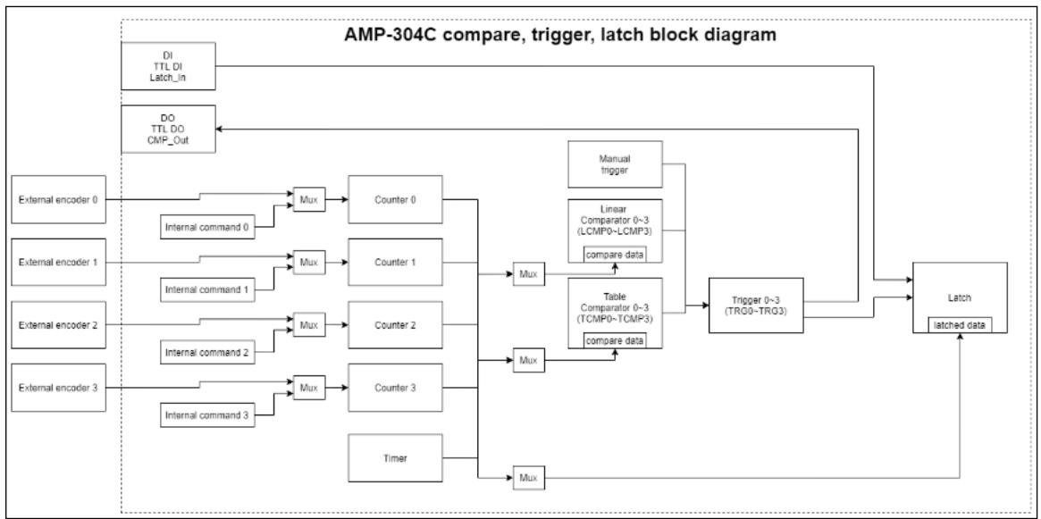
![**Title:** AMP-304C compare, trigger, latch block diagram\n\n**Labeled Blocks:**\n*   DI TTL DI Latch_in\n*   DO TTL DO CMP_Out\n*   External encoder 0\n*   Internal command 0\n*   External encoder 1\n*   Internal command 1\n*   External encoder 2\n*   Internal command 2\n*   External encoder 3\n*   Internal command 3\n*   Counter 0\n*   Counter 1\n*   Counter 2\n*   Counter 3\n*   Timer\n*   Mux (appears 7 times total: 4 on the left, 3 on the right)\n*   Manual trigger\n*   Linear Comparator 0-3 (LCMP0-LCMP3) (contains text: 'compare data')\n*   Table Comparator 0-3 (TCMP0-TCMP3) (contains text: 'compare data')\n*   Trigger 0-3 (TR0-TR3)\n*   Latch (contains text: 'latched data')\n\n**Connections:**\n*   **Input Multiplexing:**\n    *   'External encoder 0' and 'Internal command 0' both feed into a 'Mux', which outputs to 'Counter 0'.\n    *   'External encoder 1' and 'Internal command 1' both feed into a 'Mux', which outputs to 'Counter 1'.\n    *   'External encoder 2' and 'Internal command 2' both feed into a 'Mux', which outputs to 'Counter 2'.\n    *   'External encoder 3' and 'Internal command 3' both feed into a 'Mux', which outputs to 'Counter 3'.\n*   **Counters and Comparators:**\n    *   Outputs from 'Counter 0', 'Counter 1', 'Counter 2', and 'Counter 3' feed into a vertical bus line.\n    *   From this bus, three arrows feed into three vertically stacked 'Mux' blocks.\n    *   The top 'Mux' outputs to 'Linear Comparator 0-3 (LCMP0-LCMP3)'.\n    *   The middle 'Mux' outputs to 'Table Comparator 0-3 (TCMP0-TCMP3)'.\n    *   The bottom 'Mux' receives input from the vertical bus and the 'Timer'. It outputs to the 'Latch' block.\n*   **Trigger Logic:**\n    *   'Manual trigger' feeds into 'Trigger 0-3 (TR0-TR3)'.\n    *   'Linear Comparator 0-3 (LCMP0-LCMP3)' feeds into 'Trigger 0-3 (TR0-TR3)'.\n    *   'Table Comparator 0-3 (TCMP0-TCMP3)' feeds into 'Trigger 0-3 (TR0-TR3)'.\n*   **Outputs and Latching:**\n    *   'DI TTL DI Latch_in' connects to the 'Latch' block.\n    *   'Trigger 0-3 (TR0-TR3)' outputs to the 'Latch' block.\n    *   'Trigger 0-3 (TR0-TR3)' outputs to 'DO TTL DO CMP_Out'.](.aps-functionlibrary-v2-1/eb7e069679c0c7fb627788530bf7bd3c31fb8e11e0cc191495ac5f0b6dbd27e7.jpg)

There are 4 counters, which’s source can be selected as external encoders or internal commands. Related axis parameter： PRA\_CNT\_SRC.
The 4 counters are the compare data of linear comparators, table comparators and single comparators. Related trigger parameter： TGR\_LCMP0\_SRC\~ TGR\_LCMP3\_SRC, TGR\_TCMP0\_SRC\~ TGR\_TCMP3\_SRC.
The source to trigger the position latch can be selected by LTC\_IPT.

# PCIe-833x IO mapping

PCIe-833x IO mapping suggest NOT to modify the content of configuration file manually. Please use MCP2 IOmapping form to do mapping and checking.

The maximum number of software port in slave is “32” for each type IO.

• IO-mapping GUI can be used by MCP2 only. User should be use configure file download API.
• Configuration file can be save to "CSV" file by MCP2 IO-mapping form.
No need to map module that ADLINK had integrated.

# Step-by-step instructions for set up IO mapping using MCP2

# Step 1：

Update kernel version：C:\Program Files (x86)\ADLINK\PCIe-833x\Kernel Update kernel version needs to be after 2022050503\_833x\_kernel.

# Step 2：

After field bus connect,and select tree view EtherCAT IO level will show IO mapping button.Click the button to start setting up the IO mapping.
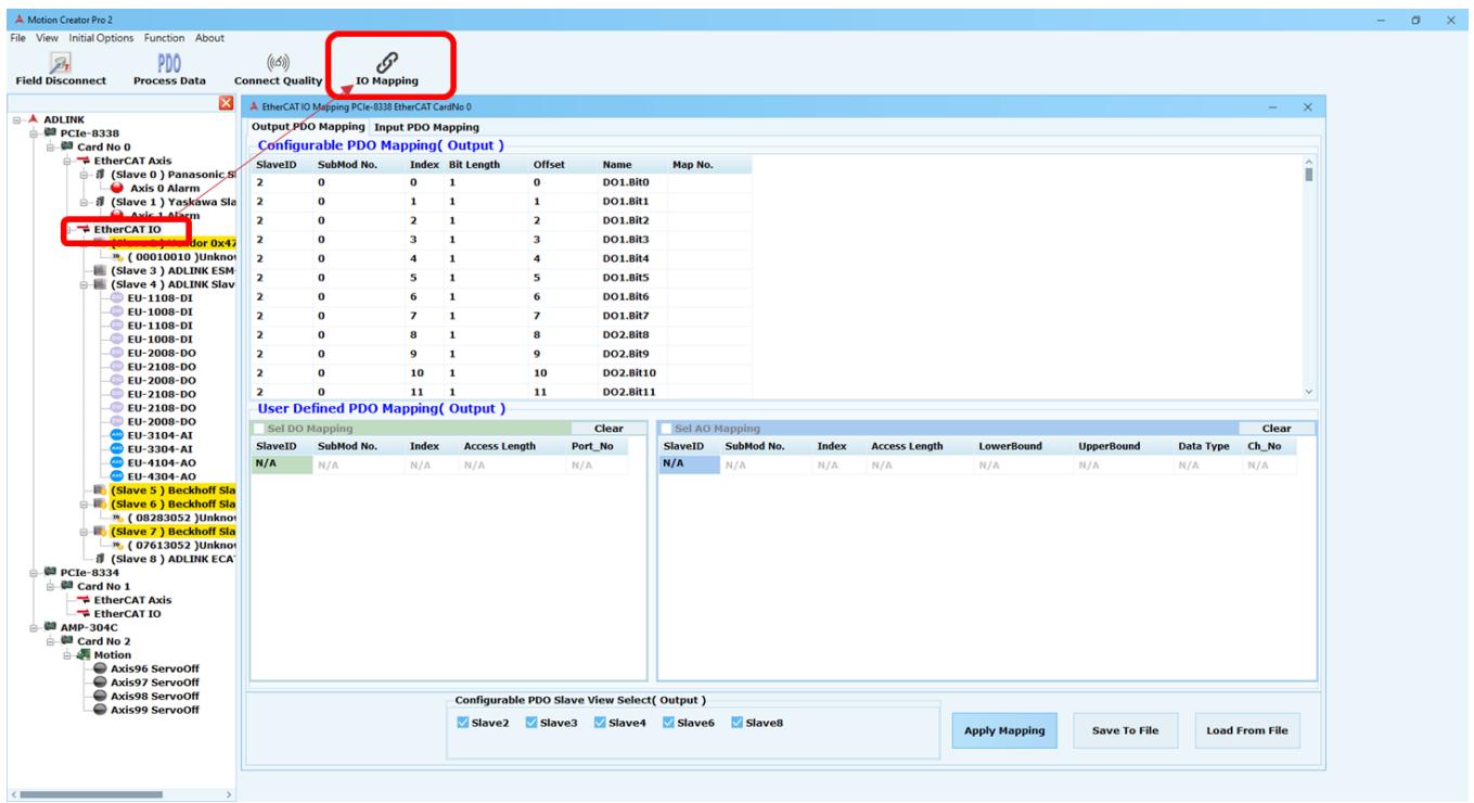
![Motion Creator Pro 2\nFile View Initial Options Function About\nField Disconnect Process Data Connect Quality IO Mapping\nADLINK PCIE-833B Card No 0\nEtherCAT Axis\n(Slave 0 ) Panasonic S\nAxis 0 Alarm\n(Slave 1 ) Yasikawa Sla\nAxis 1 Alarm\nEtherCAT IO\n(00010010)Unknown\n(Slave 3 ) ADLINK ESM\n(Slave 4 ) ADLINK Slav\nEU-1108-DI\nEU-1008-DI\nEU-1108-DI\nEU-1008-DI\nEU-2008-DO\nEU-2108-DO\nEU-2008-DO\nEU-2108-DO\nEU-2108-DO\nEU-2008-DO\nEU-3104-AI\nEU-4104-AO\nEU-4304-AO\n(Slave 5 ) Beckhoff Sla\n(Slave 6 ) Beckhoff Sla\n(08283052)Unknown\n(Slave 7 ) Beckhoff Sla\n(07613052)Unknown\n(Slave 8 ) ADLINK ECA\nPCIe-8334 Card No 1\nEtherCAT Axis\nEtherCAT IO\nAMP-304C Card No 2 Motion\nAxis96 ServoOff\nAxis97 ServoOff\nAxis98 ServoOff\nAxis99 ServoOff\nOutput PDO Mapping Input PDO Mapping\nConfigurable PDO Mapping( Output )\nSlaveID SubMod No. Index Bit Length Offset Name Map No.\n2 0 0 1 0 DO1.Bit0\n2 0 1 1 1 DO1.bit1\n2 0 2 1 2 DO1.bit2\n2 0 3 1 3 DO1.bit3\n2 0 4 1 4 DO1.bit4\n2 0 5 1 5 DO1.bit5\n2 0 6 1 6 DO1.bit6\n2 0 7 1 7 DO1.bit7\n2 0 8 1 8 DO2.bit8\n2 0 9 1 9 DO2.bit9\n2 0 10 1 10 DO2.bit10\n2 0 11 1 11 DO2.bit11\nUser Defined PDO Mapping( Output )\nSel DO Mapping Clear\nSlaveID SubMod No. Index Access Length Port_No\nN/A N/A N/A N/A N/A\nSel AO Mapping Clear\nSlaveID SubMod No. Index Access Length LowerBound UpperBound Data Type Ch_No\nN/A N/A N/A N/A N/A N/A N/A N/A N/A\nConfigurable PDO Slave View Select( Output )\nSlave2 Slave3 Slave4 Slave6 Slave8 Apply Mapping Save To File Load From File](.aps-functionlibrary-v2-1/439fbb3c80f89e11ee7313955550635bc2cdd37a2a437655d7b483430e772706.jpg)

# Step 2-1 ( Select DIO mapping )：

Select need slave IO to mapping. Refer to Configurable PDO view and input corresponding parameters.
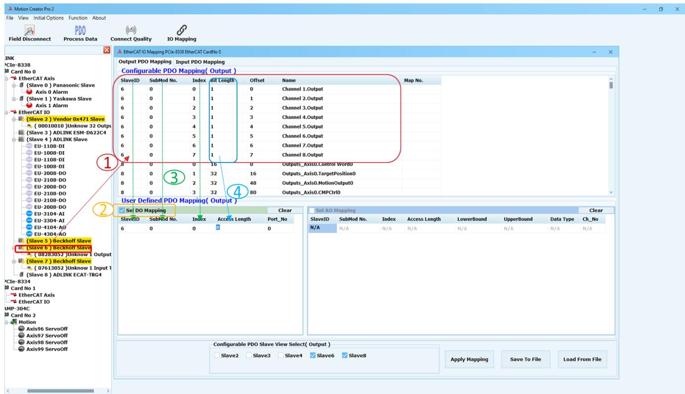
![Motion Creator Pro 2\nFile View Initial Options Function About\nField Disconnect Process Data Connect Quality IO Mapping\nINK\n*CIe-8338\nCard No 0\nEtherCAT Axis\n(Slave 0) Panasonic Slave\nAxis 0 Alarm\n(Slave 1) Yaskawa Slave\nAxis 1 Alarm\nEtherCAT IO\n(Slave 2) Vendor 0x471 Slave\n(00010010)Unknown 32 Output\n(Slave 3) ADLINK ESM-D622C4\n(Slave 4) ADLINK Slave\nEU-1108-DI\nEU-1008-DI\nEU-1108-DI\nEU-1008-DI\nEU-2008-DO\nEU-2108-DO\nEU-2008-DO\nEU-2108-DO\nEU-2108-DO\nEU-2008-DO\nEU-3104-AI\nEU-3304-AI\nEU-4104-AO\nEU-4304-AO\n(Slave 5) Beckhoff Slave\n(Slave 6) Beckhoff Slave\n(082830S2)Unknown 1 Output\n(Slave 7) Beckhoff Slave\n(076130S2)Unknown 1 Input 1\n(Slave 8) ADLINK ECAT-TRG4\nPCle-8334\nCard No 1\nEtherCAT Axis\nEtherCAT IO\nCMP-304C\nCard No 2\nMotion\nAxis96 ServoOff\nAxis97 ServoOff\nAxis98 ServoOff\nAxis99 ServoOff\nEtherCAT IO Mapping PCIe-8338 EtherCAT CardNo 0\nOutput PDO Mapping Input PDO Mapping\nConfigurable PDO Mapping( Output )\nSlaveID SubMod No. Index dit Length Offset Name Map No.\n6 0 0 1 0 Channel 1.Output\n6 0 1 1 Channel 2.Output\n6 0 2 1 Channel 3.Output\n6 0 3 1 Channel 4.Output\n6 0 4 1 Channel 5.Output\n6 0 5 1 Channel 6.Output\n6 0 6 1 Channel 7.Output\n6 0 7 1 Channel 8.Output\n8 0 0 16 0 Outputs_Axis0.Control Word0\n8 0 1 32 16 Outputs_Axis0.TargetPosition0\n8 0 2 32 48 Outputs_Axis0.MotionOutput0\n8 0 3 32 80 Outputs_Axis0.CMPCtrl0\nUser Defined PDO Mapping( Output )\nSe DO Mapping Clear\nSlaveID SubMod No. Index Access Length Port_No Clear\n6 0 0 8 0\nSel AO Mapping Clear\nSlaveID SubMod No. Index Access Length LowerBound UpperBound Data Type Ch_No\nN/A N/A N/A N/A N/A N/A N/A N/A N/A N/A N/A N/A N/A N/A N/A N/A N/A N/A N/A N/A N/A N/A N/A N/A N/A N/A N/A N/A N/A N/A N/A N/A N/A N/A N/A N/A N/A N/A N/A N/A N/A N/A N/A N/A N/A N/A N/A N/A N/A N/A N/A(nl)Configurable PDO Slave View Select( Output )\nSlave2 Slave3 Slave4 Slave6 Slave8 Apply Mapping Save To File Load From File](.aps-functionlibrary-v2-1/e9732eaa4acc3f60e01a697886f815f10baea246477bd29b06f8568f67fd3035.jpg)

○1 Select need slave IO to mapping and refer Configurable PDO view.
Tick the IO type that needs to be set.
○3 SlaveID fill in need mapping slave IO.

SubMod No. fill in the corresponding SubMod No. Please refer to SubMod No in Configurable PDO View Contents.

Index fills in the starting index. Please refer to Index in Configurable PDO View Content.

○4 Access Length fill in define the IObit required by the port.

# DIO mapping parameters：

SlaveID：Need mapping slave IO.
SubMod No. ：Configurable PDO view
Index：Access start index according to index in configurable PDO view content.
Access Length：Access port length according to Bit Length in configurable PDO view content.
Maximum : 32 bits
Minimum : 1 bit
Port\_No：Automatically generated.

# Step 2-2 (Select AIO mapping )：

Select need slave IO to mapping. Refer to Configurable PDO view and input corresponding parameters.
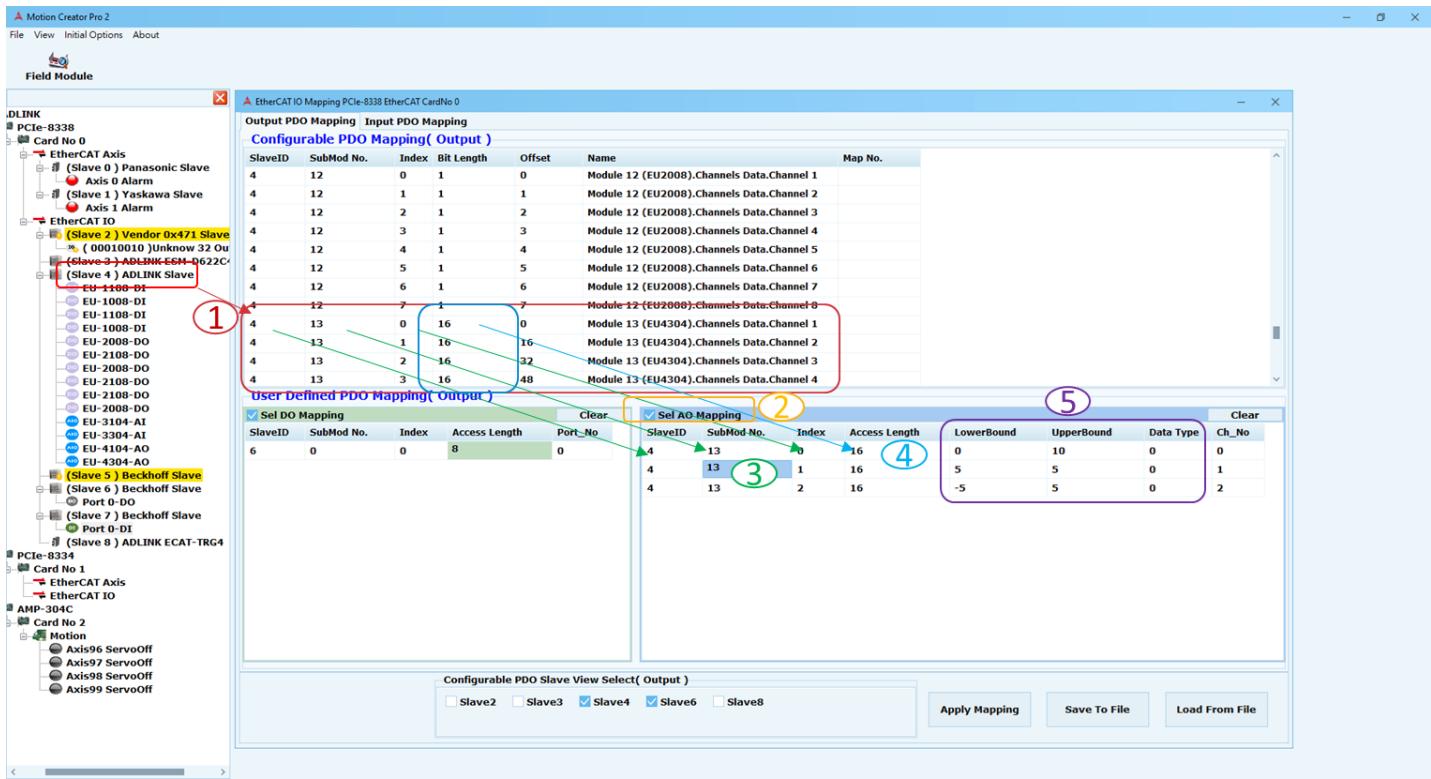
![Motion Creator Pro 2\nFile View Initial Options About\nField Module\nDLINK\nPCIe-8338 EtherCAT IO Mapping PCIe-8338 EtherCAT CardNo 0\nOutput PDO Mapping Input PDO Mapping\nConfigurable PDO Mapping( Output )\nSlaveID SubMod No. Index Bit Length Offset Name Map No.\n4 12 0 1 0 Module 12 (EU2008).Channels Data.Channel 1\n4 12 1 1 1 Module 12 (EU2008).Channels Data.Channel 2\n4 12 2 1 2 Module 12 (EU2008).Channels Data.Channel 3\n4 12 3 1 3 Module 12 (EU2008).Channels Data.Channel 4\n4 12 4 1 4 Module 12 (EU2008).Channels Data.Channel 5\n4 12 5 1 5 Module 12 (EU2008).Channels Data.Channel 6\n4 12 6 1 6 Module 12 (EU2008).Channels Data.Channel 7\n4 12 7 1 7 Module 12 (EU2008).Channels Data.Channel 8\n4 13 0 16 0 Module 13 (EU4304).Channels Data.Channel 1\n4 13 1 16 Module 13 (EU4304).Channels Data.Channel 2\n4 13 2 16 Module 13 (EU4304).Channels Data.Channel 3\n4 13 3 16 Module 13 (EU4304).Channels Data.Channel 4\nUser Defined PDO Mapping( Output )\n✓ Sel DO Mapping Clear ✓ Sel AO Mapping \nSlaveID SubMod No. Index Access Length Port_No \n6 0 0 8 0 \n4 13 0 16 LowerBound UpperBound Data Type Ch_No \n4 13 1 16\n4 13 2 16 -5 5 0\n3\n4\n5\n6\n7\n8\n9\n10\n11\n12\n13\n14\n15\n16\n17\n18\n19\n20\n21\n22\n23\n24\n25\n26\n27\n28\n29\n30\n31\n32\n33\n34\n35\n36\n37\n38\n39\n40\n41\n42\n43\n44\n45\n46\n47\n48\n49\n50\n51\n52\n53\n54\n55\n56\n57\n58\n59\n60\n61\n62\n63\n64\n65\n66\n67\n68\n69\n70\n71\n72\n73\n74\n75\n76\n77\n78\n79\n80\n81\n82\n83\n84\n85\n86\n87\n88\n89\n90\n91\n92\n93\n94\n95\n96\n97\n98\n99\n100](.aps-functionlibrary-v2-1/dd111abcb3f8ad96bcf65cbab7cdf04fa0891655e11cf2e4da79223cbaa7574f.jpg)

○1 Select need slave IO to mapping and refer Configurable PDO view.
Tick the IO type that needs to be set.
○3 SlaveID fill in need mapping slave IO.

SubMod No. fill in the corresponding SubMod No. Please refer to SubMod No in Configurable PDO View Contents.

Index fills in the starting index. Please refer to Index in Configurable PDO View Content.

○4 Access Length fill in define the IObit required by the port.
○5 LowerBound fill in physical lower limit.

UpperBound fill in physical upper limit.

Data type fill in Representation type(0：Unsigned integer、1：Signed integer、2：Absolute valuewith MSB as sign、3：Raw data)

# AIO mapping parameters：

SlaveID：Need mapping slave IO.
SubMod No. ：Configurable PDO view
Index：Access start index according to index in configurable PDO view content.

Access Length：Access channel length according to Bit Length in configurable PDO view content.(Note: need correct length)
LowerBound：physical lower limit.
UpperBound：physical upper limit.
Data type：Representation type

Type 0(Unsigned integer) E.g., for 16 bits = 0 to +65535
Type 1(Signed integer) E.g., for 16 bits = -32768 to +32767
Type 2(Absolute value with MSB as sign) E.g., for 16 bits = -32767 to +32767 Type 3(Raw data)

Ch\_No：Automatically generated.

# Step 2-3 ：( User Defiend PDO Mapping)

Add and Delete row have two method：

Right-click on the table

![SlaveID SubMod No. Index Access Length Port_No\n6 0 0 8 0\nAdd New Row(last)\nDelete Row(current)](.aps-functionlibrary-v2-1/8ddd3286a92fe8afebaff1ffdb068af474c36487e791fbd352bfa0dd383999ca.jpg)

Using the keyboard Add(Ctrl+enter)、Delete(Ctrl+delete)

<table><tr><td>SlaveID</td><td>SubMod No.</td><td>Index</td><td>Access Length</td><td>Port_No</td></tr><tr><td>6</td><td>0</td><td>0</td><td>8</td><td>0</td></tr><tr><td>6</td><td>0</td><td>0</td><td>8</td><td>1</td></tr><tr><td>6</td><td>0</td><td>0</td><td>8</td><td>2</td></tr></table>

Hint：

Move the mouse over the table and hint will appear.

![✓ Sel DO Mapping\nClear\nSlaveID SubMod No. Index Access Length Port_No\nN/A N/A N/A N/A\nPlease refer to the SubMod No. column in the PDO view table.](.aps-functionlibrary-v2-1/a6698cf1b8474a20d28f712f45537d51af0b2ae45f08692ebb26acbb94069858.jpg)

![✓ Sel DI Mapping\nClear\nSlaveID SubMod No. Index Access Length Port_No\nN/A N/f N/A ...?\nPlease refer to the SubMod No. column in the PDO view table.](.aps-functionlibrary-v2-1/120b4921d90ad4ce0c0dec9028670ec644c86446133681593e3c73b7dffa7d04.jpg)

User Defiend DIO mapping hint

<table><tr><td colspan="7">✓ Sel AO Mapping</td><td>Clear</td></tr><tr><td>SlaveID</td><td>SubMod No.</td><td>Index</td><td>Access Length</td><td>LowerBound</td><td>UpperBound</td><td>Data Type</td><td>Ch_No</td></tr><tr><td>N/A</td><td>N/A</td><td>N/A</td><td>N/A</td><td>N/A</td><td>N/A</td><td>N/A</td><td>N/A</td></tr><tr><td></td><td></td><td></td><td></td><td colspan="2">Please set a physical lower limit.</td><td></td><td></td></tr></table>

<table><tr><td colspan="7">✓ Sel AI Mapping</td><td>Clear</td></tr><tr><td>SlaveID</td><td>SubMod No.</td><td>Index</td><td>Access Length</td><td>LowerBound</td><td>UpperBound</td><td>Data Type</td><td>Ch_No</td></tr><tr><td>N/A</td><td>N/A</td><td>N/A</td><td>N/A</td><td>N/A</td><td>N/A</td><td>N/A</td><td>N/A</td></tr><tr><td></td><td></td><td></td><td></td><td></td><td colspan="3">0: Unsigned integer with N-bit resolution without sign, therefore polarity detection is no longer possible.
Example : Range for 16 bits = 0 to +65535
1: Signed integer(2&#x27;s complement(negated + 1)).
Example : Range for 16 bits = -32768 to +32767 dec.
2: Absolute value with MSB=1 (highest bit) as sign of negative values.
Example : Range for 16 bits = -32767 to +32767 dec.
3: Raw data has no transformation between physical value and raw data.</td></tr></table>

User Defiend AIO mapping hint

# Step3：

Click the Apply Mapping button. Configurable PDO view will show mapping results. Tree view will show software define Port No. or Channel No.

![Motion Creator Pro 2\nFile View Initial Options Function About\nAxis/Board Para DIO Control Kernel Performance\nADLINK\nPCIe-833B EtherCAT CardNo 0\nOutput PDO Mapping Input PDO Mapping\nConfigurable PDO Mapping( Output )\nSlaveID SubMod No. Index Bit Length Offset Name Map No.\n6 0 0 1 0 Channel 1.Output Port_No 0,\n6 0 1 1 1 Channel 2.Output Port_No 0,\n6 0 2 1 2 Channel 3.Output Port_No 0,\n6 0 3 1 3 Channel 4.Output Port_No 0,\n6 0 4 1 4 Channel 5.Output Port_No 0,\n6 0 5 1 5 Channel 6.Output Port_No 0,\n6 0 6 1 6 Channel 7.Output Port_No 0,\n6 0 7 1 7 Channel 8.Output Port_No 0,\n8 0 10 Outputs_Axis0.TargetPosition0\n8 0 1 32 16 Outputs_Axis0.TargetPosition0\n8 0 2 32 48 Outputs_Axis0.MotionOutput0\n8 0 3 32 80 Outputs_Axis0.CMPCtrl0\nUser Defined PDO Mapping( Output )\nSel DO Mapping Clear\nSlaveID SubMod No. Index Access Length Port_No\n6 0 0 8\nSel AO Mapping Clear\nSlaveID SubMod No. Index Access Length LowerBound UpperBound Data Type Ch_No\nN/A N/A N/A N/A N/A N/A N/A\nN/A N/A N/A N/A N/A N/A N/A\nApply Mapping Save To File Load From File\nPCIe-8334\nCard No 1 EtherCAT Axis EtherCAT IO\nAMP-304C\nCard No 2 Motion Axis96 ServoOff Axis97 ServoOff Axis98 ServoOff Axis99 ServoOff\nSlave 6 Beckoff Sla\nPort 0-DO\nSlave 7 Beckoff Sla\nSlave 8 Beckoff Sla\nSlave 9 Beckoff Sla\nSlave 10 Beckoff Sla\nSlave 11 Beckoff Sla\nSlave 12 Beckoff Sla\nSlave 13 Beckoff Sla\nSlave 14 Beckoff Sla\nSlave 15 Beckoff Sla\nSlave 16 Beckoff Sla\nSlave 17 Beckoff Sla\nSlave 18 Beckoff Sla\nSlave 19 Beckoff Sla\nSlave 20 Beckoff Sla\nSlave 21 Beckoff Sla\nSlave 22 Beckoff Sla\nSlave 23 Beckoff Sla\nSlave 24 Beckoff Sla\nSlave 25 Beckoff Sla\nSlave 26 Beckoff Sla\nSlave 27 Beckoff Sla\nSlave 28 Beckoff Sla\nSlave 29 Beckoff Sla\nSlave 30 Beckoff Sla\nSlave 31 Beckoff Sla\nSlave 32 Beckoff Sla\nSlave 33 Beckoff Sla\nSlave 34 Beckoff Sla\nSlave 35 Beckoff Sla\nSlave 36 Beckoff Sla\nSlave 37 Beckoff Sla\nSlave 38 Beckoff Sla\nSlave 39 Beckoff Sla\nSlave 40 Beckoff Sla\nSlave 41 Beckoff Sla\nSlave 42 Beckoff Sla\nSlave 43 Beckoff Sla\nSlave 44 Beckoff Sla\nSlave 45 Beckoff Sla\nSlave 46 Beckoff Sla\nSlave 47 Beckoff Sla\nSlave 48 Beckoff Sla\nSlave 49 Beckoff Sla\nSlave 50 Beckoff Sla\nSlave 51 Beckoff Sla\nSlave 52 Beckoff Sla\nSlave 53 Beckoff Sla\nSlave 54 Beckoff Sla\nSlave 55 Beckoff Sla\nSlave 56 Beckoff Sla\nSlave 57 Beckoff Sla\nSlave 58 Beckoff Sla\nSlave 59 Beckoff Sla\nSlave 60 Beckoff Sla\nSlave 61 Beckoff Sla\nSlave 62 Beckoff Sla\nSlave 63 Beckoff Sla\nSlave 64 Beckoff Sla\nSlave 65 Beckoff Sla\nSlave 66 Beckoff Sla\nSlave 67 Beckoff Sla\nSlave 68 Beckoff Sla\nSlave 69 Beckoff Sla\nSlave 70 Beckoff Sla\nSlave 71 Beckoff Sla\nSlave 72 Beckoff Sla\nSlave 73 Beckoff Sla\nSlave 74 Beckoff Sla\nSlave 75 Beckoff Sla\nSlave 76 Beckoff Sla\nSlave 77 Beckoff Sla\nSlave 78 Beckoff Sla\nSlave 79 Beckoff Sla\nSlave 80 Beckoff Sla\nSlave 81 Beckoff Sla\nSlave 82 Beckoff Sla\nSlave 83 Beckoff Sla\nSlave 84 Beckoff Sla\nSlave 85 Beckoff Sla\nSlave 86 Beckoff Sla\nSlave 87 Beckoff Sla\nSlave 88 Beckoff Sla\nSlave 89 Beckoff Sla\nSlave 90 Beckoff Sla\nSlave 91 Beckoff Sla\nSlave 92 Beckoff Sla\nSlave 93 Beckoff Sla\nSlave 94 Beckoff Sla\nSlave 95 Beckoff Sla\nSlave 96 Beckoff Sla\nSlave 97 Beckoff Sla\nSlave 98 Beckoff Sla\nSlave 99 Beckoff Sla](.aps-functionlibrary-v2-1/e4691b4ffb257f1b8bba77f0267bfdf715ff132818c6217a7a93bbd747383772.jpg)

DIO mapping show software define Port No.
![Motion Creator Pro 2\nFile View Initial Options Function About\nAxis/Board Para DIO Control Kernel Performance\nADLINK\nPCIe-8338\nCard No 0\nEtherCAT Axis\n(Slave 0 ) Panasonic Sl\nAxis 0 Alarm\n(Slave 1 ) Yaskawa Sla\nAxis 1 Alarm\nEtherCAT IO\n(Slave 2 ) Vendor 0x4\n( 00010010 ) Unknor\n(Slave 3 ) ADLINK ESM\n(Slave 4 ) ADLINK Slav\nEU-1108-DI\nEU-1008-DI\nEU-1108-DI\nEU-1008-DI\nEU-2008-DO\nEU-2108-DO\nEU-2008-DO\nEU-2108-DO\nEU-2108-DO\nEU-2008-DO\nEU-3104-AI\nChannel 0 -AO\nChannel 1 -AO\nChannel 2 -AO\n(Slave 5 ) Beckhoff Sla\n(Slave 6 ) Beckhoff Sla\nPort 0-DO\n(Slave 7 ) Beckhoff Sla\nPort 0-DI\n(Slave 8 ) ADLINK ECA\nPCIe-8334\nCard No 1\nEtherCAT Axis\nEtherCAT IO\nAMP-304C\nCard No 2\nMotion\nAxis96 ServoOff\nAxis97 ServoOff\nAxis98 ServoOff\nAxis99 ServoOff\nOutput PDO Mapping Input PDO Mapping\nConfigurable PDO Mapping( Output )\nSlaveID SubMod No. Index Bit Length Offset Name Map No.\n1 12 6 1 6 Module 12 (EU2008).Channels Data.Channel 7\n4 12 7 1 7 Module 12 (EU2008).Channels Data.Channel 8\n4 13 0 16 0 Module 13 (EU4304).Channels Data.Channel 1 Ch_No 0,\n4 13 1 16 Module 13 (EU4304).Channels Data.Channel 2 Ch_No 1,\n4 13 2 16 Module 13 (EU4304).Channels Data.Channel 3 Ch_No 2,\n4 13 3 16 48 Module 13 (EU4304).Channels Data.Channel 4\n6 0 0 1 0 Channel 1.Output Port_No 0,\n6 0 1 1 1 Channel 2.Output Port_No 0,\n6 0 2 1 2 Channel 3.Output Port_No 0,\n6 0 3 1 3 Channel 4.Output Port_No 0,\n6 0 4 1 4 Channel 5.Output Port_No 0,\n6 0 5 1 5 Channel 6.Output Port_No 0,\nUser Defined PDO Mapping( Output )\nSel DO Mapping Clear\nSlaveID SubMod No. Index Access Length Port_No\n6 0 0 8\nSel AO Mapping Clear\nSlaveID SubMod No. Index Access Length LowerBound UpperBound Data Type Ch_No\n4 13 0 16 0 10 0 0\n4 13 1 16 5 5 0 1\n4 13 2 16 -5 5 0 2\nConfigurable PDO Slave View Select( Output )\nSlave2 Slave3 Slave4 Slave6 Slave8 Apply Mapping Save To File Load From File](.aps-functionlibrary-v2-1/f37e6b6bcc75f09e3b1f45f630775d487582472e7951226d3ee9a75f9f83b6ff.jpg)

AIO mapping show software define Channel No.

# Step4 ：

If select tree view software define Port No. will show Field module button. Click the button to start DO/DI port control( default 32 DO/DI view ). This DO/DI control bits follows how much length the user sets. An error code is returned if the DIO bits controlled by the user settings are exceeded.

![Motion Creator Pro 2\nFile View Install Options About\nField Module\nADLINK\nPCIe-B338\nCard No 0\nEtherCAT Axis\n(Slave 0) Panasonic Slave\nAxis 0 Alarm\n(Slave 1) Yaskawa Slave\nAxis 1 Alarm\nEtherCAT IO\n(Slave 2) Vendor 0x471 SI\n(00010010)Unknown 32\n(Slave 3) ADLINK ESM-D62\n(Slave 4) ADLINK Slave\nEU-1108-DI\nEU-1008-DI\nEU-1108-DI\nEU-1008-DI\nEU-2008-DO\nEU-2108-DO\nEU-2008-DO\nEU-2108-DO\nEU-2108-DO\nEU-2008-DO\nEU-3104-AI\nEU-3304-AI\nEU-4104-AO\nEU-4304-AO\n(Slave 5) Beckhoff Slave\n(07613052)Unknown 1\n(Slave 8) ADLINK ECAT-TR\nPCIe-B334\nCard No 1\nEtherCAT Axis\nEtherCAT IO\nAMP-304C\nCard No 2\nMotion\nAxis96 ServoOff\nAxis97 ServoOff\nAxis98 ServoOff\nAxis99 ServoOff\nPCIe-8338 EtherCAT CardID 0 Slave ID 6 DO Port 0\nDO\nON 7 OFF 6 OFF 5 OFF 4 OFF 3 OFF 2 OFF 1 ON 0\nOFF 15 OFF 14 OFF 13 OFF 12 OFF 11 OFF 10 OFF 9 OFF 8\nOFF 23 OFF 22 OFF 21 OFF 20 OFF 19 OFF 18 OFF 17 OFF 16\nOFF 31 OFF 30 OFF 29 OFF 28 OFF 27 OFF 26 OFF 25 OFF 24\nMap No.\nPort_No_0,\nPort_No_0,\nPort_No_0,\nPort_No_0,\nPort_No_0,\nPort_No_0,\nPort_No_0,\nPort_No_0,\nPort_No_0,\nPort_No_0,\nPort_No_0,\nPort_No_0,\nPort_No_0,\nPort_No_0,\nPort_No_0,\nPort_No_0,\nPort_No_0,\nPort_No_0,\nPort_No_0,\nPort_No_0,\nPort_No_0, Control Word0\nOutputs_Axis0. Control Word0\nOutputs_Axis0. TargetPosition0\nOutputs_Axis0. MotionOutput0\nOutputs_Axis0. CMPCtrl0\nUser Defined PDO Mapping( Output )\nSel DO Mapping Clear\nSlaveID SubMod No. Index Access Length Port_No\n6 0 0 8 0\nSet AO Mapping Clear\nSlaveID SubMod No. Index Access Length LowerBound UpperBound Data Type Ch_No\nN/A N/A N/A N/A N/A N/A N/A N/A N/A N/A\nConfigurable PDO Slave View Select( Output )\nSlave2 Slave3 Slave4 Slave6 Slave8\nApply Mapping Save To File Load From File](.aps-functionlibrary-v2-1/9adce60987109f81c639f6b4f942715e4e7f264c9d76059321fea1e3ad8af090.jpg)

If select tree view software define Channel No. will show Field module button. Click the button to start AO/AI channel control( default 1 channel).

![Motion Creator Pro 2\nAbout\nField Module\nPCIe-8338 EtherCAT CardID 0 Slave ID 4 AO Channel 0\nRange: 0 -) 10\nCh 0 ( ) 0\nRange: 0 -) 5\nCh 1 ( ) 0\nRange: -5 -) 5\nCh 2 ( ) -5\nPCIe-8338 EtherCAT CardID 0 Slave ID 4 AO Channel 1\nRange: -5 -) 5\nCh 2 ( ) -5\nPCIe-8338 EtherCAT CardID 0 Slave ID 4 AO Channel 2\nRange: -5 -) 5\nCh 2 ( ) -5\nPCIe-8338 EtherCAT CardID 0 Slave ID 4 AO Channel 3\nRange: -5 -) 5\nCh 2 ( ) -5\nPCIe-8338 EtherCAT CardID 0 Slave ID 4 AO Channel 4\nRange: -5 -) 5\nCh 2 ( ) -5\nPCIe-8338 EtherCAT CardID 0 Slave ID 4 AO Channel 5\nRange: -5 -) 5\nCh 2 ( ) -5\nPCIe-8338 EtherCAT CardID 0 Slave ID 4 AO Channel 6\nRange: -5 -) 5\nCh 2 ( ) -5\nPCIe-8338 EtherCAT CardID 0 Slave ID 4 AO Channel 7\nRange: -5 -) 5\nCh 2 ( ) -5\nPCIe-8338 EtherCAT CardID 0 Slave ID 4 AO Channel 8\nRange: -5 -) 5\nCh 2 ( ) -5\nPCIe-8338 EtherCAT CardID 0 Slave ID 4 AO Channel 9\nRange: -5 -) 5\nCh 2 ( ) -5\nPCIe-8338 EtherCAT CardID 0 Slave ID 4 AO Channel 10\nRange: -5 -) 5\nCh 2 ( ) -5\nPCIe-8338 EtherCAT CardID 0 Slave ID 4 AO Channel 11\nRange: -5 -) 5\nCh 2 ( ) -5\nPCIe-8338 EtherCAT CardID 0 Slave ID 4 AO Channel 12\nRange: -5 -) 5\nCh 2 ( ) -5\nPCIe-8338 EtherCAT CardID 0 Slave ID 4 AO Channel 13\nRange: -5 -) 5\nCh 2 ( ) -5\nPCIe-8338 EtherCAT CardID 0 Slave ID 4 AO Channel 14\nRange: -5 -) 5\nCh 2 ( ) -5\nPCIe-8338 EtherCAT CardID 0 Slave ID 4 AO Channel 15\nRange: -5 -) 5\nCh 2 ( ) -5\nPCIe-8338 EtherCAT CardID 0 Slave ID 4 AO Channel 16\nRange: -5 -) 5\nCh 2 ( ) -5\nPCIe-8338 EtherCAT CardID 0 Slave ID 4 AO Channel 17\nRange: -5 -) 5\nCh 2 ( ) -5\nPCIe-8338 EtherCAT CardID 0 Slave ID 4 AO Channel 18\nRange: -5 -) 5\nCh 2 ( ) -5\nPCIe-8338 EtherCAT CardID 0 Slave ID 4 AO Channel 19\nRange: -5 -) 5\nCh 2 ( ) -5\nPCIe-8338 EtherCAT CardID 0 Slave ID 4 AO Channel 20\nRange: -5 -) 5\nCh 2 ( ) -5\nPCIe-8338 EtherCAT CardID 0 Slave ID 4 AO Channel 21\nRange: -5 -) 5\nCh 2 ( ) -5\nPCIe-8338 EtherCAT CardID 0 Slave ID 4 AO Channel 22\nRange: -5 -) 5\nCh 2 ( ) -5\nPCIe-8338 EtherCAT CardID 0 Slave ID 4 AO Channel 23\nRange: -5 -) 5\nCh 2 ( ) -5\nPCIe-8338 EtherCAT CardID 0 Slave ID 4 AO Channel 24\nRange: -5 -) 5\nCh 2 ( ) -5\nPCIe-8338 EtherCAT CardID 0 Slave ID 4 AO Channel 25\nRange: -5 -) 5\nCh 2 ( ) -5\nPCIe-8338 EtherCAT CardID 0 Slave ID 4 AO Channel 26\nRange: -5 -) 5\nCh 2 ( ) -5\nPCIe-8338 EtherCAT CardID 0 Slave ID 4 AO Channel 27\nRange: -5 -) 5\nCh 2 ( ) -5\nPCIe-8338 EtherCAT CardID 0 Slave ID 4 AO Channel 28\nRange: -5 -) 5\nCh 2 ( ) -5\nPCIe-8338 EtherCAT CardID 0 Slave ID 4 AO Channel 29\nRange: -5 -) 5\nCh 2 ( ) -5\nPCIe-8338 EtherCAT CardID 0 Slave ID 4 AO Channel 30\nRange: -5 -) 5\nCh 2 ( ) -5\nPCIe-8338 EtherCAT CardID 0 Slave ID 4 AO Channel 31\nRange: -5 -) 5\nCh 2 ( ) -5\nPCIe-8338 EtherCAT CardID 0 Slave ID 4 AO Channel 32\nRange: -5 -) 5\nCh 2 ( ) -5\nPCIe-8338 EtherCAT CardID 0 Slave ID 4 AO Channel 33\nRange: -5 -) 5\nCh 2 ( ) -5\nPCIe-8338 EtherCAT CardID 0 Slave ID 4 AO Channel 34\nRange: -5 -) 5\nCh 2 ( ) -5\nPCIe-8338 EtherCAT CardID 0 Slave ID 4 AO Channel 35\nRange: -5 -) 5\nCh 2 ( ) -5\nPCIe-8338 EtherCAT CardID 0 Slave ID 4 AO Channel 36\nRange: -5 -) 5\nCh 2 ( ) -5\nPCIe-8338 EtherCAT CardID 0 Slave ID 4 AO Channel](.aps-functionlibrary-v2-1/2fc5858cbe85a0e82b498c3a0c0477144a19a4155e52f680f3654b2306ed92fb.jpg)

# Save/Load file and apply mapping instructions

# Step1 ：

Click the Save to File button to export the io map data to a file.

![Motion Creator Pro 2\nFile View Initial Options About\nField Module\nADLINK\nPCIe-833B\nCard No 0\nEtherCAT IO\n(Slave 0) Panasonic Sl\nAxis 0 Alarm\n(Slave 1) Yaskawa Sla\nAxis 1 Alarm\nEtherCAT IO\n(Slave 2) Vendor 0x4\n(00010010) Unknown\n(Slave 3) ADLINK ESM\n(Slave 4) ADLINK Slav\nEU-1108-DI\nEU-1008-DI\nEU-1008-DI\nEU-2008-DO\nEU-2108-DO\nEU-3104-AI\nEU-3304-AI\nChannel 0-AO\nChannel 1-AO\nChannel 2-AO\n(Slave 5) Beckhoff Sla\n(Slave 6) Beckhoff Sla\nPort 0-DO\n(Slave 7) Beckhoff Sla\nPort 0-DI\n(Slave 8) ADLINK ECA*\nPCIe-8334\nCard No 1\nEtherCAT Axis\nEtherCAT IO\nAMP-304C\nCard No 2\nMotion\nAxis96 ServOff\nAxis97 ServOff\nAxis98 ServOff\nAxis99 ServOff\n\nEtherCAT IO Mapping PCIe-833B EtherCAT CardNo 0\nOutput PDO Mapping Input PDO Mapping\nConfigurable PDO Mapping( Output )\nSlaveID SubMod No. Index Bit Length Offset Name Map No.\n4 12 7 1 7 Module 12 (EU2008).Channels Data.Channel 8\n4 13 0 16 0 Module 13 (EU4304).Channels Data.Channel 1 Ch_No 0,\n4 13 1 16 16 Module 13 (EU4304).Channels Data.Channel 2 Ch_No 1,\n4 13 2 16 32 Module 13 (EU4304).Channels Data.Channel 3 Ch_No 2,\n4 13 3 16 48 Module 13 (EU4304).Channels Data.Channel 4\n6 0 0 1 0 Channel 1.Output Port_No 0,\n6 0 1 1 1 Channel 2.Output Port_No 0,\n6 0 2 1 2 Channel 3.Output Port_No 0,\n6 0 3 1 3 Channel 4.Output Port_No 0,\n6 0 4 1 4 Channel 5.Output Port_No 0,\n6 0 5 1 5 Channel 6.Output Port_No 0,\n6 0 6 1 6 Channel 7.Output Port_No 0,\n\nUser Defined PDO Mapping( Output )\nSel DO Mapping Clear\nSlaveID SubMod No. Index Access Length Port_No\n6 0 0 8\n\nSel AO Mapping Clear\nSlaveID SubMod No. Index Access Length LowerBound UpperBound Data Type Ch_No\n4 13 0 16 0 10 0\n4 13 1 16 0 5 0\n4 13 2 16 -5 5 0\nConfigurable PDO Slave View Select( Output )\nSlave2 Slave3 Slave4 Slave6 Slave8\n\nApply Mapping Save To File Load From File\n\n另存新模\n储存於(0): 点面\n本機\n快速存款\n保壁槽\n桌面\nPaul(J)\n到散60:1 GB,共114 GB\n煤器槽\n线路\n本機\nPCie-833B EtherCAT CardNo O\nECATIOMapping.csv\nMicrosoft Excel 填點分隔值圖像\n\n框索名稱(0): PCIe-833B EtherCAT CastNo B ECATIOMapping.csv \n存檔(5)\n存檔類型(T): *.csv\n\nSave To File](.aps-functionlibrary-v2-1/197f0aedad294f06eb2437ec54fdd6f45a1e819c2e7197f320db80cc79d38541.jpg)

# Step2：

Click the Load from file button to import and check the file contents.

![Motion Creator Pro.2\nFile View Initial Options Function About\nAxis/Board Para DIO Control Kernel Performance\nADLINK\nPCIe-8338\nCard No 0\nEtherCAT Axis\n(Slave 0) Panasonic Sl\nAxis 0 Alarm\n(Slave 1) Yaskawa Sla\nAxis 1 Alarm\nEtherCAT IO\n(Slave 2) Vendor Dx4\n(00010010)Unkno\n(Slave 3) ADLINK ESM\n(Slave 4) ADLINK Slav\nEU-1108-DI\nEU-1008-DI\nEU-1108-DI\nEU-1008-DI\nEU-2008-DO\nEU-2108-DO\nEU-2008-DO\nEU-3104-AI\nEU-3304-AI\n(Slave 5) Beckhoff Sla\n(Slave 6) Beckhoff Sla\n(Slave 7) Beckhoff Sla\n(Slave 8) ADLINK ECA\nPCIe-8334\nCard No 1\nEtherCAT Axis\nEtherCAT IO\nAMP-304C\nCard No 2\nMotion\nAxis96 ServoOff\nAxis97 ServoOff\nAxis98 ServoOff\nAxis99 ServoOff\nOutput PDO Mapping Input PDO Mapping\nConfigurable PDO Mapping( Output )\nSlaveID SubMod No. Index Bit Length Offset Name Map No.\n4 2 0 1 0 Module 2 (EU2008).Channels Data.Channel 1\n4 2 1 1 1 Module 2 (EU2008).Channels Data.Channel 2\n4 2 2 1 2 Module 2 (EU2008).Channels Data.Channel 3\n4 2 3 1 3 Module 2 (EU2008).Channels Data.Channel 4\n4 2 4 1 4 Module 2 (EU2008).Channels Data.Channel 5\n4 2 5 1 5 Module 2 (EU2008).Channels Data.Channel 6\n4 2 6 1 6 Module 2 (EU2008).Channels Data_Channel 7\n4 2 7 1 7 Module 2 (EU2008).Channels Data_Channel 8\n4 4 0 1 0 Module 4 (EU2108).Channels Data.Channel 1\n4 4 1 1 1 Module 4 (EU2108).Channels Data_Channel 2\n4 4 2 1 2 Module 4 (EU2108).Channels Data.Channel 3\n4 4 3 1 3 Module 4 (EU2108).Channels Data.Channel 4\nUser Defined PDO Mapping( Output )\nSel DO Mapping Clear\nSlaveID SubMod No. Index Access Length Port_No\nN/A N/A N/A N/A N/A\nSel AO Mapping Clear\nSlaveID SubMod No. Index Access Length LowerBound UpperBound Data Type Ch_No\nN/A N/A N/A N/A N/A N/A N/A N/A N/A\nConfigurable PDO Slave View Select( Output )\nSlave2 Slave3 Slave4 Slave6 Slave8 Apply Mapping Save To File Load From File](.aps-functionlibrary-v2-1/cf519960ecd67b4f0803f7d4ca1b0b52dccfd32474fbab3620f81f25fcc87039.jpg)
[🔗 Link to the original document](.aps-functionlibrary-v2-1/aps-functionlibrary-v2-1.pdf)
