# aTCA-80302PA/PD

# 3U 2-slot Full-Mesh 40G AdvancedTCA® Shelf

# User’s Manual

![Front view of a black server rack unit with ventilation grilles and drive bays (no visible text or symbols)](.atca-80302pd-atca-80302pa-pd-50-1g046-1000-10/dd0336a6d35c81b16f9b4eca3a05136d7f9fcbe3f899f57b034b173119e72e41.jpg)

Manual Rev.: 1.0

Revision Date: September 19, 2018

Part No.: 50-1G046-1000

# Preface

# Copyright 2018 ADLINK Technology, Inc.

This document contains proprietary information protected by copyright. All rights are reserved. No part of this manual may be reproduced by any mechanical, electronic, or other means in any form without prior written permission of the manufacturer.

# Disclaimer

The information in this document is subject to change without prior notice in order to improve reliability, design, and function and does not represent a commitment on the part of the manufacturer. In no event will the manufacturer be liable for direct, indirect, special, incidental, or consequential damages arising out of the use or inability to use the product or documentation, even if advised of the possibility of such damages.

# Environmental Responsibility

ADLINK is committed to fulfill its social responsibility to global environmental preservation through compliance with the European Union's Restriction of Hazardous Substances (RoHS) directive and Waste Electrical and Electronic Equipment (WEEE) directive. Environmental protection is a top priority for ADLINK. We have enforced measures to ensure that our products, manufacturing processes, components, and raw materials have as little impact on the environment as possible. When products are at their end of life, our customers are encouraged to dispose of them in accordance with the product disposal and/or recovery programs prescribed by their nation or company.

![Symbol of a trash bin crossed with two crossed lines, no text or labels present](.atca-80302pd-atca-80302pa-pd-50-1g046-1000-10/e8eb6f081ee068632d6a8971fa75fb8b8ba714e9a1e5ef21bb3b9f11def1ffa7.jpg)

Battery Labels (for products with battery)

![Simple line drawing of a trash bin with no text or symbols](.atca-80302pd-atca-80302pa-pd-50-1g046-1000-10/d00809bcd475339fd3bc5eca36c3e5a46e10d3988685d95179bfacb183241218.jpg)

![Li-ion](.atca-80302pd-atca-80302pa-pd-50-1g046-1000-10/834a7178788cc2d8a457117974988c83bbf787c0169e8a50cbc38e33a5587a91.jpg)

![RECYCLE\nRBRC\nLi-ion\n7.800.822.8837](.atca-80302pd-atca-80302pa-pd-50-1g046-1000-10/940678612ed93cf3fcf6544b2d8c629ea53bf678b484d8e23a3a1a371df7a7bd.jpg)

![廢電池請回收](.atca-80302pd-atca-80302pa-pd-50-1g046-1000-10/286de2f449fb4bc76676d3cbb6e982ac1e85ebdcf215bf9c572f37b973eb36f9.jpg)

# California Proposition 65 Warning

![The image shows a yellow triangular warning sign with a thick black border. Inside the yellow triangle is a large black exclamation mark.](.atca-80302pd-atca-80302pa-pd-50-1g046-1000-10/58a67d35c16f12755c137354774b169120d95e2cc0c6ed9ba3e46faf6e7c573b.jpg)

WARNING: This product can expose you to chemicals including acrylamide, arsenic, benzene, cadmium, Tris(1,3-dichloro-2-propyl)phosphate (TDCPP), 1,4-Dioxane, formaldehyde, lead, DEHP, styrene, DINP, BBP, PVC, and vinyl materials, which are

known to the State of California to cause cancer, and acrylamide, benzene, cadmium, lead, mercury, phthalates, toluene, DEHP, DIDP, DnHP, DBP, BBP, PVC, and vinyl materials, which are known to the State of California to cause birth defects or other reproductive harm. For more information go to www.P65Warnings.ca.gov.

# Table of Contents

# Preface ...........

# 1 Safety.....

1.1 Safety Symbols used in this document.. 5
1.2 General Safety Precautions.. 5
1.3 References and Architecture Specifications... 6
1.4 Terms and Acronyms . . 6
1.5 Hardware Platform...

# 2 Shelf Front and Rear View ..............

# 3 ATCA Backplane ................

3.1 Logical to Physical Slot Mapping.. 9
3.2 Interfaces.. 9
3.2.1 Fabric Interface.. 9
3.2.2 Synchronization Clock Interface .. 9
3.2.3 Update Channel Interface.. 9
3.2.4 Intelligent Platform Management Interface.. 9
3.2.5 Base Interface 10

3.3 Shelf FRU SEEPROM.. 11

3.4 Logic Ground... 11

# 4 Air Filter................... .12

4.1 Introduction . . 12

# 5 Shelf Ground Connection..... .13

5.1 Specification for the Shelf Ground connection cable. . 13

# 6 Fan Trays ..... .14

6.1 IPM Controller and Fan Control.. . 15
6.2 Fan Tray Indicators.. . 16
6.3 Fan Tray Signals . . 17
6.4 Fan Tray Connector Pin Assignment.. 17
6.5 Fan Tray IPMB Addresses . . 18
6.6 Front Board Air Distribution ... . 18
6.7 Rear Board Air Distribution .. . 19

# 7 Power... .20

7.1 AC PEM.. . 20
7.1.1 AC PEM Power Distribution... 21
7.1.2 AC PEM Signals .. . 22
7.1.3 AC PEM Indicators .. . 22
7.1.4 AC PEM Connector PIN Assignment.. . 23

7.2 DC PEM.. . 23

7.2.1 DC PEM Power Distribution.... 25

7.2.2 DC PEM Signals.. 25
7.2.3 DC PEM Indicators . . 26
7.2.4 DC PEM Connector PIN Assignment .. 26

# 8 Shelf Management... ..23

8.1 Shelf Managers . . 24
8.2 Introduction.. . 24
8.3 Front Panel Components.. .. 26
8.4 Hardware Address. . 26

# 9 Technical Data ........... .27

9.1 Shelf Dimensions.. . 30

# Getting Service ................ ..32

# 1 Safety

The intended audience of this User’s Manual is system integrators and hardware/software engineers.

# 1.1 Safety Symbols used in this document

![The image displays a triangular warning sign with a yellow background and a thick black border. In the center is a black symbol of a lightning bolt, indicating an electrical hazard or high voltage. There is no text present.](.atca-80302pd-atca-80302pa-pd-50-1g046-1000-10/253de710de8eff78090ce73884e0b43cb06486967be1b1f0ddec7fdc534079b1.jpg)

# Hazardous voltage!

This is the electrical hazard symbol. It indicates that there are dangerous voltages inside the Shelf.

![The image displays a yellow triangular warning sign with a thick black border. In the center of the triangle is a large black exclamation point. The sign is set against a white background, with the top edge of the image cropped.](.atca-80302pd-atca-80302pa-pd-50-1g046-1000-10/1eda0cb45536b94ba08cc8fab8f97533ace4dd038b314bfe7d0b6930ecf0e535.jpg)

# Caution!

Thisistheusercautionsymbol.Itindicatesaconditionwheredamageoftheequipment or injury of the service personnel could occur. To reduce the risk of damage or injury, follow all steps or procedures as instructed.

![The image shows a yellow triangular warning sign with a thick black border. Inside the triangle is a black silhouette depicting a hand reaching down towards a hammer.](.atca-80302pd-atca-80302pa-pd-50-1g046-1000-10/5de32a32c9a7b9442fde4bc8bb9f6dff9ad3571a4266ffaa2717f4d009ea97a1.jpg)

# Danger of electrostatic discharge!

TheShelfcontainsstaticsensitivedevices.Topreventstaticdamageyoumustwearan ESD wrist strap.

# 1.2 General Safety Precautions

![The image displays a yellow triangular warning sign with a thick black border and a black lightning bolt symbol in the center.](.atca-80302pd-atca-80302pa-pd-50-1g046-1000-10/3357b4a6f22d431437f5c79d46dc780854603b483d3a77aebdd1a96d3e5f891e.jpg)

# Warning!

Voltagesover60VDCcanbepresentinthisequipment.AsdefinedinthePICMG3.0 Speci- fication,thisequipmentis intendedtobeaccessed,tobe installedand maintainedby qualified and trained service personnel only.

• Service personnel must know the necessary electrical safety, wiring and connection prac- tices for installing this equipment.
• Install this equipment only in compliance with local and national electrical codes.
For additional information about this equipment, see the PICMG 3.0 Specification (www.picmg.com).

# 1.3 References and Architecture Specifications

Pigeon Point Systems IPM Sentry Shelf-External Interface Reference (www.pigeonpoint.com)
PICMG® 3.0 Revision 3.0 AdvancedTCA® Base Specification (www.picmg.com)

# 1.4 Terms and Acronyms

Table 1: Terms and Acronyms

<table><tr><td>Term</td><td>Definition</td></tr><tr><td>ATCA</td><td>Advanced Telecom Computing Architecture</td></tr><tr><td>Backplane</td><td>Passive circuit board providing the connectors for the front boards. Power distribution, management and auxiliary signal connections are supported</td></tr><tr><td>CDM</td><td>Shelf FRU Data Module</td></tr><tr><td>ECN</td><td>Engineering Change Notice</td></tr><tr><td>ESD</td><td>Electrostatic Discharge</td></tr><tr><td>ETSI</td><td>European Telecommunications Standards Institute</td></tr><tr><td>FRU</td><td>Field Replaceable Unit</td></tr><tr><td>IPMB</td><td>Intelligent Platform Management Bus</td></tr><tr><td>IPMC</td><td>Intelligent Platform Management Controller</td></tr><tr><td>IPMI</td><td>Intelligent Platform Management Interface</td></tr><tr><td>PCB</td><td>Printed Circuit Board</td></tr><tr><td>PEM</td><td>Power Entry Module</td></tr><tr><td>RTC</td><td>Real Time Clock</td></tr><tr><td>RTM</td><td>Rear Transition Module</td></tr><tr><td>Shelf</td><td>Enclosure containing subrack, Backplane, boards, cooling devices, PEMs and Fan Trays</td></tr><tr><td>VRTN</td><td>Voltage Return</td></tr></table>

# 1.5 Hardware Platform

The Shelf is 3 U high and 19“ rack mountable. The chassis is designed for easy access of any Field Replaceable Units (FRU).

• 2 slot ATCA Backplane with 15 x interconnected Fabric Interface, Base Interface in HUB/HUB or NODE/NODE configuration, bused IPMB interface, supporting two 8U ATCA hub boards or node boards (depending on chassis/backplane type)
• Mounting brackets for 19“ racks
• ESD Wrist Strap Terminals at front and rear
• Two dedicated slots for a Shelf Manager based on Pigeon Point ShMM-700
• One dedicated slot for a Schroff Shelf Alarm Panel (SAP) that provides Telco Alarm inter- face, Alarm Status LEDs and serial interface for the Shelf Manager
• Two Front pluggable Fan Trays with 5 high speed fans per tray
• Removable air filter that meets the requirements of the Telcordia GR-78-CORE specifica- tion.
• Two rear pluggable AC- or DC-Power Entry Modules, the same interface in the subrack for AC PEM and DC PEM.
• Front pluggable air inlet filter

# 2 Shelf Front and Rear View

Figure 1: Shelf Front View
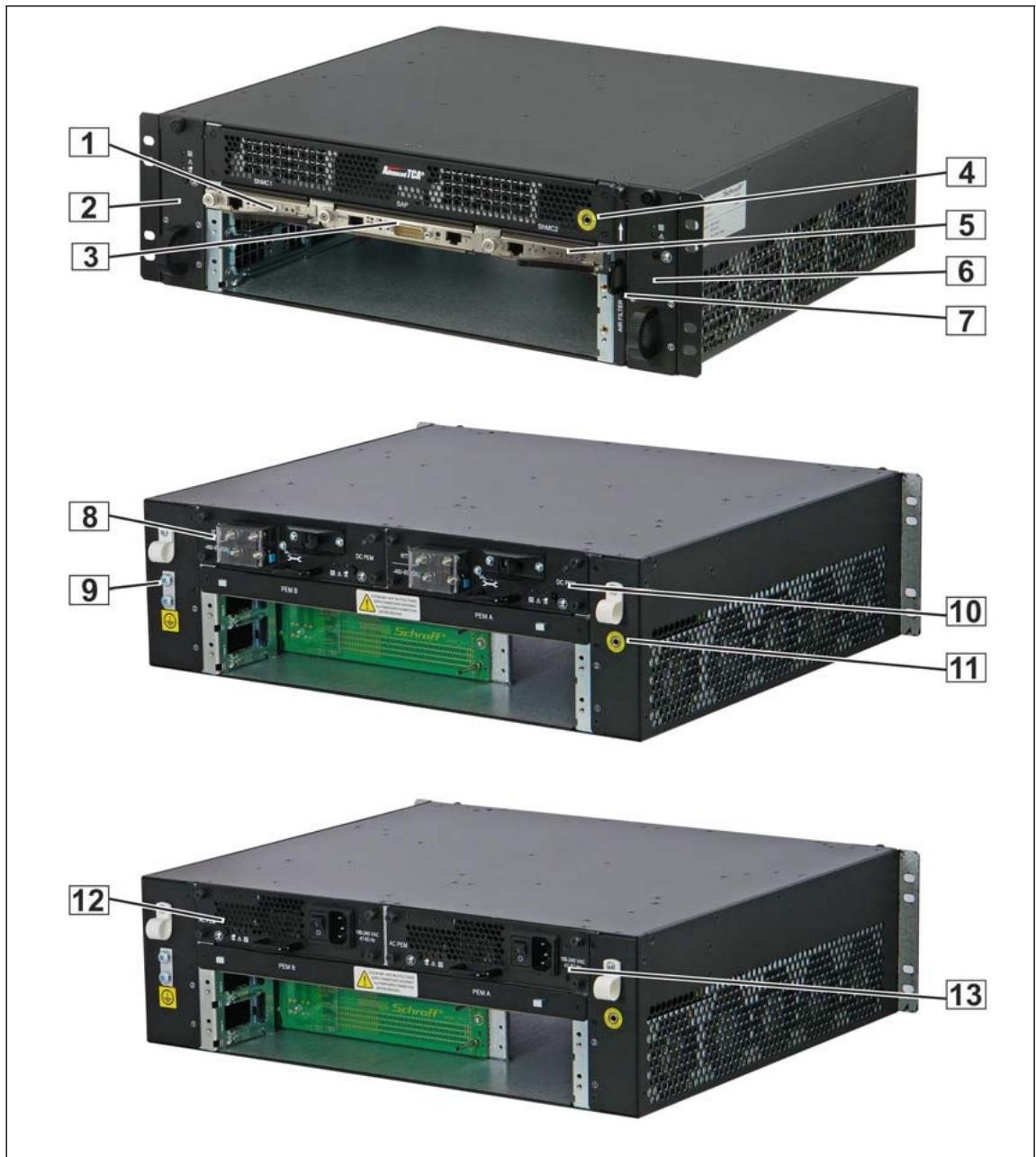
![1\n2\n3\n4\n5\n6\n7\n8\n9\n10\n11\n12\n13](.atca-80302pd-atca-80302pa-pd-50-1g046-1000-10/abd2d785f42c88b12a2e4b64fbffc515ab39d79a493d156c12877c6dfb180227.jpg)

1 Shelf Manager 1
8 DC PEM B
2 Fan Tray 1
9 Shelf Ground Terminal
3 Shelf Alarm Panel (SAP)
10 DC PEM A
4 ESD Wrist Strap Terminal
11 ESD Wrist Strap Terminal
5 Shelf Manager 2
12 AC PEM B
6 Fan Tray 2
13 AC PEM A
7 Air Filter

# 3 ATCA Backplane

The 2-slot ATCA monolithic Backplane is completely passive and is not a field replaceable unit. The backplane provides 40Gb/s connectivity (4 lanes with 10Gb/s) and 2 ATCA slots in a:

• Hub/Hub configuration or
• Node/Node configuration

# 3.1 Logical to Physical Slot Mapping

The physical and logical slots are sequentially numbered from the lower to the upper slot.

Table 2: 2-Slot ATCA Backplane physical to logical slot mapping

<table><tr><td>Physical Slot #</td><td>Logical Slot #</td><td>HW-Address (Hex)</td><td>IPMB-Address (Hex)</td><td>Update Channel</td></tr><tr><td>2</td><td>2</td><td>42</td><td>84</td><td rowspan="2"></td></tr><tr><td>1</td><td>1</td><td>41</td><td>82</td></tr></table>

# 3.2 Interfaces

# 3.2.1 Fabric Interface

All 15 Fabric Channels of slot 1 are routed to the respective Fabric Channels of slot 2.

# 3.2.2 Synchronization Clock Interface

6 pairs of synchronization clocks are bused between both ATCA slots and terminated at both ends.

# 3.2.3 Update Channel Interface

The Update Channels are wired between both ATCA slots. The Update Channel can be used to pass data or routing information between two redundant ATCA Boards.

# 3.2.4 Intelligent Platform Management Interface

The Shelf uses an Intelligent Platform Management Bus (IPMB) for management communications among all ATCA Boards. The reliability of the IPMB is improved by the addition of a second IPMB, with the two IPMBs referenced as IPMB-A and IPMB-B.

The IPMB-A and IPMB-B are routed between the ATCA slots.

# 3.2.5 Base Interface

# Node/Node configuration

All 16 Base Channels of slot 1 are routed to the respective Base Channels of slot 2.

# Hub/Hub configuration

All Base Channels 2 - 16 of slot 1 are routed to the respective Base Channels of slot 2. Base Channel 1 (ShMC) of slot 1 and 2 is cross connected to both dedicated Shelf Manager slots.

Figure 2: Backplane Topology

<table><tr><td rowspan="2" colspan="2">Connector</td><td rowspan="2">Channel</td><td colspan="4">Logic slot #</td></tr><tr><td colspan="2">1</td><td colspan="2">2</td></tr><tr><td rowspan="10">P20</td><td>1</td><td>Sync Clk</td><td>clk1</td><td>clk2</td><td>clk1</td><td>clk2</td></tr><tr><td>2</td><td rowspan="3">Update Channel</td><td></td><td>clk3</td><td></td><td>clk3</td></tr><tr><td>3</td><td></td><td></td><td></td><td></td></tr><tr><td>4</td><td></td><td></td><td></td><td></td></tr><tr><td>5</td><td rowspan="2">Fabric Ch 15</td><td></td><td></td><td></td><td></td></tr><tr><td>6</td><td></td><td></td><td></td><td></td></tr><tr><td>7</td><td rowspan="2">Fabric Ch 14</td><td></td><td></td><td></td><td></td></tr><tr><td>8</td><td></td><td></td><td></td><td></td></tr><tr><td>9</td><td rowspan="2">Fabric Ch 13</td><td></td><td></td><td></td><td></td></tr><tr><td>10</td><td></td><td></td><td></td><td></td></tr><tr><td rowspan="10">P21</td><td>1</td><td rowspan="2">Fabric Ch 12</td><td></td><td></td><td></td><td></td></tr><tr><td>2</td><td></td><td></td><td></td><td></td></tr><tr><td>3</td><td rowspan="2">Fabric Ch 11</td><td></td><td></td><td></td><td></td></tr><tr><td>4</td><td></td><td></td><td></td><td></td></tr><tr><td>5</td><td rowspan="2">Fabric Ch 10</td><td></td><td></td><td></td><td></td></tr><tr><td>6</td><td></td><td></td><td></td><td></td></tr><tr><td>7</td><td rowspan="2">Fabric Ch 9</td><td></td><td></td><td></td><td></td></tr><tr><td>8</td><td></td><td></td><td></td><td></td></tr><tr><td>9</td><td rowspan="2">Fabric Ch 8</td><td></td><td></td><td></td><td></td></tr><tr><td>10</td><td></td><td></td><td></td><td></td></tr><tr><td rowspan="10">P22</td><td>1</td><td rowspan="2">Fabric Ch 7</td><td></td><td></td><td></td><td></td></tr><tr><td>2</td><td></td><td></td><td></td><td></td></tr><tr><td>3</td><td rowspan="2">Fabric Ch 6</td><td></td><td></td><td></td><td></td></tr><tr><td>4</td><td></td><td></td><td></td><td></td></tr><tr><td>5</td><td rowspan="2">Fabric Ch 5</td><td></td><td></td><td></td><td></td></tr><tr><td>6</td><td></td><td></td><td></td><td></td></tr><tr><td>7</td><td rowspan="2">Fabric Ch 4</td><td></td><td></td><td></td><td></td></tr><tr><td>8</td><td></td><td></td><td></td><td></td></tr><tr><td>9</td><td rowspan="2">Fabric Ch 3</td><td></td><td></td><td></td><td></td></tr><tr><td>10</td><td></td><td></td><td></td><td></td></tr><tr><td rowspan="10">P23</td><td>1</td><td rowspan="2">Fabric Ch 2</td><td></td><td></td><td></td><td></td></tr><tr><td>2</td><td></td><td></td><td></td><td></td></tr><tr><td>3</td><td rowspan="2">Fabric Ch 1</td><td></td><td></td><td></td><td></td></tr><tr><td>4</td><td></td><td></td><td></td><td></td></tr><tr><td>5</td><td>Base Ch1</td><td></td><td></td><td></td><td></td></tr><tr><td>6</td><td>Base Ch2</td><td></td><td></td><td></td><td></td></tr><tr><td>7</td><td>Base Ch3</td><td></td><td></td><td></td><td></td></tr><tr><td>8</td><td>Base Ch4</td><td></td><td></td><td></td><td></td></tr><tr><td>9</td><td>Base Ch5</td><td></td><td></td><td></td><td></td></tr><tr><td>10</td><td>Base Ch6</td><td></td><td></td><td></td><td></td></tr><tr><td rowspan="10">P24</td><td>1</td><td>Base Ch7</td><td></td><td></td><td></td><td></td></tr><tr><td>2</td><td>Base Ch8</td><td></td><td></td><td></td><td></td></tr><tr><td>3</td><td>Base Ch9</td><td></td><td></td><td></td><td></td></tr><tr><td>4</td><td>Base Ch10</td><td></td><td></td><td></td><td></td></tr><tr><td>5</td><td>Base Ch11</td><td></td><td></td><td></td><td></td></tr><tr><td>6</td><td>Base Ch12</td><td></td><td></td><td></td><td></td></tr><tr><td>7</td><td>Base Ch13</td><td></td><td></td><td></td><td></td></tr><tr><td>8</td><td>Base Ch14</td><td></td><td></td><td></td><td></td></tr><tr><td>9</td><td>Base Ch15</td><td></td><td></td><td></td><td></td></tr><tr><td>10</td><td>Base Ch16</td><td></td><td></td><td></td><td></td></tr></table>

Node/Node configuration

<table><tr><td rowspan="2" colspan="2">Connector</td><td rowspan="2">Channel</td><td colspan="4">Logic slot #</td></tr><tr><td colspan="2">1</td><td colspan="2">2</td></tr><tr><td rowspan="10">P20</td><td>1</td><td>Sync Clk</td><td>clk1</td><td>clk2</td><td>clk1</td><td>clk2</td></tr><tr><td>2</td><td rowspan="3">Update Channel</td><td></td><td>clk3</td><td></td><td>clk3</td></tr><tr><td>3</td><td></td><td></td><td></td><td></td></tr><tr><td>4</td><td></td><td></td><td></td><td></td></tr><tr><td>5</td><td rowspan="2">Fabric Ch 15</td><td></td><td></td><td></td><td></td></tr><tr><td>6</td><td></td><td></td><td></td><td></td></tr><tr><td>7</td><td rowspan="2">Fabric Ch 14</td><td></td><td></td><td></td><td></td></tr><tr><td>8</td><td></td><td></td><td></td><td></td></tr><tr><td>9</td><td rowspan="2">Fabric Ch 13</td><td></td><td></td><td></td><td></td></tr><tr><td>10</td><td></td><td></td><td></td><td></td></tr><tr><td rowspan="10">P21</td><td>1</td><td rowspan="2">Fabric Ch 12</td><td></td><td></td><td></td><td></td></tr><tr><td>2</td><td></td><td></td><td></td><td></td></tr><tr><td>3</td><td rowspan="2">Fabric Ch 11</td><td></td><td></td><td></td><td></td></tr><tr><td>4</td><td></td><td></td><td></td><td></td></tr><tr><td>5</td><td rowspan="2">Fabric Ch 10</td><td></td><td></td><td></td><td></td></tr><tr><td>6</td><td></td><td></td><td></td><td></td></tr><tr><td>7</td><td rowspan="2">Fabric Ch 9</td><td></td><td></td><td></td><td></td></tr><tr><td>8</td><td></td><td></td><td></td><td></td></tr><tr><td>9</td><td rowspan="2">Fabric Ch 8</td><td></td><td></td><td></td><td></td></tr><tr><td>10</td><td></td><td></td><td></td><td></td></tr><tr><td rowspan="10">P22</td><td>1</td><td rowspan="2">Fabric Ch 7</td><td></td><td></td><td></td><td></td></tr><tr><td>2</td><td></td><td></td><td></td><td></td></tr><tr><td>3</td><td rowspan="2">Fabric Ch 6</td><td></td><td></td><td></td><td></td></tr><tr><td>4</td><td></td><td></td><td></td><td></td></tr><tr><td>5</td><td rowspan="2">Fabric Ch 5</td><td></td><td></td><td></td><td></td></tr><tr><td>6</td><td></td><td></td><td></td><td></td></tr><tr><td>7</td><td rowspan="2">Fabric Ch 4</td><td></td><td></td><td></td><td></td></tr><tr><td>8</td><td></td><td></td><td></td><td></td></tr><tr><td>9</td><td rowspan="2">Fabric Ch 3</td><td></td><td></td><td></td><td></td></tr><tr><td>10</td><td></td><td></td><td></td><td></td></tr><tr><td rowspan="10">P23</td><td>1</td><td rowspan="2">Fabric Ch 2</td><td></td><td></td><td></td><td></td></tr><tr><td>2</td><td></td><td></td><td></td><td></td></tr><tr><td>3</td><td rowspan="2">Fabric Ch 1</td><td></td><td></td><td></td><td></td></tr><tr><td>4</td><td></td><td></td><td></td><td></td></tr><tr><td>5</td><td colspan="5">ShMC Port</td></tr><tr><td>6</td><td colspan="5">Base Ch2</td></tr><tr><td>7</td><td colspan="5">Base Ch3</td></tr><tr><td>8</td><td colspan="5">Base Ch4</td></tr><tr><td>9</td><td colspan="5">Base Ch5</td></tr><tr><td>10</td><td colspan="5">Base Ch6</td></tr><tr><td rowspan="10">P24</td><td>1</td><td colspan="5">Base Ch7</td></tr><tr><td>2</td><td colspan="5">Base Ch8</td></tr><tr><td>3</td><td colspan="5">Base Ch9</td></tr><tr><td>4</td><td colspan="5">Base Ch10</td></tr><tr><td>5</td><td colspan="5">Base Ch11</td></tr><tr><td>6</td><td colspan="5">Base Ch12</td></tr><tr><td>7</td><td colspan="5">Base Ch13</td></tr><tr><td>8</td><td colspan="5">Base Ch14</td></tr><tr><td>9</td><td colspan="5">Base Ch15</td></tr><tr><td>10</td><td colspan="5">Base Ch16</td></tr></table>

Hub/Hubconfiguration

# 3.3 Shelf FRU SEEPROM

2 Shelf FRU SEEPROMS are located on the Backplane. The hardware address for these SEEPROMs is 0xA4.

The SEEPROMs are the repository of the shelf specific information capabilities of the system and other user configurable options. The SEEPROMs contain the list of which slots are connected together, how the update channels are routed, how many slots are in the system, what the maximum power is to each slot, serial number of the shelf, backplane topology, etc. The Shelf Manager uses this information to provide functions such as electronic keying, controlling the power state of the system, etc.

The Shelf allows for 2 methods to access the chassis FRU data:

• An I2C connection from each Shelf Manager directly to the SEEPROMs on the backplane.
• SEEPROMs on the backplane exposed as a FRU of the Fan Tray.

# 3.4 Logic Ground

Figure 3: Logic Ground
![Close-up of a green printed circuit board with gold contacts and a yellow arrow pointing to a grid pattern (no text or symbols visible)](.atca-80302pd-atca-80302pa-pd-50-1g046-1000-10/e03cfcf798f223a827835b6423cfc276c7bcceac19d9de3ea9f2fe8f52f54e00.jpg)

The ATCA backplane provides a mechanism to connect Logic Ground and Shelf Ground. The backplane fixing screw (arrow) is isolated by a plastic washer. To connect Logic Ground and Shelf Ground remove the screw, remove the plastic washer and re-install the screw.

![The image displays a blue square icon containing a white, lowercase letter 'i' centered within it.](.atca-80302pd-atca-80302pa-pd-50-1g046-1000-10/5c3e01b2009b5b20e52e6b736225e3e612cff87fc95871fb14caadf7dc94a66a.jpg)

The default factory assembly isolates Logic Ground from Shelf Ground.

# 4 Air Filter

Figure 4: Air Filter
![1\n2\nAIR FILTER\nSchrift\nSCHRFT\n03-10/2019\n05:48 Hz\n12.4 For Head](.atca-80302pd-atca-80302pa-pd-50-1g046-1000-10/312fc1b5268c35531bfbff551c67377f3de68e1e7fcff79bf9225db2511fbc8e.jpg)

1 Air Filter
2 Filter Element

# 4.1 Introduction

The ATCA Shelf provides a front replaceable air filter. The filter element is an open cell polyurethane foam specially coated to provide improved fire retardation and fungi resistance. It features deep loading, large dust holding capacity, low air resistance, and complies with NEBS-GR-63-CORE.

There is a switch to detect whether an air filter is installed. This switch is exposed to the Shelf manager as a presence sensor on the Fan Tray.

# 5 Shelf Ground Connection

![A yellow triangular warning sign with a thick black border containing a black lightning bolt symbol in the center.](.atca-80302pd-atca-80302pa-pd-50-1g046-1000-10/e22477397bf33df5d3fcddd1b54a9e82a162e941861da31776d1b5f5d6868795.jpg)

# Hazardous voltage!

Before powering-up the Shelf, make sure that the Shelf Ground terminals are connected to Protective Earth (PE) of the building.

The ATCA Shelf provides a Shelf ground terminal at the left rear side. The Shelf ground terminal provides two threads (M5) with a 16 mm spacing between thread centers to connect a double-lug Shelf ground terminal cable.

Figure 5: Shelf Ground Terminal
![R\n-48/-6 V/DQ\nM5\n16 mm](.atca-80302pd-atca-80302pa-pd-50-1g046-1000-10/e366e2630ff0d25204ef470f82ef9a4f394dbe81ad44171a30155c29e82a8bb3.jpg)

12713815

![The image displays a square blue icon featuring a white lowercase letter 'i' centered within it. This is the universal symbol for 'information.'](.atca-80302pd-atca-80302pa-pd-50-1g046-1000-10/7e3a72e389d0872197bff5cd2782b52384d6618c7fa61ffd08c644ab3efb4bc8.jpg)

Please note, that in a typical telecom environment, the VRTN path of the -48V supply is grounded to Protective Earth (PE) of the building.

# 5.1 Specification for the Shelf Ground connection cable

Required wire size: AWG8

Required terminals: Use only double lug terminals (Terminal Used: PANDUIT part no. LCD8- 14A-L).

# 6 Fan Trays

The 2 Slot ATCA Shelf contains two interchangeable Fan Trays arranged in a side to side configuration for maximum air flow. The Fan Trays are intelligent FRUs and plugged-in at the left and right front of the Shelf.

Each Fan Tray contains five 60 mm fans (110 m³/h (64 CFM) each). The Fan Tray is controlled via an on-board IPM controller.

Figure 6: Fan Tray
![1\n2\n3\n4\nHS\nHS\n5\nON\n1 2 3](.atca-80302pd-atca-80302pa-pd-50-1g046-1000-10/262816eaada2c0bc2695e0c59c72269c72b858df17b0181ecae4ae89564e254d.jpg)

1 Green Fan Tray OK LED 4 Hot Swap push button
2 Red Fan Tray Alarm LED 5 DIP Switch
3 Blue Hot Swap LED

# 6.1 IPM Controller and Fan Control

The on-board IPM controller is located on the Fan Tray and has 2 operation modes:

# 1. Shelf Manager Mode

As soon as a Shelf Manager is plugged-in and becomes active, the IPM controller switches automatically into the Shelf Manager mode. The Shelf Manager performs management of the Fan Tray through the two independent bussed IPMB connections.

When the Fan Tray is first inserted into the system, the fans start at full speed and then decrease to specified speed by Shelf Manager. The circuitry on-board the Fan Tray uses a PWM signal to control the speed of all the fans. Lower speeds reduce acoustic noise and power consumption and increase the lifetime of the fans.

The speed of each individual fan is monitored. If any of the fan speeds drops below the desired fan speed, a System Event Log (SEL) entry is logged by the Shelf Manager. The Shelf Manager then generates alerts and sets alarm conditions as necessary.

The system is designed to run indefinitely with any single fan failure. When one fan fails, all other fans are increased to full speed. The Fan Tray has sufficient cooling capacity to keep the Shelf cooled with a single fan failure.

# 2. Autonomous Mode

When no Shelf Manager is present, the Fans are controlled by the IPM controller. The fan speed depends on the setting of DIP switch on the controller board. With a Micro DIP switch you can select either the exhaust temperature from the left Fan Tray as reference to control the fan speed or fixed fan speed.

Table 3: Micro DIP switch settings

<table><tr><td>Bit 1</td><td>Bit 2</td><td>Bit 3</td><td>Description</td></tr><tr><td>0</td><td>0</td><td>0</td><td>Fixed Speed, 50% of Full Speed</td></tr><tr><td>0</td><td>0</td><td>1</td><td>Fixed Speed, 70% of Full Speed</td></tr><tr><td>0</td><td>1</td><td>0</td><td>Fixed Speed, 90% of Full Speed</td></tr><tr><td>0</td><td>1</td><td>1</td><td>Fixed Speed, 100% of Full Speed</td></tr><tr><td>1</td><td>0</td><td>0</td><td>Exhaust Temperature 35 ~ 45 °C</td></tr><tr><td>1</td><td>0</td><td>1</td><td>Exhaust Temperature 40 ~ 50 °C</td></tr><tr><td>1</td><td>1</td><td>0</td><td>Exhaust Temperature 45 ~ 55 °C</td></tr><tr><td>1</td><td>1</td><td>1</td><td>Exhaust Temperature 50 ~60 °C</td></tr></table>

![This image features a blue square icon containing the white lowercase letter 'i'.](.atca-80302pd-atca-80302pa-pd-50-1g046-1000-10/9d8c2f0cb29fb23b154cf94a2afc65208ddd5ed8a0c86048bfe3f5873321332a.jpg)

The default setting is 50% of full speed.

Figure 7: Fan Control curves
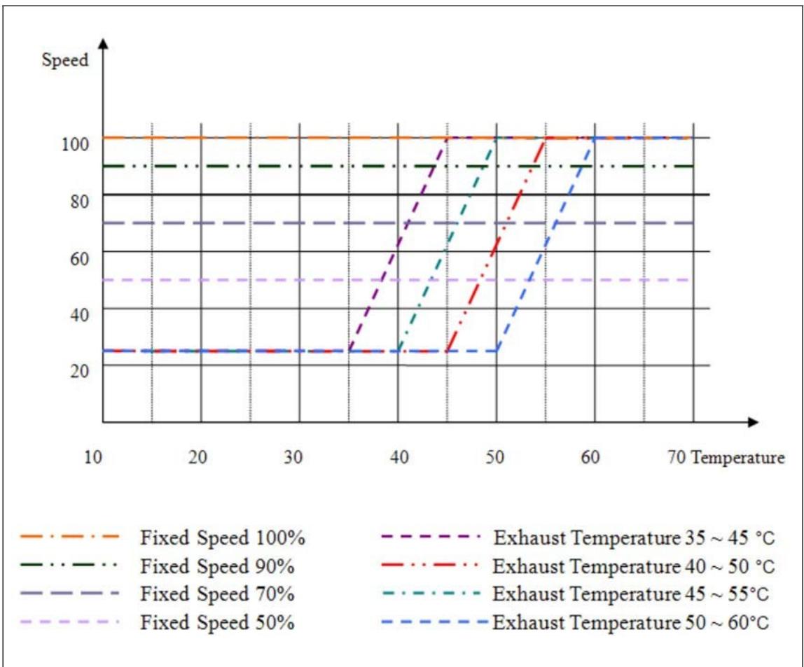
![| Temperature | Fixed Speed 100% | Fixed Speed 90% | Fixed Speed 70% | Fixed Speed 50% | Exhaust Temperature 35 ~ 45 °C | Exhaust Temperature 40 ~ 50 °C | Exhaust Temperature 45 ~ 55 °C | Exhaust Temperature 50 ~ 60 °C |\n| ----------- | ---------------- | --------------- | --------------- | --------------- | ------------------------------- | ------------------------------- | ------------------------------- | ------------------------------- |\n| 10          | 100              | 90              | 70              | 50              | 25                              | 25                              | 25                              | 25                              |\n| 20          | 100              | 90              | 70              | 50              | 25                              | 25                              | 25                              | 25                              |\n| 30          | 100              | 90              | 70              | 50              | 25                              | 25                              | 25                              | 25                              |\n| 40          | 100              | 90              | 70              | 50              | 70                              | 25                              | 30                              | 25                              |\n| 50          | 100              | 90              | 70              | 50              | 100                             | 70                              | 80                              | 25                              |\n| 60          | 100              | 90              | 70              | 50              | 100                             | 100                             | 100                             | 100                             |\n| 70          | 100              | 90              | 70              | 50              | 100                             | 100                             | 100                             | 100                             |](.atca-80302pd-atca-80302pa-pd-50-1g046-1000-10/afa53f21b680f8cfd64902077e7718517be7c991977b56235efdd182328618e3.jpg)

# 6.2 Fan Tray Indicators

The front panel includes a green and red status LED and a blue hot-swap LED.

The Hot-Swap push button indicates to the Shelf Managers that the Fan Tray is about to be removed. Its use is optional, but it is provided so that service personnel can be trained to look for a blue LED to be illuminated on any active component before removing it from the system. Once the operator pushes the Hot-Swap button, the Shelf Manager is informed of the pending extraction. When the Shelf Manager feels it is “safe“ to remove the Fan Tray, the blue Hot-Swap LED illuminates solid.

Table 4: LEDs on Fan Tray front panel

<table><tr><td>Color</td><td>Description</td><td>Status</td><td>Condition</td></tr><tr><td>Green</td><td>OK LED</td><td>OffSolid green</td><td>No Power to the Fan TrayNormal Operation</td></tr><tr><td>Red</td><td></td><td>Solid red</td><td>Attention Status (error condition)</td></tr><tr><td>Blue</td><td>Hot Swap LED</td><td>OffShort blinkSolid blue</td><td>No Power to the Fan Tray or not OK to extract Fan TrayPreparing for extractionReady to remove</td></tr></table>

# 6.3 Fan Tray Signals

The Fan Tray provides signals for:

• Voltage monitoring
• Status of the Hot Swap Controller
• Fan Speed
• Temperature

These signals are controlled by the IPM Controller on the PCB. The Shelf Manager has access to these signals via IPMB.

# 6.4 Fan Tray Connector Pin Assignment

<table><tr><td>Pin#</td><td>Signal</td><td>Description</td><td>Pin#</td><td>Signal</td><td>Description</td></tr><tr><td>A1</td><td>-48V_A</td><td>-48VDC Feed A</td><td>D1</td><td>VRTN_A</td><td>RTN Feed A</td></tr><tr><td>A2</td><td>-48V_A</td><td>-48VDC Feed A</td><td>D2</td><td>VRTN_A</td><td>RTN Feed A</td></tr><tr><td>A3</td><td></td><td></td><td>D3</td><td></td><td></td></tr><tr><td>A4</td><td>I2C_B CONTROL</td><td>I2C B Line Busy Signal</td><td>D4</td><td>PEM_PRESENT_R</td><td>Presence Signal of Right PEM</td></tr><tr><td>A5</td><td>SCL_A</td><td>IPMB A Clock</td><td>D5</td><td>GND</td><td>Fan Tray Presence,connected to GND</td></tr><tr><td>A6</td><td>SDA_A</td><td>IPMB A Data</td><td>D6</td><td>FAN_PRSENT</td><td>Presence Signal of Fan Tray</td></tr><tr><td>A7</td><td>SCL_B</td><td>IPMB BClock</td><td>D7</td><td>I2C_SCL_A</td><td>I2C A Clock</td></tr><tr><td>A8</td><td>SDA_B</td><td>IPMB B Data</td><td>D8</td><td>I2C_A CONTROL</td><td>I2C A Line Busy Signal</td></tr><tr><td>A9</td><td></td><td></td><td>D9</td><td></td><td></td></tr><tr><td>A10</td><td>VRTN_B</td><td>RTNFeed B</td><td>D10</td><td>-48V_B</td><td>-48VDC Feed B</td></tr><tr><td>A11</td><td>VRTN_B</td><td>RTNFeed B</td><td>D11</td><td>-48V_B</td><td>-48VDC Feed B</td></tr><tr><td>B1</td><td>-48V_A</td><td>-48VDCFeed A</td><td>E1</td><td>VRTN_A</td><td>RTNFeed A</td></tr><tr><td>B2</td><td>-48V_A</td><td>-48VDCFeed A</td><td>E2</td><td>VRTN_A</td><td>RTNFeed A</td></tr><tr><td>B3</td><td></td><td></td><td>E3</td><td></td><td></td></tr><tr><td>B4</td><td>H2</td><td></td><td>E4</td><td>SHELF_PRESENT</td><td>Presence Signal of Shelf Manager</td></tr><tr><td>B5</td><td>GND</td><td>Logic Ground</td><td>E5</td><td>I2C_SCL_B</td><td>I2C B Clock</td></tr><tr><td>B6</td><td>INT_I2C_A</td><td>Interrupt Signal of I2C A Line</td><td>E6</td><td>I2C_SDA_B</td><td>I2C B Data</td></tr><tr><td>B7</td><td>GND</td><td>Logic Ground</td><td>E7</td><td>+3.6V</td><td></td></tr><tr><td>B8</td><td>INT_I2C_B</td><td>Interrupt Signal of I2C B Line</td><td>E8</td><td>I2C_SDA_A</td><td>I2C A Data</td></tr><tr><td>B9</td><td></td><td></td><td>E9</td><td></td><td></td></tr><tr><td>B10</td><td>VRTN_B</td><td>RTNFeed B</td><td>E10</td><td>-48V_B</td><td>-48VDC Feed B</td></tr><tr><td>B11</td><td>VRTN_B</td><td>RTNFeed B</td><td>E11</td><td>-48V_B</td><td>-48VDC Feed B</td></tr><tr><td>C1</td><td></td><td></td><td></td><td></td><td></td></tr><tr><td>C2</td><td></td><td></td><td></td><td></td><td></td></tr><tr><td>C3</td><td></td><td></td><td></td><td></td><td></td></tr><tr><td>C4</td><td></td><td></td><td></td><td></td><td></td></tr><tr><td>C5</td><td></td><td></td><td></td><td></td><td></td></tr><tr><td>C6</td><td></td><td></td><td></td><td></td><td></td></tr><tr><td>C7</td><td></td><td></td><td></td><td></td><td></td></tr><tr><td>C8</td><td></td><td></td><td></td><td></td><td></td></tr><tr><td>C9</td><td></td><td></td><td></td><td></td><td></td></tr><tr><td>C10</td><td></td><td></td><td></td><td></td><td></td></tr><tr><td>C11</td><td></td><td></td><td></td><td></td><td></td></tr></table>

# 6.5 Fan Tray IPMB Addresses

Geographic address pins H2 at the Fan Tray Backplane connector determine the hardware addresses of the devices.

Table 5: Fan Tray IPMB Addresses

<table><tr><td></td><td>HW-Addr.</td><td>IPMB Addr.</td></tr><tr><td>Fan Tray 1 (left)</td><td>0x2E</td><td>0x5C</td></tr><tr><td>Fan Tray 2 (right)</td><td>0x2D</td><td>0x5A</td></tr></table>

# 6.6 Front Board Air Distribution

The airflow is measured with impedance boards acc. to the PICMG 3.0 R3.0

specification. Front board pressure drop: 37 Pa at 0,85 m³/min

Figure 8: Front Board Air Distribution
![| Slot   | Zone 1 | Zone 2 | Zone 3 | Zone 4 |\n|--------|--------|--------|--------|--------|\n| Slot 1 | 25     | 20     | 18     | 15     |\n| Slot 2 | 25     | 20     | 18     | 15     |](.atca-80302pd-atca-80302pa-pd-50-1g046-1000-10/e1c525b35c67ec238a920bcd68d0ba0e7ff7048139133d21f417b4fb26c1d611.jpg)

Table 6: Front Air Flow

<table><tr><td></td><td>Zone 1 [CFM]</td><td>Zone 2 [CFM]</td><td>Zone 3 [CFM]</td><td>Zone 4 [CFM]</td><td> $\sum$  [CFM]</td></tr><tr><td>Slot 1</td><td>17,9 (30,5  $m^{3}/h$ )</td><td>17,7 (30,1  $m^{3}/h$ )</td><td>16,8 (28,5  $m^{3}/h$ )</td><td>17,1 (29,0  $m^{3}/h$ )</td><td>69,4 (30,5  $m^{3}/h$ )</td></tr><tr><td>Slot 2</td><td>17,0 (28,9  $m^{3}/h$ )</td><td>16,8 (28,5  $m^{3}/h$ )</td><td>16,1 (27,4  $m^{3}/h$ )</td><td>16,1 (27,4  $m^{3}/h$ )</td><td>66,1 (28,9  $m^{3}/h$ )</td></tr><tr><td> $\sum$ </td><td>34,9 (59,3  $m^{3}/h$ )</td><td>34,5 (58,6  $m^{3}/h$ )</td><td>32,9 (59,9  $m^{3}/h$ )</td><td>33,2 (58,4  $m^{3}/h$ )</td><td>135,5 (230  $m^{3}/h$ )</td></tr></table>

# 6.7 Rear Board Air Distribution

The airflow is measured with impedance boards acc. to the PICMG 3.0 R3.0

specification. Rear board pressure drop: 24 Pa at 0,14 m³/min

Figure 9: Rear Board Air Distribution
![| Slot | bulk air flow (cfm) |\n| :--- | :--- |\n| Slot 1 | 20.0 |\n| Slot 2 | 20.0 |](.atca-80302pd-atca-80302pa-pd-50-1g046-1000-10/019efffd88fe2b179a3096047e5aec977e7d56d325b64ee22a10e2402f806933.jpg)

Table 7: Rear Air Flow

<table><tr><td></td><td>[CFM]</td></tr><tr><td>Slot 1</td><td>16,7 (28,4  $m^{3}/h$ )</td></tr><tr><td>Slot 2</td><td>16,0 (27,2  $m^{3}/h$ )</td></tr><tr><td> $\Sigma$ </td><td>32,7 (55,6  $m^{3}/h$ )</td></tr></table>

# 7 Power

![This image shows a yellow triangular warning sign with a thick black border. Inside the triangle is a black lightning bolt symbol, indicating a risk of electric shock or high voltage.](.atca-80302pd-atca-80302pa-pd-50-1g046-1000-10/1788dca04795fddb5fc11bce8ada89027469b0d9b618667650f221f042260e46.jpg)

# Hazardous voltage!

Before working ensure that the power is removed from the power connection cables.

The shelf supports AC- and DC-Power Entry Modules (PEMs). Both PEMs have the same interface to the shelf.

![The image displays two blue rectangular shapes side-by-side. The left shape is a solid blue rectangle. The right shape is a blue rectangle containing a white lowercase letter 'i'.](.atca-80302pd-atca-80302pa-pd-50-1g046-1000-10/f2c1b03e2497b4faa89134dc2ce956349d56b55e19390b4f7c9b0e7c0e7e7dd1.jpg)

The AC-PEM can be powered with 230 VAC line voltage. The specified voltage range is from 180 VAC to 265 VAC .The Shelf supports redundant power inputs but the two in- puts should be independently powered.

![The image shows a blue square containing a white lowercase letter 'i' centered within it.](.atca-80302pd-atca-80302pa-pd-50-1g046-1000-10/9167268dff8153b3dddd66b94e647eb99b6c3c157f41590bbb26b83d5d6c31b1.jpg)

The DC-PEM can be powered using a regular telecommunication power supply of -48/-60 VDC with a VDC return. The specified voltage range is from -40.5 VDC to -72 VDC. The Shelf supports redundant power inputs but the two inputs should be in- dependently powered.

# 7.1 AC PEM

Two pluggable redundant AC Power Entry Modules (PEM) are located at the rear top side of the Shelf. The power input is provided by an AC mains/line module with IEC 320-C14 connector and mains switch. The output voltage of the AC PEM is 48 VDC. Overcurrent protection is provided by a 40 A fuse in the output branch.

Figure 10: AC PEM
![AC PEM\n100-240 VAC\n47-83 Hz\n6\n5\n100-240 VAC\n47-83 Hz\nFUSE\n40A / 58V\n7\n1 2 3 4\nOK  HS  HS](.atca-80302pd-atca-80302pa-pd-50-1g046-1000-10/4d3dabd45ec98bf716c83ddfab8414caf63e68a5e231ecab4d44d24aed639b14.jpg)

1 Green Fan Tray OK LED
2 Red Fan Tray Alarm LED
3 Blue Hot Swap LED
4 Hot Swap push button
5 IEC 320-C14 connector
6 Mains switch
7 Fuse

# 7.1.1 AC PEM Power Distribution

Power distribution within the Shelf originates from each AC PEM and powers all the blades, the Shelf Managers, the Fan Trays and the SAP. For maximum fault tolerance, the two AC PEMs should be independently powered by a separate Feed A and Feed B.

A single AC PEM is capable of supplying the 450 watts of power to each blade slot and the necessary power for the PEMs, Fan Trays, and Shelf Managers.

If two AC PEMs are in service, each AC PEM is hot-swappable after removing the power cables from the AC PEM.

Figure 11: Power Distribution
![This flowchart depicts a system architecture with components connected to a central bus.\n\n**Top Components:**\nSix blocks are arranged horizontally at the top. From left to right, they are labeled:\n*   'FAN Control Board (Left)'\n*   'Shelf Manager (Active)'\n*   'ATCA board Slot 1'\n*   'ATCA board Slot 2'\n*   'Shelf Manager (Backup)'\n*   'FAN Control Board (Right)'\n\n**Central Component:**\nA large rectangular block labeled '**Backplane**' sits in the middle.\n\n**Connections:**\n*   Each of the six top blocks connects to the '**Backplane**' via two vertical lines: one red line and one blue line.\n*   From the bottom of the '**Backplane**', a single red line extends downward to the left power supply block.\n*   From the bottom of the '**Backplane**', a single blue line extends downward to the right power supply block.\n\n**Power Supply Section:**\nBelow the backplane is a rectangular area containing two blue blocks, both labeled '**1200W AC/DC**'.\n*   The left block receives the red connection from the backplane.\n*   The right block receives the blue connection from the backplane.\n\n**Inputs:**\n*   Below the left '**1200W AC/DC**' block is text reading '**AC 230V Input A**' with an arrow pointing upward into the block.\n*   Below the right '**1200W AC/DC**' block is text reading '**AC 230V Input B**' with an arrow pointing upward into the block.\n*   Centered at the very bottom is the text '**AC Input**' in red.](.atca-80302pd-atca-80302pa-pd-50-1g046-1000-10/15cb8c561d2f08c0d46b57c3aff66287d5dadc2dd8027dff57fe800f9a7d0fe5.jpg)

Table 8: Basic Specifications for the PSUs

<table><tr><td colspan="2">230 V Operation</td></tr><tr><td>Input Voltage nominal</td><td>230 VAC</td></tr><tr><td>Input Voltage Range max.</td><td>180 VAC - 265 VAC</td></tr><tr><td>Input Frequency Range</td><td>47 Hz - 63 Hz</td></tr><tr><td>Output Voltage</td><td>48 VDC</td></tr><tr><td>Output Current</td><td>25 A</td></tr><tr><td>Output Power</td><td>1200 W with 48 VDC Output Voltage</td></tr><tr><td colspan="2">115 V Operation</td></tr><tr><td>Input Voltage nominal</td><td>115 VAC</td></tr><tr><td>Input Voltage Range max.</td><td>90 VAC - 180 VAC</td></tr><tr><td>Input Frequency Range</td><td>47 Hz - 63 Hz</td></tr><tr><td>Output Voltage</td><td>48 VDC</td></tr><tr><td>Output Current</td><td>20,8 A</td></tr><tr><td>Output Power</td><td>1000 W with 48 VDC Output Voltage</td></tr></table>

![The image displays a blue square featuring a centered white lowercase letter 'i'.](.atca-80302pd-atca-80302pa-pd-50-1g046-1000-10/4a043a082e3d063d3354539fbf980ddd74920c7fc6813b74daeda146cc0f2c49.jpg)

See GE Energy Power CAR1248 Data Sheet for detailed information.

# 7.1.2 AC PEM Signals

The AC PEM provides signals for:

• PSU output Voltage monitoring
• PSU output Current monitoring (Min.100W loading for each AC PSU)
• Fuse Monitoring
• Status of the Hot Swap Controller
• Temperature

The I2C devices on the PSU and AC PEM board are connected to Master-Only I2Cbus of the Fan controller board. The Shelf Manager has access to these signals via IPM-Bus of the Fan Tray.

# 7.1.3 AC PEM Indicators

The front panel includes a green and red status LED and a blue hot-swap LED.

Table 9: LEDs on AC PEM

<table><tr><td>Color</td><td>Description</td><td>Status</td><td>Condition</td></tr><tr><td rowspan="2">Green</td><td rowspan="2">OK LED</td><td>Off</td><td>No Power to the PEM</td></tr><tr><td>Solid green</td><td>Normal Operation</td></tr><tr><td>Red</td><td></td><td>Solid red</td><td>Attention Status (error condition)</td></tr><tr><td rowspan="3">Blue</td><td rowspan="3">Hot Swap LED</td><td>Off</td><td>No Power to the PEM or not OK to extract PEM</td></tr><tr><td>Short blink</td><td>Preparing for extraction</td></tr><tr><td>Solid blue</td><td>Ready to remove</td></tr></table>

# 7.1.4 AC PEM Connector PIN Assignment

<table><tr><td>Pin#</td><td>Signal</td><td>Description</td><td>Pin#</td><td>Signal</td><td>Description</td></tr><tr><td>P1A1</td><td>VRTN</td><td>RTN</td><td>P1C1</td><td>VRTN</td><td>RTN</td></tr><tr><td>P1A2</td><td>VRTN</td><td>RTN</td><td>P1C2</td><td>VRTN</td><td>RTN</td></tr><tr><td>A1</td><td></td><td></td><td>C1</td><td></td><td></td></tr><tr><td>A2</td><td>+3.3V</td><td></td><td>C2</td><td></td><td></td></tr><tr><td>A3</td><td>SCL</td><td>I2CClock</td><td>C3</td><td></td><td></td></tr><tr><td>A4</td><td>SDA</td><td>I2CData</td><td>C4</td><td></td><td></td></tr><tr><td>A5</td><td></td><td></td><td>C5</td><td>GND</td><td>LogicGround</td></tr><tr><td>A6</td><td></td><td></td><td>C6</td><td></td><td></td></tr><tr><td>P2A1</td><td>-48V</td><td>-48VDC</td><td>P2C1</td><td>-48V</td><td>-48VDC</td></tr><tr><td>P2A2</td><td>-48V</td><td>-48VDC</td><td>P2C2</td><td>-48V</td><td>-48VDC</td></tr><tr><td>P1B1</td><td>VRTN</td><td>RTN</td><td>P1D1</td><td>VRTN</td><td>RTN</td></tr><tr><td>P1B2</td><td>VRTN</td><td>RTN</td><td>P1D2</td><td>VRTN</td><td>RTN</td></tr><tr><td>B1</td><td></td><td></td><td>D1</td><td></td><td></td></tr><tr><td>B2</td><td>+3.3V</td><td></td><td>D2</td><td>H1</td><td></td></tr><tr><td>B3</td><td></td><td></td><td>D3</td><td></td><td></td></tr><tr><td>B4</td><td>GND</td><td>PEMPresence, connected to GND</td><td>D4</td><td></td><td></td></tr><tr><td>B5</td><td>GND</td><td>LogicGround</td><td>D5</td><td>GND</td><td>LogicGround</td></tr><tr><td>B6</td><td></td><td></td><td>D6</td><td></td><td></td></tr><tr><td>P2B1</td><td>-48V</td><td>-48VDC</td><td>P2D1</td><td>-48V</td><td>-48VDC</td></tr><tr><td>P2B2</td><td>-48V</td><td>-48VDC</td><td>P2D2</td><td>-48V</td><td>-48VDC</td></tr></table>

# 7.2 DC PEM

Two pluggable redundant DC Power Entry Modules (PEM) are located at the rear top side of the Shelf. Each PEM provides power terminals for 35A power feed. Each power feed consists of a –48 VDC cable and its corresponding return cable. The feed is protected by a 35 A fused switch.

The power filtering consists of filtered power terminals and a discrete line-filter for each power branch. The input voltage range for the Shelf is from -40VDC to - 72VDC.In each power feed, voltage measurement is implemented, by means of a dedicated voltage monitor device.

The PEM (together with all shelf related FRUs) are protected against wrong polarity up to +57 VDC, but it does not block wrong polarity voltage being applied to shelf related FRUs and to Zone 1 power wiring of payload slots.

Suppressor diodes are included in the feed chain that provide protection against a K.20 pulse of 500 V being applied to its input (K.20 surge pulse, "Basic level", Table 7, pulse type 7.3, 500 V applied to -48 V and RTN branches at the same time against shelf ground) so that PEM itself and other shelf related FRUs can sustain this level of pulse.

Figure 12: DC PEM
![R\n-48I-6 VDD\nPEM B\nRT\n-48I-6V\nDC PEM\nSchroff®\n1 2 3 4\nOK HS HS](.atca-80302pd-atca-80302pa-pd-50-1g046-1000-10/737faf57f0abe21e624ae82a39003beab508323557e7e4911b813c5323b1a145.jpg)

1 Green Fan Tray OK LED
2 Red Fan Tray Alarm LED
3 Blue Hot Swap LED
4 Hot Swap push button

5 RTN Input
6 -48 V Input
7 Fused switch

# 7.2.1 DC PEM Power Distribution

Power distribution within the Shelf originates from each DC PEM and powers all the blades, the Shelf Managers, the Fan Trays and the SAP. For maximum fault tolerance, the two DC PEMs should be independently powered by a separate Feed A and Feed B.

A single DC PEM is capable of supplying the 450 watts of power to each blade slot and the necessary power for the PEMs, Fan Trays, and Shelf Managers.

If two DC PEMs are in service, each DC PEM is hot-swappable after removing the power input cables from the DC PEM.

Figure 13: Power Distribution
![The diagram displays a system architecture with the following labeled blocks and connections:\n\n**Blocks:**\n*   **Top Row:** 'FAN Control Board (Left)', 'Shelf Manager (Active)', 'ATCA board Slot 1', 'ATCA board Slot 2', 'Shelf Manager (Backup)', 'FAN Control Board (Right)'\n*   **Middle Row:** 'Backplane'\n*   **Bottom Row:** Two blocks labeled 'DC PEM', text labels 'DC -48V Input A', 'DC -48V Input B', and a label 'DC Input'.\n\n**Connections:**\n*   Red and blue lines connect each of the six blocks in the top row to the 'Backplane'.\n*   From the 'Backplane', a red line descends to connect to the left 'DC PEM' block.\n*   From the 'Backplane', a blue line descends to connect to the right 'DC PEM' block.\n*   'DC -48V Input A' points upward into the left 'DC PEM'.\n*   'DC -48V Input B' points upward into the right 'DC PEM'.](.atca-80302pd-atca-80302pa-pd-50-1g046-1000-10/3df9d9bb1925ebef0e1bcb62cd8f1ce72ac9cba01b29112926f2a0ce8e95870e.jpg)

# 7.2.2 DC PEM Signals

The DC PEM provides signals for:

• Voltage monitoring
• Current monitoring
• Fuse Monitoring
• Status of the Hot Swap Controller
• Temperature

The I2C devices on the DC PEM board are connected to Master-Only I2C-bus of the Fan controller board. The Shelf Manager has access to these signals via IPM-Bus of the Fan Tray.

# 7.2.3 DC PEM Indicators

The front panel includes a green and red status LED and a blue hot-swap LED.

Table 10: LEDs on DC PEM

<table><tr><td>Color</td><td>Description</td><td>Status</td><td>Condition</td></tr><tr><td rowspan="2">Green</td><td rowspan="2">OK LED</td><td>Off</td><td>No Power to the PEM</td></tr><tr><td>Solid green</td><td>Normal Operation</td></tr><tr><td>Red</td><td></td><td>Solid red</td><td>Attention Status (error condition)</td></tr><tr><td rowspan="3">Blue</td><td rowspan="3">Hot Swap LED</td><td>Off</td><td>No Power to the PEM or not OK to extract PEM</td></tr><tr><td>Short blink</td><td>Preparing for extraction</td></tr><tr><td>Solid blue</td><td>Ready to remove</td></tr></table>

# 7.2.4 DC PEM Connector PIN Assignment

<table><tr><td>Pin#</td><td>Signal</td><td>Description</td><td>Pin#</td><td>Signal</td><td>Description</td></tr><tr><td>P1A1</td><td>VRTN</td><td>RTN</td><td>P1C1</td><td>VRTN</td><td>RTN</td></tr><tr><td>P1A2</td><td>VRTN</td><td>RTN</td><td>P1C2</td><td>VRTN</td><td>RTN</td></tr><tr><td>A1</td><td></td><td></td><td>C1</td><td></td><td></td></tr><tr><td>A2</td><td>+3.3V</td><td></td><td>C2</td><td></td><td></td></tr><tr><td>A3</td><td>SCL</td><td>I2CClock</td><td>C3</td><td></td><td></td></tr><tr><td>A4</td><td>SDA</td><td>I2CData</td><td>C4</td><td></td><td></td></tr><tr><td>A5</td><td></td><td></td><td>C5</td><td>GND</td><td>LogicGround</td></tr><tr><td>A6</td><td></td><td></td><td>C6</td><td></td><td></td></tr><tr><td>P2A1</td><td>-48V</td><td>-48VDC</td><td>P2C1</td><td>-48V</td><td>-48VDC</td></tr><tr><td>P2A2</td><td>-48V</td><td>-48VDC</td><td>P2C2</td><td>-48V</td><td>-48VDC</td></tr><tr><td>P1B1</td><td>VRTN</td><td>RTN</td><td>P1D1</td><td>VRTN</td><td>RTN</td></tr><tr><td>P1B2</td><td>VRTN</td><td>RTN</td><td>P1D2</td><td>VRTN</td><td>RTN</td></tr><tr><td>B1</td><td></td><td></td><td>D1</td><td></td><td></td></tr><tr><td>B2</td><td>+3.3V</td><td></td><td>D2</td><td>H1</td><td></td></tr><tr><td>B3</td><td></td><td></td><td>D3</td><td></td><td></td></tr><tr><td>B4</td><td>GND</td><td>PEMPresence, connected to GND</td><td>D4</td><td></td><td></td></tr><tr><td>B5</td><td>GND</td><td>LogicGround</td><td>D5</td><td>GND</td><td>LogicGround</td></tr><tr><td>B6</td><td></td><td></td><td>D6</td><td></td><td></td></tr><tr><td>P2B1</td><td>-48V</td><td>-48VDC</td><td>P2D1</td><td>-48V</td><td>-48VDC</td></tr><tr><td>P2B2</td><td>-48V</td><td>-48VDC</td><td>P2D2</td><td>-48V</td><td>-48VDC</td></tr></table>

# 8 Shelf Management

The ATCA Shelves are designed to work with two redundant Shelf Managers in dedicated Shelf Manager slots.

Upon request is also a version with on-blade shelf management available. With onblade shelf management, the I²C components of the PEMs and the SEEPROM are connected to the internal I²C bus on the Fan Trays. The on-blade Shelf Manager has access to these components via the IPM controller of the Fan Trays.

Figure 14: Shelf Management
![Based on the provided flowchart, here is an accurate and concise description of the blocks and connections:\n\n**Legend & Key**\n*   **I2C BUS:** Represented by a dotted pink line.\n*   **IPMB BUS:** Represented by a solid black line.\n*   **Blue Block:** IPM Controller (IPMC)\n*   **Green Block:** Shelf Management Controller (ShMC)\n*   **Pink Block:** AdvancedTCA Board\n*   **Dark Pink/Red Block:** Shelf Manager w/ Dedicated ShMC\n*   **Beige Block:** Other Field Replaceable Unit (FRU)\n\n**Labeled Blocks**\n*   **Top Section:** Two 'Fan Tray' blocks and two 'Power Entry Module' blocks. Below these are two blue 'IPMC' blocks labeled below as 'Slave' (left) and 'Master' (right).\n*   **Middle Section:** A central switch icon, followed by two light blue blocks labeled 'CDM2' and 'CDM1'. Below this is a thick black horizontal line labeled '2x Redundant, Bused or Radial, IPMB-0'.\n*   **Bottom Section (connected to the main bus):**\n    *   Far Left: A dark pink block labeled 'Shelf Manager (Backup)' containing a green 'ShMC'.\n    *   Left-Center: A dotted box labeled 'Alternated Shelf Manager' containing two pink blocks labeled 'Slot1' and 'Slot2' (both 'ATCA Board'), each containing a green 'ShMC'.\n    *   Center: Two pink blocks labeled 'Slot1' and 'Slot2' (both 'ATCA Board'), each containing a blue 'IPMC'.\n    *   Far Right: A dark pink block labeled 'Shelf Manager (Active)' containing a green 'ShMC'.\n\n**Connections**\n*   **I2C BUS (Dotted Pink Lines):**\n    *   Connects the top 'IPMC' blocks to their respective 'Fan Tray' and 'Power Entry Module' blocks.\n    *   Connects both top 'IPMC' blocks to the central switch icon.\n    *   Connects the central switch icon to 'CDM2' and 'CDM1'.\n    *   Connects 'CDM2' to 'Shelf Manager (Backup)' and the left 'Slot1' (ATCA Board with IPMC).\n    *   Connects 'CDM1' to the 'Slot1' and 'Slot2' (ATCA Boards with ShMC) inside the 'Alternated Shelf Manager' box, and to the 'Shelf Manager (Active)'.\n*   **IPMB BUS (Solid Black Lines):**\n    *   Connects the top 'IPMC' blocks (Slave/Master) to the main '2x Redundant, Bused or Radial, IPMB-0' bus line.\n    *   Connects all bottom components ('Shelf Manager (Backup)', 'Slot1' & 'Slot2' ATCA Boards, and 'Shelf Manager (Active)') to the main bus line.](.atca-80302pd-atca-80302pa-pd-50-1g046-1000-10/d35611323b4339fb122056f553aeef43a98a87095ef2c8e29b6382c47c39541e.jpg)

# 8.1 Shelf Managers

This Chapter describes the Shelf Manager hardware. For explicit software documentation see:

• Pigeon Point Shelf Manager User Guide
• Pigeon Point Shelf Manager External Interface Reference

# 8.2 Introduction

The Shelf Manager is a 78 mm x 280 mm board that fits into a dedicated Shelf Manager slot in a ATCA Shelf.

The Shelf Manager has two main responsibilities:

1 Manage/track the FRU population and common infrastructure of a Shelf, especially the power, cooling and interconnect resources and their usage.
2 Enable the overall System Manager to join in that management/tracking through the System Manager Interface, which is typically implemented over Ethernet.

The Shelf management is based on the Pigeon Point Shelf management solution for AdvancedTCA products. The Shelf management software executes on the Pigeon Point Shelf Management Mezzanine 700 (ShMM-700), a compact SO-DIMM form-factor module, installed on the carrier board.

The carrier board includes several on-board devices that enable different aspects of Shelf management based on the ShMM-500. These facilities include I²C-based hardware monitoring/control and GPIO expander devices.

The Shelf Manager provides the Fan Controller for up to 9 fans and individual Ethernet connections to both Base Hubs (ShMC cross connect).

The Shelf Manager also provides an IPMB interface for the non-intelligent FRUs in a Shelf. The Shelf Manager communicates with the non-intelligent FRUs over I²C busses and expose the sensors for these FRUs at IPMB address 0x20.

To maximize availability, the ATCA Shelves are designed to work with two redundant ShMM-Shelf Managers.

Figure 15: Shelf Manager Front Panel Components
![Service\nETHOLO\n0\n1\nETH\nReset\nOOS\nOK\nX150\n6\n2\n3\n4\n5\n7](.atca-80302pd-atca-80302pa-pd-50-1g046-1000-10/fee798996b70f6fdf4755fc4d1874ab041eed6b5fa8af1d610aa51479fbfef8d.jpg)

1 Extraction handle 5 Backplane Connector (J2)
2 ShMM-700 6 Backplane Connector (J1)
3 RTC Backup Capacitor 7 Fixing screw
4 Carrier Board

# 8.3 Front Panel Components

Figure 16: Shelf Manager Front Panel Components
![1\n2\n3\n4\n5\n6\n7\n8\nETH0 Service\nETH\n0\n1\nRESET\nOOS\nOK\n9\n10](.atca-80302pd-atca-80302pa-pd-50-1g046-1000-10/17e90ed83bd0c4e5ad0350f7f3ced820d55e62e2ffcc2a54360fc60d6abec6d4.jpg)

<table><tr><td>1 Fixing screw</td><td>6 RESET push button</td></tr><tr><td>2 ETH 0 Ethernet Service Connector (RJ45)</td><td>7 Shelf Manager Status LED(red)- Red = Out of Service (OOS)</td></tr><tr><td>3 ETH 0 Link/Activity LED (yellow)- On = Link- Off = No Link- Blinking = Activity</td><td>8 Shelf Manager Status LED (green)- Solid Green = in Service, active Shelf Manager- Blinking = in Service, Backup Shelf Manager</td></tr><tr><td>4 ETH 1 Link/Activity LED (yellow)- On = Link- Off = No Link- Blinking = Activity</td><td>9 Hot Swap Switch- Activated by extraction handle</td></tr><tr><td>5 Hot Swap LED (blue)- Solid Blue = ready to remove- Blinking = Hot Swap is requested- Off = No Hot Swap possible</td><td>10 Extraction handle</td></tr></table>

# 8.4 Hardware Address

The Shelf Manager reads the hardware address and parity bit from the backplane connector of the Dedicated Shelf Manager slot. Geographic address pins (HA[0], HA7) at the Backplane connector determine bit 0 and bit 7, bit 1...6 are hardwarecoded on the Shelf Manager PCB.

<table><tr><td></td><td>HW-Addr.</td><td>IPMB-Addr.</td></tr><tr><td>Primary Shelf Manager (left)</td><td>0x08</td><td>0x10</td></tr><tr><td>Secondary Shelf Manager (right)</td><td>0x09</td><td>0x12</td></tr></table>

# 9 Technical Data

Table 11: Technical Data

<table><tr><td>Physical Dimensions</td><td></td></tr><tr><td>Height</td><td>3 U</td></tr><tr><td>Width</td><td>482,6 mm</td></tr><tr><td>Depth (with handles)</td><td>384,7 mm</td></tr><tr><td>Power AC</td><td></td></tr><tr><td>Input voltage nom.</td><td>115 VAC/230 VAC</td></tr><tr><td>Input voltage range</td><td>90....140 VAC / 170.... 264 VAC</td></tr><tr><td>Input Power</td><td>10 A per PEM</td></tr><tr><td>Overcurrent Protection</td><td>40 A fuses for each branch</td></tr><tr><td>Power DC</td><td></td></tr><tr><td>Input voltage nom.</td><td>-48 VDC</td></tr><tr><td>Input voltage range</td><td>40,5 ... 72 VDC</td></tr><tr><td>Input Power Protection</td><td>35 A</td></tr><tr><td>Cooling Capacity</td><td></td></tr><tr><td>Front Boards</td><td>400 W / Board</td></tr><tr><td>RTM</td><td>50 W / Board</td></tr><tr><td>Environmental</td><td></td></tr><tr><td>Ambient temperature (long term)</td><td>+5°C...+40°C (41°F to 104°F)</td></tr><tr><td>Ambient temperature (short term)</td><td>-5°C...+55°C (23°F to 131°F)</td></tr><tr><td>Humidity</td><td>+5%...+85%, no condensation</td></tr><tr><td>EMI</td><td></td></tr><tr><td>Conducted Emissions</td><td>EN 55022 Class A</td></tr><tr><td>Radiated Emissions</td><td>EN 55022 Class A</td></tr><tr><td>Safety</td><td></td></tr><tr><td>Protected Earth Test</td><td>EN50514, test current 25A, resistance &lt;100mOhm</td></tr><tr><td>Hipot Test (AC system)</td><td>EN50116Mains Input primary - PE: 2200  $V_{DC}$ -48 V/RTN - PE: 700  $V_{DC}$ </td></tr><tr><td>Hipot Test (DC system)</td><td>EN60950-11000  $V_{DC}$ </td></tr></table>

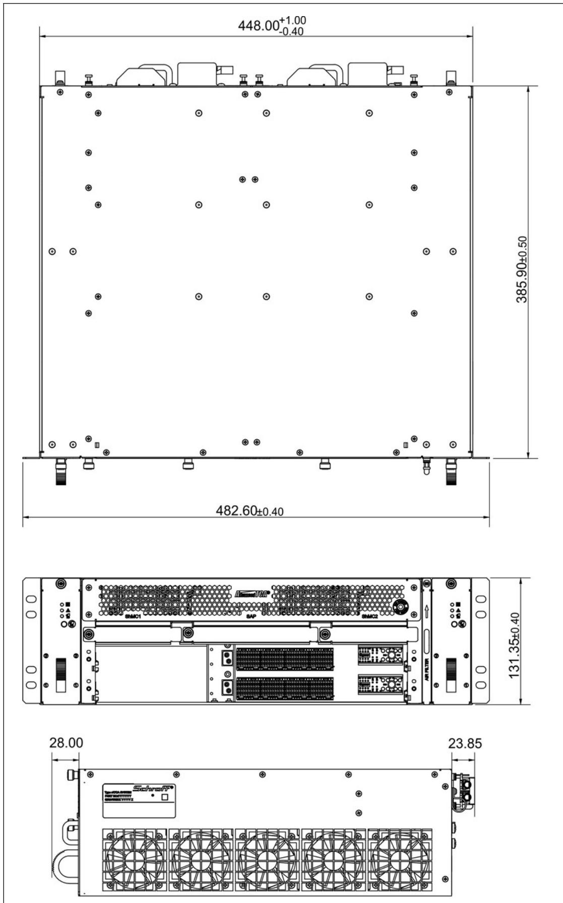
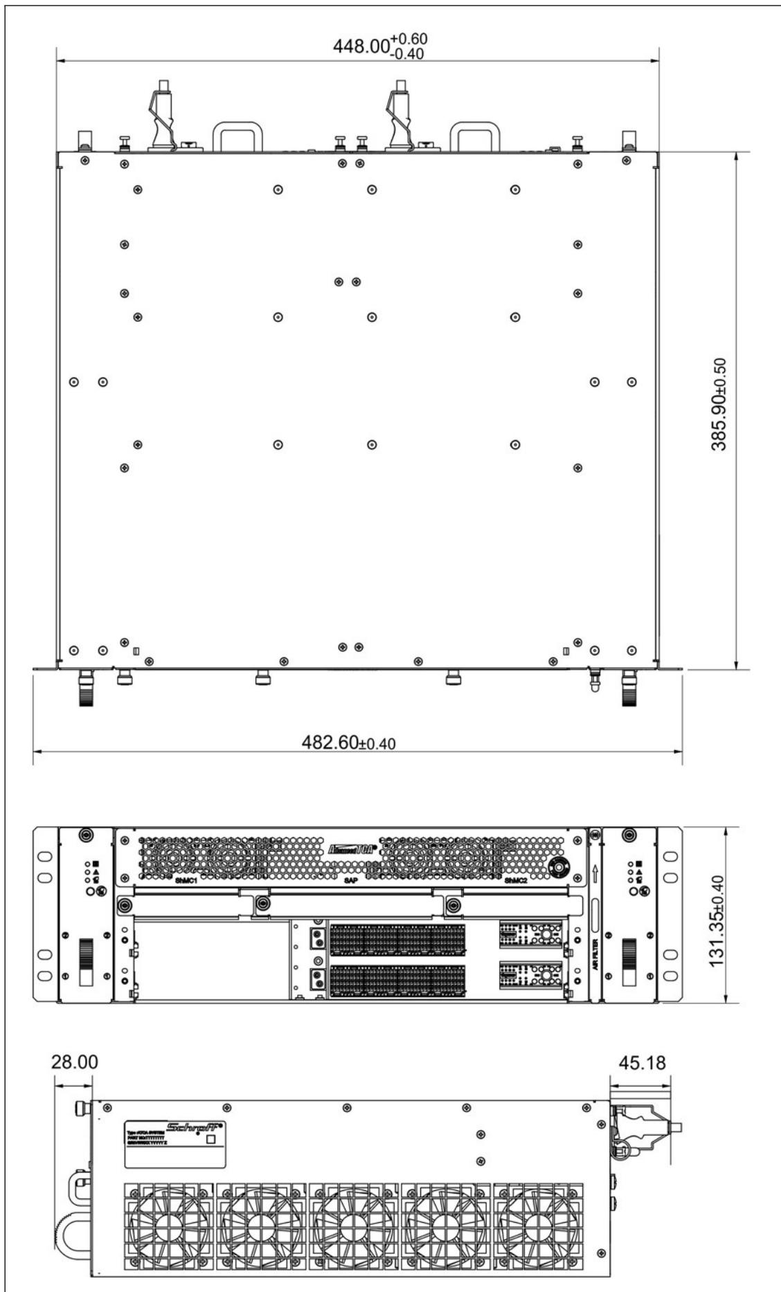
# 9.1 Shelf Dimensions

Figure 17: DC-System
![448.00+1.00\n-0.40\n385.90±0.50\n482.60±0.40\n131.35±0.40\n28.00\n23.85](.atca-80302pd-atca-80302pa-pd-50-1g046-1000-10/76576e4cb48aa484c2a31762dc4a68764eaf23352fcff759ae02bfc345b8fdae.jpg)

Dimensions in mm

Figure 18: AC-System
![448.00+0.60\n-0.40\n385.90±0.50\n482.60±0.40\n131.35±0.40\n28.00\n45.18\nSchroft®](.atca-80302pd-atca-80302pa-pd-50-1g046-1000-10/fe93f5875d99ee3977b62560f5794e913b2d25dcdc1ca7cf6556040ea0cc42f9.jpg)

Dimensions in mm

# Getting Service

Ask an Expert: http://askanexpert.adlinktech.com

# ADLINK Technology, Inc.

Address: 9F, No.166 Jian Yi Road, Zhonghe District New Taipei City 235, Taiwan 新北市中和區建一路166號9樓

Tel: +886-2-8226-5877

Fax: +886-2-8226-5717

Email: service@adlinktech.com

# Ampro ADLINK Technology, Inc.

Address: 5215 Hellyer Avenue, #110, San Jose, CA 95138, USA

Tel: +1-408-360-0200

Toll Free: +1-800-966-5200 (USA only)

Fax: +1-408-360-0222

Email: info@adlinktech.com

# ADLINK Technology (China) Co., Ltd.

Address: 300 Fang Chun Rd., Zhangjiang Hi-Tech Park, Pudong New Area Shanghai, 201203 China 上海市浦东新区张江高科技园区芳春路300号 (201203)

Tel: +86-21-5132-8988

Fax: +86-21-5132-3588

Email: market@adlinktech.com

# ADLINK Technology GmbH

Address: Hans-Thoma-Straße 11, D-68163, Mannheim, Germany

Tel: +49-621-43214-0

Fax: +49-621 43214-30

Email: emea@adlinktech.com

Please visit the Contact page at www.adlinktech.com for information on how to contact the ADLINK regional office nearest you.
[🔗 Link to the original document](.atca-80302pd-atca-80302pa-pd-50-1g046-1000-10/atca-80302pd-atca-80302pa-pd-50-1g046-1000-10.pdf)
