# aTCA-81414PD

# 14U 14-Slot AdvancedTCA® Shelf

# User‘s Manual

![Interior view of a black server rack with internal components and ventilation grilles (no visible text or symbols)](.atca-81414pd-50-1g049-1000-10/80221a856eceac4d7027659b48783a75d6b7d83626b6085b190ee65b7b099022.jpg)

Manual Rev.: 1.0

Revision Date: December 20, 2018

Part No.: 50-1G049-1000

# Preface

# Copyright © 2018 ADLINK Technology, Inc.

This document contains proprietary information protected by copyright. All rights are reserved. No part of this manual may be reproduced by any mechanical, electronic, or other means in any form without prior written permission of the manufacturer.

# Disclaimer

The information in this document is subject to change without prior notice in order to improve reliability, design, and function and does not represent a commitment on the part of the manufacturer. In no event will the manufacturer be liable for direct, indirect, special, incidental, or consequential damages arising out of the use or inability to use the product or documentation, even if advised of the possibility of such damages.

# Environmental Responsibility

ADLINK is committed to fulfill its social responsibility to global environmental preservation through compliance with the European Union's Restriction of Hazardous Substances (RoHS) directive and Waste Electrical and Electronic Equipment (WEEE) directive. Environmental protection is a top priority for ADLINK. We have enforced measures to ensure that our products, manufacturing processes, components, and raw materials have as little impact on the environment as possible. When products are at their end of life, our customers are encouraged to dispose of them in accordance with the product disposal and/or recovery programs prescribed by their nation or company.

![Symbol of a trash bin crossed with two diagonal lines, no text or labels present](.atca-81414pd-50-1g049-1000-10/f9364ae34d7288e198b914ebd035543143c943a03b047cef3912490c19f78856.jpg)

Battery Labels (for products with battery)

![Simple line drawing of a trash bin with crossed lines indicating no waste or restriction (no text or symbols)](.atca-81414pd-50-1g049-1000-10/e4c021c6b38ada1042220dd3a67baa6fb82801fb788dd7aee83ae62ab2583006.jpg)

![Li-ion](.atca-81414pd-50-1g049-1000-10/f161e1e3c4a57df1937f54d1ae3e5a283c655b540afb2f1e93870ecf89231137.jpg)

![RECYCLE\nRBRC\nLi-ion\n1.800.822.8837](.atca-81414pd-50-1g049-1000-10/d8601f8ccf01faa7229131ea012741713f72f4a84e3fc52f2b003d2ef0a1c335.jpg)

![廢電池請回收](.atca-81414pd-50-1g049-1000-10/545c02df9810a562b32c544e9a7732a95cde043e3abe3589a71f437c152d3a31.jpg)

# California Proposition 65 Warning

![The image shows a yellow triangular warning sign with a thick black border. Inside the triangle is a black exclamation mark centered vertically and horizontally.](.atca-81414pd-50-1g049-1000-10/8b786667ae0724de614438f775538ede357185ea48013e13e6e5d04b6db5ec6d.jpg)

WARNING: This product can expose you to chemicals including acrylamide, arsenic, benzene, cadmium, Tris(1,3-dichloro-2-propyl)phosphate (TDCPP), 1,4-Dioxane, formaldehyde, lead, DEHP, styrene, DINP, BBP, PVC, and vinyl materials, which are known to the State of California to cause cancer, and acrylamide, benzene, cadmium, lead, mercury, phthalates, toluene, DEHP, DIDP, DnHP, DBP, BBP, PVC, and vinyl materials, which are known to the State of California to cause birth defects or other reproductive harm. For more information go to www.p65warnings.ca.gov.

# Table of Contents

# Preface..........

# 1 Safety....

1.1 Safety Symbols used in this document... 5
1.2 General Safety Precautions . . 5
1.3 References and Architecture Specifications.. .. 6
1.4 Product Definition . .. 6
1.5 Terms and Acronyms.. .. 6
1.6 Hardware Platform...
1.7 Shelf Front and Rear View.. .. 8
1.8 ESD Wrist Strap Terminals ... . 9

# 2 ATCA Backplane ............... ...10

2.1 Interfaces... .. 10
2.1.1 Base Interface. .. 10
2.1.2 Fabric Interface . .. 10
2.1.3 Synchronization Clock Interface .. .. 10
2.1.4 Power Interface.. ... 10
2.1.5 Update Channel Interface . 11
2.2 Intelligent Platform Management Bus (IPMB).. .. 12
2.3 Shelf SEEPROM.. .. 12
2.3.1 Shelf SEEPROM Location... .. 13
2.3.2 Shelf SEEPROMs I²C Addresses.. .. 13
2.4 Shelf Manager Cross Connect .. . 14
2.5 Logic Ground .. .15

# 3 Air Filter.... ..16

3.1 Introduction..
3.2 Air Filter Presence Switch .. .. 16

# 4 Shelf Ground Connection..... .17

4.1 Specification for the Shelf Ground Connection Cable.. . 17

# 5 Fan Tray ....... .18

5.1 Introduction.. .. 18
5.2 Fan Tray Block Diagram . .. 19
5.3 Fan Tray Connectors and Indicators .. .. 20
5.4 RS-232 Serial Console Interfaces. . 21

# 6 Power... .22

6.1 PEM Overview ... .. 23
6.1.1 Power Distribution.. . 24
6.2 DC PSpecifications for the Power Cables . . 26

# 7 Shelf Management... .27

# 8 Technical Data... .28

8.1 Dimensions.. .. 29

# Getting Service .... .30

This page intentionally left blank.

# 1 Safety

The intended audience of this User’s Manual is system integrators and hardware/software engineers.

# 1.1 Safety Symbols used in this document

![A yellow triangular warning sign with a black border featuring a black lightning bolt symbol in the center.](.atca-81414pd-50-1g049-1000-10/e54e3d2c85ffaac383097f964a234d71d45a4ca65d653e9405832de2736d272e.jpg)

# Hazardous voltage!

This is the electrical hazard symbol. It indicates that there are dangerous voltages inside the Shelf.

![The image displays a yellow triangular warning sign with a thick black border. Centered inside the triangle is a black exclamation point. The sign has a slight bevel or shadow effect on its left side, giving it a subtle three-dimensional appearance. A small portion of a white background is visible at the very top edge above the sign.](.atca-81414pd-50-1g049-1000-10/3ad33cb7ef899041e18881c54ae12034625e2855e465692e1c7013b1c15e291c.jpg)

# Caution!

This is the user caution symbol. It indicates a condition where damage of the equipment or injury of the service personnel could occur. To reduce the risk of damage or injury, follow all steps or procedures as instructed.

![The image displays a yellow triangular warning sign with a thick black border. Inside the yellow background is a black silhouette of a hand reaching downward toward the bottom edge.](.atca-81414pd-50-1g049-1000-10/5c5f0010fc02c72dad5e9795f0861d952d54a4a9e1fd19eb4637509bd5e109fa.jpg)

# Risk of electrostatic discharge!

The Shelf contains static sensitive devices. To prevent static damage you must wear an ESD wrist strap.

# 1.2 General Safety Precautions

![The image displays a triangular warning sign with a thick black border and a yellow interior. Centered within the triangle is a black lightning bolt symbol, indicating an electrical hazard. There is no text visible.](.atca-81414pd-50-1g049-1000-10/497ac9ae9869bb98393f641be2a4cb6cdc0f15ef800eb4d7d44f30a7f129ad47.jpg)

# Warning!

Voltages over 42 $V _ { A C }$ or 60 $V _ { D C }$ can be present in this equipment. As defined in the PICMG 3.0 Specification, this equipment is intended to be accessed, installed, and maintained by qualified and trained service personnel only.

• Service personnel must know the necessary electrical safety, wiring and connection practices for installing this equipment.
• Install this equipment only in compliance with local and national electrical codes.
• For additional information about this equipment, see the PICMG 3.0 Specification (www.picmg.org).

# 1.3 References and Architecture Specifications

• Pigeon Point Systems IPM Sentry Shelf-External Interface Reference (www.pigeonpoint.com)
• P $| \mathsf { C M G } ^ { \otimes } 3 . 0$ Revision 3.0 AdvancedTCA® Base Specification (www.picmg.org)

# 1.4 Product Definition

The aTCA-81414PD is a 14-Slot AdvancedTCA® Shelf with 40G backplane connectivity.

# 450 W high power:

• PEM redundant, 40G Dual Star backplane, bussed IPM interface, dedicated slots for two Shelf Managers.

# 1.5 Terms and Acronyms

Table 1: Terms and Acronyms

<table><tr><td>Term</td><td>Definition</td></tr><tr><td>ATCA</td><td>Advanced Telecom Computing Architecture</td></tr><tr><td>Backplane</td><td>Passive circuit board providing the connectors for the front boards. Power distribution, management and auxiliary signal connections are supported.</td></tr><tr><td>CDM</td><td>Shelf FRU Data Module</td></tr><tr><td>ECN</td><td>Engineering Change Notice</td></tr><tr><td>ESD</td><td>Electrostatic Discharge</td></tr><tr><td>ETSI</td><td>European Telecommunications Standards Institute</td></tr><tr><td>FRU</td><td>Field Replaceable Unit</td></tr><tr><td>IPMB</td><td>Intelligent Platform Management Bus</td></tr><tr><td>IPMC</td><td>Intelligent Platform Management Controller</td></tr><tr><td>IPMI</td><td>Intelligent Platform Management Interface</td></tr><tr><td>PCB</td><td>Printed Circuit Board</td></tr><tr><td>PEM</td><td>Power Entry Module</td></tr><tr><td>RTC</td><td>Real Time Clock</td></tr><tr><td>RTM</td><td>Rear Transition Module</td></tr><tr><td>Shelf</td><td>Enclosure containing subrack, backplane, boards, cooling devices, PEMs, and Fan Trays</td></tr><tr><td>VRTN</td><td>Voltage Return</td></tr></table>

# 1.6 Hardware Platform

The Shelf is 14 U high and $1 9 ^ { 6 6 }$ “ rack mountable. The chassis is designed for easy access of any Field Replaceable Units (FRU).

• Powder-coated 14U / 19“ chassis with front card cage for ATCA boards and rear card cage for ATCA RTM boards
• 14-slot 40G ATCA Dual Star Backplane, Dual Star Base Interface, bussed IPM interface, supporting 12x8 U node board slots and two 8 U hub slots
• Mounting brackets for $1 9 ^ { 6 6 }$ racks and rear fixing point
• ESD Wrist Strap Terminals at the front and the rear
• Two dedicated Shelf Manager bays accepting Shelf Managers
• Front-pluggable, hot-swappable Fan Tray
• Air inlet filter with presence monitoring
• Rear-pluggable Power Entry Module (non-FRU)

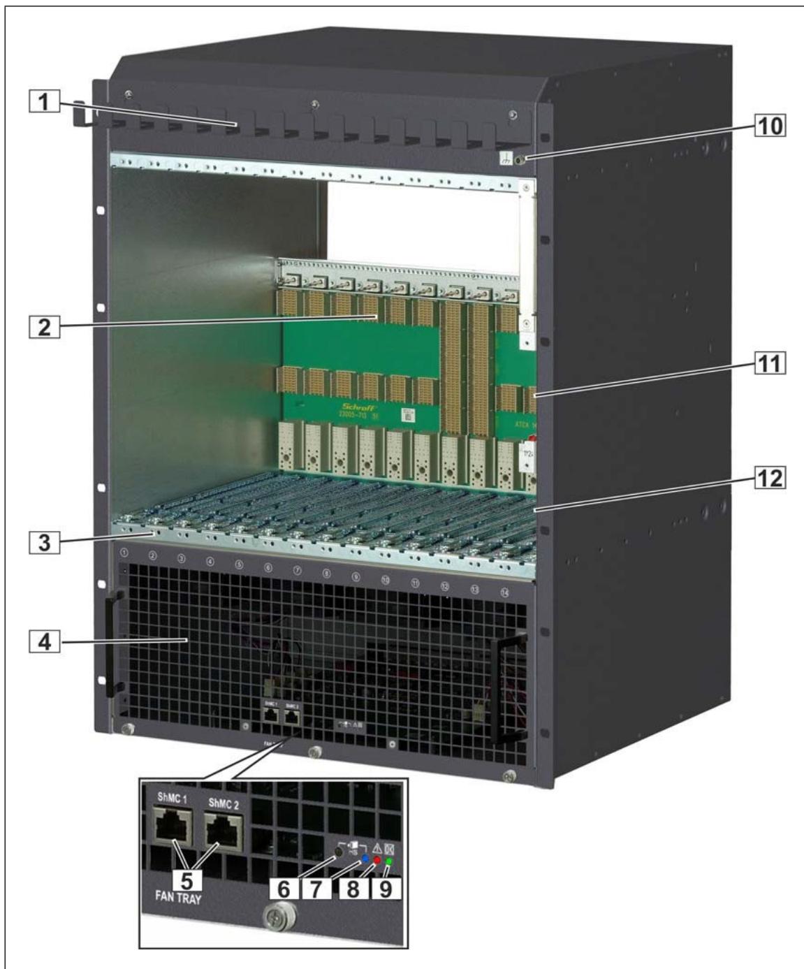
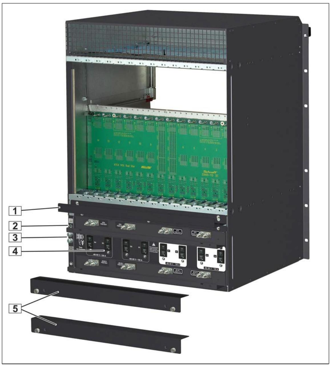
# 1.7 Shelf Front and Rear View

Figure 1: Shelf Front View
![1\n2\n3\n4\n10\n11\n12\nSchroff\n23000-70 M\nAT2A\nShMC 1 ShMC 2\n5 6 7 8 9\nFAN TRAY](.atca-81414pd-50-1g049-1000-10/d5a8d7902ae43f5ce75ff0547e53d9e7046cefe7a2411387f986c2ddb19fe844.jpg)

1 Cable Tray 7 Hot Swap LED

2 Backplane 8 Fan Tray Fault LED

3 Front Card Cage 9 Fan Tray OK LED

4 Fan Tray 10 ESD Wrist Strap Terminal

5 Serial Interfaces for ShMC 11 Slot for ShMC 1

6 Hot Swap Push Button 12 Slot for ShMC 2

Figure 2: Shelf Rear View
![1\n2\n3\n4\n5\nSchroff\n2000-10 51\nATCA HCL Dual Star\nHCC-V7-10A\nHCC-V7-10A\nHCC-V7-10A\nHCC-V7-10A\nHCC-V7-10A\nHCC-V7-10A\nHCC-V7-10A](.atca-81414pd-50-1g049-1000-10/1ae707f1ec3f9d36af48b960986444e2eafecb7f75cac16ed85c667fa01f49ec.jpg)

1 Cable Tray

4 Power Input and Circuit Breakers

2 ESD Wrist Strap Terminal

5 Cover Power Input

3 Ground Terminal

# 1.8 ESD Wrist Strap Terminals

![This image displays a triangular warning sign with a yellow background and a thick black border. Inside the triangle is a black pictogram depicting a hand on the left side next to a dark, jagged shape, symbolizing a danger of crushing or being caught in machinery.](.atca-81414pd-50-1g049-1000-10/01c49f8d1478850059d2d2cdc0f9669f8f459e6307070e6be62ce1e8cb45fbeb.jpg)

# Risk of electrostatic discharge!

The Shelf contains static sensitive devices. To prevent static damage you must wear an ESD wrist strap.

One ESD Wrist Strap Terminal is located at the Shelf‘s upper front side, one ESD Wrist Strap Terminal is located at the left rear side of the Shelf.

# 2 ATCA Backplane

The 14-slot ATCA monolithic Backplane provides:

• 40 Gb/s connectivity (4 lanes with 10 Gb/s)
• 10 ATCA Node slots
• 2 ATCA Hub slots
• Two dedicated Shelf Manager slots
. PEM slot
• Fan Tray slot
SEEPROMs

# 2.1 Interfaces

# 2.1.1 Base Interface

Logical slots 1 and 2 are the hub slots for the Dual Star Base Interface.

Base Interface Channel 1 (ShMC) of logical slot 1 and 2 is cross connected to both dedicated Shelf Manager slots on the ATCA Backplane.

# 2.1.2 Fabric Interface

The Fabric Interface is wired as Dual Star supporting four ports (8 pairs) per channel. See PICMG® 3.0 AdvancedTCA® Base Specification for details.

# 2.1.3 Synchronization Clock Interface

Six differential pairs of synchronization clocks are bused between all 14 ATCA slots and terminated at both ends with 80.6 Ohms between each differential pair.

# 2.1.4 Power Interface

Power distribution within the ATCA Backplane is divided into 4 Power Branches. This topology is used for safety reasons to keep the max. current per branch less than 50 A. Slots connected by update ports, are on separate power branches as well as both hub slots, the Shelf Manager slots and the Fan Trays.

# 2.1.5 Update Channel Interface

The Update Channels are wired between two redundant ATCA Backplane slots as 10 differential pairs.

The Update Channel is intended to pass information between two redundant ATCA Boards.

Figure 3: Update Channels
Dual Star

<table><tr><td></td><td>Node</td><td>Node</td><td>Node</td><td>Node</td><td>Node</td><td>Node</td><td>Hub Star 1</td><td>Hub Star 2</td><td>Node</td><td>Node</td><td>Node</td><td>Node</td><td>Node</td><td>Node</td></tr><tr><td>Physical Slot</td><td>1</td><td>2</td><td>3</td><td>4</td><td>5</td><td>6</td><td>7</td><td>8</td><td>9</td><td>10</td><td>11</td><td>12</td><td>13</td><td>14</td></tr><tr><td>Logical Slot</td><td>13</td><td>11</td><td>9</td><td>7</td><td>5</td><td>3</td><td>1</td><td>2</td><td>4</td><td>6</td><td>8</td><td>10</td><td>12</td><td>14</td></tr><tr><td>HW-Address (Hex)</td><td>4D</td><td>4B</td><td>49</td><td>47</td><td>45</td><td>43</td><td>41</td><td>42</td><td>44</td><td>46</td><td>48</td><td>4A</td><td>4C</td><td>4E</td></tr><tr><td>IPMB-Address (Hex)</td><td>9A</td><td>96</td><td>92</td><td>8E</td><td>8A</td><td>86</td><td>82</td><td>84</td><td>88</td><td>8C</td><td>90</td><td>94</td><td>98</td><td>9C</td></tr><tr><td>Update Channel</td><td></td><td></td><td></td><td></td><td></td><td></td><td></td><td></td><td></td><td></td><td></td><td></td><td></td><td></td></tr><tr><td>Power Branch</td><td>4</td><td>4</td><td>3</td><td>3</td><td>2</td><td>2</td><td>1</td><td>2</td><td>1</td><td>1</td><td>3</td><td>3</td><td>4</td><td>4</td></tr></table>

# 2.2 Intelligent Platform Management Bus (IPMB)

The Shelf uses an Intelligent Platform Management Bus (IPMB) for management communications among all ATCA Boards, the Fan Trays and the Shelf Managers. The reliability of the IPMB is improved by the addition of a second IPMB, with the two IPMBs referenced as IPMB-A and IPMB-B.

IPMB-A and IPMB-B are routed to the ATCA slots in a bussed configuration.

Figure 4: IPMB
![**Labeled Blocks:**\n*   **Bused IPMB** (Title)\n*   **ATCA Board** (Six blocks arranged horizontally)\n*   **IPMC** (Six blocks, each inside an ATCA Board block)\n*   **Shelf Manager 1** (Bottom left block)\n*   **Shelf Manager 2** (Bottom right block)\n*   **IPMB-A** (Legend label)\n*   **IPMB-B** (Legend label)\n\n**Connections:**\n*   **Dashed lines** (labeled **IPMB-A**) connect the bottom of each **IPMC** block to a central horizontal bus line.\n*   **Solid lines** (labeled **IPMB-B**) connect the bottom of each **IPMC** block to the central horizontal bus line.\n*   **Dashed lines** connect the left side of the central horizontal bus line to the **Shelf Manager 1** block.\n*   **Solid lines** connect the left side of the central horizontal bus line to the **Shelf Manager 1** block.\n*   **Dashed lines** connect the right side of the central horizontal bus line to the **Shelf Manager 2** block.\n*   **Solid lines** connect the right side of the central horizontal bus line to the **Shelf Manager 2** block.](.atca-81414pd-50-1g049-1000-10/aef5e69087c81ebb709f6ad96544cf2ca2de330059453b255146bbe7039e692a.jpg)

# 2.3 Shelf SEEPROM

The Shelf SEEPROM is a repository of the shelf-specific information, capabilities of the system and other user configurable options.

The SEEPROM contains as example:

• a list of which slots are connected together
• how the update channels are routed
how many slots are in the system
what the maximum power is to each slot
the serial number of the Shelf
the backplane topology etc.

The Shelf Managers use this information to provide functions such as electronic keying, controlling the power state of the system, etc.

The Shelf Managers cache the information that is stored in the SEEPROMs so that the SEEPROM is only needed when the Shelf Managers are first inserted or when the Shelf is first turned on.

The redundant SEEPROMs ensure that if one is corrupt or non-functional, the second can provide the necessary information. The Shelf Manager selects what set of information is correct and then synchronizes the two SEEPROMs from the internally cached copy of the SEEPROM information.

# 2.3.1 Shelf SEEPROM Location

The SEEPROMs are located at the rear side of the backplane.

# 2.3.2 Shelf SEEPROMs I²C Addresses

![The image displays a solid blue rectangle containing a centered, white lowercase letter 'i'. This is the standard icon used to represent 'information.'](.atca-81414pd-50-1g049-1000-10/f2ef39d5f0b22c82e7df738d1d9a0d8a258118eb779d908a6705b783fc3e5340.jpg)

The SEEPROMs have the same address but are on different I²C Channels!

<table><tr><td>CDM</td><td>I2C Channel</td><td>I2C Bus Address (7/8 bit)</td></tr><tr><td>SEEPROM1</td><td>Channel 1</td><td>0xa4/52</td></tr><tr><td>SEEPROM2</td><td>Channel 2</td><td>0xa4/52</td></tr></table>

# 2.4 Shelf Manager Cross Connect

The ATCA Backplane provides cross connect traces between the Base Hubs and the Shelf Managers.

Figure 5: Shelf Manager Cross Connect
![Based on the provided image, here is the accurate and concise description of the flowchart/block diagram:\n\n**Labeled Blocks:**\n*   **Top Component:** An image of a hardware chassis labeled '**Schroff**', '**ATCA 145L Dual Slot**', and '**AdvancedTCA**'.\n*   **Bottom Left Component:** A block labeled '**Shelf Manager 1**'. Inside this block are sub-blocks/labels: '**Backplane Connector**' (with labels '**ETH 1**' and '**ETH 0**'), '**ShMM**' (with labels '**ETH 1**' and '**ETH 0**'), '**Switch**', '**Front Plate Connector**', and '**RJ45**'.\n*   **Bottom Right Component:** A block labeled '**Shelf Manager 2**'. Inside this block are sub-blocks/labels: '**Backplane Connector**' (with labels '**ETH 1**' and '**ETH 0**'), '**ShMM**' (with labels '**ETH 1**' and '**ETH 0**'), '**Switch**', '**Front Plate Connector**', and '**RJ45**'.\n\n**Connections:**\n*   **Within Shelf Manager 1:**\n    *   A solid blue line connects '**ETH 1**' inside '**ShMM**' to '**ETH 1**' on the '**Backplane Connector**'.\n    *   A dashed red line connects '**ETH 0**' inside '**ShMM**' to the '**Switch**'.\n    *   A dashed red line connects the '**Switch**' to '**RJ45**'.\n    *   A solid blue line connects the '**Backplane Connector**' (ETH 1) upwards to the left-most blue arrow on the chassis.\n    *   A dashed red line connects the '**Switch**' upwards to the left-most red arrow on the chassis.\n*   **Within Shelf Manager 2:**\n    *   A solid blue line connects '**ETH 1**' inside '**ShMM**' to '**ETH 1**' on the '**Backplane Connector**'.\n    *   A dashed red line connects '**ETH 0**' inside '**ShMM**' to the '**Switch**'.\n    *   A dashed red line connects the '**Switch**' to '**RJ45**'.\n    *   A solid blue line connects the '**Backplane Connector**' (ETH 1) upwards to the right-most blue arrow on the chassis.\n    *   A dashed red line connects the '**Switch**' upwards to the right-most red arrow on the chassis.](.atca-81414pd-50-1g049-1000-10/8bde6356eeef63e9398674077ee8bf0d19d5e8a285b4f9edfd42ce3ec8bd9876.jpg)

Table 2: Connector (P23) pin assignments for Shelf Manager Cross Connect

<table><tr><td>Row</td><td>Designation</td><td colspan="2">ab</td><td colspan="2">cd</td><td colspan="2">ef</td><td colspan="2">gh</td></tr><tr><td rowspan="2">5</td><td rowspan="2">Shelf Manager Port with Shelf Manager Cross Connects</td><td>Tx1+</td><td>Tx1-</td><td>Rx1+</td><td>Rx1-</td><td>Tx2+</td><td>Tx2-</td><td>Rx2+</td><td>Rx2-</td></tr><tr><td colspan="4">Shelf Manager Cross Connect 1</td><td colspan="4">Shelf Manager Cross Connect 2</td></tr></table>

# 2.5 Logic Ground

Figure 6: Logic Ground
![A\nB\nA\n14 13 12 11 10 9 6 5 4 3 2 1\nPower, Vdc to\nconnect, GND to\nClossee—GND\nCoherent mounting\nscrew\nCoherent mounting\nScrew\nCoherent mounting\nScrew\nCoherent mounting\nScrew\nCoherent mounting\nScrew\nCoherent mounting\nScrew\nCoherent mounting\nScrew](.atca-81414pd-50-1g049-1000-10/5f198e20cb4b7145bec9a3407050ad6b0a47b3299ae49c4511aebf6acc299675.jpg)

The ATCA Backplane provides a mechanism to connect Logic Ground (GND) and Shelf Ground (Shelf\_GND). You can connect/isolate Logic Ground by swapping two screws from position (A) to position (B).

• Screws at position (A): Logic Ground and Shelf Ground connected.
• Screws at position (B): Logic Ground and Shelf Ground isolated.

![The image features a white lowercase letter 'i' centered on a blue background, flanked by vertical blue strips on the left and right sides.](.atca-81414pd-50-1g049-1000-10/10c6fc9d62942e17bf7141e894d66526461c940c43dd953e85b225b6815942bc.jpg)

By default, Logic Ground and Shelf Ground are isolated.

Torque for the screws: 0.7 Nm +10%

# 3 Air Filter

Figure 7: Air Filter
![3D rendering of a modular solar panel assembly with green ventilation grilles inside a black housing (no text or symbols visible)](.atca-81414pd-50-1g049-1000-10/362838f80fab2cf90996a8e0884d3367114aa68fa1c28ae00b336d936ac51ccf.jpg)

# 3.1 Introduction

The ATCA Shelf provides a replaceable air filter located on top of the fan tray. The filter element is an open cell polyurethane foam special coating to provide improved fire retardation and fungi resistance.

The filter meets the requirements of the Telcordia Technologies Generic Requirements GR- 78-CORE specification.

# 3.2 Air Filter Presence Switch

The air filter presence is detected by a sensor on the backplane. The signal is routed to the IPM controller of the fan tray.

# 4 Shelf Ground Connection

![The image displays a yellow triangular warning sign with a double black border. Inside the triangle is a black lightning bolt symbol. The sign is situated on a white background, with a black horizontal bar visible at the very top of the frame.](.atca-81414pd-50-1g049-1000-10/42b2fa060acb631bb0a89f5b540c3a0f755e0bbbeed92c65a654a73bceda0703.jpg)

# Hazardous voltage!

Before powering-up the Shelf, make sure that the Shelf Ground terminals are connected to Protective Earth (PE) of the building.

The ATCA Shelf provides a Shelf ground terminal at the left rear side. The Shelf ground terminal provides two threads (M6) with a 15.88 mm (5/8“) spacing between thread centers to connect a two hole lug Shelf ground terminal cable.

Figure 8: Shelf Ground Terminal
![M6\n15,9 mm\nTorque:\nmax. 5 Nm (44 in-lbs)](.atca-81414pd-50-1g049-1000-10/42bea685fb4ddd964cfc95f9b7eeb12dfe0951c282f548075b595222c38571a6.jpg)

1 Ground Terminal

# 4.1 Specification for the Shelf Ground Connection Cable

Required wire size: #3 AWG or #2 AWG, maximum length 3 m.

Required terminals: Use only two hole lug terminals. (For example PANDUIT LCC2-14AHQ or LCD2-14AHQ with 45° angle)

# 5 Fan Tray

# 5.1 Introduction

The Fan Tray is an intelligent FRU controlled by the ShMCs via IPMB.

The interchangeable Fan Tray is equipped with 8 high speed / high air flow fans controlled as a group by the IPM Controller in the Fan Tray.

The Fan Tray is locked into the Shelf with captive screws. A Hot Swap push button is used to provide hot-swap functionality.

The Fan Tray provides:

• A blue Hot Swap LED
• A red Fan Tray Fault LED
• A green Fan Tray OK LED
• A Hot Swap push button

The Fan Tray is controlled via an on-board IPM controller. The Shelf Manager performs management of the Fan Tray through the two independent bussed IPMB connections.

With optional on-blade shelf management, the circuit breaker status signals of the PEM and the SEEPROM on the backplane are connected to the internal I²C bus on the Fan Trays. The on-blade Shelf Manager has access to these components via the IPM controller of the Fan Trays.

The speed of each individual fan is monitored. If any of the fan speeds drops below the desired fan speed, a System Event Log (SEL) entry is logged by the Shelf Manager. The Shelf Manager then generates alerts and sets alarm conditions as necessary.

The system is designed to run indefinitely with any single fan failure. When one fan fails, all other fans are set to full speed.

![A yellow triangular warning sign with a thick black border featuring a large black exclamation point in the center.](.atca-81414pd-50-1g049-1000-10/1947c5ae0e2785b00a3ae1f0ddb76dacf2a10dbdfdd45726a54b05a5b1ec6f0f.jpg)

# Caution!

The fan tray is not redundant. Depending on the operation temperature and the load state a fan tray swap must be carried out within a maximum of 30 seconds.

# 5.2 Fan Tray Block Diagram

Figure 9: Fan Tray Block Diagram
![The diagram illustrates an IPM (Intelligent Power Module) Controller system with connections to a connector, fans, and power rails.\n\n**Central Block:**\n*   **IPM Controller**: A large yellow block in the center.\n\n**Left Side (User Interface/Status):**\n*   **Hot Swap Button**: An input arrow pointing to the IPM Controller.\n*   **LED Buffer**: Connected to the IPM Controller, linking to three indicators:\n    *   **HS** (blue circle)\n    *   **OK** (green circle)\n    *   **Fault** (red circle)\n\n**Top Right (Connector Interface):**\nThe IPM Controller connects via lines to a vertical **Connector** block on the far right. The specific signals include:\n*   **ShMC 1 Serial**\n*   **ShMC 2 Serial**\n*   **Air Filter present**\n*   **CircuitBreaker_1**\n*   **CircuitBreaker_2**\n*   **EXT_PRES 1...4**\n*   **PSU_PRES 1...4**\n*   **NSEAT (Short Pin)**\n*   **NTC 1**\n*   **NTC 2**\n*   **AVREF**\n*   **GND (Fan Tray present)**: Connected to a ground symbol.\n*   **local I2C Bus**: Connects to blocks labeled **EEPROM**, **LM75**, and **LM75**.\n*   **2.5 V**, **Uref**, **3.3 V**: Voltage references near the top.\n*   **I2C Buffer**: Connects **SDA/SCL_FT** and **I2C_CONT_FT** to the Connector.\n*   **I2C Buffer**: Connects **IPMB_A** and **IPMB_B** to the Connector.\n*   **Watchdog**: A block connecting to the Connector.\n\n**Middle Right (Status Inputs & Fan Control):**\n*   **Status Inputs** (arrows pointing into IPM Controller):\n    *   **Fuses Branch 2 OK**\n    *   **Fuses Branch 1 OK**\n    *   **3.6 V measurement**\n    *   **3.3 V measurement**\n    *   **H/S1 OK**\n    *   **H/S OFF**\n    *   **H/S2 OK**\n*   **Fan Control Signals** (outputs from IPM Controller):\n    *   **Tacho 1**\n    *   **PWM 0**\n    *   **Tacho 2**\n    *   **PWM 1**\n\n**Bottom Section (Fans, Hot Swap, and Power):**\n*   **Fan Groups**:\n    *   Top group: **Fan 1**, **Fan 4**, **Fan 5**, **Fan 8**. Connected via yellow buffer boxes.\n    *   Bottom group: **Fan 2**, **Fan 3**, **Fan 6**, **Fan 7**. Connected via yellow buffer boxes.\n*   **Control/Power Components**:\n    *   Two **Hot Swap Controller** blocks.\n    *   Two **ORing** blocks (diode arrays).\n    *   Two **Fuse Monitor** blocks (blue).\n    *   Power rails labeled **VRTN_A**, **VRTN_B**, **-48V_A**, **-48V_B** (appearing for **Branch 2** and **Branch 1**).\n    *   **48 V to 3.6 V DC/DC Converter**: Connects to a **Current Limiter** which outputs **3V6_FT**.](.atca-81414pd-50-1g049-1000-10/b2a668c4ed8e23857cc79e4f323367b54f471e82599d00ff93753ef83107930f.jpg)

Figure 10: Fan Tray
![3D cutaway view of a solar panel array with internal fan structures (no text or symbols visible)](.atca-81414pd-50-1g049-1000-10/4e48c6276f46f2eacf2bfef084021dc82b738a6f2bcff796c5e7241fa9c21ef6.jpg)

# 5.3 Fan Tray Connectors and Indicators

The front panel includes a green Fan Tray OK LED, a red Fan Tray Fault LED, and a blue Hot Swap LED.

The Hot Swap push button indicates to the Shelf Managers that the Fan Tray is about to be removed. Its use is optional, but it is provided so that service personnel can be trained to look for a blue LED to be illuminated on any active component before removing it from the system. Once the operator pushes the Hot Swap button, the Shelf Manager is informed of the pending extraction. When the Shelf Manager feels it is “safe“ to remove the Fan Tray, the blue Hot Swap LED illuminates solid.

Table 3: LEDs on Fan Tray front panel

<table><tr><td>Color</td><td>Description</td><td>Status</td><td>Condition</td></tr><tr><td rowspan="2">Green</td><td rowspan="2">Fan Tray OK LED</td><td>Off</td><td>No Power to the Fan Tray</td></tr><tr><td>Solid green</td><td>Normal Operation</td></tr><tr><td>Red</td><td>Fan Tray Fault LED</td><td>Solid red</td><td>Attention Status (error condition)</td></tr><tr><td rowspan="3">Blue</td><td rowspan="3">Hot Swap LED</td><td>Off</td><td>No Power to the Fan Tray, or not OK to extract the Fan Tray</td></tr><tr><td>Short blink</td><td>Preparing for extraction</td></tr><tr><td>Solid blue</td><td>Ready to remove</td></tr></table>

# 5.4 RS-232 Serial Console Interfaces

The Fan Tray provides two RS-232 serial console connectors for Shelf Manager 1 and 2. The connectors are 8-pin RJ45 modular receptacles.

A full set of RS-232 signals, including modem control is provided.

Table 4: RS-232 Serial Console Interface Pin assignment

<table><tr><td>RJ45 Pin</td><td>RS-232 Signal</td><td>Type</td><td>Description</td></tr><tr><td>1</td><td>RTS</td><td>Out</td><td>Request To Send</td></tr><tr><td>2</td><td>DTR</td><td>Out</td><td>Data Terminal Ready</td></tr><tr><td>3</td><td>TxD</td><td>Out</td><td>Transmit Data</td></tr><tr><td>4</td><td>GND</td><td>---</td><td>Logic Ground</td></tr><tr><td>5</td><td>GND</td><td>---</td><td>Logic Ground</td></tr><tr><td>6</td><td>RxD</td><td>In</td><td>Receive Data</td></tr><tr><td>7</td><td>DSR</td><td>In</td><td>Data Set Ready</td></tr><tr><td>8</td><td>CTS</td><td>In</td><td>Clear To Send</td></tr></table>

![The image displays a blue logo featuring two white lowercase letters 'i' positioned side-by-side. The letters are stylized with a horizontal gap separating the top dot from the vertical stem.](.atca-81414pd-50-1g049-1000-10/6b9d214a5aa613d32d2e9f68163a6ccf4f7454729989f60d521ffc938f52e91b.jpg)

The serial console default configuration is:

115200 baud

no parity

8 data

bits

1 stop bit

# 6 Power

![The image displays a black horizontal bar at the very top. Below it is a yellow triangular warning sign with a thick black border. In the center of the yellow triangle is a black lightning bolt symbol.](.atca-81414pd-50-1g049-1000-10/aa0134597860492a759a394d4dad43bf0d38f9be6b656a2d0bed0cb235f5a396.jpg)

# Hazardous voltage!

Before working ensure that the power is removed from the power connection cables.

The shelf supports low-power and high-power DC-Power Entry Modules (PEMs) with or without redundant inputs.

The pluggable DC Power Entry Module (PEM) is located at the rear bottom side of the Shelf. The PEM provides power terminals for 100 A power feeds. Each power feed consists of $\mathsf { a } - 4 8 \mathsf { V } _ { \mathsf { D C } }$ cable and its corresponding RTN cable.

The power filtering consists of filtered power terminals and a discrete line-filter for each power branch. The input voltage range for the Shelf is from $- 4 0 \vee _ { \mathsf { D C } } \mathsf { t o } - 7 5 \bigvee _ { \mathsf { D C } }$ .

Overcurrent protection is provided by 100 A circuit breakers in the -48 VDC input lines. Power distribution within the PEM is divided into 4 power branches.

![A blue square icon containing a white lowercase letter 'i' in the center.](.atca-81414pd-50-1g049-1000-10/e212a10d18e39acf82d8ca224d5220f141b1f6c221fb43483a6159e1438e271a.jpg)

The System can be powered using a regular telecommunication power supply of -48/-60 $V _ { D C }$ with a $V _ { D C }$ return. The specified voltage range is from -40 $V _ { D C }$ to-75 $V _ { D C } .$ . The Shelf supports redundant power inputs but the two inputs should be independently powered.

# 6.1 PEM Overview

Figure 11: Available PEMs
![RTN FEED B3/4\nRTN FEED B1/2\nRTN FEED A1/2\nRTN FEED A3/4\nFEED B3/4\nB4\nB3\nFEED B1/2\nB2\nB1\nDisconnect all power supply connectors before removing cover or servicing channels.\n48/-60 V + 100 A\n48/-60 V + 100 A\n48/-60 V + 100 A\nFEED A1/2\nA1\nA2\nFEED A3/4\nA3\nA4\n48/-60 V + 100 A\n48/-60 V + 100 A\nPEM High Power redundant\nRTN FEED B\nRTN FEED A\nFEED B\nB1/3\nB2/4\nDisconnect all power supply connectors before removing cover or servicing channels.\n48/-60 V + 100 A\nFEED A\nA2/4\nA1/3\n48/-60 V + 100 A\nPEM Low Power redundant\nRTN FEED 1/2\nRTN FEED 3/4\nFEED 1/2\n2\n1\nFEED 3/4\n3\n4\nDisconnect all power supply connectors before removing cover or servicing channels.\n48/-60 V + 100 A\n48/-60 V + 100 A\nPEM High Power non-redundant\nRTN FEED 1/2\nRTN FEED 3/4\nFEED 1/2\n2\n1\nFEED 3/4\n3\n4\nDisconnect all power supply connectors before removing cover or servicing channels.\n48/-60 V + 100 A\n48/-60 V + 100 A\nPEM Low Power non-redundant](.atca-81414pd-50-1g049-1000-10/ddeb6504456e3286d5ca33e2196ded676663757ec5d86199a5c95ef5fcd96a47.jpg)

# 6.1.1 Power Distribution

Power distribution within the Shelf originates from the PEM and powers all the blades, the Shelf Managers and the Fan Trays. The power is divided in 4 output branches towards the backplane.

Figure 12: Power Distribution Low Power PEMs
![Based on the provided image, here is the description of the labeled blocks and connections. The image displays two nearly identical diagrams stacked vertically, representing 'Non Redundant' and 'Redundant' states.\n\n**Labeled Blocks:**\n*   **Fan Tray** (Top section of both diagrams)\n*   **4 Fans** (Green and Grey boxes within the Fan Tray)\n*   **Physical Slot** (Row of boxes numbered 1–14)\n*   **Update Channel** (Label for connection lines between slots)\n*   **Power Branch** (Label for numbers inside Physical Slot boxes: 4, 4, 3, 3, 2, 2, 1, 2, 1, 1, 3, 3, 4, 4)\n*   **SHMC 1** (Vertical Grey box)\n*   **SHMC 2** (Vertical Green box)\n*   **PEM Low Power Non Redundant** (Bottom block of the top diagram)\n*   **PEM Low Power Redundant** (Bottom block of the bottom diagram)\n*   **AB1/3**, **AB2/4** (Labels at the bottom of the top diagram)\n*   **A1/3**, **A2/4**, **B1/3**, **B2/4** (Labels at the bottom of the bottom diagram)\n\n**Connections:**\n*   **Fan Tray to Physical Slots:**\n    *   Green dashed lines connect the top-left '4 Fans' box to Physical Slots 1, 2, 5, and 6.\n    *   Grey dashed lines connect the top-right '4 Fans' box to Physical Slots 13 and 14.\n*   **Physical Slots to SHMC and PEM:**\n    *   **Pink Lines (Power Branch 4):** Connect Physical Slots 1, 2, 13, and 14 to **SHMC 1** and the bottom row of the PEM block (specifically columns 2 and 4).\n    *   **Green Lines (Power Branch 2):** Connect Physical Slots 5, 6, and 8 to **SHMC 2** and the bottom row of the PEM block (column 1).\n    *   **Grey/Dark Grey Lines (Power Branch 3 & 1):** Connect Physical Slots 3, 4, 7, 9, 10, 11, and 12 to **SHMC 1** and the bottom row of the PEM block (columns 1 and 3).\n*   **Update Channel:** Curved black lines connect adjacent Physical Slots (1-2, 3-4, 5-6, 7-8, 9-10, 11-12, 13-14).\n*   **PEM Bottom Outputs:**\n    *   In the **top diagram**, lines from the PEM block connect to labels **AB1/3** and **AB2/4**.\n    *   In the **bottom diagram**, the PEM block is split vertically, with lines connecting to labels **A1/3**, **A2/4**, **B1/3**, and **B2/4**.](.atca-81414pd-50-1g049-1000-10/04871d8a3ed96b4ecb6e2d2d33650adf6b8f2ad27f588632c69a4f008fd8fd7a.jpg)

Figure 13: Power Distribution High Power PEMs
![Based on the provided flowchart/block diagram, here is an accurate and concise description of the labeled blocks and connections:\n\n**Top Section**\n*   **Block:** A rectangular block labeled **'Fan Tray'**.\n    *   Inside, there are two boxes: a green box labeled **'4 Fans'** and a grey box labeled **'4 Fans'**.\n*   **Connections:**\n    *   A green dashed line originates from the green **'4 Fans'** box and runs down the left side.\n    *   A grey dashed line originates from the grey **'4 Fans'** box and runs down the right side.\n\n**Middle Section**\n*   **Block:** A row of 14 vertical slots labeled **'1'** through **'14'** under the header **'Physical Slot'**.\n    *   To the right of the slots are labels: **'Physical Slot'**, **'Update Channel'**, and **'Power Branch'**.\n    *   Inside each slot is a number representing the **'Power Branch'**:\n        *   Slots 1, 2, 13, 14 contain the number **'4'** (colored pink).\n        *   Slots 3, 4, 11, 12 contain the number **'3'** (colored grey).\n        *   Slots 5, 6, 8 contain the number **'2'** (colored green).\n        *   Slots 7, 9, 10 contain the number **'1'** (colored grey).\n*   **Connections (Update Channel):**\n    *   Black curved lines connect dots within the slots, labeled as **'Update Channel'**:\n        *   One line connects slots 1, 2, 3, and 4.\n        *   One line connects slots 5, 6, 7, 8, and 9.\n        *   One line connects slots 12 and 13.\n*   **Connections (Power Branch Lines):**\n    *   Dashed lines corresponding to the slot colors extend downwards from the slots:\n        *   Pink dashed lines from slots 1, 2, 13, 14.\n        *   Green dashed lines from slots 5, 6, 8.\n        *   Grey dashed lines from slots 3, 4, 7, 9, 10, 11, 12.\n\n**Right Side**\n*   **Blocks:** Two vertical boxes on the right edge.\n    *   Top box: Grey box labeled **'SHMC 1'**.\n    *   Bottom box: Green box labeled **'SHMC 2'**.\n*   **Connections:**\n    *   The dashed lines from the physical slots connect towards these SHMC blocks and the bottom PEM block.\n    *   The green dashed line from the Fan Tray connects to **'SHMC 2'**.\n    *   The grey dashed line from the Fan Tray connects to **'SHMC 1'**.\n\n**Bottom Section**\n*   **Block:** A rectangular block labeled **'PEM High Power Non Redundant'**.\n    *   Inside, there are numbers **'1'**, **'2'**, **'3'**, **'4'** arranged in rows.\n    *   Dashed lines connect the internal dots to the dashed lines coming from the physical slots above.\n*   **Connections:**\n    *   Solid lines extend downwards from the PEM block to circles labeled **'AB1'**, **'AB2'**, **'AB3'**, and **'AB4'**.\n    *   Specifically:\n        *   A grey line connects to **'AB1'**.\n        *   A green line connects to **'AB2'**.\n        *   A grey line connects to **'AB3'**.\n        *   A pink line connects to **'AB4'**.](.atca-81414pd-50-1g049-1000-10/f3dcb32833e0e075a4f2c58b527a5e469498d3c0d2e560e0b87fe7c92cf54842.jpg)

![Based on the provided image, here is an accurate and concise description of the flowchart/block diagram:\n\n**Labeled Blocks:**\n*   **Fan Tray:** Located at the top, containing two blocks labeled '4 Fans' (one green, one grey).\n*   **Physical Slot:** A row of 14 blocks numbered 1 through 14. Each block has a background color (pink, green, or grey) and a number inside labeled 'Power Branch' (1, 2, 3, or 4).\n*   **Update Channel:** A row within the Physical Slot section showing black curved lines connecting specific slots.\n*   **SHMC 1:** A grey block on the right side.\n*   **SHMC 2:** A green block on the right side.\n*   **PEM High Power Redundant:** A large box at the bottom containing columns labeled 1, 2, 3, 4 and a second set of 1, 2, 3, 4.\n*   **Circles:** Eight circles at the very bottom labeled A1, A2, A3, A4 and B1, B2, B3, B4.\n\n**Connections:**\n*   **Fan Tray to SHMC:** A green dashed line extends from the green '4 Fans' block to the left side of the 'SHMC 2' block. A grey dashed line extends from the grey '4 Fans' block to the left side of the 'SHMC 1' block.\n*   **Physical Slots to PEM:** Vertical lines connect the bottom of the 'Physical Slot' blocks to the 'PEM High Power Redundant' block. These lines are color-coded to match the Power Branch numbers:\n    *   **Pink lines** (Power Branch 4) connect from Slots 1, 2, 13, and 14 to the columns labeled '4'.\n    *   **Green lines** (Power Branch 2) connect from Slots 5, 6, and 8 to the columns labeled '2'.\n    *   **Grey lines** (Power Branch 3) connect from Slots 3, 4, 11, and 12 to the columns labeled '3'.\n    *   **Grey lines** (Power Branch 1) connect from Slots 7, 9, and 10 to the columns labeled '1'.\n*   **PEM to Circles:** Vertical lines connect the 'PEM High Power Redundant' block to the bottom circles.\n    *   **Grey lines** connect to A1, A3, B1, and B3.\n    *   **Green lines** connect to A2 and B2.\n    *   **Pink lines** connect to A4 and B4.\n*   **Update Channel:** Black curved lines connect specific slots horizontally:\n    *   Slot 1 connects to Slot 3.\n    *   Slot 2 connects to Slot 4.\n    *   Slot 5 connects to Slot 8.\n    *   Slot 6 connects to Slot 9.\n    *   Slot 7 connects to Slot 8.\n    *   Slot 11 connects to Slot 13.\n    *   Slot 12 connects to Slot 14.](.atca-81414pd-50-1g049-1000-10/2e9605a01eedfdab07f71d0ca4561c804ecc6b0dc9b089bd633a50bc6fd74c72.jpg)

# 6.2 DC Specifications for the Power Cables

The PEM provides power terminals with M6 studs for the -48 V and the RTN feed. The stud spacing is $5 / 8 ^ { \mathfrak { \mu } }$ (15.875 mm).

![The image displays a standard warning sign featuring a yellow triangle with a thick black border. Centered inside the triangle is a large black exclamation point. The sign is set against a white background.](.atca-81414pd-50-1g049-1000-10/4fb526af427c2decff3a17269291135c1e8bc6952b404307f41c79659593830b.jpg)

# Caution!

The wiring methods and conductor sizes must be in compliance with local and national electrical codes and regulations.

The following wiring scenarios are only recommendations. The suggested wire size is for single conductors in free air with a temperature rating of $9 0 \ { } ^ { \circ } C ,$ based on the resp. tables of the National Electrical Code $( N E C )$ or the Canadian Electrical Code (CEC).

Required cable size: #3 AWG, suitable for min. $9 0 ^ { \circ } \mathsf { C }$ (194°F), maximum length = 3 m.

Recommended cable lug: Burndy YA2CL2NT14 or equivalent.

# 7 Shelf Management

The aTCA-81414PD is designed to work with two redundant Shelf Managers in dedicated Shelf Manager slots.

Upon request a version with on-blade shelf management is available. With on-blade shelf management, the SEEPROMs on the backplane are connected to the internal I²C bus on the Fan Trays. The on-blade Shelf Manager has access to these components via the IPM controller of the Fan Trays.

# 8 Technical Data

Table 5: Technical Data

<table><tr><td>Physical Dimensions</td><td></td></tr><tr><td>Height</td><td>14 U</td></tr><tr><td>Width</td><td>482.6 mm</td></tr><tr><td>Depth (with handles)</td><td>470 mm</td></tr><tr><td>Weight</td><td></td></tr><tr><td>Net Weight</td><td>38 kg</td></tr><tr><td>Gross Weight (including packaging)</td><td>73 kg</td></tr><tr><td>Power DC</td><td></td></tr><tr><td>Input voltage nom.</td><td>-48/-60  $V_{DC}$ </td></tr><tr><td>Input voltage range</td><td>-40  $V_{DC}$  to -75  $V_{DC}$ </td></tr><tr><td>Input Power Protection</td><td>100 A</td></tr><tr><td>Cooling Capacity</td><td></td></tr><tr><td>Front Boards</td><td>400 W / Board</td></tr><tr><td>RTM</td><td>50 W / Board</td></tr><tr><td>Environmental</td><td></td></tr><tr><td>Ambient temperature (long term)</td><td>+5°C...+40°C (41°F to 104°F)</td></tr><tr><td>Ambient temperature (short term)</td><td>-5°C...+55°C (23°F to 131°F)</td></tr><tr><td>Humidity</td><td>+5%...+85%, no condensation</td></tr><tr><td>EMI</td><td></td></tr><tr><td>Conducted Emissions</td><td>EN 55022 Class A</td></tr><tr><td>Radiated Emissions</td><td>EN 55022 Class A</td></tr><tr><td>Safety</td><td></td></tr><tr><td>Protected Earth Test</td><td>EN50514, test current 25 A, resistance &lt;100 mOhm</td></tr><tr><td>Hipot Test (DC system)</td><td>EN60950 -1000  $V_{DC}$ </td></tr></table>

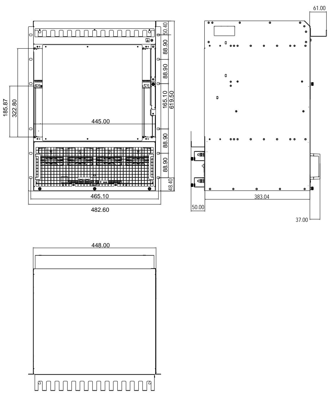
# 8.1 Dimensions

All dimensions below are in mm.

Figure 14: Dimensions
![This image is a technical engineering drawing featuring three orthographic views of a device with various dimensional measurements in millimeters.\n\n**Top Left View (Front View):**\n*   **Vertical dimensions (left side):** 185.87, 322.80\n*   **Vertical dimensions (right side):** 50.40, 88.90, 88.90, 165.10, 619.50, 88.90, 48.40\n*   **Horizontal dimension (center):** 445.00\n*   **Horizontal dimensions (bottom):** 465.10, 482.60\n\n**Top Right View (Side View):**\n*   **Top right dimension:** 61.00\n*   **Bottom horizontal dimension:** 383.04\n*   **Left side dimension:** 50.00\n*   **Right side dimension:** 37.00\n\n**Bottom View (Top/Bottom View):**\n*   **Top horizontal dimension:** 448.00](.atca-81414pd-50-1g049-1000-10/20264b56254659a2d3eb6968f8c43e74c4ae66a95f05c9edcd65f245655691f3.jpg)

# Getting Service

Ask an Expert: http://askanexpert.adlinktech.com

# ADLINK Technology, Inc.

Address: 9F, No.166 Jian Yi Road, Zhonghe District New Taipei City 235, Taiwan 新北市中和區建一路166號9樓

Tel: +886-2-8226-5877

Fax: +886-2-8226-5717

Email: service@adlinktech.com

# Ampro ADLINK Technology, Inc.

Address: 5215 Hellyer Avenue, #110, San Jose, CA 95138, USA

Tel: +1-408-360-0200

Toll Free: +1-800-966-5200 (USA only)

Fax: +1-408-360-0222

Email: info@adlinktech.com

# ADLINK Technology (China) Co., Ltd.

Address: 300 Fang Chun Rd., Zhangjiang Hi-Tech Park, Pudong New Area Shanghai, 201203 China 上海市浦东新区张江高科技园区芳春路300号 (201203)

Tel: +86-21-5132-8988

Fax: +86-21-5132-3588

Email: market@adlinktech.com

# ADLINK Technology GmbH

Address: Hans-Thoma-Straße 11, D-68163, Mannheim, Germany

Tel: +49-621-43214-0

Fax: +49-621-43214-30

Email: emea@adlinktech.com

Please visit the Contact page at www.adlinktech.com for information on how to contact the ADLINK regional office nearest you.
[🔗 Link to the original document](.atca-81414pd-50-1g049-1000-10/atca-81414pd-50-1g049-1000-10.pdf)
