# aTCA-8214 Series

12U 14-slot Dual Dual-Star AdvancedTCA Shelf

User’s Manual

![Front view of a Advanced TCA rack unit with numbered ports and ventilation grilles (no readable text or symbols beyond component labels)](.atca-8214-50-1g005-1000-200/a8953d757a1b058d3b207e6bbaef434778f3b14222d815fefe177a78782bc4a2.jpg)

Manual Revision: 2.00

Revision Date: August 13, 2008

Part No: 50-1G005-1000

![Circular black-and-white recycling symbol with three white arrows forming a cycle (no text or symbols)](.atca-8214-50-1g005-1000-200/5e7f04c592ba9125ab3dbc8189857d98ab03f8e25874c447c2b8280d0223a51d.jpg)

Recycled Paper

# Revision History

<table><tr><td>Revision</td><td>Release Date</td><td>Description of Change(s)</td></tr><tr><td>2.00</td><td>2008/08/13</td><td>Initial Release</td></tr></table>

# Preface

# Copyright 2008 ADLINK Technology Inc.

This document contains proprietary information protected by copyright. All rights are reserved. No part of this manual may be reproduced by any mechanical, electronic, or other means in any form without prior written permission of the manufacturer.

# Disclaimer

The information in this document is subject to change without prior notice in order to improve reliability, design, and function and does not represent a commitment on the part of the manufacturer.In no event will the manufacturer be liable for direct, indirect, special, incidental, or consequential damages arising out of the use or inability to use the product or documentation, even if advised of the possibility of such damages.

# Environmental Responsibility

ADLINK is committed to fulfill its social responsibility to global environmental preservation through compliance with the European Union's Restriction of Hazardous Substances (RoHS) directive and Waste Electrical and Electronic Equipment (WEEE) directive. Environmental protection is a top priority for ADLINK. We have enforced measures to ensure that our products, manufacturing processes, components, and raw materials have as little impact on the environment as possible. When products are at their end of life, our customers are encouraged to dispose of them in accordance with the product disposal and/or recovery programs prescribed by their nation or company.

# Trademarks

Product names mentioned herein are used for identification purposes only and may be trademarks and/or registered trademarks of their respective companies.

# Using this Manual

# Audience and Scope

The aTCA-8214 User’s Manual is intended for hardware technicians and systems operators with knowledge of installing, configuring and operating ATCA systems.

# Manual Organization

This manual is organized as follows:

Chapter 1, Introduction: Introduces the aTCA-8214 Series, its features, and package contents.

Chapter 2, Hardware Information: Provides information on the physical features, dimensions, and pre-installed hardware components of the aTCA-8214 Series.

Chapter 3, Getting Started: Provides information on the physical features and pre-installed hardware components of aTCA-8214 Series.

Chapter 4, Chassis Maintenance: Provides information on how to remove and replace defective components and maintain the aTCA-8214 Series chassis.

Important Safety Instructions: Presents safety instructions all users must follow for the proper setup, installation and usage of equipment and/or software.

Getting Service: Contact information for ADLINK’s worldwide offices.

# Conventions

Take note of the following conventions used throughout this manual to make sure that users perform certain tasks and instructions properly.

![The image is a graphic icon depicting a white piece of paper or document with horizontal lines running across it. The top right corner of the paper is folded down. A large, bold red checkmark is superimposed diagonally over the document. There is no text present.](.atca-8214-50-1g005-1000-200/f516e060d724f11151df1731fc0062a09d4b68638b86b5c643c78afe33c99ec7.jpg)
NOTE:

Additional information, aids, and tips that help users perform tasks.

![The image displays a standard warning sign: a yellow triangle with a black outline containing a large black exclamation point in its center.](.atca-8214-50-1g005-1000-200/0be2083e25039322c56cb8f12da831fe053f532e5ac4be047e54bb8c9f39fdbb.jpg)
CAUTION:

Information to prevent minor physical injury, component damage, data loss, and/or program corruption when trying to complete a task.

![The image shows a standard warning symbol. It consists of a red triangle with a white border. Inside the triangle is a large, white exclamation mark.](.atca-8214-50-1g005-1000-200/6118e13e8dc76b18ff3ce5c03c936a7ca4cb176e1076a22dd9de36906842a403.jpg)
WARNING:

Information to prevent serious physical injury, component damage, data loss, and/or program corruption when trying to complete a specific task.

This page intentionally left blank.

# Table of Contents

# aTCA-8214 Series.....

# Revision History............ ii

# Preface ...... iii

# Table of Contents........... .... vii

# List of Figures ....... ix

# List of Tables ........ .... xi

# 1 Introduction ....

1.1 Features...... 1
1.2 Ordering Information.. 2
1.3 Package Contents . 3

# 2 Hardware Information ...... 5

2.1 Physical Features . 5
2.2 System Block Diagram ..... 7
2.3 Backplane: aBP-5214 .. 8
2.4 Shelf Management Module, aCMM-2100 ... 12

Features: .. 12

Front Panel . .. 14

Board Architecture .. 15

IPMB Interface .. 17

Telco Interface . 17

Hot Swap LED .. 19

Hot-Swap Function ... 20

Activity LED .... 20

Hardware Address .. 21

Off Board I2C Bus .... ... 21

Thermal Detect ... 21

I2C Switch . ... 21

Connector Descriptions ..... ... 22

J1 Data Connector Pin Assignment .. ... 30

I2C Bus Devices .... .... 34

2.5 Intelligent Fan Tray, aFAN-1010... 37

2.6 Intelligent Power Entry Module, aPEM-1020 .... 3 9

# 3 Getting Started .......... . 41

3.1 Installation Environment.. 41

3.2 Installing ATCA® Boards ... 42

3.3 Installing Rear Transition Modules (RTMs)............. 44

3.4 Installing Shelf Management Modules.. 46

3.5 Powering Up the System ..... 48

3.6 Managing the Chassis . 51

aCMM-2100 Shelf Management Module ... 51

Serial Connection .... 54

LAN Connection ... .... 55

Thermal Sensors .... 56

Fan Speed Verification ... 57

# 4 Chassis Maintenance ...... 59

4.1 Removing ATCA® Boards and RTMs . 59

4.2 Removing Shelf Management Modules... 61

4.3 Removing and Replacing a FAN Tray Module........... 6 3

Removing a fan tray module . ... 64

Replacing a fan tray module ... 67

4.4 Removing and Replacing the Air Filter ..... 6 8

4.5 Removing and Replacing Power Entry Modules................ 70

Removing a Power Entry Module .... ... 70

Replacing a Power Entry Module .. 73

# Important Safety Instructions........ . 75

# Getting Service ......... 77

# List of Figures

Figure 1-1: aTCA-8214AA Rackmount AdvancedTCA Shelf............. 2

Figure 2-1: aTCA-8214AA Shelf Front Panel.. 5

Figure 2-2: aTCA-8214AA Shelf Rear Panel .. 6

Figure 2-3: aTCA-8214 System Block Diagram... 7

Figure 2-4: Backplane Layout . . 11

Figure 2-5: aCMM-2100 Block Diagram.. .. 12

Figure 2-6: aCMM-2100 Specifications... . 13

Figure 2-7: aCMM-2100 Face Plate Layout.. . 14

Figure 2-8: Board Connectors & Jumpers Layout.. . 16

Figure 2-9: CN5: Telco Alarm .. . 17

Figure 2-10: aCMM-2100 Face Plate... .. 19

Figure 2-11: Hot Swap Function Layout.. .. 20

Figure 2-12: CN2: ShMM-500 Connector .. .. 22

Figure 2-13: CN6: UART/RS-232 Interface... . 27

Figure 2-14: CN6: UART/RS-232 Port & Pin Assignment... .. 27

Figure 2-15: CN7/CN8: LAN Port & Pin Assignment . . 28

Figure 2-16: SW1: LAN Port Settings . .. 28

Figure 2-17: CN3: JTAG Connector & Pin Assignment .. .. 29

Figure 2-18: aFAN-1010 Block Diagram.. .. 37

Figure 2-19: aFAN-1010 Tray . .. 38

Figure 2-20: aPEM-1020 Block Diagram . .. 39

Figure 2-21: aPEM-1020 Layout. .. 40

Figure 3-1: aCMM-2100 Face Plate Layout.. .. 52

Figure 3-2: aCMM-2100 SW1 DIP Configuration Diagram .............. 53

This page intentionally left blank.

# List of Tables

Table 2-1: Fabric Interface Channel Port Mapping. 9

Table 2-2: Base Interface Channel Port Mapping.... 9

Table 2-3: Update Channel Pairing..... . 10

Table 2-4: Power Distribution... . 10

Table 2-5: Logical vs. Physical Slot Number Mapping.................... 10

Table 2-6: Logical, IPMB, & Physical Slot Number Mapping.......... 11

Table 2-7: CN5: Telco Alarm Pin Assignment . . 18

Table 2-8: Telco LED States.. . 18

Table 2-9: Hot-SWAP LED Status ... . 19

Table 2-10: Redundant LED Status... . 20

Table 2-11: CN2: ShMM-500 Connector Pin Assignment ................ 23

Table 2-12: J1 Data Connector Pin Assignment.. .. 30

Table 2-13: I2C Bus Device List .. . 34

Table 2-14: PCA9555@0x40 Pin Definitions... . 35

Table 2-15: PCA9554@0x46 Pin Definitions... . 35

Table 2-16: PCA9545@0xE0 Pin Definitions .. . 36

Table 3-1: aCMM-2100 Specifications.... .. 51

Table 3-2: aCMM-2100 SW1 DIP Configuration Example.............. 53

Table 3-3: aTCA-8214 Backplane Thermal Sensor Thresholds ..... 56

This page intentionally left blank.

# 1 Introduction

The aTCA-8214 Series is a 12U AdvancedTCA rackmount shelf with five slots that support AdvancedTCA modules and two slots that support two shelf management modules. Equipped with a 14- slot Dual-Dual Star topology fabric interface and standard rear transition module (RTM) slots, the aTCA-8214 Series comes with triple, hot-swappable fan tray modules and dual -48V DC power entry modules capable of filtering and monitoring up to 3000 watts of power.

Providing robust control, monitoring, and management of the aTCA-8214 Series is the optional aCMM-2100 module, a dual Pigeon Point Systems shelf manager (ShMC) that is designed to work in active or standby mode for efficient redundancy. With dual-IPMB buses and ${ \mathsf { I } } ^ { 2 } { \mathsf { C } }$ in system buses, the aCMM-2100 can control all installed AdvancedTCA blades and fan trays based on temperature and other built-in sensor readings.

# 1.1 Features

X $1 9 "$ rackmount with 12U height and $1 5 . 3 "$ depth
X 14-slot dual dual-star topology fabric interface
X 14-slot standard rear transition module (RTM)
X Dual-IPMB bus
X Three ${ \mathsf { I } } ^ { 2 } { \mathsf { C } } .$ -controlled hot-swappable fan trays
X Two shelf manager slots for PPS-based ShMC
X Two power entry modules with -48V DC

# 1.2 Ordering Information

aTCA-8214: 12U 14-slot Rackmount AdvancedTCA Shelf

aTCA-8214A: 12U 14-slot Rackmount AdvancedTCA Shelf with single aCMM-2100 Shelf Management Module

aTCA-8214AA: 12U 14-slot Rackmount AdvancedTCA Shelf with two aCMM-2100 Shelf Management Modules

![Advances TCA\n1 2 3 4 5 6 7—8 9 10 11—12 13—14](.atca-8214-50-1g005-1000-200/458ceedc7ace8da6c5047ffbcb74221fda44dc78315cbabe1d891f743ed4a194.jpg)

Figure 1-1: aTCA-8214AA Rackmount AdvancedTCA Shelf

# 1.3 Package Contents

Before unpacking, check the shipping carton for any damage. If the shipping carton and/or contents are damaged, inform your dealer immediately. Retain the shipping carton and packing materials for inspection. Obtain authorization from the dealer before returning any product to ADLINK.

The following contents are included in the shipping carton:

X aTCA-8214 Series Rackmount AdvancedTCA Shelf
X One/Two aCMM-2100 shelf management modules (or aTCA-8214A and aTCA-8214AA models only)
X $1 9 "$ rackmount brackets (pre-mounted)
X Accessory package
Z One RJ-45 to DB9 cable (available with aTCA-8214A and aTCA-8214AA models only)

![The image displays a white document icon with a folded top-right corner and horizontal gray lines. A large red checkmark is superimposed over the document.](.atca-8214-50-1g005-1000-200/cdea60a9625541f83e43f65f4f042da4b527e40505975c323960bb3f12822cdd.jpg)
NOTE:

The aTCA-8214 Series is shipped with protective front and rear panels. They DO NOT include front or rear slot filler panels. Front and rear slot filler panels are commercially available and may be purchased separately

![The image displays a red equilateral triangle containing a white exclamation point in the center.](.atca-8214-50-1g005-1000-200/0ea73242275f694d0320bc1a3c43407dc02a98f4af003ec040afe3647e8f67d8.jpg)
WARNING:

DO NOT install or apply power to equipment that is damaged or if there is missing/incomplete equipment. Doing so may cause damage to equipment or bodily harm.

This page intentionally left blank.

# 2 Hardware Information

This chapter provides information on the physical features, dimensions, and pre-installed hardware components of the aTCA-8214 Series.

# 2.1 Physical Features

![The image displays a standard icon of a document or file. It features a white square shape with a folded top-right corner, resembling a piece of paper. Inside the paper shape, there are faint, horizontal gray lines suggesting text. A large, bold red checkmark is superimposed over the document, slanting from the bottom left to the top right.](.atca-8214-50-1g005-1000-200/06e3558394bb1d8c616cb4c7b484f912a8d90a608924fbf576c7b92c585c2518.jpg)
NOTE:

The following illustrations present an aTCA-8214AA Series shelf and are intended only for reference. The figures below may differ from your actual shelf configuration

![Advanced TCA®\n1 2 3 4 6 7 8 9 10 11 12 13 14\nShelf\nManagement\nModules\nFront\nCable Tray\nFan Tray\nModules](.atca-8214-50-1g005-1000-200/80d0abbd6a03881a59a44504a77b113a3cd489d7f73e88bd0f53f2bed30aa3f5.jpg)

Figure 2-1: aTCA-8214AA Shelf Front Panel

![Rear Cable Tray\nPower Management Modules\n-40 - 40 VDC RTM\nTERMINAL BLOCK COVER\n-40 - 40 VDC RTM\nTERMINAL BLOCK COVER\nPower Management Modules\n-40 - 40 VDC RTM\nPower Management Modules](.atca-8214-50-1g005-1000-200/d88934242f99521ebe2230da9919acc0df0c6470aa3090d454a981d2b5964bd9.jpg)

Figure 2-2: aTCA-8214AA Shelf Rear Panel

# 2.2 System Block Diagram

![This block diagram illustrates a system architecture consisting of management controllers, a backplane, and peripheral cards.\n\n**Labeled Blocks:**\n\n*   **Top Section:** Two gray boxes labeled 'ShMC aCMM-2100'.\n*   **Middle Section:** A large gray box labeled '14-slot Backplane Dual Dual-Star Fabric Interface aBP-5214'. Inside this box is a vertical column of six cyan blocks labeled (from top to bottom):\n    *   'LM75 90h'\n    *   'LM75 92h'\n    *   'FRU 52h'\n    *   'FRU 52h'\n    *   'LM75 90h'\n    *   'LM75 92h'\n*   **Bottom Section:** Five gray boxes arranged horizontally from left to right:\n    *   'IPM enabled FCM C0h aFAN-1010'\n    *   'IPM enabled FCM C2h aFAN-1010'\n    *   'IPM enabled FCM C4h aFAN-1010'\n    *   'IPM enabled PEM CCh aPEM-1020'\n    *   'IPM enabled PEM CEh aPEM-1020'\n\n**Connections:**\n\n*   **I²C A/B:** Solid and dotted lines connect the top 'ShMC' blocks to the internal cyan blocks within the '14-slot Backplane'. The label 'I²C A/B' is placed next to these connections.\n*   **IPMB A/B:** A horizontal bus structure (comprising black and blue lines) runs across the bottom section and connects vertically to the five bottom blocks. The label 'IPMB A/B' is placed next to this bus.\n*   **Vertical Traces:** Black and blue lines run vertically from the top 'ShMC' blocks, through the '14-slot Backplane', and connect to the horizontal 'IPMB A/B' bus, linking the top management controllers to the bottom peripheral cards.](.atca-8214-50-1g005-1000-200/ca4fd779444eda8e48d12c4eab45c60cd5cbc61826e18a8aba74b42ccdaa29cf.jpg)

IPMB Address Assignment

<table><tr><td>PHY</td><td>1</td><td>2</td><td>3</td><td>4</td><td>5</td><td>6</td><td>7</td><td>8</td><td>9</td><td>10</td><td>11</td><td>12</td><td>13</td><td>14</td></tr><tr><td></td><td>9Ah</td><td>96h</td><td>92h</td><td>8Eh</td><td>8Ah</td><td>86h</td><td>82h</td><td>84h</td><td>88h</td><td>8Ch</td><td>90h</td><td>94h</td><td>98h</td><td>9Ch</td></tr><tr><td colspan="15">Intelligent Devices</td></tr><tr><td colspan="2">Fan tray 1</td><td>C0h</td><td colspan="2">Fan tray 2</td><td>C2h</td><td colspan="2">Fan tray 3</td><td>C4h</td><td colspan="2">PEM 1</td><td>CCh</td><td colspan="2">PEM 2</td><td>CEh</td></tr></table>

Figure 2-3: aTCA-8214 System Block Diagram

# 2.3 Backplane: aBP-5214

The aTCA-8214 Series shelf comes with the cBP-5214 backplane featuring 14 AdvancedTCA® slots that support rear I/O functionality.

# Features:

X 14-slot dual dual-star fabric interface
X Dual bussed IPMB
X Redundant ShMC slots for aCMM-2100
X Triple fan tray bays for aFAN-1010
X Redundant PEM bays for aPEM-1020
X Dual socket I2C FRU EEPROM
X Four I2C LM75CIMM sensors

aBP-5214 is a 14-slot PICMG® 3.0 R2.0 ECN002 compliant backplane. It provides dual dual-star fabric interface and dual-star base interface data connection. The channel mapping is listed in Table 2-1 on page 9 and Table 2-2 on page 9. The base interface channel 1 of slot 1 and slot 2 are split into two 10/100M Fast Ethernet ports connected to shelf managers, compliant to ECN001.

Three redundant synchronous clock busses and update channels are designed on J20/P20 Zone 2 connectors, and the update channel pairing information is listed in Table 2-3 on page 10.

<table><tr><td></td><td>1</td><td>2</td><td>3</td><td>4</td><td>5</td><td>6</td><td>7</td><td>8</td><td>9</td><td>10</td><td>11</td><td>12</td><td>13</td><td>14</td></tr><tr><td>Ch15</td><td></td><td></td><td></td><td></td><td></td><td></td><td></td><td></td><td></td><td></td><td></td><td></td><td></td><td></td></tr><tr><td>Ch14</td><td></td><td></td><td></td><td></td><td></td><td></td><td></td><td></td><td></td><td></td><td></td><td></td><td></td><td></td></tr><tr><td>Ch13</td><td>14-1</td><td>14-2</td><td>14-3</td><td>14-4</td><td></td><td></td><td></td><td></td><td></td><td></td><td></td><td></td><td></td><td></td></tr><tr><td>Ch12</td><td>13-1</td><td>13-2</td><td>13-3</td><td>13-4</td><td></td><td></td><td></td><td></td><td></td><td></td><td></td><td></td><td></td><td></td></tr><tr><td>Ch11</td><td>12-1</td><td>12-2</td><td>12-3</td><td>12-4</td><td></td><td></td><td></td><td></td><td></td><td></td><td></td><td></td><td></td><td></td></tr><tr><td>Ch10</td><td>11-1</td><td>11-2</td><td>11-3</td><td>11-4</td><td></td><td></td><td></td><td></td><td></td><td></td><td></td><td></td><td></td><td></td></tr><tr><td>Ch9</td><td>10-1</td><td>10-2</td><td>10-3</td><td>10-4</td><td></td><td></td><td></td><td></td><td></td><td></td><td></td><td></td><td></td><td></td></tr><tr><td>Ch8</td><td>9-1</td><td>9-2</td><td>9-3</td><td>9-4</td><td></td><td></td><td></td><td></td><td></td><td></td><td></td><td></td><td></td><td></td></tr><tr><td>Ch7</td><td>8-1</td><td>8-2</td><td>8-3</td><td>8-4</td><td></td><td></td><td></td><td></td><td></td><td></td><td></td><td></td><td></td><td></td></tr><tr><td>Ch6</td><td>7-1</td><td>7-2</td><td>7-3</td><td>7-4</td><td></td><td></td><td></td><td></td><td></td><td></td><td></td><td></td><td></td><td></td></tr><tr><td>Ch5</td><td>6-1</td><td>6-2</td><td>6-3</td><td>6-4</td><td></td><td></td><td></td><td></td><td></td><td></td><td></td><td></td><td></td><td></td></tr><tr><td>Ch4</td><td>5-1</td><td>5-2</td><td>5-3</td><td>5-4</td><td>4-4</td><td>4-5</td><td>4-6</td><td>4-7</td><td>4-8</td><td>4-9</td><td>4-10</td><td>4-11</td><td>4-12</td><td>4-13</td></tr><tr><td>Ch3</td><td>4-1</td><td>4-2</td><td>4-3</td><td>3-3</td><td>3-4</td><td>3-5</td><td>3-6</td><td>3-7</td><td>3-8</td><td>3-9</td><td>3-10</td><td>3-11</td><td>3-12</td><td>3-13</td></tr><tr><td>Ch2</td><td>3-1</td><td>3-2</td><td>2-2</td><td>2-3</td><td>2-4</td><td>2-5</td><td>2-6</td><td>2-7</td><td>2-8</td><td>2-9</td><td>2-10</td><td>2-11</td><td>2-12</td><td>2-13</td></tr><tr><td>Ch1</td><td>2-1</td><td>1-1</td><td>1-2</td><td>1-3</td><td>1-4</td><td>1-5</td><td>1-6</td><td>1-7</td><td>1-8</td><td>1-9</td><td>1-10</td><td>1-11</td><td>1-12</td><td>1-13</td></tr></table>

Table 2-1: Fabric Interface Channel Port Mapping

<table><tr><td></td><td>1</td><td>2</td><td>3</td><td>4</td><td>5</td><td>6</td><td>7</td><td>8</td><td>9</td><td>10</td><td>11</td><td>12</td><td>13</td><td>14</td></tr><tr><td>Ch1</td><td>Sh1/2</td><td>Sh2/1</td><td>1-3</td><td>1-4</td><td>1-5</td><td>1-6</td><td>1-7</td><td>1-8</td><td>1-9</td><td>1-10</td><td>1-11</td><td>1-12</td><td>1-13</td><td>1-14</td></tr><tr><td>Ch2</td><td>2-2</td><td>1-2</td><td>2-3</td><td>2-4</td><td>2-5</td><td>2-6</td><td>2-7</td><td>2-8</td><td>2-9</td><td>2-10</td><td>2-11</td><td>2-12</td><td>2-13</td><td>2-14</td></tr><tr><td>Ch3</td><td>3-1</td><td>3-2</td><td></td><td></td><td></td><td></td><td></td><td></td><td></td><td></td><td></td><td></td><td></td><td></td></tr><tr><td>Ch4</td><td>4-1</td><td>4-2</td><td></td><td></td><td></td><td></td><td></td><td></td><td></td><td></td><td></td><td></td><td></td><td></td></tr><tr><td>Ch5</td><td>5-1</td><td>5-2</td><td></td><td></td><td></td><td></td><td></td><td></td><td></td><td></td><td></td><td></td><td></td><td></td></tr><tr><td>Ch6</td><td>6-1</td><td>6-2</td><td></td><td></td><td></td><td></td><td></td><td></td><td></td><td></td><td></td><td></td><td></td><td></td></tr><tr><td>Ch7</td><td>7-1</td><td>7-2</td><td></td><td></td><td></td><td></td><td></td><td></td><td></td><td></td><td></td><td></td><td></td><td></td></tr><tr><td>Ch8</td><td>8-1</td><td>8-2</td><td></td><td></td><td></td><td></td><td></td><td></td><td></td><td></td><td></td><td></td><td></td><td></td></tr><tr><td>Ch9</td><td>9-1</td><td>9-2</td><td></td><td></td><td></td><td></td><td></td><td></td><td></td><td></td><td></td><td></td><td></td><td></td></tr><tr><td>Ch10</td><td>10-1</td><td>10-2</td><td></td><td></td><td></td><td></td><td></td><td></td><td></td><td></td><td></td><td></td><td></td><td></td></tr><tr><td>Ch11</td><td>11-1</td><td>11-2</td><td></td><td></td><td></td><td></td><td></td><td></td><td></td><td></td><td></td><td></td><td></td><td></td></tr><tr><td>Ch12</td><td>12-1</td><td>12-2</td><td></td><td></td><td></td><td></td><td></td><td></td><td></td><td></td><td></td><td></td><td></td><td></td></tr><tr><td>Ch13</td><td>13-1</td><td>13-2</td><td></td><td></td><td></td><td></td><td></td><td></td><td></td><td></td><td></td><td></td><td></td><td></td></tr><tr><td>Ch14</td><td>14-1</td><td>14-2</td><td></td><td></td><td></td><td></td><td></td><td></td><td></td><td></td><td></td><td></td><td></td><td></td></tr></table>

Table 2-2: Base Interface Channel Port Mapping

<table><tr><td>1</td><td>2</td><td>3</td><td>4</td><td>5</td><td>6</td><td>7</td><td>8</td><td>9</td><td>10</td><td>11</td><td>12</td><td>13</td><td>14</td></tr><tr><td>2</td><td>1</td><td>4</td><td>3</td><td>6</td><td>5</td><td>9</td><td>10</td><td>7</td><td>8</td><td>13</td><td>14</td><td>11</td><td>12</td></tr></table>

Table 2-3: Update Channel Pairing

Each slot requires 200 Watt redundant DC 48V nominal power feeds (A, B). Plus the power consumption for the fan trays and shelf managers, the 14-slot backplane dispatches 3200 Watt maximum across its slots and devices. To balance and optimize power loading, physical slot numbers 1-7 feed A will tie to slot number 8- 14 feed B, and slot number 1-7 feed B will tie to slot number 8-14 feed A, as shown in Table 2-4. The physical to logical slot number conversion is listed in Table 2-5.

<table><tr><td>PHY</td><td>1</td><td>2</td><td>3</td><td>4</td><td>5</td><td>6</td><td>7</td><td>8</td><td>9</td><td>10</td><td>11</td><td>12</td><td>13</td><td>14</td></tr><tr><td>DCA</td><td></td><td>A</td><td></td><td>A</td><td>A</td><td>A</td><td>A</td><td></td><td></td><td></td><td>A</td><td></td><td>A</td><td></td></tr><tr><td>DCB</td><td>B</td><td></td><td>B</td><td></td><td></td><td></td><td></td><td>B</td><td>B</td><td>B</td><td></td><td>B</td><td></td><td>B</td></tr><tr><td>DCA</td><td></td><td>A</td><td></td><td>A</td><td>A</td><td>A</td><td>A</td><td></td><td></td><td></td><td>A</td><td></td><td>A</td><td></td></tr><tr><td>DCB</td><td>B</td><td></td><td>B</td><td></td><td></td><td></td><td></td><td>B</td><td>B</td><td>B</td><td></td><td>B</td><td></td><td>B</td></tr></table>

Table 2-4: Power Distribution

<table><tr><td>PHY</td><td>1</td><td>2</td><td>3</td><td>4</td><td>5</td><td>6</td><td>7</td><td>8</td><td>9</td><td>10</td><td>11</td><td>12</td><td>13</td><td>14</td></tr><tr><td>LOG</td><td>13</td><td>11</td><td>9</td><td>7</td><td>5</td><td>3</td><td>1</td><td>2</td><td>4</td><td>6</td><td>8</td><td>10</td><td>12</td><td>14</td></tr></table>

Table 2-5: Logical vs. Physical Slot Number Mapping

Redundant IPMB busses (IPMB\_A, IPMB\_B) are designed across slots and intelligent devices, such as fan trays and power entry modules (PEM). The IPMB address assignment for the slots and intelligent devices is listed in Table 2-6 on page 11. Two ${ \mathsf { I } } ^ { 2 } { \mathsf { C } }$ bussed FRU EEPROM sockets are designed for non-volatile, field replaceable system configuration data storage accessible by shelf managers via legacy ${ \mathsf { I } } ^ { 2 } { \mathsf { C } }$ busses.

<table><tr><td>PHY</td><td>1</td><td>2</td><td>3</td><td>4</td><td>5</td><td>6</td><td>7</td><td>8</td><td>9</td><td>10</td><td>11</td><td>12</td><td>13</td><td>14</td></tr><tr><td>IPMB Address (Hex)</td><td>9a</td><td>96</td><td>92</td><td>8e</td><td>8a</td><td>86</td><td>82</td><td>84</td><td>88</td><td>8c</td><td>90</td><td>94</td><td>98</td><td>9c</td></tr><tr><td>LOG</td><td>13</td><td>11</td><td>9</td><td>7</td><td>5</td><td>3</td><td>1</td><td>2</td><td>4</td><td>6</td><td>8</td><td>10</td><td>12</td><td>14</td></tr></table>

Table 2-6: Logical, IPMB, & Physical Slot Number Mapping

![Technical diagram of a multi-layered electronic circuit board with labeled components and pin connections](.atca-8214-50-1g005-1000-200/45eef01a73c2117ef2e9921452bea094fe72410ae8848f877db9aeec1609ccea.jpg)

Figure 2-4: Backplane Layout

# 2.4 Shelf Management Module, aCMM-2100

The aCMM-2100 is an ATCA shelf management controller (ShMC). The purpose of the ShMC is to monitor, control, and assure proper operation of ATCA blades and other shelf components. It watches over the basic health of the shelf, reports anomalies, and takes corrective action when needed. The ShMC can retrieve inventory information and sensor readings as well as receive event reports and failure notifications from blades and other intelligent FRUs. It can also perform basic recovery operations such as power cycle or reset of managed entities.

# Features:

X Pigeon Point Systems SHM-500 based
X Dual bussed IPMB
X Dual ${ \mathsf { I } } ^ { 2 } { \mathsf { C } }$ busses for FRU EEPROM and thermal sensors
X Redundant DC 48V powered

![Based on the provided flowchart, here is an accurate and concise description of the blocks and their connections:\n\n**Central Component**\n*   **aCMM-2100**: A large blue rectangular block at the top serving as the central hub.\n\n**Left-Side Connections (attached to the left edge of aCMM-2100)**\nThese blocks feature arrowheads pointing to the left:\n*   **IPMB A/B**\n*   **i2C A/B/C/D**\n*   **10/100 A/B**\n*   **Telco Alarm**\n*   **Console**\n\n**Right-Side Connections (attached to the right edge of aCMM-2100)**\n*   **Redundancy**: Arrow points left (towards aCMM-2100).\n*   **HA(0:7)**: Arrow points left (towards aCMM-2100).\n*   **DC48V A/B**: Arrow points left (towards aCMM-2100).\n*   **DC5V/3.3V**: Located at the bottom right corner; arrow points right (away from the system).\n\n**Bottom Center Components**\nLocated below the main blue block:\n*   **PPS SHM-500**\n*   **DC/DC**](.atca-8214-50-1g005-1000-200/8853d6f6c547dcf7d46186317aebb20a711c4ba125e45d4bc8ea0c8ccb74f728.jpg)

Figure 2-5: aCMM-2100 Block Diagram

<table><tr><td colspan="2">aCMM-2100</td></tr><tr><td>Form Factor</td><td>Dimensions: 104 mm x 280 mm</td></tr><tr><td>Specifications</td><td>PICMG 3.0 R2.0 AdvancedTCA® Specification</td></tr><tr><td>Core Module</td><td>SHMM-500 Connector 144-pin socket Pigeon Point System ShMM-500 SOM (system on module) with built-in 333 MHz MIPS processor</td></tr><tr><td>LAN Interface</td><td>Two 10/100Mbps Ethernet port cross connected to backplane switch to support remote login from LANEthernet port can be redirected to RJ-45 on front faceplate</td></tr><tr><td>Serial Interface</td><td>Standard RS-232 interface with DB-9 connector on front panel</td></tr><tr><td>Telco Interface</td><td>Mini DB-15 connectorCut-off button and 3 LED indicators on faceplate</td></tr><tr><td>IPMB Interface</td><td>Direct IPMB A/B bus</td></tr><tr><td>JTAG Interface</td><td>JTAG interface</td></tr><tr><td>Redundancy Control</td><td>Redundant signals via backplane private pins using USB</td></tr><tr><td>Offboard I2C</td><td>Supports 2 off-board I2C for SEEPROM on the shelf</td></tr><tr><td>Hardware Monitoring</td><td>Board temperature monitoring</td></tr></table>

Figure 2-6: aCMM-2100 Specifications

# Hotswap

The aCMM-2100 is based on the Pigeon Point Systems SHM-500 Shelf Management Mezzanine. It is fully hot swappable and supports Active/Standby redundant mode when two aCMM-2100 are populated in the shelf.

# Power Interface

The aCMM-2100 uses a -48V DC to 12V converter module to generate 12V power, and PWM to produce 3.3V, 5V for board circuit power.

The aCMM-2100 requires redundant DC 48V nominal feeds, and its on-board DC/DC circuit generates DC 5V back to the backplane to power the FRU EEPROM and IPMC controllers on the fan tray.

# Front Panel

The external I/O interfaces of the aCMM-2100 are as follows:

X Redundant IPMB (IPMB\_A, IPMB\_B)
X Four ${ \mathsf { I } } ^ { 2 } { \mathsf { C } }$ busses
X Dual 10/100BASE-T fast Ethernet ports
X Serial console port
X Telco interface
X Telco alarm LED indicator
X Activity LED

![Serial Console Port\nTelco Interface\n10/100BASE-T Ethernet\nActivity LED](.atca-8214-50-1g005-1000-200/316ffdc0ed640a00c61601c8a5d1affe4c4cecd76be684a1ca437f02b3ac7265.jpg)

Figure 2-7: aCMM-2100 Face Plate Layout

# Board Architecture

The aCMM-2100 provides an interface to the AdvancedTCA Zone1, remote management, fan tray, and alarm connections. An I 2C bus is provide to connect to chassis mounted devices. The following sub-section introduces the aCMM-2100 connectors, pin assignments and select switches and jumpers.

X CN1 - Battery
X CN2 - ShMM-500 connector
X CN3 - JTAG
X CN4 - Activity LED connector
X CN5 - Telco Alarm
X CN6 - UART / RS-232
X CN7 - LAN
X CN8 - LAN
X J1 - Data connector
X LED1 - Telco LED1
X SW1 - LAN port setting

![CN7: LAN\nCN8: LAN\nCN6: RS-232\nCN5: Telco\nAlarm\nLED1: Telco\nLED\nCN3: JTAG SW1: LAN\nSwitch\nCN4: LED2\nCN2: SHMM-500\nCN1: Battery\nJ1: Data Connector](.atca-8214-50-1g005-1000-200/294d19f26bba8543a4896500102928ec5a4f0d06c72693c97bf9741232d93cdc.jpg)

Figure 2-8: Board Connectors & Jumpers Layout

# IPMB Interface

The aCMM-2100 supports bussed IPMB interfaces. Two IPMBs are combined as IPMB-0, which is routed directly to the backplane. IPMB signals are connected to backplane via J1.

# Telco Interface

The aCMM-2100 use a PCA9555 16 bits SMbus GPIO to support Telco interface which includes:

X Telco Alarm Connector
X Telco Alarm LED
X Telco Alarm Cut-off Button

# CN5: Telco Alarm Connector

The aCMM-2100 provides a standard front-panel Telco Alarm interface on the mini DB-15 connector. The aCMM-2100 alarm relay circuits are capable of carrying 72VDC or 1A, with a maximum rating of 30VAC. The aCMM-2100 accepts timed pulse inputs for clearing Minor and Major alarm states. (There is no reset for the Critical state.) Reset is accomplished by asserting a voltage differential from 3.3V to 48V for between 200 and 300ms. The acceptance voltage range is from 0 to 48VDC continuous (handles up to 60VDC at a 50% duty cycle). The current drawn by a reset input does not exceed 12mA.

![1 2 8\n9 10 15](.atca-8214-50-1g005-1000-200/5183ad1374b48fa84e60beaecd95853c5c2c31076f16a54dc8a193f5606abc3c.jpg)

Figure 2-9: CN5: Telco Alarm

The alarm outputs are implemented using the AXICOM, IM02GR relays, driven by the GPO of the PCA9555 GPIO port. The alarm reset circuitry includes input filters and protection diodes. The output of this circuitry drives the LED-side of an ultra-low power HP opto-coupler. The receiving side of the opto-coupler is connected to the pins of the PCA9555, configured as inputs.

<table><tr><td>Pin#</td><td>Function</td><td>Description</td><td>Signal Level</td></tr><tr><td>1</td><td>MNRRES+</td><td>Minor Reset +</td><td>-48VDC, 12mA</td></tr><tr><td>2</td><td>MNRRES-</td><td>Minor Reset -</td><td>-48VDC, 12mA</td></tr><tr><td>3</td><td>MJRRES+</td><td>Major Reset +</td><td>-48VDC, 12mA</td></tr><tr><td>4</td><td>MJRRES-</td><td>Major Reset -</td><td>-48VDC, 12mA</td></tr><tr><td>5</td><td>CRTALRM_NO</td><td>Critical Alarm NO</td><td>72VDC, 1A, or 30VA</td></tr><tr><td>6</td><td>CRTALRM_NC</td><td>Critical Alarm NC</td><td>72VDC, 1A, or 30VA</td></tr><tr><td>7</td><td>CRTALRM_COM</td><td>Critical Alarm COM</td><td>72VDC, 1A, or 30VA</td></tr><tr><td>8</td><td>MNRALRM_NO</td><td>Minor Alarm NO</td><td>72VDC, 1A, or 30VA</td></tr><tr><td>9</td><td>MNALRM_NC</td><td>Minor Alarm NC</td><td>72VDC, 1A, or 30VA</td></tr><tr><td>10</td><td>MNALRM_COM</td><td>Minor Alarm COM</td><td>72VDC, 1A, or 30VA</td></tr><tr><td>11</td><td>MJRALRM_NO</td><td>Major Alarm NO</td><td>72VDC, 1A, or 30VA</td></tr><tr><td>12</td><td>MJRALRM_NC</td><td>Major Alarm NC</td><td>72VDC, 1A, or 30VA</td></tr><tr><td>13</td><td>MJRALRM_COM</td><td>Major Alarm COM</td><td>72VDC, 1A, or 30VA</td></tr><tr><td>14</td><td>PWRALM_NO</td><td>Power Alarm NO</td><td>72VDC, 1A, or 30VA</td></tr><tr><td>15</td><td>PWRALM_COM</td><td>Power Alarm COM</td><td>72VDC, 1A, or 30VA</td></tr></table>

Table 2-7: CN5: Telco Alarm Pin Assignment

# LED1: Telco Alarm LED

The aCMM-2100 provides Telco Alarm LED via LED1 located next to the Telco Alarm connector. These yellow LEDs are used to indicate the presence of Critical, Major, and Minor alarms, respectively.

<table><tr><td>State</td><td>Description</td></tr><tr><td>Off</td><td>No alarm triggered</td></tr><tr><td>On</td><td>Alarm triggered</td></tr><tr><td>Blinking</td><td>Alarm Cutoff (ACO) is activated</td></tr></table>

Table 2-8: Telco LED States

# Telco Alarm Cut-off Button

The aCMM-2100 provides a Telco Alarm Cutoff function via the Front Panel push button switch SW3. This push button activates the Alarm Cut-off (ACO) state. When ACO is activated, the active Alarm LEDs blinks and all of the alarm relays are deactivated. This button does not clear alarms. Any necessary de-bouncing of this switch input is the responsibility of the ShMM-500 software.

![Hot SWAP\nReset Button\nTelco Alarm Cut-off](.atca-8214-50-1g005-1000-200/7ddc375ac2cb4163d622524ae178eada77883c0ed472524ffe32cdac040e136a.jpg)

Figure 2-10: aCMM-2100 Face Plate

# Hot Swap LED

A blue LED is used to indicate hot-swap status. Different states indicate different conditions.

<table><tr><td>Status</td><td>Condition</td></tr><tr><td>Off</td><td>The aCMM-2100 is not ready to be removed/disconnected from the shelf</td></tr><tr><td>Blue</td><td>The aCMM-2100 is ready to be removed/disconnected from the shelf</td></tr><tr><td>Long-blink</td><td>The ShMM-500 is activating itself</td></tr><tr><td>Short-blink</td><td>Deactivation has been requested</td></tr></table>

Table 2-9: Hot-SWAP LED Status

# Hot-Swap Function

The hot-swap includes three components:

1. Ejector/Injector switch
2. Presence
3. LED

![ShMM\nCN1\nHS_LED\nPRES#\nHS_LATCH\nS2.0\nHandle Switch\nS2.1\nBoard Presence\nDIP Switches\n2.2k\n5V\nBlue LED\n75\nSMBT2222](.atca-8214-50-1g005-1000-200/5a140beba744fe8f21a01cb0f1e491a9f5bf19bb17bc26c0fe86a3d175a105de.jpg)

Figure 2-11: Hot Swap Function Layout

# Ejector Switch

This signal reflects the input signals of the panel switch SW2.

# Presence

This signal indicates the presence of other boards on the backplane. It is used to signal that a board is fully installed on the backplane. It is used for ShMM-500 CPLD to determine the proper hot-swap action.

# Activity LED

The aCMM-2100 supports active-backup redundant operations. An Activity LED on the front panel is used to display the current status.

<table><tr><td>Status</td><td>Description</td></tr><tr><td>Blinking Green</td><td>Standby or Handshaking</td></tr><tr><td>Green</td><td>Active</td></tr><tr><td>Red</td><td>Failed</td></tr></table>

Table 2-10: Redundant LED Status

# Hardware Address

The aCMM-2100 reads 8-bit hardware addresses from the backplane via PCA9554. Hardware address signals are connected to the backplane via J1. Please see Table 2-12 on page 30 for details.

# Off Board I2C Bus

The aCMM-2100 provides $4 1 ^ { 2 } \mathsf { C }$ bus by PCA9545APW. Off-board ${ \mathsf { I } } ^ { 2 } { \mathsf { C } }$ signals are connected to backplane via J1. Please see Table 2-12 on page 30 for details.

# Thermal Detect

There is a thermal sensor LM75 on the CMM. It detects board temperature. The aCMM-2100 reads those messages via the ${ \mathsf { I } } ^ { 2 } { \mathsf { C } }$ Bus.

# I 2C Switch

The aCMM-2100 uses PCA9545 to switch the OFF Board ${ \mathsf { I } } ^ { 2 } { \mathsf { C } }$ Bus from 1 to 4.

# Connector Descriptions

# CN2: ShMM-500 Connector

The aCMM-2100 provides a ShMM-500 connector socket for ShMM-500. The socket is 144 pin connector (CN2).

![1\n2\n49\n50\n51\n52\n143\n144](.atca-8214-50-1g005-1000-200/f48ec9a432453b7512a14f78368d43926fd871e4e16380ba931dbc33ca154a03.jpg)

Figure 2-12: CN2: ShMM-500 Connector

<table><tr><td>Pin</td><td>Name</td><td>Type</td><td>Description</td><td>ShMM-300 / ShMM-500 Compatibility Comments</td></tr><tr><td>Power Supply (43)</td><td></td><td></td><td></td><td></td></tr><tr><td>1, 2, 13, 14, 30, 31, 32, 34, 49, 50, 55, 56, 71, 72, 85, 86, 103, 104, 119, 120, 139, 140</td><td>Gnd</td><td></td><td>Ground</td><td></td></tr><tr><td>63, 64, 75, 76, 93, 94, 113, 114, 129, 130, 143, 144</td><td>VCC</td><td></td><td>3.3V power supply</td><td></td></tr><tr><td>109</td><td>Vbat</td><td></td><td>External Battery</td><td></td></tr><tr><td>19, 20, 21, 22, 41, 42, 43, 44</td><td>C_Gnd</td><td></td><td>Chassis Ground</td><td></td></tr><tr><td>Pin</td><td>Name</td><td>Type</td><td>Description</td><td>ShMM-300 / ShMM-500 Compatibility Comments</td></tr><tr><td>JTAG Interface (5)</td><td></td><td></td><td></td><td></td></tr><tr><td>3</td><td>TRST</td><td>In</td><td>Test Port Reset</td><td></td></tr><tr><td>5</td><td>TMS</td><td>In</td><td>Test Mode Select</td><td></td></tr><tr><td>4</td><td>TCK</td><td>In</td><td>Test Clock</td><td></td></tr><tr><td>7</td><td>TDI</td><td>In</td><td>Test Data Input</td><td></td></tr><tr><td>6</td><td>TDO</td><td>Out</td><td>Test Data Output</td><td></td></tr><tr><td>Pin</td><td>Name</td><td>Type</td><td>Description</td><td>ShMM-300 / ShMM-500 Compatibility Comments</td></tr><tr><td>Master-Only I2C (2)</td><td></td><td></td><td></td><td></td></tr><tr><td>141</td><td>SDA</td><td>I/O</td><td>Serial Data, Master-Only I2C Bus</td><td></td></tr><tr><td>142</td><td>SCL</td><td>I/O</td><td>Serial Clock, Master-Only I2C Bus</td><td></td></tr><tr><td>Pin</td><td>Name</td><td>Type</td><td>Description</td><td>ShMM-300 / ShMM-500 Compatibility Comments</td></tr><tr><td>Serial Interface 0 (11)</td><td></td><td></td><td></td><td></td></tr><tr><td>73</td><td>Ser_En0</td><td>In</td><td>Enable On-Board RS-232 Transceivers</td><td></td></tr><tr><td>77</td><td>RD0</td><td>In</td><td>CMOS Receive Data 0</td><td></td></tr><tr><td>78</td><td>TD0</td><td>Out</td><td>CMOS Transmit Data 0</td><td></td></tr><tr><td>38</td><td>CD</td><td>In</td><td>Carrier Detect</td><td>ShMM-500: no CMOS level option</td></tr><tr><td>36</td><td>RxD0</td><td>In</td><td>Receive Data 0</td><td>ShMM-500: no CMOS level option</td></tr><tr><td>24</td><td>TxD0</td><td>Out</td><td>Transmit Data 0</td><td>ShMM-500: no CMOS level option</td></tr><tr><td>28</td><td>DTR</td><td>Out</td><td>Data Terminal Ready</td><td>ShMM-500: no CMOS level option</td></tr><tr><td>46</td><td>DSR</td><td>In</td><td>Data Set Ready</td><td>ShMM-500: no CMOS level option</td></tr><tr><td>26</td><td>RTS</td><td>Out</td><td>Request To Send</td><td>ShMM-500: no CMOS level option</td></tr><tr><td>40</td><td>CTS</td><td>In</td><td>Clear To Send</td><td>ShMM-500: no CMOS level option</td></tr><tr><td>48</td><td>RI</td><td>In</td><td>Ring Indicator</td><td>ShMM-500: no CMOS level option</td></tr><tr><td>Pin</td><td>Name</td><td>Type</td><td>Description</td><td>ShMM-300 / ShMM-500 Compatibility Comments</td></tr><tr><td>Serial Interface 1 (5)</td><td></td><td></td><td></td><td></td></tr><tr><td>10</td><td>Ser_En1</td><td>In</td><td>Enable On-Board RS-232/485 Transceivers</td><td></td></tr><tr><td>11</td><td>RD1</td><td>In</td><td>CMOS Receive Data 1</td><td></td></tr><tr><td>12</td><td>TD1</td><td>Out</td><td>CMOS Transmit Data 1</td><td></td></tr><tr><td>16</td><td>RxD1</td><td>I/O</td><td>Receive Data 1</td><td>ShMM-500: no CMOS level option; no RS-485 option</td></tr><tr><td>18</td><td>TxD1</td><td>I/O</td><td>Transmit Data 1</td><td>ShMM-500: no CMOS level option; no RS-485 option</td></tr><tr><td>IPMB0 (10)</td><td></td><td></td><td></td><td></td></tr><tr><td>133</td><td>IPMB_A_Enable</td><td>In</td><td>IPMB-A Enable input</td><td></td></tr><tr><td>134</td><td>IPMB_A_Ready</td><td>Out</td><td>IPMB-A Ready output</td><td></td></tr><tr><td>121</td><td>IPMB_A_Enable_Soft</td><td>Out</td><td>This signal must be routed back to the IPMB_A_Enable (pin 133) signal for software control of the on-board IPMB buffer.</td><td></td></tr><tr><td>131</td><td>SDA_A</td><td>I/O</td><td>Serial Data, IPMB-A</td><td></td></tr><tr><td>132</td><td>SCL_A</td><td>I/O</td><td>Serial Clock, IPMB-A</td><td></td></tr><tr><td>137</td><td>IPMB_B_Enable</td><td>In</td><td>IPMB-B Enable input</td><td></td></tr><tr><td>138</td><td>IPMB_B_Ready</td><td>Out</td><td>IPMB-B Ready output</td><td></td></tr><tr><td>127</td><td>IPMB_B_Enable_Soft</td><td>Out</td><td>This signal must be routed back to the IPMB_B_Enable (pin 137) signal for software control of the on-board IPMB buffer.</td><td></td></tr><tr><td>135</td><td>SDA_B</td><td>I/O</td><td>Serial Data, IPMB-B</td><td></td></tr><tr><td>136</td><td>SCL_B</td><td>I/O</td><td>Serial Clock, IPMB-B</td><td></td></tr><tr><td>Pin</td><td>Name</td><td>Type</td><td>Description</td><td>ShMM-300 / ShMM-500 Compatibility Comments</td></tr><tr><td>Ethernet (12)</td><td></td><td></td><td></td><td></td></tr><tr><td>17</td><td>Tx0-P</td><td></td><td></td><td></td></tr><tr><td>15</td><td>Tx0-N</td><td></td><td></td><td></td></tr><tr><td>25</td><td>Rx0-P</td><td></td><td></td><td></td></tr><tr><td>23</td><td>Rx0-N</td><td></td><td></td><td></td></tr><tr><td>27</td><td>LED1A</td><td>Out</td><td>Ethernet1 10/100 Mbit link status</td><td></td></tr><tr><td>29</td><td>LED1B</td><td>Out</td><td>Ethernet2 10/100 Mbit link status</td><td></td></tr><tr><td>39</td><td>Tx1-P</td><td></td><td></td><td></td></tr><tr><td>37</td><td>Tx1-N</td><td></td><td></td><td></td></tr><tr><td>47</td><td>Rx1-P</td><td></td><td></td><td></td></tr><tr><td>45</td><td>Rx1-N</td><td></td><td></td><td></td></tr><tr><td>33</td><td>A</td><td>Out</td><td>Ethernet1 Rx activity</td><td>ShMM Rx/Tx activity; ShMM-500 Rx activity only</td></tr><tr><td>35</td><td>B</td><td>Out</td><td>Ethernet2 Rx activity</td><td>ShMM Rx/Tx activity; ShMM-500 Rx activity only</td></tr><tr><td>Pin</td><td>Name</td><td>Type</td><td>Description</td><td>ShMM-300 / ShMM-500 Compatibility Comments</td></tr><tr><td>Hardware Redundancy Interface (8)</td><td></td><td></td><td></td><td></td></tr><tr><td>107</td><td>PRES_R-L</td><td>In</td><td>Presence of the other ShMM-500</td><td></td></tr><tr><td>112</td><td>HLY_L-L</td><td>Out</td><td>Health of this ShMM-500</td><td></td></tr><tr><td>110</td><td>HLY_R-L</td><td>In</td><td>Health of the other ShMM-500</td><td></td></tr><tr><td>106</td><td>SWR_L-L</td><td>Out</td><td>Switchover signal to the other ShMM-500</td><td></td></tr><tr><td>108</td><td>SWR_R-L</td><td>In</td><td>Switchover signal from the other ShMM-500</td><td></td></tr><tr><td>111</td><td>ACTIVE-L</td><td>Out</td><td>This ShMM-500 is in active mode</td><td></td></tr><tr><td>123</td><td>SWS_LED_R-L</td><td>Out</td><td>Switchover status LED (Red)</td><td></td></tr><tr><td>124</td><td>SWS_LED_G-L</td><td>Out</td><td>Switchover status LED (Green)</td><td></td></tr><tr><td>Hot Swap Interface (3)</td><td></td><td></td><td></td><td></td></tr><tr><td>126</td><td>HS_LATCH</td><td>In</td><td>Handle switch signal</td><td></td></tr><tr><td>128</td><td>PRES-L</td><td>In</td><td>Board presence signal</td><td></td></tr><tr><td>125</td><td>HS_LED</td><td>Out</td><td>Hot swap (Blue) LED signal</td><td></td></tr><tr><td>Pin</td><td>Name</td><td>Type</td><td>Description</td><td>ShMM-300 / ShMM-500 Compatibility Comments</td></tr><tr><td>System Control (5)</td><td></td><td></td><td></td><td></td></tr><tr><td>61</td><td>MR</td><td>In</td><td>Master Reset Input</td><td></td></tr><tr><td>62</td><td>Reset</td><td>Out</td><td>Peripheral Reset Output</td><td></td></tr><tr><td>74</td><td>INT#</td><td>In</td><td>External interrupt request</td><td></td></tr><tr><td>80</td><td>UM</td><td>In</td><td>User mode input</td><td></td></tr><tr><td>92</td><td>SW_RST-L</td><td>In</td><td>Software Reset Input</td><td></td></tr><tr><td>Pin</td><td>Name</td><td>Type</td><td>Description</td><td>ShMM-300 / ShMM-500 Compatibility Comments</td></tr><tr><td>SPI (5)</td><td></td><td></td><td></td><td></td></tr><tr><td>65</td><td>SPI_MOSI_PSC1_SDA</td><td>Out</td><td></td><td></td></tr><tr><td>66</td><td>SPI_MISO_PSC1_D1</td><td>In</td><td></td><td></td></tr><tr><td>67</td><td>SPI_CLK_PSC1_SCL</td><td>Out</td><td></td><td></td></tr><tr><td>68</td><td>SPI_EN_PSC1_SYNC1</td><td>Out</td><td></td><td>SPI enable</td></tr><tr><td>69</td><td>PSC0_SYNC0</td><td>I/O</td><td></td><td>SPI enable on ShMM; SMbus/SPI on ShMM-500</td></tr><tr><td>Pin</td><td>Name</td><td>Type</td><td>Description</td><td>ShMM-300 / ShMM-500 Compatibility Comments</td></tr><tr><td>LPC (8)</td><td></td><td></td><td></td><td></td></tr><tr><td>54</td><td>LAD3</td><td>No connect</td><td></td><td>Reserved for LPC</td></tr><tr><td>53</td><td>LAD2</td><td>No connect</td><td></td><td>Reserved for LPC</td></tr><tr><td>52</td><td>LAD1</td><td>No connect</td><td></td><td>Reserved for LPC</td></tr><tr><td>51</td><td>LAD0</td><td>No connect</td><td></td><td>Reserved for LPC</td></tr><tr><td>57</td><td>LFRAME-L</td><td>No connect</td><td></td><td>Reserved for LPC</td></tr><tr><td>59</td><td>LRESET-L</td><td>No connect</td><td></td><td>Reserved for LPC</td></tr><tr><td>58</td><td>LCLK</td><td>No connect</td><td></td><td>Reserved for LPC</td></tr><tr><td>60</td><td>SERIRQ-L</td><td>No connect</td><td></td><td>Reserved for LPC</td></tr><tr><td>Pin</td><td>Name</td><td>Type</td><td>Description</td><td>ShMM-300 / ShMM-500 Compatibility Comments</td></tr><tr><td>GPIO(9)</td><td></td><td></td><td></td><td></td></tr><tr><td>89</td><td>GPIO-E0</td><td>I/O</td><td></td><td></td></tr><tr><td>81</td><td>GPIO-E1</td><td>I/O</td><td></td><td></td></tr><tr><td>82</td><td>GPIO-E2</td><td>I/O</td><td></td><td></td></tr><tr><td>90</td><td>GPIO-E3</td><td>I/O</td><td></td><td></td></tr><tr><td>83</td><td>GPIO-E4</td><td>I/O</td><td></td><td></td></tr><tr><td>84</td><td>GPIO-E5</td><td>I/O</td><td></td><td></td></tr><tr><td>87</td><td>GPIO-E6</td><td>I/O</td><td></td><td></td></tr><tr><td>88</td><td>GPIO-E7</td><td>I/O</td><td></td><td></td></tr><tr><td>91</td><td>GPIO-E8</td><td>I/O</td><td></td><td></td></tr><tr><td>Emulation Support (3)</td><td></td><td></td><td></td><td></td></tr><tr><td>8</td><td>EMU0_CID2</td><td>I/O</td><td></td><td>JTAG on ShMM; Carrier ID on ShMM-500</td></tr><tr><td>9</td><td>EMU1_CID1</td><td>I/O</td><td></td><td>JTAG on ShMM; Carrier ID on ShMM-500</td></tr><tr><td>79</td><td>JTAG_Sel_SEEPROM_WEN</td><td>In</td><td></td><td>JTAG select on ShMM-300; EEPROM unlock input on ShMM-500</td></tr><tr><td>Pin</td><td>Name</td><td>Type</td><td>Description</td><td>ShMM-300 / ShMM-500 Compatibility Comments</td></tr><tr><td>McBSP0 (5)</td><td></td><td></td><td></td><td></td></tr><tr><td>118</td><td>CLKX0_PSC2_SDA</td><td>I/O</td><td></td><td>DSP on ShMM; SMbus/SPI on ShMM-500</td></tr><tr><td>122</td><td>FSX0_PSC0_SYNC1</td><td>I/O</td><td></td><td>DSP on ShMM; SMbus/SPI on ShMM-500</td></tr><tr><td>115</td><td>CLKR0_PSC2_SCL</td><td>I/O</td><td></td><td>DSP on ShMM; SMbus/SPI on ShMM-500</td></tr><tr><td>117</td><td>FSR0_PSC0_D1</td><td>I/O</td><td></td><td>DSP on ShMM; SMbus/SPI on ShMM-500</td></tr><tr><td>116</td><td>DR0_PSC0_SDA</td><td>I/O</td><td></td><td>DSP on ShMM; SMbus/SPI on ShMM-500</td></tr><tr><td>Pin</td><td>Name</td><td>Type</td><td>Description</td><td>ShMM-300 / ShMM-500 Compatibility Comments</td></tr><tr><td>McBSP1(5)</td><td></td><td></td><td></td><td></td></tr><tr><td>105</td><td>CLKX1_PSC3_SDA</td><td>I/O</td><td></td><td>DSP on ShMM; SMBus/SPI on ShMM-500</td></tr><tr><td>96</td><td>FSX1_PSC1_SYNC0</td><td>I/O</td><td></td><td>DSP on ShMM; SMBus/SPI on ShMM-500</td></tr><tr><td>98</td><td>CLKR1_PSC3_SCL</td><td>I/O</td><td></td><td>DSP on ShMM; SMBus/SPI on ShMM-500</td></tr><tr><td>100</td><td>FSR1_CID0</td><td>I/O</td><td></td><td>DSP on ShMM; Carrier ID on ShMM-500</td></tr><tr><td>102</td><td>DR1_PSC0_SCL</td><td>I/O</td><td></td><td>DSP on ShMM;on ShMM-500 SMbus/SPI</td></tr><tr><td>Pin</td><td>Name</td><td>Type</td><td>Description</td><td>ShMM-300 / ShMM-500 Compatibility Comments</td></tr><tr><td>CPLD Reserved for Future Use RFU Pins (4)</td><td></td><td></td><td></td><td></td></tr><tr><td>95</td><td>RFU1/USB0P</td><td>I/O</td><td></td><td>USB on ShMM-500</td></tr><tr><td>97</td><td>RFU2/USB0M</td><td>I/O</td><td></td><td>USB on ShMM-500</td></tr><tr><td>99</td><td>RFU3/USBDP</td><td>I/O</td><td></td><td>USB on ShMM-500</td></tr><tr><td>101</td><td>RFU4/USBDM</td><td>I/O</td><td></td><td>USB on ShMM-500</td></tr><tr><td>Pin</td><td>Name</td><td>Type</td><td>Description</td><td>ShMM-300 / ShMM-500 Compatibility Comments</td></tr><tr><td>Uncommitted Pins (1)</td><td></td><td></td><td></td><td></td></tr><tr><td>70</td><td></td><td>No connect</td><td></td><td>SPI enable on ShMM, reserved on ShMM-500</td></tr></table>

Table 2-11: CN2: ShMM-500 Connector Pin Assignment

# CN6: UART/RS-232 Interface

The aCMM-2100 provides an RS-232 (CN6) on the front panel for console management.
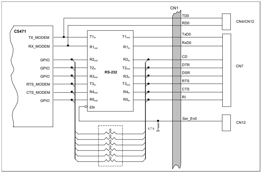
![Flowchart](.atca-8214-50-1g005-1000-200/18fffd9e00ff0480153edaf248a695b27aa26c17be021c0ea6f95ecff3cf878a.jpg)

Figure 2-13: CN6: UART/RS-232 Interface

<table><tr><td>Pin</td><td>Name</td><td>Description</td></tr><tr><td>1</td><td>RTS</td><td>Request to Send</td></tr><tr><td>2</td><td>DTR</td><td>Data Terminal Ready</td></tr><tr><td>3</td><td>TXD</td><td>Transmit Data</td></tr><tr><td>4</td><td>GND</td><td>Signal GND</td></tr><tr><td>5</td><td>GND</td><td>Signal GND</td></tr><tr><td>6</td><td>RXD</td><td>Receive Data</td></tr><tr><td>7</td><td>DSR</td><td>Data Set Ready</td></tr><tr><td>8</td><td>CTS</td><td>Clear to Send</td></tr></table>

![8\n2\n1](.atca-8214-50-1g005-1000-200/2e272a0b0b9720f913a2f5689ca1d968e148f729c6bbc4bd87135fabfae4d2b8.jpg)

Figure 2-14: CN6: UART/RS-232 Port & Pin Assignment

# CN7/CN8: LAN Interface

The aCMM-2100 provides two Ethernet ports for console management. Users can choose a single LAN port on the front panel or utilize the backplane base interface via jumper settings. The aCMM-2100 routes LAN functionality to the backplane by default.

<table><tr><td>Pin</td><td>10Base-T/100Base-TX</td></tr><tr><td>1</td><td>TX+</td></tr><tr><td>2</td><td>TX-</td></tr><tr><td>3</td><td>RX+</td></tr><tr><td>4</td><td>No connection</td></tr><tr><td>5</td><td>No connection</td></tr><tr><td>6</td><td>RX-</td></tr><tr><td>7</td><td>No connection</td></tr><tr><td>8</td><td>No connection</td></tr></table>

![Orange\nLED\nPin 1\nPin 2\nPin 3\nPin 6\nGreen\nLED](.atca-8214-50-1g005-1000-200/36d593df59dfef280c312859147dcb61a16a4b2f8fd2125f36c09dd59dfe631a.jpg)

Figure 2-15: CN7/CN8: LAN Port & Pin Assignment
![N\n1 2 3 4](.atca-8214-50-1g005-1000-200/51ff97c6922438f49317aab990c10db17deb853d44d2fd3105e4e68978c9447e.jpg)

<table><tr><td>Jumper</td><td>Description</td></tr><tr><td>1 ON</td><td>LAN 1 redirect to front panel</td></tr><tr><td>1 OFF*</td><td>LAN 1 redirect to backplane</td></tr><tr><td>2 ON</td><td>LAN 2 redirect to front panel</td></tr><tr><td>2 OFF*</td><td>LAN 2 redirect to backplane</td></tr></table>

Figure 2-16: SW1: LAN Port Settings

![An icon depicting a white document with horizontal lines and a folded corner, featuring a large red checkmark superimposed over it.](.atca-8214-50-1g005-1000-200/c730768d33c81b2bf6e982122a4e3030d2c90f57a3a338ef756eff68cd918bb5.jpg)
NOTE:

\*The default Jumper Settings are “OFF“.

# CN1: Battery

The aCMM-2100 includes a lithium battery to maintain the RTC on ShMM-500.

# CN3: JTAG Debug Interface

The aCMM-2100 provides a JTAG interface for debugging and manufacturing of the C5471 and manufacturing of the on-ShMM-500 CPLD using the CN3 connector. CN3 is a standard 14-pin JTAG port. The JTAG connector pin definition is shown below.

![13\n14\n1\n2](.atca-8214-50-1g005-1000-200/2b04bee27bb012d289f49aad804da34c5d821ad1eb68b51f0b433c752cbe4c6f.jpg)

<table><tr><td>Pin</td><td>Signal</td><td>Type</td><td>Description</td></tr><tr><td>1</td><td>NC</td><td>NC</td><td></td></tr><tr><td>3</td><td>TRST</td><td>In</td><td>Test port reset. Open drain output from the ARM Injector to the Reset signal on the target JTAG port. This pin should be pulled up on the target.</td></tr><tr><td>5</td><td>TDI</td><td>In</td><td>Test Data In signal from the ARM Injector to the target JTAG port. It is recommended that this pin be pulled to a defined state on the target.</td></tr><tr><td>7</td><td>TMS</td><td>In</td><td>Test Mode Select signal from the Injector to the target JTAG port. This pin should be pulled up on the target.</td></tr><tr><td>9</td><td>TCK</td><td>In</td><td>Test Clock signal from the Injector to the target JTAG port. This pin should be pulled to a defined state on the target.</td></tr><tr><td>11</td><td>TDO</td><td>Out</td><td>Test Data Out signal from the target JTAG port to the ARM Injector.</td></tr><tr><td>13</td><td>NC</td><td>NC</td><td></td></tr><tr><td>2, 4, 6, 8, 10, 12, 14</td><td>Gnd</td><td>Power</td><td>Ground</td></tr></table>

Figure 2-17: CN3: JTAG Connector & Pin Assignment

J1 Data Connector Pin Assignment

<table><tr><td>No.</td><td>Name</td><td>Description</td></tr><tr><td>A1</td><td>TX0_BA-P</td><td>Fast Ethernet 0, TX, positive</td></tr><tr><td>B1</td><td>TX0_BA-N</td><td>Fast Ethernet 0, TX, negative</td></tr><tr><td>C1</td><td>GND</td><td>Logic ground for reference</td></tr><tr><td>D1</td><td>PRESCN_R-L</td><td>Presence of the other ShMM-500</td></tr><tr><td>E1</td><td>PRESCN_L-L</td><td>Connect to GND</td></tr><tr><td>F1</td><td>GND</td><td>Logic ground for reference</td></tr><tr><td>A2</td><td>RX0_BA-P</td><td>Fast Ethernet 0, RX, positive</td></tr><tr><td>B2</td><td>RX0_BA-N</td><td>Fast Ethernet 0, RX, negative</td></tr><tr><td>C2</td><td>GND</td><td>Logic ground for reference</td></tr><tr><td>D2</td><td>HLYCN_R-L</td><td>Health of the other ShMM-500</td></tr><tr><td>E2</td><td>HLYCN_L-L</td><td>Health of this ShMM-500</td></tr><tr><td>F2</td><td>GND</td><td>Logic ground for reference</td></tr><tr><td>A3</td><td>TX1_BA-P</td><td>Fast Ethernet 1, TX, positive</td></tr><tr><td>B3</td><td>TX1_BA-N</td><td>Fast Ethernet 1, TX, negative</td></tr><tr><td>C3</td><td>GND</td><td>Logic ground for reference</td></tr><tr><td>D3</td><td>GND</td><td>Logic ground for reference</td></tr><tr><td>E3</td><td>HA0</td><td>Hardware Address 7</td></tr><tr><td>F3</td><td>GND</td><td>Logic ground for reference</td></tr><tr><td>A4</td><td>RX1_BA-P</td><td>Fast Ethernet 1, RX, positive</td></tr><tr><td>B4</td><td>RX1_BA-N</td><td>Fast Ethernet 1, RX, negative</td></tr><tr><td>C4</td><td>GND</td><td>Logic ground for reference</td></tr><tr><td>D4</td><td>USB0-P_CN</td><td>Redundancy USB0, positive</td></tr><tr><td>E4</td><td>USB0-N_CN</td><td>Redundancy USB0, negative</td></tr><tr><td>F4</td><td>GND</td><td>Logic ground for reference</td></tr><tr><td>A5</td><td>HA3</td><td>Hardware Address 4</td></tr><tr><td>B5</td><td>HA4</td><td>Hardware Address 3</td></tr><tr><td>C5</td><td>SWRCN_L-L</td><td>Switchover signal to the other ShMM-500</td></tr><tr><td>D5</td><td>HA7</td><td>Hardware Address 0</td></tr><tr><td>E5</td><td>HA2</td><td>Hardware Address 5</td></tr><tr><td>F5</td><td>GND</td><td>Logic ground for reference</td></tr><tr><td>A6</td><td>SHM_IPMBDAT_B</td><td>IPMB B Data</td></tr><tr><td>B6</td><td>HA5</td><td>Hardware Address 2</td></tr><tr><td>C6</td><td>GND</td><td>Logic ground for reference</td></tr><tr><td>D6</td><td>USBD-P_CN</td><td>Redundancy USBD, positive</td></tr><tr><td>E6</td><td>USBD-N_CN</td><td>Redundancy USBD, negative</td></tr><tr><td>F6</td><td>GND</td><td>Logic ground for reference</td></tr><tr><td>A7</td><td>SHM_IPMBCLK_B</td><td>IPMB B Clock</td></tr><tr><td>B7</td><td>HA6</td><td>Hardware Address 1</td></tr><tr><td>C7</td><td>SWRCN_R-L</td><td>Switchover signal from the other ShMM-500</td></tr><tr><td>D7</td><td>HA1</td><td>Hardware Address 6</td></tr><tr><td>E7</td><td>TEM_ALERT-L</td><td>Backplane Temperature Alert.</td></tr><tr><td>F7</td><td>GND</td><td>Logic ground for reference</td></tr><tr><td>A8</td><td>NC</td><td>No Connect</td></tr><tr><td>B8</td><td>NC</td><td>No Connect</td></tr><tr><td>C8</td><td>NC</td><td>No Connect</td></tr><tr><td>D8</td><td>REARVCC1</td><td>5V to Backplane</td></tr><tr><td>E8</td><td>EEPRON1_SCL</td><td>Backplane EEPROM1 I2C Clock</td></tr><tr><td>F8</td><td>GND</td><td>Logic ground for reference</td></tr><tr><td>A9</td><td>NC</td><td>No Connect</td></tr><tr><td>B9</td><td>POWEREN_B</td><td>Power B enable</td></tr><tr><td>C9</td><td>NC</td><td>No Connect</td></tr><tr><td>D9</td><td>GND</td><td>Logic ground for reference</td></tr><tr><td>E9</td><td>EEPRON1_SDA</td><td>Backplane EEPROM1 I2C Data</td></tr><tr><td>F9</td><td>GND</td><td>Logic ground for reference</td></tr><tr><td>A10</td><td>NC</td><td>No Connect</td></tr><tr><td>B10</td><td>NC</td><td>No Connect</td></tr><tr><td>C10</td><td>NC</td><td>No Connect</td></tr><tr><td>D10</td><td>REARVCC2</td><td>5V to Backplane</td></tr><tr><td>E10</td><td>EEPRON2_SCL</td><td>Backplane EEPROM2 I2C Clock</td></tr><tr><td>F10</td><td>GND</td><td>Logic ground for reference</td></tr><tr><td>A11</td><td>SHM_IPMBCLK_A</td><td>IPMB A Clock</td></tr><tr><td>B11</td><td>NC</td><td>No Connect</td></tr><tr><td>C11</td><td>SHM_IPMBDAT_A</td><td>IPMB A Data</td></tr><tr><td>D11</td><td>GND</td><td>Logic ground for reference</td></tr><tr><td>E11</td><td>EEPRON2_SDA</td><td>Backplane EEPROM2 I2C Data</td></tr><tr><td>F11</td><td>GND</td><td>Logic ground for reference</td></tr><tr><td>A15</td><td>PSU1_SDACN</td><td>PSU1 I2C Data</td></tr><tr><td>B15</td><td>PSU_P5V</td><td>PSU 5V Power</td></tr><tr><td>C15</td><td>NC</td><td>No Connect</td></tr><tr><td>D15</td><td>POWEREN_A</td><td>Power A enable</td></tr><tr><td>E15</td><td>NC</td><td>No Connect</td></tr><tr><td>F15</td><td>GND</td><td>Logic ground for reference</td></tr><tr><td>A16</td><td>PSU1_SCLCN</td><td>PSU1 I2C Clock</td></tr><tr><td>B16</td><td>PSU_GND</td><td>PSU ground</td></tr><tr><td>C16</td><td>NC</td><td>No Connect</td></tr><tr><td>D16</td><td>NC</td><td>No Connect</td></tr><tr><td>E16</td><td>NC</td><td>No Connect</td></tr><tr><td>F16</td><td>GND</td><td>Logic ground for reference</td></tr><tr><td>A17</td><td>PSU2_SDACN</td><td>PSU2 I2C Data</td></tr><tr><td>B17</td><td>PSU_P5V</td><td>PSU 5V Power</td></tr><tr><td>C17</td><td>NC</td><td>No Connect</td></tr><tr><td>D17</td><td>N48VCC_B</td><td>-48V Power B</td></tr><tr><td>E17</td><td>N48VCC_B</td><td>-48V Power B</td></tr><tr><td>F17</td><td>GND</td><td>Logic ground for reference</td></tr><tr><td>A18</td><td>PSU2_SCLCN</td><td>PSU2 I2C Clock</td></tr><tr><td>B18</td><td>PSU_GND</td><td>PSU ground</td></tr><tr><td>C18</td><td>NC</td><td>No Connect</td></tr><tr><td>D18</td><td>NC</td><td>No Connect</td></tr><tr><td>E18</td><td>NC</td><td>No Connect</td></tr><tr><td>F18</td><td>GND</td><td>Logic ground for reference</td></tr><tr><td>A19</td><td>NET_DET</td><td>Chassis airflow net detection</td></tr><tr><td>B19</td><td>NC</td><td>No Connect</td></tr><tr><td>C19</td><td>NC</td><td>No Connect</td></tr><tr><td>D19</td><td>N48VCC_B_RTN</td><td>-48V Power B Return</td></tr><tr><td>E19</td><td>N48VCC_B_RTN</td><td>-48V Power B Return</td></tr><tr><td>F19</td><td>GND</td><td>Logic ground for reference</td></tr><tr><td>A20</td><td>NC</td><td>No Connect</td></tr><tr><td>B20</td><td>NC</td><td>No Connect</td></tr><tr><td>C20</td><td>NC</td><td>No Connect</td></tr><tr><td>D20</td><td>NC</td><td>No Connect</td></tr><tr><td>E20</td><td>NC</td><td>No Connect</td></tr><tr><td>F20</td><td>GND</td><td>Logic ground for reference</td></tr><tr><td>A21</td><td>NC</td><td>No Connect</td></tr><tr><td>B21</td><td>NC</td><td>No Connect</td></tr><tr><td>C21</td><td>N48VCC_A</td><td>-48V Power A</td></tr><tr><td>D21</td><td>NC</td><td>No Connect</td></tr><tr><td>E21</td><td>CH_GND_BACK</td><td>Chassis ground</td></tr><tr><td>F21</td><td>GND</td><td>Logic ground for reference</td></tr><tr><td>A22</td><td>NC</td><td>No Connect</td></tr><tr><td>B22</td><td>NC</td><td>No Connect</td></tr><tr><td>C22</td><td>N48VCC_A</td><td>-48V Power A</td></tr><tr><td>D22</td><td>NC</td><td>No Connect</td></tr><tr><td>E22</td><td>CH_GND_BACK</td><td>Chassis ground</td></tr><tr><td>F22</td><td>GND</td><td>Logic ground for reference</td></tr><tr><td>A23</td><td>NC</td><td>No Connect</td></tr><tr><td>B23</td><td>NC</td><td>No Connect</td></tr><tr><td>C23</td><td>NC</td><td>No Connect</td></tr><tr><td>D23</td><td>NC</td><td>No Connect</td></tr><tr><td>E23</td><td>NC</td><td>No Connect</td></tr><tr><td>F23</td><td>GND</td><td>Logic ground for reference</td></tr><tr><td>A24</td><td>NC</td><td>No Connect</td></tr><tr><td>B24</td><td>NC</td><td>No Connect</td></tr><tr><td>C24</td><td>N48VCC_A_RTN</td><td>-48V Power A Return</td></tr><tr><td>D24</td><td>NC</td><td>No Connect</td></tr><tr><td>E24</td><td>NC</td><td>No Connect</td></tr><tr><td>F24</td><td>GND</td><td>Logic ground for reference</td></tr><tr><td>A25</td><td>NC</td><td>No Connect</td></tr><tr><td>B25</td><td>NC</td><td>No Connect</td></tr><tr><td>C25</td><td>N48VCC_A_RTN</td><td>-48V Power A Return</td></tr><tr><td>D25</td><td>NC</td><td>No Connect</td></tr><tr><td>E25</td><td>NC</td><td>No Connect</td></tr><tr><td>F25</td><td>GND</td><td>Logic ground for reference</td></tr></table>

Table 2-12: J1 Data Connector Pin Assignment

I 2C Bus Devices

<table><tr><td>Address</td><td>Device</td><td>Description</td></tr><tr><td>0x40</td><td>PCA9555</td><td>Telco Alarm</td></tr><tr><td>0x46</td><td>PCA9554</td><td>Hardware Address</td></tr><tr><td>0x90</td><td>LM75</td><td>Thermal Detector</td></tr><tr><td>0xE0</td><td>PCA9545</td><td>I2C Bus Switch</td></tr></table>

Table 2-13: I2C Bus Device List

Telco Alarm Interface: PCA9555

<table><tr><td>Pin</td><td>Name</td><td>Direction</td><td>Description</td></tr><tr><td>2</td><td>A1</td><td>Input</td><td>Set to logic 0</td></tr><tr><td>3</td><td>A2</td><td>Input</td><td>Set to logic 0</td></tr><tr><td>21</td><td>A0</td><td>Input</td><td>Set to logic 0</td></tr><tr><td>4</td><td>I/O 0.0</td><td>Output</td><td>Power Alarm</td></tr><tr><td>5</td><td>I/O 0.1</td><td>Output</td><td>Minor Alarm</td></tr><tr><td>6</td><td>I/O 0.2</td><td>Output</td><td>Major Alarm</td></tr><tr><td>7</td><td>I/O 0.3</td><td>Output</td><td>Critical Alarm</td></tr><tr><td>8</td><td>I/O 0.4</td><td>Output</td><td>Minor Alarm LED</td></tr><tr><td>9</td><td>I/O 0.5</td><td>Output</td><td>Major Alarm LED</td></tr><tr><td>10</td><td>I/O 0.6</td><td>Output</td><td>Critical Alarm LED</td></tr><tr><td>11</td><td>I/O 0.7</td><td></td><td>Reserved</td></tr><tr><td>13</td><td>I/O 1.0</td><td>Input</td><td>Cut-off Switch</td></tr><tr><td>14</td><td>I/O 1.1</td><td>Input</td><td>Minor Clear</td></tr><tr><td>15</td><td>I/O 1.2</td><td>Input</td><td>Major Clear</td></tr><tr><td>16</td><td>I/O 1.3</td><td></td><td>Reserved</td></tr><tr><td>17</td><td>I/O 1.4</td><td></td><td>Reserved</td></tr><tr><td>18</td><td>I/O 1.5</td><td></td><td>Reserved</td></tr><tr><td>19</td><td>I/O 1.6</td><td></td><td>Reserved</td></tr><tr><td>20</td><td>I/O 1.7</td><td></td><td>Reserved</td></tr><tr><td>22</td><td>SCL</td><td>I/O</td><td>I2C Clock</td></tr><tr><td>23</td><td>SDA</td><td>I/O</td><td>I2C Data</td></tr></table>

Table 2-14: PCA9555@0x40 Pin Definitions

Hardware Address: PCA9554

<table><tr><td>Pin</td><td>Name</td><td>Direction</td><td>Description</td></tr><tr><td>1</td><td>A0</td><td>Input</td><td>Set to logic 1</td></tr><tr><td>2</td><td>A1</td><td>Input</td><td>Set to logic 1</td></tr><tr><td>3</td><td>A2</td><td>Input</td><td>Set to logic 0</td></tr><tr><td>4</td><td>I/O 0</td><td>Input</td><td>Hardware Address 0</td></tr><tr><td>5</td><td>I/O 1</td><td>Input</td><td>Hardware Address 1</td></tr><tr><td>6</td><td>I/O 2</td><td>Input</td><td>Hardware Address 2</td></tr><tr><td>7</td><td>I/O 3</td><td>Input</td><td>Hardware Address 3</td></tr><tr><td>9</td><td>I/O 4</td><td>Input</td><td>Hardware Address 4</td></tr><tr><td>10</td><td>I/O 5</td><td>Input</td><td>Hardware Address 5</td></tr><tr><td>11</td><td>I/O 6</td><td>Input</td><td>Hardware Address 6</td></tr><tr><td>12</td><td>I/O 7</td><td>Input</td><td>Hardware Address 7/Parity</td></tr><tr><td>14</td><td>SCL</td><td>I/O</td><td>I2C Clock</td></tr><tr><td>15</td><td>SDA</td><td>I/O</td><td>I2C Data</td></tr></table>

Table 2-15: PCA9554@0x46 Pin Definitions

I 2C Bus Switch: PCA9545

<table><tr><td>Pin</td><td>Name</td><td>Direction</td><td>Description</td></tr><tr><td>1</td><td>A0</td><td>Input</td><td>Set to logic 0</td></tr><tr><td>2</td><td>A1</td><td>Input</td><td>Set to logic 0</td></tr><tr><td>3</td><td>Reset</td><td>Input</td><td>I2C Switch Reset</td></tr><tr><td>5</td><td>SD0</td><td>I/O</td><td>OFF Board I2C 1 Data</td></tr><tr><td>6</td><td>SC0</td><td>I/O</td><td>OFF Board I2C 1 Clock</td></tr><tr><td>8</td><td>SD1</td><td>I/O</td><td>OFF Board I2C 2 Data</td></tr><tr><td>9</td><td>SC1</td><td>I/O</td><td>OFF Board I2C 2 Clock</td></tr><tr><td>12</td><td>SD2</td><td>I/O</td><td>EEPRON I2C 2 Data</td></tr><tr><td>13</td><td>SC2</td><td>I/O</td><td>EEPRON I2C 2 Clock</td></tr><tr><td>15</td><td>SD3</td><td>I/O</td><td>EEPRON I2C 1 Data</td></tr><tr><td>16</td><td>SC3</td><td>I/O</td><td>EEPRON I2C 1 Clock</td></tr><tr><td>18</td><td>SCL</td><td>I/O</td><td>I2C Clock</td></tr><tr><td>19</td><td>SDA</td><td>I/O</td><td>I2C Data</td></tr><tr><td>20</td><td>VDD</td><td>Power</td><td>PCA9545 Power</td></tr></table>

Table 2-16: PCA9545@0xE0 Pin Definitions

# 2.5 Intelligent Fan Tray, aFAN-1010

The aFAN-1010 is an intelligent, fully hot-swappable fan controller. It supports three channels of built-in 14-bit PWM timers to control fan speed, and built-in Free Running Timer (FRT) to monitor the rotation speeds of the fans. The on-board DC/DC circuit converts DC 48V nominal to DC 12V to power each fan.

# Features:

X Pigeon Point Systems BMR-H8S IPMC
X Dual bussed IPMB
X Redundant DC 48V powered

![The diagram depicts a system centered around a large blue rectangular block labeled **aFAN-1010**. Inside the bottom of this block are two smaller white blocks: **PPS BMR-H8S** on the left and **DC/DC** on the right.\n\nTo the right of the main block, there are three connections (from top to bottom):\n*   An arrow pointing left (output) labeled **HA(0:7)**.\n*   A double-headed arrow labeled **IPMB A/B**.\n*   An arrow pointing left (input) labeled **DC48V A/B**.\n\nTo the left of the main block, there are three circular fan icons stacked vertically. Two arrows connect to the main block:\n*   A double-headed arrow connecting the middle fan, labeled **PWM x3**.\n*   An arrow pointing left (output) labeled **DC12V**.](.atca-8214-50-1g005-1000-200/991d5a5ec52e15ee03b126148859e1e0ad6bdb7a47d629c8db6605f126721ec8.jpg)

Figure 2-18: aFAN-1010 Block Diagram

![The image displays an icon of a white document with a black outline and a folded top-left corner. Faint horizontal lines run across the document, resembling text. A large, bold red checkmark is superimposed diagonally over the paper.](.atca-8214-50-1g005-1000-200/42035eb8635772b364248613cc7e28cb9731b24c76cf716407110417caeafa2e.jpg)
NOTE:

Without an installed aCMM-2100 module, all fans on left, center and right fan tray modules will rotate at full speed.

![Exterior view of a power supply unit with two black fans and a metallic cooling cover (no visible text or symbols)](.atca-8214-50-1g005-1000-200/ea4227a40da443d6b42f8c052ad16aebc45a5ddffbc10d96b574fc788e31b533.jpg)

Figure 2-19: aFAN-1010 Tray

# 2.6 Intelligent Power Entry Module, aPEM-1020

The aPEM-1020 is an intelligent power entry module for over-current protection, EMC filtering and IPMB interfaced shelf management. An onboard IPMC monitors DC 48V A/B conditions and circuit breaker status via ${ \mathsf { I } } ^ { 2 } { \mathsf { C } }$ interfaced TI ADS1000 A/D converter and GPI pins.

# Features:

X Pigeon Point Systems BMR-H8S IPMC
X Dual bussed IPMB
X Redundant DC 48V powered

![This block diagram depicts a system enclosed in a large blue rectangle labeled **aPEM-1 020**.\n\n**Internal Blocks:**\nInside the main container, there are four white rectangular blocks arranged in two rows:\n*   Top row: **BMR-H8S** (left) and **TI ADS1000** (right).\n*   Bottom row: **EMC Filter** (left) and **Circuit Breaker** (right).\n\n**External Connections (Arrows):**\n*   **HA(0:7)**: An arrow points from the left into the top-left section of the system.\n*   **IPMB A/B**: A bidirectional connection on the middle-left, indicated by arrows pointing both into and out of the system.\n*   **DC48V A/B** (Left): An arrow points from the bottom-left section out of the system to the left.\n*   **DC48V A/B** (Right): An arrow points from the far right into the system, directed toward the **Circuit Breaker** block.](.atca-8214-50-1g005-1000-200/790209165a9db3dfcce6872213951bcd4d98314fdc47bfc0884713a7153b224d.jpg)

Figure 2-20: aPEM-1020 Block Diagram

![Magnetic\nCircuit\nBreaker\nRTM -48 ~ -60 VDC\nTERMINAL BLOCK COVER\nRemove terminal block cover and\nall cableless before removing PEM\nHot SWAP\nLED](.atca-8214-50-1g005-1000-200/ea20a3cd04deb4e5131a1622a1ba8fc8dd4b99a11eee301d276ac84551d20048.jpg)

Figure 2-21: aPEM-1020 Layout

# 3 Getting Started

This chapter provides information on the physical features and pre-installed hardware components of aTCA-8214 Series.

![This image is a digital icon depicting a white document or piece of paper. The paper features faint horizontal lines running across it and has its top-right corner folded over (a 'dog-ear'). Superimposed over the left side of the paper is a large, bold red checkmark (or tick mark) that angles upward from the bottom left to the top right.](.atca-8214-50-1g005-1000-200/92b4039192c9d2e083ff67925b5b7c9419b9f11c2e99d28d4e2676418917d0e0.jpg)
NOTE:

The labelling on chassis, modules, and other components in this chapter may differ slightly from those on the actual product.

# 3.1 Installation Environment

Whenever unpacking and preparing to install any equipment described in this manual, please refer to the Important Safety Instructions chapter of this manual.

Only install equipment in well lit areas on flat, sturdy surfaces with access to basic tools such as flat and cross head screwdrivers, preferably with magnetic heads as screws are small and easily misplaced.

# Recommended Installation Tools

X Phillips (cross-head) screwdriver
X Flat-head screwdriver
X Anti-static Wrist Strap
X Anti-static mat

The aTCA-8214 Series contains electro-static sensitive equipment that can be easily damaged by static electricity and must be handled on a grounded anti-static mat. The operator must wear an anti-static wristband, grounded at the same point as the anti-static mat.

Inspect the carton and packaging for damage. Shipping and handling could cause damage to the equipment inside. Make sure that the equipment and its associated components have no damage before installing.

![The image displays a standard yellow triangular warning sign with a thick black border. Inside the triangle, centered vertically, is a large, black exclamation mark. The background surrounding the sign is white.](.atca-8214-50-1g005-1000-200/c6f7d88d835a18e4139f0ca726896d2e5f401adc1a73f9440cdba395b765608f.jpg)
CAUTION:

The equipment must be protected from static discharge and physical shock. Never remove any of the socketed parts except at a static-free workstation. Use the anti-static bag shipped with the product to handle the equipment and wear a grounded wrist strap when servicing.

# 3.2 Installing ATCA® Boards

The aTCA-8214 Series is designed with 14 slots that support $\mathsf { A T C A } ^ { \mathbb { \otimes } }$ boards, modules, and controllers. $\mathsf { A T C A } ^ { \mathbb { \otimes } }$ connectors are rigid and require careful handling and proper installation. $\mathsf { A T C A } ^ { \mathbb { \otimes } }$ boards are equipped with locking handles and retention screws for easy installation and removal.

![A red triangular warning sign featuring a white exclamation point in the center. Below the triangle, the word 'WARNING' appears in black capital letters.](.atca-8214-50-1g005-1000-200/902849367047556df504b76438dcff0e42f5af64d995371d099d73dccea36250.jpg)

Improper installation of $\mathsf { A T C A } ^ { \mathbb { Q } }$ boards may damage the backplane.

# To install an $\mathsf { \pmb { A T C A } } ^ { \mathbb { Q } }$ controller board follow these steps:

1. Check if all components are properly installed on the $\mathsf { A T C A } ^ { \mathbb { \otimes } }$ controller board including the CPU, heatsink, and memory modules, if any.

![Green printed circuit board with various components and connectors (no visible text or symbols)](.atca-8214-50-1g005-1000-200/5836b9187e089c3c3f5d93226b3ed6441bf98aeff10454dc176405296dae6f5c.jpg)

2. Remove any cover plates from the face of the aTCA-8214 chassis to expose the guide rails inside the chassis housing.
3. Position the $\mathsf { A T C A } ^ { \mathbb { \otimes } }$ board into the slot, then carefully slide its edges into the board guide rail. Make sure that

the board is correctly aligned with the chassis to prevent damage to the board and/or backplane.

![Interior view of a server rack with labeled components and a hand adjusting the front panel (no readable text or symbols)](.atca-8214-50-1g005-1000-200/3bec1b34f08aa483d35b884629d768c930c02e16a72d217019c9b5c2d89183cc.jpg)

4. Push the board into the slot until the handles come in contact with the chassis and the metal tacks insert into the chassis holes.
5. Push the handles inward until they 'click' in place
6. Fasten the retention screws (turning in a clock-wise direction) at both ends of the board to secure it in place.

![The image displays a standard icon representing a checked document. It features a white sheet of paper with a folded top-right corner. Faint horizontal grey lines run across the paper to simulate text. Overlaid on the left side of the document is a large, bold red checkmark.](.atca-8214-50-1g005-1000-200/448434379ae4357fff18c3bf0d3efc21e5434a62298e10a559044f5cdcbb30c8.jpg)
NOTE:

To remove and replace an ATCA® board, refer to Section 4.1 Removing ATCA® Boards and RTMs.

# 3.3 Installing Rear Transition Modules (RTMs)

Due to the short depth of RTMs, take extreme care when inserting or removing them from the chassis.

![A white sheet of lined paper with its top right corner folded down, featuring a large red checkmark superimposed over the center.](.atca-8214-50-1g005-1000-200/04d86fb8a845eeeccee13a357e18ce1701fafefc2861fbad47b516b6ac97b56c.jpg)
NOTE:

RTMs have an "R" at the beginning of the model number. The ADLINK RTM (aTCA-R6890) shown below is used for illustration purposes only. The aTCA-8214 Series chassis is NOT shipped with RTMs. RTMs must be purchased separately.

1. At the rear of the aTCA-8214 Series, access the RTM slots and remove any cover plates.

![Close-up of a black industrial machine with visible structural components and a red arrow pointing to a component (no text or symbols)](.atca-8214-50-1g005-1000-200/2f92609fd0e8eb09ea099535490d699a94e70b7ed9d4d55a4b451d9de710fab8.jpg)

2. Check if all components are properly installed on the RTM.

![Interior view of a computer motherboard showing green circuit board, drive bays, and internal memory card (no visible text or symbols)](.atca-8214-50-1g005-1000-200/3b172256534e8c5e0b1101adedbf319d07e10b64674ea890de56d331b8446062.jpg)

3. Position the RTM into the slot, then carefully slide its edges along the slot guide rail. Make sure that the module is correctly aligned with the chassis to prevent damage to the module and/or backplane.

![Interior view of a server rack with visible circuit boards and a green internal component, marked with red circles (no text or symbols)](.atca-8214-50-1g005-1000-200/b7c77975a760e7ab6ae9a2b3432c3621d6a947021064ff87a31d8252fa3a9366.jpg)

4. Push the module into the slot until the handles come in contact with the chassis and the metal tacks insert into the chassis holes.

5. Push the handles inward until they 'click' in place. Fasten the retention screws (turning in a clock-wise direction) at both ends of the board to secure it in place.

# 3.4 Installing Shelf Management Modules

The aCMM-2100 module facilitates tool-less installation with builtin retention screws and a handle.

![The image displays a white document icon with faint horizontal lines running across it. The top right corner of the paper is curled. A large, thick red checkmark is superimposed diagonally across the document, slanting upwards from left to right.](.atca-8214-50-1g005-1000-200/0bdebf1900f39a230210007099995cc8a66dbeab8adab3622d90e8a28727e8e3.jpg)
NOTE:

The aTCA-8214 DOES NOT come with aCMM-2100 modules.

This product has two shelf management module slot covers. To install aCMM-2100 modules, the slot covers must first be removed by locating and turning its retention screws counterclockwise.

The aTCA-8214A comes with one aCMM-2100 module installed in ShMC slot 1 and a module slot cover installed in ShMC slot 2.

The aTCA-8214AA comes with two aCMM-2100 pre-installed in ShMC slots 1 and 2.

When installing an aCMM-2100 module, carefully hold the module by its edges and do not force the module into the slot to avoid component damage.

To install an aCMM-2100 module:

1. Locate the shelf management module slot.
2. Carefully insert the aCMM-2100 module into the slot as shown.

![Interior view of an electronic device showing a green circuit board with internal components and a red arrow pointing to a component (no visible text or symbols)](.atca-8214-50-1g005-1000-200/ca2d13a2cb278af32ce4410283d5a10eedd7e2221d5eb917c00eea8cd132ef20.jpg)

3. Push the module into the slot until the module metal tacks are engaged with the chassis holes.
4. Gently lift the handle upward as you push it flush to the chassis front panel.
5. Once the face plate of the module is flush to the chassis face front, push the handle inward to lock the module in place.

![Two views of a server rack with mechanical components and red arrows indicating directional movement (no text or symbols)](.atca-8214-50-1g005-1000-200/88932fe178e21ea6620926bca4915d1a38fe05f43739c1d49d369e95d184f8f1.jpg)

6. Turn the retention screws in a clockwise direction to tighten and secure the module.

The aCMM-2100 powers up instantly and the ACT LED lights up green. When two aCMM-2100 modules are installed, the ACT LED of the backup module blinks.

![The image displays a digital icon of a white document or piece of paper with a folded top-right corner. Faint horizontal lines run across the document, simulating text lines. Superimposed over the document is a large, bold red checkmark. There is no actual text present in the image.](.atca-8214-50-1g005-1000-200/8799736c69f650df333900128dc2effd4b672551fef4d353a32ada7ced13f4b6.jpg)
NOTE:

To remove and replace a shelf management module, refer to Section 4.2 Removing Shelf Management Modules.

# 3.5 Powering Up the System

After installing all necessary components, connecting cables, and peripherals, you are now ready to power up the system. The aTCA-8214 Series comes with two aPEM-1020 intelligent power entry modules that connect to the ADLINK aPRS-1120 (AC-DC Power Converter Equipment), or to your own DC power supply.

![The image shows a white document icon with a folded top-left corner. Faint horizontal lines appear across the lower portion of the page. A large red checkmark is superimposed over the center.](.atca-8214-50-1g005-1000-200/cb6f57fa01f9b9f2908ce215931d1f97a6932315251633cd70f2ac74fcce47e3.jpg)
NOTE:

The ADLINK aPRS-1120 (AC-DC Power Converter Equipment) is purchased separately.

ADLINK recommends the use of approximately 3600 W power for the aTCA-8214 Series under full loading.

Purchasing Information:

aPRS-1120: 19” Rackmount Power Rack w/ 3 power unit slots (one aPRS-91120/48 1200 W power unit included)

aPRS-91120/48: 1200 W AC/DC-48 output power unit

The ADLINK aPRS-1120 accessory package includes two colorcoded, one-meter length terminal wires. You will use these wires to connect the PEMs to the power converter.

![The image displays a triangular warning symbol. It features a red background with a white border. Inside the triangle is a large white exclamation point. Above the triangle is a black horizontal line and the top edge of a white rectangular area.](.atca-8214-50-1g005-1000-200/e2bf55a3eb7ae2c99ea4abe01fda64ac659b7af52b52976d38d642adbe7ebcac.jpg)
WARNING:

Before connecting the PEMs to the power converter, make sure that the PEMs are properly installed in the chassis, the PEM circuit breakers are turned “OFF”, and the AC power cords of the power converter are disconnected. If you are using your own DC power supply, make sure the power is turned off before connecting the wires to the PEMs.

To connect the aTCA-8214 Series PEM to the power converter:

1. Loosen the aPRS-1120 DC OUT +V and -V terminal screws.

![J4\n+V\n- V\nDC OUT\nGND\nJ3 J2 J1\nAC IN\nBACK VIEW](.atca-8214-50-1g005-1000-200/ea104085d21924dbf01029519d41517f99f48f1f97ba890b787778760fa0c32b.jpg)

2. Connect one end of the red wire to the +V terminal the other end of the red wire to the RTN terminal of the PEM.
3. Connect one end of the black wire to the -V terminal and the other end of the black wire to the -48 VDC terminal of the PEM. Refer to the following illustration.

![J4 +V -V GND J3 J2 J1\nDC OUT AC IN\nBACK VIEW\nRTM -4R ~ -60 VDC\nTERMINAL BLOCK COVER\nRemove terminal block cover and\nall cabless before removing PEM](.atca-8214-50-1g005-1000-200/e5d511a048721f2d7102bc572d142b64b781d4bad6a9cb7d0b407ae77a6b27b9.jpg)

When using dual-PEMs, use two sets of red and black wires to connect the power converter to the PEMs. Refer to the illustration below:

![J4\n+V\n- V\nDC OUT\nGND\nJ3 J2 J1\nAC IN\nBACK VIEW\nRTM -48 ~ -60 VDC\nTERMINAL BLOCK COVER\nRemove terminal block cover and\nall cables before removing PEM\nRTM -47 ~ -60 VDC\nTERMINAL BLOCK COVER\nRemove terminal block cover and\nall cables before removing PEM](.atca-8214-50-1g005-1000-200/850e5df26f73a3d5229506c29aff3194bcb5e0b3d86f910860ec402005a7d994.jpg)

4. Check the aPRS-1120 configuration. If the power converter comes in default configuration (single 1200 W power unit, middle slot populated), connect the AC power cord to the J2 connector.
5. Connect the other end of the AC power cord to a wall socket or power strip, then turn on the PEM circuit breakers and all required peripherals.

![The image displays a simple digital icon of a piece of paper or document. It features a black outline of a page with a folded top-right corner and several horizontal lines near the bottom, representing text. Overlaid on the document is a large, bold red checkmark (or tick mark) that slants upwards from left to right.](.atca-8214-50-1g005-1000-200/71c83f99c7b49775838db898eaa014e54c2f760de247bda131d9d61cc07c7614.jpg)
NOTE:

Before powering up the chassis, make sure that the circuit breakers are in the "ON" position (2 per module).

To remove and replace a PEM, refer to Section 4.5

# 3.6 Managing the Chassis

# aCMM-2100 Shelf Management Module

The aTCA-8214A/aTCA-8214AA come with one/two aCMM-2100 shelf management module(s). The aTCA-8214AA is capable of providing redundant chassis management functions.

![The image is a digital icon featuring a white document with a folded top-left corner and faint grey horizontal lines representing text. A large, bold red checkmark is superimposed over the center of the document. The entire graphic is enclosed within a thick black border.](.atca-8214-50-1g005-1000-200/f34a5ac6d5b7fca11ec177bc741e7d796996340b239c1ca793c63737a70ddc7b.jpg)
NOTE:

Without an installed aCMM-2100 module, all fans on fan tray modules rotate at full speed (Level 15).

Table 3-1: aCMM-2100 Specifications

<table><tr><td>Dimensions</td><td>104 mm x 280 mm</td></tr><tr><td>Specification Compliance</td><td>PICMG®3.0 R2.0 AdvancedTCA Specification</td></tr><tr><td>Core Module</td><td>ShMM-500 Connector 144-pin socket Pigeon Point Systems ShMM-500 SOM (System On Module) with built-in 333 MHz MIPS processor</td></tr><tr><td>LAN Interface</td><td>Two 10/100Mbps Ethernet ports cross connected to backplane switch supporting remote login from LANEthernet port can be re-directed to RJ-45 on front faceplate</td></tr><tr><td>Serial Interface</td><td>Standard RS-232 interface with DB-9 connector on front panel</td></tr><tr><td>Telco Interface</td><td>Mini DB-15 connectorCut-off button and 3 LED indicators on faceplate</td></tr></table>

To access fan, temperature, $\mathsf { A T C A } ^ { \mathbb { \otimes } }$ board FRU (field replaceable unit), and power information, the installed aCMM-2100 must be connected to a host computer:

serially using an RJ-45 to DB9 cable (bundled in the aCMM-2100 package),
X over a LAN using a standard RJ-45 cable, or
X via network switch or hub.

![Serial\nConsole\nPort\nTelco\nInterface\n10/100BASE-T\nEthernet](.atca-8214-50-1g005-1000-200/6f4629a5e6a1d1324c2a791b9e5989b94844d9a0fd846266a7d97976ee74eaa5.jpg)

Figure 3-1: aCMM-2100 Face Plate Layout

# aCMM-2100 SW1 DIP Switch

The aCMM-2100 is equipped with a SW1 DIP switch. The default setting for the switch is “ON“ and users can access the LAN port for remote host, etc. Switching DIP 1 and 2 to the “OFF“ position will allow the ShMC LAN port to access the backplane connection via physical Slot 7 and 8 switch board. If there is no physical switch board, please keep the SW1 DIP set to ON for LAN use.

<table><tr><td></td><td>Slot 7 (aTCA-3100)</td><td>Slot 8 (aTCA-3100)</td></tr><tr><td>aCMM-2100 SW1No1 “ON”No2 “ON”</td><td>No Connection with aTCA-8214aCMM-2100 LANxFront Side</td><td>No Connection with aTCA-8214aCMM-2100 LANxFront Side</td></tr><tr><td>aCMM-2100 SW1No1 “OFF”No2 “OFF”</td><td>ShMC 1 / Sh1ShMC 2 / Sh2</td><td>ShMC 1 / Sh2ShMC 2 / Sh1</td></tr></table>

Table 3-2: aCMM-2100 SW1 DIP Configuration Example

![The diagram displays a timing or connection diagram with vertical timelines and horizontal connections.\n\n**Labeled Blocks and Vertical Lines:**\n*   **Left Vertical Line:** Labeled 'Slot 7 (PHY)' at the top and 'aTCA-3100' at the bottom. It features two black nodes labeled 'Sh2' (upper) and 'Sh1' (lower).\n*   **Middle Vertical Line:** Labeled 'Slot 8 (PHY)' at the top and 'aTCA-3100' at the bottom. It features two black nodes labeled 'Sh1' (upper) and 'Sh2' (lower).\n*   **Top Right Vertical Line:** Labeled 'ShMC 2' at the top. It has connection points labeled 'LAN B' (upper) and 'LAN A' (lower).\n*   **Bottom Right Vertical Line:** Labeled 'ShMC 1' at the bottom. It has connection points labeled 'LAN B' (upper) and 'LAN A' (lower).\n\n**Connections:**\n*   **Dashed Lines:**\n    *   One connects 'Sh2' on the 'Slot 7 (PHY)' line to 'LAN B' on the 'ShMC 2' line.\n    *   One connects 'Sh1' on the 'Slot 8 (PHY)' line to 'LAN A' on the 'ShMC 2' line.\n*   **Dotted Lines:**\n    *   One connects 'Sh2' on the 'Slot 8 (PHY)' line to 'LAN B' on the 'ShMC 1' line.\n    *   One connects 'Sh1' on the 'Slot 7 (PHY)' line to 'LAN A' on the 'ShMC 1' line.](.atca-8214-50-1g005-1000-200/beb48875305038c7e71149d92054b3c04c624acefefa7d3567cf0e8d30cb17bd.jpg)

Figure 3-2: aCMM-2100 SW1 DIP Configuration Diagram

# Serial Connection

You may use the bundled RJ-45 to DB9 cable to connect the chassis serially to a host computer. Refer to the illustration below.

![Host computer\nRJ-45 to DB9 cable\naCMM-2100 module](.atca-8214-50-1g005-1000-200/7711ac912770b602378f09c622208787b0fcf2bed82430bc1b66e0d416ddcba4.jpg)

The aCMM-2100 COM port is offers the following default parameters:

<table><tr><td>Type</td><td>RS232 (COM)</td></tr><tr><td>Baud Rate</td><td>115200bps</td></tr><tr><td>Data Bits</td><td>8</td></tr><tr><td>Parity</td><td>None</td></tr><tr><td>Stop Bits</td><td>1</td></tr><tr><td>Flow Control</td><td>None</td></tr></table>

# LAN Connection

With Fast Ethernet bandwidth, you may connect the aCMM-2100 directly to a notebook or PC using an RJ-45 cable or to a network switch or router for high-speed remote management. Refer to the following illustrations.

![Host computer\nRJ-45 cable\naCMM-2100 module](.atca-8214-50-1g005-1000-200/c63434cdac2d299a9b5d12d19fd98ebdc459ee11541b18d111f44f52a419350c.jpg)

![Host computer\nSwitch/Hub\nRJ-45 cable](.atca-8214-50-1g005-1000-200/f72d4789c2126017068d6eef49fa7550ad4176b8ff1556a183078d7a4cefcee6.jpg)

By default, the LAN1 port has the following settings:

<table><tr><td>IP</td><td>172.16.13.209</td></tr><tr><td>Login name</td><td>root</td></tr><tr><td>Password</td><td>None</td></tr></table>

# Thermal Sensors

The aTCA-8214 Series comes with four thermal sensors (LM75CIMM) U1 - U4 installed on the backplane of the chassis. The aCMM-2100 automatically detects these sensors and dynamically adjusts fan speed depending on the chassis temperature conditions. If any fan should go offline or malfunction, the remaining functioning fan tray modules will speed up to level 15 and only reduce operating speed upon replacement of the malfunctioning fan tray module. The aCMM-2100 also detects individual ATCA board CPU temperatures and functions, and will adjust fan speed accordingly for proper temperature control.

The thermal sensors have three temperature thresholds, Non-Critical, Critical, and Non-Recoverable (see Table 3-3 below). If the aCMM-2100 receives a reported temperature of $4 0 ^ { \circ } \mathsf { C }$ or higher from any ATCA board CPU or any of the chassis thermal sensors, the fan speed of the fan tray modules will automatically be raised one level every 30 seconds to maintain a temperature below Non-Critical status. If the temperature continues to increase, the fan tray modules will speed up to the maximum speed (level 15). The shelf will only reduce fan speed if the temperature drops below $4 0 ^ { \circ } \mathsf { C }$ (Non-Critical status) for 30 seconds and will continue to decrease by one level every 30 seconds until the default speed (level 7) is reached.

<table><tr><td>Non-Recoverable</td><td>65°C</td></tr><tr><td>Critical</td><td>50°C</td></tr><tr><td>Non-Critical</td><td>45°C</td></tr></table>

Table 3-3: aTCA-8214 Backplane Thermal Sensor Thresholds

![The image displays a white document icon with faint horizontal gray lines, overlaid with a large, bold red checkmark.](.atca-8214-50-1g005-1000-200/62ef57992803ebc2b1b890918f420183bb9d4d2683bb7b3fcf4598ff10b70d77.jpg)
NOTE:

If an ATCA board CPU temperature threshold is lower than that of the aTCA-8214, the board's threshold temperature will be used to control the fan tray modules. Consult the user’s manual for your ATCA board.

# Fan Speed Verification

System administrators may use the clia command (e.g. clia fans) to verify the fan speeds detected and adjusted by the aCMM-2100 module. The location of two of the aTCA-8214 Series thermal sensors is shown below. The remaining two are not externally visible.

![Interior view of a server rack unit with labeled components and gold-colored PCB modules (no readable text or symbols)](.atca-8214-50-1g005-1000-200/8cb15d91e3c9dd03df61cb29b88d513d453b21b37ca00d06c88990682a203048.jpg)

This page intentionally left blank.

# 4 Chassis Maintenance

This chapter provides information on how to remove and replace defective components and maintain the chassis to keep the aTCA-8214 Series in best working condition.

# 4.1 Removing ATCA® Boards and RTMs

This section describes how to remove ATCA® boards and RTMs from the aTCA-8214 Series:

1. Loosen the retention screws at both ends of the board/ module.
2. Unlatch the ATCA® board/RTM handles by pulling them outward until the board/RTM disengages from the chassis.

![Close-up of a hand inserting a component into a computer tower, showing internal circuit board and drive slots (no text or symbols visible)](.atca-8214-50-1g005-1000-200/1d9fa8e2bc89dd97ce842c421c7cf11aa356a8450723fc87880fbba94d893a46.jpg)

3. Carefully pull the board/RTM out from the chassis, then store in a safe place.

![Person installing or adjusting a server rack with red arrows pointing to components (no visible text or labels)](.atca-8214-50-1g005-1000-200/6dde6bd86fa5ca9612d3db5fea914033e95aadac00ae61c1ea9f1c6cda1d4d24.jpg)

![The image displays a white document icon with a folded top-right corner and faint horizontal gray lines running across it. A large, thick red checkmark is superimposed diagonally over the center of the document.](.atca-8214-50-1g005-1000-200/4c7a46e9d4477d62c326f9865e2781cfd269d57377ab7cd8565f0155b6e6e865.jpg)
NOTE:

Refer to the user's manual for your specific board for hotswap removal and installation instructions.

# 4.2 Removing Shelf Management Modules

This section provides information on how to remove and replace a aCMM-2100 Shelf Management Module. The modules are hotswappable and may be replaced while the chassis is operating.

To remove the aCMM-2100:

1. Loosen the retention screws located at both ends of the module.
2. Pull the module handle upward. If the system is powered on, the blue Hot Swap LED will change from “OFF” to “Short-blink”, and then to “ON”. The steady “ON” indicates that the module can be safely removed (see “Hot Swap LED” on page 19).

![Close-up of a server rack with metal components and a red arrow pointing to a component (no visible text or symbols)](.atca-8214-50-1g005-1000-200/79987c18a6e89b49c85e2f470ede9d8db0472e49739c71408f48521323d1945a.jpg)

3. Pull the module handle outward until the card disengages from the chassis.

4. Pull the module out from the slot, and store in a safe place.

![Close-up of hands installing a green printed circuit board with visible components, no text or symbols present](.atca-8214-50-1g005-1000-200/eab8ffcf33967d607fa3130d834b8c17f6c1031c87a1eec892c0fef10d7ad16d.jpg)

![The image depicts a white document icon with a folded top-right corner and faint horizontal lines running across the page. A large, thick red checkmark is superimposed over the center of the document. There is no text in the image.](.atca-8214-50-1g005-1000-200/81a97ade8769673502bb05f944a66098f120c1a9d0249ff88c7450a159e8331a.jpg)
NOTE:

If both Shelf Management Modules slots are populated for redundant operation, the remaining module will automatically switch over to Active if necessary, and the Activity LED will indicate any change in status (see “Activity LED” on page 20).

# 4.3 Removing and Replacing a FAN Tray Module

This section provides information on how to remove and replace chassis fan trays which can be accessed from the chassis front panel. The fan trays are hot-swappable and may be replaced while the chassis is operating.

![The image displays a simple icon of a white piece of paper or document featuring horizontal lines across it, with the top-left corner folded down. A large, red checkmark is drawn diagonally across the center of the paper.](.atca-8214-50-1g005-1000-200/4d7c8a97c0e280fff91444f4794042449707da5ba137bb7ab033d2a4f2753390.jpg)
NOTE:

To purchase individual fan modules, contact ADLINK or your local distributor.

![Interior view of a server rack unit with numbered cooling fans and ventilation slots (no visible text or symbols)](.atca-8214-50-1g005-1000-200/f19b8bf8cb2a237dcedfb30580e95ce375eb709102974d1fa125e57ae015fe02.jpg)

# Removing a fan tray module

1. Deactivate the fan tray module by locating the Hot Swap Button at the lower left corner as shown below.
2. Press the Hot Swap Button (Red). It will flash Red and the OK LED will change to static Green. The HS LED will then change to static blue “ON”. The module is now ready to be removed.

![Close-up of a hand using a screwdriver to adjust a hexagonal grid device, with an inset showing the internal components (no text or symbols visible)](.atca-8214-50-1g005-1000-200/e24c43b0266e2c74d56da7f7e6b57ff82e8cc7e88427bb6c59d0f2cd09191f33.jpg)

3. Locate the retention screws on the front cable tray and unscrew them by turning in a counter-clockwise direction.

![Close-up of hands installing or adjusting a device panel with red circles highlighting the components (no visible text or symbols)](.atca-8214-50-1g005-1000-200/d682b48cc384fd8c6935607753ff65169ff4afb627bcaabba864b993aae8aa17.jpg)

4. Lift up the front cable tray and pull it forward so that it rests on its hinges.

![Close-up of a hand inserting a black device into a black rack, with a red arrow indicating the next component (no visible text or symbols)](.atca-8214-50-1g005-1000-200/10abd3540e14403177eb38e2d74eab394a36a51aab882379372c45fb1c606ca8.jpg)

![The image displays a standard warning symbol featuring a red equilateral triangle pointing upward. Inside the triangle, centered, is a white exclamation mark. The background surrounding the triangle is white.](.atca-8214-50-1g005-1000-200/19a0ca1cf558e763ca7872b587f48d2a0f79c501d0b030bd933297e5839fd1b5.jpg)

WARNING:

Wait at least five seconds or until all fans stop rotating before removing fan trays to avoid injury.

5. Loosen the retention screws holding the fan tray in place, then pull the tray handle until the fan tray disengages from the fan board and chassis.

![Close-up of a hand using a screwdriver to adjust internal components on a server rack (no visible text or symbols)](.atca-8214-50-1g005-1000-200/4e4785248bd833af8c0b65c42e27182862df9b2a56c3c48a917969f6e8e02f5b.jpg)

![Close-up of a hand using a screwdriver to adjust or install a server rack with a mesh ventilation grille (no text or symbols visible)](.atca-8214-50-1g005-1000-200/996a5a10de4a71f227ef6db5862a81053f744358706a6150eead91f7d82a115f.jpg)

6. Store fan tray in a safe place.

# Replacing a fan tray module

1. Align the module in the fan tray opening.
2. Insert the module and push it in until it is completely flush to the slot opening and the connector is properly seated. The fan tray module HS LED will light up blue to confirm proper installation. The OK LED will then turn Red to confirm proper operation. Finally, the OK LED will change to static Green.

![Close-up of a hand using a screwdriver to adjust internal components on a server rack (no visible text or symbols)](.atca-8214-50-1g005-1000-200/882aee337b4222d5640c1c1f4216e287c0acaab4095d1869d3304c0fb04a36a6.jpg)

3. Tighten the retention screws at the bottom of the module to secure it to the chassis.
4. The HS LED will turn off and the fan will start to rotate.
5. Return the cable tray to its down position and tighten its retention screws.

# 4.4 Removing and Replacing the Air Filter

The intake fan tray modules are equipped with a replaceable air filter to keep dust and moisture from entering the chassis. The air filter must be cleaned or replaced regularly.

To remove and replace the air filter:

1. Lift the cable tray following the instructions from Section 4.3.

![Close-up of a hand inserting a black plastic device into a server rack, with a red arrow indicating the next component (no visible text or symbols)](.atca-8214-50-1g005-1000-200/0d52dcffe64cfdb565e05a6e2a024e36756f455b95a082a0e13eff5e77fa7c37.jpg)

2. Locate the air filter handle below the cable tray and above the center fan tray module

![Close-up of a hand adjusting a metal component with a red circle highlighting the area (no text or symbols visible)](.atca-8214-50-1g005-1000-200/ea6fae1e7a163e6638f44109bbeac6adea19f769feaea884c1783e1ae70e201b.jpg)

3. Slowly pull out air filter screen.

![Close-up of a hand holding a black handle next to a metallic mesh panel with a red arrow pointing to it (no text or symbols visible)](.atca-8214-50-1g005-1000-200/74d43fb867f641c4edcf9efffa1c6ada7d4ac4bda55c6f70880600f4583edca4.jpg)

4. Detach the air filter element from the screen, and clean it by vacuuming away any dust or particles. Replace it by reversing the steps above.

![Two hands holding a metal mesh filter plate over a black tray (no text or symbols visible)](.atca-8214-50-1g005-1000-200/0fe555cb42e81809415beb85da258a96508e3384347fc24499c82fa5cb0d487e.jpg)

![The image displays a standard icon representing a completed document. It features a white page with a black outline and a folded top-right corner, showing faint horizontal lines to suggest text. Overlaid on top of the page is a large, bold red checkmark running diagonally from the bottom left to the top right.](.atca-8214-50-1g005-1000-200/0f3d05e09ad55759371e95bea7f9d0c2d20e6f5f66db7faabc514e5989031cdd.jpg)
NOTE:

ADLINK recommends that the air filter element be cleaned or replaced every 4 months, depending on the operating environment.

# 4.5 Removing and Replacing Power Entry Modules

# Removing a Power Entry Module

Removal of one Power Entry Module (PEM) can be performed while the system is still operating, if each PEM is supplied by independent DC power sources.

1. Locate the PEM at the rear of the chassis.
2. Press the Hot Swap Button (Red) at the lower left of the PEM to deactivate it. It will flash Red and the OK LED will change to static Green. The HS LED will then change to static blue “ON”. The PEM is now ready to be removed.

![48 - 60 VDC RTM\nTERMINAL BLOCK COVER\nRemove terminal block cover and\nall cables before removing PDM\n! OK\nHS](.atca-8214-50-1g005-1000-200/126319fb5f0b249c512d59e8f1322ed9a85369bb22b299abf591e0d58153720b.jpg)

3. Power off the unit by setting both circuit breakers to “OFF”, unplug the AC power cord(s) of the AC-DC Power Converter (or turn off your DC power supply), remove the terminal block cover, and disconnect all power cables.

![The image shows a triangular warning sign with a red background and a white border. Inside the red triangle is a black exclamation point. Below the triangle, the word 'WARNING' is written in black capital letters.](.atca-8214-50-1g005-1000-200/6af9e5c1f3717420bed50ff00a1a2828dbec30f7ab926659f179f39619735c0f.jpg)

Before disconnecting the PEMs from the power converter, make sure that the PEM circuit breakers are turned “OFF”, and the AC power cords of the power converter are disconnected. If you are using your own DC power supply, make sure the power is turned off before disconnecting the wires from the PEMs.

4. Lift up the rear cable tray and remove it from its hinge.

![Close-up of a hand holding a black electronic device with a red arrow indicating rotation (no text or symbols visible)](.atca-8214-50-1g005-1000-200/b5fc4bf1cb554580537e2a87ac5076e5c49478c6efff711492cfaa408e8d9bf0.jpg)

5. Loosen the retention screws holding the PEM in place, then pull the tray handle until the module disengages from the chassis .

![RTM\nA B\n-48 ~ -60 VDC\nA B](.atca-8214-50-1g005-1000-200/35aa1a6bea4324c89ac49e913bcd5e0d9ca678407b716fd6a30f564fe88eb4ef.jpg)

![Close-up of a hand inserting a black RTM device into a black electronic device (no visible text or symbols)](.atca-8214-50-1g005-1000-200/c56cb37bb11fe283e90c0eadf99e40e2baf458e022227f2433f6993797220e8c.jpg)

6. Store power module in a safe place. Never carry the PEM only by its handle. Alway transport it in a secure manner using two hands or place it in an electro-statically safe recepticle.

# Replacing a Power Entry Module

![The image displays a standard safety warning symbol consisting of a red equilateral triangle with a white exclamation point in its center. Below the triangle, the word 'WARNING:' appears in black, uppercase letters.](.atca-8214-50-1g005-1000-200/7e6f3039fd0568e7f1a657981318d468c78070a8272850067eafffe7ed0bdd2b.jpg)

PEMs cannot be installed while the system is operating. Shut down all components and set the circuit breakers of all PEMS to “OFF” before installing/replacing a PEM.

1. Line up the PEM at the power entry module slot.
2. Insert the power module and push it in until it is completely flush to the slot opening and the connector is properly seated. Follow the instructions for connecting the PEM to the power converter (or other DC power source) in Section 3.5 Powering Up the System on page 48.
3. Tighten the retention screws on the power module to secure it.
4. Replace the rear cable tray and return it to its lowered position.

This page intentionally left blank.

# Important Safety Instructions

For user safety, please read and follow all instructions, WARNINGS, CAUTIONS, and NOTES marked in this manual and on the associated equipment before handling/operating the equipment.

X Read these safety instructions carefully.
X Keep this user’s manual for future reference.
? Read the specifications section of this manual for detailed information on the operating environment of this equipment.
X When installing/mounting or uninstalling/removing equipment:

Z Turn off power and unplug any power cords/cables.

X To avoid electrical shock and/or damage to equipment:

Z Keep equipment away from water or liquid sources;
Z Keep equipment away from high heat or high humidity;
Z Keep equipment properly ventilated (do not block or cover ventilation openings);

Z Make sure to use recommended voltage and power source settings;

Z Always install and operate equipment near an easily accessible electrical socket-outlet;

Z Secure the power cord (do not place any object on/over the power cord);

Z Only install/attach and operate equipment on stable surfaces and/or recommended mountings; and,

Z If the equipment will not be used for long periods of time, turn off and unplug the equipment from its power source.

X Never attempt to fix the equipment. Equipment should only be serviced by qualified personnel.
X A Lithium-type battery may be provided for uninterrupted, backup or emergency power.

![The image shows a yellow triangular warning sign with a black exclamation point in the center. Below the triangle is a white rectangle containing the text 'CAUTION:' in black capital letters.](.atca-8214-50-1g005-1000-200/23fe7a5577569493643cfa6764cccede0350367f54dfa56287881e957cf32264.jpg)

Risk of explosion if battery is replaced with one of an incorrect type. Dispose of used batteries according to their instructions.

X Equipment must be serviced by authorized technicians when:

Z The power cord or plug is damaged;
Z Liquid has penetrated the equipment;
Z It has been exposed to high humidity/moisture;
Z It is not functioning or does not function according to the user’s manual;
Z It has been dropped and/or damaged; and/or,
Z It has an obvious sign of breakage.

# Getting Service

Contact us should you require any service or assistance.

# ADLINK Technology Inc. (Headquarters)

Web Site: http://www.adlinktech.com

Sales & Service: service@adlinktech.com

Telephone No.: +886-2-8226-5877

Fax No.: +886-2-8226-5717

Mailing Address: 9F No. 166 Jian Yi Road, Chungho City, Taipei 235, Taiwan

# ADLINK Technology America Inc.

Sales & Service: info@adlinktech.com

Toll-Free: +1-866-4 ADLINK

Fax No.: +1-949-727-2099

Mailing Address: 8900 Research Drive, Irvine,

CA 92618, USA

# ADLINK Technology Co. Ltd. (Beijing)

Sales & Service: market@adlinktech.com

Telephone No.: +86-10-5885-8666

Fax No.: +86-10-5885-8625

Mailing Address: Rm. 801, Power Creative E, No. 1, B/D

Shang Di East Rd.

Beijing, 100085 China

# ADLINK Technology Co. Ltd. (Shanghai)

Sales & Service: market@adlinktech.com

Telephone No.: +86-21-6495-5210

Fax No.: +86-21-5450-0414

Mailing Address: 4F, Bldg. 39, No.333 Qinjiang Road,

Cao He Jing High-Tech Park

Shanghai, 200233 China

# ADLINK Technology Co. Ltd. (Shenzhen)

Sales & Service: market@adlinktech.com

Telephone No.: +86-755-2643-4858

Fax No.: +86-755-2664-6353

Mailing Address: 2F, C Block, Bld. A1,

Cyber-Tech Zone, Gao Xin Ave. Sec 7,

High-Tech Industrial Park S.,

Shenzhen, 518054 China

# ADLINK Technology Inc. (European Liaison Office)

Sales & Service: emea@adlinktech.com

Telephone No.: +49-211-495-5552

Fax No.: +49-211-495-5557

Mailing Address: Nord Carree 3, 40477

Düsseldorf, Germany

# ADLINK Technology Japan Corp.

Sales & Service: japan@adlinktech.com

Telephone No.: +81-3-4455-3722

Fax No.: +81-3-5333-6040

Mailing Address: Asahiseimei Hatagaya Bld. 8Fl. 1-1-2

Hatagaya Shibuya-ku, Tokyo, Japan

# ADLINK Technology Inc. (South Korea Liaison Office)

Sales & Service: korea@adlinktech.com

Telephone No.: +82-2-2057-0565

Fax No.: +82-2-2057-0563

Mailing Address: #402, Dongsung B/D, 60-12,

Nonhyeon-dong Gangnam-gu,

Seoul, 135-010, South Korea

# ADLINK Technology Singapore Pte. Ltd.

Sales & Service: singapore@adlinktech.com

Telephone No.: +65-6844-2261

Fax No.: +65-6844-2263

Mailing Address: 84 Genting Lane #07-02A,

Cityneon Design Center,

Singapore 349584

# ADLINK Technology Singapore Pte. Ltd. (India Liaison Office)

Sales & Service: india@adlinktech.com

Telephone No.: +91-80-6560-5817

Fax No.: +91-80-2244-3548

Mailing Address: No. 1357, Ground Floor, "Anupama",

Aurobindo Marg JP Nagar (Ph-1)

Bangalor, Karnataka 560078, India
[🔗 Link to the original document](.atca-8214-50-1g005-1000-200/atca-8214-50-1g005-1000-200.pdf)
