# aTCA-8505 Series

5U AdvancedTCA $^{®}$ Subsystem

User's Manual

Manual Rev.: 2.01

Revision Date: June 9, 2008

Part No: 50-1G004-1000

![Circular black-and-white recycling symbol with three white arrows forming a triangle (no text or numbers)](.atca-8505-manual-24/dd4e3f40367b78fc6806472e415a292d506b9184494e4d11e9d92c545209bc7f.jpg)

Recycled Paper

Revision History

<table><tr><td>Revision</td><td>Release Date</td><td>Description of Change(s)</td></tr><tr><td>2.00</td><td>2007/05/27</td><td>Initial Release</td></tr><tr><td>2.01</td><td>2008/06/09</td><td>Correct address</td></tr></table>

Copyright 2008 ADLINK TECHNOLOGY INC.

All Rights Reserved.

# Disclaimer

The information in this document is subject to change without prior notice in order to improve reliability, design, and function and does not represent a commitment on the part of the manufacturer.

In no event will the manufacturer be liable for direct, indirect, special, incidental, or consequential damages arising out of the use or inability to use the product or documentation, even if advised of the possibility of such damages.

This document contains proprietary information protected by copyright. All rights are reserved. No part of this manual may be reproduced by any mechanical, electronic, or other means in any form without prior written permission of the manufacturer.

# Trademarks

Product names mentioned herein are used for identification purposes only and may be trademarks and/or registered trademarks of their respective companies.

# CAUTION:

![The image shows a yellow triangular warning sign with a black border. Inside the triangle is a red exclamation point.](.atca-8505-manual-24/f230ef919b510aa6c4c1b475351594048fc09c1aea58a39c9e6d47119b7bb67f.jpg)

RISK OF EXPLOSION IF BATTERY IS REPLACED BY AN INCORRECT TYPE. DISPOSE OF USED BATTERIES ACCORDING TO THE INSTRUCTIONS.

# Getting Service

Customer satisfaction is our top priority. Contact us should you require any service or assistance.

# ADLINK TECHNOLOGY INC. (HEADQUARTERS)

Web Site: http://www.adlinktech.com

Sales & Service: service@adlinktech.com

Telephone No.: +886-2-8226-5877

Fax No.: +886-2-8226-5717

Mailing Address: 9F No. 166 Jian Yi Road, Chungho City,

Taipei 235, Taiwan

# ADLINK TECHNOLOGY AMERICA INC.

Sales & Service: info@adlinktech.com

Toll-Free: +1-866-423-5465

Fax No.: +1-949-727-2099

Mailing Address: 8900 Research Drive, Irvine,

CA 92618, USA

# ADLINK TECHNOLOGY INC. (EUROPEAN SALES OFFICE)

Sales & Service: emea@adlinktech.com

Toll-Free: +49-211-495-5552

Fax No.: +49-211-495-5557

Mailing Address: Nord Carree 3, 40477 Düsseldorf, Germany

# ADLINK TECHNOLOGY SINGAPORE PTE. LTD.

Sales & Service: singapore@adlinktech.com

Telephone No.: +65-6844-2261

Fax No.: +65-6844-2263

Mailing Address: 84 Genting Lane #07-02A,

Cityneon Design Center, Singapore 349584

# ADLINK TECHNOLOGY INC. (INDIA LIAISON OFFICE)

Sales & Service: india@adlinktech.com

Telephone No.: +91-80-6560-5817

Fax No.: +91-80-2244-3548

Mailing Address: No. 1357, Ground Floor, "Anupama",

Aurobindo Marg JP Nagar (Ph-1)

Bangalore, Karnataka 560078, India

# ADLINK TECHNOLOGY JAPAN CORP.

Sales & Service: japan@adlinktech.com

Telephone No.: +81-3-4455-3722

Fax No.: +81-3-5333-6040

Mailing Address: Asahiseimei Hatagaya Bldg. 1-1-2

Hatagaya Shibuya-ku, Tokyo, Japan

# ADLINK TECHNOLOGY INC. (KOREA LIAISON OFFICE)

Sales & Service: korea@adlinkchina.com.cn

Telephone No.: +82-2-2057-0565

Fax No.: +82-2-2057-0563

Mailing Address: 4F, Kostech Building, 262-2,

Yangjae-Dong, Seocho-Gu,

Seoul, 137-130, South Korea

# ADLINK TECHNOLOGY CO. LTD. (BEIJING)

Sales & Service: market@adlinkchina.com.cn

Telephone No.: +86-10-5885-8666

Fax No.: +86-10-5885-8625

Mailing Address: Room. 801, Power Creative E,

No. 1, B/D Shang Di East Rd.

Beijing, 100085 China

# ADLINK TECHNOLOGY CO. LTD. (SHANGHAI)

Sales & Service: market@adlinkchina.com.cn

Telephone No.: +86-21-6495-5210

Fax No.: +86-21-5450-0414

Mailing Address: 4F, Bldg. 39, No.333 Qinjiang Road,

Chao He Jing Hi Tech Park

Shanghai, 200233 China

# ADLINK TECHNOLOGY CO. LTD. (SHENZHEN)

Sales & Service: market@adlinkchina.com.cn

Telephone No.: +86-755-2643-4858

Fax No.: +86-755-2664-6353

Mailing Address: 2F, C Block, Bldg. A1,

Cyber-Tech Zone, Gao Xin Ave. Sec. 7,

High-Tech Industrial Park S.,

Shenzhen, 518057 China

# Using this Manual

# Audience and Scope

This manual provides you with basic information about the premium ADLINK ATCA $^{®}$ chassis you selected. It also describes and illustrates how to install components to the chassis. This manual is intended for hardware engineers and/or system integrators with advanced knowledge in AdvancedTCA $^{®}$ configurations.

# How this Manual is Organized

This manual is organized as follows:

Chapter 1 Introduction: Introduces the chassis features, specifications, and package contents.

Chapter 2 Hardware Information: Provides information on the chassis' physical features, dimensions, and pre-installed hardware components.

Chapter 3 Getting Started: Provides instructions on how to install components to the motherboard, access the BIOS Setup, and install an operating system.

Chapter 4 Chassis Maintenance: Provides information on how to remove and replace defective components to keep the chassis proper working condition.

Important Safety Instructions: Lists important NOTES, CUATIONS and WARNINGS users must observe when handling/operating equipment.

Warranty Policy: Presents the ADLINK Warranty Policy terms and coverages.

# Conventions

Take note of the following conventions used throughout this manual to make sure that you perform certain tasks and instructions properly.

NOTE: Additional information, aids, and tips that help you perform specific tasks.

IMPORTANT: Critical information that you MUST know and instructions that you MUST perform to complete a task.

WARNING: Information to prevent physical injury, data loss, component damage, program corruption etc. when trying to complete a specific task.

# Related Documentation

The following product and/or software documentation may be used as reference when using the aTCA-8505 Series User's Manual:

\- aCMM-2000 User's Manual: Provides information on the supported shelf management module. ADLINK Technology Inc., February 2007.

This page intentionally left blank.

# Table of Contents

# Table of Contents...... ix

# List of Figures ...... xi

# 1 Introduction ...... 1

1.1 Features.... 2

General Features 2

Ordering Information 2

1.2 Specifications.... 4

1.3 Package Contents 5

# 2 Hardware Information 7

2.1 Physical Features 7

2.2 Mechanical Layout and Dimensions 9

2.3 Backplane and Bridge Board 11

Backplane 11

Bridge Board 13

Fan Boards 13

2.4 Cooling System.... 14

Fan Trays 14

Fans 15

Fan Control 17

Thermal Couple 17

2.5 Power System.... 18

# 3 Getting Started 19

3.1 Installing ATCA® Boards 19

3.2 Installing Rear Transition Modules (RTMs) 22

3.3 Installing Shelf Management Modules 24

3.4 Powering Up the System 27

3.5 Managing the Chassis 29

aCMM-2000 Shelf Management Module 29

Serial Connection 30

LAN Connection 31

Thermal Couple 32

# 4 Chassis Maintenance.... 33

4.1 Removing ATCA® Boards and RTMs 33

4.2 Removing Shelf Management Modules 35
4.3 Removing and Replacing a Power Entry Module 36
4.4 Removing and Replacing Chassis Fan Trays.... 39
4.5 Removing and Replacing the Air Filter 43

# Important Safety Instructions.... 45

# Warranty Policy 47

# List of Figures

Figure 2-1: Front Panel 7

Figure 2-2: Rear Panel....8

Figure 2-3: Right Side View 8

Figure 2-4: Front Panel Dimensions 9

Figure 2-5: Side Dimensions....9

Figure 2-6: Top Dimensions.... 10

Figure 2-7: aTCA-8505 Series Installed in a Rack.... 10

Figure 2-8: cBP-5050 Backplane Layout 11

Figure 2-9: cBP-5050 Backplane Dimensions 12

Figure 2-10: aDB-1505 Bridge Board Layout.... 13

Figure 2-11: aDB-1506 Fan Board Layout.... 13

Figure 2-12: Delta FFC0912D-F00 Fan Dimensions 15

Figure 2-13: Delta AFb1512EH-4L49 Fan Dimensions ...... 16

This page intentionally left blank.

# 1 Introduction

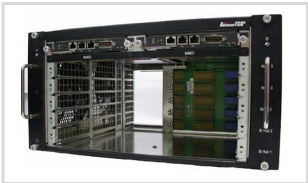
The aTCA-8505 Series is a 5U AdvancedTCA $^{®}$ rackmount system with five slots that support AdvancedTCA $^{®}$ modules and two slots that support two shelf management modules. Equipped with a 5-slot full mesh topology fabric interface and standard rear transition module (RTM) slots, the aTCA-8505 Series comes with dual, hot-swappable fan trays and dual -48 V DC power entry modules capable of filtering and monitoring up to 1200 watts of power.

Providing robust control, monitoring, and management of the aTCA-8505 Series is the optional aCMM-2000 module, a dual Pigeon Point Systems shelf manager (ShMC) that is designed to work in active or standby mode for efficient redundancy. With dual-IPMB buses and I2C in system buses, the aCMM-2000 can control all installed AdvancedTCA $^{®}$ blades and fan trays based on temperature and other built-in sensor readings.

# 1.1 Features

# General Features

▶ 19" rackmount with 5U height and 15.3" depth
▶ 5-slot full mesh topology fabric interface
▶ 5-slot standard rear transition module (RTM)
▶ Dual-IPMB bus
▶ Two I2C-controlled hot-swappable fan trays
▶ Two shelf manager slots for PPS-based ShMC
▶ Two power entry modules with -48 V DC

# Ordering Information

# aTCA-8505:

5U 5-slot Rackmount AdvancedTCA $^{®}$ system

![Front view of an IBM TCP rack unit with multiple BIMCs and internal circuitry (no visible text or labels)](.atca-8505-manual-24/503ddf856d4f7390078abd9d94176cb8d5b7b4f16e60d9486b21851707a20911.jpg)

# aTCA-8505A:

5U 5-slot Rackmount AdvancedTCA $^{®}$ system with single aCMM-2000 shelf management module

![Front view of an IBM TCP rack with internal network equipment and drive bays (no visible text or labels)](.atca-8505-manual-24/003725f917ff7b7ea82281bee8de2169036f9ff09383bae97185c804f30125d0.jpg)

# aTCA-8505AA:

5U 5-slot Rackmount AdvancedTCA $^{®}$ system with two aCMM-2000 shelf management modules

![Front view of an IBM/TCB rack unit with multiple Ethernet ports and internal storage racks (no visible text or labels)](.atca-8505-manual-24/f9d1c36cf3e347b397fd601b117636ee33b1ee19f6b9848738c21f3cb47d7297.jpg)

# 1.2 Specifications

<table><tr><td>Form Factor</td><td>19&quot; rackmount, 5U height, 15.3&quot; depthFits inside a 600 mm-deep cabinet</td></tr><tr><td>Specification</td><td>Supports up to five standard AdvancedTCA® blades and RTMsSupports up to two shelf management modules</td></tr><tr><td>Shelf Management (available only on selected models)</td><td>Active/Standby mode for high availabilitySupports multiple management interfaces including:Remote Management Control Protocol (RMCP)Remote Procedure Call (RPC)Simple Network Management Protocol (SNMP)Command Line Interface (CLI)Web-Base InterfaceDual-10/100BASE-T Fast Ethernet ports and one serial console for management access</td></tr><tr><td>Cooling System</td><td>Two hot-swappable I2C controlled fan traysRight to left transverse airflowReusable and replaceable air filter</td></tr><tr><td>Backplane</td><td>Dual-star topology base interfaceFull mesh topology fabric interfaceUpdated channels for active/standby synchronizationDual-IPMB bus</td></tr><tr><td>Power Filter</td><td>Dual -48 V DC power entry modules with redundancyTwo fan trays with microswitch LED indicators</td></tr><tr><td>Weight (barebone)</td><td>8 kg (17.6 lb.)</td></tr><tr><td>Temperature</td><td>Operating: 0°C to 50°C (depending on configuration)Storage: -20°C to 80°C</td></tr><tr><td>Humidity</td><td>5% to 95%, non-condensing</td></tr><tr><td>Dimensions</td><td>19&quot; x 5U x 15.3&quot; (W x H x D)</td></tr><tr><td>Compliance</td><td>AdvancedTCA® Specification PICMG® 3.0 R2.0</td></tr><tr><td>Certifications</td><td>CE, FCC, designed for NEBS Level 3</td></tr></table>

NOTE: Specifications are subject to change without notice.

# 1.3 Package Contents

Before unpacking, check the shipping carton for any damage. If the shipping carton and/or contents are damaged, inform your dealer immediately. Retain the shipping carton and packing materials for inspection. Obtain authorization from the dealer before returning any product to ADLINK.

The following contents are included in the shipping carton:

▶ aTCA-8505 Series subsystem
▶ One/Two aCMM-2000 shelf management modules (for aTCA-8505A and aTCA-8505AA models only)
▶ Accessory package
▷ Air Filter
Rackmount Handles
▷ Retention Screws
▶ User's Manual

# NOTE:

aTCA-8505 Series subsystems DO NOT include front or rear slot filler panels. Front and rear slot filler panels are commercially available and may be purchased separately.
![Front view of a rack-mounted server chassis with multiple Ethernet ports and internal circuit boards (no visible text or labels)](.atca-8505-manual-24/b3db1d6f9e8ebce10077fc513c0c205d13a41734f801134336d78688a1e86f8b.jpg)

This page intentionally left blank.

# 2 Hardware Information

This chapter provides information on the physical features, dimensions, and pre-installed hardware components of aTCA-8505 Series subsystem.

# 2.1 Physical Features

# NOTE:

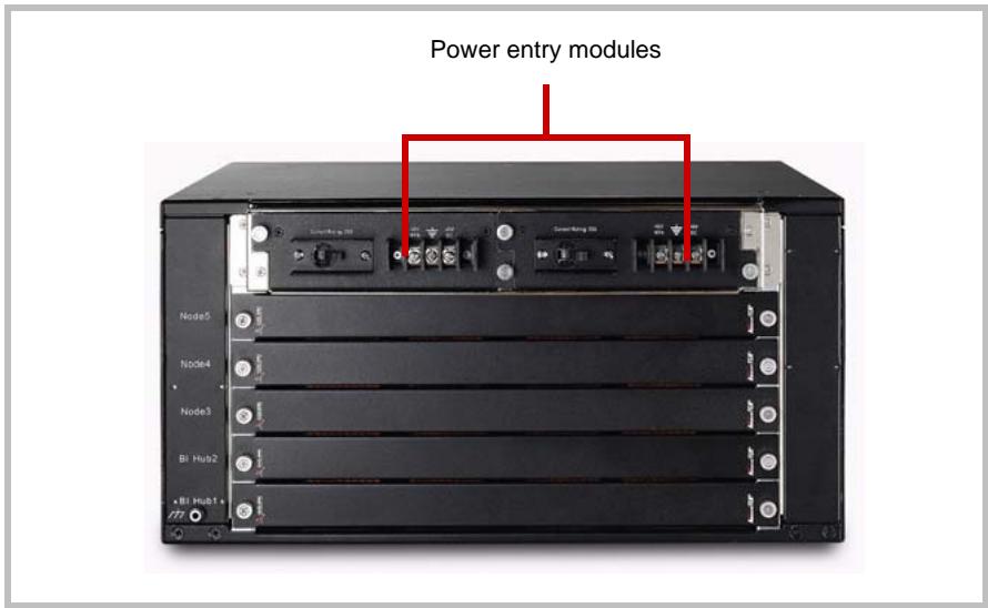
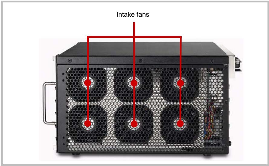
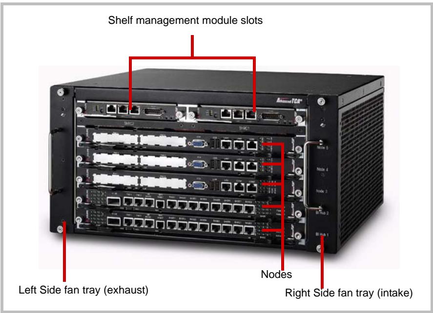
The following illustrations show a fully-configured aTCA-8505 Series chassis and are intended only for reference. The figures may not represent the actual chassis.
![Shelf management module slots\nLeft Side fan tray (exhaust)\nNodes\nRight Side fan tray (intake)](.atca-8505-manual-24/7e72dd8125ac9032eb8dd5b139b6735e9e65738c6ae266a8062900fc15e2c7b4.jpg)

Figure 2-1: Front Panel

![Power entry modules\nNode5\nNode4\nNode3\nBi Hub2\nxBi Hub1 x](.atca-8505-manual-24/40ddce99ed29d7b945b2e42ccc04f7387a2e9d095a3991cb6177c2b07f35b55c.jpg)

Figure 2-2: Rear Panel

![Intake fans](.atca-8505-manual-24/7677ccf5692b0e6ea0aa12927b917e2fdcdb4b7bb106f59aef28ded70be35747.jpg)

Figure 2-3: Right Side View

# 2.2 Mechanical Layout and Dimensions

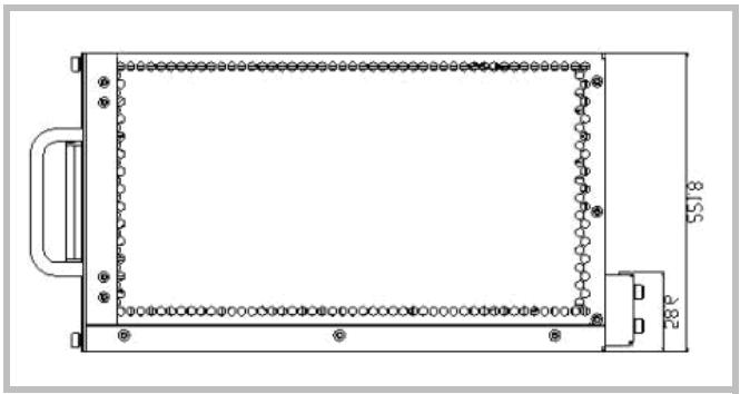
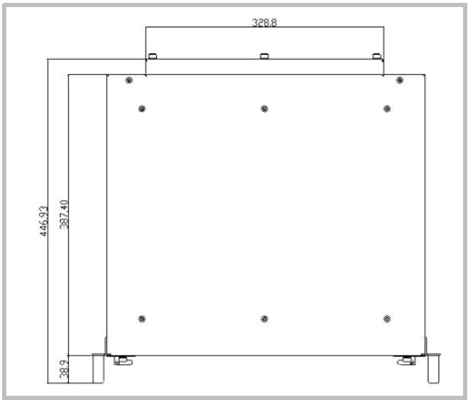
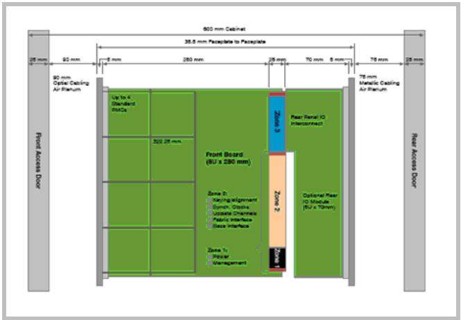
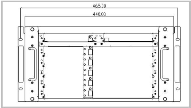
The following illustrations show the mechanical layout and dimensions of aTCA-8505 Series subsystem chassis.
![465.00\n440.00](.atca-8505-manual-24/5d05f2ec10d35c5998b3061a9e199dbd47fe59ca88552d1b1906433e895267fb.jpg)

Figure 2-4: Front Panel Dimensions

![Technical line drawing of a rectangular mechanical or electronic component with mounting holes and a side panel (no text or symbols)](.atca-8505-manual-24/3bad5262eb4e97cf77a3fef5d2544b8c5f728ef4c85b268cd50a21b69d5fe339.jpg)

Figure 2-5: Side Dimensions

![328.8\n446.93\n387.40\n38.9](.atca-8505-manual-24/94e63f2ef857fa921f091448d1e1e304c94ee9b40dd39abf973ccb868d980d59.jpg)

Figure 2-6: Top Dimensions

![600 mm Cabinet\n35.5 mm Pascplate to Pascplate\n25 mm 90 mm 250 mm 75 mm 78 mm\n90 mm Optic Casing Air Planum\nUp to 4 Standard Pitche\nFront Access Door\n300-25 mm\nFront Board (BU x 280 mm)\nZone 2: Mapping alignment\nGymth Chroma\nUssate Channels\nFabric Interface\nBase Interface\nZone 1: Power Management\nZone 2: Rear Renal IO Interconnect\nOptional Rear IO Module (BU x 70mm)\n75 mm Metallic Casing Air Planum\nRear Access Door](.atca-8505-manual-24/ad08fb0417426e95864af0ce218ea567ecb18c1e9bbd9dc05c5881ca7dd0eca7.jpg)

Figure 2-7: aTCA-8505 Series Installed in a Rack

# 2.3 Backplane and Bridge Board

# Backplane

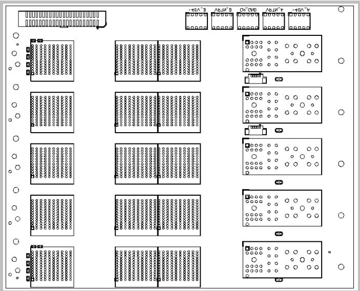
The aTCA-8505 Series subsystem comes with the cBP-5050 backplane featuring five AdvancedTCA $^{®}$ slots that support rear I/O functionality.

# Features

▶ Dual-star topology base interface
▶ Full mesh topology fabric interface
▶ Updated channels for active/standby synchronization
▶ Dual-IPMB bus

# Specifications

▶ AdvancedTCA®-compliant
▶ PICMG $^{®}$ 2.0 Advanced TCA $^{®}$ core specification R3.0
▶ PICMG $^{®}$ 2.1 Advanced TCA $^{®}$ hotswap R2.0
▶ PICMG $^{®}$ 2.5 Advanced TCA $^{®}$ Computer Telephony R1.0

# Layout
![-t0A^B\nAbJW^B\nCH^-CW0\nAbJW^C\n-t0A^C\nABJW^C\nCH^-CW0\nAbJW^C\n- t0A^C](.atca-8505-manual-24/24d2aae3413d1aab7d8f5db2ce27c35baad8a5cdf1736ad961dbda9b86fcf352.jpg)

Figure 2-8: cBP-5050 Backplane Layout

Dimensions
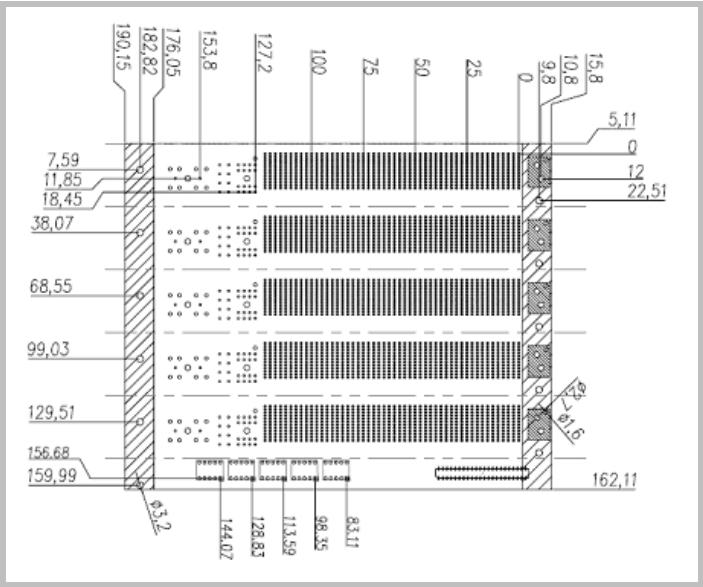
![| Section | Value |\n| ------- | ----- |\n| Top Section | 190.15 |\n| Middle Section | 182.82 |\n| Bottom Section | 176.05 |\n| Vertical Section | 153.8 |\n| Horizontal Section | 127.2 |\n| Vertical Section | 100 |\n| Horizontal Section | 75 |\n| Vertical Section | 50 |\n| Vertical Section | 25 |\n| Vertical Section | 0 |\n| Vertical Section | 9.8 |\n| Vertical Section | 10.8 |\n| Vertical Section | 15.8 |\n| Vertical Section | 5.11 |\n| Vertical Section | 0 |\n| Vertical Section | 12 |\n| Vertical Section | 22.51 |\n| Vertical Section | 38.07 |\n| Vertical Section | 68.55 |\n| Vertical Section | 99.03 |\n| Vertical Section | 129.51 |\n| Vertical Section | 156.68 |\n| Vertical Section | 159.99 |\n| Vertical Section | 0.32 |\n| Horizontal Section (Bottom) | 144.07 |\n| Horizontal Section (Top) | 128.83 |\n| Horizontal Section (Bottom) | 113.69 |\n| Horizontal Section (Top) | 98.35 |\n| Horizontal Section (Bottom) | 83.11 |\n| Horizontal Section (Top) (Right) | 162.11 |](.atca-8505-manual-24/9180a41ce482b7f6ebd61d1c31ed622220cbe24f966639c4efaa2fa57a148aa8.jpg)

Figure 2-9: cBP-5050 Backplane Dimensions

# Bridge Board

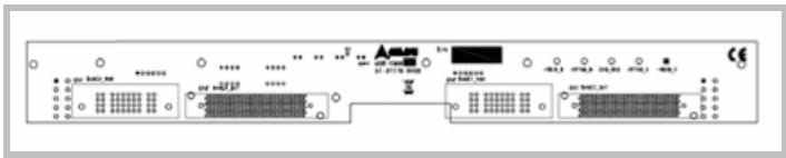
The aDB-1505 bridge board, pre-installed in the aTCA-8505 Series, is designed for aCMM-2000 shelf management modules.
![Front panel of an electronic device showing ports, connectors, and status LEDs with Chinese labels](.atca-8505-manual-24/e4eafdf58f487009c683042328f5c2b6d9c1b1d3005a1c0ce8f964e2a63d3c56.jpg)

Figure 2-10: aDB-1505 Bridge Board Layout

# Fan Boards

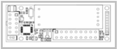
Providing the interface connectors for the fan tray modules are two aDB-1506 fan boards. The fan boards connect the right fan tray module (six fans) for air intake and the left fan tray module (two fans) for exhaust. Refer to section 2.4 for details on the aTCA-8505 Series thermal system.
![Top-down schematic of an electronic circuit board with components and connectors (no text or labels visible)](.atca-8505-manual-24/11298a47b2114d3020a8812660431228613da0b3b907ffe54a7d5f532b9359b8.jpg)

Figure 2-11: aDB-1506 Fan Board Layout

# 2.4 Cooling System

# Fan Trays

The aTCA-8505 Series subsystem chassis is equipped with several fans to provide optimum cooling for AdvancedTCA® peripherals. There are two front-access, hot-swappable fan tray modules located at the left and right of the chassis. The right side intake fan tray module comes with a replaceable air filter.

NOTE: Refer to Chapter 3 for details on removing and replacing fan tray air filter.

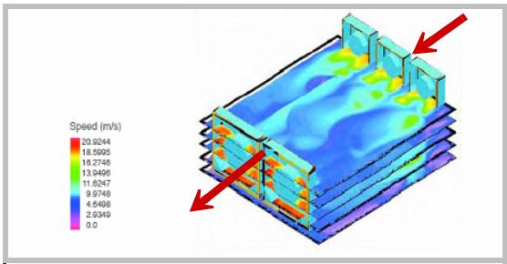
The simulation diagram illustrates airflow information inside the aTCA-8505 Series chassis.
![| Speed (m/s) |\n|-------------|\n| 20.9244     |\n| 18.5905     |\n| 16.2746     |\n| 13.9496     |\n| 11.6247     |\n| 9.9748      |\n| 4.5498      |\n| 2.9349      |](.atca-8505-manual-24/58ab1d05b03d1935601772e872611eaf01c67c9a459835b970482447ddf322b7.jpg)

# Fans

The right side fan tray module houses six Delta FFC0912D-F00 fans, while the left side fan tray module houses two Delta AFb1512EH-4L49 fans.

# Specifications and dimensions

Left-side fans

<table><tr><td>Rated voltage</td><td>12 V DC</td></tr><tr><td>Operating voltage</td><td>7.0 to 13.8 V DC</td></tr><tr><td>Input current</td><td>0.88 A (1.05 A max)</td></tr><tr><td>Input power</td><td>10.56 W (12.60 W max)</td></tr><tr><td>Speed</td><td>5000 rpm (ref.)</td></tr><tr><td>Maximum airflow (at zero static pressure)</td><td>2.832 m $^{3}$ /minute (2.549 m $^{3}$ /minute minimum)100 CFM (90.02 CFM minimum)</td></tr><tr><td>Maximum air pressure (at zero airflow)</td><td>14.40 mmH $_{2}$ O (11.66 mmH $_{2}$ O minimum)0.567 inchH $_{2}$ O (0.459 inchH $_{2}$ O minimum)</td></tr><tr><td>Acoustical noise (average)</td><td>58.0 dBa (62.0 dBA maximum)</td></tr><tr><td>Insulation type</td><td>UL Class A</td></tr></table>

![92.0±0.5\n(3.622±0.020)\n82.5±0.3\n(3.248±0.012)\n92.0±0.5\n(3.622±0.020)\n82.5±0.3\n(3.248±0.012)\nLABLE\n25.4±0.5\n(1.000±0.020)\n4.0±0.3\n(0.157±0.012)\n4.0±0.3\n(0.157±0.012)\n10.0\n(0.394)\n300.0±10.0\n(11.811±0.394)](.atca-8505-manual-24/7b7e14aa23ce8a08e9dab320281a44897fc15f09b393d2007bf0ca128a21a841.jpg)

Figure 2-12: Delta FFC0912D-F00 Fan Dimensions

Right side fans

<table><tr><td>Rated voltage</td><td>12 V DC</td></tr><tr><td>Operating voltage</td><td>10.0 to 13.2 V DC</td></tr><tr><td>Input current (average)</td><td>3.6 A (4.32 A max)</td></tr><tr><td>Input power</td><td>43.2 W (51.84 W max)</td></tr><tr><td>Speed</td><td>4300 rpm (ref.)</td></tr><tr><td>Maximum airflow (at zero static pressure)</td><td>8.230 m $^{3}$ /minute (7.410 m $^{3}$ /minute minimum)290.64 CFM (261.68 CFM minimum)</td></tr><tr><td>Maximum air pressure (at zero airflow)</td><td>20.85 mmH $_{2}$ O (16.89 mmH $_{2}$ O minimum)0.821 inchH $_{2}$ O (0.665 inchH $_{2}$ O minimum)</td></tr><tr><td>Acoustical noise (average)</td><td>61.5 dBa (65.5 dBA maximum)</td></tr><tr><td>Insulation type</td><td>UL Class A</td></tr></table>

![150.0±0.5\n(5.906±0.020)\n8-φ4.3±0.3\n(8-φ0.169±0.012)\nφ172.0±0.5\n(φ6.772±0.020)\n162.0±0.3\n(6.378±0.012)\nLABEL\nUNIT: mm(INCH)\n25.4±0.5\n(1.00 ±0.01)\n7.5\n(0.295)\n7.5\n(0.295)\n10.0\n(0.394)\n10.0\n(0.394)\n320.0±10.0\n(12.598±0.394)](.atca-8505-manual-24/c6af8f51bc03596b7a53f8f30b4fb5daf5c948b5954662105a0d2419d01cfd82.jpg)

Figure 2-13: Delta AFb1512EH-4L49 Fan Dimensions

# Fan Control

By default, the aCMM-2000 controls the fan tray modules at regular speed (Fan Level 8). The aCMM-2000 detects and adjusts the fans' speed based on two temperature sensors located inside the chassis.

<table><tr><td>Criteria</td><td>Fan Level</td></tr><tr><td>Lower than 30°C</td><td>8</td></tr><tr><td>Higher than 30°C</td><td>12</td></tr><tr><td>Higher than 40°C</td><td>15</td></tr></table>

# Thermal Couple

The aTCA-8505 Series integrates two thermal couples located internally on the left and right side of the chassis cabinet. The aCMM-2000 can detect these sensors and automatically adjust fan speed to its proper level.

<table><tr><td>Criteria</td><td>Fan Level</td></tr><tr><td>Lower than 30°C</td><td>8</td></tr><tr><td>Higher than 30°C</td><td>12</td></tr><tr><td>Higher than 40°C</td><td>15</td></tr></table>

The system administrator may use the clia command (e.g. clia fans) to verify the fan level via the aCMM-2000.

# 2.5 Power System

The aTCA-8505 Series comes with two Power Entry Modules (PEMs) that support hotswap operations.

![Power entry modules\nNode5](.atca-8505-manual-24/55ed260e019451c7c0f7448a9c53da6073c04b312cc961deea575abe30f8420d.jpg)

NOTE: Refer to Chapter 3 for details on power connections and information on how to remove and reinstall PEMs.

# 3 Getting Started

This chapter provides information on how to install components to the aTCA-8505 Series subsystem chassis.

# 3.1 Installing ATCA® Boards

The aTCA-8505 Series is designed with five slots that support ATCA $^{®}$ boards, modules, and controllers. ATCA $^{®}$ connectors are rigid and require careful handling and proper installation. ATCA $^{®}$ boards are equipped with locking handles and retention screws for easy installation and removal.

WARNING: Improper installation of ATCA $^{®}$ boards may damage the backplane.

![Front view of a black server rack with multiple Ethernet ports and internal network equipment (no visible text or labels)](.atca-8505-manual-24/e7c64c5953cb14e62554e7772649fc9f9a19427e81217ab589f244ddcf142119.jpg)

Installing an ATCA $^{®}$ controller board:

1. Check if all components are properly installed on the ATCA $^{®}$ controller board including the CPU, heatsink, and memory modules
2. Position the ATCA $^{®}$ board into the slot, then carefully slide its edges into the board guide rail. Make sure that the board is correctly aligned with the chassis to prevent damage to the board and/or backplane.

![Black server rack with internal components and a red arrow pointing to a green circuit board (no visible text or symbols)](.atca-8505-manual-24/00f546a2c120da845d9834c75547b52596ecbfd36790530ed4a05f98a447ba01.jpg)

3. Push the board into the slot until the handles come in contact with the chassis and the metal tacks insert into the chassis holes.
4. Push the handles inward until they 'click' in place.

![Front view of a black server rack with multiple ports and connectors, showing internal components and red arrows pointing to ports (no visible text or labels)](.atca-8505-manual-24/08a5c776cfbd488757620c37a6aadec904e5e307ccd2691e0ae822f7332b8a7e.jpg)

5. Fasten the retention screws (turning in a clock-wise direction) on both sides of the board to secure it in place.

![Front view of a black server rack with multiple ports and connectors, showing internal hardware and mounting points (no visible text or labels)](.atca-8505-manual-24/7c721b2664d1affc856656496b74be2d36cae34186d4593f2c40e9a3286568b3.jpg)

NOTE: To remove and replace an ATCA $^{®}$ board, refer to section 4.1.

# 3.2 Installing Rear Transition Modules (RTMs)

Because RTMs are shorter than front boards, pay close attention when inserting or removing RTMs.

NOTE: Only models with an "R" at the end of the model number support RTMs.

1. Face the rear of the aTCA-8505 Series subsystem chassis to access the RTM slots.
2. Position the RTM into the slot, then carefully slide its edges along the slot guide rail. Make sure that the module is correctly aligned with the chassis to prevent damage to the module and/or backplane.

![Close-up of hands installing a CD-ROM drive into a server rack (no visible text or labels)](.atca-8505-manual-24/f3dfe0a41532e0e4e91bb28dbd29122ad87182e9818081c009fa2d40f714fb89.jpg)

3. Push the module into the slot until the handles come in contact with the chassis and the metal tacks insert into the chassis holes.

4. Push the handles inward until they 'click' in place. Fasten the retention screws (turning in a clock-wise direction) on both sides of the board to secure it in place.

![Close-up of hands installing a server rack with a red arrow pointing to the component (no visible text or symbols)](.atca-8505-manual-24/4f2cea87a1fbddfcf273c9f4d5157d6c7b576b925d544fb269163a09cee4536c.jpg)

NOTE: To remove and replace an RTM, refer to section 4.1.

# 3.3 Installing Shelf Management Modules

The aCMM-2000 fits the shelf management module slot in aTCA-8505 Series chassis. The aCMM-2000 module facilitates tool-less installation with built-in retention screws and a locking lever.

# NOTE:

aTCA-8505 DOES NOT come with aCMM-2000 modules. This product has two shelf management module slot covers. To install aCMM-2000 modules, the slot covers must first be removed by locating and turning its retention screws counterclockwise.

aTCA-8505A comes with one aCMM-2000 module installed in ShMC slot 1 and a module slot cover installed in ShMC slot 2.

aTCA-8505AA comes with two aCMM-2000 pre-installed in ShMC slots 1 and 2.

When installing aCMM-2000 module(s) carefully hold the module on its edges and do not force the module into the slot to avoid component damage.

To install an aCMM-2000 module:

1. Locate the shelf management module slot.

![Front view of a black server rack unit with a red circle highlighting a component (no visible text or labels)](.atca-8505-manual-24/f0f0573c3c37c71f77860ca5f0abda774f5c5c22eb6c139b2c0222c93c063604.jpg)

2. Insert the aCMM-2000 module in the slot with the rear end of the module first.

![Close-up of an open black server rack with a green circuit board and a red arrow pointing to it, showing internal components (no text or symbols visible)](.atca-8505-manual-24/a013719baf668f17daf395021f55e2213896deb641e96a0ca510a316db6ff1dc.jpg)

3. Push the module into the slot until the module metal tacks are engaged with the chassis holes.

![Metal tacks](.atca-8505-manual-24/284f85aa352c389d4934d7a273faa226755c91566141269d3784e216fe0f688d.jpg)

4. Push the locking lever inward to set the module in place.

![Hand inserting a device into a rack-mounted server unit (no visible text or symbols)](.atca-8505-manual-24/4a781ead4dc5878e8a86a3a5cc379a22d8b19b935ba344dd00bec26854ac4037.jpg)

5. Turn the retention screws in a clockwise direction to tighten and secure the module.

![Close-up of a hand inserting a USB into a server rack, with red circles highlighting the ports (no text or symbols visible)](.atca-8505-manual-24/65338c8732ad33fbc668f41b8eca4487a5ae12d1311bdc2250276de1a973ab01.jpg)

The aCMM-2000 powers up instantly and the ACT LED lights up green. When two aCMM-2000 modules are installed, the ACT LED of the backup module blinks.

NOTE: To remove and replace an RTM, refer to section 4.2.

# 3.4 Powering Up the System

After installing all necessary components, connecting cables, and peripherals, you are now ready to power up the system. The aTCA-8505 Series comes with two power entry modules (PEMs) that connect to the ADLINK aPRS-1120 (AC-DC Power Converter Equipment).

NOTE: The ADLINK aPRS-1120 (AC-DC Power Converter Equipment) is purchased separately.

The ADLINK aPRS-1120 accessory package includes two color-coded, one-meter length terminal wires. You will use these to connect the PEMs to the power converter.

WARNING: Before connecting the PEMs to the power converter, make sure that the PEMs are properly installed in the chassis and the PEM switches are turned off.

To connect the aTCA-8505 Series PEM to the power converter:

1. Loosen the aPRS-1120 DC OUT +V and -V terminal screws.

![J4 +V -V GND J3 J2 J1\nDC OUT AC IN BACK VIEW](.atca-8505-manual-24/a19b334a7ba9ab3e9a8e4a49adf0d5dacad69d442248673385d25decb7dd2106.jpg)

2. Connect the red wire to the +V terminal and the black wire to the -V terminal.

3. Connect the other end of the red wire to the -48 V RTN terminal of the PEM, then connect the other end of the black wire to the -48 V DC terminal of the PEM. Refer to the following illustration.

![J4 +V -V GND J3 J2 J1\nDC OUT AC IN\nBACK VIEW\nNode5](.atca-8505-manual-24/57b8eeb713a5b9c064d824cb725499682bf0a8e6f1957907562fc70645427976.jpg)

When using dual-PEMs, use two sets of red and black wires to connect the power converter to the PEMs. Refer to the illustration below:

![J4 +V\nDC OUT\nGND\nJ3 J2 J1\nAC IN\nBACK VIEW](.atca-8505-manual-24/9f79eec52e79a069ffb9c2e8802cc7aa17aa2630ebfa900c3c2b2cf1b48dba9b.jpg)

4. Check the aPRS-1120 configuration. If the power converter comes in default configuration (single 1200 W power supply unit), connect the AC power cord to the J2 connector.
5. Connect the other end of the AC power cord to a wall socket or power strip, then turn on the PEM switch(es) and all required peripherals.

NOTE: To remove and replace a power entry module, refer to section 4.3.

# 3.5 Managing the Chassis

# aCMM-2000 Shelf Management Module

The aTCA-8505A/aTCA-8505AA come with one/two aCMM-2000 shelf management module(s). The aTCA-8505AA is capable of providing redundant chassis management function.

NOTE: Without an installed aCMM-2000 module, all fans on both left and right fan tray modules rotate at full speed (Level 15).

To access fan, temperature, ATCA $^{®}$ board FRU (field replaceable unit), and power information, the installed aCMM-2000 must be connected to a host computer:

▶ serially using an RJ-45 to DB9 cable (bundled in the aCMM-2000 package),
▶ over a LAN using a standard RJ-45 cable, or
▶ network switch or hub.

Refer to the following sections for more information.

# Serial Connection

You may use the bundled RJ-45 to DB9 cable to connect the chassis serially to the host computer. Refer to the illustration below.

![Host computer\nRJ-45 to DB9 cable\naCMM-2000 module](.atca-8505-manual-24/f698da136aaf2297f9141e2677956a05b54cc748cf2937f298f49cc5a75ef268.jpg)

The aCMM-2000 COM port is set with the following parameters:

<table><tr><td>Type</td><td>RS232 (COM)</td></tr><tr><td>Baud Rate</td><td>115200bps</td></tr><tr><td>Data Bits</td><td>8</td></tr><tr><td>Parity</td><td>None</td></tr><tr><td>Stop Bits</td><td>1</td></tr><tr><td>Flow Control</td><td>None</td></tr></table>

# LAN Connection

With Fast Ethernet bandwidth, you may connect the aCMM-2000 directly to a notebook or PC using an RJ-45 cable or to a network switch or router for high-speed remote management. Refer to the following illustrations.

![Host computer\nRJ-45 cable\naCMM-2000 module](.atca-8505-manual-24/8d65cf2712fc603242571e5d8ad61ab15e6e082a705dd2d6bf7aaf481d0814b0.jpg)

![Host computer\nSwitch/Hub\nRJ-45 cable](.atca-8505-manual-24/4ca803898cf840a69e583403281ccb9d62cdc4225219354ccd3a07fa7bd29be2.jpg)

By default, the LAN1 port has the following settings:

<table><tr><td>IP</td><td>172.16.13.201</td></tr><tr><td>Login name</td><td>root</td></tr><tr><td>Password</td><td>None</td></tr></table>

# Thermal Couple

The aTCA-8505 Series comes with two thermal couples installed on the internal left and right sides of the chassis. The aCMM-2000 automatically detects these sensors and dynamically adjusts the fans' speed depending on the chassis temperature.

<table><tr><td>Chassis Temperature</td><td>Fan Level</td></tr><tr><td>Lower than 30°C</td><td>8</td></tr><tr><td>Higher than 30°C</td><td>12</td></tr><tr><td>Higher than 40°C</td><td>15</td></tr></table>

System administrator may use the clia command (e.g. clia fans) to verify the fan speeds detected and adjusted by the aCMM-2000 module. The location of the aTCA-8505 Series thermal couple sensors is shown here.

![Front view of a server rack with multiple Ethernet ports and two circled ports, no visible text or labels](.atca-8505-manual-24/1e76fb725637a8abfd5fb5abf17c838d401c7505b3a3495a5381b8b5afae04ff.jpg)

# 4 Chassis Maintenance

This chapter provides information on how to remove and replace defective components to keep the aTCA-8505 Series in best working condition.

WARNING: Turn off the aTCA-8505 Series power entry module before removing or replacing any component(s). Failure to do so may result in electrical shock and/or component damage.

# 4.1 Removing ATCA $^{®}$ Boards and RTMs

This section describes how to remove ATCA $^{®}$ boards and RTMs from the aTCA-8505 Series.

To remove an ATCA $^{®}$ board or RTM module:

1. Loosen the retention screws on both sides of the board/module.
2. Unlatch the ATCA $^{®}$ board/RTM handles by pulling them outward until the board/RTM disengages from the chassis.

![Front view of a black server rack with multiple ports and connectors, showing red arrows pointing to ports (no visible text or labels)](.atca-8505-manual-24/be01c83f70ad1a0ea4e8b31bc28d216b880b1aded26b1201ee763278c14b6c6d.jpg)

3. Carefully pull the board/RTM out from the chassis, then store in a safe place.

![Black server rack with internal components and a red arrow pointing to a green circuit board (no visible text or symbols)](.atca-8505-manual-24/04164344b75adc5a8cfcf47262962892fdccccb8f988e896d47efc3251b421d9.jpg)

4. Install a front slot filler panel (not included, commercially available) if necessary.

![Black server rack with multiple ports and a red arrow pointing to a portion of the rack (no visible text or labels)](.atca-8505-manual-24/ffd2de9f9d98a965a28f2bc018787d87df9fd3b6965b344f96bfbfd2961df2e5.jpg)

NOTE: To install an ATCA $^{®}$ board, refer to section 3.1. To install an RTM, refer to section 3.2.

# 4.2 Removing Shelf Management Modules

To remove the aCMM-2000:

1. Loosen the retention screws located on both sides of the module.

![Close-up of a server rack with a hand holding a cable connector, showing internal components and mounting hardware (no text or symbols visible)](.atca-8505-manual-24/c4ea11dc767993a08a344dabfeb1cd087164cc3663d2fb2fd64701f0e75d2bc8.jpg)

2. Pull the module locking lever outward until the card disengages from the chassis.
3. Pull the module out from the slot, then store in a safe place.

![Close-up of a server rack with an open circuit board and two red arrows pointing to components (no visible text or symbols)](.atca-8505-manual-24/5af14138007b84abc433ca0aa905b062f42cd10d5284f8aca0d231177c477f24.jpg)

NOTE: To install a shelf management module, refer to section 3.3.

# 4.3 Removing and Replacing a Power Entry Module

This section provides information on how to remove and replace a defective power entry module (PEM).

WARNING: Turn off the power entry module(s) and the power converter before removing or replacing. Failure to do so may result in electrical shock or damage to equipment.

To remove a PEM:

1. Turn off the power entry module switch and the power converter.

![Current Rating: 25A\n-80V\nRTN](.atca-8505-manual-24/753454eab5cc3d98264cf921ceefb06afaf4c34c42532067ad972142a9758ccd.jpg)

2. Disconnect the wires from the -48 V DC and -48 V RTN terminals. Refer to section 3.4.
3. Loosen the retention screws on both sides of the module.

![Front view of a black server rack unit with multiple ports and a green circuit board (no visible text or labels)](.atca-8505-manual-24/59a83e799af8b2fc647501234ddbebcfd771a17b58efe2d5c4f67ef8211ba563.jpg)

4. Pull the module carefully out from the chassis, then store in a safe place..

![Front view of a black server rack unit with labeled ports and a red arrow pointing to a component (no readable text or symbols beyond labels)](.atca-8505-manual-24/227de47317e5444d5ccf66c7f112320037ca3d8d947066a85d138cce18453da2.jpg)

# To replace a PEM:

1. Position the module on the PEM slot.
2. Insert the PEM into the slot along the guide rails, then push until it is completely flush with the slot opening.

![Front view of a black server rack with multiple ports and a red arrow pointing to a central component (no visible text or symbols)](.atca-8505-manual-24/17b86858504e76908f7fcb9ebd694dc21ece6cadc1d4393e0f53d2686919f9fb.jpg)

3. Tighten the retention screws on both sides of the module to secure it in place.

![Front view of a black server rack unit with multiple ports and a green internal circuit board (no visible text or labels)](.atca-8505-manual-24/9a594fadc517f16f97ad24f1270668f20ce09a9ca97874deb19f9a3d4bfdac88.jpg)

4. Connect the PEM to the power converter. Refer to section 3.4.

# 4.4 Removing and Replacing Chassis Fan Trays

This section provides information on how to remove and replace chassis fan trays which can be accessed from the chassis front panel. The fan trays are hot-swappable and may be replaced while the chassis is operating.

NOTE: To replace individual fan modules, contact ADLINK or your local distributor.

To remove the right-side intake or the left-side exhaust fan tray:

1. Loosen the retention screws on the top and bottom of the fan tray handles. The hotswap LED on the tray bezel lights up blue to indicate that the fan tray(s) is being replaced.

![Hotswap LED](.atca-8505-manual-24/d9df3a08c0e0aab3ee657e3fd97b1d9d7de14304662a51571e1bad55ecb1b3a5.jpg)

WARNING: Wait at least five seconds or until all fans stop rotating before removing fan trays to avoid injury.

2. Pull the tray handle until the fan tray disengages from the fan board and the chassis.

![Front view of a black server rack with multiple ports and an open drive door, showing internal components and a red arrow pointing to the door (no text or symbols visible)](.atca-8505-manual-24/5e6607478e6fcf2458b7639017e91348dd745a3fd170c3bcef14ca0688aa6686.jpg)

![Front view of a black server rack unit with ports and connectors, showing internal components and a red arrow indicating a specific portion (no text or symbols visible)](.atca-8505-manual-24/440b5148042fc0249e00cc266a81fda7b0d567b56ee29536bad147d1f7dbd3b7.jpg)

3. Store fan tray in a safe place.

Replacing the right-side intake and left-side exhaust fan trays:

1. Line up the module at the fan tray opening. Insert the fan tray module and push it in until it is completely flush to the slot opening and connects to the fan board. The fan tray module hotswap LED will light up blue to confirm proper installation.

![Front view of a black server rack with multiple ports and an open door, showing internal components and a red arrow pointing to a component (no text or symbols visible)](.atca-8505-manual-24/009998f7a4a254c7ea584d4d4b8a86580f98cd1b51cd665aaee7eb649848b862.jpg)

![Front view of a black server rack unit with ports and ventilation slots, showing internal components and a red arrow pointing to a cable outlet (no text or symbols visible)](.atca-8505-manual-24/deb4bac0f48a6d8c80d8c9744752f81fc329b2cc08a7eca9410f21ff1ed52e39.jpg)

2. Tighten the retention screws on the top and bottom of the fan tray handles to secure the module(s).

![Hotswap LED](.atca-8505-manual-24/f371609c42e4f2ca3daefde08e998ed79b8fea72799f220bc474f271f30b5d05.jpg)

3. The hotswap LED turns off and the fans start to rotate.

# 4.5 Removing and Replacing the Air Filter

The right-side intake fan tray comes with a reusable and replaceable air filter to keep dust and moisture from entering the chassis.

The air filter must be cleaned or replaced regularly.

To remove and replace the air filter:

1. Remove the right-side fan tray module following the instructions from section 4.4.
2. Slowly pull up the air filter screen.

![Close-up of a black server rack with three fans and a red arrow pointing to a grid pattern (no text or symbols visible)](.atca-8505-manual-24/4ba6e9bc55827f1778a5e6b7f5872b46e39b090fba8e2878f5f8cfad191b469d.jpg)

3. Detach the air filter mat from the screen, then clean/replace it.

![Scanned document with Chinese text, likely a formal notice or official form, held by a hand.](.atca-8505-manual-24/bc9bf89d4511ea4a75e6015c8ba2489e70aeed6e78bb8120f8cb42896c2e7b00.jpg)

4. Attach the cleaned/new air filter to the screen, then re-install it to the fan tray module.

![Close-up of a black CPU fan base with three fans and a red arrow pointing to a grid pattern (no text or symbols visible)](.atca-8505-manual-24/a7e51eb926b3d74677514744bee9b4e80d540ae0fda3d824abb6cc05b10087b2.jpg)

5. Replace the fan tray module following the steps in section 4.4.

# Important Safety Instructions

Read and follow all instructions marked on the product and in the documentation before operating the system. Retain all safety and operating instructions for future use.

▶ Read these safety instructions carefully.
- Keep this user’s manual for future reference.
The equipment should be operated in an ambient temperature between $0^{\circ}$ C to $50^{\circ}$ C.
The equipment should be operated only from the type of power source indicated on the rating label. Make sure the voltage of the power source is correct when connecting the equipment to the power outlet.
▶ If the equipment has a voltage selector switch, make sure that the switch is set to the proper position for the area. The voltage selector switch is set at the factory to the correct voltage.
▶ For pluggable equipment, ensure they are installed near a socket-outlet that is easily accessible.
- Secure the power cord to prevent unnecessary accidents. Do not place anything over the power cord.
▶ If the equipment will not be in use for long periods of time, disconnect the equipment from the power outlet to avoid being damaged by transient overvoltage.
▶ All cautions and warnings on the equipment must be noted.
▶ Keep this equipment away from humidity.
▶ Do not use this equipment near water or a heat source.
▶ Place this equipment on a stable surface when installing to prevent injury.
▶ Never pour any liquid into the product to prevent fire or electrical shock.

▶ Openings in the chassis are provided for ventilation. Do not block or cover these openings. Make sure there is adequate space around the system for ventilation when setting up the work area. Never insert objects of any kind into the ventilation holes.
▶ To avoid electrical shock, always unplug all power and modem cables from wall outlets before removing the system covers.
▶ A Lithium-type battery is provided for the real time clock.

“CAUTION - Risk of explosion if battery is replaced by an incorrect type. Dispose used batteries as instructed.”

▶ The equipment must be serviced by authorized technicians when:

▷ The power cord or plug is damaged.
▷ Liquid has penetrated the equipment.
▷ It has been exposed to moisture.
$\triangleright$ It is not functioning or does not function according to the user's manual.
▷ It has been dropped and damaged.
▷ It has an obvious sign of breakage.

▶ Never attempt to fix the equipment. For safety reasons, the equipment should only be serviced by qualified personnel.

# Warranty Policy

Thank you for choosing ADLINK. To understand your rights and enjoy all the after-sales services we offer, please read the following carefully.

1. Before using ADLINK's products please read the user manual and follow the instructions exactly. When sending in damaged products for repair, please attach an RMA application form which can be downloaded from: http://rma.adlinktech.com/policy/

2. All ADLINK products come with a limited two-year guarantee, one year for products bought in China:

The warranty period starts on the day the product is shipped from ADLINK's factory.
▶ Peripherals and third-party products not manufactured by ADLINK will be covered by the original manufacturers' warranty.
For products containing storage devices (hard drives, flash cards, etc.), please back up your data before sending them for repair. ADLINK is not responsible for loss of data.
▶ Please ensure the use of properly licensed software with our systems. ADLINK does not condone the use of pirated software and will not service systems using such software. ADLINK will not be held legally responsible for products shipped with unlicensed software installed by the user.
For general repairs, please do not include peripheral accessories. If peripherals need to be included, be certain to specify which items you sent on the RMA Request & Confirmation Form. ADLINK is not responsible for items not listed on the RMA Request & Confirmation Form.

3. Our repair service is not covered by ADLINK's guarantee in the following situations:

▶ Damage caused by not following instructions in the User's Manual.
▶ Damage caused by carelessness on the user's part during product transportation.
▶ Damage caused by fire, earthquakes, floods, lightening, pollution, other acts of God, and/or incorrect usage of voltage transformers.
▶ Damage caused by unsuitable storage environments (i.e. high temperatures, high humidity, or volatile chemicals).
▶ Damage caused by leakage of battery fluid during or after change of batteries by customer/user.
▶ Damage from improper repair by unauthorized ADLINK technicians.
▶ Products with altered and/or damaged serial numbers are not entitled to our service.
▶ This warranty is not transferable or extendible.
▶ Other categories not protected under our warranty.

4. Customers are responsible for shipping costs to transport damaged products to ADLINK.

If you have any further questions, please E-mail our FAE staff: service@adlinktech.com.
[🔗 Link to the original document](.atca-8505-manual-24/atca-8505-manual-24.pdf)