# aTCA-9700

# Dual Intel Xeon E5-2658/2680 v2 40G AdvancedTCA Processor Blade

# User’s Manual

![Top-down view of a computer motherboard with visible CPU socket, RAM slots, and drive bays (no text or symbols)](.atca-9700-50-1g028-1010-201-en/73cf90a09a2ec853240ff3cf19b23039ff5c5f1f7400550038a10cdfd84510be.jpg)

Manual Revision: 2.01

Revision Date: March 13, 2014

Part No.: 50-1G028-1010

# Revision History

<table><tr><td>Revision</td><td>Release Date</td><td>Description of Change(s)</td></tr><tr><td>2.00</td><td>30/10/2013</td><td>Initial release</td></tr><tr><td>2.01</td><td>13/03/2014</td><td>Correct block diagram</td></tr></table>

# Copyright 2013-14 ADLINK Technology, Inc. All Rights Reserved.

The information in this document is subject to change without prior notice in order to improve reliability, design, and function and does not represent a commitment on the part of the manufacturer.

In no event will the manufacturer be liable for direct, indirect, special, incidental, or consequential damages arising out of the use or inability to use the product or documentation, even if advised of the possibility of such damages.

This document contains proprietary information protected by copyright. All rights are reserved. No part of this manual may be reproduced by any mechanical, electronic, or other means in any form without prior written permission of the manufacturer.

Trademarks

Product names mentioned herein are used for identification purposes only and may be trademarks and/or registered trademarks of their respective companies.

# Table of Contents

# Revision History .....

# 1 Overview .... .5

1.1 Introduction .. ..5
1.2 Block Diagram. ..6
1.3 Package Contents..

# 2 Specifications ................... ..8

2.1 aTCA-9700 Specifications.. ..8

2.1.1 CPU/ Chipset/ Memory..... 8
2.1.2 Standard and Interface . . 8
2.1.3 Software.. 9
2.1.4 Mechanical & Environmental . 9

2.2 Power Consumption.. ..10

2.3 Board Layout.. . 11

2.3.1 aTCA-9700 Board Layout ................ .....11
2.3.2 aTCA-9700 Front Panel.. . 12
2.3.3 Status LED Definitions ..... .. 13

2.4 Compliance .. ..16

# 3 Functional Description......... ....17

3.1 CPU, Memory and Chipset . ..17

3.1.1 CPU .... .. 17
3.1.2 Memory.... .. 18
3.1.3 Intel® C604 PCH Overview.. .. 18
3.1.4 Silicon Motion SM750 Graphics Controller............. .... 19

3.2 Peripherals... .19

3.2.1 Reset .... .. 19
3.2.2 SMBus Devices . .. 20

3.3 I/O Interfaces .21

3.3.1 USB . .. 21
3.3.2 VGA Interface ..... .. 22
3.3.3 Ethernet Connection. . 22
3.3.4 Serial Port .. .. 23
3.3.5 Onboard SATA Interface. .. 23
3.3.6 Switch And Jumper Settings.. .. 24

# 4 Intelligent Platform Management System.. .25

4.1 IPMI Sensors .. .25

4.1.1 Sensor Reading (FRU Hotswap Sensor)... .. 27
4.1.2 Get Sensor Reading (Physical IPMB-0 Sensor).. .. 28
4.1.3 Watchdog Timer Sensor .. . 29
4.1.4 Version Change Sensor.. .. 30
4.1.5 System Firmware Progress Sensor... .. 31
4.1.6 Get Sensor Reading Command . .. 32

4.2 IPMI Commands .. .34

# 5 Getting Started.. ..36

5.1 Safety Requirements . .36
5.2 Installing and Removing the aTCA-9700 . ..37

5.2.1 Installing the Blade ..... . 37
5.2.2 Removing the Blade . .. 41

5.3 Firmware Update Procedure.. ..44

5.3.1 Update Over Serial Interface . .. 44
5.3.2 Update over KCS..... ....... 45
5.3.3 Update over LAN .. .. 46

# 6 BIOS . .47

6.1 Entering the BIOS Setup Screen . ..47

6.1.1 Navigation ................ ........ 47

6.2 Main BIOS Setup Screen. ..48

6.3 Advanced Setup Screen .. ..50

6.3.1 Trusted Computing ................ ..... 51

6.3.2 CPU Configuration................. ..... 52

6.3.3 Runtime Error Logging . .. 55

6.3.4 SATA Configuration................. ..... 56

6.3.5 SAS Configuration ................ ..... 57

6.3.6 USB Configuration. .. 58

6.3.7 W83627UHG SIO Configuration...... .. 59

6.3.8 Serial Port Console Redirection ............... ..... 60

6.3.9 COM1 Console Redirection... .. 61

6.3.10 Network Stack.... .. 63

6.3.11 iSCSI ................. ...... 64

6.3.12 Ethernet Port Configuration.. .. 64

6.4 Chipset Setup Screen .. ..66

6.4.1 IOH Configuration. . 67

6.4.2 PCH Configuration.. .. 70

6.5 Server Mgmt Setup Screen.. ..73

6.5.1 System Event Log. .. 74

6.6 Boot Setup Screen.. ..75

6.7 Security Setup Screen .. ..76

6.8 Save & Exit Setup Screen.. ..77

# 7 Serial Over LAN ... ..79

7.1 Preparation For SOL Connection.. ..79

7.2 Configure The Remote Client.. ..79

7.2.1 Install IPMItool For The Remote Client................ ..... 79

7.3 Configure The Target aTCA-9700.. ..80

7.3.1 BIOS Configuration................ ..... 80

7.3.2 Linux grub Setting. .. 80

7.3.3 Linux System Setting.. .. 81

7.4 Establish SOL Connection .. ..81

# 8 Drivers .... ..83

# Safety Instructions .... ..84

# Getting Service .... ..85

# 1 Overview

# 1.1 Introduction

The ADLINK aTCA-9700 is a high performance AdvancedTCA® (ATCA) processor blade featuring dual 8-core Intel® Xeon® processor E5-2658/2680 V2, Intel® C604 PCH, eightchannel memory up to 128GB of DDR3 memory and 400W power supply subsystem. Versatile connectivity includes four 40GbE Fabric Interfaces, dual GbE Base Interfaces, dual front panel GbE egress ports, front panel dual COM and USB 2.0 ports and front panel VGA connector. An onboard SATA connector supports a disk on module (DOM) up to 128GB and the optional RTM (aTCA-R9700) supports six 10GbE SFP+ ports and one hot-swappable SAS bay providing additional network throughput and storage capacities.

The aTCA-9700's thermal solution (including VRM heat sink) ensures stable operation under extreme operating environments and allows for compliance to the NEBS Level 3 standard (design only). The robust computing power and reliability of the aTCA-9700 meets the requirements of telecom equipment manufacturers (TEMs) and network equipment providers (NEPs), allowing them to build the next-generation telecom networks and communication infrastructures.

Detailed features are outlined below and a functional block diagram is shown in the next section.

Two eight-core Intel® Xeon® processor E5-2658/2680 V2
Server-class Intel® C604 PCH
 DDR3-1866 JEDEC standard VLP RDIMM (REG/ECC), up to 128 GB
 Onboard bootable 16GB SATA interface disk on module (max. 128GB)
One Intel® I350 AM2 dual-port PCI Express Gigabit Ethernet controller
 One Intel® 82576EB dual-port PCI Express Gigabit Ethernet controller
Optional three Intel® 82599ES 10Gigabit Ethernet Controllers (6 SFP+ ports) on RTM (aTCA-R9700)
Optional SAS 3G interface drive bay on RTM (aTCA-R9700)
PICMG 3.1 Option 9-KR four Fabric Interface channels supporting dual-dual star
Failover system BIOS
 Analog VGA output up to 1920x1440 resolution

# 1.2 Block Diagram

![**Labeled Blocks:**\n*   **Memory:** 'DDR3 1866 RDIMM' (8 blocks total).\n*   **Processors:** 'Intel® Xeon® E5-2600 v2 10-core/20T CPU' (2 blocks).\n*   **Network/IO Controllers:** 'Intel I350AM2', 'Intel® Communications Chipset 8920' (2 blocks), 'Mellanox® ConnectX-3' (2 blocks), 'Intel 82576EB', 'Intel C604 PCH', 'SM750 Graphics Controller', 'Super I/O', 'IPMC Smart Fusion A2F500'.\n*   **Storage/Boot:** 'SATADOM', 'BIOS' (2 blocks), 'TPM'.\n*   **Interfaces/Zones:** 'FRONT PANEL', 'ZONE 3', 'ZONE 2', 'ZONE 1'.\n*   **Connectors:** 'RJ-45', 'USB', 'Mini USB', 'VGA', 'Front USB', 'Front mini-USB'.\n\n**Connections:**\n*   **CPU & Memory:** Each 'Intel® Xeon® E5-2600 v2' CPU connects to four 'DDR3 1866 RDIMM' blocks.\n*   **CPU Interconnect:** The two CPUs connect via 'QPI 8.0 GT/s'.\n*   **Left CPU Connections:**\n    *   Connects to 'Intel I350AM2' via 'PCIe Gen 2.0 x4'.\n    *   Connects to 'Intel® Communications Chipset 8920' (left) via 'PCIe Gen 2.0 x16'.\n    *   Connects to 'Intel C604 PCH' via 'x4 DMI 2.0'.\n    *   Outputs a 'PCIe Gen 3.0 x8' link labeled 'RTM'.\n*   **Right CPU Connections:**\n    *   Connects to 'Intel® Communications Chipset 8920' (right) via 'PCIe Gen 2.0 x16'.\n    *   Connects to 'Intel 82576EB' via 'PCIe Gen 2.0 x4'.\n    *   Connects to both 'Mellanox® ConnectX-3' modules via 'PCIe Gen 3.0 x8'.\n    *   Outputs 'PCIe Gen 3.0 x16' (labeled 'RTM') and 'SAS x2, USB x3, COM x1, PCIe Gen 3.0 x24' to 'ZONE 3'.\n*   **Intel I350AM2:** Connects to two 'RJ-45' ports.\n*   **Intel® Communications Chipset 8920 (Left):** Outputs 'USB PCH' to the 'FRONT PANEL' 'USB' port.\n*   **Intel® Communications Chipset 8920 (Right):** Outputs 'PCIe Gen 2.0 x16' to 'ZONE 3'.\n*   **Mellanox® ConnectX-3:**\n    *   Top module outputs 'FCH1' and 'FCH3' to 'ZONE 3'.\n    *   Bottom module outputs 'FCH2' and 'FCH4' to 'ZONE 2'.\n*   **Intel 82576EB:** Outputs 'BCH1' and 'BCH2' to 'ZONE 2' and connects via 'NC-SI' to 'IPMC Smart Fusion A2F500'.\n*   **Intel C604 PCH:**\n    *   Connects to 'SM750 Graphics Controller' via 'PCIe Gen 2.0 x1'.\n    *   Connects to 'SATADOM' via 'SATA'.\n    *   Outputs 'USB x2' to 'Front USB'.\n    *   Outputs 'SPI' to 'BIOS' and 'TPM'.\n    *   Outputs 'LPC' to 'Super I/O'.\n    *   Outputs 'IPMB 0/1' to 'IPMC Smart Fusion A2F500'.\n    *   Outputs 'USB x3' and 'SAS x2' (both labeled 'RTM').\n*   **SM750 Graphics Controller:** Outputs 'VGA' to the 'FRONT PANEL' 'VGA' port.\n*   **Super I/O:** Connects to 'IPMC Smart Fusion A2F500' via 'COM 3' and 'COM 1'. Outputs 'COM 1' to 'Front mini-USB' and 'COM 2' (labeled 'RTM').\n*   **IPMC Smart Fusion A2F500:** Outputs 'IPMB 0/1' to 'ZONE 1'. Outputs 'COM 1' and 'IPMC UART Debug Interface' to 'Front mini-USB'.\n*   **Front Panel:** Contains connections for 'RJ-45', 'USB', 'Mini USB' (to 'IPMC UART Debug Interface' and 'COM 1'), 'VGA', 'Front USB', and 'Front mini-USB' (to 'COM 1' and 'IPMC UART Debug Interface').](.atca-9700-50-1g028-1010-201-en/47c76b7e4d76feffa2edcc7e6537fbc37c5cef347e240df353fb05afa9eafe1c.jpg)

# 1.3 Package Contents

Before opening, please check the shipping carton for any damage. If the shipping carton and contents are damaged, notify the dealer for a replacement. Retain the shipping carton and packing material for inspection by the dealer. Obtain authorization before returning any product to ADLINK.

Check that the following items are included in the package. If there are any missing items, contact your dealer:

aTCA-9700 AdvancedTCA processor blade (CPU, RAM specifications may differ depending on options selected)
USB Mini-B to DB-9 cable (for front panel serial port)

# 2 Specifications

# 2.1 aTCA-9700 Specifications

# 2.1.1 CPU/ Chipset/ Memory

<table><tr><td>CPU</td><td>Dual 10-core Intel® Xeon® processor E5-2658/2680 v2, (2.4/2.8GHz QPI 8.0GT/s, 25MB L2 cache, LGA2011 Socket)</td></tr><tr><td>Chipset</td><td>Intel® C604 PCH</td></tr><tr><td>Memory</td><td>Registered ECC DDR3-1333/1600/1866 VLP RDIMMEight RDIMM socketsUp to 128GB</td></tr></table>

# 2.1.2 Standard and Interface

<table><tr><td>Standards</td><td>PICMG 3.0 R3.0 AdvancedTCAPICMG 3.1 AdvancedTCA Ethernet, Option 9-KR</td></tr><tr><td>Networking</td><td>One dual-port Intel® I350 AM2 Gigabit Ethernet ControllerOne dual-port Intel® 82576EB Gigabit Ethernet ControllerTwo 10/100/1000BASE-T RJ-45 ports on face plateTwo 10/100/1000BASE-T Base Interface channelsFour 10GBASE-KR4 Fabric Interface channels via two Mellanox ConnectX-3 40G Ethernet Controllers (Option 9-KR)Six 10GBASE SFP+ ports on RTM (aTCA-R9700)</td></tr><tr><td>Display</td><td>Silicon Motion SM750 graphics controllerFront panel analog VGA connector supports up to 1920x1440 resolution</td></tr><tr><td>USB</td><td>Two USB 2.0 ports on front panel, two USB 2.0 ports to RTM</td></tr><tr><td>Serial</td><td>One IPMC serial debug port (USB Mini-B)One RS-232 ports on front panel (USB Mini-B)One RS-232 port to RTM</td></tr><tr><td>Storage</td><td>Onboard SATA connector supports DOM up to 128GBTwo SAS channels to RTM</td></tr><tr><td>Front Panel I/O</td><td>1x VGA port (DB-15)2x USB 2.0 port (Type-A)1x IPMC serial debug port (USB Mini-B connector)1x RS-232 port (USB Mini-B connector)2x GbE ports (RJ45)LEDs: OOS, BIOS/OS boot OK, IPMC payload power authorization and IPMC chassis identify commandRecessed reset button</td></tr><tr><td>Rear I/O(aTCA-R9700)</td><td>6x SFP+ ports (three Intel® 82599ES 10G Ethernet Controllers)1x SAS ports from Intel® C604 PCH</td></tr></table>

# 2.1.3 Software

<table><tr><td>BIOS</td><td>AMI BIOS with 8Mbit flash memory</td></tr><tr><td>Supported OS</td><td>Microsoft Windows Server 2008Microsoft Windows Server 2008 R2Red Hat Enterprise Linux 6.xContact ADLINK for other OS availability</td></tr></table>

# 2.1.4 Mechanical & Environmental

<table><tr><td>Dimensions</td><td>322.25mm x 280mm x 30.48mm (H x D x W) - 6HP slot</td></tr><tr><td>Operating Temperature</td><td>Standard: 0°C to 55°CNEBS short-term: 0°C to 61°C (sea level)</td></tr><tr><td>Storage Temperature</td><td>-40°C to 85°C</td></tr><tr><td>Humidity</td><td>5% to 90% non-condensing</td></tr><tr><td>Shock</td><td>15G peak-to-peak, 11ms duration, non-operation</td></tr><tr><td>Vibration</td><td>Non-operating: 1.88 Grms, 5 to 500 Hz, each axisOperating: 0.5 Grms, 5 to 500Hz, each axis</td></tr><tr><td>Compliance</td><td>CE, FCC Class A, UL, NEBS Level 3 (design)</td></tr></table>

# 2.2 Power Consumption

This section provides information on the power consumption of the aTCA-9700.

# System configuration

(1) Memory: 8x TS1GKR72V3HL 16GB DDR3-1866 ECC REG
(2) Graphics: Silicon Motion SM750
(3) Power Supply: Chroma DC Power supply 62012P-80-60
(4) CPU: 2x eight-core Intel® Xeon® processor E5-2658 V2

The following table lists power consumption under different operating systems and applications with a 48V power rail.

<table><tr><td>OS and Application</td><td>Power Consumption</td></tr><tr><td>DOS</td><td>119.52 W</td></tr><tr><td>Linux, Idle</td><td>123.36 W</td></tr><tr><td>Windows Server 2008 R2, idle</td><td>75.84 W</td></tr><tr><td>Windows Server 2008 R2, BurnIn Test, CPU 100% usage</td><td>209.76 W</td></tr><tr><td>Windows Server 2008 R2, Power Thermal Utility, CPU 100% Usage</td><td>280.32 W</td></tr></table>

# 2.3 Board Layout

# 2.3.1 aTCA-9700 Board Layout

![UX4\nDIMM_FE\nJ3\nCN4\nCommunications Chipset 8920\nFE\nDIMM_HG\nJ4\nCPU2\nGH\nCN2/3\nCommunications Chipset 8920\nCU14/10\nU172\nU14\nDIMM_CD\nCD\nCPU1\nDIMM_BA\nBA\nU26 U167\nJ2\nPSU1 J1\nCSD\nCSN9\nPSU2\nCN9](.atca-9700-50-1g028-1010-201-en/bd0237b4c8b56719628e60aaec39b5f041595f400e2411653dfa8a5b46c9a880.jpg)

<table><tr><td>Location</td><td>Description</td><td>Location</td><td>Description</td></tr><tr><td>CN2/3</td><td>USB ports</td><td>J1/J2</td><td>Base/Fabric Interface</td></tr><tr><td>CN4</td><td>GbE ports</td><td>J3/4</td><td>Zone 3 to RTM</td></tr><tr><td>CN9</td><td>Zone 1 Connector</td><td>U1</td><td>Intel C604 PCH</td></tr><tr><td>CN10/,14</td><td>Serial ports (USB Mini-B)</td><td>U167</td><td>Mellanox ConnectX-3</td></tr><tr><td>CN12</td><td>VGA connector (DB-15)</td><td>U172</td><td>Mellanox ConnectX-3</td></tr><tr><td>CPU1</td><td>CPU1 Socket</td><td>U26</td><td>Intel 82576EB</td></tr><tr><td>CPU2</td><td>CPU2 Socket</td><td>UX4</td><td>Silicon Motion SM750</td></tr><tr><td>DIMM_BA/CD</td><td>DDR3 DIMM A-D</td><td>PSU1</td><td>400W -48V DC/DC module</td></tr><tr><td>DIMM_FE/HG</td><td>DDR3 DIMM E-H</td><td>PSU2</td><td>400W Hotswap Power Module</td></tr></table>

# 2.3.2 aTCA-9700 Front Panel

![GbE (RJ45)\nOOS LED\nBIOS/OS Boot OK\nIPMC Payload Power Authorized\nIPMC Chassis Identify Command\nUSB\nIPMC serial debug port\nRS-232 serial port\nVGA\nReset button\nHot-swap LED\nBase and Fabric Channel LEDs\nAdvanced TCA®](.atca-9700-50-1g028-1010-201-en/263c885af1c3667399e068d77d11cf0e3c78d5aa0be2a5da0d8df21f1f31ed3b.jpg)

# 2.3.3 Status LED Definitions

The following sections describe the front panel Status LEDs: Hot-swap LED, OOS LED, BIOS/OS Boot OK LED, IPMC Payload Power Authorized LED and IPMC Chassis Identify Command LED.

# 2.3.3.1 Out of Service (OOS) LED

![The image displays a white octagon centered on a black background. Inside the white octagon is a solid black horizontal rectangle.](.atca-9700-50-1g028-1010-201-en/6b7586e275e0dbb261284cdee2ec1a45aa054192c8fd5687d1c72e849097b77d.jpg)

<table><tr><td>Out of Service LED (Red)</td><td>State</td><td>Remark</td></tr><tr><td>Blinking</td><td>During BIOS POST</td><td>M4</td></tr><tr><td>Off</td><td>BIOS POST OK</td><td>M4</td></tr><tr><td>On</td><td>After OS shutdown</td><td>M1</td></tr></table>

# 2.3.3.2 BIOS/OS Boot OK

![The image displays a white lightning bolt symbol centered on a black square background. The black square is framed by thin white lines along its left and top edges.](.atca-9700-50-1g028-1010-201-en/1c02963747fe13b5c41e2c3bb1febf86bc87111acbf238f28bef4ec8b2d3e6d7.jpg)

<table><tr><td>BIOS/OS Boot OK (Green)</td><td>State</td><td>Remark</td></tr><tr><td>Blinking</td><td>During OS Boot</td><td></td></tr><tr><td>Off</td><td>During BIOS POST</td><td></td></tr><tr><td>On</td><td>OS Boot OK</td><td></td></tr></table>

# 2.3.3.3 IPMC Payload Power Authorized

![A white checkmark centered on a black square background, partially enclosed by a white border on the left and top sides.](.atca-9700-50-1g028-1010-201-en/ed90dba73e50eac4f00b7ac42d538fbe6cb40f1ddccaac5cb0cbabe934c0e70f.jpg)

<table><tr><td>IPMC Payload Power Authorized (Amber)</td><td>State</td><td>Remark</td></tr><tr><td>On</td><td>Payload Power Authorized</td><td></td></tr><tr><td>Off</td><td>Payload Power Not Authorized</td><td></td></tr></table>

# 2.3.3.4 IPMC Chassis Identify Command LED

![The image displays a white icon of a light bulb with rays of light emanating from the top, set against a black background.](.atca-9700-50-1g028-1010-201-en/4182b39b241f5909d159273e0ca454d324eef593e7fa550cda3dab0b9b1912fe.jpg)

<table><tr><td>IPMC Chassis Identify Command (Amber)</td><td>State</td><td>Remark</td></tr><tr><td>Off</td><td>Default Off</td><td></td></tr><tr><td>Blinking</td><td>Chassis Identify Command Active</td><td></td></tr></table>

# 2.3.3.5 Hot-swap LED

![The image shows a black square containing white geometric shapes arranged horizontally. From left to right, there is a vertical white line on the far left edge, a white arrow pointing to the left, a vertical white rectangle, and a white arrow pointing to the right.](.atca-9700-50-1g028-1010-201-en/4b4f9a8ce524084a020fa8382de8c312be941894f983d7e1ec0d0d28919e442f.jpg)

<table><tr><td>Hot-swap LED (Blue)</td><td>FRU State number</td><td>FRU State Name</td></tr><tr><td>Off</td><td>M0</td><td>FRU not installed</td></tr><tr><td>On</td><td>M1</td><td>FRU inactive</td></tr><tr><td>Long blink</td><td>M2</td><td>FRU activation request</td></tr><tr><td>Off</td><td>M3</td><td>FRU activation in process</td></tr><tr><td>Off</td><td>M4</td><td>FRU active</td></tr><tr><td>Short blink</td><td>M5</td><td>FRU deactivation request</td></tr><tr><td>Short blink</td><td>M6</td><td>FRU deactivation in process</td></tr></table>

# 2.3.3.6 Base and Fabric Channels LEDs

Base and Fabric Channels LEDs

<table><tr><td>FCH1 ACT (Amber)</td><td>Fabric 1 Link (Amber)</td><td>FCH 2 ACT (Amber)</td><td>Fabric 2 Link (Amber)</td></tr><tr><td>Blink when accessing Ethernet I/O</td><td>40Gbps – ON</td><td>Blink when accessing Ethernet I/O</td><td>40Gbps – ON</td></tr><tr><td>FCH 3 ACT (Amber)</td><td>Fabric 3 Link (Amber)</td><td>FCH 4 ACT (Amber)</td><td>Fabric 4 Link (Amber)</td></tr><tr><td>Blink when accessing Ethernet I/O</td><td>40Gbps – ON</td><td>Blink when accessing Ethernet I/O</td><td>40Gbps – ON</td></tr></table>

![40GbE\nACT   LINK   ACT   LINK\nF1     F2\nACT   LINK   ACT   LINK\nF3     F4\nACT   LINK   ACT   LINK\nB1     B2\nGbE](.atca-9700-50-1g028-1010-201-en/7a6bc759e555150ed074b7dabb2407715097eae9722fae996906bf86541992c2.jpg)

BCH1 ACT (Amber) Blink when accessing Ethernet I/O

BCH1 Speed and Link 100 Mbps: Green 1Gbps: Amber

BCH2 ACT (Amber) Blink when accessing Ethernet I/O

BCH2 Speed and Link 100 Mbps: Green 1Gbps: Amber

# 2.3.3.7 Front Panel RJ-45 GbE LED

![LEFT LED\n30.77±0.25\n13.97\n4.50\n6.70\n11.96\nRIGHT LED\nA\nB\n3.1\n6.70\n8.27\n8.40\n9.55\n5.50\n0.45\n26.67\n30.57](.atca-9700-50-1g028-1010-201-en/0e3f123e88c7560690ef26b0aad7dc48da21e90e18fc88dc310897e5ac702276.jpg)

Left LED: Speed and Link

1Gbps: Amber,

100Mbps: Green

Right LED: ACT

Blinking while data exchanging

Color: Amber

# 2.4 Compliance

The aTCA-9700 conforms to the following specifications:

 PICMG 3.0 R2.0 ECN0002 AdvancedTCA
PICMG 3.1 Ethernet over AdvancedTCA Option 9-KR
 NEBS Level 3 (design)

# 3 Functional Description

# 3.1 CPU, Memory and Chipset

# 3.1.1 CPU

The Intel® Xeon® processor E5-2658/2680 v2 implements several key technologies:

 Four channel Integrated Memory Controller supporting DDR3
Integrated I/O with up to 40 lanes for PCI Express Generation 3.0
 Two point-to-point link interface based on Intel® QuickPath Interconnect (Intel® QPI) up to 8.0GT/s
20 MB of shared cache
Streaming SIMD Extensions 2 (SSE2), Streaming SIMD Extensions 3 (SSE3) and Streaming SIMD Extensions 4 (SSE4)

The Intel® Xeon® processor E5-2658/2680 v2 supports several advanced technologies:

 Execute Disable Bit
 Intel® 64 Technology
 Enhanced Intel® SpeedStep® Technology
 Intel® Virtualization Technology (Intel® VT)
 Intel® Hyper-Threading Technology (Intel® HT Technology)

The Intel® Xeon® processor E5-2658/2680 v2 has a maximum TDP of 95W/115W and has an elevated case temperature specification. The elevated case temperatures are intended to meet the short-term thermal profile requirements of NEBS Level 3. The Intel® Xeon® processor E5-2658/2680 v2 is ideal for thermally constrained form factors in embedded servers, communications and storage markets.

# Supported Processors, Maximum Power Dissipation

The following table describes the Intel® Xeon® processor E5 family CPUs supported by the aTCA-9700:

<table><tr><td>Name</td><td>E5-2680 V2</td><td>E5-2658 V2</td></tr><tr><td>L2 cache</td><td>25MB</td><td>25MB</td></tr><tr><td>Clock</td><td>2.8GHz</td><td>2.4GHz</td></tr><tr><td>QPI</td><td>8.0 GT/s</td><td>8.0 GT/s</td></tr><tr><td>TDP</td><td>115W</td><td>95W</td></tr></table>

# 3.1.2 Memory

The aTCA-9700 is a dual processor system with each Intel® Xeon® processor E5 2600 v2 series providing four memory channels supporting DDR3 800, 1066, 1333, 1600, 1866 MT/s DIMMs. The maximum memory capacity is 128GB with memory interleaving support. The 400/533/667/800/933 MHz differential memory clocks are driven by the Intel® Xeon® processor E5-2600 v2 CPU with length-matching and impedance controlled through all the DIMM slots.

The DDR3 DIMMs support the I2 C interface. They are connected together and routed to the PCH for the management.

![The image displays a standard triangular warning sign. It features a yellow background with a black border. Centered within the triangle is a large black exclamation point.](.atca-9700-50-1g028-1010-201-en/5fd544111f9da13305260282c7ec17169ef1952772c11da2ddca8ba9909497f6.jpg)

Memory configuration changes are only permitted to be performed at the factory. Failure to comply with the above may result in damage to your board or improper operation.

# 3.1.3 Intel® C604 PCH Overview

The Intel® C604 Chipset PCH provides a connection point between various I/O components and DMI based processors. Functions and capabilities include:

 PCI Express Base Specification, Revision 2.0 support for up to eight ports with transfers up to 5 GT/s.
 PCI Local Bus Specification, Revision 2.3 support for 33 MHz PCI operations (supports up to four Req/Gnt pairs).
ACPI Power Management Logic Support, Revision 4.0a Enhanced DMA controller, interrupt controller, and timer functions
Integrated Serial Attached SCSI host controllers at transfer rate up to 3Gb/s on up to four ports.
Integrated Serial ATA host controller switch independent DMA operation on up to six ports.
USB host interface with two EHCI high-speed USB 2.0 Host controllers and 2 rate matching hubs provide support for support for up to fourteen USB 2.0 ports
 Integrated 10/100/1000 Gigabit Ethernet MAC with System Defense
System Management Bus (SMBus) Specification, version 2.0 with additional support for I 2 C devices
 Intel® High Definition Audio Supports
 Intel® Rapid Storage Technology enterprise (Intel® RSTe)
 Intel® Active Management Technology (Intel® AMT)
 Intel® Virtualization Technology for Directed I/O (Intel® VT-d)
 Intel® Trusted Execution Technology (Intel® TXT)
Low Pin Count (LPC) interface Firmware Hub (FWH) interface
 Serial Peripheral Interface (SPI)
 Intel® Anti-Theft Technology (Intel® AT)
 JTAG Boundary Scan support

# 3.1.4 Silicon Motion SM750 Graphics Controller

The aTCA-9700 provides an analog VGA port on the front panel powered by a Silicon Motion SM750 2D graphics controller with the following features:

PCI-Express x1 architecture
16MB integrated video DDR memory
Low power consumption &lt; 1.5W
300 MHz DAC supports up to 1920x1440 resolution
128-bit 2D graphic engine
ROPs, BitBLT, transparent BLT, pattern BLT, Color expansion, and Line drawing
YUV-16/32-bit RGB conversion
Support 7 layers of display frames (2 hardware cursors, primary graphic, video, video alpha, alpha, and secondary graphic)
Two 8-bit portsorone16-bitvideocaptureportsupportsITU601
• and ITU 656 specifications UV-16/32-bit RGB conversion
ReduceOn Power Management Technology
Quick-Rotation features allow for 90°, 180°, and $2 7 0 ^ { \circ }$ rotation of on-screen images

# 3.2 Peripherals

The following peripherals are available on the aTCA-9700 blade

# 3.2.1 Reset

The aTCA-9700 is automatically reset by a precision voltage monitoring circuit that detects a drop in voltage below the acceptable operating limit of 4.85V for the 5V line and below 3.2V for the 3.3V line. Other reset sources include the Watchdog Timer, the face plate push-button switch and also the RESET signal from the IPMC. The aTCA-9700 responds to any of these sources by initializing local peripherals.

A reset will be generated by the following conditions:

 Power failure, +5 V supply falls below 4.1 V (typ.) or +3.3 V supply falls below 2.93 V (typ.)
 Pushbutton "RESET" pressed
 Watchdog time-out
 IPM controller reset

# 3.2.2 SMBus Devices

The aTCA-9700 provides a System Management Bus (SMBus) hosted by the Intel® C604 PCH. The topology is shown in the diagram below.

![**SMBus Diagram**\n\n**Top Section:**\n*   **Block:** PCH\n    *   **Text inside:** SMBCLK, SMBDATA\n    *   **Label:** PCH\n*   **Connection:** A line connects PCH to PCA9515.\n    *   **Label above line:** P3V3_S8 (with a circle)\n    *   **Text on line:** HOST_3V3STBY_CLK'DATA\n*   **Block:** PCA9515\n    *   **Text inside:** PCA9515\n*   **Connection:** A line connects PCA9515 to the following blocks (branching horizontally):\n    *   **Label above line:** P3V3 (with a circle)\n    *   **Text on line:** HOST_SMBCLK'DATA\n*   **Branches:**\n    1.  **Block:** Super I/O\n        *   **Text inside:** Super I/O, W83627UHG\n        *   **Label above block:** SMBUS ADDRESS = 0x48\n    2.  **Block:** CK420BQ\n        *   **Text inside:** CK420BQ, ICS9325Q420\n        *   **Label below block:** SMBUS ADDRESS = 0xD2\n    3.  **Block:** DB1900Z\n        *   **Text inside:** DB1900Z, ICS9ZX21901\n        *   **Label below block:** SMBUS ADDRESS = 0xD8\n    4.  **Block:** LAN\n        *   **Text inside:** LAN, NHI350AM2\n        *   **Label below block:** SMBUS ADDRESS = 0xXX\n    5.  **Block:** LAN\n        *   **Text inside:** LAN, CX3-1\n        *   **Label below block:** SMBUS ADDRESS = 0xXX\n    6.  **Block:** LAN\n        *   **Text inside:** LAN, CX3-2\n        *   **Label below block:** SMBUS ADDRESS = 0xXX\n\n**Bottom Section:**\n*   **Block:** CPU 0\n    *   **Connection:** Connects to two PCA9517D blocks (one above, one below).\n*   **Top PCA9517D Group:**\n    *   **Block:** PCA9517D\n    *   **Connections:** Connects to three blocks:\n        1.  **Block:** DIMM A 0xA0 (Text: DIMM A, 0xA0)\n        2.  **Block:** DIMM B 0xA8 (Text: DIMM B, 0xA8)\n        3.  **Block:** ISL90727 0x5C (Text: ISL90727, 0x5C)\n*   **Bottom PCA9517D Group:**\n    *   **Block:** PCA9517D\n    *   **Connections:** Connects to three blocks:\n        1.  **Block:** DIMM C 0xA0 (Text: DIMM C, 0xA0)\n        2.  **Block:** DIMM D 0xA8 (Text: DIMM D, 0xA8)\n        3.  **Block:** ISL90727 0x5C (Text: ISL90727, 0x5C)\n\n*   **Block:** CPU 0\n    *   **Connection:** Connects to two PCA9517D blocks (one above, one below).\n*   **Top PCA9517D Group:**\n    *   **Block:** PCA9517D\n    *   **Connections:** Connects to three blocks:\n        1.  **Block:** DIMM E 0xA0 (Text: DIMM E, 0xA0)\n        2.  **Block:** DIMM F 0xA8 (Text: DIMM F, 0xA8)\n        3.  **Block:** ISL90728 0x5C (Text: ISL90728, 0x5C)\n*   **Bottom PCA9517D Group:**\n    *   **Block:** PCA9517D\n    *   **Connections:** Connects to three blocks:\n        1.  **Block:** DIMM G 0xA0 (Text: DIMM G, 0xA0)\n        2.  **Block:** DIMM H 0xA8 (Text: DIMM H, 0xA8)\n        3.  **Block:** ISL90728 0x5C (Text: ISL90728, 0x5C)](.atca-9700-50-1g028-1010-201-en/21fb33d2d0f9ddd08fb504810860ff58a57e25b9d5545bdc7f0b7f906606f073.jpg)

# 3.3 I/O Interfaces

# 3.3.1 USB

The aTCA-9700 supports four USB 2.0 ports:

 Two Type-A ports on front panel
 Two ports routed to RTM (available on the aTCA-R6280 RTM)

On the USB 2.0 front panel port, a USB cable up to 5 meters in length can be used.

On the USB 2.0 Rear I/O ports, it is strongly recommended to use a cable less than 3 meters in length for USB 2.0 devices.

The USB 2.0 ports are high-speed, full-speed, and low-speed capable. Hi-speed USB 2.0 allows data transfers of up to 480 Mb/s, 40 times faster than a full-speed USB (USB 1.1). One USB peripheral may be connected to each port.

With the aTCA-R6280 RTM, the aTCA-9700 supports two additional USB ports on the I/O panel of the RTM.

# USB Connector Pin Definition (Type A)

![The image is a black-and-white line drawing of a rectangular object. At the top center, there is a small rectangular protrusion. The bottom of the object features two curved legs extending outward to the left and right. Inside the main rectangle, there is a vertical division. On the left side, there is a tall vertical rectangle with a vertical line down its center. On the right side, there is a column containing three small rectangular blocks stacked vertically. A short vertical line extends downward from the bottom center of the object.](.atca-9700-50-1g028-1010-201-en/6f53a552c4b8136e0b464cdc2fed06768432a2988448f611a7346f6c59d55978.jpg)

&lt;table&gt;<tr><td>Pin</td><td>Signal</td></tr><tr><td>1</td><td>5V USB VCC</td></tr><tr><td>2</td><td>USB-</td></tr><tr><td>3</td><td>USB+</td></tr><tr><td>4</td><td>GND USB</td></tr></table>

Note: The aTCA-9700 host interfaces can be used with a maximum 500mA continuous load current as specified in the Universal Serial Bus Specification, Revision 2.0. Short circuit protection is provided. All the signal lines are EMI filtered.

# 3.3.2 VGA Interface

A DB-15 female connector on the front panel provides analog display output.

# Front Panel VGA Pin Definition (DB-15)

![This is a vertical schematic diagram of a DB-25 connector. In the center is a rectangular housing containing two rows of circular pin holes; the top row has 13 holes and the bottom row has 12. The top-rightmost hole is labeled '1' and the bottom-leftmost hole is labeled '25'. Above and below the housing are hexagonal mounting screws, each containing a circle and cross symbol. To the left of the housing are the numbers '15' and '11'. To the right are the numbers '5' and '1'.](.atca-9700-50-1g028-1010-201-en/4268b2e0302e6b6f71f613b235d7defb5b5357a49a48c45decf8a264948fabb2.jpg)

<table><tr><td>Pin</td><td>Name</td><td>Pin</td><td>Name</td></tr><tr><td>1</td><td>RED</td><td>9</td><td>+5v</td></tr><tr><td>2</td><td>GREEN</td><td>10</td><td>GND</td></tr><tr><td>3</td><td>BLUE</td><td>11</td><td>NC</td></tr><tr><td>4</td><td>NC</td><td>12</td><td>DDC_DATA</td></tr><tr><td>5</td><td>GND</td><td>13</td><td>HSYNC</td></tr><tr><td>6</td><td>GND</td><td>14</td><td>VSYNC</td></tr><tr><td>7</td><td>GND</td><td>15</td><td>DDC_CLK</td></tr><tr><td>8</td><td>GND</td><td></td><td></td></tr></table>

# 3.3.3 Ethernet Connection

The aTCA-9700 is equipped with one dual-port Intel® I350 AM2 Gigabit Ethernet Controller and one dual-port Intel® 82576EB Gigabit Ethernet Controller which provide four GbE ports in total. In default configuration, two ports from the Intel® I350 AM2 Gigabit Ethernet Controller are connected to the front panel RJ-45 ports. Two GbE ports from the Intel® 82576EB Gigabit Ethernet Controller are connected to Zone 2 Base Channels 1 and 2 (BCH1/BCH2).

Two Mellanox ConnectX-3 40G network controllers are installed on the aTCA-9700 providing four 40GBASE KR4 links to Fabric Channels 1,2,3 and 4. The four 40GBASE-KR4 links are divided into two groups. FCH1/3 are connected to one of the ConnectX-3 40G network controllers while FCH2/4 are connected to the other.

Note: The bandwidth of each ConnectX-3 40G network controller is limited by the PCIe x8 Gen3 link to the CPU. The total bandwidth of each ConnectX-3 40G network controller is approximately 50Gb/s.

With the aTCA-R9700 RTM installed, the aTCA-9700 supports six 10GbE SFP+ ports from the Intel 82599ES Network Interface Controllers.

# Front Panel GbE Pin Definition (RJ-45)

![The image displays a schematic diagram of an integrated circuit package. On the left is a square outline representing the chip body, and on the right, vertical lines extend outward representing pins. Text labels to the right identify specific pins: 'Pin 1' points to the top pin, 'Pin 2' to the second pin, and 'Pin 3' to the third pin. Below a gap in the pin sequence, 'Pin 6' points to a lower pin.](.atca-9700-50-1g028-1010-201-en/5682ae7fdafc9f385a1f9305611f9e0fdb75a29cd785ea720ed1da647d650275.jpg)

<table><tr><td>Pin</td><td>GbE Signal Names</td></tr><tr><td>1</td><td>Transmit Data1 +</td></tr><tr><td>2</td><td>Transmit Data1 -</td></tr><tr><td>3</td><td>Receive Data2 +</td></tr><tr><td>4</td><td>Receive Data3 +</td></tr><tr><td>5</td><td>Receive Data3 -</td></tr><tr><td>6</td><td>Receive Data2 +</td></tr><tr><td>7</td><td>Transmit Data4 +</td></tr><tr><td>8</td><td>Transmit Data4 -</td></tr></table>

# 3.3.4 Serial Port

Two serial ports are output to USB Mini-B connectors on the front panel for use as service terminals. The port labeled IPMI is an "IPMC" debug port and the port labeled CPU" is connected to COM 1 of the Super IO chip.

# Serial Port Pin Definition (USB Mini-B)

![This is a technical engineering drawing showing a cross-section of a rectangular electrical connector housing with contact pins inside. The image includes the following verbatim text and numerical dimensions:\n\n*   **Top:** A dimension of **6.90** indicates the overall width, and a dimension of **4.60** indicates the inner width of the cavity.\n*   **Left:** A vertical dimension of **1.60** marks the height of the top rim.\n*   **Right:** A vertical dimension of **0.31** and a total height dimension of **4.00**.\n*   **Bottom:** A dimension of **5.90** indicates the width at the base.\n*   **Label:** The text **Pin 1** points to the first contact terminal on the top left.](.atca-9700-50-1g028-1010-201-en/d8cbf2ef5467bfc10759aff9a165cf3bb8892a79033c600326b3270490637def.jpg)

<table><tr><td>PIN</td><td>Signal Name</td><td>In/Out</td></tr><tr><td>1</td><td>Signal Ground</td><td></td></tr><tr><td>2</td><td>Transmitted Data (TxD)</td><td>Out</td></tr><tr><td>3</td><td>Received Data (RxD)</td><td>In</td></tr><tr><td>4</td><td>Signal Ground</td><td></td></tr><tr><td>5</td><td>Signal Ground</td><td></td></tr></table>

# 3.3.5 Onboard SATA Interface

The aTCA-9700 has one 7-pin SATA connector reserved for onboard mounting of a Serial ATA disk on module (DOM). The SATA connector pin list is shown as below.

# SATA Pin Definition (7-pin)

![The image displays a schematic line drawing of a rectangular connector interface. Inside the outer rectangular outline, there is a vertical row of seven small black squares representing pins. To the left of these pins is a small horizontal rectangular notch. On the right side, the number '1' is positioned near the top pin and the number '7' is positioned near the bottom pin, indicating the pin numbering sequence.](.atca-9700-50-1g028-1010-201-en/1cabab6b9399f1158fc3885a1a55593a6bba0da3cf72db851423c5d7e422d8fd.jpg)

<table><tr><td>Pin</td><td>Signal Names</td></tr><tr><td>1</td><td>GND</td></tr><tr><td>2</td><td>SATA0_TX-P</td></tr><tr><td>3</td><td>SATA0_TX-N</td></tr><tr><td>4</td><td>GND</td></tr><tr><td>5</td><td>SATA0_RX-N</td></tr><tr><td>6</td><td>SATA0_RX-P</td></tr><tr><td>7</td><td>GND</td></tr></table>

The aTCA-9700 is equipped with a SATA flash module (16GB, up to 128GB available) which supports a SATA 3.0Gb/s interface with sustained read to 122MB per second and sustained write up to 119MB per second.

# 3.3.6 Switch And Jumper Settings

# 3.3.6.1 Set Blade Operation Mode

Use switch SW4 to set the Blade Operation Mode. Normal operation requires a shelf manager for the blade to boot. Standalone mode allows the blade to boot without a shelf manager.

<table><tr><td>SW4 Blade Operation</td><td>Pin 1</td><td>Pin 2</td><td>Pin 3</td><td>Pin 4</td></tr><tr><td>Normal Mode (default)</td><td>OFF</td><td>OFF</td><td>OFF</td><td>OFF</td></tr><tr><td>Standalone Mode</td><td>OFF</td><td>OFF</td><td>ON</td><td>OFF</td></tr></table>

# 3.3.6.2 IPMC JTAG Signal

The switch SW12 is designed for hardware debug purposes. Do not change the default settings. Doing may result in an abnormal boot, failure to boot, and or damage to the board.

<table><tr><td>SW12 IPMC JTAG</td><td>Pin 1</td><td>Pin 2</td><td>Pin 3</td><td>Pin 4</td></tr><tr><td>Default Setting</td><td>OFF</td><td>ON</td><td>ON</td><td>ON</td></tr></table>

# 3.3.6.3 Shelf/Logic Ground Jumper

Use JP2 to short Shelf Ground to Logic Ground.

<table><tr><td>Shelf/Logic GND</td><td>JP2 Setting</td></tr><tr><td>Shorted</td><td>1-2</td></tr><tr><td>Open (default)</td><td>2-3</td></tr></table>

The locations of SW4, SW12 and JP2 are shown below:

![SW12\nJP2\nSW4](.atca-9700-50-1g028-1010-201-en/87c8177178fc2c5e6cbad10fa3ef2c2996f3b23ff70127bc22915886e438f269.jpg)

# 4 Intelligent Platform Management System

The purpose of the intelligent platform management system is to monitor, control, and assure proper operation of AdvancedTCA® Boards and other Shelf components. The intelligent platform management system watches over the basic health of the system, reports anomalies, and takes corrective action when needed. The intelligent platform management system can retrieve inventory information and sensor readings as well as receive event reports and failure notifications from Boards and other Intelligent FRUs. The intelligent platform management system can also perform basic recovery operations such as reset of managed entities.

The IPMC controller on aTCA-9700 supports an “intelligent” hardware management system, based on the Intelligent Platform Management Interface Specification. The intelligent management system provides the ability to manage the power, cooling, and interconnect needs of intelligent devices; to monitor events; and to log events to a central repository.

# 4.1 IPMI Sensors

The following table lists all the sensors supported by the aTCA-9700. Six thresholds including Lower Non-Recoverable (LNR), Lower Critical (LC), Lower Non-Critical (LNC), Upper Non-Critical (UNC), Upper Critical (UC) and Upper Non-Critical (UNR) are defined for each voltage or temperature sensor.

<table><tr><td rowspan="2">Sensor</td><td rowspan="2">Type</td><td colspan="6">Threshold</td></tr><tr><td>LNR</td><td>LC</td><td>LNC</td><td>UNC</td><td>UC</td><td>UNR</td></tr><tr><td>Hot Swap</td><td>discrete</td><td>na</td><td>na</td><td>na</td><td>na</td><td>na</td><td>na</td></tr><tr><td>RTM Hot Swap</td><td>discrete</td><td>na</td><td>na</td><td>na</td><td>na</td><td>na</td><td>na</td></tr><tr><td>IPMB Physical</td><td>discrete</td><td>na</td><td>na</td><td>na</td><td>na</td><td>na</td><td>na</td></tr><tr><td>BMC Watchdog</td><td>discrete</td><td>na</td><td>na</td><td>na</td><td>na</td><td>na</td><td>na</td></tr><tr><td>Version change</td><td>discrete</td><td>na</td><td>na</td><td>na</td><td>na</td><td>na</td><td>na</td></tr><tr><td>System FW PROG</td><td>discrete</td><td>na</td><td>na</td><td>na</td><td>na</td><td>na</td><td>na</td></tr><tr><td>+1.5V DDR-CPU1</td><td>Volts</td><td>1.215</td><td>1.245</td><td>1.305</td><td>1.595</td><td>1.625</td><td>1.655</td></tr><tr><td>+1.8V CPU1</td><td>Volts</td><td>1.54</td><td>1.58</td><td>1.6</td><td>1.8</td><td>1.84</td><td>1.88</td></tr><tr><td>+1.5V DDR-CPU2</td><td>Volts</td><td>1.215</td><td>1.245</td><td>1.305</td><td>1.595</td><td>1.625</td><td>1.655</td></tr><tr><td>+1.8V CPU2</td><td>Volts</td><td>1.535</td><td>1.565</td><td>1.605</td><td>1.805</td><td>1.845</td><td>1.875</td></tr><tr><td>+5.0V</td><td>Volts</td><td>4.516</td><td>4.61</td><td>4.704</td><td>5.315</td><td>5.409</td><td>5.503</td></tr><tr><td>+3.3V</td><td>Volts</td><td>2.985</td><td>3.045</td><td>3.105</td><td>3.513</td><td>3.573</td><td>3.634</td></tr><tr><td>+1V CC</td><td>Volts</td><td>0.905</td><td>0.925</td><td>0.945</td><td>1.065</td><td>1.085</td><td>1.105</td></tr><tr><td>+1.05V CC</td><td>Volts</td><td>0.945</td><td>0.975</td><td>0.995</td><td>1.115</td><td>1.135</td><td>1.155</td></tr><tr><td>+1.8V CC</td><td>Volts</td><td>1.625</td><td>1.665</td><td>1.695</td><td>1.915</td><td>1.945</td><td>1.985</td></tr><tr><td>+1V CX3</td><td>Volts</td><td>0.905</td><td>0.925</td><td>0.945</td><td>1.065</td><td>1.085</td><td>1.105</td></tr><tr><td>+1.2V CX3</td><td>Volts</td><td>1.085</td><td>1.105</td><td>1.135</td><td>1.275</td><td>1.305</td><td>1.325</td></tr><tr><td>+1.8V CX3</td><td>Volts</td><td>1.625</td><td>1.665</td><td>1.695</td><td>1.915</td><td>1.945</td><td>1.985</td></tr><tr><td>+1V CX3-2</td><td>Volts</td><td>0.905</td><td>0.925</td><td>0.945</td><td>1.065</td><td>1.085</td><td>1.105</td></tr><tr><td>+1.2V CX3-2</td><td>Volts</td><td>1.085</td><td>1.105</td><td>1.135</td><td>1.275</td><td>1.305</td><td>1.325</td></tr><tr><td>+1.8V CX3-2</td><td>Volts</td><td>1.625</td><td>1.665</td><td>1.695</td><td>1.915</td><td>1.945</td><td>1.985</td></tr><tr><td>+3.3V MG</td><td>Volts</td><td>2.985</td><td>3.045</td><td>3.105</td><td>3.513</td><td>3.573</td><td>3.634</td></tr><tr><td>+12V</td><td>Volts</td><td>10.84</td><td>11.08</td><td>11.32</td><td>12.76</td><td>13</td><td>13.24</td></tr><tr><td>PCH Temp</td><td>°C</td><td>-10</td><td>-5</td><td>0</td><td>75</td><td>85</td><td>95</td></tr><tr><td>PSU1 Temp</td><td>°C</td><td>-10</td><td>-5</td><td>0</td><td>75</td><td>85</td><td>95</td></tr><tr><td>i350 Temp</td><td>°C</td><td>-10</td><td>-5</td><td>0</td><td>75</td><td>85</td><td>95</td></tr><tr><td>CPU1 VRM1 Temp</td><td>°C</td><td>-10</td><td>-5</td><td>0</td><td>75</td><td>85</td><td>95</td></tr><tr><td>CPU1 VRM2 Temp</td><td>°C</td><td>-10</td><td>-5</td><td>0</td><td>75</td><td>85</td><td>95</td></tr><tr><td>CPU1 VRM3 Temp</td><td>°C</td><td>-10</td><td>-5</td><td>0</td><td>75</td><td>85</td><td>95</td></tr><tr><td>CPU2 VRM1 Temp</td><td>°C</td><td>-10</td><td>-5</td><td>0</td><td>75</td><td>85</td><td>95</td></tr><tr><td>CPU2 VRM2 Temp</td><td>°C</td><td>-10</td><td>-5</td><td>0</td><td>75</td><td>85</td><td>95</td></tr><tr><td>CPU2 VRM3 Temp</td><td>°C</td><td>-10</td><td>-5</td><td>0</td><td>75</td><td>85</td><td>95</td></tr><tr><td>PVTT_CPU1</td><td>Volts</td><td>0.88</td><td>0.992</td><td>1.008</td><td>1.104</td><td>1.12</td><td>1.152</td></tr><tr><td>P0V75_DDR_VTT1</td><td>Volts</td><td>0.688</td><td>0.704</td><td>0.72</td><td>0.8</td><td>0.816</td><td>0.832</td></tr><tr><td>P_VCCP1</td><td>Volts</td><td>0.56</td><td>0.592</td><td>0.608</td><td>1.36</td><td>1.376</td><td>1.392</td></tr><tr><td>PVSA_CPU1</td><td>Volts</td><td>0.576</td><td>0.592</td><td>0.608</td><td>1.2</td><td>1.216</td><td>1.232</td></tr><tr><td>PVTT_CPU2</td><td>Volts</td><td>0.88</td><td>0.992</td><td>1.008</td><td>1.104</td><td>1.12</td><td>1.152</td></tr><tr><td>P0V75_DDR_VTT2</td><td>Volts</td><td>0.688</td><td>0.704</td><td>0.72</td><td>0.8</td><td>0.816</td><td>0.832</td></tr><tr><td>P_VCCP2</td><td>Volts</td><td>0.56</td><td>0.592</td><td>0.608</td><td>1.36</td><td>1.376</td><td>1.392</td></tr><tr><td>PVSA_CPU2</td><td>Volts</td><td>0.576</td><td>0.592</td><td>0.608</td><td>1.2</td><td>1.216</td><td>1.232</td></tr><tr><td>P1V1_SSB</td><td>Volts</td><td>0.992</td><td>1.024</td><td>1.04</td><td>1.168</td><td>1.2</td><td>1.216</td></tr><tr><td>P1V5_SSB</td><td>Volts</td><td>1.216</td><td>1.248</td><td>1.296</td><td>1.6</td><td>1.632</td><td>1.664</td></tr><tr><td>P1V8_LAN_82576</td><td>Volts</td><td>1.632</td><td>1.664</td><td>1.696</td><td>1.92</td><td>1.952</td><td>1.984</td></tr><tr><td>P1V8_LAN_i350</td><td>Volts</td><td>1.632</td><td>1.664</td><td>1.696</td><td>1.92</td><td>1.952</td><td>1.984</td></tr><tr><td>P1V_LAN_82576</td><td>Volts</td><td>0.912</td><td>0.928</td><td>0.944</td><td>1.072</td><td>1.088</td><td>1.104</td></tr><tr><td>P1V_LAN_i350</td><td>Volts</td><td>0.912</td><td>0.928</td><td>0.944</td><td>1.072</td><td>1.088</td><td>1.104</td></tr><tr><td>CPU1 Temp</td><td>°C</td><td>-15</td><td>-10</td><td>-5</td><td>75</td><td>85</td><td>95</td></tr><tr><td>CPU2 Temp</td><td>°C</td><td>-15</td><td>-10</td><td>-5</td><td>75</td><td>85</td><td>95</td></tr><tr><td>BIOS HPM1 status</td><td>discrete</td><td>na</td><td>na</td><td>na</td><td>na</td><td>na</td><td>na</td></tr><tr><td>BIOS Boot</td><td>discrete</td><td>na</td><td>na</td><td>na</td><td>na</td><td>na</td><td>na</td></tr></table>

# 4.1.1 Sensor Reading (FRU Hotswap Sensor)

<table><tr><td></td><td>Byte</td><td>Data field</td></tr><tr><td>Request data</td><td>1</td><td>Sensor Number (FFh = reserved)</td></tr><tr><td rowspan="5">Response data</td><td>1</td><td>Completion Code</td></tr><tr><td>2</td><td>Sensor Reading.[7:0] - Not used. Write as 00h.</td></tr><tr><td>3</td><td>Standard IPMI byte (See “Get Sensor Reading” in IPMI specification):[7] - 0b = All Event Messages disabled from this sensor[6] - 0b = sensor scanning disabled[5] - 1b = initial update in progress. This bit is set to indicate that a “Re-arm Sensor Events” or “Set Event Receiver” command has been used to request an update of the sensor status, and that update has not occurred yet. Software should use this bit to avoid getting an incorrect status while the first sensor update is in progress. This bit is only required if it is possible for the IPMController to receive and process a “Get Sensor Reading or Get Sensor Event Status” command for the sensor before the update has completed. This is most likely to be the case for sensors, such as fan RPM sensors, that may require seconds to accumulate the first reading after a re-arm.[4:0] – reserved. Ignore on read.</td></tr><tr><td>4</td><td>Current State Mask[7] – 1b = FRU Operational State M7 - Communication Lost[6] – 1b = FRU Operational State M6 - FRU Deactivation In Progress[5] – 1b = FRU Operational State M5 - FRU Deactivation Request[4] – 1b = FRU Operational State M4 - FRU Active[3] – 1b = FRU Operational State M3 - FRU Activation in Progress[2] – 1b = FRU Operational State M2 - FRU Activation Request[1] – 1b = FRU Operational State M1 - FRU Inactive[0] – 1b = FRU Operational State M0 - FRU Not Installed</td></tr><tr><td>(5)</td><td>[7:0] – Optional/Reserved. If provided, write as 80h (IPMI restriction).Ignore on read.</td></tr></table>

# 4.1.2 Get Sensor Reading (Physical IPMB-0 Sensor)

<table><tr><td></td><td>Byte</td><td>Data field</td></tr><tr><td>Request data</td><td>1</td><td>Sensor Number (FFh = reserved)</td></tr><tr><td rowspan="5">Response data</td><td>1</td><td>Completion Code</td></tr><tr><td>2</td><td>[7] – IPMB B Override State0b = Override state, bus isolated1b = Local Control state - IPM Controller determines state of bus.[6:4] = IPMB B Local Status0h = No Failure. Bus enabled if no override in effect.1h = Unable to drive clock HI2h = Unable to drive data HI3h = Unable to drive clock LO4h = Unable to drive data LO5h = Clock low timeout6h = Under test (the IPM Controller is attempting to determine if it is causing a bus hang).7h = Undiagnosed Communications Failure[3] – IPMB A Override State0b = Override state, bus isolated1b = Local Control state - IPM Controller determines state of bus.[2:0] = IPMB A Local Status0h = No failure. Bus enabled if no override in effect.1h = Unable to drive clock HI2h = Unable to drive data HI3h = Unable to drive clock LO4h = Unable to drive data LO5h = Clock low timeout6h = Under test (the IPM Controller is attempting to determine if it is causing a bus hang).7h = Undiagnosed Communications Failure</td></tr><tr><td>3</td><td>Standard IPMI byte (see “Get Sensor Reading” in IPMI specification)[7] – 0b = All Event Messages disabled from this sensor[6] – 0b = Sensor scanning disabled[5] – 1b = Initial update in progress. This bit is set to indicate that a “Re-arm Sensor Events” or “Set Event Receiver” command has been used to request an update of the sensor status, and that update has not occurred yet. Software should use this bit to avoid getting an incorrect status while the first sensor update is in progress. This bit is only required if it is possible for the controller to receive and process a “Get Sensor Reading” or “Get Sensor Event Status” command for the sensor before the update has completed. This is most likely to be the case for sensors, such as fan RPM sensors, that may require seconds to accumulate the first reading after a re-arm.[4:0] – Reserved. Ignore on read.</td></tr><tr><td>4</td><td>[7:4] – Reserved. Write as 0h, ignore on read[3] 1b = IPMB A enabled, IPMB-B enabled[2] 1b = IPMB A disabled, IPMB-B enabled[1] 1b = IPMB-A enabled, IPMB-B disabled[0] 1b = IPMB A disabled, IPMB-B disabled</td></tr><tr><td>(5)</td><td>[7:0] – Optional/Reserved. If provided, write as 80h (IPMI restriction). Ignore on read.</td></tr></table>

# 4.1.3 Watchdog Timer Sensor

<table><tr><td>Sensor Type</td><td>Sensor Type Code</td><td>Sensor Specific Offset</td><td>Event</td></tr><tr><td>Watchdog 2</td><td>23h</td><td></td><td>This sensor is recommended for new IPMI v1.0 and later implementations.Timer expired, status only (no action, no interrupt)Hard ResetPower DownPower CyclereservedTimer interruptThe Event Data 2 field for this command can be used to provide an event extension code, with the following definition:7:4 interrupt type0h = none1h = SMI2h = NMI3h = Messaging InterruptFh = unspecifiedall other = reserved3:0 timer use at expiration:0h = reserved1h = BIOS FRB22h = BIOS/POST3h = OS Load4h = SMS/OS5h = OEMFh = unspecifiedall other = reserved</td></tr></table>

4.1.4 Version Change Sensor

<table><tr><td>Sensor Type</td><td>Sensor Type Code</td><td>Sensor Specific Offset</td><td>Event</td></tr><tr><td rowspan="34">Version Change</td><td rowspan="34">2Bh</td><td>00h</td><td>00h Intelligent change detected with associated Entity. Informational. This offset does not imply whether the intelligent change was successful or not. Only that a change occurred.</td></tr><tr><td>01h</td><td>01h Firmware or software change detected with associated Entity. Informational. Success or failure not implied.</td></tr><tr><td>02h</td><td>02h Intelligent incompatibility detected with associated Entity.</td></tr><tr><td>03h</td><td>03h Firmware or software incompatibility detected with associated Entity.</td></tr><tr><td>04h</td><td>04h Entity is of an invalid or unsupported intelligent version.</td></tr><tr><td>05h</td><td>05h Entity contains an invalid or unsupported firmware or software version.</td></tr><tr><td>06h</td><td>06h Intelligent Change detected with associated Entity was successful. (deassertion event means unsuccessful&#x27;).</td></tr><tr><td>07h</td><td>07h Software or F/W Change detected with associated Entity was successful. (deassertion event means ‘unsuccessful’)</td></tr><tr><td></td><td>Event data 2 can be used for additional event information on the type of version change, with the following definition: Event Data 2</td></tr><tr><td></td><td>7:0 Version change type</td></tr><tr><td></td><td>00h unspecified</td></tr><tr><td></td><td>01h management controller device ID (change in one or more fields from ‘Get Device ID’)</td></tr><tr><td></td><td>02h management controller firmware revision</td></tr><tr><td></td><td>03h management controller device revision</td></tr><tr><td></td><td>04h management controller manufacturer ID</td></tr><tr><td></td><td>05h management controller IPMI version</td></tr><tr><td></td><td>06h management controller auxiliary firmware ID</td></tr><tr><td></td><td>07h management controller firmware boot block</td></tr><tr><td></td><td>08h other management controller firmware</td></tr><tr><td></td><td>09h system firmware (EFI / BIOS) change</td></tr><tr><td></td><td>0Ah SMBIOS change</td></tr><tr><td></td><td>0Bh operating system change</td></tr><tr><td></td><td>0Ch operating system loader change</td></tr><tr><td></td><td>0Dh service or diagnostic partition change</td></tr><tr><td></td><td>0Eh management software agent change</td></tr><tr><td></td><td>0Fh management software application change</td></tr><tr><td></td><td>10h management software middleware change</td></tr><tr><td></td><td>11h programmable intelligent change (e.g. FPGA)</td></tr><tr><td></td><td>12h board/FRU module change (change of a module plugged into associated entity)</td></tr><tr><td></td><td>13h board/FRU component change (addition or removal of a replaceable component on the board/FRU that is not tracked as a FRU)</td></tr><tr><td></td><td>14h board/FRU replaced with equivalent version</td></tr><tr><td></td><td>15h board/FRU replaced with newer version</td></tr><tr><td></td><td>16h board/FRU replaced with older version</td></tr><tr><td></td><td>17h board/FRU intelligent configuration change (e.g. strap, jumper, cable change, etc.)</td></tr></table>

4.1.5 System Firmware Progress Sensor

<table><tr><td>Sensor Type</td><td>Sensor Type Code</td><td>Sensor Specific Offset</td><td>Event</td></tr><tr><td>System Firmware Progress (formerly POST Error)</td><td>0Fh</td><td>00h</td><td>System Firmware Error (POST Error)The Event Data 2 field can be used to provide an event extension code, with the following definition:Event Data 200h Unspecified.01h No system memory is physically installed in the system.02h No usable system memory, all installed memory has experienced an unrecoverable failure.03h Unrecoverable hard-disk/ATAPI/IDE device failure.04h Unrecoverable system-board failure.05h Unrecoverable diskette subsystem failure.06h Unrecoverable hard-disk controller failure.07h Unrecoverable PS/2 or USB keyboard failure.08h Removable boot media not found09h Unrecoverable video controller failure0Ah No video device detected0Bh Firmware (BIOS) ROM corruption detected0Ch CPU voltage mismatch (processors that share same supply have mismatched voltage requirements)0Dh CPU speed matching failure0Eh to FFh reservedSystem Firmware Hang (uses same Event Data 2 definition as following System Firmware Progress offset)System Firmware ProgressThe Event Data 2 field can be used to provide an event extensioncode, with the following definition:Event Data 200h Unspecified.01h Memory initialization.02h Hard-disk initialization03h Secondary processor(s) initialization04h User authentication05h User-initiated system setup02h USB resource configuration07h PCI resource configuration08h Option ROM initialization09h Video initialization0Ah Cache initialization0Bh SM Bus initialization0Ch Keyboard controller initialization0Dh Embedded controller/management controller initialization0Eh Docking station attachment0Fh Enabling docking station10h Docking station ejection11h Disabling docking station12h Calling operating system wake-up vector13h Starting operating system boot process, e.g. calling Int 19h14h Baseboard or motherboard initialization15h reserved16h Floppy initialization17h Keyboard test18h Pointing device test19h Primary processor initialization1Ah to FFh reserved</td></tr></table>

# 4.1.6 Get Sensor Reading Command

<table><tr><td></td><td>Byte</td><td>Data field</td></tr><tr><td>Request data</td><td>1</td><td>Sensor Number (FFh = reserved)</td></tr><tr><td rowspan="4">Response data</td><td>1</td><td>Completion Code</td></tr><tr><td>2</td><td>Sensor readingByte 1: byte of reading. Ignore on read if sensor does not return an numeric (analog) reading.</td></tr><tr><td>3</td><td>[7] - 0b = All Event Messages disabled from this sensor[6] - 0b = sensor scanning disabled[5] - 1b = reading/state unavailable (formerly “initial update in progress”). This bit is set to indicate that a ‘re-arm’ or ‘Set Event Receiver’ command has been used to request an update of the sensor status, and that update has not occurred yet. Software should use this bit to avoid getting an incorrect status while the first sensor update is in progress. This bit is only required if it is possible for the controller to receive and process a ‘Get Sensor Reading’ or ‘Get Sensor Event Status’ command for the sensor before the update has completed. This is most likely to be the case for sensors, such as fan RPM sensors, that may require seconds to accumulate the first reading after a re-arm. The bit is also used to indicate when a reading/state is unavailable because the management controller cannot obtain a valid reading or state for the monitored entity, typically because the entity is not present. For more in formation, please see Section 16.4, Event Status, Even Conditions, and Present State and Section 16.6, Re-arming on the PICMG specification 3.0.[4:0] - reserved. Ignore on read.</td></tr><tr><td>4</td><td>For threshold-based sensorsPresent threshold comparison status[7:6] - reserved. Returned as 1b. Ignore on read.[5] - 1b = at or above (≥) upper non-recoverable threshold[4] - 1b = at or above (≥) upper critical threshold[3] - 1b = at or above (≥) upper non-critical threshold[2] - 1b = at or below (≤) lower non-recoverable threshold[1] - 1b = at or below (≤) lower critical threshold[0] - 1b = at or below (≤) lower non-critical thresholdFor discrete reading sensors[7] - 1b = state 7 asserted[6] - 1b = state 6 asserted[5] - 1b = state 5 asserted[4] - 1b = state 4 asserted[3] - 1b = state 3 asserted[2] - 1b = state 2 asserted[1] - 1b = state 1 asserted[0] - 1b = state 0 asserted</td></tr><tr><td></td><td>(5)</td><td>For discrete reading sensors only. (Optional)(00h Otherwise)[7] - reserved. Returned as 1b. Ignore on read.[6] - 1b = state 14 asserted[5] - 1b = state 13 asserted[4] - 1b = state 12 asserted[3] - 1b = state 11 asserted[2] - 1b = state 10 asserted[1] - 1b = state 9 asserted[0] - 1b = state 8 asserted</td></tr></table>

# 4.2 IPMI Commands

The following table presents all the commands which are supported by the aTCA-9700 in different interfaces and compatible with IPMI v1.5 and PICMG 3.0 R2.0 ECN001.

There are two interfaces implemented with IPMI command support.

(1) KCS: OpenIpmi; (2) IPMB0: IPMBa & IPMBb

<table><tr><td></td><td>KCS</td><td>IPMBO</td></tr><tr><td colspan="3">IPMI Command</td></tr><tr><td colspan="3">IPM Device “Global” Commands</td></tr><tr><td>Get Device ID</td><td>●</td><td>●</td></tr><tr><td>Cold Reset</td><td>●</td><td>●</td></tr><tr><td>Warm Reset</td><td>●</td><td>●</td></tr><tr><td>Get Self Test Results</td><td>●</td><td>●</td></tr><tr><td>Get Device GUID</td><td>●</td><td>●</td></tr><tr><td colspan="3">IPMI Messaging Support Commands</td></tr><tr><td>Set BMC Global Enables</td><td>●</td><td>●</td></tr><tr><td>Get BMC Global Enables</td><td>●</td><td>●</td></tr><tr><td>Clear Message Flags</td><td>●</td><td>●</td></tr><tr><td>Get Message Flags</td><td>●</td><td>●</td></tr><tr><td>Get Message</td><td>●</td><td>●</td></tr><tr><td>Send Message</td><td>●</td><td>●</td></tr><tr><td>Master Write-Read</td><td>●</td><td>●</td></tr><tr><td colspan="3">BMC Watchdog Timer</td></tr><tr><td>Reset Watchdog Timer</td><td>●</td><td>●</td></tr><tr><td>Set Watchdog Timer</td><td>●</td><td>●</td></tr><tr><td>Get Watchdog Timer</td><td>●</td><td>●</td></tr><tr><td colspan="3">Chassis Device Commands</td></tr><tr><td>Chassis Identify</td><td>●</td><td>●</td></tr><tr><td>Set System Boot Option</td><td>●</td><td>●</td></tr><tr><td>Get System Boot Option</td><td>●</td><td>●</td></tr><tr><td colspan="3">Event Commands</td></tr><tr><td>Set Event Receiver</td><td>●</td><td>●</td></tr><tr><td>Get Event Receiver</td><td>●</td><td>●</td></tr><tr><td>Platform Event</td><td>●</td><td>●</td></tr><tr><td colspan="3">Sensor Device Commands</td></tr><tr><td>Get Device SDR Info</td><td>●</td><td>●</td></tr><tr><td>Get Device SDR</td><td>●</td><td>●</td></tr><tr><td>Reserve Device SDR Repository</td><td>●</td><td>●</td></tr><tr><td>Get Sensor Reading Factors</td><td>●</td><td>●</td></tr><tr><td>Set Sensor Hysteresis</td><td>●</td><td>●</td></tr><tr><td>Get Sensor Hysteresis</td><td>●</td><td>●</td></tr><tr><td>Set Sensor Threshold</td><td>●</td><td>●</td></tr><tr><td>Get Sensor Threshold</td><td>●</td><td>●</td></tr><tr><td>Set Sensor Event Enable</td><td>●</td><td>●</td></tr><tr><td>Get Sensor Event Enable</td><td>●</td><td>●</td></tr><tr><td>Rearm Sensor Events</td><td>●</td><td>●</td></tr><tr><td>Get Sensor Event Status</td><td>●</td><td>●</td></tr><tr><td>Get Sensor Reading</td><td>●</td><td>●</td></tr><tr><td colspan="3">FRU Device Commands</td></tr><tr><td>Get FRU Inventory Area Info</td><td>●</td><td>●</td></tr><tr><td>Read FRU Data</td><td>●</td><td>●</td></tr><tr><td>Write FRU Data</td><td>●</td><td>●</td></tr><tr><td colspan="3">PICMG Command</td></tr><tr><td colspan="3">HPM.1 Upgrade Commands (HPM.1)</td></tr><tr><td>Get target upgrade capabilities</td><td>●</td><td>●</td></tr><tr><td>Get component properties</td><td>●</td><td>●</td></tr><tr><td>Abort Firmware Upgrade</td><td>●</td><td>●</td></tr><tr><td>Initiate upgrade action</td><td>●</td><td>●</td></tr><tr><td>Upload firmware block</td><td>●</td><td>●</td></tr><tr><td>Finish firmware upload</td><td>●</td><td>●</td></tr><tr><td>Get upgrade status</td><td>●</td><td>●</td></tr><tr><td>Activate firmware</td><td>●</td><td>●</td></tr><tr><td>Query Self-test Results</td><td>●</td><td>●</td></tr><tr><td>Query Rollback status</td><td>●</td><td>●</td></tr><tr><td>Initiate Manual Rollback</td><td>●</td><td>●</td></tr><tr><td colspan="3">AdvancedTCA</td></tr><tr><td>Get PICMG Properties</td><td>●</td><td>●</td></tr><tr><td>Get Address Info</td><td>●</td><td>●</td></tr><tr><td>FRU Control</td><td>●</td><td>●</td></tr><tr><td>FRU Control Capabilities</td><td>●</td><td>●</td></tr><tr><td>Get FRU LED Properties</td><td>●</td><td>●</td></tr><tr><td>Get LED Color Capabilities</td><td>●</td><td>●</td></tr><tr><td>Set FRU LED State</td><td>●</td><td>●</td></tr><tr><td>Get FRU LED State</td><td>●</td><td>●</td></tr><tr><td>Set IPMB State</td><td></td><td>●</td></tr><tr><td>Set FRU Activation Policy</td><td>●</td><td>●</td></tr><tr><td>Get FRU Activation Policy</td><td>●</td><td>●</td></tr><tr><td>Set FRU Activation</td><td>●</td><td>●</td></tr><tr><td>Get Device Locator Record ID</td><td>●</td><td>●</td></tr><tr><td>Get Port State</td><td>●</td><td>●</td></tr><tr><td>Set Port State</td><td></td><td>●</td></tr><tr><td>Compute Power Properties</td><td></td><td>●</td></tr><tr><td>Set Power Level</td><td></td><td>●</td></tr><tr><td>Get Power Level</td><td>●</td><td>●</td></tr><tr><td>Bused Resource Control</td><td></td><td>●</td></tr><tr><td>Get IPMB Link Info</td><td>●</td><td>●</td></tr><tr><td>SET_CLOCK_STATE</td><td>●</td><td>●</td></tr><tr><td>GET_CLOCK_STATE</td><td>●</td><td>●</td></tr><tr><td>Get AMC-Port State</td><td></td><td>●</td></tr><tr><td>Set AMC-Port State</td><td></td><td>●</td></tr></table>

# 5 Getting Started

The aTCA-9700 has been designed for easy installation. However, the following standard precautions, installation procedures, and general information must be observed to ensure proper installation and to preclude damage to the board, other system components, or injury to personnel.

# 5.1 Safety Requirements

The following safety precautions must be observed when installing or operating the aTCA-9700. ADLINK assumes no responsibility for any damage resulting from failure to comply with these requirements.

Exercised due care when handling the board as the heat sink can get very hot. Do not touch the heat sink when installing or removing the board. The board should not be placed on any surface or in any form of storage container until the board and heat sink have cooled down to room temperature.

This ATCA blade contains electrostatic sensitive devices. Please observe the necessary precautions to avoid damage to your board:

Discharge your clothing before touching the assembly. Tools must be discharged before use.
Do not touch components, connector-pins or traces.
If working at an anti-static workbench with professional discharging equipment, please do not omit to use it.

# 5.2 Installing and Removing the aTCA-9700

# 5.2.1 Installing the Blade

Follow these steps to install the aTCA-9700 blade to the chassis.

# Step 1

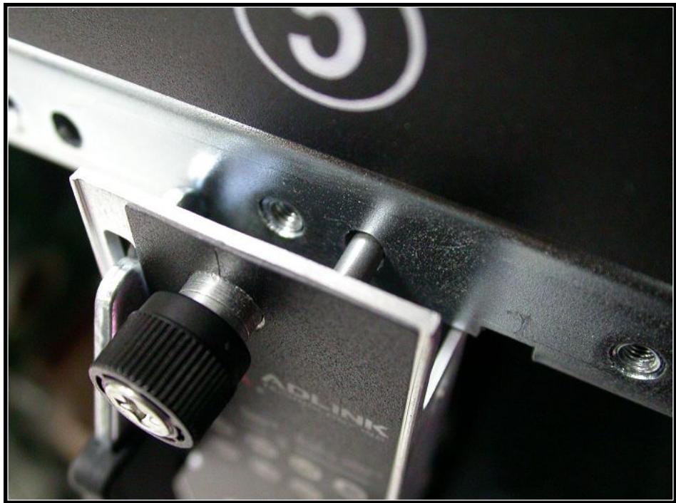
Carefully align the board edges with the chassis guide rails and push the blade inwards.
![Close-up of a metal mechanical component with a clamping tool interacting with a metallic bracket (no visible text or symbols)](.atca-9700-50-1g028-1010-201-en/4d9faded6e4e3dbf4a8e801e7b51f09355d1c2204a2a298d3c0744ece7b1dd00.jpg)

# Step 2

Check if the catch hooks and alignment pins at both ends of the module are correctly inserted into the proper openings. Push inwards on the handles until the blade is firmly seated in the chassis. (Do not force the handles if there is any abnormal resistance or it could damage the connectors and/or backplane.)
![Close-up of mechanical components with metallic parts and a black bracket, no visible text or symbols](.atca-9700-50-1g028-1010-201-en/e91649ae3792fcdb5a3f781a3207c0ef6b96fb6ca409bbca7b5bd82773b7545d.jpg)

![Close-up of a mechanical clamp or bracket component with a black threaded connector and mounting holes (no visible text or symbols)](.atca-9700-50-1g028-1010-201-en/6b2d0ef789e4ce1b44da0d76fcf8566bd0cecf08946cbb55d3d8c835fd7f671b.jpg)

# Step 3

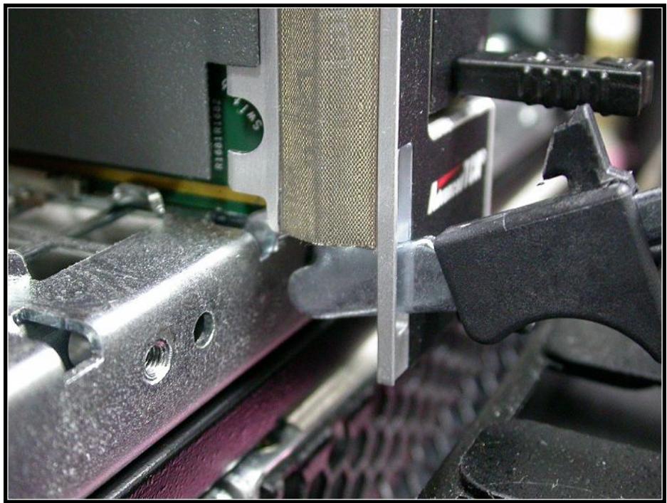
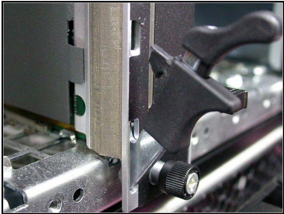
Push the ejector handles inwards until it is locked.
![Close-up of a mechanical clamping device with a metallic bracket and green circuit board (no visible text or symbols)](.atca-9700-50-1g028-1010-201-en/12b926a97315dba0cfa86d7a74fdcfb4d35a86019bcab4c3389c27eb0c46d74f.jpg)

![Close-up of a computer monitor with a black clip and plastic panel, showing mechanical components (no visible text or symbols)](.atca-9700-50-1g028-1010-201-en/c31b57d5507d2cd1ea2b339d986e0bbc89806bd12d8038fad49f380038149282.jpg)

# Step 4

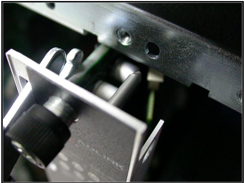
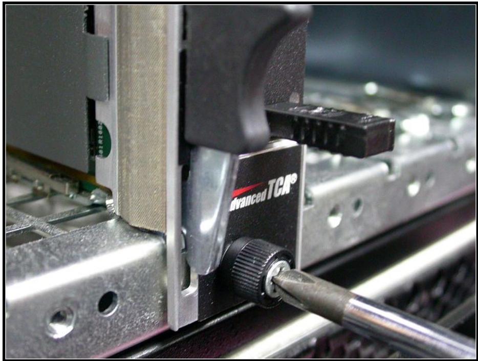
Lock both ends of the captive screws.
![Close-up of a mechanical assembly with a labeled Advanced TCR® tool inserted into a component (no readable text beyond logo)](.atca-9700-50-1g028-1010-201-en/a5f37d449b5ec0ff458b1ac28a5c7807672a515ac181d48be57f4dd733f5002b.jpg)

# 5.2.2 Removing the Blade

Follow these steps to remove the aTCA-9700 blade from the chassis.

# Step 1

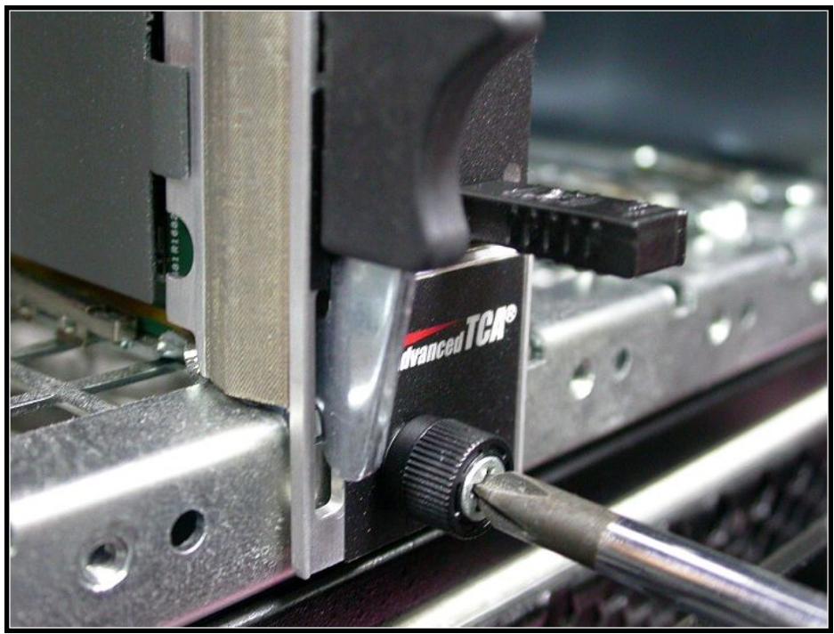
Unlock both ends of the captive screws.
![Close-up of a mechanical assembly with a precision tool inserted, showing a metallic component and a labeled 'Advanced TCR' (no readable text beyond label)](.atca-9700-50-1g028-1010-201-en/eb7e165fd1b4fc8bea985c719956be42b6e7736b918d84ebdd3c3e17836dacd0.jpg)

# Step 2

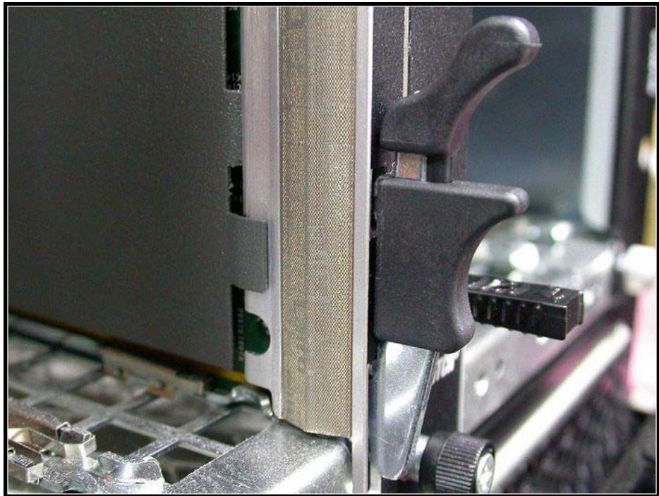
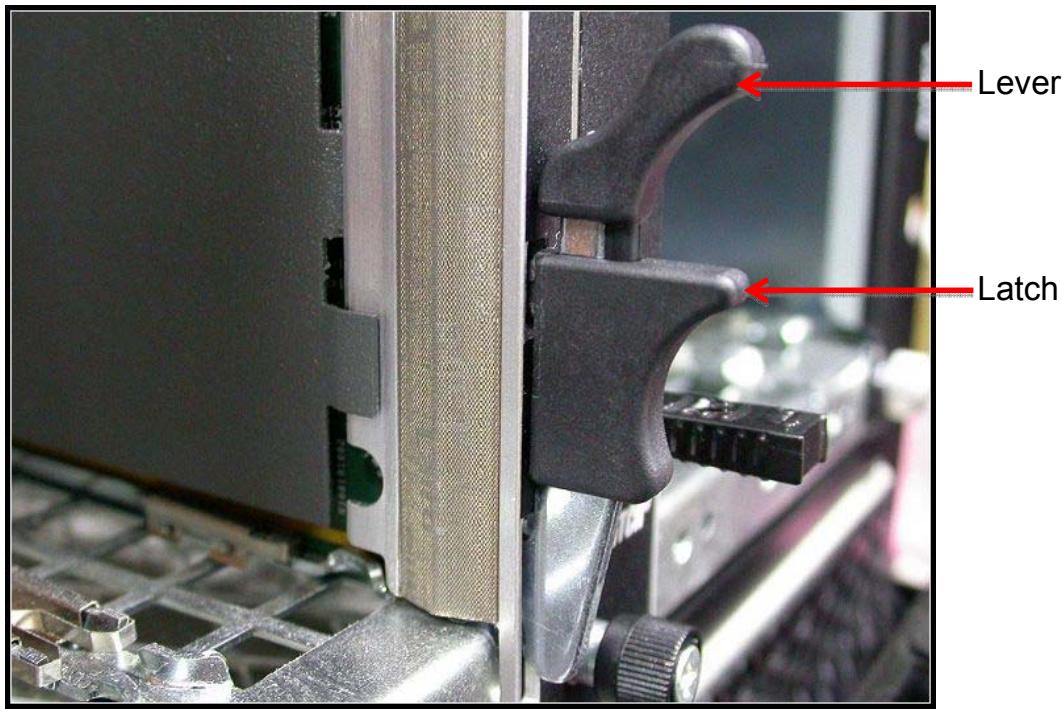
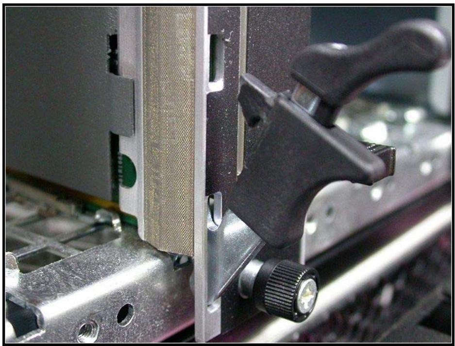
Pinch the lever and latch together then pull outwards to release the ejector handles at both ends.
![Lever\nLatch](.atca-9700-50-1g028-1010-201-en/64e700a41a9e96a691ede48004032eed8d5219c0a1ff2aeec53141cdb8287266.jpg)

![Close-up of a mechanical clamping device with metal components and a green circuit board (no visible text or symbols)](.atca-9700-50-1g028-1010-201-en/227785eb43fd181c5991806dc0de0fbf1ef6789dba8b565fee74c8262d919c34.jpg)

# Step 3

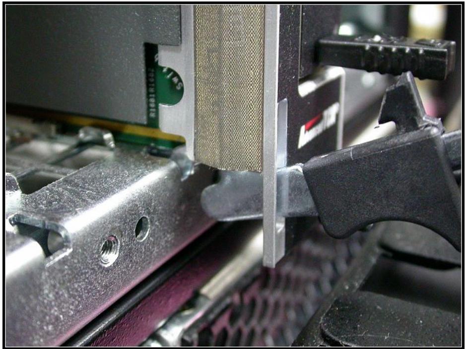
Pull the blade outwards from the chassis until it is removed.
![Close-up of a metal mechanical clamping device with a metallic mesh component and a black tool handle (no visible text or symbols)](.atca-9700-50-1g028-1010-201-en/3bec2f0495339f3c1bcc75007873da909c2ceed9215ed1245d29e37cbe50e669.jpg)

# 5.3 Firmware Update Procedure

The aTCA-9700 supports firmware update (IPMC FW, BIOS, FRU) over various interfaces (LAN, KCS, serial interface or IPMB). Please follow the procedures listed below to update the IPMC firmware.

Note: IPMB-0 will be disabled during the process of upgrading IPMC firmware. This is a limitation of the IPMC controller (SmartFusion A2F500)

# 5.3.1 Update Over Serial Interface

The following IPMItool command line parameters are used for communicating with the carrier IPMC via a serial interface:

# -I serial-terminal

This parameter instructs the IPMItool utility to use the serial interface for communications with the carrier IPMC.

# -D &lt;dev[:baudrate]&gt;

This parameter specifies the serial device and baud rate settings to use. For Linux hosts, the serial device is the system path to the device node (e.g. /dev/ttyS0).

Perform the following steps to update the IPMC firmware:

Step 1: Prepare an external host PC with Linux OS and connect it to the serial port on the aTCA-9700 via the COM port (USB Mini-B on the front panel). Put the IPMItool utility and new firmware image on the host PC. Enter the following command:

Step 2: Enter “y” when prompted and wait until the string “firmware update procedure successful” is displayed.

To update other images (BIOS, FRU, etc), just replace the target image and the file name while typing command.

<table><tr><td>Item</td><td>File name</td></tr><tr><td>IPMC firmware</td><td>hpm1fw.img</td></tr><tr><td>BIOS</td><td>hpm1bios.img</td></tr></table>

# Note:

1. The hpm1bios.img always updates the backup BIOS image.
2. Make sure the payload power is off (M1 state) before updating the IPMC firmware

# 5.3.2 Update over KCS

Step1: Prepare an aTCA-9700 with Linux system. Enter the following command to make sure the ipmi\_si and ipmi\_devintf modules are loaded before the IPMItool utility can be used.

Step2: Put IPMItool and “target image” in the Linux system then enter the following command:

Step3: Select “y” and wait until the string of “firmware update procedure successful” is displayed.

To update other images (BIOS, FRU, etc), just replace the target image and the file name while typing command.

<table><tr><td>Item</td><td>File name</td></tr><tr><td>IPMC firmware</td><td>hpm1fw.img</td></tr><tr><td>BIOS</td><td>hpm1bios.img</td></tr></table>

# 5.3.3 Update over LAN

The following IPMItool command line parameters are used for communicating with the carrier IPMC via LAN:

# -I lan

The parameter instructs the IPMItool utility to use the RMCP protocol for communicating with the IPMC.

# -H &lt;IP address &gt;

The parameter specifies the IP address of the IPMC.

Please follow the step to update firmware:

Step1: Prepare an external x86 PC and connect the target aTCA-9700 via BASE Interface. Put IPMItool and “target image” on the x86 PC with Linux system. Enter the following command:

Step2: Select “y” and wait until the string of “firmware update procedure successful” is displayed.

To update other images (BIOS, FRU, etc), just replace the target image and the file name while typing command.

<table><tr><td>Item</td><td>File name</td></tr><tr><td>IPMC firmware</td><td>hpm1fw.img</td></tr><tr><td>BIOS</td><td>hpm1bios.img</td></tr></table>

# 6 BIOS

This chapter will guide you how to configure BIOS setup items. There will be detailed description for each BIOS setup item in the following sections.

# 6.1 Entering the BIOS Setup Screen

To enter the setup screen, follow these steps:

Step 1: Power on the aTCA-9700.

Step 2: Press the &lt;DEL&gt; key on a USB keyboard when you see the following text prompt on boot up screen.

```txt
Version 2.15.1236. Copyright (C) 2012 American Megatrends, Inc.
aTCA-9700 REV:0.93
Press &lt;DEL&gt; or &lt;ESC&gt; to enter setup.
```

Step 3: After you press the &lt;DEL&gt; key, the Main BIOS setup menu will be displayed. You can access the other setup screen from the BIOS setup utility, such as CPU configuration, USB configuration and so on.

# 6.1.1 Navigation

The BIOS setup/utility uses a key-based navigation system called hot keys. Most of the BIOS setup utility hot keys can be used at any time during the setup navigation process. These keys include &lt;F1&gt;, &lt;F2&gt;, &lt;F3&gt;, &lt;F4&gt;, &lt;ESC&gt;, &lt;Enter&gt;, &lt;Arrow&gt; keys, and so on.

![The flowchart describes the navigation of a BIOS setup utility.\n\n**Blocks:**\n*   **BIOS Setup Utility**\n*   **Screens** (Label)\n*   **Left and Right Keys to Select a Setup Screen**\n*   **Screen 1**, **Screen 2**, **Screen 3**, **Screen 4**, **Screen 5**\n*   **Items** (Label)\n*   **Tab Key to Select Fields**\n*   **±** (Symbol in three boxes)\n*   **± To Change Field Values**\n*   **Up and Down Keys to Select a Setup Item**\n*   **Fields** (Label)\n\n**Connections:**\n*   **BIOS Setup Utility** points down to **Screens**.\n*   **Left and Right Keys to Select a Setup Screen** points via a dotted arrow down towards the screen row.\n*   **Screen 1** connects via double-headed arrows to **Screen 2**, which connects to **Screen 3**, **Screen 4**, and **Screen 5** in a horizontal sequence.\n*   **Screens** points down to **Items**.\n*   **Tab Key to Select Fields** points via a dotted arrow to the first **±** box in the 'Items' row.\n*   The three **±** boxes are connected horizontally by double-headed arrows.\n*   **± To Change Field Values** points via a dotted arrow to the middle **±** box.\n*   Vertical arrows (down and up) appear between the top and bottom rows of **±** boxes.\n*   **Up and Down Keys to Select a Setup Item** points via a dotted arrow to the vertical arrows.\n*   A bottom row of three **±** boxes is connected by double-headed arrows.\n*   An arrow points from the bottom row of **±** boxes to the left towards the label **Fields**.](.atca-9700-50-1g028-1010-201-en/1ab20cdd98c5491bdea3739b025f7476cc13593db7e4c36279a2990711314e28.jpg)

<table><tr><td>NOTE:</td><td>There is a hot key legend located in the right frame on most setup screens..</td></tr><tr><td>→←-</td><td>Left/Right. The Left and Right &lt; Arrow &gt; keys allow you to select a setup screen.</td></tr><tr><td>↑↓</td><td>Up/Down The Up and Down &lt; Arrow &gt; keys allow you to select a setup item or sub-screen.</td></tr><tr><td>+-</td><td>Plus/Minus the Plus and Minus &lt; Arrow &gt; keys allow you to change the field value of a particular setup item.For example: Date and Time.</td></tr><tr><td>ESC</td><td>The &lt; Esc &gt; key allows you to discard any changes you have made and exit the Setup. Press the &lt; Esc &gt; key to exit the setup without saving your changes. Press the &lt; Enter &gt; key to discard changes and exit. You can also use the &lt; Arrow &gt; key to select Cancel and then press the &lt; Enter &gt; key to abort this function and return to the previous screen.</td></tr><tr><td>Enter</td><td>The &lt; Enter &gt; key allows you to display or change the setup option listed for a particular setup item. The &lt; Enter &gt; key can also allow you to display the setup sub-screens.</td></tr></table>

# 6.2 Main BIOS Setup Screen

The Main BIOS setup menu is the screen where you start navigation of the BIOS setting menus. You can always return to the Main setup screen by selecting the Main tab. Each BIOS setup menu option is described in the following sections.

There are two parts of the Main BIOS setup menu screen. The left part of the screen displays the available options. The user can configure the options in blue text. The selected option will appear highlighted in white text. Options in gray text are for information only

The upper right part of the screen displays the description of the selected option. The lower right part of the screen shows the navigation keys that user can use.

The Main setup screen is shown below.

<table><tr><td colspan="3">Aptio Setup Utility - Copyright (C) 2012 American Megatrends, Inc.</td></tr><tr><td colspan="3">Main Advanced Chipset Server Mgmt Boot Security Save &amp; Exit</td></tr><tr><td>BIOS Information</td><td></td><td>Set the Time. Use Tab</td></tr><tr><td>BIOS Vendor</td><td>American Megatrends</td><td>to switch between Time</td></tr><tr><td>Core Version</td><td>4.6.5.4</td><td>elements.</td></tr><tr><td>Compliancy</td><td>UEFI 2.3.1; PI 1.2</td><td></td></tr><tr><td>BIOS Version</td><td>0.93</td><td></td></tr><tr><td>Build Date and Time</td><td>08/29/2013 17:50:13</td><td></td></tr><tr><td>Memory Information</td><td></td><td></td></tr><tr><td>Total Memory</td><td>8192 MB (DDR3)</td><td></td></tr><tr><td>System Language</td><td>[English]</td><td>&gt;&lt;: Select Screen
^v: Select Item</td></tr><tr><td>System Date</td><td>[Tue 09/03/2013]</td><td>Enter: Select</td></tr><tr><td>System Time</td><td>[11:53:00]</td><td>+/-: Change Opt.
F1: General Help</td></tr><tr><td>Access Level</td><td>Administrator</td><td>F2: Previous Values
F3: Optimized Defaults
F4: Save &amp; Exit
ESC: Exit</td></tr><tr><td colspan="3">Version 2.15.1236. Copyright (C) 2012 American Megatrends, Inc.</td></tr></table>

# System Language

Choose the language of BIOS setup utility. So far, there is only “English” is supported on aTCA-9700.

# System Time/System Date

Use these two options to change system time and date. Highlight System Time or System Date using the &lt;Arrow&gt; keys. Enter new values using the keyboard. Press the &lt;Tab&gt; key or the &lt;Arrow&gt; keys to move between fields. The date must be entered in MM/DD/YY format. The time is entered in HH:MM:SS format.

![The image shows a digital icon representing a document or piece of paper. It features a white background with faint horizontal grey lines running across it. Superimposed over the center is a large, bold red checkmark (or tick mark) that is angled diagonally from the bottom left to the top right. The icon has a slight shadow or border, typical of user interface elements indicating a completed or approved status.](.atca-9700-50-1g028-1010-201-en/421cd72cca08a569ffc490106b5822fe5148bf2f4e7f365e339566a7748f6723.jpg)

NOTE:

The time is in 24-hour format. For example, 5:30 A.M. appears as 05:30:00, and 5:30 P.M. as :00.

# System & Board Information

The Main BIOS setup screen reports memory and board information.

# BIOS Vendor

It reports the BIOS vendor of aTCA-9700’s BIOS. American Megatrend, Inc. is the BIOS vendor that aTCA-9700 is using.

# Core Version

It shows what core version is used from AMI to develop aTCA-9700’s BIOS.

# Compliancy

It shows what version of EFI specification is compliant with aTCA-9700’s BIOS.

# BIOS Revision

It shows revision of aTCA-9700’s BIOS.

# Build Date and Time

It shows date and time that aTCA-9700 BIOS is released.

# Total Memory

It shows the memory size on aTCA-9700.

# 6.3 Advanced Setup Screen

Select the Advanced tab from the setup screen to enter Advanced BIOS setup screen. You can select any of items in the left frame of the screen, such as CPU configuration, to go to the sub menu for that item. You can select an Advanced BIOS sub menu or option by highlighting it using the &lt;Arrow&gt; keys. The Advanced BIOS setup screen is shown below.

The sub menus are described in the following sections.

<table><tr><td colspan="3">Aptio Setup Utility - Copyright (C) 2012 American Megatrends, Inc.</td></tr><tr><td colspan="3">Main Advanced Chipset Server Mgmt Boot Security Save &amp; Exit</td></tr><tr><td></td><td></td><td>^ |Enable or Disable PXE</td></tr><tr><td>Legacy OpROM Support</td><td></td><td>* |ROM of BASE I/F LAN</td></tr><tr><td>BASE I/F LAN PXE ROM [Disabled]</td><td></td><td>* |</td></tr><tr><td>FRONT I/F LAN PXE ROM [Disabled]</td><td></td><td>* |</td></tr><tr><td>Fabric I/F LAN1 OpROM [Disabled]</td><td></td><td>* |</td></tr><tr><td>Fabric I/F LAN2 OpROM [Disabled]</td><td></td><td>* |</td></tr><tr><td></td><td></td><td>* |</td></tr><tr><td>RTM I/F LAN1 PXE ROM [Disabled]</td><td></td><td>* |</td></tr><tr><td>RTM I/F LAN2 PXE ROM [Disabled]</td><td></td><td>* |</td></tr><tr><td>RTM I/F LAN3 PXE ROM [Disabled]</td><td></td><td>* |</td></tr><tr><td>Launch iSCSI Oprom [Disabled]</td><td></td><td>* |&gt;&lt;: Select Screen +|^v: Select Item</td></tr><tr><td>Cave Creek 1 Control [Enabled]</td><td></td><td>+|Enter: Select</td></tr><tr><td>Cave Creek 2 Control [Enabled]</td><td></td><td>+|+/-: Change Opt. +|F1: General Help</td></tr><tr><td>ClkGen Spread Spectru [Disabled]</td><td></td><td>+|F2: Previous Values +|F3: Optimized Defaults</td></tr><tr><td>&gt; Trusted Computing</td><td></td><td>+|F4: Save &amp; Exit</td></tr><tr><td>WHEA Configuration</td><td></td><td>v |ESC: Exit</td></tr><tr><td></td><td></td><td>+</td></tr><tr><td colspan="3">Version 2.15.1236. Copyright (C) 2012 American Megatrends, Inc.</td></tr></table>

# BASE I/F LAN PXE ROM FRONT I/F LAN PXE ROM

These two options can be configured to invoke Ethernet’s PXE ROM on BASE/FRONT interface. When it is set to Disabled, system will boot without PXE ROM. Options: Enabled/Disabled.

# Launch Storage OpROM

Boot option for legacy mass storage devices with option ROM. Options: Enabled/Disabled.

# 6.3.1 Trusted Computing

Trusted computing is an industry standard to make personal computers more secure through a dedicated hardware chip, called a Trusted Platform Module (TPM). This option allows enabling or disabling the TPM support.
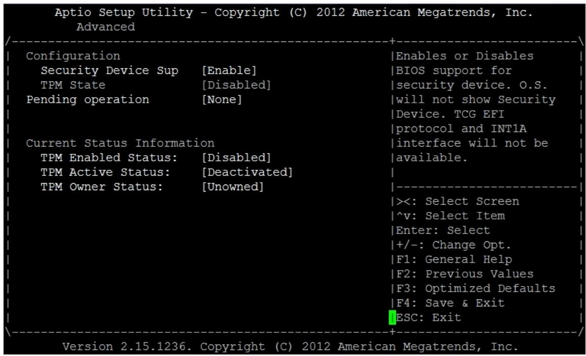
![Aptio Setup Utility - Copyright (C) 2012 American Megatrends, Inc.\nAdvanced\nConfiguration\nSecurity Device Sup (Enable)\nTPM State (Disabled)\nPending operation (None)\nCurrent Status Information\nTPM Enabled Status: (Disabled)\nTPM Active Status: (Deactivated)\nTPM Owner Status: (Unowned)\n+----+\nEnables or Disables\nBIOS support for\nsecurity device. O.S.\nwill not show Security\nDevice. TCG EFI\nprotocol and INT1A\ninterface will not be\navailable.\n-----\n×: Select Screen\n^v: Select Item\nEnter: Select\n+/-: Change Opt.\nF1: General Help\nF2: Previous Values\nF3: Optimized Defaults\nF4: Save & Exit\nESC: Exit\nVersion 2.15.1236. Copyright (C) 2012 American Megatrends, Inc.](.atca-9700-50-1g028-1010-201-en/a9a9df68c151330d8a498635061218cdc2047f28a9b69a3fd4c8a07e7c4e310b.jpg)

# 6.3.2 CPU Configuration

You can use this screen to select options for the CPU configuration settings. Use the up and down &lt;Arrow&gt; keys to select an item. Use the &lt;+&gt; and &lt;-&gt; keys to change the value of the selected option. A description of the selected item appears on the right side of the screen. The settings are described on the following pages. An example of the CPU configuration screen is shown below.
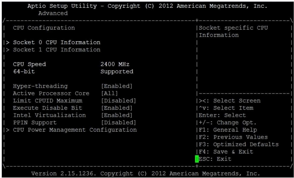
![Aptio Setup Utility - Copyright (C) 2012 American Megatrends, Inc.\nAdvanced\nCPU Configuration\nSocket specific CPU\nInformation\n) Socket 0 CPU Information\n) Socket 1 CPU Information\nCPU Speed	2400 MHz\n64-bit	Supported\nHyper-threading	(Enabled)\nActive Processor Core	(All)\nLimit CPUID Maximum	(Disabled)	)(: Select Screen\nExecute Disable Bit	(Enabled)	^v: Select Item\nIntel Virtualization	(Enabled)	Enter: Select\nPPIN Support	(Disabled)	+/-: Change Opt.\n) CPU Power Management Configuration	F1: General Help\n	F2: Previous Values\n	F3: Optimized Defaults\n	F4: Save & Exit\n	ESC: Exit\nVersion 2.15.1236. Copyright (C) 2012 American Megatrends, Inc.](.atca-9700-50-1g028-1010-201-en/fd400356dd066c625eaa5f75da114bddad68d418e1bc19d9bef3ffc0af223b51.jpg)

# Socket 0/1 CPU Information

BIOS will show the information of detected CPU, like CPU speed and its supported feature. Detailed information will also be listed in each socket CPU information sub menu like below. User can select “Socket 0” or “Socket 1” information for more detailed understanding of what CPU is using on system.
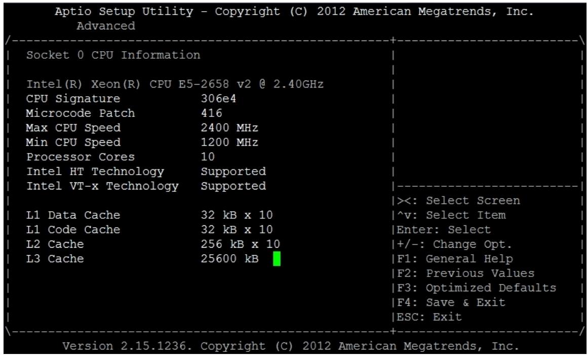
![Aptio Setup Utility - Copyright (C) 2012 American Megatrends, Inc.\nAdvanced\nSocket 0 CPU Information\nIntel(R) Xeon(R) CPU E5-2658 v2 @ 2.40GHz\nCPU Signature 306e4\nMicrocode Patch 416\nMax CPU Speed 2400 MHz\nMin CPU Speed 1200 MHz\nProcessor Cores 10\nIntel HT Technology Supported\nIntel VT-x Technology Supported\nL1 Data Cache 32 kB x 10\nL1 Code Cache 32 kB x 10\nL2 Cache 256 kB x 10\nL3 Cache 25600 kB\n)=: Select Screen\n^v: Select Item\nEnter: Select\n+/-: Change Opt.\nF1: General Help\nF2: Previous Values\nF3: Optimized Defaults\nF4: Save & Exit\nESC: Exit\nVersion 2.15.1236. Copyright (C) 2012 American Megatrends, Inc.](.atca-9700-50-1g028-1010-201-en/2c5d6e2be5c05cc2c1f382d68e79e033f56b803ce7ca7b0f116358fae467140b.jpg)

# Hyper-threading

This item allows you to enable or disable the Hyper-Threading technology. Options: Enabled/Disabled.

# Active Processor Core

This item allows you to select the number of cores to enable in each processor package. This BIOS setting is present only when a multi-core processor is installed.

# Limit CPUID Maximum

When the computer is booted up, the operating system executes CPUID instruction to identify the processor and its capabilities. Before it can do so, it must first query the processor to find out the highest input value CPUID recognizes. This determines the kind of basic information CPUID can provide the operating system. This option allows you to circumvent problems with older operating systems that do not support Intel Pentium 4 processor with Hyper-Threading Technology.

When Enabled, the processor will limit the maximum CPUID input value to 03h when queried, even if the processor supports a higher CPUID input value. When Disabled, the processor will return the actual maximum CPUID input value of the processor when queried. Options: Enabled/Disabled.

# Execute Disable Bit

Intel’s Execute Disable Bit functionality can help prevent certain classes of malicious buffer overflow attacks when combined with a supporting operating system. Execute Disable Bit allows the processor to classify areas in memory by where application code can execute and where it cannot. When a malicious worm attempts to insert code in the buffer, the processor disables code execution and prevents damage and worm propagation.

# Hardware Prefetcher

This is used for reducing the waiting time of DRAM. The hardware prefetcher looks for streams of data and tries to predict what data will be needed next by the processor and proactively tries to fetch these data. Options: Enabled/Disabled.

# Adjacent Cache Line Prefetch

It is opened for choose the optimal use of sequential memory access for performance purpose. Disable this setting for the application that requires high use of random memory access. Options: Enabled/Disabled.

# DCU Streamer Prefetch

There are two distinct hardware prefetchers on aTCA-9700. Data Cache Unit (DCU)

streamer prefetcher and Data Cache Unit (DCU) IP-prefetcher. DCU streamer prefetchers detect multiple reads to a single cache line in a certain period of time and choose to load the following cache line to the L1 data caches.

This option allows user to enable or disable DCU streamer Prefetcher.

# DCU IP Prefetcher

DCU IP Prefetcher looks for sequential load history to determine whether to prefetch the data to the L1 caches.

This option allows user to enable or disable DCU IP Prefetcher.

# Intel Virtualization

Intel Virtualization Technology consists of components that support virtualization of platforms based on Intel processors, thereby enabling the running of multiple operating systems and applications in independent partitions. Each partition behaves like a virtual machine (VM) and provides isolation and protection across partitions.

Intel VT requires the use of a processor with Intel VT support. Additionally, a thirdparty VMM may also be required. Options: Enabled/Disabled.

# CPU Power Management Configuration

CPU Power Management configuration opens some item for adjusting the load or timing to reduce the power consumption. User can go to this setup page to configure the best setting for the whole system.
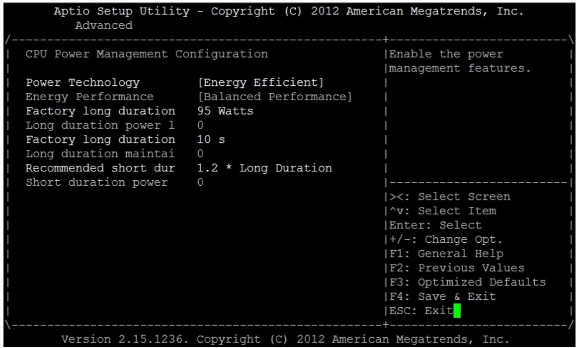
![Aptio Setup Utility - Copyright (C) 2012 American Megatrends, Inc.\nAdvanced\nCPU Power Management Configuration\nEnable the power\nmanagement features.\nPower Technology (Energy Efficient)\nEnergy Performance (Balanced Performance)\nFactory long duration 95 Watts\nLong duration power l 0\nFactory long duration 10 s\nLong duration maintai 0\nRecommended short dur 1.2 * Long Duration\nShort duration power 0\n×: Select Screen\n^v: Select Item\nEnter: Select\n+/-: Change Opt.\nF1: General Help\nF2: Previous Values\nF3: Optimized Defaults\nF4: Save & Exit\nESC: Exit\nVersion 2.15.1236. Copyright (C) 2012 American Megatrends, Inc.](.atca-9700-50-1g028-1010-201-en/63ead5b56f22a8d4cbf725478961bcd8629c76e2f8118aa8b0d7dec91f9e989a.jpg)

# Power Technology

This item enables the power management features.

# Energy Performance

This item is designed for configuring the energy performance.

# 6.3.3 Runtime Error Logging

You can use this screen to specify options for the runtime error logging settings. Use the up and down &lt;Arrow&gt; keys to select an item. Use &lt;+&gt; and &lt;-&gt; keys to change the value of the selected option. The settings are described in the following pages. The screen is shown as below.
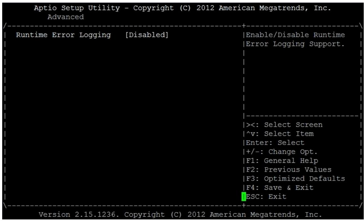
![Aptio Setup Utility - Copyright (C) 2012 American Megatrends, Inc.\nAdvanced\nRuntime Error Logging (Disabled)\nEnable/Disable Runtime\nError Logging Support.\n((: Select Screen\n^v: Select Item\nEnter: Select\n+/-: Change Opt.\nF1: General Help\nF2: Previous Values\nF3: Optimized Defaults\nF4: Save & Exit\nESC: Exit\nVersion 2.15.1236. Copyright (C) 2012 American Megatrends, Inc.](.atca-9700-50-1g028-1010-201-en/e7b63e3c12e05a793b75d6779f81108466b7b4de72a4a39095025efde925824f.jpg)

# Runtime Error Logging

This option allows user to enable or disable runtime error logging.

# Memory Corr. Error Threshold

This option is for setting memory correctable error threshold value.

# PCI Error Logging Support

This option is for enabling or disabling PCI error logging.

# Poison Support

This option is for enabling or disabling Poison Support. When poisoning is enabled, CPU doesn’t signal the uncorrectable error via MCERR but may signal CMCI if CMCI is enabled.

# Poison Support in IOH

This option is for enabling or disabling IOH Poison Support. When poison is enabled, no signaling or logging is done at IIO. Logging and signaling is responsibility of the Data consumer.

# 6.3.4 SATA Configuration

You can use this screen to specify options for the SATA configuration settings. Use the up and down &lt;Arrow&gt; keys to select an item. Use &lt;+&gt; and &lt;-&gt; keys to change the value of the selected option. The settings are described in the following pages. The screen is shown as below.
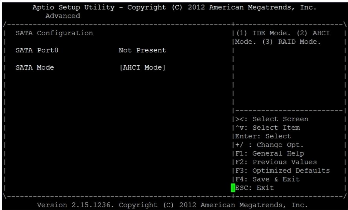
![Aptio Setup Utility - Copyright (C) 2012 American Megatrends, Inc.\nAdvanced\nSATA Configuration\nSATA Port0 Not Present\nSATA Mode (AHCI Mode)\n(1) IDE Mode. (2) AHCI\nMode. (3) RAID Mode.\n((: Select Screen\n^v: Select Item\nEnter: Select\n+/-: Change Opt.\nF1: General Help\nF2: Previous Values\nF3: Optimized Defaults\nF4: Save & Exit\nESC: Exit\nVersion 2.15.1236. Copyright (C) 2012 American Megatrends, Inc.](.atca-9700-50-1g028-1010-201-en/e75aa7b2a6180768b3a2ab7546a871a765d711e9f0c4eb5aa1e7c481545d1ec5.jpg)

# SATA Mode

This option is designed for configuring SATA mode. It can be Disabled, IDE Mode and AHCI Mode.

# Aggressive Link Power

It allows enabling or disabling Aggressive Link Power for SATA.

# Port 0 Hot Plug

When SATA Mode is configured to AHCI Mode, SATA drive is able to be hot plugged. This option allows setting the hot plug function of SATA drive.

# 6.3.5 SAS Configuration

You can use this screen to view the current SAS configuration. The SAS device is shown dynamically when system boot. The SAS option will detect the existed drive and then show them on this setup screen. User can check the result of detection from this screen. The screen is shown as below.
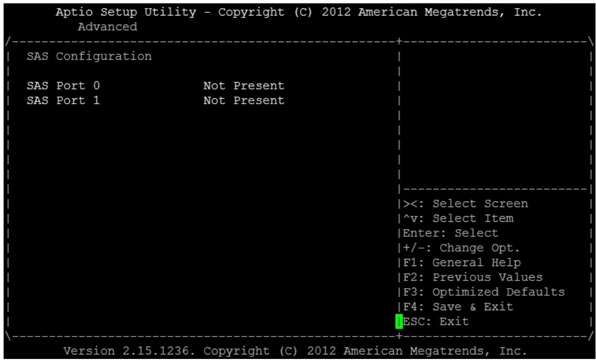
![Aptio Setup Utility - Copyright (C) 2012 American Megatrends, Inc.\nAdvanced\nSAS Configuration\nSAS Port 0 Not Present\nSAS Port 1 Not Present\n((: Select Screen\n^v: Select Item\nEnter: Select\n+/-: Change Opt.\nF1: General Help\nF2: Previous Values\nF3: Optimized Defaults\nF4: Save & Exit\nESC: Exit\nVersion 2.15.1236. Copyright (C) 2012 American Megatrends, Inc.](.atca-9700-50-1g028-1010-201-en/dc36b12387083d175bb709f678e61f538d1c0cf292db1afcca5d5f79041d040d.jpg)

# 6.3.6 USB Configuration

![Aptio Setup Utility - Copyright (C) 2012 American Megatrends, Inc.\nAdvanced\nUSB Configuration\nUSB Module Version 8.10.27\nUSB Devices:\n1 Keyboard, 2 Hubs\nLegacy USB Support (Enabled)\nUSB3.0 Support (Enabled)\nXHCI Hand-off (Enabled)\nEHCI Hand-off (Disabled)\nUSB Mass Storage Driv (Enabled)\nPort 60/64 Emulation (Enabled)\n+----+\nEnables Legacy USB\nsupport. AUTO option\ndisables legacy support\nif no USB devices are\nconnected. DISABLE\noption will keep USB\ndevices available only\nfor EFI applications.\n|\n--\n×: Select Screen\n^v: Select Item\nEnter: Select\n+/-: Change Opt.\nF1: General Help\nF2: Previous Values\nF3: Optimized Defaults\nF4: Save & Exit\nESC: Exit\nVersion 2.15.1236. Copyright (C) 2012 American Megatrends, Inc.](.atca-9700-50-1g028-1010-201-en/8cda9bb3d48dbeade7285c331cf93a6023c9f53ad25589a9e2e8843b6ceae5ca.jpg)

# Legacy USB Support

Legacy USB support refers to USB mouse and keyboard support. If this option is not enabled, any attached USB mouse or keyboard will not become available until a USB compatible operating system is fully booted with all USB drivers loaded. When this option is enabled, any attached USB mouse or keyboard can control the system even there is no USB driver loaded on the system.

# EHCI Hand-off

This is a workaround for OSes without EHCI hand-off support. The EHCI ownership change should be claimed by EHCI driver.

# USB transfer time-out

This item specifies the timeout in seconds for USB control, bulk, and interrupt transfers.

# Device reset time-out

This item specifies the number of seconds that system boot will wait for a USB mass storage device to start.

# Device power-up delay

This item specifies the maximum time that USB device will take before it reports itself properly to the USB host controller. “Auto” uses the default value: for a root port, it is 100ms, for a Hub port, the delay is taken from Hub descriptor.

# 6.3.7 W83627UHG SIO Configuration

You can use this screen to specify options for the Super IO configuration settings. Use the up and down &lt;Arrow&gt; keys to select an item. Use &lt;+&gt; and &lt;-&gt; keys to change the value of the selected option. The settings are described in the following pages. The screen is shown as below.
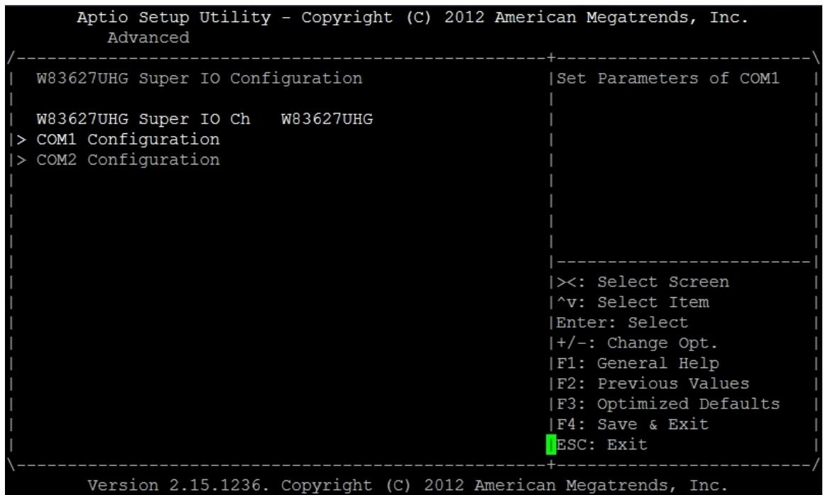
![Aptio Setup Utility - Copyright (C) 2012 American Megatrends, Inc.\nAdvanced\nW83627UHG Super IO Configuration\nW83627UHG Super IO Ch W83627UHG\n) COM1 Configuration\n) COM2 Configuration\nSet Parameters of COM1\n((: Select Screen\n^v: Select Item\nEnter: Select\n+/-: Change Opt.\nF1: General Help\nF2: Previous Values\nF3: Optimized Defaults\nF4: Save & Exit\nESC: Exit\nVersion 2.15.1236. Copyright (C) 2012 American Megatrends, Inc.](.atca-9700-50-1g028-1010-201-en/ff0e21a6d63cde58ff31b1d726a329561d70b7aaa7399cb4691b7daade26d922.jpg)

Winbond W83627UHG is designed on aTCA-9700. When system boot, BIOS will detect superIO and show the name on this screen.
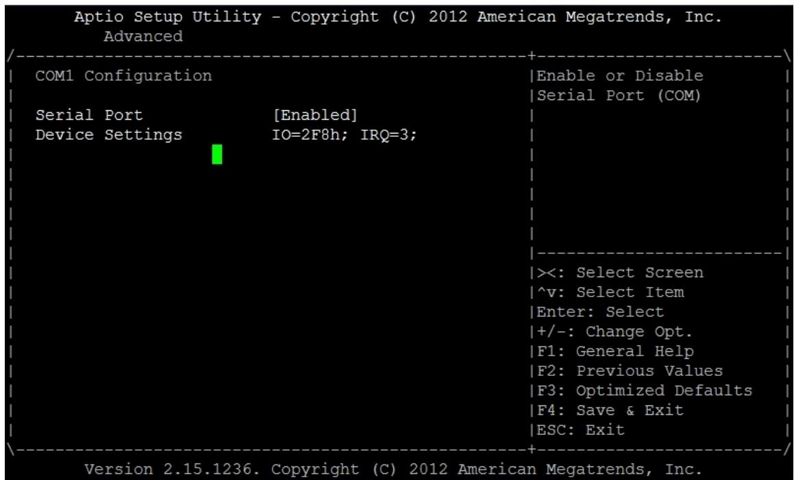
![Aptio Setup Utility - Copyright (C) 2012 American Megatrends, Inc.\nAdvanced\nCOM1 Configuration\nSerial Port (Enabled)\nDevice Settings IO=2F8h; IRQ=3;\nEnable or Disable\nSerial Port (COM)\n((: Select Screen\n^v: Select Item\nEnter: Select\n+/-: Change Opt.\nF1: General Help\nF2: Previous Values\nF3: Optimized Defaults\nF4: Save & Exit\nESC: Exit\nVersion 2.15.1236. Copyright (C) 2012 American Megatrends, Inc.](.atca-9700-50-1g028-1010-201-en/9a5cb9e4806072681715a9920d998ecada8961eb5fd9a3e4efdbdbda575cd60f.jpg)

# Serial Port

This item is designed for enabling/disabling the serial ports.

# 6.3.8 Serial Port Console Redirection

The settings on this setup screen specify how the host computer and the remote computer (which the user is using) exchange data. Both computers should have the same or compatible settings, like baud rate, terminal type, and so on.
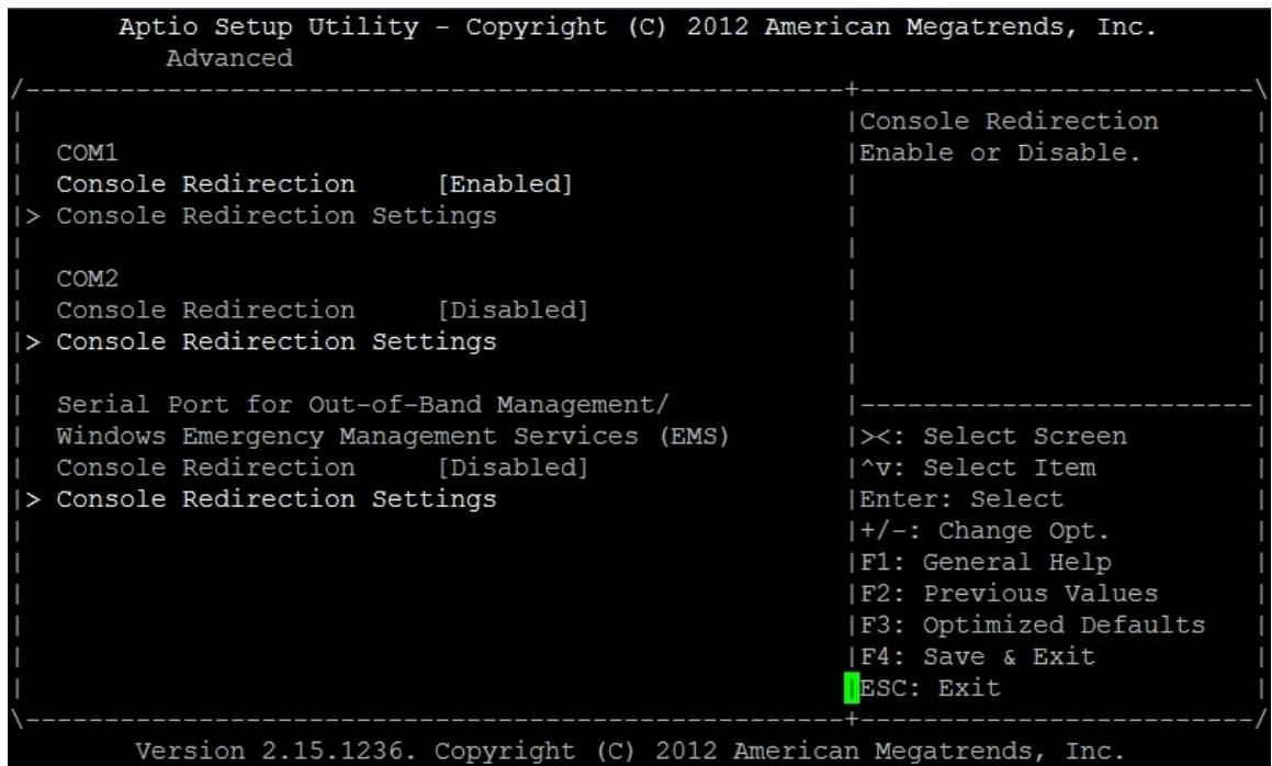
![Aptio Setup Utility - Copyright (C) 2012 American Megatrends, Inc.\nAdvanced\nCOM1\nConsole Redirection (Enabled)\n) Console Redirection Settings\nCOM2\nConsole Redirection (Disabled)\n) Console Redirection Settings\nSerial Port for Out-of-Band Management/\nWindows Emergency Management Services (EMS)\nConsole Redirection (Disabled)\n) Console Redirection Settings\nConsole Redirection Settings\n+----+\nConsole Redirection\nEnable or Disable.\n((: Select Screen\n^v: Select Item\nEnter: Select\n+/-: Change Opt.\nF1: General Help\nF2: Previous Values\nF3: Optimized Defaults\nF4: Save & Exit\nESC: Exit\nVersion 2.15.1236. Copyright (C) 2012 American Megatrends, Inc.](.atca-9700-50-1g028-1010-201-en/d7002e27ec8dd3838ba6eb0749bb45a0e53d316014e224616f432d11c8ade421.jpg)

# 6.3.9 COM1 Console Redirection

This item is used to configure the enabling/disabling of console redirection to each COM port. For example, COM1 is set to enable console redirection. The below screen will be needed to set properly for communicating with other computer that is using terminal software to receive the message from aTCA-9700.

<table><tr><td colspan="3">Aptio Setup Utility - Copyright (C) 2012 American Megatrends, Inc.
Advanced</td></tr><tr><td>COM1</td><td></td><td>Emulation: ANSI:</td></tr><tr><td>Console Redirection Settings</td><td></td><td>Extended ASCII char</td></tr><tr><td></td><td></td><td>set. VT100: ASCII char</td></tr><tr><td>Terminal Type</td><td>[VT100]</td><td>set. VT100+: Extends</td></tr><tr><td>Bits per second</td><td>[115200]</td><td>VT100 to support color,</td></tr><tr><td>Data Bits</td><td>[8]</td><td>function keys, etc.</td></tr><tr><td>Parity</td><td>[None]</td><td>VT-UTF8: Uses UTF8</td></tr><tr><td>Stop Bits</td><td>[1]</td><td>encoding to map Unicode</td></tr><tr><td>Flow Control</td><td>[None]</td><td>chars onto 1 or more</td></tr><tr><td>VT-UTF8 Combo Key Sup</td><td>[Enabled]</td><td>-----</td></tr><tr><td>Recorder Mode</td><td>[Disabled]</td><td>&gt;&lt;: Select Screen</td></tr><tr><td>Resolution 100x31</td><td>[Disabled]</td><td>^v: Select Item</td></tr><tr><td>Legacy OS Redirection</td><td>[80x24]</td><td>Enter: Select</td></tr><tr><td>Putty KeyPad</td><td>[VT100]</td><td>+/-: Change Opt.</td></tr><tr><td>Redirection After BIO</td><td>[Always Enable]</td><td>F1: General Help</td></tr><tr><td></td><td></td><td>F2: Previous Values</td></tr><tr><td></td><td></td><td>F3: Optimized Defaults</td></tr><tr><td></td><td></td><td>F4: Save &amp; Exit</td></tr><tr><td></td><td></td><td>ESC: Exit</td></tr><tr><td colspan="3">Version 2.15.1236. Copyright (C) 2012 American Megatrends, Inc.</td></tr></table>

# Terminal Type

VT-UTF8 is the preferred terminal type for out-of-band management. The next best choice is VT100+ and then VT100.

# Bits per second

Select the bits per second that you want serial port to use for console redirection.

# Data Bits

This option allows to select the data bits you want the serial port to use for console redirection.

# Parity

Set this option to select Parity for console redirection.

# Stop Bits

Stop bits indicate the end of a serial data packet. (A start bit indicates the beginning). The standard setting is 1 stop bit. Communication with slow devices may requires more than 1 stop bit.

# Flow Control

Set this option to select Flow control for console redirection.

# VT-UTF8 Combo Key Sup

This option is used for enabling or disabling VT-UTF8 Combo key.

# Recorder Mode

This option is used for enabling or disabling Recorder Mode.

# Resolution 100x31

This option is used for enabling or disabling resolution 100x31 support.

# Legacy OS Redirection

This option is used for configuring the legacy OS text format for proper display if system boots to legacy OS with console redirection enabled.

# Putty KeyPad

This option allows configuring the format of keypad when console redirection is enabled.

# Redirection After BIOS

This option allows user to configure the console redirection mode via serial port after BIOS POST OK.

# Terminal Type

VT-UTF8 is the preferred terminal type for out-of-band management. The next best choice is VT100+ and then VT100.

# Bits per second

Select the bits per second that you want serial port to use for console redirection.

# Flow Control

Set this option to select Flow control for console redirection.

# Data Bits

This option allows to select the data bits you want the serial port to use for console

redirection.

# Parity

Set this option to select Parity for console redirection.

# Stop Bits

Stop bits indicate the end of a serial data packet. (A start bit indicates the beginning). The standard setting is 1 stop bit. Communication with slow devices may requires more than 1 stop bit.

# 6.3.10 Network Stack

You can use this screen to specify options for the Network Stack settings. The screen is shown as below.

![Aptio Setup Utility - Copyright (C) 2012 American Megatrends, Inc.\nAdvanced\nNetwork stack (Disabled) Enable/Disable UEFI\nnetwork stack\n×: Select Screen\n^v: Select Item\nEnter: Select\n+/-: Change Opt.\nF1: General Help\nF2: Previous Values\nF3: Optimized Defaults\nF4: Save & Exit\nESC: Exit\nVersion 2.15.1236. Copyright (C) 2012 American Megatrends, Inc.](.atca-9700-50-1g028-1010-201-en/a24ea62115eb7dfbed919643b4ab497f2aab88bbe86ec33d1b3632670b7d5247.jpg)

# Network Stack

This option is used for enabling or disabling the network stack for onboard Ethernet.

# 6.3.11 iSCSI

You can use this screen to specify options for the iSCSI settings. The screen is shown as below.

![Aptio Setup Utility - Copyright (C) 2012 American Megatrends, Inc.\nAdvanced\niSCSI Initiator Name	The worldwide unique\n	{name of iSCSI\n) Add an Attempt	Initiator. Only IQN\n	{format is accepted.\n) Delete Attempts\n) Change Attempt Order\n		-\n		-:\n		-:\n			)-: Select Screen\n		|^v: Select Item\n		_Enter: Select\n			+/-: Change Opt.\n			F1: General Help\n			F2: Previous Values\n			F3: Optimized Defaults\n			F4: Save & Exit\n				ESC: Exit\nVersion 2.15.1236. Copyright (C) 2012 American Megatrends, Inc.](.atca-9700-50-1g028-1010-201-en/6527d5a317da1e590924229671c506173251b2d2ea05991e0984c3e6b7d0385e.jpg)

# 6.3.12 Ethernet Port Configuration

You can use this screen to specify options for the Ethernet port configuration settings. The screen is shown as below.

![Aptio Setup Utility - Copyright (C) 2012 American Megatrends, Inc.\nAdvanced\n|\nPORT CONFIGURATION MENU\n) NIC Configuration\nBlink LEDs 0\nPORT CONFIGURATION INFORMATION\nUEFI Driver: Intel(R) PRO/1000 5.5.23\nAdapter PBA: FFFFFFF-0FF\nChip Type Intel 82576\nPCI Device ID 10C9\nBus:Device:Function 02:00:00\nLink Status (Disconnected)\nMAC Address 00:30:64:B4:00:23\n+----+\n|Configure Boot\n|Protocol, Wake on LAN,\n|Link Speed, and VLAN.\n|\n|-\n|-\n|-\n|-\n|-\n|-\n|-\n|-\n|-\n|-\n|-\n|-\n|-\n|-\n|-\n|-\n|-\n|-\n|-\n|-\n|-\n|-\n|-\n|-\n|-\n|-\n|-\n|-\n|-\n|-\n|-\n|-\n|-\n|-\n|-\n|-\n|-\n|-\n|-\n|-\n|-\n|-\n|-\n|-\n|-\n|-\n|-\n|-\n|-\n|-\n|+\nVersion 2.15.1236. Copyright (C) 2012 American Megatrends, Inc.](.atca-9700-50-1g028-1010-201-en/fdd718480b19e9a5b66b987c05734b24bd0583c3c14cfc1e37a6406c164a289c.jpg)

# Ethernet Port Information

The port configuration information will be shown on screen, like chip type, device ID, MA address, and so on.

![Aptio Setup Utility - Copyright (C) 2012 American Megatrends, Inc.\nAdvanced\nLink Speed (Auto Negotiated) | Specifies the port\nWake On LAN (Enabled) | speed used for the\nselected boot protocol.\n)(: Select Screen\n^v: Select Item\nEnter: Select\n+/-: Change Opt.\nF1: General Help\nF2: Previous Values\nF3: Optimized Defaults\nF4: Save & Exit\nESC: Exit\nVersion 2.15.1236. Copyright (C) 2012 American Megatrends, Inc.](.atca-9700-50-1g028-1010-201-en/2e7f41a1537c46d6d92ed56224b9c5273b4a7281f844312e392ceab70f74e4ff.jpg)

# Link Speed

This option allows user to change link speed and duplex for the current Ethernet port that user is configuring.

# 6.4 Chipset Setup Screen

Select Chipset tab from the setup screen to enter Chipset BIOS setup screen. You can select any of the items in the left frame of the screen to go to sub menu for that item. An example of Chipset BIOS setup screen is shown below.

There are two sub bios setup menus for chipset configuration. They are for north bridge and south bridge.

![Aptio Setup Utility - Copyright (C) 2012 American Megatrends, Inc.\nMain Advanced Chipset Server Mgmt Boot Security Save & Exit\n) North Bridge\n) South Bridge\nNorth Bridge Parameters\n|\n|\n|\n|\n|\n|\n|\n|\n|\n|\n|\n|\n|\n|\n|\n|\n|\n|\n|\n|\n|\n|\n|\n|\n|\n|\n|\n|\n|\n|\n|\n|\n|\n|\n|\n|\n|\n|\n|\n|\n|\n|\n|\n|\n|\n|\n|\n|\n|\n|\n|\n|\n|\n|\n|\n|\n|\n|\n|\n|\n|\n|\n|\n|\n|\n|\n|\n|\n|\n|\n|\n|\n|\n|\n|\n|\n|\n|\n|\n|\n|\n|\n|\n|\n|\n|\n|\n|\n|\n|\n|\n|\n|\n|\n|\n|\n|\n|\n|\n|\n|-\nSelect Screen\n^v: Select Item\nEnter: Select\n+/-: Change Opt.\nF1: General Help\nF2: Previous Values\nF3: Optimized Defaults\nF4: Save & Exit\nESC: Exit\nVersion 2.15.1236. Copyright (C) 2012 American Megatrends, Inc.](.atca-9700-50-1g028-1010-201-en/ec04a92904ad2f1d6e6c7e58257332ae440e2cc8184eec496d0c9e727b6a5721.jpg)

# 6.4.1 IOH Configuration

You can use this screen to specify options for the North Bridge settings. Use the up and down &lt;Arrow&gt; keys to select an item. Use &lt;+&gt; and &lt;-&gt; keys to change the value of the selected option. The settings are described in the following pages. The screen is shown as below.

![Aptio Setup Utility - Copyright (C) 2012 American Megatrends, Inc.\nChipset\nIOH Configuration Page\n) IOH Configuration\nCompatibility RID (Enabled)\nMemory Configuration\nTotal Memory 8192 MB (DDR3)\nCurrent Memory Speed 1600 MHz\nDDR Speed (Auto)\nChannel Interleaving (Auto)    )(: Select Screen\nRank Interleaving (Auto)    ^v: Select Item\nPatrol Scrub (Enabled)    Enter: Select\nDemand Scrub (Disabled)    +/-: Change Opt.\nData Scrambling (Enabled)    F1: General Help\nThermal Throttling (CLTT)    F2: Previous Values\nDIMM Information\nF3: Optimized Defaults\nF4: Save & Exit\nESC: Exit\nVersion 2.15.1236. Copyright (C) 2012 American Megatrends, Inc.](.atca-9700-50-1g028-1010-201-en/eee49ec7b3d7b94a2e25d6036d971d3f4c870f86b0933b5174bdc97df9dae820.jpg)

# Memory Information

In this setup screen, some memory information will be shown.

# Memory Mode

This option is used for configuring the memory mode.

# Patrol Scrub

This item is used for enabling or disabling patrol scrub.

# Demand Scrub

This item is used for enabling or disabling Demand Scrubbing feature.

# Data Scrambling

This item is used for enabling or disabling Data Scrambling.

![Aptio Setup Utility - Copyright (C) 2012 American Megatrends, Inc.\nChipset\n|^Intel(R) VT for\n*|Directed I/O\n)| Intel(R) VT for Directed I/O Configuration\n*|Configuration\n|\n|\n|\n*|\nIOH 0 PCIe port Bifurcation Control\n|\n|\n|\n*|\nPORT 1A Link Speed (GEN3)\nIOU2 - PCIe Port (x8x4x4)\nPORT 2A Link Speed (GEN2)\nPORT 2B Link Speed (GEN2)\nPORT 2C Link Speed (GEN2)\nPORT 3A Link Speed (GEN2)\n|\n|\n|\n*|+/-: Change Opt.\nIOH 1 PCIe port Bifurcation Control\n|\n|\n|\nF1: General Help\n+|F2: Previous Values\nIOU1 - PCIe Port (x8)\nPORT 1A Link Speed (GEN3)\nIOU2 - PCIe Port (x16)\n+|F3: Optimized Defaults\n+|F4: Save & Exit\nvESC: Exit\nVersion 2.15.1236. Copyright (C) 2012 American Megatrends, Inc.](.atca-9700-50-1g028-1010-201-en/bb4ffb34db6feba7fe2e2573cc70fa3af92b7f25b25a1fb9def54609ee5762b8.jpg)

# PORT 1A Link Speed

Port 1A is designed to link onboard PCIe x8 Ethernet. This item is for configuring the link speed to x8 device.

# IOU2 – PCIe Port

IOU2 can be configured to x4x4x4x4 (if RTM has two x4 PCIe devices) or x4x4x8 (if RTM has one x8 PCIe device)

# PORT 2A Link Speed

Port 2A is designed to link onboard PCIe x4 Ethernet. It provides the link to RTM base channel. This item is for configuring the link speed to x4 device.

# PORT 2B Link Speed

Port 2B is designed to link onboard PCIe x4 Ethernet. It provides the link to front GbE ports. This item is for configuring the link speed to x4 device.

# PORT 2C Link Speed

Port 2C is designed to link onboard PCIe x4/x8 Ethernet. It provides the link to RTM. This item is for configuring the link speed to x4/x8 device.

# PORT 3A Link Speed

Port 3A is designed to link onboard PCIe x4 Ethernet. It will not show in setup screen if IOU2 port is configured to x4x4x8. It provides the link to RTM base channel. This item is for configuring the link speed to x4 device.

# IOU3 – PCIe Port

IOU3 provides a x16 link to PCIe device.

# PORT 3A Link Speed

Port 3A is designed to link onboard PCIe x16 device. This item is for configuring the link speed to x16 device.

![Aptio Setup Utility - Copyright (C) 2012 American Megatrends, Inc.\nChipset\nIntel(R) VT-d (Disabled) Enable/Disable Intel(R)\nVirtualization\nTechnology for Directed\nI/O.\n×: Select Screen\n^v: Select Item\nEnter: Select\n+/-: Change Opt.\nF1: General Help\nF2: Previous Values\nF3: Optimized Defaults\nF4: Save & Exit\nESC: Exit\nVersion 2.15.1236. Copyright (C) 2012 American Megatrends, Inc.](.atca-9700-50-1g028-1010-201-en/7ed9d4dfd7146488570677acac0768675bc1ad2fb1a91f6cf28dd238f9eeeedc.jpg)

# Intel(R) VT-d

This item allows user to enable or disable Intel ® VT for directed I/O (VT-d) which provides additional hardware support for managing I/O virtualization.

# Coherency Support

It allows user to enable or disable Non-Isoch VT-d Engine Coherency support.

# ATS Support

It allows user to enable or disable Non-Isoch VT-d Engine Address Translation Services (ATS) support.

# 6.4.2 PCH Configuration

You can use this screen to specify options for the PCH configuration settings. Use the up and down &lt;Arrow&gt; keys to select an item. Use &lt;+&gt; and &lt;-&gt; keys to change the value of the selected option. The settings are described in the following pages. The screen is shown as below.

![Aptio Setup Utility - Copyright (C) 2012 American Megatrends, Inc.\nChipset\nPCH Information\nName Patsburg\nStepping 06 (C1 Stepping)\nSB Chipset Configuration\nDisable SCU devices (Disabled)\nOnboard SAS Oprom/Dri (Enabled)\nOnboard SATA RAID Opr (Enabled)\n) PCI Express Ports Configuration\n) USB Configuration\n+ Enable/Disable Patsburg\nSCU devices. SMBus\n0,1,2 will be disabled\nwhile SCU devices are\ndisabled.\n)(: Select Screen\n^v: Select Item\nEnter: Select\n+/-: Change Opt.\nF1: General Help\nF2: Previous Values\nF3: Optimized Defaults\nF4: Save & Exit\nESC: Exit\nVersion 2.15.1236. Copyright (C) 2012 American Megatrends, Inc.](.atca-9700-50-1g028-1010-201-en/ce35501615a53634db4b45a7716d2df5fafdc788301fbd9eb79ae49af3b631b0.jpg)

# PCH Information

The PCH information will include the name and stepping of PCH that is designed on aTCA-9700.

# Disable SCU devices

It is for enabling or disabling Patsburg SCU devices.

# Onboard SAS Oprom

This item allows user to enable or disable SAS option ROM.

# Onboard SATA RAID Oprom

This item allows user to enable or disable SATA RAID option ROM.

# USB Configuration

You can use this screen to specify options for the USB configuration settings. Use the up and down &lt;Arrow&gt; keys to select an item. Use &lt;+&gt; and &lt;-&gt; keys to change the value of the selected option. The settings are described in the following pages.

The screen is shown as below.

![Aptio Setup Utility - Copyright (C) 2012 American Megatrends, Inc.\nChipset\nUSB Configuration\nEnabled/Disabled All\nUSB Devices\nAll USB Devices (Enabled)\nEHCI Controller 1 (Enabled)\nEHCI Controller 2 (Enabled)\nFront USB Port 1 (Enabled)\nFront USB Port 2 (Enabled)\nRTM USB Port 1 (Enabled)\nRTM USB Port 2 (Enabled)\nRTM USB Port 3 (Enabled)\n----: Select Screen\n^v: Select Item\nEnter: Select\n+/-: Change Opt.\nF1: General Help\nF2: Previous Values\nF3: Optimized Defaults\nF4: Save & Exit\nESC: Exit\nVersion 2.15.1236. Copyright (C) 2012 American Megatrends, Inc.](.atca-9700-50-1g028-1010-201-en/260b87912c311c7311ebedc5453cb65fbcbd3d24015dbd879a7deb52d91469e7.jpg)

# All USB Devices

This item enables or disables all USB devices.

# EHCI Controller 1

This item enables or disables USB 2.0 (EHCI) controller 1.

# EHCI Controller 2

This item enables or disables USB 2.0 (EHCI) controller 2.

# FRONT USB Port 1

This item is for enabling or disabling front USB port. When it is disabled, all USB device plugged in this front USB port will not work properly.

# FRONT USB Port 2

This item is for enabling or disabling front USB port. When it is disabled, all USB device plugged in this front USB port will not work properly.

# RTM USB Port 1

This item is for enabling or disabling RTM USB port. When it is disabled, all USB device plugged in this RTM USB port will not work properly.

# RTM USB Port 2

This item is for enabling or disabling RTM USB port. When it is disabled, all USB device plugged in this RTM USB port will not work properly.

# RTM USB Port 3

This item is for enabling or disabling RTM USB port. When it is disabled, all USB device plugged in this RTM USB port will not work properly.

# 6.5 Server Mgmt Setup Screen

You can use this screen to specify options for the Server Management settings. Use the up and down &lt;Arrow&gt; keys to select an item. Use &lt;+&gt; and &lt;-&gt; keys to change the value of the selected option. The settings are described in the following pages. The screen is shown as below.

![Aptio Setup Utility - Copyright (C) 2012 American Megatrends, Inc.\nMain Advanced Chipset Server Mgmt Boot Security Save & Exit\nBMC Self Test Status PASSED Enable or Disable POST\nPOST Watchdog Timer (Enabled)\nPOST Watchdog Timeout (35 seconds)\nPOST Watchdog Timer P (Reset)\nOS Load Watchdog Time (Disabled)\nOS Load Watchdog Time (20 seconds)\nOS Load Watchdog Time (Reset)\n((: Select Screen\n^v: Select Item\nEnter: Select\n+/-: Change Opt.\nF1: General Help\nF2: Previous Values\nF3: Optimized Defaults\nF4: Save & Exit\nESC: Exit\nVersion 2.15.1236. Copyright (C) 2012 American Megatrends, Inc.](.atca-9700-50-1g028-1010-201-en/bb4730215fcb2dd8c831892ce6c304e523cc101e4a89b521292e3a031c25b7ef.jpg)

# BMC Self Test Status

It shows the BMC Self Test Status

# POST Watchdog Timer

It is for enabling or disabling POST Watchdog timer.

# POST Watchdog timeout

It can select the value between 3 to 6 min for FRB-2 timer expiration value.

# OS Load Watchdog Timer

If enabled, starts a BIOS timer which can only be shut off by Intel Management software after the OS loads.

# OS Load Watchdog Timeout

If is for configuring the length of the OS boot watchdog timer. Not available if OS boot watchdog timer is disabled.

# 6.5.1 System Event Log

You can use this screen to specify options for the System Event Log settings. Use the up and down &lt;Arrow&gt; keys to select an item. Use &lt;+&gt; and &lt;-&gt; keys to change the value of the selected option. The settings are described in the following pages. The screen is shown as below.

![Optio Setup Utility - Copyright (C) 2011 American Megatrends, Inc.\nServer Mgmt\nEnabling/Disabling Options\nSEL Components (Disabled)\nErasing Settings\nErase SEL (No)\nWhen SEL is Full (Do Nothing)\nCustom EFI Logging Options\nLog EFI Status Codes (Both)\nNOTE: All values changed here do not take\nuntil computer is restarted.\nChange this to enable\nor disable all features\nof System Event Logging\nduring boot.\n)(: Select Screen\n^v: Select Item\nEnter: Select\n+/-: Change Opt.\nF1: General Help\nF2: Previous Values\nF3: Optimized Defaults\nF4: Save & Exit\nESC: Exit\nVersion 2.14.1219. Copyright (C) 2011 American Megatrends, Inc.](.atca-9700-50-1g028-1010-201-en/d0c0b7bba7f02f05479a3c56f6f75a750f479fbc8da15514b74a97aa9ca006c3.jpg)

# SEL Components

It is designed for enabling or disabling all features of system event logging during boot.

# Erase SEL

It is used for enabling or disabling SEL erasing.

# When SEL is Full

It is used for configuring the action if SEL reaches full condition.

# Log EFI Status Codes

It is used for disable the logging of EFI status codes or log only error code or only progress code or both.

# 6.6 Boot Setup Screen

You can use this screen to specify options for the Boot configuration settings. Use the up and down &lt;Arrow&gt; keys to select an item. Use the &lt;+&gt; and &lt;-&gt; keys to change the value of the selected option. The settings are described in the following pages. The screen is shown as the below.

![Aptio Setup Utility - Copyright (C) 2012 American Megatrends, Inc.\nMain Advanced Chipset Server Mgmt Boot Security Save & Exit\n----+\n| Boot Configuration\n| Setup Prompt Timeout 1\n| Bootup NumLock State (On)\n| Quiet Boot (Disabled)\n| Fast Boot (Disabled)\n| Boot Option Priorities\n| Boot Option #1 (UEFI: Built-in EFI ...)\n| ) CSM16 Parameters\n| Number of seconds to\n| wait for setup\n| activation key.\n| 65535(0xFFFF) means\n| indefinite waiting.\n| ----\n| )(: Select Screen\n| ^v: Select Item\n| Enter: Select\n| +/-: Change Opt.\n| F1: General Help\n| F2: Previous Values\n| F3: Optimized Defaults\n| F4: Save & Exit\n| ESC: Exit |\n----+\nVersion 2.15.1236. Copyright (C) 2012 American Megatrends, Inc.](.atca-9700-50-1g028-1010-201-en/06edbbedf9b4972a1459c15d87e45a8b54ebc169c258cb178dbf746a6e2dd6e2.jpg)

# Setup Prompt Timeout

It’s the number of seconds to wait for setup activation key. 65535 (0xFFFF) means indefinite waiting. Use the &lt;+&gt; and &lt;-&gt; keys to change the value of this item.

# Quiet Boot

This item allows system BIOS to show the boot up splash logo. When it is set to “Enabled”, the logo that in system BIOS will be shown during display outputs.

# Boot Option Priorities

It shows the boot priority of boot devices. User can adjust the order to make customized boot priority of found bootable devices.

# CSM16 Parameters

Use this item to enable or disable CSM support. For legacy OS application, CSM is non-EFI environment for proper operation.

# 6.7 Security Setup Screen

![Aptio Setup Utility - Copyright (C) 2012 American Megatrends, Inc.\nMain Advanced Chipset Server Mgmt Boot Security Save & Exit\nPassword Description\nSet Administrator\nPassword\nIf ONLY the Administrator's password is set,\nthen this only limits access to Setup and is\nonly asked for when entering Setup.\nIf ONLY the User's password is set, then this\nis a power on password and must be entered to\nboot or enter Setup. In Setup the User will\nhave Administrator rights.\nThe password length must be\nin the following range:\nMinimum length 3\nMaximum length 20\n|\n|\n|\n|\n|\n|\n|\n|\n|\n|\n|\n|\n|\n|\n|\n|\n|\n|\n|\n|\n|\n|\n|\n|\n|\n|\n|\n|\n|\n|\n|\n|\n|\n|\n|\n|\n|\n|\n|\n|\n|\n|\n|\n|\n|\n|\n|\n|\n|\n|\n|\n|\n|\n|\n|\n|\n|\n|\n|\n|\n|\n|\n|\n|\n|\n|\n|\n|\n|\n|\n|\n|\n|\n|\n|\n|\n|\n|\n|\n|\n|\n|\n|\n|\n|\n|\n|\n|\n|\n|\n|\n|\n|\n|\n|\n|\n|\n|\n|\n|\n| Minimum length 3\nMaximum length 20\nAdministrator Password\nUser Password\nSet Administrator\n| |\n| |\n| |\n| |\n| |\n| |\n| |\n| |\n| |\n| |\n| |\n| |\n| |\n| |\n| |\n| |\n| |\n| |\n| |\n| |\n| |\n| |\n| |\n| |\n| |\n| |\n| |\n| |\n| |\n| |\n| |\n| |\n| |\n| |\n| |\n| |\n| |\n| |\n| |\n| |\n| |\n| |\n| |\n| |\n| |\n| |\n| |\n| |\n| |\n| |\n| |](.atca-9700-50-1g028-1010-201-en/08dc23ecdd296950b07ac97a7ccd49b0aef4fd8ba56ca0de33bdd7f19a794c60.jpg)

System BIOS provides two levels of password protection. They are Administrator password and User password. The system can be configured that all users must enter password every time the system boots or when setup utility is executed, using either Administrator password or User password.

The Administrator and User passwords activate two different levels of password security. If you select password support, you are prompted for 3 to 20 characters password. Type the password on the keyboard. The password doesn’t appear on the screen when typed. Make sure you write it down. If you forget it, you must drain NVRAM and re-configure it.

# Administrator Password

Use this option to set a password for administrator with full control of the BIOS setup utility.

# User Password

Use this option to set a password for user with limited access to the BIOS setup utility.

# 6.8 Save & Exit Setup Screen

Select Save & Exit tab from setup utility to enter Save & Exit BIOS setup screen. You can select an item by highlighting it using the &lt;Arrow&gt; keys. The Save & Exit BIOS setup screen is shown below.

![Aptio Setup Utility - Copyright (C) 2012 American Megatrends, Inc.\nMain Advanced Chipset Server Mgmt Boot Security Save & Exit\nSave Changes and Exit	|Exit system setup after\nDiscard Changes and Exit	saving the changes.\nSave Changes and Reset\nDiscard Changes and Reset\nSave Options\nSave Changes\nDiscard Changes\nRestore Defaults	----\nSave as User Defaults	|×: Select Screen\nRestore User Defaults	|^v: Select Item\nBoot Override	|Enter: Select\nUEFI: Built-in EFI Shell	|+/-: Change Opt.\n	F1: General Help\n	F2: Previous Values\n	F3: Optimized Defaults\n	F4: Save & Exit\n	|ESC: Exit\nVersion 2.15.1236. Copyright (C) 2012 American Megatrends, Inc.](.atca-9700-50-1g028-1010-201-en/8ffa63c995e6b98b08e3c7f1061fa2d41b6bd40ed6e280faa5a3a606c2b97bb6.jpg)

# Save Changes and Exit

When you have completed the system configuration changes, select this option to leave setup utility and reboot the computer to let new system configuration parameters can take effect. When selecting this item and then press &lt;Enter&gt;. The below message will be shown up and wait for the confirmation.

# Save Changes and Exit?

# [OK] [Cancel]

Select OK and press &lt;Enter&gt; to save changes and exit. It will keep booting the system to OS if no changes need to reset system.

# Discard Changes and Exit

Select this option to quit setup without making any permanent changes to the system configuration. When selecting this item and then press &lt;Enter&gt;. The below message will be shown up and wait for the confirmation.

# Discard Changes and Exit?

# [OK] [Cancel]

Select OK and press &lt;Enter&gt; to discard changes and exit. It will keep booting the system to OS.

# Save Changes and Reset

It has the same function as Save Changes and Exit except resetting system. System will always be reset after selecting this item no matter what change is made,

# Discard Changes and Reset

It has the same function as Discard Changes and Exit except resetting system. System will always be reset after selecting this item and will not save any configuration.

# Save Changes

Save the changes done so far to any of setup options.

# Discard Options

Discard the changes done so far to any of setup options.

# Restore Defaults

Load BIOS built-in default value for all setup options.

# Save as User Defaults

Save the changes done so far as user defaults.

# Restore User Defaults

Restore the saved user default to all the setup options.

# 7 Serial Over LAN

Serial Over LAN (SOL) is a remote management feature that allows the IPMC (Smart Fusion A2F500) to redirect the serial console from the blade via an IPMI session over the network with RMCP+ protocol.

The aTCA-9700 supports SOL on the Base Interface which is powered by the Intel 82576 Gigabit Ethernet Controller. The Intel 82576 Gigabit Ethernet Controller is connected to the IPMC (Smart Fusion A2F500) via the NC-SI interface, which provides remote management capability before the payload power is authorized. Users can use the SOL feature to transmit/receive serial console message from a remote site with full console management functionality.

The aTCA-9700 supports 2 channels (channel 1/2) and 2 user IDs for SOL. You can refer to the following sections for more detailed information.

Note: SOL does not support simultaneous login of more than one user.

# 7.1 Preparation For SOL Connection

First of all, you need to prepare a remote client with Linux OS and connect to the network.

# 7.2 Configure The Remote Client

# 7.2.1 Install IPMItool For The Remote Client

You can download the latest IPMItool and document from the following website http://IPMItool.sourceforge.net

Click on either the \*bz or \*gz version of IPMItool to download the bzipped or gzipped IPMItool source code tarball respectively.

To build IPMItool, unzip and untar the downloaded IPMItool package, configure IPMItool for your system, and change to the created IPMItool directory to build IPMItool.

Example using the gzipped tarball:

tar xvzf IPMItool\*.tar.gz cd IPMItool\*

Run the following to configure IPMItool for your system: ./configure

Build the source code and install IPMItool:

make make install

Now your remote client is ready to connect to the target the aTCA-9700.

Note: The install must be run with root permissions to overlay the existing IPMItool utility in /usr/local/bin.

# 7.3 Configure The Target aTCA-9700

# 7.3.1 BIOS Configuration

You can refer to section 6.3.8/6.3.9 to enable Serial Port Console Redirection on COM0

Note: The aTCA-9700 supports SOL on COM0 only

# 7.3.2 Linux grub Setting

GRUB supports sending its messages to the serial console. The following lines should be added to the top of the /boot/grub/grub.conf file.

```shell
default=1
timeout=5
serial --unit=1 --speed=115200 --word=8 --parity=no --stop=1
terminal --timeout=15 serial console
```

The following parameters need to be passed to each instance of the Linux kernel. They should be added to the kernel line.

```javascript
console=tty0 console=ttyS1,115200n8
```

An example is shown below:

```txt
title SOL (2.6.18-128.el5)
root (hd0,0)
kernel /boot/vmlinuz-2.6.18-128.el5 ro root=LABEL=/ console=tty0
console=ttyS1,115200n8
initrd /boot/initrd-2.6.18-128.el5.img
```

# 7.3.3 Linux System Setting

Linux needs to be told to listen for logins on the serial port. This is done by adding the following line to /etc/inittab.

Add the following line to the init configuration file /etc/inittab.

s1:12345:respawn:/sbin/agetty –L ttyS1 115200 vt100

Now the target aTCA-9700 is ready for SOL connection.

# 7.4 Establish SOL Connection

Execute the following command from your remote client to establish the SOL Connection Command:

ipmitool -I lanplus -H &lt;Target IPMC IP &gt; -C &lt; Cipher Suite Id &gt; -U &lt;User Name&gt; -P &lt;Password&gt; sol activate

Note: Please refer to the following table for the Cipher Suite Id

<table><tr><td>ID</td><td>characteristics</td><td>Cipher Suite</td><td>Authentication Algorithm</td><td>Integrity Algorithm(s)</td><td>Confidentiality Algorithm(s)</td></tr><tr><td>0</td><td>“straight password”</td><td>00h, 00h, 00h</td><td>RAKP-none</td><td>None</td><td>None</td></tr><tr><td>1</td><td>S</td><td>01h, 00h, 00h</td><td rowspan="5">RAKP-HMAC-SHA1</td><td>None</td><td>None</td></tr><tr><td>2</td><td>S, A</td><td>01h, 01h, 00h</td><td rowspan="4">HMAC-SHA1-96</td><td>None</td></tr><tr><td>3</td><td>S, A, E</td><td>01h, 01h, 01h</td><td>AES-CBC-128</td></tr><tr><td>4</td><td>S, A, E</td><td>01h, 01h, 02h</td><td>xRC4-128</td></tr><tr><td>5</td><td>S, A, E</td><td>01h, 01h, 03h</td><td>xRC4-40</td></tr><tr><td>6</td><td>S</td><td>02h, 00h, 00h</td><td rowspan="9">RAKP-HMAC-MD5</td><td>None</td><td>None</td></tr><tr><td>7</td><td>S, A</td><td>02h, 02h, 00h</td><td rowspan="4">HMAC-MD5-128</td><td>None</td></tr><tr><td>8</td><td>S, A, E</td><td>02h, 02h, 01h</td><td>AES-CBC-128</td></tr><tr><td>9</td><td>S, A, E</td><td>02h, 02h, 02h</td><td>xRC4-128</td></tr><tr><td>10</td><td>S, A, E</td><td>02h, 02h, 03h</td><td>xRC4-40</td></tr><tr><td>11</td><td>S, A</td><td>02h, 03h, 00h</td><td rowspan="4">MD5-128</td><td>None</td></tr><tr><td>12</td><td>S, A, E</td><td>02h, 03h, 01h</td><td>AES-CBC-128</td></tr><tr><td>13</td><td>S, A, E</td><td>02h, 03h, 02h</td><td>xRC4-128</td></tr><tr><td>14</td><td>S, A, E</td><td>02h, 03h, 03h</td><td>xRC4-40</td></tr><tr><td>80h-BFh</td><td>OEM specified</td><td>OEM specified</td><td>OEM specified</td><td>OEM specified</td><td>OEM specified</td></tr><tr><td>C0h-FFh</td><td>reserved</td><td>-</td><td>-</td><td>-</td><td>-</td></tr></table>

The default values of the aTCA-9700 SOL parameters are listed in the table below

<table><tr><td>Parameter</td><td>Default Value</td></tr><tr><td>Channel 1 IP Address</td><td>172.17.172.134</td></tr><tr><td>Channel 2 IP Address</td><td>172.17.172.135</td></tr><tr><td>User ID</td><td>2</td></tr><tr><td>User Name</td><td>adlinkuser</td></tr><tr><td>Password</td><td>adlinkuser</td></tr></table>

Below are 2 samples to establish the SOL session via channel 1 with default user name and password:

Sample:

Establish a non-nncrypted RMCP+ SOL session

./ipmitool -I lanplus -H 172.17.172.134 -C 0 -U "adlinkuser" -P "adlinkuser" sol activate

Establish an encrypted RMCP+ SOL session

./ipmitool -I lanplus -H 172.17.172.134 -C 3 -k gkey -U "adlinkuser" -P "adlinkuser" sol activate

For more details on IPMI commands, please visit the following site: http://ipmitool.sourceforge.net.

# 8 Drivers

The drivers for aTCA-9700 are available on the ADLINK website. Please visit the aTCA-9700 product web site for more details:

http://www.adlinktech.com/PD/web/PD\_detail.php?cKind=&pid=1111

We recommend using all the drivers provided on the ADLINK website to ensure driver compatibility. Contact ADLINK to get support for other operating system..

# Safety Instructions

1. Please read these safety instructions carefully.
2. Please keep this User‘s Manual for later reference.
3. One AC Inlets provided and service as Disconnect Devices, disconnect the equipment from both AC outlets use these AC Inlets before servicing or clearing. Use moisture sheet or cloth for cleaning.
4. For pluggable equipment, that the socket-outlet shall be installed near the equipment and shall be easily accessible.
5. Please keep this equipment from humidity.
6. Lay this equipment on a reliable surface when install. A drop or fall could cause injury.
7. Make sure the voltage of the power source when connect the equipment to the power outlet.
8. Place the power cord such a way that people can not step on it. Do not place anything over the power cord.
9. All cautions and warnings on the equipment should be noted.
10. If the equipment is not use for long time, disconnect the equipment from mains to avoid being damaged by transient overvoltage.
11. Never pour any liquid into openings; this could cause fire or electrical shock.
12. Never open the equipment. For safety reason, the equipment should only be opened by qualified service personnel.
13. If one of the following situations arises, get the equipment checked by a service personnel:
a. The Power cord or plug is damaged.
b. Liquid has penetrated into the equipment.
c. The equipment has been exposed to moisture.
d. The equipment has not work well or you can not get it work according to user‘s manual.
e. The equipment has dropped and damaged.
f. If the equipment has obvious sign of breakage.

14. The equipment can be operated at an ambient temperature of 55°C.

15. Lithium Battery provided (real time clock battery), contact ADLINK for replacement.

CAUTION – Risk of explosion if battery is replaced by one of an incorrect type. Dispose of used batteries according to the instructions.

# Getting Service

Contact us should you require any service or assistance.

# ADLINK Technology, Inc.

Address: 9F, No.166 Jian Yi Road, Zhonghe DistrictNew Taipei City 235, Taiwan新北市中和區建一路 166 號 9 樓

Tel: +886-2-8226-5877

Fax: +886-2-8226-5717

Email: service@adlinktech.com

# Ampro ADLINK Technology, Inc.

Address: 5215 Hellyer Avenue, #110, San Jose, CA 95138, USA

Tel: +1-408-360-0200

Toll Free: +1-800-966-5200 (USA only)

+1-408-360-0222

Email: info@adlinktech.com

# ADLINK Technology (China) Co., Ltd.

Address: 上海市浦东新区张江高科技园区芳春路 300 号 (201203) 300 Fang Chun Rd., Zhangjiang Hi-Tech Park, Pudong New Area Shanghai, 201203 China

Tel: +86-21-5132-8988

Fax: +86-21-5132-3588

Email: market@adlinktech.com

# ADLINK Technology Beijing

Address: 北京市海淀区上地东路 1 号盈创动力大厦 E 座 801 室(100085) Rm. 801, Power Creative E, No. 1, B/D, Shang Di East Rd. Beijing, 100085 China

Tel: +86-10-5885-8666

Fax: +86-10-5885-8625

Email: market@adlinktech.com

# ADLINK Technology Shenzhen

Address: 深圳市南山区科技园南区高新南七道 数字技术园 A1 栋 2 楼 C 区 (518057)2F, C Block, Bldg. A1, Cyber-Tech Zone, Gao Xin Ave. Sec. 7High-Tech Industrial Park S., Shenzhen, 518054 China

Tel: +86-755-2643-4858

Fax: +86-755-2664-6353

Email: market@adlinktech.com

# LiPPERT ADLINK Technology GmbH

Address: Hans-Thoma-Strasse 11, D-68163, Mannheim, Germany

Tel: +49-621-43214-0

Fax: +49-621 43214-30

Email: emea@adlinktech.com

# ADLINK Technology, Inc. (French Liaison Office)

Address: 6 allée de Londres, Immeuble Ceylan 91940 Les Ulis, France

Tel: +33 (0) 1 60 12 35 66

Fax: +33 (0) 1 60 12 35 66

Email: france@adlinktech.com

# ADLINK Technology Japan Corporation

Address: 〒101-0045 東京都千代田区神田鍛冶町 3-7-4神田 374 ビル 4F

KANDA374 Bldg. 4F, 3-7-4 Kanda Kajicho, Chiyoda-ku, Tokyo 101-0045, Japan

Tel: +81-3-4455-3722

Fax: +81-3-5209-6013

Email: japan@adlinktech.com

# ADLINK Technology, Inc. (Korean Liaison Office)

Address: 137-881 서울시 서초구 서초대로 326, 802 (서초동, 모인터빌딩)802, Mointer B/D, 326 Seocho-daero, Seocho-Gu,Seoul 137-881, Korea

Tel: +82-2-2057-0565

+82-2-2057-0563

Email: korea@adlinktech.com

# ADLINK Technology Singapore Pte. Ltd.

Address: 84 Genting Lane #07-02A, Cityneon Design Centre, Singapore 349584

Tel: +65-6844-2261

Fax: +65-6844-2263

Email: singapore@adlinktech.com

# ADLINK Technology Singapore Pte. Ltd. (Indian Liaison Office)

Address: #50-56, First Floor, Spearhead Towers Margosa Main Road (between 16th/17th Cross) Malleswaram, Bangalore - 560 055, India

Tel: +91-80-65605817, +91-80-42246107

Fax: +91-80-23464606

Email: india@adlinktech.com

# ADLINK Technology, Inc. (Israeli Liaison Office)

Address: 27 Maskit St., Corex Building

PO Box 12777

Herzliya 4673300, Israel

Tel: +972-77-208-0230

Fax: +972-77-208-0230

Email: israel@adlinktech.com

# ADLINK Technology, Inc. (UK Liaison Office)

Tel: +44 774 010 59 65

Email: UK@adlinktech.com
[🔗 Link to the original document](.atca-9700-50-1g028-1010-201-en/atca-9700-50-1g028-1010-201-en.pdf)