# AVA-RAGX

# AI Enabled Railway Computer in Small Form Factor

# User's Manual

![Front view of a black DMDO industrial device with heat sinks and ports (no visible text or symbols on body)](.ava-ragx-50m-00081-1020-12/08a9b10c153040070ea90292638f12b08f1c0d1dce56ce8e4af703314207b66c.jpg)

Manual Rev.: Rev. 1.2

Revision Date: November 14, 2022

Part No.: 50M-00081-1020

# Preface

# Copyright © 2022 ADLINK Technology, Inc.

This document contains proprietary information protected by copyright. All rights are reserved. No part of this manual may be reproduced by any mechanical, electronic, or other means in any form without prior written permission of the manufacturer.

# Disclaimer

The information in this document is subject to change without prior notice in order to improve reliability, design, and function and does not represent a commitment on the part of the manufacturer.

In no event will the manufacturer be liable for direct, indirect, special, incidental, or consequential damages arising out of the use or inability to use the product or documentation, even if advised of the possibility of such damages.

# Environmental Responsibility

ADLINK is committed to fulfill its social responsibility to global environmental preservation through compliance with the European Union's Restriction of Hazardous Substances (RoHS) directive and Waste Electrical and Electronic Equipment (WEEE) directive. Environmental protection is a top priority for ADLINK. We have enforced measures to ensure that our products, manufacturing processes, components, and raw materials have as little impact on the environment as possible. When products are at their end of life, our customers are encouraged to dispose of them in accordance with the product disposal and/or recovery programs prescribed by their nation or company.

![Symbol of a trash bin crossed out by two diagonal lines (no text or numbers present)](.ava-ragx-50m-00081-1020-12/ac946d9d626dc36e3b39a2bbf4167eba532420659ffc2a084508d9fd9968136b.jpg)

![The image displays a simple graphic composed of horizontal lines. At the very top and bottom edges are thin black horizontal lines. Just inside these outer black lines are thin white horizontal lines. Sandwiched between the inner white lines is a thick, solid black rectangle that spans the entire width of the image.](.ava-ragx-50m-00081-1020-12/f348fc1bab3872fab35a78bace7e789ad45be7c6263d97bf70c6198786c5ef90.jpg)

# Trademarks

Product names mentioned herein are used for identification purposes only and may be trademarks and/or registered trademarks of their respective companies.

Revision History

<table><tr><td>Revision</td><td>Release Date</td><td>Description of Change(s)</td></tr><tr><td>1.0</td><td>2022-07-08</td><td>Initial release</td></tr><tr><td>1.1</td><td>2022-07-25</td><td>Correct OS update instructions</td></tr><tr><td>1.2</td><td>2022-11-14</td><td>Correct ground cable ring terminal size, power supply pinout, specifications; remove MAXN power mode</td></tr></table>

# Conventions

![This image shows a safety warning sign. It consists of a yellow triangle with a black border containing a black exclamation point. Beneath the triangle, the text 'CAUTION:' appears in black capital letters.](.ava-ragx-50m-00081-1020-12/5fa01b925d3a9884098a18f6d2bf1dbcb78782c30b25de11fcc7fb28fbefd4bd.jpg)

Information to prevent minor physical injury, component damage, data loss, and/or program corruption when trying to complete a task.

![This image displays a standard safety warning symbol: a red equilateral triangle containing a white exclamation point in the center. Directly beneath the triangle, the word 'WARNING:' is written in black, uppercase letters.](.ava-ragx-50m-00081-1020-12/d67d14aac228cd71f01804ab049e6dc7a6c4f210666aab67ce7f0b45cc0aff4e.jpg)

Information to prevent serious physical injury, component damage, data loss, and/or program corruption when trying to complete a specific task.

# Table of Contents

# Preface 2

# 1 Overview 6

1.1 Introduction 6
1.2 Features....7

1.2.1 AVA-RAGX(I) with Jetson AGX Xavier™ Industrial 7

1.3 Package Contents....9
1.4 Optional Accessories 9

# 2 System Description.... 10

2.1 Module Specifications 10
2.2 System Specifications....11
2.3 Block Diagram....14
2.4 Mechanical Dimensions....15
2.5 Mechanical Layout 16

2.5.1 Front View....16
2.5.2 Rear View 16

2.6 Power Specifications.... 17

2.6.1 AVA-RAGXI Power Consumption....17
2.6.2 AVA-RAGX....18

# 3 Getting Started.... 19

3.1 Removing the Chassis Bottom Cover 19
3.2 Installing M.2 E Key Modules.... 20
3.3 Installing an M.2 M Key 2280 SATA Module 21
3.4 Installing an M.2 B-key 3042 LTE/5G Module 22
3.5 Installing micro-USIM Card 23
3.6 Wall or Surface Mounting....24
3.7 Installing a microSD Card 25
3.8 Connecting a Ground Cable 26
3.9 Connecting Peripherals....26
3.10 Connecting the Power Supply....27
3.11 Starting the System....28

# 4 System Interfaces....29

4.1 External Connectors 29

4.1.1 GbE M12 X-code Connectors....29
4.1.2 USB 3.0 Connector....29
4.1.3 COM DB9 Connectors....30
4.1.4 DC Power Input M12 Connector....30
4.1.5 HDMI Connector 31
4.1.6 COM DB9 Connectors....31
4.1.7 DIO DB9 Connectors....32

4.2 Internal Connectors.... 33

4.2.1 M.2 M Key 2280 SATA Module Connector ....33
4.2.2 M.2 B-key 3042 LTE/5G Module Connector....34
4.2.3 M.2 E Key 2230 Wi-Fi Module Connector ....35

4.3 Buttons and LEDs 36

4.3.1 Power Button 36
4.3.2 Reset Button 36
4.3.3 Recovery Button 36
4.3.4 Status LEDs....37

# 5 Software Upgrade.... 38

5.1 Operating System Update Procedure 38
5.2 User-Defined LED Sample Code 39

# Important Safety Instructions.... 42

# Getting Service 43

# 1 Overview

# 1.1 Introduction

The AVA-RAGX(I) is a fanless AI-enabled video analytics platform equipped with the NVIDIA® Jetson AGX Xavier™ Series system-on-module. This EN50155 certified AloT platform is designed for both wayside and onboard deployment with its wide range 16.8-137.5V DC input, isolated and rugged I/O interfaces, and extended operating temperature from -20°C to 70°C for real-time video/graphic analysis applications. The target applications include but are not limited to:

• Train Station Surveillance
- Onboard Video Security
• Passenger Information Systems
• Railroad Hazard/intrusion Detection

The AVA-RAGXI model is equipped with an industrial version of the NVIDIA® Jetson AGX Xavier™ Series system-on-module, supporting wide operating temperature, ECC memory, and long life cycle.

# 1.2 Features

# 1.2.1 AVA-RAGX(I) with Jetson AGX Xavier™ Industrial

AVA-RAGXI is equipped with NVIDIA® Jetson AGX Xavier™ Industrial (JAXi). AVA-RAGX is equipped with NVIDIA® Jetson AGX Xavier™ Commercial (JAX).

□ Volta GPU
□ Carmel CPU
□ 32GB LPDDR4x
□ 64GB eMMC
□ 64MB NOR

# - Volta GPU

<table><tr><td colspan="3">GPC Configuration</td><td rowspan="2">Performance (peak)</td><td rowspan="2">Operating Freq. per Core (up to)</td></tr><tr><td>Number of TPC</td><td>CUDA Cores</td><td>Tensor Cores</td></tr><tr><td>4</td><td>512</td><td>64</td><td>10 TFLOPS / 32 TOPS</td><td>JAXi: 1.21 GHzJAX: 1.37 GHz</td></tr></table>

# - Carmel GPU

<table><tr><td colspan="3">CPU Configuration</td><td rowspan="2">CPU Cores</td><td rowspan="2">Operating Freq.per Core (up to)</td></tr><tr><td>CPU Cluster</td><td>L2 Cache</td><td>L3 Cache</td></tr><tr><td>4x dual-core</td><td>8MB</td><td>4MB</td><td>8</td><td>JAXi: 2.03 GHzJAX: 2.26 GHz</td></tr></table>

# ● Memory Subsystem LPDDR4x

<table><tr><td>Size</td><td>Max. Bandwidth</td><td>Max. Bus Frequency</td><td>ECC Support</td></tr><tr><td>32GB</td><td>136.5 GB/s</td><td>2133MHz</td><td>JAXi: Yes (enabled by SW)JAX: No</td></tr></table>

# - Storage

□ Supports 64GB eMMC 5.1 flash storage with 8-bit bus width, max. bus frequency: 200MHz
☐ 1x microSD card slot (internal on SOM)
☐ 1x microSD card slot (rear panel)
☐ 1x M.2 2280 M-key NVMe slot, PCIe x4 Gen4

# - Front Panel I/O:

☐ 4x M12-X-coded supports PoE IEEE 802.3at by BOM option, PSE total max. power 40W for 4 ports with 1.5kVac (2100VDC) isolation
☐ 2x USB 3.0 Type A
☐ 1x thermal block 4 input/4 output for 24-110VDC with 1.5kVDC isolation
□ 1x DB-9 COM port
□ 2x DB-9 CAN ports

# - Rear Service I/O

☐ 1x M12 S-coded male connector for power input
☐ 1x HDMI 2.0 with lockable connector
☐ 2x USB 3.0 Type A
☐ 1x USB 2.0 OTG for image update
□ 1x USIM slot
□ 1x microSD card slot

# - Connectivity Options

☐ 1x M.2 B-key 3042/52 for 5G/LTE module by USB 3.0
☐ 1x external accessible USIM socket in 2FF mini-SIM (25x15mm)
☐ 1x M.2 A/E key 2230 for Wi-Fi via PCIe x1 or BT via USB 2.0
☐ 4+2x SMA antenna on rear side

# - Input Voltage:

Nominal Voltage: 24VDC, 36VDC, 72VDC and 110VDC (EN50155 compliant)

# 1.3 Package Contents

Please check that your package contains the items below. If you discover damaged or missing items, please contact your vendor.

• AVA-RAGX(I) Series AI-Enabled Video Analytics Platform
• Wall-mount bracket and screw pack
- 5G module SIMCOM 8202G thermal kit
- M12 S-coded 4-pin female connector for user to make power cable (P/N: 30-51044-0000-A0)

![The image features a red triangle containing a white exclamation point. Below the triangle is the text 'WARNING:' in black capital letters.](.ava-ragx-50m-00081-1020-12/73aec465bdfaae1e603cd33234adf2eb36f9a714217bccd8aa8d4810a7faf220.jpg)

DO NOT install or apply power to equipment that is damaged or if there is missing/incomplete equipment. Retain the shipping carton and packing materials for inspection. Please contact your ADLINK dealer/vendor immediately for assistance. Obtain authorization from your dealer before returning any product to ADLINK.

# 1.4 Optional Accessories

# M.2 5G Sub-6G Module (P/N: 29-08202-F000)

\- 1x M.2 3042 5G module (SIMCom SIM8202G-M2, Multi-Band 5G NR/LTE-FDD/LTETDD/HSPA+ module)

# M.2 LTE Module (P/N: 29-D0042-G000)

• 1x M.2 3042 module (Quectel EM06-E, LTE-A Cat 6/ WCDMA/UMTS/HSPA(+), GNSS)

# 160W Adapter with M12 S-coded Cable (P/N:91-95311-000#)

- 1x M12 S-coded 4-pin (female) to 14-pin cable
• AC-DC 160W output 24V/6.67Ap adapter

# 2 System Description

2.1 Module Specifications

<table><tr><td colspan="3">NVIDIA® JetsonTM AGX Xavier Series System-on-Module (SOM)</td></tr><tr><td>Feature</td><td>Jetson AGX Xavier Commercial</td><td>Jetson AGX Xavier Industrial</td></tr><tr><td colspan="3">Module Specifications</td></tr><tr><td>GPU</td><td colspan="2">NVIDIA VoltaTM architecture with 512 NVIDIA® CUDA® cores and 64 Tensor cores</td></tr><tr><td>CPU</td><td colspan="2">8-core NVIDIA Carmel Arm®v8.2 64-bit CPU, 8MB L2 + 4MB L3</td></tr><tr><td>DL Accelerator</td><td>GPU (22.6 TOPs) and 2x NVDLA Engines (5.7 TOPs each)</td><td>GPU (19.8 TOPs) and 2x NVDLA Engines (5.27 TOPs each)</td></tr><tr><td>Vision Accelerator</td><td colspan="2">2x 7-Way VLIW Vision Processor (1.1 DL INT8 TOP)</td></tr><tr><td>Memory</td><td>8/16/32 GB 256-bit LPDDR4x</td><td>32 GB 256-bit LPDDR4x w/ECC</td></tr><tr><td>Storage</td><td>32 GB eMMC</td><td>64 GB eMMC</td></tr><tr><td>QSPI NOR</td><td>Not supported</td><td>64 MB</td></tr><tr><td>Networking: RGMII</td><td colspan="2">10/100/1000 Mbit</td></tr><tr><td>Video Encode</td><td>4x 4K60 (H.265)8x 4K30 (H.265)16x 1080p60 (H.265)32x 1080p30 (H.265)30x1080p30 (H.264)</td><td>2x 4K60 (H.265/H.264)6x 4K30 (H.265/H.264)12x 1080p60 (H.265/H.264)24x 1080p30 (H.265/H.264)</td></tr><tr><td>Video Decode</td><td>2x 8K30 (H.265)6x 4K60 (H.265)12x 4K30 (H.265)26x 1080p60 (H.265)52x 1080p30 (H.265)30x 1080p30 (H.264)</td><td>2x 8K30 (H.265)4x 4K60 (H.265)8x 4K30 (H.265)18x 1080p60 (H.265)36x 1080p30 (H.265)24x 1080p30(H.264)</td></tr><tr><td>Mechanical</td><td colspan="2">100 mm x 87 mm x 15.23 mm</td></tr><tr><td>Input Voltage</td><td colspan="2">HV rail: 9V to 20VMV rail: 5V</td></tr><tr><td>Operating Temperature Range</td><td>-25°C to 80°C</td><td>-40°C to 85°C</td></tr><tr><td colspan="3">Interfaces</td></tr><tr><td>USB 2.0</td><td colspan="2">4x</td></tr><tr><td>USB 3.0</td><td colspan="2">3x (3.1)</td></tr><tr><td>PCIe</td><td colspan="2">x1 (Gen4) + 1 x2 + 1 x4 + 1 x8.All support Root Port.Only x8 has both Root Port and Endpoint support.</td></tr><tr><td>Display</td><td colspan="2">Three multi-mode (e)DP 1.4/HDMI TM 2.0aOne HDMI connector with lockable on the front panel support HDMI2.0a/b (up to 6Gbps) standard specification. It can connect to VGA, DVI, Display Port monitors via HDMI to VGA adapter cable, HDMI to DVI adapter cable, and HDMI cable. HDMI Supports HDMI2.0a/b, resolutions up to 4096 x 2160 at 60Hz</td></tr><tr><td>CSI</td><td colspan="2">16 lanes (4x4 or 6x2 or 6x1) MIPI CSI-2D-PHY 1.2 (2.5Gb/s per pair, total up to 40 Gbps)C-PHY 1.1 (1.7Gsym/s per trio, total up to 62 Gbps)</td></tr><tr><td colspan="3">Interfaces (cont'd)</td></tr><tr><td>SLVS</td><td>8-lane</td><td>Not supported</td></tr><tr><td>Audio (I2S)</td><td>4x</td><td>3x</td></tr><tr><td>SDIO/SD Card</td><td colspan="2">1x SD Card/SDIO</td></tr><tr><td>Gigabit Ethernet</td><td colspan="2">Supported</td></tr><tr><td>JTAG</td><td colspan="2">Supported</td></tr><tr><td>Fan</td><td colspan="2">PWM and Tach Input</td></tr></table>

# 2.2 System Specifications

<table><tr><td colspan="3">AVA-RAGX(I) System</td></tr><tr><td rowspan="5">System-On-Module</td><td>Processor</td><td>AVA-RAGX: Xavier JetsonTM CommercialAVA-RAGXI: Xavier JetsonTM Industrial</td></tr><tr><td>CPU</td><td>Carmel ARMv8.2 2.26GHz</td></tr><tr><td>GPU</td><td>512-core NVIDIA Volta GPU w/ 64 Tensor Cores, 1.37GHz</td></tr><tr><td>Memory</td><td>32GB 256b LPDDR4x on module</td></tr><tr><td>Storage</td><td>32GB AVA-RAGX, 64GB AVA-RAGXI (on module)</td></tr><tr><td rowspan="5">Front Interfaces</td><td>GbE</td><td>4x GbE connector in M12 female X-coded connectorsSupport POE IEEE 802.3at by BOM option, PSE total Max. power 40W for 4 portsIsolation 1.5kVac (2100VDC) include PoE power</td></tr><tr><td>USB</td><td>2x USB 3.0 in connector with lock</td></tr><tr><td>Serial port</td><td>1x DB-9 RS-232/422/485 originated from AGX module, TX, RX, CTS, RTX</td></tr><tr><td>DIO</td><td>1x terminal block 4 input/4 output for 24-110VDC, Isolation 1.5kVDCDI voltage:Input low(0) at value &lt; 5VInput high(1) at Value &gt; 12VMax input current is 4mADO max. working voltage is 110VDO max. current 250mA</td></tr><tr><td>CAN</td><td>1x DB-9 CAN-FD from AGX module, with isolation1x DB-9 CAN-FD from AGX module, with isolation by pin-header for CAN-FD from AGX module</td></tr><tr><td rowspan="5">Rear Interfaces</td><td>Graphics</td><td>1x HDMI 2.0 with lock at rear side</td></tr><tr><td>USB</td><td>1x USB 2.0 OTG port for updating OS image1x USB 3.0 for maintenance</td></tr><tr><td>Power inlet</td><td>1x 4-pin S-coded M12</td></tr><tr><td>USIM</td><td>1x USIM socket, external accessible, miniSIM (25x15mm) 2FF</td></tr><tr><td>Antenna</td><td>4+2x SMA antenna cutouts reserved on rear side</td></tr><tr><td rowspan="5">Internal Interfaces</td><td>Storage Expansion</td><td>1x M.2 M-Key Socket (PCIe Gen3X4)2280 for Storage (Need NVMe SSD)</td></tr><tr><td>SD Card</td><td>1x microSD</td></tr><tr><td>Expansion</td><td>1x M.2 B-key 3042 (reserve mechanical design for 3052 for LTE/5G) through USB 3.0Ideally use FR1(sub-6GHz), solution can be SIMCOM SIM8202G 30421x M.2 A/E key 2230 for Wifi (PCIEx1)/BT (USB2.0)Wi-Fi 5: EnLi BNA2174_M2I (29-E2174-9000, Primary)</td></tr><tr><td>TPM</td><td>Supports TPM 2.0</td></tr><tr><td>RTC</td><td>Real time clock (RTC) with goldcap backup (charge holds 48h)</td></tr><tr><td rowspan="7">Power</td><td>Button</td><td>Power Button, Reset Button, Recovery Button on rear</td></tr><tr><td>Ignition input</td><td>Ignition control</td></tr><tr><td>Power input</td><td>+24/36/72/110VDC with M12 4-pin S code connector (16.8V to 137.5V, EN50155 compliant)</td></tr><tr><td>Ignition input</td><td>Ignition control</td></tr><tr><td>Compliance</td><td>Compliant to Interruptions of voltage supply according EN50155 SEC. 5.1.1.4 Class S2 &amp; C1 &gt;=10ms</td></tr><tr><td>Power Consumption</td><td>&lt; 130W at 100% GPU loading</td></tr><tr><td>Ground</td><td>M6 threaded stainless steel stud for protective grounding on rear</td></tr><tr><td>Operating System</td><td>Operating System</td><td>Ubuntu 18.04</td></tr><tr><td rowspan="4">Mechanical</td><td>Mounting</td><td>Wall mount</td></tr><tr><td>Dimensions</td><td>288(W) x 190(D) x 78(H) mm</td></tr><tr><td>IP</td><td>IP20</td></tr><tr><td>Weight</td><td>≤ 6 kg (TBD)</td></tr><tr><td rowspan="5">Environmental Chamber/Shock/Vibration</td><td>Operating temperature</td><td>AVA-RAGX: -25°C to +55°C (OT1) + 15C 10 mins. ST1AVA-RAGXI: -25°C to +70°C (OT3) + 15C 10 mins. ST1</td></tr><tr><td>Storage temperature</td><td>-40°C to 85°C</td></tr><tr><td>Humidity operating</td><td>10% to 95% relative humidity (non-condensing)</td></tr><tr><td>Humidity storage</td><td>5% to 95% relative humidity (non-condensing)</td></tr><tr><td>Environmental</td><td>EN50155:2017Low temperature storage test – EN50155 13.4.6(Ref. to IEC60068-2-1)Low temperature start-up test – EN50155 13.4.4(Ref. to IEC60068-2-1)Dry heat test – EN50155 13.4.5(Ref. to IEC60068-2-2)Cyclic damp heat test – EN50155 13.4.7(Ref. to IEC60068-2-30)Shock and vibration test – EN50155 13.4.11(Ref. to IEC61373)Altitude test - EN50125-1:2014, EN50125-1_4.2(Ref. to IEC 60068-2-13)RoHS 2.0 &amp; REACH</td></tr><tr><td rowspan="4">Environmental EMC/Safety</td><td>EMI/EMC</td><td>·EN 50155:2017 Clause 4.3.6·EMC: with reference to EN 50121-1:2017; EN 50121-3-2:2016·EN 61000-4-2:2009; EN 61000-4-3:2006 + A1:2008 + A2:2010·EN 61000-4-4:2012; EN 61000-4-5:2014 + A1: 2017·EN 61000-4-6:2014 + AC: 2015 FCC 47 CFR, Part 15, Subpart B, Class A·EN IEC 61000-6-4: 2019·EN IEC 61000-6-2: 2019</td></tr><tr><td>Safety</td><td>EN 50124-1:2017</td></tr><tr><td>Fire Protection</td><td>Compliant to EN45545-2:2013+A1:2015 (HL 1-3 )</td></tr><tr><td>Rolling stock</td><td>BS EN 50155:2017</td></tr><tr><td rowspan="3">Others</td><td>LEDs</td><td>1 x Power On LED,6x User defined LEDs on front interface(Green: U1, U2, U3, U6; Red: U5; Yellow: U4)</td></tr><tr><td>MTBF</td><td>&gt;218.125 Hours @40°C according to IEC/TR 62380 (TBC)Calculation Model: Telcordia Issue4Environment: GB, GC</td></tr><tr><td>Conformal Coating</td><td>All PCBs conformal coated both sides – type HumiSeal 1B73 Coating (AR) Acrylic.</td></tr></table>

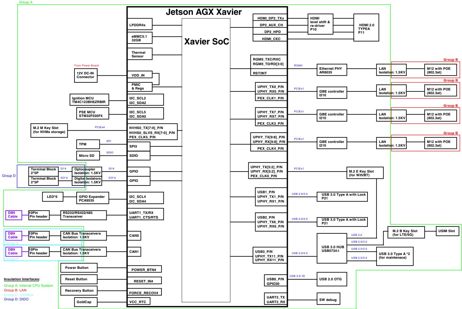
# 2.3 Block Diagram

![The block diagram illustrates the architecture of a 'Jetson AGX Xavier' system, centered around the 'Xavier SoC'. The blocks and connections are organized as follows:\n\n**Central Block:**\n*   **Jetson AGX Xavier** (Header)\n*   **Xavier SoC** (Central Processor)\n\n**Left Side Connections (Inputs & Control):**\n*   **LPDDR4x** connects to Xavier SoC.\n*   **eMMC5.1 32GB** connects to Xavier SoC.\n*   **Thermal Sensor** connects to Xavier SoC.\n*   **VDD_IN** connects to Xavier SoC and **12V DC-IN Connector** (via text 'From Power Board').\n*   **PMIC & Regs** connects to Xavier SoC.\n*   **I2C_SCL2** and **I2C_SDA2** connect to Xavier SoC and **Ignition MCU TM4C123BH6ZRBIR**.\n*   **I2C_SCL5** and **I2C_SDA5** connect to Xavier SoC and **PSE MCU STM32F030F4**.\n*   **NVHS0_TX(7:0)_P/N**, **NVHS0_SLV5_RX(7:0)_P/N**, and **PEX_CLK5_P/N** connect to Xavier SoC and **M.2 M Key Slot (for NVMe storage)** (via 'PCIE4').\n*   **SPI3** connects to Xavier SoC and **TPM** (via 'SPI').\n*   **SDIO** connects to Xavier SoC and **Micro SD** (via 'SDIO').\n*   **GPIO** connects to Xavier SoC and **Terminal Block 2*5P** (via 'DI*4').\n*   **GPIO** connects to Xavier SoC, **Optocoupler Isolation: 1.5KV**, **Digital Isolators Isolation: 1.5KV**, and **Terminal Block 2*5P** (via 'DO*4').\n*   **I2C_SCL4** and **I2C_SDA4** connect to Xavier SoC and **GPIO Expander PCA9535** -) **LED*6**.\n*   **UART1_TX/RX** and **UART1_CTS/RTS** connect to Xavier SoC, **10Pin Pin header**, **RS232/RS422/485 Transceiver**, and **DB9 Cable**.\n*   **CAN0** connects to Xavier SoC, **CAN Bus Transceivers Isolation: 1.5KV**, **10Pin Pin header**, and **DB9 Cable**.\n*   **CAN1** connects to Xavier SoC, **CAN Bus Transceivers Isolation: 1.5KV**, **10Pin Pin header**, and **DB9 Cable**.\n*   **POWER_BTN#** connects to Xavier SoC and **Power Button**.\n*   **RESET_IN#** connects to Xavier SoC and **Reset Button**.\n*   **FORCE RECOV#** connects to Xavier SoC and **Recovery Button**.\n*   **VCC_RTC** connects to Xavier SoC and **GoldCap**.\n\n**Right Side Connections (Outputs & Peripheral):**\n*   **HDMI DP2_TX**, **DP2_AUX_CH**, **DP2_HPD**, **HDMI_CEC** connect to Xavier SoC, **HDMI level shift & re-driver P10**, and **HDMI 2.0 TYPEA P11**.\n*   **RGMII_TXC/RXC**, **RGMII_TD/RD(3:0)**, **RST/INT** connect to Xavier SoC, **Ethernet PHY AR8035** (via 'RGMII'), **LAN Isolation: 1.5KV**, and **M12 with POE (802.3at)**.\n*   **UPHY_TX0_P/N**, **UPHY_RX0_P/N**, **PEX_CLK1_P/N** connect to Xavier SoC, **GBE controller I210** (via 'PCIE1'), **LAN Isolation: 1.5KV**, and **M12 with POE (802.3at)**.\n*   **UPHY_TX7_P/N**, **UPHY_RX7_P/N**, **PEX_CLK3_P/N** connect to Xavier SoC, **GBE controller I210** (via 'PCIE1'), **LAN Isolation: 1.5KV**, and **M12 with POE (802.3at)**.\n*   **UPHY_TX(9:8)_P/N**, **UPHY_RX(9:8)_P/N**, **PEX_CLK4_P/N** connect to Xavier SoC, **GBE controller I210** (via 'PCIE1'), **LAN Isolation: 1.5KV**, and **M12 with POE (802.3at)**.\n*   **UPHY_TX(5:2)_P/N**, **UPHY_RX(5:2)_P/N**, **PEX_CLK0_P/N** connect to Xavier SoC and **M.2 E Key Slot (for WiFi/BT)** (via 'PCIE1').\n*   **USB1_P/N**, **UPHY_TX1_P/N**, **UPHY_RX1_P/N** connect to Xavier SoC and **USB 3.0 Type A with Lock P21** (via 'USB 2.0/3.0').\n*   **USB2_P/N**, **UPHY_TX6_P/N**, **UPHY_RX6_P/N** connect to Xavier SoC and **USB 3.0 Type A with Lock P21** (via 'USB 2.0/3.0').\n*   **USB3_P/N**, **UPHY_TX11_P/N**, **UPHY_RX11_P/N** connect to Xavier SoC and **USB 3.0 HUB USB5734-I** (via 'USB 2.0/3.0').\n    *   From Hub: **USB 2.0** connects to **M.2 B Key Slot (for LTE/5G)** -) **USIM Slot**.\n    *   From Hub: **USB 2.0/3.0** connects to **USB 3.0 Type A *2 (for maintenance)**.\n    *   From Hub: **USB 2.0/3.0** connects to the right edge.\n*   **USB0_P/N** and **GPIO30** connect to Xavier SoC and **USB 2.0 OTG** (via 'USB 2.0/ ID').\n*   **UART3_TX** and **UART3_RX** connect to Xavier SoC and **SW debug**.\n\n**Groups and Legends:**\n*   **Group A** (Green box): Encompasses the left side components. Legend text: 'Group A: Internal CPU System'.\n*   **Group B** (Red boxes): Encompasses the four Ethernet LAN blocks on the right. Legend text: 'Group B: LAN'.\n*   **Group D** (Blue box): Encompasses the Dido section on the left. Legend text: 'Group D: DIDO'.\n*   **Insulation Interfaces** legend at bottom left lists: 'Group A: Internal CPU System', 'Group B: LAN', 'Group C: CANBus', 'Group D: DIDO'.](.ava-ragx-50m-00081-1020-12/b3f5a059e31332937076bc71418db50af66e5da5bf8958e51ae25163ad8e73dd.jpg)

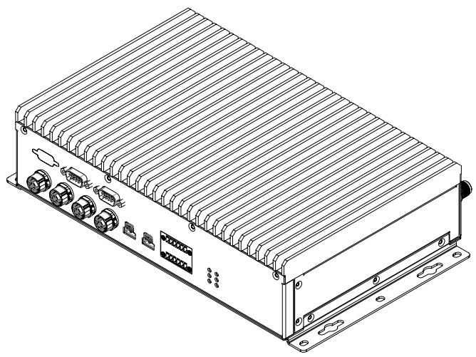
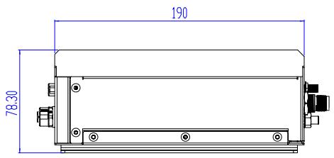
# 2.4 Mechanical Dimensions

Units: mm
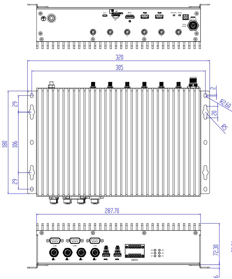
![320\n305\n29\n180\n106\n29\n287.70\n72.30\n6](.ava-ragx-50m-00081-1020-12/886977f7d92df161ec0e75b6f6baac2eed6d3eca68b7d0cd2331694b0404ee20.jpg)

![Isometric line drawing of a rectangular electronic device with multiple ports and connectors (no text or symbols)](.ava-ragx-50m-00081-1020-12/874628f6ae4034372d93300afc40520bb7ad5d923987721198290afca0e9ea8c.jpg)

![190\n78.30](.ava-ragx-50m-00081-1020-12/1cf4c6d2378f45fbf6877f771dd38006b136076ea2fa62dab41ef0f7c0006d82.jpg)

# 2.5 Mechanical Layout

# 2.5.1 Front View
![A\nCAN1 CAN2 COM\nD\nUSB 3.0 USB 3.0\nE\nDI/DO\nF\nU3 U6\nU2 U5\nU1 U4\nC](.ava-ragx-50m-00081-1020-12/74a33a4b8b1f49e89b3496cb4a58561841503546513f7b3e07d405757affba88.jpg)

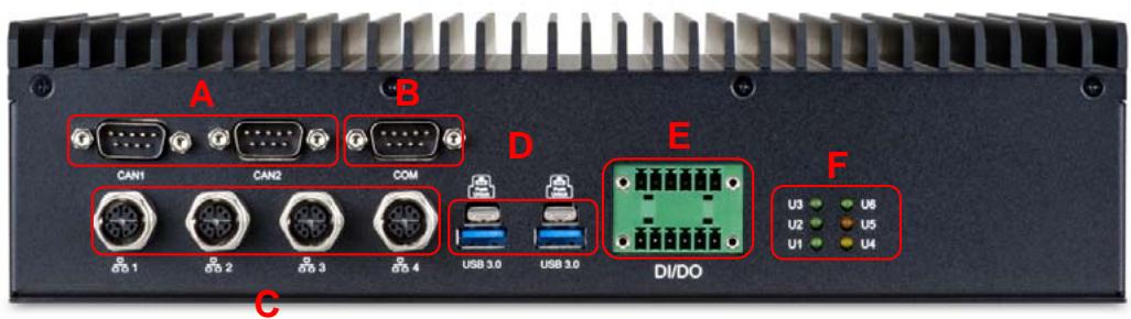
<table><tr><td>A</td><td>CAN bus</td></tr><tr><td>B</td><td>Serial Port</td></tr><tr><td>C</td><td>M12 Female X-coded</td></tr><tr><td>D</td><td>USB 3.0 with Lock</td></tr><tr><td>E</td><td>DIO</td></tr><tr><td>F</td><td>User-Defined LEDs</td></tr></table>

# 2.5.2 Rear View

![H\n+ 24~110 VDC\nPower\nInput\nI Reset Recovery\nJ\nUSB 3.0 K USB 3.0\nG\n4\n5\n6\nU\nSD\nL\nN\nOTG\nM\nO](.ava-ragx-50m-00081-1020-12/aba6caf7531fdfeab0ecb4cdbbd107a369793dcb526762712e2cae3d9716bfa7.jpg)

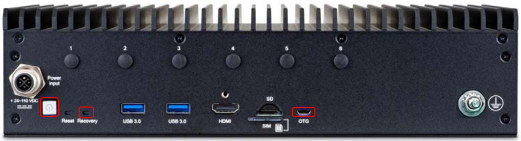
<table><tr><td>G</td><td>Antenna Cutouts</td></tr><tr><td>H</td><td>M12 4-pin S-coded</td></tr><tr><td>I</td><td>Power Button</td></tr><tr><td>J</td><td>Reset/Recovery Buttons</td></tr><tr><td>K</td><td>USB 3.0 Ports</td></tr><tr><td>L</td><td>HDMI Port</td></tr><tr><td>N</td><td>microSD / USIM Slots</td></tr><tr><td>M</td><td>Micro USB 2.0 OTG Port</td></tr><tr><td>O</td><td>Ground Stud</td></tr></table>

# 2.6 Power Specifications

The following tables present the AVA-RAGX Series power consumption data at room temperature under the following test conditions.

• AVA-RAGX Mother Board: 55-32201-100E (Jetson AGX Xavier & Jetson AGX Xavier Industrial)
- System-on-Module
• Power Module: 55-32202-000E
• Chassis Heat Sink: 32-60039-0000-A0
• OS: NVIDIA ARM OS

# Software:

• NVIDIA ALLTEST: YOLO.mp4
• 5G module: PuTTY with stress command
- BSP:ava-ragx.1v2.4 Jetpack 4.6 [L4T 32.6.1]

# Test Fixture:

- DI/Do Test Fixture
• CAN1 / CAN2 Pin to Pin
- PoE Test Fixture: 4 port total 40W
- USB Dummy Loading: 5W\*3
• DC Power supply: 62006P-300-8

# 2.6.1 AVA-RAGXI Power Consumption

40W All Mode

<table><tr><td colspan="2">AVA-RAGXI/POE</td><td colspan="2">AVA-RAGXI/NPOE</td></tr><tr><td>DC</td><td>40W All</td><td>DC</td><td>40W All</td></tr><tr><td>24V</td><td>111.36W</td><td>24V</td><td>63.12W</td></tr><tr><td>36V</td><td>108W</td><td>36V</td><td>61.2W</td></tr><tr><td>72V</td><td>103.68W</td><td>72V</td><td>61.2W</td></tr><tr><td>110V</td><td>103.4W</td><td>110V</td><td>61.6W</td></tr></table>

Idle Mode

<table><tr><td colspan="2">AVA-RAGXI/POE</td></tr><tr><td>DC</td><td>40W All</td></tr><tr><td>24V</td><td>26.88W</td></tr><tr><td>36V</td><td>27W</td></tr><tr><td>72V</td><td>27.36W</td></tr><tr><td>110V</td><td>27.5W</td></tr></table>

# 2.6.2 AVA-RAGX

30W All & 15W Desktop Mode

<table><tr><td colspan="3">AVA-RAGX/POE</td><td colspan="3">AVA-RAGX/NPOE</td></tr><tr><td>DC</td><td>30W All</td><td>15W Desktop</td><td>DC</td><td>30W All</td><td>15W Desktop</td></tr><tr><td>24V</td><td>108.96W</td><td>100.8W</td><td>24V</td><td>59.76W</td><td>52.32W</td></tr><tr><td>36V</td><td>107.64W</td><td>99W</td><td>36V</td><td>60.12W</td><td>52.92W</td></tr><tr><td>72V</td><td>105.84W</td><td>97.92W</td><td>72V</td><td>59.76W</td><td>52.56W</td></tr><tr><td>110V</td><td>106.7W</td><td>99W</td><td>110V</td><td>58.3W</td><td>51.7W</td></tr></table>

Idle Mode

<table><tr><td colspan="3">AVA-RAGX/NPOE</td></tr><tr><td>DC</td><td>30W All</td><td>15W Desktop</td></tr><tr><td>24V</td><td>21.17W</td><td>21.02W</td></tr><tr><td>36V</td><td>20.52W</td><td>20.87W</td></tr><tr><td>72V</td><td>20.19W</td><td>20.08W</td></tr><tr><td>110V</td><td>21.6W</td><td>21.2W</td></tr></table>

# 3 Getting Started

Follow the instructions describe installation of USIM cards, Wi-Fi, cellular and M.2 SATA modules; mounting brackets; ground cable; and DC power supply

Note: MXM modules must be installed at the factory. Please contact your local ADLINK representative for more information.

# 3.1 Removing the Chassis Bottom Cover

To install the optional modules, first remove the bottom cover as described below.

1. Place the chassis on a suitable surface with the bottom side facing up. Remove the 8 screws from the bottom side and 3 screws each from the left and right side as indicated below.

![Isometric technical diagram of an electronic device chassis with labeled ports and connectors (no text or symbols present)](.ava-ragx-50m-00081-1020-12/7691050af5de9dc9651c4df97a96bf5b8581905fe6b924636772b0b6f6687b0f.jpg)

2. Lift the rear cover off of the chassis.

To re-install the bottom cover, place it in its original location and replace the 8 screws removed in Step 1.

# 3.2 Installing M.2 E Key Modules

Follow the instructions below to install a M.2 E key 2230 Wi-Fi or cellular module.

1. Insert the M.2 A/E key 2230 Wi-Fi module into one of the slots as shown and secure it using two M2.5 screws

![Technical line drawing of an electronic device chassis with exposed ports and internal components (no text or symbols)](.ava-ragx-50m-00081-1020-12/d34a482f44b644891dcfeff0abe009e41f005caf597d2f353ff4e3380a90fd84.jpg)

2. Connect the internal RF cables to the module and install the SMA connectors into the antenna openings.

Note: M.2 modules may require an additional thermal solution when operated above $60^{\circ}$ C. The accessory kit includes a generic M.2 thermal pad for installation by the user. If you have any questions about thermal limitations, please contact your local ADLINK representative for more information.

# 3.3 Installing an M.2 M Key 2280 SATA Module

To install an M.2 2280 SATA module, insert the module into the slot and secure it with one M2.5 screw as shown.

![Technical line drawing of an electronic device chassis with ports, connectors, and a red indicator light (no text or symbols)](.ava-ragx-50m-00081-1020-12/08ce2374b2e3a5680a1070ae126e030067dbfe463d1a3736675af29ef77add8f.jpg)

Note: M.2 modules may require an additional thermal solution when operated above $60^{\circ}$ C. The accessory kit includes a generic M.2 thermal pad for installation by the user. If you have any questions about thermal limitations, please contact your local ADLINK representative for more information.

# 3.4 Installing an M.2 B-key 3042 LTE/5G Module

To install an M.2 B-key 3042 LTE/5G, insert the module into the slot and secure it with one M2.5 screw as shown.

![Technical line drawing of an electronic device chassis with visible ports, connectors, and internal components (no text or labels)](.ava-ragx-50m-00081-1020-12/c67f9c1e1360249c54c293f9a1bb038b124289134d875d8db867602825f74a87.jpg)

Note: M.2 modules may require an additional thermal solution when operated above 60 °C. The accessory kit includes a generic M.2 thermal pad for installation by the user. If you have any questions about thermal limitations, please contact your local ADLINK representative for more information.

# 3.5 Installing micro-USIM Card

To install a micro-USIM card, insert the card into the slot on the rear panel as shown.

![Technical line drawing of a multi-chamber electronic device with cooling fins and ports (no text or symbols)](.ava-ragx-50m-00081-1020-12/27faa813c74d7bd1a45ea1436f835f2162f04f21cd0ef47d0ffb95a61177ce3a.jpg)

![The image displays a technical diagram featuring a horizontal rectangular slot at the top with internal contacts. Below the slot is the text 'SIM' centered. To the right of the text is a SIM card icon, and next to it is a bracket-like shape.](.ava-ragx-50m-00081-1020-12/75a773a094bac7da38024374461f8132800a910dd9d6ef9923986251c5f7f988.jpg)

# 3.6 Wall or Surface Mounting

The AVA-RAGX can be wall or surface mounted using the wall mount brackets and screws provided. If wall mounting, make sure the wall can support the weight of the device. Secure the brackets to the chassis using the 6 screws provided as shown.

![Technical line drawing of an electronic device chassis with mounting brackets and connectors (no text or symbols)](.ava-ragx-50m-00081-1020-12/161380dd33937adf83c486d95968f03e9b6b34cd20bab3bf2e6317f1959f9e65.jpg)

Refer to 2.4 Mechanical Dimensions on page 15 for bracket mounting hole dimensions.

# 3.7 Installing a microSD Card

To install a microSD card, insert the card into the slot on the rear panel as shown

![Technical line drawing of a rectangular electronic device with multiple ports and connectors (no text or symbols)](.ava-ragx-50m-00081-1020-12/5a8cbcc9481407925445893c9fc0004a84200d073b500288dc9834e6c7aa5a0d.jpg)

# 3.8 Connecting a Ground Cable

![The image displays a standard safety warning sign featuring a yellow triangle with a black border containing a black exclamation point. Below the triangle is the text 'CAUTION:' in black capital letters.](.ava-ragx-50m-00081-1020-12/03f8c3e82b03dcaf2fa55485e1ebce55ed4cd0f96e5d57ec0453f1f3742f4a9b.jpg)

Connect the ground cable before making any other connections. When disassembling the system, always detach the ground cable last.

- Use a ground cable with a cross section of at least 0.823mm2 (18AWG) and an M6 size ring terminal.
- Slide the ring terminal onto the ground stud and secure it with the locking M6 nut.

![Power\nInput\n+ 24-110 VDC\nReset Recovery\nUSB 3.0\nUSB 3.0\nHDMI\nSD\nSIM OTG\nGround Stud](.ava-ragx-50m-00081-1020-12/5a57424a4e6f29f3919a4e39ddf576491743cb5a938506e0736eba41e72644cd.jpg)

# 3.9 Connecting Peripherals

Connect all the peripheral devices needed for your system to function (e.g. KB/MS, display, etc.).

# 3.10 Connecting the Power Supply

![The image shows a yellow triangular warning sign with a black border and a black exclamation point in the center. Below the triangle, the word 'CAUTION:' is written in black capital letters.](.ava-ragx-50m-00081-1020-12/4574003a28e92d847c80ea58d1d441a683f51bb371e342d960095a4c77e718bb.jpg)

Connect the ground cable before making any other connections. When disassembling the system, always detach the ground cable last.

![The image features a red triangular warning sign with a white exclamation point in the center. Below the triangle is the text 'WARNING:' in black, uppercase letters.](.ava-ragx-50m-00081-1020-12/b2266a37959b72392206ea8ee12e9ba7061fbbf4788c946c79a6f25a12e32faf.jpg)

- Work on the computer system may only be carried out by personnel qualified for the specific task and who have the training and experience to identify risks and avoid potential hazards.
- Make sure that a ground cable has been connected to the system before connecting an external power supply and switching on the system.
- Make sure that the voltage supplied by the external power supply conforms with specifications of the system

Connect the power supply to the 4-pin M12 connector on the rear of the chassis the device will power up when the power supply is turned on.

<table><tr><td>Pin #</td><td>Signal</td></tr><tr><td>1</td><td>Ignition</td></tr><tr><td>2</td><td>Vin+</td></tr><tr><td>3</td><td>Vin-</td></tr><tr><td>4</td><td>NA</td></tr></table>

![1\n2\n3\n4](.ava-ragx-50m-00081-1020-12/04d5b15422b8ac80f57287196d482219f960364d76daf0018e640480d9aeab35.jpg)

Note: The user must provide the +24/36/72/110VDC to Pin 1 Ignition

An M12 S-coded 4-pin female connector (P/N: 30-51044-0000-A0) is provided for the user to make their own power cable.

![55.0 (REF.)\nAmphenol\n16.0 Hex.\n(Metal Nut)\n4\n1\n2\n3\n18.60\n47.0 Hex.](.ava-ragx-50m-00081-1020-12/92bbe7197f6b28f9b2f1e2d6173c36f7ce2f06dc20f1f770f4ef159e97141bb9.jpg)

# 3.11 Starting the System

Connect the DC power supply to the M12 4-pin connector on the rear panel. The AVA-RAGX will power on and boot up into the installed Linux Ubuntu OS.

# 4 System Interfaces

# 4.1 External Connectors

Please refer to 2.5.1 Mechanical Layout Front View on page 16 for connector locations.

# 4.1.1 GbE M12 X-code Connectors

<table><tr><td>Pin #</td><td>Signal Name</td></tr><tr><td>1</td><td>MDI_T_P0</td></tr><tr><td>2</td><td>MDI_T_N0</td></tr><tr><td>3</td><td>MDI_T_P1</td></tr><tr><td>4</td><td>MDI_T_N1</td></tr><tr><td>5</td><td>MDI_T_P3</td></tr><tr><td>6</td><td>MDI_T_N3</td></tr><tr><td>7</td><td>MDI_T_N2</td></tr><tr><td>8</td><td>MDI_T_P2</td></tr></table>

![4\n3\n2\n1\n5\n6\n7\n8](.ava-ragx-50m-00081-1020-12/b06c77b84ab9be970067508044fe5a6ac8b04b84a121aee18f2b1df0c0e55ba8.jpg)

# 4.1.2 USB 3.0 Connector

<table><tr><td>Pin #</td><td>Signal Name</td></tr><tr><td>1</td><td>+5V_USB3</td></tr><tr><td>2</td><td>USB2_P0_DN</td></tr><tr><td>3</td><td>USB2_P0_DP</td></tr><tr><td>4</td><td>GND</td></tr><tr><td>5</td><td>USB3_P0_RXN</td></tr><tr><td>6</td><td>USB3_P0_RXP</td></tr><tr><td>7</td><td>GND</td></tr><tr><td>8</td><td>USB3_P0_TXN</td></tr><tr><td>9</td><td>USB3_P0_TXP</td></tr></table>

![This image is a black-and-white line drawing of a DB9 connector. It depicts a rectangular metal shell with mounting brackets on the top, bottom, and sides. Inside the shell is a central plastic insulator block holding two rows of pins. The left row contains pins labeled with the numbers 1, 2, 3, and 4 from top to bottom. The right row contains pins labeled with the numbers 9, 8, 7, 6, and 5 from top to bottom.](.ava-ragx-50m-00081-1020-12/8652e27e370674b002e5dc4595d79884f2d8a951a4cf83edeca8ceb1438b86c6.jpg)

# 4.1.3 COM DB9 Connectors

![Pin 1\nPin 6\n1\n2\n3\n4\n5\n6\n9\nPin 5\nPin 9](.ava-ragx-50m-00081-1020-12/5dc5a90dcc98df38051edbff66b4613ab4cd3df90f69bb191657efba5cb935df.jpg)

<table><tr><td>Pin #</td><td>RS-232</td><td>RS-422</td><td>RS-485</td></tr><tr><td>Pin1</td><td>DCD</td><td>TXD-</td><td>D-</td></tr><tr><td>Pin2</td><td>RXD</td><td>TXD+</td><td>D+</td></tr><tr><td>Pin3</td><td>TXD</td><td>RXD+</td><td>NA</td></tr><tr><td>Pin4</td><td>DTR</td><td>RXD-</td><td>NA</td></tr><tr><td>Pin5</td><td>GND</td><td>GND</td><td>GND</td></tr><tr><td>Pin6</td><td>DSR</td><td>NA</td><td>NA</td></tr><tr><td>Pin7</td><td>RTS</td><td>NA</td><td>NA</td></tr><tr><td>Pin8</td><td>CTS</td><td>NA</td><td>NA</td></tr><tr><td>Pin9</td><td>RI</td><td>NA</td><td>NA</td></tr></table>

# 4.1.4 DC Power Input M12 Connector

<table><tr><td>Pin #</td><td>Signal</td></tr><tr><td>1</td><td>Ignition</td></tr><tr><td>2</td><td>Vin+</td></tr><tr><td>3</td><td>Vin-</td></tr><tr><td>4</td><td>NA</td></tr></table>

![1\n2\n3\n4](.ava-ragx-50m-00081-1020-12/f98825d03883241104a1015057b14fc3987b5c578112682a4e2054d65ed2e0a9.jpg)

# 4.1.5 HDMI Connector

One HDMI connector with lockable on the front panel support HDMI2.0a/b (up to 6Gbps) standard specification. It can connect to VGA, DVI, Display Port monitors via HDMI to VGA adapter cable, HDMI to DVI adapter cable, and HDMI cable. HDMI Supports HDMI2.0a/b, resolutions up to 4096 x 2160 at 60Hz

![19 17\n3 1\n18\n4 2](.ava-ragx-50m-00081-1020-12/682c8d6b6572900e21d3b1a8fd1fd661cf714301633fc5eea68122c1026c7eea.jpg)

<table><tr><td>Pin #</td><td>Signal</td><td>Pin #</td><td>Signal</td></tr><tr><td>Pin1</td><td>TMDS Data2+</td><td>Pin 11</td><td>TMDS Clock Shield</td></tr><tr><td>Pin2</td><td>TMDS Data2 Shield</td><td>Pin 12</td><td>TMDS Clock-</td></tr><tr><td>Pin3</td><td>TMDS Data2-</td><td>Pin13</td><td>CEC</td></tr><tr><td>Pin4</td><td>TMDS Data1+</td><td>Pin 14</td><td>Reserved</td></tr><tr><td>Pin5</td><td>TMDS Data1 Shield</td><td>Pin 15</td><td>SCL</td></tr><tr><td>Pin6</td><td>TMDS Data1-</td><td>Pin 16</td><td>SDA</td></tr><tr><td>Pin7</td><td>TMDS Data0+</td><td>Pin 17</td><td>DDC/CEC Ground</td></tr><tr><td>Pin8</td><td>TMDS Data0 Shield</td><td>Pin 18</td><td>+5V Power</td></tr><tr><td>Pin9</td><td>TMDS Data0-</td><td>Pin 19</td><td>Hot Plug Detect</td></tr><tr><td>Pin10</td><td>TMDS Clock+</td><td></td><td></td></tr></table>

# 4.1.6 COM DB9 Connectors

![Pin 1\nPin 6\n1\n5\n6\n9\nPin 5\nPin 9](.ava-ragx-50m-00081-1020-12/680a4ff8dc442a8973da0493bdca50600456953cfa63c7d957c3307183c205b6.jpg)

<table><tr><td>Pin #</td><td>Port 0</td><td>Port 1</td></tr><tr><td>1</td><td>NC</td><td>NC</td></tr><tr><td>2</td><td>Port 0 CAN L</td><td>Port 1 CAN L</td></tr><tr><td>3</td><td>CANx_ISOGND</td><td>CANx_ISOGND</td></tr><tr><td>4</td><td>NC</td><td>NC</td></tr><tr><td>5</td><td>Sx_GND</td><td>Sx_GND</td></tr><tr><td>6</td><td>CANx_ISOGND</td><td>CANx_ISOGND</td></tr><tr><td>7</td><td>Port 0 CAN H</td><td>Port 1 CAN H</td></tr><tr><td>8</td><td>NC</td><td>NC</td></tr><tr><td>9</td><td>NC</td><td>NC</td></tr></table>

# 4.1.7 DIO DB9 Connectors

The location and pin definitions of the optional DIO connectors are as shown below.

![CAN1\nCAN2\nCOM\nU3\nU6\nU2\nU5\nU1\nU4\nU5 1\nU5 2\nU5 3\nU5 4\nUSB 3.0\nUSB 3.0\nDI/DO](.ava-ragx-50m-00081-1020-12/ce643e97d71de31259a8fe54f7e1cf333314a779d551af23f1f83aa553ae3cff.jpg)

<table><tr><td>Pin #</td><td>Port 0/1</td></tr><tr><td>1</td><td>CN_DI0</td></tr><tr><td>2</td><td>CN_DI2</td></tr><tr><td>3</td><td>DI_COM</td></tr><tr><td>4</td><td>CN_DO0</td></tr><tr><td>5</td><td>CN_DO2</td></tr><tr><td>6</td><td>P_+VDO_EXT01</td></tr><tr><td>7</td><td>CN_DI1</td></tr><tr><td>8</td><td>CN_DI3</td></tr><tr><td>9</td><td>DI_COM</td></tr><tr><td>10</td><td>CN_DO1</td></tr><tr><td>11</td><td>CN_DO3</td></tr><tr><td>12</td><td>ISO_DIDO_GND</td></tr></table>

# 4.2 Internal Connectors

# 4.2.1 M.2 M Key 2280 SATA Module Connector

![1\n75\n2\n74](.ava-ragx-50m-00081-1020-12/8b754864e1f03da74562a76bb6ad9fbae104e48bb5bcc4de3b818a28ac060397.jpg)

<table><tr><td>Pin</td><td>Signal Name</td><td>Pin</td><td>Signal Name</td></tr><tr><td>1</td><td>M2B_CONFIG_3</td><td>2</td><td>P_3V3_M2M</td></tr><tr><td>3</td><td>GND</td><td>4</td><td>P_3V3_M2M</td></tr><tr><td>5</td><td>NVHS0_RX3_N</td><td>6</td><td>N/C</td></tr><tr><td>7</td><td>NVHS0_RX3_P</td><td>8</td><td>N/C</td></tr><tr><td>9</td><td>GND</td><td>10</td><td>N/C</td></tr><tr><td>11</td><td>NVHS0_TX3_N</td><td>12</td><td>P_3V3_M2M</td></tr><tr><td>13</td><td>NVHS0_TX3_P</td><td>14</td><td>P_3V3_M2M</td></tr><tr><td>15</td><td>GND</td><td>16</td><td>P_3V3_M2M</td></tr><tr><td>17</td><td>NVHS0_RX2_N</td><td>18</td><td>P_3V3_M2M</td></tr><tr><td>19</td><td>NVHS0_RX2_P</td><td>20</td><td>N/C</td></tr><tr><td>21</td><td>M2B_CONFIG_0</td><td>22</td><td>N/C</td></tr><tr><td>23</td><td>NVHS0_TX2_N</td><td>24</td><td>N/C</td></tr><tr><td>25</td><td>NVHS0_TX2_P</td><td>26</td><td>N/C</td></tr><tr><td>27</td><td>GND</td><td>28</td><td>N/C</td></tr><tr><td>29</td><td>NVHS0_RX1_N</td><td>30</td><td>N/C</td></tr><tr><td>31</td><td>NVHS0_RX1_P</td><td>32</td><td>N/C</td></tr><tr><td>33</td><td>GND</td><td>34</td><td>N/C</td></tr><tr><td>35</td><td>NVHS0_TX1_N</td><td>36</td><td>N/C</td></tr><tr><td>37</td><td>NVHS0_TX1_P</td><td>38</td><td>DEVSLP</td></tr><tr><td>39</td><td>GND</td><td>40</td><td>N/C</td></tr><tr><td>41</td><td>NVHS0_RX0_N</td><td>42</td><td>N/C</td></tr><tr><td>43</td><td>NVHS0_RX0_P</td><td>44</td><td>N/C</td></tr><tr><td>45</td><td>GND</td><td>46</td><td>N/C</td></tr><tr><td>47</td><td>NVHS0_TX0_N</td><td>48</td><td>N/C</td></tr><tr><td>49</td><td>NVHS0_TX0_P</td><td>50</td><td>PCIE_RST5_N</td></tr><tr><td>51</td><td>GND</td><td>52</td><td>PCIE_CLKREQ5_N</td></tr><tr><td>53</td><td>PCIE_REF5_CLKN</td><td>54</td><td>PCIE_WAKE_N</td></tr><tr><td>55</td><td>PCIE_REF5_CLKP</td><td>56</td><td>N/C</td></tr><tr><td>57</td><td>GND</td><td>58</td><td>N/C</td></tr><tr><td colspan="4">M-key</td></tr><tr><td>67</td><td>PCIE_RST5_N</td><td>68</td><td>M.2_M_SUSCLK</td></tr><tr><td>69</td><td>M2B_CONFIG_1</td><td>70</td><td>P_3V3_M2M</td></tr><tr><td>71</td><td>GND</td><td>72</td><td>P_3V3_M2M</td></tr><tr><td>73</td><td>GND</td><td>74</td><td>P_3V3_M2M</td></tr><tr><td>75</td><td>M2B_CONFIG_2</td><td></td><td></td></tr></table>

# 4.2.2 M.2 B-key 3042 LTE/5G Module Connector

![1\n8\n75\n8\nH](.ava-ragx-50m-00081-1020-12/6228615308d35d5baf79061ddf95eaf0d985ada4433dff6b428fb96a91865f05.jpg)

<table><tr><td>Pin</td><td>Signal Name</td><td>Pin</td><td>Signal Name</td></tr><tr><td>1</td><td>CONFIG_3</td><td>2</td><td>P_3V3_M2B</td></tr><tr><td>3</td><td>GND</td><td>4</td><td>P_3V3_M2B</td></tr><tr><td>5</td><td>GND</td><td>6</td><td>P_3V3_M2B</td></tr><tr><td>7</td><td>USB_DS1_DP</td><td>8</td><td>P_3V3_M2B</td></tr><tr><td>9</td><td>USB_DS1_DN</td><td>10</td><td>N/C</td></tr><tr><td>11</td><td>GND</td><td></td><td></td></tr><tr><td colspan="4">KEY-B</td></tr><tr><td>21</td><td>M2_CONFIG_0</td><td>20</td><td>N/C</td></tr><tr><td>23</td><td>N/C</td><td>22</td><td>N/C</td></tr><tr><td>25</td><td>N/C</td><td>24</td><td>N/C</td></tr><tr><td>27</td><td>GND</td><td>26</td><td>N/C</td></tr><tr><td>29</td><td>USB_SSDS1_RXN_CN</td><td>28</td><td>N/C</td></tr><tr><td>31</td><td>USB_SSDS1_RXP_CN</td><td>30</td><td>M2_UIM_RST_R</td></tr><tr><td>33</td><td>GND</td><td>32</td><td>M2_UIM_CLK_R</td></tr><tr><td>35</td><td>USB_SSDS1_TXN_CN</td><td>34</td><td>M2_UIM_DATA_R</td></tr><tr><td>37</td><td>USB_SSDS1_TXP_CN</td><td>36</td><td>P_+3V3_UIM_M2</td></tr><tr><td>39</td><td>GND</td><td>38</td><td>N/C</td></tr><tr><td>41</td><td>N/C</td><td>40</td><td>N/C</td></tr><tr><td>43</td><td>N/C</td><td>42</td><td>N/C</td></tr><tr><td>45</td><td>GND</td><td>44</td><td>N/C</td></tr><tr><td>47</td><td>N/C</td><td>46</td><td>N/C</td></tr><tr><td>49</td><td>N/C</td><td>48</td><td>N/C</td></tr><tr><td>51</td><td>GND</td><td>50</td><td>MP2_RST_N</td></tr><tr><td>53</td><td>N/C</td><td>52</td><td>N/C</td></tr><tr><td>55</td><td>N/C</td><td>54</td><td>N/C</td></tr><tr><td>57</td><td>GND</td><td>56</td><td>N/C</td></tr><tr><td>59</td><td>N/C</td><td>58</td><td>N/C</td></tr><tr><td>61</td><td>N/C</td><td>60</td><td>N/C</td></tr><tr><td>63</td><td>N/C</td><td>62</td><td>N/C</td></tr><tr><td>65</td><td>N/C</td><td>64</td><td>N/C</td></tr><tr><td>67</td><td>WWAN_RESET-L</td><td>66</td><td>M2_USIM_DET_R</td></tr><tr><td>69</td><td>M2_CONFIG_1</td><td>68</td><td>N/C</td></tr><tr><td>71</td><td>GND</td><td>70</td><td>P_3V3_M2B</td></tr><tr><td>73</td><td>GND</td><td>72</td><td>P_3V3_M2B</td></tr><tr><td>75</td><td>M2_CONFIG_2</td><td>74</td><td>P_3V3_M2B</td></tr></table>

# 4.2.3 M.2 E Key 2230 Wi-Fi Module Connector

![PIN1\nPIN75\nPIN2\nPIN74](.ava-ragx-50m-00081-1020-12/cfaf90c5f41ba28f17ad9e461586898d84477ba847d28257c955debed9266c9a.jpg)

<table><tr><td>Pin</td><td>Signal Name</td><td>Pin</td><td>Signal Name</td></tr><tr><td>1</td><td>GND</td><td>2</td><td>P_3V3_M2E</td></tr><tr><td>3</td><td>USB_DS4_DP</td><td>4</td><td>P_3V3_M2E</td></tr><tr><td>5</td><td>USB_DS4_DN</td><td>6</td><td>N/C</td></tr><tr><td>7</td><td>GND</td><td>8</td><td>N/C</td></tr><tr><td>9</td><td>N/C</td><td>10</td><td>N/C</td></tr><tr><td>11</td><td>N/C</td><td>12</td><td>N/C</td></tr><tr><td>13</td><td>N/C</td><td>14</td><td>N/C</td></tr><tr><td>15</td><td>N/C</td><td>16</td><td>N/C</td></tr><tr><td>17</td><td>N/C</td><td>18</td><td>GND</td></tr><tr><td>19</td><td>N/C</td><td>20</td><td>N/C</td></tr><tr><td>21</td><td>N/C</td><td>22</td><td>N/C</td></tr><tr><td>23</td><td>N/C</td><td>24</td><td>N/C</td></tr><tr><td colspan="4">Key E</td></tr><tr><td>33</td><td>GND</td><td>32</td><td>N/C</td></tr><tr><td>35</td><td>PCIe_x4_TX0_P</td><td>34</td><td>N/C</td></tr><tr><td>37</td><td>PCIe_x4_TX0_N</td><td>36</td><td>N/C</td></tr><tr><td>39</td><td>GND</td><td>38</td><td>CL_RST-L</td></tr><tr><td>41</td><td>PCIe_x4_RX0_P</td><td>40</td><td>CL_DATA</td></tr><tr><td>43</td><td>PCIe_x4_RX0_N</td><td>42</td><td>CL_CLK</td></tr><tr><td>45</td><td>GND</td><td>44</td><td>N/C</td></tr><tr><td>47</td><td>PCIE_REF0_CLKP</td><td>46</td><td>N/C</td></tr><tr><td>49</td><td>PCIE_REF0_CLKN</td><td>48</td><td>N/C</td></tr><tr><td>51</td><td>GND</td><td>50</td><td>M2E_SUSCLK</td></tr><tr><td>53</td><td>PCIE_CLKREQ0_N</td><td>52</td><td>PCIE_RST0_N</td></tr><tr><td>55</td><td>PCIE_WAKE_N</td><td>54</td><td>M2E_BT</td></tr><tr><td>57</td><td>GND</td><td>56</td><td>M2E_WiFi</td></tr><tr><td>59</td><td>N/C</td><td>58</td><td>M2E_SMBDATA</td></tr><tr><td>61</td><td>N/C</td><td>60</td><td>M2E_SMBCCLK</td></tr><tr><td>63</td><td>GND</td><td>62</td><td>M2E_ALERT</td></tr><tr><td>65</td><td>N/C</td><td>64</td><td>N/C</td></tr><tr><td>67</td><td>N/C</td><td>66</td><td>PCIE_RST0_N</td></tr><tr><td>69</td><td>GND</td><td>68</td><td>N/C</td></tr><tr><td>71</td><td>N/C</td><td>70</td><td>M2E_PEWAKE1</td></tr><tr><td>73</td><td>N/C</td><td>72</td><td>P_3V3_M2E</td></tr><tr><td>75</td><td>GND</td><td>74</td><td>P_3V3_M2E</td></tr></table>

# 4.3 Buttons and LEDs

# 4.3.1 Power Button

The power button is non-latched, with a blue LED indicator. System is turned on when the button is depressed, and the power LED lights. If the system hangs, depressing the button for 5 seconds to turn off the system completely.

<table><tr><td>System status</td><td>Power Button LED</td></tr><tr><td>Idle on OS</td><td>On</td></tr><tr><td>Suspend</td><td>Blinking (1Hz)</td></tr><tr><td>Hibernation</td><td>Blinking (1Hz)</td></tr><tr><td>Power Off</td><td>Off</td></tr></table>

# 4.3.2 Reset Button

The reset button is a non-latched. The system is restarted when the button is depressed. If the system hangs, press the button to restart the system.

# 4.3.3 Recovery Button

Press this button to force the system into recovery mode only when flashing the operating system. Refer to 5.1 Operating System Update Procedure on page 38.

# 4.3.4 Status LEDs

![CAN1 CAN2 COM\n85 1 85 2 85 3 85 4 USB 3.0 USB 3.0 DI/DO\nU3 U5\nU2 U5\nU1 U4](.ava-ragx-50m-00081-1020-12/cf923d8ae94e6b36f3eb2c31e6e90090f88588390b9073e97658b9d763d6867e.jpg)

<table><tr><td>LED indicator</td><td>Color</td><td>Description</td></tr><tr><td>SATA Drive</td><td>Red</td><td>When blinking, indicates the SATA drive is active.</td></tr><tr><td>Watchdog (WD)</td><td>Amber</td><td>Indicates watchdog timer status. When watchdog timer starts, the LED flashes. When the timer is expired, the system will auto reboot.</td></tr><tr><td>Diagnostic</td><td>Green</td><td>If lit continuously, indicates no physical storage is connected.If blinking, indicates no memory is installed on either SO-DIMM socket.</td></tr><tr><td>U1</td><td>Green</td><td>The LED is Green color for User control</td></tr><tr><td>U2</td><td>Green</td><td>The LED is Green color for User control</td></tr><tr><td>U3</td><td>Green</td><td>The LED is Green color for User control</td></tr><tr><td>U4</td><td>Yellow</td><td>The LED is Yellow color for User control</td></tr><tr><td>U5</td><td>Red</td><td>The LED is Red color for User control</td></tr><tr><td>U6</td><td>Green</td><td>The LED is Green color for User control</td></tr></table>

# 5 Software Upgrade

To upgrade the system software, follow the steps below.
![+ 24~110 VDC\nPower\nInput\nReset Recovery\nUSB 3.0\nUSB 3.0\nHDMI\nSD\nSIM OTG](.ava-ragx-50m-00081-1020-12/315a346d62a3336f824dc7b81502a27c88ace1d1c83820e6e0f0087cdcd92b5c.jpg)

# 5.1 Operating System Update Procedure

To update the operating system, perform the following steps.

1. Download the released manufacturing image (MFI) package and extract the tarball file. For example:

- AVA-RAGX (NVIDIA Jetson AGX Xavier Commercial): mfi\_jetson-ava-ragx-emmc - 1v2.2.tbz2
- AVA-RAGX (NVIDIA Jetson AGX Xavier Industrial): mfi\_jetson-ava-ragx-emmc-ind-1v2.2.tbz2

2. Put the AVA-RAGX into reset/recovery mode.

• Power on the AVA-RAGX.
- Press and hold the recovery button, and then press the reset button.
- Release the reset button and recovery button.

3. Connect the AVA-RAGX's OTG port to the host with an OTG micro-usb cable.

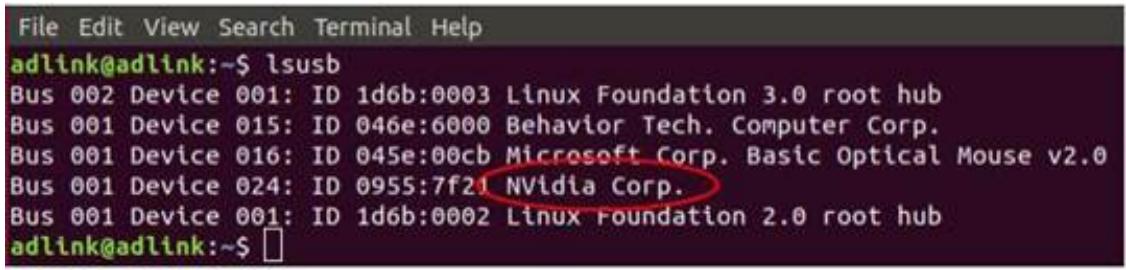
4. Open a terminal on the host PC and run the following command:

\- \$ lsusb

5. Look for “NVidia Corp.” in the terminal output (an example is circled in red in the screenshot below). If found, the host PC has recognized the client and you may proceed. If not, check the OTG cable connection and perform troubleshooting as needed until the client is recognized
![File Edit View Search Terminal Help\nadlink@adlink:~\$ lsusb\nBus 002 Device 001: ID 1d6b:0003 Linux Foundation 3.0 root hub\nBus 001 Device 015: ID 046e:6000 Behavior Tech. Computer Corp.\nBus 001 Device 016: ID 045e:00cb Microsoft Corp. Basic Optical Mouse v2.0\nBus 001 Device 024: ID 0955:7f21 Nvidia Corp.\nBus 001 Device 001: ID 1d6b:0002 Linux Foundation 2.0 root hub\nadlink@adlink:~\$ □](.ava-ragx-50m-00081-1020-12/168d8854ae96cfa2733d8f7407068cb9bdf61b96f3dd486ee56b3a7a743f7274.jpg)

6. Run the following commands in the directory that contains your downloaded BSP file:

- # sudo tar mfi\_jetson-ava-ragx-emmc -&lt;version&gt;.tbz2
- # cd mfi\_jetson-ava-ragx-emmc -&lt;version&gt;
- # sudo ./nvmflash.sh

# 5.2 User-Defined LED Sample Code

#!/bin/bash
```shell
# Check script is running as root
if [ "$EUID" -ne 0 ]
    then echo "Please run as root"
    exit
fi
```

```shell
SCRIPT_DIR="$(dirname $(readlink -f "${0})")
SCRIPT_NAME="$(basename "${0}")"
```

```txt
LED1_IDX="1"
LED2_IDX="2"
LED3_IDX="3"
LED4_IDX="4"
LED5_IDX="5"
LED6_IDX="6"
```

```txt
LED1_MAX_BRIGHTNESS="255"
LED2_MAX_BRIGHTNESS="255"
LED3_MAX_BRIGHTNESS="255"
LED4_MAX_BRIGHTNESS="255"
LED5_MAX_BRIGHTNESS="255"
LED6_MAX_BRIGHTNESS="255"
```

```python
LED1_BRIGHTNESS="0"
LED2_BRIGHTNESS="0"
LED3_BRIGHTNESS="0"
LED4_BRIGHTNESS="0"
LED5_BRIGHTNESS="0"
LED6_BRIGHTNESS="0"
```

```shell
showLED () {
    echo -e "+================+================+================+================+================+
    echo -e "|    AVA-RAGX LED Status    |"
    echo -e "+----+----+----+"
    echo -e "| LED NO | max_brightness | brightness |
    echo -e "+================+================+================+================+
    echo -e "| LED1 | ${LED1_MAX_BRIGHTNESS}    | ${LED1_BRIGHTNESS}    |"
    echo -e "+----+----+----+"
    echo -e "| LED2 | ${LED2_MAX_BRIGHTNESS}    | ${LED2_BRIGHTNESS}    |"
    echo -e "+----+----+----+"
    echo -e "| LED3 | ${LED3_MAX_BRIGHTNESS}    | ${LED3_BRIGHTNESS}    |"
    echo -e "+----+----+----+"
    echo -e "| LED4 | ${LED4_MAX_BRIGHTNESS}    | ${LED4_BRIGHTNESS}    |"
    echo -e "+----+----+----+"
    echo -e "| LED5 | ${LED5_MAX_BRIGHTNESS}    | ${LED5_BRIGHTNESS}    |"
    echo -e "+----+----+----+"
    echo -e "| LED6 | ${LED6_MAX_BRIGHTNESS}    | ${LED6_BRIGHTNESS}    |"
```

```shell
echo -e "+==========+==========+==========+==========+"
}

getLED_MAX_BRIGHTNESS () {
    LED1_MAX_BRIGHTNESS=`cat /sys/class/leds/LED${LED1_IDX}/max_brightness`
    LED2_MAX_BRIGHTNESS=`cat /sys/class/leds/LED${LED2_IDX}/max_brightness`
    LED3_MAX_BRIGHTNESS=`cat /sys/class/leds/LED${LED3_IDX}/max_brightness`
    LED4_MAX_BRIGHTNESS=`cat /sys/class/leds/LED${LED4_IDX}/max_brightness`
    LED5_MAX_BRIGHTNESS=`cat /sys/class/leds/LED${LED5_IDX}/max_brightness`
    LED6_MAX_BRIGHTNESS=`cat /sys/class/leds/LED${LED6_IDX}/max_brightness`
}

getLED_BRIGHTNESS () {
    LED1_BRIGHTNESS=`cat /sys/class/leds/LED${LED1_IDX}/brightness`
    LED2_BRIGHTNESS=`cat /sys/class/leds/LED${LED2_IDX}/brightness`
    LED3_BRIGHTNESS=`cat /sys/class/leds/LED${LED3_IDX}/brightness`
    LED4_BRIGHTNESS=`cat /sys/class/leds/LED${LED4_IDX}/brightness`
    LED5_BRIGHTNESS=`cat /sys/class/leds/LED${LED5_IDX}/brightness`
    LED6_BRIGHTNESS=`cat /sys/class/leds/LED${LED6_IDX}/brightness`
}

setLED_BRIGHTNESS () {
    LED_IDX=$1
    LED_BRIGHTNESS=$2

if [[ ${LED_IDX} != "1" && ${LED_IDX} != "2" && ${LED_IDX} != "3" && ${LED_IDX} -ne "4" && ${LED_IDX} -ne "5" && ${LED_IDX} -ne "6" ]; then
    echo "Invalid LED index !!"
    exit
fi

if [[ ${LED_BRIGHTNESS} != "0" && ${LED_BRIGHTNESS} != "1" ]; then
    echo "Invalid LED brightness value !!"
    exit
fi

`echo ${LED_BRIGHTNESS} > /sys/class/leds/LED${LED_IDX}/brightness`
}

usage () {
    echo "${SCRIPT_NAME} Usage:"
    echo "--------"
    echo "(A)$/SCRIPT_NAME} [-h]--help] : show this help."
    echo "(B)$/SCRIPT_NAME} --show] : show LED status."
    echo " e.g. ${SCRIPT_NAME} --show"
    echo "(C)$/SCRIPT_NAME} [--set LED_IDX LED_BRIGHTNESS] : set the DO value."
    echo " LED_IDX: [1|2|3|4|5|6], LED_BRIGHTNESS: [0|1]"
    echo " e.g. ${SCRIPT_NAME} --set 3 1"
    echo "--------"
    exit
}

if [ $#-ge 1 ]; then
    if ["$1" = "-h"] ; then
    usage
    elif ["$1" = "--help"] ; then
    usage
    elif ["$1" = "--show"] ; then
    getLED_MAX_BRIGHTNESS
    getLED_BRIGHTNESS
```

```shell
showLED
elif [ "$1" = "--set" ]; then
    if [ $# -ne 3 ]; then
    usage
    else
    setLED_BRIGHTNESS $2 $3
    getLED_MAX_BRIGHTNESS
    getLED_BRIGHTNESS
    showLED
    fi
else
    usage
fi
else
usage
fi
```

# Important Safety Instructions

For user safety, please read and follow all instructions, WARNINGS, CAUTIONS, and NOTES marked in this manual and on the associated equipment before handling/operating the equipment.

- Read these safety instructions carefully.
- Keep this user’s manual for future reference.
- Read the specifications section of this manual for detailed information on the operating environment of this equipment.
- When installing/mounting or uninstalling/removing equipment:
- Turn off power and unplug any power cords/cables.
● To avoid electrical shock and/or damage to equipment:
- Keep equipment away from water or liquid sources;
- Keep equipment away from high heat or high humidity;
- Keep equipment properly ventilated (do not block or cover ventilation openings);
- Make sure to use recommended voltage and power source settings;
▪ Always install and operate equipment near an easily accessible electrical socket-outlet;
- Secure the power cord (do not place any object on/over the power cord);
- Only install/attach and operate equipment on stable surfaces and/or recommended mountings; and,
- If the equipment will not be used for long periods of time, turn off and unplug the equipment from its power source.

● A Lithium-type battery may be provided for backup power.

![The image shows a standard warning sign featuring a red triangle with a white exclamation point in the center. Below the triangle, the word 'WARNING' is printed in black capital letters.](.ava-ragx-50m-00081-1020-12/fae2833070ac7e0095f0bcaa80a41b01f5a79695797eb83b7452058ad7c401b6.jpg)

Risk of explosion if battery is replaced with one of an incorrect type. Dispose of used batteries appropriately.

\- Never attempt to fix the equipment. Equipment should only be serviced by qualified personnel.

● Equipment must be serviced by authorized technicians when:

▪ The power cord or plug is damaged;
- Liquid has penetrated the equipment;
- It has been exposed to high humidity/moisture;
- It is not functioning or does not function according to the user’s manual;
- It has been dropped and/or damaged; and/or,
▪ It has an obvious sign of breakage.

# Getting Service

Ask an Expert: http://askanexpert.adlinktech.com

# ADLINK Technology, Inc.

<table><tr><td>Address:</td><td>No. 66, Huaya 1st Rd., Guishan DistrictTaoyuan City 333411, Taiwan333411 桃園市龜山區華亞一路 66 號</td></tr><tr><td>Tel:</td><td>+886-3-216-5088</td></tr><tr><td>Fax:</td><td>+886-3-328-5706</td></tr><tr><td>Email:</td><td>service@adlinktech.com</td></tr></table>

# Ampro ADLINK Technology, Inc.

<table><tr><td>Address:</td><td>6450 Via Del Oro, San Jose, CA 95119-1208, USA</td></tr><tr><td>Tel:</td><td>+1-408-360-0200</td></tr><tr><td>Toll Free:</td><td>+1-800-966-5200 (USA only)</td></tr><tr><td>Fax:</td><td>+1-408-600-1189</td></tr><tr><td>Email:</td><td>info@adlinktech.com</td></tr></table>

# ADLINK Technology (China) Co., Ltd.

<table><tr><td rowspan="2">Address:</td><td>上海市浦东新区张江高科技园区芳春路300号(201203)</td></tr><tr><td>300 Fang Chun Rd., Zhangjiang Hi-Tech Park, Pudong New Area Shanghai, 201203 China</td></tr><tr><td>Tel:</td><td>+86-21-5132-8988</td></tr><tr><td>Fax:</td><td>+86-21-5132-3588</td></tr><tr><td>Email:</td><td>market@adlinktech.com</td></tr></table>

# ADLINK Technology GmbH

<table><tr><td>Address:</td><td>Hans-Thoma-Strasse 11, D-68163, Mannheim, Germany</td></tr><tr><td>Tel:</td><td>+49-621-43214-0</td></tr><tr><td>Fax:</td><td>+49-621 43214-30</td></tr><tr><td>Email:</td><td>emea@adlinktech.com</td></tr></table>

Please visit the Contact page at www.adlinktech.com for information on how to contact the ADLINK regional office nearest you.
[🔗 Link to the original document](.ava-ragx-50m-00081-1020-12/ava-ragx-50m-00081-1020-12.pdf)