# AXE-7120SR

1U Edge Server

with

4th Gen Intel® Xeon® Scalable Processor Family

# User’s Manual

![Front view of a server rack with network ports and drive bays (no visible text or labels)](.axe-7120sr-50m-22808-2010-11/15450142058c831989908e956dec578323f7a20599fe3407b2d082df197305bb.jpg)

Manual Rev.: Rev. 1.1

Revision Date: May 21, 2026

Part No.: 50M-22808-2010

# Preface

# Copyright © 2026 ADLINK Technology, Inc.

This document contains proprietary information protected by copyright. All rights are reserved. No part of this manual may be reproduced by any mechanical, electronic, or other means in any form without prior written permission of the manufacturer.

# Disclaimer

The information in this document is subject to change without prior notice in order to improve reliability, design, and function and does not represent a commitment on the part of the manufacturer.

In no event will the manufacturer be liable for direct, indirect, special, incidental, or consequential damages arising out of the use or inability to use the product or documentation, even if advised of the possibility of such damages.

# Environmental Responsibility

ADLINK is committed to fulfill its social responsibility to global environmental preservation through compliance with the European Union’s Restriction of Hazardous Substances (RoHS) directive and Waste Electrical and Electronic Equipment (WEEE) directive. Environmental protection is a top priority for ADLINK. We have enforced measures to ensure that our products, manufacturing processes, components, and raw materials have as little impact on the environment as possible. When products are at their end of life, our customers are encouraged to dispose of them in accordance with the product disposal and/or recovery programs prescribed by their nation or company.

![Symbol of a trash bin crossed out by two diagonal lines (no text or numbers present)](.axe-7120sr-50m-22808-2010-11/5e36bc0a42360367777aa0cd601edf412e7831443c3e12643a08103457e18813.jpg)

![The image displays a section of a table or grid. Horizontal lines separate rows. A large, solid black rectangle is situated in the middle. Below a horizontal line, a lower row contains a black rectangle centered within white space.](.axe-7120sr-50m-22808-2010-11/5ec14b5a9209d6b1519d8416cf95601607c0fe6b865ed1deba3b4fc2e355e55f.jpg)

# Trademarks

Product names mentioned herein are used for identification purposes only and may be trademarks and/or registered trademarks of their respective companies.

Revision History

<table><tr><td>Revision</td><td>Release Date</td><td>Description of Change(s)</td></tr><tr><td>1.0</td><td>2025-08-12</td><td>Initial release</td></tr><tr><td>1.1</td><td>2026-05-21</td><td>Getting started updated</td></tr></table>

# Conventions

![The image displays a standard safety warning sign. It features a yellow triangle with a black border containing a black exclamation point in the center. Below the triangle, the word 'CAUTION:' is printed in black capital letters.](.axe-7120sr-50m-22808-2010-11/b13894d609d0db3d1c6f0496c946a35e7fb6f226ba3ad81d2684db51c7f4ade5.jpg)
mise en garde

Information to prevent minor physical injury, component damage, data loss, and/or program corruption when trying to complete a task.

Informations destinées à prévenir les blessures corporelles mineures, les dommages aux composants, la perte de données et/ou la corruption de programme lors de l'exécution d'une tâche.

![The image displays a standard warning symbol consisting of a deep red equilateral triangle pointing upwards. Centered within the triangle is a large white exclamation point (!). The symbol is set against a plain white background.](.axe-7120sr-50m-22808-2010-11/ef81437b327d60acb786238a3c953fd541dafda97658e3456c2afb421cc0f44e.jpg)
WARNING:
AVERTISSEMENT

Information to prevent serious physical injury, component damage, data loss, and/or program corruption when trying to complete a specific task.

Informations destinées à prévenir les blessures corporelles graves, les dommages aux composants, la perte de données et/ou la corruption de programme lors de l'exécution d'une tâche spécifique.

# Table of Contents

# Preface .................

# 1 Overview ................... 8

1.1 Introduction .. 8
1.2 Block Diagram .9
1.3 Mechanical Overview...... .10

1.3.1 AXE-7120SR Front Panel .10
1.3.2 AXE-7120SR Rear Panel .11
1.3.3 AXE-7120SR Internal Layout.. .12
1.3.4 Mechanical Dimensions .... .14

# 2 Specifications ..... . 15

2.1 AXE-7120SR Specifications ..15

# 3 Getting Started .... . 17

3.1 Removing the Chassis Cover ......... .17
3.2 Installing Memory Modules... ..18
3.3 PCIe Card Installation ..20

3.3.1 PCIe x16 Slot ..20
3.3.2 PCIe x16 Slot with x8 Lanes (SKU2) .. .22

3.4 PCIe Slot Secondary Power Supply.. ..24
3.5 Rails Assembly and Rack Installation....... ..25
3.6 Uninstalling the Rails from the Chassis ...... ..29
3.7 Connecting the System to Ground .. .32
3.8 System Power Cable Installation ..33
3.9 Login to the BMC via Console Port... ..34
3.10 BMC eth0/eth1 Location ..36
3.11 BMC eth0 Default and Static IP Settings ... ..36
3.12 BMC eth1 Default and Static IP Settings . ..37
3.13 BIOS Update ..38

3.13.1 Updating BIOS via Host with BIOS Tool ..38

3.14 BMC Firmware Update via Network ..39
3.15 BMC Firmware Update via Host with Yafuflash.. 42
3.16 CPLD Update ..43

3.15.1 Yafuflash ....43

3.17 Enter BIOS Setup... ... 45
3.18 Create a RAID Volume...... ... 46
3.19 Clear CMOS ..49
3.20 Create a RAID Volume....... ... 50

# 4 System Interfaces..... 52

4.1 Status LEDs ..52
4.2 LAN Ports ..53
4.3 RGPS Port ..54
4.4 SFP+ Ports ..55
4.5 Dual USB 3.0 and RJ-45 Console Port... ..56
4.6 1PPS/TOD Connector....... ..57
4.7 HDD/User LED Jumper...... ..58

4.8 User LED Commands... .59

4.8.1 OEM ADLINK Set LED Status ...... ..59
4.8.2 OEM ADLINK Get LED Status...... .....60

4.9 Board Layout ... ..61

# 5 BIOS Setup..... 63

5.1 BIOS Setup Menu .......... ..63

5.1.1 Menu Selection Bar ...... .....63
5.1.2 Menu Conventions ...... ......64

5.2 Main Menu ....... ...64

5.2.1 BIOS Information ...... ....65
5.2.2 System Information.. ..65

5.3 Platform Configuration Menu.... ...66

5.3.1 PCH-IO Configuration ...... ..67
5.3.2 Miscellaneous Configuration ....... ..70
5.3.3 Network Configuration ...... ..71
5.3.4 System Event Log . .72

5.4 Advanced Menu ... 73

5.4.1 Serial Port Console Redirection.... ....74
5.4.2 NVMe Configuration .77
5.4.3 PCI Subsystem Settings . 78
5.4.4 Network Stack Configuration .79
5.4.5 Advanced Power Management.. ..80
5.4.6 Trusted Computing .. ....86
5.4.7 Intel(R) I210 Gigabit Network Connection.... ..8.7
5.4.8 Intel(R) Ethernet Connection E823-L for 10GbE .....88

5.5 Socket Configuration Menu ..89

5.5.1 Processor Configuration ..90
5.5.2 Common RefCode Configuration. ..91
5.5.3 Memory Configuration.. .92
5.5.4 IIO Configuration .. ...9.4

5.6 Server Mgmt Menu........ ..97

5.6.1 5.6.1 BMC Network Configuration ........ BMC Network Configurato. ..98 ..98

5.7 Security Menu ..... ..99
5.8 Boot Menu ..... 100
5.9 Save & Exit Menu..... .... 101

# 6 BMC.. . 102

6.1 BMC Introduction... ... 102

6.1.1 6.1.1 Software Interface Software Interfa.ce.. .... 102 ..102

6.1.1.1 Web GUI.. ...... 102
6.1.1.2 IPMI Interface.......
6.1.1.3 Redfish..

6.2 Web GUI Introduction ..104

6.2.1 Web Login.... ....104

6.2.1.1 Environment Setup... ... 104
6.2.1.2 User Sign-In .. .. 105

6.2.2 Web Interface Overview.... ..107
6.2.3 Server Information .... 109

6.2.3.1 FRU Information..............
6.2.3.2 Sensor Information........ .......110
6.2.3.2.1 Introduction to sensor interface ............ .......110
6.2.3.2.2 Detailed Sensor Information ......... .......112
6.2.3.2.3 Modifying Sensor Thresholds... .......113

6.2.4 Server Information .... 115

6.2.4.1 IPMI Event Log.. ..115
6.2.4.2 System Log.. ..117
6.2.4.3 Audit Log... ...118
6.2.4.4 Video Log ....... .....118
6.2.4.5 SOL Video Log .. .. 120

6.2.5 Power Control... ..121
6.2.6 BMC Settings ...... ..122

6.2.6.1 Captured BSOD.. . 123

6.2.6.2 Date & Time.. .. 124
6.2.6.3 External User Services . . 127
6.2.6.3.1 LDAP/E-Directory Settings. . 127
6.2.6.3.2 Active Directory Settings.. ... 130
6.2.6.3.3 RADIUS Settings.. .. 134
6.2.6.4 Service Management . .. 137
6.2.6.5.1 Network IP Settings.. ... 138
6.2.6.5.2 Network Link Configuration.. ... 140
6.2.6.5.3 DNS Configuration.. ... 140
6.2.6.5.4 Sideband Interface (NC-SI) .. .. 144

6.2.7 Remote Management.. .... 145

6.2.7.1 KVM .. .. 145
6.2.7.2 SOL.

6.2.8 Server Maintenance... ..153

6.2.8.1 Firmware Update . .. 153
6.2.8.1.1 BMC Update.. .. 153
6.2.8.1.2 BIOS Update .. .. 158
6.2.8.1.3 HPM Firmware Update – CPLD/BIOS.. ... 160
6.2.8.2 Firmware Configuration ............... ...... 163
6.2.8.2.1 Dual Image Configuration... ... 163

6.2.9 One-Click Log Collection ....... ..165
6.2.10 Firmware and Hardware versions..... ...166

6.3 IPMI ... 167

6.3.1 Overview of ipmitool... ..167

6.3.1.1 General Usage of ipmitool . ... 167
6.3.1.2 Specific Interface Options.. ... 167

6.3.2 ipmitool Command Introduction ....... ..1.70

6.3.2.1 Fan Control.. ... 170
6.3.2.2 Sensor Information.. ... 172
6.3.2.3 Power Control ... .. 174
6.3.2.3.1 Redundancy Mode .. .. 174
6.3.2.3.2 Power Supply Reading.. ... 175
6.3.2.3.3 Chassis Power Reboot Reasons .. ... 177
6.3.2.3.4 Power Control Method... ... 177
6.3.2.4 LED Control.. ... 178
6.3.2.4.1 OEM Command.. ... 178
6.3.2.4.2 ipmitool for UID LED . ... 180
6.3.2.5 Network Configuration.. ... 181
6.3.2.5.1 Get the current configuration of the management port . ... 181
6.3.2.5.2 Set the IP address source..... ...... 181
6.3.2.5.3 Set the IP address ....... ...... 181
6.3.2.5.4 Set the netmask... ... 182
6.3.2.5.5 Set the default gateway IP address ... ... 182
6.3.2.5.6 Set network configuration via BIOS .. ... 182
6.3.2.6 x86 Watchdog Configuration... ... 184
6.3.2.6.1 Configure the watchdog via BIOS.. ... 184
6.3.2.6.2 Get Watchdog Timer ........ ..... 184

6.3.2.6.3 Set Watchdog Timer... ... 185

6.3.2.6.4 Reset Watchdog Timer..

6.3.2.6.5 Shutoff Watchdog Timer ... ... 186

6.3.2.7 BIOS POST Code..... ... 187

6.3.2.7.1 Read Latest BIOS POST Code ..... ..... 187

6.3.2.7.2 Read BIOS POST Codes ...... ..... 187

6.3.2.8 MAC Address Burning.. ... 188

6.3.2.8.1 Burning ethx MAC Address Preparation. ... 188

6.3.2.8.2 Burning ethx MAC Address.. ... 188

6.3.2.9 SOL. . 189

6.3.2.10 Firmware and Hardware Versions..

6.3.2.10.1 Get Device ID . ... 190

6.3.2.10.2 Get CPLD Version and SKU Version..

6.3.2.11 CPLD Update... ... 192

6.4 Redfish ...... 193

6.4.1 Network Configuration ....... ..193

6.4.1.1 GET - Ethernet Interface Collection........... ... 193

6.4.1.2 GET - Ethernet Interface Instance....... ...... 193

6.4.1.3 PATCH - Ethernet Interface Instance .......... ... 197

6.4.2 BIOS Configuration...... ..199

6.4.2.1 GET - HostInterface Instance ....... ... 199

6.4.2.2 GET – BIOS and BIOS/SD. ..... 200

6.4.2.3 POST – Reset BIOS Settings ........ ..... 201

6.4.2.4 POST – Change BIOS Password.. ..... 201

6.4.2.5 PATCH – BIOS SD.. ..... 202

6.4.3 x86 Watchdog Configuration .. 203

6.4.3.1 GET - BIOS Watchdog Configuration.. ..... 203

6.4.3.2 PATCH - BIOS Watchdog Configuration . ... 204

6.4.4 Sensor Information ..205

6.4.5 BMC Update ..209

6.4.5.1 GET - Preserve Configuration .. ... 209

6.4.5.2 PATCH - Preserve Configuration.. ... 210

6.4.5.3 POST – Firmware Update.. ...211

6.4.6 BIOS Update ..214

6.4.6.1 GET - BIOS Update Status.. ... 214

6.4.6.2 POST – Firmware Update..

6.4.7 CPLD Update ..219

6.4.7.1 GET - CPLD Update Status ... ... 219

6.4.7.2 POST – Firmware Update.. ... 219

6.4.8 Power Control ..... ...222

6.4.9 Firmware and Hardware Versions .... 223

6.4.10 BIOS Version...... ..24

Important Safety Instructions..... . 225

Consignes de Sécurité Importantes .... . 227

Getting Service ..... . 230

# 1 Overview

# 1.1 Introduction

The ADLINK AXE-7120SR is a 1U 19" rackmount edge computing server with 4th Gen Intel® Xeon® Scalable Family Processor. The AXE-7120SR features an I/O intensive architecture with up to 2x PCIe x16 Gen4 FHFL, 1x PCIe x8 Gen4 FHHL, 2x 2.5’’ SATA drive bays, 2x SFP28 ports, and 2x 1GbE ports. It also features IEEE 1588v2 Precision Time Protocol (PTP) and is an ideal platform for 5G mobile edge computing infrastructure deployment.

The main features of the AXE-7120SR as follows:

 Intel® Sapphire Rapids-SP/EE Family Processor
 6x DDR5 DIMMs, 4800MT/s (6 channels, 1DPC)
 On-board 2x 25G SFP28 Ethernet ports
 1U 19’’ rackmount form factor for telecom infrastructure deployment
 Motherboard shared by 1U systems supporting varying storage bays and PCIe slots
 RunBMC with AST2600, IPMI v2.0/Redfish compliant
 Optional clock module providing time sync from GNSS
 Designed for 5G: DU,DU+CU, DU+CU+MEC, MEC, uCPE

# 1.2 Block Diagram

![The flowchart depicts a hardware block diagram centered around a **CPU** and a **PCH Emmitsburg** chip.\n\n**CPU Block (150W/225W Sapphire Rapid):**\n*   **Memory:** Connected to three **DDR5 RDIMM** blocks on the left (**DIMM1**, **DIMM2**, **DIMM3**) and three on the right (**DIMM4**, **DIMM5**, **DIMM6**).\n*   **Left Connections:**\n    *   **PE0(0:7)** connects to **Oculink PCIE x8** (**CN29**) via **PCIE GEN4 x8**.\n    *   **PE0(8:15)** connects to **25GbE E810-XXVAM2** via **PCIE GEN3 x8**.\n*   **Right Connections:**\n    *   **PE1(0:15)** connects to **Riser** (**PCIE x32**) via **PCIE GEN4 x16** (**DOWN X16**).\n    *   **PE2(0:15)** connects to **Riser** (**PCIE x32**) via **PCIE GEN4 x16** (**UP X16**).\n*   **Bottom Connection:** Connects to **PCH Emmitsburg** via **DMI (x8)**.\n\n**25GbE E810-XXVAM2 Block:**\n*   **Left:** Connected to **25G X2 CONN (SFP28)** (**CN21**) via **25G x2**.\n*   **Right:** Connected to CPU (**PE0(8:15)**) via **PCIE GEN3 x8**.\n*   **Top:** Connected to **260PIN SODIMM** via **NCSI / MAC3**.\n\n**260PIN SODIMM Block (CN17):**\n*   **Top:** Connected to **25GbE E810-XXVAM2** via **NCSI / MAC3**.\n*   **Left:** Connected to **VGA CONN (CN27)** via **VGA**.\n*   **Right:**\n    *   Connected to **1GbE I210A** via **NCSI (MAC4)**.\n    *   Connected to **PCH Emmitsburg** via **eSPI**, **PCIE GEN2 x1** (two connections), and **USB2.0 x2**.\n*   **Bottom:** Connected to **MUX** via **SPI1**.\n\n**PCH Emmitsburg Block:**\n*   **Top:** Connected to **CPU** via **DMI (x8)**.\n*   **Network/PCIe:**\n    *   Connected to **1GbE I210A** via **FIA(7:0)**, **FIA(13)**, and **PCIe GEN2 x1**.\n    *   Connected to **1GbE I210B** via **FIA(12)** and **PCIe GEN2 x1**.\n*   **USB:**\n    *   Connected to **RJ45 GBE x2** (**CN24**) via **USB2_8** (**USB2.0** -) **DOWN**) and **USB2_10/USB2_12** (**USB2.0** -) **UP**).\n    *   Connected to **MID USB (CN20)** via **USB2_6** (**USB2.0**).\n    *   Connected to **UP USB3.0 x2 (CN28)** via **FIA(18)/USB2(4)** (**USB3.0/2.0**).\n    *   Connected to **DOWN (CN28)** via **FIA(19)/USB2(5)** (**USB3.0/2.0**).\n    *   Connected to **M.2 (B-key) (CN13)** via **FIA(16)/USB2(0)** (**USB3.0/2.0**).\n*   **Storage (SATA):**\n    *   Connected to **Minisas SATA x4 (CN19)** via **FIA(23:20)** (**SATA3.0 x4**).\n    *   Connected to **M.2 (M key) (CN5)** via **FIA(15)** (**SATA x1**) and **FIA(11:10)** (**PCIe x2 (or SATA x1)**).\n    *   Connected to **SATA A (SATA1)** via **FIA(9)** (**SATA3.0 x1**).\n    *   Connected to **SATA B (SATA2)** via **FIA(8)** (**SATA3.0 x1**).\n*   **UART:**\n    *   Connected to **CLKB GPS (CN16)** via **UART0**.\n    *   Connected to **Riser down Oculink (PCIE_1)** via **UART1**.\n\n**Other Connections:**\n*   **RJ45 GBE x2 (CN24):** Connected to **Riser** via **USB2.0**.\n*   **SIM (CN15):** Connected to **M.2 (B-key) (CN13)**.\n*   **MUX:** Connected to **260PIN SODIMM** (**SPI1**), **Main BIOS ROM (BIOS1)**, and **TPM (TPM_CN1)** (**SPI**).\n*   **TPM (TPM_CN1):** Connected to **MUX** (**SPI**).\n*   **CLKB DAPU (CN16):** Connected to **260PIN SODIMM** via **UART 4**.\n*   **CPLD 10M50DA:** Connected via **BMC SMBUS**.\n*   **Switching/UART Peripherals:**\n    *   **CONSOLE CONN (RJ45) (CN28)** connects to **SWITCH (SW5)**.\n    *   **SWITCH (SW5)** connects to **PCH Emmitsburg** (**UART1**, **UART5**).\n    *   **RS422 (RJ45) (CN25)** and **RGPS (RJ45) (RGPS1)** connect to **JUMPER (CN23)**.\n    *   **JUMPER (CN23)** connects to **PCH Emmitsburg** (**UART2**).](.axe-7120sr-50m-22808-2010-11/4cb193070e72a6176035817b5cbca396549cd5e903583056ebcc1e5dfad06ebb.jpg)

# 1.3 Mechanical Overview

# 1.3.1 AXE-7120SR Front Panel

![2x SATA Bay\nPower Button & LED\nHeath/Alert/\nHDD LED\n2x SMA\nConsole Port\n1GbE (Host)\n2x FHFL PCIe Slots\nVGA\n2x USB\n1GbE (Host & BMC)\n2x SFP28\nUID Button & LED\nRGPS\n1PPS/TOD Port](.axe-7120sr-50m-22808-2010-11/ad4734072807de297916beff007ac67c77ee4707617c7614e786c694b6c3616c.jpg)

FOR HDD SKU
![FHHL PCIe Slot\nPower Button & LED\nHeath/Alert/\nHDD LED\n2x SMA\nConsole Port\n1GbE (Host)\n2x FHFL PCIe Slots\nVGA\n2x USB\n1GbE (Host & BMC)\n2x SFP28\nUID Button & LED\nRGPS\n1PPS/TOD Port](.axe-7120sr-50m-22808-2010-11/8c77e545c06bbef46bda0b5c440520d211d4e6c53e575358debe858210e7fd37.jpg)

FOR PCIE SKU

# 1.3.2 AXE-7120SR Rear Panel

![Fans X 5\nGrounding Stud\nRedundant Power Supply](.axe-7120sr-50m-22808-2010-11/1e299eaa8b2954d848b9e4434351f7fd602970fb2fd2f123be73344e609356f6.jpg)

# 1.3.3 AXE-7120SR Internal Layout

![PSU\n6x DDR5 DIMM\nFans\nM.2 SATA/NVME Slot\n2x PCIe x16 Gen4 FHFL\n2x SATA Drive Bays\nM.2 SATA B-key 2280/5G Module\n3052 Slot Card (under the clock)](.axe-7120sr-50m-22808-2010-11/6b7abcf98e498332f286fdb49faa2f2651ce58bd6e762e632924cd1d939a3311.jpg)

FOR HDD SKU

![PSU\n6x DDR5 DIMM\nFans\nM.2 SATA/NVME Slot\n2x PCIe x16 Gen3 FHFL\nFHHL Single-slot PCIe x16 (8 lines) Gen4 Slot\nM.2 B-key SATA 2280/5G Module 3052 Slot Card (under the clock)](.axe-7120sr-50m-22808-2010-11/4f63d1f4a6b1c01816e5b4d525683f006529edae737c6e1f2af689b2663ac39b.jpg)

FOR PCIE SKU

See 3.1 Removing the Chassis Cover on page 17 for instructions on removing the cover.

# 1.3.4 Mechanical Dimensions

Units: mm
![438.00\n420.00\n482.00\n465.00\n43.60](.axe-7120sr-50m-22808-2010-11/4e7f70f948da7da0ffd7814a886ddb94b12b526709c550176097a33c162b771e.jpg)

# 2 Specifications

# 2.1 AXE-7120SR Specifications

Main System

<table><tr><td>CPU</td><td>Single 4th or 5th Gen Intel Xeon Scalable processor, up to 225W TDP</td></tr><tr><td>Chipset</td><td>Intel® C740 Series chipsets</td></tr><tr><td>Memory</td><td>6x DDR5 DIMM, Max. 4800MT/s (6 channels, 1DPC)</td></tr><tr><td>BIOS</td><td>AMI BIOS on SPI flash memory</td></tr><tr><td>Operating System</td><td>Microsoft Windows Server 2019Ubuntu server (32/64-bit)</td></tr><tr><td>Hardware Acceleration</td><td>QAT supported by SPR-SP processor SKU5G FEC acceleration supported by SPR-EE processor SKU</td></tr><tr><td>Trusted Platform Module</td><td>Plug-in TPM 2.0 module</td></tr><tr><td>Chassis Management</td><td>IPMI v2.0/Redfish compliant with iKVM and SOL support</td></tr><tr><td>Clock Sync (via ADLINK CLK Card CLK-100)</td><td>OCPv2.0 add on clock card (available)Support IEEE 1588 v2 over 2x25G and clock sync signals to PCIe slotOne SMA header for GPS antenna input2x RS-422 clock synchronous port1x RGPS port to sync PPS and TOD from external RPGS module</td></tr></table>

Interfaces

<table><tr><td>Expansion (SKU dependent)</td><td>SKU1: 2x FHFL single PCIe x16 Gen4 slot (via riser card)SKU2: 2x FHFL single PCIe x16 Gen4 slot (via riser card)+1x FHHL single PCIe x16 Gen4 slot with x8 lanes (via riser card)</td></tr><tr><td>Ethernet</td><td>2x 1G RJ45 Ethernet port2x 25G SFP28 Ethernet ports</td></tr><tr><td>Remote Console</td><td>1x RJ-45 serial port</td></tr><tr><td>USB</td><td>2x USB 3.0 (5V/0.9A) / USB 2.01x USB 2.0 Header (internal)</td></tr><tr><td>Other</td><td>1x VGA port</td></tr><tr><td>LEDs</td><td>Health, Alert, HDD, Power, UID</td></tr><tr><td>Control Buttons</td><td>Power, UID (front access)</td></tr><tr><td>Internal</td><td>2x 1pps MMCX header</td></tr></table>

Storage

<table><tr><td>Drive Bays (SKU dependent)</td><td>SKU1: 2x 2.5” SATA 6Gb/s</td></tr><tr><td>Internal</td><td>2x onboard M.2 NVME/SATA socket</td></tr></table>

Mechanical & Environmental

<table><tr><td>Form Factor</td><td>1U 19” rackmount 438mm x 43.8mm x 420mm (WxHxD)</td></tr><tr><td>Fans</td><td>5x fans, smart fan speed control</td></tr><tr><td>Power</td><td>550W 1+1 redundant PSUsAC: 100V to 240V AC @50-60HzDC: 36V to 72V DC ,20A max., Tma = 55°C</td></tr><tr><td>Temperature &amp; Humidity</td><td>Operating: 10% to 95% RH @40°C, non-condensingStorage: 5% to 90% RH, non-condensing</td></tr><tr><td rowspan="2">Shock</td><td>Operating: half-sine 2G, 11ms pulse, 100 pulses on each of three axes</td></tr><tr><td>Non-operating: trapezoidal, 25G, 170 inches/sec delta V, three drops on each of three axes</td></tr><tr><td>Vibration</td><td>Non-operating: 2.2Grms, 10 minutes per axis on all three axes</td></tr><tr><td>Acoustic</td><td>Sound pressure &lt; 75 dBA @1m with all fans maximum speed</td></tr><tr><td>Certifications (TBC)</td><td>FCC, CE, CCC Class B, UL, CB and RoHS compliantNote: Certifications were passed with 550W PSU installed.</td></tr><tr><td>MTBF</td><td>150,000 hours (TBC)</td></tr></table>

# 3 Getting Started

# 3.1 Removing the Chassis Cover

Follow the instructions below to remove the chassis top cover.

![The image displays a yellow triangular warning sign with a black border. Inside the triangle is a black exclamation point. Below the triangle, the word 'CAUTION' is written in black capital letters.](.axe-7120sr-50m-22808-2010-11/ead074360cce774b1297fec12626c28f01882edab38a7374e374f87ce733ed7e.jpg)
mise en garde

All installation procedures are restricted to skilled personnel.

Toutes les procédures d'installation sont réservées au personnel qualifié.

1. Loosen the captive screw at the rear of the cover (arrow).
2. Press down on the two depressions with your thumbs and slide the cover towards the rear of the chassis and remove the cover.

![Pure schematic diagram of a mechanical or electrical component layout with no text, numbers, or symbols](.axe-7120sr-50m-22808-2010-11/bb0681d5e8c38843fd854917fd0e7efccd1324d2960a91f2d0a646a00e226248.jpg)

To reinstall the cover, slide it towards the front of the chassis, then tighten the screw loosened in Step 1.

# 3.2 Installing Memory Modules

![ASSEMBLY INSTRUCTIONS:\n1. MOVE ALL 4 WIRESTO LOOKED POSITION\n2. TORQUE-4 NUTS TO 6-12IN-LB](.axe-7120sr-50m-22808-2010-11/422fd4e1dc5761ec35bd161381a17400c57e04295cc48583141167318597e2ad.jpg)

<table><tr><td rowspan="2">DIMM Quantity</td><td colspan="6">AXE-7120SR DIMM</td></tr><tr><td>DIMM1</td><td>DIMM2</td><td>DIMM3</td><td>DIMM4</td><td>DIMM5</td><td>DIMM6</td></tr><tr><td>1DIMM</td><td></td><td></td><td>V</td><td></td><td></td><td></td></tr><tr><td>1DIMM</td><td></td><td></td><td></td><td>V</td><td></td><td></td></tr><tr><td>1DIMM</td><td></td><td>V</td><td></td><td></td><td></td><td></td></tr><tr><td>2DIMM</td><td></td><td></td><td>V</td><td></td><td>V</td><td></td></tr><tr><td>2DIMM</td><td>V</td><td></td><td></td><td>V</td><td></td><td></td></tr><tr><td>4DIMM</td><td>V</td><td></td><td>V</td><td>V</td><td>V</td><td></td></tr><tr><td>6DIMM</td><td>V</td><td>V</td><td>V</td><td>V</td><td>V</td><td>V</td></tr></table>

![The image displays a yellow triangular warning sign with a black border and a black exclamation point in the center. Below the triangle, the text 'CAUTION:' appears in black capital letters.](.axe-7120sr-50m-22808-2010-11/cc1eb58cc9ba525a3041492d8e5ab7159d3f62489ef1cd753ac04fd6ff7d76b5.jpg)

mise en garde

All installation procedures are restricted to skilled personnel.

Toutes les procédures d'installation sont réservées au personnel qualifié.

# 3.3 PCIe Card Installation

Sample installation instructions for FHFL PCIe expansion cards are described below. For detailed information on the specific installation procedures for your cards, please contact our ADLINK representative.

![The image displays a standard warning sign featuring a yellow triangle with a thick black border. Inside the triangle is a large black exclamation point. Below the triangle, the word 'CAUTION:' is written in black, capital letters.](.axe-7120sr-50m-22808-2010-11/56620d2480ecca1e9c6cb771f68a7ae71f5150259e34d25acf7899067a601c49.jpg)
mise en garde

All installation procedures are restricted to skilled personnel. Only UL listed PCIe expansion cards or PCIe cards with openings less than 5 mm in any dimension are recommended

Toutes les procédures d'installation sont réservées au personnel qualifié. Seules les cartes d'extension PCIe répertoriées UL ou les cartes PCIe avec des ouvertures inférieures à 5 mm dans n'importe quelle dimension sont recommandées.

# 3.3.1 PCIe x16 Slot

1. Remove the four screws at the positions shown below.

![Technical diagram of a server rack with labeled ports and red annotations pointing to specific components](.axe-7120sr-50m-22808-2010-11/8190a862a483a67983d298a0433433e050479f9dc88d0adca66cf3f6e8e8690a.jpg)

2. Remove the PCIe bracket in the direction of the green arrow.

![Diagram of a server rack with multiple ports and an open rear panel, showing internal components and a green arrow indicating a specific location (no text or symbols present)](.axe-7120sr-50m-22808-2010-11/1053607fed85b885f1acd54b6c3b4234e69e63e109b7daf312aeff7225b3fd0e.jpg)

3. Remove the PCIe panel from the bracket, and then install the PCIe card and tighten the screws to secure it.

![Technical line drawing of a rectangular electronic device with mounting brackets and internal components (no text or symbols)](.axe-7120sr-50m-22808-2010-11/881e07c16807ad5419b85a06ce7174cc670d0fe94e21e0d21535b8d6042e3a04.jpg)

4. Insert the PCIe tail fixing bracket with screws. The screw locations indicated below may be used: A1 – A3 / B1 – B3 (screw and bracket optional).

![A1\nB1\nB2\nA2\nA3\nB3](.axe-7120sr-50m-22808-2010-11/56d4f7c73e42e95141ccd995675c3d8444154565ab5bb8f9ea891c8a20f6a97b.jpg)

5. Insert the PCIe component into the chassis and secure it with screws.

![Technical line drawing of a server rack with an open rear panel and a red arrow indicating a component (no text or symbols present)](.axe-7120sr-50m-22808-2010-11/67b2a57362bbcbad5b7b72f73ca185225825e35772118319ac0b7f5d21dd24b4.jpg)

# 3.3.2 PCIe x16 Slot with x8 Lanes (SKU2)

1. Remove the screws shown below and remove the small cover plate.

![3D CAD model of an electronic device chassis with visible internal components and connectors (no text or symbols)](.axe-7120sr-50m-22808-2010-11/f3601ccbf9311bbb50631aeca162b9c23d2e86652896864668f778ca4c9e6f0f.jpg)

2. Remove the screws shown below and remove the PCIe baffle.

![3D CAD model of a server rack with internal components and a highlighted control panel (no readable text or symbols)](.axe-7120sr-50m-22808-2010-11/3cd6525a9e799ee3d11629cb93657044977e65f944ef2508aaa95485a4789799.jpg)

3. Insert the PCIe card in the direction of the blue arrow. The red arrow indicates the locking screw that needs to be tightened.

![Interior layout diagram of a computer room with PC, monitor, and circuit board (no text or symbols)](.axe-7120sr-50m-22808-2010-11/c4911857c3abcb103a30ab4680db0bf097cf1d41919ab0875c60702ae9c92fb0.jpg)

4. Install the small cover plate and lock the screw at the red arrow position. (Optional, place the tail end fixing bracket in the upper right corner of the PCIE, lock the screw)

![Top-down view of a room layout with furniture and a central appliance (no visible text or symbols)](.axe-7120sr-50m-22808-2010-11/27b052491a1d4fd899ab9f982b3f294506d1926adbfc3944d5bd3e46eb449b20.jpg)

![3D architectural rendering of a building interior with structural elements and greenery (no visible text or symbols)](.axe-7120sr-50m-22808-2010-11/1b06636a3c9bd66997319d6320e42b2b45623039a624e211ff01cee0ebe2dab7.jpg)

# 3.4 PCIe Slot Secondary Power Supply

The AXE-7120SR is equipped with one 4-pin ATX-type 12V power connector on the mainboard (see 1.3.3 AXE-7120SR Internal Layout on page 12) to provide secondary power for PCIe expansion cards if required. Two adapter cables are included. The pin definitions of the connectors and cables are described below.

![The image shows a yellow triangular warning sign with a black border and a black exclamation point in the center. Below the triangle, the word 'CAUTION' is partially visible in black capital letters, cut off on the right side. Underneath that, the French phrase 'mise en garde' is visible in black lowercase letters.](.axe-7120sr-50m-22808-2010-11/4abc2a18f4b9fa3f23ae9854a64d3fd626d8cf8309bf107749609219c4109971.jpg)

All installation procedures are restricted to skilled personnel.

Toutes les procédures d'installation sont réservées au personnel qualifié.

# 4-pin ATX-type 12V Power Connector Pinout

<table><tr><td>Pin #</td><td>Signal</td><td>Color</td></tr><tr><td>1</td><td>GND</td><td>black</td></tr><tr><td>2</td><td>GND</td><td>black</td></tr><tr><td>3</td><td>P12V</td><td>yellow</td></tr><tr><td>4</td><td>P12V</td><td>yellow</td></tr></table>

![The image is a black and white line drawing of a connector diagram. It features a central rectangular housing with a small rectangular latch at the top center. Inside the housing, there are four square shapes arranged in a 2x2 grid, each containing a circle.\n\nSurrounding the housing are the numbers 1, 2, 3, and 4:\n- **4** is positioned to the left of the top row.\n- **2** is positioned to the left of the bottom row.\n- **3** is positioned to the right of the top row.\n- **1** is positioned to the right of the bottom row.](.axe-7120sr-50m-22808-2010-11/300a48eece625424383147444f7d09d86fd1ddaa07066e08c99e58765b0ef69f.jpg)

# Adapter Cable Connector Pinout

![P1\n1 3\n2 4\n(30)\n300± 10\n(30)\nP2\n#1 #2\n3 6\n1 4](.axe-7120sr-50m-22808-2010-11/9cd2ecb7b1c92397cf39791f7cff0210d36d9a2b14b1dbca79e318066fa32410.jpg)

Pinout
![| Category | P1 | P2 |\n|---|---|---|\n| black | 1 | 1 |\n| black | 2 | 2 |\n| black | 3 | 3 |\n| #1 | 4 | 4 |\n| #2 | 5 | 5 |\n| yellow | 4 | 6 |](.axe-7120sr-50m-22808-2010-11/8674f797fb03317cff687e6ef936d967020c99ac9471f73a97e356ab1fc4ce1a.jpg)

# 3.5 Rails Assembly and Rack Installation

![The image displays the upper section of a yellow triangular warning sign featuring a thick black border and a large black exclamation point centered within it.](.axe-7120sr-50m-22808-2010-11/13fc3371ee948f2b167f3121b8f3d23d88e6ad02af733fcf6782144d73712030.jpg)
CAUTION:
mise en garde

Stability hazard – The rack may tip over causing serious personal injury Before extending the rack to the installation position, read the installation instructions. Do not put any load on the slide-rail mounted equipment in the installation position. Do not leave the slide-rail mounted equipment in the installation position.

Danger d’instabilité - Le rack peut basculer et provoquer des blessures corporelles graves. Avant d’étendre le rack en position d’installation, lire les instructions d’installation. Ne pas charger l’équipement monté sur rail de glissière en position d’installation.

Note: Please check rack post type before proceeding. The pre-installed rail type is for square hole posts. If the rack post has round holes, please switch to the appropriate screws as shown below. Veuillez vérifier le type de poteau de rack avant de continuer. Le type de rail préinstallé est destiné aux poteaux à trous carrés. Si le montant du rack comporte des trous ronds, veuillez utiliser les vis appropriées comme indiqué ci-dessous.

![Left\nRight](.axe-7120sr-50m-22808-2010-11/e934c5c1d0e870ad646a452bdab70470fa3eccdeb9381a63b69de6052db22b90.jpg)

To switch from round hole to square hole, remove the “A” type screws (pre-installed) and switch to “B” type screws.

![A 9.5 Square Hole\n(Pre-installed)](.axe-7120sr-50m-22808-2010-11/bc2d5022e8b45beda89f7f868458a2e86cee727772006c8d6d6f5f68001b7ce1.jpg)

![⑧ 7.1 Round Hole](.axe-7120sr-50m-22808-2010-11/cac5de8a73d0f7faed46f71b15bbaebc05f6adad31c8013d225b8e01f8a05765.jpg)

1. Remove the inner rail.

![The image is an instructional diagram featuring the following labeled blocks and connections:\n\n**Text and Labels:**\n*   **2** (in a black circle) followed by the text: 'Pull release button A or B to take out inner member.'\n*   **A** (in a circle) inside a box labeled **2** (in a black circle). Inside the box is an image of a rectangular component with an arrow pointing left labeled 'Pull'.\n*   **B** (in a circle) inside a box labeled **2** (in a black circle). Inside the box is an image of a curved component with an arrow pointing left labeled 'Pull'.\n*   **1** (in a black circle) followed by 'Click!' next to a dashed line on the rod.\n\n**Diagram and Connections:**\n*   A long, diagonal rod mechanism is shown on the right.\n*   Two dashed circles highlight specific points on the rod.\n*   A thick black arrow connects the box labeled **A** to the lower dashed circle on the rod.\n*   A thick black arrow connects the box labeled **B** to the upper dashed circle on the rod.\n*   A large white arrow points downward at the bottom center.](.axe-7120sr-50m-22808-2010-11/b8e2ee2891048a26a8e9c9af192da9bf26ab857d217f6b9f7dcb3bb6e83bc9b1.jpg)

![3 inner rail\nouter rail\nbracket](.axe-7120sr-50m-22808-2010-11/4b536525947c9afc659be238ebe4ec5475d8d174c2d15fed212f966edeb6d9d7.jpg)

# 2. Install the inner rail onto the chassis.

![1U\n2U\nClick!\nM4x3.2](.axe-7120sr-50m-22808-2010-11/5d40b6bcc0cc583aa28150c5a18136fa4ab4199bbf730acb27e7244073e6c6f2.jpg)

# 3. Attach the outer rail/bracket assembly to the rack.

![Based on the provided image, here is a description of the flowchart/diagram:\n\n**Top Assembly Diagram**\nTwo long drawer slides are depicted horizontally.\n*   **Upper Slide:** Arrows point outward, indicating the inner and outer runners are being separated. Dashed circles highlight the locking mechanisms at both ends of the slide.\n*   **Lower Slide:** Arrows point inward, indicating the runners are being pushed together. Dashed circles highlight the locking mechanisms at the ends.\n\n**Step 1**\nA dotted oval labeled **1** encloses a close-up view.\n*   Inside the oval, a drawer side is shown with three mounting slots. Three arrows point to the left, indicating the direction of insertion.\n*   To the right of the drawer side (still inside the oval), the slide mechanism with mounting screws is shown.\n\n**Step 2**\nA solid white arrow points from Step 1 to a second dotted oval labeled **2**.\n*   Inside this oval, the slide mechanism is shown fully inserted and locked into place.\n*   The text **'Click!'** is written next to the engaged mechanism.](.axe-7120sr-50m-22808-2010-11/cb234b828f7fabc00559dc1a44abf0981426c29a793b557981ce283c007672e6.jpg)

Note: Front and rear bracket installation procedures are the same. The left and right sides of the rail are symmetrical. Repeat the installation steps for the other side.

4. Insert chassis with mounted inner rails to complete the installation.

Ensure the ball bearing retainer is located at the front of the rail.
Insert the chassis into the outer rails.
When the chassis is fully inserted, pull/push the release tab on the inner rails.
Secure the system to the rack using the captive screws located on the rack handles of the system.

![This diagram illustrates a four-step assembly process for mounting a server chassis into rails.\n\n**1.** A server chassis and a mounting rail are shown. A circular inset labeled **1** highlights a latch mechanism with the text '**Click!**'. A black arrow indicates the rail being attached to the chassis.\n\n**2.** The chassis is shown with one rail attached and a second rail to the right. A label **2** indicates the position of the second rail. A black arrow shows the second rail being attached to the chassis.\n\n**3.** The chassis is shown with rails partially inserted. A label **3** indicates the sliding rails. A separate circular detail labeled **3** points to a latch with the text '**Pull**' and an arrow pointing left. A black arrow indicates the direction of the sliding motion.\n\n**4.** The chassis is fully seated in the rails. A label **4** points to the rear locking mechanism. A circular inset shows the side latch with the text '**locking**'. A white arrow points to a final diagram showing the latch in an engaged position.](.axe-7120sr-50m-22808-2010-11/101a7b246ec7c8e0913edbc5c0008e25d9bafb55f4e134db6e8eb9d4387a067c.jpg)

# 3.6 Uninstalling the Rails from the Chassis

M4 x3.2
Release the latch to detach the inner rail.

![Diagram illustrating the internal structure and assembly of a server rack, with numbered annotations indicating component locations.](.axe-7120sr-50m-22808-2010-11/b1422bc4a4977179984a8dae9dbb6522cb5b5c77e9b9bc3e6c49941202596ef4.jpg)

Detach the outer rail/bracket assembly from the rack.

![Based on the provided image, here is the accurate and concise description of the flowchart/block diagram elements and their connections:\n\n**Labeled Blocks:**\n*   **Top Rail Assembly:** A long, extended rail component positioned at the top.\n*   **Bottom Rail Assembly:** A long rail component positioned below the top one, featuring a housing structure.\n*   **Detail Block 1:** A dotted circle highlighting the mounting bracket area of the bottom rail. It contains a black circle with the number **1** and the text **Pull** accompanied by a curved arrow.\n*   **Detail Block 2:** A dotted circle highlighting the mounting bracket in an engaged position. It contains a black circle with the number **2**.\n\n**Connections:**\n*   **Separation Arrows:** A dashed arrow points to the left (originating from the top rail assembly) and a dashed arrow points to the right (originating from the bottom rail assembly), indicating an opposing pulling motion.\n*   **Process Arrow:** A solid white arrow points from **Detail Block 1** to **Detail Block 2**.\n*   **Bracket Arrows:** Inside **Detail Block 2**, three black arrows point towards the slots of the mounting bracket.](.axe-7120sr-50m-22808-2010-11/0c31c9324340c1b7c81b61adf261d36dd770664f3b4d53522b1216ab3ff4682c.jpg)

Note: Front and rear bracket detachment procedures are the same. The left and right sides of the rail are symmetrical. Repeat the steps for the other side.

Loosen the captive screws and then pull out the chassis.
Pull release button A or B to remove the chassis.

![**Labeled Blocks:**\n\n*   **Top Section:** An image of a server chassis with two large black circles containing the number **1**. Small circular icons highlight latch mechanisms on the chassis.\n*   **Middle Section:** An exploded view showing the server chassis sliding onto long rails. Large arrows indicate movement.\n*   **Bottom Right Section:** The server chassis and rails shown separated. Dashed lines indicate where they connect.\n*   **Left Inset (Top):** A dashed circle magnifying a latch mechanism with the text **Release**.\n*   **Left Inset (Bottom):** A large black circle containing the number **2**.\n*   **Bottom Left Box 1:** A box showing a curved latch component labeled **B** inside a circle, with an arrow and the text **Pull**.\n*   **Bottom Left Box 2:** A box showing a rectangular latch component labeled **A** inside a circle, with an arrow and the text **Pull**.\n\n**Connections:**\n\n*   An arrow points from the top **1** label towards the **Release** inset.\n*   A large arrow points from the top chassis image to the middle chassis image (showing installation onto rails).\n*   A large arrow points from the middle chassis image to the bottom right separated image.\n*   An arrow points from the **2** label to the bottom left inset boxes detailing the **Pull** actions for latches **A** and **B**.](.axe-7120sr-50m-22808-2010-11/ddd47d7f3bfa09b0e5b7903440fae9ff763f2863cbc09b29b9adf7e6413e8655.jpg)

# 3.7 Connecting the System to Ground

# AC Version

A grounding stud (M4 size) is provided on the rear of the chassis for additional connection to ground. The bonding wire shall be minimum 18 AWG and with green and yellow insulation jacket.

![Grounding\nStud](.axe-7120sr-50m-22808-2010-11/d223c5253d9a5011eb3e57a1c582825af63cf047fe6ce5ab7165f2f87b95cddd.jpg)

The others are connected to ground by the PSU ground pin of the 3-prong IEC power cord. Please use the power cord provided with the system for your region.

![Grounding\nStud](.axe-7120sr-50m-22808-2010-11/560c606ac988dfd22e528f5de4e86f72d58dbd357d94b38c078d91e9e50c2837.jpg)

# DC Version

A grounding stud (M4 size) is provided on the rear of the chassis for additional connection to ground. The bonding wire shall be minimum 18 AWG and with green and yellow insulation jacket.

![Grounding\nStud](.axe-7120sr-50m-22808-2010-11/f6f9628224fbacbcab93b003e32b85100b7b081434d110e693c3df2d7b21efe2.jpg)

The others are connected to ground by the PSU ground pin of the DC power cord.. The bonding wire shall be minimum 14 AWG.

![Grounding\nStud](.axe-7120sr-50m-22808-2010-11/dedd946eeb94a30b9dcf4a2119aedcca5a3a7cffc6298dc54805fdbf6e506474.jpg)

# 3.8 System Power Cable Installation

# AC PSU Input

3-prong IEC power connector

![3-prong IEC power\nconnector](.axe-7120sr-50m-22808-2010-11/fec3fd90fa0f9ce99b2b5310ce103ccd2a3e8ee9253b0c281c76b3075fcdd0aa.jpg)

# DC PSU Input

Use the included cable to the DC power inlet (PR-S-XA-3V3P000).

![DC power inlet\n48V\nGND\nRTN](.axe-7120sr-50m-22808-2010-11/b181a889a605ff33fa7a868296fca85e827f0c55e9163e9e5cb5071f90dc0d0e.jpg)

Align the connector on the cable with DC power inlet and secure it with the two captive screws.

![3000±20\n50±5\n50±5\n4.3±0.5\n8.5±0.5\n- (Black)\n24.5±1.5\nGND(Green)\n+(Red)\n38.8±0.5\n14.5±0.38\n36±0.5\n③④⑥\n①②\n⑦\n⑤](.axe-7120sr-50m-22808-2010-11/2c4bdf7d4579a43a4a9c55a5b5d14f068e32ac7c9934b4f4312b650cc899f032.jpg)

![The image displays a yellow triangular warning sign with a black border and a central black exclamation point. Below the sign, black text reads 'CAUTION:' followed by 'mise en garde' on the line beneath.](.axe-7120sr-50m-22808-2010-11/ea830c089110b440bf9f195d64326736a908185b82e12171ad0017ac9f563e4f.jpg)

All installation procedures are restricted to skilled personnel.

The terminal block is suitable for a minimum 14 AWG, minimum 60V, minimum 105 °C, VW-1 power cord. Torque value is 1.2 N·m.

Toutes les procédures d'installation sont réservées au personnel qualifié. Le bornier est adapté à un cordon d'alimentation VW-1 minimum de 14 AWG, 33minimum 60 V, minimum 105 °C. La valeur de couple est de 1,2 N·m.

# 3.9 Login to the BMC via Console Port

# Step 1

Set the Console Port to BMC mode using the 4-pole DIP Console Port Mode Switch (SW5) on the mother board inside the chassis (see 4.9 Board Layout on page 60).

<table><tr><td>Pin</td><td>Default</td><td>BMC Debug</td></tr><tr><td>1</td><td>On</td><td>Off</td></tr><tr><td>2</td><td>On</td><td>Off</td></tr><tr><td>3</td><td>Off</td><td>On</td></tr><tr><td>4</td><td>Off</td><td>On</td></tr></table>

# Step 2

Use the included RJ-45 to DB-9 console port adapter cable to connect the PC to the RJ-45 console port of the AXE-7120SR (see 1.3.1 AXE-7120SR Front Panel on page 10). See 4.5 Dual USB 3.0 and RJ-45 Console Port on page 56 for the adapter cable pin definition.

![Exterior view of a beige USB connector with port, isolated on plain background (no text or symbols)](.axe-7120sr-50m-22808-2010-11/c82152c5b79668893b6f664f0fa02441324718b7a04b703caa2b46ef3491f310.jpg)

# Step 3

Open a serial port console tool (such as PuTTY), choose the higher COM port (it may be different depending on the computer), then set the baud rate to 115200.

![PuTTY Configuration\nCategory:\nSession\nLogging\nTerminal\nKeyboard\nBell\nFeatures\nWindow\nAppearance\nBehaviour\nTranslation\nSelection\nColours\nConnection\nData\nProxy\nTelnet\nRlogin\nSSH\nSerial\nBasic options for your PuTTY session\nSpecify the destination you want to connect to\nSerial line Speed\nCOM3 115200\nConnection type:\nRaw Telnet Rlogin SSH Serial\nLoad, save or delete a stored session\nSaved Sessions\nCOM3\nDefault Settings\n2600T\n2600_CPU_Server\n2610T\n2610T_board\nCOM3\nCSA-7400\nLoad\nSave\nDelete\nClose window on exit:\nAlways Never Only on clean exit\nAbout Help Open Cancel](.axe-7120sr-50m-22808-2010-11/e175c9716ecd8a1ec4d579ecc049d1837ae479979038a35bb4407f1887550a8d.jpg)

# Step 4

Input the user name “sysadmin” and password “superuser” to login to the system.

![AMI00306425F122 login: sysadmin\nPassword:\nlogin(1773): pam_unix(login:account): account sysadmin has password changed in future\nlogin(1773): pam_unix(login:session): session opened for user sysadmin by LOGIN(uid=0)\n(1773 INFO)SERIAL Login from IP:127.0.0.1 user:sysadmin\n\nlogin(1773): (1773 INFO)SERIAL Login from IP:127.0.0.1 user:sysadmin\n\nlogin(1773): root login on 'ttyS4'\n~ #](.axe-7120sr-50m-22808-2010-11/4fb4edd2c83e0ed507d86155b6b5ebf2f20d67856104ad0d341456a3ccac7c98.jpg)

# 3.10 BMC eth0/eth1 Location

![▽1 SFP28 △2\nRGPS\nUSB 3.0\n▽I SYN △O\n▽1 GPE △2\neth0\neth1](.axe-7120sr-50m-22808-2010-11/767115aa42c4a29051a2542f6f143330bd9eb9680635109f0ef389723cf3e977.jpg)

Note: BIOS BMC Network Configuration: LAN channel 1 is eth0, and LAN channel 2 is eth1.

# 3.11 BMC eth0 Default and Static IP Settings

The default IP setting is DHCP. Users can login to the BMC to modify the IP.

# Static IP Settings:

Show the current LAN setting

 ipmitool lan print 1

Set the IP source to static

 ipmitool lan set 1 ipsrc static

Set the IP address

 ipmitool lan set 1 ipaddr xxx.xxx.xxx.xxx

Set the netmask address

 ipmitool lan set 1 netmask xxx.xxx.xxx.xxx

Set the gateway address

 ipmitool lan set 1 defgw ipaddr xxx.xxx.xxx.xxx

# Restore Default:

Set IP source to DHCP

 ipmitool lan set 1 ipsrc dhcp

Note: BMC IP can be set in the BIOS. See 5.6.1 BMC Network Configuration on page 97.

# 3.12 BMC eth1 Default and Static IP Settings

The default IP setting is DHCP. Users can login to the BMC to modify the IP.

# Static IP Settings:

Show the current LAN setting

 ipmitool lan print 8

Set the IP source to static

 ipmitool lan set 8 ipsrc static

Set the IP address

 ipmitool lan set 8 ipaddr xxx.xxx.xxx.xxx

Set the netmask address

 ipmitool lan set 8 netmask xxx.xxx.xxx.xxx

Set the gateway address

 ipmitool lan set 8 defgw ipaddr xxx.xxx.xxx.xxx

# Restore Default:

Set IP source to DHCP

 ipmitool lan set 8 ipsrc dhcp

Note: BMC IP can be set in the BIOS. See 5.6.1 BMC Network Configuration on page 97.

# 3.13 BIOS Update

Users can update the AXE-7120SR system BIOS over various interfaces (Gigabit LAN, KCS, console port).

# 3.13.1 Updating BIOS via Host with BIOS Tool

1. Boot/Login to Shell
2. Update the BIOS over host with the following commands.

Example:

AfuEfix64 BIOS.ROM /p /b /n /k (to update BIOS without ME)
```txt
Shell> fs0:
FS0:\> cd MECS-7120_1210_FullImage
FS0:\MECS-7120_1210_FullImage\> dir
Directory of: FS0:\MECS-7120_1210_FullImage\
02/27/2024 16:33 &lt;DIR&gt; 16,384 .
02/27/2024 16:33 &lt;DIR&gt; 0 ..
06/08/2023 14:44 621,616 AfuEfix64.efi
01/24/2024 14:09 6,522 HISTORY.txt
01/24/2024 10:32 67,108,864 MECS-7120_1210.BIN
01/24/2024 10:32 16,777,216 MECS-7120_1210.ROM
01/24/2024 14:09 401 pBIOS.nsh
5 File(s) 84,514,619 bytes
2 Dir(s)
FSO:\MECS-7120_1210_FullImage\>
```
Note: Updating BIOS via BMC, please refer Chapter 6.

# 3.14 BMC Firmware Update via Network

This section outlines the various methods available for updating the BMC firmware. BMC firmware updates can be performed through three primary methods:

# 1. Web interface update

For detailed steps and guidelines, please refer to Section 6.2.8.1.1 BMC Update.

# 2. Redfish update

3. For detailed steps and guidelines, please refer to Section 6.4.5 BMC Update.

# 4. Yafuflash tool update

See below for detailed steps and guidelines.

Yafuflash supports three primary methods for updating BMC firmware: via Network, USB, and KCS. Below is an example via Network and its steps.

# Network Medium:

./Yafuflash -nw -ip [BMC\_ip] -u [username] -p [user password] [FW\_IMAGE\_FILE]

# Example:

./Yafuflash -nw -ip 192.168.0.1 -u admin -p admin.123 rom.ima

This command uses the network to upgrade BMC.

# Step-by-Step Guide (Using Network Update as Example):

# 1. Initiating Update Command:

root@bmc-AXE-7120SR:/home/bmc/yafu/v7-LTS-v13/Linux\_x86\_64# ./Yafuflash -nw -ip 172.20.2.36 -u admin -p admin.123 rom.ima

INFO: Yafu INI Configuration File not found... Default options will not be applied...

Creating IPMI session via network with address 172.20.2.36...Done

IYAFUFlash - Firmware Upgrade Utility v7.01.0111I

| Copyright (c) 2020 American Megatrends International, LLC |

\+ ---+

Image to be updated is Inactive Image (Image-2)

Please type (Y/y) to proceed or (N/n) to change the Image:

# Note:

 The system will prompt if you want to proceed with updating the inactive image.
 Typing Y will proceed with the update, while N will lead to the image selection interface.

# 2. Selecting the Image to Update:

If Y is selected, the system will prompt if you want to proceed with updating the inactive image:

```txt
+----+
| YAFUFlash - Firmware Upgrade Utility v7.01.0111 |
| Copyright (c) 2020 American Megatrends International, LLC |
+----+
Image to be updated is Inactive Image (Image-2)
Please type (Y/y) to proceed or (N/n) to change the Image:y
The Module root allocated size is different from the one in the Image
The Module osimage location is different from the one in the Image
The Module www location is different from the one in the Image
The Module extlog location is different from the one in the Image
The Module bootlogo location is different from the one in the Image
The Module arcity size is different from the one in the Image
So, type (Y/y) to do Full Firmware Upgrade or (N/n) to exit
Enter your Option :
```

If N is selected:
```txt
INFO: Yafu INI Configuration File not found... Default options will not be applied...
```

```txt
Creating IPMI session via network with address 172.20.2.36...Done
```

```txt
+----+
| YAFUFlash - Firmware Upgrade Utility v7.01.0111 |
| Copyright (c) 2020 American Megatrends International, LLC |
+----+
Image to be updated is Inactive Image (Image-2)
Please type (Y/y) to proceed or (N/n) to change the Image:n
Please type Option '0' : to Flash Inactive Image Image-2
    '1' : to Flash Image-1
    '2' : to Flash Image-2
    '3' : to Flash both Images :
```

Note: User will be presented with options to choose which image to update: inactive image, Image-1, Image-2, or both.

# 3. Firmware Update Process:

After making the selection, you will be prompted to confirm the update by typing Y.

<table><tr><td colspan="5">Firmware Details</td></tr><tr><td></td><td colspan="2">RomImage</td><td>Image 1</td><td>Image 2</td></tr><tr><td>ModuleName</td><td>Description</td><td>Version</td><td>Version</td><td>Version</td></tr><tr><td>1. boot</td><td>BootLoader</td><td>13.5.000000</td><td>13.5.000000</td><td>13.5.000000</td></tr><tr><td>2. conf</td><td>ConfigParams</td><td>13.5.000000</td><td>13.5.000000</td><td>13.5.000000</td></tr><tr><td>3. root</td><td>Root</td><td>13.5.000000</td><td>13.5.000000</td><td>13.5.000000</td></tr><tr><td>4. osimage</td><td>Linux OS</td><td>13.5.000000</td><td>13.5.000000</td><td>13.5.000000</td></tr><tr><td>5. www</td><td>Web Pages</td><td>13.5.000000</td><td>13.5.000000</td><td>13.5.000000</td></tr><tr><td>6. extlog</td><td>ExtendedLog</td><td>13.5.000000</td><td>13.5.000000</td><td>13.5.000000</td></tr><tr><td>7. extlog</td><td>ExtendedLog</td><td>13.5.000000</td><td>13.5.000000</td><td>13.5.000000</td></tr><tr><td>8. bootlogo</td><td></td><td>1.0.000000</td><td>1.0.000000</td><td>1.0.000000</td></tr><tr><td>9. arcity</td><td></td><td>13.5.010003</td><td>13.5.010003</td><td>13.5.010003</td></tr><tr><td colspan="5">Existing Image and Current Image are SameSo, type (Y/y) to do Full Firmware Upgrade or (N/n) to exitEnter your Option :</td></tr></table>

Upon confirmation, the BMC firmware update will begin. The BMC will automatically reboot after the update is completed.

\*\*\*\*\*\*\*\*\*\*\*\*\*\*\*\*\*\*\*\*\*\*\*\*\*\*\*\*\*\*\*\*\*\*\*\*\*\*\*\*\*\*\*\*\*\*\*\*\*\*\*\*\*\*\*\*\*\*\*\*\*\*\*\*\*\*\*\*\*\*\*\*\*\*\*\*

# WARNING!

FIRMWARE UPGRADE MUST NOT BE INTERRUPTED ONCE IT IS STARTED.

PLEASE DO NOT USE THIS FLASH TOOL FROM THE REDIRECTION CONSOLE.

\*\*\*\*\*\*\*\*\*\*\*\*\*\*\*\*\*\*\*\*\*\*\*\*\*\*\*\*\*\*\*\*\*\*\*\*\*\*\*\*\*\*\*\*\*\*\*\*\*\*\*\*\*\*\*\*\*\*\*\*\*\*\*\*\*\*\*\*\*\*\*\*\*\*\*\*

Preserving Env Variables... done

Uploading Firmware Image : 100%... done

Skipping [boot] Module ....

Flashing [conf] Module ....

Flashing Firmware Image : 100%... done

Verifying Firmware Image : 100%... done

Flashing [root] Module ....

Flashing Firmware Image : 100%... done

Verifying Firmware Image : 100%... done

Flashing [osimage] Module....

Flashing Firmware Image : 100%... done

Verifying Firmware Image : 100%... done

Flashing [www] Module ....

Flashing Firmware Image : 10o%... done

Verifying Firmware Image : 10o%... done

Flashing [extlog] Module..

Flashing Firmware Image : 100%... done

Verifying Firmware Image : 100%... done

Flashing [extlog] Module ....

Flashing Firmware Image : 100%... done

Verifying Firmware Image : 100%... done

Flashing [bootlogo] Module ....

Flashing Firmware Image : 100%... done

Verifying Firmware Image : 100%... done

Flashing [arcity] Module ....

Flashing Firmware Image : 100%... done

Verifying Firmware Image : 100%... done

Daaot+ina +ha finm-ona

# 3.15 BMC Firmware Update via Host with Yafuflash

The AXE-7120SR supports a BMC Chassis Management firmware, IPMI v2.0/Redfish compliant.

To update the BMC firmware via host with Yafuflash, perform the following steps.

1. Login to the OS with root user permission.
2. Update the BMC over host using the commands below:

KCS Medium:
```txt
./Yafuflash -kcs [FW_IMAGE_FILE]
Example:
./Yafuflash -kcs rom.ima
This performs the BMC upgrade via KCS.
```

USB Medium:
```txt
./Yafuflash -cd [FW_IMAGE_FILE]
Example:
./Yafuflash -cd rom.ima
This command utilizes a USB drive to upgrade BMC.
```

# 3.16 CPLD Update

This section outlines the various methods available for updating the BMC firmware. BMC firmware updates can be performed through four primary methods:

# 1. Web interface update

For detailed steps and guidelines, please refer to Section 3.8.1.3 HPM Firmware Update - CPLD/BIOS.

# 2. Redfish update

For detailed steps and guidelines, please refer to Section 5.7 CPLD Update.

# 3. Yafuflash tool update

See below for detailed steps and guidelines.

# 4. ipmitool update

For detailed steps and guidelines, please refer to Section 4.2.11 CPLD Update.

# 3.15.1 Yafuflash

Yafuflash supports three primary methods for updating CPLD firmware: via Network, USB, and KCS. Below are examples and steps for each method.

# Network Medium:

./Yafuflash -nw -ip [BMC\_ip] -u [username] -p [user password] -d 0x04 [HPM\_FILE]

Example:

./Yafuflash -nw -ip 192.168.0.1 -u admin -p admin.123 -d 0x04 outputjbc\_02b4.hpm

This command uses the network to upgrade CPLD.

# USB Medium:

./Yafuflash -cd -d 0x04 [HPM\_FILE]

Example:

./Yafuflash -cd -d 0x04 outputjbc\_02b4.hpm

This command utilizes a USB drive to upgrade CPLD.

# KCS Medium:

./Yafuflash -kcs -d Ox04 [HPM\_FILE]

Example:

./Yafuflash -kcs -d 0x04 outputjbc\_02b4.hpm

This performs the CPLD upgrade via KCS.

# Step-by-Step Guide (Using Network Update as Example):

# 1. Get CPLD Device List

BMC will response what CPLD device is connected to BMC via JTAG/SPI.

root@BMC:/# ./Yafuflash -nw -ip 172.20.2.18 -u admin -p admin.123 -d 0x04 outputjbc\_02b4.hpm

INFO: Yafu INI Configuration File not found... Default options will not be applied...

Creating IPMI session via network with address 172.20.2.18...Done

\+ -+

YAFUFlash - Firmware Upgrade Utility v7.01.0111 | | Copyright (c) 2020 American Megatrends International, LLC |

Beginning CPLD Update...

Total CPLD Device Count: 1

Device Number: 0

Device Name: ALTERA 10M50DA CPLD

ID Code: 31050dd

User Code: 00000000

Interface: JTAG

Interface Number: 0

Enter a Device Number to Enable CPLD Firmware Update Mode: 0

Enabled CPLD Firmware Update Mode ...

Please type (Y/y) to Update or (N/n) to Cancel

Enter your Option : y

Enable CPLD Firmware Update Mode: the user must select one of CPLD, then it will notify the CPLD component to lock that for the firmware update.

Note: If a CPLD firmware has been uploaded, it will print "Error in activate flash mode".

# 2. Firmware Update Processing

Uploading Image : 100%... done

Flashing Firmware Image : 100%... done

Verifying Firmware Image : 100%... done

# 3.17 Enter BIOS Setup

To enter the BIOS setup screen, follow these steps:

1. Power on the AXE-7120SR.
2. Press the &lt;Delete&gt; or &lt;ESC&gt; key on your keyboard when you see the following text prompt: “Press DEL or ESC to enter Setup”.

(Note: If Quick Boot is enabled, the screen below will not display, but pressing the &lt;Delete&gt; or &lt;ESC&gt; key will still allow you to enter the BIOS setup screen.)

![Abstract geometric pattern with orange and black diagonal stripes on black background (no text or symbols)](.axe-7120sr-50m-22808-2010-11/76579e970390391f029933c201b34395b410e284e878418354d83a973fb93a3b.jpg)

ami

Version 2.22.1292.Copyright （C）2024 AMI

MECS-7120 REV:1.2.10

Press &lt;DEL&gt;or &lt;ESC&gt;to enter setup.

Configuringfirmwareisinprogress...

Importing firmware configuration settings from OData server.

Pushing firmware layout to OData server.

3. After pressing the &lt;Delete&gt; or &lt;ESC&gt; key, the main BIOS setup menu will display. You can access the other setup screens from the main BIOS setup menu, such as Chipset and Power menus.

# 3.18 Create a RAID Volume

To create a RAID volume, the RAID option must be enabled in the BIOS so that the system loads the RAID option ROM code (see 5.3.1.2 SATA Configuration on page 69).

1. Go to Platform Configuration > PCH-IO Configuration > SATA and RST Configuration > Controller 1 SATA Configuration.
2. Set SATA Mode Selection to RAID, save changes, and reboot the system.

<table><tr><td colspan="3">Aptio Setup - AMI
Platform Configuration</td></tr><tr><td colspan="2">Controller 2 SATA And RST Configuration</td><td>^Determines how SATA
*controller(s) operate.</td></tr><tr><td>SATA Configuration</td><td>[Enabled]</td><td>*</td></tr><tr><td>SATA Mode Selection</td><td>[AHCI]</td><td>*</td></tr><tr><td>SATA Test Mode</td><td>[Disabled]</td><td>*</td></tr><tr><td>Aggressive LPM Support</td><td>[Enabled]</td><td>*</td></tr><tr><td>Force SATA Gen Speed</td><td>[Gen3]</td><td>*</td></tr><tr><td>SATA SGPIO Enable</td><td>[Enabled]</td><td>+</td></tr><tr><td></td><td></td><td>+</td></tr><tr><td>SATA Port 0</td><td>[Not Installed]</td><td>+</td></tr><tr><td>Software Preserve</td><td>/--- SATA Mode Selection ----/</td><td>+</td></tr><tr><td>SATA Port 0</td><td>AHCI
RAID</td><td></td></tr><tr><td>Hot Plug</td><td></td><td></td></tr><tr><td>Configured as eSATA</td><td></td><td>&lt;&lt;: Select Screen
^v: Select Item</td></tr><tr><td>External</td><td></td><td></td></tr><tr><td>Spin Up Device</td><td>[Disabled]</td><td>+Enter: Select</td></tr><tr><td>SATA Device Type</td><td>[Hard Disk Drive]</td><td>+|+/-: Change Opt.</td></tr><tr><td>DITO Configuration</td><td>[Disabled]</td><td>+F1: General Help</td></tr><tr><td>DITO Value</td><td>625</td><td>+F8: Previous Values</td></tr><tr><td>DM Value</td><td>15</td><td>+F9: Optimized Defaults</td></tr><tr><td>SATA Port 1</td><td>[Not Installed]</td><td>+F10: Save &amp; Exit</td></tr><tr><td>Software Preserve</td><td>Unknown</td><td>+ESC: Exit</td></tr><tr><td>SATA Port 1</td><td>[Enabled]</td><td>+</td></tr><tr><td>Hot Plug</td><td>[Disabled]</td><td>+</td></tr><tr><td>Configured as eSATA</td><td>Hot Plug supported</td><td>v</td></tr><tr><td></td><td></td><td></td></tr></table>

# To create a RAID volume, go to the Advanced menu

<table><tr><td>Pcie Delay support [Enabled]Delay Time in Seconds 0ACPI SettingsAST2600 Super IO ConfigurationSerial Port Console RedirectionUSB ConfigurationPCI Subsystem SettingsNetwork Stack ConfigurationRedfish Host Interface SettingsNVMe ConfigurationTrusted ComputingIntel(R) VROC sSATA ControllerIntel(R) Ethernet Controller E810-XXV for SFP -00:30:64:8E:BE:CEIntel(R) Ethernet Controller E810-XXV for SFP -00:30:64:8E:BE:CF</td><td>This formset allows the user to manage RAID volumes on the Intel(R) RAID Controller++: Select Screen↑↓: Select ItemEnter: Select+/-: Change Opt.F1: General HelpF8: Previous ValuesF9: Optimized DefaultsF10: Save &amp; ExitESC: Exit</td></tr></table>

Enter the Intel(R) VROC sSATA Controller submenu and click on Create RAID Volume.

<table><tr><td rowspan="2">Intel(R) VROC 8.0.0.4006 sSATA Driver▶ Create RAID VolumeNon-RAID Physical Disks:▶ Port 4, TS128GMTS552T2 SN:G232820007, 119.24GB▶ Port 6, 2.5&quot; SATA SSD 3TE7 SN:BCA12304180120008, 111.79GB▶ Port 7, 2.5&quot; SATA SSD 3TE7 SN:BCA12304180120006, 111.79GB</td><td>This page allows you to create a RAID volume</td></tr><tr><td>+:-: Select Screen↑↓: Select ItemEnter: Select+/-: Change Opt.F1: General HelpF8: Previous ValuesF9: Optimized DefaultsF10: Save &amp; ExitESC: Exit</td></tr></table>

# 3.19 Clear CMOS

See 4.9 Board Layout on page 60 for the location of the Clear CMOS jumper (J3).

<table><tr><td>J3</td><td>Setting</td></tr><tr><td>1-2</td><td>default</td></tr><tr><td>2-3</td><td>Clear CMOS</td></tr></table>

# 3.20 Create a RAID Volume

To create a RAID volume, the RAID option must be enabled in the BIOS so that the system loads the RAID option ROM code (see SATA Configuration on page 69).

3. Go to Platform Configuration > PCH-IO Configuration > SATA And RST Configuration > Controller 1 SATA Configuration.
4. Set SATA Mode Selection to RAID, save changes, and reboot the system.

<table><tr><td colspan="3">Aptio Setup - AMI
Platform Configuration</td></tr><tr><td colspan="2">Controller 2 SATA And RST Configuration</td><td>^Determines how SATA
*controller(s) operate.</td></tr><tr><td>SATA Configuration</td><td>[Enabled]</td><td>*</td></tr><tr><td>SATA Mode Selection</td><td>[AHCI]</td><td>*</td></tr><tr><td>SATA Test Mode</td><td>[Disabled]</td><td>*</td></tr><tr><td>Aggressive LPM Support</td><td>[Enabled]</td><td>*</td></tr><tr><td>Force SATA Gen Speed</td><td>[Gen3]</td><td>*</td></tr><tr><td>SATA SGPIO Enable</td><td>[Enabled]</td><td>+</td></tr><tr><td></td><td></td><td>+</td></tr><tr><td>SATA Port 0</td><td>[Not Installed]</td><td>+</td></tr><tr><td>Software Preserve</td><td>/--- SATA Mode Selection ----/</td><td>+</td></tr><tr><td>SATA Port 0</td><td>AHCI
RAID</td><td></td></tr><tr><td>Hot Plug</td><td></td><td></td></tr><tr><td>Configured as eSATA</td><td></td><td>&lt;&lt;: Select Screen
^v: Select Item</td></tr><tr><td>External</td><td></td><td></td></tr><tr><td>Spin Up Device</td><td>[Disabled]</td><td>+Enter: Select</td></tr><tr><td>SATA Device Type</td><td>[Hard Disk Drive]</td><td>+|+/-: Change Opt.</td></tr><tr><td>DITO Configuration</td><td>[Disabled]</td><td>+F1: General Help</td></tr><tr><td>DITO Value</td><td>625</td><td>+F8: Previous Values</td></tr><tr><td>DM Value</td><td>15</td><td>+F9: Optimized Defaults</td></tr><tr><td>SATA Port 1</td><td>[Not Installed]</td><td>+F10: Save &amp; Exit</td></tr><tr><td>Software Preserve</td><td>Unknown</td><td>+ESC: Exit</td></tr><tr><td>SATA Port 1</td><td>[Enabled]</td><td>+</td></tr><tr><td>Hot Plug</td><td>[Disabled]</td><td>+</td></tr><tr><td>Configured as eSATA</td><td>Hot Plug supported</td><td>v</td></tr><tr><td></td><td></td><td></td></tr></table>

# To create a RAID volume, do the following:

# 1. Go to the Advanced menu.

<table><tr><td colspan="2">Aptio Setup - AMI
Main Advanced Platform Configuration Socket Configuration Server Mgmt Security Boot</td></tr><tr><td rowspan="2">Pcie Delay support [Enabled]
Delay Time in Seconds 0
►ACPI Settings
►AST2600 Super IO Configuration
►Serial Port Console Redirection
►USB Configuration
►PCI Subsystem Settings
►Network Stack Configuration
►Redfish Host Interface Settings
►NVMe Configuration
►Trusted Computing
►Intel(R) VROC ssATA Controller
►Intel(R) Ethernet Controller E810-XXV for SFP - 00:30:64:8E:BE:CE
►Intel(R) Ethernet Controller E810-XXV for SFP - 00:30:64:8E:BE:CF</td><td>This formset allows the user to manage RAID volumes on the Intel(R) RAID Controller</td></tr><tr><td>+: Select Screen
↑↓: Select Item
Enter: Select
+/-: Change Opt.
F1: General Help
F8: Previous Values
F9: Optimized Defaults
F10: Save &amp; Exit
ESC: Exit</td></tr></table>

# 2. Enter the Intel(R) VROC sSATA Controller submenu and click on Create RAID Volume.

<table><tr><td colspan="2">Aptio Setup - AMI Advanced</td></tr><tr><td>Intel(R) VROC 8.0.0.4006 sSATA Driver
► Create RAID Volume
Non-RAID Physical Disks:
► Port 4, TS128GMTS552T2 SN:G232820007, 119.24GB
► Port 6, 2.5&quot; SATA SSD 3TE7 SN:BCA12304180120008, 111.79GB
► Port 7, 2.5&quot; SATA SSD 3TE7 SN:BCA12304180120006, 111.79GB</td><td>This page allows you to create a RAID volume</td></tr><tr><td></td><td>+: Select Screen
↑↓: Select Item
Enter: Select
+/-: Change Opt.
F1: General Help
F8: Previous Values
F9: Optimized Defaults
F10: Save &amp; Exit
ESC: Exit</td></tr></table>

# 4 System Interfaces

![Health LED\nAlert LED\nHDD LED\nPower\nButton\nand LED\n2x SFP28\n▽1 SFP28 △2\nUID\nUID Button and\nLED\nVGA\nRGPS\nConsole\nPort\n2x GbE\nUSB 3.0\n2x USB\n▽I SYN △O\n1PPS/TOD\nPorts\n▽1 GbE △2](.axe-7120sr-50m-22808-2010-11/bfc3cd9420067a05957c595f94b9c41968419d65c9bc75847f664d10cfa38ec3.jpg)

# 4.1 Status LEDs

# Health LED (green)

The Health Behavior LED has the following behavior.

 Default: Green indicates healthy BMC status.
□ Override: User can use the OEM LED command to override the LED status to reflect the system health status.

# Alert LED (red)

Off: Indicates normal system operation. On: Indicates a critical alarm.

# Drive Activity (HDD) LED (yellow)

The Drive Activity (HDD) LED is controlled by SATALED# from the M.2 storage. When SATA storage is active (read/write), the LED will blink.

Note1 : This LED can also be user defined. See 4.7 HDD/User LED Jumper and 4.8 User LED Commands on pages 58 and 58.

Note2 : Only work with M.2 storage.

# Power Button and LED (green/yellow)

The Power LED will light when the system is booted up (S0 state).

 Off: No power.
 Yellow: Standby power
 Green: Main power

# UID Button and LED (blue)

The UID button/indicator is used to conveniently locate the server. The LED can be turned off or on manually by pressing the UID button or remotely controlled by management command.

# 4.2 LAN Ports

<table><tr><td>Pin #</td><td>Signal</td></tr><tr><td>1</td><td>TX1+</td></tr><tr><td>2</td><td>TX1-</td></tr><tr><td>3</td><td>TX2+</td></tr><tr><td>4</td><td>TX2-</td></tr><tr><td>5</td><td>TX3+</td></tr><tr><td>6</td><td>TX3-</td></tr><tr><td>7</td><td>TX4+</td></tr><tr><td>8</td><td>TX4-</td></tr></table>

![LED1\nLED2\n8\n1](.axe-7120sr-50m-22808-2010-11/ae33815deb8221f86c5ec32f8692d9359accad4ecd0b31b8ab2bad8a0e8a2219.jpg)

# LAN LED Behaviour

The LAN LEDs are integrated into the RJ-45 connector. Their behavior is as follows:

The LED1 (Speed) indicates the speed of the LAN connection.

<table><tr><td colspan="2">LED1 (Speed)</td></tr><tr><td>10 Mbps</td><td>Off</td></tr><tr><td>100 Mbps</td><td>Green</td></tr><tr><td>1000 Mbps</td><td>Orange</td></tr></table>

The LED2 (Link/Activity) indicates that a link has been established by lighting orange. When data is transmitted the LED blinks orange.

<table><tr><td colspan="2">LED2 (Link/Activity)</td></tr><tr><td>Link with no activity</td><td>Steady</td></tr><tr><td>Link with activity</td><td>Blinking</td></tr></table>

# 4.3 RGPS Port

<table><tr><td>Pin #</td><td>Signal</td></tr><tr><td>1</td><td>P12V</td></tr><tr><td>2</td><td>GND</td></tr><tr><td>3</td><td>CONN_1PPS_RGPS_N</td></tr><tr><td>4</td><td>CONN_TOD_RGPS_TXD_P</td></tr><tr><td>5</td><td>CONN_TOD_RGPS_TXD_N</td></tr><tr><td>6</td><td>CONN_1PPS_RGPS_P</td></tr><tr><td>7</td><td>CONN_TOD_RGPS_RXD_N</td></tr><tr><td>8</td><td>CONN_TOD_RGPS_RXD_P</td></tr></table>

![8\n1](.axe-7120sr-50m-22808-2010-11/4594693809bd70a987c8634410f033d686e9ff1136c85bed38f0055691b8f3e4.jpg)

# RGPS power setting header

<table><tr><td>J5</td><td>Setting</td></tr><tr><td>1-2</td><td>NO RGPS power (default)</td></tr><tr><td>2-3</td><td>RGPS power</td></tr></table>

# 4.4 SFP+ Ports

<table><tr><td>Pin</td><td>Signal Name</td></tr><tr><td>1</td><td>GND</td></tr><tr><td>2</td><td>TX_FAULT</td></tr><tr><td>3</td><td>TX_DSBL</td></tr><tr><td>4</td><td>SDA</td></tr><tr><td>5</td><td>SCL</td></tr><tr><td>6</td><td>MOD_ABS</td></tr><tr><td>7</td><td>RS0</td></tr><tr><td>8</td><td>RX_OS</td></tr><tr><td>9</td><td>RS1</td></tr><tr><td>10</td><td>GND</td></tr><tr><td>11</td><td>GND</td></tr><tr><td>12</td><td>RD-</td></tr><tr><td>13</td><td>RD+</td></tr><tr><td>14</td><td>GND</td></tr><tr><td>15</td><td>VCCR</td></tr><tr><td>16</td><td>VCCT</td></tr><tr><td>17</td><td>GND</td></tr><tr><td>18</td><td>TX+</td></tr><tr><td>19</td><td>TX-</td></tr><tr><td>20</td><td>GND</td></tr></table>

![20\n11\n1\n10](.axe-7120sr-50m-22808-2010-11/a728986b45170a9431f170bea02f25a8f1072501b1331188c3c381ec02fefe7d.jpg)

# SFP+ LED Behavior

![Link\nStatus\nLink\nActivity](.axe-7120sr-50m-22808-2010-11/1fb506b71f5f630e329e366a85a416c373f8ffbb6191df820531e37b1bf20aae.jpg)

The LEDs point to the respective port.

<table><tr><td>LED</td><td>Status</td><td>Behavior</td></tr><tr><td rowspan="2">Link Status</td><td>Link up</td><td>Green (blink)</td></tr><tr><td>Link down</td><td>Off</td></tr><tr><td rowspan="2">Link Activity</td><td>Active</td><td>Green 25G / Orange 10G/1G (steady)</td></tr><tr><td>Not active</td><td>Off</td></tr></table>

# 4.5 Dual USB 3.0 and RJ-45 Console Port

<table><tr><td>Pin</td><td>Signal Name</td></tr><tr><td>R1</td><td>N/C</td></tr><tr><td>R2</td><td>N/C</td></tr><tr><td>R3</td><td>COM_TXD</td></tr><tr><td>R4</td><td>GND</td></tr><tr><td>R5</td><td>GND</td></tr><tr><td>R6</td><td>COM_RXD</td></tr><tr><td>R7</td><td>N/C</td></tr><tr><td>R8</td><td>N/C</td></tr><tr><td>U1</td><td>5V</td></tr><tr><td>U2</td><td>USB2_N</td></tr><tr><td>U3</td><td>USB2_P</td></tr><tr><td>U4</td><td>GND</td></tr><tr><td>U5</td><td>SSRX_N</td></tr><tr><td>U6</td><td>SSRX_P</td></tr><tr><td>U7</td><td>GND</td></tr><tr><td>U8</td><td>SSTX_N</td></tr><tr><td>U9</td><td>SSTX_P</td></tr><tr><td>U10</td><td>5V</td></tr><tr><td>U11</td><td>USB2_N</td></tr><tr><td>U12</td><td>USB2_P</td></tr><tr><td>U13</td><td>GND</td></tr><tr><td>U14</td><td>SSRX_N</td></tr><tr><td>U15</td><td>SSRX_P</td></tr><tr><td>U16</td><td>GND</td></tr><tr><td>U17</td><td>SSTX_N</td></tr><tr><td>U18</td><td>SSTX_P</td></tr></table>

![R8\nR1\nU18\nU14\nU18\nU14\nU10\nU10\nU13\nU9\nU5\nU9\nU5\nU1\nU4\nU1](.axe-7120sr-50m-22808-2010-11/7553b700f9481234e8126ef9095e6f544b2137059fa49458a25134f9b8dd7d4e.jpg)

The AXE-7120SR comes with an RJ-45 to DB-9 console port adapter cable.

<table><tr><td>DB-9 Pin</td><td>Signal</td></tr><tr><td>1</td><td>—</td></tr><tr><td>2</td><td>RXD</td></tr><tr><td>3</td><td>TXD</td></tr><tr><td>4</td><td>DTR</td></tr><tr><td>5</td><td>SG</td></tr><tr><td>6</td><td>DSR</td></tr><tr><td>7</td><td>RTS</td></tr><tr><td>8</td><td>CTS</td></tr><tr><td>9</td><td>—</td></tr></table>

![9\n1\nA\n8\nB\n1\nB向](.axe-7120sr-50m-22808-2010-11/98410c4a7801ac769d80b186ff56db2db8b6217b5d469f0569be086107c7f78a.jpg)

# 4.6 1PPS/TOD Connector

<table><tr><td>Pin #</td><td>Signal (Upper)</td><td>Signal (Lower)</td></tr><tr><td>1</td><td>NC</td><td>NC</td></tr><tr><td>2</td><td>NC</td><td>NC</td></tr><tr><td>3</td><td>1PPS_TXD_N</td><td>1PPS_RXD_N</td></tr><tr><td>4</td><td>GND</td><td>GND</td></tr><tr><td>5</td><td>GND</td><td>GND</td></tr><tr><td>6</td><td>1PPS_TXD_P</td><td>1PPS_RXD_P</td></tr><tr><td>7</td><td>TOD_TXD_N</td><td>TOD_RXD_N</td></tr><tr><td>8</td><td>TOD_TXD_P</td><td>TOD_RXD_P</td></tr></table>

![1\n8](.axe-7120sr-50m-22808-2010-11/b4b5b0f99c345ee643f7992bfc278c8ba48b8e544418684c9b9c2420ae35f1e3.jpg)

Vi SYN △O

# 4.7 HDD/User LED Jumper

The HDD/User LED Jumper (SW2, see 4.9 Board Layout on page 60) can be used to set the function of the Drive Activity LED (default is Drive Activity).

![1\n2\n3](.axe-7120sr-50m-22808-2010-11/434c6d8d95612d44e730ce9204b01f661371a4d305eb52466a24be6d1a8a676a.jpg)

<table><tr><td>SW2</td><td>Setting</td></tr><tr><td>1-2</td><td>HDD Drive Activity (default)</td></tr><tr><td>2-3</td><td>User Defined</td></tr></table>

# 4.8 User LED Commands

# 4.8.1 OEM ADLINK Set LED Status

NetFn=2Eh, Cmd=10h

<table><tr><td>Byte</td><td>Data Field</td></tr><tr><td>1~3</td><td>ADLINK Manufacturer ID -005F13h, LS byte first.</td></tr><tr><td>4</td><td>LED ID:02h = USR LED (Yellow, HDD shared)03h = Alert LED (Red)04h = Health LED (Green)Other values: reserved</td></tr><tr><td>5</td><td>LED Function:00h = LED OFF override.01h - 1Eh = LED BLINKING override. The off duration is specified by the value of this byte, and the on duration is specified by the value of byte 5. Both values specify the time in hundreds of milliseconds (100 ms-3 s).1Fh = LED state is restored to Local Control state20h-FEh ReservedFF = LED ON override</td></tr><tr><td>6</td><td>On-duration:The LED on-time in hundreds of milliseconds if (01h &lt;=Byte 6&lt;=1Eh) and ignored otherwise.Otherwise, this field is ignored and is set to 0h.</td></tr><tr><td></td><td>Response Field</td></tr><tr><td>1</td><td>Completion Code</td></tr><tr><td>2~4</td><td>ADLINK Manufacturer ID -005F13h, LS byte first.</td></tr></table>

# 4.8.2 OEM ADLINK Get LED Status

NetFn=2Eh, Cmd=11h

<table><tr><td>Byte</td><td>Data Field</td></tr><tr><td>1~3</td><td>ADLINK Manufacturer ID -005F13h, LS byte first.</td></tr><tr><td>4</td><td>LED ID:02h = USR LED (Yellow, HDD shared)03h = Alert LED (Red)04h = Health LED (Green)Other values: reserved</td></tr><tr><td></td><td>Response Field</td></tr><tr><td>1</td><td>Completion Code</td></tr><tr><td>2~4</td><td>ADLINK Manufacturer ID D of ran, LS byte first.</td></tr><tr><td>5</td><td>LED ID:02h = USR LED (Yellow, HDD shared)03h = Alert LED (Red)04h = Health LED (Green)Other values: reserved</td></tr><tr><td>6</td><td>LED Function:00h = LED OFF override.01h - 1Eh = LED BLINKING override. The off duration is specified by the value of this byte, and the on duration is specified by the value of byte 7. Both values specify the time in hundreds of milliseconds (100 ms-3 s).1Fh = LED is in Local Control state20h-FEh ReservedFF = LED ON override</td></tr><tr><td>7</td><td>On-duration:The LED on-time in hundreds of milliseconds if (01h Byte 6 1Eh) and ignored otherwise set to 0h.</td></tr></table>

4.9 Board Layout
![A\nB\nG\nO\nN\nI\nL\nC\nP\nH F R K E M D](.axe-7120sr-50m-22808-2010-11/e7a0d8ea187504d41aa79de0c2e5e23df99254f953c85255f10f438ad44c7108.jpg)

<table><tr><td>A</td><td>Intel® Xeon® Scalable Processor</td><td>J</td><td>Primary BIOS SPI Flash</td></tr><tr><td>B</td><td>DDR5 Socket</td><td>K</td><td>RGPS port</td></tr><tr><td>C</td><td>Port 80 connector</td><td>L</td><td>OCP Connector</td></tr><tr><td>D</td><td>BMC/ AXE-7120SR LAN RJ-45</td><td>M</td><td>1PPS+TOD Ports</td></tr><tr><td>E</td><td>Console Port RJ-45 + USB 3.0</td><td>N</td><td>PCIe Connector</td></tr><tr><td>F</td><td>SFP28 Connectors</td><td>O</td><td>Clear CMOS Jumper (J3)</td></tr><tr><td>G</td><td>M.2 Slot</td><td>P</td><td>BMC Mode Switch (SW5)</td></tr><tr><td>H</td><td>Status LEDs</td><td>Q</td><td>HDD/User LED Switch (SW2)</td></tr><tr><td>I</td><td>RunBMC connector</td><td>R</td><td>VGA port</td></tr></table>

# 5 BIOS Setup

# 5.1 BIOS Setup Menu

The BIOS setup utility is invoked by pressing &lt;ESC&gt; or &lt;DEL&gt; keys. User can change BIOS settings during setup utility runs. A system reset is required for new settings to take effect.

In the BIOS setup utility, there are several hot keys are designed for specific purposes, as listed below.

&lt;F1&gt;: General help in setup menu
 &lt;F8&gt;: Load previous BIOS values
 &lt;F9&gt;: Load BIOS default in setup utility
&lt;F10&gt;: Save & Exit setup utility

To navigate through the BIOS setup menu, use the following.

<table><tr><td>→←</td><td>Left/Right. The Left and Right &lt; Arrow &gt; keys allow you to select a setup screen.For example: Main screen, Advanced screen, Chipset screen, and so on.</td></tr><tr><td>↑↓</td><td>Up/Down The Up and Down &lt; Arrow &gt; keys allow you to select a setup item or sub-screen.</td></tr><tr><td>+-</td><td>Plus/Minus The Plus and Minus &lt; Arrow &gt; keys allow you to change the field value of a particular setup item.For example: Date and Time.</td></tr><tr><td>Tab</td><td>The &lt; Tab &gt; key allows you to select setup fields.</td></tr></table>

# 5.1.1 Menu Selection Bar

The Menu Selection Bar is located at the top of the screen. It displays the top level available menus to the user:

Main Menu
 Advanced Menu
 Platform Configuration Menu
 Server Mgmt
 Security Menu
 Boot Menu
 Save & Exit Menu

# 5.1.2 Menu Conventions

The appearance of the setup menu listed in this chapter is a sample to describe the item list. It is shown on a VT100 terminal via serial console. The menu conventions are as follows.

# Using color

The mandatory BIOS setup fields are in black. The BIOS setup fields currently not used are in grey. The display only strings are in black.

# Using brackets

Editable menu options are marketed with squares ‘[‘ and ‘]’ to distinguish them from display only fields that can’t be modified.

# 5.2 Main Menu

The Main Menu provides read-only information about the system and also allows you to set the system date and time. The tables below show screen shots of the Main menu details, submenus and settings.

![Aptio Setup - AMI\nMain Platform Configuration Advanced Socket Configuration Server Mgmt\nBIOS Information\nBIOS Vendor American Megatrends\nBIOS Version 0.11.10\nBuild Date 04/13/2022\nRC Version 21.D01\nME FW Version 11:5.0.0.60\nSystem Information\nProject Name MECS-6120\nCPU Board Version A2\nCPU Brand String Intel (R)Xeon(R) D-1749\nCPU Frequency 3.00GHz\nTotal Memory 32768 MB (DDR4)\nMemory Frequency 2666 MHz\nPCH SKU CDF SKU\nSystem Date (Wed 04/13/2022)\nSystem Time (20:00:20)\nSet the Time. Use Tab\nto switch between Time\nelements.\n++: Select Screen\n↑↓: Select Item\nEnter: Select\n+/-: Change Opt.\nF1: General Help\nF8: Previous Values\nF9: Optimized Defaults\nF10: Save & Exit\nESC: Exit\nVersion 2.22.1282 Copyright (C) 2022 AMI\nAB](.axe-7120sr-50m-22808-2010-11/39ae59f7fe7619decf9e8b32739ce336562703b84fd22fceabd23cc1e1cbda4c.jpg)

# 5.2.1 BIOS Information

<table><tr><td>BIOS Item</td><td>Options</td><td>Description</td></tr><tr><td>BIOS Vendor</td><td>Info-only.American Megatrends</td><td>Display vendor name of system BIOS.</td></tr><tr><td>BIOS Version</td><td>Info-only.x.yy.zz</td><td>Display version of booting BIOS.</td></tr><tr><td>Build Date</td><td>Info-only.MM/DD/YYYY</td><td>It shows the date that BIOS was built.</td></tr><tr><td>MRC Version</td><td>Info-only.xxx.Ryy</td><td>Display the revision of MRC code which is implemented in BIOS.</td></tr><tr><td>ME FW Version</td><td>Info-only.ww:x.y.z.aaa</td><td>Display the version of Intel manageability firmware which is implemented in BIOS.</td></tr></table>

# 5.2.2 System Information

<table><tr><td>BIOS Item</td><td>Options</td><td>Description</td></tr><tr><td>Project Name</td><td>Info-only.</td><td>Shows Project Name</td></tr><tr><td>CPU Board Version</td><td>Info-only.</td><td>Shows Main Board Version</td></tr><tr><td>CPU Brand String</td><td>Info-only.Intel(R) Core, ...</td><td>Shows what CPU is booting the system.</td></tr><tr><td>CPU Frequency</td><td>Info-only.XXXX MHz</td><td>Shows CPU frequency.</td></tr><tr><td>Total Memory</td><td>Info-only.XXXX MB (DDR4)</td><td>Shows total memory size used on the motherboard and memory type.</td></tr><tr><td>Memory Frequency</td><td>Info-only.XXXX MHz</td><td>Shows memory frequency.</td></tr><tr><td>System Date</td><td>MM/DD/YYYY</td><td>For configuring/showing system date.When setting the Date, usekey to switch between Date elements.</td></tr><tr><td>System Time</td><td>HH:MM:SS</td><td>For configuring/showing system time.When setting the Time, usekey to switch between Time elements.</td></tr><tr><td>Access Level</td><td>Info-only.Administrator/User</td><td>It shows what access level is used to enter BIOS setup menu.</td></tr></table>

# 5.3 Platform Configuration Menu

This menu contains the Platform Configuration settings.

![Aptio Setup - AMI\nMain Platform Configuration Advanced Socket Configuration Server Mgmt\n▶ PCH-IO Configuration\n▶ Miscellaneous Configuration\n▶ Network Configuration\n▶ System Event Log\n------------------\n------------------\nSetup Warning:\nSetting items on this Screen to incorrect\nvalues\nmay cause system to malfunction!\nPCH Parameters\n++: Select Screen\n↑↓: Select Item\nEnter: Select\n+/-: Change Opt.\nF1: General Help\nF8: Previous Values\nF9: Optimized Defaults\nF10: Save & Exit\nESC: Exit\nVersion 2.22.1282 Copyright (C) 2022 AMI\nAB](.axe-7120sr-50m-22808-2010-11/3964624d1c5882f4d3b6aa8c315b22b340c0ec6d35483fcd4f12e8b17a1c9dbb.jpg)

<table><tr><td>BIOS Item</td><td>Options</td><td>Description</td></tr><tr><td>PCH-IO Configuration</td><td>Sub-Menu</td><td>For PCH-IO setting</td></tr><tr><td>Miscellaneous Configuration</td><td>Sub-Menu</td><td>For Miscellaneous Configuration</td></tr><tr><td>Network Configuration</td><td>Sub-Menu</td><td>For configuring Network.</td></tr><tr><td>System Event Log</td><td>Sub-Menu</td><td>System Event Log</td></tr></table>

# 5.3.1 PCH-IO Configuration

![Aptio Setup - AMI\nPlatform Configuration\nPCH-IO Configuration\n► PCI Express Configuration\n► SATA Configuration\nSerial IRQ Mode (Continuous)\nState After G3 (SO State)\nPCI Express\nConfiguration settings\n++: Select Screen\n↑↓: Select Item\nEnter: Select\n+/-: Change Opt.\nF1: General Help\nF8: Previous Values\nF9: Optimized Defaults\nF10: Save & Exit\nESC: Exit\nVersion 2.22.1282 Copyright (C) 2022 AMI\nAB](.axe-7120sr-50m-22808-2010-11/19474053fdcc254ce07ac6c256264916c443373f4b5716382e1a6e336451b0d3.jpg)

<table><tr><td>BIOS Item</td><td>Options</td><td>Description</td></tr><tr><td>PCI Express Configuration</td><td>Sub-Menu</td><td>PCI Express Configuration</td></tr><tr><td>SATA Configuration</td><td>Sub-Menu</td><td>SATA Configuration</td></tr><tr><td>Serial IRQ Mode</td><td>QuietContinuous</td><td>Configure Serial IRQ Mode.</td></tr><tr><td>State After G3</td><td>S0 StateS5 State</td><td>Specify what state to go to when power is re-applied after a power failure</td></tr></table>

# PCI Express Configuration

![Aptio Setup - AMI\nPlatform Configuration\nPCI Express Configuration\n► PCI Express Root Port Cluster 0(x8)\n► PCI Express Root Port 9(I210)\n► PCI Express Root Port 10(I210)\nPCI Express Root Port Settings.](.axe-7120sr-50m-22808-2010-11/57965a3591d8d320ee2423abd2242438540f3c60df60e835bbf9536a208ba7ae.jpg)

<table><tr><td>BIOS Item</td><td>Options</td><td>Description</td></tr><tr><td>PCI ExpressConfiguration</td><td>Sub-Menu</td><td>To enable or disable PCI-E Port.</td></tr></table>

# SATA Configuration

![Aptio Setup - AMI\nPlatform Configuration\n► Controller 1 SATA Configuration\n► Controller 2 SATA Configuration\nSATA Controller 1\nDevice Options Settings](.axe-7120sr-50m-22808-2010-11/2465489137ea3a270309ff2375b03d3b8e0cd7df223d35d339ececae0587141f.jpg)

![Aptio Setup - AMI\nPlatform Configuration\nController 1 SATA Configuration\nSATA Configuration (Enabled)\nSATA Mode Selection (AHCI)\nSATA Port 0 TS64GMTS400 - 64.0 GB\nPort 0 (Enabled)\nHot Plug (Disabled)\nConfigured as eSATA Hot Plug supported\nSATA Port 1 (Not Installed)\nPort 1 (Enabled)\nHot Plug (Disabled)\nConfigured as eSATA Hot Plug supported\nSATA Port 2 (Not Installed)\nPort 2 (Enabled)\nHot Plug (Disabled)\nConfigured as eSATA Hot Plug supported\nSATA test settings\n++: Select Screen\n↑↓: Select Item\nEnter: Select\n+/-: Change Opt.\nF1: General Help\nF8: Previous Values\nF9: Optimized Defaults\nF10: Save & Exit\nESC: Exit\nVersion 2.22.1282 Copyright (C) 2022 AMI\nAB](.axe-7120sr-50m-22808-2010-11/cbb8fed44ba45756e3f2a5947e3257879bfa94cf566eeb05663eb143f3af0fc7.jpg)

<table><tr><td>BIOS Item</td><td>Options</td><td>Description</td></tr><tr><td>SATA Configuration</td><td>DisabledEnabled</td><td>To enable or disable SATA Controller.</td></tr><tr><td>SATA Mode Selection</td><td>AHCIRAID</td><td>For SATA operating mode setting.</td></tr><tr><td>SATA Port X</td><td>Info Only</td><td>To show installed SATA info</td></tr><tr><td>Port X</td><td>EnableDisable</td><td>To enable or disable this SATA port</td></tr><tr><td>Hot Plug</td><td>EnableDisable</td><td>To enable or disable this port as Hot Pluggable</td></tr></table>

# 5.3.2 Miscellaneous Configuration

<table><tr><td>Miscellaneous Configuration
----
---
Wake On Lan Support [Disable]
Active Video [Auto]
RTC Wake system from [Disable]
S4/S5</td><td>Enable or Disable Wake
On Lan Support</td></tr><tr><td></td><td>+: Select Screen
↑↓: Select Item
Enter: Select
+/-: Change Opt.
F1: General Help
F8: Previous Values
F9: Optimized Defaults
F10: Save &amp; Exit
ESC: Exit</td></tr></table>

Version 2.22.1282 Copyright (C） 2022 AMI

AB

<table><tr><td>BIOS Item</td><td>Options</td><td>Description</td></tr><tr><td>Wake On LAN Support</td><td>DisabledEnabled</td><td>To enable or disable WOL</td></tr><tr><td>Active Video</td><td>AutoOnboard DevicePCIE Device</td><td>Select BIOS display device</td></tr><tr><td>RTC Wake system from S4/S5</td><td>DisabledEnabled</td><td>System will wake on the day::hr::min::sec specified</td></tr></table>

# 5.3.3 Network Configuration

![Aptio Setup - AMI\nPlatform Configuration\nLegacy Option ROMs (Disabled)\nsupport\nEFI Network (Disabled)\nEnable/Disable Legacy\nPXE Option ROM\nexecution for LANs.\n++: Select Screen\n↑↓: Select Item\nEnter: Select\n+/-: Change Opt.\nF1: General Help\nF8: Previous Values\nF9: Optimized Defaults\nF10: Save & Exit\nESC: Exit\nVersion 2.22.1282 Copyright (C) 2022 AMI\nAB](.axe-7120sr-50m-22808-2010-11/b6064cbf9920442a1259281bbc2d7fdcdc6fd20cda0f11a27845ad04f2448cbd.jpg)

<table><tr><td>BIOS Item</td><td>Options</td><td>Description</td></tr><tr><td>Legacy Option ROMs support</td><td>EnabledDisabled</td><td>Enable or disable Legacy PXEOption ROM</td></tr><tr><td>EFI Network</td><td>EnabledDisabled</td><td>Enable or disable EFI Network Driver</td></tr></table>

# 5.3.4 System Event Log

<table><tr><td>System Event Log
----
---
System Errors [Enable]
RAS Log Level [MIN (BASIC_FLOW)]</td><td>System Error
Enable/Disable setup
options.</td></tr><tr><td></td><td>+: Select Screen
↑↓: Select Item
Enter: Select
+/-: Change Opt.
F1: General Help
F8: Previous Values
F9: Optimized Defaults
F10: Save &amp; Exit
ESC: Exit</td></tr><tr><td colspan="2">Version 2.22.1282 Copyright (C) 2022 AMI AB</td></tr></table>

<table><tr><td>BIOS Item</td><td>Options</td><td>Description</td></tr><tr><td>System Errors</td><td>DisabledEnabled</td><td>To enable or disable system error log</td></tr><tr><td>RAS Log Level</td><td>MIN (BASIC_FLOW)MID (BASIC_FLOW, FUNC_FLOW)MAX(BASIC_FLOW, FUNC_FLOW, REG)</td><td>RAS Log setup options.</td></tr></table>

# 5.4 Advanced Menu

This menu contains the Advanced settings.

![Aptio Setup - AMI\nMain Platform Configuration Advanced Socket Configuration Server Mgmt\nSerial Port Console Redirection\nNVMe Configuration\nPCI Subsystem Settings\nNetwork Stack Configuration\nAdvanced Power Management Configuration\nTrusted Computing\nPcie Delay support (Enabled)\nDelay Time in seconds 0\nTls Auth Configuration\nAll Cpu Information\nEmulation Configuration\nRAM Disk Configuration\nIntel(R) I210 Gigabit Network Connection -\n00:30:64:6F:70:B2\nIntel(R) I210 Gigabit Network Connection -\n00:30:64:6F:70:B3\nPcie Delay support\nfunction, setting delay\ntime to scan PCIe card\n++: Select Screen\n↑↓: Select Item\nEnter: Select\n+/-: Change Opt.\nF1: General Help\nF8: Previous Values\nF9: Optimized Defaults\nF10: Save & Exit\nESC: Exit\nVersion 2.22.1282 Copyright (C) 2022 AMI\nAB](.axe-7120sr-50m-22808-2010-11/c2ffebf2328a953c256b8c09074a83ddeabaa61894e52255c058e281b6afe450.jpg)

<table><tr><td>BIOS Item</td><td>Options</td><td>Description</td></tr><tr><td>Serial Port Console Redirection</td><td>Sub-Menu</td><td>For configuring serial console.</td></tr><tr><td>NVME Configuration</td><td>Sub-Menu</td><td>For NVME devices</td></tr><tr><td>PCI Subsystem Settings</td><td>Sub-Menu</td><td>PCI settings</td></tr><tr><td>Network Stack Configuration</td><td>Sub-Menu</td><td>For configuring Network Stack.</td></tr><tr><td>Advanced Power Management Configuration</td><td>Sub-Menu</td><td>For Advanced Power Management</td></tr><tr><td>Trusted Computing</td><td>Sub-Menu</td><td>For TPM settings</td></tr><tr><td>PCIe Delay support</td><td>Disabled Enabled</td><td>PCIe Delay support function, setting delay time to scan PCIe card default is 0s,max is 10s</td></tr><tr><td>Tls Auth ConfigurationAll CPU InformationEmulation Configuration</td><td>No Detail</td><td>Dynamic page</td></tr><tr><td>Intel(R) I210 Gigabit Network Connection - ...Intel(R) Ethernet Connection E823-L 10GbE SFP+ ...</td><td>Sub-Menu</td><td>Onboard Ethernet controller configuration loaded by EFI driver. The setup page is designed by Intel and is shown when running the Ethernet EFI driver. It is related to the “Network” settings on the Boot setup page.</td></tr></table>

# 5.4.1 Serial Port Console Redirection

![Aptio Setup - AMI\nAdvanced\nCOMO\nConsole Redirection (Enabled)\n► Console Redirection Settings\nCOM1\nConsole Redirection (Disabled)\n► Console Redirection Settings\nCOM2\nConsole Redirection (Disabled)\n► Console Redirection Settings\nCOM3\nConsole Redirection (Disabled)\n► Console Redirection Settings\nCOM4(Pci Bus0,Dev26,Func0)\nConsole Redirection\nConsole Redirection\nConsole Redirection Settings\nConsole Redirection Settings\nConsole Redirection\nConsole Redirection\nConsole Redirection Settings\nConsole Redirection\nConsole Redirection\nConsole Redirection Settings\nConsole Redirection Settings\nConsole Redirection Settings\nConsole Redirection Settings\nConsole Redirection Settings\nConsole Redirection Settings\nConsole Redirection Settings\nConsole Redirection Settings\nConsole Redirection Settings\nConsole Redirection Settings\nConsole Redirection Settings\nConsole Redirection Settings\nConsole Redirection Settings\nConsole Redirection Settings\nConsole Redirection Settings\nConsole Redirection Settings\nConsole Redirection Settings\nConsole Redirection Settings\nConsole Redirection Settings\nConsole Redirection Settings\nConsole Redirection\nConsole Redirection\nConsole Redirection Settings\nConsole Redirection Settings\nConsole Redirection Settings\nConsole Redirection Settings\nConsole Redirection Settings\nConsole Redirection Settings\nConsole Redirection Settings\nConsole Redirection Settings\nConsole Redirection Settings\nConsole Redirection Settings\nConsole Redirection Settings\nConsole Redirection Settings\nConsole Redirection Settings\nConsole Redirection Settings\nConsole Redirection Settings\nConsole Redirection Settings\nConsole Redirection Settings\nSoftware Setup - AMI Advanced\nConsole Redirection Enable or Disable.\n+:-: Select Screen\n↑↓: Select Item\nEnter: Select\n+/-: Change Opt.\nF1: General Help\nF8: Previous Values\nF9: Optimized Defaults\nF10: Save & Exit\nESC: Exit\nVersion 2.22.1282 Copyright (C) 2022 AMI AB](.axe-7120sr-50m-22808-2010-11/d8cb89f6ab8c4fb40f69f419499dec2370dd33a9d650c82d150ade7f0e465d9e.jpg)

<table><tr><td>BIOS Item</td><td>Options</td><td>Description</td></tr><tr><td>Console Redirection</td><td>EnabledDisabled</td><td>Enable or disable serial portconsole redirection function.</td></tr><tr><td>Console Redirection Settings</td><td>Sub-Menu</td><td>For configuring serial port settingswhen console redirection functionis enabled.</td></tr></table>

# Serial Port Console Redirection > COM0

# Aptio Setup - AMI Advanced

COMO

Console Redirection Settings

Bits per second

Data Bits

Parity

Stop Bits

Flow Control

VT-UTF8 Combo Key

Support

Recorder Mode

Resolution 100x31

Putty KeyPad

[115200]

[[8]

[None]

[1]

[None]

[Enabled]

[Disabled]

[Disabled]

[VT100]

Emulation: ANSI:

Extended AscII char

set. VT100: ASCII char

set. VT100Plus: Extends

VT100 to support color,

function keys, etc.

VT-UTF8: UseS UTF8

encoding to map Unicode

+: Select Screen

↑↓: Select Item

Enter: Select

+/-: Change Opt.

F1: General Help

F8: Previous Values

F9: Optimized Defaults

F10: Save & Exit

ESC:Exit

Version 2.22.1282 Copyright (C) 2022 AMI

AB

<table><tr><td>BIOS Item</td><td>Options</td><td>Description</td></tr><tr><td>Terminal Type</td><td>VT100VT100+VT-UTF8ANSI</td><td>Configure type of console emulation.Emulation:ANSI: Extended ASCII char set.VT100: ASCII char set.VT100+: Extends VT100 to support color, function keys, etc.VT-UTF8: Uses UTF8 encoding to map Unicode chars onto 1 or more bytes.</td></tr><tr><td>Bits per second</td><td>9600192003840057600115200</td><td>Selects serial port transmission speed.The speed must be matched on the other side. Long or noisy lines may require lower speed.</td></tr><tr><td>Data Bits</td><td>78</td><td>Configure the number of data bits in each transmitted or received serial character for both serial ports.</td></tr><tr><td>Parity</td><td>NoneEvenOddMarkSpace</td><td>Configures if parity bit is generated (transmit data) or checked.A parity bit can be sent with the data bits to detect some transmission errors.Even: parity bit is 0 if the num of 1's in the data bits is even. Odd: parity bit is 0 if num of 1's in the data bits is odd.Mark: parity bit is always 1. Space: Parity bit is always 0. Mark and Space Parity do not allow for error detection.They can be used as an additional data bit.</td></tr><tr><td>Stop Bits</td><td>12</td><td>Configures the number of stop bits transmitted and received in each serial character for both serial ports. Stop bits indicate the end of a serial data packet. (A start bit indicates the beginning). The standard setting is 1 stop bit. Communication with slow devices may require more than 1 stop bit.</td></tr><tr><td>Flow Control</td><td>NoneHardware RTS/CTS</td><td>Configures flow control for console redirection. Hardware flow control uses RTC/CTS.</td></tr><tr><td>VT-UTF8 Combo Key Support</td><td>DisabledEnabled</td><td>Enable VT-UTF8 Combination Key Support for ANSI/VT100 terminals</td></tr><tr><td>Recorder Mode</td><td>DisabledEnabled</td><td>This mode only text wil be sent</td></tr><tr><td>Resolution 100x31</td><td>DisabledEnabled</td><td>To enable or disable extended terminal resolution</td></tr><tr><td>Putty Keypad</td><td>VT100</td><td>Select Function Key and keypad on Putty</td></tr></table>

# 5.4.2 NVMe Configuration

Aptio Setup - AMI

Advanced

Seg:Bus:Dev:Func

Mode1 Number

Total Size

Vendor ID

Device ID

00:02:00:00

TS256GMTE452T

256.0GB

126F

2263

Namespace:1

Device Self Test:

Self Test Action

Run Device Self Test

Short Device Selftest

Result

Extended Device

Selftest Result

Size:256.0 GB

[Controller Only Test]

[Not Available]

[Not Available]

Select either Short or Extended Self Test.

Short option will take couple of minutes and extended option will take several minutes to complete.

+: Select Screen

t↓: Select Item

Enter: Select

+/-: Change Opt.

F1: General Help

F8: Previous Values

F9: Optimized Defaults

F10: Save & Exit

ESC: Exit

Version 2.22.1282 Copyright (C) 2022 AMI

AB

# 5.4.3 PCI Subsystem Settings

<table><tr><td>PCI Bus Driver Version A5.01.26
PCI Devices Common Settings:
Above 4G Decoding [Enabled]
SR-IOV Support [Enabled]</td><td>Enables or Disables
64bit capable Devices
to be Decoded in Above
4G Address Space (Only
if System Supports 64
bit PCI Decoding).</td></tr><tr><td></td><td>+: Select Screen
↑↓: Select Item
Enter: Select
+/-: Change Opt.
F1: General Help
F8: Previous Values
F9: Optimized Defaults
F10: Save &amp; Exit
ESC: Exit</td></tr></table>

Version 2.22.1282 Copyright (C) 2022 AMI

AB

<table><tr><td>BIOS Item</td><td>Options</td><td>Description</td></tr><tr><td>Above 4G Decoding</td><td>DisabledEnabled</td><td>To enable or disable decoded in above 4G address space.</td></tr><tr><td>SR-IOV Support</td><td>DisabledEnabled</td><td>Enable or disable Single Root IO virtualization support</td></tr></table>

# 5.4.4 Network Stack Configuration

<table><tr><td colspan="2">Aptio Setup - AMI Advanced</td></tr><tr><td>Network Stack [Disabled]</td><td>Enable/Disable UEFI Network Stack</td></tr><tr><td></td><td>+:-: Select Screen ↑↓: Select Item Enter: Select +/-: Change Opt. F1: General Help F8: Previous Values F9: Optimized Defaults F10: Save &amp; Exit ESC: Exit</td></tr><tr><td colspan="2">Version 2.22.1282 Copyright (C) 2022 AMI AB</td></tr></table>

<table><tr><td>BIOS Item</td><td>Options</td><td>Description</td></tr><tr><td>Network Stack</td><td>DisabledEnabled</td><td>To enable or disable network stack.</td></tr></table>

# 5.4.5 Advanced Power Management

<table><tr><td colspan="2">Aptio Setup - AMI Advanced</td></tr><tr><td>Advanced Power Management Configuration
--------CPU P State Control
▶ Hardware PM State Control
▶ CPU C State Control
▶ Package C State Control
▶ CPU Thermal Management
▶ CPU - Advanced PM Tuning</td><td>P State Control
Configuration Sub Menu,
include Turbo, XE and
etc.</td></tr><tr><td></td><td>+: Select Screen
↑↓: Select Item
Enter: Select
+/-: Change Opt.
F1: General Help
F8: Previous Values
F9: Optimized Defaults
F10: Save &amp; Exit
ESC: Exit</td></tr><tr><td colspan="2">Version 2.22.1282 Copyright (C) 2022 AMI AB</td></tr></table>

<table><tr><td>BIOS Item</td><td>Options</td><td>Description</td></tr><tr><td>CPU P State Control</td><td>Sub-Menu</td><td>P State Control (Turbo, EIST and ETC.)</td></tr><tr><td>Hardware PM State Control</td><td>Sub-Menu</td><td>Hardware P-State settings</td></tr><tr><td>CPU C State Control</td><td>Sub-Menu</td><td>CPU C State settings</td></tr><tr><td>Package C State Control</td><td>Sub-Menu</td><td>Package C State settings</td></tr><tr><td>CPU Thermal Management</td><td>Sub-Menu</td><td>CPU Thermal related settings</td></tr><tr><td>CPU – Advanced PM Tuning</td><td>Sub-Menu</td><td>Advanced PM Tuning settings</td></tr></table>

# CPU P State Control

<table><tr><td rowspan="2" colspan="2">CPU P State ControlSpeedStep (Pstates) [Enable]Boot performance mode [Max Performance]Energy Efficient Turbo [Enable]Turbo Mode [Enable]</td><td>Enable/Disable EIST(P-States)</td></tr><tr><td>++: Select Screen↑↓: Select ItemEnter: Select+/-: Change Opt.F1: General HelpF8: Previous ValuesF9: Optimized DefaultsF10: Save &amp; ExitESC: Exit</td></tr><tr><td colspan="3">Version 2.22.1282 Copyright (C) 2022 AMIAB</td></tr></table>

<table><tr><td>BIOS Item</td><td>Options</td><td>Description</td></tr><tr><td>SpeedStep (Pstates)</td><td>DisableEnable</td><td>Enhanced Intel SpeedStep Technology</td></tr><tr><td>Boot performance mode</td><td>Max PerformanceMax EfficientSet by Intel Node Manager</td><td>Select the performance state that the BIOS will set before OS hand off.</td></tr><tr><td>Energy Efficient Turbo</td><td>DisableEnable</td><td>Energy Efficient Turbo Disable, MSR 0x1FC [19]</td></tr><tr><td>Turbo Mode</td><td>DisableEnable</td><td>Enable/Disable processor Turbo Mode</td></tr></table>

# Hardware PM State Control

![Aptio Setup - AMI\nAdvanced\nHardware PM State Control\nHardware P-States (Native Mode)\nDisable: Hardware\nchooses a P-state based\non OS Request (Legacy\nP-States)\nNative Mode: Hardware\nchooses a P-state based\non OS guidance\nOut of Band\n+: Select Screen\n↑↓: Select Item\nEnter: Select\n+/-: Change Opt.\nF1: General Help\nF8: Previous Values\nF9: Optimized Defaults\nF10: Save & Exit\nESC: Exit\nVersion 2.22.1282 Copyright (C) 2022 AMI\nAB](.axe-7120sr-50m-22808-2010-11/a0b8b71f78f85820bd1fdde8b6dc1ae945ac928114c0e466e1dc63e7891e18b8.jpg)

<table><tr><td>BIOS Item</td><td>Options</td><td>Description</td></tr><tr><td>Hardware P-States</td><td>DisableNative ModeNative Mode with No Legacy Support</td><td>Disable: Legacy P-States.Native Mode: Hardware chooses a P-state based on OS guidance.Native Mode with No Legacy Support: Hardware autonomously chooses a P-state.</td></tr></table>

# CPU C State Control

<table><tr><td rowspan="2">CPU C State ControlEnable Monitor MWAIT [Enable]CPU C1 auto demotion [Enable]CPU C1 auto undemotion [Enable]CPU C6 report [Auto]Enhanced Halt State [Enable](C1E)OS ACPI Cx [ACPI C2]</td><td>Allows Monitor andMWAIT instructions.</td></tr><tr><td>++: Select Screen↑↓: Select ItemEnter: Select+/-: Change Opt.F1: General HelpF8: Previous ValuesF9: Optimized DefaultsF10: Save &amp; ExitESC: Exit</td></tr><tr><td colspan="2">Version 2.22.1282 Copyright (C) 2022 AMIAB</td></tr></table>

<table><tr><td>BIOS Item</td><td>Options</td><td>Description</td></tr><tr><td>Enable Monitor MWAIT</td><td>Disable Enable</td><td>Allows Monitor and MWAIT instructions</td></tr><tr><td>CPU C1 auto demotion</td><td>Disable Enable</td><td>Allows CPU to automatically demote to C1. Takes effect after reboot</td></tr><tr><td>CPU C1 auto undemotion</td><td>Disable Enable</td><td>Allows CPU to automatically undemote from C1</td></tr><tr><td>CPU C6 report</td><td>Disable/Enable/Auto</td><td>Enable/Disable CPU C6(ACPI C3) report to OS</td></tr><tr><td>Enhanced Halt State (C1E)</td><td>Disable/Enable</td><td>Core C1E auto promotion Control.</td></tr><tr><td>OS ACPI Cx</td><td>ACPI C2 ACPI C3</td><td>Report CC3/CC6 to OS ACPI C2 or ACPI C3</td></tr></table>

# Package C State Control

![Aptio Setup - AMI\nAdvanced\nPackage C State Control\nPackage C State (C0/C1 state)\nC2C3TT 0\nDynamic L1 (Enable)\nPKG C-state Lat. Neg. (Disable)\nLTR IIO Input (Ignore IIO LTR input.)\nPackage C State limit\n+: Select Screen\n↑↓: Select Item\nEnter: Select\n+/-: Change Opt.\nF1: General Help\nF8: Previous Values\nF9: Optimized Defaults\nF10: Save & Exit\nESC: Exit\nVersion 2.22.1282 Copyright (C) 2022 AMI\nAB](.axe-7120sr-50m-22808-2010-11/72ded3133770ef9146d5e0ae93570fe536f172194da32cb90b5c408f52ab352e.jpg)

<table><tr><td>BIOS Item</td><td>Options</td><td>Description</td></tr><tr><td>Package C State Control</td><td>C0/C1 stateC2 stateC6 (non-retention) stateAuto</td><td>Package C State limit</td></tr><tr><td>C2C3TT</td><td>0</td><td>Default = 0, means [AUTO]</td></tr><tr><td>Dynamic L1</td><td>DisableEnable</td><td>PCU_MISC_CONFIG Bit[21] = dynamic L1 enable</td></tr><tr><td>PKG C-state Lat. Neg.</td><td>Disable/Enable</td><td>MSR 1FCh Bit[30]PCH_NEG_DISABLE</td></tr><tr><td>LTR IIO Input</td><td>Take IIO LTR input.Ignore IIO LTR input</td><td>MSR 1FCh Bit[29] = LTR_IIO_DISABLE.Disable = Ignore IIO LTR input</td></tr></table>

# CPU Thermal Management

![Aptio Setup - AMI\nAdvanced\nCPU Thermal Management\n▶ CPU T State Control\nCPU T State setting](.axe-7120sr-50m-22808-2010-11/17f14a1adef45ea9c6edbf7c39025db1781e8905473043bce5ade6ac431d8409.jpg)

<table><tr><td>BIOS Item</td><td>Options</td><td>Description</td></tr><tr><td>CPU T State Control</td><td>Sub-menu</td><td>CPU T State settings</td></tr></table>

![Aptio Setup - AMI\nAdvanced\nCPU T State Control\nSoftware Controlled (Disable)\nT-States\nEnable/Disable Software\nControlled T-States](.axe-7120sr-50m-22808-2010-11/6ef13283aca4236a529c0f177727d8846546cf95a857372a16b3d4a8e6371459.jpg)

<table><tr><td>BIOS Item</td><td>Options</td><td>Description</td></tr><tr><td>Software Controlled T-States</td><td>Disable Enable</td><td>Software Controlled T State setting</td></tr></table>

# CPU-Advanced PM Tuning

![Aptio Setup - AMI\nAdvanced\nCPU - Advanced PM Tuning\nUncore Freq Scaling (Enable)\nUncore Freq RAPL (Enable)\nIf disable, user can\ninput Uncore Frequency.](.axe-7120sr-50m-22808-2010-11/18cfc82b4964e81f41fe9ff3cae5512abb45d33b0478c0674c0be1f8affc8e53.jpg)

<table><tr><td>BIOS Item</td><td>Options</td><td>Description</td></tr><tr><td>Uncore Freq Scaling</td><td>DisableEnable</td><td>If disable, user can input Uncore Frequency</td></tr></table>

# 5.4.6 Trusted Computing

<table><tr><td rowspan="2">Configuration
Security Device [Enable]
Support
Disable Block Sid [Disabled]
NO Security Device
Found</td><td>Enables or Disables
BIOS support for security device. O.S.
will not show Security Device. TCG EFI protocol and INT1A interface will not be available.</td></tr><tr><td>+: Select Screen
↑↓: Select Item
Enter: Select
+/-: Change Opt.
F1: General Help
F8: Previous Values
F9: Optimized Defaults
F10: Save &amp; Exit
ESC: Exit</td></tr><tr><td colspan="2">Version 2.22.1282 Copyright (C) 2022 AMI AB</td></tr></table>

<table><tr><td>BIOS Item</td><td>Options</td><td>Description</td></tr><tr><td>Security Device</td><td>DisabledEnabled</td><td>Enable or Disable security device, such as TPM</td></tr></table>

# 5.4.7 Intel(R) I210 Gigabit Network Connection

When the BIOS boots the system, it will launch the onboard Intel® Ethernet I210 controller’s UEFI driver. The driver provides a setup page for configuring Ethernet parameters and shows information about Ethernet controller. When EFI Network is disabled, the Ethernet UEFI driver is not executed and this setup page will not be shown (see 5.3.3 Network Configuration on page 715).

![Aptio Setup - AMI\nAdvanced\n► Firmware Image Properties\n► NIC Configuration\n► iSCSI Configuration\n► Device Level Configuration\nBlink LEDs 0\nUEFI Driver Intel(R) PRO/1000\n9.7.06 PCI-E\nAdapter PBA 000300-000\nDevice Name Intel(R) I210 Gigabit\nNetwork Connection\nChip Type Intel i210\nPCI Device ID 1533\nPCI Address 03:00:00\nLink Status (Disconnected)\nLink Speed Status (Auto Negotiated)\nView device firmware\nversion information.\n++: Select Screen\n↑↓: Select Item\nEnter: Select\n+/-: Change Opt.\nF1: General Help\nF8: Previous Values\nF9: Optimized Defaults\nF10: Save & Exit\nESC: Exit\nVersion 2.22.1282 Copyright (C) 2022 AMI\nAB](.axe-7120sr-50m-22808-2010-11/93430ee0f1eae843bef8802945993d110717a52e8c4c58e0fd79a99e7e7becf9.jpg)

<table><tr><td>BIOS Item</td><td>Options</td><td>Description</td></tr><tr><td>NIC Configuration</td><td></td><td>For configuring link speed and wake function.</td></tr></table>

# 5.4.8 Intel(R) Ethernet Connection E823-L for 10GbE

When the BIOS boots the system, it will launch the onboard Intel® Ethernet E823-L controller’s UEFI driver. The driver provides a setup page for configuring Ethernet parameters and shows information about Ethernet controller. When EFI Network is disabled, the Ethernet UEFI driver is not executed and this setup page will not be shown (see 5.3.3 Network Configuration on page 70).

<table><tr><td colspan="2">Aptio Setup - AMI
Advanced</td></tr><tr><td>▶ Firmware Image Properties
▶ NIC Configuration</td><td>View device firmware version information.</td></tr><tr><td>Blink LEDs 0</td><td></td></tr><tr><td>UEFI Driver Intel(R) 100GbE 3.1.18
Adapter PBA N/A
Device Name Intel(R) Ethernet
Connection E823-L for SFP</td><td></td></tr><tr><td>Chip Type Intel E823-L</td><td rowspan="6">+: Select Screen
↑↓: Select Item
Enter: Select
+/-: Change Opt.
F1: General Help
F8: Previous Values
F9: Optimized Defaults</td></tr><tr><td>PCI Device ID 124D</td></tr><tr><td>PCI Address F4:00:01</td></tr><tr><td>Link Status [Disconnected]</td></tr><tr><td>MAC Address 00:00:00:00:01:01</td></tr><tr><td>Virtual MAC Address 00:00:00:00:00:00</td></tr><tr><td colspan="2">Version 2.22.1282 Copyright (C) 2022 AMI AB</td></tr></table>

<table><tr><td>BIOS Item</td><td>Options</td><td>Description</td></tr><tr><td>NIC Configuration</td><td></td><td>For configuring link speed and wake function.</td></tr></table>

# 5.5 Socket Configuration Menu

This menu contains the settings for Socket Configuration.

![Aptio Setup - AMI\nMain Platform Configuration Advanced Socket Configuration Server Mgmt\n► Processor Configuration\n► Common RefCode Configuration\n► Memory Configuration\n► IIO Configuration\nDisplays and provides option to change the Processor Settings\n+:-: Select Screen\n↑↓: Select Item\nEnter: Select\n+/-: Change Opt.\nF1: General Help\nF8: Previous Values\nF9: Optimized Defaults\nF10: Save & Exit\nESC: Exit\nVersion 2.22.1282 Copyright (C) 2022 AMI\nAB](.axe-7120sr-50m-22808-2010-11/5711120c5968fa512a18f0ea3117163dfa622bf2ed59f7f41547b799dce2e06c.jpg)

<table><tr><td>BIOS Item</td><td>Options</td><td>Description</td></tr><tr><td>Processor Configuration</td><td>Sub-Menu</td><td>For CPU settings</td></tr><tr><td>Common RefCode Configuration</td><td>Sub-Menu</td><td>For RC settings</td></tr><tr><td>Memory Configuration</td><td>Sub-Menu</td><td>PCU_MISC_CONFIG Bit[21] = dynamic L1 enable</td></tr><tr><td>IIO Configuration</td><td>Sub-Menu</td><td>MSR 1FCh Bit[30]PCH_NEG_DISABLE</td></tr></table>

# 5.5.1 Processor Configuration

![Aptio Setup - AMI\nSocket Configuration\nProcessor BSP Revision 606C1 - ICX-D LCC B\nProcessor Socket Socket 0 Socket 1\nProcessor ID 000606C1*\nProcessor Frequency 3.000GHz\nProcessor Max Ratio 1EH\nProcessor Min Ratio 08H\nMicrocode Revision 01000132\nL1 Cache RAM(Per Core) 80KB\nL2 Cache RAM(Per Core) 1280KB\nL3 Cache RAM(Per 15360KB\nPackage)\nProcessor O Version Intel (R)Xeon(R) D-1749 NT CPU @ 3.00GHz\nHyper-Threading (ALL) (Enable)\nEnable Intel(R) TXT (Disable)\nVMX (Enable)\nEnables the Vanderpool\nTechnology, takes\neffect after reboot.\n++: Select Screen\n↑↓: Select Item\nEnter: Select\n+/-: Change Opt.\nF1: General Help\nF8: Previous Values\nF9: Optimized Defaults\nF10: Save & Exit\nESC: Exit\nVersion 2.22.1282 Copyright (C) 2022 AMI\nAB](.axe-7120sr-50m-22808-2010-11/42adbcb906327c379ee8093ed94125289b80dcc9e205da8d8fb2eed1649d9465.jpg)

<table><tr><td>BIOS Item</td><td>Options</td><td>Description</td></tr><tr><td>CPU string</td><td>Info only</td><td>To show CPU info</td></tr><tr><td>Hyper-Threading [ALL]</td><td>DisableEnable</td><td>To enable or disable logical processor threads</td></tr><tr><td>Enable Intel(R) TXT</td><td>DisableEnable</td><td>Enables Intel(R) TXT</td></tr><tr><td>VMX</td><td>EnableDisable</td><td>To enable or disable the Vanderpool Technology(VTx)</td></tr></table>

# 5.5.2 Common RefCode Configuration

![Aptio Setup - AMI\nSocket Configuration\nCommon RefCode Configuration\n----\n---\nMMCFG Base (Auto)\nMMCFG Size (Auto)\nMMIO High Base (2T)\nMMIO High Granularity (64G)\nSize\nNuma (Enable)\nSelect MMCFG Base\n+: Select Screen\n↑↓: Select Item\nEnter: Select\n+/-: Change Opt.\nF1: General Help\nF8: Previous Values\nF9: Optimized Defaults\nF10: Save & Exit\nESC: Exit\nVersion 2.22.1282 Copyright (C) 2022 AMI\nAB](.axe-7120sr-50m-22808-2010-11/060e1aa358a406dfd28fd908eb602e322bff3c52f91e3bae4d66d027473de140.jpg)

<table><tr><td>BIOS Item</td><td>Options</td><td>Description</td></tr><tr><td>MMCFG Base</td><td>1G/1.5G/1.75G...Auto</td><td>Select MMCFG Base</td></tr><tr><td>MMCFG Size</td><td>1G/2G...Auto</td><td>Select MMCFG Size</td></tr><tr><td>MMIO High Base</td><td>2T/1T/512G</td><td>Select MMIO High Base</td></tr><tr><td>MMIO High Granularity Size</td><td>16G/64G/256G</td><td>Selects the allocation size used to assign mmioh resources</td></tr><tr><td>Numa</td><td>DisableEnable</td><td>Enable or Disable Non uniform Memory Access</td></tr></table>

# 5.5.3 Memory Configuration

![Aptio Setup - AMI\nSocket Configuration\n---- ---- ---- ---- ---- ---- ---- ---- ---- ---- ---- ---- ---- ---- ---- ---- ---- ---- ---- ---- ---- ---- ---- ---- ---- ---- ---- ---- ---- ---- ---- ---- ---- ---- ---- ---- ---- ---- ---- ---- ---- ---- ---- ---- ---- ---- ---- ---- ---- ---- ---- ---- ---- ---- ---- ---- ---- ---- ---- ---- ---- ---- ---- ---- ---- ---- ---- ---- ---- ---- ---- ---- ---- ---- ---- ---- ---- ---- ---- ---- ---- ---- ---- ---- ---- ---- ---- ---- ---- ---- ---- ---- ---- ---- ---- ---- ---- ---- ---- ---- ---- ----- ----- ----- ----- ----- ----- ----- ----- ----- ----- ----- ----- ----- ----- ----- ----- ----- ----- ----- ----- ----- ----- ----- ----- ----- ----- ----- ----- ----- ----- ----- ----- ----- ----- ----- ----- ----- ----- ----- ----- ----- ----- ----- ----- ----- ----- ----- ----- ----- ----- ----- ----- ----- ----- ----- ----- ----- ----- ----- ----- ----- ----- ----- ----- ----- ----- ----- ----- ----- ----- ----- ----- ----- ----- ----- ----- ----- ----- ----- ----- ----- ----- ----- ----- ----- ----- ----- ----- ----- ----- ----- ----- ----- ----- ----- ----- ----- ----- ----- ----- ------- ------- ------- ------- ------- ------- ------- ------- ------- ------- ------- ------- ------- ------- ------- ------- ------- ------- ------- ------- ------- ------- ------- ------- ------- ------- ------- ------- ------- ------- ------- ------- ------- ------- ------- ------- ------- ------- ------- ------- ------- ------- ------- ------- ------- ------- ------- ------- ------- ------- ------- ------- ------- ------- ------- ------- ------- ------- ------- ------- ------- ------- ------- ------- ------- ------- ------- ------- ------- ------- ------- ------- ------- ------- ------- ------- ------- ------- ------- ------- ------- ------- ------- ------- ------- ------- ------- ------- ------- ------- ------- ------- ------- ------- ------- ------- ------- ------- ------- ---------------- ------- ------- ------- ------- ------- ------- ------- ------- ------- ------- ------- ------- ------- ------- ------- ------- ------- ------- ------- ------- ------- ------- ------- ------- ------- ------- ------- ------- ------- ------- ------- ------- ------- ------- ------- ------- ------- ------- ------- ------- ------- ------- ------- ------- ------- ------- ------- ------- ------- ------- ------- ------- ------- ------- ------- ------- ------- ------- ------- ------- ------- ------- ------- ------- ------- ------- ---------------- --------------------------------------------------------------------------------------------------------------------------------------------------------------------------------------------------------------------------------------------------------------------------------------------------------------------------------------------------------------------------------------------------------------------------------------------------------------------------------------------------------------------------------------------------------------------------------------------------------------------------------------------------------------------------------------------------------------------------------------------------------------------------------------------------------------------------------------------------------------------------------------------------------------------------------------------------\nIntegrated Memory Controller (iMC)\nEnforce POR (POR)\nEnforce Population POR (Enforce Supported Populations)\nMemory Frequency (Auto)\nIMC BCLK (Auto)\n► Memory Topology\n► Memory Timings Override\nEnable - Enforces Plan Of Record restrictions for DDR4 frequency and voltage programming. Disable - Disables this feature and user is able to run at higher frequencies, specified\n++: Select Screen\n↑↓: Select Item Enter: Select\n+/-: Change Opt.\nF1: General Help\nF8: Previous Values\nF9: Optimized Defaults\nF10: Save & Exit\nESC: Exit\nVersion 2.22.1282 Copyright (C) 2022 AMI AB](.axe-7120sr-50m-22808-2010-11/be676385cabc552898dc3b1ab936ea5bb94bef57831bee30c140550260d45fe2.jpg)

<table><tr><td>BIOS Item</td><td>Options</td><td>Description</td></tr><tr><td>Enforce POR</td><td></td><td></td></tr><tr><td>Enforce Population POR</td><td></td><td></td></tr><tr><td>Memory Frequency</td><td>Auto800100010661200......</td><td>To select maximum memory frequency</td></tr><tr><td>Attempt Fast Boot</td><td>AutoDisableEnable</td><td>To enable or disable skip memory reference code on warm boots, Auto is Enable now</td></tr><tr><td>Attempt Fast Cold Boot</td><td>AutoDisableEnable</td><td>To enable or disable skip memory reference code on cold boots, Auto is Enable now</td></tr></table>

# Memory Topology

![Aptio Setup - AMI\nSocket Configuration\n\n---\nSocket0.ChA.Dimm0: 2666MT/s Transcend SRx8\n16GB RDIMM\nSocket0.ChB.Dimm0: 2666MT/s Transcend SRx8\n16GB RDIMM\n\n---\n+: Select Screen\n↑↓: Select Item\nEnter: Select\n+/-: Change Opt.\nF1: General Help\nF8: Previous Values\nF9: Optimized Defaults\nF10: Save & Exit\nESC: Exit\n\nVersion 2.22.1282 Copyright (C) 2022 AMI\nAB](.axe-7120sr-50m-22808-2010-11/4bd3b1306b73cdc68b02e1d629c3191041682496c41d2df632eefeb225ad9980.jpg)

<table><tr><td>BIOS Item</td><td>Options</td><td>Description</td></tr><tr><td>SocketX.ChX.DimmX</td><td>Info only</td><td>To show channel /dimm spd info</td></tr></table>

# Memory Timings Override

![Aptio Setup - AMI\nSocket Configuration\nXMP Profile (Disable) Selects the XMP profile to use](.axe-7120sr-50m-22808-2010-11/96e3070e2aeae4c18f1b68def60bb6093e9aa10c8a05fa4c3b2440179a89a1c5.jpg)

<table><tr><td>BIOS Item</td><td>Options</td><td>Description</td></tr><tr><td>XMP Profile</td><td>Disable Enable</td><td>To enable or disable Intel Extreme Memory Profiles to support memory over-clock</td></tr></table>

# 5.5.4 IIO Configuration

![Aptio Setup - AMI\nSocket Configuration\n\nIIO Configuration\n---\n► Socket0 Configuration\n► Intel® VT for Directed I/O (VT-d)\n\n+:-: Select Screen\n↑↓: Select Item\nEnter: Select\n+/-: Change Opt.\nF1: General Help\nF8: Previous Values\nF9: Optimized Defaults\nF10: Save & Exit\nESC: Exit\n\nVersion 2.22.1282 Copyright (C) 2022 AMI\nAB](.axe-7120sr-50m-22808-2010-11/9ed56a624bcb1ce3898bb73b2073f5bcaf82a51e72f99b8e4f7a5354e5648aed.jpg)

# Sub-Menu: Socket0 Configuration

![Aptio Setup - AMI\nSocket Configuration\nIOUO (IIO PCIe Port 1) (x16)\n► Port 1A\nSelects PCIe port\nBifurcation for\nselected slot(s)\n+: Select Screen\n↑↓: Select Item\nEnter: Select\n+/-: Change Opt.\nF1: General Help\nF8: Previous Values\nF9: Optimized Defaults\nF10: Save & Exit\nESC: Exit\nVersion 2.22.1282 Copyright (C) 2022 AMI\nAB](.axe-7120sr-50m-22808-2010-11/bd45be6ca55963061b617bc32134d134c096fda33e89bf2db82c016b52e55e8c.jpg)

<table><tr><td>BIOS Item</td><td>Options</td><td>Description</td></tr><tr><td>IOU0 (IIO PCIe Port 1)</td><td>X4x4x4x4 / X4x4x8X8x4x4 / X8x8 / X16</td><td>Selects PCIe port bifurcation for riser card upstream port</td></tr><tr><td>Port 1A</td><td>Sub Page</td><td>To show PCIe port link status</td></tr></table>

# Socket0 Configuration > Port 1A

![Aptio Setup - AMI\nSocket Configuration\nPort 1A\nIn auto mode the BIOS\nwill remove the EXP\nport if there is no\ndevice or errors on\nthat device and the\ndevice is not HP\ncapable.\nEnable/Disable is used\nPCI-E Port (Enable)\nLink Speed (Gen 3 (8 GT/s))\nOverride Max Link (x16)\nWidth\nPCI-E Port DeEmphasis (-3.5 dB)\nPCI-E Port Link Status Link Did Not Train\nPCI-E Port Link Max Max Width x16\nPCI-E Port Link Speed Link Did Not Train\n+: Select Screen\n↑↓: Select Item\nEnter: Select\n+/-: Change Opt.\nF1: General Help\nF8: Previous Values\nF9: Optimized Defaults\nF10: Save & Exit\nESC: Exit\nVersion 2.22.1282 Copyright (C) 2022 AMI\nAB](.axe-7120sr-50m-22808-2010-11/1c55e971de864516569f72220a858331b4fceb5dc2b85cfa41818e148e2ac694.jpg)

<table><tr><td>BIOS Item</td><td>Options</td><td>Description</td></tr><tr><td>PCI-E Port</td><td>Disable/Enable</td><td>To enable or disable PCI-E Port</td></tr><tr><td>Link Speed</td><td>Gen 1 (2.5 GT/s)Gen 2 (5 GT/s)Gen 3 (8 GT/s)</td><td>Choose Link Speed</td></tr><tr><td>Override Max Link Width</td><td>Auto/X1/X2/X4/X8/X16</td><td>Override the max link width that was set by bifurcation</td></tr><tr><td>PCI-E Port DeEmphasis</td><td>-3.5 dB / -6.0 dB</td><td>De-Emphasis control (LNKCON2[6])</td></tr><tr><td>PCI-E Port Link StatusPCI-E Port Link MaxPCI-E Port Link Speed</td><td>Info Only</td><td>To show PCIE-E Port link or lot; width; speed</td></tr></table>

# Intel(R) VT for Directed I/O (vt-d)

![Aptio Setup - AMI\nSocket Configuration\nIntel® VT for Directed I/O (VT-d)\n----\n---\nIntel® VT for (Enable)\nDirected I/O\nEnable/Disable Intel®\nVirtualization\nTechnology for Directed\nI/O (VT-d) by reporting\nthe I/O device\nassignment to VMM\nthrough DMAR ACPI\nTables.\n++: Select Screen\n↑↓: Select Item\nEnter: Select\n+/-: Change Opt.\nF1: General Help\nF8: Previous Values\nF9: Optimized Defaults\nF10: Save & Exit\nESC: Exit\nVersion 2.22.1282 Copyright (C) 2022 AMI\nAB](.axe-7120sr-50m-22808-2010-11/a28e4e965b62d1c82a49e7ba0be8ce5bc65438bd793ebbb669eb68d8707c4975.jpg)

<table><tr><td>BIOS Item</td><td>Options</td><td>Description</td></tr><tr><td>Intel(R) VT for Directed I/O (VT-d)</td><td>Disable Enable</td><td>To enable or disable Intel Virtualization Technology for Directed I/O</td></tr></table>

# 5.6 Server Mgmt Menu

This menu contains the Server Management settings.

![Aptio Setup - AMI\nMain Platform Configuration Advanced Socket Configuration Server Mgmt\nBMC Self Test Status PASSED\nBMC Device ID 32\nBMC Device Revision 1\nBMC Firmware Revision 1.02\nIPMI Version 2.0\nIPMI BMC Interface KCS\nBMC Support (Enabled)\nWait For BMC (Enabled)\nTime Zone(UTC Offset) 0x07FF\nCurrent Time Zone +00:00\nPOST Watchdog Timer (Disabled)\nPOST Watchdog timeout (6 minutes)\nPOST Watchdog Timer (Do Nothing)\nPolicy\nOS Watchdog Timer (Disabled)\nOS Wtd Timer Timeout (10 minutes)\nOS Wtd Timer Policy (Reset)\nWait For BMC response\nfor specified time out.\nIn PILOTII, BMC starts\nat the same time when\nBIOS starts during AC\npower ON. It takes\naround 30 seconds to\ninitialize Host to BMC\n+: Select Screen\n↑↓: Select Item\nEnter: Select\n+/-: Change Opt.\nF1: General Help\nF8: Previous Values\nF9: Optimized Defaults\nF10: Save & Exit\nESC: Exit\nVersion 2.22.1282 Copyright (C) 2022 AMI\nAB](.axe-7120sr-50m-22808-2010-11/24bc278480471922907a940b75414a0e6960545990e8eed19f94f9abf6c9d0e8.jpg)

<table><tr><td>BIOS Item</td><td>Options</td><td>Description</td></tr><tr><td>BMC Self Test Status</td><td>Info-only</td><td>To show BMC self test status</td></tr><tr><td>BMC Device ID</td><td>Info-only</td><td>To show BMC Device ID</td></tr><tr><td>BMC Device Revision</td><td>Info-only</td><td>To show BMC Device Revision</td></tr><tr><td>BMC Firmware Revision</td><td>Info-only</td><td>To show BMC Firmware version</td></tr><tr><td>IPMI Version</td><td>Info-only</td><td>To show IPMI version</td></tr><tr><td>BMC Interfaces(s)</td><td>Info-only</td><td>To show BMC interface such as KCS</td></tr><tr><td>BMC support</td><td>EnabledDisabled</td><td>To enable or disable communicate with BMC</td></tr><tr><td>Wait For BMC</td><td>EnabledDisabled</td><td>To enable or disable wait for BMC 30s before sending Self Test command</td></tr><tr><td>Time Zone (UTC Offset)Current Time Zone</td><td>0x7FFFInfo-only</td><td>Enter UTC Offset in hours, ox7FFF to consider BIOS time as local time</td></tr><tr><td>POST Watchdog Timer</td><td>EnabledDisabled</td><td>Enable or Disable POST Watchdog Timer(FRB-2 timer)</td></tr><tr><td>POST Watchdog timeout</td><td>3mins/4mins5mins/6mins</td><td>Select 3mins/4mins/5mins/6mins for POST Watchdog Timer Expiration value</td></tr><tr><td>POST Watchdog Timer Policy</td><td>Do NothingResetPower DownPower Cycle</td><td>Configure how the system should respond if the POST Watchdog Timer (FRB-2 Timer) expires. Not available if Timer is disabled.</td></tr><tr><td>OS Watchdog Timer</td><td>EnabledDisabled</td><td>If enabled, starts a BIOS timer which can only be shut off by Management Software after the OS loads. Helps determine that the OS successfully loaded or follows the OS Boot Watchdog Timer policy.</td></tr><tr><td>OS Watchdog timeout</td><td>5 minutes10 minutes15 minutes20 minutes</td><td>Select 5mins/10mins/15mins/20mins for OS Boot Watchdog Timer Expiration. Not available if OS Boot Watchdog Timer is disabled.</td></tr><tr><td>OS Watchdog Timer Policy</td><td>Do NothingResetPower DownPower Cycle</td><td>Configure how the system should respond if the OS Boot Watchdog Timer expires. Not available if OS Boot Watchdog Timer is disabled.</td></tr><tr><td>BMC network configuration</td><td>Sub-Menu</td><td>Configure BMC network parameters</td></tr></table>

# 5.6.1 BMC Network Configuration

![Aptio Setup - AMI\nServer Mgmt\n--BMC network configuration--\n*****************\nConfigure IPv4 support\n*****************\nLan channel 1\nConfiguration Address (DynamicBmcDhcp)\nsource\nCurrent Configuration DynamicAddressBmcDhcp\nAddress source\nStation IP address 0.0.0.0\nSubnet mask 0.0.0.0\nStation MAC address 00-30-64-6F-70-B2\nRouter IP address 0.0.0.0\nRouter MAC address 00-00-00-00-00-00\nLan channel 2\nSelect to configure LAN\nchannel parameters\nstatically or\ndynamically(by BIOS or\nBMC). Unspecified\noption will not modify\nany BMC network\nparameters during BIOS\n++: Select Screen\n↑↓: Select Item\nEnter: Select\n+/-: Change Opt.\nF1: General Help\nF8: Previous Values\nF9: Optimized Defaults\nF10: Save & Exit\nESC: Exit\nVersion 2.22.1282 Copyright (C) 2022 AMI\nAB](.axe-7120sr-50m-22808-2010-11/ee310d11c5866bc16849944acce67b1827475d7abfa65ca02ba96fd742b545d0.jpg)

<table><tr><td>BIOS Item</td><td>Options</td><td>Description</td></tr><tr><td>Configure IPV4 support</td><td>Read only</td><td></td></tr><tr><td>Configuration Address source</td><td>StaticDynamicBmcDhcp</td><td>Select to configure LAN channel parameters statically or dynamically(by BIOS or BMC)</td></tr><tr><td>Configure IPV6 support</td><td>Read only</td><td></td></tr><tr><td>IPV6 Support</td><td>Disable / Enable</td><td>Enable or Disable LAN IPV6 Support</td></tr><tr><td>Configuration Address source</td><td>StaticDynamicBmcDhcp</td><td>To configure LAN Address source when IPV6 supported</td></tr></table>

# 5.7 Security Menu

This menu contains the Security settings.

![Aptio Setup - AMI\nSecurity Boot Save & Exit\nIf ONLY the User's password is set, then this\nis a power on password and must be entered to\nboot or enter Setup. In Setup the User will\nhave Administrator rights.\nThe password length must be\nin the following range:\nMinimum length 3\nMaximum length 20\nAdministrator Password\nUser Password\nSecure Boot\nSecure Boot\nconfiguration\n+: Select Screen\n↑↓: Select Item\nEnter: Select\n+/-: Change Opt.\nF1: General Help\nF8: Previous Values\nF9: Optimized Defaults\nF10: Save & Exit\nESC: Exit\nVersion 2.22.1282 Copyright (C) 2022 AMI\nAB](.axe-7120sr-50m-22808-2010-11/0fa3e9d95ecdec5da83c79fda0883a7c2e5ed4c20bf95d77e5f34e24e9b08683.jpg)

<table><tr><td>BIOS Item</td><td>Options</td><td>Description</td></tr><tr><td>Administrator Password</td><td>Enter to set password</td><td>Configure/Clear Administrator Password.When pressing enter, a menu will be popped up for creating new password. When password installed, press enter without inputting password, it will clear password.</td></tr><tr><td>User Password</td><td>Enter to set password</td><td>Configure/Clear User Password.When pressing enter, a menu will be popped up for creating new password. When password installed, press enter without inputting password, it will clear password.</td></tr><tr><td>Secure Boot</td><td>Sub-Menu</td><td>Secure Boot Menu. Default is Disabled.</td></tr></table>

# 5.8 Boot Menu

This menu contains the settings for bootable devices in the system.

![Aptio Setup - AMI\nSecurity Boot Save & Exit\nBoot Configuration\nSetup Prompt Timeout 3\nBootup NumLock State (On)\nQuiet Boot (Enabled)\nBoot Configuration\nBoot Option #1 (Hard Disk:Windows\nBoot Manager (P0:\nTS64GMTS400))\nBoot Option #2 (NVME:ubuntu\n(TS256GMTE452T))\nBoot Option #3 (UEFI AP:UEFI:\nBuilt-in EFI Shell)\nBoot Option #4 (CD/DVD)\nBoot Option #5 (SD)\nBoot Option #6 (USB Hard Disk)\nNumber of seconds to\nwait for setup\nactivation key.\n65535(0xFFFF) means\nindefinite waiting.\n+: Select Screen\n↑↓: Select Item\nEnter: Select\n+/-: Change Opt.\nF1: General Help\nF8: Previous Values\nF9: Optimized Defaults\nF10: Save & Exit\nESC: Exit\nVersion 2.22.1282 Copyright (C) 2022 AMI\nAB](.axe-7120sr-50m-22808-2010-11/95c6f86291640d24748da4b0e6519a873f86b12cc367759f727459836984c8e6.jpg)

<table><tr><td>BIOS Item</td><td>Options</td><td>Description</td></tr><tr><td>Setup Prompt Timeout</td><td>3</td><td>Number of seconds to wait for setup activation</td></tr><tr><td>Bootup NumLock State</td><td>OnOff</td><td></td></tr><tr><td>Quiet Boot</td><td>EnabledDisabled</td><td></td></tr><tr><td>Boot Option #1 ~ #9</td><td>#1: Hard Disk#2: CD/DVD#3: SD#4: USB Hard Disk#5: USB CD/DVD#6: USB Key#7: USB Floppy#8: USB LAN#9: Network</td><td>For boot priority setting.</td></tr><tr><td>XXXX Drive BBS Priorities</td><td>Sub-Menu</td><td>When the bootable device is attached to system and found by BIOS, it will be listed at boot option#. If there are many devices with the same device type found, it can set priority among these devices through this sub-menu.</td></tr></table>

# 5.9 Save & Exit Menu

![Aptio Setup - AMI\nSecurity Boot Save & Exit\nSave Options\nSave Changes and Exit\nDiscard Changes and Exit\nSave Changes and Reset\nDiscard Changes and Reset\nSave Changes\nDiscard Changes\nDefault Options\nRestore Defaults\nSave as User Defaults\nRestore User Defaults\nBoot Override\nWindows Boot Manager (P0: TS64GMTS400)\nubuntu (TS256GMTE452T)\nExit system setup after\nsaving the changes.\n++: Select Screen\n↑↓: Select Item\nEnter: Select\n+/-: Change Opt.\nF1: General Help\nF8: Previous Values\nF9: Optimized Defaults\nF10: Save & Exit\nESC: Exit\nVersion 2.22.1282 Copyright (C) 2022 AMI\nAB](.axe-7120sr-50m-22808-2010-11/999854155557989c030d91cbc1ae2c34e788f6dad9785a38943d80c99e910658.jpg)

<table><tr><td>BIOS Item</td><td>Options</td><td>Description</td></tr><tr><td>Save Changes and Exit</td><td>Enter</td><td>Save changed settings and exit BIOS setup utility.</td></tr><tr><td>Discard Changes and Exit</td><td>Enter</td><td>Skip changed setting and exit BIOS setup utility.</td></tr><tr><td>Save Changes and Reset</td><td>Enter</td><td>Save all changed settings and let system do reset to boot system.</td></tr><tr><td>Discard Changes and Reset</td><td>Enter</td><td>Discard all changed settings and let system do reset to boot system.</td></tr><tr><td>Save Changes</td><td>Enter</td><td>Save all changed settings.</td></tr><tr><td>Discard Changes</td><td>Enter</td><td>Discard changes done so far to any of the setup options.</td></tr><tr><td>Restore Default</td><td>Enter</td><td>Load the default made when BIOS was built.</td></tr><tr><td>Save as User Default</td><td>Enter</td><td>Save all changed done so far as User Defaults.</td></tr><tr><td>Restore User Default</td><td>Enter</td><td>Load the default that user save as user defaults.</td></tr><tr><td>Boot Override</td><td>Info-only</td><td></td></tr></table>

# 6 BMC

This chapter provides detailed information on understanding, configuring, and managing the BMC, intended for system administrators who are involved in using ADLINK AXE edge server.

<table><tr><td>Abbreviation</td><td>Description</td></tr><tr><td>BMC</td><td>Baseboard management controller</td></tr><tr><td>CLI</td><td>Command line interface</td></tr><tr><td>FRU</td><td>Field replaceable unit</td></tr><tr><td>GUI</td><td>Graphical user interface</td></tr><tr><td>IPMI</td><td>Intelligent platform management interface</td></tr><tr><td>IPU</td><td>Intelligence Processing Unit</td></tr><tr><td>NTP</td><td>Network time protocol</td></tr><tr><td>PSU</td><td>Power supply unit</td></tr><tr><td>SDR</td><td>Sensor data record</td></tr><tr><td>SEL</td><td>System event log</td></tr><tr><td>SNMP</td><td>Simple network management protocol</td></tr><tr><td>SoL</td><td>Serial over LAN</td></tr></table>

# 6.1 BMC Introduction

# 6.1.1 Software Interface

BMC (Baseboard Management Controller) is equipped with a multitude of interfaces, each designed to cater to different aspects of server management and monitoring. These interfaces provide comprehensive control and insight, ensuring administrators can effectively oversee server operations.

# 6.1.1.1 Web GUI

The product supports Web GUI access through HTTPS (port 443), with HTTP disabled by default for enhanced security. The Web GUI offers a management interface, enabling users to view system information, system events, and status, as well as to control the managed servers.

# 6.1.1.2 IPMI Interface

The IPMI (Intelligent Platform Management Interface) is a standardized interface used for remote monitoring and management of server systems. It provides a powerful set of tools for system administrators to control and monitor servers independently of the operating system.

# Features of IPMI

Remote Management: IPMI allows for remote management of servers, including power control, rebooting, and accessing BIOS configurations.

Health Monitoring: It enables monitoring of physical attributes such as temperature, fan speeds, and power supply status.

Event Logging: Critical system events and hardware status changes are logged, facilitating efficient troubleshooting.

Security: IPMI supports secure interfaces and protocols for safe remote management.

# 6.1.1.3 Redfish

Redfish is a modern, RESTful API used for the management of servers, storage, and networking equipment in data centers and large-scale enterprise environments. It's designed to replace older, less efficient management interfaces with a standardized, scalable, and secure approach.

# 6.2 Web GUI Introduction

The Web GUI of BMC is a critical component that offers an intuitive and user-friendly platform for managing and monitoring server operations remotely. This web-based interface ensures administrators can efficiently interact with the server’s BMC from anywhere.

# 6.2.1 Web Login

Web login to the BMC interface is a straightforward process designed to provide secure and easy access to server management tools.

# 6.2.1.1 Environment Setup

Before logging into the BMC's Web GUI, certain environmental prerequisites must be met:

 Network Configuration
Ensure the server and the device used for access are on the same network or have a route to connect.
 Browser Requirements:
Verify that the web browser used is compatible with the BMC's Web GUI. Commonly supported browsers include Chrome, Firefox, Safari, and Edge.
 BMC IP Address
Since the BMC is configured to use a dynamic IP address, you will need to retrieve the current IP address from the server’s BIOS interface.
Navigate to the "Server Mgmt" tab and select the "BMC network configuration" option.

![Aptio Setup - AMI\nServer Mgmt\n--BMC network configuration--\n******************\nConfigure IPv4 support\n******************\nLan channel 1\nConfiguration Address (Unspecified)\nCurrent Configuration DynamicAddressBmcDhcp\nStation IP address 0.0.0.0\nSubnet mask 0.0.0.0\nStation MAC address 00-30-64-66-77-88\nRouter IP address 0.0.0.0\nRouter MAC address 00-00-00-00-00-00\nLan channel 2\nConfiguration Address (Unspecified)\nCurrent Configuration DynamicAddressBmcDhcp\nStation IP address 172.20.2.12\nSelect to configure LAN\nchannel parameters\nstatically or\ndynamically(by BIOS or\nBMC). Unspecified\noption will not modify\nany BMC network\nparameters during BIOS\n+: Select Screen\n↑↓: Select Item\nEnter: Select\n+/-: Change Opt.\nF1: General Help\nF8: Previous Values\nF9: Optimized Defaults\nF10: Save & Exit\nESC: Exit\nVersion 2.22.1289 Copyright (C) 2024 AMI\nAB](.axe-7120sr-50m-22808-2010-11/52ad3e9259cce956451a6544ba93f37fe8aac757a08c3d92bd03728ae4194c54.jpg)

 Security Considerations

For security reasons, access to the BMC Web GUI is exclusively through HTTPS.

# 6.2.1.2 User Sign-In

 Accessing the Login Page

Open your web browser and type in the BMC's IP address, obtained from the BIOS, preceded by "https://". For example, https://[BMC-IP-Address].

This action will direct you to the BMC Web GUI login page.

![MEGARAC\nMECS-7120\nUsername\nPassword\nUS - English\nRemember Username\nSign me in\nI forgot my password](.axe-7120sr-50m-22808-2010-11/bd96cf0d18076b76ab5b82193fc6d939cb59ae4131d739029c035354810a3322.jpg)

 Selecting Language

Below the login fields, there is an option to select your preferred language.

The BMC Web GUI supports multiple languages, including Simplified Chinese, Traditional Chinese, and English.

Choose your desired language from the dropdown menu before logging in.

 Entering Login Credentials

On the login page, you will be prompted to enter your username and password.

The default username: admin

The default password: admin.123

After entering these credentials, click the "Sign me in" button to proceed.

 Other fields

Remember Username: Check this option to remember your login Username. If you select this option, the browser will save your credentials internally in its memory, and when you open that site the next time, it will auto-fill Username for you.

I Forgot my Password: If you forget your password, you can generate a new password using this link.

# 6.2.2 Web Interface Overview

This section provides an overview of the BMC's Web Interface, emphasizing the functionalities and information displayed on the main interface. The primary purpose of the main interface is to offer a quick and comprehensive understanding of the current status of the BMC.

![MECS-7120\nVersion Information\nBMC: 1.4.dd360de7\nBIOS: 1.2.10\nCPLD: 02b4\nHW: A2 SKU: 1U\nMar 15 2024 05:58:02 UTC\nHost Online\nQuick Links..\nDashboard\nSensor\nSystem Inventory\nFRU Information\nLogs & Reports\nOne-click log collection\nSettings\nRemote Control\nImage Redirection\nPower Control\nMaintenance\nSign out\nDashboard Control Panel\nHome ) Dashboard\n0 d 0 hrs\nPower-On Hours\n1\nAccess Logs\nMore info](.axe-7120sr-50m-22808-2010-11/d1b52e7d7f993b3d4ee3962970446f709cade66475e8cc1e770301cfe086452e.jpg)

The BMC Web GUI is primarily divided into three sections, each offering specific functionalities and information crucial for server management.

# 1. Top Menu Bar

Functionality: The top menu bar is designed for receiving and viewing server messages, setting BMC global configurations, and accessing the BIOS configuration interface. This area serves as a quick access point for important notifications and system adjustments.

<table><tr><td>Function</td><td>Icon</td><td>Detailed Description</td></tr><tr><td>Message</td><td>&lt;img src="images/fa2856e6f4825d2b65ebcf3d8464e1182b29985dd5933e8fda59fc9a299a6c19.jpg"/&gt;</td><td>Display the messages received.</td></tr><tr><td>Notification</td><td>&lt;img src="images/25c2fb2aaadad4b9ddc4d73885f9beccf9ca287b7609f33d1447032dfb79e049.jpg"/&gt;</td><td>Display the notifications received.</td></tr><tr><td>Language</td><td>&lt;img src="images/909301a3fbab8a2e871184d7a9285b81f361dd3c193ace1d461256aee4b766b8.jpg"/&gt;</td><td>Set Board Language.</td></tr><tr><td>Bios interface</td><td>&lt;img src="images/4fdbe1975e0b87c50bed487c8b4f7014db2b70b8cdf9c268179c5ad761acec09.jpg"/&gt;</td><td>Open the new window or popup to configure the BIOS settings.</td></tr><tr><td>Dashboard Expansion</td><td>&lt;img src="images/0c8aff4deb621a1fa76d48f5fff668779b6d35e16ca09b1e4256ba471127357c.jpg"/&gt;</td><td>Show/Hide limited Dashboard Widgets.</td></tr><tr><td>2FA</td><td>&lt;img src="images/00cb563f6c32aea61bd1989f9e4642550d3e0a0e1c810a866fd86b8259485fc8.jpg"/&gt;</td><td>Enable/Disable Two Factor Authentication.</td></tr><tr><td>Synchronization</td><td>&lt;img src="images/3ce2cd4b4c351dd9b5638ef4862580ab5f6e8a68f5f3c4a91f6afc8bd1272f14.jpg"/&gt;</td><td>On/Off to synchronize with latest Sensor and Event Log updates.</td></tr><tr><td>Refresh</td><td>&lt;img src="images/e3283700e01f383e18e2f254f4499411e0d09ea2fc2c498cbe2fb841aa6cc60d.jpg"/&gt;</td><td>Reload the current page.</td></tr><tr><td>Profile</td><td>&lt;img src="images/b444645327d69d1ae24220df476a3910b16da9de52065d98e19e0cd63cf05792.jpg"/&gt; &lt;img src="images/48ce948c8593f2e391383d830db1a4b63bcb7bd2de11fa517898e8d3c2729d33.jpg"/&gt;</td><td>Set the User Profile.</td></tr></table>

# 2. Server Version Information

This section of the interface displays the current version information of various server components, listed in the following order:

<table><tr><td>Version Information</td></tr><tr><td>BMC: 1.4.dd360de7</td></tr><tr><td>BIOS: 1.2.10</td></tr><tr><td>CPLD: 02b4</td></tr><tr><td>HW: A2 SKU: 1U</td></tr><tr><td>Mar 15 2024 05:58:02 UTC</td></tr></table>

 BMC Version Information
 BIOS Version Information
 CPLD Version Information
 Hardware Version Information
 SKU Version Information
 BMC Image Build Date and Time

The version information window provides a quick overview of the server's hardware and firmware status, ensuring that administrators are immediately aware of the current versions and operational status.

# 3. Function Menu bar

The menu bar displays the following.

Version Information will be displayed with the latest version, date and time details. Power Control Status will be displayed as Host Online. To Change the Power Control Status, click Host Online link.

 Dashboard
 Sensor
 System Inventory
 FRU Information
 Logs & Reports
 One-click log collection
 Settings
 Remote Control
 Image Redirection
 Power Control
 Maintenance
 Sign out

# 6.2.3 Server Information

# 6.2.3.1 FRU Information

Available FRU Devices

FRU Device ID

![The image displays a rectangular dropdown menu interface element. Inside the box, the number '0' is visible on the left side, accompanied by a downward-pointing arrow (chevron) on the right side. A thin horizontal line is visible along the top edge of the box.](.axe-7120sr-50m-22808-2010-11/c1f1071f683d5e52988393a587ded034507909b0467981e3a0f5f45332ae7c93.jpg)

BMC\_FRU

Chassis Information

Chassis Information Area Format Version

![The image displays the number '1' in black text on a white background.](.axe-7120sr-50m-22808-2010-11/c007c03317c27d36ba9c69ff2a2f2c7ad3c6b1854fca0f7cc24bd795a595e152.jpg)

Chassis Serial Number

00000000000000000000

Board Information

Board Information Area Format Version

![A black digit '1' is positioned on a white background. To the left of the number, faint, blurry vertical marks are visible.](.axe-7120sr-50m-22808-2010-11/aa22e92fcee121a16b5838b9fee2a926acd206730925c80c6ac3c08b71377880.jpg)

Board Manufacturer

Board Product Name

MECS-7120

Board Serial Number

0000000000000000

Product Information

Product Information Area Format Version

![The image displays a single, blurry black digit, which is the number 1.](.axe-7120sr-50m-22808-2010-11/96bff9babfc0da43f24aa140eed3f750e5b99ed25ccc346a63f522a42ab5a4df.jpg)

91-XXXX-XXX

![The image features the number '1' written in black serif font against a white background.](.axe-7120sr-50m-22808-2010-11/b613912d16b60e8f82d4523347a0843033524fedc3967af006226d16be5b078f.jpg)

00000000000000000000

TEST

The FRU (Field Replaceable Unit) Information interface in the BMC Web GUI is accessed by clicking on the "FRU Information" option in the left-hand function bar. This feature allows users to view electronic label information for the motherboard and other components, providing detailed FRU data.

Structure and Functionality of the FRU Information Interface. The FRU information is divided into four main sections, each offering specific insights:

<table><tr><td>Information Category</td><td>Description</td></tr><tr><td>Available FRU Devices</td><td>Details about each FRU device:FRU Device IDFRU Device Name</td></tr><tr><td>Chassis Information</td><td>Information related to the server's chassis, featuring:Chassis Information Area Format VersionChassis TypeChassis Part NumberChassis Serial NumberChassis Extra</td></tr><tr><td>Board Information</td><td>Data about the server's mainboard, encompassing:Board Information Area Format VersionLanguageManufacture Date TimeBoard ManufacturerBoard Product NameBoard Serial NumberBoard Part NumberFRU File IDBoard Extra</td></tr><tr><td>Product Information</td><td>Comprehensive details about the product, including:Product Information Area Format VersionLanguageProduct ManufacturerProduct NameProduct Part NumberProduct VersionProduct Serial NumberAsset TagFRU File IDProduct Extra</td></tr></table>

# 6.2.3.2 Sensor Information

The Sensor Information panel in the BMC Web GUI provides a detailed overview of the current status and readings from various sensors within the server. Accessing and understanding this data is essential for maintaining the server's health and performance.

 Accessing the Sensor Information Panel
 Navigating to the Panel
 Click on the "Sensor" button located on the left side of the BMC Web GUI

# 6.2.3.2.1 Introduction to sensor interface

This will lead you to the Sensor Information interface, which is central for real-time sensor status monitoring.

# Sensor Information Interface Layout

The Sensor Information interface is divided into four distinct sections, each providing specific types of sensor data:

# 1. Critical Sensors

<table><tr><td>Sensor Reading Live reading of all sensors</td><td>Home &gt; Sensor Reading</td></tr><tr><td></td><td>?</td></tr><tr><td>Critical Sensors (0)</td><td>All threshold sensors are normal</td></tr></table>

This section displays the status of critical sensors, highlighting if any sensor has exceeded its threshold or is showing abnormal readings.

It's a focal point for quickly identifying potential issues that require immediate attention.

# 2. Discrete Sensor States

<table><tr><td>Sensor Name</td><td>State</td></tr><tr><td>ACPI_Power</td><td>S0/G0 &#x27;Working</td></tr><tr><td>FAN1_Presence</td><td>Device Inserted / Device Present</td></tr><tr><td>FAN2_Presence</td><td>Device Inserted / Device Present</td></tr><tr><td>FAN3_Presence</td><td>Device Inserted / Device Present</td></tr><tr><td>FAN4_Presence</td><td>Device Inserted / Device Present</td></tr><tr><td>FAN5_Presence</td><td>Device Inserted / Device Present</td></tr><tr><td>HDD1_Status</td><td>Drive Presence</td></tr><tr><td>HDD2_Status</td><td>Drive Absence</td></tr><tr><td>PSU1_Presence</td><td>Device Inserted / Device Present</td></tr><tr><td>PSU1_Status</td><td>Presence Detected, Power Supply Failure Detected, Power Supply Input Lost (AC/DC)</td></tr><tr><td>PSU2_Presence</td><td>Device Inserted / Device Present</td></tr><tr><td>PSU2_Status</td><td>Presence Detected</td></tr></table>

Shows the status of discrete sensors, particularly focusing on those that are offline. This part is crucial for identifying sensors that are not functioning or are disconnected.

# 3. Normal Sensors

Normal Sensors (46)

<table><tr><td>Sensor Name</td><td>Reading</td><td>Behavior</td></tr><tr><td>↓ CPU_Outlet_Temp</td><td>28 °C</td><td></td></tr><tr><td>○ CPU_Power</td><td>34 Watts</td><td></td></tr><tr><td>↓ CPU_TJMAX</td><td>99 °C</td><td></td></tr><tr><td>↓ CPU_Temp</td><td>31 °C</td><td></td></tr><tr><td>↓ DIMM_A1_Temp</td><td>23 °C</td><td></td></tr><tr><td>♣ FAN1_Speed_Inner</td><td>7050 Rpm</td><td></td></tr><tr><td>♣ FAN1_Speed_Outer</td><td>6000 Rpm</td><td></td></tr><tr><td>♣ FAN2_Speed_Inner</td><td>7050 Rpm</td><td></td></tr><tr><td>♣ FAN2_Speed_Outer</td><td>6000 Rpm</td><td></td></tr><tr><td>♣ FAN3_Speed_Inner</td><td>7050 Rpm</td><td></td></tr><tr><td>♣ FAN3_Speed_Outer</td><td>6000 Rpm</td><td></td></tr><tr><td>♣ FAN4_Speed</td><td>6750 Rpm</td><td></td></tr></table>

Displays the actual readings from various sensors.

These readings include data such as temperature, fan speeds, voltage levels, and more. The section provides a comprehensive view of the real-time operating conditions of the server.

# 4. Disabled Sensors

xDIMM\_B1\_Temp

XDIMM\_H1\_Temp

XTBF100\_Up\_Temp

XPSU2\_PIN

XDIMM\_C1\_Temp

XTBF100\_Down\_Temp

XPSU2\_Status

XDIM\_E1\_Temp

XPSU2\_VOUT

XTBF100\_Up\_PWR

XDIM\_G1\_Temp

XTBF100\_Down\_PWR

Lists sensors that are currently not in operation or are disabled.

This section helps in identifying which sensors are not contributing to the monitoring process and may need reactivation or maintenance.

# 6.2.3.2.2 Detailed Sensor Information

Accessing and Viewing Sensor Details. To view detailed information about a specific sensor, simply click on the desired sensor listed in the Sensor Information panel. This action will lead you to a dedicated detail page for that sensor.

On this detailed page, extensive information about the selected sensor is displayed, including its current operational status, various parameters, and any unique specifications.

WACPI\_Power Sensor Information

Sensor State Reading-0x8001

January2024

![The image displays a blue vertical line running through the center of a solid blue circle. Inside the circle is a white outline icon of a human brain. The blue line extends vertically both above and below the circle against a white background.](.axe-7120sr-50m-22808-2010-11/fd39ddd8b5c7f75039c75730c2f11b154abf3275cf5aef6ffa0f6ebdda5a084f.jpg)

![The image features a blue circular icon containing a white outline of a human brain in its center. A thin black line extends vertically downward from the bottom edge of the blue circle. There is no text in the image.](.axe-7120sr-50m-22808-2010-11/b0af5eb41e40a6130ca205810bb8b27f9c9763a292d866f486036fc83e0e637f.jpg)

![The image displays a blue icon shaped like a notification bell. Inside the circular body of the bell is a white silhouette of a human brain. There is a small stem at the top center of the circle.](.axe-7120sr-50m-22808-2010-11/e08221d8f8332d1958e87aae723a2ead47349cf22ab32866efc4bedc634e6110.jpg)

![A blue circular sign featuring a white, arched shape containing small white dots, mounted on a thin vertical black line.](.axe-7120sr-50m-22808-2010-11/3723375b6c28f6e4de6d054199fe6f308a3e01add28059b672bbf95566f52d46.jpg)

![The image displays a vertical section of a blue circle. Inside the circle, occupying the upper portion, is a white semi-circle shape. Within this white area, there are small black dots arranged in a pattern that resembles eyes and possibly a nose or mouth. At the bottom right edge, a small black shape extends downwards, resembling a stem or base. There is no text visible.](.axe-7120sr-50m-22808-2010-11/a21b91bfc7c11158210a13a35b9c5c714aa51fcae94633e8ad5b1512a6fd0923.jpg)

![The image shows a blue circular icon. Inside the circle is a white semi-circle shape. Within the white semi-circle, there are several small, dark dots arranged in a grid-like pattern. A thin, vertical line extends downwards from the bottom center of the blue circle.](.axe-7120sr-50m-22808-2010-11/f74f5b63ee32aaec2a311c6263e42ead321ec18f1d3dc68399d9a7a056adb723.jpg)

Customizing Sensor Thresholds:

For general sensors, the detailed interface provides the capability to adjust various sensor threshold parameters. Administrators have the flexibility to modify several threshold levels including:

Upper Non-Recoverable

Upper Critical

Upper Non-Critical

Lower Non-Critical

Lower Critical

Lower Non-Recoverable

# Practical Application:

Adjusting these thresholds is vital for preemptive alerts and ensuring that sensors are operating within safe and optimal ranges.

![The image displays a vertical strip featuring a single graphic element: a light green circle with a white question mark in the center. The background is white.](.axe-7120sr-50m-22808-2010-11/2da4ecd8b7ee493d85c2d72ef7c6902324c05bdcf0d471993b2fc87ae2c5a2f5.jpg)

贝POV8\_E810 Sensor Information
![| Time (HH:MM:SS) | Volts |\n| --------------- | ----- |\n| 14:51:20        | 0.83  |\n| 14:51:41        | 0.79  |\n| 14:52:45        | 0.82  |\n| 14:53:06        | 0.79  |\n| 14:53:26        | 0.82  |\n| 14:53:47        | 0.79  |\n| 14:             | 0.83  |](.axe-7120sr-50m-22808-2010-11/88f338ae78ddec6ee1cdd6702d1551b0b67229738c03392a76e7647924ea5ed8.jpg)

0.81Volts

<table><tr><td>Upper Non-Recoverable</td><td>0.88 Volts</td></tr><tr><td>Upper Critical</td><td>NA</td></tr><tr><td>Upper Non-Critical</td><td>NA</td></tr><tr><td>Lower Non-Critical</td><td>0.76 Volts</td></tr><tr><td>Lower Critical</td><td>0.74 Volts</td></tr><tr><td>Lower Non-Recoverable</td><td>0.72 Volts</td></tr></table>

Change Thresholds

If the synchronization button in the top menu bar is active, accessing the detail interface for a general sensor will enable a graphing feature. This feature provides a line graph depicting the sensor’s data over time. It serves as a visual tool for quickly assessing the sensor’s performance.

# 6.2.3.2.3 Modifying Sensor Thresholds

Accessing Sensor Thresholds Modification Interface. In the Sensor Details interface, locate and click on the "Change Thresholds" button. This action will redirect you to the Sensor Thresholds interface.

# Sensor Thresholds

# Change Threshold Values

![A vertical, blurry image featuring a light green circle centered on a white background. Inside the circle is a white question mark.](.axe-7120sr-50m-22808-2010-11/6043e645dbdf32dc2a3490e9cf6d70a1453acc198a4581cc294d64c4f304b288.jpg)

#

# Sensor Name

Upper Non-recoverable

13.20

Upper Critical

12.84

Upper Non-critical

12.60

Lower Non-critical

11.40

Lower Critical

11.16

Lower Non-recoverable

10.80

Retain Threshold Values

Save

# Sensor Thresholds Interface:

 The Sensor Thresholds interface displays each sensor's name along with its threshold values.
Users can view and modify thresholds for each sensor, including upper and lower warning and critical limits.
 Thresholds not applicable or unavailable for a sensor are marked as "NA".

# Retaining Threshold Values

At the bottom of the interface, a "Retain Threshold Values" checkbox is provided.

Note: If this option is not selected, threshold adjustments will be temporary, reverting to default upon BMC reboot or power loss.

# 6.2.4 Server Information

BMC provides various logging functions that are crucial for system diagnosis, monitoring, and security. Logs are divided into different types, each with a specific purpose.

# Accessing BMC Logs

To view these logs, navigate to the BMC web interface:

 From the left-side functional panel, click on "Logs & Reports".
 A dropdown menu will appear, listing the following types of logs available for viewing:

![Logs & Reports\n» IPMI Event Log\n» System Log\n» Audit Log\n» Video Log\n» SOL Video Log](.axe-7120sr-50m-22808-2010-11/33244e86006a2a7dbfc639d5bb939238d3d7c57cd677bc54e85d4efb9edfeaeb.jpg)

 IPMI Event Log
 System Log
 Audit Log
 Video Log
 SOL Video Log

# 6.2.4.1 IPMI Event Log

This page displays the list of event logs occurred by the different sensors on this device. Double click on a record to see the details of that entry. You can use the sensor type or sensor name filter options to view those specific events or you can also sort the list of entries by clicking on any of the column headers.

To open the Event Log page, click Logs & Reports -> Event Log from the menu bar. A sample screenshot of Event Log page is shown below.

![The image displays a user interface for an 'Event Log' system.\n\n**Header and Filters:**\nAt the top, the title reads 'Event Log All sensor event logs'. The navigation path is 'Home ) Event Log'. Below this is a filter section with:\n*   'Filter by Date' with fields for 'Start Date' and 'End Date'.\n*   'Filter by type' set to 'All Events' and 'All Sensors'.\n*   'UTC Offset: GMT + 8:0'.\n*   A red button labeled 'Clear Event Logs'.\n*   A green button labeled 'Download Event Logs'.\n\n**Left Panel (Chart):**\nOn the left is a bar chart with a cyan background labeled 'Event Logs Statistics'. The x-axis labels are 'January 2000', 'January 2022', and 'January 2024'. The y-axis has numbers 0, 1, 2, and 3.\n\n**Right Panel (Log Entries):**\nOn the right, under the text 'Event Log: 6 out of 6 event entries', is a list of logs grouped by date:\n\n*   **January 2024:**\n    *   'ID: 6 HDD1_Status sensor of type Drive Slot (Bay) logged a drive presence' (3 days ago)\n    *   'ID: 5 Unknown sensor of type System Event logged a timestamp clock sync' (3 days ago)\n\n*   **January 2022:**\n    *   'ID: 4 Unknown sensor of type System Event logged a timestamp clock sync' (2 years ago)\n    *   'ID: 3 PSU1_Status sensor of type Power Supply logged a power supply input lost ac or dc' (2 years ago)\n    *   'ID: 2 PSU1_Status sensor of type Power Supply logged a power supply failure detected' (2 years ago)](.axe-7120sr-50m-22808-2010-11/2d5c2ea00865f5cff46db140d0ec5ab7a61c12070a07817478d35cb806d4ef48.jpg)

The Event Log page consists of the following Fields.

Filter By Date: Filtering can be done by selecting Start Date and End Date using Calendar.

Note: Date should be in MM/DD/YYYY format.

By default, all log time will be displayed in BMC time zone.

Filter By Type: The category could be either All Events, System Event Records, OEM Event Records, BIOS Generated Events, SMI Handler Events, System Management Software Events, System Software - OEM Events, Remote Console Software Events, Terminal Mode Remote Console software Events.

Note: Once the Filter By Date and Filter type are selected, the list of events will be displayed with the Event ID, Time Stamp, Sensor Type, Sensor Name and Description.

UTC Offset: Displays the current UTC Offset value based on which event Time Stamps will be updated. Navigational arrows can be used to selectively access different pages of the Event Log.

Event Log Statistics: Displays the statistical graph for the selected date.

Clear Event Logs: To delete all the event logs.

Download Event Logs: To download the event logs.

# Procedure

1. From the Filter ByDate field, select the time period by Start Date and End Date using Calendar for the event categories. The events will be displayed according to the selected date.
2. From the Filter By Type field, select the Type of the event and Sensor name to view the events for the date. The events will be displayed based on the selected time period.
3. To clear all events from the list, click Clear All Event Logs.
4. To download the event logs, click Download Event Logs.

Note: When Clear All Event Logs action is performed, there might be some events present even after clearing those events are generated after performing clear operation which can be verified using its timestamp.

# 6.2.4.2 System Log

System Log page will display all the system events occurred in this device that has been already configured.

Note: Logs have to be configured under Settings ‐> Log Settings in order to display any entries.

To open the Event Log page, click Logs & Reports -> System Log from the menu bar.

![System Log All system event logs\nFilter by Date Start Date End Date Event Category Alert\nSystem Log: 1 out of 1 event entries\nJanuary 2024\nID: 1 January 22nd 2024, 6:40:12 pm AMI003064F3092B kernel: kernel - - (7.330370) Copyright (c) 2009-2015 American Megatrends Inc. -](.axe-7120sr-50m-22808-2010-11/90547b81d0c3102b4478979ff54e5de61dc8ca63b6f90b21a2763aabc4ab453c.jpg)

# Procedure

To view System Log, click the System Log tab to view all system events. Entries can be filtered based on Filter By Date (Start Date and End Date) and Event Category like Alert, Critical, Error, Notification, Warning, Debug, Emergency and Information.

# 6.2.4.3 Audit Log

Audit Log page will display all the system events occurred in this device that has been already configured.

Note: Logs have to be configured under Settings ‐> Log Settings ‐> Advanced Log Settings in order to display any entries.

To open the Event Log page, click Logs & Reports -> Audit Log from the menu bar.

![Audit Log All audit logs\nFilter by Date Start Date End Date\nJanuary 2024\nID: 4 January 23rd 2024, 10:03:13 am AMI003064F3092B spx_restservice: spx_restservice - - (2094 : 2094 INFO)https Login from IP:172.20.2.72 user:admin -\nID: 3 January 22nd 2024, 7:13:34 pm AMI003064F3092B spx_restservice: spx_restservice - - (2094 : 2094 INFO)HTTPS logout from IP:172.20.2.54 user:admin -\nID: 2 January 22nd 2024, 6:40:35 pm AMI003064F3092B login(2273): login 2273 - (2273 : 2273 INFO)SERIAL Login from IP:127.0.0.1 user:sysadmin -\nID: 1 January 22nd 2024, 6:40:25 pm AMI003064F3092B spx_restservice: spx_restservice - - (2094 : 2094 INFO)https Login from IP:172.20.2.54 user:admin -](.axe-7120sr-50m-22808-2010-11/d9b51eeb1cba93a355b674af56e9555695f705b2be693807610ab8fae5404a29.jpg)

# 6.2.4.4 Video Log

The video log page will record the configured system events in the device in a video format that has been already configured.

Note: Video Trigger Settings should be enabled, to display the Video Log page. Video Trigger Settings can be configured under Settings ‐> Video Recording ‐> Auto Video Settings ‐> Video Trigger Settings.

To open the Video Log page, click Logs & Reports -> Video Log from the menu bar. A sample screenshot of Video Log page is shown below

![Video Log All video event logs\nFilter by Date Start Date End Date\nVideo Log: 1 out of 1 event entries\nJanuary 2024\nvideo_dump_2024y-01m-23d_10h-55m-26s.dat Post Event Recorded on Tuesday, January 23rd 2024, 10:55:45 am\nID: 1 7 minutes ago](.axe-7120sr-50m-22808-2010-11/9926a51f30243e3a946c1b4894be7f54da8bd3b51ab484a7f2802099d602196c.jpg)

After clicking on the video event, the video conversation box will pop up. Play the current

video. In this interface, you can choose to download or delete the current video log.

![Video Log\nFilter by\nJanuary 2\nDuration 800\nUS - English\n2FA\nSync\nRefresh\nadmin\nHome ) Video Log\nID: 1 an hour ago](.axe-7120sr-50m-22808-2010-11/115f0a035729012bfcf5b0c6907b85ca7665696713aabc9f98b2576c35df03fd.jpg)

Note: Video will be allowed to play/download only if file size is lesser than 40MB. Browsers have various memory restrictions, due to this browser cannot store and process data greater than 40MB (approximately). If file size is greater than 40MB, user will be notified with a message to use Java player Application.

The video data may not be proper if the browser zoom in/out settings are changed during video playback.

To download a video, you need to wait for the video buffering to complete before downloading.

# 6.2.4.5 SOL Video Log

The sol log page will record configured system events through sol.

Note: SOL Trigger Settings should be enabled, to display the SOL Log page. SOL Trigger Settings can be configured under Settings ‐> Video Recording ‐> SOL Settings ‐> SOL Trigger Settings.

SOL Configurations can set the baud rate of the serial port.

To open the Video Log page, click Logs & Reports -> SOL Log from the menu bar. A sample screenshot of SOL Log page is shown below.

![SOL Video log All SOL Video log\nS.No File Name File Information\n1 SOLHostCapture_Archive_1_01232024_13_26_08.log Tuesday, January 23rd 2024, 1:26:08 pm](.axe-7120sr-50m-22808-2010-11/a4b7a6ddc453daebaaebc05a970252cceb2982f8be2c05ded458ec8b36cff744.jpg)

S.No - The serial number

File Name - The video filename

File Information - Day, date and time of video upload

Download - To download the selected video

Delete - To delete the selected video.

Note: The timestamp displayed in the file information represents last modified time, and it will be updated (if the file is modified) when the webpage is refreshed.

# 6.2.5 Power Control

It is used to control power on the WEB. A sample screenshot of service management is shown as below.

![Power Control on Host Server\nPower Actions\nHost is currently on\nPower Off\nPower On\nPower Cycle\nHard Reset\nACPI Shutdown](.axe-7120sr-50m-22808-2010-11/e8e2e037fd3e076f32b91a3fc6c2159fc9f14ad5d1accd3700791c5a30858126.jpg)

The power control consists of the following items.

 Power off: Power on the chassis.
 Power on: Power off the chassis.
 Power Cycle: Power off the chassis and power on the chassis.
 Hard Reset: Restart the chassis.
 ACPI Shutdown: Soft power off the chassis.

# 6.2.6 BMC Settings

The BMC Settings section in the BMC web interface is a centralized location for accessing and modifying a wide range of configuration settings for the BMC.

1. In the BMC web interface, click on the "Settings" button located in the functional menu on the left side.
2. This action will open a group menu that displays various configurable options and settings.

![The image displays a dark grey icon of a camera centered on a white background. The icon features a rectangular shape with a rounded top and a large central circle representing a lens. There is no text visible in the image.](.axe-7120sr-50m-22808-2010-11/9bbf9b02affa2558b62ff9754bbf496a6b6771ec0a9e386737b7586726a6be30.jpg)

![A dark circular icon with a white, L-shaped design inside resembling clock hands.](.axe-7120sr-50m-22808-2010-11/f6d0a2bcd219acbeafebfd4d0270c7e684b831fbe51bb900453a88951fa582df.jpg)

![The image displays a simple, dark-colored icon of a book standing upright and leaning slightly to the right. On the front cover, there are graphic elements resembling lines or a design: two thin horizontal lines are positioned near the top, and below them is a thicker, solid horizontal bar. The spine of the book is visible on the left side.](.axe-7120sr-50m-22808-2010-11/ee9988ef2c170ab2ea18d321cd2e9a78d79cd09d3dea6443470d2488e312e228.jpg)

![The image shows a vertical, black computer mouse against a plain white background. The mouse features a white scroll wheel in the upper center and a white vertical line separating the left and right click buttons. The image appears to be a simplified digital icon or a low-resolution crop.](.axe-7120sr-50m-22808-2010-11/c99c62400d58a5d956be81939cbddc82d4634bb604467c613294398d59c79842.jpg)

![A black, pixelated icon depicting a document or file symbol on a white background. The icon features a shape resembling a piece of paper with a folded top-right corner. Inside the document shape, there are three horizontal black lines representing text.](.axe-7120sr-50m-22808-2010-11/67a8acdaeb04622dc05815fed262367447cff222c9ae315e5aae43c4bf9ff5d3.jpg)

![The image displays a simple, black-and-white line drawing of a toaster. It features a rectangular body with two vertical slots on the top surface. On the right side, there is a small lever sticking out. The front face has a distinct lower panel containing two small, solid circles, likely representing dials or indicators. There is no text visible in the image.](.axe-7120sr-50m-22808-2010-11/add42c545be045840815b8914576f83ac712b158a2ba70f30ce5b9fb5b69545d.jpg)

![The image is a low-resolution, black-and-white icon depicting a hierarchical structure. It features a single square block at the top connected by lines to three square blocks arranged in a horizontal row below. This design is commonly used to represent a tree diagram, an organizational chart, or a folder containing multiple sub-items.](.axe-7120sr-50m-22808-2010-11/81fe9a6ca300d106755f342b654aaadb70bb5de4db7375a768d203f76496dfb4.jpg)

![The image displays a black graphic icon on a white background. On the left is a downward-pointing arrow. To the right is a vertical stack of four horizontal lines. The lines increase in length from the top (shortest) to the bottom (longest).](.axe-7120sr-50m-22808-2010-11/63a6df07146ce80a6b0f7b0387d3439411b89419be8186ed1ee07a23fe0f9dd8.jpg)

![The image displays a black, inverted funnel or cone-shaped icon set against a white background. It is a solid geometric shape, tapering from a wide top to a narrow bottom, resembling a standard 'filter' symbol. There is no text present in the image.](.axe-7120sr-50m-22808-2010-11/c317ac6214f15495dac8fc9675d65eff9db9b699445e5f9139f31c9211edfc3e.jpg)

![The image displays a dark grey icon of interlocking gears against a white background. A large gear is positioned on the left, meshing with two smaller gears stacked vertically on the right side. There is no text in the image.](.axe-7120sr-50m-22808-2010-11/b0ce3aaac0713947889a4170e0bf269d15ced1fb2a1995cd13f246338db63bed.jpg)

![The image displays a black rectangular icon resembling a closed envelope. Inside the black rectangle is a white shape formed by two crossed diagonal lines creating an 'X' near the top, meeting at a small white triangle at the bottom center, representing the flaps of the envelope. There is no text.](.axe-7120sr-50m-22808-2010-11/e705505d2b9032d74297a80b056dd1cf0bc687b51d3601d8ae1697e1242504a9.jpg)

![The image features a single, dark grey, starburst-like shape centered on a plain white background. The object resembles a stylized gear or sun, characterized by a central area with numerous short, triangular points radiating outward in a circular pattern.](.axe-7120sr-50m-22808-2010-11/d4aed54c9e2e08d9f095d434abcca18373a0d55321b88ef0c1c50b14af18e7d8.jpg)

![The image displays a dark grey icon of a closed padlock centered on a white background.](.axe-7120sr-50m-22808-2010-11/1c6dc544537c54aee17d4b98ed6a94b1c88badf517f8cf2065428a20a27ec486.jpg)

![This is a graphic icon depicting two dark grey silhouettes of people against a white background. A larger figure stands in the foreground on the left, partially obscuring a second, smaller figure behind it to the right. The figures are stylized busts with no facial details. There is no text in the image.](.axe-7120sr-50m-22808-2010-11/6a543126a499141a60e37c6aa4d93be7440e9ce527296b062ea7e3097482bd1a.jpg)

![The image displays a simple graphic icon on a white background. It consists of two black shapes arranged horizontally. On the left is a solid square. On the right is a speaker symbol, composed of a small triangle pointing to the right followed by two curved lines expanding outward, representing sound waves. This is the standard symbol for 'volume muted.' There is no text in the image.](.axe-7120sr-50m-22808-2010-11/c16386d9b6cc2708433f7d0ed4e9080ceaca0d65eed52c73e100cdf5357e047f.jpg)

![The image displays a simple black line drawing on a white background, resembling a network diagram or icon. It features three circles (nodes) connected by lines. Two circles are vertically aligned on the left side, and a third circle is positioned to the right, horizontally aligned with the midpoint of the vertical pair. Lines extend from a central junction point to connect to each of the three circles, forming a shape similar to the letter 'T' rotated 90 degrees counter-clockwise.](.axe-7120sr-50m-22808-2010-11/556f8c8a691dd470259ffcbb0732aeb302f3a8d0d0fee17adff19fb8ed0a3385.jpg)

# Features

Comprehensive Configuration: This interface allows you to adjust and set most of the BMC's configurations, tailoring the controller to your specific needs and preferences.

Information Retrieval: Besides configuration, this section also provides access to essential information about the BMC and the server it manages.

# 6.2.6.1 Captured BSOD

This page displays a snapshot of the blue screen captured if the host system crashed since last reboot.

A screenshot of Captured BSOD is shown below.

![Captured BSOD\nLast BSOD Screen Captured\nterminal File Edit View Search Terminal Help\nroot@amiqa:~\nroot@amiqa:-#](.axe-7120sr-50m-22808-2010-11/d86201211305e4ab40be9130e78128af1de35636834750c4e4553dfd859c549a.jpg)

Note: KVM service should be enabled to display the BSOD screen. KVM Service can be configured under Settings -> Services -> KVM.

# 6.2.6.2 Date & Time

This field is used to set the date and time on the BMC. A sample screenshot of Date & Time is shown as below.

# Date&Time

# ConfigureDate&Time

![The image features a light green, circular icon centered on a white background. Inside the green circle is a large, white question mark (?).](.axe-7120sr-50m-22808-2010-11/a866d580bb2df9ce04c435758fdd098c0d57b204cfc992cbf4401748295e819c.jpg)

![World map with scattered white circular markers indicating locations, no text or labels present](.axe-7120sr-50m-22808-2010-11/6d91d4bba2e8e5e0f989bd2cb60c5e81809c3ca00478465d367065d33490c5f8.jpg)

Select Time Zone

\_Feb 26,202410:45:52AM(GMT+08:00 CST)-Asia/Shanghai

Automatic NTP Date&Time

√ Automatic PTP Date& Time

PTP Interface

![The image displays a section of a blank grid or spreadsheet. It features light gray horizontal and vertical lines that create rows and columns of empty rectangular cells. There is no text, numbers, or other content visible within the grid.](.axe-7120sr-50m-22808-2010-11/ddbef1452c693624f156bc2d7a63a175f9d86b9624479a38b6f4918437e10b5d.jpg)

PTP Transport

![The image displays a close-up of a dropdown menu interface. Inside the menu header bar, the text 'ipv4' appears in black font on a white background. To the right of the text is a small, black, downward-pointing arrow. Below the header, a faint, blurry rectangular outline suggests the area where the menu list would expand.](.axe-7120sr-50m-22808-2010-11/9778f2e2e9d8f531cf0bc47ad6ec7b4868d934f0d463bf431500634abf0e6a70.jpg)

PTP Unicast IP

PTP Inbound Latency

PTP Priority1

![The image displays two zeros stacked vertically in the top left corner, followed by a horizontal black line spanning the width below them.](.axe-7120sr-50m-22808-2010-11/65cbc9fc53568cf97c56949ea3fd533ed739f1d6835d5d19374184f1caca70a6.jpg)

Panic Mode

PTP Preset

PTP Ipmode

Unicast

PTP Delay Mechanism

E2E

PTP Outbound Latency

PTP Max Master capacity

5

PTP Log request delay

![The image displays a close-up of a computer screen showing an email interface. At the top left, a button partially reads 'ew Message'. The main section lists emails with column headers: 'From', 'Subject', and 'Date'. Three identical rows appear below the headers, each containing the text 'Shawn' under 'From', 'Test' under 'Subject', and 'Friday' under 'Date'. Below the list is a grey preview pane. At the bottom right, a button labeled 'Reply' is visible.](.axe-7120sr-50m-22808-2010-11/89021efd8627e3c5ec8fca16504f5d3a7276df45ead82e929f714dfc7a59e9f3.jpg)

Save

The Date & Time section consists of the following fields.

Configure Date & Time: Displays Time zone list containing the UTC offset along with the locations and Navigational line to select the location which can be used to display the exact local time.

Select Time Zone: This field is used to set the date and time on the BMC.

Note: Based on the manual selection of GMT or ETC/GMT, time zone alone will be changed and date & time will remain the same.

Automatic NTP Date & Time: To automatically synchronize Date and Time with the NTP Server.

Primary NTP Server: To configure a primary NTP server to use when automatically setting the date and time.

The following address formats & Domain name format are supported:

 IPv4 Address format

 IPv6 Address format

 Domain name format allowed ‘A-Z’, ‘a-z’, ‘0-9’, dash (-), underscore (\_) and dot(.) characters

 Secondary NTP Server: To configure a secondary NTP server to use when automatically setting the date and time.

The following address formats & Domain name format are supported

 IPv4 Address format

 IPv6 Address format

 Domain name format allowed ‘A-Z’, ‘a-z’, ‘0-9’, dash (-), underscore (\_) and dot(.) characters

 Automatic PTP Date & Time: To enable/disable the use of PTP servers to automatically set the date and time.

 PTP Interface: To configure a PTP server interface to use when automatically setting the date and time.

 PTP Preset: To configure a PTP Preset type to use when automatically setting the date and time.

 PTP Transport: To configure a PTP Transport type to use when automatically setting the date and time.

 PTP Ipmode: To configure a PTP Ipmode type to use when automatically setting the date and time.

 PTP Unicast IP: To configure a Unicast IP when ipmode is unicast and server to use when automatically setting the date and time.

 PTP Delay Mechanism: To configure a PTP Delay Mechanism type to use when

automatically setting the date and time.

PTP Inbound Latency: To configure an Inbound latency of the server to use when automatically setting the date and time.
PTP Outbound Latency: To configure a PTP outbound latency server to use when automatically setting the date and time.
 PTP Priority1: To configure a priority of PTP clock to use when automatically setting the date and time.
 PTP Max Master capacity: To configure a max master capacity of the PTP clock to use when automatically setting the date and time.
 Panic Mode: To configure a PTP clock to not reset if jump is more than 1 second, use when automatically setting the date and time.

Save: To save the settings.

Note: If the time zone is selected as Manual Offset, the map selection will be disabled. The Time-Zone settings will be reflected only after saving the settings. If disable the Automatic Date & Time, the time needs to select by users themselves or the time would not change.

# Procedure

1. Select the Timezone location either using drop down or Map.
2. Enable Automatic Date &Time option to enable/disable the use of NTP servers to automatically set the date and time.
a) In the Primary NTP Server and Secondary NTP Server fields, specify the NTP servers of the device respectively.
Note: Secondary NTP server is optional field. If the Primary NTP server is not working fine, then the Secondary NTP Server will be tried.

3. Enable Automatic PTP Date &Time to enable/disable the use of PTP servers to automatically set the date and time.

a) Enter the Interface, Preset, Transport, Ipmode, Unicast IP, Delay Mechanism, Inbound Latency, Outbound Latency, Priority1, Max Master capacity and Log request delay details in their corresponding fields.
b) Enable/Disable Panic Mode to not reset if jump is more than 1 second, use when automatically setting the date and time.

4. Click Save button to save the settings.

# 6.2.6.3 External User Services

# 6.2.6.3.1 LDAP/E-Directory Settings

The Lightweight Directory Access Protocol (LDAP)/E-Directory Settings is an application protocol for querying and modifying data of directory services implemented in Internet Protocol (IP) networks.

In MegaRAC GUI, LDAP is an Internet protocol that MegaRAC® card can use to authenticate users. If you have an LDAP server configured on your network, you can use it as an easy way to add, manage and authenticate MegaRAC® card users. This is done by passing login requests to your LDAP Server. This means that there is no need to define an additional authentication mechanism, when using the MegaRAC card. Since your existing LDAP Server keeps an authentication centralized, you will always know who is accessing the network resources and can easily define the user or group-based policies to control access.

To open External User Services page, click Settings -> External User Services from the menu bar. A sample screenshot of External User Services page is shown below.

![External User Services\nLDAP/E-Directory Settings\nActive Directory Settings\nRADIUS Settings](.axe-7120sr-50m-22808-2010-11/f0a4f07ee224ba26eb422f91f3eef8b2ff9b548a3285ead6b1214c8960a7401c.jpg)

To open LDAP/E-DIRECTORY Settings page, click Settings -> External User Services -> LDAP/E-Directory Settings from the menu bar.

A sample screenshot of External User Services page is shown below.

![LDAP/E-Directory Settings\nGeneral Settings\nRole Groups](.axe-7120sr-50m-22808-2010-11/ec508156e6b1a8d9768d9dc3550668f9d7fbfd14009ee149053790597a8a6fe0.jpg)

The fields of LDAP/E-Directory Settings Page are explained below.

General Settings: To configure LDAP/E-Directory Settings. Options are Enable LDAP/E-Directory Authentication, IP Address, Port and Search base.

Role Groups: To add a new role group to the device. Alternatively, double click on a free slot to add a role group.

Note: It is recommended to Enable LDAP configuration from configure general settings page otherwise error message will pop-up stating that "LDAP configuration is not enabled" while trying to create/view LDAP role groups.

# Procedure

Entering the details in General LDAP/E-Directory Settings Page.

1. In the LDAP/E-Directory Settings Page, click General Settings. A sample screenshot of General LDAP Settings page is given below.

General LDAP Settings

![Enable LDAP/E-Directory Authentication\nEncryption Type\n✓ No Encryption ○ SSL ○ StartTLS\nCommon Name Type\n✓ IP Address ○ FQDN\nServer Address\nPort\n389\nBind DN\nE.g., cn=admin,ou=login,dc=domain,dc=com\nPassword\nWhitespace not allowed\nSearch Base\nE.g., ou=login,dc=domain,dc=com\nAttribute of User Login\ncn\nSave](.axe-7120sr-50m-22808-2010-11/37ca382a441182cfc81ea45fda027d66cd928008a0b412fee056f3319633f198.jpg)

2. Click Enable LDAP/E-Directory Authentication, to enable LDAP/E-Directory Settings.
Note: During login prompt, use username to login as an LDAP Group member.
3. Select the encryption type for LDAP/E-Directory from the Encryption Type.
Note: Configure proper port number, when SSL is enabled.
4. Select the Common Name Type as IP Address.
5. Enter the IP address of LDAP server in the Server Address field.

# Note:

IP Address made of 4 numbers separated by dots as in ‘xxx.xxx.xxx.xxx’.

Each Number ranges from 0 to 255.

First Number must not be 0.

Supports IPv4 Address format and IPv6 Address format.

Configure FQDN address, when using StartTLS with FQDN.

6. Specify the LDAP Port in the Port field.

#

Default Port is 389. For SSL connections, default port is 636. The Port value ranges from 1 to 65535.

7. Specify the Bind DN that is used during bind operation, which authenticates the client to the server.

# Note:

Bind DN is a string of 4 to 253 alpha-numeric characters.

It must start with an alphabetical character.

Special Symbols like dot(.), comma(,), hyphen(-), underscore(\_), equal-to(=) are allowed.

Example: cn=manager,ou=login, dc=domain,dc=com

8. Enter the password in the Password field.

# Note:

Password must be at least 1 character long.

White space is not allowed.

This field will not allow more than 48 characters.

9. Enter the Search Base. The Search base allows the LDAP server to find which part of the external directory tree to be searched. The search base may be something equivalent to the organization, group of external directory.

# Note:

Search base is a string of 4 to 253 alpha-numeric characters.

It must start with an alphabetical character.

Special Symbols like dot(.), comma(,), hyphen(-), underscore(\_), equal-to(=) are allowed.

Example: ou=login,dc=domain,dc=com.

10. Select Attribute of User Login to find the LDAP/E-Directory server which attribute should be used to identify the user.

Note: It only supports cn or uid.

11. Select CA Certificate File from the Browse field to identify the certificate of the trusted CA certs.

12. Select the Certificate File to find the client certificate filename.

13. Select Private Key to find the client private key filename.

Note: All the 3 files are required, when SSL or StartTLS is enabled.

14. Click Save to save the settings.

# To add a new Role Group

1. In the LDAP/E-Directory Settings Page, Click Role Groups and select a blank row.
Note: It is recommended to Enable LDAP configuration from configure general settings page otherwise error message will pop-up stating that "LDAP configuration is not enabled" while trying to create/view LDAP role groups.

2. Click Add Role Group or alternatively double click on the blank row to open the Add Role group Page as shown in the screenshot below.

Role Groups

![Group Name\nGroup Domain\neg, dc=domain\nGroup Privilege\nKVM Access\nVMedia Access\nSave](.axe-7120sr-50m-22808-2010-11/5d64a88e9eeb49c1149604abccfcba4507135e0b312a86895c495e4ad1c4ca1b.jpg)

3. In the Group Name field, enter the name that identifies the role group.

# Note:

Maximum size of Role Group Name is 255 bytes.

Special symbols hyphen and underscore are allowed.

4. In the Group Domain field. Enter the Role Group Domain where the role group is located.

# Note:

Maximum size of Group Domain Name is 255 bytes.

It must start with an alphabetical character.

Special Symbols like dot(.), comma(,), hyphen(-), underscore(\_), equal-to(=) are allowed.

Example: cn=manager,ou=login, dc=domain,dc=com

5. In the Group Privilege field, enter the level of privilege (User, Administrator, Operator,

None) to assign to this role group.

6. Select the required options or both.

 KVM Access
 VMedia Access

Note: VMedia privilege is not applicable for LMedia and RMedia clients.

7. Click Save to save the new role group and return to the Role Group List.

8.

# 6.2.6.3.2 Active Directory Settings

An active directory is a directory structure used on Microsoft Windows based computers and servers to store information and data about networks and domains. An active directory (sometimes referred to as AD) does a variety of functions including the ability to provide information on objects. It also helps to organize these objects for easy retrieval and access, allows access by end users and administrators and allows the administrator to set security up for the directory.

In MegaRAC SP-X application, Active Directory allows you to configure the Active Directory Server Settings. The displayed table shows any configured Role Groups and the available slots. You can modify, add or delete role groups from here. Group domain can be the AD domain or a trusted domain. Group Name should correspond to the name of an actual AD group.

Note: To view the page, you must be at least a User and to modify or add a group, you must be an Administrator.

To open Active Directory Settings page, click Settings -> External User Settings -> Active Directory from the menu bar. A sample screenshot of Active Directory Settings page is shown below.

![Active directory Settings\nGeneral Settings\nRole Groups](.axe-7120sr-50m-22808-2010-11/b870d6fe79263c3e844201b1503a1aa8817db8efb3e690055655e646502e20a8.jpg)

The fields of Active Directory page are explained below.

General Settings: This option is used to configure Active Directory General Settings. Options are Enable Active Directory Authentication, Secret User Name, Secret Password, User Domain name, and up to three Domain Controller Server Addresses.

Role Groups: To add a new role group to the device. Alternatively, double click on a free slot to add a role group.

Note: It is recommended to Enable AD configuration from configure general settings page otherwise error message will pop-up stating that "AD configuration is not enabled" while trying to create/view AD role groups.

# Procedure

# Entering the details in General Active Directory Settings Page

1. Click on General Settings to open the General Active Directory Settings Page.

![General Active Directory Settings\nEnable Active Directory Authentication\nSSL\nSecret Username\nSecret Password\nUser Domain Name\nDomain Controller Server Address 1\nDomain Controller Server Address 2\nDomain Controller Server Address 3\nSave](.axe-7120sr-50m-22808-2010-11/6d38558662bbb457cdb1a25d5366b57a18b166d27908a7b6bbf2ba1daea56604.jpg)

2. In the Active Directory Settings page, check or uncheck the Enable Active directory Authentication check box to enable or disable Active Directory Authentication

respectively.

Note: If you have enabled Active Directory Authentication, enter the required information to access the Active Directory server.

3. SSL: Check or uncheck to enable or disable the SSL.
4. Specify the Secret user name and password in the Secret UserName and Secret Password fields respectively.

# Note:

 Secret username/password for AD is not mandatory. When secret username & password is empty, Authentication fails will be always treated as Invalid Password error. For Invalid Password error PAM will not try other Authentication Methods.
 User Name is a string of 1 to 64 alpha-numeric characters.
 It must start with an alphabetical character.
 It is case-sensitive.
 Special characters like comma, period, colon, semicolon, slash, backslash, square brackets, angle brackets, pipe, equal, plus, asterisk, question mark, ampersand, double quotes, space are not allowed.
 Password must be at least 6 character long and will not allow more than 127 characters.
 White space is not allowed.

5. Specify the Domain Name for the user in the User Domain Name field. E.g.

MyDomain.com

6. Configure IP addresses in Domain Controller Server Address1, Domain Controller Server Address2 and Domain Controller Server Address3.

# Note:

IP address of Active Directory server: At least one Domain Controller Server Address must be configured.

 IP Address made of 4 numbers separated by dots as in "xxx.xxx.xxx.xxx".
 Each number ranges from 0 to 255.
 First number must not be 0.
 Domain Controller Server Addresses will supports IPv4 Address format and IPv6 Address format.

7. Click Save to save the entered settings and return to Active Directory Settings Page.

![Based on the image provided, which appears to be a settings interface rather than a traditional flowchart, here is the accurate description of the layout and text:\n\n**Header and Navigation:**\n*   **Title:** Role Groups\n*   **Breadcrumb Path:** Home ) Settings ) External User Settings ) Active directory Settings ) Role Groups\n\n**Labeled Blocks (Grid Layout):**\nThere are five distinct blocks arranged in a grid (four in the top row, one in the bottom left). Each block contains a user group icon and the text label 'None'.\n\n*   **Block 1 (Top Left):** Contains a user icon and the text 'None'.\n*   **Block 2 (Top Center-Left):** Contains a user icon and the text 'None'.\n*   **Block 3 (Top Center-Right):** Contains a user icon and the text 'None'.\n*   **Block 4 (Top Right):** Contains a user icon and the text 'None'.\n*   **Block 5 (Bottom Left):** Contains a user icon and the text 'None'.\n\n**Connections:**\nThere are no visible lines, arrows, or connecting paths between the blocks. They are arranged as independent grid cells.](.axe-7120sr-50m-22808-2010-11/cb1ca225e31e29a48cd4179f1f599688b7f02e0606761d7e2b0aa1fa3e39ee9c.jpg)

The fields of Role Group page are explained below.

Role Group Name: The name that identifies the role group in the Active Directory.

# Note:

 Maximum size of Role Group Name is 255 bytes.
 Special symbols hyphen and underscore are allowed.

Group Domain: The domain where the role group is located.

#

 Maximum size of Group Domain Name is 255 bytes.
 Special symbols hyphen, underscore and dot are allowed.

Group Privilege: The level of privilege to assign to this role group.

KVM Access: To provide access to KVM for AD authenticated role group user.

VMedia Access: To provide access to VMedia for AD authenticated role group user.

# To add a new Role Group

1. In the Active Directory Settings Page, select a Role Group and click Add Role Group or alternatively double click on the blank row to open the Add Role group Page as shown in the screenshot below.

Note: It is recommended to Enable AD configuration from configure general settings page otherwise error message will pop-up stating that "AD configuration is not enabled" while trying to create/view AD role groups.

Role Groups
![Group Name\nGroup Domain\neg., MyDomain.com\nGroup Privilege\nKVM Access\nVMedia Access\nSave](.axe-7120sr-50m-22808-2010-11/726acb2107965e27e83ea8460da1fc9815460c3fc854049c3ed16efaaabe65d3.jpg)

2. In the Group Name field, enter the name that identifies the role group in the Active Directory.

#

 Maximum size of Role Group Name is 255 bytes.
 Special symbols hyphen and underscore are allowed.

3. In the Group Domain field, enter the domain where the role group is located.

# Note:

 Maximum size of Group Domain Name is 255 bytes.
 Special symbols hyphen, underscore and dot are allowed.

4. In the Group Privilege field, enter the level of privilege to assign to this role group.
5. Select the required options

 KVM Access
 VMedia Access

Note: VMedia privilege is not applicable for LMedia and RMedia clients.

6. Click Save to add the new role group and return to the Role Group List.

# To Delete a Role Group

1. In the Role Groups Page, select the row that you wish to delete.
2. Click Delete Role Group.

# 6.2.6.3.3 RADIUS Settings

RADIUS is a modular, high performance and feature-rich RADIUS suite including server, clients, development libraries and numerous additional RADIUS related utilities.

In MegaRAC GUI, this page is used to set the RADIUS Authentication.

To open RADIUS Settings page, click Settings -> External User Settings -> RADIUS Settings from the menu bar. A sample screenshot of RADIUS Settings page is shown below.

RADIUS Settings

![The image displays a black silhouette of a classic telephone handset against a plain white background. The icon is oriented diagonally, slanting downwards from the top left to the bottom right. It features the curved receiver at the top and the base of the phone at the bottom, rendered in a simple, somewhat pixelated style. There is no text present in the image.](.axe-7120sr-50m-22808-2010-11/427de799a0ac099cac7f3cbb7da1bf3fbd0530e0d4e4efe4ea0f904435e05a2a.jpg)

![Three grey, pixelated gear icons are shown. One larger gear is on the left, interlocking with two smaller gears stacked vertically on the right, all set against a white background.](.axe-7120sr-50m-22808-2010-11/a90ab257c9e0f43df9015db0a06e87478cf039ba5132174f115c50519b305a73.jpg)

# General RADIUS Settings

General RADIUS Settings

![The image displays a blue square containing a centered white checkmark. A sliver of an adjacent blue square is visible on the left edge.](.axe-7120sr-50m-22808-2010-11/bf0646e8606ee66d0468981566c782f3564058f8d1c92005dd829ae1d90d8e0d.jpg)

Enable RADIUS Authentication

Server Address

Port

1812

Secret

![The image displays a blue square icon containing a white checkmark in the center.](.axe-7120sr-50m-22808-2010-11/b7c29a18b26c7a7c9845fc44709e9ea2798ac0e9b09d6e9b11f5ee8ea27d3755.jpg)

Enable KVM Access

![The image displays a cropped section of a digital interface. On the far left is a thin, vertical white strip. To its right is a medium-blue rectangular area containing a white checkmark centered within it.](.axe-7120sr-50m-22808-2010-11/b7c21054e0b9d4a2e7e4255ce1f57650bdb392c8bce6b774c45dda1102e9575e.jpg)

Enable VMedia Access

Save

The fields of General RADIUS Settings page are explained below.

Enable RADIUS Authentication: Option to enable/disable RADIUS authentication.

Server Address: The IP address of RADIUS server.

# Note:

 IP Address (Both IPv4 and IPv6 format).
 FQDN (Fully Qualified Domain Name) format.

Port: The RADIUS Port number.

# Note:

 Default Port is 1812.
 Port value ranges from 1 to 65535.

Secret: The Authentication Secret for RADIUS server.

# Note:

 This field will not allow more than 31 characters.
 Secret must be at least 4 characters long.
White space is not allowed.

Enable KVM Access: This field provides access to KVM for RADIUS authenticated users.

Enable VMedia Access: This field provides access to VMedia for RADIUS authenticated users.

Save: To save the settings.

# Procedure

1. Enable the RADIUS Authentication check box to authenticate the RADIUS.
2. Click Advanced RADIUS Settings. This opens the Radius Authorization window as shown below.

# Note:

It will not allow more than 127 characters. Special characters like ‘;’ and ‘#’ are not allowed. It is recommended to Enable Radius configuration from configure general RADIUS settings page otherwise error message will pop-up stating that "Radius configuration is not enabled" while trying to create/view Advanced RADIUS Settings.

Advanced RADIUS Settings

![RADIUS Authorization\nAdministrator\nH=4\nOperator\nH=3\nUser\nH=2\nOEM Proprietary\nH=1\nNo Access\nH=0](.axe-7120sr-50m-22808-2010-11/278bcaee6b008fdb370687e71476efaa9c96a8f1afdbdc3f262214c099694328.jpg)

For Authorization Purpose, configure the Radius user with Vendor Specific Attribute in Server side.

# Example:1

testadmin Auth-Type :=PAP,Cleartext-Password:= "admin"

Auth-Type :=PAP, Vendor-Specific="H=4"

# Example:2

testoperator Auth-Type := PAP, Cleartext-Password := "operator"

Auth-Type :=PAP, Vendor-Specific="H=3"

If you change the Vendor-Specific value in server then you should change the same values in this page.

3. Click Save to save the changes made.

# 6.2.6.4 Service Management

It is used to set service information on the BMC. A sample screenshot of service management is shown as below.

<table><tr><td>Service</td><td>Status</td><td>Interfaces</td><td>Secure Port</td><td>Timeout</td><td>Maximum Sessions</td></tr><tr><td>web</td><td>Active</td><td>both</td><td>443</td><td>1800</td><td>20</td></tr><tr><td>kvm</td><td>Active</td><td>both</td><td>443</td><td>1800</td><td>4</td></tr><tr><td>cd-media</td><td>Active</td><td>both</td><td>443</td><td>N/A</td><td>4</td></tr><tr><td>hd-media</td><td>Active</td><td>both</td><td>443</td><td>N/A</td><td>4</td></tr><tr><td>ssh</td><td>Active</td><td>NA</td><td>22</td><td>600</td><td>N/A</td></tr><tr><td>watchdog</td><td>Inactive</td><td>NA</td><td>N/A</td><td>N/A</td><td>1</td></tr></table>

The service management consists of the following items.

web
 kvm
 cd-media
 hd-media
 ssh
 watchdog

(Click the "edit" button in the "watchdog" column to enter the "watchdog" configuration interface (the interface is as follows), watchdog default state is inactive, if watchdog is set to the active state, it will monitor the BMC in real time.)

# Service Configuration

![Service Name\nwatchdog\nActive\nMaximum Sessions\n1\nSave](.axe-7120sr-50m-22808-2010-11/641eb0855f0dbfb11ea53f22c96efebfe83959d036a7f734bfb86245c2a6f6ad.jpg)

# 6.2.6.5 Network Configuration

Note: Change the IP settings of the management ports will disconnect the network.

This section is used to configure the network settings for the available LAN channels.

# 6.2.6.5.1 Network IP Settings

This section is used to configure the network IP settings.

To open the Network IP Settings page, click Settings -> Network Settings -> Network IP Settings.

Network IP Settings

![Enable LAN\nLAN Interface\neth0\nMAC Address\n00:30:64:66:77:88\nEnable IPv4\nEnable IPv4 DHCP\nIPv4 Address\n188.188.1.100\nIPv4 Subnet\n255.255.255.0\nIPv4 Gateway\n188.188.1.1](.axe-7120sr-50m-22808-2010-11/6492f7214a92dd783adc7cbe6129285213d93ca49046c593579c884a4a65bc86.jpg)

The fields of Network IP Settings page are explained below.

 Enable LAN: Enable or disable the LAN settings.
 LAN Interface: Select the LAN interface to be configured.
 MAC Address: Display the read-only MAC Address of the selected interface.
 Enable IPv4: Enable or disable the IPv4 settings for the selected interface.
Enable IPv4 DHCP: Enable or disable the IPv4 DHCP support for the selected interface. If disable the IPv4 DHCP support, then static IP address is selected, configure the static IPv4 Address, IPv4 Subnet, and IPv4 Gateway.

# Notes:

 An IP address consists of 4 numbers separated by dots, as in "xxx.xxx.xxx.xxx".
 Each number ranges from 0 to 255.
 The first number must not be 0.

![Enable IPv6\nEnable IPv6 DHCP\nIPv6 Index\n0\nIPv6 Address\nfe80::15ca:1212:749e:8f27%4\nSubnet Prefix Length\n0\nIPv6 Gateway\n::](.axe-7120sr-50m-22808-2010-11/fbcf8739ef89e9022446b7c39f9425964443edd93b566857eba3d7f0c8a9c9dd.jpg)

 Enable IPv6: Enable or disable the IPv6 configuration settings.
Enable IPv6 DHCP: Enable or disable the IPv6 DHCP support for the selected interface. It dynamically configures IPv6 address using DHCP (Dynamic Host Configuration Protocol).
Note: Disable this Enable IPv6 DHCP field and enter the values in following fields such as IPv6 Index, IPv6 Address, Subnet Prefix Length and IPv6 Gateway.
 IPv6 Index: Specify a static IPv6 index to be configured to the device. E.g.: 0
 IPv6 Address: Specify a static IPv6 address to be configured to the device. E.g.: 2004::2010.
Subnet Prefix Length: Specify the subnet prefix length for the IPv6 settings. The value ranges from 0 to 128.
 IPv6 Gateway: Specify an IPv6 default gateway for the IPv6 settings.

![Enable VLAN\nVLAN ID\n0\nVLAN Priority\n0\nSave](.axe-7120sr-50m-22808-2010-11/c09f0846f1746af9be0551fe92365cc0a8b1628d89322567c05815ec1f1b1cfb.jpg)

 Enable VLAN: Enable or disable VLAN support for the selected interface.
 VLAN ID: Value ranges from 2 to 4094. VLAN ID 0, 1 & 4095 are reserved VLAN IDs.
 VLAN Priority: Value ranges from 0 to 7. 7 is the highest priority for VLAN.
 Save: Save the entries.

# 6.2.6.5.2 Network Link Configuration

This section is used to configure the network link.

To open Network Link Configuration page, click Settings ->Network Settings -> Network Link Configuration.

Network Link Configuration

![LAN Interface\neth1\n✓ Auto Negotiation\nLink Speed\n100 Mbps\nDuplex Mode\nFULL Duplex\nNCSI Interface\nEnabled\nSave](.axe-7120sr-50m-22808-2010-11/c911038c19e8f33ca3d8844ad045c8738999301775c07970c978acdff63b3567.jpg)

The fields of the Network Link Configuration page are explained below.

 LAN Interface: Select the required network interface from the list to which the link speed and duplex mode are to be configured.
 Auto Negotiation: Enable to allow the device to perform automatic configuration to achieve the best possible mode of operation (speed and duplex) over a link.
 Link Speed: Link speed will list all the supported capabilities of the network interface. It can be 10/100/1000 Mbps.
Note: Link speed of 1000 Mbps is not applicable when Auto Negotiation is OFF.
 Duplex Mode: This field could be either Half Duplex or Full Duplex.
 NCSI Interface: The NCSI interface status could be either Enabled or Disabled for the selected LAN interface.
 Save: Save the settings.

# 6.2.6.5.3 DNS Configuration

The Domain Name System (DNS) is a distributed hierarchical naming system for computers, services, or any resource connected to the Internet or a private network. It associates the information with domain names assigned to each of the participants. Most importantly, it translates domain names meaningful to humans into the numerical (binary) identifiers associated with networking equipment for the purpose of locating and addressing these devices worldwide.

This section is used to manage the DNS settings of a device.

# To open DNS Configuration page, click Settings > Network Settings > DNS Configuration.

DNS Configuration

![DNS Enabled\nmDNS Enabled\nHost Name Setting\nAutomatic Manual\nHost Name\nAMI003064667788](.axe-7120sr-50m-22808-2010-11/3b72d5316fe76092e4540999a9e98fbba20cd6d53639e784ead1ba08d701e905.jpg)

The fields of DNS Configuration page are explained below.

# Domain Name Service Configuration

 DNS Enabled: Enable or disable all the DNS service configurations.
 mDNS Enabled: Enable or disable the multicast DNS.
 Host Name Setting: Choose either Automatic or Manual settings.
 Host Name: Display host name of the device.

\- If the Host setting is chosen as Manual, then specify the host name of the device.

# Notes:

 Value ranges from 1 to 64 alpha-numeric characters.
 Special character ‘-’(hyphen) is allowed.
 It must not start or end with a ‘-’(hyphen).
 The underscore (\_) character and double hyphen (--) character are not a legal character for use in host names.

BMC Registration Settings

BMC Interface

etho

![The image displays a blue square with a white checkmark centered inside it.](.axe-7120sr-50m-22808-2010-11/668c0fe66c910971a317361fba20daf1fee06893a761388ff25773eb1fb9c13b.jpg)

Register BMC

Registration Method

![A blue circular icon containing a white checkmark in the center.](.axe-7120sr-50m-22808-2010-11/24601d89fbdd1d0a87ab6c1b107dbb31bf7870c055ce45ffff41c487b371a31d.jpg)

Nsupdate

![The image displays a white background containing three graphical elements arranged horizontally. On the far left is a faint, thin vertical dark line. In the center is a large, thin black circle outline. On the far right is another faint, thin vertical dark line. There is no text present in the image.](.axe-7120sr-50m-22808-2010-11/64aa735741f5d61d3f88bb8e57dfe928a9f892faaa3cc3b36e9f009ae85fa02c.jpg)

DHCP Client FQDN

![Two large, empty circles outlined in thin gray lines are positioned side-by-side on a white background. A thin black horizontal line runs across the very top edge of the image.](.axe-7120sr-50m-22808-2010-11/b670a5b13f4b9e5e177f9920a24b71c1268f5dcc031c548a9fd3003d4502856a.jpg)

Hostname

BMC Interface

eth1

![The image displays a blue square icon containing a white checkmark in the center.](.axe-7120sr-50m-22808-2010-11/e8cae2876518998a120394d6d0afe0c6a9576cb976801297bef4eceb19e49ce8.jpg)

Register BMC

Registration Method

![A blue circle containing a white checkmark.](.axe-7120sr-50m-22808-2010-11/55877b33547972ff89c9896515d841486aebba1a7249fdb97600b23a0a5dfbb9.jpg)

Nsupdate

![The image displays three identical, thin black circles arranged horizontally in a row against a plain white background. They are spaced evenly apart and appear to be simple outlines with nothing inside them.](.axe-7120sr-50m-22808-2010-11/537d8e2da2f9aac68da8a9bddf0ced882edb397b7707952a063366f165b56f98.jpg)

DHCP Client FQDN

![The image shows two identical white circles with thin grey outlines, positioned side-by-side horizontally against a plain white background. The image is low resolution and slightly blurry. There is no text present.](.axe-7120sr-50m-22808-2010-11/6c0d9246660cbacec3ee52a1e61fa21ea018c084256e93d7530ba591446a2900.jpg)

Hostname

# BMC Registration Settings

 BMC Interface: Options to register the BMC through the Interfaces (eth0&eth1).
 Register BMC: Register BMC through registration method.
 Registration Method: Options to register the BMC through Nsupdate or DHCP Client FQDN or Hostname.

![Both\nEth0 TSIG Configuration\nTSIG Authentication Enabled\nCurrent TSIG Private File Information\nNot Available\nNew TSIG Private File\nEth1 TSIG Configuration\nTSIG Authentication Enabled\nCurrent TSIG Private File Information\nNot Available\nNew TSIG Private File](.axe-7120sr-50m-22808-2010-11/19b488d3e294f942e14a1a2ca4217a15bede183faf3c7782b58fe9c066d565c5.jpg)

# TSIG Configuration

 Both: Check this option to modify TSIG authentication for both interfaces.
 Eth 0&1:

TSIG Authentication Enabled: Check this box to enable TSIG authentication while registering DNS via nsupdate. Separate TSIG files can be uploaded for each LAN interface.
Current TSIG Private File Information: The information of current TSIG private file along with its uploaded date and time will be displayed (read only).
- New TSIG Private File: Browse and navigate to the TSIG private file.

![Domain Setting\n✓ Automatic ○ Manual\nDomain Interface\neth1_v4](.axe-7120sr-50m-22808-2010-11/2c4fe3d474fd6bbfc23a57fa4bb3f31011deff9a04bf4c742889b979600961fb.jpg)

 Domain Setting: Select whether the domain interface will be configured manually or automatically.

- Automatic: If you select Automatic, the Domain Name cannot be configured as it will be done automatically.
- Manual: If you select Manual, then specify the domain name of the device.

Notes:

 If you select Automatic, it displays the Domain Interface option. If you select

# Manual, it displays Domain name.

 Domain name must be a string of 4 to 253 alphanumeric characters. (254 characters are allowed only if the last byte is dot.)
 Domain name must start with a letter and end with a letter or digit. (Must contain at least one dot character) Only letters, digits, dot and hyphen are allowed.

![Domain Name Server Setting\n✓ Automatic ○ Manual\nDNS Interface\neth0\nIP Priority\n✓ IPv4 ○ IPv6\nSave](.axe-7120sr-50m-22808-2010-11/375fd875ad1ec6359801e256c54ba87130e0cdea500640ff6c1ebb1bcc399dc6.jpg)

#  Domain Name Server Setting:

Automatic - If you select Automatic, DNS Interface option should be explained. - Manual - Specify the DNS (Domain Name System) server address to be configured for the BMC.

#  IP Priority:

- IPv4: It will have 2 IPv4 DNS servers and 1 IPv6 DNS server.
- IPv6: It will have 2 IPv6 DNS servers and 1 IPv4 DNS server.
Note: This is not applicable for Manual configuration.

#  DNS Server 1, 2 & 3:

Specify the DNS (Domain Name System) server address to be configured for the BMC.

# Notes:

- IPv4 Addresses should be given in dotted decimal representation.
IPv6 Addresses are supported and must be global unicast addresses.
- DNS Server Address will support the following:

 IPv4 Address format.
 IPv6 Address format.

 Save: Save the entered changes.

# 6.2.6.5.4 Sideband Interface (NC-SI)

This section is used to configure Network Controller Sideband Interface (NCSI) settings.

To open the Sideband Interface (NC-SI) page, click Settings -> Network Settings -> Sideband Interface (NC-SI).

Sideband Interface (NC-SI)

![NCSI Mode\n✓ Auto Failover Mode ○ Manual Switch Mode\nNCSI Interface\neth1\nPackage ID\n0 (active)\nChannel Number\n0 (package 0)(active)](.axe-7120sr-50m-22808-2010-11/ec40f6bfee4d463e949051f7eb659693727c0505f7e1220c483c6d6b7d59b93c.jpg)

The fields of the Sideband Interface (NC-SI) page are explained below.

 NCSI Mode:

 If you select Auto Failover Mode, the NCSI interface and other settings will be configured automatically.
 If you select Manual Switch Mode, you are allowed to configure the below settings.

 NCSI Interface: Select the NSCI interface for which you need to configure NCSI settings.
 Package ID: Select the package ID to be configured for the selected interface.
 Channel Number: Select the channel number to be configured for the selected interface.
 Save: Save the settings.

# 6.2.7 Remote Management

The "Remote Control" includes two functions: KVM and SOL, KVM is mainly used to remotely access the x86 system through WEB, and SOL is mainly to access x86 BIOS configuration information through WEB, WEB UI is as follows.

Remote Control Remote KVM & SOL

H5Viewer

Click here to go to Remote Session Settings.

![The image displays a white icon on a solid green background, depicting a square outline with an arrow pointing outward from the top-right corner, symbolizing an 'open link' or 'external link.'](.axe-7120sr-50m-22808-2010-11/8e3d5edb764ccf808c8e1453ce616e3c82896b482861cad202562f9318c2e602.jpg)

Launch H5Viewer

Serial Over LAN

![The image displays a white icon on a solid green background. The icon consists of a square outline with an arrow pointing diagonally upwards and to the right, originating from the top right corner and extending outside the square.](.axe-7120sr-50m-22808-2010-11/137c5442a01021076c4528224ae3ba4b5211792a4d2b61b9c29b29b4f4e4617a.jpg)

Activate

# 6.2.7.1 KVM

# Launch H5Viewer

The system and browser requirements for Remote Control are given below.

# System Requirements

Client machine with 8GB RAM.

If the client machine has 4GB RAM or lower, there will be lag in Video/Keyboard/ Mouse/Media redirection functionality.

# Supported Browsers

 Chrome latest version
 IE11 and above
 Firefox (with limited support)

 Safari (On Mac only)

Note: It is advisable to use Chrome or IE for H5Viewer, since Firefox has its own memory limitations.

To open Remote Control page, click Remote Control from the menu bar. A detailed description of the menu items is given below.

Open the "Remote Control" page, click "Launch H5Viewer". A sample screenshot of the Remote KVM page is shown below.

![Remote KVM (172.20.2.137) - (1024 x 768 ) - Google Chrome\n不安全 https://172.20.2.137/viewer.html\nStop KVM\nVideo Mouse Options Keyboard Send Keys Hot Keys Video Record Power Active Users Help\nCD Image: Browse File (0 KB) Start Media\nZoom 100 %\nUsername\nUbuntu\nLWIN RWIN LALT LCTRL RALT RCTRL NUM CAPS SCR](.axe-7120sr-50m-22808-2010-11/9a61a383e3787fe94df7f6106c70db6c13431e904b3bccaa116f456da8be7ab6.jpg)

# Procedure to Start KVM

1. Click Launch H5Viewer to open the Remote Control KVM page.
2. To stop the H5Viewer video redirection, click Stop KVM.

# Procedure to Start /Stop Media

1. Click Browse File to select CD Image. After selecting the image, Select/Unselect media boost option.
2. Click Start Media to redirect the selected CD image file to the Host. A sample screenshot is as shown below.

Note: If media boost mode is selected, the processes related to media redirection will have high priority than other processes. This will improve media performance but other processes will have limited access to CPU cycle.

CD Image:ubuntu-2.04-desktop-amd64.iso (14665 KB)  Media Boost Stop Media

# 3. To stop the CD Image redirection, click Stop Media.

A detailed description of menu items are given below.

# Video

This menu contains the following sub menu items.

Pause Video: This option is used for pausing Console Redirection.

Resume Video: This option is used to resume the Console Redirection when the session is paused.

Refresh Video: This option can be used to update the display shown in the Console Redirection window.

Capture Screen: This option helps to take the screenshot of the host screen and save it in the client s system.

# Mouse

Show Client Cursor: This menu item can be used to show or hide the local mouse cursor on the remote client system.

Mouse Mode: This option handles mouse emulation from local window to remote screen using either of the two methods. Only Administrator has the right to configure this option.

Absolute mouse mode: The absolute position of the local mouse is sent to the server if this option is selected.
Relative mouse mode: The Relative mode sends the calculated relative mouse position displacement to the server if this option is selected.
Other mouse mode: This mouse mode sets the client cursor in the middle of the client system and sends the deviation to the host. This mouse mode is specific for SUSE Linux installation.
Note: AMI MegaRAC SP‐X suggests users to use Linux version of OS except SUSE11.4 with BMC to avoid mouse sync issue in absolute mouse mode.
Client cursor will be hidden always. If you want to enable, use Alt + C to access the menu.

# Options

# Zoom:

Normal - By default, this option is selected.

Zoom In - For increasing the screen size. This zoom varies from 100% to 150% with an interval of 10%

Zoom Out - For decreasing the screen size. This zoom varies from 100% to 50% with an interval of 10%

Block Privilege Request: To enable or disable the access privilege of the user.

\*Compression Mode: This option helps to compress the Video data transfer to the specific mode.

\*DTC Quantization Table: This option helps to choose the video quality.

Note: \*Specific to AST SOC.

# Keyboard

Keyboard Layout: This feature is fully compatible when host and client has the same keyboard language layout. If the client and host language layouts differ, some special characters will not be compatible.

List of Host Physical Keyboard languages supported in SPX H5Viewer.

English U.S.
German.
Japanese.

# Send Keys

This option is used to key items. This menu contains the following sub menu items.

Hold Down

Press and Release

# Hold Down

This menu contains the following sub menu items.

Right Ctrl Key: This menu item can be used to act as the right-side &lt;CTRL&gt; key when in Console Redirection.

Right Alt Key: This menu item can be used to act as the right-side &lt;ALT&gt; key when in Console Redirection.

Right Windows Key: This menu item can be used to act as the right-side &lt;WIN&gt; key when in Console Redirection.

Left Ctrl Key: This menu item can be used to act as the left-side &lt;CTRL&gt; key when in Console Redirection.

Left Alt Key: This menu item can be used to act as the left-side &lt;ALT&gt; key when in Console Redirection.

Left Windows Key: This menu item can be used to act as the left-side &lt;WIN&gt; key when in Console Redirection. You can also decide how the key should be pressed: Hold Down or Press and Release.

# Press and Release

Ctrl+Alt+Del: This menu item can be used to act as if you depressed the &lt;CTRL&gt;, &lt;ALT&gt;and&lt;DEL&gt; keys down simultaneously on the server that you are redirecting.

Left Windows Key: This menu item can be used to act as the left-side &lt;WIN&gt; key when in Console Redirection. You can also decide how the key should be pressed: Hold Down or Press and Release.

Right Windows Key: This menu item can be used to act as the right-side &lt;WIN&gt; key when in Console Redirection.

Context Menu Key: This menu item can be used to act as the context menu key, when in Console Redirection.

Print Screen Key: This menu item can be used to act as the print screen key, when in Console Redirection.

# Hot Keys

This menu is used to add the user configurable shortcut keys to invoke in the host machine.

The configured key events are saved in the BMC.

This menu contains the following sub menu items.

  Add Hot Keys - This menu is used to enable macros. Click Add to macros.

# Video Record

This menu contains the following sub menu items.

Record Video: This option is to start recording the screen.

Stop Recording: This option is used to stop the recording.

Record Settings: This option is used to set video record duration and video compression value. Video record duration value should be in the range of 1 to 1800 seconds. Video Compression value should be in the range of 0.1 (Low image quality) to 1.0 (High image quality).

Normalized video resolution to 1024 X 768 (\*specific to AST SOC): Host video will be scaled to 1024 x 768 in the recorded video file. Enabling this option improves client side video recording performance in H5Viewer.

Disable this option to record video at same resolution as host video. The host video capture depends on client system performance. If this option is disabled, recorded video file may have inconsistency. (i.e., Recorded video file duration may not be the same as configured value).

# Note:

The Maximum video file size allowed is around 40MB. If the video file size reaches its max size limit, the recorded file is downloaded and recording will be in progress until the configured video recording time is reached. The video file is saved as video date‐month‐year hr‐min‐sec part no in client side video recording.

User have to take care of saving the video files in different browsers.

When H5Viewer focus is lost and if video recording is in progress, the recording will be stopped with a notification message and the recorded video file will be discarded.

Due to browser limitation, Set timeout/set interval will be delayed from specified time of interval when browser window loses focus, hence video server will not send the video packets to H5Viewer and so the video recording will be stopped.

# Power

The power options are to perform any power cycle operation. Click on the required option to perform the following operation.

Reset Server: To reboot the system without powering off (warm boot).

Immediate Shutdown: To perform Power OFF Immediately.

Orderly Shutdown: To Power OFF the server in proper order.

Power ON Server: To Power ON the server.

Power Cycle Serve: To first power off, and then reboot the system (cold boot).

# Active Users

Click this option to display the active users and their system ip address.

Active KVM Session can be terminated when there are multiple KVM Session from Master [FULL Privilege KVM Session].

# Help

Click this option to get more information About H5Viewer. The KVM Remote Console utility version and plugin version will be displayed.

# Quick Buttons

Quick Buttons: The upper right of H5Viewer window displays all the quick buttons. These quick buttons allow you to perform the below functions by clicking them.

<table><tr><td>Quick Buttons</td><td>Explanation</td></tr><tr><td>&lt;img src="images/86be72b6085e155f6bdd9b514f7dec82b184c22821f2990ca8a5297d1918092a.jpg"/&gt;</td><td>This quick button will show / hide notifications dropdown menu, which will contains the list of notifications displayed by H5Viewer.</td></tr><tr><td>&lt;img src="images/27ab0fb9b19f54fa954685af1ee7ea49d2b7691a08e0c01e29c109eda33e12d5.jpg"/&gt;</td><td>It shows the current zoom value in percentage.</td></tr><tr><td>&lt;img src="images/50b46bb136b9388dc9cc419e5679be8787902a27681ef88645d8daeb5829b2a1.jpg"/&gt;</td><td>This quick button is used to display the current host monitor status. If icon is in green color then host monitor is unlocked. If the icon is in red color host monitor is locked. By clicking the button, host monitor status can be toggled.</td></tr><tr><td>&lt;img src="images/dc64884cfb2dbe3db29037941811eb6051a7484f16ef303664e5acff2664bb0c.jpg"/&gt;</td><td>This quick button is used to display the current server power status. If the icon is in green color, the server status is powered on. If the icon is in red color, the server status is powered off. Click the button to toggle immediate power off / power on the host.</td></tr></table>

# Status barbuttons

![LWIN RWIN LALT LCTRL RALT RCTRL NUM CAPS SCR](.axe-7120sr-50m-22808-2010-11/69e1abf9a3b58c5e8233eb70484106a2e0f89e8f65203da910c927fbf3bc27d9.jpg)

Num/Caps/Scroll lock buttons are LED status buttons that denotes the current status of Num/Caps/ Scroll lock in the host.

# Keyboard LED Sync

When the H5Viewer is launched, the keyboard locks status and LEDs denoting the lock status of the host machine, should be in sync with the client machine. That is, if the Num/Caps/Scroll lock is enabled/disabled in the client machine, the same should be updated in the host machine as well.

# Note:

# Client Side Limitations

Due to web browser related security concerns, this feature has following limitations.

 Host LED status will be synced with client LED status, only if user presses any key in client keyboard when H5Viewer window is in focus.
 Client keyboard LED status cannot be updated from web browsers.

# Host Side Limitations

In some Linux hosts, when the host is booted into text mode, CAPS LOCK LED status will not be updated properly. CAPS LOCK LED will not turn ON/OFF while changing the CAPS lock status in the host OS.

‐ In such cases, H5Viewer CAPS LOCK synchronization functionality will not work properly.

‐Example ‐ Typing letters in H5Viewer (after pressing CAPS LOCK) will toggle between lower to upper case inside host.

# KVM Sharing

MegaRAC SP-X stack supports N number of KVM redirection sessions. Only one full permission H5Viewer session at a time. With Full permission in H5Viewer, the user can control the KVM redirection, and the other H5Viewer users can only view the video redirected from the server without intervention.

When the First user launches H5Viewer, the user will get full permission to control the host during KVM redirection. When another H5Viewer session is launched, the Video server will send KVM sharing permission request packet to the current session, for the new Requesting session.

Once the requesting session is authenticated, a packet containing the information such as the client IP/hostname and user name of the newly authenticated or logged in user, will be send to the current session. The first client shows the dialog as a shown below:

![Slave Permission\n\nadmin user with IP address 172.20.2.72 is trying to connect. What level of permission do you wish to grant them?(If Full Permission is selected, active H5Viewer media redirection will be terminated)\nYou have 4 more seconds to make a decision. The YES option will be chosen if no answer is obtained.\n\nFull Permission	Partial Permission	Block Privilege Request	No Permission\n		Partial Permission\n		No Permission](.axe-7120sr-50m-22808-2010-11/cbaaeb2bbbddaf82764e7714ee0daacaae45ffdf85b70d8f807037b31e8c72a8.jpg)

Clicking the button in the dialog box will trigger specified action:

Full Permission: When this button is clicked, the requesting session will receive full access permission, and the current (full permission) session will have a partial KVM access permission only.

Partial Permission: When this button is clicked, the requesting session will receive partial permission and can only view server display (Video only).

Block Privilege Request -> Partial Permission: Once this option is selected, both newly requesting session and active partial privileged session will get partial permission as auto response and can only view server display. Further request will be served by auto response mechanism.

Block Privilege Request -> No Permission: Once this option is selected, both newly requesting session and active partial privileged session access will be denied as auto response. Further request will be served by auto response mechanism.

No Permission: When this button is clicked, the requesting session access will be denied.

# 6.2.7.2 SOL

The serial over LAN (SOL) feature is very useful, and the SOL redirects the local serial interface via an IPMI session, allowing remote access to the console.

Click the "Active" button on the "Remote Control" interface to enter the SOL output window, and then enter the BIOS configuration interface, and the content of the BIOS configuration will be redirected to the WEB UI, as shown in the following figure.

<table><tr><td colspan="5">Aptio Setup - AMI</td><td></td></tr><tr><td>Main</td><td>Advanced</td><td>Platform</td><td>Configuration</td><td>Socket Configuration</td><td>Server Mgmt S</td></tr><tr><td>BIOS Information</td><td></td><td></td><td></td><td></td><td>Set the Date.</td></tr><tr><td>BIOS Vendor</td><td></td><td></td><td>American Megatrends</td><td></td><td>switch between</td></tr><tr><td>BIOS Version</td><td></td><td></td><td>1.2.10</td><td></td><td>Default Range</td></tr><tr><td>Build Date</td><td></td><td></td><td>01/24/2024</td><td></td><td>Year: 1998-99</td></tr><tr><td>RC Version</td><td></td><td></td><td>370.P03</td><td></td><td>Months: 1-12</td></tr><tr><td>SPS FW Version</td><td></td><td></td><td>6.1.2.48</td><td></td><td>Days: Depende</td></tr><tr><td></td><td></td><td></td><td></td><td></td><td>Range of Year</td></tr><tr><td>System Information</td><td></td><td></td><td></td><td></td><td></td></tr><tr><td>Project Name</td><td></td><td></td><td>MECS-7120</td><td></td><td></td></tr><tr><td>CPU Board Version</td><td></td><td></td><td>A1</td><td></td><td></td></tr><tr><td>CPU Brand String</td><td></td><td></td><td>Intel (R) Xeon? Gold 542 3N</td><td></td><td></td></tr><tr><td>CPU Frequency</td><td></td><td></td><td>2.10GHz</td><td></td><td></td></tr><tr><td>Total Memory</td><td></td><td></td><td>16384 MB (DDR5)</td><td></td><td>&gt;&lt;: Select Sc</td></tr><tr><td>Memory Frequency</td><td></td><td></td><td>4000 MHz</td><td></td><td>^v: Select It</td></tr><tr><td>PCH SKU</td><td></td><td></td><td>EBG B1</td><td></td><td>Enter: Select</td></tr><tr><td></td><td></td><td></td><td colspan="2">Save &amp; Exit ----</td><td>+/-: Change O</td></tr><tr><td>System Date</td><td></td><td></td><td rowspan="6" colspan="2">Quit without saving?</td><td>F1: General H</td></tr><tr><td>System Time</td><td></td><td></td><td>F8: Previous</td></tr><tr><td rowspan="3">Access Level</td><td rowspan="3"></td><td rowspan="3"></td><td>F9: Optimized</td></tr><tr><td>F10: Save &amp; E</td></tr><tr><td>ESC: Exit</td></tr><tr><td>PCH SKU</td><td></td><td></td><td></td></tr></table>

# 6.2.8 Server Maintenance

This function is mainly maintenance tasks on the device. Click Maintenance on the left function bar to enter the following interface.

Maintenance

![Backup Configuration\nFirmware Update\nSystem Administrator](.axe-7120sr-50m-22808-2010-11/6c675a033677484f52dfc88229dad83c1b6d3ca46df355c2278fa821dd052484.jpg)

![Dual Image configuration\nPreserve Configuration](.axe-7120sr-50m-22808-2010-11/15221366e01d744f65120b22114c9915ed85d88eaa2832fb1552c28ae7e98a16.jpg)

![Firmware Image Location\nRestore Configuration](.axe-7120sr-50m-22808-2010-11/e83d31a082e52b73fcd5830acbdf189195d78d3bc2d9a0ea16e2c8adef2ed3e3.jpg)

![i\nFirmware Information\nRestore Factory Defaults](.axe-7120sr-50m-22808-2010-11/bf82a8257ca1f01b14960d3220a8c608ca27667d924a775b9ca70c12ee5f277c.jpg)

# 6.2.8.1 Firmware Update

The system upgrade function is for updating and maintaining the system. Mainly used to update BMC and BIOS. Here's how to update via the Web.

# 6.2.8.1.1 BMC Update

# Preserve Configuration

This page allows the user to configure the preserve configuration items, which will be used by the Restore factory defaults to preserve the existing configuration without overwriting with defaults/Firmware Upgrade configuration.

To open Preserve Configuration page, click Maintenance -> Preserve Configuration from the menu bar. A sample screenshot of Preserve Configuration page is shown below.

![Preserve Configuration\nClick here to go to Firmware Update or Restore Factory Defaults\n✓ Check All\n✓ SDR\n✓ FRU\n✓ SEL\n✓ IPMI\n✓ Network\n✓ NTP\n✓ SNMP\n✓ SSH\n✓ KVM\n✓ Authentication\n✓ Syslog\n✓ Web\n✓ Extlog\n✓ Redfish\nSave](.axe-7120sr-50m-22808-2010-11/431f26e24f4641eaece337bac5dd1d9fedf82061ae70defdff54f5dfd2d7b3bf.jpg)

The various fields of Preserve Configuration are as follows.

Click here to go to Firmware Update or Restore Factory Defaults: This link will redirect

to the Firmware Update or Restore Factory Defaults page which needs to be preserved.

Check All: To check the entire configuration list.

Save: To save any changes made.

# Procedure

1. Click Firmware Update or Restore Configuration link to view Firmware Update or Restore Configuration page accordingly.
2. Select the required Preserve Configuration items by either choosing the items individually by selecting the appropriate check boxes or by selecting all or none using Check All.
3. Click Save to save the changes.

# Firmware Update

This wizard takes you through the process of firmware upgradation. A reset of the box will automatically follow if the upgrade is completed or cancelled. An option to Preserve All Configuration is available. Enable it, if you wish to preserve configured settings through the upgrade.

To perform Dual Firmware Update operation, click Maintenance -> Firmware Update from the menu bar.

# Procedure

1. Click Browse to select firmware image.
Note: A file upload pop-up will be displayed for http/https but in the case of tftp files, the file is automatically uploaded displaying the status of upload.
2. Click Start firmware update to load the Firmware Update information. A sample screenshot is displayed below.

# Firmware Update

![The image displays a blurry, light green circular icon containing a darker green question mark in the center. It resembles a standard 'help' symbol often used in software interfaces. There is no text present.](.axe-7120sr-50m-22808-2010-11/eb58be2c7770f0f067a292f1b2d91a6c1f3d387c4531b11aa21748b9f99f9d18.jpg)

#

Select Firmware Image

![A white icon resembling a folded document or paper sits on the left against a blue background, with a horizontal dotted white line extending to the right.](.axe-7120sr-50m-22808-2010-11/bb7a648109b11950b061e2e2c28e63494e1e40f45f23a72e70e93606c68f1f19.jpg)

# Start firmware update

Thedualimageformationtobeused forfirmware updateis displayed as follows.To configureImage tobebooted from upon Reset, choose 'Dual Image Configuration' under Maintenance,

Current Active Image

Image to be Undated

Inactive Image

![This is a low-resolution, pixelated image featuring a dark, V-shaped symbol, resembling a downward-pointing chevron or a checkmark, situated on a white background. To the left of the symbol, a faint, dotted horizontal line is visible.](.axe-7120sr-50m-22808-2010-11/972f148c7eb5154b2657be8b61e81a10900c4c735906343c50256ed515a256d9.jpg)

Preserve all Configuration.This willpreserve allthe configuration settings during thefrmware update-irrespective of the individual items marked as preserve/overwrite in the table below.

All configurationitems below willbe preserved as default during the restore configuration operation. Click "Edit Preserve

S.No Preserve Configuration Item Preserve Status

SEL

4

NETWORK

9

11 SYSLOG

12

13

# Proceed to Flash

BOOT,and APP components of Firmware.

3. Select an Image (Inactive Image, Image 1, Image 2 or Both Image) from Image to be Updated drop-down list. The selected image will be getting flashed.

• Image to be Updated: To update an Image (Inactive, Image 1, Image 2 or Both) to be flashed. If You select an Inactive image, the Inactive image will be flashed. If you select both images, then Both Image 1 and Image 2 will be flashed with uploaded image file.
• reboot the device after update: This option is used to reboot the device after the firmware update.

Protocol Type:

HTTPS

Thedualimageformationtobe used forfirmware updateis displayedas follows.To configure Image tobe booted from upon Reset, choose 'Dual Image Configuration' under Maintenance.

Current Active Image

lmage to be Updated

Inactive Image

Inactive Image

Image 1

Image 2

Both Images

4. Click Preserve all Configuration to preserve all configuration.

• Preserve all Configuration: To preserve all configuration.
• Edit Preserve Configuration: To modify the Preserve status settings.

5. Click Proceed to Flash, it will prompt you with the warning message. Click Ok to start the Firmware update.

# The Dual Firmware Update undergoes the following steps:

a) Closing all active client requests
b) Preparing Device for Firmware Upgrade
c) Uploading Firmware Image
d) Verifying Firmware Image:

In Section Based Firmware Update, you can configure the firmware image for section based flashing. Check the required sections and click Proceed to update the firmware.

If flashing is required for all images, select the option Full Flash.

If you select Version Compare Flash option from web, the current and uploaded module versions, FMHlocation, size will be compared.

• If the modules differ in size and location, proceed with force firmware upgrade.

If all the module versions are same, restart BMC by saying all the module versions are similar.

If only few module versions are differ, those modules will be flashed.

Section Based Firmware Update

![The image displays a low-resolution, black-and-white graphic featuring three empty rectangular boxes arranged horizontally in a row. The boxes are separated by thin vertical lines, appearing as a single rectangular block divided into three equal sections. There is no text or other content visible within the frames.](.axe-7120sr-50m-22808-2010-11/ad83fbff75e6c620ac5a7c5a3881d888d552d51a2168507726771c3f48921615.jpg)
Version Compare Flash

![The image displays a simple line drawing of a table structure containing three adjacent, empty rectangular columns. Vertical lines separate the columns, and a horizontal line runs along the bottom edge. There is no text visible in the image.](.axe-7120sr-50m-22808-2010-11/d19a4e694927f109cc8c87274c877447796304ebe0ed5bc3a62b3d4cce8f7261.jpg)
Full Flash

<table><tr><td>Section Name</td><td>Image-1 Version</td><td>Image-2 Version</td><td>Uploaded version</td><td>Upgradable/Non-Upgradable</td></tr><tr><td>boot</td><td>13.5.000000</td><td>13.5.000000</td><td>13.5.000000</td><td></td></tr><tr><td>conf</td><td>13.5.000000</td><td>13.5.000000</td><td>13.5.000000</td><td></td></tr><tr><td>root</td><td>13.5.000000</td><td>13.5.000000</td><td>13.5.000000</td><td></td></tr><tr><td>osimage</td><td>13.5.000000</td><td>13.5.000000</td><td>13.5.000000</td><td></td></tr><tr><td>www</td><td>13.5.000000</td><td>13.5.000000</td><td>13.5.000000</td><td></td></tr><tr><td>extlog</td><td>13.5.000000</td><td>13.5.000000</td><td>13.5.000000</td><td></td></tr><tr><td>extlog</td><td>13.5.000000</td><td>0.0.</td><td>13.5.000000</td><td></td></tr><tr><td>bootlogo</td><td>1.0.000000</td><td>1.0.000000</td><td>1.0.000000</td><td></td></tr><tr><td>arcity</td><td>13.5.010003</td><td>13.5.010002</td><td>13.5.010003</td><td></td></tr></table>

e) Flashing Firmware Image
f) Resetting the image

# 6.2.8.1.2 BIOS Update

This wizard takes you through the process of BIOS firmware upgradation.

To perform BIOS Firmware Update operation, click Maintenance -> Firmware Update.

![Firmware Update\nNote:\nFollowing are the Firmware update methods and components supported in this page.\n• Dual Firmware update.\n• HPM Firmware update supports the following components.\n    ○ BOOT and APP\n    ○ BIOS\n• BIOS Firmware update.\n\nSelect Firmware Image\nMECS-7120_1110.BIN\n\nStart firmware update\n\nPreparing to flash...\n\nProceed\n\nWARNING: Please note that after entering the update mode, the widgets, other web pages and services will not work. All the open widgets will be automatically closed. If the upgradation is cancelled in the middle of the wizard, the device will be reset only for BMC BOOT, and APP components of Firmware.](.axe-7120sr-50m-22808-2010-11/bca3e9e14a0331cc47d1c1e2f4e8f58688b09791aad950a7526dfd5b77be62b6.jpg)

# Procedure

1. Click Browse to select BIOS Firmware Image.
Note: Firmware update wizard will detect .bin and .bin\_enc extensions, and validate as BIOS firmware image.
2. Click Start firmware update to load the BIOS firmware image information.
3. Click Proceed, it will prompt you with the warning message. Click OK to start the firmware update.

172.20.2.12 says

Are you sure you want to flash?

![The image features two rectangular buttons placed side by side. The left button is blue with the text 'OK' in white. The right button is white with the text 'Cancel' in black.](.axe-7120sr-50m-22808-2010-11/489c0d1e369ca5b3f61376e3176d3f532aba465f376adbcec762231e117afa45.jpg)

4. Select the components from the list to flash. BIOS is mandatory, ME and NVRAM are optional.

# Firmware Update

![Note:\nFollowing are the Firmware update methods and components supported in this page.\n• Dual Firmware update.\n• HPM Firmware update supports the following components.\n○ BOOT and APP\n○ BIOS\n• BIOS Firmware update.\n\nSelect Firmware Image\nMECS-7120_1110.BIN\n\nStart firmware update\n\nPreparing to flash...\n\nList of Components\n# Component Name Existing Version Uploaded Version Upgrade Progress\n1 BIOS 2280811 In progress...\n2 ME \n3 NVRAM \n\nProceed to flash image Cancel\n\nUploading 100%](.axe-7120sr-50m-22808-2010-11/a0f0c33eef16fe925c2c085413bf68ef261fa79ee67465a835d947867c0c76a1.jpg)

WARNING: Please note that after entering the update mode,the widgets, other web pages and services middle of the wizard,the device willbe reset only for BMC BOOT, and APP components of Firmware.

# 5. Click Proceed to flash image, it will prompt you with the selection message. Click Cancel, the update will be cancelled.

172.20.2.12 says

Are you sure the BlOS upgrade takes effect immediately? If yes, BMC will power off and power on the chassis after flash update. If no, the BlOS upgrade will take effect when the chassis is powered off.

OK

Cancel

Click OK: Update the device immediately, the chassis will be powered cycle. Once the BIOS firmware update is completed, it will prompt you with the success message. Click OK to complete the process.

172.20.2.12 says

The device has been updated successfully.

OK

Click Cancel: Update the device when the chassis is powered off. It will prompt you with the notification message. Click OK to complete the process.

172.20.2.12 says

The BlOS upgrade will take effect when the chassis is powered off.

OK

# 6.2.8.1.3 HPM Firmware Update – CPLD/BIOS

To perform HPM Firmware Update operation, click Maintenance -> Firmware Update from the menu bar.

Note: For BIOS or CPLD firmware update, it is required to hash its uploaded image via creating HPM image utility.

# Create HPM Image

```txt
./CreateHPMImage create hpmimage.conf
```

CreateHPMImage is the creating HPM image utility from AMI.

# Sample of hpmimage.conf

```ini
[GLOBAL]

DeviceID = 0x20 ;1B Device ID as per IPMI

ManufacturerID = 0x005f13 ;3B Manufacturer ID as per IPMI

ProductID = 0x7120 ;2B Product ID

HPMImage = /home/bmc/outputjbc_02b4.hpm ;Path & Filename of final output HPM Image

[CPLD] ;Component Type: BIOS, CPLD

UpgradeActionType = 0x02 ;1B Upgrade Action Type: 0x02 = Upload, 0x03 - 0xFF = Reserved

FwVersionMajor = 0x02 ;1B This component's Major Version

FwVersionMinor = 0x04 ;1B This component's Minor Version

FwVersionAux = 0x02200000 ;4B This component's Aux Version

FwDescription = "cpld" ;21B Firmware Description String to be used

FwData = /home/bmc/cpld_02b4.jbc ;Path & Filename of Component's Image

SectionFlash = 0x0 ;For Section based flashing of the particular component 0 -disabled 1 - enabled
```

Note: The CPLD Image should be a .jbc file and enable the option "Enable real-time ISP to allow background programming when available".

Enable real-time ISP to allow background programming when available

# Procedure for CPLD Firmware Update

1. Select HPM format of CPLD supported image to perform the CPLD Firmware Update.
2. Click Start firmware update to load the Firmware Update information. Once the image is successfully uploaded, the uploaded image information such as Component Name, Existing Version, Uploaded Version and Upgrade will be displayed as shown in the screenshot below. In addition, all the CPLD devices information such as Name, Interface, Interface Number, ID code and Firmware Version will be displayed as well. User can select the device that needs to be updated.

#

Select Firmware Image

outputjbc\_02b4.hpm

![The image displays a white icon on a blue background. The icon features a stack of two overlapping folders positioned on the left, followed by a horizontal ellipsis consisting of five small dots to the right.](.axe-7120sr-50m-22808-2010-11/c82ea1ec7f9deb4695902b7dfae68799b9f12a4c78c4fa25949eed0c039b94d1.jpg)

Start firmware update

#

![The image displays a blue square icon containing a white checkmark in the center, set against a white background. There is no text.](.axe-7120sr-50m-22808-2010-11/cbf7c2cf653b0f8b336c60223851f6f82a76787014ab1c0e0cdaf3d70b2a22e2.jpg)

List of Components

<table><tr><td>#</td><td>Component Name</td><td>Existing Version</td><td>Uploaded Version</td><td>Upgrade</td></tr><tr><td>1</td><td>CPLD</td><td>0.0.0</td><td>2.4.35651584</td><td>[CTBT]</td></tr></table>

List of CPLD devices

<table><tr><td>Name</td><td>Interface</td><td>Interface Number</td><td>ID Code</td><td>Firmware Version</td></tr><tr><td>ALTERA 10M50DA CPLD</td><td>JTAG</td><td>0x0</td><td>0x31050dd</td><td>0x65bba5</td></tr></table>

Proceed

3. Click Proceed, it will prompt you with the warning message. Click OK to start the firmware update.

172.20.2.18 says

Are you sure you want to flash?

OK

Cancel

If a CPLD firmware has been uploaded, it will prompt you with the selection message. Click Cancel, the update will be cancelled.

# 172.20.2.18 says

A new firmware has been upload. Are you sure to force update?

OK

Cancel

# A sample screenshot is displayed below.

![Note:\nFollowing are the Firmware update methods and components supported in this page.\n• Dual Firmware update.\n• HPM Firmware update supports the following components.\n    • BOOT and APP\n    • BIOS\n    • CPLD\n• BIOS Firmware update\n\nSelect Firmware Image\noutputjbc_02b4.hpm\n\nStart firmware update\n\nPreparing to flash...\n\nUpdate All\n\nList of Components\n# Component Name Existing Version Uploaded Version Upgrade Progress\n1 CPLD 0.0.0 2.4.35651584 In progress...\n\nList of CPLD devices\nName Interface Interface Number ID Code Firmware Version\nALTERA 10M50DA CPLD JTAG 0x0 0x31050dd 0x65bba5\nProceed\n\nUpgrade (50%)](.axe-7120sr-50m-22808-2010-11/6499c4b5d26f4df7304357baa5508f6c0e30fa65d8d5034f0fff9a74addef5d2.jpg)

4. Once the CPLD Firmware Update process is completed, an alert message will be displayed as shown in the screenshot below.

# 172.20.2.18 says

The device has been updated successfuly

OK

# 6.2.8.2 Firmware Configuration 6.2.8.2.1 Dual Image Configuration

This page is used to configure the dual image information. Dual Image support feature is helpful to store two firmware images on two SPI flash, and boot any of the image according to users request.

The running firmware is responsible for setting the Boot Selector options and Firmware Upload Selector options.

To open Dual Image Configuration, click Maintenance -> Dual Image Configuration from the menu bar. A sample screenshot of Dual Image Configuration page is shown below.

![Dual Image configuration\nIMAGE 1\nFirmware Version 13.05.10003\nState Active\n✓ Image to be booted from upon reset\nIMAGE 2\nFirmware Version 13.05.10002\nState stand-by\n○ Image to be booted from upon reset\n○ Higher firmware version\n○ Lower firmware version\n○ Most recently updated firmware\n○ Least recently updated firmware\nSave](.axe-7120sr-50m-22808-2010-11/a8463d51fa23449182bb144a85c3526473572d4d2c0305c1b908377b8bbf1cbc.jpg)

The various options of Dual Image Configuration are given below.

Firmware Version: Displays the firmware version of both images.

State: Displays the current state of both images.

Image to be booted from upon reset: This option is to boot particular image (either 1 or 2) in the next boot up process.

Higher firmware version: This option is to boot higher firmware version image among the dual images in the next boot up process.

Lower firmware version: This option is to boot lower firmware version image among the dual images in the next boot up process.

Most recently updated firmware: This option is to boot most recently updated firmware image among the dual images in the next boot up process.

Least recently updated firmware: This option is to boot least recently updated firmware image among the dual images in the next boot up process.

# Procedure

1. Select the required image to be configured or the required option for Image setting.

2. Click Save to save the changes.

# Fail Safe Booting Configuration:

Hardware based fail safe boot support: This feature supports switching to secondary image as failsafe using hardware configurations. Using this feature, the user can boot into secondary image, even though primary uboot is crashed. Please verify whether SOC supports this feature.

Software FailSafe Boot: Legacy AMI dual image support. This feature uses common UBOOT which switches between 2 different images based on user requirement. This feature does not requires a special hardware support.

# 6.2.9 One-Click Log Collection

The One-Click Log Collection feature enables users to download essential BMC information data for detailed analysis of BMC status or issue identification.

To open the One-Click Log Collection, click One-click Log collection from the menu bar. A sample screenshot of Event Log page is shown below.

One-click Log Collection

![The image displays a rectangular green button featuring a white download icon—a downward-pointing arrow above a horizontal line—followed by the word 'Download' in white capital letters.](.axe-7120sr-50m-22808-2010-11/684b991ade7b91cc27f08fa7a660166f08a1935411c85e679f2a413fa5afd8be.jpg)

Click the "Download" button to automatically download the Log to the system.

The log package is named：

One-Click\_Collection\_Log\_[time].zip

Inside the zip file, you will find the following folders:

conf: Configuration files
• tmp: Temporary files
• var: Variable files

# 6.2.10 Firmware and Hardware versions

To get the version info of BMC, BIOS, CPLD and hardware, please refer to home page, upleft corner.

For example:

![MECS-7120\nVersion Information\nBMC: 1.4.dd360de7\nBIOS: 1.2.10\nCPLD: 02b4\nHW: A2 SKU: 1U\nMar 15 2024 05:58:02 UTC\nHost Online](.axe-7120sr-50m-22808-2010-11/79a20e4dc9694655b4ab2b192787b8c279213cdaeb234670c8bf509932c4f9af.jpg)

# 6.3 IPMI

Intelligent Platform Management Interface (IPMI) is a standardized interface used for managing a computer system and monitoring its operation. It provides a set of specifications for hardware-based management, independent of the operating system.

# 6.3.1 Overview of ipmitool

The ipmitool is a command-line utility that interfaces with the IPMI system. It allows administrators to execute a range of IPMI commands to manage and monitor servers. This tool is essential for system management, providing an interface to the IPMI functionalities of the server's BMC.

# 6.3.1.1 General Usage of ipmitool

The ipmitool allows for a range of operations through its command-line interface. The general syntax includes various parameters for network communication and authentication.

Common Parameters:

-H or --hostname: Hostname or IP address of the target server (for network interfaces).
-U or --user: Username for login.
-P or --password: Password for login (it's recommended to input interactively for security).

<table><tr><td>Parameter</td><td>Alias</td><td>Description</td></tr><tr><td>-H</td><td>--hostname</td><td>Hostname or IP address of the target server (for network interfaces).</td></tr><tr><td>-U</td><td>--user</td><td>Username for login.</td></tr><tr><td>-P</td><td>--password</td><td>Password for login (recommended to be input interactively for security).</td></tr></table>

# 6.3.1.2 Specific Interface Options

# LAN Interface (lan)

Usage: ipmitool -I lan -H [hostname] -U [username] -P [password] [command]

Note: The LAN interface is suitable for local communication with IPMI. For remote management capabilities, the LANplus interface should be used.

# Example:

```txt
~ # ipmitool -I lan -H 127.0.0.1 -U admin -P admin.123 mc info
IOCTL to get IP failed: -1
Device ID : 32
Device Revision : 1
Firmware Revision : 1.03
IPMI Version : 2.0
Manufacturer ID : 24339
Manufacturer Name : ADLINK Technology Inc.
Product ID : 28960 (0x7120)
Product Name : Unknown (0x7120)
Device Available : yes
Provides Device SDRs : yes
Additional Device Support :
Sensor Device
SDR Repository Device
SEL Device
FRU Inventory Device
IPMB Event Receiver
IPMB Event Generator
Chassis Device
Aux Firmware Rev Info :
0x11
0x0d
0x10
0xb9
```

# LANplus Interface (lanplus)

Usage: ipmitool -I lanplus -H [hostname] -U [username] -P [password] [command] Enhanced LAN interface with better encryption and additional features for secure remote communication.

# Example:

```txt
root@adlink-Default-string:/home/adlink# ipmitool -I lanplus -H 172.20.2.137 -U admin -P admin.123 mc info
Device ID : 32
Device Revision : 1
Firmware Revision : 1.03
IPMI Version : 2.0
Manufacturer ID : 24339
Manufacturer Name : ADLINK Technology Inc.
Product ID : 28960 (0x7120)
Product Name : Unknown (0x7120)
Device Available : yes
Provides Device SDRs : yes
Additional Device Support :
Sensor Device
SDR Repository Device
SEL Device
FRU Inventory Device
IPMB Event Receiver
IPMB Event Generator
Chassis Device
Aux Firmware Rev Info :
0x11
0x0d
0x10
0xb9
```

# KCS Interface (kcs)

Usage: ipmitool [command]

KCS (Keyboard Controller Style) is used for communication between the x86 segment and the BMC directly, without needing the -I parameter. It's used for local, direct communication with BMC.

# Example:

```txt
root@adlink-Default-string:/home/adlink#
root@adlink-Default-string:/home/adlink# ipmitool mc info
Device ID : 32
Device Revision : 1
Firmware Revision : 1.03
IPMI Version : 2.0
Manufacturer ID : 24339
Manufacturer Name : ADLINK Technology Inc.
Product ID : 28960 (0x7120)
Product Name : Unknown (0x7120)
Device Available : yes
Provides Device SDRs : yes
Additional Device Support :
Sensor Device
SDR Repository Device
SEL Device
FRU Inventory Device
IPMB Event Receiver
IPMB Event Generator
Chassis Device
Aux Firmware Rev Info :
0x11
0x0d
0x10
0xb9
root@adlink-Default-string:/home/adlink#
```

# 6.3.2 ipmitool Command Introduction

This section is dedicated to introducing and explaining a variety of ipmitool commands, with detailed descriptions of their specific uses.

# 6.3.2.1 Fan Control

The ipmitool provides capabilities to manage and monitor fan control settings, including reading the current fan level and switching between manual and automatic control modes.

# Get Fan Level

To retrieve the current fan level, the following specific OEM command is used for systems:

Command:

(NetFn = 2Eh, Cmd = 81h)

ipmitool raw 0x2e 0x81 0x13 0x5f 0x00 &lt;Fan Number&gt;

<table><tr><td rowspan="8">Request DataResponse Data</td><td>Byte</td><td>Data Field</td></tr><tr><td>1~3</td><td>ADLINK Manufacturer ID - 005F13h, LS byte first.</td></tr><tr><td>4</td><td>Fan Number: Fan Tray Site Number start from 0.</td></tr><tr><td>1</td><td>Completion Code</td></tr><tr><td>2~4</td><td>ADLINK Manufacturer ID - 005F13h, LS byte first.</td></tr><tr><td>5</td><td>The current mode of the fan:00h: Fan in local (automatic) control mode.01h: Fan level in override (manual) control mode with a fixed speed.02h: Minimum fan level in override control mode.Other values are invalid.</td></tr><tr><td>6</td><td>Minimum FAN level, value range (1~max)</td></tr><tr><td>7</td><td>Current FAN level, value range (1~max)</td></tr></table>

# Example:

![root@adlink-MECS-7120:/# ipmitool raw 0x2e 0x81 0x13 0x5f 0x00 1\n13 5f 00 00 01 01\nroot@adlink-MECS-7120:/#\nroot@adlink-MECS-7120:/# ipmitool raw 0x2e 0x81 0x13 0x5f 0x00 0\n13 5f 00 00 01 01\nCmd Manufacturer ID Fan num](.axe-7120sr-50m-22808-2010-11/d0a6c34bd6e810ba054cd24b00f79993feb18de519113768729c123a2ed64ca9.jpg)

Manufacturer ID Fan control mode mini fan level Current fan level

# Set Fan Level

The ipmitool is the ability to set the fan level, allowing administrators to manually control the speed of the fans within their server system.

# Command:

(NetFn = 2Eh, Cmd = 80h)

ipmitool raw 0x2e Ox80 0x13 Ox5f Ox00 &lt;Fan Number&gt; &lt;Fan Control Mode&gt; [&lt;Fan Level&gt;]

<table><tr><td rowspan="4">Request Data</td><td>Byte</td><td>Data Field</td></tr><tr><td>1~3</td><td>ADLINK Manufacturer ID - 005F13h, LS byte first.</td></tr><tr><td>4</td><td>Fan Number: Fan Tray Site Number start from 0.FFh: Control all fans.</td></tr><tr><td>5</td><td>Fan Control Mode: Set the desired control mode for the fan.00h: Fan in local (automatic) control mode.01h: Fan level in override (manual) control mode with a fixed speed.02h: Minimum fan level in override control mode.</td></tr><tr><td rowspan="3">Response Data</td><td>6</td><td>Fan Level: FAN level to set, value range (1~max).Ignored when byte 5 is set to 00h.Fix the current FAN level when byte 5 is set to 01h.Fix the mini FAN level when byte 5 is set to 02h.</td></tr><tr><td>1</td><td>Completion Code</td></tr><tr><td>2~4</td><td>ADLINK Manufacturer ID - 005F13h, LS byte first.</td></tr></table>

# Example:

<table><tr><td>root@adlink-Default-string:/home/adlink# ipmitool raw 0x2e 0x81 0x13 0x5f 0x00 013 5f 00 00 01 01</td></tr><tr><td>root@adlink-Default-string:/home/adlink# ipmitool raw 0x2e 0x80 0x13 0x5f 0x00 0 0x01 313 5f 00</td></tr><tr><td>root@adlink-Default-string:/home/adlink# ipmitool raw 0x2e 0x81 0x13 0x5f 0x00 013 5f 00 01 00 03</td></tr><tr><td>root@adlink-Default-string:/home/adlink#</td></tr><tr><td>root@adlink-Default-string:/home/adlink#</td></tr><tr><td>root@adlink-Default-string:/home/adlink# ipmitool raw 0x2e 0x80 0x13 0x5f 0x00 0 0x0013 5f 00</td></tr><tr><td>root@adlink-Default-string:/home/adlink# ipmitool raw 0x2e 0x81 0x13 0x5f 0x00 013 5f 00 00 01 01</td></tr><tr><td>root@adlink-Default-string:/home/adlink#</td></tr><tr><td>root@adlink-Default-string:/home/adlink# ipmitool raw 0x2e 0x80 0x13 0x5f 0x00 0 0x02 413 5f 00</td></tr><tr><td>root@adlink-Default-string:/home/adlink# ipmitool raw 0x2e 0x81 0x13 0x5f 0x00 013 5f 00 02 04 04</td></tr><tr><td>root@adlink-Default-string:/home/adlink#</td></tr><tr><td>root@adlink-Default-string:/home/adlink#</td></tr><tr><td>root@adlink-Default-string:/home/adlink# ipmitool raw 0x2e 0x80 0x13 0x5f 0x00 0 0x0013 5f 00</td></tr><tr><td>root@adlink-Default-string: /home/adlink# ipmitool raw 0x2e 0x81 0x13 0x5f 0x00 013 5f 00 00 01 04</td></tr><tr><td>root@adlink-Default-string:/home/adlink# ipmitool raw 0x2e 0x81 0x13 0x5f 0x00 013 5f 00 00 01 01</td></tr></table>

Setting Fan to Manual Mode

control Mode

Setting Minimum Fan Level Mode

# 6.3.2.2 Sensor Information

The ipmitool command is used to retrieve sensor information, allowing system users to monitor various hardware sensors within the server. These sensors can include temperature, voltage, fan speed, and other key operating metrics.

List sensor information using ipmitool command:

# Command:

ipmitool sensor ipmitool sensor list

Return Details:

<table><tr><td>Return Details</td><td>Description</td></tr><tr><td>Sensor Name</td><td>Identifies the sensor.</td></tr><tr><td>Reading</td><td>The current value or status reported by the sensor.</td></tr><tr><td>Units</td><td>The measurement units for the sensor reading.</td></tr><tr><td>Status</td><td>Indicates the operational status of the sensor.</td></tr><tr><td>Lower/Upper Thresholds</td><td>The predefined limits for the sensor values, indicating warning or critical conditions.</td></tr></table>

Example:

<table><tr><td colspan="10">root@adlink-Default-string:/home/adlink# ipmitool sensor list</td></tr><tr><td>P12V_PSU</td><td>12.230</td><td>Volts</td><td>ok</td><td>10.800</td><td>11.160</td><td>11.400</td><td>12.600</td><td>12.840</td><td>13.200</td></tr><tr><td>P12V_AUX</td><td>12.200</td><td>Volts</td><td>ok</td><td>10.800</td><td>11.160</td><td>11.400</td><td>12.600</td><td>12.840</td><td>13.200</td></tr><tr><td>P3V3</td><td>3.315</td><td>Volts</td><td>ok</td><td>2.970</td><td>3.069</td><td>3.135</td><td>3.465</td><td>3.531</td><td>3.630</td></tr><tr><td>P5V</td><td>5.120</td><td>Volts</td><td>ok</td><td>4.500</td><td>4.650</td><td>4.750</td><td>5.250</td><td>5.350</td><td>5.500</td></tr><tr><td>PVNN_PCH_AUX</td><td>0.905</td><td>Volts</td><td>ok</td><td>0.810</td><td>0.837</td><td>0.855</td><td>0.941</td><td>0.963</td><td>0.990</td></tr><tr><td>P1V05_PCH_AUX</td><td>1.057</td><td>Volts</td><td>ok</td><td>0.945</td><td>0.977</td><td>0.998</td><td>1.082</td><td>1.124</td><td>1.155</td></tr><tr><td>P1V8_AUX</td><td>1.816</td><td>Volts</td><td>ok</td><td>1.620</td><td>1.674</td><td>1.728</td><td>1.864</td><td>1.926</td><td>1.980</td></tr><tr><td>P3V_BAT</td><td>2.998</td><td>Volts</td><td>ok</td><td>2.002</td><td>2.302</td><td>2.500</td><td>3.148</td><td>3.208</td><td>3.298</td></tr><tr><td>PVCCIN_CPU</td><td>1.813</td><td>Volts</td><td>ok</td><td>1.441</td><td>1.489</td><td>1.519</td><td>1.891</td><td>1.927</td><td>1.981</td></tr><tr><td>P0V8_E810</td><td>0.822</td><td>Volts</td><td>ok</td><td>0.720</td><td>0.744</td><td>0.760</td><td>na</td><td>na</td><td>0.880</td></tr><tr><td>PVCCINFAON</td><td>1.090</td><td>Volts</td><td>ok</td><td>0.856</td><td>0.900</td><td>0.930</td><td>1.130</td><td>1.150</td><td>1.180</td></tr><tr><td>P3V3_AUX</td><td>3.300</td><td>Volts</td><td>ok</td><td>2.970</td><td>3.069</td><td>3.135</td><td>3.465</td><td>3.531</td><td>3.630</td></tr><tr><td>PVCCFA_EHV_FIVRA</td><td>1.812</td><td>Volts</td><td>ok</td><td>1.620</td><td>1.674</td><td>1.710</td><td>1.890</td><td>1.926</td><td>1.980</td></tr><tr><td>P0V9_E810</td><td>0.888</td><td>Volts</td><td>ok</td><td>0.810</td><td>0.837</td><td>0.855</td><td>0.945</td><td>0.963</td><td>0.990</td></tr><tr><td>PVCCD_HV</td><td>1.124</td><td>Volts</td><td>ok</td><td>0.990</td><td>1.030</td><td>1.050</td><td>1.192</td><td>1.220</td><td>1.270</td></tr><tr><td>P12V_S3_DIMM</td><td>12.060</td><td>Volts</td><td>ok</td><td>10.800</td><td>11.160</td><td>11.400</td><td>12.600</td><td>12.840</td><td>13.200</td></tr><tr><td>PCIE_Outlet_Temp</td><td>27.000</td><td>degrees C</td><td>ok</td><td>na</td><td>na</td><td>na</td><td>55.000</td><td>60.000</td><td>65.000</td></tr><tr><td>CPU_Outlet_Temp</td><td>33.000</td><td>degrees C</td><td>ok</td><td>na</td><td>na</td><td>na</td><td>na</td><td>na</td><td>na</td></tr><tr><td>SYS_Inlet_Temp</td><td>28.000</td><td>degrees C</td><td>ok</td><td>na</td><td>na</td><td>na</td><td>na</td><td>na</td><td>na</td></tr><tr><td>HDD_BP_Temp</td><td>22.000</td><td>degrees C</td><td>ok</td><td>na</td><td>na</td><td>na</td><td>47.000</td><td>51.000</td><td>55.000</td></tr><tr><td>CPU_Temp</td><td>37.000</td><td>degrees C</td><td>ok</td><td>na</td><td>na</td><td>na</td><td>91.000</td><td>95.000</td><td>99.000</td></tr><tr><td>CPU_TJMAX</td><td>97.000</td><td>degrees C</td><td>ok</td><td>na</td><td>na</td><td>na</td><td>na</td><td>na</td><td>na</td></tr><tr><td>PCH_Temp</td><td>31.000</td><td>degrees C</td><td>ok</td><td>na</td><td>na</td><td>na</td><td>na</td><td>na</td><td>na</td></tr><tr><td>DIMM_A1_Temp</td><td>na</td><td>degrees C</td><td>na</td><td>na</td><td>na</td><td>na</td><td>106.000</td><td>116.000</td><td>125.000</td></tr><tr><td>DIMM_B1_Temp</td><td>na</td><td>degrees C</td><td>na</td><td>na</td><td>na</td><td>na</td><td>106.000</td><td>116.000</td><td>125.000</td></tr><tr><td>DIMM_C1_Temp</td><td>na</td><td>degrees C</td><td>na</td><td>na</td><td>na</td><td>na</td><td>106.000</td><td>116.000</td><td>125.000</td></tr><tr><td>DIMM_E1_Temp</td><td>31.000</td><td>degrees C</td><td>ok</td><td>na</td><td>na</td><td>na</td><td>106.000</td><td>116.000</td><td>125.000</td></tr><tr><td>DIMM_G1_Temp</td><td>na</td><td>degrees C</td><td>na</td><td>na</td><td>na</td><td>na</td><td>106.000</td><td>116.000</td><td>125.000</td></tr><tr><td>DIMM_H1_Temp</td><td>na</td><td>degrees C</td><td>na</td><td>na</td><td>na</td><td>na</td><td>106.000</td><td>116.000</td><td>125.000</td></tr><tr><td>ACPI_Power</td><td>0x0</td><td>discrete</td><td>0x0180</td><td>na</td><td>na</td><td>na</td><td>na</td><td>na</td><td>na</td></tr></table>

# Other ipmitool Commands Related to Sensor Information

Below is a table summarizing additional ipmitool commands pertinent to sensor management and monitoring:

<table><tr><td>Command Element</td><td>Description</td></tr><tr><td>ipmitool sdr list</td><td>Lists all Sensor Data Records (SDR) in a compact format.</td></tr><tr><td>ipmitool sensor get</td><td>Retrieves detailed information for a specific sensor.</td></tr><tr><td>ipmitool sensor thresh</td><td>Displays the threshold values for a specific sensor.</td></tr><tr><td>ipmitool sdr enlist all</td><td>Lists all Sensor Data Records (SDR) in an extended format, providing more details.</td></tr><tr><td>ipmitool sensor thresh</td><td>Sets a specific threshold value for a sensor, such as upper or lower limits.</td></tr></table>

# 6.3.2.3 Power Control

Using ipmitool commands, you can effectively control the power mode, check the status of the power supply unit (PSU), and view its output power. This includes viewing and setting PSU redundancy modes.

# 6.3.2.3.1 Redundancy Mode

Changing this mode with ipmitool commands directly affects the Power LED's status. The LED's behavior—solid, blinking, or off—visually indicates the current redundancy setting. For understanding these LED states, refer to 6.2.4 Power LED.

# Get PSU Redundancy Mode

# Command:

(NetFn = 2Eh, Cmd = 59h)

ipmitool raw 0x2e 0x59 0x13 0x5f 0x00 &lt;PSU Number&gt;

<table><tr><td></td><td>Byte</td><td>Data Field</td></tr><tr><td>Request Data</td><td>1~3</td><td>ADLINK Manufacturer ID - 005F13h, LS byte first.</td></tr><tr><td rowspan="4">Response Data</td><td>4</td><td>PSU Number: Start from 1.</td></tr><tr><td>1</td><td>Completion Code</td></tr><tr><td>2~4</td><td>ADLINK Manufacturer ID - 005F13h, LS byte first.</td></tr><tr><td>5</td><td>PSU redundancy mode.</td></tr></table>

# Set PSU Redundancy Mode

# Command:

(NetFn = 2Eh, Cmd = 58h)

ipmitool raw 0x2e 0x58 0x13 0x5f 0x00 &lt;PSU Number&gt; &lt;Redundancy Mode&gt;

<table><tr><td rowspan="4">Request Data</td><td>Byte</td><td>Data Field</td></tr><tr><td>1~3</td><td>ADLINK Manufacturer ID - 005F13h, LS byte first.</td></tr><tr><td>4</td><td>PSU Number.0x1 -&gt; PSU10x2 -&gt; PSU20x3 -&gt; PSU3...0xFE -&gt; PSU2540xFF -&gt; all PSUs are set together.</td></tr><tr><td>5</td><td>Redundancy Mode: Set PSU redundancy mode.0x00: Standard redundancy (default power-on state).0x01: Cold redundancy active.0x02 - 0x05: Various levels of cold standby.0x06 - 0xFF: Reserved for future use or manufacturer-specific modes.</td></tr><tr><td>Response Data</td><td>1</td><td>Completion Code</td></tr></table>

<table><tr><td>Byte</td><td>Data Field</td></tr><tr><td>2~4</td><td>ADLINK Manufacturer ID - 005F13h, LS byte first.</td></tr></table>

# Example:

This example shows using ipmitool to manage PSU redundancy modes in a server. It covers checking PSU statuses, changing their redundancy modes, and seeing how the system responds to these changes.

<table><tr><td>root@adlink-Default-string:/home/adlink# ipmitool raw 0x2e 0x59 0x13 0x5f 0x00 0x01 13 5f 00 00</td><td>ipmitool</td><td>raw</td><td>0x2e</td><td>0x59</td><td>0x13</td><td>0x5f</td><td>0x00</td><td>0x01</td><td rowspan="12">Checking Redundancy Mode of Individual PSUs</td></tr><tr><td colspan="9">root@adlink-Default-string:/home/adlink# ipmitool raw 0x2e 0x59 0x13 0x5f 0x00 0x02</td></tr><tr><td colspan="9">root@adlink-Default-string:/home/adlink# ipmitool raw 0x2e 0x58 0x13 0x5f 0x00 0xff 13 5f 00</td></tr><tr><td colspan="9">root@adlink-Default-string:/home/adlink# ipmitool raw 0x2e 0x59 0x13 0x5f 0x00 0x01 Setting All PSUs to Active Redundancy Mode</td></tr><tr><td colspan="9">root@adlink-Default-string:/home/adlink# ipmitool raw 0x2e 0x59 0x13 0x5f 0x00 0x02</td></tr><tr><td colspan="9">root@adlink-Default-string:/home/adlink# ipmitool raw 0x2e 0x58 0x13 0x5f 0x0O 0x02</td></tr><tr><td colspan="9">root@adlink-Default-string:/home/adlink# ipmitool raw 0x2e 0x59 0x13 0x5f 0x0O 0x01 Setting PSU2 to Cold Redundancy Mode</td></tr><tr><td colspan="9">root@adlink-Default-string:/home/adlink# ipmitool raw 0x2e 0x59 0x13 0x5f 0x0O 0x02</td></tr><tr><td colspan="9">root@adlink-Default-string:/home/adlink# ipmitool raw 0x2e 0x58 0x13 0x5f 0x0O 0x01</td></tr><tr><td colspan="9">root@adlink-Default-string:/home/adlink# ipmitool raw 0x2e 0x59 0x13 0x5f 0x0O 0x01 Attempt to set PSU1 to Redundancy while PSU2 is in Redundancy Mode</td></tr><tr><td colspan="9">root@adlink-Default-string:/home/adlink# ipmitool raw 0x2e 0x59 0x13 0x5f 0x0O 0x02</td></tr><tr><td colspan="9">root@adlink-Default-string:/home/adlink# ipmitool raw 0x2e 0x59 0x13 0x5f 0x0O 0x02</td></tr></table>

# Note:

Both PSUs in redundancy mode is not a valid configuration, the system reverts all PSUs to the default mode.

# 6.3.2.3.2 Power Supply Reading

This section explains two methods to read power consumption data from a server’s PSUs using ipmitool.

Method 1: Using ipmitool sensor list

Refer to 6.13.2 Sensor Information for details on using ipmitool sensor list to read PSU power metrics.

Method 2: Using ipmitool dcmi Command

# Command:

ipmitool dcmi power reading [sample time]

# With sample time

The sample time parameter determines the length of time over which the power readings are averaged or analyzed, which include:

5\_sec, 15\_sec, 30\_sec, 1\_min, 3\_min, 7\_min, 15\_min, 30\_min, and 1\_hour.

# Without sample time

If the sample time parameter is omitted, the command will automatically default to providing power readings that encompass the entire duration from the system's last startup to the present time.

This command is used to get detailed power readings from the server's PSU.

<table><tr><td>Return Details</td><td>Description</td></tr><tr><td>Instantaneous Power Reading</td><td>Shows the current power usage in Watts.</td></tr><tr><td>Minimum During Sampling Period</td><td>The lowest power usage recorded during the period.</td></tr><tr><td>Maximum During Sampling Period</td><td>The highest power usage recorded during the period.</td></tr><tr><td>Average Power Reading Over Sample Period</td><td>Average power usage over the entire period.</td></tr><tr><td>IPMI Timestamp</td><td>Timestamp of the reading.</td></tr><tr><td>Sampling Period</td><td>Duration of the power reading sample.</td></tr><tr><td>Power Reading State</td><td>Current state of the power reading.</td></tr></table>

# Example:

<table><tr><td colspan="2">root@adlink-Default-string:/home/adlink# ipmitool dcmi power reading</td><td rowspan="8">General Power Reading</td></tr><tr><td>Instantaneous power reading:</td><td>88 Watts</td></tr><tr><td>Minimum during sampling period:</td><td>84 Watts</td></tr><tr><td>Maximum during sampling period:</td><td>96 Watts</td></tr><tr><td>Average power reading over sample period:</td><td>80 Watts</td></tr><tr><td>IPMI timestamp:</td><td>Thu Jan 18 16:50:55 2024</td></tr><tr><td>Sampling period:</td><td>00004473 Seconds.</td></tr><tr><td>Power reading state is:</td><td>activated</td></tr><tr><td colspan="2">root@adlink-Default-string:/home/adlink# ipmitool dcmi power reading 0</td><td rowspan="12">Viewing Available Parameters</td></tr><tr><td colspan="2">Invalid sample time. Valid times are:</td></tr><tr><td>5_sec</td><td></td></tr><tr><td>15_sec</td><td></td></tr><tr><td>30_sec</td><td></td></tr><tr><td>1_min</td><td></td></tr><tr><td>3_min</td><td></td></tr><tr><td>7_min</td><td></td></tr><tr><td>15_min</td><td></td></tr><tr><td>30_min</td><td></td></tr><tr><td>1_hour</td><td></td></tr><tr><td colspan="2">| | | | | | | | |</td></tr><tr><td colspan="2">root@adlink-Default-string:/home/adlink# ipmitool dcmi power reading 5_sec</td><td rowspan="8">Reading Power Over 5 Seconds</td></tr><tr><td>Instantaneous power reading:</td><td>164 Watts</td></tr><tr><td>Minimum during sampling period:</td><td>88 Watts</td></tr><tr><td>Maximum during sampling period:</td><td>164 Watts</td></tr><tr><td>Average power reading over sample period:</td><td>148 Watts</td></tr><tr><td>IPMI timestamp:</td><td>Thu Jan 18 16:51:17 2024</td></tr><tr><td>Sampling period:</td><td>5_sec</td></tr><tr><td>Power reading state is:</td><td>activated</td></tr><tr><td colspan="2">root@adlink-Default-string:/home/adlink# ipmitool dcmi power reading 15_min</td><td rowspan="8">Reading Power Over 15 Minutes</td></tr><tr><td>Instantaneous power reading:</td><td>92 Watts</td></tr><tr><td>Minimum during sampling period:</td><td>84 Watts</td></tr><tr><td>Maximum during sampling period:</td><td>164 Watts</td></tr><tr><td>Average power reading over sample period:</td><td>88 Watts</td></tr><tr><td>IPMI timestamp:</td><td>Thu Jan 18 16:51:29 2024</td></tr><tr><td>Sampling period:</td><td>15_min</td></tr><tr><td>Power reading state is:</td><td>activated</td></tr></table>

# 6.3.2.3.3 Chassis Power Reboot Reasons

To understand the reasons behind a chassis reboot, ipmitool provides a specific command that reveals the cause of the last system restart.

# Command:

ipmitool chassis restart cause

Return Details:

<table><tr><td>Restart Cause</td><td>Description</td></tr><tr><td>OEM</td><td>System restarts from within the operating system.</td></tr><tr><td>Chassis Power Control Command</td><td>The system was rebooted using a web interface or an ipmitool command.</td></tr><tr><td>Power-up via Pushbutton</td><td>Suggests that the system was restarted using the power button on the front panel.</td></tr></table>

# 6.3.2.3.4 Power Control Method

Using ipmitool command, it can control the power, such as power on, power off, power cycle, power reset.

# Command:

ipmitool power &lt;on | offl cvcle | reset&gt;

<table><tr><td>Command Element</td><td>Description</td></tr><tr><td>ipmitool power on</td><td>Power on the chassis.</td></tr><tr><td>ipmitool power off</td><td>Power off the chassis.</td></tr><tr><td>ipmitool power cycle</td><td>Power off the chassis and power on the chassis.</td></tr><tr><td>ipmitool power reset</td><td>Restart the chassis.</td></tr></table>

# Example:

root@bmc:/# ipmitool power on

Chassis Power Control: Up/On

root@bmc:/# ipmitool power off

Chassis Power Control: Down/Off

root@bmc:/# ipmitool power cycle

Chassis Power Control: Cycle

root@bmc:/# ipmitool power reset

Chassis Power Control: Reset

# 6.3.2.4 LED Control

This section details how to use ipmitool commands for controlling the operational status of LEDs on a server.

# 6.3.2.4.1 OEM Command

Servers come with OEM commands to control certain LEDs, including the USR LED (Yellow, HDD shared), Alert LED (Red), and Health LED (Green).

# Get LED Status

Command:

(NetFn = 2Eh, Cmd = 11h)

ipmitool raw 0x2e 0x11 0x13 0x5f 0x00 &lt;LED ID&gt;

<table><tr><td rowspan="2">Request Data</td><td>Byte</td><td>Data Field</td></tr><tr><td>1~3</td><td>ADLINK Manufacturer ID - 005F13h, LS byte first.</td></tr><tr><td rowspan="6">Response Data</td><td>4</td><td>LED ID :02h = USR LED (Yellow, HDD shared)03h = Alert LED (Red)04h = Health LED (Green)</td></tr><tr><td>1</td><td>Completion Code</td></tr><tr><td>2~4</td><td>ADLINK Manufacturer ID - 005F13h, LS byte first.</td></tr><tr><td>5</td><td>LED ID:02h = USR LED (Yellow, HDD shared)03h = Alert LED (Red)04h = Health LED1 (Green)Other values: reserved</td></tr><tr><td>6</td><td>LED Function:00h = LED OFF override.01h - 1Eh = LED BLINKING override. The off duration is specified by the value of this byte, and the on duration is specified by the value of byte 7. Both values specify the time in hundreds of milliseconds (100 ms-3 s).1Fh = LED is in Local Control state20h-FEh ReservedFFh = LED ON override</td></tr><tr><td>7</td><td>On-duration:The LED on-time in hundreds of milliseconds if (01h Byte 6 1Eh) and ignored otherwise set to 0h.</td></tr></table>

# Set LED Status

Command:

(NetFn = 2Eh, Cmd = 10h)

ipmitool raw 0x2e 0x10 0x13 0x5f Ox00 &lt;LED ID&gt; &lt;LED Function&gt; &lt;On Duration&gt;

Request Data

<table><tr><td>Byte</td><td>Data Field</td></tr><tr><td>1~3</td><td>ADLINK Manufacturer ID - 005F13h, LS byte first.</td></tr><tr><td>4</td><td>LED ID :</td></tr></table>

Response Data

<table><tr><td>Byte</td><td>Data Field</td></tr><tr><td></td><td>02h = USR LED (Yellow, HDD shared)03h = Alert LED (Red)04h = Health LED (Green)Other values: reserved</td></tr><tr><td>5</td><td>LED Function:00h = LED OFF override.01h - 1Eh = LED BLINKING override. The off duration is specified by the value of this byte, and the on duration is specified by the value of byte 5. Both values specify the time in hundreds of milliseconds (100 ms-3 s).1Fh = LED state is restored to Local Control state20h-FEh ReservedFFh = LED ON override</td></tr><tr><td>6</td><td>On Duration:The LED on-time in hundreds of milliseconds if (01h &lt;=Byte 6&lt;=1Eh) and ignored otherwise.Otherwise, this field is ignored and is set to 0h.</td></tr><tr><td>1</td><td>Completion Code</td></tr><tr><td>2~4</td><td>ADLINK Manufacturer ID - 005F13h, LS byte first.</td></tr></table>

# Note:

USR LED: By default, it is not controlled by the BMC and acts as an HDD activity indicator.

Manual control requires hardware changes (e.g., dip switch adjustments).

Example:

<table><tr><td>root@adlink-Default-string:/# ipmitool raw 0x2e 0x11 0x13 0x5f 0x00 0x0213 5f 00 02 1f root@adlink-Default-string:/# ipmitool raw 0x2e 0x11 0x13 0x5f 0x00 0x0313 5f 00 03 1f root@adlink-Default-string:/# ipmitool raw 0x2e 0x11 0x13 0x5f 0x00 0x0413 5f 00 04 1f</td><td>Reading Initial LED States</td></tr><tr><td>root@adlink-Default-string:/# ipmitool raw 0x2e 0x10 0x13 0x5f 0x00 0x02 0x0013 5f 00 root@adlink-Default-string:/# ipmitool raw 0x2e 0x10 0x13 0x5f 0x00 0x03 0x0013 5f 00 root@adlink-Default-string:/# ipmitool raw 0x2e 0x11 0x13 0x5f 0x00 0x0213 5f 00 02 00 root@adlink-Default-string:/# ipmitool raw 0x2e 0x11 0x13 0x5f 0x00 0x0313 5f 00 03 00</td><td>Turning Off USR LED and Alert LED</td></tr><tr><td>root@adlink-Default-string:/# ipmitool raw 0x2e 0x10 0x13 0x5f 0x00 0x03 0x05 0x0513 5f 00 root@adlink-Default-string:/# ipmitool raw 0x2e 0x11 0x13 0x5f 0x00 0x0313 5f 00 03 05 05</td><td>Setting Alert LED to BlinkBlink 0.5 sec; Stay lit 0.5 sec</td></tr><tr><td>root@adlink-Default-string:/# ipmitool raw 0x2e 0x10 0x13 0x5f 0x00 0x04 0x0a 0x0513 5f 00 root@adlink-Default-string:/# ipmitool raw 0x2e 0x11 0x13 0x5f 0x00 0x0413 5f 00 04 0a 05</td><td>Setting Health LED to BlinkBlink 1 sec; Stay lit 0.5 sec</td></tr><tr><td>root@adlink-Default-string:/# ipmitool raw 0x2e 0x10 0x13 0x5f 0x00 0x02 0x1f13 5f 00 root@adlink-Default-string:/# ipmitool raw 0x2e 0x10 0x13 0x5f 0x00 0x03 0x1f13 5f 00 root@adlink-Default-string:/# ipmitool raw 0x2e 0x10 0x13 0x5f 0x00 0x04 0x1f13 5f 00 root@adlink-Default-string:/# ipmitool raw 0x2e 0x11 0x13 0x5f 0x00 0x0213 5f 00 02 1f root@adlink-Default-string:/# ipmitool raw 0x2e 0x11 0x13 0x5f 0x00 0x03 13 5f 00 03 1f root@adlink-Default-string:/# ipmitool raw 0x2e 0x11 0x13 0x5f 0x00 0x0413 5f 00 04 1f</td><td>Restoring Initial LED States</td></tr></table>

# 6.3.2.4.2 ipmitool for UID LED

The control of the UID LED can be managed using standard IPMI commands through ipmitool. These commands allow for the activation of the UID LED for a specified duration or indefinitely.

# Command:

```txt
ipmitool chassis identify [&lt;second&gt; | force]
```

seconds: Specifies the duration for which the UID LED should remain active. The duration is set in seconds.

force: This parameter keeps the UID LED on indefinitely, without any time limit.

If no parameter is provided, the UID LED will default to a 15-second active period.

# Example:

```txt
root@bmc:/# ipmitool chassis identify
Activates the UID LED for 15 seconds, which is the default time period.

root@bmc:/# ipmitool chassis identify 50
Turns on the UID LED for 50 seconds.

root@bmc:/# ipmitool chassis identify 100
Turns on the UID LED for 100 seconds.

root@bmc:/# ipmitool chassis identify force
```

# Note:

The UID LED's behavior controlled by ipmitool commands can be overridden by physical interactions with the server's chassis, and vice versa.

Command Overrides Physical Button:

If the UID LED is activated using the ipmitool chassis identify command and then the physical UID button on the server is pressed, the LED will turn off, overriding the command's action.

Physical Button Overrides Command:

Conversely, if the UID LED is turned on using the physical button and subsequently a command is executed to change its state (e.g., ipmitool chassis identify 0 to turn it off), the command will take precedence and alter the LED's state as specified.

# 6.3.2.5 Network Configuration

# 6.3.2.5.1 Get the current configuration of the management port

ipmitool lan print [&lt;channel number&gt;]

Note: To determine on which channel the LAN interface is located, issue the 'ipmitool channel info number' command until you come across a valid 802.3 LAN channel.

# Example:

```yaml
root@bmc:/# ipmitool lan print 8
Set in Progress : Set Complete
Auth Type Support :
Auth Type Enable : Callback :
: User :
: Operator :
: Admin :
: OEM :
IP Address Source : DHCP Address
IP Address : 192.168.1.12
Subnet Mask : 255.255.255.0
MAC Address : 00:30:64:a8:7b:04
SNMP Community String : AMI
IP Header : TTL=0x40 Flags=0x40 Precedence=0x00 TOS=0x10
BMC ARP Control : ARP Responses Enabled, Gratuitous ARP Disabled
Gratituous ARP Intrvl : 1.0 seconds
Default Gateway IP : 192.168.1.1
Default Gateway MAC : 50:7b:9d:25:56:a1
Backup Gateway IP : 0.0.0.0
Backup Gateway MAC : 00:00:00:00:00:00
802.1q VLAN ID : Disabled
802.1q VLAN Priority : 0
RMCP+ Cipher Suites : 3,17
Cipher Suite Priv Max : XXXaXXXXXXXXaXXX
: X=Cipher Suite Unused
: c=CALLBACK
: u=USER
: o=OPERATOR
: a=ADMIN
: O=OEM
Bad Password Threshold : 0
Invalid password disable: no
Attempt Count Reset Int.: 0
User Lockout Interval : 0
```

# 6.3.2.5.2 Set the IP address source

ipmitool lan set &lt;channel number&gt; ipsrc &lt;source&gt;

# source:

 static: manually configured static IP address
 dhcp: address obtained by BMC running DHCP

# 6.3.2.5.3 Set the IP address

ipmitool lan set &lt;channel number&gt; ipaddr &lt;x.x.x.x&gt;

# Example:

root@bmc:/# ipmitool lan set 8 ipaddr 192.168.1.100

Setting LAN IP Address to 192.168.1.100

# 6.3.2.5.4 Set the netmask

ipmitool lan set &lt;channel number&gt; netmask &lt;x.x.x.x&gt;

# 6.3.2.5.5 Set the default gateway IP address

ipmitool lan set &lt;channel number&gt; defgw ipaddr &lt;x.x.x.x&gt;

Note: Make sure the gateway IP address is pingable.

# 6.3.2.5.6 Set network configuration via BIOS

Enter BIOS Setup -> Server Mgmt -> BMC network configuration.

![Aptio Setup - AMI\nServer Mgmt\n/----+----\\n| --BMC network configuration--    ^|Select to configure LAN ^\n|                  *|channel parameters  *|\n| Configure IPv4 support    *|statically or  *|\n|                  *|dynamically(by BIOS or  *|\n|                    +|BMC). Unspecified  *|\n| Lan channel 1        +|option will not modify  *|\n| Configuration Address (Unspecified)  +|any BMC network  +|\n| Current Configuration   DynamicAddressBmcDhcp  +|parameters during BIOS v|\n| Station IP address      0.0.0.0    +|\n| Subnet mask          0.0.0.0    +|----\n| Station MAC address     00-30-64-66-77-88    +|)(: Select Screen |\n| Router IP address      0.0.0.0    +|^v: Select Item |\n| Router MAC address     00-00-00-00-00-00    +|Enter: Select |\n|                        |+|+/-: Change Opt. |\n| Lan channel 2         +|F1: General Help |\n| Configuration Address (Unspecified)  +|F8: Previous Values |\n| Current Configuration   DynamicAddressBmcDhcp  +|F9: Optimized Defaults |\n| Station IP address      192.168.1.12    v|F10: Save & Exit |\n|                        ||ESC: Exit |\n\----+----/\nVersion 2.22.1289 Copyright (C) 2024 AMI](.axe-7120sr-50m-22808-2010-11/91c06b2882f58f668702fbaa3080fc0b6f7315d12307eb0b68bc8ce3310d6c86.jpg)

Aptio Setup - AMI

![Server Mgmt\n/----+----\\n| --BMC network configuration--    ^|Select to configure LAN ^\n|                 *|channel parameters   *\n| Configure IPv4 support    *|statically or   *\n|                 *|dynamically(by BIOS or   *\n|                     +|BMC). Unspecified   *\n| Lan channel 1        +|option will not modify   *\n| Configuration Address (Static)    +|any BMC network   +|\n| Station IP address 188.188.1.2    +|parameters during BIOS v|\n| Subnet mask          255.255.255.0    +|\n| Station MAC address 00-30-64-66-77-88    +|----\n| Router IP address 188.188.1.1    +|)(: Select Screen   |\n| Router MAC address 00-00-00-00-00-00    +|^v: Select Item   |\n| |                     +|Enter: Select   |\n| Lan channel 2         +|+/-: Change Opt.   |\n| Configuration Address (Unspecified)    +|F1: General Help   |](.axe-7120sr-50m-22808-2010-11/236172addcde749d32d7e1c70739407027ef283fa265733b9f1697f3c530f744.jpg)

![| Current Configuration | DynamicAddressBmcDhcp +|F8: Previous Values |\n| | Station IP address | 192.168.1.12    +|F9: Optimized Defaults |\n| | Subnet mask | 255.255.255.0    v|F10: Save & Exit |\n| |                    |ESC: Exit     |\nVersion 2.22.1289 Copyright (C) 2024 AMI](.axe-7120sr-50m-22808-2010-11/95cdf5f65cf19178a05bbba65778fd61df402e27128bb3b9aa5cc8e74ccb8d1f.jpg)

<table><tr><td>BIOS Item</td><td>Options</td><td>Description</td></tr><tr><td>Configuration Address source</td><td>StaticDynamicBmcDhcp</td><td>Set the IP address source</td></tr><tr><td>Station IP address</td><td>x.x.x.x</td><td>Set the IP address</td></tr><tr><td>Subnet mask</td><td>x.x.x.x</td><td>Set the netmask</td></tr><tr><td>Router IP address</td><td>x.x.x.x</td><td>Set the default gateway IP address</td></tr><tr><td>Router MAC address</td><td>xx:xx:xx:xx:xx:xx</td><td>Set the default gateway MAC address</td></tr></table>

# 6.3.2.6 x86 Watchdog Configuration

The x86 watchdog is used to guard the x86 system health.

# 6.3.2.6.1 Configure the watchdog via BIOS

Enter BIOS Setup -> Server Mgmt.

<table><tr><td colspan="3">Aptio Setup - AMI</td></tr><tr><td colspan="3">Main Advanced Platform Configuration Socket Configuration Server Mgmt &gt;</td></tr><tr><td colspan="3">/----+----\</td></tr><tr><td colspan="3">BMC Self Test Status PASSED ^If enabled, starts a ^|</td></tr><tr><td colspan="3">BMC Device ID 32 *|BIOS timer which can *|</td></tr><tr><td colspan="3">BMC Device Revision 81 *|only be shut off by *|</td></tr><tr><td colspan="3">BMC Firmware Revision 1.03 *|Management Software *|</td></tr><tr><td colspan="3">IPMI Version 2.0 *|after the OS loads. *|</td></tr><tr><td colspan="3">IPMI BMC Interface KCS *|Helps determine that *|</td></tr><tr><td colspan="3">| *|the OS successfully +|</td></tr><tr><td colspan="3">BMC Support [Enabled] *|loaded or follows the v|</td></tr><tr><td colspan="3">IPMI Interface Type [Kcs Interface] *|</td></tr><tr><td colspan="3">Wait For BMC [Enabled] *|----|</td></tr><tr><td colspan="3">FRB-2 Timer [Enabled] *|&gt;&lt;: Select Screen |</td></tr><tr><td colspan="3">FRB-2 Timer timeout 6 *|^v: Select Item |</td></tr><tr><td colspan="3">FRB-2 Timer Policy [Do Nothing] *|Enter: Select |</td></tr><tr><td colspan="3">OS Watchdog Timer [Enabled] *|+/-: Change Opt. |</td></tr><tr><td colspan="3">OS Wtd Timer Timeout 10 *|F1: General Help |</td></tr><tr><td colspan="3">OS Wtd Timer Policy [Reset] *|F8: Previous Values |</td></tr><tr><td colspan="3">&gt;Bmc self test log +|F9: Optimized Defaults |</td></tr><tr><td colspan="3">&gt;BMC network configuration v|F10: Save &amp; Exit |</td></tr><tr><td colspan="3">| ESC: Exit |</td></tr><tr><td colspan="3">/----+----/</td></tr><tr><td colspan="3">Version 2.22.1289 Copyright (C) 2024 AMI</td></tr></table>

<table><tr><td>BIOS Item</td><td>Options</td><td>Description</td></tr><tr><td>FRB-2 Timer</td><td>EnabledDisabled</td><td>Enable or disable FRB-2 Watchdog Timer.</td></tr><tr><td>FRB-2 Timer timeout</td><td>Number</td><td>Set FRB-2 Watchdog Timer expiration time. Unit is minutes. Not available if FRB-2 Watchdog Timer is disabled.</td></tr><tr><td>FRB-2 Timer Policy</td><td>Do NothingResetPower DownPower Cycle</td><td>Configure how the system should respond if the FRB-2 Watchdog Timer expires. Not available if FRB-2 Watchdog Timer is disabled.</td></tr><tr><td>OS Watchdog Timer</td><td>EnabledDisabled</td><td>Enable or disable OS Watchdog Timer.</td></tr><tr><td>OS Wtd Timer Timeout</td><td>Number</td><td>Set OS Watchdog Timer expiration time. Unit is minutes. Not available if OS Watchdog Timer is disabled.</td></tr><tr><td>OS Wtd Timer Policy</td><td>Do NothingResetPower DownPower Cycle</td><td>Configure how the system should respond if the OS Watchdog Timer expires. Not available if OS Watchdog Timer is disabled.</td></tr></table>

# 6.3.2.6.2 Get Watchdog Timer

ipmitool mc watchdog get

# Example:

root@bmc:/# ipmitool mc watchdog get

Watchdog Timer Use: OS Load (0x43)

Watchdog Timer Is: Started/Running

Watchdog Timer Actions: Power Down (0x02)

Pre-timeout interval: 0 seconds

Timer Expiration Flags: 0x00

Initial Countdown: 300 sec

Present Countdown: 229 sec

# 6.3.2.6.3 Set Watchdog Timer

This command is used for initializing and configuring the watchdog timer.

(NetFn = 06h, Cmd = 24h)

ipmitool raw 0x06 0x24 &lt;Timer Use&gt; &lt;Timer Actions&gt; &lt;Pre-timeout interval&gt; &lt;Timer Fxniratinn Flags&gt; &lt;Initial Cnuintdnwn lshvte&gt; &lt;Initial Cniintdnwn mshvte&gt;

<table><tr><td rowspan="4">Request Data</td><td>Byte</td><td>Data Field</td></tr><tr><td>1</td><td>Timer Use[7] - 1b[6] - 1b = don't stop timer on 'Set Watchdog Timer' command new parameters take effect immediately. If timer is already running, countdown value will get set to given value ahs countdown will continue from that point. If timer is already stopped, it will remain stopped. If the pre-timeout interrupt bit is set, it will get cleared.0b = timer stops automatically when 'Set Watchdog Timer' command is received[5:3] - reserved[2:0] - timer use (logged on expiration when "don't log" bit = 0b)000b = reserved001b = BIOS FRB2010b = BIOS/POST011b = OS Load100b = SMS/OS101b = OEM110b - 111b = reserved</td></tr><tr><td>2</td><td>Timer Actions[7] - reserved[6:4] - pre-timeout interrupt (logged on expiration when "don't log" bit = 0b)000b = none001b = SMI (optional)010b = NMI / Diagnostic Interrupt (optional)011b = Messaging Interrupt100b - 111b = reserved[3] - reserved[2:0] - timeout action000b = no action001b = Hard Reset010b = Power Down011b = Power Cycle100b - 111b = reserved</td></tr><tr><td>3</td><td>Pre-timeout interval in seconds.</td></tr><tr><td>Byte</td><td>Data Field</td></tr><tr><td>4</td><td>Timer Use Expiration flags clear(0b = leave alone, 1b = clear timer use expiration bit)[7] - reserved[6] - reserved[5] - OEM[4] - SMS/OS[3] - OS Load[2] - BIOS/POST[1] - BIOS FRB2[0] - reserved</td></tr><tr><td>5</td><td>Initial countdown value, lsbyte (100 ms/count)</td></tr><tr><td>6</td><td>Initial countdown value, msbyte</td></tr><tr><td>1</td><td>Completion Code</td></tr></table>

# Example:

root@bmc:/# ipmitool raw 0x06 0x24 0x04 0x02 0x00 0x10 0xb8 0x0b

root@bmc:/# ipmitool mc watchdog get

Watchdog Timer Use: SMS/OS (0x04)

Watchdog Timer Is: Stopped

Watchdog Timer Actions: Power Down (0x02)

Pre-timeout interval: 0 seconds

Timer Expiration Flags: 0x00

Initial Countdown: 300 sec

Present Countdown: 300 sec

# 6.3.2.6.4 Reset Watchdog Timer

This command is used for starting and restarting the Watchdog Timer from the initial countdown value that was specified in the 'Set Watchdog Timer' command.

ipmitool mc watchdog reset

# 6.3.2.6.5 Shutoff Watchdog Timer

ipmitool mc watchdog off

# 6.3.2.7 BIOS POST Code

# 6.3.2.7.1 Read Latest BIOS POST Code

(NetFn = 2Eh, Cmd = 92h)

ipmitool raw 0x2e 0x92 0x13 0x5f 0x00

<table><tr><td></td><td>Byte</td><td>Data Field</td></tr><tr><td>Request Data</td><td>1~3</td><td>ADLINK Manufacturer ID - 005F13h, LS byte first.</td></tr><tr><td rowspan="3">Response Data</td><td>1</td><td>Completion Code</td></tr><tr><td>2~4</td><td>ADLINK Manufacturer ID - 005F13h, LS byte first.</td></tr><tr><td>5</td><td>Latest BIOS POST Code</td></tr></table>

# Example:

root@bmc:/# ipmitool raw 0x2e 0x92 0x13 0x5f 0x00

13 5f 00 e3

# 6.3.2.7.2 Read BIOS POST Codes

(NetFn = 32h, Cmd = 73h)

ipmitool raw 0x32 0x73 <Code>

<table><tr><td></td><td>Byte</td><td>Data Field</td></tr><tr><td>Request Data</td><td>1</td><td>Code: read old/current data00h = Current BIOS POST Codes01h = Previous BIOS POST Codes</td></tr><tr><td rowspan="2">Response Data</td><td>1</td><td>Completion Code</td></tr><tr><td>2~n</td><td>BIOS POST Codes</td></tr></table>

# Example:

root@bmc:/# ipmitool raw 0x32 0x73 0x00

50 10 01 02 03 04 05 06 03 03 23 23 00 02 7f 48
0e 49 4a 4d 15 52 55 19 f4 31 00 a1 a3 a3 a7 a9
a9 a2 a2 a7 a7 a7 a9 a9 a8 aa ae e0 e0 e0 e1 e4
e3 e5 af b0 b5 7e cf 7e 73 cd b0 7e c1 70 b1 b1
7e 7e c2 7e 7e 7e b1 b1 b1 b6 7e b4 b8 b2 c6 b3
b3 b6 b6 b6 p0 p7 b6 b6 7e 7e 7e 7e b7 b7 b7 b7
7e 70 70 70 70 7e b7 b7 be be 7e 7e d2 7e d2 d6
70 b9 7e cc b7 b7 b7 b7 b8 b8 d7 da db ba 70 70
7e 70 70 7e 70 7e 7e cb bb bb bb bb bb bb bb bb
bb bb 7e 7e d0 7e d0 7e d0 7e d1 d1 7e 70 7e b7
ca ca dc 7e cc bc bc bc bc bc ce c6 7e bf af af
e7 e9 eb ec ed ee 03 23 02 22 00 02 7f 48 0e 49
4a 4d 15 52 55 02 22 00 04 06 0b 0c 0d 15 7f 00
7f 40 41 42 47 4f 33 60 61 68 70 90 91 92 94 94
94 94 94 94 94 94 94 94 94 94 95 96 ef 92 92 92
92 92 92 99 91 92 92 92 92 92 92 92 97 98 9d 9a
9c b4 b4 b4 b4 b4 b4 b4 b4 98 b4 b4 b4 b4 b4 b4
92 a0 a2 a2 a2 a2 a2 a0 a2 a2 a2 a2 99 92 92 92
92 92 92 ad af b0 b1 b1 84 ee aa e3 e3 e3

# 6.3.2.8 MAC Address Burning

# 6.3.2.8.1 Burning ethx MAC Address Preparation

(NetFn = 0Ch, Cmd = 01h)

ipmitool raw 0x0c 0x01 &lt;eth0leth1&gt; 0xc2

<table><tr><td></td><td>Byte</td><td>Data Field</td></tr><tr><td rowspan="2">Request Data</td><td>1</td><td>Which eth?0x01 is for eth00x08 is for eth1</td></tr><tr><td>2</td><td>0xC2 is for burning MAC preparation</td></tr><tr><td>Response Data</td><td>1</td><td>Completion Code</td></tr></table>

# Example:

root@bmc:/# ipmitool raw 0x0c 0x01 0x01 0xc2

# 6.3.2.8.2 Burning ethx MAC Address

(NetFn = 0Ch, Cmd = 01h)

ipmitool raw 0x0c 0x01 &lt;eth0|eth1&gt; 0x05 &lt;MAC address&gt;

<table><tr><td rowspan="3">Request Data</td><td>Byte</td><td>Data Field</td></tr><tr><td>1</td><td>Which eth?0x01 is for eth00x08 is for eth1</td></tr><tr><td>2</td><td>0x05 is for burning MAC</td></tr><tr><td rowspan="2">Response Data</td><td>3~8</td><td>Ethernet MAC address</td></tr><tr><td>1</td><td>Completion Code</td></tr></table>

# Example:

root@bmc:/# ipmitool raw 0x0c 0x01 0x01 0x05 0x00 0x30 0x64 0x11 0x22 0x33

Note: Config the eth0 MAC address to run the first ipmitool command (ipmitool raw 0x0c 0x01 0x01 0xc2) and then execute the second ipmitool command (ipmitool raw 0x0c 0x01 0x01 0x05 0x00 0x30 0x64 0x11 0x22 0x33).

# 6.3.2.9 SOL

The serial over LAN (SOL) feature is very useful, and the SOL redirects the local serial interface via an IPMI session, allowing remote access to the console.

Open SOL functionality using ipmitool command:

# Command:

ipmitool sol activate

Example:

<table><tr><td colspan="3">Main Advanced Platform Configuration Socket Configuration Server Mgmt &gt;</td></tr><tr><td>BIOS Information</td><td></td><td>Set the Date</td></tr><tr><td>BIOS Vendor</td><td>American Megatrends</td><td>switch betwe</td></tr><tr><td>BIOS Version</td><td>1.2.10</td><td>Default Rang</td></tr><tr><td>Build Date</td><td>01/24/2024</td><td>Year: 1998-9</td></tr><tr><td>RC Version</td><td>370.P03</td><td>Months: 1-12</td></tr><tr><td>SPS FW Version</td><td>6.1.2.48</td><td>Days: Depend</td></tr><tr><td></td><td></td><td>Range of Yea</td></tr><tr><td>System Information</td><td></td><td></td></tr><tr><td>Project Name</td><td>MECS-7120</td><td></td></tr><tr><td>CPU Board Version</td><td>/---- Save &amp; Exit ----\</td><td></td></tr><tr><td>CPU Brand String</td><td></td><td></td></tr><tr><td></td><td>Quit without saving?</td><td></td></tr><tr><td>CPU Frequency</td><td></td><td></td></tr><tr><td>Total Memory</td><td></td><td>&lt;&lt;: Select S</td></tr><tr><td>Memory Frequency</td><td>Yes No</td><td>^v: Select I</td></tr><tr><td>PCH SKU</td><td></td><td>Enter: Selec</td></tr><tr><td></td><td></td><td>+/-: Change</td></tr><tr><td>System Date</td><td>[Fri 01/26/2024]</td><td>F1: General</td></tr><tr><td>System Time</td><td>[03:01:19]</td><td>F8: Previous</td></tr><tr><td></td><td></td><td>F9: Optimize</td></tr><tr><td>Access Level</td><td>Administrator</td><td>F10: Save &amp;</td></tr><tr><td></td><td></td><td>ESC: Exit</td></tr><tr><td></td><td></td><td></td></tr><tr><td></td><td></td><td></td></tr><tr><td></td><td></td><td></td></tr><tr><td></td><td></td><td></td></tr><tr><td></td><td></td><td></td></tr><tr><td></td><td></td><td></td></tr><tr><td></td><td></td><td></td></tr><tr><td></td><td></td><td></td></tr><tr><td></td><td></td><td></td></tr><tr><td></td><td></td><td></td></tr><tr><td></td><td></td><td></td></tr><tr><td></td><td></td><td></td></tr><tr><td></td><td></td><td></td></tr><tr><td></td><td></td><td></td></tr><tr><td></td><td></td><td></td></tr><tr><td></td><td></td><td></td></tr><tr><td></td><td></td><td></td></tr><tr><td></td><td></td><td></td></tr><tr><td></td><td></td><td></td></tr></table>

Enter the "ipmitool sol activate" command on CLI to enter the SOL output window, then enter the BIOS configuration interface, and the content of the BIOS field interface will be redirected to the local terminal, as shown in the above figure.

# Other ipmitool Commands Related to SOL

Below is a table summarizing additional ipmitool commands related to SOL:

<table><tr><td>Command Element</td><td>Description</td></tr><tr><td>ipmitool sol deactivate</td><td>Close SOL functionality</td></tr><tr><td>ipmitool sol info</td><td>Show SOL detailed information</td></tr><tr><td>ipmitool sol setenabled | force-encryption | force-authentication | privilege-level | character-accumulate-level | character-send-threshold | retry-count | retry-interval | non-volatile-bit-rate | volatile-bit-rate&gt;&lt;value&gt;</td><td>Set SOL parameter value</td></tr><tr><td>ipmitool sol payload &lt;enable | disable | status&gt;</td><td>Set SOL payload value</td></tr><tr><td>ipmitool sol looptest</td><td>SOL connection stress test</td></tr></table>

# 6.3.2.10 Firmware and Hardware Versions

Normally there should be the following firmware components on board which all have version control.

BMC
BIOS
CPLD

# 6.3.2.10.1 Get Device ID

Besides, some of the products also provide PCB revision and hardware SKU version. To get the information via ipmitool please refer to the following command:

ipmitool mc info

# For example:

```txt
root@bmc:/# ipmitool mc info
Device ID : 32
Device Revision : 1
Firmware Revision : 1.03
IPMI Version : 2.0
Manufacturer ID : 24339
Manufacturer Name : ADLINK Technology Inc.
Product ID : 28960 (0x7120)
Product Name : Unknown (0x7120)
Device Available : yes
Provides Device SDRs : yes
Additional Device Support :
Sensor Device
SDR Repository Device
SEL Device
FRU Inventory Device
IPMB Event Receiver
IPMB Event Generator
Chassis Device
Aux Firmware Rev Info :
0x12
0x22
0x10
0xb3
```

BMC version:

# Refer to "Firmware Revision".

Please be noted that due to the fixed format of ipmitool, minor version number always takes two digits, and do not consider it as a decimal.

Such as "1.03", means the version number is "1.3".

# BIOS, CPLD, PCB, SKU versions:

They are all in "Aux Firmware Rev Info", assign numbers to them as following

# Aux Firmware Rev Info:

0x12 Byte 1

0x22 Byte 2

0x10 Byte 3

0xb3 Byte 4

# Byte 1

Low 4 bits - PCB version. In this case, 0x2, means A2.

High 4 bits - SKU version. In this case, 0x1, means SKU 1.

# Byte 2 and byte 3

BIOS version.

High 3 bits of byte 2 - Leading version. In this case, 0b001, for 1.

Low 5 bits of byte 2 - Major version. In this case, 0b00010, for 2.

Byte 3 - Minor version. In this case, 0x10.

# Please pay special attention that minor version of BIOS is always represented in hexadecimal number.

Combined version number should be 1.2.10.

# Byte 4

CPLD version. In this case, 0xb3.

# 6.3.2.10.2 Get CPLD Version and SKU Version

$$
(\text { NetFn } = 2 \text { Eh }, \text { Cmd } = 2 0 \text { h })
$$

ipmitool raw 0x2e 0x20 0x13 0x5f 0x00

<table><tr><td>Request Data</td></tr><tr><td>Response Data</td></tr></table>

<table><tr><td>Byte</td><td>Data Field</td></tr><tr><td>1~3</td><td>ADLINK Manufacturer ID - 005F13h, LS byte first.</td></tr><tr><td>1</td><td>Completion Code</td></tr><tr><td>2~4</td><td>ADLINK Manufacturer ID - 005F13h, LS byte first.</td></tr><tr><td>5~5+N</td><td>CPLD Version, &quot;N&quot; is the length of CPLD Version. Byte 5+N is 0.</td></tr><tr><td>6+N~15+N</td><td>SKU Version (ASCII text).</td></tr></table>

# Example:

root@bmc:/# ipmitool raw 0x2e 0x20 0x13 0x5f 0x00

13 5f 00 b4 02 00 31 55 00 00 00 00 00 00 00 00

CPLD Version is 02b4.

SKU Version is "31 55"(ASCII) -> "1U".

# 6.3.2.11 CPLD Update

ipmitool -z 0x3ff hpm upgrade &lt;hpm file&gt; component 5 force

Note: If a CPLD firmware has been uploaded, it will print "Firmware upgrade procedure failed".

# Example:

root@bmc:/# ipmitool -I lanplus -H 172.20.2.18 -U admin -P admin.123 -z 0x3fff hpm upgrade outputjbc\_02b4.hpm component 5 force

Setting large buffer to 16383

PICMG HPM.1 Upgrade Agent 1.0.9:

Validating firmware image integrity...OK

Performing preparation stage...

Services may be affected during upgrade. Do you wish to continue? (y/n): y

Performing upgrade stage:
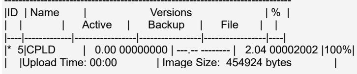
![| ID | Name | | Versions | | % |\n| : | : | Active | Backup | File | |\n| --- | --- | --- | --- | --- | |\n* 5|CPLD | 0.00 00000000 | ---.--- | 2.04 00002002 |100%|\n| |Upload Time: 00:00 | Image Size: 454924 bytes |](.axe-7120sr-50m-22808-2010-11/d135abf30d5af097b555b404cf8c6171838c80a5e45b276b5ba04ac95d0cb525.jpg)

(\*) Component requires Payload Cold Reset

Firmware upgrade procedure successful

# 6.4 Redfish

Redfish is a modern, RESTful API used for the management of servers, storage, and networking equipment in data centers and large-scale enterprise environments. It's designed to replace older, less efficient management interfaces with a standardized, scalable, and secure approach.

# 6.4.1 Network Configuration

# 6.4.1.1 GET - Ethernet Interface Collection

# Request:

GET https://{{bmc ip}}/redfish/v1/Managers/Self/EthernetInterfaces

# Response:

The response status is 200 OK.

# Example:

GET

![The image displays three identical, white, downward-pointing chevrons arranged in a horizontal row against a solid grey background. The symbols are evenly spaced and centered vertically.](.axe-7120sr-50m-22808-2010-11/cd9cf9f323d671d710dd21498faeeb292e9498fceba3b938789cc4afd4179a7c.jpg)

https://172.20.2.12/redfish/v1/Managers/Self/Ethernetlnterfaces

```jsonl
{
    "@odata.context": "/redfish/v1/$metadata#EthernetInterfaceCollection.EthernetInterfaceCollection",
    "@odata.etag": "\"1705564980\",\""
    "@odata.id": "/redfish/v1/Managers/Self/EthernetInterfaces",
    "@odata.type": "#EthernetInterfaceCollection.EthernetInterfaceCollection",
    "Description": "Collection of Ethernet Interfaces for this Manager",
    "Members": [
    {
    "@odata.id": "/redfish/v1/Managers/Self/EthernetInterfaces/eth0"
    },
    {
    "@odata.id": "/redfish/v1/Managers/Self/EthernetInterfaces/eth1"
    },
    {
    "@odata.id": "/redfish/v1/Managers/Self/EthernetInterfaces/usb0"
    }
    ],
    "Members@odata.count": 3,
    "Name": "Ethernet Network Interface Collection"
}
```

# 6.4.1.2 GET - Ethernet Interface Instance

# Request:

GET htps://{bmc ip}}/redfish/v1/Managers/Self/EthernetInterfaces/{instance}}

Response:

The response status is 200 OK. The format is JSON.

Ethernet Interface Properties:

<table><tr><td>Name</td><td>Type</td><td>Read Only</td><td>Description</td></tr><tr><td>AutoNeg</td><td>Boolean</td><td>×</td><td>Auto negotiation of speed and duplex on this interface is enabled or not.</td></tr><tr><td>DHCPv4</td><td>Object</td><td>×</td><td>Refer to DHCPv4 properties.</td></tr><tr><td>DHCPv6</td><td>Object</td><td>×</td><td>Refer to DHCPv6 properties.</td></tr><tr><td>Description</td><td>String</td><td>√</td><td></td></tr><tr><td>FullDuplex</td><td>Boolean</td><td>×</td><td>The value of this property shall represent the duplex status of the Ethernet connection on this interface.</td></tr><tr><td>HostName</td><td>String</td><td>×</td><td>DNS Hostname without any domain information.Maximum string size limit is 64.Minimum string size limit is 2.</td></tr><tr><td>IPv4Addresses</td><td>Array of Objects</td><td>√</td><td>Refer to IPv4 Address properties.</td></tr><tr><td>IPv4StaticAddresses</td><td>Array of Objects</td><td>×</td><td>Refer to IPv4 Address properties.</td></tr><tr><td>IPv6Addresses</td><td>Array of Objects</td><td>√</td><td>Refer to IPv6 Address properties.</td></tr><tr><td>IPv6StaticAddresses</td><td>Array of Objects</td><td>×</td><td>Refer to IPv6 Address properties.</td></tr><tr><td>IPv6DefaultGateway</td><td>String</td><td>√</td><td></td></tr><tr><td>Id</td><td>String</td><td>√</td><td></td></tr><tr><td>InterfaceEnabled</td><td>Boolean</td><td>×</td><td></td></tr><tr><td>LinkStatus</td><td>String</td><td>√</td><td></td></tr><tr><td>MACAddress</td><td>String</td><td>√</td><td></td></tr><tr><td>MTUSize</td><td>Number</td><td>×</td><td>Maximum size limit is 1500.Minimum size limit is 576.</td></tr><tr><td>MaxIPv6StaticAddresses</td><td>Number</td><td>√</td><td></td></tr><tr><td>Name</td><td>String</td><td>√</td><td></td></tr><tr><td>NameServers</td><td>Array of Strings</td><td>√</td><td></td></tr><tr><td>Oem</td><td>Object</td><td>√</td><td></td></tr><tr><td>PermanentMACAddress</td><td>String</td><td>√</td><td></td></tr><tr><td>SpeedMbps</td><td>Number</td><td>×</td><td>The current link speed of the interface in Mbps.</td></tr><tr><td>StatelessAddressAutoConfig</td><td>Object</td><td>×</td><td>This object shall contain the IPv4 and IPv6 Stateless Address Automatic Configuration (SLAAC) properties for this interface.</td></tr><tr><td>StaticNameServers</td><td>Array of Strings</td><td>×</td><td>Statically-defined set of DNS server IPv4 and IPv6 addresses.</td></tr><tr><td>Status</td><td>Object</td><td>√</td><td></td></tr><tr><td>VLAN</td><td>Object</td><td>×</td><td>VLANId: 0~4094.</td></tr></table>

DHCPv4 properties:

<table><tr><td>Name</td><td>Type</td><td>Read Only</td><td>Description</td></tr><tr><td>DHCPEnabled</td><td>Boolean</td><td>×</td><td>Determines whether DHCPv4 is enabled on this interface.</td></tr></table>

DHCPv6 properties:

<table><tr><td>Name</td><td>Type</td><td>Read Only</td><td>Description</td></tr><tr><td>OperatingMode</td><td>Boolean</td><td>×</td><td>This property shall control the operating mode of DHCPv6 on this interface. DHCPv6 stateful mode is used to configure addresses, and when it is enabled, stateless mode is also implicitly enabled.</td></tr></table>

IPv4 Address properties:

<table><tr><td>Name</td><td>Type</td><td>Read Only</td><td>Description</td></tr><tr><td>Address</td><td>String</td><td>-</td><td>IPv4 address.</td></tr><tr><td>AddressOrigin</td><td>String</td><td>-</td><td>IPv4 address source.</td></tr><tr><td>Gateway</td><td>String</td><td>-</td><td>IPv4 default gateway IP address.</td></tr><tr><td>SubnetMask</td><td>String</td><td>-</td><td>IPv4 netmask.</td></tr></table>

IPv6 Address properties:

<table><tr><td>Name</td><td>Type</td><td>Read Only</td><td>Description</td></tr><tr><td>Address</td><td>String</td><td>-</td><td>IPv6 address.</td></tr><tr><td>AddressOrigin</td><td>String</td><td>-</td><td>IPv6 address source.</td></tr><tr><td>PrefixLength</td><td>String</td><td>-</td><td>IPv6 network prefix length in bits. Max is 128.</td></tr></table>

# Example:

GET

https://172.20.2.12/redfish/v1/Managers/Self/Ethernetlnterfaces/eth1

{

```javascript
"@odata.context": "/redfish/v1/$metadata#EthernetInterface.EthernetInterface",
"@odata.etag": "\"1705564980\",
"@odata.id": "/redfish/v1/Managers/Self/EthernetInterfaces/eth1",
"@odata.type": "#EthernetInterface.v1_6_2.EthernetInterface",
"AutoNeg": true,
"DHCPv4": {
    "DHCPEnabled": true
},
"DHCPv6": {
    "OperatingMode": "Stateless"
},
"Description": "Ethernet Interface eth1",
"FullDuplex": true,
"HostName": "AMI003064667788",
```

```csv
"IPv4Addresses": [
    {
    "Address": "172.20.2.12",
    "AddressOrigin": "DHCP",
    "Gateway": "172.20.2.1",
    "SubnetMask": "255.255.255.0"
    }
],
"IPv6Addresses": [
    {
    "Address": "fe80::230:64ff:fea1:b104",
    "AddressOrigin": "LinkLocal",
    "PrefixLength": 64
    }
],
"IPv6DefaultGateway": null,
"Id": "eth1",
"InterfaceEnabled": true,
"LinkStatus": "LinkUp",
"MACAddress": "00:30:64:A1:B1:04",
"MTUSize": 1500,
"MaxIPv6StaticAddresses": 16,
"Name": "eth1",
"NameServers": [
    "192.168.1.213",
    "192.168.1.214"
],
"Oem": {
    "Ami": {
    "@odata.type": "#AMIDNSConfiguration.v1_0_0.AMIDNSConfiguration",
    "DNSEnabled": true,
    "HostNameSetting": "Auto"
    }
},
"PermanentMACAddress": "00:30:64:A1:B1:04",
"SpeedMbps": 100,
"StatelessAddressAutoConfig": {
    "IPv4AutoConfigEnabled": false,
    "IPv6AutoConfigEnabled": false
},
"StaticNameServers": [
    null,
    null,
    null
],
"Status": {
    "Health": "OK",
    "State": "Enabled"
},
"VLAN": {
    "VLANEnable": false,
    "VLANId": 0
```

```txt
}
}
```

# 6.4.1.3 PATCH - Ethernet Interface Instance

# Request:

```txt
PATCH https://{bmc ip}/redfish/v1/Managers/Self/EthernetInterfaces/{instance}
```

Please refer to the Ethernet Interface Properties that are patchable for which Read Only is False that can be sent as Request body in JSON format.

# Response:

The response status is 202 Accepted, with newly created Task details.

Example: Disable IPv4 DHCP and set static IPv4 address.

Add a key "If-Match" in request Headers tab. The value is your ETag value.
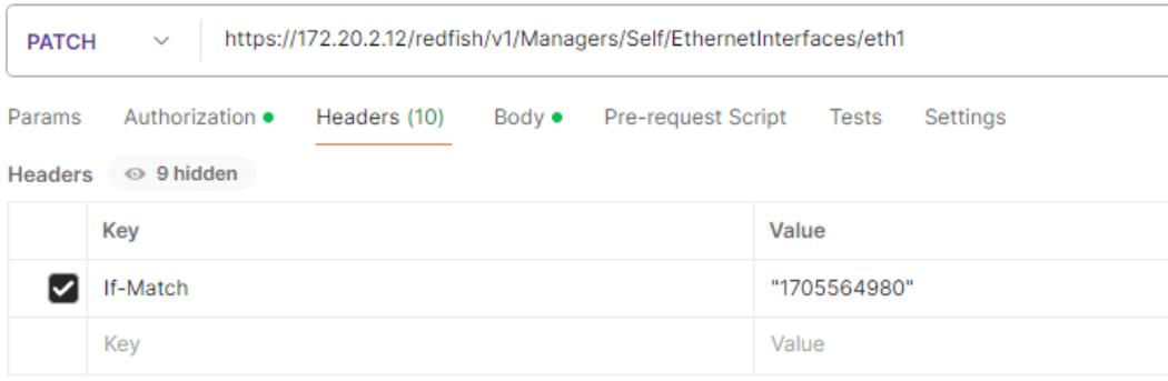
![PATCH https://172.20.2.12/redfish/v1/Managers/Self/EthernetInterfaces/eth1\nParams Authorization • Headers (10) Body • Pre-request Script Tests Settings\nHeaders 9 hidden\nKey Value\nIf-Match '1705564980'\nKey Value](.axe-7120sr-50m-22808-2010-11/bfcb3bda33b66802a79402f874d30bd9590bef542388ef816cb9f9f503267b6d.jpg)

Add raw body data in request Body tab. The data format is JSON.

```json
Params Authorization Headers (10) Body Pre-request Script Tests Settings
none form-data x-www-form-urlencoded raw binary JSON
{
    "DHCPv4": {
    "DHCPEnabled": false
    },
    "IPv4StaticAddresses": [
    {
    "Address": "172.20.2.234",
    "Gateway": "172.20.2.1",
    "SubnetMask": "255.255.255.0"
    }
    ]
}
```

Response body content.

```jsonl
{
"@odata.context": "/redfish/v1/$metadata#Task.Task",
"@odata.id": "/redfish/v1/TaskService/Tasks/1",
"@odata.type": "#Task.v1_4_2.Task",
```

```json
"Description": "Task for EthernetInterface Action",
"Id": "1",
"Name": "EthernetInterface Action",
"TaskMonitor": "/redfish/v1/TaskService/TaskMonitors/1",
"TaskState": "New"
}
```

# 6.4.2 BIOS Configuration

# 6.4.2.1 GET - HostInterface Instance

# Request:

GET https://{bmc ip}}/redfish/v1/Managers/Self/HostInterfaces/Self

# Response:

The response status is 200 OK.

# Example:

GET

![The image displays four identical black downward-pointing chevrons arranged in a horizontal row against a plain white background.](.axe-7120sr-50m-22808-2010-11/d70cc92b7bc842f9c33aa4c4317b3de4e66156426937da764e01df9a7b256ed7.jpg)

https://172.20.2.12/redfish/v1/Managers/Self/Hostlnterfaces/Self

```jsonl
{
    "@odata.context": "/redfish/v1/$metadata#HostInterface.HostInterface",
    "@odata.etag": "\"1705997262\",\""
    "@odata.id": "/redfish/v1/Managers/Self/HostInterfaces/Self",
    "@odata.type": "#HostInterface.v1_3_0.HostInterface",
    "AuthenticationModes": [
    "BasicAuth",
    "RedfishSessionAuth"
],
    "CredentialBootstrapping": {
    "EnableAfterReset": false,
    "Enabled": true,
    "RoleId": "HostInterfaceAdministrator"
},
    "Description": "Host Interface",
    "ExternallyAccessible": false,
    "HostEthernetInterfaces": {
    "@odata.id": "/redfish/v1/Managers/Self/HostInterfaces/Self/HostEthernetInterfaces"
},
    "HostInterfaceType": "NetworkHostInterface",
    "Id": "Self",
    "InterfaceEnabled": true,
    "Links": {
    "ComputerSystems": [
    {
    "@odata.id": "/redfish/v1/Systems/Self"
    }
    ],
    "ComputerSystems@odata.count": 1,
    "CredentialBootstrappingRole": {
    "@odata.id": "/redfish/v1/AccountService/Roles/HostInterfaceAdministrator"
    }
},
    "ManagerEthernetInterface": {
    "@odata.id": "/redfish/v1/Managers/Self/EthernetInterfaces/usb0"
}
```

```txt
},
"Name": "Host Interface",
"NetworkProtocol": {
    "@odata.id": "/redfish/v1/Managers/Self/NetworkProtocol"
},
"Status": {
    "Health": "OK",
    "State": "Enabled"
}
```

# 6.4.2.2 GET – BIOS and BIOS/SD

# Request:

Get current BIOS Settings:

```txt
GET https://{bmc ip}/redfish/v1/Systems/Self/Bios
```

Get future BIOS Settings:

```handlebars
GET https://{{bmc ip}}/redfish/v1/Systems/Self/Bios/SD
```

# Response:

The response status is 200 OK.

# Example:

GET

https://172.20.2.12/redfish/v1/Systems/Self/Bios

```jsonl
{
    "@Redfish.Settings": {
    "@odata.type": "#Settings.v1_2_2.Settings",
    "SettingsObject": {
    "@odata.id": "/redfish/v1/Systems/Self/Bios/SD"
    }
},
"@odata.context": "/redfish/v1/$metadata#Bios.Bios",
"@odata.etag": "\"1705640880\",\"",
"@odata.id": "/redfish/v1/Systems/Self/Bios",
"@odata.type": "#Bios.v1_2_0.Bios",
"Actions": {
    "#Bios.ChangePassword": {
    "@Redfish.ActionInfo": "/redfish/v1/Systems/Self/Bios/ChangePasswordActionInfo",
    "target": "/redfish/v1/Systems/Self/Bios/Actions/Bios.ChangePassword"
    },
    "#Bios.ResetBios": {
    "target": "/redfish/v1/Systems/Self/Bios/Actions/Bios.ResetBios"
    }
},
"AttributeRegistry": "BiosAttributeRegistry22808.1.1.0",
```

```json
"Attributes": {
    "ACPI004": false,
    "CRCS005": "CRCS005Enable",
    "FBO001": "FBO001UEFI",
    "FBO101": "FBO101HardDisk",
    "FBO102": "FBO102NVME",
    ...
},
"Description": "Current BIOS Settings",
"Id": "Bios",
"Name": "Current BIOS Settings",
"ResetBiosToDefaultsPending": false
}
```

# 6.4.2.3 POST – Reset BIOS Settings

# Request:

```txt
POST https://{bmc ip}/redfish/v1/Svsts/Self/Bios/Actions/Bios.ResetBios
```

# Response:

The response status is 204 No Content.

# Example:

Add raw body data in request Body tab. The data format is JSON.

![POST\nhttps://172.20.2.137/redfish/v1/Systems/Self/Bios/Actions/Bios.ResetBios\nParams Authorization \nHeaders (9) Body \nPre-request Script Tests Settings\nnone form-data x-www-form-urlencoded raw binary JSON \n1\n2](.axe-7120sr-50m-22808-2010-11/e2d8b41ec7151d6a804dc51626f24227502993a6efc6b3ad9e80f4f6b05d18c4.jpg)

# 6.4.2.4 POST – Change BIOS Password

# Request:

```txt
POST https://{bmc ip}}/redfish/v1/Svsts/Self/Bios/Actions/Bios.ChangePassword
```

# Response:

The response status is 204 No Content.

# Example:

Add raw body data in request Body tab. The data format is JSON.

```txt
POST https://172.20.2.137/redfish/v1/Systems/Self/Bios/Actions/Bios.ChangePassword
Params Authorization Headers (9) Body Pre-request Script Tests Settings
none form-data x-www-form-urlencoded raw binary JSON
{
"PasswordName": "SETUP001",
"OldPassword": "old",
"NewPassword": "new"
}
```

# 6.4.2.5 PATCH – BIOS SD

Change the values of the attributes.

# Request:

```handlebars
PATCH https://{{bmc ip}}/redfish/v1/Svstems/Self/Bios/SD
```

# Response:

The response status is 204 No Content.

Refer to PATCH - BIOS Watchdog Configuration.

# 6.4.3 x86 Watchdog Configuration

# 6.4.3.1 GET - BIOS Watchdog Configuration

# Request:

Get current BIOS Settings:

```txt
GET https://{{bmc ip}}/redfish/v1/Svstems/Self/Bios
```

Get future BIOS Settings:

```handlebars
GET https://{{bmc ip}}/redfish/v1/Svstems/Self/Bios/SD
```

<table><tr><td>BIOS Item</td><td>Redfish Attribute</td><td>Redfish Value</td></tr><tr><td>FRB-2 Timer</td><td>IPMI100</td><td>IPMI100EnabledIPMI100Disabled</td></tr><tr><td>FRB-2 Timer timeout</td><td>IPMI101</td><td>Number: 1~30</td></tr><tr><td>FRB-2 Timer Policy</td><td>IPMI102</td><td>IPMI102DoNothingIPMI102ResetIPMI102PowerDownIPMI102PowerCycle</td></tr><tr><td>OS Watchdog Timer</td><td>IPMI103</td><td>IPMI103DisabledIPMI103Enabled</td></tr><tr><td>OS Wtd Timer Timeout</td><td>IPMI104</td><td>Number: 1~30</td></tr><tr><td>OS Wtd Timer Policy</td><td>IPMI105</td><td>IPMI105DoNothingIPMI105ResetIPMI105PowerDownIPMI105PowerCycle</td></tr></table>

# Response:

The response status is 200 OK.

# Example:

GET

![The image displays a simple, grey, downward-pointing chevron or arrow icon centered on a white background. It resembles a standard dropdown menu indicator.](.axe-7120sr-50m-22808-2010-11/7f309088fc279fd3584183057a08e6be80d1c7cd0fffea7d69a6843d657746bb.jpg)

https://172.20.2.12/redfish/v1/Systems/Self/Bios

{

```txt
"@odata.etag": "\"1705653894\",\" Used in PATCH method
...
"AttributeRegistry": "BiosAttributeRegistry22808.1.1.0",
"Attributes": {
...
"IPMI100": "IPMI100Enabled",
"IPMI101": 6,
"IPMI102": "IPMI102DoNothing",
"IPMI103": "IPMI103Enabled",
"IPMI104": 5,
"IPMI105": "IPMI105PowerDown",
...
```

```txt
},
"Description": "Current BIOS Settings",
"Id": "Bios",
"Name": "Current BIOS Settings",
"ResetBiosToDefaultsPending": false
}
```

# 6.4.3.2 PATCH - BIOS Watchdog Configuration

# Request:

```handlebars
PATCH https://{{bmc ip}}/redfish/v1/Svstems/Self/Bios/SD
```

Please refer to the GET - BIOS Watchdog Configuration to get “etag”.

# Response:

The response status is 204 No Content.

Example: Enable the OS Watchdog Timer, set the expiration time and action.

Add a key "If-Match" in request Headers tab. The value is your ETag value.
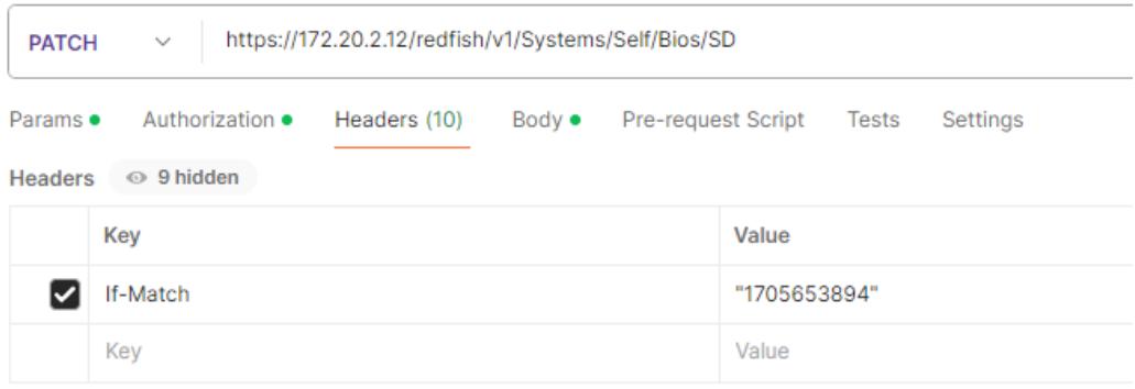
![PATCH https://172.20.2.12/redfish/v1/Systems/Self/Bios/SD\nParams Authorization Headers (10) Body Pre-request Script Tests Settings\nHeaders 9 hidden\nKey Value\nIf-Match '1705653894'\nKey Value](.axe-7120sr-50m-22808-2010-11/23cfbbf847cd9819e9eb3943e911f2068432e3d2aa045a02b09b88f9d6666bf3.jpg)

Add raw body data in request Body tab. The data format is JSON.

```txt
Params Authorization Headers (10) Body Pre-request Script Tests Settings
none form-data x-www-form-urlencoded raw binary JSON
{
"Attributes": {
"IPMI103": "IPMI103Enabled",
"IPMI104": 5,
"IPMI105": "IPMI105PowerCycle"
}
}
```

# 6.4.4 Sensor Information

This section is dedicated to explaining how to obtain sensor information through Redfish. Users can obtain the specific data of the required sensor through the following command.

# Request:

```handlebars
GET https://{{bmc ip}}/redfish/v1/Chassis/Self/Sensors/{{Sensor ID}}
```

# Response:

The response status is 200 OK.

# Example:

GET

![Two dark grey, downward-pointing chevron symbols arranged horizontally side-by-side on a white background.](.axe-7120sr-50m-22808-2010-11/5747fdf528c6b05da086a35cba3c176df32778d52bd86e882e0b2984dc8fb81b.jpg)

https://172.20.2.36/redfish/v1/Chassis/Self/Sensors/1

```jsonl
{
    "@odata.context": "/redfish/v1/$metadata#Sensor.Sensor",
    "@odata.etag": "\"1708661966\
    "@odata.id": "/redfish/v1/Chassis/Self/Sensors/1",
    "@odata.type": "#Sensor.v1_0_2.Sensor",
    "Accuracy": null,
    "AdjustedMaxAllowableOperatingValue": null,
    "AdjustedMinAllowableOperatingValue": null,
    "ApparentVA": null,
    "Description": null,
    "ElectricalContext": null,
    "Id": "1",
    "LoadPercent": null,
    "Location": {
    "AltitudeMeters": null,
    "Contacts": [
    null
    ],
    "Latitude": null,
    "Longitude": null,
    "PartLocation": {
    "LocationOrdinalValue": null,
    "LocationType": null,
    "Orientation": null,
    "Reference": null,
    "ServiceLabel": null
    },
    "Placement": {
    "AdditionalInfo": null,
    "Rack": null,
    "RackOffset": null,
    "RackOffsetUnits": null,
    "Row": null
    },
}
```

```javascript
"PostalAddress": {
    "AdditionalCode": null,
    "AdditionallInfo": null,
    "Building": null,
    "City": null,
    "Community": null,
    "Country": null,
    "District": null,
    "Division": null,
    "Floor": null,
    "HouseNumber": null,
    "HouseNumberSuffix": null,
    "Landmark": null,
    "LeadingStreetDirection": null,
    "Name": null,
    "Neighborhood": null,
    "POBox": null,
    "PlaceType": null,
    "PostalCode": null,
    "Road": null,
    "RoadBranch": null,
    "RoadPostModifier": null,
    "RoadPreModifier": null,
    "RoadSection": null,
    "RoadSubBranch": null,
    "Room": null,
    "Seat": null,
    "Street": null,
    "StreetSuffix": null,
    "Territory": null,
    "TrailingStreetSuffix": null,
    "Unit": null
}
},
"MaxAllowableOperatingValue": null,
"MinAllowableOperatingValue": null,
"Name": "P12V_PSU",
"PeakReading": null,
"PeakReadingTime": null,
"PhysicalContext": "VoltageRegulator",
"PhysicalSubContext": null,
"PowerFactor": null,
"Precision": null,
"ReactiveVAR": null,
"Reading": 12.22,
"ReadingRangeMax": 13.25,
"ReadingRangeMin": 10.7,
"ReadingType": "Voltage",
"ReadingUnits": null,
"SensingFrequency": null,
"SensorResetTime": null,
"Status": {
```

```txt
"Health": "OK",
"HealthRollup": null,
"State": "Enabled"
},
"Thresholds": {
"LowerCaution": {
"Activation": null,
"DwellTime": null,
"Reading": 11.4
},
"LowerCritical": {
"Activation": null,
"DwellTime": null,
"Reading": 11.16
},
"LowerFatal": {
"Activation": null,
"DwellTime": null,
"Reading": 10.8
},
"UpperCaution": {
"Activation": null,
"DwellTime": null,
"Reading": 12.6
},
"UpperCritical": {
"Activation": null,
"DwellTime": null,
"Reading": 12.84
},
"UpperFatal": {
"Activation": null,
"DwellTime": null,
"Reading": 13.2
}
},
"VoltageType": null
}
```

Other commands to access sensor information using Redfish:

# General Thermal Sensors Information

GET httns://{hmc in}}/redfish/v1/Chassis/Self/Thermal

Retrieves detailed information about the server's thermal sensors, including current temperature readings.

# Temperature Sensor IDs

GET httns://{bmc in}}/redfish /v1/Chassis/Self/ThermalSubsvstem/ThermalMetrics

Retrieves IDs and specific metrics of temperature-related sensors.

# General Power Sensors Information

GFT httns://{(hmr in} /redfisch /v1/Chassis /Self/Pnwer

Retrieves comprehensive data about power-related sensors, including power supply status and output power.

# Power Sensor IDs

GET https://{{bmc ip}}/redfish/v1/Chassis/Self/PowerSubsystem

Retrieves IDs and detailed metrics related to power sensors.

# 6.4.5 BMC Update

This section specifically explains how to obtain and upgrade BMC through Redfish. Users can upgrade BMC and set Preserve Configuration through the following commands.

# 6.4.5.1 GET - Preserve Configuration

This section describes how to use redfish to Get Preserve Configuration before upgrading BMC.

# Request:

```txt
GET https://{bmc ip}/redfish/v1/UpdateService
```

# Response:

The response status is 200 OK.

# Example:

GET

![The image displays a simple, gray, downward-pointing arrow or chevron icon centered on a white background. The graphic is somewhat blurry or pixelated, resembling a standard user interface symbol used for dropdown menus. There is no text present.](.axe-7120sr-50m-22808-2010-11/ced09d1406e189c16c65aacb18e425070df9e5d005487c91967aad4f504bc84f.jpg)

https://172.20.2.36/redfish/v1/UpdateService

```jsonl
{
    "@odata.context": "/redfish/v1/$metadata#UpdateService.UpdateService",
    "@odata.etag": "\"1708925760\",
    "@odata.id": "/redfish/v1/UpdateService",
    "@odata.type": "#UpdateService.v1_6_0.UpdateService",
    "Actions": {
    "#UpdateService.SimpleUpdate": {
    "@Redfish.ActionInfo": "/redfish/v1/UpdateService/SimpleUpdateActionInfo",
    "target": "/redfish/v1/UpdateService/Actions/SimpleUpdate"
    },
    "Oem": {
    "#UpdateService.UploadCABundle": {
    "@Redfish.ActionInfo": "/redfish/v1/UpdateService/UploadCABundleActionInfo",
    "target": "/redfish/v1/UpdateService/Actions/Oem/UpdateService.UploadCABundle"
    }
    }
    },
    "Description": "Redfish Update Service",
    "FirmwareInventory": {
    "@odata.id": "/redfish/v1/UpdateService/FirmwareInventory"
    },
    "Id": "UpdateService",
    "MaxImageSizeBytes": 496611328,
    "MultipartHttpPushUri": "/redfish/v1/UpdateService/upload",
    "Name": "Update Service",
    "Oem": {
    "AMIUpdateService": {
    "@odata.type": "#AMIUpdateService.v1_0_0.AMIUpdateService",
```

```json
"FlashPercentage": null,
"PreserveConfiguration": {
    "Authentication": false,
    "EXTLOG": false,
    "FRU": false,
    "IPMI": false,
    "KVM": false,
    "NTP": false,
    "Network": false,
    "REDFISH": false,
    "SDR": false,
    "SEL": false,
    "SNMP": false,
    "SSH": false,
    "Syslog": false,
    "WEB": false
},
"UpdateStatus": null,
"UpdateTarget": null
},
"BMC": {
"@odata.type": "#AMIUpdateService.v1_0_0.BMC",
"DullImageConfigurations": {
"ActiveImage": "2",
"BootImage": "2",
"FirmwareImage1Name": "Image1",
"FirmwareImage1Version": "13.05.010004",
"FirmwareImage2Name": "Image2",
"FirmwareImage2Version": "13.05.010003"
}
},
"ServiceEnabled": true,
"Status": {
"Health": "OK",
"State": "Enabled"
}
```

# 6.4.5.2 PATCH - Preserve Configuration

This section describes how to use redfish to Set Preserve Configuration before upgrading BMC.

# Request:

PATCH https://{{bmc ip}}/redfish/v1/UpdateService

Please refer to the GET - Preserve Configuration.

# Response:

The response status is 204 No Content.

Example: Enable saving IPMI and SEL when upgrading BMC.

Add a key "If-Match" in request Headers tab. The value is your ETag value. This value can be obtained from GET - Preserve Configuration.
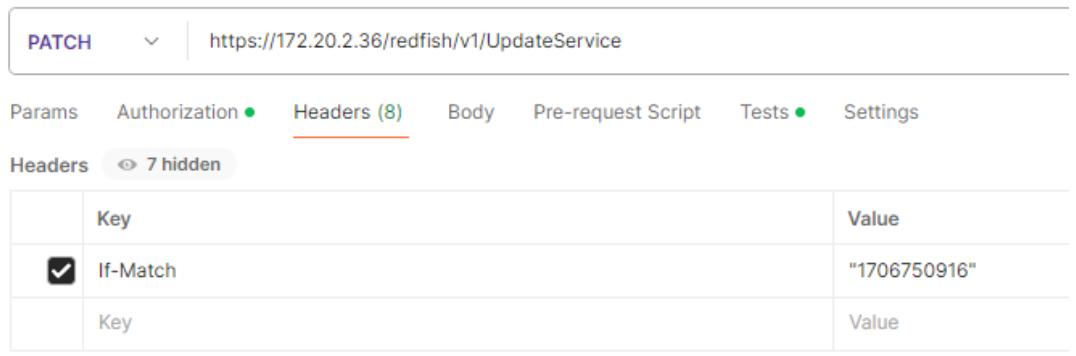
![PATCH https://172.20.2.36/redfish/v1/UpdateService\nParams Authorization • Headers (8) Body Pre-request Script Tests • Settings\nHeaders 7 hidden\nKey Value\nIf-Match '1706750916'\nKey Value](.axe-7120sr-50m-22808-2010-11/6bff3810b5c34c44099f02a81baa9ab6581597b13ba964e33330b6c0c46bfbd0.jpg)

Add raw body data in request Body tab. The data format is JSON.
```json
Params Authorization Headers (10) Body Pre-request Script Tests Settings
none form-data x-www-form-urlencoded raw binary JSON
{
    "Oem": {
    "AMIUpdateService": {
    "PreserveConfiguration": {
    "IPMI": true,
    "SEL": true
    }
    }
    }
}
```

# 6.4.5.3 POST – Firmware Update

This section describes how to use redfish to Update BMC firmware.

# Request:

```txt
POST https://{bmc ip}/redfish/v1/UpdateService/upload
```

# Response:

The response status is 202 Accepted.

# Example:

Using POSTMAN, please follow the steps as given below.

1. Ensure that all necessary files mentioned in the subsequent steps are placed in your working directory. Go to the top right corner of POSTMAN and click on the settings button. In the general settings, make the necessary adjustments.

# Working directory

![A gray, horizontally oriented toggle switch with a white circular knob positioned on the left side.](.axe-7120sr-50m-22808-2010-11/77385d94c6d80110b8d89ab90a25f0b52912be41a36a6148a9348edf5d3e3ab5.jpg)

2. Create a JSON file parameters.json with content like below.

```json
{
    "Targets": [
    "/redfish/v1/UpdateService/FirmwareInventory/BMCImage1"
    ]
}
```

3. Create a JSON file oem\_parameters.json with content like below.

```json
{
    "ImageType": "BMC"
}
```

4. Open POSTMAN and enter the URI to POST the request.

5. Select POST method.

6. In the Authorization tab, select Basic Auth and update request.

7. In the Body tab, select form-data and provide the key name as UpdateFile in the KEY section and change its type from Text to File.

8. Click on Select File in the VALUE section to select the signed image which is available in your local machine to update.

9. Like step 7 and 8, provide key name UpdateParameters and select parameters.json created in step 2.

10.Like step 7 and 8, provide key name OemParameters and select oem\_parameters.json created in step 3.

11.Click Send.
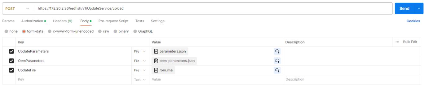
![POST\nhttps://172.20.2.36/redfish/v1/UpdateService/upload\nSend\nParams Authorization Headers (9) Body Pre-request Script Tests Settings\nnone form-data x-www-form-urlencoded raw binary GraphQL\nKey Value Description --- Bulk Edit\nUpdateParameters File parameters.json\nOemParameters File oem_parameters.json\nUpdateFile File rom.ima\nKey Text Value Description](.axe-7120sr-50m-22808-2010-11/12a825ed73fcad610ca0fa5d028fc41d069dd42822edd0c8441f29109891c938.jpg)

# Response:

<table><tr><td colspan="5">Body Cookies Headers (14) Test Results Status: 202 Accepted</td></tr><tr><td>Pretty</td><td>Raw</td><td>Preview</td><td>Visualize</td><td>JSON</td></tr><tr><td>1</td><td></td><td></td><td></td><td></td></tr><tr><td>2</td><td rowspan="2" colspan="4">&quot;@odata.type&quot;: &quot;#UpdateService.v1_6_0.UpdateService&quot;, &quot;Messages&quot;: [</td></tr><tr><td>3</td></tr><tr><td>4</td><td colspan="4">{</td></tr><tr><td>5</td><td rowspan="7" colspan="4">&quot;@odata.type&quot;: &quot;#Message.v1_0_8.Message&quot;, &quot;Message&quot;: &quot;A new task /redfish/v1/TaskService/Tasks/4 was created.&quot;, &quot;MessageArgs&quot;: [ &quot;/redfish/v1/TaskService/Tasks/4&quot; ], &quot;MessageId&quot;: &quot;Task.1.0.New&quot;, &quot;Resolution&quot;: &quot;None&quot;, &quot;Severity&quot;: &quot;OK&quot; } ,</td></tr><tr><td>9</td></tr><tr><td>10</td></tr><tr><td>11</td></tr><tr><td>12</td></tr><tr><td>13</td></tr><tr><td>14</td></tr><tr><td>15</td><td rowspan="4" colspan="4">&quot;@odata.type&quot;: &quot;#Message.v1_0_8.Message&quot;, &quot;Message&quot;: &quot;The action UpdateService.MultipartPush was submitted to do firmware update.&quot;, &quot;MessageArgs&quot;: [ &quot;UpdateService.MultipartPush&quot;</td></tr><tr><td>16</td></tr><tr><td>17</td></tr><tr><td>18</td></tr></table>

# Note:

The details of UpdateParameters are given in the table below.

<table><tr><td>Allowed value</td><td>Description</td></tr><tr><td>redfish/v1/UpdateService/FirmwareInventory/BMC</td><td>When the system does not support Dual Flash</td></tr><tr><td>redfish/v1/UpdateService/FirmwareInventory/BMCImage1</td><td>For systems with Dual Flash support, to upgrade Image 1</td></tr><tr><td>redfish/v1/UpdateService/FirmwareInventory/BMCImage2</td><td>For systems with Dual Flash support, to upgrade Image 2</td></tr></table>

# 6.4.6 BIOS Update

This section specifically explains how to obtain and upgrade BIOS through Redfish. Users can upgrade BIOS through the following commands.

# 6.4.6.1 GET - BIOS Update Status

# Request:

GET https://{{bmc ip}}/redfish/v1/UpdateService

# Response:

The response status is 200 OK.

<table><tr><td>Name</td><td>Type</td><td>Read Only</td><td>Description</td></tr><tr><td>BIOSFlashEffectStatus</td><td>String</td><td>√</td><td>Indicates the BIOS update effect status:Waiting: there is a BIOS update task waiting to take effect.Updating: someone is updating BIOS.null: no BIOS update task.</td></tr></table>

# Example:

GET

![The image displays a dark grey, downward-pointing chevron or arrow symbol centered on a white background.](.axe-7120sr-50m-22808-2010-11/8a7e12d1eba897eaf192a472fe087a95477b4cfb26800e32bc3664c905fc63da.jpg)

https://172.20.2.18/redfish/v1/UpdateService

```jsonl
{
    "@odata.context": "/redfish/v1/$metadata#UpdateService.UpdateService",
    "@odata.etag": "\"1708587273\",
    "@odata.id": "/redfish/v1/UpdateService",
    "@odata.type": "#UpdateService.v1_6_0.UpdateService",
    "Actions": {
    "#UpdateService.SimpleUpdate": {
    "@Redfish.ActionInfo": "/redfish/v1/UpdateService/SimpleUpdateActionInfo",
    "target": "/redfish/v1/UpdateService/Actions/SimpleUpdate"
    },
    "Oem": {
    "#UpdateService.UploadCABundle": {
    "@Redfish.ActionInfo": "/redfish/v1/UpdateService/UploadCABundleActionInfo",
    "target": "/redfish/v1/UpdateService/Actions/Oem/UpdateService.UploadCABundle"
    }
    }
},
"Description": "Redfish Update Service",
"FirmwareInventory": {
    "@odata.id": "/redfish/v1/UpdateService/FirmwareInventory"
},
"Id": "UpdateService",
"MaxImageSizeBytes": 496717824,
"MultipartHttpPushUri": "/redfish/v1/UpdateService/upload",
"Name": "Update Service",
```

```json
"Oem": {
    "AMIUpdateService": {
    "@odata.type": "#AMIUpdateService.v1_0_0.AMIUpdateService",
    "BIOSFlashEffectStatus": null,
    "FlashPercentage": null,
    "PreserveConfiguration": {
    "Authentication": false,
    "EXTLOG": false,
    "FRU": false,
    "IPMI": false,
    "KVM": false,
    "NTP": false,
    "Network": false,
    "REDFISH": false,
    "SDR": false,
    "SEL": false,
    "SNMP": false,
    "SSH": false,
    "Syslog": false,
    "WEB": false
    },
    "UpdateStatus": null,
    "UpdateTarget": null
},
"BMC": {
    "@odata.type": "#AMIUpdateService.v1_0_0.BMC",
    "DualImageConfigurations": {
    "ActiveImage": "1",
    "BootImage": "1",
    "FirmwareImage1Name": "Image1",
    "FirmwareImage1Version": "13.05.010004",
    "FirmwareImage2Name": "Image2",
    "FirmwareImage2Version": "13.05.010003"
    }
}
},
"ServiceEnabled": true,
"Status": {
    "Health": "OK",
    "State": "Enabled"
}
```

# 6.4.6.2 POST – Firmware Update

This section describes how to use redfish to Update BIOS firmware.

# Request:

POST https://{bmc ip}}/redfish/v1/UpdateService/upload

# Response:

The response status is 202 Accepted.

# Example:

Using POSTMAN, please follow the steps as given below.

1. Ensure that all necessary files mentioned in the subsequent steps are placed in your working directory. Go to the top right corner of POSTMAN and click on the settings button. In the general settings, make the necessary adjustments.

# Working directory

![The image displays a digital toggle switch icon set against a black background. The switch is in the 'off' position, featuring a grey, rounded rectangular track with a white circular knob positioned on the left side of the track.](.axe-7120sr-50m-22808-2010-11/9c20c1f458beef33abf8ddafd3a92e8f900443d6b85eb120ecd0fee68dd72b19.jpg)

2. Create a JSON file parameters.json with content like below.

```json
{
    "Targets": [
    "/redfish/v1/UpdateService/FirmwareInventory/BIOS"
    ]
}
```

3. Create a JSON file oem\_parameters.json with content like below.

```json
{
    "ImageType": "BIOS",
    "update_me": false,
    "update_nvram": false,
    "effect_poweroff": false,
    "force_update": false
}
```

<table><tr><td>Name</td><td>Type</td><td>Description</td></tr><tr><td>update_me</td><td>Boolean</td><td>Optional. Default value is false. true: update ME. false: skip ME.</td></tr><tr><td>update_nvram</td><td>Boolean</td><td>Optional. Default value is false. true: update NVRAM. false: skip NVRAM.</td></tr><tr><td>effect_poweroff</td><td>Boolean</td><td>Optional. Default value is false. true: take effect when powered off.false: take effect immediately.</td></tr><tr><td>force_update</td><td>Boolean</td><td>Optional. Default value is false. true: force to update. false: do not update when other user is in in update mode or a BIOS firmware has been uploaded.</td></tr></table>

4. Open POSTMAN and enter the URI to POST the request.
5. Select POST method.
6. In the Authorization tab, select Basic Auth and update request.
7. In the Body tab, select form-data and provide the key name as UpdateFile in the KEY section and change its type from Text to File.
8. Click on Select File in the VALUE section to select the signed image which is available in your local machine to update.
9. Like step 7 and 8, provide key name UpdateParameters and select parameters.json created in step 2.
10.Like step 7 and 8, provide key name OemParameters and select oem\_parameters.json created in step 3.

# 11.Click Send.
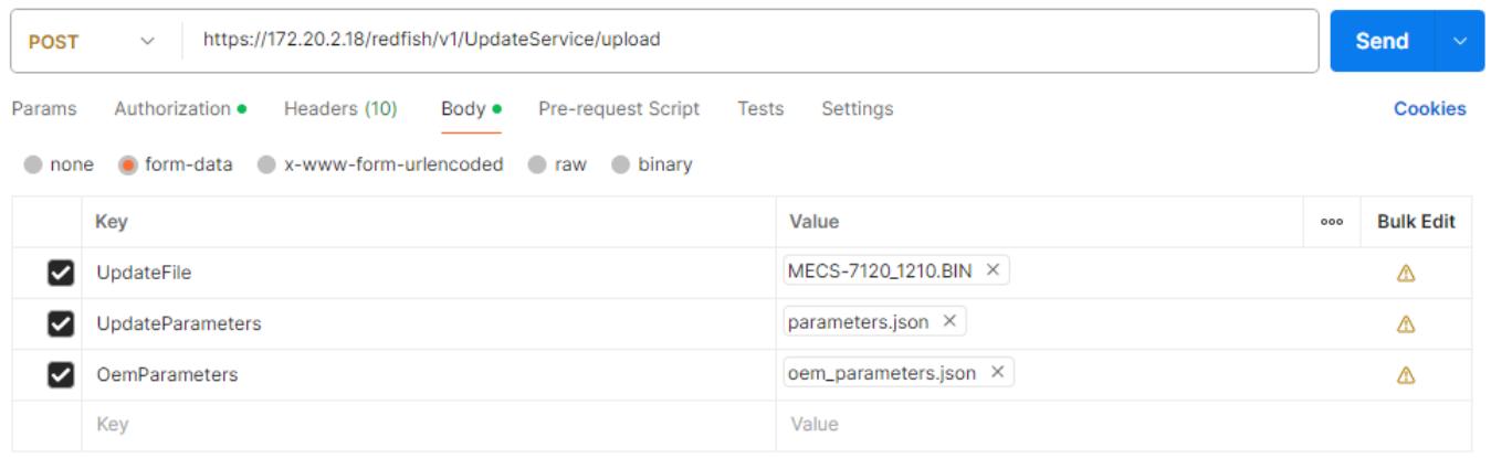
![POST\nhttps://172.20.2.18/redfish/v1/UpdateService/upload\nSend\nParams Authorization Headers (10) Body Pre-request Script Tests Settings Cookies\nnone form-data x-www-form-urlencoded raw binary\nKey Value 000 Bulk Edit\nUpdateFile MECS-7120_1210.BIN ×\nUpdateParameters parameters.json ×\nOemParameters oem_parameters.json ×\nKey Value](.axe-7120sr-50m-22808-2010-11/d3c9550a6aa2d8415e37fc91a7221fe9c72e6af35d2ae501853a570fb9454581.jpg)

# Response:

```json
{
    "@odata.type": "#UpdateService.v1_6_0.UpdateService",
    "Messages": [
    {
    "@odata.type": "#Message.v1_0_8.Message",
    "Message": "A new task /redfish/v1/TaskService/Tasks/1 was created.",
    "MessageArgs": [
    "/redfish/v1/TaskService/Tasks/1"
    ],
    "MessageId": "Task.1.0.New",
    "Resolution": "None",
```

```txt
"Severity": "OK"
},
{
"@odata.type": "#Message.v1_0_8.Message",
"Message": "The action UpdateService.MultipartPush was submitted to do firmware update.",
"MessageArgs": [
"UpdateService.MultipartPush"
],
"MessageId": "UpdateService.1.0.StartFirmwareUpdate",
"Resolution": "None",
"Severity": "OK"
}
]
```

# 6.4.7 CPLD Update

This section specifically explains how to obtain and upgrade BIOS through Redfish. Users can upgrade BIOS through the following commands.

# 6.4.7.1 GET - CPLD Update Status

# Request:

```txt
GET https://{bmc ip}/redfish/v1/UpdateService
```

# Response:

The response status is 200 OK.

<table><tr><td>Name</td><td>Type</td><td>Read Only</td><td>Description</td></tr><tr><td>CPLDFlashEffectStatus</td><td>String</td><td>√</td><td>Indicates the CPLD update effect status:Waiting: there is a CPLD update waiting to take effect.Updating: someone is updating Firmware.null: no CPLD update.</td></tr></table>

# Example:

```snap
GET https://172.20.2.18/redfish/v1/UpdateService
{
...
"Oem": {
    "AMIUpdateService": {
    "@odata.type": "#AMIUpdateService.v1_0_0.AMIUpdateService",
    "BIOSFlashEffectStatus": null,
    "CPLDFlashEffectStatus": null,
    "FlashPercentage": null,
}
```

# 6.4.7.2 POST – Firmware Update

This section describes how to use redfish to Update CPLD firmware.

# Request:

```txt
POST https://{bmc ip}/redfish/v1/UpdateService/upload
```

# Response:

The response status is 202 Accepted.

# Example:

Using POSTMAN, please follow the steps as given below.

1. Ensure that all necessary files mentioned in the subsequent steps are placed in your working directory. Go to the top right corner of POSTMAN and click on the settings button. In the general settings, make the necessary adjustments.

# Working directory

![The image displays a horizontal toggle switch consisting of a grey rectangular track with a white circular knob positioned on the left side.](.axe-7120sr-50m-22808-2010-11/3f3215a3663ebad6faa152f531ec7fa3256f90d73062dcc149f2ddac76ca995f.jpg)

2. Create a JSON file parameters.json with content like below.

```json
{
    "Targets": [
    "/redfish/v1/UpdateService/FirmwareInventory/CPLD"
    ]
}
```

3. Create a JSON file oem\_parameters.json with content like below.

```json
{
    "ImageType": "HPM",
    "force_update": false
}
```

<table><tr><td>Name</td><td>Type</td><td>Description</td></tr><tr><td>force_update</td><td>Boolean</td><td>Optional. Default value is false. true: force to update. false: do not update when other user is in in update mode or a CPLD firmware has been uploaded.</td></tr></table>

4. Open POSTMAN and enter the URI to POST the request.
5. Select POST method.
6. In the Authorization tab, select Basic Auth and update request.
7. In the Body tab, select form-data and provide the key name as UpdateFile in the KEY section and change its type from Text to File.
8. Click on Select File in the VALUE section to select the signed image which is available in your local machine to update.

9. Like step 7 and 8, provide key name UpdateParameters and select parameters.json created in step 2.

10.Like step 7 and 8, provide key name OemParameters and select oem\_parameters.json created in step 3.

# 11.Click Send.
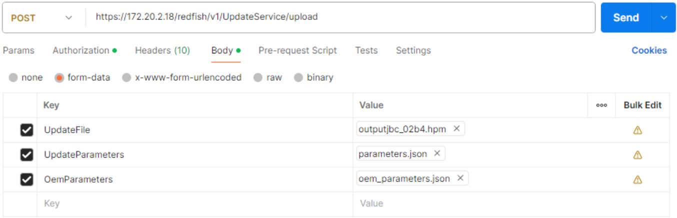
![POST\nhttps://172.20.2.18/redfish/v1/UpdateService/upload\nSend\nParams Authorization \nHeaders (10) Body \nPre-request Script Tests Settings\nnone \nform-data x-www-form-urlencoded raw binary\nKey Value 000 Bulk Edit\nUpdateFile outputjbc_02b4.hpm\nUpdateParameters parameters.json\nOemParameters oem_parameters.json\nKey Value](.axe-7120sr-50m-22808-2010-11/faff12c53d5a841744c1750bf64c128a21943aba30dd9a6966d304ed0d0e1711.jpg)

# Response:

```jsonl
{
    "@odata.type": "#UpdateService.v1_6_0.UpdateService",
    "Messages": [
    {
    "@odata.type": "#Message.v1_0_8.Message",
    "Message": "A new task /redfish/v1/TaskService/Tasks/1 was created.",
    "MessageArgs": [
    "/redfish/v1/TaskService/Tasks/1"
    ],
    "MessageId": "Task.1.0.New",
    "Resolution": "None",
    "Severity": "OK"
    },
    {
    "@odata.type": "#Message.v1_0_8.Message",
    "Message": "The action UpdateService.MultipartPush was submitted to do firmware update.",
    "MessageArgs": [
    "UpdateService.MultipartPush"
    ],
    "MessageId": "UpdateService.1.0.StartFirmwareUpdate",
    "Resolution": "None",
    "Severity": "OK"
    }
    ]
}
```

# 6.4.8 Power Control

This section is dedicated to explaining how to control power through Redfish.

# Request:

```txt
POST https://{bmc ip}/redfish/v1/Chassis/Self/Actions/Chassis.Reset
```

# Response:

The response status is 202 Accepted.

# Example:

```txt
POST https://172.20.2.16/redfish/v1/Chassis/Self/Actions/Chassis.Reset
Params Authorization Headers (10) Body Pre-request Script Tests Settings
none form-data x-www-form-urlencoded raw binary JSON
{
"ResetType": "ForceRestart"
}
```

Note: The ResetType can be one of the following values: "On", "ForceOff", "GracefulShutdown", "ForceRestart", "PowerCycle".

# Response:

```json
{
    "@odata.context": "/redfish/v1/$metadata#Task.Task",
    "@odata.id": "/redfish/v1/TaskService/Tasks/1",
    "@odata.type": "#Task.v1_4_2.Task",
    "Description": "Task for Chassis Reset",
    "Id": "1",
    "Name": "Chassis Reset",
    "TaskMonitor": "/redfish/v1/TaskService/TaskMonitors/1",
    "TaskState": "New"
}
```

# 6.4.9 Firmware and Hardware Versions

To get BMC version, CPLD version and hardware version, use "Managers" class.

# Request:

```txt
POST https://{bmc ip}/redfish/v1/Managers/Self
```

# Response:

The response status is 202 OK.

# Example:

![GET https://172.20.2.16/redfish/v1/Managers/Self\nParams Authorization Headers (8) Body Pre-request Script Tests Settings\nnone form-data x-www-form-urlencoded raw binary](.axe-7120sr-50m-22808-2010-11/1a888506201290fa746e297a49853fac7887e87817e57137472681f1fffbd2aa.jpg)

<table><tr><td colspan="6">Body Cookies Headers (24) Test Results 200 OK 203 ms 4.36 KB S</td></tr><tr><td>Pretty</td><td>Raw</td><td>Preview</td><td>Visualize</td><td>JSON</td><td>=P</td></tr><tr><td>62</td><td>?</td><td></td><td></td><td></td><td></td></tr><tr><td>63</td><td colspan="5">&quot;FirmwareVersion&quot;: &quot;1.04 - 0xb4000012&quot;,</td></tr><tr><td>64</td><td colspan="5">&quot;GraphicalConsole&quot;: {</td></tr><tr><td>65</td><td></td><td colspan="4">&quot;ConnectTypesSupported&quot;: [</td></tr><tr><td>66</td><td></td><td colspan="4">&quot;KVMIP&quot;</td></tr><tr><td>45</td><td colspan="5">&quot;CPLDVersion&quot;: &quot;02b4&quot;,</td></tr></table>

Member "FirmwareVersion" consists of:

BMC version - 1.4

CPLD version - 02b4

Hardware version - 2.1 (PCB A2 SKU 1)

# 6.4.10 BIOS Version

To get BIOS version, use "Systems" class.

# Request:

```handlebars
POST https://{{bmc ip}}/redfish/v1/Systems/Self
```

# Response:

The response status is 202 OK.

# Example:
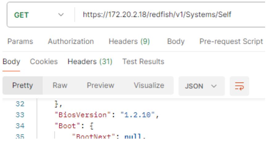
![GET\nhttps://172.20.2.18/redfish/v1/Systems/Self\nParams Authorization Headers (9) Body Pre-request Script\nBody Cookies Headers (31) Test Results\nPretty Raw Preview Visualize JSON\n32 },\n33 'BiosVersion': '1.2.10',\n34 'Boot': {\n35 'RootNext': null.](.axe-7120sr-50m-22808-2010-11/7a96986b440ecedd5f48f796bf4088e941121f38fc559b90701fb6cf33976b55.jpg)

Member "BiosVersion" has the value.

"1.2.10" - Leading version.Major version.Minor version

Please pay special attention that minor version of BIOS is always represented in hexadecimal number.

# Important Safety Instructions

For user safety, please read and follow all instructions, WARNINGS, CAUTIONS, and NOTES marked in this manual and on the associated equipment before handling/operating the equipment.

1. Read these safety instructions carefully.
2. Keep this user’s manual for future reference.
3. Read the specifications section of this manual for detailed information on the operating environment of this equipment.
4. The equipment can be operated at an ambient temperature of 55°C.
5. When installing/mounting or uninstalling/removing equipment; or when removal of the chassis lid required for user servicing (Section 3.1-3.5):
 Turn off power and unplug any power cords/cables, and
 Reinstall the chassis lid before restoring power.

![The image displays a standard safety symbol consisting of a red triangle with a white exclamation point in the center. Below the triangle is the text 'WARNING:' written in black, capital letters.](.axe-7120sr-50m-22808-2010-11/11e158be45b6b663a87128d16a4cb0ef3ca916e259db9fad4b7b05991725a390.jpg)

Hazardous moving parts. Keep body parts out of the motion path.

![The image displays a black line drawing of a triangle pointing upward. Inside the triangle is a centered symbol resembling a four-bladed fan or propeller with curved blades radiating from a central point.](.axe-7120sr-50m-22808-2010-11/223008e4ff9114127210a644d63c0283a4d716456c1ace7b597de0ce1ebf2bf7.jpg)

6. To avoid electrical shock and/or damage to equipment:

 Keep equipment away from water or liquid sources;
 Keep equipment away from high heat or high humidity;
 Keep equipment properly ventilated (do not block or cover ventilation openings);
 Make sure to use recommended voltage and power source settings;
 Always install and operate equipment near an easily accessible electrical socketoutlet;
 Secure the power cord (do not place any object on/over the power cord);
 Only install/attach and operate equipment on stable surfaces and/or recommended mountings;
 If the equipment will not be used for long periods of time, turn off and unplug the equipment from its power source.
 The power cord must be connected to a socket or outlet with a ground connection.

7. Never attempt to fix the equipment. Equipment should only be serviced by qualified personnel.

8. An RTC battery may be provided for uninterrupted, backup or emergency power.

![A yellow triangular warning sign featuring a black exclamation mark in the center. Below the triangle, the word 'CAUTION:' appears in black, uppercase letters.](.axe-7120sr-50m-22808-2010-11/1e0b4aca5c7c8ed2b20ebb58371c53e3d51d698ea0f324e371db8327d239803f.jpg)

Risk of explosion if battery is replaced with one of an incorrect type.

Discard used batteries according to the manufacturer's instructions.

9. This equipment is not suitable for use in locations where children are likely to be present.

10.Equipment must be serviced by authorized technicians when:

 The power cord or plug is damaged;
 Liquid has penetrated the equipment;
 It has been exposed to high humidity/moisture;
 It is not functioning or does not function according to the user’s manual;
 It has been dropped and/or damaged; and/or,
 It has an obvious sign of breakage.

11.Please pay strict attention to all warnings and advisories appearing on the device, to avoid injury or damage.

12.The equipment may have more than one power supply input. To reduce the risk of electrical shock, trained personnel should disconnect all power supply inputs before servicing.

![The image displays a yellow triangular warning sign with a black border. Inside the triangle is a large black exclamation point. Directly below the triangle, the word 'CAUTION' is written in black capital letters.](.axe-7120sr-50m-22808-2010-11/3e5511c1bb3744ccbf45c80db61e1b108fae258b25f7e714e183b77183c5abff.jpg)

Shock hazard! Disconnect all power supply inputs before servicing.

![The image displays a safety warning sign featuring a yellow equilateral triangle with a black border containing a black lightning bolt symbol. Below the triangle, the text 'Shock hazard!' is printed in black.](.axe-7120sr-50m-22808-2010-11/7787708fa54735d78d1b025a24f3bcf3167330613362c028d1f20e70f5753fc7.jpg)

![Multiple power sources](.axe-7120sr-50m-22808-2010-11/fca503f9558677c759315ee3d0e79b61d0659092ca6d61d334b3add09bf97e0f.jpg)

13.It is recommended that equipment be installed only in a server room or computer room where access is:

 Restricted to qualified service personnel or users familiar with restrictions applied to the location, reasons therefor, and any precautions required;
 Only afforded by the use of a tool or lock and key, or other means of security, and is controlled by the authority responsible for the location.

14.Suitable for installation in Information Technology Rooms in accordance with Article 645 of the National Electrical Code and NFPA 75.

15.This product is intended to be supplied by a certified DC power source providing reinforced/double insulation from AC mains with an output rating of 36V to 72V DC ,20A max., Tma $= 5 5 ^ { \circ } \mathrm { C }$ . All power connection wiring must be performed by a qualified electrician in accordance with National Electrical Code, ANSI/NFPA 70 and Canadian Electrical Code, Part I, CSA C22.1. The DC power supply should be well-grounded to ensure safe operation. The protective earthing conductor shall be minimum 14 AWG and having green-and-yellow insulation. The ground wire should be installed first (before "+" and "-") and then removed.

16.When using a Fiber Optic Small-Form Pluggable (SFP) module, ensure it is IEC 60825-1, IEC 60825-2 and IEC 60950-1 or IEC 62368-1 certified and a Class 1 Laser Product.

17.Make sure to connect the power cord to a socket-outlet with earthing if supplied by Class I power supply or power source.

18.Equipment intended for installation in Restricted Access Location.

# Consignes de Sécurité Importantes

Pour assurer la sécurité de l’utilisateur, veuillez lire et suivre toutes les directives, ainsi que les AVERTISSEMENTS, MISES EN GARDE et REMARQUES de ce manuel et indiqués sur l’équipement associé avant de manipuler ou utiliser l’équipement.

1. Veuillez lire attentivement ces instructions de sécurité avec soin.
2. Veuillez conserver ce manuel pour référence future.
3. Veuillez lire la section des spécifications de ce manuel pour avoir des informations détaillées sur l’environnement d’exploitation de cet équipement.
4. L’équipement peut être utilisé à une température ambiante de 55 °C.
5. Lors de l’installation ou du montage et de la désinstallation ou de la dépose de l’équipement; ou lors de la dépose du couvercle du châssis pour procéder à l’entretien par l’utilisateur (Sections 3.1-3.5):

 Coupez l’alimentation et débranchez les cordons et les câbles d’alimentation, et
 Reposez le couvercle du châssis avant de remettre l’alimentation.

![The image displays a standard safety warning symbol consisting of a red triangle with a white exclamation point in the center. Below the triangle, the word 'WARNING:' is printed in black capital letters.](.axe-7120sr-50m-22808-2010-11/7c8b82ae48b609d46a4be1f854fbfb8c7fb2736a7925e61bea46f5026e72b1c9.jpg)
AVERTISSEMENT

Pièces mobiles dangereuses. Gardez les parties du corps hors de la trajectoire.

![The image features a simple black-and-white line drawing. Centered within the frame is a black outline of an equilateral triangle pointing upward. Inside the triangle is a symbol resembling a four-bladed fan or propeller, with four curved blades radiating from a small central circle. Solid black horizontal bars run along the very top and bottom edges of the image.](.axe-7120sr-50m-22808-2010-11/63d80ee59f9f2abf7387e852df9d6288bb34fede7063166e90a2f9e604101d92.jpg)

6. Pour éviter un risque d’électrocution et pour éviter d’endommager l’équipement :

 Éloignez l’équipement de l’eau et de toute source liquide;
 Éloignez l’équipement de toute source de chaleur ou d’humidité élevée;
 Gardez l’équipement correctement ventilé (ne pas bloquer ou couvrir les ouvertures de ventilation);
 Veillez à utiliser la tension recommandée et les réglages adéquats pour la source d’alimentation;
 Veuillez toujours installer et exploiter l’équipement à proximité d’une prise de courant facilement accessible;
 Assurez-vous que le cordon d’alimentation est acheminé de manière sécuritaire (ne déposez aucun objet dessus);
 Installez, fixez et utilisez l’équipement sur des surfaces stables ou sur les fixations recommandées uniquement;
 Si l’équipement n’est pas utilisé pendant une longue période, éteignez-le et débranchez-le de sa source d’alimentation.
 Le cordon d'alimentation doit être connecté à une prise ou à une prise de courant avec mise à la terre.

7. N’essayez jamais de réparer l’équipement. L’équipement ne doit être réparé que par du personnel qualifié.

8. Une pile au lithium peut être installée pour assurer l’alimentation de secours ou d’urgence en continu.

![The image features a yellow triangular warning sign with a black border. Inside the triangle is a large black exclamation point. Below the triangle, the text 'CAUTION:' appears in black capital letters. Underneath that, the text 'mise en garde' is written in black lowercase letters. The background of the sign is white.](.axe-7120sr-50m-22808-2010-11/39988b110003b3829c7a191c745399a9701999ff721ed017ccd9237423761800.jpg)

Risque d'explosion si la batterie est remplacée par une batterie d'un type incorrect. Jetez les piles usagées conformément aux instructions du fabricant.

9. Cet équipement ne convient pas à une utilisation dans des lieux pouvant accueillir des enfants.
10.L’équipement doit être entretenu par des techniciens agréés lorsque :

 le cordon d’alimentation est endommagé ou lorsque la fiche électrique est endommagée;
 du liquide a pénétré à l’intérieur de l’équipement;
 l’équipement a été exposé à un taux d’humidité élevé;
 l’équipement ne fonctionne pas ou ne fonctionne pas conformément au manuel de l’utilisateur;
 l’équipement est tombé ou lorsqu’il a été endommagé;
 l’équipement présente un signe évident de défaillance.

11.Veuillez porter une attention rigoureuse à tous les avertissements et à tous les avis figurant sur l’appareil, pour éviter des blessures ou des dommages.
12.L’équipement peut avoir plus d’une entrée d’alimentation. Pour réduire le risque d’électrocution, le personnel qualifié devrait déconnecter toutes les entrées d’alimentation avant de procéder à l’entretien.

![The image features a yellow triangular warning sign with a black exclamation mark. Below the sign, the text 'CAUTION:' appears in black capital letters, followed by the phrase 'mise en garde' in black lowercase letters on the line below.](.axe-7120sr-50m-22808-2010-11/3a454ba0e98232cf557b36457d3c271bc582367d1c9b6cb487a029b1d38e0d5d.jpg)

Risque d'électrocution! Débranchez toutes les entrées d'alimentation avant de procéder à l'entretien.

![Shock hazard!\nRisque d'électrocution!](.axe-7120sr-50m-22808-2010-11/ad49f9a80489b06a7ca871b8ea3fc8a68f25706b613703471d7e5713af9eafaf.jpg)

![Multiple power sources\nSources d'alimentation multiples](.axe-7120sr-50m-22808-2010-11/9c6735c84a3dd27f4822aa059193f45b9f80a0153fe6369ce6138eb239cc77a4.jpg)

13.Il est recommandé que l'équipement soit installé que dans une salle de serveur ou de la salle informatique où:

 L'accès est limité au personnel de maintenance qualifié ou utilisateurs familiers avec les restrictions appliquées à l'emplacement, motifs, et tout les précautions nécessaires, et;
 L'accès est uniquement assurée par l'utilisation d'un outil ou clé, ou d'autres moyens de sécurité, et est contrôlé par l'autorité responsable de l'emplacement.

14.Peut être installé dans des salles de matériel de traitement de l’information conformément à l’article 645 du National Electrical Code et à la NFPA 75.

15.Ce produit est destiné à être alimenté par une source d'alimentation CC certifiée fournissant une isolation renforcée/double du secteur CA avec une puissance de sortie de -48 V à -60 V CC, 12 A max., Tma = 55°C. Tout le câblage de connexion d'alimentation doit être effectué par un électricien qualifié conformément au Code national de l'électricité, ANSI / NFPA 70 et au Code canadien de l'électricité, Partie I, CSA C22.1. L'alimentation CC doit être bien mise à la terre pour garantir un fonctionnement sûr. Le conducteur de mise à la terre de protection doit être au minimum 14 AWG et avoir une isolation verte et jaune. Le fil de terre doit être installé en premier (avant «+» et «-») puis retiré.

16.Lorsque vous utilisez un module à fibre optique Small-Form Pluggable (SFP), assurezvous qu'il est certifié CEI 60825-1, CEI 60825-2 et CEI 60950-1 ou CEI 62368-1 et qu'il s'agit d'un produit laser de classe 1.
17.Assurez-vous de connecter le cordon d'alimentation à une prise de courant avec connexion à la terre si elle est fournie par une alimentation ou une source d'alimentation de classe I.
18.Équipement destiné à être installé dans un emplacement à accès restreint

# Getting Service

Ask an Expert: https://www.adlinktech.com/en/Askanexpert

# ADLINK Technology, Inc.

Address: No. 66, Huaya 1st Rd., Guishan District

Taoyuan City 333411, Taiwan

333411 66

Tel: +886-3-216-5088

Fax: +886-3-328-5706

Email: service@adlinktech.com

# Ampro ADLINK Technology, Inc.

Address: 6450 Via Del Oro, San Jose, CA 95119-1208, USA

Tel: +1-408-360-0200

Toll Free: +1-800-966-5200 (USA only)

Fax: +1-408-600-1189

Email: info@adlinktech.com

# ADLINK Technology (China) Co., Ltd.

Address: 东桃 桃 张桃 300 (201203)

300 Fang Chun Rd., Zhangjiang Hi-Tech Park, Pudong New Area

Shanghai, 201203 China

Tel: +86-21-5132-8988

Fax: +86-21-5132-3588

Email: market@adlinktech.com

# ADLINK Technology GmbH

Address: Hans-Thoma-Strasse 8-10, 68163, Mannheim, Germany

Tel: +49-621-43214-0

Fax: +49-621 43214-30

Email: emea@adlinktech.com

Please visit the Contact page at www.adlinktech.com for information on how to contact the ADLINK regional office nearest you.
[🔗 Link to the original document](.axe-7120sr-50m-22808-2010-11/axe-7120sr-50m-22808-2010-11.pdf)