# AXE-7400SR

4U Edge Server

with

5th/4th Gen Intel® Xeon® Processor Scalable Family

# User’s Manual

![Front view of a server rack unit with multiple drive bays and ventilation grilles (no visible text or labels)](.axe-7400sr-50m-99307-2000-10/90d27e71baaf526108c5002afc3f48f9f5b9bbde5824cedd3661ed241c984e0d.jpg)

Manual Rev.: Rev. 1.0

Revision Date: January 19, 2026

Part No.: 50M-99307-2000

# Preface

# Copyright © 2026 ADLINK Technology, Inc.

This document contains proprietary information protected by copyright. All rights are reserved. No part of this manual may be reproduced by any mechanical, electronic, or other means in any form without prior written permission of the manufacturer.

# Disclaimer

The information in this document is subject to change without prior notice in order to improve reliability, design, and function and does not represent a commitment on the part of the manufacturer.

In no event will the manufacturer be liable for direct, indirect, special, incidental, or consequential damages arising out of the use or inability to use the product or documentation, even if advised of the possibility of such damages.

# Environmental Responsibility

ADLINK is committed to fulfill its social responsibility to global environmental preservation through compliance with the European Union’s Restriction of Hazardous Substances (RoHS) directive and Waste Electrical and Electronic Equipment (WEEE) directive. Environmental protection is a top priority for ADLINK. We have enforced measures to ensure that our products, manufacturing processes, components, and raw materials have as little impact on the environment as possible. When products are at their end of life, our customers are encouraged to dispose of them in accordance with the product disposal and/or recovery programs prescribed by their nation or company.

![Symbol of a trash bin crossed out by two diagonal lines (no text or labels)](.axe-7400sr-50m-99307-2000-10/0018e6ed9ca38b702ad0fbbf87b7835fed0cc056248d658a34ae37b3603786f2.jpg)

![The image displays a black, block-style uppercase letter 'F' on a white background. It features a vertical line segment on the left with two horizontal segments extending to the right from the top and middle portions.](.axe-7400sr-50m-99307-2000-10/4b6494c45b9ac88a4853f26f3b0564b0690a0b02d2205fd9898d1868da6a310a.jpg)

# Trademarks

Product names mentioned herein are used for identification purposes only and may be trademarks and/or registered trademarks of their respective companies.

Revision History

<table><tr><td>Revision</td><td>Release Date</td><td>Description of Change(s)</td></tr><tr><td>1.0</td><td>2026-01-19</td><td>Initial release</td></tr></table>

# Conventions

![This image shows a rectangular sign featuring a yellow triangle with a black border and a black exclamation point in the center. Below the triangle, the text 'CAUTION:' appears in black capital letters, followed by the French text 'mise en garde' in black lowercase letters.](.axe-7400sr-50m-99307-2000-10/da45f66065e00063bcc3d15be6665b7f304991c8edcffd92f7a5a4ef01fb677e.jpg)

Information to prevent minor physical injury, component damage, data loss, and/or program corruption when trying to complete a task.

Informations destinées à prévenir les blessures corporelles mineures, les dommages aux composants, la perte de données et/ou la corruption de programme lors de l'exécution d'une tâche.

![The image shows a warning label consisting of a red inverted triangle containing a white exclamation mark. Below the triangle, the text 'WARNING:' is printed in black capital letters. Underneath that, the text 'AVERTISSEME' is visible in black capital letters.](.axe-7400sr-50m-99307-2000-10/838997b30a8460be590291573e93ab0747fea3d192221adc207f614ea660f5a3.jpg)

Information to prevent serious physical injury, component damage, data loss, and/or program corruption when trying to complete a specific task. Informations destinées à prévenir les blessures corporelles graves, les dommages aux composants, la perte de données et/ou la corruption de programme lors de l'exécution d'une tâche spécifique.

# Table of Contents

# Preface.....................

# Table of Contents................

# 1 Overview ...............

1.1 Introduction .. . 5
1.2 Block Diagram.. . 6
1.3 Mechanical Overview .. 7

1.3.1 AXE-7400SR Front Panel..
1.3.2 AXE-7400SR Rear Panel . .. 8
1.3.3 Mechanical Dimensions.. . 9

# 2 Specifications ................ .... 10

2.1 AXE-7400SR Specifications. .. 10

# 3 Getting Started... . 12

3.1 Removing the Chassis Cover.. ..12
3.2 Installing Memory Modules.. ..12
3.3 PCIe Card Installation .
3.4 PCIe Slot Secondary Power Supply . ..16
3.5 Onboard LAN LED Color Definition . .17
3.6 Login in BMC Web . .17

# 4 Enter BIOS Setup... . 19

4.1 Main Menu .. ..20
4.2 Advanced Menu . ..50
4.3 CPU Configuration Subsystem .. ..125
4.4 Chipset Menu.. ..152
4.5 Server Management.. ..165
4.6 Security ... ..173
4.7 Boot .. ..178
4.8 Save & Exit .. ..181

# 5 Diagnostics .... .. 183

5.1 AMIBIOS Post Code (Aptio) .. ..183

# Important Safety Instructions.... ... 191

# Consignes de Sécurité Importantes ..... ... 193

# Getting Service ..... .. 195

# 1 Overview

# 1.1 Introduction

The ADLINK AXE-7400SR is a 4U 19" rackmount edge computing server with 5th/4th Gen Intel® Xeon® Processor Scalable Family Processor.

The main features of the AXE-7400SR include:

 Single Intel® Sapphire Rapids-SP Family Processor
8x DDR5 DIMMs, 4800MT/s (8 channels, 1DPC)
Offering up to eight full-height PCIe slots for GPU/FPGA accelerator cards
 BMC with AST2600, IPMI v2.0/Redfish compliant

1.2 Block Diagram
![This block diagram illustrates the architecture of a server motherboard featuring an Intel Xeon Platinum processor and a C741 PCH (Emmitsburg).\n\n**Central Components:**\n*   **LGA4677 Socket E CPU 0** (containing 'intel XEON PLATINUM')\n*   **Emmitsburg (EBG) C741 PCH**\n*   **Aspeed AST2600** (BMC Chip)\n\n**Memory and CPU Connections:**\n*   The CPU connects to **DDR5 Channels A/B/C/D** and **DDR5 Channels E/F/G/H**.\n*   The CPU connects to **PCIe 4.0 x4**, **PCIe 5.0 x8**, **PCIe 5.0 x4**, and three **PCIe 5.0 x16** lanes.\n*   The CPU connects directly to the **Emmitsburg (EBG) C741 PCH**.\n\n**PCIe Slots and Storage (Connected to CPU):**\n*   **PCIe 5.0 x8** connects to **MCIO**.\n*   **PCIe 5.0 x4** connects to **PCIe 5.0 x8 slot #4**.\n*   **PCIe 5.0 x16** connects to **PCIe 5.0 x16 slot #1**.\n*   Three **PCIe 5.0 x16** lines connect to **PCIe 5.0 x16 slot #5**, **PCIe 5.0 x16 slot #7**, and **PCIe 5.0 x16 slot #3**.\n\n**PCH (Emmitsburg) Connections:**\n*   Connects to **Realtek ALC888S** via **HDA** (which connects to **2.1 Channel HD Audio**).\n*   Connects to **TPM Header** and **BIOS Chip** via **SPI**.\n*   Connects to **NVMe M.2 2280** via **PCIe 3.0 x4**.\n*   Connects to **SATA 2~3** and **SATA 4~7**.\n*   Connects to **Intel i210-AT** via **PCIe 3.0 x1**.\n*   Connects to **Aspeed AST2600** via **PCIe 3.0 x1**.\n\n**BMC (Aspeed AST2600) Connections:**\n*   Connects to **Intel i210-AT** via **NC-SI**.\n*   Connects to **BMC Firmware** via **SPI**.\n*   Connects to **Realtek RTL8211F** via **RGMII**.\n*   Connects to **Rear I/O VGA** via **RGB**.\n*   Connects to **COM1 Rear I/O** and **COM2 Header** via **UART**.\n*   Connects to **Auto Fan Control** via **PWM**.\n\n**Network Interfaces:**\n*   **Intel i210-AT** connects via **MDI** to **1GBase-T**.\n*   **Realtek RTL8211F** connects via **MDI** to **Dedicated IPMI**.\n*   **Optional** block contains **Intel X550-AT2** connected via **MDI** to two **10GBase-T** ports (originating from the CPU).](.axe-7400sr-50m-99307-2000-10/1188dbeee817c7278429b2f4535ca7ee17c463b7797a313f424021b92d9d8699.jpg)

# 1.3 Mechanical Overview

1.3.1 AXE-7400SR Front Panel
![USB2.0\nSATA1~SATA6\nN/A\nPOWER SW &\nPOWER LED\nRESET\nHDD LED\nNIC1 LED\nNIC2 LED\nUID LED\nPWR FAIL LED\nUID SW](.axe-7400sr-50m-99307-2000-10/68c9425399a31c413a11ce729eadac70dc09398c123461a06af824f6effe5a80.jpg)

# 1.3.2 AXE-7400SR Rear Panel

![PSU\nAudi\n2xUSB2.0.\nIPMI\nVGA GbE\n2x10GbE\nPCIE Slot](.axe-7400sr-50m-99307-2000-10/24ffb79694e52c24541634a53696c97836d94709920154cb8a9012e4d37d782c.jpg)

COM

2xUSB3.2

# 1.3.3 Mechanical Dimensions

Units: mm

![4275\n06](.axe-7400sr-50m-99307-2000-10/105213da104121231bfabc9c669b1b8077e6a64e3f3d2d5fe438bbc81b13c330.jpg)

![Technical line drawing of a mechanical or electronic device with internal compartments and mounting brackets (no text or symbols)](.axe-7400sr-50m-99307-2000-10/64c37ec7452e9b41ba2f8f24294d7fe684f8860a8668178208d6695c0d44f731.jpg)

![Technical line drawing of a server rack with internal compartments and mounting points (no text or symbols)](.axe-7400sr-50m-99307-2000-10/323b93210d27bfced7a031622b5247a59b3c8d443b3f3ae4f89df06f1b89afef.jpg)

![Technical line drawing of a server rack with multiple drive bays and a central grid (no text or labels)](.axe-7400sr-50m-99307-2000-10/45935ae7b24242ca44cc746c553693a2e13982b669e2e79d8a88bbdbe7b13e9d.jpg)

![Technical line drawing of a mechanical assembly with no visible text or symbols](.axe-7400sr-50m-99307-2000-10/9404edd9db4d4dc84aee53b43bdb4d0fff778ca43799505eda8f3b75bc07bcd2.jpg)

# 2 Specifications

2.1 AXE-7400SR Specifications

<table><tr><td>CPU/Chipset/Memory</td><td>CPU: Single Intel® Sapphire Rapids Scalable ProcessorChipset: Emmitsburg C741 PCHMemory: 8x DDR5 DIMMs, 4800MT/s (8 channels, 1DPC)</td></tr><tr><td>BIOS</td><td>AMI BIOS on SPI flash Memory</td></tr><tr><td>I/O Interface</td><td>Expansion:4x FHFL single-slot PCIe Gen.5 x16 slots and 1x FHFL Single-slot PCIe Gen.5 x8 slotOR 4x FHFL dual-slot PCIe Gen.5 x16 slotsEthernet :SKU1 : 1xGbE portSKU2: 1xGbE + 2x10GbE portsUSB:2x USB3.2 Gen1 (rear)2x USB2.0 (rear),2x USB2.0 (front)Graphics:1xVGA Port1xDB-9 COM ConnectorStorage:1x NVMe M.2 2280 slot (PCIe 3.0 x4)6x SATA-III 3.5 “/2.5” disk with RAID 0/1/10/5 (Intel RSTe)</td></tr><tr><td>BMC Controller</td><td>Aspeed AST2600 with IPMI 2.0 &amp; Redfish support1x GbE dedicated for IPMI</td></tr><tr><td>Control Buttons</td><td>1x Power button (front)1x UID button (front)1x Reset hole (front)1x UID button (rear)</td></tr><tr><td>LEDS</td><td>HDD LEDNIC1 LEDNIC2 LEDUID LED</td></tr><tr><td>Operating System</td><td>Windows Server 2022Ubuntu 22.04LTS</td></tr><tr><td>Mechanical and Environmental</td><td>Form Factor: 4U 19 “ rackmount, 650 x 437.5 x 176.5mmFans: 3x fans, smart fan speed controlPower: 1600W/2000W, AC</td></tr><tr><td>TPM</td><td>Plug-in TPM 2.0 module (Optional)</td></tr><tr><td>Temperature and Humidity</td><td>Operating: 0°C to 35°C, 5%-95% RH @40°C, non-condensingStorage: -40°C to 70°C, 5%-90% RH, non-condensing</td></tr></table>

# 3 Getting Started

# 3.1 Removing the Chassis Cover

Follow the instructions below to remove the chassis top cover.

![The image shows a yellow triangular warning sign with a thick black border. Inside the triangle is a large black exclamation point. Below the triangle, the text 'CAUTION:' is written in black capital letters.](.axe-7400sr-50m-99307-2000-10/3ad4e726c87ed5795da8ba3f8b1fa86001c36d53134e1f060d92f74a6e16731e.jpg)
mise en garde

All installation procedures are restricted to skilled personnel.

Toutes les procédures d'installation sont réservées au personnel qualifié.

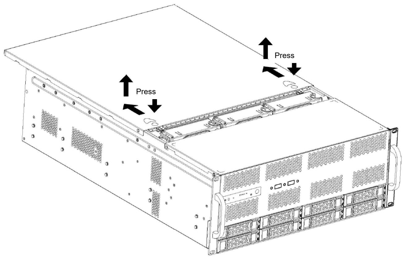
1. Loosen the three screws around the cover.
2. Press down on the top cover lock button, push it back 10-15mm, then lift it open vertically.
![Press\nPress](.axe-7400sr-50m-99307-2000-10/3cd5ca74eb65549c10e945ea18c4b480af3e9d3bc33a35d23667e96188aec398.jpg)

To reinstall the cover, slide it towards the front of the chassis, then tighten the screws loosened in Step 1.

# 3.2 Installing Memory Modules

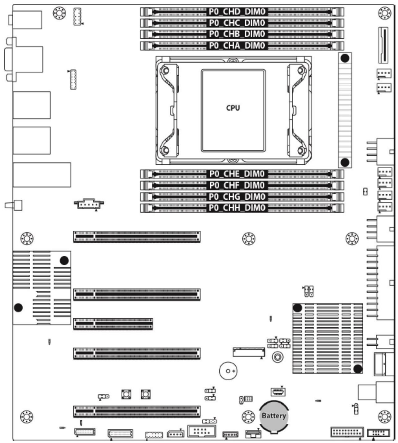
DIMM location.
![P0_CHD_DIMO\nP0_CHC_DIMO\nP0_CHB_DIMO\nP0_CHA_DIMO\nCPU\nP0_CHE_DIMO\nP0_CHF_DIMO\nP0_CHG_DIMO\nP0_CHH_DIMO\nBattery](.axe-7400sr-50m-99307-2000-10/9e39decad055912b502f0e097d2641f342553b7dd85c273bd3e503e45645f084.jpg)

All installed memory will be automatically detected. No jumpers or settings need to be changed for memory detection.

All memory must be of the same type and density. Different memory types can NOT be mixed and matched on the same motherboard.

Recommended Memory Population Table:

<table><tr><td></td><td colspan="12">Quantity of memory installed</td></tr><tr><td>DDR5</td><td colspan="4">1DDRS</td><td colspan="2">2DDRS</td><td>4DDRS</td><td colspan="4">6DDRS</td><td>8DDRS</td></tr><tr><td>1 DIMM at DIMM A0</td><td>√</td><td></td><td></td><td></td><td>√</td><td></td><td>√</td><td>√</td><td>√</td><td></td><td>√</td><td>√</td></tr><tr><td>1 DIMM at DIMM B0</td><td></td><td>√</td><td></td><td></td><td></td><td></td><td></td><td></td><td>√</td><td>√</td><td>√</td><td>√</td></tr><tr><td>1 DIMM at DIMM C1</td><td></td><td></td><td></td><td></td><td></td><td>√</td><td>√</td><td>√</td><td>√</td><td>√</td><td>√</td><td>√</td></tr><tr><td>1 DIMM at DIMM D0</td><td></td><td></td><td></td><td></td><td></td><td></td><td></td><td>√</td><td></td><td>√</td><td></td><td>√</td></tr><tr><td>1 DIMM at DIMM E0</td><td></td><td></td><td>√</td><td></td><td></td><td>√</td><td>√</td><td>√</td><td>√</td><td>√</td><td></td><td>√</td></tr><tr><td>1 DIMM at DIMM F0</td><td></td><td></td><td></td><td>√</td><td></td><td></td><td></td><td>√</td><td></td><td>√</td><td>√</td><td>√</td></tr><tr><td>1 DIMM at DIMM G1</td><td></td><td></td><td></td><td></td><td>√</td><td></td><td>√</td><td>√</td><td>√</td><td></td><td>√</td><td>√</td></tr><tr><td>1 DIMM at DIMM H0</td><td></td><td></td><td></td><td></td><td></td><td></td><td></td><td></td><td>√</td><td>√</td><td>√</td><td>√</td></tr></table>

# 3.3 PCIe Card Installation

Before installing add-in cards, it’s helpful to know if they are fully compatible with your motherboard. For this reason, we’ve provided the diagrams below, showing the slots that may appear on your motherboard.

![The image displays a yellow triangular warning sign with a black border. Inside the triangle is a black exclamation point. Below the sign, the text 'CAUTION:' appears in black capital letters.](.axe-7400sr-50m-99307-2000-10/6cb46b479ac7d4810316d1b182b414ba25223731fdb09d5cb116762b2482a117.jpg)
mise en garde

All installation procedures are restricted to skilled personnel. Only UL listed PCIe expansion cards or PCIe cards with openings less than 5 mm in any dimension are recommended

Toutes les procédures d'installation sont réservées au personnel qualifié. Seules les cartes d'extension PCIe répertoriées UL ou les cartes PCIe avec des ouvertures inférieures à 5 mm dans n'importe quelle dimension sont recommandées.

<table><tr><td>Slot</td><td>Support spec</td><td>Card install notes</td></tr><tr><td rowspan="5">&lt;img src="images/0ed6bdb92721c8cad9fcd100df305fb77e3232af405ebf50a0f22f195e9fda95.jpg"/&gt;</td><td>Standard PCIE x16 slot FH/FL, support PCIE Gen5 16 lanes (PCIE#7)</td><td>Double wide FH/FL GPGPU</td></tr><tr><td>Standard PCIE x16 slot FH/FL, support PCIE Gen5 16 lanes (PCIE#5)</td><td>Double wide FH/FL GPGPU</td></tr><tr><td>Standard PCIE x8 slot FH/FL, support PCIE Gen5 4 lanes (PCIE#4)</td><td></td></tr><tr><td>Standard PCIE x16 slot FH/FL, support PCIE Gen5 16 lanes (PCIE#3)</td><td>Double wide FH/FL GPGPU</td></tr><tr><td>Standard PCIE x16 slot FH/FL, support PCIE Gen5 16 lanes(PCIE#1)</td><td>Double wide FH/FL GPGPU</td></tr></table>

# 3.4 PCIe Slot Secondary Power Supply

The AXE-7400SR is equipped with six ATX 8pin EPS +12V power connectors on the mainboard to provide secondary power for PCIe expansion cards if required. Two adapter cables are included. The pin definitions of the connectors and cables are described below.

![A yellow triangular warning sign with a black exclamation point in the center. Below the triangle, the word 'CAUTION:' is printed in black capital letters.](.axe-7400sr-50m-99307-2000-10/296053d92125d576eba5140abdc8b8ec957382fa43d3d25707e2e909578fc6cf.jpg)

All installation procedures are restricted to skilled personnel.

Toutes les procédures d'installation sont réservées au personnel qualifié.

mise en garde

![garde\n4.6\n160\n76.5\n150.9\n4.6\nØ5\nØ4\n125.5\n99.5\n130\n125.5\n130\nATX 8pin\nEPS +12V\nPROJECTION\nUNIT\nmm\nDAT\nDESIGN](.axe-7400sr-50m-99307-2000-10/5edee1e3abd2082203a1cd3d8e9ecd1cd9537cfc8c71fd9b3f3e6dbd9975cb75.jpg)

<table><tr><td>3</td><td></td><td></td></tr><tr><td>2</td><td></td><td></td></tr><tr><td>REV</td><td>NOTES</td><td>DATE</td></tr></table>

<table><tr><td>PROJECTION</td><td></td><td>DATE</td><td>2020-02-26</td></tr><tr><td>UNIT</td><td>mm</td><td>DESIGNER</td><td>曾建新</td></tr><tr><td>DRAWING</td><td></td><td>CHECK</td><td>荀霜</td></tr><tr><td>MATERIAL</td><td></td><td>APPROVED</td><td>邹建华</td></tr></table>

Please use the provided GPU power cable below to supply power to the GPU card.

![600±10\n150±10](.axe-7400sr-50m-99307-2000-10/6ca7ec6a090cb0c2d1d4e778e05f204a5ee760b250a50fd552310e47f72256df.jpg)

# 3.5 Onboard LAN LED Color Definition

Onboard Ethernet ports have green and Amber LEDs to indicate LAN status. The chart below illustrates the different LED states.

<table><tr><td colspan="4">X550 100 Mbps /1000 Mbps /10Gbps LAN Link/Activity LED Scheme</td></tr><tr><td></td><td>&lt;img src="images/25ffde970fd8c1729b82260bf44c1dbbf3df0efec04b32c101bdb546303adfb9.jpg"/&gt;</td><td>Left LED(Link/Activity)</td><td>Right LED (Speed)</td></tr><tr><td>No Link</td><td></td><td>OFF</td><td>OFF</td></tr><tr><td rowspan="2">100 Mbps</td><td>Link</td><td>Solid Green</td><td>Solid Green</td></tr><tr><td>Active</td><td>Blinking Green</td><td>Solid Green</td></tr><tr><td rowspan="2">1000 Mbps</td><td>Link</td><td>Solid Green</td><td>Solid Yellow</td></tr><tr><td>Active</td><td>Blinking Green</td><td>Solid Yellow</td></tr><tr><td rowspan="2">(10Gbps)</td><td>Link</td><td>Solid Yellow</td><td>Solid Yellow</td></tr><tr><td>Active</td><td>Blinking Yellow</td><td>Solid Yellow</td></tr></table>

<table><tr><td colspan="5">I210 10 Mbps /100 Mbps /1Gbps Link/Activity LED Scheme</td></tr><tr><td></td><td colspan="2">&lt;img src="images/3caea93736101023f05aa0956bf9cc016a2277df2fb2fa1146ed47fae1b4e708.jpg"/&gt;</td><td>Left LED</td><td>Right LED</td></tr><tr><td colspan="3">No Link</td><td>OFF</td><td>OFF</td></tr><tr><td rowspan="2" colspan="2">10 Mbps</td><td>Link</td><td>Green Solid On</td><td>OFF</td></tr><tr><td>Active</td><td>Green Blinking</td><td>OFF</td></tr><tr><td rowspan="2" colspan="2">100 Mbps</td><td>Link</td><td>Green Solid On</td><td>Green Solid On</td></tr><tr><td>Active</td><td>Green Blinking</td><td>Green Solid On</td></tr><tr><td rowspan="2" colspan="2">1Gbps</td><td>Link</td><td>Green Solid On</td><td>Amber Solid On</td></tr><tr><td>Active</td><td>Green Blinking</td><td>Amber Solid On</td></tr></table>

# 3.6 Login in BMC Web

The default IP setting is DHCP. Users can modify the IP in BIOS Menu..

If the BMC is connected to a network, after it get an IP address, it will print the IP address on the BIOS booting screen.

# MEGARAC SP-X

Sign me in

Default login account:

Username: root

Password: superuser

When logging into the BMC web interface for the first time, you will receive a reminder to change the BMC login password. If you do change it, be sure to make a record of it to avoid being unable to log in later.

# 4 Enter BIOS Setup

To enter the BIOS setup screen, follow these steps:

1. Power on the AXE-7400SR.
2. Press &lt;F2&gt; or &lt;Del&gt; during POST (&lt;Tab&gt; on remote console) to start the BIOS setup utility.

Setup Basics
The table below shows how to navigate in the setup program using the keyboard.

<table><tr><td>Key</td><td>Function</td></tr><tr><td>↑↓→←</td><td>Move cursor</td></tr><tr><td></td><td>Execute command or select submenu</td></tr><tr><td>&lt;-&gt;/&lt;+&gt;</td><td>Select the previous or next value/setting of the field</td></tr><tr><td></td><td>Exit current menu</td></tr><tr><td></td><td>General help</td></tr><tr><td></td><td>Previous values</td></tr><tr><td></td><td>Load the Optimal default configuration values of the menu</td></tr><tr><td></td><td>Save and exit</td></tr><tr><td></td><td>Scroll help area upwards</td></tr><tr><td></td><td>Scroll help area downwards</td></tr><tr><td>/</td><td>Move cursor to next/previous page</td></tr></table>

# 4.1 Main Menu

In this section, you can alter general features such as the date and time.

Note that the options listed below are for options that can directly be changed within the Main Setup screen.

![Aptio Setup - AMI\nMain Advanced CPU Chipset Server Mgmt Security Boot Save & Exit\nBIOS Information\nProduct Name B5652F65TV6E2H-2T-N\nBIOS Version V0.008.B10\nBuild Date and Time 09/06/2022 07:26:48\nMemory Information\nTotal Memory 16384 MB\nMemory Frequency 4800 MT/s\nSystem Language (English)\nSystem Date (Tue 09/06/2022)\nSystem Time (00:41:51)\nAccess Level Administrator\nChoose the system default language\n+: Select Screen\n↑↓: Select Item\nEnter: Select\n+/-: Change Opt.\nF1: General Help\nF2: Previous Values\nF3: Optimized Defaults\nF4: Save & Exit\nESC: Exit\nVersion 2.22.1286 Copyright (C) 2022 AMI](.axe-7400sr-50m-99307-2000-10/2d23db00957d5a2a4820970ea5c90c05a5509b4bba162a4c2d535f3bd0370ba4.jpg)

# BIOS Information

It displays BIOS related information.

# Product Name

It displays Product information.

# BIOS Version

It displays BIOS version information

# Build Date and Time

It displays the time when built

# Access Level

Administrator

# Platform Information

It displays the processor and PCH information

# Memory Information Total Memory

It displays the total memory size.

# Memory Frequency

It displays Memory frequency

# System Language

Choose the system default language.

English / Simplified Chinese / Japanese

# System Date

Set the Date. Use Tab to switch between Date elements. Default Ranges: Year: 1998-9999

Months: 1-12

Days: dependent on month Range of Years may vary

# System Time

Adjust the system clock.

HH (24 hours format): MM (Minutes): SS (Seconds)

# 4.2 Advanced Menu

This section facilitates configuring advanced BIOS options for your system.

![Aptio Setup - AMI\nMain Advanced CPU Chipset Server Mgmt Security Boot Save & Exit\n► Network Stack Configuration\n► S5 RTC Make Settings\n► Serial Port Console Redirection\n► PCIe Device Configuration\n► USB Configuration\n► Onboard Device Configuration\n► Super IO Configuration\n► Hardware Health Configuration\n► PCI Subsystem Settings\n► NVMe Configuration\n► Trusted Computing\n► CSM Configuration\n► Redfish Host Interface Settings\n► Tis Auth Configuration\n► iSCSI Configuration\n► VLAN Configuration (MAC:4E722FE47F30)\n► MAC:4E722FE47F30-IPv4 Network Configuration\n► MAC:4E722FE47F30-IPv6 Network Configuration\n► Intel(R) I210 Gigabit Network Connection - A0:42:3F:4F:...\n► VLAN Configuration (MAC:A0423F4FA133)\n► MAC:A0423F4FA133-IPv4 Network Configuration\n► MAC:A0423F4FA133-IPv6 Network Configuration\n► Intel(R) Ethernet Converged Network Adapter X550-T2 - A0...\n► VLAN Configuration (MAC:A0423F4FA134)\n► MAC:A0423F4FA134-IPv4 Network Configuration\nNetwork Stack Settings\n+: Select Screen\n↑↓: Select Item\nEnter: Select\n+/-: Change Opt.\nF1: General Help\nF2: Previous Values\nF3: Optimized Defaults\nF4: Save & Exit\nESC: Exit\nVersion 2.22.1286 Copyright (C) 2022 AMI](.axe-7400sr-50m-99307-2000-10/625116acc1d5b61e9e117cc06f2454352169ae9b550add0e910ecf92ee4f3564.jpg)

NOTE: This is a sample screenshot of the Advanced Menu. The HII network drivers displayed here depend on the card(s) you installed and the functions you enabled.

# Network Stack Configuration

Network Stack Settings

# S5 RTC Wake Settings

Enable system to wake from S5 using RTC alarm

# Serial Port Console Redirection

Serial Port Console Redirection

# PCIe Device Configuration

Onboard PCIE Slot Configuration

# USB Configuration

USB Configuration Parameters

# Onboard Device Configuration

Onboard Device and Function Configuration.

# Super IO Configuration

System Super IO Chip Parameters.

# Hardware Health Configuration

Hardware Health Configuration

# PCI Subsystem Settings

PCI, PCI-X and PCI Express Settings

# NVMe Configuration

NVMe Device information

# Trusted Computing

Trusted Computing settings.

# CSM Configuration

CSM Configuration, Enable/Disable Option ROM execution setting, etc

# Redfish Host Interface Settings

Redfish Host Interface Parameters

# Tls Auth Configuration

Press&lt;Enter&gt; to select Tls Auth configuration.

# iSCSI Configuration

Configure the iSCSI parameters

# VLAN Configuration(MAC: 4E722FE47F30)

VLAN Configuration(MAC: 4E722FE47F30)

# MAC: 4E722FE47F30-IPv4 Network Configuration

Configure IPv4 network parameters.(MAC: 4E722FE47F30)

# MAC: 4E722FE47F30-IPv6 Network Configuration

Configure IPv6 network parameters.(MAC: 4E722FE47F30)

Intel ® I210 Gigabit Network Connection

Configure Gigabit Ethernet device parameters.

VLAN Configuration (MAC:A0423F4FA133)

VLAN Configuration (MAC:A0423F4FA133)

MAC: A0423F4FA133-IPv4 Network Configuration

Configure IPv4 network parameters.(MAC: A0423F4FA133)

MAC: A0423F4FA133-IPv6 Network Configuration

Configure IPv6 network parameters.(MAC: A0423F4FA133)

Intel® Ethernet Converged Network Adapter X550-T2-A0

Configure 10 Gigabit Ethernet device parameters.

VLAN Configuration (MAC:A0423F4FA134)

VLAN Configuration MAC:A0423F4FA134

MAC: A0423F4FA134-IPv4 Network Configuration

Configure IPv4 network parameters.(MAC: A0423F4FA134)

MAC: A0423F4FA134-IPv6 Network Configuration

Configure IPv6 network parameters.(MAC: A0423F4FA134)

Intel® Ethernet Converged Network Adapter X550-T2-A0

Configure 10 Gigabit Ethernet device parameters.

VLAN Configuration (MAC:A0423F4FA135)

VLAN Configuration MAC:A0423F4FA135

MAC: A0423F4FA135-IPv4 Network Configuration

Configure IPv4 network parameters.(MAC: A0423F4FA135)

MAC: A0423F4FA135-IPv6 Network Configuration

Configure IPv6 network parameters.(MAC: A0423F4FA135)

![Advanced\nNetwork Stack	(Enabled)\nIPv4 PXE Support	(Enabled)\nIPv4 HTTPS Support	(Disabled)\nIPv6 PXE Support	(Disabled)\nIPv6 HTTPS Support	(Disabled)\nPXE boot wait time	0\nMedia detect count	1\nEnable/Disable UEFI Network\nStack\n+: Select Screen\n↑↓: Select Item\nEnter: Select\n+/-: Change Opt.\nF1: General Help\nF2: Previous Values\nF3: Optimized Defaults\nF4: Save & Exit\nESC: Exit\nVersion 2.22.1286 Copyright (C) 2022 AMI](.axe-7400sr-50m-99307-2000-10/8f0cba71410f31813462ee12d41b8037220df470a6322ad9a0744d5a15381c93.jpg)

# Network Stack Configuration

# Network Stack

Enable/Disable UEFI Network Stack

Disabled / Enabled

NOTE: When Network Stack was set to Enabled, the following item will appear.

# IPv4 PXE Support.

Enable/Disable IPv4 PXE boot support. If disabled, IPv4 PXE boot support will not be available.

Disabled / Enabled

# IPv4 HTTPs Support

Enable/Disable IPv4 HTTPs boot support. If disabled, IPv4 HTTPS boot support will not be available.

Disabled / Enabled

# IPv6 PXE Support

Enable/Disable IPv6 HTTPs boot support. If disabled, IPv6 HTTPS boot support will not be available.

Disabled / Enabled

# IPv6 HTTPs Support

Enable/Disable IPv6 HTTPs boot support. If disabled, IPv6 HTTPS boot support will not be available.

Disabled / Enabled

# PXE boot wait time

Wait time in seconds to press ESC key to abort the PXE boot. Use either +/- or numeric keys to set the value.

0

# Media detect count

Number of times the presence of media will be checked. Use either +/- or numeric keys to set the value.

# S5 RTC Wake Settings

![Advanced\nAptio Setup - AMI\nWake system from S5 (Disabled)\nEnable or disable System wake\non alarm event. Select\nFixedTime, system will wake on\nthe hr::min::sec specified.\nSelect DynamicTime , System\nwill wake on the current time\n+ Increase minute(s)\n+: Select Screen\n↑↓: Select Item\nEnter: Select\n+/-: Change Opt.\nF1: General Help\nF2: Previous Values\nF3: Optimized Defaults\nF4: Save & Exit\nESC: Exit\nVersion 2.22.1286 Copyright (C) 2022 AMI](.axe-7400sr-50m-99307-2000-10/3d012bb397339c4d1e526daa656002acc1cc7cd7bfd15aedc1c62524e8a85a30.jpg)

# Wake system from S5

Enable or disable System wake on alarm event. Select Fixed Time, system will wake on the hr::min::sec specified. Select dynamic Time, system will wake on the current time+ increase minute(s)

Disabled / Fixed Time / Dynamic Time

# Serial Port Console Redirection

![Optio Setup - AMI\nAdvanced\nCOM1\nConsole Redirection (Disabled)\n► Console Redirection Settings\nCOM2\nConsole Redirection (Disabled)\n► Console Redirection Settings\nLegacy Console Redirection\n► Legacy Console Redirection Settings\nSerial Port for Out-of-Band Management/\nWindows Emergency Management Services (EMS)\nConsole Redirection (Disabled)\n► Console Redirection Settings\nConsole Redirection Enable or\nDisable.\n+: Select Screen\n↑↓: Select Item\nEnter: Select\n+/-: Change Opt.\nF1: General Help\nF2: Previous Values\nF3: Optimized Defaults\nF4: Save & Exit\nESC: Exit\nVersion 2.22.1286 Copyright (C) 2022 AMI](.axe-7400sr-50m-99307-2000-10/629268b17707584616ec2fe38bc39cd3153d8eedefdaebeea9b27e484b87572a.jpg)

# COM1/COM2

# Console Redirection

Console redirection enable or disable.

Disabled / Enabled

# Legacy Console Redirection

Legacy Console Redirection Settings

# Serial Port for Out-Of-Band Management/Windows Emergency Services (EMS) Console Redirection

Console redirection enable or disable.

Disabled / Enabled

# Console Redirection Settings

The settings specify how the host computer (which the user is using) will exchange data. Both computers should have the same or compatible settings.

NOTE: Console Redirection Settings menu only be available to set up when

Console Redirection was set to [Enabled].

# COM1 Console Redirection Settings

![Optio Setup - AMI\nAdvanced\nCOM1\nConsole Redirection Settings\nTerminal Type (VT100+)\nBits per second (115200)\nData Bits (8)\nParity (None)\nStop Bits (1)\nFlow Control (None)\nVT-UTF8 Combo Key Support (Enabled)\nRecorder Mode (Disabled)\nResolution 100x31 (Enabled)\nPutty KeyPad (VT100)\nEmulation: ANSI: Extended\nASCII char set. VT100: ASCII\nchar set. VT100+: Extends\nVT100 to support color,\nfunction keys, etc. VT-UTF8:\nUses UTF8 encoding to map\nUnicode chars onto 1 or more\nbytes.\n+: Select Screen\n↑↓: Select Item\nEnter: Select\n+/-: Change Opt.\nF1: General Help\nF2: Previous Values\nF3: Optimized Defaults\nF4: Save & Exit\nESC: Exit\nVersion 2.22.1286 Copyright (C) 2022 AMI](.axe-7400sr-50m-99307-2000-10/dc25cd42269fcca64261be0df7c469f16278db8577b6a5a6734de76aadae1829.jpg)

# Terminal Type

Emulation: ANSI: Extended ASCII char set. VT100: ASCII char set.

VT100+: Extends VT100 to support color function keys, etc.

VT-UTF8: Uses UTF8 encoding to map Unicode chars onto 1 or more bytes.

VT100 / VT100+ / VT-UTF8 / ANSI

# Bits per Second

Select serial port transmission speed. The speed must be matched on the other side. Long or noisy lines may require lower speeds.

9600 / 19200 / 38400 / 57600 / 115200

# Data Bits

8 / 7

# Parity

A parity bit can be sent with the data bits to detect some transmission errors. Even: parity bit is 0 if the num of 1’s in the data bits is even. Odd: parity bit is 0 if the num of 1’s in the data bits is odd. Mark: parity bit is always 1. Space: parity bit is always

0. Mark and Space parity do not allow for error detection.

None / Even / Odd / Mark / Space

# Stop Bits

Stop bits indicate the end of a serial data packet. (A start bit indicates the beginning). The standard setting is 1 stop bit. Communication with slow devices may require more than 1 stop bit.

1 / 2

# Flow Control

Flow Control can prevent data loss from buffer overflow. When sending data, if the receiving buffers are full, a ‘stop’ signal can be sent to stop the data flow. Once the buffers are empty, a ‘start’ signal can be sent to re-start the flow. Hardware flow control uses two wires to send start/stop signal.

None / Hardware RTS/CTS

# VT-UTF8 Combo Key Support

Enable VT-UTF8 Combination Key Support for ANSI/VT100 terminals.

Enabled / Disabled

# Recorder Mode

With this mode enabled only text will be sent. This is to capture Terminal data.

Disabled / Enabled

# Resolution 100x31

Enable or disable extended terminal resolution.

Disabled / Enabled

# Putty KeyPad

Select FunctionKey and KeyPad on Putty.

VT100 / LINUX / XTERMR6 / SCO / ESCN / VT400

# COM2 Console Redirection Settings

![Optio Setup - AMI\nAdvanced\nCOM2\nConsole Redirection Settings\nTerminal Type (VT100+)\nBits per second (115200)\nData Bits (8)\nParity (None)\nStop Bits (1)\nFlow Control (None)\nVT-UTF8 Combo Key Support (Enabled)\nRecorder Mode (Disabled)\nResolution 100x31 (Enabled)\nPutty KeyPad (VT100)\nEmulation: ANSI: Extended\nASCII char set. VT100: ASCII\nchar set. VT100+: Extends\nVT100 to support color,\nfunction keys, etc. VT-UTF8:\nUses UTF8 encoding to map\nUnicode chars onto 1 or more\nbytes.\n+: Select Screen\n↑↓: Select Item\nEnter: Select\n+/-: Change Opt.\nF1: General Help\nF2: Previous Values\nF3: Optimized Defaults\nF4: Save & Exit\nESC: Exit\nVersion 2.22.1285 Copyright (C) 2022 AMI](.axe-7400sr-50m-99307-2000-10/685d764b1920b066773c5fa843e730a7b67c553722fda934821988222f80a9fc.jpg)

# Terminal Type

Emulation: ANSI: Extended ASCII char set. VT100: ASCII char set.

VT100+: Extends VT100 to support color function keys, etc.

VT-UTF8: Uses UTF8 encoding to map Unicode chars onto 1 or more bytes.

VT100 / VT100+ / VT-UTF8 / ANSI

# Bits per Second

Select serial port transmission speed. The speed must be matched on the other side. Long or noisy lines may require lower speeds.

9600 / 19200 / 38400 / 57600 / 115200

# Data Bits

8 / 7

# Parity

A parity bit can be sent with the data bits to detect some transmission errors. Even: parity bit is 0 if the num of 1’s in the data bits is even. Odd: parity bit is 0 if the num of 1’s in the data bits is odd. Mark: parity bit is always 1. Space: parity bit is always

0. Mark and Space parity do not allow for error detection.

None / Even / Odd / Mark / Space

# Stop Bits

Stop bits indicate the end of a serial data packet. (A start bit indicates the beginning). The standard setting is 1 stop bit. Communication with slow devices may require more than 1 stop bit.

1 / 2

# Flow Control

Flow Control can prevent data loss from buffer overflow. When sending data, if the receiving buffers are full, a ‘stop’ signal can be sent to stop the data flow. Once the buffers are empty, a ‘start’ signal can be sent to re-start the flow. Hardware flow control uses two wires to send start/stop signals.

None / Hardware RTS/CTS

# VT-UTF8 Combo Key Support

Enable VT-UTF8 Combination Key Support for ANSI/VT100 terminals.

Enabled / Disabled

# Recorder Mode

With this mode enabled only text will be sent. This is to capture Terminal data.

Disabled / Enabled

# Resolution 100x31

Enable or disable extended terminal resolution.

Disabled / Enabled

# Putty KeyPad

Select FunctionKey and KeyPad on Putty.

VT100 / LINUX / XTERMR6 / SCO / ESCN / VT400

# Legacy Console Redirection Settings

![Advanced\nLegacy Console Redirection Settings\nRedirection COM Port (COM1)\nResolution (80x24)\nRedirect After POST (Always Enable)\nSelect a COM port to display\nredirection of Legacy OS and\nLegacy OPROM Messages\n+: Select Screen\n↑↓: Select Item\nEnter: Select\n+/-: Change Opt.\nF1: General Help\nF2: Previous Values\nF3: Optimized Defaults\nF4: Save & Exit\nESC: Exit\nVersion 2.22.1286 Copyright (C) 2022 AMI](.axe-7400sr-50m-99307-2000-10/04bca2378a6c6634129870e2158b5746f70e8086b844a47b9d7e3730d52a3310.jpg)

# Redirection COM Port

Select a COM port to display redirection of Legacy OS and Legacy OPROM Messages

COM1 / COM2

# Resolution

On Legacy OS, the Number of Rows and Columns supported redirection

80x24 / 80x25

# Redirect After POST

when Bootloader is selected, then Legacy Console Redirection is disabled before booting to legacy OS, when Always Enable is selected, then Legacy Console Redirection is enabled for Legacy OS. Default setting for this option is set to Always Enable.

Always Enable / BootLoader

# Serial Port for Out-Of-Band Management/Windows Emergency Services (EMS) Console Redirection Settings

![Optio Setup - AMI\nAdvanced\nOut-of-Band Mgmt Port (COM1)\nTerminal Type (VT-UTF8)\nBits per second (115200)\nFlow Control (None)\nData Bits EMS 8\nParity EMS None\nStop Bits EMS 1\nMicrosoft Windows Emergency\nManagement Services (EMS)\nallows for remote management\nof a Windows Server OS through\na serial port.\n+: Select Screen\n↑↓: Select Item\nEnter: Select\n+/-: Change Opt.\nF1: General Help\nF2: Previous Values\nF3: Optimized Defaults\nF4: Save & Exit\nESC: Exit\nVersion 2.22.1286 Copyright (C) 2022 AMI](.axe-7400sr-50m-99307-2000-10/b848a5166d1e34d6086a4b021b919cacdf0dcf34489c64752b2a461ae1b2af8b.jpg)

# Out-of Band Mgmt Port

Microsoft Windows Emergency Management Services (EMS) allows for remote management of a Windows Server OS through a serial port.

COM1 / COM2

# Terminal Type

VT-UTF8 is the preferred terminal type for out-of-band management. The next best choice is VT100+ and then VT100. See above, in Console Redirection Settings page, for more Help with Terminal Type/Emulation.

VT-UTF8 / VT100 / VT100+ / ANSI

# Bits per Second

Select serial port transmission speed. The speed must be matched on the other side. Long or noisy lines may require lower speeds.

9600 / 19200 / 57600 / 115200

# Flow Control

Flow Control can prevent data loss from buffer overflow. When sending data, if the receiving buffers are full, a ‘stop’ signal can be sent to stop the data flow. Once the buffers are empty, a ‘start’ signal can be sent to restart the flow. Hardware flow control uses two wires to send start/stop signal.

None / Hardware RTS/CTS / Software Xon/Xoff

# Data Bits EMS / Parity EMS / Stop Bits EMS

Read only.

![Aptio Setup - AMI\nAdvanced\nPCIe Device Configuration\n► Option ROM Dispatch Policy\n\n+: Select Screen\n↑↓: Select Item\nEnter: Select\n+/-: Change Opt.\nF1: General Help\nF2: Previous Values\nF3: Optimized Defaults\nF4: Save & Exit\nESC: Exit\n\nVersion 2.22.1286 Copyright (C) 2022 AMI](.axe-7400sr-50m-99307-2000-10/9dab67f8ed9bcd824bafd3067325bfe675d4f5d58f5331dfbc5ca2b118a12fea.jpg)

# PCIe Device Configuration

# Option ROM Dispatch Policy

Option ROM Dispatch Policy settings.

![Optio Setup - AMI\nAdvanced\nDevice Class Option ROM Dispatch Policy:\nLAN1 & LAN2 (X550)    (Enabled)\nLAN4 (I210)    (Enabled)\nPCIE#1 Option ROM    (Enabled)\nPCIE#2 Option ROM    (Enabled)\nPCIE#3 Option ROM    (Enabled)\nPCIE#4 Option ROM    (Enabled)\nPCIE#5 Option ROM    (Enabled)\nWARNING: Changing Device(s) Option ROM\ndispatch policy may affect system's ability\nto post and/or boot!PROCEED WITH CAUTION!\nEnable or Disable X550 LAN1\nand LAN2 Option ROM\n+: Select Screen\n↑↓: Select Item\nEnter: Select\n+/-: Change Opt.\nF1: General Help\nF2: Previous Values\nF3: Optimized Defaults\nF4: Save & Exit\nESC: Exit\nVersion 2.22.1286 Copyright (C) 2022 AMI](.axe-7400sr-50m-99307-2000-10/68167a9656d537fbcf9f2c5b41995d2a8929dd42cd1227328f6fef9e5b0367de.jpg)

# Device Class Option ROM Dispatch Policy:

# LAN1&LAN2 (X550)

Enable or Disable X550 LAN1 and LAN2 Option ROM

Enabled

/ Disabled

# LAN4 (I210)

Enable or Disable LAN2 Option Rom

Enabled

/ Disabled

# PCIE#1 Option ROM

Enable or Disable Option ROM execution for selected Slot.

Enabled

/ Disabled

# PCIE#2 Option ROM

Enable or Disable Option ROM execution for selected Slot.

Enabled

/ Disabled

# PCIE#3 Option ROM

Enable or Disable Option ROM execution for selected Slot.

Enabled

/ Disabled

# PCIE#4 Option ROM

Enable or Disable Option ROM execution for selected Slot.

Enabled / Disabled

# PCIE#5 Option ROM

Enable or Disable Option ROM execution for selected Slot.

Enabled / Disabled

![Optio Setup - AMI\nAdvanced\nUSB Configuration\nUSB Controllers:\n 1 XHCI\nUSB Devices:\n 3 Drives, 2 Keyboards, 2 Mice, 1 Hub\nLegacy USB Support (Enabled)\nXHCI Hand-off (Enabled)\nUSB Mass Storage Driver Support (Enabled)\nPort 60/64 Emulation (Enabled)\nUSB hardware delays and time-outs:\nUSB transfer time-out (20 sec)\nDevice reset time-out (20 sec)\nDevice power-up delay (Auto)\nEnables Legacy USB support.\nAUTO option disables legacy\nsupport if no USB devices are\nconnected. DISABLE option will\nkeep USB devices available\nonly for EFI applications.\n+: Select Screen\n↑↓: Select Item\nEnter: Select\n+/-: Change Opt.\nF1: General Help\nF2: Previous Values\nF3: Optimized Defaults\nF4: Save & Exit\nESC: Exit\nVersion 2.22.1286 Copyright (C) 2022 AMI](.axe-7400sr-50m-99307-2000-10/9cb39ae69ee309bad3c1e824a50f13bacdd992d65644936b1643f5dab3da3ab1.jpg)

# USB Configuration

# Legacy USB Support

Enables legacy USB support. AUTO option disables legacy support if no USB devices are connected. DISABLE option will keep USB devices available only for EFI applications.

Enabled / Disabled / Auto

# XHCI Hand-off

This is a workaround for OSes without XHCI hand-off support. The XHCI ownership change should be claimed by XHCI driver.

Enabled / Disabled

# USB Mass Storage Driver Support

Enable/Disable USB Mass Storage Driver Support.

Disabled / Enabled

# Port 60/64 Emulation

Enable I/O port 60h/64h emulation support. This should be enabled for the complete USB keyboard legacy support for non-USB awareOSes.

Disabled / Enabled

# USB transfer time-out

The time-out value for Control, Bulk and Interrupt transfers.

1 sec / 5 sec / 10 sec / 20 sec

# Device reset time-out

USB mass storage device Start Unit command time-out.

10 sec / 20 sec / 30 sec / 40 sec

# Device power-up delay

Maximum time the device will take before it properly reports itself to the Host Controller. ‘AUTO’ uses default value: for a Root port it is 100 ms, for a Hub port the delay is taken from Hub descriptor.

Auto / Manual

# Onboard Device Configuration

![Advanced\nOnboard Device Configuration\nOnboard VGA (Enabled)\nLAN1 & LAN2 (X550) (Enabled)\nLAN4 (I210) (Enabled)\nPrimary Display (Onboard)\nNMI Function (Disabled)\nChassis Intrusion Detection (Disabled)\nEnable/Disable ASPEED VGA\n+: Select Screen\n↑↓: Select Item\nEnter: Select\n+/-: Change Opt.\nF1: General Help\nF2: Previous Values\nF3: Optimized Defaults\nF4: Save & Exit\nESC: Exit\nVersion 2.22.1286 Copyright (C) 2022 AMI](.axe-7400sr-50m-99307-2000-10/d2cac80887fe1ff87fd242f99398b5194aeac9b16a8f519d4ebdf36d8d16ae05.jpg)

# Onboard VGA

Enable/Disable ASPEED VGA Disabled / Enabled

# LAN1& LAN2 (X550)

LAN Enable/Disable control function.

Disabled / Enabled

# LAN4 (I210)

LAN4 Enable/Disable control function.

Disabled / Enabled

# Primary Display

Select active Video type.

Onboard / External

# NMI Button

Enable or disable NMI button.

Disabled / Enabled

# Chassis Intrusion Detection

Enabled: When a chassis open event is detected, the BIOS will display the event.

Disabled / Enabled

![Aptio Setup - AMI\nAdvanced\nSuper IO Configuration\n► Serial Port 1 Configuration\n► Serial Port 2 Configuration\nSet Parameters of Serial Port\n1 (COMA)\n+: Select Screen\n↑↓: Select Item\nEnter: Select\n+/-: Change Opt.\nF1: General Help\nF2: Previous Values\nF3: Optimized Defaults\nF4: Save & Exit\nESC: Exit\nVersion 2.22.1286 Copyright (C) 2022 AMI](.axe-7400sr-50m-99307-2000-10/3cc8a12fd8dbadfa7d3defc0f2b6aa91d316c94689d4e381b7c8f918c94b74b0.jpg)

# Super IO Configuration

# Serial Port 1 Configuration

Set Parameters of serial Port 1 (COMA)

# Serial Port 2 Configuration

Set Parameters of serial Port 2 (COMB)

![Advanced\nSerial Port 1 Configuration\nSerial Port (Enabled)\nDevice Settings IO=3F8h; IRQ=4;\nChange Settings (Auto)\nEnable or Disable Serial Port\n(COM)\n+: Select Screen\n↑↓: Select Item\nEnter: Select\n+/-: Change Opt.\nF1: General Help\nF2: Previous Values\nF3: Optimized Defaults\nF4: Save & Exit\nESC: Exit\nVersion 2.22.1286 Copyright (C) 2022 AMI](.axe-7400sr-50m-99307-2000-10/bce1a806b06e7330792372e09a70232cae4c872df021a0e8e7ca02b6399ccd58.jpg)

# Serial Port 1 Configuration

# Serial Port

Select an optimal settings for Super IO Device.

Disabled / Enabled

NOTE: Serial Port has set to Enabled, the following items will be appear.

# Change Settings

Select an optimal settings for Super IO device.

# Auto /

![Advanced\nSerial Port 2 Configuration\nSerial Port (Enabled)\nDevice Settings IO=2F8h; IRQ=3;\nChange Settings (Auto)\nEnable or Disable Serial Port\n(COM)\n+: Select Screen\n↑↓: Select Item\nEnter: Select\n+/-: Change Opt.\nF1: General Help\nF2: Previous Values\nF3: Optimized Defaults\nF4: Save & Exit\nESC: Exit\nVersion 2.22.1286 Copyright (C) 2022 AMI](.axe-7400sr-50m-99307-2000-10/bbf2fef5e77317729f1512125549c7433afefbf1bcf6bce8546ee8a33a1c3287.jpg)

# Serial Port 2 Configuration

# Serial Port

Enable or Disable Serial Port (COM).

Disabled / Enabled

NOTE: Serial Port has set to Enabled, the following items will be appear.

# Change Settings

Select an optimal settings for Super IO device.

# Auto /

# Hardware Health Configuration

![Aptio Setup - AMI\nAdvanced\nHardware Health Configuration\nFan Speed Control (Manual)\nPWM Minimum Duty Cycle(%) 30\nBMC Alert Beep (On)\nPSU Status Monitor\nPMBus Support (Disabled)\nHardware Health Event Monitoring\n► Sensor Data Register Monitoring\nFan Speed Control\n+: Select Screen\n↑↓: Select Item\nEnter: Select\n+/-: Change Opt.\nF1: General Help\nF2: Previous Values\nF3: Optimized Defaults\nF4: Save & Exit\nESC: Exit\nVersion 2.22.1287 Copyright (C) 2023 AMI](.axe-7400sr-50m-99307-2000-10/14db39acd32fd87647f010e4c00b82e8ac8abf5d93f9c323134a31c0118728c2.jpg)

# Auto Fan Control

Auto Fan Control help.

Manual / Full Speed

# PWM Minimal Duty Cycle

PWM Minimal Duty Cycle (%). This item is available when Fan Speed Control is set to [Manual].

30

# BMC Alert Beep

Enable/Disable BMC Alert Beep.

On / Off

# PMBus support

PMBus Support.

Disabled / Enabled

# Sensor Data Register Monitoring

When you enter the Sensor Data Register Monitoring submenu, you will see the following dialog window pop out. Please wait 8\~10 seconds.

![PC Health Status\nID# NAME      READING   Unit   STATUS\n\nSensor Data are reading now,\n\nPlease wait a moment!!](.axe-7400sr-50m-99307-2000-10/7a344213d630f468a0eafa09f23e5b1df28ab5301193c795228b30386a331c3a.jpg)

NOTE 1: SDR can not be modified. Read only.

![Pc Health Status\nID# NAME READING UNIT STATUS\n01 PO_Temp : 46 °C OK\n02 PO_DTS_Margin : -49 °C OK\n05 PO_THRM_Margin : -41 °C OK\n09 PCH_Temp : 58 °C OK\n10 PO_CHA_DIMO : N/A °C\n11 PO_CHB_DIMO : N/A °C\n12 PO_CHC_DIMO : N/A °C\n13 PO_CHD_DIMO : N/A °C\n14 PO_CHE_DIMO : 43 °C OK\n15 PO_CHF_DIMO : N/A °C\n16 PO_CHG_DIMO : N/A °C\n17 PO_CHH_DIMO : N/A °C\n20 PO_MOSFET1 : N/A °C\n21 PO_MOSFET2 : N/A °C\n22 PO_MOSFET3 : N/A °C\n30 SYS_Air_Inlet : N/A °C\n32 SYS_Air_Outlet : 46 °C OK\n34 MB_Air_Inlet : 46 °C OK\n50 U.2_NVME_SSD_0 : N/A °C\n51 U.2_NVME_SSD_1 : N/A °C\n52 M.2_NVME_SSD_0 : N/A °C\n5F CPU_FAN : 7560 RPM OK\n++: Select Screen\n↑↓: Select Item\nEnter: Select\n+/-: Change Opt.\nF1: General Help\nF2: Previous Values\nF3: Optimized Defaults\nF4: Save & Exit\nESC: Exit\nVersion 2.22.1286 Copyright (C) 2022 AMI](.axe-7400sr-50m-99307-2000-10/4317ef78b897e3b02e21c481574b512931e04bb085bd469d5fdfa9de4807eb96.jpg)

![Aptio Setup - AMI\nAdvanced\n5F CPU_FAN : 7560 RPM OK\n60 SYS_FAN_1 : N/A RPM\n61 SYS_FAN_2 : N/A RPM\n62 SYS_FAN_3 : N/A RPM\n63 SYS_FAN_4 : N/A RPM\n64 SYS_FAN_5 : N/A RPM\n65 SYS_FAN_6 : N/A RPM\n66 SYS_FAN_7 : N/A RPM\n67 SYS_FAN_8 : N/A RPM\n68 SYS_FAN_9 : N/A RPM\n69 SYS_FAN_10 : N/A RPM\n6A SYS_FAN_11 : N/A RPM\n6B SYS_FAN_12 : N/A RPM\n70 PSU0_Temp : Disabled\n71 PSU0_Fan : Disabled\n72 PSU0_Pout : Disabled\n73 PSU0_Pin : Disabled\nC0 PSU0_Status : Disabled\n78 PSU1_Temp : Disabled\n79 PSU1_Fan : Disabled\n7A PSU1_Pout : Disabled\n7B PSU1_Pin : Disabled\nC1 PSU1_Status : Disabled\n90 P12V_IN : 11.919 V OK\n91 P12V_AUX : 11.919 V OK\n++: Select Screen\n↑↓: Select Item\nEnter: Select\n+/-: Change Opt.\nF1: General Help\nF2: Previous Values\nF3: Optimized Defaults\nF4: Save & Exit\nESC: Exit\nVersion 2.22.1286 Copyright (C) 2022 AMI](.axe-7400sr-50m-99307-2000-10/23ced795afdd37c49ff9acb8f184139c8fa747b4ee3de43211e6ace80a09fa61.jpg)

![Aptio Setup - AMI\nAdvanced\n71 PSU0_Fan : Disabled\n72 PSU0_Pout : Disabled\n73 PSU0_Pin : Disabled\nC0 PSU0_Status : Disabled\n78 PSU1_Temp : Disabled\n79 PSU1_Fan : Disabled\n7A PSU1_Pout : Disabled\n7B PSU1_Pin : Disabled\nC1 PSU1_Status : Disabled\n90 P12V_IN : 11.919 V OK\n91 P12V_AUX : 11.919 V OK\n92 P3V3 : 3.3082 V OK\n93 P5V : 5.0260 V OK\n94 PVNN_PCH_AUX : 0.9016 V OK\n95 P1V05_PCH_AUX : 1.0500 V OK\n96 P1V8_AUX : 1.7902 V OK\n97 P3V_BAT : 3.2705 V OK\n98 PU1_VCCIN_CPU0 : 1.8098 V OK\n9A PU1_FAQN_CPU0 : 1.0882 V OK\n9E PU2VCCD_CPU0 : 1.1490 V OK\nA1 CPU_Power : 96 W OK\nBA Chassis_Status : Disabled\n++: Select Screen\n↑↓: Select Item\nEnter: Select\n+/-: Change Opt.\nF1: General Help\nF2: Previous Values\nF3: Optimized Defaults\nF4: Save & Exit\nESC: Exit](.axe-7400sr-50m-99307-2000-10/414a6f680f3f5f4b63e869ef0670df7eb44c7f2aca917c7575c400345096e765.jpg)

Version 2.22.1286 Copyright (C) 2022 AMI

![PCI Devices Common Settings:\nAbove 4G Decoding (Enabled)\nSR-IOV Support (Enabled)\nPCI Express Settings\nEnables or Disables 64bit\ncapable Devices to be Decoded\nin Above 4G Address Space\n(Only if System Supports 64\nbit PCI Decoding).\n+: Select Screen\n↑↓: Select Item\nEnter: Select\n+/-: Change Opt.\nF1: General Help\nF2: Previous Values\nF3: Optimized Defaults\nF4: Save & Exit\nESC: Exit\nVersion 2.22.1285 Copyright (C) 2022 AMI](.axe-7400sr-50m-99307-2000-10/25e0f3e580fc58ad6aa340d5e329d598988828ac8f50736181d47ba66ea4e581.jpg)

# PCI Device Common Settings

# Above 4G Decoding

Enables or Disables 64bit capable Devices to be decoded in Above 4G Address Space(Only if System supports 64 bit PCI Decoding).

Enabled / Disabled

# SR-IOV Support

If system has SR-IOV capable PCIe devices, this option Enables or Disables Single Root IO virtualization Support

Enabled / Disabled

# PCI Express Settings

Change PCI Express Devices Settings

![PCI Express Device Register Settings\nMaximum Payload (Auto)\nSet Maximum Payload of PCI\nExpress Device or allow System\nBIOS to select the value.\n+: Select Screen\n↑↓: Select Item\nEnter: Select\n+/-: Change Opt.\nF1: General Help\nF2: Previous Values\nF3: Optimized Defaults\nF4: Save & Exit\nESC: Exit\nVersion 2.22.1286 Copyright (C) 2022 AMI](.axe-7400sr-50m-99307-2000-10/b2c1368fd889b290692ac1697da45a038138744ee2c77639b3335c198628e6c9.jpg)

# PCI Express Subsystem

# Maximum Payload

Set Maximum Payload of PCI Express Device or allow System BIOS to select the value.

Auto / 128 Bytes / 256 Bytes / 512 Bytes / 1024 Bytes / 2048 Bytes / 4096

Bytes

![Aptio Setup - AMI\nAdvanced\nNVMe Controller and Drive information\nNVMe0 Bus:01 Dev:0 Func:0 INTEL SSDPEKKR128G7\nNVMe Size 128.0GB\n\n+: Select Screen\n↑↓: Select Item\nEnter: Select\n+/-: Change Opt.\nF1: General Help\nF2: Previous Values\nF3: Optimized Defaults\nF4: Save & Exit\nESC: Exit\n\nVersion 2.22.1286 Copyright (C) 2022 AMI](.axe-7400sr-50m-99307-2000-10/97e246c49495610772d309fcbd36216adfa2e32baed5f4085822609609b2f817.jpg)

# NVMe Configuration

![Optio Setup - AMI\nAdvanced\nConfiguration\nSecurity Device Support (Disabled)\nNO Security Device Found\nEnables or Disables BIOS\nsupport for security device.\nO.S. will not show Security\nDevice. TCG EFI protocol and\nINT1A interface will not be\navailable.\n+: Select Screen\n↑↓: Select Item\nEnter: Select\n+/-: Change Opt.\nF1: General Help\nF2: Previous Values\nF3: Optimized Defaults\nF4: Save & Exit\nESC: Exit\nVersion 2.22.1286 Copyright (C) 2022 AMI](.axe-7400sr-50m-99307-2000-10/4083cffc0597608ba531d417ad145a6d0b0ed95e2514371a06bcdb0d19ae533e.jpg)

# Trusted Computing

# Security Device Support

Enables or disables BIOS support for security device. O.S. will not show Security device. O.S. will not show Security Device. TCG EFI protocol and INT1A interface will not be available.

Enabled / Disabled

![Optio Setup - AMI\nAdvanced\nCompatibility Support Module Configuration\nCSM Support (Enabled)\nOption ROM Messages (Force BIOS)\nOption ROM execution\nNetwork (UEFI)\nStorage (UEFI)\nVideo (UEFI)\nOther PCI devices (UEFI)\nEnable/Disable CSM Support.\n++: Select Screen\n↑↓: Select Item\nEnter: Select\n+/-: Change Opt.\nF1: General Help\nF2: Previous Values\nF3: Optimized Defaults\nF4: Save & Exit\nESC: Exit\nVersion 2.22.1286 Copyright (C) 2022 AMI](.axe-7400sr-50m-99307-2000-10/58980281611fd17103037cb73de8339d4f8e6e6a23a1bc53262d0893bd0653aa.jpg)

# CSM Configuration

# CSM support

Enable/Disable CSM Support

Enabled / Disabled

NOTE：When the CSM support set to Enabled, the following items will appear.

# Option ROM Messages

Set display mode for Option ROM

Force BIOS / Keep Current

# Network

Controls the execution of UEFI and legacy PXE OpROM

UEFI / legacy

# Storage

Controls the execution of UEFI and legacy PXE OpROM

UEFI / legacy

# Video

Controls the execution of UEFI and legacy Video OpROM

UEFI / legacy

# Other PCI devices

Determines OpRom execution policy for devices other than network, storage, or video

UEFI / legacy

![Advanced\nRedfish Host Interface Settings\nRedfish	(Enabled)\nBMC Redfish Version	1.11.0\nBIOS Redfish Version	1.11.0\nRedfish BMC Settings\nIP address	169.254.0.17\nIP Mask address	255.255.0.0\nIP Port	443\n+:-: Select Screen\n↑↓: Select Item\nEnter: Select\n+/-: Change Opt.\nF1: General Help\nF2: Previous Values\nF3: Optimized Defaults\nF4: Save & Exit\nESC: Exit\nVersion 2.22.1286 Copyright (C) 2022 AMI\nEnable/Disable AMI Redfish](.axe-7400sr-50m-99307-2000-10/6c2ecabe4e37b07388a38176e979e29ab5d8b170d2e69e6a396be1a9f15a318b.jpg)

# Redfish Host Interface Settings

# Redfish

Enable/Disable AMI Redfish.

Disabled / Enabled

![Aptio Setup - AMI\nAdvanced\n► Server CA Configuration\n► Client Cert Configuration\nPress (Enter) to configure\nServer CA.\n+:-: Select Screen\n↑↓: Select Item\nEnter: Select\n+/-: Change Opt.\nF1: General Help\nF2: Previous Values\nF3: Optimized Defaults\nF4: Save & Exit\nESC: Exit\nVersion 2.22.1286 Copyright (C) 2022 AMI](.axe-7400sr-50m-99307-2000-10/e65ff1c4cd77815588b4fe7f7e0d5da7d19c1968962d8f1dd6b79b2a5b592778.jpg)

# Tls Auth Configuration

# Server CA Configuration

Press &lt;Enter&gt; to configure Server CA.

![Aptio Setup - AMI\nAdvanced\n► Enroll Cert\n► Delete Cert\nPress (Enter) to enroll cert.\n+: Select Screen\n↑↓: Select Item\nEnter: Select\n+/-: Change Opt.\nF1: General Help\nF2: Previous Values\nF3: Optimized Defaults\nF4: Save & Exit\nESC: Exit\nVersion 2.22.1285 Copyright (C) 2022 AMI](.axe-7400sr-50m-99307-2000-10/c96a979013ea3af1f3605f80a74b96ccac5736685d0f13dc45d4c58754858a14.jpg)

# Tls Auth Configuration

# Enroll Cert

Press &lt;Enter&gt; to enroll cert.

# Delete Cert

Press &lt;Enter&gt; to delete cert.

![Aptio Setup - AMI\nAdvanced\n► Enroll Cert Using File\nCert GUID\n► Commit Changes and Exit\n► Discard Changes and Exit\nEnroll Cert Using File\n+: Select Screen\n↑↓: Select Item\nEnter: Select\n+/-: Change Opt.\nF1: General Help\nF2: Previous Values\nF3: Optimized Defaults\nF4: Save & Exit\nESC: Exit\nVersion 2.22.1286 Copyright (C) 2022 AMI](.axe-7400sr-50m-99307-2000-10/b50e06e721c28e38f595b95ea323419893db3cb1d49a80ed32399c006f43c59e.jpg)

# Enroll Cert Configuration

# Enroll Cert Using File

Enroll Cert Using File

# Cert GUID

Input digit character in 11111111-2222-3333-4444-1234567890ab format.

# Commit Changes and Exit

Commit Changes and Exit

# Discard Changes and Exit

Discard Changes and Exit

![Optio Setup - AMI\nAdvanced\nFE9C6606-8B49-44A3-8B6B-DEA3A0E032 (Disabled)\nGUID for CERT\n+: Select Screen\n↑↓: Select Item\nEnter: Select\n+/-: Change Opt.\nF1: General Help\nF2: Previous Values\nF3: Optimized Defaults\nF4: Save & Exit\nESC: Exit\nVersion 2.22.1286 Copyright (C) 2022 AMI](.axe-7400sr-50m-99307-2000-10/c55697d88e2fd9bab8b4231ec7978e28f97b9c57d0b510eb9aba83c19ed4fe57.jpg)

# Delete Cert Configuration

# FEXXXXXX-XXXX-XXXX-XXXX-XXXXXXXXXX

GUID for CERT

Disabled / Enabled

![Aptio Setup - AMI\nAdvanced\n► Host iSCSI Configuration\nHost iSCSI Configuration\n+: Select Screen\n↑↓: Select Item\nEnter: Select\n+/-: Change Opt.\nF1: General Help\nF2: Previous Values\nF3: Optimized Defaults\nF4: Save & Exit\nESC: Exit\nVersion 2.22.1286 Copyright (C) 2022 AMI](.axe-7400sr-50m-99307-2000-10/abb71c138ae44879aa3a73ff06237d841890ad03118c699cfc2699e879ea404b.jpg)

# ISCSI Initiator Configuration

# Host iSCSI Configuration

Host iSCSI Configuration settings

![Aptio Setup Utility - Copyright (C) 2020 American Megatrends, Inc.\nAdvanced\niSCSI Initiator Name    iqn.dqa\n► Add an Attempt\n► Attempt 1\n► Attempt 2\n► Attempt 3\n► Delete Attempts\n► Change Attempt Order\nDelete one or more attempts\n+: Select Screen\n↑↓: Select Item\nEnter: Select\n+/-: Change Opt.\nF1: General Help\nF2: Previous Values\nF3: Optimized Defaults\nF4: Save & Exit\nESC: Exit\nVersion 2.20.1275. Copyright (C) 2020 American Megatrends, Inc.](.axe-7400sr-50m-99307-2000-10/90334fcf8be147a9b510920eef56e6aac4590220e7ed363fd0bd707cd6e7936f.jpg)

# Host iSCSI Configuration

Please follow the instructions to initiate the iSCSI function. Step 1.

Select Advanced  CSM Configuration  Network  [UEFI]. Step 2.

Select Advanced  Network Stack Configuration  Network Stack  [Enabled] Step 3.

Save changes and reboot.

# iSCSI Initiator Name

The worldwide unique name of iSCSI Initiator. Only IQN format is accepted. Range is from 4 to 223.

# Add an Attempt

Add one or more attempts

Attempt 1

Attempt 2

Attempt 3

# Delete Attempts

Delete one or more attempts

# Change Attempt Order

Change attempt sequence

# Add an Attempt

![Aptio Setup Utility - Copyright (C) 2020 American Megatrends, Inc.\nAdvanced\nMAC 36:02:0B:83:D7:63\nMAC A0:42:3F:37:EA:08\nPFA: Bus 35 | Dev 0 | Func 3\n+: Select Screen\n↑↓: Select Item\nEnter: Select\n+/-: Change Opt.\nF1: General Help\nF2: Previous Values\nF3: Optimized Defaults\nF4: Save & Exit\nESC: Exit\nVersion 2.20.1275. Copyright (C) 2020 American Megatrends, Inc.](.axe-7400sr-50m-99307-2000-10/c3e29b91e2559405be201af4d60959af5d61b2d86ef571b135e559fb78fa81dc.jpg)

Read only.

![Aptio Setup Utility - Copyright (C) 2020 American Megatrends, Inc.\nAdvanced\niSCSI Attempt Name	Attempt 2\niSCSI Mode	(Disabled)\nInternet Protocol	(IPv4)\nConnection Retry Count	0\nConnection Establishing Timeout	1000\nOUI-format ISID	36020B83D763\nConfigure ISID	83D763\nEnable DHCP	(Disabled)\nInitiator IP Address	0.0.0.0\nInitiator Subnet Mask	0.0.0.0\nGateway	0.0.0.0\nTarget Name\nTarget Address\nTarget Port	3260\nBoot LUN	0\nAuthentication Type	(None)\nSave Changes\nThe human name defined for\nthis attempt.\n+: Select Screen\n↑↓: Select Item\nEnter: Select\n+/-: Change Opt.\nF1: General Help\nF2: Previous Values\nF3: Optimized Defaults\nF4: Save & Exit\nESC: Exit\nVersion 2.20.1275. Copyright (C) 2020 American Megatrends, Inc.](.axe-7400sr-50m-99307-2000-10/e57c9dedfb8f8153d5d59e5f30cbb49bb21219a2874bc7dab90f77f4a4b84ec4.jpg)

MAC 36:02:0B:83:D7:63

# iSCSI Mode

Disabled, Enabled, Enabled for MPIO.

Disabled / Enabled / Enabled for MPIO

# Internet Protocol

Initiator IP address is system assigned in IP6 mode. In Autoconfigure mode, iSCSI driver will attempt to connect iSCSI target via IPv4 stack, if failed then attempt IPv6 stack.

IPv4 / IPv6 / Autoconfigure

# Connection Retry Count

The minimum value is 0 and the maximum is 16. 0 means no retry.

# Connection Establishing Timeout

The timeout value in milliseconds. The minimum value is 100 milliseconds and the maximum is 20 seconds.

# Configure ISID

OUI-format ISID in 6 bytes, default value is derived from MAC address. Only last 3 bytes are configurable. Example: update 0ABBCCDDEEFF to OABBCCF07901 by input F07901.

# Enable DHCP

Enable DHCP.

Disabled / Enabled

# Initiator IP Address

Enter IP address in dotted-decimal notation.

# Initiator Subnet Mask

Enter IP address in dotted-decimal notation.

# Gateway

Enter IP address in dotted-decimal notation.

# Target Name

The worldwide unique name of the target. Only iqn. format is accepted. Range is from 4 to 223

# iqu. xxx

# Target Address

Enter Target address in IPv4, IPv6 or URL format. You need to configure DNS server address in advance if input a URL string.

# Target Port

Target Port.

# Boot LUN

Hexadecimal representation of the LU number. Examples are: 4752-3A4F-6b7e- 3F99, 6734-9-156f-127, 4186-9.

# Authentication Type

Authentication method: CHAP, Kerberos, or None.

CHAP / None

# Save Changes

Must reboot system manually for changes to take place.

![Aptio Setup Utility - Copyright (C) 2020 American Megatrends, Inc.\nAdvanced\niSCSI Attempt Name	Attempt 4\niSCSI Mode	(Disabled)\nInternet Protocol	(IPv4)\nConnection Retry Count	0\nConnection Establishing Timeout	1000\nOUI-format ISID	20423F37EA08\nConfigure ISID	37EA08\nEnable DHCP	(Disabled)\nInitiator IP Address	0.0.0.0\nInitiator Subnet Mask	0.0.0.0\nGateway	0.0.0.0\nTarget Name\nTarget Address\nTarget Port	3260\nBoot LUN	0\nAuthentication Type	(None)\nSave Changes\nThe human name defined for\nthis attempt.\n+: Select Screen\n↑↓: Select Item\nEnter: Select\n+/-: Change Opt.\nF1: General Help\nF2: Previous Values\nF3: Optimized Defaults\nF4: Save & Exit\nESC: Exit\nVersion 2.20.1275. Copyright (C) 2020 American Megatrends, Inc.](.axe-7400sr-50m-99307-2000-10/53ed843c8346c647d8227e4d835446467a394f4c99ebc9388db013799f0c0953.jpg)

# iSCSI Mode

Disabled, Enabled, Enabled for MPIO.

Disabled / Enabled / Enabled for MPIO

# Internet Protocol

Initiator IP address is system assigned in IP6 mode. In Autoconfigure mode, iSCSI driver will attempt to connect iSCSI target via IPv4 stack, if failed then attempt IPv6 stack.

IPv4 / IPv6 / Autoconfigure

# Connection Retry Count

The minimum value is 0 and the maximum is 16. 0 means no retry.

# Connection Establishing Timeout

The timeout value in milliseconds. The minimum value is 100 milliseconds and the maximum is 20 seconds.

# Configure ISID

OUI-format ISID in 6 bytes, default value is derived from MAC address. Only last 3 bytes are configurable. Example: update 0ABBCCDDEEFF to OABBCCF07901 by input F07901.

# Enable DHCP

Enable DHCP.

Disabled / Enabled

# Initiator IP Address

Enter IP address in dotted-decimal notation.

# Initiator Subnet Mask

Enter IP address in dotted-decimal notation.

# Gateway

Enter IP address in dotted-decimal notation.

# Target Name

The worldwide unique name of the target. Only iqn. format is accepted. Range is from 4 to 223

iqu. xxx

# Target Address

Enter Target address in IPv4, IPv6 or URL format. You need to configure DNS server address in advance if input a URL string.

# Target Port

Target Port.

# Boot LUN

Hexadecimal representation of the LU number. Examples are: 4752-3A4F-6b7e- 3F99, 6734-9-156f-127, 4186-9.

# Authentication Type

Authentication method: CHAP, Kerberos, or None.

CHAP / None

# Save Changes

Must reboot system manually for changes to take place.

![Aptio Setup Utility - Copyright (C) 2020 American Megatrends, Inc.\nAdvanced\nAttempt 1 (Disabled)\nAttempt 2 (Disabled)\nAttempt 3 (Disabled)\nCommit Changes and Exit\nDiscard Changes and Exit\nMAC: A0:42:3F:37:EA:08, PFA:\nBus 97 | Dev 0 | Func 0, iSCSI\nmode: Enabled, IP version: IPv4\n+: Select Screen\n↑↓: Select Item\nEnter: Select\n+/-: Change Opt.\nF1: General Help\nF2: Previous Values\nF3: Optimized Defaults\nF4: Save & Exit\nESC: Exit\nVersion 2.20.1275. Copyright (C) 2020 American Megatrends, Inc.](.axe-7400sr-50m-99307-2000-10/5e41e68704eb2d2efdd1222705d172dbfc64e76e5d3347785d279170f25c6ec6.jpg)

# Delete Attempts

# Attempt 1

MAC: A0:42:3F:37:EA:08, PFA: Bus 97/ Dev 0 / Func 0, iSCSI mode: Enabled, IP version: IPv4.

Disabled / Enabled

# Attempt 2

MAC: 36:02:0B:83:D7:63, PFA: Bus 35 / Dev 0 / Func 3, iSCSI mode: Disabled, IP version: IPv4.

Disabled / Enabled

# Attempt 3

MAC: 36:02:0B:83:D7:63, PFA: Bus 35 / Dev 0 / Func 3, iSCSI mode: Disabled, IP version: IPv4.

Disabled / Enabled

# Commit Changes and Exit

Commit Changes and Exit.

# Discard Changes and Exit

Discard Changes and Exit.

![Aptio Setup Utility - Copyright (C) 2020 American Megatrends, Inc.\nAdvanced\nChange Attempt Order (Attempt 1)\nCommit Changes and Exit\nDiscard Changes and Exit\nChange the order of Attempts\nusing +/- keys. Use arrow keys\nto select the attempt then\npress +/- to move the attempt\nup/down in the attempt order\nlist.\n+: Select Screen\n↑↓: Select Item\nEnter: Select\n+/-: Change Opt.\nF1: General Help\nF2: Previous Values\nF3: Optimized Defaults\nF4: Save & Exit\nESC: Exit\nVersion 2.20.1275. Copyright (C) 2020 American Megatrends, Inc.](.axe-7400sr-50m-99307-2000-10/37073ae50a74a3fca100b18ba7f075157fee7d10e1964e014b95ef94bf4c0121.jpg)

# Change Attempt Order

# Change Attempt Order

Change the order of Attempts using +/- keys. Use arrow keys to select the attempt then press +/- to move the attempt up/down in the attempt order list.

Attempt 1 / Attempt 2 / Attempt 3

# Commit Changes and Exit

Commit Changes and Exit.

# Discard Changes and Exit

Discard Changes and Exit.

![Aptio Setup - AMI\nAdvanced\nEnter Configuration Menu\nPress ENTER to enter\nconfiguration menu for VLAN\nconfiguration.\n+: Select Screen\n↑↓: Select Item\nEnter: Select\n+/-: Change Opt.\nF1: General Help\nF2: Previous Values\nF3: Optimized Defaults\nF4: Save & Exit\nESC: Exit\nVersion 2.22.1286 Copyright (C) 2022 AMI](.axe-7400sr-50m-99307-2000-10/6b6e113b96d11bfc1d761d342cd451640bb296d8a49abfaa0238f641b669bcff.jpg)

# VLAN Configuration

# Enter Configuration

Press ENTER to enter configuration menu for VLAN configuration.

![Optio Setup - AMI\nAdvanced\nCreate new VLAN\nVLAN ID 0\nPriority 0\nAdd VLAN\nConfigured VLAN List\nRemove VLAN\nVLAN ID of new VLAN or\nexisting VLAN, valid value is\n0~4094\n+: Select Screen\n↑↓: Select Item\nEnter: Select\n+/-: Change Opt.\nF1: General Help\nF2: Previous Values\nF3: Optimized Defaults\nF4: Save & Exit\nESC: Exit\nVersion 2.22.1286 Copyright (C) 2022 AMI](.axe-7400sr-50m-99307-2000-10/16646e6b9b86c1d6329259df5e96e4ff9d2179d9f2077d34bf4d11ac04cf00c6.jpg)

# Enter Configuration

# VLAN ID

VLAN ID of new VLAN or existing VLAN, valid value is 0\~4094

# Priority

802.1Q Priority, valid value is 0\~7

# Add VLAN

Create a new VLAN or update existing VLAN

# Remove VLAN

Remove selected VLANs

![Optio Setup - AMI\nAdvanced\nConfigured (Disabled)\nSave Changes and Exit\nIndicate whether network\naddress configured\nsuccessfully or not.\n++: Select Screen\n↑↓: Select Item\nEnter: Select\n+/-: Change Opt.\nF1: General Help\nF2: Previous Values\nF3: Optimized Defaults\nF4: Save & Exit\nESC: Exit\nVersion 2.22.1286 Copyright (C) 2022 AMI](.axe-7400sr-50m-99307-2000-10/c6465dd93ce71771df2ab7fa695d79e7fb36476a83c7f720478238bbd9947d2e.jpg)

# MAC: 4E722FER47F30-IPv4 Network Menu

# Configured

Indicate whether network address configured successfully or not.

Disabled / Enabled

NOTE: When Configured was set to Enabled, the following items will be available to set up.

# Enable DHCP

Indicate whether network address configured successfully or not.

Disabled / Enabled

# Local IP Address

Enter IP address in dotted-decimal notation. Example: 162.168.10.12

# Local NetMask

Enter Netmask in dotted-decimal notation. Example:255.255.255.0

# Local Gateway

Enter Gateway in dotted-decimal notation. Example:192.168.10.1

# Local DNS Servers

Enter DNS Servers in dotted-decimal notation. Example:192.168.10.8 192.168.10.9

# Save Changes and Exit

Save Changes and Exit

# MAC: 4E722FER47F30-IPv6 Network Menu

![Optio Setup - AMI\nAdvanced\nEnter Configuration Menu\nPress ENTER to enter\nconfiguration menu for IPv6\nconfiguration.\n+: Select Screen\n↑↓: Select Item\nEnter: Select\n+/-: Change Opt.\nF1: General Help\nF2: Previous Values\nF3: Optimized Defaults\nF4: Save & Exit\nESC: Exit\nVersion 2.22.1286 Copyright (C) 2022 AMI](.axe-7400sr-50m-99307-2000-10/f35fcd7cf721cd5db87ea8240522f41478f0a59e7785876b55d517947a93c552.jpg)

# Enter Configuration Menu

Press ENTER to enter configuration menu for IPv6 configuration.

![Advanced\nInterface Name : eth0\nInterface Type : Ethernet\nMAC address : 4E-72-2F-E4-7F-30\nHost addresses :\nFE80::4C72:2FFF:FEE4:...\nRoute Table :\nFE80::/64 ))::\nGateway addresses :\nDNS addresses :\nInterface ID 4C:72:2F:FF:FE:E4:7F:30\nDAD Transmit Count 1\nPolicy (automatic)\nSave Changes and Exit\nThe 64 bit alternative\ninterface ID for the device.\nThe string is colon separated.\ne.g. ff:dd:88:66:cc:1:2:3\n+: Select Screen\n↑↓: Select Item\nEnter: Select\n+/-: Change Opt.\nF1: General Help\nF2: Previous Values\nF3: Optimized Defaults\nF4: Save & Exit\nESC: Exit\nVersion 2.22.1286 Copyright (C) 2022 AMI](.axe-7400sr-50m-99307-2000-10/b81d5a7d6818ae3a08cdb574a7b9e72e3904585590e3d29ef089bf16e1afe05a.jpg)

# Enter Configuration Menu

# Interface ID

The 64 bit alternative interface ID for the device. The string is colon separated. e.g. ff:dd:88:66:cc:1:2:3

# DAD Transmit Count

The number of consecutive Neighbor Solicitation message sent while performing Duplicate Address Detection on a tentative address. A value of zero indicates that duplicate address detection is not performed.

# Policy

Automatic or manual

Automatic / manual

# Save Changes and Exit

Save changes for interface ID, DAD transmit count, policy, and data in advanced configuration.

# Intel® I210 Gigabit Network Connection Settings

![Optio Setup - AMI\nAdvanced\n► Firmware Image Properties\n► NIC Configuration\nBlink LEDs 0\nUEFI Driver Intel(R) PRO/1000 9.8...\nAdapter PBA 000300-000\nDevice Name Intel(R) I210 Gigabit...\nChip Type Intel i210\nPCI Device ID 1533\nPCI Address 04:00:00\nLink Status (Disconnected)\nMAC Address A0:42:3F:4F:A1:33\nVirtual MAC Address 00:00:00:00:00:00\nView device firmware version information.\n+: Select Screen\n↑↓: Select Item\nEnter: Select\n+/-: Change Opt.\nF1: General Help\nF2: Previous Values\nF3: Optimized Defaults\nF4: Save & Exit\nESC: Exit\nVersion 2.22.1286 Copyright (C) 2022 AMI](.axe-7400sr-50m-99307-2000-10/76ccfc4989740dcdb6b7d3fb904b915566d05ad888935e5f7cae14d26cba325f.jpg)

# Firmware Image Properties

View device firmware version information.

# NIC Configuration

Click to configure the network device port.

# Blink LEDs

Blink LEDs for a duration up to 15 seconds.

# Firmware Image Properties Settings

![Optio Setup - AMI\nAdvanced\nOption ROM version N/A\nUnique NVM/EEPROM ID 0x800005CB\nNVM Version N/A\n+: Select Screen\n↑↓: Select Item\nEnter: Select\n+/-: Change Opt.\nF1: General Help\nF2: Previous Values\nF3: Optimized Defaults\nF4: Save & Exit\nESC: Exit\nVersion 2.22.1286 Copyright (C) 2022 AMI](.axe-7400sr-50m-99307-2000-10/d13e6bf06a04c6ee9d2da1a26722108a8fb931d2dbf68f18fb2b3505800d7a68.jpg)

Only Read

# NIC Configuration Settings

![Optio Setup - AMI\nAdvanced\nLink Speed (Auto Negotiated)\nWake On LAN (Enabled)\nSpecifies the port speed used\nfor the selected boot protocol.\n+: Select Screen\n↑↓: Select Item\nEnter: Select\n+/-: Change Opt.\nF1: General Help\nF2: Previous Values\nF3: Optimized Defaults\nF4: Save & Exit\nESC: Exit\nVersion 2.22.1286 Copyright (C) 2022 AMI](.axe-7400sr-50m-99307-2000-10/ad7e8015a779e42d6e5957927276e37c01fed27b622bb46df862a75ada06d202.jpg)

# Link Speed

Specifies the port speed used for the selected boot protocol

Auto Negotiated / 10 Mbps Half / 10 Mbps Full / 100 Mbps Half / 100 Mbps Full

# Wake on LAN

Enables power on of the system via LAN. Note that configuring Wake on LAN in the operating system does not change the value of this setting, but does override the behavior of Wake on LAN in OS controlled power states.

Disabled / Enabled

![Aptio Setup - AMI\nAdvanced\nEnter Configuration Menu\nPress ENTER to enter\nconfiguration menu for VLAN\nconfiguration.\n+: Select Screen\n↑↓: Select Item\nEnter: Select\n+/-: Change Opt.\nF1: General Help\nF2: Previous Values\nF3: Optimized Defaults\nF4: Save & Exit\nESC: Exit\nVersion 2.22.1286 Copyright (C) 2022 AMI](.axe-7400sr-50m-99307-2000-10/d945ac8a86440ead5434e88f535e6fef08c9b0153719d3e6928d749027d74784.jpg)

# VLAN Configuration (MAC: A0423F4FA133)

# Enter Configuration Menu

Press ENTER to enter configuration menu for VLAN configuration.

# Enter Configuration Settings

![Optio Setup - AMI\nAdvanced\nCreate new VLAN\nVLAN ID 0\nPriority 0\nAdd VLAN\nConfigured VLAN List\nRemove VLAN\nVLAN ID of new VLAN or\nexisting VLAN, valid value is\n0~4094\n+: Select Screen\n↑↓: Select Item\nEnter: Select\n+/-: Change Opt.\nF1: General Help\nF2: Previous Values\nF3: Optimized Defaults\nF4: Save & Exit\nESC: Exit\nVersion 2.22.1286 Copyright (C) 2022 AMI](.axe-7400sr-50m-99307-2000-10/48ae411ef4a98f8a8446811c54863a1c6e63cbbb9b2ce1149405f15a5163f451.jpg)

# VLAN ID

VLAN ID of new VLAN or existing VLAN, valid value is 0\~4094

# Priority

802.1Q Priority, valid value is 0\~7

# Add VLAN

Create a new VLAN or update existing VLAN

# Remove VLAN

Remove selected VLANs

![Optio Setup - AMI\nAdvanced\nConfigured (Disabled)\nSave Changes and Exit\nIndicate whether network\naddress configured\nsuccessfully or not.\n+: Select Screen\n↑↓: Select Item\nEnter: Select\n+/-: Change Opt.\nF1: General Help\nF2: Previous Values\nF3: Optimized Defaults\nF4: Save & Exit\nESC: Exit\nVersion 2.22.1286 Copyright (C) 2022 AMI](.axe-7400sr-50m-99307-2000-10/3cfeb4b7afd7c851e642d8765e8a8f1c567fe01ef8e3527c5271e46face77592.jpg)

# MAC: A0423F4FA133-IPv4 Network Menu

# Configured

Indicated whether network address configured successfully.

# Save Changes and Exit

Save changes and exit.

![Aptio Setup - AMI\nAdvanced\nEnter Configuration Menu\nPress ENTER to enter\nconfiguration menu for IPv6\nconfiguration.\n+: Select Screen\n↑↓: Select Item\nEnter: Select\n+/-: Change Opt.\nF1: General Help\nF2: Previous Values\nF3: Optimized Defaults\nF4: Save & Exit\nESC: Exit\nVersion 2.22.1286 Copyright (C) 2022 AMI](.axe-7400sr-50m-99307-2000-10/b5af3c443b46c16e88dd365890cd83108a45ad05ba6386e7935b98f2db377b00.jpg)

# MAC: A0423F4FA133-IPv6 Network Menu

# Enter Configuration Menu

Press ENTER to enter configuration menu for IPv6 configuration.

![Advanced\nInterface Name : eth1\nInterface Type : Ethernet\nMAC address : A0-42-3F-4F-A1-33\nHost addresses :\nFE80::A242:3FFF:FE4F:...\nRoute Table :\nFE80::/64 ))::\nGateway addresses :\nDNS addresses :\nInterface ID A2:42:3F:FF:FE:4F:A1:33\nDAD Transmit Count 1\nPolicy (automatic)\nSave Changes and Exit\nThe 64 bit alternative\ninterface ID for the device.\nThe string is colon separated.\ne.g. ff:dd:88:66:cc:1:2:3\n+: Select Screen\n↑↓: Select Item\nEnter: Select\n+/-: Change Opt.\nF1: General Help\nF2: Previous Values\nF3: Optimized Defaults\nF4: Save & Exit\nESC: Exit\nVersion 2.22.1286 Copyright (C) 2022 AMI](.axe-7400sr-50m-99307-2000-10/86d9f7bb58e164f0aeac25083b35eb9ca5f2e607271dddd759ae75063c0526ba.jpg)

# Enter Configuration Menu

# Interface ID

The 64 bit alternative interface ID for the device. The string is colon separated. E.g. ff:dd:88:66::cc:1:2:3

# DAD Transmit Count

The number of consecutive Neighbor Solicitation message sent while performing duplicate address detection on a tentative address. A value of zero indicates that duplicate address detection is not performed.

1

# Policy

Automatic or manual

Automatic / manual

# Save Changes and Exit

Save Changes for interface ID, DAD transmit count, policy, and data in advanced configuration.

![Aptio Setup - AMI\nAdvanced\n► Firmware Image Properties\n► NIC Configuration\nBlink LEDs 0\nUEFI Driver Intel(R) 10GbE Driver...\nAdapter PBA FA0708-0F8\nDevice Name Intel(R) Ethernet Con...\nChip Type Intel X550\nPCI Device ID 1563\nPCI Address C0:00:00\nLink Status (Disconnected)\nMAC Address A0:42:3F:4F:A1:34\nVirtual MAC Address 00:00:00:00:00:00\nView device firmware version information.\n+: Select Screen\n↑↓: Select Item\nEnter: Select\n+/-: Change Opt.\nF1: General Help\nF2: Previous Values\nF3: Optimized Defaults\nF4: Save & Exit\nESC: Exit\nVersion 2.22.1286 Copyright (C) 2022 AMI](.axe-7400sr-50m-99307-2000-10/25032a27d09912cf7c0e780bed0216aa07fdf88b3722928b48ea9b8b78886c62.jpg)

# Intel® Ethernet Converged Network Adapter X550-T2-A0 Firmware Image Properties

View device firmware version information.

# NIC Configuration

Clink to configure the network device port.

# Blink LEDs

Blink LEDs for a duration up to 15 seconds.

# Firmware Image Properties

![Optio Setup - AMI\nAdvanced\nOption ROM version N/A\nUnique NVM/EEPROM ID 0x800007B5\nNVM Version 1.5\n+: Select Screen\n↑↓: Select Item\nEnter: Select\n+/-: Change Opt.\nF1: General Help\nF2: Previous Values\nF3: Optimized Defaults\nF4: Save & Exit\nESC: Exit\nVersion 2.22.1286 Copyright (C) 2022 AMI](.axe-7400sr-50m-99307-2000-10/381435cab02fc29547791bd03b76a1b19796d85f4f44190533f54b9c1650b180.jpg)

# Only Read

# NIC Configuration

![Advanced\nOptio Setup - AMI\nLink Speed (Auto Negotiated)\nWake On LAN (Enabled)\nEnables power on of the system via LAN. Note that configuring Wake on LAN in the operating system does not change the value of this setting, but does override the behavior of Wake on LAN in OS controlled power states.\n+: Select Screen\n↑↓: Select Item\nEnter: Select\n+/-: Change Opt.\nF1: General Help\nF2: Previous Values\nF3: Optimized Defaults\nF4: Save & Exit\nESC: Exit\nVersion 2.22.1286 Copyright (C) 2022 AMI](.axe-7400sr-50m-99307-2000-10/8580d91a62dfb3f84b60d32f65e15d68f38f50fc83c3d779ac06b01c0bdfb631.jpg)

# Wake on LAN

Enables power on of the system via LAN. Note that configuring Wake on LAN in the operating system does not change the value of this setting, but does override the behavior of Wake on LAN in OS controlled power states.

Enabled / Disabled

VLAN Configuration (MAC: A0423F4FA134)
![Optio Setup - AMI\nAdvanced\nEnter Configuration Menu\nPress ENTER to enter\nconfiguration menu for VLAN\nconfiguration.\n+: Select Screen\n↑↓: Select Item\nEnter: Select\n+/-: Change Opt.\nF1: General Help\nF2: Previous Values\nF3: Optimized Defaults\nF4: Save & Exit\nESC: Exit\nVersion 2.22.1286 Copyright (C) 2022 AMI](.axe-7400sr-50m-99307-2000-10/1afa504109dadb830d47bd138348bb41466ee410eed8bcfbed5629b58d086384.jpg)

# Enter Configuration Menu

Press Enter to enter configuration menu for VLAN configuration

# Enter Configuration Menu

![Optio Setup - AMI\nAdvanced\nCreate new VLAN\nVLAN ID 0\nPriority 0\nAdd VLAN\nConfigured VLAN List\nRemove VLAN\nVLAN ID of new VLAN or\nexisting VLAN, valid value is\n0~4094\n+: Select Screen\n↑↓: Select Item\nEnter: Select\n+/-: Change Opt.\nF1: General Help\nF2: Previous Values\nF3: Optimized Defaults\nF4: Save & Exit\nESC: Exit\nVersion 2.22.1286 Copyright (C) 2022 AMI](.axe-7400sr-50m-99307-2000-10/81bebde37d85157ae75b75974e33567277c3e3999f518d04ebaa5860ee13cbd4.jpg)

# VLAN ID

VLAN ID of new VLAN or existing VLAN, valid value is 0\~4094

# Priority

802.1Q Priority, valid value is 0\~7

# Add VLAN

Create a new VLAN or update existing VLAN

# Remove VLAN

Remove selected VLANs

![Optio Setup - AMI\nAdvanced\nConfigured (Disabled)\nSave Changes and Exit\nIndicate whether network\naddress configured\nsuccessfully or not.\n+: Select Screen\n↑↓: Select Item\nEnter: Select\n+/-: Change Opt.\nF1: General Help\nF2: Previous Values\nF3: Optimized Defaults\nF4: Save & Exit\nESC: Exit\nVersion 2.22.1286 Copyright (C) 2022 AMI](.axe-7400sr-50m-99307-2000-10/417ccac06496c40bc2e7f47036f91fa74bd17c3b2f89d23befe79f750a4109b0.jpg)

# MAC: A0423F4FA134-IPv4 Network Menu

# Configured

Indicate whether network address configured sucessfully or not.

Enabled / Disabled

# Save Changes and Exit

Save Changes and exit

![Aptio Setup - AMI\nAdvanced\nEnter Configuration Menu\nPress ENTER to enter\nconfiguration menu for IPv6\nconfiguration.\n+: Select Screen\n↑↓: Select Item\nEnter: Select\n+/-: Change Opt.\nF1: General Help\nF2: Previous Values\nF3: Optimized Defaults\nF4: Save & Exit\nESC: Exit\nVersion 2.22.1286 Copyright (C) 2022 AMI](.axe-7400sr-50m-99307-2000-10/2e8e8b8b7bc3180b40edee75034e01aa45d0e37656a5500db22977382a67d1de.jpg)

# MAC: A0423F4FA134-IPv6 Network Menu

# Enter Configuration Menu

Press ENTER to enter configuration menu for IPv6 configuration.

![Advanced\nInterface Name : eth2\nInterface Type : Ethernet\nMAC address : A0-42-3F-4F-A1-34\nHost addresses :\nFE80::A242:3FFF:FE4F:...\nRoute Table :\nFE80::/64 ))::\nGateway addresses :\nDNS addresses :\nInterface ID A2:42:3F:FF:FE:4F:A1:34\nDAD Transmit Count 1\nPolicy (automatic)\nSave Changes and Exit\nThe 64 bit alternative\ninterface ID for the device.\nThe string is colon separated.\ne.g. ff:dd:88:66:cc:1:2:3\n+: Select Screen\n↑↓: Select Item\nEnter: Select\n+/-: Change Opt.\nF1: General Help\nF2: Previous Values\nF3: Optimized Defaults\nF4: Save & Exit\nESC: Exit\nVersion 2.22.1286 Copyright (C) 2022 AMI](.axe-7400sr-50m-99307-2000-10/8e9c5f039b804c3f45d89890fa368cf20d720720293a32aeb1d3e17562dba12f.jpg)

# Enter Configuration Menu

# Interface ID

The 64 bit alternative interface ID for the device. The string is colon separated. E.g. ff:dd:88:66::cc:1:2:3

# DAD Transmit Count

The number of consecutive Neighbor Solicitation message sent while performing duplicate address detection on a tentative address. A value of zero indicates that duplicate address detection is not performed.

1

# Policy

Automatic or manual

Automatic / manual

# Save Changes and Exit

Save Changes for interface ID, DAD transmit count, policy, and data in advanced configuration.

![Optio Setup - AMI\nAdvanced\n► Firmware Image Properties\n► NIC Configuration\nBlink LEDs 0\nUEFI Driver Intel(R) 10GbE Driver...\nAdapter PBA FA0708-0F8\nDevice Name Intel(R) Ethernet Con...\nChip Type Intel X550\nPCI Device ID 1563\nPCI Address C0:00:01\nLink Status (Disconnected)\nMAC Address A0:42:3F:4F:A1:35\nVirtual MAC Address 00:00:00:00:00:00\nView device firmware version information.\n+: Select Screen\n↑↓: Select Item\nEnter: Select\n+/-: Change Opt.\nF1: General Help\nF2: Previous Values\nF3: Optimized Defaults\nF4: Save & Exit\nESC: Exit\nVersion 2.22.1286 Copyright (C) 2022 AMI](.axe-7400sr-50m-99307-2000-10/8c4cb35ac153bc9ede73b2083b690d8d9fab5e82c10c1a2406f6daa2387784b3.jpg)

# Intel® Ethernet Converged Network Adapter X550-T2-A0 Firmware Image Properties

View device firmware version information.

# NIC Configuration

Clink to configure the network device port.

# Blink LEDs

Blink LEDs for a duration up to 15 seconds.

# Firmware Image Properties

![Optio Setup - AMI\nAdvanced\nOption ROM version N/A\nUnique NVM/EEPROM ID 0x800007B5\nNVM Version 1.5\n+: Select Screen\n↑↓: Select Item\nEnter: Select\n+/-: Change Opt.\nF1: General Help\nF2: Previous Values\nF3: Optimized Defaults\nF4: Save & Exit\nESC: Exit\nVersion 2.22.1286 Copyright (C) 2022 AMI](.axe-7400sr-50m-99307-2000-10/1cbb8fceebb560f0f42f0044e28e2ad4c494c65a3a3759fee0b7775991f1e47f.jpg)

# Only Read

# NIC Configuration

![Advanced\nOptio Setup - AMI\nLink Speed (Auto Negotiated)\nWake On LAN (Enabled)\nEnables power on of the system via LAN. Note that configuring Wake on LAN in the operating system does not change the value of this setting, but does override the behavior of Wake on LAN in OS controlled power states.\n+: Select Screen\n↑↓: Select Item\nEnter: Select\n+/-: Change Opt.\nF1: General Help\nF2: Previous Values\nF3: Optimized Defaults\nF4: Save & Exit\nESC: Exit\nVersion 2.22.1286 Copyright (C) 2022 AMI](.axe-7400sr-50m-99307-2000-10/1d6fbb299f807f2a9ce3718a4b74cae148cb13302e225bc159e371705edf59e6.jpg)

# Wake on LAN

Enables power on of the system via LAN. Note that configuring Wake on LAN in the operating system does not change the value of this setting, but does override the behavior of Wake on LAN in OS controlled power states.

Enabled / Disabled

VLAN Configuration (MAC: A0423F4FA135)
![Aptio Setup - AMI\nAdvanced\nEnter Configuration Menu\nPress ENTER to enter\nconfiguration menu for VLAN\nconfiguration.\n+: Select Screen\n↑↓: Select Item\nEnter: Select\n+/-: Change Opt.\nF1: General Help\nF2: Previous Values\nF3: Optimized Defaults\nF4: Save & Exit\nESC: Exit\nVersion 2.22.1286 Copyright (C) 2022 AMI](.axe-7400sr-50m-99307-2000-10/5bca2255099ae1a57ff09c3f7b301d172479a310f15f1b6a26ccbb80bf684466.jpg)

# Enter Configuration Menu

Press Enter to enter configuration menu for VLAN configuration

# Enter Configuration Menu

![Optio Setup - AMI\nAdvanced\nCreate new VLAN\nVLAN ID 0\nPriority 0\nAdd VLAN\nConfigured VLAN List\nRemove VLAN\nVLAN ID of new VLAN or\nexisting VLAN, valid value is\n0~4094\n+: Select Screen\n↑↓: Select Item\nEnter: Select\n+/-: Change Opt.\nF1: General Help\nF2: Previous Values\nF3: Optimized Defaults\nF4: Save & Exit\nESC: Exit\nVersion 2.22.1286 Copyright (C) 2022 AMI](.axe-7400sr-50m-99307-2000-10/710691a27df0aca199f08a105ef2d755effffbaad2adaf268fd003a58faed432.jpg)

# VLAN ID

VLAN ID of new VLAN or existing VLAN, valid value is 0\~4094

# Priority

802.1Q Priority, valid value is 0\~7

# Add VLAN

Create a new VLAN or update existing VLAN

# Remove VLAN

Remove selected VLANs

![Optio Setup - AMI\nAdvanced\nConfigured (Disabled)\nSave Changes and Exit\nIndicate whether network\naddress configured\nsuccessfully or not.\n+: Select Screen\n↑↓: Select Item\nEnter: Select\n+/-: Change Opt.\nF1: General Help\nF2: Previous Values\nF3: Optimized Defaults\nF4: Save & Exit\nESC: Exit\nVersion 2.22.1286 Copyright (C) 2022 AMI](.axe-7400sr-50m-99307-2000-10/a1fd46cbe0063ec3a21f0713f482524b733f8b9506554ba6bca49a0ca0eab779.jpg)

# MAC: A0423F4FA135-IPv4 Network Menu

# Configured

Indicate whether network address configured sucessfully or not.

Enabled / Disabled

# Save Changes and Exit

Save Changes and exit

![Aptio Setup - AMI\nAdvanced\nEnter Configuration Menu\nPress ENTER to enter\nconfiguration menu for IPv6\nconfiguration.\n+: Select Screen\n↑↓: Select Item\nEnter: Select\n+/-: Change Opt.\nF1: General Help\nF2: Previous Values\nF3: Optimized Defaults\nF4: Save & Exit\nESC: Exit\nVersion 2.22.1286 Copyright (C) 2022 AMI](.axe-7400sr-50m-99307-2000-10/987c9500876556f673d2ba865cf2b75870559c335bc7670701c495508e6bdace.jpg)

# MAC: A0423F4FA134-IPv6 Network Menu

# Enter Configuration Menu

Press ENTER to enter configuration menu for IPv6 configuration.

![Advanced\nInterface Name : eth3\nInterface Type : Ethernet\nMAC address : A0-42-3F-4F-A1-35\nHost addresses :\nFE80::A242:3FFF:FE4F:...\nRoute Table :\nFE80::/64 ))::\nGateway addresses :\nDNS addresses :\nInterface ID A2:42:3F:FF:FE:4F:A1:35\nDAD Transmit Count 1\nPolicy (automatic)\nSave Changes and Exit\nThe 64 bit alternative\ninterface ID for the device.\nThe string is colon separated.\ne.g. ff:dd:88:66:cc:1:2:3\n+: Select Screen\n↑↓: Select Item\nEnter: Select\n+/-: Change Opt.\nF1: General Help\nF2: Previous Values\nF3: Optimized Defaults\nF4: Save & Exit\nESC: Exit\nVersion 2.22.1286 Copyright (C) 2022 AMI](.axe-7400sr-50m-99307-2000-10/f905d92207f65b4078591515311485d7cdd39ee09560247db4a4dc53677b9fc8.jpg)

# Enter Configuration Menu

# Interface ID

The 64 bit alternative interface ID for the device. The string is colon separated. E.g. ff:dd:88:66::cc:1:2:3

# DAD Transmit Count

The number of consecutive Neighbor Solicitation message sent while performing duplicate address detection on a tentative address. A value of zero indicates that duplicate address detection is not performed.

1

# Policy

Automatic or manual

Automatic / manual

# Save Changes and Exit

Save Changes for interface ID, DAD transmit count, policy, and data in advanced configuration.

# 4.3 CPU Configuration Subsystem

![Aptio Setup - AMI\nMain Advanced CPU Chipset Server Mgmt Security Boot Save & Exit\n► Processor Configuration\n► Common RefCode Configuration\n► Uncore Configuration\n► Memory Configuration\n► IIO Configuration\n► Advanced Power Management Configuration\nDisplays and provides option\nto change the IIO Settings\n+: Select Screen\n↑↓: Select Item\nEnter: Select\n+/-: Change Opt.\nF1: General Help\nF2: Previous Values\nF3: Optimized Defaults\nF4: Save & Exit\nESC: Exit\nVersion 2.22.1286 Copyright (C) 2022 AMI](.axe-7400sr-50m-99307-2000-10/add598ba4c021217b90c17e4f41ddaf13ca83ce2ada7ea5a457da98150ac0b11.jpg)

# Processor Configuration

Displays and provides option to change the Processor Settings.

# Common RefCode Configuration

Displays and provides option to change the Common RefCode Settings.

# Uncore Configuration

Displays and provides option to change the Uncore Settings

# Memory Configuration

Displays and provides option to change the Memory Settings.

# IIO Configuration

Displays and provides option to change the IIO Settings.

# Advanced Power Management Configuration

Displays and provides option to change the Power Management Settings.

![Aptio Setup - AMI\nCPU\nProcessor Configuration\n----------\n    Processor BSP Revision 806F6 - Unknown\n    Processor Socket Socket 0\n    Processor ID 000806F6*\n    Processor Frequency 2.200GHz\n    Processor Max Ratio 16H\n    Processor Min Ratio 08H\n    Microcode Revision 2B000021\n    L1 Cache RAM(Per Core) 80KB\n    L2 Cache RAM(Per Core) 2048KB\n    L3 Cache RAM(Per Package) 99840KB\n    Processor O Version Intel(R) Xeon(R) Pla\n        tinum 8461V\n\nEnabled LP (Global) (ALL LPs)\nEnabled Intel® TXT (Disabled)\nHardware Prefetcher (Enabled)\nAdjacent Cache Prefetch (Enabled)\nExtended APIC (Disabled)\nAES-NI (Enabled)\n\nEnabledsd Logical processor\n(Software Method to\nEnabled/Disabled Logical\nProcessor threads)\n(Hyper-Threading)\n\n+: Select Screen\n↑↓: Select Item\nEnter: Select\n+/-: Change Opt.\nF1: General Help\nF2: Previous Values\nF3: Optimized Defaults\nF4: Save & Exit\nESC: Exit\n\nVersion 2.22.1286 Copyright (C) 2022 AMI](.axe-7400sr-50m-99307-2000-10/ef765c1389d411b6cb43377d967b84cc579c28318693f38b3f64dddc9d1f570a.jpg)

# Processor Configuration

# Enabled LP [Global]

Enabled sd Logical processor (software method to Enabled/Disabled logical processor threads) (Hyper-Threading).

ALL LPs / Single LP

# Enable Intel® TXT

Enable Intel® TXT.

Disabled / Enabled

# Hardware Prefetcher

=MLC Streamer Prefetcher (MSR 1A4h Bit [0]).

Disabled / Enabled

# Adjacent Cache Prefetch

=MLC Spatial Prefetcher (MSR 1A4h Bit [1]).

Disabled / Enabled

# Extended APIC

Enabled/Disabled extended APIC support

Note: This will Enabled VT-d automatically if x2APIC is Enabled.

Disabled / Enabled

# AES-NI

Enabled/Disabled AES-NI support.

Disabled / Enabled

![Aptio Setup - AMI\nCPU\nCommon RefCode Configuration\n--------(Enabled)\nNuma\nEnabled or Disabled Non\nuniform Memory Access (NUMA).\n+:-: Select Screen\n↑↓: Select Item\nEnter: Select\n+/-: Change Opt.\nF1: General Help\nF2: Previous Values\nF3: Optimized Defaults\nF4: Save & Exit\nESC: Exit\nVersion 2.22.1286 Copyright (C) 2022 AMI](.axe-7400sr-50m-99307-2000-10/e89dec6d5218fef0b37b8899ee3c2352efcc8eb316198204ae569d8ff40dafd0.jpg)

# Common RefCode Configuration

# Numa

Enabled or Disabled Non uniform Memory Access(NUMA).

Disabled / Enabled

![Aptio Setup - AMI\nCPU\nUncore Configuration\n--------▶ Uncore General Configuration\nDisplays and provides option\nto change the Uncore General\nSettings\n+: Select Screen\n↑↓: Select Item\nEnter: Select\n+/-: Change Opt.\nF1: General Help\nF2: Previous Values\nF3: Optimized Defaults\nF4: Save & Exit\nESC: Exit\nVersion 2.22.1286 Copyright (C) 2022 AMI](.axe-7400sr-50m-99307-2000-10/dcc4aff056723f58e20bae976bb5ebf651bdde4d48beecb93acc95b322c30815.jpg)

# Uncore Configuration

# Uncore General Configuration

Displays and provides option to change the uncore General settings.

![Aptio Setup - AMI\nCPU\nUncore General Configuration\n► Uncore Status\nLink Speed Mode (Fast)\nLink Frequency Select (Auto)\nLink L0p Enabled (Auto)\nLink L1 Enabled (Auto)\nSNC (Disabled)\nMMCFG Base (Auto)\nMMCFG Size (Auto)\nMMIO High Base (32T)\nMMIO High Granularity Size (64G)\nUncore Status Help\n++: Select Screen\n↑↓: Select Item\nEnter: Select\n+/-: Change Opt.\nF1: General Help\nF2: Previous Values\nF3: Optimized Defaults\nF4: Save & Exit\nESC: Exit\nVersion 2.22.1286 Copyright (C) 2022 AMI](.axe-7400sr-50m-99307-2000-10/c5d213cd7043842f3175418c4fed8401965948304913181979360a98cd37b0ec.jpg)

# Uncore General Configuration

# Uncore Status

Uncore Status Help

# Link Speed Mode

Select the UPI link speed as either the POR speed (fast) default speed (slow) Slow / Fast

# Link Frequency Select

Allows for selecting the UPI Link frequency

12.8GT/s / 14.4 GT/s / 16.0 GT/s / Auto / Use Per Link Setting

# Link L0p Enabled

Enabled – Set the c\_10p\_en, Disabled – Reset it,

Auto – Auto decides based on Si Compatibility.

Disabled / Enabled / Auto

# Link L1 Enabled

Enabled – Set the c\_l1\_en, Disabled – Reset it,

Auto – Auto decides based on Si Compatibility.

Disabled / Enabled / Auto

# SNC

Disabled supports 1-cluster and 4-IMC way interleave. Enabled SNC2 supports 2- clusters SNC and 2- way IMC interleave. Enabled SNC4 supports 4-cluster and 1- IMC way interleave.

Disabled / Enabled SNC2 (2-clusters) / Enabled SNC4 (4-clusters)

# MMCFG Base

Select MMCFG Base，

Auto – Auto decides based on Si Compatibility 1G / 1.5G / 1.75G / 2G / 2.25G / 3G / Auto

# MMCFG Size

Select MMCFG Size,

Auto – Auto decides based on Si Compatibility. 64M / 128M / 256M / 512M / 1G / 2G / Auto

# MMIO High Base

Select MMIO High Base

56T / 40T / 32T / 24T / 16T / 4T / 2T / 1T / 512G / 3584T

# MMIO High Granularity Size

Selects the allocation size used to assign mmioh resources. Total mmioh space can be up to 32x granularity. Per stack mmioh resource asignments are multiples of the granularity where 1 unit per stack is the defalult allocation.

1G / 4G / 16G / 64G / 256G / 1024G

# Uncore General Configuration

![CPU\nAptio Setup - AMI\nUncore Status\nNumber of CPU          1\nCurrent UPI Link Speed    Slow or 1S Configurat...\nCurrent UPI Link Frequency    Unknown or 1S configu...\nGlobal MMIO Low Base / Limit    90000000 / FBFFFFFF\nGlobal MMIO High Base / Limit    0000200000000000 / 00...\nPci-e Configuration Base / Size    80000000 / 10000000\n\n++: Select Screen\n↑↓: Select Item\nEnter: Select\n+/-: Change Opt.\nF1: General Help\nF2: Previous Values\nF3: Optimized Defaults\nF4: Save & Exit\nESC: Exit\n\nVersion 2.22.1286 Copyright (C) 2022 AMI](.axe-7400sr-50m-99307-2000-10/bbfaa4b83834ca4c231a9b7fd890f1c8605abc4ca93d47b0fd91721b919f9f3b.jpg)

![Aptio Setup - AMI\nCPU\n-------- Integrated Memory Controller (iMC)\n-------- Memory Frequency (Auto)\n▶ Memory Topology\n▶ Memory RAS Configuration\nMaximum Memory Frequency\nSelections in MT/s. If Enforce\nPOR is disabled, user will be\nable to run at higher\nfrequencies than the memory\nsupport (limited by processor\nsupport). Do not select\nReserved\n+: Select Screen\n↑↓: Select Item\nEnter: Select\n+/-: Change Opt.\nF1: General Help\nF2: Previous Values\nF3: Optimized Defaults\nF4: Save & Exit\nESC: Exit\nVersion 2.22.1286 Copyright (C) 2022 AMI](.axe-7400sr-50m-99307-2000-10/337a73acaee7f0544f1f621ac697da0f99f6fba7cc6fada54a138f5ceddd61e4.jpg)

# Memory Configuration

# Memory Frequency

Maximum Memory Frequency Selections in MT/s. If Enforce POR is disabled, user will be able to run at higher frequencies than the memory support (limited by processor support). Do not select Reserved.

Auto / 4000 / 4400 / 4800

# Memory Topology

Displays memory topology with Dimm population information

# Memory RAS Configuration

Displays and provides option to change the Memory RAS Settings

![Aptio Setup - AMI\nCPU\nP0_CHA_DIMO: Not Present\nP0_CHB_DIMO: Not Present\nP0_CHC_DIMO: Not Present\nP0_CHD_DIMO: Not Present\nP0_CHE_DIMO: 4800MT/s Micron SRx8 16GB RDIMM\nP0_CHF_DIMO: Not Present\nP0_CHG_DIMO: Not Present\nP0_CHH_DIMO: Not Present\n\n++: Select Screen\n↑↓: Select Item\nEnter: Select\n+/-: Change Opt.\nF1: General Help\nF2: Previous Values\nF3: Optimized Defaults\nF4: Save & Exit\nESC: Exit\n\nVersion 2.22.1286 Copyright (C) 2022 AMI](.axe-7400sr-50m-99307-2000-10/39e2a9ad0c2e07ca70cebb9b723a7db88ffaeac58f24d11aec4e1a75b8df048c.jpg)

# Memory Topology

![Aptio Setup - AMI\nCPU\nMemory RAS Configuration Setup\nDynamic ECC Mode Selection (Enabled)\nMirror Mode (Disabled)\nMirror TADO (Disabled)\nCorrectable Error Threshold 10\nPatrol Scrub (Enabled)\nPatrol Scrub Interval 24\nEnabled/Disabled Dynamic ECC\nMode Selection\n+: Select Screen\n↑↓: Select Item\nEnter: Select\n+/-: Change Opt.\nF1: General Help\nF2: Previous Values\nF3: Optimized Defaults\nF4: Save & Exit\nESC: Exit\nVersion 2.22.1286 Copyright (C) 2022 AMI](.axe-7400sr-50m-99307-2000-10/37f201cd9d29d3fff8eba23a5694d5f65fa3d6f0c35050ca2f776b4996f9fc19.jpg)

# Memory RAS Configuration

# Dynamic ECC Mode Selection

Enabled/Disabled Dynamic ECC Mode selection Disabled / Enabled

# Mirror Mode

Full Mirror mode will set entire 1LM memory in system to be mirrored , consequently reducing the memory capacity by half. Partial Mirror Mode will enable the required size of memory to be mirrored. If rank sparing is enabled partial mirroring will not take effect. Enabling any type of Mirror Mode will disable.

Disabled / Enabled

# Mirror TAD0

Enabled Mirror on entire memory for TAD0

Disabled / Enabled

# Correctable Error Threshold

Correctable Error Threshold (1-32767) used for sparing, and leaky bucket.

# Patrol Scrub

Enabled/Disabled Patrol Scrub

Disabled / Enabled

# Patrol Scrub Interval

Enabled/Disabled Patrol Scrub Disabled / Enabled

# Patrol Scrub Interval

Select the number of hours (1-24) required to complete full scrub. A value of zero means auto!

![Aptio Setup - AMI\nCPU\nIIO Configuration\nSocket0 Configuration\nIntel® VT for Directed I/O (VT-d)\nIntel® VMD technology\nIIO-PCIE Express Global Options\nPCIe Hot Plug (Yes)\nPCIe ASPM Support (Global) (Disabled)\nPCIe Max Read Request Size (4096B)\n+: Select Screen\n↑↓: Select Item\nEnter: Select\n+/-: Change Opt.\nF1: General Help\nF2: Previous Values\nF3: Optimized Defaults\nF4: Save & Exit\nESC: Exit\nVersion 2.22.1286 Copyright (C) 2022 AMI](.axe-7400sr-50m-99307-2000-10/a84221abe2b4ac102896ffaa38f9dfd73273d46a5df215a5ee7e4a68ae303f3f.jpg)

# IIO Configuration

# Socket0 Configuration

Press &lt;Enter&gt; to bring up the Socket0 Configuration

# Intel® VT for Directed I/O (VT-d)

Press &lt;Enter&gt; to bring up the Intel® VT for Directed I/O (VT-d) Configuration menu.

# Intel® VMD Technology

Press &lt;Enter&gt; to bring up the Intel® VMD for Volume Management Device Configuration menu.

# PCIe Hot Plug

Enabled/Disabled PCIe Hot Plug globally.

No / Yes

# PCIe ASPM Support (Global)

This option can disable ASPM support in all PCIe root ports.

Disabled / Per Port

# PCIe Max Read Request Size

This option can set requested Max Read Request Size in PCI Hierarchy.’Default’ keeps hardware default.

Auto / 128B / 256B / 512B / 1024B / 2048B / 4096B

![Aptio Setup - AMI\nCPU\nSocket0 Configuration\nIOU0 (IIO PCIe Port 1) (Auto)\nIOU1 (IIO PCIe Port 2) (Auto)\nIOU2 (IIO PCIe Port 3) (Auto)\nIOU3 (IIO PCIe Port 4) (Auto)\nIOU4 (IIO PCIe Port 5) (Auto)\n► Port 1A\n► Port 2A\n► Port 3A\n► Port 4A\n► Port 5A\n► Port 5C\n► Port 5E\n► Port 5G\nSelects PCIe port Bifurcation\nfor selected slot(s)\nPort Format: xDxCxBxA\nThe port can further be x2x2\n+: Select Screen\n↑↓: Select Item\nEnter: Select\n+/-: Change Opt.\nF1: General Help\nF2: Previous Values\nF3: Optimized Defaults\nF4: Save & Exit\nESC: Exit\nVersion 2.22.1286 Copyright (C) 2022 AMI](.axe-7400sr-50m-99307-2000-10/02d6c2a8cf0b12b3f88797c3e06219893b7465a180e92b055804a1ab1692ac5e.jpg)

# Socket0 Configuration

# IOU0 (IIO PCIe Port 1)

Selects PCIe port Bifurcation for selected slot(s) Port Format:xDxCxBxA. The port can further be x2x2

Auto / x4x4x4x4 / x4x4\_x8 / x\_x8x4x4 / x\_x8x\_x8 / x\_x\_x\_x16

# IOU1 (IIO PCIe Port 2)

Selects PCIe port Bifurcation for selected slot(s) Port Format: xDxCxBxA. The port can further be x2x2

Auto / x4x4x4x4 / x4x4\_x8 / x\_x8x4x4 / x\_x8x\_x8 / x\_x\_x\_x16

# IOU2 (IIO PCIe Port 3)

Selects PCIe port Bifurcation for selected slot(s) Port Format: xDxCxBxA. The port can further be x2x2

Auto / x4x4x4x4 / x4x4\_x8 / x\_x8x4x4 / x\_x8x\_x8 / x\_x\_x\_x16

# IOU3 (IIO PCIe Port 4)

Selects PCIe port Bifurcation for selected slot(s) Port Format: xDxCxBxA.

The port can further be x2x2

Auto / x4x4x4x4 / x4x4\_x8 / x\_x8x4x4 / x\_x8x\_x8 / x\_x\_x\_x16

# IOU4 (IIO PCIe Port 5)

Selects PCIe port Bifurcation for selected slot(s).

Auto / x4x4x4x4 / x4x4\_x8 / x\_x8x4x4 / x\_x8x\_x8 / x\_x\_x\_x16

# Port 1A/2A/3A/4A/5A/5C/5E/5G

Settings related to PCI Express Ports

(0/1A/1B/1C/1D/2A/2B/2C/2D/3A/3B/3C/3D/4A/4B/4C/4D/5A/5B/5C/5D).

# Port 1A/2A/3A/4A/5A/5C/5E/5G

<table><tr><td colspan="2">Aptio Setup - AMI
CPU</td></tr><tr><td colspan="2">Port 1A
-----</td></tr><tr><td>PCI-E Port
Hot Plug Capable
Surprise Hot Plug Capable
Link Speed
Override Max Link Width
PCI-E Port DeEmphasis
PCI-E Port Link Status
PCI-E Port Link Max
PCI-E Port Link Speed
PCI-E ASPM Support
PCI-E Port L1 Exit Latency
MCTP</td><td>[Auto]
[Auto]
[Disabled]
[Auto]
[Auto]
[-6.0 dB]
Link Did Not Train
Max Width x 16
Link Did Not Train
[Disabled]
[8uS - 16uS]
[No]</td></tr><tr><td></td><td>In auto mode the BIOS will remove the EXP port if there is no device or errors on that device and the device is not HP capable. Enabled/Disabled is used to enable/disable the port and expose/hide its CFG space.</td></tr><tr><td></td><td>+: Select Screen
↑↓: Select Item
Enter: Select
+/-: Change Opt.
F1: General Help
F2: Previous Values
F3: Optimized Defaults
F4: Save &amp; Exit
ESC: Exit</td></tr></table>

# PCI-E Port

In auto mode the BIOS will remove the EXP port if there is no device or errors on that device and the device is not HP capable. Enabled/Disabled is used to enable/disable the port and expose/hide its CFG space.

Auto / No / Yes

# Hot Plug Capable

This option specifies if the link is considered Hot Plug capable.

Auto / Disabled / Enabled

# Surprise Hot Plug Capable

This option specifies if the link is considered Hot Plug capable.

Disabled / Enabled

# Link Speed

Choose Link Speed for this PCIe port.

Auto / Gen1 (2.5 GT/s) / Gen2 (5 GT/s) / Gen3 (8 GT/s) / Gen4 (16 GT/s) / Gen 5 (32 GT/s)

# Override Max Link Width

Override the max link width that was set by bifurcation.

Auto / x1 / x2 / x4 / x8 / x16

# PCIE Port DeEmphasis

De-Emphasis control (LNKCON2[6]) for this PCIe port.

-6.0 dB / -3.5 dB

# PCI-E ASPM Support

This option can disable ASPM support in a PCIe root port. ‘Auto’ keeps hardware default.

Disabled / Auto

# Hide Port?

User can force to hide this root port from OS.

no / yes

# MCTP

Enabled/Disabled MCTP

No / Yes

![Aptio Setup - AMI\nCPU\nIntel® VT for Directed I/O (VT-d)\n------(Enabled)\nIntel® VT for Directed I/O (Enabled)\nPre-boot DMA Protection (Disabled)\nPCIe ACSCTL (Disabled)\nSource Validation (Disabled)\nTranslation Blocking (Disabled)\nP2P Request Redirect (Enabled)\nP2P Completion Redirect (Enabled)\nUpstream Forwarding Enabled (Enabled)\nEnabled/Disabled Intel®\nVirtualization Technology for\nDirected I/O (VT-d) by\nreporting the I/O device\nassignment to VMM through DMAR\nACPI Tables.\n+:-: Select Screen\n↑↓: Select Item\nEnter: Select\n+/-: Change Opt.\nF1: General Help\nF2: Previous Values\nF3: Optimized Defaults\nF4: Save & Exit\nESC: Exit\nVersion 2.22.1286 Copyright (C) 2022 AMI](.axe-7400sr-50m-99307-2000-10/4794e003be7f336fea0802ce847b8d9dc128e49c16802775df80bf5a7ff20780.jpg)

# Intel® VT for Directed I/O (VT-d)

# Intel® VT for Directed I/O

Enable/Disable Intel® Virtualization Technology for Directed I/O (VT-d) by reporting the I/O device assignment to VMM through DMAR ACPI Tables.

Enabled / Disabled

# Pre-boot DMA Protection

Enable DMA Protection in Pre-boot environment (If DMAR table is installed in DXE and If VTD\_INFO\_PPI is installed in PEI.)

Enabled / Disabled

# PCIe ACSCTL

Enabled/Disabled overwrite of PCI Access Control Services Control register in PCI root ports.

Enabled / Disabled

![Aptio Setup - AMI\nCPU\nIntel® VMD technology\n► Intel® VMD for Volume Management Device on Socket 0\n+: Select Screen\n↑↓: Select Item\nEnter: Select\n+/-: Change Opt.\nF1: General Help\nF2: Previous Values\nF3: Optimized Defaults\nF4: Save & Exit\nESC: Exit\nVersion 2.22.1286 Copyright (C) 2022 AMI](.axe-7400sr-50m-99307-2000-10/806a996eab691be33191c304d2f9f701891e8b0f4d8907eee91d4de898eda62e.jpg)

Intel® VMD Technology

![Aptio Setup - AMI\nCPU\nVMD Config for IOU 0\nEnabled/Disabled VMD (Disabled)\nVMD Config for IOU 1\nEnabled/Disabled VMD (Disabled)\nVMD Config for IOU 2\nEnabled/Disabled VMD (Disabled)\nVMD Config for IOU 3\nEnabled/Disabled VMD (Disabled)\nVMD Config for IOU 4\nEnabled/Disabled VMD (Disabled)\nEnabled/Disabled VMD (Disabled)\nEnabled/Disabled VMD in this Stack.\n+:-: Select Screen\n↑↓: Select Item\nEnter: Select\n+/-: Change Opt.\nF1: General Help\nF2: Previous Values\nF3: Optimized Defaults\nF4: Save & Exit\nESC: Exit\nVersion 2.22.1286 Copyright (C) 2022 AMI](.axe-7400sr-50m-99307-2000-10/18fe46210c180963c0524d0a6b9f824c0f53cec7129513acb38dc5daa9f5d464.jpg)

# Intel VMD for Volume Management for Socket 0

# VMD Config for IOU0

Enable/Disable VMD in this Stack.

Disabled

/ Enabled

# VMD Config for IOU1

Enable/Disable VMD in this Stack.

Disabled

/ Enabled

# VMD Config for IOU2

Enable/Disable VMD in this Stack.

Disabled

/ Enabled

# VMD Config for IOU3

Enable/Disable VMD in this Stack.

Disabled

/ Enabled

# VMD Config for IOU4

Enable/Disable VMD in this Stack.

Disabled

/ Enabled

![Aptio Setup - AMI\nCPU\nAdvanced Power Management Configuration\nCPU P State Control\nHardware PM State Control\nCPU C State Control\nPackage C State Control\nCPU Advanced PM Tuning\nPackage Current Config\nSOCKET RAPL Config\nP State Control Configuration\nSub Menu, include Turbo, XE\nand etc.\n+: Select Screen\n↑↓: Select Item\nEnter: Select\n+/-: Change Opt.\nF1: General Help\nF2: Previous Values\nF3: Optimized Defaults\nF4: Save & Exit\nESC: Exit\nVersion 2.22.1286 Copyright (C) 2022 AMI](.axe-7400sr-50m-99307-2000-10/03b725bfaf56fb599d5019d2945c561d34ddb4a794840fb3a1aed2f4aa17e722.jpg)

# Advanced Power Management Configuration

# CPU P State Control

P State Control Configuration Sub Menu, include Turbo, XE and ete.

# Hardware PM State Control

Hardware P-State setting

CPU C State Control CPU C State setting.

# Package C State Control

Package C State setting

# CPU Advanced PM Tuning

Setting Energy Per Bias, Pwr\_Ctl, PP0 Current SWLTD, SAPM etc

# Package Current Config

Program PRI\_PLANE\_CURT\_CFG\_CTRl\_MSR

0x601 Sub Menu

# SOCKET RAPL Config

SOCKET RAPL Configuration Sub Menu – TURBO\_POWER\_LIMIT CSR & MSR

![CPU P State Control\nSpeedStep (Pstates) (Enabled)\nBoot performance mode (Max Performance)\nEnergy Efficient Turbo (Enabled)\nTurbo Mode (Enabled)\nCPU Flex Ratio Override (Disabled)\nCPU Core Flex Ratio 23\nEnabled/Disabled EIST\n(P-States)\n++: Select Screen\n↑↓: Select Item\nEnter: Select\n+/-: Change Opt.\nF1: General Help\nF2: Previous Values\nF3: Optimized Defaults\nF4: Save & Exit\nESC: Exit\nVersion 2.22.1286 Copyright (C) 2022 AMI](.axe-7400sr-50m-99307-2000-10/e8819ad588d35072982791420b9119e8dd9efd400280298e10daf0706a8cfc65.jpg)

# CPU P State Control Configuration

# SpeedStep (Pstates)

Enable/Disable EIST (P-States).

Disabled / Enabled

# Boot performance mode

Select the performance state that the BIOS will set before OS hand off.

Max Performance / Max Efficient / Set by Intel Node Manager

# Energy Efficient Turbo

Energy Efficient Turbo Disable, MSR 0x1FC [19].

Enabled / Disabled

# Turbo Mode

Enable/Disable processor Turbo Mode (requires EMTTM enabled too).

Disabled / Enabled

# CPU Flex Ratio Override

Enable/Disable CPU Flex Ratio Programming

Disabled / Enabled

![Aptio Setup - AMI\nCPU\nHardware PM State Control\nHardware P-States (Native Mode)\nDisabled: Hardware chooses a\nP-state based on OS Request\n(Legacy P-States)\nNative Mode: Hardware chooses a\nP-state based on OS guidance\nOut of Band Mode: Hardware\nautonomously chooses a P-state\n(no OS guidance)\n+: Select Screen\n↑↓: Select Item\nEnter: Select\n+/-: Change Opt.\nF1: General Help\nF2: Previous Values\nF3: Optimized Defaults\nF4: Save & Exit\nESC: Exit\nVersion 2.22.1286 Copyright (C) 2022 AMI](.axe-7400sr-50m-99307-2000-10/adc74335c4201636752eeb3df5f402ffc0bf9d859778ffd6f4eeb802fc1e1961.jpg)

# Hardware PM State Control

# Hardware P-States

Disabled: Hardware choose a P-state based on OS Request (Legacy P-States) Native Mode: Hardware choose a P-state based on OS guidance

Out of Band Mode: Hardware autonomously chooses a P-state (no OS guidance) Disabled / Native Mode / Out of Band Mode / Native Mode with No Legacy

Support

![CPU C State Control\nCPU C1 auto demotion (Enabled)\nCPU C6 report (Auto)\nEnhanced Halt State (C1E) (Enabled)\nOS ACPI Cx (ACPI C2)\n\nAllows CPU to automatically\ndemote to C1. Takes effect\nafter reboot.\n\n+: Select Screen\n↑↓: Select Item\nEnter: Select\n+/-: Change Opt.\nF1: General Help\nF2: Previous Values\nF3: Optimized Defaults\nF4: Save & Exit\nESC: Exit\n\nVersion 2.22.1286 Copyright (C) 2022 AMI](.axe-7400sr-50m-99307-2000-10/03937f7ea7bf2b55d2917f2d0eb016fb1a4a28c55bdbaf5a2bc25eaa46360ac6.jpg)

# CPU C State Control

# CPU C1 auto demotion

Allows CPU to automatically demote to C1. Takes effect after reboot.

Disabled / Enabled

# CPU C6 report

Enable/Disable CPU C6 (ACPI C3) report to OS. Disabled / Enabled / Auto

# Enhanced Halt State (C1E)

Core C1E auto promotion Control. Take effect after reboot.

Disabled / Enabled

# OS ACPI Cx

Report CC3/CC6 to OS ACPI C2 or ACPI C3

ACPI C2 / ACPI C3

![Aptio Setup - AMI\nCPU\nPackage C State Control\nPackage C State (Auto)\nPackage C State limit\n+: Select Screen\n↑↓: Select Item\nEnter: Select\n+/-: Change Opt.\nF1: General Help\nF2: Previous Values\nF3: Optimized Defaults\nF4: Save & Exit\nESC: Exit\nVersion 2.22.1286 Copyright (C) 2022 AMI](.axe-7400sr-50m-99307-2000-10/30b509baa4c031a8b662bc1015ea5fe9963d0791df1b8965ffbfba4aabc4c43d.jpg)

# Package C State Control

# Package C State

Package C State limit

C0/C1 state / C2 state / C6(non Retention) state / C6(Retention) state / No Limit / Auto

![Aptio Setup - AMI\nCPU\nCPU Advanced PM Tuning\nPower Performance Tuning (OS Controls EPB)\nENERGY_PERF_BIAS_CFG mode (Balanced Performance)\nOptions decides who Controls EPB.\nIn OS mode:\nIA32_ENERGY_PERF_BIAS is used\nIn BIOS mode:\nENERGY_PERF_BIAS_CONFIG is used\nIn PECI mode: PCS53 is used\n+: Select Screen\n↑↓: Select Item\nEnter: Select\n+/-: Change Opt.\nF1: General Help\nF2: Previous Values\nF3: Optimized Defaults\nF4: Save & Exit\nESC: Exit\nVersion 2.22.1286 Copyright (C) 2022 AMI](.axe-7400sr-50m-99307-2000-10/d49b386bcf5fcb73874091b5f79f344710e4953a4b28d8e4d68a9a6d29fdd27c.jpg)

# CPU Advanced PM Tuning

# Power Performance Tuning

Options decide who Controls EPB. In OS mode: IA32\_ENERGY\_PERF\_BIAS is used In BIOS mode: ENERGY\_PERF\_BIAS\_CONFIG is used In PECI mode: PCS53 is used OS Controls EPB / BIOS Controls EPB / PECI Controls EPB

![Aptio Setup - AMI\nCPU\nPackage Current Config\nCurrent Limit Override (Disabled)\nDisable - Default, do nothing;\nEnable, override Current\nlimitation in 1/8 A increments.\n+: Select Screen\n↑↓: Select Item\nEnter: Select\n+/-: Change Opt.\nF1: General Help\nF2: Previous Values\nF3: Optimized Defaults\nF4: Save & Exit\nESC: Exit\nVersion 2.22.1286 Copyright (C) 2022 AMI](.axe-7400sr-50m-99307-2000-10/9bfaee718c8c97635990a84ac4841c4b16de4ae9fd4986c2d00b245b34061e2e.jpg)

# Package Current Config

# Current Limit Override

Disable – Default, do nothing;

Enable, override Current limitation in 1/8 A increments.

Disabled / Enabled

![CPU\nAptio Setup - AMI\nSOCKET RAPL Config\nPL1 Power Limit 0\nPL1 Time Window (1)\nPL2 Power Limit 0\nPL2 Time Window (0.012)\nPL1 Power Limit in Watts. The value may vary from 0 to Fused Value. If the value is 0, the fused value will be programmed. A value greater than fused TDP value will not be programmed.\n+: Select Screen\n↑↓: Select Item\nEnter: Select\n+/-: Change Opt.\nF1: General Help\nF2: Previous Values\nF3: Optimized Defaults\nF4: Save & Exit\nESC: Exit\nVersion 2.22.1286 Copyright (C) 2022 AMI](.axe-7400sr-50m-99307-2000-10/a513b4c848a9e240c2fc0e86dcfcf39eff34b598add21beb3f56037cfe9a830e.jpg)

# SOCKET RAPL Configuration

# PL1 Power Limit

PL1 Power Limit in Watts. The value may vary from 0 to Fused Value. If the value is 0, the fused value will be programmed. A value greater than fused TDP value will not be programmed.

0

# PL1 Time Window

PL1 value in seconds. The value may vary from 0 to 448. Indicates the time window over which TDP value should be maintained.

1

# PL2 Power Limit

PL2 Power Limit in Watts. The value may vary from 0 to Fused Value. If the value is 0, BIOS programs 120%\*TDP

0

# PL2 Time Window

PL2 value in seconds. The value may vary from 0 to 438. Indicates the time window over which TDP value should be maintained.

0.001 / 0.0012 / 0.0015 / 0.0017 / 0.002 / 0.0024 / 0.003 / 0.0034 /

0.004 / 0.005 / 0.006 / 0.007 / 0.008 / 0.01 / 0.012 / 0.014 / 0.016 / 0.02 / 0.023

# 4.4 Chipset Menu

![Aptio Setup - AMI\nMain Advanced CPU Chipset Server Mgmt Security Boot Save & Exit\n▶ PCH-IO Configuration\n▶ Server ME Configuration\nPCH Parameters\n+: Select Screen\n↑↓: Select Item\nEnter: Select\n+/-: Change Opt.\nF1: General Help\nF2: Previous Values\nF3: Optimized Defaults\nF4: Save & Exit\nESC: Exit\nVersion 2.22.1286 Copyright (C) 2022 AMI](.axe-7400sr-50m-99307-2000-10/410a3ad0681a77617b2fe2a11ca9f51350a1ba9423cbbd378d12e5fb386d1cb6.jpg)

# PCH-IO Configuration

PCH Parameters

# Server ME Configuration

Configure Server ME Technology Parameters

![Aptio Setup - AMI\nChipset\nPCH-IO Configuration\n► PCI Express Configuration\n► SATA And RST Configuration\n► Deep Sx Configuration\nRestore AC Power Loss (Last State)\nPCI Express Configuration\nsettings\n+: Select Screen\n↑↓: Select Item\nEnter: Select\n+/-: Change Opt.\nF1: General Help\nF2: Previous Values\nF3: Optimized Defaults\nF4: Save & Exit\nESC: Exit\nVersion 2.22.1286 Copyright (C) 2022 AMI](.axe-7400sr-50m-99307-2000-10/09c1e05e80a6e1e6b5eace60e9b19e0ca401dfcac1c0a94fdec680e576c3b920.jpg)

# PCH-IO Configuration

# PCI Express Configuration

PCI Express Configuration settings

# SATA And RST Configuration

Device Options Settings

# Deep Sx Configuration

Deep Sx Option Settings

# Restore AC Power Loss

Specify what state to go to when power is re-applied after a power failure (G3 state).

Power On / Power Off / Last State

![Aptio Setup - AMI\nChipset\nPCI Express Configuration\n► PCI Express Root Port 1\n► PCI Express Root Port 2\n► PCI Express Root Port 3\n► PCI Express Root Port 4\n► PCI Express Root Port 5\n► PCI Express Root Port 6\n► PCI Express Root Port 7\n► PCI Express Root Port 8\n► PCI Express Root Port 9\n► PCI Express Root Port 10\n► PCI Express Root Port 11\n► PCI Express Root Port 12\n► PCI Express Root Port 13\n► PCI Express Root Port 14\n► PCI Express Root Port 15\n► PCI Express Root Port 16\nPCI Express Root Port 1\nPCI Express Root Port 10\nPCI Express Root Port 11\nPCI Express Root Port 12\nPCI Express Root Port 13\nPCI Express Root Port 14\nPCI Express Root Port 15\nPCI Express Root Port 16\nPCI Express Root Port 1\nPCI Express Root Port 1\nPCI Express Root Port 1\nPCI Express Root Port 1\nPCI Express Root Port 1\nPCI Express Root Port 1\nPCI Express Root Port 1\nPCI Express Root Port 1\nPCI Express Root Port 1\nPCI Express Root Port 1\nPCI Express Root Port 1\nPCI Express Root Port 1\nPCI Express Root Port 1\nPCI Express Root Port 1\nPCI Express Root Port 1\nPCI Express Root Port 1\nPCI Express Root Port 1\nPCI Express Root Port 1\nPCI Express Root Port 1\nPCI Express Root Port 1\nPCI Express Root Port 1\nPCI Express Root Port 1\nPCI Express Root Port 1\nPCI Express Root Port 1\nPCI Express Root Port 1\nPCI Express Root Port 1\nPCI Express Root Port 1\nPCI Express Root Port 1\nPCI Express Root Port 1\nPCI Express MainPort 1\nPCI Express MainPort 2\nPCI Express MainPort 3\nPCI Express MainPort 4\nPCI Express MainPort 5\nPCI Express MainPort 6\nPCI Express MainPort 7\nPCI Express MainPort 8\nPCI Express MainPort 9\nPCI Express MainPort 10\nPCI Express MainPort 11\nPCI Express MainPort 12\nPCI Express MainPort 13\nPCI Express MainPort 14\nPCI Express MainPort 15\nPCI Express MainPort 16\nPCI Express MainPort 1\nPCI Express MainPort 2\nPCI Express MainPort 3\nPCI Express MainPort 4\nPCI Express MainPort 5\nPCI Express MainPort 6\nPCI Express MainPort 7\nPCI Express MainPort 8\nPCI Express MainPort 9\nPCI Express MainPort 10\nPCI Express MainPort 11\nPCI Express MainPort 12\nPCI Express MainPort 13\nPCI Express Main port 14\nPCI Express MainPort 15\nPCI Express MainPort 16\nPCI Express MainPort 17\nPCI Express MainPort 18\nPCI Express MainPort 19\nPCI Express MainPort 20\nPCI Express MainPort 21\nPCI Express MainPort 22\nPCI Express MainPort 23\nPCI Express MainPort 24\nPCI Express MainPort 25\nPCI Express MainPort 26\nPCI Express MainPort 27\nPCI Express MainPort 28\nPCI Express MainPort 29\nPCI Express MainPort 30\nPCI Express MainPort 31\nPCI Express MainPort 32\nPCI Express MainPort 33\nPCI Express MainPort 34\nPCI Express MainPort 35\nPCI Express MainPort 36\nPCI Express MainPort 37\nPCI Express MainPort 38\nPCI Express MainPort 39\nPCI Express MainPort 40\nPCI Express MainPort 41\nPCI Express MainPort 42\nPCI Express MainPort 43\nPCI Express MainPort 44\nPCI Express MainPort 45\nPCI Express MainPort 46\nPCI Express MainPort 47\nPCI Express MainPort 48\nPCI Express MainPort 49\nPCI Express MainPort 50](.axe-7400sr-50m-99307-2000-10/59ca627899ef31b0be42f7bd0bb4a374be3e054e45e48daae134891e3a16cf6a.jpg)

PCI Express Configuration

PCI Express Root Port 1\~16

![Aptio Setup - AMI\nChipset\nPCI Express Root Port 1\nPCI Express Root Port 1	(Enabled)\nASPM	(Disabled)\nL1 Substates	(Disabled)\nPCIe Speed	(Auto)\nMax Payload Size	(128 bytes)\nControl the PCI Express Root Port.\n+: Select Screen\n↑↓: Select Item\nEnter: Select\n+/-: Change Opt.\nF1: General Help\nF2: Previous Values\nF3: Optimized Defaults\nF4: Save & Exit\nESC: Exit\nVersion 2.22.1286 Copyright (C) 2022 AMI](.axe-7400sr-50m-99307-2000-10/dbe130e0e2813eb1fc6607501e7817a544a79dce4f3c0428dbd9759cb6557047.jpg)

# PCI Express Root Configuration1\~16

# PCI Express Root Port 1

Control the PCI Express Root Port.

Disabled / Enabled

# ASPM

PCI Express Active State Power Management Settings.

Disabled / L1

# L1 Substates

PCI Express L1 Substates settings.

Disabled / L1.1 / L1.2 / L1.1 & L1.2

# PCIe Speed

Configure PCIe Speed

Auto / Gen1 / Gen2 / Gen3

# Max Payload Size

Set Maximum TLP payload size

128 bytes / 256 bytes

# SATA And RST Configuration

![Aptio Setup - AMI\nChipset\n► Controller 0 SATA And RST Configuration\n► Controller 1 SATA And RST Configuration\nSATA Controller 0 Device\nOptions Settings\n+: Select Screen\n↑↓: Select Item\nEnter: Select\n+/-: Change Opt.\nF1: General Help\nF2: Previous Values\nF3: Optimized Defaults\nF4: Save & Exit\nESC: Exit\nVersion 2.22.1286 Copyright (C) 2022 AMI](.axe-7400sr-50m-99307-2000-10/1b1a098f067ed3f6dbd620a1cd6ae7fadbc98e515452babe67564140e4a96950.jpg)

# Controller 0 SATA And RST Configuration

SATA Controller 0 Device Options Settings

# Controller 1 SATA And RST Configuration

SATA Controller 1 Device Options Settings

# Controller 0 SATA And RST Configuration

<table><tr><td colspan="2">Chipset Aptio Setup - AMI</td></tr><tr><td>Controller O SATA And RST Configuration</td><td>Enabled/Disabled SATA Device.</td></tr><tr><td>SATA Controller(s) [Enabled]</td><td></td></tr><tr><td>SATA Mode Selection [AHCI]</td><td></td></tr><tr><td>SATAO Port 4 [Not Installed]</td><td></td></tr><tr><td>Port 4 [Enabled]</td><td></td></tr><tr><td>Hot Plug [Disabled]</td><td></td></tr><tr><td>Spin Up Device [Disabled]</td><td></td></tr><tr><td>SATA Device Type [Hard Disk Drive]</td><td></td></tr><tr><td></td><td>+: Select Screen
↑↓: Select Item
Enter: Select
+/-: Change Opt.
F1: General Help
F2: Previous Values
F3: Optimized Defaults
F4: Save &amp; Exit
ESC: Exit</td></tr></table>

# SATA Controller(S)

Enabled/Disabled SATA Device.

Enabled / Disabled

# SATA Mode Selection

Determines how SATA controllers operate.

AHCI / RAID

# Port 4

Enabled or Disabled SATA Port

Enabled / Disabled

# Hot Plug

Designates this port as Hot Pluggable.

Enabled / Disabled

# Spin Up Device

If enabled for any of ports Staggerred Spin Up will be performed and only the drives which have this option enabled will spin up at boot. Otherwise all drives spin up at boot.

Enabled / Disabled

# SATA Device Type

Indentify the SATA port is connected to Solid State Drive or Hard Disk Drive

Hard Disk Drive / Solid State Drive

# Controller 1 SATA And RST Configuration

![Aptio Setup - AMI\nChipset\nController 1 SATA And RST Configuration\nSATA Controller(s)	(Enabled)\nSATA Mode Selection	(AHCI)\nSATA1 Port 2	(Not Installed)\nPort 2	(Enabled)\nHot Plug	(Disabled)\nSpin Up Device	(Disabled)\nSATA Device Type	(Hard Disk Drive)\nSATA1 Port 3	(Not Installed)\nPort 3	(Enabled)\nHot Plug	(Disabled)\nSpin Up Device	(Disabled)\nSATA Device Type	(Hard Disk Drive)\nSATA1 Port 4	(Not Installed)\nPort 4	(Enabled)\nHot Plug	(Disabled)\nSpin Up Device	(Disabled)\nSATA Device Type	(Hard Disk Drive)\nSATA1 Port 5	(Not Installed)\nPort 5	(Enabled)\nEnabled/Disabled SATA Device.\n+:-: Select Screen\n↑↓: Select Item\nEnter: Select\n+/-: Change Opt.\nF1: General Help\nF2: Previous Values\nF3: Optimized Defaults\nF4: Save & Exit\nESC: Exit\nVersion 2.22.1286 Copyright (C) 2022 AMI](.axe-7400sr-50m-99307-2000-10/f2ff5fc4bf662a095170b1c8e7911594225be30f9d86f3b65340564fd83a8f59.jpg)

# SATA Controller(s)

Enabled/Disabled SATA Device.

Enabled / Disabled

# SATA Mode Selection

Determines how SATA controllers operate.

AHCI / RAID

# SATA1 Port 2

Port 2

Enable or Disabled SATA Port

Enabled / Disabled

# Hot Plug

Designates this port as Hot Pluggable.

Enabled / Disabled

# Spin Up Device

If enabled for any of ports Staggered Spin Up will be performed and only the drives which have this option enabled will spin up at boot. Otherwise all drives spin up at boot.

Enabled / Disabled

# SATA Device Type

Indentify the SATA port is connected to Solid State Drive or Hard Disk Drive.

Hard Disk Drive / Solid State Drive

# SATA1 Port 3

Port 3

Enable or Disabled SATA Port

Enabled / Disabled

# Hot Plug

Designates this port as Hot Pluggable.

Enabled / Disabled

# Spin Up Device

If enabled for any of ports Staggered Spin Up will be performed and only the drives which have this option enabled will spin up at boot. Otherwise all drives spin up at boot.

Enabled / Disabled

# SATA Device Type

Identify the SATA port is connected to Solid State Drive or Hard Disk Drive.

Hard Disk Drive / Solid State Drive

# SATA1 Port 4

Port 4

Enable or Disabled SATA Port

Enabled / Disabled

# Hot Plug

Designates this port as Hot Pluggable.

Enabled / Disabled

# Spin Up Device

If enabled for any of ports Staggered Spin Up will be performed and only the drives which have this option enabled will spin up at boot. Otherwise all drives spin up at boot.

Enabled / Disable

# SATA Device Type

Identify the SATA port is connected to Solid State Drive or Hard Disk Drive.

Hard Disk Drive / Solid State Drive

# SATA1 Port 5

Port 5

Enable or Disabled SATA Port

Enabled / Disabled

# Hot Plug

Designates this port as Hot Pluggable.

Enabled / Disabled

# Spin Up Device

If enabled for any of ports Staggered Spin Up will be performed and only the drives which have this option enabled will spin up at boot. Otherwise all drives spin up at boot.

Enabled / Disabled SATA Device Type

Identify the SATA port is connected to Solid State Drive or Hard Disk Drive.

Hard Disk Drive / Solid State Drive

# SATA1 Port 6

Port 6

Enable or Disabled SATA Port

Enabled / Disabled

# Hot Plug

Designates this port as Hot Pluggable.

Enabled / Disabled

# Spin Up Device

If enabled for any of ports Staggered Spin Up will be performed and only the drives which have this option enabled will spin up at boot. Otherwise all drives spin up at boot.

Enabled / Disabled

# SATA Device Type

Identify the SATA port is connected to Solid State Drive or Hard Disk Drive.

Hard Disk Drive / Solid State Drive

# SATA1 Port 7

Port 7

Enable or Disabled SATA Port

Enabled / Disabled

# Hot Plug

Designates this port as Hot Pluggable.

Enabled / Disabled

# Spin Up Device

If enabled for any of ports Staggered Spin Up will be performed and only the drives which have this option enabled will spin up at boot. Otherwise all drives spin up at boot.

Enabled / Disabled

# SATA Device Type

Identify the SATA port is connected to Solid State Drive or Hard Disk Drive.

Hard Disk Drive / Solid State Drive

# Deep Sx Configuration

![Chipset\nAptio Setup - AMI\nDeep Sx Configuration\nDeepSx Power Policies (Disabled)\nPlatform Deep S5 Mode (Hardware)\nPlatform Deep S5 Delay Time (3s)\nconfigure the DeepSx Mode\nconfiguration.\n++: Select Screen\n↑↓: Select Item\nEnter: Select\n+/-: Change Opt.\nF1: General Help\nF2: Previous Values\nF3: Optimized Defaults\nF4: Save & Exit\nESC: Exit\nVersion 2.22.1286 Copyright (C) 2022 AMI](.axe-7400sr-50m-99307-2000-10/359d0af4f1d8f480df30de04ab03998508faa6d6426eebf90c1396febf94d9a6.jpg)

# DeepSx Power Policies

Configure the DeepSx Mode configuration.

Disabled / Enabled in S5 / Enabled in S4-S5 / Enabled in S3-S4-S5

NOTE: When the DeepSx Power Policies is set to Enabled in S5/S4-S5/S3-S4-S5, the following items will be available to set up.

# Platform Deep S5 Mode

Enabled – Enabled Platform Deep S5 mode, Disable – Disable Platform Deep S5 mode, Hardware– No support Platform Deep S5 mode

Disabled / Enabled / Hardware

# Platform Deep S5 Delay Time

Delay (0/3/6/10) seconds to enter deep S5 state 0S/3S/6S/10S

![Chipset\nAptio Setup - AMI\nGeneral ME Configuration\nOper. Firmware Version 18:6.0.3.176\nRecovery Firmware Version 18:6.0.3.176\nME Firmware Status #1 0x00000355\nME Firmware Status #2 0x80504006\nCurrent State Operational\nError Code No Error\nRecovery Cause N/A\nServer ME firmware features NodeManager\n+: Select Screen\n↑↓: Select Item\nEnter: Select\n+/-: Change Opt.\nF1: General Help\nF2: Previous Values\nF3: Optimized Defaults\nF4: Save & Exit\nESC: Exit\nVersion 2.22.1286 Copyright (C) 2022 AMI](.axe-7400sr-50m-99307-2000-10/35bb00e8d4247e527e6df2b6f6d139e840f4917af00be535946dde2bbb62aead.jpg)

# Server ME Configuration

Only Read

# 4.5 Server Management

![Aptio Setup - AMI\nMain Advanced CPU Chipset Server Mgmt Security Boot Save & Exit\nBMC Self Test Status PASSED\nFRB-2 Timer (Disabled)\nFRB-2 Timer timeout (6 minutes)\nFRB-2 Timer Policy (Do Nothing)\nOS Watchdog Timer (Disabled)\nOS Wtd Timer Timeout (10 minutes)\nOS Wtd Timer Policy (Reset)\nBMC Logo (Enabled)\n► System Event Log\n► BMC network configuration\n► BMC User Settings\nConfigure BMC network\nparameters\n+: Select Screen\n↑↓: Select Item\nEnter: Select\n+/-: Change Opt.\nF1: General Help\nF2: Previous Values\nF3: Optimized Defaults\nF4: Save & Exit\nESC: Exit\nVersion 2.22.1286 Copyright (C) 2022 AMI](.axe-7400sr-50m-99307-2000-10/086c41624bcabf2f65b26c1137fad37f815da69542c46bd20b152456ec092add.jpg)

# FRB-2 Timer

Enable or Disable FRB-2 timer (POST timer).

Enabled / Disabled

NOTE: When FRB-2 Timer was set to Enabled, the following 3 items will be available.

# FRB-2 Timer timeout

Enter value Between 3 to 6 min for FRB-2 Timer Expiration value.

3 minutes / 4 minutes / 5 minutes / 6 minutes / 12 minutes

# FRB-2 Timer Policy

Configure how the system should respond if the FRB-2 Timer expires. Not available if FRB-2 Timer is disabled.

Do Nothing / Reset / Power Down / Power Cycle

# OS Watchdog Timer

If enabled, starts a BIOS timer which can only be shut off by Management Software after the OS loads. Helps determine that the OS successfully loaded or follows the OS Boot Watchdog Timer policy.

Enabled / Disabled

NOTE: When OS Watchdog Timer was set to Enabled, the following 2 items will be available.

# OS Wtd Timer timeout

Configure the length of the OS Boot Watchdog Timer. Not available if OS Boot Watchdog timer is disabled.

5 minutes / 10 minutes / 15 minutes / 20 minutes

# OS Wtd Timer Policy

Configure how the system should respond if the OS Boot Watchdog Timer expires. Not available if OS Boot Watchdog timer is disabled.

Do Nothing / Reset / Power Down / Power Cycle

# BMC Logo

Enable or Disable BMC Logo Disabled / Enabled

# System Event Log

Press&lt;Enter&gt; to change the SEL event log configuration.

# BMC network configuration

Configure BMC network parameters

# BMC User Settings

Press&lt;Enter&gt; to Add, Delete and Set Privilege level for user.

![Aptio Setup - AMI\nServer Mgmt\nEnabling/Disabling Options\nSEL Components (Enabled)\nErasing Settings\nErase SEL (No)\nCustom EFI Logging Options\nLog EFI Status Codes (Error code)\nNOTE: All values changed here do not take\neffect until computer is restarted.\nChange this to enable or\ndisable event logging for\nerror/progress codes during\nboot.\n+: Select Screen\n↑↓: Select Item\nEnter: Select\n+/-: Change Opt.\nF1: General Help\nF2: Previous Values\nF3: Optimized Defaults\nF4: Save & Exit\nESC: Exit\nVersion 2.22.1286 Copyright (C) 2022 AMI](.axe-7400sr-50m-99307-2000-10/d097bde89974bd46a87b7a6bb57ec3d15afd5aeb124201c1de46c674e187314f.jpg)

# System Event Log Configuration

# SEL Components

Change this to enable or disable event logging for error/progress codes during boot.

Disabled / Enabled

# Erase SEL

Choose options for erasing SEL.

No / Yes, On next reset / Yes, On every reset

# Log EFI Status Codes

Disable the logging of EFI Status Codes or log only error code or only progress code or both.

Disabled / Both / Error code / Progress code

![Aptio Setup - AMI\nServer Mgmt\nBMC network configuration\nConfigure IPv4 support\nManagement Port 1\nConfiguration Address source (Unspecified)\nCurrent Configuration Address sour DynamicAddressBmcDhcp\nStation IP address 10.99.240.117\nSubnet mask 255.255.254.0\nStation MAC address A0-42-3F-4F-A1-36\nRouter IP address 10.99.241.254\nRouter MAC address 00-00-0C-07-AC-F0\nManagement Port 2 (Disabled)\nConfigure IPv6 support\nManagement Port 1\nIPv6 Support (Enabled)\nConfiguration Address source (Unspecified)\nCurrent Configuration Address sour DynamicAddressBmcDhcp\nStation IPv6 address\nSelect to configure LAN\nchannel parameters statically\nor dynamically(by BIOS or\nBMC). Unspecified option will\nnot modify any BMC network\nparameters during BIOS phase\n+: Select Screen\n↑↓: Select Item\nEnter: Select\n+/-: Change Opt.\nF1: General Help\nF2: Previous Values\nF3: Optimized Defaults\nF4: Save & Exit\nESC: Exit\nVersion 2.22.1286 Copyright (C) 2022 AMI](.axe-7400sr-50m-99307-2000-10/86a8db1baf65055d7576ab2158d8224434de29f7920a23702e5fbf99752f2df2.jpg)

# BMC Network Configuration

# Configure IPV4 Support Management Port 1 Configuration Address Source

Select the configure LAN channel parameters statically or dynamically (by BIOS or BMC). Unspecified option will not modify any BMC network parameters during BIOS phase.

Unspecified / Static / DynamicBmcDhcp / DynamicBmcNonDhcp

# Management Port 2

Enable/Disable BMC Share Nic.

Enabled / Disabled

# Configure IPV6 Support Server Management Port 1 IPV6 Support

Enable or Disable LAN1 IPV6 Support.

Enabled / Disabled

# Configuration Address Source

Select the configure LAN channel parameters statically or dynamically (by BIOS or BMC). Unspecified option will not modify any BMC network parameters during BIOS phase.

Unspecified / Static / DynamicBmcDhcp

# Server Management Port 2 IPV6 Support

Enable or Disable LAN1 IPV6 Support.

Enabled / Disabled

# IPv6 Support

Enable or Disable LAN2 IPv6 Support.

Enabled / Disabled

# Configuration Address source

Enable or Disable LAN2 IPv6 Support.

Unspecified / Static / DynamicBmcDhcp

# BMC User Setting Configuration

![Aptio Setup - AMI\nServer Mgmt\nBMC User Settings\n► Add User\n► Delete User\n► Change User Settings\nPress (Enter) to Add a User.\n+: Select Screen\n↑↓: Select Item\nEnter: Select\n+/-: Change Opt.\nF1: General Help\nF2: Previous Values\nF3: Optimized Defaults\nF4: Save & Exit\nESC: Exit\nVersion 2.22.1286 Copyright (C) 2022 AMI](.axe-7400sr-50m-99307-2000-10/c566b4db8a7bf6e5c15ffea7b8b8ef31b5815a1b8aa812584c0558db940bb7bc.jpg)

# Add User

Press&lt; Enter&gt; to Add a User

# Delete User

Press&lt;Enter&gt; to Delete a User

# Change User Settings

Press&lt;Enter&gt; to Change User settings

![Aptio Setup - AMI\nMain\nBMC Add User Details\nUser Name\nUser Password\nUser Access (Disabled)\nChannel No (N/A)\nUser Privilege Limit (User)\nEnter BMC User Name\n+: Select Screen\n↑↓: Select Item\nEnter: Select\n+/-: Change Opt.\nF1: General Help\nF2: Previous Values\nF3: Optimized Defaults\nF4: Save & Exit\nESC: Exit\nVersion 2.22.1286 Copyright (C) 2022 AMI](.axe-7400sr-50m-99307-2000-10/de421cb95551b9be4b7943284fb6e03d4c7af5f9f700eeeee86b31db0feab65b.jpg)

# BMC Add User Configuration

# User Name

Enter BMC User Name

![Aptio Setup - AMI\nMain\nBMC Delete User Details\nUser Name\nUser Password\nEnter BMC User Name\n+: Select Screen\n↑↓: Select Item\nEnter: Select\n+/-: Change Opt.\nF1: General Help\nF2: Previous Values\nF3: Optimized Defaults\nF4: Save & Exit\nESC: Exit\nVersion 2.22.1286 Copyright (C) 2022 AMI](.axe-7400sr-50m-99307-2000-10/9f26bf1850f95d7c55a30336e9c502d4e612a8bcd09d378e26c3bf5a8a4721ef.jpg)

# BMC Delete User Configuration

# User Name

Enter BMC User Name

![Main\nBMC Change User Settings\nUser Name\nUser Password\nChange User Password\nUser Access (Disabled)\nChannel No (N/A)\nUser Privilege Limit (None)\nEnter BMC User Name\n+: Select Screen\n↑↓: Select Item\nEnter: Select\n+/-: Change Opt.\nF1: General Help\nF2: Previous Values\nF3: Optimized Defaults\nF4: Save & Exit\nESC: Exit\nVersion 2.22.1286 Copyright (C) 2022 AMI](.axe-7400sr-50m-99307-2000-10/faf7e3ea70a0cdcf836819d38ef0a2004be780f5e725193d1ceae23b2ef16f5d.jpg)

# BMC Change User Configuration

# User Name

Enter BMC User Name

# 4.6 Security

![Aptio Setup - AMI\nMain Advanced CPU Chipset Server Mgmt Security Boot Save & Exit\nPassword Description\nIf ONLY the Administrator's password is set,\nthen this only limits access to Setup and is\nonly asked for when entering Setup.\nIf ONLY the User's password is set, then this\nis a power on password and must be entered to\nboot or enter Setup. In Setup the User will\nhave Administrator rights.\nThe password length must be\nin the following range:\nMinimum length 3\nMaximum length 20\nAdministrator Password\nUser Password\nHDD Security Configuration\nSecurity Frozen Mode (Enabled)\n▶ Secure Boot\nSecure Boot configuration\n+: Select Screen\n↑↓: Select Item\nEnter: Select\n+/-: Change Opt.\nF1: General Help\nF2: Previous Values\nF3: Optimized Defaults\nF4: Save & Exit\nESC: Exit\nVersion 2.22.1286 Copyright (C) 2022 AMI](.axe-7400sr-50m-99307-2000-10/0488061f8728c23d271a0eeafe456c050e8aef19645324e7774d79879348eb20.jpg)

# Password Description

Read only.

# Administrator Password

Set administrator password in the Create New Password window. After you key in the password, the Confirm New Password window will pop out to ask for confirmation.

# User Password

Set user password in the Create New Password window. After you key in the password, the Confirm New Password window will pop out to ask for confirmation.

# Security Frozen Mode

Enable or disable HDD security freeze lock. Disable to support secure erase function. For AHCI SATA ports only.

Enabled / Disabled

![Aptio Setup - AMI\nSecurity\nSystem Mode	Setup\nSecure Boot	(Disabled)\n	Not Active\nSecure Boot Mode	(Custom)\n► Restore Factory Keys\n► Reset To Setup Mode\n► Key Management\nSecure Boot feature is Active\nif Secure Boot is Enabled,\nPlatform Key(PK) is enrolled\nand the System is in User mode.\nThe mode change requires\nplatform reset\n+: Select Screen\n↑↓: Select Item\nEnter: Select\n+/-: Change Opt.\nF1: General Help\nF2: Previous Values\nF3: Optimized Defaults\nF4: Save & Exit\nESC: Exit\nVersion 2.22.1286 Copyright (C) 2022 AMI](.axe-7400sr-50m-99307-2000-10/ec70e0a13fea5e0ef31a427045671bb531e866dde65f4bffcf8d7ac03aa72af4.jpg)

# Secure Boot

# Secure Boot

Secure boot feature is Active if Secure Boot is Enabled, Platform Key (PK) is enrolled and System is in User mode. The mode change requires platform reset.

Disabled / Enabled

# Secure Boot Mode

Secure Boot mode selector: Standard/Custom. In Custom mode Secure Boot Variables can be configured without authentication.

Standard / Custom

NOTE: When Secure Boot Mode was set to [Custom], the following items will be available to change.

# Restore Factory Keys

Force System to User Mode. Install factory default Secure Boot Key databases

# Reset To Setup Mode

Delete all Secure Boot Key databases from NVRAM

# Key Management

Enables expert users to modify Secure Boot Policy variables without full authentication.

![Main\nAptio Setup - AMI\nVendor Keys Valid\nFactory Key Provision (Disabled)\n►Restore Factory Keys\n►Reset To Setup Mode\n►Enroll Efi Image\n►Export Secure Boot variables\nSecure Boot variable | Size | Keys | Key Source\n►Platform Key(PK) | 0 | 0 | No Keys\n►Key Exchange Keys | 0 | 0 | No Keys\n►Authorized Signatures | 0 | 0 | No Keys\n►Forbidden Signatures | 0 | 0 | No Keys\n►Authorized TimeStamps | 0 | 0 | No Keys\n►OsRecovery Signatures | 0 | 0 | No Keys\nInstall factory default Secure\nBoot keys after the platform\nreset and while the System is\nin Setup mode\n+: Select Screen\n↑↓: Select Item\nEnter: Select\n+/-: Change Opt.\nF1: General Help\nF2: Previous Values\nF3: Optimized Defaults\nF4: Save & Exit\nESC: Exit\nVersion 2.22.1286 Copyright (C) 2022 AMI](.axe-7400sr-50m-99307-2000-10/dda98d622892682d158aff304d956250fab79916e6338f698047f5d343392259.jpg)

# Key Management

# Factory keys Provision

Allow to provision factory default Secure Boot keys when System is in Setup Mode.

Disabled / Enabled

# Restore Factory Keys

Force System to User Mode. Install Factory Default Secure Boot key databases.

# Reset To Setup Mode

Delete all Secure Boot key database from NVRAM

# Enroll Efi Image

Allow the image to run in Secure Boot mode. Enroll SHA256 has of the binary into Authorized signature Database (db).

# Export Secure Boot variables

Copy NVRAM content of Secure Boot variables to files in a root folder on a file system device

# Platform Key (PK)

Enroll Factory Defaults or load certificates from a file:

1. Public Key Certificate:
a) EFI\_SIGNATURE\_LIST
b) EFI\_CERT\_X509 (DER)
c) EFI\_CERT\_RSA2048 (bin)
d) EFI\_CERT\_SHAXXX
2. Authenticated UEFI Variable
3. EFI PE/C0FF Image (SHA256) Key source: Default, External, Mixed

# Update

# Key Exchange Keys

Enroll Factory Defaults or load certificates from a file:

1. Public Key Certificate :
a) EFI\_SIGNATURE\_LIST
b) EFI\_CERT\_X509 (DER)
c) EFI\_CERT\_RSA2048 (bin)
d) EFI\_CERT\_SHAXXX
2. Authenticated UEFI Variable
3. EFI PE/C0FF Image (SHA256) Key source: Default, External, Mixed

Update / Append

# Authorized Signatures

Enroll Factory Defaults or load certificates from a file:

1. Public Key Certificate:
a) EFI\_SIGNATURE\_LIST
b) EFI\_CERT\_X509 (DER)
c) EFI\_CERT\_RSA2048 (bin)
d) EFI\_CERT\_SHAXXX
2. Authenticated UEFI Variable
3. EFI PE/C0FF Image (SHA256) Key source: Default, External, Mixed

Update / Append

# Forbidden Signatures

Enroll Factory Defaults or load certificates from a file:

1. Public Key Certificate:
a) EFI\_SIGNATURE\_LIST
b) EFI\_CERT\_X509 (DER)
c) EFI\_CERT\_RSA2048 (bin)
d) EFI\_CERT\_SHAXXX
2. Authenticated UEFI Variable
3. EFI PE/C0FF Image (SHA256) Key source: Default, External, Mixed

Update / Append

# Authorized TimeStamps

Enroll Factory Defaults or load certificates from a file:

1. Public Key Certificate:
a) EFI\_SIGNATURE\_LIST
b) EFI\_CERT\_X509 (DER)
c) EFI\_CERT\_RSA2048 (bin)
d) EFI\_CERT\_SHAXXX
2. Authenticated UEFI Variable
3. EFI PE/C0FF Image (SHA256) Key source: Factory, External, Mixed

Update / Append

# OsRecovery Signatures

Enroll Factory Defaults or load certificates from a file:

1. Public Key Certificate in:
a) EFI\_SIGNATURE\_LIST
b) EFI\_CERT\_X509 (DER)
c) EFI\_CERT\_RSA2048 (bin)
d) EFI\_CERT\_SHAXXX
2. Authenticated UEFI Variable
3. EFI PE/C0FF Image (SHA256) Key source: Default, External, Mixed

Update / Append

# 4.7 Boot

![Aptio Setup - AMI\nMain Advanced CPU Chipset Server Mgmt Security Boot Save & Exit\nBoot Configuration\nSetup Prompt Timeout 1\nBootup NumLock State (Off)\nQuiet Boot (Disabled)\nWait For 'ESC' If Error (Enabled)\nEndless boot (Disabled)\nBoot Option Priorities\nBoot Option #1 (UEFI: PXE IPv4 Int...)\nBoot Option #2 (UEFI: PXE IPv4 Int...)\nBoot Option #3 (UEFI: PXE IPv4 Int...)\nBoot Option #4 (Windows Boot Manag...)\nBoot Option #5 (UEFI: SanDisk Cruz...)\nBoot Option #6 (UEFI: Built-in EFI...)\nAdd New Boot Option\nDelete Boot Option\nNumber of seconds to wait for\nsetup activation key.\n65535(0xFFFF) means indefinite\nwaiting.\n+: Select Screen\n↑↓: Select Item\nEnter: Select\n+/-: Change Opt.\nF1: General Help\nF2: Previous Values\nF3: Optimized Defaults\nF4: Save & Exit\nESC: Exit\nVersion 2.22.1286 Copyright (C) 2022 AMI](.axe-7400sr-50m-99307-2000-10/8c67d095b25c6d7ec7415043562530b76140eb471f1b7bc8356ec405706ca582.jpg)

# Setup Prompt Timeout

Number of seconds to wait for setup activation key. 65535 (0xFFFF) means indefinite waiting.

1

# Bootup NumLock State

Select the keyboard NumLock state.

Off / On

# Quiet Boot

Enable or disable Quiet Boot option.

Disabled / Enabled

# Wait for ‘ESC’ If Error

Wait for ‘ESC’ key to be pressed if error occurs.

Disabled / Enabled

# Endless Boot

Enabled: BIOS try bootable devices constantly in loop until finding a bootable device (Excluding Built – in EFI Shell)

Disabled / Enabled

# Boot Option Priorities Boot Option #1\~#6

Select the first/second boot device.

Device Name / Disabled

# Add New Boot Option

Add a new EFI boot option to the boot order

# Delete Boot Option

Remove an EFI boot option from the boot order

![Aptio Setup - AMI\nBoot\nAdd New Boot Option\nAdd boot option\nPath for boot option\nBoot option File Path\nCreate\nCreate new boot option\n+: Select Screen\n↑↓: Select Item\nEnter: Select\n+/-: Change Opt.\nF1: General Help\nF2: Previous Values\nF3: Optimized Defaults\nF4: Save & Exit\nESC: Exit\nVersion 2.22.1286 Copyright (C) 2022 AMI](.axe-7400sr-50m-99307-2000-10/66bdc1fd9d3d07d3fc935a9ddaaca4a7ebee760a0093bcd60e5fde44a88ed315.jpg)

# Add New Boot Management

# Add boot option

Create new boot option

# Path for boot option

Enter the path to the boot option in the format Fs0:\path\filename.efi

# Create

Create the newly formed boot option

![Aptio Setup - AMI\nBoot\nDelete Boot Option\nDelete Boot Option (Select one to Delete)\nRemove an EFI boot option from\nthe boot order\n+: Select Screen\n↑↓: Select Item\nEnter: Select\n+/-: Change Opt.\nF1: General Help\nF2: Previous Values\nF3: Optimized Defaults\nF4: Save & Exit\nESC: Exit\nVersion 2.22.1286 Copyright (C) 2022 AMI](.axe-7400sr-50m-99307-2000-10/705d0eee4d67dd3240bf64e985f089cf8021820554118cdd7bf814db72233029.jpg)

# Delete Boot Option

# Delete Boot Option

Remove an EFI boot option from the boot order

Select one to Delete / Device Name

# 4.8 Save & Exit

![Aptio Setup - AMI\nMain Advanced CPU Chipset Server Mgmt Security Boot Save & Exit\nSave Options\nSave Changes and Exit\nDiscard Changes and Exit\nSave Changes and Reset\nDiscard Changes and Reset\nSave Changes\nDiscard Changes\nDefault Options\nRestore Defaults\nSave as User Defaults\nRestore User Defaults\nBoot Override\nUEFI: PXE IPv4 Intel(R) I210 Gigabit Network Connection\nUEFI: PXE IPv4 Intel(R) Ethernet Converged Network Adapt...\nUEFI: PXE IPv4 Intel(R) Ethernet Converged Network Adapt...\nWindows Boot Manager (NVMe0 #0100 INTEL SSDPEKKR128G7)\nUEFI: SanDisk Cruzer Blade 1.26, Partition 1\nUEFI: Built-in EFI Shell\nExit system setup after saving the changes.\n+: Select Screen\n↑↓: Select Item\nEnter: Select\n+/-: Change Opt.\nF1: General Help\nF2: Previous Values\nF3: Optimized Defaults\nF4: Save & Exit\nESC: Exit\nVersion 2.22.1286 Copyright (C) 2022 AMI](.axe-7400sr-50m-99307-2000-10/4dd60c84e401ba3ef717ec49992685667b925e9b0b8466e7a1ef72193a9283e6.jpg)

# Save Changes and Exit

Exit system setup after saving the changes.

# Discard Changes and Exit

Exit system setup without saving any changes.

# Save Changes and Reset

Reset the system after saving the changes.

# Discard Changes and Reset

Reset system setup without saving any changes.

# Save Changes

Save changes done so far to any of the setup options.

# Discard Changes

Discard changes done so far to any of the setup options.

# Restore Defaults

Restore/Load Default values for all the setup options.

# Save as User Defaults

Save the changes done so far as User Defaults.

# Restore User Defaults

Restore the User Defaults to all the setup options.

# Boot Override

Read only.

# 5 Diagnostics

# 5.1 AMIBIOS Post Code (Aptio)

The POST code checkpoints are the largest set of checkpoints during the BIOS pre- boot process. The following table describes the type of checkpoints that may occur during the POST portion of the BIOS:

Checkpoint Ranges

<table><tr><td>Status Code Range</td><td>Description</td></tr><tr><td>0x01 – 0x0B</td><td>SEC execution</td></tr><tr><td>0x0C – 0x0F</td><td>SEC errors</td></tr><tr><td>0x10 – 0x2F</td><td>PEI execution up to and including memory detection</td></tr><tr><td>0x30 – 0x4F</td><td>PEI execution after memory detection</td></tr><tr><td>0x50 – 0x5F</td><td>PEI errors</td></tr><tr><td>0x60 – 0x8F</td><td>DXE execution up to BDS</td></tr><tr><td>0x90 – 0xCF</td><td>BDS execution</td></tr><tr><td>0xD0 – 0xDF</td><td>DXE errors</td></tr><tr><td>0xE0 – 0xE8</td><td>S3 Resume (PEI)</td></tr><tr><td>0xE9 – 0xEF</td><td>S3 Resume errors (PEI)</td></tr><tr><td>0xF0 – 0xF8</td><td>Recovery (PEI)</td></tr><tr><td>0xF9 – 0xFF</td><td>Recovery errors (PEI)</td></tr></table>

Standard Checkpoints

SEC Phase

<table><tr><td>Status Code</td><td>Description</td></tr><tr><td>0x00</td><td>Not used</td></tr><tr><td colspan="2">Progress Codes</td></tr><tr><td>0x01</td><td>Power on. Reset type detection (soft/hard).</td></tr><tr><td>0x02</td><td>AP initialization before microcode loading</td></tr><tr><td>0x03</td><td>North Bridge initialization before microcode loading</td></tr><tr><td>0x04</td><td>South Bridge initialization before microcode loading</td></tr><tr><td>0x05</td><td>OEM initialization before microcode loading</td></tr><tr><td>0x06</td><td>Microcode loading</td></tr><tr><td>0x07</td><td>AP initialization after microcode loading</td></tr><tr><td>0x08</td><td>North Bridge initialization after microcode loading</td></tr><tr><td>0x09</td><td>South Bridge initialization after microcode loading</td></tr><tr><td>0x0A</td><td>OEM initialization after microcode loading</td></tr><tr><td>0x0B</td><td>Cache initialization</td></tr><tr><td colspan="2">SEC Error Codes</td></tr><tr><td>0x0C – 0x0D</td><td>Reserved for future AMI SEC error codes</td></tr><tr><td>0x0E</td><td>Microcode not found</td></tr><tr><td>0x0F</td><td>Microcode not found</td></tr></table>

SEC Beep Codes None

PEI Phase

<table><tr><td>Status Code</td><td>Description</td></tr><tr><td colspan="2">Progress Codes</td></tr><tr><td>0x10</td><td>PEI Core is started</td></tr><tr><td>0x11</td><td>Pre-memory CPU initialization is started</td></tr><tr><td>0x12</td><td>Pre-memory CPU initialization (CPU module specific)</td></tr><tr><td>0x13</td><td>Pre-memory CPU initialization (CPU module specific)</td></tr><tr><td>0x14</td><td>Pre-memory CPU initialization (CPU module specific)</td></tr><tr><td>0x15</td><td>Pre-memory North Bridge initialization is started</td></tr><tr><td>0x16</td><td>Pre-Memory North Bridge initialization (North Bridge module specific)</td></tr><tr><td>0x17</td><td>Pre-memory North Bridge initialization (North Bridge module specific)</td></tr><tr><td>0x18</td><td>Pre-Memory North Bridge initialization (North Bridge module specific)</td></tr><tr><td>0x19</td><td>Pre-memory South Bridge initialization is started</td></tr><tr><td>0x1A</td><td>Pre-Memory South Bridge initialization (South Bridge module specific)</td></tr><tr><td>0x1B</td><td>Pre-memory South Bridge initialization (South Bridge module specific)</td></tr><tr><td>0x1C</td><td>Pre-Memory South Bridge initialization (South Bridge module specific)</td></tr><tr><td>0x1D – 0x2A</td><td>OEM pre-memory initialization codes</td></tr><tr><td>0x2B</td><td>Memory initialization. Serial Presence Detect (SPD) data reading</td></tr><tr><td>0x2C</td><td>Memory initialization. Memory presence detection</td></tr><tr><td>0x2D</td><td>Memory initialization. Programming memory timing information</td></tr><tr><td>0x2E</td><td>Memory initialization. Configuring memory</td></tr><tr><td>0x2F</td><td>Memory initialization (other)</td></tr><tr><td>0x30</td><td>Reserved for ASL (see ASL Status Codes section below)</td></tr><tr><td>0x31</td><td>Memory Installed</td></tr><tr><td>0x32</td><td>CPU post-memory initialization is started</td></tr><tr><td>0x33</td><td>CPU post-memory initialization. Cache initialization</td></tr><tr><td>0x34</td><td>CPU post-memory initialization. Application Processor(s) (AP) initialization</td></tr><tr><td>0x35</td><td>CPU post-memory initialization. Boot Strap Processor (BSP) selection</td></tr><tr><td>0x36</td><td>CPU post-memory initialization. System Management Mode(SMM) initialization</td></tr><tr><td>0x37</td><td>Post-Memory North Bridge initialization is started</td></tr><tr><td>0x38</td><td>Post-Memory North Bridge initialization (North Bridge module specific)</td></tr><tr><td>0x39</td><td>Post-Memory North Bridge initialization (North Bridge module specific)</td></tr><tr><td>0x3A</td><td>Post-Memory North Bridge initialization (North Bridge module specific)</td></tr><tr><td>0x3B</td><td>Post-Memory South Bridge initialization is started</td></tr><tr><td>0x3C</td><td>Post-Memory South Bridge initialization (South Bridge module specific)</td></tr><tr><td>0x3D</td><td>Post-Memory South Bridge initialization (South Bridge module specific)</td></tr><tr><td>0x3E</td><td>Post-Memory South Bridge initialization (South Bridge module specific)</td></tr><tr><td>0x3F – 0x4E</td><td>OEM post memory initialization codes</td></tr><tr><td>0x4F</td><td>DXE IPL is started</td></tr><tr><td colspan="2">PEI Error Codes</td></tr><tr><td>0x50</td><td>Memory initialization error. Invalid memory type or incompatible memory speed</td></tr><tr><td>0x51</td><td>Memory initialization error. SPD reading has failed</td></tr><tr><td>0x52</td><td>Memory initialization error. Invalid memory size or memory modules do not match</td></tr><tr><td>0x53</td><td>Memory initialization error. No usable memory detected</td></tr><tr><td>0x54</td><td>Unspecified memory initialization error</td></tr><tr><td>0x55</td><td>Memory not installed</td></tr><tr><td>0x56</td><td>Invalid CPU type or speed</td></tr><tr><td>0x57</td><td>CPU mismatch</td></tr><tr><td>0x58</td><td>CPU self test failed or possible CPU cache error</td></tr><tr><td>0x59</td><td>CPU microcode is not found or microcode update is failed</td></tr><tr><td>0x5A</td><td>Internal CPU error</td></tr><tr><td>0x5B</td><td>Reset PPI is not available</td></tr><tr><td>0x5C – 0x5F</td><td>Reserved for future AMI error codes</td></tr><tr><td colspan="2">S3 Resume Progress Codes</td></tr><tr><td>0xE0</td><td>S3 Resume is started (S3 Resume PPI is called by the DXE IPL)</td></tr><tr><td>0xE1</td><td>S3 Boot Script execution</td></tr><tr><td>0xE2</td><td>Video repost</td></tr><tr><td>0xE3</td><td>OS S3 wake vector call</td></tr><tr><td>0xE4 – 0xE7</td><td>Reserved for future AMI progress codes</td></tr><tr><td colspan="2">S3 Resume Error Codes</td></tr><tr><td>0xE8</td><td>S3 Resume Failed</td></tr><tr><td>0xE9</td><td>S3 Resume PPI not Found</td></tr><tr><td>0xEA</td><td>S3 Resume Boot Script Error</td></tr><tr><td>0xEB</td><td>S3 OS Wake Error</td></tr><tr><td>0xEC – 0xEF</td><td>Reserved for future AMI error codes</td></tr><tr><td colspan="2">Recovery Progress Codes</td></tr><tr><td>0xF0</td><td>Recovery condition triggered by firmware (Auto recovery)</td></tr><tr><td>0xF1</td><td>Recovery condition triggered by user (Forced recovery)</td></tr><tr><td>0xF2</td><td>Recovery process started</td></tr><tr><td>0xF3</td><td>Recovery firmware image is found</td></tr><tr><td>0xF4</td><td>Recovery firmware image is loaded</td></tr><tr><td>0xF5 – 0xF7</td><td>Reserved for future AMI progress codes</td></tr><tr><td colspan="2">Recovery Error Codes</td></tr><tr><td>0xF8</td><td>Recovery PPI is not available</td></tr><tr><td>0xF9</td><td>Recovery capsule is not found</td></tr><tr><td>0xFA</td><td>Invalid recovery capsule</td></tr><tr><td>0xFB – 0xFF</td><td>Reserved for future AMI error codes</td></tr></table>

DXE Phase

<table><tr><td>Status Code</td><td>Description</td></tr><tr><td>0x60</td><td>DXE Core is started</td></tr><tr><td>0x61</td><td>NVRAM initialization</td></tr><tr><td>0x62</td><td>Installation of the South Bridge Runtime Services</td></tr><tr><td>0x63</td><td>CPU DXE initialization is started</td></tr><tr><td>0x64</td><td>CPU DXE initialization (CPU module specific)</td></tr><tr><td>0x65</td><td>CPU DXE initialization (CPU module specific)</td></tr><tr><td>0x66</td><td>CPU DXE initialization (CPU module specific)</td></tr><tr><td>0x67</td><td>CPU DXE initialization (CPU module specific)</td></tr><tr><td>0x68</td><td>PCI host bridge initialization</td></tr><tr><td>0x69</td><td>North Bridge DXE initialization is started</td></tr><tr><td>0x6A</td><td>North Bridge DXE SMM initialization is started</td></tr><tr><td>0x6B</td><td>North Bridge DXE initialization (North Bridge module specific)</td></tr><tr><td>0x6C</td><td>North Bridge DXE initialization (North Bridge module specific)</td></tr><tr><td>0x6D</td><td>North Bridge DXE initialization (North Bridge module specific)</td></tr><tr><td>0x6E</td><td>North Bridge DXE initialization (North Bridge module specific)</td></tr><tr><td>0x6F</td><td>North Bridge DXE initialization (North Bridge module specific)</td></tr><tr><td>0x70</td><td>South Bridge DXE initialization is started</td></tr><tr><td>0x71</td><td>South Bridge DXE SMM initialization is started</td></tr><tr><td>0x72</td><td>South Bridge devices initialization</td></tr><tr><td>0x73</td><td>South Bridge DXE initialization (South Bridge module specific)</td></tr><tr><td>0x74</td><td>South Bridge DXE initialization (South Bridge module specific)</td></tr><tr><td>0x75</td><td>South Bridge DXE initialization (South Bridge module specific)</td></tr><tr><td>0x76</td><td>South Bridge DXE initialization (South Bridge module specific)</td></tr><tr><td>0x77</td><td>South Bridge DXE initialization (South Bridge module specific)</td></tr><tr><td>0x78</td><td>ACPI module initialization</td></tr><tr><td>0x79</td><td>CSM initialization</td></tr><tr><td>0x7A – 0x7F</td><td>Reserved for future AMI DXE codes</td></tr><tr><td>0x80 – 0x8F</td><td>OEM DXE initialization codes</td></tr><tr><td>0x90</td><td>Boot Device Selection (BDS) phase is started</td></tr><tr><td>0x91</td><td>Driver connecting is started</td></tr><tr><td>0x92</td><td>PCI Bus initialization is started</td></tr><tr><td>0x93</td><td>PCI Bus Hot Plug Controller initialization</td></tr><tr><td>0x94</td><td>PCI Bus Enumeration</td></tr><tr><td>0x95</td><td>PCI BUS Request Resources</td></tr><tr><td>0x96</td><td>PCI Bus Assign Resources</td></tr><tr><td>0x97</td><td>Console Output devices connect</td></tr><tr><td>0x98</td><td>Console Input devices connect</td></tr><tr><td>0x99</td><td>Super IO initialization</td></tr><tr><td>0x9A</td><td>USB initialization is started</td></tr><tr><td>0x9B</td><td>USB Reset</td></tr><tr><td>0x9C</td><td>USB Detect</td></tr><tr><td>0x9D</td><td>USB Enable</td></tr><tr><td>0x9E -0x9F</td><td>Reserved for future AMI codes</td></tr><tr><td>0xA0</td><td>IDE initialization is started</td></tr><tr><td>0xA1</td><td>IDE Reset</td></tr><tr><td>0xA2</td><td>IDE Detect</td></tr><tr><td>0xA3</td><td>IDE Enable</td></tr><tr><td>0xA4</td><td>SCSI initialization is started</td></tr><tr><td>0xA5</td><td>SCSI Reset</td></tr><tr><td>0xA6</td><td>SCSI Detect</td></tr><tr><td>0xA7</td><td>SCSI Enable</td></tr><tr><td>0xA8</td><td>Setup Verifying Password</td></tr><tr><td>0xA9</td><td>Start of Setup</td></tr><tr><td>0xAA</td><td>Reserved for ASL (see ASL Status Codes section below)</td></tr><tr><td>0xAB</td><td>Setup Input Wait</td></tr><tr><td>0xAC</td><td>Reserved for ASL (see ASL Status Codes section below)</td></tr><tr><td>0xAD</td><td>Ready To Boot event</td></tr><tr><td>0xAE</td><td>Legacy Boot event</td></tr><tr><td>0xAF</td><td>Exit Boot Services event</td></tr><tr><td>0xB0</td><td>Runtime Set Virtual Address MAP Begin</td></tr><tr><td>0xB1</td><td>Runtime Set Virtual Address MAP End</td></tr><tr><td>0xB2</td><td>Legacy Option ROM initialization</td></tr><tr><td>0xB3</td><td>System Reset</td></tr><tr><td>0xB4</td><td>USB hot plug</td></tr><tr><td>0xB5</td><td>PCI bus hot plug</td></tr><tr><td>0xB6</td><td>Clean-up of NVRAM</td></tr><tr><td>0xB7</td><td>Configuration Reset (reset of NVRAM settings)</td></tr><tr><td>0xB8 – 0xBF</td><td>Reserved for future AMI codes</td></tr><tr><td>0xC0 – 0xCF</td><td>OEM BDS initialization codes</td></tr><tr><td colspan="2">DXE Error Codes</td></tr><tr><td>0xD0</td><td>CPU initialization error</td></tr><tr><td>0xD1</td><td>North Bridge initialization error</td></tr><tr><td>0xD2</td><td>South Bridge initialization error</td></tr><tr><td>0xD3</td><td>Some of the Architectural Protocols are not available</td></tr><tr><td>0xD4</td><td>PCI resource allocation error. Out of Resources</td></tr><tr><td>0xD5</td><td>No Space for Legacy Option ROM</td></tr><tr><td>0xD6</td><td>No Console Output Devices are found</td></tr><tr><td>0xD7</td><td>No Console Input Devices are found</td></tr><tr><td>0xD8</td><td>Invalid password</td></tr><tr><td>0xD9</td><td>Error loading Boot Option (LoadImage returned error)</td></tr><tr><td>0xDA</td><td>Boot Option is failed (StartImage returned error)</td></tr><tr><td>0xDB</td><td>Flash update is failed</td></tr><tr><td>0xDC</td><td>Reset protocol is not available</td></tr></table>

ACPI/ASL Checkpoints

<table><tr><td>Status Code</td><td>Description</td></tr><tr><td>0x01</td><td>System is entering S1 sleep state</td></tr><tr><td>0x02</td><td>System is entering S2 sleep state</td></tr><tr><td>0x03</td><td>System is entering S3 sleep state</td></tr><tr><td>0x04</td><td>System is entering S4 sleep state</td></tr><tr><td>0x05</td><td>System is entering S5 sleep state</td></tr><tr><td>0x10</td><td>System is waking up from the S1 sleep state</td></tr><tr><td>0x20</td><td>System is waking up from the S2 sleep state</td></tr><tr><td>0x30</td><td>System is waking up from the S3 sleep state</td></tr><tr><td>0x40</td><td>System is waking up from the S4 sleep state</td></tr><tr><td>0xAC</td><td>System has transitioned into ACPI mode. Interrupt controller is in PIC mode.</td></tr><tr><td>0xAA</td><td>System has transitioned into ACPI mode. Interrupt controller is in APIC mode.</td></tr></table>

This page intentionally left blank

# Important Safety Instructions

For user safety, please read and follow all instructions, WARNINGS, CAUTIONS, and NOTES marked in this manual and on the associated equipment before handling/operating the equipment.

1. Read these safety instructions carefully.
2. Keep this user’s manual for future reference.
3. Read the specifications section of this manual for detailed information on the operating environment of this equipment.
4. The equipment can be operated at an ambient temperature of 55°C.
5. When installing/mounting or uninstalling/removing equipment; or when removal of the chassis lid required for user servicing (Section 3.1-3.5):
• Turn off power and unplug any power cords/cables, and
Reinstall the chassis lid before restoring power.

![The image displays a red triangular warning symbol with a white exclamation point in the center. Below the triangle, the word 'WARNING:' is printed in black capital letters.](.axe-7400sr-50m-99307-2000-10/5efe8d3e993d2ed15e030bf797fe52012b878f7fc7c65943e6d8e1281d21f77f.jpg)

Hazardous moving parts. Keep body parts out of the motion path.

![The image displays a black and white graphic symbol. It features a large, upward-pointing triangle outlined in black. Inside the triangle is a symbol resembling a four-bladed fan or propeller, with curved blades radiating from a central point. The graphic is framed by a thick black horizontal bar at the very top and another at the very bottom.](.axe-7400sr-50m-99307-2000-10/80006d345f54526a78a795aff74341b0bea396dbdd70da17208558faa00e60b0.jpg)

6. To avoid electrical shock and/or damage to equipment:

• Keep equipment away from water or liquid sources;
• Keep equipment away from high heat or high humidity;
• Keep equipment properly ventilated (do not block or cover ventilation openings);
• Make sure to use recommended voltage and power source settings;
• Always install and operate equipment near an easily accessible electrical socketoutlet;
• Secure the power cord (do not place any object on/over the power cord);
Only install/attach and operate equipment on stable surfaces and/or recommended mountings;
If the equipment will not be used for long periods of time, turn off and unplug the equipment from its power source.
• The power cord must be connected to a socket or outlet with a ground connection.

7. Never attempt to fix the equipment. Equipment should only be serviced by qualified personnel.

8. An RTC battery may be provided for uninterrupted, backup or emergency power.

![The image displays a safety warning sign. It features a yellow triangle with a black border containing a black exclamation point. Below the triangle, the text 'CAUTION:' appears in black capital letters on a white background.](.axe-7400sr-50m-99307-2000-10/f38dd89407e82be492715dd0e431e12dfbe35e5e87e349e45f16b11ca728de1b.jpg)

Risk of explosion if battery is replaced with one of an incorrect type.

Discard used batteries according to the manufacturer's instructions.

9. This equipment is not suitable for use in locations where children are likely to be present.

10.Equipment must be serviced by authorized technicians when:

• The power cord or plug is damaged;
Liquid has penetrated the equipment;
• It has been exposed to high humidity/moisture;
• It is not functioning or does not function according to the user’s manual;
• It has been dropped and/or damaged; and/or,
• It has an obvious sign of breakage.

11.Please pay strict attention to all warnings and advisories appearing on the device, to avoid injury or damage.

12.The equipment may have more than one power supply input. To reduce the risk of electrical shock, trained personnel should disconnect all power supply inputs before servicing.

![The image displays a yellow triangular warning sign with a black border containing a black exclamation point in the center. Below the triangle, the word 'CAUTION:' is printed in black, capital letters.](.axe-7400sr-50m-99307-2000-10/6d7b5c988172271d9771a613488da9d80726c2ea71b1c09a642a945aa208f9e0.jpg)

Shock hazard! Disconnect all power supply inputs before servicing.

![The image displays a yellow triangular warning sign with a black border containing a black lightning bolt symbol. Below the sign, the text 'Shock hazard!' is written in black.](.axe-7400sr-50m-99307-2000-10/48ec7969e555d8be7b17acc70f7273d7b4cf5f1184562306e608121cd7743cec.jpg)

![Multiple power sources](.axe-7400sr-50m-99307-2000-10/6b3278d2f52f00401a749e69c09cb60c8bf02b22c3d71d28527894ba5739f957.jpg)

13.It is recommended that equipment be installed only in a server room or computer room where access is:

Restricted to qualified service personnel or users familiar with restrictions applied to the location, reasons therefor, and any precautions required;
Only afforded by the use of a tool or lock and key, or other means of security, and is controlled by the authority responsible for the location.

14.Suitable for installation in Information Technology Rooms in accordance with Article 645 of the National Electrical Code and NFPA 75.

15.This product is intended to be supplied by a certified DC power source providing reinforced/double insulation from AC mains with an output rating of -48V to -60V DC, 12A min., Tma = 55°C. All power connection wiring must be performed by a qualified electrician in accordance with National Electrical Code, ANSI/NFPA 70 and Canadian Electrical Code, Part I, CSA C22.1. The DC power supply should be well-grounded to ensure safe operation. The protective earthing conductor shall be minimum 14 AWG and having green-and-yellow insulation. The ground wire should be installed first (before "+" and "-") and then removed.

16.When using a Fiber Optic Small-Form Pluggable (SFP) module, ensure it is IEC 60825- 1, IEC 60825-2 and IEC 60950-1 or IEC 62368-1 certified and a Class 1 Laser Product.

# Consignes de Sécurité Importantes

Pour assurer la sécurité de l’utilisateur, veuillez lire et suivre toutes les directives, ainsi que les AVERTISSEMENTS, MISES EN GARDE et REMARQUES de ce manuel et indiqués sur l’équipement associé avant de manipuler ou utiliser l’équipement.

1. Veuillez lire attentivement ces instructions de sécurité avec soin.
2. Veuillez conserver ce manuel pour référence future.
3. Veuillez lire la section des spécifications de ce manuel pour avoir des informations détaillées sur l’environnement d’exploitation de cet équipement.
4. L’équipement peut être utilisé à une température ambiante de $5 5 ^ { \circ } C .$ .
5. Lors de l’installation ou du montage et de la désinstallation ou de la dépose de l’équipement; ou lors de la dépose du couvercle du châssis pour procéder à l’entretien par l’utilisateur (Sections 3.1-3.5):

• Coupez l’alimentation et débranchez les cordons et les câbles d’alimentation, et
• Reposez le couvercle du châssis avant de remettre l’alimentation.

![The image displays a maroon triangle containing a white exclamation point. Below the triangle, the text 'WARNING:' is written in black capital letters.](.axe-7400sr-50m-99307-2000-10/685ee518bd8b368bc4c7b4ce990a6d038d684884e3e3b26ef8a7354a0768374f.jpg)
AVERTISSEME A

Pièces mobiles dangereuses. Gardez les parties du corps hors de la trajectoire.

![The image displays a simple black line drawing of a triangle. Inside the triangle, there is a symbol resembling a four-bladed propeller or a flower, with curved blades meeting at a central point.](.axe-7400sr-50m-99307-2000-10/ae776a1a86d2a77adf32a00a5756c7a3f8b45ad4d045b2dadd8b905bf8a5aab4.jpg)

6. Pour éviter un risque d’électrocution et pour éviter d’endommager l’équipement :

• Éloignez l’équipement de l’eau et de toute source liquide;
• Éloignez l’équipement de toute source de chaleur ou d’humidité élevée;
Gardez l’équipement correctement ventilé (ne pas bloquer ou couvrir les ouvertures de ventilation);
Veillez à utiliser la tension recommandée et les réglages adéquats pour la source d’alimentation;
Veuillez toujours installer et exploiter l’équipement à proximité d’une prise de courant facilement accessible;
Assurez-vous que le cordon d’alimentation est acheminé de manière sécuritaire (ne déposez aucun objet dessus);
Installez, fixez et utilisez l’équipement sur des surfaces stables ou sur les fixations recommandées uniquement;
Si l’équipement n’est pas utilisé pendant une longue période, éteignez-le et débranchez-le de sa source d’alimentation.
• Le cordon d'alimentation doit être connecté à une prise ou à une prise de courant avec mise à la terre.

7. N’essayez jamais de réparer l’équipement. L’équipement ne doit être réparé que par du personnel qualifié.
8. Une pile au lithium peut être installée pour assurer l’alimentation de secours ou d’urgence en continu.

![The image displays a yellow triangular warning sign with a black border. Inside the triangle is a large black exclamation point. Below the triangle, the word 'CAUTION:' is written in black, capital letters.](.axe-7400sr-50m-99307-2000-10/9c910c335a03635213bace9775c61b1ef567f74b560d4670636c15c6525a7062.jpg)
mise en garde

Risque d'explosion si la batterie est remplacée par une batterie d'un type incorrect. Jetez les piles usagées conformément aux instructions du fabricant.

9. Cet équipement ne convient pas à une utilisation dans des lieux pouvant accueillir des enfants.
10.L’équipement doit être entretenu par des techniciens agréés lorsque :

le cordon d’alimentation est endommagé ou lorsque la fiche électrique est endommagée;
• du liquide a pénétré à l’intérieur de l’équipement;
• l’équipement a été exposé à un taux d’humidité élevé;
• l’équipement ne fonctionne pas ou ne fonctionne pas conformément au manuel de l’utilisateur;
• l’équipement est tombé ou lorsqu’il a été endommagé;
• l’équipement présente un signe évident de défaillance.

11.Veuillez porter une attention rigoureuse à tous les avertissements et à tous les avis figurant sur l’appareil, pour éviter des blessures ou des dommages.

12.L’équipement peut avoir plus d’une entrée d’alimentation. Pour réduire le risque d’électrocution, le personnel qualifié devrait déconnecter toutes les entrées d’alimentation avant de procéder à l’entretien.

![The image displays a yellow triangular warning sign with a black border containing a black exclamation point in the center. Below the triangle, the word 'CAUTION:' is written in black capital letters.](.axe-7400sr-50m-99307-2000-10/76dd52240d1a52f1fa52de77ce289a205b1f71e08664fd11d0810875b3b2c74d.jpg)
mise en garde

Risque d'électrocution! Débranchez toutes les entrées d'alimentation avant de procéder à l'entretien.

![The image displays a standard yellow triangular warning sign with a thick black border. Inside the triangle is a black lightning bolt symbol, indicating a high voltage or electrical hazard.](.axe-7400sr-50m-99307-2000-10/6fdddd3a3ad4850211936ce925ffaae171bf2cd785fec89ab22a5a3cfc6d3dbe.jpg)
Shock hazard! Risque d'électrocution!

![The image displays a black-and-white line drawing composed of geometric shapes arranged horizontally. From left to right, there is a thin vertical line, followed by three small squares stacked vertically. Next to the squares is a large triangle pointing downwards. Extending from the upper right area of the triangle is a jagged, zig-zag line that terminates in an arrowhead pointing to the right.](.axe-7400sr-50m-99307-2000-10/631713e5542ee863526ff5f2dc95e47033475d1544f1dbddcac2111a3c288c90.jpg)
Multiple power sources Sources d'alimentation multiples

13.Il est recommandé que l'équipement soit installé que dans une salle de serveur ou de la salle informatique où:

L'accès est limité au personnel de maintenance qualifié ou utilisateurs familiers avec les restrictions appliquées à l'emplacement, motifs, et tout les précautions nécessaires, et;
• L'accès est uniquement assurée par l'utilisation d'un outil ou clé, ou d'autres moyens de sécurité, et est contrôlé par l'autorité responsable de l'emplacement.

14.Peut être installé dans des salles de matériel de traitement de l’information conformément à l’article 645 du National Electrical Code et à la NFPA 75.
15.Ce produit est destiné à être alimenté par une source d'alimentation CC certifiée fournissant une isolation renforcée/double du secteur CA avec une puissance de sortie de -48 V à -60 V CC, 12 A min., Tma = 55°C. Tout le câblage de connexion d'alimentation doit être effectué par un électricien qualifié conformément au Code national de l'électricité, ANSI / NFPA 70 et au Code canadien de l'électricité, Partie I, CSA C22.1. L'alimentation CC doit être bien mise à la terre pour garantir un fonctionnement sûr. Le conducteur de mise à la terre de protection doit être au minimum 14 AWG et avoir une isolation verte et jaune. Le fil de terre doit être installé en premier (avant «+» et «-») puis retiré.

# Getting Service

Ask an Expert: https://www.adlinktech.com/en/Askanexpert

# ADLINK Technology, Inc.

Address: No. 66, Huaya 1st Rd., Guishan District

Taoyuan City 333411, Taiwan

333411 桃園市龜山區華亞一路 66 號

Tel: +886-3-216-5088

Fax: +886-3-328-5706

Email: service@adlinktech.com

# Ampro ADLINK Technology, Inc.

Address: 6450 Via Del Oro, San Jose, CA 95119-1208, USA

Tel: +1-408-360-0200

Toll Free: +1-800-966-5200 (USA only)

Fax: +1-408-600-1189

Email: info@adlinktech.com

# ADLINK Technology (China) Co., Ltd.

Address: 上海市浦东新区张江高科技园区芳春路 300 号 (201203)

300 Fang Chun Rd., Zhangjiang Hi-Tech Park, Pudong New Area

Shanghai, 201203 China

Tel: +86-21-5132-8988

Fax: +86-21-5132-3588

Email: market@adlinktech.com

# ADLINK Technology GmbH

Address: Hans-Thoma-Strasse 8-10, 68163, Mannheim, Germany

Tel: +49-621-43214-0

Fax: +49-621 43214-30

Email: emea@adlinktech.com

Please visit the Contact page at www.adlinktech.com for information on how to contact the ADLINK regional office nearest you.
[🔗 Link to the original document](.axe-7400sr-50m-99307-2000-10/axe-7400sr-50m-99307-2000-10.pdf)
