# CEI-2x10G SFP+
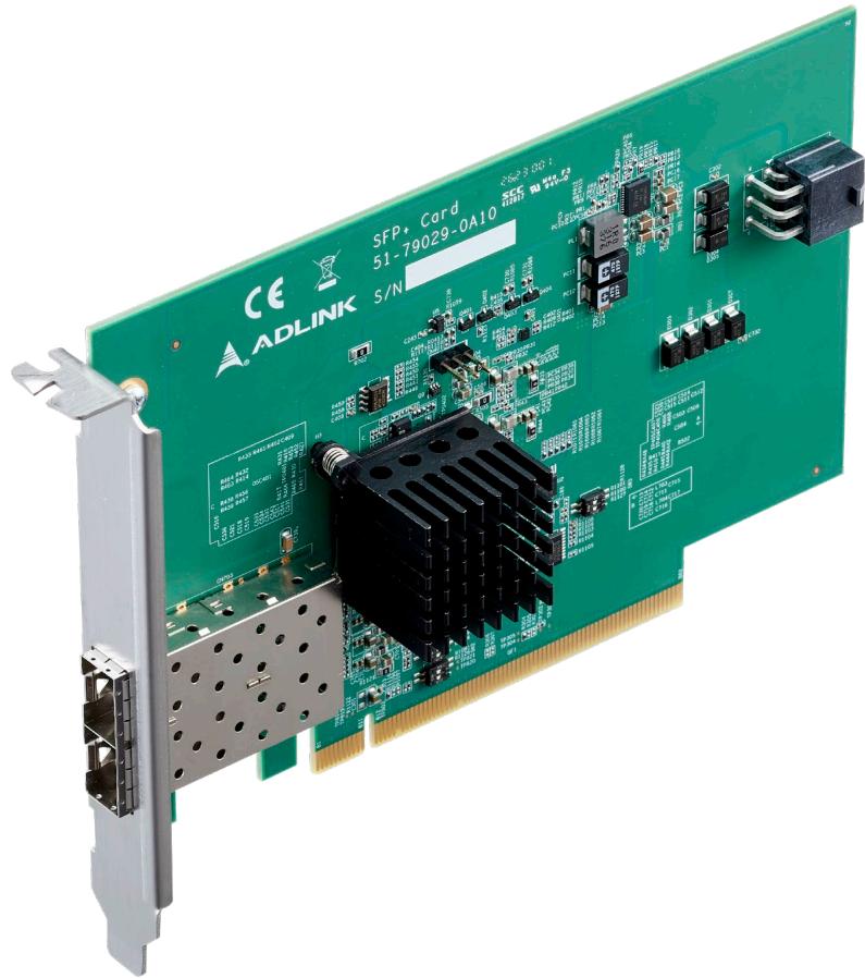
Network Adapter Card for Express-VR7
User’s Guide
Revision History
| Revision | Description | Date | Author |
| 0.1 | Preliminary release | 2023-12-18 | CC |
# Preface
# Disclaimer
Information in this document is provided in connection with ADLINK products. No license, express or implied, by estoppel or otherwise, to any intellectual property rights is granted by this document. Except as provided in ADLINK´s Terms and Conditions of Sale for such products, ADLINK assumes no liability whatsoever, and ADLINK disclaims any express or implied warranty, relating to sale and/or use of ADLINK products including liability or warranties relating to fitness for a particular purpose, merchantability, or infringement of any patent, copyright or other intellectual property right. If you intend to use ADLINK products in or as medical devices, you are solely responsible for all required regulatory compliance, including, without limitation, Title 21 of the CFR (US), Directive 2007/47/EC (EU), and ISO 13485 & 14971, if any. ADLINK may make changes to specifications and product descriptions at any time, without notice.
# Environmental Responsibility
ADLINK is committed to fulfil its social responsibility to global environmental preservation through compliance with the European Union's Restriction of Hazardous Substances (RoHS) directive and Waste Electrical and Electronic Equipment (WEEE) directive. Environmental protection is a top priority for ADLINK. We have enforced measures to ensure that our products, manufacturing processes, components, and raw materials have as little impact on the environment as possible. When products are at their end of life, our customers are encouraged to dispose of them in accordance with the product disposal and/or recovery programs prescribed by their nation or company.

California Proposition 65 Warning: This product can expose you to chemicals including acrylamide, arsenic, benzene, cadmium, Tris(1,3- dichloro-2-propyl)phosphate (TDCPP), 1,4-Dioxane, formaldehyde, lead, DEHP, styrene, DINP, BBP, PVC, and vinyl materials, which are known to the State of California to cause cancer, and acrylamide, benzene, cadmium, lead, mercury, phthalates, toluene, DEHP, DIDP, DnHP, DBP, BBP, PVC, and vinyl materials, which are known to the State of California to cause birth defects or other reproductive harm. For more information go to www.P65Warnings.ca.gov.

# Trademarks
Product names mentioned herein are used for identification purposes only and may be trademarks / registered trademarks of respective companies.
# Copyright © 2023 ADLINK Technology Incorporated
This document contains proprietary information protected by copyright. All rights are reserved. No part of this manual may be reproduced by any mechanical, electronic, or other means in any form without prior written permission of the manufacturer.
# Safety Instructions
For user safety, please read and follow all Instructions, WARNINGs, CAUTIONs, and NOTEs marked in this manual and on the associated equipment before handling/operating the equipment.
Read these safety instructions carefully.
Keep this manual for future reference.
• Read the specifications section of this manual for detailed information on the operating environment of this equipment.
• Turn off power and unplug any power cords/cables when installing/mounting or un-installing/removing equipment.
• To avoid electrical shock and/or damage to equipment:
Keep equipment away from water or liquid sources;
Keep equipment away from high heat or high humidity;
• Keep equipment properly ventilated (do not block or cover ventilation openings);
• Make sure to use recommended voltage and power source settings;
• Always install and operate equipment near an easily accessible electrical socket outlet;
• Secure the power cord (do not place any object on/over the power cord);
• Only install/attach and operate equipment on stable surfaces and/or recommended mountings;
• If the equipment will not be used for long periods of time, turn off the power source and unplug the equipment.
# Conventions
The following conventions may be used throughout this manual, denoting special levels of information

Note: This information adds clarity or specifics to text and illustrations.

Caution: This information indicates the possibility of minor physical injury, component damage, data loss, and/or program corruption.

Warning: This information warns of possible serious physical injury, component damage, data loss, and/or program corruption.
# Getting Service
Ask an Expert: https://www.adlinktech.com/en/Askanexpert
# ADLINK Technology, Inc.
No. 66, Huaya 1st Rd., Guishan District, Taoyuan City 333411, Taiwan
Tel: +886-3-216-5088
Fax: +886-3-328-5706
Email: service@adlinktech.com
# Ampro ADLINK Technology, Inc.
6450 Via Del Oro, San Jose, CA 95119-1208, USA
Tel: +1-408-360-0200
Toll Free: +1-800-966-5200 (USA only)
Fax: +1-408-600-1189
Email: info@adlinktech.com
# ADLINK Technology (China) Co., Ltd.
300 Fang Chun Rd., Zhangjiang Hi-Tech Park, Pudong New Area, Shanghai, 201203, China
Tel: +86-21-5132-8988
Fax: +86-21-5132-3588
Email: market@adlinktech.com
# ADLINK Technology GmbH
Hans-Thoma-Strasse 11, D-68163 Mannheim, Germany
Tel: +49-621-43214-0
Fax: +49-621 43214-30
Email: emea@adlinktech.com
Please visit the Contact page at www.adlinktech.com for information on how to contact the ADLINK regional office nearest you.
# Table of Contents
Revision History ..
Preface .. 3
List of Figures ... . 8
1. Introduction ... C
2. Specifications... .10
2.1. Interface.. ... 10
2.2. 10GbE PHY ... ... 10
2.3. Dimensions... ..11
2.4. Operating Temperature... ... 11
2.5. Specification Compliance.. ..12
2.6. IO Expander & EEPROM.. ... 12
3. Block Diagram... .13
4. Pinout and Signal Descriptions .. .14
4.1. Input Interface Definitions .. ... 14
5. Module Interfaces and Configuration . 17
5.1. Connector and LED Locations .. ... 17
5.2. Network Adaptor Card Installation . ... 18
6. Mechanical... .19
# List of Figures
Figure 1 – CEI-2x10G SFP+ function diagram.. ..13
Figure 2 – Adapter card feature locations ..... .17
Figure 3 – Adapter card installation illustration ... ...18
Figure 4 – CEI-2x10G SFP+ mechanical dimensions ....... ..19
# 1. Introduction
The ADLINK CEI-2x10G SFP+ card is a 10GbE SFP+ network adapter card that is dedicated to Express-VR7 module. Delivering 10Gbps network within the guidelines of PICMG COM.0 R3.1 specification, the adapter card converts up to two 10GBASE-KR interfaces, and related CEI sideband signals, to two 10G SFP+ interfaces via SFP+ connectors, through Intel CS4227 PHY and multiple I/O expanders.
The CEI-2x10G SFP+ network adapter card can only be used with ADLINK Express-VR7 COM Express module (PICMG COM.0 R3.1 Type 7 compliant)
Utilizing the CEI-2x10G SFP+ card along with an Express-VR7 COM Express module and Express-BASE7 Plus reference carrier board, you can easily emulate the functionality of your end product for software development and hardware verification. Applications include entry level switch, cloud storage platforms, communications servers, and more.
# 2. Specifications
# 2.1. Interface
# Input
Up to 2x 10GBASE-KR and related CEI sideband signals from a dedicated COM Express Type 7 module through 164-pin edge connector (PCIe x16 slot PCIEKR on Express-BASE7 Plus)
# Output
Up to 2x 10G SFP+ interfaces via 2x SFP+ connectors
# 2.2. 10GbE PHY
# PHY
Intel CS4227
Converts 10GBASE-KR and sidebands to 10G SFP+ interface
# PHY Firmware on SPI ROM
Dedicated ROM for storing PHY firmware
COM Express module Express-VR7
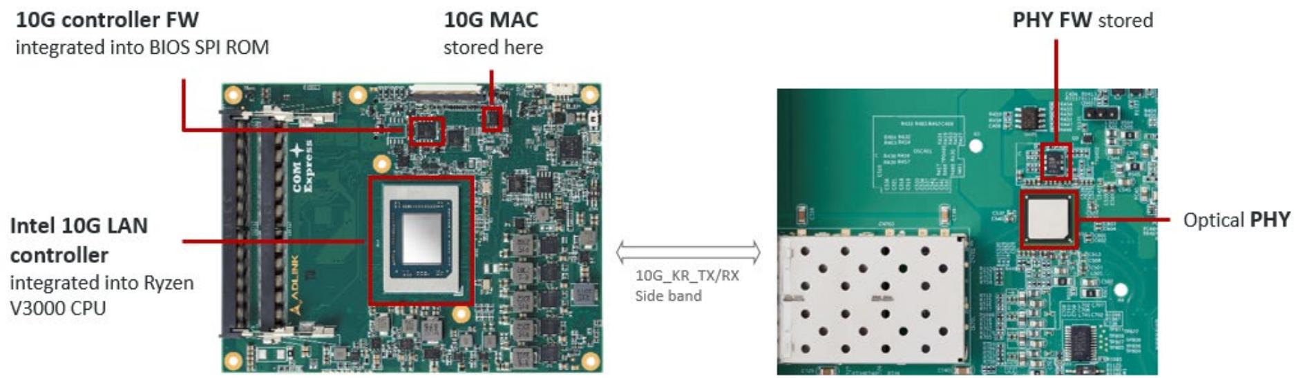
Integrated intocustomer'sside carrierboard or1OGadaptorcard
# 2.3. Dimensions
168 mm x 107 mm (PCB only, including edge connector)
# 2.4. Operating Temperature
0°C to 85°C
# 2.5. Specification Compliance
PICMG COM.0 Rev 3.1 Type 7
# 2.6. IO Expander & EEPROM
Additional expander and EEPROM not mention are described as:
# PCA9555 IO Expander
I2C based device, de-serialized for low speed sideband I/O, including interrupt, reset, etc.
# PCA9545 Multiplexer
I2C based device, identifies the capabilities of the attached site.
# PCA9685 LED Ctrl
I2C based device, controls LED indication
# 3. Block Diagram
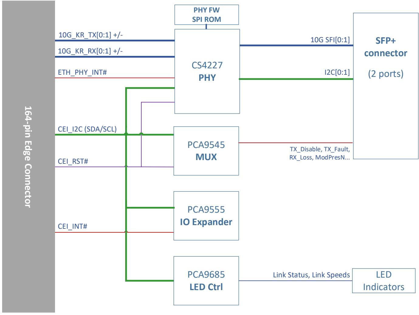
Figure 1 – CEI-2x10G SFP+ function diagram
# 4. Pinout and Signal Descriptions
# 4.1. Input Interface Definitions
The table below is a comprehensible list of all signal pins supported on the 164-pin Edge connector of the CEI-2x10G SFP+ card. Signal names follow the PICMG COM.0 R3.1 specification. Signals described in the specification but not supported on the CEI-2x10G SFP+ card are marked with strikethrough STRIKETHROUGH.
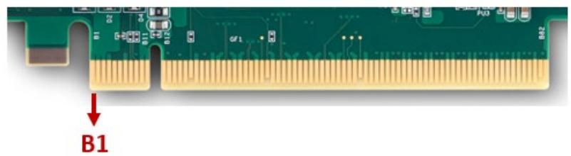
Row B
Row A
| Pin | Name | Pin | Name |
| B1 | 12V | A1 | NC |
| B2 | 12V | A2 | 12V |
| B3 | 12V | A3 | 12V |
| B4 | GND | A4 | GND |
| B5 | NC | A5 | NC |
| B6 | NC | A6 | NC |
| B7 | GND | A7 | GND |
| B8 | CEI_SDA | A8 | NC |
| B9 | CEI_SCL | A9 | NC |
| B10 | 3V3SB | A10 | GND |
| B11 | 3V3SB | A11 | NC |
| B12 | NC | A12 | GND |
| B13 | 5VSB | A13 | NC |
| B14 | 5VSB | A14 | NC |
| B15 | NC | A15 | GND |
Row B
Row A
| Pin | Name | Pin | Name |
| B16 | ETH_PHY_INT# | A16 | NC |
| B17 | CEI_INT# | A17 | NC |
| B18 | GND | A18 | GND |
| B19 | NC | A19 | NC |
| B20 | NC | A20 | GND |
| B21 | GND | A21 | NC |
| B22 | GND | A22 | NC |
| B23 | NC | A23 | GND |
| B24 | NC | A24 | GND |
| B25 | GND | A25 | NC |
| B26 | GND | A26 | NC |
| B27 | NC | A27 | GND |
| B28 | NC | A28 | GND |
| B29 | GND | A29 | NC |
| B30 | NC | A30 | NC |
| B31 | CEI_RST# | A31 | GND |
| B32 | GND | A32 | NC |
| B33 | 10G_KR_RX1+ | A33 | NC |
| B34 | 10G_KR_RX1- | A34 | GND |
| B35 | GND | A35 | 10G_KR_TX1+ |
| B36 | GND | A36 | 10G_KR_TX1- |
| B37 | NC | A37 | GND |
| B38 | NC | A38 | GND |
| B39 | GND | A39 | CEI_MDIO |
| B40 | GND | A40 | CEI_MDC |
| B41 | 10G_KR_RX0+ | A41 | GND |
| B42 | 10G_KR_RX0- | A42 | GND |
| B43 | GND | A43 | 10G_KR_TX0+ |
| B44 | GND | A44 | 10G_KR_TX0- |
| B45 | NC | A45 | GND |
| B46 | NC | A46 | GND |
| B47 | GND | A47 | NC |
| B48 | NC | A48 | NC |
| B49 | GND | A49 | GND |
Row B
Row A
| Pin | Name | Pin | Name |
| B50 | NC | A50 | NC |
| B51 | NC | A51 | GND |
| B52 | GND | A52 | NC |
| B53 | GND | A53 | NC |
| B54 | NC | A54 | GND |
| B55 | NC | A55 | GND |
| B56 | GND | A56 | NC |
| B57 | GND | A57 | NC |
| B58 | NC | A58 | GND |
| B59 | NC | A59 | GND |
| B60 | GND | A60 | NC |
| B61 | GND | A61 | NC |
| B62 | NC | A62 | GND |
| B63 | NC | A63 | GND |
| B64 | GND | A64 | NC |
| B65 | GND | A65 | NC |
| B66 | NC | A66 | GND |
| B67 | NC | A67 | GND |
| B68 | GND | A68 | NC |
| B69 | GND | A69 | NC |
| B70 | NC | A70 | GND |
| B71 | NC | A71 | GND |
| B72 | GND | A72 | NC |
| B73 | GND | A73 | NC |
| B74 | NC | A74 | GND |
| B75 | NC | A75 | GND |
| B76 | GND | A76 | NC |
| B77 | GND | A77 | NC |
| B78 | NC | A78 | GND |
| B79 | NC | A79 | GND |
| B80 | GND | A80 | NC |
| B81 | NC | A81 | NC |
| B82 | NC | A82 | GND |
# 5. Module Interfaces and Configuration
This chapter describes connectors, LEDs, and switches that are used on the CEI-2x10G SFP+ card.
# 5.1. Connector and LED Locations
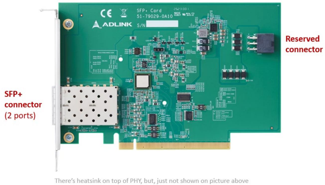
Figure 2 – Adapter card feature locations
# 5.2. Network Adaptor Card Installation
Below is an example (illustration purposes only) of the CEI-2x10G SFP+ card installed on an Express-BASE7 Plus carrier board with a Type 7 COM Express module.
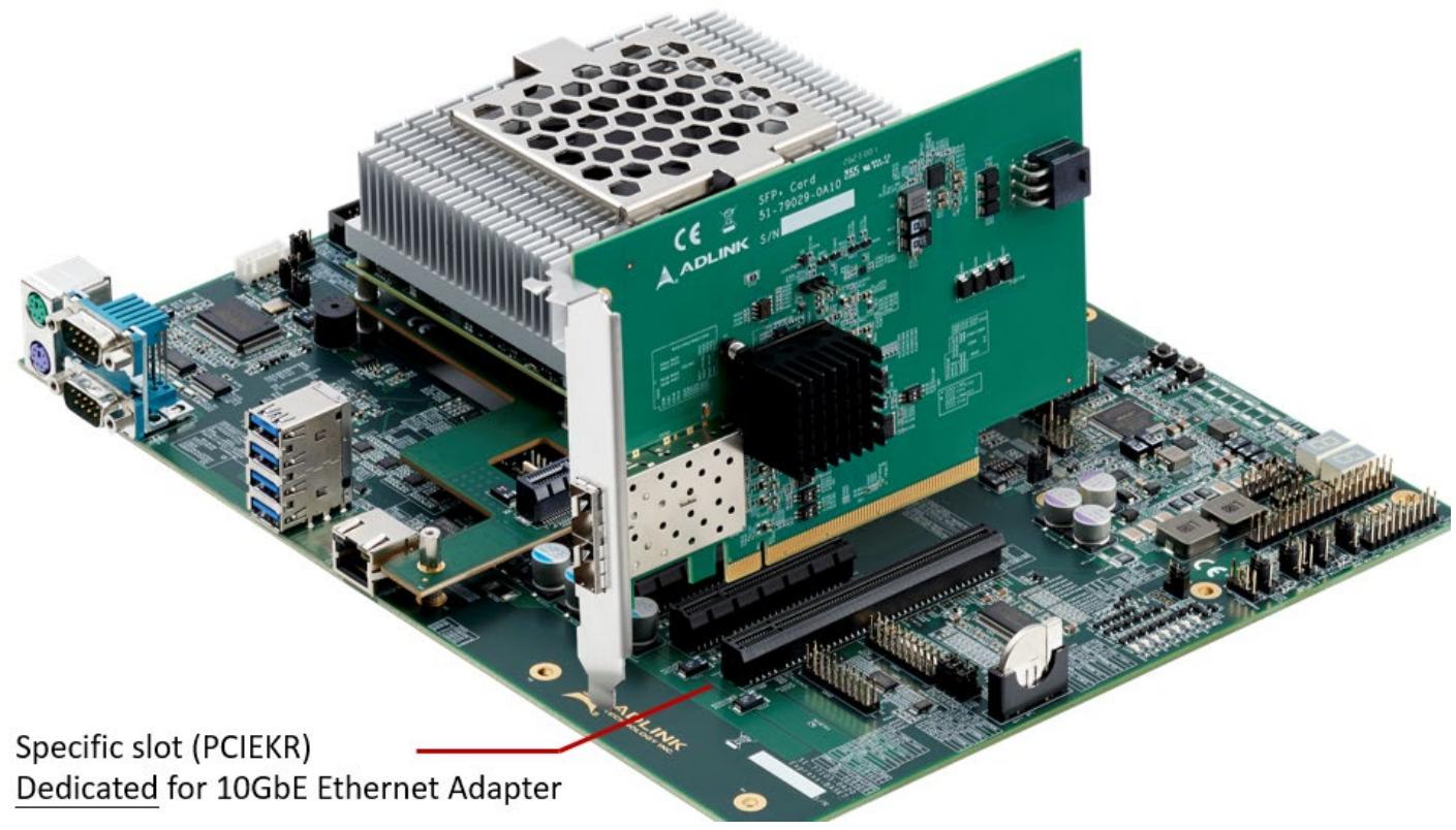
Figure 3 – Adapter card installation illustration
# 6. Mechanical
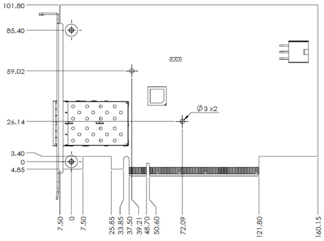
Figure 4 – CEI-2x10G SFP+ mechanical dimensions

Note: All dimensions are shown in millimeters with a tolerance of ± 0.25mm unless otherwise noted.
[🔗 Link to the original document](.cei-2x10g-sfp-prelim-manual-50m-79029-1000-01-231218/cei-2x10g-sfp-prelim-manual-50m-79029-1000-01-231218.pdf)