# COM Express Type 6 Starter Kit Plus Quick Start Guide

![Type 6\nCOM Express\nStarter Kit Plus\nEverything you need to start your own carrier board design\nContents\n• Reference carrier board with power supply\n• Video Adapter Card (T6-DDI)\n• Necessary cabling and Debug Card (DB40)\n• USB flash drive with:\n- COM Express Carrier Design Guide\n- Reference carrier board schematics and layout files\n- Drivers and BSPs\nLive Linux on USB flash drive\nCOM Express Type 6 module (opt.)\nThermal solution and mechanical files (opt.)\nADLINK\nLeading EDGE COMPUTING www.adlinktech.com\nCOM Express](.com-express-type-6-starter-kit-plus-manual-en-20171025-v1/59fad1457125f64b2dfd7ea891385e224c43eca5d6e556bf32d5dbcbdeb6c3c7.jpg)

![COM\nExpress®](.com-express-type-6-starter-kit-plus-manual-en-20171025-v1/d3b71ae647df30f81d685e0686b554e5696a69c8a4ebc65ab2aa272f7ffd9a42.jpg)

Manual Rev.: 2.1

Revision Date: October 12, 2017

Part Number: 50-1J039-1010

# Preface

# Copyright

Copyright 2017 ADLINK Technology, Inc. This document contains proprietary information protected by copyright. All rights are reserved. No part of this manual may be reproduced by any mechanical, electronic, or other means in any form without prior written permission of the manufacturer.

# Disclaimer

The information in this document is subject to change without prior notice in order to improve reliability, design, and function and does not represent a commitment on the part of the manufacturer. In no event will the manufacturer be liable for direct, indirect, special, incidental, or consequential damages arising out of the use or inability to use the product or documentation, even if advised of the possibility of such damages.

# Environmental Responsibility

ADLINK is committed to fulfill its social responsibility to global environmental preservation through compliance with the European Union's Restriction of Hazardous Substances (RoHS) directive and Waste Electrical and Electronic Equipment (WEEE) directive. Environmental protection is a top priority for ADLINK. We have enforced measures to ensure that our products, manufacturing processes, components, and raw materials have as little impact on the environment as possible. When products are at their end of life, our customers are encouraged to dispose of them in accordance with the product disposal and/or recovery programs prescribed by their nation or company.

# Trademarks

Product names mentioned herein are used for identification purposes only and may be trademarks and/or registered trademarks of their respective companies.

Revision History

<table><tr><td>Revision</td><td>Description</td><td>Date</td><td>By</td></tr><tr><td>2.00</td><td>Initial release</td><td>2012-12-07</td><td>JC</td></tr><tr><td>2.1</td><td>Update T6-DDI and Debug card information</td><td>2017-10-12</td><td>JC</td></tr></table>

# Table of Contents

# Preface ....................

# 1. Introduction...

1.1. How to Order the Type 6 Starter Kit .
1.2. What’s Included in the Type 6 Starter Kit Plus ... 2

# 2. Getting Started...........

2.1. Unpacking.. .5
2.2. Board Installation ... 7
2.3. Power and I/O Connectors . .9
2.4. Powering Up the Express-BASE6 System .. .. 10

# 3. T6-DDI Video Adapter Card........... .13

3.1. HDMI / DP Output Setting.... . 14
3.2. T6-DDI Video Adapter Card Installation . .. 15

# 4. PCIe x16 to two PCIe x8 Adapter Card... .17

# 5. Debug Card .... .19

5.1. Connecting the COM Express Module and Debug Card ... .. 20
5.2. Buttons and Switches . .. 20
5.3. Display and LEDs . .21

# Safety Instructions.... .23

# Getting Service.............. .24

This page intentionally left blank.

# 1. Introduction

The Type 6 Starter Kit Plus is intended for testing and verification of COM Express systems based on Type 6 modules and includes everything customers need to begin their own design and development. The Type 6 Starter Kit Plus includes the Express-BASE6 ATX size COM Express Type 6 reference carrier board, a COM Express Type 6 module (of your choice), memory (of your choice), thermal solution (heatspreader or heatsink, of your choice) and additional items such as a debug card, cabling, and ATX power supply.

The complete kit allows cusomters to quickly emulate the functionality of their end product for software development and hardware verification. Drivers, BSP, carrier board design files (including schematics, mechanical drawings and BOM), certificates, test reports, COM Express module user’s manual and thermal solution drawing (specific to your chosen configuration) are included to assist cusomters in designing their own custom carrier board.

The Type 6 Starter Kit Plus also includes additional development cards, such as a DDI video adapter card for HDMI and DisplayPort verification (T6-DDI), a PCIe x16 to two PCIe x8 adapter card (P16TO28) and a debug card (DB40).

The Type 6 Starter Kit Plus also includes a USB flash drive with SEMA pre-installed in a Linux OS environment. This helps customers quickly review the features provided by the EAPI.

# 1.1. How to Order the Type 6 Starter Kit

![This flowchart consists of three rectangular blocks arranged vertically, connected by downward-pointing arrows indicating a linear process:\n\n1.  **Top Block:** 'Select a COM Express module, memory and thermal solution'\n2.  **Middle Block:** 'Contact an ADLINK sales representative in your region'\n3.  **Bottom Block:** 'Get the specific part number for your starter kit'](.com-express-type-6-starter-kit-plus-manual-en-20171025-v1/455dc5cfd0cf71dd839b3d909efe306b0b8ecff465b8831826a7e375fcbbcd76.jpg)

# 1.2. What’s Included in the Type 6 Starter Kit Plus

# 1.2.1. Standard Items

<table><tr><td>No.</td><td>Photo</td><td>Part Number</td><td>Description</td></tr><tr><td>1.</td><td>&lt;img src="images/ccb38a37881593769e630a593a4d11cc8abd71a719196b6cae4d803ede807019.jpg"/&gt;</td><td>91-77104-0060</td><td>Express-BASE6Type 6 reference carrier board</td></tr><tr><td>2.</td><td>&lt;img src="images/9f915ae77f90fe91a6b47daec3782591e2a65b0248deeecd43f73778f3b3e2a8.jpg"/&gt;</td><td>91-79302-0020</td><td>T6-DDICOM Express Type 6 DDI-to-HDMI/DVI/DisplayPort adapter card</td></tr><tr><td>3.</td><td>&lt;img src="images/f47d6def8ebdf679b007bb9225a988f4d74e0773481209e0c42d1fe1b7cf8e99.jpg"/&gt;</td><td>91-79301-0010</td><td>PCIe x16 to two PCIe x8 adapter card (P16TO28)</td></tr><tr><td>4.</td><td>&lt;img src="images/77f6e1a8794fb8a2fcc05ac07b28e7d7e06e3f5dce80dbfa2cdf2f6365a4dfa0.jpg"/&gt;</td><td>91-79007-002030-30016-000030-10192-000030-20736-0000</td><td>Debug Card (DB40)40-pin flat cableExternal SPI cable (used for BIOS update)DB40 to BMC cable (used for BMC FW update)</td></tr><tr><td>5.</td><td>&lt;img src="images/d36e4b21deca77167e52dee5de5b2c11c1816b7202b5115698e0b138ef3b2317.jpg"/&gt;</td><td>31-32220-0000</td><td>Power Supply Unit</td></tr><tr><td>6.</td><td>&lt;img src="images/f680c3b2337c4bb65e4704fd3758253669b010f14158e0d00e111a3f6b00b0af.jpg"/&gt;</td><td>29-02480-0040</td><td>USB Flash Drive (2pcs)One containing documentsOne with SEMA pre-installed in Linux OS</td></tr><tr><td>7.</td><td>&lt;img src="images/acd0a113920e5d3bc1d9b66c5df8026592c1e8b9e5ac071ab77c49a051acf01e.jpg"/&gt;</td><td>30-01120-0020</td><td>DisplayPort to DVI cable</td></tr><tr><td>8.</td><td>&lt;img src="images/afc1f082a3ccab315de4c7f4dad9e50ed40a321b600510285f2392625ae1fc51.jpg"/&gt;</td><td>30-10057-5010</td><td>7-pin SATA cable180° (-) to 180°</td></tr><tr><td>9.</td><td>&lt;img src="images/9f228e3fe053a7ab0df9a1b2ba776dd30c3efd4d64e62ea6c3cc8724c5d10787.jpg"/&gt;</td><td>30-20171-1000</td><td>SATA Power to Molex 4-pin cable</td></tr><tr><td>10.</td><td>&lt;img src="images/641f77d5bf3dcc85fe75ac2266f11bcc97751db87e2c157614882b163711f0c4.jpg"/&gt;</td><td>30-20027-3000</td><td>PSU Converter HarnessATX 20-pin to 24-pin</td></tr><tr><td>11.</td><td>&lt;img src="images/a50975fd9fde1683361ba7c9457814ba78f806928381cb58b9618ba333ffd377.jpg"/&gt;</td><td>30-00001-0030</td><td>US Power Cord, 10A, 125V</td></tr><tr><td>12.</td><td>&lt;img src="images/edcd1b9f1ee592fa0ca95bcecc341d37ba90c5a7dcd1059065782245af3e3ac6.jpg"/&gt;</td><td>30-00002-0010</td><td>EU Power Cord, 220V</td></tr></table>

1.2.2. Optional Items

<table><tr><td>No.</td><td>Photo</td><td>Part Number</td><td>Description</td></tr><tr><td>1.</td><td>&lt;img src="images/358adc105f094654c103ecbae30622e5c0f1c3de1e374bd06edc807c99e4691e.jpg"/&gt;</td><td>-</td><td>COM Express Type 6 module of your choice</td></tr><tr><td>2.</td><td>&lt;img src="images/b250482841a8862f84f1d3dba0de2e487c4542f73b2f8886b78cb85f13d5c4f5.jpg"/&gt;</td><td>-</td><td>Memory module(s) of your choice</td></tr><tr><td>3.</td><td>&lt;img src="images/dfef3f52901a55b2230526401b5a51ffca8007a70272e296fafc672f83e89a21.jpg"/&gt;&lt;img src="images/3ad4ecea32d65f45dc2f9e6070e06597970459bdc66003133efb6b94e99e7193.jpg"/&gt;&lt;img src="images/18ff01bf49a61f075ab6f31851a7e63f145ced593d71c523633481d224869c67.jpg"/&gt;</td><td>-</td><td>Thermal solution of your choice</td></tr></table>

This page intentionally left blank.

# 2. Getting Started

# 2.1. Unpacking

Check that the EPE foam layers contain the items shown below:

![Based on the visual flow from left to right and top to bottom, here is the accurate description of the blocks and connections:\n\n**1. Top-Left Section**\n*   **Source Image:** An image of a tray containing components.\n*   **Connections:**\n    *   A yellow arrow points right from a component to a label: **P16TO28**.\n    *   A yellow arrow points down from a component to a label: **T6-DDI**.\n    *   A yellow arrow points diagonally down-right from a component to a label above the next image: **Express-BASE6**.\n\n**2. Middle Section (Express-BASE6)**\n*   **Source Image:** An image of a tray below the 'Express-BASE6' label.\n*   **Connections:**\n    *   A yellow arrow points right from the top-right component to a packaged component. Above it is a label: **Layer 1 Type 6 Module**.\n    *   A yellow arrow points right from the bottom-right component to a packaged component. Below it is a label: **Layer 1 DB40 Card**.\n\n**3. Right Section (Layer 1 to Layer 3)**\n*   **From 'Layer 1 Type 6 Module':**\n    *   A yellow arrow points right to an image of a fan/heatsink. Above it is a label: **Layer 2 Heatsink & Screws**.\n*   **From 'Layer 1 DB40 Card':**\n    *   A yellow arrow points right to an image of a tray. Below it is a label: **Layer 2 Memory & Documents**.\n    *   From that image, a yellow arrow points right to a final tray image. Below it is a label: **Layer 3 Linux OS w/ SEMA pre-installed**.](.com-express-type-6-starter-kit-plus-manual-en-20171025-v1/bdecab71ab1eda5a8aca34146bc6673392a38d07c256ff8e048e440f8287beff.jpg)

Remove the EPE foam layers and check accessory boxes contain items shown below:

![The image is a collage illustrating the unboxing of electronic components, connected by yellow arrows indicating the flow.\n\n*   **Top Left:** An empty cardboard box.\n*   **Middle Row:** A vertical arrow points down to a box containing a silver rectangular metal unit and a bundle of multi-colored cables (red, yellow, black). A diagonal arrow points to a long, narrow box containing black cables.\n*   **Bottom Row:** The contents of the boxes are laid out.\n    *   **Left:** The silver unit, the multi-colored cable bundle, a plastic bag with a black cable, a plastic bag with a red wire, and a cable at the very bottom.\n    *   **Right:** Two coiled black power cables and a flat ribbon cable are displayed next to a plastic bag.\n*   **Text:** In the bottom right corner, a grey box contains the text '**Cables for DB40**' with an arrow pointing up to the plastic bag.](.com-express-type-6-starter-kit-plus-manual-en-20171025-v1/558b0ee3e53ed55e2d66fc6489adf315d9fc3e99bc4b2d48fd2d995377502f7b.jpg)

# 2.2. Board Installation

<table><tr><td>Procedure</td><td>Required Items</td></tr><tr><td>Step 1Insert SO-DIMM memory into the COM Express Type 6 module's SO-DIMM socket.&lt;img src="images/7490bf831eb3bf4aebcacd4a38e80da3373085cfa91bcb098522dc41447908fa.jpg"/&gt;</td><td>&lt;img src="images/52b129c604bada7d0dd2bdc906441eed541e8b32bd6d32b57cf937b0e1f26955.jpg"/&gt;[IMAGE]</td></tr><tr><td>Step 2Removed all protective membranes from the thermal pads.&lt;img src="images/56762c5d620ffd6b659c7899166e313d1e5cda831237d45393d4b6543cfe5054.jpg"/&gt;</td><td rowspan="2">&lt;img src="images/42f34fcc5fb4b9d8072c98a365d41174b8dc6219a6d2a99eb0a86f6fbcf54a17.jpg"/&gt;&lt;img src="images/bcc5c9139989801ba6a2391da5a69f812577aee8d132cf6bbdebe07647c562d2.jpg"/&gt;[IMAGE]</td></tr><tr><td>Step 3Assemble the thermal solution onto the COM Express Type 6 module.&lt;img src="images/20c67a96ef328874aba0449c4eb9f7756f1a919f4655543a69b995e1cd503d90.jpg"/&gt;</td></tr><tr><td>Step 4Use the M2.5, L=6mm screws provided to fasten the thermal solution to the COM Express Type 6 module.&lt;img src="images/cd2b38c1e3461385d85b1b8e881d9be07161b7dd2c4162b8cab00294b9f9804f.jpg"/&gt;</td><td>&lt;img src="images/854d5ad21365c0083ae666a1d2ea1b6149ac88f8885cd496c44a3b5d06f561d4.jpg"/&gt;</td></tr><tr><td>Step 5Place the COM Express Type 6 module and thermal solution assembly onto the connectors on the carrier board as shown.</td><td></td></tr><tr><td>&lt;img src="images/ee76d834964e3580318c22d29f3415b96816c80b0db2df083cb2fda1ddf4a98c.jpg"/&gt;</td><td>&lt;img src="images/e6372d198dc65ef898f4f0adc21ad6247e286d27369dfe3baf9b7f787be1b059.jpg"/&gt;</td></tr><tr><td>Step 6Use the M2.5, L=16mm screws provided to secure the COM Express Type 6 module to the carrier board from the solder side.</td><td></td></tr><tr><td>&lt;img src="images/d067263fe9b981ec97ec5511fd2eeb350fae2414099753a4ce1d9ac8f175c8ee.jpg"/&gt;</td><td>&lt;img src="images/94f3fe86887f320fe6f23e2a096fa51f0e44ae4250bdfbfbe00ab4a584840ee6.jpg"/&gt;</td></tr><tr><td>Step 7If you are installing a heatsink with fan, plug the fan connector into the carrier board as shown.</td><td>None</td></tr><tr><td>&lt;img src="images/504de47c6dd2b006bfe22025de4a03edfffc029b39819b8b0cf338360c1423f6.jpg"/&gt;</td><td></td></tr></table>

# 2.3. Power and I/O Connectors

<table><tr><td>Connect the Power Supply</td><td>Required Items</td></tr><tr><td>Plug the ATX connector of the power supply into CN1 and plug the ATX 12V 4-pin connector of the power supply into CN5. &lt;img src="images/deace7d504c2af60c30473d37f0c19a90c4b359d10d16eae449ce3aeb5872c2e.jpg"/&gt;</td><td>&lt;img src="images/3c761916ebf3d1db72c3af36038c9090074f7e94ccf2fa48553503182457f4d5.jpg"/&gt;</td></tr><tr><td colspan="2">&lt;img src="images/c2f3a6209694dd42ed0d2a20eb74213d0cba695aad35b93a123b595786538653.jpg"/&gt; &lt;img src="images/05d8b87a7008b3449738698031ea016257133ab1af73873aafd452fcea622952.jpg"/&gt; DO NOT plug the ATX 12V 4-pin connector into the ATX 24-pin power connector.</td></tr><tr><td>Plug the AC power cord into the power supply. &lt;img src="images/f810d9f3041e87511867114fc50a3c7cb3b7c42d1ff2c4bdfc2de24bcea85c1f.jpg"/&gt;</td><td>&lt;img src="images/8e3aeb8523fa1ea2ef1a65a75e0efd85e048a883d5a3e503f0238a1154c178e1.jpg"/&gt;</td></tr><tr><td>Connect the Keyboard, Mouse and Monitor</td><td>Required Items</td></tr><tr><td>Plug keyboard, mouse and VGA cable (if selected COM Express module support VGA output) into the Express-BASE6.</td><td>None</td></tr><tr><td>&lt;img src="images/ae20febba9f4c61600df36b2d9fb295c4972c965b2d4c8f8b5ece9cce6031465.jpg"/&gt;</td><td></td></tr><tr><td>Or Plug keyboard, mouse, T6-DDI card and DP/HDMI cable (if selected COM Express module support DDI output in place of VGA output) (please refer to Chapter 3 for T6-DDI card installation)</td><td></td></tr><tr><td>&lt;img src="images/28bd5c94898b94f52f5da950144eccbb011241bda31cd22b28197f25a69574ee.jpg"/&gt;</td><td></td></tr></table>

# 2.4. Powering Up the Express-BASE6 System

<table><tr><td colspan="3">Powering up the Express-BASE6 system</td><td>Required Items</td></tr><tr><td colspan="3">The POST LEDs on the Express-BASE6 will display the bootup status – “Ab or Ad” indicates a successful boot.</td><td>None</td></tr><tr><td colspan="3">&lt;img src="images/9689248bfcbb0cd1a38889581d4f45a765d0442d898e77ed835efac0628d209d.jpg"/&gt;</td><td></td></tr><tr><td colspan="3">Note: “Ad” indicates boot to UEFI shell“Ab” indicates boot to BIOS setup menu, by pressing DEL (delete key)</td><td></td></tr><tr><td colspan="3">First Boot into UEFI Shell or BIOS setup menu</td><td>Required Items</td></tr><tr><td colspan="3">If no operating system is installed on the system, then the monitor will display the UEFI shell or BIOS setup menu after the first boot up.</td><td rowspan="2">None</td></tr><tr><td colspan="3"></td></tr></table>

<table><tr><td>How to quick load BIOS default settings</td><td>Required Items</td></tr><tr><td>Press thekey to bring up the “Load Optimized Defaults” window as shown.</td><td>None</td></tr><tr><td>&lt;img src="images/4394e52b905ef85f15497b94fe83a7e3b38468e59bd2aceda6ea59f8dfb26ca0.jpg"/&gt; &lt;img src="images/8fa32871a9863114462aa40016ac36a30d0e849072d8b609ef4d525e771a4af6.jpg"/&gt;</td><td></td></tr><tr><td>Press thekey to load optimized BIOS defaults.</td><td></td></tr><tr><td>&lt;img src="images/f5fd0d98141e876e8a865b04489913fa1864fcd3f42b8ca0904c1d3848a55a39.jpg"/&gt;</td><td></td></tr><tr><td>Press thekey to bring up the “Save &amp; Exit” window as shown.</td><td></td></tr><tr><td>&lt;img src="images/0d385d649d0ea956ca58827fd60086cc6eee7311ff6aaffe84af64b4c798ea53.jpg"/&gt; &lt;img src="images/51f5517118f143495b2cc07d72d00f34b4d17b9a5b6cdaf71202cdf49c47882b.jpg"/&gt;</td><td></td></tr><tr><td>Press thekey to save the configuration.</td><td></td></tr><tr><td>&lt;img src="images/14824413b733bded9c88dbc4b5f2b2160bc63c15841e0f1620fcfaae1323b58d.jpg"/&gt;</td><td></td></tr></table>

This page intentionally left blank.

# 3. T6-DDI Video Adapter Card

The T6-DDI Video Adapter Card provides connector access to the COM Express Type 6 module’s Digital Display Interface (DDI) ports which can be individually set to HDMI or DisplayPort output mode.
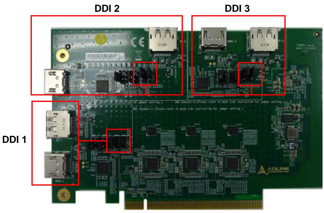
![DDI 2\nDDI 3\nDDI 1\nADLINK](.com-express-type-6-starter-kit-plus-manual-en-20171025-v1/4d3a9f1ad752f0ae5c00980302cda08a929541199189a27e242a93d286fd10b9.jpg)

# 3.1. HDMI / DP Output Setting

# Jumper Settings for DisplayPort Output

Short pins 1-2 of the jumpers for each DDI port you wish to set DisplayPort output mode. Take DDI 1 port (JP1 & JP10 jumpers) as example shown below
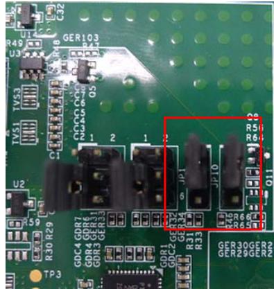
![R49\nU3\nC2\nR18 GER103\nR47\nTV53\nC1\nCCOO CG\nRGAS 6\nOS\n1 2 1 2\nGDR7 GDR6\nGDR4 GER31\nGDR3 GER33\nTP3\nGDR1 GCR32\nGDR2 GER34\nR31 R33\nR10\nR5 R6 R7\nGGER30G\nGER29GERN\nQ11](.com-express-type-6-starter-kit-plus-manual-en-20171025-v1/3a48738a7cee0eec30fa40738feb693854b059846fb97cfae2acfb79a960e39c.jpg)

DDI 1 port: JP1 & JP10

DDI 2 port: JP4 & JP11

DDI 3 port: JP7 & JP12

# Jumper Settings for HDMI Output

Short pins 2-3 of the jumpers for each DDI port you wish to set HDMI output mode. Take DDI 1 port (JP1 & JP10 jumpers) as example shown below
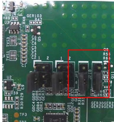
![R49\nU12\nR48\nGER103\nR47\nU3\nTV53\nC1\nO5\nCOCO COC\n2 1 2 1 2\nGDC4 GDD7\nGDR4 GBR6\nGDR3 GBR3\nGDR1 GBR3\nGDR2 GBR2\nGDR3 GBR3\nGDR4 GBR4\nGDR5 GBR5\nGDR6 GBR6\nGDR7 GBR7\nGDR8 GBR8\nGDR9 GBR9\nGDR10 GBR10\nGDR11 GBR11\nGDR12 GBR12\nGDR13 GBR13\nGDR14 GBR14\nGDR15 GBR15\nGDR16 GBR16\nGDR17 GBR17\nGDR18 GBR18\nGDR19 GBR19\nGDR20 GBR20\nTP3\nTP2\nQ11\nR51\nR61\nR62\nR63\nR64\nR65\nR66\nR67\nR68\nR69\nR70\nR71\nR72\nR73\nR74\nR75\nR76\nR77\nR78\nR79\nR80\nR81\nR82\nR83\nR84\nR85\nR86\nR87\nR88\nR89\nR90](.com-express-type-6-starter-kit-plus-manual-en-20171025-v1/806a27b5a7c85242849f40c4092d2cc01e25b0247736cd1eba7ae7f6ffc4ece2.jpg)

DDI 1 port: JP1 & JP10

DDI 2 port: JP4 & JP11

DDI 3 port: JP7 & JP12

# 3.2. T6-DDI Video Adapter Card Installation

# T6-DDI Installation

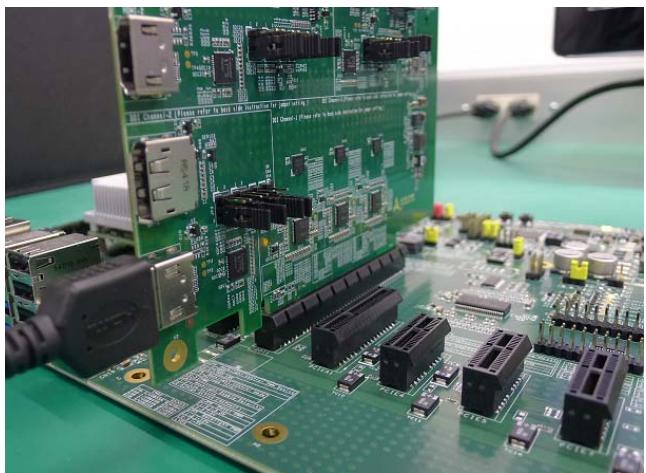
Plug the T6-DDI card into the DDI1 slot of the Express-BASE6 carrier board.
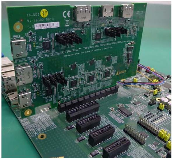
![Close-up of a green printed circuit board with various electronic components and connectors (no readable text or symbols)](.com-express-type-6-starter-kit-plus-manual-en-20171025-v1/5046473bcdcd59563a8a95dd056a01e84e66f978b2b55ea312cf8a542509a6a6.jpg)

Plug display cable into the desired T6-DDI card connector (DDI 1 port & HDMI output shown)
![Close-up of a green printed circuit board with various electronic components and connectors (no visible text or symbols)](.com-express-type-6-starter-kit-plus-manual-en-20171025-v1/d0069d834c9e8206f6ce85a3f054963d261ba66a38449dbed9249e6138c75c3c.jpg)

# DVI Display Output

A DisplayPort-to-DVI cable is included with the T6-DDI as shown.

![Close-up of a black USB cable with two connectors (no text or symbols visible)](.com-express-type-6-starter-kit-plus-manual-en-20171025-v1/1793c4ed9c0f186fd024a527e19682df134730c5f3bd99acea01e8ef70202339.jpg)

To connect the T6-DDI card DisplayPort output to a DVI monitor, please use this cable.

This page intentionally left blank.

# 4. PCIe x16 to two PCIe x8 Adapter Card

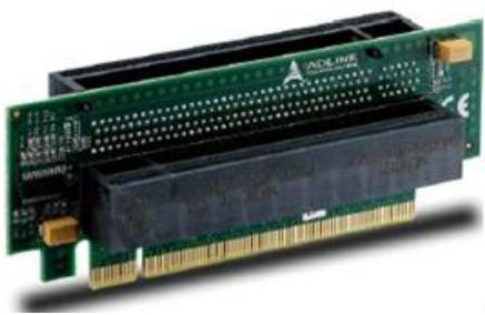
The PCIe x16 to two PCIe x8 Adapter Card allows the use of two PCIe x8 add-on cards from a single PCIe x16 slot
![Close-up of a green ADMI computer card with visible pin and gold connectors (no text or symbols)](.com-express-type-6-starter-kit-plus-manual-en-20171025-v1/9262b42a2862bdb79e61639c913215b2c4802d2ee366d5e7e843479ebd803171.jpg)

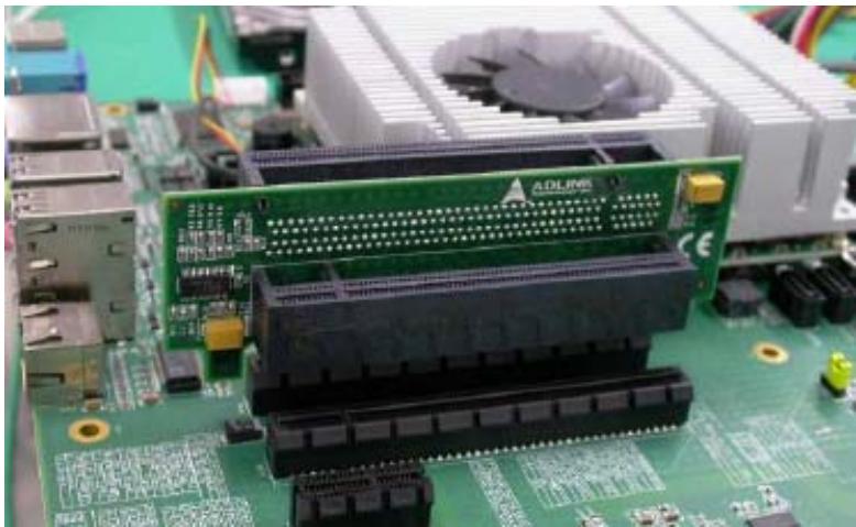
Insert the adapter card into the PEG1 slot of the Express-BASE6 carrier board as shown below.
![Close-up of a green computer motherboard with visible RAM slots and CPU socket (no readable text or symbols)](.com-express-type-6-starter-kit-plus-manual-en-20171025-v1/46094ba93197514429c012a8234001427d89beefdae7225d69302aa61ca8e3f6.jpg)

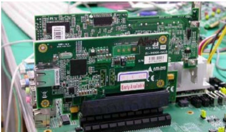
Insert PCIe x8 cards as required into the PCIe x8 slots of the adapter card.
![Close-up of a green printed circuit board with electronic components and wiring (no readable text or symbols)](.com-express-type-6-starter-kit-plus-manual-en-20171025-v1/13f9ecf1671f94a7e485fdd41b6a6e94f05d874cf7e3d896beb73c0c90d42863.jpg)

This page intentionally left blank.

# 5. Debug Card

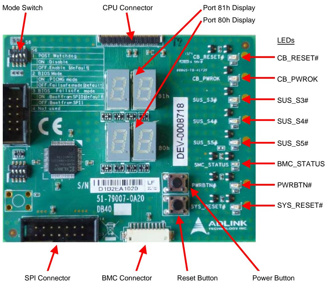
The DB40 Debug Card provides COM Express.system debugging functions and includes the following features:

Port 80/81 Decoding Interface with LED hexadecimal display for Power On Self Test (POST) via LPC interface
Interface to SPI Flash for BIOS update
• Interface to BMC for Board Management Controller (BMC) update
Buttons for Power and Reset
• Status LEDs for Power Button, Reset Button, CB\_PWPOK, CB\_RESET#, SLP\_S3#, SLP\_S4#, SLP\_S5#

The DB40 Debug Card can only be used with COM Express products that have the appropriate 40-pin flat flexible connector (FFC).
![Mode Switch\nCPU Connector\nPort 81h Display\nPort 80h Display\n56\n1 POST Watchdog\nON :Disable\nOFF:Enable (default)\n2 BIOS Mode\nON :PICMG mode\nOFF:Failsafe mode (default)\n3 BIOS Failsafe mode\nON :Boot from SPI0 (default)\nOFF:Boot from SPI1\n4 Not used\nCE\nS/N\n51-79007-0A20\nDB40\nDEV-0008718\nLEDs\nCB_RESET#\nCB_PWROK\nSUS_S3#\nSUS_S4#\nSUS_S5#\nBMC_STATUS\nPWRBTN#\nSYS_RESET#\nSPI Connector\nBMC Connector\nReset Button\nPower Button](.com-express-type-6-starter-kit-plus-manual-en-20171025-v1/b7348541c4cfc15dc444dc02a6bac35b2d8371c1d06bede87d317153220fb296.jpg)

# 5.1. Connecting the COM Express Module and Debug Card

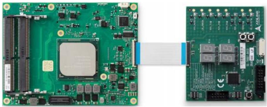
Connect the COM Express module to the DB40 debug card using the 40-pin flat cable provided (P/N: 30-30016- 0000).
![Green printed circuit board with integrated components and a close-up view of its connector (no visible text or symbols)](.com-express-type-6-starter-kit-plus-manual-en-20171025-v1/8905fe93959485ffb9f7652349ff7aa971c8f2685c63b9304e1590213796d9bc.jpg)

# 5.2. Buttons and Switches

This section describes the buttons and switches on the DB40 debug card.

Power Button: toggles the PWRBTN# signal of the COM Express module.

Reset Button: toggles the SYS\_RESET# signal of the COM Express module.

Mode Switch: this 4-pole DIP switch selects several modes :

<table><tr><td>Switch</td><td>Function</td></tr><tr><td>1</td><td>POST WatchdogON = DisableOFF = Enable (default)</td></tr><tr><td>2</td><td>BIOS ModeON = PICMG ModeOFF = Failsafe Mode (default)</td></tr><tr><td>3</td><td>BIOS Failsafe ModeON = Boot from SPI0 (default)OFF = Boot from SPI1</td></tr><tr><td>4</td><td>Not used</td></tr></table>

# 5.3. Display and LEDs

This section describes the hexadecimal display and LED functionality.

# 5.3.1. Bootup Procedure

During power-up and BIOS execution the CPU will first retrieve commands from POST and then execute them. Each command has a corresponding debug port data code or BIOS POST checkpoint code. The results from each checkpoint can be viewed on the DB40 Debug Card’s LED display, allowing the techinican or administrator to debug the system. The POST code is written to I/O port 80h, and for extended POST codes port 80h and 81h are used.

The POST code is shown on the two 7-segment LED displays on the board

# 5.3.2. LED Table

The following LEDs indicate status of system signals as shown in the table below.

<table><tr><td>LED</td><td>Function</td></tr><tr><td>CB_RESET#</td><td>LED lights on active reset signal of carrier board</td></tr><tr><td>CB_PWROK</td><td>LED lights on active power-OK from COM Express module</td></tr><tr><td>SUS_S3#</td><td>LED lights on released SUS_S3# signal from COM Express module</td></tr><tr><td>SUS_S4#</td><td>LED lights on released SUS_S4# signal from COM Express module</td></tr><tr><td>SUS_S5#</td><td>LED lights on released SUS_S5# signal from COM Express module</td></tr><tr><td>BMC_STATUS</td><td>LED shows the status of the BMC on the COM Express module</td></tr><tr><td>PWRBTN#</td><td>LED lights on active power button signal of COM Express module</td></tr><tr><td>SYS_RESET#</td><td>LED lights on active reset signal of COM Express module</td></tr></table>

# 5.3.3. BMC Status

The BMC\_STATUS LED shows the status of the BMC on the COM Express module.

<table><tr><td>Behavior (blue)</td><td>Description</td></tr><tr><td>Blinking</td><td>A blinking BMC_STATUS LED indicates a failure during power up. The number of flashes indicates the error code. A missing/wrong system voltage, stuck on the reset line, BIOS failure or an unexpected shutdown of an onboard power supply is displayed by this signaling code. The error code is board specific (refer to the user&#x27;s manual for your COM Express module).</td></tr><tr><td>Bright flash</td><td>A system state change occurs. Power-button activity, Reset-button activity, PCI_RST# activity or activity on the SLP_Sx signals is shown by this signaling mode.</td></tr><tr><td>Fast blinking</td><td>If the board is running on Fail-Safe-BIOS, the BMC_STATUS LED blinks very quickly.</td></tr><tr><td>Short bright flash every 4 seconds</td><td>System is in Suspend-to-RAM or Suspend-to-Disk state.</td></tr></table>

This page intentionally left blank.

# Safety Instructions

Read and follow all instructions marked on the product and in the documentation before you operate your system. Retain all safety and operating instructions for future use.

Please read these safety instructions carefully.
• Please keep this User‘s Manual for later reference.
The equipment should be operated only from the type of power source indicated on the rating label. Make sure the voltage of the power source when connect the equipment to the power outlet.
• If your equipment has a voltage selector switch, make sure that the switch is in the proper position for your area. The voltage selector switch is set at the factory to the correct voltage.
• For pluggable equipment, that the socket-outlet shall be installed near the equipment and shall be easily accessible.
• Place the power cord such a way that people can not step on it. Do not place anything over the power cord.
• If the equipment is not use for long time, disconnect the equipment from mains to avoid being damaged by transient overvoltage.
• All cautions and warnings on the equipment should be noted.
Please keep this equipment from humidity.
• Do not use this equipment near water or a heat source.
• Lay this equipment on a reliable surface when install. A drop or fall could cause injury.
Never pour any liquid into opening; this could cause fire or electrical shock.
Openings in the case are provided for ventilation. Do not block or cover these openings. Make sure you provide adequate space around the system for ventilation when you set up your work area. Never insert objects of any kind into the ventilation openings.
• To avoid electrical shock, always unplug all power cables and modem cables from the wall outlets before removing covers.
Lithium Battery provided (real time clock battery)

# CAUTION – Risk of explosion if battery is replaced with one of an incorrect type. Dispose of used batteries according to the instructions

• If one of the following situations arises, get the equipment checked by a service personnel:

 The power cord or plug is damaged.
 Liquid has penetrated into the equipment.
 The equipment has been exposed to moisture.
 The equipment has not work well or you can not get it work according to user‘s manual.
 The equipment has dropped and damaged.
 If the equipment has obvious sign of breakage.

# Getting Service

Ask an Expert: http://askanexpert.adlinktech.com

# ADLINK Technology, Inc.

<table><tr><td>Address:</td><td>9F, No.166 Jian Yi Road, Zhonghe District New Taipei City 235, Taiwan</td></tr><tr><td>Tel:</td><td>+886-2-8226-5877</td></tr><tr><td>Fax:</td><td>+886-2-8226-5717</td></tr><tr><td>Email:</td><td>service@adlinktech.com</td></tr></table>

# Ampro ADLINK Technology, Inc.

Address: 5215 Hellyer Avenue, #110, San Jose, CA 95138, USA

Tel: +1-408-360-0200

Toll Free: +1-800-966-5200 (USA only)

Fax: +1-408-360-0222

Email: info@adlinktech.com

# ADLINK Technology (China) Co., Ltd.

Address: 300 Fang Chun Rd., Zhangjiang Hi-Tech Park, Pudong New Area Shanghai, 201203 China

Tel: +86-21-5132-8988

Fax: +86-21-5132-3588

Email: market@adlinktech.com

# LiPPERT ADLINK Technology GmbH

Address: Hans-Thoma-Strasse 11, D-68163, Mannheim, Germany

Tel: +49-621-43214-0

Fax: +49-621 43214-30

Email: emea@adlinktech.com

Please visit the Contact page at www.adlinktech.com for information on how to contact the ADLINK regional office nearest you.
[🔗 Link to the original document](.com-express-type-6-starter-kit-plus-manual-en-20171025-v1/com-express-type-6-starter-kit-plus-manual-en-20171025-v1.pdf)
