# cPCI-6S10 Series

# 6U CompactPCI Switch Blade User’s Manual

![Back view of a green printed circuit board with various components and connectors (no visible text or symbols)](.cpci-6s10-50-15099-1000-10/07b98a429a83d21d4a9af2e61d9a524e09871d36b81c1578592581be4fad9579.jpg)

Manual Rev. 1.0

Revision Date: September 3, 2018

Part No.: 50-15099-1000

# Revision History

<table><tr><td>Revision</td><td>Release Date</td><td>Description of Change(s)</td></tr><tr><td>1.0</td><td>03/09/2018</td><td>Initial release</td></tr></table>

# Preface

# Copyright 2018 ADLINK Technology, Inc.

This document contains proprietary information protected by copyright. All rights are reserved. No part of this manual may be reproduced by any mechanical, electronic, or other means in any form without prior written permission of the manufacturer.

# Disclaimer

The information in this document is subject to change without prior notice in order to improve reliability, design, and function and does not represent a commitment on the part of the manufacturer.

In no event will the manufacturer be liable for direct, indirect, special, incidental, or consequential damages arising out of the use or inability to use the product or documentation, even if advised of the possibility of such damages.

# Environmental Responsibility

ADLINK is committed to fulfill its social responsibility to global environmental preservation through compliance with the European Union's Restriction of Hazardous Substances (RoHS) directive and Waste Electrical and Electronic Equipment (WEEE) directive. Environmental protection is a top priority for ADLINK. We have enforced measures to ensure that our products, manufacturing processes, components, and raw materials have as little impact on the environment as possible. When products are at their end of life, our customers are encouraged to dispose of them in accordance with the product disposal and/or recovery programs prescribed by their nation or company.

![Symbol of a trash bin crossed with a diagonal line and a horizontal bar below (no text or labels)](.cpci-6s10-50-15099-1000-10/1e0dcfc02336ea620a9c7a3812ffbce6eedc583b81564cdd7d71050b9a36b547.jpg)

Battery Labels (for products with battery)

![Symbol of a trash bin crossed out by two diagonal lines (no text or numbers present)](.cpci-6s10-50-15099-1000-10/3189a84483d069eac5ce4113a799ad6a451ad44b28f1864d39e1e02eb10a5d46.jpg)

![Simple recycling symbol icon with three chasing arrows inside a square border (no text or labels)](.cpci-6s10-50-15099-1000-10/fe9405e4fededad9cc855417bf65ede83b093368ba3fef27d8615eb9b8736404.jpg)

Li-ion

![RECYCLE\nRBRC\nLi-ion\n7.800.822.8837](.cpci-6s10-50-15099-1000-10/3918f2abe4c3d349f9b36c0707c59e74bb5902fdd8351e7aa675d4e332afc11f.jpg)

![Abstract geometric pattern with interlocking black and white shapes (no text or symbols)](.cpci-6s10-50-15099-1000-10/87c90a10c938aca9505ccfeb5505c7147986ab0db71f49e614d26d4d0c45c98f.jpg)

ᑜ㔚ᳰ⺧࿁ᡴ

# California Proposition 65 Warning

![The image displays a standard yellow triangular warning sign with a thick black border. Inside the triangle, centered, is a black exclamation point.](.cpci-6s10-50-15099-1000-10/5d621a5c94c94a1fe5eca7119cb6a3bb3629e0cc8fb063225380f3d9905fb4b4.jpg)

WARNING: This product can expose you to chemicals including acrylamide, arsenic, benzene, cadmium, Tris(1,3-dichloro-2-propyl)phosphate (TDCPP), 1,4-Dioxane, formaldehyde, lead, DEHP, styrene, DINP, BBP, PVC, and vinyl materials, which are known to the State of California to cause cancer, and acrylamide, benzene, cadmium, lead, mercury, phthalates, toluene, DEHP, DIDP, DnHP, DBP, BBP, PVC, and vinyl materials, which are known to the State of California to cause birth defects or other reproductive harm. For more information go to www.P65Warnings.ca.gov.

# Trademarks

Product names mentioned herein are used for identification purposes only and may be trademarks and/or registered trademarks of their respective companies.

# Conventions

Take note of the following conventions used throughout this manual to make sure that users perform certain tasks and instructions properly.

![The image displays a graphic icon of a white document or sheet of paper featuring faint horizontal gray lines near the bottom. Superimposed over the document is a large, bold red checkmark (or tick) running diagonally from the bottom left to the upper right.](.cpci-6s10-50-15099-1000-10/5278617f34814db0f463238643d56bff08dbf6af9885f88bc0cb5d75345682c9.jpg)
NOTE:

Additional information, aids, and tips that help users perform tasks.

![The image displays a cropped view of a standard safety warning sign. It features a bright yellow triangle with a thick black border. Inside the triangle is a large black exclamation point (!). The sign is framed by black horizontal lines at the very top and bottom edges of the image.](.cpci-6s10-50-15099-1000-10/dd6519b1a67e063484dbf4d6cae8b8361f28aae1be6aec1bdd082b251a89b600.jpg)
CAUTION:

Information to prevent minor physical injury, component damage, data loss, and/or program corruption when trying to complete a task.

![The image displays a standard triangular warning sign. It features a deep red background with a white border. Centered inside the triangle is a large white exclamation mark.](.cpci-6s10-50-15099-1000-10/3ec181284b0ee55c66f28120c042699ae7e09b924a38cbb36c0dfa3cc652dab2.jpg)
WARNING:

Information to prevent serious physical injury, component damage, data loss, and/or program corruption when trying to complete a specific task.

# Table of Contents

# Revision History........ ii

# Preface ............. iii

# List of Tables ........ .... vii

# List of Figures ......... ix

# 1 Overview .........

1.1 Block Diagram ...... 2
1.2 Package Contents ..... 3

# 2 Specifications & Board Interfaces...... 5

2.1 cPCI-6S10 Specifications ..... 5
2.2 Board Layout 6
2.3 Front Panel Layout . 7
2.4 Connector Pinouts ..... 9
2.5 Switch Settings ... 17

# 3 Hardware Platform Management ......... 1 9

3.1 Platform Management Overview .. 19
3.2 IPMI Commands ... . 20
3.3 Controller Specific OEM/Group Commands ....... 59

# 4 Getting Started ..... . 65

4.1 Heatsink.... 65
4.2 Installing the cPCI-6S10 ... 65
4.3 Configuring the cPCI-6S10 .... 65

# 5 Software Management ....... 7 5

5.1 Introduction ..... 75
5.2 Broadcom Network Switching Software SDK .... 7 5
5.3 Commands ..... . 76

5.4 Packet Manager..... . 78

Important Safety Instructions...... . 79

Getting Service ......... ...... 81

# List of Tables

Table 2-1: cPCI-6S10 Specifications 5

Table 3-1: NetFn codes 20

Table 3-2: Response Codes .. 2 1

Table 3-3: Required Message Length for IPMI 1.5 . 22

Table 3-4: cPCIS-3300BLS Chassis Slots .. 23

This page intentionally left blank.

# List of Figures

Figure 1-1: cPCI-6S10 Series Block Diagram...... 2

Figure 2-1: cPCI-6S10 Board Layout... 6

This page intentionally left blank.

# 1 Overview

The ADLINK cPCI-6S10 is a fully managed CompactPCI Gigabit Ethernet switch blade supporting up to twenty four 1GbE ports and two 10GbE SPF+ uplink ports. On the front panel are three GbE ports, two 10GbE SFP+ uplink ports, one COM port and one 10/100 RJ-45 management port. Twenty GbE ports are routed to rear I/O and an IPMI interface is provided to monitor and control system health.

The ADLINK cPCI-6S10 integrates Broadcom BCM56150 switch silicon along with an ARM Cortex-A9 processor and one Broadcom BCM54685 Octal port 1000BASE-T PHY. The cPCI-6S10 is ideal for CompactPCI platform adopters who require high speed and high bandwidth data transport interconnects for packet switching management.

The ADLINK cPCI-6S10 supports ADLINK PacketManager, a software suite with an extensive feature set and integration capabilities that enables powerful networking functionality for the Base Interface. It also provides comprehensive device management capabilities for network administrators.

# 1.1 Block Diagram

![The diagram illustrates a system architecture with three main vertical sections: 'Front Panel' (left), central processing blocks (center), and 'CompactPCI Conn.' (right).\n\n**Labeled Blocks:**\n*   **Front Panel:** 'GbE x3', '10G SFP+ x2', 'Mgt x1', 'RJ-45 COM x1', 'LED'\n*   **Central Processing:** 'BCM56150', 'BCM54685', 'Atmel IPMC'\n*   **CompactPCI Conn.:** 'J5', 'J4', 'J3', 'J2', 'J1'\n\n**Connections:**\n*   **From Front Panel to BCM56150:**\n    *   'GbE x3' connects via a path labeled 'MDI x3'.\n    *   '10G SFP+ x2' connects via a path labeled 'SFI x2'.\n    *   'Mgt x1' connects directly.\n    *   'RJ-45 COM x1' connects via a path labeled 'UART'.\n*   **Between Central Blocks:**\n    *   'BCM56150' connects to 'BCM54685'.\n    *   'BCM56150' connects to 'Atmel IPMC' via a path labeled 'UART'.\n*   **To CompactPCI Conn. (Right Side):**\n    *   'BCM56150' connects to 'J5' via a path labeled 'MDI x11'.\n    *   'BCM56150' connects to 'J4' via a path labeled 'MDI x1'.\n    *   'BCM56150' connects to 'J3' via a path labeled 'MDI x1'.\n    *   'BCM54685' connects to 'J3' via a path labeled 'MDI x8'.\n*   **Unconnected Blocks:** 'LED', 'J2', and 'J1' have no connections shown.](.cpci-6s10-50-15099-1000-10/9e6f56398f6621b8d9d921b83900a20dc3c748d80dcab3bb7defa46e2e7ff43d.jpg)

Figure 1-1: cPCI-6S10 Series Block Diagram

# 1.2 Package Contents

The cPCI-6S10 is packaged with the components listed below (RTMs and adapter kits are optional). If any of the items in the contents list are missing or damaged, retain the shipping carton and packing material and contact the dealer for inspection. Please obtain authorization before returning any product to ADLINK. The packing contents of non-standard configurations may vary depending on customer requests.

X cPCI-6S10 CompactPCI switch blade
X RJ-45 to DB-9 adapter for UART port

![The image displays a white document icon with a folded top-left corner and faint horizontal lines, overlaid with a large red checkmark.](.cpci-6s10-50-15099-1000-10/5733c920dfe28318e01ce8dd9a9426d1c3ef6af1110fa49a43c388e0bced0d53.jpg)
NOTE:

The contents of non-standard cPCI-6S10 Series configurations may vary depending on customer requests.

![The image displays a yellow triangular warning sign with a thick black border. Centered inside the triangle is a large black exclamation point. The sign is set against a white background, with thin black horizontal lines visible along the very top edge of the frame.](.cpci-6s10-50-15099-1000-10/9653c5f76791a3a35d000c1d474c2507a391f2016d5746348f720156fc7b3499.jpg)
CAUTION:

This product must be protected from static discharge and physical shock. Never remove any of the components except at a static-free workstation. Use the anti-static bag shipped with the product when putting the board on a surface. Wear an anti-static wrist strap properly grounded on one of the system's ESD ground jacks when installing or servicing system components.

This page intentionally left blank.

# 2 Specifications & Board Interfaces

2.1 cPCI-6S10 Specifications

<table><tr><td colspan="2">Standards and Interfaces</td></tr><tr><td>CompactPCI Standard</td><td>PICMG 2.0 CompactPCI Rev. 3.0PICMG 2.9 System Management Bus Rev. 1.0PICMG 2.16 Packet Switching Backplane Rev.1.0</td></tr><tr><td>Switch Fabric, PHY</td><td>Broadcom BCM56150 24-port GbE switch with two 10G SFP+ uplink portsBroadcom BCM54685 Octal-port 10/100/1000BASE-T PHYBroadcom BCM5221 10/100BASE-TX management port</td></tr><tr><td>Networking</td><td>3x 10/100/1000BASE-T ports to front panel (BCM56150)20x 10/100/1000BASE-T ports to rear (BCM56150, 9x to J3, 11x to J5)1x inter-switch link 1000BASE-T2x 10G SFP+ ports for uplink through BCM561501x 10/100BASE-TX for management</td></tr><tr><td>Front Panel IO</td><td>3x 10/100/1000BASE-T RJ-45 ports2x 10G SFP+ interfaces for uplink interface1x 10/100 RJ-45 management port1x UART port via RJ-45</td></tr><tr><td>Rear IO</td><td>20x 10/100/1000BASE-T ports to J3 and J5</td></tr><tr><td colspan="2">Mechanical &amp; Environmental</td></tr><tr><td>Dimensions</td><td>233.35mm x 160mm (L x W), 6U 4HP single slot</td></tr><tr><td>Operating Temp.</td><td>Standard: 0°C to 60°CETT version upon request</td></tr><tr><td>Storage Temp.</td><td>-50°C to 100°C</td></tr><tr><td>Humidity</td><td>95% non-condensing</td></tr><tr><td>Shock</td><td>15G peak-to-peak, 11ms duration, non-operating</td></tr><tr><td>Vibration</td><td>Non-operating: 2Grms, 5 to 500 Hz, each axis</td></tr><tr><td>Compliance</td><td>CE, FCC Class A</td></tr><tr><td>Power Consumption (under Linux)</td><td>Idle (w/o RTM): 12.2WFull loading (w/o RTM): 15WIdle (w/ RTM): 15.5WFull loading (w/ RTM): 20W</td></tr></table>

![The image displays an icon of a document. It features a white sheet of paper with a folded top-left corner and faint horizontal gray lines representing text. A large, bold red checkmark is superimposed over the center of the paper.](.cpci-6s10-50-15099-1000-10/ab8545c20fa55b47ce305e594e125c921778739b1fe351fa6d694d0439eb4112.jpg)
Table 2-1: cPCI-6S10 Specifications

![The image displays a graphic of a white document with a folded top-left corner. Faint gray horizontal lines run across the page, suggesting text. A large, bold red checkmark is superimposed diagonally across the document, slanting from the bottom left to the top right.](.cpci-6s10-50-15099-1000-10/ab8545c20fa55b47ce305e594e125c921778739b1fe351fa6d694d0439eb4112.jpg)

Specifications are subject to change without prior notice.

# 2.2 Board Layout
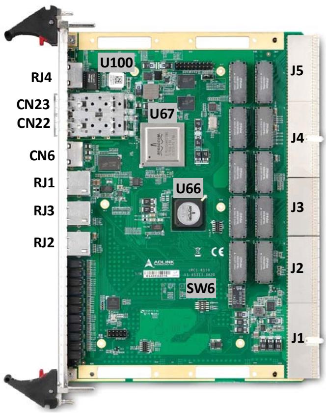
![U100\nU67\nU66\nSW6\nRJ4\nCN23\nCN22\nCN6\nRJ1\nRJ3\nRJ2\nJ5\nJ4\nJ3\nJ2\nJ1](.cpci-6s10-50-15099-1000-10/5151205e8d66763e44511faa29aaa9867835464129af623be3b83057b53e5c32.jpg)

Figure 2-1: cPCI-6S10 Board Layout

<table><tr><td>U100</td><td>BCM5221</td><td>RJ1-3</td><td>10/100/1000 GbE</td></tr><tr><td>U67</td><td>BCM56150</td><td>RJ4</td><td>10/100 Mgmt GbE</td></tr><tr><td>U66</td><td>BCM54685</td><td>CN6</td><td>UART Port</td></tr><tr><td>J1-J5</td><td>CompactPCI connectors</td><td>CN22-23</td><td>SFP+ Uplink ports</td></tr><tr><td>SW6</td><td>Standalone mode switch</td><td></td><td></td></tr></table>

# 2.3 Front Panel Layout

![Management\nPort\nSFP+\nCOM\nGbE x3\nLED x22\nHW LED\nPower LED](.cpci-6s10-50-15099-1000-10/fea20c8d1e1be96ef54a1429f771b32b4be0baa314b0fd071586314751f68c69.jpg)

The following section describes the behavior of the LEDs on the front panel.

Power LED

<table><tr><td>Power LED (Green)</td><td>Status</td></tr><tr><td>On</td><td>Power status normal</td></tr><tr><td>Off</td><td>Power off</td></tr></table>

HW LED (Hardware Health)

<table><tr><td>HW LED (Yellow)</td><td>Status</td></tr><tr><td>On</td><td>POST and sensor status of IPMC is normal</td></tr><tr><td>Blinking</td><td>TBD</td></tr><tr><td>Off</td><td>POST and sensor status of IPMC is abnormal</td></tr></table>

# Rear IO GbE Status LEDs (LP1 - LP20)

# Upper LED

Off: Link down

# Lower LED

Blink: Packet Activity

![LP2\nLP4\nLP6\nLP8\nLP10\nLP12\nLP14\nLP16\nLP18\nLPF\nMg\nLP1\nLP3\nLP5\nLP7\nLP9\nLP11\nLP13\nLP15\nLP17\nLP19\nLP20](.cpci-6s10-50-15099-1000-10/f6ceb8e4005445b067dc9af56a7ba4a1d41a471c89e2b8a3e2be2929b7ab11d1.jpg)

# SFP+ Status LEDs (XE 0 - XE 1)

# Link LED (Green)

ON: Link up

OFF: Link down

# Act LED (Orange)

Blink: Packet Activity

![LP2\nLP4\nLP6\nLP8\nLP10\nLP12\nLP14\nLP16\nLP18\nLPF\nMg\nLP1\nLP3\nLP5\nLP7\nLP9\nLP11\nLP13\nLP15\nLP17\nLP19\nLP20](.cpci-6s10-50-15099-1000-10/c04759016c08da557200729a39841a68cd52e8a8214d3499489a4d8e0eb127d7.jpg)

# 2.4 Connector Pinouts

# UART COM Connector (CN6)

Set SW21 to IPMI or BCM56150 UART MUX debug port

<table><tr><td>Pin #</td><td>10BASE-T/100BASE-TX</td></tr><tr><td>1</td><td>NC</td></tr><tr><td>2</td><td>NC</td></tr><tr><td>3</td><td>NC</td></tr><tr><td>4</td><td>IPM_DBG_TX</td></tr><tr><td>5</td><td>IPM_DBG_RX</td></tr><tr><td>6</td><td>GND</td></tr><tr><td>7</td><td>NC</td></tr><tr><td>8</td><td>NC</td></tr></table>

![The image shows a black square outline containing a black Ethernet port (RJ45 jack) centered within it. Two thin black lines extend downward from the bottom of the port to the numbers 8 and 1 located below the square.](.cpci-6s10-50-15099-1000-10/6527bc521926c7f79f0a91d651ea8f93a584649f3dcfabb675128cfe9b6f7de5.jpg)

# RJ-45 10/100BASE-T Mgmt. Ethernet Connector (RJ4)

<table><tr><td>Pin #</td><td>10BASE-T/100BASE-TX</td></tr><tr><td>1</td><td>NC</td></tr><tr><td>2</td><td>NC</td></tr><tr><td>3</td><td>NC</td></tr><tr><td>4</td><td>IPM_DBG_TX</td></tr><tr><td>5</td><td>IPM_DBG_RX</td></tr><tr><td>6</td><td>GND</td></tr><tr><td>7</td><td>NC</td></tr><tr><td>8</td><td>NC</td></tr></table>

![The image displays a black electrical plug with three pins inside a square border. At the bottom, there are two numbers: '8' on the left and '1' on the right. Thin black lines connect these numbers to the plug. The line from '8' points to the top earth pin, and the line from '1' points to the bottom right pin.](.cpci-6s10-50-15099-1000-10/106bf287d691b1d1352de3c054756027ad9c2a26437ca1f333f8405dc13dd695.jpg)

# RJ-45 Gigabit Ethernet Connectors ((RJ1/2/3)

<table><tr><td>Pin #</td><td>1000BASE-T</td></tr><tr><td>1</td><td>LAN_TX0+</td></tr><tr><td>2</td><td>LAN_TX0-</td></tr><tr><td>3</td><td>LAN_TX1+</td></tr><tr><td>4</td><td>LAN_TX2+</td></tr><tr><td>5</td><td>LAN_TX2-</td></tr><tr><td>6</td><td>LAN_TX1-</td></tr><tr><td>7</td><td>LAN_TX3+</td></tr><tr><td>8</td><td>LAN_TX3+</td></tr></table>

Link Activity
![The image displays a close-up of a black electronic component, resembling a CPU socket, encased in a white border with visible internal metal contacts. Two metal legs extend downward from the bottom. Below the component, the text 'GE 0' is centered. At the bottom left is the number '8' and at the bottom right is the number '1'.](.cpci-6s10-50-15099-1000-10/741aa12122897cf6f6212ee92db337af397f57cc933c9992dc667f2565d8ac2e.jpg)

# GbE Status LEDs

# Left LED

On: Link up

Off: Link down

# Right LED:

Blink: Packet Activity

SFP+ 10Gigabit Ethernet Connector (CN22/23)

<table><tr><td>Pin #</td><td>1000BASE-T</td></tr><tr><td>1</td><td>GND</td></tr><tr><td>2</td><td>SFP_TX_FAULT</td></tr><tr><td>3</td><td>SFP_TX_DISABLE</td></tr><tr><td>4</td><td>SFP_SDA</td></tr><tr><td>5</td><td>SFP_SCL</td></tr><tr><td>6</td><td>SFP_MOD_ABS</td></tr><tr><td>7</td><td>GND</td></tr><tr><td>8</td><td>SFP_RX_LOS</td></tr><tr><td>9</td><td>GND</td></tr><tr><td>10</td><td>GND</td></tr><tr><td>11</td><td>GND</td></tr><tr><td>12</td><td>SRDS_RX-N</td></tr><tr><td>13</td><td>SRDS_RX-P</td></tr><tr><td>14</td><td>GND</td></tr><tr><td>15</td><td>SFP_V3P3_R</td></tr><tr><td>16</td><td>SFP_V3P3_T</td></tr><tr><td>17</td><td>GND</td></tr><tr><td>18</td><td>SRDS_TX-P</td></tr><tr><td>19</td><td>SRDS_TX-N</td></tr><tr><td>20</td><td>GND</td></tr></table>

![20\n11\nLINK\nACT\n+\nXE 1\n1\n10](.cpci-6s10-50-15099-1000-10/7fbad2aab8673e409b674b7a7a6f272bb4564e78153ef030d698b5beac666fa8.jpg)

# SFP+ 10GbE Status LEDs

Link LED: Yellow (Left)

Act LED: Green (Right)

CompactPCI J1 Connector Pin Assignment

<table><tr><td>Pin</td><td>Z</td><td>A</td><td>B</td><td>C</td><td>D</td><td>E</td><td>F</td></tr><tr><td>25</td><td>GND</td><td>P5V</td><td>NC</td><td>CPCI_ENUM_L</td><td>P3V3</td><td>P5V</td><td>GND</td></tr><tr><td>24</td><td>GND</td><td>NC</td><td>P5V</td><td>CPCI_VIO</td><td>NC</td><td>NC</td><td>GND</td></tr><tr><td>23</td><td>GND</td><td>P3V3</td><td>NC</td><td>NC</td><td>P5V</td><td>NC</td><td>GND</td></tr><tr><td>22</td><td>GND</td><td>NC</td><td>GND</td><td>P3V3</td><td>NC</td><td>NC</td><td>GND</td></tr><tr><td>21</td><td>GND</td><td>P3V3</td><td>NC</td><td>NC</td><td>GND</td><td>NC</td><td>GND</td></tr><tr><td>20</td><td>GND</td><td>NC</td><td>GND</td><td>CPCI_VIO</td><td>NC</td><td>NC</td><td>GND</td></tr><tr><td>19</td><td>GND</td><td>P3V3</td><td>NC</td><td>NC</td><td>GND</td><td>NC</td><td>GND</td></tr><tr><td>18</td><td>GND</td><td>NC</td><td>GND</td><td>P3V3</td><td>NC</td><td>NC</td><td>GND</td></tr><tr><td>17</td><td>GND</td><td>P3V3</td><td>IPMB_SCL</td><td>IPMB_SDA</td><td>GND</td><td>NC</td><td>GND</td></tr><tr><td>16</td><td>GND</td><td>NC</td><td>GND</td><td>CPCI_VIO</td><td>NC</td><td>NC</td><td>GND</td></tr><tr><td>15</td><td>GND</td><td>P3V3</td><td>NC</td><td>NC</td><td>CPCI_BDSEL_L</td><td>NC</td><td>GND</td></tr><tr><td>12-14</td><td>GND</td><td colspan="5">Key Area</td><td>Key</td></tr><tr><td>11</td><td>GND</td><td>NC</td><td>NC</td><td>NC</td><td>GND</td><td>NC</td><td>GND</td></tr><tr><td>10</td><td>GND</td><td>NC</td><td>GND</td><td>P3V3</td><td>NC</td><td>NC</td><td>GND</td></tr><tr><td>9</td><td>GND</td><td>NC</td><td>GND</td><td>NC</td><td>GND</td><td>NC</td><td>GND</td></tr><tr><td>8</td><td>GND</td><td>NC</td><td>GND</td><td>CPCI_VIO</td><td>NC</td><td>NC</td><td>GND</td></tr><tr><td>7</td><td>GND</td><td>NC</td><td>NC</td><td>NC</td><td>GND</td><td>NC</td><td>GND</td></tr><tr><td>6</td><td>GND</td><td>NC</td><td>CPCI_PRESENT_L</td><td>P3V3</td><td>NC</td><td>NC</td><td>GND</td></tr><tr><td>5</td><td>GND</td><td>NC</td><td>NC</td><td>NC</td><td>GND</td><td>NC</td><td>GND</td></tr><tr><td>4</td><td>GND</td><td>P5V_IPMB</td><td>CPCI_HEALTHY-L</td><td>CPCI_VIO</td><td>NC</td><td>NC</td><td>GND</td></tr><tr><td>3</td><td>GND</td><td>NC</td><td>NC</td><td>NC</td><td>P5V</td><td>NC</td><td>GND</td></tr><tr><td>2</td><td>GND</td><td>NC</td><td>P5V</td><td>NC</td><td>NC</td><td>NC</td><td>GND</td></tr><tr><td>1</td><td>GND</td><td>P5V</td><td>N12V</td><td>NC</td><td>P12V</td><td>P5V</td><td>GND</td></tr></table>

CompactPCI J2 Connector Pin Assignment

<table><tr><td>Pin</td><td>Z</td><td>A</td><td>B</td><td>C</td><td>D</td><td>E</td><td>F</td></tr><tr><td>22</td><td>GND</td><td>GA4</td><td>GA3</td><td>GA2</td><td>GA1</td><td>GA0</td><td>GND</td></tr><tr><td>21</td><td>GND</td><td>NC</td><td>GND</td><td>NC</td><td>NC</td><td>NC</td><td>GND</td></tr><tr><td>20</td><td>GND</td><td>NC</td><td>GND</td><td>NC</td><td>GND</td><td>NC</td><td>GND</td></tr><tr><td>19</td><td>GND</td><td>GND</td><td>GND</td><td>IPMB_SDA</td><td>IPMB_SCL</td><td>NC</td><td>GND</td></tr><tr><td>18</td><td>GND</td><td>NC</td><td>NC</td><td>NC</td><td>GND</td><td>NC</td><td>GND</td></tr><tr><td>17</td><td>GND</td><td>NC</td><td>GND</td><td>CHASS_RST_L</td><td>NC</td><td>NC</td><td>GND</td></tr><tr><td>16</td><td>GND</td><td>NC</td><td>NC</td><td>CPCI_DEG_L</td><td>GND</td><td>NC</td><td>GND</td></tr><tr><td>15</td><td>GND</td><td>NC</td><td>GND</td><td>CPCI_FAL_L</td><td>NC</td><td>NC</td><td>GND</td></tr><tr><td>14</td><td>GND</td><td>NC</td><td>NC</td><td>NC</td><td>GND</td><td>NC</td><td>GND</td></tr><tr><td>13</td><td>GND</td><td>NC</td><td>GND</td><td>CPCI_VIO</td><td>NC</td><td>NC</td><td>GND</td></tr><tr><td>12</td><td>GND</td><td>NC</td><td>NC</td><td>NC</td><td>GND</td><td>NC</td><td>GND</td></tr><tr><td>11</td><td>GND</td><td>NC</td><td>GND</td><td>CPCI_VIO</td><td>NC</td><td>NC</td><td>GND</td></tr><tr><td>10</td><td>GND</td><td>NC</td><td>NC</td><td>NC</td><td>GND</td><td>NC</td><td>GND</td></tr><tr><td>9</td><td>GND</td><td>NC</td><td>GND</td><td>CPCI_VIO</td><td>NC</td><td>NC</td><td>GND</td></tr><tr><td>8</td><td>GND</td><td>NC</td><td>NC</td><td>NC</td><td>GND</td><td>NC</td><td>GND</td></tr><tr><td>7</td><td>GND</td><td>NC</td><td>GND</td><td>CPCI_VIO</td><td>NC</td><td>NC</td><td>GND</td></tr><tr><td>6</td><td>GND</td><td>NC</td><td>NC</td><td>NC</td><td>GND</td><td>NC</td><td>GND</td></tr><tr><td>5</td><td>GND</td><td>NC</td><td>GND</td><td>CPCI_VIO</td><td>NC</td><td>NC</td><td>GND</td></tr><tr><td>4</td><td>GND</td><td>CPCI_VIO</td><td>NC</td><td>NC</td><td>GND</td><td>NC</td><td>GND</td></tr><tr><td>3</td><td>GND</td><td>NC</td><td>GND</td><td>NC</td><td>NC</td><td>NC</td><td>GND</td></tr><tr><td>2</td><td>GND</td><td>NC</td><td>NC</td><td>SYSEN-L</td><td>NC</td><td>NC</td><td>GND</td></tr><tr><td>1</td><td>GND</td><td>NC</td><td>GND</td><td>NC</td><td>NC</td><td>NC</td><td>GND</td></tr></table>

CompactPCI J3 Pin Assignment

<table><tr><td>Pin</td><td>Z</td><td>A</td><td>B</td><td>C</td><td>D</td><td>E</td><td>F</td></tr><tr><td>19</td><td>GND</td><td>SGA4</td><td>SGA3</td><td>SGA2</td><td>SGA1</td><td>SGA0</td><td>GND</td></tr><tr><td>18</td><td>GND</td><td>LAN_A_LPFp</td><td>LAN_A_LPFn</td><td>GND</td><td>LAN_C_LPFp</td><td>LAN_C_LPFn</td><td>GND</td></tr><tr><td>17</td><td>GND</td><td>LAN_B_LPFp</td><td>LAN_B_LPFn</td><td>GND</td><td>LAN_D_LPFp</td><td>LAN_D_LPFn</td><td>GND</td></tr><tr><td>16</td><td>GND</td><td>LAN_A_8P</td><td>LAN_A_8N</td><td>GND</td><td>LAN_C_8P</td><td>LAN_C_8N</td><td>GND</td></tr><tr><td>15</td><td>GND</td><td>LAN_B_8P</td><td>LAN_B_8N</td><td>GND</td><td>LAN_D_8P</td><td>LAN_D_8N</td><td>GND</td></tr><tr><td>14</td><td>GND</td><td>LAN_A_7P</td><td>LAN_A_7N</td><td>GND</td><td>LAN_C_7P</td><td>LAN_C_7N</td><td>GND</td></tr><tr><td>13</td><td>GND</td><td>LAN_B_7P</td><td>LAN_B_7N</td><td>GND</td><td>LAN_D_7P</td><td>LAN_D_7N</td><td>GND</td></tr><tr><td>12</td><td>GND</td><td>LAN_A_6P</td><td>LAN_A_6N</td><td>GND</td><td>LAN_C_6P</td><td>LAN_C_6N</td><td>GND</td></tr><tr><td>11</td><td>GND</td><td>LAN_B_6P</td><td>LAN_B_6N</td><td>GND</td><td>LAN_D_6P</td><td>LAN_D_6N</td><td>GND</td></tr><tr><td>10</td><td>GND</td><td>LAN_A_5P</td><td>LAN_A_5N</td><td>GND</td><td>LAN_C_5P</td><td>LAN_C_5N</td><td>GND</td></tr><tr><td>9</td><td>GND</td><td>LAN_B_5P</td><td>LAN_B_5N</td><td>GND</td><td>LAN_D_5P</td><td>LAN_D_5N</td><td>GND</td></tr><tr><td>8</td><td>GND</td><td>LAN_A_4P</td><td>LAN_A_4N</td><td>GND</td><td>LAN_C_4P</td><td>LAN_C_4N</td><td>GND</td></tr><tr><td>7</td><td>GND</td><td>LAN_B_4P</td><td>LAN_B_4N</td><td>GND</td><td>LAN_D_4P</td><td>LAN_D_4N</td><td>GND</td></tr><tr><td>6</td><td>GND</td><td>LAN_A_3P</td><td>LAN_A_3N</td><td>GND</td><td>LAN_C_3P</td><td>LAN_C_3N</td><td>GND</td></tr><tr><td>5</td><td>GND</td><td>LAN_B_3P</td><td>LAN_B_3N</td><td>GND</td><td>LAN_D_3P</td><td>LAN_D_3N</td><td>GND</td></tr><tr><td>4</td><td>GND</td><td>LAN_A_2P</td><td>LAN_A_2N</td><td>GND</td><td>LAN_C_2P</td><td>LAN_C_2N</td><td>GND</td></tr><tr><td>3</td><td>GND</td><td>LAN_B_2P</td><td>LAN_B_2N</td><td>GND</td><td>LAN_D_2P</td><td>LAN_D_2N</td><td>GND</td></tr><tr><td>2</td><td>GND</td><td>LAN_A_1P</td><td>LAN_A_1N</td><td>GND</td><td>LAN_C_1P</td><td>LAN_C_1N</td><td>GND</td></tr><tr><td>1</td><td>GND</td><td>LAN_B_1P</td><td>LAN_B_1N</td><td>GND</td><td>LAN_D_1P</td><td>LAN_D_1N</td><td>GND</td></tr></table>

CompactPCI J4 Connector Pin Assignment

<table><tr><td>Pin</td><td>Z</td><td>A</td><td>B</td><td>C</td><td>D</td><td>E</td><td>F</td></tr><tr><td>25</td><td>GND</td><td>NC</td><td>NC</td><td>NC</td><td>NC</td><td>NC</td><td>GND</td></tr><tr><td>24</td><td>GND</td><td>NC</td><td>NC</td><td>NC</td><td>NC</td><td>NC</td><td>GND</td></tr><tr><td>23</td><td>GND</td><td>NC</td><td>NC</td><td>NC</td><td>NC</td><td>NC</td><td>GND</td></tr><tr><td>22</td><td>GND</td><td>CMM_J4_TX0P</td><td>CMM_J4_TX0N</td><td>NC</td><td>CMM_J4_RX0P</td><td>CMM_J4_RX0N</td><td>GND</td></tr><tr><td>21</td><td>GND</td><td>NC</td><td>NC</td><td>NC</td><td>NC</td><td>NC</td><td>GND</td></tr><tr><td>20</td><td>GND</td><td>NC</td><td>NC</td><td>NC</td><td>NC</td><td>NC</td><td>GND</td></tr><tr><td>19</td><td>GND</td><td>NC</td><td>NC</td><td>NC</td><td>NC</td><td>NC</td><td>GND</td></tr><tr><td>18</td><td>GND</td><td>NC</td><td>NC</td><td>NC</td><td>IPMB_SCL</td><td>IPMB_SDA</td><td>GND</td></tr><tr><td>17</td><td>GND</td><td>NC</td><td>NC</td><td>NC</td><td>IPMB_SCL</td><td>IPMB_SDA</td><td>GND</td></tr><tr><td>16</td><td>GND</td><td>NC</td><td>NC</td><td>NC</td><td>NC</td><td>NC</td><td>GND</td></tr><tr><td>15</td><td>GND</td><td>NC</td><td>NC</td><td>NC</td><td>NC</td><td>NC</td><td>GND</td></tr><tr><td>12-14</td><td>GND</td><td colspan="5">Key Area</td><td>Key</td></tr><tr><td>11</td><td>GND</td><td>NC</td><td>NC</td><td>NC</td><td>NC</td><td>NC</td><td>GND</td></tr><tr><td>10</td><td>GND</td><td>NC</td><td>NC</td><td>NC</td><td>NC</td><td>NC</td><td>GND</td></tr><tr><td>9</td><td>GND</td><td>NC</td><td>NC</td><td>NC</td><td>NC</td><td>NC</td><td>GND</td></tr><tr><td>8</td><td>GND</td><td>NC</td><td>NC</td><td>NC</td><td>NC</td><td>NC</td><td>GND</td></tr><tr><td>7</td><td>GND</td><td>NC</td><td>NC</td><td>NC</td><td>NC</td><td>NC</td><td>GND</td></tr><tr><td>6</td><td>GND</td><td>NC</td><td>NC</td><td>NC</td><td>NC</td><td>NC</td><td>GND</td></tr><tr><td>5</td><td>GND</td><td>NC</td><td>NC</td><td>NC</td><td>NC</td><td>NC</td><td>GND</td></tr><tr><td>4</td><td>GND</td><td>NC</td><td>NC</td><td>NC</td><td>NC</td><td>NC</td><td>GND</td></tr><tr><td>3</td><td>GND</td><td>NC</td><td>NC</td><td>NC</td><td>NC</td><td>NC</td><td>GND</td></tr><tr><td>2</td><td>GND</td><td>NC</td><td>NC</td><td>NC</td><td>NC</td><td>NC</td><td>GND</td></tr><tr><td>1</td><td>GND</td><td>NC</td><td>NC</td><td>NC</td><td>NC</td><td>NC</td><td>GND</td></tr></table>

CompactPCI J5 Pin Assignment

<table><tr><td>Pin</td><td>Z</td><td>A</td><td>B</td><td>C</td><td>D</td><td>E</td><td>F</td></tr><tr><td>22</td><td>GND</td><td>LAN_A_19P</td><td>LAN_A_19N</td><td>GND</td><td>LAN_C_19P</td><td>LAN_C_19N</td><td>GND</td></tr><tr><td>21</td><td>GND</td><td>LAN_B_19P</td><td>LAN_B_19N</td><td>GND</td><td>LAN_D_19P</td><td>LAN_D_19N</td><td>GND</td></tr><tr><td>20</td><td>GND</td><td>LAN_A_18P</td><td>LAN_A_18N</td><td>GND</td><td>LAN_C_18P</td><td>LAN_C_18N</td><td>GND</td></tr><tr><td>19</td><td>GND</td><td>LAN_B_18P</td><td>LAN_B_18N</td><td>GND</td><td>LAN_D_18P</td><td>LAN_D_18N</td><td>GND</td></tr><tr><td>18</td><td>GND</td><td>LAN_A_17P</td><td>LAN_A_17N</td><td>GND</td><td>LAN_C_17P</td><td>LAN_C_17N</td><td>GND</td></tr><tr><td>17</td><td>GND</td><td>LAN_B_17P</td><td>LAN_B_17N</td><td>GND</td><td>LAN_D_17P</td><td>LAN_D_17N</td><td>GND</td></tr><tr><td>16</td><td>GND</td><td>LAN_A_16P</td><td>LAN_A_16N</td><td>GND</td><td>LAN_C_16P</td><td>LAN_C_16N</td><td>GND</td></tr><tr><td>15</td><td>GND</td><td>LAN_B_16P</td><td>LAN_B_16N</td><td>GND</td><td>LAN_D_16P</td><td>LAN_D_16N</td><td>GND</td></tr><tr><td>14</td><td>GND</td><td>LAN_A_15P</td><td>LAN_A_15N</td><td>GND</td><td>LAN_C_15P</td><td>LAN_C_15N</td><td>GND</td></tr><tr><td>13</td><td>GND</td><td>LAN_B_15P</td><td>LAN_B_15N</td><td>GND</td><td>LAN_D_15P</td><td>LAN_D_15N</td><td>GND</td></tr><tr><td>12</td><td>GND</td><td>LAN_A_14P</td><td>LAN_A_14N</td><td>GND</td><td>LAN_C_14P</td><td>LAN_C_14N</td><td>GND</td></tr><tr><td>11</td><td>GND</td><td>LAN_B_14P</td><td>LAN_B_14N</td><td>GND</td><td>LAN_D_14P</td><td>LAN_D_14N</td><td>GND</td></tr><tr><td>10</td><td>GND</td><td>LAN_A_13P</td><td>LAN_A_13N</td><td>GND</td><td>LAN_C_13P</td><td>LAN_C_13N</td><td>GND</td></tr><tr><td>9</td><td>GND</td><td>LAN_B_13P</td><td>LAN_B_13N</td><td>GND</td><td>LAN_D_13P</td><td>LAN_D_13N</td><td>GND</td></tr><tr><td>8</td><td>GND</td><td>LAN_A_12P</td><td>LAN_A_12N</td><td>GND</td><td>LAN_C_12P</td><td>LAN_C_12N</td><td>GND</td></tr><tr><td>7</td><td>GND</td><td>LAN_B_12P</td><td>LAN_B_12N</td><td>GND</td><td>LAN_D_12P</td><td>LAN_D_12N</td><td>GND</td></tr><tr><td>6</td><td>GND</td><td>LAN_A_11P</td><td>LAN_A_11N</td><td>GND</td><td>LAN_C_11P</td><td>LAN_C_11N</td><td>GND</td></tr><tr><td>5</td><td>GND</td><td>LAN_B_11P</td><td>LAN_B_11N</td><td>GND</td><td>LAN_D_11P</td><td>LAN_D_11N</td><td>GND</td></tr><tr><td>4</td><td>GND</td><td>LAN_A_10P</td><td>LAN_A_10N</td><td>GND</td><td>LAN_C_10P</td><td>LAN_C_10N</td><td>GND</td></tr><tr><td>3</td><td>GND</td><td>LAN_B_10P</td><td>LAN_B_10N</td><td>GND</td><td>LAN_D_10P</td><td>LAN_D_10N</td><td>GND</td></tr><tr><td>2</td><td>GND</td><td>LAN_A_9P</td><td>LAN_A_9N</td><td>GND</td><td>LAN_C_9P</td><td>LAN_C_9N</td><td>GND</td></tr><tr><td>1</td><td>GND</td><td>LAN_B_9P</td><td>LAN_B_9N</td><td>GND</td><td>LAN_D_9P</td><td>LAN_D_9N</td><td>GND</td></tr></table>

# 2.5 Switch Settings

# Standalone/CMM Mode Switch (SW6)

The cPCI-6S10 comes with SW6 for user to set the blade to standalone mode or CMM mode. The cPCI-6S10 can boot without CMM in standalone mode.

<table><tr><td>Pin</td><td>Function</td></tr><tr><td>All off</td><td>Stand alone mode (default)</td></tr><tr><td>2 ON</td><td>CMM Disable</td></tr><tr><td>3 ON</td><td>SYSTEM# ENABLE</td></tr><tr><td>4 ON</td><td>EJECT Close</td></tr></table>

![1\n2\n3\n4\nON](.cpci-6s10-50-15099-1000-10/4585968dfafbd8dd0f7236385ee76e2e04c999cd1bbc913eeb0d3c9d4ebd5f4b.jpg)

# Boot Select Switch (SW13)

SW13 switch is to select boot from either SPI flash or NAND flash.

<table><tr><td>Pin</td><td>Function</td></tr><tr><td>1 ON</td><td>Boot from SPI flash (Default)</td></tr><tr><td>2 ON</td><td>Boot from nand flash</td></tr></table>

![1\n2\nON](.cpci-6s10-50-15099-1000-10/7f47e439ac7049fa366538ebe97140a8579cdcc6c87256d4be7adb1ca067c245.jpg)

# NAND Flash Boot Mode Switch (SW14)

SW14 switch sets either Auto or Manual mode for boot from NAND flash

<table><tr><td>Pin 1</td><td>Pin 2</td><td>Function</td></tr><tr><td>Off</td><td>(no effect)</td><td>Auto mode (default)</td></tr><tr><td>On</td><td>On</td><td>Manual mode: Select NAND 0</td></tr><tr><td>On</td><td>Off</td><td>Manual mode: Select NAND 1</td></tr></table>

![1\n2\nON](.cpci-6s10-50-15099-1000-10/48267c39d2c68a83f957e51cafd966b5a6f7fa32589c85fd9e84ed77b8c00d2e.jpg)

# Console Port Switch (SW21)

SW21 switch sets the console port to either BCM56150 or to IPMC.

<table><tr><td>Pin</td><td>Function</td></tr><tr><td>1/2 On, 3/4 Off</td><td>Console port to BCM56150 (Default)</td></tr><tr><td>1/2 Off, 3/4 On</td><td>Console port to IPMC</td></tr></table>

![1\n2\n3\n4\nON](.cpci-6s10-50-15099-1000-10/599367d095d25cc12d878cb8245893922fb91cb06277429ecef2625d976361b9.jpg)

# 3 Hardware Platform Management

# 3.1 Platform Management Overview

The purpose of the hardware platform management system is to monitor, control, and assure proper operation of CompactPCI blades. The hardware platform management system watches over the basic health of the system, reports anomalies, and provides feedback to the chassis management module (CMM) when needed. The hardware platform management system can retrieve inventory information and sensor readings as well as receive event reports and failure notifications from blades and other Intelligent FRUs. The hardware platform management system can also perform basic recovery operations such as power cycle or reset of managed entities.

The IPMC controller on the cPCI-6S10 supports an intelligent hardware management system, based on the Intelligent Platform Management Interface Specification. The hardware management system provides the ability to manage the power, cooling, and interconnect needs of intelligent devices; monitor events; and log events to a central repository.

# 3.2 IPMI Commands

# 3.2.1 Standard Commands

In terminal mode, the command is enclosed by square brackets. Each Hex number is separated by a single blank. This command group ranges from 0x00, 0x02, 0x04, 0x06, 0x08, 0x0A, to 0x0C in Netfn list.

# Format

# Request: [18 00 02]

X Byte 1: NetFn/rsLUN(00b)
X Byte 2: rqSeq/Bridge
X Byte 3: Command
X Byte 4-n: request data

# Response: [1C 00 02 00]

X Byte 1: NetFn
X Byte 2: rqSeq
X Byte 3: Command
X Byte 4: Completion code
X Byte 5-n: response data

NetFn Codes:

<table><tr><td>Request</td><td>Response</td><td>Name</td></tr><tr><td>00</td><td>01</td><td>Chassis</td></tr><tr><td>02</td><td>03</td><td>Bridge</td></tr><tr><td>04</td><td>05</td><td>Sensor / Event</td></tr><tr><td>06</td><td>07</td><td>App</td></tr><tr><td>08</td><td>09</td><td>Firmware</td></tr><tr><td>0A</td><td>0B</td><td>Storage</td></tr><tr><td>0C</td><td>0D</td><td>Transport</td></tr><tr><td>0E</td><td>2B</td><td>Reserved</td></tr><tr><td>2C</td><td>2D</td><td>Group Extension</td></tr><tr><td>2E</td><td>2F</td><td>OEM</td></tr><tr><td>30</td><td>3F</td><td>Controller specific OEM/Group</td></tr></table>

Table 3-1: NetFn codes

Response Codes

<table><tr><td>Description</td><td>Code</td></tr><tr><td>IPMI_SUCCESS</td><td>0x00</td></tr><tr><td>IPMI_NODE_BUSY</td><td>0xC0</td></tr><tr><td>IPMI_INVALID_COMMAND</td><td>0xC1</td></tr><tr><td>IPMI_COMMAND_INVALID_FOR_LUN</td><td>0xC2</td></tr><tr><td>IPMI_TIMEOUT</td><td>0xC3</td></tr><tr><td>IPMI_OUT_OF_SPACE</td><td>0xC4</td></tr><tr><td>IPMI_RESERVATION_INVALID_OR_CANCELED</td><td>0xC5</td></tr><tr><td>IPMI_REQUEST_DATA_TRUNCATED</td><td>0xC6</td></tr><tr><td>IPMI_REQUEST_DATA_LENGTH_INVALID</td><td>0xC7</td></tr><tr><td>IPMI_REQUEST_DATA_LENGTH_LIMIT_EXCEEDED</td><td>0xC8</td></tr><tr><td>IPMI_PARAMETER_OUT_OF_RANGE</td><td>0xC9</td></tr><tr><td>IPMI_CANNOT_RETURN_NUMBER_OF_REQUESTED_BYTE S</td><td>0xCA</td></tr><tr><td>IPMI_REQUESTED_DATA_NOT_PRESENT</td><td>0xCB</td></tr><tr><td>IPMI_INVALID_DATA_IN_REQUEST</td><td>0xCC</td></tr><tr><td>IPMI_COMMAND_ILLEGAL_FOR_SPECIFIED_OBJECT</td><td>0xCD</td></tr><tr><td>IPMI_CANNOT Provide_COMMAND_RESPONSE</td><td>0xCE</td></tr><tr><td>IPMI_CANNOT EXECUTE_DUPLICATED_REQUEST</td><td>0xCF</td></tr><tr><td>IPMI_SDR_REPOSITORY_IN_UPDATE_MODE</td><td>0xD0</td></tr><tr><td>IPMI_DEVICE_IN_FIRMWARE_UPDATE_MODE</td><td>0xD1</td></tr><tr><td>IPMI_INITIALIZATION_IN_PROGRESS</td><td>0xD2</td></tr><tr><td>IPMI_DESTINATION_UNAVAILABLE</td><td>0xD3</td></tr><tr><td>IPMI_INSUFFICIENT_PRIVILEGE_LEVEL</td><td>0xD4</td></tr><tr><td>IPMI_COMMAND_NOT_SUPPORTED_IN_PRESENT_STATE</td><td>0xD5</td></tr><tr><td>IPMI_READ_ONLY_PARAMETER</td><td>0x82</td></tr><tr><td>IPMI_UNSPECIFIED_ERROR</td><td>0xFF</td></tr></table>

Table 3-2: Response Codes

# Message Length

The IPMI standard overall message for “no-bridging” messages is specified as 32 bytes, maximum, including slave address. For bridging messages to other interfaces, Master Write-Read and Send Message commands are allowed to exceed 32-bytes on IPMI.

The table below shows the required interface length in IPMI 1.5. Some interfaces have extra recommended values in the IPMI specification.

<table><tr><td>Interface</td><td>Length(bytes)</td></tr><tr><td>KCS/SMIC Input</td><td>40</td></tr><tr><td>KCS/SMIC Output</td><td>38</td></tr><tr><td>BT Input</td><td>42</td></tr><tr><td>BT Output</td><td>40</td></tr><tr><td>IPMB Input</td><td>32</td></tr><tr><td>IPMB Output</td><td>36</td></tr><tr><td>SMBus 2.0 Input</td><td>36</td></tr><tr><td>SMBus 2.0 Output</td><td>36</td></tr><tr><td>Private Bus Input</td><td>34</td></tr><tr><td>Private Bus Output</td><td>23</td></tr><tr><td>LAN/PPP Input</td><td>45</td></tr><tr><td>LAN/PPP Output</td><td>42</td></tr></table>

Table 3-3: Required Message Length for IPMI 1.5

# 3.2.2 IPMItool

IPMItool is an open-source software, which supports several message interfaces to communicate with IPMI devices. It includes pre-define commands such like “fru” and “mc”, and can also send raw IPMI commands.

To send IPMI commands to the cPCI-6S10’s IPMC, instead of using IPMItool under Linux login, it is possible to communicate remotely with cPCI-6S10 IPMC through RMCP protocol, with the help of the IPMItool utility.

# Message Interfaces

X Access through Linux driver (on LMP locally): ipmitool &lt;command&gt;
X RMCP remote client: ipmitool -I lan -H &lt;hostname&gt; [-p &lt;port&gt;] [-U &lt;username&gt;] [-A &lt;authtype&gt;] &lt;command&gt;
If bridged command is issued. An extra parameter should be applied.

Z -t: select target slave address (0xB0 for slot1, 0xB2 for slot2, etc, in ADLINK Chassis cPCIS-3300BLS).

<table><tr><td>Slot No.</td><td>IPMB Address (hex)</td><td>Type</td></tr><tr><td>01</td><td>B0</td><td>CPU</td></tr><tr><td>02</td><td>B2</td><td>CPU</td></tr><tr><td>03</td><td>B4</td><td>CPU</td></tr><tr><td>04</td><td>B6</td><td>CPU</td></tr><tr><td>05</td><td>B8</td><td>SWH</td></tr><tr><td>06</td><td>BA</td><td>CPU</td></tr><tr><td>07</td><td>BC</td><td>CPU</td></tr><tr><td>08</td><td>BE</td><td>CPU</td></tr><tr><td>09</td><td>C0</td><td>CPU</td></tr><tr><td>10</td><td>C4</td><td>SWH</td></tr><tr><td>11</td><td>C6</td><td>CPU</td></tr><tr><td>12</td><td>C8</td><td>CPU</td></tr><tr><td>13</td><td>CA</td><td>CPU</td></tr><tr><td>14</td><td>CC</td><td>CPU</td></tr></table>

Table 3-4: cPCIS-3300BLS Chassis Slots

# Examples

# Access from local LMP

# ipmitool mc info

Get device Information from onboard payload with Linux IPMI driver.

# ipmitool raw 0x06 0x01

Get device id with IPMI raw command.

# Access from RMCP remote client, bridged through the BMC

# ipmitool -I lan -H 172.20.5.225 -U admin -P admin -t 0xB8 raw 0x06 0x01

Remote send raw command “Get device Id” to IPMC (172.20.5.225) via RMCP protocol with username: admin, password: admin, and let CMM to bridge it to CPCI-6S10 board plugged in slot 5 (slave address: 0xB8).

# Response

X Complete: Completion code is 0x00 and will be skipped, and only response data be printed.
X Error: More error message will be printed.

# 3.2.3 IPMItool Pre-defined Commands

X ipmitool raw: Send a raw command request.
X ipmitool mc: Print the management controller status and global enabled options.

```python
# ipmitool mc
MC Commands:
    reset &lt;warm|cold&gt;
    info
    wdt
    selftest
    getenables
    setenables &lt;option=on|off&gt; ...
    recv_msg_intr Receive Message Queue Int.
    event_msg_intr Event Message Buffer Full Int.
    event_msg Event Message Buffer
    system_event_log System Event Logging
    oem0 OEM 0
    oem1 OEM 1
    oem2 OEM 2
```

X ipmitool fru: Print built-in FRU and scan SDR for FRU locators.

```txt
# ipmitool fru
FRU Device Description: Builtin FRU Device (ID 0)
Board Mfg Date: Tue Sep 16 20:00:00 2014
Board Mfg: ADLINK Technology
```

```txt
Board Product: cPCI-6S10
Board Serial: ADLINK-XXXX-XXXX
Board Part Number: cPCI-6S10
Product Manufacturer: ADLINK Technology
Product Name: cPCI-6S10
Product Part Number: cPCI-6S10
Product Version: A2
Product Serial: ADLINK-XXXX-XXXX
Product Asset Tag: N/A
```

ipmitool -I lan -H 172.20.5.225 -U admin -P admin -t 0xB4 sdr: Print Sensor Data Repository entries and readings.

```csv
BMC_WatchDog | no reading | ns
POWER_GOOD | 0 unspecified | cr
P1V | 1.01 Volts | ok
P1V2 | 1.20 Volts | ok
P1V5 | 1.50 Volts | ok
P0V75 | 0.74 Volts | ok
+3.3V | 3.32 Volts | ok
+5.0V | 5.05 Volts | ok
54685_TEMP | 47 degrees C | ok
56150_TEMP | 67 degrees C | nc
```

# 3.2.4 Supported IPMItool Commands

Get Device ID

<table><tr><td>ipmitool</td><td>ipmitool [parameters] mc info</td></tr><tr><td>Terminal mode</td><td>[18 00 01]: raw 0x06 01</td></tr><tr><td>Description</td><td>Get device&#x27;s id from selected MC.</td></tr></table>

Example

```txt
root@BDSP-A-0-0-1:~# ipmi mc info
Device ID : 18
Device Revision : 0
Firmware Revision : 1.2
IPMI Version : 1.5
Manufacturer ID : 24339
Manufacturer Name : Unknown (0x5F13)
Product ID : 21267 (0x5313)
```

```asm
Product Name : Unknown (0x5313)
Device Available : yes
Provides Device SDRs : yes
Additional Device Support :
Sensor Device
FRU Inventory Device
IPMB Event Generator
Aux Firmware Rev Info :
0xa1
0x00
0x00
0x00
```

Response Data Fields

<table><tr><td>1</td><td>Completion code</td></tr><tr><td>2</td><td>Device ID. 00 = unspecified.</td></tr><tr><td>3</td><td>Device Revision</td></tr><tr><td>4</td><td>Firmware Revision 1</td></tr><tr><td>5</td><td>Firmware Revision 2</td></tr><tr><td>6</td><td>IPMI version</td></tr><tr><td>7</td><td>Addition Device support</td></tr><tr><td>8:10</td><td>Manufacture ID</td></tr><tr><td>11:12</td><td>Product ID</td></tr></table>

Cold Reset

<table><tr><td>ipmitool</td><td>ipmitool [parameters] mc reset cold</td></tr><tr><td>Terminal mode</td><td>[18 00 02]: raw 0x06 0x02</td></tr><tr><td>Description</td><td>Reset IPMC</td></tr></table>

In IPMC console, cold reset message will be printed.

```txt
&lt;__&gt;: BMR-AVR Firmware (v1.0.2), cPCI edition.
&lt;__&gt;: Pigeon Point Systems (c) Copyright 2004.
&lt;__&gt;: boot_type: 0xA3
&lt;__&gt;: Reset type: COLD, reset cause: Software
&lt;__&gt;: app_status: 0x01
&lt;__&gt;: Operating mode: Normal
```
Response Data Fields

<table><tr><td>1</td><td>Completion code</td></tr></table>

Reset Watchdog Timer

<table><tr><td>ipmitool</td><td>ipmitool [parameters] mc wdt rst</td></tr><tr><td>Terminal mode</td><td>[18 00 22]: raw 0x06 0x22</td></tr><tr><td>Description</td><td>This command is used to reset IPMC watchdog timer. The ipmitool supports this command.</td></tr></table>

Response Data Fields

<table><tr><td>1</td><td>Completion code</td></tr></table>

Set Watchdog Timer

<table><tr><td>ipmitool</td><td>ipmitool [parameters] raw 0x06 0x24 0x03 0x01 0x00 0x20 0x00 0x01</td></tr><tr><td>Terminal mode</td><td>[18 00 24 03 01 00 20 00 01]</td></tr><tr><td>Description</td><td>This command is used to set IPMC watchdog timer.</td></tr></table>

Response Data Fields

<table><tr><td>1</td><td>Time use[7] -1b = don&#x27;t log[6] -1b = do not stop timer on set Watchdog Timer command.[5:3] – reserved[2:0] – timer use000b = reserved001b = BIOS FRB2010b = BIOS/POST011b = OS Load100b = SMS/OS101b = OEM110b – 111b = reserved</td></tr><tr><td>2</td><td>Timer actions[7] – reserved[6:4] – pre-timeout interrupt000b = none001b = SMI010b = NMI / Diagnostic Interrupt011b = Messaging interrupt110b,111b = reserved[3] – reserved[2:0] = timeout action000b = no action001b = Hard reset010b = Power down011b = Power cycle110b,111b = reserved</td></tr><tr><td>3</td><td>Pre-timeout interval in seconds.</td></tr><tr><td>4</td><td>Timer use expiration flags clear(0b = leave alone, 1b = clear timer use expiration bit)[7] – reserved[6] – reserved[5] – OEM[4] – SMS/OS[3] – OS/Load[2] – BIOS/POST[1] – BIOS FRB2[0] – reserved</td></tr><tr><td>5</td><td>Initial countdown value, lsbyte(100ms/count)</td></tr><tr><td>6</td><td>Initial countdown value, msbyte</td></tr></table>

# Get Watchdog Timer

<table><tr><td>ipmitool</td><td>ipmitool [parameters] mc watchdog get</td></tr><tr><td>Terminal mode</td><td>[18 00 25] : raw 0x06 0x25</td></tr><tr><td>Description</td><td>This command is used to get watchdog timer info.We can use ipmitool command to get this information.</td></tr></table>

# Response:

<table><tr><td colspan="2">root@iProc /root:~# ipmitool mc watchdog get</td></tr><tr><td>Timer Use:</td><td>0x42 - BIOS/POST</td></tr><tr><td>Timer Actions:</td><td>0x01 - Hard Reset</td></tr><tr><td>Pre-timeout interval:</td><td>0x00</td></tr><tr><td>Timer Use Expiration:</td><td>0x00</td></tr><tr><td>Initial Countdown:</td><td>360 ms</td></tr><tr><td>Present Countdown:</td><td>357 ms</td></tr></table>

# Response Data Fields

<table><tr><td>1</td><td>Completion code</td></tr><tr><td>2</td><td>Timer use[7] -1b = don't log[6] -1b = timer started.0b = timer stopped.[5:3] – reserved[2:0] – timer use000b = reserved001b = BIOS FRB2010b = BIOS/POST011b = OS Load100b = SMS/OS101b = OEM110b – 111b = reserved</td></tr><tr><td>3</td><td>Timer actions[7] – reserved[6:4] – pre-timeout interrupt000b = none001b = SMI010b = NMI / Diagnostic Interrupt011b = Messaging interrupt110b,111b = reserved[3] – reserved[2:0] = timeout action000b = no action001b = Hard reset010b = Power down011b = Power cycle110b,111b = reserved</td></tr><tr><td>4</td><td>Pre-timeout interval in seconds.</td></tr><tr><td>5</td><td>Timer use expiration flags(1b = timer expired while associated ‘use’ was selected)[7] – reserved[6] – reserved[5] – OEM[4] – SMS/OS[3] – OS/Load[2] – BIOS/POST[1] – BIOS FRB2[0] – reserved</td></tr><tr><td>6</td><td>Initial countdown value, lsbyte(100ms/count)</td></tr><tr><td>7</td><td>Initial countdown value, msbyte</td></tr><tr><td>8</td><td>Preset countdown value, lsbyte</td></tr><tr><td>9</td><td>Preset countdown value, msbyte</td></tr></table>

# Master Write-Read

<table><tr><td>ipmitool</td><td>Ipmitool [parameters] raw 0x06 0x52 ...</td></tr><tr><td>Terminal mode</td><td>[18 00 52 ....]</td></tr><tr><td>Description</td><td>This command is used for low-level I2C write, read, or write-read access to IPMB or private busses behind a management controller.</td></tr></table>

# Request Fields

<table><tr><td>1</td><td>Bus ID:[7:4] channel number[3:1] bus ID, 0-based (always 000b for public bus)[0] bus type:0 = public (e.g. IPMB or PCI Management Bus)1 = private bus</td></tr><tr><td>2</td><td>[7:1] - Slave Address[0] - reserved. Write as 0.</td></tr><tr><td>3</td><td>Read count. Number of bytes to read, 1 based. 0 = no bytes to read. The maximum read count should be at least 34 bytes. This allows the command to be used for an SMBus Block Read. This is required if the command provides access to an SMBus or IPMB. Otherwise, if FRU SEEPROM devices are accessible, at least 31 bytes must be supported. Note that an implementation can support fewer bytes can be supported if none of the devices to be accessed can handle the recommended minimum.</td></tr><tr><td>4:N</td><td>Data to write. This command should support at least 35 bytes of write data. This allows the command to be used for an SMBus Block Write with PEC. Otherwise, if FRU SEEPROM devices are accessible, at least 31 bytes must be supported. Note that an implementation is allowed to support fewer bytes if none of the devices to can handle the recommended minimum.</td></tr></table>

# Response Data Fields

<table><tr><td>1</td><td>Completion CodeA management controller shall return an error Completion Code if an attemptis made to access an unsupported bus.generic, plus following command specific codes:81h = Lost Arbitration82h = Bus Error83h = NAK on Write84h = Truncated Read</td></tr><tr><td>(2:M)</td><td>Bytes read from specified slave address. This field will be absent if the read count is 0. The controller terminates the I 2 C transaction with a STOP condition after reading the requested number of bytes.</td></tr></table>

# Set Event Receiver

<table><tr><td>ipmitool</td><td>ipmitool [parameters] raw 0x04 0x00 0x20 0x00</td></tr><tr><td>Terminal mode</td><td>[10 00 00 20 00]</td></tr><tr><td>Description</td><td>Set event receiver address, default event receiver is 0x20.</td></tr></table>

# Request Data Fields

<table><tr><td>1</td><td>Slave address</td></tr><tr><td>2</td><td>[7:2] = reserved[1:0] = Event receiver LUN</td></tr></table>

Note: The commands “Set event receiver” and “Get event receiver” are used for event delivery between IPMC and BMC. Other address (except 0x20 to CMM by default) will cause incorrect behavior.

# Get Event Receiver

<table><tr><td>ipmitool</td><td>ipmitool [parameters] raw 0x04 0x01</td></tr><tr><td>Terminal mode</td><td>[10 00 01]</td></tr><tr><td>Description</td><td>Get event receiver&#x27;s slave address</td></tr></table>

# Response Data Fields

<table><tr><td>1</td><td>Completion code</td></tr><tr><td>2</td><td>Slave address</td></tr><tr><td>3</td><td>[7:2] = reserved[1:0] = Event receiver LUN</td></tr></table>

Note: The commands “Set event receiver” and “Get event receiver” are used for event delivery between IPMC and CMM. Other address (except 0x20 to CMM by default) will cause incorrect behavior.

# Platform Event

<table><tr><td>ipmitool</td><td>ipmitool [parameters] raw 0x04 0x02 0x04 0x01 0x01 0x01 0x07 0xFF 0xFF 0x48</td></tr><tr><td>Terminal mode</td><td>[10 00 02 04 01 01 01 07 FF FF 48]</td></tr><tr><td>Description</td><td>Send event to event receiver. We don’t need to fire this command directly.This command can be testing when we test sensor event.</td></tr></table>

Note: The command “Platform event” is only available from Linux driver side. IPMC would only accept this command from Addin card, and drops messages from CMM with bridged format. Because IPMC only send this command to CMM, IPMC don’t receive this command coming from outside.

We can test IPMC by sending a event to BMC:

```txt
root@BCNMB-A:~# ipmitool raw 0x2E 0x88 0x39 0x28
0x00 0x02
39 28 00
root@BCNMB-A:~# ipmitool -I lan -H 172.20.225 -U admin -P admin sel list last 1
2e | 04/28/2010 | 00:49:19 | Add-in Card #0x9d
| soft reset | Asserted
```

Get Device SDR Info

<table><tr><td>ipmitool</td><td>ipmitool [parameters] raw 0x4 0x20</td></tr><tr><td>Terminal mode</td><td>[10 00 20]</td></tr><tr><td>Description</td><td>Get device sdr information</td></tr></table>

```asm
root@BCNMB-A:~# ipmitool raw 0x4 0x20
0a 01 00 00 00 00
```
Response Fields

<table><tr><td>1</td><td>Completion code</td></tr><tr><td>2</td><td>Number of sensors in device for LUN this command was addressed to.</td></tr><tr><td>3</td><td>Flags:Dynamic population[7] – 0b = static sensor population1b = dynamic sensor population[6:4] = reservedDevice LUns:[3] – 1b = LUN 3 has sensors[2] – 1b = LUN 2 has sensors[1] – 1b = LUN 1 has sensors[0] – 1b = LUN 0 has sensors</td></tr><tr><td>4:7</td><td>Sensor Population Change Indicator LS byte first.Four byte timestamp or counter. Updated or incremented each time the sensor population changes. This field is not provided if the flags indicate a static sensor population.</td></tr></table>

# Get Device SDR

<table><tr><td>ipmitool</td><td>ipmitool [parameters] sdr list all</td></tr><tr><td>Terminal mode</td><td>[10 00 21 00 00 00 00 00 FF]</td></tr><tr><td>Description</td><td>This command is used to get SDR info. SDR format depends on IPMI spec.Ipmitool support sdr command to read those data. We can use “ipmitool sdr” to get those data without pain.If MC support “SDR repository device”, ipmitool will use “SDR repository” first.When MC only support “Sensor Device”, this command has been applied to retrieve SDR.We fix ipmitool to support list SDR from Device SDR with “list” command.</td></tr></table>

# Example:

List all SDR from IPMC (from Device SDR)

<table><tr><td colspan="3">root@BCNMB-A:~# ipmitool -I lan -H 172.20.5.225-U admin -P admin -t 0xB8 sdr list all</td></tr><tr><td>cPCI-6S10</td><td>Dynamic MC @ B4h</td><td>ok</td></tr><tr><td>BMC_WatchDog</td><td>0 unspecified</td><td>nc</td></tr><tr><td>POWER_GOOD</td><td>0 unspecified</td><td>cr</td></tr><tr><td>P1V</td><td>1.01 Volts</td><td>ok</td></tr><tr><td>P1V2</td><td>1.20 Volts</td><td>ok</td></tr><tr><td>P1V5</td><td>1.50 Volts</td><td>ok</td></tr><tr><td>P0V75</td><td>0.74 Volts</td><td>ok</td></tr><tr><td>+3.3V</td><td>3.32 Volts</td><td>ok</td></tr><tr><td>+5.0V</td><td>5.05 Volts</td><td>ok</td></tr><tr><td>54685_TEMP</td><td>48 degrees C</td><td>ok</td></tr><tr><td>56150_TEMP</td><td>66 degrees C</td><td>nc</td></tr></table>

# Request Fields

<table><tr><td>1</td><td>Reservation ID. LS Byte. Only required for partial reads with a non-zero ‘Offset into record’ field. Use 0000h for reservation ID otherwise.</td></tr><tr><td>2</td><td>Reservation ID. MS Byte.</td></tr><tr><td>3</td><td>Record ID of record to Get LS Byte. 0000h returns the first record</td></tr><tr><td>4</td><td>Record ID of record to Get, MS Byte.</td></tr><tr><td>5</td><td>Offset into record</td></tr></table>

<table><tr><td>6</td><td>Bytes to read. FFh means read entire record</td></tr></table>

Response Fields

<table><tr><td>1</td><td>Completion code</td></tr><tr><td>2</td><td>Record ID for next record, LS Byte</td></tr><tr><td>3</td><td>Record Id for next record. MS Byte</td></tr><tr><td>4:3+N</td><td>Requested bytes from record</td></tr></table>

Reserve Device SDR Repository

<table><tr><td>ipmitool</td><td>ipmitool [parameters] raw 0x04 0x22</td></tr><tr><td>Terminal mode</td><td>[10 00 22]</td></tr><tr><td>Description</td><td>This command is used to obtain a reservation ID. Reserve ID is used by “Get Device SDR” command.</td></tr></table>

Response Fields

<table><tr><td>1</td><td>Completion code</td></tr><tr><td>2</td><td>Reservation ID, LS Byte 0000h reserved</td></tr><tr><td>3</td><td>Reservation ID, MS Byte</td></tr></table>

Set Sensor Threshold

<table><tr><td>ipmitool</td><td>ipmitool [parameters] sensor thresh “sensor id”</td></tr><tr><td>Terminal mode</td><td>[10 00 26 00 00 00 00 00 00 00 00]</td></tr><tr><td>Description</td><td>This command is used to set sensor threshold. We can use ipmitool to fire this command.</td></tr></table>

Command Format:
```txt
sensor thresh &lt;id&gt; &lt;threshold&gt; &lt;setting&gt;
    id : name of the sensor for which
    threshold is to be set
    threshold : which threshold to set
    unr = upper non-recoverable
    ucr = upper critical
    unc = upper non-critical
    lnc = lower non-critical
    lcr = lower critical
    lnr = lower non-recoverable
    setting : the value to set the threshold to
```
Example:

```batch
Set sensor "56150_TEMP"'s UNR threshold to 88 ipmitool -I lan -H 172.20.5.225 -U admin -P admin -t 0xB8 sensor thresh "56150_TEMP" unr 88
```
Request Fields

<table><tr><td>1</td><td>Sensor number( FFh = reserved)</td></tr><tr><td>2</td><td>[7:6] – reserved[5] – 1b = set upper non-recoverable threshold[4] – 1b = set upper critical threshold[3] – 1b = set upper non- critical threshold[2] – 1b = set lower non-recoverable threshold[1] – 1b = set lower critical threshold[0] – 1b = set lower non- critical threshold</td></tr><tr><td>3</td><td>Lower non-critical threshold</td></tr><tr><td>4</td><td>Lower critical threshold</td></tr><tr><td>5</td><td>Lower non-recoverable threshold</td></tr><tr><td>6</td><td>Upper non-critical threshold</td></tr><tr><td>7</td><td>Upper critical threshold</td></tr><tr><td>8</td><td>Upper non-recoverable threshold</td></tr></table>

# Response Fields

# 1 Completion code

# Get Sensor Threshold

<table><tr><td>ipmitool</td><td>ipmitool [parameters] sensor get</td></tr><tr><td>Terminal mode</td><td>[10 00 27 00]</td></tr><tr><td>Description</td><td>This command is used to get threshold. We can use ipmitool command to get this info.</td></tr></table>

# Example:

```txt
root@BCNMB-A:~# ipmitool -I lan -H 172.20.5.225
-U admin -P admin sensor get "56150_TEMP "
Locating sensor record...
Sensor ID : 56150_TEMP (0x8)
Entity ID : 160.96
Sensor Type (Analog) : Temperature
Sensor Reading : 67 (+/- 0) degrees C
Status : Upper Non-Critical
Lower Non-Recoverable : na
Lower Critical : na
Lower Non-Critical : na
Upper Non-Critical : 60.000
Upper Critical : 75.000
Upper Non-Recoverable : 88.000
Assertion Events : unc+
Deassertion Events : lnc- lnc+ lcr- lcr+
lnr- lnr+ unc- ucr- ucr+ unr- unr+
Assertions Enabled : unc+ ucr+ unr+
Deassertions Enabled : unc+ ucr+ unr+
```

# Request Fields

# 1 Sensor number( FFh = reserved)

# Response Fields

<table><tr><td>1</td><td>Completion code</td></tr><tr><td>2</td><td>[7:6] – reserved[5] – 1b = upper non-recoverable threshold[4] – 1b = upper critical threshold[3] – 1b = upper non- critical threshold[2] – 1b = lower non-recoverable threshold[1] – 1b = lower critical threshold[0] – 1b = lower non- critical threshold</td></tr><tr><td>3</td><td>Lower non-critical threshold</td></tr><tr><td>4</td><td>Lower critical threshold</td></tr><tr><td>5</td><td>Lower non-recoverable threshold</td></tr><tr><td>6</td><td>Upper non-critical threshold</td></tr><tr><td>7</td><td>Upper critical threshold</td></tr><tr><td>8</td><td>Upper non-recoverable threshold</td></tr></table>

# Set Sensor Event Enable

<table><tr><td>ipmitool</td><td>ipmitool [parameters] raw 0x04 0x28 0x01 0xd0 0x30 0x0c 0x00 0x00</td></tr><tr><td>Terminal mode</td><td>[10 00 28 01 d0 03 0C 00 00]</td></tr><tr><td>Description</td><td>This command is use to enable sensor events.</td></tr></table>

Example: Enable sensor 1’s assertion for lower non-recoverable going high, and assertion event for upper non-recoverable going high.

[10 00 28 01 d0 20 08 00 00]

# Request Fields

<table><tr><td>1</td><td>Sensor number( FFh = reserved)</td></tr><tr><td>2</td><td>[7] – 0b = disable all event message from this sensor[6] – 0b = disable scanning on this sensor[5:4] – 00b = do not change individual enables01h = enable selected event messages10b = disable selected event messages11b = reserved</td></tr><tr><td>3</td><td>For sensors with threshold based events:[7] – 1b = select assertion event for upper non-critical going high[6] – 1b = select assertion event for upper non-critical going low[5] – 1b = select assertion event for lower non-recoverable going high[4] – 1b = select assertion event for lower non-recoverable going low[3] – 1b = select assertion event for lower critical going high[2] – 1b = select assertion event for lower critical going low[1] – 1b = select assertion event for lower non-critical going high[0] – 1b = select assertion event for lower non-critical going lowFor Sensors with discrete event:[7] – 1b = select assertion event for state bit 7[6] – 1b = select assertion event for state bit 6[5] – 1b = select assertion event for state bit 5[4] – 1b = select assertion event for state bit 4[3] – 1b = select assertion event for state bit 3[2] – 1b = select assertion event for state bit 2[1] – 1b = select assertion event for state bit 1[0] – 1b = select assertion event for state bit 0</td></tr><tr><td>4</td><td>For sensors with threshold base events:[7:4] – reserved.[3] – 1b = select assertion event for upper non-recoverable going high[2] – 1b = select assertion event for upper non-recoverable going low[1] – 1b = select assertion event for upper critical going high[0] – 1b = select assertion event for upper critical going lowFor sensors with discrete events:[7] – reserved[6] – 1b = select assertion event for state bit 14[5] – 1b = select assertion event for state bit 13[4] – 1b = select assertion event for state bit 12[3] – 1b = select assertion event for state bit 11[2] – 1b = select assertion event for state bit 10[1] – 1b = select assertion event for state bit 9[0] – 1b = select assertion event for state bit 8</td></tr><tr><td>5</td><td>For sensors with threshold based events:[7] – 1b = select deassertion event for upper non-critical going high[6] – 1b = select deassertion event for upper non-critical going low[5] – 1b = select deassertion event for lower non-recoverable going high[4] – 1b = select deassertion event for lower non-recoverable going low[3] – 1b = select deassertion event for lower critical going high[2] – 1b = select deassertion event for lower critical going low[1] – 1b = select deassertion event for lower non-critical going high[0] – 1b = select deassertion event for lower non-critical going lowFor Sensors with discrete event:[7] – 1b = select deassertion event for state bit 7[6] – 1b = select deassertion event for state bit 6[5] – 1b = select deassertion event for state bit 5[4] – 1b = select deassertion event for state bit 4[3] – 1b = select deassertion event for state bit 3[2] – 1b = select deassertion event for state bit 2[1] – 1b = select deassertion event for state bit 1[0] – 1b = select deassertion event for state bit 0</td></tr></table>

#

For sensors with threshold base events:

[7:4] – reserved.

[3] – 1b = select deassertion event for upper non-recoverable going high

[2] – 1b = select deassertion event for upper non-recoverable going low

[1] – 1b = select deassertion event for upper critical going high

[0] – 1b = select deassertion event for upper critical going low

For sensors with discrete events:

[7] – reserved

[6] – 1b = select deassertion event for state bit 14

[5] – 1b = select deassertion event for state bit 13

[4] – 1b = select deassertion event for state bit 12

[3] – 1b = select deassertion event for state bit 11

[2] – 1b = select deassertion event for state bit 10

[1] – 1b = select deassertion event for state bit 9

[0] – 1b = select deassertion event for state bit 8

# Response Fields

# 1

Completion code

# Get Sensor Event Enable

<table><tr><td>ipmitool</td><td>ipmitool [parameters] sensor get</td></tr><tr><td>Terminal mode</td><td>[10 00 28 01 00 00 00]</td></tr><tr><td>Description</td><td>This command is used to get which sensor event is enable or no. We can use ipmitool to get this information.</td></tr></table>

Example:
```txt
root@BCNMB-A:~# ipmitool -I lan -H 172.20.5.225
-U admin -P admin sensor get "56150_TEMP "
Locating sensor record...
Sensor ID : 56150_TEMP (0x8)
Entity ID : 160.96
Sensor Type (Analog) : Temperature
Sensor Reading : 67 (+/- 0) degrees C
Status : Upper Non-Critical
Lower Non-Recoverable : na
Lower Critical : na
Lower Non-Critical : na
Upper Non-Critical : 60.000
Upper Critical : 75.000
Upper Non-Recoverable : 88.000
Assertion Events : unc+
Deassertion Events : lnc- lnc+ lcr- lcr+
lnr- lnr+ unc- ucr- ucr+ unr- unr+
Assertions Enabled : unc+ ucr+ unr+
Deassertions Enabled : unc+ ucr+ unr+
```

Request Fields
```txt
1 Sensor number( FFh = reserved)
```

Response Fields
```txt
1 Completion code
2 [7] – 0b = All event messages disabled form this sensor
[6] – 0b = Sensor scanning disabled
[5:0] - reserved
```

<table><tr><td>3</td><td>For sensors with threshold based events:[7] – 1b = select assertion event for upper non-critical going high[6] – 1b = select assertion event for upper non-critical going low[5] – 1b = select assertion event for lower non-recoverable going high[4] – 1b = select assertion event for lower non-recoverable going low[3] – 1b = select assertion event for lower critical going high[2] – 1b = select assertion event for lower critical going low[1] – 1b = select assertion event for lower non-critical going high[0] – 1b = select assertion event for lower non-critical going lowFor Sensors with discrete event:[7] – 1b = select assertion event for state bit 7[6] – 1b = select assertion event for state bit 6[5] – 1b = select assertion event for state bit 5[4] – 1b = select assertion event for state bit 4[3] – 1b = select assertion event for state bit 3[2] – 1b = select assertion event for state bit 2[1] – 1b = select assertion event for state bit 1[0] – 1b = select assertion event for state bit 0</td></tr><tr><td>4</td><td>For sensors with threshold base events:[7:4] – reserved.[3] – 1b = select assertion event for upper non-recoverable going high[2] – 1b = select assertion event for upper non-recoverable going low[1] – 1b = select assertion event for upper critical going high[0] – 1b = select assertion event for upper critical going lowFor sensors with discrete events:[7] – reserved[6] – 1b = select assertion event for state bit 14[5] – 1b = select assertion event for state bit 13[4] – 1b = select assertion event for state bit 12[3] – 1b = select assertion event for state bit 11[2] – 1b = select assertion event for state bit 10[1] – 1b = select assertion event for state bit 9[0] – 1b = select assertion event for state bit 8</td></tr><tr><td>5</td><td>For sensors with threshold based events:[7] – 1b = select deassertion event for upper non-critical going high[6] – 1b = select deassertion event for upper non-critical going low[5] – 1b = select deassertion event for lower non-recoverable going high[4] – 1b = select deassertion event for lower non-recoverable going low[3] – 1b = select deassertion event for lower critical going high[2] – 1b = select deassertion event for lower critical going low[1] – 1b = select deassertion event for lower non-critical going high[0] – 1b = select deassertion event for lower non-critical going lowFor Sensors with discrete event:[7] – 1b = select deassertion event for state bit 7[6] – 1b = select deassertion event for state bit 6[5] – 1b = select deassertion event for state bit 5[4] – 1b = select deassertion event for state bit 4[3] – 1b = select deassertion event for state bit 3[2] – 1b = select deassertion event for state bit 2[1] – 1b = select deassertion event for state bit 1[0] – 1b = select deassertion event for state bit 0</td></tr><tr><td>6</td><td>For sensors with threshold base events:[7:4] – reserved.[3] – 1b = select deassertion event for upper non-recoverable going high[2] – 1b = select deassertion event for upper non-recoverable going low[1] – 1b = select deassertion event for upper critical going high[0] – 1b = select deassertion event for upper critical going lowFor sensors with discrete events:[7] – reserved[6] – 1b = select deassertion event for state bit 14[5] – 1b = select deassertion event for state bit 13[4] – 1b = select deassertion event for state bit 12[3] – 1b = select deassertion event for state bit 11[2] – 1b = select deassertion event for state bit 10[1] – 1b = select deassertion event for state bit 9[0] – 1b = select deassertion event for state bit 8</td></tr></table>

# Re-arm Sensor Event

<table><tr><td>ipmitool</td><td>ipmitool [parameters] raw 0x04 0x2a 0x01 0x00</td></tr><tr><td>Terminal mode</td><td>[10 00 2a 01 00]</td></tr><tr><td>Description</td><td>This command is used to re-arm a sensor.</td></tr></table>

# Request Fields

<table><tr><td>1</td><td>sensor number (FFh = reserved)</td></tr><tr><td>2</td><td>[7] - 0b = re-arm all event status from this sensor. If 0, following parameterbytes are ignored, but should still be written as 0, if sent.[6:0] - reserved. Write as 000_0000b.</td></tr><tr><td>(3)*</td><td>For sensors with threshold based events:[7] - 1b = re-arm assertion event for upper non-critical going high[6] - 1b = re-arm assertion event for upper non-critical going low[5] - 1b = re-arm assertion event for lower non-recoverable going high[4] - 1b = re-arm assertion event for lower non-recoverable going low[3] - 1b = re-arm assertion event for lower critical going high[2] - 1b = re-arm assertion event for lower critical going low[1] - 1b = re-arm assertion event for lower non-critical going high[0] - 1b = re-arm assertion event for lower non-critical going lowFor sensors with discrete events:[7] - 1b = re-arm assertion event for state bit 7[6] - 1b = re-arm assertion event for state bit 6[5] - 1b = re-arm assertion event for state bit 5[4] - 1b = re-arm assertion event for state bit 4[3] - 1b = re-arm assertion event for state bit 3[2] - 1b = re-arm assertion event for state bit 2[1] - 1b = re-arm assertion event for state bit 1[0] - 1b = re-arm assertion event for state bit 0</td></tr><tr><td>(4)*</td><td>For sensors with threshold based events:[7:4] - reserved. Write as 0000b.[3] - 1b = re-arm assertion event for upper non-recoverable going high[2] - 1b = re-arm assertion event for upper non-recoverable going low[1] - 1b = re-arm assertion event for upper critical going high[0] - 1b = re-arm assertion event for upper critical going lowFor sensors with discrete events:(00h otherwise)[7] - reserved. Ignore on read.[6] - 1b = re-arm assertion event for state bit 14[5] - 1b = re-arm assertion event for state bit 13[4] - 1b = re-arm assertion event for state bit 12[3] - 1b = re-arm assertion event for state bit 11[2] - 1b = re-arm assertion event for state bit 10[1] - 1b = re-arm assertion event for state bit 9[0] - 1b = re-arm assertion event for state bit 8</td></tr><tr><td>(5)*</td><td>For sensors with threshold based events:[7] - 1b = re-arm deassertion event for upper non-critical going high[6] - 1b = re-arm deassertion event for upper non-critical going low[5] - 1b = re-arm deassertion event for lower non-recoverable going high[4] - 1b = re-arm deassertion event for lower non-recoverable going low[3] - 1b = re-arm deassertion event for lower critical going high[2] - 1b = re-arm deassertion event for lower critical going low[1] - 1b = re-arm deassertion event for lower non-critical going high[0] - 1b = re-arm deassertion event for lower non-critical going lowFor sensors with discrete events:(00h otherwise)[7] - 1b = re-arm deassertion event for state bit 7[6] - 1b = re-arm deassertion event for state bit 6[5] - 1b = re-arm deassertion event for state bit 5[4] - 1b = re-arm deassertion event for state bit 4[3] - 1b = re-arm deassertion event for state bit 3[2] - 1b = re-arm deassertion event for state bit 2[1] - 1b = re-arm deassertion event for state bit 1[0] - 1b = re-arm deassertion event for state bit 0</td></tr></table>

# (6)\*

For sensors with threshold based events:

[7:4] - reserved. Write as 0000b.

[3] - 1b = re-arm deassertion event for upper non-recoverable going high

[2] - 1b = re-arm deassertion event for upper non-recoverable going low

[1] - 1b = re-arm deassertion event for upper critical going high

[0] - 1b = re-arm deassertion event for upper critical going low

For sensors with discrete events:

(00h otherwise)

[7] - reserved. Ignore on read.

[6] - 1b = re-arm deassertion event for state bit 14

[5] - 1b = re-arm deassertion event for state bit 13

[4] - 1b = re-arm deassertion event for state bit 12

[3] - 1b = re-arm deassertion event for state bit 11

[2] - 1b = re-arm deassertion event for state bit 10

[1] - 1b = re-arm deassertion event for state bit 9

[0] - 1b = re-arm deassertion event for state bit 8

# Response Fields

#

Completion code

# Get Sensor Reading

<table><tr><td>ipmitool</td><td>ipmitool [parameters] sensor get</td></tr><tr><td>Terminal mode</td><td>[10 00 2d 01]</td></tr><tr><td>Description</td><td>This command is used to get sensor reading.We can use ipmitool to read each sensor&#x27;s reading value.</td></tr></table>

Example: Get Tmp421 sensor reading

```txt
root@BCNMB-A:~# ipmitool -I lan -H 172.20.5.225
-U admin -P admin sensor get "56150_TEMP "
Locating sensor record...
Sensor ID : 56150_TEMP (0x8)
Entity ID : 160.96
Sensor Type (Analog) : Temperature
Sensor Reading : 67 (+/- 0) degrees C
Status : Upper Non-Critical
Lower Non-Recoverable : na
Lower Critical : na
Lower Non-Critical : na
Upper Non-Critical : 60.000
Upper Critical : 75.000
Upper Non-Recoverable : 88.000
Assertion Events : unc+
Deassertion Events : lnc- lnc+ lcr- lcr+
lnr- lnr+ unc- ucr- ucr+ unr- unr+
Assertions Enabled : unc+ ucr+ unr+
Deassertions Enabled : unc+ ucr+ unr+
```

# Request Fields

<table><tr><td>1</td><td>Sensor number( FFh = reserved)</td></tr></table>

# Response Fields

<table><tr><td>1</td><td>Completion code</td></tr><tr><td>2</td><td>Sensor reading</td></tr><tr><td>3</td><td>[7] – 0b = all event messages disabled form this sensor[6] – 0b = sensor scaling disabled[5] – 1b = reading/state unavailable[4:0] – reserved</td></tr><tr><td rowspan="2">4</td><td>For threshold-base sensorsPresent threshold comparison status[7:6] – reserved[5] – 1b = at or above (&gt;=) upper non-recoverable threshold[4] – 1b = at or above (&gt;=) upper critical threshold[3] – 1b = at or above (&gt;=) upper non- critical threshold[2] – 1b = at or above (&lt;=) lower non- recoverable threshold[1] – 1b = at or above (&lt;=)lower critical threshold[0] – 1b = at or above (&lt;=)lower non- critical threshold</td></tr><tr><td>For discrete reading sensors[7] – 1b = state 7 asserted[6] – 1b = state 6 asserted[5] – 1b = state 5 asserted[4] – 1b = state 4 asserted[3] – 1b = state 3 asserted[2] – 1b = state 2 asserted[1] – 1b = state 1 asserted[0] – 1b = state 0 asserted</td></tr><tr><td>5</td><td>For discrete reading sensors only( optional)[7] – reserved[6] – 1b = state 14 asserted[5] – 1b = state 13 asserted[4] – 1b = state 12 asserted[3] – 1b = state 11 asserted[2] – 1b = state 10 asserted[1] – 1b = state 9 asserted[0] – 1b = state 8 asserted</td></tr></table>

Get Sensor Type

<table><tr><td>ipmitool</td><td>ipmitool [parameters] sensor get</td></tr><tr><td>Terminal mode</td><td>[10 00 2F 00]</td></tr><tr><td>Description</td><td>This command is used to get sensor type.We can use ipmitool to get this information</td></tr></table>

Example:
```txt
root@BCNMB-A:~# ipmitool -I lan -H 172.20.5.226
-U admin -P admin sensor get "P1V "
Locating sensor record...
Sensor ID : P1V (0x2)
Entity ID : 3.96
Sensor Type (Analog) : Voltage
Sensor Reading : 1.005 (+/- 0) Volts
Status : ok
Lower Non-Recoverable : 0.945
Lower Critical : 0.965
Lower Non-Critical : 0.985
Upper Non-Critical : 1.105
Upper Critical : 1.125
Upper Non-Recoverable : 1.155
Assertion Events : lnc- lcr-
Deassertion Events : lnc+ lcr+ lnr- lnr+
unc- unc+ ucr- ucr+ unr- unr+
Assertions Enabled : lnc- lcr- lnr- unc+
ucr+ unr+
Deassertions Enabled : lnc- lcr- lnr- unc+
ucr+ unr+
```
Request Fields

```txt
1 Sensor number( FFh = reserved)
```

Response Fields
```txt
1 Completion code
2 Sensor type
3 [7] – reserved
[6:0] – Event/Reading type code
```

# Get FRU Inventory Area Info

<table><tr><td>ipmitool</td><td>Ipmitool [parameters] raw 0x0A 0x10 0x00</td></tr><tr><td>Terminal mode</td><td>[28 00 10 00]</td></tr><tr><td>Description</td><td>Get FRU inventory area info</td></tr></table>

# Request Fields

<table><tr><td>1</td><td>FRU Device ID. (FFh = reserved)0 – CMM32h – PSU133h – PSU2</td></tr></table>

# Response Fields

<table><tr><td>1</td><td>Completion code</td></tr><tr><td>2</td><td>FRU inventory area size in bytes, LS byte</td></tr><tr><td>3</td><td>FRU inventory area size in bytes, MS byte</td></tr><tr><td>4</td><td>[7:1] – reserved[0] – 0b = device is accessed by bytes1b = device is accessed by words</td></tr></table>

Note: The command “Get FRU inventory area info” and “Read FRU data” support customized design on this platform for PSU FRU eeprom re-direction. However, “write FRU data” is not acceptable for PSU.

# Read FRU Data

<table><tr><td>ipmitool</td><td>Ipmitool [parameters] raw 0x0A 0x11 0x00 0x00 0x00 0x08</td></tr><tr><td>Terminal mode</td><td>[28 00 11 00 00 00 08]</td></tr><tr><td>Description</td><td>Read FRU data</td></tr></table>

# IPMItool Support:

IPMItool supports “read entire fru record” command. We can use below command to get entire fru command:

ipmitool fru read 0 fru-data.bin

Then fru with id 0 will save to file fru-data.bin

# Example:

# IPMC

```txt
root@BCNMB-A:~# ipmitool fru read 0
fru-data.bin
Fru Size : 512 bytes
Done
```

We can print all fru:

```txt
root@BCNMB-A:~# ipmitool fru
Board Mfg Date : Tue Sep 16 20:00:00 2014
Board Mfg : ADLINK Technology
Board Product : cPCI-6S10
Board Serial : ADLINK-XXXX-XXXX
Board Part Number : cPCI-6S10
Product Manufacturer: ADLINK Technology
Product Name : cPCI-6S10
Product Part Number : cPCI-6S10
Product Version : A2
Product Serial : ADLINK-XXXX-XXXX
Product Asset Tag : N/A
```

# Request Fields

<table><tr><td>1</td><td>FRU Device ID. (FFh = reserved)0 – CMM32h – PSU133h – PSU2</td></tr><tr><td>2</td><td>FRU inventory offset to read, LS Byte</td></tr><tr><td>3</td><td>FRU inventory offset to read, MS Byte</td></tr><tr><td>4</td><td>Count to read – count is ‘1’ based</td></tr></table>

# Response Fields

<table><tr><td>1</td><td>Completion code</td></tr><tr><td>2</td><td>Count returned – count is ‘1’ based</td></tr><tr><td>3:2+N</td><td>Requested data</td></tr></table>

Note: The command “Get FRU inventory area info” and “Read FRU data” support customized design on this platform for PSU FRU eeprom re-direction. However, “write FRU data” is not acceptable for PSUs.

```txt
[root@iProc /root]# ipmitool -I lan -H 127.0.0.1
-U admin -P admin raw 0xa 0x11 0x0 0x0 0x0
8
08 01 00 01 0c 13 19 00 c6
```

# Write FRU Data

<table><tr><td>ipmitool</td><td>Ipmitool [parameters] raw 0x0A 0x12 0x00 0x00 0x00 0x01</td></tr><tr><td>Terminal mode</td><td>[28 00 12 00 00 00 01]</td></tr><tr><td>Description</td><td>This command is used to write raw FRU data to eeprom.We can use ipmitool to write data more easy.</td></tr></table>

# IPMItool Support:

We can use ipmitool to write entire FRU record.

ipmitool fru write 0 fru-data.bin

Additionally, we can write raw data to eeprom:

```yaml
ipmitool fru 0 field &lt;section&gt; &lt;index&gt; &lt;string&gt;
    &lt;section&gt;: is a string which refers to FRU
    Inventory Information
    Storage Areas and may be referring to:
    c FRU Inventory Chassis Info Area
    b FRU Inventory Board Info Area
    p FRU Inventory Product Info Area
    &lt;index&gt;: specifies the field number. Field
    numbering starts on the first 'English text'
```

field type. For instance in the &lt;board&gt; info area field ’0’ is &lt;Board Manufacturer&gt; and field ’2’ is &lt;Board Serial Number&gt;; see IPMI Platform Management FRU Information Storage Definition v1.0 R1.1 for field locations. &lt;string&gt; must be the same length as the string being replaced and must be 8-bit ASCII (0xCx).

Request Fields

<table><tr><td>1</td><td>FRU Device ID. (FFh = reserved)</td></tr><tr><td>2</td><td>FRU inventory offset to read, LS Byte</td></tr><tr><td>3</td><td>FRU inventory offset to read, MS Byte</td></tr><tr><td>4:3+N</td><td>Data to write</td></tr></table>

Response Fields

<table><tr><td>1</td><td>Completion code</td></tr><tr><td>2</td><td>Count written – count is 1 based</td></tr></table>

Get SDR Repository Info

<table><tr><td>ipmitool</td><td>ipmitool [parameters] sdr info</td></tr><tr><td>Terminal mode</td><td>[28 00 20]</td></tr><tr><td>Description</td><td>Get SDR repository information</td></tr></table>

```batch
root@BCNMB-A:~# ipmitool -I lan -H 127.0.0.1 -U admin -P admin sdr info
SDR Version : 0x51
Record Count : 117
Free Space : 33016 bytes
Most recent Addition :
Most recent Erase :
SDR overflow : no
SDR Repository Update Support : non-modal
Delete SDR supported : yes
Partial Add SDR supported : yes
Reserve SDR repository supported : yes
SDR Repository Alloc info supported : yes
```
Response Fields

<table><tr><td>1</td><td>Completion code</td></tr><tr><td>2</td><td>SDR Version - version number of the SDR command set for the SDR Device.51h for this specification. (BCD encoded with bits 7:4 holding the Least Significant digit of the revision and bits 3:0 holding the Most Significant bits.)</td></tr><tr><td>3</td><td>Record count LS Byte - number of records in the SDR Repository</td></tr><tr><td>4</td><td>Record count MS Byte - number of records in the SDR Repository</td></tr><tr><td>5:6</td><td>Free Space in bytes, LS Byte first. 0000h indicates ‘full’, FFFEh indicates64KB-2 or more available. FFFFh indicates ‘unspecified’.</td></tr><tr><td>7:10</td><td>Most recent addition timestamp. LS byte first.</td></tr><tr><td>11:14</td><td>Most recent erase (delete or clear) timestamp. LS byte first.</td></tr><tr><td>15</td><td>Operation Support[7] - Overflow Flag. 1=SDR could not be written due to lack of space in the SDR Repository.[6:5] - 00b = modal/non-modal SDR Repository Update operation unspecified01b = non-modal SDR Repository Update operation supported10b = modal SDR Repository Update operation supported11b = both modal and non-modal SDR Repository Update supported[4] - reserved. Write as 0b[3] - 1b=Delete SDR command supported[2] - 1b=Partial Add SDR command supported[1] - 1b=Reserve SDR Repository command supported[0] - 1b=Get SDR Repository Allocation Information command supported</td></tr></table>

Get SDR

<table><tr><td>ipmitool</td><td>Ipmitool [parameters] raw 0xa 0x23</td></tr><tr><td>Terminal mode</td><td>[28 00 23]</td></tr><tr><td>Description</td><td>Get a SDR record from repositoryIf get a partial SDR record, user should call “Reserve SDR repository” to get a valid reservation id.A partial get command means offset is not 0 or length is not 0xff.A record id with 0x0000 is first record.If a MC support both “Sensor Device” and “SDR repository device”, “SDR repository device” will has been used first.Ipmitool will check “Get_device_id” command to decide use which SDR source.</td></tr></table>

# Example:

Get SDR use raw command.

```batch
root@BCNMB-A:~# ipmitool -I lan -H 127.0.0.1 -U admin -P admin raw 0xa 0x22
06 00
root@BCNMB-A:~# ipmitool -I lan -H 127.0.0.1 -U admin -P admin raw 0xa 0x23 0x6 0x0 0 0 0 10
01 00 00 00 51 12 13 20 00 cc 29 00
```

List all SDR from IPMC (from Device SDR)

```txt
root@BCNMB-A:~# ipmitool -I lan -H 172.20.5.225
-U admin -P admin -t 0xB4 sdr list all
BMC_WatchDog | 0 unspecified | nc
POWER_GOOD | 0 unspecified | cr
P1V | 1.01 Volts | ok
P1V2 | 1.20 Volts | ok
P1V5 | 1.50 Volts | ok
P0V75 | 0.74 Volts | ok
+3.3V | 3.32 Volts | ok
+5.0V | 5.05 Volts | ok
54685_TEMP | 34 degrees C | ok
56150_TEMP | 47 degrees C | ok
```

# Request Fields

<table><tr><td>1</td><td>Reservation ID. LS Byte. Only required for partial reads with a non-zero ‘Offset into record’ field. Use 0000h for reservation ID otherwise.</td></tr><tr><td>2</td><td>Reservation ID. MS Byte.</td></tr><tr><td>3</td><td>Record ID of record to Get, LS Byte</td></tr><tr><td>4</td><td>Record ID of record to Get, MS Byte</td></tr><tr><td>5</td><td>Offset into record</td></tr><tr><td>6</td><td>Bytes to read. FFh means read entire record.</td></tr></table>

# Response Fields

<table><tr><td>1</td><td>Completion code</td></tr><tr><td>2</td><td>Record ID for next record, LS Byte</td></tr><tr><td>3</td><td>Record ID for next record, MS Byte</td></tr><tr><td>4:N</td><td>Record Data</td></tr></table>

# 3.3 Controller Specific OEM/Group Commands

# Show Card Version

<table><tr><td>ipmitool</td><td>ipmitool [parameters] raw 0x30 0x12</td></tr><tr><td>Terminal mode</td><td>[C0 00 12]</td></tr><tr><td>Description</td><td>Show 6S10 Card Version.</td></tr></table>

Request Data Fields

<table><tr><td>1</td><td>None</td></tr></table>

Response Data Fields

<table><tr><td>1</td><td>Completion Code</td></tr><tr><td>2</td><td>Predefined – A5h</td></tr><tr><td>3</td><td>‘V’– 56h (Version)</td></tr><tr><td>4</td><td>APP_FIRMWARE_REV (MSB)</td></tr><tr><td>5</td><td>APP_FIRMWARE_REV (LSB)</td></tr><tr><td>6</td><td>‘P’ –50h (Product)</td></tr><tr><td>7</td><td>APP_PRODUCT_ID(MSB)</td></tr><tr><td>8</td><td>APP_PRODUCT_ID(LSB)</td></tr><tr><td>9</td><td>‘S’ –53h</td></tr><tr><td>10</td><td>Reserved – 00h</td></tr><tr><td>11</td><td>Predefined – 5Ah</td></tr></table>

# Example:

# Show Card Version

[root@iProc /root]#ipmitool raw 0x30 0x12 a5 56 01 02 50 53 13 53 00 5a

# Re-Scan GA Input

<table><tr><td>ipmitool</td><td>ipmitool [parameters] raw 0x30 0x22</td></tr><tr><td>Terminal mode</td><td>[C0 00 22]</td></tr><tr><td>Description</td><td>Re-Scan the IPMB address from the HW GA Input</td></tr></table>

# Example:

Use this command to read the Card’s IPMB address.

[root@iProc /root]#ipmitool raw 0x30 0x22 b8

# Request Data Fields

<table><tr><td>1</td><td>None</td></tr></table>

# Response Data Fields

<table><tr><td>1</td><td>Completion Code</td></tr><tr><td>2</td><td>IPMB Address – xxh</td></tr></table>

# Report Geography Address

<table><tr><td>ipmitool</td><td>ipmitool [parameters] raw 0x30 0xF0</td></tr><tr><td>Terminal mode</td><td>[C0 00 F0]</td></tr><tr><td>description</td><td>Get 6S10 Geography Address.</td></tr></table>

# Example:

Use this command to read the Card’s IPMB and Geography Address.

```asm
[root@iProc /root]#ipmitool raw 0x30 0xF0
b8 03 01
```

# Request Data Fields

1 None

# Response Data Fields

<table><tr><td>1</td><td>Completion Code</td></tr><tr><td>2</td><td>IPMB Address – xxh</td></tr><tr><td>3</td><td>Geography Address – xxh</td></tr><tr><td>4</td><td>Reserved – 01h</td></tr></table>

# Payload Power Reset

<table><tr><td>ipmitool</td><td>ipmitool [parameters] raw 0x30 0xF5</td></tr><tr><td>Terminal mode</td><td>[C0 00 F5]</td></tr><tr><td>Description</td><td>Reset the Payload when it is in PowerOn state.</td></tr></table>

# Request Data Fields

1 None

# Response Data Fields

<table><tr><td>1</td><td>Completion Code</td></tr><tr><td>2</td><td>None</td></tr></table>

# Power Off the Payload

<table><tr><td>ipmitool</td><td>Ipmitool [parameters] raw 0x30 0xF6</td></tr><tr><td>Terminal mode</td><td>[C0 00 F6]</td></tr><tr><td>Description</td><td>Power Off the Payload.</td></tr></table>

# Request Data Fields

<table><tr><td>1</td><td>None</td></tr></table>

# Response Data Fields

<table><tr><td>1</td><td>Completion Code</td></tr></table>

# Power On the Payload

<table><tr><td>ipmitool</td><td>Ipmitool [parameters] raw 0x30 0xF7</td></tr><tr><td>Terminal mode</td><td>[C0 00 F7]</td></tr><tr><td>Description</td><td>Power On the Payload.</td></tr></table>

# Request Data Fields

<table><tr><td>1</td><td>None</td></tr></table>

# Response Data Fields

<table><tr><td>1</td><td>Completion Code</td></tr></table>

# Set Boot Flash

<table><tr><td>ipmitool</td><td>Ipmitool [parameters] raw 0x30 0x15 0x0</td></tr><tr><td>Terminal mode</td><td>[C0 00 15 00]</td></tr><tr><td>Description</td><td>Set the Boot Flash.</td></tr></table>

# Request Data Fields

<table><tr><td>1</td><td>Boot flash number – 0 (Flash #0)/1 (Flash #1)</td></tr></table>

# Response Data Fields

<table><tr><td>1</td><td>Completion Code</td></tr></table>

Note: This command will not change the physical boot flash CS# signal until a power-off cycle done.

# Get Boot Flash

<table><tr><td>ipmitool</td><td>Ipmitool [parameters] raw 0x30 0x16</td></tr><tr><td>Terminal mode</td><td>[C0 00 16]</td></tr><tr><td>Description</td><td>Get the Boot Flash No.</td></tr></table>

# Request Data Fields

<table><tr><td>1</td><td>None</td></tr></table>

# Response Data Fields

<table><tr><td>1</td><td>Completion Code</td></tr><tr><td>2</td><td>Boot flash number – 0/1</td></tr></table>

This page intentionally left blank.

# 4 Getting Started

This chapter describes the installation of the cPCI-6S10:

# 4.1 Heatsink

The cPCI-6S10 comes with on board BGA BCM 56150 processor and heatsink pre-installed. Removal of heatsink/CPU by users is not recommended. Please contact your ADLINK service representative for assistance.

![The image displays a yellow triangular warning sign with a black border. Inside the triangle is a large black exclamation mark. Below the triangle, the text 'CAUTION:' is printed in black capital letters on a white background.](.cpci-6s10-50-15099-1000-10/32c397369b8cfe10eace3c4fcbc7e9c7dd131a5982891d585e61bd5b3e5a0a4a.jpg)

Handle with caution as the heat sink can get very hot. Do not touch the heat sink when installing or removing the board. The board should not be placed on any surface or in any form of storage container until the board and heat sink have cooled down to room temperature.

# 4.2 Installing the cPCI-6S10

Insert the cPCI-6S10 into a PICMG 2.16 backplane with a fabric slot. The symbol for the switch slot is

![The image displays a section of a grid. In the top-left quadrant, there is a black shape resembling a bow tie or two triangles touching at a central vertex. In the bottom-right quadrant, the number '1' is printed in black. The top-right and bottom-left quadrants are blank white space.](.cpci-6s10-50-15099-1000-10/79ee79a890dc3fd3328c5995d99f3865343c264e01760bf7c75ec072db1ad47f.jpg)

# 4.3 Configuring the cPCI-6S10

There is a serial port and management port at the front panel of the cPCI-6S10. Both ports can be used to connect to the cPCI-6S10 console. Follow the steps below.

User's can connect to the cPCI-6S10 console using "PuTTY". Download PuTTY from http://www.putty.org. Run the program to open the PuTTY configuration window.

# Serial Port Connection

Connect the RJ-45 to DB-9 adapter cable to the COM port on the front panel. Set "Serial line" to the COM port of the client PC.

To connect to the cPCI-6S10 local management processor (LMP) console:

X Set SW21 on the cPCI-6S10 to "Console port to BCM56150": 1, 2 On; 3, 4 Off; see “Console Port Switch (SW21)” on page 18
X Enter the following settings into the PuTTY Configuration window:
Z Speed: 115200
Z Parity bit: None
Z Flow Control: None
Z All others settings default

X Click "Open" to open the PuTTY command line interface

![PuTTY Configuration\nCategory:\nSession\nLogging\nTerminal\nKeyboard\nBell\nFeatures\nWindow\nAppearance\nBehaviour\nTranslation\nSelection\nColours\nConnection\nData\nProxy\nTelnet\nRlogin\nSSH\nSerial\nBasic options for your PuTTY session\nSpecify the destination you want to connect to\nSerial line Speed\nCOM1 115200\nConnection type:\nRaw Telnet Rlogin SSH Serial\nLoad, save or delete a stored session\nSaved Sessions\ncom1:115200\nDefault Settings\nLoad\nSave\nDelete\nClose window on exit:\nAlways Never Only on clean exit\nAbout Open Cancel](.cpci-6s10-50-15099-1000-10/ebb8359fcf574aa0aad42b20d32d98e168cde684e769e23ccf0560d81942b688.jpg)

![PuTTY Configuration\nCategory:\nSession\nLogging\nTerminal\nKeyboard\nBell\nFeatures\nWindow\nAppearance\nBehaviour\nTranslation\nSelection\nColours\nConnection\nData\nProxy\nTelnet\nRlogin\nSSH\nSerial\nOptions controlling local serial lines\nSelect a serial line\nSerial line to connect to COM1\nConfigure the serial line\nSpeed (baud) 115200\nData bits 8\nStop bits 1\nParity None\nFlow control None\nAbout Open Cancel](.cpci-6s10-50-15099-1000-10/6a87a39a5d60782d2b6ad4fbef56d00e053aa68639dc7285fd83ad6ac25f0085.jpg)

# To connect to the cPCI-6S10 IPMC debug serial port:

X Set the SW21 the cPCI-6S10 to "Console port to IPMC": 1,2 Off; 3, 4 On; see “Console Port Switch (SW21)” on page 18
X Enter the following settings into the PuTTY Configuration window:
Z Speed: 9600
Z Parity bit: None
Z Flow Control: None
Z All others settings default

X Click "Open" to open the PuTTY command line interface

After powering on the cPCI-6S10, the terminal program PuTTY will connect to the switch blade via the COM port. Login with the following:

User: root

No Password

![COM2 - PuTTY\nInitializing random number generator... done.\nSetting up OpenIPMI driver...\nipmi message handler version 39.2\nipmi device interface\nIPMI Serial System Interface driver\nipmi_serial: Registering TerminalMode codec\nipmi_serial(ttyS1): Found a matching serial port\nipmi_serial(ttyS1): Invalid return from get global enables command, cannot enable the event buffer.\nserial8250 serial8250.0: Found new EMC (man_id: 0x005f13, prod_id: 0x5313, dev_id: 0x12)\nCopyright (C) 2004 MontaVista Software - IPMI Powerdown via sys_reboot.\nIPMI poweroff: ATCA Detect mfg 0x5F13 prod 0x5313\nIPMI poweroff: Found a ATCA style poweroff function\nStarting network...\nStarting Broadcom Switch Software .linux_kernel_bde: module license 'Proprietary' taints kernel.\nDisabling lock debugging due to kernel taint\n......OK\nWelcome to Broadcom Linux\niProc login: root\nPassword:\n(root@iProc /root)#](.cpci-6s10-50-15099-1000-10/3f4486046e733af11bec5a2cd30ecba90afcd7cbdffc860d3ef593e438a1328a.jpg)

# LAN Port Connection

Connect the client computer to the Management port on the front panel with an RJ-45 cable.

Set the client computer IP to 192.168.7.10.

![Internet Protocol Version 4 (TCP/IPv4) Properties\nGeneral\nYou can get IP settings assigned automatically if your network supports this capability. Otherwise, you need to ask your network administrator for the appropriate IP settings.\nObtain an IP address automatically\nUse the following IP address:\nIP address: 192 . 168 . 7 . 10\nSubnet mask: 255 . 255 . 255 . 0\nDefault gateway: .\nObtain DNS server address automatically\nUse the following DNS server addresses:\nPreferred DNS server: .\nAlternate DNS server: .\nValidate settings upon exit Advanced...\nOK Cancel](.cpci-6s10-50-15099-1000-10/beeb1df7da0aad5118cc97ef6175e777412ec0ce854728c8ae1ac9fcf932d70a.jpg)

In the PuTTY configuration window, set “Connection type” to “SSH”. Set the host IP to 192.168.7.101, Port 22.

![PuTTY Configuration\nCategory:\nSession\nLogging\nTerminal\nKeyboard\nBell\nFeatures\nWindow\nAppearance\nBehaviour\nTranslation\nSelection\nColours\nConnection\nData\nProxy\nTelnet\nRlogin\nSSH\nSerial\nBasic options for your PuTTY session\nSpecify the destination you want to connect to\nHost Name (or IP address)	Port\n192.168.7.101	22\nConnection type:\nRaw	Telnet	Rlogin	SSH Serial\nLoad, save or delete a stored session\nSaved Sessions\nDefault Settings\nLoad\nSave\nDelete\nClose window on exit:\nAlways	Never	Only on clean exit\nAbout	Open	Cancel](.cpci-6s10-50-15099-1000-10/2958425d4e704ce852571b13c2e69ae783ed2f84c2c98fd81bc452d3f9bffced.jpg)

Login as follows:

User: root

No Password

![login as: root\nroot@192.168.7.101's password:\n(root@iProc /root)#](.cpci-6s10-50-15099-1000-10/41505b9487c472c34a3666bfad7c41fe6f5bafcdeef498c165729f0e0cfe6f4e.jpg)

# Login to the Broadcom Shell

Users can login to the Broadcom shell by connecting to LAN port or serial port. The application "/usr/local/bcm/bcm.user" is the complete BCM command shell. This includes the BCM shell application as well as the BCM API and all drivers. All BCM SDK related files are stored in the directory "/usr/local/bcm/", and the startup script is "/etc/init.d/S70bcm".

After Linux has started, it runs bcm.user in background mode and listens to port 9895. Users can enter the BCM shell by using the following command:

telnet localhost 9895

In the CLI, typing "quit" will close the telnet connection, but will not terminate the bcm.user process.

When bcm.user is started, it clears all Ethernet switch settings. Meanwhile, the shell executes the startup script "/usr/local/bcm/rc.soc". The system administrator can customize the startup script and add initialization command sequences as required.

On the cPCI-6S10, another script file "/usr/local/bcm/customer\_config.soc" is used to include special configurations for the board. It is executed as the last part of "/usr/local/bcm/rc.soc".

\# customer extra configurations after SDK init.

# /usr/local/bcm/customer\_config.soc

```tcl
# ADLINK. Switch LED to Serial2Parallel mode.
setreg top_parallel_led_ctrl 0x3ff00
# ADLINK. Restart LEDuP to load program.
led stop
led load /usr/local/bcm/cpci-6s10_led_0.hex
led auto on
led start
# ADLINK. 54685 LED select & act set.
phy ge16 0x1c 0xb430
phy ge17 0x1c 0xb430
phy ge18 0x1c 0xb430
phy ge19 0x1c 0xb430
```

```txt
phy ge20 0x1c 0xb430
phy ge21 0x1c 0xb430
phy ge22 0x1c 0xb430
phy ge23 0x1c 0xb430
phy ge16 0x10 0
phy ge17 0x10 0
phy ge18 0x10 0
phy ge19 0x10 0
phy ge20 0x10 0
phy ge21 0x10 0
phy ge22 0x10 0
phy ge23 0x10 0
```

```txt
# Set xe0 and xe2 as SFI
port xe0,xe2 if=sfi an=off speed=10000
```

```txt
# Disable flow control
port ge rpau=off tpau=off
port xe rpau=off tpau=off
```

The example script reads parameters from "/usr/local/bcm/config.bcm.cpci-6s10". This config file contains most of the PHY addresses.

/usr/local/bcm/config.bcm.cpci-6s10
```ini
obcm5615x_config=0
os=unix
pbmp_xport_xe.0=0x3c000000
phy_port_primary_and_offset_ge8=0x0a00
phy_port_primary_and_offset_ge9=0x0a01
phy_port_primary_and_offset_ge10=0x0a02
phy_port_primary_and_offset_ge11=0x0a03
phy_port_primary_and_offset_ge12=0x0a04
phy_port_primary_and_offset_ge13=0x0a05
phy_port_primary_and_offset_ge14=0x0a06
phy_port_primary_and_offset_ge15=0x0a07
phy_port_primary_and_offset_ge16=0x1200
phy_port_primary_and_offset_ge17=0x1201
phy_port_primary_and_offset_ge18=0x1202
phy_port_primary_and_offset_ge19=0x1203
phy_port_primary_and_offset_ge20=0x1204
phy_port_primary_and_offset_ge21=0x1205
phy_port_primary_and_offset_ge22=0x1206
```

```ini
phy_port_primary_and_offset_ge23=0x1207
phy_port_primary_and_offset_ge0=0x0207
phy_port_primary_and_offset_ge1=0x0206
phy_port_primary_and_offset_ge2=0x0205
phy_port_primary_and_offset_ge3=0x0204
phy_port_primary_and_offset_ge4=0x0203
phy_port_primary_and_offset_ge5=0x0202
phy_port_primary_and_offset_ge6=0x0201
phy_port_primary_and_offset_ge7=0x0200
```

```txt
# 54685 phy address
port_phy_addr_ge16=0x11
port_phy_addr_ge17=0x12
port_phy_addr_ge18=0x13
port_phy_addr_ge19=0x14
port_phy_addr_ge20=0x15
port_phy_addr_ge21=0x16
port_phy_addr_ge22=0x17
port_phy_addr_ge23=0x18
```

```ini
# 84752 phy address
phy_84752=1
phy_ext_rom_boot=0
port_phy_addr_xe0=0x3e
port_phy_addr_xe2=0x3f
```

The script "/etc/init.d/S70bcm" controls the execution of the BCM shell. "/etc/init.d/S70bcm start" launches the shell in background. This is done automatically every time the cPCI-6S10 boots up. "/etc/init.d/S70bcm stop" stops the BCM shell.

The commands in the BCM shell are classified into two categories: general commands for shell and commands for controlling the Ethernet switch. Refer to the cPCI-6S10 Software User's Manual for information on the commands used on the cPCI-6S10.

This page intentionally left blank.

# 5 Software Management

# 5.1 Introduction

cPCI-6S10 board has an Ethernet switch function block integrated in System-on-a-Chip(SOC) BCM56150 Ethernet controller processor as the heart of board. Broadcom provides software package "Broadcom® Network Switching Software SDK". This Broadcom SDK software enables software development for target systems using Broadcom switch devices from the StrataSwitch and StrataXGS families.

The source code provided by Broadcom can be compiled "out-of-the-box" into fully functional images for any of the reference platforms and development kits supported by Broadcom.

The BCM shell is an interactive application running on arm Linux. It allows users to access registers and memories on the switch devices and provides a means of higher-level configuration. The BCM shell has a number of useful capabilities:

X It is a finished, self-contained sample application that serves as a template for new applications.
It is an efficient diagnostic tool. Customers may include access to BCM shell in their systems if they require extended diagnostics.
It is a script running application; the SDK includes a number of sample scripts that the BCM shell can execute. The most important and widely used is the rc.soc script, which implements a full device initialization sequence.

# 5.2 Broadcom Network Switching Software SDK

Broadcom Network Switching Software SDK, hereafter referred to as BCM SDK, stores all related files in the directory "/usr/local/bcm/". The start-up script is "/etc/init.d/S70bcm". The complete BCM command shell is located in "/usr/local/bcm/bcm.user".

# bcm.user Application

The bcm.user application is the complete BCM diagnostics shell. This includes the BCM shell application as well as the BCM API and complete driver.

![The image displays a white document icon featuring horizontal grey lines and a folded top-right corner. A large, bold red checkmark is superimposed over the center of the document.](.cpci-6s10-50-15099-1000-10/31b81c54b9ffce315d8a6ef226428c74f5f5dad009aca03a9d87ed8887d69880.jpg)
NOTE:

It is not necessary to configure the cPCI-6S10 for general purpose packet switching. Incorrect use of following BCM.USER command may result in malfunction of the blade. Please contact ADLINK for assistance technical if you are not familiar with the bcm.user application.

Building and using this application must always be the first step to advanceyour system, as it allows you to easily validate the hardware platform and the correct operation of the driver software in your system. After the linux\_kernel\_bde.o and linux\_user\_bde.o modules have been inserted, and the device file created, you can run the bcm.user application that provides the BCM> prompt.

![The image displays a white document icon with a folded top-left corner and faint horizontal lines, overlaid with a large, bold red checkmark.](.cpci-6s10-50-15099-1000-10/97e50bdad454b10afed329532ac62a873bf7ddbf7dd9226c2733621ec4b5cf2a.jpg)
NOTE:

It is recommended that there should be only one running instance of bcm.user. That means, when bcm.user is running in background mode (system default), you should not launch another instance of it.

bcm.user is launched automatically on the cPCI-6S10 when Linux boots up. All I/O is redirected to a network socket by “netserver”, a useful tool provided by Broadcom. The user can keep the SDK application running in the background and access the diagnostic shell via telnet when necessary.

# 5.3 Commands

The commands in the BCM shell are classified into two categories. The first category listed below has general commands for the shell. The second category contains commands for controlling the Ethernet switch.

The command syntax is case-insensitive. In the command descriptions below, each command is composed of upper- and lower-case characters. The upper-case characters represent the command abbreviation. For example, the command "ps" is the abbreviation of the command "PortState".

Commands Common to All Modes

<table><tr><td>Command</td><td>Display list of commands</td></tr><tr><td>ASSert</td><td>Assert</td></tr><tr><td>BackGround</td><td>Execute a command in the background.</td></tr><tr><td>BCM</td><td>Set shell mode to BCM.</td></tr><tr><td>BCMX</td><td>Set shell mode to BCMX.</td></tr><tr><td>CASE</td><td>Execute command based on string match</td></tr><tr><td>CD</td><td>Change current working directory</td></tr><tr><td>cint</td><td>Enter the C interpreter</td></tr><tr><td>CONFig</td><td>Configure Management interface</td></tr><tr><td>CONSole</td><td>Control console options</td></tr><tr><td>CoPy</td><td>Copy a file</td></tr><tr><td>DATE</td><td>Set or display current date</td></tr><tr><td>DeBug</td><td>Enable/Disable debug output</td></tr><tr><td>DeBugMod</td><td>Enable/Disable debug output per module</td></tr><tr><td>DELAY</td><td>Put CLI task in a busy-wait loop for some amount of time</td></tr><tr><td>DEVice</td><td>Device add/remove</td></tr><tr><td>DISPatch</td><td>BCM Dispatch control.</td></tr><tr><td>Echo</td><td>Echo command line</td></tr><tr><td>EDline</td><td>Edit file using ancient line editor</td></tr><tr><td>EXIT</td><td>Exit the current shell (and possibly reset)</td></tr><tr><td>EXPR</td><td>Evaluate infix expression</td></tr><tr><td>FLASHINIT</td><td>Initialize on board flash as a file system</td></tr><tr><td>FLASHSYNC</td><td>Sync up on board flash with file system</td></tr><tr><td>FOR</td><td>Execute a series of commands in a loop</td></tr><tr><td>Help</td><td>Print this list OR usage for a specific command</td></tr><tr><td>HISTORY</td><td>List command history</td></tr><tr><td>IF</td><td>Conditionally execute commands</td></tr><tr><td>JOBS</td><td>List current background jobs</td></tr><tr><td>KILL</td><td>Terminate a background job</td></tr><tr><td>LOCal</td><td>Create/Delete a variable in the local scope</td></tr><tr><td>LOG</td><td>Enable/Disable logging and set log file</td></tr><tr><td>LOOP</td><td>Execute a series of commands in a loop</td></tr><tr><td>LS</td><td>List current directory</td></tr><tr><td>MKDIR</td><td>Make a directory</td></tr><tr><td>MODE</td><td>Set shell mode</td></tr><tr><td>MORe</td><td>Copy a file to the console</td></tr><tr><td>MoVe</td><td>Rename a file on a file system</td></tr><tr><td>NOEcho</td><td>Ignore command line</td></tr><tr><td>Pause</td><td>Pause command processing and wait for input</td></tr><tr><td>PRINTENV</td><td>Display current variable list</td></tr><tr><td>PWD</td><td>Print platform dependent working directory</td></tr><tr><td>RCCache</td><td>Save contents of an rc file in memory</td></tr><tr><td>RCLoad</td><td>Load commands from a file</td></tr><tr><td>REBOOT</td><td>Reboot the processor</td></tr><tr><td>RM</td><td>Remove a file from a file system</td></tr><tr><td>RMDIR</td><td>Remove a directory</td></tr><tr><td>SAVE</td><td>Write data to a file</td></tr><tr><td>SET</td><td>Set various configuration options</td></tr><tr><td>SETENV</td><td>Create/Delete a variable in the global scope</td></tr><tr><td>SHell</td><td>Invoke a system dependent shell</td></tr><tr><td>SLeep</td><td>Suspend the CLI task for specified amount of time</td></tr><tr><td>TIME</td><td>Time the execution of one or more commands</td></tr><tr><td>Version</td><td>Print version and build information</td></tr></table>

# 5.4 Packet Manager

Users can use the ADLINK proprietary API tool, PacketManager, to configure the cPCI-6S10. For detailed information, please go to the ADLINK portal: www.adlinktech.com/Products/

AdvancedTCA/ARiPSoftware/PacketManager to download the PacketManager user’s manuals:

X ADLINK PacketManager Configuration Guide
X ADLINK PacketManager API Programming Guide

# Important Safety Instructions

For user safety, please read and follow all instructions, WARNINGS, CAUTIONS, and NOTES marked in this manual and on the associated equipment before handling/operating the equipment.

X Read these safety instructions carefully.
X Keep this user’s manual for future reference.
X Read the specifications section of this manual for detailed information on the operating environment of this equipment.
X When installing/mounting or uninstalling/removing equipment:
Z Turn off power and unplug any power cords/cables.
X To avoid electrical shock and/or damage to equipment:
Z Keep equipment away from water or liquid sources;
Z Keep equipment away from high heat or high humidity;
Z Keep equipment properly ventilated (do not block or cover ventilation openings);
Z Make sure to use recommended voltage and power source settings;
Z Always install and operate equipment near an easily accessible electrical socket-outlet;
Z Secure the power cord (do not place any object on/over the power cord);
Z Only install/attach and operate equipment on stable surfaces and/or recommended mountings; and,
Z If the equipment will not be used for long periods of time, turn off and unplug the equipment from its power source.

X Never attempt to fix the equipment. Equipment should only be serviced by qualified personnel.

A Lithium-type battery may be provided for uninterrupted, backup or emergency power.

![The image displays a vertical warning sign. It features a maroon equilateral triangle containing a white exclamation point in the center. Below the triangle, the text 'WARNING:' is written in black capital letters.](.cpci-6s10-50-15099-1000-10/b7703ed354657d5484d6b135194412afcc7e6aa83f92ed1ee27ec81b61375cd4.jpg)

Risk of explosion if battery is replaced with one of an incorrect type. Dispose of used batteries appropriately.

X Equipment must be serviced by authorized technicians when:

Z The power cord or plug is damaged;
Z Liquid has penetrated the equipment;
Z It has been exposed to high humidity/moisture;
Z It is not functioning or does not function according to the user’s manual;
Z It has been dropped and/or damaged; and/or,
Z It has an obvious sign of breakage.

# Getting Service

Ask an Expert: http://askanexpert.adlinktech.com

# ADLINK Technology, Inc.

9F, No.166 Jian Yi Road, Zhonghe District

New Taipei City 235, Taiwan

Tel: +886-2-8226-5877

Fax: +886-2-8226-5717

Email: service@adlinktech.com

# Ampro ADLINK Technology, Inc.

5215 Hellyer Avenue, #110

San Jose, CA 95138, USA

Tel: +1-408-360-0200

Toll Free: +1-800-966-5200 (USA only)

Fax: +1-408-360-0222

Email: info@adlinktech.com

# ADLINK Technology (China) Co., Ltd.

300 Fang Chun Rd., Zhangjiang Hi-Tech Park

Pudong New Area, Shanghai, 201203 China

Tel: +86-21-5132-8988

Fax: +86-21-5132-3588

Email: market@adlinktech.com

# ADLINK Technology GmbH

Hans-Thoma-Strasse 11

D-68163 Mannheim, Germany

Tel: +49-621-43214-0

Fax: +49-621 43214-30

Email: emea@adlinktech.com

Please visit the Contact page at www.adlinktech.com for information on how to contact the ADLINK regional office nearest you.
[🔗 Link to the original document](.cpci-6s10-50-15099-1000-10/cpci-6s10-50-15099-1000-10.pdf)
