# CSA-7210

# 2U Rackmount Network Appliance with Dual Intel® Xeon® Processor

# User’s Manual

![Front view of a black server rack with multiple Ethernet ports and ventilation grilles (no visible text or labels)](.csa-7210-50-1z307-1000-10/06cd1b008ad24ebf145b3007f1ade1e15922894566ed8fa72a080ae15f722a37.jpg)

Manual Rev.: Rev. 1.0

Revision Date: July 3, 2020

Part No.: 50-1Z307-1000

# Preface

# Copyright © 2020 ADLINK Technology, Inc.

This document contains proprietary information protected by copyright. All rights are reserved. No part of this manual may be reproduced by any mechanical, electronic, or other means in any form without prior written permission of the manufacturer.

# Disclaimer

The information in this document is subject to change without prior notice in order to improve reliability, design, and function and does not represent a commitment on the part of the manufacturer.

In no event will the manufacturer be liable for direct, indirect, special, incidental, or consequential damages arising out of the use or inability to use the product or documentation, even if advised of the possibility of such damages.

# Environmental Responsibility

ADLINK is committed to fulfill its social responsibility to global environmental preservation through compliance with the European Union's Restriction of Hazardous Substances (RoHS) directive and Waste Electrical and Electronic Equipment (WEEE) directive. Environmental protection is a top priority for ADLINK. We have enforced measures to ensure that our products, manufacturing processes, components, and raw materials have as little impact on the environment as possible. When products are at their end of life, our customers are encouraged to dispose of them in accordance with the product disposal and/or recovery programs prescribed by their nation or company.

![Symbol of a trash bin crossed with two diagonal lines, no text or labels present](.csa-7210-50-1z307-1000-10/4971f815e1c4ff3f4f44be0450c806fbfc01dd019dbe3816e8228a0ccaf9d9d1.jpg)

# Trademarks

Product names mentioned herein are used for identification purposes only and may be trademarks and/or registered trademarks of their respective companies.

Revision History

<table><tr><td>Revision</td><td>Release Date</td><td>Description of Change(s)</td></tr><tr><td>1.0</td><td>2020-07-03</td><td>Initial release</td></tr></table>

# Conventions

![The image displays a standard caution warning sign. It features a yellow triangle with a black border containing a black exclamation point in the center. Below the triangle, the word 'CAUTION:' is written in black capital letters.](.csa-7210-50-1z307-1000-10/bcf5ec1e62d08b073ef939e05e1e7190fadfa632994848d01287f266699e19db.jpg)

Information to prevent minor physical injury, component damage, data loss, and/or program corruption when trying to complete a task.

Informations destinées à prévenir les blessures corporelles mineures, les dommages aux composants, la perte de données et/ou la corruption de programme lors de l'exécution d'une tâche.

![The image displays a bilingual safety warning label on a white background. It features a red equilateral triangle containing a white exclamation point in the center. Below the triangle, the text 'WARNING:' appears in black uppercase letters, followed by the French translation 'AVERTISSEMENT' in black uppercase letters directly underneath.](.csa-7210-50-1z307-1000-10/bc5270eafcb14e5197dd26bc9d7e0c55bb11a5e1ac4e94ab3138e4375561b470.jpg)

Information to prevent serious physical injury, component damage, data loss, and/or program corruption when trying to complete a specific task. Informations destinées à prévenir les blessures corporelles graves, les dommages aux composants, la perte de données et/ou la corruption de programme lors de l'exécution d'une tâche spécifique.

# Table of Contents

# Preface ...

# 1 Overview .... 5

1.1 Introduction ... .. 5
1.2 Block Diagram.. .. 6
1.3 Mechanical Overview... 7
1.3.1 Front Panel ..
1.3.2 Rear Panel..
1.3.3 Chassis Layout .. .8
1.3.4 Dimensions .................. ....9

# 2 Specifications .......... ........ 10

2.1 CSA-7210 Specifications . . 10

# 3 Getting Started.. . 12

3.1 Installing Memory Modules . . 12
3.2 BIOS Update.. . 13
3.2.1 Updating the BIOS via Network with BMC Tool..... ....13
3.2.2 Updating BIOS via Host with BIOS Tool.. .14
3.3 BMC Firmware Update . . 15
3.4 Login to the BMC via Serial Console . .. 16
3.5 BMC eth0 Default and Static IP Settings. .. 18

# 4 System Interfaces.......... ........ 19

4.1 Status LEDs .. . 19
4.1.1 HDD LED (yellow).... ..19
4.1.2 Power LED (green). .19
4.1.3 Alert LED (red). .19
4.2 LAN LEDs .. .. 20
4.3 NIM LED Definitions... .. 20
4.4 SFP+ Ports... .. 21
4.5 Dual USB 3.0 and RJ-45 Console Port.. . 22
4.6 Board Layout.. . 23

# 5 LAN Bypass Function ........... ... 24

5.1 LAN Bypass Support.. . 24
5.2 NIM Hardware Description.. . 25
5.3 NIM Slot LAN Segmentation .. . 25
5.4 NIM Slot PCIe Mapping Table.. .. 26

# Important Safety Instructions.. . 27

# Consignes de Sécurité Importantes .. . 29

# Getting Service ...... 31

# 1 Overview

# 1.1 Introduction

The ADLINK CSA-7210 is a 2U 19" rackmount Network Appliance with Intel® Xeon® Scalable processor and Intel® C620 series Chipset. The CSA-7210 features an IO intensive architecture with up to 64x SFP+ ports, high scalability with four Network Interface Module (NIM) slots, 3.5’’ SATA drive bays, and is an ideal platform for communications infrastructure deployment.

The main features of the CSA-7210 are summarized as follows:

Support 2x FHFL PCIE extension and four network interface modules (NIMs) or Flexible IO interfaces through eight network interface modules (NIMs) adaptable to a variety of complex connectivity scenarios
• Advanced LAN bypass features; bypass modes of each NIM can be set independently through BIOS or IPMI interface
• 16x DDR4 memory slots for up to 512GB memory to meet the requirement of network packet processing
• Up to 4x 3.5" SATA drives, supports additional storage expansion via PCIe or CFast
• Intelligent system management compatible with IPMI 2.0, supports SOL and adaptive fan speeds
Support for PacketManager software to provide data plane software stacks for dynamic layer 3 forwarding and flow-based forwarding, accelerating development of customer applications
Integrates Wind River® Titanium Server, and open source software including Intel® DPDK, Open vSwitch and nDPI, facilitating the building of packet parsing applications

# 1.2 Block Diagram

![**Labeled Blocks:**\n*   PWR button (Pulse)\n*   To PWR/RST Header\n*   CFast\n*   PSU\n*   Three fan icons (circles with X)\n*   On board Low-profile PCIe8 slot\n*   Intel C622/C627 PCH (containing sub-blocks '3xQAT' and 'PCH 4x10G')\n*   SKL EP CPU0 non-FPGA SKU\n*   SKL EP CPU1 non-FPGA SKU\n*   AST-2500\n*   SPI Flash\n*   LAN BYPASS Circuit\n*   2xUSB Socket\n*   I210 (two blocks)\n*   X86 UART\n*   UART SW\n*   VGA Header\n*   PWR/RST Header\n*   RGB\n*   swappable 3.5' SATA\n*   Console\n*   LCM Header\n*   2xUSB\n*   4xSFP+ w/LCM\n*   2xSFP+ w/LCM\n*   1xRJ45 1xRJ45 (IPMI)\n*   LAN Port 0,1,3,4\n*   3.5' SATA (three blocks)\n*   Bottom row (green box with yellow connectors)\n*   HW\n*   Alert LED\n*   HDD/APP LED\n*   PWR LED\n\n**Connections:**\n*   **PWR button (Pulse)** connects to **To PWR/RST Header**, which connects to **Intel C622/C627 PCH**.\n*   **CFast** connects via **SATA** to **Intel C622/C627 PCH**.\n*   **PSU** connects to **Intel C622/C627 PCH**, **SKL EP CPU0 non-FPGA SKU**, and **SKL EP CPU1 non-FPGA SKU**.\n*   Three fan icons connect to **SKL EP CPU0 non-FPGA SKU** and **SKL EP CPU1 non-FPGA SKU**.\n*   **On board Low-profile PCIe8 slot** connects via **PCIe8** to **SKL EP CPU0 non-FPGA SKU**.\n*   **Intel C622/C627 PCH** connects to **SKL EP CPU0 non-FPGA SKU** via **PCIe16** and **DMx4**.\n*   **SKL EP CPU0 non-FPGA SKU** and **SKL EP CPU1 non-FPGA SKU** connect via two **UPI** lines.\n*   **AST-2500** connects to **Intel C622/C627 PCH** via **NC-SI**, **PMB/PECI/GPIO/...**, **USB**, **PCIe1**, and **LPC**.\n*   **AST-2500** connects to **SPI Flash** via **I2C**. **Intel C622/C627 PCH** connects to **SPI Flash** via **SPI** and **I2C**.\n*   **AST-2500** and **Intel C622/C627 PCH** connect to **LAN BYPASS Circuit** via **I2C**. **AST-2500** connects to **LAN BYPASS Circuit** via **GPIOx8**.\n*   **PWM/TACH** connects the PCH/AST-2500 area to the fan icons.\n*   **2xUSB Socket** connects to **Intel C622/C627 PCH**.\n*   **I210** blocks connect to **Intel C622/C627 PCH** and **LAN Port 0,1,3,4**.\n*   **AST-2500** connects to **X86 UART** via **UART**. **X86 UART** connects to **LCM Header** via **UART**.\n*   **AST-2500** connects to **UART SW** and **Console**.\n*   **AST-2500** connects to **VGA Header** via **RGB**.\n*   **AST-2500** connects to **PWR/RST Header**.\n*   **AST-2500** connects to **swappable 3.5' SATA** via **SATAx4**.\n*   **LAN Port 0,1,3,4** connects to **4xSFP+ w/LCM**, **2xSFP+ w/LCM**, and **1xRJ45 1xRJ45 (IPMI)**.\n*   **Intel C622/C627 PCH** connects to **2xUSB** via **USB3.0x2**.\n*   **SKL EP CPU0 non-FPGA SKU** connects to two **3.5' SATA** blocks via **2xPCIe8, PCIe16**.\n*   **SKL EP CPU1 non-FPGA SKU** connects to one **3.5' SATA** block via **2xPCIe8, PCIe16**.\n*   **AST-2500** connects to the bottom right area (green box) via **SATAx3** and **GPIOx8**.\n*   **HW** connects to **Alert LED**, **HDD/APP LED**, and **PWR LED**.](.csa-7210-50-1z307-1000-10/69152a1c4ba30632d1bd17bc34a66ecf8ef58f43058f22b401e80d118cbf7b99.jpg)

# 1.3 Mechanical Overview

# 1.3.1 Front Panel

![SPF+\n3.5' Hot-Swap\nLEDs x2 Drive Bay 3.5' Internal Drive Bays x3\nRJ-45 x2 USB x2 Console Port NIM Slots x4](.csa-7210-50-1z307-1000-10/75a9f19bfc24a4da9627c08ab6caadb7be05688868a01224cc5448a3c15499ff.jpg)

# 1.3.2 Rear Panel

![Fans\nRedundant\nPower Supply](.csa-7210-50-1z307-1000-10/2bb4f576c7ab754905415bae534ba7a98a507e89e760847e045061fad35917ce.jpg)

# 1.3.3 Chassis Layout

![PSU\nDIMMs x16\nFans\nC Fast Slot\nUSB x2\nPCIe x16 Gen3 FHFL x2\n3.5' Internal Drive Bays x3\n3.5' Hot-Swap Drive Bay\nNIM Slots x4](.csa-7210-50-1z307-1000-10/47ae400f5162e65cab22cd3f11b3fe0ae3678bce8724f48719c5dc4460e09878.jpg)

# 1.3.4 Dimensions

Dimensions: mm
![ASSEMBLY ORDER 12.4\n3.\n4\n2\n560\n438](.csa-7210-50-1z307-1000-10/fcab29b5c9790f6d386abe104256e280c7b0abd74236c2cbac682e8f6d53fee9.jpg)

![480.80\n86.10](.csa-7210-50-1z307-1000-10/54d31c69e2fbac9478e81fb30b4a65280e5b622064a39413be1928348adcfcee.jpg)

# 2 Specifications

# 2.1 CSA-7210 Specifications

Main System

<table><tr><td>CPU</td><td>Intel® Xeon® Silver 4110 Processor 2.10Hz (8C/16T, 85W)Intel® Xeon® Silver 4114 Processor 2.20 GHz (10C/20T, 85W)Intel® Xeon® Gold 5120T Processor 2.20 GHz (14C/28T, 105W)Intel® Xeon® Gold 6130 Processor 2.10 GHz (16C/32T, 125W)Intel® Xeon® Gold 6140 Processor 2.30 GHz (18C/36T, 140W)Intel® Xeon® Gold 6150 Processor 2.70 GHz (18C/36T, 165W)</td></tr><tr><td>L3 Cache</td><td>11MB to 24.75MB, dependent on processor</td></tr><tr><td>Chipset</td><td>Intel® C622/C627 Chipset</td></tr><tr><td>Memory</td><td>16x DDR4-2133/2400/2666 DIMM sockets, ECC, registered, up to 512GB</td></tr><tr><td>BIOS</td><td>AMI BIOS on SPI flash memory</td></tr><tr><td>Operating System</td><td>Windows 7 64-bit, Windows 10 64-bit, Windows Server 2016, Linux Kernel 2.6 and above</td></tr><tr><td>Intel® QuickAssist Technology</td><td>100Gb/s Intel® QAT support (optional)</td></tr><tr><td>Trusted Platform Module</td><td>TPM 1.2 (TPM 2.0 optional)</td></tr><tr><td>Chassis Management</td><td>IPMI v2.0 compliant with iKVM and SOL support</td></tr><tr><td>Software Support</td><td>Validated with DPDK, provides a high throughput for data plane packet processing</td></tr></table>

Interfaces

<table><tr><td>Expansion (SKU dependent)</td><td>8x Network Interface Module (NIM) slots*or4x NIM slots*2x PCIe x16 Gen 3 slot (FHHL)*ADLINK Network Interface Module (NIM) proprietary form factor</td></tr><tr><td>Ethernet</td><td>2x RJ-45 10/100/1000BASE-T Ethernet ports2x 10G SFP+ Ethernet ports</td></tr><tr><td>Remote Console</td><td>1x RJ-45 serial port</td></tr><tr><td>USB</td><td>2x USB 3.0 (front panel)2x USB 3.0 (internal)</td></tr><tr><td>Graphics</td><td>1x VGA port (internal, optional)</td></tr><tr><td>LEDs</td><td>Power, Alert, Drive Activity (user programmable)</td></tr></table>

Storage

<table><tr><td>Drive Bays</td><td>1x 3.5” hot-swappable SATA 6 Gb/s drive bay</td></tr><tr><td>Internal</td><td>1x onboard CFast socket3x 3.5” internal SATA 6 Gb/s drive bays with hardware RAID support (SKU dependent)</td></tr></table>

Mechanical & Environmental

<table><tr><td>Form Factor</td><td>2U 19&quot; rackmount 438mm x 88mm x 560mm (W x H x D)</td></tr><tr><td>Fans</td><td>3 fans, adaptive speed</td></tr><tr><td>Power</td><td>800W or 1200W, AC/DC/HVDC</td></tr><tr><td>Temperature</td><td>Operating temp.: 0°C -40°CStorage temp.: -40°C to 70°C</td></tr><tr><td>Humidity</td><td>Operating: 10% to 85% @40°C, non-condensingStorage: 5% to 90%, non-condensing</td></tr><tr><td rowspan="2">Shock</td><td>Operating: half-sine 2G, 11ms pulse, 100 pulses on each of three axes</td></tr><tr><td>Non-operating: trapezoidal, 25G, 170 inches/sec delta V, three drops on each of three axes</td></tr><tr><td>Vibration</td><td>Non-operating: 2.2Grms, 10 minutes per axis on all three axes</td></tr><tr><td>Acoustic Level</td><td>Sound pressure &lt; 75 dBA @1m with all fans at maximum speed</td></tr><tr><td>Certifications</td><td>FCC Class A, CE emissions, UL, CB, CCC and RoHS compliant</td></tr><tr><td>MTBF</td><td>90,000 hours</td></tr></table>

# 3 Getting Started

# 3.1 Installing Memory Modules

When installing memory modules in the CSA-7210, the blue DIMM slots of each channel can be freely populated (it is suggested to fill the slots from “outside to inside” for each CPU). However, the black DIMM slots must be populated after the blue DIMM slots are completely filled, otherwise the device will not boot up. Please refer to the figure below.

Note: The device will not boot up if the black DIMM slots are populated before the blue DIMM slots are completely filled.
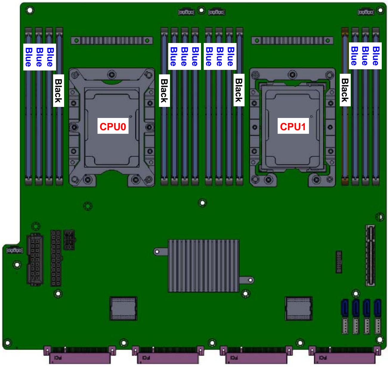
![Blue\nBlue\nBlack\nCPU0\nBlack\nBlue\nBlue\nBlue\nBlack\nCPU1\nBlack\nBlue\nBlue\nBlue\nBlue\nBlue\nBlue\nDd\nDd\nDd\nDd](.csa-7210-50-1z307-1000-10/09d9ac3b93c606f5ca28466ead4488c492afcef222f88f78c959a8fce1b60096.jpg)

# 3.2 BIOS Update

Users can update the CSA-7210 system BIOS over various interfaces (GbE LAN, KCS, console port).

# 3.2.1 Updating the BIOS via Network with BMC Tool

1. Install a Linux distribution, such as Ubuntu 14, to the debug PC.
2. Install “expect” to your debug PC (ex: sudo apt-get install expect).
3. Copy the BMC FW package “BMC\_CSA-7210\_Release\_V1.05” to the debug PC;

# Upgrade Procedure:

1. Check the IP of the BMC of CSA-7210. Power on the CSA-7210, boot the BMC to Linux (username: sysadmin; Passwd: superuser), and type “ifconfig” check its IP address.

```txt
AMI72696679006E login:
AMI72696679006E login: sysadmin
Password:
login[1623]: pam_unix(login:session): session opened for user sysadmin by LOGIN(uid=0)
[1623 INFO]SERIAL Login from IP:127.0.0.1 user:sysadmin

login[1623]: [1623 INFO]SERIAL Login from IP:127.0.0.1 user:sysadmin

login[1623]: root login on 'ttyS4'
~ #
~ #
~ # ifconfig

eth0 Link encap:Ethernet HWaddr 72:69:66:79:00:6E
inet addr:172.20.5.77 Bcast:172.20.5.255 Mask:255.255.255.0
inet0 addr: fe80::1009.66ff:fe79:6e/64 Scope:Link
UP BROADCAST RUNNING MULTICAST MTU:1500 Metric:1
RX packets:191 errors:0 dropped:5 overruns:0 frame:0
TX packets:58 errors:0 dropped:0 overruns:0 carrier:0
collisions:0 txqueuelen:1000
RX bytes:21025 (20.5 KiB) TX bytes:8142 (7.9 KiB)
Interrupt:2

eth1 Link encap:Ethernet HWaddr 01:C0:A8:12:36:57
inet6 addr: fe80::1c0:a800:112:3657/64 Scope:Link
UP BROADCAST RUNNING MULTICAST MTU:1500 Metric:1
RX packets:0 errors:0 dropped:0 overruns:0 frame:0
TX packets:44 errors:0 dropped:0 overruns:0 carrier:0
collisions:0 txqueuelen:1000
RX bytes:0 (0.0 B) TX bytes:10332 (10.0 KiB)
Interrupt:3
```

2. On the debug PC, execute the following commands to perform the upgrade.

cd BMC\_CSA-7210\_Release\_V1.05

cd BIOS

./adlinktool.sh bios1 BIOS\_xxxx.bin 172.20.5.77

# 3.2.2 Updating BIOS via Host with BIOS Tool

1. Boot/Login to Shell
2. Update the BIOS over host with the following commands.

Example:

AfuEfix64 BIOS.ROM /p /b /n /k (to update BIOS without ME) AfuExfi64 BIOS.BIN /p /b /n /k /me (to update the entire BIOS)

```txt
blk5 :Removable BlockDevice - Alias (null)
PciRoot(0x0)/Pci(0x14,0x0)/USB(0x4,0x0)/USB(0x0,0x0)/Unit(0x3)
blk6 :Removable BlockDevice - Alias (null)
PciRoot(0x0)/Pci(0x14,0x0)/USB(0x4,0x0)/USB(0x1,0x0)

Press ESC in 3 seconds to skip startup.nsh, any other key to continue.
Shell> fs0:
fs0:\> cd csa7210_00310

fs0:\CSA7210_00310> dir
Directory of: fs0:\CSA7210_00310

01/10/19 03:51p &lt;DIR&gt; 4,096 .
01/10/19 03:51p &lt;DIR&gt; 0 ..
05/17/17 05:48p 505,968 AfuEfix64.efi
01/10/19 03:54p 401 pBIOS.nsh
01/10/19 03:54p 404 pSPI.nsh
01/10/19 03:56p 33,554,432 CSA-7210_00310.BIN
01/10/19 03:56p 16,777,216 CSA-7210_00310.ROM
5 File(s) 50,838,421 bytes
2 Dir(s)

fs0:\CSA7210_00310>
```

# 3.3 BMC Firmware Update

1. Install a Linux distribution, such as Ubuntu 14, to the debug PC.
2. Install “expect” to your debug PC (ex: sudo apt-get install expect).
3. Copy the BMC FW package “BMC\_CSA-7210\_Release\_V1.05” to the debug PC;

# Upgrade Procedure:

1. Check the IP of the BMC of CSA-7210. Power on the CSA-7210, boot the BMC to Linux (username: sysadmin; Passwd: superuser), and type “ifconfig” check its IP address.

```txt
AMI72696679006E login:
AMI72696679006E login: sysadmin
Password:
login[1623]: pam_unix(login:session): session opened for user sysadmin by LOGIN(uid=0)
[1623 INFO]SERIAL Login from IP:127.0.0.1 user:sysadmin

login[1623]: [1623 INFO]SERIAL Login from IP:127.0.0.1 user:sysadmin

login[1623]: root login on 'ttyS4'
~ #
~ #
~ # ifconfig

eth0 Link encap:Ethernet HWaddr 72:69:66:79:00:6E
inet addr:172.20.5.77 Bcast:172.20.5.255 Mask:255.255.255.0
ineto addr: fe80..1009.66ff:fe79:6e/64 Scope:Link
UP BROADCAST RUNNING MULTICAST MTU:1500 Metric:1
RX packets:191 errors:0 dropped:5 overruns:0 frame:0
TX packets:58 errors:0 dropped:0 overruns:0 carrier:0
collisions:0 txqueuelen:1000
RX bytes:21025 (20.5 KiB) TX bytes:8142 (7.9 KiB)
Interrupt:2

eth1 Link encap:Ethernet HWaddr 01:C0:A8:12:36:57
inet6 addr: fe80::1c0:a800:112:3657/64 Scope:Link
UP BROADCAST RUNNING MULTICAST MTU:1500 Metric:1
RX packets:0 errors:0 dropped:0 overruns:0 frame:0
TX packets:44 errors:0 dropped:0 overruns:0 carrier:0
collisions:0 txqueuelen:1000
RX bytes:0 (0.0 B) TX bytes:10332 (10.0 KiB)
Interrupt:3
```

2. On the debug PC, execute the following commands to perform the upgrade.

cd BMC\_CSA-7210\_Release\_V1.05

cd FW

./adlinktool.sh bmc1 rom.ima 172.20.5.77

# 3.4 Login to the BMC via Serial Console

# Step 1

Set the UART to BMC mode using SW1 on the I/O board.

<table><tr><td>SW1</td><td>Default</td><td>BMC Debug</td></tr><tr><td>TX</td><td>Pins 2-7: ON</td><td>Pins 1-8: ON</td></tr><tr><td>RX</td><td>Pins 4-5: ON</td><td>Pins 3-6: ON</td></tr></table>

# Step 2

Connect the serial cable between CSA-7210 board and PC;

![Two white USB connectors with metallic leads, one connected to a terminal connector (no visible text or symbols)](.csa-7210-50-1z307-1000-10/ea48460d1870de4d9422c8353acbd22bff4fa3e2777ce35f22b96c876b88b7b8.jpg)

![1\n2\n3\n4\n5\n6\n7\n8\n9\n10\n11\n12\n13\n14\n15\n16\n17\n18\n19\n20\n21\n22\n23\n24\n25\n26\n27\n28\n29\n30\n31\n32\n33\n34\n35\n36\n37\n38\n39\n40\n41\n42\n43\n44\n45\n46\n47\n48\n49\n50\n51\n52\n53\n54\n55\n56\n57\n58\n59\n60\n61\n62\n63\n64\n65\n66\n67\n68\n69\n70\n71\n72\n73\n74\n75\n76\n77\n78\n79\n80](.csa-7210-50-1z307-1000-10/1eedaed5e11dc9953a30a99d3628214261a4488077e12981ea3104437a42e436.jpg)

# Step 3

Open a serial port console tool (such as PuTTY), choose the higher numbered COM port (it may be different on different computers, please try both), then set the baud rate to 115200.

![PuTTY Configuration\nCategory:\nSession\nLogging\nTerminal\nKeyboard\nBell\nFeatures\nWindow\nAppearance\nBehaviour\nTranslation\nSelection\nColours\nConnection\nData\nProxy\nTelnet\nRlogin\nSSH\nSerial\nBasic options for your PuTTY session\nSpecify the destination you want to connect to\nSerial line Speed\nCOM3 115200\nConnection type:\nRaw Telnet Rlogin SSH Serial\nLoad, save or delete a stored session\nSaved Sessions\nCOM3\nDefault Settings\n2600T\n2600_CPU_Server\n2610T\n2610T_board\nCOM3\nCSA-7400\nLoad\nSave\nDelete\nClose window on exit:\nAlways Never Only on clean exit\nAbout Help Open Cancel](.csa-7210-50-1z307-1000-10/ac5a44b336806f4f87f64ec96c69eb3b90bc150d1ca075b51742750d55ce6d25.jpg)

# Step 3

Input the user name “sysadmin” and password “superuser” to login to the system.

![AMI00306425F122 login: sysadmin\nPassword:\nlogin(1773): pam_unix(login:account): account sysadmin has password changed in future\nlogin(1773): pam_unix(login:session): session opened for user sysadmin by LOGIN(uid=0)\n(1773 INFO)SERIAL Login from IP:127.0.0.1 user:sysadmin\n\nlogin(1773): (1773 INFO)SERIAL Login from IP:127.0.0.1 user:sysadmin\n\nlogin(1773): root login on 'ttyS4'\n~ #](.csa-7210-50-1z307-1000-10/824faca4b72ea1f4d2ae8a661e5a9d5b3f58e1867fb58e5b4614308154b67924.jpg)

# 3.5 BMC eth0 Default and Static IP Settings

The default IP setting is DHCP. Users can login to the BMC to modify.

# Static IP Settings

Ipmitool -I lan -H 127.0.0.1 -U admin -P admin raw 0x0c 0x01 0x01 0x0 0x1 # start config

Ipmitool -I lan -H 127.0.0.1 -U admin -P admin raw 0x0c 0x01 0x01 0x4 0x1 # set IP to static mode

Ipmitool -I lan -H 127.0.0.1 -U admin -P admin raw 0x0c 0x01 0x01 0x3 0xac 0x14 0x5 0xe8 # set IP, the last four bytes is IP in hex, here is 172.20.5.232

Ipmitool -I lan -H 127.0.0.1 -U admin -P admin raw 0xc 0x1 0x1 0x6 0xff 0xff 0xff 0x0 #Change Mask to 255.255.255.0

Ipmitool -I lan -H 127.0.0.1 -U admin -P admin raw 0x0c 0x01 0x01 0xC 0xac 0x14 0x5 0xfe # set Gateway, the last four bytes, here is 172.20.5.254

Ipmitool -I lan -H 127.0.0.1 -U admin -P admin raw 0x0c 0x01 0x01 0x0 0x0 # set complete DHCP setting:

Ipmitool -I lan -H 127.0.0.1 -U admin -P admin raw 0x0c 0x01 0x01 0x0 0x1 # start config

Ipmitool -I lan -H 127.0.0.1 -U admin -P admin raw 0x0c 0x01 0x01 0x4 0x2 # set IP to DHCP mode

Ipmitool -I lan -H 127.0.0.1 -U admin -P admin raw 0x0c 0x01 0x01 0x0 0x0 # set complete

# 4 System Interfaces

![SPF+\n3.5' Hot-Swap\nDrive Bay\nLEDs\nx2\nRJ-45 x2\nUSB x2\nConsole\nPort](.csa-7210-50-1z307-1000-10/2d3805e3f87e32305c20126e3437dd53384d2211dc745ba365887e75f163eefa.jpg)

# 4.1 Status LEDs

# 4.1.1 HDD LED (yellow)

The HDD LED is controlled by SATALED# from the chipset. When SATA storage is active (read/write), the LED will blink.

# 4.1.2 Power LED (green)

The Power LED will light up in boot up state.

# 4.1.3 Alert LED (red)

The LED will light when a BIOS failure is detected or a sensor reading exceeds its upper/lower un-recoverable threshold.

# 4.2 LAN LEDs

The LAN LEDs are integrated into the RJ-45 connector. Their behavior is as follows.

<table><tr><td colspan="2">LED1 - Left (Speed)</td></tr><tr><td>10 Mbps</td><td>Off</td></tr><tr><td>100 Mbps</td><td>Green</td></tr><tr><td>1000 Mbps</td><td>Orange</td></tr></table>

The LED2 (Link/Activity) indicates that a link has been established by lighting orange. When data is transmitted the LED blinks orange.

<table><tr><td colspan="2">LED2 - Right (Link/Activity)</td></tr><tr><td>Link with no activity</td><td>Orange (steady)</td></tr><tr><td>Link with activity</td><td>Orange (blinking)</td></tr></table>

![Left LED\nRight LED\nA\nB\nC8\nC1\nA](.csa-7210-50-1z307-1000-10/66607a4b40179cd8e9a51d022361435b350e926244c17264a8b5b703fd830060.jpg)

# 4.3 NIM LED Definitions

NIM Service Port Status LED behaviour is as follows.

<table><tr><td>LAN</td><td>LED</td><td>Status</td><td>LED Color</td></tr><tr><td rowspan="5">SFP/SFP+</td><td rowspan="2">Left</td><td>Link up</td><td>Yellow</td></tr><tr><td>Link down</td><td>Off</td></tr><tr><td rowspan="3">Right</td><td>Link with no activity</td><td>Off</td></tr><tr><td>Link with activity</td><td>Green Blinking</td></tr><tr><td>Link down</td><td>Off</td></tr><tr><td rowspan="6">GbE RJ45</td><td rowspan="3">Left</td><td>10 Mbps</td><td>Off</td></tr><tr><td>100 Mbps</td><td>Green</td></tr><tr><td>1000 Mbps</td><td>Yellow</td></tr><tr><td rowspan="3">Right</td><td>Link with no activity</td><td>Green</td></tr><tr><td>Link with activity</td><td>Green blinking</td></tr><tr><td>Link down</td><td>Off</td></tr></table>

# 4.4 SFP+ Ports

<table><tr><td>Pin</td><td>Signal Name</td></tr><tr><td>1</td><td>GND</td></tr><tr><td>2</td><td>TX_FAULT</td></tr><tr><td>3</td><td>TX_DSBL</td></tr><tr><td>4</td><td>SDA</td></tr><tr><td>5</td><td>SCL</td></tr><tr><td>6</td><td>MOD_ABS</td></tr><tr><td>7</td><td>RS0</td></tr><tr><td>8</td><td>RX_,OS</td></tr><tr><td>9</td><td>RS1</td></tr><tr><td>10</td><td>GND</td></tr><tr><td>11</td><td>GND</td></tr><tr><td>12</td><td>RD-</td></tr><tr><td>13</td><td>RD+</td></tr><tr><td>14</td><td>GND</td></tr><tr><td>15</td><td>VCCR</td></tr><tr><td>16</td><td>VCCT</td></tr><tr><td>17</td><td>GND</td></tr><tr><td>18</td><td>TD+</td></tr><tr><td>19</td><td>TD-</td></tr><tr><td>20</td><td>GND</td></tr></table>

![20\n11\n1\n10](.csa-7210-50-1z307-1000-10/059143d9603d6a2c9bda62bc834a98ecf47b3457068328b30ed5eff787cd6706.jpg)

# 4.5 Dual USB 3.0 and RJ-45 Console Port

<table><tr><td>Pin</td><td>Signal Name</td></tr><tr><td>R1</td><td>N/C</td></tr><tr><td>R2</td><td>N/C</td></tr><tr><td>R3</td><td>COM_TXD</td></tr><tr><td>R4</td><td>GND</td></tr><tr><td>R5</td><td>GND</td></tr><tr><td>R6</td><td>COM_RXD</td></tr><tr><td>R7</td><td>N/C</td></tr><tr><td>R8</td><td>N/C</td></tr><tr><td>U1</td><td>5V</td></tr><tr><td>U2</td><td>USB2_N</td></tr><tr><td>U3</td><td>USB2_P</td></tr><tr><td>U4</td><td>GND</td></tr><tr><td>U5</td><td>SSRX_N</td></tr><tr><td>U6</td><td>SSRX_P</td></tr><tr><td>U7</td><td>GND</td></tr><tr><td>U8</td><td>SSTX_N</td></tr><tr><td>U9</td><td>SSTX_P</td></tr><tr><td>U10</td><td>5V</td></tr><tr><td>U11</td><td>USB2_N</td></tr><tr><td>U12</td><td>USB2_P</td></tr><tr><td>U13</td><td>GND</td></tr><tr><td>U14</td><td>SSRX_N</td></tr><tr><td>U15</td><td>SSRX_P</td></tr><tr><td>U16</td><td>GND</td></tr><tr><td>U17</td><td>SSTX_N</td></tr><tr><td>U18</td><td>SSTX_P</td></tr></table>

![R8\nR1\nU18\nU14\nU18\nU14\nU10\nU13\nU9\nU5\nU9\nU5\nU1\nU4](.csa-7210-50-1z307-1000-10/8352482304bfe65bc88f08a9e39a4cce2c8fad4d6e35a37b420c74a054fe4aef.jpg)

The CSA-7210 comes with an RJ-45 to DB-9 console port adapter cable.

![9\n1\nA\n8\nB\nB向](.csa-7210-50-1z307-1000-10/adf29c38e2b742dc0a67d3a13dca9393cbfe473fc8038c986b5a434cc26f6848.jpg)

<table><tr><td>DB-9 Pin</td><td>Signal</td></tr><tr><td>1</td><td>—</td></tr><tr><td>2</td><td>RXD</td></tr><tr><td>3</td><td>TXD</td></tr><tr><td>4</td><td>DTR</td></tr><tr><td>5</td><td>SG</td></tr><tr><td>6</td><td>DSR</td></tr><tr><td>7</td><td>RTS</td></tr><tr><td>8</td><td>CTS</td></tr><tr><td>9</td><td>—</td></tr></table>

# 4.6 Board Layout

![H\nK\nE\nG\nD\nC\nJ\nB\nF\nA](.csa-7210-50-1z307-1000-10/50444ff396228bf17a71a396b5e5d7b73015a2d78cb3bc1cceafe818294d0314.jpg)

<table><tr><td>A</td><td>CPU0</td><td>G</td><td>PCIe x8 slot</td></tr><tr><td>B</td><td>CPU1</td><td>H</td><td>SATA Port</td></tr><tr><td>C</td><td>PCH</td><td>I</td><td>NIM slot</td></tr><tr><td>D</td><td>BMC Chip</td><td>J</td><td>PWR CONN</td></tr><tr><td>E</td><td>CPLD Chip</td><td>K</td><td>B2B for Daughter Board</td></tr><tr><td>F</td><td>DDR4 DIMM</td><td></td><td></td></tr></table>

# 5 LAN Bypass Function

The CSA-7210 is equipped with a LAN Bypass function to allow uninterrupted network traffic in the case of power disruption, system failure, or if a single in-line appliance is shut down or hangs. The default behavior of the LAN Bypass function is determined by BIOS setting.

# 5.1 LAN Bypass Support

The following table outlines the behaviour of the LAN Bypass function when when set On/Off in the BIOS under different power conditions.

<table><tr><td colspan="2">Bypass Setting\Status</td><td>Power On Mode</td><td>Power Off Mode(S5, Standby Power only)</td><td>No AC/DC power with  $1^{st}$  Gen NIM</td><td>No AC/DC power with  $2^{nd}$  Gen NIM</td></tr><tr><td colspan="2">All Bypass Off</td><td>Bypass Off</td><td>Bypass Off</td><td>Bypass On</td><td>Bypass Off</td></tr><tr><td colspan="2">All Bypass On</td><td>On boot Bypass is On for all segments.Control is handed to the BMC as soon as it is ready.</td><td>Bypass On</td><td>Bypass On</td><td>Bypass On</td></tr><tr><td rowspan="2">By Segment</td><td>Bypass On</td><td>On boot Bypass is On.Control is handed to the BMC as soon as it is ready.</td><td>Bypass On</td><td>Bypass On</td><td>Bypass On</td></tr><tr><td>Bypass Off</td><td>On boot Bypass is Off.Control is handed to the BMC as soon as it is ready.</td><td>Bypass Off</td><td>Bypass On</td><td>Bypass Off</td></tr></table>

Table 1. LAN Bypass Support for $1 ^ { \mathsf { s t } }$ and $\pmb { 2 } ^ { \mathsf { n d } }$ generation of NIMs

Note: Check the generation of the installed NIMs and make sure the Error! Reference source not found. on page Error! Bookmark not defined. are correct.

# 5.2 NIM Hardware Description

The CSA-7210 can bypass the LAN port on designated NIMs (CSA-Z4X01, CSA-Z8X10).

(1) Bypass LED (Front Panel)

Yellow: When one or more LAN segment has LAN Bypass is enabled

Off: When all LAN segments LAN Bypass are disabled

(2) CSA-Z4X01 LAN Bypass Port Pairing

LAN Bypass Pair 1: Port 1 & Port 2

LAN Bypass Pair 2: Port 3 & Port 4

(3) CSA-Z8X10 LAN Bypass Port Pairing

![| Speed | Link/ACT |\n|-------|----------|\n| 8     |          |\n| 7     |          |\n| 6     |          |\n| 5     |          |\n| 1     |          |\n| 2     |          |\n| 3     |          |\n| 4     |          |](.csa-7210-50-1z307-1000-10/f1f49ef212f81fb36a5a9e4eaeec43669ce759d1eae9c85de29906ac237b14c9.jpg)

LAN Bypass Pair 1: Port 1 & Port 2

LAN Bypass Pair 2: Port 3 & Port 4

LAN Bypass Pair 3: Port 5 & Port 6

LAN Bypass Pair 4: Port 7 & Port 8

# 5.3 NIM Slot LAN Segmentation

The NIM slot numbers correspond to the LAN segment numbers.

![Slot 1\nSlot 2\nSlot 3\nSlot 4](.csa-7210-50-1z307-1000-10/fa9a76e962f327275a8b8d7eedb342974471e2df20949849c360cd4e8e15b90e.jpg)

# 5.4 NIM Slot PCIe Mapping Table

<table><tr><td>CPU</td><td>NIM Slot</td><td>PCIe Root Port Number</td></tr><tr><td>CPU0</td><td>Slot 1</td><td>2C</td></tr><tr><td>CPU0</td><td>Slot 2</td><td>2A</td></tr><tr><td>CPU1</td><td>Slot 3</td><td>2C</td></tr><tr><td>CPU1</td><td>Slot 4</td><td>2A</td></tr></table>

# Important Safety Instructions

For user safety, please read and follow all instructions, WARNINGS, CAUTIONS, and NOTES marked in this manual and on the associated equipment before handling/operating the equipment.

1. Read these safety instructions carefully.
2. Keep this user’s manual for future reference.
3. Read the specifications section of this manual for detailed information on the operating environment of this equipment.
4. The equipment can be operated at an ambient temperature of $4 0 ^ { \circ } \mathsf { C }$
5. When installing/mounting or uninstalling/removing equipment; or when removal of the chassis lid required for user servicing (Section 3.1-3.5):
• Turn off power and unplug any power cords/cables, and
• Reinstall the chassis lid before restoring power.

![The image displays a standard warning sign featuring a red triangle with a white background and a black exclamation point in the center. Below the triangle, the text 'WARNING:' appears in black, capital letters.](.csa-7210-50-1z307-1000-10/2f103abfe2881e07ad96b4b5fcc7022706a784f5fce827e746e9b889af951360.jpg)
AVERTISSEMENT

Hazardous moving parts. Keep body parts out of the motion path.

6. To avoid electrical shock and/or damage to equipment:

• Keep equipment away from water or liquid sources;
• Keep equipment away from high heat or high humidity;
• Keep equipment properly ventilated (do not block or cover ventilation openings);
• Make sure to use recommended voltage and power source settings;
• Always install and operate equipment near an easily accessible electrical socketoutlet;
• Secure the power cord (do not place any object on/over the power cord);
Only install/attach and operate equipment on stable surfaces and/or recommended mountings;
If the equipment will not be used for long periods of time, turn off and unplug the equipment from its power source.
• The power cord must be connected to a socket or outlet with a ground connection.

7. Never attempt to fix the equipment. Equipment should only be serviced by qualified personnel.

8. A Lithium-type battery may be provided for uninterrupted, backup or emergency power.

![The image displays a standard warning sign featuring a yellow triangle with a black border and a black exclamation point in the center. Below the triangle is the word 'CAUTION:' in black capital letters.](.csa-7210-50-1z307-1000-10/11a8e6151a8a0f7a20fb792e4ef8c98ca763ff69643b89ee7eadca994384ac0d.jpg)

Risk of explosion if battery is replaced with one of an incorrect type. Please dispose of used batteries appropriately.

9. This equipment is not suitable for use in locations where children are likely to be present.

10. Equipment must be serviced by authorized technicians when:

• The power cord or plug is damaged;
Liquid has penetrated the equipment;
• It has been exposed to high humidity/moisture;
• It is not functioning or does not function according to the user’s manual;
• It has been dropped and/or damaged; and/or,
It has an obvious sign of breakage.

11. Please pay strict attention to all warnings and advisories appearing on the device, to avoid injury or damage.
12. The equipment may have more than one power supply input. To reduce the risk of electrical shock, trained personnel should disconnect all power supply inputs before servicing.

![The image shows a yellow triangular warning sign with a black border and a black exclamation point in the center. Below the triangle, the word CAUTION is written in black capital letters.](.csa-7210-50-1z307-1000-10/060dca718f6bf701227257434745bda7ea9e8bfe083311be48ea7321f6acbd13.jpg)

Shock hazard! Disconnect all power supply inputs before servicing.

![The image displays a standard electrical hazard warning sign. It features a yellow triangle with a thick black border. Inside the triangle is a black lightning bolt symbol centered in the middle.](.csa-7210-50-1z307-1000-10/b3a9968540996718a8bc14814106df6756da9f408ebc3fd2681cbdfe308854f2.jpg)
Shock hazard! Risque d'électrocution!

![The image displays a black-and-white schematic line drawing containing several symbolic elements.\n\n*   **Central Element:** A logic gate symbol, specifically an AND gate shape (flat vertical back, curved front) pointing to the right. It has three horizontal input lines entering the left side and three short horizontal lines protruding from the right side of the gate body.\n*   **Left Element:** To the left of the gate inputs, there are two vertical parallel lines.\n*   **Top Elements:** Above the gate, there are three curved lines with arrowheads pointing diagonally up and to the right. To the upper right of these, a larger arrow points horizontally to the right.](.csa-7210-50-1z307-1000-10/644ecd053cfb8a9796948b827e47aa0d8dd85cc23ad4f9b8c8e168370a3b770c.jpg)
Multiple power sources Sources d'alimentation multiples

13. It is recommended that equipment be installed only in a server room or computer room where access is:

Restricted to qualified service personnel or users familiar with restrictions applied to the location, reasons therefor, and any precautions required;
Only afforded by the use of a tool or lock and key, or other means of security, and is controlled by the authority responsible for the location.

14. Suitable for installation in Information Technology Rooms in accordance with Article 645 of the National Electrical Code and NFPA 75.

# Consignes de Sécurité Importantes

Pour assurer la sécurité de l’utilisateur, veuillez lire et suivre toutes les directives, ainsi que les AVERTISSEMENTS, MISES EN GARDE et REMARQUES de ce manuel et indiqués sur l’équipement associé avant de manipuler ou utiliser l’équipement.

1. Veuillez lire attentivement ces instructions de sécurité avec soin.
2. Veuillez conserver ce manuel pour référence future.
3. Veuillez lire la section des spécifications de ce manuel pour avoir des informations détaillées sur l’environnement d’exploitation de cet équipement.
4. L’équipement peut être utilisé à une température ambiante de $4 0 \ ^ { \circ } \mathsf { C } .$ .
5. Lors de l’installation ou du montage et de la désinstallation ou de la dépose de l’équipement; ou lors de la dépose du couvercle du châssis pour procéder à l’entretien par l’utilisateur (Sections 3.1-3.5):

• Coupez l’alimentation et débranchez les cordons et les câbles d’alimentation, et
• Reposez le couvercle du châssis avant de remettre l’alimentation.

![This image features a standard safety warning symbol. It consists of a dark red triangle containing a white exclamation mark. Directly below the triangle is the text 'WARNING:' printed in black, capital letters.](.csa-7210-50-1z307-1000-10/85157687cbe6978906ceb290b50fe3064675a54a9f0bc2a607554ac389e1ceda.jpg)

Pièces mobiles dangereuses. Gardez les parties du corps hors de la trajectoire.

6. Pour éviter un risque d’électrocution et pour éviter d’endommager l’équipement :

• Éloignez l’équipement de l’eau et de toute source liquide;
• Éloignez l’équipement de toute source de chaleur ou d’humidité élevée;
Gardez l’équipement correctement ventilé (ne pas bloquer ou couvrir les ouvertures de ventilation);
Veillez à utiliser la tension recommandée et les réglages adéquats pour la source d’alimentation;
• Veuillez toujours installer et exploiter l’équipement à proximité d’une prise de courant facilement accessible;
Assurez-vous que le cordon d’alimentation est acheminé de manière sécuritaire (ne déposez aucun objet dessus);
Installez, fixez et utilisez l’équipement sur des surfaces stables ou sur les fixations recommandées uniquement;
Si l’équipement n’est pas utilisé pendant une longue période, éteignez-le et débranchez-le de sa source d’alimentation.
• Le cordon d'alimentation doit être connecté à une prise ou à une prise de courant avec mise à la terre.

7. N’essayez jamais de réparer l’équipement. L’équipement ne doit être réparé que par du personnel qualifié.

8. Une pile au lithium peut être installée pour assurer l’alimentation de secours ou d’urgence en continu.

![The image shows a yellow triangular warning sign with a black border. Inside the triangle is a black exclamation point. Below the triangle, the text 'CAUTION:' appears in black capital letters.](.csa-7210-50-1z307-1000-10/107f7cd040f6e4377e130db9b8373c7313af9bb90b631167065efe082f910b8e.jpg)

Risque d'explosion si la batterie est remplacée par une batterie d'un type incorrect. Veuillez éliminer les piles usagées de manière appropriée.

9. Cet équipement ne convient pas à une utilisation dans des lieux pouvant accueillir des enfants.
10. L’équipement doit être entretenu par des techniciens agréés lorsque :

• le cordon d’alimentation est endommagé ou lorsque la fiche électrique est endommagée;
• du liquide a pénétré à l’intérieur de l’équipement;
• l’équipement a été exposé à un taux d’humidité élevé;
• l’équipement ne fonctionne pas ou ne fonctionne pas conformément au manuel de l’utilisateur;
• l’équipement est tombé ou lorsqu’il a été endommagé;
• l’équipement présente un signe évident de défaillance.

11. Veuillez porter une attention rigoureuse à tous les avertissements et à tous les avis figurant sur l’appareil, pour éviter des blessures ou des dommages.

12. L’équipement peut avoir plus d’une entrée d’alimentation. Pour réduire le risque d’électrocution, le personnel qualifié devrait déconnecter toutes les entrées d’alimentation avant de procéder à l’entretien.

![The image displays a yellow triangular warning sign with a black border. Centered inside the yellow triangle is a large, black exclamation point. The symbol is set against a white background, framed by a black horizontal line running across the top and another black horizontal line running across the bottom.](.csa-7210-50-1z307-1000-10/2301bd000c0fbdd40cd96a4a382d5354ee0e9552769ba540e61070a45eeb415f.jpg)
CAUTION:

Risque d'électrocution! Débranchez toutes les entrées d'alimentation avant de procéder à l'entretien.

![The image displays a yellow triangular warning sign with a thick black border. Inside the triangle is a black lightning bolt symbol in the center. There is no text.](.csa-7210-50-1z307-1000-10/cd45df2d324ebbfb0b6ecbe9ce6c87d8e6b104d2177318c2f2e96df7537a243c.jpg)
Shock hazard!
Risque d'électrocution!

![The image displays a schematic symbol, likely for a logic gate or buffer.\n\n*   **Central Shape:** A triangle pointing to the right.\n*   **Internal Lines:** Inside the triangle, near the left base, there are three short horizontal lines stacked vertically.\n*   **Right Side:** Extending to the right from the upper right side of the triangle are three short horizontal lines stacked vertically.\n*   **Left Side:** Three vertical lines enter the left base of the triangle. To the left of these input lines, there are two additional vertical lines.\n*   **Top Right:** A large arrow pointing to the right is positioned above the right-side horizontal lines.](.csa-7210-50-1z307-1000-10/b3094b5cdd3c75d3adeffc163f4c35aa8f4859d304e40691df8967e8a9c2508e.jpg)
Multiple power sources
Sources d'alimentation multiples

13. Il est recommandé que l'équipement soit installé que dans une salle de serveur ou de la salle informatique où:

L'accès est limité au personnel de maintenance qualifié ou utilisateurs familiers avec les restrictions appliquées à l'emplacement, motifs, et tout les précautions nécessaires, et;
• L'accès est uniquement assurée par l'utilisation d'un outil ou clé, ou d'autres moyens de sécurité, et est contrôlé par l'autorité responsable de l'emplacement.

14. Peut être installé dans des salles de matériel de traitement de l’information conformément à l’article 645 du National Electrical Code et à la NFPA 75.

# Getting Service

Ask an Expert: http://askanexpert.adlinktech.com

# ADLINK Technology, Inc.

Address: 9F, No.166 Jian Yi Road, Zhonghe District

New Taipei City 235, Taiwan

新北市中和區建一路 166 號 9 樓

Tel: +886-2-8226-5877

Fax: +886-2-8226-5717

Email: service@adlinktech.com

# Ampro ADLINK Technology, Inc.

Address: 5215 Hellyer Avenue, #110, San Jose, CA 95138, USA

Tel: +1-408-360-0200

Toll Free: +1-800-966-5200 (USA only)

Fax: +1-408-360-0222

Email: info@adlinktech.com

# ADLINK Technology (China) Co., Ltd.

Address: 上海市浦东新区张江高科技园区芳春路 300 号 (201203)

300 Fang Chun Rd., Zhangjiang Hi-Tech Park, Pudong New Area

Shanghai, 201203 China

Tel: +86-21-5132-8988

Fax: +86-21-5132-3588

Email: market@adlinktech.com

# ADLINK Technology GmbH

Address: Hans-Thoma-Strasse 11, D-68163, Mannheim, Germany

Tel: +49-621-43214-0

Fax: +49-621 43214-30

Email: emea@adlinktech.com

Please visit the Contact page at www.adlinktech.com for information on how to contact the ADLINK regional office nearest you.
[🔗 Link to the original document](.csa-7210-50-1z307-1000-10/csa-7210-50-1z307-1000-10.pdf)
