# CSA-7400

4U Rackmount Network Appliance with Dual Intel® Xeon® Processor CPU Sleds & Intel® Ethernet Multi-Host Controller Switch Sleds

# User’s Manual

![Front view of a server rack with multiple drive bays and network ports (no visible text or labels)](.csa-7400-50-1z240-2010-11/f629c154a85442fe5599189791cca6236d3c5cf68e53246d7d2af481c6aad90c.jpg)

Manual Revision: 1.1

Revision Date: October 23, 2018

Part No.: 50-1Z240-2010

# Preface

# Copyright 2018 ADLINK Technology, Inc.

This document contains proprietary information protected by copyright. All rights are reserved. No part of this manual may be reproduced by any mechanical, electronic, or other means in any form without prior written permission of the manufacturer.

# Disclaimer

The information in this document is subject to change without prior notice in order to improve reliability, design, and function and does not represent a commitment on the part of the manufacturer.

In no event will the manufacturer be liable for direct, indirect, special, incidental, or consequential damages arising out of the use or inability to use the product or documentation, even if advised of the possibility of such damages.

# Environmental Responsibility

ADLINK is committed to fulfill its social responsibility to global environmental preservation through compliance with the European Union's Restriction of Hazardous Substances (RoHS) directive and Waste Electrical and Electronic Equipment (WEEE) directive.

Environmental protection is a top priority for ADLINK. We have enforced measures to ensure that our products, manufacturing processes, components, and raw materials have as little impact on the environment as possible. When products are at their end of life, our customers are

encouraged to dispose of them in accordance with the product disposal and/or recovery programs prescribed by their nation or company.

![Simple line drawing of a trash bin with two crossed lines indicating no waste or prohibition (no text or symbols)](.csa-7400-50-1z240-2010-11/cc3ecac2cfb1e15aa8981e84c451f0c3bcb928b4399b9aaaa2ff5873807ef8ae.jpg)

![The image displays a graphic composed of three horizontal sections. There is a thin white horizontal band at the top, followed by a large, solid black rectangular block in the center, and another thin white horizontal band at the bottom.](.csa-7400-50-1z240-2010-11/ee882e8e033751da103077b9c9fe2f282f84bbd8ec661b3ac78f2d7ac7cfac91.jpg)

Battery Labels (for products with battery)

![Simple line drawing of a trash bin with two crossed lines (no text or symbols)](.csa-7400-50-1z240-2010-11/ca3c9329062c772affad0481739cfa56014f23de824f8f2b33114b26983c81d8.jpg)

![Li-ion](.csa-7400-50-1z240-2010-11/c50ea2f3f3aa5ea42501c8ab694f7d26a003d1a76f0cfe5d2263a0a165b76df0.jpg)

![RECYCLF\nRBRC\nLi-ion\n7.800.822.8837](.csa-7400-50-1z240-2010-11/d47ba8e25df2356659125c3c27e4395ecb9a76df68e540875d4441d8af373678.jpg)

![廢電池請回收](.csa-7400-50-1z240-2010-11/95ebaff31d2253f0fb5d990d27ae2ceff2245ba22f46af18be89f85728bf1041.jpg)

# California Proposition 65 Warning

![This image displays a standard warning sign featuring a yellow triangle with a thick black border. Inside the triangle, centered, is a black exclamation point. The sign is set against a plain white background.](.csa-7400-50-1z240-2010-11/c9f043ac851d1532e921641343adb1d16de9658b82f716ac89ae67300783083e.jpg)

WARNING: This product can expose you to chemicals including acrylamide, arsenic, benzene, cadmium, Tris(1,3-dichloro-2-propyl)phosphate (TDCPP), 1,4- Dioxane, formaldehyde, lead, DEHP, styrene, DINP, BBP, PVC, and vinyl materials, which are known to the State of California to cause cancer, and acrylamide, benzene, cadmium, lead, mercury, phthalates, toluene, DEHP, DIDP, DnHP, DBP, BBP, PVC, and vinyl materials, which are known to the State of California to cause birth defects or other reproductive harm. For more information go to www.P65Warnings.ca.gov.

# Trademarks

Product names mentioned herein are used for identification purposes only and may be trademarks and/or registered trademarks of their respective companies.

Revision History

<table><tr><td>Revision</td><td>Release Date</td><td>Description of Change(s)</td></tr><tr><td>1.0</td><td>2018-03-22</td><td>Initial release</td></tr><tr><td>1.1</td><td>2018-10-23</td><td>Move CPU and switch sled content to separate manuals; add rackmount warnings</td></tr></table>

# Table of Contents

# Preface ....

# Table of Contents...

# 1 Overview ....

1.1 Introduction .. . 5
1.2 CSA-7400 System Architecture .. . 6
1.3 CSA-7400 Mechanical Overview ... . 8

1.3.1 Front Panel.. .8
1.3.2 Rear Panel .. ...8

1.4 CSA-7400 Mechanical Dimensions . . 9
1.5 Package Contents.. . 10

# 2 Specifications .... ..11

2.1 Chassis Module List.. ..11
2.2 Fan Modules .. ..11
2.3 PSU Modules.. ..11
2.4 Environmental. . 12

# 3 Assembling and powering up CSA-7400.... . 13

3.1 Inserting and Removing the CPU Sled .. .. 13
3.2 Inserting and Removing the Switch Sled .. .. 17
3.3 Routing the VGA Cable on switch sled . . 19
3.4 Connecting Power Cords to the CSA-7400 .. .. 20
3.5 Powering Up the CSA-7400.. . 20

# 4 Maintenance...................... . 21

4.1 Hot-Swapping the CPU Sled.. .. 21
4.2 Hot-Swapping the Switch Sled.. . 21
4.3 Removing and Replacing a Fan Module. . 22
4.4 Removing and Replacing a PSU . . 23

# 5 Remote Management via CMM.. . 24

5.1 IPMI Topology .... . 25
5.2 Configuring the CMM IP Address.. . 26
5.3 Using IPMItool... . 31
5.4 Using the Web UI.. 32
5.5 Updating the CMM Firmware.. . 39

# Safety Instructions .... 42

# Consignes de Sécurité Importantes ................ .. 44

# Getting Service ...................... ................. 46

# 1 Overview

# 1.1 Introduction

The ADLINK CSA-7400 is a high-performance high-density computing platform supporting four dual Intel® Xeon® Processor E5 CPU sleds or dual Intel® Xeon® Scalable Processor CPU sleds, interconnected by dual redundant switch sleds. The CSA-7400 can ensure uninterrupted service delivery through hot-swappable CPU and switch sleds. It is ideally suited for building next generation high-performance firewalls and virtualized telecom elements.

The main features of the CSA-7400 are summarized as follows:

Supports four single-system dual Xeon® Processor E5 CPU sleds (MCN-2600T) or dual Intel® Xeon® Scalable Processor CPU sleds (MCN-2610T)
Dual redundant switch sleds provide up to 2x 50G data plane links to each CPU sled, and 360G (MXN-3610) or 400G (MXN-4100) uplinks
Independent 1G control plane links that connect four CPU sleds, two switch management CPUs (implemented by COM Express modules) and two Chassis Management Modules (CMM)
• Supports IPMI 2.0 specification, provides web-based intelligent system management, and supports SOL on compute nodes
• Four redundant hot-swappable power supply units provide active power management on compute nodes and support flexible power limit polices
• Integrates ADLINK PacketManager software to provide common Layer 2 and Layer 3 switch stacks, RPC interface, CLI.
Optionally integrates Wind River® Titanium Server or OPNFV software to provide carrier grade NFV service

# 1.2 System Architecture

![Flowchart](.csa-7400-50-1z240-2010-11/153ecb45d223e83964023ee244328ae703736f5ff663a3e8147b959c94557b53.jpg)

![This diagram illustrates a network architecture with four identical processing blocks on the left connected to two switching blocks on the right.\n\n**Labeled Blocks:**\n*   **Left Side:** Four rectangular areas labeled **Mid-Left**, **Bottom-Left**, **Mid-Right**, and **Bottom-Right**. Each contains the text **MCN-2600T/MCN-2610T**, an orange box labeled **CPU1**, and an orange box labeled **CPU0**.\n*   **Right Side:** Two rectangular areas labeled **Top-Left** and **Top-Right**. Each contains a vertical orange box labeled **VSC7512 1G Switch**, two smaller orange boxes labeled **CMM** and **COME**, and the text **MXN-3610/MXN-4100**.\n\n**Connections:**\n*   **Internal Connections (Left):** In each of the four left blocks (**Mid-Left**, **Bottom-Left**, **Mid-Right**, **Bottom-Right**), a red line connects **CPU1** to **CPU0**.\n*   **Internal Connections (Right):** In both the **Top-Left** and **Top-Right** blocks, blue lines connect the **VSC7512 1G Switch** to the **CMM** and **COME** boxes.\n*   **Inter-Block Connections:** Blue lines, labeled at the bottom as **1G (Control Plane)**, connect each **CPU0** block from the left side to both the **Top-Left** and **Top-Right** switch blocks. Specifically, every **CPU0** has connections routing to the **VSC7512 1G Switch** in the **Top-Left** block and the **VSC7512 1G Switch** in the **Top-Right** block.](.csa-7400-50-1z240-2010-11/dfa12255a221759b0760e1edf37f16f961f16540d8c42ec5fdfd67eb31972731.jpg)

CSA-7400 includes four CPU sleds (MCN-2600T or MCN-2610T) and two switch sleds (MXN-3610 or MXN-4100). Each CPU sled has two PCIe x8 Gen3 interfaces (providing up to 2x50G Ethernet bandwidth) that are routed to two switch sleds, respectively.

Each switch sled is connected to four CPU sleds via four PCIe x8 Gen3 interfaces, and they provide a maximum of 36x10G or 4x100G Ethernet ports for external communication. Of the 36x10G Ethernet ports, 20x10G are provided on the MXN-3610 front panel directly, and the other 16x10G Ethernet ports are provided via a NIM-1610 switch IO card. Alternatively, the NIM-1610 can be replaced with a NIM-0440 providing 4x40G Ethernet ports.

In addition, there is a Microsemi® VSC7512 GbE switch on the MXN-3610/MXN-4100 switch sleds to provide an independent 1G control plane between the four compute switch sleds, as well as two switch management COMe modules and two CMMs.

# 1.3 Mechanical Overview

# 1.3.1 Front Panel

![MXN-3610/MXN-4100\nNIM-1610/NIM-0440\nMCN-2600T/MCN-2610T](.csa-7400-50-1z240-2010-11/aa71990312aa46947bcaf1f93128dc69a08304b0605090f1fff0c82a45e406ca.jpg)

# 1.3.2 Rear Panel

![N+1 PSU\nFan Modules](.csa-7400-50-1z240-2010-11/5f50b3f25e98fc2cc64b43918acf92db660228a1066a8afeb69d09542a9b33d7.jpg)

# 1.4 Mechanical Dimensions

![| Dimension | Value |\n| --------- | ----- |\n| Width     | 21    |\n| Height    | 599   |\n| Width     | 31.06 |\n| Height    | 482.60 |\n| Width     | 437.80 |](.csa-7400-50-1z240-2010-11/b723b2c3d0f46967412c69b5d3e70f4ec61db4326a12c2586fad25092b832df7.jpg)

![Technical line drawing of a vertical panel with mounting holes and dimension label (174.30), no readable text or symbols beyond measurement markers.](.csa-7400-50-1z240-2010-11/a490f9b7767144593d5144b58409909f83d06c6d78955dd863edc2297da80175.jpg)

Dimensions in mm

# 1.5 Package Contents

Before opening, please check the shipping carton for any damage. If the shipping carton and contents are damaged, notify the dealer for a replacement. Retain the shipping carton and packing material for inspection by the dealer. Obtain authorization before returning any product to ADLINK.

Check that the following items are included in the package. If there are any missing items, contact your dealer:

• CSA-7400 Rackmount Network Appliance
Package check list
USB console cable
• VGA cable for switch sled

# 2 Specifications

# 2.1 Chassis Module List

The CSA-7400 chassis include the following field replaceable units.

• 3 x Fan Modules (hot-swappable)
• 4 x Power Supply Units (hot-swappable)

# 2.2 Fan Modules

There are three hot-swappable fan modules on the CSA-7400. Fan speed is intelligently controlled by the chassis management module (CMM), which adjusts the speed of the fan based on real-time thermal conditions.

# 2.3 PSU Modules

The CSA-7400 features 3+1 redundant power, and supports hot-swappable power supply modules.

850W, 100-240V AC @0-60Hz
850W, 190-310V DC

2.4 Environmental

<table><tr><td>Temperature</td><td>Operating: 0°C to +40°CStorage: -40°C to+70°CShort term operating: -5°C to +45°C, 5%-90% RH</td></tr><tr><td>Humidity</td><td>10%-85% RH@40°C, non-condensingNon-operating: 5%-90% RH</td></tr><tr><td>Shock</td><td>Operating: Half-sine 2G, 11ms pulse, 100 pulses in each directionNon-operating: Trapezoidal, 25G, 170 inches/sec delta V, three drops in each direction</td></tr><tr><td>Vibration</td><td>Non-operating Vibration: 2.2Grms, 10 minutes per axis in each direction</td></tr><tr><td>Acoustic</td><td>Acoustic Sound pressure &lt; 75 dBA @1m with all fans maximum speed</td></tr><tr><td>Regulatory</td><td>Regulatory NEBS Level 3 compliance (design), FCC Class A, CE emission, UL, CB, CCC and RoHS compliant</td></tr><tr><td>MTBF</td><td>90,000 hours</td></tr></table>

# 3 Assembling and Powering Up the CSA-7400

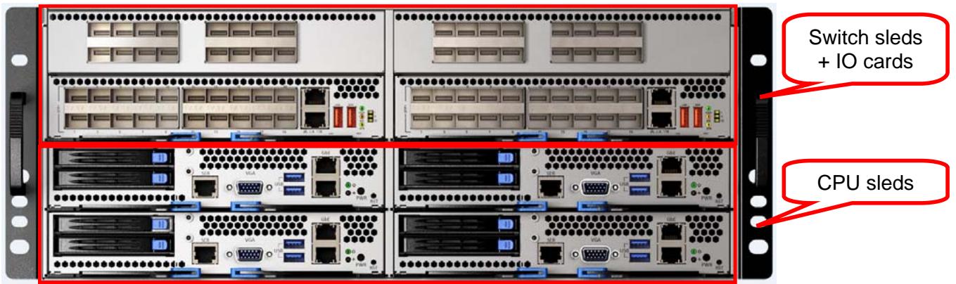
Insert the MXN-3610/4100 (switch sleds) and MCN-2600T/2610T (CPU nodes) into the chassis as follows.
![Switch sleds\n+ IO cards\nCPU sleds](.csa-7400-50-1z240-2010-11/882455c20923b00500e67fd1422de2e41a1fb92d9a07dc72fe5c86bbe23ccad6.jpg)

# 3.1 Inserting and Removing the CPU Sled

Insert the CPU sleds into the 4 slots in lower 2 layers.

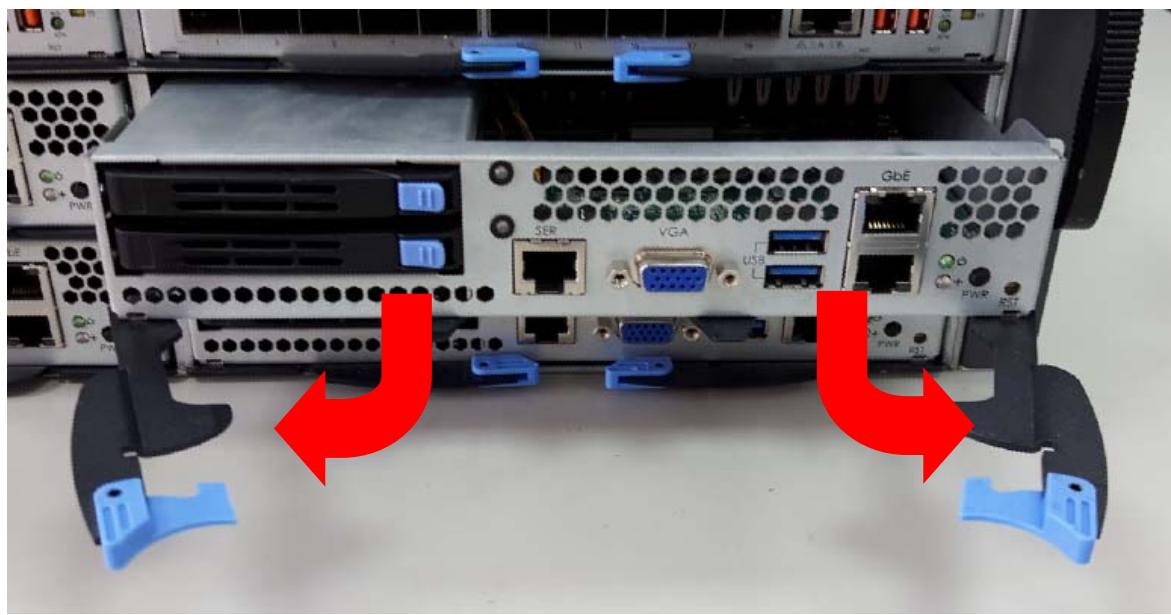
1. Insert the CPU sled into one of the lower 4 slots and open the ejector handles as shown.
![Front view of a server rack with labeled ports and connectors, showing red arrows pointing to ports without any readable text or symbols.](.csa-7400-50-1z240-2010-11/ed29732ed724262492af2ff583720253b3f80556e6a360884fbc4623d477d6bc.jpg)

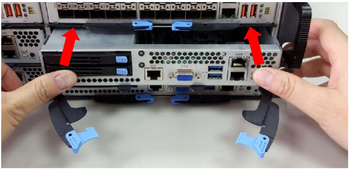
2. Push the CPU sled into the slot until the front panel is flush with the chassis.
![Close-up of hands installing or adjusting a server rack with labeled ports and connectors (no readable text or symbols)](.csa-7400-50-1z240-2010-11/c868a6bd0fe8f4f0ae4c09d573aed8c277b1675648d4adeda9ca97c57e150ebb.jpg)

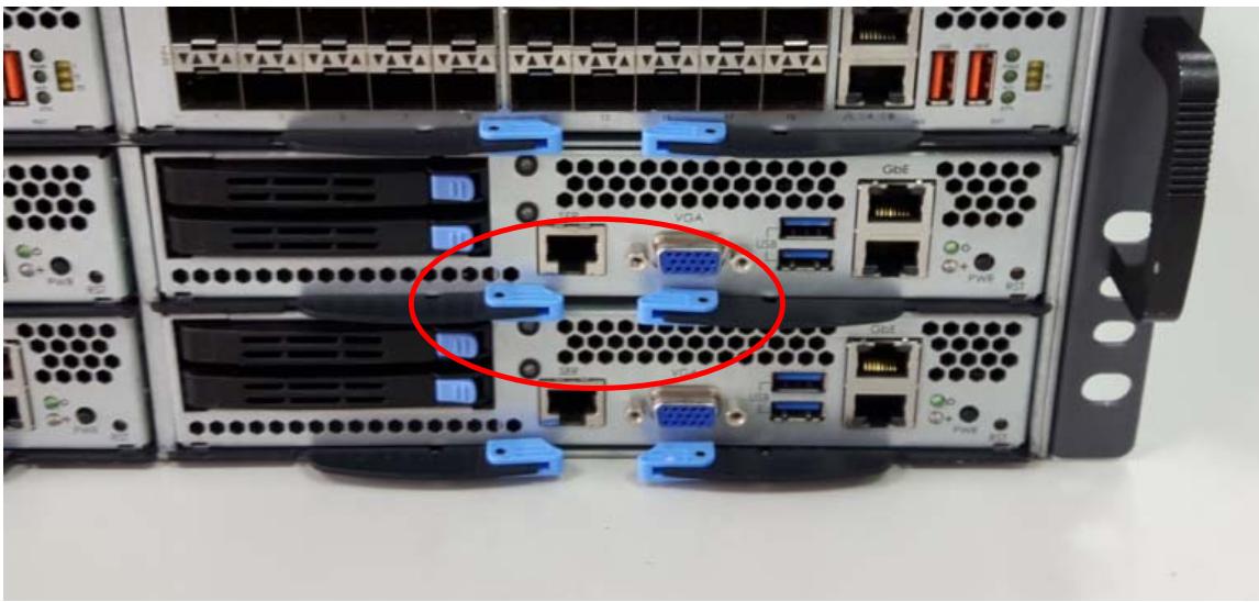
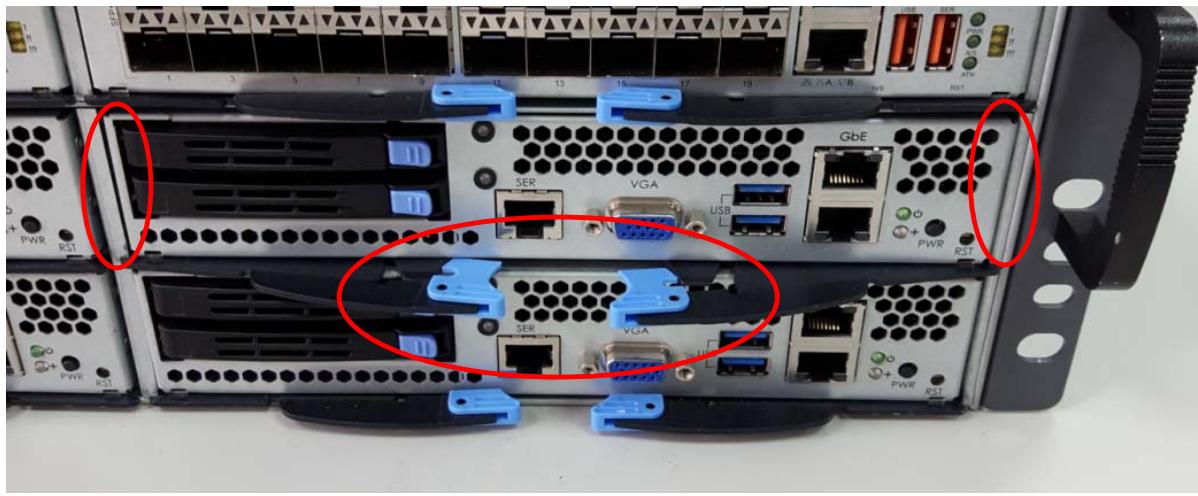
3. When the CPU sled is fully inserted into the chassis, the locking handles will be pulled into the closed position and the front panel will be flush with the chassis.
![Internal view of a server rack with labeled ports and connectors, highlighting two red circles for emphasis points.](.csa-7400-50-1z240-2010-11/fae485b787b22f3c2c17798977ff6e68eb8ea5126954bf8f2404e91f4a9933c5.jpg)

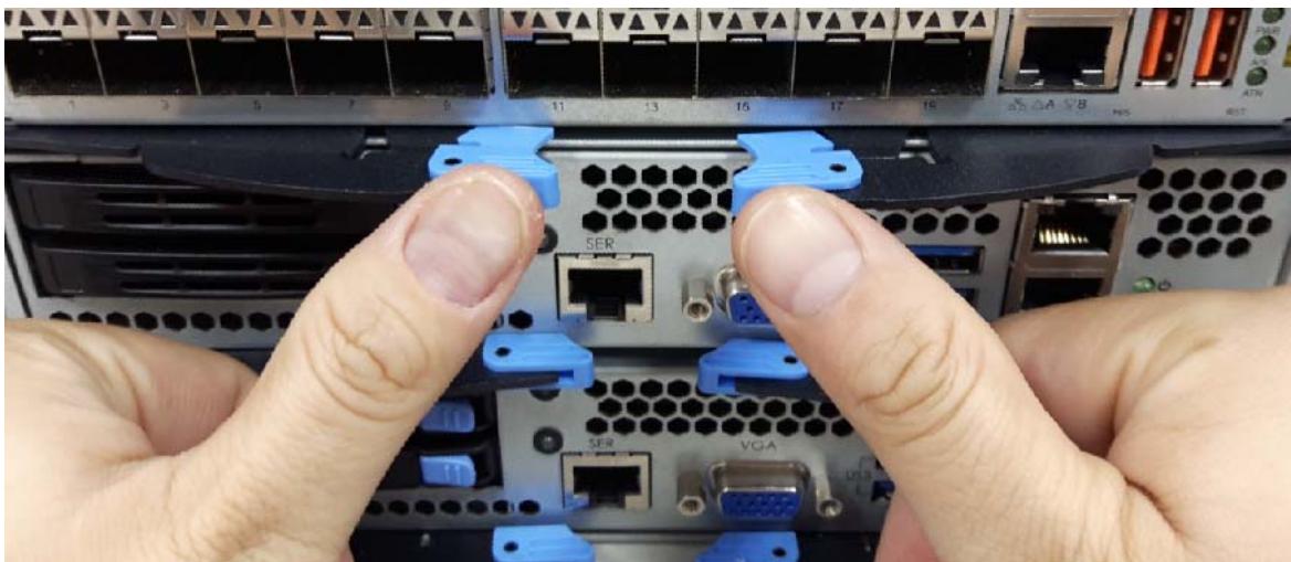
4. Press inwards on the ejector handles until they lock into place. You will hear a “click”.
![Close-up of hands installing a server rack with labeled ports (SER, VGA) and connectors (no readable text beyond labels)](.csa-7400-50-1z240-2010-11/bbd65c4aa47e95a04b48f804ca5b3e471a0beb8b9bd7d5a00af565d713778cb2.jpg)

![Back view of a server rack with multiple ports, connectors, and a highlighted VGA port (no readable text or symbols)](.csa-7400-50-1z240-2010-11/7604f838fcfaf34e7ffbab4577fa99905473f32a6ca40072090ca821ca0177c2.jpg)

# To remove a CPU sled:

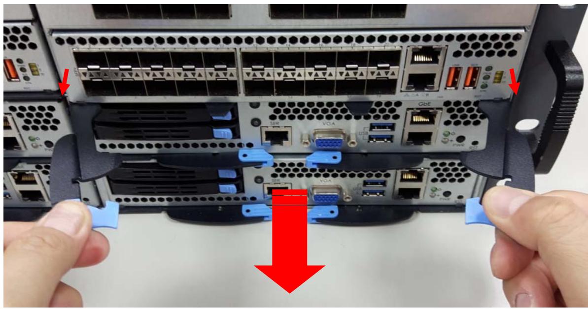
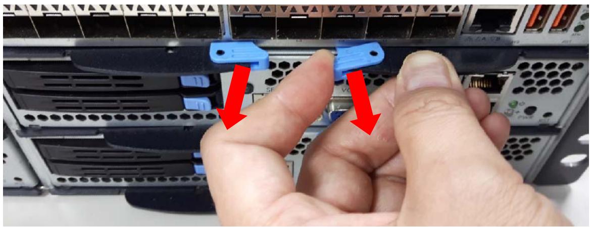
1. Pull outwards to release the locking latch of each ejector handle as shown.
![Close-up of hands installing a blue USB drive component on server racks, with red arrows indicating the process (no text or symbols visible)](.csa-7400-50-1z240-2010-11/da88500a076dccba8ba4ee712010cd0794fc91bb60bf94ca957f8de311b0ceba.jpg)

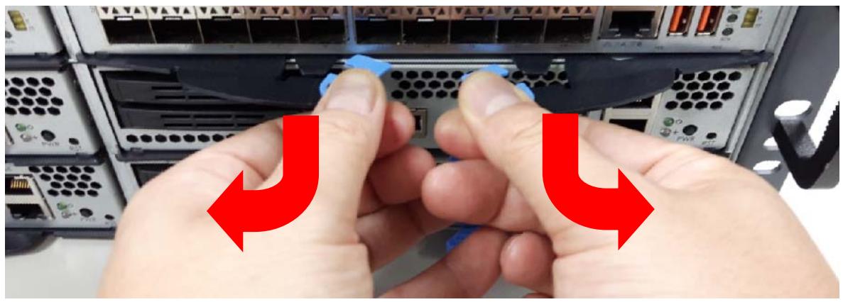
2. Pull outwards on the ejector handles as shown to eject the CPU sled from the chassis.
![Close-up of hands installing a USB port into a server rack, with red arrows indicating the process (no text or symbols present)](.csa-7400-50-1z240-2010-11/685f3c63f176e854345ad48b573cf69fcc6f8e41cc2bbe3a654b02025a4eeec2.jpg)

![Close-up of a server rack with labeled ports and connectors, showing hands holding blue plastic clips (no readable text or symbols)](.csa-7400-50-1z240-2010-11/006ad1b860e15bb281551752fd9b4c734104c2d67dbdd97bd8aec9c103d7025b.jpg)

3. Pull back on the ejector handles to remove the CPU sled from the chassis.

# 3.2 Inserting and Removing the Switch Sled

Insert the Switch sleds into the 2 slots in upper 2 layers.

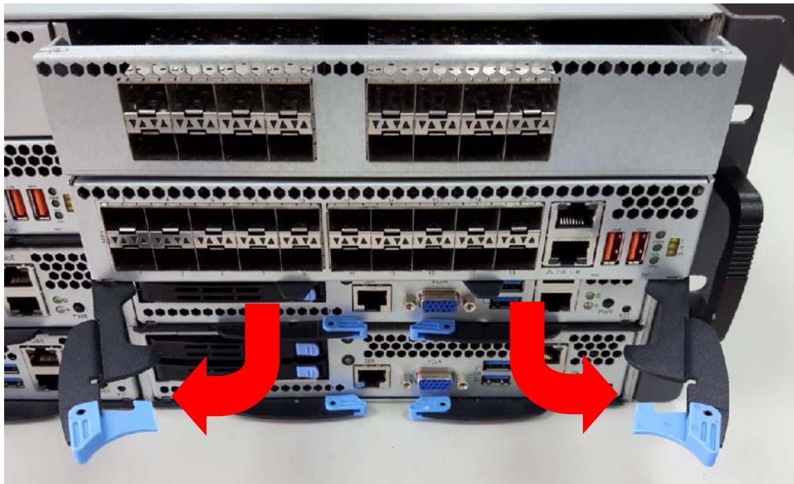
1. Insert the Switch sled into one of the upper 2 slots and open the ejector handles as shown.
![Back view of a server rack with multiple Ethernet ports and connectors, showing red arrows indicating internal connections (no text or symbols present)](.csa-7400-50-1z240-2010-11/c207ff9d68e2bd2d798abad475bdb1a7aef65b4113904dd80ce4cbcfe229019d.jpg)

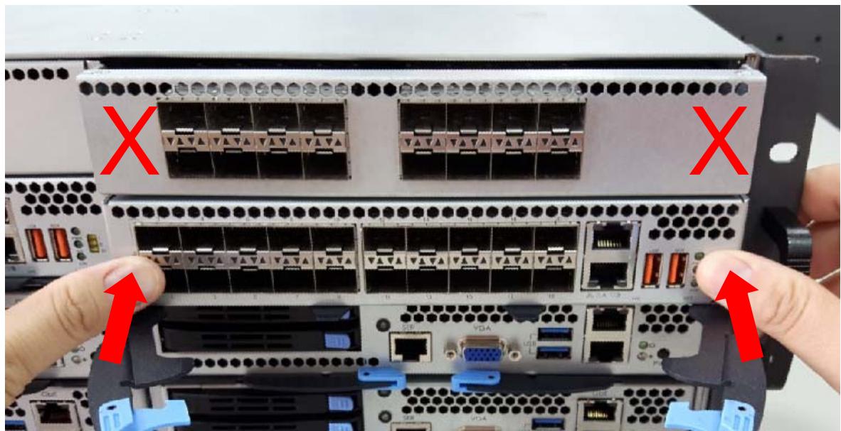
2. Push the Switch sled into the slot by pressing on the front panel of the Switch until the front panel is flush with the chassis.

Caution: Do NOT press on the front panel of the IO card. Doing so may cause damage to the Switch and IO card.
![Close-up of server rack with multiple Ethernet ports and connectors, showing red X marks indicating status or connection points (no readable text or symbols)](.csa-7400-50-1z240-2010-11/c26d7ee5b89b14300b43a37d325ce5db730962b4f1c36bbf7b9482c47dc1cb7b.jpg)

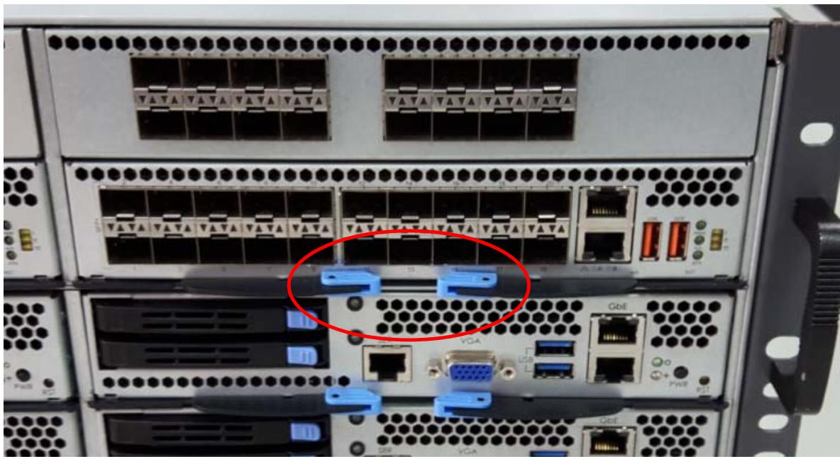
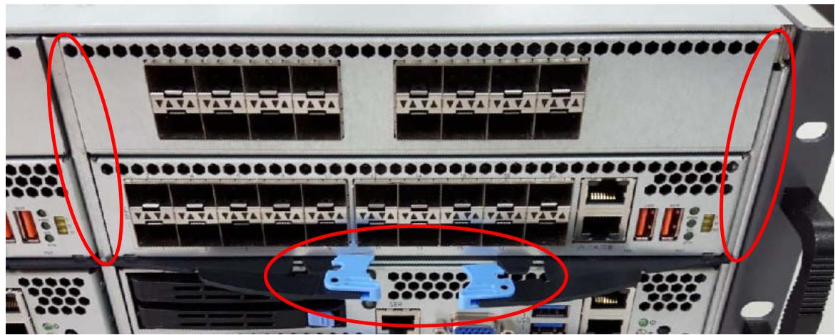
3. When the Switch sled is fully inserted into the chassis, the locking handles will be pulled into the closed position and the front panel will be flush with the chassis.
![Front view of a server rack with multiple Ethernet ports and connectors, highlighted by red circles (no text or symbols visible)](.csa-7400-50-1z240-2010-11/ea96b5ff6b9cf391ae51a2466ab348090e843e045744ff9cb10bf29333985660.jpg)

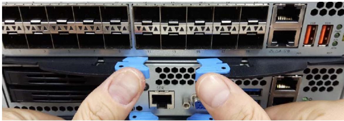
4. Press inwards on the ejector handles until they lock into place. You will hear a click.
![Close-up of hands installing a server rack with network ports and connectors (no visible text or symbols)](.csa-7400-50-1z240-2010-11/a6d81fc2ec4bcb23d7e419a4de8094312a72330762ead89bc60e86b5b6b61903.jpg)

![Front view of a server rack with multiple Ethernet ports, connectors, and I/O ports (no readable text or symbols)](.csa-7400-50-1z240-2010-11/b98d291eb904d7d442570b4aa9611d5b7ab64dcf567f1389e58e88215e0e13cd.jpg)

# To remove a CPU sled:

Follow the instructions above for removing a CPU sled.

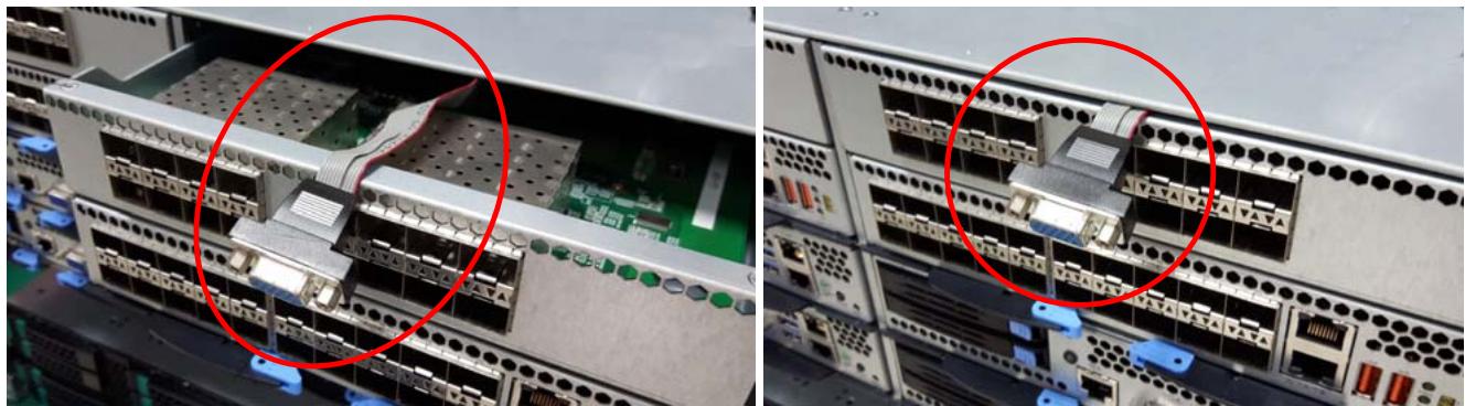
# 3.3 Routing the VGA Cable on Switch Sled

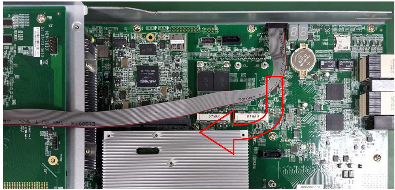
Note: If you are using the MXN-3610/4100 with VGA cable connected, route the VGA cable as shown below. Refer to the MXN-3610/4100 user’s manual for instruction on how to connect the VGA cable to the switch board.
![67MA3\n67MA8\n1000200-A3D](.csa-7400-50-1z240-2010-11/93aa1bfaedc2f3922bf6a1cd3b40f6e2c09c39784d9b7f82540853e1db071073.jpg)

![Close-up of a server rack with visible network ports and circuit board, showing two red-circled zones of internal components (no text or symbols present)](.csa-7400-50-1z240-2010-11/2d4c8e521e768ad1ce05633a324da226dd57333315e3335586097053e34f637a.jpg)

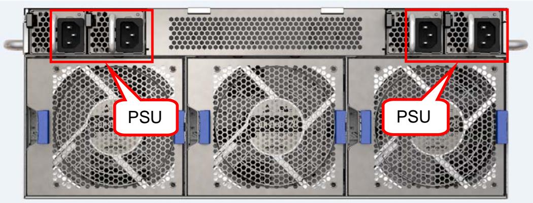
# 3.4 Connecting Power Cords to the CSA-7400

Power cords are connected to the CSA-7400 platform as shown below. Connect all of the power cords to the AC power inputs. The CSA-7400 has a 3+1 redundant PSU design.
![PSU\nPSU](.csa-7400-50-1z240-2010-11/1557e28533008c3900fb834521cc790cf252ffe35dc1d6957c1afc77717ac8d8.jpg)

# 3.5 Powering Up the CSA-7400

When power is supplied to the CSA-7400, all components will power up automatically. The behavior of the system when powered up is described below.

1. Cooling fans start speeding up as soon as power is applied to the system.
2. Power LEDs of both CPU and switch nodes turn ON (green).
3. CPU nodes start booting up: The status LED turns ON (red), indicating BIOS POST status. After BIOS POST is completed, the status LED changes from red to green, Indicating system status
Note: The BMC Watchdog timeout will turn off the status LED. If the BMC watchdog is not enabled, the green status LED will stay on.
4. After a few seconds, the switch node A/S LED turns ON (steady or blinking) indicating CM Active/Standby status.

# 4 Maintenance

# 4.1 Hot-Swapping the CPU Sled

Before hot-swapping the CPU Sled, the user must first shutdown the OS by executing a command from the OS or holding down the power button more than 4 seconds.

# 4.2 Hot-Swapping the Switch Sled

When hot-swapping the switch sled, the user must first push the hot-swap (H/S) button at the lower right of the front panel, and wait until the ATN LED turns on before removing the switch sled from the chassis.

![ATN LED](.csa-7400-50-1z240-2010-11/e081dbe5bea947bf650c1d81fae4574fa272d7326c359e00ca0f76d2a5010b81.jpg)

A detailed description of the hot-swap process is outlined below:

When the H/S button is pushed, the signal is replicated by a logic module on the mid plane and sent to the four CPU sleds. At the same time, a graceful shutdown of the COMe module is triggered by briefly pulling the COMe PWR\_BTN GPIO high, emulating a user to push the power button.
When the CPU sled detects the H/S signal, it will perform a PCIe device removal on CPU sled based on the PCIe hot-swap specification. When the CPU sled finishes this task, it asserts its ATN LED line.
After the logic module on the midplane detects that all ATN LED lines are asserted and the COMe module S5 signal is also asserted, it will turn on the ATN LED on the switch front panel.

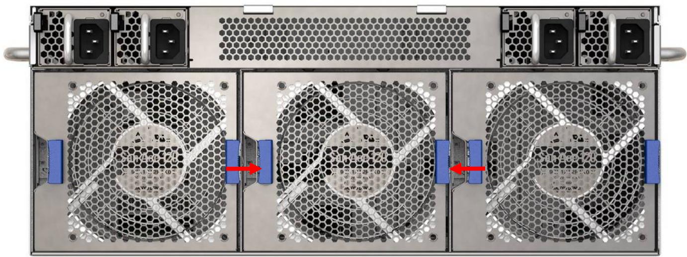
# 4.3 Removing and Replacing a Fan Module

The CSA-7400 is equipped with three hot swappable fan modules. To replace a faulty module, follow the steps below.
![Three-panel view of a server rack with hexagonal heat sinks and labeled connectors, showing internal components and red directional arrows (no readable text or symbols)](.csa-7400-50-1z240-2010-11/9becb33e0971443e54c171eb960234aecfb9d8031adf74152ee95eb1937cdd89.jpg)

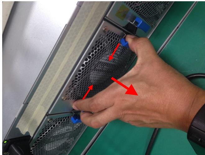
1. Press the left and right fan ejector latches (blue) simultaneously in an inwards direction as shown. Pull the fan tray module out of the chassis.
![Close-up of hands adjusting a black mesh fan panel with red arrows pointing to the edge (no text or symbols visible)](.csa-7400-50-1z240-2010-11/9fe67a9cde938646c00f78e15d07cacf8419804f68d8c1eb2568aaea3473f6b2.jpg)

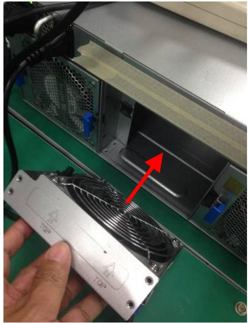
2. Align the new fan module so that the arrows and “TOP” markings are as shown below. Insert the fan into the fan slot and press firmly until both fan ejector latches are secured.
![Close-up of a hand holding a power supply unit with a fan blade and red arrow indicating a component (no text or symbols visible)](.csa-7400-50-1z240-2010-11/9fd8d8b8f04e9ff9e35c8fe5a0f892b46e66fe95fae9ef971034e664f830acba.jpg)

# 4.4 Removing and Replacing a PSU

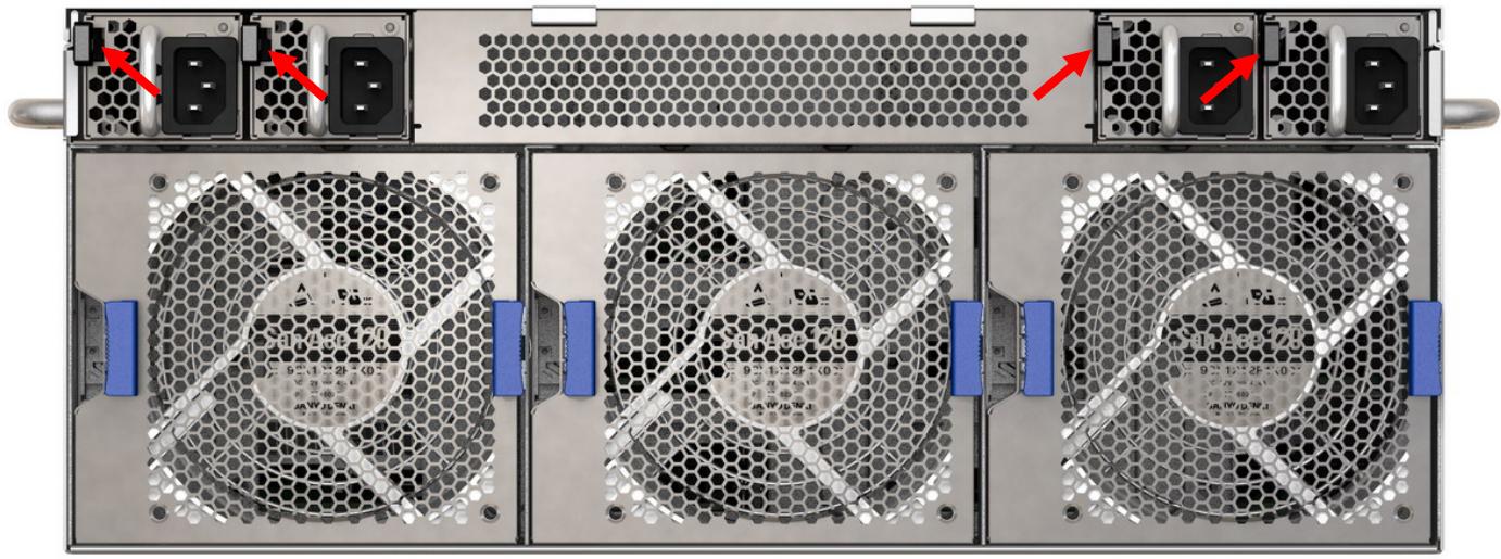
1. Push the latch and pull out the PSU.
![Three-panel view of a server rack with hexagonal heat sinks and red arrows indicating ports (no readable text or symbols)](.csa-7400-50-1z240-2010-11/3483d17b2bbeb835c7d6c9a99cfe34dc81256ef2b008e7f320b0a8c4145d2689.jpg)

2. Insert the new PSU into the PSU slot until it is flush with the chassis and the latch clicks into place.

# 5 Remote Management via CMM

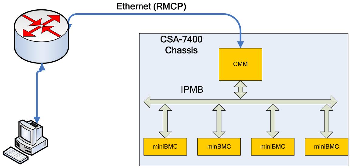
The Chassis Management Module (CMM) over switch board (MXN-3610/MXN-4100) provides a remote management interface (via network) for the CSA-7400.
![The diagram illustrates a system connection involving a chassis and external devices.\n\n**Labeled Blocks:**\n*   **CSA-7400 Chassis:** A large container box on the right side.\n*   **CMM:** A yellow rectangular block inside the top right of the chassis.\n*   **IPMB:** A horizontal bus line running across the middle of the chassis.\n*   **miniBMC:** A yellow rectangular block at the bottom left of the chassis.\n*   **minBMC:** A yellow rectangular block next to the first miniBMC (note the singular 'min').\n*   **miniBMC:** A yellow rectangular block next to the second miniBMC.\n*   **miniBMC:** A yellow rectangular block at the bottom right of the chassis.\n\n**Connections:**\n*   **Ethernet (RMCP):** A blue curved arrow connects a network/router icon (top left) to the **CMM** block.\n*   **Network to Computer:** A blue vertical arrow connects the network icon to a computer icon (bottom left).\n*   **CMM to IPMB:** A grey double-headed arrow connects the **CMM** block to the **IPMB** bus line.\n*   **IPMB to BMCs:** Four grey double-headed arrows connect the **IPMB** bus line to the four **miniBMC**/**minBMC** blocks below it.](.csa-7400-50-1z240-2010-11/6b81ec351fdcdf65dc71af8ffe31c40ae267f22254b49eda8cf26ab1b295b9fa.jpg)

# 5.1 IPMI Topology

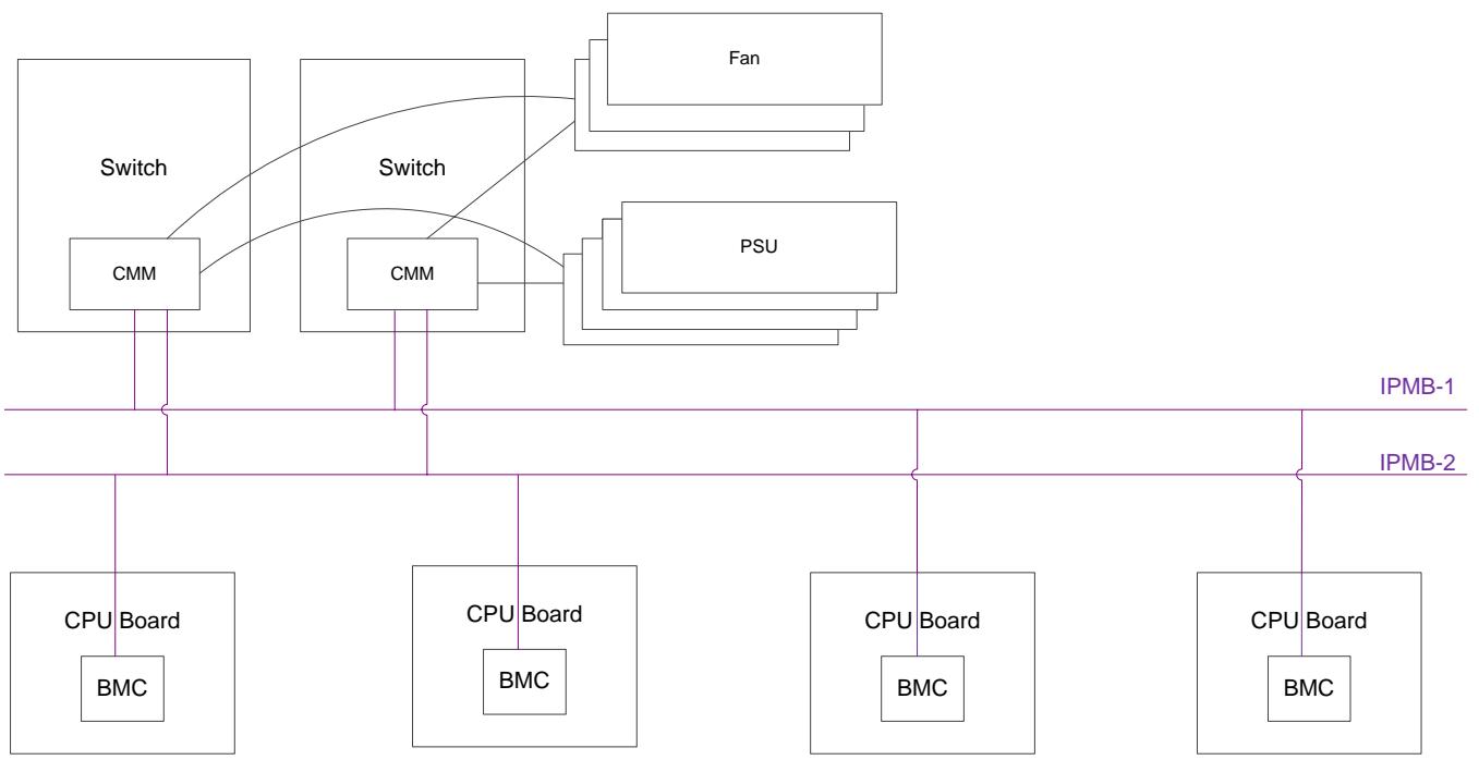
The following figure shows a top-level view of the Chassis Management hardware topology.
![Based on the provided image, here is the accurate and concise description of the flowchart:\n\n**Labeled Blocks:**\n*   **Switch:** Two large boxes at the top.\n*   **CMM:** Smaller boxes located inside each 'Switch' box.\n*   **Fan:** A stack of boxes at the top right.\n*   **PSU:** A stack of boxes below the 'Fan'.\n*   **IPMB-1:** The upper horizontal purple line.\n*   **IPMB-2:** The lower horizontal purple line.\n*   **CPU Board:** Four large boxes at the bottom.\n*   **BMC:** Smaller boxes located inside each 'CPU Board'.\n\n**Connections:**\n*   **Switch to Peripherals:** Curved lines connect the 'Switch' boxes to the 'Fan' and 'PSU' stacks.\n*   **Top to Middle:** Vertical lines connect the 'CMM' boxes down to the 'IPMB-1' and 'IPMB-2' lines.\n*   **Middle to Bottom:** Vertical lines connect the 'IPMB' lines down to the 'CPU Board' boxes. Specifically, the leftmost and rightmost 'CPU Board' boxes connect to both 'IPMB-1' and 'IPMB-2', while the two middle 'CPU Board' boxes connect to 'IPMB-2'.](.csa-7400-50-1z240-2010-11/579e9284c10351cbbaa35c711da642a1b0a3525f55f9c065f19e0b9b48b60df3.jpg)

# 5.2 Login to the CMM via Serial Console

# Step 1

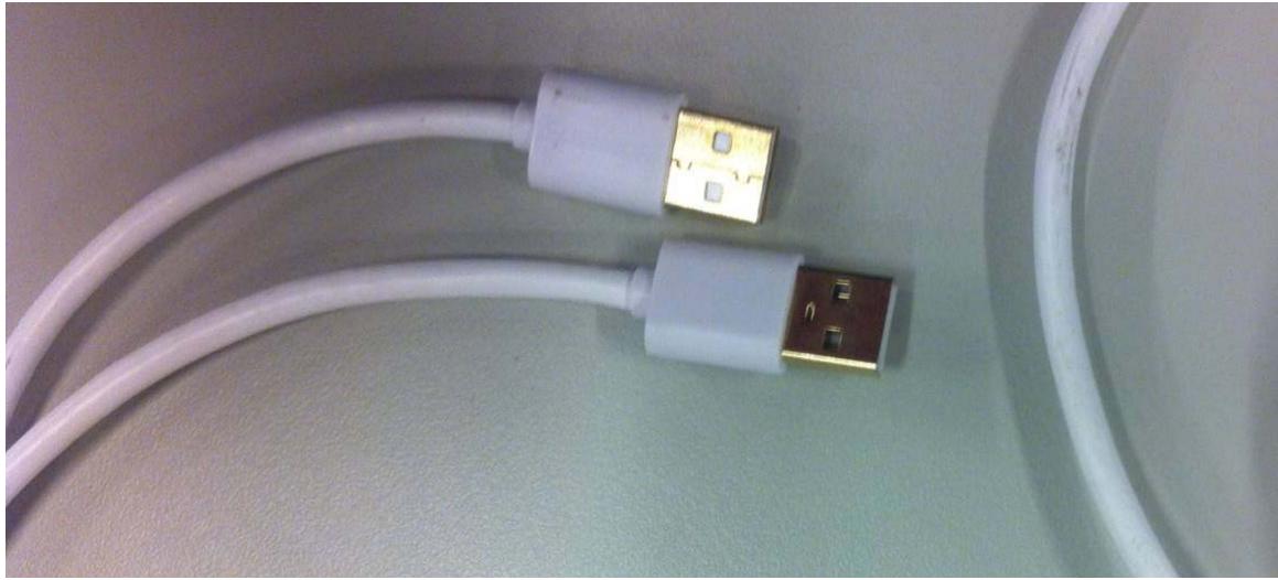
Connect a PC and MXN-3610/MXN-4100 with USB-to-USB cable using the port labeled “SER”.
![Close-up of a white USB cable with gold connector, placed on a plain surface (no text or symbols visible)](.csa-7400-50-1z240-2010-11/9dd4013a5b26252b0128fbff560f851f6d3420dd21686ad19a050869dcf78d76.jpg)

![Front panel of a network equipment rack with labeled ports and indicator lights, showing port numbers and status indicators.](.csa-7400-50-1z240-2010-11/df21f7092837a9229c1fc472f75d368fecaecdce86e7cade65445cf381aac140.jpg)

# Step 2

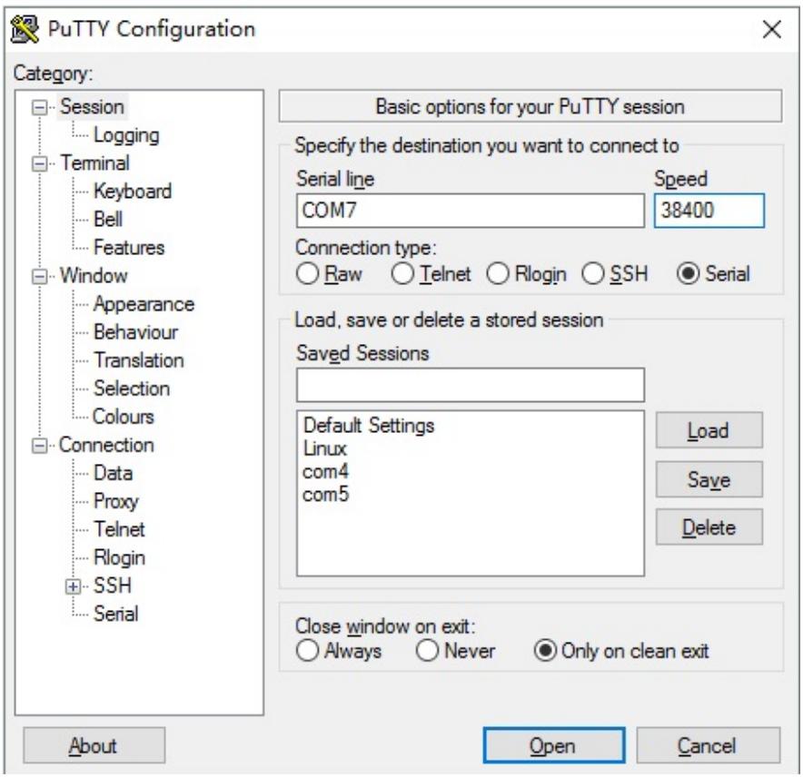
Open a serial port console tool (such as PuTTY), choose the larger COM port (it may be different on different computers, please try both), then set baud rate to 38400.
![PuTTY Configuration\nCategory:\nSession\nLogging\nTerminal\nKeyboard\nBell\nFeatures\nWindow\nAppearance\nBehaviour\nTranslation\nSelection\nColours\nConnection\nData\nProxy\nTelnet\nRlogin\nSSH\nSerial\nBasic options for your PuTTY session\nSpecify the destination you want to connect to\nSerial line Speed\nCOM7 38400\nConnection type:\nRaw Telnet Rlogin SSH Serial\nLoad, save or delete a stored session\nSaved Sessions\nDefault Settings\nLinux\ncom4\ncom5\nLoad\nSave\nDelete\nClose window on exit:\nAlways Never Only on clean exit\nAbout Open Cancel](.csa-7400-50-1z240-2010-11/8ac5a23835c00bf598e102322552a7c515870c4532089e65294fba0f4fc8fa99.jpg)

# Step 3

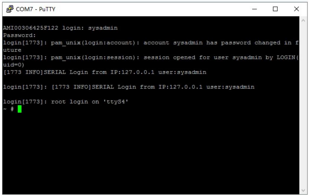
Input the user name “sysadmin” and password “superuser” to login to the system.
![AMI00306425F122 login: sysadmin\nPassword:\nlogin(1773): pam_unix(login:account): account sysadmin has password changed in future\nlogin(1773): pam_unix(login:session): session opened for user sysadmin by LOGIN(uid=0)\n(1773 INFO)SERIAL Login from IP:127.0.0.1 user:sysadmin\n\nlogin(1773): (1773 INFO)SERIAL Login from IP:127.0.0.1 user:sysadmin\n\nlogin(1773): root login on 'ttyS4'\n~ #](.csa-7400-50-1z240-2010-11/5eae44a845b1121d47f1bfc9ed49f71941524778e3d3f03747d91a0f0ea3741e.jpg)

# 5.3 Configuring the CMM IP Address

The CMM can be accessed remotely via the control plane switch. The user can set the network via edit “/conf/interfaces”, by logging into the CMM serial console.

```txt
This file describes the network interfaces available on your system
# and how to activate them. For more information, see interfaces(5).

# The loopback network interface
auto lo
iface lo inet loopback

# The primary network interface
auto eth0
iface eth0 inet dhcp
iface eth0 inet6 autoconf

auto eth1
iface eth1 inet static
address 10.10.0.10
netmask 255.255.0.0
gateway 10.10.0.254
#iface eth1 inet6 autoconf
```

An example of Network Configuration is as follows:

# To set eth0 to dhcp mode:

```txt
auto eth0
iface eth0 inet dhcp
iface eth0 inet6 autoconf
```

# To set eth1 to static IP mode:

```batch
auto eth1
iface eth1 inet static
address 10.10.0.10
netmask 255.255.0.0
gateway 10.10.0.254
```

After editing, save the changes and restart the CMM. The settings will be applied.

# 5.4 Login to the CMM via Network

# Step 1

Connect the LAN port of the CMM to the DHCP server.

![Diagram of a network device rear panel with labeled ports, connectors, and a highlighted internal component.](.csa-7400-50-1z240-2010-11/fcf83d7c749d00da47be8302e31fa0268d5ecdb8456ebd947586198fccb1d4d6.jpg)

# Step 2

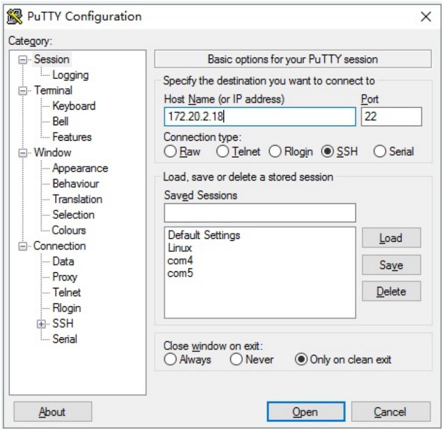
Open a SSH tool (such as PuTTY), input host name “172.20.2.18” (use serial port login to the CMM to check the IP address).
![PuTTY Configuration\nCategory:\nSession\nLogging\nTerminal\nKeyboard\nBell\nFeatures\nWindow\nAppearance\nBehaviour\nTranslation\nSelection\nColours\nConnection\nData\nProxy\nTelnet\nRlogin\nSSH\nSerial\nBasic options for your PuTTY session\nSpecify the destination you want to connect to\nHost Name (or IP address) Port\n172.20.2.18 22\nConnection type:\nRaw Telnet Rlogin SSH Serial\nLoad, save or delete a stored session\nSaved Sessions\nDefault Settings\nLinux\ncom4\ncom5\nLoad\nSave\nDelete\nClose window on exit:\nAlways Never Only on clean exit\nAbout Open Cancel](.csa-7400-50-1z240-2010-11/b6b3580b226a07add2ccb96a5d9685322ce6b79e61eb5763725d014905021933.jpg)

# Step3

Input the user name “sysadmin” and password “superuser” to login to the system.

# 5.5 Checking the CMM Firmware Version

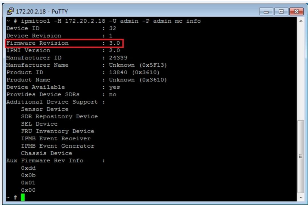
After logging in to the CMM, you can check CMM firmware version by using the following command:

ipmitool –H 172.20.2.18 –U admin –P admin mc info

The shipped CMM firmware version is 3.0, as show below.
![~ # ipmitool -H 172.20.2.18 -U admin -P admin mc info\nDevice ID : 32\nDevice Revision : 1\nFirmware Revision : 3.0\nIPMI Version : 2.0\nManufacturer ID : 24339\nManufacturer Name : Unknown (0x5F13)\nProduct ID : 13840 (0x3610)\nProduct Name : Unknown (0x3610)\nDevice Available : yes\nProvides Device SDRs : no\nAdditional Device Support :\nSensor Device\nSDR Repository Device\nSEL Device\nFRU Inventory Device\nIPMB Event Receiver\nIPMB Event Generator\nChassis Device\nAux Firmware Rev Info :\n0xdd\n0x0b\n0x01\n0x00\n~ #](.csa-7400-50-1z240-2010-11/8d4d8d42b0c34c4b9a3abf75664995a02c265e45014c1f3f0bbc03e264c85261.jpg)

# 5.6 Using IPMItool

The CMM provides an IPMI RMCP interface for users to manage the chassis remotely through the network. The following commands are fully compliant with IPMI v2.0.

# Examples of IPMI commands

To get the CMM device ID:
```batch
root@jean:# ipmitool -I lan -H 172.20.5.150 -U admin -P admin raw 0x06 0x01
RAW RSP (15 bytes)
20 01 02 07 02 bf 13 5f 00 10 36 dd 0b 01 00
```

To get the module’s device ID (with IPMB Address 0x80):
```batch
root@jean:# ipmitool -I lan -H 172.20.5.150 -U admin -P admin -t 0x80 raw 0x06 0x01
RAW RSP (15 bytes)
20 01 01 06 02 bf 13 5f 00 00 15 a2 00 00 00
```

To read the CMM sensor:
```txt
root@jean:# ipmitool -I lan -H 172.20.5.150 -U admin -P admin sensor get P1V
Locating sensor record...
Sensor ID : P1V (0x30)
Entity ID : 7.0
Sensor Type (Threshold): Voltage
Sensor Reading : 0.990 (+/- 0) Volts
Status : ok
Lower Non-Recoverable : 0.850
Lower Critical : 0.900
Lower Non-Critical : 0.950
Upper Non-Critical : 1.050
Upper Critical : 1.100
Upper Non-Recoverable : 1.150
Positive Hysteresis : 0.010
Negative Hysteresis : 0.010
Assertion Events :
Assertions Enabled : lnc- lcr- lnr- unc+ ucr+ unr+
Deassertions Enabled : lnc- lcr- lnr- unc+ ucr+ unr+
```

To read the module sensor:
```txt
root@jean:# ipmitool -I lan -H 172.20.5.150 -U admin -P admin -t 0x80 sensor get
LANA_3V3
Locating sensor record...
Sensor ID : LANA_3V3 (0x6)
Entity ID : 7.0
Sensor Type (Threshold) : Voltage
Sensor Reading : 3.290 (+/- 0) Volts
Status : ok
Lower Non-Recoverable : 2.790
Lower Critical : 2.890
Lower Non-Critical : 2.990
Upper Non-Critical : 3.590
Upper Critical : 3.690
Upper Non-Recoverable : 3.790
Positive Hysteresis : Unspecified
Negative Hysteresis : Unspecified
Assertion Events :
Assertions Enabled : lnc- lcr- lnr- unc+ ucr+ unr+
Deassertions Enabled : lnc- lcr- lnr- unc+ ucr+ unr+
```

# 5.7 Using the Web UI

# Managing the Chassis

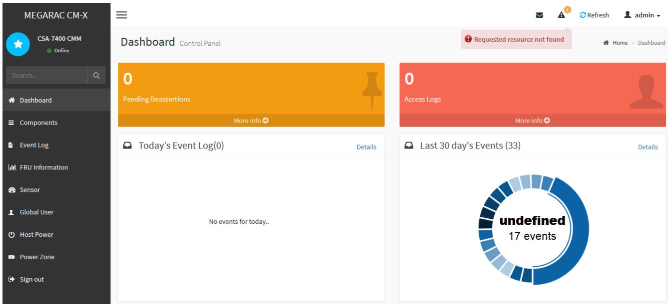
To use the Megarac CM-X chassis management web UI,

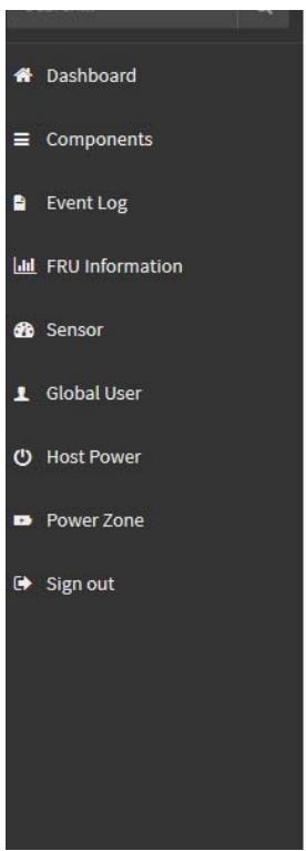
The screenshot below shows the layout of the Megarac CM-X chassis management web UI:
![MEGARAC CM-X\nCSA-7400 CMM\nOnline\nSearch...\nDashboard\nComponents\nEvent Log\nFRU Information\nSensor\nGlobal User\nHost Power\nPower Zone\nSign out\nDashboard Control Panel\nRequested resource not found\nHome ) Dashboard\n0\nPending Deassertions\nMore info\n0\nAccess Logs\nMore info\nToday's Event Log(0)\nDetails\nNo events for today..\nLast 30 day's Events (33)\nDetails\nundefined\n17 events](.csa-7400-50-1z240-2010-11/f06cf2def4a2c83c5c0dbd530929715d8cd60787618d3e42d67d5d8541ce8847.jpg)

# Login

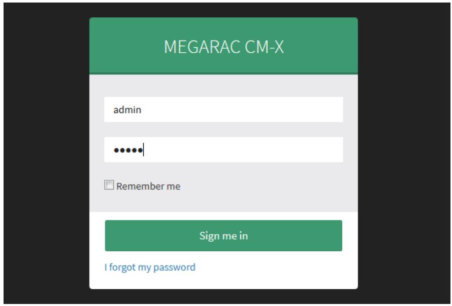
To login to the CM-X application, follow the steps below:

1. Open a web brower (AMI recommends Firefox) and go to the IP address of the CMM
2. Enter the default user name and password.

Username: admin

Password: admin
![MEGARAC CM-X\nadmin\n......\nRemember me\nSign me in\nI forgot my password](.csa-7400-50-1z240-2010-11/332ee5bddcd73154b2775551497b6366d57a59f35bf3e488185feffa9c45bc80.jpg)

# Logout

To logout of the CM-X UI:

Click “admin”->”Sign out” at the top right corner of the screen, or click “Sign out” in the bottom left corner.

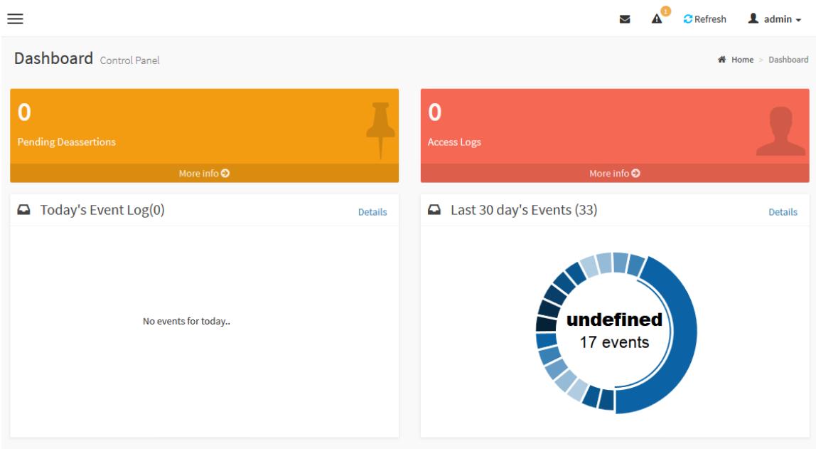
# Dashboard

The Dashboard displays the overall status of the chassis as shown in the screenshot below.
![Dashboard Control Panel\n0\nPending Deassertions\nMore info\n0\nAccess Logs\nMore info\nToday's Event Log(0)\nDetails\nNo events for today..\nLast 30 day's Events (33)\nDetails\nundefined\n17 events](.csa-7400-50-1z240-2010-11/825d74e1454d416f543859b8ea549ce0bf3280b39433620f2cd2fa3266a4f76a.jpg)

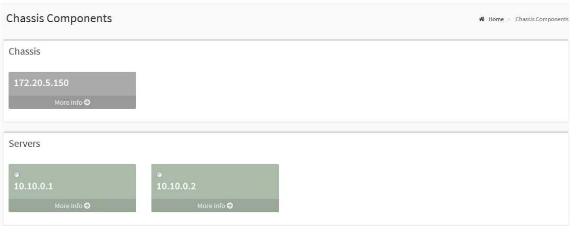
# Chassis Components

Chassis Components shows the IPMC nodes summary information. The chassis node is the CMM itself. Server nodes are the BMC nodes on the modules.
![Chassis Components\nChassis\n172.20.5.150\nMore Info\nServers\n10.10.0.1\nMore Info\n10.10.0.2\nMore Info](.csa-7400-50-1z240-2010-11/0c8bb0f62b45fbb3c10ae92b8eecabe3fba21c60deff307008d326ccd7ac4895.jpg)

# Event Log

An event is any significant occurrence in the system or in a program that requires the users to be notified or an entry to be added to a log. The event log service records application security and system events. From the events on the Event Log page, the user can obtain information about system hardware and components and can monitor security events on a local or remote computer. The event logs help the user to identify the source of current system problems and predict potential system problems.

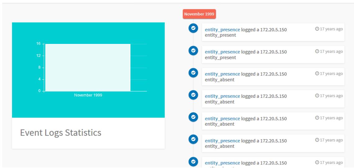
![Filter by Date\nStart Date\nEnd Date\nFilter by type\nAll Events\nAll Sensors\nComponent\n172.20.5.150\nClear Event Logs\nShow SEL Information](.csa-7400-50-1z240-2010-11/84acc90f9094e4044a3fd8230d1b9085d4c8d751d310aad8f8dd2b6e5b633873.jpg)

![| Event Logs Statistics | Value |\n| :--- | :--- |\n| entity_presence logged a 172.20.5.150 entity_present | 17 years ago |\n| entity_presence logged a 172.20.5.150 entity_present | 17 years ago |\n| entity_presence logged a 172.20.5.150 entity_absent | 17 years ago |\n| entity_presence logged a 172.20.5.150 entity_absent | 17 years ago |\n| entity_presence logged a 172.20.5.150 entity_absent | 17 years ago |\n| entity_presence logged a 172.20.5.150 entity_absent | 17 years ago |\n| entity_Presence logged a 172.20.5.150 entity_present | 17 years ago |\n| entity_Presence logged a 172.20.5.150 entity_present | 17 years ago |\n| entity_Presence logged a 172.20.5.150 entity_present | 17 years ago |\n| entity_Presence logged a 172.20.5.150 entity_present | 17 years ago |](.csa-7400-50-1z240-2010-11/710162b863ce43ada869537ea8c4f942768422d27b0eae26750746ea00dbf780.jpg)

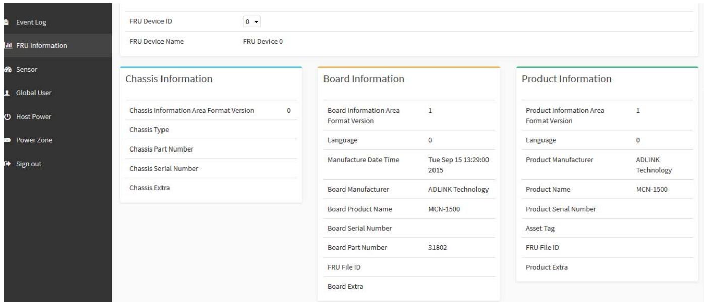
# FRU Information

The FRU (Field Replacement Unit) Information page displays chassis FRU information. The information displayed on this page is internal, chassis, board, and product information of the selected device. To view FRU information, click FRU Information in the left pane and select the FRU device ID of the component to be checked.
![Event Log\nFRU Information\nSensor\nGlobal User\nHost Power\nPower Zone\nSign out\nFRU Device ID 0\nFRU Device Name FRU Device 0\nChassis Information\nChassis Information Area Format Version 0\nChassis Type\nChassis Part Number\nChassis Serial Number\nChassis Extra\nBoard Information\nBoard Information Area 1\nFormat Version\nLanguage 0\nManufacture Date Time Tue Sep 15 13:29:00 2015\nBoard Manufacturer ADLINK Technology\nBoard Product Name MCN-1500\nBoard Serial Number\nBoard Part Number 31802\nFRU File ID\nBoard Extra\nProduct Information\nProduct Information Area 1\nFormat Version\nLanguage 0\nProduct Manufacturer ADLINK Technology\nProduct Name MCN-1500\nProduct Serial Number\nAsset Tag\nFRU File ID\nProduct Extra](.csa-7400-50-1z240-2010-11/35c6491605c66713c1e4665be84ebbfdacb48d96c225782f02689e6178c86fd8.jpg)

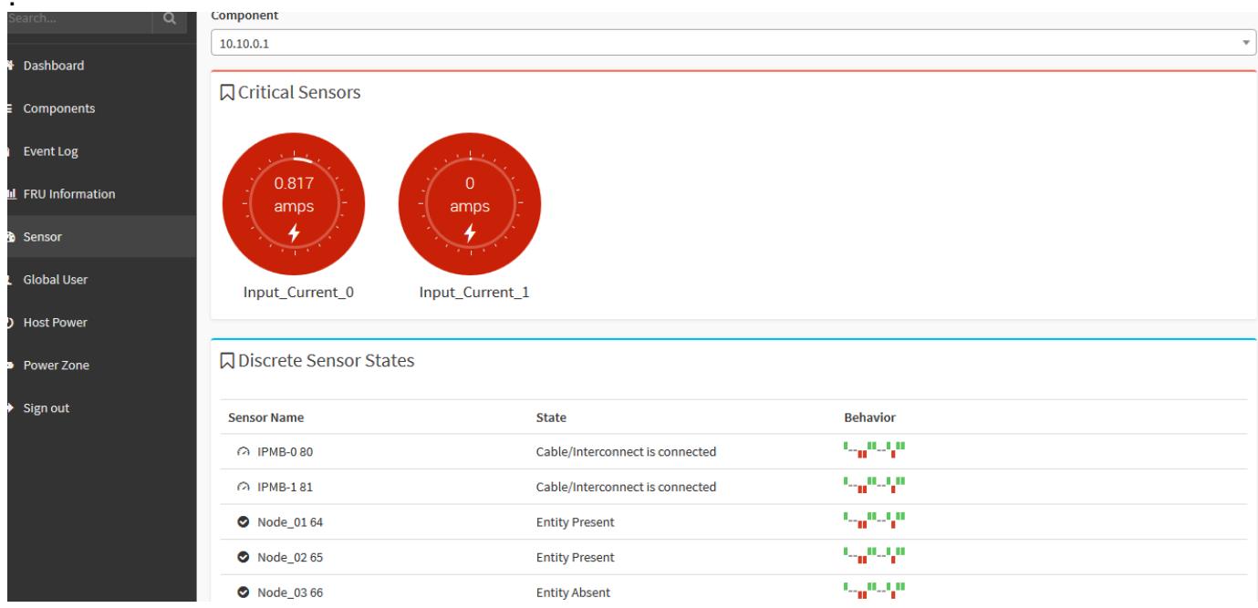
# Sensor

Sensor related information of the chassis is displayed on the Sensor page. Details such as type of sensors, sensor readings, and sensor status are shown on this page. To view the sensor readings, click Sensor in the left panel.
![| Component             | Value |\n| --------------------- | ----- |\n| Critical Sensors      | 0.817 |\n| Critical Sensors      | 0     |\n| Discrete Sensor States|       |](.csa-7400-50-1z240-2010-11/56e7957b1b3ce4bcb02ed5299b433bafd4cad97eed820a72d74a4d8403a24080.jpg)

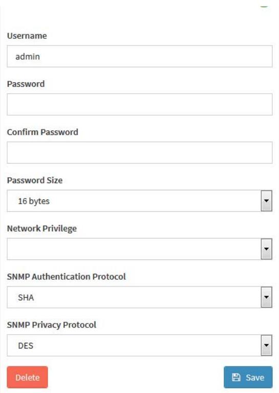
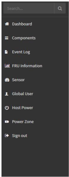
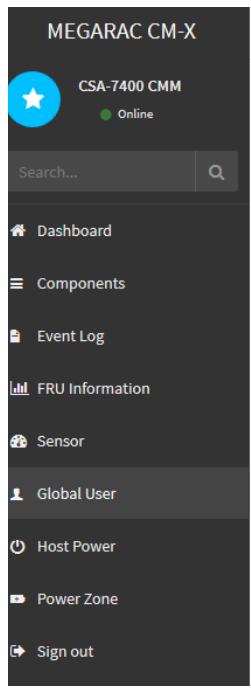
# Global User

This page is used to set the web UI user properties, such as username/password.
![MEGARAC CM-X\nCSA-7400 CMM\nOnline\nSearch...\nDashboard\nComponents\nEvent Log\nFRU Information\nSensor\nGlobal User\nHost Power\nPower Zone\nSign out](.csa-7400-50-1z240-2010-11/f3996cb5bb33a320160a20debdd79e56462c816e7e9038bacc040442086d22ec.jpg)

![The image displays a vertical stack of four thick, black horizontal bars centered on a white background.](.csa-7400-50-1z240-2010-11/2325d122e4e0a6ae1f9b79835f9944955f91a16d9b842d90f6c1a430e23165e7.jpg)

Global User

![The image displays a standard icon featuring two dark grey silhouettes of human figures against a white background. A larger figure stands in the foreground on the left, partially overlapping a smaller figure positioned behind it to the right. This graphic is commonly used to represent 'users,' 'contacts,' or a 'group' in software interfaces.](.csa-7400-50-1z240-2010-11/1260bd94234866bbba3c397680f0f33009db46c92b88eafc2f4aa44e9f51e731.jpg)

Global User

![Dashboard\nComponents\nEvent Log\nFRU Information\nSensor\nGlobal User\nHost Power\nPower Zone\nSign out](.csa-7400-50-1z240-2010-11/09db7429efa6393dd8b0b734d7b25d91cbc7d0337b691eeab65cfa36af02b8ca.jpg)

![Username\nadmin\nPassword\nConfirm Password\nPassword Size\n16 bytes\nNetwork Privilege\nSNMP Authentication Protocol\nSHA\nSNMP Privacy Protocol\nDES\nDelete Save](.csa-7400-50-1z240-2010-11/f1d931a8b6a929d98b3c8206ff9e0411fdcffb9999122c2d7211ff461fc34de7.jpg)

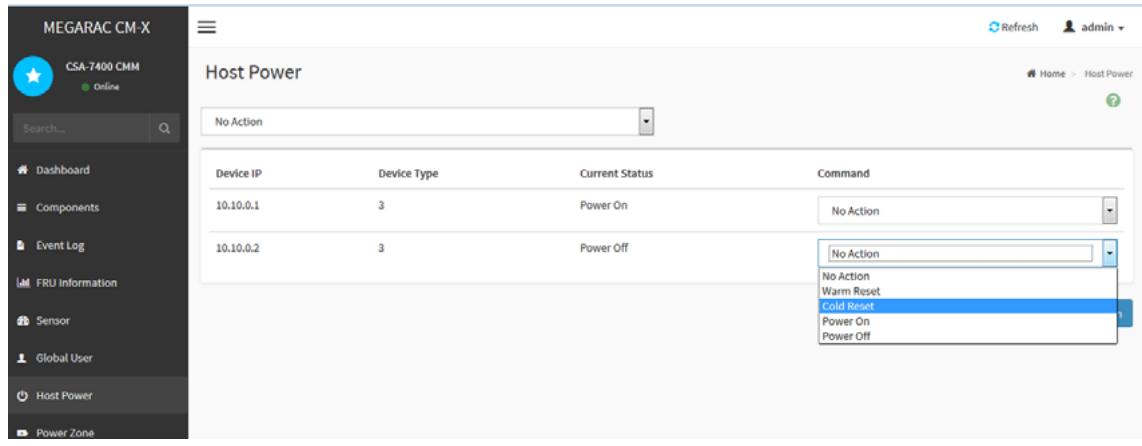
# Host Power

This page implement the chassis control functions. Users can execute chassis power control commands on the selected module.
![MEGARAC CM-X\nCSA-7400 CMM\nOnline\nHost Power\nNo Action\nDevice IP Device Type Current Status Command\n10.10.0.1 3 Power On No Action\n10.10.0.2 3 Power Off No Action\nNo Action\nWarm Reset\nCold Reset\nPower On\nPower Off\nSearch...\nDashboard\nComponents\nEvent Log\nFRU Information\nSensor\nGlobal User\nHost Power\nPower Zone](.csa-7400-50-1z240-2010-11/58e8eeccab008d984ab028343786429f779bf97f5da21e281c3b816ed9208d19.jpg)

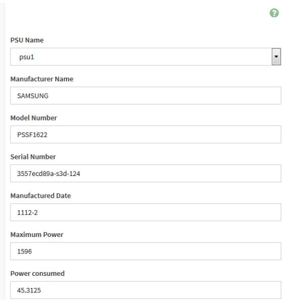
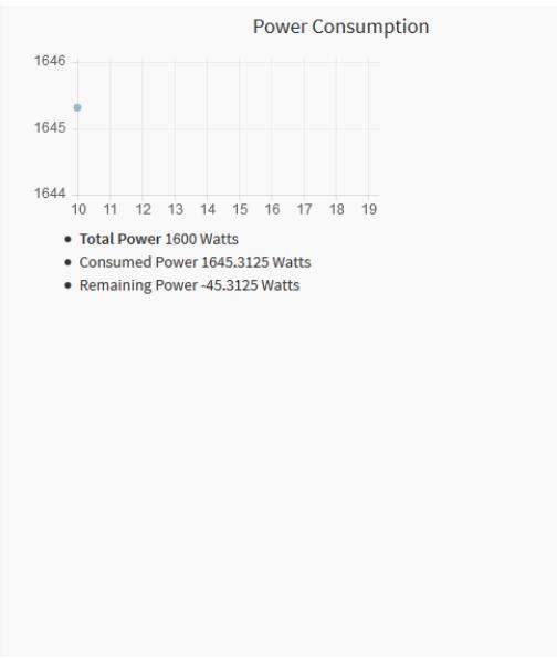
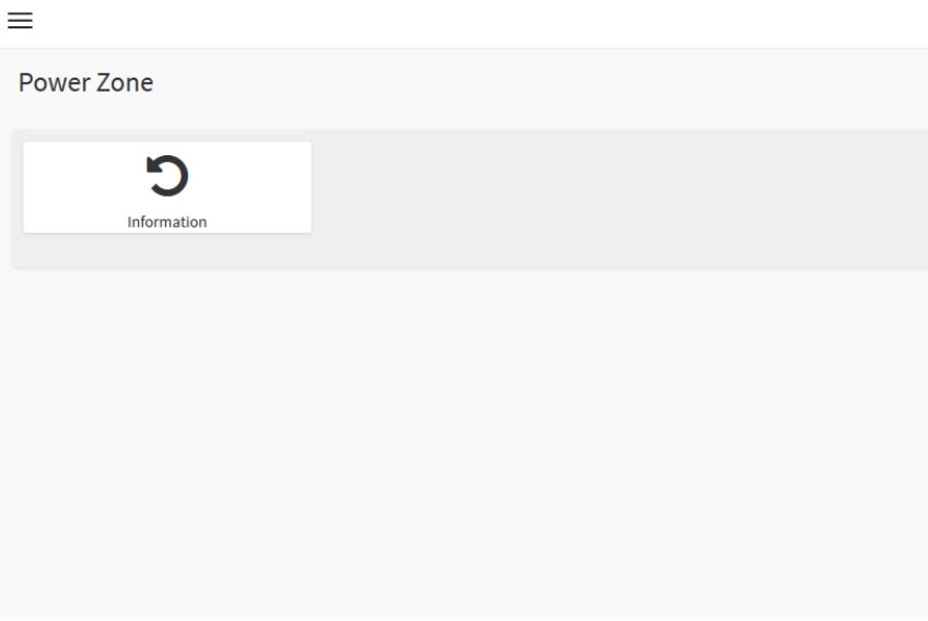
# Power Zone

This page shows chassis PSU information such power rating, power consumed, and fault state of PSU.
![MEGARAC CM-X\nCSA-7400 CMM\nOnline\nSearch...\nDashboard\nComponents\nEvent Log\nFRU Information\nSensor\nGlobal User\nHost Power\nPower Zone](.csa-7400-50-1z240-2010-11/4408e01febd6a8d8330332edc24e437a6d640fab315932ce2a9ff76f291f4836.jpg)

![≡\nPower Zone\nInformation](.csa-7400-50-1z240-2010-11/088a495648aa3aab7f190d3212bed2e596488605a0074b0091c031f77a1509a2.jpg)

![Search...\nDashboard\nComponents\nEvent Log\nFRU Information\nSensor\nGlobal User\nHost Power\nPower Zone\nSign out](.csa-7400-50-1z240-2010-11/b1b511034d901211f269316e7e10233c69b20b9bbab714711d53228c1902160f.jpg)

![PSU Name\npsu1\nManufacturer Name\nSAMSUNG\nModel Number\nPSSF1622\nSerial Number\n3557ecd89a-s3d-124\nManufactured Date\n1112-2\nMaximum Power\n1596\nPower consumed\n45.3125](.csa-7400-50-1z240-2010-11/80fdef18e5e61baf8d38620db17fb96e54afeae1d4c8e9e561982d88963d28c7.jpg)

![| Category             | Value       |\n| -------------------- | ----------- |\n| Total Power          | 1600 Watts  |\n| Consumed Power       | 1645.3125 Watts |\n| Remaining Power      | -45.3125 Watts |](.csa-7400-50-1z240-2010-11/d9d110a7108bb183cafc28f5bfd8f3a885ed707e4b17463ad7f997956c743cad.jpg)

# 5.8 Updating the CMM Firmware

The CMM module provides two upgrade methods for the user to choose from.

Option 1: Upgrade FW in uboot mode
• Option 2: Upgrade FW over network via AMI “Yafuflash” tool

# Option 1: Upgrade FW in uboot Mode

# Upgrade Steps via uboot

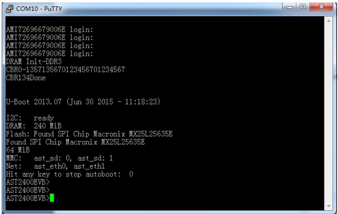
1. Lauch PuTTY and reset the CMM board (push the reset button) to enter uboot shell.
![AMI72696679006E login:\nAMI72696679006E login:\nAMI72696679006E login:\nAMI72696679006E login:\nDRAM Init-DDR3\nCBRO-1357135870123456701234567\nCBR134Done\n\nU-Boot 2013.07 (Jun 30 2015 - 11:18:23)\n\nI2C: ready\nDRAM: 240 MiB\nFlash: Found SPI Chip Macronix MX25L25635E\nFound SPI Chip Macronix MX25L25635E\n64 MiB\nMMC: ast_sd: 0, ast_sd: 1\nNet: ast_eth0, ast_eth1\nHit any key to stop autoboot: 0\nAST2400EVB)\nAST2400EVB)\nAST2400EVB)](.csa-7400-50-1z240-2010-11/6fcbbf2e92e28b8327216ac584c224e06a9771c0d64cd8907874f42fde49c282.jpg)

2. Disable the uboot watchdog to avoid a reboot in case of timeout.

```txt
mw 1e78500c 0 1
```

3. Store the CMM FW image “rom.ima” to a tfpt server

4. Lauch PuTTY, and reset the CMM board(push the reset button) to uboot shell, and set the correct uboot parameters.

```batch
set baudrate 38400
set bootdelay 2
set bootfile "all.bin"
set eth1addr 00:30:64:43:EB:EB
set ethaddr 00:30:64:43:EB:EA
set fileaddr 42000000
set filesize 39274
set gatewayip 172.20.5.254
set serverip 172.20.5.69
set ipaddr 172.20.5.225
set netmask 255.255.255.0
set eeprom y
```

Note: Pay close attention to the highlighted lines above so that each board’s MAC address is unique. Do not set the same MAC address for different boards.

5. Load the CMM FW image from the tftp server.

tftp 0x42000000 rom.ima

6. Program the CMM FW image to the onboard flash.

```asm
protect off all
erase all"
cp.b 0x42000000 0x20000000 0x2000000";
cp.b 0x42000000 0x22000000 0x2000000";
save"
reset
```

# Option 2: Upgrade FW over network via AMI “Yafuflash” tool

# SW Environment Preparation

1. Copy the CMM FW image “rom.ima” to a Linux PC
2. Copy the CMM upgrade tool “Yafuflash” to the PC

# Upgrade steps via AMI “Yafuflash” tool

1. Power on the CMM board, and boot into Linux (username: sysadmin; password: superuser), and type “ifconfig” to check its IP address.

```txt
AMI72696679006E login:
Password:
login[1623]: pam_unix(login:session): session opened for user sysadmin by LOGIN(uid=0)
[1623 INFO]SERIAL Login from IP:127.0.0.1 user:sysadmin

login[1623]: [1623 INFO]SERIAL Login from IP:127.0.0.1 user:sysadmin

login[1623]: root login on 'ttyS4'
~ #
~ #
~ # ifconfig
eth0 Link encap:Ethernet HWaddr 72:69:66:79:00:6E
inet addr:172.20.5.77 Bcast:172.20.5.255 Mask:255.255.255.0
ineto addr:1880..1009.66ff:fe79:6e/64 Scope:Link
UP BROADCAST RUNNING MULTICAST MTU:1500 Metric:1
RX packets:191 errors:0 dropped:5 overruns:0 frame:0
TX packets:58 errors:0 dropped:0 overruns:0 carrier:0
collisions:0 txqueuelen:1000
RX bytes:21025 (20.5 KiB) TX bytes:8142 (7.9 KiB)
Interrupt:2

eth1 Link encap:Ethernet HWaddr 01:C0:A8:12:36:57
inet6 addr: fe80::1c0:a800:112:3657/64 Scope:Link
UP BROADCAST RUNNING MULTICAST MTU:1500 Metric:1
RX packets:0 errors:0 dropped:0 overruns:0 frame:0
TX packets:44 errors:0 dropped:0 overruns:0 carrier:0
collisions:0 txqueuelen:1000
RX bytes:0 (0.0 B) TX bytes:10332 (10.0 KiB)
Interrupt:3
```

2. On the Linux PC , type the following command in xterm shell.

./Yafuflash -force-boot -nw -ip 172.20.5.77 -u admin -p admin rom.ima

# Safety Instructions

For user safety, please read and follow all instructions, WARNINGS, CAUTIONS, and NOTES marked in this manual and on the associated equipment before handling/operating the equipment.

1. Read these safety instructions carefully.
2. Keep this user’s manual for future reference.
3. Read the specifications section of this manual for detailed information on the operating environment of this equipment.
4. The equipment can be operated at an ambient temperature of $4 0 ^ { \circ } \mathsf { C }$ .
5. When installing/mounting or uninstalling/removing equipment; or when removal of the chassis lid required for user servicing (Section 3.1-3.5):
• Turn off power and unplug any power cords/cables, and
• Reinstall the chassis lid before restoring power.

6. To avoid electrical shock and/or damage to equipment:

• Keep equipment away from water or liquid sources;
• Keep equipment away from high heat or high humidity;
• Keep equipment properly ventilated (do not block or cover ventilation openings);
• Make sure to use recommended voltage and power source settings;
Always install and operate equipment near an easily accessible electrical socketoutlet;
• Secure the power cord (do not place any object on/over the power cord);
Only install/attach and operate equipment on stable surfaces and/or recommended mountings;
If the equipment will not be used for long periods of time, turn off and unplug the equipment from its power source.

7. Never attempt to fix the equipment. Equipment should only be serviced by qualified personnel.

8. A Lithium-type battery may be provided for uninterrupted, backup or emergency power.

CAUTION! Risk of explosion if battery is replaced with one of an incorrect type. Please dispose of used batteries appropriately.

9. Equipment must be serviced by authorized technicians when:

• The power cord or plug is damaged;
Liquid has penetrated the equipment;
It has been exposed to high humidity/moisture;
• It is not functioning or does not function according to the user’s manual;
• It has been dropped and/or damaged; and/or,
• It has an obvious sign of breakage.

10. Please pay strict attention to all warnings and advisories appearing on the device, to avoid injury or damage.

11. The equipment may have more than one power supply input. To reduce the risk of electrical shock, trained personnel should disconnect all power supply inputs before servicing.

CAUTION! Disconnect all power supply inputs before servicing.

12. It is recommended that equipment be installed only in a server room or computer room where access is:

Restricted to qualified service personnel or users familiar with restrictions applied to the location, reasons therefor, and any precautions required;
Only afforded by the use of a tool or lock and key, or other means of security, and is controlled by the authority responsible for the location.

13. Elevated Operating Ambient: If installed in a closed or multi-unit rack assembly, the operating ambient temperature of the rack environment may be greater than room ambient. Therefore, consideration should be given to installing the equipment in an environment compatible with the maximum ambient temperature (Tma) specified by the manufacturer.

14. Reduced Air Flow: Installation of the equipment in a rack should be such that the amount of air flow required for safe operation of the equipment is not compromised.

15. Mechanical Loading: Mounting of the equipment in the rack should be such that a hazardous condition is not achieved due to uneven mechanical loading.

16. Circuit Overloading: Consideration should be given to the connection of the equipment to the supply circuit and the effect that overloading of the circuits might have on overcurrent protection and supply wiring. Appropriate consideration of equipment nameplate ratings should be used when addressing this concern.

17. Reliable Earthing: Reliable earthing of rack-mounted equipment should be maintained. Particular attention should be given to supply connections other than direct connections to the branch circuit (e.g. use of power strips).

# Consignes de Sécurité Importantes

Pour assurer la sécurité de l’utilisateur, veuillez lire et suivre toutes les directives, ainsi que les AVERTISSEMENTS, MISES EN GARDE et REMARQUES de ce manuel et indiqués sur l’équipement associé avant de manipuler ou utiliser l’équipement.

1. Veuillez lire attentivement ces instructions de sécurité avec soin.
2. Veuillez conserver ce manuel pour référence future.
3. Veuillez lire la section des spécifications de ce manuel pour avoir des informations détaillées sur l’environnement d’exploitation de cet équipement.
4. L’équipement peut être utilisé à une température ambiante de 40 °C.
5. Lors de l’installation ou du montage et de la désinstallation ou de la dépose de l’équipement; ou lors de la dépose du couvercle du châssis pour procéder à l’entretien par l’utilisateur (Sections 3.1-3.5):

• Coupez l’alimentation et débranchez les cordons et les câbles d’alimentation, et
• Reposez le couvercle du châssis avant de remettre l’alimentation.

6. Pour éviter un risque d’électrocution et pour éviter d’endommager l’équipement :

• Éloignez l’équipement de l’eau et de toute source liquide;
Éloignez l’équipement de toute source de chaleur ou d’humidité élevée;
Gardez l’équipement correctement ventilé (ne pas bloquer ou couvrir les ouvertures de ventilation);
Veillez à utiliser la tension recommandée et les réglages adéquats pour la source d’alimentation;
• Veuillez toujours installer et exploiter l’équipement à proximité d’une prise de courant facilement accessible;
Assurez-vous que le cordon d’alimentation est acheminé de manière sécuritaire (ne déposez aucun objet dessus);
Installez, fixez et utilisez l’équipement sur des surfaces stables ou sur les fixations recommandées uniquement;
Si l’équipement n’est pas utilisé pendant une longue période, éteignez-le et débranchez-le de sa source d’alimentation.

7. N’essayez jamais de réparer l’équipement. L’équipement ne doit être réparé que par du personnel qualifié.

8. Une pile au lithium peut être installée pour assurer l’alimentation de secours ou d’urgence en continu.

ATTENTION! Risque d’explosion si la pile est remplacée par une autre de type incorrect. Veuillez jeter les piles usagées de façon appropriée.

9. L’équipement doit être entretenu par des techniciens agréés lorsque :

le cordon d’alimentation est endommagé ou lorsque la fiche électrique est endommagée;
du liquide a pénétré à l’intérieur de l’équipement;
• l’équipement a été exposé à un taux d’humidité élevé;
• l’équipement ne fonctionne pas ou ne fonctionne pas conformément au manuel de l’utilisateur;
• l’équipement est tombé ou lorsqu’il a été endommagé;
• l’équipement présente un signe évident de défaillance.

10. Veuillez porter une attention rigoureuse à tous les avertissements et à tous les avis figurant sur l’appareil, pour éviter des blessures ou des dommages.

11. ATTENTION! L’équipement peut avoir plus d’une entrée d’alimentation. Pour réduire le risque d’électrocution, le personnel qualifié devrait déconnecter toutes les entrées d’alimentation avant de procéder à l’entretien.

12. Il est recommandé que l'équipement soit installé que dans une salle de serveur ou de la salle informatique où:

• L'accès est limité au personnel de maintenance qualifié ou utilisateurs familiers avec les restrictions appliquées à l'emplacement, motifs, et tout les précautions nécessaires, et;
• L'accès est uniquement assurée par l'utilisation d'un outil ou clé, ou d'autres moyens de sécurité, et est contrôlé par l'autorité responsable de l'emplacement.

13. Température ambiante de fonctionnement élevée - S'il est installé dans un rack ou des unités multiples, la température ambiante de fonctionnement de l'environnement du rack peut être supérieure à celle de la pièce. Par conséquent, il convient d'envisager d'installer l'équipement dans un environnement compatible avec la température ambiante maximale (Tma) spécifiée par le fabricant.

14. Débit d'air réduit - L'installation de l'équipement dans un rack doit être telle que la quantité de flux d'air requise pour un fonctionnement en toute sécurité de l'équipement ne soit pas compromise.

15. Chargement mécanique - Le montage de l'équipement dans le rack doit être tel que des conditions dangereuses ne soient pas créées en raison d'un chargement mécanique inégal.

16. Surcharge du circuit - Il convient de prendre en compte le raccordement de l'équipement au circuit d'alimentation et les effets qu'une surcharge des circuits peut avoir sur la protection contre les surintensités et le câblage d'alimentation. Lors de la résolution de ce problème, il convient de prendre en compte les caractéristiques de la plaque signalétique de l'équipement.

17. Mise à la terre fiable - La mise à la terre fiable des équipements montés en armoire doit être maintenue. Une attention particulière doit être accordée aux connexions d’alimentation autres que les connexions directes au circuit de dérivation (par exemple, utilisation de barrettes d’alimentation).

# Getting Service

Ask an Expert: http://askanexpert.adlinktech.com

# ADLINK Technology, Inc.

Address: 9F, No.166 Jian Yi Road, Zhonghe District

New Taipei City 235, Taiwan

新北市中和區建一路 166 號 9 樓

Tel: +886-2-8226-5877

Fax: +886-2-8226-5717

Email: service@adlinktech.com

# Ampro ADLINK Technology, Inc.

Address: 5215 Hellyer Avenue, #110, San Jose, CA 95138, USA

Tel: +1-408-360-0200

Toll Free: +1-800-966-5200 (USA only)

Fax: +1-408-360-0222

Email: info@adlinktech.com

# ADLINK Technology (China) Co., Ltd.

Address: 上海市浦东新区张江高科技园区芳春路 300 号 (201203)

300 Fang Chun Rd., Zhangjiang Hi-Tech Park, Pudong New Area

Shanghai, 201203 China

Tel: +86-21-5132-8988

Fax: +86-21-5132-3588

Email: market@adlinktech.com

# ADLINK Technology GmbH

Address: Hans-Thoma-Straße 11, D-68163, Mannheim, Germany

Tel: +49-621-43214-0

Fax: +49-621 43214-30

Email: emea@adlinktech.com

Please visit the Contact page at www.adlinktech.com for information on how to contact the ADLINK regional office nearest you.
[🔗 Link to the original document](.csa-7400-50-1z240-2010-11/csa-7400-50-1z240-2010-11.pdf)