# DLAP-8100 Series

# User’s Manual

Industrial Edge AI System with 14th/13th/12th Intel® CoreTM Processor

![Front view of a black ADLINK network device with ports, connectors, and ventilation grilles (no readable text or symbols beyond branding)](.dlap-8100-50m-41061-1010-11/37026456708e803f33057ad04ba28ef4b594a14335e45cb54bc68339ba52354c.jpg)

Manual Rev.: Rev 1.1

Revision Date: June 16, 2025

Part Number: 50M-41061-1010

# Preface

# Copyright

Copyright © 2025 ADLINK Technology, Inc. This document contains proprietary information protected by copyright. All rights are reserved. No part of this manual may be reproduced by any mechanical, electronic, or other means in any form without prior written permission of the manufacturer.

# Disclaimer

The information in this document is subject to change without prior notice in order to improve reliability, design, and function and does not represent a commitment on the part of the manufacturer. In no event will the manufacturer be liable for direct, indirect, special, incidental, or consequential damages arising out of the use or inability to use the product or documentation, even if advised of the possibility of such damages.

# Environmental Responsibility

ADLINK is committed to fulfill its social responsibility to global environmental preservation through compliance with the European Union's Restriction of Hazardous Substances (RoHS) directive and Waste Electrical and Electronic Equipment (WEEE) directive. Environmental protection is a top priority for ADLINK. We have enforced measures to ensure that our products, manufacturing processes, components, and raw materials have as little impact on the environment as possible. When products are at their end of life, our customers are encouraged to dispose of them in accordance with the product disposal and/or recovery programs prescribed by their nation or company.

![Symbol of a trash bin crossed with a diagonal line and a horizontal bar below (no text or labels)](.dlap-8100-50m-41061-1010-11/aecf0718745d432440c8b5fe5dcd6109322a992c2cf90ad5424548ed6fae0f0c.jpg)

Battery Labels (for products with battery)
![Simple line drawing of a trash bin with two crossed lines (no text or symbols)](.dlap-8100-50m-41061-1010-11/38bf62381ec269134deb3b51360de6cf226ceae22d60dbf8781e75db669f63a9.jpg)

![Li-ion](.dlap-8100-50m-41061-1010-11/31abb81dd9def66c702d130594ac76b0462bea98e59f9bcc1f810c12de5fe1dc.jpg)

![RECYCLF\nRBRC\nLi-ion\n7.800.822.8837](.dlap-8100-50m-41061-1010-11/48aacc6db6685b13465ecb8ac97b924a11afc8f49fe960cc44d0c433663e9adc.jpg)

![The image displays a black square with rounded corners containing four white arrows arranged in a square formation. Each arrow points outward towards the edge of the square—one pointing up, one down, one left, and one right—creating a design often associated with an 'expand' or 'fullscreen' icon.](.dlap-8100-50m-41061-1010-11/60856af2fefab9b650493418fccdec5c832b5f19987919d235e91fc6daeb2f68.jpg)
廢電池請回收

# California Proposition 65 Warning

![The image shows a standard warning symbol consisting of a yellow triangle with a thick black border. Inside the triangle, a large black exclamation point is centered. The background behind the sign is white.](.dlap-8100-50m-41061-1010-11/1324c7b3192413a91dd8e58a11e106f21a4992082d19c220fe7201b9e3ec2a5a.jpg)

WARNING: This product can expose you to chemicals including acrylamide, arsenic, benzene, cadmium, Tris(1,3-dichloro-2-propyl)phosphate (TDCPP), 1,4-Dioxane, formaldehyde, lead, DEHP, styrene, DINP, BBP, PVC, and vinyl materials, which are known to the State of California to cause cancer, and acrylamide, benzene, cadmium, lead, mercury, phthalates, toluene, DEHP, DIDP, DnHP,

DBP, BBP, PVC, and vinyl materials, which are known to the State of California to cause birth defects or other reproductive harm. For more information go to www.P65Warnings.ca.gov.

# Trademarks

Product names mentioned herein are used for identification purposes only and may be trademarks and/or registered trademarks of their respective companies.

# Conventions

Take note of the following conventions used throughout this manual to make sure that users perform certain tasks and instructions properly.

![The image features a white document icon with a folded top corner. A large red checkmark is positioned on the left side, overlapping faint gray horizontal lines that simulate text on the page.](.dlap-8100-50m-41061-1010-11/7fad40764e6d5cbd01671ada1ed56d01a14117e9d16150601dd12df1367e8532.jpg)
NOTE:

Additional information, aids, and tips that help users perform tasks.

![The image displays a standard yellow triangular warning sign with a thick black border. Inside the triangle, there is a large black exclamation point centered vertically.](.dlap-8100-50m-41061-1010-11/9690529778dc5fac0a125ae45f3e6958ed16c103f3bd05292ad4acb9710b254a.jpg)
CAUTION:

Information to prevent minor physical injury, component damage, data loss, and/or program corruption when trying to complete a task.

Informations destinées à prévenir les blessures corporelles mineures, les dommages aux composants, la perte de données et/ou la corruption de programme lors de l'exécution d'une tâche.

![The image displays a vertical, dark red triangle with a thin white border. Inside the triangle, centered, is a large white exclamation point. The background surrounding the triangle is white.](.dlap-8100-50m-41061-1010-11/82d48f4128c96c7397163849e0a3a7a0c7ff7dbf013a77cbbb09dc69b9fd6e14.jpg)
WARNING:

Information to prevent serious physical injury, component damage, data loss, and/or program corruption when trying to complete a specific task.

Informations destinées à prévenir les blessures corporelles graves, les dommages aux composants, la perte de données et/ou la corruption de programme lors de l'exécution d'une tâche spécifique.

Revision History

<table><tr><td>Revision</td><td>Description</td><td>Date</td><td>By</td></tr><tr><td>1.0</td><td>Initial release</td><td>2025-02-24</td><td>AL</td></tr><tr><td>1.1</td><td>Mechanical layouts and connectors and jumpers updated</td><td>2025-06-16</td><td>AL</td></tr></table>

# Table of Contents

# Preface...

# List of Figures ..............

# List of Tables....

# 1. Introduction.........

1.1 Overview ..
1.2 Features..
1.3 Packing List..

# 2. Specifications ....

Product Specifications.... 3
2.2 Display Options .

# 3. Functional Block Diagram .......

# 4. Mechanical Layouts ....

4.1 Connector Locations ..
4.2 Mechanical Dimensions . ..10

# 5. Getting Started... .13

Installing Wall-Mount Brackets . .13
5.2 Mounting the Device / Montage de l'Appareil.. ..14
5.3 Driver Installation . ..15

# 6. Connectors and Jumpers .... .17

6.1 Front Panel I/O Connectors.. .17
6.2 Internal I/O Connectors . ..21

# 7. BIOS Settings..... .23

7.1 Main .. ..23
7.2 Advanced .. ..24
7.3 Chipset.. .32
7.4 Security .. ..39
7.5 Boot .. ..40
7.6 Save & Exit . ..41

# 8. Appendix A BIOS Settings......... ..43

# 9. Appendix C Watchdog Timer (WDT) Function Library........ ..45

9.1 WDT with API/Windows .. ..45
9.2 WDT with DOS/Linux . ..47

# 10. Appendix D Digital Input/Output with Function Library..... ..49

# Safety Instructions......... .50

# Getting Services.... .52

# List of Figures

Figure 1: Functional block diagram.. 5

Figure 2: DLAP 8100 connector locations .

Figure 2: PCIe slot connector locations . .8

Figure 3: DLAP-8100 front view (Wall-mount brackets included) . ..10

Figure 4: DLAP-8100 left side view . .10

Figure 5: DLAP-8100 right side view . ..11

Figure 6: DLAP-8100 top view.. .11

# List of Tables

Table 1: Maximum display resolution configurations . 4

Table 2: DLAP 8100 connector descriptions..

Table 3: Backplane connector descriptions . .9

This page intentionally left blank.

# 1. Introduction

# Overview

ADLINK’s DLAP-8100 Series is an industrial AI edge computing workstation that supports 14th/13th/12th Gen Intel® Core™ i9/i7/i5/i3 embedded processors, an Intel® R680 chipset, DDR5 memory (up to 192GB), and one PCIe Gen4 x16 slot for a full-height, full-length GPU card, providing powerful computing capabilities for AI edge computing applications.

It includes versatile I/O interfaces (2x HDMI, 2x DisplayPort, 6x USB 3.2, and 3x 2.5GbE), as well as one M.2 2230 E-key, one M.2 3052/3042 B-key, and one M.2 NVMe/SATA 2280 M-key with a single-side access design, optimizing ease of maintenance in industrial automation environments.

The DLAP-8100 Series fully meets the performance requirements of industrial customers in vision inspection, motion control, and surveillance applications. Its fanless construction not only overcomes contaminant and noise challenges in harsh industrial automation environments, but the elimination of problematic structural elements that negatively affect MTBF significantly increases the platform's lifecycle expectations.

# Features

• 14th/13th/12th Intel® CoreTM i9/i7/i5/i3 embedded processors with R680E chipset
Up to 192 GB DDR5 3600MHz (4x SODIMM slots)
• 2x DP++, 2x HDMI, 3x 2.5 GbE, 2x COM, 8 DI/8 DO, 4x USB 3.2, 2x USB 3.1, TPM 2.0
• 4x 2.5-inch HDD/SDD tray (3x SATAIII 6 Gb/s and 1x USB-to-SATA)
• 1x M.2 2230 E-key, 1x M.2 3052/3042 B-key, 1x M.2 NVMe/SATA 2280 M-key
Support 1x FHFL PCI Express GPU cars (e.g., NVIDIA RTX 6000 Ada)
PCIe x16, x 4, x4, x1 signals with physical x16, x8, x8, x1 slots
100-240 AC input

# Packing List

Before unpacking, check the shipping carton for any damage. If the shipping carton and/or contents are damaged, inform your dealer immediately. Retain the shipping carton and packing materials for inspection. Obtain authorization from your dealer before returning any product to ADLINK. Ensure that the following items are included in the package.

# DLAP-8100 Industrial GPU Workstation

• Accessory box
Wall-mount brackets
Screw pack

This page intentionally left blank.

# 2. Specifications

Product Specifications

<table><tr><td>Model</td><td>DLAP-8100</td></tr><tr><td colspan="2">System Core</td></tr><tr><td>Processor</td><td>Intel® 14th/13th/12th-Gen CoreTM 35W/ 65W LGA1700 CPU</td></tr><tr><td>Chipset</td><td>R680E</td></tr><tr><td>Memory</td><td>Up to 192GB DDR5 4800MHz (4x SODIMM slots)</td></tr><tr><td>Display</td><td>2x DP++ and 2x HDMI</td></tr><tr><td colspan="2">I/O Interface</td></tr><tr><td>Ethernet</td><td>3x 2.5GBE with TSN supported (i225)</td></tr><tr><td>Serial Ports</td><td>COM1/2: RS-232/422/485, COM3/4: RS-232</td></tr><tr><td>USB</td><td>4x USB 3.2 Gen2 (Type A)2x USB 3.2 Gen 1 (Type A)</td></tr><tr><td>Audio</td><td>Line-out, Mic-in</td></tr><tr><td>M.2</td><td>1x M.2 2230 Key E (PCIe Gen3 x1)1x M.2 3042/3052 Key B (PCIe Gen3 x1 / USB3)1x M.2 2280 Key M, NVMe/SATA (PCIe Gen3 x4 / SATA)</td></tr><tr><td>DI/O</td><td>8-ch DI and 8-ch DO</td></tr><tr><td>TPM 2.0</td><td>Supported</td></tr><tr><td colspan="2">Storage</td></tr><tr><td>2.5&quot; SATA</td><td>3x SATA III (6Gb/s) slots and 1x USB-to-SATA slot for 2.5-inch SSD</td></tr><tr><td colspan="2">Mechanical</td></tr><tr><td>Dimensions</td><td>210 (W) x 210 (D) x 350 (H) mm (8.27&quot; x 8.27&quot; x 13.8&quot;)</td></tr><tr><td>Weight</td><td>10 Kg</td></tr><tr><td>Mounting</td><td>Wall mount</td></tr><tr><td colspan="2">Power Supply</td></tr><tr><td>DC Input</td><td>100-240V AC</td></tr><tr><td colspan="2">Environmental</td></tr><tr><td>Operating Temperature</td><td>-20°C to 60°C (without PEG card)</td></tr><tr><td>Storage Temperature</td><td>-40°C to 85°C (-40°F to 185°F) (excluding storage)</td></tr><tr><td>Humidity</td><td>~95% @ 40°C (104°F) (non-condensing)</td></tr><tr><td>Vibration</td><td>Operating: 2 Grms, 5-500 Hz, 3 axes (w/ SSD/CFast)</td></tr><tr><td>Shock</td><td>Operating: 20 Grms, half sine 11ms duration (w/ SSD/CFast)</td></tr><tr><td>ESD</td><td>Contact ±4KV, Air ±8KV</td></tr><tr><td>EMC</td><td>EN61000-6-4/-2, CE &amp; FCC Class B</td></tr><tr><td>Safety</td><td>UL/cUL, CB</td></tr></table>

# Display Options

With computing and graphic performance enhancement from its 14th/13th/12th Generation Intel processors, the DLAP-8100 controller can support or three independednt displays, with configurations as follows.

Table 1: Maximum display resolution configurations

<table><tr><td></td><td>Port</td><td>Resolution</td></tr><tr><td>Display Option 1</td><td>DisplayPort1</td><td>4096x2304@60Hz</td></tr><tr><td>Display Option 2</td><td>DisplayPort2</td><td>4096x2304@60Hz</td></tr><tr><td>Display Option 3</td><td>HDMI1</td><td>3840X2160@60Hz</td></tr><tr><td>Display Option 4</td><td>HDMI2</td><td>3840X2160@60Hz</td></tr></table>

# 3. Functional Block Diagram

![Here is an accurate and concise description of the flowchart, organized by the central processing units and their connections.\n\n**Central Core**\n*   **Intel Processor** and **Intel® PCH R680E** are connected via **DMI x8 Gen 4**.\n\n**Intel Processor Connections**\n*   **DDR5 SO-DIMM 1~4 2 DIMM - 3600** connects via **CH0, 1**.\n*   **DP1 CN** connects via **DDI-C(RVP)**.\n*   **DP2 CN** connects via **DDI-E(RVP)**.\n*   **HDMI 1.4** connects to **HDMI 1** and **HDMI 2**.\n*   **PCIe x16(GEN5)** connects to **BP conn A PCIe x16/SATA x3/USB3 x1**.\n*   **SATA x3 + USB x1** connects to **BP conn B PCIe x4/PCIe x4/PCIe x1/USB2 x1**.\n*   **PCIe gen3 x3** and **PCIe gen3 x1** connect to the **MUX**.\n*   **PCIe gen3 x1 + USB2 x1** and **PCIe gen3 x4 + PCIe gen3 x4** originate from the Processor and point towards the PCH area.\n\n**MUX and Storage Interconnections**\n*   **M.2 M-Key Conn. 2280 (NVMe/SATA)** connects via **PCIe/SATA** to the **MUX**.\n*   The **MUX** outputs **SATA** to the **Intel® PCH R680E**.\n\n**Intel® PCH R680E Connections (Left Side)**\n*   **PCIe gen3** and **USB3.0/2.0** connect to **M.2 B-Key Conn. 3042/3052 (5G module)** (which connects to **Micro SIM Slot 1 & 2**).\n*   **PCIe gen1** and **USB2.0** connect to **M.2 E-Key Conn. 2230 (WiFi/BT)**.\n*   **SATA x2** connects to **SATA Conn x2 (2.5' storage x1)** (which connects via **Cable** to **2.5' storage x1**).\n*   **USB2.0** connects to **USB DONGLE**.\n*   **I2C** connects to **I2C Wafer x2**.\n\n**Intel® PCH R680E Connections (Right Side)**\n*   **USB2.0 + USB3.2 Gen2** connects to **USB3.2 Gen2 Type A x4**.\n*   **USB2.0 + USB3.2 Gen1** connects to **USB3.2 Gen1 Type A x2**.\n*   **PCIe x3** connects to **Intel i225-LM x3** (via **MDI** to **2.5G RJ45 x3**).\n*   **HDA Audio** connects to **Audio Codec** (via **Cable** to **Line-out/MIC** and **SPK out(option)**).\n*   **GPIO** connects to **8DI/8DO Wafer** (via **Cable** to **DI/DO DB26**).\n*   **eSPI** connects to **Super IO** (via **FAN out** to **FAN conn**).\n*   **DB40 conn** connects to the following serial/USB paths:\n    *   **UART 5/6** → **ADM213E** → **Cable** → **RS232 x2 (option)**.\n    *   **UART 1/2** → **SP339EER** → **Cable** → **RS232/422/485 x2 (DB9 CN)**.\n    *   **UART 3/4** → **ADM213E** → **Cable** → **RS232 x2 (DB9 CN)**.\n    *   **SPI** → **TPM 2.0 SLB 9670**.](.dlap-8100-50m-41061-1010-11/bbefdab16dcb2ecaca836fdeb9b105743a5c47364d007677d71abaac3d64b2b5.jpg)

Figure 1: Functional block diagram

This page intentionally left blank.

# 4. Mechanical Layouts

# Connector Locations

# 4.1.1 DLAP 8100 Connector Locations

![G A B G D G F H I G\nANT 1 ADLINK ANT 2 1 2 3 ANT 3 ANT 4\nDP++1 DP++2 1 2 3 5 U3 WD\nHDMI 1 HDMI 2 USB 3 Gen2 USB 3 Gen2 USB 3 Gen1 U2 U1\nCOM 1 COM 2 COM 3 COM 4 J DI/O\nANT 5 ANT 6\nK\n4 3 2 1](.dlap-8100-50m-41061-1010-11/702029ac2812bf36ee31385b68bca262ece7b7a0fd3f65c7379856003de7ed26.jpg)

Figure 2: DLAP 8100 connector locations

Table 2: DLAP 8100 connector descriptions

<table><tr><td>A</td><td>4x COM Port (2x RS-232/422/485, 2x RS-232)</td><td>G</td><td>6x Antenna</td></tr><tr><td>B</td><td>2x DisplayPort++</td><td>H</td><td>External Power Button Connector</td></tr><tr><td>C</td><td>2x HDMI</td><td>I</td><td>Power Button</td></tr><tr><td>D</td><td>3x 2.5GbE</td><td>J</td><td>Digital Input/Output</td></tr><tr><td>E</td><td>4x USB 3.2, 2x USB 3.1</td><td>K</td><td>4x SATA tray for 2.5inch SSD</td></tr><tr><td>F</td><td>LED Indicators</td><td colspan="2"></td></tr></table>

# 4.1.2 PCIe Slot Locations

![ADLINK\nANT1\nANT4\nANT6\nANT3\nU3WD\nU2\nU1\nD/O\nUSB 3\nCOM 4\nUSB 3\nCOM 3\nUSB 3\nHDMI 2\nCOM 2\nHDMI 1\nCOM 1\nGND\nANT5\nA\nB\nC\nD](.dlap-8100-50m-41061-1010-11/a42f796fad84f4ea2347805dccb1d69c42ab9bdeabec4d06a7f87f18cd254189.jpg)

Figure 3: PCIe slot connector locations

Backplane Connector Locations
![A\nB\nC\nD](.dlap-8100-50m-41061-1010-11/beb70e9af0951bf1e0b4c9a989b03d60cec8aaaf4f4511af644bc863e9f84e39.jpg)

![PC52\nPC67\nPC60\nPC65\nPC70\nPC58\nPC54\nPC56\nPC59\nPC61\nH16\nE\nPC149\n4 0 8\nS V P T\n2 7 0\n1 6\n2 7 0\nF\nPC17A\nPE61\n3 54\n700\n6\n5\n4\n3\n2\n1\nG\nR193\nCN1\n217\n270\n35P\n217\n35P\n220\n220\n3168\nR204](.dlap-8100-50m-41061-1010-11/3fc5d5adca825e53a7ec5f705bab2d6bbbefdefb59deab77ff862f82bdc1dc23.jpg)

Table 3: Backplane connector descriptions

<table><tr><td>A</td><td>1x 2-slot GEN4 PCIe x16</td></tr><tr><td>B</td><td>1x GEN3 PCIe x1</td></tr><tr><td>C</td><td>1x GEN3 PCIe x8 (signal x4)</td></tr><tr><td>D</td><td>1x GEN3 PCIe x8 (signal x4)</td></tr><tr><td>E</td><td>PEG1: 8-pin ATX for graphic card, max 150W</td></tr><tr><td>F</td><td>PEG2: 12VHPWR for graphic card, max 450W</td></tr><tr><td>G</td><td>Jumper for 12VHPWER Power config</td></tr></table>

# Mechanical Dimensions

![350\n380\n393\n72.50\n190\n202\n210](.dlap-8100-50m-41061-1010-11/3d0c10c82d37b49b70e269e49f8ca58781114fa3b260a5ad845effe3b8a2476c.jpg)

units: mm
Figure 4: DLAP-8100 front view (Wall-mount brackets included)

![ADLINK\nANT 1\nANT 2\n1\n2\n3\nANT 3\nANT 4\nGND\nDP++1\nDP++2\n1\n3\n5 U3 WD\nHDMI 1 HDMI 2 USB 3 Gen2 USB 3 Gen2 4 USB 3 Gen1\nCOM 1 COM 2 COM 3 COM 4 DI/O\nANT 5 ANT 6\n210\n210\nunits: mm](.dlap-8100-50m-41061-1010-11/7441fa5f287ca1fe920c7433d5332101d467f313fabebbed090326cb20d57b82.jpg)

Figure 5: DLAP-8100 left side view

![Front view of a device casing with an internal electrical connector and four circular mounting holes, labeled 'units: mm' at the bottom (no other text or symbols)](.dlap-8100-50m-41061-1010-11/3a14592e207be8f0fb93ff0443489663d342beb03fc526e6625d64d9f1db4f52.jpg)

Figure 6: DLAP-8100 right side view

![PLAP\nunits: mm\n210\n212](.dlap-8100-50m-41061-1010-11/ac4ea5d5450fb0ea6fe8460639acbfbb6b26d1b8f167b49d159663bd7b550209.jpg)

Figure 7: DLAP-8100 top view

This page intentionally left blank.

# 5. Getting Started

# Installing Wall-Mount Brackets

Use the 6 M4 6mm screws included in the accessory box to attach the 2 included wall-mount brackets to the chassis, as indicated by the red circles below.

Utilisez les 6 vis M4 6 mm incluses dans la boîte d'accessoires pour fixer les 2 supports de montage mural inclus au châssis, comme indiqué par les cercles rouges ci-dessous.

![wall-mount bracket\nwall-mount bracket](.dlap-8100-50m-41061-1010-11/4841254d821104785764fd9bf25ab1de5b437ce9219f5bf3be4736729354d143.jpg)

# Mounting the Device / Montage de l'Appareil

Mount the device to the wall using the 4 keyhole openings, encircled in red, or the 6 mounting holes, encircled in green, according to the spacing dimensions of the holes in the bracket as shown in Figure 3, DLAP-8100 Front View (wall-mount brackets included).

It is recommended to use 4 M5 16 mm wall-mounted screws (for the keyholes) or 6 M5 16 mm screws (for the mounting holes).

Montez l'appareil sur un mur à l'aide des 4 ou 6 ouvertures de trou de serrure en fonction des dimensions d'espacement des trous dans le support, comme indiqué dans Figure 3 DLAP-8100 Front View (wall-mount brackets).

II est recommande d'utiliser 4 (pour trou de serrure) ou 6 (pour trous de montage) vis de fixation murale M5 16 mm.

keyhole opening
![Metallic electronic device casing with heat sinks and mounting holes, no visible text or symbols](.dlap-8100-50m-41061-1010-11/8395fe5be1837c25dbcc66235f2a0a742a360760700f8bf02c57e9d3f12858c2.jpg)

Mounting holes

# Driver Installation

Download the Windows 10 drivers for your system from the product page at https://www.adlinktech.com/Products/Industrial\_PCs\_Fanless\_Embedded\_PCs/IPCSystems/DLAP-8100\_Series?lang=zh-Hant and install them.

The following drivers must be installed:

Chipset
• Graphics
• Audio
• Ethernet
• Intel ME
DI/O

This page intentionally left blank.

# 6. Connectors and Jumpers

# 6.1 Front Panel I/O Connectors

# 6.1.1 Power Button and LEDs

The power button is a non-latched push button with a blue LED indicator. System is turned on when the button is depressed, and the power LED lights. If the system hangs, depress the button for 5 seconds to turn off the system completely.

<table><tr><td>System status</td><td>Power LED</td></tr><tr><td>System turn on</td><td>Light ON</td></tr><tr><td>Suspend (S3)</td><td>Blinking</td></tr><tr><td>Hybernation (S4)</td><td>Blinking</td></tr><tr><td>Power OFF (S5)</td><td>Light OFF</td></tr></table>

# 6.1.2 LED Status Indicators

There are three LEDs on the front panel, apart from the power LED, indicating the following operations.

<table><tr><td>LED Indicator</td><td>Color</td><td>Description</td></tr><tr><td>Watchdog (WD)</td><td>Yellow (Top right)</td><td>Indicates watchdog timer status. When watchdog timer starts, the LED flashes. When the timer is expired, the LED remains lit..</td></tr><tr><td>Hard disk drive (HD)</td><td>Orange (Middle right)</td><td>Indicates the HDD operating state. When the SATA hard drive or CFast card is active, the LED indicator flashes.</td></tr><tr><td>Diagnostic (DG)</td><td>Green (Bottom right)</td><td>When lit continuously, indicates no physical storage is connected, and if blinking, indicates no memory is installed on either SODIMM socket.</td></tr><tr><td>User defined (U1)</td><td>Green (Top left)</td><td>User defined.</td></tr><tr><td>User defined (U2)</td><td>Green (Middle left)</td><td>User defined.</td></tr><tr><td>User defined (U3)</td><td>Green</td><td>User defined.</td></tr></table>

# 6.1.3 PCI Express x16 Slots

One PCI Express x16 slot (x16 data bus) supports expansion with a standard PCIe Gen4 GPU card. Maximum card size: L: 335mm x W: 135mm.

Jumper CN1 & CN2 for PCI Express 12VHPWER connector power limit

<table><tr><td colspan="2">12VHPWER power jumper setting</td></tr><tr><td>450W (Default)</td><td>&lt;img src="images/471583a0ef1d527f9b6a54bd641ebf8d0c5b8bd4cdebe72193e757586d4705ee.jpg"/&gt;</td></tr><tr><td>300W</td><td>&lt;img src="images/f977f540bd5db8060526ef99dc0af2f94f6b0ea2ddfece95045511b0d1462a51.jpg"/&gt;</td></tr></table>

150W

![The image displays a diagram with two vertical columns labeled **CN1** and **CN2** at the top. To the left, row numbers **1**, **2**, and **3** are listed. Each column features a dark rectangular area on the left spanning rows 1 and 2, containing two vertically aligned black dots. To the right, a white rectangular area contains a single black dot at the bottom, aligned with row 3.](.dlap-8100-50m-41061-1010-11/c172e70b7322bcd9d857aa337b963406ab21d66f2d6dd2a5afc9156cbbfda5a8.jpg)

# 6.1.4 PCI Express x8 Slots

Two PCI Express x8 slots (x4 data bus) support expansion with standard PCIe Gen3 cards.

# 6.1.5 PCI Express x1 Slot

Two PCI Express x1 slots (x1 data bus) support expansion with standard PCIe Gen3 cards.

Note: The total power consumption of all PCIe slots should be under 500 watts within the operating temperature range of -20°C to 50°C.

# 6.1.6 External Power Button Connector

The DLAP-8100 Series provides an external power button connector to remotely power on/off the platform.

![This image is a black-and-white architectural floor plan. It depicts a large rectangular room outline with an inner square wall structure. Inside the main area, there are two small squares and rectangular shapes resembling desks near the top wall. A large, bold number '1' is positioned on the right side. At the bottom right corner, a horizontal scale bar is visible with the numbers 1 2 3 4 5 6 7 8 9 10.](.dlap-8100-50m-41061-1010-11/d5387943078ee0b39311afe8212e7431e7e6ead0cd16c80813ed04385c25951e.jpg)

<table><tr><td>Pin</td><td>Signal</td></tr><tr><td>1</td><td>PWR_BTN-L</td></tr><tr><td>2</td><td>GND</td></tr></table>

# 6.1.7 Reset Button

The reset button executes a hard reset for the DLAP-8100.

# 6.1.8 DisplayPort Connectors

The reset button executes a hard reset for the DLAP-8100.

<table><tr><td>Pin</td><td>Signal</td><td>Pin</td><td>Signal</td></tr><tr><td>1</td><td>CN_DDPx0+</td><td>11</td><td>GND</td></tr><tr><td>2</td><td>GND</td><td>12</td><td>CN_DDPx3-</td></tr><tr><td>3</td><td>CN_DDPx0-</td><td>13</td><td>CN_DDPx_AUX_SEL</td></tr><tr><td>4</td><td>CN_DDPx1+</td><td>14</td><td>CN_DDPx_CONFIG2</td></tr><tr><td>5</td><td>GND</td><td>15</td><td>CN_DDPx_AUX+</td></tr><tr><td>6</td><td>CN_DDPx1-</td><td>16</td><td>GND</td></tr><tr><td>7</td><td>CN_DDPx2+</td><td>17</td><td>CN_DDPx_AUX-</td></tr><tr><td>8</td><td>GND</td><td>18</td><td>CN_DDPx_HPD</td></tr><tr><td>9</td><td>CN_DDPx2-</td><td>19</td><td>GND</td></tr><tr><td>10</td><td>CN_DDPx3+</td><td>20</td><td>+V3.3_DDPx_PWR_CN</td></tr></table>

![19\n1\n20\n2](.dlap-8100-50m-41061-1010-11/124e8c06b7297a22715304af062835783c5cf3ee9aad53abd23bd8dffc131b36.jpg)

# 6.1.9 Digital I/O Connector

The DLAP-8100 provides 8 channels of non-isolation digital input and 8 channels of non-isolation digital output circuits, with spec and circuits as follows.

# 8-channel Digital Input

• VIH: 2 to 5.25V
• VIL: 0 to 0.8V

# 8-channel Digital Output

• Output type: Open drain N-channel
• MOSFET driver with internal pull high of 200Ω resistance.
• Source/Sink current for all channels: 24mA
• VOH: 2.4 to 5V
• VOL: 0 to 0.5V

![9\n1\n26\n19](.dlap-8100-50m-41061-1010-11/6a5129e1f8f8db0d22b375e4fb4e550b1ca0795a3093abd7104cf6489b657a90.jpg)

<table><tr><td>Pin</td><td>Signal</td><td>Pin</td><td>Signal</td><td>Pin</td><td>Signal</td><td>Pin</td><td>Signal</td></tr><tr><td>1</td><td>DI0</td><td>8</td><td>DI7</td><td>15</td><td>N/C</td><td>22</td><td>DO3</td></tr><tr><td>2</td><td>DI1</td><td>9</td><td>GND</td><td>16</td><td>N/C</td><td>23</td><td>DO4</td></tr><tr><td>3</td><td>DI2</td><td>10</td><td>N/C</td><td>17</td><td>N/C</td><td>24</td><td>DO5</td></tr><tr><td>4</td><td>DI3</td><td>11</td><td>N/C</td><td>18</td><td>GND</td><td>25</td><td>DO6</td></tr><tr><td>5</td><td>DI4</td><td>12</td><td>N/C</td><td>19</td><td>DO0</td><td>26</td><td>DO7</td></tr><tr><td>6</td><td>DI5</td><td>13</td><td>N/C</td><td>20</td><td>DO1</td><td></td><td></td></tr><tr><td>7</td><td>DI6</td><td>14</td><td>N/C</td><td>21</td><td>DO2</td><td></td><td></td></tr></table>

![+3.3V\n2.2Nö\nDI_IN\nDIn\n100Nö\nG\nS\nMOS\nDI_GND](.dlap-8100-50m-41061-1010-11/5cac12c5f57fb5785f0d277d3d22e790e93b9bd7772472ee526e239579e0c562.jpg)

![+3.3V\n+5.0V\n2.2Nö 200ö\nDO_OUT G D\nMOS\nS\nDOn](.dlap-8100-50m-41061-1010-11/3e0b7abb14481264d676483009af5cc9848c20a1e7edf1619dddc037c9ca6167.jpg)

# 6.1.10 USB 3.1 Ports

The DLAP-8100 Series provides four USB 3.2 Gen 2 ports and two USB 3.2 Gen 1 ports, supporting Type-A USB 3.2 connections on the front panel. All USB 3.2 ports are compatible with SuperSpeed Gen 2, high-speed, fullspeed, and low-speed USB devices. USB1 and USB2 provide 1.6A of current, while USB3 and USB4 share 1.6A of current, and USB5 and USB6 share 1.6A of current. The full 1.6A current is available if only one port is used.

# 6.1.11 Gigabit Ethernet Ports and LEDs

Three Gigabit Ethernet ports on the front panel support Intel I225-LM at 2.5 Gbps.

<table><tr><td>Speed LEDGreen/Orange</td><td>Active/LinkYellow</td></tr></table>

![8\n1](.dlap-8100-50m-41061-1010-11/426d9356c572b4a700b0d5abd164ecb8b6c911a739639f27e615713af7d0f945.jpg)

<table><tr><td>Pin</td><td>10BASE-T/100BASE-TX</td><td>1000BASE-T</td></tr><tr><td>1</td><td>TX+</td><td>LAN_TX0+</td></tr><tr><td>2</td><td>TX-</td><td>LAN_TX0-</td></tr><tr><td>3</td><td>RX+</td><td>LAN_TX1+</td></tr><tr><td>4</td><td>—</td><td>LAN_TX2+</td></tr><tr><td>5</td><td>—</td><td>LAN_TX2-</td></tr><tr><td>6</td><td>RX-</td><td>LAN_TX1-</td></tr><tr><td>7</td><td>—</td><td>LAN_TX3+</td></tr><tr><td>8</td><td>—</td><td>LAN_TX3-</td></tr></table>

<table><tr><td>LED Color</td><td>Status</td><td>Description</td></tr><tr><td rowspan="3">Yellow</td><td>OFF</td><td>Ethernet port is disconnected.</td></tr><tr><td>ON</td><td>Ethernet port is connected with no activity.</td></tr><tr><td>Flashing</td><td>Ethernet port is connected and active.</td></tr></table>

<table><tr><td>LED Color</td><td>Status</td><td>Description</td></tr><tr><td rowspan="3">Green/Orange</td><td>OFF</td><td>10/100 Mbps</td></tr><tr><td>Green</td><td>1000 Mbps</td></tr><tr><td>Orange</td><td>1000 Mbps</td></tr></table>

# 6.1.12 COM Port Connectors

The DLAP-8100 provides four COM ports through D-sub 9-pin connectors. The COM1 & COM2 ports support RS-232/422/485 modes by BIOS setting, while COM3 and COM4 support only RS- 232.

![The image displays a schematic line drawing of a 9-pin D-sub connector. It features a rounded rectangular outline containing two rows of circular holes representing pins. The top row consists of five holes, with the number '1' positioned above the leftmost hole and '5' above the rightmost hole. The bottom row consists of four holes, with the number '6' positioned below the leftmost hole and '9' below the rightmost hole. Flanking the main connector shape on the far left and right sides are two circular shapes resembling screw heads.](.dlap-8100-50m-41061-1010-11/fa1e4f6dfa8c0db77019b7bad5c8efe0f7709a891a39273912727f13522f45a7.jpg)

<table><tr><td rowspan="2">Pin</td><td colspan="3">Signal Name</td></tr><tr><td>RS-232</td><td>RS-422</td><td>RS-485</td></tr><tr><td>1</td><td>DCD#</td><td>TXD422-</td><td>485DATA-</td></tr><tr><td>2</td><td>RXD</td><td>TXD422+</td><td>485DATA+</td></tr><tr><td>3</td><td>TXD</td><td>RXD422+</td><td>N/S</td></tr><tr><td>4</td><td>DTR#</td><td>RXD422-</td><td>N/S</td></tr><tr><td>5</td><td>GND</td><td>N/S</td><td>N/S</td></tr><tr><td>6</td><td>DSR#</td><td>N/S</td><td>N/S</td></tr><tr><td>7</td><td>RTS#</td><td>N/S</td><td>N/S</td></tr><tr><td>8</td><td>CTS#</td><td>N/S</td><td>N/S</td></tr><tr><td>9</td><td>RI#</td><td>N/S</td><td>N/S</td></tr></table>

# 6.2 Internal I/O Connectors

# 6.2.1 Mainboard Top Connector Locations

<table><tr><td>A</td><td>Power button</td></tr><tr><td>B</td><td>M.2 M Key</td></tr><tr><td>C</td><td>CPU Socket</td></tr><tr><td>D</td><td>DDR5 SODIMM #1</td></tr><tr><td>E</td><td>DDR5 SODIMM #3</td></tr><tr><td>F</td><td>HDMI + DP</td></tr><tr><td>G</td><td>HDMI + DP</td></tr><tr><td>H</td><td>RJ45 + USB 3.0 x2</td></tr><tr><td>I</td><td>RJ45 + USB 3.0 x2</td></tr><tr><td>J</td><td>RJ45 + USB 3.0 x2</td></tr><tr><td>K</td><td>External Power Connector</td></tr></table>

![ADLINK\nCE\nC\nB\nD\nE\nF\nG\nH\nI\nJ\nK\nA](.dlap-8100-50m-41061-1010-11/53d4107f16a3a137a8d4fbe76b898f47107cdd52068d67a0e81284d559e245cc.jpg)

# 6.2.2 Mainboard Bottom Connector Locations

<table><tr><td>A</td><td>M.2 E Key</td></tr><tr><td>B</td><td>DDR5 SO-DIMM #2</td></tr><tr><td>C</td><td>DDR5 SO-DIMM #4</td></tr><tr><td>D</td><td>PCIE GEN4 + Power slot for BP Board</td></tr><tr><td>E</td><td>SIM connector</td></tr><tr><td>F</td><td>M.2 B Key</td></tr><tr><td>G</td><td>Wafer for DIDO + MIC</td></tr><tr><td>H</td><td>Wafer for COM1, 2, 3, 4</td></tr><tr><td>I</td><td>External Power Connector for BP board</td></tr></table>

![Labeled diagram of a computer motherboard with numbered components and highlighted areas for assembly or maintenance.](.dlap-8100-50m-41061-1010-11/fe76a40bc5001c615c3981fe47b4e716963a589f89d2f67ae7aa63bc0bed772f.jpg)

# 6.2.3 12V Fan Connector

DC 12V fan module power supply is provided through the connector, to which the optional fan module connects when installed in the chassis.

<table><tr><td>Pin</td><td>Signal</td></tr><tr><td>1</td><td>FAN_GND</td></tr><tr><td>2</td><td>P_+12V_FAN</td></tr><tr><td>3</td><td>SIO_FAN_IN</td></tr><tr><td>4</td><td>SIO_FAN_OUT</td></tr></table>

![The image is a black and white line drawing featuring a large rectangular outline. Inside, near the top center, is a smaller horizontal rectangular shape. Below this, a row of four small squares is spaced evenly across the middle. The number '1' is visible in the lower right corner.](.dlap-8100-50m-41061-1010-11/e41e5a10fd3bf94c49d07c25c4dc26ff61a800a8f53bb7467302047027a6f21c.jpg)

# 6.2.4 Clear CMOS Jumper

Upon encountering an abnormal condition preventing the DLAP- 8100 from booting, the jumper can clear the BIOS content stored in CMOS and restore default settings. To clear CMOS, short pin #1 to pin #2 for a minimum of 3 seconds, and then remove the jumper to return to normal mode (replace to pins #2 and #3, default).

![The image shows three white square buttons with black borders arranged horizontally. Inside each square, a single digit is centered in black text: '1', '2', and '3'. These squares are set against a light grey background, with a dark vertical bar visible on the far left edge.](.dlap-8100-50m-41061-1010-11/ae63d71dba1ad57e65839dd29963c1b58be0c0a2b3a7a465f62694f09b0d6c2b.jpg)

# 6.2.5 USIM Slot

The USIM slot connects to the Mini PCIe and M.2 slots.

# 7. BIOS Settings

# 7.1 Main

Changing BIOS settings may lead to incorrect controller behavior and possible inability to boot.

<table><tr><td colspan="3">Main Advanced Chipset Security Boot Save &amp; Exit MEBx</td></tr><tr><td>BIOS Information</td><td></td><td rowspan="12">Set the Date. Use Tab to switch between Date elements. Default Ranges: Year: 1998-9999 Months: 1-12 Days: Dependent on month Range of Years may vary.</td></tr><tr><td>BIOS Vendor</td><td>American Megatrends Inc.</td></tr><tr><td>BIOS Version</td><td>2.11.10</td></tr><tr><td>Build Date</td><td>12/09/2024</td></tr><tr><td>MRC Version</td><td>0.0.4.204</td></tr><tr><td>GOP Version</td><td>17.0.1081</td></tr><tr><td>ME FW Version</td><td>16.1.30.2361</td></tr><tr><td>System Information</td><td></td></tr><tr><td>Project Name</td><td>DLAP-8100</td></tr><tr><td>CPU Board Version</td><td>A2</td></tr><tr><td>CPU Brand String</td><td>13th Gen Intel(R)</td></tr><tr><td></td><td>Core(TM) i5-13500E</td></tr><tr><td>CPU Frequency</td><td>2.40GHz</td><td rowspan="7">+: Select Screen ↑↓: Select Item Enter: Select +/-: Change Opt. F1: General Help F8: Previous Values F9: Optimized Defaults F10: Save &amp; Exit ESC: Exit</td></tr><tr><td>Total Memory</td><td>32768 MB (DDR5)</td></tr><tr><td>Memory Frequency</td><td>3600 MHz</td></tr><tr><td>PCH SKU</td><td>R680E</td></tr><tr><td>System Date</td><td>[Mon 12/09/2024]</td></tr><tr><td>System Time</td><td>[12:10:39]</td></tr><tr><td>Access Level</td><td>Administrator</td></tr></table>

Contains basic system information for DLAP-8100

![The image displays a red triangle featuring a white exclamation point in its center.](.dlap-8100-50m-41061-1010-11/2d0ff6777b4f150748258af220f375f5d33555c70fc3ad8f1f1d1005db64d680.jpg)
WARNING:

Changing BIOS settings may lead to incorrect controller behavior and possible inability to boot. In such a case, Section 6.2.4: 'Clear CMOS Jumper' provides instructions on clearing the CMOS and restoring default settings.

# BIOS Information

Shows the current system BIOS Vendor, BIOS Version, Build Date, MRC Version, GOP Version, and ME FW Version.

# System Time/System Date

Allows adjustment of system time and date, as follows.

1. Highlight System Time or System Date using the up and down &lt;Arrow&gt; keys
2. Enter new values using the keyboard and select &lt;Enter&gt;
3. Select &lt; Tab &gt; to move between fields.

![The image shows a graphic of a white document with a folded top-right corner and horizontal black lines running across it. A large, bold red checkmark is superimposed diagonally over the document.](.dlap-8100-50m-41061-1010-11/6289d65e06a6556cfe072dea976e6dd61e8d03f02f6a399b86a7353a21007902.jpg)
NOTE:

The date must be entered in MM/DD/YY format, and the time in HH:MM:SS format. The time is in 24-hour format. For example, 5:30 A.M. appears as 05:30:00, and 5:30 P.M. appears as 17:30:00.

# 7.2 Advanced

<table><tr><td colspan="2">Aptio Setup - AMI</td></tr><tr><td colspan="2">Main Advanced Chipset Security Boot Save &amp; Exit MEBx</td></tr><tr><td>CPU Configuration
Power Management
Serial Port Console Redirection
USB Configuration
Trusted Computing
Onboard Devices Configuration
NCT6126D Hardware Monitor
BIOS Watchdog Timer
Network Stack Configuration
Intel(R) Ethernet Controller (3) I225-IT - 00:30:64:8F:76:57
Intel(R) Ethernet Controller (3) I225-IT - 00:30:64:8F:76:58
Intel(R) Ethernet Controller (3) I225-IT - 00:30:64:8F:76:59</td><td>CPU Configuration Parameters</td></tr><tr><td></td><td>+:- Select Screen
↑↓: Select Item
Enter: Select
+/-: Change Opt.
F1: General Help
F8: Previous Values
F9: Optimized Defaults
F10: Save &amp; Exit
ESC: Exit</td></tr><tr><td colspan="2">Version 2.22.1293 Copyright (C) 2025 AMI</td></tr></table>

Accesses advanced options of the DLAP-81000

![The image displays a simple icon of a white document or piece of paper with its top-right corner folded down. Faint gray horizontal lines run across the bottom half, suggesting text. A large, bold red checkmark is superimposed over the left side of the document.](.dlap-8100-50m-41061-1010-11/5394a9dd910360ae7225f676b2ef6ff70b09f51ba5c399d3d5386ac2165ce160.jpg)

Setting incorrect or conflicting values in Advanced BIOS Setup may cause system malfunction.

# 7.2.1 Advanced > CPU Configuration

<table><tr><td colspan="2">CPU Configuration Parameters</td><td rowspan="11">Displays the E-core Information</td></tr><tr><td>ID</td><td>0xB06F2</td></tr><tr><td>Brand String</td><td>13th Gen Intel(R)</td></tr><tr><td></td><td>Core(TM) i5-13500E</td></tr><tr><td>VMX</td><td>Supported</td></tr><tr><td>SMX/TXT</td><td>Supported</td></tr><tr><td>TXT Crash Code</td><td>0x00000000</td></tr><tr><td>TXT SPAD</td><td>0x9840000080000000</td></tr><tr><td>Boot Guard Status</td><td>0xC000B000</td></tr><tr><td>Boot Guard ACM Policy Status</td><td>0x000000012000DEB1</td></tr><tr><td>Boot Guard SACM Information</td><td>0x000000130000007D</td></tr><tr><td colspan="2">Efficient-core Information</td><td rowspan="12">+: Select Screen
↑↓: Select Item
Enter: Select
+/-: Change Opt.
F1: General Help
F8: Previous Values
F9: Optimized Defaults
F10: Save &amp; Exit
ESC: Exit</td></tr><tr><td colspan="2">Performance-core Information</td></tr><tr><td>Active Performance-cores</td><td>[All]</td></tr><tr><td>Active Efficient-cores</td><td>[All]</td></tr><tr><td>Intel (VMX) Virtualization</td><td>[Enabled]</td></tr><tr><td colspan="2">Technology</td></tr><tr><td>Hyper-Threading</td><td>[Enabled]</td></tr><tr><td>Intel Trusted Execution Technology</td><td>[Disabled]</td></tr><tr><td>Intel(R) SpeedStep(tm)</td><td>[Disabled]</td></tr><tr><td>Intel(R) Speed Shift Technology</td><td>[Disabled]</td></tr><tr><td>C states</td><td>[Disabled]</td></tr><tr><td>Tcc Activation Offset</td><td>0</td></tr></table>

Efficient-Core Information

Displays the E-core information.

Performance-Core Information

Displays the P-core information.

# Active Performance-cores

Number of P-cores to enable in each processor package.

Note: Number of Cores and E-cores are looked at together. When both are {0,0}, Pcode will enable all cores.

# Active Efficient-cores

Number of E-cores to enable in each processor package.

Note: Number of Cores and E-cores are looked at together. When both are {0,0}, Pcode will enable all cores.

# Intel (VMX) Virtualization Technology

When enabled, a VMM can utilize the additional hardware capabilities provided by Vanderpool Technology.

# Hyper-Threading

Enabled for Windows XP and Linux (optimized for Hyper-Threading Technology) and disabled for other operating systems (not optimized for Hyper-Threading Technology). When disabled, only one thread per enabled core is active.

# Intel Trusted Execution Technology

Enables utilization of additional hardware capabilities provided by Intel(R) Trusted Execution Technology. Changes require a full power cycle to take effect.

# Intel® SpeedStep™

Allows support for more than two frequency ranges.

# Intel® Speed Shift Technology

Enables or disables Intel® Speed Shift Technology support. Enabling this feature will expose the CPPC v2 interface to allow hardware-controlled P-states.

# C States

Enable/Disable CPU Power Management. Allows CPU to go to C states when it is not 100% utilized.

# TCC Activation Offset

The offset from the factory-set TCC activation temperature at which the Thermal Control Circuit (TCC) must be activated. TCC will be activated at: TCC Activation Temp - TCC Activation Offset. The TCC Activation Offset range is from 0 to 63.

# 7.2.2 Advanced > Power Management

<table><tr><td colspan="2">Aptio Setup - AMI</td></tr><tr><td>Power Management
State After G3
RTC Wake system from S5
PCIe Wake</td><td>[Last State]
[Disabled]
[Enabled]</td></tr><tr><td></td><td></td></tr><tr><td></td><td>+:- Select Screen
↑↓: Select Item
Enter: Select
+/-: Change Opt.
F1: General Help
F8: Previous Values
F9: Optimized Defaults
F10:Save &amp; Exit
ESC: Exit</td></tr><tr><td colspan="2">Version 2.22.1286 Copyright (C) 2023 AMI</td></tr></table>

# State After G3

Specifies the state to which the system should transition when power is re-applied after a power failure (G3 state).

# RTC Wake System from S5

Enable or disable System wake on alarm event. Select FixedTime for the system to wake at the hr::min::sec specified. Select DynamicTime for the system to wake at the current time + Increase minute(s).

# PCIe Wake

Enables or disables PCI Express wake capability.

# 7.2.3 Advanced> Serial Console Configuration

![Aptio Setup - AMI\nAdvanced\nSerial Console Redirection\nCOM1\nConsole Redirection (Disabled)\n► Console Redirection Settings\nConsole Redirection Enable or\nDisable.\n+: Select Screen\n↑↓: Select Item\nEnter: Select\n+/-: Change Opt.\nF1: General Help\nF8: Previous Values\nF9: Optimized Defaults\nF10:Save & Exit\nESC: Exit\nVersion 2.22.1286 Copyright (C) 2023 AMI](.dlap-8100-50m-41061-1010-11/1fffb4a4fc4e6c0d8c854c2ddc0f9a957bc1c5867f6b558ed2f094499155e4fc.jpg)

# COM1

# Console Redirection

Enables or disables SIO COM1 Console Redirection.

# Console Redirection Settings

Specifies how the host computer and the remote computer (in use) exchange data. Both computers should have the same or compatible settings.

# 7.2.4 Advanced > USB Configuration

<table><tr><td colspan="2">Advanced Aptio Setup - AMI</td></tr><tr><td>USB Configuration
USB Module Version 34
USB Controllers:
1 XHCI
USB Devices:
2 Drives, 1 Keyboard, 1 Mouse
USB Mass Storage Driver Support [Enabled]</td><td>Enable/Disable USB Mass
Storage Driver Support.</td></tr><tr><td>USB hardware delays and time-outs:
USB transfer time-out [20 sec]
Device reset time-out [20 sec]
Device power-up delay [Auto]</td><td rowspan="2">+: Select Screen
↑↓: Select Item
Enter: Select
+/-: Change Opt.
F1: General Help
F8: Previous Values
F9: Optimized Defaults
F10: Save &amp; Exit
ESC: Exit</td></tr><tr><td>Mass Storage Devices:
KingstonDT microDuo 3C PMAP [Auto]
ASMT 2115 0 [Auto]</td></tr><tr><td colspan="2">Version 2.22.1293 Copyright (C) 2025 AMI</td></tr></table>

# USB Mass Storage Driver Support

Enables or disables USB mass storage driver support.

# USB Transfer Time-Out

The time-out value for Control, Bulk, and Interrupt transfers.

# Device Reset Time-Out

The USB mass storage device Start Unit command time-out.

# Device Power-Up Delay

The maximum time the device will take before it properly reports itself to the Host Controller. When set to Auto, the default value is 100ms for Root ports, and the delay for Hub ports is taken from the Hub descriptor.

# 7.2.5 Advanced > TPM 2.0 Configuration

<table><tr><td colspan="2">Aptio Setup - AMI Advanced</td></tr><tr><td>TPM 2.0 Configuration TPM 2.0 Device Found Firmware Version: Vendor: Security Device Support Active PCR banks Available PCR banks SHA256 PCR Bank Pending operation Platform Hierarchy Storage Hierarchy Endorsement Hierarchy Physical Presence Spec Version TPM 2.0 InterfaceType PH Randomization</td><td>Enables or Disables BIOS support for security device. O.S. will not show Security Device. TCG EFI protocol and INT1A interface will not be available. +/-: Select Screen ↑↓: Select Item Enter: Select +/-: Change Opt. F1: General Help F8: Previous Values F9: Optimized Defaults F10:Save &amp; Exit ESC: Exit</td></tr><tr><td colspan="2">Version 2.22.1286 Copyright (C) 2023 AMI</td></tr></table>

# Security Device Support

Enables or disables BIOS support for the security device. The OS will not show the Security Device, and the TCG EFI protocol and INT1A interface will not be available.

# SHA256 PCR Bank

Enables or disables the SHA256 PCR Bank.

# Pending Operation

Schedules an operation for the Security Device. The computer will reboot during restart to change the state of the Security Device.

# Platform Hierarchy

Enables or disables the Platform Hierarchy.

# Storage Hierarchy

Enables or disables the Storage Hierarchy.

# Endorsement Hierarchy

Enables or disables the Endorsement Hierarchy.

# TPM 2.0 Interface Type

Select the Communication Interface to TPM 20 Device.

# PH Randomization

Enables or Disables Platform Hierarchy randomization. DO NOT ENABLE THIS QUESTION IN PRODUCTION PLATFORMS. THIS IS FOR DEVELOPMENT TESTING. OVERRIDE Change-PlatformAuth ELINK for production platforms supporting TXT.

# 7.2.6 Advanced > Onboard Devices Configuration

<table><tr><td colspan="2">Advanced Aptio Setup - AMI</td></tr><tr><td rowspan="2">Onboard Devices Configuration Serial Port Configuration COM1 Mode Control [RS485] COM1 Device Settings IO=3F8h; IRQ=4; COM2 Mode Control [RS232] COM2 Device Settings IO=2F8h; IRQ=3; COM3 Device Settings IO=3E8h; IRQ=5; COM4 Device Settings IO=2E8h; IRQ=7; Lan Port Configuration LAN #1 [Enabled] LAN #2 [Enabled] LAN #3 [Enabled]</td><td>Select COM1 mode. RS232, RS422, RS485</td></tr><tr><td>+: Select Screen ↑↓: Select Item Enter: Select +/-: Change Opt. F1: General Help F8: Previous Values F9: Optimized Defaults F10: Save &amp; Exit ESC: Exit</td></tr><tr><td colspan="2">Version 2.22.1293 Copyright (C) 2025 AMI</td></tr></table>

# COM1 Mode Control

Selects the COM1 mode from RS232, RS422, or RS485.

# COM2 Mode Control

Selects the COM2 mode from RS232, RS422, or RS485.

# LAN #1 (Intel I225)

Enables or disables I225 LAN1.

# LAN #2 (Intel I225)

Enables or disables I225 LAN2.

# LAN #3 (Intel I225)

Enables or disables I225 LAN3.

# 7.2.7 Advanced > NCT6126D HW Monitor

<table><tr><td>Advanced</td><td colspan="2">Aptio Setup - AMI</td></tr><tr><td colspan="2">NCT6126D Hardware Monitor CPU temperature : +57 % Board temperature : +36 % System Fan Speed : 1075 RPM Backplane Fan Speed : 1121 RPM System Fan Control Mode [Auto Mode] VCORE : +0.872 V +12V_A : +12.096 V +5V0_S : +5.005 V +1V8_A : +1.824 V +3V3_SIO_AVSB : +3.344 V +3V3_VBAT_SIO : +3.056 V</td><td>Configure Fan Control Mode. Select Maunal Mode, user can configure a fix fan duty. Select SMART FAN IV, user can configure 4 temperatures and 4 fan duties. Select Auto Mode, FAN will run at automatic speed with thermal. ++: Select Screen ↑↓: Select Item Enter: Select +/-: Change Opt. F1: General Help F8: Previous Values F9: Optimized Defaults F10:Save &amp; Exit ESC: Exit</td></tr><tr><td colspan="3">Version 2.22.1286 Copyright (C) 2023 AMI</td></tr></table>

Displays CPU/board temperatures, system/backplane fan speeds, and various voltages.

# System Fan Control Mode

Configures the fan control mode from among Manual Mode, Auto Mode, and SMART FAN IV.

# Manual Mode

Allows the configuration of a set fan duty cycle.

<table><tr><td colspan="2">Advanced Aptio Setup - AMI</td></tr><tr><td colspan="2">NCT6126D Hardware Monitor
CPU temperature : +52 °C
Board temperature : +33 °C
System Fan Speed : 1145 RPM
Backplane Fan Speed : 1125 RPM
System Fan Control Mode [Manual mode]
Duty Cycle 128</td></tr><tr><td colspan="2">VCORE : +0.880 V
+12V_A : +12.096 V
+5V0_S : +5.005 V
+1V8_A : +1.824 V
+3V3_SIO_AVSB : +3.360 V
+3V3_VBAT_SIO : +3.056 V</td></tr><tr><td></td><td>Configure Fan Control Mode.
Select Maunal Mode, user can configure a fix fan duty.
Select SMART FAN IV, user can configure 4 temperatures and 4 fan duties. Select Auto Mode,
FAN will run at automatic speed with thermal.</td></tr><tr><td colspan="2">++: Select Screen
↑↓: Select Item
Enter: Select
+/-: Change Opt.
F1: General Help
F8: Previous Values
F9: Optimized Defaults
F10:Save &amp; Exit
ESC: Exit</td></tr><tr><td colspan="2">Version 2.22.1286 Copyright (C) 2023 AMI</td></tr></table>

# Auto Mode

Fan runs at an automatic speed for optimal thermal solution.

<table><tr><td>Advanced</td><td colspan="2">Aptio Setup - AMI</td></tr><tr><td colspan="2">NCT6126D Hardware MonitorCPU temperature : +57 °Board temperature : +36 °System Fan Speed : 1075 RPMBackplane Fan Speed : 1121 RPMSystem Fan Control Mode [Auto Mode]VCORE : +0.872 V+12V_A : +12.096 V+5V0_S : +5.005 V+1V8_A : +1.824 V+3V3_SIO_AVSB : +3.344 V+3V3_VBAT_SIO : +3.056 V</td><td>Configure Fan Control Mode.Select Maunal Mode, user canconfigure a fix fan duty.Select SMART FAN IV, user canconfigure 4 temperatures and 4fan duties. Select Auto Mode,FAN will run at automaticspeed with thermal.+: Select Screen↑↓: Select ItemEnter: Select+/-: Change Opt.F1: General HelpF8: Previous ValuesF9: Optimized DefaultsF10:Save &amp; ExitESC: Exit</td></tr></table>

# SMART FAN IV

Four temperatures and four fan duties can be user-configured.

<table><tr><td colspan="2">NCT6126D Hardware Monitor</td></tr><tr><td colspan="2">CPU temperature : +53 %Board temperature : +33 %System Fan Speed : 1125 RPMBackplane Fan Speed : 1120 RPMSystem Fan Control Mode [SMART FAN IV]</td></tr><tr><td colspan="2">Temperature 1 44FAN Duty 1 77</td></tr><tr><td colspan="2">Temperature 2 49FAN Duty 2 103</td></tr><tr><td colspan="2">Temperature 3 54FAN Duty 3 154</td></tr><tr><td colspan="2">Temperature 4 59FAN Duty 4 205</td></tr><tr><td colspan="2">Critical temperature 63</td></tr><tr><td colspan="2">VCORE : +0.880 V+12V_A : +12.096 V+5VO_S : +5.005 V</td></tr></table>

# 7.2.8 Advanced > BIOS Watchdog Timer

<table><tr><td colspan="2">Advanced Aptio Setup - AMI</td></tr><tr><td rowspan="2">BIOS Watchdog Timer
BIOS POST Watchdog [Disabled]</td><td>1. Disable: Disable WatchDog Timer; 2. Second Mode: Enable Watchdog Timer in second mode; 3. Minute Mode: Enable Watchdog Timer in minute mode.</td></tr><tr><td>+: Select Screen
↑↓: Select Item
Enter: Select
+/-: Change Opt.
F1: General Help
F8: Previous Values
F9: Optimized Defaults
F10: Save &amp; Exit
ESC: Exit</td></tr><tr><td colspan="2">Version 2.22.1286 Copyright (C) 2023 AMI</td></tr></table>

# BIOS POST Watchdog

Disabled: Disables the watchdog timer

Second Mode: Enables watchdog timer in second mode

Minute Mode: Enables watchdog timer in minute mode.

# 7.2.9 Advanced > Network Stack Configuration

<table><tr><td colspan="2">Advanced Aptio Setup - AMI</td></tr><tr><td rowspan="2">Network Stack [Disabled]</td><td>Enable/Disable UEFI Network Stack</td></tr><tr><td>+:- Select Screen
↑↓: Select Item
Enter: Select
+/-: Change Opt.
F1: General Help
F8: Previous Values
F9: Optimized Defaults
F10:Save &amp; Exit
ESC: Exit</td></tr><tr><td colspan="2">Version 2.22.1286 Copyright (C) 2023 AMI</td></tr></table>

# Network Stack

Enables/disables EUFI Network Stack.

# 7.2.10 Advanced > Intel® Ethernet Controller (3) I225-IT

<table><tr><td colspan="2">Advanced Aptio Setup - AMI</td></tr><tr><td rowspan="2">UEFI Driver Intel(R) 2.5G Ethernet
Controller 0.10.04
Device Name Intel(R) Ethernet
Controller (3) I225-IT
Link Status [Disconnected]
MAC Address 00:30:64:84:D7:24</td><td></td></tr><tr><td>+: Select Screen
↑↓: Select Item
Enter: Select
+/-: Change Opt.
F1: General Help
F8: Previous Values
F9: Optimized Defaults
F10:Save &amp; Exit
ESC: Exit</td></tr><tr><td colspan="2">Version 2.22.1286 Copyright (C) 2023 AMI</td></tr></table>

Displays UEFI Driver, Device Name, Link Status, and MAC Address.

# 7.3 Chipset

![Aptio Setup - AMI\nMain Advanced Chipset Security Boot Save & Exit MEBx\n► System Agent (SA) Configuration\n► PCH-IO Configuration\n► BackPlane PCIe Configuration\nSystem Agent (SA) Parameters\n+: Select Screen\n↑↓: Select Item\nEnter: Select\n+/-: Change Opt.\nF1: General Help\nF8: Previous Values\nF9: Optimized Defaults\nF10: Save & Exit\nESC: Exit\nVersion 2.22.1293 Copyright (C) 2025 AMI](.dlap-8100-50m-41061-1010-11/6688fa4e0f62c6a76dcbbd3f1d9b9f208165d4f20238ee8d1a93fc759d0ae5aa.jpg)

![The image shows a standard icon representing a document or file. It features a white background with a black outline and a folded top-right corner. Inside the document area, there are horizontal black lines representing text. Superimposed over the center of the document is a large, bold red checkmark.](.dlap-8100-50m-41061-1010-11/5163590748ac7cf79b0bda2e435187e0dde0748dd95833a00469efd18451ba7f.jpg)
NOTE:

Setting incorrect or conflicting values in Chipset BIOS setup may cause system malfunction.

# 7.3.1 Chipset > System Agent (SA) Parameters

![Aptio Setup - AMI\nChipset\nSystem Agent (SA) Parameters\nVT-d                    Supported\nVT-d                    (Enabled)\n► Memory Configuration\n► Graphics Configuration\n► DMI/OPI Configuration\n► VMD setup menu\nVT-d capability\n+: Select Screen\n↑1: Select Item\nEnter: Select\n+/-: Change Opt.\nF1: General Help\nF8: Previous Values\nF9: Optimized Defaults\nF10: Save & Exit\nESC: Exit\nVersion 2.22.1293 Copyright (C) 2025 AMI](.dlap-8100-50m-41061-1010-11/5e13716b78ad932ce6eae87f81e9f216b70a4e735920a63c1eca2261a62243e6.jpg)

# System Agent (SA) Parameters

Displays and configures the VT-d capability, and provides settings for memory, graphics, DMI/OPI, and VMD configuration.

# 7.3.2 Chipset > Memory Configuration

<table><tr><td colspan="2">Chipset Aptio Setup - AMI</td></tr><tr><td>Memory Configuration</td><td></td></tr><tr><td>Memory RC Version 0.0.4.204 Memory Frequency 3600 MHz tCL-tRCD-tRP-tRAS 30-29-29-58 MC 0 Ch 0 DIMM 0 Populated &amp; Enabled Size 32768 MB (DDR5) Number of Ranks 2 Manufacturer UnKnown MC 0 Ch 0 DIMM 1 Not Populated / Disabled MC 1 Ch 0 DIMM 0 Not Populated / Disabled MC 1 Ch 0 DIMM 1 Not Populated / Disabled</td><td></td></tr><tr><td></td><td>+: Select Screen ↑↓: Select Item Enter: Select +/-: Change Opt. F1: General Help F8: Previous Values F9: Optimized Defaults F10: Save &amp; Exit ESC: Exit</td></tr><tr><td colspan="2">Version 2.22.1293 Copyright (C) 2025 AMI</td></tr></table>

# Memory Configuration

Displays memory speed, size, manufacturer, and configuration.

# 7.3.3 Chipset > Graphics Configuration

<table><tr><td colspan="2">Chipset Aptio Setup - AMI</td></tr><tr><td>Graphics Configuration Primary Display [IGFX] Internal Graphics [Enabled] GTT Size [8MB] Aperture Size [256MB] DVMT Pre-Allocated [128M]</td><td>Select which of IGFX/PEG/PCI Graphics device should be Primary Display Or select HG for Hybrid Gfx.</td></tr><tr><td></td><td>+: Select Screen ↑↓: Select Item Enter: Select +/-: Change Opt. F1: General Help F8: Previous Values F9: Optimized Defaults F10: Save &amp; Exit ESC: Exit</td></tr><tr><td colspan="2">Version 2.22.1293 Copyright (C) 2025 AMI</td></tr></table>

# Primary Display

Select which of IGFX/PEG/PCI Graphics device should be the Primary Display.

# Internal Graphics

Keeps IGFX enabled based on setup options.

# GTT Size

Selects the GTT size.

# Aperture Size

Selects the aperture size.

# DVMT Pre-Allocated

Selects the DVMT 5.0 pre-allocated (fixed) graphics memory size used by the internal graphics device.

# 7.3.4 Chipset > DMI/OPI Configuration

<table><tr><td colspan="2">Chipset Aptio Setup - AMI</td></tr><tr><td>DMI/OPI Configuration
DMI X8 Gen4
DMI Max Link Speed [Gen4]</td><td>Set DMI Speed Gen1/Gen2/Gen3</td></tr><tr><td></td><td>+: Select Screen
↑↓: Select Item
Enter: Select
+/-: Change Opt.
F1: General Help
F8: Previous Values
F9: Optimized Defaults
F10:Save &amp; Exit
ESC: Exit</td></tr></table>

# DMI/OPI Configuration

Displays DMI link speed and width.

# DMI Max Link Speed

Sets DMI Speed to Gen1/Gen2/Gen3/Gen4.

# 7.3.5 Chipset > VMD Setup Menu

<table><tr><td colspan="2">Chipset Aptio Setup - AMI</td></tr><tr><td>VMD Configuration
Enable VMD controller [Enabled]
Enable VMD Global Mapping [Enabled]
Map this Root Port under VMD [Disabled]
Root Port BDF details SATA Controller
RAID0 [Enabled]
RAID1 [Enabled]
RAID5 [Enabled]
RAID10 [Enabled]
Intel(R) Optane(TM) Memory [Enabled]
ZPODD [Disabled]</td><td>Enable/Disable to VMD controller
+: Select Screen
↑↓: Select Item
Enter: Select
+/-: Change Opt.
F1: General Help
F8: Previous Values
F9: Optimized Defaults
F10: Save &amp; Exit
ESC: Exit</td></tr><tr><td colspan="2">Version 2.22.1293 Copyright (C) 2025 AMI</td></tr></table>

# Enable VMD Controller

Enable/Disable VMD controller.

# Enable VMD Global Mapping

Enable/Disable VMD Global Mapping.

# RAID0

Enable/disable RAID0 support.

# RAID1

Enable/disable RAID1 support.

# RAID5

Enable/Disable RAID5 support.

# RAID10

Enable/Disable RAID10 support.

# Intel® Optane™ Memory

Enable/Disable System Acceleration with Intel® Optane™ Memory feature.

# ZPODD

Enables/disables ZPODD. The option is only needed to be enabled when ZPODD is connected in VMD mode.

# 7.3.6 PCH-IO Configuration

![Aptio Setup - AMI\nChipset\nPCH-IO Configuration\n► SATA Configuration\n► NVMe Configuration\n► Security Configuration\nSATA Device Options Settings\n+: Select Screen\n↑↓: Select Item\nEnter: Select\n+/-: Change Opt.\nF1: General Help\nF8: Previous Values\nF9: Optimized Defaults\nF10: Save & Exit\nESC: Exit\nVersion 2.22.1293 Copyright (C) 2025 AMI](.dlap-8100-50m-41061-1010-11/f7fe5eae46eccaca650b967b3456913b0f24fd55b7d27d18ef63620e209c102f.jpg)

# PCH-IO Configuration

Configures SATA, NVMe, and security.

# 7.3.7 SATA Configuration

<table><tr><td colspan="3">Chipset Aptio Setup - AMI</td></tr><tr><td>SATA Configuration</td><td></td><td rowspan="9">Determines how SATA controller(s) operate.</td></tr><tr><td>SATA Mode Selection</td><td>[AHCI]</td></tr><tr><td>SATA Controller Speed</td><td>[Gen3]</td></tr><tr><td>SATA HDD 1</td><td>Empty</td></tr><tr><td>SATA HDD 1</td><td>[Enabled]</td></tr><tr><td>Hot Plug</td><td>[Disabled]</td></tr><tr><td>SATA HDD 2</td><td>Empty</td></tr><tr><td>SATA HDD 2</td><td>[Enabled]</td></tr><tr><td>Hot Plug</td><td>[Disabled]</td></tr><tr><td>SATA HDD 3</td><td>Empty</td><td rowspan="5">+: Select Screen
↑↓: Select Item
Enter: Select
+/-: Change Opt.
F1: General Help
F8: Previous Values
F9: Optimized Defaults
F10: Save &amp; Exit
ESC: Exit</td></tr><tr><td>SATA HDD 3</td><td>[Enabled]</td></tr><tr><td>Hot Plug</td><td>[Disabled]</td></tr><tr><td>M.2 SATA</td><td>Empty</td></tr><tr><td>M.2 SATA</td><td>[Enabled]</td></tr></table>

# SATA Mode Selection

Determines how the SATA controller(s) operate.

# SATA Controller Speed

Sets the maximum speed that the SATA controller can support.

# SATA HDD 1/2/3

Enables or disables SATA ports.

Enables or disables hot plug.

# M.2 SATA

Enables/disables M.2 SATA.

# 7.3.8 NVMe Configuration

![Chipset\nAptio Setup - AMI\nNVMe Configuration\nNo NVME Device Found\n\n+: Select Screen\n↑↓: Select Item\nEnter: Select\n+/-: Change Opt.\nF1: General Help\nF8: Previous Values\nF9: Optimized Defaults\nF10: Save & Exit\nESC: Exit\n\nVersion 2.22.1286 Copyright (C) 2023 AMI](.dlap-8100-50m-41061-1010-11/c3b178aed012208e641d8e149b9406d97b87c9ec4b8fe4578d4622421eee7273.jpg)

Displays NVMe device status.

# 7.3.9 Chipset > Security Configuration

<table><tr><td colspan="2">Chipset Aptio Setup - AMI</td></tr><tr><td rowspan="2">Security Configuration
BIOS Lock [Enabled]</td><td>Enable/Disable the PCH BIOS Lock Enable feature. Required to be enabled to ensure SMM protection of flash.</td></tr><tr><td>+: Select Screen
↑↓: Select Item
Enter: Select
+/-: Change Opt.
F1: General Help
F8: Previous Values
F9: Optimized Defaults
F10:Save &amp; Exit
ESC: Exit</td></tr><tr><td colspan="2">Version 2.22.1286 Copyright (C) 2023 AMI</td></tr></table>

# BIOS Lock

Enables or disables the PCH BIOS Lock. It is required to be enabled to ensure SMM flash protection.

# 7.3.10 Chipset > BackPlane PCIe Configuration

<table><tr><td colspan="2">Chipset Aptio Setup - AMI</td></tr><tr><td>BackPlane PCIe Configuration</td><td></td></tr><tr><td>BackPlane ABX-8100-BP1</td><td></td></tr><tr><td>BP PEG #1 Not Present</td><td></td></tr><tr><td>PCIe Speed [Auto]</td><td></td></tr><tr><td>Max. detection time 100</td><td></td></tr><tr><td>Min. time PERST active 20</td><td></td></tr><tr><td>Max. time PERST deactive 200</td><td></td></tr><tr><td>BP PCH PCIe x4 #1 Not Present</td><td></td></tr><tr><td>PCIe Speed [Auto]</td><td></td></tr><tr><td>Max. detection time 100</td><td></td></tr><tr><td>Min. time PERST active 20</td><td></td></tr><tr><td>Max. time PERST deactive 200</td><td></td></tr><tr><td>BP PCH PCIe x4 #2 Not Present</td><td></td></tr><tr><td>PCIe Speed [Auto]</td><td></td></tr><tr><td>Max. detection time 100</td><td></td></tr><tr><td>Min. time PERST active 20</td><td></td></tr><tr><td>Max. time PERST deactive 200</td><td></td></tr><tr><td>BP PCH PCIe/PCI x1 Not Present</td><td></td></tr><tr><td>PCIe Speed [Auto]</td><td></td></tr><tr><td>Max. detection time 100</td><td></td></tr></table>

Displays BackPlane model name, slot information, speed control, and time tunings.

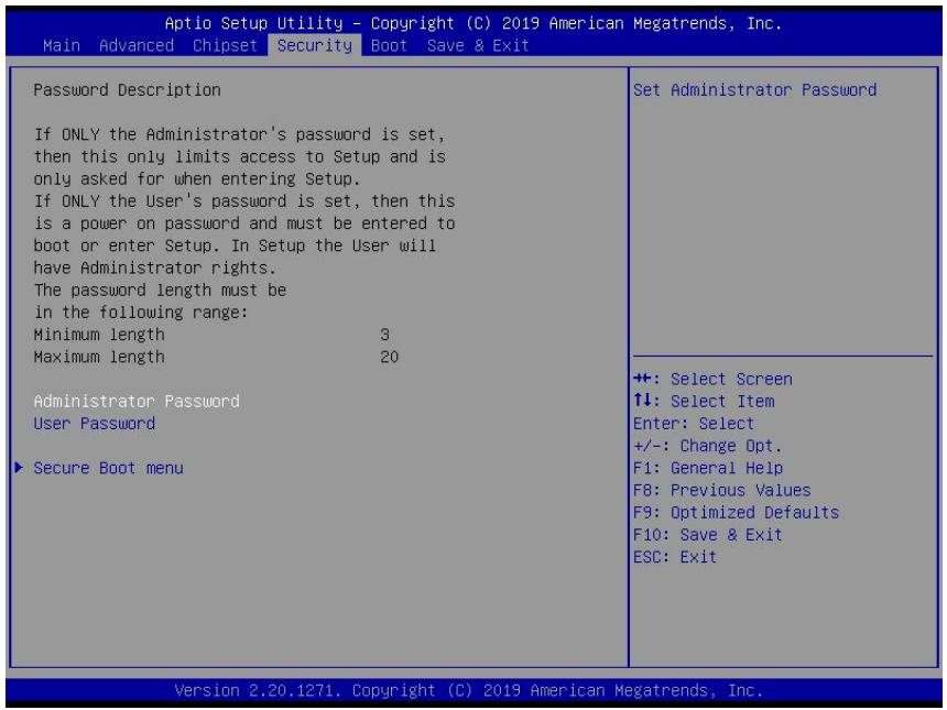
# 7.4 Security
![Aptio Setup Utility - Copyright (C) 2019 American Megatrends, Inc.\nMain Advanced Chipset Security Boot Save & Exit\nPassword Description\nIf ONLY the Administrator's password is set,\nthen this only limits access to Setup and is\nonly asked for when entering Setup.\nIf ONLY the User's password is set, then this\nis a power on password and must be entered to\nboot or enter Setup. In Setup the User will\nhave Administrator rights.\nThe password length must be\nin the following range:\nMinimum length 3\nMaximum length 20\nAdministrator Password\nUser Password\n► Secure Boot menu\nSet Administrator Password\n+: Select Screen\n↑↓: Select Item\nEnter: Select\n+/-: Change Opt.\nF1: General Help\nF8: Previous Values\nF9: Optimized Defaults\nF10: Save & Exit\nESC: Exit\nVersion 2.20.1271. Copyright (C) 2019 American Megatrends, Inc.](.dlap-8100-50m-41061-1010-11/29238e9ba15b8d98b33ca903af71ce506bb5d66fe91fa45fee9034a28f6a2281.jpg)

If only the Administrator password is set, access is limited, and the password is requested on Setup. If the User password is set, it acts as a power-on password and must be entered to boot or access setup.

# Administrator Password

Sets the Administrator password.

# User Password

Sets the User password.

# Secure Boot Menu

Configures Secure Boot.

# 7.4.1 Security > Secure Boot Menu

<table><tr><td colspan="2">Aptio Setup - AMI</td></tr><tr><td>Security</td><td></td></tr><tr><td>System Mode User</td><td></td></tr><tr><td>Secure Boot [Disabled] Not Active</td><td></td></tr><tr><td>Secure Boot Mode [Standard]</td><td></td></tr><tr><td>►Restore Factory Keys</td><td></td></tr><tr><td>►Reset To Setup Mode</td><td></td></tr><tr><td>►Key Management</td><td></td></tr><tr><td></td><td>+: Select Screen
↑↓: Select Item
Enter: Select
+/-: Change Opt.
F1: General Help
F8: Previous Values
F9: Optimized Defaults
F10: Save &amp; Exit
ESC: Exit</td></tr><tr><td colspan="2">Version 2.22.1293 Copyright (C) 2025 AMI</td></tr></table>

# Secure Boot Control

Active if Secure Boot is enabled, the Platform Key (PK) is enrolled, and the system is in User mode. A mode change requires a platform reset.

# Secure Boot Mode

Selects between Standard or Custom. In Custom mode, Secure Boot Policy variables can be configured by a physically present user without full authentication.

# Restore Factory Keys

Force system to user mode. Install factory default secure boot key databases.

# Reset to Setup Mode

Delete all secure boot key databases from NVRAM.

# Key Management

Enables expert users to modify Secure Boot Policy variables without full authentication.

# 7.5 Boot

<table><tr><td colspan="2">Aptio Setup - AMI</td></tr><tr><td colspan="2">Main Advanced Chipset Security Boot Save &amp; Exit MEBx</td></tr><tr><td>Boot Configuration
Setup Prompt Timeout 1
Bootup NumLock State [Off]
Quiet Boot [Enabled]
Fast Boot [Disable Link]</td><td>Number of seconds to wait for setup activation key. The maximum value is 8</td></tr><tr><td>Boot Configuration
Boot Option #1 [Hard Disk]
Boot Option #2 [NVME]
Boot Option #3 [UEFI AP]
Boot Option #4 [CD/DVD]
Boot Option #5 [SD]
Boot Option #6 [USB Hard Disk]
Boot Option #7 [USB CD/DVD]
Boot Option #8 [USB Key:UEFI:
SanDisk, Partition 1]
Boot Option #9 [USB Floppy]
Boot Option #10 [USB Lan]
Boot Option #11 [Network]</td><td>+: Select Screen
↑1: Select Item
Enter: Select
+/-: Change Opt.
F1: General Help
F8: Previous Values
F9: Optimized Defaults
F10:Save &amp; Exit
ESC: Exit</td></tr><tr><td>UEFI USB Key Drive BBS Priorities</td><td></td></tr></table>

# Setup Prompt Timeout

Number of seconds to wait for setup activation key. The maximum value is 8.

# Bootup Num-Lock State

Sets the keypad Num Lock status following boot.

Quiet Boot

<table><tr><td>Option</td><td>Description</td></tr><tr><td>Disabled</td><td>Directs BIOS to display POST messages</td></tr><tr><td>Enabled</td><td>Directs BIOS to display the OEM logo.</td></tr></table>

Fast Boot

<table><tr><td>Option</td><td>Description</td></tr><tr><td>Disabled</td><td>Directs BIOS to perform all POST tests.</td></tr><tr><td>Enabled</td><td>Directs BIOS to skip certain POST tests to boot faster.</td></tr></table>

While enabling Fast Boot can reduce system ready time, certain prerequisites may reduce its effectiveness.

# Boot Configuration

Specifies the priority of boot devices, all of which are detected during POST and displayed. Select the desired device by clicking on "Target Boot Option #."

# UEFI USB Hard Drive Disk Drives BBS Priorities

Specifies the boot device priority sequence for available UEFI USB drives.

# 7.6 Save & Exit

![Aptio Setup Utility - Copyright (C) 2019 American Megatrends, Inc.\nMain Advanced Chipset Security Boot Save & Exit\n\nSave Changes and Exit\nDiscard Changes and Exit\nSave Changes and Reset\nDiscard Changes and Reset\n\nSave Options\nSave Changes\nDiscard Changes\n\nRestore Defaults\nSave as User Defaults\nRestore User Defaults\n\nBoot Override\nUEFI: JetFlashTranscend 64GB 1100, Partition 1\nLaunch EFI Shell from filesystem device\n\n+: Select Screen\n↑↓: Select Item\nEnter: Select\n+/-: Change Opt.\nF1: General Help\nF8: Previous Values\nF9: Optimized Defaults\nF10: Save & Exit\nESC: Exit\n\nVersion 2.20.1271. Copyright (C) 2019 American Megatrends, Inc.](.dlap-8100-50m-41061-1010-11/52541642777efc49bf3533fa70ac58aebfe5c63f9fadf7776f6192fb02e4fb13.jpg)

# Save Changes and Exit

Exits system setup after saving the changes.

# Discard Changes and Exit

Exits system setup without saving any changes.

# Save Changes and Reset

Resets the system setup after saving changes.

# Discard Changes and Reset

Resets system setup without saving any changes.

# Save Changes

Saves the changes made so far to the setup options.

# Discard Changes

Discards the changes made so far to the setup options.

# Restore Defaults

Restores all BIOS options to their default settings, designed for maximum system stability but lower performance.

Select "Restore Defaults" if the computer encounters system configuration problems.

# Save as User Defaults

Saves all changes made so far as User Defaults.

# Restore User Defaults

Restores user defaults to all setup options.

# Launch EFI Shell from Filesystem Device

Attempts to launch the EFI Shell application (Shell.efi) from one of the available filesystem devices.

# 8. Appendix A BIOS Settings

The Basic Input/Output System (BIOS) is a program that provides a basic level of communication between the processor and peripherals. In addition, the BIOS contains code for various advanced features specific to the DLAP-8100. The BIOS setup program includes menus for configuring settings and enabling features of the DLAP-8100. Most users do not need to use the BIOS setup program, as the DLAP-8100 ships with default settings that work well for most configurations.

Enter the BIOS setup by pressing DEL when the system is powered on and the POST (Power-On Self-Test) message is displayed. The DLAP-8100 controller also supports a one-time Boot Menu, allowing you to select the boot device. Enter the Boot Menu by pressing F7 during POST.

![The image displays a digital icon of a white document with a folded top-right corner. Faint horizontal gray lines run across the document, suggesting text or a list. A large, bold red checkmark is superimposed over the center of the document.](.dlap-8100-50m-41061-1010-11/62655d62ecbdf4fc32d28cf684dd35ab38fea53760563be8c8f6a0d603ed237f.jpg)
NOTE:

 BIOS options listed are for reference only.
 Different configurations can affect BIOS behavior.
 Displayed material may reflect only the BIOS
version corresponding to initial release and may differ from that of the purchased motherboard.
 Users are welcome to download the latest BIOS version from our official website.

This page intentionally left blank.

# 9. Appendix C Watchdog Timer (WDT) Function Library

This appendix describes the use of the watchdog timer (WDT) function library for the DLAP-8100 controller. The watchdog timer is a hardware mechanism designed to reset the system if the operating system or an application stall. After activation, the watchdog timer in the application must be periodically reset before it expires. Once the watchdog timer expires, a hardware-generated signal is sent to reset the system.

# 9.1 WDT with API/Windows

The WDT API library files and a demo program (incl. source code) can be downloaded here: https://www.adlinktech.com/Products/Industrial\_PCs\_Fanless\_Embedded\_PCs/IPCSystems/DLAP-8100\_Series

To use the WDT function library for the DLAP-8100, include the header file WDT.h and the linkage library WDT.lib in your C++ project.

# 9.1.1 InitWDT

Initializes the watchdog timer function. Must be called before the invocation of any other WDT function.

# Syntax

C/C++

BOOL InitWDT()

# Parameters

None

# Return codes

TRUE If watchdog timer has successfully initialized.

FALSE If watchdog timer fails to initialize.

# 9.1.2 SetWDT

Sets the timeout value of the watchdog timer. This function takes two parameters: one to indicate the timeout ticks and the other to specify the unit. ResetWDT or StopWDT should be called before the expiration of watchdog timer, or the system will reset.

# Syntax

C/C++

BOOL SetWDT(BYTE tick, BYTE unit)

# Parameters

• tick

Specify the number of ticks for watchdog timer. A valid value is 1 - 255.

• unit

Specifies the timeout ticks of the watchdog timer.

<table><tr><td>Value</td><td>Description</td></tr><tr><td>0</td><td>The unit for one tick is one second. For example, when one tick is specified as 100 and the unit as 0, the timeout value is 100 seconds.</td></tr><tr><td>1</td><td>The unit for one tick is one minute. For example, when one tick is specified as 100 and the unit as 1, the timeout value is 100 minutes.</td></tr></table>

# Return codes

TRUE If timeout value of watchdog timer has successfully set.

FALSE If timeout value of watchdog timer fails to set.

# 9.1.3 StartWDT

Start the watchdog timer function. Once StartWDT is invoked, the watchdog timer starts. RESETWDT or StopWDT should be called before the expiration of the watchdog timer, or the system will reset.

# Syntax

C/C++

BOOL StartWDT()

# Parameters

None

# Return codes

TRUE If the watchdog timer has successfully started.

FALSE If the watchdog timer fails to start.

# 9.1.4 ResetWDT

Reset the watchdog timer. The invocation of ResetWDT allows restoration of the watchdog timer to the initial timeout value specified in the SetWDT function. ResetWDT or StopWDT should be called before the expiration of the watchdog timer, or the system will reset.

# Syntax

C/C++

BOOL ResetWDT()

# Parameters

None

# Return codes

TRUE If the watchdog timer has successfully reset.

FALSE If the watchdog timer fails to reset.

# 9.1.5 StopWDT

Stops the watchdog timer.

# Syntax

C/C++

BOOL StopWDT()

# Parameters

None

# Return codes

TRUE If the watchdog timer has successfully stopped.

FALSE If the watchdog timer fails to stop.

# 9.2 WDT with DOS/Linux

Under Linux, program the WDT function using the same LPC I/O registers according to the sample program below:

```c
#include &lt;dos.h&gt;
#include &lt;stddef.h&gt;
#include &lt;stdio.h&gt;

/* Config LPC IO NCT6102D to enter config mode */ EnterConfig(void)
{
    outp(0x4E, 0x87); outp(0x4E, 0x87);
}

/* Config LPC IO to exit config mode */ ExitConfig(void)
{
    outp(0x4E, 0xAA);
}

/* Read byte from LPC IO register */ unsigned char r_reg(unsigned char regoffset)
{
    outp(0x4E, regoffset); return inp(0x4F); }

/* Write byte to LPC IO register */
void w_reg(unsigned char regoffset, unsigned char data)
{
    outp(0x4E, regoffset); outp(0x4F, data);
}

main(void)
{
    unsigned int count;
    /* print program title */
    printf("----MXC-6400 WDT Demo----
    ---\n");
    printf("Init and config GPIO ports&lt;&lt;&lt;&lt;&lt;&lt;&lt;&lt;&lt;&lt;&lt;&lt;&lt;&lt;\n");
    printf("----
    ----\n");
    EnterConfig();
    /* config WDT registers */ w_reg(0x07,0x08);
    /* enable keyboard interrupt to reset WDT timeout value */
    w_reg(0xF2,r_reg(0xF2)|0x40);
    /* set unit as second */ w_reg(0xF0,r_reg(0xF0)&~0x04);
    /* start the Watchdog */ w_reg(0x30,0x01);
    /* set timeout value as 30 seconds */
    /* WDT start automatically while timeout value is set
    */ w_reg(0xF1,0x1E);

    printf("----
    ----\n");
```

```c
printf("WDT is set and counting down now.&lt;&lt;&lt;&lt;&lt;&lt;&lt;&lt;&lt;&lt;&lt;&lt;&lt;&lt;&lt;\n");
printf("_____
----\n");
for(count=30;count!=0;count--)
{ printf("Countdown %2d : .\n",count);
/* reset WDT timeout value to 10 seconds */
/* w_reg(0x73,0x0A); */ sleep(1);
}
/* disable WDT */
/* WDT stop while timeout value is set to zero */ w_reg(0x30,0x00);
printf("WDT is disable. Program is terminating."); ExitConfig();
return 0;
}
```

# 10. Appendix D Digital Input/Output with Function Library

DI/O provides input/output support for inter-device communications. Simple programming guides enable easy transmission of digital signals between the system and attached peripherals.

# DI/O with API/Windows

Matrix DI/O API library files and a demo program (including source code) can be downloaded from https://www.adlinktech.com/Products/Industrial\_PCs\_Fanless\_Embedded\_PCs/IPCSystems/DLAP-8100\_Series?lang=zh-Hant.

To use the DI/O function library for the DLAP-8100 series, include the header file awl.h and the linkage library awl.lib in your C++ project.

The DI/O functions are as follows:

# AwlDioGetValue

Reads the digital logic state of a digital input line.

# Syntax

C/C++

```lisp
int _ stdcall AwlDioGetValue(int Index)
```

# Parameter(s)

Index

Indexes the digital logic state of the DLAP-8100 digital input channels 1 to 8 (bit 0 to 7).

# Return codes

0: Operation success

-1: Operation failed

# AwlDioSetValue

Sets the digital logic state of the digital output line.

# AwlDioGetValue

Reads the digital logic state of a digital input line.

# Syntax

C/C++

```txt
Int stdcall AwlDioSetValue(int Index, int Value);
```

# Parameter(s)

Index

Indexes the digital logic state of the DLAP-8100 digital input channels 1 to 8 (bits 0 to 7).

# Value

Sets the digital logic state of the DLAP-8100 digital output channels 1 to 8 (bits 0 to 7) to 0 or 1.

# Return Codes

0: Operation successful

-1: Operation failed

# Safety Instructions

For user safety, please read and follow all instructions, Warnings, Cautions, and Notes marked in this manual and on the associated device before handling/operating the device, to avoid injury or damage.

S'il vous plaît prêter attention stricte à tous les avertissements et mises en garde figurant sur l'appareil , pour éviter des blessures ou des dommages.

► Read these safety instructions carefully.
► Keep the User’s Manual for future reference.
► Read the Specifications section of this manual for detailed information on the recommended operating environment.
► When installing/mounting or uninstalling/removing device; or when removal of a chassis cover is required for user servicing (See “Getting Started”):
[&gt; Turn off power and unplug any power cords/cables.
[> Reinstall all chassis covers before restoring power.
► To avoid electrical shock and/or damage to device:
[> Keep device away from water or liquid sources.
[> Keep device away from high heat or humidity.
[> Keep device properly ventilated (do not block or cover ventilation openings).
[> Always use recommended voltage and power source settings.
[> Always install and operate device near an easily accessible electrical outlet.
[> Secure the power cord (do not place any object on/over the power cord) and connect it to a socket-outlet with earthing connection.
[> Only install/attach and operate device on stable surfaces and/or recommended mountings.
► If the device will not be used for long periods of time, turn off and unplug from its power source.
► Never attempt to repair the device, which should only be serviced by qualified technical personnel using suitable tools.
► A Lithium-type battery may be provided for uninterrupted backup or emergency power.

![The image displays a yellow triangular warning sign with a black border and a large black exclamation point in the center. Vertical black lines are visible on the left and right edges of the frame.](.dlap-8100-50m-41061-1010-11/a58ea4dcdd39337bdd4255bc2dbcc3305535f75bcbbb54097824dea99d996544.jpg)
CAUTION:

Risk of explosion if battery is replaced with one of an incorrect type; please dispose of used batteries appropriately.

Risque d’explosion si la pile est remplacée par une autre de type incorrect. Veuillez jeter les piles usagées de façon appropriée.

► The device must be serviced by authorized technicians when:

[> The power cord or plug is damaged.
[> Liquid has entered the device interior.
[> The device has been exposed to high humidity and/or moisture.
[> The device is not functioning or does not function according to the User’s Manual.
[> The device has been dropped and/or damaged and/or shows obvious signs of breakage.

? Disconnect the power supply cord before loosening the thumbscrews and always fasten the thumbscrews with a screwdriver before starting the system up.

[> The equipment is not intended to be installed or used in a home, school, or public area accessible to the general population.
[> The knurled thumb screws with slotted heads for each Node module should be tightened with a tool after both initial installation and subsequent use.

► It is recommended that the device be installed only in a server room or computer room where access is:

[> Restricted to qualified service personnel or users familiar with restrictions applied to the location, reasons therefore, and any precautions required.

[> Only afforded by the use of a tool or lock and key, or other means of security, and controlled by the authority responsible for the location.

► Please use an approved power source certified by IEC or UL. If you need an adapter, optional accessories, or further assistance, please contact ADLINK for more information.

![The image displays a yellow triangular warning sign with a thick black border. Inside the triangle is a black symbol consisting of three vertical wavy lines rising from a horizontal line, indicating a hot surface.](.dlap-8100-50m-41061-1010-11/763e357d14c1c3ba62b8e292ca4987bdab8fa51e9e1ec1e3824ec309295da641.jpg)

# BURN HAZARD

Touching this surface could result in bodily injury. To reduce risk, allow the surface to cool before touching.

# RISQUE DE BRÛLURES

Ne touchez pas cette surface, cela pourrait entraîner des blessures. Pour éviter tout danger, laissez la surface refroidir avant de la toucher.

► Lisez attentivement ces consignes de sécurité
► Conservez le manuel de l'utilisateur pour pouvoir le consulter ultérieurement
Lisez la section Spécifications de ce manuel pour des informations détaillées sur l'environnement d'exploitation recommandé
Lors de l'installation/montage ou de la désinstallation/retrait de l'appareil ; ou lorsque le retrait d'un boîtier est nécessaire pour l'entretien par l'utilisateur (voir Mise en route) :
► Éteignez l'alimentation et débranchez tous les cordons/câbles d'alimentation.
► Réinstallez tous les panneaux du boîtier avant de remettre l'alimentation sous tension.
► Pour éviter les chocs électriques et/ou d’endommager l’appareil :

► Tenez l'appareil à l'écart de toute source d'eau ou de liquide
► Tenez l'appareil à l'écart d'une forte chaleur ou d'une humidité élevée
► Maintenez l'appareil correctement ventilé (n'obstruer ou ne couvrez pas les ouvertures de ventilation)
► Utilisez toujours les réglages de tension et de source d'alimentation recommandés
► Installez et utilisez toujours l'appareil près d'une prise de courant facilement accessible
Fixez le cordon d'alimentation (ne placez aucun objet sur/au-dessus du cordon d'alimentation) et connectez-le à une prise de courant avec mise à la terre

► N'essayez jamais de réparer l'appareil, qui doit être réparé uniquement par du personnel technique qualifié et utilisant des outils appropriés.

► Lors de l'installation/montage ou de la désinstallation/retrait d'un périphérique, ou lorsque le retrait d'un couvercle de châssis est requis pour l'entretien par l'utilisateur :
► Coupez l’alimentation et débranchez tous les cordons/câbles d’alimentation.

► Réinstallez tous les capots du châssis avant de rétablir l'alimentation. Installez/fixez et utilisez l'appareil uniquement sur des surfaces stables et/ou des supports recommandés.

► Si l'appareil n'est pas utilisé pendant une longue période, éteignez-le et débranchez-le de sa source d'alimentation.

► Une batterie de type lithium peut être fournie pour une alimentation de secours ou de secours ininterrompue.

► L'appareil doit être réparé par des techniciens agréés lorsque :
► Le cordon d'alimentation ou la fiche est endommagé.
► Du liquide est entré dans l’appareil. € L'appareil a été exposé à une humidité élevée et/ou à l'humidité.
► L'appareil ne fonctionne pas ou ne fonctionne pas conformément au manuel de l'utilisateur.

► L'appareil est tombé et/ou a été endommagé et/ou présente des signes évidents de casse.
► Débranchez le cordon d'alimentation avant de desserrer les vis moletées et fixez toujours les vis moletées avec un tournevis avant de démarrer le système.
L'équipement n'est pas destiné à être installé ou utilisé dans une maison, une école ou une zone publique accessible au grand public.
Les vis à molette avec têtes fendue pour chaque module Node doivent être serrées avec un outil après l'installation initiale et lors de l'utilisation suivante.
► Il est recommandé d'installer l'appareil uniquement dans une salle de serveurs ou une salle informatique dont l'accès est :

Réservé au personnel de service qualifié ou aux utilisateurs familiers avec les restrictions appliquées à l'emplacement, les raisons de celles-ci et les précautions requises.
Autorisé uniquement par l'utilisation d'un outil ou d'une serrure et d'une clé, ou d'autres moyens de sécurité, et contrôlé par l'autorité responsable du lieu.

► Veuillez utiliser une source d'alimentation approuvée et certifiée par la norme IEC ou UL. Si vous avez besoin d'un adaptateur, d'accessoires en option ou d'une assistance supplémentaire, veuillez contacter ADLINK pour plus d'informations.

# Getting Services

Ask an Expert: https://www.adlinktech.com/en/Askanexpert

# ADLINK Technology, Inc.

Address: No. 66, Huaya 1st Road, Guishan District Taoyuan City 333, Taiwan

Tel: +886-3-216-5088

Fax: +886-3-328-5723

Email: service@adlinktech.com

# Ampro ADLINK Technology, Inc.

Address: 6450 Via Del Oro, San Jose, CA 95119, USA

Tel: +1-408-360-0200

Toll Free: +1-800-966-5200 (USA only)

Fax: +1-408-600-1189

Email: info@adlinktech.com

# ADLINK Technology (China) Co., Ltd.

Address: 300 Fang Chun Rd., Zhangjiang Hi-Tech Park, Pudong New Area Shanghai, 201203 China

Tel: +86-21-5132-8988

Fax: +86-21-5132-3588

Email: market@adlinktech.com

# ADLINK Technology GmbH

Address: Hans-Thoma-Strasse 8-10, 68163 Mannheim, Germany

Tel: +49-621-43214-0

Fax: +49-621 43214-30

Email: emea@adlinktech.com

Please visit the Contact page at www.adlinktech.com for information on how to contact the ADLINK regional office nearest you.
[🔗 Link to the original document](.dlap-8100-50m-41061-1010-11/dlap-8100-50m-41061-1010-11.pdf)
