# ECAT-4XMO Series

ECAT-4XMO/ECAT-TRG4

EtherCAT Distributed 4-axis

Motion Control and Trigger Module

User’s Manual

![Interior view of an electronic device chassis with multiple connectors and a central display unit (no visible text or symbols)](.ecat-4xmo-trg4-50m-00003-1010-11/803ba6e395139cb59e3ad1bb94e371208cecd981eb7136337f7c6ce7fda03fa1.jpg)

Manual Rev.: 1.1

Revision Date: March 4, 2021

Part No: 50M-00003-1010

Revision History

<table><tr><td>Revision</td><td>Release Date</td><td>Description of Change(s)</td></tr><tr><td>1.0</td><td>2021-01-08</td><td>Initial release</td></tr><tr><td>1.1</td><td>2021-03-04</td><td>Update Servo I/O CM1-CM4 connector diagram</td></tr></table>

# Preface

# Copyright © 2021 ADLINK Technology Inc.

This document contains proprietary information protected by copyright. All rights are reserved. No part of this manual may be reproduced by any mechanical, electronic, or other means in any form without prior written permission of the manufacturer.

# Disclaimer

The information in this document is subject to change without prior notice in order to improve reliability, design, and function and does not represent a commitment on the part of the manufacturer.

In no event will the manufacturer be liable for direct, indirect, special, incidental, or consequential damages arising out of the use or inability to use the product or documentation, even if advised of the possibility of such damages.

# Environmental Responsibility

ADLINK is committed to fulfill its social responsibility to global environmental preservation through compliance with the European Union's Restriction of Hazardous Substances (RoHS) directive and Waste Electrical and Electronic Equipment (WEEE) directive. Environmental protection is a top priority for ADLINK. We have enforced measures to ensure that our products, manufacturing processes, components, and raw materials have as little impact on the environment as possible. When products are at their end of life, our customers are encouraged to dispose of them in accordance with the product disposal and/or recovery programs prescribed by their nation or company.

![Symbol of a trash bin crossed with two crossed lines and a solid rectangle below (no text or labels)](.ecat-4xmo-trg4-50m-00003-1010-11/1c0b2afd71260f12057774675e3c9b44a2b4f5d545835c96e34d572dd052b0e5.jpg)

Battery Labels (for products with battery)

![Symbol of a trash bin crossed out by two diagonal lines (no text or numbers present)](.ecat-4xmo-trg4-50m-00003-1010-11/7690f56ad340f5efaf957850c4edd8da1f33f5afe5168970f4f95fc33e971c34.jpg)

![Recycling symbol icon with three chasing arrows inside a square frame (no text or labels)](.ecat-4xmo-trg4-50m-00003-1010-11/114e23d4ac1030b6877eec481f4ed9631cc425ba279138ea315cfa487ccb1580.jpg)

Li-ion

![RECYCLE\nRBRC\nLi-ion\n1.800.822.8837](.ecat-4xmo-trg4-50m-00003-1010-11/a26b845cd4bf26a3a823d8c3a1a1f2cb364349294470cca376d97fd85c2e1fbb.jpg)

![Abstract geometric pattern with interlocking X and Y shapes (no text or symbols)](.ecat-4xmo-trg4-50m-00003-1010-11/0fc07bbcaf47c452b982fa6a8e4a7eacb6e06e4190c58057dc651f20cbc05acc.jpg)

ᘄ㟁ụㄳᅇᨲ

# California Proposition 65 Warning

![The image displays a standard warning symbol featuring a yellow equilateral triangle with a thick black border. Inside the triangle is a single black exclamation point.](.ecat-4xmo-trg4-50m-00003-1010-11/dc6a48b203dbbc853982cacbec9b523f9625a88cea0feb8226efd40c74dcb229.jpg)

WARNING: This product can expose you to chemicals including acrylamide, arsenic, benzene, cadmium, Tris(1,3-dichloro-2-propyl) phosphate (TDCPP), 1,4- Dioxane, formaldehyde, lead, DEHP, styrene, DINP, BBP, PVC, and vinyl materials, which are known to the State of California to cause cancer, and acrylamide, benzene, cadmium, lead, mercury, phthalates, toluene, DEHP, DIDP, DnHP, DBP, BBP, PVC, and vinyl materials, which are known to the State of California to cause birth defects or other reproductive harm. For more information go to www.P65Warnings.ca.gov.

# Trademarks

Product names mentioned herein are used for identification purposes only and may be trademarks and/or registered trademarks of their respective companies.

# Conventions

Take note of the following conventions used throughout this manual to make sure that users perform certain tasks and instructions properly.

![The image shows an icon of a white document with a folded top-right corner and horizontal lines across it. A large red checkmark is superimposed over the document.](.ecat-4xmo-trg4-50m-00003-1010-11/ac7f830388ba9798daab78b4f90468af36e93ef7fc4aa01ecaf846dc4d790db9.jpg)
NOTE:

Additional information, aids, and tips that help users perform tasks.

![The image displays a standard warning symbol consisting of a yellow triangle with a thick black border pointing upwards. Inside the triangle is a large, black exclamation point. Above the top vertex of the triangle, there is a horizontal black line.](.ecat-4xmo-trg4-50m-00003-1010-11/51998c7df893de147cf9702d0681b7d2796e88f1a31bb8207b5e5249c0fbadc3.jpg)
CAUTION:

Information to prevent minor physical injury, component damage, data loss, and/or program corruption when trying to complete a task.

ATTENTION: Informations destinées à prévenir les blessures corporelles mineures, les dommages aux composants, la perte de données et/ou la corruption de programme lors de l'exécution d'une tâche.

![The image shows a red triangular warning symbol containing a large white exclamation point in the center. It is set against a white background, with a black horizontal line visible at the very top edge.](.ecat-4xmo-trg4-50m-00003-1010-11/2443da87a8501d5edfd3f1bfda9252f2a61de7a58de1d922734c3199b4203a0a.jpg)
WARNING:

Information to prevent serious physical injury, component damage, data loss, and/or program corruption when trying to complete a specific task.

AVERTISSEMENT: Informations destinées à prévenir les blessures corporelles graves, les dommages aux composants, la perte de données et/ou la corruption de programme lors de l'exécution d'une tâche spécifique.

# Table of Contents

# Preface ......... iii

# List of Tables ......... ... vii

# List of Figures ........ ix

# 1 Introduction ........

1.1 Overview... 1
1.2 Features... 2
1.3 Specifications...... 2
1.4 Supported Software ... 4

# 2 Getting Started ..... 7

2.1 Installation Environment . 7
2.2 Package Contents .... 8

# 3 ECAT-4XMO/TRG4 Layout...... 9

3.1 Mechanical Dimensions.. 9
3.2 ECAT-4XMO/TRG4 Interfaces ... 1 0
3.3 Servo I/O Connectors (CM1-CM4) .... 1 1
3.4 Motion I/O Connectors (IOIF1-4) .. 1 2
3.5 Board ID Switch (S1) .... 1 3
3.6 LED Indicators (4XMO only) ...... 13
3.7 DO to Alarm Reset Switch (S3, S5) (4XMO only).............. 14
3.8 EMG Jumper (JP3) ...... 14
3.9 Power Connector (J1).. 1 5
3.10 Trigger Out Connector (CN1) ...... 16
3.11 I/O Power Source Selection (JP5, JP6).... 17
3.12 Power/Run/Error LED Indicator .... 17
3.13 RJ45 LED Indicator.... 18
3.14 EA1+/-, EB1+/- Connect Selection (SW1) . 19
3.15 Encoder Re-driver Input Connector (CN6) . 20

3.16 Encoder Re-driver Output Connector (CN7)............ 21

# 4 Signal Connections ....... . 23

4.1 Emergency Stop Signal (EMG).. 23
4.2 Trigger Output Signals (CMP+/CMP-) .. . 24
4.3 Pulse Output Signals (OUT/DIR) .... 25
4.4 Encoder Feedback Signals (EA/EB/EZ) .. 27
4.5 Origin Signals (ORG) ... 29
4.6 End-Limit Signals (PEL/MEL) . 31
4.7 In-position Signal (INP) . 33
4.8 Alarm Signal (ALM)..... 34
4.9 General Purpose Signal (SVON) ..... 35
4.10 Deviation Counter Clear Signal (ERC)..... 3 6
4.11 General-purpose Signal (RDY).. 37
4.12 General Purpose Digital Output Signals (DO) ........... 38
4.13 General Purpose Digital Input Signals (DI).... 39

# Important Safety Instructions........ 41

# Consignes de Sécurité Importante ......... 43

# Getting Service .......... . 47

# List of Tables

Table 3-1: Board Features Legend.. . 10
Table 3-2: Servo I/O Connectors (CM1-CM4) Pin Definition .......... 11
Table 3-3: Motion I/O Connectors (IOIF1-4) Pin Definition ............. 12
Table 3-4: LED Indicator Colors... . 13
Table 3-5: DO to Alarm Reset Switch (S3, S5) Pin Definition......... 14
Table 3-6: EMG Jumper (JP3) Pin Definition.. . 14
Table 3-7: Power Connector (J1) Pin Definition... . 15
Table 3-8: Trigger Out Connector (CN1) Pin Definition ......... . 16
Table 3-9: I/O Power Selection (JP5, JP6) Pin Definition ............... 17
Table 3-10: Power/Run/Error LED Indicator .. . 17
Table 3-11: RJ45 LED Indicator.... . 18
Table 3-12: EA1+/-, EB1+/- Connect Selection (SW1) .. . 19
Table 3-13: Encoder Re-driver Input Connector (CN6) . . 20
Table 3-14: Encoder Re-driver Output Connector (CN7)...... . 21

This page intentionally left blank.

# List of Figures

Figure 3-1: ECAT-4MXO Top View.. 9

Figure 3-2: ECAT-4MXO Side View.. 9

Figure 3-3: ECAT-4XMO/TRG4 Interfaces . . 10

Figure 3-4: Servo I/O Connectors (CM1-CM4) Pin Definition .......... 11

Figure 3-5: Motion I/O Connectors (IOIF1-4) Pin Definition ............. 12

Figure 3-6: Board ID Switch (S1) Pin Definition ... . 13

Figure 3-7: DO to Alarm Reset Switch (S3, S5) Pin Definition......... 14

Figure 3-8: EMG Jumper (JP3) Pin Definition.. . 14

Figure 3-9: Power Connector (J1) Pin Definition... . 15

Figure 3-10: Trigger Out Connector (CN1) Pin Definition ......... . 16

Figure 3-11: I/O Power Selection (JP5, JP6) Pin Definition ............... 17

Figure 3-12: RJ45 LED Indicator.. . 18

Figure 3-13: EA1+/-, EB1+/- Connect Selection (SW1) ...... .. 19

Figure 3-14: Encoder Re-driver Input Connector (CN6) . .. 20

Figure 3-15: Encoder Re-driver Output Connector (CN7)............... ... 21

Figure 4-1: Emergency Stop Wiring Diagram . .. 23

Figure 4-2: Trigger Output Signals Wiring Diagram. .. 24

Figure 4-3: OUT/DIR Signal Axis Wiring Diagram .. .. 26

Figure 4-4: OUT/DIR Pulse Output Signal Circuit. .. 26

Figure 4-5: Encoder Feedback Signals (EA/EB/EZ) Circuit ............. 28

Figure 4-6: Connection to Line Driver Output Circuit . .. 28

Figure 4-7: Origin Signals (ORG) Input Circuit.. .. 30

Figure 4-8: End-Limit Signals (PEL/MEL) Circuits .. 32

Figure 4-9: In-position Signal (INP) Circuit.. .. 33

Figure 4-10: Alarm Signal (ALM) Circuit . 34

Figure 4-11: General Purpose Signal (SVON) Circuit.. . 35

Figure 4-12: Deviation Counter Clear Signal (ERC) Circuit ............... 36

Figure 4-13: General-purpose Signal (RDY) Circuit.. . 37

Figure 4-14: DO Signal Circuit . .. 38

Figure 4-15: DI Signal Circuit .. . 39

This page intentionally left blank.

# 1 Introduction

# 1.1 Overview

The ECAT-4XMO/TRG4 is a 4-axis motion controller module for EtherCAT distributed motion systems. It can generate fast frequency pulses to drive stepper or servomotors for machine automation and provides comprehensive motion functions which include 2D/3D circular interpolation, up to 32 sets Gantry function, 2-4 axis linear interpolation, or continuous interpolation for continual velocity. Changing position/speed on the fly is available with a single axis operation.

Multiple ECAT-4XMO/TRG4 modules (up to 16 sets max.) can be used in one EtherCAT system. Incremental encoder interfaces on all four axes provide the ability to correct positioning errors generated by inaccurate mechanical transmissions. By integrating EtherCAT technology, whole motion functions can be performed with time-deterministic cycle times. In addition, a mechanical sensor interface, servo motor interface, and general-purposed I/O signals are provided for easy system integration.

The ECAT-4XMO/TRG4 applies FPGA technology to perform 4- axis motion control and supports one ECAT satellite to communicate with a host PC and EtherCAT protocol. The motion control functions include linear and S-curve acceleration/deceleration, circular interpolation between two axes, linear interpolation between 2-4 axes and 9 home return modes.

In addition to the motion functions, ADLINK offers the ECAT-4XMO/TRG4 and ECAT-TRG4 that come equipped with real-time position comparison and trigger pulse output function for easy integration into automated optical inspection application systems supporting up to 10 MHz within 255 points at 250 μs cycle time trigger output frequency. The ECAT-4XMO/TRG4 and ECAT-TRG4 also support encoder sharing that can trigger equipment by using the same encoder data. The advanced path move function features continuous moving with constant velocity. The Advance Point Table guarantees time-deterministic, continuous and smooth motion progression.

# 1.2 Features

 Up to 64 axes by EtherCAT network
 EtherCAT cycle time up to 250 μs
 Maximum wiring distance up to 100 meters between 2 stations
 4-axis pulse train output channels; frequency up to 12 MHz
 Encoder input frequency up to 20 MHz under 4x AB feedback mode
 Supports 9 homing modes
 Pulse output support OUT/DIR, CW/CCW types
 4 table triggers, maximum frequency 10 Mhz with FIFO 255 points
 4 linear triggers, maximum 10Mhz
 4-channel maximum latch response frequency 3 Mhz with 255 points
 Hardware emergency stop interface
 Supports gantry function up to 32 sets with master
 Power-off memory for axis parameter
 Supports encoder re-driver function
 Supports advanced point table

# 1.3 Specifications

<table><tr><td colspan="2">EtherCAT Communication</td></tr><tr><td>Communication Cycle Time</td><td>250 / 500 / 1000 / 2000 microsecond</td></tr><tr><td>Number of Controllable Axes</td><td>4</td></tr><tr><td>Supported Motion Modes</td><td>Single Axis Move, Multi-axes Move Trigger and Stop, Jog Move, Advanced Single Move and Interpolation, Advanced Point Table, Gear/ Gantry Function, Manual Pulse Generator Function. (Refer to ADLINK APS function library)</td></tr><tr><td colspan="2">I/O</td></tr><tr><td>Motion I/O</td><td>▶ PEL, MEL, ORG (ECAT-4XMO only)▶ LTC, CMP</td></tr><tr><td>Servo I/O</td><td>SVON, RDY, RST, ALM, INP, ERC (ECAT-4XMO only)</td></tr><tr><td>Pulse Output</td><td>OUT/DIR, frequency up to 12 MHz (ECAT-4XMO only)CW/CCW, frequency up to 12 MHz (ECAT-4XMO only)</td></tr><tr><td>Encoder Input</td><td>CW/CCW, frequency up to 8 MHzOUT/DIR, frequency up to 8 MHz1/2/4xAB, frequency up to 20 MHz</td></tr><tr><td>Encoder Re-driver</td><td>Encoder input OUT/DIR signal sharing to output pin,frequency up to 10 MHz</td></tr><tr><td>Trigger Output</td><td>4 Linear triggers max. 10 Mhz4 Table triggers max. freq. 10 Mhz (w/ FIFO 255 points)Table size = 8192 points/axis</td></tr><tr><td>Latch Input</td><td>Source type, DI/PWM 4-channel max. latch responsefrequency, 3 Mhz with 255 points(Multiple &amp; Single Point Size = 5256 points)</td></tr><tr><td>GPIO</td><td>4 DI, 4 DO(4 DO and RST share a common pin, selected by DIP switch)</td></tr><tr><td>EMG</td><td>Per Module</td></tr><tr><td>DIP Switch</td><td>▶ 6-bit for ID setting▶ 4-bit for EA1+/-, EB1+/- open/short selectionbetween CN6 and CM1▶ 4-bit for DO connect to alarm reset pin of D-SUB26P (ECAT-4XMO only)</td></tr><tr><td colspan="2">General</td></tr><tr><td>Power Consumption</td><td>5W max. (power supply input 24V DC ±10%)</td></tr><tr><td>Protection</td><td>Over current, short, reverse, 1A</td></tr><tr><td>Operating Temperature</td><td>0°C to 50°C</td></tr><tr><td>Storage Temperature</td><td>-40°C to 70°C</td></tr><tr><td>Relative Humidity</td><td>10% to 90%, non-condensing</td></tr><tr><td>Dimensions</td><td>165.3 x 74.9 x 52.7mm (W x D x H)</td></tr><tr><td colspan="2">Certificate</td></tr><tr><td>EMC</td><td>FCC Part 15b, and EN55032 (CISPR 32) for Class B</td></tr><tr><td>Safety</td><td>IEC62368; IEC61010</td></tr></table>

# 1.4 Supported Software

# 1.4.1 APS Function Library

The Automation Product Software (APS) library provides users a uniform interface to access all ADLINK products that support it, and covers many automation fields including machine automation. The APS library supports motion control with components such as system platform management, field bus communications, general digital/analog input/output, and various counter/timer support builtin, making the APS library an all-in-one solution for ADLINK products in the automation field.

There are several benefits to using the APS library.

# Hardware Independent

Because the APS library acts as middleware between different hardware, time and effort is saved that would normally be spent having to reprogram custom software interfaces each time new hardware is added or replaced. Thus, custom device programming based on hardware dependecies is eliminated.

# Operating System Independent

The standard APS package supports a variety of operating systems including Microsoft Windows XP/2000/Vista and newer verions as well as 32-bit or 64-bit single core and multi-core (SMP) patforms. Planned support for non Windows operating systems include Linux and DOS, as well as real-time operating systems like RTX and VxWorks.

# Programming Consistency

Applications like motion control, I/O control and communication benefit from the programming consistency offered by the APS library. It makes no difference whether a motor is stepper or servo, or the sytem has a distributed or centralized topology because the APS library utilizes the same programming method and parameter definitions as well as providing various programming language interfaces and programming examples like ANSI C/C++, Microsoft Visual C/C++, Visual Basic, C#, Visual Basic.NET, Borland Delphi, and C/C++ builder.

# 1.4.2 MotionCreatorPro 2 Utility

This Windows-based utility is used to setup cards, motors, and systems. It can also aid in debugging hardware and software problems. It allows users to set I/O logic parameters to be loaded in their own program. The MotionCreatorPro 2 Utility is bundled with the card.

This page intentionally left blank.

# 2 Getting Started

This chapter describes the proper installation environment, installation procedures, package contents and basic information users should be aware of regarding the ECAT-4XMO/ECAT-TRG4.

We suggest the following order of actions:

1. Unpack the ECAT-4XMO/ECAT-TRG4
2. Ensure the package contents are complete
3. Check the ECAT-4XMO/ECAT-TRG4 module for visible damage
4. Install the module
5. Install the driver

# 2.1 Installation Environment

When unpacking and preparing to install, refer to Important Safety Instructions.

Only install equipment in well-lit areas on flat, sturdy surfaces with access to basic tools such as flat- and cross-head screwdrivers, preferably with magnetic heads as screws and standoffs are small and easily misplaced.

Recommended Installation Tools

 Phillips (cross-head) screwdriver
 Flat-head screwdriver
 Anti-static wrist strap
 Antistatic mat

![This image features a yellow triangular warning sign with a black border. Centered inside the triangle is a black exclamation point. Below the triangle, the text 'CAUTION:' appears in black capital letters on a white background.](.ecat-4xmo-trg4-50m-00003-1010-11/9728af3f6634b6ae71e5a21f97871610e7f1d7a0ffd1c045d69b1a045c018f2c.jpg)

The equipment must be protected from static discharge and physical shock. Never remove any of the socketed parts except at a static-free workstation. Use the anti-static bag shipped with the product to handle the equipment and wear a grounded wrist strap when servicing.

# 2.2 Package Contents

Inspect the carton and packaging for damage. Shipping and handling can cause damage to the equipment inside. Make sure that the equipment and its associated components have no damage before installation. In addition to this User’s Manual, the package also includes either the

ECAT-4XMO EtherCAT 4-axis Motion Control Module

or the

ECAT-TRG4 EtherCAT High Speed 4Ch Trigger Module

Ensure the correct model is present and check the package condition.

If any of these items are missing or damaged, contact the dealer from whom you purchased the product.

# 3 ECAT-4XMO/TRG4 Layout

# 3.1 Mechanical Dimensions

![The image displays a simple graphic of a white piece of paper, resembling a document or a form, with faint horizontal lines across it. A large, bold red checkmark (or tick mark) is centered on the paper, slanting upwards from left to right. The top right corner of the paper appears slightly curled. There is no text in the image.](.ecat-4xmo-trg4-50m-00003-1010-11/55881d2bc7f27db356ab47abc40c67ea19d011d6bf5d70daf4e873c4dd02e409.jpg)
NOTE:

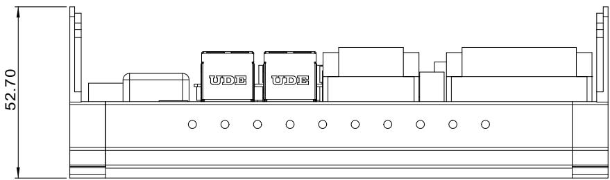
All dimensions shown are in mm.
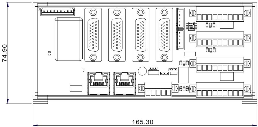
![74.90\n165.30](.ecat-4xmo-trg4-50m-00003-1010-11/e3df8feae8c2bb0b207430a37a562abf8a3888df879f659d4d66ac8302c38937.jpg)

Figure 3-1: ECAT-4MXO Top View

![52.70\nÜDIE ÜDIE](.ecat-4xmo-trg4-50m-00003-1010-11/c38c6460fcdd527e1d32a656f989b638591e2d67771d8d65c3a955030f79fd28.jpg)

Figure 3-2: ECAT-4MXO Side View

# 3.2 ECAT-4XMO/TRG4 Interfaces
![C\nE\n1 2 3 4\nK L J G\nN F M B B A I H G\n1\n2\n3\n4\nD](.ecat-4xmo-trg4-50m-00003-1010-11/b55f14b5eeffd521213d999911e87de6d7a261d9f5917c3298ae925d17e85d41.jpg)

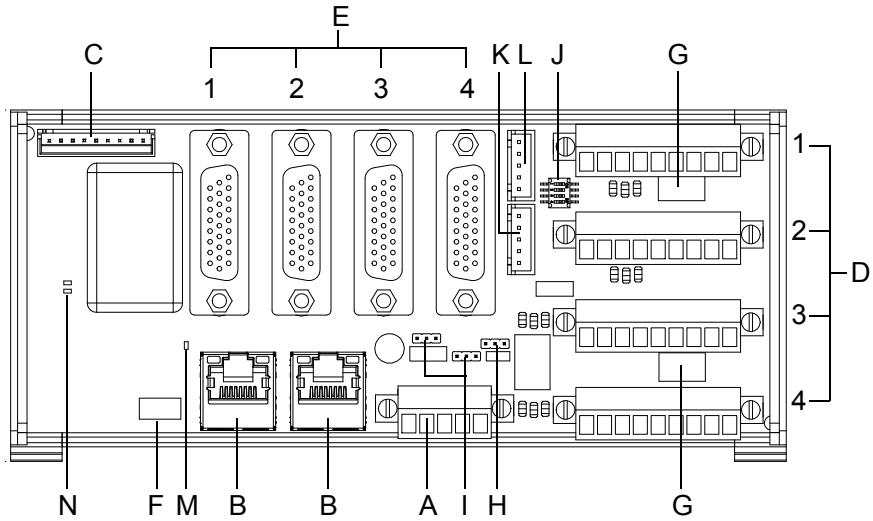
Figure 3-3: ECAT-4XMO/TRG4 Interfaces

<table><tr><td></td><td>Item</td><td>Function</td></tr><tr><td>A</td><td>J1</td><td>Power supply, input common and emergency stop input connector</td></tr><tr><td>B</td><td>RJ1, RJ2</td><td>EtherCAT communication signal connector</td></tr><tr><td>C</td><td>CN1</td><td>Compare trigger output signals</td></tr><tr><td>D</td><td>IOIF1-IOIF4</td><td>Motion I/O connector</td></tr><tr><td>E</td><td>CM1-CM4</td><td>Servo I/O connector</td></tr><tr><td>F</td><td>S1</td><td>Board ID switch</td></tr><tr><td>G</td><td>S3, S5</td><td>Enable/Disable DO to alarm reset switch (4XMO only)</td></tr><tr><td>H</td><td>JP3</td><td>Enable/Disable EMG signal (4XMO only)</td></tr><tr><td>I</td><td>JP5, JP6</td><td>Common or differential power selection</td></tr><tr><td>J</td><td>SW1</td><td>Encoder re-driver Enable/Disable selection</td></tr><tr><td>K</td><td>CN6</td><td>Encoder re-driver input connector</td></tr><tr><td>L</td><td>CN7</td><td>Encoder re-driver output connector</td></tr><tr><td>M</td><td>D6</td><td>Power LED</td></tr><tr><td>N</td><td>D7, LED2</td><td>EtherCAT status LED</td></tr></table>

Table 3-1: Board Features Legend

# 3.3 Servo I/O Connectors (CM1-CM4)
![19\n26\n10\n18\n1\n9](.ecat-4xmo-trg4-50m-00003-1010-11/9f47e6a6fe1d364c3722df90a2149e299edb762dc572d19064c883ab29e5d507.jpg)

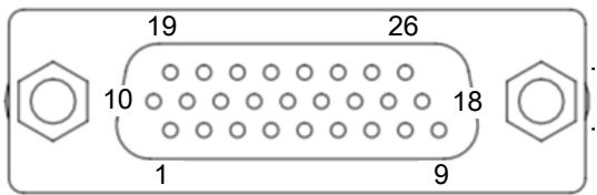
Figure 3-4: Servo I/O Connectors (CM1-CM4) Pin Definition

<table><tr><td>Pin</td><td>Signal</td><td>Function</td><td>Pin</td><td>Signal</td><td>Function</td></tr><tr><td>1</td><td>SVON</td><td>Servo on output signal</td><td>2</td><td>INP</td><td>In-position input signal</td></tr><tr><td>3</td><td>ERC</td><td>Deviation counter clear</td><td>4</td><td>RDY</td><td>Ready input signal</td></tr><tr><td>5</td><td>OUT-</td><td>Pulse signal (-)</td><td>6</td><td>OUT+</td><td>Pulse signal (+)</td></tr><tr><td>7</td><td>EA-</td><td>Encoder A-phase (-)</td><td>8</td><td>EA+</td><td>Encoder A-phase (+)</td></tr><tr><td>9</td><td>N/C</td><td>Empty</td><td>10</td><td>RST</td><td>Alarm reset output signal</td></tr><tr><td>11</td><td>ALM</td><td>Alarm input signal</td><td>12</td><td>I24V</td><td>Internal power supply, +24V</td></tr><tr><td>13</td><td>IGND</td><td>Internal power ground</td><td>14</td><td>N/C</td><td>Empty</td></tr><tr><td>15</td><td>DGND</td><td>Pulse and encoder digital ground</td><td>16</td><td>EB-</td><td>Encoder B-phase (-)</td></tr><tr><td>17</td><td>EB+</td><td>Encoder B-phase (+)</td><td>18</td><td>DGND</td><td>Pulse and encoder digital ground</td></tr><tr><td>19</td><td>EMG</td><td>Emergency Stop</td><td>20</td><td>IGND</td><td>Internal power ground</td></tr><tr><td>21</td><td>IGND</td><td>Internal power ground</td><td>22</td><td>IGND</td><td>Internal power ground</td></tr><tr><td>23</td><td>DIR-</td><td>Direction Signal (-)</td><td>24</td><td>DIR+</td><td>Direction Signal (+)</td></tr><tr><td>25</td><td>EZ-</td><td>Encoder Z-phase (-)</td><td>26</td><td>EZ+</td><td>Encoder Z-phase (+)</td></tr></table>

Table 3-2: Servo I/O Connectors (CM1-CM4) Pin Definition

![The image displays an icon of a white sheet of paper featuring faint horizontal gray lines. A large, bold red checkmark is drawn diagonally across the document, extending from the bottom left to the top right.](.ecat-4xmo-trg4-50m-00003-1010-11/75461f4eb4f851f56aade2e397b79819dcd37c95fae6508ecf9d90495eb561b1.jpg)
NOTE:

ECAT-4XMO servo I/O includes: OUT+/-, DIR+/-, EA+/-,

EB+/-, EZ+/-, EMG, ALM, INP, RDY, SVON, ERC, RST

ECAT-TRG4 servo I/O includes: EA+/-, EB+/-, EZ+/-

# 3.4 Motion I/O Connectors (IOIF1-4)

![Pure electrical circuit lines without any symbols](.ecat-4xmo-trg4-50m-00003-1010-11/1125e8847c3dd947a8458defd150842ee58490dadb551acfca59c0aaeabc935f.jpg)

Figure 3-5: Motion I/O Connectors (IOIF1-4) Pin Definition

<table><tr><td>Pin</td><td>Signal</td><td>Description</td></tr><tr><td>1</td><td>I24</td><td>I/O power supply, +24V</td></tr><tr><td>2</td><td>MEL</td><td>End Limit input signal (-) (4XMO only)</td></tr><tr><td>3</td><td>ORG</td><td>Origin input signal (4XMO only)</td></tr><tr><td>4</td><td>PEL</td><td>End Limit input signal (+) (4XMO only)</td></tr><tr><td>5</td><td>LTC</td><td>Latch signal edge trigger</td></tr><tr><td>6</td><td>DI</td><td>General purpose input</td></tr><tr><td>7</td><td>DO</td><td>General purpose output</td></tr><tr><td>8</td><td>N/A</td><td>Empty</td></tr><tr><td>9</td><td>IGND</td><td>External power ground</td></tr></table>

Table 3-3: Motion I/O Connectors (IOIF1-4) Pin Definition

# 3.5 Board ID Switch (S1)

![ON\n1 2 3 4 5 6](.ecat-4xmo-trg4-50m-00003-1010-11/f71be48e093e4a658542170f8a8f52b95a55f5b8334b6cfa2db3ac84e6339b59.jpg)

<table><tr><td>ON = 1</td><td></td><td></td></tr><tr><td></td><td>000000</td><td>Address 0 (default)</td></tr><tr><td></td><td>100000</td><td>Address 1</td></tr><tr><td></td><td>010000</td><td>Address 2</td></tr><tr><td></td><td></td><td>~</td></tr><tr><td></td><td>011111</td><td>Address 62</td></tr><tr><td></td><td>111111</td><td>Address 63</td></tr><tr><td>OFF = 0</td><td></td><td></td></tr></table>

Figure 3-6: Board ID Switch (S1) Pin Definition

# 3.6 LED Indicators (4XMO only)

PEL/MEL/ORG LED for each axis.

LED indicator ‘active’ color:

<table><tr><td></td><td>PEL &amp; MEL</td><td>ORG</td></tr><tr><td>DICOM= I24V</td><td>Red</td><td>Green</td></tr><tr><td>DICOM= IGND</td><td>Green</td><td>Red</td></tr></table>

Table 3-4: LED Indicator Colors

# 3.7 DO to Alarm Reset Switch (S3, S5) (4XMO only)

![ON\n1 2](.ecat-4xmo-trg4-50m-00003-1010-11/00b2c017655969a14555b75d7d2c2056dd7f31bea892b9a2f28f3d68c7436b1d.jpg)

Figure 3-7: DO to Alarm Reset Switch (S3, S5) Pin Definition
ON: DO = servo driver alarm reset
OFF: DO (default)

<table><tr><td></td><td>Pin 1</td><td>Pin 2</td></tr><tr><td>S3</td><td>Servo driver 1 reset</td><td>Servo driver 2 reset</td></tr><tr><td>S5</td><td>Servo driver 3 reset</td><td>Servo driver 4 reset</td></tr></table>

Table 3-5: DO to Alarm Reset Switch (S3, S5) Pin Definition

# 3.8 EMG Jumper (JP3)

![The image displays the number '1' followed by a rectangular box with rounded corners. Inside the box are three square sections, each containing a smaller square with an 'x' inside it.](.ecat-4xmo-trg4-50m-00003-1010-11/6b61ee6d2903fd30c7de9a0bff252f96cac95c7010bf732ea7cc9548aedb9106.jpg)
Figure 3-8: EMG Jumper (JP3) Pin Definition

<table><tr><td></td><td>Pin 1-2 Short (Default)</td><td>Pin 2-3 Short</td></tr><tr><td>EMG</td><td>Enable</td><td>Disable</td></tr></table>

Table 3-6: EMG Jumper (JP3) Pin Definition

# 3.9 Power Connector (J1)

![Pure electrical connector diagram without any text, numbers, or symbols](.ecat-4xmo-trg4-50m-00003-1010-11/b8c88f477fd6883d04122ad1a943b1b700a95670c0670b87af705c41079611bb.jpg)

Figure 3-9: Power Connector (J1) Pin Definition

<table><tr><td>Pin</td><td>Signal</td><td>Description</td></tr><tr><td>1</td><td>E24V</td><td>External power supply(DC/DC converter FKC08-24S05 input +24V)</td></tr><tr><td>2</td><td>EGND</td><td>External power ground(DC/DC converter FKC08-24S05 input GND)</td></tr><tr><td>3</td><td>FGND</td><td>Frame ground</td></tr><tr><td>4</td><td>DICOM</td><td>Mechanical input and general input common</td></tr><tr><td>5</td><td>EMG</td><td>Emergency stop input</td></tr></table>

Table 3-7: Power Connector (J1) Pin Definition

# 3.10 Trigger Out Connector (CN1)

![Pure technical line drawing of a rectangular frame with evenly spaced square holes, no text or symbols present](.ecat-4xmo-trg4-50m-00003-1010-11/314c3d67241c6c648d7033c8ae55a74c208cef16f64c892eae16260388a99f9e.jpg)

Figure 3-10: Trigger Out Connector (CN1) Pin Definition

<table><tr><td>Pin</td><td>Signal</td><td>Description</td></tr><tr><td>1</td><td>CMP1+</td><td>Trigger Out 1 (+)</td></tr><tr><td>2</td><td>CMP1-</td><td>Trigger Out 1 (-)</td></tr><tr><td>3</td><td>CMP2+</td><td>Trigger Out 2 (+)</td></tr><tr><td>4</td><td>CMP2-</td><td>Trigger Out 2 (-)</td></tr><tr><td>5</td><td>CMP3+</td><td>Trigger Out 3 (+)</td></tr><tr><td>6</td><td>CMP3-</td><td>Trigger Out 3 (-)</td></tr><tr><td>7</td><td>CMP4+</td><td>Trigger Out 4 (+)</td></tr><tr><td>8</td><td>CMP4-</td><td>Trigger Out 4 (-)</td></tr><tr><td>9</td><td>DGND</td><td>Digital ground</td></tr></table>

Table 3-8: Trigger Out Connector (CN1) Pin Definition

# 3.11 I/O Power Source Selection (JP5, JP6)

![The image displays a large, bold number '1' on the left side. To its right is a vertical rectangle with a double-line border on its left and right sides. Inside this rectangle are three squares stacked vertically, each containing a smaller square in the center.](.ecat-4xmo-trg4-50m-00003-1010-11/537e8c75f839ba2a4fe07809ec605441784a8cf59ba099da499d80ad1584fdff.jpg)
Figure 3-11: I/O Power Selection (JP5, JP6) Pin Definition

<table><tr><td></td><td>JP5, JP6 Pin 1-2 Short</td><td>JP5, JP6 Pin 2-3 Short (Default)</td></tr><tr><td>E24V, I24V</td><td>different power</td><td>common power (default)</td></tr><tr><td>EGND, IGND</td><td>different GND</td><td>common GND (default)</td></tr></table>

Table 3-9: I/O Power Selection (JP5, JP6) Pin Definition

# 3.12 Power/Run/Error LED Indicator

<table><tr><td>LED</td><td>Part</td><td>Indicator</td><td>Function</td><td>Status</td></tr><tr><td rowspan="2">Power</td><td rowspan="2">D6</td><td>Green</td><td rowspan="2">System power status</td><td>Power on</td></tr><tr><td>OFF</td><td>Power off or VIN &lt; +18 V</td></tr><tr><td rowspan="3">Run</td><td rowspan="3">D7</td><td>Green</td><td rowspan="3">EtherCAT Communication Status</td><td>Normal operation</td></tr><tr><td>Blinking</td><td>Warning</td></tr><tr><td>OFF</td><td>•Under configuration•Watchdog counter expired (1 sec.)</td></tr><tr><td rowspan="2">Error</td><td rowspan="2">LED2</td><td>Red</td><td rowspan="2">System error handling</td><td>Error</td></tr><tr><td>OFF</td><td>No warning and error</td></tr></table>

Table 3-10: Power/Run/Error LED Indicator

# 3.13 RJ45 LED Indicator

![Pure electrical connector pinout diagram without any text or symbols](.ecat-4xmo-trg4-50m-00003-1010-11/81501f7cbbb2eda529d574eff200d86b2675604218cb838876eb290e7dcb21fe.jpg)

Figure 3-12: RJ45 LED Indicator

<table><tr><td>Label</td><td>Indicator</td><td>Status</td></tr><tr><td rowspan="2">Right LED10/100</td><td>Off</td><td>10 Mbps</td></tr><tr><td>Green</td><td>100 Mbps</td></tr><tr><td rowspan="2">Left LEDACT/LINK</td><td>Yellow</td><td>Link</td></tr><tr><td>Blinking</td><td>Activity</td></tr></table>

Table 3-11: RJ45 LED Indicator

# 3.14 EA1+/-, EB1+/- Connect Selection (SW1)

![ON\nDIP\n1 2 3 4](.ecat-4xmo-trg4-50m-00003-1010-11/a903a0b698a62a1d12d9f2852ead006480b1b43628e12a25cdc93c616982a513.jpg)

Figure 3-13: EA1+/-, EB1+/- Connect Selection (SW1)

<table><tr><td>Pin</td><td>Signal</td><td>Connect Multiple ECAT-4XMO EA1+/-, EB1+/- pins</td><td>Disconnect Multiple ECAT-4XMO EA1+/-, EB1+/- pins</td></tr><tr><td>1</td><td>EA1+</td><td>ON</td><td>OFF</td></tr><tr><td>2</td><td>EA1-</td><td>ON</td><td>OFF</td></tr><tr><td>3</td><td>EB1+</td><td>ON</td><td>OFF</td></tr><tr><td>4</td><td>EB1-</td><td>ON</td><td>OFF</td></tr></table>

Table 3-12: EA1+/-, EB1+/- Connect Selection (SW1)

# 3.15 Encoder Re-driver Input Connector (CN6)

![Simple line drawing of a rectangular structure with four small square holes, labeled '1' at the bottom (no text or symbols within the diagram itself)](.ecat-4xmo-trg4-50m-00003-1010-11/ca662709b00c9db71ed71cce40dae35da06e17987cd9053fba8af9adabeda02a.jpg)

Figure 3-14: Encoder Re-driver Input Connector (CN6)

<table><tr><td>Pin</td><td>Signal</td><td>Description</td></tr><tr><td>1</td><td>EA1+_IN</td><td>Encoder re-driver input (EA+)</td></tr><tr><td>2</td><td>EA1-_IN</td><td>Encoder re-driver input (EA-)</td></tr><tr><td>3</td><td>EB1+_IN</td><td>Encoder re-driver input (EB+)</td></tr><tr><td>4</td><td>EB1-_IN</td><td>Encoder re-driver input (EB-)</td></tr><tr><td>5</td><td>DGND</td><td>Digital ground</td></tr></table>

Table 3-13: Encoder Re-driver Input Connector (CN6)

# 3.16 Encoder Re-driver Output Connector (CN7)

![Simple line drawing of a rectangular structure with four small square holes, labeled '1' at the bottom (no text or symbols within the diagram itself)](.ecat-4xmo-trg4-50m-00003-1010-11/c80e07942dbf695e6296e996fdd732607a293e438f19fe0016ec1a2e9d53c50b.jpg)

Figure 3-15: Encoder Re-driver Output Connector (CN7)

<table><tr><td>Pin</td><td>Signal</td><td>Description</td></tr><tr><td>1</td><td>EA1+_OUT</td><td>Encoder re-driver output (EA+)</td></tr><tr><td>2</td><td>EA1-_OUT</td><td>Encoder re-driver output (EA-)</td></tr><tr><td>3</td><td>EB1+_OUT</td><td>Encoder re-driver output (EB+)</td></tr><tr><td>4</td><td>EB1-_OUT</td><td>Encoder re-driver output (EB-)</td></tr><tr><td>5</td><td>DGND</td><td>Digital ground</td></tr></table>

Table 3-14: Encoder Re-driver Output Connector (CN7)

This page intentionally left blank.

# 4 Signal Connections

Signal connections of all I/O’s are described in this chapter. Refer to the contents of this chapter before wiring any cable between the ECAT-4XMO/TRG4/TRG4 and any motor driver.

# 4.1 Emergency Stop Signal (EMG)

There is an emergency stop input pin for this module. When EMG is active, all motion pulse output commands will be rejected until the EMG is deactivated. The emergency stop switch should have a contact capacity of +24V @ 6mA minimum. ‘B-type’ (normal closed) contact switches can be used. The type of switch can be configured by software.

<table><tr><td>CM1 Pin No.</td><td>Signal Name</td><td>Axis #</td><td>CM2 Pin No.</td><td>Signal Name</td><td>Axis #</td></tr><tr><td>19</td><td>EMG</td><td>1</td><td>19</td><td>EMG</td><td>2</td></tr></table>

<table><tr><td>CM3 Pin No.</td><td>Signal Name</td><td>Axis #</td><td>CM4 Pin No.</td><td>Signal Name</td><td>Axis #</td></tr><tr><td>19</td><td>EMG</td><td>3</td><td>19</td><td>EMG</td><td>4</td></tr></table>

<table><tr><td>J1 Pin No.</td><td>Signal Name</td><td>Axis #</td></tr><tr><td>5</td><td>EMG</td><td>All</td></tr></table>

![Based on the provided image, here is the accurate description of the flowchart/block diagram:\n\n**Labeled Blocks:**\n*   **I/O Connector** (Vertical rectangle on the left)\n*   **Schmitt Trigger Buffer** (Rectangle in the center)\n*   **FPGA** (Rectangle on the right)\n\n**Text Labels:**\n*   **DICOM** (Red text)\n*   **EMG** (Red text)\n*   **D3.3V** (Black text)\n*   **Schmitt Trigger Buffer** (Inside the center block)\n*   **FPGA** (Inside the right block)\n*   **I/O Connector** (Inside the left block)\n\n**Connections:**\n*   **From I/O Connector:** Two signal lines emerge.\n    *   The top line is labeled **DICOM**. It features a vertical stub going up to a dot, passes through a resistor (zigzag line), and connects to the main input line of the **Schmitt Trigger Buffer**.\n    *   The bottom line is labeled **EMG**. It connects to the anode (left side) of a diode symbol enclosed in a blue box. The cathode (right side) of this diode connects to the main input line of the **Schmitt Trigger Buffer**.\n*   **Power/Ground:**\n    *   A vertical wire labeled **D3.3V** at the top goes down through a resistor and connects to the main input line of the **Schmitt Trigger Buffer**.\n    *   The bottom end of this vertical wire connects to a ground symbol.\n*   **To FPGA:** The output of the **Schmitt Trigger Buffer** connects to the input of the **FPGA**.\n*   **Signal Flow:** Large white arrows indicate the direction of signal flow from the **I/O Connector** area towards the **Schmitt Trigger Buffer**, and from the **Schmitt Trigger Buffer** to the **FPGA**.](.ecat-4xmo-trg4-50m-00003-1010-11/febd70a49f2855a90cdc7c057fbb54f6de7076fc4f68f881e6ac07cbc892976c.jpg)

Figure 4-1: Emergency Stop Wiring Diagram

# 4.2 Trigger Output Signals (CMP+/CMP-)

The ECAT-4XMO/TRG4 provides 4 comparison output channels. The comparison output channel generates a pulse signal when the encoder counter reaches a pre-set value set by the user.

<table><tr><td>CN1 Pin No.</td><td>Signal Name</td><td>Description</td><td>Axis #</td></tr><tr><td>1</td><td>CMP1+</td><td>Trigger signal (+)</td><td>1</td></tr><tr><td>2</td><td>CMP1-</td><td>Trigger signal (-)</td><td>1</td></tr><tr><td>3</td><td>CMP2+</td><td>Trigger signal (+)</td><td>2</td></tr><tr><td>4</td><td>CMP2-</td><td>Trigger signal (-)</td><td>2</td></tr><tr><td>5</td><td>CMP3+</td><td>Trigger signal (+)</td><td>3</td></tr><tr><td>6</td><td>CMP3-</td><td>Trigger signal (-)</td><td>3</td></tr><tr><td>7</td><td>CMP4+</td><td>Trigger signal (+)</td><td>4</td></tr><tr><td>8</td><td>CMP4-</td><td>Trigger signal (-)</td><td>4</td></tr></table>

![26LS31\nCMP\nCMP+\nCMP-\nGND\nDGND](.ecat-4xmo-trg4-50m-00003-1010-11/7d37ccfdd6d87cf6c6f0a70ba841a0909aeb5004edc2278ad36a60de3a71ad37.jpg)

Figure 4-2: Trigger Output Signals Wiring Diagram

![An icon showing a white document with a folded top-right corner and faint horizontal lines. A large red checkmark is superimposed over the document.](.ecat-4xmo-trg4-50m-00003-1010-11/59b9bc4c2deb4bd7df39a883ce17d6cac3167781029885dc3ae0f569995d6251.jpg)
NOTE:

The CMP trigger type can be set as normal low (rising edge) or normal high (falling edge). The default setting is normal low.

# 4.3 Pulse Output Signals (OUT/DIR)

There are 4 axes pulse output signals on the ECAT-4XMO. For each axis, two pairs of OUT and DIR differential signals are used to transmit the pulse train and indicate the direction. The OUT and DIR signals can also be programmed as CW and CCW signal pairs. In this section, the electrical characteristics of the OUT and DIR signals are detailed. Each signal consists of a pair of differential signals. For example, OUT1 consists of OUT1+ and OUT1- signals. The following tables show all pulse output signals on CM1-CM4.

<table><tr><td>CM1 Pin No.</td><td>Signal Name</td><td>Description</td><td>Axis #</td></tr><tr><td>6</td><td>OUT1+</td><td>Pulse signal (+)</td><td>1</td></tr><tr><td>5</td><td>OUT1-</td><td>Pulse signal (-)</td><td>1</td></tr><tr><td>24</td><td>DIR1+</td><td>Direction signal (+)</td><td>1</td></tr><tr><td>23</td><td>DIR1-</td><td>Direction signal (-)</td><td>1</td></tr></table>

<table><tr><td>CM2 Pin No.</td><td>Signal Name</td><td>Description</td><td>Axis #</td></tr><tr><td>6</td><td>OUT2+</td><td>Pulse signal (+)</td><td>2</td></tr><tr><td>5</td><td>OUT2-</td><td>Pulse signal (-)</td><td>2</td></tr><tr><td>24</td><td>DIR2+</td><td>Direction signal (+)</td><td>2</td></tr><tr><td>23</td><td>DIR2-</td><td>Direction signal (-)</td><td>2</td></tr></table>

<table><tr><td>CM3 Pin No.</td><td>Signal Name</td><td>Description</td><td>Axis #</td></tr><tr><td>6</td><td>OUT3+</td><td>Pulse signal (+)</td><td>3</td></tr><tr><td>5</td><td>OUT3-</td><td>Pulse signal (-)</td><td>3</td></tr><tr><td>24</td><td>DIR3+</td><td>Direction signal (+)</td><td>3</td></tr><tr><td>23</td><td>DIR3-</td><td>Direction signal (-)</td><td>3</td></tr></table>

<table><tr><td>CM4 Pin No.</td><td>Signal Name</td><td>Description</td><td>Axis #</td></tr><tr><td>6</td><td>OUT4+</td><td>Pulse signal (+)</td><td>4</td></tr><tr><td>5</td><td>OUT4-</td><td>Pulse signal (-)</td><td>4</td></tr><tr><td>24</td><td>DIR4+</td><td>Direction signal (+)</td><td>4</td></tr><tr><td>23</td><td>DIR4-</td><td>Direction signal (-)</td><td>4</td></tr></table>

The default setting of OUT and DIR is set to differential line driver mode.

![OUT/DIR\n26LS31\nOUT+/DIR+\nOUT-/DIR-\nGND\nDGND](.ecat-4xmo-trg4-50m-00003-1010-11/a83c73722c69c3b14eac2ab5aee98ad36628b7a1c6af419447ac768cc01df35c.jpg)

Figure 4-3: OUT/DIR Signal Axis Wiring Diagram

![The image displays a simple icon representing a document. It shows a white piece of paper with a folded top-right corner and faint horizontal gray lines running across it, suggesting text. Superimposed over the document is a large, bold red checkmark.](.ecat-4xmo-trg4-50m-00003-1010-11/60d7588574b533b165723ff0b940f0ba61017341a6b06044b9d29ce033337051.jpg)
NOTE:

Suggested Usage: See the following figure. Choose OUT-/ DIR- to connect to the driver’s OUT/DIR.

![Inside Motion Card\nVDD\nOUT+, DIR+\nOUT-, DIR-\nDG ND\nInside Motor Driver\n+5V\n470 Ohm](.ecat-4xmo-trg4-50m-00003-1010-11/20ca49f732894f760c31194b2c6280a5f9f8590d4cb25aef4b9e45b7b7721c15.jpg)

Figure 4-4: OUT/DIR Pulse Output Signal Circuit

![The image features a red equilateral triangle with a black outline. Inside the triangle is a large white exclamation mark (!). This is commonly used as a generic warning or caution symbol.](.ecat-4xmo-trg4-50m-00003-1010-11/cb7f7ce9725601463d88b56c1aaa34492b7a7ea55ee68fee956d611eeae20586.jpg)
WARNING:

The sink current must not exceed 20mA or the 26LS31 will be damaged!

# 4.4 Encoder Feedback Signals (EA/EB/EZ)

The encoder feedback signals include EA, EB, and EZ. Every axis has six pins for three differential pairs of phase-A (EA), phase-B (EB), and index (EZ) inputs. EA and EB are used for position counting, and EZ is used for zero position indexing.

CM1-CM2

<table><tr><td>CM1 Pin No.</td><td>Signal Name</td><td>Axis #</td><td>CM2 Pin No.</td><td>Signal Name</td><td>Axis #</td></tr><tr><td>8</td><td>EA1+</td><td>1</td><td>8</td><td>EA2+</td><td>2</td></tr><tr><td>17</td><td>EB1+</td><td>1</td><td>17</td><td>EB2+</td><td>2</td></tr><tr><td>26</td><td>EZ1+</td><td>1</td><td>26</td><td>EZ2+</td><td>2</td></tr><tr><td>7</td><td>EA1-</td><td>1</td><td>7</td><td>EA2-</td><td>2</td></tr><tr><td>16</td><td>EB1-</td><td>1</td><td>16</td><td>EB2-</td><td>2</td></tr><tr><td>25</td><td>EZ1-</td><td>1</td><td>25</td><td>EZ2-</td><td>2</td></tr></table>

CM3-CM4

<table><tr><td>CM3 Pin No.</td><td>Signal Name</td><td>Axis #</td><td>CM4 Pin No.</td><td>Signal Name</td><td>Axis #</td></tr><tr><td>8</td><td>EA3+</td><td>3</td><td>8</td><td>EA4+</td><td>4</td></tr><tr><td>17</td><td>EB3+</td><td>3</td><td>17</td><td>EB4+</td><td>4</td></tr><tr><td>26</td><td>EZ3+</td><td>3</td><td>26</td><td>EZ4+</td><td>4</td></tr><tr><td>7</td><td>EA3-</td><td>3</td><td>7</td><td>EA4-</td><td>4</td></tr><tr><td>16</td><td>EB3-</td><td>3</td><td>16</td><td>EB4-</td><td>4</td></tr><tr><td>25</td><td>EZ3-</td><td>3</td><td>25</td><td>EZ4-</td><td>4</td></tr></table>

![The diagram depicts a signal flow from left to right involving four main blocks and associated circuitry.\n\n**Blocks:**\n*   **I/O Connector** (Vertical rectangle on the far left)\n*   **Differential line receiver** (Central rectangle)\n*   **Buffer** (Rectangle to the right of the receiver)\n*   **FPGA** (Square rectangle on the far right)\n\n**Connections and Labels:**\n1.  **From I/O Connector to Differential line receiver:**\n    *   Two parallel lines exit the connector.\n    *   The top line is labeled **EA+ / EB+ / EZ+** and passes through a resistor labeled **1K + 1%**.\n    *   The bottom line is labeled **EA- / EB- / EZ-** and passes through a resistor labeled **1K + 1%**.\n    *   Below the bottom signal line, a connection drops down to a ground symbol labeled **DGND**, passing through two capacitors labeled **22uF 50V**.\n    *   Arrows indicate signal flow from the connector towards the receiver.\n\n2.  **From Differential line receiver to Buffer:**\n    *   A single line connects the right side of the **Differential line receiver** to the left side of the **Buffer**.\n    *   An arrow indicates flow from the receiver to the buffer.\n\n3.  **From Buffer to FPGA:**\n    *   A line exits the **Buffer** labeled **EA / EB / EZ** and connects to the left side of the **FPGA**.\n    *   An arrow indicates flow from the buffer towards the FPGA.](.ecat-4xmo-trg4-50m-00003-1010-11/c9f50c083b44713e4ed2961542a6c557d0964d5f21476c9c9e481a2813efb974.jpg)

Figure 4-5: Encoder Feedback Signals (EA/EB/EZ) Circuit

The voltage across each differential pair of encoder input signals (EA+, EA-), (EB+, EB-), and (EZ+, EZ-) have a ±7V common mode range. Therefore, the output current must be confirmed when connecting to the encoder feedback or motor driver feedback as not to over drive the source. The differential signal pairs are converted to digital signals EA, EB, and EZ, and then fed to the FPGA side.

# Connection to Line Driver Output

Below is an example of connecting the input signals with an external circuit. The input circuit can be connected to an encoder or motor driver if it is equipped with a differential line driver.

To drive the ECAT-4XMO/TRG4 encoder input, the driver output must provide at least 0.2V across the differential pairs. The case grounds of both sides must be tied together. The maximum frequency is 5 Mhz or more depending on wiring distance and signal condition.

![This diagram illustrates a signal interface between two sections:\n\n**Labeled Sections:**\n*   **Inside 4XMO** (Left side)\n*   **External Encoder / Driver With line driver output** (Right side)\n\n**Labeled Blocks and Text:**\n*   **EA+, EB+, EZ+** (Top signal line)\n*   **EA-, EB-, EZ-** (Middle signal line)\n*   **DGND** (Ground line on the left)\n*   **GND** (Ground label on the right, in red text)\n*   **A, B phase signals Index signal** (Output text on the far right)\n\n**Connections:**\n*   The signal lines **EA+, EB+, EZ+** and **EA-, EB-, EZ-** originate on the left, cross a vertical dashed line, and enter a triangular buffer/driver symbol.\n*   The output of the triangle points to the right, leading to the text **A, B phase signals Index signal**.\n*   The **DGND** line connects across the dashed lines to **GND** and terminates in a downward-pointing arrow (ground symbol).](.ecat-4xmo-trg4-50m-00003-1010-11/2d4a04846e160481d8435809aba80ab4a9d4f392f20eb502041cf703f9a94786.jpg)

Figure 4-6: Connection to Line Driver Output Circuit

# 4.5 Origin Signals (ORG)

The origin signals (ORG1-ORG4) are used as input signals for the origin of the mechanism.

<table><tr><td>IOIF1 Pin No.</td><td>Signal Name</td><td>Axis #</td><td>IOIF2 Pin No.</td><td>Signal Name</td><td>Axis #</td></tr><tr><td>3</td><td>ORG1</td><td>1</td><td>3</td><td>ORG2</td><td>2</td></tr></table>

<table><tr><td>IOIF3 Pin No.</td><td>Signal Name</td><td>Axis #</td><td>IOIF4 Pin No.</td><td>Signal Name</td><td>Axis #</td></tr><tr><td>3</td><td>ORG3</td><td>3</td><td>3</td><td>ORG4</td><td>4</td></tr></table>

The input circuit of the ORG signals is shown below. Usually, a limit switch is used to indicate the origin on one axis. The specifications of the limit switch should have a contact capacity of +24V at 6mA minimum. An internal filter circuit is used to filter out any high frequency spikes, which may cause errors in the operation.

![Source Type\nTo Motion\nASIC\nVCC\nInside 4XMO\nIOIF1~4\n4.7K DICOM\n1V max.\nDGND\nPS2805\nORG\n← Switch\nIGND\nSink Type\nTo Motion\nASIC\nVCC\nInside 4XMO\nIOIF1~4\n4.7K DICOM\n1V max.\nDGND\nPS2805\nORG\n← Switch\nIGND\nI24V](.ecat-4xmo-trg4-50m-00003-1010-11/572bbb1e13856fead84b58870dd13387eafc5118159fa8e9c3f8348712b01802.jpg)

Figure 4-7: Origin Signals (ORG) Input Circuit

When the motion controller is operated in the home return mode, the ORG signal is used to inhibit the control output signals (OUT and DIR).

# 4.6 End-Limit Signals (PEL/MEL)

There are two end-limit signals, PEL and MEL, for each axis. PEL indicates the end limit signal is in the plus direction and MEL indicates the end limit signal is in the minus direction.

<table><tr><td>IOIF1 Pin No.</td><td>Signal Name</td><td>Axis #</td><td>IOIF2 Pin No.</td><td>Signal Name</td><td>Axis #</td></tr><tr><td>4</td><td>PEL1</td><td>1</td><td>4</td><td>PEL2</td><td>2</td></tr><tr><td>2</td><td>MEL1</td><td>1</td><td>2</td><td>MEL2</td><td>2</td></tr></table>

<table><tr><td>IOIF3 Pin No.</td><td>Signal Name</td><td>Axis #</td><td>IOIF4 Pin No.</td><td>Signal Name</td><td>Axis #</td></tr><tr><td>4</td><td>PEL3</td><td>3</td><td>4</td><td>PEL4</td><td>4</td></tr><tr><td>2</td><td>MEL3</td><td>3</td><td>2</td><td>MEL4</td><td>4</td></tr></table>

In the circuit diagram diagram below, the external limit switch should have a contact capacity of +24V at 6mA minimum. Either ‘A-type’ (normal open) contact or ‘B-type’ (normal closed) contact switches can be used. The type of switch can be configured by software.

![Source Type\nTo Motion ASIC\nVCC\nInside 4XMO\n1V max.\n4.7K DICOM\nDGND\nPS2805\nI24V\nPEL\nMEL\nSwitch\nIGND\nIOIF1~4](.ecat-4xmo-trg4-50m-00003-1010-11/331992df8ebd315757020641fdd0ae47cf202e9d48339822c69379c9eca90e57.jpg)

![Sink Type\nVCC\nInside 4XMO\nIOIF1~4\nTo Motion ASIC\n4.7K DICOM\n1V max.\nDGND\nPS2805\nIGND\nPEL\nMEL\nSwitch\nI24V](.ecat-4xmo-trg4-50m-00003-1010-11/bfeb9500fd747fd07004b7d63624b62c1e30f43d402a865d09a015734f0de521.jpg)

Figure 4-8: End-Limit Signals (PEL/MEL) Circuits

# 4.7 In-position Signal (INP)

The in-position signal (INP) from a servo motor driver indicates its deviation error. If there is no deviation error then the servo’s position indicates zero.

<table><tr><td>CM1 Pin No.</td><td>Signal Name</td><td>Axis #</td><td>CM2 Pin No.</td><td>Signal Name</td><td>Axis #</td></tr><tr><td>2</td><td>INP1</td><td>1</td><td>2</td><td>INP2</td><td>2</td></tr></table>

<table><tr><td>CM3 Pin No.</td><td>Signal Name</td><td>Axis #</td><td>CM4 Pin No.</td><td>Signal Name</td><td>Axis #</td></tr><tr><td>2</td><td>INP3</td><td>3</td><td>2</td><td>INP4</td><td>4</td></tr></table>

![Based on the provided flowchart/block diagram, here is an accurate and concise description:\n\n**Labeled Blocks:**\n*   **I/O Connector**: A vertical rectangle on the far left.\n*   **FPGA**: A square block on the far right.\n*   **Optocoupler**: A blue-outlined square in the center containing electronic symbols (an LED and a phototransistor).\n\n**Labeled Text:**\n*   **I24V**\n*   **ALM / INP / RDY**\n*   **D3.3V**\n\n**Connections:**\n1.  **From I/O Connector:** Two signal lines originate from the right side of the 'I/O Connector'.\n    *   The top line starts at a node labeled **I24V**, passes through a resistor, and connects to the top input terminal of the central optocoupler block.\n    *   The bottom line is labeled **ALM / INP / RDY** and connects to the bottom input terminal of the central optocoupler block.\n2.  **Within/Output of Optocoupler:**\n    *   The bottom output terminal of the optocoupler connects to a ground symbol (three horizontal lines).\n    *   The top output terminal connects to a junction point.\n3.  **To FPGA:**\n    *   From the junction point on the top output side, a line goes upward through a resistor to a node labeled **D3.3V**.\n    *   From the same junction point, a line extends to the right into the **FPGA** block.\n\n**Directional Indicators:**\n*   An arrow points to the right below the **ALM / INP / RDY** line.\n*   An arrow points to the right between the **D3.3V** resistor and the **FPGA** block.](.ecat-4xmo-trg4-50m-00003-1010-11/c4949390079e461b06aeaea5afb9b49aaf2d3dc0d720826fbb75f097c46ec3ab.jpg)

Figure 4-9: In-position Signal (INP) Circuit

The in-position signal is usually generated by the servomotor driver and is ordinarily an open collector output signal. An external circuit must provide at least 6mA current sink capability to drive the INP signal.

# 4.8 Alarm Signal (ALM)

The alarm signal (ALM) is used to indicate the alarm status from the servo driver.

<table><tr><td>CM1 Pin No.</td><td>Signal Name</td><td>Axis #</td><td>CM2 Pin No.</td><td>Signal Name</td><td>Axis #</td></tr><tr><td>11</td><td>ALM1</td><td>1</td><td>11</td><td>ALM2</td><td>2</td></tr></table>

<table><tr><td>CM3 Pin No.</td><td>Signal Name</td><td>Axis #</td><td>CM4 Pin No.</td><td>Signal Name</td><td>Axis #</td></tr><tr><td>11</td><td>ALM3</td><td>3</td><td>11</td><td>ALM4</td><td>4</td></tr></table>

The ALM signal usually is generated by the servomotor driver and is ordinarily an open collector output signal. An external circuit must provide at least 6mA current sink capabilities to drive the ALM signal.

![Based on the provided block diagram, here is the accurate description:\n\n**Labeled Blocks:**\n*   **I/O Connector**: A tall vertical rectangle on the far left.\n*   **Blue Rectangular Block**: A central block containing a diode symbol (left) and a transistor symbol (right), representing an optocoupler.\n*   **FPGA**: A square block on the far right.\n\n**Connections:**\n*   **Input Side (Left to Center):**\n    *   A purple wire labeled **I24V** originates from the **I/O Connector**, passes through a resistor, and connects to the top terminal of the blue block.\n    *   A red wire labeled **ALM / INP / RDY** originates from the **I/O Connector** and connects to the bottom terminal of the blue block.\n    *   A large white arrow points from the **I/O Connector** towards the blue block.\n*   **Output Side (Center to Right):**\n    *   From the top terminal of the blue block, a purple wire connects to a junction.\n    *   One path from this junction goes upward through a resistor to a terminal labeled **D3.3V**.\n    *   The other path from this junction goes rightward to the **FPGA** block.\n    *   From the bottom terminal of the blue block, a red wire connects to a ground symbol (triangle).\n    *   A large white arrow points from the blue block towards the **FPGA** block.](.ecat-4xmo-trg4-50m-00003-1010-11/c7f428061bbde8327560a2594127ae109c9f1942bc3f1bd7b0781ac44d0c92d8.jpg)

Figure 4-10: Alarm Signal (ALM) Circuit

# 4.9 General Purpose Signal (SVON)

The SVON signal can be used as a servomotor-on control or general purpose output signal.

<table><tr><td>CM1 Pin No.</td><td>Signal Name</td><td>Axis #</td><td>CM2 Pin No.</td><td>Signal Name</td><td>Axis #</td></tr><tr><td>1</td><td>SVON1</td><td>1</td><td>1</td><td>SVON 2</td><td>2</td></tr></table>

<table><tr><td>CM3 Pin No.</td><td>Signal Name</td><td>Axis #</td><td>CM4 Pin No.</td><td>Signal Name</td><td>Axis #</td></tr><tr><td>1</td><td>SVON 3</td><td>3</td><td>1</td><td>SVON 4</td><td>4</td></tr></table>

![This block diagram illustrates a signal interface circuit connecting an FPGA to an I/O connector via an optocoupler.\n\n**Labeled Blocks:**\n*   **FPGA:** A square block on the far left.\n*   **Optocoupler:** A blue rectangular box in the center containing the schematic symbol for an optocoupler (LED and phototransistor).\n*   **I/O Connector:** A tall vertical rectangular block on the far right.\n\n**Connections:**\n1.  **FPGA to Optocoupler Input:** A line with a right-pointing arrow connects the **FPGA** block to the bottom input pin (cathode) of the optocoupler.\n2.  **Power Input:** A resistor connects the label **D3.3V** (at a red node) to the top input pin (anode) of the optocoupler.\n3.  **Optocoupler to I/O Connector (Top Line):** A red line connects the top output pin (collector) of the optocoupler to the **I/O Connector**. This line is labeled **SVON / DO** in red text and has a right-pointing arrow above it.\n4.  **Optocoupler to I/O Connector (Bottom Line):** A line connects the bottom output pin (emitter) of the optocoupler to the **I/O Connector**. This connection is tied to a ground symbol labeled **IGND**.](.ecat-4xmo-trg4-50m-00003-1010-11/c3d278653f379c7d2a6b82016544df2a3d364f6a5837a3e32556399f28239cb8.jpg)

Figure 4-11: General Purpose Signal (SVON) Circuit

# 4.10 Deviation Counter Clear Signal (ERC)

The deviation counter clear signal (ERC) is active in the following situations:

1. Home return is complete
2. End-limit switch is active
3. An alarm signal stops OUT and DIR signals
4. An emergency stop command is issued by software (operator)

The ERC signal is used to clear the deviation counter of the servomotor driver. The ERC output circuit is an open collector with a maximum of 35V at 6mA driving capacity.

<table><tr><td>CM1 Pin No.</td><td>Signal Name</td><td>Axis #</td><td>CM2 Pin No.</td><td>Signal Name</td><td>Axis #</td></tr><tr><td>3</td><td>ERC1</td><td>1</td><td>3</td><td>ERC2</td><td>2</td></tr></table>

<table><tr><td>CM3 Pin No.</td><td>Signal Name</td><td>Axis #</td><td>CM4 Pin No.</td><td>Signal Name</td><td>Axis #</td></tr><tr><td>3</td><td>ERC3</td><td>3</td><td>3</td><td>ERC4</td><td>4</td></tr></table>

![Based on the provided diagram, here is the description of the blocks and connections:\n\n**Labeled Blocks and Components:**\n*   **FPGA**: A square block on the far left.\n*   **D3.3V**: A label at the top left connected via a resistor.\n*   **Central Protection Circuit**: A blue rectangle in the center containing diode symbols (likely a TV diode array).\n*   **I/O Connector**: A tall vertical rectangular block on the far right.\n*   **IGND**: A ground symbol label at the bottom center.\n\n**Connections and Flow:**\n1.  **FPGA to Central Circuit**: A line connects the **FPGA** block to the left side of the central blue circuit box. A large white arrow indicates signal flow from left to right.\n2.  **D3.3V Connection**: A resistor connects the **D3.3V** source to the top wire entering the central circuit box.\n3.  **Central Circuit to I/O Connector**: Two lines exit the right side of the central blue box and enter the **I/O Connector**.\n    *   **Top Line**: Labeled **ERC** in red text. A large white arrow is positioned above it indicating rightward flow.\n    *   **Bottom Line**: Connects to the bottom input of the **I/O Connector**. A vertical line drops down from this wire to a ground symbol labeled **IGND**.](.ecat-4xmo-trg4-50m-00003-1010-11/7fe39c6b924a039e0270aef2e4732d68a6efa065693838945703f981afef547f.jpg)

Figure 4-12: Deviation Counter Clear Signal (ERC) Circuit

# 4.11 General-purpose Signal (RDY)

The RDY signals can be used as motor driver ready input or general purpose input signals.

<table><tr><td>CM1 Pin No.</td><td>Signal Name</td><td>Axis #</td><td>CM2 Pin No.</td><td>Signal Name</td><td>Axis #</td></tr><tr><td>4</td><td>RDY1</td><td>1</td><td>4</td><td>RDY 2</td><td>2</td></tr></table>

<table><tr><td>CM3 Pin No.</td><td>Signal Name</td><td>Axis #</td><td>CM4 Pin No.</td><td>Signal Name</td><td>Axis #</td></tr><tr><td>4</td><td>RDY 3</td><td>3</td><td>4</td><td>RDY 4</td><td>4</td></tr></table>

![Based on the provided block diagram, here is the accurate description of the labeled blocks and connections:\n\n**Blocks:**\n*   **I/O Connector:** A vertical rectangular block on the left side.\n*   **Central Component:** A blue rectangular block in the center containing a schematic symbol for an optocoupler (featuring input diodes/LEDs and an output transistor).\n*   **FPGA:** A square block on the right side.\n\n**Connections and Labels:**\n*   **Input Side (Left):**\n    *   From the **I/O Connector**, a top wire extends to the right. A vertical line connects this wire to a node labeled **I24V**. The wire continues through a resistor (zig-zag line) and connects to the upper input side of the central blue block.\n    *   From the **I/O Connector**, a lower wire extends to the right, labeled **ALM / INP / RDY** in red text. This red line connects to the lower input side of the central blue block.\n*   **Output Side (Right):**\n    *   The output side of the central blue block (the transistor side) connects to a node.\n    *   From this node, a wire extends to the right to connect to the **FPGA** block.\n    *   From the same node, a resistor connects upwards to a node labeled **D3.3V**.\n    *   The emitter of the transistor in the central block connects to a ground symbol (inverted triangle).\n*   **Flow Indicators:** Two white block arrows indicate signal flow from the **I/O Connector** towards the **FPGA** (one arrow is below the main circuit lines, and another is above, near the FPGA input).](.ecat-4xmo-trg4-50m-00003-1010-11/7bd0d4943758b6fe640ba16a66d1fc5727d192ee16b63fa2092a0c1303153535.jpg)

Figure 4-13: General-purpose Signal (RDY) Circuit

# 4.12 General Purpose Digital Output Signals (DO)

The ECAT-4XMO/TRG4 provides 4 general purpose output channels (DO1 to DO4). The general purpose output channels are located on IOIF1 to IOIF4.

<table><tr><td>IOIF1 Pin No.</td><td>Signal Name</td><td>Axis #</td><td>IOIF2 Pin No.</td><td>Signal Name</td><td>Axis #</td></tr><tr><td>7</td><td>DO1</td><td>1</td><td>7</td><td>DO2</td><td>2</td></tr></table>

<table><tr><td>IOIF3 Pin No.</td><td>Signal Name</td><td>Axis #</td><td>IOIF4 Pin No.</td><td>Signal Name</td><td>Axis #</td></tr><tr><td>7</td><td>DO3</td><td>3</td><td>7</td><td>DO4</td><td>4</td></tr></table>

![VCC\nInside 4XMO\nIOIF1~4\nFrom\nPS2802\n35V @ 50mA Maximum\nDO\nIGND](.ecat-4xmo-trg4-50m-00003-1010-11/00179718b7d0198e54948da53b4c59de10f70b16fda1875156d83f6a82312bb8.jpg)

Figure 4-14: DO Signal Circuit

# 4.13 General Purpose Digital Input Signals (DI)

The ECAT-4XMO/TRG4 provides 4 general purpose input channels (DI1 to DI4). The general purpose input channels are located on IOIF1 to IOIF4.

<table><tr><td>IOIF1 Pin No.</td><td>Signal Name</td><td>Axis #</td><td>IOIF2 Pin No.</td><td>Signal Name</td><td>Axis #</td></tr><tr><td>6</td><td>DI1</td><td>1</td><td>6</td><td>DI2</td><td>2</td></tr></table>

<table><tr><td>IOIF3 Pin No.</td><td>Signal Name</td><td>Axis #</td><td>IOIF4 Pin No.</td><td>Signal Name</td><td>Axis #</td></tr><tr><td>6</td><td>DI3</td><td>3</td><td>6</td><td>DI4</td><td>4</td></tr></table>

![Source Type\nTo Motion\nASIC\nVCC\nInside 4XMO\nIOIF1~4\n4.7K DICOM\n1V max.\nDI\nI24V\nDGN\nPS2805\nSwitch\nIGND\nSink Type\nTo Motion\nASIC\nVCC\nInside 4XMO\nIOIF1~4\n4.7K DICOM\n1V max.\nDI\nSwitch\nDGN\nPS2805\nI24V](.ecat-4xmo-trg4-50m-00003-1010-11/c2461281fafeca4030c2b4d4bb922d355d1e11c15336bc1a1df71055f4b56ef0.jpg)

Figure 4-15: DI Signal Circuit

This page intentionally left blank.

# Important Safety Instructions

For user safety, please read and follow all instructions, Warnings, Cautions, and Notes marked in this manual and on the associated device before handling/operating the device, to avoid injury or damage.

 Read these safety instructions carefully.
 Keep the User’s Manual for future reference.
Read the Specifications section of this manual for detailed information on the recommended operating environment.
 The device can be operated at an ambient temperature of $4 5 \%$ with DC input, and $\mathtt { 3 5 ^ { \circ } C }$ with adapter input.
It is recommended that the device be installed in Information Technology Rooms that are in accordance with Article 645 of the National Electrical Code and NFPA 75.

 To avoid electrical shock and/or damage to device:

 Keep device away from water or liquid sources.
 Keep device away from high heat or humidity.
 Keep device properly ventilated (do not block or cover ventilation openings).
 Always use recommended voltage and power source settings.
 Always install and operate device near an easily accessible electrical outlet.
 Secure the power cord (do not place any object on/over the power cord).
 Only install/attach and operate device on stable surfaces and/or recommended mountings.
 The power cord must be connected to a socket or outlet with a ground connection.

If the device will not be used for long periods of time, turn off and unplug from its power source.
 Never attempt to repair the device, which should only be serviced by qualified technical personnel using suitable tools.

 A Lithium-type battery may be provided for uninterrupted backup or emergency power.

![The image displays a standard safety warning sign featuring a yellow triangle with a black border and a large black exclamation point in the center. Below the triangle is a white label with the text 'CAUTION !'.](.ecat-4xmo-trg4-50m-00003-1010-11/ef1f6c549bd871f750794aa2b28d823dad40f1b80e40219b143f5022d320e1f0.jpg)

Risk of explosion if battery is replaced with one of an incorrect type; please dispose of used batteries appropriately.

 This equipment is not suitable for use in locations where children are likely to be present.
 The device must be serviced by authorized technicians when:

 The power cord or plug is damaged
 Liquid has entered the device interior
 The device has been exposed to high humidity and/or moisture
 The device is not functioning or does not function according to the User’s Manual
 The device has been dropped and/or damaged and/or shows obvious signs of breakage

Disconnect the power supply cord before loosening the thumbscrews and always fasten the thumbscrews with a screwdriver before starting the system up
 It is recommended that the device be installed only in a server room or computer room where access is:

 Restricted to qualified service personnel or users familiar with restrictions applied to the location, reasons therefor, and any precautions required
 Only afforded by the use of a tool or lock and key, or other means of security, and controlled by the authority responsible for the location

![Warning sign depicting steam rising inside a yellow triangle, indicating caution or hazard.](.ecat-4xmo-trg4-50m-00003-1010-11/38ffc232c1530e834670850c68c61fd3601e34decf259ca6430c991818fa32a0.jpg)

# BURN HAZARD

Hot surface! Do not touch! Touching this surface could result in bodily injury. To reduce risk, allow the surface to cool before touching.

# Consignes de Sécurité Importante

S'il vous plaît prêter attention stricte à tous les avertissements et mises en garde figurant sur l'appareil, pour éviter des blessures ou des dommages.

 Lisez attentivement ces consignes de sécurité.
 Conservez le manuel de l'utilisateur pour pouvoir le consulter ultérieurement.
Lisez la section Spécifications de ce manuel pour des informations détaillées sur l'environnement d'exploitation recommandé.
L'appareil peut fonctionner à une température ambiante de 45°C avec une entrée CC et de 35°C avec une entrée d'adaptateur.
Il est recommandé d'installer l'appareil dans des salles de technologie de l'information conformes à l'article 645 du National Electrical Code et à la NFPA 75.

 Pour éviter les chocs électriques et/ou d’endommager l’appareil:

 Tenez l'appareil à l'écart de toute source d'eau ou de liquide.
 Tenez l'appareil à l'écart d'une forte chaleur ou d'une humidité élevée.
 Maintenez l'appareil correctement ventilé (n'obstruer ou ne couvrez pas les ouvertures de ventilation).
 Utilisez toujours les réglages de tension et de source d'alimentation recommandés.
 Installez et utilisez toujours l'appareil près d'une prise de courant facilement accessible.
 Fixez le cordon d'alimentation (ne placez aucun objet sur le cordon d'alimentation).
 Installez/fixez et utilisez l'appareil uniquement sur des surfaces stables et/ou sur les fixations recommandées.
 Le cordon d'alimentation doit être connecté à une prise ou à une prise de courant avec mise à la terre.

Si l'appareil ne doit pas être utilisé pendant de longues périodes, éteignez-le et débranchez-le de sa source d'alimentation
N'essayez jamais de réparer l'appareil, qui ne doit être réparé que par un personnel technique qualifié à l'aide d'outils appropriés
 Une batterie de type Lithium peut être fournie pour une alimentation de secours ininterrompue ou d'urgence.

![The image displays a standard safety warning sign featuring a yellow triangle with a black border. Inside the triangle is a large black exclamation point. Directly below the triangle, the text 'CAUTION:' is printed in black capital letters.](.ecat-4xmo-trg4-50m-00003-1010-11/68f4d52376e84fcd579c8e4e6570fd6e69b0e6db02c079714819a9ca3c35cb81.jpg)

ATTENTION: Risque d’explosion si la pile est remplacée par une autre de type incorrect. Veuillez jeter les piles usagées de façon appropriée.

Cet équipement ne convient pas à une utilisation dans des lieux pouvant accueillir des enfants.
 L'appareil doit être entretenu par des techniciens agrees lorsque:
 Le cordon d’alimentation ou la prise est endommagé(e)
 Un liquide a pénétré à l'intérieur de l'appareil.
 L'appareil a été exposé à une forte humidité et/ou de la buée.
 L'appareil ne fonctionne pas ou ne fonctionne pas selon le manuel de l'utilisateur.
L'appareil est tombé et/ou a été endommagé et/ou présente des signes évidents de dommage.
Débranchez le cordon d'alimentation avant de desserrer les vis à oreilles et serrez toujours les vis à oreilles avec un tournevis avant de mettre le système en marche.
 Il est recommandé d'installer l'appareil uniquement dans une salle de serveurs ou une salle informatique où l'accès est:

 Réservé au personnel de service qualifié ou aux utilisateurs familiarisés avec les restrictions appliquées à l'emplacement, aux raisons de ces restrictions et toutes les précautions requises
 Uniquement autorisé par l'utilisation d'un outil, d'une serrure et d'une clé, ou d'un autre moyen de sécurité, et contrôlé par l'autorité responsable de l'emplacement.

![Yellow triangular warning sign with black smoke symbol indicating hot weather](.ecat-4xmo-trg4-50m-00003-1010-11/277d83d6b2bb0517f66b2a6e0919b0f2dbcec49f71741ee1581258ccf8751f32.jpg)

# RISQUE DE BRÛLURES

Partie chaude! Ne touchez pas cette surface, cela pourrait entraîner des blessures. Pour éviter tout danger, laissez la surface refroidir avant de la toucher.

This page intentionally left blank.

# Getting Service

Ask an Expert: http://askanexpert.adlinktech.com

# ADLINK Technology, Inc.

9F, No.166 Jian Yi Road, Zhonghe District

New Taipei City 235, Taiwan

Tel: +886-2-8226-5877

Fax: +886-2-8226-5717

Email: service@adlinktech.com

# Ampro ADLINK Technology, Inc.

5215 Hellyer Avenue, #110

San Jose, CA 95138, USA

Tel: +1-408-360-0200

Toll Free: +1-800-966-5200 (USA only)

Fax: +1-408-360-0222

Email: info@adlinktech.com

# ADLINK Technology (China) Co., Ltd.

300 Fang Chun Rd., Zhangjiang Hi-Tech Park

Pudong New Area, Shanghai, 201203 China

Tel: +86-21-5132-8988

Fax: +86-21-5132-3588

Email: market@adlinktech.com

# ADLINK Technology GmbH

Hans-Thoma-Straße 11

D-68163 Mannheim, Germany

Tel: +49-621-43214-0

Fax: +49-621 43214-30

Email: emea@adlinktech.com

Please visit the Contact page at www.adlinktech.com for information on how to contact the ADLINK regional office nearest you:
[🔗 Link to the original document](.ecat-4xmo-trg4-50m-00003-1010-11/ecat-4xmo-trg4-50m-00003-1010-11.pdf)