# EMU-200 Series

# Arm-based IoT Gateway

# User’s Manual

![Black wireless router with two antennas and external antennas, showing ports, cables, and connectors (no visible text or symbols)](.emu-200-50m-19701-1000-10/78a7438abe34a45e12caa001feeec2520a68c2cae2f9d723b939c7c293158fb1.jpg)

Manual Rev.: 1.0

Revision Date: Oct. 3, 2023

Part No: 50M-19701-1000

Revision History

<table><tr><td>Revision</td><td>Release Date</td><td>Description of Change(s)</td></tr><tr><td>1.0</td><td>2023-10-03</td><td>Initial release</td></tr></table>

# Preface

# Copyright © 2023 ADLINK Technology Inc.

This document contains proprietary information protected by copyright. All rights are reserved. No part of this manual may be reproduced by any mechanical, electronic, or other means in any form without prior written permission of the manufacturer.

# Disclaimer

The information in this document is subject to change without prior notice in order to improve reliability, design, and function and does not represent a commitment on the part of the manufacturer.

In no event will the manufacturer be liable for direct, indirect, special, incidental, or consequential damages arising out of the use or inability to use the product or documentation, even if advised of the possibility of such damages.

ADLINK is committed to fulfill its social responsibility to global environmental preservation through compliance with the European Union's Restriction of Hazardous Substances (RoHS) directive and Waste Electrical and Electronic Equipment (WEEE) directive. Environmental protection is a top priority for ADLINK. We have enforced measures to ensure that our products, manufacturing processes, components, and raw materials have as little impact on the environment as possible. When products are at their end of life, our customers are encouraged to dispose of them in accordance with the product disposal and/or recovery programs prescribed by their nation or company.

![Symbol of a trash bin crossed with a diagonal line and a horizontal bar below (no text or labels)](.emu-200-50m-19701-1000-10/8f5d058cf670c51e3d089fc979334d42f24fc6db0a2a4d882e9e50c952313a99.jpg)

Battery Labels (for products with battery)
![Symbol of a trash bin crossed out by two diagonal lines (no text or numbers present)](.emu-200-50m-19701-1000-10/9bbc17546573ba10e87dc488bb027bfb797b611962ca69d6fa4f80aed2eafca1.jpg)

![Recycling symbol icon with three chasing arrows inside a square frame (no text or labels)](.emu-200-50m-19701-1000-10/85ce29cfea9e703c4f512f4196cf002ccbacabe5e8a44f6853341b3057eae222.jpg)

Li-ion

![RECYCLE\nRBRC\nLi-ion\n7.800.822.8837](.emu-200-50m-19701-1000-10/8a5bc1a3025a5685fa513bdff47e7dfd4660245847116603551e2fb134ef1033.jpg)

![Abstract geometric pattern with interlocking black and white shapes (no text or symbols)](.emu-200-50m-19701-1000-10/8da0ad67cdc24f9356487f315e8657b5629d847a980e1251baa4e62bed24c325.jpg)

ᘄ㟁ụㄳᅇᨲ

# California Proposition 65 Warning

![The image displays a standard warning sign, characterized by a yellow triangle with a thick black border. Centered within the triangle is a large, black exclamation point.](.emu-200-50m-19701-1000-10/179c8e9947a91fa217dba877cc7206de93874d307781116b181fe1bd7276387c.jpg)

WARNING: This product can expose you to chemicals including acrylamide, arsenic, benzene, cadmium, Tris(1,3-dichloro-2-propyl)phosphate (TDCPP), 1,4-Dioxane, formaldehyde, lead, DEHP, styrene, DINP, BBP, PVC, and vinyl materials, which are known to the State of California to cause cancer, and acrylamide, benzene, cadmium, lead, mercury, phthalates, toluene, DEHP, DIDP, DnHP, DBP, BBP, PVC, and vinyl materials, which are known to the State of California to cause birth defects or other reproductive harm. For more information go to www.P65Warnings.ca.gov.

# Trademarks

Product names mentioned herein are used for identification purposes only and may be trademarks and/or registered trademarks of their respective companies.

# Conventions

Take note of the following conventions used throughout this manual to make sure that users perform certain tasks and instructions properly.

![The image displays a white document icon featuring faint horizontal lines, overlaid with a large red checkmark.](.emu-200-50m-19701-1000-10/fecd813c1fcb30a7907ac23c4f005dcd0743a3dbfdff8f89d0ef0b396fcd153e.jpg)
NOTE:

Additional information, aids, and tips that help users perform tasks.

![A yellow triangular warning sign with a black border containing a large black exclamation mark.](.emu-200-50m-19701-1000-10/871f0785a1543e927214a505f749b0933fd308e2a60daaad4be9e9d84b9d7547.jpg)
CAUTION:

Information to prevent minor physical injury, component damage, data loss, and/or program corruption when trying to complete a task.

![The image displays a standard warning sign. It features a red equilateral triangle with a thick white border. Inside the triangle, centered, is a large white exclamation point (!). There is no text present in the image.](.emu-200-50m-19701-1000-10/c204af836454a18f3814e84d65f2ad07bd051ac114614e56a443ff247374604f.jpg)
WARNING:

Information to prevent serious physical injury, component damage, data loss, and/or program corruption when trying to complete a specific task.

# Table of Contents

# Preface ....... iii

# List of Figures ....... ...... vii

# 1 Introduction .......

1.1 Features..... 1
1.2 Applications .... 1
1.3 Specifications...... 2
1.4 Functional Block Diagram..... 4
1.5 Mechanical Drawings... 5
1.6 I/O Connectors... 1 0

# 2 Getting Started ..... . 17

2.1 Unpacking the EMU-200 Series .... 17
2.2 Connecting to I/O ... 1 8
2.3 Connecting/Disconnecting Power... 1 9
2.4 Checking Device Status and Connection .. 2 0
2.5 Usage Scenarios . 2 1

# 3 EGiFlow ......... 23

3.1 EGiFlow Login ..... 2 3
3.2 EGiFlow Menu ..... . 25

# A Appendix: Debian Linux OS ...... ....... 61

A.1 Connecting and Logging in via SSH .. 61
A.2 User LED Control.. 6 2
A.3 Serial Port Configuration... 6 3
A.4 LAN Configuration . 6 5
A.5 RTC .... 6 6
A.6 4G LTE Module Configuration and Connection (optional) . 67
A.7 WiFi Configuration and Connection . 69

B Appendix: 4G LTE Module Assembly ........... ....73

Important Safety Instructions........ . 77

Consignes de Sécurité Importantes ......... . 79

Getting Service ....... ..... 83

# List of Figures

Figure 1-1: Functional Block Diagram.. 4

Figure 1-2: EMU-200 Series Dimensions . 5

Figure 1-3: DIN Rail Mount 1 . . 6

Figure 1-4: DIN Rail Mount 2 ..

Figure 1-5: Wall Mount 1.. .. 8

Figure 1-6: Wall Mount 2.. .. 8

Figure 1-7: Wall Mount 3.. . 9

Figure 1-8: COM Port Pin Definition . . 13

Figure 1-9: DC Power Input .. .. 14

Figure 3-1: EGiFlow Login Page..... .. 24

Figure 3-2: EGiFlow Main Page.. .. 24

Figure 3-3: Create EGiFlow iApp .. .. 26

Figure 3-4: Modbus TCP/RTU to Cloud. . 27

Figure 3-5: Create Modbus TCP. .. 28

Figure 3-6: Configure Modbus TCP. .. 28

Figure 3-7: Create Modbus RTU.. .. 29

Figure 3-8: Configure Modbus RTU.. .. 29

Figure 3-9: Create Compute .. .. 30

Figure 3-10: Develop Customized Data Conversion... .. 30

Figure 3-11: Create Azure .. . 31

Figure 3-12: Configure Azure.... .. 31

Figure 3-13: Create AWS.. . 32

Figure 3-14: Configure AWS.. .. 32

Figure 3-15: Run and Deploy.. . 33

Figure 3-16: Modbus TCP/RTU to MQTT . . 33

Figure 3-17: Create MQTT Publish.. .. 35

Figure 3-18: Configure MQTT Publish . . 35

Figure 3-19: Modbus TCP/RTU to RESTful.. .. 36

Figure 3-20: Create RESTful . .. 37

Figure 3-21: Configure RESTful.. . 38

Figure 3-22: Modbus RTU to Modbus TCP . .. 38

Figure 3-23: Create Modbus TCP Write ... . 39

Figure 3-24: Configure Modbus TCP Write... . 39

Figure 3-25: OPC UA to AWS... ... 40

Figure 3-26: Create OPC UA ... ... 41

Figure 3-27: Configure OPC UA .. .. 41

Figure 3-28: Create Compute .. .. 42

Figure 3-29: Develop Customized Data Conversion... .. 42

Figure 3-30: Create AWS... .. 43

Figure 3-31: Configure AWS.. . 43

Figure 3-32: Create Python iApp... .. 44

Figure 3-33: Select a template and enter a name.. .. 44

Figure 3-34: The new iApp can be edited . .. 45

Figure 3-35: Run a new iApp . ... 45

Figure 3-36: Network Settings... . 46

Figure 3-37: Select LAN Port . .. 46

Figure 3-38: Configure LAN Port... .. 47

Figure 3-39: Select DHCP or Static .. . 47

Figure 3-40: Configure Static IP (IPv4) . . 48

Figure 3-41: Configure Static IP (IPv6) . . 48

Figure 3-42: DNS Settings (IPv4)... . 49

Figure 3-43: Network Settings... . 49

Figure 3-44: WiFi Network Information . 50

Figure 3-45: Select Country Code and SSID Name... . 50

Figure 3-46: Cellular Network .. . 51

Figure 3-47: Enable Cellular Network . . 51

Figure 3-48: Select Time Settings.... . 52

Figure 3-49: Configure Time Settings . . 52

Figure 3-50: Configure NTP Settings.. .53

Figure 3-51: Synchronize Time.. . 53

Figure 3-52: Serial Settings... . 54

Figure 3-53: Configure Serial Port .. . 54

Figure 3-54: Account Management.. . 55

Figure 3-55: Create User Accounts.. . 55

Figure 3-56: System Management.. . 56

Figure 3-57: Factory Default and Firmware Upgrade... . 56

Figure 3-58: Event Log . . 57

Figure 3-59: Event Log Information... . 57

Figure 3-60: External Storage... . 58

Figure 3-61: Manage External Storage. . 58

Figure 3-62: System Information... .59

Figure 3-63: Device Information and Software Version ..... . 59

# 1 Introduction

The EMU-200 Series IoT Energy Gateway provides communication conversion between different Ethernet or serial-based protocols allowing for wider integration of devices into a network with the ability to send data to the cloud. The EMU-200 Series is designed to work under a large variety of applications such as monitoring energy consumption, electric vehicle charging control and monitoring, solar power monitoring, and smart manufacturing.

# 1.1 Features

 Python-enabled programmable open platform for customized applications at the edge
Supported communication protocols for powered devices including Modus TCP/RTU, MQTT, OPCUA and Restful
 Supports Azure, AWS cloud connection
 Flexible configuration for different user scenarios with EGiFlow
 2x RS-232/422/485 ports for serial communication with Modbus RTU protocol
 Two 1 Gb Ethernet ports for cascading
 WiFi and cellular communication (optional)
 SD card for external storage

# 1.2 Applications

 Asset energy management
 Power consumption monitoring
 Solar and wind power generation monitoring
 ESG Policy for Energy Management System
 IoT for Smart Factory
 Electric Vehicle Charging Control and Monitoring System

# 1.3 Specifications

<table><tr><td>Model</td><td>EMU-200</td><td>EMU-200-W</td></tr><tr><td colspan="3">System</td></tr><tr><td>Processor</td><td colspan="2">ARM Cortex A9 1.0 GHz</td></tr><tr><td>Memory</td><td colspan="2">1 GB DDR3</td></tr><tr><td>NAND Flash (eMMC)</td><td colspan="2">32 GB eMMC</td></tr><tr><td>WiFi</td><td>N/A</td><td>2.4GHz/5GHz</td></tr><tr><td>OS</td><td colspan="2">Debian 11</td></tr><tr><td>Configuration Interface</td><td colspan="2">EGiFlow Interface</td></tr><tr><td colspan="3">I/O Interface</td></tr><tr><td>Ethernet</td><td colspan="2">2x RJ45 10BASE-T/100BASE-TX/1000BASE-T ports</td></tr><tr><td>Serial Ports</td><td colspan="2">2x RS-232/422/485, 300 bps to 115.2 kbps</td></tr><tr><td>USB</td><td colspan="2">2x USB 2.0 Type-A (front panel)</td></tr><tr><td>Antenna</td><td colspan="2">5</td></tr><tr><td>M.2</td><td colspan="2">1</td></tr><tr><td>Micro-SIM</td><td colspan="2">1</td></tr><tr><td colspan="3">Storage</td></tr><tr><td>Storage Slot</td><td colspan="2">1x microSD</td></tr><tr><td colspan="3">Mechanical</td></tr><tr><td>Dimensions</td><td colspan="2">110.90 (L) x 40 (W) x 131.4 (H) mm</td></tr><tr><td>Weight</td><td colspan="2">307g</td></tr><tr><td>Mounting</td><td colspan="2">DIN rail kit / wall mount kit</td></tr><tr><td>Housing</td><td colspan="2">Metal, IP40</td></tr><tr><td colspan="3">Power Supply</td></tr><tr><td>DC Input</td><td colspan="2">9 to 30V</td></tr><tr><td colspan="3">Environmental</td></tr><tr><td>Operating Temperature</td><td colspan="2">-40°C to 70°C</td></tr><tr><td>Storage Temperature</td><td colspan="2">-40°C to 85°C</td></tr><tr><td>Humidity</td><td colspan="2">approx. 95% @ 40°C (non-condensing)</td></tr><tr><td>Vibration Resistance</td><td colspan="2">IEC 60068-2-64 compliant Operating: 2 Grms, 5-500 Hz, 3 axes</td></tr><tr><td>Shock Resistance</td><td colspan="2">IEC 60068-2-27 compliant Operating: 20 G, Pulse width: 11 ms duration, 3 times per axis</td></tr><tr><td colspan="3">Certifications</td></tr><tr><td>EMC</td><td colspan="2">CE/FCC/ICES-003/RCM/BSMI, Class A EN 55032, EN 55035, EN 61000-6-2, EN 61000-6-4, CNS 15936</td></tr><tr><td>Safety</td><td colspan="2">IEC/EN/UL 62368-1</td></tr><tr><td>RF</td><td>N/A</td><td>CE-RED (EN 300328, EN300440, EN 301489 -1/-17, EN301893), RCM, FCC, ISED, NCC</td></tr></table>

<table><tr><td>Model</td><td colspan="2">EMU-200-W</td></tr><tr><td>Function</td><td>Frequency</td><td>Maximum Output Power (EIRP)</td></tr><tr><td rowspan="3">WiFi</td><td>2412MHz to 2472MHz</td><td>20dBm</td></tr><tr><td>5180MHz to 5240MHz</td><td>19dBm</td></tr><tr><td>5745MHz to 5825MHz</td><td>13.98dBm</td></tr></table>

# 1.4 Functional Block Diagram

![The block diagram depicts an **ARM Cortex A9** processor connected to various peripherals and interfaces.\n\n**Direct Connections from ARM Cortex A9:**\n*   **DDR3** connects to **DDR3L SDRAM 1GB**\n*   **MMC** connects to **eMMC 32GB**\n*   **SDIO** connects to **SD Card Connector**\n*   **SDIO** connects to **WiFi Module**, which connects to **WIFI Antenna Connector X2**\n*   **USB 2.0** connects to **USB 2.0 Connector**\n*   **USB 2.0** connects to **USB 2.0 Hub**\n*   **RMII** connects to **LAN PHY**, which connects via **MDI** to **GbE RJ45**\n*   **RMII** connects to **LAN PHY**, which connects via **MDI** to **GbE RJ45**\n*   Unlabeled connection to **Function Button**\n*   Unlabeled connection to **LED X5**\n*   Unlabeled connection to **RTC Battery w/ Cable**\n\n**Connections from USB 2.0 Hub:**\n*   **USB 2.0** connects to **USB 2.0 Connector**, which connects to **GPS Antenna Connector** and **Antenna Connector X2**\n*   **USB 2.0** connects to **M.2 Connector**, which connects to **Micro SIM slot**\n*   **USB 2.0** connects to **Isolated Circuit**, which connects to **RS485/422/232 X2** and **TX & RX LED X4**\n    *   **RS485/422/232 X2** connects to **5 Pin Connector X2**\n*   **USB 2.0** connects to **USB 2.0 Pin header (For External BT)**](.emu-200-50m-19701-1000-10/bef4f066c4e676fe52b8cba03080a26aa42b1051ddb5b97569d2d04be08e42dd.jpg)

Figure 1-1: Functional Block Diagram

# 1.5 Mechanical Drawings

![The image features a white icon of a document with a folded top-right corner and faint horizontal lines across it. A large, red checkmark is superimposed over the document, slanting diagonally from the bottom left to the top right.](.emu-200-50m-19701-1000-10/91aa46c5413c0604100eefb8e50beeafbcc0eb0e64c83de7027ed3cbbe40e4d1.jpg)
NOTE:

All dimensions are in millimeters unless noted.

# 1.5.1 Dimensions

![PWR SYS\nU1 U2 U3\nANT3\nANT4\n5 4 3 2 1\nCOM1\n5 4 3 2 1\nCOM2\nCOM1\nCOM2\nANT5\nSD/SM\n40\n131.40](.emu-200-50m-19701-1000-10/884089b28aa7e9ec213160a470750da8664cb1ebf23823df302a7ea697f83265.jpg)

![Technical line drawing of a rectangular enclosure with mounting fixtures and circular features, dimensioned at 110.90 (no text or symbols)](.emu-200-50m-19701-1000-10/5e41e8bb52e0930b481edd4dc7b1c4f3a2d92444b85e76bacced96805dd3c546.jpg)

Figure 1-2: EMU-200 Series Dimensions

# 1.5.2 DIN Rail Mounting

The DIN rail mount can be attached to the EMU-200 Series with two screws included in the wall mounting kit.

![Technical diagram of an electronic device with labeled components and dimensional annotations](.emu-200-50m-19701-1000-10/9cefaa26101c6fe7ca19e1d56acf4abd561e6aa586402c0765f65c2b090e6518.jpg)

Figure 1-3: DIN Rail Mount 1

![Technical diagram of an electronic device with labeled components and mounting points](.emu-200-50m-19701-1000-10/a301b70e1d6d1522b3d03207cb8764c11020909664af07a79239b38fe46454ff.jpg)

![48.27\n33](.emu-200-50m-19701-1000-10/f2cabe8a1f6c1b065a0890848ad3749bccf0e3717819d30179ab7dca57391206.jpg)

Figure 1-4: DIN Rail Mount 2

# 1.5.3 Wall Mounting

Each wall mount bracket can be attached to the EMU-200 Series with two screws included in the wall mounting kit.

![5.20\n20\nR5\n131.40\n40\n55\n70\nφ5.20\n40\n50\n40.50](.emu-200-50m-19701-1000-10/3575408cf576f3222945db7ae7ad955b22701d30101e44b6b85ac005c1cc4abb.jpg)

Figure 1-5: Wall Mount 1

![Ø5.20\n5.20\nR5\nH1\nMNT\n2 4 6 8\nUBS2\nV-DCD-V\nHINT\n30.25\n40\n55\n70\n110.90](.emu-200-50m-19701-1000-10/06a74a7d854d72909a2e926af36301d201b4c132ab375e67496e20ff9c0305be.jpg)

Figure 1-6: Wall Mount 2

![50\n40\n33.25\n158.95\n173.95\n5.20\n20\nØ5.20\nR5](.emu-200-50m-19701-1000-10/18880aab42592a79309b6c6d17a4af27d7b7cf85abe2a55f5f7e8c08b7d809b9.jpg)

![Technical line drawing of an electronic device with multiple ports and mounting brackets (no text or symbols)](.emu-200-50m-19701-1000-10/0fc745c865504d131d3198923e44751ade43ceafd3afd876f801c96f0e778c7f.jpg)

Figure 1-7: Wall Mount 3

# 1.6 I/O Connectors

The EMU-200 Series provides rich peripherals, including:

 2 Gigabit Ethernet ports
 1 microSD slot
 1 Micro-SIM slot
 2 USB 2.0 Type-A ports
 5 antenna ports
 9 status indicator LEDs
 1 system reset button
 Function Key

 2 RS-232/422/485 ports (COM1, COM2)

# 1.6.1 Gigabit Ethernet Ports

There are two Gigabit Ethernet (GbE) ports on the front panel with two MAC address. Either port can be used for connecting to a host PC

 LAN1: The default is DHCP
 LAN2: The default static IP address is 192.168.50.2

<table><tr><td>Pin</td><td>10BASE-T/100BASE-TX</td><td>1000BASE-T</td></tr><tr><td>1</td><td>TX+</td><td>LAN_TX0+</td></tr><tr><td>2</td><td>TX-</td><td>LAN_TX0-</td></tr><tr><td>3</td><td>RX+</td><td>LAN_TX1+</td></tr><tr><td>4</td><td>-</td><td>LAN_TX2+</td></tr><tr><td>5</td><td>-</td><td>LAN_TX2-</td></tr><tr><td>6</td><td>RX-</td><td>LAN_TX1-</td></tr><tr><td>7</td><td>-</td><td>LAN_TX3+</td></tr><tr><td>8</td><td>-</td><td>LAN_TX3-</td></tr></table>

Table 1-1: Ethernet Port Pin Definition

<table><tr><td>LED1 (Orange)</td><td>LED2 (Green)</td><td>Link/Activity</td></tr><tr><td>OFF</td><td>OFF</td><td>Link off</td></tr><tr><td>OFF</td><td>ON</td><td>1000 Link/Activity (Tx, Rx)</td></tr><tr><td>ON</td><td>OFF</td><td>100 Link/Activity (Tx, Rx)</td></tr><tr><td>ON</td><td>ON</td><td>10 Link/Activity (Tx, Rx)</td></tr></table>

Table 1-2: Active/Link/Speed LED Indicators

# 1.6.2 LED Indicators

The EMU-200 Series has nine LEDs located on the front panel.

<table><tr><td>LED</td><td>Function</td><td>Description</td></tr><tr><td>PWR (Green)</td><td>Power input</td><td>▸ OFF: Device is not powered▸ Steady green: Device is powered</td></tr><tr><td>SYS (Red/Green)</td><td>Boot up and system status</td><td>▸ OFF: Powered off▸ Green LED flashing slowly: Booting up▸ Green LED steady on: Boot up completed without errors▸ Red LED steady on: Boot up with errors indicates hardware issues with the WiFi module or COM ports.</td></tr><tr><td>U1 (Green)</td><td>User LED1</td><td>User-programmable LED1</td></tr><tr><td>U2 (Green)</td><td>User LED2</td><td>User-programmable LED2</td></tr><tr><td>U3 (Green)</td><td>User LED3</td><td>User-programmable LED3</td></tr><tr><td>COM1 TX (Green)</td><td>COM1 TX LED</td><td>Data is being transmitted at serial port 1</td></tr><tr><td>COM1 RX (Red)</td><td>COM1 RX LED</td><td>Data is being received at serial port 1</td></tr><tr><td>COM2 TX (Green)</td><td>COM2 TX LED</td><td>Data is being transmitted at serial port 2</td></tr><tr><td>COM2 RX (Red)</td><td>COM2 RX LED</td><td>Data is being received at serial port 2</td></tr></table>

# 1.6.3 USB 2.0 Ports

The EMU-200 Series provides two USB 2.0 Type-A ports. All USB ports are compatible with high-speed, full-speed and low-speed USB devices. USB ports can be used to add a USB dongle.

# 1.6.4 Reset Button

Restore the EMU-200 Series to factory default settings using a paper clip or similar item inserted into the reset pin hole and pressing the reset button until the device reboots.

<table><tr><td>Item</td><td>Default Value</td></tr><tr><td>username</td><td>root</td></tr><tr><td>password</td><td>adlink</td></tr><tr><td>COM Port 1</td><td>RS-485/9600/N/8/1</td></tr><tr><td>COM Port 2</td><td>RS-485/9600/N/8/1</td></tr><tr><td>LAN 1</td><td>DHCP</td></tr><tr><td>LAN 2</td><td>Static IP:192.168.50.2</td></tr><tr><td>WiFi</td><td>▸ Disconnect WiFi network connection▸ Clean all parameters</td></tr><tr><td>Cellular (optional)</td><td>▸ Disconnect cellular network connection▸ Clean all parameters</td></tr></table>

# 1.6.5 Antenna Ports

Antenna ports ANT1-5 support the functions listed below.

<table><tr><td>Antenna ID</td><td>Function</td></tr><tr><td>ANT1</td><td>WiFi Main</td></tr><tr><td>ANT2</td><td>WiFi Aux</td></tr><tr><td>ANT3</td><td>LTE Main</td></tr><tr><td>ANT4</td><td>GNSS</td></tr><tr><td>ANT5</td><td>LTE Aux</td></tr></table>

# 1.6.6 COM Port Connectors

The EMU-200 Series provides four COM ports through 5-pin connectors. The COM1 & COM2 ports support RS-232/422/485 modes. (Default RS-485)

![RX TX\n5 4 3 2 1\nCOM 1\nRX TX\n5 4 3 2 1\nCOM 2](.emu-200-50m-19701-1000-10/2e9f88422e82611513c74058cd21ed8da7ea6d9773abe840207af78ef80a7eb5.jpg)

Figure 1-8: COM Port Pin Definition

<table><tr><td rowspan="2">Pin</td><td colspan="3">Signal</td></tr><tr><td>RS-232</td><td>RS-422</td><td>RS-485</td></tr><tr><td>1</td><td>CTS</td><td>TXD-</td><td>DATA-</td></tr><tr><td>2</td><td>Rx</td><td>TXD+</td><td>DATA+</td></tr><tr><td>3</td><td>Tx</td><td>RXD+</td><td></td></tr><tr><td>4</td><td>RTS</td><td>RXD-</td><td></td></tr><tr><td>5</td><td>GND</td><td>GND</td><td>GND</td></tr></table>

Table 1-3: 5-pin Signal Function of COM Ports

# 1.6.7 DC Power Input

![V+ GND V-](.emu-200-50m-19701-1000-10/3cbae91ac05ffeb6f9557d6f324b149177b03277597abbc36e16cebae102402d.jpg)

Figure 1-9: DC Power Input

<table><tr><td>Pin</td><td>Signal</td></tr><tr><td>1</td><td>V+ (DC_IN)</td></tr><tr><td>2</td><td>GND</td></tr><tr><td>3</td><td>V-</td></tr></table>

Table 1-4: DC Power Input Pin Definition

Use an approved power source as certified by IEC or UL. If you need an adaptor, optional accessories or further assistance, contact ADLINK for further information.

 Tma: $5 0 ^ { \circ } \mathrm { C }$
 Operating altitude: up to 2000 m, with LPS and SELV (ES1) compliant circuits

# Power Source Rating

<table><tr><td></td><td>Voltage</td><td>Current</td></tr><tr><td>DC Power Source</td><td>9 to 30V DC</td><td>1.68A to 0.51A</td></tr><tr><td>AC-to-DC Adapter</td><td>24V DC</td><td>0.63A</td></tr></table>

![The image displays a vertical sign featuring a maroon triangle pointing upward. Inside the triangle is a white exclamation point. Below the triangle, the text 'WARNING:' appears in black capital letters.](.emu-200-50m-19701-1000-10/7c989fadc81bfd81d5318a48ce0a178010e3b598bc4380e1753d4b265daef2c2.jpg)

Before providing DC power, ensure the voltage and polarity provided are compatible with the DC input. Improper input voltage and/or polarity can cause system damage.

Veuillez utiliser une source d'alimentation approuvée et certifiée par IEC ou UL.

Si vous avez besoin d'un adaptateur d'appareil, d'accessoires en option ou d'une assistance supplémentaire, veuillez contacter ADLINK pour plus d'informations.

 Tma: $5 0 ^ { \circ } C$
 L'altitude pendant le fonctionnement est jusqu'à 2000 m dont la sortie répond aux circuits LPS et SELV (ES1)

Évaluation de la source d'alimentationg

<table><tr><td></td><td>Tension</td><td>Courant</td></tr><tr><td>Source d&#x27;alimentation CC</td><td>9 à 30V DC</td><td>1.68A à 0.51A</td></tr><tr><td>Adaptateur CA vers CC</td><td>24V DC</td><td>0.63A</td></tr></table>

![The image displays a standard safety warning sign. It features a red triangle with a black border containing a black exclamation point in the center. Below the triangle, the text 'WARNING:' is printed in black capital letters.](.emu-200-50m-19701-1000-10/46d2af3fe8267f3f6e5af3bc75d3043cad576875b818dba07ce77ea33f2151a2.jpg)

AVERTISSEMENT: Avant de fournir une alimentation CC à l'appareil, assurez-vous que la tension et la polarité fournies sont compatibles avec l'entrée CC. Une mauvaise tension d'entrée et / ou polarité peut être responsable des dommages au système.

# 1.6.8 Micro-SIM Slot

Insert a micro-SIM card into the slot. Make sure it is properly aligned and inserted all the way. Once the card is inserted, the EMU-200 Series can connect to a cellular network and access the Internet.

# 1.6.9 microSD Slot

Insert a microSD card into the slot for additional storage.

# 1.6.10 Function Key

Pressing the Function key for eight seconds will cause the system to reboot.

This page intentionally left blank.

# 2 Getting Started

# 2.1 Unpacking the EMU-200 Series

Ensure that the following items are included in the package. If any items are missing, contact your sales representative for assistance.

 EMU-200 Series
 DIN rail mount kit with 2x flat head screws
 Wall mount kit with 4x pan head screws
 Quick Start Guide
 Optional accessories (if applicable):

 40W AC-DC adapter

![The image displays a maroon triangle with a white exclamation point in the center. Below the triangle is the text 'WARNING:' in black, capital letters.](.emu-200-50m-19701-1000-10/7ca8f8e37305d588b90b1c39cbbd82f50eb22554d1f5ebc4d4f3a808f538bfda.jpg)

Before unpacking, check the shipping carton for any damage. If the shipping carton and/or contents are damaged, inform your dealer immediately. Retain the shipping carton and packing materials for inspection. Obtain authorization from your dealer before returning any product to ADLINK.

# Déballage de la série EMU-200

Assurez-vous que les éléments suivants sont inclus dans le colis. Si des éléments sont manquants, veuillez contacter votre représentant commercial pour obtenir de l'aide.

 EMU-200 Série
 Kit de montage sur rail DIN avec 2 vis à tête plate
 Kit de montage mural avec 4 vis à tête cylindrique
 Guide de Démarrage Rapide
 Accessoires optionnels (si applicables):
 Adaptateur AC-DC 40W

![The image displays a warning sign featuring a dark red triangle with a white exclamation point in its center. Below the triangle, the text 'WARNING:' appears in black capital letters.](.emu-200-50m-19701-1000-10/f003d075d9bb37c9760bc14a95f0fde7446dccdaa2a70b98d210d5a04b87d575.jpg)

AVERTISSEMENT: Avant de déballer, vérifiez l'emballage d'expédition pour tout dommage. Si l'emballage d'expédition et/ou le contenu sont endommagés, informez immédiatement votre revendeur. Conservez l'emballage d'expédition et les matériaux d'emballage pour inspection. Obtenez l'autorisation de votre revendeur avant de retourner tout produit à ADLINK.

# 2.2 Connecting to I/O

1 For serial ports, insert the signal wires into the terminal block.
2. Use a CAT 5 type Ethernet cable to connect a host PC to one of the Ethernet ports on the top panel.

# 2.3 Connecting/Disconnecting Power

1 Before turning on the power source, connect the positive and negative wires from a 9 to 30V DC power source to the terminal block.
2. Turn on the power source. If the power was connected correctly, the front panel green PWR LED will light up.

If the EMU-200 Series needs to be shut down, turn off the power source.

To remove the power wires, use a flat head screwdriver to push the orange slots on the terminal block and then pull out the wires.

![The image displays a standard warning sign featuring a yellow equilateral triangle with a thick black border. Inside the triangle is a large black exclamation point. Below the triangle, the word 'CAUTION:' is printed in black capital letters.](.emu-200-50m-19701-1000-10/2f3bf3cdbcb9d639712a3b9978303c392b28ab7ec380c881c47e800eb4897cbc.jpg)

Ensure the power source is turned off before connecting or removing the power wires.

# Connexion/Déconnexion de l'alimentation

1 Avant de mettre sous tension la source d'alimentation, connectez les fils positifs et négatifs d'une source d'alimentation en courant continu de 9 à 30V à la borne de connexion.
2. Mettez sous tension la source d'alimentation. Si l'alimentation a été connectée correctement, le voyant vert PWR du panneau avant s'allumera.

Si la série EMU-200 doit être éteinte, éteignez la source d'alimentation.

Pour retirer les fils d'alimentation, utilisez un tournevis à tête plate pour pousser les fentes oranges sur la borne de connexion, puis retirez les fils.

![The image shows a yellow triangular warning sign with a black border. Centered inside the triangle is a large black exclamation point. Below the triangle is a white rectangular area containing the word 'CAUTION' in black, uppercase letters. The right edge of the image is cropped, cutting off the end of the word.](.emu-200-50m-19701-1000-10/a1fe4862683da0026020990c7006748e3317dfb28b674b8d78b7aded2908e9e0.jpg)

ATTENTION:Assurez-vous que la source d'alimentation est éteinte avant de connecter ou de retirer les fils d'alimentation.

# 2.4 Checking Device Status and Connection

1 When power is supplied, the PWR LED will initially blink green while the system boots up, then change to a solid green indicating the device has successfully booted up.
2. Wait for the SYS LED to display solid green after powering on to confirm that the operating system kernel is ready.
3. Connect LAN2 of the EMU-200 Series to the host computer.
4. Set the network domain of the host computer to 192.168.50.xx.
5. Open a web browser (Google Chrome is recommended) on the host computer and enter http://192.168.50.2 to access EGiFlow (Figure 3-1).
6. Enter admin as the username and adlink as the password (Figure 3-1).
7. After logging in, EGiFlow displays. (Figure 3-2).

# 2.5 Usage Scenarios

The EMU-200 Series is designed as a distributed protocol translator for different devices via ethernet/wireless communication and can be used in many kinds of scenarios. Choose the most suitable scenario depending on your system infrastructure. The EMU-200 Series is provided with three kinds of software support:

 No code. Users can transfer the different protocols to achieve different applications by using EGiFlow. For more information, see “EGiFlow” on page 23.
(Supported models: EMU-200 & EMU-200-W)
Users develop applications with iApp Creator through Python. For more information, see “EGiFlow” on page 23. (Supported models: EMU-200 & EMU-200-W)
 An open platform with Debian Linux for system integrators to develop customized applications. For more information, see “Debian Linux OS” on page 61.
(Supported models: EMU-200L & EMU-200L-W)

This page intentionally left blank.

# 3 EGiFlow

This chapter describes how to use the built-in EGiFlow to configure the EMU-200 Series and start different kind of applications.

# 3.1 EGiFlow Login

After the EMU-200 Series has been successfully powered on, access EGiFlow via one of the default following options.

Option 1: With a host PC connected to the EMU-200 series LAN2 port, do the following:

1. Set the host PC’s network setting to Static IP mode.
2. Modify the host PC’s IP address to be on the same network segment as the device (192.168.50.x).
3. Open a web browser (Google Chrome is recommended) on the host PC to access EGiFlow: http://192.168.50.2, or enter the EMU-200 Series hostname in the address bar (e.g., http://emu200-2361100lba.local/)

Option 2: With a host PC connected to the EMU-200 series LAN1 port, do the following:

1. Set the host PC’s network setting to DHCP mode.
2. Open a web browser (Google Chrome is recommended) on the host PC to access EGiFlow by entering the EMU-200 Series hostname in the address bar (e.g., http://emu200-2361100lba.local/)

Option 3: Connect the LAN1 port of the EMU-200 series to a network component (switch/router) with DNS functionality:

1. Set the host PC’s network setting to DHCP mode and connect to network component (switch/router).
2. Open a web browser (Google Chrome is recommended) on the host PC to access EGiFlow by entering the EMU-200 Series hostname in the address bar (e.g., http://emu200-2361100lba.local/)

A unique default hostname is generated for each EMU-200 series device and can be found on the label of the chassis it was shipped in. The hostname can be changed from EGiFlow (default username: admin, default password: adlink).

![The image displays a red, upward-pointing triangle resembling the letter 'A.' Inside the upper portion of the triangle are three horizontal white stripes. Below the triangle sits a white curved line. To the right of the graphic is a registered trademark symbol (®).](.emu-200-50m-19701-1000-10/9ba9c6b59bef35b4d273e102227def3c051f8940236f61824a0b164f3a396945.jpg)

# ADLINK

#

Username

Password

# Sign In

Figure 3-1: EGiFlow Login Page
![ADLINK\nEGiFlow\nOverview\niApp Creator\nNetwork Settings\nTime Settings\nSerial Settings\nAccount Management\nSystem Management\nEvent Log\nExternal Storage\nSystem Information\nSystem Information\nDevice Type: EMU200\nHostname: EMU-200\nDevice UID: 44dbcb80-c85e-S18d-9609-\n544816923d6\nSerial Number:\nUptime: 10:33:28 up 30 min\nNetwork Interfaces\nLAN1\nCable unplugged\nLAN2\nIPv4 address: 192.168.50.2\nIPv6 Address: fw80:230:64fffe73:c296\nResource Usages\nCPU: 13.3%\nMemory: 358.18 MB free\nStorage: 23.16 GB free\nCopyright © 2022 - Current, ADLINK Technology Inc. All Rights Reserved.](.emu-200-50m-19701-1000-10/31f3ab665542bf5cea84522937887e6cb2d154d4d5a63ca85ea841bf014502a0.jpg)

Figure 3-2: EGiFlow Main Page

# 3.2 EGiFlow Menu

EGiFlow includes the following items for configuration and protocol translation in different field applications.

#  EGiFlow iApp

 Modbus TCP/RTU to AWS and Azure
 Modbus TCP/RTU to MQTT
 Modbus TCP/RTU to RESTful
 Modbus RTU to Modbus TCP
 OPCUA to AWS

#  Python iApp

 Development
 Deploy and Run

#  Gateway Configuration & Management

 Network Setting (LAN) (IPv4 IPv6)
 Network Setting (WiFi) (IPv4 IPv6)"
 Network Setting (Cellular) (IPv4 IPv6)"
 Time Sync Setting, NTP
 Account Management
 System Management
 Event Log
 External Storage
 System Information
 Serial Settings

# 3.2.1 EGiFlow iApp

EGiFlow iApp provides an intuitive and straightforward configuration method, allowing the EMU-200 Series to acquire the required sensor data for measurement through various communication protocols. It then converts and transmits the data to various services, including edge servers, local SCADA, or the cloud, for applications such as energy monitoring in buildings, factories, smart factories, and for energy storage monitoring.

Below are a few commonly used scenarios to illustrate how to create and use EGiFlow iApp to complete the conversion and data transmission of various communication protocols.

![ADLINK\nEGiFlow\nOverview\niApp Creator\nNew\nExport\nImport\nKeyword Search\nName ↑↓\nNo iApp found.\nCreate a new project\nEGiFlow iApp\nPython iApp\nLast Modified Date ↑↓](.emu-200-50m-19701-1000-10/e172087f319c63458d5768cb2acc3b228d52d90a037bd88217c5eaa963ae62f4.jpg)

Figure 3-3: Create EGiFlow iApp

# Modbus TCP/RTU to AWS and Azure

The overall architecture of the application is shown below, aiming to acquire sensor data from the Modbus interface and send it to cloud services such as Azure and AWS.

![This block diagram illustrates a data flow architecture involving IoT devices and cloud services.\n\n**Labeled Blocks and Text:**\n*   **Top Section:** A grey cloud icon, the 'aws' logo, and the 'Microsoft Azure' logo. Icons for Wi-Fi, '4G', and a network hub are also present. The label 'EMU- 200' appears in the top left.\n*   **Middle Section (Dashed Box):** Labeled 'EMU- 200' at the top left corner. Inside, the text reads 'AWS IoT Core' and 'Azure IoT Hub' at the top, and 'Modbus TCP Client' and 'Modbus RTU Master' at the bottom.\n*   **Bottom Section:**\n    *   Left side: 'Modbus TCP Server' with associated icons labeled 'Energy' and 'Sensors'.\n    *   Right side: 'Modbus RTU Slave' with associated icons labeled 'Energy' and 'Sensors'.\n\n**Connections (Dashed Green Arrows):**\n*   An upward arrow connects 'Modbus TCP Server' to 'Modbus TCP Client'.\n*   An upward arrow connects 'Modbus RTU Slave' to 'Modbus RTU Master'.\n*   An upward arrow connects the bottom interior of the 'EMU- 200' box to 'AWS IoT Core'.\n*   An upward arrow connects the top interior of the 'EMU- 200' box to the grey cloud icon.](.emu-200-50m-19701-1000-10/92523137db37677db0e46d506fcf9cfce7a83d64bcf02c0579a490d0ec5a5af2.jpg)

Figure 3-4: Modbus TCP/RTU to Cloud

To achieve this, you can utilize EGiFlow iApp as a middleware component.

1. Modbus TCP Client (Master): Use EGiFlow iApp's intuitive setup to create and configure the Modbus TCP client (master) functionality. Specify the Modbus server's IP address, port number, and other necessary parameters. EGiFlow iApp provides an interface to define the data registers to be read from the Modbus server.

![ADLINK\nOverview\niApp Creator\nNetwork Settings\nTime Settings\nSerial Settings\nAccount Management\nSystem Management\nEvent Log\nExternal Storage\nSystem Information\nEZiApp_1692446359\nRun Stop\nSource\n+\nCompute\nDestination\nChoose Your Source Component\nOPC UA Read Modbus TCP Read Modbus RTU Read MQTT Sub](.emu-200-50m-19701-1000-10/875728d337033c2f5f4eee33ea57685f5039b85087257c972ac4aa55c72274f1.jpg)

Figure 3-5: Create Modbus TCP

![Configure Your Source\nModbus TCP\nKey ModbusTCP-9fb73a\nIP Address*\n172.30.70.52 Port* Slave ID*\n502 0\n+ Add\nTag Function Address Quantity Type\nt1 Input Register 1 2 float32 ✓ ✓ ✗\n( Back ✓ Save](.emu-200-50m-19701-1000-10/61e40b6c69598519fc2b9d689246aa76266d533b058ab65a71251c72bbb27da2.jpg)

Figure 3-6: Configure Modbus TCP

2. Modbus RTU Master: Use EGiFlow iApp's setup to create and configure the Modbus RTU Master functionality. Determine the serial parameters required for communication, such as baud rate, parity, data bits, and stop bits. EGiFlow iApp provides an interface to define the data registers to be read from the Modbus slave.

![ADLINK\nOverview\nUApp Creator\nNetwork Settings\nTime Settings\nSerial Settings\nAccount Management\nSystem Management\nEvent Log\nExternal Storage\nSystem Information\nEZiApp_1692446359\nRun Stop\nSource\n+\nCompute\nDestination\nChoose Your Source Component\nOPC UA Read	Modbus TCP Read	Modbus RTU Read	MQTT Sub](.emu-200-50m-19701-1000-10/82039e7fdd6e70c7f884feba1919a18b058bb27d5234ef8f1e46662e7c3887b8.jpg)

Figure 3-7: Create Modbus RTU

![Configure Your Source\nModbus RTU\nKey* ModbusRTU-f132a0\nSerial Port*\nBaudrate*\nSlave ID*\nCOM1 9600 0\nData Bits* Parity* Stop Bits*\n8 None 1\n+ Add\nTag Function Address Quantity Type\nt2 Discrete Input 3 2 float32\n( Back Save](.emu-200-50m-19701-1000-10/e697de4cd2f63527f3898fb5c4d14f0a414051a7d7418891b76c59e80a146d1a.jpg)

Figure 3-8: Configure Modbus RTU

3. Data Conversion by Compute: Upon receiving the sensor data from the Modbus server/slave, EGiFlow iApp can perform any required data conversions or formatting as per the specific requirements of Azure and AWS. This may include transforming the data into the appropriate format, applying data preprocessing or aggregation, and ensuring compatibility with the cloud service APIs.

![ADLINK\nOverview\nUapp Creator\nNetwork Settings\nTime Settings\nSerial Settings\nAccount Management\nSystem Management\nEvent Log\nExternal Storage\nSystem Information\nEZiApp_1692446359\nRun Stop\nSource\nCompute\nDestination\n+\n+\nChoose Your Compute Component\nPython\nFunction](.emu-200-50m-19701-1000-10/c19663ba22c6b2907ff9d8ddc052489f4055fc20814c3d16024446e1a19696f0.jpg)

Figure 3-9: Create Compute

Configure Your Compute

![The image displays two dark gray icons on a light beige background. On the left, there is a square outline containing a smaller square with an arrow pointing diagonally up and to the right from the bottom-left corner. On the right is a simple 'X' shape.](.emu-200-50m-19701-1000-10/34c0451705cd8f9c871925492797b6b8b57f10c50e200ad625adff2a6ad3da03.jpg)

Python Function

Show Sam

![Retrieve values from source component by it's tag.\nApply custom logic to these values to compute a new value\nThe most important thing is to return a value at the end\ne.g.\ncomputed_value = values('(source_tag)') + 1\nreturn computed_value\n'''\ncomputed_value = values('ModbusRTU-Test_t1') + 1\nreturn computed_value](.emu-200-50m-19701-1000-10/84adf0ae94884de8f01c4800c2004d989c865c554f5ff5ab6b50ca06f7e2b434.jpg)

![ModbusRTU-Test_t1\nModbusRTU-Test\nModbusRTU-Test_t1\nModbusRTU-Test_t2](.emu-200-50m-19701-1000-10/df377873ebc87050a771563e0fbb75beb293a5696d81d0256e2949e8c0bc3125.jpg)

Figure 3-10: Develop Customized Data Conversion

4. Data Transmission to Azure: EGiFlow iApp can utilize Azure IoT Hub to securely transmit the converted sensor data. It establishes a connection with Azure and publishes the data to the desired Azure endpoint.

![ADLINK\nOverview\niApp Creator\nNetwork Settings\nTime Settings\nSerial Settings\nAccount Management\nSystem Management\nEvent Log\nExternal Storage\nSystem Information\nEZiApp_1692446359\nRun Stop\nSource Compute Destination\n+ +\n+ +\nChoose Your Destination Component\nMQTT\nPub Azure\nIoT Hub\nPub AWS IoT\nCore Pub RESTful\nWrite OPC UA\nWrite Modbus\nTCP Write](.emu-200-50m-19701-1000-10/26181ab5a55f7d5b689e6c20f48faa6e637de6933d751338133891b04b35fb01.jpg)

Figure 3-11: Create Azure

![Configure Your Target\nAzure IoT Hub Pub\nKey AzurelotHub-1faab8 Select Input Tags\nConnection String*\nHostName=xxxx.azure-devices.net;DeviceId=xxx;SharedAccessKey=(KEY)\nBack Save](.emu-200-50m-19701-1000-10/15d253e1402e4f71bd2dc58920312dfe0b5c67d9c10e98f1b9265a268f60b5d4.jpg)

Figure 3-12: Configure Azure

5. Data Transmission to AWS: Similarly, EGiFlow iApp can leverage AWS IoT Core to securely transmit the converted sensor data. It establishes a connection with AWS and publishes the data to the desired AWS endpoint.

![ADLINK\nOverview\niApp Creator\nNetwork Settings\nTime Settings\nSerial Settings\nAccount Management\nSystem Management\nEvent Log\nExternal Storage\nSystem Information\nEZiApp_1692446359\nRun Stop\nSource\nCompute\nDestination\n+\n+\n+\nChoose Your Destination Component\nMQTT\nPub\nAzure\nIoT Hub\nPub\nAWS IoT\nCore Pub\nRESTful\nWrite\nOPC UA\nWrite\nModbus\nTCP\nWrite](.emu-200-50m-19701-1000-10/de7c0781acd112f9b952a9f19b651e3742ad77d67ede7ce193b3621584fe0576.jpg)

Figure 3-13: Create AWS

![Configure Your Target\nAWS IoT Core Pub\nKey	AWSIoTCore-8f481e	Select Input Tags\nClient ID*\nCLIENT_ID	Endpoint*\nxxxx-xxxx.amazonaws.com\nTopic*\nsdk/test/python	QoS*\n0\nCertificate*\n+ Choose your certificate\nPrivate Key*\n+ Choose your private key\nRoot CA*\n+ Choose your root CA\n( Back	✓ Save](.emu-200-50m-19701-1000-10/7e6468c32ec03fdadf2f89617ecfcfd53f9c012722657344c0c4e2a2116ceb56.jpg)

Figure 3-14: Configure AWS

6. Run and Deploy: Click Run and wait for the deployment to finish.

![Test\n✓ Deploy Success\ndeploy done\nRun Stop](.emu-200-50m-19701-1000-10/07f3d44131c78d8f083622e967942141c05643ce131401c8600808078334d819.jpg)

Figure 3-15: Run and Deploy

# Modbus TCP/RTU to MQTT

The overall architecture of the application is in Figure 3-16, with the objective of acquiring sensor data from the Modbus interface and transmitting it via MQTT to an Edge Server or Local SCADA.

![Based on the provided image, here is a description of the flowchart:\n\n**Top Layer**\n*   **Block:** A computer and server icon labeled 'Edger Server/Local SCADA'.\n*   **Text:** Below the label is 'MQTT Subscribe'.\n*   **Connection:** An arrow points upward toward this block from below, passing through wireless icons (a Wi-Fi symbol, '4G', and a network switch).\n\n**Middle Layer (Inside Dashed Box)**\n*   **Label:** 'EMU- 200' (top left of the box).\n*   **Block:** 'MQTT Publish' (center top).\n*   **Block:** 'Modbus TCP Client' (left side).\n*   **Block:** 'Modbus RTU Master' (right side).\n*   **Connections:** Arrows point upward from both 'Modbus TCP Client' and 'Modbus RTU Master' to 'MQTT Publish'.\n\n**Bottom Layer**\n*   **Block:** 'Modbus TCP Server' (left side).\n*   **Block:** 'Modbus RTU Slave' (right side).\n*   **Icons/Text:** Above the sensor icons for both blocks is the text 'Energy'. Below the sensor icons is the text 'Sensors'.\n*   **Connections:**\n    *   An arrow connects 'Modbus TCP Server' upward to 'Modbus TCP Client'.\n    *   An arrow connects 'Modbus RTU Slave' upward to 'Modbus RTU Master'.](.emu-200-50m-19701-1000-10/d48541467748d6e2d7f5359dfac545d76ea84fd67e6ec72838b09227eaaa36a0.jpg)

Figure 3-16: Modbus TCP/RTU to MQTT

To accomplish this, you can follow the steps below using EGiFlow iApp:

1. Modbus TCP Client (Master): Use EGiFlow iApp's setup to create and configure the Modbus TCP client (master) functionality. Specify the Modbus server's IP address, port number, and other necessary parameters. EGiFlow iApp provides an interface to define the data registers to be read from the Modbus server. (See Figure 3-5 and Figure 3-6)

2. Modbus RTU Master: Use EGiFlow iApp's setup to create and configure the Modbus RTU Master functionality. Determine the serial parameters required for communication, such as baud rate, parity, data bits, and stop bits. EGiFlow iApp provides an interface to define the data registers to be read from the Modbus slave. (See Figure 3-7 and Figure 3-8)

3. Data Conversion by Compute: Upon receiving the sensor data from the Modbus server/slave, EGiFlow iApp can perform any necessary data conversion or formatting to ensure compatibility with MQTT. This may involve transforming the data into a suitable format, applying any required preprocessing or aggregation, and ensuring adherence to the MQTT payload structure. (See Figure 3-10)

4. MQTT Communication: EGiFlow iApp integrates MQTT functionality to connect to an MQTT broker. It establishes a connection with the broker and publishes the converted sensor data as MQTT messages. The MQTT broker can be located on the Edge Server or within the Local SCADA environment.

![ADLINK\nTest\nRun Stop\nSource\nCompute\nTarget\n+\n+\n+\nChoose Your Target Component\nMQTT Pub\nAzure IoT\nHub Pub\nAWS IoT Core\nPub\nRESTful](.emu-200-50m-19701-1000-10/ac1236e3b4261f52238f70c157b20a165bee0666e8355d1c06fb2105646bc739.jpg)

Figure 3-17: Create MQTT Publish

![Configure Your Destination\nMQTT Pub\nKey* MqttPub-34c771\nCompute-42798\nBroker Address*\n127.0.0.1\nTopic*\ntest\nUsername\nPassword\nBack\nSave](.emu-200-50m-19701-1000-10/62d2928f5066a3ffd6dd1b4057556f6579c90532637dbab844f6d27f4ac7dbe1.jpg)

Figure 3-18: Configure MQTT Publish

5. Run and Deploy: Click Run and wait for the deployment to finish. (See Figure 3-15)

# Modbus TCP/RTU to RESTful

The overall architecture of the application is in Figure 3-19, with the objective of acquiring sensor data from the Modbus interface and transmitting it via RESTful API to an Edge Server or Local SCADA.

![This diagram illustrates a data flow architecture involving an EMU-200 unit communicating with sensors and an upper-level server.\n\n**Labeled Blocks:**\n\n*   **Top Level:** Icons of a computer monitor and a server rack. Text labels read 'Edger Server/Local SCADA' and 'Web Server'. Below these are icons for Wi-Fi, '4G', and a network switch.\n*   **Middle Level:** A dashed rectangular box labeled 'EMU-200'. Inside this box are three text blocks: 'RESTful' at the top center, 'Modbus TCP Client' on the left, and 'Modbus RTU Master' on the right.\n*   **Bottom Level:**\n    *   Left side: Label 'Modbus TCP Server'. Next to it is an energy meter icon and a row of four sensor icons. Text above the sensor row reads 'Energy'. Text below the sensor row reads 'Sensors'.\n    *   Right side: Label 'Modbus RTU Slave'. Next to it is an energy meter icon and a row of four sensor icons. Text above the sensor row reads 'Energy'. Text below the sensor row reads 'Sensors'.\n\n**Connections (Arrows):**\n\n*   An arrow points upward from 'RESTful' towards the top section (passing near the Wi-Fi and 4G icons).\n*   An arrow points upward from the 'Modbus TCP Server' area to 'Modbus TCP Client'.\n*   An arrow points upward from the 'Modbus RTU Slave' area to 'Modbus RTU Master'.](.emu-200-50m-19701-1000-10/264a8bc563661122fd233587b1bd27e53d3bd7b85c9638a68f5a918bb4df2794.jpg)

Figure 3-19: Modbus TCP/RTU to RESTful

To achieve this, you can follow the steps below using EGiFlow iApp:

1. Modbus TCP Client (Master): Use EGiFlow iApp's setup to create and configure the Modbus TCP client (master) functionality. Specify the Modbus server's IP address, port number, and other necessary parameters. EGiFlow iApp provides an interface to define the data registers to be read from the Modbus server. (See Figure 3-5 and Figure 3-6)

2. Modbus RTU Master: Use EGiFlow iApp's setup to create and configure the Modbus RTU Master functionality. Determine the serial parameters required for communication, such as baud rate, parity, data bits, and stop bits. EGiFlow iApp provides an interface to define the data registers to be read from the Modbus slave. (See Figure 3-7 and Figure 3-8)

3. Data Conversion by Compute: Upon receiving the sensor data from the Modbus server/slave, EGiFlow iApp can perform any required data conversion or formatting to prepare it for RESTful API transmission. This may involve transforming the data into a compatible format, applying preprocessing or aggregation, and organizing it according to the RESTful API payload structure. (See Figure 3-9)

4. RESTful API Communication: EGiFlow iApp integrates RESTful API functionality to connect to the Edge Server or Local SCADA system. It establishes an HTTP/HTTPS connection with the designated API endpoint and sends the converted sensor data as RESTful API requests. The API endpoint should be configured to receive and process the incoming data accordingly.

![ADLINK\nOverview\niApp Creator\nNetwork Settings\nTime Settings\nSerial Settings\nAccount Management\nSystem Management\nEvent Log\nExternal Storage\nSystem Information\nEZiApp_1692446359\nRun Stop\nSource\nCompute\nDestination\n+\n+\n+\nChoose Your Destination Component\nMQTT\nPub\nAzure\nIoT Hub\nPub\nAWS IoT\nCore Pub\nRESTful\nWrite\nOPC UA\nWrite\nModbus\nTCP\nWrite](.emu-200-50m-19701-1000-10/3b28b235b20a334701405f1448a91b21ecd468d2f740979364c1f0974b307699.jpg)

Figure 3-20: Create RESTful

![Configure Your Target\nRESTful\nKey* Rest-848ec4 Select Input Tags\nURL*\nhttp://127.0.0.1:8080 Method*\nPOST\nBack Save](.emu-200-50m-19701-1000-10/0b268b19b18e5fb155f4b482d3429a8aba03f439e8f5dbdc11527acc2c095842.jpg)

Figure 3-21: Configure RESTful

5. Run and Deploy: Click Run and wait for the deployment to finish. (See Figure 3-15)

# Modbus RTU to Modbus TCP

The overall architecture of the application, as shown in Figure 3-22, aims to convert Modbus RTU to Modbus TCP.

![The flowchart depicts a data communication chain moving from left to right:\n\n1.  **Modbus RTU Slave**: On the far left, this section includes the sub-header **Energy** (accompanied by icons of a lightning bolt, battery, line graph, gauge, and smartphone) and the sub-header **Sensors** (accompanied by a battery icon). A dashed arrow points from these elements to the central unit.\n2.  **EMU- 200**: In the center, a dashed box labeled **EMU- 200** contains two internal stages connected by a dashed arrow: **Modbus RTU Master** points to **Modbus TCP Server**.\n3.  **Network/Transmission**: A dashed arrow points from the **Modbus TCP Server** to a group of connectivity icons: a network switch, a WiFi symbol, and the text **4G**.\n4.  **Modbus TCP Client**: Finally, a dashed arrow points from the network icons to the right-hand section labeled **Modbus TCP Client**. This section displays three client devices: a server rack, a desktop computer setup (monitor and tower) showing a graph, and a device labeled **Touch Screen (Panel Computer)**.](.emu-200-50m-19701-1000-10/2f200f1b6006c49d5fdafbcb57e8dd029986bbafd9d284e1145fde75162b3bcc.jpg)

Figure 3-22: Modbus RTU to Modbus TCP

1. Modbus RTU Master: Use EGiFlow iApp's setup to create and configure the Modbus RTU Master functionality. Determine the serial parameters required for communication, such as baud rate, parity, data bits, and stop bits. EGiFlow iApp provides an interface to define the data registers to be read from the Modbus slave. (See Figure 3-7 and Figure 3-8)

2. Modbus TCP Conversion: Modbus RTU requests are recieved from the RTU devices and converted into Modbus TCP requests.

![ADLINK\nEZiApp_1692446359\nRun Stop\nSource Compute Destination\n+ +\n+ +\nChoose Your Destination Component\nMQTT\nPub Azure\nIoT Hub\nPub AWS IoT\nCore Pub RESTful\nWrite OPC UA\nWrite Modbus\nTCP\nWrite](.emu-200-50m-19701-1000-10/2651925f42ae551112310a15a2ab2dfc9d66a4e2050d5ebdeb23875e1ce7332e.jpg)

Figure 3-23: Create Modbus TCP Write

![Configure Your Destination\nModbus TCP Write\nKey ModbusTcpWrite-4c9334\nIP Address*\nPort*\nSlave ID*\n127.0.0.1 502 0\nTest Connection\n+ Add\nTag Function Address Quantity Input Tag\nt1 Holding Registers (HR) 1 1 ModbusRTU-Test_t1\nt2 Holding Registers (HR) 2 1 ModbusRTU-Test_t2\nBack Save](.emu-200-50m-19701-1000-10/2b4035c6e295f69cea2f7974bd327f07e70fe45715eb8d3b66f21c8e65043364.jpg)

Figure 3-24: Configure Modbus TCP Write

# OPC UA to AWS

The overall architecture of the application is in Figure 3-25.

![Based on the provided image, here is the description of the flowchart:\n\n**Labeled Blocks:**\n*   **Top:** A cloud icon and the text 'aws'.\n*   **Middle (Enclosed in a dashed box labeled 'EMU- 200'):** 'AWS IoT Core' and 'OPC UA Client'.\n*   **Bottom:** A server icon labeled 'OPC UA Server'. Below it are the labels 'Energy' (next to a lightning bolt icon) and 'Sensors' (below icons of a battery, gauge, and mobile device).\n*   **Network Indicators:** Icons for WiFi, the text '4G', and a network switch/router icon are situated between the middle and top layers.\n\n**Connections:**\n*   A dashed arrow points upward from 'OPC UA Server' to 'OPC UA Client'.\n*   A dashed arrow points upward from 'OPC UA Client' to 'AWS IoT Core'.\n*   A dashed arrow points upward from the 'AWS IoT Core' area towards the Cloud icon.](.emu-200-50m-19701-1000-10/fbfcb645b68da2d33f2c40b2b08662f4c9f2570b467a5c32ddf24d2a33bf3ac3.jpg)

Figure 3-25: OPC UA to AWS

To achieve this, you can follow the steps below using EGiFlow iApp:

1. OPC UA Client: Use EGiFlow iApp's intuitive setup to create and configure the OPC UA client functionality. Specify the OPC UA server's IP address, port number, and other necessary parameters. EGiFlow iApp provides an interface to browse node information from the server.

![ADLINK\niApp Creator\nNetwork Settings\nTime Settings\nSerial Settings\nAccount Management\nSystem Management\nEvent Log\nExternal Storage\nSystem Information\nEZiApp_1692446359\nRun Stop\nSource\n+\nCompute\n+\nDestination\nChoose Your Source Component\nOPC UA Read Modbus TCP Read Modbus RTU Read MQTT Sub](.emu-200-50m-19701-1000-10/99055bb863b020ccfa6732411207f0697b84ebb41f1b411e1c8916c99affa80e.jpg)

Figure 3-26: Create OPC UA

Configure Your Source

![Two identical circular icons arranged horizontally side-by-side. Each icon features a light grey circle border containing a grey 'X' mark in the center.](.emu-200-50m-19701-1000-10/8eb8ee8c7e3b73ba0384fd0af4bb1d230e8969f4fa29fbf9e9afa743eab4b2f1.jpg)

OPC UA Read

![Key OPCUA-Test\nIP Address*\n192.168.233.131\nPort*\n4841\nPath*\nOPCUA/SimulationServer\nSecurity Mode*\nSign and Encrypt\nSecurity Policy*\nBasic2565ha256\nUser Auth\nTest Connection\nb](.emu-200-50m-19701-1000-10/a8978e71b95c44bf24682938a54554335a8dd5de711357627293b3f8435e255e.jpg)

\+ Browse Server

T

Node Id

Data Type

Value

Figure 3-27: Configure OPC UA

2. Data Conversion by Compute: Use EGiFlow iApp's setup to create python functions, import OPC UA server data from the drop-down menu, reference sample code or write your own algorithms.

![ADLINK\nOverview\niApp Creator\nNetwork Settings\nTime Settings\nSerial Settings\nAccount Management\nSystem Management\nEvent Log\nExternal Storage\nSystem Information\nEZiApp_1692446359\nRun Stop\nSource\nOPCUA-934a3\nOPC UA Read\nIP: 192.168.1.8 port: 53530\nCompute\n+\nDestination\nChoose Your Compute Component\nPython\nFunction](.emu-200-50m-19701-1000-10/c5b5906ed86b76b245d91ae0956c720ddc696feeaf9bbacd8ead898743ccf429.jpg)

Figure 3-28: Create Compute

![Configure Your Compute\nPython Function\nKey* Compute-e53f6a\nOPCUA-Test_AnalogInputs\n✓\nOPCUA-Test\n✓OPCUA-Test_AnalogInputs\nShow Sar\ncurrent_net_values = {}\nfor i in range(12):\n    # Decode Object data\n    data_opc_tree = values('OPCUA-Test_AnalogInputs')(i)\n    data_opc_tree = data_opc_tree.__dict__\n    data_opc_binary = data_opc_tree('Body')\n# Decode binary data\ndata_opc = decode_opcuabinary(binary_data=data_opc_binary)\ncurrent_net_value=float(data_opc(5))\nserver = f'AnalogInput{i}'\ncurrent_net_values(server) = current_net_value\nreturn current_net_values](.emu-200-50m-19701-1000-10/d16979a54ee05763322c29e9c80dc16e5e988440ae8e2df8748272887fdc2a4d.jpg)

Figure 3-29: Develop Customized Data Conversion

# 3. Data Transmission to AWS: Establishes a connection with AWS and publishes data to the desired AWS endpoint.

![ADLINK\nOverview\niApp Creator\nNetwork Settings\nTime Settings\nSerial Settings\nAccount Management\nSystem Management\nEvent Log\nExternal Storage\nSystem Information\nEZiApp_1692446359\nRun Stop\nSource\nCompute\nDestination\n+\n+\nChoose Your Destination Component\nMQTT\nPub\nAzure\nIoT Hub\nPub\nAWS IoT\nCore Pub\nRESTful\nWrite\nOPC UA\nWrite\nModbus\nTCP\nWrite](.emu-200-50m-19701-1000-10/f0bc3f3ed8f035500784da05a3954a8091271f623bc60e6d28e0509df14bc848.jpg)

Figure 3-30: Create AWS

![Configure Your Target\nAWS IoT Core Pub\nKey	AWSIoTCore-8f481e	Select Input Tags\nClient ID*\nCLIENT_ID	Endpoint*\nxxxx-xxxx.amazonaws.com\nTopic*\nsdk/test/python	QoS*\n0\nCertificate*\n+ Choose your certificate\nPrivate Key*\n+ Choose your private key\nRoot CA*\n+ Choose your root CA\n( Back	✓ Save](.emu-200-50m-19701-1000-10/95d53d4a6ed5a00b592b440972324a7c406799ae1b60777e01159329e87ecd23.jpg)

Figure 3-31: Configure AWS

# 4. Run and Deploy: Click Run and wait for the deployment to finish. (See Figure 3-15)

# 3.2.2 Python iApp

This section includes a tutorial on how to create an iApp before deployment. iApps are saved in a repository and can be deployed to devices.

1. Create and Development: Click iApp Creator from the left sidebar and select Python iApp.
2. Select an iApp template and enter a name for it and then click Create. After creation, the a new iApp will be automatically loaded into the editor where it can be edited as necessary.

![ADLINK\nEGiFlow\nOverview\niApp Creator\nNew\nExport\nImport\nKeyword Search\nName ↑↓\nNo iApp found.\nCreate a new project\nEGiFlow iApp Python iApp\nLast Modified Date ↑↓](.emu-200-50m-19701-1000-10/858bc6532ac8c7d3b36522bb4fe3015a526e91acabd5ce5118c57f2f935a38d7.jpg)

Figure 3-32: Create Python iApp

![Create iApp\nName: Publish Temperature\nSelect a template: MQTT\nEmpty\nSimpleio Modbus\nREST server\nREST client\nMQTT\n✓ Create](.emu-200-50m-19701-1000-10/7161915f2bd32a9410020d90caba70854924085fd8db619ba1e6ae61a7519847.jpg)

Figure 3-33: Select a template and enter a name

![1 import simpleio\n2 import numpy as np\n3 import paho.mqtt.client as mqtt\n4 import json\n5\n6\n7\n8 client = mqtt.client()\n9 client.connect('192.168.0.100', 1883, 60)\n10 # set loop interval (if not set, the default value is 5)\n11 interval = 1\n12 # execute when start up\n13\n14 def setup():\n15    simpleio.ai.set_total_channels(4)\n16    simpleio.ai.set_sample_rate(10000)\n17    simpleio.ai.set_sample_count(10040)\n18\n19 # execute every interval\n20\n21 def loop():\n22    data={\n23    voltages = simpleio.ai.fetch()\n24    CHO = voltages(0).tolist()\n25\n26 main.py](.emu-200-50m-19701-1000-10/b2866a23eeb19ae4b77465438238f2a5064c118cb66264826eca74933ea4c2ec.jpg)

Figure 3-34: The new iApp can be edited

3. Run and Deploy: Click Run and wait for the deployment to finish.

![1 import simpleio\n2 import numpy as np\n3 import paho.mqtt.client as mqtt\n4 import json\n5\n6\n7\n8 client = mqtt.Client()\n9 client.connect('192.168.0.100', 1883, 60)\n10 # set loop interval (if not set, the default value is 5)\n11 interval = 1\n12 # execute when start up\n13\n14 def setup():\n15    simpleio.ai.set_total_channels(4)\n16    simpleio.ai.set_sample_rate(10000)\n17    simpleio.ai.set_sample_count(10040)\n18\n19\n20 # execute every interval\n21\n22 def loop():\n23 data=()\n24 voltages = simpleio.ai.fetch()\n25 CHO = voltages(0).tolist()\n3 Save iApp\nSave File\nmain.py](.emu-200-50m-19701-1000-10/79a5660474cbc725ea313aa2b9ba8f1a92f0258f3ff4c34160c768b73226bf59.jpg)

Figure 3-35: Run a new iApp

# 3.2.3 Gateway Configuration & Management

# LAN Network Settings

The EMU-200 Series has two Ethernet ports that can be configured to support IPv4 and IPv6 network modes.

1. Open the Network Settings page.

![ADLINK\na LEADING EDGE COMPUTING\nOverview\n( ) iApp Creator\nNetwork Settings](.emu-200-50m-19701-1000-10/6027b23734eb8ebb9964c374e6a351dbf59da2c9df7182825651777ee572ec51.jpg)

Figure 3-36: Network Settings

2. Select a LAN Port to set the wired network information.

Network Settings

![LAN(eth0) LAN(eth1) WiFi Cellular\nIPv4\nIP assignment: Static\naddress: 192.168.50.2\nnetmask: 255.255.255.0\nIPv6\nIP assignment: Automatic\naddress: fe80::5645:38ff.fe51:9f00\nprefix: 64](.emu-200-50m-19701-1000-10/61bb224b086051d07ebedbd6bf7a88bb8bd41809679230a0f56759d84599e230.jpg)

Figure 3-37: Select LAN Port

# 3. Configure the DHCP or static IP settings.

Network Settings
![LAN(eth0) LAN(eth1) WiFi Cellular\nIPv4\nIP assignment: Static\naddress: 192.168.50.2\nnetmask: 255.255.255.0\nIPv6\nIP assignment: Automatic\naddress: fe80::5645:38ff:fe51:9f00\nprefix: 64](.emu-200-50m-19701-1000-10/ad7e5642ccdd2e7c633f1f02b2c55594131858f43544e4c9bd2e559f9ca3ab0f.jpg)

Figure 3-38: Configure LAN Port

![Network Settings\nLAN(eth0) LAN(eth1) WiFi Cellular\nIPv4\nIPv4 Settings\nInterface Name: eth0\nMethod\nSelect method\nAutomatic(DHCP)\nStatic](.emu-200-50m-19701-1000-10/23c110d0fb0b85344cdc41a808e2c7023b3f677befcee7bea9332a5d4cddd188.jpg)

Figure 3-39: Select DHCP or Static

![Network Settings\nIPv4 Settings\nInterface Name: eth0\nMethod\nStatic\nIP address\n192.168.50.3\nNetmask\n255.255.255.0\nGateway\nCancel Save](.emu-200-50m-19701-1000-10/5f30997edde15c468a4f253e09e4cd65df16263e11323654d7834fc7dde70cb7.jpg)

Figure 3-40: Configure Static IP (IPv4)

![Network Settings\nIPv6 Settings\nInterface Name: eth1\nMethod\nStatic\nAddress\nfe80::5645:38ff:fe51:9f00\nPrefix\n64\nGateway\nNone\nCancel ✓ Save\nIPv4\nIP assignment: Sta\naddress: 192.168.5\nnetmask: 255.255.](.emu-200-50m-19701-1000-10/56fd43140520cfcb62212486c08100b70cd7e64c68f7fbecb57d6c4eae48f43a.jpg)

Figure 3-41: Configure Static IP (IPv6)

4. For DNS settings, The DNS server will be used first.

![IPv4 Settings\nInterface Name: eth1\nMethod\nStatic\nIP address\n192.168.50.2\nNetmask\n255.255.255.0\nGateway\nDNS Server\nCancel Save](.emu-200-50m-19701-1000-10/ce38514caae41f706f6ad002573481493d0788569b9639e6555776c35ce4b0ed.jpg)

Figure 3-42: DNS Settings (IPv4)

# WiFi Network Settings

Similar to the Ethernet port, the WiFi network client mode also supports IPv4 and IPv6 network mode settings.

1. Open the Network Settings page.

![ADLINK\nLEADING EDGE COMPUTING\nOverview\niApp Creator\nNetwork Settings](.emu-200-50m-19701-1000-10/d749d24af891c961647a9371d36d6f0433ba61556067047d02a5133793e5f45f.jpg)

Figure 3-43: Network Settings

# 2. Select to set WiFi network information.

![Network Settings\nLAN(eth0) LAN(eth1) WiFi Cellular\nWi-Fi\nCurrent SSID:\nIPv4 Address:\nIPv6 Address:\nMAC Address: 00:30:64:73:77:52](.emu-200-50m-19701-1000-10/5f9285b09af713bfb42f122b93e384878584c8156945e334860a6859d66af118.jpg)

Figure 3-44: WiFi Network Information

# 3. Users need to select the Country Code, SSID name and security of the WLAN to join the network.

![Wifi Settings\nInterface Name: wlan0\nAdvanced..\n6-4\nWifi Advanced Settings\nCountry Code\nTaiwan\nNew Zealand\nAustralia\nUnited States of America\nCanada\nTaiwan\nCancel  Connect](.emu-200-50m-19701-1000-10/9cb60a7ff9d17d7f2e6e3c994ac1dde39abf165336f9c8842343babc3c4561e7.jpg)

![Wifi Settings\nInterface Name: wlan0 Advanced...\n6-4\nVincent\n\xe4\xbd\xa0\xe9\x80\xa3\xe4\xb8\x8d\xe5\x88\xb0\xe7\nhsu\nIRONPHONE\nLi House\n292Y149267\nPAN-HOUSE1\nhocc\nPassword\n©......\nCancel Connect](.emu-200-50m-19701-1000-10/92262e2c32d0ef69ec023e00dc8d3831b1f76ad57e035001f221a5c7766d3c7a.jpg)

Figure 3-45: Select Country Code and SSID Name

# 4. Click Apply to complete the configuration.

# Cellular Network Settings (Optional)

1. Open the Network Settings page, and select to set Cellular network information.

![ADLINK\nLEADING CODE COMPUTING\nOverview\niApp Creator\nNetwork Settings\nTime Settings\nSerial Settings\nNetwork Settings\nLAN1 LAN2 WiFi Cellular\nCellular](.emu-200-50m-19701-1000-10/ca22582ef9bce156f04be44b500b70dcd39e3c474f7b513a1bb85a3fe184027c.jpg)

Figure 3-46: Cellular Network

2. Make sure the system has a 4G LTE module and SIM card installed, and then enable the cellular network.

![Network Settings\nLAN(eth0) LAN(eth1) WiFi Cellular\nCellular](.emu-200-50m-19701-1000-10/7dbf372c67b4ebf63fe4274e2b0b972019724be43f46e7232ff090ad04b31d83.jpg)

Figure 3-47: Enable Cellular Network

# Time Sync Setting, NTP

Users can adjust the time synchronization settings.

1. Double click Time Settings to enter the configuration page.

![ADLINK\nLEADING EDGE COMPUTING\nOverview\niApp Creator\nNetwork Settings\nTime Settings](.emu-200-50m-19701-1000-10/21351eee105c40e336fb0e3607b6f5c5c0f2637f5097786e36ce34ef087f0f74.jpg)

Figure 3-48: Select Time Settings

2. The selection of synchronization with the NTP server allows the device to synchronize with a source, and the address of the source can be a domain name or an IP address.

Time Settings

![19:05\nSunday, June 04, 2023\nTaipei\nAsia/Taipei (CST, +0800)\nNTP: Active\nNTP Server: Sync Now](.emu-200-50m-19701-1000-10/797120dc189f4b510e474e01d1607c617cb5d82134e5d0baec238b5aa5b0f93e.jpg)

Figure 3-49: Configure Time Settings

![Time Settings\n19:05\nSunday, June 04, 2023\nNTP Settings\nTimezone\nAsia/Taipei\nNTP Enabled ✓\nNTP Server\nCancel ✓ Save](.emu-200-50m-19701-1000-10/2dbe7c4f2f23ba6f8ac8db5ebe10db9fd218a988ee6b645453468fe86c894b8d.jpg)

Figure 3-50: Configure NTP Settings

![Taipei\nAsia/Taipei (CST, +0800)\nNTP: Active\nNTP Server:\nSync Now](.emu-200-50m-19701-1000-10/ad830b98415196007b5097206b3a2462d3258726364be9e87e1c3bb127eb73aa.jpg)

Figure 3-51: Synchronize Time

3. Check serve as a NTP server to enable the device to be a time synchronization source for other devices to synchronize their time with this device.

# Serial Settings

This page manages serial settings.

1. Double click Serial Settings to enter the configuration page.

![Overview\niApp Creator\nNetwork Settings\nTime Settings\nSerial Settings](.emu-200-50m-19701-1000-10/e3e49b3e4dff6ab824d52d51be9210c2fb6cdc55d07f9bbc9289887558f70a96.jpg)

Figure 3-52: Serial Settings

2. Select the serial port to configure it.

Serial Settings

![COM1\nMode: 485\nBaudrate: 9600\nData Bits: 8\nParity: N\nStop Bits: 1\nCOM2\nMode: 485\nBaudrate: 9600\nData Bits: 8\nParity: N\nStop Bits: 1\nCOM1 Serial Settings\nMode*\n485\nBaudrate*\n9600\nData Bits*\n8\nParity*\nNone\nStop Bits*\n1\nCancel Save](.emu-200-50m-19701-1000-10/251dd1fa798b11f74bf8d65980fdae9d1605855f10f78b0e33a03cc4f489aad4.jpg)

Figure 3-53: Configure Serial Port

# Account Management

This page manages user accounts.

1. Double click Account Management to enter the configuration page.

![The image shows a rectangular button with a red border. Inside, on the left, is a small blue icon of a person. To the right is the text 'Account Management'.](.emu-200-50m-19701-1000-10/01fa67892e85009432ef83f49691fce163f28d5e7681507d3c6cfd9086a68c57.jpg)

Figure 3-54: Account Management

2. Create user accounts and access privileges.

![Account Management\nCreate User\nGlobal Search\nUser Name Email Operations\nadmin admin@email.com](.emu-200-50m-19701-1000-10/92fc62c3ff8e4431da86daf3af8788cd89d0e4c7f4b8805cf7b98928630545e3.jpg)

![Create User\nUser Name*\nEmail*\nPassword*\nCancel Create](.emu-200-50m-19701-1000-10/e4f3d71e432b6e5f8477bb73c561532e4339a54584ff54791eae057e71be79e7.jpg)

Figure 3-55: Create User Accounts

# System Management

This page manages restoring to factory defaults and firmware upgrades.

1. Double click System Management to enter the configuration page.

MANAGEMENT

![The image displays a simple, gray icon representing a generic human figure or user profile. It features a circular shape for the head atop a curved, semi-circular line representing the shoulders and upper torso, set against a plain white background.](.emu-200-50m-19701-1000-10/cf6282a10306aebd1f9605966fafb32f3b711b95526efe0e1e5e49636b4daded.jpg)

Account Management

![The image displays a simple, light purple line-art icon of a gear or cog centered on a white background. The icon features a central circular hole surrounded by a thin inner ring. Eight teeth extend outward from the center, spaced evenly around the perimeter. The lines are thin and slightly pixelated, giving the graphic a soft, low-resolution appearance.](.emu-200-50m-19701-1000-10/e2c58c7cbeb441d220d2c8ba00f6cd9f269dcb2b91f64ebbce3008312a0cf8b6.jpg)

System Management

![The image displays a simple, black-and-white line icon of a document or page. It is depicted as a rectangle with the top-right corner folded down (a 'dog-ear'). Inside the shape, there are horizontal lines of varying lengths representing text, with a short line near the top and several longer lines below it.](.emu-200-50m-19701-1000-10/1356d0483421bfe15bf5b5d0c56282ba898701a86d33b50f1b6ff92859ce0b62.jpg)

Event Log

![The image displays a simple, black-and-white line drawing of a vertical stack of three cylinders. Each cylinder is depicted as a flat, disc-like shape with an oval top surface, stacked directly on top of the previous one. Small gaps separate each of the three stacked levels. This is a common iconographic representation for a database, server, or data storage unit.](.emu-200-50m-19701-1000-10/8942dcae560efb9137adb1d0d45487a6a721e31919fa53efa835a2110e7a9677.jpg)

External Storage

Figure 3-56: System Management

2. Factory default: Restores the EMU-200 to factory default settings.
3. Firmware upgrade: A firmware upgrade file can be uploaded to the EMU-200 through this feature. These files will periodically be provided through the product web page: https://www.adlinktech.com/Products/ Industrial\_IoT\_and\_Cloud\_solutions/IoTGateway/ EMU-200\_Series.

System Management

Factory default

![The image displays a blurry, red graphic resembling a lowercase letter 'e' on a white background.](.emu-200-50m-19701-1000-10/3303d6ef85b249d6c0ce7b1cf4427818afb9300461529263b47319e023aab1bd.jpg)

Reset

Firmware upgrade

![The image displays a simple digital icon representing an 'upload' action. It features a light blue or periwinkle arrow pointing upwards, positioned just above a horizontal line. Flanking the arrow are two vertical lines rising from the horizontal base, creating the appearance of an open tray or box. The background is white.](.emu-200-50m-19701-1000-10/449d81a4a4bc170b6300b5903fa8f2e7e4c64aa33992c592a303ba7bf76181ae.jpg)

Choose

![The image displays four identical, light purple icons arranged in a horizontal row on a white background. Each icon resembles a stylized house or building, featuring a square base with a triangular roof. The image is quite blurry and pixelated.](.emu-200-50m-19701-1000-10/1e1883d25a7f488b9bf3c1531db53ff708e76002d0ca252121281d40f3320242.jpg)

Figure 3-57: Factory Default and Firmware Upgrade

# Event Log

This page manages the system log.

1. Double click Event Log to enter the page.

目External Storage

Figure 3-58: Event Log

2. The log information includes Date Time, Level, Module and Message.

Event Log

<table><tr><td>Date Time ↑↓</td><td>Level</td><td>Module</td><td>Message</td></tr><tr><td>2022-12-22 19:59:59</td><td>SUCCESS</td><td>Account Management</td><td>admin authenticated successfully.</td></tr><tr><td>2023-07-14 13:54:53</td><td>SUCCESS</td><td>Account Management</td><td>admin authenticated successfully.</td></tr><tr><td>2023-07-14 16:23:28</td><td>ERROR</td><td>Time Settings</td><td>NTP sync status read failed. Command &#x27;timedatectl timesync-status&#x27; returned non-zero exit status 1.</td></tr><tr><td>2023-07-19 13:49:52</td><td>WARNING</td><td>Account Management</td><td>admin authenticated failed.</td></tr><tr><td>2023-07-19 13:50:00</td><td>SUCCESS</td><td>Account Management</td><td>admin authenticated successfully.</td></tr><tr><td>2023-07-19 14:11:21</td><td>ERROR</td><td>Time Settings</td><td>NTP sync status read failed. Command &#x27;timedatectl timesync-status&#x27; returned non-zero exit status 1.</td></tr><tr><td>2023-07-21 17:46:01</td><td>WARNING</td><td>Account Management</td><td>admin authenticated failed.</td></tr><tr><td>2023-07-21 17:46:09</td><td>SUCCESS</td><td>Account Management</td><td>admin authenticated successfully.</td></tr><tr><td>2023-07-21 18:20:41</td><td>SUCCESS</td><td>Account Management</td><td>admin authenticated successfully.</td></tr><tr><td>2023-07-21 18:35:15</td><td>ERROR</td><td>Time Settings</td><td>NTP sync status read failed. Command &#x27;timedatectl timesync-status&#x27; returned non-zero exit status 1.</td></tr></table>

Figure 3-59: Event Log Information

# External Storage

This page manages external storage.

1. Double click External Storage to enter the page.
![The image displays a rectangular interface element, likely a button or menu item, enclosed within a thick red border. Inside the border, on a white background, is a light purple icon depicting a stack of disks on the left, followed by the text 'External Storage' in matching light purple text.](.emu-200-50m-19701-1000-10/d7db084cf0cbe70f4dd2fb35db09a422f94251141f387cc5f8e13d9e319e784b.jpg)
Figure 3-60: External Storage

2. Manage external storage.

External Storage

sdcard\_1
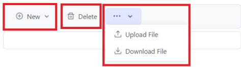
![New\nDelete\nUpload File\nDownload File](.emu-200-50m-19701-1000-10/d1ac9339cb3239f7351986643f58830e20667c25cc380c9af421323ea215ed30.jpg)

Figure 3-61: Manage External Storage

# System Information

This page manages system information.

1. Double click System Information to enter the page.
![i System Information](.emu-200-50m-19701-1000-10/619bf23ad131b44260eeab0b2c616de3dcf9ebd3191f304497fc94416805f75d.jpg)

Figure 3-62: System Information

2. System information includes device information and software version.

System Information

Device Information

Device Type: EMU200

Host Name: EMU

Device UID: 59acc135-1336-515a-8619-80a697ff07ed

Serial Number:

Software Versions

Web Console Version: 23.07.0713.0

Figure 3-63: Device Information and Software Version

This page intentionally left blank.

# Appendix A Debian Linux OS

Debian Linux is used as the EMU-200 Series operating system for system integrators to develop customization applications.This appendix includes information on the following items.

 Connecting and Logging in via SSH
 User LED Control
 Serial Port Configuration
 Changing the static IP
 RTC Function
 Mounting/Unmounting a FAT32 USB Drive
 4G LTE Module Configuration and Connection (optional)
 WiFi Configuration and Connection

# A.1 Connecting and Logging in via SSH

1. Wait for the SYS LED to display a solid green light after powering on to confirm that the OS kernel is ready.
2. Set the network domain of the host computer that will be connected to the EMU-200 Series to 192.168.50.xx.
3. Open Putty on the host computer and enter the IP address of the EMU-200 Series: 192.168.50.2.
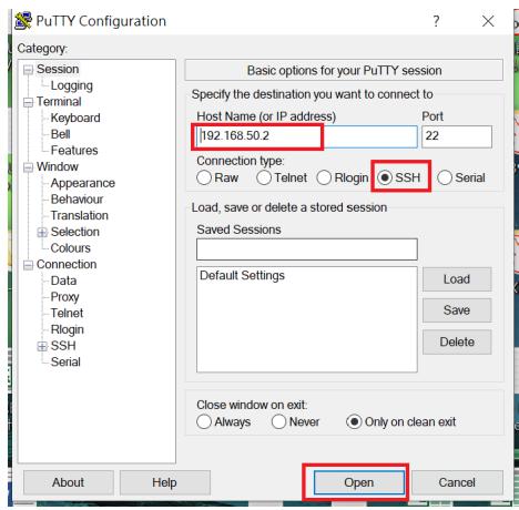
![PuTTY Configuration\nCategory:\nSession\nLogging\nTerminal\nKeyboard\nBell\nFeatures\nWindow\nAppearance\nBehaviour\nTranslation\nSelection\nColours\nConnection\nData\nProxy\nTelnet\nRlogin\nSSH\nSerial\nBasic options for your PuTTY session\nSpecify the destination you want to connect to\nHost Name (or IP address) Port\n192.168.50.2 22\nConnection type:\nRaw Telnet Rlogin SSH Serial\nLoad, save or delete a stored session\nSaved Sessions\nDefault Settings\nLoad\nSave\nDelete\nClose window on exit:\nAlways Never Only on clean exit\nOpen\nAbout Help Cancel](.emu-200-50m-19701-1000-10/aa7999d18e567c3b6426d8ae5f2c12415500d548b4ef005d5599787f20cc9cfe.jpg)

4. Log in by username and password

 Enter the username: root
 Enter the password: adlink

5. You have successfully connected to the EMU-200 Series.

# A.2 User LED Control

Turn on/Turn off User LED1 with the following commands:

```txt
$ cd /sys/class/leds/led_user1g
```

Turn on:

```txt
$ echo 1 > brightness
```

Turn off:

```txt
$ echo 0 > brightness
```

Turn on/Turn off User LED2 with the following commands:

```txt
$ cd /sys/class/leds/led_user2g
```

Turn on:

```txt
$ echo 1 > brightness
```

Turn off:

```txt
$ echo 0 > brightness
```

Turn on/Turn off User LED3 with the following commands:

```txt
$ cd /sys/class/leds/led_user3g
```

Turn on:

```txt
$ echo 1 > brightness
```

Turn off:

```txt
$ echo 0 > brightness
```

# A.3 Serial Port Configuration

Use the following command to check the current Serial Port Interface.

```txt
$ cat /etc/com_mode.conf
```

```batch
root@EMU-200:~# cat /etc/com_mode.conf
485
485
```

The first row is COM1, the second row is COM2.

Use the following command to set the Serial Port to RS-422 mode.

```asm
cd /usr/bin
./set_com.sh COM1 422
./set_com.sh COM2 422
```

```perl
root@EMU-200:~# cd /usr/bin
root@EMU-200:/usr/bin# ./set_com.sh COM1 422
COM setting has been updated.
root@EMU-200:/usr/bin# ./set_com.sh COM2 422
COM setting has been updated.
```

Use the following command to set the Serial Port to RS-232 mode.

```txt
cd /usr/bin
./set_com.sh COM1 232
./set_com.sh COM2 232
```

```perl
root@EMU-200:~# cd /usr/bin
root@EMU-200:/usr/bin# ./set_com.sh COM1 232
COM setting has been updated.
root@EMU-200:/usr/bin# ./set_com.sh COM2 232
COM setting has been updated.
```

Follow the steps below to set the Serial Device in Minicom to /dev/ ttyXRUSB1, so that dev/ttyXRUSB0 is COM1 and /dev/ ttyXRUSB1 is COM2.

1. Enter the command: \$ minicom -s

![root@adlink:/sys/devices/platform/44000000.ocp/48000000.interconnect/48000000.interconnect:segment@300000/48380000.target-module/48380000.omap_dwc3/48390000.usb/xhci-hcd.5.auto/usb1/1-1/1-1.2/1-1.2:1.2# minicom -s](.emu-200-50m-19701-1000-10/cf6012156b08bdc0bf30cb06cdcecf18ba1ac37e294895f789a454ba9353a8f0.jpg)

2. Select Serial port setup.

![lqqqqq(configuration)qqqqqqk\nx Filenames and paths x\nx File transfer protocols x\nx Serial port setup x\nx Modem and dialing x\nx Screen and keyboard x\nx Save setup as dfl x\nx Save setup as.. x\nx Exit x\nx Exit from Minicom x\nmqqqqqqqqqqqqqqqqqqqqqqqqqqqj](.emu-200-50m-19701-1000-10/48dffaa8fbc4f401339a7d31fa53a950ef77e9f4433e52f3b49d4a3e2d4b73af.jpg)

3. Select Serial Device and configure the parameters for the COM port. (dev/ttyXRUSB0 is COM1 and /dev/ ttyXRUSB1 is COM2)
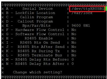
![1qggggggggggggggggggggggggggggggggggggggggggggggggggggggggggggggggggggggggggggggggggggggggggggggggggggggggggggggggggggggggggggggggggggggggggggggggggggggggggggggggggggggggggggggggggggggggggggggggggggg\nx A - Serial Device : /dev/ttyXRUSB1\nx B - Lockfile Location : 7Var/lock\nx C - Callin Program : \nx D - Callout Program : \nx E - Bps/Par/Bits : 9600 8N1\nx F - Hardware Flow Control : No\nx G - Software Flow Control : No\nx H - RS485 Enable : No\nx I - RS485 Rts On Send : No\nx J - RS485 Rts After Send : No\nx K - RS485 Rx During Tx : No\nx L - RS485 Terminate Bus : No\nx M - RS485 Delay Rts Before: 0\nx N - RS485 Delay Rts After : 0\nx\nx Change which setting?\nmqqgqqgqqgqqgqqgqqgqqgqqgqqgqqgqqgqqgqqgqqgqqgqqgqqgqqgqqgqqgqqgqqgqqgqqgqqgqqgqqgqqgqqgqqgqqgqqgqqgqqgqqgqqgqqgqqgqqgqqgqqgqqgqqgqqgqqgqqgqqgqqgqqgqqgqq g](.emu-200-50m-19701-1000-10/db4d62c423c80cb4ebdd3e7d20135fc0d9f3ef11ef2659f1d9f97c417bc73625.jpg)

4. Save setup and then exit.

![lqqqqg (configuration) qqqqqg\n× Filenames and paths ×\n× File transfer protocols ×\n× Serial port setup ×\n× Modem and dialing ×\n× Screen and keyboard ×\n× Save setup as dfl ×\n× Save setup as..\n× Exit ×\n× Exit from Minicom ×\nlqqqqg (configuration) qqqqqg\n× Filenames and paths ×\n× File transfer protocols ×\n× Serial port setup ×\n× Modem and dialing ×\n× Screen and keyboard ×\n× Save setup as dfl ×\n× Save setup as..\n× Exit ×\n× Exit from Minicom ×\nmqqqqg qqqqqg qqqqqg qqqqqg qqqqqg](.emu-200-50m-19701-1000-10/79ed6a530bb40624a1362fb4249d823b945681c39dae31002741fc5d76a799a0.jpg)

# A.4 LAN Configuration

# A.4.1 LAN1 Configuration

1. Use the vi editor to enter the following command.

```txt
$ vi /etc/systemd/network/10-eth.network
```

```batch
root@EMU-200:~# vi /etc/systemd/network/10-eth.network
```

2. Press 'i' to enter edit mode.

```ini
[Match]
Name=eth0
KernelCommandLine=!root=/dev/nfs
[Network]
DHCP=yes
~
```

After editing, press &lt;Esc&gt;, type :wq and then press &lt;Enter&gt; to save and exit edit mode.

3. After configuring, restart the 'networkd' service. Execute the following command, and the system will reboot after a few seconds.

```powershell
$ systemctl restart systemd-networkd.service
```

```batch
root@EMU-200:~# systemctl restart systemd-networkd.service
```

# A.4.2 LAN2 Configuration

1. Use the vi editor to enter the following command.

```txt
$ vi /etc/systemd/network/11-eth1.network
```

```batch
root@EMU-200:~# vi /etc/systemd/network/11-eth1.network
```

2. Press 'i' to enter edit mode.

```ini
[Match]
Name=eth1

[Network]
Address=192.168.50.2/24
Gateway=192.168.50.1
DNS=8.8.8.8
DNS=8.8.4.4
~
```

3. After configuring, restart the 'networkd' service. Execute the following command, and the system will reboot after a few seconds.

```powershell
$ systemctl restart systemd-networkd.service
```

```batch
root@EMU-200:~# systemctl restart systemd-networkd.service
```

# A.5 RTC

Enter the following command to check the current system time.

```powershell
$ date -R
```

```txt
root@adlink:~# date -R
Fri, 07 Apr 2023 16:01:01 +0800
root@adlink:~#
```

# A.6 4G LTE Module Configuration and Connection (optional)

1. Enter the following command for the 4G network dial-up settings (Module: QUECTEL/EM05-CE).

\$ modemon quectel
```csv
send (ATI; +CSQ; +CPIN?; +COPS?; +CGREG?; &D2^M)
expect (OK)
^M
^M
Quectel^M
EM05^M
Revision: EM05CEFAR06A02M4G^M
^M
+CSQ: 23,99^M
^M
+CPIN: READY^M
^M
+COPS: 0,0, "Chunghwa Telecom", 7^M
^M
+CSREG: 0,1^M
^M
OK
-- got it
send (AT+CGDCONT=1, "IPV4V6", "internet", 0,0^M)
expect (OK)
^M
^M
OK
-- got it
send (AT+CFUN=1^M)
expect (OK)
^M
^M
OK
-- got it
```

Alternatively, enter the following command for the 4G network dial-up settings with a Sierra 4G LTE module.

\$ modemon sierra

2. Enter the following command to check if the 4G network interface (ppp0) appears.

\$ ifconfig
```txt
eth1: flags=4163&lt;UP,BROADCAST,RUNNING,MULTICAST&gt; mtu 1500
inet 192.168.50.2 netmask 255.255.255.0 broadcast 192.168.50.255
inet6 fe80::5a2b:aff:fec8:680a prefixlen 64 scopeid 0x20&lt;link&gt;
ether 58:2b:0a:c8:68:0a txqueuelen 1000 (Ethernet)
RX packets 419 bytes 27625 (26.9 KiB)
RX errors 0 dropped 0 overruns 0 frame 0
TX packets 13 bytes 1006 (1006.0 B)
TX errors 0 dropped 0 overruns 0 carrier 0 collisions 0

lo: flags=73&lt;UP,LOOPBACK,RUNNING&gt; mtu 65536
inet 127.0.0.1 netmask 255.0.0.0
inet6 ::1 prefixlen 128 scopeid 0x10&lt;host&gt;
loop txqueuelen 1000 (Local Loopback)
RX packets 0 bytes 0 (0.0 B)
RX errors 0 dropped 0 overruns 0 frame 0
TX packets 0 bytes 0 (0.0 B)
TX errors 0 dropped 0 overruns 0 carrier 0 collisions 0

gpp0: flags=4305&lt;UP,POINTOPOINT,RUNNING,NOARP,MULTICAST&gt; mtu 1500
inet 10.122.111.55 netmask 255.255.255.255 destination 10.64.64.64
inet6 2001:b400:e33e:4bbb:dcdd:7fd3:4e3:d879 prefixlen 64 scopeid 0x
global>
inet6 fe80::dddd:7fd3:4e3:d879 prefixlen 128 scopeid 0x20&lt;link&gt;
ppp txqueuelen 3 (Point-to-Point Protocol)
RX packets 8 bytes 238 (238.0 B)
RX errors 0 dropped 0 overruns 0 frame 0
TX packets 9 bytes 162 (162.0 B)
TX errors 0 dropped 0 overruns 0 carrier 0 collisions 0
```

3. Enter the following command to execute a 4G Networking Functional Test (ping Google DNS).

\$ ping -I ppp0 8.8.8.8
```txt
root@adlink:~# ping -1 ppp0 8.8.8.8
PING 8.8.8.8 (8.8.8.8) from 10.122.111.55 ppp0: 56(84) bytes of data.
64 bytes from 8.8.8.8: icmp_seq=1 ttl=55 time=184 ms
64 bytes from 8.8.0.8: icmp_seq=2 ttl=55 time=63.7 ms
64 bytes from 8.8.0.8: icmp_seq=3 ttl=55 time=47.7 ms
64 bytes from 8.8.8.8: icmp_seq=4 ttl=55 time=38.8 ms
64 bytes from 8.8.0.8: icmp_seq=5 ttl=55 time=51.7 ms
64 bytes from 8.8.8.8: icmp_seq=6 ttl=55 time=46.6 ms
64 bytes from 8.8.8.8: icmp_seq=7 ttl=55 time=62.6 ms
64 bytes from 8.8.8.8: icmp_seq=8 ttl=55 time=50.4 ms
64 bytes from 8.8.8.8: icmp_seq=9 ttl=55 time=42.0 ms
64 bytes from 8.8.8.8: icmp_seq=10 ttl=55 time=48.9 ms
64 bytes from 8.8.8.8: icmp_seq=11 ttl=55 time=48.4 ms
64 bytes from 8.8.8.8: icmp_seq=12 ttl=55 time=56.7 ms
64 bytes from 8.8.0.8: icmp_seq=13 ttl=55 time=63.7 ms
64 bytes from 8.8.0.8: icmp_seq=14 ttl=55 time=222 ms
64 bytes from 8.8.0.8: icmp_seq=15 ttl=55 time=49.1 ms
64 bytes from 8.8.0.8: icmp_seq=16 ttl=55 time=30.3 ms
64 bytes from 8.8.0.8: icmp_seq=17 ttl=55 time=65.9 ms
```

# A.7 WiFi Configuration and Connection

1. Enter the following EMU-200 search WIFI device command.

\$ dmesg | grep wl
```txt
root@EMU-200:~# dmesg | grep wl
[ 0.839101] reg-fixed-voltage fixed-regulator-wlen: GPIO lookup for consumer (null)
[ 0.839115] reg-fixed-voltage fixed-regulator-wlen: using device tree for GPIO lookup
[ 0.839147] of_get_named_gpiod_flags: can't parse 'gpios' property of node '/fixed-regulator-wlen[0]'
[ 0.839172] reg-fixed-voltage fixed-regulator-wlen: No GPIO consumer (null) found
[ 2.881138] reg-fixed-voltage fixed-regulator-wlen: GPIO lookup for consumer (null)
[ 2.881155] reg-fixed-voltage fixed-regulator-wlen: using device tree for GPIO lookup
[ 2.881189] of_get_named_gpiod_flags: can't parse 'gpios' property of node '/fixed-regulator-wlen[0]'
[ 2.881217] reg-fixed-voltage fixed-regulator-wlen: No GPIO consumer (null) found
[ 3.087483] reg-fixed-voltage fixed-regulator-wlen: GPIO lookup for consumer (null)
[ 3.087495] reg-fixed-voltage fixed-regulator-wlen: using device tree for GPIO lookup
[ 3.087521] of_get_named_gpiod_flags: can't parse 'gpios' property of node '/fixed-regulator-wlen[0]'
[ 3.087554] of_get_named_gpiod_flags: parsed 'gpio' property of node '/fixed-regulator-wlen[0]' - status (0)
[ 19.260805] wl18xx_driver wl18xx.6.auto: Direct firmware load for ti-connectivity/wl18xx-conf.bin failed with error -2
[ 19.271702] wlcore: ERROR could not get configuration binary ti-connectivity/wl18xx-conf.bin: -2
[ 19.280555] wlcore: WARNING falling back to default config
[ 19.890132] wlcore: wl18xx HW: 183x or 180x, PG 2.2 (ROM 0x11)
[ 19.998396] wlcore: loaded
[ 33.126099] wlan_en_regulator: disabling
[ 146.366321] wlcore: using inverted interrupt logic: 8
[ 146.463185] wlcore: PHY firmware version: Rev 8.2.0.0.246
[ 146.580124] wlcore: firmware booted (Rev 8.9.0.0.90)
[ 151.400183] wlan0: authenticate with d0:17:c2:32:52:40
[ 151.416435] wlan0: send auth to d0:17:c2:32:52:40 (try 1/3)
[ 151.445962] wlan0: authenticated
[ 151.457313] wlan0: associate with d0:17:c2:32:52:40 (try 1/3)
[ 151.468905] wlan0: RX AssocResp from d0:17:c2:32:52:40 (capab=0xc11 status=0 aid=1)
[ 151.501369] wlan0: associated
[ 151.917017] IPv6: ADDRCONF(NETDEV_CHANGE): wlan0: link becomes ready
[ 151.945853] wlcore: Association completed
```

2. Enter the following command to the following path to modify WIFI AP and password.

\$ vi /etc/wpa\_supplicant/wpa\_supplicant.conf
```hcl
ctrl_interface=/var/run/wpa_supplicant
ctrl_interface_group=0
update_config=1
network={
    ssid="ADLINKTECH"
    psk="adlink6166"
# key_mgmt=NONE
    key_mgmt=WPA-PSK
}
```

After entering the screen, press 'i' to enter edit mode to make changes. After making the changes, press &lt;Esc&gt;, type :wq and then press &lt;Enter&gt; to save and exit edit mode.

3. Enter the following command to set the country code. For example, to set the country code to The United States, enter:

\$ iw reg set US

Refer to the following table for the list of acceptable counrty codes.

<table><tr><td>Country</td><td>Code</td></tr><tr><td>Global</td><td>00</td></tr><tr><td>Australia</td><td>AU</td></tr><tr><td>Canada</td><td>CA</td></tr><tr><td>Europe</td><td>EU</td></tr><tr><td>New Zealand</td><td>NZ</td></tr><tr><td>Taiwan (Republic of China)</td><td>TW</td></tr><tr><td>Unites States</td><td>US</td></tr></table>

4. Enter the following command to turn on the WiFi and connect to the access point (AP).

```shell
$ wpa_supplicant -B -i wlan0 -c /etc/wpa_supplicant/wpa_supplicant.conf
```

```batch
root@EMU-200:~# wpa_supplicant -B -i wlan0 -c /etc/wpa_supplicant/wpa_supplicant.conf
Successfully initialized wpa_supplicant
```

5. Enter the following command to automatically configure the IP address.

```txt
$ udhcpc -i wlan0
```

```txt
root@EMU-200:~# udhcpc -i wlan0
udhcpc: started, v1.30.1
udhcpc: sending discover
udhcpc: sending select for 192.168.50.111
udhcpc: lease of 192.168.50.111 obtained, lease time 86400
root@EMU-200:~#
```

6. Enter the following command to check if wlan0 is configured with an IP address before connecting to the internet.

\$ ifconfig
```txt
wlan0: flags=4163&lt;UP,BROADCAST,RUNNING,MULTICAST&gt; mtu 1500
inet 192.168.50.111 netmask 255.255.255.0 broadcast 192.168.50.255
inet6 fe80::f6b8:98ff:fe38:e9b7 prefixlen 64 scopeid 0x20&lt;link&gt;
ether f4:b8:98:38:e9:b7 txqueuelen 1000 (Ethernet)
RX packets 4 bytes 966 (966.0 B)
RX errors 0 dropped 0 overruns 0 frame 0
TX packets 25 bytes 3252 (3.1 KiB)
TX errors 0 dropped 0 overruns 0 carrier 0 collisions 0
```

7. Enter the following command to add a new route (based on the automatically configured IP address, changing the last octet to 1) to set a gateway (gw) for wlan0, as it needs a gateway to establish a connection to the external network.

```txt
$ route add default gw xxx.xxx.xxx.1
```

8. Enter the following command to execute a WiFi Networking Functional Test (ping Google DNS).

\$ ping -I wlan0 8.8.8.8
```txt
root@EMU-200:~# ping -I wlan0 8.8.8.8
PING 8.8.8.8 (8.8.8.8) from 192.168.50.111 wlan0: 56(84) bytes of data.
64 bytes from 8.8.8.8: icmp_seq=2 ttl=114 time=8.39 ms
64 bytes from 8.8.8.8: icmp_seq=1 ttl=114 time=1085 ms
64 bytes from 8.8.8.8: icmp_seq=3 ttl=114 time=5.22 ms
64 bytes from 8.8.8.8: icmp_seq=4 ttl=114 time=5.22 ms
64 bytes from 8.8.8.8: icmp_seq=5 ttl=114 time=21.8 ms
64 bytes from 8.8.8.8: icmp_seq=6 ttl=114 time=5.25 ms
64 bytes from 8.8.8.8: icmp_seq=7 ttl=114 time=6.60 ms
```

This page intentionally left blank.

# Appendix B 4G LTE Module Assembly

1. Remove screws from chassis and open the top cover.

![1/pic1\nADLINK\n1\n4\n3\n2\n1\n2\n1\n2](.emu-200-50m-19701-1000-10/334bb3c85060eecf321430591a82f12319a6ab84857ea478fc00cf2ffec8739d.jpg)

2. Insert 4G LTE module in M.2 slot and tighten the screw.

![Interior view of an electronic device showing a green circuit board with internal components and a red annotation highlighting a component (no readable text or symbols)](.emu-200-50m-19701-1000-10/3ce59e82fac88236ac4df2072b14893a67344827ab58b34e6ec893f7c3838e50.jpg)

3. Connect the RF cables from 4G LTE module to chassis.

![Interior view of an electronic device showing a circuit board with components and wiring (no readable text or symbols)](.emu-200-50m-19701-1000-10/b2a78830ab61a4af962ff8ee4078fb01ca9ea0f8a37778f5e47a37fe69278083.jpg)

4. Tighten washer and hex nut of RF cable on chassis.

![Close-up of a circuit board with connectors and a magnified inset showing a connector detail (no text or symbols visible)](.emu-200-50m-19701-1000-10/13ee7862402164e423308191a0a484108972ecc19f684ee523b9f453c9a940dc.jpg)

5. Remove protective film from thermal pad and attach it on the spreader.

![Three-step assembly process showing a blue textured sample being rotated into two metallic components, one with red arrows indicating transformation (no text or symbols)](.emu-200-50m-19701-1000-10/5f33bb29212caa7f8f728eb05ca160037ffad34b4a0c799b4dd0421d88bf8e03.jpg)

6. Put heat sink on 4G LTE module and tighten the screws.

![Interior view of an electronic device with visible circuit board, capacitors, and connectors (no text or symbols)](.emu-200-50m-19701-1000-10/b892d391179aa6e2587915e547643d4e7e9ec256a6899a8682ba0adb6f23bf7e.jpg)

# 7. Replace the top cover.

![1/pic1\nADLINK\n1\n4\n3\n2\n1\n2\n1\n2](.emu-200-50m-19701-1000-10/0ae57fc86bbb2499677ff4175aa27f0671d13ccad1833397b4c2b4e4bba4f172.jpg)

# Important Safety Instructions

For user safety, please read and follow all instructions, Warnings, Cautions, and Notes marked in this manual and on the associated device before handling/operating the device, to avoid injury or damage.

 Read these safety instructions carefully.
 Keep the User’s Manual for future reference.
 Read the Specifications section of this manual for detailed information on the recommended operating environment.
 The device can be operated at an ambient temperature of 50ºC for DC power source and adapter.
 It is recommended that the device be installed in Information Technology Rooms that are in accordance with Article 645 of the National Electrical Code and NFPA 75.
 When installing/mounting or uninstalling/removing device:
 Turn off power and unplug any power cords/cables.
 Reinstall all chassis covers before restoring power.
 To avoid electrical shock and/or damage to device:
 Keep device away from water or liquid sources.
 Keep device away from high heat or humidity.
 Keep device properly ventilated (do not block or cover ventilation openings).
 Always use recommended voltage and power source settings.
 Always install and operate device near an easily accessible electrical outlet.
 Secure the power cord (do not place any object on/over the power cord).
 Only install/attach and operate device on stable surfaces and/or recommended mountings.
 This apparatus is powered by adapter or DC source. Please ensure the adapter or DC source has a grounded connection.
 If the device will not be used for long periods of time, turn off and unplug it from its power source
 Never attempt to repair the device, which should only be serviced by qualified technical personnel using suitable tools

 A Lithium-type battery may be provided for uninterrupted backup or emergency power.

![The image shows a yellow triangular warning sign with a black border. Inside the triangle is a black exclamation point. Below the triangle is the text 'CAUTION:' in black capital letters.](.emu-200-50m-19701-1000-10/20a910cfb4e0cb20196bc32cc4841762ef242d5ae279e6dc70c601f0f978910f.jpg)

Risk of explosion if battery is replaced with one of an incorrect type; please dispose of used batteries appropriately.

Risque d’explosion si la pile est remplacée par une autre de type incorrect. Veuillez jeter les piles usagées de façon appropriée.

 The device must be serviced by authorized technicians when:

 The power cord or plug is damaged.
 Liquid has entered the device interior.
 The device has been exposed to high humidity and/or moisture.
 The device is not functioning or does not function according to the User’s Manual.
 The device has been dropped and/or damaged and/or shows obvious signs of breakage.

Disconnect the power supply cord before loosening the thumbscrews and always fasten the thumbscrews with a screwdriver before starting the system up.

Terminal block wires should be fixed tightly by an authorized technician with the recommendation wire range: 16-24, str, sol, wire type: copper.

 It is recommended that the device be installed only in a server room or computer room where access is:

 Restricted to qualified service personnel or users familiar with restrictions applied to the location, reasons therefor, and any precautions required.
 Only afforded by the use of a tool or lock and key, or other means of security, and controlled by the authority responsible for the location.

![Yellow triangular warning sign with black smoke symbol indicating hot weather or hazard](.emu-200-50m-19701-1000-10/7dbad3fb190e41cb0a92bce381c3a492acf6225b4b9bdb81de8e0c462157e10c.jpg)

# BURN HAZARD

Touching this surface could result in bodily injury. To reduce risk, allow the surface to cool before touching.

# RISQUE DE BRÛLURES

Ne touchez pas cette surface, cela pourrait entraîner des blessures.

Pour éviter tout danger, laissez la surface refroidir avant de la toucher.

# Consignes de Sécurité Importantes

Pour la sécurité de l'utilisateur, veuillez lire et suivre toutes les instructions, avertissements, mises en garde et notes marqués dans ce manuel et sur l'appareil associé avant de manipuler/ d'utiliser l'appareil, afin d'éviter toute blessure ou tout dommage.

 Lisez attentivement ces consignes de sécurité
 Conservez le manuel de l'utilisateur pour pouvoir le consulter ultérieurement
Lisez la section Spécifications de ce manuel pour des informations détaillées sur l'environnement d'exploitation recommandé
L'appareil peut être utilisé à une température ambiante de 50 ° C pour la source d'alimentation et l'adaptateur CC.
 Il est recommandé d'installer l'appareil dans Information Salles technologiques conformes à l'article 645 du Code national de l'électricité et NFPA 75.
1 Lorsque l'installation/le montage ou la désinstallation/le retrait du périphérique est requis:
Lorsque l'installation/le montage ou la désinstallation/le retrait du périphérique est necessaire:
 Mettez l'appareil hors tension et débranchez tous les cordons/câbles d'alimentation
 Réinstallez tous les couvercles de châssis avant de rétablir l'alimentation
 Pour éviter les chocs électriques et/ou d’endommager l’appareil:
 Tenez l'appareil à l'écart de toute source d'eau ou de liquide
 Tenez l'appareil à l'écart d'une forte chaleur ou d'une humidité élevée
 Maintenez l'appareil correctement ventilé (n'obstruer ou ne couvrez pas les ouvertures de ventilation)
 Utilisez toujours les réglages de tension et de source d'alimentation recommandés
 Installez et utilisez toujours l'appareil près d'une prise de courant facilement accessible

 Fixez le cordon d'alimentation (ne placez aucun objet sur le cordon d'alimentation)
 Installez/fixez et utilisez l'appareil uniquement sur des surfaces stables et/ou sur les fixations recommandées
 Cet appareil est alimenté par un adaptateur ou une source DC. Veuillez vous assurer que l'adaptateur ou la source DC est relié à la terre s'il dispose d'une mise à la terre de protection.

Si l'appareil ne doit pas être utilisé pendant de longues périodes, éteignez-le et débranchez-le de sa source d'alimentation
N'essayez jamais de réparer l'appareil, qui ne doit être réparé que par un personnel technique qualifié à l'aide d'outils appropriés
 Une batterie de type Lithium peut être fournie pour une alimentation de secours ininterrompue ou d'urgence.

![A vertical yellow triangular warning sign featuring a black exclamation point inside a black circle. Below the triangle, the text 'CAUTION:' is printed in black capital letters on a white background.](.emu-200-50m-19701-1000-10/2814346df4d2ba3577081fc9677cd27d50c6896688553831523f836059f7c9ad.jpg)

Risque d’explosion si la pile est remplacée par une autre de type incorrect. Veuillez jeter les piles usagées de façon appropriée.

 L'appareil doit être entretenu par des techniciens agrees lorsque:
 Le cordon d’alimentation ou la prise est endommagé(e)
 Un liquide a pénétré à l'intérieur de l'appareil
 L'appareil a été exposé à une forte humidité et/ou de la buée
 L'appareil ne fonctionne pas ou ne fonctionne pas selon le manuel de l'utilisateur
 L'appareil est tombé et/ou a été endommagé et/ou présente des signes évidents de dommage

Débranchez le cordon d'alimentation avant de desserrer les vis à oreilles et serrez toujours les vis à oreilles avec un tournevis avant de mettre le système en marche

 Le fil du bornier doit être fixé fermement par un technicien agréé et recommandé pour la gamme de fils : 16-24, str, sol, type de fil: Cu

 Il est recommandé d'installer l'appareil uniquement dans une salle de serveurs ou une salle informatique où l'accès est:

 Réservé au personnel de service qualifié ou aux utilisateurs familiarisés avec les restrictions appliquées à l'emplacement, aux raisons de ces restrictions et toutes les précautions requises
 Uniquement autorisé par l'utilisation d'un outil, d'une serrure et d'une clé, ou d'un autre moyen de sécurité, et contrôlé par l'autorité responsable de l'emplacement

![Warning sign with yellow triangle and black smoke symbol indicating hot weather](.emu-200-50m-19701-1000-10/d62a4c32553725f14bf4c8300c2e5fa208af65da5ac851676bc916396aac6157.jpg)

# RISQUE DE BRÛLURES

Ne touchez pas cette surface, cela pourrait entraîner des blessures.

Pour éviter tout danger, laissez la surface refroidir avant de la toucher.

This page intentionally left blank.

# Getting Service

Ask an Expert: https://www.adlinktech.com/en/Askanexpert

# ADLINK Technology, Inc.

No. 66, Huaya 1st Road, Guishan District

Taoyuan City 333, Taiwan

Tel: +886-3-216-5088

Fax: +886-3-328-5723

Email: service@adlinktech.com

# Ampro ADLINK Technology, Inc.

6450 Via Del Oro, San Jose,

CA 95119-1208, USA

Tel: +1-408-360-0200

Toll Free: +1-800-966-5200 (USA only)

Fax: +1-408-600-1189

Email: info@adlinktech.com

# ADLINK Technology (China) Co., Ltd.

300 Fang Chun Rd., Zhangjiang Hi-Tech Park

Pudong New Area, Shanghai, 201203 China

Tel: +86-21-5132-8988

Fax: +86-21-5132-3588

Email: market@adlinktech.com

# ADLINK Technology GmbH

Hans-Thoma-Straße 11

D-68163 Mannheim, Germany

Tel: +49-621-43214-0

Fax: +49-621 43214-30

Email: emea@adlinktech.com

Please visit the Contact page at www.adlinktech.com for information on how to contact the ADLINK regional office nearest you.
[🔗 Link to the original document](.emu-200-50m-19701-1000-10/emu-200-50m-19701-1000-10.pdf)