# EOS-JNX-I / EOS-JNX-G

# Edge AI Vision Inference System User's Manual

![Exterior view of a ADLINK network device with ports, connectors, and ventilation slots (no readable text or symbols beyond branding)](.eos-jnx-50m-00054-1010-11/c2e7ade1864891a908657becc9656c6c5252876d3dfac945d74b20868e954960.jpg)

![Exterior view of a ADLINK network device with ports, connectors, and Ethernet ports (no readable text or symbols)](.eos-jnx-50m-00054-1010-11/0bf3b9af7b284165f10327ae0813dedc589a42e41aa0b5b6e761dc7e957f5e75.jpg)

Manual Rev.: 1.1

Revision Date: February 17, 2022

Part No: 50M-00054-1010

Revision History

<table><tr><td>Revision</td><td>Release Date</td><td>Description of Change(s)</td></tr><tr><td>1.0</td><td>2021-12-08</td><td>Initial Release</td></tr><tr><td>1.1</td><td>2022-02-17</td><td>Correct Front and Rear Panel I/O descriptions; add safety warning</td></tr></table>

# Preface

Copyright © 2022 ADLINK Technology, Inc.

This document contains proprietary information protected by copyright. All rights are reserved. No part of this manual may be reproduced by any mechanical, electronic, or other means in any form without prior written permission of the manufacturer.

# Disclaimer

The information in this document is subject to change without prior notice in order to improve reliability, design, and function and does not represent a commitment on the part of the manufacturer.

In no event will the manufacturer be liable for direct, indirect, special, incidental, or consequential damages arising out of the use or inability to use the product or documentation, even if advised of the possibility of such damages.

# Environmental Responsibility

ADLINK is committed to fulfill its social responsibility to global environmental preservation through compliance with the European Union's Restriction of Hazardous Substances (RoHS) directive and Waste Electrical and Electronic Equipment (WEEE) directive. Environmental protection is a top priority for ADLINK. We have enforced measures to ensure that our products, manufacturing processes, components, and raw materials have as little impact on the environment as possible. When products are at their end of life, our customers are encouraged to dispose of them in accordance with the product disposal and/or recovery programs prescribed by their nation or company.

# Trademarks

Product names mentioned herein are used for identification purposes only and may be trademarks and/or registered trademarks of their respective companies.

# Conventions

Take note of the following conventions used throughout this manual to make sure that users perform certain tasks and instructions properly.

![The image displays a square icon of a white document featuring horizontal grey lines. The top right corner of the document is folded down. A large red checkmark is overlaid on the document.](.eos-jnx-50m-00054-1010-11/cc58ad4917a6b9eff38326bf9df923f3e3b80db99cfd3754547a29afaf24eb4e.jpg)
NOTE:

Additional information, aids, and tips that help users perform tasks.

![A yellow triangular warning sign with a black border featuring a large black exclamation point in the center.](.eos-jnx-50m-00054-1010-11/f307400dbc7a53bdf47a9e633db0ec54cbd8e0e354f900e1847807fbd084fd60.jpg)
CAUTION:

Information to prevent minor physical injury, component damage, data loss, and/or program corruption when trying to complete a task.

Informations destinées à prévenir les blessures corporelles mineures, les dommages aux composants, la perte de données et/ou la corruption de programme lors de l'exécution d'une tâche.

![The image displays a red triangle pointing upwards with a white exclamation point centered inside it. Above the triangle is a thick black horizontal line.](.eos-jnx-50m-00054-1010-11/f792d2e10ba8fa97459039a998ef2552dde2ac02417e50f42a57ab68a98d4da2.jpg)
WARNING:

Information to prevent serious physical injury, component damage, data loss, and/or program corruption when trying to complete a specific task.

Informations destinées à prévenir les blessures corporelles graves, les dommages aux composants, la perte de données et/ou la corruption de programme lors de l'exécution d'une tâche spécifique.

# Table of Contents

# Revision History...... ii

# Preface...... iii

# List of Tables...... vii

# List of Figures ix

# 1 Introduction ...... 1

1.1 Features.... 1
1.2 Specifications.... 2
1.3 Mechanical Dimensions.... 4
1.4 External Layout.... 6
1.5 Pin Definitions.... 9

1.5.1 RJ45 LAN/PoE Connectors 9
1.5.2 PoE LED 12
1.5.3 USB Connectors.... 12
1.5.4 D-sub 15-pin DI/O Connector (Female)....14
1.5.5 HDMI Connector.... 15
1.5.6 DC Power Connector.... 16
1.5.7 D-sub 9-pin RS-232/485 Connector (Male)....17
1.5.8 Front Panel System Status LED 17

1.6 Wafer Connector (2.0mm Pin Pitch) 18
1.7 USB Micro-A Connector 19

# 2 Getting Started 21

2.1 Unpacking Checklist 21
2.2 Cooling Considerations.... 21
2.3 Internal Storage Installation (Optional) 22

2.3.1 Removing the Chassis Cover 22
2.3.2 Installing an M.2 SSD Module/USB Dongle 25

2.3.3 Installing an M.2 2230 Module (Optional)....27
2.3.4 Installing an Internal USB Device (Optional) 29

# 2.4 Front Panel I/O Connection 30

2.4.1 Connecting General Input/Output Ports....30
2.4.2 Connecting PoE Camera 31
2.4.3 Digital I/O Connection....32
2.4.4 Connecting DC Power 33
2.4.5 COM Port (RS-232/485) Connection 33

# 2.5 Wall Mount (Optional) 34

# 2.6 DIN Rail Mount.... 35

# 3 Using the System.... 37

3.1 Software Configuration 37
3.2 System Reset 37
3.3 System Recovery.... 38

# Important Safety Instructions.... 39

# Getting Service 43

# List of Tables

Table 1-1: Specifications ...... 2

Table 1-2: Front Panel I/O Connectors & Controls 6

Table 1-3: Rear Panel I/O Connectors 8

Table 1-4: RJ45 LAN/PoE Connector Pin Definition....9

Table 1-5: PoE LAN/Uplink Port Connector Definition...... 10

Table 1-6: PoE/Uplink LAN LED Connection Status .... 10

Table 1-7: GigE LAN LED Connection Status 11

Table 1-8: EOS-JNX-G PoE LAN Port Connector Definition ..... 11

Table 1-9: PoE LAN LED Connection Status 11

Table 1-10: GigE LAN LED Connection Status 12

Table 1-11: PoE LED Status.... 12

Table 1-12: USB 2.0 Type-A Connector Pin Definition....12

Table 1-13: USB 3.0 Type-A Connector Pin Definition.... 13

Table 1-14: D-sub 15-pin DI/O Connector Pin Definition.... 14

Table 1-15: HDMI Connector Pin Definition.... 15

Table 1-16: DC Power Connector Pin Definition 16

Table 1-17: D-sub 9-pin RS-232/485 Connector Pin Definition ... 17

Table 1-18: Front Panel System Status LED....17

Table 1-19: Wafer Connector Pin Definition 18

Table 1-20: USB Micro-A Connector Pin Definition....19

This page intentionally left blank.

# List of Figures

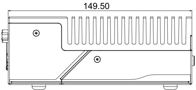
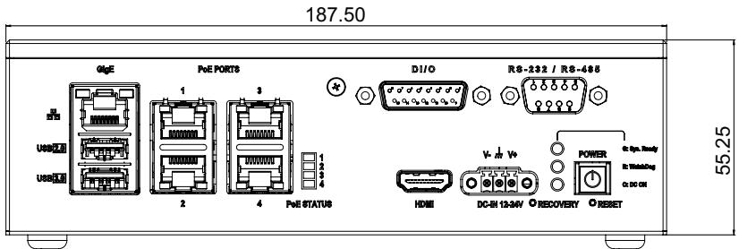
Figure 1-1: EOS-JNX-I Front View....4

Figure 1-2: EOS-JNX-I Side View 4

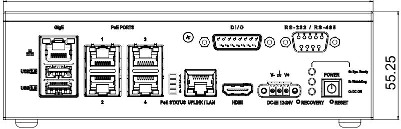
Figure 1-3: EOS-JNX-G Front View....5

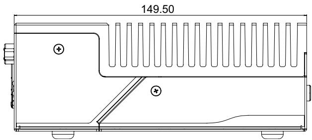
Figure 1-4: EOS-JNX-G Side View 5

Figure 1-5: Front Panel I/O Connectors....6

Figure 1-6: Rear Panel I/O Connectors 8

Figure 2-1: Installing an M.2 SSD Module/USB dongle 25

Figure 2-2: Installing M.2 2230 Module Cable Clips 27

Figure 2-3: M.2 2230 Module Cable Routing....28

Figure 2-4: Installing Internal USB Device (Optional) 29

Figure 2-5: USB Device Sponges (Optional) 29

Figure 2-6: Digital Input Schematic Diagram 32

Figure 2-7: Digital Output Schematic Diagram 32

Figure 2-8: Wall Mounting....34

Figure 2-9: DIN Rail Mount 35

This page intentionally left blank.

# 1 Introduction

ADLINK's EOS-JNX (-I/-G) Series leverages the power of an NVIDIA® Jetson Xavier™ module to deliver artificial intelligence (AI) at the edge, and provides PoE switch functionality for IP camera (-I) or GigE camera (-G) connections. The EOS-JNX Edge AI platforms with integrated NVIDIA Jetson Xavier NX accelerates deep learning workloads for object detection, recognition, and classification suitable for industrial embedded applications such as medical image processing, logistics automation, smart retail, security, and AI applications.

This fanless system provides a wide variety of industrial I/O and visual inferencing capabilities in a compact system. EOS-JNX supports general interfaces for users to easily connect their devices, including an RS-232/485 COM port, HDMI display port, USB 3.0/2.0 ports, multiple Ethernet LAN ports with PoE, a microSD slot and an M.2 PCI-E slot for additional storage options, and an M.2 PCIe slot for an extendable WiFi module. EOS-JNX series enables AI at the edge with exceptional performance and convenience while providing optimized PoE switch function to deploy IP camera or GigE camera.

# 1.1 Features

▶ AI inference acceleration with NVIDIA® Jetson Xavier™ NX
▶ Fanless system 187.5(W) x 149.5(D) x 55.25(H) mm
▶ Standard temperature range support from $-20^{\circ}C$ to $50^{\circ}C$ (wide temperature range support up to $70^{\circ}C$ , supported by Xavier NX reduced power settings)
▶ Expanded storage by microSD/M.2 PCIe SSD for larger application installation
▶ Supports 12V to 24V DC-in
▶ 4 PoE ports supporting 60W total power
▶ Smart PoE SW API supports power output control and power loss detection

# 1.2 Specifications

<table><tr><td>Model</td><td>EOS-JNX-I</td><td>EOS-JNX-G</td></tr><tr><td colspan="3">System Core</td></tr><tr><td>Platform</td><td colspan="2">NVIDIA® Jetson XavierTM NX</td></tr><tr><td>Processor</td><td colspan="2">6-core NVIDIA Carmel ARM® v8.2 64-bit CPU6 MB L2 + 4 MB L3</td></tr><tr><td>GPU</td><td colspan="2">NVIDIA Volta architecture with 384 NVIDIA CUDA® coresand 48 Tensor cores</td></tr><tr><td>Memory</td><td colspan="2">8 GB 128-bit LPDDR4</td></tr><tr><td>eMMC</td><td colspan="2">16G</td></tr><tr><td colspan="3">Front Panel I/O Interface</td></tr><tr><td>Ethernet</td><td colspan="2">1x GigE w/o PoE</td></tr><tr><td>PoE Port 1-4(Total 60W)</td><td>4x PoE ports (30W max.per-channel, 802.3at) forIP camera (10M/100M)</td><td>4x PoE ports (30W max. per-channel, 802.3at) forGigE camera (1Gb)</td></tr><tr><td>Uplink Port</td><td>1Gb NVR connection</td><td>N/A</td></tr><tr><td>USB Port</td><td colspan="2">1x USB 2.0, 1x USB 3.0</td></tr><tr><td>Graphic Output</td><td colspan="2">1x HDMI 1.4</td></tr><tr><td>Serial Port</td><td colspan="2">1x RS-232 / RS-485</td></tr><tr><td>Digital I/O</td><td colspan="2">D-sub 15-pin (expandable to 37-pin DIO board)4-ch digital I/O with isolation</td></tr><tr><td colspan="3">Rear Panel I/O Interface</td></tr><tr><td>microSD Slot</td><td colspan="2">1x microSD slot(OS boot from microSD card, preinstalled 64G)</td></tr><tr><td>Micro USB</td><td colspan="2">1x Micro USB (to flash Jetson NX)</td></tr><tr><td>WaferConnector</td><td colspan="2">for system flash with jumper</td></tr><tr><td colspan="3">Internal I/O Interface</td></tr><tr><td>M.2 2280 slot</td><td colspan="2">M key, and support for B+M key PCIe (Gen 2 x1) SSD</td></tr><tr><td>M.2 2230 slot</td><td colspan="2">E key, and support for A+E key PCIe or USB devices</td></tr><tr><td>Internal USB</td><td colspan="2">1x USB2.0 (for license protection)</td></tr></table>

Table 1-1: Specifications

<table><tr><td>Model</td><td>EOS-JNX-I</td><td>EOS-JNX-G</td></tr><tr><td colspan="3">Power</td></tr><tr><td>DC Input</td><td colspan="2">DC 12 to 24V</td></tr><tr><td>Fail Reset</td><td colspan="2">Reset and Recovery buttons</td></tr><tr><td>PoE Switch</td><td colspan="2">PoE initial mode setup</td></tr><tr><td colspan="3">Mechanical</td></tr><tr><td>Dimensions</td><td colspan="2">187.5(W) x 149.5(D) x 55.25(H) mm</td></tr><tr><td>Weight</td><td colspan="2">1.85 kg</td></tr><tr><td>Mounting</td><td colspan="2">supports wall mount &amp; DIN rail mount</td></tr><tr><td colspan="3">Environmental</td></tr><tr><td>Operating Temperature</td><td colspan="2">Standard: -20°C to 50°C (w/ 0.6m/s airflow)PoE full load and Xavier NX @ max. 20W: max. 50°CPoE full load and Xavier NX @ max. 15W: max. 60°CPoE full load and Xavier NX @ max. 10W: max. 70°C</td></tr><tr><td>Storage Temperature</td><td colspan="2">-40°C to 85°C</td></tr><tr><td>Humidity</td><td colspan="2">40% to 95% (non-condensing)</td></tr><tr><td>Vibration</td><td colspan="2">Operating: 5-500 Hz, 5 Grms, 3 axes</td></tr><tr><td>Shock</td><td colspan="2">Operating: 11ms duration, 30G, half sine, 3 axes</td></tr><tr><td>ESD</td><td colspan="2">Contact +/- 4kV, Air +/- 8kV</td></tr><tr><td>EMC</td><td colspan="2">CE and FCC Class A (EN61000-6-4/6-2)</td></tr><tr><td>Safety</td><td colspan="2">UL(62368) and CB</td></tr></table>

Table 1-1: Specifications

![The image displays a standard safety sign featuring a red triangle with a white exclamation point in its center. Below the triangle, the word 'WARNING' is printed in black capital letters on a white background.](.eos-jnx-50m-00054-1010-11/4c4b2af0b7e48482c6730767184b58b0cb33e62515c4730f8e0f8b7c8fc4d623.jpg)

Models in this manual are investigated to IEC TR 62102 as ES1 and SELV circuits and only connected to PoE without routing to the outside plant, including campus environments..

Avertissement: Les modèles de ce manuel sont étudiés selon IEC TR 62102 en tant que circuits ES1 et SELV et uniquement connectés à PoE sans routage vers l'installation extérieure, y compris les environnements de campus.

# 1.3 Mechanical Dimensions

All dimensions shown in millimeters (mm).

187.50
![06E\nPoE PORTS\nD1/O\nR8-232 / R8-485\nUSB ports\n1\n2\n3\n4\nPoE STATUS UPLINK / LAN\nHDMI\nDC-B1 12:04V O RECOVERY O RESET\nPOWER\nCo. bpm. Heavy\nCo. WashingDog\nCo. DC ON\n55 25](.eos-jnx-50m-00054-1010-11/70c402a336720e1b8510b8a80fb35e718e3fc07316fdb0909e35bf7e3a725057.jpg)

Figure 1-1: EOS-JNX-I Front View

![149.50](.eos-jnx-50m-00054-1010-11/96527c0347518fbd7eff12bf7a630dc2677bfc5aba42293cf69e2dca00479c92.jpg)

Figure 1-2: EOS-JNX-I Side View

![187.50\n55.25\nGigE\nPoE PORTS\nD/I/O\nRS-232 / RS-486\nUSB port 1\nUSB port 2\nUSB port 3\nPoE STATUS\nV- V+\nDC-SH 13-34V O RECOVERY O RESET\nPOWER\nC: Op. Ready\nC: Matching\nC: DC Oil](.eos-jnx-50m-00054-1010-11/610d5c7409bdbf99f53332fa5860b322a587656f822e1c30f4c9a61f045f7be7.jpg)

Figure 1-3: EOS-JNX-G Front View

![149.50](.eos-jnx-50m-00054-1010-11/cf5f2351e38dff4a7074c7c8cc19cfb400989c391755e3e6718f5c9474c35647.jpg)

Figure 1-4: EOS-JNX-G Side View

# 1.4 External Layout

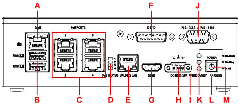
EOS-JNX Series Front Panel
![A\nGGE\nPoE PORTS\n1\n3\nD I PO\nR8-232\nR8-686\nUSB\nUSB\n2\n4\nPoE STATUS UPLHC7/LAH\nHOME\nDC-B103-MV\nPOWER\nRe Winding\nRESET\nB\nC\nD\nE\nG\nH\nI\nK\nL\nM\nJ](.eos-jnx-50m-00054-1010-11/c2b7029ce7ece4fa4710bb5a26ab2c078b97d94f53f03b1683adbc0eaab3a680.jpg)

Figure 1-5: Front Panel I/O Connectors

<table><tr><td>Item</td><td>Name</td><td>Description</td></tr><tr><td>A</td><td>Ethernet Port</td><td>GigE LAN from NVIDIA® JetsonTM Xavier NX.</td></tr><tr><td>B</td><td>USB Port</td><td>1x USB 2.0 and 1x USB 3.0 general use for input/output devices like keyboard, mouse, or dongle receiver.</td></tr><tr><td>C</td><td>PoE Ports</td><td>4x PoE (Power over Ethernet) ports for PoE IP or GigE cameras. Each channel provides 30W max.(802.3at), with 4 ports totaling 60W max. The power budget allocation priority is from Port 4 to 1 if the PoE total power budget is over 60W.</td></tr><tr><td>D</td><td>PoE Status LED</td><td>PoE port enabled status.</td></tr><tr><td>E</td><td>Uplink Port(EOS-JNX-I only)</td><td>NVR (Network Video Recorder) connection for PoE IP cameras (EOS-JNX-I only).Maximum bandwidth: 1Gbps.Note: The Uplink Port (E) cannot be used as an Ethernet connection. Make sure to connect a LAN cable to the Ethernet Port (A).</td></tr><tr><td>F</td><td>DI/O Port</td><td>4-channel digital I/O port via D-sub connector, expandable to 37-pin DIO board with cable.</td></tr><tr><td>G</td><td>HDMI Port</td><td>HDMI 1.4 display output.</td></tr><tr><td>H</td><td>DC in Connector</td><td>12V to 24V DC-in. Connect power cord to terminal block first, then to power source.</td></tr></table>

Table 1-2: Front Panel I/O Connectors & Controls

<table><tr><td>Item</td><td>Name</td><td>Description</td></tr><tr><td>I</td><td>Recovery Button</td><td>Press recovery button and reset button at the same time to trigger recovery mode.See 3.3 System Recovery on page 38.</td></tr><tr><td>J</td><td>RS-232/485 Port</td><td>Supports RS-232/485 connectivity and control.</td></tr><tr><td>K</td><td>System Status LEDs</td><td>Shows system operation statusGreenOn: OS readyBlinking: The system is booting or cannot boot successfullyRedOn: Watchdog triggered and then OS boots successfullyBlinking: Watchdog has consecutively triggered more than two times and then OS boots successfullyOrangeDC-in ready</td></tr><tr><td>L</td><td>Reset Button</td><td>Press to reboot the system.</td></tr><tr><td>M</td><td>Power Button</td><td>Press to boot up, or shut down the system.</td></tr></table>

Table 1-2: Front Panel I/O Connectors & Controls

EOS-JNX Series Rear Panel
![Micro SD\nMicro USB\nOFF ON\nPolE\nN O P Q](.eos-jnx-50m-00054-1010-11/f8666bd8651a72a9b033b23a4c4f9205d42e923f40b55551211fedef1152d9ae.jpg)

Figure 1-6: Rear Panel I/O Connectors

<table><tr><td>Item</td><td>Name</td><td>Description</td></tr><tr><td>N</td><td>Wafer Connector</td><td>For system image flashing or debugging via jumpers</td></tr><tr><td>O</td><td>microSD Slot</td><td>OS boot storage. (Preinstalled 64G microSD card)</td></tr><tr><td>P</td><td>Micro USB Port</td><td>Connect to client for system image flashing.</td></tr><tr><td>Q</td><td>PoE Switch</td><td>PoE initial mode setup switchOn (default)EOS-JNX-G enables PoE after user presses the Power buttonEOS-JNX-I enables PoE when DC power is on OffInitial PoE status of both models is disabled and PoE On/Off status is controlled by the AVS SDK.</td></tr></table>

Table 1-3: Rear Panel I/O Connectors

# 1.5 Pin Definitions

# 1.5.1 RJ45 LAN/PoE Connectors

![Pure electrical connector diagram without any text, numbers, or symbols](.eos-jnx-50m-00054-1010-11/b89d2fc36f9af7a5ff5b101000890283c076dc70153d8a57ad120e6479105c3a.jpg)

<table><tr><td>Pin No.</td><td>Function</td><td>Description</td></tr><tr><td>1</td><td>BI_DA+</td><td>Bi-directional pair A+</td></tr><tr><td>2</td><td>BI_DA-</td><td>Bi-directional pair A-</td></tr><tr><td>3</td><td>BI_DB+</td><td>Bi-directional pair B+</td></tr><tr><td>4</td><td>BI_DB-</td><td>Bi-directional pair C+</td></tr><tr><td>5</td><td>BI_DC+</td><td>Bi-directional pair C-</td></tr><tr><td>6</td><td>BI_DC-</td><td>Bi-directional pair B-</td></tr><tr><td>7</td><td>BI_DD+</td><td>Bi-directional pair D+</td></tr><tr><td>8</td><td>BI_DD-</td><td>Bi-directional pair D-</td></tr></table>

Table 1-4: RJ45 LAN/PoE Connector Pin Definition

EOS-JNX-I LAN/PoE/Uplink Connectors
![GIGE\nPoE PORTS\n1\n2\n3\n4\nPoE STATUS UPLINK / LAN\n1\n2\n3\n4](.eos-jnx-50m-00054-1010-11/9fbbe97480a592b9b8d6af2e8b75aef65e2d7b8c9fbe55d27e31c0be322cf2ed.jpg)

<table><tr><td>Port</td><td>Description</td></tr><tr><td>PoE LAN 1-4</td><td>Bandwidth: 10/100Mbps, for PoE IP CAM connection</td></tr><tr><td>Uplink (EOS-JNX-I only)</td><td>Bandwidth: 1Gbps, for external NVR connection</td></tr></table>

Table 1-5: PoE LAN/Uplink Port Connector Definition

PoE/Uplink LAN LED connection status:

<table><tr><td>Left LED (Green)</td><td>Right LED (Green)</td><td>Status</td></tr><tr><td>OFF</td><td>OFF</td><td>LINK OFF</td></tr><tr><td>OFF</td><td>ON</td><td>1Gbps Link</td></tr><tr><td>OFF</td><td>Blinking</td><td>1Gbps Activity</td></tr><tr><td>ON</td><td>OFF</td><td>100Mbps Link</td></tr><tr><td>Blinking</td><td>OFF</td><td>100Mbps Activity</td></tr><tr><td>ON</td><td>ON</td><td>10Mbps Link</td></tr><tr><td>Blinking</td><td>Blinking</td><td>10Mbps Activity</td></tr></table>

Table 1-6: PoE/Uplink LAN LED Connection Status

GigE LAN LED connection status:

<table><tr><td>Left LED (Green)</td><td>Right LED (Yellow)</td></tr><tr><td>LINK</td><td>ACT</td></tr></table>

Table 1-7: GigE LAN LED Connection Status

EOS-JNX-G LAN/PoE Connectors
![The image displays a technical diagram divided into two main sections.\n\n**Left Section:**\n- Labeled **'GigE'** at the top.\n- Below is a tall rectangular outline containing three stacked connector diagrams.\n    - The top connector contains the number **'1'** and has a green square on the left and a yellow square on the right.\n    - The middle connector is labeled **'USB 2.0'** to its left and contains the numbers **'2'** and **'3'**.\n    - The bottom connector is labeled **'USB 3.0'** to its left and contains the number **'4'**.\n- There is a small connector icon to the left of the 'USB 2.0' label.\n\n**Right Section:**\n- Labeled **'PoE PORTS'** at the top.\n- This section shows four separate port diagrams arranged in two columns.\n    - The top-left port is labeled **'1'** above it.\n    - The bottom-left port is labeled **'2'** below it.\n    - The top-right port is labeled **'3'** above it.\n    - The bottom-right port is labeled **'4'** below it.\n- Each of these four port diagrams shows a connector with green squares on the top corners and yellow squares on the bottom corners (or similar arrangement depending on the specific port drawing). Specifically, ports 1 and 3 have green/yellow squares at the top of the connector, and ports 2 and 4 have green/yellow squares at the bottom of the connector.](.eos-jnx-50m-00054-1010-11/78dba3ea948eb3f02e5eeea0d3aca58fee37ee36002ff71735a5e5ffb3433519.jpg)

<table><tr><td>Port</td><td>Description</td></tr><tr><td>PoE LAN 1-4</td><td>Bandwidth: 10/100/1000 Mbps, for PoE GigE CAM connection.</td></tr></table>

Table 1-8: EOS-JNX-G PoE LAN Port Connector Definition

PoE LAN LED connection status:

<table><tr><td>Left LED (Green)</td><td>Status</td><td>Right LED (Green/Yellow)</td><td>Status</td></tr><tr><td>OFF</td><td>LINK OFF</td><td>OFF</td><td>10M bps</td></tr><tr><td>ON</td><td>LINK</td><td>Green</td><td>100M bps</td></tr><tr><td>Blinking</td><td>ACT</td><td>Yellow</td><td>1G bps</td></tr></table>

Table 1-9: PoE LAN LED Connection Status

GigE LAN LED connection status:

<table><tr><td>Left LED(Green)</td><td>Right LED(Yellow)</td></tr><tr><td>LINK</td><td>ACT</td></tr></table>

Table 1-10: GigE LAN LED Connection Status

# 1.5.2 PoE LED

<table><tr><td>LED</td><td>Status (Yellow)</td></tr><tr><td>1</td><td>ON: LAN 1 PoE OnOFF: LAN 1 PoE Off</td></tr><tr><td>2</td><td>ON: LAN 2 PoE OnOFF: LAN 2 PoE Off</td></tr><tr><td>3</td><td>ON: LAN 3 PoE OnOFF: LAN 3 PoE Off</td></tr><tr><td>4</td><td>ON: LAN 4 PoE OnOFF: LAN 4 PoE Off</td></tr></table>

![1\n2\n3\n4](.eos-jnx-50m-00054-1010-11/5294bf05f70a76f9deb887862bc3540241d7dd7dd9e487cc708ff19cf16af6c0.jpg)

Table 1-11: PoE LED Status

# 1.5.3 USB Connectors

USB 2.0 Type-A Connector

<table><tr><td>Pin No.</td><td>Signal</td></tr><tr><td>1</td><td>VBUS</td></tr><tr><td>2</td><td>D-</td></tr><tr><td>3</td><td>D+</td></tr><tr><td>4</td><td>GND</td></tr></table>

![1\n2\n3\n4](.eos-jnx-50m-00054-1010-11/f7e96e32f8a0eb259581c50131bb96e1113320306ebe07fc0b5394ce40ed75d2.jpg)

Table 1-12: USB 2.0 Type-A Connector Pin Definition

# USB 3.0 Type-A Connector

<table><tr><td>Pin No.</td><td>Signal</td></tr><tr><td>1</td><td>VBUS</td></tr><tr><td>2</td><td>D-</td></tr><tr><td>3</td><td>D+</td></tr><tr><td>4</td><td>GND</td></tr><tr><td>5</td><td>StdA_SSRX-</td></tr><tr><td>6</td><td>StdA_SSRX+</td></tr><tr><td>7</td><td>GND_DRAIN</td></tr><tr><td>8</td><td>StdA_SSTX-</td></tr><tr><td>9</td><td>StdA_SSTX+</td></tr></table>

![9 8 7 6 5\n1 2 3 4](.eos-jnx-50m-00054-1010-11/be4e9896dcecc0768e99086f27872119fbc4d22dd9af9a113c7b97b2b2610201.jpg)

Table 1-13: USB 3.0 Type-A Connector Pin Definition

# 1.5.4 D-sub 15-pin DI/O Connector (Female)

![8\n7\n6\n5\n4\n3\n2\n1\n15\n14\n13\n12\n11\n10\n9](.eos-jnx-50m-00054-1010-11/da9ef20edcba6c67edcaefa14d1eee2fa3e1627c98320f032e375ad269bef342.jpg)

<table><tr><td>Pin No.</td><td>Function</td></tr><tr><td>1</td><td>NC</td></tr><tr><td>2</td><td>IGND</td></tr><tr><td>3</td><td>General Purpose DO0</td></tr><tr><td>4</td><td>General Purpose DO1</td></tr><tr><td>5</td><td>General Purpose DO2</td></tr><tr><td>6</td><td>General Purpose DO3</td></tr><tr><td>7</td><td>NC</td></tr><tr><td>8</td><td>WatchDog Alarm DO</td></tr><tr><td>9</td><td>NC</td></tr><tr><td>10</td><td>IGND</td></tr><tr><td>11</td><td>General Purpose DI0</td></tr><tr><td>12</td><td>General Purpose DI1</td></tr><tr><td>13</td><td>General Purpose DI2</td></tr><tr><td>14</td><td>General Purpose DI3</td></tr><tr><td>15</td><td>NC</td></tr></table>

Table 1-14: D-sub 15-pin DI/O Connector Pin Definition

# 1.5.5 HDMI Connector

The HDMI connector supports HDMI 1.4.

![19 17\n18\n3 1\n4 2](.eos-jnx-50m-00054-1010-11/8602aba77ad98c34ff76796d29fd5d6ff25c270ef90665a2b79986a4ecf3e44c.jpg)

<table><tr><td>Pin #</td><td>Signal</td><td>Pin #</td><td>Signal</td></tr><tr><td>1</td><td>TMDS Data2+</td><td>2</td><td>TMDS Data2 Shield</td></tr><tr><td>3</td><td>TMDS Data2-</td><td>4</td><td>TMDS Data1+</td></tr><tr><td>5</td><td>TMDS Data1 Shield</td><td>6</td><td>TMDS Data1-</td></tr><tr><td>7</td><td>TMDS Data0+</td><td>8</td><td>TMDS Data0 Shield</td></tr><tr><td>9</td><td>TMDS Data0-</td><td>10</td><td>TMDS Clock+</td></tr><tr><td>11</td><td>TMDS Clock Shield</td><td>12</td><td>TMDS Clock-</td></tr><tr><td>13</td><td>CEC</td><td>14</td><td>Reserved</td></tr><tr><td>15</td><td>SCL</td><td>16</td><td>SDA</td></tr><tr><td>17</td><td>DDC/CEC Ground</td><td>18</td><td>+5 V Power</td></tr><tr><td>19</td><td>Hot Plug Detect</td><td></td><td></td></tr></table>

Table 1-15: HDMI Connector Pin Definition

# 1.5.6 DC Power Connector

The system requires a 12-24V DC power source with a screw-type connector.

![V- GND V+](.eos-jnx-50m-00054-1010-11/599b47ffc2b879cd17fa9e42034f1000c38730f14bd69513ca88c562fd1c1410.jpg)

<table><tr><td>Pin No.</td><td>Function</td></tr><tr><td>1</td><td>V+ Power</td></tr><tr><td>2</td><td>Chassis GND</td></tr><tr><td>3</td><td>V- Ground</td></tr></table>

Table 1-16: DC Power Connector Pin Definition

# 1.5.7 D-sub 9-pin RS-232/485 Connector (Male)

![1 2 3 4 5\n6 7 8 9](.eos-jnx-50m-00054-1010-11/aae469b9796565c36e92b16257be6fb5ee9448bd21e9dd1698c90bb2dde85168.jpg)

<table><tr><td rowspan="2">Pin No.</td><td colspan="2">Function</td></tr><tr><td>RS-232</td><td>RS-485</td></tr><tr><td>1</td><td>NC</td><td>Data-</td></tr><tr><td>2</td><td>RX</td><td>Data+</td></tr><tr><td>3</td><td>TX</td><td>NC</td></tr><tr><td>4</td><td>NC</td><td>NC</td></tr><tr><td>5</td><td colspan="2">GND</td></tr><tr><td>6</td><td colspan="2">NC</td></tr><tr><td>7</td><td>RTS</td><td>NC</td></tr><tr><td>8</td><td>CTS</td><td>NC</td></tr><tr><td>9</td><td colspan="2">NC</td></tr></table>

Table 1-17: D-sub 9-pin RS-232/485 Connector Pin Definition

# 1.5.8 Front Panel System Status LED

<table><tr><td>LED</td><td>Status</td></tr><tr><td>Green</td><td>System Ready</td></tr><tr><td>Red</td><td>WatchDog Alarm</td></tr><tr><td>Yellow</td><td>Standby power ready</td></tr></table>

Table 1-18: Front Panel System Status LED

# 1.6 Wafer Connector (2.0mm Pin Pitch)

![9 □ □ □ □ 1\n10 □ □ □ □ 2](.eos-jnx-50m-00054-1010-11/8fe8df000ac892b85484d25513a8f40a7ace5090f11c4f3e1ce1c6f63aead329.jpg)

<table><tr><td>Pin No.</td><td>Function</td><td>Description</td></tr><tr><td>1</td><td>Debug UART2_RX</td><td>RX channel of debug UART port</td></tr><tr><td>2</td><td>Debug UART2_TX</td><td>TX channel of debug UART port</td></tr><tr><td>3</td><td>RESET_IN#</td><td>System reset</td></tr><tr><td>4</td><td>GND</td><td>Digital Ground</td></tr><tr><td>5</td><td>FORCE_RECOV#</td><td>Force Recovery Strap Pin (System Recovery Mode)</td></tr><tr><td>6</td><td>GND</td><td>Digital Ground</td></tr><tr><td>7</td><td>NC</td><td></td></tr><tr><td>8</td><td>GND</td><td>Digital Ground</td></tr><tr><td>9</td><td>NC</td><td></td></tr><tr><td>10</td><td>GND</td><td>Digital Ground</td></tr></table>

Table 1-19: Wafer Connector Pin Definition

# 1.7 USB Micro-A Connector

![1\n5](.eos-jnx-50m-00054-1010-11/a4acd28b1c483a33accdab167c527ac98a685f37ac30063df86e44359decafa8.jpg)

<table><tr><td>Pin No.</td><td>Function</td><td>Description</td></tr><tr><td>1</td><td>Power Input</td><td>DC 5V</td></tr><tr><td>2</td><td>USB 2.0 Data -</td><td>USB 2.0 bi-directional pair -</td></tr><tr><td>3</td><td>USB 2.0 Data +</td><td>USB 2.0 bi-directional pair +</td></tr><tr><td>4</td><td>NC</td><td>No Connection</td></tr><tr><td>5</td><td>GND</td><td>Digital Ground</td></tr><tr><td>6</td><td>NC</td><td>No Connection</td></tr><tr><td>7</td><td>GND</td><td>Digital Ground</td></tr><tr><td>8</td><td>NC</td><td>No Connection</td></tr><tr><td>9</td><td>GND</td><td>Digital Ground</td></tr></table>

Table 1-20: USB Micro-A Connector Pin Definition

This page intentionally left blank.

# 2 Getting Started

# 2.1 Unpacking Checklist

Before unpacking, check the shipping carton for any damage. If the shipping carton and/or contents are damaged, inform your dealer immediately. Retain the shipping carton and packing materials for inspection. Obtain authorization from your dealer before returning any product to ADLINK. Ensure that the following items are included in the package.

▶ EOS-JNX system
▶ 2x terminal blocks (1x DC-in connector, 1x backup)
▶ 2x jumpers (for flashing Xavier NX)
▶ Screw pack (includes M2.5 backup screws, TIM pads, cable clips, and sponge as optional parts for internal device installation. These items are not necessary if the system will not be used in a shock/vibration environment.)
▶ Quick Start Guide

# 2.2 Cooling Considerations

EOS-JNX has a fanless design featuring an aluminum heatsink with additional TIM (thermal interface material) to conduct heat generated from the Jetson NX module and PoE power components. To maximize efficiency of heat dissipation, keep a minimum of 2 inches (5 cm) clearance from the top of the EOS-JNX system.

# 2.3 Internal Storage Installation (Optional)

# 2.3.1 Removing the Chassis Cover

Follow the instructions below to remove the chassis top cover.

![The image displays a yellow triangular warning sign containing a black exclamation mark in the center. Below the triangle, the text 'CAUTION:' is printed in black capital letters.](.eos-jnx-50m-00054-1010-11/7dd2b2f850c6ee148cff939867ae9865fb7a5c7c7b75d4e54a692f370536e945.jpg)

All installation procedures are restricted to skilled personnel.

Mise en garde: Toutes les procédures d'installation sont réservées au personnel qualifié.

To access the EOS-JNX internal components, remove the underside of the chassis as follows.

1. Place the unit bottom-side-up on a flat surface and remove 7 screws (3 bottom, 2 front, 1 each side) as indicated to remove the panels and reveal the internal components.

![Technical diagram of a computer drive with labeled ports and mounting holes, showing internal components and red circular annotations.](.eos-jnx-50m-00054-1010-11/b0979b298239f1497ceb443127013bf7de6ac7e7db0e927732af2bc968ddc908.jpg)

# 2. Slide the cover in the direction indicated.

![Diagram of an internal electronic device casing with a red downward arrow indicating a component or process (no text or symbols present)](.eos-jnx-50m-00054-1010-11/b245df210a4e05dc776d2d7ec60f070f1cbbb12c675189440d9aac34b6151738.jpg)

# 3. Lift the cover off of the chassis.

![Top-down schematic of an electronic device casing showing internal components and connectors (no text or labels)](.eos-jnx-50m-00054-1010-11/1da4fb7a28dbfeb0495aba9bca8ba915ae99ae25985accff2b02236311d0ecc8.jpg)

Reverse the steps to replace the bottom cover.

# 2.3.2 Installing an M.2 SSD Module/USB Dongle

Use the following steps to install an M.2 SSD module or USB dongle.

1. Install a suitable storage device, as shown.

![Supports USB\n2.0 dongle\nSupports M.2-2230, A+E\nKey, PCI-E/USB2.0\nM2.5 Screw\nfor M.2 devices\nSupports M.2-2280,\nB+M Key, PCI-E\nThermal Pad\n(bottom) to\nsupport M.2-2280](.eos-jnx-50m-00054-1010-11/8da70ae822106cdeed3bf371b38674525f1d5a497ef7eb666850a13879d8c1ef.jpg)

Figure 2-1: Installing an M.2 SSD Module/USB dongle

2. Skip this step if the EOS-JNX will not be used in a shock/vibration environment. For M.2-2280 slot installation, apply 2 thermal interface material (TIM) pads on the PCBA before installing the M.2 2280 module. Apply 1 long TIM pad on the underside of the rear cover along the aligned marks, as shown.

![Technical line drawing of an electronic component with visible circuitry and a red arrow indicating a specific area (no text or symbols present)](.eos-jnx-50m-00054-1010-11/722ba6d6901b435e5b4c758b138b447072e28810e5c2f9a75b8b38937ffffc37.jpg)

![Technical line drawing of a metal enclosure with internal compartments and mounting holes (no text or symbols)](.eos-jnx-50m-00054-1010-11/d68e350a7f950b9596ae4c4e28ff7c8f61241173666f81367bc0632579bb7552.jpg)

3. Insert screw and tighten to lock down M.2 module. (TIM pads and screws included in screw pack.)

# 2.3.3 Installing an M.2 2230 Module (Optional)

Use the following steps to install an M.2 2230 module or USB dongle.

1. Insert 4 cable clips (included in screw pack) as shown (2 each from the top and underside of the mainboard).

![Technical line drawing of an electronic device chassis with labeled ports and connectors (no text or symbols present)](.eos-jnx-50m-00054-1010-11/764b8e219f55b90b857adc230a9032bb0734af54d7a9a026184ff3ff14536a0c.jpg)

Figure 2-2: Installing M.2 2230 Module Cable Clips

2. Install an M.2 2230 module device.
3. Route cabling as shown.

![Cable\nClip](.eos-jnx-50m-00054-1010-11/7c587c8341da1eeb815cc7ccfd095f754d03d23a39eb6783f99208f7a9364e04.jpg)

Figure 2-3: M.2 2230 Module Cable Routing

# 2.3.4 Installing an Internal USB Device (Optional)

The EOS-JNX has a reserved USB 2.0 slot for an additional internal USB dongle device that can be used for license protection. Use the sponge piece provided in the screw pack and and install as shown.

![USB device\nsponge adjustability bracket](.eos-jnx-50m-00054-1010-11/21b47c916994430b15d1c642a835b977e45e725b8f848f82f498ba357764470e.jpg)

Figure 2-4: Installing Internal USB Device (Optional)

![sponge\nmarking line](.eos-jnx-50m-00054-1010-11/fec77ae11c472bafd6de3940a68a833efe57396f10b492fc566acfc308ea1601.jpg)

Figure 2-5: USB Device Sponges (Optional)

# 2.4 Front Panel I/O Connection

Before inserting any front panel I/O connectors, make sure to complete installation of any internal components. See 2.3 “Internal Storage Installation (Optional)” on page 22.

![Digital I/O Board\nRS-232 Device\nEthernet Port\nD I/O Port\n(D-sub 15-pin Female)\nRS-232/485 Port\n(D-sub 9-pin Male)\nGigE\nPoE PORTS\nD1/O\nRS-232\nRS-606\nUSB2.0\nUSB3.0\n1x USB 2.0\n1x USB 3.0\nKB/MS\n4x PoE Ports\nPoE STATUS UP LINK / LAN\nHDMI\nDC-BI 13-6V RECOVERY RESET\n1x USB 2.0\n1x USB 3.0\nIP CAM GigE CAM\nNVR Display\nUplink Port\n(EOS-JNX-I only)\nHDMI Port\nDC-In](.eos-jnx-50m-00054-1010-11/e60575f1948b36ddcb533a422c5f513079875f924b42dad4ee378095aed38a45.jpg)

# 2.4.1 Connecting General Input/Output Ports

▶ Ethernet LAN port for network connection
▶ USB input devices like keyboard/mouse. or other USB devices
▶ HDMI port for display device

# 2.4.2 Connecting PoE Camera

EOS-JNX series PoE ports support PoE interface cameras. Select the right EOS-JNX model for the camera being used.

▶ EOS-JNX-I PoE port bandwidth supports IP cameras (10M/100M), and the uplink port supports NVR (Network Video Recorder) connection.

To ensure the initial NVR setup connects with the IP camera, make sure the system is powered on and the OS is operating normally.

If DC power is cut to the system, reconnect the power, power on the system and wait until the OS is operating normally. Then wait for the initial NVR setup to connect with the IP camera.

▶ EOS-JNX-G PoE LAN bandwidth supports GigE cameras and is able to setup independent IP addresses for each LAN port.

# 2.4.3 Digital I/O Connection

External devices such as trigger sensors, LED light controllers or relays can be connected to the EOS-JNX to implement different applications. The figures below show of how to connect these kinds of devices. ADLINK also provides a DI/O cable (P/N: 30-01332-0010-A0) and a DIN37 termination board (P/N: 91-14025-1020) for DI/O applications. For more information, refer to the NEON-JNX User's Manual.

![Camera Side\nDI 0-3\n(non-Isolation)\nMax 5V\nVDD\ncontrol circuit\nDI/O GND](.eos-jnx-50m-00054-1010-11/af967d322da3d7d03cdffc04f8566411e03c5f3dca728fb27281075c2c8dbd28.jpg)

Figure 2-6: Digital Input Schematic Diagram

![EOS-JNX\ncontrol circuit\nOCP/OVP\nDO 0-3\n(non-Isolation)\nMax. 100mA\nload\nDC\nMax. 30V\nDI/O GND](.eos-jnx-50m-00054-1010-11/957e037e413c055f5add6f7cbd28ecb6db9aab4be33236182dc69e89230a7356.jpg)

Figure 2-7: Digital Output Schematic Diagram

# 2.4.4 Connecting DC Power

![The image shows a warning sign featuring a red triangle with a white exclamation point in the center. Below the triangle, the text 'WARNING:' is written in black capital letters.](.eos-jnx-50m-00054-1010-11/9d7354f7ab9b8a6c4d3fd7aa9f1371324ce5a403f4797c97e094a482406e695b.jpg)

Before providing DC power to the EOS-JNX, ensure the voltage and polarity provided are compatible with the DC input. Improper input voltage and/or polarity can be responsible for system damage.

Avant de connecter le PC EOS-JNX à une source de courant continu, veuillez vous assurer de la polarité de la tension conformément à l'entrée CC du PC. Une tension et/ou une polarité incorrectes peuvent causer des dommages irréversibles sur le système.

DC power sources must comply with SELV circuits with no energy hazard, as well as the following:

▶ IEC 62368-1 + IEC 60950-1 + UL 62368-1
▶ Input voltage: 12-24V DC
▶ Input current: min. 8A @12V DC; min. 4A@24V DC
▶ TMA: 50°C minimum

The EOS-JNX DC power input connector uses V+, V-, and chassis ground pins.

Customers may optionally order a DC power adapter (P/N:31-62120-0010) and terminal block (P/N: 20-C2M2C-0030) from ADLINK.

# 2.4.5 COM Port (RS-232/485) Connection

The EOS-JNX COM port default setting is RS-232. The serial port (/dev/ttyTHS0) UART mode can be configured by the EOSJNX-ConfigManager tool.

adlink@localhost:\~\$ EOSJNXConfigManager uartmode rs232

# 2.5 Wall Mount (Optional)

An optional wall mount kit is available for the EOS-JNX. Refer to the product datasheet or website for ordering information. Follow the steps below to mount the device to a wall.

1. Attach the brackets to a wall (or other suitable mounting surface) so that their keyhole-shaped mounting holes are oriented with the wider openings at the top.
2. Secure the four M4 screws to the bottom of the chassis.
3. Securely attach the device to the wall-mount brackets by first inserting the heads of the screws into the wider openings of the bracket's mounting holes, then sliding the device down so that the screws are firmly held by the narrower portions of the mounting holes.

![M4 x5mm screw](.eos-jnx-50m-00054-1010-11/ba09ce55bf9f11c9d51e4f1692622623f3d5dd6e2bcdeaba7212d86e1b035cef.jpg)

Figure 2-8: Wall Mounting

# 2.6 DIN Rail Mount

An optional DIN rail mount kit is available for the EOS-JNX. with its own M4 screws. Use two M4 screws to attach the DIN rail bracket to the EOS-JNX as shown.

![M4 x6mm Screw](.eos-jnx-50m-00054-1010-11/9e0af10d19b82a3031a50a4b026ee1f89a323559e9f8fd8c7e36bce5d87d2fc0.jpg)

Figure 2-9: DIN Rail Mount

This page intentionally left blank.

# 3 Using the System

# 3.1 Software Configuration

The EOS-JNX ships with a customized software image preinstalled. The software configuration includes:

▶ NVIDIA Jetpack
▶ Basler Pylon
▶ AVS SDK
▶ Edge Vision Analytics (EVA) SDK
▶ ONNXRuntime
RS-232/485 ConfigManager
▶ Watchdog ConfigManager
▶ Retrieve RTSP URL from ONVIF service
▶ ONVIF Discovery service
▶ VLAN Configuration tool

![The image displays a document icon featuring a folded top-right corner and horizontal lines representing text. Superimposed over the document is a large, red checkmark.](.eos-jnx-50m-00054-1010-11/a24cc782d01bed502be63f200916a0efb517e517f736d8102c07c3afa4bfd2a9.jpg)
NOTE:

Software application versions may not be up-to-date and depend on when the installed image was created.

For more details and software feature instructions, see the Function Library Reference online at:

https://www.adlinktech.com/Products/Machine\_Vision/VisionSystems/EOS-JNX\_Series

# 3.2 System Reset

The front panel RESET button can be used to reset the system in the event of any unexpected system error. Use the end of a paperclip to press and hold the reset button until the system reboots.

# 3.3 System Recovery

You will need a Linux host PC (Ubuntu is recommended) in order to flash your client device with a new system image. Complete the following steps on the client before performing the host PC steps.

1. Press the power button to turn on the system.
2. Press and hold the RECOVERY button, press and release the RESET button, then release the RECOVERY button.

For information on how to update the operating system, check online at: https://aiot-ist.github.io/eos-jnx/

# Important Safety Instructions

For user safety, please read and follow all instructions, Warnings, Cautions, and Notes marked in this manual and on the associated device before handling/operating the device, to avoid injury or damage.

▶ Read these safety instructions carefully.
- Keep the User’s Manual for future reference.
▶ Read the Specifications section of this manual for detailed information on the recommended operating environment.
The device can be operated at an ambient temperature of $70^{\circ}$ C with 0.6ms air flow.
It is recommended that the device be installed in Information Technology Rooms that are in accordance with Article 645 of the National Electrical Code and NFPA 75.
▶ When installing/mounting or uninstalling/removing the device:
▷ Turn off power and unplug any power cords/cables.
▷ Reinstall all chassis covers before restoring power.
▶ To avoid electrical shock and/or damage to device:
▷ Keep device away from water or liquid sources.
▷ Keep device away from high heat or humidity.
▷ Keep device properly ventilated (do not block or cover ventilation openings).
▶ Always use recommended voltage and power source settings.
▶ Always install and operate device near an easily accessible electrical outlet.
▷ Secure the power cord (do not place any object on/over the power cord).
▶ Only install/attach and operate device on stable surfaces and/or recommended mountings.
The Smart Touch Computer is powered by adapter or DC source. Ensure that the adapter or DC source is properly grounded.

▶ If the device will not be used for long periods of time, turn off and unplug it from its power source

▶ Never attempt to repair the device, which should only be serviced by qualified technical personnel using suitable tools
The device must be serviced by authorized technicians when:

The power cord or plug is damaged.
▷ Liquid has entered the device interior.
The device has been exposed to high humidity and/or moisture.
The device is not functioning or does not function according to the User's Manual.
The device has been dropped and/or damaged and/or shows obvious signs of breakage.

▶ Disconnect the power supply cord before loosening the thumbscrews and always fasten the thumbscrews with a screwdriver before starting the system up.
It is recommended that the device be installed only in a server room or computer room where access is:

▶ Restricted to qualified service personnel or users familiar with restrictions applied to the location, reasons therefor, and any precautions required.
▶ Only afforded by the use of a tool or lock and key, or other means of security, and controlled by the authority responsible for the location.

![Yellow triangular warning sign with black smoke symbol indicating hot weather](.eos-jnx-50m-00054-1010-11/bd84c9cbcb2a23ec5e86ba88dad192de5c1a493b393e3dc07633be1ee468b8f9.jpg)

# BURN HAZARD

Touching this surface could result in bodily injury. To reduce risk, allow the surface to cool before touching.

# Consignes de Sécurité Importantes

Pour la sécurité de l'utilisateur, veuillez lire et suivre toutes les instructions, avertissements, mises en garde et notes indiquées dans ce manuel et sur les l'appareil avant de manipuler/d'utiliser l'appareil, afin d'éviter toute blessure ou dommage.

▶ Lisez attentivement ces consignes de sécurité
▶ Conservez le manuel de l'utilisateur pour pouvoir le consulter ultérieurement
▶ Lisez la section Spécifications de ce manuel pour des informations détaillées sur l'environnement d'exploitation recommandé
L'appareil peut fonctionner à une température ambiante de 70°C avec un débit d'air de 0,6 ms.
▶ Il est recommandé d'installer l'appareil dans Information Salles technologiques conformes à l'article 645 du Code national de l'électricité et NFPA 75.
Lorsque l'installation/le montage ou la désinstallation/le retrait du périphérique est requis:

▷ Mettez l'appareil hors tension et débranchez tous les cordons/câbles d'alimentation
Réinstallez tous les couvercles de châssis avant de rétablir l'alimentation

Pour éviter les chocs électriques et/ou d'endommager l'appareil:

▷ Tenez l'appareil à l'écart de toute source d'eau ou de liquide
▷ Tenez l'appareil à l'écart d'une forte chaleur ou d'une humidité élevée
- Maintenez l'appareil correctement ventilé (n'obstruer ou ne couvrez pas les ouvertures de ventilation)

Utilisez toujours les réglages de tension et de source d'alimentation recommandés

Installez et utilisez toujours l'appareil près d'une prise de courant facilement accessible

▷ Fixez le cordon d'alimentation (ne placez aucun objet sur le cordon d'alimentation)

Installez/fixez et utilisez l'appareil uniquement sur des surfaces stables et/ou sur les fixations recommandées

L'ordinateur Smart Touch est alimenté par un adaptateur ou une source CC. Veuillez vous assurer que l'adaptateur ou la source CC doit conserver la connexion à la terre s'il est doté d'une protection.

Si l'appareil ne doit pas être utilisé pendant de longues périodes, éteignez-le et débranchez-le de sa source d'alimentation
N'essayez jamais de réparer l'appareil, qui ne doit être réparé que par un personnel technique qualifié à l'aide d'outils appropriés
L'appareil doit être entretenu par des techniciens agrees lorsque:

▷ Le cordon d'alimentation ou la prise est endommagé(e)
▷ Un liquide a pénétré à l'intérieur de l'appareil
▷ L'appareil a été exposé à une forte humidité et/ou de la buée
▷ L'appareil ne fonctionne pas ou ne fonctionne pas selon le manuel de l'utilisateur
▷ L'appareil est tombé et/ou a été endommagé et/ou présente des signes évidents de dommage

Débranchez le cordon d'alimentation avant de desserrer les vis à oreilles et serrez toujours les vis à oreilles avec un tournevis avant de mettre le système en marche
Il est recommandé d'installer l'appareil uniquement dans une salle de serveurs ou une salle informatique où l'accès est:

Réservé au personnel de service qualifié ou aux utilisateurs familiarisés avec les restrictions appliquées à l'emplacement, aux raisons de ces restrictions et toutes les précautions requises

▷ Uniquement autorisé par l'utilisation d'un outil, d'une serrure et d'une clé, ou d'un autre moyen de sécurité, et contrôlé par l'autorité responsable de l'emplacement

<table><tr><td>&lt;img src="images/e7a13b68b08153f56521b7b5ccf18fe01709714b518511666ba832d2142e3df0.jpg"/&gt;</td><td>RISQUE DE BRÛLURESNe touchez pas cette surface, cela pourrait entraîner des blessures.Pour éviter tout danger, laissez la surface refroidir avant de la toucher.</td></tr></table>

# Getting Service

Ask an Expert: http://askanexpert.adlinktech.com

# ADLINK Technology, Inc.

No. 66, Huaya 1st Rd., Guishan Dist.,

Taoyuan City 333411, Taiwan

Tel: +886-3-216-5088

Fax: +886-3-328-5706

Email: service@adlinktech.com

# Ampro ADLINK Technology, Inc.

6450 Via Del Oro

San Jose, CA 95119-1208, USA

Tel: +1-408-360-0200

Toll Free: +1-800-966-5200 (USA only)

Fax: +1-408-600-1189

Email: info@adlinktech.com

# ADLINK Technology (China) Co., Ltd.

300 Fang Chun Rd., Zhangjiang Hi-Tech Park

Pudong New Area, Shanghai, 201203 China

Tel: +86-21-5132-8988

Fax: +86-21-5132-3588

Email: market@adlinktech.com

# ADLINK Technology GmbH

Hans-Thoma-Strasse 11

D-68163 Mannheim, Germany

Tel: +49-621-43214-0

Fax: +49-621 43214-30

Email: emea@adlinktech.com

# ADLINK Technology, Inc. (UK Liaison Office)

First Floor West Exeter House, Chichester Fields Business Park

Tangmere, West Sussex, PO20 2FU, United Kingdom

Tel: +44-1243-859677

Email: uk@adlinktech.com

Please visit the Contact page at www.adlinktech.com for information on how to contact the ADLINK regional office nearest you.
[🔗 Link to the original document](.eos-jnx-50m-00054-1010-11/eos-jnx-50m-00054-1010-11.pdf)