# ES Series

# User’s Manual

EtherCAT Slice I/O Module

![PWR\nRUN\nERR\nEEP\nES-6000\nES-1008\nPR RUN\n01 02 03 04 05 06 07 08\nIN — EtherCat — OUT — +24V\nES-1016\nPR RUN\n01 09 10 11 12 13 14 15 16\nES-2008\nPR RUN\n01 09 10 11 12 13 14 15 16\nES-2016\nPR RUN\n01 09 10 11 12 13 14 15 16\nES-2108\nPR RUN\n01 09 10 11 12 13 14 15 16\nES-2116\nPR RUN\n01 09 10 11 12 13 14 15 16](.es-series-50m-19030-1030-13/8046676e0a6731ea1fe92e820ecfe0782811a4b4e1c4ba4513f711b00684a670.jpg)

Manual Rev.: Rev. 1.3

Revision Date: August 08, 2025

Part Number: 50M-19030-1030

# Revision History

<table><tr><td>Revision</td><td>Description</td><td>Date</td><td>By</td></tr><tr><td>1.0</td><td>Initial release</td><td>2025-01-14</td><td>AL</td></tr><tr><td>1.1</td><td>Connector pinouts updated</td><td>2025-01-23</td><td>AL</td></tr><tr><td>1.2</td><td>Parameter description, appendix A, appendix C updated</td><td>2025-03-07</td><td>AL</td></tr><tr><td>1.3</td><td>Specifications updated</td><td>2025-08-08</td><td>AL</td></tr></table>

# Preface

# Copyright

Copyright 2025 ADLINK Technology, Inc. This document contains proprietary information protected by copyright. All rights are reserved. No part of this manual may be reproduced by any mechanical, electronic, or other means in any form without prior written permission of the manufacturer.

# Disclaimer

The information in this document is subject to change without prior notice in order to improve reliability, design, and function and does not represent a commitment on the part of the manufacturer. In no event will the manufacturer be liable for direct, indirect, special, incidental, or consequential damages arising out of the use or inability to use the product or documentation, even if advised of the possibility of such damages.

# Environmental Responsibility

ADLINK is committed to fulfill its social responsibility to global environmental preservation through compliance with the European Union's Restriction of Hazardous Substances (RoHS) directive and Waste Electrical and Electronic Equipment (WEEE) directive. Environmental protection is a top priority for ADLINK. We have enforced measures to ensure that our products, manufacturing processes, components, and raw materials have as little impact on the environment as possible. When products are at their end of life, our customers are encouraged to dispose of them in accordance with the product disposal and/or recovery programs prescribed by their nation or company.

![Symbol of a trash bin crossed with no text or labels, representing waste sorting or disposal (no text present)](.es-series-50m-19030-1030-13/45346040599acea1210140bcb56012208e1aaa5392da0325f9e8179b1ee7fc35.jpg)

Battery Labels (for products with battery)

![Symbol of a trash bin crossed out by two diagonal lines (no text or numbers present)](.es-series-50m-19030-1030-13/79b218711ce8d2875865e8fb34210f43118141a99756394912872b0f0bbc61a7.jpg)

![Li-ion](.es-series-50m-19030-1030-13/36573a42a39d6ef7c600eacc1c91b5ad6bb449e9bf3e344e22b41e88886096ba.jpg)

![RECYCLE\nRBRC\nLi-ion\n7.800.822.8837](.es-series-50m-19030-1030-13/232f0836470d5754c1e1caaacd6b9216eca3c8db4baa9a8c8808a47c6a73548e.jpg)

![廢電池請回收](.es-series-50m-19030-1030-13/e6820c3dd7a990c613d0bb9f5e592df1f043a1d162aa4a6099d65d1c2947065a.jpg)

# California Proposition 65 Warning

![A yellow triangular warning sign with a thick black border containing a large black exclamation point.](.es-series-50m-19030-1030-13/dc70c17b789642a1497b5e8308be8cbbed8a1a701a12fc596e9604227ffa08a4.jpg)

WARNING: This product can expose you to chemicals including acrylamide, arsenic, benzene, cadmium, Tris(1,3-dichloro-2-propyl)phosphate (TDCPP), 1,4-Dioxane, formaldehyde, lead, DEHP, styrene, DINP, BBP, PVC, and vinyl materials, which are known to the State of California to cause cancer, and acrylamide, benzene, cadmium, lead, mercury, phthalates, toluene, DEHP, DIDP, DnHP,

DBP, BBP, PVC, and vinyl materials, which are known to the State of California to cause birth defects or other reproductive harm. For more information go to www.P65Warnings.ca.gov.

# Trademarks

Product names mentioned herein are used for identification purposes only and may be trademarks and/or registered trademarks of their respective companies.

# Conventions

Take note of the following conventions used throughout this manual to make sure that users perform certain tasks and instructions properly.

![The image shows a white document icon with a folded top-left corner. Faint grey horizontal lines are visible on the left side of the paper, resembling a list or text. A large, bold red checkmark is superimposed over the right side of the document.](.es-series-50m-19030-1030-13/00780d9aafa2ba609541b7d7c0d86b416f176223d8b09d316d55c3cc82490ad1.jpg)
NOTE:

Additional information, aids, and tips that help users perform tasks.

![The image displays a standard warning sign. It consists of a yellow equilateral triangle with a thick black border. Centered inside the triangle is a large, black exclamation point. There is no other text present.](.es-series-50m-19030-1030-13/a093356d86b8b1041c60f40282ef5d14f75fbf1ddd851bfd3188ab2028ca2a49.jpg)
CAUTION:

Information to prevent minor physical injury, component damage, data loss, and/or program corruption when trying to complete a task.

![This image displays a red triangular warning sign containing a white exclamation mark in the center.](.es-series-50m-19030-1030-13/e2cb8e99da96c933229ca7f40fc30cdc44320ddd23b1852fcd27a45635731939.jpg)
WARNING:

Information to prevent serious physical injury, component damage, data loss, and/or program corruption when trying to complete a specific task.

# Table of Contents

# Preface...

# List of Figures .... .viii

# 1 Introduction....

1.1 Overview.. ..9
1.2 Features.. .9
1.3 Supported Software . .9

# 2 Getting Started... .11

2.1 Unpacking Checklist .. ..11
2.2 Hardware Installation and Mounting..... ..11
2.3 Terminal and Wiring ..... .15

# 3 Specifications ........... .19

3.1 Product Specifications.. ..19

# 4 Mechanical Layout .. .29

4.1 Mechanical Dimensions . .29
4.2 ES-0200 Dimensions . ..30
4.3 ES-0040 Dimensions . ..30
4.4 Panel Structure .. ..31

# 5 Connector Pinouts .. .37

5.1 ES-6000 Connector Pinouts... .37
5.2 ES-1008 and ES-1016 Connector Pinouts . ..39
5.3 ES-2108 and ES-2116 Connector Pinouts .. ..40
5.4 ES-3104 Connector Pinouts.. ..42
5.5 ES-4104 Connector Pinouts.. ..44
5.6 ES-3504 Connector Pinouts. ..45
5.7 ES-5003 Connector Pinouts. ..46
5.8 ES-0012 Connector Pinouts.. ..47
5.9 ES-0040 Connector Pinouts... ..48

# 6 Parameter Description .. .51

6.1 Digital and Input Filtering . ..51
6.2 Digital Output Signal Clear/Hold.. .51
6.3 Analog Input Filtering .. .52
6.4 Analog Output Signal Clear/Hold .. .52
6.5 Analog Power-Off Memory...... ..53
6.6 ES-3504 Configuration Parameter Definition.... ..53

6.7 ES-5003 Configuration Parameter Definition.. ..55
6.8 Modbus Alarm Code . ..66

# 7 Process Data Objects........ .69

7.1 ES-6000 PDO . ..69
7.2 ES-1008/ES-1016 PDO . ..69
7.3 ES-2108/2116 PDO . ..70
7.4 ES-3104 PDO . ..70
7.5 ES-3504 PDO . ..71
7.6 ES-4104 PDO . ..71
7.7 ES-5003 32-Byte PDO.. ..71

# 8 Appendix A – Object Dictionary ........ ..73

8.1 ES-6000 Object Dictionary.. ..73
8.2 ES-1008/1016 Object Dictionary . ..74
8.3 ES-2108/ES-2116 Object Dictionary . ..74
8.4 ES-3104 Object Dictionary. ..75
8.5 ES-3504 Object Dictionary. ..75
8.6 ES-4104 Object Dictionary.. ...76
8.7 ES-5003 Object Dictionary. ..77

# 9 Appendix B - TwinCAT® Operation Example............ ..79

9.1 Import EtherCAT Slave Information (ESI) Files . ...79
9.2 Activate for ES Devices.. ..79
9.3 Operation.. ..81

# 10 Appendix C - TwinCAT® with ES-3504 .... ..83

10.1 Parameter Configuration .. ..84
10.2 Temperature Input Channel Data Monitoring . ..86
10.3 Temperature Compensation Function .. ..88
10.4 Temperature Cold Junction Compensation Function.. ..90

# 11 Appendix C - TwinCAT® with ES-5003 ... .93

11.1 Verify Basic Function .. ..93
11.2 RTU Master Mode Function Example ..97
11.3 RTU Slave Mode Function Example . ..102
11.4 ASCII Master Mode Function Example .. ..105
11.5 ASCII Slave Mode Function Example ..107
11.6 Freeport\_Input Mode Function Example . ..109
11.7 Freeport\_Output Mode Function Example.. ..111
11.8 Freeport\_Request Mode Function Example . ..113
11.9 Freeport\_Input\_Output Mode Function Example. ..116

12 Appendix D – Firmware Online Upgrade ..... ...121

Safety Instructions... ...123

Getting Services.... ..125

# List of Figures

Figure 1: ES-6000 dimensions . ..29

Figure 2: ES-1008/1016/2108/2116/3104/4104/3504/5003/0012 dimensions...........29

Figure 3: ES-0200 dimensions . ..30

Figure 4: ES-0040 dimensions ..30

Figure 5: ES-6000 panel structure.. .31

Figure 6: ES-1008 and ES-1016 panel structure. ..32

Figure 7: ES-3104 panel structure.. .32

Figure 8: ES-4104 panel structure. ..33

Figure 9: ES-3504 panel structure.. .33

Figure 10: ES-5003 panel structure. .34

Figure 11: ES-0012 panel structure. .34

Figure 12: ES-0040 panel structure.. .35

# 1 Introduction

# 1.1 Overview

ADLINK’s complete EtherCAT solution, with every element from hardware to middleware to software tailored for dedicated EtherCAT functionality, includes PCIe-833x and SuperCAT master controllers, ES & ECAT-IO slave systems, and remote monitoring and control providers. Additionally, ADLINK’s Softmotion one-stop control kernel delivers flexible and easy-to-use intelligent platforms for driving next-generation modern Smart Factories.

ADLINK's ES series I/O modules adopt a structure that combines coupler and I/O modules. The coupler connects the scalable I/O modules to the real-time industrial EtherCAT system, with the backplane using the S-Link bus. The coupler module is responsible for field bus communication, thus enabling real-time data exchange between various I/O modules and the coupler/controller.

The ES slave system is uniquely designed for full operability in conditions ranging from -20°C to $6 0 ^ { \circ } \mathsf { C }$ . It also fully complies with EN 61000-6 standards for heavy industrial EMC protection and carries an emission certificate.

# 1.2 Features

Compliance with EtherCAT standard.
Optimization with ADLINK EtherCAT MainDevice (250 µs cycle time).
Comprehensive SubDevice modules, including bus coupler, digital I/O, analog I/O, power supply, serial communication, switch hub, and terminal shield.
DO/AO options to maintain the output state when disconnected.
Compliance with industrial IEC standards.
• Excellent scalability, powered by a modular and slice-type design.
Spring clamp-type pluggable terminal block.

# 1.3 Supported Software

# 1.3.1 OS Support and Software Compatibility

# OS Support

Windows 7/10/11 (x86/x64)

# Software Compatibility

• Visual Studio VB.NET, C#, VC.NET
• APS Function Library Support

# 1.3.2 APS Functions

The ES Series is fully compliant with the APS (Automation Product Software) function library, independent of programming languages and operating systems (OS). A complete and detailed list of functions can be found in the APS Function Library User Manual.

# 1.3.3 MotionCreatorPro 2 (MCP2)

MotionCreatorPro2™ is a user interface exclusively developed for ADLINK motion control products in a standard Windows environment, designed to set up cards and axis parameters easily. A Setup Wizard guides users through hardware installation, wiring, and I/O manipulation in minutes.

MotionCreatorPro2™ not only effectively reduces development time but also enables concurrent validation of overall mechanisms and electric designs with all DIO and AIO operation pages.

This page intentionally left blank.

# 2 Getting Started

The ES system incorporates one or more couplers with functional modules connected to the right thereof, performing certain tasks and instructions properly.

![The image displays a white document icon with a folded top-right corner. Superimposed over the document is a large, red checkmark. Below the icon is the text 'NOTE:' in black capital letters.](.es-series-50m-19030-1030-13/44caa4ac2eab1dd53e96014aac0369a07f8da1932469acffa8016d69de932ed6.jpg)

Diagrams and illustrated equipment are for reference only. Actual system configuration and specifications may vary.

![The image displays a safety warning sign. At the top is a solid black horizontal bar. Below that is a yellow triangle with a black border, centered within which is a large black exclamation point. Underneath the triangle, the word 'CAUTION:' is printed in black capital letters.](.es-series-50m-19030-1030-13/a42754052f7ba88d4c65c7a2bb79df8d63ff0e88deed451493e57dd3c106dac5.jpg)

ES modules are NOT hot-swappable, the system must be powered down before module removal or installation.

# 2.1 Unpacking Checklist

Before unpacking, check the shipping carton for any damage. If the shipping carton and/or contents are damaged, inform your dealer immediately. Retain the shipping carton and packing materials for inspection. Obtain authorization from your dealer before returning any product to ADLINK.

Please ensure that the ES module is included in the package. If any items are missing or damaged, contact the dealer from whom you purchased the product. Keep the shipping materials and cartons in case you want to ship or store the product in the future.

![The image features a white document icon with a folded top-right corner and faint horizontal lines running across it. A large red check mark is superimposed over the center of the paper. At the bottom, the word 'NOTE' is printed in black capital letters.](.es-series-50m-19030-1030-13/40e2b423d223c72a00c9d862384dc66ee45ba8ce14dc9e1d8ad4874f111e6fd7.jpg)

The internal thermal status is monitored by onboard thermal sensors and reported to the host automatically to ensure prompt action in the event of temperature overages.

![The image displays a standard safety warning sign. It features a yellow triangle with a black border containing a large black exclamation point in the center. Directly beneath the triangle, the word 'CAUTION:' is printed in black capital letters.](.es-series-50m-19030-1030-13/0657a290f9338093e485b3b07b736b610bb0a256937b24e82020d510bea66d6a.jpg)

Do not install or apply power to equipment that is damaged or missing components. Retain the shipping carton and packing materials for inspection. Please contact your ADLINK dealer/vendor immediately for assistance and obtain authorization before returning any product.

# 2.2 Hardware Installation and Mounting

1. The protection level of the module is IP20. The module needs to be installed in the cabinet and used indoors.
2. Ensure that the cabinet has good ventilation (e.g., installing an exhaust fan).
3. Do not install this device next to or above equipment that may cause overheating.
4. Be sure to install the module vertically on the fixed guide rail and maintain surrounding air circulation (with at least 50 mm of space above and below the module).
5. Installation/disassembly must be performed with the power supply turned off.
6. After the module is installed, it is recommended to wire it according to the specified up-and-down wiring method.

![A yellow triangular warning sign with a black border and a black exclamation point in the center. Below it is the text 'CAUTION:'.](.es-series-50m-19030-1030-13/569f71e56ab61bdbf4ff4c98c6d2f0dbd173ccf08c9fa05e9dc2986f569cb4fc.jpg)

If the product is not used in accordance with the user manual, the protection provided by the device may be compromised.

# 2.2.1 Mounting on the DIN Rail

Make sure all of the module is installed vertically on the DIN rail.

The installation steps are as follows:

![Technical line drawing of an industrial electronic device with multiple ports and a metal bracket (no text or symbols)](.es-series-50m-19030-1030-13/700d94010a66944d1370092ae668394b8e6fa6ee111d405ab2aaf4ab9c54acdf.jpg)

1. Mount the bus coupler to the mounting rail (not shown) by applying rearward pressure until it is firmly seated.

![Technical line drawing of a mechanical assembly with a bracket and mounting plate (no text or symbols)](.es-series-50m-19030-1030-13/b39ded90ca65bb765ed641b98170149f14788c6482041066c68684e6db98e7ef.jpg)

2. Mount additional modules to the right by aligning the module's groove runner (along the top left edge) with the previously mounted terminal's tongue runner (along the top right edge). Slide the module rearward until it clicks into place, indicating it has made contact with the rail.

![Technical line drawing of an electronic device with a panel and housing, showing internal components and a blue directional arrow (no text or symbols)](.es-series-50m-19030-1030-13/d68e7fc60f1129de5a68ab87c638a740a11ceb5425bb355cd8c3549156d137d9.jpg)

3. If mounted correctly, no significant gap should be visible between the housings.

# 2.2.2 Dismounting from the DIN Rail

1. Pull the orange tab upward by approximately 1 cm until it clicks. The module will be released from the mounting rail lock and can be pulled out of the bus terminal block easily without using excessive force.

![Technical line drawing of an industrial control unit with a screwdriver and connector, showing internal wiring and mounting brackets (no text or symbols)](.es-series-50m-19030-1030-13/2094a3bc936c9aa1a497986adedd4d271351ab60e3267f632a16048aed41311e.jpg)

2. To remove a module, grasp it at both top and bottom groove runners, and pull outward until it is free of the terminal block.

![Technical line drawing of an industrial server rack with a blue arrow indicating a component (no text or symbols present)](.es-series-50m-19030-1030-13/8737186585877b8a06664247383560ef05b71de60d712ea8eb4230802b83790a.jpg)

# 2.2.3 Disassembly of Terminal Blocks

The ES system allows for module changes without the need to remove the cable. As shown in the figure below, press down on the latch of the terminal block, then pull outward to remove the terminal block, allowing the module to be replaced.

![Technical diagram of an industrial control unit with labeled components and directional arrows indicating flow or movement.](.es-series-50m-19030-1030-13/7072118c67206a44282b46c43baabaebb403636282a658bcae0f9934910059cb.jpg)

Note: Be sure to turn off the power before replacing the module.

# 2.2.4 Assembly of Terminal Blocks

When installing, first position the half-moon mechanism under the terminal block at a 45-degree angle, and then push it forward into the IO body. When you hear a click, the installation is successful.

![Diagram showing a device with labeled components and directional arrows, including numbered parts ① and ②.](.es-series-50m-19030-1030-13/7291f48512aec38a30ac1d91a517515aab300e8c2a1dd7bfbc825e562ab3c914.jpg)

# 2.3 Terminal and Wiring

# 2.3.1 ES-6000 Terminal and Wiring

# Terminal Specification

<table><tr><td colspan="3">Terminal</td></tr><tr><td rowspan="4">Power terminal</td><td>Rated voltage</td><td>300V</td></tr><tr><td>Rated current</td><td>8A</td></tr><tr><td>Poles</td><td>6P</td></tr><tr><td>Wire sizes</td><td>24-16 AWG 0.2-1.5 mm $^{2}$ </td></tr><tr><td rowspan="4">I/O module terminals (i.e., input and output terminals)</td><td>Rated voltage</td><td>63V</td></tr><tr><td>Rated current</td><td>8A</td></tr><tr><td>Poles</td><td>18P</td></tr><tr><td>Wire Sizes</td><td>24-16 AWG 0.2-1.5 mm $^{2}$ </td></tr><tr><td>EtherCAT interface</td><td>2×RJ45</td><td>UTP or STP (STP recommended) of Cat.5 or above</td></tr></table>

# Wiring Instructions and Requirements

# Power wiring precautions

• The module system-side power supply and field-side power supply should be configured and used separately. Do not mix them.
• PE must be reliably grounded.

# Wiring tool requirements

The power terminals and signal cable terminals adopt a screw-free design, allowing cables to be installed and removed using a flat-blade screwdriver (specification: ≤3mm).

![≤3mm](.es-series-50m-19030-1030-13/c998de0c59879d0fa7e89f5da279804e42124b167a8d8be8145f2eb87ad3ea72.jpg)

# Stripping length requirement

The recommended cable stripping length for power and signal wire terminals is 10 mm.

![Two pairs of brown and black cables with copper insulation, shown from different angles (no text or symbols)](.es-series-50m-19030-1030-13/5f5fd989f87a2f43191e7a70692cc604603a5ad0beb1a04d71692f471e8fa826.jpg)

# Wiring method

For single-strand hard wires, after stripping the appropriate length of wire, press the button and insert the single-strand wire directly into the corresponding port.
For multi-stranded flexible wires, after stripping the appropriate length, they can be directly connected or used with cold-pressed terminals (tubular insulated terminals, reference specifications are shown in the table below). Press the button and insert the insulated terminal directly into the corresponding port.

![Two types of electrical wires: black and white, one with a copper rod and the other with a coiled wire (no text or symbols visible)](.es-series-50m-19030-1030-13/38296d667c467e6bda6834761101551b89843407caa204687eaa24e0b6317517.jpg)

The specifications of power terminals and signal wire terminals are shown in the table below:

• Use only copper conductors for wiring conductors.
Cable temperature: 80℃.

<table><tr><td colspan="3">Tubular Insulating Terminal Specification</td></tr><tr><td>Specification requirements</td><td>Model</td><td>Wire cross-sectional area  $mm^2$ </td></tr><tr><td rowspan="5">&lt;img src="images/64e785d220248f7ae7210ab278c0abfe9749a8ae63292c0c277920b368a1b6e0.jpg"/&gt;The length of the tubular insulated terminal L is 10 mm</td><td>E0310</td><td>0.3</td></tr><tr><td>E0510</td><td>0.5</td></tr><tr><td>E7510</td><td>0.75</td></tr><tr><td>E1010</td><td>1.0</td></tr><tr><td>E1510</td><td>1.5</td></tr></table>

# 2.3.2 ES-0040 Terminal and Wiring

# Terminal Specification

<table><tr><td colspan="3">Terminal</td></tr><tr><td rowspan="2">Power terminal</td><td>Poles</td><td>3P</td></tr><tr><td>Wire sizes</td><td>22-16 AWG 0.3-1.5 mm $^{2}$ </td></tr><tr><td>EtherCAT interface</td><td>4×RJ45</td><td>UTP or STP (STP recommended) of Cat.5 or above</td></tr></table>

# Wiring instructions and requirements

# Power wiring precautions

• The module system-side power supply and field-side power supply should be configured and used separately, do not mix them.
. PE needs must be reliably grounded.

# Wiring tool requirements

The power terminals and signal cable terminals adopt a screw-free design, allowing cables to be installed and removed using a flat-blade screwdriver (specification: ≤3mm).

![≤3mm](.es-series-50m-19030-1030-13/3d8b3f3f0c7af40985f1ffa69004f744ca1158e8fd56067df66672d2ab1b924b.jpg)

# Stripping length requirement

The recommended cable stripping length for power and signal wire terminals is 10 mm.

![Two pairs of black and brown cables with exposed copper wires, shown from different angles (no text or symbols)](.es-series-50m-19030-1030-13/ae52d8d0804fe99ffec95e628bca48714c18a39fd00a3b29a0eabc90d315b930.jpg)

# Wiring method

• For single-strand hard wires, after stripping the corresponding length of wire, press the button and insert the single-strand wire directly into the corresponding port.
Multi-stranded flexible wires, after stripping the corresponding length, they can be directly connected or used with cold-pressed terminals (tubular insulated terminals, reference specifications are shown in the table below). Press the button and insert the insulated terminal directly into the corresponding port.

![Two types of electrical wires: a black cable with copper wire and a white plastic connector (no text or symbols visible)](.es-series-50m-19030-1030-13/e2a5b61ddee99307475a05dd01965ecfdd76eca39495df829639530c279ab9ab.jpg)

The specifications of power terminals and signal wire terminals are shown in the table below:

• Use only copper conductors for wiring.
Cable temperature: 80℃.

<table><tr><td colspan="3">Tubular Insulating Terminal Specification</td></tr><tr><td>Specification requirements</td><td>Model</td><td>Wire cross-sectional area  $mm^2$ </td></tr><tr><td rowspan="4">&lt;img src="images/295aecc45aa493cbefbcb720a50941500c11b5b2d7b410a202b2ab39af6a9e8b.jpg"/&gt;The length of the tubular insulated terminal L is ≥ 10 mm</td><td>E0510</td><td>0.5</td></tr><tr><td>E7510</td><td>0.75</td></tr><tr><td>E1010</td><td>1.0</td></tr><tr><td>E1510</td><td>1.5</td></tr></table>

This page intentionally left blank.

# 3 Specifications

The ES Series provides software-configurable trigger bus bridges, allowing the user to set the status of each trigger bus line, while offering remarkable flexibility and expandability to address diverse application requirements.

<table><tr><td>Module</td><td>Description</td></tr><tr><td>ES-6000</td><td>EtherCAT bus coupler (Includes terminal cover)</td></tr><tr><td>ES-1008</td><td>8-ch, sourcing/sinking, digital input</td></tr><tr><td>ES-1016</td><td>16-ch, sourcing/sinking, digital input</td></tr><tr><td>ES-2108</td><td>8-ch, sinking, digital output</td></tr><tr><td>ES-2116</td><td>16-ch, sinking, digital output</td></tr><tr><td>ES-3104</td><td>4-ch, -10~10V, 16-bit, analog input</td></tr><tr><td>ES-4104</td><td>4-ch, -10~10V, 16-bit, analog output</td></tr><tr><td>ES-3504</td><td>4-ch, TC/RTD temperature acquisition</td></tr><tr><td>ES-5003</td><td>1-ch, Modbus RTU communication module (via RS232/485/422)</td></tr><tr><td>ES-0012</td><td>5VDC/2A, Extended Power module</td></tr><tr><td>ES-0040</td><td>1 input &amp; 3 output, EtherCAT switch hub</td></tr></table>

Compatibility with 3rd party EtherCAT master controllers:

To use ES Series modules with a non-ADLINK EtherCAT master controller, please download the ESI file from the ES Series product page at www.adlinktech.com/products/motion\_control/ethercatsolution/es\_series?lang=en#tabordering.

# 3.1 Product Specifications

# 3.1.1 ES-6000 Bus Coupler Module Specifications

The ES-6000 EtherCAT bus coupler module supports not only EtherCAT transmission but also ES peripheral module control and measurement. The ES-6000 fully operable in environments from $\mathsf { - } 2 0 ^ { \circ } \mathsf { C }$ to $6 0 ^ { \circ } \mathsf { C }$ .

<table><tr><td>Model Name</td><td>ES-6000</td></tr><tr><td>Type</td><td>EtherCAT bus coupler</td></tr><tr><td>System input voltage</td><td>SELV input, 24VDC (18V to 36V)</td></tr><tr><td>System input current</td><td>Max: 600mA @ 24VDC</td></tr><tr><td>Bus protocol</td><td>S-Link</td></tr><tr><td>Bus power output</td><td>5VDC / Max: 2A</td></tr><tr><td>SubDevice supported</td><td>Max: 32</td></tr><tr><td>Device supported</td><td>Depends on master support</td></tr><tr><td>Data transmission cable</td><td>Ethernet/EtherCAT CAT5 Cable</td></tr><tr><td>Transmission rate</td><td>100Mbps</td></tr><tr><td>EtherCAT cycle time</td><td>Min: 250 μs</td></tr><tr><td>Transmission distance</td><td>≤ 100m</td></tr><tr><td>Bus interface</td><td>2×RJ45</td></tr><tr><td>LED Indicator</td><td>PWR, RUN, ERR, EEP</td></tr><tr><td>Operating temperature</td><td>-20°C to 60°C</td></tr><tr><td>Storage temperature</td><td>-40°C to 80°C</td></tr><tr><td>Humidity</td><td>95% none-condensing</td></tr><tr><td>Certification</td><td>CE, RoHS</td></tr><tr><td>Dimension (WxHxD)</td><td>25.55 x 107 x 80 mm</td></tr><tr><td>Weight</td><td>100g</td></tr></table>

Note: The ES-6000 bus coupler supports a maximum of 32 modules and has a maximum current output of 2A. If the total current drawn by the connected modules exceeds 2A, an ES-0012 power module must be installed in the terminal block at a location that ensures the current draw from the ES-6000 does not exceed 2A.

# 3.1.2 ES-1008 and ES-1016 Digital Input Specifications

The ES-1008 8-channel and ES-1016 16-channel source/sink type digital input modules operate from $\mathfrak { - 2 0 \circ } \mathsf { C }$ to 60°C and provide high isolation protection.

<table><tr><td>Model Name</td><td>ES-1008</td><td>ES-1016</td></tr><tr><td>Type</td><td colspan="2">Digital input</td></tr><tr><td>Bus input voltage</td><td colspan="2">5VDC (4.5V to 5.5V)</td></tr><tr><td>Bus input current</td><td>≤ 40mA</td><td>≤ 50mA</td></tr><tr><td>Input voltage</td><td colspan="2">24VDC (20.4V to 28.8V)</td></tr><tr><td>Input current</td><td colspan="2">5mA @ 24VDC</td></tr><tr><td>Channel</td><td>8</td><td>16</td></tr><tr><td>Input type</td><td colspan="2">Souring (PNP) / Sinking (NPN)</td></tr><tr><td>Logic0 voltage (PNP)</td><td colspan="2">-3V to 5V / &lt;0.9mA</td></tr><tr><td>Logic1 voltage (PNP)</td><td colspan="2">11V to 30V / &gt;2.1mA</td></tr><tr><td>Logic0 voltage (NPN)</td><td colspan="2">11V to 30V / &gt;2.1mA</td></tr><tr><td>Logic1 voltage (NPN)</td><td colspan="2">-3V to 5V / &lt;0.9mA</td></tr><tr><td>Response time</td><td colspan="2">&lt; 50μs</td></tr><tr><td>Digital filter</td><td colspan="2">No filter/0.1ms/0.2ms/0.5ms/1ms/2ms/3ms(Default)/4ms...20ms(Interval 1ms)</td></tr><tr><td>Max input frequency</td><td colspan="2">150Hz @ filter 3ms</td></tr><tr><td>Input resistance</td><td colspan="2">5.4KΩ</td></tr><tr><td>Isolation type</td><td colspan="2">Optocoupler</td></tr><tr><td>Isolation voltage</td><td colspan="2">500VAC</td></tr><tr><td>Rated current consumption</td><td>40mA</td><td>50mA</td></tr><tr><td>Power consumption</td><td>0.2W</td><td>0.25W</td></tr><tr><td>LED indicator</td><td colspan="2">PR, RUN, DI status</td></tr><tr><td>Operating temperature</td><td colspan="2">-20°C to 60°C</td></tr><tr><td>Storage temperature</td><td colspan="2">-40°C to 80°C</td></tr><tr><td>Humidity</td><td colspan="2">95% none-condensing</td></tr><tr><td>Certification</td><td colspan="2">CE, RoHS</td></tr><tr><td>Dimension (WxHxD: mm)</td><td colspan="2">15.7x107x80.7</td></tr><tr><td>Weight</td><td colspan="2">Approx. 85g</td></tr></table>

Note: The NPN type connects to 24V, and the PNP type connects to 0V.

# 3.1.3 ES-2108 and ES-2116 Sink Digital Output Module Specifications

The ES-2108 8-channel and ES-2116 16-channel sink type digital output module operates from $\mathfrak { - 2 0 \circ } \mathsf { C }$ to $6 0 ^ { \circ } \mathsf { C }$ and provides high isolation protection, and supports disconnection retention.

<table><tr><td>Model Name</td><td>ES-2108</td><td>ES-2116</td></tr><tr><td>Type</td><td colspan="2">Digital Output</td></tr><tr><td>Bus input voltage</td><td colspan="2">5VDC (4.5V-5.5V)</td></tr><tr><td>Bus input current</td><td>≤ 65mA</td><td>≤ 75mA</td></tr><tr><td>Input voltage</td><td colspan="2">24VDC (20.4V-28.8V)</td></tr><tr><td>Channel</td><td>8</td><td>16</td></tr><tr><td>Output type</td><td colspan="2">Sinking (NPN)</td></tr><tr><td>Output voltage drop</td><td colspan="2">&lt; 1V</td></tr><tr><td>Rated current output</td><td colspan="2">500mA per channel</td></tr><tr><td>Leakage Current</td><td colspan="2">&lt; 10μA</td></tr><tr><td>Response time</td><td colspan="2">&lt; 150μs</td></tr><tr><td>Channel protection</td><td colspan="2">Short circuit protection (automatic recovery)</td></tr><tr><td>Module protection</td><td colspan="2">Reverse and surge protection</td></tr><tr><td>Isolation type</td><td colspan="2">Optocoupler</td></tr><tr><td>Isolation voltage</td><td colspan="2">500VAC</td></tr><tr><td>Rated current consumption</td><td>65mA</td><td>75mA</td></tr><tr><td>Power consumption</td><td>0.325W</td><td>0.375W</td></tr><tr><td>LED indicator</td><td colspan="2">PR, RUN, DO status</td></tr><tr><td>Operating temperature</td><td colspan="2">-20°C to 60°C</td></tr><tr><td>Storage temperature</td><td colspan="2">-40°C to 80°C</td></tr><tr><td>Humidity</td><td colspan="2">95% none-condensing</td></tr><tr><td>Certification</td><td colspan="2">CE, RoHS</td></tr><tr><td>Dimension (WxHxD: mm)</td><td colspan="2">15.7x107x80.7</td></tr><tr><td>Weight</td><td colspan="2">Approx. 85g</td></tr></table>

# 3.1.4 ES-3104 Analog Input Module Specifications

The ES-3104 is a 4-channel, single-ended voltage input module with a range of -10V to 10V at 16-bit resolution, an operating temperature range of -20°C to 60°C, and high isolation protection.

<table><tr><td>Model Name</td><td>ES-3104</td></tr><tr><td>Type</td><td>Analog input</td></tr><tr><td>Bus input voltage</td><td>5VDC (4.5V-5.5V)</td></tr><tr><td>Bus input current</td><td>≤ 145mA</td></tr><tr><td>Channel</td><td>4</td></tr><tr><td>Input type</td><td>Voltage</td></tr><tr><td>Input Range</td><td>-10V to 10V</td></tr><tr><td>Interface</td><td>Single-ended</td></tr><tr><td>Conversion time</td><td>230μs/ch, 380μs/4 ch</td></tr><tr><td>Resolution</td><td>16 bits</td></tr><tr><td>Sampling rate (All channel)</td><td>1k sample/s</td></tr><tr><td>Accuracy</td><td>±0.1% FSR accuracy @25°C</td></tr><tr><td>Input impedance</td><td>≥ 400kΩ</td></tr><tr><td>Analog input voltage</td><td>Max: 30V</td></tr><tr><td>Over-voltage protection</td><td>±30V</td></tr><tr><td>Isolation voltage</td><td>500VAC</td></tr><tr><td>Rated current consumption</td><td>145mA</td></tr><tr><td>Power consumption</td><td>0.725W</td></tr><tr><td>LED Indicator</td><td>PR, RUN</td></tr><tr><td>Operating temperature</td><td>-20°C to 60°C</td></tr><tr><td>Storage temperature</td><td>-40°C to 80°C</td></tr><tr><td>Humidity</td><td>95% none-condensing</td></tr><tr><td>Certification</td><td>CE, RoHS</td></tr><tr><td>Dimension (WxHxD: mm)</td><td>15.7x107x80.7</td></tr><tr><td>Weight</td><td>Approx. 85g</td></tr></table>

Voltage input value

<table><tr><td>Voltage</td><td>Digital Value</td></tr><tr><td>-10</td><td>-32768</td></tr><tr><td>-9</td><td>-29491</td></tr><tr><td>-8</td><td>-26214</td></tr><tr><td>-7</td><td>-22937</td></tr><tr><td>-6</td><td>-19661</td></tr><tr><td>-5</td><td>-16384</td></tr><tr><td>-4</td><td>-13107</td></tr><tr><td>-3</td><td>-9830</td></tr><tr><td>-2</td><td>-6554</td></tr><tr><td>-1</td><td>-3277</td></tr><tr><td>-0.13</td><td>-426</td></tr><tr><td>-0.06</td><td>-197</td></tr><tr><td>0</td><td>0</td></tr><tr><td>1</td><td>3277</td></tr><tr><td>2</td><td>6554</td></tr><tr><td>3</td><td>9830</td></tr><tr><td>4</td><td>13107</td></tr><tr><td>5</td><td>16384</td></tr><tr><td>6</td><td>19661</td></tr><tr><td>7</td><td>22937</td></tr><tr><td>8</td><td>26214</td></tr><tr><td>9</td><td>29491</td></tr><tr><td>10</td><td>32767</td></tr></table>

\* Digital value formula: Digital value = (65535/20) \* voltage
\* Voltage formula: Voltage = (digital value\*20) / 65535

Note: The voltage input module supports overflow and underflow functions when the range is -10V to 10V (-32768 to 32767). That is, when the channel input is greater than 10V, the maximum digital value displayed is 32767. When the channel input is less than -10V, the minimum digital value displayed is -32768.

# 3.1.5 ES-4104 Analog Output Module Specifications

The ES-4104 is a 4-channel, -10V to 10V, 16-bit voltage output module that supports disconnection retention.

<table><tr><td>Model Name</td><td>ES-4104</td></tr><tr><td>Type</td><td>Analog output</td></tr><tr><td>Bus input voltage</td><td>5VDC (4.5V-5.5V)</td></tr><tr><td>Bus input current</td><td>≤ 30mA</td></tr><tr><td>Channel</td><td>4</td></tr><tr><td>Input voltage</td><td>24VDC (20.4V-28.8V)</td></tr><tr><td>Input type</td><td>Voltage</td></tr><tr><td>Voltage range</td><td>-10V to 10V</td></tr><tr><td>Conversion time</td><td>200μs/ch, 200μs/4 ch</td></tr><tr><td>Resolution</td><td>16 bits</td></tr><tr><td>Accuracy</td><td>±0.1% FSR accuracy @25°C</td></tr><tr><td>Load impedance</td><td>≥ 2kΩ</td></tr><tr><td>Isolation voltage</td><td>500VAC</td></tr><tr><td>Rated current consumption</td><td>30mA</td></tr><tr><td>Power consumption</td><td>0.15W</td></tr><tr><td>LED Indicator</td><td>PR, RUN</td></tr><tr><td>Operating temperature</td><td>-20°C to 60°C</td></tr><tr><td>Storage temperature</td><td>-40°C to 80°C</td></tr><tr><td>Humidity</td><td>95% none-condensing</td></tr><tr><td>Certification</td><td>CE, RoHS</td></tr><tr><td>Dimension (WxHxD: mm)</td><td>15.7x107x80.7</td></tr><tr><td>Weight</td><td>Approx. 85g</td></tr></table>

\* Digital value formula: Digital value = (65535/20) \* voltage
\*Voltage formula: Voltage = (digital value\*20) / 65535
Voltage output value

<table><tr><td>Voltage</td><td>Digital Value</td></tr><tr><td>-10</td><td>-32768</td></tr><tr><td>-9</td><td>-29491</td></tr><tr><td>-8</td><td>-26214</td></tr><tr><td>-7</td><td>-22937</td></tr><tr><td>-6</td><td>-19661</td></tr><tr><td>-5</td><td>-16384</td></tr><tr><td>-4</td><td>-13107</td></tr><tr><td>-3</td><td>-9830</td></tr><tr><td>-2</td><td>-6554</td></tr><tr><td>-1</td><td>-3277</td></tr><tr><td>0</td><td>0</td></tr><tr><td>1</td><td>3277</td></tr><tr><td>2</td><td>6554</td></tr><tr><td>3</td><td>9830</td></tr><tr><td>4</td><td>13107</td></tr><tr><td>5</td><td>16384</td></tr><tr><td>6</td><td>19661</td></tr><tr><td>7</td><td>22937</td></tr><tr><td>8</td><td>26214</td></tr><tr><td>9</td><td>29491</td></tr><tr><td>10</td><td>32767</td></tr></table>

# 3.1.6 ES-3504 Temperature Aquisition Module Specifications

ES-3504 is a 4-channel temperature acquisition module that supports thermal resistors and thermocouples sensors. By adopting the S-Link bus and using the ES coupler, the module takes up little space and is highly practical, providing users with high-speed data collection, optimized system configuration, simplified field wiring, and improved system reliability.

<table><tr><td>Model Name</td><td colspan="3">ES-3504</td></tr><tr><td>Type</td><td colspan="3">Temperature acquisition</td></tr><tr><td>Bus input voltage</td><td colspan="3">5VDC (4.5V-5.5V)</td></tr><tr><td>Channel</td><td colspan="3">4</td></tr><tr><td>Sensor type</td><td>TC</td><td>RTD</td><td>R</td></tr><tr><td>Connection method</td><td>2-wire</td><td>2-wire, 3-wire</td><td>2-wire</td></tr><tr><td>Sensor code and range</td><td>B: 50 to 1800°C E: -20 to 1000°C J: -200 to 1200°C K: -200 to 1370°C S: -50 to 1690°C</td><td>Pt100: -200 to 850°C Pt200: -200 to 850°C Pt500: -200 to 850°C Pt1000: -200 to 850°C Ni100: -60 to 250°C Ni1000: -60 to 250°C</td><td>15Ω~3kΩ</td></tr><tr><td>Accuracy</td><td>±0.3% @25°C (F.S.) ±0.5% @-20 to 60°C (F.S.)</td><td colspan="2">±0.1% @25°C (F.S.) ±0.3% @-20 to 60°C (F.S.)</td></tr><tr><td>Sensitivity</td><td colspan="2">0.1°C</td><td>±0.1Ω</td></tr><tr><td>Resolution</td><td colspan="3">16 bits</td></tr><tr><td>Conversion time</td><td>20ms/ch, 110ms/4-ch</td><td colspan="2">80ms/ch, 330ms/4 ch</td></tr><tr><td>Input filter</td><td colspan="3">Single channel filtering, configurable (number of stages 0 to 10)</td></tr><tr><td>Open circuit diagnosis</td><td colspan="3">YES</td></tr><tr><td>Open circuit diagnosis time</td><td colspan="3">2ms</td></tr><tr><td>Maximum input voltage</td><td colspan="3">±30V</td></tr><tr><td>Noise suppression</td><td colspan="3">50Hz, 60Hz, 10Hz, None</td></tr><tr><td>Excitation current</td><td colspan="3">&lt;2mA</td></tr><tr><td>Input impedance</td><td colspan="3">≥10KΩ</td></tr><tr><td>Isolation method</td><td colspan="3">Digital isolation</td></tr><tr><td>Electrical isolation</td><td colspan="3">500VAC</td></tr><tr><td>Rated current consumption</td><td colspan="3">75mA</td></tr><tr><td>Power consumption</td><td colspan="3">0.375W</td></tr><tr><td>LED Indicator</td><td colspan="3">PR, RUN</td></tr><tr><td>Operating temperature</td><td colspan="3">-20°C to 60°C</td></tr><tr><td>Storage temperature</td><td colspan="3">-40°C to 80°C</td></tr><tr><td>Humidity</td><td colspan="3">95% none-condensing</td></tr><tr><td>Certification</td><td colspan="3">CE, RoHS</td></tr><tr><td>Dimension (WxHxD: mm)</td><td colspan="3">15.7x107x80.7</td></tr><tr><td>Weight</td><td colspan="3">Approx. 65g</td></tr></table>

# 3.1.7 ES-5003 Modbus RTU Communication Module Specifications (Via RS232/485/422)

The ES-5003 is a plug-in, 1-channel serial communication module that supports Modbus master-slave station and Freeport serial communication functions.

• Supports multiple communication modes, including eight modes: MRM/MRS/MAM/MAS.
• Please refer to the ES-5003 Configuration Parameter Definition.
• Supports three communication interfaces: RS485/RS422/RS232 three interfaces [1].
• Supports three communication protocols: Modbus RTU/ Modbus ASCII/Freeport.

Note [1]: Only one of the RS232, RS485, and RS422 interfaces can be used at a time.

<table><tr><td>Model Name</td><td>ES-5003</td></tr><tr><td>Type</td><td>Communication module</td></tr><tr><td>Bus input voltage</td><td>5VDC (4.5V-5.5V)</td></tr><tr><td>Channel</td><td>1</td></tr><tr><td>Interface type [1]</td><td>RS232/RS485/RS422</td></tr><tr><td>Communication protocol</td><td>Modbus RTU / Modbus ASCII / Freeport</td></tr><tr><td>Baud rate</td><td>1200bps to 115200bps</td></tr><tr><td>Isolation Voltage</td><td>500VAC</td></tr><tr><td>Rated current consumption</td><td>170mA</td></tr><tr><td>Power consumption</td><td>0.85W</td></tr><tr><td>LED Indicator</td><td>PR, RUN, TX, RX</td></tr><tr><td>Operating temperature</td><td>-20°C to 60°C</td></tr><tr><td>Storage temperature</td><td>-40°C to 80°C</td></tr><tr><td>Humidity</td><td>95% none-condensing</td></tr><tr><td>Certification</td><td>CE, RoHS</td></tr><tr><td>Dimension (WxHxD: mm)</td><td>15.7x107x80.7</td></tr><tr><td>Weight</td><td>Approx. 65g</td></tr></table>

Note[1]: Only one of the RS232, RS485, and RS422 interfaces can be used at a time.

3.1.8 ES-0012 Extended Power Module Specifications

<table><tr><td>Model Name</td><td>ES-0012</td></tr><tr><td>Type</td><td>Extended power</td></tr><tr><td>Bus input voltage</td><td>SELV Input, 24VDC (18V-36V)</td></tr><tr><td>Bus input current</td><td>Max: 500mA @ 24VDC</td></tr><tr><td>Backplane power supply current</td><td>Max: 2A</td></tr><tr><td>Backplane power supply voltage</td><td>5VDC</td></tr><tr><td>Isolation voltage</td><td>500VAC</td></tr><tr><td>Rated current consumption</td><td>500mA</td></tr><tr><td>Power consumption</td><td>10W</td></tr><tr><td>LED indicator</td><td>PR</td></tr><tr><td>Operating temperature</td><td>-20°C to 60°C</td></tr><tr><td>Storage temperature</td><td>-40°C to 80°C</td></tr><tr><td>Humidity</td><td>95% none-condensing</td></tr><tr><td>Certification</td><td>CE, RoHS</td></tr><tr><td>Dimension (WxHxD: mm)</td><td>15.7x107x80.7</td></tr><tr><td>Weight</td><td>Approx. 70g</td></tr></table>

# 3.1.9 ES-0200 Terminal Cover

The Terminal cover protects ES terminals.

<table><tr><td>Model Name</td><td>ES-0200</td></tr><tr><td>Type</td><td>Terminal cover</td></tr><tr><td>Certification</td><td>CE, RoHS</td></tr><tr><td>Dimension (WxHxD: mm)</td><td>5x100.5x80.5</td></tr><tr><td>Weight</td><td>Approx. 65g</td></tr></table>

# 3.1.10 ES-0040 EtherCAT Switch Module Specifications

The ES-0040 is a 4-port EtherCAT switch module that adopts the EtherCAT industrial Ethernet bus interface and is compatible with EtherCAT networks from multiple manufacturers. It supports cascading functions and can be flexibly combined into a variety of topologies. It is widely used in various industries and systems.

<table><tr><td>Model Name</td><td>ES-0040</td></tr><tr><td>Type</td><td>EtherCAT switch hub</td></tr><tr><td>Bus protocol</td><td>EtherCAT</td></tr><tr><td>Bus interface</td><td>4 x RJ45 (1 in 3 out)</td></tr><tr><td>Data transmission cable</td><td>Ethernet/EtherCAT CAT5 Cable</td></tr><tr><td>Network port hot-swappable</td><td>Supported</td></tr><tr><td>Transmission distance</td><td>≤ 100m</td></tr><tr><td>Transmission rate</td><td>100Mbps</td></tr><tr><td>Configuration method</td><td>Via EtherCAT Master site</td></tr><tr><td>System Input voltage</td><td>24VDC (18V~36V)</td></tr><tr><td>Isolation voltage</td><td>500VAC</td></tr><tr><td>Rated current consumption</td><td>80mA</td></tr><tr><td>Power consumption</td><td>1.92W</td></tr><tr><td>LED Indicator</td><td>PWR, IN1, OUT2, OUT3, OUT4</td></tr><tr><td>Operating temperature</td><td>-10°C to 60°C</td></tr><tr><td>Storage temperature</td><td>-20°C to 75°C</td></tr><tr><td>Humidity</td><td>95% none-condensing</td></tr><tr><td>Certification</td><td>CE, RoHS</td></tr><tr><td>Dimension (WxHxD: mm)</td><td>28 x 112 x 76</td></tr><tr><td>Weight</td><td>Approx. 110g</td></tr></table>

# Terminal Specification

<table><tr><td colspan="3">Terminal</td></tr><tr><td rowspan="2">Power terminal</td><td>Poles</td><td>3P</td></tr><tr><td>Wire Sizes</td><td>22 to 16 AWG 0.3 to 1.5 mm $^{2}$ </td></tr><tr><td>EtherCAT interface</td><td>4×RJ45</td><td>UTP or STP (STP recommended) of Cat.5 or above</td></tr></table>

This page intentionally left blank.

# 4 Mechanical Layout

![The image displays a white document icon with a folded top-right corner, overlaid with a large red checkmark. Below the icon is the text 'NOTE:' in black capital letters.](.es-series-50m-19030-1030-13/7c56c3596a25ad67cb61ffddd440d5e741570f099ff836d8afd054462a539e69.jpg)

All dimensions shown are in millimeters.

# 4.1 Mechanical Dimensions

![This is a technical line drawing displaying three orthographic views of an electronic device.\n\n**Top View (Top Right):** Shows the top surface with internal components visible. A dimension line at the bottom indicates a length of **80**.\n\n**Front View (Left):** Shows the front face featuring a display area, two RJ-style connectors, and terminal blocks. Dimensions include a depth of **13** and a bottom width of **24.25**.\n\n**Side View (Right):** Shows the side profile with mounting clips and a large cutout. Dimensions include a total height of **100**, a lower section height of **27.2**, an upper section height of **35.5**, and small mounting details labeled **2** and **3**.](.es-series-50m-19030-1030-13/2ac8b1bb4562c739c786dbecfa93205473fa8d45809d2c16e02d6515bd14e035.jpg)
Figure 1: ES-6000 dimensions

![The image is a technical engineering drawing featuring three orthographic projections of a rectangular electronic device, annotated with dimensional measurements in millimeters.\n\n**Top View (Top Right):**\nShows the top profile of the unit.\n*   Length: **80.7**\n*   Height/Depth: **15.7**\n\n**Front View (Bottom Right):**\nShows the front face, including a display screen and mounting clips.\n*   Total Height: **107**\n*   Display Width: **35.5**\n*   Lower Section Width: **27.2**\n*   Top Clip Height: **7**\n*   Top Clip Width: **3**\n\n**Side View (Left):**\nShows the side panel with connectors and mounting slots.\n*   Vertical Spacing: **13**\n*   Connector Width: **9.5**\n*   Mounting Flange Width: **12**](.es-series-50m-19030-1030-13/7e234df22e81d05271373d0a9d9ece89a0edc00c397ccbfc9654f8551a0147a3.jpg)
Figure 2: ES-1008/1016/2108/2116/3104/4104/3504/5003/0012 dimensions

# 4.2 ES-0200 Dimensions

![80±0.5\n35.5±0.3\n100±0.5](.es-series-50m-19030-1030-13/b6493a5fe19c6ff2f794f89d0b65b151cc9cb76d46cc417e8d34d251170a7464.jpg)

![4.6±0.3](.es-series-50m-19030-1030-13/5f6db070710e62e45ca346524a5c23a9d2a481fc907231da7ed5e1609ebf4751.jpg)

Note: They are all installed using DIN 35 mm standard rails. The DIN rail specifications are 35x7.5x1.0 and 35x15x1.0 (unit: mm).

Figure 3: ES-0200 dimensions

# 4.3 ES-0040 Dimensions

![76\n112](.es-series-50m-19030-1030-13/d7f4b0c14c6e9cf01dcdaa11702e900b80f97c224a47c336ba45db00c4ac9d5e.jpg)

![28\nOUT4\nOUT3\nOUT2\nIN1\nPOW\nOUT4\nOUT3\nOUT2\nIN1](.es-series-50m-19030-1030-13/8d41b0d91ba4c77387d1d47c93ceadfebb6edf3a89caa05e3ee8ff25a7a7e7fc.jpg)

![4\n35.70](.es-series-50m-19030-1030-13/6d602c1a2daeed6813f204ef306c785557f876ff47c5dd09cb1e3ba44d9568a1.jpg)

Figure 4: ES-0040 dimensions

# 4.4 Panel Structure

![PWR\nRUN\nERR\nEEP\nES-6000\n①\n②\n③\n④\n⑤\nOUT\nIN\nETH/OUT\n10V+24](.es-series-50m-19030-1030-13/83b95de79cd81e6c934b8373d63cd4a09dc9c9c0e59eb31ac8b0ee2c0cf5f35e.jpg)

<table><tr><td>Number</td><td>Definition</td><td>Description</td></tr><tr><td>1</td><td>Module Indicator Light and Indicator Light Identification</td><td>Indicates Coupler Power Status, System Operation Status</td></tr><tr><td>2</td><td>Bus Connector</td><td>Communication Signal</td></tr><tr><td>3</td><td>EtherCAT Connector IN</td><td>RJ45 Interface</td></tr><tr><td>4</td><td>EtherCAT Connector OUT</td><td>RJ45 Interface</td></tr><tr><td>5</td><td>24V Power Connector</td><td>6P Spring-Loaded Terminal Block</td></tr></table>

Figure 5: ES-6000 panel structure

![ES-1016\nPR 2 EER\n211 8 09\n222 8 10\n233 8 11\n244 8 12\n255 8 13\n266 8 14\n277 8 15\n288 8 16\nSystem Indicators\nChannel Number\nand Indicator Light\nES-1016\nADLINK Digital Input x 16\nI/O Channel\nField Power\nTerminal Blocks](.es-series-50m-19030-1030-13/34195bc719ede5735cb3cdfd7f2d46e00a828028d429e345b3c8c681567fb4b2.jpg)

Figure 6: ES-1008 and ES-1016 panel structure

![System Indicators\nES-3104\nVoltage Input x 4\nI/O Channel](.es-series-50m-19030-1030-13/04f93cca9f6de10be8fcf5cb8a17e9a759f6ca757f25c66765252cee4f3aeae0.jpg)

Figure 7: ES-3104 panel structure

![ES-4104\nPR B EER\nES-4104\nVoltage Outinput x 4\nSystem Indicators\nI/O Channel\nField Power\nTerminal Blocks](.es-series-50m-19030-1030-13/5f4c80232fbeaf6c192ae4c6e0e8228ab87e2cf5a137602a8c59719f3f70284b.jpg)

Figure 8: ES-4104 panel structure

![System Indicators\nI/O Channel\nES-3504\nADLINK® TC/RTD module x 4\nModel Name\nWiring Diagram](.es-series-50m-19030-1030-13/9ff0cc4aeefed24621623ea1d503a71022e1f27699e11fa7bc68d5b911e727b5.jpg)

Figure 9: ES-3504 panel structure

![System Indicators\nPR\nTX\nRUN\nRX\nES-5003\nProduct Name\nADLINK® Channel 30n1 Serial Port + 1\nI/O Channel\nWiring Diagram](.es-series-50m-19030-1030-13/8c3afda7b41dbe43dd3fd5af2b9ddc5dbb61cb7110b66d4ee0ee3deeab91492d.jpg)

Figure 10: ES-5003 panel structure

![System Indicators\nES-0012\nProduct Name\nADLINK® ES-0012 Auxiliary Power\nI/O Channel\nWiring Diagram](.es-series-50m-19030-1030-13/477e22ba5b03581d359a77f2e7582e626d68a6633eb01c762a4c8eb3048cf25b.jpg)

Figure 11: ES-0012 panel structure

![Power Terminal\nLED Indicators\nDIN Rail Slot\nADLINK\nES-0040\nOUT4\nOUT3\nOUT2\nIN1\nPWR\nOUT4\nOUT3\nOUT2\nIN1\nEDLCAI 4-port switch\nADLINK\nES-0040\nField Bus Interface OUT4\nField Bus Interface OUT3\nField Bus Interface OUT2\nField Bus Interface IN1](.es-series-50m-19030-1030-13/e3e9b5d944fb993f5e12033178daea927098a5c1f0ccc0a214c2ff730fb0c739.jpg)

Figure 12: ES-0040 panel structure

This page intentionally left blank.

# 5 Connector Pinouts

# 5.1 ES-6000 Connector Pinouts

# 5.1.1 I/O Pin Assignment

Use a 24VDC power supply. Refer to the wiring method and connect the power supply according to the circuit shown in the diagram below. Ensure the PE (Protective Earth) is reliably grounded. It is recommended to use twisted-pair wires for the power lines.

![- +24V\nDC24V 0V\nPE\nA0 B0 24V\nA1 B1 0V\nA2 B2 PE](.es-series-50m-19030-1030-13/ebbe2817474d218bbf957c6e031544e9a377bfe142c496eab9cd6383c77fe09c.jpg)

5.1.2 LED Indicators

<table><tr><td>Function</td><td>Color</td><td>Status</td></tr><tr><td>PWR</td><td>Green</td><td>Off: Power offOn: Power on</td></tr><tr><td>RUN</td><td>Green</td><td>Off: InitializationBlinking (2.5Hz): Pre-operationalSingle flash (on 200ms/ off 1s): Safe operationalFlashing (10Hz): BootstrapOn: Operational</td></tr><tr><td>ERR</td><td>Red</td><td>Off: No ErrorBlinking (2.5Hz): Invalid ConfigurationSingle Flash (On 200ms/ Off 1s): Local Module ErrorDouble Flash: Watchdog TimeoutNote: A double flash refers to a pattern where the light stays on for 200ms, turns off for 200ms, stays on for another 200ms, then turns off for 1000ms, and repeats the cycle.</td></tr><tr><td>EEP</td><td>Green</td><td>Blinking (1Hz): No data interactionFlashing (10Hz): The coupler firmware is upgradingOn: I/O process data has been established</td></tr><tr><td rowspan="2">IN / OUT(on RJ45)</td><td>Orange</td><td>Off: No data interaction or exceptionBlinking: Link and TX/RX activity</td></tr><tr><td>Green</td><td>Off: No link or exceptionOn: Good link</td></tr></table>

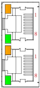
# 5.1.3 RJ45 Network Wiring

Using a standard RJ45 network interface connector, the pin assignment is shown in the table below.
![1\n8\n1\n8](.es-series-50m-19030-1030-13/35ce57bfbac12bdcaa90fc4c88d052c36938d5d9c5ee874f6f5ec534e9ee94d1.jpg)

<table><tr><td>Pin</td><td>Signal</td></tr><tr><td>1</td><td>TD+</td></tr><tr><td>2</td><td>TD-</td></tr><tr><td>3</td><td>RD+</td></tr><tr><td>4</td><td>—</td></tr><tr><td>5</td><td>—</td></tr><tr><td>6</td><td>RD-</td></tr><tr><td>7</td><td>—</td></tr><tr><td>8</td><td>—</td></tr></table>

# Note:

• It is recommended to use a Cat 5 or higher double-shielded (braided mesh + aluminum foil) STP cable for communication.
The length of the cables between devices should not exceed 100m.

# 5.2 ES-1008 and ES-1016 Connector Pinouts

# 5.2.1 I/O Pin Assignment

![Based on the provided flowchart/block diagram, here is an accurate and concise description:\n\n**Labeled Blocks:**\n*   **Central Grid:** A large dashed rectangle containing two columns of circles. The left column is labeled **A0** through **A8**. The right column is labeled **B0** through **B8**.\n*   **Power Source:** A box in the bottom left labeled **DC24V** with **+** and **-** terminals.\n*   **Input Switches:** Rectangular symbols with diagonal lines.\n    *   Left side: Labeled **X00**, **X01**, **X02**, **X03**, **X04**, **X05**, **X06**, **X07**.\n    *   Right side: Labeled **X08**, **X09**, **X0A**, **X0B**, **X0C**, **X0D**, **X0E**, **X0F**.\n*   **Labels:** **+COM** and **COM**.\n\n**Connections:**\n*   **DC24V (+)** connects to **+COM**. An arrow extends from **+COM** into circle **A8**.\n*   **DC24V (-)** connects to a vertical bus line on the far left.\n*   **Left Side:** The left vertical bus line connects to the left side of switches **X00** through **X07**. Arrows extend from these switches to the right, pointing into circles **A0** through **A7** respectively.\n*   **Right Side:** A vertical bus line on the far right connects to the right side of switches **X08** through **X0F**. Arrows extend from these switches to the left, pointing into circles **B0** through **B7** respectively.\n*   **Bottom Right:** The label **COM** is positioned to the right of circle **B8**.](.es-series-50m-19030-1030-13/9f5a2f6b6d50aff6bc2ea5f5185b2dff6daefa7042593f8ac5ea19387cf762de.jpg)

![Pure electrical connector diagram without any text, numbers, or symbols](.es-series-50m-19030-1030-13/5cb63a456a2a098e1dc6cb81ee2f6d31f49a42d45545af20032c12e809f6d6d0.jpg)

\*COM internal conduction; NPN/PNP compatible
Note: For 8-channel model, only A0 to A8 are functional, and B0 to B8 do not require wiring.

Signal connection
![Based on the provided block diagram, here is an accurate and concise description:\n\n**Labeled Blocks:**\n*   **Inputs:** Labeled switches/terminals 'DI0', 'DI7', and 'DI17' (with squiggly lines indicating intermediate inputs DI1-DI16).\n*   **Resistors:** Rectangular symbols connected in series with each input line.\n*   **Photocoupler:** Labeled components consisting of an LED and a phototransistor symbol.\n*   **Internal Circuit:** A large grey block on the right side.\n*   **Sourcing Type:** A box containing a DC 24V source (circle with + and - terminals).\n*   **Sinking Type:** A box containing a DC 24V source (circle with - and + terminals).\n\n**Connections:**\n*   **Input Bus:** A vertical line on the far left connects the common side of the switches (DI0, DI7, DI17).\n*   **Signal Path:** From each switch, a horizontal line extends rightward through a resistor and connects to the anode (left side) of a 'Photocoupler'.\n*   **Common Return:** The cathode (right side) of each 'Photocoupler' connects to a common vertical dashed line.\n*   **Output:** The output side (phototransistor) of each 'Photocoupler' connects to the 'Internal Circuit' block.\n*   **Sourcing Type Wiring:** The DC 24V source labeled 'Sourcing Type' connects its positive (+) terminal to the far left input bus and its negative (-) terminal to the common dashed line.\n*   **Sinking Type Wiring:** The DC 24V source labeled 'Sinking Type' connects its negative (-) terminal to the far left input bus and its positive (+) terminal to the common dashed line.](.es-series-50m-19030-1030-13/77fa1d17a073a493115b888ce30b3e6c0338b39e509283852b6a7d422712be68.jpg)

5.2.2 LED Indicators

<table><tr><td>Function</td><td>Color</td><td>Status</td></tr><tr><td>PR</td><td>Green</td><td>Off: Power off/ exceptionalOn: Power on</td></tr><tr><td>RUN</td><td>Green</td><td>Off: System is not workingBlinking (1Hz): No data interactionFlashing (10Hz): Firmware is upgradingOn: System is running normally</td></tr><tr><td>Channel01~08/16</td><td>Green</td><td>Off: InactiveOn: Active</td></tr></table>

# 5.3 ES-2108 and ES-2116 Connector Pinouts

# 5.3.1 I/O Pin Assignment

![Y00\nY01\nY02\nY03\nY04\nY05\nY06\nY07\n24V\nA0 B0\nA1 B1\nA2 B2\nA3 B3\nA4 B4\nA5 B5\nA6 B6\nA7 B7\nA8 B8\nY08\nY09\nY0A\nY0B\nY0C\nY0D\nY0E\nY0F\n+ 0V -\nDC24V](.es-series-50m-19030-1030-13/02bddcc1aa31b033bdf1170f9a5d0b2c338a01bf99db136340c065df7a72da7e.jpg)

Note: For 8-channel model, only A0 to A8 and B8 are functional, B0 to B7 do not require wiring.

Signal connection
![The image displays a block diagram illustrating the wiring of a PLC output module.\n\n**Labeled Blocks:**\n*   **Internal Circuit:** A large grey vertical rectangle on the left side.\n*   **Switches:** Four circular symbols with left-pointing arrows inside, connected to the 'Internal Circuit'. Dotted lines between them indicate additional intermediate switches.\n*   **Output Lines:** Labeled **Y0**, **Y7**, **Y10**, and **Y17**.\n*   **Load:** Four rectangular blocks labeled **Load**, each with a left-pointing arrow next to it.\n*   **Power Source:** A circle at the bottom right labeled **DC 24V** with a plus sign (**+**) inside.\n*   **Lines/Rails:** Labeled **24V** and **COM**.\n\n**Connections:**\n1.  The **Internal Circuit** block connects to the control terminals of the circular switch symbols.\n2.  The top terminal of each switch connects to an output line (**Y0**, **Y7**, **Y10**, or **Y17**).\n3.  The bottom terminal of each switch connects to the common line labeled **COM**.\n4.  The output lines (**Y0**, **Y7**, **Y10**, **Y17**) connect to the left side of the **Load** blocks.\n5.  The right side of the **Load** blocks connects to a vertical line that leads to the horizontal line labeled **24V**.\n6.  The **24V** line connects to the positive terminal (**+**) of the **DC 24V** source.\n7.  The **COM** line connects to the negative terminal of the **DC 24V** source (completing the circuit).](.es-series-50m-19030-1030-13/ba93646a4a8ef73be29904d8e205464f54386fedfa651ef2cac355d72b0848d3.jpg)

5.3.2 LED Indicators

<table><tr><td>Function</td><td>Color</td><td>Status</td></tr><tr><td>PR</td><td>Green</td><td>Off: Power off/ exceptionalOn: Power on</td></tr><tr><td>RUN</td><td>Green</td><td>Off: System is not workingBlinking (1Hz): No data interactionFlashing (10Hz): Firmware is upgradingOn: System is running normally</td></tr><tr><td>Channel 01~08/16</td><td>Green</td><td>Off: InactiveOn: Active</td></tr></table>

# 5.4 ES-3104 Connector Pinouts

# 5.4.1 I/O Pin Assignment

![This diagram illustrates the wiring configuration for a terminal block module.\n\n**Central Terminal Block**\nThe center features a grid of circular connection points arranged in columns labeled **A0–A8** and **B0–B8**.\n*   Rows **A6/B6** and **A8/B8** are labeled **NC** (No Connection).\n*   Row **A7/B7** is labeled **PE**.\n\n**Left Side Connections (3-wire and 4-wire)**\n*   **3-wire:** Inputs **+24V** and **0V** connect to terminals **AI+** and **AI-**. These pass through a dashed box with a cross. The outputs connect to the central block: **AO+** to **A0**, **AO-** to **A1**, and **PE** to **A2**.\n*   **4-wire:** Inputs **+24V** and **0V** connect to terminals **AI+** and **AI-**. These pass through a dashed box with a cross. The outputs connect to the central block: **A2+** to **A3**, **A2-** to **A4**, and **PE** to **A5**.\n\n**Right Side Connections (2-wire sinking and sourcing)**\n*   **2-wire sinking:** Connections from the central block **A1+** (to **B0**) and **A1-** (to **B1**) pass through a dashed box with a cross. The outputs are labeled **AI+** and **AI-**. The terminal **PE** connects to **B2**.\n*   **2-wire sourcing:** Connections from the central block **A3+** (to **B3**) and **A3-** (to **B4**) pass through a dashed box with a cross. The outputs are labeled **AI+** and **AI-**. Power is applied such that **+24V** connects to **AI+** and **0V** connects to **AI-**. The terminal **PE** connects to **B5**.\n\n**Additional Connections**\n*   A **PE** terminal located below **B5** connects to a ground symbol.](.es-series-50m-19030-1030-13/991caa486dc1586001e876faf710719b68019184578c0cd965b15b292cba0650.jpg)

\*PE internal conduction
\*Signal cables are recommended to use shielded twisted pairs

Signal connection
![This block diagram illustrates a system with four input channels and a power supply section.\n\n**Input Channels:**\nOn the left, there are four parallel channels. Each channel includes:\n*   An input labeled **IN_0V**, **IN_1V**, **IN_2V**, or **IN_3V**.\n*   A ground labeled **AGND**.\n*   A resistor connected to the **IN** input.\n*   A triangle symbol (representing an amplifier or comparator).\n\n**Connections:**\n*   In each channel, the output of the resistor and the **AGND** line join at a common node.\n*   This node connects to the positive (+) input of the triangle symbol.\n*   The negative (-) input of the triangle symbol connects to the **AGND** line.\n*   The output of each triangle connects to a large grey block labeled **Internal Circuit**.\n*   Each triangle symbol is connected to power rails labeled **+15V** and **-15V**.\n\n**Power and Ground Section:**\n*   At the bottom right, there is a block labeled **DC/DC Converter**.\n*   It is connected to a block labeled **Internal 5V**.\n*   It is also connected to rails labeled **+15V**, **AGND**, and **-15V**. (Arrows point from these labels towards the DC/DC Converter).\n*   A label **PE** connects to a main vertical ground line.\n*   This main ground line connects to all **AGND** labels in the input channels and the bottom **AGND** rail.](.es-series-50m-19030-1030-13/0df21ef36bcbc413a73e99ee6a8ff98454392ad1adbf6944b46b7c1e930eff07.jpg)

5.4.2 LED Indicators

<table><tr><td>Function</td><td>Color</td><td>Status</td></tr><tr><td>PR</td><td>Green</td><td>Off: Power off/ exceptionalOn: Power on</td></tr><tr><td>RUN</td><td>Green</td><td>Off: System is not workingBlinking (1Hz): No data interactionFlashing (10Hz): Firmware is upgradingOn: System is running normally</td></tr></table>

# 5.5 ES-4104 Connector Pinouts

![**Central Column:**\nA vertical stack of 18 circles arranged in two columns.\n*   **Left Column (top to bottom):** A0, A1, A2, A3, A4, A5, A6, A7, A8.\n*   **Right Column (top to bottom):** B0, B1, B2, B3, B4, B5, B6, B7, B8.\n*   The circles are arranged in horizontal pairs: (A0, B0), (A1, B1), (A2, B2), (A3, B3), (A4, B4), (A5, B5), (A6, B6), (A7, B7), (A8, B8).\n\n**Top Left Block:**\n*   A dashed rectangular box containing an 'X'.\n*   **Left side:** Arrows pointing left labeled 'AO+' and 'AO-'.\n*   **Right side:** Arrows pointing right labeled 'AO+' and 'AO-'.\n*   **Bottom:** Arrow pointing down labeled 'PE'.\n\n**Top Right Block:**\n*   A dashed rectangular box containing an 'X'.\n*   **Left side:** Arrows pointing left labeled 'A1+' and 'A1-'.\n*   **Right side:** Arrows pointing right labeled 'AO+' and 'AO-'.\n*   **Bottom:** Arrow pointing down labeled 'PE'.\n\n**Middle Left Block:**\n*   A dashed rectangular box containing an 'X'.\n*   **Left side:** Arrows pointing left labeled 'AO+' and 'AO-'.\n*   **Right side:** Arrows pointing right labeled 'A2+' and 'A2-'.\n*   **Bottom:** Arrow pointing down labeled 'PE'.\n\n**Middle Right Block:**\n*   A dashed rectangular box containing an 'X'.\n*   **Left side:** Arrows pointing left labeled 'A3+' and 'A3-'.\n*   **Right side:** Arrows pointing right labeled 'AO+' and 'AO-'.\n*   **Bottom:** Arrow pointing down labeled 'PE'.\n\n**Bottom Section:**\n*   **Left Side Labels (aligned with central column rows):**\n    *   'NC' (aligned with A6/B6).\n    *   'PE' (aligned with A7/B7).\n    *   '24V' (aligned with A8). An arrow from '24V' points right towards A8.\n*   **Right Side Labels (aligned with central column rows):**\n    *   'NC' (aligned with B6).\n    *   'PE' (aligned with B7).\n    *   '0V' (aligned with B8). An arrow from '0V' points left towards B8.\n*   **Power Source:** A battery symbol at the bottom labeled 'DC24V'.\n    *   The positive terminal (+) connects to the '24V' line.\n    *   The negative terminal (-) connects to the '0V' line.\n*   **Ground:** A ground symbol connected to the '0V' line.](.es-series-50m-19030-1030-13/36a2d3c50953ae20855df444700ce83528d047dde4b2ea247384609df0a0f928.jpg)

![Pure electrical connector diagram without any text, numbers, or symbols](.es-series-50m-19030-1030-13/e80cb39ed0b7a6d02859fe51da2e0140bc92a6a7a62ea88c6b5a706e3559291b.jpg)

\*PE internal conduction
\*Signal cables are recommended to use shielded twisted pairs

Signal connection
![Based on the provided block diagram, here is a description of the labeled blocks and their connections:\n\n**Power Generation Section:**\n*   A battery symbol labeled **DC-24V** connects to a block labeled **DC/DC Converter**.\n*   A block labeled **PE** connects to the negative terminal of the **DC-24V** source.\n*   The **DC/DC Converter** outputs three power lines: **+15V**, **AGND**, and **-15V**.\n\n**Signal Processing Section:**\n*   There are four input labels on the left: **OUT_0V**, **OUT_1V**, **OUT_2V**, and **OUT_3V**.\n*   Each input label connects to the signal input of a triangular amplifier symbol.\n*   Each amplifier is powered by the **+15V** rail (connected to the top) and the **-15V** rail (connected to the bottom).\n*   The output of each amplifier connects to a block labeled **ADC Converter**.\n*   Each **ADC Converter** is also connected to the **+15V** and **-15V** power rails.\n\n**Main Processing Section:**\n*   The outputs of all four **ADC Converter** blocks connect to a large grey vertical block labeled **Internal Circuit**.](.es-series-50m-19030-1030-13/fd634f87096932f2ca454591eacb0717d76fef67352d22f114ff59e5e1bdfb66.jpg)

5.5.1 LED Indicators

<table><tr><td>Function</td><td>Color</td><td>Status</td></tr><tr><td>PR</td><td>Green</td><td>Off: Power off/ exceptionalOn: Power on</td></tr><tr><td>RUN</td><td>Green</td><td>Off: System is not workingBlinking (1Hz): No data interactionFlashing (10Hz): Firmware is upgradingOn: System is running normally</td></tr></table>

# 5.6 ES-3504 Connector Pinouts

# 5.6.1 I/O Pin Assignment

![This diagram illustrates two groups of terminal connections for signal inputs, likely for a data acquisition system. The central area features two columns of circular terminals labeled with letters (A and B) and numbers (0-8).\n\n**Top Section (Channels 0 & 1):**\n*   **Left Block:** Labeled 'RTD/TD'.\n    *   '0+' connects to circle **A0**.\n    *   '0-' connects to circle **A1**.\n    *   'COM' connects to circle **A2**.\n    *   'PE' connects to circle **A3**.\n*   **Right Block:** Labeled 'TC'.\n    *   '1+' connects to circle **B0**.\n    *   '1-' connects to circle **B1**.\n    *   'COM' connects to circle **B2**.\n    *   'PE' connects to circle **B3**.\n\n**Bottom Section (Channels 2 & 3):**\n*   **Left Block:** Labeled 'RTD/TD'.\n    *   '2+' connects to circle **A4**.\n    *   '2-' connects to circle **A5**.\n    *   'COM' connects to circle **A6**.\n    *   'PE' connects to circle **A7**.\n    *   'NC' connects to circle **A8**.\n*   **Right Block:** Labeled 'TC'.\n    *   '3+' connects to circle **B4**.\n    *   '3-' connects to circle **B5**.\n    *   'COM' connects to circle **B6**.\n    *   'PE' connects to circle **B7**.\n    *   'NC' connects to circle **B8**.](.es-series-50m-19030-1030-13/d82c03fee15630884f564b7fcd8230698d8213a017f84220ba69e6360642339f.jpg)

![Pure electrical connector diagram without any text, numbers, or symbols](.es-series-50m-19030-1030-13/afd718ea5ead433e0623d2f7e8eee33602208fe8b4e85c31c62eafb09afd79bd.jpg)

\*COM and PE are internally conductive.

Pin assignment

<table><tr><td>Pin No.</td><td>Definition</td><td>Description</td><td>Pin No.</td><td>Definition</td><td>Description</td></tr><tr><td>A0</td><td>0+</td><td rowspan="4">CH0 Temperature input</td><td>B0</td><td>1+</td><td rowspan="4">CH1 Temperature input</td></tr><tr><td>A1</td><td>0-</td><td>B1</td><td>1-</td></tr><tr><td>A2</td><td>COM</td><td>B2</td><td>COM</td></tr><tr><td>A3</td><td>PE</td><td>B3</td><td>PE</td></tr><tr><td>A4</td><td>2+</td><td rowspan="4">CH2 Temperature input</td><td>B4</td><td>3+</td><td rowspan="4">CH3 Temperature input</td></tr><tr><td>A5</td><td>2-</td><td>B5</td><td>3-</td></tr><tr><td>A6</td><td>COM</td><td>B6</td><td>COM</td></tr><tr><td>A7</td><td>PE</td><td>B7</td><td>PE</td></tr><tr><td>A8</td><td>NC</td><td>Empty</td><td>B8</td><td>NC</td><td>Empty</td></tr></table>

5.6.2 LED Indicators

<table><tr><td>Function</td><td>Color</td><td>Status</td></tr><tr><td>PR</td><td>Green</td><td>Off: Power off/ exceptionalOn: Power on</td></tr><tr><td>RUN</td><td>Green</td><td>Off: System is not workingBlinking (1Hz): No data interactionFlashing (10Hz): Firmware is upgradingOn: System is running normally</td></tr></table>

# 5.7 ES-5003 Connector Pinouts

# 5.7.1 I/O Pin Assignment

![RS232\nDevice\nRXD\nTXD\nSG\nTX\nA0\nB0\nRX\nGND\nA1\nB1\nGND\nA+\nA2\nB2\nB-\nRS485\nDevice\nA+\nB-\n120Ω\nRS422\nDevice\nRX+\nRX-\nTX+\nTX+\nTX-\nRX+\nTX-\nRX-\nConverter\nCF+\nA5\nB5\nCF-\nNC\nA6\nB6\nNC\nNC\nA7\nB7\nNC\nNC\nA8\nB8\nNC\nPC\nIO Config\nRS485](.es-series-50m-19030-1030-13/51f620097bc356e74df4dc03a85e23482bbe5852a61df87a91fc05d541c9d5fc.jpg)

\*GND is the RS232 signal ground, which is internally conductive.
\*Cables should be shielded twisted-pairs and reliably grounded.
\*CF+/CF- reserve the debugging interface for the module and are not yet enabled.

Pin assignment

<table><tr><td>No.</td><td>Definition</td><td>Description</td><td>No.</td><td>Definition</td><td>Description</td></tr><tr><td>A0</td><td>TX</td><td>RS232 sender</td><td>A0</td><td>Rx</td><td>RS232 receiving</td></tr><tr><td>A1</td><td>GND</td><td>RS232 ground</td><td>A1</td><td>GND</td><td>RS232 ground</td></tr><tr><td>A2</td><td>A+</td><td>RS485 send+</td><td>A2</td><td>B-</td><td>RS485 send-</td></tr><tr><td>A3</td><td>TX+</td><td>RS422 send+</td><td>A3</td><td>TX-</td><td>RS422 send-</td></tr><tr><td>A4</td><td>RX+</td><td>RS422 receive+</td><td>A4</td><td>RX-</td><td>RS422 receive-</td></tr><tr><td>A5</td><td>CF+</td><td>reserved</td><td>A5</td><td>CF-</td><td>reserved</td></tr><tr><td>A6</td><td>NC</td><td>Empty terminal</td><td>A6</td><td>NC</td><td>Empty terminal</td></tr><tr><td>A7</td><td>NC</td><td>Empty terminal</td><td>A7</td><td>NC</td><td>Empty terminal</td></tr><tr><td>A8</td><td>NC</td><td>Empty terminal</td><td>A8</td><td>NC</td><td>Empty terminal</td></tr></table>

5.7.2 LED Indicators

<table><tr><td>Function</td><td>Color</td><td>Status</td></tr><tr><td>PR</td><td>Green</td><td>Off: Power off/ exceptionalOn: Power on</td></tr><tr><td>RUN</td><td>Green</td><td>Off: System is not workingBlinking (1Hz): No data interactionFlashing (10Hz): Firmware is upgradingOn: System is running normally</td></tr><tr><td>TX</td><td>Green</td><td>Off: No data is sent on the channelFlashing: The channel has data to send</td></tr><tr><td>RX</td><td>Green</td><td>Off: No data reception on the channelFlashing: The channel has data reception</td></tr></table>

# 5.8 ES-0012 Connector Pinouts

# 5.8.1 I/O Pin Assignment

![24V\n24V\n24V\n- +24V\nDC24V 0V\nA0 B0 24V\nA1 B1 24V\nA2 B2 24V\nA3 B3 24V\nA4 B4 0V\nA5 B5 0V\nA6 B6 0V\nA7 B7 0V\nPE A8 B8 PE](.es-series-50m-19030-1030-13/dc1f980c783ac1b16dd54600660a468743dffe9697264d4c0b5e5629c72b59b2.jpg)

\*24V and 0V are internally conductive.

# 5.8.2 LED Indicators

<table><tr><td>Function</td><td>Color</td><td>Status</td></tr><tr><td>PR</td><td>Green</td><td>Off: Power off/ exceptionalOn: Power on</td></tr></table>

# 5.9 ES-0040 Connector Pinouts

# 5.9.1 I/O Pin Assignment

Use a 24VDC power supply. Refer to the wiring diagram below and connect the power supply according to the circuit shown. Ensure that the PE (Protective Earth) is reliably grounded. It is recommended to use twisted-pair wires for the power lines.

![PE 0V 24V\n+24V 220V\n0V 24V =](.es-series-50m-19030-1030-13/53ab9d5aa47c43005b59ca606fa0817711d03d1584b13ca584cf153e3ea7989b.jpg)

# 5.9.2 LED Indicators

<table><tr><td>Function</td><td>Color</td><td>Status</td></tr><tr><td>PWR</td><td>Green</td><td>Off: Power offOn: Power on</td></tr><tr><td>IN1</td><td>Green</td><td>Off: No data interaction or exceptionBlinking: Link and TX/RX activityOn: Establish a network connection</td></tr><tr><td>OUT2~4</td><td>Green</td><td>Off: No data interaction or exceptionBlinking: Link and TX/RX activityOn: Establish a network connection</td></tr></table>

# 5.9.3 RJ45 Network Wiring

Using a standard RJ45 network interface connector, the pin assignment is shown in the table below.

![OUT4\nOUT3\nOUT2\nIN1](.es-series-50m-19030-1030-13/fb4e7f7c387130782196aa6bc9d3236b433d5c7ada932b2980f2378c9dffec0d.jpg)

<table><tr><td>Pin</td><td>Signal</td></tr><tr><td>1</td><td>TD+</td></tr><tr><td>2</td><td>TD-</td></tr><tr><td>3</td><td>RD+</td></tr><tr><td>4</td><td>—</td></tr><tr><td>5</td><td>—</td></tr><tr><td>6</td><td>RD-</td></tr><tr><td>7</td><td>—</td></tr><tr><td>8</td><td>—</td></tr></table>

# Note:

• It is recommended to use Cat 5 or higher double-shielded (braided mesh + aluminum foil) STP cable for communication.
The length of the cables in between should not exceed 100m.

This page intentionally left blank.

# 6 Parameter Description

# 6.1 Digital and Input Filtering

Digital input filtering prevents the program from responding to unexpected rapid changes in the input signal, which may be caused by switch contact bounce or electrical noise. Digital input filter supports single-module settings, allowing each module to be configured individually, but channels cannot be configured separately.

The default configuration for the digital input filter time (FilterTime) is 3 ms, with a configurable range of 0 to 20ms. When set to 3 ms, noise within 3 ms can be filtered out. A 3 ms input filter time means that a signal must remain at "0" to "1" or "1" to "0" for 3 ms to be detected; any high or low pulse shorter than 3 ms will not be detected.

Function Description: When the input filter is configured to 1 ms, noise within 1ms can be filtered out. If a signal input of 250μs is received, it will be considered an invalid signal. Any high or low pulse shorter than 1 ms will not be detected, while signals of 1 ms or longer will be captured.

![| Signal Type       | Timeframe Label     |\n| ----------------- | ------------------- |\n| Input Signal      | 250μs (Invalid Signal) |\n| Collect Signal    | 1ms (Valid Signal)   |](.es-series-50m-19030-1030-13/30f4d8e623cd330a2b5cbfe44e9ff6023210b22cc7f7f1285c9d4730878bbe2d.jpg)

# 6.2 Digital Output Signal Clear/Hold

The clear/hold function applies to modules with output channels. This function allows the configuration of the output mode for the output channels when the module is not in the OP state (i.e., stopped operation or network cable disconnected from the coupler). The parameter supports the following output states:

• Clear Output: When communication is disconnected, the module's output channel automatically clears the output, i.e., output 0.
• Output Valid Value: When communication is disconnected, the module's output channel continuously outputs a valid value, i.e., output 1.
• Hold Last Output Value: When communication is disconnected, the module's output channel holds the last output value.

The digital clear/hold function supports both module settings (template mode) and single-channel settings (singlechannel mode). Any channel can be configured using either single-channel mode or template mode, with singlechannel mode taking priority over template mode. The specific configuration methods are shown in the table below, with the default setting being module-wide clear output.

<table><tr><td colspan="5">Digital output module clears and holds parameters</td></tr><tr><td>Name</td><td>Mode</td><td>Value</td><td>Value Description</td><td>Default</td></tr><tr><td rowspan="3">TemplateMode</td><td rowspan="3">Template mode</td><td>1</td><td>PresetLow: Clears the output to &quot;0&quot;</td><td rowspan="3">1</td></tr><tr><td>2</td><td>PresetHigh: Outputs valid value to &quot;1&quot;</td></tr><tr><td>3</td><td>KeepMode: Keeps the last output value</td></tr><tr><td rowspan="4">Channel x</td><td rowspan="4">Single-channel mode</td><td>0</td><td>TemplateValue: Applies to all channels of this module (disable single channel mode)</td><td rowspan="4">0</td></tr><tr><td>1</td><td>PresetLow: Clears output &quot;0&quot;</td></tr><tr><td>2</td><td>PresetHigh: Outputs valid value &quot;1&quot;</td></tr><tr><td>3</td><td>KeepMode: Keeps the last output value</td></tr></table>

# 6.3 Analog Input Filtering

Analog Input Filtering Function: The analog input filtering function (Filter) averages the data after A/D conversion internally to reduce fluctuations caused by noise or other disturbances in the input signal.

The analog input is processed using a moving average based on the specified number of A/D conversions.

Filtering Function Configuration: Each channel can be configured individually, with a configuration range from 1 to 200, and the default is 10 times.

The sampling rate for the 4-channel module is: 2.5KHz/4 channels (400µs/4 channels).

# 6.4 Analog Output Signal Clear/Hold

The clear/hold function applies to modules with output channels. This function allows the configuration of the output mode for the output channels when the module is not in the OP state (i.e., stopped operation or network cable disconnected from the coupler). The parameter supports the following output states:

• Clear Output: When communication is disconnected, the module's output channel automatically clears the output.
• Hold Output: When communication is disconnected, the module's output channel continuously holds the output.
• Output Preset Value: When communication is disconnected, the module's output channel outputs the preset value.

The analog clear/hold function supports both module-wide settings (template mode) and single-channel settings (single-channel mode). Any channel can be configured using single-channel mode or template mode, with singlechannel mode taking priority over template mode. The specific configuration methods are shown in the table below, with the default setting being module-wide clear output.

<table><tr><td colspan="5">Digital output module clears and holds parameters</td></tr><tr><td>Name</td><td>Mode</td><td>Value</td><td>Value Description</td><td>Default</td></tr><tr><td rowspan="3">TemplateMode</td><td rowspan="3">Template mode</td><td>0</td><td>Clear: Clear the output of all channels.</td><td rowspan="3">0</td></tr><tr><td>1</td><td>Hold: Hold the output of all channels.</td></tr><tr><td>2</td><td>Preset: Output the preset value on all channels.</td></tr><tr><td rowspan="4">TemplateValue Chx</td><td rowspan="4">Single channel clear/keep configuration</td><td>0</td><td>TemplateValue: Template mode value, meaning single-channel mode is not enabled.</td><td rowspan="4">0</td></tr><tr><td>1</td><td>Clear (Single Channel): Clear the output of the single channel.</td></tr><tr><td>2</td><td>Hold (Single Channel): Hold the output of the single channel.</td></tr><tr><td>3</td><td>Preset (Single Channel): Output the preset value on the single channel.</td></tr><tr><td>Preset Value Chx</td><td>Single channel preset</td><td>Value range</td><td>Output code value corresponding to current/voltage value. (Corresponding to the range code value table)</td><td>0</td></tr></table>

# 6.5 Analog Power-Off Memory

The analog parameter supports the function of saving all configuration parameters in the event of an abnormal power-off or communication disconnection. By default, all analog modules support power-off memory.

6.6 ES-3504 Configuration Parameter Definition

<table><tr><td>Function</td><td>Parameter</td><td>Value Range</td><td>Default</td></tr><tr><td rowspan="12">Sensor type selection</td><td rowspan="12">Sensor Type</td><td>0: PT100</td><td rowspan="12">0</td></tr><tr><td>1: PT200</td></tr><tr><td>2: PT500</td></tr><tr><td>3: PT1000</td></tr><tr><td>5: THERMOCOUPLE_K</td></tr><tr><td>6: THERMOCOUPLE_J</td></tr><tr><td>8: THERMOCOUPLE_E</td></tr><tr><td>10: THERMOCOUPLE_S</td></tr><tr><td>12: THERMOCOUPLE_B</td></tr><tr><td>16: Ni 100</td></tr><tr><td>17: Ni 1000</td></tr><tr><td>24: RESISTANCE_15:3000</td></tr><tr><td rowspan="4">Filter function</td><td rowspan="4">Filter Type</td><td>0: Default</td><td rowspan="4">0</td></tr><tr><td>50hz</td></tr><tr><td>60hz</td></tr><tr><td>10hz</td></tr><tr><td>Cold junction compensation</td><td>Cold Compensation</td><td>0~65535</td><td>0 (Enable)</td></tr><tr><td rowspan="3">Temperature unit</td><td rowspan="3">Temp Mode</td><td>Centigrade</td><td rowspan="3">0</td></tr><tr><td>Fahrenheit</td></tr><tr><td>Thermodynamic</td></tr><tr><td>Channel filter time</td><td>Filter Time CH00</td><td>0~10</td><td>0</td></tr><tr><td rowspan="2">Channel usage setting</td><td rowspan="2">Enable CH00</td><td>Disable</td><td rowspan="2">1</td></tr><tr><td>Enable</td></tr><tr><td>Temperature compensation</td><td>Cmp CH00</td><td></td><td>0</td></tr></table>

Sensor Type Selection: The module supports sensor type configuration (for sensor type, please refer to Sensor Type selection of the ES-3504 Configuration Parameter Definition).

The same module only supports the same type of sensors, and a single channel cannot be configured.

Note: The default sensor type is PT100.

Filter Function: The module provides filtering options for no filtering, 50Hz, 60Hz, and 10Hz hardware configurations, utilizing a Sigma-Delta ADC for precise signal processing.

Each channel can apply filtering to its measurement value, performing a sliding average processing on the first N collected data to reduce measurement jitter and improve stability and accuracy.

Filtering time = Number of module cycles (N) × module cycle time

Module cycle time = Conversion time + Disconnection detection time

Note: N configuration range is 0 to 10.

Cold Junction Compensation: The module supports enabling/disabling the thermocouple cold junction compensation. It is all turned on by default. It supports single-channel configuration. There are 4 channels with a total of 8 bits. Each channel occupies 2 bits.

If set to 00, the cold junction compensation function will be enabled for the channel.

If set to 01, the channel will disable this function.

Temperature Unit: The module supports configuration conversion of temperature measurement units between degrees Celsius (Centigrade), Fahrenheit (Fahrenheit), and thermodynamic temperature scale (Thermodynamic).

Note: The default sensor type is Celsius (Centigrade).

Channel Usage Setting: The module determines whether a channel is used through the "enable/disable" parameter setting. If a channel is set to disable, it will be disabled, and a value of -9999 will not be displayed regardless of whether the sensor is connected.

Note: The default is enabled.

Temperature Compensation: The module supports manual cold junction compensation for each channel data in thermocouple and thermal resistance modes. The data compensation value can be entered according to actual needs.

After setting the compensation value, the compensated temperature will be automatically calculated in the uploaded data (Input). This means that the uploaded data is the final compensated temperature.

Divide the read data by 10 to get the compensated temperature in °C.

# 6.6.1 ES-3504 Process Data

<table><tr><td colspan="5">Upload data 8 bytes (2 bytes per channel, channel n ranges from 0 to 3)</td></tr><tr><td>Name</td><td>Description</td><td>Value Range</td><td>Data type</td><td>Length</td></tr><tr><td>Channel n</td><td>Channel nTemperature/resistance data acquisition</td><td>-32768~32767</td><td>Int16</td><td>2 Byte</td></tr></table>

# Data Description

# 1. Temperature/resistance data acquisition Channel [n]

The uploaded data (Input) from the temperature module represents the temperature or resistance data collected by each channel. The data of each channel is a 2-byte signed integer. The collected data is 10 times the actual value. Divide the read data by 10 to get the real temperature or resistance value in °C or Ω.

6.7 ES-5003 Configuration Parameter Definition

<table><tr><td>Model Name</td><td>Range</td><td>Description</td></tr><tr><td rowspan="9">Communication Mode</td><td>0</td><td>&quot;NoSelect&quot; means no select</td></tr><tr><td>1</td><td>&quot;Modbus RTU Master&quot; means RTU master mode</td></tr><tr><td>2</td><td>&quot;Modbus RTU Slave&quot; means RTU slave mode</td></tr><tr><td>3</td><td>&quot;Modbus ASCII Master&quot; means ASCII master mode</td></tr><tr><td>4</td><td>&quot;Modbus ASCII Slave&quot; means ASCII slave mode</td></tr><tr><td>5</td><td>&quot;FP_Request&quot; means free port request mode</td></tr><tr><td>6</td><td>&quot;FP_Input_Output&quot; means free port input and output mode</td></tr><tr><td>7</td><td>&quot;FP_Input&quot; means free port input mode</td></tr><tr><td>8</td><td>&quot;FP_Output&quot; means free port output mode</td></tr><tr><td rowspan="8">Baud Rate</td><td>0</td><td>1200 bps</td></tr><tr><td>1</td><td>2400 bps</td></tr><tr><td>2</td><td>4800 bps</td></tr><tr><td>3</td><td>9600 bps</td></tr><tr><td>4</td><td>19200 bps</td></tr><tr><td>5</td><td>38400 bps</td></tr><tr><td>6</td><td>57600 bps</td></tr><tr><td>7</td><td>115200 bps</td></tr><tr><td rowspan="2">Stop Bit</td><td>0</td><td>1 Bit</td></tr><tr><td>1</td><td>2 Bits</td></tr><tr><td rowspan="2">Word Format</td><td>0</td><td>8 Bits</td></tr><tr><td>1</td><td>7 Bits</td></tr><tr><td rowspan="3">Parity</td><td>0</td><td>Parity None</td></tr><tr><td>1</td><td>Parity Odd</td></tr><tr><td>2</td><td>Parity Even</td></tr><tr><td rowspan="3">Control Mode</td><td>0</td><td>Disable</td></tr><tr><td>1</td><td>Level</td></tr><tr><td>2</td><td>Rising Edge</td></tr><tr><td rowspan="2">Node Output Mode</td><td>0</td><td>Poll</td></tr><tr><td>1</td><td>Change Trigger</td></tr><tr><td rowspan="2">Communication Error Behavior</td><td>0</td><td>Clear</td></tr><tr><td>1</td><td>Hold</td></tr><tr><td>Respond Timeout</td><td>5~3000</td><td>Unit: ms, default 50ms</td></tr><tr><td>Poll Delay</td><td>5~3000</td><td>Unit: ms, default 10ms</td></tr><tr><td>Slave ID</td><td>1~247</td><td>Valid in slave mode, default 1</td></tr><tr><td>Slave Respond Delay</td><td>0~3000</td><td>Unit: ms, default 50ms</td></tr><tr><td rowspan="8">Frame Interval</td><td>0</td><td>1.5T</td></tr><tr><td>1</td><td>3.5T</td></tr><tr><td>2</td><td>5T</td></tr><tr><td>3</td><td>10T</td></tr><tr><td>4</td><td>20T</td></tr><tr><td>5</td><td>50T</td></tr><tr><td>6</td><td>100T</td></tr><tr><td>7</td><td>200T</td></tr><tr><td>Node_1_Param_1</td><td>0~FFFFFFFF</td><td rowspan="3">Default 0, see ES-5003 Node Code Parameters for details</td></tr><tr><td>Node_1_Param_2 :</td><td>0~FFFFFFFF</td></tr><tr><td>Node_16_Param_1</td><td>0~FFFFFFFF</td></tr></table>

<table><tr><td>Node_16_Param_2</td><td>0~FFFFFFFF</td></tr></table>

# 6.7.1 ES-5003 Node Code Parameters

# Modbus Master Function

In Modbus master mode, parameter 1 (Param\_1) is composed of a 2-byte start address parameter and a 2-byte node code parameter. Parameter 2 (Param\_2) is composed of a 2-bit byte exchange parameter and a 1-byte slave station.

Station number parameter composition.

<table><tr><td colspan="4">Param_1</td></tr><tr><td>BIT31~BIT16</td><td colspan="3">BIT15~BIT0</td></tr><tr><td>Start Address</td><td colspan="3">Please refer to the Modbus Master Function Node code for the Node Code.</td></tr><tr><td colspan="4">Param_2</td></tr><tr><td>BIT31~BIT16</td><td>BIT15~BIT10</td><td>BIT9~BIT8</td><td>BIT7~BIT0</td></tr><tr><td colspan="2">Reserve</td><td>Refer to ExByte Flag</td><td>Slave Station Number</td></tr></table>

Note: The starting address parameter range is 0000\~FFFFH, and the slave station number parameter range is 1 to 247.

Modbus Master Function Node Code

<table><tr><td>SubModule Group</td><td>SubModule</td><td>SubModule ID (16#)</td></tr><tr><td rowspan="16">Modbus Master Read Coils</td><td>Read 8 bits</td><td>0x0101</td></tr><tr><td>Read 16 bits</td><td>0x0102</td></tr><tr><td>Read 24 bits</td><td>0x0103</td></tr><tr><td>Read 32 bits</td><td>0x0104</td></tr><tr><td>Read 40 bits</td><td>0x0105</td></tr><tr><td>Read 48 bits</td><td>0x0106</td></tr><tr><td>Read 56 bits</td><td>0x0107</td></tr><tr><td>Read 64 bits</td><td>0x0108</td></tr><tr><td>Read 72 bits</td><td>0x0109</td></tr><tr><td>Read 80 bits</td><td>0x010A</td></tr><tr><td>Read 88 bits</td><td>0x010B</td></tr><tr><td>Read 96 bits</td><td>0x010C</td></tr><tr><td>Read 104 bits</td><td>0x010D</td></tr><tr><td>Read 112 bits</td><td>0x010E</td></tr><tr><td>Read 120 bits</td><td>0x010F</td></tr><tr><td>Read 128 bits</td><td>0x0110</td></tr><tr><td rowspan="16">Modbus Master Read Discrete</td><td>Read 8 bits</td><td>0x0201</td></tr><tr><td>Read 16 bits</td><td>0x0202</td></tr><tr><td>Read 24 bits</td><td>0x0203</td></tr><tr><td>Read 32 bits</td><td>0x0204</td></tr><tr><td>Read 40 bits</td><td>0x0205</td></tr><tr><td>Read 48 bits</td><td>0x0206</td></tr><tr><td>Read 56 bits</td><td>0x0207</td></tr><tr><td>Read 64 bits</td><td>0x0208</td></tr><tr><td>Read 72 bits</td><td>0x0209</td></tr><tr><td>Read 80 bits</td><td>0x020A</td></tr><tr><td>Read 88 bits</td><td>0x020B</td></tr><tr><td>Read 96 bits</td><td>0x020C</td></tr><tr><td>Read 104 bits</td><td>0x020D</td></tr><tr><td>Read 112 bits</td><td>0x020E</td></tr><tr><td>Read 120 bits</td><td>0x020F</td></tr><tr><td>Read 128 bits</td><td>0x0210</td></tr><tr><td rowspan="3">Modbus Master Read Hold</td><td>Read 1 Reg</td><td>0x0301</td></tr><tr><td>Read 2 Regs</td><td>0x0302</td></tr><tr><td>Read 3 Regs</td><td>0x0303</td></tr><tr><td rowspan="13"></td><td>Read 4 Regs</td><td>0x0304</td></tr><tr><td>Read 5 Regs</td><td>0x0305</td></tr><tr><td>Read 6 Regs</td><td>0x0306</td></tr><tr><td>Read 7 Regs</td><td>0x0307</td></tr><tr><td>Read 8 Regs</td><td>0x0308</td></tr><tr><td>Read 9 Regs</td><td>0x0309</td></tr><tr><td>Read 10 Regs</td><td>0x030A</td></tr><tr><td>Read 11 Regs</td><td>0x030B</td></tr><tr><td>Read 12 Regs</td><td>0x030C</td></tr><tr><td>Read 13 Regs</td><td>0x030D</td></tr><tr><td>Read 14 Regs</td><td>0x030E</td></tr><tr><td>Read 15 Regs</td><td>0x030F</td></tr><tr><td>Read 16 Regs</td><td>0x0310</td></tr><tr><td rowspan="16">Modbus Master Read Input</td><td>Read 1 Reg</td><td>0x0401</td></tr><tr><td>Read 2 Regs</td><td>0x0402</td></tr><tr><td>Read 3 Regs</td><td>0x0403</td></tr><tr><td>Read 4 Regs</td><td>0x0404</td></tr><tr><td>Read 5 Regs</td><td>0x0405</td></tr><tr><td>Read 6 Regs</td><td>0x0406</td></tr><tr><td>Read 7 Regs</td><td>0x0407</td></tr><tr><td>Read 8 Regs</td><td>0x0408</td></tr><tr><td>Read 9 Regs</td><td>0x0409</td></tr><tr><td>Read 10 Regs</td><td>0x040A</td></tr><tr><td>Read 11 Regs</td><td>0x040B</td></tr><tr><td>Read 12 Regs</td><td>0x040C</td></tr><tr><td>Read 13 Regs</td><td>0x040D</td></tr><tr><td>Read 14 Regs</td><td>0x040E</td></tr><tr><td>Read 15 Regs</td><td>0x040F</td></tr><tr><td>Read 16 Regs</td><td>0x0410</td></tr><tr><td rowspan="17">Modbus Master Write Coils</td><td>Write 8 bits</td><td>0x0501</td></tr><tr><td>Write 16 bits</td><td>0x0502</td></tr><tr><td>Write 24 bits</td><td>0x0503</td></tr><tr><td>Write 32 bits</td><td>0x0504</td></tr><tr><td>Write 40 bits</td><td>0x0505</td></tr><tr><td>Write 48 bits</td><td>0x0506</td></tr><tr><td>Write 56 bits</td><td>0x0507</td></tr><tr><td>Write 64 bits</td><td>0x0508</td></tr><tr><td>Write 72 bits</td><td>0x0509</td></tr><tr><td>Write 80 bits</td><td>0x050A</td></tr><tr><td>Write 88 bits</td><td>0x050B</td></tr><tr><td>Write 96 bits</td><td>0x050C</td></tr><tr><td>Write 104 bits</td><td>0x050D</td></tr><tr><td>Write 112 bits</td><td>0x050E</td></tr><tr><td>Write 120 bits</td><td>0x050F</td></tr><tr><td>Write 128 bits</td><td>0x0510</td></tr><tr><td>Write Single bit</td><td>0x05FF</td></tr><tr><td rowspan="17">Modbus Master Write Hold</td><td>Write 1 Reg</td><td>0x0601</td></tr><tr><td>Write 2 Regs</td><td>0x0602</td></tr><tr><td>Write 3 Regs</td><td>0x0603</td></tr><tr><td>Write 4 Regs</td><td>0x0604</td></tr><tr><td>Write 5 Regs</td><td>0x0605</td></tr><tr><td>Write 6 Regs</td><td>0x0606</td></tr><tr><td>Write 7 Regs</td><td>0x0607</td></tr><tr><td>Write 8 Regs</td><td>0x0608</td></tr><tr><td>Write 9 Regs</td><td>0x0609</td></tr><tr><td>Write 10 Regs</td><td>0x060A</td></tr><tr><td>Write 11 Regs</td><td>0x060B</td></tr><tr><td>Write 12 Regs</td><td>0x060C</td></tr><tr><td>Write 13 Regs</td><td>0x060D</td></tr><tr><td>Write 14 Regs</td><td>0x060E</td></tr><tr><td>Write 15 Regs</td><td>0x060F</td></tr><tr><td>Write 16 Regs</td><td>0x0610</td></tr><tr><td>Write Single Reg</td><td>0x06FF</td></tr></table>

# Modbus Slave Function

In Modbus slave mode, parameter 1 (Param\_1) is composed of a 2-byte start address parameter and a 2-byte node code parameter. Parameter 2 (Param\_2) is composed of a 2-bit byte exchange parameter.

<table><tr><td colspan="3">Param_1</td></tr><tr><td>BIT31~BIT16</td><td colspan="2">BIT15~BIT0</td></tr><tr><td>Start Address</td><td colspan="2">Please refer to the Modbus Slave Function Node Code.</td></tr><tr><td colspan="3">Param_2</td></tr><tr><td>BIT31~BIT16</td><td>BIT15~BIT2</td><td>BIT1~BIT0</td></tr><tr><td colspan="2">Reserve</td><td>Refer to ExByte Flag</td></tr></table>

Note: The starting address parameter range is 0000\~FFFFH.

# Modbus Slave Function Node Code

<table><tr><td>SubModule Group</td><td>SubModule</td><td>SubModule ID (16#)</td></tr><tr><td rowspan="16">Modbus Slave Read Coils</td><td>Read 8 bits</td><td>0x0701</td></tr><tr><td>Read 16 bits</td><td>0x0702</td></tr><tr><td>Read 24 bits</td><td>0x0703</td></tr><tr><td>Read 32 bits</td><td>0x0704</td></tr><tr><td>Read 40 bits</td><td>0x0705</td></tr><tr><td>Read 48 bits</td><td>0x0706</td></tr><tr><td>Read 56 bits</td><td>0x0707</td></tr><tr><td>Read 64 bits</td><td>0x0708</td></tr><tr><td>Read 72 bits</td><td>0x0709</td></tr><tr><td>Read 80 bits</td><td>0x070A</td></tr><tr><td>Read 88 bits</td><td>0x070B</td></tr><tr><td>Read 96 bits</td><td>0x070C</td></tr><tr><td>Read 104 bits</td><td>0x070D</td></tr><tr><td>Read 112 bits</td><td>0x070E</td></tr><tr><td>Read 120 bits</td><td>0x070F</td></tr><tr><td>Read 128 bits</td><td>0x0710</td></tr><tr><td rowspan="15">Modbus Slave Read Hold</td><td>Read 1 Reg</td><td>0x0801</td></tr><tr><td>Read 2 Regs</td><td>0x0802</td></tr><tr><td>Read 3 Regs</td><td>0x0803</td></tr><tr><td>Read 4 Regs</td><td>0x0804</td></tr><tr><td>Read 5 Regs</td><td>0x0805</td></tr><tr><td>Read 6 Regs</td><td>0x0806</td></tr><tr><td>Read 7 Regs</td><td>0x0807</td></tr><tr><td>Read 8 Regs</td><td>0x0808</td></tr><tr><td>Read 9 Regs</td><td>0x0809</td></tr><tr><td>Read 10 Regs</td><td>0x080A</td></tr><tr><td>Read 11 Regs</td><td>0x080B</td></tr><tr><td>Read 12 Regs</td><td>0x080C</td></tr><tr><td>Read 13 Regs</td><td>0x080D</td></tr><tr><td>Read 14 Regs</td><td>0x080E</td></tr><tr><td>Read 15 Regs</td><td>0x080F</td></tr><tr><td rowspan="16">Modbus Slave Write Coils</td><td>Write 8 bits</td><td>0x0901</td></tr><tr><td>Write 16 bits</td><td>0x0902</td></tr><tr><td>Write 24 bits</td><td>0x0903</td></tr><tr><td>Write 32 bits</td><td>0x0904</td></tr><tr><td>Write 40 bits</td><td>0x0905</td></tr><tr><td>Write 48 bits</td><td>0x0906</td></tr><tr><td>Write 56 bits</td><td>0x0907</td></tr><tr><td>Write 64 bits</td><td>0x0908</td></tr><tr><td>Write 72 bits</td><td>0x0909</td></tr><tr><td>Write 80 bits</td><td>0x090A</td></tr><tr><td>Write 88 bits</td><td>0x090B</td></tr><tr><td>Write 96 bits</td><td>0x090C</td></tr><tr><td>Write 104 bits</td><td>0x090D</td></tr><tr><td>Write 112 bits</td><td>0x090E</td></tr><tr><td>Write 120 bits</td><td>0x090F</td></tr><tr><td>Write 128 bits</td><td>0x0910</td></tr><tr><td rowspan="16">Modbus Slave Write Discrete</td><td>Write 8 bits</td><td>0x0A01</td></tr><tr><td>Write 16 bits</td><td>0x0A02</td></tr><tr><td>Write 24 bits</td><td>0x0A03</td></tr><tr><td>Write 32 bits</td><td>0x0A04</td></tr><tr><td>Write 40 bits</td><td>0x0A05</td></tr><tr><td>Write 48 bits</td><td>0x0A06</td></tr><tr><td>Write 56 bits</td><td>0x0A07</td></tr><tr><td>Write 64 bits</td><td>0x0A08</td></tr><tr><td>Write 72 bits</td><td>0x0A09</td></tr><tr><td>Write 80 bits</td><td>0x0A0A</td></tr><tr><td>Write 88 bits</td><td>0x0A0B</td></tr><tr><td>Write 96 bits</td><td>0x0A0C</td></tr><tr><td>Write 104 bits</td><td>0x0A0D</td></tr><tr><td>Write 112 bits</td><td>0x0A0E</td></tr><tr><td>Write 120 bits</td><td>0x0A0F</td></tr><tr><td>Write 128 bits</td><td>0x0A10</td></tr><tr><td rowspan="15">Modbus Slave Write Hold</td><td>Write 1 Reg</td><td>0x0B01</td></tr><tr><td>Write 2 Regs</td><td>0x0B02</td></tr><tr><td>Write 3 Regs</td><td>0x0B03</td></tr><tr><td>Write 4 Regs</td><td>0x0B04</td></tr><tr><td>Write 5 Regs</td><td>0x0B05</td></tr><tr><td>Write 6 Regs</td><td>0x0B06</td></tr><tr><td>Write 7 Regs</td><td>0x0B07</td></tr><tr><td>Write 8 Regs</td><td>0x0B08</td></tr><tr><td>Write 9 Regs</td><td>0x0B09</td></tr><tr><td>Write 10 Regs</td><td>0x0B0A</td></tr><tr><td>Write 11 Regs</td><td>0x0B0B</td></tr><tr><td>Write 12 Regs</td><td>0x0B0C</td></tr><tr><td>Write 13 Regs</td><td>0x0B0D</td></tr><tr><td>Write 14 Regs</td><td>0x0B0E</td></tr><tr><td>Write 15 Regs</td><td>0x0B0F</td></tr><tr><td rowspan="15">Modbus Slave Write Input</td><td>Write 1 Reg</td><td>0x0C01</td></tr><tr><td>Write 2 Regs</td><td>0x0C02</td></tr><tr><td>Write 3 Regs</td><td>0x0C03</td></tr><tr><td>Write 4 Regs</td><td>0x0C04</td></tr><tr><td>Write 5 Regs</td><td>0x0C05</td></tr><tr><td>Write 6 Regs</td><td>0x0C06</td></tr><tr><td>Write 7 Regs</td><td>0x0C07</td></tr><tr><td>Write 8 Regs</td><td>0x0C08</td></tr><tr><td>Write 9 Regs</td><td>0x0C09</td></tr><tr><td>Write 10 Regs</td><td>0x0C0A</td></tr><tr><td>Write 11 Regs</td><td>0x0C0B</td></tr><tr><td>Write 12 Regs</td><td>0x0C0C</td></tr><tr><td>Write 13 Regs</td><td>0x0C0D</td></tr><tr><td>Write 14 Regs</td><td>0x0C0E</td></tr><tr><td>Write 15 Regs</td><td>0x0C0F</td></tr></table>

6.7.2 ExByte Flag

<table><tr><td>Byte Number</td><td>Function</td><td>Length</td></tr><tr><td>0</td><td>No Exchange</td><td>2 Bits</td></tr><tr><td>1</td><td>2Bytes Exchange</td><td>2 Bits</td></tr><tr><td>2</td><td>4Bytes Register Exchange</td><td>2 Bits</td></tr><tr><td>3</td><td>4Bytes Big-Little-Endian Exchange</td><td>2 Bits</td></tr></table>

# 6.7.3 Freeport Function

In Freeport mode, parameter 1 (Param\_1) is a 2-byte node code parameter.

<table><tr><td colspan="2">Param_1</td></tr><tr><td>BIT31~BIT16</td><td>BIT15~BIT0</td></tr><tr><td>Reserve</td><td>Please refer to the Freeport Function Node Code.</td></tr><tr><td colspan="2">Param_2</td></tr><tr><td colspan="2">BIT31~BIT0</td></tr><tr><td colspan="2">Reserve</td></tr></table>

# Freeport Function Node Code

<table><tr><td>SubModule Group</td><td>SubModule</td><td>SubModule ID (16#)</td></tr><tr><td rowspan="12">Freeport Input</td><td>Input 1 byte</td><td>0x0D01</td></tr><tr><td>Input 2 bytes</td><td>0x0D02</td></tr><tr><td>Input 4 bytes</td><td>0x0D03</td></tr><tr><td>Input 8 bytes</td><td>0x0D04</td></tr><tr><td>Input 16 bytes</td><td>0x0D05</td></tr><tr><td>Input 32 bytes</td><td>0x0D06</td></tr><tr><td>Input 64 bytes</td><td>0x0D07</td></tr><tr><td>Input 128 bytes</td><td>0x0D08</td></tr><tr><td>Input 160 bytes</td><td>0x0D09</td></tr><tr><td>Input 192 bytes</td><td>0x0D0A</td></tr><tr><td>Input 224 bytes</td><td>0x0D0B</td></tr><tr><td>Input 255 bytes</td><td>0x0D0C</td></tr><tr><td rowspan="12">Freeport Output</td><td>Output 1 byte</td><td>0x0E01</td></tr><tr><td>Output 2 bytes</td><td>0x0E02</td></tr><tr><td>Output 4 bytes</td><td>0x0E03</td></tr><tr><td>Output 8 bytes</td><td>0x0E04</td></tr><tr><td>Output 16 bytes</td><td>0x0E05</td></tr><tr><td>Output 32 bytes</td><td>0x0E06</td></tr><tr><td>Output 64 bytes</td><td>0x0E07</td></tr><tr><td>Output 128 bytes</td><td>0x0E08</td></tr><tr><td>Output 160 bytes</td><td>0x0E09</td></tr><tr><td>Output 192 bytes</td><td>0x0E0A</td></tr><tr><td>Output 224 bytes</td><td>0x0E0B</td></tr><tr><td>Output 255 bytes</td><td>0x0E0C</td></tr><tr><td rowspan="5">Freeport Parity</td><td>CRC8</td><td>0x0F01</td></tr><tr><td>CRC16</td><td>0x0F02</td></tr><tr><td>XOR</td><td>0x0F03</td></tr><tr><td>SUM8</td><td>0x0F04</td></tr><tr><td>LRC</td><td>0x0F05</td></tr></table>

# 6.7.4 Control and Status Node Code

When the configuration parameter Control Mode is set to ‘disable’ for the control and status mode, there is no need to configure the control and status node code. However, when the Control Mode parameter Control Mode for control and status mode is set to Level or Rising Edge, the node code must be configured first in Node 1 parameter 1 (Node\_1\_Param\_1).

The node code is shown in the table below:

<table><tr><td>SubModule Group</td><td>SubModule</td><td>SubModule ID (16#)</td><td>Remarks</td></tr><tr><td rowspan="20">Control &amp; Status</td><td>1 Node</td><td>0x0001</td><td rowspan="15">Configuration in Master Mode</td></tr><tr><td>2 Node</td><td>0x0002</td></tr><tr><td>3 Node</td><td>0x0003</td></tr><tr><td>4 Node</td><td>0x0004</td></tr><tr><td>5 Node</td><td>0x0005</td></tr><tr><td>6 Node</td><td>0x0006</td></tr><tr><td>7 Node</td><td>0x0007</td></tr><tr><td>8 Node</td><td>0x0008</td></tr><tr><td>9 Node</td><td>0x0009</td></tr><tr><td>10 Node</td><td>0x000A</td></tr><tr><td>11 Node</td><td>0x000B</td></tr><tr><td>12 Node</td><td>0x000C</td></tr><tr><td>13 Node</td><td>0x000D</td></tr><tr><td>14 Node</td><td>0x000E</td></tr><tr><td>15 Node</td><td>0x000F</td></tr><tr><td>Freeport Req</td><td>0x0020</td><td rowspan="4">Configuration in freeport mode</td></tr><tr><td>Freeport Input_Output</td><td>0x0021</td></tr><tr><td>Freeport Input</td><td>0x0022</td></tr><tr><td>Freeport Output</td><td>0x0023</td></tr><tr><td>Modbus Slave</td><td>0x0030</td><td>Configuration in Slave Mode</td></tr></table>

# 6.7.5 Process Data

The upload and download data lengths of the ES-5003 are 32Bytes each as shown in the table below. When the amount of PDO data generated by the module's communication node parameter configuration exceeds a certain threshold (either the upload data amount or the download data amount reaches the limit), the coupler module will trigger alarm 0x5002.

<table><tr><td colspan="3">PDO length range and model matching table</td></tr><tr><td>Module</td><td>Upload data length (Byte)</td><td>Download data length (Byte)</td></tr><tr><td>ES-5003-32Byte</td><td>0~32</td><td>0~32</td></tr></table>

The following example uses the model ES-5003-32Bytes model to introduce the configuration parameters.

When the configuration parameter Control Mode for control and status mode is set to disable, the upload and download process data are shown in the table below.

<table><tr><td colspan="4">Upload Data (32 byte)</td></tr><tr><td>Byte No.</td><td>Function</td><td>Definition</td><td>Address Range</td></tr><tr><td>1</td><td>Input Data</td><td rowspan="4">Serial communication module input data</td><td rowspan="4">32 Byte</td></tr><tr><td>2</td><td>Input Data</td></tr><tr><td>...</td><td>...</td></tr><tr><td>32</td><td>Input Data</td></tr><tr><td colspan="4">Download Data (32 byte)</td></tr><tr><td>Byte No.</td><td>Function</td><td>Definition</td><td>Address Range</td></tr><tr><td>1</td><td>Output Data</td><td>Serial communication module output data</td><td>32 Byte</td></tr><tr><td>2</td><td>Output Data</td><td rowspan="3"></td><td rowspan="3"></td></tr><tr><td>...</td><td>...</td></tr><tr><td>32</td><td>Output Data</td></tr></table>

Modbus Master Process Data

<table><tr><td colspan="4">Upload Data (32 byte)</td></tr><tr><td>Byte No.</td><td>Function</td><td>Definition</td><td>Address Range</td></tr><tr><td rowspan="3">1</td><td rowspan="3">Status word</td><td>Bit0: idle state</td><td rowspan="3">1 Byte</td></tr><tr><td>Bit1: busy state, transmitting data</td></tr><tr><td>Bit2: Completion status, transmission of data is completed</td></tr><tr><td>2</td><td>Alarm code</td><td>Refer to Modbus Alarm Code</td><td>1 Byte</td></tr><tr><td>3</td><td>Input Data</td><td rowspan="4">Serial communication module input data</td><td rowspan="4">last 30 bytes</td></tr><tr><td>4</td><td>Input Data</td></tr><tr><td>...</td><td>...</td></tr><tr><td>32</td><td>Input Data</td></tr><tr><td colspan="4">Download Data (32 byte)</td></tr><tr><td>Byte No.</td><td>Function</td><td>Definition</td><td>Address Range</td></tr><tr><td rowspan="2">1</td><td rowspan="2">Control word</td><td>When the configuration parameter Control Mode is Level, set it to 1 to send data</td><td rowspan="2">1 Byte</td></tr><tr><td>When the configuration parameter Control Mode is Rising Edge, 0 &gt;1 sends data</td></tr><tr><td>2</td><td>Output Data</td><td rowspan="4">Serial communication module output data</td><td rowspan="4">last 31 bytes</td></tr><tr><td>3</td><td>Output Data</td></tr><tr><td>...</td><td>...</td></tr><tr><td>32</td><td>Output Data</td></tr></table>

Note: The process data in the above table is for configuring one node in Level or Rising Edge mode; if two nodes are configured, byte numbers 1 and 2 of the upload data represent the "Status word" and "Alarm code" of node 1, and byte numbers 3 and 4 represent the "Status word" and "Alarm code" of node 2, the remaining bytes are data bytes.
Byte number 1 of the downloaded data is the "Control word" of node 1, byte number 2 is the "Control word" of node 2, the remaining bytes are data byte and up to 15 nodes can be configured.

Modbus Slave Process Data

<table><tr><td colspan="4">Upload Data (32 byte)</td></tr><tr><td>Byte No.</td><td>Function</td><td>Definition</td><td>Address Range</td></tr><tr><td rowspan="3">1</td><td rowspan="3">Status word</td><td>Bit0: idle state</td><td rowspan="3">1 Byte</td></tr><tr><td>Bit1: busy state, transmitting data</td></tr><tr><td>Bit2: Completion status, transmission of data is completed</td></tr><tr><td>2</td><td>Alarm code</td><td>Refer to Modbus Alarm Code</td><td>1 Byte</td></tr><tr><td>3</td><td>Input Data</td><td rowspan="4">Serial communication module input data</td><td rowspan="4">last 30 bytes</td></tr><tr><td>4</td><td>Input Data</td></tr><tr><td>...</td><td>...</td></tr><tr><td>32</td><td>Input Data</td></tr><tr><td colspan="4">Download Data (32 byte)</td></tr><tr><td>Byte No.</td><td>Function</td><td>Definition</td><td>Address Range</td></tr><tr><td>1</td><td>Control word</td><td>Bit0: Clear alarm code</td><td>1 Byte</td></tr><tr><td>2</td><td>Output Data</td><td rowspan="4">Serial communication module output data</td><td rowspan="4"></td></tr><tr><td>3</td><td>Output Data</td></tr><tr><td>...</td><td>...</td></tr><tr><td>32</td><td>Output Data</td></tr></table>

Freeport\_Request Process Data

<table><tr><td colspan="4">Upload Data (32 byte)</td></tr><tr><td>Byte No.</td><td>Function</td><td>Definition</td><td>Address Range</td></tr><tr><td rowspan="3">1</td><td rowspan="3">Status word</td><td>Bit0: Idle state</td><td rowspan="3">1 byte</td></tr><tr><td>Bit1: Busy state, that is, data is being transmitted</td></tr><tr><td>Bit2: Completion status, that is, the transmission of data is completed</td></tr><tr><td rowspan="3">2</td><td rowspan="3">Alarm code</td><td>Bit0: Received data length error</td><td rowspan="3">1 byte</td></tr><tr><td>Bit1: Verification error</td></tr><tr><td>Bit2: Timeout error</td></tr><tr><td>3</td><td>Receive data length</td><td>0~255</td><td>1 byte</td></tr><tr><td>4~5</td><td>Receive exception count</td><td>0~65535</td><td>2 bytes</td></tr><tr><td>6~7</td><td>Receive data count</td><td>0~65535</td><td>2 bytes</td></tr><tr><td>8</td><td>Input Data</td><td rowspan="4">Serial communication module input data</td><td rowspan="4">last 25 bytes</td></tr><tr><td>9</td><td>Input Data</td></tr><tr><td>...</td><td>...</td></tr><tr><td>32</td><td>Input Data</td></tr><tr><td colspan="4">Download Data (32 byte)</td></tr><tr><td>Byte No.</td><td>Function</td><td>Definition</td><td>Address Range</td></tr><tr><td rowspan="3">1</td><td rowspan="3">Control word</td><td>Bit0: Enable</td><td rowspan="3">1 byte</td></tr><tr><td>Bit1: Status word cleared</td></tr><tr><td>Bit2: Clear receiving data</td></tr><tr><td>2</td><td>Send data length</td><td>0~255</td><td>1 byte</td></tr><tr><td rowspan="3">3</td><td rowspan="3">Count cleared</td><td>Bit0: Clear reception exception count</td><td rowspan="3">1 byte</td></tr><tr><td>Bit1: Clear received data count</td></tr><tr><td>Bit2: Clear the received data length to zero</td></tr><tr><td rowspan="3">4</td><td rowspan="3">Clear error code</td><td>Bit0: Length exception cleared</td><td rowspan="3">1 byte</td></tr><tr><td>Bit1: Verification error cleared</td></tr><tr><td>Bit2: Timeout error clear</td></tr><tr><td>5</td><td>Output data</td><td rowspan="4">Serial communication module output data</td><td rowspan="4">last 28 bytes</td></tr><tr><td>6</td><td>Output data</td></tr><tr><td>...</td><td>...</td></tr><tr><td>32</td><td>Output data</td></tr></table>

Freeport\_Input Process Data

<table><tr><td colspan="4">Upload Data (32 byte)</td></tr><tr><td>Byte No.</td><td>Function</td><td>Definition</td><td>Address Range</td></tr><tr><td rowspan="2">1</td><td rowspan="2">Alarm code</td><td>Bit0: Received data length error</td><td rowspan="2">1 byte</td></tr><tr><td>Bit1: Verification error</td></tr><tr><td>2</td><td>Receive data length</td><td>0~255</td><td>1 byte</td></tr><tr><td>3~4</td><td>Receive exception count</td><td>0~65535</td><td>2 bytes</td></tr><tr><td>5~6</td><td>Receive data count</td><td>0~65535</td><td>2 bytes</td></tr><tr><td>7</td><td>Enter data</td><td rowspan="4">Serial communication module input data</td><td rowspan="4">last 26 bytes</td></tr><tr><td>8</td><td>Enter data</td></tr><tr><td>...</td><td>...</td></tr><tr><td>32</td><td>Enter data</td></tr><tr><td colspan="4">Download Data (32 byte)</td></tr><tr><td>Byte No.</td><td>Function</td><td>Definition</td><td>Address Range</td></tr><tr><td rowspan="3">1</td><td rowspan="3">Control word</td><td>Bit0: enable</td><td rowspan="3">1 byte</td></tr><tr><td>Bit1: Status word cleared</td></tr><tr><td>Bit2: Clear receiving data</td></tr><tr><td rowspan="3">2</td><td rowspan="3">Count cleared</td><td>Bit0: Clear reception exception count</td><td rowspan="3">1 byte</td></tr><tr><td>Bit1: Clear received data count</td></tr><tr><td>Bit2: Clear the received data length to zero</td></tr><tr><td rowspan="2">3</td><td rowspan="2">Clear error code</td><td>Bit0: Receive length error cleared</td><td rowspan="2">1 byte</td></tr><tr><td>Bit1: Verification error cleared</td></tr><tr><td>4</td><td>Output data</td><td rowspan="4">Serial communication module output data</td><td rowspan="4">last 29 bytes</td></tr><tr><td>5</td><td>Output data</td></tr><tr><td>...</td><td>...</td></tr><tr><td>32</td><td>Output data</td></tr></table>

Freeport\_Output Process Data

<table><tr><td colspan="4">Download Data (32 byte)</td></tr><tr><td>Byte No.</td><td>Function</td><td>Definition</td><td>Address Range</td></tr><tr><td>1</td><td>Control word</td><td>Bit0 : Enable</td><td>1 byte</td></tr><tr><td>2</td><td>Send data length</td><td>0~255</td><td>1 byte</td></tr><tr><td>3</td><td>Output data</td><td rowspan="4">Serial communication module output data</td><td rowspan="4">last 30 bytes</td></tr><tr><td>4</td><td>Output data</td></tr><tr><td>...</td><td>...</td></tr><tr><td>32</td><td>Output data</td></tr></table>

Freeport\_Input\_Output Process Data

<table><tr><td colspan="4">Upload Data (32 byte)</td></tr><tr><td>Byte No.</td><td>Function</td><td>Definition</td><td>Address Range</td></tr><tr><td rowspan="2">1</td><td rowspan="2">Alarm code</td><td>Bit0: Received data length error</td><td rowspan="2">1 byte</td></tr><tr><td>Bit1: Verification error</td></tr><tr><td>2</td><td>Receive data length</td><td>0~255</td><td>1 byte</td></tr><tr><td>3~4</td><td>Receive exception count</td><td>0~65535</td><td>2 bytes</td></tr><tr><td>5~6</td><td>Receive data count</td><td>0~65535</td><td>2 bytes</td></tr><tr><td>7</td><td>Enter data</td><td rowspan="4">Serial communication module input data</td><td rowspan="4">last 26 bytes</td></tr><tr><td>8</td><td>Enter data</td></tr><tr><td>...</td><td>...</td></tr><tr><td>32</td><td>Enter data</td></tr><tr><td colspan="4">Download Data (32 byte)</td></tr><tr><td>Byte No.</td><td>Function</td><td>Definition</td><td>Address Range</td></tr><tr><td rowspan="3">1</td><td rowspan="3">Control word</td><td>Bit0: enable</td><td rowspan="3">1 byte</td></tr><tr><td>Bit1: Status word cleared</td></tr><tr><td>Bit2: Clear receiving data</td></tr><tr><td>2</td><td>Send data length</td><td>0~255</td><td>1 byte</td></tr><tr><td rowspan="3">3</td><td rowspan="3">Count cleared</td><td>Bit0: Clear reception exception count</td><td rowspan="3">1 byte</td></tr><tr><td>Bit1: Clear received data count</td></tr><tr><td>Bit2: Clear the received data length to zero</td></tr><tr><td rowspan="2">4</td><td rowspan="2">Clear error code</td><td>Bit0: Receive length error cleared</td><td rowspan="2">1 byte</td></tr><tr><td>Bit1: Verification error cleared</td></tr><tr><td>5</td><td>Output data</td><td rowspan="4">Serial communication module output data</td><td rowspan="4">last 28 bytes</td></tr><tr><td>6</td><td>Output data</td></tr><tr><td>...</td><td>...</td></tr><tr><td>32</td><td>Output data</td></tr></table>

6.8 Modbus Alarm Code

<table><tr><td>Alarm Code</td><td>Comment</td></tr><tr><td>0x00</td><td>No errors</td></tr><tr><td>0x01</td><td>Slave device address error</td></tr><tr><td>0x02</td><td>Function code error</td></tr><tr><td>0x03</td><td>CRC check error</td></tr><tr><td>0x04</td><td>Response byte count error</td></tr><tr><td>0x05</td><td>Coil register data error</td></tr><tr><td>0x06</td><td>Holding register data error</td></tr><tr><td>0x07</td><td>Illegal data address</td></tr><tr><td>0x08</td><td>Slave device failure</td></tr><tr><td>0x09</td><td>LRC check error</td></tr><tr><td>0x0C</td><td>Data length error</td></tr><tr><td>0x0D</td><td>Data conversion error</td></tr><tr><td>0x0E</td><td>ASCII frame error</td></tr><tr><td>0x0F</td><td>Response timeout</td></tr></table>

6.8.1 Bus Coupler General Error Codes

<table><tr><td>Number</td><td>Error Type</td><td>Error Code</td><td>Event Name</td><td>Event Code (16#)</td><td>Processing Method</td></tr><tr><td rowspan="2">2</td><td rowspan="2">Online upgrade error</td><td>1</td><td>Firmware upgrade abnormality</td><td>0x0081</td><td>Try to upgrade again, check whether there is any interference in the environment, whether the firmware is too large, etc.</td></tr><tr><td>2</td><td>The firmware does not match the current module model</td><td>0x0082</td><td>Check whether the file is correct, whether there are any abnormalities or interference in the module, etc.</td></tr><tr><td>3</td><td>Voltage error</td><td>5</td><td>Load side voltage is not connected</td><td>0x00C5</td><td>Check whether the on-site power supply is connected</td></tr><tr><td>6</td><td>Channel error</td><td>4</td><td>Channel overflow and underflow</td><td>0x0184</td><td>Check whether the input signal of the corresponding channel exceeds the measurement range and whether the output signal exceeds the configurable range.</td></tr><tr><td>7</td><td>Parameter error</td><td>0</td><td>Abnormal parameter setting</td><td>0x01C0</td><td>Check module parameter settings</td></tr><tr><td rowspan="4">63</td><td rowspan="4">S-Link communication error</td><td>1</td><td>S-Link initialization failed</td><td>0x0FC1</td><td>Check whether the module connection is normal</td></tr><tr><td>2</td><td>S-Link token timeout</td><td>0x0FC2</td><td>Check the module for abnormalities or interference, etc.</td></tr><tr><td>3</td><td>S-Link module runs offline</td><td>0x0FC3</td><td>Check whether the module is online or there is interference, etc.</td></tr><tr><td>4</td><td>Parsing data CRC error</td><td>0x0FC4</td><td>Check the module for abnormalities or interference, etc.</td></tr><tr><td>1</td><td>ES-3504</td><td>0</td><td>Disconnect</td><td>0x2040</td><td>Check whether the corresponding channel wiring is normal</td></tr><tr><td rowspan="2">0</td><td rowspan="2">ES-5003</td><td>0</td><td>General parameter error</td><td>0x5000</td><td>Check whether the common parameter exists and exceeds the parameter limit</td></tr><tr><td>1</td><td>Communication node parameter error</td><td>0x5001</td><td>Check whether the communication node format and node settings are consistent with the communication mode and control mode</td></tr><tr><td rowspan="3"></td><td rowspan="3"></td><td>2</td><td>Process data error</td><td>0x5002</td><td>After the parameter configuration is completed and there are no other alarms, power off and on again to scan the module again.</td></tr><tr><td>3</td><td>Modbus register map conflict</td><td>0x5003</td><td>Compare the starting address and length setting of each Modbus write command of communication node parameter 1 to see if there is any overlap in the range.</td></tr><tr><td>4</td><td>Modbus node ID setting error</td><td>0x5004</td><td>Check whether the slave ID range of communication node parameter 2 is in the range of 1~247</td></tr></table>

# 6.8.2 Check Error Codes

Taking TwinCAT3 software as an example, check the alarm information under Error in the Error List window. As shown in the figure below, the alarm code is Hex: 00c5, which means a voltage error. The load side voltage is not connected. You can check whether the on-site side power supply is connected.
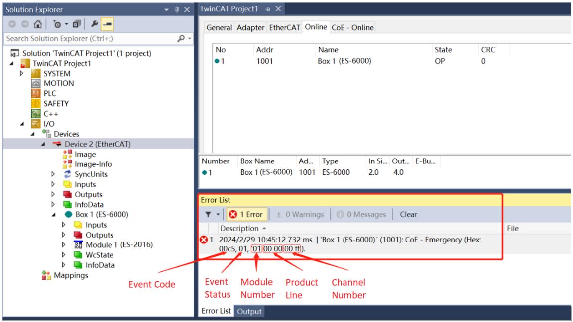
![Solution Explorer\nSearch Solution Explorer (Ctrl+)\nSolution 'TwinCAT Project1' (1 project)\nTwinCAT Project1\nSYSTEM\nMOTION\nPLC\nSAFETY\nC++\nI/O\nDevices\nDevice 2 (EtherCAT)\nImage\nImage-Info\nSyncUnits\nInputs\nOutputs\nInfoData\nBox 1 (ES-6000)\nInputs\nOutputs\nModule 1 (ES-2016)\nWcState\nInfoData\nMappings\nEvent Code\nTwinCAT Project1\nGeneral Adapter EtherCAT Online CoE - Online\nNo Addr Name State CRC\n1 1001 Box 1 (ES-6000) OP 0\nNumber Box Name Ad... Type In Si... Out... E-Bu...\n1 Box 1 (ES-6000) 1001 ES-6000 2.0 4.0\nError List\n1 Error 0 Warnings 0 Messages Clear\nDescription\n1 2024/2/29 10:45:12 732 ms | 'Box 1 (ES-6000)' (1001): CoE - Emergency (Hex: 00c5, 01, (01 00 00 00 ff)).\nEvent Module Product Channel\nStatus Number Line Number\nError List Output](.es-series-50m-19030-1030-13/1a1bfce8a10def281b32eed91c0a1938f135e12ce75ce46d6b8eaba11ad4732f.jpg)

The method of viewing event information is shown in the table below:

<table><tr><td colspan="8">The structure of event information</td></tr><tr><td>byte0</td><td>byte1</td><td>byte2</td><td>byte3</td><td>byte4</td><td>byte5</td><td>byte6</td><td>byte7</td></tr><tr><td colspan="2">Event Code</td><td>Event Status</td><td>Module Number</td><td colspan="2">Product Line</td><td colspan="2">Channel Number</td></tr><tr><td colspan="2"></td><td>For example:0x01: event occurs0x00: eventdisappears</td><td></td><td colspan="2"></td><td colspan="2">For example:0xFF: Channel level event0x00: Channel 0</td></tr></table>

This page intentionally left blank.

# 7 Process Data Objects

7.1 ES-6000 PDO

<table><tr><td>Index</td><td>Sub Index</td><td>Name/Description</td><td>PDO Mapping</td><td>Range</td><td>Data Type</td><td>Access</td><td>Description</td></tr><tr><td>0xF100</td><td>1</td><td>CouplerState</td><td>TxPDO</td><td>0~FFFF</td><td>UINT</td><td>RO</td><td>Coupler State Word</td></tr><tr><td>0xF200</td><td>1</td><td>CouplerCtr</td><td>RxPDO</td><td>0~FFFF</td><td>UINT</td><td>RW</td><td>Coupler Control Word</td></tr></table>

7.2 ES-1008/ES-1016 PDO

<table><tr><td>Index</td><td>Sub Index</td><td>Name/ Description</td><td>PDO Mapping</td><td>Range</td><td>Data Type</td><td>Access</td><td>Description</td></tr><tr><td>0x6nn0</td><td>1</td><td>Channel 0</td><td>TxPDO</td><td>0~1</td><td>BIT</td><td>RO</td><td>Digital input channel 0 data</td></tr><tr><td>0x6nn0</td><td>2</td><td>Channel 1</td><td>TxPDO</td><td>0~1</td><td>BIT</td><td>RO</td><td>Digital input channel 1 data</td></tr><tr><td>0x6nn0</td><td>3</td><td>Channel 2</td><td>TxPDO</td><td>0~1</td><td>BIT</td><td>RO</td><td>Digital input channel 2 data</td></tr><tr><td>0x6nn0</td><td>4</td><td>Channel 3</td><td>TxPDO</td><td>0~1</td><td>BIT</td><td>RO</td><td>Digital input channel 3 data</td></tr><tr><td>0x6nn0</td><td>5</td><td>Channel 4</td><td>TxPDO</td><td>0~1</td><td>BIT</td><td>RO</td><td>Digital input channel 4 data</td></tr><tr><td>0x6nn0</td><td>6</td><td>Channel 5</td><td>TxPDO</td><td>0~1</td><td>BIT</td><td>RO</td><td>Digital input channel 5 data</td></tr><tr><td>0x6nn0</td><td>7</td><td>Channel 6</td><td>TxPDO</td><td>0~1</td><td>BIT</td><td>RO</td><td>Digital input channel 6 data</td></tr><tr><td>0x6nn0</td><td>8</td><td>Channel 7</td><td>TxPDO</td><td>0~1</td><td>BIT</td><td>RO</td><td>Digital input channel 7 data</td></tr><tr><td>0x6nn0</td><td>9</td><td>Channel 8</td><td>TxPDO</td><td>0~1</td><td>BIT</td><td>RO</td><td>Digital input channel 8 data</td></tr><tr><td>0x6nn0</td><td>A</td><td>Channel 9</td><td>TxPDO</td><td>0~1</td><td>BIT</td><td>RO</td><td>Digital input channel 9 data</td></tr><tr><td>0x6nn0</td><td>B</td><td>Channel 10</td><td>TxPDO</td><td>0~1</td><td>BIT</td><td>RO</td><td>Digital input channel 10 data</td></tr><tr><td>0x6nn0</td><td>C</td><td>Channel 11</td><td>TxPDO</td><td>0~1</td><td>BIT</td><td>RO</td><td>Digital input channel 11 data</td></tr><tr><td>0x6nn0</td><td>D</td><td>Channel 12</td><td>TxPDO</td><td>0~1</td><td>BIT</td><td>RO</td><td>Digital input channel 12 data</td></tr><tr><td>0x6nn0</td><td>E</td><td>Channel 13</td><td>TxPDO</td><td>0~1</td><td>BIT</td><td>RO</td><td>Digital input channel 13 data</td></tr><tr><td>0x6nn0</td><td>F</td><td>Channel 14</td><td>TxPDO</td><td>0~1</td><td>BIT</td><td>RO</td><td>Digital input channel 14 data</td></tr><tr><td>0x6nn0</td><td>10</td><td>Channel 15</td><td>TxPDO</td><td>0~1</td><td>BIT</td><td>RO</td><td>Digital input channel 15 data</td></tr></table>

Remark: "nn" means the slot number and starting from 00 to 31, corresponding to the expansion IO module in sequence.

7.3 ES-2108/2116 PDO

<table><tr><td>Index</td><td>Sub Index</td><td>Name /Description</td><td>PDO Mapping</td><td>Range</td><td>Data Type</td><td>Access</td><td>Description</td></tr><tr><td>0x7nn0</td><td>1</td><td>Channel 0</td><td>RxPDO</td><td>0~1</td><td>BIT</td><td>RW</td><td>Digital output channel 0 data</td></tr><tr><td>0x7nn0</td><td>2</td><td>Channel 1</td><td>RxPDO</td><td>0~1</td><td>BIT</td><td>RW</td><td>Digital output channel 1 data</td></tr><tr><td>0x7nn0</td><td>3</td><td>Channel 2</td><td>RxPDO</td><td>0~1</td><td>BIT</td><td>RW</td><td>Digital output channel 2 data</td></tr><tr><td>0x7nn0</td><td>4</td><td>Channel 3</td><td>RxPDO</td><td>0~1</td><td>BIT</td><td>RW</td><td>Digital output channel 3 data</td></tr><tr><td>0x7nn0</td><td>5</td><td>Channel 4</td><td>RxPDO</td><td>0~1</td><td>BIT</td><td>RW</td><td>Digital output channel 4 data</td></tr><tr><td>0x7nn0</td><td>6</td><td>Channel 5</td><td>RxPDO</td><td>0~1</td><td>BIT</td><td>RW</td><td>Digital output channel 5 data</td></tr><tr><td>0x7nn0</td><td>7</td><td>Channel 6</td><td>RxPDO</td><td>0~1</td><td>BIT</td><td>RW</td><td>Digital output channel 6 data</td></tr><tr><td>0x7nn0</td><td>8</td><td>Channel 7</td><td>RxPDO</td><td>0~1</td><td>BIT</td><td>RW</td><td>Digital output channel 7 data</td></tr><tr><td>0x7nn0</td><td>9</td><td>Channel 8</td><td>RxPDO</td><td>0~1</td><td>BIT</td><td>RW</td><td>Digital output channel 8 data</td></tr><tr><td>0x7nn0</td><td>A</td><td>Channel 9</td><td>RxPDO</td><td>0~1</td><td>BIT</td><td>RW</td><td>Digital output channel 9 data</td></tr><tr><td>0x7nn0</td><td>B</td><td>Channel 10</td><td>RxPDO</td><td>0~1</td><td>BIT</td><td>RW</td><td>Digital output channel 10 data</td></tr><tr><td>0x7nn0</td><td>C</td><td>Channel 11</td><td>RxPDO</td><td>0~1</td><td>BIT</td><td>RW</td><td>Digital output channel 11 data</td></tr><tr><td>0x7nn0</td><td>D</td><td>Channel 12</td><td>RxPDO</td><td>0~1</td><td>BIT</td><td>RW</td><td>Digital output channel 12 data</td></tr><tr><td>0x7nn0</td><td>E</td><td>Channel 13</td><td>RxPDO</td><td>0~1</td><td>BIT</td><td>RW</td><td>Digital output channel 13 data</td></tr><tr><td>0x7nn0</td><td>F</td><td>Channel 14</td><td>RxPDO</td><td>0~1</td><td>BIT</td><td>RW</td><td>Digital output channel 14 data</td></tr><tr><td>0x7nn0</td><td>10</td><td>Channel 15</td><td>RxPDO</td><td>0~1</td><td>BIT</td><td>RW</td><td>Digital output channel 15 data</td></tr></table>

Remark: "nn" means the slot number, ranging from 00 to 31, corresponding to the expansion IO module in sequence.

7.4 ES-3104 PDO

<table><tr><td>Index</td><td>Sub Index</td><td>Name /Description</td><td>PDO Mapping</td><td>Range</td><td>Data Type</td><td>Access</td><td>Description</td></tr><tr><td>0x6nn1</td><td>1</td><td>Channel 0</td><td>TxPDO</td><td>-32768 to 32767</td><td>INT</td><td>RO</td><td>Analog input channel 0 data</td></tr><tr><td>0x6nn1</td><td>2</td><td>Channel 1</td><td>TxPDO</td><td>-32768 to 32767</td><td>INT</td><td>RO</td><td>Analog input channel 1 data</td></tr><tr><td>0x6nn1</td><td>3</td><td>Channel 2</td><td>TxPDO</td><td>-32768 to 32767</td><td>INT</td><td>RO</td><td>Analog input channel 2 data</td></tr><tr><td>0x6nn1</td><td>4</td><td>Channel 3</td><td>TxPDO</td><td>-32768 to 32767</td><td>INT</td><td>RO</td><td>Analog input channel 3 data</td></tr></table>

Remark: "nn" means the slot number and starting from 00 to 31, corresponding to the expansion IO module in sequence.

7.5 ES-3504 PDO

<table><tr><td>Index</td><td>Sub Index</td><td>Name /Description</td><td>PDO Mapping</td><td>Range</td><td>Data Type</td><td>Access</td><td>Description</td></tr><tr><td>0x6nn1</td><td>1</td><td>Channel 0</td><td>TxPDO</td><td>-32768 to 32767</td><td>INT</td><td>RO</td><td>Analog input channel 0 data</td></tr><tr><td>0x6nn1</td><td>2</td><td>Channel 1</td><td>TxPDO</td><td>-32768 to 32767</td><td>INT</td><td>RO</td><td>Analog input channel 1 data</td></tr><tr><td>0x6nn1</td><td>3</td><td>Channel 2</td><td>TxPDO</td><td>-32768 to 32767</td><td>INT</td><td>RO</td><td>Analog input channel 2 data</td></tr><tr><td>0x6nn1</td><td>4</td><td>Channel 3</td><td>TxPDO</td><td>-32768 to 32767</td><td>INT</td><td>RO</td><td>Analog input channel 3 data</td></tr></table>

Remark: "nn" means the slot number, ranging from 00 to 31, corresponding to the expansion IO module in sequence.

7.6 ES-4104 PDO

<table><tr><td>Index</td><td>Sub Index</td><td>Name /Description</td><td>PDO Mapping</td><td>Range</td><td>Data Type</td><td>Access</td><td>Description</td></tr><tr><td>0x7nn1</td><td>1</td><td>Channel 0</td><td>RxPDO</td><td>-32768 to 32767</td><td>INT</td><td>RW</td><td>Analog output channel 0 data</td></tr><tr><td>0x7nn1</td><td>2</td><td>Channel 1</td><td>RxPDO</td><td>-32768 to 32767</td><td>INT</td><td>RW</td><td>Analog output channel 1 data</td></tr><tr><td>0x7nn1</td><td>3</td><td>Channel 2</td><td>RxPDO</td><td>-32768 to 32767</td><td>INT</td><td>RW</td><td>Analog output channel 2 data</td></tr><tr><td>0x7nn1</td><td>4</td><td>Channel 3</td><td>RxPDO</td><td>-32768 to 32767</td><td>INT</td><td>RW</td><td>Analog output channel 3 data</td></tr></table>

Remark: "nn" means the slot number, ranging from 00 to 31, corresponding to the expansion IO module in sequence.

7.7 ES-5003 32-Byte PDO

<table><tr><td>Index</td><td>Sub Index</td><td>Name /Description</td><td>PDO Mapping</td><td>Range</td><td>Data Type</td><td>Access</td><td>Description</td></tr><tr><td>0x7nn1</td><td>1</td><td>TX 1</td><td>RxPDO</td><td>0~FF</td><td>USINT</td><td>RW</td><td>Send 1</td></tr><tr><td>0x7nn1</td><td>2</td><td>TX 2</td><td>RxPDO</td><td>0~FF</td><td>USINT</td><td>RW</td><td>Send 2</td></tr><tr><td>⋮</td><td>⋮</td><td>⋮</td><td>⋮</td><td>⋮</td><td>⋮</td><td>⋮</td><td>⋮</td></tr><tr><td>0x7nn1</td><td>1F</td><td>TX 31</td><td>RxPDO</td><td>0~FF</td><td>USINT</td><td>RW</td><td>Send 31</td></tr><tr><td>0x7nn1</td><td>20</td><td>TX 32</td><td>RxPDO</td><td>0~FF</td><td>USINT</td><td>RW</td><td>Send 32</td></tr><tr><td>0x6nn1</td><td>1</td><td>RX 1</td><td>TxPDO</td><td>0~FF</td><td>USINT</td><td>RO</td><td>Receive 1</td></tr><tr><td>0x6nn1</td><td>2</td><td>RX 2</td><td>TxPDO</td><td>0~FF</td><td>USINT</td><td>RO</td><td>Receive 2</td></tr><tr><td>⋮</td><td>⋮</td><td>⋮</td><td>⋮</td><td>⋮</td><td>⋮</td><td>⋮</td><td>⋮</td></tr><tr><td>0x6nn1</td><td>1F</td><td>RX 31</td><td>TxPDO</td><td>0~FF</td><td>USINT</td><td>RO</td><td>Receive 31</td></tr><tr><td>0x6nn1</td><td>20</td><td>RX 32</td><td>TxPDO</td><td>0~FF</td><td>USINT</td><td>RO</td><td>Receive 32</td></tr></table>

Note: Sub index: Accumulation, hexadecimal.

Remark: "nn" means the slot number, ranging from 00 to 31, corresponding to the expansion IO module in sequence.

This page intentionally left blank.

# 8 Appendix A – Object Dictionary

8.1 ES-6000 Object Dictionary

<table><tr><td>Index</td><td>Sub Index</td><td>Name / Description</td><td>Access</td><td>Default Value</td><td>Description</td></tr><tr><td>0x1000</td><td>0</td><td>Device type</td><td>RO</td><td>0x00001389</td><td>Slave Device Type</td></tr><tr><td>0x1001</td><td>0</td><td>Error</td><td>RO</td><td>0x00</td><td></td></tr><tr><td>0x1008</td><td>0</td><td>Device Name</td><td>RO</td><td>ES-6000</td><td>Device Name</td></tr><tr><td>0x1009</td><td>0</td><td>Hardware version</td><td>RO</td><td>X.X.X.XX</td><td>Coupler Hardware Version Number</td></tr><tr><td>0x100A</td><td>0</td><td>Software version</td><td>RO</td><td>X.X.X.XX</td><td>Coupler Firmware Version Number</td></tr><tr><td>0x1018</td><td>0</td><td>Identify</td><td>RO</td><td>4</td><td>Coupler Basic Information</td></tr><tr><td>0x1018</td><td>1</td><td>Vender ID</td><td>RO</td><td>0x0000144A</td><td>Vendor ID</td></tr><tr><td>0x1018</td><td>2</td><td>Product Code</td><td>RO</td><td>0x00000200</td><td>Product ID</td></tr><tr><td>0x1018</td><td>3</td><td>Revision Name</td><td>RO</td><td>0x00000001</td><td>Version</td></tr><tr><td>0x1018</td><td>4</td><td>Serial Number</td><td>RO</td><td>0x00000000</td><td>Series</td></tr><tr><td>0x10F3</td><td>0</td><td>Diagnosis History</td><td>RO</td><td>5</td><td>Historical Diagnostics</td></tr><tr><td>0x10F3</td><td>1</td><td>Maximum Messages</td><td>RO</td><td>0x40</td><td></td></tr><tr><td>0x10F3</td><td>2</td><td>Newest Message</td><td>RO</td><td>0x00</td><td></td></tr><tr><td>0x10F3</td><td>3</td><td>Newest Acknowledged Message</td><td>RO</td><td>0x00</td><td></td></tr><tr><td>0x10F3</td><td>4</td><td>New Messages Available</td><td>RO</td><td>FALSE</td><td></td></tr><tr><td>0x10F3</td><td>5</td><td>Flags</td><td>RW</td><td>0x0001</td><td></td></tr><tr><td>0x10F3</td><td>6</td><td>Diagnosis Message</td><td>RO</td><td></td><td>First Diagnostic Information, Incrementing Index</td></tr><tr><td>0x4F00</td><td>0</td><td>Coupler Produce Information</td><td>RO</td><td>7</td><td></td></tr><tr><td>0x4F00</td><td>1</td><td>ProducInfo1</td><td>RW</td><td>0xFFFFFFFF</td><td>Material Code</td></tr><tr><td>0x4F00</td><td>2</td><td>ProducInfo2</td><td>RW</td><td>0xFFFFFFFF</td><td>Manufacture Date</td></tr><tr><td>0x4F00</td><td>3</td><td>ProducInfo3</td><td>RW</td><td>0xFFFFFFFF</td><td>Production Serial Number</td></tr><tr><td>0x4F00</td><td>4</td><td>ProducInfo4</td><td>RW</td><td>0xFFFFFFFF</td><td>Production Test Completion Flag</td></tr><tr><td>0x4F00</td><td>5</td><td>ProducInfo5</td><td>RW</td><td>0xFFFFFFFF</td><td>Write Switch + Machine Test Completion Flag</td></tr><tr><td>0x4F00</td><td>6</td><td>ProducInfo6</td><td>RW</td><td>0xFFFFFFFF</td><td rowspan="2">Last 8 of SN Code</td></tr><tr><td>0x4F00</td><td>7</td><td>ProducInfo7</td><td>RW</td><td>0xFFFFFFFF</td></tr><tr><td>0x5F00</td><td>0</td><td>Bus Feature</td><td>RO</td><td>4</td><td></td></tr><tr><td>0x5F00</td><td>1</td><td>BusFault Communication Configuration</td><td>RW</td><td>0</td><td>Default Bus Communication Configuration</td></tr><tr><td>0x5F00</td><td>2</td><td>Bus Communication CycleTime Min</td><td>RO</td><td>0</td><td>Bus Communication Minimum Cycle Time</td></tr><tr><td>0x5F00</td><td>3</td><td>Bus Communication CycleTime Max</td><td>RO</td><td>0</td><td>Bus Communication Maximum Cycle Time</td></tr><tr><td>0x5F00</td><td>4</td><td>Bus Communication CycleTime Current</td><td>RO</td><td>0</td><td>Bus Communication Current Cycle Time</td></tr><tr><td>0x5F01</td><td>0</td><td>Coupler Feature</td><td>RO</td><td>1</td><td></td></tr><tr><td>0x5F01</td><td>1</td><td>Coupler RunTimeAccumulation</td><td>RO</td><td>0</td><td>Coupler Accumulated Runtime</td></tr></table>

8.2 ES-1008/1016 Object Dictionary

<table><tr><td>Index</td><td>Sub Index</td><td>Name / Description</td><td>Access</td><td>Default Value</td><td>Description</td></tr><tr><td>0x2nn0</td><td>0</td><td>ES-1016 Config</td><td>RO</td><td>1</td><td></td></tr><tr><td>0x2nn0</td><td>1</td><td>FilterTime</td><td>RW</td><td>3</td><td>Enter filter parameters (0ms-20ms optional)</td></tr><tr><td>0x4nn0</td><td>0</td><td>Produce Information</td><td>RO</td><td>7</td><td></td></tr><tr><td>0x4nn0</td><td>1</td><td>ProducInfo1</td><td>RW</td><td>0xFFFFFFFF</td><td>Material Code</td></tr><tr><td>0x4nn0</td><td>2</td><td>ProducInfo2</td><td>RW</td><td>0xFFFFFFFF</td><td>Manufacture Date</td></tr><tr><td>0x4nn0</td><td>3</td><td>ProducInfo3</td><td>RW</td><td>0xFFFFFFFF</td><td>Production Serial Number</td></tr><tr><td>0x4nn0</td><td>4</td><td>ProducInfo4</td><td>RW</td><td>0xFFFFFFFF</td><td>Production Test Completion Flag</td></tr><tr><td>0x4nn0</td><td>5</td><td>ProducInfo5</td><td>RW</td><td>0xFFFFFFFF</td><td>Write Switch + Machine Test Completion Flag</td></tr><tr><td>0x4nn0</td><td>6</td><td>ProducInfo6</td><td>RW</td><td>0xFFFFFFFF</td><td rowspan="2">Last 8 of SN Code</td></tr><tr><td>0x4nn0</td><td>7</td><td>ProducInfo7</td><td>RW</td><td>0xFFFFFFFF</td></tr><tr><td>0x5nn0</td><td>0</td><td>ES-1016 Diag</td><td>RO</td><td>2</td><td></td></tr><tr><td>0x5nn0</td><td>1</td><td>RunningTime</td><td>RO</td><td>0</td><td>I/O module cumulative run time</td></tr><tr><td>0x5nn0</td><td>2</td><td>Software Version</td><td>RO</td><td>X.X.X.XX</td><td>I/O module firmware version number</td></tr></table>

Remark: "nn" means the slot number, ranging from 00 to 31, corresponding to the expansion IO module in sequence.

8.3 ES-2108/ES-2116 Object Dictionary

<table><tr><td>Index</td><td>Sub Index</td><td>Name / Description</td><td>Access</td><td>Default Value</td><td>Description</td></tr><tr><td>0x2nn0</td><td>0</td><td>ES-2116 Config</td><td>RO</td><td>17</td><td></td></tr><tr><td>0x2nn0</td><td>1</td><td>TemplateMode</td><td>RW</td><td>1</td><td>The output action when the bus is abnormal, follow this setting when the ChannelMode n value below is 0:1: PresetLow output is low2: PresetHigh output is high3:KeepMode maintains the current output</td></tr><tr><td>0x2nn0</td><td>2</td><td>Channel 00</td><td>RW</td><td>0</td><td rowspan="16">The output action when the bus is abnormal. When the value is 0, it follows the "TemplateMode" setting. When the value is non-0, it does not follow the "TemplateMode" setting. The action is performed according to the corresponding state:0:TemplateValue1: PresetLow output is low2: PresetHigh output is high3:KeepMode maintains the current output</td></tr><tr><td>0x2nn0</td><td>3</td><td>Channel 01</td><td>RW</td><td>0</td></tr><tr><td>0x2nn0</td><td>4</td><td>Channel 02</td><td>RW</td><td>0</td></tr><tr><td>0x2nn0</td><td>5</td><td>Channel 03</td><td>RW</td><td>0</td></tr><tr><td>0x2nn0</td><td>6</td><td>Channel 04</td><td>RW</td><td>0</td></tr><tr><td>0x2nn0</td><td>7</td><td>Channel 05</td><td>RW</td><td>0</td></tr><tr><td>0x2nn0</td><td>8</td><td>Channel 06</td><td>RW</td><td>0</td></tr><tr><td>0x2nn0</td><td>9</td><td>Channel 07</td><td>RW</td><td>0</td></tr><tr><td>0x2nn0</td><td>A</td><td>Channel 08</td><td>RW</td><td>0</td></tr><tr><td>0x2nn0</td><td>B</td><td>Channel 09</td><td>RW</td><td>0</td></tr><tr><td>0x2nn0</td><td>C</td><td>Channel 10</td><td>RW</td><td>0</td></tr><tr><td>0x2nn0</td><td>D</td><td>Channel 11</td><td>RW</td><td>0</td></tr><tr><td>0x2nn0</td><td>E</td><td>Channel 12</td><td>RW</td><td>0</td></tr><tr><td>0x2nn0</td><td>F</td><td>Channel 13</td><td>RW</td><td>0</td></tr><tr><td>0x2nn0</td><td>10</td><td>Channel 14</td><td>RW</td><td>0</td></tr><tr><td>0x2nn0</td><td>11</td><td>Channel 15</td><td>RW</td><td>0</td></tr><tr><td>0x4nn0</td><td>0</td><td>Produce Information</td><td>RO</td><td>7</td><td></td></tr><tr><td>0x4nn0</td><td>1</td><td>ProducInfo1</td><td>RW</td><td>0xFFFFFFFF</td><td>Material Code</td></tr><tr><td>0x4nn0</td><td>2</td><td>ProducInfo2</td><td>RW</td><td>0xFFFFFFFF</td><td>Manufacture Date</td></tr><tr><td>0x4nn0</td><td>3</td><td>ProducInfo3</td><td>RW</td><td>0xFFFFFFFF</td><td>Production Serial Number</td></tr><tr><td>0x4nn0</td><td>4</td><td>ProducInfo4</td><td>RW</td><td>0xFFFFFFFF</td><td>Production Test Completion Flag</td></tr><tr><td>0x4nn0</td><td>5</td><td>ProducInfo5</td><td>RW</td><td>0xFFFFFFFF</td><td>Write Switch + Machine Test Completion Flag</td></tr><tr><td>0x4nn0</td><td>6</td><td>ProducInfo6</td><td>RW</td><td>0xFFFFFFFF</td><td rowspan="2">Last 8 of SN Code</td></tr><tr><td>0x4nn0</td><td>7</td><td>ProducInfo7</td><td>RW</td><td>0xFFFFFFFF</td></tr><tr><td>0x5nn0</td><td>0</td><td>ES-2116 Diag</td><td>RO</td><td>2</td><td></td></tr><tr><td>0x5nn0</td><td>1</td><td>RunningTime</td><td>RO</td><td>0</td><td>I/O module cumulative run time</td></tr><tr><td>0x5nn0</td><td>2</td><td>Software Version</td><td>RO</td><td>X.X.X.XX</td><td>I/O module firmware versionnumber</td></tr></table>

Remark: "nn" means the slot number, ranging from 00 to 31, corresponding to the expansion IO module in sequence.

8.4 ES-3104 Object Dictionary

<table><tr><td>Index</td><td>Sub Index</td><td>Name / Description</td><td>Access</td><td>Default Value</td><td>Description</td></tr><tr><td>0x2nn0</td><td>0</td><td>ES-3104 Config</td><td>RO</td><td>8</td><td></td></tr><tr><td>0x2nn0</td><td>1</td><td>Range Select Ch00</td><td>RW</td><td>1</td><td rowspan="4">Channel 0-3 range selection:0: Disable1: -10V~10V(-32768~32767)(default)</td></tr><tr><td>0x2nn0</td><td>2</td><td>Range Select Ch01</td><td>RW</td><td>1</td></tr><tr><td>0x2nn0</td><td>3</td><td>Range Select Ch02</td><td>RW</td><td>1</td></tr><tr><td>0x2nn0</td><td>4</td><td>Range Select Ch03</td><td>RW</td><td>1</td></tr><tr><td>0x2nn0</td><td>5</td><td>Filter Ch00</td><td>RW</td><td>10</td><td rowspan="4">Filter parameter, optional value1~200, default 10</td></tr><tr><td>0x2nn0</td><td>6</td><td>Filter Ch01</td><td>RW</td><td>10</td></tr><tr><td>0x2nn0</td><td>7</td><td>Filter Ch02</td><td>RW</td><td>10</td></tr><tr><td>0x2nn0</td><td>8</td><td>Filter Ch03</td><td>RW</td><td>10</td></tr><tr><td>0x4nn0</td><td>0</td><td>Produce Information</td><td>RO</td><td>7</td><td></td></tr><tr><td>0x4nn0</td><td>1</td><td>ProducInfo1</td><td>RW</td><td>0xFFFFFFFF</td><td>Material Code</td></tr><tr><td>0x4nn0</td><td>2</td><td>ProducInfo2</td><td>RW</td><td>0xFFFFFFFF</td><td>Manufacture Date</td></tr><tr><td>0x4nn0</td><td>3</td><td>ProducInfo3</td><td>RW</td><td>0xFFFFFFFF</td><td>Production Serial Number</td></tr><tr><td>0x4nn0</td><td>4</td><td>ProducInfo4</td><td>RW</td><td>0xFFFFFFFF</td><td>Production Test Completion Flag</td></tr><tr><td>0x4nn0</td><td>5</td><td>ProducInfo5</td><td>RW</td><td>0xFFFFFFFF</td><td>Write Switch + Machine TestCompletion Flag</td></tr><tr><td>0x4nn0</td><td>6</td><td>ProducInfo6</td><td>RW</td><td>0xFFFFFFFF</td><td rowspan="2">Last 8 of SN Code</td></tr><tr><td>0x4nn0</td><td>7</td><td>ProducInfo7</td><td>RW</td><td>0xFFFFFFFF</td></tr><tr><td>0x5nn0</td><td>0</td><td>ES-3104 Diag</td><td>RO</td><td>2</td><td></td></tr><tr><td>0x5nn0</td><td>1</td><td>RunningTime</td><td>RO</td><td>0</td><td>I/O module cumulative run time</td></tr><tr><td>0x5nn1</td><td>2</td><td>Software Version</td><td>RO</td><td>X.X.X.XX</td><td>I/O module firmware versionnumber</td></tr></table>

Remark: "nn" means the slot number, ranging from 00 to 31, corresponding to the expansion IO module in sequence.

Remark: "nn" means the slot number, ranging from 00 to 31, corresponding to the expansion IO module in sequence.
8.5 ES-3504 Object Dictionary

<table><tr><td>Index</td><td>Sub Index</td><td>Name / Description</td><td>Access</td><td>Default Value</td><td>Description</td></tr><tr><td>0x2nn0</td><td>0</td><td>ES-3504 Config</td><td>RO</td><td>16</td><td></td></tr><tr><td>0x2nn0</td><td>1</td><td>Sensor Type</td><td>RW</td><td>0</td><td>Sensor type</td></tr><tr><td>0x2nn0</td><td>2</td><td>Filter Type</td><td>RW</td><td>0</td><td>Filter type (0~3 optional)</td></tr><tr><td>0x2nn0</td><td>3</td><td>Cold Compensation</td><td>RW</td><td>0</td><td>Cold junction compensation function (0~65535 optional)</td></tr><tr><td>0x2nn0</td><td>4</td><td>Temp Mode</td><td>RW</td><td>0</td><td>Temperature measurement unit switching (0~2 optional)</td></tr><tr><td>0x2nn0</td><td>5</td><td>Filter Time CH00</td><td>RW</td><td>0</td><td>Channel 0 filter time (0-10)</td></tr><tr><td>0x2nn0</td><td>6</td><td>Filter Time CH01</td><td>RW</td><td>0</td><td>Channel 1 filter time (0-10)</td></tr><tr><td>0x2nn0</td><td>7</td><td>Filter Time CH02</td><td>RW</td><td>0</td><td>Channel 2 filter time (0-10)</td></tr><tr><td>0x2nn0</td><td>8</td><td>Filter Time CH03</td><td>RW</td><td>0</td><td>Channel 3 filter time (0-10)</td></tr><tr><td>0x2nn0</td><td>9</td><td>Enable CH00</td><td>RW</td><td>1</td><td>Channel 0 enable switch (0, 1 optional)</td></tr><tr><td>0x2nn0</td><td>A</td><td>Enable CH01</td><td>RW</td><td>1</td><td>Channel 1 enable switch (0, 1 optional)</td></tr><tr><td>0x2nn0</td><td>B</td><td>Enable CH02</td><td>RW</td><td>1</td><td>Channel 2 enable switch (0, 1 optional)</td></tr><tr><td>0x2nn0</td><td>C</td><td>Enable CH03</td><td>RW</td><td>1</td><td>Channel 3 enable switch (0, 1 optional)</td></tr><tr><td>0x2nn0</td><td>D</td><td>Cmp CH00</td><td>RW</td><td>0</td><td>Channel 0 temperature compensation (-2147483648 ~ 2147483647)</td></tr><tr><td>0x2nn0</td><td>E</td><td>Cmp CH01</td><td>RW</td><td>0</td><td>Channel 1 temperaturecompensation(-2147483648 ~ 2147483647)</td></tr><tr><td>0x2nn0</td><td>F</td><td>Cmp CH02</td><td>RW</td><td>0</td><td>Channel 2 temperature compensation(-2147483648 ~ 2147483647)</td></tr><tr><td>0x2nn0</td><td>10</td><td>Cmp CH03</td><td>RW</td><td>0</td><td>Channel 3 temperature compensation(-2147483648 ~ 2147483647)</td></tr><tr><td>0x4nn0</td><td>0</td><td>ES-3504 Produce Information</td><td>RO</td><td>7</td><td></td></tr><tr><td>0x4nn0</td><td>1</td><td>ProducInfo1</td><td>RW</td><td>0xFFFFFFFF</td><td>Material Code</td></tr><tr><td>0x4nn0</td><td>2</td><td>ProducInfo2</td><td>RW</td><td>0xFFFFFFFF</td><td>Manufacture Date</td></tr><tr><td>0x4nn0</td><td>3</td><td>ProducInfo3</td><td>RW</td><td>0xFFFFFFFF</td><td>Production Serial Number</td></tr><tr><td>0x4nn0</td><td>4</td><td>ProducInfo4</td><td>RW</td><td>0xFFFFFFFF</td><td>Production Test Completion Flag</td></tr><tr><td>0x4nn0</td><td>5</td><td>ProducInfo5</td><td>RW</td><td>0xFFFFFFFF</td><td>Write Switch + Machine Test Completion Flag</td></tr><tr><td>0x4nn0</td><td>6</td><td>ProducInfo6</td><td>RW</td><td>0xFFFFFFFF</td><td rowspan="2">Last 8 of SN Code</td></tr><tr><td>0x4nn0</td><td>7</td><td>ProducInfo7</td><td>RW</td><td>0xFFFFFFFF</td></tr><tr><td>0x5nn0</td><td>0</td><td>ES-3504 Diag</td><td>RO</td><td>2</td><td></td></tr><tr><td>0x5nn0</td><td>1</td><td>RunningTime</td><td>RO</td><td>0</td><td>I/O module cumulative run time</td></tr><tr><td>0x5nn1</td><td>2</td><td>Software Version</td><td>RO</td><td>0</td><td>I/O module firmware version number</td></tr></table>

8.6 ES-4104 Object Dictionary

<table><tr><td>Index</td><td>Sub Index</td><td>Name / Description</td><td>Access</td><td>Default Value</td><td>Description</td></tr><tr><td>0x2nn0</td><td>0</td><td>ES-4104 Config</td><td>RO</td><td>8</td><td></td></tr><tr><td>0x2nn0</td><td>1</td><td>Range Select Ch00</td><td>RW</td><td>1</td><td rowspan="4">Channel 0-3 range selection:0: Disable1: -10V~10V(-32768~32767)(default)</td></tr><tr><td>0x2nn0</td><td>2</td><td>Range Select Ch01</td><td>RW</td><td>1</td></tr><tr><td>0x2nn0</td><td>3</td><td>Range Select Ch02</td><td>RW</td><td>1</td></tr><tr><td>0x2nn0</td><td>4</td><td>Range Select Ch03</td><td>RW</td><td>1</td></tr><tr><td>0x2nn0</td><td>5</td><td>TemplateMode</td><td>RW</td><td>0</td><td>All channel clearing, holding, and default value effective flags:0: All channels are configured to be cleared (default)1: All channels are configured to hold2: All channels are configured as preset value output</td></tr><tr><td>0x2nn0</td><td>6</td><td>TemplateValue Ch00</td><td>RW</td><td>0</td><td rowspan="4">Single channel clearing, holding, and default value effective flags:0: TemplateValue1:Clear2:Hold3:Preset</td></tr><tr><td>0x2nn0</td><td>7</td><td>TemplateValue Ch01</td><td>RW</td><td>0</td></tr><tr><td>0x2nn0</td><td>8</td><td>TemplateValue Ch02</td><td>RW</td><td>0</td></tr><tr><td>0x2nn0</td><td>9</td><td>TemplateValue Ch03</td><td>RW</td><td>0</td></tr><tr><td>0x2nn0</td><td>A</td><td>Preset Value Ch00</td><td>RW</td><td>0</td><td rowspan="4"></td></tr><tr><td>0x2nn0</td><td>B</td><td>Preset Value Ch01</td><td>RW</td><td>0</td></tr><tr><td>0x2nn0</td><td>C</td><td>Preset Value Ch02</td><td>RW</td><td>0</td></tr><tr><td>0x2nn0</td><td>D</td><td>Preset Value Ch03</td><td>RW</td><td>0</td></tr><tr><td>0x4nn0</td><td>0</td><td>Produce Information</td><td>RO</td><td>7</td><td></td></tr><tr><td>0x4nn0</td><td>1</td><td>Producelinfo1</td><td>RW</td><td>0xFFFFFFFF</td><td>Material Code</td></tr><tr><td>0x4nn0</td><td>2</td><td>Producelinfo2</td><td>RW</td><td>0xFFFFFFFF</td><td>Manufacture Date</td></tr><tr><td>0x4nn0</td><td>3</td><td>Producelinfo3</td><td>RW</td><td>0xFFFFFFFF</td><td>Production Serial Number</td></tr><tr><td>0x4nn0</td><td>4</td><td>Producelinfo4</td><td>RW</td><td>0xFFFFFFFF</td><td>Production Test Completion Flag</td></tr><tr><td>0x4nn0</td><td>5</td><td>Producelinfo5</td><td>RW</td><td>0xFFFFFFFF</td><td>Write Switch + Machine Test Completion Flag</td></tr><tr><td>0x4nn0</td><td>6</td><td>Producelinfo6</td><td>RW</td><td>0xFFFFFFFF</td><td rowspan="2">Last 8 of SN Code</td></tr><tr><td>0x4nn0</td><td>7</td><td>Producelinfo7</td><td>RW</td><td>0xFFFFFFFF</td></tr><tr><td>0x5nn0</td><td>0</td><td>ES-4104 Diag</td><td>RO</td><td>2</td><td></td></tr><tr><td>0x5nn0</td><td>1</td><td>RunningTime</td><td>RO</td><td>0</td><td>I/O module cumulative run time</td></tr><tr><td>0x5nn1</td><td>2</td><td>Software Version</td><td>RO</td><td>X.X.X.XX</td><td>I/O module firmware version number</td></tr></table>

Remark: "nn" means the slot number, ranging from 00 to 31, corresponding to the expansion IO module in sequence.

8.7 ES-5003 Object Dictionary
Remark: "nn" means the slot number, ranging from 00 to 31, corresponding to the expansion IO module in sequence.

<table><tr><td>Index</td><td>Sub Index</td><td>Name / Description</td><td>Access</td><td>Default Value</td><td>Description</td></tr><tr><td>0x2nn0</td><td>0</td><td>ES-5003 Config</td><td>RO</td><td>46</td><td></td></tr><tr><td>0x2nn0</td><td>1</td><td>Communication Mode</td><td>RW</td><td>0</td><td>Communication mode selection:0:NoSelect1:ModbusRTUMaster2:ModbusRTUSlave3:ModbusAsciiMaster4:ModbusAsciiSlave5:FP_Request6:FP_Input_Output7:FP_Input8:FP_Output9:SetPDOLength32Bytes</td></tr><tr><td>0x2nn0</td><td>2</td><td>Baud Rate</td><td>RW</td><td>7</td><td>Baud rate selection:0:12001:24002:48003:96004:192005:384006:576007:115200</td></tr><tr><td>0x2nn0</td><td>3</td><td>Stop Bit</td><td>RW</td><td>0</td><td>Stop bit selection:0:StopBit 11:StopBit 2</td></tr><tr><td>0x2nn0</td><td>4</td><td>Word Format</td><td>RW</td><td>0</td><td>Character format selection:0:8Bits1:7Bits</td></tr><tr><td>0x2nn0</td><td>5</td><td>Parity</td><td>RW</td><td>0</td><td>Check sum selection:0:Parity None1:Parity Odd2:Parity Even</td></tr><tr><td>0x2nn0</td><td>6</td><td>Control Mode</td><td>RW</td><td>0</td><td>Control mode selection:0:Disable1:Level2:Rising Edge</td></tr><tr><td>0x2nn0</td><td>7</td><td>Node Output Mode</td><td>RW</td><td>0</td><td>Node output mode selection:0:Poll1:Change Trigger</td></tr><tr><td>0x2nn0</td><td>8</td><td>Communication Error Behavior</td><td>RW</td><td>0</td><td>Abnormal communication behavior selection:0:Clear1:Hold</td></tr><tr><td>0x2nn0</td><td>9</td><td>Respond Timeout</td><td>RW</td><td>50</td><td>5~3000 ms</td></tr><tr><td>0x2nn0</td><td>A</td><td>Poll Delay</td><td>RW</td><td>10</td><td>5~3000 ms</td></tr><tr><td>0x2nn0</td><td>B</td><td>Slave ID</td><td>RW</td><td>1</td><td>ID 1-247</td></tr><tr><td>0x2nn0</td><td>C</td><td>Slave Respond Delay</td><td>RW</td><td>50</td><td>Delay 0~3000 ms</td></tr><tr><td>0x2nn0</td><td>D</td><td>Frame Interval</td><td>RW</td><td>0</td><td>0:1.5T1:3.5T2:5T3:10T4:20T5:50T6:100T7:200T</td></tr><tr><td>0x2nn0</td><td>E</td><td>Node_1_Param1</td><td>RW</td><td>0</td><td rowspan="32">Refer to ES-5003 Node Code Parameters</td></tr><tr><td>0x2nn0</td><td>F</td><td>Node_1_Param2</td><td>RW</td><td>0</td></tr><tr><td>0x2nn0</td><td>10</td><td>Node_2_Param1</td><td>RW</td><td>0</td></tr><tr><td>0x2nn0</td><td>11</td><td>Node_2_Param2</td><td>RW</td><td>0</td></tr><tr><td>0x2nn0</td><td>12</td><td>Node_3_Param1</td><td>RW</td><td>0</td></tr><tr><td>0x2nn0</td><td>13</td><td>Node_3_Param2</td><td>RW</td><td>0</td></tr><tr><td>0x2nn0</td><td>14</td><td>Node_4_Param1</td><td>RW</td><td>0</td></tr><tr><td>0x2nn0</td><td>15</td><td>Node_4_Param2</td><td>RW</td><td>0</td></tr><tr><td>0x2nn0</td><td>16</td><td>Node_5_Param1</td><td>RW</td><td>0</td></tr><tr><td>0x2nn0</td><td>17</td><td>Node_5_Param2</td><td>RW</td><td>0</td></tr><tr><td>0x2nn0</td><td>18</td><td>Node_6_Param1</td><td>RW</td><td>0</td></tr><tr><td>0x2nn0</td><td>19</td><td>Node_6_Param2</td><td>RW</td><td>0</td></tr><tr><td>0x2nn0</td><td>1A</td><td>Node_7_Param1</td><td>RW</td><td>0</td></tr><tr><td>0x2nn0</td><td>1B</td><td>Node_7_Param2</td><td>RW</td><td>0</td></tr><tr><td>0x2nn0</td><td>1C</td><td>Node_8_Param1</td><td>RW</td><td>0</td></tr><tr><td>0x2nn0</td><td>1D</td><td>Node_8_Param2</td><td>RW</td><td>0</td></tr><tr><td>0x2nn0</td><td>1E</td><td>Node_9_Param1</td><td>RW</td><td>0</td></tr><tr><td>0x2nn0</td><td>1F</td><td>Node_9_Param2</td><td>RW</td><td>0</td></tr><tr><td>0x2nn0</td><td>20</td><td>Node_10_Param1</td><td>RW</td><td>0</td></tr><tr><td>0x2nn0</td><td>21</td><td>Node_10_Param2</td><td>RW</td><td>0</td></tr><tr><td>0x2nn0</td><td>22</td><td>Node_11_Param1</td><td>RW</td><td>0</td></tr><tr><td>0x2nn0</td><td>23</td><td>Node_11_Param2</td><td>RW</td><td>0</td></tr><tr><td>0x2nn0</td><td>24</td><td>Node_12_Param1</td><td>RW</td><td>0</td></tr><tr><td>0x2nn0</td><td>25</td><td>Node_12_Param2</td><td>RW</td><td>0</td></tr><tr><td>0x2nn0</td><td>26</td><td>Node_13_Param1</td><td>RW</td><td>0</td></tr><tr><td>0x2nn0</td><td>27</td><td>Node_13_Param2</td><td>RW</td><td>0</td></tr><tr><td>0x2nn0</td><td>28</td><td>Node_14_Param1</td><td>RW</td><td>0</td></tr><tr><td>0x2nn0</td><td>29</td><td>Node_14_Param2</td><td>RW</td><td>0</td></tr><tr><td>0x2nn0</td><td>2A</td><td>Node_15_Param1</td><td>RW</td><td>0</td></tr><tr><td>0x2nn0</td><td>2B</td><td>Node_15_Param2</td><td>RW</td><td>0</td></tr><tr><td>0x2nn0</td><td>2C</td><td>Node_16_Param1</td><td>RW</td><td>0</td></tr><tr><td>0x2nn0</td><td>2D</td><td>Node_16_Param2</td><td>RW</td><td>0</td></tr><tr><td>0x4nn0</td><td>0</td><td>Produce Information</td><td>RO</td><td>7</td><td></td></tr><tr><td>0x4nn0</td><td>1</td><td>ProducInfo1</td><td>RW</td><td>0xFFFFFFFF</td><td>Material Code</td></tr><tr><td>0x4nn0</td><td>2</td><td>ProducInfo2</td><td>RW</td><td>0xFFFFFFFF</td><td>Manufacture Date</td></tr><tr><td>0x4nn0</td><td>3</td><td>ProducInfo3</td><td>RW</td><td>0xFFFFFFFF</td><td>Production Serial Number</td></tr><tr><td>0x4nn0</td><td>4</td><td>ProducInfo4</td><td>RW</td><td>0xFFFFFFFF</td><td>Production Test Completion Flag</td></tr><tr><td>0x4nn0</td><td>5</td><td>ProducInfo5</td><td>RW</td><td>0xFFFFFFFF</td><td>Write Switch + Machine Test Completion Flag</td></tr><tr><td>0x4nn0</td><td>6</td><td>ProducInfo6</td><td>RW</td><td>0xFFFFFFFF</td><td rowspan="2">Last 8 of SN Code</td></tr><tr><td>0x4nn0</td><td>7</td><td>ProducInfo7</td><td>RW</td><td>0xFFFFFFFF</td></tr><tr><td>0x5nn0</td><td>0</td><td>ES-5003 Diag</td><td>RO</td><td>2</td><td></td></tr><tr><td>0x5nn0</td><td>1</td><td>RunningTime</td><td>RO</td><td>0</td><td>I/O module cumulative run time</td></tr><tr><td>0x5nn0</td><td>2</td><td>Software Version</td><td>RO</td><td>X.X.X.XX</td><td>I/O module firmware version number</td></tr></table>

# 9 Appendix B - TwinCAT® Operation Example

TwinCAT is a software system from Beckhoff that provides an integrated development environment (IDE) for programming and configuring industrial automation and control systems.

In this case, we will show how to connect the ES to TwinCAT and operate the I/O functions.

# 9.1 Import EtherCAT Slave Information (ESI) Files

The ESI file is typically provided in XML format and can be accessed and read by EtherCAT configuration and programming tools that support the EtherCAT communication protocol. The ESI file is an essential component of an EtherCAT system, as it enables the EtherCAT master device to communicate with and control EtherCAT slave devices on the network.

ESI files must be imported into the TwinCAT I/O EtherCAT installation folder before initiating TwinCAT.

Taking Twincat version 3.1 as an example, the default path is C:\TwinCAT\3.1\Config\Io\EtherCAT

After importing the ESI file, reopen TwinCAT and wait for the utility to rebuild the EtherCAT device description cache.

# 9.2 Activate for ES Devices

1. Create a project and right click I/O Devices, then select Scan to initiate a scan for EtherCAT devices.
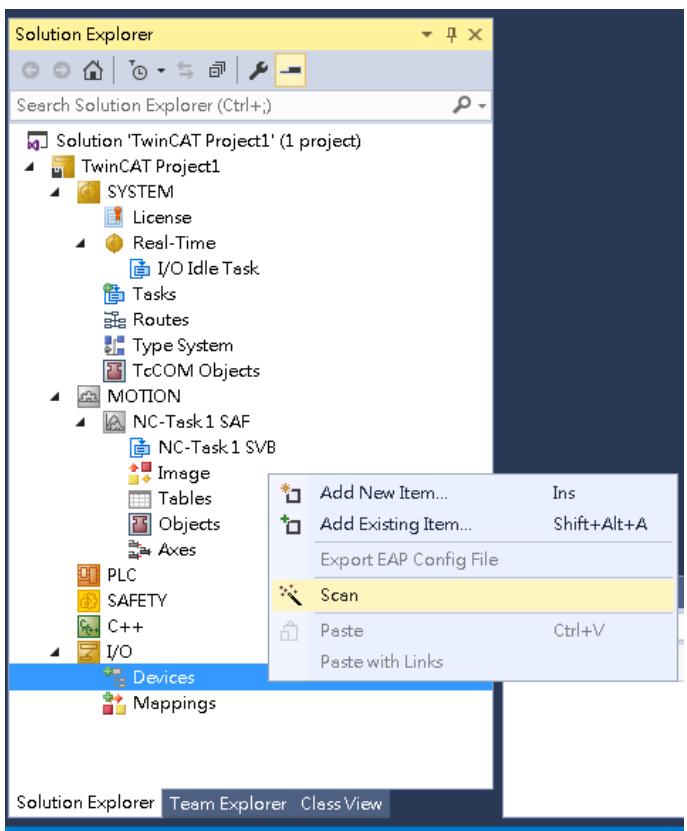
![Solution Explorer\nSearch Solution Explorer (Ctrl+;)\nSolution 'TwinCAT Project1' (1 project)\nTwinCAT Project1\nSYSTEM\nLicense\nReal-Time\nI/O Idle Task\nTasks\nRoutes\nType System\nTcCOM Objects\nMOTION\nNC-Task 1 SAF\nNC-Task 1 SVB\nImage\nTables\nObjects\nAxes\nPLC\nSAFETY\nC++\nI/O\nDevices\nMappings\nAdd New Item... Ins\nAdd Existing Item... Shift+Alt+A\nExport EAP Config File\nScan\nPaste Ctrl+V\nPaste with Links\nSolution Explorer Team Explorer Class View](.es-series-50m-19030-1030-13/cc733584abaeffe52aa5b76f662cf3a82f10820da6600a5e2b8204e51eeb0648.jpg)

All network interface cards will be listed in the popup window. If slaves are connected to the network interface card and have been identified by TwinCAT, the device checkbox will be checked.
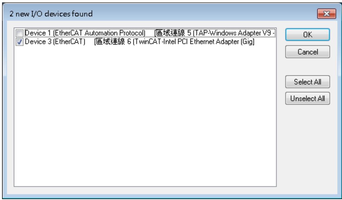
![2 new I/O devices found\nDevice 1 (EtherCAT Automation Protocol) (區域連線 5 (TAP-Windows Adapter V9 -)\nDevice 3 (EtherCAT) (區域連線 6 (TwinCAT-Intel PCI Ethernet Adapter (Gig)\nOK\nCancel\nSelect All\nUnselect All](.es-series-50m-19030-1030-13/c1be5d79e4c42e244d5a127be811add4d3be8fadf00292256390f5beafba0545.jpg)

2. Click Yes to activate the slaves.

![Microsoft Visual Studio\nActivate Free Run\nYes	No](.es-series-50m-19030-1030-13/036c3dbef525a47d2bd26b37add1edd11b616bbbc8ce6c2eeb4c0b27f237b455.jpg)

The ES I/O will be listed as a slave device of the EtherCAT master, and the “Run” status LED will emit a green light. This indicates that the user can begin operating the device.
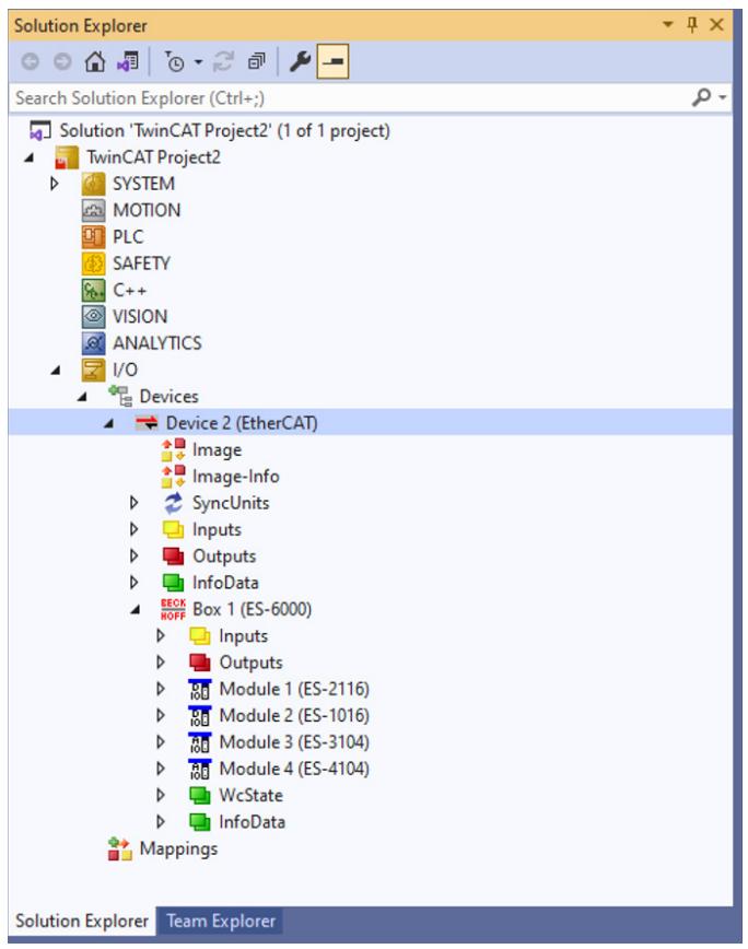
![Solution Explorer\nSearch Solution Explorer (Ctrl+;)\nSolution 'TwinCAT Project2' (1 of 1 project)\nTwinCAT Project2\nSYSTEM\nMOTION\nPLC\nSAFETY\nC++\nVISION\nANALYTICS\nI/O\nDevices\nDevice 2 (EtherCAT)\nImage\nImage-Info\nSyncUnits\nInputs\nOutputs\nInfoData\nBOX 1 (ES-6000)\nRECK\nROFF\nInputs\nOutputs\nModule 1 (ES-2116)\nModule 2 (ES-1016)\nModule 3 (ES-3104)\nModule 4 (ES-4104)\nWcState\nInfoData\nMappings\nSolution Explorer Team Explorer](.es-series-50m-19030-1030-13/96d87e5d8ce628cb185c63635296400b1b9205ac2ff5ab3d042f9b8f509952fa.jpg)

# 9.3 Operation

In this example, there is an ES-2116 module in the topology, which has 16 digital output channels which are respectively controlled by subindex 0 to 15.

The value "0" of each bit means turn off, and "1" means turn on. The setting in the picture is a decimal value "1", which means that the channel 0 is turned on.
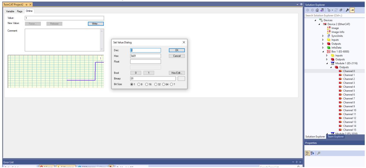
![TwinCAT Project2\nVariable Flags Online\nValue: 1\nNew Value: Force Release Write\nComment:\nSet Value Dialog\nDec: 0 OK\nHex: DoT1 Cancel\nFloat:\nBoot: 0 1 Hex Edit...\nBinary: 01\nBit Size: @ 1 8 16 32 64 ?\nSolution Explorer\nSearch Solution Explorer (Ctrl+)\nDevices\nDevice 2 (EtherCAT)\nImage\nImage-Info\nSyncUnits\nInputs\nOutputs\nInfoData\nBox 1 (ES-6000)\nInputs\nOutputs\nModule 1 (ES-2116)\nOutputs\nChannel 0\nChannel 1\nChannel 2\nChannel 3\nChannel 4\nChannel 5\nChannel 6\nChannel 7\nChannel 8\nChannel 9\nChannel 10\nChannel 11\nChannel 12\nChannel 13\nChannel 14\nChannel 15\nMultiInfo Iraq-2016\nSolution Explorer Team Explorer\nProperties\nError List](.es-series-50m-19030-1030-13/d029fca60571bf5f0e2c495113f0f0c5d833db395ca8b82a53f52fd48b387fe5.jpg)

The ES-4104 module in the topology and has 4 analog output channels, which are respectively controlled by subindex 1 to 4.

For the value corresponding to the voltage output, please refer to Voltage Output Value table.
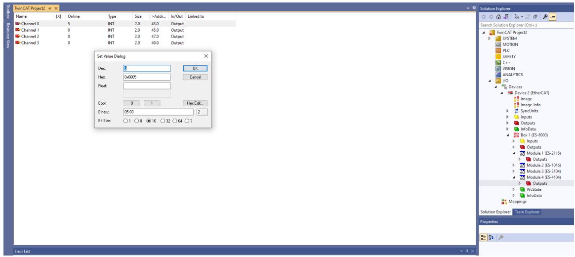
![TwinCAT Project2\nName\nX\nOnline\nType\nSize\n)Add...\nIn/Out\nLinked to\nChannel 0\n5\nINT\n2.0\n43.0\nOutput\nChannel 1\n0\nINT\n2.0\n45.0\nOutput\nChannel 2\n0\nINT\n2.0\n47.0\nOutput\nChannel 3\n0\nINT\n2.0\n49.0\nOutput\nSet Value Dialog\nDec:\n8\nOK\nHex:\n0x005\nCancel\nFloat:\nBook:\n0\n1\nHex Edit...\nBinary:\n05.00\n2\nBit Size:\n○1 ○8 ●16 ○32 ○64 ○?\nDevice 2 (EtherCAT)\nImage\nImage-Info\nSyncUnits\nInputs\nOutputs\nInfoData\nBox 1 (ES-6000)\nInputs\nOutputs\nModule 1 (ES-2116)\nOutputs\nModule 2 (ES-1016)\nModule 3 (ES-3104)\nModule 4 (ES-4104)\nOutputs\nWixState\nInfoData\nMappings\nSolution Explorer Team Explorer\nProperties\nError List](.es-series-50m-19030-1030-13/ec4fe09ed6bc4f2dc68f292f2e680f3c4a28f5c0e8fdf72199d16298b625f8f7.jpg)

# 10 Appendix C - TwinCAT® with ES-3504

Please refer to the steps below for the process of connecting the ES-3504 to TwinCAT and operating its I/O functions.

1. After scanning the device, you will see Box1 (ES-6000) and Module1 (ES-3504). In “Online” sheet, you can see that TwinCAT is in the "OP" state, and the RUN light of the slave device be turn on.
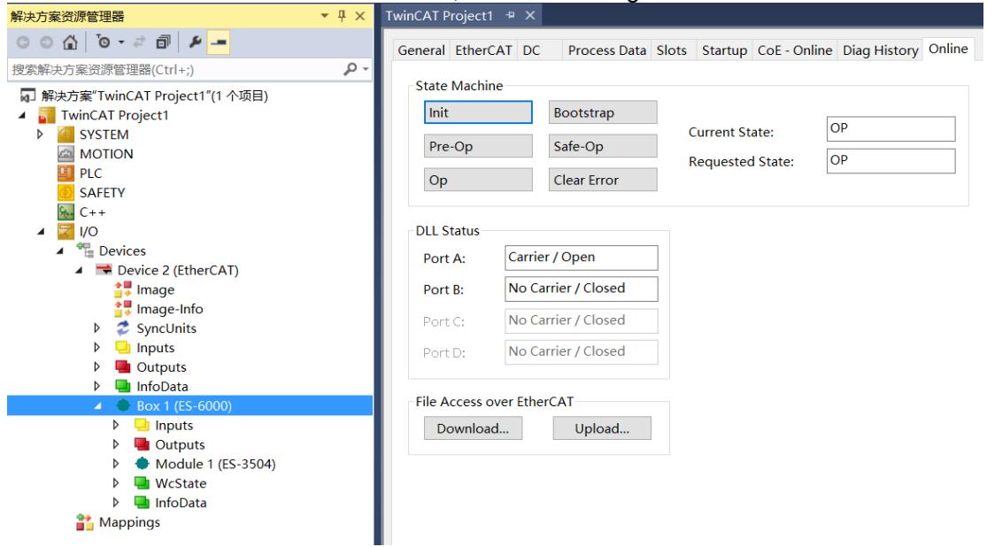
![解决方案资源管理器\n搜索解决方案资源管理器(Ctrl+;)\n解决方案'TwinCAT Project1'(1 个项目)\nTwinCAT Project1\nSYSTEM\nMOTION\nPLC\nSAFETY\nC++\nI/O\nDevices\nDevice 2 (EtherCAT)\nImage\nImage-Info\nSyncUnits\nInputs\nOutputs\nInfoData\nBox 1 (ES-6000)\nInputs\nOutputs\nModule 1 (ES-3504)\nWcState\nInfoData\nMappings\nTwinCAT Project1\nGeneral EtherCAT DC Process Data Slots Startup CoE - Online Diag History Online\nState Machine\nInit Bootstrap\nPre-Op Safe-Op Current State: OP\nOp Clear Error Requested State: OP\nDLL Status\nPort A: Carrier / Open\nPort B: No Carrier / Closed\nPort C: No Carrier / Closed\nPort D: No Carrier / Closed\nFile Access over EtherCAT\nDownload... Upload...](.es-series-50m-19030-1030-13/b281117d009be15c7cf93421aadc78257d39754cc4cf213c59649a7ef1f1a5c5.jpg)

# 10.1 Parameter Configuration

1 Click Box1 > Startup > New in the left tree viewer to enter the configuration parameter editing page.
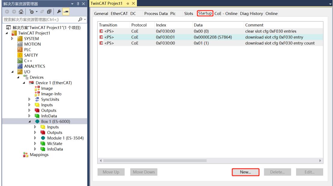
![解决方案资源管理器\n搜索解决方案资源管理器(Ctrl+;)\n解决方案'TwinCAT Project1'(1 个项目)\nTwinCAT Project1\nSYSTEM\nMOTION\nPLC\nSAFETY\nC++\nANALYTICS\nI/O\nDevices\nDevice 1 (EtherCAT)\nImage\nImage-Info\nSyncUnits\nInputs\nOutputs\nInfoData\nBox 1 (ES-6000)\nInputs\nOutputs\nModule 1 (ES-3504)\nWcState\nInfoData\nMappings\nTransition	Protocol/Index	Data	Comment\n(PS)	CoE	0xF030:00	0x00 (0)	clear slot cfg 0xF030 entries\n(PS)	CoE	0xF030:01	0x0000E208 (57864)	download slot cfg 0xF030 entry\n(PS)	CoE	0xF030:00	0x01 (1)	download slot cfg 0xF030 entry count\nMove Up	Move Down	New...	Delete...	Edit...](.es-series-50m-19030-1030-13/6c3d50fd63455db39ae08a403dd8ef645466e0e613f49b33b2fd3116d848fe2a.jpg)

2. In the Edit CANopen Startup Entry pop-up window, click "+" in front of Index 2000:0 to expand the configuration parameter menu. You can see 16 configuration parameters. Click on the parameter to set the relevant configuration.
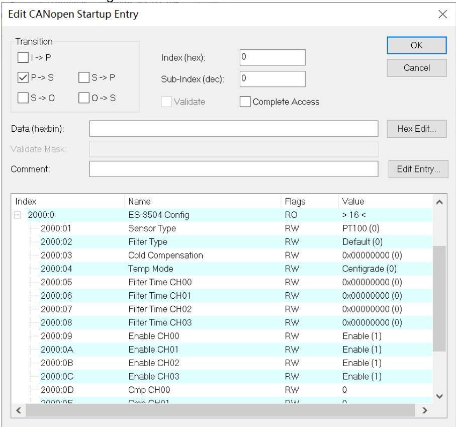
![Edit CANopen Startup Entry\nTransition\nI -) P\nP -) S S -) P\nS -) O O -) S\nIndex (hex): 0\nSub-Index (dec): 0\nValidate Complete Access\nData (hexbin):\nHex Edit...\nValidate Mask:\nComment:\nIndex Name Flags Value\n2000:0 ES-3504 Config RO ) 16 (\n2000:01 Sensor Type RW PT100 (0)\n2000:02 Filter Type RW Default (0)\n2000:03 Cold Compensation RW 0x00000000 (0)\n2000:04 Temp Mode RW Centigrade (0)\n2000:05 Filter Time CH00 RW 0x00000000 (0)\n2000:06 Filter Time CH01 RW 0x00000000 (0)\n2000:07 Filter Time CH02 RW 0x00000000 (0)\n2000:08 Filter Time CH03 RW 0x00000000 (0)\n2000:09 Enable CH00 RW Enable (1)\n2000:0A Enable CH01 RW Enable (1)\n2000:0B Enable CH02 RW Enable (1)\n2000:0C Enable CH03 RW Enable (1)\n2000:0D Cmp CH00 RW 0\n2000:0E Cmp CH01 RW 0\n(](.es-series-50m-19030-1030-13/19026751bb303b986473a992a6b4b94c560688f5109914c25361f43712dd13a3.jpg)

3. For example, to modify the sensor type selection, double-click Sensor Type and modify the parameter value in the drop-down box.
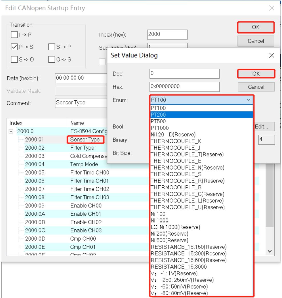
![Edit CANopen Startup Entry\nTransition\nI -) P\nP -) S\nS -) P\nS -) O\nO -) S\nData (hexbin): 00 00 00 00\nValidate Mask:\nComment: Sensor Type\nIndex Name\n2000:0 ES-3504 Config\n2000:01 Sensor Type\n2000:02 Filter Type\n2000:03 Cold Compensa\n2000:04 Temp Mode\n2000:05 Filter Time CH00\n2000:06 Filter Time CH01\n2000:07 Filter Time CH02\n2000:08 Filter Time CH03\n2000:09 Enable CH00\n2000:0A Enable CH01\n2000:0B Enable CH02\n2000:0C Enable CH03\n2000:0D Cmp CH00\n2000:0E Cmp CH01\n2000:0F Cmp CH02\nIndex (hex): 2000\nSub-Index (doc): 1\nSet Value Dialog\nDec: 0\nHex: 0x0000000\nOK\nOK\nCancel\nEnum:\nPT100\nPT100\nPT200\nBool:\nPT500\nPT100\nPT120_ID(Reserve)\nTHERMOCOUPLE_K\nTHERMOCOUPLE_J\nTHERMOCOUPLE_T(Reserve)\nTHERMOCOUPLE_E\nTHERMOCOUPLE_N(Reserve)\nTHERMOCOUPLE_S\nTHERMOCOUPLE_R(Reserve)\nTHERMOCOUPLE_B\nTHERMOCOUPLE_C(Reserve)\nTHERMOCOUPLE_L(Reserve)\nTHERMOCOUPLE_U(Reserve)\nNi 100\nNi 1000\nLG-Ni 1000(Reserve)\nNi 200(Reserve)\nNi 500(Reserve)\nRESISTANCE_15:150(Reserve)\nRESISTANCE_15:300(Reserve)\nRESISTANCE_15:600(Reserve)\nRESISTANCE_15:300\nV: -1:1V(Reserve)\nV: -250:250mV(Reserve)\nV: -50:50mV(Reserve)\nV: -80:80mV(Reserve)](.es-series-50m-19030-1030-13/fd05db6cb5f9aca3c772603556f450b6767d62236b0676a44976d24da8b7ebbe.jpg)

4. After the parameter modification is complete, you will see the modified parameter items and parameter values under Startup, as shown in the figure below. Once the parameter setting is complete, the Reload operation and the module needs to be powered on again to enable the automatic delivery of parameter settings by the master station.
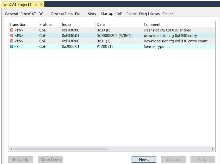
![TwinCAT Project1\nGeneral EtherCAT DC Process Data Plc Slots Startup CoE - Online Diag History Online\nTransition Protocol Index Data Comment\n(PS) CoE 0xF030:00 0x00 (0) clear slot cfg 0xF030 entries\n(PS) CoE 0xF030:01 0x0000E208 (57864) download slot cfg 0xF030 entry\n(PS) CoE 0xF030:00 0x01 (1) download slot cfg 0xF030 entry count\nPS CoE 0x2000:01 PT200 (1) Sensor Type\nMove Up Move Down New... Delete... Edit...](.es-series-50m-19030-1030-13/846e5d1297af9b77c4902fefc2f91ec8baeae4c748a55633a16f56b21e40a1ac.jpg)

5. The left tree viewer Module 1 > Inputs displays the upload data of the module and is used to monitor the status of the module.
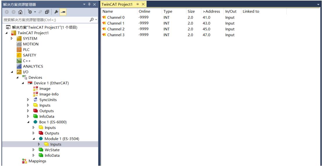
![解决方案资源管理器\n搜索解决方案资源管理器(Ctrl+;)\n解决方案'TwinCAT Project1'(1 个项目)\nTwinCAT Project1\nSYSTEM\nMOTION\nPLC\nSAFETY\nC++\nANALYTICS\nI/O\nDevices\nDevice 1 (EtherCAT)\nImage\nImage-Info\nSyncUnits\nInputs\nOutputs\nInfoData\nBox 1 (ES-6000)\nInputs\nOutputs\nModule 1 (ES-3504)\nInputs\nWcState\nInfoData\nMappings\nName	Online	Type	Size	)Address)In/Out	Linked to](.es-series-50m-19030-1030-13/f7806bad162840d326e75294ac70fa84dc9b40c6275a7b0e12b7e52b9291624d.jpg)

# 10.2 Temperature Input Channel Data Monitoring

1. Channel 0 is connected to the thermal resistance sensor. Configure the configuration parameters as needed, select PT100 as the sensor type, the temperature measurement unit switch is set to degrees Celsius by default, and channel 0 is set to enabled by default, as shown in the figure below.
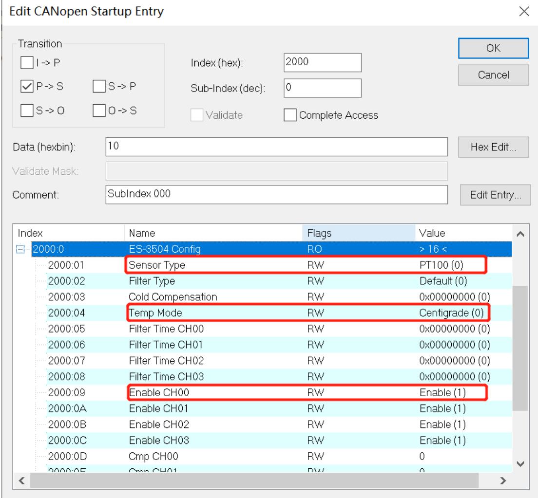
![| Index | Name | Flags | Value |\n| --- | --- | --- | --- |\n| 2000:0 | ES-3504 Config | RO | ) 16 ( |\n| 2000:01 | Sensor Type | RW | PT100 (0) |\n| 2000:02 | Filter Type | RW | Default (0) |\n| 2000:03 | Cold Compensation | RW | 0x0000000 (0) |\n| 2000:04 | Temp Mode | RW | Centigrade (0) |\n| 2000:05 | Filter Time CH00 | RW | 0x0000000 (0) |\n| 2000:06 | Filter Time CH01 | RW | 0x0000000 (0) |\n| 2000:07 | Filter Time CH02 | RW | 0x0000000 (0) |\n| 2000:08 | Filter Time CH03 | RW | 0x0000000 (0) |\n| 2000:09 | Enable CH00 | RW | Enable (1) |\n| 2000:0A | Enable CH01 | RW | Enable (1) |\n| 2000:0B | Enable CH02 | RW | Enable (1) |\n| 2000:0C | Enable CH03 | RW | Enable (1) |\n| 2000:0D | Cmp CH00 | RW | 0 |\n| 2000:0E | Cmp CH01 | RW | 0 |](.es-series-50m-19030-1030-13/3e2e3cfe0850772defb7303c2d0b6e437b1e1d8a32015fd020d649a3f1e1ff90.jpg)

2. You can see that the current temperature value of channel 0 is 228, which corresponds to $2 2 . 8 ^ { \circ } \mathrm { C }$ . The other channels are not connected to a sensor, and the displayed value is -9999.
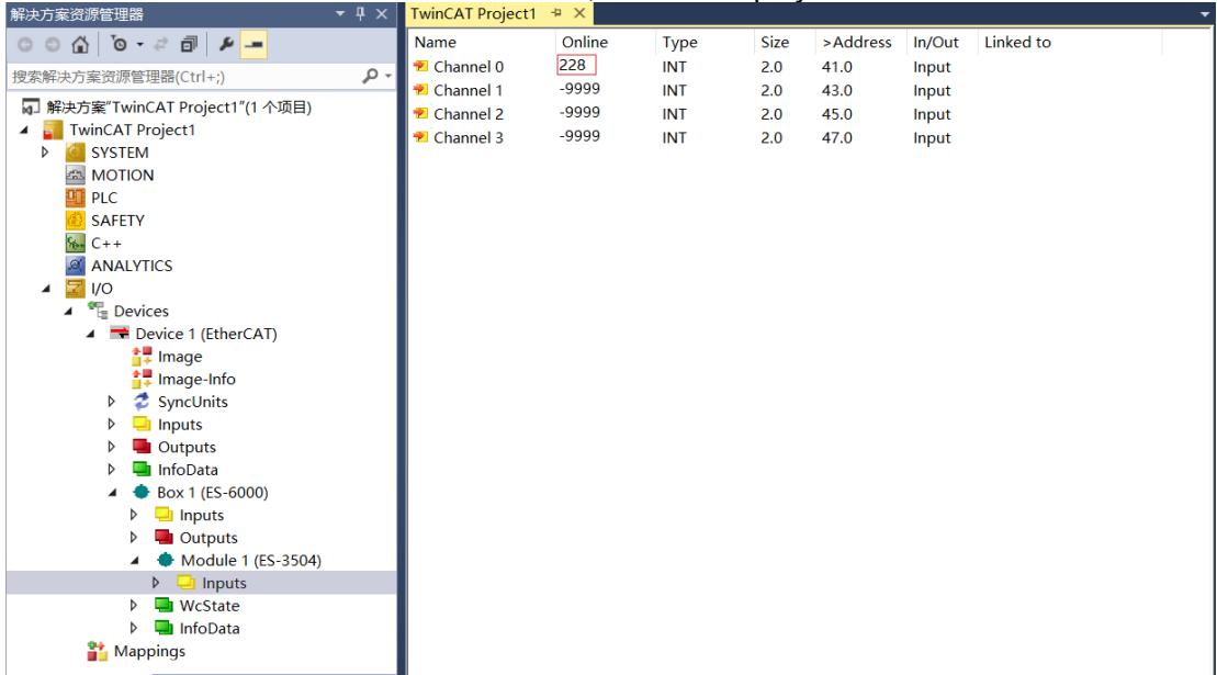
![解决方案资源管理器\n搜索解决方案资源管理器(Ctrl+;)\n解决方案'TwinCAT Project1'(1 个项目)\nTwinCAT Project1\nSYSTEM\nMOTION\nPLC\nSAFETY\nC++\nANALYTICS\nI/O\nDevices\nDevice 1 (EtherCAT)\nImage\nImage-Info\nSyncUnits\nInputs\nOutputs\nInfoData\nBox 1 (ES-6000)\nInputs\nOutputs\nModule 1 (ES-3504)\nInputs\nWcState\nInfoData\nMappings\nName	Online	Type	Size	)Address	In/Out	Linked to\nChannel 0	228(INT	2.0	41.0.Input\nChannel 1	-9999(INT	2.0	43.0.Input\nChannel 2	-9999(INT	2.0	45.0.Input\nChannel 3	-9999(INT	2.0	47.0.Input](.es-series-50m-19030-1030-13/71e3ec767598add91f377ca74cf893a812b884b726b527f39e6c7eda43944d40.jpg)

3. Click Box1 > CoE-Online in the left tree viewer to enter the configuration parameter editing page and set channel 0 to be disabled.
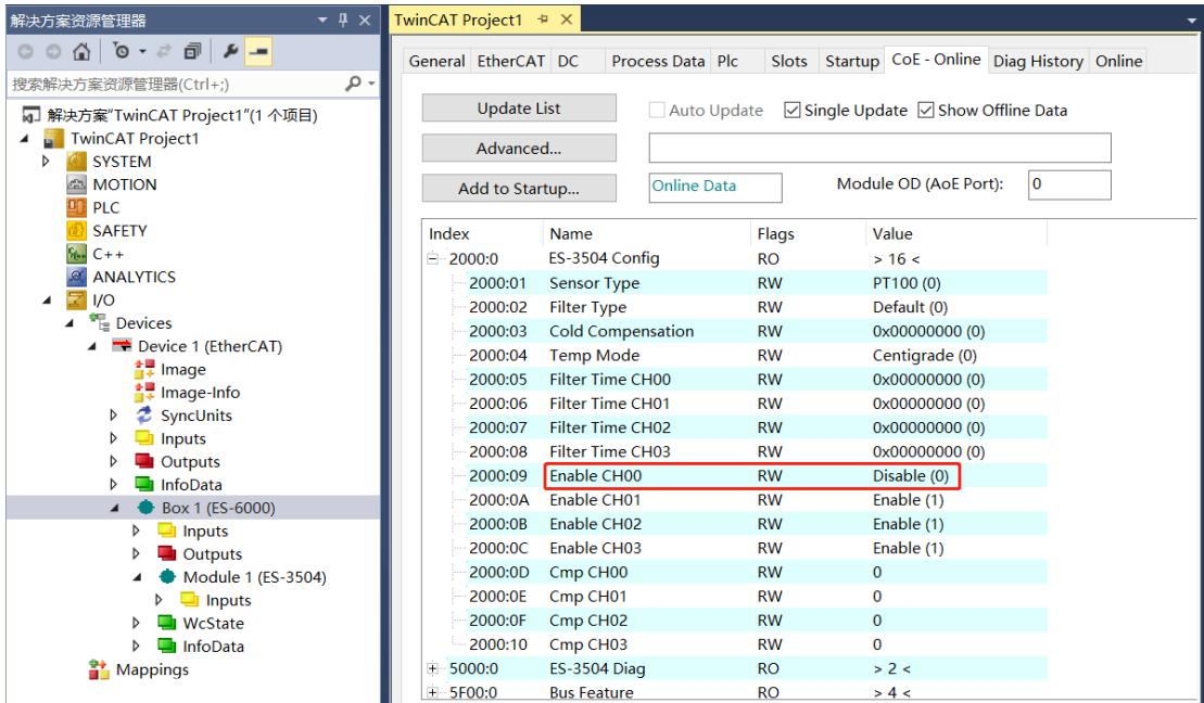
![解决方案资源管理器\n搜索解决方案资源管理器(Ctrl+;)\n解决方案'TwinCAT Project1'(1 个项目)\nTwinCAT Project1\nSYSTEM\nMOTION\nPLC\nSAFETY\nC++\nANALYTICS\nI/O\nDevices\nDevice 1 (EtherCAT)\nImage\nImage-Info\nSyncUnits\nInputs\nOutputs\nInfoData\nBox 1 (ES-6000)\nInputs\nOutputs\nModule 1 (ES-3504)\nInputs\nWcState\nInfoData\nMappings\nTwinCAT Project1\nGeneral EtherCAT DC Process Data Plc Slots Startup CoE - Online Diag History Online\nUpdate List Auto Update Single Update Show Offline Data\nAdvanced...\nAdd to Startup... Online Data Module OD (AoE Port): 0\nIndex Name Flags Value\n2000:0 ES-3504 Config RO ) 16 (\n2000:01 Sensor Type RW PT100 (0)\n2000:02 Filter Type RW Default (0)\n2000:03 Cold Compensation RW 0x00000000 (0)\n2000:04 Temp Mode RW Centigrade (0)\n2000:05 Filter Time CH00 RW 0x00000000 (0)\n2000:06 Filter Time CH01 RW 0x00000000 (0)\n2000:07 Filter Time CH02 RW 0x00000000 (0)\n2000:08 Filter Time CH03 RW 0x00000000 (0)\n2000:09 Enable CH00 RW Disable (0)\n2000:OA Enable CH01 RW Enable (1)\n2000:OB Enable CH02 RW Enable (1)\n2000:OC Enable CH03 RW Enable (1)\n2000:OD Cmp CH00 RW 0\n2000:OE Cmp CH01 RW 0\n2000:OF Cmp CH02 RW 0\n2000:1O Cmp CH03 RW 0\n500:O ES-3504 Diag RO ) 2 (\n5F0:O Bus Feature RO ) 4 (](.es-series-50m-19030-1030-13/d7590bacff5832aff2e90d4785f5b49765ad3deb3ae2ce8b85c1b4391284124a.jpg)

# 4. You can see that the current display value of channel 0 is -9999.
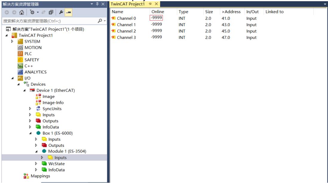
![解决方案资源管理器\n搜索解决方案资源管理器(Ctrl+;)\n解决方案'TwinCAT Project1'(1 个项目)\nTwinCAT Project1\nSYSTEM\nMOTION\nPLC\nSAFETY\nC++\nANALYTICS\nI/O\nDevices\nDevice 1 (EtherCAT)\nImage\nImage-Info\nSyncUnits\nInputs\nOutputs\nInfoData\nBox 1 (ES-6000)\nInputs\nOutputs\nModule 1 (ES-3504)\nInputs\nWcState\nInfoData\nMappings\nName	Online	Type	Size	)Address)In/Out	Linked to\nChannel 0	-9999(INT	2.0	41.0.Input\nChannel 1	-9999(INT	2.0	43.0.Input\nChannel 2	-9999(INT	2.0	45.0.Input\nChannel 3	-9999(INT	2.0	47.0.Input](.es-series-50m-19030-1030-13/c852d85154a36eabf28fa5cf1652e414811e67c45d164257273cb96b727f6016.jpg)

# 10.3 Temperature Compensation Function

1. Channel 0 is connected to the thermocouple sensor. Configure the configuration parameters as needed. For example, select the K-type thermocouple as the sensor type. The temperature measurement unit switch is set to degrees Celsius by default. Channel 0 is set to enable by default.

Edit CANopen Startup Entry
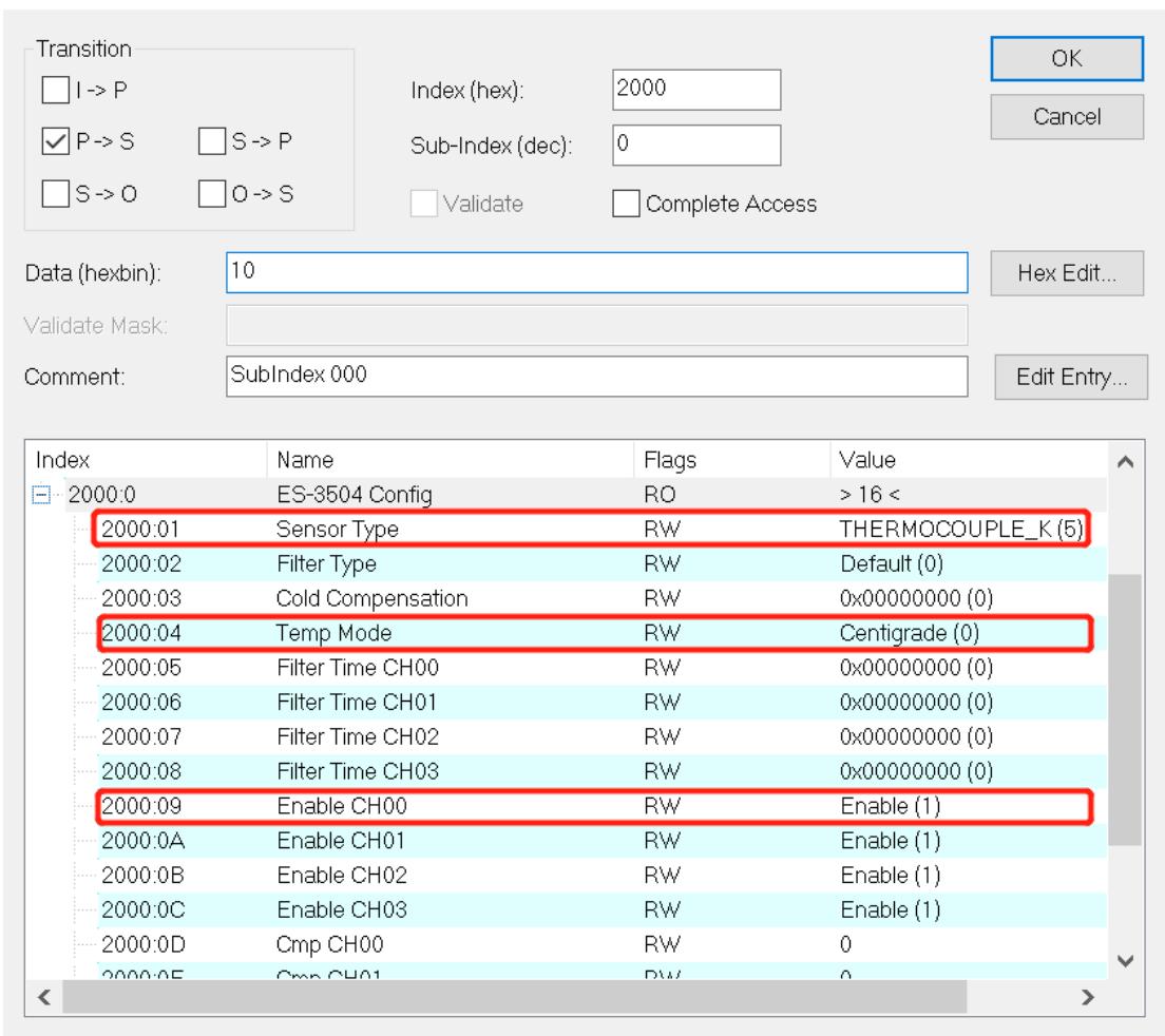
![Transition\nI -) P\nP -) S\nS -) O\nIndex (hex): 2000\nSub-Index (dec): 0\nValidate Complete Access\nData (hexbin): 10\nHex Edit...\nValidate Mask:\nComment: SubIndex 000\nEdit Entry...\nIndex Name Flags Value\n2000:0 ES-3504 Config RO ) 16 (\n2000:01 Sensor Type RW THERMOCOUPLE_K (5)\n2000:02 Filter Type RW Default (0)\n2000:03 Cold Compensation RW 0x00000000 (0)\n2000:04 Temp Mode RW Centigrade (0)\n2000:05 Filter Time CH00 RW 0x00000000 (0)\n2000:06 Filter Time CH01 RW 0x00000000 (0)\n2000:07 Filter Time CH02 RW 0x00000000 (0)\n2000:08 Filter Time CH03 RW 0x00000000 (0)\n2000:09 Enable CH00 RW Enable (1)\n2000:0A Enable CH01 RW Enable (1)\n2000:0B Enable CH02 RW Enable (1)\n2000:0C Enable CH03 RW Enable (1)\n2000:0D Cmp CH00 RW 0\n2000:0E Cmp CH01 RW 0](.es-series-50m-19030-1030-13/be78775973ace942789e9d289da9d83e358c677ec6eea6b1a7b2a861a4956b1c.jpg)

2. Taking channel 0 as an example, you can see that the measured temperature value of channel 0 is 233, which corresponds to $2 3 . 3 ^ { \circ } \mathsf C$ .
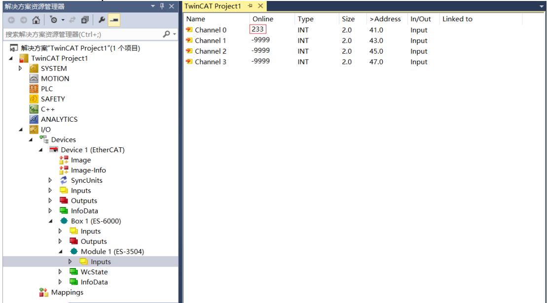
![解决方案资源管理器\n搜索解决方案资源管理器(Ctrl+;)\n解决方案'TwinCAT Project1'(1 个项目)\nTwinCAT Project1\nSYSTEM\nMOTION\nPLC\nSAFETY\nC++\nANALYTICS\nI/O\nDevices\nDevice 1 (EtherCAT)\nImage\nImage-Info\nSyncUnits\nInputs\nOutputs\nInfoData\nBox 1 (ES-6000)\nInputs\nOutputs\nModule 1 (ES-3504)\nInputs\nWcState\nInfoData\nMappings\nName	Online	Type	Size	)Address	In/Out	Linked to\nChannel 0	233(INT	2.0	41.0	Output\nChannel 1	-9999(INT	2.0	43.0	Output\nChannel 2	-9999(INT	2.0	45.0	Output\nChannel 3	-9999(INT	2.0	47.0	Output](.es-series-50m-19030-1030-13/c21db957a0889c39a0ce0794986e0ea66c3354d59d1eb57f48b1387603784db8.jpg)

3. Click Box1 > CoE-Online in the left tree viewer to enter the configuration parameter editing page and set the channel 0 temperature compensation value to 50, which corresponds to $5 ^ { \circ } \mathsf { C }$ .
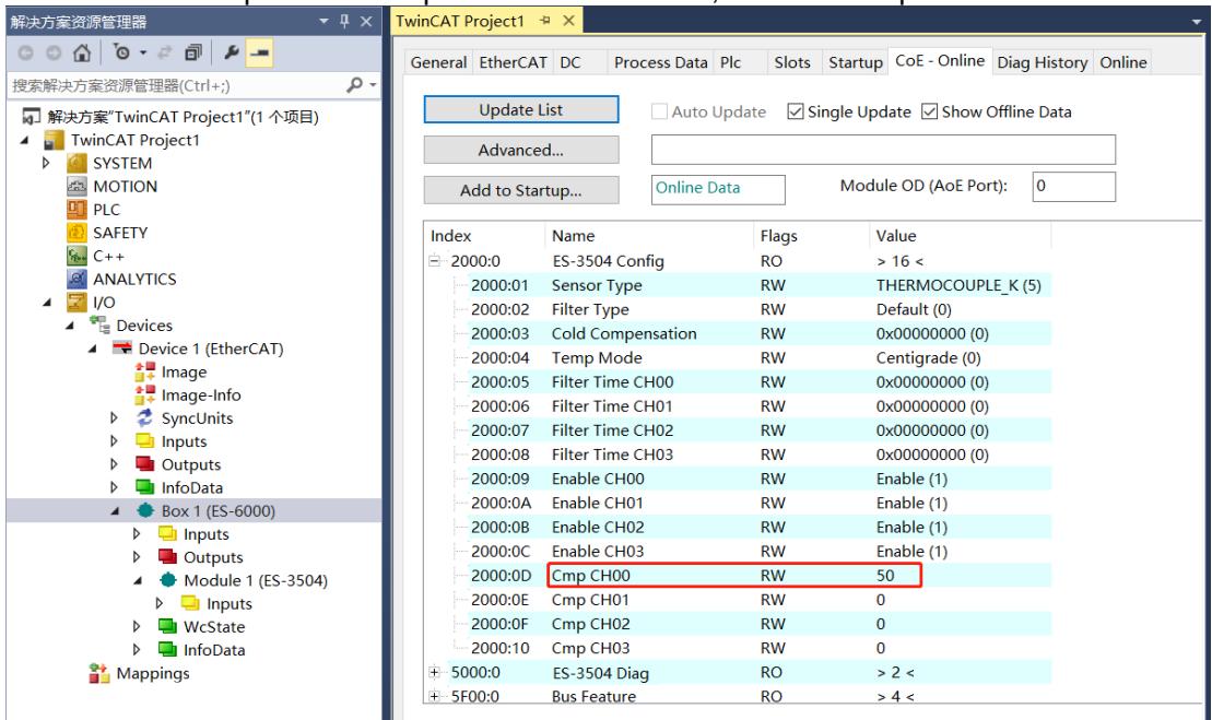
![解决方案资源管理器\n搜索解决方案资源管理器(Ctrl+;)\n解决方案'TwinCAT Project1'(1 个项目)\nTwinCAT Project1\nSYSTEM\nMOTION\nPLC\nSAFETY\nC++\nANALYTICS\nI/O\nDevices\nDevice 1 (EtherCAT)\nImage\nImage-Info\nSyncUnits\nInputs\nOutputs\nInfoData\nBox 1 (ES-6000)\nInputs\nOutputs\nModule 1 (ES-3504)\nInputs\nWcState\nInfoData\nMappings\nTwinCAT Project1\nGeneral EtherCAT DC Process Data Plc Slots Startup CoE - Online Diag History Online\nUpdate List Auto Update Single Update Show Offline Data\nAdvanced...\nAdd to Startup... Online Data Module OD (AoE Port): 0\nIndex Name Flags Value\n2000:0 ES-3504 Config RO ) 16 (\n2000:01 Sensor Type RW THERMOCOUPLE_K (5)\n2000:02 Filter Type RW Default (0)\n2000:03 Cold Compensation RW 0x00000000 (0)\n2000:04 Temp Mode RW Centigrade (0)\n2000:05 Filter Time CH00 RW 0x00000000 (0)\n2000:06 Filter Time CH01 RW 0x00000000 (0)\n2000:07 Filter Time CH02 RW 0x00000000 (0)\n2000:08 Filter Time CH03 RW 0x00000000 (0)\n2000:09 Enable CH00 RW Enable (1)\n2000:0A Enable CH01 RW Enable (1)\n2000:0B Enable CH02 RW Enable (1)\n2000:0C Enable CH03 RW Enable (1)\n2000:OD Cmp CH00 RW 50\n2000:OE Cmp CH01 RW 0\n2000:OF Cmp CH02 RW 0\n2000:10 Cmp CH03 RW 0\n5000:O ES-3504 Diag RO ) 2 (\n5F00:O Bus Feature RO ) 4 (](.es-series-50m-19030-1030-13/698718d1af2a7de8e98b75aa42859929b4eab5530d2e571b7010aa79885e23d7.jpg)

4. After setting the compensation value, the channel 0 temperature value is 283, which corresponds to $2 8 . 3 ^ { \circ } \mathsf C$ .
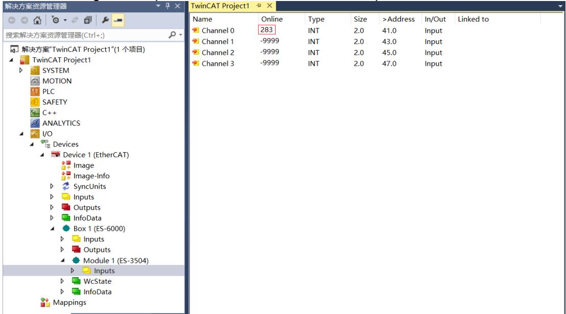
![解决方案资源管理器\n搜索解决方案资源管理器(Ctrl+;)\n解决方案'TwinCAT Project1'(1 个项目)\nTwinCAT Project1\nSYSTEM\nMOTION\nPLC\nSAFETY\nC++\nANALYTICS\nI/O\nDevices\nDevice 1 (EtherCAT)\nImage\nImage-Info\nSyncUnits\nInputs\nOutputs\nInfoData\nBox 1 (ES-6000)\nInputs\nOutputs\nModule 1 (ES-3504)\nInputs\nWcState\nInfoData\nMappings\nName	Online	Type	Size	)Address	In/Out	Linked to\nChannel 0	283(INT	2.0	41.0.Input\nChannel 1	-9999(INT	2.0	43.0.Input\nChannel 2	-9999(INT	2.0	45.0.Input\nChannel 3	-9999(INT	2.0	47.0.Input](.es-series-50m-19030-1030-13/ec061117f5ebc9e740920f0d100b8cfd717116d2c64225f6604da38f1ee79be2.jpg)

# 10.4 Temperature Cold Junction Compensation Function

1. Channel 0 is connected to the thermocouple sensor. Configure the configuration parameters as needed, select K-type thermocouple as the sensor type, and set cold compensation to ON.
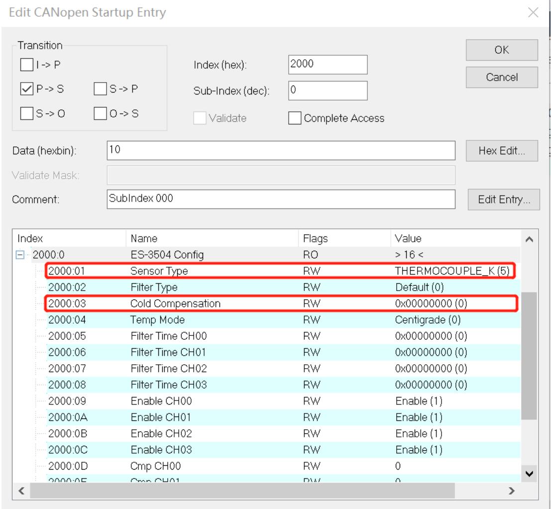
![Edit CANopen Startup Entry\nTransition\nI -) P\nP -) S\nS -) O\nS -) P\nO -) S\nIndex (hex): 2000\nSub-Index (dec): 0\nValidate Complete Access\nData (hexbin): 10\nHex Edit...\nValidate Mask:\nComment: SubIndex 000\nEdit Entry...\nIndex Name Flags Value\n2000.0 ES-3504 Config RO ) 16 (\n2000.01 Sensor Type RW THERMOCOUPLE_K (5)\n2000.02 Filter Type RW Default (0)\n2000.03 Cold Compensation RW 0x0000000 (0)\n2000.04 Temp Mode RW Centigrade (0)\n2000.05 Filter Time CH00 RW 0x0000000 (0)\n2000.06 Filter Time CH01 RW 0x0000000 (0)\n2000.07 Filter Time CH02 RW 0x0000000 (0)\n2000.08 Filter Time CH03 RW 0x0000000 (0)\n2000.09 Enable CH00 RW Enable (1)\n2000.1A Enable CH11 RW Enable (1)\n2000.1B Enable CH12 RW Enable (1)\n2000.1C Enable CH13 RW Enable (1)\n2000.1D Cmp CH14 RW 0\n2000.1E Cmp CH15 RW 0](.es-series-50m-19030-1030-13/abf558087e7c2e2f696a2b80c2f5de5d1f2766bb02e3c4c294839c1fdbc5e045.jpg)

2. You can see the temperature value when channel 0 cold compensation is turned on.
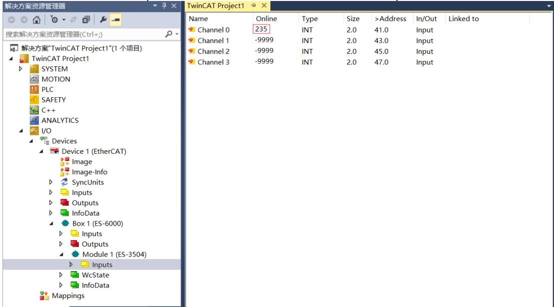
![解决方案资源管理器\n搜索解决方案资源管理器(Ctrl+;)\n解决方案'TwinCAT Project1'(1 个项目)\nTwinCAT Project1\nSYSTEM\nMOTION\nPLC\nSAFETY\nC++\nANALYTICS\nI/O\nDevices\nDevice 1 (EtherCAT)\nImage\nImage-Info\nSyncUnits\nInputs\nOutputs\nInfoData\nBox 1 (ES-6000)\nInputs\nOutputs\nModule 1 (ES-3504)\nInputs\nWcState\nInfoData\nMappings\nName	Online	Type	Size	)Address	In/Out	Linked to\nChannel 0	235(INT	2.0	41.0	Output\nChannel 1	-9999(INT	2.0	43.0	Output\nChannel 2	-9999(INT	2.0	45.0	Output\nChannel 3	-9999(INT	2.0	47.0	Output](.es-series-50m-19030-1030-13/bb2da4a628c7d4aa1cee8a673dc8cb97fc70d934db21ae5e08d2505030f2e1c2.jpg)

3. Click Box1 > CoE-Online in the tree viewer on the left to enter the configuration parameter editing page and set channel 0 cold compensation to off.
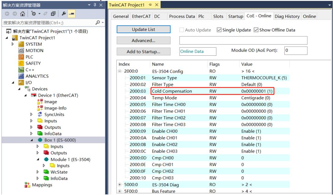
![解决方案资源管理器\n搜索解决方案资源管理器(Ctrl+;)\n解决方案'TwinCAT Project1'(1 个项目)\nTwinCAT Project1\nSYSTEM\nMOTION\nPLC\nSAFETY\nC++\nANALYTICS\nI/O\nDevices\nDevice 1 (EtherCAT)\nImage\nImage-Info\nSyncUnits\nInputs\nOutputs\nInfoData\nBox 1 (ES-6000)\nInputs\nOutputs\nModule 1 (ES-3504)\nInputs\nWcState\nInfoData\nMappings\nTwinCAT Project1\nGeneral EtherCAT DC Process Data Plc Slots Startup CoE - Online Diag History Online\nUpdate List Auto Update Single Update Show Offline Data\nAdvanced...\nAdd to Startup... Online Data Module OD (AoE Port): 0\nIndex Name Flags Value\n2000:0 ES-3504 Config RO ) 16 (\n2000:01 Sensor Type RW THERMOCOUPLE_K (5)\n2000:02 Filter Type RW Default (0)\n2000:03 Cold Compensation RW 0x00000001 (1)\n2000:04 Temp Mode RW Centigrade (0)\n2000:05 Filter Time CH00 RW 0x00000000 (0)\n2000:06 Filter Time CH01 RW 0x00000000 (0)\n2000:07 Filter Time CH02 RW 0x00000000 (0)\n2000:08 Filter Time CH03 RW 0x00000000 (0)\n2000:09 Enable CH00 RW Enable (1)\n2000:0A Enable CH01 RW Enable (1)\n2000:0B Enable CH02 RW Enable (1)\n2000:0C Enable CH03 RW Enable (1)\n2000:0D Cmp CH00 RW 0\n2000:0E Cmp CH01 RW 0\n2000:0F Cmp CH02 RW 0\n2000:10 Cmp CH03 RW 0\n500:0 ES-3504 Diag RO ) 2 (\n5F0:0 Bus Feature RO ) 4 (](.es-series-50m-19030-1030-13/b98b2110c9d2b7a40fdc6f91d9ca0b87cb139be789b26a9b2aa3e2496e5032fe.jpg)

4. You can see the temperature value when channel 0 cold compensation is turned off.
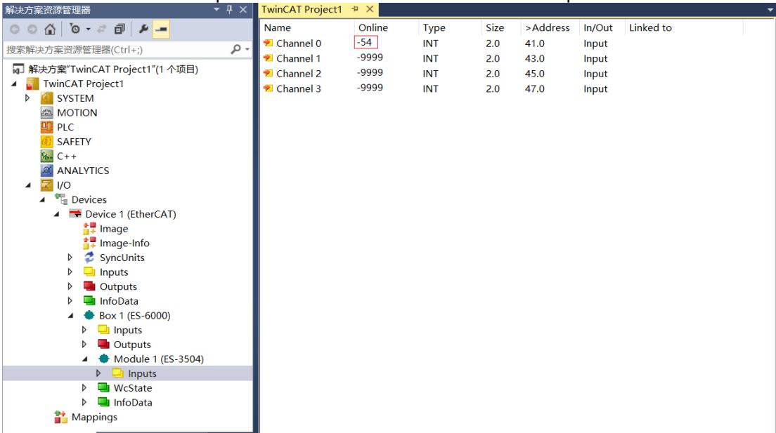
![解决方案资源管理器\n搜索解决方案资源管理器(Ctrl+;)\n解决方案'TwinCAT Project1'(1 个项目)\nTwinCAT Project1\nSYSTEM\nMOTION\nPLC\nSAFETY\nC++\nANALYTICS\nI/O\nDevices\nDevice 1 (EtherCAT)\nImage\nImage-Info\nSyncUnits\nInputs\nOutputs\nInfoData\nBox 1 (ES-6000)\nInputs\nOutputs\nModule 1 (ES-3504)\nInputs\nWcState\nInfoData\nMappings\nName	Online	Type	Size	)Address)In/Out	Linked to\nChannel 0	-54(INT	2.0	41.0.Input\nChannel 1	-9999(INT	2.0	43.0.Input\nChannel 2	-9999(INT	2.0	45.0.Input\nChannel 3	-9999(INT	2.0	47.0.Input](.es-series-50m-19030-1030-13/c291064d0b9bd6d1a9f9841ddba763d423904226f6bd4056e5bf6e2e34552b18.jpg)

# 11 Appendix C - TwinCAT® with ES-5003

Please refer to the steps below for the process of connecting the ES-5003 to TwinCAT and operating its I/O functions.

After scanning the device, you will see Box1 (ES-6000) and Module1 (ES-5003-32Bytes) in the left tree viewer. You will also see that TwinCAT is in the "OP" state at "Online", and you can observe the slave station. The device RUN light is always on.
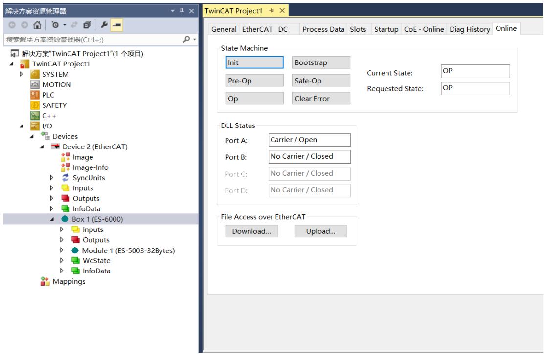
![解决方案资源管理器\n搜索解决方案资源管理器(Ctrl+;)\n解决方案'TwinCAT Project1'(1 个项目)\nTwinCAT Project1\nSYSTEM\nMOTION\nPLC\nSAFETY\nC++\nI/O\nDevices\nDevice 2 (EtherCAT)\nImage\nImage-Info\nSyncUnits\nInputs\nOutputs\nInfoData\nBox 1 (ES-6000)\nInputs\nOutputs\nModule 1 (ES-5003-32Bytes)\nWcState\nInfoData\nMappings\nTwinCAT Project1\nGeneral EtherCAT DC Process Data Slots Startup CoE - Online Diag History Online\nState Machine\nInit Bootstrap\nPre-Op Safe-Op Current State: OP\nOp Clear Error Requested State: OP\nDLL Status\nPort A: Carrier / Open\nPort B: No Carrier / Closed\nPort C: No Carrier / Closed\nPort D: No Carrier / Closed\nFile Access over EtherCAT\nDownload... Upload...](.es-series-50m-19030-1030-13/f773dd7fd34fedc9159aecae6f9731045644d42a380aadcbe265fe78c6a6dd31.jpg)

# 11.1 Verify Basic Function

1. Click Box1 > Startup > New in the left tree viewer to enter the configuration parameter editing page.
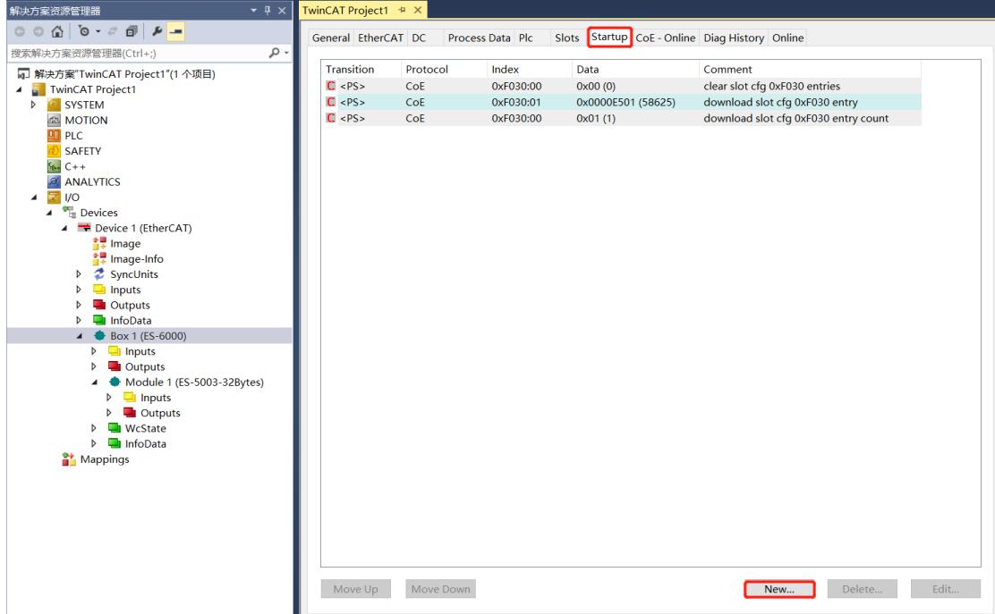
![解决方案资源管理器\n搜索解决方案资源管理器(Ctrl+;)\n解决方案'TwinCAT Project1'(1 个项目)\nTwinCAT Project1\nSYSTEM\nMOTION\nPLC\nSAFETY\nC++\nANALYTICS\nI/O\nDevices\nDevice 1 (EtherCAT)\nImage\nImage-Info\nSyncUnits\nInputs\nOutputs\nInfoData\nBox 1 (ES-6000)\nInputs\nOutputs\nModule 1 (ES-5003-32Bytes)\nInputs\nOutputs\nWcState\nInfoData\nMappings\nGeneral EtherCAT DC Process Data Plc Slots Startup CoE - Online Diag History Online\nTransition Protocol Index Data Comment\n(PS) CoE 0xF030:00 0x00 (0) clear slot cfg 0xF030 entries\n(PS) CoE 0xF030:01 0x0000E501 (58625) download slot cfg 0xF030 entry\n(PS) CoE 0xF030:00 0x01 (1) download slot cfg 0xF030 entry count\nMove Up Move Down New... Delete... Edit...](.es-series-50m-19030-1030-13/1ee792d81d7ae0606f391523c32f44c626eacd5dc5ca3446a672f1a0245b5d7c.jpg)

2. In the Edit CANopen Startup Entry window, click the "+" in front of Index 2000:0 to expand the configuration parameter menu. You will see a number of configuration parameters. Click on any parameter to set the relevant configuration.
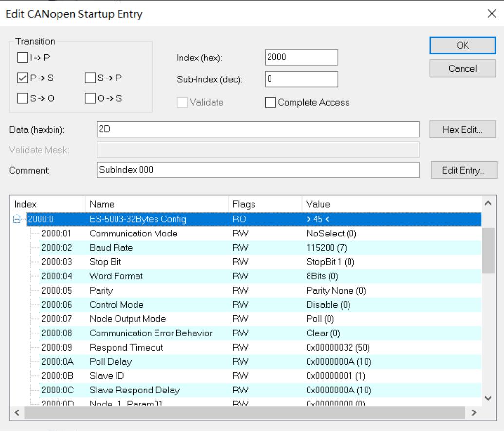
![Edit CANopen Startup Entry\nTransition\nI-)P\nP-)S S-)P\nS-)O O-)S\nIndex (hex): 2000\nSub-Index (dec): 0\nValidate Complete Access\nData (hexbin): 2D\nValidate Mask:\nComment: SubIndex 000\nHex Edit...\nEdit Entry...\nIndex Name Flags Value\n2000:0 ES-5003-32Bytes Config RO )45 (\n2000:01 Communication Mode RW NoSelect (0)\n2000:02 Baud Rate RW 115200 (7)\n2000:03 Stop Bit RW StopBit 1 (0)\n2000:04 Word Format RW 8Bits (0)\n2000:05 Parity RW Parity None (0)\n2000:06 Control Mode RW Disable (0)\n2000:07 Node Output Mode RW Poll (0)\n2000:08 Communication Error Behavior RW Clear (0)\n2000:09 Respond Timeout RW 0x00000032 (50)\n2000:0A Poll Delay RW 0x0000000A (10)\n2000:0B Slave ID RW 0x00000001 (1)\n2000:0C Slave Respond Delay RW 0x0000000A (10)\n2000:0D Node 1 Param01 RW 0x0000000 (1)](.es-series-50m-19030-1030-13/ee8446d3af31225b31965665e61b5806172f745d467bacbf5d61d3178407875a.jpg)

3. For example, to modify the communication mode parameters, double-click Communication Mode to modify the parameter values, as shown in the figure below.
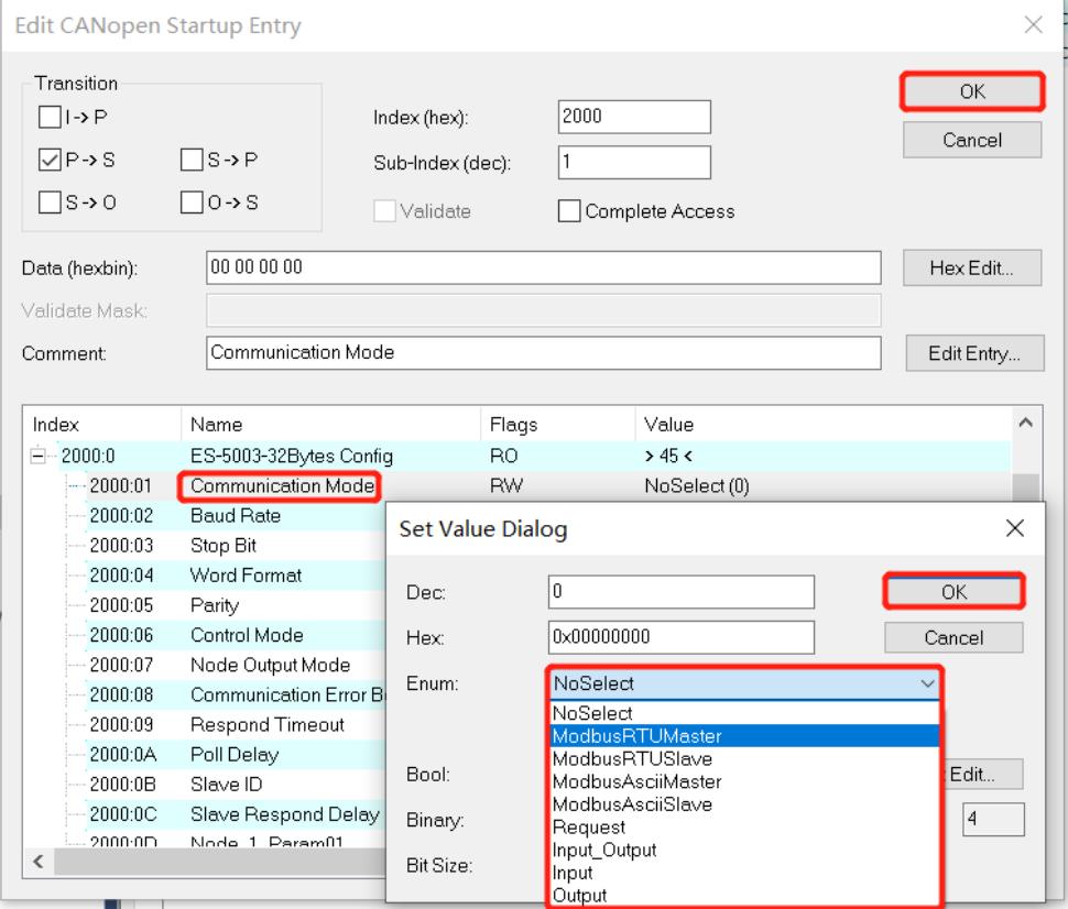
![Edit CANopen Startup Entry\nTransition\nI→P\nP→S S→P\nS→O O→S\nIndex (hex): 2000\nSub-Index (dec): 1\nValidate Complete Access\nData (hexbin): 00 00 00 00\nHex Edit...\nValidate Mask:\nComment: Communication Mode\nIndex Name Flags Value\n2000:0 ES-5003-32Bytes Config RO )45 (\n2000:01 Communication Mode\n2000:02 Baud Rate\n2000:03 Stop Bit\n2000:04 Word Format\n2000:05 Parity\n2000:06 Control Mode\n2000:07 Node Output Mode\n2000:08 Communication Error B\n2000:09 Respond Timeout\n2000:0A Poll Delay\n2000:0B Slave ID\n2000:0C Slave Respond Delay\n2000:0D Node 1 Param01\nSet Value Dialog\nDec: 0 OK\nHex: 0x00000000 Cancel\nEnum: NoSelect\nNoSelect ModbusRTUMaster\nModbusRTUSlave ModbusRTUSlave ModbusAsciiSlave ModbusAsciiSlave Request Input_Output Input Output\nBool: \nBinary: \nBit Size: \nOK](.es-series-50m-19030-1030-13/3ea99320e6db71da4fca641cdc23d6e9446702f3dc909d06ede12941e8d9bc48.jpg)

4. After the parameter modification is complete, you will see the modified parameter items and parameter values under Startup, as shown in the figure below. After the parameter setting is complete, the Reload operation and the module need to be powered on again to enable the automatic delivery of parameter settings by the master station.
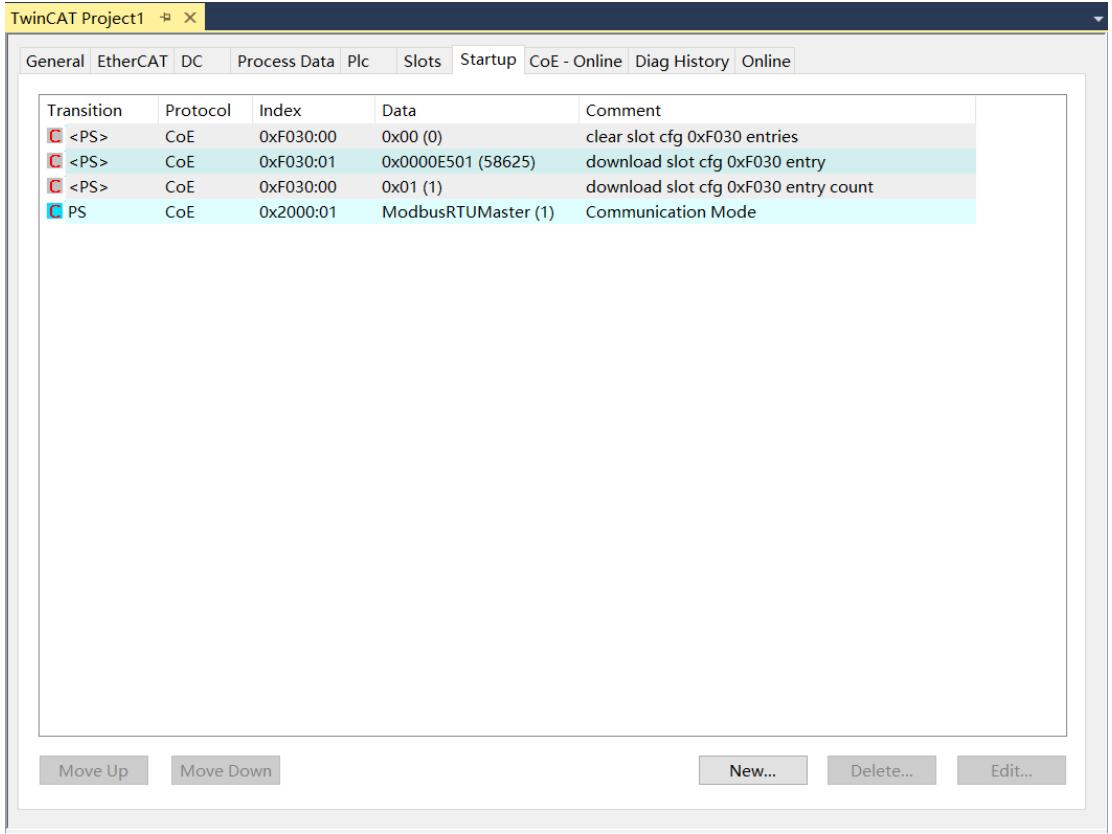
![TwinCAT Project1\nGeneral EtherCAT DC Process Data Plc Slots Startup CoE - Online Diag History Online\nTransition Protocol Index Data Comment\n(PS) CoE 0xF030:00 0x00 (0) clear slot cfg 0xF030 entries\n(PS) CoE 0xF030:01 0x0000E501 (58625) download slot cfg 0xF030 entry\n(PS) CoE 0xF030:00 0x01 (1) download slot cfg 0xF030 entry count\nPS CoE 0x2000:01 ModbusRTUMaster (1) Communication Mode\nMove Up Move Down New... Delete... Edit...](.es-series-50m-19030-1030-13/ec61dd2efc314418a0bf38bb90be8e0feb6a7de75e8c752d56d56967308f6b0c.jpg)

5. The left tree viewer Module 1 > Inputs displays the upload data of the communication module and is used to monitor the status of the module, as shown in the figure below.

<table><tr><td colspan="8">解决方案资源管理器</td></tr><tr><td colspan="8">搜索解决方案资源管理器(Ctrl+;)</td></tr><tr><td colspan="8">解决方案&quot;TwinCAT Project1&quot;(1 个项目)</td></tr><tr><td colspan="8">TwinCAT Project1</td></tr><tr><td colspan="8">SYSTEM</td></tr><tr><td colspan="8">MOTION</td></tr><tr><td colspan="8">PLC</td></tr><tr><td colspan="8">SAFETY</td></tr><tr><td colspan="8">C++</td></tr><tr><td colspan="8">I/O</td></tr><tr><td colspan="8">Devices</td></tr><tr><td colspan="8">Device 2 (EtherCAT)</td></tr><tr><td colspan="4">Image</td><td>USINT</td><td>1.0</td><td>41.0</td><td>Input 0</td></tr><tr><td colspan="4">Image-Info</td><td>USINT</td><td>1.0</td><td>42.0</td><td>Input 0</td></tr><tr><td colspan="4">SyncUnits</td><td>USINT</td><td>1.0</td><td>43.0</td><td>Input 0</td></tr><tr><td colspan="4">Inputs</td><td>USINT</td><td>1.0</td><td>44.0</td><td>Input 0</td></tr><tr><td colspan="4">Outputs</td><td>USINT</td><td>1.0</td><td>45.0</td><td>Input 0</td></tr><tr><td colspan="4">InfoData</td><td>USINT</td><td>1.0</td><td>46.0</td><td>Input 0</td></tr><tr><td rowspan="32">Box 1 (ES-6000) Inputs Outputs Module 1 (ES-5003-32Bytes) Inputs Outputs WcState InfoData Mappings</td><td></td><td></td><td></td><td></td><td></td><td></td><td></td></tr><tr><td></td><td></td><td></td><td></td><td></td><td></td><td></td></tr><tr><td></td><td></td><td></td><td></td><td></td><td></td><td></td></tr><tr><td></td><td></td><td></td><td></td><td></td><td></td><td></td></tr><tr><td></td><td></td><td></td><td></td><td></td><td></td><td></td></tr><tr><td></td><td></td><td></td><td></td><td></td><td></td><td></td></tr><tr><td></td><td></td><td></td><td></td><td></td><td></td><td></td></tr><tr><td></td><td></td><td></td><td></td><td></td><td></td><td></td></tr><tr><td></td><td></td><td></td><td></td><td></td><td></td><td></td></tr><tr><td></td><td></td><td></td><td></td><td></td><td></td><td></td></tr><tr><td></td><td></td><td></td><td></td><td></td><td></td><td></td></tr><tr><td></td><td></td><td></td><td></td><td></td><td></td><td></td></tr><tr><td>Inputs Outputs Module 1 (ES-5003-32Bytes) Inputs Outputs WcState InfoData Mappings</td><td></td><td></td><td></td><td></td><td></td><td></td></tr><tr><td></td><td></td><td></td><td></td><td></td><td></td><td></td></tr><tr><td></td><td></td><td></td><td></td><td></td><td></td><td></td></tr><tr><td></td><td></td><td></td><td></td><td></td><td></td><td></td></tr><tr><td></td><td></td><td></td><td></td><td></td><td></td><td></td></tr><tr><td></td><td></td><td></td><td></td><td></td><td></td><td></td></tr><tr><td></td><td></td><td></td><td></td><td></td><td></td><td></td></tr><tr><td></td><td></td><td></td><td></td><td></td><td></td><td></td></tr><tr><td>Inputs Outputs Module 1 (ES-5003-32Bytes) Inputs Outputs WcState InfoData Mappings</td><td></td><td>1.0 72.0 Input 0</td><td>1.0 71.0 Input 0</td><td>1.0 69.0 Input 0</td><td>1.0 70.0 Input 0</td><td>1.0 72.0 Input 0</td></tr><tr><td>Inputs Outputs Module 1 (ES-5003-32Bytes) Inputs Outputs WcState InfoData Mappings</td><td>1.0 72.0 Input 0</td><td>1.0 71.0 Input 0</td><td>1.0 69.0 Input 0</td><td>1.0 70.0 Input 0</td><td>1.0 72.0 Input 0</td><td>1.0 71.0 Input 0</td></tr><tr><td>Inputs Outputs Module 1 (ES-5003-32Bytes) Inputs Outputs WcState InfoData Mappings</td><td>1.0 72.0 Input 0</td><td>1.0 71.0 Input 0</td><td>1.0 69.0 Input 0</td><td>1.0 70.0 Input 0</td><td>1.0 72.0 Input 0</td><td>1.0 69.0 Input 0</td></tr><tr><td>Inputs Outputs Module 1 (ES-5003-32Bytes) Inputs Outputs WcState InfoData Mappings</td><td>1.0 72.0 Input 0</td><td>1.0 71.0 Input 0</td><td>1.0 69.0 Input 0</td><td>1.0 70.0 Input 0</td><td>1.0 72.0 Input 0</td><td>1.0 81.5 Input 0</td></tr><tr><td>Inputs Outputs Module 1 (ES-5003-32Bytes) Inputs Outputs WcState InfoData Mappings</td><td>1.0 72.0 Input 0</td><td>1.0 71.5 Input 0</td><td>1.0 69.5 Input 0</td><td>1.0 72.5 Input 0</td><td>1.0 72.5 Input 0</td><td>1.0 82.5 Input 0</td></tr><tr><td>Inputs Outputs Module 1 (ES-5003-32Bytes) Inputs Outputs WcState InfoData Mappings</td><td>1.0 72.5 Input 0</td><td>1.0 72.5 Input 0</td><td>1.0 72.5 Input 0</td><td>1.0 72.5 Input 0</td><td>1.0 72.5 Input 0</td><td>1.0 82.5 Input 0</td></tr><tr><td>Inputs Outputs Module 1 (ES-5003-32Bytes) Inputs Outputs WcState InfoData Mappings</td><td>1.0 72.5 Input 0</td><td>1.0 72.5 Input 0</td><td>1.0 69.5 Input 0</td><td>1.0 72.5 Input 0</td><td>1.0 72.5 Input 0</td><td>1.0 82.5 Input 0</td></tr><tr><td>Inputs Outputs Module 1 (ES-5003-32Bytes) Inputs Outputs WcState InfoData Mappings</td><td>1.0 72.5 Input 0</td><td>1.0 69.5 Input 0</td><td>1.0 72.5 Input 0</td><td>1.0 72.5 Input 0</td><td>1.0 72.5 Input 0</td><td>1.0 82.5 Input 0</td></tr><tr><td>Inputs Outputs Module 1 (ES-5003-32Bytes) Inputs Outputs WcState InfoData Mappings</td><td>1.0 72.5 Input 0</td><td>1.0 69.5 Input 0</td><td>1.0 69.5 Input 0</td><td>1.0 72.5 Input 0</td><td>1.0 72.5 Input 0</td><td>1.0 82.5 Input 0</td></tr><tr><td>Inputs Outputs Module 1 (ES-5003-32Bytes) Inputs Outputs WcState InfoData Mappings</td><td>1.0 72.5 Input 0</td><td>1.0 82.5 Input 0</td><td>1.0 69.5 Input 0</td><td>1.0 72.5 Input 0</td><td>1.0 72.5 Input 0</td><td>1.0 82.5 Input 0</td></tr><tr><td>Inputs Outputs Module 1 (ES-50O3-32Bytes) Inputs Outputs WcState InfoData Mappings</td><td>1.0 72.5 Input 0</td><td>1.0 82.5 Input 0</td><td>1.0 69.5 Input 0</td><td>1.0 72.5 Input 0</td><td>1.0 72.5 Input 0</td><td>1.0 82.5 Input 0</td></tr><tr><td>Inputs Outputs Module 1 (ES-5O3-32Bytes) Inputs Outputs WcState InfoData Mappings</td><td>1.0 72.5 Input 0</td><td>1.0 82.5 Input 0</td><td>1.0 69.5 Input 0</td><td>1.0 72.5 Input 0</td><td>1.0 72.5 Input 0</td><td>1.0 82,5 Output - Output - Output - Output - Output - Output - Output - Output - Output - Output - Output - Output - Output - Output - Output - Output - Output - Output - Output - Output - Output - Output - Output - Output - Output - Output - Output - Output - Output - Output - Output - Output - Output - Output - Output - Output - Output - Output - Output - Output - Output - Output - Output - Output - Output - Output - Output - Output - Output - Output - Output</td></tr></table>

6. The left tree viewer Module 1 > Outputs displays the download data of the communication module and is used to monitor the output status of the module, as shown in the figure below.
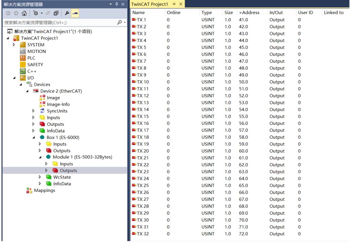
![解决方案资源管理器\n搜索解决方案资源管理器(Ctrl+;)\n解决方案'TwinCAT Project1'(1 个项目)\nTwinCAT Project1\nSYSTEM\nMOTION\nPLC\nSAFETY\nC++\nI/O\nDevices\nDevice 2 (EtherCAT)\nImage\nImage-Info\nSyncUnits\nInputs\nOutputs\nInfoData\nBox 1 (ES-6000)\nInputs\nOutputs\nModule 1 (ES-5003-32Bytes)\nInputs\nOutputs\nWcState\nInfoData\nMappings\nTwinCAT Project1\nName	Online	Type	Size	)Address)In/Out	User ID	Linked to\nTX 1	0	USINT	1.0	41.0	Output	0\nTX 2	0	USINT	1.0	42.0	Output	0\nTX 3	0	USINT	1.0	43.0	Output	0\nTX 4	0	USINT	1.0	44.0	Output	0\nTX 5	0	USINT	1.0	45.0	Output	0\nTX 6	0	USINT	1.0	46.0	Output	0\nTX 7	0	USINT	1.0	47.0	Output	0\nTX 8	0	USINT	1.0	48.0	Output	0\nTX 9	0	USINT	1.0	49.0	Output	0\nTX 10	0	USINT	1.0	50.0	Output	0\nTX 11	0	USINT	1.0	51.0	Output	0\nTX 12	0	USINT	1.0	52.0	Output	0\nTX 13	0	USINT	1.0	53.0	Output	0\nTX 14	0	USINT	1.0	54.0	Output	0\nTX 15	0	USINT	1.0	55.0	Output	0\nTX 16	0	USINT	1.0	56.0	Output	0\nTX 17	0	USINT	1.0	57.0	Output	0\nTX 18	0	USINT	1.0	58.0	Output	0\nTX 19	0	USINT	1.0	59.0	Output	0\nTX 20	0	USINT	1.0	60.0	Output	0\nTX 21	0	USINT	1.0	61.0	Output	0\nTX 22	0	USINT	1.0	62.0	Output	0\nTX 23	0	USINT	1.0	63.0	Output	0\nTX 24	0	USINT	1.0	64.0	Output	0\nTX 25	0	USINT	1.0	65.0	Output	0\nTX 26	0	USINT	1.0	66.0	Output	0\nTX 27	0	USINT	1.0	67.0	Output	0\nTX 28	0	USINT	1.0	68.0	Output	0\nTX 29	0	USINT	1.0	69.0	Output	0\nTX 30	0	USINT	1.0	70.0	Output	0\nTX 31	0	USINT	1.0	71.0	Output	0\nTX 32	0	USINT	1.0	72.0	Output	0](.es-series-50m-19030-1030-13/12a9af52d15a276a6a431d8c6ff378d646fe41b0452ec138a098b48aaf570c13.jpg)

# 11.2 RTU Master Mode Function Example

Example 1: Use tools such as Modbus Slave debugging software or device verification module RTU master station to write the values of 2 holding registers in disable mode.

1. Configure the parameters and select 1 as the communication mode, which is the RTU master mode.

Communication Mode: Select ModbusRTUMester.
Control Mode: Select Disable.
• Node\_1\_Param\_1: Configure to 0x00000602, please refer to Modbus Master Function Node code for configuration parameters.
Node\_1\_Param\_2: Configure to 0x00000001, please refer to Modbus Master Function Node code for configuration parameters.
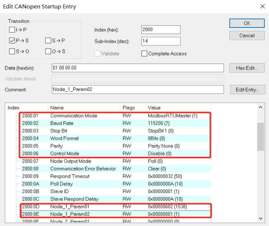
![Edit CANopen Startup Entry\nTransition\nI-) P\nP-) S\nS-) O\nS-) P\nO-) S\nIndex (hex): 2000\nSub-Index (dec): 14\nValidate Complete Access\nData (hexbin): 01 00 00 00\nValidate Mask:\nComment: Node_1_Param02\nHex Edit...\nEdit Entry...\nIndex Name Flags Value\n2000:01 Communication Mode RW ModbusRTUMaster (1)\n2000:02 Baud Rate RW 115200 (7)\n2000:03 Stop Bit RW StopBit 1 (0)\n2000:04 Word Format RW 8Bits (0)\n2000:05 Parity RW Parity None (0)\n2000:06 Control Mode RW Disable (0)\n2000:07 Node Output Mode RW Poll (0)\n2000:08 Communication Error Behavior RW Clear (0)\n2000:09 Respond Timeout RW 0x00000032 (50)\n2000:0A Poll Delay RW 0x0000000A (10)\n2000:0B Slave ID RW 0x00000001 (1)\n2000:0C Slave Respond Delay RW 0x0000000A (10)\n2000:0D Node_1_Param01 RW 0x00000602 (1538)\n2000:0E Node_1_Param02 RW 0x00000001 (1)\n2000:0F Node_2_Param01 RW 0x0000000( 1)](.es-series-50m-19030-1030-13/cef3efdc5735afd17675c7538acddab2d9c8377f32f284e195f56b27f427fdd0.jpg)

# 2. In the download data, write the values of 2 holding registers.
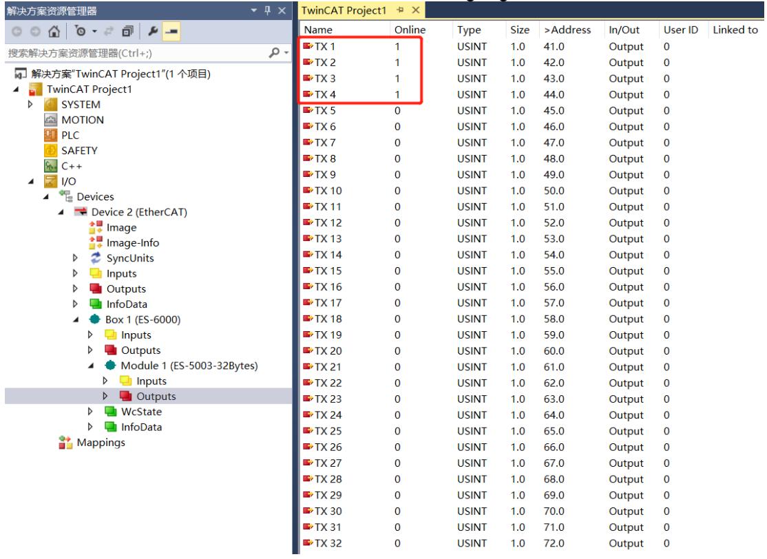
![The image shows a software interface, likely TwinCAT, divided into two panels.\n\n**Left Panel (Solution Explorer):**\n- **Header:** 解决方案资源管理器\n- **Search bar:** 搜索解决方案资源管理器(Ctrl+;)\n- **Tree Structure:**\n    - 解决方案'TwinCAT Project1'(1 个项目)\n    - TwinCAT Project1\n        - SYSTEM\n        - MOTION\n        - PLC\n        - SAFETY\n        - C++\n        - I/O\n            - Devices\n                - Device 2 (EtherCAT)\n                    - Image\n                    - Image-Info\n                    - SyncUnits\n                    - Inputs\n                    - Outputs\n                    - InfoData\n            - Box 1 (ES-6000)\n                - Inputs\n                - Outputs\n            - Module 1 (ES-5003-32Bytes)\n                - Inputs\n                - Outputs\n                    - WcState\n                    - InfoData\n    - Mappings\n\n**Right Panel (Data Table):**\n- **Header:** TwinCAT Project1\n- **Columns:** Name, Online, Type, Size, )Address, In/Out, User ID, Linked to\n- **Rows (TX 1 to TX 32):**\n    - A red box highlights rows **TX 1** through **TX 4**, which have an **Online** status of **1**.\n    - **TX 1:** Type USINT, Size 1.0, )Address 41.0, In/Out Output, User ID 0\n    - **TX 2:** Type USINT, Size 1.0, )Address 42.0, In/Out Output, User ID 0\n    - **TX 3:** Type USINT, Size 1.0, )Address 43.0, In/Out Output, User ID 0\n    - **TX 4:** Type USINT, Size 1.0, )Address 44.0, In/Out Output, User ID 0\n    - **TX 5** through **TX 32:** All rows have an **Online** status of **0**. The **Type** is **USINT**, **Size** is **1.0**, **In/Out** is **Output**, and **User ID** is **0**. The **)Address** column increments sequentially from **45.0** (TX 5) to **72.0** (TX 32).](.es-series-50m-19030-1030-13/ab34bdc2187540e5c9c32e904032229ce595de44df87d102e33edf1642d82429.jpg)

# 3. You can see the values of the two received registers through the debugging software.

Modbus Slave - Mbslav1
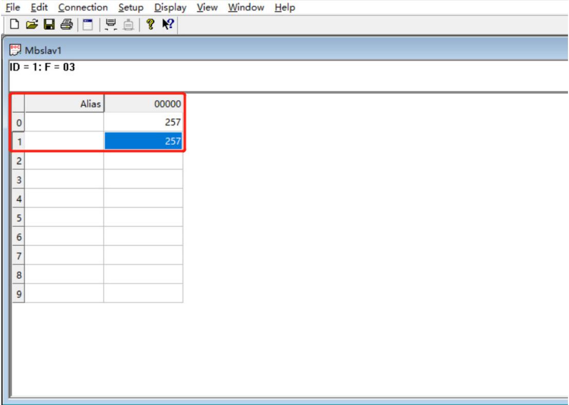
![File Edit Connection Setup Display View Window Help\nMbslav1\nID = 1: F = 03\nAlias 00000\n0 257\n1 257\n2\n3\n4\n5\n6\n7\n8\n9](.es-series-50m-19030-1030-13/13502e3acbe60c278e4e68b781c046d2b5b0b275771c3adc66b5ae8445b44aae.jpg)

For Help,press F1.

Example 2: Read 10 holding registers in Level mode through tools such as Modbus Slave debugging software or device verification module RTU master station.

1. Configure the parameters and select the communication mode 1, which is the RTU master mode.

• Communication Mode: Select ModbusRTUMester.
Control Mode: Select Level.
• Node\_1\_Param\_1: Configure to 0x00000001. For details of configuration parameters, see Control and status node code.
Node\_2\_Param\_1: Configure to 0x0000030A. For details of configuration parameters, see Modbus Master Function Node code.
Node\_2\_Param\_2: Configure to 0x00000001. For details on configuration parameters, see Modbus Master Function Node code.

Edit CANopen Startup Entry
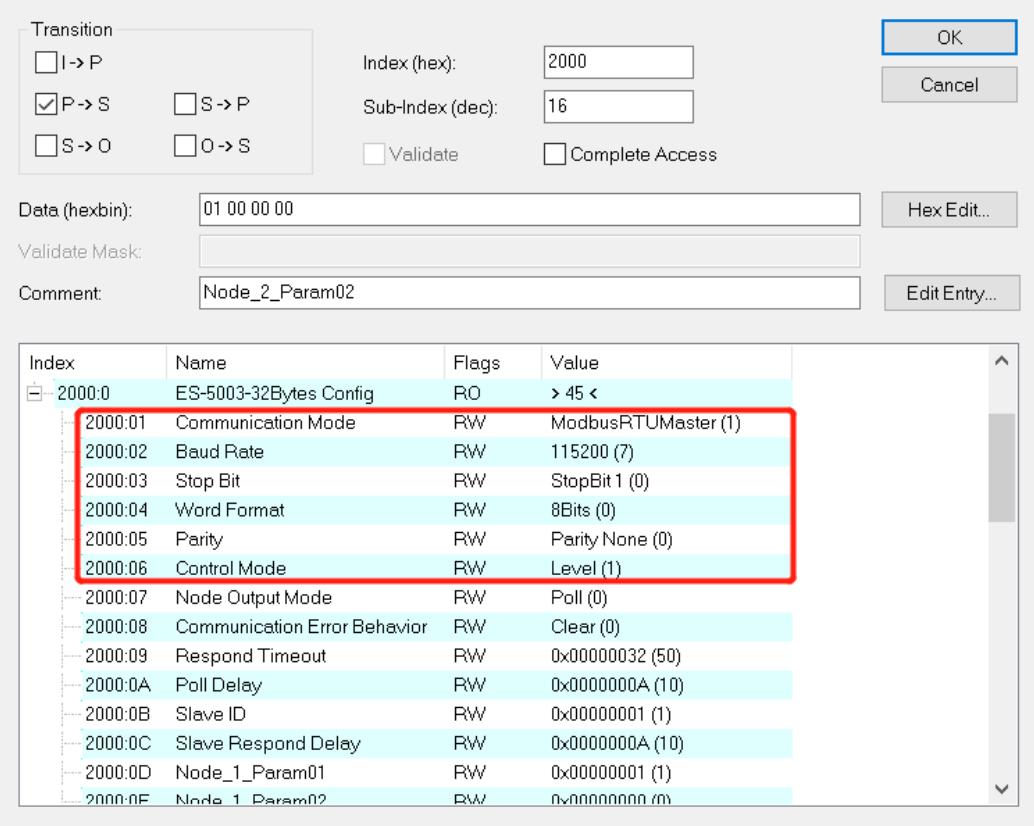
![Transition\nI-)P\nP-)S S-)P\nS-)O O-)S\nIndex (hex): 2000\nSub-Index (dec): 16\nValidate Complete Access\nData (hexbin): 01 00 00 00\nValidate Mask:\nComment: Node_2_Param02\nHex Edit...\nEdit Entry...\nIndex Name Flags Value\n2000:0 ES-5003-32Bytes Config RO )45(\n2000:01 Communication Mode RW ModbusRTUMaster (1)\n2000:02 Baud Rate RW 115200 (7)\n2000:03 Stop Bit RW StopBit 1 (0)\n2000:04 Word Format RW 8Bits (0)\n2000:05 Parity RW Parity None (0)\n2000:06 Control Mode RW Level (1)\n2000:07 Node Output Mode RW Poll (0)\n2000:08 Communication Error Behavior RW Clear (0)\n2000:09 Respond Timeout RW 0x00000032 (50)\n2000:0A Poll Delay RW 0x0000000A (10)\n2000:0B Slave ID RW 0x00000001 (1)\n2000:0C Slave Respond Delay RW 0x0000000A (10)\n2000:0D Node_1_Param01 RW 0x00000001 (1)\n2000:0E Node_1_Param02 RW 0x0000000 (1)](.es-series-50m-19030-1030-13/8e32273f093b0cd98892d14f6d837f2d436d5c1cf532c3579d3fcdcb2b6767e7.jpg)

![Edit CANopen Startup Entry\nTransition\nI→P\nP→S S→P\nS→O O→S\nIndex (hex): 2000\nSub-Index (dec): 16\nValidate Complete Access\nData (hexbin): 01 00 00 00\nValidate Mask:\nComment: Node_2_Param02\nHex Edit...\nEdit Entry...\nIndex Name Flags Value\n2000:06 Control Mode RW Level (1)\n2000:07 Node Output Mode RW Poll (0)\n2000:08 Communication Error Behavior RW Clear (0)\n2000:09 Respond Timeout RW 0x00000032 (50)\n2000:0A Poll Delay RW 0x0000000A (10)\n2000:0B Slave ID RW 0x00000001 (1)\n2000:0C Slave Respond Delay RW 0x0000000A (10)\n2000:0D Node_1_Param01 RW 0x00000001 (1)\n2000:0E Node_1_Param02 RW 0x00000000 (0)\n2000:0F Node_2_Param01 RW 0x000030A (778)\n2000:10 Node_2_Param02 RW 0x00000001 (1)\n2000:11 Node_3_Param01 RW 0x00000000 (0)\n2000:12 Node_3_Param02 RW 0x00000000 (0)\n2000:13 Node_4_Param01 RW 0x00000000 (0)\n2000:14 Node_4_Param02 RW 0x00000001 (1)](.es-series-50m-19030-1030-13/3fd8a259e2d274e5fb7fa5827351e055088ec6a9ac70135e2a8075404f8c71f1.jpg)

# 2. Set the control word to 1 in the download data and open the debugging software to send the data.

![解决方案资源管理器\n搜索解决方案资源管理器(Ctrl+;)\n解决方案'TwinCAT Project1'(1 个项目)\nTwinCAT Project1\nSYSTEM\nMOTION\nPLC\nSAFETY\nC++\nI/O\nDevices\nDevice 2 (EtherCAT)\nImage\nImage-Info\nSyncUnits\nInputs\nOutputs\nInfoData\nBox 1 (ES-6000)\nInputs\nOutputs\nModule 1 (ES-5003-32Bytes)\nInputs\nOutputs\nWcState\nInfoData\nMappings\nName	Online	Type	Size	)Address)In/Out	User ID	Linked to\nTX 1	1	USINT	1.0	41.0	Output	0\nTX 2	0	USINT	1.0	42.0	Output	0\nTX 3	0	USINT	1.0	43.0	Output	0\nTX 4	0	USINT	1.0	44.0	Output	0\nTX 5	0	USINT	1.0	45.0	Output	0\nTX 6	0	USINT	1.0	46.0	Output	0\nTX 7	0	USINT	1.0	47.0	Output	0\nTX 8	0	USINT	1.0	48.0	Output	0\nTX 9	0	USINT	1.0	49.0	Output	0\nTX 10	0	USINT	1.0	50.0	Output	0\nTX 11	0	USINT	1.0	51.0	Output	0\nTX 12	0	USINT	1.0	52.0	Output	0\nTX 13	0	USINT	1.0	53.0	Output	0\nTX 14	0	USINT	1.0	54.0	Output	0\nTX 15	0	USINT	1.0	55.0	Output	0\nTX 16	0	USINT	1.0	56.0	Output	0\nTX 17	0	USINT	1.0	57.0	Output	0\nTX 18	0	USINT	1.0	58.0	Output	0\nTX 19	0	USINT	1.0	59.0	Output	0\nTX 20	0	USINT	1.0	60.0	Output	0\nTX 21	0	USINT	1.0	61.0	Output	0\nTX 22	0	USINT	1.0	62.0	Output	0\nTX 23	0	USINT	1.0	63.0	Output	0\nTX 24	0	USINT	1.0	64.0	Output	0\nTX 25	0	USINT	1.0	65.0	Output	0\nTX 26	0	USINT	1.0	66.0	Output	0\nTX 27	0	USINT	1.0	67.0	Output	0\nTX 28	0	USINT	1.0	68.0	Output	0\nTX 29	0	USINT	1.0	69.0	Output	0\nTX 30	0	USINT	1.0	70.0	Output	0\nTX 31	0	USINT	1.0	71.0	Output	0\nTX 32	0	USINT	1.0	72.0	Output	0](.es-series-50m-19030-1030-13/9c9fed37405da648cd43cf72e14c333a29813838e21492c9107719aabd0040cb.jpg)

# 3. The received data can be viewed in the uploaded data.

![解决方案资源管理器\n搜索解决方案资源管理器(Ctrl+;)\n解决方案'TwinCAT Project1'(1 个项目)\nTwinCAT Project1\nSYSTEM\nMOTION\nPLC\nSAFETY\nC++\nI/O\nDevices\nDevice 2 (EtherCAT)\nImage\nImage-Info\nSyncUnits\nInputs\nOutputs\nInfoData\nBox 1 (ES-6000)\nInputs\nOutputs\nModule 1 (ES-5003-32Bytes)\nInputs\nOutputs\nWcState\nInfoData\nMappings\nTwinCAT Project1\nName	Online	Type	Size	)Address	In/Out	User ID	Linked to\nRX 1	5	USINT	1.0	41.0.Input	0\nRX 2	0	USINT	1.0	42.0.Input	0\nRX 3	0	USINT	1.0	43.0.Input	0\nRX 4	255	USINT	1.0	44.0.Input	0\nRX 5	0	USINT	1.0	45.0.Input	0\nRX 6	255	USINT	1.0	46.0.Input	0\nRX 7	0	USINT	1.0	47.0.Input	0\nRX 8	255	USINT	1.0	48.0.Input	0\nRX 9	0	USINT	1.0	49.0.Input	0\nRX 10	255	USINT	1.0	50.0.Input	0\nRX 11	0	USINT	1.0	51.0.Input	0\nRX 12	255	USINT	1.0	52.0.Input	0\nRX 13	0	USINT	1.0	53.0.Input	0\nRX 14	255	USINT	1.0	54.0.Input	0\nRX 15	0	USINT	1.0	55.0.Input	0\nRX 16	255	USINT	1.0	56.0.Input	0\nRX 17	0	USINT	1.0	57.0.Input	0\nRX 18	255	USINT	1.0	58.0.Input	0\nRX 19	0	USINT	1.0	59.0.Input	0\nRX 20	255	USINT	1.0	60.0.Input	0\nRX 21	0	USINT	1.0	61.0.Input	0\nRX 22	255	USINT	1.0	62.0.Input	0\nRX 23	0	USINT	1.0	63.0.Input	0\nRX 24	0	USINT	1.0	64.0.Input	0\nRX 25	0	USINT	1.0	65.0.Input	0\nRX 26	0	USINT	1.0	66.0.Input	0\nRX 27	0	USINT	1.0	67.0.Input	0\nRX 28	0	USINT	1.0	68.0.Input	0\nRX 29	0	USINT	1.0	69.0.Input	0\nRX 30	0	USINT	1.0	70.0.Input	0\nRX 31	0	USINT	1.0	71.0.Input	0\nRX 32	0	USINT	1.0	72.0.Input	0](.es-series-50m-19030-1030-13/e8082f85bb562c4c3415b92610d4964f593a989d9ad4a33676b07a2e03ee2b72.jpg)

# 11.3 RTU Slave Mode Function Example

Example: Use tools such as Modbus Poll debugging software or device verification module RTU slave station to read 10 holding registers in Level mode.

1. Configure the parameters and select the communication mode 2, which is the RTU slave mode.

• Communication Mode: Select ModbusRTUSlave.
• Control Mode: Select Level.
• Node\_1\_Param\_1: Configure to 0x00000030. For details of configuration parameters, see Control and status node code.
Node\_2\_Param\_1: Configure to 0x0000080A. For details of configuration parameters, see Modbus Slave Function Node code.
• Node\_2\_Param\_2: Configure to 0x00000000. For details on configuration parameters, see Modbus Slave Function Node code.

![Edit CANopen Startup Entry\nTransition\nI -) P\nP -) S\nS -) O\nIndex (hex): 2000\nSub-Index (dec): 15\nValidate Complete Access\nData (hexbin): 0A 08 00 00\nHex Edit...\nValidate Mask:\nComment: Node_2_Param01\nEdit Entry...\nIndex Name Flags Value\n2000:0 ES-5003-32Bytes Config RO ) 45 (\n2000:01 Communication Mode RW ModbusRTUSlave (2)\n2000:02 Baud Rate RW 115200 (7)\n2000:03 Stop Bit RW StopBit 1 (0)\n2000:04 Word Format RW 8Bits (0)\n2000:05 Parity RW Parity None (0)\n2000:06 Control Mode RW Level (1)\n2000:07 Node Output Mode RW Poll (0)\n2000:08 Communication Error Behavior RW Clear (0)\n2000:09 Respond Timeout RW 0x0000032 (50)\n2000:0A Poll Delay RW 0x000000A (10)\n2000:0B Slave ID RW 0x0000001 (1)\n2000:0C Slave Respond Delay RW 0x000000A (10)\n2000:0D Node_1_Param01 RW 0x0000030 (48)\n2000:0E Node_1_Param02 RW 0x0000033 (3)](.es-series-50m-19030-1030-13/876a2e0c05d72e659532653450f159ca15585ae72eead670483a13c05b1a6e6a.jpg)

Edit CANopen Startup Entry
![Transition\nI -) P\nP -) S\nS -) O\nO -) S\nIndex (hex): 2000\nSub-Index (dec): 15\nValidate Complete Access\nData (hexbin): 0A 08 00 00\nValidate Mask:\nComment: Node_2_Param01\nOK\nCancel\nHex Edit...\nEdit Entry...](.es-series-50m-19030-1030-13/e0720e37b66e4c0d9c7973b75554df2e425560c2d5c7e8b8d7e0f6906bcf2e6e.jpg)

![| Index | Name | Flags | Value |\n| :--- | :--- | :--- | :--- |\n| 2000:06 | Control Mode | RW | Level (1) |\n| 2000:07 | Node Output Mode | RW | Poll (0) |\n| 2000:08 | Communication Error Behavior | RW | Clear (0) |\n| 2000:09 | Respond Timeout | RW | 0x00000032 (50) |\n| 2000:0A | Poll Delay | RW | 0x0000000A (10) |\n| 2000:0B | Slave ID | RW | 0x00000001 (1) |\n| 2000:0C | Slave Respond Delay | RW | 0x0000000A (10) |\n| 2000:0D | Node_1_Param01 | RW | 0x00000030 (48) |\n| 2000:0E | Node_1_Param02 | RW | 0x00000000 (0) |\n| 2000:0F | Node_2_Param01 | RW | 0x0000080A (2058) |\n| 2000:10 | Node_2_Param02 | RW | 0x00000000 (0) |\n| 2000:11 | Node_3_Param01 | RW | 0x00000000 (0) |\n| 2000:12 | Node_3_Param02 | RW | 0x00000000 (0) |\n| 2000:13 | Node_4_Param01 | RW | 0x00000000 (0) |\n| 2000:14 | Node_4_Param02 | RW | 0x00000000 (0) |](.es-series-50m-19030-1030-13/a37b7ca932a68c69d9c9205abf00905eeab66e1e606bc89bb3ac1355747a242f.jpg)

# 2. Set the control word to 1 in the download data, and open the debugging software to send the data.

![解决方案资源管理器\n搜索解决方案资源管理器(Ctrl+)\n解决方案'TwinCAT Project1'(1 个项目)\nTwinCAT Project1\nSYSTEM\nMOTION\nPLC\nSAFETY\nC++\nANALYTICS\nI/O\nDevices\nDevice 2 (EtherCAT)\nImage\nImage-Info\nSyncUnits\nInputs\nOutputs\nInfoData\nBox 1 (ES-6000)\nInputs\nOutputs\nModule 1 (ES-5003-32Bytes)\nInputs\nOutputs\nWcState\nInfoData\nMappings\nName	Online	Type	Size	)Address)In/Out	Linked to\nTX 1	1	USINT	1.0	41.0	Output\nTX 2	0	USINT	1.0	42.0	Output\nTX 3	0	USINT	1.0	43.0	Output\nTX 4	0	USINT	1.0	44.0	Output\nTX 5	0	USINT	1.0	45.0	Output\nTX 6	0	USINT	1.0	46.0	Output\nTX 7	0	USINT	1.0	47.0	Output\nTX 8	0	USINT	1.0	48.0	Output\nTX 9	0	USINT	1.0	49.0	Output\nTX 10	0	USINT	1.0	50.0	Output\nTX 11	0	USINT	1.0	51.0	Output\nTX 12	0	USINT	1.0	52.0	Output\nTX 13	0	USINT	1.0	53.0	Output\nTX 14	0	USINT	1.0	54.0	Output\nTX 15	0	USINT	1.0	55.0	Output\nTX 16	0	USINT	1.0	56.0	Output\nTX 17	0	USINT	1.0	57.0	Output\nTX 18	0	USINT	1.0	58.0	Output\nTX 19	0	USINT	1.0	59.0	Output\nTX 20	0	USINT	1.0	60.0	Output\nTX 21	0	USINT	1.0	61.0	Output\nTX 22	0	USINT	1.0	62.0	Output\nTX 23	0	USINT	1.0	63.0	Output\nTX 24	0	USINT	1.0	64.0	Output\nTX 25	0	USINT	1.0	65.0	Output\nTX 26	0	USINT	1.0	66.0	Output\nTX 27	0	USINT	1.0	67.0	Output\nTX 28	0	USINT	1.0	68.0_Output\nTX 29	0	USINT	1.0	69.0_Output\nTX 30	0	USINT	1.0	70.0_Output\nTX 31	0	USINT	1.0	71.0_Output\nTX 32	0	USINT	1.0	72.0_Output](.es-series-50m-19030-1030-13/4a16d6f02bd96cfc4b965f9b44e25907d2429d530dfb1bff69984b3d326cd54f.jpg)

# 3. The received data can be viewed in the upload data.

![解决方案资源管理器\n搜索解决方案资源管理器(Ctrl+;)\n解决方案'TwinCAT Project1'(1 个项目)\nTwinCAT Project1\nSYSTEM\nMOTION\nPLC\nSAFETY\nC++\nANALYTICS\nI/O\nDevices\nDevice 2 (EtherCAT)\nImage\nImage-Info\nSyncUnits\nInputs\nOutputs\nInfoData\nBox 1 (ES-6000)\nInputs\nOutputs\nModule 1 (ES-5003-32Bytes)\nInputs\nOutputs\nWcState\nInfoData\nMappings\nTwinCAT Project1\nName	Online	Type	Size	)Address)In/Out	Linked to\nRX 1	0	USINT	1.0	41.0.Input\nRX 2	0	USINT	1.0	42.0.Input\nRX 3	255	USINT	1.0	43.0.Input\nRX 4	0	USINT	1.0	44.0.Input\nRX 5	255	USINT	1.0	45.0.Input\nRX 6	0	USINT	1.0	46.0.Input\nRX 7	255	USINT	1.0	47.0.Input\nRX 8	0	USINT	1.0	48.0.Input\nRX 9	255	USINT	1.0	49.0.Input\nRX 10	0	USINT	1.0	50.0.Input\nRX 11	255	USINT	1.0	51.0.Input\nRX 12	0	USINT	1.0	52.0.Input\nRX 13	255	USINT	1.0	53.0.Input\nRX 14	0	USINT	1.0	54.0.Input\nRX 15	255	USINT	1.0	55.0.Input\nRX 16	0	USINT	1.0	56.0.Input\nRX 17	255	USINT	1.0	57.0.Input\nRX 18	0	USINT	1.0	58.0.Input\nRX 19	255	USINT	1.0	59.0.Input\nRX 20	0	USINT	1.0	60.0.Input\nRX 21	255	USINT	1.0	61.0.Input\nRX 22	0	USINT	1.0	62.0.Input\nRX 23	0	USINT	1.0	63.0.Input\nRX 24	0	USINT	1.0	64.0.Input\nRX 25	0	USINT	1.0	65.0.Input\nRX 26	0	USINT	1.0	66.0.Input\nRX 27	0	USINT	1.0	67.0.Input\nRX 28	0	USINT	1.0	68.0.Input\nRX 29	0	USINT	1.0	69.0.Input\nRX 30	0	USINT	1.0	70.0.Input\nRX 31	0	USINT	1.0	71.0.Input\nRX 32	0	USINT	1.0	72.0.Input](.es-series-50m-19030-1030-13/3996df63adb2a4f42384fd89b5445d59d5641a7a9326d853c56318c4a40a236a.jpg)

# 11.4 ASCII Master Mode Function Example

Example: Use tools such as Modbus Slave debugging software or device verification module ASCII master station to write the value of 2 holding registers in disable mode.

1. Configure the parameters and select the communication mode 3, which is the ASCII master mode, as shown in the figure below.

Communication Mode: Select ModbusAsciiMaster. Control Mode: Select Disable.
• Node\_1\_Param\_1: Configure to 0x00000602, please refer to Modbus Master Function Node code for configuration parameters.
• Node\_1\_Param\_2: Configure to 0x00000001, please refer to Modbus Master Function Node code for configuration parameters.

![Transition\nI -) P\nP -) S\nS -) O\nIndex (hex): 2000\nSub-Index (dec): 15\nValidate Complete Access\nData (hexbin): 00 00 00 00\nHex Edit...\nValidate Mask:\nComment: Node_2_Param01\nEdit Entry...\nIndex Name Flags Value\n2000:0 ES-5003-32Bytes Config RO ) 45 (\n2000:01 Communication Mode RW ModbusAsciiMaster (3)\n2000:02 Baud Rate RW 115200 (7)\n2000:03 Stop Bit RW StopBit 1 (0)\n2000:04 Word Format RW 8Bits (0)\n2000:05 Parity RW Parity None (0)\n2000:06 Control Mode RW Disable (0)\n2000:07 Node Output Mode RW Poll (0)\n2000:08 Communication Error Behavior RW Clear (0)\n2000:09 Respond Timeout RW 0x00000032 (50)\n2000:0A Poll Delay RW 0x0000000A (10)\n2000:0B Slave ID RW 0x00000001 (1)\n2000:0C Slave Respond Delay RW 0x0000000A (10)\n2000:0D Node_1_Param01 RW 0x0000602 (1538)\n2000:0E Node_1_Param02 RW 0x0000001 (1)\n2000:0F Node_2_Param01 RW 0x0000002 (1)](.es-series-50m-19030-1030-13/7d323d0179b884cb93963b1b2e0a7892285db7d55d661caaa61015bee8a0b305.jpg)

# 2. In the download data, write the values of 2 holding registers.

![解决方案资源管理器\n搜索解决方案资源管理器(Ctrl+)\n解决方案'TwinCAT Project1'(1 个项目)\nTwinCAT Project1\nSYSTEM\nMOTION\nPLC\nSAFETY\nC++\nANALYTICS\nI/O\nDevices\nDevice 2 (EtherCAT)\nImage\nImage-Info\nSyncUnits\nInputs\nOutputs\nInfoData\nBox 1 (ES-6000)\nInputs\nOutputs\nModule 1 (ES-5003-32Bytes)\nInputs\nOutputs\nWcState\nInfoData\nMappings\nName	Online	Type	Size	)Address)In/Out	Linked to\nTX 1	1	USINT	1.0	41.0	Output\nTX 2	0	USINT	1.0	42.0	Output\nTX 3	1	USINT	1.0	43.0	Output\nTX 4	0	USINT	1.0	44.0	Output\nTX 5	0	USINT	1.0	45.0	Output\nTX 6	0	USINT	1.0	46.0	Output\nTX 7	0	USINT	1.0	47.0	Output\nTX 8	0	USINT	1.0	48.0	Output\nTX 9	0	USINT	1.0	49.0	Output\nTX 10	0	USINT	1.0	50.0	Output\nTX 11	0	USINT	1.0	51.0	Output\nTX 12	0	USINT	1.0	52.0	Output\nTX 13	0	USINT	1.0	53.0	Output\nTX 14	0	USINT	1.0	54.0	Output\nTX 15	0	USINT	1.0	55.0	Output\nTX 16	0	USINT	1.0	56.0	Output\nTX 17	0	USINT	1.0	57.0	Output\nTX 18	0	USINT	1.0	58.0	Output\nTX 19	0	USINT	1.0	59.0	Output\nTX 20	0	USINT	1.0	60.0	Output\nTX 21	0	USINT	1.0	61.0	Output\nTX 22	0	USINT	1.0	62.0	Output\nTX 23	0	USINT	1.0	63.0	Output\nTX 24	0	USINT	1.0	64.0	Output\nTX 25	0	USINT	1.0	65.0	Output\nTX 26	0	USINT	1.0	66.0	Output\nTX 27	0	USINT	1.0	67.0	Output\nTX 28	0	USINT	1.0	68.0	Output\nTX 29	0	USINT	1.0	69.0	Output\nTX 30	0	USINT	1.0	70.0	Output\nTX 31	0	USINT	1.0	71.0	Output\nTX 32	0	USINT	1.0	72.0	Output](.es-series-50m-19030-1030-13/848487e4d1e64f32996d87d130ccb173757b6ba78bde572b221f2ce1f0171ff7.jpg)

# 3. The values of the two received registers can be viewed through the debugging software.

![Modbus Slave - Mbslav1\nFile Edit Connection Setup Display View Window Help\nMbslav1\nID = 1: F = 03\nAlias 00000\n0 256\n1 256\n2 0\n3 0\n4 0\n5 0\n6 0\n7 0\n8 0\n9 0](.es-series-50m-19030-1030-13/cc26581476e268f7499b27f46244228b565bbed32c62dadffb168416057ace5f.jpg)

# 11.5 ASCII Slave Mode Function Example

Example: Use tools such as Modbus Poll debugging software or device verification module ASCII slave to read 10 holding registers in disabled mode.

1. Configure the configuration parameters and select the communication mode 4, which is the ASCII slave mode, as shown in the figure below.

Communication Mode: Select ModbusAsciiSlave.
Control Mode: Select Disable.

Node\_1\_Param\_1: Configure to 0x0000080A. For details of configuration parameters, see Modbus Slave Function Node code.

Node\_1\_Param\_2: Configure to 0x00000000. For details on configuration parameters, see Modbus Slave Function Node code.

Edit CANopen Startup Entry
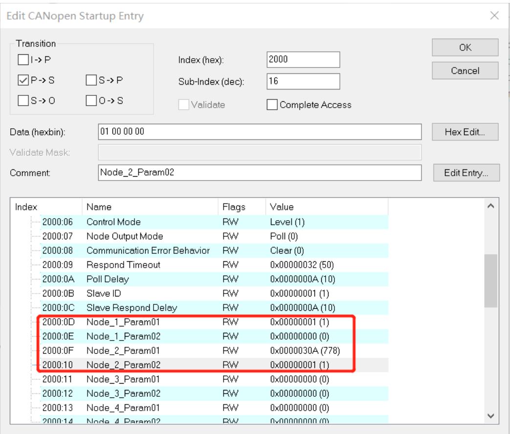
![Transition\nI -) P\n✓ P -) S    □ S -) P\n□ S -) O    □ O -) S\nIndex (hex): 2000\nSub-Index (dec): 1\nValidate Complete Access\nData (hexbin): 04 00 00 00\nValidate Mask:\nComment: Communication Mode\nOK\nCancel\nHex Edit...\nEdit Entry...](.es-series-50m-19030-1030-13/2d47cf88e9fcd6eebf3adaace794cd988418ea42b8ea0c9e465cb2da68a34363.jpg)

![| Index | Name | Flags | Value |\n| :--- | :--- | :--- | :--- |\n| 2000:01 | Communication Mode | RW | ModbusAsciiSlave (4) |\n| 2000:02 | Baud Rate | RW | 115200 (7) |\n| 2000:03 | Stop Bit | RW | StopBit 1 (0) |\n| 2000:04 | Word Format | RW | 8Bits (0) |\n| 2000:05 | Parity | RW | Parity None (0) |\n| 2000:06 | Control Mode | RW | Disable (0) |\n| 2000:07 | Node Output Mode | RW | Poll (0) |\n| 2000:08 | Communication Error Behavior | RW | Clear (0) |\n| 2000:09 | Respond Timeout | RW | 0x00000032 (50) |\n| 2000:0A | Poll Delay | RW | 0x0000000A (10) |\n| 2000:0B | Slave ID | RW | 0x00000001 (1) |\n| 2000:0C | Slave Respond Delay | RW | 0x0000000A (10) |\n| 2000:0D | Node_1_Param01 | RW | 0x0000080A (2058) |\n| 2000:0E | Node_1_Param02 | RW | 0x00000000 (0) |\n| 2000:0F | Node_2_Param01 | RW | 0x0000000 (0) |](.es-series-50m-19030-1030-13/a2b034e51c59bd72b3dcf144bdb4f2c3413b425ab3621735360c1b732efe2216.jpg)

2. Open the debugging software to send data, and you can see the received data in the upload data.
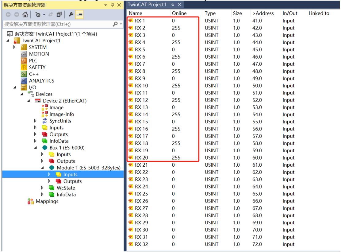
![解决方案资源管理器\n搜索解决方案资源管理器(Ctrl+)\n解决方案'TwinCAT Project1'(1 个项目)\nTwinCAT Project1\nSYSTEM\nMOTION\nPLC\nSAFETY\nC++\nANALYTICS\nI/O\nDevices\nDevice 2 (EtherCAT)\nImage\nImage-Info\nSyncUnits\nInputs\nOutputs\nInfoData\nBox 1 (ES-6000)\nInputs\nOutputs\nModule 1 (ES-5003-32Bytes)\nInputs\nOutputs\nWcState\nInfoData\nMappings\nName	Online	Type	Size	)Address)In/Out	Linked to\nRX 1	0	USINT	1.0	41.0.Input\nRX 2	255	USINT	1.0	42.0.Input\nRX 3	0	USINT	1.0	43.0.Input\nRX 4	255	USINT	1.0	44.0.Input\nRX 5	0	USINT	1.0	45.0.Input\nRX 6	255	USINT	1.0	46.0.Input\nRX 7	0	USINT	1.0	47.0.Input\nRX 8	255	USINT	1.0	48.0.Input\nRX 9	0	USINT	1.0	49.0.Input\nRX 10	255	USINT	1.0	50.0.Input\nRX 11	0	USINT	1.0	51.0.Input\nRX 12	255	USINT	1.0	52.0.Input\nRX 13	0	USINT	1.0	53.0.Input\nRX 14	255	USINT	1.0	54.0.Input\nRX 15	0	USINT	1.0	55.0.Input\nRX 16	255	USINT	1.0	56.0.Input\nRX 17	0	USINT	1.0	57.0.Input\nRX 18	255	USINT	1.0	58.0.Input\nRX 19	0	USINT	1.0	59.0.Input\nRX 20	255	USINT	1.0	60.0.Input\nRX 21	0	USINT	1.0	61.0.Input\nRX 22	0	USINT	1.0	62.0.Input\nRX 23	0	USINT	1.0	63.0.Input\nRX 24	0	USINT	1.0	64.0.Input\nRX 25	0	USINT	1.0	65.0.Input\nRX 26	0	USINT	1.0	66.0.Input\nRX 27	0	USINT	1.0	67.0.Input\nRX 28	0	USINT	1.0	68.0.Input\nRX 29	0	USINT	1.0	69.0.Input\nRX 30	0	USINT	1.0	70.0.Input\nRX 31	0	USINT	1.0	71.0.Input\nRX 32	0	USINT	1.0	72.0.Input](.es-series-50m-19030-1030-13/347c4f753ff21dd0b8318df958fa55e324c04ac315f86c323608836ac8fbf8f4.jpg)

# 11.6 Freeport\_Input Mode Function Example

Example: Use Freeport\_Input to receive 8-byte data in Level mode through tools or devices such as the Serial Debug Assistant.

1. Configure the parameters and select the communication mode 7, which is the Freeport\_Input mode, as shown in the figure below.

• Communication Mode: Select Input.
Control Mode: Select Level.
Node\_1\_Param\_01: Configure to 0x00000022. For details of configuration parameters, see Control and Status Node Code.
Node\_2\_Param\_01: Configure to 0x00000D04. For details on configuration parameters, see Freeport function.
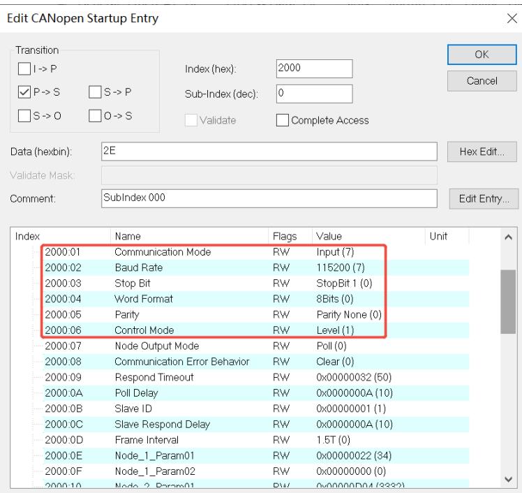
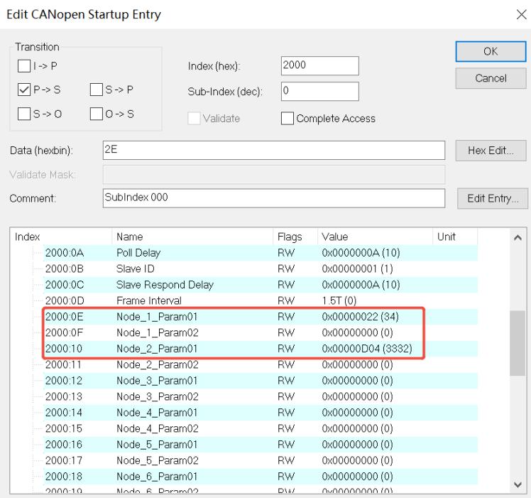
![Edit CANopen Startup Entry\nTransition\nI -) P\nP -) S\nS -) O\nIndex (hex): 2000\nSub-Index (dec): 0\nValidate Complete Access\nData (hexbin): 2E\nHex Edit...\nValidate Mask:\nComment: SubIndex 000\nEdit Entry...\nIndex Name Flags Value Unit\n2000.01 Communication Mode RW Input (7)\n2000.02 Baud Rate RW 115200 (7)\n2000.03 Stop Bit RW StopBit 1 (0)\n2000.04 Word Format RW 8Bits (0)\n2000.05 Parity RW Parity None (0)\n2000.06 Control Mode RW Level (1)\n2000.07 Node Output Mode RW Poll (0)\n2000.08 Communication Error Behavior RW Clear (0)\n2000.09 Respond Timeout RW 0x00000032 (50)\n2000.0A Poll Delay RW 0x0000000A (10)\n2000.0B Slave ID RW 0x00000001 (1)\n2000.0C Slave Respond Delay RW 0x0000000A (10)\n2000.0D Frame Interval RW 1.5T (0)\n2000.0E Node_1_Param01 RW 0x00000022 (34)\n2000.0F Node_1_Param02 RW 0x0000000 (0)\n2000.1G Node_2_Param01 RW 0x0000D04 (33)](.es-series-50m-19030-1030-13/966a02051e7efc3994354038c397b8e13fceb1a3488da9d802b87b368f102f7c.jpg)

![Edit CANopen Startup Entry\nTransition\nI -) P\nP -) S\nS -) O\nO -) S\nIndex (hex): 2000\nSub-Index (dec): 0\nValidate Complete Access\nData (hexbin): 2E\nHex Edit...\nValidate Mask:\nComment: SubIndex 000\nEdit Entry...\nIndex Name Flags Value Unit\n2000:0A Poll Delay RW 0x0000000A (10)\n2000:0B Slave ID RW 0x00000001 (1)\n2000:0C Slave Respond Delay RW 0x0000000A (10)\n2000:0D Frame Interval RW 1.5T (0)\n2000:0E Node_1_Param01 RW 0x00000022 (34)\n2000:0F Node_1_Param02 RW 0x00000000 (0)\n2000:10 Node_2_Param01 RW 0x0000D04 (3332)\n2000:11 Node_2_Param02 RW 0x00000000 (0)\n2000:12 Node_3_Param01 RW 0x00000000 (0)\n2000:13 Node_3_Param02 RW 0x00000000 (0)\n2000:14 Node_4_Param01 RW 0x00000000 (0)\n2000:15 Node_4_Param02 RW 0x00000000 (0)\n2000:16 Node_5_Param01 RW 0x00000000 (0)\n2000:17 Node_5_Param02 RW 0x00000000 (0)\n2000:18 Node_6_Param01 RW 0x00000000 (0)\n2000:19 Node_6_Param02 RW 0x000D4(3)](.es-series-50m-19030-1030-13/ee2d192536736b57d12ea5bd4803c37aab1cae3ec3ff97e8fb47c1203b01a2f0.jpg)

2. Set the control word to 1 in the download data, then open the serial port debugging assistant to send data.
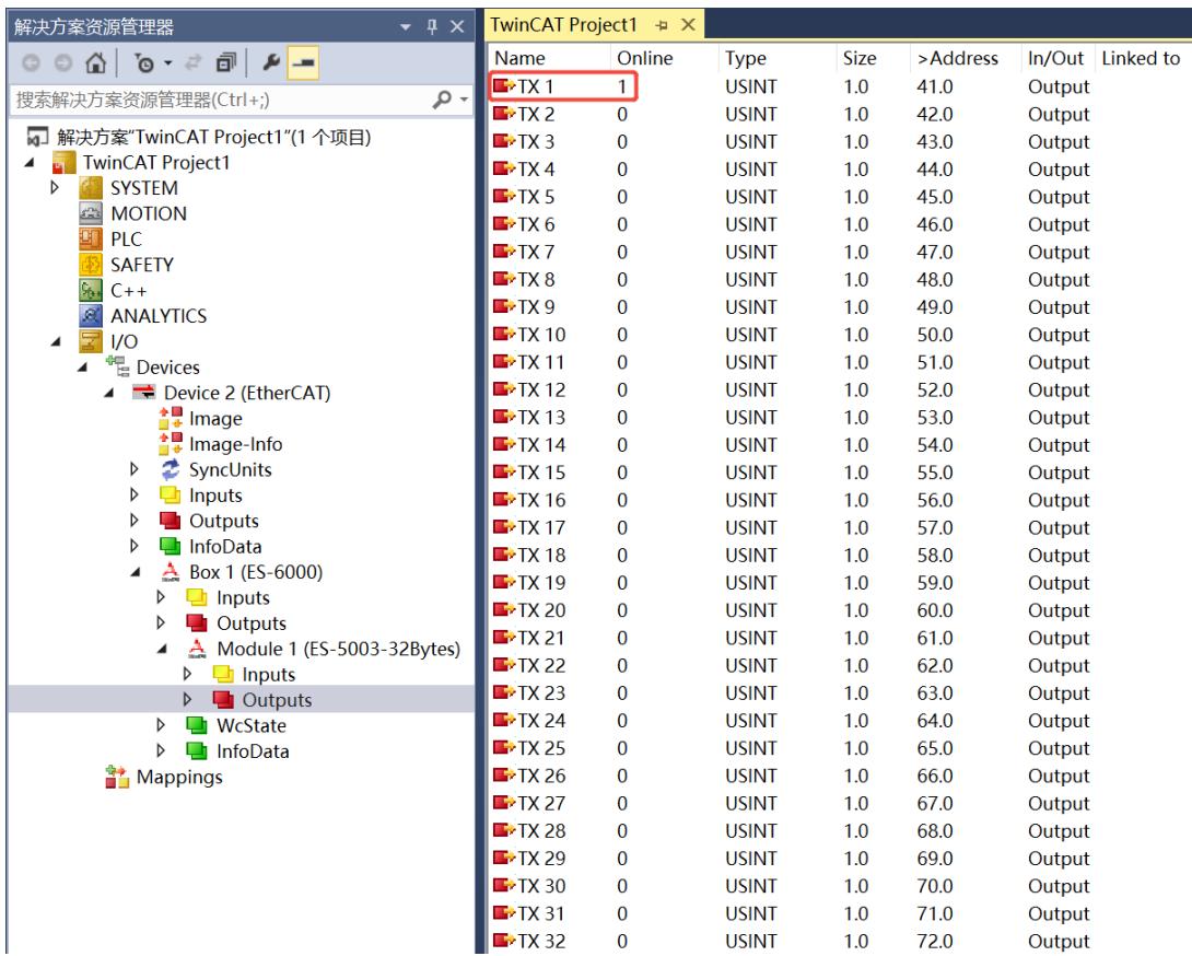
![解决方案资源管理器\n搜索解决方案资源管理器(Ctrl+;)\n解决方案'TwinCAT Project1'(1 个项目)\nTwinCAT Project1\nSYSTEM\nMOTION\nPLC\nSAFETY\nC++\nANALYTICS\nI/O\nDevices\nDevice 2 (EtherCAT)\nImage\nImage-Info\nSyncUnits\nInputs\nOutputs\nInfoData\nBox 1 (ES-6000)\nInputs\nOutputs\nModule 1 (ES-5003-32Bytes)\nInputs\nOutputs\nWcState\nInfoData\nMappings\nTwinCAT Project1\nName	Online	Type	Size	)Address)In/Out	Linked to\nTX 1	1	USINT	1.0	41.0	Output\nTX 2	0	USINT	1.0	42.0	Output\nTX 3	0	USINT	1.0	43.0	Output\nTX 4	0	USINT	1.0	44.0	Output\nTX 5	0	USINT	1.0	45.0	Output\nTX 6	0	USINT	1.0	46.0	Output\nTX 7	0	USINT	1.0	47.0	Output\nTX 8	0	USINT	1.0	48.0	Output\nTX 9	0	USINT	1.0	49.0	Output\nTX 10	0	USINT	1.0	50.0	Output\nTX 11	0	USINT	1.0	51.0	Output\nTX 12	0	USINT	1.0	52.0	Output\nTX 13	0	USINT	1.0	53.0	Output\nTX 14	0	USINT	1.0	54.0	Output\nTX 15	0	USINT	1.0	55.0	Output\nTX 16	0	USINT	1.0	56.0	Output\nTX 17	0	USINT	1.0	57.0	Output\nTX 18	0	USINT	1.0	58.0	Output\nTX 19	0	USINT	1.0	59.0	Output\nTX 20	0	USINT	1.0	60.0	Output\nTX 21	0	USINT	1.0	61.0	Output\nTX 22	0	USINT	1.0	62.0	Output\nTX 23	0	USINT	1.0	63.0	Output\nTX 24	0	USINT	1.0	64.0	Output\nTX 25	0	USINT	1.0	65.0_Output\nTX 26	0	USINT	1.0	66.0_Output\nTX 27	0	USINT	1.0	67.0_Output\nTX 28	0	USINT	1.0	68.0_Output\nTX 29	0	USINT	1.0	69.0_Output\nTX 30	0	USINT	1.0	70.0_Output\nTX 31	0	USINT	1.0	71.0_Output\nTX 32	0	USINT	1.0	72.0_Output](.es-series-50m-19030-1030-13/285a17b9b0719b835440bc30df3434cad769dc8177a4c478a0b5fb364b66cd17.jpg)

• From the uploaded data, you can see that the received data length is 8, data count is 1, and the 8 bytes of data (RX7 to RX14) are all displayed.
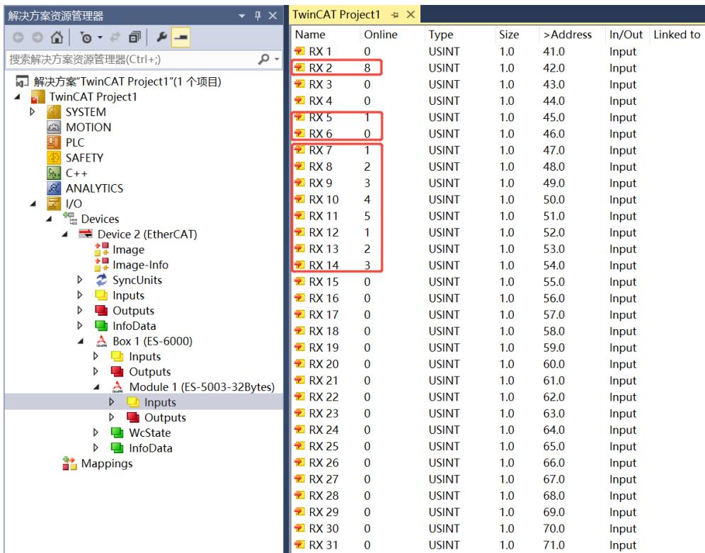
![解决方案资源管理器\n搜索解决方案资源管理器(Ctrl+;)\n解决方案'TwinCAT Project1'(1 个项目)\nTwinCAT Project1\nSYSTEM\nMOTION\nPLC\nSAFETY\nC++\nANALYTICS\nI/O\nDevices\nDevice 2 (EtherCAT)\nImage\nImage-Info\nSyncUnits\nInputs\nOutputs\nInfoData\nBox 1 (ES-6000)\nInputs\nOutputs\nModule 1 (ES-5003-32Bytes)\nInputs\nOutputs\nWcState\nInfoData\nMappings\nName	Online	Type	Size	)Address	In/Out	Linked to\nRX 1	0	USINT	1.0	41.0.Input\nRX 2	8	USINT	1.0	42.0.Input\nRX 3	0	USINT	1.0	43.0.Input\nRX 4	0	USINT	1.0	44.0.Input\nRX 5	1	USINT	1.0	45.0.Input\nRX 6	0	USINT	1.0	46.0.Input\nRX 7	1	USINT	1.0	47.0.Input\nRX 8	2	USINT	1.0	48.0.Input\nRX 9	3	USINT	1.0	49.0.Input\nRX 10	4	USINT	1.0	50.0.Input\nRX 11	5	USINT	1.0	51.0.Input\nRX 12	1	USINT	1.0	52.0.Input\nRX 13	2	USINT	1.0	53.0.Input\nRX 14	3	USINT	1.0	54.0.Input\nRX 15	0	USINT	1.0	55.0.Input\nRX 16	0	USINT	1.0	56.0.Input\nRX 17	0	USINT	1.0	57.0.Input\nRX 18	0	USINT	1.0	58.0.Input\nRX 19	0	USINT	1.0	59.0.Input\nRX 20	0	USINT	1.0	60.0.Input\nRX 21	0	USINT	1.0	61.0.Input\nRX 22	0	USINT	1.0	62.0.Input\nRX 23	0	USINT	1.0	63.0.Input\nRX 24	0	USINT	1.0	64.0.Input\nRX 25	0	USINT	1.0	65.0.Input\nRX 26	0	USINT	1.0	66.0.Input\nRX 27	0	USINT	1.0	67.0.Input\nRX 28	0	USINT	1.0	68.0.Input\nRX 29	0	USINT	1.0	69.0.Input\nRX 30	0	USINT	1.0	70.0.Input\nRX 31	0	USINT	1.0	71.0.Input](.es-series-50m-19030-1030-13/d0d99ff1ecfe44afeb7ece3d146ecc46933dd549a9c85878dfa9b8d63b5d6f78.jpg)

# 11.7 Freeport\_Output Mode Function Example

Example: Use Freeport\_Output to send 8 bytes of data in disabled mode through tools or devices such as the Serial Debug Assistant.

1. Configure the parameters and select the communication mode 8, which is the Freeport\_Output mode, as shown in the figure below.

Communication Mode: Select Output.
Control Mode: Select Disable.
Node\_1\_Param\_01: Configure to 0x00000E03. For details of configuration parameters, see Freeport function.
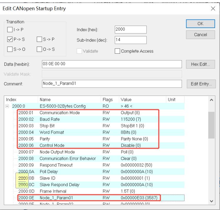
![Edit CANopen Startup Entry\nTransition\nI -) P\nP -) S\nS -) O\nS -) P\nO -) S\nIndex (hex): 2000\nSub-Index (dec): 14\nValidate Complete Access\nData (hexbin): 03 0E 00 00\nHex Edit...\nValidate Mask:\nComment: Node_1_Param01\nIndex Name Flags Value Unit\n2000.0 ES-5003-32Bytes Config RO ) 46 (\n2000.01 Communication Mode RW Output (8)\n2000.02 Baud Rate RW 115200 (7)\n2000.03 Stop Bit RW StopBit 1 (0)\n2000.04 Word Format RW 8Bits (0)\n2000.05 Parity RW Parity None (0)\n2000.06 Control Mode RW Disable (0)\n2000.07 Node Output Mode RW Poll (0)\n2000.08 Communication Error Behavior RW Clear (0)\n2000.09 Respond Timeout RW 0x0000032 (50)\n2000.0A Poll Delay RW 0x000000A (10)\n2000.0B Slave ID RW 0x0000001 (1)\n2000.0C Slave Respond Delay RW 0x000000A (10)\n2000.0D Frame Interval RW 1.5T (0)\n2000.0E Node_1_Param01 RW 0x0000E03 (3587)\n2000.0E Node_1_Param02 RW 0x0000E03 (3587)](.es-series-50m-19030-1030-13/92a88ff30721ed79a38cd818cdcb3b89b2eed77b4d25ecfc2ac8ae97b04fa25c.jpg)

# 2. Configure the data to be sent in the download data.
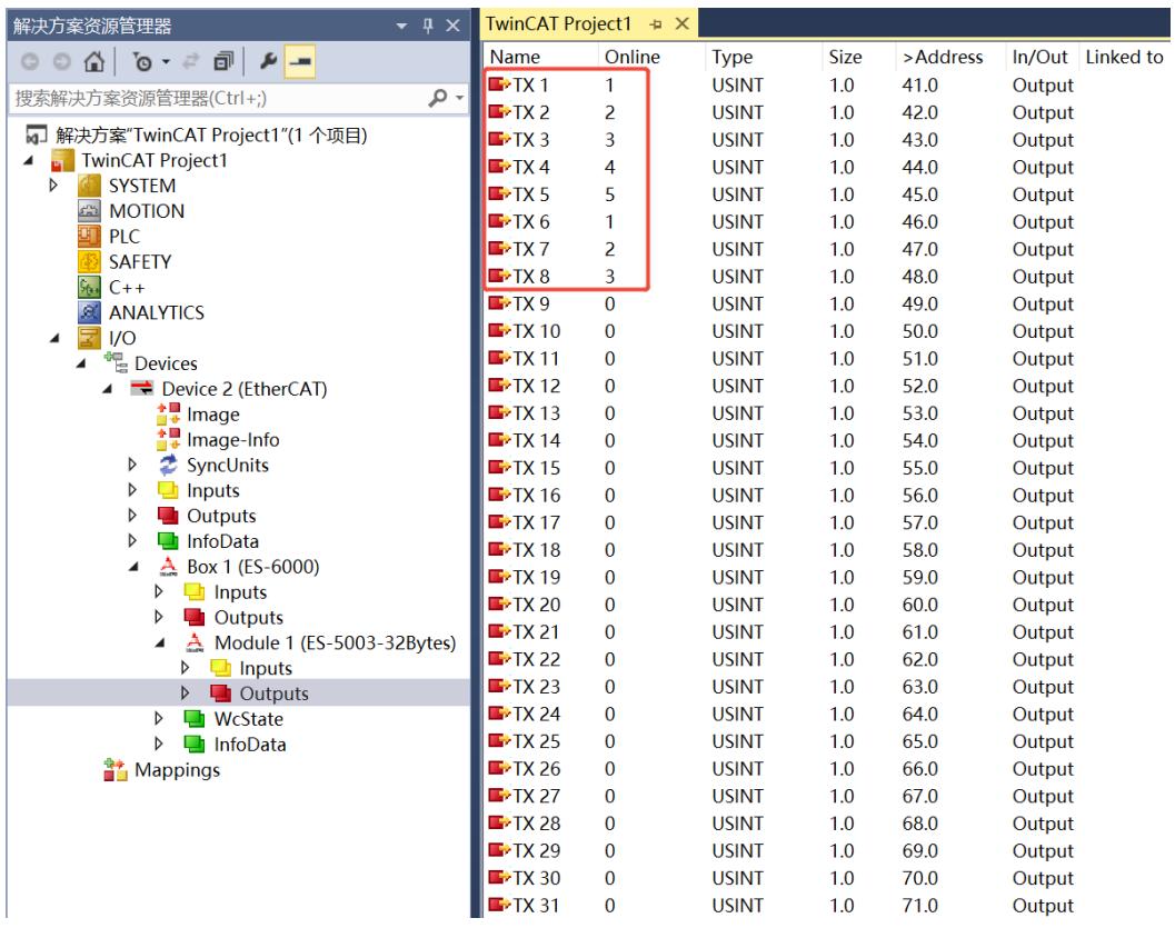
![解决方案资源管理器\n搜索解决方案资源管理器(Ctrl+;)\n解决方案'TwinCAT Project1'(1 个项目)\nTwinCAT Project1\nSYSTEM\nMOTION\nPLC\nSAFETY\nC++\nANALYTICS\nI/O\nDevices\nDevice 2 (EtherCAT)\nImage\nImage-Info\nSyncUnits\nInputs\nOutputs\nInfoData\nBox 1 (ES-6000)\nInputs\nOutputs\nModule 1 (ES-5003-32Bytes)\nInputs\nOutputs\nWcState\nInfoData\nMappings\nTwinCAT Project1\nName	Online	Type	Size	)Address)In/Out	Linked to\nTX 1	1	USINT	1.0	41.0	Output\nTX 2	2	USINT	1.0	42.0	Output\nTX 3	3	USINT	1.0	43.0	Output\nTX 4	4	USINT	1.0	44.0	Output\nTX 5	5	USINT	1.0	45.0	Output\nTX 6	1	USINT	1.0	46.0	Output\nTX 7	2	USINT	1.0	47.0	Output\nTX 8	3	USINT	1.0	48.0	Output\nTX 9	0	USINT	1.0	49.0	Output\nTX 10	0	USINT	1.0	50.0	Output\nTX 11	0	USINT	1.0	51.0	Output\nTX 12	0	USINT	1.0	52.0	Output\nTX 13	0	USINT	1.0	53.0	Output\nTX 14	0	USINT	1.0	54.0	Output\nTX 15	0	USINT	1.0	55.0	Output\nTX 16	0	USINT	1.0	56.0	Output\nTX 17	0	USINT	1.0	57.0	Output\nTX 18	0	USINT	1.0	58.0	Output\nTX 19	0	USINT	1.0	59.0	Output\nTX 20	0	USINT	1.0	60.0	Output\nTX 21	0	USINT	1.0	61.0	Output\nTX 22	0	USINT	1.0	62.0	Output\nTX 23	0	USINT	1.0	63.0	Output\nTX 24	0	USINT	1.0	64.0	Output\nTX 25	0	USINT	1.0	65.0	Output\nTX 26	0	USINT	1.0	66.0	Output\nTX 27	0	USINT	1.0	67.0	Output\nTX 28	0	USINT	1.0	68.0	Output\nTX 29	0	USINT	1.0	69.0	Output\nTX 30	0	USINT	1.0	70.0	Output\nTX 31	0	USINT	1.0	71.0	Output](.es-series-50m-19030-1030-13/a34cf62c09afec17a44bde40a1a8b298405700efc1ab484b542ba77d7c447527.jpg)

# 3. View the sent data through the serial port debugging assistant tool.
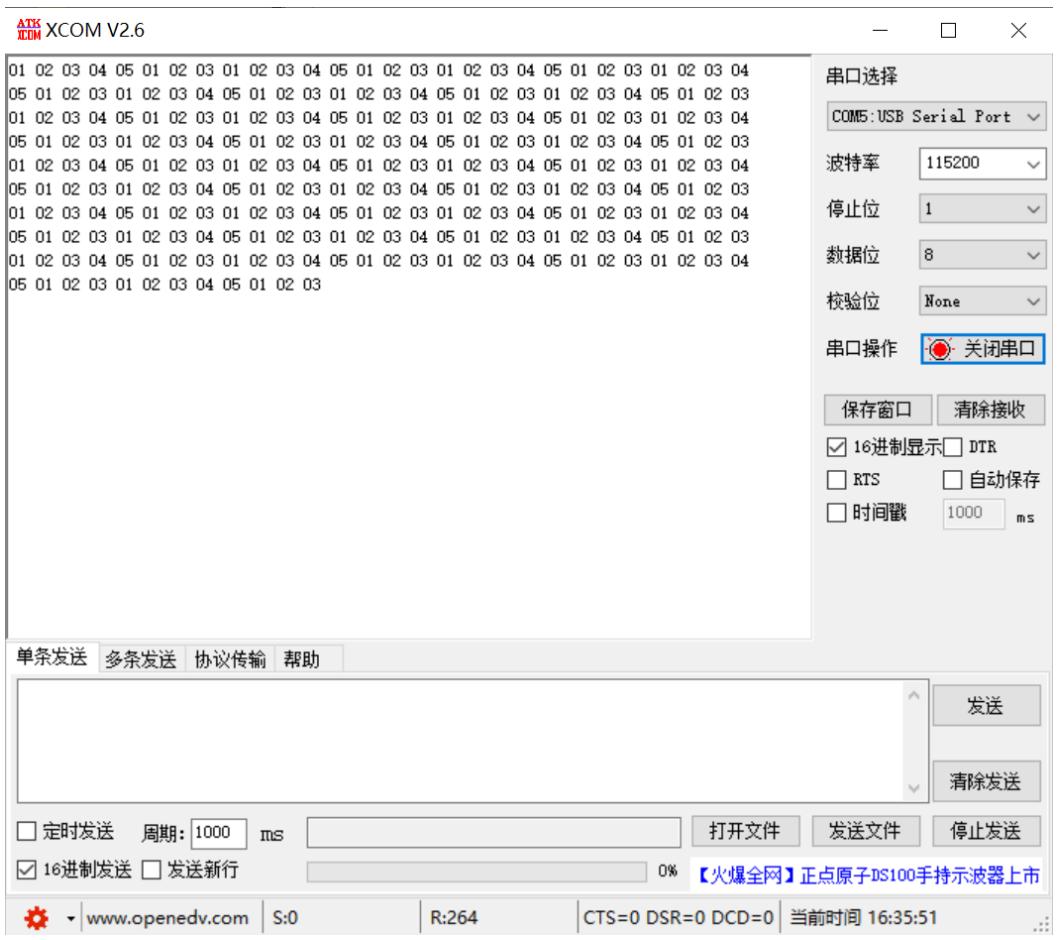
![ATK\nXCOM V2.6\n01 02 03 04 05 01 02 03 01 02 03 04 05 01 02 03 01 02 03 04 05 01 02 03 01 02 03 04\n05 01 02 03 01 02 03 04 05 01 02 03 01 02 03 04 05 01 02 03 01 02 03 04 05 01 02 03\n01 02 03 04 05 01 02 03 01 02 03 04 05 01 02 03 01 02 03 04 05 01 02 03\n05 01 02 03 01 02 03 04 05 01 02 03 01 02 03 04 05 01 02 03 01 02 03\n01 02 03 04 05 01 02 03 01 02 03 04 05 01 02 03 01 02 03\n05 01 02 03 01 02 03 04 05 01 02 03 01 02 03\n01 02 03 04 05 01 02 03 01 02\n05\n01\n单条发送 多条发送 协议传输 帮助\n串口选择\nCOM5:USB Serial Port\n波特率\n115200\n停止位\n1\n数据位\n8\n校验位 None\n串口操作 关闭串口\n保存窗口 清除接收\n✓16进制显示 DTR\n☐RTS ☐自动保存\n☐时间戳\n1000 ms\n发送\n清除发送\n□定时发送 周期:1000 ms 打开文件 发送文件 停止发送\n✓16进制发送 □发送新行\n【火爆全网】正点原子DS100手持示波器上市\nwww.openedv.com S:O R:264 CTS=O DSR=O DCD=O 当前时间16:35:51](.es-series-50m-19030-1030-13/dffb0585737e77ae0efc4b33bcc921fb1485c3dd9ed8789afe19822085e94cdd.jpg)

# 11.8 Freeport\_Request Mode Function Example

Example: Use Freeport\_Request to send and receive 4 bytes of data in disabled mode through tools or devices such as the Serial Debug Assistant.

1. Configure the parameters and select the communication mode 5, which is the Freeport\_Request mode, as shown in the figure below.

Communication Mode: Select Request.
Control Mode: Select Disable.
Node\_1\_Param\_01: Configure to 0x00000D03. For details of configuration parameters, see Freeport function.
Node\_2\_Param\_01: Configure to 0x00000E03. For details on configuration parameters, see Freeport function.
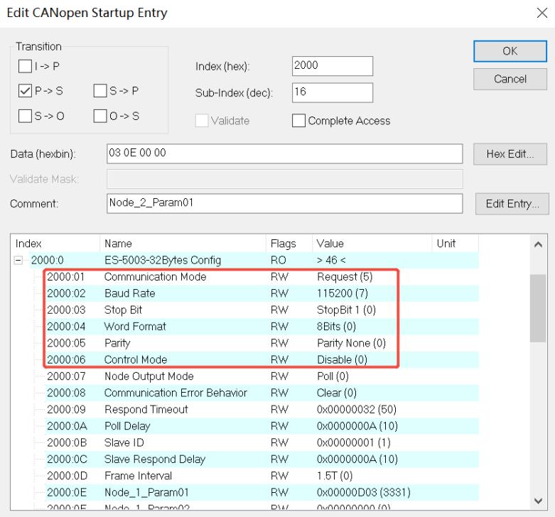
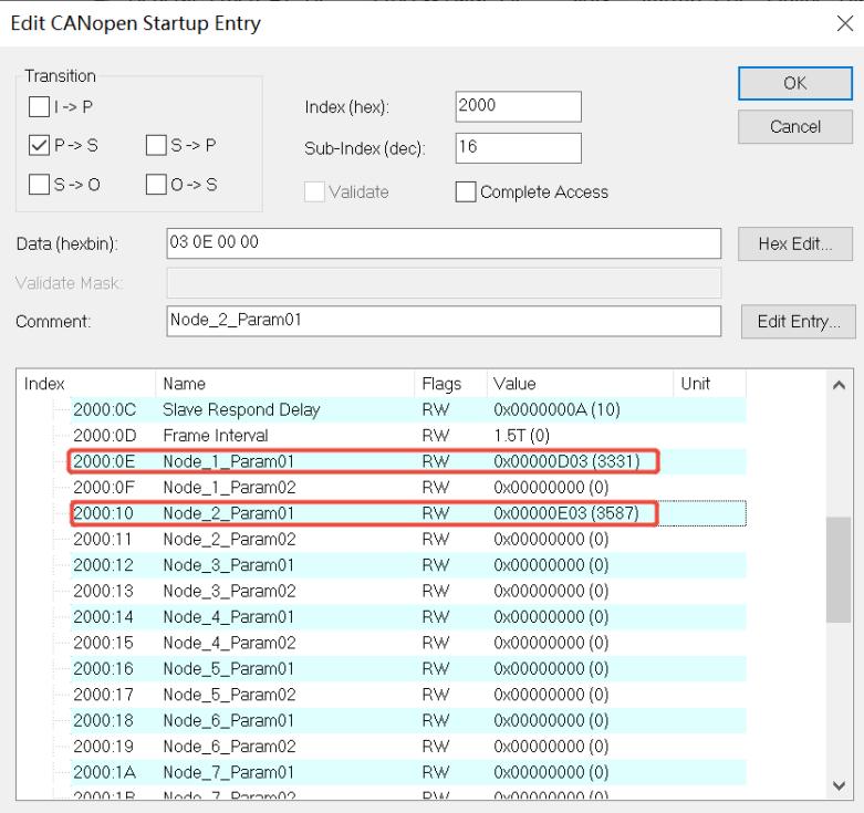
![Edit CANopen Startup Entry\nTransition\nI -) P\nP -) S\nS -) O\nS -) P\nO -) S\nIndex (hex): 2000\nSub-Index (dec): 16\nValidate Complete Access\nData (hexbin): 03 0E 00 00\nHex Edit...\nValidate Mask:\nComment: Node_2_Param01\nEdit Entry...\nIndex Name Flags Value Unit\n2000:0 ES-5003-32Bytes Config RO )46 (\n2000:01 Communication Mode RW Request (5)\n2000:02 Baud Rate RW 115200 (7)\n2000:03 Stop Bit RW StopBit 1 (0)\n2000:04 Word Format RW 8Bits (0)\n2000:05 Parity RW Parity None (0)\n2000:06 Control Mode RW Disable (0)\n2000:07 Node Output Mode RW Poll (0)\n2000:08 Communication Error Behavior RW Clear (0)\n2000:09 Respond Timeout RW 0x00000032 (50)\n2000:0A Poll Delay RW 0x0000000A (10)\n2000:0B Slave ID RW 0x00000001 (1)\n2000:0C Slave Respond Delay RW 0x0000000A (10)\n2000:0D Frame Interval RW 1.5T (0)\n2000:0E Node_1_Param01 RW 0x0000D03 (3331)\n2000:0F Node_1_Param02 RW 0x0000D03 (3331)](.es-series-50m-19030-1030-13/b5a6eee27986f75ea5f8abacc4e755958ad699018b5b0cfe12f93097bb6cd6ce.jpg)

![Edit CANopen Startup Entry\nTransition\nI -) P\nP -) S\nS -) O\nS -) P\nO -) S\nIndex (hex): 2000\nSub-Index (dec): 16\nValidate Complete Access\nData (hexbin): 03 0E 00 00\nHex Edit...\nValidate Mask:\nComment: Node_2_Param01\nEdit Entry...\nIndex Name Flags Value Unit\n2000:0C Slave Respond Delay RW 0x0000000A (10)\n2000:0D Frame Interval RW 1.5T (0)\n2000:0E Node_1_Param01 RW 0x00000D03 (3331)\n2000:0F Node_1_Param02 RW 0x00000000 (0)\n2000:10 Node_2_Param01 RW 0x00000E03 (3587)\n2000:11 Node_2_Param02 RW 0x00000000 (0)\n2000:12 Node_3_Param01 RW 0x00000000 (0)\n2000:13 Node_3_Param02 RW 0x00000000 (0)\n2000:14 Node_4_Param01 RW 0x00000000 (0)\n2000:15 Node_4_Param02 RW 0x00000000 (0)\n2000:16 Node_5_Param01 RW 0x00000000 (0)\n2000:17 Node_5_Param02 RW 0x00000000 (0)\n2000:18 Node_6_Param01 RW 0x00000000 (0)\n2000:19 Node_6_Param02 RW 0x00000000 (0)\n2000:1A Node_7_Param01 RW 0x00000000 (0)\n2000:1B Node_7_Param02 RW  9x9x9x9x9x9x9x9x9x9x9x9x9x9x9x9x9x9x9x9x9x9x9x9x9x9x9x9x9x9x9x9x9x9x9x9x9x9x9x9x9x9x9x9x9x9x9x9x9x9x9\nOK\nCancel](.es-series-50m-19030-1030-13/ce196f769045793482783abe88c042cd8aa1d48ca66d59594d87b0d955297596.jpg)

# 2. Configure the data has been downloaded .
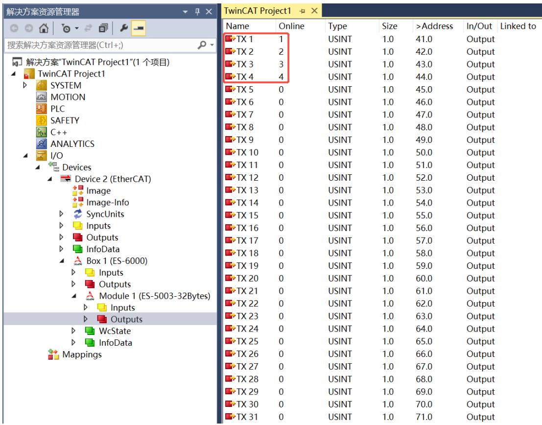
![解决方案资源管理器\n搜索解决方案资源管理器(Ctrl+;)\n解决方案'TwinCAT Project1'(1 个项目)\nTwinCAT Project1\n  SYSTEM\n  MOTION\n  PLC\n  SAFETY\n  C++\n  ANALYTICS\n  I/O\n  Devices\n    Device 2 (EtherCAT)\n      Image\n      Image-Info\n  SyncUnits\n  Inputs\n  Outputs\n  InfoData\n    Box 1 (ES-6000)\n    Inputs\n    Outputs\n    Module 1 (ES-5003-32Bytes)\n    Inputs\n    Outputs\n    WcState\n    InfoData\n  Mappings\nName	Online	Type	Size	)Address)In/Out	Linked to\nTX 1	1	USINT	1.0	41.0	Output\nTX 2	2	USINT	1.0	42.0	Output\nTX 3	3	USINT	1.0	43.0	Output\nTX 4	4	USINT	1.0	44.0	Output\nTX 5	0	USINT	1.0	45.0	Output\nTX 6	0	USINT	1.0	46.0	Output\nTX 7	0	USINT	1.0	47.0	Output\nTX 8	0	USINT	1.0	48.0	Output\nTX 9	0	USINT	1.0	49.0	Output\nTX 10	0	USINT	1.0	50.0	Output\nTX 11	0	USINT	1.0	51.0	Output\nTX 12	0	USINT	1.0	52.0	Output\nTX 13	0	USINT	1.0	53.0	Output\nTX 14	0	USINT	1.0	54.0	Output\nTX 15	0	USINT	1.0	55.0	Output\nTX 16	0	USINT	1.0	56.0	Output\nTX 17	0	USINT	1.0	57.0	Output\nTX 18	0	USINT	1.0	58.0	Output\nTX 19	0	USINT	1.0	59.0	Output\nTX 20	0	USINT	1.0	60.0	Output\nTX 21	0	USINT	1.0	61.0	Output\nTX 22	0	USINT	1.0	62.0	Output\nTX 23	0	USINT	1.0	63.0	Output\nTX 24	0	USINT	1.0	64.0	Output\nTX 25	0	USINT	1.0	65.0	Output\nTX 26	0	USINT	1.0	66.0	Output\nTX 27	0	USINT	1.0	67.0	Output\nTX 28	0	USINT	1.0	68.0	Output\nTX 29	0	USINT	1.0	69.0	Output\nTX 30	0	USINT	1.0	70.0	Output\nTX 31	0	USINT	1.0	71.0	Output](.es-series-50m-19030-1030-13/17a92186de6a8e14e2ee02a4fb61f82a321b4725b68bea74d53ab57dbfe4de93.jpg)

# 3. View the sent data through the serial port debugging assistant tool.
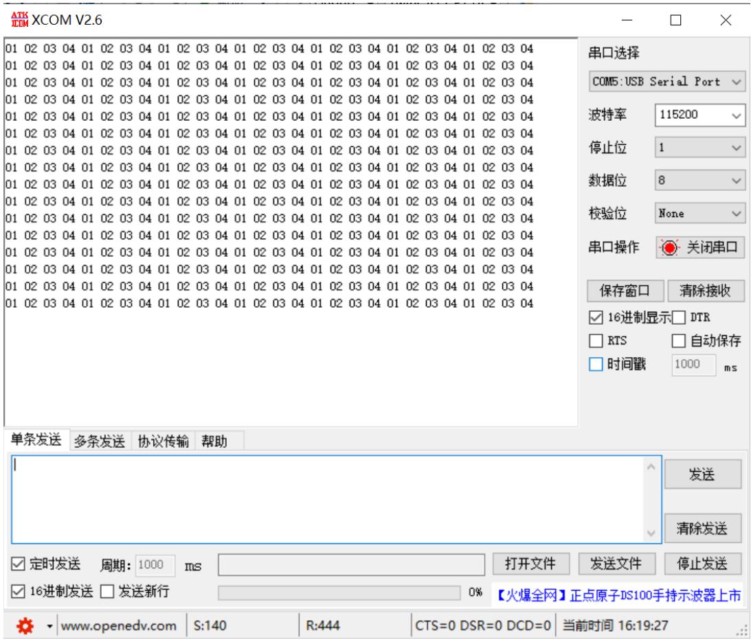
![ATK\nCOM XCOM V2.6\n01 02 03 04 01 02 03 04 01 02 03 04 01 02 03 04 01 02 03 04 01 02 03 04\n01 02 03 04 01 02 03 04 01 02 03 04 01 02 03 04 01 02 03 04 01 02 03 04\n01 02 03 04 01 02 03 04 01-02 03 04 01 02 03 04 01 02 03 04 01 02 03 04\n01 02 03 04 01 02 03 04 01 02 03 04 01 02 03 04 01 02 34 04 01 02 34 04\n01 02 03 04 01 02 03 04 01-02-03-04-01-02-03-04-01-02-03-04-01-02-34-04-01-02-34-04\n01 02 03 04 -01-02-03-04-01-02-03-04-01-02-34-04-01-02-34-04-01-02-34-04-01-02-34-04-01-02-34-04\n01 02 34 -54 -58 -68 -78 -88 -98 -188 -288 -388 -588 -688 -788 -888 -988 -1888 -2888 -3888 -5888 -6888 -7888 -8888 -9888 -1888\n串口选择\nCOM5:USB Serial Port\n波特率	115200\n停止位	1\n数据位	8\n校验位	None\n串口操作	关闭串口\n保存窗口	清除接收\n✓16进制显示□DTR\n□RTS	□自动保存\n□时间戳	1000 ms\n单条发送	多条发送	协议传输	帮助\n发送\n清除发送\n✓定时发送	周期:1000 ms		打开文件	发送文件	停止发送\n✓16进制发送	□发送新行		%【火爆全网】正点原子DS10手持示波器上市\nwww.openedv.com	S:140	R:444	CTS=O DSR=O DCD=O 当前时间16:19:27](.es-series-50m-19030-1030-13/67293ce7aa892ac7c1e49c2570a3572a3fa3ca91697f7ede8472f8dce324947c.jpg)

4. Send 4 bytes of data through the serial port debugging assistant tool, and you can see the received 4 bytes of data (RX1\~RX4) in the uploaded data.
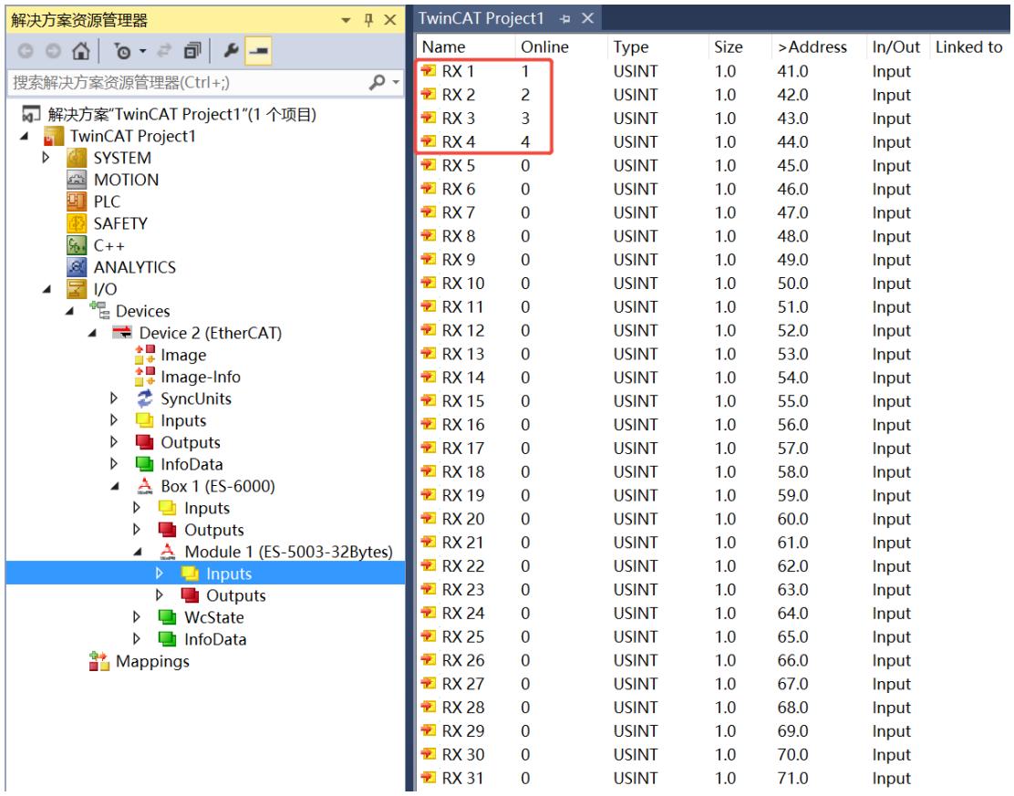
![解决方案资源管理器\n搜索解决方案资源管理器(Ctrl+;)\n解决方案'TwinCAT Project1'(1 个项目)\nTwinCAT Project1\nSYSTEM\nMOTION\nPLC\nSAFETY\nC++\nANALYTICS\nI/O\nDevices\nDevice 2 (EtherCAT)\nImage\nImage-Info\nSyncUnits\nInputs\nOutputs\nInfoData\nBox 1 (ES-6000)\nInputs\nOutputs\nModule 1 (ES-5003-32Bytes)\nInputs\nOutputs\nWcState\nInfoData\nMappings\nName	Online	Type	Size	)Address	In/Out	Linked to\nRX 1	1	USINT	1.0	41.0.Input\nRX 2	2	USINT	1.0	42.0.Input\nRX 3	3	USINT	1.0	43.0.Input\nRX 4	4	USINT	1.0	44.0.Input\nRX 5	0	USINT	1.0	45.0.Input\nRX 6	0	USINT	1.0	46.0.Input\nRX 7	0	USINT	1.0	47.0.Input\nRX 8	0	USINT	1.0	48.0.Input\nRX 9	0	USINT	1.0	49.0.Input\nRX 10	0	USINT	1.0	50.0.Input\nRX 11	0	USINT	1.0	51.0.Input\nRX 12	0	USINT	1.0	52.0.Input\nRX 13	0	USINT	1.0	53.0.Input\nRX 14	0	USINT	1.0	54.0.Input\nRX 15	0	USINT	1.0	55.0.Input\nRX 16	0	USINT	1.0	56.0.Input\nRX 17	0	USINT	1.0	57.0.Input\nRX 18	0	USINT	1.0	58.0.Input\nRX 19	0	USINT	1.0	59.0.Input\nRX 20	0	USINT	1.0	60.0.Input\nRX 21	0	USINT	1.0	61.0.Input\nRX 22	0	USINT	1.0	62.0.Input\nRX 23	0	USINT	1.0	63.0.Input\nRX 24	0	USINT	1.0	64.0.Input\nRX 25	0	USINT	1.0	65.0.Input\nRX 26	0	USINT	1.0	66.0.Input\nRX 27	0	USINT	1.0	67.0.Input\nRX 28	0	USINT	1.0	68.0.Input\nRX 29	0	USINT	1.0	69.0.Input\nRX 30	0	USINT	1.0	70.0.Input\nRX 31	0	USINT	1.0	71.0.Input](.es-series-50m-19030-1030-13/46203fa4a9f743ca1214653fe81e334f8bb806015de105fa641d5706108b6335.jpg)

# 11.9 Freeport\_Input\_Output Mode Function Example

Example: Use Freeport\_Input\_Output to send and receive 4 bytes of data in Level mode through tools or devices such as the Serial Debug Assistant.

1. Configure the parameters and select the communication mode 6, which is the Freeport\_Input\_Output mode, as shown in the figure below.

Communication Mode: Select Input\_Output.
Control Mode: Select Level.
Node\_1\_Param\_01: Configure to 0x00000021. For details of configuration parameters, see Control and Status Node Code.
Node\_2\_Param\_01: Configure to 0x00000D03. For details on configuration parameters, see Freeport function.
• Node\_3\_Param\_01: Configure to 0x00000E03. For details on configuration parameters, see Freeport function.
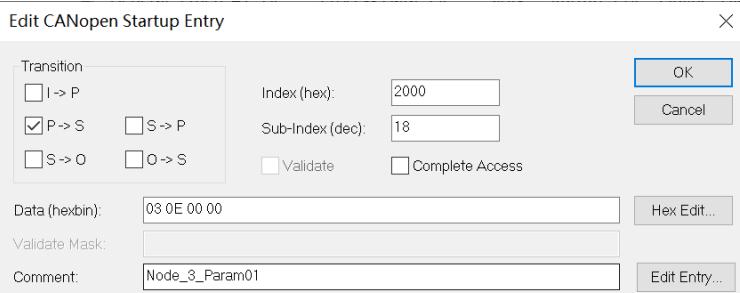
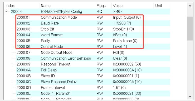
![Edit CANopen Startup Entry\nTransition\nI -) P\nP -) S\nS -) O\nO -) S\nIndex (hex): 2000\nSub-Index (dec): 18\nValidate Complete Access\nData (hexbin): 03 0E 00 00\nValidate Mask:\nComment: Node_3_Param01\nOK\nCancel\nHex Edit...\nEdit Entry...](.es-series-50m-19030-1030-13/00d4231980a9e060ecac91cd85ebb8d52b7d4007578d2182d45971f823f48851.jpg)

![Index\n2000:0\nES-5003-32Bytes Config\nRO\n) 46 (\n2000:01\nCommunication Mode\nRW\nInput_Output (6)\n2000:02\nBaud Rate\nRW\n115200 (7)\n2000:03\nStop Bit\nRW\nStopBit 1 (0)\n2000:04\nWord Format\nRW\n8Bits (0)\n2000:05\nParity\nRW\nParity None (0)\n2000:06\nControl Mode\nRW\nLevel (1)\n2000:07\nNode Output Mode\nRW\nPoll (0)\n2000:08\nCommunication Error Behavior\nRW\nClear (0)\n2000:09\nRespond Timeout\nRW\n0x00000032 (50)\n2000:0A\nPoll Delay\nRW\n0x0000000A (10)\n2000:0B\nSlave ID\nRW\n0x00000001 (1)\n2000:0C\nSlave Respond Delay\nRW\n0x0000000A (10)\n2000:0D\nFrame Interval\nRW\n1.5T (0)\n2000:0E\nNode_1_Param01\nRW\n0x00000021 (33)\n2000:0F\nNode_1_Param2\nRW\n0x0000000 (1)](.es-series-50m-19030-1030-13/e04a15bca7837897a29c464b56cae7f3f699ed6756f56a764db51e4ed064cc20.jpg)

![Edit CANopen Startup Entry\nTransition\nI -) P\nP -) S\nS -) O\nO -) S\nIndex (hex): 2000\nSub-Index (dec): 18\nValidate Complete Access\nData (hexbin): 03 0E 00 00\nValidate Mask:\nComment: Node_3_Param01\nOK\nCancel\nHex Edit...\nEdit Entry...](.es-series-50m-19030-1030-13/e1692abde787848a720d43d3b62eabb82619314e6e5499080f6c1c8dc4e7602f.jpg)

![Index\n2000:0A Poll Delay RW 0x0000000A (10)\n2000:0B Slave ID RW 0x00000001 (1)\n2000:0C Slave Respond Delay RW 0x0000000A (10)\n2000:0D Frame Interval RW 1.5T (0)\n2000:0E Node_1_Param01 RW 0x00000021 (33)\n2000:0F Node_1_Param02 RW 0x00000000 (0)\n2000:10 Node_2_Param01 RW 0x0000D03 (3331)\n2000:11 Node_2_Param02 RW 0x00000000 (0)\n2000:12 Node_3_Param01 RW 0x0000E03 (3587)\n2000:13 Node_3_Param02 RW 0x0000E00 (0)\n2000:14 Node_4_Param01 RW 0x0000E00 (0)\n2000:15 Node_4_Param02 RW 0x000E00 (0)\n2000:16 Node_5_Param01 RW 0x00E-5(1)\n2000:17 Node_5_Param02 RW 0xE-5(1)\n2000:18 Node_6_Param01 RW 0xE-6(1)\n2000:19 Node_6_Param02 RW 0xE-6(1)](.es-series-50m-19030-1030-13/521260e540bf19069b6fd773873ca4ab0809b149d8a5b25cd65731afc295faed.jpg)

2. Configure the data that has been downloaded. The length of the sent data is 4 and the control word is set to 1.
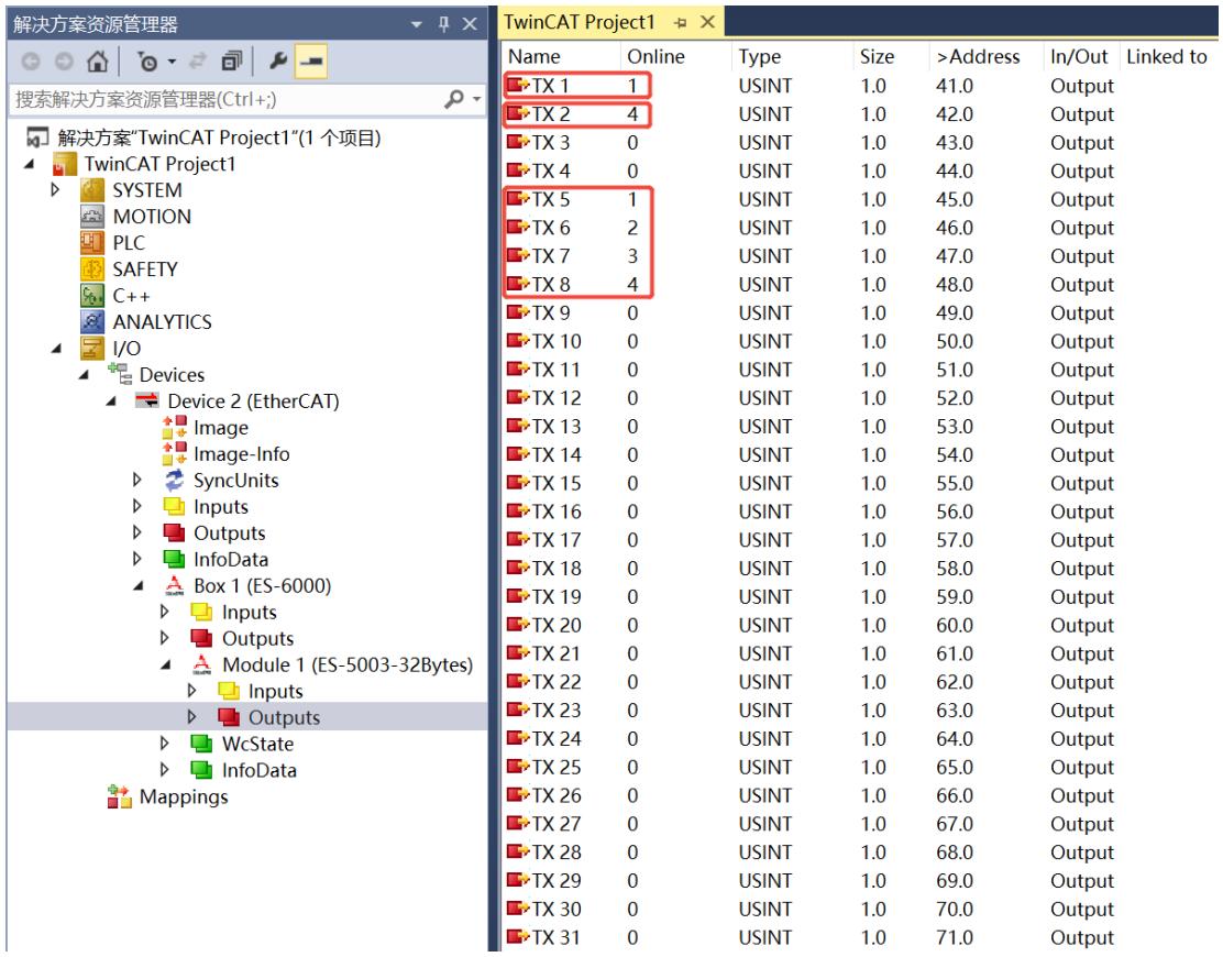
![解决方案资源管理器\n搜索解决方案资源管理器(Ctrl+;)\n解决方案'TwinCAT Project1'(1 个项目)\nTwinCAT Project1\nSYSTEM\nMOTION\nPLC\nSAFETY\nC++\nANALYTICS\nI/O\nDevices\nDevice 2 (EtherCAT)\nImage\nImage-Info\nSyncUnits\nInputs\nOutputs\nInfoData\nBox 1 (ES-6000)\nInputs\nOutputs\nModule 1 (ES-5003-32Bytes)\nInputs\nOutputs\nWcState\nInfoData\nMappings\nName	Online	Type	Size	)Address)In/Out	Linked to\nTX 1	1	USINT	1.0	41.0	Output\nTX 2	4	USINT	1.0	42.0	Output\nTX 3	0	USINT	1.0	43.0	Output\nTX 4	0	USINT	1.0	44.0	Output\nTX 5	1	USINT	1.0	45.0	Output\nTX 6	2	USINT	1.0	46.0	Output\nTX 7	3	USINT	1.0	47.0	Output\nTX 8	4	USINT	1.0	48.0	Output\nTX 9	0	USINT	1.0	49.0	Output\nTX 10	0	USINT	1.0	50.0	Output\nTX 11	0	USINT	1.0	51.0	Output\nTX 12	0	USINT	1.0	52.0	Output\nTX 13	0	USINT	1.0	53.0	Output\nTX 14	0	USINT	1.0	54.0	Output\nTX 15	0	USINT	1.0	55.0	Output\nTX 16	0	USINT	1.0	56.0	Output\nTX 17	0	USINT	1.0	57.0	Output\nTX 18	0	USINT	1.0	58.0	Output\nTX 19	0	USINT	1.0	59.0	Output\nTX 20	0	USINT	1.0	60.0	Output\nTX 21	0	USINT	1.0	61.0	Output\nTX 22	0	USINT	1.0	62.0	Output\nTX 23	0	USINT	1.0	63.0	Output\nTX 24	0	USINT	1.0	64.0	Output\nTX 25	0	USINT	1.0	65.0	Output\nTX 26	0	USINT	1.0	66.0	Output\nTX 27	0	USINT	1.0	67.0	Output\nTX 28	0	USINT	1.0	68.0	Output\nTX 29	0	USINT	1.0	69.0	Output\nTX 30	0	USINT	1.0	70.0	Output\nTX 31	0	USINT	1.0	71.0	Output](.es-series-50m-19030-1030-13/9d0ea733c95739f322c9e1603e28f1ece87c40b76af3a96a6b927a7babe3daeb.jpg)

3. View the sent data through the serial port debugging assistant tool.
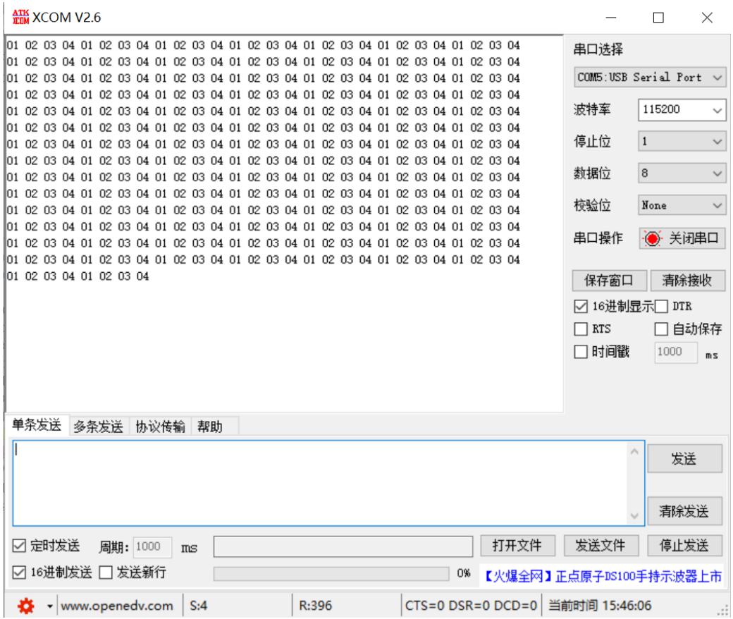
![ATX\nXCOM V2.6\n01 02 03 04 01 02 03 04 01 02 03 04 01 02 03 04 01 02 03 04 01 02 03 04\n01 02 03 04 01 02 03 04 01 02 03 04 01 02 03 04 01 02 03 04 01 02 03 04\n01 02 03 04 01 02 03 04 01\n01 02 03 04 01 02 03 04 01 02 03 04 01 02 03 04 01 02 03 04\n01 02 03 04 01 02 03 04 01 02 03 04 01 12\n01 02 03 04 01 02 03 04 01 02 03 04 01 02 03 04 01 02 03 04\n01 02 03 04 01 02 03 04 01\n01 02 03 04 12\n01 02 03 04 12\n01 02 03 04\n01\n单条发送 多条发送 协议传输 帮助\n串口选择\nCOM5:USB Serial Port\n波特率\n115200\n停止位\n1\n数据位\n8\n校验位 None\n串口操作 关闭串口\n保存窗口 清除接收\n✓16进制显示 DTR\n□RTS □自动保存\n□时间戳\n1000 ms\n发送\n清除发送\n✓定时发送 周期：1000 ms 打开文件 发送文件 停止发送\n✓16进制发送 □发送新行\n【火爆全网】正点原子DS100手持示波器上市\nwww.openedv.com S:4 R:396 CTS=O DSR=O DCD=O 当前时间15:46:06](.es-series-50m-19030-1030-13/79c5fffe85fcced8016957504bc5456e90775943870ad81d05ccaa73fb1f8a88.jpg)

4. Send 4 bytes of data through the serial port debugging assistant tool. In the upload data, you can see that the received data length is 4, the data count (RX5\~RX6), and the 4 bytes of data (RX7\~RX10).
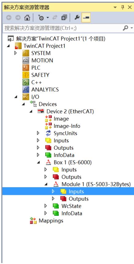
![解决方案资源管理器\n搜索解决方案资源管理器(Ctrl+;)\n解决方案'TwinCAT Project1'(1 个项目)\nTwinCAT Project1\nSYSTEM\nMOTION\nPLC\nSAFETY\nC++\nANALYTICS\nI/O\nDevices\nDevice 2 (EtherCAT)\nImage\nImage-Info\nSyncUnits\nInputs\nOutputs\nInfoData\nBox 1 (ES-6000)\nInputs\nOutputs\nModule 1 (ES-5003-32Bytes)\nInputs\nOutputs\nWcState\nInfoData\nMappings](.es-series-50m-19030-1030-13/e679c8f2d8fad71dcf2bc5e4cc8504f6cf895d293c73f052ef29906fbcdd8a73.jpg)

<table><tr><td colspan="7">TwinCAT Project1</td></tr><tr><td>Name</td><td>Online</td><td>Type</td><td>Size</td><td>&gt;Address</td><td>In/Out</td><td>Linked to</td></tr><tr><td>RX 1</td><td>0</td><td>USINT</td><td>1.0</td><td>41.0</td><td>Input</td><td></td></tr><tr><td>RX 2</td><td>4</td><td>USINT</td><td>1.0</td><td>42.0</td><td>Input</td><td></td></tr><tr><td>RX 3</td><td>0</td><td>USINT</td><td>1.0</td><td>43.0</td><td>Input</td><td></td></tr><tr><td>RX 4</td><td>0</td><td>USINT</td><td>1.0</td><td>44.0</td><td>Input</td><td></td></tr><tr><td>RX 5</td><td>1</td><td>USINT</td><td>1.0</td><td>45.0</td><td>Input</td><td></td></tr><tr><td>RX 6</td><td>0</td><td>USINT</td><td>1.0</td><td>46.0</td><td>Input</td><td></td></tr><tr><td>RX 7</td><td>1</td><td>USINT</td><td>1.0</td><td>47.0</td><td>Input</td><td></td></tr><tr><td>RX 8</td><td>2</td><td>USINT</td><td>1.0</td><td>48.0</td><td>Input</td><td></td></tr><tr><td>RX 9</td><td>3</td><td>USINT</td><td>1.0</td><td>49.0</td><td>Input</td><td></td></tr><tr><td>RX 10</td><td>4</td><td>USINT</td><td>1.0</td><td>50.0</td><td>Input</td><td></td></tr><tr><td>RX 11</td><td>0</td><td>USINT</td><td>1.0</td><td>51.0</td><td>Input</td><td></td></tr><tr><td>RX 12</td><td>0</td><td>USINT</td><td>1.0</td><td>52.0</td><td>Input</td><td></td></tr><tr><td>RX 13</td><td>0</td><td>USINT</td><td>1.0</td><td>53.0</td><td>Input</td><td></td></tr><tr><td>RX 14</td><td>0</td><td>USINT</td><td>1.0</td><td>54.0</td><td>Input</td><td></td></tr><tr><td>RX 15</td><td>0</td><td>USINT</td><td>1.0</td><td>55.0</td><td>Input</td><td></td></tr><tr><td>RX 16</td><td>0</td><td>USINT</td><td>1.0</td><td>56.0</td><td>Input</td><td></td></tr><tr><td>RX 17</td><td>0</td><td>USINT</td><td>1.0</td><td>57.0</td><td>Input</td><td></td></tr><tr><td>RX 18</td><td>0</td><td>USINT</td><td>1.0</td><td>58.0</td><td>Input</td><td></td></tr><tr><td>RX 19</td><td>0</td><td>USINT</td><td>1.0</td><td>59.0</td><td>Input</td><td></td></tr><tr><td>RX 20</td><td>0</td><td>USINT</td><td>1.0</td><td>60.0</td><td>Input</td><td></td></tr><tr><td>RX 21</td><td>0</td><td>USINT</td><td>1.0</td><td>61.0</td><td>Input</td><td></td></tr><tr><td>RX 22</td><td>0</td><td>USINT</td><td>1.0</td><td>62.0</td><td>Input</td><td></td></tr><tr><td>RX 23</td><td>0</td><td>USINT</td><td>1.0</td><td>63.0</td><td>Input</td><td></td></tr><tr><td>RX 24</td><td>0</td><td>USINT</td><td>1.0</td><td>64.0</td><td>Input</td><td></td></tr><tr><td>RX 25</td><td>0</td><td>USINT</td><td>1.0</td><td>65.0</td><td>Input</td><td></td></tr><tr><td>RX 26</td><td>0</td><td>USINT</td><td>1.0</td><td>66.0</td><td>Input</td><td></td></tr><tr><td>RX 27</td><td>0</td><td>USINT</td><td>1.0</td><td>67.0</td><td>Input</td><td></td></tr><tr><td>RX 28</td><td>0</td><td>USINT</td><td>1.0</td><td>68.0</td><td>Input</td><td></td></tr><tr><td>RX 29</td><td>0</td><td>USINT</td><td>1.0</td><td>69.0</td><td>Input</td><td></td></tr><tr><td>RX 30</td><td>0</td><td>USINT</td><td>1.0</td><td>70.0</td><td>Input</td><td></td></tr><tr><td>RX 31</td><td>0</td><td>USINT</td><td>1.0</td><td>71.0</td><td>Input</td><td></td></tr></table>

• In the downloaded data, the configuration count is cleared to 2.

![解决方案资源管理器\n搜索解决方案资源管理器(Ctrl+;)\n解决方案'TwinCAT Project1'(1 个项目)\nTwinCAT Project1\nSYSTEM\nMOTION\nPLC\nSAFETY\nC++\nANALYTICS\nI/O\nDevices\nDevice 2 (EtherCAT)\nImage\nImage-Info\nSyncUnits\nInputs\nOutputs\nInfoData\nBox 1 (ES-6000)\nInputs\nOutputs\nModule 1 (ES-5003-32Bytes)\nInputs\nOutputs\nWcState\nInfoData\nMappings](.es-series-50m-19030-1030-13/fb8a498079d94b159fd0a9ab7aac2c4e8f92c9b95bda2777adb0b315d31049e6.jpg)

<table><tr><td colspan="7">TwinCAT Project1 ☐ ×</td></tr><tr><td>Name</td><td>Online</td><td>Type</td><td>Size</td><td>&gt;Address</td><td>In/Out</td><td>Linked to</td></tr><tr><td>TX 1</td><td>1</td><td>USINT</td><td>1.0</td><td>41.0</td><td>Output</td><td></td></tr><tr><td>TX 2</td><td>4</td><td>USINT</td><td>1.0</td><td>42.0</td><td>Output</td><td></td></tr><tr><td>TX 3</td><td>2</td><td>USINT</td><td>1.0</td><td>43.0</td><td>Output</td><td></td></tr><tr><td>TX 4</td><td>0</td><td>USINT</td><td>1.0</td><td>44.0</td><td>Output</td><td></td></tr><tr><td>TX 5</td><td>1</td><td>USINT</td><td>1.0</td><td>45.0</td><td>Output</td><td></td></tr><tr><td>TX 6</td><td>2</td><td>USINT</td><td>1.0</td><td>46.0</td><td>Output</td><td></td></tr><tr><td>TX 7</td><td>3</td><td>USINT</td><td>1.0</td><td>47.0</td><td>Output</td><td></td></tr><tr><td>TX 8</td><td>4</td><td>USINT</td><td>1.0</td><td>48.0</td><td>Output</td><td></td></tr><tr><td>TX 9</td><td>0</td><td>USINT</td><td>1.0</td><td>49.0</td><td>Output</td><td></td></tr><tr><td>TX 10</td><td>0</td><td>USINT</td><td>1.0</td><td>50.0</td><td>Output</td><td></td></tr><tr><td>TX 11</td><td>0</td><td>USINT</td><td>1.0</td><td>51.0</td><td>Output</td><td></td></tr><tr><td>TX 12</td><td>0</td><td>USINT</td><td>1.0</td><td>52.0</td><td>Output</td><td></td></tr><tr><td>TX 13</td><td>0</td><td>USINT</td><td>1.0</td><td>53.0</td><td>Output</td><td></td></tr><tr><td>TX 14</td><td>0</td><td>USINT</td><td>1.0</td><td>54.0</td><td>Output</td><td></td></tr><tr><td>TX 15</td><td>0</td><td>USINT</td><td>1.0</td><td>55.0</td><td>Output</td><td></td></tr><tr><td>TX 16</td><td>0</td><td>USINT</td><td>1.0</td><td>56.0</td><td>Output</td><td></td></tr><tr><td>TX 17</td><td>0</td><td>USINT</td><td>1.0</td><td>57.0</td><td>Output</td><td></td></tr><tr><td>TX 18</td><td>0</td><td>USINT</td><td>1.0</td><td>58.0</td><td>Output</td><td></td></tr><tr><td>TX 19</td><td>0</td><td>USINT</td><td>1.0</td><td>59.0</td><td>Output</td><td></td></tr><tr><td>TX 20</td><td>0</td><td>USINT</td><td>1.0</td><td>60.0</td><td>Output</td><td></td></tr><tr><td>TX 21</td><td>0</td><td>USINT</td><td>1.0</td><td>61.0</td><td>Output</td><td></td></tr><tr><td>TX 22</td><td>0</td><td>USINT</td><td>1.0</td><td>62.0</td><td>Output</td><td></td></tr><tr><td>TX 23</td><td>0</td><td>USINT</td><td>1.0</td><td>63.0</td><td>Output</td><td></td></tr><tr><td>TX 24</td><td>0</td><td>USINT</td><td>1.0</td><td>64.0</td><td>Output</td><td></td></tr><tr><td>TX 25</td><td>0</td><td>USINT</td><td>1.0</td><td>65.0</td><td>Output</td><td></td></tr><tr><td>TX 26</td><td>0</td><td>USINT</td><td>1.0</td><td>66.0</td><td>Output</td><td></td></tr><tr><td>TX 27</td><td>0</td><td>USINT</td><td>1.0</td><td>67.0</td><td>Output</td><td></td></tr><tr><td>TX 28</td><td>0</td><td>USINT</td><td>1.0</td><td>68.0</td><td>Output</td><td></td></tr><tr><td>TX 29</td><td>0</td><td>USINT</td><td>1.0</td><td>69.0</td><td>Output</td><td></td></tr><tr><td>TX 30</td><td>0</td><td>USINT</td><td>1.0</td><td>70.0</td><td>Output</td><td></td></tr><tr><td>TX 31</td><td>0</td><td>USINT</td><td>1.0</td><td>71.0</td><td>Output</td><td></td></tr></table>

• You can see that the received data count is cleared to zero.

![解决方案资源管理器\n搜索解决方案资源管理器(Ctrl+;)\n解决方案'TwinCAT Project1'(1 个项目)\nTwinCAT Project1\nSYSTEM\nMOTION\nPLC\nSAFETY\nC++\nANALYTICS\nI/O\nDevices\nDevice 2 (EtherCAT)\nImage\nImage-Info\nSyncUnits\nInputs\nOutputs\nInfoData\nBox 1 (ES-6000)\nInputs\nOutputs\nModule 1 (ES-5003-32Bytes)\nInputs\nOutputs\nWcState\nInfoData\nMappings\nName	Online	Type	Size	)Address)In/Out	Linked to\nRX 1	0	USINT	1.0	41.0.Input\nRX 2	4	USINT	1.0	42.0.Input\nRX 3	0	USINT	1.0	43.0.Input\nRX 4	0	USINT	1.0	44.0.Input\nRX 5	0	USINT	1.0	45.0.Input\nRX 6	0	USINT	1.0	46.0.Input\nRX 7	1	USINT	1.0	47.0.Input\nRX 8	2	USINT	1.0	48.0.Input\nRX 9	3	USINT	1.0	49.0.Input\nRX 10	4	USINT	1.0	50.0.Input\nRX 11	0	USINT	1.0	51.0.Input\nRX 12	0	USINT	1.0	52.0.Input\nRX 13	0	USINT	1.0	53.0.Input\nRX 14	0	USINT	1.0	54.0.Input\nRX 15	0	USINT	1.0	55.0.Input\nRX 16	0	USINT	1.0	56.0.Input\nRX 17	0	USINT	1.0	57.0.Input\nRX 18	0	USINT	1.0	58.0.Input\nRX 19	0	USINT	1.0	59.0.Input\nRX 20	0	USINT	1.0	60.0.Input\nRX 21	0	USINT	1.0	61.0.Input\nRX 22	0	USINT	1.0	62.0.Input\nRX 23	0	USINT	1.0	63.0.Input\nRX 24	0	USINT	1.0	64.0.Input\nRX 25	0	USINT	1.0	65.0.Input\nRX 26	0	USINT	1.0	66.0.Input\nRX 27	0	USINT	1.0	67.0.Input\nRX 28	0	USINT	1.0	68.0.Input\nRX 29	0	USINT	1.0	69.0.Input\nRX 30	0	USINT	1.0	70.0.Input\nRX 31	0	USINT	1.0	71.0.Input](.es-series-50m-19030-1030-13/afed84028cd49346a7dc23784fe0811b2258629ab100f8d93e353fd1c4abc781.jpg)

• In the downloaded data, the count is reset to 4.

![解决方案资源管理器\n搜索解决方案资源管理器(Ctrl+;)\n解决方案'TwinCAT Project1'(1 个项目)\nTwinCAT Project1\nSYSTEM\nMOTION\nPLC\nSAFETY\nC++\nANALYTICS\nI/O\nDevices\nDevice 2 (EtherCAT)\nImage\nImage-Info\nSyncUnits\nInputs\nOutputs\nInfoData\nBox 1 (ES-6000)\nInputs\nOutputs\nModule 1 (ES-5003-32Bytes)\nInputs\nOutputs\nWcState\nInfoData\nMappings\nName	Online	Type	Size	)Address)In/Out	Linked to\nTX 1	1	USINT	1.0	41.0	Output\nTX 2	4	USINT	1.0	42.0	Output\nTX 3	4	USINT	1.0	43.0	Output\nTX 4	0	USINT	1.0	44.0	Output\nTX 5	1	USINT	1.0	45.0	Output\nTX 6	2	USINT	1.0	46.0	Output\nTX 7	3	USINT	1.0	47.0	Output\nTX 8	4	USINT	1.0	48.0	Output\nTX 9	0	USINT	1.0	49.0	Output\nTX 10	0	USINT	1.0	50.0	Output\nTX 11	0	USINT	1.0	51.0	Output\nTX 12	0	USINT	1.0	52.0	Output\nTX 13	0	USINT	1.0	53.0	Output\nTX 14	0	USINT	1.0	54.0	Output\nTX 15	0	USINT	1.0	55.0	Output\nTX 16	0	USINT	1.0	56.0	Output\nTX 17	0	USINT	1.0	57.0	Output\nTX 18	0	USINT	1.0	58.0	Output\nTX 19	0	USINT	1.0	59.0	Output\nTX 20	0	USINT	1.0	60.0	Output\nTX 21	0	USINT	1.0	61.0	Output\nTX 22	0	USINT	1.0	62.0	Output\nTX 23	0	USINT	1.0	63.0	Output\nTX 24	0	USINT	1.0	64.0	Output\nTX 25	0	USINT	1.0	65.0	Output\nTX 26	0	USINT	1.0	66.0	Output\nTX 27	0	USINT	1.0	67.0	Output\nTX 28	0	USINT	1.0	68.0	Output\nTX 29	0	USINT	1.0	69.0	Output\nTX 30	0	USINT	1.0	70.0	Output\nTX 31	0	USINT	1.0	71.0	Output](.es-series-50m-19030-1030-13/d286b250ceaa4adadf44792a03fda33d6aa616148a38cc112e1a0be750884e71.jpg)

• You can see that the received data length is cleared to zero.

![解决方案资源管理器\n搜索解决方案资源管理器(Ctrl+;)\n解决方案'TwinCAT Project1'(1 个项目)\nTwinCAT Project1\nSYSTEM\nMOTION\nPLC\nSAFETY\nC++\nANALYTICS\nI/O\nDevices\nDevice 2 (EtherCAT)\nImage\nImage-Info\nSyncUnits\nInputs\nOutputs\nInfoData\nBox 1 (ES-6000)\nInputs\nOutputs\nModule 1 (ES-5003-32Bytes)\nInputs\nOutputs\nWcState\nInfoData\nMappings\nTwinCAT Project1 → ✗\nName	Online	Type	Size	)Address	In/Out	Linked to\nRX 1	0	USINT	1.0	41.0.Input\nRX 2	0	USINT	1.0	42.0.Input\nRX 3	0	USINT	1.0	43.0.Input\nRX 4	0	USINT	1.0	44.0.Input\nRX 5	0	USINT	1.0	45.0.Input\nRX 6	0	USINT	1.0	46.0.Input\nRX 7	1	USINT	1.0	47.0.Input\nRX 8	2	USINT	1.0	48.0.Input\nRX 9	3	USINT	1.0	49.0.Input\nRX 10	4	USINT	1.0	50.0.Input\nRX 11	0	USINT	1.0	51.0.Input\nRX 12	0	USINT	1.0	52.0.Input\nRX 13	0	USINT	1.0	53.0.Input\nRX 14	0	USINT	1.0	54.0.Input\nRX 15	0	USINT	1.0	55.0.Input\nRX 16	0	USINT	1.0	56.0.Input\nRX 17	0	USINT	1.0	57.0.Input\nRX 18	0	USINT	1.0	58.0.Input\nRX 19	0	USINT	1.0	59.0.Input\nRX 20	0	USINT	1.0	60.0.Input\nRX 21	0	USINT	1.0	61.0.Input\nRX 22	0	USINT	1.0	62.0.Input\nRX 23	0	USINT	1.0	63.0.Input\nRX 24	0	USINT	1.0	64.0.Input\nRX 25	0	USINT	1.0	65.0.Input\nRX 26	0	USINT	1.0	66.0.Input\nRX 27	0	USINT	1.0	67.0.Input\nRX 28	0	USINT	1.0	68.0.Input\nRX 29	0	USINT	1.0	69.0.Input\nRX 30	0	USINT	1.0	70.0.Input\nRX 31	0	USINT	1.0	71.0.Input](.es-series-50m-19030-1030-13/782cc94dd7de3e204875770d8425c8190023b0f451f1259815a3e84d6a0f225e.jpg)

# 12 Appendix D – Firmware Online Upgrade

The ES system can directly update the firmware through FOE. Please refer to the following update steps.

Taking TwinCAT3 software as an example, the topology is ES-6000+ES-2016.

![Solution Explorer\nSearch Solution Explorer (Ctrl+;)\nSolution 'TwinCAT Project1' (1 project)\nTwinCAT Project1\nSYSTEM\nMOTION\nPLC\nSAFETY\nC++\nI/O\nDevices\nDevice 2 (EtherCAT)\nImage\nImage-Info\nSyncUnits\nInputs\nOutputs\nInfoData\nBox 1 (ES-6000)\nInputs\nOutputs\nModule 1 (ES-2016)\nWcState\nInfoData\nMappings\nTwinCAT Project1\nGeneral EtherCAT DC Process Data Slots Startup CoE - Online Diag History Online\nState Machine\nInit Bootstrap\nPre-Op Safe-Op Current State: OP\nOp Clear Error Requested State: OP\nDLL Status\nPort A: Carrier / Open\nPort B: No Carrier / Closed\nPort C: No Carrier / Closed\nPort D: No Carrier / Closed\nFile Access over EtherCAT\nDownload... Upload...\nName Online Type Size )A... In/... Us... Linked to\nCouplerS... 0 UINT 2.0 39.0 In... 0\nWcState 0 BIT 0.1 152... In... 0\nInputTog 1 BIT 0.1 152 In... 0](.es-series-50m-19030-1030-13/ed7e8a2db4c571de9f2d6dbba9a93d4c4c178a851b8900cdc1314a1e89de8ff3.jpg)

1. Click the coupler ES-6000 in the left tree viewer, then click the Online option in the right menu. Next, click the Bootstrap option in the State Machine, wait until the Current State displays the BOOT status, and then click the Download option in File Access over EtherCAT below.

![Solution Explorer\nSearch Solution Explorer (Ctrl+;)\nSolution 'TwinCAT Project1' (1 project)\nTwinCAT Project1\nSYSTEM\nMOTION\nPLC\nSAFETY\nC++\nI/O\nDevices\nDevice 2 (EtherCAT)\nImage\nImage-Info\nSyncUnits\nInputs\nOutputs\nInfoData\nBox 1 (ES-6000)\nInputs\nOutputs\nModule 1 (ES-2016)\nWcState\nInfoData\nMappings\nTwinCAT Project1\nGeneral EtherCAT DC Process Data Slots Startup CoE - Online Diag History Online\nState Machine\n3\nBootstrap\n4\nPre-Op Safe-Op Current State: BOOT\nOp Clear Error Requested State: BOOT\nDLL Status\nPort A: Carrier / Open\nPort B: No Carrier / Closed\nPort C: No Carrier / Closed\nPort D: No Carrier / Closed\nFile Access over EtherCAT\nDownload... 5 Upload...\nName Online Type Size )A... In/... Us... Linked to\nCouplerS... 0 UINT 2.0 39.0 In... 0\nWcState 1 BIT 0.1 152... In... 0\nInputTag 0 BIT 0.1 152 In 0](.es-series-50m-19030-1030-13/dbbc5c0a200c5976451b38b0948c57da01b654ff9c1d1d20b5490fa10cc3f4b6.jpg)

2. The open file window pops up, select the All Files option, select the bin file corresponding to the module to be upgraded, and click Open.

3. The setting window pops up; enter the password. A Password of “0” means upgrading the bus coupler. Click OK to upgrade, as shown in the figure below.

Note: To upgrade the corresponding slave module, you need to fill in the corresponding station number in the password field.

For example, enter 1 when upgrading the ES-2016. After confirming the upgrade, observe the progress bar and module performance below to confirm whether the upgrade is successful (see the next step for details).

![Edit FoE Name\nString: encrypt(ES-6000)0614-105051\nHex: 65 6E 63 63 72 79 70 74 28 45 53 2D 36 30 30\nLength: 28\nPassword (hex): 00000000](.es-series-50m-19030-1030-13/dbac333578e5a4a945ef66cab94ec7a6cd52e71c4cfbf6894f2d0b55e7324d3b.jpg)

4. Successful upgrade process of different modules

EtherCAT coupler online upgrade:

a. After the progress bar is full, the coupler EEP starts to flash at 10Hz (on for 50ms and off for 50ms);
b. The EEP flashes from 10Hz to 1Hz, indicating a successful upgrade;
c. After the online upgrade is successful, you need to manually switch to the OP state before the connection can be re-established;
d. If you want to repeat the upgrade, you need to switch the OP state to BOOT state again.

• I/O module online upgrade:

a. After the progress bar is full, the coupler’s EEP and the RUN light of the module being upgraded start flashing at 10Hz (on for 50ms and off for 50ms);
b. The RUN light of the module being upgraded changes from 10Hz to off, indicating that the upgrade is successful (after the upgrade is complete, it needs to be powered on and off again to connect normally);
c. You can continue upgrading other modules without the interruption of power supply.

# Safety Instructions

For user safety, please read and follow all instructions, Warnings, Cautions, and Notes marked in this manual and on the associated device before handling/operating the device, to avoid injury or damage.

S'il vous plaît prêter attention stricte à tous les avertissements et mises en garde figurant sur l'appareil , pour éviter des blessures ou des dommages.

► Read these safety instructions carefully.
► Keep the User’s Manual for future reference.
► Read the Specifications section of this manual for detailed information on the recommended operating environment.
► The device can be operated at an ambient temperature of 50ºC.
► When installing/mounting or uninstalling/removing device; or when removal of a chassis cover is required for user servicing (See “Getting Started” on page 9.):
[> Turn off power and unplug any power cords/cables.
[> Reinstall all chassis covers before restoring power.
► To avoid electrical shock and/or damage to device:
[> Keep device away from water or liquid sources.
[> Keep device away from high heat or humidity.
[> Keep device properly ventilated (do not block or cover ventilation openings).
[> Always use recommended voltage and power source settings.
[> Always install and operate device near an easily accessible electrical outlet.
[> Secure the power cord (do not place any object on/over the power cord).
[> Only install/attach and operate device on stable surfaces and/or recommended mountings.
► If the device will not be used for long periods of time, turn off and unplug from its power source.
► Never attempt to repair the device, which should only be serviced by qualified technical personnel using suitable tools.
► A Lithium-type battery may be provided for uninterrupted backup or emergency power.

![The image displays a standard warning sign featuring a yellow triangle with a thick black border. Inside the triangle is a large, centered black exclamation mark. Below the triangle, there is a white rectangular area separated by a thin black horizontal line.](.es-series-50m-19030-1030-13/91524ea4a2ca929e9b97a516c3f9b9fea2dda65356da0a7bcf30798e6e95e6ad.jpg)
CAUTION:

Risk of explosion if battery is replaced with one of an incorrect type; please dispose of used batteries appropriately.

Risque d’explosion si la pile est remplacée par une autre de type incorrect. Veuillez jeter les piles usagées de façon appropriée.

► The device must be serviced by authorized technicians when:

[> The power cord or plug is damaged.
[> Liquid has entered the device interior.
[> The device has been exposed to high humidity and/or moisture.
[> The device is not functioning or does not function according to the User’s Manual.
[> The device has been dropped and/or damaged and/or shows obvious signs of breakage.

► Disconnect the power supply cord before loosening the thumbscrews and always fasten the thumbscrews with a screwdriver before starting the system up.

► It is recommended that the device be installed only in a server room or computer room where access is: [> Restricted to qualified service personnel or users familiar with restrictions applied to the location, reasons therefore, and any precautions required.

[> Only afforded by the use of a tool or lock and key, or other means of security, and controlled by the authority responsible for the location.

► If PoE (Power over Ethernet) is enabled for the device, the system can ONLY be deployed indoors. Unless otherwise noted, the PoE system is NOT designed to withstand the rigors of outdoor use.

<table><tr><td>&lt;img src="images/22b5e36621391380af89b5ba6f3748c970bfcdef2ed42e0dddc3927b5ceb4f49.jpg"/&gt;</td><td>BURN HAZARDTouching this surface could result in bodily injury.To reduce risk, allow the surface to cool before touching.RISQUE DE BRÛLURESNe touchez pas cette surface, cela pourrait entraîner des blessures.</td></tr></table>

# Getting Services

Ask an Expert: https://www.adlinktech.com/en/Askanexpert

# ADLINK Technology, Inc.

<table><tr><td>Address:</td><td>No. 66, Huaya 1st Road, Guishan DistrictTaoyuan City 333, Taiwan</td></tr><tr><td>Tel:</td><td>+886-3-216-5088</td></tr><tr><td>Fax:</td><td>+886-3-328-5723</td></tr><tr><td>Email:</td><td>service@adlinktech.com</td></tr></table>

# Ampro ADLINK Technology, Inc.

Address: 6450 Via Del Oro, San Jose, CA 95119-1208, USA

Tel: +1-408-360-0200

Toll Free: +1-800-966-5200 (USA only)

Fax: +1-408-600-1189

Email: info@adlinktech.com

# ADLINK Technology (China) Co., Ltd.

<table><tr><td>Address:</td><td>300 Fang Chun Rd., Zhangjiang Hi-Tech Park, Pudong New Area Shanghai, 201203 China</td></tr><tr><td>Tel:</td><td>+86-21-5132-8988</td></tr><tr><td>Fax:</td><td>+86-21-5132-3588</td></tr><tr><td>Email:</td><td>market@adlinktech.com</td></tr></table>

# ADLINK Technology GmbH

<table><tr><td>Address:</td><td>Hans-Thoma-Strasse 8-10, 68163 Mannheim, Germany</td></tr><tr><td>Tel:</td><td>+49-621-43214-0</td></tr><tr><td>Fax:</td><td>+49-621 43214-30</td></tr><tr><td>Email:</td><td>emea@adlinktech.com</td></tr></table>

Please visit the Contact page at www.adlinktech.com for information on how to contact the ADLINK regional office nearest you.
[🔗 Link to the original document](.es-series-50m-19030-1030-13/es-series-50m-19030-1030-13.pdf)