# Express-DN7

# User's Manual

COM Express Basic Size Type 7 Module with up to 16 cores Intel Atom® C3000 SoC (Denverton-NS)

![Close-up of a green printed circuit board with visible components and gold contacts (no readable text or symbols)](.express-dn7-50m-00049-1020-12/59fcf0b96d963110354ce73021dd30bea1251ff82cdd8bf4b9987d2701029db0.jpg)

COM Express®

Manual Rev.: 1.2

Revision Date: October 6, 2021

Part Number: 50M-00049-1020

# Preface

# Copyright

Copyright © 2018, 2019, 2021 ADLINK Technology, Inc. This document contains proprietary information protected by copyright. All rights are reserved. No part of this manual may be reproduced by any mechanical, electronic, or other means in any form without prior written permission of the manufacturer.

# Disclaimer

The information in this document is subject to change without prior notice in order to improve reliability, design, and function and does not represent a commitment on the part of the manufacturer. In no event will the manufacturer be liable for direct, indirect, special, incidental, or consequential damages arising out of the use or inability to use the product or documentation, even if advised of the possibility of such damages.

# Environmental Responsibility

ADLINK is committed to fulfill its social responsibility to global environmental preservation through compliance with the European Union's Restriction of Hazardous Substances (RoHS) directive and Waste Electrical and Electronic Equipment (WEEE) directive. Environmental protection is a top priority for ADLINK. We have enforced measures to ensure that our products, manufacturing processes, components, and raw materials have as little impact on the environment as possible. When products are at their end of life, our customers are encouraged to dispose of them in accordance with the product disposal and/or recovery programs prescribed by their nation or company.

Battery Labels (for products with battery)

![Symbol of a trash bin crossed out by two diagonal lines (no text or numbers present)](.express-dn7-50m-00049-1020-12/31f1a453fb6386596358e5a021407467d7b51002e4fc8f0ebb967a65106eab87.jpg)

![The image displays a black-and-white line drawing of the standard recycling symbol (the Mobius loop). It features three chasing arrows forming a triangle, enclosed within a square border with rounded corners. There is no text present in the image.](.express-dn7-50m-00049-1020-12/8565fdeebb42778146d243b311e07b18e15d218f6116a6454c209b5cf78926ef.jpg)
Li-ion

![RECYCLE\nRBRC\nLi-ion\n7.800.822.8837](.express-dn7-50m-00049-1020-12/f4f479b710c7b69c3e2568b32cfdfef7e119d5b570e5e5ecdf8eaf193cb93e9d.jpg)

![The image displays a black square icon with rounded corners. Inside the black border, four white arrows point outward toward each of the four corners, intersecting in the center to form an 'X' shape. This is a standard icon representing 'expand' or 'fullscreen.'](.express-dn7-50m-00049-1020-12/e19a9835064f504b60aafa3c4508d545a9c4becfbd4bd57bf29719e857c7d4db.jpg)
廢電池請回收

# California Proposition 65 Warning

![A yellow triangular warning sign with a thick black border and a black exclamation point in the center.](.express-dn7-50m-00049-1020-12/726c3e156586c7349a2d51d2463594fa1d837dd5306cb08750341b3847a70092.jpg)

WARNING: This product can expose you to chemicals including acrylamide, arsenic, benzene, cadmium, Tris(1,3-dichloro-2-propyl)phosphate (TDCPP), 1,4-Dioxane, formaldehyde, lead, DEHP, styrene, DINP, BBP, PVC, and vinyl materials, which are known to the State of California to cause cancer, and acrylamide, benzene, cadmium, lead, mercury, phthalates, toluene, DEHP, DIDP, DnHP,

DBP, BBP, PVC, and vinyl materials, which are known to the State of California to cause birth defects or other reproductive harm. For more information go to www.P65Warnings.ca.gov.

# Trademarks

Product names mentioned herein are used for identification purposes only and may be trademarks and/or registered trademarks of their respective companies.

Revision History

<table><tr><td>Revision</td><td>Description</td><td>Date</td><td>By</td></tr><tr><td>1.0</td><td>Initial release</td><td>2018-09-14</td><td>JC</td></tr><tr><td>1.1</td><td>Update specifications, pin descriptions, BMC codes, BIOS</td><td>2019-03-29</td><td>JC</td></tr><tr><td>1.2</td><td>Update BIOS, Fixed I/O Address Range Map</td><td>2021-10-06</td><td>JC</td></tr></table>

# Table of Contents

Preface....ii

List of Figures ......v

List of Tables......vi

1. Introduction......1

2. Specifications ....3

2.1. Core System....3

2.2. Expansion Busses ....4

2.3. 10GBASE-KR 4

2.4. Gigabit Ethernet....5

2.5. NC-SI 5

2.6. Multi I/O and Storage....5

2.7. Serial I/O on Module 6

2.8. Trusted Platform Module (TPM) 7

2.9. SEMA Board Controller 7

2.10. Debug....7

2.11. Power Specifications....7

2.12. Power Consumption 7

2.13. Operating Temperatures 8

2.14. Environmental 8

2.15. Specification Compliance 8

2.16. Operating Systems 8

2.17. Functional Diagram 9

2.18. Mechanical Drawing 10

3. Pinouts and Signal Descriptions....11

3.1. AB/CD Pin Definitions....11

3.2. Signal Description Terminology....14

3.3. AB Signal Descriptions 15

3.4. CD Signal Descriptions....24

4. Connector Pinouts on Module....31

4.1. Connector, Switch and LED Locations 31

4.2. 40-pin Debug Connector....33

4.3. Status LEDs....34

4.4. MIPI60 Debug Header 35

4.5. Fan Connector 36

4.6. BIOS Setup Defaults Reset Button....37
4.7. Switch Settings 38
4.8. PCIe x8-to-two-x4 Adapter Card....39

# 5. Smart Embedded Management Agent (SEMA) 41

5.1. Board Specific SEMA Functions (update later) 42

# 6. System Resources ....45

6.1. System Memory Map....45
6.2. Direct Memory Access Channels....45
6.3. Fixed I/O Address Range Map 45
6.4. Variable I/O Address Range Map 47
6.5. APIC Interrupt Mapping 47
6.6. PCI Configuration Space Map 48
6.7. PCI Interrupt Routing Map....49
6.8. SMBus Address Table....49

# 7. BIOS Setup....51

7.1. Menu Structure 51
7.2. Main 52
7.3. IntelRCSetup 54
7.4. Advanced....76
7.5. Event Logs....91
7.6. Security....92
7.7. Boot 93

# 8. BIOS Checkpoints, Beep Codes......95

8.1. Status Code Ranges....96
8.2. Standard Status Codes....96
8.3. OEM-Reserved Checkpoint Ranges....103

# 9. Mechanical Information....105

9.1. Board-to-Board Connectors.... 105
9.2. Thermal Solution....106
9.3. Mounting Methods ...... 109
9.4. Standoff Types....110

# Safety Instructions....111

# Getting Service....112

# List of Figures

Figure 1: Express-DN7 Functional Block Diagram....9
Figure 2: Express-DN7 Mechanical Drawing .... 10
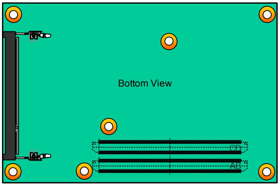
Figure 3: Express-DN7 Connector, Switch and LED Locations.... 31
Figure 4: Express-DN7 and the DB40 Debug Module 32
Figure 5: cExpress Switch Locations .... 38
Figure 6: COM Express Mounting Methods....109
Figure 7: COM Express Standoff Types.... 110

# List of Tables

Table 1: Express-DN7 AB/CD Pin Definitions.... 11
Table 2: 40-pin Debug Connector Pin Definition.... 33
Table 3: Express-DN7 LED Descriptions ...... 34
Table 4: MIPI60 Debug Header Pin Definition .... 35
Table 5: Fan Connector Pin Definition ...... 36
Table 6: BIOS Select and Mode Configuration Switch Settings.... 38
Table 7: SEMA Onboard Voltage Monitor 42
Table 8: SEMA BMC Status 42
Table 9: SEMA Exception Codes....43
Table 10: SEMA BMC Flags....44

# 1. Introduction

The Express-DN7 is a COM Express® COM.0 R3.0 Basic Size Type 7 module supporting the 64-bit Intel Atom® C3000 processor (formerly “Denverton-NS”) system-on-chip (SoC). 16 CPU cores with 31W TDP and integrated 10G Ethernet make the Express-DN7 especially suited for customers who need excellent computing performance with low power consumption, such as edge computing applications, in a long product life solution.

The Express-DN7 features Intel® Quick Assist Technology (cryptographic and compression acceleration), Intel® Virtualization Technology (including VT-x, VT-d), Intel® AES-NI Technology, and DDR4 ECC (or non-ECC) dual-channel memory at 1866/2133/2400 MHz (dependent on SoC SKU) to provide excellent overall performance. In addition, the Express-DN7 has up to three SODIMM sockets that are fully compliant with the COM Express mechanical specification.

An integrated Intel® 10G Ethernet controller supports a maximum of four 10GBASE-KR interfaces, relevant sideband signals and NC-SI. The Express-DN7 is designed to serve customers with optimized computing capability per watt and high speed connectivity requirements who want to outsource the custom core logic of their systems for reduced development time.

Input/output features include expanded PCIe bandwidth up to two PCIe x8 Gen3 lanes, a single onboard Gigabit Ethernet port with IEEE 1588 support suitable for real-time applications, USB 3.0/2.0 ports, and SATA 6 Gb/s ports. Support is provided for SMBus and I2C. The module is equipped with SPI AMI EFI BIOS with CMOS backup, supporting embedded features such as remote console, hardware monitor, and watchdog timer.

This page intentionally left blank.

# 2. Specifications

# 2.1. Core System

<table><tr><td>CPU</td><td>Intel Atom® processor C3000 SoC, 14nm (formerly Denverton-NS)Intel Atom® C3808 2.0GHz 25W (12C/2133MHz, 20HSIO, eTEMP)Intel Atom® C3708 1.7GHz 17W (8C/2133MHz, 20HSIO, eTEMP)Intel Atom® C3508 1.6GHz 12W (4C/1866MHz, 8HSIO, eTEMP)Intel Atom® C3308 1.6/2.1GHz 10W (2C/1866MHz, 6HSIO, eTEMP)Intel Atom® C3958 2.0GHz 31W (16C/2400MHz, 20HSIO, by request)Intel Atom® C3858 2.0GHz 25W (12C/2400MHz, 20HSIO, by request)Intel Atom® C3758 2.2GHz 25W (8C/2400MHz, 20HSIO, by request)Intel Atom® C3558 2.2GHz 16W (4C/2133MHz, 12HSIO, by request)Intel Atom® C3538 2.1GHz 15W (4C/2133MHz, 12HSIO, by request)Intel Atom® C3338 1.5/2.2GHz 9W (2C/1866MHz, 10HSIO, by request)Supporting: Intel® Quick Assist Technoloty (cryptographic and compression acceleration), Intel® VT (including VT-x, VT-d, VT-x with Extended Page Tables), Intel® Turbo Boost Technology 2.0, Intel® SSE4.2, Intel® 64 Architecture, Intel® ISA compatibility, Intel® Execurt Disable Bit, Intel® OS Guard, Intel® Secure Key, Intel® AES-NI, Intel® Security Hash Algorithm Extensions (SHA-1, SHA-256)Notes:Availability of features may vary between processor SKUs.SoC SKUs not listed above or marked “by request” are supported by project basis.Please contact your local ADLINK representative.</td></tr><tr><td>Cache</td><td>16MB for C3708/C3958/C3758, 12MB for C3808/C3858, 8MB for C3508/C3558/C3538, 4MB for C3308/C3338</td></tr><tr><td>Memory</td><td>Dual channel ECC (or non-ECC) 1866/2133/2400 MHz DDR4 memory up to 48GB in three SODIMM sockets (support for 96GB is under verification)Notes:Supported memory frequencies may vary between processor SKUs.The  $3^{rd}$ SODIMM on the module’s bottom side is supported by project basis. Please contact local sales.C3308/C3338 only support one channel in the lower SODIMM socket on top side.</td></tr><tr><td>Embedded BIOS</td><td>AMI Aptio 5 EFI with CMOS backup in 16MB SPI BIOS</td></tr><tr><td>Chipset</td><td>Integrated in SoC</td></tr></table>

# 2.2. Expansion Busses

<table><tr><td>PCI Express</td><td>Up to 1 PCI Express x8 Lanes Gen3 (CD):Lanes 16-23: four controllers/root ports, can be configured to x8, x4, x2, x1 (connected to PCIe Cluster 1 which has four root ports RP 4/5/6/7)Up to 1 PCI Express x8 Lanes Gen3 (AB &amp; CD):Lanes 0-7: four controllers/root ports, can be configured to x8, x4, x2, x1 (dependent on GbE support, connected to PCIe Cluster 0 which has four root ports, RP 0/1/2/3)Notes:Number of PCIe lanes depends on SoC SKUs. Refer to 2.6 Multi I/O and Storage for detailed infoRoot port 3 (PCIe lanes 6/7) is connected to GbE controller by default; support for PCIe lanes 6/7 is by build option.Although the Denverton-NS platform supports four roots on Lanes 0-7, the PICMG COM.0 R3.0 specification for Lanes 0-7 states: “Type 7 module may support eight x1 root hubs. It is expected that future generation products may limit the number of available root hubs.”</td></tr><tr><td>Other</td><td>LPC busSMBus (system) $I^{2}C$  (user)</td></tr></table>

# 2.3. 10GBASE-KR

<table><tr><td>Integrated on Processor</td><td>Intel® 10G Ethernet Controller (two controllers)</td></tr><tr><td>10GbE Feature Support</td><td>Four 10GBASE-KR ports (on CD connector)Sideband signals (on CD connector) for 10GbENotes:10GBASE-KR ports 0, 1 are from LAN controller 0, 10GBASE-KR ports 2, 3 are from LAN controller 1Maximum combined throughput on all four ports is 20Gb/s&lt;img src="images/ad71ef3be96102f1dca0525166ba34f1cc441aca887a69cd5f1da165fb3e9fc7.jpg"/&gt;&lt;img src="images/1f2d1217cb4ef08599905af7148f504d45cb95fb45c451d611355d9ae4c7ef03.jpg"/&gt;Note:The default 10GbE firmware supports four ports optical fiber PHY. Support for 10GBASE-T (copper PHY) is by project basis.</td></tr></table>

# 2.4. Gigabit Ethernet

<table><tr><td>Intel Controller</td><td>Intel® i210 Ethernet Controller, IEEE 1588 PTP support</td></tr><tr><td>Interface</td><td>10/100/1000 Mbit/s connection</td></tr></table>

Note: GbE0\_SDP pin (A49) is supported.

# 2.5. NC-SI

● NC-SI (on AB connector): manageability interface, connecting to IPMI BMC located on carrier board
- Routing from Intel® i210 Ethernet Controller to row AB connector

# 2.6. Multi I/O and Storage

<table><tr><td>I/O Hub</td><td>Integrated on SoC</td></tr><tr><td>USB</td><td>Up to 2x USB 3.0/2.0 (USB 0,1), 2x USB 2.0 (USB 2,3)</td></tr><tr><td>SATA*</td><td>Up to 2x SATA 6Gb/s (SATA 0,1)</td></tr><tr><td>GPIO</td><td>4 GPO and 4 GPI (GPI with interrupt)</td></tr><tr><td>eMMC 5.0 (build option)</td><td>8/16/32/64GB (boot-up device functionality supported by project basis)</td></tr></table>

\*Note: For SATA 6Gb/s compatibility, it is strongly recommended to use a SATA redriver on the carrier board.

# I/O Support of SoC SKUs

C3808, C3708, C3958, C3858, C3758
20 HSIO, 2CH DDR4 max., 48 GB DDR4

![Based on the provided image, here is the accurate and concise description of the flowchart/block diagram:\n\n**Top Section (PCIe Layouts & Interfaces)**\n*   **Main Columns:** Four columns labeled **B1**, **B3**, **B4**, and **B2**.\n*   **Rows:**\n    *   Each column has an **x8** block at the top.\n    *   Below the x8 blocks, **B1** and **B3** have **x4** blocks (colored yellow). **B4** and **B2** have **x4** blocks (white).\n    *   The bottom rows break these down into **x2** and **x1** blocks. The blocks under **B1** and **B3** are colored yellow; the blocks under **B4** and **B2** are white.\n*   **Interface Blocks (Top Right):**\n    *   **SATA** with blocks **0**, **1**.\n    *   **USB 3.0 upgrade** with blocks **0**, **1**, **2**, **3**.\n    *   **USB 2.0** with blocks **0**, **1**, **2**, **3**.\n*   **Annotation:** The text **last PCIe port for GbE** is positioned below the main grid, with dashed arrows pointing downward.\n\n**Bottom Section (Layouts & Definitions)**\n*   **Left Grid:** A smaller grid labeled **B1** showing an **x8** block, two **x4** blocks, four **x2** blocks, and four **x1** blocks (all colored yellow). Below this grid is the text **no GbE**.\n*   **Center Text Box:** 'Dual layout supports default GbE using last PCIe port in the B1 bucket, alternative is no GbE but full PCIe x8 on B1'.\n*   **Right Text Box:**\n    *   'B1: ports 0-7'\n    *   'B3: ports 16-23'\n    *   'B4: ports 24-31'\n    *   'B2: ports 8-15'\n\n**Legend and Notes**\n*   **Yellow Square:** 'compliant with PICMG definition'.\n*   **Light Yellow Square:** 'Supported by Express-DN7 design, please note the description from PICGM specification below before using these po'.\n*   **Additional Text:** 'Type 7 modules may support more x1 root hubs in bucket one (B1). It's expected that future generation products may limit the number of available root hubs on the bucket one (B1) to 2.'](.express-dn7-50m-00049-1020-12/d5a2ca6c0182ca5d96174961f02b027aefd2b8fc53d1b57d76d8d1656a837fe1.jpg)

C3558, C3538
12 HSIO, 2CH DDR4, max. 48 GB DDR4

![This diagram illustrates a PCIe lane layout and port configuration, likely for a motherboard or expansion card.\n\n**Main Grid (Top Left)**\n*   **Headers:** The top row features blocks labeled **B1**, **B3**, **B4**, and **B2**.\n*   **Lanes:** Below the headers is a hierarchical grid of blocks representing lane widths:\n    *   A row of four blocks labeled **x8**.\n    *   A row of eight blocks labeled **x4**.\n    *   A row of sixteen blocks labeled **x2**.\n    *   A bottom row of thirty-two blocks labeled **x1**.\n*   **Highlighting:** Various blocks in this grid are highlighted in shades of yellow/orange, indicating active connections.\n\n**Top Right Headers**\n*   **SATA:** A block labeled **SATA** containing sub-blocks **0** (highlighted yellow) and **1**.\n*   **USB 3.0 upgrade:** A block labeled **USB 3.0 upgrade** containing sub-blocks **0**, **1**, **2**, and **3**.\n*   **USB 2.0:** A block labeled **USB 2.0** containing sub-blocks **0**, **1** (highlighted yellow), **2**, and **3**.\n\n**Bottom Left Box**\n*   A smaller grid labeled **B1** at the top.\n*   Inside, it shows a hierarchy: **x8** (yellow), **x4** (yellow), **x2** (light yellow), and a bottom row of **x1** blocks (alternating orange and white).\n*   Below this grid is the text **no GbE**.\n\n**Text Box and Connections**\n*   A dashed arrow points downward from the main grid (specifically the bottom row of the B1 column) to the bottom left box. The label on this arrow is **last PCIe port for GbE**.\n*   A solid arrow points from the text **last PCIe port for GbE** to a text box on the right.\n*   The text box contains the following explanation: **Dual layout supports default GbE using last PCIe port in the B1 bucket, alternative is no GbE but full PCIe x8 on B1**](.express-dn7-50m-00049-1020-12/353e1f3b12e67f276061991e018dd0ac0cafcde8e9698e6bb97085021be752c2.jpg)

# C3338

10 HSIO, 1CH DDR4, max. 16 GB DDR4

<table><tr><td colspan="7">B1</td><td colspan="7">B3</td><td colspan="6">B4</td><td colspan="6">B2</td></tr><tr><td colspan="7">x8</td><td colspan="7">x8</td><td colspan="6">x8</td><td colspan="6">x8</td></tr><tr><td colspan="3">x4</td><td colspan="4">x4</td><td colspan="4">x4</td><td colspan="3">x4</td><td colspan="3">x4</td><td colspan="3">x4</td><td colspan="3">x4</td><td colspan="3">x4</td></tr><tr><td colspan="2">x2</td><td>x2</td><td colspan="2">x2</td><td colspan="2">x2</td><td colspan="2">x2</td><td colspan="2">x2</td><td colspan="2">x2</td><td>x2</td><td colspan="2">x2</td><td colspan="2">x2</td><td colspan="2">x2</td><td colspan="2">x2</td><td colspan="2">x2</td><td colspan="2">x2</td></tr><tr><td>x1</td><td></td><td>x1</td><td></td><td>x1</td><td></td><td>x1</td><td></td><td>x1</td><td></td><td>x1</td><td></td><td>x1</td><td></td><td>x1</td><td></td><td>x1</td><td></td><td>x1</td><td></td><td>x1</td><td></td><td>x1</td><td></td><td>x1</td><td></td></tr></table>

last PCIe port for GbE

<table><tr><td colspan="2">SATA</td><td colspan="4">USB 3.0 upgrade</td><td colspan="4">USB 2.0</td></tr><tr><td>0</td><td>1</td><td>0</td><td>1</td><td>2</td><td>3</td><td>0</td><td>1</td><td>2</td><td>3</td></tr></table>

<table><tr><td colspan="8">B1</td></tr><tr><td colspan="8">x8</td></tr><tr><td colspan="4">x4</td><td colspan="4">x4</td></tr><tr><td colspan="2">x2</td><td colspan="2">x2</td><td colspan="2">x2</td><td colspan="2">x2</td></tr><tr><td>x1</td><td></td><td>x1</td><td></td><td>x1</td><td></td><td>x1</td><td></td></tr></table>

no GbE

<table><tr><td>Dual layout supports default GbE using last PCIe port in the B1 bucket, alternative is no GbE but full PCIe x8 on B1</td></tr></table>

# C3508

8 HSIO, 2CH DDR4, max. 48 GB DDR4

<table><tr><td colspan="101">B1</td><td></td><td></td><td></td></tr><tr><td colspan="100">x8</td><td></td><td></td><td></td><td></td></tr><tr><td colspan="5">x4</td><td colspan="99">x4</td></tr></table>

last PCIe port for GbE

<table><tr><td colspan="2">SATA</td><td colspan="4">USB 3.0 upgrade</td><td colspan="4">USB 2.0</td></tr><tr><td>0</td><td>1</td><td>0</td><td>1</td><td>2</td><td>3</td><td>0</td><td>1</td><td>2</td><td>3</td></tr></table>

# C3308

6 HSIO, 1CH DDR4, max. 16 GB DDR4

<table><tr><td colspan="101">B1</td><td></td><td></td><td></td></tr><tr><td colspan="100">x8</td><td></td><td></td><td></td><td></td></tr><tr><td colspan="5">x4</td><td colspan="99">x4</td></tr></table>

last PCIe port for GbE

<table><tr><td colspan="2">SATA</td><td colspan="4">USB 3.0 upgrade</td></tr><tr><td>0</td><td>1</td><td>0</td><td>1</td><td>2</td><td>3</td></tr></table>

Note: PCIe configurations not listed in standard BIOS setting can be supported by project basis. Please contact your local ADLINK representative.

# 2.7. Serial I/O on Module

● Chipset: Nuvoton NCT5104D
Note: two UART ports native from SoC instead of NCT5104D supported by build option
- Ports: 2x UARTs Rx/Tx only
- Console Redirection: COM 1 or COM 2 selectable in BIOS

<table><tr><td>COM Port</td><td>Description</td><td>IRQ</td><td>Address</td><td>Console redirection support</td></tr><tr><td>COM 1</td><td>Supported by module (SER0, A98/A99), via NCT5104D</td><td>4</td><td>0x3F8</td><td>YES</td></tr><tr><td>COM 2</td><td>Supported by module (SER1, A101/A102), via NCT5104D</td><td>3</td><td>0x2F8</td><td>YES</td></tr><tr><td>COM 3</td><td>Supported by Super I/O (W83627DHG) on carrier board</td><td>5</td><td>0x240</td><td>YES</td></tr><tr><td>COM 4</td><td>Supported by Super I/O (W83627DHG) on carrier board</td><td>7</td><td>0x248</td><td>YES</td></tr></table>

Note: NCT5104D is 16550-compatible and it supports up to 1.5Mb/s (baud rate at 24MHz)

# 2.8. Trusted Platform Module (TPM)

- Chipset: Infineon (TPM is supported by build option)
- Type: TPM 2.0

# 2.9. SEMA Board Controller

● Type: ADLINK Smart Embedded Management Agent (SEMA)
- Functions:

• Voltage/Current monitoring
• Power sequence debug support
• AT/ATX mode control
• Logistics and forensic information
- Flat panel control (not supported on this product, as the platform has no GPU)
- General purpose I2C
• Failsafe BIOS (dual BIOS)
• Watchdog timer and fan control

# 2.10. Debug

- 40-pin flat cable connector to be used with DB-40 debug module
Supports: BIOS POST code LED, BMC access, SPI BIOS flashing, power testpoints, debug LEDs
● MIPI60 header for debug of SoC (build option)

# 2.11. Power Specifications

<table><tr><td>Power Modes</td><td>AT and ATX mode (AT mode startup controlled by SEMA Board Controller)</td></tr><tr><td>Standard Voltage Input</td><td>ATX @ 12V±5%,/ 5Vsb ±5% or AT @ 12V ±5%</td></tr><tr><td>Wide Voltage Input</td><td>ATX @ 8.5-20V, 5Vsb ±5% or AT @ 8.5-20V</td></tr><tr><td>Power Management</td><td>ACPI 5.0 compliant, Smart Battery support</td></tr><tr><td>Power States</td><td>Supports C0, C1, C2, C3, S0, S4, S5, S5 ECO mode(Wake-on-USB S4, WOL S4/S5)</td></tr><tr><td>ECO Mode</td><td>Supports deep S5 for 5Vsb power saving</td></tr></table>

# 2.12. Power Consumption

Please contact your ADLINK representative for the document "COM Express Module Power Consumption".

# 2.13. Operating Temperatures

<table><tr><td>Standard Operating Temperature</td><td>0°C to +60°C (Wide Voltage Input)Storage: -20°C to +80°C</td></tr><tr><td>Extreme Rugged Operating Temperature (optional)</td><td>-40°C to +85°C (Standard Voltage Input, only for eTEMP SKUs, by build option, TBC)Storage: -40°C to +85°C</td></tr></table>

# 2.14. Environmental

<table><tr><td>Humidity</td><td>Operating: 5-90% RH, non-condensingStorage: 5-95% RH (and operating with conformal coating)</td></tr><tr><td>Shock and Vibration</td><td>IEC 60068-2-64 and IEC-60068-2-27MIL-STD-202F, Method 213B, Table 213-I, Condition A and Method 214A, Table 214-I,Condition D</td></tr><tr><td>HALT</td><td>Thermal Stress, Vibration Stress, Thermal Shock and Combined Test</td></tr></table>

# 2.15. Specification Compliance

● PICMG COM.0: Rev 3.0 Type 7, Basic size 125 x 95 mm

# 2.16. Operating Systems

<table><tr><td>Standard Support</td><td>• Windows Server 2012/2016 (64-bit)• Yocto project based Linux(64-bit)</td></tr><tr><td>Extended Support (BSP)</td><td>• Yocto project based Linux (64-bit)</td></tr></table>

# 2.17. Functional Diagram

![This block diagram illustrates the architecture of an **Intel® Atom® C3000 'Denverton-NS'** system.\n\n**Central Component:**\nThe core of the diagram is the **Intel® Atom® C3000 'Denverton-NS'** block.\n\n**Left Side Connections (Vertical Bar 'AB'):**\n*   **Memory:** Three blocks labeled **SODIMM 1**, **SODIMM 2**, and **SODIMM 3** are listed. Each contains the text 'Up to 2400 MHz' and '4-16 GB ECC/non-ECC DDR4'.\n    *   **SODIMM 1** connects to **CH_A**.\n    *   **SODIMM 2** connects to **CH_B**.\n    *   **SODIMM 3** connects via a dotted line.\n    *   Text below reads: 'Note: Memory frequency dependent on SoC SKU'.\n*   **Peripherals:**\n    *   **Up to 6 PCIe lanes (Gen3)** connects to the left bar. Text: '(ports 0-5, B1, 3 controllers)'.\n    *   **2x SATA 6Gb/s** connects to the left bar. Text: '(port 0/1)'.\n    *   **NC-SI** connects from **GbE Controller** to the left bar.\n    *   **GbE Controller** connects to the central block (via dotted line) and the left bar.\n    *   **4 x USB 2.0** connects to the left bar. Text: '(ports 0/1/2/3)'.\n    *   **UART0/1** connects from **LPC to UART NCT5014D** to the left bar.\n    *   **LPC to UART NCT5014D** connects to the central block (via dotted line).\n    *   **Debug header**, **TPM 2.0**, and **LPC bus** are interconnected. **LPC bus** connects to the central block (via dotted line).\n    *   **SMBus** connects the central block to **GPIO PCA9535**.\n    *   **GPIO PCA9535** connects to the left bar with text '4x GPO, 4x GPI'.\n    *   **GP I2C** connects **GPIO PCA9535** to the left bar.\n    *   **SPI_CS#** and **SPI** connect **New SEMA BMC** to the left bar.\n\n**Right Side Connections (Vertical Bar 'CD'):**\n*   **MIPI60 header** connects bidirectionally to the central block. Text: 'By BOM option'.\n*   **LAN_Controller_0** connects to **2x 10G KR ports**, which then connects to the right bar.\n*   **LAN_Controller_1** connects to **2x 10G KR ports**, which then connects to the right bar.\n*   **10G Sideband Signals** connects to the right bar. Text: 'Note: 10G KR bandwidth dependent on SoC SKU'.\n*   **Up to 1 PCIe x8 lanes (Gen3)** connects to the right bar. Text: '(ports 16-23, B3, 4 controllers)'.\n*   **Up to 2 PCIe lanes (Gen3)** connects via a dotted line to the right bar. Text: '(ports 6-7, B3, 1 controller)'.\n*   **Up to 2x USB 3.0 upgrade** connects to the right bar. Text: '(port 0/1)'.\n*   **eMMC 5.0** connects via a dotted line from the central block. Text: '8/16/32/64GB'.\n\n**Bottom Right Section:**\n*   **New SEMA BMC** connects to **SMBus** (via dotted line from central block), **GPIO PCA9535**, and three blocks below it:\n    *   **SPI 0 BIOS**\n    *   **SPI 1 BIOS**\n    *   **LM73 Sensor**](.express-dn7-50m-00049-1020-12/42621fecfd833b6fe47ca53adf7830b97cf26384d6bf14536839eb94f5741473.jpg)

Figure 1: Express-DN7 Functional Block Diagram

Note: I/O dependent on the specific SoC SKU, described in 2.6 Multi I/O and Storage above.

# 2.18. Mechanical Drawing

![The image displays a technical engineering drawing consisting of two sections: a 'Top View' and a 'Side View.'\n\n**Top View**\nThis section shows the layout of a rectangular board with various dimensions and features:\n*   **Text:** 'Top View' and 'connector on bottom side'.\n*   **Dimensions (Left/Vertical):** 95, 91 (top), 75.32 (center), 28.33, 18, 6, 4, 0 (bottom left).\n*   **Dimensions (Bottom/Horizontal):** 0, 4, 16.50, 40.67, 70.14, 74.20, 80.\n*   **Dimensions (Right/Vertical):** 121, 125.\n*   **Visual Elements:** Four horizontal rows of slots are visible in the lower-left quadrant. Four vertical slots are aligned on the right side. Circular mounting holes are located at the corners and the center.\n\n**Side View**\nThis section shows the profile of the object below the top view:\n*   **Text:** 'Side View'.\n*   **Dimensions:** '2' (left, indicating thickness), '4' and '8' (right side, indicating heights), and '4' (bottom right corner).\n*   **Visual Elements:** A long, thin horizontal profile representing the board, with connector details visible on both the left and right ends.](.express-dn7-50m-00049-1020-12/6252e2920b557cdae23b796961b56440812da4b5cb7657c32596f0b43b32340f.jpg)
All dimensions are shown in millimeters. Tolerances should be $\pm$ 0.25mm, unless otherwise noted. The tolerances on the module connector locating peg holes (dimensions [16.50, 6.00] and [16.50, 18.00]) should be $\pm$ 0.10mm.

Figure 2: Express-DN7 Mechanical Drawing

# 3. Pinouts and Signal Descriptions

# 3.1. AB/CD Pin Definitions

The Express-DN7 is a Type 7 module supporting up to 16 PCIe lanes and four 10GBASE-KR ports on the CD connector and NC-SI on the AB connector. In the table below, all standard pins of the COM Express specification are described, including those not supported on the Express-DN7. Signals not supported on the Express-DN7 module are crossed out.

Table 1: Express-DN7 AB/CD Pin Definitions

<table><tr><td colspan="3">Row A</td><td colspan="2">Row B</td><td colspan="2">Row C</td><td colspan="2">Row D</td></tr><tr><td>Pin</td><td>Name</td><td>Pin</td><td>Name</td><td>Pin</td><td>Name</td><td>Pin</td><td>Name</td><td></td></tr><tr><td>A1</td><td>GND (fixed)</td><td>B1</td><td>GND (fixed)</td><td>C1</td><td>GND (fixed)</td><td>D1</td><td>GND (fixed)</td><td></td></tr><tr><td>A2</td><td>GBE0_MDI3-</td><td>B2</td><td>GBE0_ACT#</td><td>C2</td><td>GND</td><td>D2</td><td>GND</td><td></td></tr><tr><td>A3</td><td>GBE0_MDI3+</td><td>B3</td><td>LPC_FRAME#/ESPI_CS0#</td><td>C3</td><td>USB_SSRX0-</td><td>D3</td><td>USB_SSTX0-</td><td></td></tr><tr><td>A4</td><td>GBE0_LINK100#</td><td>B4</td><td>LPC_AD0/ESPI_IO-0</td><td>C4</td><td>USB_SSRX0+</td><td>D4</td><td>USB_SSTX0+</td><td></td></tr><tr><td>A5</td><td>GBE0_LINK1000#</td><td>B5</td><td>LPC_AD1/ESPI_IO-1</td><td>C5</td><td>GND</td><td>D5</td><td>GND</td><td></td></tr><tr><td>A6</td><td>GBE0_MDI2-</td><td>B6</td><td>LPC_AD2/ESPI_IO-2</td><td>C6</td><td>USB_SSRX1-</td><td>D6</td><td>USB_SSTX1-</td><td></td></tr><tr><td>A7</td><td>GBE0_MDI2+</td><td>B7</td><td>LPC_AD3/ESPI_IO-3</td><td>C7</td><td>USB_SSRX1+</td><td>D7</td><td>USB_SSTX1+</td><td></td></tr><tr><td>A8</td><td>GBE0_LINK#</td><td>B8</td><td>LPC_DRQ0#/ESPI_ALERT0#</td><td>C8</td><td>GND</td><td>D8</td><td>GND</td><td></td></tr><tr><td>A9</td><td>GBE0_MDI1-</td><td>B9</td><td>LPC_DRQ1#/ESPI_ALERT1#</td><td>C9</td><td>USB_SSRX2-</td><td>D9</td><td>USB_SSTX2-</td><td></td></tr><tr><td>A10</td><td>GBE0_MDI1+</td><td>B10</td><td>LPC_CLK/ESPI_CK</td><td>C10</td><td>USB_SSRX2+</td><td>D10</td><td>USB_SSTX2+</td><td></td></tr><tr><td>A11</td><td>GND (fixed)</td><td>B11</td><td>GND (fixed)</td><td>C11</td><td>GND (fixed)</td><td>D11</td><td>GND (fixed)</td><td></td></tr><tr><td>A12</td><td>GBE0_MDI0-</td><td>B12</td><td>PWRBTN#</td><td>C12</td><td>USB_SSRX3-</td><td>D12</td><td>USB_SSTX3-</td><td></td></tr><tr><td>A13</td><td>GBE0_MDI0+</td><td>B13</td><td>SMB_CK</td><td>C13</td><td>USB_SSRX3+</td><td>D13</td><td>USB_SSTX3+</td><td></td></tr><tr><td>A14</td><td>GBE0_CTREF</td><td>B14</td><td>SMB_DAT</td><td>C14</td><td>GND</td><td>D14</td><td>GND</td><td></td></tr><tr><td>A15</td><td>SUS_S3#</td><td>B15</td><td>SMB_ALERT#</td><td>C15</td><td>10G_PHY_MDC_SCL3</td><td>D15</td><td>10G_PHY_MDIO_SDA3</td><td></td></tr><tr><td>A16</td><td>SATAO_TX+</td><td>B16</td><td>SATA1_TX+</td><td>C16</td><td>10G_PHY_MDC_SCL2</td><td>D16</td><td>10G_PHY_MDIO_SDA2</td><td></td></tr><tr><td>A17</td><td>SATAO_TX-</td><td>B17</td><td>SATA1_TX-</td><td>C17</td><td>10G_SDP2</td><td>D17</td><td>10G_SDP3</td><td></td></tr><tr><td>A18</td><td>SUS_S4#</td><td>B18</td><td>SUS_STAT#/ESPI_RESET#</td><td>C18</td><td>GND</td><td>D18</td><td>GND</td><td></td></tr><tr><td>A19</td><td>SATAO_RX+</td><td>B19</td><td>SATA1_RX+</td><td>C19</td><td>PCIE_RX6+ *</td><td>D19</td><td>PCIE_TX6+ *</td><td></td></tr><tr><td>A20</td><td>SATAO_RX-</td><td>B20</td><td>SATA1_RX-</td><td>C20</td><td>PCIE_RX6- *</td><td>D20</td><td>PCIE_TX6- *</td><td></td></tr><tr><td>A21</td><td>GND (fixed)</td><td>B21</td><td>GND (fixed)</td><td>C21</td><td>GND (fixed)</td><td>D21</td><td>GND (fixed)</td><td></td></tr><tr><td>A22</td><td>PCIE_TX15+</td><td>B22</td><td>PCIE_RX15+</td><td>C22</td><td>PCIE_RX7+ *</td><td>D22</td><td>PCIE_TX7+ *</td><td></td></tr><tr><td>A23</td><td>PCIE_TX15-</td><td>B23</td><td>PCIE_RX15-</td><td>C23</td><td>PCIE_RX7- *</td><td>D23</td><td>PCIE_TX7- *</td><td></td></tr><tr><td>A24</td><td>SUS_S5#</td><td>B24</td><td>PWR_OK</td><td>C24</td><td>10G_INT2</td><td>D24</td><td>10G_INT3</td><td></td></tr><tr><td>A25</td><td>PCIE_TX14+</td><td>B25</td><td>PCIE_RX14+</td><td>C25</td><td>GND</td><td>D25</td><td>GND</td><td></td></tr><tr><td>A26</td><td>PCIE_TX14-</td><td>B26</td><td>PCIE_RX14-</td><td>C26</td><td>10G_KR_RX3+</td><td>D26</td><td>10G_KR_TX3+</td><td></td></tr><tr><td>A27</td><td>BATLOW#</td><td>B27</td><td>WDT</td><td>C27</td><td>10G_KR_RX3-</td><td>D27</td><td>10G_KR_TX3-</td><td></td></tr><tr><td>A28</td><td>(S)ATA_ACT#</td><td>B28</td><td>RSVD</td><td>C28</td><td>GND</td><td>D28</td><td>GND</td><td></td></tr><tr><td>A29</td><td>RSVD</td><td>B29</td><td>RSVD</td><td>C29</td><td>10G_KR_RX2+</td><td>D29</td><td>10G_KR_TX2+</td><td></td></tr><tr><td>A30</td><td>RSVD</td><td>B30</td><td>RSVD</td><td>C30</td><td>10G_KR_RX2-</td><td>D30</td><td>10G_KR_TX2-</td><td></td></tr><tr><td>A31</td><td>GND (fixed)</td><td>B31</td><td>GND (fixed)</td><td>C31</td><td>GND (fixed)</td><td>D31</td><td>GND (fixed)</td><td></td></tr><tr><td>A32</td><td>RSVD</td><td>B32</td><td>SPKR</td><td>C32</td><td>10G_SFP_SDA3</td><td>D32</td><td>10G_SFP_SCL3</td><td></td></tr><tr><td>A33</td><td>RSVD</td><td>B33</td><td>I2C_CK</td><td>C33</td><td>10G_SFP_SDA2</td><td>D33</td><td>10G_SFP_SCL2</td><td></td></tr><tr><td>A34</td><td>BIOS_DIS0#/ESPI_SAFS</td><td>B34</td><td>I2C_DAT</td><td>C34</td><td>10G_PHY_RST_23</td><td>D34</td><td>10G_PHY_CAP_23</td><td></td></tr><tr><td>A35</td><td>THRMTRIP#</td><td>B35</td><td>THRM#</td><td>C35</td><td>10G_PHY_RST_01</td><td>D35</td><td>10G_PHY_CAP_01</td><td></td></tr></table>

Row A
Row B
Row C
Row D

<table><tr><td>Pin</td><td>Name</td><td>Pin</td><td>Name</td><td>Pin</td><td>Name</td><td>Pin</td><td>Name</td></tr><tr><td>A36</td><td>PCIE_TX13+</td><td>B36</td><td>PCIE_RX13+</td><td>C36</td><td>10G_LED_SDA</td><td>D36</td><td>RSVD</td></tr><tr><td>A37</td><td>PCIE_TX13-</td><td>B37</td><td>PCIE_RX13-</td><td>C37</td><td>10G_LED_SCL</td><td>D37</td><td>RSVD</td></tr><tr><td>A38</td><td>GND</td><td>B38</td><td>GND</td><td>C38</td><td>10G_SFP_SDA1</td><td>D38</td><td>10G_SFP_SCL1</td></tr><tr><td>A39</td><td>PCIE_TX12+</td><td>B39</td><td>PCIE_RX12+</td><td>C39</td><td>10G_SFP_SDA0</td><td>D39</td><td>10G_SFP_SCL0</td></tr><tr><td>A40</td><td>PCIE_TX12-</td><td>B40</td><td>PCIE_RX12-</td><td>C40</td><td>10G_SDP0</td><td>D40</td><td>10G_SDP1</td></tr><tr><td>A41</td><td>GND (fixed)</td><td>B41</td><td>GND (fixed)</td><td>C41</td><td>GND (fixed)</td><td>D41</td><td>GND (fixed)</td></tr><tr><td>A42</td><td>USB2-</td><td>B42</td><td>USB3-</td><td>C42</td><td>10G_KR_RX1+</td><td>D42</td><td>10G_KR_TX1+</td></tr><tr><td>A43</td><td>USB2+</td><td>B43</td><td>USB3+</td><td>C43</td><td>10G_KR_RX1-</td><td>D43</td><td>10G_KR_TX1-</td></tr><tr><td>A44</td><td>USB_2_3_OC#</td><td>B44</td><td>USB_0_1_OC#</td><td>C44</td><td>GND</td><td>D44</td><td>GND</td></tr><tr><td>A45</td><td>USB0-</td><td>B45</td><td>USB1-</td><td>C45</td><td>10G_PHY_MDC_SCL1</td><td>D45</td><td>10G_PHY_MDIO_SDA1</td></tr><tr><td>A46</td><td>USB0+</td><td>B46</td><td>USB1+</td><td>C46</td><td>10G_PHY_MDC_SCL0</td><td>D46</td><td>10G_PHY_MDIO_SDA0</td></tr><tr><td>A47</td><td>VCC_RTC</td><td>B47</td><td>ESPI_EN</td><td>C47</td><td>10G_INT0</td><td>D47</td><td>10G_INT1</td></tr><tr><td>A48</td><td>RSVD</td><td>B48</td><td>USB0_HOST_PRSNT</td><td>C48</td><td>GND</td><td>D48</td><td>GND</td></tr><tr><td>A49</td><td>GBE0_SDP</td><td>B49</td><td>SYS_RESET#</td><td>C49</td><td>10G_KR_RX0+</td><td>D49</td><td>10G_KR_TX0+</td></tr><tr><td>A50</td><td>LPC_SERIRQ/ESPI_CS1#</td><td>B50</td><td>CB_RESET#</td><td>C50</td><td>10G_KR_RX0-</td><td>D50</td><td>10G_KR_TX0-</td></tr><tr><td>A51</td><td>GND (fixed)</td><td>B51</td><td>GND (fixed)</td><td>C51</td><td>GND (fixed)</td><td>D51</td><td>GND (fixed)</td></tr><tr><td>A52</td><td>PCIE_TX5+</td><td>B52</td><td>PCIE_RX5+</td><td>C52</td><td>PCIE_RX16+</td><td>D52</td><td>PCIE_TX16+</td></tr><tr><td>A53</td><td>PCIE_TX5-</td><td>B53</td><td>PCIE_RX5-</td><td>C53</td><td>PCIE_RX16-</td><td>D53</td><td>PCIE_TX16-</td></tr><tr><td>A54</td><td>GPIO</td><td>B54</td><td>GPO1</td><td>C54</td><td>TYPE0#</td><td>D54</td><td>RSVD</td></tr><tr><td>A55</td><td>PCIE_TX4+</td><td>B55</td><td>PCIE_RX4+</td><td>C55</td><td>PCIE_RX17+</td><td>D55</td><td>PCIE_TX17+</td></tr><tr><td>A56</td><td>PCIE_TX4-</td><td>B56</td><td>PCIE_RX4-</td><td>C56</td><td>PCIE_RX17-</td><td>D56</td><td>PCIE_TX17-</td></tr><tr><td>A57</td><td>GND</td><td>B57</td><td>GPO2</td><td>C57</td><td>TYPE1#</td><td>D57</td><td>TYPE2#</td></tr><tr><td>A58</td><td>PCIE_TX3+</td><td>B58</td><td>PCIE_RX3+</td><td>C58</td><td>PCIE_RX18+</td><td>D58</td><td>PCIE_TX18+</td></tr><tr><td>A59</td><td>PCIE_TX3-</td><td>B59</td><td>PCIE_RX3-</td><td>C59</td><td>PCIE_RX18-</td><td>D59</td><td>PCIE_TX18-</td></tr><tr><td>A60</td><td>GND (fixed)</td><td>B60</td><td>GND (fixed)</td><td>C60</td><td>GND (fixed)</td><td>D60</td><td>GND (fixed)</td></tr><tr><td>A61</td><td>PCIE_TX2+</td><td>B61</td><td>PCIE_RX2+</td><td>C61</td><td>PCIE_RX19+</td><td>D61</td><td>PCIE_TX19+</td></tr><tr><td>A62</td><td>PCIE_TX2-</td><td>B62</td><td>PCIE_RX2-</td><td>C62</td><td>PCIE_RX19-</td><td>D62</td><td>PCIE_TX19-</td></tr><tr><td>A63</td><td>GPIO1</td><td>B63</td><td>GPO3</td><td>C63</td><td>RSVD</td><td>D63</td><td>RSVD</td></tr><tr><td>A64</td><td>PCIE_TX1+</td><td>B64</td><td>PCIE_RX1+</td><td>C64</td><td>RSVD</td><td>D64</td><td>RSVD</td></tr><tr><td>A65</td><td>PCIE_TX1-</td><td>B65</td><td>PCIE_RX1-</td><td>C65</td><td>PCIE_RX20+</td><td>D65</td><td>PCIE_TX20+</td></tr><tr><td>A66</td><td>GND</td><td>B66</td><td>WAKE0#</td><td>C66</td><td>PCIE_RX20-</td><td>D66</td><td>PCIE_TX20-</td></tr><tr><td>A67</td><td>GPIO2</td><td>B67</td><td>WAKE1#</td><td>C67</td><td>RAPID_SHUTDOWN</td><td>D67</td><td>GND</td></tr><tr><td>A68</td><td>PCIE_TX0+</td><td>B68</td><td>PCIE_RX0+</td><td>C68</td><td>PCIE_RX21+</td><td>D68</td><td>PCIE_TX21+</td></tr><tr><td>A69</td><td>PCIE_TX0-</td><td>B69</td><td>PCIE_RX0-</td><td>C69</td><td>PCIE_RX21-</td><td>D69</td><td>PCIE_TX21-</td></tr><tr><td>A70</td><td>GND (fixed)</td><td>B70</td><td>GND (fixed)</td><td>C70</td><td>GND (fixed)</td><td>D70</td><td>GND (fixed)</td></tr><tr><td>A71</td><td>PCIE_TX8+</td><td>B71</td><td>PCIE_RX8+</td><td>C71</td><td>PCIE_RX22+</td><td>D71</td><td>PCIE_TX22+</td></tr><tr><td>A72</td><td>PCIE_TX8-</td><td>B72</td><td>PCIE_RX8-</td><td>C72</td><td>PCIE_RX22-</td><td>D72</td><td>PCIE_TX22-</td></tr><tr><td>A73</td><td>GND</td><td>B73</td><td>GND</td><td>C73</td><td>GND</td><td>D73</td><td>GND</td></tr><tr><td>A74</td><td>PCIE_TX9+</td><td>B74</td><td>PCIE_RX9+</td><td>C74</td><td>PCIE_RX23+</td><td>D74</td><td>PCIE_TX23+</td></tr><tr><td>A75</td><td>PCIE_TX9-</td><td>B75</td><td>PCIE_RX9-</td><td>C75</td><td>PCIE_RX23-</td><td>D75</td><td>PCIE_TX23-</td></tr><tr><td>A76</td><td>GND</td><td>B76</td><td>GND</td><td>C76</td><td>GND</td><td>D76</td><td>GND</td></tr><tr><td>A77</td><td>PCIE_TX10+</td><td>B77</td><td>PCIE_RX10+</td><td>C77</td><td>RSVD</td><td>D77</td><td>RSVD</td></tr><tr><td>A78</td><td>PCIE_TX10-</td><td>B78</td><td>PCIE_RX10-</td><td>C78</td><td>PCIE_RX24+</td><td>D78</td><td>PCIE_TX24+</td></tr><tr><td>A79</td><td>GND</td><td>B79</td><td>GND</td><td>C79</td><td>PCIE_RX24-</td><td>D79</td><td>PCIE_TX24-</td></tr></table>

<table><tr><td colspan="3">Row A</td><td colspan="2">Row B</td><td colspan="2">Row C</td><td colspan="2">Row D</td></tr><tr><td>Pin</td><td>Name</td><td>Pin</td><td>Name</td><td>Pin</td><td>Name</td><td>Pin</td><td>Name</td><td></td></tr><tr><td>A80</td><td>GND (fixed)</td><td>B80</td><td>GND (fixed)</td><td>C80</td><td>GND (fixed)</td><td>D80</td><td>GND (fixed)</td><td></td></tr><tr><td>A81</td><td>PCIE_TX11+</td><td>B81</td><td>PCIE_RX11+</td><td>C81</td><td>PCIE_RX25+</td><td>D81</td><td>PCIE_TX25</td><td></td></tr><tr><td>A82</td><td>PCIE_TX11-</td><td>B82</td><td>PCIE_RX11-</td><td>C82</td><td>PCIE_RX25-</td><td>D82</td><td>PCIE_TX25-</td><td></td></tr><tr><td>A83</td><td>GND</td><td>B83</td><td>GND</td><td>C83</td><td>RSVD</td><td>D83</td><td>RSVD</td><td></td></tr><tr><td>A84</td><td>NCSI_TX_EN</td><td>B84</td><td>VCC_5V_SBY</td><td>C84</td><td>GND</td><td>D84</td><td>GND</td><td></td></tr><tr><td>A85</td><td>GPI3</td><td>B85</td><td>VCC_5V_SBY</td><td>C85</td><td>PCIE_RX26+</td><td>D85</td><td>PCIE_TX26+</td><td></td></tr><tr><td>A86</td><td>RSVD</td><td>B86</td><td>VCC_5V_SBY</td><td>C86</td><td>PCIE_RX26-</td><td>D86</td><td>PCIE_TX26-</td><td></td></tr><tr><td>A87</td><td>RSVD</td><td>B87</td><td>VCC_5V_SBY</td><td>C87</td><td>GND</td><td>D87</td><td>GND</td><td></td></tr><tr><td>A88</td><td>PCIE0_CK_REF+</td><td>B88</td><td>BIOS_DIS1#</td><td>C88</td><td>PCIE_RX27+</td><td>D88</td><td>PCIE_TX27+</td><td></td></tr><tr><td>A89</td><td>PCIE0_CK_REF-</td><td>B89</td><td>NSCI_RX_ER</td><td>C89</td><td>PCIE_RX27-</td><td>D89</td><td>PCIE_TX27-</td><td></td></tr><tr><td>A90</td><td>GND (fixed)</td><td>B90</td><td>GND (fixed)</td><td>C90</td><td>GND (fixed)</td><td>D90</td><td>GND (fixed)</td><td></td></tr><tr><td>A91</td><td>SPI_POWER</td><td>B91</td><td>NCSI_CLK_IN</td><td>C91</td><td>PCIE_RX28+</td><td>D91</td><td>PCIE_TX28+</td><td></td></tr><tr><td>A92</td><td>SPI_MISO</td><td>B92</td><td>NCSI_RXD1</td><td>C92</td><td>PCIE_RX28-</td><td>D92</td><td>PCIE_TX28-</td><td></td></tr><tr><td>A93</td><td>GPO0</td><td>B93</td><td>NCSI_RXD0</td><td>C93</td><td>GND</td><td>D93</td><td>GND</td><td></td></tr><tr><td>A94</td><td>SPI_CLK</td><td>B94</td><td>NCSI_CRS_DV</td><td>C94</td><td>PCIE_RX29+</td><td>D94</td><td>PCIE_TX29+</td><td></td></tr><tr><td>A95</td><td>SPI_MOSI</td><td>B95</td><td>NCSI_TXD1</td><td>C95</td><td>PCIE_RX29-</td><td>D95</td><td>PCIE_TX29-</td><td></td></tr><tr><td>A96</td><td>TPM_PP</td><td>B96</td><td>NCSI_TXD0</td><td>C96</td><td>GND</td><td>D96</td><td>GND</td><td></td></tr><tr><td>A97</td><td>TYPE10#</td><td>B97</td><td>SPI_CS#</td><td>C97</td><td>RSVD</td><td>D97</td><td>RSVD</td><td></td></tr><tr><td>A98</td><td>SER0_TX</td><td>B98</td><td>NCSI_ARB_IN</td><td>C98</td><td>PCIE_RX30+</td><td>D98</td><td>PCIE_TX30+</td><td></td></tr><tr><td>A99</td><td>SER0_RX</td><td>B99</td><td>NCSI_ARB_OUT</td><td>C99</td><td>PCIE_RX30-</td><td>D99</td><td>PCIE_TX30-</td><td></td></tr><tr><td>A100</td><td>GND (fixed)</td><td>B100</td><td>GND (fixed)</td><td>C100</td><td>GND (fixed)</td><td>D100</td><td>GND (fixed)</td><td></td></tr><tr><td>A101</td><td>SER1_TX</td><td>B101</td><td>FAN_PWMOUT</td><td>C101</td><td>PCIE_RX31+</td><td>D101</td><td>PCIE_TX31+</td><td></td></tr><tr><td>A102</td><td>SER1_RX</td><td>B102</td><td>FAN_TACHIN</td><td>C102</td><td>PCIE_RX31-</td><td>D102</td><td>PCIE_TX31-</td><td></td></tr><tr><td>A103</td><td>LID#</td><td>B103</td><td>SLEEP#</td><td>C103</td><td>GND</td><td>D103</td><td>GND</td><td></td></tr><tr><td>A104</td><td>VCC_12V</td><td>B104</td><td>VCC_12V</td><td>C104</td><td>VCC_12V</td><td>D104</td><td>VCC_12V</td><td></td></tr><tr><td>A105</td><td>VCC_12V</td><td>B105</td><td>VCC_12V</td><td>C105</td><td>VCC_12V</td><td>D105</td><td>VCC_12V</td><td></td></tr><tr><td>A106</td><td>VCC_12V</td><td>B106</td><td>VCC_12V</td><td>C106</td><td>VCC_12V</td><td>D106</td><td>VCC_12V</td><td></td></tr><tr><td>A107</td><td>VCC_12V</td><td>B107</td><td>VCC_12V</td><td>C107</td><td>VCC_12V</td><td>D107</td><td>VCC_12V</td><td></td></tr><tr><td>A108</td><td>VCC_12V</td><td>B108</td><td>VCC_12V</td><td>C108</td><td>VCC_12V</td><td>D108</td><td>VCC_12V</td><td></td></tr><tr><td>A109</td><td>VCC_12V</td><td>B109</td><td>VCC_12V</td><td>C109</td><td>VCC_12V</td><td>D109</td><td>VCC_12V</td><td></td></tr><tr><td>A110</td><td>GND (fixed)</td><td>B110</td><td>GND (fixed)</td><td>C110</td><td>GND (fixed)</td><td>D110</td><td>GND (fixed)</td><td></td></tr></table>

# Notes:

- LPC and eSPI are muxed in the standard COM Express specification. The Denverton-NS platform only supports the LPC bus.
- PCIe lanes 6 & 7 are supported by build option, in place of GbE (PCIe lanes 6/7 come from one controller)
- PCIe lanes, USB 3.0 upgrade signals, SATA ports dependent on SoC SKUs. Refer to 2.6 Multi I/O and Storage for detailed info.

# 3.2. Signal Description Terminology

The following terms are used in the COM Express AB/CD Signal Descriptions below.

I Input to the Module

O Output from the Module

I/O Bi-directional input/output signal

OD Open drain output

I 3.3V Input 3.3V tolerant

I 5V Input 5V tolerant

O 3.3V Output 3.3V signal level

O 5V Output 5V signal level

I/O 3.3V Bi-directional signal 3.3V tolerant

I/O 5V Bi-directional signal 5V tolerant

I/O 3.3Vsb Bi-directional 3.3V tolerant active in standby state

I 3.3Vsb Input 3.3V tolerant active in standby state

P Power Input/Output

REF Reference voltage output that may be sourced from a module power plane.

PDS Pull-down strap. This is an output pin on the module that is either tied to GND or not connected. The signal is used to indicate the PICMG module type to the Carrier Board.

PU ADLINK implemented pull-up resistor on module

PD ADLINK implemented pull-down resistor on module

# 3.3. AB Signal Descriptions

# 3.3.1. Network Controller Sideband Interface (NC-SI)

<table><tr><td>Signal</td><td>Pin</td><td>Description</td><td>I/O</td><td>PU/PD</td><td>Comment</td></tr><tr><td>NCSI_CLK_IN</td><td>B91</td><td>Clock reference for receive, transmit and control interface</td><td>I 3.3VSB</td><td>PD 10k</td><td></td></tr><tr><td>NCSI_RXD[1:0]</td><td>B92B93</td><td>Receive Data (from NC to BMC)</td><td>O 3.3VSB</td><td>PU 10k3.3VSB</td><td>PU 10k that aligns with LAN chip specification</td></tr><tr><td>NCSI_TXD[1:0]</td><td>B95B96</td><td>Transmit Data (from BMC to NC)</td><td>I 3.3VSB</td><td>PU 10k3.3VSB</td><td></td></tr><tr><td>NCSI_CRS_DV</td><td>B94</td><td>Carrier Sense/Receive Data valid to MC, indicating that the transmitted data from NC to BMC is valid</td><td>O 3.3VSB</td><td>PD 10k</td><td>PU 10k that aligns with LAN chip specification</td></tr><tr><td>NCSI_TX_EN</td><td>A84</td><td>Transmit enable</td><td>I 3.3VSB</td><td>PD 10k</td><td></td></tr><tr><td>NCSI_RX_ER</td><td>B89</td><td>Receive error</td><td>O 3.3VSB</td><td></td><td></td></tr><tr><td>NCSI_ARB_IN</td><td>B98</td><td>Network Controller hardware arbitration input</td><td>I 3.3VSB</td><td></td><td>Left floating on module, that aligns with LAN chip specification</td></tr><tr><td>NCSI_ARB_OUT</td><td>B99</td><td>Network Controller hardware arbitration output</td><td>O 3.3VSB</td><td></td><td></td></tr></table>

# 3.3.2. Gigabit Ethernet

<table><tr><td>Gigabit Ethernet</td><td>Pin</td><td>Description</td><td>I/O</td><td>PU/PD</td><td>Comment</td></tr><tr><td>GBE0_MDI0+GBE0_MDI0-GBE0_MDI1+GBE0_MDI1-GBE0_MDI2+GBE0_MDI2-GBE0_MDI3+GBE0_MDI3-</td><td>A13A12A10A9A7A6A3A2</td><td>Gigabit Ethernet Controller 0: Media Dependent Interface Differential Pairs 0, 1, 2, 3. The MDI can operate in 1000, 100, and 10Mbit/sec modes. Some pairs are unused in some modes according to the following:____1000BASE-T 100BASE-TX 10BASE-TMDI[0]+/- B1_DA+/- TX+/- TX+/-MDI[1]+/- B1_DB+/- RX+/- RX+/-MDI[2]+/- B1_DC+/-MDI[3]+/- B1_DD+/-</td><td>I/OAnalog</td><td></td><td>Twisted pair signals for external transformer.</td></tr><tr><td>GBE0_ACT#</td><td>B2</td><td>Gigabit Ethernet Controller 0 activity indicator, active low.</td><td>O 3.3VSB</td><td></td><td></td></tr><tr><td>GBE0_LINK#</td><td>A8</td><td>Gigabit Ethernet Controller 0 link indicator, active low.</td><td>O 3.3VSB</td><td></td><td></td></tr><tr><td>GBE0_LINK100#</td><td>A4</td><td>Gigabit Ethernet Controller 0 100Mbit/sec link indicator, active low.</td><td>O 3.3VSB</td><td></td><td></td></tr><tr><td>GBE0_LINK1000#</td><td>A5</td><td>Gigabit Ethernet Controller 0 1000Mbit/sec link indicator, active low.</td><td>O 3.3VSB</td><td></td><td></td></tr><tr><td>GBE0_CTREF</td><td>A14</td><td>Reference voltage for Carrier Board Ethernet channel 1 and 2 magnetics center tap. The reference voltage is determined by the requirements of the Module PHY and may be as low as 0V and as high as 3.3V. The reference voltage output shall be current limited on the Module. In the case in which the reference is shorted to ground, the current shall be 250 mA or less.</td><td>REFGND min3.3V max</td><td></td><td>NC pin</td></tr><tr><td>GBE0_SDP</td><td>A49</td><td>Gigabit Ethernet Controller 0 Software-Definable Pins.Can also be used for IEEE1588 support such as a 1pps signal.</td><td>I/O3.3VSB</td><td></td><td></td></tr></table>

3.3.3. SATA

<table><tr><td>Signal</td><td>Pin</td><td>Description</td><td>I/O</td><td>PU/PD</td><td>Comment</td></tr><tr><td>SATA0_TX+SATA0_TX-</td><td>A16A17</td><td>Serial ATA channel 0, Transmit Output differential pair.</td><td>O SATA</td><td></td><td>AC coupled on Module</td></tr><tr><td>SATA0_RX+SATA0_RX-</td><td>A19A20</td><td>Serial ATA channel 0, Receive Input differential pair.</td><td>I SATA</td><td></td><td>AC coupled on Module</td></tr><tr><td>SATA1_TX+SATA1_TX-</td><td>B16B17</td><td>Serial ATA channel 1, Transmit Output differential pair.</td><td>O SATA</td><td></td><td>AC coupled on Module</td></tr><tr><td>SATA1_RX+SATA1_RX-</td><td>B19B20</td><td>Serial ATA channel 1, Receive Input differential pair.</td><td>I SATA</td><td></td><td>AC coupled on Module</td></tr><tr><td>(S)ATA_ACT#</td><td>A28</td><td>ATA (parallel and serial) or SAS activity indicator, active low.</td><td>O 3.3V</td><td></td><td></td></tr></table>

<table><tr><td>SATA on COMe Module</td><td>HSIO Function on SoC</td></tr><tr><td>SATA 0</td><td>SATA controller #2, 5 (Lane 16)</td></tr><tr><td>SATA 1</td><td>SATA controller #2, 6 (Lane 17)</td></tr></table>

Note: Maximum number of HSIO dependent on SoC SKU. C3808 is used as an example here (20 HSIO).

3.3.4. PCI Express

<table><tr><td>Signal</td><td>Pin</td><td>Description</td><td>I/O</td><td>PU/PD</td><td>Comment</td></tr><tr><td>PCIE_TX0+PCIE_TX0-</td><td>A68A69</td><td>PCI Express channel 0, Transmit Output differential pair.</td><td>O PCIE</td><td></td><td>AC coupled on Module</td></tr><tr><td>PCIE_RX0+PCIE_RX0-</td><td>B68B69</td><td>PCI Express channel 0, Receive Input differential pair.</td><td>I PCIE</td><td></td><td>AC coupled off Module</td></tr><tr><td>PCIE_TX1+PCIE_TX1-</td><td>A64A65</td><td>PCI Express channel 1, Transmit Output differential pair.</td><td>O PCIE</td><td></td><td>AC coupled on Module</td></tr><tr><td>PCIE_RX1+PCIE_RX1-</td><td>B64B65</td><td>PCI Express channel 1, Receive Input differential pair.</td><td>I PCIE</td><td></td><td>AC coupled off Module</td></tr><tr><td>PCIE_TX2+PCIE_TX2-</td><td>A61A62</td><td>PCI Express channel 2, Transmit Output differential pair.</td><td>O PCIE</td><td></td><td>AC coupled on Module</td></tr><tr><td>PCIE_RX2+PCIE_RX2-</td><td>B61B62</td><td>PCI Express channel 2, Receive Input differential pair.</td><td>I PCIE</td><td></td><td>AC coupled off Module</td></tr><tr><td>PCIE_TX3+PCIE_TX3-</td><td>A58A59</td><td>PCI Express channel 3, Transmit Output differential pair.</td><td>O PCIE</td><td></td><td>AC coupled on Module</td></tr><tr><td>PCIE_RX3+PCIE_RX3-</td><td>B58B59</td><td>PCI Express channel 3, Receive Input differential pair.</td><td>I PCIE</td><td></td><td>AC coupled off Module</td></tr><tr><td>PCIE_TX4+PCIE_TX4-</td><td>A55A56</td><td>PCI Express channel 4, Transmit Output differential pair.</td><td>O PCIE</td><td></td><td>AC coupled on Module</td></tr><tr><td>PCIE_RX4+PCIE_RX4-</td><td>B55B56</td><td>PCI Express channel 4, Receive Input differential pair.</td><td>I PCIE</td><td></td><td>AC coupled off Module</td></tr><tr><td>PCIE_TX5+PCIE_TX5-</td><td>A52A53</td><td>PCI Express channel 5, Transmit Output differential pair.</td><td>O PCIE</td><td></td><td>AC coupled on Module</td></tr><tr><td>PCIE_RX5+PCIE_RX5-</td><td>B52B53</td><td>PCI Express channel 5, Receive Input differential pair.</td><td>I PCIE</td><td></td><td>AC coupled off Module</td></tr><tr><td>PCIE_TX8+PCIE_TX8-</td><td>A71A72</td><td>PCI Express channel 8, Transmit Output differential pair.</td><td>O PCIE</td><td></td><td>Not supported</td></tr><tr><td>PCIE_RX8+PCIE_RX8-</td><td>B71B72</td><td>PCI Express channel 8, Receive Input differential pair.</td><td>I PCIE</td><td></td><td>Not supported</td></tr><tr><td>PCIE_TX9+PCIE_TX9-</td><td>A74A75</td><td>PCI Express channel 9, Transmit Output differential pair.</td><td>O PCIE</td><td></td><td>Not supported</td></tr><tr><td>PCIE_RX9+PCIE_RX9-</td><td>B74B75</td><td>PCI Express channel 9, Receive Input differential pair.</td><td>I PCIE</td><td></td><td>Not supported</td></tr><tr><td>PCIE_TX10+PCIE_TX10-</td><td>A77A78</td><td>PCI Express channel 10, Transmit Output differential pair.</td><td>O PCIE</td><td></td><td>Not supported</td></tr><tr><td>PCIE_RX10+PCIE_RX10-</td><td>B77B78</td><td>PCI Express channel 10, Receive Input differential pair.</td><td>I PCIE</td><td></td><td>Not supported</td></tr><tr><td>PCIE_TX11+PCIE_TX11-</td><td>A81A82</td><td>PCI Express channel 11, Transmit Output differential pair.</td><td>O PCIE</td><td></td><td>Not supported</td></tr><tr><td>PCIE_RX11+PCIE_RX11-</td><td>B81B82</td><td>PCI Express channel 11, Receive Input differential pair.</td><td>I PCIE</td><td></td><td>Not supported</td></tr><tr><td>PCIE_TX12+PCIE_TX12-</td><td>A39A40</td><td>PCI Express channel 12, Transmit Output differential pair.</td><td>O PCIE</td><td></td><td>Not supported</td></tr><tr><td>PCIE_RX12+PCIE_RX12-</td><td>B39B40</td><td>PCI Express channel 12, Receive Input differential pair.</td><td>I PCIE</td><td></td><td>Not supported</td></tr><tr><td>PCIE_TX13+PCIE_TX13-</td><td>A36A37</td><td>PCI Express channel 13, Transmit Output differential pair.</td><td>O PCIE</td><td></td><td>Not supported</td></tr><tr><td>PCIE_RX13+PCIE_RX13-</td><td>B36B37</td><td>PCI Express channel 13, Receive Input differential pair.</td><td>I PCIE</td><td></td><td>Not supported</td></tr><tr><td>PCIE_TX14+PCIE_TX14-</td><td>A25A26</td><td>PCI Express channel 14, Transmit Output differential pair.</td><td>O PCIE</td><td></td><td>Not supported</td></tr><tr><td>PCIE_RX14+PCIE_RX14-</td><td>B25B26</td><td>PCI Express channel 14, Receive Input differential pair.</td><td>I PCIE</td><td></td><td>Not supported</td></tr><tr><td>PCIE_TX15+PCIE_TX15-</td><td>A22A23</td><td>PCI Express channel 15, Transmit Output differential pair.</td><td>O PCIE</td><td></td><td>Not supported</td></tr><tr><td>PCIE_RX15+PCIE_RX15-</td><td>B22B23</td><td>PCI Express channel 15, Receive Input differential pair.</td><td>I PCIE</td><td></td><td>Not supported</td></tr><tr><td>PCIE_CLK_REF+PCIE_CLK_REF-</td><td>A88A89</td><td>PCI Express Reference Clock output for all PCI Express and PCI Express Graphics Lanes.</td><td>O PCIE</td><td></td><td></td></tr></table>

<table><tr><td>PCIe on COMe Module</td><td>HSIO Function on SoC</td><td>Note</td></tr><tr><td>PCIE 0</td><td>Lane 0</td><td rowspan="8">The behavior of this platform:Only four controllers on Lanes 0-7. It can be used as one x8, two x4 or four x2/x1.Lanes 0-7 are from PCIe Cluster 0.It supports RP 0/1/2/3:RP0 for Lane 0/1RP1 for Lane 2/3RP3 for Lane 4/5RP4 for Lane 6/7</td></tr><tr><td>PCIE 1</td><td>Lane 1</td></tr><tr><td>PCIE 2</td><td>Lane 2</td></tr><tr><td>PCIE 3</td><td>Lane 3</td></tr><tr><td>PCIE 4</td><td>Lane 4</td></tr><tr><td>PCIE 5</td><td>Lane 5</td></tr><tr><td>PCIE 6</td><td>Lane 6</td></tr><tr><td>PCIE 7</td><td>Lane 7</td></tr><tr><td>PCIE 16</td><td>Lane 8</td><td rowspan="3">The behavior of this platform:Only four controllers on Lanes 8-15. It can be used as one x8, two x4 or four x2/x1.Lanes 16-23 are from PCIe Cluster 1.</td></tr><tr><td>PCIE 17</td><td>Lane 9</td></tr><tr><td>PCIE 18</td><td>Lane 10</td></tr><tr><td>PCIE 19</td><td>Lane 11</td><td rowspan="5">It supports RP 4/5/6/7:RP4 for Lane 8/9RP5 for Lane 10/11RP6 for Lane 12/13RP7 for Lane 14/15</td></tr><tr><td>PCIE 20</td><td>Lane 12</td></tr><tr><td>PCIE 21</td><td>Lane 13</td></tr><tr><td>PCIE 22</td><td>Lane 14</td></tr><tr><td>PCIE 23</td><td>Lane 15</td></tr></table>

Note: Maximum number of HSIO dependent on SoC SKUs. C3808 is used as an example (20 HSIO).

# 3.3.5. LPC Bus

<table><tr><td>Signal</td><td>Pin</td><td>Description</td><td>I/O</td><td>PU/PD</td><td>Comment</td></tr><tr><td>LPC_AD[0:3]</td><td>B4-B7</td><td>LPC multiplexed address, command and data bus</td><td>I/O 3.3V</td><td></td><td></td></tr><tr><td>LPC_FRAME#</td><td>B3</td><td>LPC frame indicates the start of an LPC cycle</td><td>O 3.3V</td><td></td><td></td></tr><tr><td>LPC_DRQ0#LPC_DRQ1#</td><td>B8B9</td><td>LPC serial DMA request</td><td>I 3.3V</td><td></td><td>Not supported</td></tr><tr><td>LPC_SERIRQ</td><td>A50</td><td>LPC serial interrupt</td><td>I/O OD 3.3V</td><td>PU 8.2k 3.3V</td><td></td></tr><tr><td>LPC_CLK</td><td>B10</td><td>LPC clock output -33MHz nominal</td><td>O 3.3V</td><td></td><td>This platform supports 24MHz nominal</td></tr></table>

Note: eSPI and LPC buses are muxed as defined by PICMG. The Denverton-NS platform only supports LPC interface.

# 3.3.6. USB

<table><tr><td>Signal</td><td>Pin</td><td>Description</td><td>I/O</td><td>PU/PD</td><td>Comment</td></tr><tr><td>USB0+USB0-</td><td>A46A45</td><td>USB differential data pairs for Port 0</td><td>I/O 3.3VSB</td><td></td><td>USB 1.1/ 2.0 compliant</td></tr><tr><td>USB1+USB1-</td><td>B46B45</td><td>USB differential data pairs for Port 1</td><td>I/O 3.3VSB</td><td></td><td>USB 1.1/ 2.0 compliant</td></tr><tr><td>USB2+USB2-</td><td>A43A42</td><td>USB differential data pairs for Port 1</td><td>I/O 3.3VSB</td><td></td><td>USB 1.1/ 2.0 compliant</td></tr><tr><td>USB3+USB3-</td><td>B43B42</td><td>USB differential data pairs for Port 2</td><td>I/O 3.3VSB</td><td></td><td>USB 1.1/ 2.0 compliant</td></tr><tr><td>USB_0_1_OC#</td><td>B44</td><td>USB over-current sense, USB ports 0 and 1. A pull-up for this line shall be present on the module. An open drain driver from a USB current monitor on the carrier board may drive this line low.</td><td>I 3.3VSB</td><td>PU 10K3.3VSB</td><td>Do not pull high on carrier</td></tr><tr><td>USB_2_3_OC#</td><td>A44</td><td>USB over-current sense, USB ports 2 and 3. A pull-up for this line shall be present on the module. An open drain driver from a USB current monitor on the carrier board may drive this line low..</td><td>I 3.3VSB</td><td>PU 10K3.3VSB</td><td>Do not pull high on carrier</td></tr><tr><td>USB0_HOST_PRSNT</td><td>A48</td><td>Module USB client may detect the presence of a USB host on USB0. A high value indicates that a host is present.</td><td>I 3.3VSB</td><td></td><td>Not Supported. Limitation of this platform</td></tr></table>

# 3.3.7. USB Root Segmentation

Denverton-NS
USB Ports

Express-DN7
USB Ports

<table><tr><td colspan="8">USB Combo Controller</td></tr><tr><td colspan="4">USB 3.0</td><td colspan="4">USB 2.0</td></tr><tr><td>0</td><td>1</td><td>2</td><td>3</td><td>0</td><td>1</td><td>2</td><td>3</td></tr><tr><td></td><td></td><td></td><td></td><td></td><td></td><td></td><td></td></tr><tr><td></td><td>USB 3 Port 0</td><td>USB 3 Port 0</td><td>USB 2 Port 0</td><td>USB 2 Port 1</td><td>USB 2 Port 2</td><td>USB 2 Port 3</td><td></td></tr></table>

Notes: Maximum number of HSIO dependent on SoC SKU. C3808 is used as an example (20 HSIO). USB 3.0 0/1/2/3 mapping to HSIO Lane 16/17/18/19. Lane 16 & 17 are SATA and USB 3.0 muxed. On Express-DN7, the Lanes 16 & 17 are used for SATA ports support.

# 3.3.8. SPI (BIOS only)

<table><tr><td>Signal</td><td>Pin</td><td>Description</td><td>I/O</td><td>PU/PD</td><td>Comment</td></tr><tr><td>SPI_CS#</td><td>B97</td><td>Chip select for Carrier Board SPI BIOS Flash.</td><td>O 3.3VSB</td><td>PU 10k3.3VSB</td><td></td></tr><tr><td>SPI_MISO</td><td>A92</td><td>Data in to module from carrier board SPI BIOS flash.</td><td>I 3.3VSB</td><td></td><td></td></tr><tr><td>SPI_MOSI</td><td>A95</td><td>Data out from module to carrier board SPI BIOS flash.</td><td>O 3.3VSB</td><td></td><td></td></tr><tr><td>SPI_CLK</td><td>A94</td><td>Clock from module to carrier board SPI BIOS flash.</td><td>O 3.3VSB</td><td></td><td></td></tr><tr><td>SPI_POWER</td><td>A91</td><td>Power supply for Carrier Board SPI – sourced from Module – nominally 3.3V.The Module shall provide a minimum of 100mA on SPI_POWER.Carriers shall use less than 100mA of SPI_POWER.SPI_POWER shall only be used to power SPI devices on the Carrier</td><td>OP3.3VSB</td><td></td><td></td></tr><tr><td>BIOS_DIS0#</td><td>A34</td><td>Selection strap to determine the BIOS boot device.</td><td>I</td><td>PU 10k3.3VSB</td><td>Carrier shall pull to GND or leave not-connected.</td></tr><tr><td>BIOS_DIS1#</td><td>B88</td><td>Selection strap to determine the BIOS boot device.</td><td>I</td><td>PU 10k3.3VSB</td><td>Carrier shall pull to GND or leave not-connected</td></tr></table>

# 3.3.9. Miscellaneous

<table><tr><td>Signal</td><td>Pin</td><td>Description</td><td>I/O</td><td>PU/PD</td><td>Comment</td></tr><tr><td>SPKR</td><td>B32</td><td>Output for audio enunciator, the “speaker” in PC-AT systems</td><td>O 3.3V</td><td>PU 10k 3.3V</td><td>Not Supported</td></tr><tr><td>WDT</td><td>B27</td><td>Output indicating that a watchdog time-out event has occurred.</td><td>O 3.3V</td><td>PU 10k 3.3V</td><td></td></tr><tr><td>THRM#</td><td>B35</td><td>Input from off-module temp sensor indicating an over-temp situation.</td><td>I 3.3VSB</td><td></td><td></td></tr><tr><td>THRMTRIP#</td><td>A35</td><td>Active low output indicating that the CPU has entered thermal shutdown.</td><td>O 3.3V</td><td>PU 10k 3.3V</td><td></td></tr><tr><td>FAN_PWMOUT</td><td>B101</td><td>Fan speed control. Uses the Pulse Width Modulation (PWM) technique to control the fan’s RPM.</td><td>O OD 3.3V</td><td>PU 2.2K 3.3V</td><td></td></tr><tr><td>FAN_TACHIN</td><td>B102</td><td>Fan tachometer input for a fan with a two pulse output.</td><td>I OD 3.3V</td><td>PU 47K 3.3V</td><td></td></tr><tr><td>TPM_PP</td><td>A96</td><td>Trusted Platform Module (TPM) Physical Presence pin. Active high. TPM chip has an internal pull down. This signal is used to indicate Physical Presence to the TPM.</td><td>I 3.3V</td><td>PD 100k 3.3V</td><td>PD only when TPM on module</td></tr></table>

# 3.3.10. SMBus

<table><tr><td>Signal</td><td>Pin</td><td>Description</td><td>I/O</td><td>PU/PD</td><td>Comment</td></tr><tr><td>SMB_CK</td><td>B13</td><td>System Management Bus bidirectional clock line. Power sourced through 5V standby rail and main power rails.</td><td>I/O OD3.3VSB</td><td>PU 2.2k3.3VSB</td><td>Equivalent resistor is 2.2k</td></tr><tr><td>SMB_DAT#</td><td>B14</td><td>System Management Bus bidirectional data line. Power sourced through 5V standby rail and main power rails.</td><td>I/O OD3.3VSB</td><td>PU 2.2k3.3VSB</td><td>Equivalent resistor is 2.2k</td></tr><tr><td>SMB_ALERT#</td><td>B15</td><td>System Management Bus Alert – active low input can be used to generate an SMI# (System Management Interrupt) or to wake the system. Power sourced through 5V standby rail and main power rails.</td><td>I 3.3VSB</td><td>PU 10k3.3VSB</td><td></td></tr></table>

# 3.3.11. I2C Bus

<table><tr><td>Signal</td><td>Pin</td><td>Description</td><td>I/O</td><td>PU/PD</td><td>Comment</td></tr><tr><td>I2C_CK</td><td>B33</td><td>General purpose I2C port clock output/input</td><td>I/O OD 3.3VSB</td><td>PU 2.2K 3.3VSB</td><td>Source SEMA BMC</td></tr><tr><td>I2C_DAT</td><td>B34</td><td>General purpose I2C port data I/O line</td><td>I/O OD 3.3VSB</td><td>PU 2.2K 3.3VSB</td><td>Source SEMA BMC</td></tr></table>

# 3.3.12. General Purpose I/O (GPIO)

<table><tr><td>Signal</td><td>Pin</td><td>Description</td><td>I/O</td><td>PU/PD</td><td>Comment</td></tr><tr><td>GPO[0]</td><td>A93</td><td>General purpose output pins.</td><td>O 3.3V</td><td>PU 10K 3.3V</td><td>After hardware RESET output low</td></tr><tr><td>GPO[1]</td><td>B54</td><td>General purpose output pins.</td><td>O 3.3V</td><td>PU 10K 3.3V</td><td>After hardware RESET output low</td></tr><tr><td>GPO[2]</td><td>B57</td><td>General purpose output pins.</td><td>O 3.3V</td><td>PU 10K 3.3V</td><td>After hardware RESET output low</td></tr><tr><td>GPO[3]</td><td>B63</td><td>General purpose output pins.</td><td>O 3.3V</td><td>PU 10K 3.3V</td><td>After hardware RESET output low</td></tr><tr><td>GPI[0]</td><td>A54</td><td>General purpose input pins.Pulled high internally on the module.</td><td>I 3.3V</td><td>PU 10K 3.3V</td><td></td></tr><tr><td>GPI[1]</td><td>A63</td><td>General purpose input pins.Pulled high internally on the module.</td><td>I 3.3V</td><td>PU 10K 3.3V</td><td></td></tr><tr><td>GPI[2]</td><td>A67</td><td>General purpose input pins.Pulled high internally on the module.</td><td>I 3.3V</td><td>PU 10K 3.3V</td><td></td></tr><tr><td>GPI[3]</td><td>A85</td><td>General purpose input pins.Pulled high internally on the module.</td><td>I 3.3V</td><td>PU 10K 3.3V</td><td></td></tr></table>

# 3.3.13. Serial Interface Signals

<table><tr><td>Signal</td><td>Pin</td><td>Description</td><td>I/O</td><td>PU/PD</td><td>Comment</td></tr><tr><td>SER0_TX</td><td>A98</td><td>General purpose serial port transmitter (TTL level output)</td><td>O CMOS</td><td></td><td>Power rail tolerance 5V, 12V</td></tr><tr><td>SER0_RX</td><td>A99</td><td>General purpose serial port receiver (TTL level input)</td><td>I CMOS</td><td>PU 10k 3.3V</td><td>Power rail tolerance 5V, 12V</td></tr><tr><td>SER1_TX</td><td>A101</td><td>General purpose serial port transmitter (TTL level output)</td><td>O CMOS</td><td></td><td>Power rail tolerance 5V, 12V</td></tr><tr><td>SER1_RX</td><td>A102</td><td>General purpose serial port receiver (TTL level input)</td><td>I CMOS</td><td>PU 10k 3.3V</td><td>Power rail tolerance 5V, 12V</td></tr></table>

# 3.3.14. Power and System Management

<table><tr><td>Signal</td><td>Pin</td><td>Description</td><td>I/O</td><td>PU/PD</td><td>Comment</td></tr><tr><td>PWRBTN#</td><td>B12</td><td>Power button to bring system out of S5 (soft off), active on falling edge.</td><td>I 3.3VSB</td><td>PU 10k 3.3VSB</td><td></td></tr><tr><td>SYS_RESET#</td><td>B49</td><td>Reset button input. Active low request for module to reset and reboot. May be falling edge sensitive. For situations when SYS_RESET# is not able to reestablish control of the system, PWR_OK or a power cycle may be used.</td><td>I 3.3VSB</td><td>PU 10k 3.3VSB</td><td></td></tr><tr><td>CB_RESET#</td><td>B50</td><td>Reset output from module to Carrier Board. Active low. Issued by module chipset and may result from a low SYS_RESET# input, a low PWR_OK input, a VCC_12V power input that falls below the minimum specification, a watchdog timeout, or may be initiated by the module software.</td><td>O 3.3V</td><td></td><td></td></tr><tr><td>PWR_OK</td><td>B24</td><td>Power OK from main power supply. A high value indicates that the power is good. This signal can be used to hold off Module startup to allow carrier based FPGAs or other configurable devices time to be programmed.</td><td>I 3.3VSB</td><td>PU 1k 3.3VSB</td><td>Should have weak pull up</td></tr><tr><td>SUS_STAT#</td><td>B18</td><td>Indicates imminent suspend operation; used to notify LPC devices.</td><td>O 3.3VSB</td><td></td><td></td></tr><tr><td>SUS_S3#</td><td>A15</td><td>Indicates system is in Suspend to RAM state. Active-low output. An inverted copy of SUS_S3# on the carrier board (also known as “PS_ON”) may be used to enable the non-standby power on a typical ATX power supply.</td><td>O 3.3VSB</td><td></td><td></td></tr><tr><td>SUS_S4#</td><td>A18</td><td>Indicates system is in Suspend to Disk state. Active low output.</td><td>O 3.3VSB</td><td></td><td></td></tr><tr><td>SUS_S5#</td><td>A24</td><td>Indicates system is in Soft Off state.</td><td>O 3.3VSB</td><td></td><td></td></tr><tr><td>WAKE0#</td><td>B66</td><td>PCI Express wake up signal.</td><td>I 3.3VSB</td><td>PU 10k 3.3VSB</td><td></td></tr><tr><td>WAKE1#</td><td>B67</td><td>General purpose wake up signal. May be used to implement wake-up on PS/2 keyboard or mouse activity.</td><td>I 3.3VSB</td><td>PU 10k 3.3VSB</td><td>Connect to WAKE 1#</td></tr><tr><td>BATLOW#</td><td>A27</td><td>Battery low input. This signal may be driven low by external circuitry to signal that the system battery is low, or may be used to signal some other external power-management event.</td><td>I 3.3VSB</td><td>PU 10k 3.3VSB</td><td></td></tr><tr><td>LID#</td><td>A103</td><td>LID button. Low active signal used by the ACPI operating system for a LID switch.</td><td>I OD 3.3VSB</td><td>PU 47k 3.3VSB</td><td></td></tr><tr><td>SLEEP#</td><td>B103</td><td>Sleep button. Low active signal used by the ACPI operating system to bring the system to sleep state or to wake it up again.</td><td>I OD 3.3VSB</td><td>PU 47k 3.3VSB</td><td></td></tr></table>

3.3.15. Power and Ground

<table><tr><td>Signal</td><td>Pin</td><td>Description</td><td>I/O</td><td>PU/PD</td><td>Comment</td></tr><tr><td>VCC_12V</td><td>A104-A109B104-B109</td><td>Primary power input: +12V nominal (wide range). All available VCC_12V pins on the connector(s) shall be used.</td><td>P</td><td></td><td>8.5-20 V</td></tr><tr><td>VCC_5V_S BY</td><td>B84-B87</td><td>Standby power input: +5.0V nominal. See COM.0 Base Specification, Section 7 “Electrical Specifications” for allowable input range. If VCC5_SBY is used, all available VCC_5V_SBY pins on the connector(s) shall be used. Only used for standby and suspend functions. May be left unconnected if these functions are not used in the system design.</td><td>P</td><td></td><td>5Vsb ±5%</td></tr><tr><td>VCC_RTC</td><td>A47</td><td>Real-time clock circuit-power input. Nominally +3.0V.</td><td>P</td><td></td><td></td></tr><tr><td>GND</td><td>A1, A11, A21, A31, A41, A51, A57, A60, A66, A70, A80, A90, A100, A110, B1, B11, B21,B31, B41, B51, B60, B70, B80, B90, B100, B110</td><td>Ground - DC power and signal and AC signal return path.</td><td>P</td><td></td><td></td></tr></table>

# 3.4. CD Signal Descriptions

# 3.4.1. USB 3.0 Extension

<table><tr><td>Signal</td><td>Pin</td><td>Description</td><td>I/O</td><td>PU/PD</td><td>Comment</td></tr><tr><td>USB_SSRX0-USB_SSRX0+</td><td>C3C4</td><td>Additional Receive signal differential pairs for the SuperSpeed USB data path on USB0</td><td>I PCIE</td><td></td><td>AC coupled off module</td></tr><tr><td>USB_SSTX0-USB_SSTX0+</td><td>D3D4</td><td>Additional Transmit signal differential pairs for the SuperSpeed USB data path on USB0</td><td>O PCIE</td><td></td><td>AC coupled on module</td></tr><tr><td>USB_SSRX1-USB_SSRX1+</td><td>C6C7</td><td>Additional Receive signal differential pairs for the SuperSpeed USB data path on USB1</td><td>I PCIE</td><td></td><td>AC coupled off module</td></tr><tr><td>USB_SSTX1-USB_SSTX1+</td><td>D6D7</td><td>Additional Transmit signal differential pairs for the SuperSpeed USB data path on USB1</td><td>O PCIE</td><td></td><td>AC coupled on module</td></tr><tr><td>USB_SSRX2-USB_SSRX2+</td><td>C9C10</td><td>Additional Receive signal differential pairs for the SuperSpeed USB data path on USB2</td><td>I PCIE</td><td></td><td>Not supported</td></tr><tr><td>USB_SSTX2-USB_SSTX2+</td><td>D9D10</td><td>Additional Transmit signal differential pairs for the SuperSpeed USB data path on USB2</td><td>O PCIE</td><td></td><td>Not supported</td></tr><tr><td>USB_SSRX3-USB_SSRX3+</td><td>C12C13</td><td>Additional Receive signal differential pairs for the SuperSpeed USB data path on USB3</td><td>I PCIE</td><td></td><td>Not supported</td></tr><tr><td>USB_SSTX3-USB_SSTX3+</td><td>D12D13</td><td>Additional Transmit signal differential pairs for the SuperSpeed USB data path on USB3</td><td>O PCIE</td><td></td><td>Not supported</td></tr></table>

# 3.4.2. PCI Express x1

<table><tr><td>Signal</td><td>Pin</td><td>Description</td><td>I/O</td><td>PU/PD</td><td>Comment</td></tr><tr><td>PCIE_TX6+PCIE_TX6-</td><td>D19D20</td><td>PCI Express channel 6, Transmit Output differential pair.</td><td>O PCIE</td><td></td><td>AC coupled on module</td></tr><tr><td>PCIE_RX6+PCIE_RX6-</td><td>C19C20</td><td>PCI Express channel 6, Receive Input differential pair.</td><td>I PCIE</td><td></td><td>AC coupled off module</td></tr><tr><td>PCIE_TX7+PCIE_TX7-</td><td>D22D23</td><td>PCI Express channel 7, Transmit Output differential pair.</td><td>O PCIE</td><td></td><td>AC coupled on module</td></tr><tr><td>PCIE_RX7+PCIE_RX7-</td><td>C22C23</td><td>PCI Express channel 7, Receive Input differential pair.</td><td>I PCIE</td><td></td><td>AC coupled off module</td></tr></table>

Note: PCIe lane 6 is supported by build option in place of GbE.

# 3.4.3. 10G Ethernet

10GbE port 0/1

<table><tr><td>Signal</td><td>Pin</td><td>Description</td><td>I/O</td><td>PU/PD</td><td>Comment</td></tr><tr><td>10G_KR_RX0+10G_KR_RX0-10G_KR_RX1+10G_KR_RX1-</td><td>C49C50C42C43</td><td>10GBASE-KR ports,Receive Input differential paris</td><td>I KR</td><td></td><td>AC coupled on Module</td></tr><tr><td>10G_KR_TX0+10G_KR_TX0-10G_KR_TX1+10G_KR_TX1-</td><td>D49D50D42D43</td><td>10GBASE-KR ports,Transmit Output differential paris</td><td>O KR</td><td></td><td>AC coupled on Carrier</td></tr><tr><td>10G_INT010G_INT1</td><td>C47D47</td><td>Interrupt pin from Copper PHY or Optical SFP+ module to the 10GbE controller</td><td>I 3.3VSB</td><td>PU 2.2k3.3VSB</td><td></td></tr><tr><td rowspan="2">10G_PHY_MDIO_SDA0</td><td rowspan="2">D46</td><td>MDIO ModeManagement Data I/O Interface mode data signal for serial data transfers between the MAC and an external PHY</td><td>O3.3VSB</td><td></td><td></td></tr><tr><td> $I^{2}C$  Mode $I^{2}C$  Data signal, of the 2-wire management interface used for serial data transfers between the MAC and the external PHY</td><td>I/O OD3.3VSB</td><td>PU 2.2k3.3VSB</td><td></td></tr><tr><td rowspan="2">10G_PHY_MDC_SCL0</td><td rowspan="2">C46</td><td>MDIO ModeManagement Data I/O Interface mode clock signal for serial data transfers between the MAC and an external PHY</td><td>O3.3VSB</td><td></td><td></td></tr><tr><td> $I^{2}C$  Mode $I^{2}C$  Data signal, of the 2-wire management interface used for serial data transfers between the MAC and the external PHY</td><td>I/O OD3.3VSB</td><td>PU 2.2k3.3VSB</td><td></td></tr><tr><td rowspan="2">10G_PHY_MDIO_SDA1</td><td rowspan="2">D45</td><td>MDIO ModeManagement Data I/O Interface mode data signal for serial data transfers between the MAC and an external PHY</td><td>O3.3VSB</td><td></td><td></td></tr><tr><td> $I^{2}C$  Mode $I^{2}C$  Data signal, of the 2-wire management interface used for serial data transfers between the MAC and the external PHY</td><td>I/O OD3.3VSB</td><td>PU 2.2k3.3VSB</td><td></td></tr><tr><td rowspan="2">10G_PHY_MDC_SCL1</td><td rowspan="2">C45</td><td>MDIO ModeManagement Data I/O Interface mode clock signal for serial data transfers between the MAC and an external PHY</td><td>O3.3VSB</td><td></td><td></td></tr><tr><td> $I^{2}C$  Mode $I^{2}C$  Data signal, of the 2-wire management interface used for serial data transfers between the MAC and the external PHY</td><td>I/O OD3.3VSB</td><td>PU 2.2k3.3VSB</td><td></td></tr><tr><td>10G_SDP010G_SDP1</td><td>C40D40</td><td>Software-Definable Pins</td><td>I/O3.3VSB</td><td></td><td>Not supported</td></tr><tr><td>10G_SFP_SDA010G_SFP_SDA1</td><td>C39C38</td><td> $I^{2}C$  Data signal, of the 2-wire management interface used by 10GbEcontroller to access the management registers of an external Optical SFP+ module</td><td>I/O OD3.3VSB</td><td>PU 2.2k3.3VSB</td><td></td></tr><tr><td>10G_SFP_SCL010G_SFP_SCL1</td><td>D39D38</td><td> $I^{2}C$  Clock signal, of the 2-wire management interface used by 10GbE controller to access the management registers of an external Optical SFP+ module</td><td>I/O OD3.3VSB</td><td>PU 2.2k3.3VSB</td><td></td></tr><tr><td>10G_PHY_RST_01</td><td>C35</td><td>Output signal that resets and Optical PHY on port 0 and port 1</td><td>O3.3VSB</td><td></td><td>This signal is not used for Copper PHY</td></tr><tr><td>10G_PHY_CAP_01</td><td>D35</td><td>Phy mode capability pin: Indicates if the PHY for 10G lanes 0 and1 is capable of configuration by I2C. High indicates MDIO-only configuration, and low indicates configuration capability via I2C or MDIO. The actual protocol used for PHY configuration is determined by the module, in part based on this input. The actual protocol used is indicated over the dedicated I2C interface</td><td>I 3.3VSB</td><td>PU 10k3.3VSB</td><td>Default state is MDIO mode. For  $I^{2}C$  mode pull down with 1K on carrier</td></tr><tr><td>10G_LED_SDA</td><td>C36</td><td> $I^{2}C$  Data signal, of the 2-wire that transfers all LED signals and additional Strapping signal for  $I^{2}C$  or MDIO mode of Optical PHY</td><td>I/O OD3.3VSB</td><td>PU 2.2k3.3VSB</td><td>LED signals for 10GbE port 2/3 are also transferred through this pin</td></tr><tr><td>10G_LED_SCL</td><td>C37</td><td> $I^{2}C$  Clock signal, of the 2-wire that transfers all LED signals and additional Strapping signal for  $I^{2}C$  or MDIO mode of Optical PHY</td><td>I/O OD3.3VSB</td><td>PU 2.2k3.3VSB</td><td>LED signals for 10GbE port 2/3 are also transferred through this pin</td></tr></table>

10GbE port 2/3

<table><tr><td>Signal</td><td>Pin</td><td>Description</td><td>I/O</td><td>PU/PD</td><td>Comment</td></tr><tr><td>10G_KR_RX2+</td><td>C29</td><td rowspan="4">10GBASE-KR ports,Receive Input differential paris</td><td rowspan="4">I KR</td><td rowspan="4"></td><td rowspan="4">AC coupled on Module</td></tr><tr><td>10G_KR_RX2-</td><td>C30</td></tr><tr><td>10G_KR_RX3+</td><td>C26</td></tr><tr><td>10G_KR_RX3-</td><td>C27</td></tr><tr><td>10G_KR_TX2+</td><td>D29</td><td rowspan="4">10GBASE-KR ports,Transmit Output differential paris</td><td rowspan="4">O KR</td><td rowspan="4"></td><td rowspan="4">AC coupled on Carrier</td></tr><tr><td>10G_KR_TX2-</td><td>D30</td></tr><tr><td>10G_KR_TX3+</td><td>D26</td></tr><tr><td>10G_KR_TX3-</td><td>D27</td></tr><tr><td>10G_INT2</td><td>C24</td><td rowspan="2">Interrupt pin from Copper PHY or Optical SFP+ module to the 10GbE controller</td><td rowspan="2">I 3.3VSB</td><td rowspan="2">PU 2.2k 3.3VSB</td><td rowspan="2"></td></tr><tr><td>10G_INT3</td><td>D24</td></tr><tr><td rowspan="2">10G_PHY_MDIO_SDA2</td><td rowspan="2">D16</td><td>MDIO Mode Management Data I/O Interface mode data signal for serial data transfers between the MAC and an external PHY</td><td>O 3.3VSB</td><td></td><td></td></tr><tr><td> $I^2C$  Mode  $I^2C$  Data signal, of the 2-wire management interface used for serial data transfers between the MAC and the external PHY</td><td>I/O OD 3.3VSB</td><td>PU 2.2k 3.3VSB</td><td></td></tr><tr><td>10G_PHY_MDC_SCL2</td><td>C16</td><td>MDIO Mode Management Data I/O Interface mode clock signal for serial data transfersbetween the MAC and an external PHY</td><td>O 3.3VSB</td><td></td><td></td></tr><tr><td></td><td></td><td> $I^{2}C$  Mode $I^{2}C$  Data signal, of the 2-wire management interface used for serial data transfers between the MAC and the external PHY</td><td>I/O OD3.3VSB</td><td>PU 2.2k3.3VSB</td><td></td></tr><tr><td rowspan="2">10G_PHY_MDIO_SDA3</td><td rowspan="2">D15</td><td>MDIO ModeManagement Data I/O Interface mode data signal for serial data transfers between the MAC and an external PHY</td><td>O3.3VSB</td><td></td><td></td></tr><tr><td> $I^{2}C$  Mode $I^{2}C$  Data signal, of the 2-wire management interface used for serial data transfers between the MAC and the external PHY</td><td>I/O OD3.3VSB</td><td>PU 2.2k3.3VSB</td><td></td></tr><tr><td rowspan="2">10G_PHY_MDC_SCL3</td><td rowspan="2">C15</td><td>MDIO ModeManagement Data I/O Interface mode clock signal for serial data transfers between the MAC and an external PHY</td><td>O3.3VSB</td><td></td><td></td></tr><tr><td> $I^{2}C$  Mode $I^{2}C$  Data signal, of the 2-wire management interface used for serial data transfers between the MAC and the external PHY</td><td>I/O OD3.3VSB</td><td>PU 2.2k3.3VSB</td><td></td></tr><tr><td>10G_SDP210G_SDP3</td><td>C17D17</td><td>Software-Definable Pins</td><td>I/O3.3VSB</td><td></td><td>Not supported</td></tr><tr><td>10G_SFP_SDA210G_SFP_SDA3</td><td>C33C32</td><td> $I^{2}C$  Data signal, of the 2-wire management interface used by 10GbE controller to access the management registers of an external Optical SFP+ module</td><td>I/O OD3.3VSB</td><td>PU 2.2k3.3VSB</td><td></td></tr><tr><td>10G_SFP_SCL210G_SFP_SCL3</td><td>D33D32</td><td> $I^{2}C$  Clock signal, of the 2-wire management interface used by 10GbE controller to access the management registers of an external Optical SFP+ module</td><td>I/O OD3.3VSB</td><td>PU 2.2k3.3VSB</td><td></td></tr><tr><td>10G_PHY_RST_23</td><td>C34</td><td>Output signal that resets and Optical PHY on port 0 and port 1</td><td>O3.3VSB</td><td></td><td>This signal is not used for Copper PHY</td></tr><tr><td>10G_PHY_CAP_23</td><td>D34</td><td>Phy mode capability pin: Indicates if the PHY for 10G lanes 0 and1 is capable of configuration by I2C. High indicates MDIO-only configuration, and low indicates configuration capability via I2C or MDIO. The actual protocol used for PHY configuration is determined by the module, in part based on this input. The actual protocol used is indicated over the dedicated I2C interface</td><td>I 3.3VSB</td><td>PU 10k3.3VSB</td><td>Default state is MDIO mode. For  $I^{2}C$  mode pull down with 1K on carrier</td></tr></table>

3.4.4. PCI Express

<table><tr><td>Signal</td><td>Pin</td><td>Description</td><td>I/O</td><td>PU/PD</td><td>Comment</td></tr><tr><td>PCIE_TX16+PCIE_TX16-</td><td>D52D53</td><td>PCI Express channel 16, Transmit Output differential pair.</td><td>O PCIE</td><td></td><td>AC coupled on Module</td></tr><tr><td>PCIE_RX16+PCIE_RX16-</td><td>C52C53</td><td>PCI Express channel 16, Receive Input differential pair.</td><td>I PCIE</td><td></td><td>AC coupled off Module</td></tr><tr><td>PCIE_TX17+PCIE_TX17-</td><td>D55D56</td><td>PCI Express channel 17, Transmit Output differential pair.</td><td>O PCIE</td><td></td><td>AC coupled on Module</td></tr><tr><td>PCIE_RX17+PCIE_RX17-</td><td>C55C56</td><td>PCI Express channel 17, Receive Input differential pair.</td><td>I PCIE</td><td></td><td>AC coupled off Module</td></tr><tr><td>PCIE_TX18+PCIE_TX18-</td><td>D58D59</td><td>PCI Express channel 18, Transmit Output differential pair.</td><td>O PCIE</td><td></td><td>AC coupled on Module</td></tr><tr><td>PCIE_RX18+PCIE_RX18-</td><td>C58C59</td><td>PCI Express channel 18, Receive Input differential pair.</td><td>I PCIE</td><td></td><td>AC coupled off Module</td></tr><tr><td>PCIE_TX19+PCIE_TX19-</td><td>D61D62</td><td>PCI Express channel 19, Transmit Output differential pair.</td><td>O PCIE</td><td></td><td>AC coupled on Module</td></tr><tr><td>PCIE_RX19+PCIE_RX19-</td><td>C61C62</td><td>PCI Express channel 19, Receive Input differential pair.</td><td>I PCIE</td><td></td><td>AC coupled off Module</td></tr><tr><td>PCIE_TX20+PCIE_TX20-</td><td>D65D66</td><td>PCI Express channel 20, Transmit Output differential pair.</td><td>O PCIE</td><td></td><td>AC coupled on Module</td></tr><tr><td>PCIE_RX20+PCIE_RX20-</td><td>C65C66</td><td>PCI Express channel 20, Receive Input differential pair.</td><td>I PCIE</td><td></td><td>AC coupled off Module</td></tr><tr><td>PCIE_TX21+PCIE_TX21-</td><td>D68D69</td><td>PCI Express channel 21, Transmit Output differential pair.</td><td>O PCIE</td><td></td><td>AC coupled on Module</td></tr><tr><td>PCIE_RX21+PCIE_RX21-</td><td>C68C69</td><td>PCI Express channel 21, Receive Input differential pair.</td><td>I PCIE</td><td></td><td>AC coupled off Module</td></tr><tr><td>PCIE_TX22+PCIE_TX22-</td><td>D71D72</td><td>PCI Express channel 22, Transmit Output differential pair.</td><td>O PCIE</td><td></td><td>AC coupled on Module</td></tr><tr><td>PCIE_RX22+PCIE_RX22-</td><td>C71C72</td><td>PCI Express channel 22, Receive Input differential pair.</td><td>I PCIE</td><td></td><td>AC coupled off Module</td></tr><tr><td>PCIE_TX23+PCIE_TX23-</td><td>D74D75</td><td>PCI Express channel 23, Transmit Output differential pair.</td><td>O PCIE</td><td></td><td>AC coupled on Module</td></tr><tr><td>PCIE_RX23+PCIE_RX23-</td><td>C74C75</td><td>PCI Express channel 23, Receive Input differential pair.</td><td>I PCIE</td><td></td><td>AC coupled off Module</td></tr><tr><td>PCIE_TX24+PCIE_TX24-</td><td>D78D79</td><td>PCI Express channel 24, Transmit Output differential pair.</td><td>O PCIE</td><td></td><td>Not supported</td></tr><tr><td>PCIE_RX24+PCIE_RX24-</td><td>C78C79</td><td>PCI Express channel 24, Receive Input differential pair.</td><td>I PCIE</td><td></td><td>Not supported</td></tr><tr><td>PCIE_TX25+PCIE_TX25-</td><td>D81D82</td><td>PCI Express channel 25, Transmit Output differential pair.</td><td>O PCIE</td><td></td><td>Not supported</td></tr><tr><td>PCIE_RX25+PCIE_RX25-</td><td>C81C82</td><td>PCI Express channel 25, Receive Input differential pair.</td><td>I PCIE</td><td></td><td>Not supported</td></tr><tr><td>PCIE_TX26+PCIE_TX26-</td><td>D85D86</td><td>PCI Express channel 26, Transmit Output differential pair.</td><td>O PCIE</td><td></td><td>Not supported</td></tr><tr><td>PCIE_RX26+PCIE_RX26-</td><td>C85C86</td><td>PCI Express channel 26,Receive Input differential pair.</td><td>I PCIE</td><td></td><td>Not supported</td></tr><tr><td>PCIE_TX27+PCIE_TX27-</td><td>D88D89</td><td>PCI Express channel 27,Transmit Output differential pair.</td><td>O PCIE</td><td></td><td>Not supported</td></tr><tr><td>PCIE_RX27+PCIE_RX27-</td><td>C88C89</td><td>PCI Express channel 27,Receive Input differential pair.</td><td>I PCIE</td><td></td><td>Not supported</td></tr><tr><td>PCIE_TX28+PCIE_TX28-</td><td>D91D92</td><td>PCI Express channel 28,Transmit Output differential pair.</td><td>O PCIE</td><td></td><td>Not supported</td></tr><tr><td>PCIE_RX28+PCIE_RX28-</td><td>C91C92</td><td>PCI Express channel 28,Receive Input differential pair.</td><td>I PCIE</td><td></td><td>Not supported</td></tr><tr><td>PCIE_TX29+PCIE_TX29-</td><td>D94D95</td><td>PCI Express channel 29,Transmit Output differential pair.</td><td>O PCIE</td><td></td><td>Not supported</td></tr><tr><td>PCIE_RX29+PCIE_RX29-</td><td>C94C95</td><td>PCI Express channel 29,Receive Input differential pair.</td><td>I PCIE</td><td></td><td>Not supported</td></tr><tr><td>PCIE_TX30+PCIE_TX30-</td><td>D98D99</td><td>PCI Express channel 30,Transmit Output differential pair.</td><td>O PCIE</td><td></td><td>Not supported</td></tr><tr><td>PCIE_RX30+PCIE_RX30-</td><td>C98C99</td><td>PCI Express channel 30,Receive Input differential pair.</td><td>I PCIE</td><td></td><td>Not supported</td></tr><tr><td>PCIE_TX31+PCIE_TX31-</td><td>D101D102</td><td>PCI Express channel 31,Transmit Output differential pair.</td><td>O PCIE</td><td></td><td>Not supported</td></tr><tr><td>PCIE_RX31+PCIE_RX31-</td><td>C101C102</td><td>PCI Express channel 31,Receive Input differential pair.</td><td>I PCIE</td><td></td><td>Not supported</td></tr></table>

3.4.5. Module Type Definition

<table><tr><td>Signal</td><td>Pin</td><td colspan="4">Description</td><td>I/O</td><td>Comment</td></tr><tr><td>TYPE0#</td><td>C54</td><td rowspan="3" colspan="4">The TYPE pins indicate to the Carrier Board the Pin-out Type that is implemented on the module. The pins are tied on the module to either ground (GND) or are no-connects (NC). For Pinout Type 1, these pins are don&#x27;t care (X).</td><td rowspan="12"></td><td rowspan="12">Type 7</td></tr><tr><td>TYPE1#</td><td>C57</td></tr><tr><td>TYPE2#</td><td>D57</td></tr><tr><td>TYPE7#</td><td></td><td>TYPE2#</td><td>TYPE1#</td><td>TYPE0#</td><td></td></tr><tr><td></td><td></td><td>X</td><td>X</td><td>X</td><td>Pinout Type 1</td></tr><tr><td></td><td></td><td>NC</td><td>NC</td><td>NC</td><td>Pinout Type 2</td></tr><tr><td></td><td></td><td>NC</td><td>NC</td><td>GND</td><td>Pinout Type 3 (no IDE)</td></tr><tr><td></td><td></td><td>NC</td><td>GND</td><td>NC</td><td>Pinout Type 4 (no PCI)</td></tr><tr><td></td><td></td><td>NC</td><td>GND</td><td>GND</td><td>Pinout Type 5 (no IDE, no PCI)</td></tr><tr><td></td><td></td><td>GND</td><td>NC</td><td>NC</td><td>Pinout Type 6 (no IDE, no PCI)</td></tr><tr><td></td><td></td><td>GND</td><td>NC</td><td>GND</td><td>Pinout Type 7 (server level with 10GbE)</td></tr><tr><td></td><td></td><td colspan="4">The Carrier Board should implement combinatorial logic that monitors the module TYPE pins and keeps power off (e.g deactivates the ATX_ON signal for an ATX power supply) if an incompatible module pin-out type is detected. The Carrier Board logic may also implement a fault indicator such as an LED.</td></tr></table>

# 3.4.6. Power and Ground

<table><tr><td>Signal</td><td>Pin</td><td>Description</td><td>I/O</td><td>PU/PD</td><td>Comment</td></tr><tr><td>VCC_12V</td><td>C104-C109D104-D109</td><td>Primary power input: +12V nominal (wide range 5-20V).All available VCC_12V pins on the connector(s) shall be used</td><td>P</td><td></td><td>8.5-20V</td></tr><tr><td>GND</td><td>C1, C2, C5, C8, C11, C14, C21, C31, C41, C51, C60, C70, C73, C76, C80, C84, C87, C90, C93, C96, C100, C103, C110, D1, D2, D5, D8, D11, D14, D21, D31, D41, D51, D60, D67, D70, D73 D76, D80, D84, D87, D90, D93, D96, D100, D103, D110</td><td>Ground - DC power and signal and AC signal return path.All available GND connector pins shall be used and tied to carrier board GND plane.</td><td>P</td><td></td><td></td></tr></table>

# 4. Connector Pinouts on Module

This chapter describes connectors and pinouts, LEDs and switches that are used on the module but are not included in the PICMG standard specification

# 4.1. Connector, Switch and LED Locations
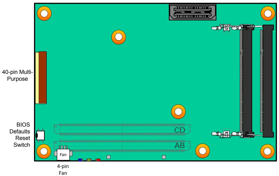
![40-pin Multi-\nPurpose\nBIOS\nDefaults\nReset\nSwitch\nCD\nAB\nFan\n4-pin\nFan](.express-dn7-50m-00049-1020-12/61421b5b914a0a68dc308ed4891d13d2628b250545974c7d5b0fa705b8957f2e.jpg)

![Bottom View\nCD\nAB](.express-dn7-50m-00049-1020-12/11d4cdfd217ecb36a294fe69bc070a7f39f75f72e800a8967dc5b113dd5dd39a.jpg)

Note: $3^{rd}$ SODIMM is located on back-side of module (supported by build option).

Figure 3: Express-DN7 Connector, Switch and LED Locations

# COM Express module and the DB40 Debug Module

For illustration purposes only
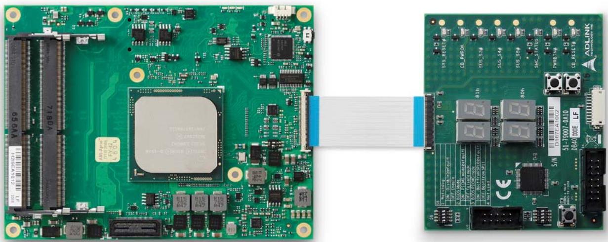
![Two views of a green printed circuit board with internal components and connectors, showing close-up assembly (no readable text or symbols)](.express-dn7-50m-00049-1020-12/7b1c3ab8365a6d22a65b38170e55c7a31ba93491a64e14a8a4d3ef60a19db0f4.jpg)

Figure 4: COM Express module and the DB40 Debug Module

# 4.2. 40-pin Debug Connector

FPC Connector Type: Molex 502790-4091

Pin Orientation
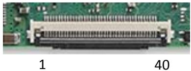
![Close-up of a green printed circuit board with a black connector (no visible text or symbols)](.express-dn7-50m-00049-1020-12/5d892ea4a673cecdfb174a9f0ab6c7aa78ad8c1d0dbfc58746d5c0bf88c900bc.jpg)

40-pin Debug Connector Pin Definition on the COM Express Module

<table><tr><td>Pin</td><td>Interface</td><td>Signal</td><td>Remark</td></tr><tr><td>40</td><td rowspan="7">SPI Program interface</td><td>VCC_SPI_IN</td><td></td></tr><tr><td>39</td><td>GND</td><td></td></tr><tr><td>38</td><td>SPI_BIOS_CS0#</td><td></td></tr><tr><td>37</td><td>SPI_BIOS_CS1#</td><td>PU 10k 3.3VSB</td></tr><tr><td>36</td><td>SPI_BIOS_MISO</td><td></td></tr><tr><td>35</td><td>SPI_BIOS_MOSI</td><td></td></tr><tr><td>34</td><td>SPI_BIOS_CLK</td><td></td></tr><tr><td>33</td><td rowspan="10">LPC Bus</td><td>3V3_LPC</td><td></td></tr><tr><td>32</td><td>GND</td><td></td></tr><tr><td>31</td><td>BIOS_DIS0</td><td>PU 10k 3.3VSB</td></tr><tr><td>30</td><td>RST#</td><td></td></tr><tr><td>29</td><td>CLK33_LP C</td><td></td></tr><tr><td>28</td><td>LPC_FRAME#</td><td></td></tr><tr><td>27</td><td>LPC_AD3</td><td></td></tr><tr><td>26</td><td>LPC_AD2</td><td></td></tr><tr><td>25</td><td>LPC_AD1</td><td></td></tr><tr><td>24</td><td>LPC_AD0</td><td></td></tr><tr><td>23</td><td rowspan="3">BMC Program interface</td><td>3.3V_BMC</td><td></td></tr><tr><td>22</td><td>3.3VSB</td><td></td></tr><tr><td>21</td><td>GND</td><td></td></tr></table>

<table><tr><td>Pin</td><td>Interface</td><td>Signal</td><td>Remark</td></tr><tr><td>20</td><td rowspan="8">BMC Program interface (cont&#x27;d)</td><td>TXD6</td><td></td></tr><tr><td>19</td><td>RXD6</td><td></td></tr><tr><td>18</td><td>FUMD0</td><td></td></tr><tr><td>17</td><td>RESET_IN#</td><td>PU 10k 3.3VSB</td></tr><tr><td>16</td><td>DATA</td><td>PU 2.2k 3.3VSB Equivalent</td></tr><tr><td>15</td><td>CLK</td><td>PU 2.2k 3.3VSB Equivalent</td></tr><tr><td>14</td><td>OCD0A</td><td></td></tr><tr><td>13</td><td>OCD0B</td><td></td></tr><tr><td>12</td><td rowspan="7">Test points</td><td>PWRBTN#</td><td>PU 10k 3.3VSB</td></tr><tr><td>11</td><td>SYS_RESET #</td><td>PU 10k 3.3VSB</td></tr><tr><td>10</td><td>CB_RESET#</td><td>PU 1k 3.3VSB</td></tr><tr><td>9</td><td>CB_PWROK</td><td></td></tr><tr><td>8</td><td>SUS_S3#</td><td></td></tr><tr><td>7</td><td>SUS_S4#</td><td></td></tr><tr><td>6</td><td>SUS_S5#</td><td></td></tr><tr><td>5</td><td rowspan="4">BMC Debug signals</td><td>POSTWDT_DIS#</td><td>PU 100k 3.3VSB</td></tr><tr><td>4</td><td>SEL_BIOS</td><td></td></tr><tr><td>3</td><td>BIOS_MODE</td><td></td></tr><tr><td>2</td><td>BMC_STATUS</td><td></td></tr><tr><td>1</td><td>Reserved</td><td></td><td>Tied to GND through 0ohm resistor</td></tr></table>

Table 2: 40-pin Debug Connector Pin Definition
Note: The pin definition on the debug module is the inverse of that on the COM Express module.

# 4.3. Status LEDs

To facilitate easier maintenance, status LED's are mounted on the board.

![Close-up of a green printed circuit board with visible traces and components (no readable text or symbols)](.express-dn7-50m-00049-1020-12/30872dbf3454e17cd22bcbc805ca3e65bc2ce0db31ee87a24cae822f5c67fa04.jpg)

LED1 LED2 LED3

LED Descriptions

<table><tr><td>Name</td><td>Color</td><td>Connection</td><td>Function</td></tr><tr><td>LED1</td><td>Blue</td><td>BMC output</td><td>Power Sequence Status Code (BMC)Power Changes, RESET(see 5.1.4 Exception Codes below)</td></tr><tr><td>LED2</td><td>Green</td><td>Power Source 3Vcc</td><td>S0 LED ONS3/S4/S5 LED OFFECO mode LED OFF</td></tr><tr><td>LED3</td><td>Red</td><td>BMC outputand same signal as WDT (B27) on BtB connector</td><td>Module power up LED OFFWatchdog counting Keep last stateWatchdog timed out LED ONWatchdog RESET LED ONRebooted after WD RESET LED ONRebooted after PWRBTN LED OFFRebooted after RESET BTN LED OFFNote: only a RESET not initiated by the BMC can clear the WD LED (user action)</td></tr></table>

Table 3: Express-DN7 LED Descriptions

# 4.4. MIPI60 Debug Header

Not all pins of the Intel MIPI60 connector are connected to the CombiProbe Intel x86/x64 MIPI-C.

<table><tr><td>Pin</td><td>Signal</td></tr><tr><td>1</td><td>VREF_DEBUG</td></tr><tr><td>3</td><td>TCK0</td></tr><tr><td>5</td><td>TDI</td></tr><tr><td>7</td><td>Reset In</td></tr><tr><td>9</td><td>TRST_N</td></tr><tr><td>11</td><td>PRDY_N</td></tr><tr><td>13</td><td>PTI_0_CLK</td></tr><tr><td>15</td><td>GND</td></tr><tr><td>17</td><td>No Connect</td></tr><tr><td>19</td><td>PTI_0_DATA[0]</td></tr><tr><td>21</td><td>PTI_0_DATA[1]</td></tr><tr><td>23</td><td>PTI_0_DATA[2]</td></tr><tr><td>25</td><td>PTI_0_DATA[3]</td></tr><tr><td>27</td><td>PTI_0_DATA[4]</td></tr><tr><td>29</td><td>PTI_0_DATA[5]</td></tr><tr><td>31</td><td>PTI_0_DATA[6]</td></tr><tr><td>33</td><td>PTI_0_DATA[7]</td></tr><tr><td>35</td><td>No Connect</td></tr><tr><td>37</td><td>No Connect</td></tr><tr><td>39</td><td>No Connect</td></tr><tr><td>41</td><td>No Connect</td></tr><tr><td>43</td><td>No Connect</td></tr><tr><td>45</td><td>No Connect</td></tr><tr><td>47</td><td>No Connect</td></tr><tr><td>49</td><td>No Connect</td></tr><tr><td>51</td><td>No Connect</td></tr><tr><td>53</td><td>No Connect</td></tr><tr><td>55</td><td>No Connect</td></tr><tr><td>57</td><td>GND</td></tr><tr><td>59</td><td>No Connect</td></tr></table>

<table><tr><td>Pin</td><td>XDP Signal</td></tr><tr><td>2</td><td>TMS</td></tr><tr><td>4</td><td>TDO</td></tr><tr><td>6</td><td>Open Drain Reset Out</td></tr><tr><td>8</td><td>No Connect</td></tr><tr><td>10</td><td>PREQ_N</td></tr><tr><td>12</td><td>VREF_TRACE</td></tr><tr><td>14</td><td>PTI_1_CLK</td></tr><tr><td>16</td><td>GND</td></tr><tr><td>18</td><td>PTI_1_DATA[0]</td></tr><tr><td>20</td><td>PTI_1_DATA[1]</td></tr><tr><td>22</td><td>PTI_1_DATA[2]</td></tr><tr><td>24</td><td>PTI_1_DATA[3]</td></tr><tr><td>26</td><td>No Connect</td></tr><tr><td>28</td><td>No Connect</td></tr><tr><td>30</td><td>No Connect</td></tr><tr><td>32</td><td>No Connect</td></tr><tr><td>34</td><td>Reset Out</td></tr><tr><td>36</td><td>Boot Stall</td></tr><tr><td>38</td><td>CPU Boot Stall</td></tr><tr><td>40</td><td>Power Button</td></tr><tr><td>42</td><td>PWRGOOD</td></tr><tr><td>44</td><td>No Connect</td></tr><tr><td>46</td><td>No Connect</td></tr><tr><td>48</td><td>I2C_SCL</td></tr><tr><td>50</td><td>I2C_SDA</td></tr><tr><td>52</td><td>No Connect</td></tr><tr><td>54</td><td>DBG_UART_TX</td></tr><tr><td>56</td><td>DBG_UART_RX</td></tr><tr><td>58</td><td>GND</td></tr><tr><td>60</td><td>No Connect</td></tr></table>

Table 4: MIPI60 Debug Header Pin Definition

# 4.5. Fan Connector

Connector Type: JVE 24W1125A-04M00

Pin Orientation
![Close-up of a green printed circuit board with a yellow circular component and various electronic components (no visible text or symbols)](.express-dn7-50m-00049-1020-12/be9c4bedd36e3cdb7db66130c8d1c279fc42a5b35e5c174508518b911f5c0db7.jpg)

1234

# Pin Assignment

<table><tr><td>Name</td><td>Signal</td></tr><tr><td>1</td><td>FAN_PWMOUT</td></tr><tr><td>2</td><td>FAN_TACHIN</td></tr><tr><td>3</td><td>Ground</td></tr><tr><td>4</td><td>5V</td></tr></table>

Table 5: Fan Connector Pin Definition

# 4.6. BIOS Setup Defaults Reset Button

![Close-up of a green printed circuit board with visible traces and components (no readable text or symbols)](.express-dn7-50m-00049-1020-12/526ad646a042b975c9b52f8e2701a18c3ea146c5aa1572ffe91d035aa5ac60f9.jpg)

To perform a hardware reset of BIOS default settings, perform the following steps:

1. Shut down the system.
2. Hold down the BIOS Setup Defaults Reset Button and boot up the system. You can release the button when the BIOS prompt screen appears
3. The BIOS prompt screen will display a confirmation that BIOS defaults have been reset and request that you reboot the system.

![American\nMegatrends\nVersion 2.15.1236. Copyright (C) 2012 American Megatrends, Inc.\nExpress-HL REV:1.04\nPress (CTRL + P) to Enter MEBX setup menu\nPress (DEL) or (ESC) to enter setup.\nDefault settings had been loaded due to BIOS_DEFAULT jumper is set!\nPlease turn off system power and remove BIOS_DEFAULT jumper!](.express-dn7-50m-00049-1020-12/08762ea75ad6267bf8b5844764eeafbbde7ab4267f31cf1ad9b9671fd6e3639a.jpg)

# 4.7. Switch Settings

# Switch Locations

![NDAV\n76JFB\n100\nBIOS Select and Mode\nConfiguration Switch (SW2)](.express-dn7-50m-00049-1020-12/e6766ff543adb98b5372f0f68358ff7cb566b74d67d4fc1c982d1bd257535d60.jpg)

Figure 5: Express-DN7 Switch Locations

# BIOS Select and Mode Configuration Switch

The module has two BIOS chips and BIOS operation can be configured to "PICMG" and dual-BIOS "Failsafe" modes using the BIOS Select and Mode Configuration Switch (SW2), Pin 2.

Setting the module to PICMG mode will configure the BIOS chips on the module as SPI0 and SPI1. In PICMG mode, a BIOS chip cannot be placed in the SPI0 slot on the carrier.

In dual-BIOS Failsafe mode, both BIOS chips on the module are configured as SPI1. Only one of the two is connected to the SPI bus at any given time. In case of failure of the primary SPI1 BIOS, the system will reboot and switch to the secondary SPI1 BIOS on the module. In Failsafe mode, the SPI0 BIOS socket on the carrier can be populated.

In either mode, Pin 1 is used to select whether to boot from SPI0 or SPI1.

<table><tr><td>Mode</td><td>Pin 1</td><td>Pin 2</td></tr><tr><td>Boot from SPI0 (default)</td><td>On</td><td>—</td></tr><tr><td>Boot from SPI1</td><td>Off</td><td>—</td></tr><tr><td>Set BIOS to PICMG mode</td><td>—</td><td>On</td></tr><tr><td>Set BIOS to Failsafe BIOS mode (default)</td><td>—</td><td>Off</td></tr></table>

Table 6: BIOS Select and Mode Configuration Switch Settings

# 4.8. PCIe x8-to-two-x4 Adapter Card

The Express-DN7 can be used with the PCIe x8-to-two-x4 Adapter Card on the Express-BASE7 Reference Carrier to support bifurbication of the PCIe x8 interface. The card reroutes the PCIe x8 to two x4 and allows testing of two independent PCIe add-on cards with x4/x2/x1 width. To use the card, set BIOS > Chipset > IIO Configuration > IIO0 Configuration > IOU2 (IIO PCIe Port 1) to "x4x4".

![Green printed circuit board with black plastic connectors and gold contacts (no readable text or symbols)](.express-dn7-50m-00049-1020-12/87815b6688fd4579ef8b2d3d732fcf1fe4daf71dc8399fcc880071dc901da78f.jpg)

PCIex8-to-two-x4 Adapter Card (Model: P8TO24, Part No.:)

This page intentionally left blank.

# 5. Smart Embedded Management Agent (SEMA)

The onboard microcontroller (BMC) implements power sequencing and Smart Embedded Management Agent (SEMA) functionality. The microcontroller communicates via the System Management Bus with the CPU/chipset. The following functions are implemented:

• Total operating hours counter. Counts the number of hours the module has been run in minutes.
- On-time minutes counter. Counts the seconds since last system start.
- Temperature monitoring of CPU and board temperature. Minimum and maximum temperature values of CPU and board are stored in flash.
• Power cycles counter
- Boot counter. Counts the number of boot attempts.
- Watchdog Timer. Set/Reset/Disable Watchdog Timer. Features auto-reload at power-up.
• System Restart Cause. Power loss/BIOS Fail/Watchdog/Internal Reset/External Reset
- Fail-safe BIOS support. In case of a boot failure, hardware signals tells external logic to boot from fail-safe BIOS.
• Flash area. 1kB Flash area for customer data
• 2K Bytes Protected Flash area. Keys, IDs, etc. can be stored in a write- and clear-protectable region.
• Board Identify. Vendor/Board/Serial number/Production Date
• Main-current & voltage. Monitors drawn current and main voltages

For a detailed description of SEMA features and functionality, please refer to SEMA Technical Manual and SEMA Software Manual, downloadable at: http://www.adlinktech.com/sema/.

# 5.1. Board Specific SEMA Functions (update later)

Note: To be confirmed.

# 5.1.1. Voltages

The BMC of the Express-DN7 implements a voltage monitor and samples several onboard voltages. The voltages can be read by calling the SEMA function “Get Voltages”. The function returns a 16-bit value divided into high-byte (MSB) and low-byte (LSB).

<table><tr><td>ADC Channel</td><td>Voltage Name</td><td>Voltage Formula [V]</td></tr><tr><td>0</td><td>VCORE</td><td>(MSB&lt;&lt;8 + LSB) x 1.0 x 3.3 / 1024</td></tr><tr><td>1</td><td>VMEM</td><td>(MSB&lt;&lt;8 + LSB) x 1.0 x 3.3 / 1024</td></tr><tr><td>2</td><td>RTC</td><td>(MSB&lt;&lt;8 + LSB) x 1.0 x 3.3 / 1024</td></tr><tr><td>3</td><td>3.3V</td><td>(MSB&lt;&lt;8 + LSB) x 1.1 x 3.3 / 1024</td></tr><tr><td>4</td><td>5VSB</td><td>(MSB&lt;&lt;8 + LSB) x 1.826 x 3.3 / 1024</td></tr><tr><td>5</td><td>VIN</td><td>(MSB&lt;&lt;8 + LSB) x 3.7 x 3.3 / 1024</td></tr><tr><td>6</td><td>3.3VSB</td><td>(MSB&lt;&lt;8 + LSB) x 1.1 x 3.3 / 1024</td></tr><tr><td>7</td><td>5V</td><td>(MSB&lt;&lt;8 + LSB) x 1.826 x 3.3 / 1024</td></tr></table>

Table 7: SEMA Onboard Voltage Monitor

# 5.1.2. Main Current

The BMC of the Express-DN7 implements a current monitor. The current can be read by calling the SEMA function "Get Main Current". The function returns four 16-bit values divided in high-byte (MSB) and low-byte (LSB). These 4 values represent the last 4 currents drawn by the board. The values are sampled every 250ms. The order of the 4 values is NOT in chronological order. Access by the BMC may increase the drawn current of the whole system. In this case, there are still 3 samples not influenced by the read access.

$$
\text { Main   Current } = (\text { MSB\_n } &lt;   &lt;   8 + \text { LSB\_n }) \times 8. 0 6 \mathrm{mA}
$$

# 5.1.3. BMC Status

This register shows the status of BMC controlled signals on the Express-DN7.

&lt;table&gt;<tr><td>Status Bit</td><td>Signal</td></tr><tr><td>0</td><td>WDT_OUT</td></tr><tr><td>1</td><td>Reserved</td></tr><tr><td>2</td><td>Reserved</td></tr><tr><td>3</td><td>BIOS_MODE</td></tr><tr><td>4</td><td>POSTWDT_DISn</td></tr><tr><td>5</td><td>SEL_BIOS</td></tr><tr><td>6</td><td>BIOS_DIS0n</td></tr><tr><td>7</td><td>BIOS_DIS1n</td></tr></table>

Table 8: SEMA BMC Status

# 5.1.4. Exception Codes

In case of an error, the BMC drives a blinking code on the blue Status LED (LED1). The same error code is also reported by the BMC Flags register. The Exception Code is not stored in the Flash Storage and is cleared when the power is removed. Therefore, a “Clear Exception Code” command is not needed or supported.

<table><tr><td>Exception Code</td><td>Error Message</td></tr><tr><td>0</td><td>NOERROR</td></tr><tr><td>2</td><td>NO_SUSCLK</td></tr><tr><td>3</td><td>NO_SLP_S45</td></tr><tr><td>4</td><td>NO_SLP_S3</td></tr><tr><td>5</td><td>RESET_FAIL</td></tr><tr><td>6</td><td>BIOS_FAIL</td></tr><tr><td>7</td><td>NO_CB_PWROK</td></tr><tr><td>8</td><td>POWER_FAIL</td></tr><tr><td>9</td><td>VOLTAGE_FAIL</td></tr><tr><td>10</td><td>NO_VCC_CORE</td></tr><tr><td>11</td><td>NO_VDDQ</td></tr><tr><td>12</td><td>NO_VRTC</td></tr><tr><td>13</td><td>NO_V3P3_S</td></tr><tr><td>14</td><td>NO_V5VSB</td></tr><tr><td>15</td><td>NO_V12</td></tr><tr><td>16</td><td>NO_V3P3_A</td></tr><tr><td>17</td><td>NO_V5V_S</td></tr><tr><td>18</td><td>NO_P_5V_3P3_PG</td></tr><tr><td>19</td><td>NO_5V_PG</td></tr><tr><td>20</td><td>NO_VCCRAM_PG</td></tr><tr><td>21</td><td>NO_VNN_PG</td></tr><tr><td>22</td><td>NO_V5_DUAL</td></tr><tr><td>23</td><td>NO_V1P8_A_PG</td></tr><tr><td>24</td><td>NO_V1P05_A_PG</td></tr><tr><td>25</td><td>NO_ALL_SYS_PG</td></tr><tr><td>26</td><td>CRITICAL_TEMP</td></tr><tr><td>27</td><td>RESETIN_FAIL</td></tr></table>

Table 9: SEMA Exception Codes

# 5.1.5. BMC Flags

The BMC Flags register returns the last detected Exception Code since power-up and shows the BIOS in use and the power mode.

<table><tr><td>Bit</td><td>Description</td></tr><tr><td>[0 ~ 4]</td><td>Exception Code</td></tr><tr><td>[6]</td><td>0 = AT mode1 = ATX mode</td></tr><tr><td>[7]</td><td>0 = Standard BIOS1 = Fail-safe BIOS.</td></tr></table>

Table 10: SEMA BMC Flags

# 6. System Resources

# 6.1. System Memory Map

<table><tr><td>Memory Range</td><td>Target</td></tr><tr><td>0000 0000h – 000D FFFFh0010 0000h – TOM(Top of Memory)</td><td>Main Memory</td></tr><tr><td>000E 0000h – 000F FFFFh</td><td>Motherboard resources</td></tr><tr><td></td><td></td></tr><tr><td>FEC0 0000h-FEC0 0fffh</td><td>IO(x) APIC</td></tr><tr><td>FED0 0000 – FED0 03FF</td><td>HPET</td></tr><tr><td>FF00 0000 h – FFFF FFFFh</td><td>IFAW (BIOS)</td></tr></table>

# 6.2. Direct Memory Access Channels

<table><tr><td>Channel Number</td><td>Data Width</td><td>System Resource</td></tr><tr><td>0</td><td>8-bits</td><td>Generic</td></tr><tr><td>1</td><td>8-bits</td><td>Generic</td></tr><tr><td>2</td><td>8-bits</td><td>Generic</td></tr><tr><td>3</td><td>8-bits</td><td>Generic</td></tr><tr><td>4</td><td></td><td>Reserved - cascade channel</td></tr><tr><td>5</td><td>16-bits</td><td>Generic</td></tr><tr><td>6</td><td>16-bits</td><td>Generic</td></tr><tr><td>7</td><td>16-bits</td><td>Generic</td></tr></table>

# 6.3. Fixed I/O Address Range Map

<table><tr><td>Hex Range</td><td>Device</td></tr><tr><td>020-021</td><td>Interrupt Controller</td></tr><tr><td>024-025</td><td>Interrupt Controller</td></tr><tr><td>028-029</td><td>Interrupt Controller</td></tr><tr><td>02C-02D</td><td>Interrupt Controller</td></tr><tr><td>02E-02F</td><td>LPC SIO</td></tr><tr><td>030-031</td><td>Interrupt Controller</td></tr><tr><td>034-035</td><td>Interrupt Controller</td></tr><tr><td>038-039</td><td>Interrupt Controller</td></tr><tr><td>03C-03D</td><td>Interrupt Controller</td></tr><tr><td>040-042</td><td>Timer/Counter</td></tr><tr><td>043</td><td>Timer/Counter</td></tr><tr><td>04E-04F</td><td>LPC SIO</td></tr><tr><td>050-052</td><td>Timer/Counter</td></tr><tr><td>053</td><td>Timer/Counter</td></tr><tr><td>060</td><td>Microcontroller</td></tr><tr><td>061</td><td>NMI Controller</td></tr><tr><td>062</td><td>Microcontroller</td></tr><tr><td>064</td><td>Microcontroller</td></tr><tr><td>066</td><td>Microcontroller</td></tr><tr><td>070-077</td><td>RTC</td></tr><tr><td>080081-083084-086087088089-08B08C-08E08F</td><td>DMA Controller and LPC,PCI,or PCIE</td></tr><tr><td>090-091</td><td>DMA Controller</td></tr><tr><td>093-09F</td><td>DMA Controller</td></tr><tr><td>092</td><td>Reset Generator</td></tr><tr><td>0A0-0A10A4-0A50A8-0A90AC-0AD</td><td>Interrupt Controller</td></tr><tr><td>0B0-0B10B4-0B50B8-0B90BC-0BD</td><td>Interrupt Controller</td></tr><tr><td>0B2-0B3</td><td>Power Management</td></tr><tr><td>0C0-0D10D2-0DD0DE-0DF</td><td>DMA Controller</td></tr><tr><td>0F0</td><td>FERR# / Interrupt Controller</td></tr><tr><td>240-247</td><td>COM3</td></tr><tr><td>248-24F</td><td>COM4</td></tr><tr><td>2F8-2FF</td><td>COM2</td></tr><tr><td>3F8-3FF</td><td>COM1</td></tr><tr><td>4D0-4D1</td><td>Interrupt Controller</td></tr><tr><td>CA0-CB0</td><td>IPMI Usage</td></tr><tr><td>CF9</td><td>Reset Generator</td></tr></table>

6.4. Variable I/O Address Range Map

<table><tr><td>Hex Range</td><td>Device</td></tr><tr><td>Anywhere in 64 KB I/O Space</td><td>ACPI</td></tr><tr><td>Anywhere in 64 KB I/O Space</td><td>SATA Index/Data Pair</td></tr><tr><td>Anywhere in 64 KB I/O Space</td><td>SMBus</td></tr><tr><td>96 Bytes above ACPI Base</td><td>TCO</td></tr><tr><td>Anywhere in 64 KB I/O Space</td><td>GPIO</td></tr><tr><td>8 Ranges in 64 KB I/O Space</td><td>Serial Port 1</td></tr><tr><td>8 Ranges in 64 KB I/O Space</td><td>Serial Port 2</td></tr><tr><td>Anywhere in 64 KB I/O Space</td><td>LAN</td></tr><tr><td>Anywhere in 64 KB I/O Space</td><td>LPC Generic 1</td></tr><tr><td>Anywhere in 64 KB I/O Space</td><td>LPC Generic 2</td></tr><tr><td>Anywhere in 64 KB I/O Space</td><td>LPC Generic 3</td></tr><tr><td>Anywhere in 64 KB I/O Space</td><td>LPC Generic 4</td></tr><tr><td>Anywhere in 64 KB I/O Space</td><td>I/O Trapping Ranges</td></tr></table>

6.5. APIC Interrupt Mapping

<table><tr><td>IRQ#</td><td>Typical Interrupt Resource</td><td>Using SERIRQ</td></tr><tr><td>0</td><td>Cascade from 8259 #1</td><td>No</td></tr><tr><td>1</td><td></td><td>Yes</td></tr><tr><td>2</td><td>8254 Counter 0,HPET #0(Legacy mode)</td><td>No</td></tr><tr><td>3</td><td>COM2</td><td>Yes</td></tr><tr><td>4</td><td>COM1</td><td>Yes</td></tr><tr><td>5</td><td>COM3</td><td>Yes</td></tr><tr><td>6</td><td></td><td>Yes</td></tr><tr><td>7</td><td>COM4</td><td>Yes</td></tr><tr><td>8</td><td>RTC,HPET #1(Legacy mode)</td><td>No</td></tr><tr><td>9</td><td>Option for SCI,TCO</td><td>Yes</td></tr><tr><td>10</td><td>Option for SCI,TCO</td><td>Yes</td></tr><tr><td>11</td><td>HPET #2,Option for SCI,TCO</td><td>Yes</td></tr><tr><td>12</td><td></td><td>Yes</td></tr><tr><td>13</td><td>FERR# logic</td><td>No</td></tr><tr><td>14</td><td></td><td></td></tr><tr><td>15</td><td></td><td></td></tr><tr><td>16</td><td>Internal devices are routable.</td><td>PIRQA#</td></tr><tr><td>17</td><td>Internal devices are routable.</td><td>PIRQB#</td></tr><tr><td>18</td><td>Internal devices are routable.</td><td>PIRQC#</td></tr><tr><td>19</td><td>Internal devices are routable.</td><td>PIRQD#</td></tr><tr><td>20</td><td>Option for SCI,TCO,HPET #0,1,2,3.Other internal device are routable.</td><td>N/A</td></tr><tr><td>21</td><td>Option for SCI,TCO,HPET #0,1,2,3.Other internal device are routable.</td><td>N/A</td></tr><tr><td>22</td><td>Option for SCI,TCO,HPET #0,1,2,3.Other internal device are routable.</td><td>N/A</td></tr><tr><td>23</td><td>Option for SCI,TCO,HPET #0,1,2,3.Other internal device are routable.</td><td>N/A</td></tr></table>

6.6. PCI Configuration Space Map

<table><tr><td>Bus Number</td><td>Device Number</td><td>Function Number</td><td>Description</td></tr><tr><td>00h</td><td>00h</td><td>00h</td><td>System Agent</td></tr><tr><td>00h</td><td>04h</td><td>00h</td><td>Global and Local Error Registers (GLMREG)</td></tr><tr><td>00h</td><td>05h</td><td>00h</td><td>Root Complex Event Collector</td></tr><tr><td>00h</td><td>06h</td><td>00h</td><td>RP - Intel® QuickAssist Technology</td></tr><tr><td>00h</td><td>09h~0Ch,0Eh~11h</td><td>00h</td><td>PCI Express Root Ports</td></tr><tr><td>00h</td><td>13h</td><td>00h</td><td>SATA Controllers</td></tr><tr><td>00h</td><td>15h</td><td>00h</td><td>USB Combo Controller</td></tr><tr><td>00h</td><td>18h</td><td>00h</td><td>System Management</td></tr><tr><td>00h</td><td>1Ah</td><td>00h</td><td>HSUART Controller</td></tr><tr><td>00h</td><td>1Bh</td><td>00h</td><td>Innovation Engine</td></tr><tr><td>00h</td><td>1Ch</td><td>00h</td><td>eMMC Controller</td></tr><tr><td>00h</td><td>1Fh</td><td>00h</td><td>LPC Controller</td></tr><tr><td>00h</td><td>1Fh</td><td>01h</td><td>Primary to Side Band Bridge</td></tr><tr><td>00h</td><td>1FH</td><td>02H</td><td>Power Management Controller</td></tr><tr><td>00h</td><td>1Fh</td><td>04h</td><td>SMBus - Legacy</td></tr><tr><td>00h</td><td>1Fh</td><td>05h</td><td>SPI Controller</td></tr></table>

# 6.7. PCI Interrupt Routing Map

<table><tr><td>INT Line</td><td>xHCI Controller</td><td>PCIE Port1</td><td>PCIE Port 2</td><td>PCIE Port 3</td><td>PCIE Port 4</td><td>PCIE Port 5</td><td>PCIE Port 6</td></tr><tr><td>Int0</td><td>INTD:19</td><td>INTA:16</td><td>INTB:17</td><td>INTC:18</td><td>INTD:19</td><td>INTE:20</td><td>INTH:23</td></tr><tr><td>Int1</td><td></td><td>INTB:17</td><td>INTC:18</td><td>INTD:19</td><td>INTA:16</td><td>INTF:21</td><td>INTE:20</td></tr><tr><td>Int2</td><td></td><td>INTC:18</td><td>INTD:19</td><td>INTA:16</td><td>INTB:17</td><td>INTG:22</td><td>INTF:21</td></tr><tr><td>Int3</td><td></td><td>INTD:19</td><td>INTA:16</td><td>INTB:17</td><td>INTC:18</td><td>INTH:23</td><td>INTG:22</td></tr></table>

<table><tr><td>INT Line</td><td>PCIE Port 7</td><td>PCIE Port 8</td><td>SATA Controller</td><td>SMBus Controller</td></tr><tr><td>Int0</td><td>INTG:22</td><td>INTH:23</td><td>INTE:20</td><td></td></tr><tr><td>Int1</td><td>INTH:23</td><td>INTE:20</td><td></td><td></td></tr><tr><td>Int2</td><td>INTE:20</td><td>INTF:21</td><td></td><td>INTH:23</td></tr><tr><td>Int3</td><td>INTF:21</td><td>INTG:22</td><td></td><td></td></tr></table>

# 6.8. SMBus Address Table

<table><tr><td>Device</td><td>Address</td></tr><tr><td>BMC</td><td>50h</td></tr><tr><td>Extend GPIO</td><td>40h</td></tr></table>

This page intentionally left blank.

# 7. BIOS Setup

# 7.1. Menu Structure

This section presents the six primary menus of the BIOS Setup Utility. Use the following table as a quick reference for the contents of the BIOS Setup Utility. The subsections in this section describe the Submenus and setting options for each menu item. The default setting options are presented in bold, and the function of each setting is described in the right hand column of the respective table.

<table><tr><td>Main</td><td>IntelRCSetup</td><td>Advanced</td><td>Event Logs</td><td>Security</td><td>Boot</td><td>Save &amp; Exit</td></tr><tr><td>BIOS Information System Information Board Information System Date and Time Access Level</td><td>PlatformRC RevisionProcessor BSPRevisionMicrocodeRevisionProcessorConfigurationCPU ThermalConfigurationCK420ConfigurationServer MEConfigurationServer MEConfigurationSystem EventLogNorth BridgeChipsetConfigurationSouth BridgeChipsetConfiguration</td><td>PowerManagement ▶SystemManagement ▶ThermalManagement ▶Watchdog Timer ▶CSM Configuration ▶Super IOConfiguration ▶Serial ConsoleRedirection ▶USB Configuration ▶Network StackConfiguration ▶Miscellaneous ▶Driver Health ▶Trusted Computing ▶</td><td>Change SMBIOS Event Log Settings ▶Vies SMBIOS Event Log ▶</td><td>SetupAdministratorPassword ▶User PasswordSecure Boot ▶</td><td>Boot ▶ConfigurationFIXED BOOT ORDER ▶PrioritiesUEFI USBKey DriveBBS Priorities ▶</td><td>Save Change and Exit ▶Discard Changes and Exit ▶Save Changes and Reset ▶Discard Changes and Reset ▶Save OptionsBoot Override ▶</td></tr></table>

# Notes:

▶ indicates a Submenu
Gray text indicates info only

# 7.2. Main

The Main Menu provides read-only information about your system and also allows you to set the System Date and Time. Refer to the tables below for details of the settings.

7.2.1. Main > BIOS Information

<table><tr><td>Feature</td><td>Options</td><td>Description</td></tr><tr><td>BIOS Vender</td><td>Info only</td><td>American Megatrends</td></tr><tr><td>BIOS Version</td><td>Info only</td><td>ADLINK BIOS version</td></tr><tr><td>Build Date</td><td>Info only</td><td>ADLINK BIOS Build Date</td></tr><tr><td>SPS Firmware Version</td><td>Info only</td><td>Display SPS Firmware Version</td></tr></table>

7.2.2. Main > System Information

<table><tr><td>Feature</td><td>Options</td><td>Description</td></tr><tr><td>Project Name</td><td>Info only</td><td>Display Project Name.</td></tr><tr><td>Hardware version</td><td>Info only</td><td>Display CPU Board Version.</td></tr><tr><td>CPU Brand String</td><td>Info only</td><td>Display CPU Board String.</td></tr><tr><td>CPU Frequency</td><td>Info only</td><td>Display CPU Frequency.</td></tr><tr><td>Total Memory</td><td>Info only</td><td>Display Installed Memory Size.</td></tr><tr><td>SOC SKU</td><td>Info only</td><td></td></tr></table>

# 7.2.3. Main > Board Information

<table><tr><td>Feature</td><td>Options</td><td>Description</td></tr><tr><td>Board Information</td><td>Submenu</td><td></td></tr><tr><td>Board Information</td><td>Info only</td><td></td></tr><tr><td>Serial Number</td><td>Info only</td><td>Display SEMA serial Number.</td></tr><tr><td>Manufacturing Date</td><td>Info only</td><td>Display SEMA manufacturing date.</td></tr><tr><td>Last Repair Date</td><td>Info only</td><td>Display SEMA last repair date.</td></tr><tr><td>MAC ID</td><td>Info only</td><td>Display SEMA MAC ID.</td></tr><tr><td>Runtime Statistics</td><td>Info only</td><td></td></tr><tr><td>Total Runtime</td><td>Info only</td><td>The returned value specifies the total time in minutes the system is running in S0 state.</td></tr><tr><td>Current Runtime</td><td>Info only</td><td>The returned value specifies the time in seconds the system is running in S0 state.This counter is cleared when the system is removed from the external power supply.</td></tr><tr><td>Power Cycles</td><td>Info only</td><td>The returned value specifies the number of times the external power supply has been shut down</td></tr><tr><td>Boot Cycles</td><td>Info only</td><td>The Boot counter is increased after a HW- or SW-Reset or after a successful power-up.</td></tr><tr><td>Boot Reason</td><td>Info only</td><td>The boot reason is the event which causes the reboot of the system.</td></tr></table>

# 7.2.4. Main >System Date/Time

<table><tr><td>Feature</td><td>Options</td><td>Description</td></tr><tr><td>System Date</td><td>Info only</td><td></td></tr><tr><td>System Time</td><td>Info only</td><td></td></tr></table>

# 7.2.5. Main >Access Level

<table><tr><td>Feature</td><td>Options</td><td>Description</td></tr><tr><td>Access Level</td><td>Info only</td><td></td></tr></table>

# 7.3. IntelRCSetup

7.3.1. IntelRCSetup >Processor Configuration

<table><tr><td>Feature</td><td>Options</td><td>Description</td></tr><tr><td>Processor Configuration</td><td>Info only</td><td></td></tr><tr><td>EIST (GV3)</td><td>Disabled Enabled</td><td>Enable/Disable EIST. GV3 and TM1 must be enabled for TM2 to be available. GV3 must be enabled for Turbo. Auto-Enable for B0 CPU stepping, all others disabled, change setting to override.</td></tr><tr><td>BIOS Request Frequency</td><td>Disabled Enabled</td><td>Two modes: Min Frequency and Max Frequency (the CPU will be instructed to provide the highest possible legal frequency to the processor).</td></tr><tr><td>Turbo</td><td>Disabled Enabled</td><td>Enable or Disable CPU Turbo capability. This option only applies to ES2 and above.</td></tr><tr><td>TM1</td><td>Disabled Enabled</td><td>Enable/Disable TM1. TM1 and GV3 must be enabled in order to support TM2</td></tr><tr><td>TM2 Mode</td><td>LFM Throttling Adaptive Throttling</td><td>Select LFM throttling or adaptive throttling for TM2 mechanisms.</td></tr><tr><td>Dynamic Self Refresh</td><td>Disabled Enabled</td><td>Enable or Disable dynamic self refresh in memory controller</td></tr><tr><td>PMOP Levels</td><td>Slow Fast</td><td>Power Mode Opcode during Self Refresh Slow/Fast</td></tr><tr><td>CPU C State</td><td>Disabled Enabled</td><td>Enables the Enhanced Cx state of the CPU, takes effect after reboot. Auto - Enable for B0 CPU stepping, all others disabled, change setting to override.</td></tr><tr><td>Package C State limit</td><td>No Pkg C-State No S0lx No Limit</td><td>No Package C State limit</td></tr><tr><td>Max Core C-State</td><td>C1 C6</td><td>Options are: C1 and C6.</td></tr><tr><td>Enhanced Halt State (C1E)</td><td>Disabled Enabled</td><td>Enables the Enhanced C1E state of the CPU, takes effect after reboot.</td></tr><tr><td>Monitor/Mwait</td><td>Disabled Enabled</td><td>Enable or Disable the Monitor/Mwait instruction</td></tr><tr><td>L1 Prefetcher</td><td>Disabled Enabled</td><td>Enable/Disable L1 Prefetch</td></tr><tr><td>L2 Prefetcher</td><td>Disabled Enabled</td><td>Enable/Disable L2 Prefetch</td></tr><tr><td>ACPI 3.0 T-States</td><td>Disabled Enabled</td><td>Enable/Disable ACPI 3.0 T-States.</td></tr><tr><td>Fast String</td><td>Disabled Enabled</td><td>When enabled, enables fast strings for REP MOVS/STOS</td></tr><tr><td>Machine Check</td><td>Disabled Enabled</td><td>Enable or Disable the Machine Check</td></tr><tr><td>Max CPUID Value Limit</td><td>Disabled Enabled</td><td>This should be enabled in order to boot legacy OSes that cannot support CPUs with extended CPUID functions.</td></tr><tr><td>Execute Disable Bit</td><td>Disabled Enabled</td><td>When disabled, forces the XD feature flag to always return 0.</td></tr><tr><td>vmx</td><td>DisabledEnabled</td><td>Enables the Vanderpool Technology, takes effect after reboot.</td></tr><tr><td>BIST Selection</td><td>DisabledEnabled</td><td>Enables BIST, takes effect after reboot.</td></tr><tr><td>Extended APIC</td><td>Info only</td><td></td></tr><tr><td>MSR 606PKG_POWER_SKU_UNIT</td><td>Info only</td><td></td></tr><tr><td>Lock PACKAGE_RAPL_LIMIT</td><td>DisabledEnabled</td><td>Allows the user to lock the MSR 0x610(PACKAGE_RAPL_LIMIT) by setting the lock bit</td></tr><tr><td>PL1 Time Window</td><td>45</td><td>Defines RAPL time window 1 in milliseconds</td></tr><tr><td>PL1 Power Level</td><td>25</td><td>Defines RAPL power limit 1 in Watts</td></tr><tr><td>PL2 Power Level</td><td>29</td><td>Defines RAPL power limit 2 in Watts</td></tr><tr><td>Active Processor Cores</td><td>0</td><td>Set the number of Active Processor Cores in the SoC.A 0 indicates all Existing Processor Cores are Active.</td></tr><tr><td>Dump Crash Log</td><td>DisabledEnabled</td><td>Enable Dump Crash Lo</td></tr><tr><td>CPU Flex Ratio Override</td><td>DisabledEnabled</td><td>Enable/Disable CPU Flex Ratio Programming</td></tr><tr><td>CPU Core Ratio</td><td>Info only</td><td></td></tr><tr><td>Ratio Limits</td><td>DisabledEnabled</td><td>Enable/Disable the configuration of the ratio limits MSRs</td></tr><tr><td>Ratio Limits Configuration</td><td>Submenu</td><td></td></tr><tr><td>Processor DFX Configuration</td><td>Submenu</td><td></td></tr></table>

7.3.1.1. IntelRCSetup >Processor Configuration >Ratio Limits Configuration

<table><tr><td>Feature</td><td>Options</td><td>Description</td></tr><tr><td>Ratio Limits Configuration</td><td>Info only</td><td></td></tr><tr><td>Ratio Limit 0</td><td>0</td><td>The frequency limit corresponding to the maximum number of active cores specified in CORE_COUNT_0 in FREQ_LIMIT_CORES.</td></tr><tr><td>Ratio Limit 1</td><td>0</td><td>The frequency limit corresponding to the maximum number of active cores specified in CORE_COUNT_1 in FREQ_LIMIT_CORES.</td></tr><tr><td>Ratio Limit 2</td><td>0</td><td>The frequency limit corresponding to the maximum number of active cores specified in CORE_COUNT_2 in FREQ_LIMIT_CORES.</td></tr><tr><td>Ratio Limit 3</td><td>0</td><td>The frequency limit corresponding to the maximum number of active cores specified in CORE_COUNT_3 in FREQ_LIMIT_CORES.</td></tr><tr><td>Ratio Limit 4</td><td>0</td><td>The frequency limit corresponding to the maximum number of active cores specified in CORE_COUNT_4 in FREQ_LIMIT_CORES.</td></tr><tr><td>Ratio Limit 5</td><td>0</td><td>The frequency limit corresponding to the maximum number of active cores specified in CORE_COUNT_5 in FREQ_LIMIT_CORES.</td></tr><tr><td>Ratio Limit 6</td><td>0</td><td>The frequency limit corresponding to the maximum number of active cores specified in CORE_COUNT_6 in FREQ_LIMIT_CORES.</td></tr><tr><td>Ratio Limit 7</td><td>0</td><td>The frequency limit corresponding to the maximum number of active cores specified in CORE_COUNT_7 in FREQ_LIMIT_CORES.</td></tr><tr><td>Core Count 0</td><td>0</td><td>The number of maximum active cores corresponding to the frequency limit specified in RATIO_LIMIT_0 in FREQ_LIMIT_RATIOS.</td></tr><tr><td>Core Count 1</td><td>0</td><td>The number of maximum active cores corresponding to the frequency limit specified in RATIO_LIMIT_1 in FREQ_LIMIT_RATIOS.</td></tr><tr><td>Core Count 2</td><td>0</td><td>The number of maximum active cores corresponding to the frequency limit specified in RATIO_LIMIT_2 in FREQ_LIMIT_RATIOS.</td></tr><tr><td>Core Count 3</td><td>0</td><td>The number of maximum active cores corresponding to the frequency limit specified in RATIO_LIMIT_3 in FREQ_LIMIT_RATIOS.</td></tr><tr><td>Core Count 4</td><td>0</td><td>The number of maximum active cores corresponding to the frequency limit specified in RATIO_LIMIT_4 in FREQ_LIMIT_RATIOS.</td></tr><tr><td>Core Count 5</td><td>0</td><td>The number of maximum active cores corresponding to the frequency limit specified in RATIO_LIMIT_5 in FREQ_LIMIT_RATIOS.</td></tr><tr><td>Core Count 6</td><td>0</td><td>The number of maximum active cores corresponding to the frequency limit specified in RATIO_LIMIT_6 in FREQ_LIMIT_RATIOS.</td></tr><tr><td>Core Count 7</td><td>0</td><td>The number of maximum active cores corresponding to the frequency limit specified in RATIO_LIMIT_7 in FREQ_LIMIT_RATIOS.</td></tr></table>

7.3.1.2. IntelRCSetup >Processor Configuration >Processor DFX Configuration

<table><tr><td>Feature</td><td>Options</td><td>Description</td></tr><tr><td>Processor DFX Configuration</td><td>Info only</td><td></td></tr><tr><td>Energy Performance Bias</td><td>PerformanceBalanced PerformanceBalanced EfficiencyEnergy Efficient</td><td>Selects the energy efficiency policies used in making turbo decision by the CPU. The energy policy controls turbo performance vs. power.</td></tr><tr><td>Lock PL3_CONTROL</td><td>DisabledEnabled</td><td>Allows the user to lock the MSR 0x615 (PACKAGE_RAPL_LIMIT) by setting the lock bit</td></tr><tr><td>PL3 Time Window</td><td>2ms4ms8ms16ms</td><td>Defines RAPL time window 3 in milliseconds</td></tr><tr><td>PL3 Enable</td><td>DisabledEnabled</td><td>Enable/Disable PL3 Algorithm</td></tr><tr><td>PL3 Power Level</td><td>0</td><td>Defines RAPL power limit 3 in Watts</td></tr><tr><td>PL3 Duty Cycle Percentage</td><td>25</td><td>Power limit excursion duty cycle control for PL3, describing what percentage of time it is allowed for the SOC to exceed the programmed PL3 power limit. This is expressed as a percentage</td></tr><tr><td>PMAX Power</td><td>0</td><td>The SOC guarantees it will never exceed this power limit even for very short time windows</td></tr><tr><td>Self Refresh Delay</td><td>30</td><td>Configures self refresh delay in microseconds. DDR-1600 up to 1300us, DDR-1867 up to 1100us, DDR-2133 up to 950us, DDR-2400 up to 850us, DDR-2666 up to 750us.</td></tr></table>

7.3.2. IntelRCSetup >CPU Thermal Configuration

<table><tr><td>Feature</td><td>Options</td><td>Description</td></tr><tr><td>CPU Thermal Configuration</td><td>Info only</td><td></td></tr><tr><td>TJ Target</td><td>0</td><td>Offset below TJMAX to set as the PROCHOT# activation temperature. Valid range 0C to 63C.</td></tr><tr><td>Tcontrol Offset</td><td>0</td><td>Offset to modify Tcontrol for DTS2.0. Valid range 0C to 63C.</td></tr><tr><td>Tcontrol Offset Sign</td><td>Positive Negative</td><td>To select the the sign for the Tcontrol Offset value</td></tr><tr><td>TM1</td><td>Disabled Enabled</td><td>Enable/Disable TM1. TM1 and GV3 must be enabled in order to support TM2</td></tr><tr><td>TM2 Status</td><td>Info only</td><td></td></tr><tr><td>TM2 Mode</td><td>LFM Throttling Adaptive Throttling</td><td>Select LFM throttling or adaptive throttling for TM2 mechanisms.</td></tr><tr><td>CPU DFX Thermal Configuration</td><td>Submenu</td><td></td></tr></table>

7.3.3. IntelRCSetup >CPU Thermal Configuration >CPU DFX Thermal Configuration

<table><tr><td>Feature</td><td>Options</td><td>Description</td></tr><tr><td>CPU DFX Thermal Configuration</td><td>Info only</td><td></td></tr><tr><td>Out of Spec Interrupt</td><td>DisabledEnabled</td><td>Enables generation of a thermal interrupt whenever Out of Spec temperature threshold is crossed.</td></tr><tr><td>Low Temp Interrupt</td><td>DisabledEnabled</td><td>Trigger an interrupt when the temperature goes from HOT to NOT_HOT.</td></tr><tr><td>High Temp Interrupt</td><td>DisabledEnabled</td><td>Triggers an interrupt when the temperature goes from NOT_HOT to HOT.</td></tr><tr><td>Threshold 1 Rel Temp</td><td>5</td><td>Degrees below TJMAX to signal an interrupt whenever the temperature crosses this threshold. Range is 0C - 127C</td></tr><tr><td>Threshold 2 Rel Temp</td><td>10</td><td>Degrees below TJMAX to signal an interrupt whenever the temperature crosses this threshold. Range is 0C - 127C</td></tr><tr><td>Threshold 1 Interrupt</td><td>DisabledEnabled</td><td>Enables generation of a thermal interrupt whenever Threshold 1 is crossed.</td></tr><tr><td>Threshold 2 Interrupt</td><td>DisabledEnabled</td><td>Enables generation of a thermal interrupt whenever Threshold 2 is crossed.</td></tr><tr><td>External PROCHOT Interrupt</td><td>DisabledEnabled</td><td>Enables generation of an interrupt when an external device drives the PROCHOT# pin.</td></tr><tr><td>PROCHOT RESPONSE</td><td>DisabledEnabled</td><td>Prochot Configurable Response Enable. INTERNAL INTEL ONLY:Ucode will copy this value to/from PCU_CR_FIRM_CONFIG(12).</td></tr><tr><td>Prochot Output Mode Disable</td><td>DisabledEnabled</td><td>Prochot output disable. INTERNAL INTEL ONLY:Prochot output disable. Ucode will copy this value to/from PCU_CR_FIRM_CONFIG(11).</td></tr><tr><td>VR_THERM_ALERT_DISABLE</td><td>DisabledEnabled</td><td>When set to 1, disables the VR_THERMAL_ALERT signaling. INTERNAL INTEL ONLY:Disable SVID during bclk overclocking mode. This bit is a mirror of PCU_CR_FIRM_CONFIG(14).</td></tr><tr><td>Prochot Frequency Response</td><td>DisabledEnabled</td><td>Control the level of PROCHOT throttling.</td></tr><tr><td>LOCK_THERM_INT</td><td>DisabledEnabled</td><td>Ties thermal interrupts from both cores. If set then thermal interrupt on one core is routed to all cores.</td></tr></table>

7.3.4. IntelRCSetup >CK420 Configuration

<table><tr><td>Feature</td><td>Options</td><td>Description</td></tr><tr><td>CK420 Configuration</td><td>Info only</td><td></td></tr><tr><td>CK420 Spread spectrum</td><td></td><td>Spread spectrum off/on</td></tr></table>

# 7.3.5. IntelRCSetup >Server ME Configuration

<table><tr><td>Feature</td><td>Options</td><td>Description</td></tr><tr><td>Server ME Configuration</td><td>Info only</td><td></td></tr><tr><td>Altitude</td><td>80000000</td><td>The altitude of the platform location above the see level, expressed in meters. The hex number is decoded as 2&#x27;s complement signed integer.\nProvide the 80000000 value if the altitude is unknown.</td></tr><tr><td>MCTP Bus Owner</td><td>0</td><td>MCTP bus owner location on PCIe: [15:8] bus, [7:3] device, [2:0] function. If all zeros sending bus owner is disabled.</td></tr><tr><td>ME Shutdown Message</td><td>DisabledEnabled</td><td>Enable/Disable sending ME_SHUTDOWN message to ME when launching operating system</td></tr></table>

# 7.3.6. IntelRCSetup >System Event Log

<table><tr><td>Feature</td><td>Options</td><td>Description</td></tr><tr><td>System Event Log</td><td>Info only</td><td></td></tr><tr><td>System Errors</td><td>DisabledEnabled</td><td>System Error Enable/Disable/ Auto setup options. If Auto is selected the enabling or disbling of errors in the driver is skipped.</td></tr><tr><td>Memory Event Log</td><td>Submenu</td><td></td></tr><tr><td>PCIe Event Log</td><td>Submenu</td><td></td></tr><tr><td>Whea Settings</td><td>Submenu</td><td></td></tr></table>

# 7.3.6.1. IntelRCSetup >System Event Log >Memory Event Log

<table><tr><td>Feature</td><td>Options</td><td>Description</td></tr><tr><td>Memory ELog Support</td><td>DisabledEnabled</td><td>Enable/Disable Memory Error logging support</td></tr><tr><td>Parity Check</td><td>DisabledEnabled</td><td>Enable/Disable Parity Check</td></tr><tr><td>Log Correctable Errors</td><td>DisabledEnabled</td><td>Enable/Disable Correctable Memory Error logging support</td></tr><tr><td>Log Un-Correctable Errors</td><td>DisabledEnabled</td><td>Enable/Disable Un-Correctable Memory Error logging support</td></tr><tr><td>Enable/Disable Error Cloaking</td><td>DisabledEnabled</td><td>Error Cloaking Feature to Hide CE Errors to O</td></tr></table>

7.3.6.2. IntelRCSetup >System Event Log >PCIe Event Log

<table><tr><td>Feature</td><td>Options</td><td>Description</td></tr><tr><td>PCIe Event Log</td><td>Info only</td><td></td></tr><tr><td>PCIe ELog Support</td><td>Disabled Enabled</td><td>Enable/Disable PCIe Error logging support</td></tr><tr><td>Log Fatal Error</td><td>Disabled Enabled</td><td>Send system event Signal on Fatal error</td></tr><tr><td>Log Non-Fatal Error</td><td>Disabled Enabled</td><td>Send system event Signal on Non Fatal error</td></tr><tr><td>Log Correctable Error</td><td>Disabled Enabled</td><td>Send system event Signal on Correctable error</td></tr><tr><td>PCIe System Error</td><td>Disabled Enabled</td><td>Enable System Error reporting on all enumerated Root ports, bridges and devices</td></tr><tr><td>PCIe Parity Error</td><td>Disabled Enabled</td><td>Enable Parity Error reporting on all enumerated Root ports, bridges and devices</td></tr></table>

7.3.6.3. IntelRCSetup >System Event Log >Whea Settings

<table><tr><td>Feature</td><td>Options</td><td>Description</td></tr><tr><td>Whea Settings</td><td>Info only</td><td></td></tr><tr><td>WHEA Support</td><td>DisabledEnabled</td><td>Enable/Disable WHEA ACPI support</td></tr><tr><td>WHEA Error Injection 5.0 Extension</td><td>DisabledEnabled</td><td>Whea EINJ ACPI 5.0 support for set error type with address and vendor extensions.</td></tr><tr><td>Whea Logging</td><td>DisabledEnabled</td><td>Enable/Disable Whea logging of errors.</td></tr><tr><td>WHEA PCIe Error Injection</td><td>DisabledEnabled</td><td>Enable/Disable WHEA PCIe Error Injection</td></tr></table>

7.3.6.4. IntelRCSetup >North Bridge Chipset Configuration

<table><tr><td>Feature</td><td>Options</td><td>Description</td></tr><tr><td>North Bridge Chipset Configuration</td><td>Info only</td><td></td></tr><tr><td>Pass Gate Setup</td><td>Submenu</td><td></td></tr><tr><td>Leaky Bucket Setup</td><td>Submenu</td><td></td></tr><tr><td>NonVolatile Memory Setup</td><td>Submenu</td><td></td></tr><tr><td>Fast Boot</td><td>DisabledEnabled</td><td>Enables/Disables fast boot which skips memory training and attempts to boot using last known good configuration.</td></tr><tr><td>Command Mode</td><td>Default1N2N</td><td>Set tCMD to Default, 1N or 2N</td></tr><tr><td>Smm Size (MB)</td><td>24816</td><td>Specify the size of the SMM/TSEG region 1 MB aligned</td></tr><tr><td>Command Address Parity</td><td>Info only</td><td></td></tr><tr><td>Memory Frequency</td><td>DDR-1600 DDR-1867 DDR-2133 DDR-2400</td><td>DDR memory frequency: DDR4 up to DDR-2666. DDR3 up to DDR-1867</td></tr><tr><td>Enable 32 bit bus</td><td>Disabled Enabled</td><td>This enables 32 bit bus memory mode</td></tr><tr><td>TCL performance</td><td>Disabled Enabled</td><td>Enable TCL increase for performance</td></tr><tr><td>Enable Parallel Training</td><td>Disabled Enabled</td><td>Memory Training Algorithms will run in parallel</td></tr><tr><td>Memory Channels</td><td>Dual Channel Single Channel</td><td>DDR Memory Channels</td></tr><tr><td>MRC Debug Messages</td><td>Disabled Minimum Medium Maximum General options</td><td>Enable to display debug output in MRC</td></tr><tr><td>Memory Preservation</td><td>Disabled Enabled</td><td>Enables memory content preservation thru Warm Reset</td></tr><tr><td>Fine Ddr Voltag</td><td>100</td><td>Select between -100 to 100 mV in steps of 5mv. 0 -&gt; -100mV :: 100 -&gt; 0mV :: 200 -&gt; 100mV</td></tr><tr><td>Read Per Bit Training</td><td>Disabled Enabled</td><td>Enables/Disables the Read Per Bit memory training</td></tr><tr><td>Write Per Bit Training</td><td>Disabled Enabled</td><td>Enables/Disables the Write Per Bit memory training</td></tr><tr><td>ECC Support</td><td>Disabled Enabled</td><td>Select to enable/disable ECC Support</td></tr><tr><td>Faulty Part Tracking</td><td>Disabled Enabled</td><td>Select to enable/disable faulty part tracking</td></tr><tr><td>On Correctable Faulty Part</td><td>Halt Continue</td><td>On Correctable Faulty DIMM issue (single bit) halt or continue</td></tr><tr><td>Patrol Scrub Enable</td><td>Disabled Enabled</td><td>Select to enable/disable Patrol Scrub Support</td></tr><tr><td>Patrol Scrub Period</td><td>1 hour 4 hours 10 hours 20 hours</td><td>Select the Patrol Scrub Period</td></tr><tr><td>Demand Scrub Enable</td><td>Disabled Enabled</td><td>Select to enable/disable Demand Scrub Support</td></tr><tr><td>AB Segments in DRAM</td><td>Disabled Enabled</td><td>When this bit is set reads and writes targeting AorB-segments are routed to DRAM</td></tr><tr><td>E Segment in DRAM</td><td>Disabled Enabled</td><td>When this bit is set reads and writes targeting E segment are routed to DRAM</td></tr><tr><td>F Segment in DRAM</td><td>Disabled Enabled</td><td>When this bit is set reads and writes targeting F segment are routed to DRAM</td></tr><tr><td>ZQ Calibration</td><td>Disabled Enabled</td><td>Enables ZQ Calibration.</td></tr><tr><td>Rank Margin Tool</td><td>DisabledEnabled</td><td>Enable Rank Margin Tool support</td></tr><tr><td>RMT CPGC exp_loop_cnt</td><td>12</td><td>Set the CPGC exp_loop_cnt field for MRC trainings 2^(exp_loop_cnt -1)</td></tr><tr><td>RMT CPGC num_bursts</td><td>6</td><td>Set the CPGC num_bursts field for RMT execution 2^(num_bursts -1)</td></tr><tr><td>Out of order memory processing</td><td>DisabledEnabled</td><td>Enables out of order memory processing, improving performance</td></tr><tr><td>Read Two Clock Preamble</td><td>DisabledEnabled</td><td>Enables Two Clock Preamble for Reads</td></tr><tr><td>Write Two Clock Preamble</td><td>DisabledEnabled</td><td>Enables Two Clock Preamble for Writes</td></tr><tr><td>Write Data Early Enable</td><td>DisabledEnabled</td><td>Enables Write Data Early</td></tr><tr><td>Out of order aging threshold</td><td>8</td><td>Specifies the number of requests that can be processed ahead of another request sitting in the In-Progress request queue before OOO is disabled</td></tr><tr><td>New request bypass</td><td>DisabledEnabled</td><td>Enables new memory requests to be processed immediately, skipping the In-Progress queue, if the queue is empty</td></tr><tr><td>Select Refresh Rate</td><td>1x/2X1X/2X/4X</td><td>Disable, 1x, 2x or 4x options available</td></tr><tr><td>CKE Power Down</td><td>DisabledActive Power DownPrecharge Power Down</td><td>Enables/Disables the CKE Power Down</td></tr><tr><td>RAPL Time Window</td><td>0</td><td>DRAM RAPL Time Window for PL1</td></tr><tr><td>RAPL Power Limit Enable</td><td>DisabledEnabled</td><td>DRAM RAPL Power Limit[1] Enable for DDR Domain</td></tr><tr><td>RAPL Power Limit</td><td>2047875</td><td>DRAM RAPL Power Limit[1] for DDR Domain specified in mWatts</td></tr><tr><td>LOCK MSR 618DDR_RAPL_LIMIT</td><td>DisabledEnabled</td><td>Allows user to lock the corresponding MSRs by setting the lock bit</td></tr><tr><td>PMOP Value for PC0</td><td>4</td><td>Power Mode Opcode for PC0</td></tr><tr><td>PMOP Value for PCX</td><td>7</td><td>Power Mode Opcode for PCX</td></tr><tr><td>Open Page Policy Timer</td><td>DisabledEnabled</td><td>Set Page Closure Timer to Disabled / Immediate / 30-60 ns / 60-120ns / 120-240ns / 240-480ns / 480-960ns / 1-2us</td></tr><tr><td>Memory Thermal Throttling</td><td>AutoDisabled</td><td>Enable/Disable Memory Thermal Throttling Management mode</td></tr><tr><td>Thermal Throttling Type</td><td>CLTTOLTT</td><td>Select CLTT/OLTT mode</td></tr><tr><td>CLTT Mode</td><td>NormalPassthru</td><td>Select CLTT Normal/Passthru mode</td></tr><tr><td>High Temperature</td><td>105</td><td>Set temperature level from 105C to 255C</td></tr><tr><td>Medium Temperature</td><td>85</td><td>Set temperature level from 85C to 104C</td></tr><tr><td>Low Temperature</td><td>82</td><td>Set temperature level from 0C to 84C</td></tr><tr><td>Critical BW Level</td><td>3</td><td>Set Bandwidth level from 0% to 9%</td></tr><tr><td>High BW Level</td><td>10</td><td>Set Bandwidth level from 10% to 50%</td></tr><tr><td>Medium BW Level</td><td>100</td><td>Set Bandwidth level from 51% to 100%</td></tr><tr><td>MEMHOT Level</td><td>DisabledMidHiCritical</td><td>MEMHOT disabled (no response to pin assertion), Mid Level, Hi Level, Critical Level (MEMHOT re-uses CLTT THRT MID/HI/CRIT registers or OLTT BW Level)</td></tr><tr><td>MEMTRIP</td><td>DisabledEnabled</td><td>Enable\Disable MEMTRIP</td></tr><tr><td>Rx Skew Control</td><td>No Skew+2 Ticks-2 Ticks</td><td>Selects Rx Skew Control 0: No skew, 1: +2, 2: -2 ticks</td></tr><tr><td>Tx Skew Control</td><td>No Skew+2 Ticks-2 Ticks</td><td>Selects Tx Skew Control 0: No skew, 1: +2, 2: -2 ticks</td></tr><tr><td>Performance Profile</td><td>17_19_13_1817_19_6_1817_19_6_7</td><td>Performance profile for DMAP</td></tr><tr><td>Override Checkpoints</td><td>AutoDisabledEnabled</td><td>Set to Auto (normal function)/Enabled(Adds a breakpoint if warm-reset can't be executed)/Disabled</td></tr><tr><td>Scrambler</td><td>DisabledEnabled</td><td>Enable / Disable the scrambler</td></tr><tr><td>Slow Power Down Exit</td><td>DisabledEnabled</td><td>Enable / Disable Slow Power Down Exit from pre-charge</td></tr><tr><td>Timing Configuration</td><td>Submenu</td><td></td></tr><tr><td>SSA Config</td><td>Submenu</td><td></td></tr><tr><td>Memory config DFX Menu</td><td>Submenu</td><td></td></tr></table>

7.3.6.5. IntelRCSetup >North Bridge Chipset Configuration >Pass Gate Setup

<table><tr><td>Feature</td><td>Options</td><td>Description</td></tr><tr><td>Pass Gate Setup</td><td>Info only</td><td></td></tr><tr><td>Pass Gate Test</td><td>DisabledEnabled</td><td>Enables/Disables the Pass Gate Test</td></tr><tr><td>Pass Gate Test Direction</td><td>Lowest-&gt;HighesHighest-&gt;Lowest</td><td>Selects if move through memory from Lowest-&gt;Highest or from Highest-&gt;Lowest</td></tr><tr><td>Pass Gate Test Repetition</td><td>900</td><td>Pass Gate Test Repetition Count Range over the same row (1000x)</td></tr><tr><td>Pass Gate Test Iterations</td><td>1</td><td>Pass Gate Test Iterations on Row (repeat the &#x27;Pass Gate Test Repetition&#x27;)</td></tr><tr><td>Pass Gate Swizzle</td><td>AutoEnabled</td><td>Forces Swizzle mode (for Samsung)</td></tr><tr><td>Pass Gate Pattern</td><td>0&#x27;s1&#x27;s</td><td>Select between Pattern 1&#x27;s or 0&#x27;s Agressor</td></tr><tr><td>Pass Gate Target Pattern</td><td>0&#x27;s1&#x27;s</td><td>Select to target pattern 1&#x27;s or 0&#x27;s</td></tr><tr><td>Pass Gate Speed</td><td>1x Only2x Only4x Only8x Only</td><td>Speed of execution of the characterization test</td></tr><tr><td>Pass Gate Partial</td><td>DisabledEnabled</td><td>Enables/Disables the Pass Gate Test in an specified memory range</td></tr><tr><td>Row Bank Min</td><td>0</td><td>Select the minimum address to test. If DDR3 &#x27;Row Bank Min[2:0] -&gt; Banks&#x27; and &#x27;Row Bank Min[18:3] -&gt; Rows&#x27;, if DDR4 &#x27;Row Bank Min[1:0] -&gt; Banks&#x27;, &#x27;Row Bank Min[3:2] -&gt; Banks Groups&#x27; and &#x27;Row Bank Min[21:4] -&gt; Rows&#x27;</td></tr><tr><td>Row Bank Max</td><td>8</td><td>Select the maximum address to test. If DDR3 &#x27;Row Bank Max[2:0] -&gt; Banks&#x27; and &#x27;Row Bank Max[18:3] -&gt; Rows&#x27;, if DDR4 &#x27;Row Bank Max[1:0] -&gt; Banks&#x27;, &#x27;Row Bank Max[3:2] -&gt; Banks Groups&#x27; and &#x27;Row Bank Max[21:4] -&gt; Rows&#x27;</td></tr><tr><td>Channel x:</td><td>Info only</td><td></td></tr><tr><td>Rank x</td><td>DisabledEnabled</td><td>Allow the Rank x to be tested</td></tr><tr><td>Pass Gate MonteCarlo</td><td>DisabledEnabled</td><td>Enable/Disable Search Algorithm in order to find PG Max</td></tr><tr><td>Pass Gate Max Failures</td><td>50</td><td>The number of failures before reducing repetition value</td></tr><tr><td>Pass Gate Montecarlo Start</td><td>900</td><td>The start repetition value for MonteCarlo</td></tr><tr><td>Pass Gate Montecarlo Decrement</td><td>10</td><td>Step Decrement value</td></tr></table>

7.3.6.6. IntelRCSetup >North Bridge Chipset Configuration >Leaky Bucket Setup

<table><tr><td>Feature</td><td>Options</td><td>Description</td></tr><tr><td>Leaky Bucket Setup</td><td>Info only</td><td></td></tr><tr><td>Channel x</td><td>Info only</td><td></td></tr><tr><td>Leak Rate Units</td><td>Microseconds Days</td><td>Configure Leak Rate Units for programming all Ranks</td></tr><tr><td>Leak Rate Configuration</td><td>Info only</td><td></td></tr><tr><td>Rank x</td><td>0</td><td>Allow the Rank x to be tested</td></tr><tr><td>Correctable Error Threshold</td><td>Info only</td><td></td></tr><tr><td>Rank x</td><td>0</td><td>Allow the Rank x to be tested</td></tr></table>

7.3.6.7. IntelRCSetup >North Bridge Chipset Configuration >NonVolatile Memory Setup

<table><tr><td>Feature</td><td>Options</td><td>Description</td></tr><tr><td>NonVolatile Memory Setup</td><td>Info only</td><td></td></tr><tr><td>Method</td><td>DisabledEnabled</td><td></td></tr><tr><td>SoC Pwr loss support</td><td>DisabledEnabled</td><td>enable internal detection of ADR entry instead of a CPLD</td></tr><tr><td>Cache Flushing</td><td>MemCtrlr onlyL1, L2 and MemCtrlr</td><td>Select the amount of cache that should be flushed</td></tr><tr><td>ADR State source</td><td>Internal external</td><td>Selects whether ADR State source is internal or external</td></tr><tr><td>Internal Pwr Loss Event Setup</td><td>Submenu</td><td></td></tr><tr><td>Interleaving</td><td>DisabledEnabled</td><td>interleaved or separate NVDIMMs address space</td></tr><tr><td>Restore</td><td>DisabledEnabled</td><td>Enable restoring of data from the NVDIMMs</td></tr><tr><td>Erase &amp; Arm</td><td>DisabledEnabled</td><td>Enable erasing and arming of NVDIMM after data recovery</td></tr><tr><td>NVDIMM battery</td><td>inactive - charging</td><td>NVDIMM not available until adequate charge is available</td></tr><tr><td>LBA Start Location</td><td>Fixed LBAC2F disk Partition</td><td>The method used to determine the C2F storage space</td></tr><tr><td>LBA</td><td>0</td><td>the starting LBA where C2F data will be saved</td></tr><tr><td>Size(MB)</td><td>1024</td><td>the amount (in megabytes) from the top of memory space to be saved, limited to memory space above 4gig</td></tr><tr><td>Test NonVol mode:</td><td>DisabledEnabled</td><td>force a NonVolatile memory flow</td></tr></table>

IntelRCSetup >North Bridge Chipset Configuration >NonVolatile Memory Setup >Internal Pwr Loss Event Setup

<table><tr><td>Feature</td><td>Options</td><td>Description</td></tr><tr><td>SoC Pwr loss support</td><td>DisabledEnabled</td><td>enable internal detection of ADR entry instead of a CPLD</td></tr><tr><td>PMC reset</td><td>DisabledEnabled</td><td>Notify when global reset because of SMBUS Slave pwr down; CF9 w/global reset; Host partition timeout w/Promote to global reset; Sx entry timeout</td></tr><tr><td>Power Button Override</td><td>DisabledEnabled</td><td>Notify when Power Button Override</td></tr><tr><td>ME Pwr Button Override</td><td>DisabledEnabled</td><td>Notify when ME initiated Power Button Override</td></tr><tr><td>ME WDT</td><td>DisabledEnabled</td><td>Notify when ME watchdog timer expire</td></tr><tr><td>ME reset</td><td>DisabledEnabled</td><td>Notify when ME initiated global reset</td></tr><tr><td>PMC WDT</td><td>DisabledEnabled</td><td>Notify when PMC watchdog timer expire</td></tr><tr><td>ME uncorr Error</td><td>DisabledEnabled</td><td>Notify when ME uncorrectable error</td></tr><tr><td>SYS_PWROK</td><td>DisabledEnabled</td><td>Notify when SYS_PWROK failure</td></tr><tr><td>PMC parity error</td><td>DisabledEnabled</td><td>Notify when PMC parity error</td></tr><tr><td>Return power</td><td>DisabledEnabled</td><td>Power up ~4 sec after ADR entry</td></tr></table>

7.3.6.8. IntelRCSetup >North Bridge Chipset Configuration >Timing Configuration

<table><tr><td>Feature</td><td>Options</td><td>Description</td></tr><tr><td>Timing Configuration</td><td>Info only</td><td></td></tr><tr><td>tCL</td><td>Auto</td><td>Set tCL to Auto | 7 -&gt; 18, 20 DRAM Clocks</td></tr><tr><td>tRCD</td><td>Auto</td><td>Set tRCD to Auto | 7 -&gt; 18, 20 DRAM Clocks</td></tr><tr><td>tRP</td><td>Auto</td><td>Set tRP to Auto | 7 -&gt; 18, 20 DRAM Clocks</td></tr><tr><td>tRAS</td><td>Auto</td><td>Set tRAS to Auto | 24 -&gt; 44 DRAM clocks</td></tr><tr><td>tRTP</td><td>Auto</td><td>Set tRTP to Auto | 6 -&gt; 10 DRAM clocks</td></tr><tr><td>tRRD</td><td>Auto</td><td>Set tRRD to Auto | 4 -&gt; 10 DRAM clocks</td></tr><tr><td>tFAW</td><td>Auto</td><td>Set tFAW to Auto | 16 | 20 | 22 | 23 | 24 | 26 | 27 | 30 | 32 | 33 DRAM clocks</td></tr><tr><td>tCCD</td><td>Auto</td><td>Set tCCD to Auto | 4 -&gt; 8 DRAM clocks</td></tr><tr><td>tWTP</td><td>Auto</td><td>Set tWTP to Auto / 15 / 16 / 17 / 18 / 19 / 20 / 21 / 22 / 23 / 24 / 25 / 26 / 27 / 28 / 29 / 30 DRAM clocks</td></tr><tr><td>tWCL</td><td>Auto</td><td>Set tWCL to Auto | 7 -&gt; 12, 14, 16, 18 DRAM clocks</td></tr></table>

7.3.6.9. IntelRCSetup >North Bridge Chipset Configuration >SSA Config

<table><tr><td>Feature</td><td>Options</td><td>Description</td></tr><tr><td>SSA Config</td><td>Info only</td><td></td></tr><tr><td>VT-d</td><td>Disabled Enabled</td><td>COption to Enable / Disable VT-d</td></tr><tr><td>VT-d Interrupt remapping</td><td>Disabled Enabled</td><td>Option to Enable/Disable VT-d Interrupt remapping</td></tr></table>

IntelRCSetup >North Bridge Chipset Configuration >SSA Config >DFX SSA Config

<table><tr><td>Feature</td><td>Options</td><td>Description</td></tr><tr><td>DFX SSA Config</td><td>Info only</td><td></td></tr><tr><td>SSA Clock Gating</td><td>Disabled Enabled</td><td>Enable SSA Clock Gating on NorthBridge</td></tr><tr><td>In Order APIC</td><td>Disabled Enabled</td><td>Enable/Disable In Order APIC. Option applies to B0 Stepping ONLY.</td></tr><tr><td>Scheduler Lat</td><td>8</td><td>Scheduler Latency. Value programmed has 250ns resolution.</td></tr><tr><td>MSI algorithm</td><td>Fixed priority Round Robin</td><td>Allow change the MSI algorithm</td></tr><tr><td>COS CAT Agentx</td><td>0</td><td>COS Category for Agent</td></tr><tr><td>BestEffortMaxLat</td><td>63</td><td>Best Effort Max Latency</td></tr><tr><td>PageHitDelay</td><td>0</td><td>Page Hit Delay</td></tr><tr><td>ISOCBankPref</td><td>0</td><td>ISOC Bank Prefetch</td></tr><tr><td>BestEffortBankPref</td><td>32</td><td>Best Effort Bank Prefetch</td></tr></table>

7.3.6.10. IntelRCSetup >North Bridge Chipset Configuration >Memory config DFX Menu

<table><tr><td>Feature</td><td>Options</td><td>Description</td></tr><tr><td>Memory config DFX Menu</td><td>Info only</td><td></td></tr><tr><td>Bank XOR Mapping</td><td>DisabledEnabled</td><td>Memory Bank XOR Mapping</td></tr><tr><td>Error Threshold</td><td>16384</td><td>Modify the MCI Error threshold from 1-&gt;32768</td></tr><tr><td>Rank-to-Rank</td><td>DisabledEnabled</td><td>Enables/Disables the Rank To Rank Switching</td></tr><tr><td>Memory Test Loop</td><td>DisabledEnabled</td><td>Enable to repeat memory test infinitely</td></tr><tr><td>LoopCount</td><td>1</td><td>Number of time CPGC will be tested 1 - 65535</td></tr><tr><td>Interleave Mode</td><td>Mode 0Mode 1Mode 2HVM Mode</td><td>Selects the Interleave Mode Settings</td></tr><tr><td>Halt on Memtest Fail</td><td>DisabledEnabled</td><td>Enable to halt the system if an error is observed during memory test</td></tr><tr><td>MRC Reset Test</td><td>DisabledEnabled</td><td>Enable to execute MRC Reset Test a defined number of cycles</td></tr><tr><td>Max Scrub Debit Count</td><td>0</td><td>Maximum Number of debit Patrol scrub operations</td></tr><tr><td>BRAM Parity</td><td>AutoDisabled</td><td>Enables MC Error reporting for BRAM parity errors. &#x27;Auto&#x27; applies the safest setting for the stepping.</td></tr><tr><td>Training CPGC exp_loop_cnt</td><td>10</td><td>Set the CPGC exp_loop_cnt field for RMT execution 2^(exp_loop_cnt -1)</td></tr><tr><td>Training CPGC num_bursts</td><td>8</td><td>Set the CPGC num_bursts field for MRC trainings 2^(num_bursts -1)</td></tr><tr><td>Vref Override Enable</td><td>DisabledEnabled</td><td>Enables/Disables Vref Override Enable</td></tr><tr><td>MeSeg Enable</td><td>DisabledEnabled</td><td>Enables Memory for Manageability Engine Usage</td></tr><tr><td>MMIO Size / BMBOUND Base</td><td>Auto1024M / 3072M3072M / 1024M</td><td>Size of memory mapped IO space / Corresponding BMBOUND Base setting. BMBound base plus Memory map IO low will always be 4GB</td></tr><tr><td>BDebug1 DRAM Self Refresh</td><td>DisabledEnabled</td><td>Enable/Disable DRAM Self Refresh During C0</td></tr></table>

IntelRCSetup >North Bridge Chipset Configuration >Memory config DFX Menu >PPR Option 0\~7

<table><tr><td>Feature</td><td>Options</td><td>Description</td></tr><tr><td>PPR Sequence</td><td>DisabledEnabled</td><td>Enables/Disables the PPR Sequence</td></tr><tr><td>Target Row</td><td>0</td><td>Selects the failure row</td></tr><tr><td>Target Bank</td><td>0</td><td>Selects the failure bank</td></tr><tr><td>Target Bank Group</td><td>0</td><td>Selects the failure bank group</td></tr><tr><td>Target Dram Device</td><td>0</td><td>Selects the failure DRAM device for max device is 7 and for x4 is 16</td></tr><tr><td>Target Rank</td><td>0</td><td>Selects the failure rank</td></tr><tr><td>Target Channel</td><td>0</td><td>Selects the failure channel</td></tr></table>

7.3.7. IntelRCSetup >South Bridge Chipset Configuration

<table><tr><td>Feature</td><td>Options</td><td>Description</td></tr><tr><td>South Bridge Chipset Configuration</td><td>Info only</td><td></td></tr><tr><td>SATA Configuration</td><td>Submenu</td><td></td></tr><tr><td>USB Configuration</td><td>Submenu</td><td></td></tr><tr><td>PCIE IP Configuration</td><td>Submenu</td><td></td></tr><tr><td>PPM Config</td><td>Submenu</td><td></td></tr><tr><td>IQAT Configuration</td><td>Submenu</td><td></td></tr><tr><td>GPIO Status</td><td>DisabledEnabled</td><td>GPIO Status Help</td></tr><tr><td>DCI Enable</td><td>DisabledEnabled</td><td>When DCI is Enabled, it is taken as user consent to enable the DCI which allows debug over the USB3 interface. When Disabled, the host control is not enabling DCI feature.</td></tr><tr><td>SMBUS Controller</td><td>DisabledEnabled</td><td>SMBUS Controller options</td></tr><tr><td>SMBusIOSFClockGating</td><td>DisabledEnabled</td><td>SMBusIOSFClockGating</td></tr><tr><td>SMBus Host Speed</td><td>Standard (80 kHz)Standard (100 kHz)Fast Mode (400 kHz)Fast Mode Plus (1 MHz)</td><td>SMBus Host Speed: Value to indicate what speed physical bus must operate.</td></tr><tr><td>IOAPIC 24-119 Entries</td><td>DisabledEnabled</td><td>Enables/Disables IOAPIC 24-119 Entries to expand to PIRQI-PIRQX</td></tr><tr><td>SouthBridge DFX Configuration</td><td>Submenu</td><td></td></tr></table>

7.3.7.1. IntelRCSetup >South Bridge Chipset Configuration >SATA Configuration

<table><tr><td>Feature</td><td>Options</td><td>Description</td></tr><tr><td>SATA x</td><td>Submenu</td><td></td></tr></table>

7.3.7.2. IntelRCSetup >South Bridge Chipset Configuration >SATA Configuration >SATA 0\~1

<table><tr><td>Feature</td><td>Options</td><td>Description</td></tr><tr><td>Enable controller</td><td>DisabledEnabled</td><td>Enables/Disables SATA Controller if supported by current cpu SKU.</td></tr><tr><td>SATA Testmode</td><td>DisabledEnabled</td><td>Enable/Disable SATA test mode</td></tr><tr><td>LPM</td><td>DisabledEnabled</td><td>Enables/Disables Link Power Management</td></tr><tr><td>Speed limit</td><td>Gen 1Gen 2Gen 3</td><td>Indicates the highest allowable speed of the interface</td></tr><tr><td>Port Multiplier Support</td><td>DisabledEnabled</td><td>Enables port multiplier support in CAP register of the controller.</td></tr><tr><td>Port 0</td><td>Submenu</td><td></td></tr><tr><td>Port 1</td><td>Submenu</td><td></td></tr></table>

IntelRCSetup >South Bridge Chipset Configuration >SATA Configuration >SATA 0\~1 >Port 0\~1

<table><tr><td>Feature</td><td>Options</td><td>Description</td></tr><tr><td>SATA x Port x</td><td>Info only</td><td></td></tr><tr><td>Enable/disable port</td><td>DisabledEnabled</td><td>Enables/Disables SATA Controller port if supported by current cpu SKU.</td></tr><tr><td>Hot plug</td><td>DisabledEnabled</td><td>Hot plug</td></tr><tr><td>Spin up</td><td>DisabledEnabled</td><td>Spin up</td></tr><tr><td>Topology</td><td>UnknownISATADirect ConnectFlexM2</td><td>Identify the SATA Topology if it is Default or ISATA or Flex or DirectConnect or M2</td></tr></table>

7.3.7.3. IntelRCSetup >South Bridge Chipset Configuration >USB Configuration

<table><tr><td>Feature</td><td>Options</td><td>Description</td></tr><tr><td>USB SS Configuration</td><td>Submenu</td><td></td></tr><tr><td>USB HS Configuration</td><td>Submenu</td><td></td></tr><tr><td>USB Precondition</td><td>DisabledEnabled</td><td>Precondition work on USB host controller and root ports for faster enumeration.</td></tr><tr><td>Inactivity Initiated L1</td><td>Disabled1024 bb_cclk</td><td>If programmed to non-zero, it allows L1 power managed to be enabled after the time-out period specified</td></tr><tr><td>XHC Initiated L1</td><td>DisabledEnabled</td><td>If set, allow the XHC initiated L1 power management to be enabled.</td></tr><tr><td>XHCI Compliance Mode</td><td>DisabledEnabled</td><td>Disable Compliance Mode</td></tr></table>

IntelRCSetup >South Bridge Chipset Configuration >USB Configuration >USB SS Configuration >Port 0\~3

<table><tr><td>Feature</td><td>Options</td><td>Description</td></tr><tr><td>USB SS Physical Connector</td><td>DisabledEnabled</td><td>Enable/Disable this USB Physical Connector (physical port). Once disabled, any USB devices plug into the connector will not be detected by BIOS or OS.</td></tr></table>

IntelRCSetup >South Bridge Chipset Configuration >USB Configuration >USB HS Configuration >Port 0\~3

<table><tr><td>Feature</td><td>Options</td><td>Description</td></tr><tr><td>USB HS Physical Connector</td><td>DisabledEnabled</td><td>Enable/Disable this USB Physical Connector (physical port). Once disabled, any USB devices plug into the connector will not be detected by BIOS or OS.</td></tr></table>

7.3.7.4. IntelRCSetup >South Bridge Chipset Configuration >PCIE IP Configuration

<table><tr><td>Feature</td><td>Options</td><td>Description</td></tr><tr><td>Bifurcation PCIE0</td><td>X2X2X4</td><td>Select and force Root Complex BifurcationConfiguration regardless board or trident detection</td></tr><tr><td>Bifurcation PCIE1</td><td>X2X2X4X4X8</td><td>Select and force Root Complex BifurcationConfiguration regardless board or trident detection</td></tr><tr><td>Compliance Test Mode</td><td>DisabledEnabled</td><td>Enable when using Compliance Load Board</td></tr><tr><td>Root Port x</td><td>Submenu</td><td></td></tr><tr><td>Topologies for PCIE lane by lane</td><td>Submenu</td><td></td></tr></table>

IntelRCSetup >South Bridge Chipset Configuration >PCIE IP Configuration >Root Port x

<table><tr><td>Feature</td><td>Options</td><td>Description</td></tr><tr><td>Link Speed</td><td>Gen1Gen2Gen3</td><td>Select upper limit on link operational speed for PCI Express RootPort.</td></tr><tr><td>Clock Gating</td><td>DisabledEnabled</td><td>Enable / Disable Clock Gating for PCI Express RootPort.</td></tr><tr><td>Max Payload</td><td>128 Bytes256 Bytes512 Bytes1024 Bytes2048 Bytes4096 Bytes</td><td>Set Maximum Payload of PCI Express RootPort or allow BIOS to select the value</td></tr><tr><td>Max Read Request</td><td>Auto128 Bytes256 Bytes512 Bytes1024 Bytes2048 Bytes4096 Bytes</td><td>Set Maximum Read Request of PCI Express RootPort or allow BIOS to select the value</td></tr><tr><td>Extended Tag</td><td>DisabledEnabled</td><td>If Enabled allows Device to use 8-bit Tag field as a requester</td></tr><tr><td>Relaxed Ordering</td><td>DisabledEnabled</td><td>Enables or Disables PCI Express Device Relaxed Ordering.</td></tr><tr><td>Extended Synch</td><td>DisabledEnabled</td><td>If Enabled allows generation of Extended Synchronization patterns</td></tr><tr><td>De-Emphasis</td><td>-3.5 dB-6.0 dB</td><td>When the link is operating at 5 Gb/s speed, this bit selects the level of de-emphasis for an Downstream Port</td></tr><tr><td>Stop and Scream</td><td>DisabledEnabled</td><td>Stop and Scream option</td></tr><tr><td>ASPM Support</td><td>L1Disabled</td><td>Enable PCI Express Active State Power Management settings.</td></tr><tr><td>Surprise link</td><td>DisabledEnabled</td><td>Activate surprise link</td></tr><tr><td>RW - Lock</td><td>UnLockLock</td><td>Root Port lock option</td></tr><tr><td>Lane Reversal</td><td>DisabledEnabled</td><td>Enable / Disable Dynamic Lane Reversal on PCI Express RootPort</td></tr><tr><td>Completion Timeout Disabled</td><td>DisabledEnabled</td><td>Enable / Disable Completion Timeout</td></tr><tr><td>Completion Timeout Range</td><td>65ms to 210ms</td><td>This field indicates the Completion Timeout Range value</td></tr></table>

IntelRCSetup >South Bridge Chipset Configuration >PCIE IP Configuration >Topologies for PCIE lane by lane

<table><tr><td>Feature</td><td>Options</td><td>Description</td></tr><tr><td>Topology</td><td>SATA ExpressM2X4M2X1X4X1Unknown</td><td>Identify PCIE Topology:x1, x4, sata express or M2</td></tr><tr><td>Topology</td><td>SATA ExpressM2X4M2X1X4X1Unknown</td><td>Identify PCIE Topology:x1, x4, sata express or M2</td></tr><tr><td>Topology</td><td>SATA ExpressM2X4M2X1X4X1Unknown</td><td>Identify PCIE Topology:x1, x4, sata express or M2</td></tr><tr><td>Topology</td><td>SATA ExpressM2X4M2X1X4X2Unknown</td><td>Identify PCIE Topology:x1, x4, sata express or M2</td></tr><tr><td>Topology</td><td>SATA ExpressM2X4M2X1X4X1Unknown</td><td>Identify PCIE Topology:x1, x4, sata express or M2</td></tr><tr><td>Topology</td><td>SATA ExpressM2X4M2X1X4X1Unknown</td><td>Identify PCIE Topology:x1, x4, sata express or M</td></tr><tr><td>Topology</td><td>SATA ExpressM2X4M2X1X4X1Unknown</td><td>Identify PCIE Topology:x1, x4, sata express or M2</td></tr><tr><td>Topology</td><td>SATA ExpressM2X4M2X1X4X1Unknown</td><td>Identify PCIE Topology:x1, x4, sata express or M2</td></tr><tr><td>Topology</td><td>SATA ExpressM2X4M2X1X4X4X1Unknown</td><td>Identify PCIE Topology:x1, x4, sata express or M2</td></tr><tr><td>Topology</td><td>SATA ExpressM2X4M2X1X4X4X1Unknown</td><td>Identify PCIE Topology:x1, x4, sata express or M2</td></tr><tr><td>Topology</td><td>SATA ExpressM2X4M2X1X4X4X1Unknown</td><td>Identify PCIE Topology:x1, X4, sata express or M2</td></tr><tr><td></td><td>M2X4M2X1X4X1Unknown</td><td></td></tr><tr><td>Topology</td><td>SATA ExpressM2X4M2X1X4X1Unknown</td><td>Identify PCIE Topology:x1, x4, sata express or M2</td></tr><tr><td>Topology</td><td>SATA ExpressM2X4M2X1X4X1Unknown</td><td>Identify PCIE Topology:x1, x4, sata express or M2</td></tr><tr><td>Topology</td><td>SATA ExpressM2X4M2X1X4X1Unknown</td><td>Identify PCIE Topology:x1, x4, sata express or M2</td></tr><tr><td>Topology</td><td>SATA ExpressM2X4M2X1X4X 1Unknown</td><td>Identify PCIE Topology:x1, x4, sata express or M2</td></tr><tr><td>Topology</td><td>SATA ExpressM2X4M2X1X4X1Unknown</td><td>Identify PCIE Topology:x1, x4, sata express or M2</td></tr><tr><td>Topology</td><td>SATA ExpressM2X4M2X1X4X1Unknown</td><td>Identify PCIE Topology:x1, x4, sata express orM2</td></tr><tr><td>Topology</td><td>SATA ExpressM2X4M2X1X4X1Unknown</td><td>Identify PCIE Topology:x1, x4, sata express or M2</td></tr><tr><td>Topology</td><td>SATA ExpressM2X4M2X1X4X1Unknown</td><td>Identify PCIE Topology:x1, x4, sata express or M2</td></tr><tr><td>Topology</td><td>SATA ExpressM2X4M2X1X4x1Unknown</td><td>Identify PCIE Topology:x1, x4, sata express or M2</td></tr></table>

# 7.3.7.5. IntelRCSetup >South Bridge Chipset Configuration >PPM Config

<table><tr><td>Feature</td><td>Options</td><td>Description</td></tr><tr><td>C-state POPUP</td><td>DisabledEnabled</td><td>Enable/Disable C-state POPUP</td></tr></table>

# 7.3.7.6. IntelRCSetup >South Bridge Chipset Configuration >IQAT Configuration

<table><tr><td>Feature</td><td>Options</td><td>Description</td></tr><tr><td>IQAT</td><td>DisabledEnabled</td><td>Hides IQAT device from an OS</td></tr><tr><td>Set IQAT FUSECTL</td><td>DisabledEnabled</td><td>Enable the setting of IQAT FUSECTL Register</td></tr><tr><td>Set 64B MRR/MPL</td><td>DisabledEnabled</td><td>Enable the setting of 64B MRR/MPL in IQAT DevCtl Register</td></tr></table>

# 7.3.7.7. IntelRCSetup >South Bridge Chipset Configuration >SouthBridge DFX Configuration

<table><tr><td>Feature</td><td>Options</td><td>Description</td></tr><tr><td>SouthBridge DFX Configuration</td><td>Info only</td><td></td></tr><tr><td>IQAT Configuration</td><td>Submenu</td><td></td></tr></table>

IntelRCSetup >South Bridge Chipset Configuration >SouthBridge DFX Configuration >IQAT Configuration

<table><tr><td>Feature</td><td>Options</td><td>Description</td></tr><tr><td>IQAT</td><td>DisabledEnabled</td><td>Hides IQAT device from an OS</td></tr><tr><td>Set IQAT FUSECTL</td><td>DisabledEnabled</td><td>Enable the setting of IQAT FUSECTL Register</td></tr><tr><td>Set 64B MRR/MPL</td><td>DisabledEnabled</td><td>Enable the setting of 64B MRR/MPL in IQAT DevCtl Register</td></tr></table>

# 7.4. Advanced

This menu contains the settings for most of the user interfaces in the system.

7.4.1. Advanced > Power Management

<table><tr><td>Feature</td><td>Options</td><td>Description</td></tr><tr><td>Power Management</td><td>Info only</td><td></td></tr><tr><td>Enable ACPI Auto Configuration</td><td>Disabled Enabled</td><td>Enable or Disables BIOS ACPI Auto Configuration.</td></tr><tr><td>Enable Hibernation</td><td>Disabled Enabled</td><td>Enables or Disables System ability to Hibernate (OS/S4 Sleep State). This option may be not effective with some OS.</td></tr><tr><td>Lock Legacy Resource</td><td>Disabled Enabled</td><td>Enables or Disables Lock of Legacy Resources</td></tr><tr><td>Emulation AT/ATX</td><td>Emulation AT ATX</td><td>Select Emulation AT or ATX function. If this option is set to [Emulation AT], BIOS will report no suspend functions to ACPI OS. In windows XP, it will make OS show shutdown</td></tr><tr><td>LID Function</td><td>Disabled Enabled</td><td>Enable/Disable LID Function</td></tr><tr><td>ECO Mode</td><td>Disabled Enabled</td><td></td></tr><tr><td>Power-up Mode</td><td>Turn On Remain Off Last State</td><td></td></tr><tr><td>Power Consumption</td><td>Submenu</td><td>Power Consumption information.</td></tr></table>

7.4.2. Advanced > Power Management->Power Consumption

<table><tr><td>Feature</td><td>Options</td><td>Description</td></tr><tr><td>Power Consumption</td><td>Info Only</td><td></td></tr><tr><td>Current Input Current</td><td>Info Only</td><td>Display Current Input Current</td></tr><tr><td>Current Input Power</td><td>Info Only</td><td>Display Current Input Power</td></tr><tr><td>VCORE</td><td>Info Only</td><td>Display VCORE Voltage</td></tr><tr><td>VMEM</td><td>Info Only</td><td>Display VMEM Voltage</td></tr><tr><td>5VSB</td><td>Info Only</td><td>Display 5VSB Voltage</td></tr><tr><td>VIN</td><td>Info Only</td><td>Display VIN Voltage</td></tr><tr><td>3.3VSB</td><td>Info Only</td><td>Display 3.3VSB Voltage</td></tr><tr><td>5V</td><td>Info Only</td><td>Display 5V Voltage</td></tr></table>

7.4.3. Advanced > System Management

<table><tr><td>Feature</td><td>Options</td><td>Description</td></tr><tr><td>System Management</td><td>Info Only</td><td></td></tr><tr><td>Version</td><td>Info Only</td><td>Display SEMA Module Version.</td></tr><tr><td>SEMA Firmware</td><td>Info Only</td><td>Display SEMA Firmware Version.</td></tr><tr><td>Build Date</td><td>Info Only</td><td>Display SEMA Firmware Build Date.</td></tr><tr><td>SEMA Bootloader</td><td>Info Only</td><td>Display SEMA Bootloader Version.</td></tr><tr><td>Build Date</td><td>Info Only</td><td>Display SEMA Bootloader Build Date.</td></tr><tr><td>SEMA Features</td><td>Submenu</td><td>Display SEMA Supported Features</td></tr><tr><td>SEMA Supported Features</td><td>Info only</td><td>Display SEMA Supported Features</td></tr><tr><td>Flags</td><td>Submenu</td><td>Flag</td></tr><tr><td>Flags</td><td>Info only</td><td></td></tr><tr><td>BMC Flags</td><td>Info Only</td><td></td></tr><tr><td>BIOS Select</td><td>Info Only</td><td></td></tr><tr><td>ATX/AT-Mode</td><td>Info Only</td><td></td></tr><tr><td>Exception Code</td><td>Info Only</td><td></td></tr></table>

7.4.4. Advanced > Thermal Management

<table><tr><td>Feature</td><td>Options</td><td>Description</td></tr><tr><td>Temperatures and Fan Speed</td><td>Info Only</td><td></td></tr><tr><td>CPU Temperature</td><td>Info Only</td><td></td></tr><tr><td>Current</td><td>Info Only</td><td>Display Current CPU Temperature</td></tr><tr><td>Startup</td><td>Info Only</td><td>Display Startup CPU Temperature</td></tr><tr><td>Min</td><td>Info Only</td><td>Display Min CPU Temperature</td></tr><tr><td>Max</td><td></td><td>Display Max CPU Temperature</td></tr><tr><td>Board Temperature</td><td>Info Only</td><td></td></tr><tr><td>Current</td><td>Info Only</td><td>Display Current Board Temperature</td></tr><tr><td>Startup</td><td>Info Only</td><td>Display Startup Board Temperature</td></tr><tr><td>Min</td><td>Info Only</td><td>Display Min Board Temperature</td></tr><tr><td>Max</td><td>Info Only</td><td>Display Max Board Temperature</td></tr><tr><td>CPU Fan Speed</td><td>Info Only</td><td>Display CPU Fan Speed</td></tr><tr><td>Smart Fan</td><td>Submenu</td><td></td></tr><tr><td>Critical Trip Point</td><td>Disabled65 C75 C85 C</td><td>The value is the temperature threshold of the Critical Trip Point.</td></tr><tr><td>Passive Cooling Trip Point</td><td>Disabled80 C90 C</td><td>The value is the temperature threshold of the Passive Cooling Trip Point.</td></tr><tr><td>Watchdog ACPI Event Shutdown</td><td>DisabledEnabled</td><td>Watchdog ACPI Event Shutdown Enabled/Disabled</td></tr></table>

7.4.4.1. Advanced > Thermal Management > Smart Fan

<table><tr><td>Feature</td><td>Options</td><td>Description</td></tr><tr><td>Smart Fan</td><td>Info Only</td><td></td></tr><tr><td>CPU Smart Fan Temperature Source</td><td>CPU Sensor Board Sensor</td><td>CPU Smart Fan Temperature Source</td></tr><tr><td>CPU Fan Mode</td><td>AUTO (Smart Fan) Fan Off Fan On</td><td>CPU Fan Mode</td></tr><tr><td>Trigger Point 1 to 4</td><td>Info Only</td><td>Display Trigger Point 1 to 4 information</td></tr><tr><td>Trigger Temperature</td><td>0-100</td><td>Select Trigger Temperature</td></tr><tr><td>PWM Level</td><td>0-100</td><td>Select Trigger Temperature</td></tr></table>

# 7.4.5. Advanced > Watchdog Timer

<table><tr><td>Feature</td><td>Options</td><td>Description</td></tr><tr><td>Watchdog Timer</td><td>Info only</td><td></td></tr><tr><td>RunTime Watchdog</td><td>DisabledEnabled</td><td>The RunTime Watchdog resets the system after a certain amount of time after power up.</td></tr><tr><td>Power-Up Watchdog</td><td>DisabledEnabled</td><td>The Power Up Watchdog resets the system after a certain amount of time after power up.</td></tr></table>

# 7.4.6. Advanced > CSM Configuration

<table><tr><td>Feature</td><td>Options</td><td>Description</td></tr><tr><td>Compatibility Support Module Configuration</td><td>Info only</td><td></td></tr><tr><td>CSM Support</td><td>Disabled Enabled</td><td>Enabled / Disabled CSM Support.</td></tr><tr><td>CSM16 Module Version</td><td>Info only</td><td>Display CSM16 Module Version</td></tr><tr><td>GateA20 Active</td><td>Upon Request Always</td><td>UPON REQUEST - GA20 can be disabled using BIOS services. ALWAYS - do not allow disabling GA20; this option is useful when any RT code is executed above 1MB.</td></tr><tr><td>Boot option filter</td><td>UEFI and Legacy Legacy only UEFI only</td><td>This option controls Legacy/UEFI ROMs priority</td></tr><tr><td>Option ROM execution</td><td>Info only</td><td></td></tr><tr><td>Network</td><td>Do not launch UEFI Legacy</td><td>Controls the execution of UEFI and Legacy PXE OpROM</td></tr><tr><td>Storage</td><td>Do not launch UEFI Legacy</td><td>Controls the execution of UEFI and Legacy Storage OpROM</td></tr><tr><td>Video</td><td>Do not launch UEFI Legacy</td><td>Controls the execution of UEFI and Legacy Video OpROM</td></tr><tr><td>Other PCI devices</td><td>Do not launch UEFI Legacy</td><td>Determines OpROM execution policy for devices other than Network, Storage, or Video</td></tr></table>

# 7.4.7. Advanced > Super IO Configuration

<table><tr><td>Feature</td><td>Options</td><td>Description</td></tr><tr><td>Super IO Configuration</td><td>Info only</td><td></td></tr><tr><td>Super IO Chip NCT5104D</td><td>Info only</td><td></td></tr><tr><td>Serial Port 1 Configuration</td><td>Submenu</td><td>Set Parameters of Serial Port 1 (COMA).</td></tr><tr><td>Serial Port 2 Configuration</td><td>Submenu</td><td>Set Parameters of Serial Port 2 (COMB).</td></tr><tr><td>Super IO Chip W83627DHG</td><td>Info Only</td><td></td></tr><tr><td>Serial Port 1 Configuration</td><td>Submenu</td><td>Set Parameters of Serial Port 1 (COMA).</td></tr><tr><td>Serial Port 2 Configuration</td><td>Submenu</td><td>Set Parameters of Serial Port 2 (COMB).</td></tr></table>

# 7.4.7.1. Advanced > Super IO Configuration > Serial Port 1 Configuration (NCT5104D)

<table><tr><td>Feature</td><td>Options</td><td>Description</td></tr><tr><td>Serial Port 1 Configuration</td><td>Submenu</td><td>Set Parameters of Serial Port 1 (COMA).</td></tr><tr><td>Serial Port 1 Configuration</td><td>Info only</td><td></td></tr><tr><td>Serial Port</td><td>DisabledEnabled</td><td>Enable or Disable Serial Port (COM).</td></tr><tr><td>Device Settings</td><td>Info Only</td><td>Display IO / IRQ information of COM Port.</td></tr><tr><td>Change Settings</td><td>AutoIO=240h; IRQ=10;IO=240h; IRQ=3,4,5,6,7,10,11,12IO=248h; IRQ=3,4,5,6,7,10,11,12IO=250h; IRQ=3,4,5,6,7,10,11,12IO=258h; IRQ=3,4,5,6,7,10,11,12</td><td>Select an optimal setting for Super IO Device.</td></tr></table>

# 7.4.7.2. Advanced > Super IO Configuration > Serial Port 2 Configuration (NCT5104D)

<table><tr><td>Feature</td><td>Options</td><td>Description</td></tr><tr><td>Serial Port 2 Configuration</td><td>Submenu</td><td>Set Parameters of Serial Port 2 (COMB).</td></tr><tr><td>Serial Port 2 Configuration</td><td>Info only</td><td></td></tr><tr><td>Serial Port</td><td>DisabledEnabled</td><td>Enable or Disable Serial Port (COM).</td></tr><tr><td>Device Settings</td><td>Info Only</td><td>Display IO / IRQ information of COM Port.</td></tr><tr><td>Change Settings</td><td>AutoIO=248h; IRQ=11;IO=240h; IRQ=3,4,5,6,7,10,11,12IO=248h; IRQ=3,4,5,6,7,10,11,12IO=250h; IRQ=3,4,5,6,7,10,11,12IO=258h; IRQ=3,4,5,6,7,10,11,12</td><td>Select an optimal setting for Super IO Device.</td></tr></table>

7.4.7.3. Advanced > Super IO Configuration > Serial Port 1 Configuration (W83627DHG)

<table><tr><td>Feature</td><td>Options</td><td>Description</td></tr><tr><td>Serial Port 1 Configuration</td><td>Submenu</td><td>Set Parameters of Serial Port 1 (COMA).</td></tr><tr><td>Serial Port 1 Configuration</td><td>Info only</td><td></td></tr><tr><td>Serial Port</td><td>DisabledEnabled</td><td>Enable or Disable Serial Port (COM).</td></tr><tr><td>Device Settings</td><td>Info Only</td><td>Display IO / IRQ information of COM Port.</td></tr><tr><td>Change Settings</td><td>AutoIO=3F8h; IRQ=4;IO=3F8h; IRQ=3,4,5,6,7,10,11,12IO=2F8h; IRQ=3,4,5,6,7,10,11,12IO=3E8h; IRQ=3,4,5,6,7,10,11,12IO=2E8h; IRQ=3,4,5,6,7,10,11,12</td><td>Select an optimal setting for Super IO Device.</td></tr></table>

7.4.7.4. Advanced > Super IO Configuration > Serial Port 2 Configuration (W83627DHG)

<table><tr><td>Feature</td><td>Options</td><td>Description</td></tr><tr><td>Serial Port 2 Configuration</td><td>Submenu</td><td>Set Parameters of Serial Port 2 (COMB).</td></tr><tr><td>Serial Port 2 Configuration</td><td>Info only</td><td></td></tr><tr><td>Serial Port</td><td>DisabledEnabled</td><td>Enable or Disable Serial Port (COM).</td></tr><tr><td>Device Settings</td><td>Info Only</td><td>Display IO / IRQ information of COM Port.</td></tr><tr><td>Change Settings</td><td>AutoIO=2F8h; IRQ=3;IO=3F8h; IRQ=3,4,5,6,7,10,11,12IO=2F8h; IRQ=3,4,5,6,7,10,11,12IO=3E8h; IRQ=3,4,5,6,7,10,11,12IO=2E8h; IRQ=3,4,5,6,7,10,11,12</td><td>Select an optimal setting for Super IO Device.</td></tr></table>

7.4.8. Advanced > Serial Console Redirection

<table><tr><td>Feature</td><td>Options</td><td>Description</td></tr><tr><td>COM1</td><td>Info only</td><td></td></tr><tr><td>Console Redirection</td><td>EnabledDisabled</td><td>Console Redirection Enable or Disable.</td></tr><tr><td>Console Redirection Settings</td><td>Submenu</td><td>The settings specify how the host computer and the remote computer (which the user is using) will exchange data.Both computers should have the same or compatible settings.The item will be lunched before enable Console Redirection.</td></tr><tr><td>COM2</td><td>Info only</td><td></td></tr><tr><td>Console Redirection</td><td>EnabledDisabled</td><td>Console Redirection Enable or Disable.</td></tr><tr><td>Console Redirection Settings</td><td>Submenu</td><td>The settings specify how the host computer and the remote computer (which the user is using) will exchange data.Both computers should have the same or compatible settings.The item will be lunched before enable Console Redirection.</td></tr><tr><td>COM3</td><td>Info only</td><td></td></tr><tr><td>Console Redirection</td><td>EnabledDisabled</td><td>Console Redirection Enable or Disable.</td></tr><tr><td>Console Redirection Settings</td><td>Submenu</td><td>The settings specify how the host computer and the remote computer (which the user is using) will exchange data.Both computers should have the same or compatible settings.The item will be lunched before enable Console Redirection.</td></tr><tr><td>COM4</td><td>Info only</td><td></td></tr><tr><td>Console Redirection</td><td>EnabledDisabled</td><td>Console Redirection Enable or Disable.</td></tr><tr><td>Console Redirection Settings</td><td>Submenu</td><td>The settings specify how the host computer and the remote computer (which the user is using) will exchange data.Both computers should have the same or compatible settings.The item will be lunched before enable Console Redirection.</td></tr><tr><td>Serial Port for Out-of-Band Management Windows Emergency Management Services (EMS)</td><td>Info only</td><td></td></tr><tr><td>Console Redirection</td><td>DisabledEnabled</td><td>Console Redirection Enable or Disable.</td></tr><tr><td>Console Redirection Settings</td><td>Submenu</td><td>The settings specify how the host computer and the remote computer (which the user is using) will exchange data. Both computers should have the same or compatible settings.</td></tr></table>

7.4.8.1. Advanced > Serial Console Redirection > Console Redirection Settings (If COM1 Enable)

<table><tr><td>Feature</td><td>Options</td><td>Description</td></tr><tr><td>COM1</td><td>Info only</td><td></td></tr><tr><td>Console Redirection Settings</td><td>Info only</td><td></td></tr><tr><td>Teriminal Type</td><td>VT100VT100+VT-UTF8ANSI</td><td>Emulation:ANSI: Extended ASCII char set.VT100: ASCII char set.VT100+: Extends VT100 to support color, function keys, etc.VT-UTF8: Uses UTF8 encoding to map Unicode chars onto 1 or more bytes.</td></tr><tr><td>Bits per second</td><td>9600192003840057600115200</td><td>Selects serial port transmission speed. The speed must be matched on the other side. Long or noisy lines may require lower speeds.</td></tr><tr><td>Data Bits</td><td>78</td><td>Data Bits</td></tr><tr><td>Parity</td><td>NoneEvenOddMarkSpace</td><td>A parity bit can be sent with the data bits to detect some transmission errors.Even: parity bit is 0 if the num of 1&#x27;s in the data bits is even.Odd: parity bit is 0 if num of 1&#x27;s in the data bits is odd.Mark: parity bit is always 1.Space: Parity bit is always 0. Mark and Space Parity do not allow for error detection.They can be used as an additional data bit.</td></tr><tr><td>Stop Bits</td><td>12</td><td>Stop bits indicate the end of a serial data packet. (A start bit indicates the beginning). The standard setting is 1 stop bit. Communication with slow devices may require more than 1 stop bit.</td></tr><tr><td>Flow Control</td><td>NoneHardware RTS/CTS</td><td>Flow control can prevent data loss from buffer overflow. When sending data, if the receiving buffers are full, a &#x27;stop&#x27; signal can be sent to stop the data flow. Once the buffers are empty, a &#x27;start&#x27; signal can be sent to re-start the flow. Hardware flow control uses two wires to send start/stop signals.</td></tr><tr><td>VT-UTF8 Combo Key Support</td><td>EnabledDisabled</td><td>Enable VT-UTF8 Combination Key Support for ANSI/VT100 terminals</td></tr><tr><td>Recorder Mode</td><td>DisabledEnabled</td><td>With this mode enabled only text will be sent.This is to capture terminal data.</td></tr><tr><td>Resolution 100x31</td><td>EnabledDisabled</td><td>On Legacy OS, the Number of Rows and Columns supported redirection</td></tr><tr><td>Putty KeyPad</td><td>VT100Intel LinuxXTERMR6SCOESCNVT400</td><td>Select FunctionKey and KeyPad on Putty.</td></tr></table>

7.4.8.2. Advanced > Serial Console Redirection > Console Redirection Settings (If COM2 Enable)

<table><tr><td>Feature</td><td>Options</td><td>Description</td></tr><tr><td>COM2</td><td>Info only</td><td></td></tr><tr><td>Console Redirection Settings</td><td>Info only</td><td></td></tr><tr><td>Teriminal Type</td><td>VT100VT100+VT-UTF8ANSI</td><td>Emulation:ANSI: Extended ASCII char set.VT100: ASCII char set.VT100+: Extends VT100 to support color, function keys, etc.VT-UTF8: Uses UTF8 encoding to map Unicode chars onto 1 or more bytes.</td></tr><tr><td>Bits per second</td><td>9600192003840057600115200</td><td>Selects serial port transmission speed. The speed must be matched on the other side. Long or noisy lines may require lower speeds.</td></tr><tr><td>Data Bits</td><td>78</td><td>Data Bits</td></tr><tr><td>Parity</td><td>NoneEvenOddMarkSpace</td><td>A parity bit can be sent with the data bits to detect some transmission errors.Even: parity bit is 0 if the num of 1&#x27;s in the data bits is even.Odd: parity bit is 0 if num of 1&#x27;s in the data bits is odd.Mark: parity bit is always 1.Space: Parity bit is always 0. Mark and Space Parity do not allow for error detection.They can be used as an additional data bit.</td></tr><tr><td>Stop Bits</td><td>12</td><td>Stop bits indicate the end of a serial data packet. (A start bit indicates the beginning). The standard setting is 1 stop bit. Communication with slow devices may require more than 1 stop bit.</td></tr><tr><td>Flow Control</td><td>NoneHardware RTS/CTS</td><td>Flow control can prevent data loss from buffer overflow. When sending data, if the receiving buffers are full, a &#x27;stop&#x27; signal can be sent to stop the data flow. Once the buffers are empty, a &#x27;start&#x27; signal can be sent to re-start the flow. Hardware flow control uses two wires to send start/stop signals.</td></tr><tr><td>VT-UTF8 Combo Key Support</td><td>EnabledDisabled</td><td>Enable VT-UTF8 Combination Key Support for ANSI/VT100 terminals</td></tr><tr><td>Recorder Mode</td><td>DisabledEnabled</td><td>With this mode enabled only text will be sent.This is to capture Terminal data.</td></tr><tr><td>Resolution 100x31</td><td>EnabledDisabled</td><td>On Legacy OS, the Number of Rows and Columns supported redirection</td></tr><tr><td>Putty KeyPad</td><td>VT100Intel LinuxXTERMR6SCOESCNVT400</td><td>Select FunctionKey and KeyPad on Putty.</td></tr></table>

7.4.8.3. Advanced > Serial Console Redirection > Console Redirection Settings (If COM3 Enable)

<table><tr><td>Feature</td><td>Options</td><td>Description</td></tr><tr><td>COM3</td><td>Info only</td><td></td></tr><tr><td>Console Redirection Settings</td><td>Info only</td><td></td></tr><tr><td>Teriminal Type</td><td>VT100VT100+VT-UTF8ANSI</td><td>Emulation:ANSI: Extended ASCII char set.VT100: ASCII char set.VT100+: Extends VT100 to support color, function keys, etc.VT-UTF8: Uses UTF8 encoding to map Unicode chars onto 1 or more bytes.</td></tr><tr><td>Bits per second</td><td>9600192003840057600115200</td><td>Selects serial port transmission speed. The speed must be matched on the other side. Long or noisy lines may require lower speeds.</td></tr><tr><td>Data Bits</td><td>78</td><td>Data Bits</td></tr><tr><td>Parity</td><td>NoneEvenOddMarkSpace</td><td>A parity bit can be sent with the data bits to detect some transmission errors.Even: parity bit is 0 if the num of 1&#x27;s in the data bits is even.Odd: parity bit is 0 if num of 1&#x27;s in the data bits is odd.Mark: parity bit is always 1.Space: Parity bit is always 0. Mark and Space Parity do not allow for error detection. They can be used as an additional data bit.</td></tr><tr><td>Stop Bits</td><td>12</td><td>Stop bits indicate the end of a serial data packet. (A start bit indicates the beginning). The standard setting is 1 stop bit. Communication with slow devices may require more than 1 stop bit.</td></tr><tr><td>Flow Control</td><td>NoneHardware RTS/CTS</td><td>Flow control can prevent data loss from buffer overflow. When sending data, if the receiving buffers are full, a &#x27;stop&#x27; signal can be sent to stop the data flow. Once the buffers are empty, a &#x27;start&#x27; signal can be sent to re-start the flow. Hardware flow control uses two wires to send start/stop signals.</td></tr><tr><td>VT-UTF8 Combo Key Support</td><td>EnabledDisabled</td><td>Enable VT-UTF8 Combination Key Support for ANSI/VT100 terminals</td></tr><tr><td>Recorder Mode</td><td>DisabledEnabled</td><td>With this mode enabled only text will be sent.This is to capture Terminal data.</td></tr><tr><td>Resolution 100x31</td><td>EnabledDisabled</td><td>On Legacy OS, the Number of Rows and Columns supported redirection</td></tr><tr><td>Putty KeyPad</td><td>VT100Intel LinuxXTERMR6SCOESCNVT400</td><td>Select FunctionKey and KeyPad on Putty.</td></tr></table>

7.4.8.4. Advanced > Serial Console Redirection > Console Redirection Settings (If COM4 Enable)

<table><tr><td>Feature</td><td>Options</td><td>Description</td></tr><tr><td>COM4</td><td>Info only</td><td></td></tr><tr><td>Console Redirection Settings</td><td>Info only</td><td></td></tr><tr><td>Teriminal Type</td><td>VT100VT100+VT-UTF8ANSI</td><td>Emulation:ANSI: Extended ASCII char set.VT100: ASCII char set.VT100+: Extends VT100 to support color, function keys, etc.VT-UTF8: Uses UTF8 encoding to map Unicode chars onto 1 or more bytes.</td></tr><tr><td>Bits per second</td><td>9600192003840057600115200</td><td>Selects serial port transmission speed. The speed must be matched on the other side. Long or noisy lines may require lower speeds.</td></tr><tr><td>Data Bits</td><td>78</td><td>Data Bits</td></tr><tr><td>Parity</td><td>NoneEvenOddMarkSpace</td><td>A parity bit can be sent with the data bits to detect some transmission errors.Even: parity bit is 0 if the num of 1&#x27;s in the data bits is even.Odd: parity bit is 0 if num of 1&#x27;s in the data bits is odd.Mark: parity bit is always 1.Space: Parity bit is always 0. Mark and Space Parity do not allow for error detection.They can be used as an additional data bit.</td></tr><tr><td>Stop Bits</td><td>12</td><td>Stop bits indicate the end of a serial data packet. (A start bit indicates the beginning). The standard setting is 1 stop bit. Communication with slow devices may require more than 1 stop bit.</td></tr><tr><td>Flow Control</td><td>NoneHardware RTS/CTS</td><td>Flow control can prevent data loss from buffer overflow. When sending data, if the receiving buffers are full, a &#x27;stop&#x27; signal can be sent to stop the data flow. Once the buffers are empty, a &#x27;start&#x27; signal can be sent to re-start the flow. Hardware flow control uses two wires to send start/stop signals.</td></tr><tr><td>VT-UTF8 Combo Key Support</td><td>EnabledDisabled</td><td>Enable VT-UTF8 Combination Key Support for ANSI/VT100 terminals</td></tr><tr><td>Recorder Mode</td><td>DisabledEnabled</td><td>With this mode enabled only text will be sent.This is to capture Terminal data.</td></tr><tr><td>Resolution 100x31</td><td>EnabledDisabled</td><td>On Legacy OS, the Number of Rows and Columns supported redirection</td></tr><tr><td>Putty KeyPad</td><td>VT100Intel LinuxXTERMR6SCOESCNVT400</td><td>Select FunctionKey and KeyPad on Putty.</td></tr></table>

7.4.9. Advanced > USB Configuration

<table><tr><td>Feature</td><td>Options</td><td>Description</td></tr><tr><td>USB Configuration</td><td>Info Only</td><td></td></tr><tr><td>USB Module Version</td><td>Info Only</td><td>Display USB Module Version</td></tr><tr><td>USB Controllers:</td><td>Info Only</td><td>Display USB Controllers is XHCI or EHCI.</td></tr><tr><td>USB Devices:</td><td>Info Only</td><td>Display attatcment USB deviecs.</td></tr><tr><td>Legacy USB Support</td><td>EnabledDisabledAuto</td><td>Enables Legacy USB support.Auto option disables legacy support if no USB devices are connected.Disable option will keep USB devices available only for EFI applications.</td></tr><tr><td>XHCI Hand-off</td><td>EnabledDisabled</td><td>This is a workaround for Oses without XHCI hand-off support.The XHCI ownership change should be claimed by XHCI driver.</td></tr><tr><td>EHCI Hand-off</td><td>DisabledEnabled</td><td>This is a workaround for Oses without EHCI hand-off support. The EHCI ownership change should be claimed by EHCI driver.</td></tr><tr><td>USB Mass Storage Driver Support</td><td>DisabledEnabled</td><td>Enable / Disable USB Mass Storge Driver Support.</td></tr><tr><td>USB hardware delays and time-outs:</td><td>Info Only</td><td></td></tr><tr><td>USB transfer rime-out</td><td>1 sec5sec10sec20 sec</td><td>The time-out value for Control, Bulk, and Interrupt transfers.</td></tr><tr><td>Device reset time-out</td><td>10 sec20 sec30 sec40 sec</td><td>USB mass storage device Start Unit command time-out.</td></tr><tr><td>Device power-up delay</td><td>AutoManual</td><td>Maximum time the device will take before it properly reports itself to the Hot Controller.&#x27;Auto&#x27; uses default value: for a Root po\rt it is 100 ms, for a Hub port the delay is taken form Hub descriptor.</td></tr></table>

7.4.10. Advanced > Network Stack Configuration

<table><tr><td>Feature</td><td>Options</td><td>Description</td></tr><tr><td>Network Stack</td><td>Disable Enable</td><td>Enable / Disable UEFI Network Stack.</td></tr></table>

# 7.4.11. Advanced > Miscellaneous

<table><tr><td>Feature</td><td>Options</td><td>Description</td></tr><tr><td>Miscellaneous</td><td>Info Only</td><td></td></tr><tr><td>NVMe Configuration</td><td>Submenu</td><td>NVMe Device Options Settings</td></tr><tr><td>Smart Battery Function</td><td>DisableEnable</td><td>Enable / Disable Battery Function</td></tr><tr><td>SPD write protect</td><td>DisableEnable</td><td>Enable:Writes to SMBus slave addresses A0h - AEh are disabled.</td></tr><tr><td>Onboard LAN Controller</td><td>DisabledEnabled</td><td>Enable/Disable onboard Intel I210LM LAN controller.</td></tr><tr><td>Wake On Lan from S5</td><td>DisabledEnabled</td><td>Enable or Disable the Wake on Lan from S5</td></tr><tr><td>BMC I2C Mode</td><td>400Kbps100Kbps</td><td>BMC I2C Mode</td></tr><tr><td>eMMC SPEED</td><td>HS400HS200</td><td>Adjust eMMC speed HS400/HS200</td></tr></table>

# 7.4.11.1. Advanced > Miscellaneous> NVMe Configuration

<table><tr><td>Feature</td><td>Options</td><td>Description</td></tr><tr><td>NVMe controller and Drive information</td><td>Info Only</td><td>NVMe controller and Drive information.</td></tr><tr><td>Bus:x Dev:x Func:x</td><td>Info only</td><td></td></tr><tr><td>Nvme Size</td><td>Info only</td><td></td></tr></table>

# 7.4.12. Advanced > TPM Configuration

<table><tr><td>Feature</td><td>Options</td><td>Description</td></tr><tr><td>TPM20 Device Found</td><td>Info Only</td><td></td></tr><tr><td>Security Device Support</td><td>Disable Enable</td><td>Enables or Disable BIOS support for security device.OS will not show Security Device.TCG EFI protocol and available.</td></tr><tr><td>Active PCR banks*</td><td>Info Only</td><td></td></tr><tr><td>Available PCR banks*</td><td>Info Only</td><td></td></tr><tr><td>SHA-1 PCR Bank*</td><td>Disabled Enabled</td><td>Enable or Disable SHA-1 PCR Bank</td></tr><tr><td>SHA256 PCR Bank*</td><td>Disabled Enabled</td><td>Enable or Disable SHA256 PCR Bank</td></tr><tr><td>Pending operation*</td><td>None TPM Clear</td><td>Schedule an Operation for the Security Device.NOTE: Your Computer will reboot during restart in order to change State of Security Device.</td></tr></table>

\*Note: Displayed if Security Device Support is enabled when TPM device is connected.

7.4.13. Advanced > Intel® I210 Gigabit Network Connection

<table><tr><td>Feature</td><td>Options</td><td>Description</td></tr><tr><td>Port Configuration Menu</td><td>Info only</td><td></td></tr><tr><td>NIC Configuration</td><td>Submenu</td><td></td></tr><tr><td>Link Speed</td><td>Auto Negotiated10 Mbps Half10Mbps Full100Mbps Half100Mbps Full</td><td>Specifies the port speed used for the selected boot protocol.</td></tr><tr><td>Wake On LAN</td><td>DisableEnable</td><td>Enables the server to be powered on using an in-band magic packet.</td></tr><tr><td>Blink LEDs</td><td>0</td><td>Identify the physical network port by blinking the associated LED</td></tr><tr><td>Port Configuration Information</td><td>Info Only</td><td></td></tr><tr><td>UEFI Driver:</td><td>Info Only</td><td></td></tr><tr><td>Adapter PBA:</td><td>Info Only</td><td></td></tr><tr><td>Chip Type</td><td>Info Only</td><td></td></tr><tr><td>PCI Device ID</td><td>Info Only</td><td></td></tr><tr><td>PCI Address</td><td>Info Only</td><td></td></tr><tr><td>Link Status</td><td>Info Only</td><td></td></tr><tr><td>MAC Address</td><td>Info Only</td><td></td></tr><tr><td>Virtual MAC Address</td><td>Info Only</td><td></td></tr></table>

7.4.14. Advanced > Intel® Ethernet Connection X553 10 GbE SFP+

<table><tr><td>Feature</td><td>Options</td><td>Description</td></tr><tr><td>NIC Configuration</td><td>Submenu</td><td></td></tr><tr><td>Link Speed</td><td>Auto Negotiated10 Mbps Half10Mbps Full100Mbps Half100Mbps Full</td><td>Specifies the port speed used for the selected boot protocol.</td></tr><tr><td>Wake On LAN</td><td>DisableEnable</td><td>Enables the server to be powered on using an in-band magic packet.</td></tr><tr><td>Blink LEDs</td><td>0</td><td>Identify the physical network port by blinking the associated LED</td></tr><tr><td>Port Configuration Information</td><td>Info Only</td><td></td></tr><tr><td>UEFI Driver:</td><td>Info Only</td><td></td></tr><tr><td>Adapter PBA:</td><td>Info Only</td><td></td></tr><tr><td>Chip Type</td><td>Info Only</td><td></td></tr><tr><td>PCI Device ID</td><td>Info Only</td><td></td></tr><tr><td>PCI Address</td><td>Info Only</td><td></td></tr><tr><td>Link Status</td><td>Info Only</td><td></td></tr><tr><td>MAC Address</td><td>Info Only</td><td></td></tr><tr><td>Virtual MAC Address</td><td>Info Only</td><td></td></tr></table>

# 7.5. Event Logs

# 7.5.1. Event Logs >Change SMBIOS Event Log Settings

<table><tr><td>Feature</td><td>Options</td><td>Description</td></tr><tr><td>Enabling/Disabling Options</td><td>Info only</td><td></td></tr><tr><td>SMBIOS Event Log</td><td>DisabledEnabled</td><td>Change this to enable or disable all features of SMBIOS Event Logging during boot.</td></tr><tr><td>Erasing Setting</td><td>Info only</td><td></td></tr><tr><td>Erase Event Log</td><td>NoYes, Next resetYes, Every reset</td><td>Choose options for erasing SMBIOS Event Log.Erasing is done prior to any logging activation during reset.</td></tr><tr><td>When Log is Full</td><td>Do NothingErase Immediately</td><td></td></tr><tr><td>SMBIOS Event Log Standard Settings</td><td>Info only</td><td></td></tr><tr><td>Log System Boot Event</td><td>DisabledEnabled</td><td>Choose option to enable/disable logging of System boot event</td></tr><tr><td>MECI</td><td>1</td><td>Multiple Event Count Increment: The number of occurrences of a duplicate event that must pass before the multiple-event counter of log entry is updated. The value ranges from 1 to 255.</td></tr><tr><td>METW</td><td>60</td><td>Multiple Event Time Window: The number of minutes which must pass between duplicate log entries which utilize a multiple-event counter. The value ranges from 0 to 99 minutes.</td></tr><tr><td>Custom Options</td><td>Info only</td><td></td></tr><tr><td>Log OEM Codes</td><td>DisabledEnabled</td><td>Enable or disable the logging of EFI Status Codes as OEM Codes (if not already converted to legacy).</td></tr><tr><td>Convert OEM Codes</td><td>DisabledEnabled</td><td>Enable or disable the converting of EFI Status Codes to Standard SMBIOS Types (Not all may be translated).</td></tr></table>

# 7.5.2. Event Logs >View SMBIOS Event Log

<table><tr><td>Feature</td><td>Options</td><td>Description</td></tr><tr><td>Date Time Error Code Severity</td><td>Info only</td><td></td></tr></table>

# 7.6. Security

7.6.1. Security > Password Description

<table><tr><td>Feature</td><td>Options</td><td>Description</td></tr><tr><td>Password Description</td><td>Info only</td><td></td></tr><tr><td>Setup Administrator Password</td><td>Enter Password</td><td>Set Setup Administrator Password</td></tr><tr><td>User Password</td><td>Enter Password</td><td>Set User Password</td></tr><tr><td>Secure Boot menu</td><td>Submenu</td><td>Customizable Secure Boot settings.</td></tr><tr><td>System Mode</td><td>Info only</td><td></td></tr><tr><td>Secure Boot</td><td>Info only</td><td></td></tr><tr><td>Secure Boot Control</td><td>DisabledEnabled</td><td>Secure Boot activated when\n Platform Key(PK) is enrolled,\n System mode is User/Deployed,\n and CSM function is disabled</td></tr></table>

7.7. Boot

<table><tr><td>Feature</td><td>Options</td><td>Description</td></tr><tr><td>Boot Configuration</td><td>Info only</td><td></td></tr><tr><td>Setup Prompt Timeout</td><td>1</td><td>Number of seconds to wait for setup activation key. 65535(0xFFFF) means indefinite waiting.</td></tr><tr><td>Bootup NumLock State</td><td>On Off</td><td>Select the keyboard Number state.</td></tr><tr><td>Ouiet Boot</td><td>Disabled Enabled</td><td>Select the keyboard NumLock state.</td></tr><tr><td>Fast Boot</td><td>Disabled Enabled</td><td>Enable or Disable FastBoot features. Most probes are skipped to reduce time cost during boot.</td></tr><tr><td>SATA Support</td><td>All SATA Devices Last Boot HDD Only&quot;</td><td>Last Boot HDD Only: only last boot HDD device will be available in POST. All SATA Devices: all SATA devices will be available in OS and POST.</td></tr><tr><td>VGA Support</td><td>EFI Driver Auto</td><td>Auto: only install Legacy OpRom with Legacy OS and logo will NOT be shown during POST. EFI Driver: will still be installed with EFI OS.</td></tr><tr><td>USB Support</td><td>Disabled Full Initial Partial Initial</td><td>If Disabled, all USB devices will NOT be available until after OS boot. If Partial Initial, USB Mass Storage and specific USB port/device will NOT be available before OS boot. If Full Initial, all USB devices will be available in OS and Post.</td></tr><tr><td>PS2 Devices Support</td><td>Disabled Enabled</td><td>If Disabled, PS2 devices will be skipped.</td></tr><tr><td>NetWork Stack Driver Support</td><td>Disabled Enabled</td><td>If Disabled, NetWork Stack Driver will be skipped.</td></tr><tr><td>Boot mode select</td><td>UEFI Legacy</td><td>Select boot mode LEGACY/UEFI</td></tr></table>

7.7.1. Boot > Fixed Boot Order Priorities

<table><tr><td>Feature</td><td>Options</td><td>Description</td></tr><tr><td>Boot Option #1</td><td>Hardware</td><td>Set the system boot order.</td></tr><tr><td>Boot Option #2</td><td>CD/DVD</td><td>Set the system boot order.</td></tr><tr><td>Boot Option #3</td><td>USB Hard Disk</td><td>Set the system boot order.</td></tr><tr><td>Boot Option #4</td><td>USB CD/DVD</td><td>Set the system boot order.</td></tr><tr><td>Boot Option #5</td><td>USB Key</td><td>Set the system boot order.</td></tr><tr><td>Boot Option #6</td><td>USB Floppy</td><td>Set the system boot order.</td></tr><tr><td>Boot Option #7</td><td>USB Lan</td><td>Set the system boot order.</td></tr><tr><td>Boot Option #8</td><td>Network</td><td>Set the system boot order.</td></tr></table>

This page intentionally left blank.

# 8. BIOS Checkpoints, Beep Codes

This section of this document lists checkpoints and beep codes generated by AMI Aptio BIOS. The checkpoints defined in this document are inherent to the AMIBIOS generic core, and do not include any chipset or board specific checkpoint definitions.

# Checkpoints and Beep Codes Definition

A checkpoint is either a byte or word value output to I/O port 80h. The BIOS outputs checkpoints throughout bootblock and Power-On Self Test (POST) to indicate the task the system is currently executing. Checkpoints are very useful for debugging problems that occur during the preboot process.

Beep codes are used by the BIOS to indicate a serious or fatal error. They are used when an error occurs before the system video has been initialized, and generated by the system board speaker.

# Aptio Boot Flow

While performing the functions of the traditional BIOS, Aptio 5.x core follows the firmware model described by the Intel Platform Innovation Framework for EFI (“the Framework”). The Framework refers the following “boot phases”, which may apply to various status code & checkpoint descriptions:

• Security (SEC) – initial low-level initialization
- Pre-EFI Initialization (PEI) – memory initialization $^{1}$
- Driver Execution Environment (DXE) – main hardware initialization $^{2}$
- Boot Device Selection (BDS) – system setup, pre-OS user interface & selecting a bootable device (CD/DVD, HDD, USB, Network, Shell, ...)

# Viewing BIOS Checkpoints

Viewing all checkpoints generated by the BIOS requires a checkpoint card, also referred to as a OST Card or POST Diagnostic Card. These are PCI add-in cards that show the value of I/O port 80h on a LED display.

Some computers display checkpoints in the bottom right corner of the screen during POST. This display method is limited, since it only displays checkpoints that occur after the video card has been activated.

Keep in mind that not all computers using AMI Aptio BIOS enable this feature. In most cases, a checkpoint card is the best tool for viewing AMI Aptio BIOS checkpoints.

$^{1}$ Analogous to “bootblock” functionality of legacy BIOS

$^{2}$ Analogous to “POST” functionality in legacy BIOS

# 8.1. Status Code Ranges

<table><tr><td>Status Code Range</td><td>Description</td></tr><tr><td>0x01 – 0x0B</td><td>SEC execution</td></tr><tr><td>0x0C – 0x0F</td><td>SEC errors</td></tr><tr><td>0x10 – 0x2F</td><td>PEI execution up to and including memory detection</td></tr><tr><td>0x30 – 0x4F</td><td>PEI execution after memory detection</td></tr><tr><td>0x50 – 0x5F</td><td>PEI errors</td></tr><tr><td>0x60 – 0x8F</td><td>DXE execution up to BDS</td></tr><tr><td>0x90 – 0xCF</td><td>BDS execution</td></tr><tr><td>0xD0 – 0xDF</td><td>DXE errors</td></tr><tr><td>0xE0 – 0xE8</td><td>S3 Resume (PEI)</td></tr><tr><td>0xE9 – 0xEF</td><td>S3 Resume errors (PEI)</td></tr><tr><td>0xF0 – 0xF8</td><td>Recovery (PEI)</td></tr><tr><td>0xF9 – 0xFF</td><td>Recovery errors (PEI)</td></tr></table>

# 8.2. Standard Status Codes

# 8.2.1. SEC Phase

<table><tr><td>Status Code</td><td>Description</td></tr><tr><td>0x00</td><td>Not used</td></tr><tr><td colspan="2">Progress Codes</td></tr><tr><td>0x01</td><td>Power on. Reset type detection (soft/hard).</td></tr><tr><td>0x02</td><td>AP initialization before microcode loading</td></tr><tr><td>0x03</td><td>North Bridge initialization before microcode loading</td></tr><tr><td>0x04</td><td>South Bridge initialization before microcode loading</td></tr><tr><td>0x05</td><td>OEM initialization before microcode loading</td></tr><tr><td>0x06</td><td>Microcode loading</td></tr><tr><td>0x07</td><td>AP initialization after microcode loading</td></tr><tr><td>0x08</td><td>North Bridge initialization after microcode loading</td></tr><tr><td>0x09</td><td>South Bridge initialization after microcode loading</td></tr><tr><td>0x0A</td><td>OEM initialization after microcode loading</td></tr><tr><td>0x0B</td><td>Cache initialization</td></tr><tr><td colspan="2">SEC Error Codes</td></tr><tr><td>0x0C – 0x0D</td><td>Reserved for future AMI SEC error codes</td></tr><tr><td>0x0E</td><td>Microcode not found</td></tr><tr><td>0x0F</td><td>Microcode not loaded</td></tr></table>

# 8.2.2. SEC Beep Codes

None

# 8.2.3. PEI Phase

<table><tr><td>Status Code</td><td>Description</td></tr><tr><td colspan="2">Progress Codes</td></tr><tr><td>0x10</td><td>PEI Core is started</td></tr><tr><td>0x11</td><td>Pre-memory CPU initialization is started</td></tr><tr><td>0x12</td><td>Pre-memory CPU initialization (CPU module specific)</td></tr><tr><td>0x13</td><td>Pre-memory CPU initialization (CPU module specific)</td></tr><tr><td>0x14</td><td>Pre-memory CPU initialization (CPU module specific)</td></tr><tr><td>0x15</td><td>Pre-memory North Bridge initialization is started</td></tr><tr><td>0x16</td><td>Pre-Memory North Bridge initialization (North Bridge module specific)</td></tr><tr><td>0x17</td><td>Pre-Memory North Bridge initialization (North Bridge module specific)</td></tr><tr><td>0x18</td><td>Pre-Memory North Bridge initialization (North Bridge module specific)</td></tr><tr><td>0x19</td><td>Pre-memory South Bridge initialization is started</td></tr><tr><td>0x1A</td><td>Pre-memory South Bridge initialization (South Bridge module specific)</td></tr><tr><td>0x1B</td><td>Pre-memory South Bridge initialization (South Bridge module specific)</td></tr><tr><td>0x1C</td><td>Pre-memory South Bridge initialization (South Bridge module specific)</td></tr><tr><td>0x1D – 0x2A</td><td>OEM pre-memory initialization codes</td></tr><tr><td>0x2B</td><td>Memory initialization. Serial Presence Detect (SPD) data reading</td></tr><tr><td>0x2C</td><td>Memory initialization. Memory presence detection</td></tr><tr><td>0x2D</td><td>Memory initialization. Programming memory timing information</td></tr><tr><td>0x2E</td><td>Memory initialization. Configuring memory</td></tr><tr><td>0x2F</td><td>Memory initialization (other).</td></tr><tr><td>0x30</td><td>Reserved for ASL (see ASL Status Codes section below)</td></tr><tr><td>0x31</td><td>Memory Installed</td></tr><tr><td>0x32</td><td>CPU post-memory initialization is started</td></tr><tr><td>0x33</td><td>CPU post-memory initialization. Cache initialization</td></tr><tr><td>0x34</td><td>CPU post-memory initialization. Application Processor(s) (AP) initialization</td></tr><tr><td>0x35</td><td>CPU post-memory initialization. Boot Strap Processor (BSP) selection</td></tr><tr><td>0x36</td><td>CPU post-memory initialization. System Management Mode (SMM) initialization</td></tr><tr><td>0x37</td><td>Post-Memory North Bridge initialization is started</td></tr><tr><td>0x38</td><td>Post-Memory North Bridge initialization (North Bridge module specific)</td></tr><tr><td>0x39</td><td>Post-Memory North Bridge initialization (North Bridge module specific)</td></tr><tr><td>0x3A</td><td>Post-Memory North Bridge initialization (North Bridge module specific)</td></tr><tr><td>0x3B</td><td>Post-Memory South Bridge initialization is started</td></tr><tr><td>0x3C</td><td>Post-Memory South Bridge initialization (South Bridge module specific)</td></tr><tr><td>0x3D</td><td>Post-Memory South Bridge initialization (South Bridge module specific)</td></tr><tr><td>0x3E</td><td>Post-Memory South Bridge initialization (South Bridge module specific)</td></tr><tr><td>0x3F-0x4E</td><td>OEM post memory initialization codes</td></tr><tr><td>0x4F</td><td>DXE IPL is started</td></tr><tr><td colspan="2">PEI Error Codes</td></tr><tr><td>0x50</td><td>Memory initialization error. Invalid memory type or incompatible memory speed</td></tr><tr><td>0x51</td><td>Memory initialization error. SPD reading has failed</td></tr><tr><td>0x52</td><td>Memory initialization error. Invalid memory size or memory modules do not match.</td></tr><tr><td>0x53</td><td>Memory initialization error. No usable memory detected</td></tr><tr><td>0x54</td><td>Unspecified memory initialization error.</td></tr><tr><td>0x55</td><td>Memory not installed</td></tr><tr><td>0x56</td><td>Invalid CPU type or Speed</td></tr><tr><td>0x57</td><td>CPU mismatch</td></tr><tr><td>0x58</td><td>CPU self test failed or possible CPU cache error</td></tr><tr><td>0x59</td><td>CPU micro-code is not found or micro-code update is failed</td></tr><tr><td>0x5A</td><td>Internal CPU error</td></tr><tr><td>0x5B</td><td>reset PPI is not available</td></tr><tr><td>0x5C-0x5F</td><td>Reserved for future AMI error codes</td></tr><tr><td colspan="2">S3 Resume Progress Codes</td></tr><tr><td>0xE0</td><td>S3 Resume is stared (S3 Resume PPI is called by the DXE IPL)</td></tr><tr><td>0xE1</td><td>S3 Boot Script execution</td></tr><tr><td>0xE2</td><td>Video repost</td></tr><tr><td>0xE3</td><td>OS S3 wake vector call</td></tr><tr><td>0xE4-0xE7</td><td>Reserved for future AMI progress codes</td></tr><tr><td colspan="2">S3 Resume Error Codes</td></tr><tr><td>0xE8</td><td>S3 Resume Failed</td></tr><tr><td>0xE9</td><td>S3 Resume PPI not Found</td></tr><tr><td>0xEA</td><td>S3 Resume Boot Script Error</td></tr><tr><td>0xEB</td><td>S3 OS Wake Error</td></tr><tr><td>0xEC-0xEF</td><td>Reserved for future AMI error codes</td></tr><tr><td colspan="2">Recovery Progress Codes</td></tr><tr><td>0xF0</td><td>Recovery condition triggered by firmware (Auto recovery)</td></tr><tr><td>0xF1</td><td>Recovery condition triggered by user (Forced recovery)</td></tr><tr><td>0xF2</td><td>Recovery process started</td></tr><tr><td>0xF3</td><td>Recovery firmware image is found</td></tr><tr><td>0xF4</td><td>Recovery firmware image is loaded</td></tr><tr><td>0xF5-0xF7</td><td>Reserved for future AMI progress codes</td></tr><tr><td colspan="2">Recovery Error Codes</td></tr><tr><td>0xF8</td><td>Recovery PPI is not available</td></tr><tr><td>0xF9</td><td>Recovery capsule is not found</td></tr><tr><td>0xFA</td><td>Invalid recovery capsule</td></tr><tr><td>0xFB – 0xFF</td><td>Reserved for future AMI error codes</td></tr></table>

8.2.4. PEI Beep Codes

<table><tr><td># of Beeps</td><td>Description</td></tr><tr><td>1</td><td>Memory not Installed</td></tr><tr><td>1</td><td>Memory was installed twice (InstallPeiMemory routine in PEI Core called twice)</td></tr><tr><td>2</td><td>Recovery started</td></tr><tr><td>3</td><td>DXEIPL was not found</td></tr><tr><td>3</td><td>DXE Core Firmware Volume was not found</td></tr><tr><td>4</td><td>Recovery failed</td></tr><tr><td>4</td><td>S3 Resume failed</td></tr><tr><td>7</td><td>Reset PPI is not available</td></tr></table>

8.2.5. DXE Status Codes

<table><tr><td>Status Code</td><td>Description</td></tr><tr><td>0x60</td><td>DXE Core is started</td></tr><tr><td>0x61</td><td>NVRAM initialization</td></tr><tr><td>0x62</td><td>Installation of the South Bridge Runtime Services</td></tr><tr><td>0x63</td><td>CPU DXE initialization is started</td></tr><tr><td>0x64</td><td>CPU DXE initialization (CPU module specific)</td></tr><tr><td>0x65</td><td>CPU DXE initialization (CPU module specific)</td></tr><tr><td>0x66</td><td>CPU DXE initialization (CPU module specific)</td></tr><tr><td>0x67</td><td>CPU DXE initialization (CPU module specific)</td></tr><tr><td>0x68</td><td>PCI host bridge initialization</td></tr><tr><td>0x69</td><td>North Bridge DXE initialization is started</td></tr><tr><td>0x6A</td><td>North Bridge DXE SMM initialization is started</td></tr><tr><td>0x6B</td><td>North Bridge DXE initialization (North Bridge module specific)</td></tr><tr><td>0x6C</td><td>North Bridge DXE initialization (North Bridge module specific)</td></tr><tr><td>0x6D</td><td>North Bridge DXE initialization (North Bridge module specific)</td></tr><tr><td>0x6E</td><td>North Bridge DXE initialization (North Bridge module specific)</td></tr><tr><td>0x6F</td><td>North Bridge DXE initialization (North Bridge module specific)</td></tr><tr><td>0x70</td><td>South Bridge DXE initialization is started</td></tr><tr><td>0x71</td><td>South Bridge DXE SMM initialization is started</td></tr><tr><td>0x72</td><td>South Bridge devices initialization</td></tr><tr><td>0x73</td><td>South Bridge DXE Initialization (South Bridge module specific)</td></tr><tr><td>0x74</td><td>South Bridge DXE Initialization (South Bridge module specific)</td></tr><tr><td>0x75</td><td>South Bridge DXE Initialization (South Bridge module specific)</td></tr><tr><td>0x76</td><td>South Bridge DXE Initialization (South Bridge module specific)</td></tr><tr><td>0x77</td><td>South Bridge DXE Initialization (South Bridge module specific)</td></tr><tr><td>0x78</td><td>ACPI module initialization</td></tr><tr><td>0x79</td><td>CSM initialization</td></tr><tr><td>0x7A – 0x7F</td><td>Reserved for future AMI DXE codes</td></tr><tr><td>0x80 – 0x8F</td><td>OEM DXE initialization codes</td></tr><tr><td>0x90</td><td>Boot Device Selection (BDS) phase is started</td></tr><tr><td>0x91</td><td>Driver connecting is started</td></tr><tr><td>0x92</td><td>PCI Bus initialization is started</td></tr><tr><td>0x93</td><td>PCI Bus Hot Plug Controller Initialization</td></tr><tr><td>0x94</td><td>PCI Bus Enumeration</td></tr><tr><td>0x95</td><td>PCI Bus Request Resources</td></tr><tr><td>0x96</td><td>PCI Bus Assign Resources</td></tr><tr><td>0x97</td><td>Console Output devices connect</td></tr><tr><td>0x98</td><td>Console input devices connect</td></tr><tr><td>0x99</td><td>Super IO Initialization</td></tr><tr><td>0x9A</td><td>USB initialization is started</td></tr><tr><td>0x9B</td><td>USB Reset</td></tr><tr><td>0x9C</td><td>USB Detect</td></tr><tr><td>0x9D</td><td>USB Enable</td></tr><tr><td>0x9E – 0x9F</td><td>Reserved for future AMI codes</td></tr><tr><td>0xA0</td><td>IDE initialization is started</td></tr><tr><td>0xA1</td><td>IDE Reset</td></tr><tr><td>0xA2</td><td>IDE Detect</td></tr><tr><td>0xA3</td><td>IDE Enable</td></tr><tr><td>0xA4</td><td>SCSI initialization is started</td></tr><tr><td>0xA5</td><td>SCSI Reset</td></tr><tr><td>0xA6</td><td>SCSI Detect</td></tr><tr><td>0xA7</td><td>SCSI Enable</td></tr><tr><td>0xA8</td><td>Setup Verifying Password</td></tr><tr><td>0xA9</td><td>Start of Setup</td></tr><tr><td>0xAA</td><td>Reserved for ASL (see ASL Status Codes section below)</td></tr><tr><td>0xAB</td><td>Setup Input Wait</td></tr><tr><td>0xAC</td><td>Reserved for ASL (see ASL Status Codes section below)</td></tr><tr><td>0xAD</td><td>Ready To Boot event</td></tr><tr><td>0xAE</td><td>Legacy Boot event</td></tr><tr><td>0xAF</td><td>Exit Boot Services event</td></tr><tr><td>0xB0</td><td>Runtime Set Virtual Address MAP Begin</td></tr><tr><td>0xB1</td><td>Runtime Set Virtual Address MAP End</td></tr><tr><td>0xB2</td><td>Legacy Option ROM Initialization</td></tr><tr><td>0xB3</td><td>System Reset</td></tr><tr><td>0xB4</td><td>USB hot plug</td></tr><tr><td>0xB5</td><td>PCI bus hot plug</td></tr><tr><td>0xB6</td><td>Clean-up of NVRAM</td></tr><tr><td>0xB7</td><td>Configuration Reset (reset of NVRAM settings)</td></tr><tr><td>0xB8 – 0xBF</td><td>Reserved for future AMI codes</td></tr><tr><td>0xC0 – 0xCF</td><td>OEM BDS initialization codes</td></tr><tr><td colspan="2">DXE Error Codes</td></tr><tr><td>0xD0</td><td>CPU initialization error</td></tr><tr><td>0xD1</td><td>North Bridge initialization error</td></tr><tr><td>0xD2</td><td>South Bridge initialization error</td></tr><tr><td>0xD3</td><td>Some of the Architectural Protocols are not available</td></tr><tr><td>0xD4</td><td>PCI resource allocation error. Out of Resources</td></tr><tr><td>0xD5</td><td>No Space for Legacy Option ROM</td></tr><tr><td>0xD6</td><td>No Console Output Devices are found</td></tr><tr><td>0xD7</td><td>No Console Input Devices are found</td></tr><tr><td>0xD8</td><td>Invalid password</td></tr><tr><td>0xD9</td><td>Error loading Boot Option (LoadImage returned error)</td></tr><tr><td>0xDA</td><td>Boot Option is failed (StartImage returned error)</td></tr><tr><td>0xDB</td><td>Flash update is failed</td></tr><tr><td>0xDC</td><td>Reset protocol is not available</td></tr></table>

# 8.2.6. DXE Beep Codes

<table><tr><td># of Beeps</td><td>Description</td></tr><tr><td>1</td><td>Invalid password</td></tr><tr><td>4</td><td>Some of the Architectural Protocols are not available</td></tr><tr><td>5</td><td>No Console Output Devices are found</td></tr><tr><td>5</td><td>No Console Input Devices are found</td></tr><tr><td>6</td><td>Flash update is failed</td></tr><tr><td>7</td><td>Reset protocol is not available</td></tr><tr><td>8</td><td>Platform PCI resource requirements cannot be met</td></tr></table>

# 8.2.7. ACPI/ASL Checkpoint

<table><tr><td>Status Code</td><td>Description</td></tr><tr><td>0x01</td><td>System is entering S1 sleep state</td></tr><tr><td>0x02</td><td>System is entering S2 sleep state</td></tr><tr><td>0x03</td><td>System is entering S3 sleep state</td></tr><tr><td>0x04</td><td>System is entering S4 sleep state</td></tr><tr><td>0x05</td><td>System is entering S5 sleep state</td></tr><tr><td>0x10</td><td>System is waking up from the S1 sleep state</td></tr><tr><td>0x20</td><td>System is waking up from the S2 sleep state</td></tr><tr><td>0x30</td><td>System is waking up from the S3 sleep state</td></tr><tr><td>0x40</td><td>System is waking up from the S4 sleep state</td></tr><tr><td>0xAC</td><td>System has transitioned into ACPI mode. Interrupt controller is in PIC mode.</td></tr><tr><td>0xAA</td><td>System has transitioned into ACPI mode. Interrupt controller is in APIC mode.</td></tr></table>

# 8.3. OEM-Reserved Checkpoint Ranges

<table><tr><td>Status Code</td><td>Description</td></tr><tr><td>0x05</td><td>OEM SEC initialization before microcode loading</td></tr><tr><td>0x0A</td><td>OEM SEC initialization after microcode loading</td></tr><tr><td>0x1D – 0x2A</td><td>OEM pre-memory initialization codes</td></tr><tr><td>0x3F – 0x4E</td><td>OEM PEI post memory initialization codes</td></tr><tr><td>0x80 – 0x8F</td><td>OEM DXE initialization codes</td></tr><tr><td>0xC0 – 0xCF</td><td>OEM BDS initialization codes</td></tr></table>

This page intentionally left blank.

# 9. Mechanical Information

# 9.1. Board-to-Board Connectors

To allow for different stacking heights, the receptacles for COM Express carrier boards are available in two heights: 5 mm and 8 mm. When 5 mm receptacles are chosen, the carrier board should be free of components.

# Tyco 3-1827253-6

# Foxconn QT002206-2131-3H

- 220-pin board-to-board connector with 0.5mm for a stacking height of 5 mm.
- This connector can be used with 5 mm through-hole standoffs (SMT type).

![Exterior view of a multi-layered electronic component with metallic pins and mounting holes (no text or symbols visible)](.express-dn7-50m-00049-1020-12/17f2936f4abb337549dd90ee63cb04db08c601da184abe29e1c41b2cd92a3c91.jpg)

# Tyco 3-6318491-6

# Foxconn QT002206-4141-3H

- 220-pin board-to-board connector with 0.5mm for a stacking height of 8 mm.
- This connector can be used with 8 mm through-hole standoffs (SMT type).

![Exterior view of a rectangular electronic component with multiple slots and mounting holes (no text or symbols visible)](.express-dn7-50m-00049-1020-12/24b3d4716c96f72345cb9374168a5ce14d336915b187227ddefbc09fa2ca2121.jpg)

# Common Specifications

• Current capacity: 0.5A per pin
• Rated voltage: 50 VAC
• Insulation resistance: 100M or greater @ 500 VDC
• Temperature rating: $-40^{\circ}C \sim 85^{\circ}C$
• UL certification (ECBT2.E28476)
• Copper alloy (contacts)
• Housing: thermo-plastic molded compound (L.C.P.)

# 9.2. Thermal Solution

# 9.2.1. Heat Spreaders

The function of the heat spreader is to ensure an identical mechanical profile for all COM Express modules. By using a heat spreader, the thermal solution that is built on top of the module is compatible with all COM Express modules.

# 9.2.2. Heat Sinks

A heat sink can be used as a thermal solution for a specific COM Express module and can have a fan or be fanless, depending on the thermal requirements.

# 9.2.3. Installation

Install a heat spreader or heat sink using the following instructions.

Step 1: Before mounting the heatsink, install the required memory modules onto the SODIMM socket(s) on the COM Express module.

![Hand in white glove holding a green printed circuit board with multiple components, set against a green background (no visible text or symbols)](.express-dn7-50m-00049-1020-12/7818ca3834d0cc135af54810b38b1d70a051cde2a6ae4ffc83db11c278c948e3.jpg)

Step 2: Remove the protective membranes from the thermal pads.

![Close-up of a small green textured object being processed with tweezers, placed on a white surface (no text or symbols visible)](.express-dn7-50m-00049-1020-12/154896700ed9ccafc101fcfc3d26597dd7efaed4adcf7885f5d2abb8f6a17467.jpg)

Step 3: Assemble the heatsink onto the COM Express module.

Step 4: Use the four M2.5, L=6mm screws provided to fasten the heatsink to the module.

![Close-up of a green printed circuit board with ADLINK logo and soldering probe, no visible text or symbols on components](.express-dn7-50m-00049-1020-12/82f24ad4587956dc12e3ca5b59be1288c41d1acc0ae590892ae6a5221b7ea559.jpg)

![Four metallic screw or connector pins arranged horizontally on a plain background (no text or symbols visible)](.express-dn7-50m-00049-1020-12/39e54ac241dc8f5e30178d892d1df8d91582fb39e234488bc792de93041915a2.jpg)

Step 5: Place the COM Express module and heatsink assembly onto the connectors on the carrier board as shown.

![Close-up of a green circuit board with electronic components and a white hard drive component (no visible text or symbols)](.express-dn7-50m-00049-1020-12/8f62793b9cbd579784fb51f3dbe39819efd111242a8f88358fc8bd7155819b70.jpg)

Then press down on the module until it is firmly seated on the carrier board.

Step 6: Use the five M2.5, L=16mm screws provided to secure the COM Express module to the carrier board from the solder side.

![Close-up of a green printed circuit board with multiple electronic components and red circular annotations (no readable text or symbols)](.express-dn7-50m-00049-1020-12/3a11ef03cdf8a616b8b5af277bfab8a572e44ef86e92d592b1b0ac445818a16d.jpg)

![Five metallic screw pins arranged horizontally on a plain background (no text or symbols visible)](.express-dn7-50m-00049-1020-12/383c90dcfb8ed60a2cce0c41d6c267db7ebc33444f79ebb55bc0b4c7759b92fc.jpg)

Step 7: If you are installing a heatsink with a fan, plug the fan connector into the carrier board as shown.

![Close-up of a green printed circuit board with electronic components and a hand holding a cooling fan (no visible text or symbols)](.express-dn7-50m-00049-1020-12/78336c08b805f76c94eeedcf88060247f24c621cf91195adf380690f4bd19af7.jpg)

# 9.3. Mounting Methods

There are several standard ways to mount the COM Express module with a thermal solution onto a carrier board. In addition to the choice of 5 mm or 8mm board-to-board connectors, there is the choice of Top and Bottom mounting. In Top mounting, the threaded standoffs are on the carrier board and the thermal solution is equipped with through-hole standoffs. In Bottom mounting, the threaded standoffs are on the thermal solution and the carrier board has through-hole standoffs.

![Top Mounting\nwith 5 mm connectors\nM2.5 : 18 mm\nwith spring / was r\nØ27\nØ5C\n9 nm heatsprader with\n9 mm through-hole standoffs](.express-dn7-50m-00049-1020-12/e9ad9771290d7b5ff94b1cf99f3769c42503fb3633f8244cff9d75cd82e936aa.jpg)

Figure 6: COM Express Mounting Methods

COM Express Module \~ 2 mm

M2 5

∅55

∅38

5 mm threaded standoff (DIP)

# 9.4. Standoff Types

The standoffs available for Top and Bottom mounting methods are shown below. Note that threaded standoffs are DIP type and through-hole standoffs are SMT type. Other types not listed are available upon request.

<table><tr><td>5mm through-hole standoff (SMT type)P/N: 33-72000-0050&lt;img src="images/219cf5c717dfb3fe6c678729702fd1d06a89fc936075124a05dd4444057d9ff6.jpg"/&gt;</td><td>5mm threaded standoff (DIP type)P/N: 33-72016-0050&lt;img src="images/67bc22fa21d1074b5eafd2c3a1b4f7fe4ea1a0e14703a0e9aedb47c94ac17dfd.jpg"/&gt;</td></tr><tr><td>8mm through-hole standoff (SMT type)P/N: 33-72000-0080&lt;img src="images/d27b160b8f4e2ebb1de2231d985d42b2f083d7439e652e6288b4822656574599.jpg"/&gt;</td><td>8mm threaded standoff (DIP type)P/N: 33-72015-0050&lt;img src="images/c77f216b9ddae710390fc3b9ccbfe323e3b1da08b7e780847935bf288d170330.jpg"/&gt;</td></tr></table>

Figure 7: COM Express Standoff Types

# Safety Instructions

Read and follow all instructions marked on the product and in the documentation before you operate your system. Retain all safety and operating instructions for future use.

- Please read these safety instructions carefully.
- Please keep this User's Manual for later reference.
- Read the specifications section of this manual for detailed information on the operating environment of this equipment.
- When installing/mounting or uninstalling/removing equipment, turn off the power and unplug any power cords/cables.
• To avoid electrical shock and/or damage to equipment:

- Keep equipment away from water or liquid sources.
- Keep equipment away from high heat or high humidity.
- Keep equipment properly ventilated (do not block or cover ventilation openings).
■ Make sure to use recommended voltage and power source settings.
■ Always install and operate equipment near an easily accessible electrical socket-outlet.
- Secure the power cord (do not place any object on/over the power cord).
- Only install/attach and operate equipment on stable surfaces and/or recommended mountings.
- If the equipment will not be used for long periods of time, turn off and unplug the equipment from its power source.

\- Never attempt to fix the equipment. Equipment should only be serviced by qualified personnel.

# Getting Service

Ask an Expert: http://askanexpert.adlinktech.com

# ADLINK Technology, Inc.

No. 66, Huaya 1st Road, Guishan District, Taoyuan City 333, Taiwan

Tel: +886-3-216-5088

Fax: +886-3-328-5723

Email: service@adlinktech.com

# Ampro ADLINK Technology, Inc.

Address: 6450 Via Del Oro, San Jose, CA 95119-1208, USA

Tel: +1-408-360-0200

Toll Free: +1-800-966-5200 (USA only)

Fax: +1-408-600-1189

Email: info@adlinktech.com

# ADLINK Technology (China) Co., Ltd.

Address: 300 Fang Chun Rd., Zhangjiang Hi-Tech Park, Pudong New Area Shanghai, 201203 China

Tel: +86-21-5132-8988

Fax: +86-21-5132-3588

Email: market@adlinktech.com

# ADLINK Technology GmbH

Address: Hans-Thoma-Straße 11, D-68163, Mannheim, Germany

Tel: +49-621-43214-0

Fax: +49-621 43214-30

Email: emea@adlinktech.com

Please visit the Contact page at www.adlinktech.com for information on how to contact the ADLINK regional office nearest you.
[🔗 Link to the original document](.express-dn7-50m-00049-1020-12/express-dn7-50m-00049-1020-12.pdf)