# Express-RLP

User’s Guide

intel

![Close-up of a green printed circuit board with integrated circuits and memory chips (no readable text or symbols)](.express-rlp-manual-230411/bdfc9ac6176770eecae4a899d561bf604df026e0ec420f65c184e00dec179c44.jpg)

Revision History

<table><tr><td>Revision</td><td>Description</td><td>Date</td><td>Author</td></tr><tr><td>1.0</td><td>Initial release</td><td>2023-04-11</td><td>CC</td></tr></table>

# Preface

# Disclaimer

Information in this document is provided in connection with ADLINK products. No license, express or implied, by estoppel or otherwise, to any intellectual property rights is granted by this document. Except as provided in ADLINK´s Terms and Conditions of Sale for such products, ADLINK assumes no liability whatsoever, and ADLINK disclaims any express or implied warranty, relating to sale and/or use of ADLINK products including liability or warranties relating to fitness for a particular purpose, merchantability, or infringement of any patent, copyright or other intellectual property right. If you intend to use ADLINK products in or as medical devices, you are solely responsible for all required regulatory compliance, including, without limitation, Title 21 of the CFR (US), Directive 2007/47/EC (EU), and ISO 13485 & 14971, if any. ADLINK may make changes to specifications and product descriptions at any time, without notice.

# Environmental Responsibility

ADLINK is committed to fulfil its social responsibility to global environmental preservation through compliance with the European Union's Restriction of Hazardous Substances (RoHS) directive and Waste Electrical and Electronic Equipment (WEEE) directive. Environmental protection is a top priority for ADLINK. We have enforced measures to ensure that our products, manufacturing processes, components, and raw materials have as little impact on the environment as possible. When products are at their end of life, our customers are encouraged to dispose of them in accordance with the product disposal and/or recovery programs prescribed by their nation or company.

![The image displays a standard yellow triangular warning sign with a thick black border. Centered inside the triangle is a large black exclamation mark. The sign is set against a white background, flanked by vertical black bars on either side.](.express-rlp-manual-230411/ff24f63baa5dd7610ce56779f445ff8511ebfc21b19e90a0be1e30e757f16b11.jpg)

California Proposition 65 Warning: This product can expose you to chemicals including acrylamide, arsenic, benzene, cadmium, Tris(1,3- dichloro-2-propyl)phosphate (TDCPP), 1,4-Dioxane, formaldehyde, lead, DEHP, styrene, DINP, BBP, PVC, and vinyl materials, which are known to the State of California to cause cancer, and acrylamide, benzene, cadmium, lead, mercury, phthalates, toluene, DEHP, DIDP, DnHP, DBP, BBP, PVC, and vinyl materials, which are known to the State of California to cause birth defects or other reproductive harm. For more information go to www.P65Warnings.ca.gov.

![The image displays a black line drawing of a wheeled trash bin. A large black 'X' is superimposed over the bin. At the bottom of the image is a solid black rectangle. No legible text is present.](.express-rlp-manual-230411/7dda0b8e2f8cfce2ce41f871ad61a0422ca988856bece6e99f03c08f5496d4e9.jpg)

# Trademarks

Product names mentioned herein are used for identification purposes only and may be trademarks / registered trademarks of respective companies.

# Copyright © 2023 ADLINK Technology Incorporated

This document contains proprietary information protected by copyright. All rights are reserved. No part of this manual may be reproduced by any mechanical, electronic, or other means in any form without prior written permission of the manufacturer.

# Safety Instructions

For user safety, please read and follow all Instructions, WARNINGs, CAUTIONs, and NOTEs marked in this manual and on the associated equipment before handling/operating the equipment.

Read these safety instructions carefully.

Keep this manual for future reference.
• Read the specifications section of this manual for detailed information on the operating environment of this equipment.
• Turn off power and unplug any power cords/cables when installing/mounting or un-installing/removing equipment.
• To avoid electrical shock and/or damage to equipment:
Keep equipment away from water or liquid sources;
Keep equipment away from high heat or high humidity;
• Keep equipment properly ventilated (do not block or cover ventilation openings);
• Make sure to use recommended voltage and power source settings;
• Always install and operate equipment near an easily accessible electrical socket outlet;
• Secure the power cord (do not place any object on/over the power cord);
• Only install/attach and operate equipment on stable surfaces and/or recommended mountings;
• If the equipment will not be used for long periods of time, turn off the power source and unplug the equipment.

# Conventions

The following conventions may be used throughout this manual, denoting special levels of information

![The image displays a digital icon of a document. It features a red outline shaped like a piece of paper with a folded bottom-right corner. Inside the outline, there are three horizontal red lines stacked vertically, centered within the page area. The background is white.](.express-rlp-manual-230411/8d17d3aa1fe58b2f7c04353f092ca68891ed4205fb6aad44730e0ab9615e21bd.jpg)

Note: This information adds clarity or specifics to text and illustrations.

![A yellow triangular warning sign featuring a black exclamation point in the center.](.express-rlp-manual-230411/6b9df858808f290dba66ceca1e90d835b2c5f8f6d5ea65107bb67102737f7bd7.jpg)

Caution: This information indicates the possibility of minor physical injury, component damage, data loss, and/or program corruption.

![The image displays a red, triangular warning sign containing a centered white exclamation mark.](.express-rlp-manual-230411/9ddacb1ab3e5578dc6621c608300c8b57db479a05b4e49fdec895cfc00ed41dc.jpg)

Warning: This information warns of possible serious physical injury, component damage, data loss, and/or program corruption.

# Getting Service

Ask an Expert: http://askanexpert.adlinktech.com

# ADLINK Technology, Inc.

No. 66, Huaya 1st Rd., Guishan District, Taoyuan City 333411, Taiwan

Tel: +886-3-216-5088

Fax: +886-3-328-5706

Email: service@adlinktech.com

# Ampro ADLINK Technology, Inc.

6450 Via Del Oro, San Jose, CA 95119-1208, USA

Tel: +1-408-360-0200

Toll Free: +1-800-966-5200 (USA only)

Fax: +1-408-600-1189

Email: info@adlinktech.com

# ADLINK Technology (China) Co., Ltd.

300 Fang Chun Rd., Zhangjiang Hi-Tech Park, Pudong New Area, Shanghai, 201203, China

Tel: +86-21-5132-8988

Fax: +86-21-5132-3588

Email: market@adlinktech.com

# ADLINK Technology GmbH

Hans-Thoma-Strasse 11, D-68163 Mannheim, Germany

Tel: +49-621-43214-0

Fax: +49-621 43214-30

Email: emea@adlinktech.com

Please visit the Contact page at www.adlinktech.com for information on how to contact the ADLINK regional office nearest you.

# Table of Contents

Revision History ..

Preface .

Table of Contents..

List of Figures ... . 9

1. Introduction .. .10
2. Specifications... .11

2.1. Core System... .11

2.2. Video .. ... 12

2.2.1 Display Interface Support .... ..13

2.3. Audio .... ... 13

2.4. Expansion Busses .. ... 14

2.5. Ethernet .... ... 15

2.6. Multi I/O and Storage .. .15

2.7. Trusted Platform Module (TPM).. ... 16

2.8. SEMA Board controller.. ..17

2.9. Debug... ..17

2.10. Power.... ... 17

2.11. Mechanical and Environmental... ... 18

3. Block Diagram... .19
4. Pinout and Signal Descriptions ....... ...20

4.1. Pin Summary.... ..20

4.2. Signal Terminology Descriptions .. ..25

4.3. AB Connector Signal Descriptions.. ..26

4.3.1 Audio.. ..26

4.3.2 Analog VGA... ..27

4.3.3 LVDS or eDP .. ..28

4.3.4 Gigabit Ethernet ... ..31

4.3.5 SATA .. ..32

4.3.6 PCI Express .. ..33

4.3.7 LPC Bus ... ..35

4.3.8 USB.... ..36

4.3.9 SPI Bus (BIOS only). ..37

4.3.10 Miscellaneous... .... 38

4.3.11 SMBus ... ..39

4.3.12 I2C Bus... ..39

4.3.13 General Purpose I/O (GPIO)... .... 40

4.3.14 Serial Interface Signals.. .... 40

4.3.15 Power and System Management... .... 41

4.3.16 Power and Ground . .... 42

4.4. CD Connector Signal Descriptions .. ... 43

4.4.1 USB 3.0 Extensions .. .... 43

4.4.2 PCI Express .. .... 44

4.4.3 DDI1 Port ... .... 45

4.4.4 DDI2 Port ... .... 48

4.4.5 DDI3 Port .. ..51

4.4.6 PCIe Graphics Port (PEG)... ..54

4.4.7 Module Type Definition... ..57

4.4.8 Power and Ground .. ..58

5. Additional Features.. ...59

5.1. Module Feature Locations. ..59

5.2. Debug Connector ... ..60

5.3. Status LEDs... ..61

5.4. Exception Codes.. ..62

5.5. Fan Connector... ..63

5.6. BIOS Default Reset Button.. ..64

5.7. BIOS Boot Select .. ..65

6. BIOS Checkpoints, Beep Codes .... ...66

7. Software Support .......... ...67

7.1. Windows 10 IoT Enterprise 64-bit .. ..67

7.2. Yocto Linux 64-bit.... ..67

8. Mechanical and Thermal.. ..68

8.1. Module Dimensions.. ..68

8.2. Thermal Solutions... ..69

8.2.1 Heatspreader: HTS.. ... 69

8.2.2 Heatsink: THS ... ..70

8.2.3 Heatsink High Profile: THSH .. ..71

8.2.4 Heatsink with Fan: THSF..... ..... 72

# List of Figures

Figure 1 – Module function diagram... ..19

Figure 2 - Module rear side row and pin numbering ....... ...20

Figure 3 – Module feature locations (top side) ... ..59

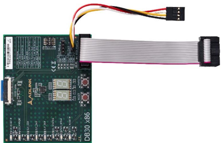
Figure 5 – Express-RLP and Debug Module .... ..60

Figure 6 – Module mechanical dimensions ... ..68

Figure 7 – Heatspreader: HTS.. ...69

Figure 8 – Heatsink: THS... ...70

Figure 9 – Heatsink High Profile: THSH .. .71

Figure 10 – Heatsink with Fan: THSF.... ...72

# 1. Introduction

The Express-RLP is a COM.0 R3.1 compliant COM Express® Basic Size Type 6 module based on 13th Gen Intel® Core™ and Intel® Celeron® SoC utilizing Intel’s advanced hybrid architecture (formerly “Raptor Lake-P”). It features up to 6 Performance-cores (P-cores) for IoT workloads, maximum responsiveness and 8 Efficient-cores (E-cores) for offload multi-tasking at background, and is integrated with up to 96 Intel® Iris® Xe high performance graphics cores that boost productivity and fueling IoT innovation across a wide variety of deployments. Typical industries in need of such high performance, low power characteristics include industrial automation and control, medical ultra sound, image processing and analysis, high-speed video encoding and streaming, predictive traffic analysis, and multi camera-based AI.

The Express-RLP supports up to 64GB (2x 32GB) DDR5 memory, maximum 4800 MT/s memory frequency at two SODIMM sockets, and suits power envelopes ranging across 15, 28, and 45W, making it well suited for mission-critical applications for both stationary and mobile edge use cases.

The integrated Intel® Iris® Xe Graphics includes features such as OpenGL 4.5, DirectX 12, OpenCL 2.1/2.0/1.2, Intel® Clear Video HD Technology, and DirectX Video Acceleration (DXVA) support for full H.265/HEVC 10-bit, VP9 hardware codecs. In addition, High Dynamic Range is supported for enhanced picture color and quality, and digital content protection has been upgraded to HDCP 2.3. Graphics outputs include LVDS and three DDI ports supporting HDMI/DVI/DisplayPort and eDP/VGA as a build option, with a maximum of four 4K displays supported. In addition, maximum 2x USB4 that can transfer media and data through a single tunnel is a build option supported by project basis in place of DDI 1/2. The Express-RLP is specifically designed for customers with high-performance processing graphics requirements who want to outsource the custom core logic of their systems for reduced development time. Adding to the onboard integrated graphics, a multiplexed 16 PCIe Gen4 graphics bus at one x8 plus two x4 configuration is available for discrete graphics expansion.

Input/output features include up to eight PCIe Gen3 lanes via PCIe switch that can be used for NVMe SSD, allowing application access to the highest speed storage solutions, as well as a single onboard 2.5Gigabit Ethernet port with optional Time Sensitive Network (TSN) support, four USB 3.2 Gen2/2.0 ports, four USB 2.0 ports, and two SATA 6 Gb/s ports. Optional onboard PCIe NVMe SSD is offered by project basis. Support is provided for SMBus and I2C. The module is equipped with SPI AMI EFI BIOS with CMOS backup, supporting embedded features such as remote console, hardware monitor, and watchdog timer.

# 2. Specifications

# 2.1. Core System

# CPU

13th Gen Intel® Core™ Processor (formerly Raptor Lake-P)

• Intel® Core™ i7-13800HE, 6P+8E/20T, 24MB, 45W(35W cTDP), Iris Xe 96EU
• Intel® Core™ i5-13600HE, 4P+8E/16T, 18MB, 45W(35W cTDP), Iris Xe 80EU
• Intel® Core™ i3-13300HE, 4P+4E/12T, 12MB, 45W(35W cTDP), UHD 48EU
• Intel® Core™ i7-1370PE, 6P+8E/20T, 24MB, 28W(20W cTDP), Iris Xe 96EU
• Intel® Core™ i5-1350PE, 4P+8E/16T, 12MB, 28W(20W cTDP), Iris Xe 80EU
• Intel® Core™ i3-1320PE, 4P+4E/12T, 12MB, 28W(20W cTDP), UHD 48EU
• Intel® Core™ i7-1365UE, 2P+8E/12T, 12MB, 15W(12W cTDP), Iris Xe 96EU
• Intel® Core™ i5-1345UE, 2P+8E/12T, 12MB, 15W(12W cTDP), Iris Xe 80EU
• Intel® Core™ i3-1315UE, 2P+4E/8T, 10MB, 15W(12W cTDP), UHD 64EU
• Intel® Celeorn™ U300E, 1P+4E/5T, 8MB, 15W(12W cTDP), UHD 48EU
• Intel® Core™ i7-13800HRE, 6P+8E/20T, 24MB, 45W(35W cTDP), Iris Xe 96EU (TCC/TSN, IBECC capable)
• Intel® Core™ i5-13600HRE, 4P+8E/16T, 18MB, 45W(35W cTDP), Iris Xe 80EU (TCC/TSN, IBECC capable)
• Intel® Core™ i3-13300HRE, 4P+4E/12T, 12MB, 45W(35W cTDP), UHD 48EU (TCC/TSN, IBECC capable)
• Intel® Core™ i7-1365URE, 2P+8E/12T, 12MB, 15W(12W cTDP), Iris Xe 96EU (TCC/TSN, IBECC capable)
• Intel® Core™ i5-1345URE, 2P+8E/12T, 12MB, 15W(12W cTDP), Iris Xe 80EU (TCC/TSN, IBECC capable)
• Intel® Core™ i3-1315URE, 2P+4E/8T, 10MB, 15W(12W cTDP), UHD 64EU (TCC/TSN, IBECC capable)

Supporting: Intel® VT (including VT-x, VT-d, VT-x with Extended Page Tables), Intel® HT Technology, Intel® SSE4.2, Intel® 64 Architecture, Intel® Turbo Boost Technology 2.0, Intel® AVX512-VNNI, Intel® TXT, Execute Disable Bit, Intel® Data Protection Technology with Intel® Secure Key, Intel®

AES-NI (availability of features may vary between processor SKUs)

Note: Standard offering will be based on 45W SKU. SKUs with other power envelopes and with TCC/TSN-, IBECC-capabilities will be available by project basis. Please contact your local ADLINK representative for details.

# Memory

Up to 64GB (2x 32GB) non-ECC DDR5 in two SODIMM sockets (one on top, one on bottom), maximum 32GB per socket, maximum 4800 MT/s.

![The image shows an icon of a white document page with rounded corners and a folded bottom-right corner. It is outlined with a thick red border. Inside the white area, there are two horizontal red lines centered horizontally, resembling text.](.express-rlp-manual-230411/da4b9be9f1a5cf5b9098c173ccbc14fcd9aa4dd69e2df77ac24b942f7794c825.jpg)

Note: It is recommended to check that the bottom side specifications are suitable for your application purposes.

# Embedded BIOS

AMI Aptio V UEFI with CMOS backup in 32 MB SPI BIOS, dual BIOS by build option

# 2.2. Video

# GPU

Intel® Iris Xe Graphics architecture with up to 96 execution units

# Feature Support

• 4 independent and simultaneous combinations of DisplayPort/HDMI/LVDS/eDP/VGA and display alternative mode through USB4/Thunderbolt4 graphics outputs (4x 4K @60Hz, up to 8K@60Hz)
(eDP optional in place of LVDS, VGA optional in place of DDI 3)
• Playback of high-definition content including Blu-ray Disc and Blu-ray Disc 3D content using HDMI (1.4a spec compliant with 3D)
• DirectX Video Acceleration (DXVA) support for accelerated video processing
• HEVC/H.265, H.264, M/JPEG, MPEG2, AV1, WMV9, VP9 HW decode
HEVC/H.265, H.264, JPEG, VP9 HW encode, up to 8K60 HEVC

• Advanced Scheduler 2.0, 1.0, XPDM support
• DirectX up to 12
• OpenGL up to 4.6 and ES 2.0 support
• OpenCL up to 2.1 support

![The image displays a red outline icon resembling a document or memo. It is shaped like a square piece of paper with the bottom right corner folded over. Inside the white background of the shape, there are two horizontal red lines; the top line is shorter than the bottom line.](.express-rlp-manual-230411/cff8031a117d0e6cab08164140fd7a2133ecdd24f5abb38c850c2cb9c03fe77d.jpg)

Note: Availability of features is dependent on the operating system used (Windows 10 64-bit, Linux 64-bit).

# 2.2.1 Display Interface Support

LVDS: Single/dual channel 18/24-bit LVDS through eDP to LVDS IC, supports DE mode and Hsync/Vsync mode.

Max. resolution 1920x1200@60Hz in dual mode. Pixel clock frequency up to 112 MHz. VESA and JEIDA panel data formats supported.

eDP: eDP 1.4b up to 4 lane support, in place of LVDS (BOM option), up to 4096x2304@60Hz bpp with DSC

DDI x3: Digital Display Ports (DDI) support DisplayPort 1.4a, HDMI 2.0b or DVI

VGA: VGA BOM option support in place of DDI 3; max. resolution 1920x1200@60Hz

![The image displays a red-outlined icon of a document or page with a folded bottom-right corner. Inside the white square shape are two horizontal red lines centered vertically.](.express-rlp-manual-230411/3bbed4c2c92362bb35d3701c3be1a62196061015d8cdb8f11b6e220640486bce.jpg)

Note: USB4 is a build option (HW and BIOS) supported by project basis in place of DDI channels. Maximum 2x USB4 by using DDI 1 and DDI 2 channels. USB4 support also requires re-timer and PD on carrier.

# 2.3. Audio

Intel® HD Audio integrated

Located on carrier Express-BASE6 or Express-BASE6 R3.1 (ALC886 standard support)

# 2.4. Expansion Busses

1 PCI Express x8 Gen4 (45W CPU only): PEG0-7 (configurable to 1 x8). Gen4 support dependent on carrier design.
2 PCI Express x4 Gen4 : PEG8-11 and PEG12-15 (configurable to 2 x4). Gen4 support dependent on carrier design.
8 PCI Express x1 Gen3: Lanes 0-3 (configurable to 4 x1, 2 x2, 1 x4, 1 x2 + 2 x1) and Lanes 4-7 (configurable to 4 x1, via PCIe switch)
Other: SMBus (system), I2 C (user), LPC bus (via eSPI to LPC bridge IC)

# 2.5. Ethernet

2.5GbE Intel® Ethernet Controller I225 Series (V, IT or LM version)

Supports up to 2.5GbE and 1000/100/10 Mbit/s connections

IT version supports TSN feature on Linux OS, GbE0\_SDP available if TSN support enabled

# 2.6. Multi I/O and Storage

# USB 4

2x USB4: build option (HW and BIOS) supported by project basis in place of DDI channels. Maximum 2x USB4 by using DDI 1 and DDI 2 channels. USB4 support also requires re-timer and PD on carrier.

![The image displays a red outline icon of a document. Inside the document shape are two horizontal lines representing text, and the bottom-right corner is curled upward.](.express-rlp-manual-230411/cc4bbcc8f6b74b202669d019453c5f6654950b4d330ebad2c38bf9b4dd3bdc22.jpg)

Note: Capable of TBT4. Please contact your local ADLINK representative for details.

# USB

4x USB 3.2 Gen2/2.0/1.1 (USB 0,1,2,3), 4x USB 2.0/1.1 (USB 4,5,6,7)

SuperSpeedPlus, SuperSpeed, High-Speed, Full-Speed and Low-Speed USB signaling

![](.express-rlp-manual-230411/6897fa180faa90a694b7c402eb99a333532c33626adce870157b39ee4681e4e8.jpg)

Note: Carrier board must be designed for Gen2 operation. USB 0,1,2,3 are backward compatible with USB 2.0/1.1.

# SATA

2x SATA 6Gb/s (SATA 0,1)

![](.express-rlp-manual-230411/f6777e87a13aa22d734098f51a3436d7f9702c8c7a0343793d1e155d3a907dc8.jpg)

Note: For SATA 6Gb/s compatibility, it is strongly recommended to use a SATA redriver on the carrier board

# GPIO or SD

4 GPO and 4 GPI (GPI with interrupt)

# On-board Storage

Soldered type PCIe NVMe SSD, available capacities: 60GB/120GB/240GB. Build option support by project basis

PCIe NVMe SSD co-lay 1 PCI Express x4 Gen4 : PEG12-15

![](.express-rlp-manual-230411/6d4e593ddacce4cdff9056e1c6a019d39b51b046ac0914c9007110b29902fc31.jpg)

Note: For the NVMe SSD build option, DIMM support is limited to 2 slots. Please contact your local ADLINK representative for details.

# UART

Two UART interfaces SER0 and SER1 RX/TX on module

Console Redirection via COM 1 or COM 2 selectable in BIOS

Up to 4 serial ports supported by standard BIOS, including Super I/O on carrier board

<table><tr><td>COM Port</td><td>Description</td><td>IRQ</td><td>Address</td><td>Console Redirection Support</td></tr><tr><td>COM 1</td><td>Supported by module (SER0, A98/A99), via embedded controller</td><td>4</td><td>0x3F8</td><td>Yes</td></tr><tr><td>COM 2</td><td>Supported by module (SER1, A101/A102), via embedded controller</td><td>3</td><td>0x2F8</td><td>Yes</td></tr><tr><td>COM 3</td><td>Supported by Super I/O (W83627DHG) on carrier board</td><td>5</td><td>0x240</td><td>Yes</td></tr><tr><td>COM 4</td><td>Supported by Super I/O (W83627DHG) on carrier board</td><td>7</td><td>0x248</td><td>Yes</td></tr></table>

![](.express-rlp-manual-230411/aa3d96d7fd5d18d02e60ba8065c740dbad995c2c9f3ecca03b5c2e7d726cfb6d.jpg)

Note: SER0, SER1 from SoC HSUART are BOM option support by project basis

# 2.7. Trusted Platform Module (TPM)

Chipset: Infineon solution

Type: TPM 2.0 (SPI bus based)

# 2.8. SEMA Board controller

Supports: Voltage/current monitoring, power sequence debug support, AT/ATX mode control, logistics and forensic information, flat panel control, general purpose I2 C, failsafe BIOS (dual BIOS, opt. support), watchdog timer and fan control.

# 2.9. Debug

30-pin flat cable connector for use with DB-30 x86 debug module

Supports embedded controller access, SPI BIOS flashing, internal power rail test points, debug LEDs

# 2.10. Power

Power Modes: AT and ATX mode (AT mode startup controlled by SEMA Board Controller)

<table><tr><td>Standard Voltage Input:</td><td>ATX: 12V±5% / 5Vsb ±5%</td><td>or</td><td>AT: 12V±5%</td></tr><tr><td>Wide Voltage Input:</td><td>ATX: 8.5-20V, 5Vsb ±5%</td><td>or</td><td>AT: 8.5-20V</td></tr></table>

Power Management: ACPI 5.0 compliant, Smart Battery support

Power States: C1-C6, S0, S1, S3, S4, S5, S5 ECO mode (Wake-on-USB S3/S4, WoL S3/S4/S5)

ECO Mode support for deep S5 for 5Vsb power saving

# Power Consumption

Please contact your ADLINK representative for the document “COM Express Module Power Consumption”.

# 2.11. Mechanical and Environmental

# Form Factor and specification

PICMG COM Express Rev 3.1 (COM.0 R3.1), Type 6, Basic size 125 x 95 mm

# Operating Temperature

<table><tr><td>Standard</td><td>0°C to 60°C (wide voltage input)</td><td>Storage: -20°C to 80°C</td></tr><tr><td>Extreme Rugged</td><td>-40°C to 85°C (selected SKUs, TBC)</td><td>Storage: -40°C to 85°C</td></tr></table>

# Humidity

5-90% RH operating, non-condensing, 5-95% RH storage (and operating with conformal coating)

# Shock and Vibration

<table><tr><td>IEC 60068-2-64 and IEC-60068-2-27</td></tr><tr><td>MIL-STD-202F, Method 213B, Table 213-I, Condition A and Method 214A, Table 214-I, Condition D</td></tr></table>

# HALT tested

Thermal Stress, Vibration Stress, Thermal Shock and Combined Test

# 3. Block Diagram

PICMG COM.0 R3.1 compliant
![This flowchart centers on a large red block labeled **'13th Gen Intel® Core Processor (Raptor Lake-P)'**.\n\n**Left Column (Memory & Controllers):**\n*   **'on-die ECC'** connects to two blocks labeled **'DDR5 SODIMM max. 4800MT/s 8-32GB'**.\n*   **'eDP/LVDS'** connects via a dashed box **'eDP x4'** and a blue box **'eDP to LVDS'**.\n*   **'VGA'** connects via a dashed box **'DP to VGA'**.\n*   **'USB 2.0 Lane 0-7'** connects directly.\n*   **'Max. 2.5GbE'** connects via a blue box **'LAN controller i225'**.\n*   **'PCIe Lane 0-3'**, **'PCIe Lane 4'**, and **'PCIe Lane 5'** connect via a blue box **'PCIe switch'**.\n*   **'SATA 0-1'** and **'SATA 2-3'** connect directly.\n*   **'HDA'** connects directly.\n*   **'SPI'** connects via a blue box **'BIOS flash'**.\n*   **'TPM 2.0'** (blue box) connects to the SPI line, near a dashed box **'BIOS flash'**.\n*   **'SMBus'** connects directly.\n*   **'I2C'** connects via dashed boxes labeled **'2x I2C'** and **'2x HSUART'**.\n*   **'8x GPIO/SDIO'**, **'2x UART/CAN'**, and **'LPC/eSPI'** connect to the bottom section.\n*   A dashed box at the bottom reads **'eSPI build option(TBC)'**.\n\n**Right Column (External Ports):**\n*   **'TCP 0'** connects to **'DDI/USB4/TBT4 Port 1'**.\n*   **'TCP 1'** connects to **'DDI/USB4/TBT4 Port 2'**.\n*   **'DDI only Port 3'** connects directly.\n*   **'HSIO 0-3'** connects to **'USB 3.x Lane 0'**, **'USB 3.x Lane 1'**, **'USB 3.x Lane 2'**, and **'USB 3.x Lane 3'**.\n*   **'1 PCIe Gen3 (HSIO)'** connects to **'PCIe Lane 0-3'**.\n*   **'4 PCIe Gen3 (HSIO)'** connects to **'PCIe Lane 4'**.\n*   **'1 PCIe Gen3 (HSIO)'** connects to **'PCIe Lane 5'**.\n*   **'two x1'** connects to **'PCIe Lane 6-7'**.\n*   **'GEN4 x8 (CPU)'** connects to **'PEG Port PCIe 16-23'**.\n*   **'GEN4 x4 (CPU)'** connects to **'PCIe 24-27'**.\n*   **'GEN4 x4 (CPU)'** connects to **'PCIe 28-31'**.\n*   A dashed box at the bottom right reads **'NVMe BGA SSD build option'**.\n\n**Bottom Section:**\n*   A blue box labeled **'Embedded Controller'** connects to:\n    *   A blue box labeled **'eSPI to LPC'**.\n    *   A blue box labeled **'build option fan connector'**.\n    *   A blue box labeled **'LM73 (board)'**.](.express-rlp-manual-230411/85d6e661d290b6490beb716faa924de0d30f283d57fca6ae5d219aed5c974cf6.jpg)

Figure 1 – Module function diagram

# Pinout and Signal Descriptions

# 4.1. Pin Summary

The table below is a comprehensible list of all signal pins supported on the dual 220-pin COM Express connectors as defined for Type 6 in the PICMG COM.0 R3.1 specification. Signals described in the specification but not supported on the Express-RLP are marked with strikethrough.

![NVMe SSD\noptional\nD1\nCD\nC1\nB1\nAB\nA110\nA1](.express-rlp-manual-230411/79df04c1c7104238518cac4ea61e0c6f94e320cab6ac428b198089c3ffdd7b64.jpg)

Figure 2 - Module rear side row and pin numbering

<table><tr><td colspan="2">Row A</td><td></td><td colspan="2">Row B</td><td></td><td colspan="2">Row C</td><td></td><td colspan="2">Row D</td></tr><tr><td>A1</td><td>GND (FIXED)</td><td></td><td>B1</td><td>GND (FIXED)</td><td></td><td>C1</td><td>GND FIXED)</td><td></td><td>D1</td><td>GND FIXED)</td></tr><tr><td>A2</td><td>GBE0_MDI3-</td><td></td><td>B2</td><td>GBE0_ACT#</td><td></td><td>C2</td><td>GND</td><td></td><td>D2</td><td>GND</td></tr><tr><td>A3</td><td>GBE0_MDI3+</td><td></td><td>B3</td><td>LPC_FRAME#/ESPI_CS0 $^{1}$ </td><td></td><td>C3</td><td>USB_SSRX0-</td><td></td><td>D3</td><td>USB_SSTX0-</td></tr><tr><td>A4</td><td>GBE0_LINK_MID#</td><td></td><td>B4</td><td>LPC_AD0/ESPI_IO_0 $^{1}$ </td><td></td><td>C4</td><td>USB_SSRX0+</td><td></td><td>D4</td><td>USB_SSTX0+</td></tr><tr><td>A5</td><td>GBE0_LINK_MAX#</td><td></td><td>B5</td><td>LPC_AD1/ESPI_IO_1 $^{1}$ </td><td></td><td>C5</td><td>GND</td><td></td><td>D5</td><td>GND</td></tr><tr><td>A6</td><td>GBE0_MDI2-</td><td></td><td>B6</td><td>LPC_AD2/ESPI_IO_2 $^{1}$ </td><td></td><td>C6</td><td>USB_SSRX1-</td><td></td><td>D6</td><td>USB_SSTX1-</td></tr><tr><td>A7</td><td>GBE0_MDI2+</td><td></td><td>B7</td><td>LPC_AD3/ESPI_IO_3 $^{1}$ </td><td></td><td>C7</td><td>USB_SSRX1+</td><td></td><td>D7</td><td>USB_SSTX1+</td></tr><tr><td>A8</td><td>GBE0_LINK#</td><td></td><td>B8</td><td>LPC_DRQ0#/ESPI_ALERT0#</td><td></td><td>C8</td><td>GND</td><td></td><td>D8</td><td>GND</td></tr><tr><td>A9</td><td>GBE0_MDI1-</td><td></td><td>B9</td><td>LPC_DRQ1#/ESPI_ALERT1#</td><td></td><td>C9</td><td>USB_SSRX2-</td><td></td><td>D9</td><td>USB_SSTX2-</td></tr><tr><td>A10</td><td>GBE0_MDI1+</td><td></td><td>B10</td><td>LPC_CLK/ESPI_CK $^{1}$ </td><td></td><td>C10</td><td>USB_SSRX2+</td><td></td><td>D10</td><td>USB_SSTX2+</td></tr><tr><td>A11</td><td>GND (FIXED)</td><td></td><td>B11</td><td>GND (FIXED)</td><td></td><td>C11</td><td>GND (FIXED)</td><td></td><td>D11</td><td>GND (FIXED)</td></tr><tr><td>A12</td><td>GBE0_MDIO-</td><td></td><td>B12</td><td>PWRBTN#</td><td></td><td>C12</td><td>USB_SSRX3-</td><td></td><td>D12</td><td>USB_SSTX3-</td></tr><tr><td>A13</td><td>GBE0_MDIO+</td><td></td><td>B13</td><td>SMB_CK</td><td></td><td>C13</td><td>USB_SSRX3+</td><td></td><td>D13</td><td>USB_SSTX3+</td></tr><tr><td>A14</td><td>GBE0_CTREF</td><td></td><td>B14</td><td>SMB_DAT</td><td></td><td>C14</td><td>GND</td><td></td><td>D14</td><td>GND</td></tr><tr><td>A15</td><td>SUS_S3#</td><td></td><td>B15</td><td>SMB_ALERT#</td><td></td><td>C15</td><td>USB4_1_LSTX $^{1}$ </td><td></td><td>D15</td><td>DDI1_CTRLCLK_AUX+/USB4_1_AUX+ $^{1}$ </td></tr><tr><td>A16</td><td>SATAO_TX+</td><td></td><td>B16</td><td>SATA1_TX+</td><td></td><td>C16</td><td>USB4_1_LSRX $^{1}$ </td><td></td><td>D16</td><td>DDI1_CTRLDATA_AUX-/USB4_1_AUX- $^{1}$ </td></tr><tr><td>A17</td><td>SATAO_TX-</td><td></td><td>B17</td><td>SATA1_TX-</td><td></td><td>C17</td><td>USB4_RT_ENA $^{1}$ </td><td></td><td>D17</td><td>USB4_PD_I2C_ALERT $^{1}$ </td></tr><tr><td>A18</td><td>SUS_S4#</td><td></td><td>B18</td><td>SUS_STAT#/ESPI_RESET $^{1}$ </td><td></td><td>C18</td><td>GND</td><td></td><td>D18</td><td>PMCALERT $^{1}$ </td></tr><tr><td>A19</td><td>SATAO_RX+</td><td></td><td>B19</td><td>SATA1_RX+</td><td></td><td>C19</td><td>PCIE_RX6+ $^{1}$ </td><td></td><td>D19</td><td>PCIE_TX6+</td></tr><tr><td>A20</td><td>SATAO_RX-</td><td></td><td>B20</td><td>SATA1_RX-</td><td></td><td>C20</td><td>PCIE_RX6- $^{1}$ </td><td></td><td>D20</td><td>PCIE_TX6-</td></tr><tr><td>A21</td><td>GND (FIXED)</td><td></td><td>B21</td><td>GND (FIXED)</td><td></td><td>C21</td><td>GND (FIXED)</td><td></td><td>D21</td><td>GND (FIXED)</td></tr><tr><td>A22</td><td>SATA2_TX+</td><td></td><td>B22</td><td>SATA3_TX+</td><td></td><td>C22</td><td>PCIE_RX7+ $^{1}$ </td><td></td><td>D22</td><td>PCIE_TX7+</td></tr><tr><td>A23</td><td>SATA2_TX-</td><td></td><td>B23</td><td>SATA3_TX-</td><td></td><td>C23</td><td>PCIE_RX7- $^{1}$ </td><td></td><td>D23</td><td>PCIE_TX7-</td></tr><tr><td>A24</td><td>SUS_S5#</td><td></td><td>B24</td><td>PWR_OK</td><td></td><td>C24</td><td>DDI1_HPD</td><td></td><td>D24</td><td>GND</td></tr><tr><td>A25</td><td>SATA2_RX+</td><td></td><td>B25</td><td>SATA3_RX+</td><td></td><td>C25</td><td>SML0_CLK $^{1}$ </td><td></td><td>D25</td><td>GND</td></tr><tr><td>A26</td><td>SATA2_RX-</td><td></td><td>B26</td><td>SATA3_RX-</td><td></td><td>C26</td><td>SML0_DAT $^{1}$ </td><td></td><td>D26</td><td>DDI1_PAIR0+/USB4_1_SSTX0+ $^{1}$ </td></tr><tr><td>A27</td><td>BATLOW#</td><td></td><td>B27</td><td>WDT</td><td></td><td>C27</td><td>SML1_CLK $^{1}$ </td><td></td><td>D27</td><td>DDI1_PAIR0-/USB4_1_SSTX0- $^{1}$ </td></tr><tr><td>A28</td><td>(S)ATA_ACT#</td><td></td><td>B28</td><td>HDA_SDIN2/SNDW0_CLK $^{2}$ </td><td></td><td>C28</td><td>SML1_DAT $^{1}$ </td><td></td><td>D28</td><td>GND</td></tr><tr><td>A29</td><td>HDA_SYNC</td><td></td><td>B29</td><td>HDA_SDIN1/SNDW0_DAT $^{2}$ </td><td></td><td>C29</td><td>USB4_PD_I2C_CLK $^{1}$ </td><td></td><td>D29</td><td>DDI1_PAIR1+/USB4_1_SSRX0+ $^{1}$ </td></tr><tr><td>A30</td><td>HDA_RST#</td><td></td><td>B30</td><td>HDA_SDINO</td><td></td><td>C30</td><td>USB4_PD_I2C_DAT $^{1}$ </td><td></td><td>D30</td><td>DDI1_PAIR1-/USB4_1_SSRX0- $^{1}$ </td></tr><tr><td>A31</td><td>GND (FIXED)</td><td></td><td>B31</td><td>GND (FIXED)</td><td></td><td>C31</td><td>GND (FIXED)</td><td></td><td>D31</td><td>GND (FIXED)</td></tr><tr><td>A32</td><td>HDA_BITCLK</td><td></td><td>B32</td><td>SPKR</td><td></td><td>C32</td><td>DDI2_CTRLCLK_AUX+/USB4_2_AUX+1</td><td></td><td>D32</td><td>DDI1_PAIR2+/USB4_1_SSTX1+1</td></tr><tr><td>A33</td><td>HDA_SDOUT</td><td></td><td>B33</td><td>I2C_CK</td><td></td><td>C33</td><td>DDI2_CTRLDATA_AUX-/USB4_2_AUX-1</td><td></td><td>D33</td><td>DDI1_PAIR2-/USB4_1_SSTX1-1</td></tr><tr><td>A34</td><td>BIOS_DIS0#/ESPI_SAFS1</td><td></td><td>B34</td><td>I2C_DAT</td><td></td><td>C34</td><td>DDI2_DDC_AUX_SEL</td><td></td><td>D34</td><td>DDI1_DDC_AUX_SEL</td></tr><tr><td>A35</td><td>THRMTRIP#</td><td></td><td>B35</td><td>THRM#</td><td></td><td>C35</td><td>USB4_2_LSTX1</td><td></td><td>D35</td><td>USB4_2_LSRX1</td></tr><tr><td>A36</td><td>USB6-</td><td></td><td>B36</td><td>USB7-</td><td></td><td>C36</td><td>DDI3_CTRLCLK_AUX+</td><td></td><td>D36</td><td>DDI1_PAIR3+/USB4_1_SSRX1+1</td></tr><tr><td>A37</td><td>USB6+</td><td></td><td>B37</td><td>USB7+</td><td></td><td>C37</td><td>DDI3_CTRLDATA_AUX-</td><td></td><td>D37</td><td>DDI1_PAIR3-/USB4_1_SSRX1-1</td></tr><tr><td>A38</td><td>USB_6_7_OC#</td><td></td><td>B38</td><td>USB_4_5_OC#</td><td></td><td>C38</td><td>DDI3_DDC_AUX_SEL</td><td></td><td>D38</td><td>GND</td></tr><tr><td>A39</td><td>USB4-</td><td></td><td>B39</td><td>USB5-</td><td></td><td>C39</td><td>DDI3_PAIR0+</td><td></td><td>D39</td><td>DDI2_PAIR0+/USB4_2_SSTX0+1</td></tr><tr><td>A40</td><td>USB4+</td><td></td><td>B40</td><td>USB5+</td><td></td><td>C40</td><td>DDI3_PAIR0-</td><td></td><td>D40</td><td>DDI2_PAIR0-/USB4_2_SSTX0-1</td></tr><tr><td>A41</td><td>GND (FIXED)</td><td></td><td>B41</td><td>GND (FIXED)</td><td></td><td>C41</td><td>GND (FIXED)</td><td></td><td>D41</td><td>GND (FIXED)</td></tr><tr><td>A42</td><td>USB2-</td><td></td><td>B42</td><td>USB3-</td><td></td><td>C42</td><td>DDI3_PAIR1+</td><td></td><td>D42</td><td>DDI2_PAIR1+/USB4_2_SSRX0+1</td></tr><tr><td>A43</td><td>USB2+</td><td></td><td>B43</td><td>USB3+</td><td></td><td>C43</td><td>DDI3_PAIR1-</td><td></td><td>D43</td><td>DDI2_PAIR1-/USB4_2_SSRX0-1</td></tr><tr><td>A44</td><td>USB_2_3_OC#</td><td></td><td>B44</td><td>USB_0_1_OC#</td><td></td><td>C44</td><td>DDI3_HPD</td><td></td><td>D44</td><td>DDI2_HPD</td></tr><tr><td>A45</td><td>USB0-</td><td></td><td>B45</td><td>USB1-</td><td></td><td>C45</td><td>GP_SPI_CS#2</td><td></td><td>D45</td><td>GND</td></tr><tr><td>A46</td><td>USB0+</td><td></td><td>B46</td><td>USB1+</td><td></td><td>C46</td><td>DDI3_PAIR2+</td><td></td><td>D46</td><td>DDI2_PAIR2+/USB4_2_SSTX1+1</td></tr><tr><td>A47</td><td>VCC_RTC</td><td></td><td>B47</td><td>ESPI_EN#1</td><td></td><td>C47</td><td>DDI3_PAIR2-</td><td></td><td>D47</td><td>DDI2_PAIR2-/USB4_2_SSTX1-1</td></tr><tr><td>A48</td><td>RSMRST_OUT#</td><td></td><td>B48</td><td>USB0_HOST_PRSNT</td><td></td><td>C48</td><td>RSVD</td><td></td><td>D48</td><td>GND</td></tr><tr><td>A49</td><td>GBE0_SDP1</td><td></td><td>B49</td><td>SYS_RESET#</td><td></td><td>C49</td><td>DDI3_PAIR3+</td><td></td><td>D49</td><td>DDI2_PAIR3+/USB4_2_SSRX1+1</td></tr><tr><td>A50</td><td>LPC_SERIRQ/ESPI_CS1#1</td><td></td><td>B50</td><td>CB_RESET#</td><td></td><td>C50</td><td>DDI3_PAIR3-</td><td></td><td>D50</td><td>DDI2_PAIR3-/USB4_2_SSRX1-1</td></tr><tr><td>A51</td><td>GND (FIXED)</td><td></td><td>B51</td><td>GND (FIXED)</td><td></td><td>C51</td><td>GND (FIXED)</td><td></td><td>D51</td><td>GND (FIXED)</td></tr><tr><td>A52</td><td>PCIE_TX5+1</td><td></td><td>B52</td><td>PCIE_RX5+1</td><td></td><td>C52</td><td>PEG_RX0+</td><td></td><td>D52</td><td>PEG_TX0+</td></tr><tr><td>A53</td><td>PCIE_TX5-1</td><td></td><td>B53</td><td>PCIE_RX5-1</td><td></td><td>C53</td><td>PEG_RX0-</td><td></td><td>D53</td><td>PEG_TX0-</td></tr><tr><td>A54</td><td>GPIO</td><td></td><td>B54</td><td>GPO1</td><td></td><td>C54</td><td>TYPE0#</td><td></td><td>D54</td><td>PEG_LANE_RV#</td></tr><tr><td>A55</td><td>PCIE_TX4+</td><td></td><td>B55</td><td>PCIE_RX4+</td><td></td><td>C55</td><td>PEG_RX1+</td><td></td><td>D55</td><td>PEG_TX1+</td></tr><tr><td>A56</td><td>PCIE_TX4-</td><td></td><td>B56</td><td>PCIE_RX4-</td><td></td><td>C56</td><td>PEG_RX1-</td><td></td><td>D56</td><td>PEG_TX1-</td></tr><tr><td>A57</td><td>GND</td><td></td><td>B57</td><td>GPO2</td><td></td><td>C57</td><td>TYPE1#</td><td></td><td>D57</td><td>TYPE2#</td></tr><tr><td>A58</td><td>PCIE_TX3+</td><td></td><td>B58</td><td>PCIE_RX3+</td><td></td><td>C58</td><td>PEG_RX2+</td><td></td><td>D58</td><td>PEG_TX2+</td></tr><tr><td>A59</td><td>PCIE_TX3-</td><td></td><td>B59</td><td>PCIE_RX3-</td><td></td><td>C59</td><td>PEG_RX2-</td><td></td><td>D59</td><td>PEG_TX2-</td></tr><tr><td>A60</td><td>GND (FIXED)</td><td></td><td>B60</td><td>GND (FIXED)</td><td></td><td>C60</td><td>GND (FIXED)</td><td></td><td>D60</td><td>GND (FIXED)</td></tr><tr><td>A61</td><td>PCIE_TX2+</td><td></td><td>B61</td><td>PCIE_RX2+</td><td></td><td>C61</td><td>PEG_RX3+</td><td></td><td>D61</td><td>PEG_TX3+</td></tr><tr><td>A62</td><td>PCIE_TX2-</td><td></td><td>B62</td><td>PCIE_RX2-</td><td></td><td>C62</td><td>PEG_RX3-</td><td></td><td>D62</td><td>PEG_TX3-</td></tr><tr><td>A63</td><td>GPI1</td><td></td><td>B63</td><td>GPO3</td><td></td><td>C63</td><td>GND</td><td></td><td>D63</td><td>GND</td></tr><tr><td>A64</td><td>PCIE_TX1+</td><td></td><td>B64</td><td>PCIE_RX1+</td><td></td><td>C64</td><td>GND</td><td></td><td>D64</td><td>GND</td></tr><tr><td>A65</td><td>PCIE_TX1-</td><td></td><td>B65</td><td>PCIE_RX1-</td><td></td><td>C65</td><td>PEG_RX4+</td><td></td><td>D65</td><td>PEG_TX4+</td></tr><tr><td>A66</td><td>GND</td><td></td><td>B66</td><td>WAKE0#</td><td></td><td>C66</td><td>PEG_RX4-</td><td></td><td>D66</td><td>PEG_TX4-</td></tr><tr><td>A67</td><td>GPI2</td><td></td><td>B67</td><td>WAKE1#</td><td></td><td>C67</td><td>RAPID_SHUTDOWN</td><td></td><td>D67</td><td>GND</td></tr><tr><td>A68</td><td>PCIE_TX0+</td><td></td><td>B68</td><td>PCIE_RX0+</td><td></td><td>C68</td><td>PEG_RX5+</td><td></td><td>D68</td><td>PEG_TX5+</td></tr><tr><td>A69</td><td>PCIE_TX0-</td><td></td><td>B69</td><td>PCIE_RX0-</td><td></td><td>C69</td><td>PEG_RX5-</td><td></td><td>D69</td><td>PEG_TX5-</td></tr><tr><td>A70</td><td>GND (FIXED)</td><td></td><td>B70</td><td>GND (FIXED)</td><td></td><td>C70</td><td>GND (FIXED)</td><td></td><td>D70</td><td>GND (FIXED)</td></tr><tr><td>A71</td><td>LVDS_A0+ / eDP_TX2+1</td><td></td><td>B71</td><td>LVDS_B0+</td><td></td><td>C71</td><td>PEG_RX6+</td><td></td><td>D71</td><td>PEG_TX6+</td></tr><tr><td>A72</td><td>LVDS_A0- / eDP_TX2-1</td><td></td><td>B72</td><td>LVDS_B0-</td><td></td><td>C72</td><td>PEG_RX6-</td><td></td><td>D72</td><td>PEG_TX6-</td></tr><tr><td>A73</td><td>LVDS_A1+ / eDP_TX1+1</td><td></td><td>B73</td><td>LVDS_B1+</td><td></td><td>C73</td><td>GND</td><td></td><td>D73</td><td>GND</td></tr><tr><td>A74</td><td>LVDS_A1- / eDP_TX1-1</td><td></td><td>B74</td><td>LVDS_B1-</td><td></td><td>C74</td><td>PEG_RX7+</td><td></td><td>D74</td><td>PEG_TX7+</td></tr><tr><td>A75</td><td>LVDS_A2+ / eDP_TX0+1</td><td></td><td>B75</td><td>LVDS_B2+</td><td></td><td>C75</td><td>PEG_RX7-</td><td></td><td>D75</td><td>PEG_TX7-</td></tr><tr><td>A76</td><td>LVDS_A2- / eDP_TX0-1</td><td></td><td>B76</td><td>LVDS_B2-</td><td></td><td>C76</td><td>GND</td><td></td><td>D76</td><td>GND</td></tr><tr><td>A77</td><td>LVDS_VDD_EN / eDP_VDD_EN1</td><td></td><td>B77</td><td>LVDS_B3+</td><td></td><td>C77</td><td>GND</td><td></td><td>D77</td><td>GND</td></tr><tr><td>A78</td><td>LVDS_A3+</td><td></td><td>B78</td><td>LVDS_B3-</td><td></td><td>C78</td><td>PEG_RX8+</td><td></td><td>D78</td><td>PEG_TX8+</td></tr><tr><td>A79</td><td>LVDS_A3-</td><td></td><td>B79</td><td>LVDS_BKLT_EN</td><td></td><td>C79</td><td>PEG_RX8-</td><td></td><td>D79</td><td>PEG_TX8-</td></tr><tr><td>A80</td><td>GND (FIXED)</td><td></td><td>B80</td><td>GND (FIXED)</td><td></td><td>C80</td><td>GND (FIXED)</td><td></td><td>D80</td><td>GND (FIXED)</td></tr><tr><td>A81</td><td>LVDS_A_CK+ / eDP_TX3+1</td><td></td><td>B81</td><td>LVDS_B_CK+</td><td></td><td>C81</td><td>PEG_RX9+</td><td></td><td>D81</td><td>PEG_TX9+</td></tr><tr><td>A82</td><td>LVDS_A_CK- / eDP_TX3-1</td><td></td><td>B82</td><td>LVDS_B_CK-</td><td></td><td>C82</td><td>PEG_RX9-</td><td></td><td>D82</td><td>PEG_TX9-</td></tr><tr><td>A83</td><td>LVDS_I2C_CK / eDP_AUX+1</td><td></td><td>B83</td><td>LVDS_BKLT_CTRL / eDP_BKLT_CTRL1</td><td></td><td>C83</td><td>GND</td><td></td><td>D83</td><td>GND</td></tr><tr><td>A84</td><td>LVDS_I2C_DAT / eDP_AUX-1</td><td></td><td>B84</td><td>VCC_5V_SBY</td><td></td><td>C84</td><td>GND</td><td></td><td>D84</td><td>GND</td></tr><tr><td>A85</td><td>GPI3</td><td></td><td>B85</td><td>VCC_5V_SBY</td><td></td><td>C85</td><td>PEG_RX10+</td><td></td><td>D85</td><td>PEG_TX10+</td></tr><tr><td>A86</td><td>GP_SPI_MOSI2</td><td></td><td>B86</td><td>VCC_5V_SBY</td><td></td><td>C86</td><td>PEG_RX10-</td><td></td><td>D86</td><td>PEG_TX10-</td></tr><tr><td>A87</td><td>eDP_HPD</td><td></td><td>B87</td><td>VCC_5V_SBY</td><td></td><td>C87</td><td>GND</td><td></td><td>D87</td><td>GND</td></tr><tr><td>A88</td><td>PCIE_CK_REF+</td><td></td><td>B88</td><td>BIOS_DIS1#</td><td></td><td>C88</td><td>PEG_RX11+</td><td></td><td>D88</td><td>PEG_TX11+</td></tr><tr><td>A89</td><td>PCIE_CK_REF-</td><td></td><td>B89</td><td>VGA_RED1</td><td></td><td>C89</td><td>PEG_RX11-</td><td></td><td>D89</td><td>PEG_TX11-</td></tr><tr><td>A90</td><td>GND (FIXED)</td><td></td><td>B90</td><td>GND (FIXED)</td><td></td><td>C90</td><td>GND (FIXED)</td><td></td><td>D90</td><td>GND (FIXED)</td></tr><tr><td>A91</td><td>SPI_POWER</td><td></td><td>B91</td><td>VGA_GRN1</td><td></td><td>C91</td><td>PEG_RX12+</td><td></td><td>D91</td><td>PEG_TX12+</td></tr><tr><td>A92</td><td>SPI_MISO</td><td></td><td>B92</td><td>VGA_BLU1</td><td></td><td>C92</td><td>PEG_RX12-</td><td></td><td>D92</td><td>PEG_TX12-</td></tr><tr><td>A93</td><td>GPO0</td><td></td><td>B93</td><td> $VGA_HSYNC^1$ </td><td></td><td>C93</td><td>GND</td><td></td><td>D93</td><td>GND</td></tr><tr><td>A94</td><td>SPI_CLK</td><td></td><td>B94</td><td> $VGA_VSYNC^1$ </td><td></td><td>C94</td><td>PEG_RX13+</td><td></td><td>D94</td><td>PEG_TX13+</td></tr><tr><td>A95</td><td>SPI_MOSI</td><td></td><td>B95</td><td> $VGA_I2C_CK^1$ </td><td></td><td>C95</td><td>PEG_RX13-</td><td></td><td>D95</td><td>PEG_TX13-</td></tr><tr><td>A96</td><td>TPM_PP</td><td></td><td>B96</td><td> $VGA_I2C_DAT^1$ </td><td></td><td>C96</td><td>GND</td><td></td><td>D96</td><td>GND</td></tr><tr><td>A97</td><td>TYPE10#</td><td></td><td>B97</td><td>SPI_CS#</td><td></td><td>C97</td><td>GND</td><td></td><td>D97</td><td>GND</td></tr><tr><td>A98</td><td>SER0_TX</td><td></td><td>B98</td><td> $GP_SPI_MISO^2$ </td><td></td><td>C98</td><td>PEG_RX14+</td><td></td><td>D98</td><td>PEG_TX14+</td></tr><tr><td>A99</td><td>SER0_RX</td><td></td><td>B99</td><td> $GP_SPI_CK^2$ </td><td></td><td>C99</td><td>PEG_RX14-</td><td></td><td>D99</td><td>PEG_TX14-</td></tr><tr><td>A100</td><td>GND (FIXED)</td><td></td><td>B100</td><td>GND (FIXED)</td><td></td><td>C100</td><td>GND (FIXED)</td><td></td><td>D100</td><td>GND (FIXED)</td></tr><tr><td>A101</td><td>SER1_TX/CAN_TX</td><td></td><td>B101</td><td>FAN_PWMOUT</td><td></td><td>C101</td><td>PEG_RX15+</td><td></td><td>D101</td><td>PEG_TX15+</td></tr><tr><td>A102</td><td>SER1_RX/CAN_RX</td><td></td><td>B102</td><td>FAN_TACHIN</td><td></td><td>C102</td><td>PEG_RX15-</td><td></td><td>D102</td><td>PEG_TX15-</td></tr><tr><td>A103</td><td>LID#</td><td></td><td>B103</td><td>SLEEP#</td><td></td><td>C103</td><td>GND</td><td></td><td>D103</td><td>GND</td></tr><tr><td>A104</td><td>VCC_12V</td><td></td><td>B104</td><td>VCC_12V</td><td></td><td>C104</td><td>VCC_12V</td><td></td><td>D104</td><td>VCC_12V</td></tr><tr><td>A105</td><td>VCC_12V</td><td></td><td>B105</td><td>VCC_12V</td><td></td><td>C105</td><td>VCC_12V</td><td></td><td>D105</td><td>VCC_12V</td></tr><tr><td>A106</td><td>VCC_12V</td><td></td><td>B106</td><td>VCC_12V</td><td></td><td>C106</td><td>VCC_12V</td><td></td><td>D106</td><td> $VCC_{12V}^1$ </td></tr><tr><td>A107</td><td>VCC_12V</td><td></td><td>B107</td><td>VCC_12V</td><td></td><td>C107</td><td>VCC_12V</td><td></td><td>D107</td><td>VCC_12V</td></tr><tr><td>A108</td><td>VCC_12V</td><td></td><td>B108</td><td>VCC_12V</td><td></td><td>C108</td><td>VCC_12V</td><td></td><td>D108</td><td>VCC_12V</td></tr><tr><td>A109</td><td>VCC_12V</td><td></td><td>B109</td><td>VCC_12V</td><td></td><td>C109</td><td>VCC_12V</td><td></td><td>D109</td><td>VCC_12V</td></tr><tr><td>A110</td><td>GND (FIXED)</td><td></td><td>B110</td><td>GND (FIXED)</td><td></td><td>C110</td><td>GND (FIXED)</td><td></td><td>D110</td><td>GND (FIXED)</td></tr></table>

![](.express-rlp-manual-230411/8787f1886b8f5f245132298e8b75db7ee4f234be29bf8ed054dcfc18f286fb5e.jpg)
Note: Strike-through entries are not supported functions on this product.
PEG 0-7 are available only for 45W CPU SKUs.
1. eDP (in place of LVDS), VGA (in place of DDI 3), eSPI (in place of LPC), PCIe lane5-7 (via PCIe switch), USB4\_1/2 (in place of DDI 1/2), and GBE0\_SDP (for selected LAN controller versions) are BOM options supported by project basis.
2. GP\_SPI and SNDW0 support TBC.

# 4.2. Signal Terminology Descriptions

Meaning of the terms used for signal description tables

<table><tr><td>Term</td><td>Description</td></tr><tr><td>I</td><td>Input to the module</td></tr><tr><td>O</td><td>Output from the module</td></tr><tr><td>I/O</td><td>Bi-directional Input / Output</td></tr><tr><td>OD</td><td>Open drain output from the module</td></tr><tr><td></td><td></td></tr><tr><td>I 3.3V</td><td>Input 3.3V tolerant</td></tr><tr><td>I 5V</td><td>Input 5V tolerant</td></tr><tr><td>O 3.3V</td><td>Output 3.3V signal level</td></tr><tr><td>O 5V</td><td>Output 5V signal level</td></tr><tr><td>I/O 3.3V</td><td>Bi-directional signal 3.3V tolerant</td></tr><tr><td>I/O 5V</td><td>Bi-directional signal 5V tolerant</td></tr><tr><td>I/O  $3.3V_{SB}$ </td><td>Input or output 3.3V tolerant active in standby state</td></tr><tr><td></td><td></td></tr><tr><td>DDC</td><td>Display Data Channel</td></tr><tr><td>PCIE</td><td>PCI Express compatible differential signal</td></tr><tr><td>PEG</td><td>PCI Express Graphics</td></tr><tr><td>SATA</td><td>Serial ATA specification Revision 2.6 and 3</td></tr><tr><td>LVDS</td><td>Low Voltage Differential Signal - 330 mV nominal; 450 mV maximum differential signal</td></tr><tr><td></td><td></td></tr><tr><td>P</td><td>Power Input / Output</td></tr><tr><td>REF</td><td>Reference voltage output. May be sourced from a Module power plane.</td></tr><tr><td>PDS</td><td>Pull-down strap. A Module output pin that is either tied to GND or is not connected.Used to signal Module capabilities to the Carrier Board.</td></tr><tr><td></td><td></td></tr><tr><td>PU</td><td>PU (pull-up) resistor on module</td></tr><tr><td>PD</td><td>PD (pull-down) resistor on module</td></tr></table>

# 4.3. AB Connector Signal Descriptions

4.3.1 Audio

<table><tr><td>Name</td><td>Pin #</td><td>Description</td><td>I/O</td><td>PU / PD</td><td>Comment</td></tr><tr><td colspan="6"></td></tr><tr><td>AC_RST# / HDA_RST#</td><td>A30</td><td>Reset output to CODEC, active low.</td><td>O 3.3VSB</td><td></td><td></td></tr><tr><td>AC_SYNC / HDA_SYNC</td><td>A29</td><td>Sample-synchronization signal to the CODEC(s).</td><td>O 3.3VSB</td><td></td><td>PCH internal PD 20Kohm</td></tr><tr><td>AC_BITCLK / HDA_BITCLK</td><td>A32</td><td>Serial data clock generated by the external CODEC(s).</td><td>I/O 3.3VSB</td><td></td><td></td></tr><tr><td>AC_SDOUT / HDA_SDOUT</td><td>A33</td><td>Serial TDM data output to the CODEC.</td><td>O 3.3VSB</td><td></td><td>PCH internal PD 20Kohm</td></tr><tr><td>AC_SDIN[2:0] / HDA_SDIN[2:0]</td><td>B28 B29 B30</td><td>Serial TDM data inputs from up to 3 CODECs.</td><td>I/O 3.3VSB</td><td></td><td>PCH internal PD 20Kohm AC_SDNI2/HDA_SDIN2 not supported</td></tr></table>

4.3.2 Analog VGA

<table><tr><td>Name</td><td>Pin #</td><td>Description</td><td>I/O</td><td>PU / PD</td><td>Comment</td></tr><tr><td>VGA_RED</td><td>B89</td><td>Red for monitor. Analog DAC output, designed to drive a 37.5-Ohm equivalent load.</td><td>O Analog</td><td>PD 150R</td><td></td></tr><tr><td>VGA_GRN</td><td>B91</td><td>Green for monitor. Analog DAC output, designed to drive a 37.5-Ohm equivalent load.</td><td>O Analog</td><td>PD 150R</td><td></td></tr><tr><td>VGA_BLU</td><td>B92</td><td>Blue for monitor. Analog DAC output, designed to drive a 37.5-Ohm equivalent load.</td><td>O Analog</td><td>PD 150R</td><td></td></tr><tr><td>VGA_HSYNC</td><td>B93</td><td>Horizontal sync output to VGA monitor</td><td>O 3.3V</td><td></td><td></td></tr><tr><td>VGA_VSYNC</td><td>B94</td><td>Vertical sync output to VGA monitor</td><td>O 3.3V</td><td></td><td></td></tr><tr><td>VGA_I2C_CK</td><td>B95</td><td>DDC clock line (I2C port dedicated to identifying VGA monitor capabilities)</td><td>I/O OD 3.3V</td><td>PU 2k2 3.3V</td><td></td></tr><tr><td>VGA_I2C_DAT</td><td>B96</td><td>DDC data line.</td><td>I/O OD 3.3V</td><td>PU 2k2 3.3V</td><td></td></tr></table>

![](.express-rlp-manual-230411/4b82fa605d79ccbd7390e593e0d0d737566ce95095b1a7681b9ed33894eab2b7.jpg)
Note: VGA is BOM option support (in place of DDI 3) by project basis

# 4.3.3 LVDS or eDP

The module default supports a single or dual channel LVDS display panel with up to 24-bit colors. A BOM option that removes the eDP to LVDS bridge IC and outputs the eDP signals directly is available. eDP vs LVDS pin mapping is described below.

<table><tr><td>Pin #</td><td>LVDS mode</td><td>eDP mode</td></tr><tr><td>A71</td><td>LVDS_A0+</td><td>eDP_TX2+</td></tr><tr><td>A72</td><td>LVDS_A0-</td><td>eDP_TX2-</td></tr><tr><td>A73</td><td>LVDS_A1+</td><td>eDP_TX1+</td></tr><tr><td>A74</td><td>LVDS_A1-</td><td>eDP_TX1-</td></tr><tr><td>A75</td><td>LVDS_A2+</td><td>eDP_TX0+</td></tr><tr><td>A76</td><td>LVDS_A2-</td><td>eDP_TX0-</td></tr><tr><td>A78</td><td>LVDS_A3+</td><td>-</td></tr><tr><td>A79</td><td>LVDS_A3-</td><td>-</td></tr><tr><td>A81</td><td>LVDS_A_CK+</td><td>eDP_TX3+</td></tr><tr><td>A82</td><td>LVDS_A_CK-</td><td>eDP_TX3-</td></tr><tr><td>B71</td><td>LVDS_B0+</td><td>-</td></tr><tr><td>B72</td><td>LVDS_B0-</td><td>-</td></tr><tr><td>B73</td><td>LVDS_B1+</td><td>-</td></tr><tr><td>B74</td><td>LVDS_B1-</td><td>-</td></tr><tr><td>B75</td><td>LVDS_B2+</td><td>-</td></tr><tr><td>B76</td><td>LVDS_B2-</td><td>-</td></tr><tr><td>B77</td><td>LVDS_B3+</td><td>-</td></tr><tr><td>B78</td><td>LVDS_B3-</td><td>-</td></tr><tr><td>B81</td><td>LVDS_B_CK+</td><td>-</td></tr><tr><td>B82</td><td>LVDS_B_CK-</td><td>-</td></tr><tr><td>A77</td><td>LVDS_VDD_EN</td><td>eDP_VDD_EN</td></tr><tr><td>B79</td><td>LVDS_BKLT_EN</td><td>eDP_BKLT_EN</td></tr><tr><td>B83</td><td>LVDS_BKLT_CTRL</td><td>eDP_BKLT_CTRL</td></tr><tr><td>A83</td><td>LVDS_I2C_CK</td><td>eDP_AUX+</td></tr><tr><td>A84</td><td>LVDS_I2C_DAT</td><td>eDP_AUX-</td></tr><tr><td>A87</td><td>-</td><td>eDP_HPD</td></tr></table>

![](.express-rlp-manual-230411/616117ae8394e7e0dfae8b1f971696696da363561de3345f4e1a1c8c993b10ff.jpg)
Note: LVDS is the default mode and eDP is a BOM option

4.3.3.1. Single/Dual Channel LVDS (default)

<table><tr><td>Name</td><td>Pin #</td><td>Description</td><td>I/O</td><td>PU / PD</td><td>Comment</td></tr><tr><td colspan="6"></td></tr><tr><td>LVDS_A0+</td><td>A71</td><td>LVDS Channel A differential pairs</td><td>O LVDS</td><td></td><td></td></tr><tr><td>LVDS_A0-</td><td>A72</td><td></td><td></td><td></td><td></td></tr><tr><td>LVDS_A1+</td><td>A73</td><td></td><td></td><td></td><td></td></tr><tr><td>LVDS_A1-</td><td>A74</td><td></td><td></td><td></td><td></td></tr><tr><td>LVDS_A2+</td><td>A75</td><td></td><td></td><td></td><td></td></tr><tr><td>LVDS_A2-</td><td>A76</td><td></td><td></td><td></td><td></td></tr><tr><td>LVDS_A3+</td><td>A78</td><td></td><td></td><td></td><td></td></tr><tr><td>LVDS_A3-</td><td>A79</td><td></td><td></td><td></td><td></td></tr><tr><td>LVDS_A_CK+</td><td>A81</td><td>LVDS Channel A differential clock</td><td>O LVDS</td><td></td><td></td></tr><tr><td>LVDS_A_CK-</td><td>A82</td><td></td><td></td><td></td><td></td></tr><tr><td>LVDS_B0+</td><td>B71</td><td>LVDS Channel B differential pairs</td><td>O LVDS</td><td></td><td></td></tr><tr><td>LVDS_B0-</td><td>B72</td><td></td><td></td><td></td><td></td></tr><tr><td>LVDS_B1+</td><td>B73</td><td></td><td></td><td></td><td></td></tr><tr><td>LVDS_B1-</td><td>B74</td><td></td><td></td><td></td><td></td></tr><tr><td>LVDS_B2+</td><td>B75</td><td></td><td></td><td></td><td></td></tr><tr><td>LVDS_B2-</td><td>B76</td><td></td><td></td><td></td><td></td></tr><tr><td>LVDS_B3+</td><td>B77</td><td></td><td></td><td></td><td></td></tr><tr><td>LVDS_B3-</td><td>B78</td><td></td><td></td><td></td><td></td></tr><tr><td>LVDS_B_CK+</td><td>B81</td><td>LVDS Channel B differential clock</td><td>O LVDS</td><td></td><td></td></tr><tr><td>LVDS_B_CK-</td><td>B82</td><td></td><td></td><td></td><td></td></tr><tr><td>LVDS_VDD_EN</td><td>A77</td><td>LVDS panel power enable</td><td>O 3.3V</td><td>PD 100K</td><td></td></tr><tr><td>LVDS_BKLT_EN</td><td>B79</td><td>LVDS panel backlight enable</td><td>O 3.3V</td><td>PD 100K</td><td></td></tr><tr><td>LVDS_BKLT_CTRL</td><td>B83</td><td>LVDS panel backlight brightness control</td><td>O 3.3V</td><td>PD 100K</td><td></td></tr><tr><td>LVDS_I2C_CK</td><td>A83</td><td>DDC lines used for flat panel detection and control.</td><td>O 3.3V</td><td>PU 2k2 3.3V</td><td></td></tr><tr><td>LVDS_I2C_DAT</td><td>A84</td><td>DDC lines used for flat panel detection and control.</td><td>I/O 3.3V</td><td>PU 2k2 3.3V</td><td></td></tr></table>

4.3.3.2. 4-lane eDP

<table><tr><td>Name</td><td>Pin #</td><td>Description</td><td>I/O</td><td>PU / PD</td><td>Comment</td></tr><tr><td>eDP_TX3+</td><td>A81</td><td>eDP differential pairs</td><td>O PCIE</td><td></td><td>AC coupled off module</td></tr><tr><td>eDP_TX3-</td><td>A82</td><td></td><td></td><td></td><td></td></tr><tr><td>eDP_TX2+</td><td>A71</td><td></td><td></td><td></td><td></td></tr><tr><td>eDP_TX2-</td><td>A72</td><td></td><td></td><td></td><td></td></tr><tr><td>eDP_TX1+</td><td>A73</td><td></td><td></td><td></td><td></td></tr><tr><td>eDP_TX1-</td><td>A74</td><td></td><td></td><td></td><td></td></tr><tr><td>eDP_TX0+</td><td>A75</td><td></td><td></td><td></td><td></td></tr><tr><td>eDP_TX0-</td><td>A76</td><td></td><td></td><td></td><td></td></tr><tr><td>eDP_VDD_EN</td><td>A77</td><td>eDP power enable</td><td>O 3.3V</td><td>PD 100K</td><td></td></tr><tr><td>eDP_BKLT_EN</td><td>B79</td><td>eDP backlight enable</td><td>O 3.3V</td><td>PD 100K</td><td></td></tr><tr><td>eDP_BKLT_CTRL</td><td>B83</td><td>eDP backlight brightness control</td><td>O 3.3V</td><td>PD 100K</td><td></td></tr><tr><td>eDP_AUX+</td><td>A83</td><td>eDP AUX+</td><td>I/O PCIE</td><td></td><td>AC coupled off module</td></tr><tr><td>eDP_AUX-</td><td>A84</td><td>eDP AUX-</td><td>I/O PCIE</td><td></td><td>AC coupled off module</td></tr><tr><td>eDP_HPD</td><td>A87</td><td>Detection of Hot Plug / Unplug and notification of the link layer</td><td>I 3.3V</td><td>PD 100K</td><td>PD 100K on this pin when eDP is supported</td></tr></table>

4.3.4 Gigabit Ethernet

<table><tr><td>Name</td><td>Pin #</td><td colspan="4">Description</td><td>I/O</td><td>PU / PD</td><td>Comment</td></tr><tr><td>GBE0_MDI0+</td><td>A13</td><td rowspan="3" colspan="4">Gigabit Ethernet Controller 0: Media Dependent Interface Differential Pairs 0, 1, 2, 3. The MDI can operate in 1000, 100, and 10Mbit/sec modes. Some pairs are unused in some modes according to the following:</td><td rowspan="8">I/O Analog</td><td rowspan="8"></td><td rowspan="8">Twisted pair signals for external transformer.</td></tr><tr><td>GBE0_MDI0-</td><td>A12</td></tr><tr><td>GBE0_MDI1+</td><td>A10</td></tr><tr><td>GBE0_MDI1-</td><td>A9</td><td colspan="2">1000</td><td>100</td><td>10</td></tr><tr><td>GBE0_MDI2+</td><td>A7</td><td>MDI[0]+/-</td><td>B1_DA+/-</td><td>TX+/-</td><td>TX+/-</td></tr><tr><td>GBE0_MDI2-</td><td>A6</td><td>MDI[1]+/-</td><td>B1_DB+/-</td><td>RX+/-</td><td>RX+/-</td></tr><tr><td>GBE0_MDI3+</td><td>A3</td><td>MDI[2]+/-</td><td>B1_DC+/-</td><td></td><td></td></tr><tr><td>GBE0_MDI3-</td><td>A2</td><td>MDI[3]+/-</td><td>B1_DD+/-</td><td></td><td></td></tr><tr><td>GBE0_ACT#</td><td>B2</td><td colspan="4">Gigabit Ethernet Controller 0 activity indicator, active low.</td><td>OD 3.3VSB</td><td></td><td></td></tr><tr><td>GBE0_LINK#</td><td>A8</td><td colspan="4">Gigabit Ethernet Controller 0 link indicator, active low.</td><td>OD 3.3VSB</td><td></td><td></td></tr><tr><td>GBE0_LINK100# *</td><td>A4</td><td colspan="4">Gigabit Ethernet Controller 0 100Mbit/sec link indicator, active low.</td><td>OD 3.3VSB</td><td></td><td></td></tr><tr><td>GBE0_LINK1000# *</td><td>A5</td><td colspan="4">Gigabit Ethernet Controller 0 1000Mbit/sec link indicator, active low.</td><td>OD 3.3VSB</td><td></td><td></td></tr><tr><td>GBE0_CTREF</td><td>A14</td><td colspan="4">Reference voltage for Carrier Board Ethernet channel 1 and 2 magnetics center tap. The reference voltage is determined by the requirements of the Module PHY and may be as low as 0V and as high as 3.3V. The reference voltage output shall be current limited on the Module. In the case in which the reference is shorted to ground, the current shall be 250 mA or less.</td><td>REF GND min 3.3V max</td><td></td><td>Not supported</td></tr><tr><td>GBE0_SDP</td><td>A49</td><td colspan="4">Gigabit Ethernet Controller 0 Software-Definable Pin. Can also be used for IEEE1588 support such as 1pps signal.</td><td>IO 3.3VSB</td><td>GBE0_SDP</td><td>Depends on the selection of LAN controller. i225-IT support this pin</td></tr></table>

![](.express-rlp-manual-230411/c8dc3a2f87179e67cc4a6a3be0ffdb85cc699e0fe22b3f0f1ff381b07ffbcf87.jpg)

Note: This product supports up to 2.5GbE. The LAN LED behavior is optimized for maximum 2.5GbE speed.

GBE0\_LINK1000# will be active for 2.5GbE speed indication.

GBE0\_LINK100# will be active for 1GbE speed indication or lower.

GBE0\_ACT# and GBE0\_LINK# share the same source from the LAN controller.

For 100Mbit/sec and 10Mbit/sec speed, the LAN LED will be OFF.

4.3.5 SATA

<table><tr><td>Name</td><td>Pin #</td><td>Description</td><td>I/O</td><td>PU / PD</td><td>Comment</td></tr><tr><td>SATA0_TX+SATA0_TX-</td><td>A16A17</td><td>Serial ATA channel 0, Transmit Output differential pair.</td><td>O SATA</td><td></td><td>AC coupled on Module</td></tr><tr><td>SATA0_RX+SATA0_RX-</td><td>A19A20</td><td>Serial ATA channel 0, Receive Input differential pair.</td><td>I SATA</td><td></td><td>AC coupled on Module</td></tr><tr><td>SATA1_TX+SATA1_TX-</td><td>B16B17</td><td>Serial ATA channel 1, Transmit Output differential pair.</td><td>O SATA</td><td></td><td>AC coupled on Module</td></tr><tr><td>SATA1_RX+SATA1_RX-</td><td>B19B20</td><td>Serial ATA channel 1, Receive Input differential pair.</td><td>I SATA</td><td></td><td>AC coupled on Module</td></tr><tr><td>SATA2_TX+SATA2_TX-</td><td>A22A23</td><td>Serial ATA channel 2, Transmit Output differential pair.</td><td>O SATA</td><td></td><td>Not supported</td></tr><tr><td>SATA2_RX+SATA2_RX-</td><td>A25A26</td><td>Serial ATA channel 2, Receive Input differential pair.</td><td>I SATA</td><td></td><td>Not supported</td></tr><tr><td>SATA3_TX+SATA3_TX-</td><td>B22B23</td><td>Serial ATA channel 3, Transmit Output differential pair.</td><td>O SATA</td><td></td><td>Not supported</td></tr><tr><td>SATA3_RX+SATA3_RX-</td><td>B25B26</td><td>Serial ATA channel 3, Receive Input differential pair.</td><td>I SATA</td><td></td><td>Not supported</td></tr><tr><td>(S)ATA_ACT#</td><td>A28</td><td>ATA (parallel and serial) or SAS activity indicator, active low.</td><td>O 3.3V</td><td>PU 10K3.3V</td><td>AC coupled on Module</td></tr></table>

4.3.5.1. PCH HSIO Lane Assignments

<table><tr><td>Name</td><td>HSIO name on SOC</td><td>Comment</td></tr><tr><td>SATA0</td><td>HSIO 26</td><td></td></tr><tr><td>SATA1</td><td>HSIO 27</td><td></td></tr><tr><td>SATA2</td><td>HSIO 28</td><td>Not supported</td></tr><tr><td>SATA3</td><td>HSIO 29</td><td>Not supported</td></tr></table>

4.3.6 PCI Express

<table><tr><td>Name</td><td>Pin #</td><td>Description</td><td>I/O</td><td>PU / PD</td><td>Comment</td></tr><tr><td colspan="6"></td></tr><tr><td>PCIE_TX0+PCIE_TX0-</td><td>A68A69</td><td>PCI Express channel 0, Transmit Output differential pair.</td><td>O PCIE</td><td></td><td>AC coupled on Module</td></tr><tr><td>PCIE_RX0+PCIE_RX0-</td><td>B68B69</td><td>PCI Express channel 0, Receive Input differential pair.</td><td>I PCIE</td><td></td><td>AC coupled off Module</td></tr><tr><td>PCIE_TX1+PCIE_TX1-</td><td>A64A65</td><td>PCI Express channel 1, Transmit Output differential pair.</td><td>O PCIE</td><td></td><td>AC coupled on Module</td></tr><tr><td>PCIE_RX1+PCIE_RX1-</td><td>B64B65</td><td>PCI Express channel 1, Receive Input differential pair.</td><td>I PCIE</td><td></td><td>AC coupled off Module</td></tr><tr><td>PCIE_TX2+PCIE_TX2-</td><td>A61A62</td><td>PCI Express channel 2, Transmit Output differential pair.</td><td>O PCIE</td><td></td><td>AC coupled on Module</td></tr><tr><td>PCIE_RX2+PCIE_RX2-</td><td>B61B62</td><td>PCI Express channel 2, Receive Input differential pair.</td><td>I PCIE</td><td></td><td>AC coupled off Module</td></tr><tr><td>PCIE_TX3+PCIE_TX3-</td><td>A58A59</td><td>PCI Express channel 3, Transmit Output differential pair.</td><td>O PCIE</td><td></td><td>AC coupled on Module</td></tr><tr><td>PCIE_RX3+PCIE_RX3-</td><td>B58B59</td><td>PCI Express channel 3, Receive Input differential pair.</td><td>I PCIE</td><td></td><td>AC coupled off Module</td></tr><tr><td>PCIE_TX4+PCIE_TX4-</td><td>A55A56</td><td>PCI Express channel 4, Transmit Output differential pair.</td><td>O PCIE</td><td></td><td>AC coupled on Module</td></tr><tr><td>PCIE_RX4+PCIE_RX4-</td><td>B55B56</td><td>PCI Express channel 4, Receive Input differential pair.</td><td>I PCIE</td><td></td><td>AC coupled off Module</td></tr><tr><td>PCIE_TX5+PCIE_TX5-</td><td>A52A53</td><td>PCI Express channel 5, Transmit Output differential pair.</td><td>O PCIE</td><td></td><td>AC coupled on Module</td></tr><tr><td>PCIE_RX5+PCIE_RX5-</td><td>B52B53</td><td>PCI Express channel 5, Receive Input differential pair.</td><td>I PCIE</td><td></td><td>AC coupled off Module</td></tr><tr><td>PCIE_CLK_REF+PCIE_CLK_REF-</td><td>A88A89</td><td>PCI Express Reference Clock output for all PCI Express and PCI Express Graphics Lanes.</td><td>O PCIE</td><td></td><td></td></tr></table>

4.3.6.1. PCH HSIO Lane Assignments

<table><tr><td>Name</td><td>HSIO name on SOC / Switch IC</td><td>Comment</td></tr><tr><td>PCIE0</td><td>HSIO 22</td><td></td></tr><tr><td>PCIE1</td><td>HSIO 23</td><td></td></tr><tr><td>PCIE2</td><td>HSIO 24</td><td></td></tr><tr><td>PCIE3</td><td>HSIO 25</td><td></td></tr><tr><td>PCIE4</td><td>PCIe SW DPE_0</td><td></td></tr><tr><td>PCIE5</td><td>PCIe SW DPE_1</td><td></td></tr><tr><td>PCIE6</td><td>PCIe SW DPE_6</td><td></td></tr><tr><td>PCIE7</td><td>PCIe SW DPE_14</td><td></td></tr></table>

4.3.7 LPC Bus

<table><tr><td>Name</td><td>Pin #</td><td>Description</td><td>I/O</td><td>PU / PD</td><td>Comment</td></tr><tr><td colspan="6"></td></tr><tr><td>LPC_AD0</td><td>B4</td><td>LPC multiplexed address, command and data bus</td><td>I/O 3.3VSB</td><td></td><td></td></tr><tr><td>LPC_AD1</td><td>B5</td><td></td><td></td><td></td><td></td></tr><tr><td>LPC_AD2</td><td>B6</td><td></td><td></td><td></td><td></td></tr><tr><td>LPC_AD3</td><td>B7</td><td></td><td></td><td></td><td></td></tr><tr><td>LPC_FRAME#</td><td>B3</td><td>LPC frame indicates the start of an LPC cycle</td><td>O 3.3VSB</td><td></td><td></td></tr><tr><td>LPC_DRQ0#</td><td>B8</td><td>LPC serial DMA request</td><td>I 3.3V</td><td></td><td>Not connected</td></tr><tr><td>LPC_DRQ1#</td><td>B9</td><td></td><td></td><td></td><td></td></tr><tr><td>LPC_SERIRQ</td><td>A50</td><td>LPC serial interrupt</td><td>I/O 3.3VSB</td><td>PU 8.2K3.3VSB</td><td></td></tr><tr><td>LPC_CLK</td><td>B10</td><td>LPC clock output -33MHz nominal</td><td>O 3.3VSB</td><td></td><td>The LPC_CLK frequency is 24MHz on this platform</td></tr></table>

![](.express-rlp-manual-230411/e0f36d4c681e2f876a8ee3b531eaac420253f1f447ef2b3e939e93ece89fe69f.jpg)
Note: LPC Bus is supported by an eSPI to LPC bridge IC

4.3.8 USB

<table><tr><td>Name</td><td>Pin #</td><td>Description</td><td>I/O</td><td>PU / PD</td><td>Comment</td></tr><tr><td colspan="6"></td></tr><tr><td>USB0+USB0-</td><td>A46A45</td><td>USB differential data pairs for Port 0</td><td>I/O 3.3VSB</td><td></td><td>USB 1.1/ 2.0 compliant</td></tr><tr><td>USB1+USB1-</td><td>B46B45</td><td>USB differential data pairs for Port 1</td><td>I/O 3.3VSB</td><td></td><td>USB 1.1/ 2.0 compliant</td></tr><tr><td>USB2+USB2-</td><td>A43A42</td><td>USB differential data pairs for Port 1</td><td>I/O 3.3VSB</td><td></td><td>USB 1.1/ 2.0 compliant</td></tr><tr><td>USB3+USB3-</td><td>B43B42</td><td>USB differential data pairs for Port 2</td><td>I/O 3.3VSB</td><td></td><td>USB 1.1/ 2.0 compliant</td></tr><tr><td>USB4+USB4-</td><td>A40A39</td><td>USB differential data pairs for Port 3</td><td>I/O 3.3VSB</td><td></td><td>USB 1.1/ 2.0 compliant</td></tr><tr><td>USB5+USB5-</td><td>B40B39</td><td>USB differential data pairs for Port 4</td><td>I/O 3.3VSB</td><td></td><td>USB 1.1/ 2.0 compliant</td></tr><tr><td>USB6+USB6-</td><td>A37A36</td><td>USB differential data pairs for Port 5</td><td>I/O 3.3VSB</td><td></td><td>USB 1.1/ 2.0 compliant</td></tr><tr><td>USB7+USB7-</td><td>B37B37</td><td>USB differential data pairs for Port 6</td><td>I/O 3.3VSB</td><td></td><td>USB 1.1/ 2.0 compliant</td></tr><tr><td>USB_0_1_OC#</td><td>B44</td><td>USB over-current sense, USB ports 0 and 1 (see *Note)</td><td>I 3.3VSB</td><td>PU 10K 3.3VSB</td><td>Do not pull high on carrier</td></tr><tr><td>USB_2_3_OC#</td><td>A44</td><td>USB over-current sense, USB ports 2 and 3 (see *Note)</td><td>I 3.3VSB</td><td>PU 10K 3.3VSB</td><td>Do not pull high on carrier</td></tr><tr><td>USB_4_5_OC#</td><td>B38</td><td>USB over-current sense, USB ports 4 and 5 (see *Note)</td><td>I 3.3VSB</td><td>PU 10K 3.3VSB</td><td>Do not pull high on carrier</td></tr><tr><td>USB_6_7_OC#</td><td>A38</td><td>USB over-current sense, USB ports 6 and 7 (see *Note)</td><td>I 3.3VSB</td><td>PU 10K 3.3VSB</td><td>Do not pull high on carrier</td></tr><tr><td>USB0_HOST_PRSNT</td><td>B48</td><td>Module USB client may detect the presence of a USB host on USB0. A high value indicates that a host is present.</td><td>I 3.3VSB</td><td></td><td>Not supported</td></tr></table>

![](.express-rlp-manual-230411/8ad8af909f8826adb720d817c159773ea11c5e1f9a50dca0c6a352b04c2f4f92.jpg)
\*Note: A pull-up for this line shall be present on the module. An open drain driver from a USB current monitor on the carrier board may drive this line low.

4.3.9 SPI Bus (BIOS only)

<table><tr><td>Name</td><td>Pin #</td><td>Description</td><td>I/O</td><td>PU / PD</td><td>Comment</td></tr><tr><td>SPI_CS#</td><td>B97</td><td>Chip select for Carrier Board SPI BIOS Flash.</td><td>O 3.3VSB</td><td>PU 10K3.3VSB</td><td></td></tr><tr><td>SPI_MISO</td><td>A92</td><td>Data in to module from carrier board SPI BIOS flash.</td><td>I 3.3VSB</td><td></td><td></td></tr><tr><td>SPI_MOSI</td><td>A95</td><td>Data out from module to carrier board SPI BIOS flash.</td><td>O 3.3VSB</td><td></td><td></td></tr><tr><td>SPI_CLK</td><td>A94</td><td>Clock from module to carrier board SPI BIOS flash.</td><td>O 3.3VSB</td><td></td><td></td></tr><tr><td>SPI_POWER</td><td>A91</td><td>Power supply for Carrier Board SPI – sourced from Module – nominally 3.3V. The Module shall provide a minimum of 100mA on SPI_POWER. Carriers shall use less than 100mA of SPI_POWER. SPI_POWER shall only be used to power SPI devices on the Carrier</td><td>O P 3.3VSB</td><td></td><td></td></tr><tr><td>BIOS_DIS0#</td><td>A34</td><td>Selection strap to determine the BIOS boot device.</td><td>I</td><td>PU 10K3.3VSB</td><td>Carrier shall pull to GND or leave not- connected.</td></tr><tr><td>BIOS_DIS1#</td><td>B88</td><td>Selection strap to determine the BIOS boot device.</td><td>I</td><td>PU 10K3.3VSB</td><td>Carrier shall pull to GND or leave not- connected</td></tr></table>

4.3.10 Miscellaneous

<table><tr><td>Name</td><td>Pin #</td><td>Description</td><td>I/O</td><td>PU / PD</td><td>Comment</td></tr><tr><td>SPKR</td><td>B32</td><td>Output for audio enunciator, the &quot;speaker&quot; in PC-AT systems</td><td>O 3.3V</td><td></td><td></td></tr><tr><td>WDT</td><td>B27</td><td>Output indicating that a watchdog time-out event has occurred.</td><td>O 3.3V</td><td>PU 10K 3.3V</td><td></td></tr><tr><td>THRM#</td><td>B35</td><td>Input from off-module temp sensor indicating an over-temp situation.</td><td>I 3.3VSB</td><td></td><td></td></tr><tr><td>THRMTRIP#</td><td>A35</td><td>Active low output indicating that the CPU has entered thermal shutdown.</td><td>O 3.3VSB</td><td>PU 100K 3.3VSB</td><td></td></tr><tr><td>FAN_PWMOUT</td><td>B101</td><td>Fan speed control. Uses the Pulse Width Modulation (PWM) technique to control the fan&#x27;s RPM.</td><td>O OD 3.3V</td><td></td><td>There shall be PD on carrier board</td></tr><tr><td>FAN_TACHIN</td><td>B102</td><td>Fan tachometer input for a fan with a two-pulse output.</td><td>I OD 3.3V</td><td>PU 47K 3.3V</td><td></td></tr><tr><td>TPM_PP</td><td>A96</td><td>Trusted Platform Module (TPM) Physical Presence pin. Active high. TPM chip has an internal pull down. This signal is used to indicate Physical Presence to the TPM.</td><td>I 3.3V</td><td>PD 100K</td><td>PD only when TPM on module. Modules implementing a TPM shall pull down</td></tr></table>

4.3.11 SMBus

<table><tr><td>Name</td><td>Pin #</td><td>Description</td><td>I/O</td><td>PU / PD</td><td>Comment</td></tr><tr><td colspan="6"></td></tr><tr><td>SMB_CK</td><td>B13</td><td>System Management Bus bidirectional clock line. Power sourced through 3.3V standby rail and main power rails.</td><td>I/O OD3.3VSB</td><td>PU 4.7K3.3VSB</td><td></td></tr><tr><td>SMB_DAT#</td><td>B14</td><td>System Management Bus bidirectional data line. Power sourced through 3.3V standby rail and main power rails.</td><td>I/O OD3.3VSB</td><td>PU 4.7K3.3VSB</td><td></td></tr><tr><td>SMB_ALERT#</td><td>B15</td><td>System Management Bus Alert – active low input can be used to generate an SMI# (System Management Interrupt) or to wake the system. Power sourced through 3.3V standby rail and main power rails.</td><td>I 3.3VSB</td><td>PU 10K3.3VSB</td><td></td></tr></table>

4.3.12 I 2 C Bus

<table><tr><td>Name</td><td>Pin #</td><td>Description</td><td>I/O</td><td>PU / PD</td><td>Comment</td></tr><tr><td colspan="6"></td></tr><tr><td>I2C_CK</td><td>B33</td><td>General purpose I2C port clock output/input</td><td>I/O OD 3.3VSB</td><td>PU 2.2K 3.3VSB</td><td>Source SEMA BMC as default (chipset by BOM option)</td></tr><tr><td>I2C_DAT</td><td>B34</td><td>General purpose I2C port data I/O line</td><td>I/O OD 3.3VSB</td><td>PU 2.2K 3.3VSB</td><td>Source SEMA BMC as default (chipset by BOM option)</td></tr></table>

4.3.13 General Purpose I/O (GPIO)

<table><tr><td>Name</td><td>Pin #</td><td>Description</td><td>I/O</td><td>PU / PD</td><td>Comment</td></tr><tr><td>GPO[0]</td><td>A93</td><td>General purpose output pins.</td><td>O 3.3V</td><td>PD 10K</td><td>After hardware RESET output low</td></tr><tr><td>GPO[1]</td><td>B54</td><td>General purpose output pins.</td><td>O 3.3V</td><td>PD 10K</td><td>After hardware RESET output low</td></tr><tr><td>GPO[2]</td><td>B57</td><td>General purpose output pins.</td><td>O 3.3V</td><td>PD 10K</td><td>After hardware RESET output low</td></tr><tr><td>GPO[3]</td><td>B63</td><td>General purpose output pins.</td><td>O 3.3V</td><td>PD 10K</td><td>After hardware RESET output low</td></tr><tr><td>GPI[0]</td><td>A54</td><td>General purpose input pins. Pulled high internally on the module.</td><td>I 3.3V</td><td>PU 10K 3.3V</td><td></td></tr><tr><td>GPI[1]</td><td>A63</td><td>General purpose input pins. Pulled high internally on the module.</td><td>I 3.3V</td><td>PU 10K 3.3V</td><td></td></tr><tr><td>GPI[2]</td><td>A67</td><td>General purpose input pins. Pulled high internally on the module.</td><td>I 3.3V</td><td>PU 10K 3.3V</td><td></td></tr><tr><td>GPI[3]</td><td>A85</td><td>General purpose input pins. Pulled high internally on the module.</td><td>I 3.3V</td><td>PU 10K 3.3V</td><td></td></tr></table>

4.3.14 Serial Interface Signals

<table><tr><td>Name</td><td>Pin #</td><td>Description</td><td>I/O</td><td>PU / PD</td><td>Comment</td></tr><tr><td colspan="6"></td></tr><tr><td>SERO_TX</td><td>A98</td><td>General purpose serial port transmitter</td><td>O CMOS3.3V</td><td></td><td>Power rail tolerance 5V, 12VThere shall be PD on carrier board</td></tr><tr><td>SERO_RX</td><td>A99</td><td>General purpose serial port receiver</td><td>I CMOS3.3V</td><td>PU 10K 3.3V</td><td>Power rail tolerance 5V, 12V</td></tr><tr><td>SER1_TX</td><td>A101</td><td>General purpose serial port transmitter</td><td>O CMOS3.3V</td><td></td><td>Power rail tolerance 5V, 12VThere shall be PD on carrier board</td></tr><tr><td>SER1_RX</td><td>A102</td><td>General purpose serial port receiver</td><td>I CMOS3.3V</td><td>PU 10K 3.3V</td><td>Power rail tolerance 5V, 12V</td></tr></table>

4.3.15 Power and System Management

<table><tr><td>Name</td><td>Pin #</td><td>Description</td><td>I/O</td><td>PU / PD</td><td>Comment</td></tr><tr><td>PWRBTN#</td><td>B12</td><td>Power button to bring system out of S5 (soft off), active on falling edge.</td><td>I 3.3VSB</td><td>PU 10K 3.3VSB</td><td></td></tr><tr><td>SYS_RESET#</td><td>B49</td><td>Reset button input. Active low request for module to reset and reboot. May be falling edge sensitive. For situations when SYS_RESET# is not able to reestablish control of the system, PWR_OK or a power cycle may be used.</td><td>I 3.3VSB</td><td>PU 10K 3.3VSB</td><td></td></tr><tr><td>CB_RESET#</td><td>B50</td><td>Reset output from module to Carrier Board. Active low. Issued by module chipset and may result from a low SYS_RESET# input, a low PWR_OK input, a VCC_12V power input that falls below the minimum specification, a watchdog timeout, or may be initiated by the module software.</td><td>O 3.3V</td><td></td><td></td></tr><tr><td>PWR_OK</td><td>B24</td><td>Power OK from main power supply. A high value indicates that the power is good. This signal can be used to hold off Module startup to allow carrier-based FPGAs or other configurable devices time to be programmed.</td><td>I 3.3VSB</td><td>PU 10K 3.3VSB</td><td>Should have weak pull up.</td></tr><tr><td>SUS_STAT#</td><td>B18</td><td>Indicates imminent suspend operation; used to notify LPC devices.</td><td>O 3.3VSB</td><td></td><td></td></tr><tr><td>SUS_S3#</td><td>A15</td><td>Indicates system is in Suspend to RAM state. Active-low output. An inverted copy of SUS_S3# on the carrier board (also known as “PS_ON”) may be used to enable the non-standby power on a typical ATX power supply.</td><td>O 3.3VSB</td><td>PD 100K</td><td></td></tr><tr><td>SUS_S4#</td><td>A18</td><td>Indicates system is in Suspend to Disk state. Active low output.</td><td>O 3.3VSB</td><td>PD 100K</td><td></td></tr><tr><td>SUS_S5#</td><td>A24</td><td>Indicates system is in Soft Off state.</td><td>O 3.3VSB</td><td>PD 100K</td><td></td></tr><tr><td>WAKE0#</td><td>B66</td><td>PCI Express wake up signal.</td><td>I 3.3VSB</td><td>PU 10K 3.3VSB</td><td></td></tr><tr><td>WAKE1#</td><td>B67</td><td>General purpose wake-up signal. May be used to implement wake-up on PS/2 keyboard or mouse activity.</td><td>I 3.3VSB</td><td>PU 10K 3.3VSB</td><td>Connect to WAKE 0#</td></tr><tr><td>BATLOW#</td><td>A27</td><td>Battery low input. This signal may be driven low by external circuitry to signal that the system battery is low or may be used to signal some other external power-management event.</td><td>I 3.3VSB</td><td>PU 10K 3.3VSB</td><td></td></tr><tr><td>LID#</td><td>A103</td><td>LID button. Low active signal used by the ACPI operating system for a LID switch.</td><td>I OD 3.3VSB</td><td>PU 47K 3.3VSB</td><td>Emulated on GPIO (BIOS)</td></tr><tr><td>SLEEP#</td><td>B103</td><td>Sleep button. Low active signal used by the ACPI operating system to bring the system to sleep state or to wake it up again.</td><td>I OD 3.3VSB</td><td>PU 47K 3.3VSB</td><td>Emulated on GPIO (BIOS)</td></tr><tr><td>RAPID_SHUTDOWN</td><td>C67</td><td>Trigger for Rapid Shutdown. Must be driven to 5V though a &lt;=50 ohm source impedance for ≥20 μs.</td><td>I CMOS 5VSB</td><td></td><td>Not supported</td></tr></table>

4.3.16 Power and Ground

<table><tr><td>Name</td><td>Pin #</td><td>Description</td><td>I/O</td><td>PU / PD</td><td>Comment</td></tr><tr><td>VCC_12V</td><td>A104, A105, A106, A107, A108, A109, B104, B105, B106, B107, B109</td><td>Primary power input supports wide range 5—20V input. All available VCC_12V pins on the connector(s) shall be used.</td><td>P</td><td></td><td>8.5-20 V</td></tr><tr><td>VCC_5V_SBY</td><td>B84, B85, B86, B87</td><td>Standby power input: +5.0V nominal. If VCC5_SBY is used, all available VCC_5V_SBY pins on the connector(s) shall be used. Only used for standby and suspend functions. May be left unconnected if these functions are not used in the system design.</td><td>P</td><td></td><td>5Vsb ±5%</td></tr><tr><td>VCC_RTC</td><td>A47</td><td>Real-time clock circuit-power input. Nominally +3.0V.</td><td>P</td><td></td><td></td></tr><tr><td>GND</td><td>A1, A11, A21, A31, A41, A51, A57, A60, A66, A70, A80, A90, A100, A110, B1, B11, B21, B31, B41, B51, B60, B70, B80, B90, B100, B110</td><td>Ground - DC power and signal and AC signal return path.</td><td>P</td><td></td><td></td></tr></table>

# 4.4. CD Connector Signal Descriptions

4.4.1 USB 3.0 Extensions

<table><tr><td>Name</td><td>Pin #</td><td>Description</td><td>I/O</td><td>PU / PD</td><td>Comment</td></tr><tr><td>USB_SSRX0-USB_SSRX0+</td><td>C3C4</td><td>Additional Receive signal differential pairs for the SuperSpeed USB data path on USB0</td><td>I PCIE</td><td></td><td>AC coupled off module</td></tr><tr><td>USB_SSTX0-USB_SSTX0+</td><td>D3D4</td><td>Additional Transmit signal differential pairs for the SuperSpeed USB data path on USB0</td><td>O PCIE</td><td></td><td>AC coupled on module</td></tr><tr><td>USB_SSRX1-USB_SSRX1+</td><td>C6C7</td><td>Additional Receive signal differential pairs for the SuperSpeed USB data path on USB1</td><td>I PCIE</td><td></td><td>AC coupled off module</td></tr><tr><td>USB_SSTX1-USB_SSTX1+</td><td>D6D7</td><td>Additional Transmit signal differential pairs for the SuperSpeed USB data path on USB1</td><td>O PCIE</td><td></td><td>AC coupled on module</td></tr><tr><td>USB_SSRX2-USB_SSRX2+</td><td>C9C10</td><td>Additional Receive signal differential pairs for the SuperSpeed USB data path on USB2</td><td>I PCIE</td><td></td><td>AC coupled off module</td></tr><tr><td>USB_SSTX2-USB_SSTX2+</td><td>D9D10</td><td>Additional Transmit signal differential pairs for the SuperSpeed USB data path on USB2</td><td>O PCIE</td><td></td><td>AC coupled on module</td></tr><tr><td>USB_SSRX3-USB_SSRX3+</td><td>C12C13</td><td>Additional Receive signal differential pairs for the SuperSpeed USB data path on USB3</td><td>I PCIE</td><td></td><td>AC coupled off module</td></tr><tr><td>USB_SSTX3-USB_SSTX3+</td><td>D12D13</td><td>Additional Transmit signal differential pairs for the SuperSpeed USB data path on USB3</td><td>O PCIE</td><td></td><td>AC coupled on module</td></tr></table>

# 4.4.1.1. USB Root Segmentation

All USB interfaces are derived from the xHCI controller.

4.4.2 PCI Express

<table><tr><td>Name</td><td>Pin #</td><td>Description</td><td>I/O</td><td>PU / PD</td><td>Comment</td></tr><tr><td colspan="6"></td></tr><tr><td>PCIE_TX6+PCIE_TX6-</td><td>D19D20</td><td>PCI Express channel 6, Transmit Output differential pair.</td><td>O PCIE</td><td></td><td>AC coupled on Module</td></tr><tr><td>PCIE_RX6+PCIE_RX6-</td><td>C19C20</td><td>PCI Express channel 6, Receive Input differential pair.</td><td>I PCIE</td><td></td><td>AC coupled off Module</td></tr><tr><td>PCIE_TX7+PCIE_TX7-</td><td>D22D23</td><td>PCI Express channel 7, Transmit Output differential pair.</td><td>O PCIE</td><td></td><td>AC coupled on Module</td></tr><tr><td>PCIE_RX7+PCIE_RX7-</td><td>C22C23</td><td>PCI Express channel 7, Receive Input differential pair.</td><td>I PCIE</td><td></td><td>AC coupled off Module</td></tr></table>

# 4.4.2.1. PCH HSIO Lane Assignments

Refer to Section 4.3.6.1 PCH HSIO Lane Assignments on page 34.

# 4.4.3 DDI1 Port

<table><tr><td>Name</td><td>Pin #</td><td>DisplayPort (DP)</td><td>HDMI</td></tr><tr><td>DDI1_PAIR0+</td><td>D26</td><td>DP1_LANE0+</td><td>TMDS1_DATA2+</td></tr><tr><td>DDI1_PAIR0-</td><td>D27</td><td>DP1_LANE0-</td><td>TMDS1_DATA2-</td></tr><tr><td>DDI1_PAIR1+</td><td>D29</td><td>DP1_LANE1+</td><td>TMDS1_DATA1+</td></tr><tr><td>DDI1_PAIR1-</td><td>D30</td><td>DP1_LANE1-</td><td>TMDS1_DATA1-</td></tr><tr><td>DDI1_PAIR2+</td><td>D32</td><td>DP1_LANE2+</td><td>TMDS1_DATA0+</td></tr><tr><td>DDI1_PAIR2-</td><td>D33</td><td>DP1_LANE2-</td><td>TMDS1_DATA0-</td></tr><tr><td>DDI1_PAIR3+</td><td>D36</td><td>DP1_LANE3+</td><td>TMDS1_CLK+</td></tr><tr><td>DDI1_PAIR3-</td><td>D37</td><td>DP1_LANE3-</td><td>TMDS1_CLK-</td></tr><tr><td>DDI1_PAIR4+</td><td>C25</td><td>-</td><td>-</td></tr><tr><td>DDI1_PAIR4-</td><td>C26</td><td></td><td></td></tr><tr><td>DDI1_PAIR5+</td><td>C29</td><td>-</td><td>-</td></tr><tr><td>DDI1_PAIR5-</td><td>C30</td><td></td><td></td></tr><tr><td>DDI1_PAIR6+</td><td>C15</td><td>-</td><td>-</td></tr><tr><td>DDI1_PAIR6-</td><td>C16</td><td></td><td></td></tr><tr><td>DDI1_HPD</td><td>C24</td><td>DP1_HPD</td><td>HDMI1_HPD</td></tr><tr><td>DDI1_CTRLCLK_AUX+</td><td>D15</td><td>DP1_AUX+</td><td>HMDI1_CTRLCLK</td></tr><tr><td>DDI1_CTRLCLK_AUX-</td><td>D16</td><td>DP1_AUX-</td><td>HMDI1_CTRLDATA</td></tr><tr><td>DDI1_DDC_AUX_SEL</td><td>D34</td><td>DDI1_DDC_AUX_SEL</td><td>DDI1_DDC_AUX_SEL</td></tr></table>

![The image features a simple red icon representing a document or page. The shape is a square with the bottom-right corner folded upwards (a 'dog-ear'). Inside the red outline, two horizontal red lines are centered in the upper portion, symbolizing text or content.](.express-rlp-manual-230411/aa4048a405129b17961486ab768533ee5af6bb023fce7f9b78f6d573e3362d9f.jpg)

Note: Dual Mode (HDMI and DisplayPort on the same pins) implementations may be realized. This is desirable for SOCs that natively implement this capability. With such SOCs, the primary Dual Mode implementation challenge is that the HDMI\_CTRL\_DAT and HDMI\_CTRL\_CK lines are DC coupled, but the DP\_AUX+ /- pair must be AC coupled. A set of FET switches is usually used to sort this out. The FET gates can be controlled by the AUX\_SEL pin function.

4.4.3.1. DisplayPort (DP) Mode

<table><tr><td>Name</td><td>Pin #</td><td>Description</td><td>I/O</td><td>PU / PD</td><td>Comment</td></tr><tr><td colspan="6"></td></tr><tr><td>DP1_LANE0+</td><td>D26</td><td>DP Port 1, differential pair data lines</td><td>O PCIE</td><td></td><td>AC coupled off Module</td></tr><tr><td>DP1_LANE0-</td><td>D27</td><td></td><td></td><td></td><td rowspan="7">100 nF DC blocking capacitors shall be placed on the Carrier</td></tr><tr><td>DP1_LANE1+</td><td>D29</td><td></td><td></td><td></td></tr><tr><td>DP1_LANE1-</td><td>D30</td><td></td><td></td><td></td></tr><tr><td>DP1_LANE2+</td><td>D32</td><td></td><td></td><td></td></tr><tr><td>DP1_LANE2-</td><td>D33</td><td></td><td></td><td></td></tr><tr><td>DP1_LANE3+</td><td>D36</td><td></td><td></td><td></td></tr><tr><td>DP1_LANE3-</td><td>D37</td><td></td><td></td><td></td></tr><tr><td>DP1_HPD</td><td>C24</td><td>DP Port 1, detection of Hot Plug / Unplug and notification of the link layer</td><td>I 3.3V</td><td>PD 100K</td><td>Module must tolerate high level in stand-by mode. The carrier board shall include a blocking FET on DP1_HPD to prevent back-drive current from damaging the Module.</td></tr><tr><td>DP1_AUX+</td><td>D15</td><td>DP Port 1, Bidirectional Channel used for Link Management and Device Control</td><td>I/O PCIE</td><td>PD 100K</td><td>AC coupled on Module</td></tr><tr><td>DP1_AUX-</td><td>D16</td><td>DP Port 1, Bidirectional Channel used for Link Management and Device Control</td><td>I/O PCIE</td><td>PU 100K</td><td>AC coupled on Module</td></tr><tr><td>DDI1_DDC_AUX_SEL</td><td>D34</td><td>Strapping Signal to select HDMI or DP output1M pull-down to logic ground enables HDMI Floating enables DisplayPort mode</td><td>I 3.3V</td><td>PD 1M</td><td>DP mode enabled</td></tr></table>

4.4.3.2. HDMI Mode

<table><tr><td>Name</td><td>Pin #</td><td>Description</td><td>I/O</td><td>PU / PD</td><td>Comment</td></tr><tr><td>TMDS1_DATA2+</td><td>D26</td><td rowspan="6">HDMI / DVI Port, Differential Pair Data Lines</td><td rowspan="6">O PCIE</td><td rowspan="6"></td><td rowspan="6">AC coupled off Module100 nF DC blocking capacitors shall be placed on the Carrier</td></tr><tr><td>TMDS1_DATA2-</td><td>D27</td></tr><tr><td>TMDS1_DATA1+</td><td>D29</td></tr><tr><td>TMDS1_DATA1-</td><td>D30</td></tr><tr><td>TMDS1_DATA0+</td><td>D32</td></tr><tr><td>TMDS1_DATA0-</td><td>D33</td></tr><tr><td>TMDS1_CLK+</td><td>D36</td><td rowspan="2">HDMI Port, Differential Pair Clock Lines</td><td rowspan="2"></td><td rowspan="2"></td><td rowspan="2"></td></tr><tr><td>TMDS1_CLK-</td><td>D37</td></tr><tr><td>HDMI_HPD</td><td>C24</td><td>Detection of Hot Plug / Unplug and notification of the link layer</td><td>I 3.3V</td><td>PD 100K</td><td></td></tr><tr><td>HDMI1_CTRLCLK</td><td>D15</td><td>I2C_CLK Line for HDMI</td><td>I/O PCIE</td><td>PU 2.2K</td><td>AC couple on Module</td></tr><tr><td>HDMI1_CTRLDATA</td><td>D16</td><td>I2C_DAT Line for HDMI</td><td>I/O PCIE</td><td>PU 2.2K</td><td>AC couple on Module</td></tr><tr><td>DDI1_DDC_AUX_SEL</td><td>D34</td><td>Strapping Signal to select HDMI or DP output 1M pull-down to logic ground enables HDMI Leve this signal floating enables DisplayPort mode</td><td>I 3.3V</td><td>PD 1M</td><td>HDMI mode enabled</td></tr></table>

4.4.4 DDI2 Port

<table><tr><td>Name</td><td>Pin #</td><td>DisplayPort (DP)</td><td>HDMI</td></tr><tr><td>DDI2_PAIR0+</td><td>D39</td><td>DP2_LANE0+</td><td>TMDS2_DATA2+</td></tr><tr><td>DDI2_PAIR0-</td><td>D40</td><td>DP2_LANE0-</td><td>TMDS2_DATA2-</td></tr><tr><td>DDI2_PAIR1+</td><td>D42</td><td>DP2_LANE1+</td><td>TMDS2_DATA1+</td></tr><tr><td>DDI2_PAIR1-</td><td>D43</td><td>DP2_LANE1-</td><td>TMDS2_DATA1-</td></tr><tr><td>DDI2_PAIR2+</td><td>D46</td><td>DP2_LANE2+</td><td>TMDS2_DATA0+</td></tr><tr><td>DDI2_PAIR2-</td><td>D47</td><td>DP2_LANE2-</td><td>TMDS2_DATA0-</td></tr><tr><td>DDI2_PAIR3+</td><td>D49</td><td>DP2_LANE3+</td><td>TMDS2_CLK+</td></tr><tr><td>DDI2_PAIR3-</td><td>D50</td><td>DP2_LANE3-</td><td>TMDS2_CLK-</td></tr><tr><td>DDI2_HPD</td><td>D44</td><td>DP2_HPD</td><td>HDMI2_HPD</td></tr><tr><td>DDI2_CTRLCLK_AUX+</td><td>C32</td><td>DP2_AUX+</td><td>HMDI2_CTRLCLK</td></tr><tr><td>DDI2_CTRLCLK_AUX-</td><td>C33</td><td>DP2_AUX-</td><td>HMDI2_CTRLDATA</td></tr><tr><td>DDI2_DDC_AUX_SEL</td><td>C34</td><td>DDI2_DDC_AUX_SEL</td><td>DDI2_DDC_AUX_SEL</td></tr></table>

![The image displays a simple, red-outlined icon resembling a document or notepad. It features a rectangular shape with a folded corner at the bottom right. Inside the rectangle, two horizontal lines are centered, suggesting lines of text.](.express-rlp-manual-230411/7ad9e03871ccb484f2817d1f5a8f71fd89022fc3decd49cc4dad4ea2ff529294.jpg)

# Note:

Dual Mode (HDMI and DisplayPort on the same pins) implementations may be realized. This is desirable for SOCs that natively implement this capability. With such SOCs, the primary Dual Mode implementation challenge is that the HDMI\_CTRL\_DAT and HDMI\_CTRL\_CK lines are DC coupled, but the DP\_AUX+ /- pair must be AC coupled. A set of FET switches is usually used to sort this out. The FET gates can be controlled by the AUX\_SEL pin function.

4.4.4.1. DisplayPort (DP) Mode

<table><tr><td>Name</td><td>Pin #</td><td>Description</td><td>I/O</td><td>PU / PD</td><td>Comment</td></tr><tr><td colspan="6"></td></tr><tr><td>DP2_LANE0+</td><td>D39</td><td>DP Port 2, differential pair data lines</td><td>O PCIE</td><td></td><td>AC coupled off Module</td></tr><tr><td>DP2_LANE0-</td><td>D40</td><td></td><td></td><td></td><td rowspan="7">100 nF DC blocking capacitors shall be placed on the Carrier</td></tr><tr><td>DP2_LANE1+</td><td>D42</td><td></td><td></td><td></td></tr><tr><td>DP2_LANE1-</td><td>D43</td><td></td><td></td><td></td></tr><tr><td>DP2_LANE2+</td><td>D46</td><td></td><td></td><td></td></tr><tr><td>DP2_LANE2-</td><td>D47</td><td></td><td></td><td></td></tr><tr><td>DP2_LANE3+</td><td>D49</td><td></td><td></td><td></td></tr><tr><td>DP2_LANE3-</td><td>D50</td><td></td><td></td><td></td></tr><tr><td>DP2_HPD</td><td>D44</td><td>DP Port 2, detection of Hot Plug / Unplug and notification of the link layer</td><td>I 3.3V</td><td>PD 100K</td><td>Module must tolerate high level in stand-by mode. The carrier board shall include a blocking FET on DP1_HPD to prevent back-drive current from damaging the Module.</td></tr><tr><td>DP2_AUX+</td><td>C32</td><td>DP Port 2, Bidirectional Channel used for Link Management and Device Control</td><td>I/O PCIE</td><td>PD 100K</td><td>AC coupled on Module</td></tr><tr><td>DP2_AUX-</td><td>C33</td><td>DP Port 2, Bidirectional Channel used for Link Management and Device Control</td><td>I/O PCIE</td><td>PU 100K</td><td>AC coupled on Module</td></tr><tr><td>DDI2_DDC_AUX_SEL</td><td>C34</td><td>Strapping Signal to select HDMI or DP output1M pull-down to logic ground enables HDMI Floating enables DisplayPort mode</td><td>I 3.3V</td><td>PD 1M</td><td>DP mode enabled</td></tr></table>

4.4.4.2. HDMI Mode

<table><tr><td>Name</td><td>Pin #</td><td>Description</td><td>I/O</td><td>PU / PD</td><td>Comment</td></tr><tr><td>TMDS2_DATA2+</td><td>D39</td><td rowspan="6">HDMI / DVI Port, Differential Pair Data Lines</td><td rowspan="6">O PCIE</td><td rowspan="6"></td><td rowspan="6">AC coupled off Module100 nF DC blocking capacitors shall be placed on the Carrier</td></tr><tr><td>TMDS2_DATA2-</td><td>D40</td></tr><tr><td>TMDS2_DATA1+</td><td>D42</td></tr><tr><td>TMDS2_DATA1-</td><td>D43</td></tr><tr><td>TMDS2_DATA0+</td><td>D46</td></tr><tr><td>TMDS2_DATA0-</td><td>D47</td></tr><tr><td>TMDS2_CLK+</td><td>D49</td><td rowspan="2">HDMI Port, Differential Pair Clock Lines</td><td rowspan="2"></td><td rowspan="2"></td><td rowspan="2"></td></tr><tr><td>TMDS2_CLK-</td><td>D50</td></tr><tr><td>HDM2_HPD</td><td>D44</td><td>Detection of Hot Plug / Unplug and notification of the link layer</td><td>I 3.3V</td><td>PD 100K</td><td></td></tr><tr><td>HDMI2_CTRLCLK</td><td>C32</td><td>I2C_CLK Line for HDMI</td><td>I/O PCIE</td><td>PU 2.2K</td><td>AC couple on Module</td></tr><tr><td>HDMI2_CTRLDATA</td><td>C33</td><td>I2C_DAT Line for HDMI</td><td>I/O PCIE</td><td>PU 2.2K</td><td>AC couple on Module</td></tr><tr><td>DDI2_DDC_AUX_SEL</td><td>C34</td><td>Strapping Signal to select HDMI or DP output 1M pull-down to logic ground enables HDMI Leve this signal floating enables DisplayPort mode</td><td>I 3.3V</td><td>PD 1M</td><td>HDMI mode enabled</td></tr></table>

4.4.5 DDI3 Port

<table><tr><td>Name</td><td>Pin #</td><td>DisplayPort (DP)</td><td>HDMI</td></tr><tr><td>DDI3_PAIR0+</td><td>C39</td><td>DP3_LANE0+</td><td>TMDS3_DATA2+</td></tr><tr><td>DDI3_PAIR0-</td><td>C40</td><td>DP3_LANE0-</td><td>TMDS3_DATA2-</td></tr><tr><td>DDI3_PAIR1+</td><td>C42</td><td>DP3_LANE1+</td><td>TMDS3_DATA1+</td></tr><tr><td>DDI3_PAIR1-</td><td>C43</td><td>DP3_LANE1-</td><td>TMDS3_DATA1-</td></tr><tr><td>DDI3_PAIR2+</td><td>C46</td><td>DP3_LANE2+</td><td>TMDS3_DATA0+</td></tr><tr><td>DDI3_PAIR2-</td><td>C47</td><td>DP3_LANE2-</td><td>TMDS3_DATA0-</td></tr><tr><td>DDI3_PAIR3+</td><td>C49</td><td>DP3_LANE3+</td><td>TMDS3_CLK+</td></tr><tr><td>DDI3_PAIR3-</td><td>C50</td><td>DP3_LANE3-</td><td>TMDS3_CLK-</td></tr><tr><td>DDI3_HPD</td><td>C44</td><td>DP3_HPD</td><td>HDMI3_HPD</td></tr><tr><td>DDI3_CTRLCLK_AUX+</td><td>C36</td><td>DP3_AUX+</td><td>HMDI3_CTRLCLK</td></tr><tr><td>DDI3_CTRLCLK_AUX-</td><td>C37</td><td>DP3_AUX-</td><td>HMDI3_CTRLDATA</td></tr><tr><td>DDI3_DDC_AUX_SEL</td><td>C38</td><td>DDI3_DDC_AUX_SEL</td><td>DDI3_DDC_AUX_SEL</td></tr></table>

![The image displays a red outline icon of a document or page with a folded bottom-right corner. Inside the square shape, there are two horizontal lines centered horizontally.](.express-rlp-manual-230411/0d26bcf76a55efd79c4784676438628ca5aea752e10446c98eda1c313707e762.jpg)

# Note:

Dual Mode (HDMI and DisplayPort on the same pins) implementations may be realized. This is desirable for SOCs that natively implement this capability. With such SOCs, the primary Dual Mode implementation challenge is that the HDMI\_CTRL\_DAT and HDMI\_CTRL\_CK lines are DC coupled, but the DP\_AUX+ /- pair must be AC coupled. A set of FET switches is usually used to sort this out. The FET gates can be controlled by the AUX\_SEL pin function.

4.4.5.1. DisplayPort (DP) Mode

<table><tr><td>Name</td><td>Pin #</td><td>Description</td><td>I/O</td><td>PU / PD</td><td>Comment</td></tr><tr><td colspan="6"></td></tr><tr><td>DP3_LANE0+</td><td>C39</td><td>DP Port 3, differential pair data lines</td><td>O PCIE</td><td></td><td>AC coupled off Module</td></tr><tr><td>DP3_LANE0-</td><td>C40</td><td></td><td></td><td></td><td rowspan="7">100 nF DC blocking capacitors shall be placed on the Carrier</td></tr><tr><td>DP3_LANE1+</td><td>C42</td><td></td><td></td><td></td></tr><tr><td>DP3_LANE1-</td><td>C43</td><td></td><td></td><td></td></tr><tr><td>DP3_LANE2+</td><td>C46</td><td></td><td></td><td></td></tr><tr><td>DP3_LANE2-</td><td>C47</td><td></td><td></td><td></td></tr><tr><td>DP3_LANE3+</td><td>C49</td><td></td><td></td><td></td></tr><tr><td>DP3_LANE3-</td><td>C50</td><td></td><td></td><td></td></tr><tr><td>DP3_HPD</td><td>C44</td><td>DP Port 3, detection of Hot Plug / Unplug and notification of the link layer</td><td>I 3.3V</td><td>PD 100K</td><td>Module must tolerate high level in stand-by mode. The carrier board shall include a blocking FET on DP1_HPD to prevent back-drive current from damaging the Module.</td></tr><tr><td>DP3_AUX+</td><td>C36</td><td>DP Port 3, Bidirectional Channel used for Link Management and Device Control</td><td>I/O PCIE</td><td>PD 100K</td><td>AC coupled on Module</td></tr><tr><td>DP3_AUX-</td><td>C37</td><td>DP Port 3, Bidirectional Channel used for Link Management and Device Control</td><td>I/O PCIE</td><td>PU 100K</td><td>AC coupled on Module</td></tr><tr><td>DDI3_DDC_AUX_SEL</td><td>C38</td><td>Strapping Signal to select HDMI or DP output1M pull-down to logic ground enables HDMI Floating enables DisplayPort mode</td><td>I 3.3V</td><td>PD 1M</td><td>DP mode enabled</td></tr></table>

4.4.5.2. HDMI Mode

<table><tr><td>Name</td><td>Pin #</td><td>Description</td><td>I/O</td><td>PU / PD</td><td>Comment</td></tr><tr><td>TMDS3_DATA2+</td><td>C39</td><td rowspan="6">HDMI / DVI Port, Differential Pair Data Lines</td><td rowspan="6">O PCIE</td><td rowspan="6"></td><td rowspan="6">AC coupled off Module100 nF DC blocking capacitors shall be placed on the Carrier</td></tr><tr><td>TMDS3_DATA2-</td><td>C40</td></tr><tr><td>TMDS3_DATA1+</td><td>C42</td></tr><tr><td>TMDS3_DATA1-</td><td>C43</td></tr><tr><td>TMDS3_DATA0+</td><td>C46</td></tr><tr><td>TMDS3_DATA0-</td><td>C47</td></tr><tr><td>TMDS3_CLK+</td><td>C49</td><td rowspan="2">HDMI Port, Differential Pair Clock Lines</td><td rowspan="2"></td><td rowspan="2"></td><td rowspan="2"></td></tr><tr><td>TMDS3_CLK-</td><td>C50</td></tr><tr><td>HDM3_HPD</td><td>C44</td><td>Detection of Hot Plug / Unplug and notification of the link layer</td><td>I 3.3V</td><td>PD 100K</td><td></td></tr><tr><td>HDMI3_CTRLCLK</td><td>C36</td><td>I2C_CLK Line for HDMI</td><td>I/O PCIE</td><td>PU 2.2K</td><td>AC couple on Module</td></tr><tr><td>HDMI3_CTRLDATA</td><td>C37</td><td>I2C_DAT Line for HDMI</td><td>I/O PCIE</td><td>PU 2.2K</td><td>AC couple on Module</td></tr><tr><td>DDI3_DDC_AUX_SEL</td><td>C38</td><td>Strapping Signal to select HDMI or DP output 1M pull-down to logic ground enables HDMI Leve this signal floating enables DisplayPort mode</td><td>I 3.3V</td><td>PD 1M</td><td>HDMI mode enabled</td></tr></table>

4.4.6 PCIe Graphics Port (PEG)

<table><tr><td>Name</td><td>Pin #</td><td>Description</td><td>I/O</td><td>PU / PD</td><td>Comment</td></tr><tr><td>PEG_TX0+PEG_TX0-</td><td>D52D53</td><td>PCI Express Graphics transmit differential pairs. These are the same lines as PCIE_TX[16:31]+ and – in Module pin-out Type 6</td><td>O PCIE</td><td></td><td>AC coupled on Module</td></tr><tr><td>PEG_RX0+PEG_RX0-</td><td>C52C53</td><td>PCI Express Graphics receive differential pairs. These are the same lines as PCIE_TX[16:31]+ and – in Module pin-out Type 6</td><td>I PCIE</td><td></td><td>AC coupled off Module</td></tr><tr><td>PEG_TX1+PEG_TX1-</td><td>D55D56</td><td>PCI Express Graphics transmit differential pairs. These are the same lines as PCIE_TX[16:31]+ and – in Module pin-out Type 6</td><td>O PCIE</td><td></td><td>AC coupled on Module</td></tr><tr><td>PEG_RX1+PEG_RX1-</td><td>C55C56</td><td>PCI Express Graphics receive differential pairs. These are the same lines as PCIE_TX[16:31]+ and – in Module pin-out Type 6</td><td>I PCIE</td><td></td><td>AC coupled off Module</td></tr><tr><td>PEG_TX2+PEG_TX2-</td><td>D58D59</td><td>PCI Express Graphics transmit differential pairs. These are the same lines as PCIE_TX[16:31]+ and – in Module pin-out Type 6</td><td>O PCIE</td><td></td><td>AC coupled on Module</td></tr><tr><td>PEG_RX2+PEG_RX2-</td><td>C58C59</td><td>PCI Express Graphics receive differential pairs. These are the same lines as PCIE_TX[16:31]+ and – in Module pin-out Type 6</td><td>I PCIE</td><td></td><td>AC coupled off Module</td></tr><tr><td>PEG_TX3+PEG_TX3-</td><td>D61D62</td><td>PCI Express Graphics transmit differential pairs. These are the same lines as PCIE_TX[16:31]+ and – in Module pin-out Type 6</td><td>O PCIE</td><td></td><td>AC coupled on Module</td></tr><tr><td>PEG_RX3+PEG_RX3-</td><td>C61C62</td><td>PCI Express Graphics receive differential pairs. These are the same lines as PCIE_TX[16:31]+ and – in Module pin-out Type 6</td><td>I PCIE</td><td></td><td>AC coupled off Module</td></tr><tr><td>PEG_TX4+PEG_TX4-</td><td>D65D66</td><td>PCI Express Graphics transmit differential pairs. These are the same lines as PCIE_TX[16:31]+ and – in Module pin-out Type 6</td><td>O PCIE</td><td></td><td>AC coupled on Module</td></tr><tr><td>PEG_RX4+PEG_RX4-</td><td>C65C66</td><td>PCI Express Graphics receive differential pairs. These are the same lines as PCIE_TX[16:31]+ and – in Module pin-out Type 6</td><td>I PCIE</td><td></td><td>AC coupled off Module</td></tr><tr><td>PEG_TX5+PEG_TX5-</td><td>D68D69</td><td>PCI Express Graphics transmit differential pairs. These are the same lines as PCIE_TX[16:31]+ and – in Module pin-out Type 6</td><td>O PCIE</td><td></td><td>AC coupled on Module</td></tr><tr><td>PEG_RX5+PEG_RX5-</td><td>C68C69</td><td>PCI Express Graphics receive differential pairs. These are the same lines as PCIE_TX[16:31]+ and – in Module pin-out Type 6</td><td>I PCIE</td><td></td><td>AC coupled off Module</td></tr><tr><td>PEG_TX6+PEG_TX6-</td><td>D71D72</td><td>PCI Express Graphics transmit differential pairs. These are the same lines as PCIE_TX[16:31]+ and – in Module pin-out Type 6</td><td>O PCIE</td><td></td><td>AC coupled on Module</td></tr><tr><td>PEG_RX6+PEG_RX6-</td><td>C71C72</td><td>PCI Express Graphics receive differential pairs. These are the same lines as PCIE_TX[16:31]+ and – in Module pin-out Type 6</td><td>I PCIE</td><td></td><td>AC coupled off Module</td></tr><tr><td>PEG_TX7+PEG_TX7-</td><td>D74D75</td><td>PCI Express Graphics transmit differential pairs. These are the same lines as PCIE_TX[16:31]+ and – in Module pin-out Type 6</td><td>O PCIE</td><td></td><td>AC coupled on Module</td></tr><tr><td>PEG_RX7+PEG_RX7-</td><td>C74C75</td><td>PCI Express Graphics receive differential pairs. These are the same lines as PCIE_TX[16:31]+ and – in Module pin-out Type 6</td><td>I PCIE</td><td></td><td>AC coupled off Module</td></tr><tr><td>PEG_TX8+PEG_TX8-</td><td>D78D79</td><td>PCI Express Graphics transmit differential pairs. These are the same lines as PCIE_TX[16:31]+ and – in Module pin-out Type 6</td><td>O PCIE</td><td></td><td>AC coupled on Module</td></tr><tr><td>PEG_RX8+PEG_RX8-</td><td>C78C79</td><td>PCI Express Graphics receive differential pairs. These are the same lines as PCIE_TX[16:31]+ and – in Module pin-out Type 6</td><td>I PCIE</td><td></td><td>AC coupled off Module</td></tr><tr><td>PEG_TX9+PEG_TX9-</td><td>D81D82</td><td>PCI Express Graphics transmit differential pairs. These are the same lines as PCIE_TX[16:31]+ and – in Module pin-out Type 6</td><td>O PCIE</td><td></td><td>AC coupled on Module</td></tr><tr><td>PEG_RX9+PEG_RX9-</td><td>C81C82</td><td>PCI Express Graphics receive differential pairs. These are the same lines as PCIE_TX[16:31]+ and – in Module pin-out Type 6</td><td>I PCIE</td><td></td><td>AC coupled off Module</td></tr><tr><td>PEG_TX10+PEG_TX10-</td><td>D85D86</td><td>PCI Express Graphics transmit differential pairs. These are the same lines as PCIE_TX[16:31]+ and – in Module pin-out Type 6</td><td>O PCIE</td><td></td><td>AC coupled on Module</td></tr><tr><td>PEG_RX10+PEG_RX10-</td><td>C85C86</td><td>PCI Express Graphics receive differential pairs. These are the same lines as PCIE_TX[16:31]+ and – in Module pin-out Type 6</td><td>I PCIE</td><td></td><td>AC coupled off Module</td></tr><tr><td>PEG_TX11+PEG_TX11-</td><td>D88D89</td><td>PCI Express Graphics transmit differential pairs. These are the same lines as PCIE_TX[16:31]+ and – in Module pin-out Type 6</td><td>O PCIE</td><td></td><td>AC coupled on Module</td></tr><tr><td>PEG_RX11+PEG_RX11-</td><td>C88C89</td><td>PCI Express Graphics receive differential pairs. These are the same lines as PCIE_TX[16:31]+ and – in Module pin-out Type 6</td><td>I PCIE</td><td></td><td>AC coupled off Module</td></tr><tr><td>PEG_TX12+PEG_TX12-</td><td>D91D92</td><td>PCI Express Graphics transmit differential pairs. These are the same lines as PCIE_TX[16:31]+ and – in Module pin-out Type 6</td><td>O PCIE</td><td></td><td>AC coupled on Module</td></tr><tr><td>PEG_RX12+PEG_RX12-</td><td>C91C92</td><td>PCI Express Graphics receive differential pairs. These are the same lines as PCIE_TX[16:31]+ and – in Module pin-out Type 6</td><td>I PCIE</td><td></td><td>AC coupled off Module</td></tr><tr><td>PEG_TX13+PEG_TX13-</td><td>D94D95</td><td>PCI Express Graphics transmit differential pairs. These are the same lines as PCIE_TX[16:31]+ and – in Module pin-out Type 6</td><td>O PCIE</td><td></td><td>AC coupled on Module</td></tr><tr><td>PEG_RX13+PEG_RX13-</td><td>C94C95</td><td>PCI Express Graphics receive differential pairs. These are the same lines as PCIE_TX[16:31]+ and – in Module pin-out Type 6</td><td>I PCIE</td><td></td><td>AC coupled off Module</td></tr><tr><td>PEG_TX14+PEG_TX14-</td><td>D98D99</td><td>PCI Express Graphics transmit differential pairs. These are the same lines as PCIE_TX[16:31]+ and – in Module pin-out Type 6</td><td>O PCIE</td><td></td><td>AC coupled on Module</td></tr><tr><td>PEG_RX14+PEG_RX14-</td><td>C98C99</td><td>PCI Express Graphics receive differential pairs. These are the same lines as PCIE_TX[16:31]+ and – in Module pin-out Type 6</td><td>I PCIE</td><td></td><td>AC coupled off Module</td></tr><tr><td>PEG_TX15+PEG_TX15-</td><td>D101D102</td><td>PCI Express Graphics transmit differential pairs. These are the same lines as PCIE_TX[16:31]+ and – in Module pin-out Type 6</td><td>O PCIE</td><td></td><td>AC coupled on Module</td></tr><tr><td>PEG_RX15+PEG_RX15-</td><td>C101C102</td><td>PCI Express Graphics receive differential pairs. These are the same lines as PCIE_TX[16:31]+ and – in Module pin-out Type 6</td><td>I PCIE</td><td></td><td>AC coupled off Module</td></tr><tr><td>PEG_LANE_RV#</td><td>D54</td><td>PCI Express Graphics lane reversal input strap. Pull low on the Carrier Board to reverse lane order.</td><td>I 3.3V</td><td></td><td></td></tr></table>

4.4.7 Module Type Definition

<table><tr><td>Name</td><td>Pin #</td><td>Description</td><td>I/O</td><td>PU / PD</td><td>Comment</td></tr><tr><td colspan="6"></td></tr><tr><td>TYPE0#</td><td>C54</td><td rowspan="3">The TYPE pins indicate to the Carrier Board the Pin-out Type that is implemented on the Module. The pins are tied on the Module to either ground (GND) or are no-connects (NC).</td><td rowspan="3"></td><td rowspan="3"></td><td rowspan="3">Type 6</td></tr><tr><td>TYPE1#</td><td>C57</td></tr><tr><td>TYPE2#</td><td>D57</td></tr><tr><td></td><td></td><td>For Pin-out Type 1 and Type 10 that lack a CD connector, these pins are not present (X)</td><td></td><td></td><td></td></tr><tr><td></td><td></td><td>TYPE2# TYPE1# TYPE0#</td><td></td><td></td><td></td></tr><tr><td></td><td></td><td>X X X Pinout Type 1</td><td></td><td></td><td></td></tr><tr><td></td><td></td><td>X X X Pinout Type 10</td><td></td><td></td><td></td></tr><tr><td></td><td></td><td>NC NC NC Pinout Type 2</td><td></td><td></td><td></td></tr><tr><td></td><td></td><td>NC NC GND Pinout Type 3</td><td></td><td></td><td></td></tr><tr><td></td><td></td><td>NC GND NC Pinout Type 4</td><td></td><td></td><td></td></tr><tr><td></td><td></td><td>NC GND GND Pinout Type 5</td><td></td><td></td><td></td></tr><tr><td></td><td></td><td>GND NC NC Pinout Type 6</td><td></td><td></td><td></td></tr><tr><td></td><td></td><td>GND NC GND Pinout Type 7</td><td></td><td></td><td></td></tr><tr><td></td><td></td><td>The Carrier Board should implement combinatorial logic that monitors the module TYPE pins and keeps power off (e.g. deactivates the ATX_ON signal for an ATX power supply) if an incompatible module pin-out type is detected. The Carrier Board logic may also implement a fault indicator such as an LED.</td><td></td><td></td><td></td></tr><tr><td>TYPE10#</td><td>A97</td><td>In case of a type 10 module this pin signal is tied to GND through a 47K resistor on the module.</td><td></td><td></td><td>No PD</td></tr></table>

4.4.8 Power and Ground

<table><tr><td>Name</td><td>Pin #</td><td>Description</td><td>I/O</td><td>PU / PD</td><td>Comment</td></tr><tr><td>VCC_12V</td><td>C104, C105, C106, C107, C108, C109, D104, D105, D106, D107, D108, D109</td><td>Primary power input supports wide range 5~20V input. All available VCC_12V pins on the connector(s) shall be used.</td><td>P</td><td></td><td>8.5-20 V</td></tr><tr><td>GND</td><td>C1, C2, C5, C8, C11, C14, C21, C31, C41, C51, C60, C70, C73, C76, C80, C84, C87, C90, C93, C96, C100, C103, C110, D1, D2, D5, D8, D11, D14, D21, D31, D41, D51, D60, D67, D70, D73, D76, D80, D84, D87, D90, D93, D96, D100, D103, D110</td><td>Ground - DC power and signal and AC signal return path.</td><td>P</td><td></td><td></td></tr></table>

# 5. Additional Features

This chapter describes connectors, LEDs, switches and additional items located on the module and not necessarily included in the PICMG standard specification. The locations of these items are as below:
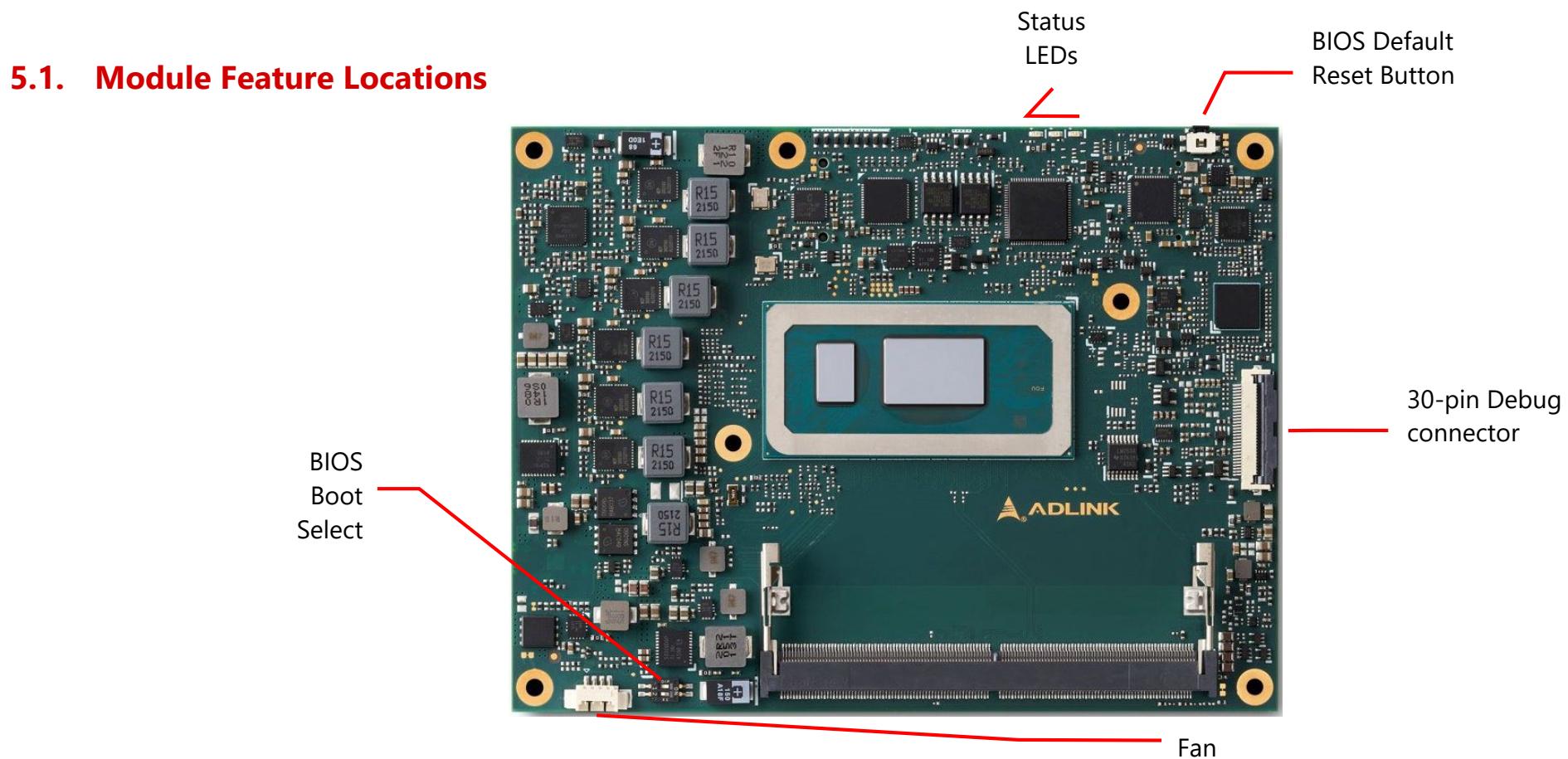
![5.1. Module Feature Locations\nStatus LEDs\nBIOS Default Reset Button\n30-pin Debug connector\nBIOS Boot Select\nADLINK\nFan](.express-rlp-manual-230411/9747e5d223e63095ac4dde2d912f6d290e7b6da01acffe4b75d1327eddbb5a6d.jpg)

Figure 3 – Module feature locations (top side)

# 5.2. Debug Connector

This connector is particular useful during carrier design and bring up phase. It offers access to the following critical parts of the module:

Test points measurement of internal power rails
SPI BIOS programming interface
Embedded Controller programming interface

30-pin Debug Connector located on bottom side (illustration only)
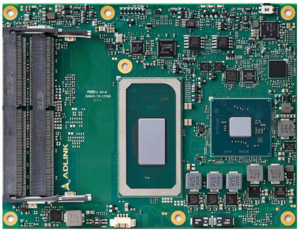
![Close-up of a green printed circuit board with multiple microchips and connectors (no readable text or symbols)](.express-rlp-manual-230411/fccb9af76750a50c0c69395f39358061ad8a688e6eeba919ca6820757e9d7181.jpg)

![Electronic circuit board with gold contacts and a coiled ribbon, no visible text or symbols](.express-rlp-manual-230411/164540a79e8f25a38b37d26fbd3ae2004342fe7892ecda34801a269b7a8ce3a3.jpg)

Figure 4 – Express-RLP and Debug Module

# 5.3. Status LEDs

Status LED’s are mounted on the module to facilitate easier maintenance.
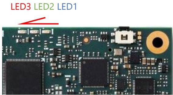
![LED3 LED2 LED1](.express-rlp-manual-230411/8ff7ed29bb0f4dc656889d537c27e563ce226f54f2b277f75297c122cdabd7dc.jpg)

<table><tr><td>Name</td><td>Color</td><td>Connection</td><td>Function</td></tr><tr><td>LED1</td><td>Blue</td><td>EC output</td><td>Power Sequence Status Code (EC) Power Changes, RESET (see Exception Codes below)</td></tr><tr><td>LED2</td><td>Green</td><td>Power Source 3Vcc</td><td>S0 LED ONS3/S4/S5 LED OFFECO mode LED OFF</td></tr><tr><td>LED3</td><td>Red</td><td>EC output and same signal as WDT (B27) on BtB connector</td><td>Module power up WD LED = LED OFFWatchdog counting WD LED = Keep Last StateWatchdog timed out WD LED = LED ONWatchdog RESET WD LED = LED ONRebooted after WD RESET WD LED = LED ONRebooted after PWRBTN WD LED = LED OFFRebooted after RESET BTN WD LED = LED OFFNote: only a RESET not initiated by the BMC can clear the WD LED (user action)</td></tr></table>

# 5.4. Exception Codes

<table><tr><td>Exception Code</td><td>Error Message</td></tr><tr><td>0</td><td>NOERROR</td></tr><tr><td>3</td><td>NO_SLP_S5</td></tr><tr><td>4</td><td>NO_SLP_S4</td></tr><tr><td>5</td><td>NO_SLP_S3</td></tr><tr><td>6</td><td>BIOS_FAIL</td></tr><tr><td>7</td><td>RESET_FAIL</td></tr><tr><td>9</td><td>NO_CB_PWROK</td></tr><tr><td>10</td><td>CRITICAL_TEMP</td></tr><tr><td>11</td><td>POWER_FAIL</td></tr><tr><td>12</td><td>VOLTAGE_FAIL</td></tr><tr><td>13</td><td>RSMRST_FAIL</td></tr><tr><td>14</td><td>NO_VDDQ_PG</td></tr><tr><td>16</td><td>NO_VCORE_PG</td></tr><tr><td>17</td><td>NO_SYS_GD</td></tr><tr><td>19</td><td>NO_V3P3A</td></tr><tr><td>21</td><td>NO_PWRSRC_GD</td></tr></table>

# 5.5. Fan Connector

Connector type: JVE 24W1125A-04M00

![Close-up of a green printed circuit board with various electronic components and a red arrow pointing to component 4 (no readable text or symbols)](.express-rlp-manual-230411/b0227df207604e4ba0913f7e821aac2312db9e85a94fc4375d8baafa154ba126.jpg)

<table><tr><td>Name</td><td>Description</td></tr><tr><td>1</td><td>FAN_PWMOUT</td></tr><tr><td>2</td><td>FAN_TACHIN</td></tr><tr><td>3</td><td>GND</td></tr><tr><td>4</td><td>12V</td></tr></table>

# 5.6. BIOS Default Reset Button

![Close-up of a green printed circuit board with electronic components and a red arrow pointing to a component (no visible text or symbols)](.express-rlp-manual-230411/5c0f63dcb7382edca6bf9edd296abc0d49eb0cd746fa0bcda80aa87f91f3f8c6.jpg)

To perform a hardware reset of BIOS default settings, perform the following steps:

1. Shut down the system.
2. Keep the BIOS Setup Defaults Reset Button pressed and boot up the system. You can release the button when the BIOS prompt screen appears
3. The BIOS prompt screen will display a confirmation that BIOS defaults have been reset and request that you reboot the system.

![American\nMegatrends\nVersion 2.15.1236. Copyright (C) 2012 American Megatrends, Inc.\nExpress-HL REV:1.04\nPress (CTRL + P) to Enter MEBX setup menu\nPress (DEL) or (ESC) to enter setup.\nDefault settings had been loaded due to BIOS_DEFAULT jumper is set!\nPlease turn off system power and remove BIOS_DEFAULT jumper!](.express-rlp-manual-230411/e2b381eb0722f343cd58bfa76f9ce7559148f954503d9e5b4943294cdc03b7b5.jpg)

# 5.7. BIOS Boot Select

The module has two BIOS chips (BOM option) and BIOS operation can be configured to "PICMG" and dual-BIOS "Failsafe" modes using BIOS Select and Mode Configuration Switch, Pin 2.

Setting the module to PICMG mode will configure the BIOS chips on the module as SPI0 and SPI1. In PICMG mode, a BIOS chip cannot be placed in the SPI0 slot on the carrier.

In dual-BIOS Failsafe mode, both BIOS chips on the module are configured as SPI1. Only one of the two is connected to the SPI bus at any given time. In case of failure of the primary SPI1 BIOS, the system will reboot and switch to the secondary SPI1 BIOS on the module. In Failsafe mode, the SPI0 BIOS socket on the carrier can be populated.

In either mode, BIOS Select and Mode Configuration Switch Pin 1 is used to select whether to boot from SPI0 or SPI1.

<table><tr><td>Mode</td><td>Pin 1</td><td>Pin 2</td></tr><tr><td>Boot from SPI0 (default)</td><td>On</td><td>-</td></tr><tr><td>Boot from SPI1</td><td>Off</td><td>-</td></tr><tr><td>Set BIOS to PICMG mode (default)</td><td>-</td><td>On</td></tr><tr><td>Set BIOS to Failsafe BIOS mode</td><td>-</td><td>Off</td></tr></table>

# 6. BIOS Checkpoints, Beep Codes

A status code is a data value used to provide diagnostic information about the boot process. Progress codes are status codes that signify successful progression to a following initialization step. Error codes signify error conditions encountered in the process of system initialization. The Aptio 5.x core can be configured to send status codes to a variety of sources. The two most commonly used types of status codes are checkpoint codes and beep codes. Checkpoint codes are byte length data values. Checkpoints are typically output to I/O port 80h, but the Aptio 5.x core can be configured to send checkpoints to a variety of sources. The Aptio 5.x core outputs checkpoints throughout the boot process to indicate the task the system is currently executing. Checkpoints are very useful in aiding software developers or technicians in debugging problems that occur during the pre-boot process on production hardware. A beep code is a series of short sound signals. Beep codes are typically error codes that do not occur during normal boot process.

![The image displays a red icon resembling a document or a note. It features a thick red outline with rounded corners. Inside the white space, there are two horizontal red lines centered vertically.](.express-rlp-manual-230411/7570aad20cc39e7b55c148fbf67262e2d8e3c544c658d881c6bfd359cb775511.jpg)

Note: Beep codes are not the only sounds generated during the boot process. Some firmware components may use sounds to notify the user about other events such as detection of a hot-pluggable device. These sounds are typically generated using a frequency that is different from the frequency of the beep codes

# Viewing Checkpoints

Checkpoints generated by the Aptio firmware can be viewed using a PCI checkpoint card, also referred to as a “POST Card” or “POST Diagnostic Card”. These PCI add-on cards show the value of I/O port 80h on an LED display.

# Aptio V Checkpoint and Beep Codes

Download the Aptio V Checkpoint and Beep Codes from the AMI website at: www.ami.com/download/aptio-v-checkpoint-and-beep-codes

# 7. Software Support

7.1. Windows 10 IoT Enterprise 64-bit
7.2. Yocto Linux 64-bit

https://github.com/ADLINK/meta-adlink-x86-64bit (TBC)

# 8. Mechanical and Thermal

8.1. Module Dimensions
![95\n91\nYAM 2000\n51.41\n28.41\n4\n0\n0 4\n25.79\n80\n88.79\n121\n125](.express-rlp-manual-230411/bcd03b83eab92f5a3011592c484aa3dc669e4788b6795b6e02ee28815fe32f74.jpg)

![Top View\n5 2 ±0.25\n2\n4 ±0.25\nFront View](.express-rlp-manual-230411/d477ddec9278faea127669d1fb7ac0bdbdeeed1353355306e3fa8688a11a1cb8.jpg)

![Bottom Side RAM\nModule Keepout\n125\n121\n88.79\n85.05\n80\n74.2\n25.79\n16.5\n9.95\n4\n0\n95\n91\n57.195\n51.41\n28.41\n18\n6\n4\n0](.express-rlp-manual-230411/94f9772c22154a885d0ac6bfc0627e1ffed86ec7b81ceea91e55a3dbc8cba35e.jpg)

Bottom View

All dimensions are shown in millimeters. Tolerances should be ± 0.25mm, unless otherwise noted. The tolerances on the module connector locating peg holes (dimensions [16.50, 6.00]&[16.50,18.00]) should be ± 0.10mm.

Dimensions: mm

Figure 5 – Module mechanical dimensions

# 8.2. Thermal Solutions

8.2.1 Heatspreader: HTS
![Dimensions: mm\n11\nM2.5*2PCS\nM2.5*5PCS\n95\n125\n89\n94\n125\n41\n87](.express-rlp-manual-230411/4434f5525fac3bef7d990a1a9b90c1fd56f10e560d0672b85c8bc37ce2d28116.jpg)

Heatspreader:HTS
Figure 6 – Heatspreader: HTS

# 8.2.2 Heatsink: THS

![The image displays a technical engineering drawing of a component labeled at the bottom center as 'Heatsink: THS'. The top right corner indicates 'Dimensions: mm'.\n\nThe diagram presents six views of the object:\n*   **Top Left:** A side profile view with a vertical dimension of **16.39**.\n*   **Top Middle:** An isometric view showing screw holes labeled **'M2.5*2PCS'** and **'M2.5*5PCS'**.\n*   **Top Right:** An isometric view showing the array of cooling fins.\n*   **Bottom Left:** A front view showing the fins, with a width dimension of **95** and a height dimension of **125**.\n*   **Bottom Middle:** A thin side profile view.\n*   **Bottom Right:** A rear view featuring a gold-colored mounting plate, with dimensions labeled **125** (total height), **41** (vertical offset), and **87** (width).](.express-rlp-manual-230411/6dec7a5451d7d2a4efe59f45f6572accc097183d162f74eefa985ef8a29b5f5a.jpg)
Figure 7 – Heatsink: THS

# 8.2.3 Heatsink High Profile: THSH

Dimensions: mm

![This image displays technical CAD renderings and orthographic projections of a grey heatsink assembly. Six views are arranged in two rows.\n\n*   **Top Left:** A side profile view with a height dimension labeled **31.41**.\n*   **Top Middle:** An isometric top view showing a mounting plate with screws, annotated with **M2.5*2PCS** and **M2.5*5PCS**.\n*   **Top Right:** An isometric view highlighting the vertical cooling fins.\n*   **Bottom Left:** A front view showing the fins, with a width dimension of **95** and a height dimension of **125**.\n*   **Bottom Middle:** A thin side profile view.\n*   **Bottom Right:** A bottom view showing the mounting plate, with dimensions labeled **125**, **41**, and **87**.\n\nCentered at the very bottom is the text **Heatsink: THSH**.](.express-rlp-manual-230411/9bfb7aa5baf26144cd57415cf34e334e689265288e71e2546280a2c668275b08.jpg)
Figure 8 – Heatsink High Profile: THSH

# 8.2.4 Heatsink with Fan: THSF

Dimensions: mm
![The image displays a technical CAD rendering of a computer heatsink from multiple angles, accompanied by dimensions and labels.\n\n**Top Row:**\n*   **Left:** A side profile view with a vertical dimension labeled **43.6**.\n*   **Center:** A top-down isometric view highlighting screw placements with labels pointing to them: **M2.5*2PCS** and **M2.5*5PCS**.\n*   **Right:** An angled view showcasing the fin structure and hexagonal cutouts.\n\n**Bottom Row:**\n*   **Left:** A front view displaying the fin array and hexagonal pattern, with dimensions **95** (width) and **125** (height).\n*   **Center:** A thin side profile view.\n*   **Right:** A rear view showing mounting holes and a central rectangular area, with dimensions **125** (height), **41** (hole spacing), and **87** (width).\n\n**Bottom Caption:**\nThe text at the very bottom reads: **Heatsink with Fan: THSF**](.express-rlp-manual-230411/52ea49e9222b731fd9647aedeca0d6f7b70e34d46d45c27eecfe8324c8520f6f.jpg)
Figure 9 – Heatsink with Fan: THSF
[🔗 Link to the original document](.express-rlp-manual-230411/express-rlp-manual-230411.pdf)