# Package Checklist

![Simple line drawing of a document with a square containing the letter 'N' and a diagonal line, no text or symbols present.](.gw-01-user-manual-english/39f8fc336a0e7c2d895c51824bc31bf45587af108d07bf80f0c7a23045327e3b.jpg)

GW-01 x1

![The image displays a simple black-and-white line drawing, likely a schematic of a door. On the left side, there is a square outline containing two smaller squares stacked vertically; each small square features a diagonal line. To the right of this square section is a thick, vertical black rectangle, representing the door itself. Attached to the right edge of the black rectangle is a small, white rectangular shape resembling a handle.](.gw-01-user-manual-english/fa1ad035657c7fc92ce7616be8b9e1eea3ca056279000ba320f0d4befbf84cc8.jpg)
USB recovery drive

![A black-and-white line drawing of a rectangular connector or plug angled to show its front and side faces. The front face displays the letters 'HP' in bold, sans-serif font within a rectangular outline, situated above a smaller, empty rectangle. The side of the object features three raised, parallel rectangular ridges.](.gw-01-user-manual-english/4b78e3fc3742ba1ee62d655a4a0fe0e80631b6a5dac5242f6d5bd44b7ef4b618.jpg)
Plug-able power terminal x1

![The image displays a black-and-white line drawing of a vertical object divided into distinct sections. At the very top, two small rectangles containing dots are positioned above a horizontal line that features a small circle in its center. Below this is a horizontal band decorated with a symmetrical, swirling scroll or wave pattern. Centered beneath the scroll pattern is a single circle. A vertical line extends downward from the center to a second circle. The bottom of the object is defined by a thick, solid horizontal rectangular band.](.gw-01-user-manual-english/c2438e7b0c6f58acb56c0c2fd5462b0e2f0caf1df1b4651f730aa518e414b915.jpg)
DIN-rail mounting kit x1: 25mm DIN-rail clip x1 M3x6mm flat Head Screw x2

# Power Connection

The device requires a power voltage of DC 24V (+/-20%). For a power consumption of 6W on the device, a power supply of 8W or above is recommended.

# Importance Notice

It is recommended that the power plug must be connected to the device power terminal prior to connecting to the power source.

# Power-connecting steps

1. Remove the power plug from the power terminal of the device.
2. Loosen the three screws on the power plug.
3. Strip the cable to expose the copper wire to about 7-8mm.
4. Insert the exposed copper wire into the three openings on the power plug.
5. Retighten the three screws on the power plug.
6. Plug the power plug back into the power terminal of the device.

# Note

The power plug is included and already plugged into the power terminal of the device.

![The image displays a schematic diagram of an electrical connector pinout.\n\n*   **Top Section:** A rectangular outline contains four smaller rectangular outlines arranged horizontally, representing the contact slots of the connector.\n*   **Middle Section:** Below the contact slots, four hatched columns extend downwards. The upper portion of these columns is hatched vertically, and the lower portion transitions to diagonal hatching, representing the pins or terminals.\n*   **Bottom Section:** Two labels indicate the wiring connections.\n    *   On the left, the text **'DC'** is written above **'+24 V'**.\n    *   On the right, the text **'FG'** is written above a ground symbol (a circle with three horizontal lines of increasing length).\n*   **Connections:** The diagram illustrates that the leftmost three pins are connected to the DC +24V supply, while the rightmost pin is connected to the Frame Ground (FG).](.gw-01-user-manual-english/8caa452a3635c69e850e1ec6ded0ffdee58a90e359362b7bbc0fe4cf60542cd5.jpg)

<table><tr><td>Power Line Type</td><td>Power Line (AWG)</td><td>Strip Length</td><td>Torque</td></tr><tr><td>Solid</td><td>28-12</td><td>About 7-8 mm</td><td>About 4.5lb-in</td></tr><tr><td>Stranded</td><td>30-12</td><td>About 7-8 mm</td><td>About 4.5lb-in</td></tr></table>

\* with copper conduction wire only.

# Grounding

In order to maintain the operational condition and functioning of the hardware components, please ensure proper power grounding.

Please ensure that the cable connecting the FG power terminal to the ground has a cable resistance lower than 100.

# Warning

Please read this manual before continuing with installation or operation of the device.

# General Guide

• Installation and operation of the device must be done by professionally trained staff.
• Installation of the device must follow the instructions as printed in this manual.
• Installation of the device must be kept away from the risk of any liquid or metal particles getting into the device. Foreign particles may cause internal components to short circuit and thus damage the device or even catch fire.
• Installation of the device must be kept away from the risk of corrosion, explosion, or heavy electronic and magnetic elds. It must also be kept away from high humidity and extreme shifts in temperature.

# Power Supply

• The device is designed with an input power of DC 24V. If the supply voltage is outside of the DC 24V +/- 20% range, it may result in damage or malfunction to the device. Therefore, please confirm that the voltage is correct before powering the device on. Please also ensure that the supplied power is stable during device operation.

# Installation:

• Please avoid placing communication lines in the same conduit as the power lines and high voltage lines. Isolated lines are suggested to reduce surrounding noise interference.

# Service and Maintenance

• Please do not allow any non-trained staff members to perform the maintenance servicing.
• Please do not use batteries with poor quality.

# Waste and Recycling

• Please adhere to local regulations when recycling device.
• The lithium battery, and capacitors contain hazardous material to individual health and local environment, and must be disposed responsibly.

# Dimensions

![NOVAKON\n31.25mm\n85.45mm\n25mm\n50mm\n2.5mm\n120mm\nUSB](.gw-01-user-manual-english/0b5e33f6a3327b67f413cb18f2847b604d080e051c6f6df143fc5247d3d49d18.jpg)

# Product Specifications

<table><tr><td>Type</td><td>Protocol Conversion Gateway Series</td></tr><tr><td>Model Number</td><td>GW-01</td></tr><tr><td>CPU</td><td>ARM Cortex-A8 (1GHz)</td></tr><tr><td>SDRAM</td><td>512M Bytes</td></tr><tr><td>Flash Memory</td><td>4GB, 8bit eMMC</td></tr><tr><td>FRAM (non-volatile)</td><td>32K Bytes</td></tr><tr><td>RTC</td><td>CR2032 Replaceable</td></tr><tr><td>COM</td><td>1 x RS232 1 x RS422/485</td></tr><tr><td>Ethernet</td><td>2 x 10/100 Mbit</td></tr><tr><td>USB</td><td>1 x Type A (Host)</td></tr><tr><td>Power Input</td><td>24V ± 20 % DC , Isolated Power</td></tr><tr><td>Power Consumption</td><td>6W</td></tr><tr><td>Operating Temperature</td><td>-20 ~ 70°C</td></tr><tr><td>Storage Temperature</td><td>-20 ~ 80°C</td></tr><tr><td>Operation Humidity</td><td>10 ~ 90%RH non-condensing @40°C</td></tr><tr><td>Dimension (mm)</td><td>120.00(W) x 85.45(H) x 31.25(D) mm</td></tr><tr><td>Net Weight</td><td>0.25 kg</td></tr><tr><td>Gross Weight</td><td>0.42 kg</td></tr></table>

# COM Port

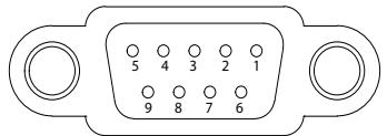
The assignment of each pin and COM port varies from that of a standard PC. Please refer to the above table for signal connection and pin assignment.

COM Port Pin Assignment：
![The image is a line drawing of a connector housing, rectangular with rounded corners and two mounting holes on the left and right sides. Inside the housing, there are ten circular pin positions arranged in two rows. The top row contains five pins labeled with the numbers 5, 4, 3, 2, and 1 from left to right. The bottom row contains four pins labeled with the numbers 9, 8, 7, and 6 from left to right.\n\nText content:\n5 4 3 2 1\n9 8 7 6](.gw-01-user-manual-english/ff3a81e1c3739c43a89b03ad386ff26160280351c3258bbef2d2f1d0a3379bc9.jpg)

<table><tr><td>Pin</td><td>COM</td></tr><tr><td>1</td><td>RS422 TX+ / RS485 TX/RX+</td></tr><tr><td>2</td><td>RS232 RX</td></tr><tr><td>3</td><td>RS232 TX</td></tr><tr><td>4</td><td>RS422 RX+</td></tr><tr><td>5</td><td>SG</td></tr><tr><td>6</td><td>RS422 TX- / RS485 TX/RX-</td></tr><tr><td>7</td><td>Optional TTL Level TXD</td></tr><tr><td>8</td><td>Optional TTL Level RXD</td></tr><tr><td>9</td><td>RS422 RX-</td></tr></table>

# Preparation

# Setup Requirement

1. GW-01 x1
2. Computer with ethernet port x1
3. DC24V power supply x1

![Line drawing of a network device connected to a laptop, showing a grid-connected module and cable (no text or symbols)](.gw-01-user-manual-english/832d9ce377fb63561e5adf13aed0e15c89dc1b76395ee48db0c246d6dbf178b2.jpg)

# Installation Procedure

Step 1: Fasten the DIN rail clip to the Gateway with two screws

Step 2: Clip the device onto the DIN rail

![Pure electrical circuit lines without any symbols](.gw-01-user-manual-english/275dfdf7873093375d00f607ec20dc9d26b2a085a2bb880572a4c71a333545ae.jpg)

![1\n2](.gw-01-user-manual-english/b50f8c2b2635f4a656330c9903a3716b308b2f258d138ddbca1d2ec18011ae6b.jpg)

# Accessing Your GW-01

First time accessing the GW-01, connect your computer to the default ethernet port [LAN1] of GW-01 with the default IP address http://192.168.0.80.

Change your computer's IP setting to be in the same network with GW-01, e.g., the default IP address of GW-01 is 192.168.0.80; computer IP address set as 192.168.0.xxx. If not necessary, do not change the default IP address of LAN1.

![Ethernet Properties\nNetworking Sharing\nConnect using:\nRealtek PCIe GBE Family Controller\nConfigure...\nThis connection uses the following items:\n✓ Client for Microsoft Networks\n✓ File and Printer Sharing for Microsoft Networks\n✓ QoS Packet Scheduler\n✓ Internet Protocol Version 4 (TCP/IPv4)\n□ Microsoft Network Adapter Multiplexor Protocol\n✓ Microsoft LLDP Protocol Driver\n✓ Internet Protocol Version 6 (TCP/IPv6)\nInstall...\nLiveInstall\nProperties\nDescription\nTransmission Control Protocol/Internet Protocol. The default\nwide area network protocol that provides communication\nacross diverse interconnected networks.\nOK Cancel](.gw-01-user-manual-english/3383924516ef76f85e29a4cf9b4290f212c3cc4a5c744a9e99b36916a581ff50.jpg)

![Internet Protocol Version 4 (TCP/IPv4) Properties\nGeneral\nYou can get IP settings assigned automatically if your network supports this capability. Otherwise, you need to ask your network administrator for the appropriate IP settings.\nObtain an IP address automatically\nUse the following IP address:\nIP address: 192 . 168 . 0 . 158\nSubnet mask: 255 . 255 . 255 . 0\nDefault gateway: .\nObtain DNS server address automatically\nUse the following DNS server addresses:\nPreferred DNS server: .\nAlternate DNS server: .\nValidate settings upon exit\nAdvanced...\nOK Cancel](.gw-01-user-manual-english/da9e6826b81ec189e7cff1deb85db88fe1e963ab76bf6c58250684ab84e16204.jpg)

![Sign in to access this site\nAuthorization required by http://192.168.0.80\nYour connection to this site is not secure\nUsername\nPassword\nSign in    Cancel](.gw-01-user-manual-english/712fd86a965e1aae5c501a7a6f61d5efa682a8b129f63909e3696c4ef64dfb7f.jpg)

1. Open a browser and connect to http://192.168.0.80
2. Type the default username and password:
Username: admin Password: 1234

# Configuring IP and Network Settings

![IM-CONNECT\nABOUT\nPLC SETTING\nTAG SETTING\nDATA LOGGER\nALARM\nMQTT\nMACRO EDITOR\nOPCUA CLIENT\nONLINE MONITOR\nPROJECT SETTING\nSYSTEM SETUP](.gw-01-user-manual-english/d49b4afa8a6a878396556e835fb7ac351e2e15b09ac231014bfe00796c509519.jpg)

Click [ ] to view the [iM-CONNECT] menu. Click [System Setup]. Click [Network Setup] to configure Gateway's IP Address and Network Settings.

# A. Ethernet

Configure the IP address, Mask, Gateway, and DNS of [LAN1] and [LAN2] respectively.

# B. IP Address Ethernet

[Obtain IP address automatically(DHCP)]：System automatically obtains IP addresses.

[Use static IP address below] ：Manually input the IP Addresses.

After configuration of each LAN, click [Submit] to save the settings to GW-01.

![IM-CONNECT ) System Setup\nSystem Information\nNetwork Setup\nDate and Time\nSecurity Setting\nService Status\nEthernet\nLAN1\nNVC Address: 80.81.13.CE.34.75\nLAN2\nNVC Address: 80.81.13.CE.34.77\nIP Address Ethernet\nObtain IP address automatically(OHCP)\nUse static IP address below\nIP:\n192 . 168 . 0 . 80\nMask:\n255 . 255 . 255 . 0\nGateway:\n0 . 0 . 0 . 0\nDNS1:\n0 . 0 . 0 . 0\nDNS2:\n0 . 0 . 0 . 0\nSave\nNOVAKON\nIM-CONNECT®](.gw-01-user-manual-english/095bdbf5045b216696ad3b0f9e5ed55f9f39734bdb23e7594975b21f48cfb2de.jpg)

# Reset to Default

If you forget the password or default configuration information, you can reset GW-01 to factory defaults. By plugging in the supplied USB recovery drive into the USB port on the GW-01 for a few seconds, it will be restored to factory configuration and reboot.

# Note:

After GW-01 reboots, wait until the "beep" sound before opening or refreshing the webpage.

# Service Port

When connecting GW-01 to external services, following port numbers will be required according to different services to permit the access.

<table><tr><td>Server</td><td>Default Port</td></tr><tr><td>OPCUA Server</td><td>4840</td></tr><tr><td>MQTT Broker</td><td>1833 (unencrypted)8883 (encrypted)</td></tr><tr><td>FTP Server</td><td>21</td></tr><tr><td>Web Server</td><td>80 / 9000</td></tr></table>

<table><tr><td>Client</td><td>Default Port</td></tr><tr><td>MySQL</td><td>3306</td></tr><tr><td>MSSQL</td><td>1433</td></tr><tr><td>OPEN VPN</td><td>1194</td></tr><tr><td>LINE</td><td>443</td></tr><tr><td>Email</td><td>587</td></tr></table>

3. Click [Sign In] and the configuration page is displayed
![IM-CONNECT\nWELCOME TO IM-CONNECT\niM-CONNECT is a web-based IoT gateway configuration and management software developed by\nNOVAKON CO₂ LTD, for user to quickly set up and access the NOVAKON IoT product series anytime\nand anywhere through the web browser.\nFor more information,\nvisit www.novakon.com.tw\nDownload the user\nmanual here\nFurther technical support\nneeded, please contact us\nat www.novakon.com.tw\nNOVAKON\nIM CONNECT](.gw-01-user-manual-english/eb56acc93e7518e64dd7f90fb2a8da067ac9d453d1aadc78e72b1993f72ca648.jpg)

# Additional Information

To download the detailed user guide of GW-01 and understand the supported PLC models, pay a visit to Novakon official website：https://www.novakon.com.tw
[🔗 Link to the original document](.gw-01-user-manual-english/gw-01-user-manual-english.pdf)