# HDV62A

High-Definition Video/Audio Capture Card

User's Manual

![Green printed circuit board with various electronic components and connectors (no readable text or symbols)](.hdv62a-50-11246-1010-200-en-en/49d7ca629695e3c26676bb07f554ffddce19412f5ac0df7b5b54d4d7b622b4d1.jpg)

Manual Rev.: 2.00

Revision Date: Nov. 23, 2012

Part No: 50-11246-1010

![Black circular icon with three white arrows forming a recycling symbol (no text or numbers)](.hdv62a-50-11246-1010-200-en-en/e37abc249f33e7d2734c6a829c6cfc5171be6ac8c3b7866a0004c5e9fb566e54.jpg)

Recycled Paper

# Revision History

<table><tr><td>Revision</td><td>Release Date</td><td>Description of Change(s)</td></tr><tr><td>2.00</td><td>Nov 23, 2012</td><td>Initial Release</td></tr></table>

# Preface

# Copyright 2012 ADLINK Technology, Inc.

This document contains proprietary information protected by copyright. All rights are reserved. No part of this manual may be reproduced by any mechanical, electronic, or other means in any form without prior written permission of the manufacturer.

# Disclaimer

The information in this document is subject to change without prior notice in order to improve reliability, design, and function and does not represent a commitment on the part of the manufacturer.

In no event will the manufacturer be liable for direct, indirect, special, incidental, or consequential damages arising out of the use or inability to use the product or documentation, even if advised of the possibility of such damages.

# Environmental Responsibility

ADLINK is committed to fulfill its social responsibility to global environmental preservation through compliance with the European Union's Restriction of Hazardous Substances (RoHS) directive and Waste Electrical and Electronic Equipment (WEEE) directive. Environmental protection is a top priority for ADLINK. We have enforced measures to ensure that our products, manufacturing processes, components, and raw materials have as little impact on the environment as possible. When products are at their end of life, our customers are encouraged to dispose of them in accordance with the product disposal and/or recovery programs prescribed by their nation or company.

# Trademarks

Product names mentioned herein are used for identification purposes only and may be trademarks and/or registered trademarks of their respective companies.

# Conventions

Take note of the following conventions used throughout this manual to make sure that users perform certain tasks and instructions properly.

![The image shows a white document icon featuring horizontal gray lines, resembling a piece of lined paper, with the top-right corner curled. A large, bold red checkmark is superimposed diagonally over the center of the document.](.hdv62a-50-11246-1010-200-en-en/03e261f066be427a9b7b5359d5495a32dc0efe8685d510c98f168ead4e271e23.jpg)
NOTE:

Additional information, aids, and tips that help users perform tasks.

![The image displays a yellow triangular warning sign with a black border. Inside the triangle, there is a large black exclamation point centered vertically.](.hdv62a-50-11246-1010-200-en-en/b0b737a52a68575bbd1b7a4b0c631fd58bddd0e58b01754a2484446fa5711e8d.jpg)
CAUTION:

Information to prevent minor physical injury, component damage, data loss, and/or program corruption when trying to complete a task.

![This image displays a deep red, equilateral triangle with a thin white border. Centered inside the triangle is a large white exclamation point.](.hdv62a-50-11246-1010-200-en-en/c2db7721a05b6412c445f72fad9634496eae479e03d29b2907a3386f63d51b9e.jpg)
WARNING:

Information to prevent serious physical injury, component damage, data loss, and/or program corruption when trying to complete a specific task.

# Table of Contents

# Revision History...... ii

# Preface .... iii

# List of Figures ix

# List of Tables.... xi

# 1 Introduction ...... 1

1.1 Overview.... 1
1.2 Features.... 1
1.3 Applications 2
1.4 Specifications.... 2

1.4.1 Video 2
1.4.2 Audio 5
1.4.3 General 6

1.5 Schematics & Connections.... 6

1.5.1 DVI-I 8
1.5.2 Toslink Optical and RCA Connectors 10

1.6 Switch Settings 11

1.6.1 Card ID Switch (SW3) 12
1.6.2 FPGA Boot Flash Selection Switch (SW4).... 13

1.7 Optional Connections 13

1.7.1 YPbPr/S-Video/CVBS I/O Bracket.... 13
1.7.2 DVI-DVI/VGA Cable 17
1.7.3 Dsub9-Composite/S-video Cable 19

# 2 Getting Started 21

2.1 Unpacking Checklist 21
2.2 Windows Driver Installation 21
2.3 ViewCreator Pro Utility 29

2.3.1 Devices Panel 31
2.3.2 Adjustment Panel....32
2.3.3 Tool Panel 33
2.3.4 Display Panel....39
2.3.5 Display Menu 41
2.3.6 Color Format Menu 46
2.3.7 Audio Format Menu 46
2.3.8 Audio Input Menu 47
2.3.9 Image Size Menu 47
2.3.10 Tool Menu....48

2.4 HDV62(A) Setting Utility 49

# 3 DirectShow Programming Guide.... 51

3.1 Filters 52

3.1.1 Source Filters....52
3.1.2 Example Graphs....54

3.2 Driver Control.... 63

3.2.1 Property Pages....63
3.2.2 COM interfaces....64

ADLINK HDV62A Crossbar 65

3.3 Color Space 65
3.4 Proprietary Interfaces.... 67

3.4.1 IVideoFormat 67

Sensor Format 68
Cropping 72
Horizontal Delay 73
AutoDetectSensorFormat 74
Image Orientation 75

3.4.2 IAdvance....77

EDID ROM Ready Status 77

EDID ROM Access Permission 78

Write Protection 79

ROM Read/Write 80

3.4.3 CardInfo....81

Version 81

Card ID 83

Video Capabilities 83

Audio Capabilities 88

3.5 Build Environment Settings.... 91

3.5.1 Include Files 91

3.5.2 Library Files 91

3.5.3 Microsoft Visual C++ 92

3.5.4 .Net Programming Users 92

A Appendix: EDID Default Settings....93

Important Safety Instructions.... 95

Getting Service.... 97

This page intentionally left blank.

# List of Figures

Figure 1-1: HDV62A PCB Overview 7

Figure 1-2: HDV62A PCB Side View
(showing I/O bracket connectors)....7

Figure 1-3: HDV62A I/O Panel....7

Figure 1-4: DVI-I Connector....8

Figure 1-5: Optical and RCA Connectors .... 10

Figure 1-6: Switch Locations on PCB 11

Figure 1-7: Card ID Switch....12

Figure 1-8: Flash Selection Switch .... 13

Figure 1-9: I/O Bracket PCB Connections ..... 14

Figure 1-10: 10-pin Box Header on PCB 14

Figure 1-11: I/O Bracket....15

Figure 1-12: I/O Bracket External Connections ...... 15

Figure 1-13: PCB-I/O Bracket Signal Correspondence .... 16

Figure 1-14: D-sub Connector for CVBS/S-video 16

Figure 1-15: DVI-DVI/VGA Cable 17

Figure 1-16: VGA connector for DVI-DVI/VGA Cable.... 18

Figure 1-17: Dsub9-Composite/S-video Cable 19

Figure 2-1: ViewCreator Pro Interface 30

Figure 2-2: Devices Panel....31

Figure 2-3: RGB Display Menu 41

Figure 2-4: Cropping Dialog....47

Figure 2-5: EDID Dialog....48

Figure 2-6: HDV62A Setting Utility Interface....49

Figure 3-1: GraphEdit Insert Filters Dialog .... 55

Figure 3-2: Video Format Dialog....56

Figure 3-3: Audio Format Dialog....57

Figure 3-4: Video Proc Amp Dialog 58

Figure 3-5: Video Decoder Dialog....59

Figure 3-6: Capture Pin Properties Dialog 60

Figure 3-7: Crossbar Properties Dialog 61

Figure 3-8: GraphEdit Interface 62

Figure 3-9: Bottom-up Image Orientation .... 76

Figure 3-10: Top-down Image Orientation 77

This page intentionally left blank.

# List of Tables

Table 1-1: HDV62A I/O Legend 8

Table 1-2: DVI-I Pin Connections 9

Table 1-3: Optical and RCA Pin Assignment.... 10

Table 1-4: Switch Locations Legend.... 12

Table 1-5: Card ID Settings 12

Table 1-6: Flash Selection Settings 13

Table 1-7: I/O Bracket PCB Connection Legend 14

Table 1-8: 10-pin Box Header Pin Connections.... 15

Table 1-9: D-sub Connector Pin Assignment.... 17

Table 1-10: DVI Connector Pin Assignment 18

Table 1-11: VGA Connector Pin Assignment.... 19

Table 2-1: Devices Panel Items....31

Table 2-2: Tool Panel Controls 34

Table 2-3: FocusValue Tools....39

Table 2-4: RGB (DVI-I) Available Formats....42

Table 2-5: YPbPr (EXT) Available Formats 43

Table 2-6: HDMI (DVI-I) Available Formats 45

Table 2-7: Composite (EXT) Available Formats 45

Table 2-8: S-Video (EXT) Available Formats......46

Table 2-9: Audio Formats 46

This page intentionally left blank.

# 1 Introduction

# 1.1 Overview

The HDV62A full HD video/audio capture card, based on the PCI Express $^{®}$ x4 interface, enables acquisition of video and digital audio streams from both HD (high-definition) and SD (standard-definition) video at up to 170 MHz DVI input.

ADLINK's HDV62A not only delivers superior quality high-definition video data from DVI or HDMI, suitable for medical, scientific imaging and multi media device testing, but also provides an analog video decoder comprehensively supporting CVBS, S-video, analog RGB, and Component signal capture.

Equipped with a FPGA (field programmable gate array) and a 512 MB memory buffer, the HDV62A enables image streaming of specified target areas to a host PC, as well as real-time hardware color space conversion to offload repetitive tasks from the host CPU.

The HDV62A is equipped with the ViewCreator Pro® utility, enabling setup, configuration, testing, and system debugging without requiring any software programming. As well, ADLINK's WDM driver is compatible with Microsoft® Directshow to reduce engineering effort and accelerate time to market.

# 1.2 Features

▶ Uncompressed 1920 x 1080p, 60 fps video stream
▶ Support for CVBS, S-video, RGB and component video input
▶ Support for HDMI and DVI video input
▶ Support for HDMI, S/PDIF audio input
▶ PCI Express® x4 interface
▶ Hardware color spacezRAM frame buffer
▶ Configurable EDID
▶ Direct SDK support

# 1.3 Applications

The HDV62A is ideally suited to frame grab functions in a wide variety of applications, including, medical imaging, scientific imaging, HDMI video/audio testing, and multimedia device testing.

# 1.4 Specifications

# 1.4.1 Video

Format

<table><tr><td>Item</td><td>Specification</td></tr><tr><td>Digital</td><td>DVI 1.0, HDMI 1.3 (with HDCP)</td></tr><tr><td>Analog</td><td>R,G,BY,Pb,PrCVBS (NTSC / PAL)S-Video (NTSC / PAL)</td></tr></table>

Resolution)

<table><tr><td>Item</td><td></td><td>Specification</td></tr><tr><td rowspan="3">DVI</td><td>YCrCb</td><td>VGA@60Hz(640 x 480)SVGA@60Hz (800 x 600)XGA@60Hz(1024 x 768)WXGA+ @60Hz(1280 x 768)WXGA @60Hz(1360x768)WXGA @60Hz(1280 x 800)SXGA @60Hz(1280 x 1024)UXGA @60Hz(1600 x 1200)WSXGA+@60Hz(1680 x 1050)525i@30(720 x 480)625i@25 Hz(720 x 576)720p@50/60Hz(1280 x 720)1200P@50/60Hz(1920 x 1200)1080i@25/30Hz(1920 x 1080)1080p@24/25/30/48/50/60Hz(1920 x 1080)</td></tr><tr><td>SD</td><td>VGA @60Hz (640x480),SVGA @60Hz (800x600),XGA @60Hz (1024x768z),SXGA @60Hz (1280x1024),UXGA @60Hz (1600x1200),</td></tr><tr><td>RGB</td><td>WXGA @60Hz (1360x768),WXGA+ @60Hz (1280 x 768),WSXGA+ @60Hz (1680 x 1050)525i @30 (720 x 480),625i @25 (720 x 576),720p @50/60Hz (1280 x 720)1200P @50/60Hz (1920 x 1200),1080i @25/30Hz (1920 x 1080),1080p @24/25/30/48/50/60Hz (1920 x 1080)</td></tr></table>

<table><tr><td>Item</td><td></td><td>Specification</td></tr><tr><td colspan="2">RGB (Analog)</td><td>VGA @60/@75/@85Hz (640x480)SVGA @60/@75/@85Hz (800x600)XGA @60/@75/@85Hz (1024x768)WXGA+ @60/@75/@85Hz (1280x768)WXGA @60/@75/@85Hz (1280x800)SXGA @60/@75/@85Hz (1280x1024)UXGAc @60Hz (1600x1200)WSXGA+ @60Hz (1680x1050)XGA+ 75fps (1152 x 864)Wide XGA 60fps (1360 x768)SXGA+ 60fps (1400 x 1050)SXGA+ 75fps (1400 x 1050)</td></tr><tr><td colspan="2">YPbPr (Analog)(via extension bracket)</td><td>525i @30 525p@60625i @25 625p@50720p @50/601080i @25/301080p @50/60</td></tr><tr><td colspan="2">CVBS &amp; S-video(Analog)(via extension bracket)</td><td>SDTV:720 x 576720 x 480</td></tr></table>

General Video

<table><tr><td>Item</td><td>Specification</td></tr><tr><td>Pixel Output Format</td><td>RGB:32bit RGB*30bit RGB*24bit RGBYCbCr:24 bit 4:4:4 YCbCr16 bit 4:2:2 YCbCrMonochrome:8-bit Y</td></tr><tr><td>Area of Interest</td><td>One AOI range, range ( W:16x, H: 2x)</td></tr><tr><td>Capture Modes</td><td>▸ Free Run▸ Snap</td></tr><tr><td>Video In</td><td>▸ DVI-I Dual Link connector: DVI, HDMI (Only single-link signal)▸ SMB,BNC connector (I/O bracket): Y,Pb,Pr▸ 10 Pin Box header, 9-pin D-Sub Female connector: (I/O bracket): CVBS,S-Video</td></tr></table>

![The image displays a white document icon with a folded top-right corner and horizontal lines representing text. A large red checkmark is superimposed over the center of the document.](.hdv62a-50-11246-1010-200-en-en/5151e7f68278a0dbec144242aa2a5bf4108efd14c872e793aa71fc634f4ecf90.jpg)
NOTE:

Some computers may experience minor (10% or less) reduction of fps performance when 32bit or 30bit RGB output settings are in effect.

1.4.2 Audio

<table><tr><td>Item</td><td>Specification</td></tr><tr><td>Digital Format S/PDIF (IEC60958-compatible)</td><td>Sampling Rate:16, 22.05, 32, 44.1, 64, 88.2, 96 KHzInput Bit format:16 bit, 20 bit, 24 bitOutput Bit format:24 bitsChannels:2.0 (2)Note: no A/V sync</td></tr><tr><td>Digital Format HDMI (HDMI1.3)</td><td>Sampling Rate:32, 44.1, 48, 88.2, 96, 176.4, 192KHz.Input Bit Format:16 bit, 20 bit, 24 bitOutput Bit Format:24 bitsChannels:2.0 (2), 5.1 (6), 7.1 (8)Note: no A/V sync</td></tr><tr><td>Analog Format</td><td>N/A</td></tr><tr><td>Capture Modes</td><td>► Free Run► Snap: software</td></tr><tr><td>Audio in (SPDIF)</td><td>► Toslink connector (for optical fiber cable)► RCA connector (for 75-ohm coaxial cable)</td></tr><tr><td>EDID</td><td>► EDID 1.3 (Audio and Video)► Software configuration</td></tr></table>

# 1.4.3 General

<table><tr><td>Item</td><td>Specification</td></tr><tr><td>RAM (Frame Buffer)</td><td>DDR2 667 512MB</td></tr><tr><td>Power Consumption</td><td>▶ Max. 0.5mA @ +12V▶ Max. 2.2A @ +3.3V</td></tr><tr><td>Board Dimensions</td><td>174.62 x 111.15 mm</td></tr><tr><td>Board</td><td>▶ Half-length PCI Express 1.0a x4 compliant▶ RoHS Compliant</td></tr><tr><td>Operating Temp.</td><td>0 to 55°C</td></tr><tr><td>Software Support</td><td>XP / Win 7, 32/64 bit, DirectShow, Labview 2009,2010,and 2011</td></tr></table>

# 1.5 Schematics & Connections

![The image shows a white document icon with a folded top-right corner and faint horizontal lines. A large red checkmark is superimposed over the center of the document.](.hdv62a-50-11246-1010-200-en-en/9edd6f5d456740c064130501bb2a556ec6893adf3ef61085993af44d9986e3ef.jpg)
NOTE:

Please note that all dimensions shown are in mm.

![174.52\n100.36\n111.15\n59.05\n176.42](.hdv62a-50-11246-1010-200-en-en/2c13e698221d916fecd048ae049001b04993945124760c07f897ca0ad0fe6a84.jpg)

Figure 1-1: HDV62A PCB Overview
![Technical diagram of a mechanical assembly with red arrows indicating downward components (no text or symbols present)](.hdv62a-50-11246-1010-200-en-en/fccb268c56551335cff2418ac91ba025309fe916ecc2ad3db1f474d6f40bdc43.jpg)

Figure 1-2: HDV62A PCB Side View (showing I/O bracket connectors)

![A\nB\nC\nS/PDF\nCoastal\nOptical](.hdv62a-50-11246-1010-200-en-en/bad7e6788c63a524439e66a348bf643b5fdaf2d98b90ef65399e358b8245ee4b.jpg)

Figure 1-3: HDV62A I/O Panel

<table><tr><td>A</td><td>DVI-I for DVI, HDMI and RGB</td></tr><tr><td>B</td><td>RCA for S/PDIF</td></tr><tr><td>C</td><td>Toslink for S/PDIF</td></tr></table>

Table 1-1: HDV62A I/O Legend

# 1.5.1 DVI-I

![C4 C3 24 17\nC5\nC2 C1 8 1](.hdv62a-50-11246-1010-200-en-en/b5946e94e1db9d0652437ce1b3feb0d8d7d7562b03b77bc9164277e65c728309.jpg)

Figure 1-4: DVI-I Connector

<table><tr><td>Pin</td><td>Signal</td><td>In/Out</td><td>Pin</td><td>Signal</td><td>In/Out</td></tr><tr><td>1</td><td>T.M.D.S data2-</td><td>Input</td><td>16</td><td>Hot plug detect</td><td>Output</td></tr><tr><td>2</td><td>T.M.D.S data2+</td><td>Input</td><td>17</td><td>T.M.D.S data0-</td><td>Input</td></tr><tr><td>3</td><td colspan="2">T.M.D.S data2 shield</td><td>18</td><td>T.M.D.S data0+</td><td>Input</td></tr><tr><td>4</td><td colspan="2">NC</td><td>19</td><td colspan="2">T.M.D.S data2 shield</td></tr><tr><td>5</td><td colspan="2">NC</td><td>20</td><td colspan="2">NC</td></tr><tr><td>6</td><td>DDC clock</td><td>Input</td><td>21</td><td colspan="2">NC</td></tr><tr><td>7</td><td>DDC data</td><td>Input</td><td>22</td><td colspan="2">T.M.D.S clock shield</td></tr><tr><td>8</td><td>Analog Vertical Sync.</td><td>Input</td><td>23</td><td>T.M.D.S clock+</td><td>Input</td></tr><tr><td>9</td><td>T.M.D.S data1-</td><td>Input</td><td>24</td><td>T.M.D.S clock-</td><td>Input</td></tr><tr><td>10</td><td>T.M.D.S data1+</td><td>Input</td><td colspan="3"></td></tr><tr><td>11</td><td colspan="2">T.M.D.S data1 shield</td><td>C1</td><td>Analog Red</td><td>Input</td></tr><tr><td>12</td><td colspan="2">NC</td><td>C2</td><td>Analog Green</td><td>Input</td></tr><tr><td>13</td><td colspan="2">NC</td><td>C3</td><td>Analog Blue</td><td>Input</td></tr></table>

<table><tr><td>Pin</td><td>Signal</td><td>In/Out</td><td>Pin</td><td>Signal</td><td>In/Out</td></tr><tr><td>14</td><td>+5V Power</td><td>Input</td><td>C4</td><td>Analog Horizontal Snyc.</td><td>Input</td></tr><tr><td>15</td><td colspan="2">Ground (Return for +5V Hsync and Vsync)</td><td>C5</td><td colspan="2">Analog Ground (Return for Analog R, G, and B)</td></tr></table>

Table 1-2: DVI-I Pin Connections

# 1.5.2 Toslink Optical and RCA Connectors

![SPDIF\nCoedal\nOptical](.hdv62a-50-11246-1010-200-en-en/1f81a4df42837caca742e1ffbef722c3581abdedfc01d1d53d66ac424a024c03.jpg)

Figure 1-5: Optical and RCA Connectors

<table><tr><td>Pin</td><td>Signal</td><td>In/Out</td></tr><tr><td>RCA (Coaxial)</td><td>S/PDIF</td><td>Input</td></tr><tr><td>Toslink (Optical)</td><td>S/PDIF</td><td>Input</td></tr></table>

Table 1-3: Optical and RCA Pin Assignment

# 1.6 Switch Settings

![Pb Pr Y\nA\nDB-HDV62A 001E LF\n51-L4077-0A20\nSTM-5\n10.94V-0\n50:11\n5/N\nBC3FA1010\n4C](.hdv62a-50-11246-1010-200-en-en/4a971ead00fb15e321c91c6a76508b8b0da826f22cee19fef16435d4bbfa5927.jpg)

![Green printed circuit board with labeled components and annotations, including a magnified inset showing a component labeled 'B'.](.hdv62a-50-11246-1010-200-en-en/48fd7df8c9174cdc2c18a3ba0c5222698ba170c5f2a8189444900fbd84ef2445.jpg)

Figure 1-6: Switch Locations on PCB

<table><tr><td>A</td><td>Card ID switch</td></tr><tr><td>B</td><td>Flash selection switch</td></tr></table>

Table 1-4: Switch Locations Legend

# 1.6.1 Card ID Switch (SW3)

![A white document icon featuring horizontal lines and a folded top-right corner is overlaid with a large red checkmark.](.hdv62a-50-11246-1010-200-en-en/44e514e24faad0807b1e24dea0825b3b7a114cfe7a321f01c661ef9ad099b749.jpg)
NOTE:

Please note: all settings shown 4321, and ON=0, OFF=1

![Close-up of a green printed circuit board with black terminal blocks and soldered pins (no readable text or symbols)](.hdv62a-50-11246-1010-200-en-en/d3956b4ae0d852da0ace0566b6fd0ce6f6fe7938c639765a6a2939752f1af43d.jpg)

Figure 1-7: Card ID Switch

<table><tr><td>Card ID</td><td>Setting</td><td>Card ID</td><td>Setting</td></tr><tr><td>0</td><td>0000</td><td>8</td><td>1000</td></tr><tr><td>1</td><td>0001</td><td>9</td><td>1001</td></tr><tr><td>2</td><td>0010</td><td>10</td><td>1010</td></tr><tr><td>3</td><td>0011</td><td>11</td><td>1011</td></tr><tr><td>4</td><td>0100</td><td>12</td><td>1100</td></tr><tr><td>5</td><td>0101</td><td>13</td><td>1101</td></tr><tr><td>6</td><td>0110</td><td>14</td><td>1110</td></tr><tr><td>7</td><td>0111</td><td>15</td><td>1111</td></tr></table>

Table 1-5: Card ID Settings

# 1.6.2 FPGA Boot Flash Selection Switch (SW4)

![Close-up of a black electronic component labeled SW4 on a green circuit board (no readable text or symbols beyond label)](.hdv62a-50-11246-1010-200-en-en/b05e38d458372193b6ca65c97ae4c332ed7af9e97d126dd115071698767946a4.jpg)

Figure 1-8: Flash Selection Switch

<table><tr><td>Boot Flash</td><td>Switch (Bit2,Bit1)</td></tr><tr><td>Working Flash (default)</td><td>OFF,OFF</td></tr><tr><td>Golden Flash</td><td>ON,ON</td></tr></table>

Table 1-6: Flash Selection Settings

![The image displays an icon representing a completed document. It features a white page with faint horizontal gray lines, simulating a sheet of paper. A large, bold red checkmark is drawn diagonally across the center. The top-left corner of the document is folded down.](.hdv62a-50-11246-1010-200-en-en/ff7dae260bd3bd53942d297c16789ab75e5d36cf502b211b976ede76db892813.jpg)
NOTE:

While the default FPGA boot flash is the Working Flash, if firmware update fails and device malfunction occurs, changing the boot flash to Golden Flash will allow reboot.

# 1.7 Optional Connections

ADLINK provides expanded connectivity with a variety of optional cable solutions, available to HDV62A users.

# 1.7.1 YPbPr/S-Video/CVBS I/O Bracket

3x SMB to BNC + 1x 10-pin to CVBS/S-Video cables with I/O bracket allow external connection of YPbPr and CVBS/S-Video signal sources (See “HDV62A PCB Side View (showing I/O bracket connectors)” on page 7. for connector location on PCB).

![A\nB](.hdv62a-50-11246-1010-200-en-en/5dbb922cc1e9311d115514759709054a8333b2d54b199feef4225c7fec5027e9.jpg)

Figure 1-9: I/O Bracket PCB Connections

<table><tr><td>A</td><td>SMB</td></tr><tr><td>B</td><td>10-pin</td></tr></table>

Table 1-7: I/O Bracket PCB Connection Legend

![9 □ □ □ □ □ 1\n10 □ □ □ □ □ 2](.hdv62a-50-11246-1010-200-en-en/5438b7094af31542e09edd67622c1df77966a2d89837d07b6df26a2593a87d86.jpg)

Figure 1-10: 10-pin Box Header on PCB

<table><tr><td>Pin</td><td>Signal</td><td>Pin</td><td>Signal</td></tr><tr><td>1</td><td>Y(S-Video)</td><td>2</td><td>CVBS</td></tr><tr><td>3</td><td>C(S-Video)</td><td>4</td><td>Video Ground</td></tr><tr><td>5</td><td>Video Ground</td><td>6</td><td>Video Ground</td></tr><tr><td>7</td><td>NC</td><td>8</td><td>NC</td></tr><tr><td>9</td><td>NC</td><td>10</td><td>NC</td></tr></table>

Table 1-8: 10-pin Box Header Pin Connections

![Technical line drawing of a multi-pin connector with connectors and shafts (no text or symbols)](.hdv62a-50-11246-1010-200-en-en/49561ed086b6db72a04f401af1b6e9310014a439f83a21127c48ab734560fb3a.jpg)

Figure 1-11: I/O Bracket

![Pb\nPr\nY\nCVBS/S-video](.hdv62a-50-11246-1010-200-en-en/d63b3fb8c619ba26c653a0757c95f987042f6813b0a643b78cc0127e28385b63.jpg)

Figure 1-12: I/O Bracket External Connections

![Pb\nPr\nY\nCVBS / S-video\nCWB/S-video](.hdv62a-50-11246-1010-200-en-en/1b9e822bb922f4cad3da8af0c0634a981476a7966522c8fd1efe28d78d9d94fc.jpg)

Figure 1-13: PCB-I/O Bracket Signal Correspondence

![6\n9\n1\n5\nCVBS / S-video](.hdv62a-50-11246-1010-200-en-en/20cc5d02d4624a06678f31f6afab662d131a4b57b1f3f77475dfaf7306f7124f.jpg)

Figure 1-14: D-sub Connector for CVBS/S-video

<table><tr><td>Pin</td><td>Signal</td><td>In/Out</td></tr><tr><td>1</td><td>Y(S-Video)</td><td>Input</td></tr><tr><td>2</td><td>C(S-Video)</td><td>Input</td></tr><tr><td>3</td><td colspan="2">Video Ground</td></tr></table>

<table><tr><td>Pin</td><td>Signal</td><td>In/Out</td></tr><tr><td>4</td><td colspan="2">N/A</td></tr><tr><td>5</td><td colspan="2">N/A</td></tr><tr><td>6</td><td>CVBS</td><td>Input</td></tr><tr><td>7</td><td colspan="2">Video Ground</td></tr><tr><td>8</td><td colspan="2">Video Ground</td></tr><tr><td>9</td><td colspan="2">N/A</td></tr></table>

Table 1-9: D-sub Connector Pin Assignment

# 1.7.2 DVI-DVI/VGA Cable

![Diagram of two connected VGA connectors showing internal structure (no text or labels)](.hdv62a-50-11246-1010-200-en-en/f8d380307332342d6b1d59a58b7d147d006bc6060b921d94b6c4072f07a7ea6c.jpg)

Figure 1-15: DVI-DVI/VGA Cable

# DVI Connector

(for DVI connector diagram, See "DVI-I Connector" on page 8.

<table><tr><td>Pin</td><td>Signal</td><td>In/Out</td><td>Pin</td><td>Signal</td><td>In/Out</td></tr><tr><td>1</td><td>T.M.D.S data2-</td><td>Input</td><td>16</td><td>Hot plug detect</td><td>Output</td></tr><tr><td>2</td><td>T.M.D.S data2+</td><td>Input</td><td>17</td><td>T.M.D.S data0-</td><td>Input</td></tr><tr><td>3</td><td colspan="2">T.M.D.S data2 shield</td><td>18</td><td>T.M.D.S data0+</td><td>Input</td></tr><tr><td>4</td><td colspan="2">NC</td><td>19</td><td colspan="2">T.M.D.S data2 shield</td></tr><tr><td>5</td><td colspan="2">NC</td><td>20</td><td colspan="2">NC</td></tr><tr><td>6</td><td>DDC clock</td><td>Input</td><td>21</td><td colspan="2">NC</td></tr></table>

<table><tr><td>Pin</td><td>Signal</td><td>In/Out</td><td>Pin</td><td>Signal</td><td>In/Out</td></tr><tr><td>7</td><td>DDC data</td><td>Input</td><td>22</td><td colspan="2">T.M.D.S clock shield</td></tr><tr><td>8</td><td>Analog Vertical Sync.</td><td>Input</td><td>23</td><td>T.M.D.S clock+</td><td>Input</td></tr><tr><td>9</td><td>T.M.D.S data1-</td><td>Input</td><td>24</td><td>T.M.D.S clock-</td><td>Input</td></tr><tr><td>10</td><td>T.M.D.S data1+</td><td>Input</td><td colspan="3"></td></tr><tr><td>11</td><td colspan="2">T.M.D.S data1 shield</td><td>C1</td><td>Analog Red</td><td>Input</td></tr><tr><td>12</td><td colspan="2">NC</td><td>C2</td><td>Analog Green</td><td>Input</td></tr><tr><td>13</td><td colspan="2">NC</td><td>C3</td><td>Analog Blue</td><td>Input</td></tr><tr><td>14</td><td>+5V Power</td><td>Input</td><td>C4</td><td>Analog Horizontal Snyc.</td><td>Input</td></tr><tr><td>15</td><td colspan="2">Ground (Return for +5V,Hsync and Vsync)</td><td>C5</td><td colspan="2">Analog Ground (Return for Analog R, G, and B)</td></tr></table>

Table 1-10: DVI Connector Pin Assignment

VGA Connector
![5\n1\n15\n11](.hdv62a-50-11246-1010-200-en-en/6f224efb2d347e44926fde85df2b58ab82bd0254a0a51bc6dad7126e56b17e48.jpg)

Figure 1-16: VGA connector for DVI-DVI/VGA Cable

<table><tr><td>Pin</td><td>Signal</td><td>In/Out</td></tr><tr><td>1</td><td>Analog Red</td><td>Input</td></tr><tr><td>2</td><td>Analog Green</td><td>Input</td></tr><tr><td>3</td><td>Analog Blue</td><td>Input</td></tr><tr><td>4</td><td colspan="2">N/C</td></tr><tr><td>5</td><td colspan="2">Ground for Horizontal and Vertical Sync</td></tr></table>

<table><tr><td>Pin</td><td>Signal</td><td>In/Out</td></tr><tr><td>6</td><td>Analog Ground for Analog Red</td><td>Input</td></tr><tr><td>7</td><td>Analog Ground for Analog Green</td><td>Input</td></tr><tr><td>8</td><td>Analog Ground for Analog Blue</td><td>Input</td></tr><tr><td>9</td><td>+5V Power</td><td>Input</td></tr><tr><td>10</td><td colspan="2">Ground for Horizontal and Vertical SyN/C</td></tr><tr><td>11</td><td colspan="2">N/C</td></tr><tr><td>12</td><td colspan="2">N/C</td></tr><tr><td>13</td><td>Analog Horizontal Sync</td><td>Input</td></tr><tr><td>14</td><td>Analog Vertical Sync</td><td>Input</td></tr><tr><td>15</td><td colspan="2">N/C</td></tr><tr><td>16</td><td colspan="2">N/C</td></tr></table>

Table 1-11: VGA Connector Pin Assignment

# 1.7.3 Dsub9-Composite/S-video Cable

![Pure electrical connector diagram showing two UHV connectors connected to a multi-pin connector (no text or symbols)](.hdv62a-50-11246-1010-200-en-en/e44c46278a0128459e8efc3f9ad383f4806f02120880559120b425c5c6464acb.jpg)

Figure 1-17: Dsub9-Composite/S-video Cable

This page intentionally left blank.

# 2 Getting Started

# 2.1 Unpacking Checklist

Before unpacking, check the shipping carton for any damage. If the shipping carton and/or contents are damaged, inform your dealer immediately. Retain the shipping carton and packing materials for inspection. Obtain authorization from your dealer before returning any product to ADLINK. Ensure that the following items are included in the package.

▶ HDV62A unit
▶ User's manual

![The image displays an icon of a white document with a folded top corner and faint horizontal lines, overlaid with a large red checkmark.](.hdv62a-50-11246-1010-200-en-en/5379923e8c9ecc33ca01c2ab038db33d157dc3226e64c33c8afb4320a525b809.jpg)
NOTE:

OEM versions with non-standard configuration, functionality, or packaging may vary according to individual requirements.

# 2.2 Windows Driver Installation

While the following driver installation procedure is demonstrated on a Windows Vista-equipped system, procedures for other Windows OSs are similar.

# 1. Run Setup. Installation commences

![InstallShield Wizard\nPreparing to Install...\nPCIe-HDV62 Setup is preparing the InstallShield Wizard,\nwhich will guide you through the program setup process.\nPlease wait.\nExtracting: PCIe-HDV62.msi\nCancel](.hdv62a-50-11246-1010-200-en-en/356aff35eb65567b51ff41cf1231cf63cf719fb4c83860b2a6992d59261ae770.jpg)

if .Net Framework 2.0 is not currently installed, confirmation of Installation appears.

![InstallShield\nPCIe-HDV62 optionally uses the Microsoft (R) .NET 2.0 Framework. Would you like to install it now?\nYes	No](.hdv62a-50-11246-1010-200-en-en/f795cebb83e782f7661adf3d0d138cd7fa73d99b40c9218fef7363063a8c097c.jpg)

2. Select Yes to install .Net Framework.

![Microsoft .NET Framework 2.0 Setup\nWelcome to Microsoft .NET Framework 2.0\nSetup\n\nThis wizard will guide you through the installation process.\n\nNext )\nCancel](.hdv62a-50-11246-1010-200-en-en/edaca7b92461d1b5b29e1ca6b937b85e07be33248a9aca5b42805eb982ae2b73.jpg)

3. Accept the terms of the License Agreement and select Install when requested

![Microsoft .NET Framework 2.0 Setup\nEnd-User License Agreement\nEnd-User License Agreement\nMICROSOFT SOFTWARE SUPPLEMENTAL LICENSE TERMS\nMICROSOFT .NET FRAMEWORK 2.0\nMicrosoft Corporation (or based on where you live, one of its affiliates) licenses this\nsupplement to you. If you are licensed to use Microsoft Windows operating system\nsoftware (the 'software'), you may use this supplement. You may not use it if you do\nnot have a license for the software. You may use a copy of this supplement with each\nvalidly licensed copy of the software.\nPrint\nBy clicking 'I accept the terms of the License Agreement' and proceeding to use the\nproduct, I indicate that I have read, understood, and agreed to the terms of the End-User\nLicense Agreement.\n✓ I accept the terms of the License Agreement\n( Back	Install )	Cancel](.hdv62a-50-11246-1010-200-en-en/5693b93888bec9a7494a30529da6da60cb3773c1e852eba2a8925256ef0f5914.jpg)

4. Select Next until driver installation is completed.

![PCIe-HDV62 - InstallShield Wizard\nReady to Install the Program\nThe wizard is ready to begin installation.\nClick Install to begin the installation.\nIf you want to review or change any of your installation settings, click Back. Click Cancel to exit the wizard.\nInstallShield\n( Back	Install	Cancel](.hdv62a-50-11246-1010-200-en-en/9d3247840105a394163384bd378920ee483ca6cb8ee0e83610047e190fb0841b.jpg)

5. If a Windows Security warning appears, as shown, select "Install this driver anyway".

![Windows Security\nWindows can't verify the publisher of this driver software\nDon't install this driver software\nYou should check your manufacturer's website for updated driver software\nfor your device.\nInstall this driver software anyway\nOnly install driver software obtained from your manufacturer's website or\ndisc. Unsigned software from other sources may harm your computer or steal\ninformation.\nSee details](.hdv62a-50-11246-1010-200-en-en/a364310b55053c7e8c17319ab76d0c0e6cc8733b1490b84a26acfc8c4eef1810.jpg)

![The image displays a white document icon with a folded upper-left corner. Faint horizontal lines are visible on the lower portion of the paper. A large, bold red checkmark is superimposed over the center of the document.](.hdv62a-50-11246-1010-200-en-en/f61c2cfad4503acd9217a17fc03da183f3661ab165d67b087b71efea896b33df.jpg)
NOTE:

If a “Found New Hardware Wizard” window appears, no action is required. Following installation, the window automatically closes.

6. If an installation failure notice appears as shown, select Finish

![PCIe-HDV62 - InstallShield Wizard\nInstallShield Wizard Completed\nThe wizard was interrupted before PCIe-HDV62 could be completely installed.\nYour system has not been modified. To complete installation at another time, please run setup again.\nClick Finish to exit the wizard.\n( Back	Finish	Cancel](.hdv62a-50-11246-1010-200-en-en/6088483beb3db90b74d600b07bcf44645ca2de7c0886a1dce9ae5b9267b89a82.jpg)

and please email the file setupapi.log (in the Windows folder) to ADLINK.

![The image displays a white document icon featuring faint horizontal lines. A large red checkmark is superimposed over the center of the document.](.hdv62a-50-11246-1010-200-en-en/a60aaeea8ac062212f20aa762b6eebf427b7fa495bd703d7bf4f8969075126f5.jpg)
NOTE:

Log files on the Vista system are moved to %windir%\inf and renamed to setupapi.app.log and setupapi.dev.log where windir is the Windows folder.

7. If no error occurs, installation is complete, select Finish.

![PCIe-HDV62 - InstallShield Wizard\nInstallShield Wizard Completed\nThe InstallShield Wizard has successfully installed PCIe-HDV62.\nClick Finish to exit the wizard.](.hdv62a-50-11246-1010-200-en-en/2f0b82015a9f8782dcc32c38a9db714311da66845816ea56070526276dcb1279.jpg)

8. Select Yes to restart the system.

![PCIe-HDV62 Installer Information\nYou must restart your system for the configuration changes made to PCIe-HDV62 to take effect. Click Yes to restart now or No if you plan to restart later.\nYes	No](.hdv62a-50-11246-1010-200-en-en/e25f398d305fbf8c653457c3d4422d1240e3bc4cf902c9bb7b9a589fca43ad36.jpg)

9. Open the Device Manager in the System directory of the Control Panel. (If both HDV62 and HDV62A cards are installed, both will appear in the Device Manager)

![Device Manager\nFile Action View Help\nADLINKPC\nADLINK Vision\nADLINK HDV62A A/V Capture\nComputer\nDisk drives\nDisplay adapters\nDVD/CD-ROM drives\nFloppy drive controllers\nIDE ATA/ATAPI controllers\nKeyboards\nMice and other pointing devices\nMonitors\nNetwork adapters\nPortable Devices\nPorts (COM & LPT)\nProcessors\nSound, video and game controllers\nStorage controllers\nSystem devices\nUniversal Serial Bus controllers](.hdv62a-50-11246-1010-200-en-en/90e0c05a39cb9a0784b9a6ff7d194da540fad7dff3bf40dd8f184e34286243fb.jpg)

![This is an icon depicting a white document with a folded top-left corner and faint horizontal lines, overlaid with a large, bold red checkmark.](.hdv62a-50-11246-1010-200-en-en/8bb8610a016da587bf03aee1fb0bd454b9df7684644a26f2c69b02e67cb8edc4.jpg)
NOTE:

For Windows Vista and Windows 7 users, security errors during operation of the ViewCreatorPro utility can be avoided by disabling User Account Control (UAC), at [Start] -> [Settings] -> [Control Panel] -> [User Accounts] -> [Turn User Account Control on or off]. Disable the UAC as shown, and restart the computer.

![User Accounts ▶ Turn User Account Control On or Off\nTurn on User Account Control (UAC) to make your computer more secure\nUser Account Control (UAC) can help prevent unauthorized changes to your computer. We recommend that\nyou leave UAC turned on to help protect your computer.\n□ Use User Account Control (UAC) to help protect your computer\nOK Cancel](.hdv62a-50-11246-1010-200-en-en/8b47e61ce7f2a4b19492311d49b157b5bf5f9c4e5cbec9117dd2b35ca3b205b6.jpg)

# 2.3 ViewCreator Pro Utility

The included ViewCreator Pro utility provides simple yet powerful setup, configuration, testing, and debugging of your vision system.

![The image shows a white document icon with a folded upper-right corner. Red horizontal lines run across the document, resembling text or a list. A large red checkmark is superimposed over the center of the document.](.hdv62a-50-11246-1010-200-en-en/158981ad4a4eb12506c7664ca43df99801671d352a139a9e1f02adb31b45785f.jpg)
NOTE:

ViewCreator Pro is only available for Windows XP/Vista/7 systems, with recommended screen resolution exceeding 800x600

# ViewCreator Pro provides

▶ 32/64-bit compatibility under Windows XP/Vista/7 Direct-Show driver
▶ Access to and configuration of HDV62A cards
▶ Video picture adjustment
▶ Image file (BMP or JPG) viewing and saving
▶ EDID R/W

![ViewCreator Pro\nFile View Video Format Color Format Audio Format Audio Input Image Size Tool Help\nDevices\nLocal\nHDV63A_Cardi_80(DirectShow)\nPort0\np = (0,0) v = 0 capture rate = .00 fps display rate = .00 fps total : 0 frames ratio = 1.00, 1.00\nR(Min,Max,Avg,SD) = (0,0,0,0) G(Min,Max,Avg,SD) = (0,0,0,0) B(Min,Max,Avg,SD) = (0,0,0,0) Signal Detected: No](.hdv62a-50-11246-1010-200-en-en/98b8382d5a0a72a547ad13a01175d7ed6b7e8ab5a330efb667adb9e5137c67af.jpg)

Figure 2-1: ViewCreator Pro Interface

The ViewCreator Pro interface provides a variety of panels and toolbars, allowing comprehensive task performance in all areas of function.

# 2.3.1 Devices Panel

![Devices\nLocal\nHDV62A_Card0_Id0(DirectShow)\nPort0](.hdv62a-50-11246-1010-200-en-en/45a7937c64ae8f28f67c80faa9d26816d73e4e2821bfd52c50f62aecb23dda53.jpg)

Figure 2-2: Devices Panel

![The image displays a digital icon featuring a white sheet of paper with a black outline. The paper has several horizontal black lines across its lower half, resembling a notepad or a document. A large, bold red checkmark is overlaid on the left side of the paper, extending from the bottom left upwards towards the center right.](.hdv62a-50-11246-1010-200-en-en/721c0a19d29437df332461e9e33820d3aff7a3da391bbc64dc3be4d8d8351175.jpg)
NOTE:

Card# is defined by the computer, and ID# by the sw3, as shown in Section 1.6.1 Card ID Switch (SW3).

For example, if 3 HDV62A is used and all ID#s set to 0, 3 HDV62A is displayed, defined as Card0\_Id0, Card1\_Id0, and Card2\_Id0.

<table><tr><td>Panel Item</td><td>Function</td></tr><tr><td>Local</td><td>Lists cards on the local system supported by ViewCreator Pro</td></tr><tr><td>Active Device</td><td>The device to which all operations will apply</td></tr><tr><td>Inactive Device</td><td>Currently inactive devices which can be activated by selection from this menu</td></tr><tr><td>Active port</td><td>The port to which all operations will apply</td></tr><tr><td>Inactive port</td><td>Currently inactive port which can be activated by selection from this menu</td></tr></table>

Table 2-1: Devices Panel Items

# 2.3.2 Adjustment Panel

![Adjustment\nContrast\n128\nHue\n0\nSaturation\n128\nH Delay\n0\nDefault](.hdv62a-50-11246-1010-200-en-en/93af370a398314532b8248edfe48ea69b3b70b4d3af71052dde5057b1c037a6c.jpg)

Allows adjustment of image parameters including contrast, hue, saturation, and horizontal delay. Values can be entered by dragging the slider, or directly inputting a numeric value in the edit box. Contrast, hue, and saturation can be adjusted only when YPbPr format is selected.

Other than the SD image, if the captured image shows black lines at the vertical border, the H Delay function can be used to adjust the display.

Selection of Default returns all available parameters to factory-preset values.

# 2.3.3 Tool Panel

<table><tr><td>Tool</td><td>Button</td><td>Function</td></tr><tr><td>ContinueGrab</td><td>&lt;img src="images/11bbc29e4cd2f05755765b752e5dec56620bb020dc7b6b4cb0a9795861545026.jpg"/&gt;</td><td>Toggles continuous acquisition of images</td></tr><tr><td>SnapShot</td><td>&lt;img src="images/29ba4987b1d46076fd1663b73d4e10a9805aea8934ada345d5d86bc435b8a732.jpg"/&gt;</td><td>Captures a single image</td></tr><tr><td>Hide/Show Image</td><td>&lt;img src="images/0bd1f9e194073ba678d7085d84df8e0e418460c67cb87ee82fd2420ab2fa590e.jpg"/&gt;</td><td>Toggles display of the image</td></tr><tr><td>FitSize</td><td>&lt;img src="images/396cc1baae3d9b9e5c9a8037e6437f59192255a224f95424cfb45fc0e21307f8.jpg"/&gt;</td><td>Resizes the image to fit the display area</td></tr><tr><td>OriginalSize</td><td>&lt;img src="images/04641007de12f357f64a6e4ae7f5a968fc27476d9989c1198f11cc9e8bdd8718.jpg"/&gt;</td><td>Restores the image to original size</td></tr><tr><td>ZoomIn</td><td>&lt;img src="images/3cc94de0cbd90bf01c5785c0477f3aa72b606de04f07cf1bd13492246576e44d.jpg"/&gt;</td><td>Increases image closeup</td></tr><tr><td>ZoomOut</td><td>&lt;img src="images/64a1a7ac2e795dcff1b383889564c099384be8d8d8285d492a4c812e053c0594.jpg"/&gt;</td><td>Decreases image closeup</td></tr><tr><td>FocusCross</td><td>&lt;img src="images/ca427498b8dbdef1a05b541822eb90e03574f72c3cd7fecbb7d84b1ced021c28.jpg"/&gt;</td><td>Displays blue crosshairs at any selected point on the image, the pixel values of which are displayed on the Status Panel</td></tr><tr><td>Focus Value</td><td>&lt;img src="images/39cb727867eda27de67b8ef793b89e69f4789a897a39673faf727997cdfdf616.jpg"/&gt;</td><td>(See “FocusValue Operating Details” on page 34.)</td></tr><tr><td>Histogram</td><td>&lt;img src="images/bdcb2965cbc46c6e8111f21bf9f2b049e76eaeca8aa533508499e8e7a099a7e5.jpg"/&gt;</td><td>Opens a window showing the histogram of the display region</td></tr><tr><td>Fourier Transform</td><td>&lt;img src="images/4662613705aa6b745b12de56bf36199fe0618597bb29671befe2edca35deef97.jpg"/&gt;</td><td>Opens a window showing the Fourier-Transformed image</td></tr></table>

<table><tr><td>Tool</td><td>Button</td><td>Function</td></tr><tr><td>HSI Conversion</td><td>&lt;img src="images/3922eac3bbe6a814094623064bdfa773f99f83bc57d4f845a85f6052bed82576.jpg"/&gt;</td><td>Opens a window showing the HSI values along the selected line on the image</td></tr><tr><td>YCbCr Enable</td><td>&lt;img src="images/fa1bfe63fdfa40326b5c3dd58285cca2210504a832150ce446df721d991865da.jpg"/&gt;</td><td>Transforms the image to YCbCr color space, toggling YCbCr Enable/Y Enable (CbCr=128)/CbCr Enable (Y=0)/YCbCr Disable</td></tr><tr><td>Image Flip</td><td>&lt;img src="images/32c31a72ef530121a15bd4acc12b4dca253b2f03a945180e4c359fcd49b4a7e8.jpg"/&gt;</td><td>Toggles No Flip/Flip X axis (horizontal)/Flip Y axis (vertical)</td></tr></table>

Table 2-2: Tool Panel Controls

# FocusValue Operating Details

A Focus Value window opens, displaying pixel values along a selected horizontal line of the image, which is displayed as red. Selecting the displayed image allows movement of the selected line.

If acquisition is in progress, the background color of the window is gray. The chart updates immediately once an image is acquired. The x-axis region is determined by the number of horizontal pixels shown in the display panel.

![| Pixel | Red Value | Green Value | Blue Value |\n|-------|-----------|-------------|------------|\n| 0     | 128       | 128         | 128        |\n| 639   | 224       | 192         | 128        |](.hdv62a-50-11246-1010-200-en-en/667cf2f8bf92707b52d8651fc60c16fb60e2b97019cb355a99c52eb453d92b19.jpg)

When acquisition is complete, the background color of the window changes to black. X-axis size is the width of the entire image.

![| Pixel | Red Value | Green Value | Blue Value |\n|-------|-----------|-------------|------------|\n| 0     | 128       | 128         | 128        |\n| 639   | 224       | 224         | 224        |](.hdv62a-50-11246-1010-200-en-en/defa0a06e783dc51f14df9812ca2182f2ae00a545ccce6a6653b03f2c307e1e6.jpg)

If the image is chromatic, three curves, individually representing red, green, and blue are shown.

![| Pixel | Blue Line | Green Line | Red Line |\n|-------|-----------|------------|----------|\n| 0     | 192       | 64         | 32       |\n| 319   | 256       | 160        | 96       |](.hdv62a-50-11246-1010-200-en-en/c9488cd5e627e7370451377cae38e5b929bfe9038fb4f865122c5ff7e98a5dd3.jpg)

If the color format of captured image is YUV, three curves individually representing Y, U, and V are shown.

![| Pixel | Value (Teal) | Value (Orange) | Value (Gray) |\n|-------|--------------|----------------|--------------|\n| 0     | 192          | 96             | 128          |\n| 319   | 192          | 96             | 128          |](.hdv62a-50-11246-1010-200-en-en/c17b409dfd2fc309eb5013d18ccf92bbcdaa96207a22618350be6fdba328d3a1.jpg)

# FocusValue Tools

<table><tr><td>Tool</td><td>Button</td><td>Function</td></tr><tr><td>Zoom In</td><td>&lt;img src="images/63f0be49dd990161dd85af3b62199c73681923ce9cce89de323fe72e66268fe9.jpg"/&gt;</td><td>Increases closeup on the area in the FocusValue window bound by the green rectangle, which can be resized by dragging the side borders</td></tr><tr><td>Differential</td><td>&lt;img src="images/3b436a414c37c222e6512dff0a86918f508a1d016e30d08f6cd8c284a18ceb2b.jpg"/&gt;</td><td>Displays slope of the line for the area in the FocusValue window bound by the green rectangle, which can be resized by dragging the side borders</td></tr><tr><td>Show/Hide Red Values</td><td>&lt;img src="images/a9ebd3b1f530d010ecf41e834997ad16efc1d9b313599d14174c9de1c5338d33.jpg"/&gt;</td><td>Toggles display of red pixel values.</td></tr><tr><td>Show/Hide Green Values</td><td>&lt;img src="images/900cb9ba6cfa09b4ddaeed40f0aaf226c848f1cb9b80b9f2821e44747dc2e499.jpg"/&gt;</td><td>Toggles display of green pixel values.</td></tr><tr><td>Show/Hide Blue Values</td><td>&lt;img src="images/f16f6f3be92e811be7920b1e9c421816bbc045a99fe5b3a3b2dd42d6334f59fe.jpg"/&gt;</td><td>Toggles display of blue pixel values.</td></tr><tr><td>Show/Hide Y Values</td><td>&lt;img src="images/c26f72a5fe2a3e73e0e96b0bc2fdb16afb7fa25275dc8d6d0bd3bd648656341a.jpg"/&gt;</td><td>Toggles display of Y pixel values.</td></tr><tr><td>Show/Hide U Values</td><td>&lt;img src="images/2491abf818e421cb8685b963ce1cea8550a2fda1dd177ecc9aa756733247fe41.jpg"/&gt;</td><td>Toggles display of U pixel values.</td></tr><tr><td>Show/Hide V Values</td><td>&lt;img src="images/d71909db3c79204b3e7aa23a967728b679fba83e5f6278a11401165dc59e5545.jpg"/&gt;</td><td>Toggles display of V pixel values.</td></tr><tr><td>Focus Cross</td><td>&lt;img src="images/3d0930d729fb6c4f819f9cc16e34b5be90a22b470cf20b09e72d442c4c79e96a.jpg"/&gt;</td><td>Displays blue crosshairs at any selected point on the image, the pixel values of which are displayed on the Status Panel</td></tr></table>

Table 2-3: FocusValue Tools

# 2.3.4 Display Panel

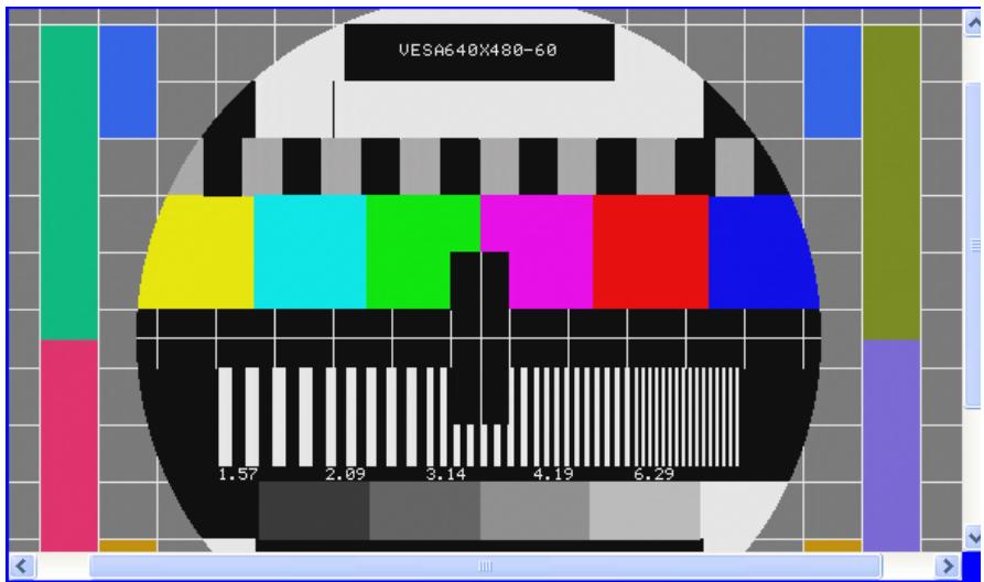
Captured images are displayed on this panel as shown.
![UESA640X480-60\n1.57 2.09 3.14 4.19 6.29](.hdv62a-50-11246-1010-200-en-en/cc5da26628bd5cc4cacc5e7a72ffedf46a2ebf2003191a43f79afa6ef518f515.jpg)

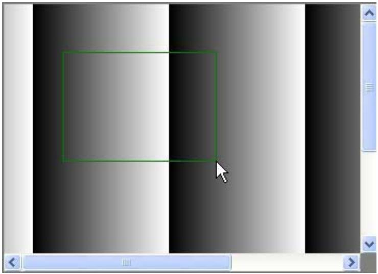
Clicking and dragging the cursor generates a green rectangle, with the bound area magnified to the same size as the display region. Holding “Shift” while dragging retains the aspect ratio of the rectangle.
![Abstract grayscale gradient background with a green rectangular selection box and a white cursor pointer (no text or symbols)](.hdv62a-50-11246-1010-200-en-en/807f723480378066397384d80b11544b69e6846ccea9d15c58aa58b2318c4833.jpg)

Right-clicking transforms the cursor into a move2D icon. When the size of the image exceeds that of the display panel, this icon allows the image to be dragged.

# 2.3.5 Display Menu

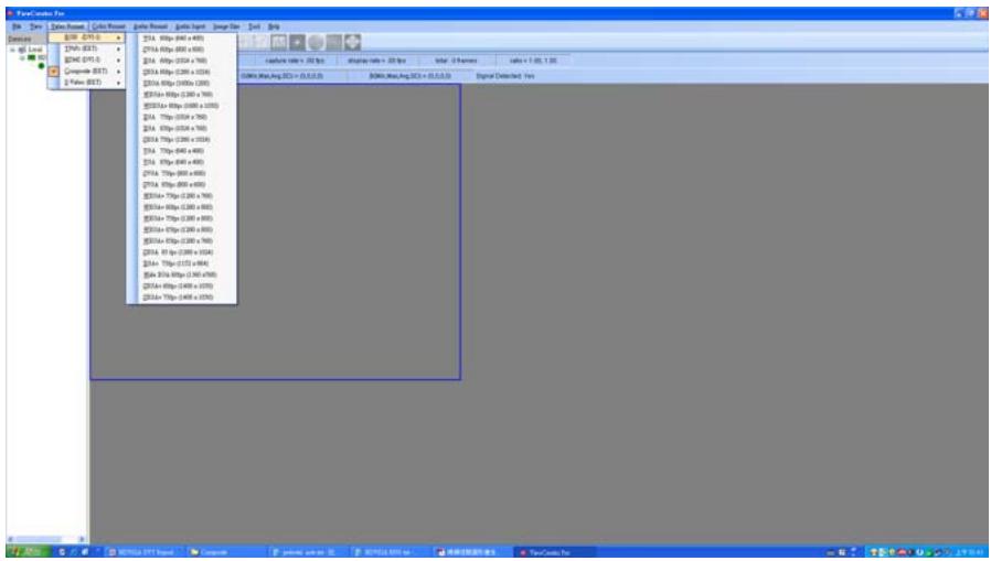
Allows selection of desired video format based on the video source, with support for RGB (DVI-I), YPbPr (EXT), HDMI (DVI-I), Composite (EXT), and S-Video (EXT).

The RGB menu is shown open as an example.
![File1\index Pro\nFile  Date  Date-Format  Color-Format  Global Format  Global Input  Image Size  Print  Help\nB20 - B70 - B75\nB74 - B73\nB74 - B73\nComposite (B73)\nC:\Java\B71\nB74 - B73\nB74 - B73\nB74 - B73\nB74 - B73\nB74 - B73\nB74 - B73\nB74 - B73\nB74 - B73\nB74 - B73\nB74 - B73\nB74 - B73\nB74 - B73\nB74 - B73\nB75 - B74\nB75 - B74\nB75 - B74\nB75 - B74\nB75 - B74\nB75 - B74\nB75 - B74\nB75 - B74\nB75 - B74\nB75 - B74\nB75 - B74\nB75 - B74\nB75 - B74\nB76 - B75\nB76 - B75\nB76 - B75\nB76 - B75\nB76 - B75\nB76 - B75\nB76 - B75\nB76 - B75\nB76 - B75\nB76 - B75\nB76 - B75\nB76 - B75\nB76 - B75\nB77 - B76\nB77 - B76\nB77 - B76\nB77 - B76\nB77 - B76\nB77 - B76\nB78 - B77\nB78 - B78\nB78 - B78\nB78 - B78\nB78 - B78\nB78 - B78\nB78 - B78\nB79 - B79\nB79 - B79\nB79 - B79\nB79 - B79\nB80 - B80\nB80 - B80\nB80 - B80\nB80 - B80\nB80 - B80\nB80 - B80\nB80 - B80\nB81 - B81\nB81 - B81\nB81 - B81\nB81 - B81\nB81 - B81\nB82 - B82\nB82 - B82\nB82 - B82\nB82 - B82\nB82 - B82\nB83 - B83\nB83 - B83\nB83 - B83\nB83 - B83\nB83 - B83\nB84 - B84\nB84 - B84\nB84 - B84\nB84 - B84\nB84 - B84\nB85 - B85\nB85 - B85\nB85 - B85\nB85 - B85\nB85 - B85\nB86 - B86\nB86 - B86\nB86 - B86\nB86 - B86\nB86 - B86\nB86 - B86\nB87 - B87\nB87 - B87\nB87 - B87\nB87 - B87\nB88 - B88\nB88 - B88\nB88 - B88\nB89 - B89\nB89 - B89\nB89 - B89\nB90 - B90\nB90 - B90\nB90 - B90\nB91 - B91\nB91 - B91\nB92 - B92\nB92 - B92\nB92 - B92\nB93 - B93\nB93 - B93\nB93 - B93\nB94 - B94\nB94 - B94\nB94 - B94\nB95 - B95\nB95 - B95\nB95 - B95\nB96 - B96\nB96 - B96\nB96 - B96\nB96 - B96\nB97- 0.0.0.0.0.0.0.0.0.0.0.0.0.0.0.0.0.0.0.0.0.0.0.0.0.0.0.0.0.0.0.0.0.0.0.0.0.0.0.0.0.0.0.0.0.0.0.0.0.0.0.](.hdv62a-50-11246-1010-200-en-en/7142b77415369fd3c77de7611b3f0cefc28d99f24ed280b98f2a17ede0325ac4.jpg)

Figure 2-3: RGB Display Menu

RGB (DVI-I)

<table><tr><td>Format</td><td>Resolution</td></tr><tr><td>VGA 60 fps</td><td>640 x 480</td></tr><tr><td>SVGA 60 fps</td><td>800 x 600</td></tr><tr><td>XGA 60 fps</td><td>1024 x 768</td></tr><tr><td>SXGA 60 fps</td><td>1280 x 1024</td></tr><tr><td>UXGA 60fps</td><td>1600 x 1200</td></tr><tr><td>WXGA+ 60fps</td><td>1280 x 768</td></tr><tr><td>WSXGA+ 60fps</td><td>1680 x 1050</td></tr><tr><td>XGA 75fps</td><td>1024 x 768</td></tr><tr><td>XGA 85fps</td><td>1024 x 768</td></tr><tr><td>SXGA 75fps</td><td>1280 x 1024</td></tr><tr><td>VGA 75fps</td><td>640 x 480</td></tr><tr><td>VGA 85fps</td><td>640 x 480</td></tr><tr><td>SVGA 75fps</td><td>800 x 600</td></tr><tr><td>SVGA 85fps</td><td>800 x 600</td></tr><tr><td>WXGA+ 75fps</td><td>1280 x 768</td></tr><tr><td>WXGA+ 60fps</td><td>1280 x 800</td></tr><tr><td>WXGA+ 75fps</td><td>1280 x 800</td></tr><tr><td>WXGA+ 85fps</td><td>1280 x 800</td></tr><tr><td>WXGA+ 85fps</td><td>1280 x 768</td></tr><tr><td>SXGA 85 fps</td><td>1280 x 1024</td></tr><tr><td>XGA+ 75fps</td><td>1152 x 864</td></tr><tr><td>Wide XGA 60fps</td><td>1360 x768</td></tr><tr><td>SXGA+ 60fps</td><td>1400 x 1050</td></tr><tr><td>SXGA+ 75fps</td><td>1400 x 1050</td></tr></table>

Table 2-4: RGB (DVI-I) Available Formats

YPbPr (EXT)

<table><tr><td>Format</td><td>Resolution</td></tr><tr><td>525i 30 fps</td><td>720 x 480 interlace</td></tr><tr><td>625i 25 fps</td><td>720 x 576 interlace</td></tr><tr><td>525p 60 fps</td><td>720 x 480 progressive</td></tr><tr><td>625p 50 fps</td><td>720 x 576 progressive</td></tr><tr><td>720p 50 fps</td><td>1280 x 720 progressive</td></tr><tr><td>720p 60 fps</td><td>1280 x 720 progressive</td></tr><tr><td>1080i 25 fps</td><td>1920 x 1080 interlace</td></tr><tr><td>1080i 30 fps</td><td>1920 x 1080 interlace</td></tr><tr><td>1080p 50 fps</td><td>1920 x 1080 progressive</td></tr><tr><td>1080p 60 fps</td><td>1920 x 1080 progressive</td></tr></table>

Table 2-5: YPbPr (EXT) Available Formats

HDMI (DVI-I)

<table><tr><td>Format</td><td>Resolution</td></tr><tr><td>720p 50 fps YCrCb In</td><td>1280 x 720 progressive</td></tr><tr><td>720p 60 fps YCrCb In</td><td>1280 x 720 progressive</td></tr><tr><td>1080i 25 fps YCrCb In</td><td>1920 x 1080 interlace</td></tr><tr><td>1080i 30 fps YCrCb In</td><td>1920 x 1080 interlace</td></tr><tr><td>1080p 25 fps YCrCb In</td><td>1920 x 1080 progressive</td></tr><tr><td>1080p 30 fps YCrCb In</td><td>1920 x 1080 progressive</td></tr><tr><td>1080p 50 fps YCrCb In</td><td>1920 x 1080 progressive</td></tr><tr><td>1080p 60 fps YCrCb In</td><td>1920 x 1080 progressive</td></tr><tr><td>VGA 60 fps</td><td>640 x 480</td></tr><tr><td>SVGA 60 fps</td><td>800 x 600</td></tr><tr><td>XGA 60 fps</td><td>1024 x 768</td></tr><tr><td>SXGA 60 fps</td><td>1280 x 1024</td></tr><tr><td>UXGA 60 fps</td><td>1600 x 1200</td></tr><tr><td>720p 50 fps RGB In</td><td>1280 x 720 progressive</td></tr><tr><td>720p 60 fps RGB In</td><td>1280 x 720 progressive</td></tr><tr><td>1080i 25 fps RGB In</td><td>1920 x 1080 interlace</td></tr><tr><td>1080i 30 fps RGB In</td><td>1920 x 1080 interlace</td></tr><tr><td>1080p 25 fps RGB In</td><td>1920 x 1080 progressive</td></tr><tr><td>1080p 30 fps RGB In</td><td>1920 x 1080 progressive</td></tr><tr><td>1080p 50 fps RGB In</td><td>1920 x 1080 progressive</td></tr><tr><td>1080p 60 fps RGB In</td><td>1920 x 1080 progressive</td></tr><tr><td>1080p 24 fps YCrCb In</td><td>1920 x 1080 progressive</td></tr><tr><td>1080p 48 fps YCrCb In</td><td>1920 x 1080 progressive</td></tr><tr><td>WXGA 60 fps YCrCb In</td><td>1360 x 768</td></tr><tr><td>1200p 50 fps YCrCb In</td><td>1920 x 1200 progressive</td></tr><tr><td>1200p 60 fps YCrCb In</td><td>1920 x 1200 progressive</td></tr><tr><td>1080p 24 fps RGB In</td><td>1920 x 1080 progressive</td></tr><tr><td>1080p 48 fps RGB In</td><td>1920 x 1080 progressive</td></tr><tr><td>WXGA 60 fps RGB In</td><td>1360 x 768</td></tr><tr><td>1200p 50 fps RGB In</td><td>1920 x 120 progressive</td></tr><tr><td>1200p 60 fps RGB In</td><td>1920 x 1200 progressive</td></tr></table>

<table><tr><td>Format</td><td>Resolution</td></tr><tr><td>525i 30 fps YCrCb In</td><td>720 x 480 interlace</td></tr><tr><td>625i 25 fps YCrCb In</td><td>720 x 576 interlace</td></tr><tr><td>525i 30 fps RGB In</td><td>720 x 480 interlace</td></tr><tr><td>625i 25 fps RGB In</td><td>720 x 576 interlace</td></tr><tr><td>WXGA+ 60 fps RGB In</td><td>1280 x 768</td></tr><tr><td>WSXGA+ 60 fps RGB In</td><td>1680 x 1050</td></tr><tr><td>VGA 60 fps YCrCb In</td><td>640 x 480</td></tr><tr><td>SVGA 60 fps YCrCb In</td><td>800 x 600</td></tr><tr><td>XGA 60 fps YCrCb In</td><td>1024 x 768</td></tr><tr><td>WXGA+ 60 fps YCrCb In</td><td>1280 x 768</td></tr><tr><td>WXGA 60 fps YCrCb In</td><td>1280 x 800</td></tr><tr><td>SXGA 60 fps YCrCb In</td><td>1280 x 1024</td></tr><tr><td>UXGA 60 fps YCrCb In</td><td>1600 x 1200</td></tr><tr><td>WSXGA+ 60 fps YCrCb In</td><td>1680 x 1050</td></tr></table>

Table 2-6: HDMI (DVI-I) Available Formats

Composite (EXT)

<table><tr><td>Format</td></tr><tr><td>NTSC-MJ</td></tr><tr><td>PAL 60</td></tr><tr><td>NTSC 4.43</td></tr><tr><td>PAL BGHID</td></tr><tr><td>PAL M</td></tr><tr><td>PAL Nc</td></tr></table>

Table 2-7: Composite (EXT) Available Formats

# S-Video (EXT)

<table><tr><td>Format</td></tr><tr><td>NTSC-J</td></tr><tr><td>PAL 60</td></tr><tr><td>NTSC 4.43</td></tr><tr><td>PAL BGHID</td></tr><tr><td>PAL M</td></tr><tr><td>PAL Nc</td></tr></table>

Table 2-8: S-Video (EXT) Available Formats

# 2.3.6 Color Format Menu

Sets the captured image to the selected color format.

# 2.3.7 Audio Format Menu

Sets the audio format, with available Sample Rates and Channels variable according to the input selected.

<table><tr><td>Sampling Rate</td><td> $\triangleright$  16 kHz $\triangleright$  22.05 kHz $\triangleright$  32 kHz $\triangleright$  44.1 kHz $\triangleright$  48 kHz $\triangleright$  64 kHz $\triangleright$  88.2 kHz $\triangleright$  96 kHz $\triangleright$  176.4 kHz $\triangleright$  192 kHz</td></tr><tr><td>Sample Bits</td><td>24 bit</td></tr><tr><td>Channels</td><td> $\triangleright$  2.0 (2) $\triangleright$  5.1 (6) $\triangleright$  7.1 (8)</td></tr></table>

Table 2-9: Audio Formats

# 2.3.8 Audio Input Menu

Sets the audio input type.

# 2.3.9 Image Size Menu

# Cropping

Before an image is cropped, a correct card index must first be selected. Sensor Width and Sensor Height are the width and height of the original image, varying according to the selected video format.

Parameters X, Y, Width, and Height must first be properly set, with X and Y the coordinates of the start position (upper left corner), and Width and Height the dimensions after cropping.

Selecting OK applies changes, and selecting Continue Grab on the Tool panel following cropping acquires the cropped images.

![Cropping\nCard Index: TreeNode: HDV62A_Card0_Id0(DirectSho\\nSensor Width: 540\nNote:\n0 (= X ( Sensor Width\n0 (= Y ( Sensor Height\n0 ( Width (= Sensor Width\n0 ( Height (= Sensor Height\nX: 0\nX + Width (= Sensor Width\nY: 0\nY + Height ( Sensor Height\nWidth: 640\nWidth = 16x\nHeight = 2x\nY = 2x, if interlace CCD\nHeight: 480\nOK](.hdv62a-50-11246-1010-200-en-en/c2574853c1865e9ae80c1d7769b3a6f7d19a38786c477436d73e6397608ed54d.jpg)

Figure 2-4: Cropping Dialog

# Top-down

Enables top-down image display

# Auto Detect

Automatically detects image resolution

# 2.3.10 Tool Menu

# EDID (extended display identification data)

Before using EDID, a corresponding card index must be selected. After entering the offset and value, click the Write or Read button to write to or read from the EDID ROM. Valid range for the offset and value is 0 to 255. The values in EDID ROM are saved when the system is powered off.

![The image displays a white document icon featuring a folded top-right corner and faint grey horizontal lines, overlaid with a large, bold red checkmark.](.hdv62a-50-11246-1010-200-en-en/acfc6598e81716155db0bf491c4df5dd8a8b3405a13829e978310ad5def01fff.jpg)
NOTE:

The HDMI/DVI source must be disconnected before writing the EDID.

![EDID\nCard Index: TreeNode: HDV62A_Card0_Id0(DirectSh\n✓ ROM Ready\nOffset(Dec) Value(Dec)\n0~255 0~255\n0 0 Write\n0 1 Read\nLoad EDID Save EDID](.hdv62a-50-11246-1010-200-en-en/c9573fd73d17653a01e3b4bf01330f68b7eeb91adc09867b3175815921d03262.jpg)

Figure 2-5: EDID Dialog

# 2.4 HDV62(A) Setting Utility

HDV62Setting.exe implements queue counts for video and audio buffers, with default video queue count of 6 and default audio queue count of 20.

![HDV62(A) Setting\nQueue Settings\nVideo Queue Count: 6\nAudio Queue Count: 20\nA queue is a ring buffer designing to store data of\nvideo frames or audio segments. If applications\nprocess the data of the queue not in time, incoming\ndata will be dropped until there exist an empty\nbuffer.\nA large queue count provides more dynamic time to\nfill all buffers, but it requests more memory.\nThose settings are applied to all HDV62(A) cards on\nthe system and may be reset when you reinstall\nsetup program or driver.\nOK Cancel](.hdv62a-50-11246-1010-200-en-en/7f9ff5f5197484d9aadc7c54c642e6c31278de3cfbb845e7d1d63a7e1752222f.jpg)

Figure 2-6: HDV62A Setting Utility Interface

This page intentionally left blank.

# 3 DirectShow Programming Guide

![The image features a graphic of a white document page with faint horizontal lines and a large red checkmark drawn over it. Below the document graphic is the text 'NOTE-' in black, capital letters.](.hdv62a-50-11246-1010-200-en-en/9868fec0c16be5d626adfa2a315979b215877ee9e2ce2857f1ff901df4f16ac9.jpg)

Complete documentation for DirectShow application programming can be found at:

http://msdn.microsoft.com/en-us/library/dd390351(VS.85).aspx by searching for "DirectShow". If a DirectX SDK is installed, this documentation is also available from DirectX SDK Help. The most recent version of DirectShow SDK was moved to Windows SDK.

The goal when writing a DirectShow Application is to construct a filter graph by connecting several filters together, to execute tasks such as previewing or capturing video/audio, and multiplexing to write to a file. Each filter performs a single operation and pass data from its output is pinned to the input of the next filter in the graph.

To build a capture graph using a program, the interface pointer of the capture filter must first be obtained. The ADLINK HDV62A A/V Capture filter and the ADLINK HDV62A Crossbar filter can be obtained through the system device enumerator.

After holding an interface pointer to the capture filter object, method IGraphBuilder::AddSourceFilter adds the source filter object to the filter graph. IFilterGraph::AddFilter adds other downstream filters to the filter graph.

After filters are added, calling IFilterGraph::ConnectDirect or IGraphBuilder::Connect connect output pins from upstream filters to the input pins of the downstream filters.

Calling IAMCrossbar::Route to switch source channel, via methods IMediaControl::Run, IMediaControl::Pause or IMediaControl::Stop changes the filter state to running, paused or stopped.

Filters required for capturing video streams are

listed as follows, with detailed information for each and its pins. Example filter graphs for capturing video streams are also illustrated in this chapter with two ways of controlling the device driver.

# 3.1 Filters

This section lists the filters necessary to construct a filter graph for capturing a video stream.

# 3.1.1 Source Filters

# ADLINK HDV62A A/V Capture

A WDM Streaming Capture Device, it is actually a kernel-mode KsProxy plug-in. An application can treat it simply as a filter. Use System Device Enumerator to add this filter to a filter graph.

<table><tr><td>Filter</td><td>ADLINK HDV62A A/V Capture</td></tr><tr><td>Filter CLSID</td><td>N/A</td></tr><tr><td>Filter Category Name</td><td>WDM Streaming Capture Devices</td></tr><tr><td>Filter Category</td><td>AM_KSCATEGORY_CAPTURE and/or Video Capture Sources</td></tr><tr><td>Capture Pin Supported Media Types</td><td>MEDIATYPE_Video Subtypes: MEDIASUBTYPE_RGB24 MEDIASUBTYPE_BGR30* MEDIASUBTYPE_RGB32 MEDIASUBTYPE_RGB8* MEDIASUBTYPE_YUV8* MEDIASUBTYPE_YUV2</td></tr><tr><td>Audio Capture Pin Supported Media Types</td><td>MEDIATYPE_AUDIO Subtypes: MEDIASUBTYPE_PCM</td></tr><tr><td>Exported Interfaces</td><td>IAMAnalogVideoDecoder IAMDroppedFrames IAMStreamConfig IAMVideoProcAmp Advance** IVideoFormat** ICardInfo** INotify</td></tr><tr><td>Merit</td><td>MERIT_DO_NOT_USE</td></tr></table>

\* Please see Section 3.3: Color Space

\*\*Please see Section 3.4 Proprietary Interfaces

# ADLINK HDV62A Crossbar Filter

If the device is a capture board, a crossbar filter is required to switch video sources. In hardware design, the crossbar can switch channel input of the same card.

<table><tr><td>Filter</td><td>ADLINK HDV62A Crossbar</td></tr><tr><td>Filter Category Name</td><td>WDM_Streaming Crossbar Devices</td></tr><tr><td>Exported Interfaces</td><td>IAMCrossbar</td></tr><tr><td>Input Pins</td><td>Pin Names:Video RGB InVideo YRYBY InVideo SerialDigital InVideo Composite InVideo SVideo InAudio SPDIF InAudio SPDIF InAudio SPDIF In</td></tr><tr><td>Output Pin</td><td>Pin Name:Video Decoder OutAudio Decoder Out</td></tr></table>

![The image displays a line drawing of a document featuring a folded top-right corner and horizontal lines representing text. A large, red checkmark is superimposed over the document.](.hdv62a-50-11246-1010-200-en-en/b7652fb220c86437fcf8bc662648b2fc9bad759e6dfbced53d53c71f6fa6d8c1.jpg)
NOTE:

Video RGB In is an analog RGB signal from DVI-I connector

Video YRYBY In is an YPbPr signal from the I/O bracket connector

Video SerialDigital In is a HDMI signal from DVI-I connector

Video Composite In is a standard NTSC/PAL signal from I/O bracket

Video SVideo In is a standard NTSC/PAL signal from I/O bracket

$1^{\text{st}}$ Audio SPDIF In is a audio packet embedded into HDMI input

$2^{nd}$ Audio SPDIF In is a SPDIF audio signal from Toslink connector

3 $^{rd}$ Audio SPDIF In is a SPDIF audio signal from RCA connector

Calling IAMCrossbar::Route switches the input channel

# 3.1.2 Example Graphs

The Microsoft DirectX SDK provides the GraphEdit debugging utility, which can simulate graph building. Desired filters can be chosen from the Insert Filters command of the Graph menu. Filters are organized by categories. Insert Filter adds the filters to a graph, and two filters' pins can be selected by dragging from one output pin to another. An arrow will be drawn if both pins agree on the connection.

![Which filters do you want to insert?\nDevice Control Filters\nDirectShow Filters\nDMO Audio Capture Effects\nDMO Audio Effects\nDMO Video Effects\nExternal Renderers\nMidi Renderers\nMulti-Instance Capable VBI Codecs\nVideo Capture Sources\nADLINK HDV62A A/V Capture\nVideo Compressors\nWDM Stream Decompression Devices\nWDM Streaming Capture Devices\nWDM Streaming Communication Transforms\nWDM Streaming Crossbar Devices\nADLINK HDV62A Crossbar\nWDM Streaming Data Transforms\nWDM Streaming Encoder Devices ns\nInsert Filter\nCancel\nFavorite Filter?\nFilter Moniker:\nLegend\nDirectX Media Object (DMO)\nUses Kemel Streaming (KSProxy)\nUses Compression Manager (ACM/ICM)\nPlug and Play (PNP) device filter\nDefault filter color](.hdv62a-50-11246-1010-200-en-en/c5993439babdbc81da5c39a4bf3cab50aac804cf263780718554430cbbf6e04b.jpg)

Figure 3-1: GraphEdit Insert Filters Dialog

After inserting the ADLINK HDV62A Video Capture filter and ADLINK HDV62A Crossbar filter, right clicking the rectangle and selecting Filter Properties allows the Property pages to be used to set video settings before connecting video pins to other filters, as shown.

# HDV62A A/V Capture Filter

This selection generates the following series of Dialogs.

As shown, the System settings reflect the current configuration, with Sensor Format changed with different crossbar input. For supported sensor formats please see Sensor Format

# ADLINK HDV62A A/V Capture Properties

Video Format

Audio Format

Video Proc Amp

Video Decoder

System

Analog RGB , VGA 60fps (640 x 480)

Sensor Format

VGA 60fps (640 x 480)

VGA 60fps (640 x 480)

SVGA 60fps (800 x 600)

XGA 60fps (1024 x 768)

SXGA 60fps (1280 x 1024)

UXGA 60fps (1600 x 1200)

WXGA+ 60fps (1280 x 768)

WSXGA+ 60fps (1680 x 1050)

OK

Close

Apply

Help

Figure 3-2: Video Format Dialog

![ADLINK HDV62A A/V Capture Properties\nVideo Format Audio Format Video Proc Amp Video Decoder\nFormat PCM\nSampling Rate 44100 Hz\nChannel\n2 6 8\nSample Bits\n16 20 24\nOK Cancel Apply Help](.hdv62a-50-11246-1010-200-en-en/d6520f752a92b855d04fd0cc3715ec2d8088deb595095de7882f61d3c5c066a8.jpg)

Figure 3-3: Audio Format Dialog

ADLINK HDV62A A/V Capture Properties
![Video Format | Audio Format | Video Proc Amp | Video Decoder |\nBrightness\nContrast\nHue\nSaturation\nSharpness\nGamma\nWhite Balance\nBacklight Comp\nColorEnable □\nDefault\nAuto\nOK	Cancel	Apply	Help](.hdv62a-50-11246-1010-200-en-en/bc44fe569adca638094f3c60895a07df30bd9a22d554a4f44581daddc5c42a17.jpg)

Figure 3-4: Video Proc Amp Dialog

![ADLINK HDV62A A/V Capture Properties\nVideo Format | Audio Format | Video Proc Amp | Video Decoder |\n:Video Standard None\nSignal Detected: 1\nLines detected: 768\n□ VCR Input\n□ Output Enable\nOK Cancel Apply Help](.hdv62a-50-11246-1010-200-en-en/8953b2a3422549d7251afb1f7ec4ee3f1f8721bd805061905adc55c1b6e80279.jpg)

Figure 3-5: Video Decoder Dialog

Video Capture Properties
![Stream Format\nVideo Format\nVideo Standard: None\nFrame Rate: 60.000\nFlip Horizontal:\nColor Space / Compression:\nRGB 24\nOutput Size:\n640 x 480\nCompression\n1 Frame Interval:\nP Frame Interval:\nQuality:\nOK Cancel Apply Help](.hdv62a-50-11246-1010-200-en-en/a19ecb5e240636131aa4e81d9fb49e020039bbc74bd07d4f766003db3d986223.jpg)

Figure 3-6: Capture Pin Properties Dialog

![A white document icon with a folded top-right corner and faint horizontal lines, overlaid with a large red checkmark.](.hdv62a-50-11246-1010-200-en-en/c167b2c2b0ead76db1be2806e0ef4515942361f94006010ed8542effc7552300.jpg)
NOTE:

In this dialog, a Color Space/Compression selection of BGRA indicates an actual setting of BGR30. For Supported Color Space parameters, please refer to Section 3.3 Color Space

# ADLINK HDV62A Crossbar Filter

The relationship between inputs and outputs must be entered before the Capture pin of the ADLINK HDV62A A/V Capture filter is connected.

![ADLINK HDV62A Crossbar Properties\nCrossbar\nInput\n0: Video RGB In\nCurrent Input:\n1: Video YRYBY In\nRelated Pin:\n6: Audio SPDIFDigital In\nLink Related Streams\nOutput\n0: Video Decoder Out\nRelated Pin:\n1: Audio Decoder Out\nOK	Cancel	Apply	Help](.hdv62a-50-11246-1010-200-en-en/05b2f8636abc8f7988d897208995603f3bae7f732365f30bc98e430d31ab8113.jpg)

Figure 3-7: Crossbar Properties Dialog

# Example Graph

To generate an example graph:

1. Open GraphEdit.exe.
2. Select 'Insert a filter into the graph' on the toolbar and enter 'ADLINK HDV62A A/V Video Capture', 'ADLINK HDV62A Crossbar', and 'Video Renderer' filters in the 'Video Capture Sources' group, the 'WDM Streaming

Crossbar Devices' group, and the 'DirectShow Filters' group, respectively.

3. Right click 'ADLINK HDV62A Crossbar' filter and select 'Filter Properties...', select the Input channel, and 'OK'.
4. Right click 'ADLINK HDV62A A/V Video Capture' filter and select 'Filter Properties...', select the Sensor Format, and 'OK'.
5. Right click Capture pin of 'ADLINK HDV62A A/V Video Capture' filter and select 'Pin Properties...', select Color Space/Compression, and 'OK'.
6. Drag 'Video Decoder Out' pin to 'Analog Video In' pin and from 'Capture' pin to 'Input' pin as shown.
7. Select 'Play the graph' from the toolbar to begin preview.

![The image displays a graph edit window with four main blocks connected by arrows.\n\n**Labeled Blocks:**\n\n1.  **Left Block (Purple):**\n    *   **Left Column:**\n        *   0: Video RGB In\n        *   1: Video Y'Y'B'Y\n        *   2: Video Serial Digital In\n        *   3: Video Composite In\n        *   4: Video SVideo In\n        *   5: Audio SPDIF In\n        *   6: Audio SPDIF In\n        *   7: Audio SPDIF In\n    *   **Right Column:**\n        *   0: Video Decoder Out\n        *   1: Audio Decoder Out\n    *   **Center Text:** ADLINK HDV62A Crossbar\n\n2.  **Center Block (Orange):**\n    *   **Top Left:** Analog Video In\n    *   **Top Right:** Video Capture\n    *   **Center Text:** ADLINK HDV62A A/V Capture\n    *   **Bottom Right:** Audio Capture\n\n3.  **Top Right Block (Light Purple):**\n    *   **Top Left:** Input\n    *   **Center Text:** Video Renderer\n\n4.  **Bottom Right Block (Light Purple):**\n    *   **Top Text:** Audio Input pin (rendered)\n    *   **Center Text:** Default DirectSound Device\n\n**Connections:**\n\n*   An arrow connects **'0: Video Decoder Out'** (from the Left Block) to **'Analog Video In'** (on the Center Block).\n*   An arrow connects **'Video Capture'** (on the Center Block) to **'Input'** (on the Top Right Block).\n*   An arrow connects **'Audio Capture'** (on the Center Block) to **'Audio Input pin (rendered)'** (on the Bottom Right Block).](.hdv62a-50-11246-1010-200-en-en/d8b1ed887b7d592660460ea75cab5f9dfbd92336545ea2f147cc1451860ec51b.jpg)

Figure 3-8: GraphEdit Interface

![The image displays a graphic icon of a white document with horizontal lines and a folded top-left corner. A large, bold red checkmark is superimposed over the center of the paper.](.hdv62a-50-11246-1010-200-en-en/315cf69fed8b507135f9713c690496dcdc3839763aebcaa947aedf872d2778c6.jpg)
NOTE:

If VMR substitutes for the default Video Renderer, the preview video shows a vertical mirror video, which can be resolved by inserting a Color Space Converter filter before.

# 3.2 Driver Control

The ADLINK HDV62A A/V Capture filter provides control of video configuration by either property pages or access to COM interfaces.

# 3.2.1 Property Pages

The driver provides two embedded property pages. To show these property pages, use Windows API: OleCreatePropertyFrame.

Details about Displaying a Filter's Property Page can be found on the Microsoft MSDN homepage.

Sample code for adding property pages is as follows.

```txt
// pFilter points to an ADLINK HDV62A Video Capture filter
// or an ADLINK HDV62A Crossbar filter
```

```c
ISpecifyPropertyPages *pSpecify;
HRESULT hr;
hr = pFilter->QueryInterface(IID_ISpecifyPropertyPages, (void *)&pSpecify);
if (SUCCEEDED(hr))
{
FILTER_INFO FilterInfo;
pFilter->QueryFilterInfo(&FilterInfo);
FilterInfo.pGraph->Release();
```

```txt
CAUUID caGUID;
pSpecify->GetPages(&caGUID);
pSpecify->Release();
```

```txt
OleCreatePropertyFrame(
NULL, // Parent window
0, // x (Reserved)
0, // y (Reserved)
```

```txt
FilterInfo.achName,// Caption for the dialog box
1,// Number of filters
(IUnknown **)&m_pFilter,// Pointer to the filter
caGUID.cElems,// Number of property pages
caGUID.pElems,// Pointer to property page CLSIDs
0,// Locale identifier
0,// Reserved
NULL// Reserved
);
CoTaskMemFree(caGUID.pElems);
}
```

# 3.2.2 COM interfaces

The IAMVideoProcAmp interface of the standard DirectShow Interface provide acquisition or setting of incoming video signal attributes, such as brightness, contrast, saturation, and others. For other interfaces please refer to the DirectX SDK help.

// pFilter points to an ADLINK HDV62A A/V Video Capture filter

```c
IAMVideoProcAmp *pAmp;
HRESULT hr;
long contrast, flags;
hr = pFilter->QueryInterface(IID_IAMVideoProcAmp, (void **)&pAmp);
if (SUCCEEDED(hr))
{
pAmp->Get(VideoProcAmp_Contrast, &contrast, &flags);
pAmp->Release();
}
```

# ADLINK HDV62A Crossbar

The ADLINK HDV62A Crossbar filter, implementing an IAM-Crossbar interface, routes signals from an analog or digital source to a video capture filter.

```txt
// pFilter points to an ADLINK HDV62A Crossbar filter
```

```cpp
IAMCrossbar *pXbar;
HRESULT hr;
hr = pFilter->QueryInterface(IID_IAMCrossbar, (void **)&pXbar);
if (SUCCEDED(hr))
{
    // Route from input 1 to output 0
    pXbar->Route(0, 1);
    pXBar->Release();
}
```

# 3.3 Color Space

ADLINK HDV62A Video Capture supports the following color spaces:

('x' indicates an ignored bit)

MEDIASUBTYPE\_RGB24 - 8bit R + 8bit G + 8bit B

<table><tr><td rowspan="2">DWORD</td><td colspan="4">Pixel Data [31:0]</td></tr><tr><td>[31:24]</td><td>[23:16]</td><td>[15:8]</td><td>[7:0]</td></tr><tr><td>dw0</td><td>B1</td><td>R0</td><td>G0</td><td>B0</td></tr><tr><td>dw1</td><td>G2</td><td>B2</td><td>R1</td><td>G1</td></tr><tr><td>dw2</td><td>R3</td><td>G3</td><td>B3</td><td>R2</td></tr></table>

MEDIASUBTYPE\_BGR30 - 10bit R + 10bit G + 10bit B

<table><tr><td rowspan="2">DWORD</td><td colspan="4">Pixel Data [31:0]</td></tr><tr><td>[31:24]</td><td>[23:16]</td><td>[15:8]</td><td>[7:0]</td></tr><tr><td>dw0</td><td>xx+B[9:4]</td><td>B[3:0]+G[9:6]</td><td>G[5:0]+R[9:8]</td><td>R[7:0]</td></tr></table>

![The image displays a graphic icon of a white sheet of paper featuring a folded top-right corner and faint horizontal lines running across it. Superimposed over the center of the paper is a large, bold red checkmark.](.hdv62a-50-11246-1010-200-en-en/90e6a2d44a7a89e08b4eb6ce832d9305ce7178e68e4ce6eea1717dd366f88294.jpg)
NOTE:

Compression (FOURCC code) is 'BGRA' and GUID is 41524742-0000-0010-8000-00AA00389B71

MEDIASUBTYPE\_RGB32 - 8bit R + 8bit G + 8bit B + 8bit Alpha

<table><tr><td rowspan="2">DWORD</td><td colspan="4">Pixel Data [31:0]</td></tr><tr><td>[31:24]</td><td>[23:16]</td><td>[15:8]</td><td>[7:0]</td></tr><tr><td>dw0</td><td>Alpha</td><td>R</td><td>G</td><td>B</td></tr></table>

MEDIASUBTYPE\_RGB8 - 8bit Y (Grayscale)

<table><tr><td rowspan="2">DWORD</td><td colspan="4">Pixel Data [31:0]</td></tr><tr><td>[31:24]</td><td>[23:16]</td><td>[15:8]</td><td>[7:0]</td></tr><tr><td>dw0</td><td>Y3</td><td>Y2</td><td>Y1</td><td>Y0</td></tr></table>

MEDIASUBTYPE\_YUV8 - 8bit Y + 8bit Cb + 8bit Cr - YCbCr
4:4:4

<table><tr><td rowspan="2">DWORD</td><td colspan="4">Pixel Data [31:0]</td></tr><tr><td>[31:24]</td><td>[23:16]</td><td>[15:8]</td><td>[7:0]</td></tr><tr><td>dw0</td><td>Y1</td><td>Cr0</td><td>Cb0</td><td>Y0</td></tr><tr><td>dw1</td><td>Cb2</td><td>Y2</td><td>Cr1</td><td>Cb1</td></tr><tr><td>dw2</td><td>Cr3</td><td>Cb3</td><td>Y3</td><td>Cr2</td></tr></table>

![The image displays a white document icon with a folded top-left corner and faint horizontal lines, overlaid with a large red checkmark.](.hdv62a-50-11246-1010-200-en-en/db0890595030fa11dfc98c9dc41aea3445ef1361bb399b889129fe0df2603127.jpg)
NOTE:

Compression (FOURCC code) is 'YUV8' and GUID is 38565559-0000-0010-8000-00AA00389B71

MEDIASUBTYPE\_YUY2 - 8bit Y + 8bit Cb/Cr - YCbCr 4:2:2

<table><tr><td rowspan="2">DWORD</td><td colspan="4">Pixel Data [31:0]</td></tr><tr><td>[31:24]</td><td>[23:16]</td><td>[15:8]</td><td>[7:0]</td></tr><tr><td>dw0</td><td>Cr</td><td>Y</td><td>Cb</td><td>Y</td></tr></table>

YCbCr to RGB formula:

$$
R = Y + 1. 3 7 1 (C r - 1 2 8)
$$

$$
G = Y - 0. 6 9 8 (C r - 1 2 8) - 0. 3 3 6 (C b - 1 2 8)
$$

$$
B = Y + 1. 7 3 2 (C b - 1 2 8)
$$

# 3.4 Proprietary Interfaces

The following interfaces are specific to the ADLINK HDV62A A/V Video Capture filter, not being standard interfaces in DirectShow. COM interfaces, they can be acquired from the ADLINK HDV62A A/V Video Capture filter by calling IBaseFilter::QueryInterface.

# 3.4.1 IVideoFormat

Provides selection of sensor format, output format, horizontal delay, and video cropping.

# Sensor Format

Read or write source format of the CCD sensor including video standard, resolution, and frame rate.

# Syntax

C/C++

HRESULT WriteSensorFormat (UINT Format)

HRESULT ReadSensorFormat (UINT \*Format)

C#

int WriteSensorFormat (uint Format)

int ReadSensorFormat (out uint Format)

# VB.Net

WriteSensorFormat (ByVal Format As UInteger)
As Integer

ReadSensorFormat (ByRef Format As UInteger) As Integer

# Parameter(s)

Format

Format of the source sensor, with possible values for different crossbar input including:

Channel 0: Analog RGB from DVI-I connector

0: VGA 60 fps (640 x 480),
1: SVGA 60 fps (800 x 600),
2: XGA 60 fps (1024 x 768),
3: SXGA 60 fps (1280 x 1024),
4 : UXGA 60fps (1600 x 1200),
5 : WXGA+ 60fps (1280 x 768),
6 : WSXGA+ 60fps (1680 x 1050),
7 : XGA 75fps (1024 x 768),

8 : XGA 85fps (1024 x 768),
9 : SXGA 75fps (1280 x 1024),
10 : VGA 75fps (640 x 480),
11 : VGA 85fps (640 x 480),
12 : SVGA 75fps (800 x 600),
13 : SVGA 85fps (800 x 600),
14 : WXGA+ 75fps (1280 x 768),
15 : WXGA+ 60fps (1280 x 800),
16 : WXGA+ 75fps (1280 x 800),
17 : WXGA+ 85fps (1280 x 800),
18 : WXGA+ 85fps (1280 x 768),
19: SXGA 85 fps (1280 x 1024),
20 : XGA+ 75fps (1152 x 864),
21 : Wide XGA 60fps (1360 x768),
22 : SXGA+ 60fps (1400 x 1050),
23 : SXGA+ 75fps (1400 x 1050),

Channel 1: YPbPr from I/O bracket

0: 525i 30 fps (720 x 480 interlace, in frame per second),
1: 625i 25 fps (720 x 576 interlace, in frame per second),
2: 525p 60 fps (720 x 480 progressive),
3: 625p 50 fps (720 x 576 progressive),
5: 720p 50 fps (1280 x 720 progressive),
6: 720p 60 fps (1280 x 720 progressive),
7: 1080i 25 fps (1920 x 1080 interlace, in frame per second),
8: 1080i 30 fps (1920 x 1080 interlace, in frame per second),
9: 1080p 50 fps (1920 x 1080 progressive)

10: 1080p 60 fps (1920 x 1080 progressive)

Channel 2: HDMI from DVI-I connector

0: 720p 50 fps YCrCb In (1280 x 720 progressive),

1: 720p 60 fps YCrCb In (1280 x 720 progressive),

2: 1080i 25 fps YCrCb In (1920 x 1080 interlace, in frame per second),

3: 1080i 30 fps YCrCb In (1920 x 1080 interlace, in frame per second),

4: 1080p 25 fps YCrCb In (1920 x 1080 progressive)

5: 1080p 30 fps YCrCb In (1920 x 1080 progressive)

6: 1080p 50 fps YCrCb In (1920 x 1080 progressive)

7: 1080p 60 fps YCrCb In (1920 x 1080 progressive)

8: VGA 60 fps (640 x 480),

9: SVGA 60 fps (800 x 600),

10: XGA 60 fps (1024 x 768),

11: SXGA 60 fps (1280 x 1024),

12: UXGA 60 fps (1600 x 1200)

13: 720p 50 fps RGB In (1280 x 720 progressive),

14: 720p 60 fps RGB In (1280 x 720 progressive),

15: 1080i 25 fps RGB In (1920 x 1080 interlace, in frame per second),

16: 1080i 30 fps RGB In (1920 x 1080 interlace, in frame per second),

17: 1080p 25 fps RGB In (1920 x 1080 progressive)

18: 1080p 30 fps RGB In (1920 x 1080 progressive)

19: 1080p 50 fps RGB In (1920 x 1080 progressive)

20: 1080p 60 fps RGB In (1920 x 1080 progressive)

21: 1080p 24 fps YCrCb In (1920 x 1080 progressive)",

22: 1080p 48 fps YCrCb In (1920 x 1080 progressive)",
23: WXGA 60 fps YCrCb In (1360 x 768)",
24: 1200p 50 fps YCrCb In (1920 x 1200 progressive)",
25: 1200p 60 fps YCrCb In (1920 x 1200 progressive)",
26: 1080p 24 fps RGB In (1920 x 1080 progressive)",
27: 1080p 48 fps RGB In (1920 x 1080 progressive)",
28: WXGA 60 fps RGB In (1360 x 768)",
29: 1200p 50 fps RGB In (1920 x 120 progressive)",
30: 1200p 60 fps RGB In (1920 x 1200 progressive)",
31: 525i 30 fps YCrCb In (720 x 480 interlace, in frame per second)",
32: 625i 25 fps YCrCb In (720 x 576 interlace, in frame per second)",
33: 525i 30 fps RGB In (720 x 480 interlace, in frame per second)",
34: 625i 25 fps RGB In (720 x 576 interlace, in frame per second)",
35: WXGA+ 60 fps RGB In (1280 x 768)",
36: WSXGA+ 60 fps RGB In (1680 x 1050)",
37: VGA 60 fps YCrCb In (640 x 480)",
38: SVGA 60 fps YCrCb In (800 x 600)",
39: XGA 60 fps YCrCb In (1024 x 768)",
40: WXGA+ 60 fps YCrCb In (1280 x 768)",
41: WXGA 60 fps YCrCb In (1280 x 800)",
42: SXGA 60 fps YCrCb In (1280 x 1024)",
43: UXGA 60 fps YCrCb In (1600 x 1200)",
44: WSXGA+ 60 fps YCrCb In (1680 x 1050)"

Channel 3: Composite from I/O bracket

0: NTSC MJ

1: PAL 60

2: NTSC 4.43

3: PAL BGHID

4: PAL M

5: PAL Nc

Channel 4: S-Video from I/O bracket

0: NTSC MJ

1: PAL 60

2: NTSC 4.43

3: PAL BGHID

4: PAL M

5: PAL Nc

![An icon depicting a white piece of paper with a folded top-right corner and horizontal gray lines, overlaid with a large red checkmark.](.hdv62a-50-11246-1010-200-en-en/5a0bac5869d71b39df0a0e71e3dd2764ab53a2d1290953b068a8b346c47404c8.jpg)
NOTE:

Final resolutions of channels 0, 1, and 2 can be acquired by calling ICardInfo::GetVideoCapabilities()

# Return Value

No error occurs if return value $\geq$ 0; if a negative value, please call AMGetErrorText for return code error information.

![The image displays a white icon resembling a sheet of paper with the top right corner folded down. Faint gray horizontal lines run across the document. A large, bold red checkmark is superimposed over the paper, angled from the bottom left towards the top right.](.hdv62a-50-11246-1010-200-en-en/f9f358a3a26cf1496ee22620590cf8149fcb203559a46bb7e9da48da6ec5256d.jpg)
NOTE:

Noise and black images lasting for a few seconds (actual time of noise and black images depends on the source) may occur if the input source is HDMI plus HDCP, and can be prevented by delaying commencing capture for a few seconds after initial connection of the HDMI device

# Cropping

Reads or writes actual output resolution.

# Syntax

C/C++

```cmake
HRESULT WriteCropping (RECT Rt)
HRESULT ReadCropping (RECT * Rt)
```

C#

```txt
int WriteCropping (RECT Rt)
int ReadCropping (out RECT Rt)
```

# VB.Net

```txt
WriteCropping (ByVal Rt As RECT) As Integer
ReadCropping (ByRef Rt As RECT) As Integer
```

# Parameter(s)

Rt

A rectangle setting cropping the sensor image. The rectangle must be located inside the sensor image, and actual image starts from [Rt.left, Rt.top] with width of [Rt.right – Rt.left] and height [Rt.bottom – Rt.top]. Actual image width must be a multiple of 16 pixels and actual height even. If sensor source is interlace, the top value in Rt must be even.

# Return Value

No error occurs if return value $\geq$ 0; if a negative value, please call AMGetErrorText for return code error information

# Horizontal Delay

Reads or writes horizontal delay of frame images, moving them left or right to remove black vertical lines, like X offset.

# Syntax

C/C++

```txt
HRESULT WriteHDelay (INT Delay)
HRESULT ReadHDelay (INT * Delay)
```

C#

```txt
int WriteHDelay (int Delay)
int ReadHDelay (out int Delay)
```

# VB.Net

```txt
WriteHDelay (ByVal Delay As Integer) As Integer
ReadHDelay (ByRef Delay As Integer) As Integer
```

# Parameter(s)

Delay

Horizontal delay of frame images, with allowed values from -3 to 3. Each resolution has a default value that is called after channel and sensor format have been set.

# Return Value

No error occurs if return value $\geq$ 0; if a negative value, please call AMGetErrorText for return code error information

# AutoDetectSensorFormat

Acquires the format of the current selected video channel, reading back synchronization data from the source input. After the channel is set to a supported input, after for least 3 frames (or 6 fields), the hardware can detect the signal.

# Syntax

C/C++

```txt
HRESULT ReadAutoDetectSensorFormat(int *Format)
```

C#

```txt
int ReadAutoDetectSensorFormat (out int Format)
```

# VB.Net

```txt
ReadAutoDetectSensorFormat (ByRef Format As Integer) As Integer
```

# Parameter(s)

Format

Read-back format of video sensor, the format is set as -1, as defined in Sensor Format if no sensor is detected or sensor format is not supported

# Return Value

No error occurs if return value $\geq$ 0; if a negative value, please call AMGetErrorText for return code error information

# Image Orientation

Sets or retrieves orientation of images arranged in memory.

# Syntax

C/C++

HRESULT WriteImageOrientation (UINT Value)

HRESULT ReadImageOrientation (UINT \*Value)

C#

int WriteImageOrientation (uint Value)

int ReadImageOrientation (out uint Value)

# VB.Net

WriteImageOrientation (ByVal Value As UInteger) As Integer

ReadImageOrientation (ByRef Value As UInteger)
As Integer

# Parameter(s)

Number

The number of the device, with allowed values from 0 to 15.

Value

Indicates the image orientation, from among:

0: Bottom-up, in which the image buffer starts with the bottom row of pixels, followed by the next row up, and so forth, with the top row of the image the last row in the buffer, such that the first byte in memory is the bottom-left pixel of the image. Physical layout of a bottom-up image is as shown.

E.g. Color space = RGB24
![Start of buffer\nbottom left pixel\nImage Width\n1 B G R B G R B G R ... B G R\n2 B G R B G R B G R ... B G R\n3 B G R B G R B G R ... B G R\n4 B G R B G R B G R ... B G R\n5 B G R B G R B G R ... B G R\ntop left pixel](.hdv62a-50-11246-1010-200-en-en/16df44f6477f64d46118af97a8b49b7e2083c94f546493c8474b37f44fe8257d.jpg)

Figure 3-9: Bottom-up Image Orientation

1: Top-down, in which order of the row is reversed, with top row of the image the first row in memory, followed by the next row down, with bottom row of the image the last row in the buffer, such that first byte in memory is the top-left of the image. Physical layout of a top-down image is as shown.

E.g. Color space = RGB24

![Start of buffer\nImage Width\n1 B G R B G R B G R ... B G R\ntop left pixel\n2 B G R B G R B G R ... B G R\nImage Height\n3 B G R B G R B G R ... B G R\n4 B G R B G R B G R ... B G R\n5 B G R B G R B G R ... B G R\nbottom left pixel](.hdv62a-50-11246-1010-200-en-en/6aa7235173bd842878b47a8c078469c37491dbd8e3423e7aab0eed1cea39e602.jpg)

Figure 3-10: Top-down Image Orientation

# Return Value

No error occurs if return value $\geq$ 0; if a negative value, please call AMGetErrorText for return code error information.

# 3.4.2 IAdvance

Provides access to EDID ROM.

# EDID ROM Ready Status

Reads or writes Ready status of EDID ROM

# Syntax

C/C++

HRESULT EDID\_WriteReadyStatus (UINT Value)

HRESULT EDID\_ReadReadyStatus (UINT \*Value)

# C#

```txt
int EDID_WriteReadyStatus (uint Value)
int EDID_ReadReadyStatus (out uint Value)
```

# VB.Net

```txt
EDID_WriteReadyStatus (ByVal Value As UInteger) As Integer
EDID_ReadReadyStatus (ByRef Value As UInteger) As Integer
```

# Parameter(s)

# Value

Indicates whether or not the EDID ROM is ready, and is readable by external devices through DVI-I connector. Certain external devices can auto-adjust resolution by reading this EDID ROM. Content of the EDID ROM can be configured and set as Ready state, from among:

0: EDID ROM is not ready

1: EDID ROM is ready

# Return Value

No error occurs if return value $\geq$ 0; if a negative value, please call AMGetErrorText for return code error information

# EDID ROM Access Permission

Reads or writes access to the EDID ROM

# Syntax

C/C++
```cmake
HRESULT EDID_WriteAccessPermission (UINT Value)
HRESULT EDID_ReadAccessPermission (UINT *Value)
```
C#

```txt
int EDID_WriteAccessPermission (uint Value)
```

int EDID\_ReadAccessPermission (out uint Value)

# VB.Net

```txt
EDID_WriteAccessPermission (ByVal Value As UInteger) As Integer
EDID_ReadAccessPermission (ByRef Value As UInteger) As Integer
```

# Parameter(s)

Value

Indicates accessibility of the EDID ROM. The EDID ROM can be accessed by application or external device at the same time, and access permission must be opened, EDID ROM, configured, access permission closed, and the external device connected to the DVI-I connector. From among:

0: EDID ROM is not accessible
1: EDID ROM is accessible

# Return Value

No error occurs if return value $\geq$ 0; if a negative value, please call AMGetErrorText for return code error information

# Write Protection

Sets or retrieves writability of the EDID ROM.

# Syntax

C/C++

```cmake
HRESULT EDID_WriteWriteProtection (UINT Value)
HRESULT EDID_ReadWriteProtection (UINT *Value)
```

C#

```txt
int SetEdidWriteProtection (uint Number, uint Status)
int GetEdidWriteProtection (uint Number, out uint Status)
```

VB.Net

SetEdidWriteProtection (ByVal Number As UInteger, ByVal Status As UInteger) As Integer
GetEdidWriteProtection (ByVal Number As UInteger, ByRef Status As UInteger) As Integer

# Parameter(s)

Number

The number of the device, with allowed values from 0 to 15.

Status

Indicates writeability of the EDID ROM. Any write protection must be cleared before data can be saved to the EDID. From among the following values:

0: EDID ROM is writeable

1: EDID ROM is protected

# Return Value

No error occurs if return value $\geq$ 0; if a negative value, please call AMGetErrorText for return code error information.

# ROM Read/Write

Sets or retrieves value of the EDID ROM.

# Syntax

C/C++

```sql
HRESULT EDID_WriteRom (UINT Offset, UINT Value)
HRESULT EDID_ReadRom (UINT Offset, UINT *Value)
```

C#

```txt
int EDID_WriteRom (uint Offset, uint Value)
int EDID_ReadRom (uint Offset, out uint Value)
```

VB.Net

```c
EDID_WriteRom (ByVal Offset As UInteger, ByVal Value As UInteger) As Integer
EDID_ReadRom (ByVal Offset As UInteger, ByRef Value As UInteger) As Integer
```

# Parameter(s)

Offset

Indicates the offset of the EDID ROM, with allowed values from 0 to 255.

Value

Indicates the value of the EDID ROM, with allowed values from 0 to 255.

# Return Value

No error occurs if return value $\geq$ 0; if a negative value, please call AMGetErrorText for return code error information.

# 3.4.3 CardInfo

# Version

Acquires miscellaneous versions

Syntax

C/C++

```sql
HRESULT GetHardwareVersion (UINT *Version)
HRESULT GetFirmwareVersion (UINT *Version)
HRESULT GetDriverVersion (UINT *Version)
```

C#

```txt
int GetHardwareVersion (out uint Version)
int GetFirmwareVersion (out uint Version)
int GetDriverVersion (out uint Version)
```

VB.Net

```txt
GetHardwareVersion (ByRef Version as UInteger)
As Integer
GetFirmwareVersion (ByRef Version as UInteger)
As Integer
GetDriverVersion (ByRef Version as UInteger)
As Integer
```

# Parameter(s)

Version

Hexadecimal value in which each byte represents a version.

For driver version, Version = (Major &lt;&lt; 24 + Minor &lt;&lt; 16 + Revision &lt;&lt; 8 + Release).

For example, if Version = 0x1020201, it represents "1.2.2.1".

For firmware version, Version = (Year-2000) &lt;&lt; 28 + Month &lt;&lt; 24 + (Day / 16) &lt;&lt; 20 + (Day % 16) &lt;&lt; 16 + (Hour / 16) &lt;&lt; 12 + (Hour % 16) &lt;&lt; 8 + (Minute /16) &lt;&lt; 4 + (Minute % 16).

To simplify, can be the output of printf in C language, as follows.

int Year = (Version &gt;> 28) + 2000;

int Month = (Version >> 24) & 0x0F;

int Day = (Version >> 16) & 0xFF;

int Hour = (Version >> 8) & 0xFF;

int Minute = Version & 0xFF;

printf("%d/%d/%x %x:%x", Year, Month, Day, Hour, Minute);

For example, Version = 0xc8161131 represents "2012/08/16 11:31".

For hardware version, the least 16 bits are carrier board version and the most 16 bits are daughter board version. If most 16 bits are all zero, the hardware is a single board. Version of carrier board or daughter board = (Major &lt;&lt; 8 + Minor).

For example, Version = 0xA1A3 represents carrier board version is "A3" and daughter board version is "A1".

# Return Value

No error occurs if return value $\geq$ 0; if a negative value, please call AMGetErrorText for return code error information

# Card ID

Card ID as set by DIP switch.

# Syntax

C/C++

HRESULT GetCardID (UINT\* ID)

C#

int GetCardID (out uint ID)

# VB.Net

GetCardID (ByRef ID As UInteger) As Integer

# Parameter(s)

ID

Card ID is set by DIP switch on the HDV62A, with possible values from 0 to 15, allowing identification of individual cards when multiples are installed. For more information regarding setting Card ID, please see Section 1.6.1 Card ID Switch (SW3). Card ID can be left as default if individual assignment is undesired.

# Return Value

No error occurs if return value $\geq$ 0; if a negative value, please call AMGetErrorText for return code error information

# Video Capabilities

Acquires list of resolutions the card supports.

Syntax
```cmake
C/C++
HRESULT GetVideoCapabilities
(RESOLUTION_CAPABILITIES *Caps)
C#
int GetVideoCapabilities(out RESOLUTION_CAPABILITIES Caps)
```
VB.Net

```txt
GetVideoCapabilities (ByRef Caps As RESOLUTION_CAPABILITIES) As Integer
```
Parameter(s)

Supported resolutions defined as:
```c
C/C++
typedef struct _SENSOR_RESOLUTION
{
    char Name[ 256 ];
    unsigned long Width;
    unsigned long Height;
    unsigned long FrameRate;
    unsigned long Interlace;
    unsigned long Hf;
    unsigned long HTotal;
    unsigned long Hsw;
    unsigned long Hbp;
    unsigned long Vf;
    unsigned long VTotal;
    unsigned long Vsw;
    unsigned long Vbp;
```

} SENSOR\_RESOLUTION;
```c
typedef struct _RESOLUTION_CAPABILITIES
{
    unsigned long NumRgbResolution;
    SENSOR_RESOLUTION *RgbResolutions;
    unsigned long NumYPbPrResolution;
    SENSOR_RESOLUTION *YPbPrResolutions;
    unsigned long NumHdmiResolution;
    SENSOR_RESOLUTION *HdmiResolutions;
} RESOLUTION_CAPABILITIES;
```

C#
```java
struct SENSOR_RESOLUTION
{
    // name
    [MarshalAs(UnmanagedType(ByValTStr, SizeConst = 256)]
    public string Name;

    // video setting
    public uint Width;
    public uint Height;
    public uint FrameRate;
    public uint Interlace;

    // video timing
    public uint Hf; // horizontal frequency
    public uint HTotal; // horizontal total line
```

```txt
public uint Hsw; // horizontal sync width
public uint Hbp; // horizontal back porch
public uint Vf; // vertical frequency
public uint VTotal; // vertical total line
public uint Vsw; // vertical sync width
public uint Vbp; // vertical back porch
}

struct RESOLUTION_CAPABILITIES
{
    public uint NumRgbResolution;
    public IntPtr RgbResolutions;

    public uint NumYPbPrResolution;
    public IntPtr YPbPrResolutions;

    public uint NumHdmiResolution;
    public IntPtr HdmiResolutions;
}
```

# VB.Net

Structure SENSOR\_RESOLUTION

```txt
&lt;MarshalAs(UnmanagedType(ByValTStr, SizeConst:=256)&gt; _
Dim Name As String
Dim Width As UInteger
Dim Height As UInteger
```

Dim FrameRate As UInteger
Dim Interlace As UInteger

Dim Hf As UInteger 'horizontal frequency
Dim HTotal As UInteger 'horizontal total line
Dim Hsw As UInteger 'horizontal sync width
Dim Hbp As UInteger 'horizontal back porch
Dim Vf As UInteger 'vertical frequency
Dim VTotal As UInteger 'vertical total line
Dim Vsw As UInteger 'vertical sync width
Dim Vbp As UInteger 'vertical back porch

End Structure

Structure RESOLUTION\_CAPABILITIES

Dim NumRgbResolution As UInteger
Dim RgbResolutions As IntPtr

Dim NumYPbPrResolution As UInteger
Dim YPbPrResolutions As IntPtr

Dim NumHdmiResolution As UInteger
Dim HdmiResolutions As IntPtr

End Structure

A variable of structure RESOLUTION\_CAPABILITIES must be set and the elements of RgbResolutions, YPbPrResolutions, and HdmiResolutions set as null pointers. Calling GetVideoCapabilities() acquires sizes of NumRgbResolution, NumYPbPrResolution, and NumHdmiResolution.

Sufficient buffers must then be allocated to contain all resolutions of SENSOR\_RESOLUTION array, and GetVideoCapabilities() called again to get all resolution arrays.

# Return Value

No error occurs if return value $\geq 0$ ; if a negative value, please call AMGetErrorText for return code error information.

# Audio Capabilities

Sets or retrieves the supported audio properties of the card.

Syntax
```csv
C/C++
HRESULT GetAudioCapabilities
(AUDIO_CAPABILITIES *Caps)
C#
int GetAudioCapabilities (out
AUDIO_CAPABILITIES Caps)
```
VB.Net

```txt
GetAudioCapabilities (ByRef Caps As AUDIO_CAPABILITIES) As Integer
```

Parameter(s)
```c
AUDIO_CAPABILITIES
Structure defined as:
C/C++
typedef struct _AUDIO_FORMATS
{
    unsigned long NumChannels;
    unsigned long *Channels;
```

```c
unsigned long NumBitsPerSample;
unsigned long *BitsPerSamples;
unsigned long NumSamplesPerSec;
unsigned long *SamplesPerSecs;
} AUDIO_FORMATS;

typedef struct _AUDIO_CAPABILITIES
{
    AUDIO_FORMATS HdmiAudioFormats;
    AUDIO_FORMATS Spdif1AudioFormats;
    AUDIO_FORMATS Spdif2AudioFormats;
} AUDIO_CAPABILITIES;

C#
struct AUDIO_FORMATS
{
    public uint NumChannels;
    public IntPtr Channels;
    public uint NumBitsPerSample;
    public IntPtr BitsPerSamples;
    public uint NumSamplesPerSec;
    public IntPtr SamplesPerSecs;
}

struct AUDIO_CAPABILITIES
{
    public AUDIO_FORMATS HdmiAudioFormats;
    public AUDIO_FORMATS Spdif1AudioFormats;
    public AUDIO_FORMATS Spdif2AudioFormats;
```

}

# VB.Net

Structure AUDIO\_FORMATS

Dim NumChannels As UInteger

Dim Channels As IntPtr

Dim NumBitsPerSample As UInteger

Dim BitsPerSamples As IntPtr

Dim NumSamplesPerSec As UInteger

Dim SamplesPerSecs As IntPtr

End Structure

Public Structure AUDIO\_CAPABILITIES

Dim HdmiAudioFormats As AUDIO\_FORMATS

Dim Spdif1AudioFormats As AUDIO\_FORMATS

Dim Spdif2AudioFormats As AUDIO\_FORMATS

End Structure

A variable of structure AUDIO\_CAPABILITIES must be declared and elements of Channels, BitsPerSamples, and SamplesPerSecs set as null pointers. Calling GetAudioCapabilities() acquires the sizes of NumChannels, NumBitsPerSample, and NumSamplesPerSec, sufficient buffers to contain all settings of the array must be allocated, and then GetAudioCapabilities() called again to get all arrays.

# 3.5 Build Environment Settings

# 3.5.1 Include Files

Applications must include the files as shown.

<table><tr><td>Include File</td><td>Description</td></tr><tr><td>DShow.h</td><td>The header file is required for all C++ applications, and Microsoft DirectX SDK must be first installed..</td></tr><tr><td>Hdv62Proxy.h</td><td>The header file is required for all C++ applications.</td></tr><tr><td>Hdv62Guids.h</td><td>The header file is required for all C++ applications</td></tr><tr><td>DirectShowLib</td><td>Imports this name space for all Microsoft .Net applications by adding a reference to file DirectShowLib-2005.dll.</td></tr><tr><td>Hdv62ProxyLib</td><td>Imports this name space for all Microsoft .Net applications by adding a reference to file Hdv62ProxyLib.dll.</td></tr></table>

# 3.5.2 Library Files

Applications must include the library files as shown.

<table><tr><td>Library File</td><td>Description</td></tr><tr><td>Strmiids.lib</td><td>Exports class identifiers (CLSIDs) and interface identifiers (IIDs). All C++ applications require this library.</td></tr><tr><td>Quartz.lib</td><td>Exports the AMGetErrorText function for C++ applications. If you do not call this function, this library is not required.</td></tr><tr><td>DirectShowLib-2005.dll</td><td>The class library of DirectShow is required for all Microsoft .Net applications.</td></tr><tr><td>Hdv62ProxyLib.dll</td><td>The class library of the interfaces of HDV62A is required for all Microsoft .Net applications.</td></tr></table>

![The image displays a graphic icon of a white document with the top-right corner folded down (a 'dog-ear'). Faint horizontal lines run across the paper, suggesting text. Superimposed over the document is a large, bold, red checkmark (or tick mark) that runs diagonally from the bottom left to the top right.](.hdv62a-50-11246-1010-200-en-en/a400196bf5763cff9cf9fbdfc36e6ac45d0534297c9d858d854ae20a61355587.jpg)
NOTE:

The libraries for Microsoft .Net applications work and test on .Net Framework 2.0, Microsoft Visual Studio 2005 is recommended for building .Net applications.

# 3.5.3 Microsoft Visual C++

For VC++, the build environment must be set up prior to building, as follows.

1. Open the solution file (baseclasses.sln) or the project file (baseclasses.dsw) under %DXSDK%\Samples\C++\DirectShow\DataClasses and build it.
2. Add the paths to the include directory inproject settings:
%DXSDK%include
%DXSDK%\Samples\C++\DirectShow\DataClasses
3. Add the paths to the additional library directory in project settings:
%DXSDK%\Lib
%DXSDK%\Samples\C++\DirectShow\Data-Classes\Release
%DXSDK%\Samples\C++\DirectShow\Data-Classes\Debug

For the above, %DXSDK% is the installation path of DirectX SDK.

# 3.5.4 .Net Programming Users

Microsoft DirectShow provides only C++ programming. .Net users must convert DirectShow COM objects to .net classes. Source codes and samples from a supporting sourceforge project can be downloaded from http://sourceforge.net/projects/directshownet/. Samples dedicated to HDV62A cards are also provided in the installation directory.

# Appendix A EDID Default Settings

<table><tr><td rowspan="2">Supported Color Encoding Formats</td><td>RGB 4:4:4</td></tr><tr><td>YCrCb 4:4:4</td></tr><tr><td rowspan="5">Video Resolution (DVI)</td><td>640x480@60</td></tr><tr><td>800x600@60</td></tr><tr><td>1024x768@60</td></tr><tr><td>1280x1024@60</td></tr><tr><td>1280x1024@75</td></tr><tr><td rowspan="11">Video Resolution (HDMI)</td><td>640x480@60</td></tr><tr><td>720x480i30</td></tr><tr><td>720x480@60</td></tr><tr><td>720x576i25</td></tr><tr><td>720x576@50</td></tr><tr><td>1280x720@50</td></tr><tr><td>1280x720@60</td></tr><tr><td>1920x1080i30</td></tr><tr><td>1920x1080i50</td></tr><tr><td>1920x1080@50</td></tr><tr><td>1920x1080@60</td></tr><tr><td rowspan="2">Supported Audio Formats</td><td>L-PCM</td></tr><tr><td>DTS-HD</td></tr><tr><td>Maximum Audio Channels</td><td>8</td></tr><tr><td rowspan="7">Audio Sample Rates</td><td>192KHz</td></tr><tr><td>176.4KHz</td></tr><tr><td>96KHz</td></tr><tr><td>88.2KHz</td></tr><tr><td>48KHz</td></tr><tr><td>44.1KHz</td></tr><tr><td>32KHz</td></tr></table>

This page intentionally left blank.

# Important Safety Instructions

For user safety, please read and follow all instructions, WARNINGS, CAUTIONS, and NOTES marked in this manual and on the associated equipment before handling/operating the equipment.

▶ Read these safety instructions carefully.
- Keep this user’s manual for future reference.
▶ Read the specifications section of this manual for detailed information on the operating environment of this equipment.
▶ When installing/mounting or uninstalling/removing equipment:

▷ Turn off power and unplug any power cords/cables.

▶ To avoid electrical shock and/or damage to equipment:

▷ Keep equipment away from water or liquid sources;
▷ Keep equipment away from high heat or high humidity;
▷ Keep equipment properly ventilated (do not block or cover ventilation openings);

▶ Make sure to use recommended voltage and power source settings;

▶ Always install and operate equipment near an easily accessible electrical socket-outlet;

▷ Secure the power cord (do not place any object on/over the power cord);

▶ Only install/attach and operate equipment on stable surfaces and/or recommended mountings; and,

▷ If the equipment will not be used for long periods of time, turn off and unplug the equipment from its power source.

▶ Never attempt to fix the equipment. Equipment should only be serviced by qualified personnel.

A Lithium-type battery may be provided for uninterrupted, backup or emergency power.

![The image displays a standard safety symbol featuring a maroon triangle with a white exclamation point centered inside. Below the triangle is the text 'WARNING:' printed in black, capitalized serif font on a white background.](.hdv62a-50-11246-1010-200-en-en/3960f953a77278704b459ea84ebf39a02a2e781417e96ba3d44347f0bc96a284.jpg)

Risk of explosion if battery is replaced with one of an incorrect type. Dispose of used batteries appropriately.

▶ Equipment must be serviced by authorized technicians when:

▷ The power cord or plug is damaged;
▷ Liquid has penetrated the equipment;
▷ It has been exposed to high humidity/moisture;
$\triangleright$ It is not functioning or does not function according to the user's manual;
▷ It has been dropped and/or damaged; and/or,
▷ It has an obvious sign of breakage.

# Getting Service

Contact us should you require any service or assistance.

# ADLINK Technology, Inc.

Address: 9F, No.166 Jian Yi Road, Zhonghe District
New Taipei City 235, Taiwan
新北市中和區建一路 166 號 9 樓

Tel: +886-2-8226-5877

Fax: +886-2-8226-5717

Email: service@adlinktech.com

# Ampro ADLINK Technology, Inc.

Address: 5215 Hellyer Avenue, #110, San Jose, CA 95138, USA

Tel: +1-408-360-0200

Toll Free: +1-800-966-5200 (USA only)

Fax: +1-408-360-0222

Email: info@adlinktech.com

# ADLINK Technology (China) Co., Ltd.

Address: 上海市浦东新区张江高科技园区芳春路 300 号 (201203)
300 Fang Chun Rd., Zhangjiang Hi-Tech Park,
Pudong New Area, Shanghai, 201203 China

Tel: +86-21-5132-8988

Fax: +86-21-5132-3588

Email: market@adlinktech.com

# ADLINK Technology Beijing

Address: 北京市海淀区上地东路 1 号盈创动力大厦 E 座 801 室(100085)
Rm. 801, Power Creative E, No. 1,
Shang Di East Rd., Beijing, 100085 China

Tel: +86-10-5885-8666

Fax: +86-10-5885-8626

Email: market@adlinktech.com

# ADLINK Technology Shenzhen

Address: 深圳市南山区科技园南区高新南七道 数字技术园

A1 栋 2 楼 C 区 (518057)

2F, C Block, Bldg. A1, Cyber-Tech Zone, Gao Xin Ave. Sec. 7, High-Tech Industrial Park S., Shenzhen, 518054 China

Tel: +86-755-2643-4858

Fax: +86-755-2664-6353

Email: market@adlinktech.com

# LiPPERT ADLINK Technology GmbH

Address: Hans-Thoma-Strasse 11, D-68163, Mannheim, Germany

Tel: +49-621-43214-0

Fax: +49-621 43214-30

Email: emea@adlinktech.com

# ADLINK Technology, Inc. (French Liaison Office)

Address: 15 rue Emile Baudot, 91300 Massy CEDEX, France

Tel: +33 (0) 1 60 12 35 66

Fax: +33 (0) 1 60 12 35 66

Email: france@adlinktech.com

# ADLINK Technology Japan Corporation

Address: 〒101-0045 東京都千代田区神田鍛冶町 3-7-4

神田 374 ビル 4F

KANDA374 Bldg. 4F, 3-7-4 Kanda Kajicho,

Chiyoda-ku, Tokyo 101-0045, Japan

Tel: +81-3-4455-3722

Fax: +81-3-5209-6013

Email: japan@adlinktech.com

# ADLINK Technology, Inc. (Korean Liaison Office)

Address: 서울시 서초구 서초동 1675-12 모인터빌딩 8 층

8F Mointer B/D,1675-12, Seocho-Dong, Seocho-Gu,

Seoul 137-070, Korea

Tel: +82-2-2057-0565

Fax: +82-2-2057-0563

Email: korea@adlinktech.com

# ADLINK Technology Singapore Pte. Ltd.

Address: 84 Genting Lane #07-02A, Cityneon Design Centre, Singapore 349584

Tel: +65-6844-2261

Fax: +65-6844-2263

Email: singapore@adlinktech.com

# ADLINK Technology Singapore Pte. Ltd. (Indian Liaison Office)

Address: 1st Floor, #50-56 (Between 16th/17th Cross) Margosa Plaza, Margosa Main Road, Malleswaram, Bangalore-560055, India

Tel: +91-80-65605817, +91-80-42246107

Fax: +91-80-23464606

Email: india@adlinktech.com

# ADLINK Technology, Inc. (Israeli Liaison Office)

Address: 6 Hasadna St., Kfar Saba 44424, Israel

Tel: +972-9-7446541

Fax: +972-9-7446542

Email: israel@adlinktech.com
[🔗 Link to the original document](.hdv62a-50-11246-1010-200-en-en/hdv62a-50-11246-1010-200-en-en.pdf)
