# HPERC-IBR-HC/HH

High Performance Extreme Rugged Computer System
User's Manual

![Technical line drawings of two ADLINK technology inverter modules (no text or symbols on components)](.hperc-ibr-h-50-1z179-1000-10/2c49620e4ae56ebbc8a3c4e3dd574a18d0a9c0dc7dba19efd8c0cb12b9cbe762.jpg)

Manual Rev.: 1.0

Revision Date: July 6, 2018

Part Number: 50-1Z179-1000

# Revision History

<table><tr><td>Revision</td><td>Description of Changes</td><td>Release Date</td></tr><tr><td>1.0</td><td>Initial release</td><td>July 6, 2018</td></tr></table>

# Preface

# Copyright 2018 ADLINK Technology Inc.

This document contains proprietary information protected by copyright. All rights are reserved. No part of this manual may be reproduced by any mechanical, electronic, or other means in any form without prior written permission of the manufacturer.

# Disclaimer

The information in this document is subject to change without prior notice in order to improve reliability, design, and function and does not represent a commitment on the part of the manufacturer.

In no event will the manufacturer be liable for direct, indirect, special, incidental, or consequential damages arising out of the use or inability to use the product or documentation, even if advised of the possibility of such damages.

# Environmental Responsibility

ADLINK is committed to fulfill its social responsibility to global environmental preservation through compliance with the European Union's Restriction of Hazardous Substances (RoHS) directive and Waste Electrical and Electronic Equipment (WEEE) directive. Environmental protection is a top priority for ADLINK. We have enforced measures to ensure that our products, manufacturing processes, components, and raw materials have as little impact on the environment as possible. When products are at their end of life, our customers are encouraged to dispose of them in accordance with the product disposal and/or recovery programs prescribed by their nation or company.

![Symbol of a trash bin crossed with two crossed lines and a solid rectangle below (no text or labels)](.hperc-ibr-h-50-1z179-1000-10/5c7ad443d816d5698d64fe2e759bb1a127ecb6e0a05733c56a355d3a97201fac.jpg)

Battery Labels (for products with battery)

![Symbol of a trash bin crossed out by two diagonal lines (no text or labels)](.hperc-ibr-h-50-1z179-1000-10/a71c5b71bc681159cb3b091f98f29dcaf175ba816503cf95ca974a9e7a6e9dab.jpg)

![The image displays a black outline drawing of the standard recycling symbol, consisting of three arrows chasing each other in a triangular formation. This symbol is centered inside a square border with rounded corners. There is no text in the image.](.hperc-ibr-h-50-1z179-1000-10/d0c82f0bd64d8d14e679cdf56164bad1134bb624efc9f273873f3c40de2f3b01.jpg)
Li-ion

![RECYCLE\nRBRC\nLi-ion\n7.800.822.8837](.hperc-ibr-h-50-1z179-1000-10/00ac7bf2193aace360d0fdb40ac031cfd4a68cadb0159dfc2a138dbaae08d89e.jpg)

![The image displays a black and white icon featuring a square shape with rounded corners. Inside the black background, there are four white arrows arranged in a clockwise spiral pattern. The arrows point outwards towards the four cardinal directions: the top arrow points up, the right arrow points right, the bottom arrow points down, and the left arrow points left. The arrangement creates an interlocking design often associated with a 'shuffle' or 'randomize' function. There is no text in the image.](.hperc-ibr-h-50-1z179-1000-10/5b353328f14cf5872ff200eda055c7b2db2787d53739c473765ed8154f239466.jpg)
廢電池請回收

# California Proposition 65 Warning

WARNING: This product can expose you to chemicals including acrylamide, arsenic, benzene, cadmium, Tris(1,3-dichloro-2-propyl)phosphate (TDCPP), 1,4-Dioxane, formaldehyde, lead, DEHP, styrene, DINP, BBP, PVC, and vinyl materials, which are known to the State of California to cause cancer, and acrylamide, benzene, cadmium, lead, mercury, phthalates, toluene, DEHP, DIDP, DnHP, DBP, BBP, PVC, and vinyl materials, which are known to the State of California to cause birth defects or other reproductive harm. For more information go to www.P65Warnings.ca.gov.

# Trademarks

Product names mentioned herein are used for identification purposes only and may be trademarks and/or registered trademarks of their respective companies.

# Conventions

Take note of the following conventions used throughout this manual to make sure that users perform certain tasks and instructions properly.

![The image features an icon of a document with horizontal lines and a large red checkmark overlaid on it. Below the icon is the text 'NOTE:'.](.hperc-ibr-h-50-1z179-1000-10/36da0c78768a8afe32679c547cd5aa699ce31fc69a0cd2ac0a6c2994c34ec735.jpg)

Additional information, aids, and tips that help users perform tasks.

![The image displays a yellow triangular warning sign with a black border and a black exclamation point in the center. Below the triangle, the text 'CAUTION:' is written in black capital letters.](.hperc-ibr-h-50-1z179-1000-10/0eec01c672e3560652a19671e5d36f3035cdb5d0993526e647a264b6d00d2a7e.jpg)

Information to prevent minor physical injury, component damage, data loss, and/or program corruption when trying to complete a task.

![The image displays a standard warning sign. It features a dark red, upward-pointing triangle containing a white exclamation point in its center. Below the triangle, the word 'WARNING' is printed in black, uppercase letters on a white background.](.hperc-ibr-h-50-1z179-1000-10/3903284e09e685a8e6b603a6fed16814b8a7aeeace87593280e2ae2dd8c04cd3.jpg)

Information to prevent serious physical injury, component damage, data loss, and/or program corruption when trying to complete a specific task.

# Table of Contents

# Revision History...... ii

# Preface iii

# List of Figures ...... vii

# List of Tables ix

# 1 HPERC-IBR-H Setup.... 1

1.1 About the HPERC-IBR-H 1
1.2 Using this Guide .... 1
1.3 Requirements.... 1
1.4 Device/Peripheral Connections 2
1.5 Specifications.... 2
1.6 Block Diagram.... 4
1.7 Power Specifications.... 5
1.8 Environmental Specifications....6
1.9 What's in the Box....7
1.10 Setup Steps 8
1.11 Setting Up the Work Space 8
1.12 Installing Mounting Screws 8
1.13 Connecting Peripherals.... 12
1.14 P2 and P3 Military Connector 14

1.14.1 P2 Pin Definitions.... 15

1.14.2 P3 Pin Definitions.... 19

1.15 Applying Power to the HPERC-IBR-H 22

# 2 Internal Components.... 25

# 3 BIOS Setup.... 27

3.1 Menu Structure.... 27
3.2 Main 28

3.2.1 BIOS Information.... 28
3.2.2 Processor Information.... 28
3.2.3 PCH Information.... 28
3.2.4 ME FW Version.... 29
3.2.5 ME Firmware SKU 29
3.2.6 SPI Clock Frequency 29
3.2.7 System Language 29
3.2.8 System Date and Time.... 29
3.2.9 Access Level 29

# 3.3 Advanced.... 30

3.3.1 Watch Dog Timer.... 30

3.3.2 Intel PXE OptionROM.... 30
3.3.3 ACPI Settings 30
3.3.4 Trusted Computing.... 30
3.3.5 CPU Configuration.... 31
3.3.6 SATA Configuration.... 32
3.3.7 Intel® Rapid Start technology.... 32
3.3.8 Intel TXT(LT) Configuration.... 32
3.3.9 PCH-FW Configuration 33
3.3.10 Intel® Anti-Theft Technology Configuration 33
3.3.11 USB Configuration 33
3.3.12 F81216 Second Super IO Configuration 34
3.3.13 Super IO Configuration.... 36
3.3.14 H/W Monitor 37
3.3.15 Serial Port Console Redirection 38
3.3.16 AMI Graphic Output Protocol Policy 41
3.3.17 MXM3.0/Hybrid Graphics....41
3.3.18 Intel RC Drivers Version Detail 41
3.3.19 CPU PPM Configuration 42

3.4 Chipset 43

3.4.1 PCH-IO Configuration 43
3.4.2 System Agent (SA) Configuration 44

3.5 Boot 47

3.5.1 Boot Configuration 47
3.6 Security 49
3.6.1 Password Description 49
3.7 Save & Exit 49

Important Safety Instructions 51

Getting Service.... 53

# List of Figures

Figure 1-1: HPERC-IBR-H Block Diagram 4

Figure 1-2: Intel® Core™ i7-3517UE Peak In-Rush Current and Duration 5

Figure 1-3: HPERC-IBR-H Unit with Accessories....7

Figure 1-4: Top and Front Views of "HH" Enclosure with Mounting Dimensions....9

Figure 1-5: Top and Front Views of "HC" Enclosure with Mounting Dimensions.... 10

Figure 1-6: Bottom View of "HC" Enclosure with Mounting Holes 11

Figure 1-7: Front View of HPERC-IBR-H I/O Panel.... 12

Figure 1-8: P2 and P3 Military Interface Connector Pin Locations 14

This page intentionally left blank.

# List of Tables

Table 1-1: HPERC-IBR-H Specifications....2

Table 1-2: System Power Requirements....5

Table 1-3: Environmental Requirements....6

Table 1-4: I/O Panel Connectors (Refer to Figure 1-7 for connector locations.) 13

Table 1-5: Pin definitions and signal maps for the P2 Military Connector .... 15

Table 1-6: Pin definitions and signal maps for the P3 Military Connector .... 19

This page intentionally left blank.

# 1 HPERC-IBR-H Setup

# 1.1 About the HPERC-IBR-H

The HPERC products are intended for users of embedded systems requiring long life-cycles, configuration control, and ruggedness in hardened military packages. HPERC models feature Extreme Rugged computer boards available with varieties of processors and memory. An optional operating system (OS) can be pre-loaded onto an optional internal storage device (two 2 ½" Solid State Drives (SSDs). Board Support Packages (BSPs) are provided on the optional Support Software QuickDrive™ to support additional OSs. Just use a USB memory to load your application software and you are ready to use your system.

# 1.2 Using this Guide

This guide provides the most efficient way to set up your HPERC-IBR-H with your desired OS. The instructions provided in this guide include:

▶ Removing the HPERC-IBR-H from the shipping container and inspecting the accessories
▶ Connecting peripherals to the HPERC-IBR-H
▶ Powering up the HPERC-IBR-H

Information not provided in this User's Guide includes:

▶ Board or Module specifications
▶ Board or Module header signals and descriptions
▶ Operating system programming or operating instructions

Refer to OS manufacturers' manuals for instructions when using OS software.

# 1.3 Requirements

The following peripherals and devices are needed to make full use of the HPERC-IBR-H.

▶ Peripherals (user-provided):
▶ USB or PS/2 keyboard
▶ USB or PS/2 mouse
▷ Display monitor

The items listed above are not available from ADLINK.

▶ Power Supply (optional):
▷ AC Adapter (with plug-type mating cord)

# 1.4 Device/Peripheral Connections

▶ Ethernet (LAN) connections
▶ USB device connections
▶ At least one PCI/104-Express expansion module

# 1.5 Specifications

Table 1-1: HPERC-IBR-H Specifications

<table><tr><td>VITA Standards</td><td>VITA 75</td></tr><tr><td rowspan="2">Mechanical</td><td>HC:Form Factor: VITA-75.22 Conductive ColdplateDimension: 223.38(L) x 177.8(W) x 68.7(H) mm (with mounting brackets)Weight: 3.12 kg</td></tr><tr><td>HH:Form Factor: VITA-75 Finned Passive ConvectionDimension: 304.8(L) x 150(W) x 101.95(H) mm (with mounting brackets)Weight: 3.91 kg</td></tr><tr><td>Processor</td><td>22nm FCBGA Intel® CoreTM i7 Processor4-core Intel® CoreTM i7-3612QE Processor, 2.1 GHz, 6MB L3 cache, TDP 35W2-core Intel® CoreTM i7-3517UE Processor, 1.7 GHz, 4MB L3 cache, TDP 17W</td></tr><tr><td>Chipset</td><td>Intel® BD82QM77 Platform Controller Hub (PCH)</td></tr><tr><td>Host Memory</td><td>Dual channel DDR3-1066/1333 SDRAM with ECC, total up to 16GBOne channel in SODIMM sockets up to 8GBOne channel soldered onboard to 8GB</td></tr><tr><td>BIOS</td><td>AMI EFI BIOS, 64Mbit SPI flash memory</td></tr><tr><td>Graphics</td><td>Integrated in processorOne VGA, Two DVI and One HDMI</td></tr><tr><td>GPGPU</td><td>General Purpose GPU via MXM slot (PCIe x16 Gen3)GT745M with 2 GB GDDR5 128-bit RAMGTX950M with 2 GB GDDR5 128-bit RAM</td></tr><tr><td>Gigabit Ethernet</td><td>Four Intel I210 10/100/1000BASE-T ports</td></tr><tr><td>Serial Port</td><td>Seven RS-232/RS-422 serial ports</td></tr><tr><td>USB 2.0</td><td>Four USB 2.0 ports routed (500 mA)</td></tr><tr><td>USB 3.0</td><td>Two USB 3.0 ports routed (900 mA)</td></tr><tr><td>PS/2</td><td>One PS/2 Keyboard portOne PS/2 Mouse port</td></tr><tr><td>GPIO</td><td>Eight digital IO</td></tr><tr><td>Audio Port</td><td>One amplified stereo outputOne stereo input</td></tr><tr><td>TPM</td><td>Atmel AT97SC3204 TPM</td></tr><tr><td>Storage Interface</td><td>Two SATA 6 Gb/s direct connector for 2.5&quot; onboard drive (removable)Two SATA 3 Gb/s eSATA ports (non-powered)One removable SDIO socket supports up to 64GB SDHC on panel</td></tr></table>

Table 1-1: HPERC-IBR-H Specifications

<table><tr><td>RAID</td><td>Supports RAID 0/1</td></tr><tr><td>I/O Connector</td><td>MIL-DTL-38999 (uniquely-keyed)</td></tr><tr><td>Expansion Busses</td><td>MXM (3rd Generation PCIe x16)PCI/104 Express® Type 2 (PCIe Gen2)PCI Express Mini Card (PCIe Gen2)</td></tr><tr><td>OS Compatibility</td><td>Microsoft Windows 7 64-bitMicrosoft WES7 x86/x64Wind River VxWorks 6.9.3.1 BSPOther OS support on request</td></tr><tr><td>Power States</td><td>S0, S1, S3, S4</td></tr><tr><td rowspan="2">Operating Temperature</td><td>HC:Baseplate Point Extreme Rugged-40°C to +85°C (i7-3517UE)-40°C to +80°C (i7-3612QE)Coldplate conductionVITA 75.22 mount</td></tr><tr><td>HH:Ambient:40°C to +70°C at 1 atm airHeatsink (free air convection)VITA 75.21 mount</td></tr><tr><td>Storage Temperature</td><td>-55°C to 85°C</td></tr><tr><td>Power</td><td>+10 to +36VDC input</td></tr><tr><td>Relative Humidity</td><td>95% at +60°C non-condensing</td></tr><tr><td>Immersion</td><td>IEC60529 Edition 2.2: 2013; IP67</td></tr><tr><td>Shock</td><td>MIL-STD-810G, Method 516.6, Procedure I (Functional Shock), Table 516.6-I (40 G for Ground Equipment)MIL-STD-810G, Method 516.6, Procedure V (Crash Hazard), Table 516.6-I (75 G for Crash Hazard Shock)</td></tr><tr><td>Vibration</td><td>MIL-STD-810G, Method 514.6, Table 514.6C-X, Category 9 - Helicopter vibration exposure (General)MIL-STD-810G, Method 514.6, Figure 514.6C-10, Category 11 - Rail cargo vibration exposure.MIL-STD-810G, Method 514.6, Figure 514.6D-9, Category 21 - Shipboard random vibration exposureMIL-STD-810G, Method 514.6, Table 514.6C-VI, Category 4 - Composite wheeled vehicle vibration exposure</td></tr><tr><td>EMC Compliance</td><td>MIL-STD-461F Certification: Ground Army, Aircraft, Navy complianceCE101: Navy ASW aircraft &amp; Army aircraft (incl. flight line, below 28V)CE102: Ground Army, Aircraft, NavyCS101: Ground Army, Aircraft, NavyCS115: Ground Army, Aircraft, NavyRE102: Air &amp; space (Fixed Wing External and Helicopters)RS101: Ground ArmyRS103: 100V/m (Ground Army, Ground Navy)RE101: Ground NavyCS106: Ground Army, Aircraft, Navy ( $V_{peak}$ =400V)CS114: Aircraft (external or safety critical) -Curve5CS116: Ground Army, Aircraft, Navy ( $I_{max}$ =10A)FCC EN55022 Class A</td></tr></table>

# 1.6 Block Diagram

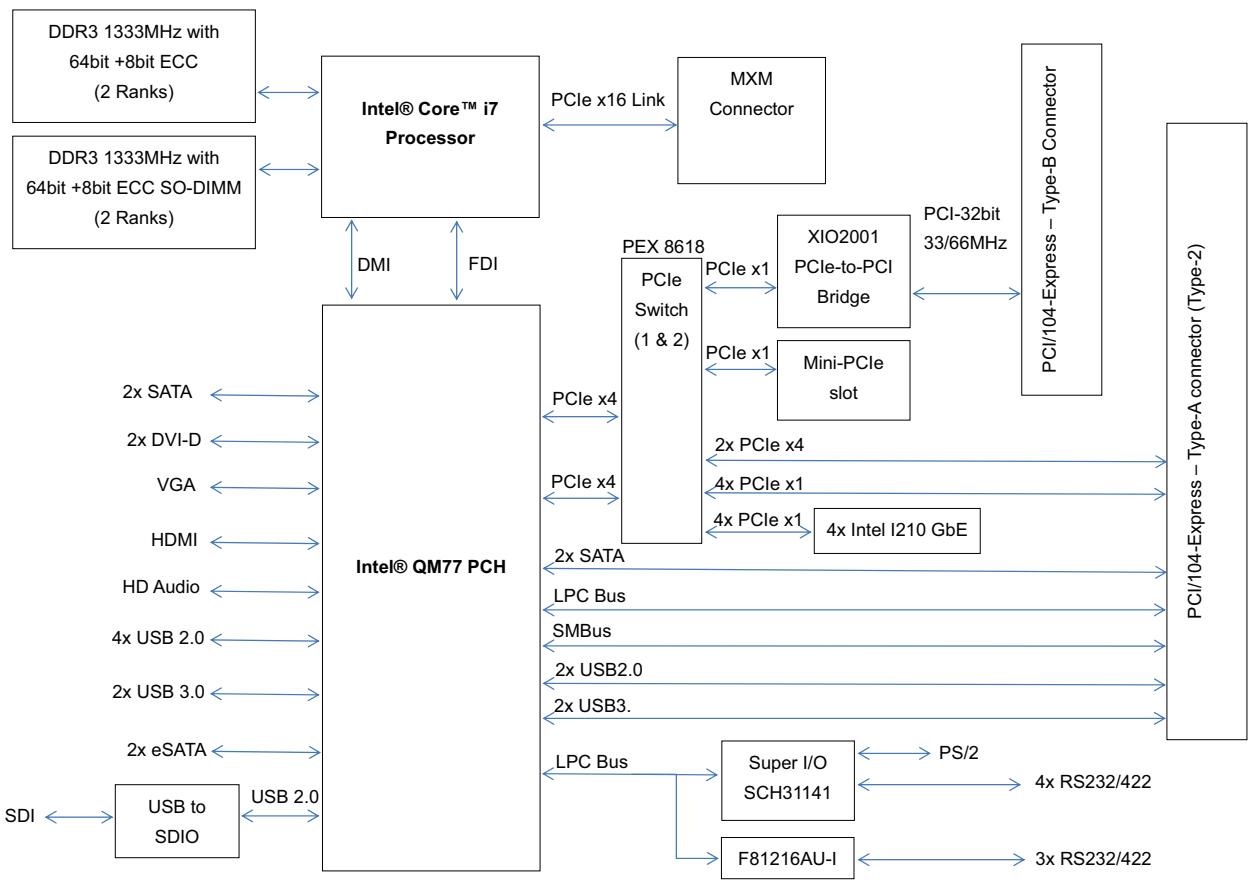
![Based on the provided flowchart, here is the accurate description of the labeled blocks and their connections:\n\n**Processor and Memory Subsystem**\n*   **Blocks:**\n    *   'DDR3 1333MHz with 64bit +8bit ECC (2 Ranks)'\n    *   'DDR3 1333MHz with 64bit +8bit ECC SO-DIMM (2 Ranks)'\n    *   'Intel® Core™ i7 Processor'\n    *   'MXM Connector'\n*   **Connections:**\n    *   Both DDR3 memory blocks connect to the 'Intel® Core™ i7 Processor'.\n    *   The 'Intel® Core™ i7 Processor' connects to the 'MXM Connector' via a 'PCIe x16 Link'.\n    *   The 'Intel® Core™ i7 Processor' connects to the 'Intel® QM77 PCH' via 'DMI' and 'FDI' links.\n\n**PCH (Platform Controller Hub) and Local Peripherals**\n*   **Block:** 'Intel® QM77 PCH'\n*   **Connections:**\n    *   Connects to: '2x SATA', '2x DVI-D', 'VGA', 'HDMI', 'HD Audio', '4x USB 2.0', '2x USB 3.0', and '2x eSATA'.\n    *   Connects to 'USB to SDIO' via 'USB 2.0' (which also connects to 'SDI').\n    *   Connects to 'PEX 8618 PCIe Switch (1 & 2)' via two 'PCIe x4' links and a '2x SATA' link.\n    *   Connects to 'Super I/O SCH31141' and 'F81216AU-I' via 'LPC Bus'.\n    *   Connects to 'PCI/104-Express - Type-A connector (Type-2)' via 'SMBus', '2x USB2.0', and '2x USB3.'.\n\n**Switch, Bridges, and PCIe Expansion**\n*   **Blocks:**\n    *   'PEX 8618 PCIe Switch (1 & 2)'\n    *   'XIO2001 PCIe-to-PCI Bridge'\n    *   'Mini-PCIe slot'\n    *   '4x Intel I210 GbE'\n    *   'PCI/104-Express - Type-B Connector'\n    *   'PCI/104-Express - Type-A connector (Type-2)'\n*   **Connections:**\n    *   'PEX 8618 PCIe Switch (1 & 2)' connects to 'XIO2001 PCIe-to-PCI Bridge' and 'Mini-PCIe slot' via 'PCIe x1' links.\n    *   'PEX 8618 PCIe Switch (1 & 2)' connects to 'PCI/104-Express - Type-B Connector' via '2x PCIe x4'.\n    *   'PEX 8618 PCIe Switch (1 & 2)' connects to 'PCI/104-Express - Type-A connector (Type-2)' via '4x PCIe x1'.\n    *   'PEX 8618 PCIe Switch (1 & 2)' connects to '4x Intel I210 GbE' via '4x PCIe x1', which then connects to the 'PCI/104-Express - Type-A connector (Type-2)'.\n    *   'XIO2001 PCIe-to-PCI Bridge' connects to the 'PCI/104-Express - Type-B Connector' via 'PCI-32bit 33/66MHz'.\n\n**Super I/O and Serial Communication**\n*   **Blocks:**\n    *   'Super I/O SCH31141'\n    *   'F81216AU-I'\n*   **Connections:**\n    *   'Super I/O SCH31141' connects to 'PS/2' and '4x RS232/422'.\n    *   'F81216AU-I' connects to '3x RS232/422'.](.hperc-ibr-h-50-1z179-1000-10/988c057b1b2401c9c2cb4763c5579f3991ba1ce0e4b968a5ec6f9255c72f0a21.jpg)

Figure 1-1: HPERC-IBR-H Block Diagram

# 1.7 Power Specifications

Table 1-2 defines the current draw values of the HPERC-IBR-H, featuring either the Intel® Core™ i7-3517UE or i7-3612QE CPUs. The table captures In-Rush, Idle, and Burn-In-Test (BIT) currents. Table 1-2 lists the current draw values of the HPERC-IBR-H

Table 1-2: System Power Requirements

<table><tr><td>Parameter</td><td>1.7GHz CPU (i7-3517UE)</td><td>2.1GHz CPU (i7-3612QE)</td></tr><tr><td>Input Type</td><td>+28 VDC Regulated DC</td><td>+24 VDC Regulated DC</td></tr><tr><td>In-Rush Peak Current and Duration</td><td>See Figure 1-2</td><td>Not yet measured</td></tr><tr><td>Idle Current and Power (Windows 7)</td><td>0.79A (22.22W)</td><td>0.89A (21.5W)</td></tr><tr><td>BIT Current and Power</td><td>1.18A (32.96W)</td><td>2.17A (52.05W)</td></tr></table>

# Operating configurations:

▶ In-rush operating configuration includes one VGA monitor and 8GB DDR3-1333L RAM.
▶ Idle operating configuration includes the In-rush configuration as well as one SATA 2.5" HDD with Windows 7 and one USB keyboard and mouse.
▶ BIT (Burn-In-Test) operating configuration is the same as the Idle configuration

![| Channel | Amplitude (mA) |\n|---------|----------------|\n| CH1     | ~500           |\n| CH2     | ~500           |](.hperc-ibr-h-50-1z179-1000-10/3109dfb14eff7baa4449e433329aff05e415ddfcf657e2bd99a9b09e798ed4c6.jpg)

Figure 1-2: Intel® Core™ i7-3517UE Peak In-Rush Current and Duration

# 1.8 Environmental Specifications

Table 1-3 provides the most efficient operating and storage condition ranges required for this system.

Table 1-3: Environmental Requirements

<table><tr><td colspan="2">Temperature</td><td colspan="2">Humidity</td></tr><tr><td>Operating</td><td>Storage</td><td>Operating</td><td>Non-operating</td></tr><tr><td>HPERC-HC (conduction cooled)–40° to +85°C (CoreTM i7-3517UE 17W)–40° to +80°C (CoreTM i7-3612QE 35W)(temp. of hottest/coldest point on baseplate)</td><td rowspan="2">–55° to +85°C</td><td rowspan="2">5% to 90%relative humidity,non-condensing</td><td rowspan="2">5% to 95%relative humidity,non-condensing</td></tr><tr><td>HPERC-HH (air cooled)-40°C to +70°C at 1 atm air(required airflow TBD)</td></tr></table>

# 1.9 What's in the Box

The Contents List identifies the items in the shipping box for the HPERC-IBR-H Unit and HPERC-IBR-H Accessories (sold separately.) See Figure 1-3.

![HPERC-IBR-HH\nCooling Fins\n(pre-installed on HH\nversion only)\nHPERC-IBR-HC\nADLINK\nTECHNOLOGY INC.\nMounting Brackets\nCold Plate\n(pre-installed on HC\nversion, only)](.hperc-ibr-h-50-1z179-1000-10/05ca327c023ed0915efa5a4bc2b69e22cf83d0bc789e0db08e8327f4e87b7066.jpg)

HPERC Accessories (sold separately)
![DC Cable Connector\nAC Adapter\nBreakout Cables\nAC Mating Cable\nBreakout Cables](.hperc-ibr-h-50-1z179-1000-10/3667eb0ed578ac6ad3052a6d85f86cf6e5d250f6bad15ed8634168ca575ca167.jpg)

Figure 1-3: HPERC-IBR-H Unit with Accessories

# 1.10 Setup Steps

Follow the setup steps in this section in the order listed. Skip any steps that do not apply to your application.

<table><tr><td>Open shipping box.</td><td>Locate the HPERC-IBR-H Contents List.Unpack the contents of the shipping box.</td></tr><tr><td>Verify contents.</td><td>Verify the contents of the shipping box against the Contents List included with your HPERC-IBR-H.If anything is missing or damaged, call your sales representative.Refer to the ADLINK web page at www.adlinktech.com for contact information.</td></tr></table>

# 1.11 Setting Up the Work Space

![The image displays a graphic icon of a white document with a folded top-left corner. Faint horizontal lines are visible on the lower portion of the paper, and a large, bold red checkmark is superimposed over the center.](.hperc-ibr-h-50-1z179-1000-10/fd0c1c613b199090aa939d48694c4268fcfde1b88daf4c71643985d6993fa38b.jpg)
NOTE:

To prevent damage to the HPERC-IBR-H, ensure sufficient clearance exists around the cooling solution for unrestricted airflow.

The air temperature inside the enclosure could rise above the specified operating temperature limits if the airflow through the cooling solution is restricted.

<table><tr><td>Select workbench location.</td><td>The workbench location should be a flat clean surface for setup and operation (including the connection of any external peripherals and optional devices).Ensure sufficient airflow clearance exists around the complete enclosure.</td></tr><tr><td>Unpack HPERC-IBR-H.</td><td>Remove the HPERC-IBR-H from its shipping container and place it on a flat work surface.The HPERC-IBR-H enclosure combined with CPU, storage (SSD), and the desired OS form a complete system, ready for operation.</td></tr></table>

# 1.12 Installing Mounting Screws

<table><tr><td>Install mounting screws.</td><td>• Install mounting screws (not included) for surface or wall mounting to the mounting brackets of the HPERC-IBR-H. See Figure 1-4 and Figure 1-5.</td></tr></table>

# Torque Values

<table><tr><td>Nominal Diameter</td><td>Material: Stainless Steel A2-70 and A4-70</td><td>Material: Stainless Steel A2-80 and A4-80</td><td>Material: SCM3 (SCM435) Strength Grade: 12.9</td></tr><tr><td>M6 (HPERC-IBR-MC)</td><td>7.6 Nm</td><td>11.1 Nm</td><td>13.83 Nm</td></tr><tr><td>M8 (HPERC-IBR-MH)</td><td>18.4 Nm</td><td>26.7 Nm</td><td>33.34 Nm</td></tr></table>

![0.622'±0.008'\n(15.8mm±0.2mm)\n5.906'±0.016'\n(150mm±0.4mm)\n4.331'±0.014'\n(110mm±0.35mm)\nØ0.374'±0.008'\n(Ø9.5mm±0.2mm)\n12'±0.022'\n(304.8mm±0.55mm)\n8'±0.006'\n(203.2mm±0.15mm)\n1'±0.008'\n(25.4mm±0.2mm)\n2'±0.016'\n(50.8mm±0.4mm)\n8.587'±0.02'\n(218.1mm±0.5mm)\n8.805'±0.026'\n(223.65mm±0.65mm)\n10'±0.022'\n(254mm±0.55mm)\n1'±0.008'\n(25.4mm±0.2mm)\n2.756'±0.008'\n(70mm±0.2mm)\n1.57'\n(40mm)](.hperc-ibr-h-50-1z179-1000-10/768471541e0dc83796305153d19c4d71dddc9c3f3cbd6ced7d76f6b315cf290f.jpg)

![ADLINK\nTECHNOLOGY INC.\n1.331'±0.014'\n(33.8mm±0.35mm)\n1.41'±0.014'\n(35.82mm±0.35mm)\n2.953'±0.014'\n(75mm±0.35mm)\n4.014'+0.022'\n-0.012'\n(101.95mm+0.55mm-\n-0.3mm)\n1.097'±0.014'\n(27.87mm±0.35mm)](.hperc-ibr-h-50-1z179-1000-10/78a96fba9bf9be728f0dfd1d410e97fd8960a85c084f6daf8463353a000985a1.jpg)

Figure 1-4: Top and Front Views of “HH” Enclosure with Mounting Dimensions

![7'±0.014'\n(177.8mm±0.35mm)\n6.5'±0.008'\n(165.1mm±0.2mm)\n5.906'±0.008'\n(150mm±0.2mm)\n8.805'±0.026'\n(223.65mm±0.65mm)\nADLINK\nTECHNOLOGY INC.\nØ0.281'±0.008'\n(Ø7.15mm±0.2mm)\nØ2'±0.008'\n(50.8mm±0.2mm)\n6'±0.008'\n(152.4mm±0.2mm)\n8'±0.008'\n(203.2mm±0.2mm)\n8.587'±0.02'\n(218.1mm±0.5mm)\n0.55'\n(13.9mm)\nØ0.281'±0.008'\n(Ø7.15mm±0.2mm)\n1.374'±0.014'\n(34.9mm±0.35mm)\nP1\nP2\nP3\n1.607'±0.014'\n(40.83mm±0.35mm)\n2.705'±0.022'\n-0.012'\n(68.7mm+0.55mm)\n-0.3mm\n1.957'±0.014'\n(49.72mm±0.35mm)\n3.5'±0.014'\n(88.9mm±0.35mm)](.hperc-ibr-h-50-1z179-1000-10/e7039b8e17bcb06f3918820ab659fe1d5349ba42055257bc2e4df6aa97f0b46b.jpg)

Figure 1-5: Top and Front Views of "HC" Enclosure with Mounting Dimensions

Optional mounting points for surface/wall mounting or heat sink (HPERC-IBR-HC only

\- Mounting holes “A” and “B” are shown below in Figure 1-6. Note the recommended torque values and maximum depth of hole “B”.

Mounting Hole "A" Size: M4 threaded

Recommended Torque: 30 Kgf-cm (2.85 N-m)

Mounting Hole "B" Size: M4 threaded, max. depth 7mm

Recommended Torque: 41 Kgf-cm (4 N-m)

![| Dimension         | Value        |\n| ----------------- | ------------ |\n| Total Width       | 7.646 ± 0.008' |\n| Total Length      | 4.022 ± 0.008' |\n| Total Height      | 2.854 ± 0.008' |\n| Total Base Width  | 1.398 ± 0.008' |\n| Total Base Height | 1.723 ± 0.008' |\n| Total Base Height | 1.398 ± 0.008' |\n| Total Base Height | 1.398 ± 0.008' |\n| Total Base Height | 1.398 ± 0.008' |\n| Total Base Height | 1.398 ± 0.008' |\n| Total Base Height | 1.398 ± 0.008' |\n| Total Base Height | 1.396 ± 0.008' |\n| Total Base Height | 1.396 ± 0.008' |\n| Total Base Height | 1.396 ± 0.008' |\n| Total Base Height | 1.396 ± 0.008' |\n| Total Base Height | 1.396 ± 0.008' |\n| Total Base Height | 1.394 ± 0.008' |\n| Total Base Height | 1.394 ± 0.008' |\n| Total Base Height | 1.394 ± 0.008' |\n| Total Base Height | 1.394 ± 0.008' |\n| Total Base Height | 1.394 ± 0.008' |\n| Total Base Height | 1.392 ± 0.008' |\n| Total Base Height | 1.392 ± 0.008' |\n| Total Base Height | 1.392 ± 0.008' |\n| Total Base Height | 1.392 ± 0.008' |\n| Total Base Height | 1.392 ± 0.008' |\n| Total Base Height | 1.391 ± 0.008' |\n| Total Base Height | 1.391 ± 0.008' |\n| Total Base Height | 1.391 ± 0.008' |\n| Total Base Height | 1.391 ± 0.008' |\n| Total Base Height | 1.391 ± 0.008' |\n| Total Base Height | 1.390 ± 0.008' |\n| Total Base Height | 1.390 ± 0.008' |\n| Total Base Height | 1.390 ± 0.008' |\n| Total Base Height | 1.390 ± 0.008' |\n| Total Base Height | 1.390 ± 0.008' |\n| Total Base Height | 1.399 ± 0.008' |\n| Total Base Height | 1.399 ± 0.008' |\n| Total Base Height | 1.399 ± 0.008' |\n| Total Base Height | 1.399 ± 0.008' |\n| Total Base Height | 1.399 ± 0.008' |\n| Total Base Height | 1.398 ± 0.008' |\n| Total Base Height | 1.398 ± 0.008' |\n| Total Base Height | 1.398 ± 0.008' |\n| Total Base Height | 1.398 ± 0.008' |\n| Total Base Height | 1.397 ± 0.008' |\n| Total Base Height | 1.397 ± 0.008' |\n| Total Base Height | 1.397 ± 0.008' |\n| Total Base Height | 1.397 ± 0.008' |\n| Total Base Height | 1.397 ± 0.008' |\n| Total Base Height | 1.396 ± 0.008' |\n| Total Base Height | 1.396 ± 0.008' |\n| Total Base Height | 1.396 ± 0.008' |\n| Total Base Height | 1.396 ± 0.008' |\n| Total Base Height | 1.395 ± 0.008' |\n| Total Base Height | 1.395 ± 0.008' |\n| Total Base Height | 1.395 ± 0.008' |\n| Total Base Height | 1.395 ± 0.008' |\n| Total Base Height | 1.395 ± 0.008' |\n| Total Base Height | 1.394 ± 0.008' |\n| Total Base Height | 1.394 ± 0.008' |\n| Total Base Height | 1.394 ± 0.008' |\n| Total Base Height | 1.394 ± 0.008' |\n| Total Base Height | 1.393 ± 0.008' |\n| Total Base Height | 1.393 ± 0.008' |\n| Total Base Height | 1.393 ± 0.008' |\n| Total Base Height | 1.393 ± 0.008' |\n| Total Base Height | 1.392 ± 0.008' |\n| Total Base Height | 1.392 ± 0.008' |\n| Total Base Height | 1.392 ± 0.008' |\n| Total Base Height | 1.392 ± 0.008' |\n| Total Base Height | 1.39(fcel)](.hperc-ibr-h-50-1z179-1000-10/704c073afdcdb694ad6877077cd139968ba530b609034a950cb3cb2ebbd0b81e.jpg)

Figure 1-6: Bottom View of "HC" Enclosure with Mounting Holes

# 1.13 Connecting Peripherals

<table><tr><td>Connect the appropriate military breakout cable to the corresponding HPERC-IBR-H military connector. See Figure 1-3 for illustrations of cables. See Figure 1-7 for locations of the HPERC-IBR-H military connectors.</td><td>·Refer to Figure 1-7 for locations and descriptions of the connectors before making connections or powering on the HPERC-IBR-H.</td></tr><tr><td>&lt;img src="images/c6a983d3ebafd10dab688689f9068c4cfe88b0a5348f89c540ef582c35ff35c6.jpg"/&gt;</td><td>·Connect the USB or PS2 keyboard to the corresponding connector on the appropriate breakout cable.</td></tr><tr><td>&lt;img src="images/fd1a324aaabd820e9e6fea9539a12c0af34751b9901bda0e8893177fe73582a5.jpg"/&gt;</td><td>·Connect the USB or PS2 mouse to the appropriate connector on the corresponding breakout cable.</td></tr><tr><td>&lt;img src="images/2b1d0e260f48a74f2a6f3af38508beb76f194c902f13a2452b4828d3c1670aa0.jpg"/&gt;</td><td>·Connect the VGA or LCD display to the appropriate connector on the corresponding breakout cable.</td></tr></table>

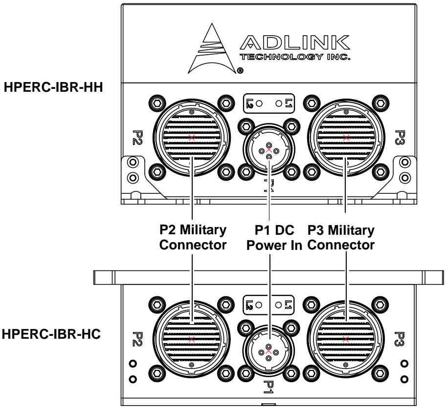
![ADLINK\nTECHNOLOGY INC.\nHPERC-IBR-HH\nP2 Military\nConnector P1 DC P3 Military\nPower In Connector\nHPERC-IBR-HC](.hperc-ibr-h-50-1z179-1000-10/8a424916ad24154afad4b06a540e0c224ee5031a3b09f7f64b5fb878e87c66dc.jpg)

Figure 1-7: Front View of HPERC-IBR-H I/O Panel

Table 1-4: I/O Panel Connectors (Refer to Figure 1-7 for connector locations.)

<table><tr><td>Control/Connector</td><td>Description</td></tr><tr><td>P1 DC Power In&lt;img src="images/3231929c3ae8d8a3a0507838a572afe7b9a04caf476e645adb0aa149c2e09f9c.jpg"/&gt;</td><td>This Military Power connector accepts DC voltages from an external source.Note: This connector is manufactured by Amphenol.</td></tr><tr><td>P2 Military Connector</td><td>This military connector provides signals for Ethernet Ports, USB 2.0, Serial Ports, Reset Switch, Ethernet LEDs, and UNDIO.</td></tr><tr><td>P3 Military Connector</td><td>This military connector provides signals for VGA, Ethernet LEDs, Ethernet Ports, Serial Ports, PS/2 Keyboard and Mouse, and RCA Jack.</td></tr><tr><td>L1/L2 LEDs</td><td>Both LEDs light amber to indicate that the system is powered on (programmable functionality is reserved for future revisions).</td></tr></table>

![The image displays a white document icon with a folded top-left corner and faint horizontal gray lines. A large, bold red checkmark is superimposed over the center of the document, which is outlined in black.](.hperc-ibr-h-50-1z179-1000-10/97f3285f3ebac4e14694e092db0d173e2cdde02b8e05d2e7cd8b1400ecf521ca.jpg)
NOTE:

To connect an external Hard Disk Drive (HDD) or CD-ROM to the HPERC-IBR-H, use one of the USB or SATA ports to connect the device.

# 1.14 P2 and P3 Military Connector

The following two tables define the signals and signal maps of the two military I/O connectors (P2 and P3) on the HPERC-IBR-H. Each table lists the P2 or P3 pin numbers, the signal names and descriptions and the corresponding pins of the internal IO boards (HIBR and Interface Board.) Figure 1-8 provides the number and location of each pin on the two military connectors.
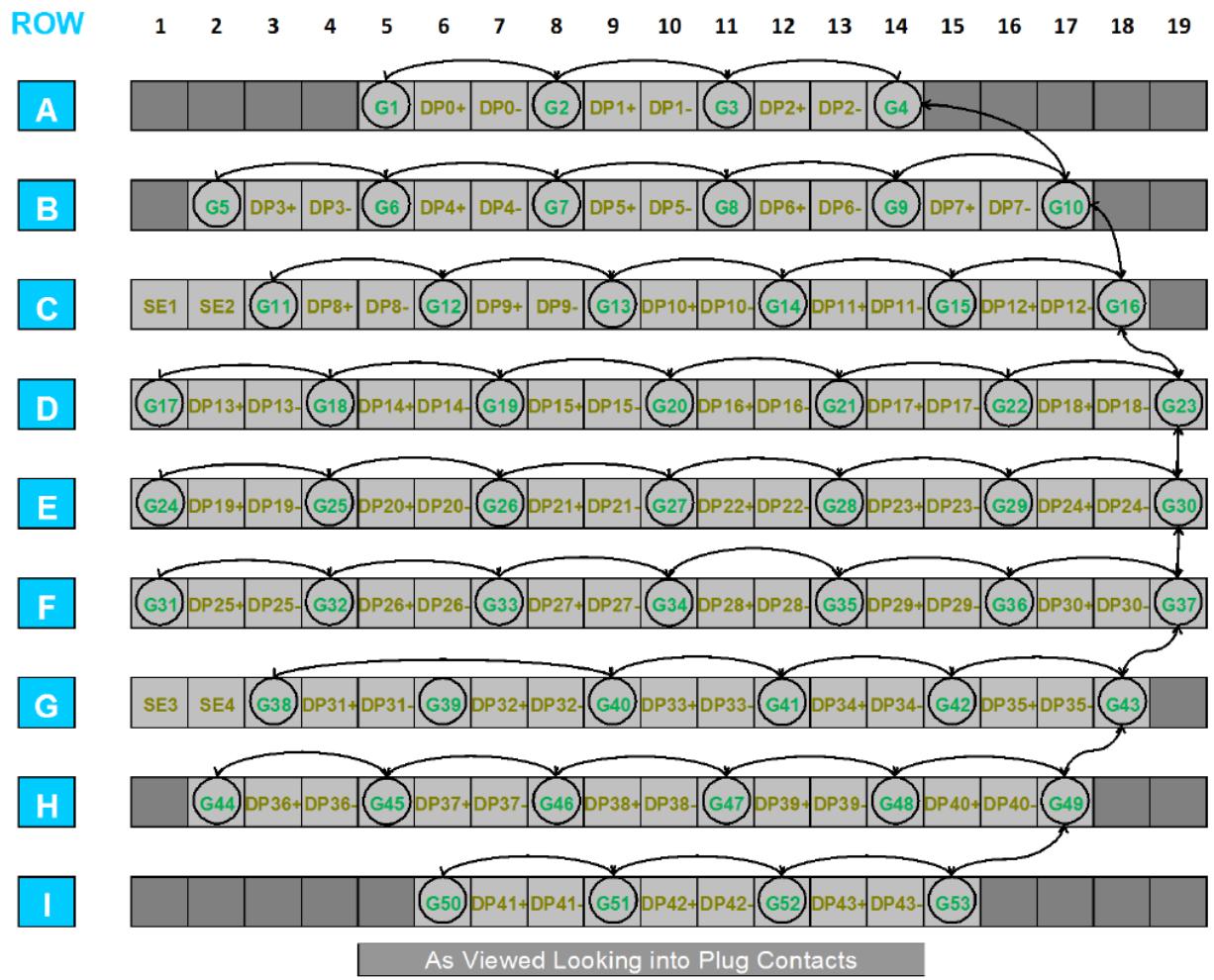
![| Row | Sequence | G1 | DP0+ | DP0- | G2 | DP1+ | DP1- | G3 | DP2+ | DP2- | G4 |\n|-----|----------|----|------|------|----|------|------|----|------|------|----|\n| A   |          |    |      |      |    |      |      |    |      |      |    |\n| B   |          | G5 | DP3+ | DP3- | G6 | DP4+ | DP4- | G7 | DP5+ | DP5- | G8 |\n| C   |          | SE1 | SE2  | G11  | DP8+ | DP8- | G12  | DP9+ | DP9- | G13  | DP10+|\n| D   |          | G17 | DP13+| DP13-| G18 | DP14+| DP14-| G19 | DP15+| DP15-| G20  |\n| E   |          | G24  | DP19+| DP19-| G25 | DP20+| DP20-| G26 | DP21+| DP21-| G27  |\n| F   |          | G31  | DP25+| DP25-| G32 | DP26+| DP26-| G33 | DP27+| DP27-| G34  |\n| G   |          | SE3  | SE4  | G38  | DP31+| DP31-| G39  | DP32+| DP32-| G40  | DP33+|\n| H   |          |    | G44  | DP36+| DP36-| G45  | DP37+| DP37-| G46  | DP38+| DP38-|\n| I   |          |    |      |      |    |      |      |    |      |      |    |\n\nAs Viewed Looking into Plug Contacts](.hperc-ibr-h-50-1z179-1000-10/3bf38d3d6dbe37c595baadd741dcca1c3bd5d324267f5fad2b193a5e3934c120.jpg)

Figure 1-8: P2 and P3 Military Interface Connector Pin Locations

# 1.14.1 P2 Pin Definitions

Table 1-5: Pin definitions and signal maps for the P2 Military Connector

<table><tr><td>MIL-DTL-38999 Pin</td><td>Function</td><td>Port</td><td>Signal</td><td>Breakout Connector Pin #</td></tr><tr><td>A5</td><td></td><td></td><td>Bussed</td><td>N/C</td></tr><tr><td>A6</td><td>USB 2</td><td>USB 3.0 Port2</td><td>USB3_TX2P</td><td>9</td></tr><tr><td>A7</td><td></td><td></td><td>USB3_TX2N</td><td>8</td></tr><tr><td>A8</td><td></td><td></td><td>Ground</td><td>7</td></tr><tr><td>A9</td><td></td><td></td><td>USB3_RX2P</td><td>6</td></tr><tr><td>A10</td><td></td><td></td><td>USB3_RX2N</td><td>5</td></tr><tr><td>A11</td><td></td><td></td><td>Ground</td><td>4</td></tr><tr><td>A12</td><td></td><td>USB 2.0 Port2</td><td>USB_N2</td><td>2</td></tr><tr><td>A13</td><td></td><td></td><td>USB_P2</td><td>3</td></tr><tr><td>A14</td><td></td><td></td><td>Bussed</td><td>N/C</td></tr><tr><td>B2</td><td></td><td></td><td>Bussed</td><td>N/C</td></tr><tr><td>B3</td><td>USB 3</td><td>USB 3.0 Port3</td><td>USB3_TX3N</td><td>8</td></tr><tr><td>B4</td><td></td><td></td><td>USB3_TX3P</td><td>9</td></tr><tr><td>B5</td><td></td><td></td><td>Ground</td><td>7</td></tr><tr><td>B6</td><td></td><td></td><td>USB3_RX3P</td><td>6</td></tr><tr><td>B7</td><td></td><td></td><td>USB3_RX3N</td><td>5</td></tr><tr><td>B8</td><td></td><td></td><td>Ground</td><td>4</td></tr><tr><td>B9</td><td></td><td>USB 2.0 Port3</td><td>USB_N3</td><td>2</td></tr><tr><td>B10</td><td></td><td></td><td>USB_P3</td><td>3</td></tr><tr><td>B11</td><td></td><td></td><td>Bussed</td><td>N/C</td></tr><tr><td>B12</td><td>USB 2</td><td>USB 3.0 Port2 Power</td><td>P5V_USB3_P2</td><td>1</td></tr><tr><td>B13</td><td></td><td></td><td>P5V_USB3_P2</td><td>1</td></tr><tr><td>B14</td><td>Audio In</td><td>Audio In</td><td>GND_A-Sleeve</td><td>1</td></tr><tr><td>B15</td><td></td><td></td><td>Right-Ring</td><td>4</td></tr><tr><td>B16</td><td></td><td></td><td>Left-Tip</td><td>2</td></tr><tr><td>B17</td><td></td><td></td><td>GND_A-Sleeve</td><td>1</td></tr><tr><td>C1</td><td>RJ-45 2 LED</td><td>LAN Port2</td><td>PCIE_ETH_2/5_LED1</td><td>LAN_Port2_LED+</td></tr><tr><td>C2</td><td>RJ-45 3 LED</td><td>LAN Port3</td><td>PCIE_ETH_3/5_LED1</td><td>LAN_Port3_LED+</td></tr><tr><td>C3</td><td></td><td></td><td>Ground</td><td>LAN_Port3_LED-</td></tr><tr><td>C4</td><td>USB 3</td><td>USB 3.0 Port3 Power</td><td>P5V_USB3_P3</td><td>1</td></tr><tr><td>C5</td><td></td><td></td><td>P5V_USB3_P3</td><td>1</td></tr><tr><td>C6</td><td>DB9 6</td><td>RS -422 Port6</td><td>Ground</td><td>5</td></tr><tr><td>C7</td><td></td><td></td><td>RS422_RX6_N</td><td>8</td></tr><tr><td>C8</td><td></td><td></td><td>RS422_RX6_P</td><td>2</td></tr><tr><td>C9</td><td></td><td></td><td>Bussed</td><td>N/C</td></tr><tr><td>C10</td><td>DB9 5</td><td>RS422 Port5</td><td>RS422_TX5_P</td><td>3</td></tr><tr><td>C11</td><td></td><td></td><td>RS422_TX5_N</td><td>7</td></tr><tr><td>C12</td><td>DB9 4</td><td>RS-422 Port4</td><td>Ground</td><td>5</td></tr><tr><td>C13</td><td></td><td></td><td>RS422_RX4_N</td><td>8</td></tr><tr><td>C14</td><td></td><td></td><td>RS422_RX4_P</td><td>2</td></tr></table>

Table 1-5: Pin definitions and signal maps for the P2 Military Connector

<table><tr><td>MIL-DTL-38999 Pin</td><td>Function</td><td>Port</td><td>Signal</td><td>Breakout Connector Pin #</td></tr><tr><td>C15</td><td>Audio Out</td><td>Audio Out</td><td>GND_A</td><td>1</td></tr><tr><td>C16</td><td></td><td></td><td>Right</td><td>4</td></tr><tr><td>C17</td><td></td><td></td><td>Left</td><td>2</td></tr><tr><td>C18</td><td></td><td></td><td>GND_A</td><td>1</td></tr><tr><td>D1</td><td>RJ-45 2 LED</td><td>LAN Port2</td><td>Ground</td><td>LAN_Port2_LED-</td></tr><tr><td>D2</td><td>DB9 6</td><td>RS-422 Port6</td><td>RS422_TX6_N</td><td>7</td></tr><tr><td>D3</td><td></td><td></td><td>RS422_TX6_P</td><td>3</td></tr><tr><td>D4</td><td>DB9 5</td><td>RS-422 Port5</td><td>Ground</td><td>5</td></tr><tr><td>D5</td><td></td><td></td><td>RS422_RX5_N</td><td>8</td></tr><tr><td>D6</td><td></td><td></td><td>RS422_RX5_P</td><td>2</td></tr><tr><td>D7</td><td></td><td></td><td>Bussed</td><td>N/C</td></tr><tr><td>D8</td><td></td><td></td><td>ERASE-L</td><td>N/C</td></tr><tr><td>D9</td><td></td><td></td><td>HDC_RUN-L</td><td>N/C</td></tr><tr><td>D10</td><td>DB9 2</td><td>RS-422 Port2</td><td>Ground</td><td>5</td></tr><tr><td>D11</td><td></td><td></td><td>RS422_RX2_N</td><td>8</td></tr><tr><td>D12</td><td></td><td></td><td>RS422_RX2_P</td><td>2</td></tr><tr><td>D13</td><td></td><td></td><td>Bussed</td><td>N/C</td></tr><tr><td>D14</td><td>DB9 4</td><td>RS-422 Port4</td><td>RS422_TX4_N</td><td>7</td></tr><tr><td>D15</td><td></td><td></td><td>RS422_TX4_P</td><td>3</td></tr><tr><td>D16</td><td></td><td></td><td>Bussed</td><td>N/C</td></tr><tr><td>D17</td><td>HDMI B</td><td>HDMI Port B</td><td>TMDS Clock-</td><td>12</td></tr><tr><td>D18</td><td></td><td></td><td>TMDS Clock+</td><td>10</td></tr><tr><td>D19</td><td></td><td></td><td>TMDS Clock Shield</td><td>11</td></tr><tr><td>E1</td><td>eSATA 1</td><td>eSATA Port1</td><td>Ground</td><td>1</td></tr><tr><td>E2</td><td></td><td></td><td>ESATA_TX-P1</td><td>2</td></tr><tr><td>E3</td><td></td><td></td><td>ESATA_TX-N1</td><td>3</td></tr><tr><td>E4</td><td></td><td></td><td>Ground</td><td>4</td></tr><tr><td>E5</td><td></td><td></td><td>ESATA_RX-P1</td><td>6</td></tr><tr><td>E6</td><td></td><td></td><td>ESATA_RX-N1</td><td>5</td></tr><tr><td>E7</td><td></td><td></td><td>Ground</td><td>7</td></tr><tr><td>E8</td><td>DB9 7</td><td>RS-422 Port7</td><td>RS422_TX7_P</td><td>3</td></tr><tr><td>E9</td><td></td><td></td><td>RS422_TX7_N</td><td>7</td></tr><tr><td>E10</td><td></td><td></td><td>Bussed</td><td>N/C</td></tr><tr><td>E11</td><td>DB9 2</td><td>RS422 Port2</td><td>RS422_TX2_P</td><td>3</td></tr><tr><td>E12</td><td></td><td></td><td>RS422_TX2_N</td><td>7</td></tr><tr><td>E13</td><td></td><td></td><td>Bussed</td><td>N/C</td></tr><tr><td>E14</td><td>Diff.</td><td>Twisted Pair-3</td><td>UDNIO16</td><td></td></tr><tr><td>E15</td><td></td><td></td><td>UDNIO15</td><td></td></tr><tr><td>E16</td><td></td><td></td><td>Bussed</td><td>N/C</td></tr><tr><td>E17</td><td>HDMI B</td><td>HDMI Port B</td><td>TMDS Data 0+</td><td>7</td></tr><tr><td>E18</td><td></td><td></td><td>TMDS Data 0-</td><td>9</td></tr><tr><td>E19</td><td></td><td></td><td>TMDS Data 0 Shield</td><td>8</td></tr><tr><td>F1</td><td></td><td></td><td>Bussed</td><td>N/C</td></tr></table>

Table 1-5: Pin definitions and signal maps for the P2 Military Connector

<table><tr><td>MIL-DTL-38999 Pin</td><td>Function</td><td>Port</td><td>Signal</td><td>Breakout Connector Pin #</td></tr><tr><td>F2</td><td>HDMI B</td><td>HDMI PortB Power</td><td>P5V</td><td>18</td></tr><tr><td>F3</td><td></td><td></td><td>Bussed</td><td>N/C</td></tr><tr><td>F4</td><td>DB9 7</td><td>RS422 Port7</td><td>Ground</td><td>5</td></tr><tr><td>F5</td><td></td><td></td><td>RS422_RX7_P</td><td>2</td></tr><tr><td>F6</td><td></td><td></td><td>RS422_RX7_N</td><td>8</td></tr><tr><td>F7</td><td>Reset Switch</td><td>RESET SWITCH</td><td>Ground</td><td>RESET SWITCH-</td></tr><tr><td>F8</td><td></td><td></td><td>RESET#_HDR</td><td>RESET SWITCH+</td></tr><tr><td>F9</td><td>Power Switch</td><td>Power Switch</td><td>PWERBTN_HDR</td><td>POWER SWITCH+</td></tr><tr><td>F10</td><td></td><td>Power Switch</td><td>Ground</td><td>POWER SWITCH-</td></tr><tr><td>F11</td><td>RJ-45 2</td><td>LAN Port2</td><td>GBE2_MDI0_0_P</td><td>1</td></tr><tr><td>F12</td><td></td><td></td><td>GBE2_MDI0_0_N</td><td>2</td></tr><tr><td>F13</td><td></td><td></td><td>Bussed</td><td>N/C</td></tr><tr><td>F14</td><td></td><td>LAN Port2</td><td>GBE2_MDI0_1_N</td><td>6</td></tr><tr><td>F15</td><td></td><td></td><td>GBE2_MDI0_1_P</td><td>3</td></tr><tr><td>F16</td><td>HDMI B</td><td>HDMI PortB</td><td>Reserved</td><td>N/C</td></tr><tr><td>F17</td><td></td><td></td><td>CEC</td><td>N/C</td></tr><tr><td>F18</td><td></td><td></td><td>Hot Plug Detect</td><td>19</td></tr><tr><td>F19</td><td></td><td></td><td>Bussed</td><td>N/C</td></tr><tr><td>G1</td><td>Power LED</td><td>Power LED</td><td>PWR_LED</td><td>POWER LED+</td></tr><tr><td>G2</td><td>SATA LED</td><td>SATA LED</td><td>SATA_LED#</td><td>SATA LED+</td></tr><tr><td>G3</td><td></td><td></td><td>Ground</td><td>SATA LED-</td></tr><tr><td>G4</td><td>Keyboard</td><td>Keyboard</td><td>DAT_KBD_CON</td><td>1</td></tr><tr><td>G5</td><td></td><td></td><td>CLK_KBD_CON</td><td>5</td></tr><tr><td>G6</td><td></td><td></td><td>Ground</td><td>3</td></tr><tr><td>G7</td><td>Diff.</td><td>Twisted Pair-4</td><td>UDNIO18</td><td></td></tr><tr><td>G8</td><td></td><td></td><td>UDNIO17</td><td></td></tr><tr><td>G9</td><td></td><td></td><td>Bussed</td><td>N/C</td></tr><tr><td>G10</td><td>RJ-45 2</td><td>LAN Port2</td><td>GBE2_MDI0_2_N</td><td>5</td></tr><tr><td>G11</td><td></td><td></td><td>GBE2_MDI0_2_P</td><td>4</td></tr><tr><td>G12</td><td></td><td></td><td>Bussed</td><td>N/C</td></tr><tr><td>G13</td><td></td><td></td><td>Bussed</td><td>N/C</td></tr><tr><td>G14</td><td>KB/MS</td><td>KB/MS Power</td><td>KM_VCC</td><td>4 &amp; 4</td></tr><tr><td>G15</td><td></td><td></td><td>Bussed</td><td>N/C</td></tr><tr><td>G16</td><td>HDMI B</td><td>HDMI PortB</td><td>TMDS Data 1+</td><td>4</td></tr><tr><td>G17</td><td></td><td></td><td>TMDS Data 1-</td><td>6</td></tr><tr><td>G18</td><td></td><td></td><td>TMDS Data 1 Shield</td><td>5</td></tr><tr><td>H2</td><td>Power LED</td><td>Power LED</td><td>Ground</td><td>POWER LED-</td></tr><tr><td>H3</td><td>RJ-45 3</td><td>LAN Port3</td><td>GBE3_MDI0_0_P</td><td>1</td></tr><tr><td>H4</td><td></td><td></td><td>GBE3_MDI0_0_N</td><td>2</td></tr><tr><td>H5</td><td></td><td></td><td>Bussed</td><td>N/C</td></tr><tr><td>H6</td><td></td><td>LAN Port3</td><td>GBE3_MDI0_1_N</td><td>6</td></tr><tr><td>H7</td><td></td><td></td><td>GBE3_MDI0_1_P</td><td>3</td></tr></table>

Table 1-5: Pin definitions and signal maps for the P2 Military Connector

<table><tr><td>MIL-DTL-38999 Pin</td><td>Function</td><td>Port</td><td>Signal</td><td>Breakout Connector Pin #</td></tr><tr><td>H8</td><td></td><td></td><td>Bussed</td><td>N/C</td></tr><tr><td>H9</td><td></td><td>LAN Port3</td><td>GBE3_MDI0_3_P</td><td>7</td></tr><tr><td>H10</td><td></td><td></td><td>GBE3_MDI0_3_N</td><td>8</td></tr><tr><td>H11</td><td></td><td></td><td>Bussed</td><td>N/C</td></tr><tr><td>H12</td><td></td><td>LAN Port3</td><td>GBE3_MDI0_2_N</td><td>5</td></tr><tr><td>H13</td><td></td><td></td><td>GBE3_MDI0_2_P</td><td>4</td></tr><tr><td>H14</td><td></td><td></td><td>Bussed</td><td>N/C</td></tr><tr><td>H15</td><td>HDMI B</td><td>HDMI PortB</td><td>TMDS Data 2+</td><td>1</td></tr><tr><td>H16</td><td></td><td></td><td>TMDS Data 2-</td><td>3</td></tr><tr><td>H17</td><td></td><td></td><td>TMDS Data 2 Shield</td><td>2</td></tr><tr><td>I6</td><td></td><td></td><td>Bussed</td><td>N/C</td></tr><tr><td>I7</td><td>Mouse</td><td>Mouse</td><td>CLK_MS_CON</td><td>5</td></tr><tr><td>I8</td><td></td><td></td><td>DAT_MS_CON</td><td>1</td></tr><tr><td>I9</td><td></td><td></td><td>Ground</td><td>3</td></tr><tr><td>I10</td><td>HDMI B</td><td>HDMI PortB</td><td>SCL</td><td>15</td></tr><tr><td>I11</td><td></td><td></td><td>SDA</td><td>16</td></tr><tr><td>I12</td><td></td><td></td><td>DDC/CEC Ground</td><td>17</td></tr><tr><td>I13</td><td>RJ-45 2</td><td>LAN Port2</td><td>GBE2_MDI0_3_N</td><td>8</td></tr><tr><td>I14</td><td></td><td></td><td>GBE2_MDI0_3_P</td><td>7</td></tr><tr><td>I15</td><td></td><td></td><td>Bussed</td><td>N/C</td></tr></table>

# 1.14.2 P3 Pin Definitions

Table 1-6: Pin definitions and signal maps for the P3 Military Connector

<table><tr><td>MIL-DTL-38999 Pin</td><td>Function</td><td>Port</td><td>Signal</td><td>Breakout Connector Pin #</td></tr><tr><td>A5</td><td></td><td></td><td>Bussed</td><td>N/C</td></tr><tr><td>A6</td><td></td><td></td><td>Bussed</td><td>N/C</td></tr><tr><td>A7</td><td></td><td></td><td>Bussed</td><td>N/C</td></tr><tr><td>A8</td><td></td><td></td><td>Bussed</td><td>N/C</td></tr><tr><td>A9</td><td>DVI D</td><td>DVI PortD</td><td>TMDS Clock-</td><td>24</td></tr><tr><td>A10</td><td></td><td></td><td>TMDS Clock+</td><td>23</td></tr><tr><td>A11</td><td></td><td></td><td>TMDS Clock Shield</td><td>22</td></tr><tr><td>A12</td><td></td><td></td><td>Hot Plug Detect</td><td>16</td></tr><tr><td>A13</td><td></td><td></td><td>Bussed</td><td>N/C</td></tr><tr><td>A14</td><td></td><td></td><td>Bussed</td><td>N/C</td></tr><tr><td>B2</td><td>RJ-45 4 LED</td><td>LAN Port4</td><td>Ground</td><td>LAN_Port4_LED-</td></tr><tr><td>B3</td><td>DVI C</td><td>DVI PortC</td><td>TMDS Data 2-</td><td>1</td></tr><tr><td>B4</td><td></td><td></td><td>TMDS Data 2+</td><td>2</td></tr><tr><td>B5</td><td></td><td></td><td>TMDS Data 2/4 Shield</td><td>3</td></tr><tr><td>B6</td><td></td><td></td><td>DDC data</td><td>7</td></tr><tr><td>B7</td><td></td><td></td><td>DDC clock</td><td>6</td></tr><tr><td>B8</td><td></td><td></td><td>Bussed</td><td>N/C</td></tr><tr><td>B9</td><td>DVI C</td><td>DVI PortC</td><td>Hot Plug Detect</td><td>16</td></tr><tr><td>B10</td><td></td><td></td><td>Bussed</td><td>N/C</td></tr><tr><td>B11</td><td></td><td></td><td>Bussed</td><td>N/C</td></tr><tr><td>B12</td><td>DVI D</td><td>DVI PortD</td><td>TMDS Data 0-</td><td>17</td></tr><tr><td>B13</td><td>DP</td><td></td><td>TMDS Data 0+</td><td>18</td></tr><tr><td>B14</td><td>DP</td><td></td><td>TMDS Data 0/5 Shield</td><td>19</td></tr><tr><td>B15</td><td>DP</td><td></td><td>TMDS Data 1-</td><td>9</td></tr><tr><td>B16</td><td>DP</td><td></td><td>TMDS Data 1+</td><td>10</td></tr><tr><td>B17</td><td>DP</td><td></td><td>TMDS Data 1/3 Shield</td><td>11</td></tr><tr><td>C1</td><td>RJ-45 4 LED</td><td>LAN Port4</td><td>PCIE_ETH_4/5_LED1</td><td>LAN_Port4_LED+</td></tr><tr><td>C2</td><td></td><td>LAN Port5</td><td>PCIE_ETH_5/5_LED1</td><td>LAN_Port5_LED+</td></tr><tr><td>C3</td><td></td><td></td><td>Ground</td><td>LAN_Port5_LED-</td></tr><tr><td>C4</td><td>DVI C</td><td>DVI PortC</td><td>TMDS Data 1-</td><td>9</td></tr><tr><td>C5</td><td>DP</td><td></td><td>TMDS Data 1+</td><td>10</td></tr><tr><td>C6</td><td>DP</td><td></td><td>TMDS Data 1/3 Shield</td><td>11</td></tr><tr><td>C7</td><td>Diff.</td><td>Twisted Pair-8</td><td>UDNIO9</td><td></td></tr><tr><td>C8</td><td>DIFF.</td><td></td><td>UDNIO10</td><td></td></tr><tr><td>C9</td><td></td><td></td><td>Bussed</td><td>N/C</td></tr><tr><td>C10</td><td>Diff.</td><td>Twisted Pair-1</td><td>UDNIO12</td><td></td></tr><tr><td>C11</td><td></td><td></td><td>UDNIO11</td><td></td></tr><tr><td>C12</td><td></td><td></td><td>Bussed</td><td>N/C</td></tr><tr><td>C13</td><td>RJ-45 4</td><td>LAN Port4</td><td>GBE4_MDI0_0_P</td><td>1</td></tr><tr><td>C14</td><td></td><td></td><td>GBE4_MDI0_0_N</td><td>2</td></tr><tr><td>C15</td><td></td><td></td><td>Bussed</td><td>N/C</td></tr></table>

Table 1-6: Pin definitions and signal maps for the P3 Military Connector

<table><tr><td>MIL-DTL-38999 Pin</td><td>Function</td><td>Port</td><td>Signal</td><td>Breakout Connector Pin #</td></tr><tr><td>C16</td><td>DVI D</td><td>DVI PortD</td><td>TMDS Data 2-</td><td>1</td></tr><tr><td>C17</td><td>DP</td><td></td><td>TMDS Data 2+</td><td>2</td></tr><tr><td>C18</td><td>DP</td><td></td><td>TMDS Data 2/4 Shield</td><td>3</td></tr><tr><td>D1</td><td></td><td></td><td>Bussed</td><td>N/C</td></tr><tr><td>D2</td><td>DVI C</td><td>DVI PortC</td><td>TMDS Data 0-</td><td>17</td></tr><tr><td>D3</td><td>DP</td><td></td><td>TMDS Data 0+</td><td>18</td></tr><tr><td>D4</td><td>DP</td><td></td><td>TMDS Data 0/5 Shield</td><td>19</td></tr><tr><td>D5</td><td>DB9 1</td><td>RS422 Port1</td><td>RS422_RX1_P</td><td>2</td></tr><tr><td>D6</td><td></td><td></td><td>RS422_RX1_N</td><td>8</td></tr><tr><td>D7</td><td></td><td></td><td>Bussed</td><td>N/C</td></tr><tr><td>D8</td><td>RJ-45 5</td><td>LAN Port5</td><td>GBE5_MDI0_1_P</td><td>3</td></tr><tr><td>D9</td><td></td><td></td><td>GBE5_MDI0_1_N</td><td>6</td></tr><tr><td>D10</td><td></td><td></td><td>Bussed</td><td>N/C</td></tr><tr><td>D11</td><td>USB 4</td><td>USB 2.0 Port4 Power</td><td>P5V_USB4_CON</td><td>1</td></tr><tr><td>D12</td><td>USB 5</td><td>USB 2.0 Port5 Power</td><td>P5V_USB5_CON</td><td>1</td></tr><tr><td>D13</td><td></td><td></td><td>Bussed</td><td>N/C</td></tr><tr><td>D14</td><td>RJ-45 4</td><td>LAN Port4</td><td>GBE4_MDI0_3_P</td><td>7</td></tr><tr><td>D15</td><td></td><td></td><td>GBE4_MDI0_3_N</td><td>8</td></tr><tr><td>D16</td><td></td><td></td><td>Bussed</td><td>N/C</td></tr><tr><td>D17</td><td>DVI D</td><td>DVI PortD</td><td>DDC data</td><td>7</td></tr><tr><td>D18</td><td></td><td></td><td>DDC clock</td><td>6</td></tr><tr><td>D19</td><td></td><td></td><td>Bussed</td><td>N/C</td></tr><tr><td>E1</td><td></td><td></td><td>Bussed</td><td>N/C</td></tr><tr><td>E2</td><td>DVI C</td><td>DVI PortC</td><td>TMDS Clock+</td><td>23</td></tr><tr><td>E3</td><td>DP</td><td></td><td>TMDS Clock-</td><td>24</td></tr><tr><td>E4</td><td>DP</td><td></td><td>TMDS Clock Shield</td><td>22</td></tr><tr><td>E5</td><td>DB9 1</td><td>RS422 Port1</td><td>RS422_TX1_N</td><td>7</td></tr><tr><td>E6</td><td></td><td></td><td>RS422_TX1_P</td><td>3</td></tr><tr><td>E7</td><td></td><td></td><td>Bussed</td><td>5</td></tr><tr><td>E8</td><td>RJ-45 5</td><td>LAN Port5</td><td>GBE5_MDI0_2_N</td><td>5</td></tr><tr><td>E9</td><td></td><td></td><td>GBE5_MDI0_2_P</td><td>4</td></tr><tr><td>E10</td><td></td><td></td><td>Bussed</td><td>N/C</td></tr><tr><td>E11</td><td>RJ-45 4</td><td>LAN Port4</td><td>GBE4_MDI0_1_P</td><td>3</td></tr><tr><td>E12</td><td></td><td></td><td>GBE4_MDI0_1_N</td><td>6</td></tr><tr><td>E13</td><td></td><td></td><td>Bussed</td><td>N/C</td></tr><tr><td>E14</td><td>RJ-45 4</td><td>LAN Port4</td><td>GBE4_MDI0_2_N</td><td>5</td></tr><tr><td>E15</td><td></td><td></td><td>GBE4_MDI0_2_P</td><td>4</td></tr><tr><td>E16</td><td></td><td></td><td>Bussed</td><td>N/C</td></tr><tr><td>E17</td><td>USB 8</td><td>USB 2.0 Port8</td><td>USB_N8_CONN</td><td>2</td></tr><tr><td>E18</td><td></td><td></td><td>USB_P8_CONN</td><td>3</td></tr><tr><td>E19</td><td></td><td></td><td>Ground</td><td>4</td></tr></table>

Table 1-6: Pin definitions and signal maps for the P3 Military Connector

<table><tr><td>MIL-DTL-38999 Pin</td><td>Function</td><td>Port</td><td>Signal</td><td>Breakout Connector Pin #</td></tr><tr><td>F1</td><td>VGA</td><td>VGA</td><td>GREEN_CONN_Return</td><td>7</td></tr><tr><td>F2</td><td></td><td></td><td>CRT_GREEN_CONN</td><td>2</td></tr><tr><td>F3</td><td></td><td></td><td>CRT_BLUE_CONN</td><td>3</td></tr><tr><td>F4</td><td></td><td></td><td>BLUE_CONN_Return</td><td>8</td></tr><tr><td>F5</td><td></td><td></td><td>CRT_DDC_CLK_CONN</td><td>15</td></tr><tr><td>F6</td><td></td><td></td><td>CRT_DDC_DATA_CONN</td><td>12</td></tr><tr><td>F7</td><td></td><td></td><td>Bussed</td><td>N/C</td></tr><tr><td>F8</td><td>Diff.</td><td>Twisted Pair-5</td><td>UDNIO20</td><td></td></tr><tr><td>F9</td><td>DIFF.</td><td></td><td>UDNIO19</td><td></td></tr><tr><td>F10</td><td></td><td></td><td>Bussed</td><td>N/C</td></tr><tr><td>F11</td><td>DB9 0</td><td>RS422 Port0</td><td>RS422_TX0_N</td><td>7</td></tr><tr><td>F12</td><td></td><td></td><td>RS422_TX0_P</td><td>3</td></tr><tr><td>F13</td><td></td><td></td><td>Bussed</td><td>N/C</td></tr><tr><td>F14</td><td>Diff.</td><td>Twisted Pair-6</td><td>UDNIO6</td><td></td></tr><tr><td>F15</td><td>DIFF.</td><td></td><td>UDNIO5</td><td></td></tr><tr><td>F16</td><td></td><td></td><td>Bussed</td><td>N/C</td></tr><tr><td>F17</td><td>Diff.</td><td>Twisted Pair-9</td><td>UDNIO2</td><td></td></tr><tr><td>F18</td><td>DIFF.</td><td></td><td>UDNIO1</td><td></td></tr><tr><td>F19</td><td></td><td></td><td>Bussed</td><td>N/C</td></tr><tr><td>G1</td><td>VGA</td><td>VGA</td><td>CRT_RED_CONN</td><td>1</td></tr><tr><td>G2</td><td></td><td></td><td>CRT_HSYNC</td><td>13</td></tr><tr><td>G3</td><td></td><td></td><td>Ground (HSYNC)</td><td>5</td></tr><tr><td>G4</td><td></td><td></td><td>CRT_VSYNC</td><td>14</td></tr><tr><td>G5</td><td></td><td>VGA &amp; DVI C/D Power</td><td>P5V</td><td>9 &amp; 14/14</td></tr><tr><td>G6</td><td>DVI C/D</td><td>DVI PortC/D</td><td>Analog Ground</td><td>C5 &amp; 15/C5 &amp; 15</td></tr><tr><td>G7</td><td>Diff.</td><td>Twisted Pair-2</td><td>UDNIO14</td><td></td></tr><tr><td>G8</td><td>DIFF.</td><td></td><td>UDNIO13</td><td></td></tr><tr><td>G9</td><td>DB9 0</td><td>RS422 Port0</td><td>Ground</td><td>5</td></tr><tr><td>G10</td><td></td><td></td><td>RS422_RX0_P</td><td>2</td></tr><tr><td>G11</td><td></td><td></td><td>RS422_RX0_N</td><td>8</td></tr><tr><td>G12</td><td></td><td></td><td>Bussed</td><td>N/C</td></tr><tr><td>G13</td><td>USB 5</td><td>USB 2.0 Port5</td><td>USB_N5_CONN</td><td>2</td></tr><tr><td>G14</td><td></td><td></td><td>USB_P5_CONN</td><td>3</td></tr><tr><td>G15</td><td></td><td></td><td>Ground</td><td>4</td></tr><tr><td>G16</td><td>USB 9</td><td>USB 2.0 Port9</td><td>USB_N9_CONN</td><td>2</td></tr><tr><td>G17</td><td></td><td></td><td>USB_P9_CONN</td><td>3</td></tr><tr><td>G18</td><td></td><td></td><td>Ground</td><td>4</td></tr><tr><td>H2</td><td>VGA</td><td>VGA</td><td>RED_CONN_Return</td><td>6</td></tr><tr><td>H3</td><td>RJ-45 5</td><td>LAN Port5</td><td>GBE5_MDI0_0_N</td><td>2</td></tr><tr><td>H4</td><td></td><td></td><td>GBE5_MDI0_0_P</td><td>1</td></tr><tr><td>H5</td><td>VGA</td><td>VGA</td><td>Ground (VSYNC, DDC)</td><td>10</td></tr></table>

Table 1-6: Pin definitions and signal maps for the P3 Military Connector

<table><tr><td>MIL-DTL-38999 Pin</td><td>Function</td><td>Port</td><td>Signal</td><td>Breakout Connector Pin #</td></tr><tr><td>H6</td><td>RJ-45 5</td><td>LAN Port5</td><td>GBE5_MDI0_3_P</td><td>7</td></tr><tr><td>H7</td><td></td><td></td><td>GBE5_MDI0_3_N</td><td>8</td></tr><tr><td>H8</td><td></td><td></td><td>Bussed</td><td>N/C</td></tr><tr><td>H9</td><td>Diff.</td><td>Twisted Pair-7</td><td>UDNIO8</td><td></td></tr><tr><td>H10</td><td>DIFF.</td><td></td><td>UDNIO7</td><td></td></tr><tr><td>H11</td><td></td><td></td><td>Bussed</td><td>N/C</td></tr><tr><td>H12</td><td>Diff.</td><td>Twisted Pair-10</td><td>UDNIO4</td><td></td></tr><tr><td>H13</td><td>DIFF.</td><td></td><td>UDNIO3</td><td></td></tr><tr><td>H14</td><td></td><td></td><td>Bussed</td><td>N/C</td></tr><tr><td>H15</td><td>USB 9</td><td>USB 2.0 Port9 Power</td><td>P5V_USB9_CON</td><td>1</td></tr><tr><td>H16</td><td>USB 8</td><td>USB 2.0 Port8 Power</td><td>P5V_USB8_CON</td><td>1</td></tr><tr><td>H17</td><td></td><td></td><td>Bussed</td><td>N/C</td></tr><tr><td>I6</td><td>eSATA 0</td><td>eSATA Port0</td><td>Ground</td><td>1</td></tr><tr><td>I7</td><td></td><td></td><td>ESATA_RX-P0</td><td>6</td></tr><tr><td>I8</td><td></td><td></td><td>ESATA_RX-N0</td><td>5</td></tr><tr><td>I9</td><td></td><td></td><td>Ground</td><td>4</td></tr><tr><td>I10</td><td></td><td></td><td>ESATA_TX-P0</td><td>2</td></tr><tr><td>I11</td><td></td><td></td><td>ESATA_TX-N0</td><td>3</td></tr><tr><td>I12</td><td></td><td></td><td>Ground</td><td>7</td></tr><tr><td>I13</td><td>USB 4</td><td>USB 2.0 Port4</td><td>USB_N4_CONN</td><td>2</td></tr><tr><td>I14</td><td></td><td></td><td>USB_P4_CONN</td><td>3</td></tr><tr><td>I15</td><td></td><td></td><td>Ground</td><td>4</td></tr></table>

# 1.15 Applying Power to the HPERC-IBR-H

<table><tr><td>1) Follow these steps to apply power to the HPERC-IBR-H.</td><td>Connect the AC Mating Cable to the AC Adapter (options.) See Figure 1-3.Plug in the DC Cable Connector from the AC Adapter (option) to the DC IN jack on the HPERC-IBR-H. See Figure 1-7.Caution:Power supplied to the unit must be within the allowed range depending on the model of the unit:+10VDC to +36VDCCaution:Failure to provide proper power may damage the system and void the warranty.Plug in the VGA or LCD monitor’s power cord to an AC outlet and turn on the monitor.Plug in the AC Mating cable to an AC outlet.Press the HPERC-IBR-H Power On button on the breakout cable to power on the HPERC-IBR-H.</td></tr><tr><td>2) Verify the HPERC-IBR-H satisfactorily powers on.</td><td>• To enter the BIOS Setup, press thekey during power-on self test (POST).Use BIOS Setup during the initial boot to set the desired options.• You should see POST complete successfully before the system starts loading the operating system (optional.) If you are using Linux, the boot loader will appear first, similar to the one shown below with the corresponding OS name displayed.</td></tr><tr><td colspan="2">&lt;img src="images/0b7ee67ce0970a331772c19b5b11ac2da2cc7f40084c18bd3ebd42d531fd67eb.jpg"/&gt;Use the↑and↓keys to select which entry is highlighted.Press Enter to boot the selected OS, ‘e’ to edit the commands before booting, ‘a’ to modify the kernel arguments before booting, or ‘c’ for a command-line.</td></tr><tr><td>3) Using the Operating System</td><td>• You should see a prompt on the monitor screen indicating the OS is loading, or has loaded.• Refer to the respective OS manual (not supplied by ADLINK.)</td></tr></table>

This page intentionally left blank.

# 2 Internal Components

The HPERC-IBR-H enclosure allows installation and removal of components including Solid State Drives (SSDs), SD memory card, PCI/104-Express expansion module, SODIMM memory, and Mini PCIe Card.

Opening and resealing any of the openings on the HPERC-IBR-H enclosure may compromise the IP67 ingress rating performance of the system. It is strongly recommended to return the system to ADLINK for servicing.

If you wish to attempt access of any of the HPERC-IBR-H's internal components, ADLINK cannot guarantee that the IP67 rating will be maintained. Please contact your ADLINK representative for instructions on how to access the internal components of the HPERC-IBR-H.

This page intentionally left blank.

# 3 BIOS Setup

This chapter provides information on how to read information from and configure the BIOS Setup utility of the HPERC-IBR-H.

# 3.1 Menu Structure

This section presents the primary menus of the BIOS Setup Utility. Use the following table as a quick reference for the contents of the BIOS Setup Utility. The subsections in this section describe the submenus and setting options for each menu item. The default setting options are presented in bold, and the function of each setting is described in the right hand column of the respective table.

<table><tr><td>Main</td><td>Advanced</td><td>Chipset</td><td>Boot</td><td>Security</td><td>Save &amp; Exit</td></tr><tr><td>BIOS Information Processor Information IGFX VBIOS Version Memory RC Version Total Memory Memory Frequency PCH Information ME FW Version ME Firmware SKU SPI Clock Frequency System Language System Date System Time Access Level</td><td>Watch Dog TimerIntel PXE option ROMACPI Settings ▶Trusted Computing ▶CPU configuration ▶SATA Configuration ▶Intel(R) Rapid Start Technology ▶Intel TXT(LT)Configuration ▶PCH-FW Configuration ▶Intel(R) Anti-Theft Technology Configuration ▶USB Configuration ▶F81216 Second Super IO Configuration ▶Super IO Configuration ▶H/W Monitor ▶Serial Port Console Redirection ▶AMI Graphic Output Protocol Policy ▶MXM 3.0/Hybrid Graphics ▶Intel RC Drivers Version Detail ▶CPU PPM Configuration ▶</td><td></td><td>Boot Configuration Quiet Boot Fast Boot Boot Option Priorities Hard Drive BBS Priorities CSM16 Parameters ▶CSM Parameters</td><td>Administrator Password User Password</td><td>Save Changes and Exit Discard Changes and Exit Save Changes and Reset Discard Changes and Reset Save Options Restore Defaults Save as User Defaults Restore User Defaults Default Options Boot Override</td></tr></table>

Note: ▶ indicates a submenu

# 3.2 Main

The Main Menu provides read-only information about your system and also allows you to set the System Date and Time. Refer to the tables below for details of the submenus and settings.

# 3.2.1 BIOS Information

<table><tr><td>Feature</td><td>Options</td><td>Description</td></tr><tr><td>BIOS Vendor</td><td>Info only</td><td>Vendor</td></tr><tr><td>Core Version</td><td>Info only</td><td>Version</td></tr><tr><td>Compliancy</td><td>Info only</td><td>Compliancy Information</td></tr><tr><td>Project Version</td><td>Info only</td><td>Project Version</td></tr><tr><td>Build Date and Time</td><td>Info only</td><td>Date and Time</td></tr></table>

# 3.2.2 Processor Information

<table><tr><td>Feature</td><td>Options</td><td>Description</td></tr><tr><td>Name</td><td>Info only</td><td>Processor codename</td></tr><tr><td>Brand String</td><td>Info only</td><td>CPU Brand String.</td></tr><tr><td>Brand String2</td><td>Info only</td><td>CPU Brand String</td></tr><tr><td>Frequency</td><td>Info only</td><td>Standard CPU frequency.</td></tr><tr><td>Processor ID</td><td>Info only</td><td>CPUID.</td></tr><tr><td>Stepping</td><td>Info only</td><td>CPU Stepping.</td></tr><tr><td>Number of Processors</td><td>Info only</td><td>Cores number.</td></tr><tr><td>Microcode Revision</td><td>Info only</td><td>Microcode revision.</td></tr><tr><td>GT Info</td><td>Info only</td><td>Internal Graphics Frequency.</td></tr><tr><td>IGFX VBIOS version</td><td>Info only</td><td>IGFX VBIOS version.</td></tr><tr><td>Memory RC version</td><td>Info only</td><td>Memory RC version.</td></tr><tr><td>Total Memory</td><td>Info only</td><td>Total memory size.</td></tr><tr><td>Memory Frequency</td><td>Info only</td><td>Memory Frequency.</td></tr></table>

# 3.2.3 PCH Information

<table><tr><td>Feature</td><td>Options</td><td>Description</td></tr><tr><td>Name</td><td>Info only</td><td>Processor codename</td></tr><tr><td>Stepping</td><td>Info only</td><td>PCH Stepping.</td></tr><tr><td>TXT Capability of Platform/PCH</td><td>Info only</td><td>Supported</td></tr><tr><td>LAN PHY Revision</td><td>Into only</td><td>N/A</td></tr></table>

# 3.2.4 ME FW Version

<table><tr><td>Feature</td><td>Options</td><td>Description</td></tr><tr><td>ME FW Version</td><td>Info only</td><td>Version</td></tr></table>

# 3.2.5 ME Firmware SKU

<table><tr><td>Feature</td><td>Options</td><td>Description</td></tr><tr><td>ME Firmware SKU</td><td>Info only</td><td>SKU</td></tr></table>

# 3.2.6 SPI Clock Frequency

<table><tr><td>Feature</td><td>Options</td><td>Description</td></tr><tr><td>DOFR Support</td><td>Info only</td><td>Supported</td></tr><tr><td>Read Status Clock Frequency</td><td>Info only</td><td>Frequency</td></tr><tr><td>Write Status Clock Frequency</td><td>Info only</td><td>Frequency</td></tr><tr><td>Fast Read Status Clock Frequency</td><td>Info only</td><td>Frequency</td></tr></table>

# 3.2.7 System Language

<table><tr><td>Feature</td><td>Options</td><td>Description</td></tr><tr><td>System Language</td><td>English</td><td>Choose the system default language</td></tr></table>

# 3.2.8 System Date and Time

<table><tr><td>Feature</td><td>Options</td><td>Description</td></tr><tr><td>System Date</td><td>Day, MM/DD/YYYY</td><td>Set the date. Use Tab to switch between Date elements</td></tr><tr><td>System Time</td><td>HH/MM/SS</td><td>Set the Time. Use Tab to switch between Time elements</td></tr></table>

# 3.2.9 Access Level

<table><tr><td>Feature</td><td>Options</td><td>Description</td></tr><tr><td>Access Level</td><td>Info only</td><td>Administrator</td></tr></table>

# 3.3 Advanced

This menu contains the settings for most of the user interfaces in the system.

# 3.3.1 Watch Dog Timer

<table><tr><td>Feature</td><td>Options</td><td>Description</td></tr><tr><td>Watch Dog Timer</td><td>Disabled30 Sec.60 Sec.120 Sec.150 Sec.</td><td>Watch Dog Function Configuration</td></tr></table>

# 3.3.2 Intel PXE OptionROM

<table><tr><td>Feature</td><td>Options</td><td>Description</td></tr><tr><td>Intel PXE OptionROM</td><td>DisabledEnabled</td><td>Intel PXE OptionROM</td></tr></table>

# 3.3.3 ACPI Settings

<table><tr><td>Feature</td><td>Options</td><td>Description</td></tr><tr><td>Enable ACPI Auto Configuration</td><td>DisabledEnabled</td><td>Enables or Disables BIOS ACPI Auto Configuration.</td></tr><tr><td>Enable Hibernation</td><td>DisabledEnabled</td><td>Enables or Disables System ability to hibernate (OS/S4 Sleep State). This option may not be effective with some OS.</td></tr><tr><td>ACPI Sleep State</td><td>Suspend Disabled S1 only (CPU Stop Clock)S3 only (Suspend to RAM)Both S1 and S3 available for OS to choose from</td><td>Select ACPI sleep state the system will enter when the SUSPEND button is pressed.</td></tr></table>

# 3.3.4 Trusted Computing

<table><tr><td>Feature</td><td>Options</td><td>Description</td></tr><tr><td>Security Device Support</td><td>DisabledEnabled</td><td>Enables or Disables BIOS support for security device. OS will not show Security Device.TCG EFI protocol and INT1A interface will not be available.</td></tr><tr><td>Current Status Information</td><td>Info only</td><td>Displays current security device support status</td></tr></table>

3.3.5 CPU Configuration

<table><tr><td>Feature</td><td>Options</td><td>Description</td></tr><tr><td>Intel® CoreTM</td><td colspan="2"></td></tr><tr><td>CPU Signature</td><td>Info only</td><td>Display CPU Signature</td></tr><tr><td>Microcode Patch</td><td>Info only</td><td>Display CPU Microcode version</td></tr><tr><td>Max CPU Speed</td><td>Info only</td><td>Display CPU Max frequency</td></tr><tr><td>Min CPU speed</td><td>Info only</td><td>Display CPU Min frequency</td></tr><tr><td>CPU Speed</td><td>Info only</td><td>Display CPU frequency</td></tr><tr><td>Processor Cores</td><td>Info only</td><td>Display number of processor cores</td></tr><tr><td>Intel HT Technology</td><td>Info only</td><td>Display Intel HT technology support</td></tr><tr><td>Intel VT-x Technology</td><td>Info only</td><td>Display Intel VT-x technology support</td></tr><tr><td>Intel SMX Technology</td><td>Info only</td><td>Display Intel SMX technology support</td></tr><tr><td>64-bit</td><td>Info only</td><td>Display 64-bit support</td></tr><tr><td>L1 Data Cache</td><td>Info only</td><td>Display L1 data cache size</td></tr><tr><td>L1 Code Cache</td><td>Info only</td><td>Display L1 code cache size</td></tr><tr><td>L2 Cache</td><td>Info only</td><td>Display L2 cache size</td></tr><tr><td>L3 Cache</td><td>Info only</td><td>Display L3 cache size</td></tr><tr><td>Hyper-threading</td><td>DisabledEnabled</td><td>Enabled for Windows XP and Linux (OS optimized for Hyper-Threading Technology) and Disabled for other OS (OS not optimized for Hyper-Threading Technology). When Disabled only one thread per enabled core is enabled.</td></tr><tr><td>Active Processor Cores</td><td>All123</td><td>Number of cores to enable in each processor package.</td></tr><tr><td>Limit CPUID Maximum</td><td>DisabledEnabled</td><td>Disabled for Windows XP</td></tr><tr><td>Execute Disable Bit</td><td>DisabledEnabled</td><td>XD can prevent certain classes of malicious buffer overflow attacks when combined with a supporting OS (Windows Server 2003 SP1, Windows XP SP2, SuSE Linux 9.2, RedHat Enterprise 3 Update 3.).</td></tr><tr><td>Intel Virtualization Technology</td><td>DisabledEnabled</td><td>When enabled, a VMM can utilize the additional hardware capabilities provided by Vanderpool technology.</td></tr><tr><td>Hardware Prefetcher</td><td>DisabledEnabled</td><td>To turn on/off the Mid Level Cache (L2) streamer prefetcher.</td></tr></table>

3.3.6 SATA Configuration

<table><tr><td>Feature</td><td>Options</td><td>Description</td></tr><tr><td>SATA Controller(s)</td><td>EnabledDisabled</td><td>Enable or Disable SATA Device</td></tr><tr><td>SATA Mode Selection</td><td>IDEAHCIRAID</td><td>Determines how SATA Controller(s) operate.</td></tr><tr><td>SATA Test Mode</td><td>DisabledEnabled</td><td>Enable or Disable Test mode</td></tr><tr><td>SATA Controller Speed</td><td>DefaultGen1Gen2Gen3</td><td>Indicates the maximum speed the SATA controller can support.</td></tr><tr><td>SATA Port Configuration</td><td colspan="2">SATA Device options settings</td></tr><tr><td>Serial ATA Port 0~5</td><td colspan="2"></td></tr><tr><td>Serial ATA port #</td><td>Info only</td><td>Device name</td></tr><tr><td>Port #</td><td>DisabledEnabled</td><td>Enable or Disable SATA Port</td></tr><tr><td>Hot Plug</td><td>DisabledEnabled</td><td>Designates this port as Hot Pluggable.</td></tr><tr><td>External SATA</td><td>DisabledEnabled</td><td>External SATA Support.</td></tr></table>

3.3.7 Intel® Rapid Start technology

<table><tr><td>Feature</td><td>Options</td><td>Description</td></tr><tr><td>Intel(R) Rapid Start Technology</td><td>DisabledEnabled</td><td>Enable or disable Intel(R) Rapid Start Technology.</td></tr></table>

3.3.8 Intel TXT(LT) Configuration

<table><tr><td>Feature</td><td>Options</td><td>Description</td></tr><tr><td>Secure Mode Extensions (SMX)</td><td>Info only</td><td>Enabled</td></tr><tr><td>Intel TXT(LT) Support</td><td>Disabled Enabled</td><td></td></tr></table>

3.3.9 PCH-FW Configuration

<table><tr><td>Feature</td><td>Options</td><td>Description</td></tr><tr><td>ME FW Version</td><td colspan="2">Info only</td></tr><tr><td>ME Firmware Mode</td><td colspan="2">Info only</td></tr><tr><td>ME Firmware Type</td><td colspan="2">Info only</td></tr><tr><td>ME Firmware SKU</td><td colspan="2">Info only</td></tr></table>

3.3.10 Intel® Anti-Theft Technology Configuration

<table><tr><td>Feature</td><td>Options</td><td>Description</td></tr><tr><td>Intel(R) Anti-Theft Technology</td><td>DisabledEnabled</td><td>Enable/Disable Intel(R) AT in BIOS for testing only.</td></tr><tr><td>Intel(R) Anti-Theft Technology Rec</td><td>3</td><td>Set the number of times recovery attempt will be allowed.</td></tr><tr><td>Enter Intel® AT Suspend Mode</td><td>DisabledEnabled</td><td></td></tr></table>

3.3.11 USB Configuration

<table><tr><td>Feature</td><td>Options</td><td>Description</td></tr><tr><td>USB Module version</td><td colspan="2">Info only</td></tr><tr><td>USB Devices:</td><td colspan="2">Info only</td></tr><tr><td>Legacy USB Support</td><td>EnabledDisabledAuto</td><td>Enables Legacy USB support. AUTO option disables legacy support if no USB devices are connected. DISABLE option will keep USB devices available only for EFI applications.</td></tr><tr><td>XHCI Hand-off</td><td>EnabledDisabled</td><td>This is a workaround for OSes without XHCI hand-off support. The XHCI ownership change should be claimed by XHCI driver.</td></tr><tr><td>EHCI Hand-off</td><td>DisabledEnabled</td><td>This is a workaround for OSes without EHCI hand-off support. The ECHI ownership change should be claimed by EHCI driver.</td></tr><tr><td>USB Mass Storage Driver Support</td><td>DisabledEnabled</td><td>Enable/Disable USB Mass Storage Driver Support.</td></tr><tr><td>USB hardware delays and time-outs</td><td colspan="2"></td></tr><tr><td>USB transfer time-out</td><td>1 sec5 sec10 sec20 sec</td><td>The time-out value for Control, Bulk, and Interrupt transfers.</td></tr><tr><td>Device reset time-out</td><td>10 sec20 sec30 sec40 sec</td><td>USB mass storage device start unit command time-out.</td></tr><tr><td>Device power-up delay</td><td>AutoManual</td><td>Maximum time the device will take before it properly reports itself to the host controller. “Auto” uses default values: for a Root port it is 100 ms, for a Hub port the delay is taken from hub descriptor.</td></tr><tr><td>Mass Storage Devices:</td><td colspan="2"></td></tr><tr><td>Generic UltraHS-COMBO</td><td>AutoFloppyForced FDDHard DiskCD-ROM</td><td>Mass storage devices emulation type. ‘AUTO’ enumerates devices according to their media format. Optical drives are emulated as ‘CDROM’, drives with no media will be emulated according to a drive type.</td></tr></table>

# 3.3.12 F81216 Second Super IO Configuration

<table><tr><td>Feature</td><td>Options</td><td>Description</td></tr><tr><td>F81216 Second Super IO Chip</td><td>Info only</td><td>F81216 Second IO</td></tr><tr><td>Serial Port 0 Configuration</td><td>Submenu</td><td>Set Parameters of Serial Port 0 (COMA)</td></tr><tr><td>Serial Port 1 Configuration</td><td>Submenu</td><td>Set Parameters of Serial Port 1 (COMB)</td></tr><tr><td>Serial Port 2 Configuration</td><td>Submenu</td><td>Set Parameters of Serial Port 2 (COMC)</td></tr><tr><td>Serial Port 3 Configuration</td><td>Submenu</td><td>Set Parameters of Serial Port 3 (COMD)</td></tr></table>

# 3.3.12.1 F81216 Second Super IO > Serial Port 0 Configuration

<table><tr><td>Feature</td><td>Options</td><td>Description</td></tr><tr><td>Serial Port</td><td>DisabledEnabled</td><td>Enable or Disable Serial Port (COM)</td></tr><tr><td>Device Setting</td><td colspan="2">Info only</td></tr><tr><td>Change Setting</td><td>AutoIO=260h;IRQ=5;IO=260h;IRQ=5,7,10,11IO=268h;IRQ=5,7,10,11IO=270h;IRQ=5,7,10,11IO=278h;IRQ=55,7,10,11</td><td>Select an optimal settings for Super IO device.</td></tr><tr><td>Device Mode</td><td>Serial Port Function ModeIR Mode,Pulse 1.6us,Full DuplexIR Mode,Pulse 1.6us,Half DuplexIR Mode,Pulse 3/16 BitTime, Full DuplexIR Mode,Pulse 3/16 BitTime, Half Duplex</td><td></td></tr><tr><td>RS232/RS422</td><td>RS232RS422</td><td>RS232/RS422 selection</td></tr></table>

3.3.12.2 F81216 Second Super IO > Serial Port 1 Configuration

<table><tr><td>Feature</td><td>Options</td><td>Description</td></tr><tr><td>Serial Port</td><td>DisabledEnabled</td><td>Enable or Disable Serial Port (COM)</td></tr><tr><td>Device Setting</td><td colspan="2">Info only</td></tr><tr><td>Change Setting</td><td>AutoIO=260h;IRQ=5;IO=260h;IRQ=5,7,10,11IO=268h;IRQ=5,7,10,11IO=270h;IRQ=5,7,10,11IO=278h;IRQ=55,7,10,11</td><td>Select an optimal settings for Super IO device.</td></tr><tr><td>RS232/RS422</td><td>RS232RS422</td><td>RS232/RS422 selection</td></tr></table>

3.3.12.3 F81216 Second Super IO > Serial Port 2 Configuration

<table><tr><td>Feature</td><td>Options</td><td>Description</td></tr><tr><td>Serial Port</td><td>DisabledEnabled</td><td>Enable or Disable Serial Port (COM)</td></tr><tr><td>Device Setting</td><td colspan="2">Info only</td></tr><tr><td>Change Setting</td><td>AutoIO=260h;IRQ=5;IO=260h;IRQ=5,7,10,11IO=268h;IRQ=5,7,10,11IO=270h;IRQ=5,7,10,11IO=278h;IRQ=55,7,10,11</td><td>Select an optimal settings for Super IO device.</td></tr><tr><td>RS232/RS422</td><td>RS232RS422</td><td>RS232/RS422 selection</td></tr></table>

3.3.12.4 F81216 Second Super IO > Serial Port 3 Configuration

<table><tr><td>Feature</td><td>Options</td><td>Description</td></tr><tr><td>Serial Port</td><td>DisabledEnabled</td><td>Enable or Disable Serial Port (COM)</td></tr><tr><td>Device Setting</td><td colspan="2">Info only</td></tr><tr><td>Change Setting</td><td>AutoIO=260h;IRQ=5;IO=260h;IRQ=5,7,10,11IO=268h;IRQ=5,7,10,11IO=270h;IRQ=5,7,10,11IO=278h;IRQ=55,7,10,11</td><td>Select an optimal settings for Super IO device.</td></tr><tr><td>RS232/RS422</td><td>RS232RS422</td><td>RS232/RS422 selection</td></tr></table>

# 3.3.13 Super IO Configuration

<table><tr><td>Feature</td><td>Options</td><td>Description</td></tr><tr><td>Super IO Chip</td><td colspan="2">Info only</td></tr><tr><td>Serial Port 0 Configuration</td><td>Submenu</td><td>Set Parameters of Serial Port 0 (COMA)</td></tr><tr><td>Serial Port 1 Configuration</td><td>Submenu</td><td>Set Parameters of Serial Port 1 (COMB)</td></tr><tr><td>Serial Port 2 Configuration</td><td>Submenu</td><td>Set Parameters of Serial Port 2 (COMC)</td></tr></table>

# 3.3.13.1 Super IO > Serial Port 0 Configuration

<table><tr><td>Feature</td><td>Options</td><td>Description</td></tr><tr><td>Serial Port</td><td>DisabledEnabled</td><td>Enable or Disable Serial Port (COM)</td></tr><tr><td>Device Settings</td><td colspan="2">Info only</td></tr><tr><td>Change Setting</td><td>AutoIO=3F8h;IRQ=4;IO=3F8h;IRQ=3,4,5,6,7,10,11,12IO=2F8h;IRQ=3,4,5,6,7,10,11,12IO=3E8h;IRQ=3,4,5,6,7,10,11,12IO=2E8h;IRQ=3,4,5,6,7,10,11,12</td><td>Select an optimal settings for Super IO device.</td></tr><tr><td>Device Mode</td><td>NormalHigh Speed</td><td>Change the Serial Port mode. Selectormode</td></tr><tr><td>RS232/RS422</td><td>RS232RS422</td><td>RS232/RS422 selection</td></tr></table>

# 3.3.13.2 Super IO > Serial Port 1 Configuration

<table><tr><td>Feature</td><td>Options</td><td>Description</td></tr><tr><td>Serial Port</td><td>DisabledEnabled</td><td>Enable or Disable Serial Port (COM)</td></tr><tr><td>Device Settings</td><td colspan="2">Info only</td></tr><tr><td>Change Setting</td><td>AutoIO=2F8h;IRQ=3;IO=3F8h;IRQ=3,4,5,6,7,10,11,12IO=2F8h;IRQ=3,4,5,6,7,10,11,12IO=3E8h;IRQ=3,4,5,6,7,10,11,12IO=2E8h;IRQ=3,4,5,6,7,10,11,12</td><td>Select an optimal settings for Super IO device.</td></tr><tr><td>Device Mode</td><td>NormalHigh Speed</td><td>Change the Serial Port mode. Selectormode</td></tr><tr><td>RS232/RS422</td><td>RS232RS422</td><td>RS232/RS422 selection</td></tr></table>

# 3.3.13.3 Super IO > Serial Port 2 Configuration

<table><tr><td>Feature</td><td>Options</td><td>Description</td></tr><tr><td>Serial Port</td><td>DisabledEnabled</td><td>Enable or Disable Serial Port (COM)</td></tr><tr><td>Device Settings</td><td colspan="2">Info only</td></tr><tr><td>Change Setting</td><td>AutoIO=3E8h;IRQ=6;IO=3F8h;IRQ=3,4,5,6,7,10,11,12IO=2F8h;IRQ=3,4,5,6,7,10,11,12IO=3E8h;IRQ=3,4,5,6,7,10,11,12IO=2E8h;IRQ=3,4,5,6,7,10,11,12</td><td>Select an optimal settings for Super IO device.</td></tr><tr><td>Device Mode</td><td>NormalHigh Speed</td><td>Change the Serial Port mode. Selectormode</td></tr><tr><td>RS232/RS422</td><td>RS232RS422</td><td>RS232/RS422 selection</td></tr></table>

# 3.3.14 H/W Monitor

<table><tr><td>Feature</td><td>Options</td><td>Description</td></tr><tr><td colspan="3">PC Health Status</td></tr><tr><td>Internal Diode Temperature</td><td colspan="2">Info only</td></tr><tr><td>+2.5V</td><td colspan="2">Info only</td></tr><tr><td>Vccp</td><td colspan="2">Info only</td></tr><tr><td>VCC</td><td colspan="2">Info only</td></tr><tr><td>+5.0V</td><td colspan="2">Info only</td></tr><tr><td>+12V</td><td colspan="2">Info only</td></tr><tr><td>VTR</td><td colspan="2">Info only</td></tr></table>

3.3.15 Serial Port Console Redirection

<table><tr><td>Feature</td><td>Options</td><td>Description</td></tr><tr><td colspan="3">COM0</td></tr><tr><td>Console Redirection</td><td>Disabled Enabled</td><td>Console Redirection Enable or Disable.</td></tr><tr><td>Console Redirection Settings</td><td>Submenu</td><td>The settings specify how the host computer and the remote computer (which the user is using) will exchange data. Both computers should have the same or compatible settings.</td></tr><tr><td colspan="3">COM1</td></tr><tr><td>Console Redirection</td><td>Disabled Enabled</td><td>Console Redirection Enable or Disable.</td></tr><tr><td>Console Redirection Settings</td><td>Submenu</td><td>The settings specify how the host computer and the remote computer (which the user is using) will exchange data. Both computers should have the same or compatible settings.</td></tr><tr><td colspan="3">COM2</td></tr><tr><td>Console Redirection</td><td>Disabled Enabled</td><td>Console Redirection Enable or Disable.</td></tr><tr><td>Console Redirection Settings</td><td>Submenu</td><td>The settings specify how the host computer and the remote computer (which the user is using) will exchange data. Both computers should have the same or compatible settings.</td></tr><tr><td colspan="3">COM3</td></tr><tr><td>Console Redirection</td><td>Disabled Enabled</td><td>Console Redirection Enable or Disable.</td></tr><tr><td>Console Redirection Settings</td><td>Submenu</td><td>The settings specify how the host computer and the remote computer (which the user is using) will exchange data. Both computers should have the same or compatible settings.</td></tr><tr><td colspan="3">COM4</td></tr><tr><td>Console Redirection</td><td>Disabled Enabled</td><td>Console Redirection Enable or Disable.</td></tr><tr><td>Console Redirection Settings</td><td>Submenu</td><td>The settings specify how the host computer and the remote computer (which the user is using) will exchange data. Both computers should have the same or compatible settings.</td></tr><tr><td colspan="3">COM5</td></tr><tr><td>Console Redirection</td><td>Disabled Enabled</td><td>Console Redirection Enable or Disable.</td></tr><tr><td>Console Redirection Settings</td><td>Submenu</td><td>The settings specify how the host computer and the remote computer (which the user is using) will exchange data. Both computers should have the same or compatible settings.</td></tr><tr><td colspan="3">COM6</td></tr><tr><td>Console Redirection</td><td>Disabled Enabled</td><td>Console Redirection Enable or Disable.</td></tr><tr><td>Console Redirection Settings</td><td>Submenu</td><td>The settings specify how the host computer and the remote computer (which the user is using) will exchange data. Both computers should have the same or compatible settings.</td></tr><tr><td colspan="3">Serial Port for Out-of-Band Management/ Windows Emergency Management Services (EMS)</td></tr><tr><td>Console Redirection</td><td>Disabled Enabled</td><td>Console Redirection Enable or Disable.</td></tr><tr><td>Console Redirection Settings</td><td>Submenu</td><td>The settings specify how the host computer and the remote computer (which the user is using) will exchange data. Both computers should have the same or compatible settings.</td></tr></table>

# 3.3.15.1 Serial Port Console Redirection > Console Redirection Settings

<table><tr><td>Feature</td><td>Options</td><td>Description</td></tr><tr><td colspan="3">COM0-6Console Redirection Settings</td></tr><tr><td>Terminal Type</td><td>VT100VT100+VT-UTF8ANSI</td><td>Emulation: ANSI: Extended ASCII char set. VT100: ASCII char set. VT100+: Extends VT100 to support color, function keys, etc. VT-UTF8: Uses UTF8 encoding to map Unicode chars onto 1 or more bytes.</td></tr><tr><td>Bits per second</td><td>9600192003840057600115200</td><td>Selects serial port transmission speed. The speed must be matched on the remote computer. Long or noisy lines may require lower speeds.</td></tr><tr><td>Data Bits</td><td>78</td><td>Data Bits.</td></tr><tr><td>Parity</td><td>NoneEvenOddMarkSpace</td><td>A parity bit can be sent with the data bits to detect some transmission errors.Even: parity bit is 0 if the num of 1's in the data bits is even.Odd: parity bit is 0 if num of 1's in the data bits is odd.Mark: parity bit is always 1.Space: Parity bit is always 0.Mark and Space Parity do not allow for error detection.</td></tr><tr><td>Stop Bits</td><td>12</td><td>Stop bits indicate the end of a serial data packet. (A start bit indicates the beginning). The standard setting is 1 stop bit.Communication with slow devices may require more than 1 stop bit.</td></tr><tr><td>Flow Control</td><td>NoneHardware RTS/CTS</td><td>Flow control can prevent data loss from buffer overflow. When sending, if the receiving buffers are full, a ‘stop’ signal can be sent to stop the data flow. Once the buffers are empty, a ‘start’ signal can be sent to re-start the flow. Hardware flow control uses two wires to send start/stop signals.</td></tr><tr><td>VT-UTF8 Combo Key support</td><td>DisabledEnable</td><td>Enable VT-UTF8 Combination Key Support for ANSI/VT100 terminals</td></tr><tr><td>Recorder Mode</td><td>DisabledEnable</td><td>On this mode enabled only text will be sent.This is to capture terminal data.</td></tr><tr><td>Resolution 100x31</td><td>DisabledEnable</td><td>Enables or disables extended terminal resolution</td></tr><tr><td>Legacy OS Redirection Resolution</td><td>80x2480x25</td><td>On legacy OS, the number of rows and columns supported by redirection</td></tr><tr><td>Putty Keypad</td><td>VT100LINUXXTERMR6SCOESCNVT400</td><td>Select Function Key and Keypad on Putty.</td></tr><tr><td>Redirection After BIOS Post</td><td>Always EnableBootLoader</td><td>The Settings specify if BootLoader is selected then legacy console redirection is disabled before booting to legacy OS. Default value is Always Enable which means Legacy console Redirectioin is enabled for Legacy OS.</td></tr></table>

# 3.3.15.2 Serial Port Console Redirection > EMS Console Redirection Settings

<table><tr><td>Feature</td><td>Options</td><td>Description</td></tr><tr><td>Out-of-Band Mgmt Port</td><td>COM0COM1COM2COM3COM4COM5COM6</td><td>Microsoft Windows Emergency Management Services (EMS) allows for remote management of a Windows Server OS through a serial port.</td></tr><tr><td>Terminal Type</td><td>[VT-UTF8]</td><td>VT-UTF8 is the preferred terminal type for out-of-band management. The next best choice is VT100+ and then VT100. See above, in Console Redirection Settings page, for more Help with Terminal Type/Emulation.</td></tr><tr><td>Bits per second</td><td>[115200]</td><td>Selects serial port transmission speed. The speed must be matched on the other side. Long or noisy lines may require lower speeds.</td></tr><tr><td>Flow Control</td><td>[None]</td><td>Flow control can prevent data loss from buffer overflow. When sending data, if the receiving buffers are full, a 'stop' signal can be sent to stop the data flow. Once the buffers are empty, a 'start' signal can be sent to re-start the flow. Hardware flow control uses two wires to send start/stop signals.</td></tr><tr><td>Data Bits</td><td>8</td><td>Info only</td></tr><tr><td>Parity</td><td>None</td><td>Info only</td></tr><tr><td>Stop Bits</td><td>1</td><td>Info only</td></tr></table>

# 3.3.16 AMI Graphic Output Protocol Policy

<table><tr><td>Feature</td><td>Options</td><td>Description</td></tr><tr><td>Output Select</td><td>Info only</td><td>Output interface</td></tr><tr><td>Output Select</td><td>Info only</td><td>Output interface</td></tr><tr><td>Output Select</td><td>Info only</td><td>Output interface</td></tr><tr><td>Output Select</td><td>Info only</td><td>Output interface</td></tr><tr><td>Output Select</td><td>Info only</td><td>Output interface</td></tr><tr><td>Output Select</td><td>Info only</td><td>Output interface</td></tr><tr><td>Output Select</td><td>Info only</td><td>Output interface</td></tr><tr><td>Output Select</td><td>Info only</td><td>Output interface</td></tr><tr><td>Output Select</td><td>Info only</td><td>Output interface</td></tr><tr><td>Brightness setting</td><td>Info only</td><td>Set Gop Brightness value</td></tr></table>

# 3.3.17 MXM3.0/Hybrid Graphics

<table><tr><td>Feature</td><td>Options</td><td>Description</td></tr><tr><td>MXM 3.0 Support</td><td>EnableDisabled</td><td>Enable/Disable the MXM 3.0 support</td></tr></table>

# 3.3.18 Intel RC Drivers Version Detail

<table><tr><td>Feature</td><td>Options</td><td>Description</td></tr><tr><td>Intel CPU RC Version</td><td>Info only</td><td></td></tr><tr><td>Intel SA RC Version</td><td>Info only</td><td></td></tr><tr><td>Intel PCH RC Version</td><td>Info only</td><td></td></tr><tr><td>Intel PPM RC Version</td><td>Info only</td><td></td></tr><tr><td>Intel ACPI RC Version</td><td>Info only</td><td></td></tr><tr><td>Intel ME RC Version</td><td>Info only</td><td></td></tr><tr><td>Intel TXT RC Version</td><td>Info only</td><td></td></tr><tr><td>Intel DTS RC Version</td><td>Info only</td><td></td></tr><tr><td>Intel iFFS RC Version</td><td>Info only</td><td></td></tr><tr><td>Intel DPTF RC Version</td><td>Info only</td><td></td></tr></table>

3.3.19 CPU PPM Configuration

<table><tr><td>Feature</td><td>Options</td><td>Description</td></tr><tr><td>EIST</td><td>Disabled Enable</td><td>Enable/Disable Intel SpeedStep.</td></tr><tr><td>Turbo Mode</td><td>Disabled Enable</td><td>Turbo Mode.</td></tr><tr><td>CPU C3 Report</td><td>Disabled Enable</td><td>Enable/Disable CPU C3(ACPI C2) report to OS.</td></tr><tr><td>CPU C6 Report</td><td>Disabled Enable</td><td>Enable/Disable CPU C6(ACPI C3) report to OS.</td></tr><tr><td>CPU C7 Report</td><td>Disabled Enable</td><td>Enable/Disable CPU C7(ACPI C3) report to OS.</td></tr></table>

# 3.4 Chipset

# 3.4.1 PCH-IO Configuration

<table><tr><td>Feature</td><td>Options</td><td>Description</td></tr><tr><td>Intel PCH RC Version</td><td>Info only</td><td></td></tr><tr><td>Intel PCH SKU Name</td><td>Info only</td><td></td></tr><tr><td>Intel PCH Rev ID</td><td>Info only</td><td></td></tr><tr><td>PCI Express Configuration</td><td>Submenu</td><td>PCI Express Configuration Settings</td></tr><tr><td>USB Configuration</td><td>Submenu</td><td>USB Configuration settings</td></tr><tr><td>PCH Azalia Configuration</td><td>Submenu</td><td>PCH Azalia Configuration settings</td></tr><tr><td>PCH LAN Controller</td><td>EnableDisabled</td><td>Enable or Disable onboard NIC</td></tr></table>

# 3.4.1.1 PCH-IO Configuration > PCI Express Configuration

<table><tr><td>Feature</td><td>Options</td><td>Description</td></tr><tr><td>Subtractive Decode</td><td>Disabled Enable</td><td>Enable or disable PCI Express Subtractive Decode.</td></tr><tr><td>PCI Express Root Port 1</td><td>Submenu</td><td>PCI Express Root Port 1 Settings.</td></tr><tr><td>PCI Express Root Port 2</td><td>Submenu</td><td>PCI Express Root Port 2 Settings.</td></tr><tr><td>PCI Express Root Port 3</td><td>Submenu</td><td>PCI Express Root Port 3 Settings.</td></tr><tr><td>PCI Express Root Port 4</td><td>Submenu</td><td>PCI Express Root Port 4 Settings.</td></tr><tr><td>PCI Express Root Port 5</td><td>Submenu</td><td>PCI Express Root Port 5 Settings.</td></tr><tr><td>PCI Express Root Port 6</td><td>Submenu</td><td>PCI Express Root Port 6 Settings.</td></tr><tr><td>PCI Express Root Port 7</td><td>Submenu</td><td>PCI Express Root Port 7 Settings.</td></tr><tr><td>PCI Express Root Port 8</td><td>Submenu</td><td>PCI Express Root Port 8 Settings.</td></tr></table>

# PCH-IO Configuration > PCI Express Configuration->PCI Express Root Port

<table><tr><td>Feature</td><td>Options</td><td>Description</td></tr><tr><td>PCI Express Root Port 1-8</td><td>Disabled Enable</td><td>Control the PCI Express Root Port.</td></tr></table>

# 3.4.1.2 PCH-IO Configuration > USB Configuration

<table><tr><td>Feature</td><td>Options</td><td>Description</td></tr><tr><td>EHCI1</td><td>Disabled Enable</td><td>Control the USB EHCI (USB 2.0) functions. One EHCI controller must always be enabled.</td></tr><tr><td>EHCI2</td><td>Disabled Enable</td><td>Control the USB EHCI (USB 2.0) functions. One EHCI controller must always be enabled.</td></tr></table>

3.4.1.3 PCH-IO Configuration > PCI Azalia Configuration

<table><tr><td>Feature</td><td>Options</td><td>Description</td></tr><tr><td>Azalia</td><td>DisabledEnableAuto</td><td>Control Detection of the Azalia device. Disabled = Azalia will be unconditionally disabledEnabled = Azalia will be unconditionally EnabledAuto = Azalia will be enabled if present,disabled otherwise.</td></tr></table>

3.4.2 System Agent (SA) Configuration

<table><tr><td>Feature</td><td>Options</td><td>Description</td></tr><tr><td>System Agent Bridge Name</td><td>Info only</td><td></td></tr><tr><td>System Agent RC Version</td><td>Info only</td><td></td></tr><tr><td>VT-d Capability</td><td>Info only</td><td></td></tr><tr><td>VT-d</td><td>Disabled Enable</td><td>Check to enable VT-d function on MCH</td></tr><tr><td>Graphics Configuration</td><td>Submenu</td><td>Configure Graphics Settings</td></tr><tr><td>NB PCIe Configuration</td><td>Submenu</td><td>Configure NB PCI Express settings</td></tr><tr><td>Memory Configuration</td><td>Submenu</td><td>Memory Configuration Parameters</td></tr></table>

3.4.2.1 System Agent Configuration > Graphics Configuration

<table><tr><td>Feature</td><td>Options</td><td>Description</td></tr><tr><td>IGFX VBIOS version</td><td colspan="2">Info only</td></tr><tr><td>IGfx Frequency</td><td colspan="2">Info only</td></tr><tr><td>Primary Display</td><td>AutoIGFXPEGPCIE</td><td>Select which of IGFX/PEG/PCIE Graphics device should be Primary Display Or select SG for Switchable Gfx.</td></tr><tr><td>Internal Graphics</td><td>AutoDisabledEnabled</td><td>Keep IGD enabled based on the setup options.</td></tr><tr><td>GTT Size</td><td>1MB2MB</td><td>Select the GTT Size.</td></tr><tr><td>Aperture Size</td><td>128MB256MB512MB</td><td>Select the Aperture Size.</td></tr><tr><td>DVMT Pre-Allocated</td><td>32MB64MB96MB128MB160MB192MB224MB256MB288MB320MB352MB384MB416MB448MB480MB512MB1024MB</td><td>Select DVMT 5.0 Pre-Allocated (Fixed) Graphics Memory size used by the Internal Graphics Device.</td></tr><tr><td>DVMT Total Gfx Mem</td><td>128M256MMax</td><td>Select DVMT5.0 Total Graphic Memory size used by the Internal Graphics Device.</td></tr><tr><td>LCD Control</td><td>Submenu</td><td>LCD Control</td></tr></table>

System Agent Configuration > Graphics Configuration > LCD Control

<table><tr><td>Feature</td><td>Options</td><td>Description</td></tr><tr><td>Primary IGFX Boot Display</td><td>VBIOS DefaultCRTEFPLFPEFP3EFP2LFP2</td><td>Select the Video Device which will be activated during POST.This has no effect if external graphics present.Secondary boot display selection will appear based on your selection. VGA modes will be supported only on primary display</td></tr><tr><td>DDI Function choose</td><td>Display PortHDMI</td><td>DDI function choose to Display Port or HDMI.</td></tr><tr><td>Spread Spectrum clock Chip</td><td>OffHardwareSoftware</td><td>&gt;&gt;Hardware: Spread is controlled by chip&gt;&gt;Software: Spread is controlled by BIOS.</td></tr></table>

3.4.2.2 System Agent Configuration > NB PCIe Configuration

<table><tr><td>Feature</td><td>Options</td><td>Description</td></tr><tr><td>NB PCIe Configuration PEG0</td><td colspan="2">Info only</td></tr><tr><td>PEG0 – Gen X</td><td>AutoGen1Gen2Gen3</td><td>Configure PEG0 B0:D1:F0 Gen1-Gen3</td></tr></table>

3.4.2.3 System Agent Configuration > Memory Configuration

<table><tr><td>Feature</td><td>Options</td><td>Description</td></tr><tr><td>Memory RC Version</td><td>Info only</td><td></td></tr><tr><td>Memory Frequency</td><td>Info only</td><td></td></tr><tr><td>Total Memory</td><td>Info only</td><td></td></tr><tr><td>DIMM#0</td><td>Info only</td><td></td></tr><tr><td>DIMM#1</td><td>Info only</td><td></td></tr><tr><td>CAS Latency (tCL)</td><td>Info only</td><td></td></tr><tr><td colspan="3">Minimum delay time</td></tr><tr><td>CAS to RAS (tRCDmin)</td><td>Info only</td><td></td></tr><tr><td>Row Precharge (tRPmin)</td><td>Info only</td><td></td></tr><tr><td>Active to Precharge (tRASmin)</td><td>Info only</td><td></td></tr></table>

# 3.5 Boot

# 3.5.1 Boot Configuration

<table><tr><td>Feature</td><td>Options</td><td>Description</td></tr><tr><td>Setup Prompt Timeout</td><td>1</td><td>Number of seconds to wait for setup activation key. 65535 (0xFFFF) means indefinite waiting.</td></tr><tr><td>Bootup NumLock State</td><td>On Off</td><td>Select the keyboard NumLock state.</td></tr><tr><td>Quiet Boot</td><td>Disabled Enabled</td><td>Enable or disables Quiet Boot option</td></tr><tr><td>Fast Boot</td><td>Disabled Enabled</td><td>Enables or disables boot with initialization of a minimal set of devices required to launch active boot option. Has no effect for BBS boot options.</td></tr><tr><td colspan="3">Boot Option Priorities</td></tr><tr><td>Boot Option #1</td><td>Generic Ultra HS-COMBO UEFI: Built-in EFI Shell Disabled</td><td>Set the system boot order</td></tr><tr><td>Boot Option #2</td><td>Generic Ultra HS-COMBO UEFI: Built-in EFI Shell Disabled</td><td>Set the system boot order</td></tr><tr><td>Hard Drive BBS Priorities</td><td>Submenu</td><td>Set the order of the legacy devices in this group</td></tr><tr><td>CSM16 Configuration</td><td>Submenu</td><td>CSM16 configuration: Enable/Disable, Option ROM execution settings, etc.</td></tr><tr><td>CSM Configuration</td><td>Submenu</td><td>OpROM execution, boot uptions filter, etc.</td></tr></table>

# 3.5.1.1 Boot Configuration > Hard Drive BBS Priorities

<table><tr><td>Feature</td><td>Options</td><td>Description</td></tr><tr><td>Boot option #1</td><td>Generic Ultra HS-COMBO Disabled</td><td>Sets the system boot order</td></tr></table>

# 3.5.1.2 Boot Configuration > CSM16 Configuration

<table><tr><td>Feature</td><td>Options</td><td>Description</td></tr><tr><td>CSM16 Module Version</td><td colspan="2">Info only</td></tr><tr><td>GateA20 Active</td><td>Upon RequestAlways</td><td>UPON REQUEST - GA20 can be disabled using BIOS services. ALWAYS - do not allow disabling GA20; this option is useful when any RT code is executed above 1MB.</td></tr><tr><td>Option ROM Messages</td><td>Force BIOSKeep Current</td><td>Set display mode for Option ROM.</td></tr><tr><td>INT19 Trap Response</td><td>ImmediatePostponed</td><td>BIOS reaction on INT19 trapping by Option ROM: IMMEDIATE - execute the trap right away; POSTPONED - execute the trap during legacy boot.</td></tr></table>

# 3.5.1.3 Boot Configuration > CSM Configuration

<table><tr><td>Feature</td><td>Options</td><td>Description</td></tr><tr><td>Launch CSM</td><td>EnabledDisable</td><td>This option controls if CSM will be launched</td></tr><tr><td>Boot option filter</td><td>UEFI and LegacyLegacy onlyUEFI only</td><td>This option controls what devices system can boot to</td></tr><tr><td>Launch PXE OpROM policy</td><td>Do not launchUEFI onlyLegacy only</td><td>Controls the execution of UEFI and Legacy PXE OpROM</td></tr><tr><td>Launch StorageOpROM policy</td><td>Do not launchUEFI onlyLegacy only</td><td>Controls the execution of UEFI and Legacy Storage OpROM</td></tr><tr><td>Launch Video OpROM policy</td><td>Do not launchUEFI onlyLegacy onlyLegacy firstUEFI first</td><td>Controls the execution of UEFI and Legacy Video OpROM</td></tr><tr><td>Other PCI device ROM priority</td><td>UEFI OpROMLegacy OpROM</td><td>For PCI devices other than Network, Mass storage, or video defines which OpROM to launch</td></tr></table>

# 3.6 Security

# 3.6.1 Password Description

If ONLY the Administrator's password is set, then this only limits access to Setup and is only asked for when entering Setup. If ONLY the User's password is set, then this is a power on password and must be entered to boot or enter Setup. In Setup the User will have Administrator rights.

The password length must be in the following range:

▶ Minimum length 3
▶ Maximum length 20

<table><tr><td>Feature</td><td>Options</td><td>Description</td></tr><tr><td></td><td>Info only</td><td></td></tr><tr><td>Administrator Password</td><td>Enter password</td><td>Set Administrator Password</td></tr><tr><td>User Password</td><td>Enter password</td><td>Set User Password</td></tr></table>

# 3.7 Save & Exit

<table><tr><td>Feature</td><td>Options</td><td>Description</td></tr><tr><td>Save Changes and Exit</td><td>Yes No</td><td>Exit system setup after saving the changes.</td></tr><tr><td>Discard Changes and Exit</td><td>Yes No</td><td>Exit system setup without saving any changes.</td></tr><tr><td>Save Changes and Reset</td><td>Yes No</td><td>Reset the system after saving the changes.</td></tr><tr><td>Discard Changes and Reset</td><td>Yes No</td><td>Reset system setup without saving any changes.</td></tr><tr><td>Save Options</td><td>Info only</td><td></td></tr><tr><td>Save Changes</td><td>Yes No</td><td>Save Changes done so far to any of the setup options.</td></tr><tr><td>Discard Changes</td><td>Yes No</td><td>Discard Changes done so far to any of the setup options.</td></tr><tr><td>Restore Defaults</td><td>Yes No</td><td>Restore/Load Default values for all the setup options.</td></tr><tr><td>Save as User Defaults</td><td>Yes No</td><td>Save the changes done so far as User Defaults.</td></tr><tr><td>Restore User Defaults</td><td>Yes No</td><td>Restore the User Defaults to all the setup options.</td></tr><tr><td>Boot Override</td><td colspan="2">Info only</td></tr><tr><td>All available boot devices</td><td colspan="2">Make selection based on available choices</td></tr></table>

This page intentionally left blank.

# Important Safety Instructions

For user safety, please read and follow all instructions, WARNINGS, CAUTIONS, and NOTES marked in this manual and on the associated equipment before handling/operating the equipment.

▶ Read these safety instructions carefully.
- Keep this user’s manual for future reference.
▶ Read the specifications section of this manual for detailed information on the operating environment of this equipment.
▶ When installing/mounting or uninstalling/removing equipment:

▷ Turn off power and unplug any power cords/cables.

▶ To avoid electrical shock and/or damage to equipment:

▷ Keep equipment away from water or liquid sources;
Keep equipment away from high heat or high humidity;
▷ Keep equipment properly ventilated (do not block or cover ventilation openings);
Make sure to use recommended voltage and power source settings;

Always install and operate equipment near an easily accessible electrical socket-outlet;

▶ Secure the power cord (do not place any object on/over the power cord);

▶ Only install/attach and operate equipment on stable surfaces and/or recommended mountings; and,

If the equipment will not be used for long periods of time, turn off and unplug the equipment from its power source.

▶ Never attempt to fix the equipment. Equipment should only be serviced by qualified personnel.

A Lithium-type battery may be provided for uninterrupted, backup or emergency power.

![The image displays a standard warning sign featuring a yellow triangle with a black border containing a large black exclamation point. Below the triangle is the text 'CAUTION:' in black capital letters.](.hperc-ibr-h-50-1z179-1000-10/5d53ce732464af9788d55e7034631ecc3c5957f1cac66be5ff1865d7ee2de4e6.jpg)

Risk of explosion if battery is replaced with one of an incorrect type. Dispose of used batteries appropriately.

▶ Equipment must be serviced by authorized technicians when:

The power cord or plug is damaged;
▷ Liquid has penetrated the equipment;
It has been exposed to high humidity/moisture;
It is not functioning or does not function according to the user's manual;
It has been dropped and/or damaged; and/or,
It has an obvious sign of breakage.

This page intentionally left blank.

# Getting Service

Ask an Expert: http://askanexpert.adlinktech.com

# ADLINK Technology, Inc.

9F, No.166 Jian Yi Road, Zhonghe District, New Taipei City 235, Taiwan

Tel: +886-2-8226-5877

Fax: +886-2-8226-5717

Email: service@adlinktech.com

# Ampro ADLINK Technology, Inc.

5215 Hellyer Avenue, #110, San Jose, CA 95138, USA

Tel: +1-408-360-0200

Toll Free:+1-800-966-5200 (USA only)

Fax: +1-408-360-0222

Email: info@adlinktech.com

# ADLINK Technology (China) Co., Ltd.

300 Fang Chun Rd., Zhangjiang Hi-Tech Park, Pudong New Area, Shanghai, 201203, China

Tel: +86-21-5132-8988

Fax: +86-21-5132-3588

Email: market@adlinktech.com

# ADLINK Technology GmbH

Hans-Thoma-Straße 11, D-68163 Mannheim, Germany

Tel: +49-621-43214-0

Fax: +49-621 43214-30

Email: germany@adlinktech.com

Please visit the Contact page at www.adlinktech.com for information on how to contact the ADLINK regional office nearest you.
[🔗 Link to the original document](.hperc-ibr-h-50-1z179-1000-10/hperc-ibr-h-50-1z179-1000-10.pdf)