# iFACE Designer

# User’s Manual

Manual Rev.: Rev. 1.00

Revision Date: 02 16, 2023

# Preface

# Copyright © 2023 ADLINK Technology， Inc.

This document contains proprietary information protected by copyright. All rights are reserved. No part of this manual may be reproduced by any mechanical， electronic， or other means in any form without prior written permission of the manufacturer.

# Disclaimer

The information in this document is subject to change without prior notice in order to improve reliability， design， and function and does not represent a commitment on the part of the manufacturer.

In no event will the manufacturer be liable for direct， indirect， special， incidental， or consequential damages arising out of the use or inability to use the product or documentation， even if advised of the possibility of such damages.

# Environmental Responsibility

ADLINK is committed to fulfill its social responsibility to global environmental preservation through compliance with the European Union's Restriction of Hazardous Substances (RoHS) directive and Waste Electrical and Electronic Equipment (WEEE) directive.

Environmental protection is a top priority for ADLINK. We have enforced measures to ensure that our products， manufacturing processes，

![Symbol of a trash bin crossed with no text or numbers, representing waste sorting or disposal (no text present)](.iface-designer-user-manual-english/1bc42d294155a3cad509c8d744adf2123c901f145d845331e0603c0189c4d158.jpg)

components， and raw materials have as little impact on the environment as possible. When products are at their end of life， our customers are encouraged to dispose of them in accordance with the product disposal and/or recovery programs prescribed by their nation or company.

# Trademarks

Product names mentioned herein are used for identification purposes only and may be trademarks and/or registered trademarks of their respective companies.

Revision History

<table><tr><td>Revision</td><td>Release Date</td><td>Description of Change(s)</td></tr><tr><td>1.00</td><td>2023-02-16</td><td> $1^{st}$  edition release</td></tr><tr><td></td><td></td><td></td></tr></table>

# Table of Contents

# Preface .............

# Table of Contents ............

# 1 Overview ..... .8

# 1.1 iFACE Designer Installatio . . 9

1.1.1 Installation and Start.. .9
1.1.2 System Specifications and Requirements . .9
1.1.3 Start iFACE Designer S.. .9

# 1.2 New Projec. . 10

1.2.1 Selection of HMI.. ...10
1.2.2 File->Exit .. .11
1.2.3 View Settings .. ..12

# 1.3 Project Design.. . 14

1.3.1 New Widget－Button.. ..14
1.3.2 New Widget－Indicator ..... ...16

# 1.4 Show the Set Tag of the Widget on the Screen... .17

# 1.5 Project Download . .18

1.5.1 Compile .... ...18
1.5.2 Transfer Setting...... ...19

# 1.6 Run the Project.. . 21

1.6.1 Power On Test... .21
1.6.2 Project Transfer... ..22
1.6.3 Connection between HMI and FX3G . ..24

# 2. Screen ... .. 26

# 2.1 Add Screen and Delete Screen .. .26

2.1.1 Add Screen ..... ...26
2.1.2 Delete Screen .... .27

# 2.2 Screen Manager... .28

# 2.3 Start-up Screen and Screen ID. .30

# 2.4 Background Screen.. .31

# 3. Tag Setting ...... ..33

3.1 Add Tag . . 33
3.2 Tags . . 34
3.3 System Information Tags . .42

3.4 System Control Tags . . 45
3.5 Internal System Tags ... .47

# 4. Button.......... .. 49

4.1 Button. . 49
4.2 Indicator . .50
4.3 Multi-state Button.. .51

# 5. Value Related Widgets . .. 53

5.1 Numerical Widget . .53
5.2 Meter .. .. 54

# 6. Action Button ............ .57

6.1 Action Button.. .57

# 7. List... .61

7.1 List . .61

# 8. Container ........... ... 64

8.1 What are Containers?. .64

# 9. Message Display ...... .71

9.1 Message Display .. 71

# 10.Static Picture and Animated Gif.. ..74

10.1 Static Picture .74

10.1.1 Original Size .... ...74
10.1.2 Scale to Fit ... ...75
10.1.3 Scale w/aspect ratio ... ...76
10.2 Animated Gif.. 77

# 11.X-Y Chart... ..79

11.1 X-Y Chart . .79

# 12.Data Logging ...... ... 83

12.1 Data Logger Service. .83

12.1.1 Data Logger Setting Dialog.. ...83

12.2 Datalog Table . .85
12.3 Trend.. .87

# 13.Alarm Service ... ..89

13.1 Alarm Service. .89
13.2 Alarm Service Dialog ... .89
13.3 Current Alarm Table.. .92
13.4 Alarm Table .93

13.5 Alarm History Table . 93

14.Recipe Setting ....... ... 95

14.1 Recipe Setting. . 95
14.2 Structure of Recipe Setting. . 95

15.Security Setting ............. .. 99

15.1 Security Setting . .99
15.2 Edit Users.. .99

15.2.1 New ..... ....100
15.2.2 Edit .. ...101
15.2.3 Other .... ...101
15.2.4 Authorization Setting.. ....102

16.FTP Setting ..... .. 105

16.1 FTP Setting . 105
16.2 HMI as Client.. 105
16.3 HMI as Server 110

17.VNC Remote Monitoring ............. .. 113

17.1 Project Properties. 113
17.2 Setting of Project Setting Window.. 113

18.Multi-Language..... .. 116

Language Box.. 116
Switch Languages. 117

19.Home Button and Status Bar... .. 119

19.1 Home Button Setting . 119
19.1.1 Home Button Setting. ...119
19.2 Status Bar Setting.. 120
19.2.1 Status Bar Setting . ....120

20.Trigger Service ... ..122

20.1 Trigger Service .. . 122

20.1.1 Trigger Service Dialog.. ...122
20.1.2 Trigger Scope..... ...123

21.Macro ........... ..128

21.1 Macro Editor. 128

21.1.1 Macro Editor ..... ....128
21.1.2 Instruction List .. ....129

21.2 Macro Manager .. . 131

21.2.1 Macro Manager .... ...132
21.2.2 Example of Macro Program-Default Parameter Setting . ...133
21.2.3 Example of Macro Program－Unit Conversion.. ...134
21.2.4 Example of Macro Program-Conditional Determination . ...137

# 22.Periodic Interval .. ..139

22.1 Periodic Interval.. 139
22.2 Periodic Interval of a Widget .. 140
22.3 Communication Command Setting . . 140

22.3.1 Screen Tags Information .. ...141
22.3.2 Block Command.. ...142

# 23.Schedule Service .. ..143

23.1 Schedule Service . 143
23.2 【Constant/Weekly】 145
23.3 【Constant/Individually】 147
23.4 【Constant/Specified】 . 148
23.5 【Dynamic/Weekly】 . 149
23.6 【Dynamic/Individually】 151
23.7 【Dynamic/Specified】 151

# 24.Project Transmission.... ... 152

24.1 Transfer Setting.. . 152

24.1.1 Download Function .... ....152
24.1.2 Transfer Media – Removable Storage ..... ...153
24.1.3 Transfer Media – Ethernet 1-1 . ...155
24.1.4 Transfer Media – USB Device.. ...157
24.1.5 Transfer Media – Ethernet Probe.. ...158
24.1.6 Transfer Media – Local Disk ... ....160

24.2 File Protection 161

24.2.1 Project File Password . ...161
24.2.2 Compile File Password . ...162
24.2.3 Compile – Restore Information .. ...163

24.3 Upload Application.. 164

24.3.1 Upload Application by iFace Designer ...... ...164
24.3.2 Upload and Restore by Ethernet. ...164
24.3.3 Upload and Restore by USB Device.. ....165
24.3.4 Restore from Application in Disk . ...166

# 25.Wi-Fi Application ... ..167

25.1 Basic Setting . 167
25.2 WIFI Setting－Station . 167
25.3 Wi-Fi Setting－AP . 171
25.4 DHCP Setting . 172

# 26.Rest API Application .. .. 175

26.1 Rest API Setting ... 175
26.2 Actions Related to REST API.. 180

26.2.1 Call REST API.. ...180

26.2.2 Website Connection Status Check.. ...180

# 1 Overview

This tutorial introduces how to install and use iFACE Designer. A practical project will be built through easy and fast operating method while using P10-N as an example. The project will be downloaded to HMI for users to easily realize the communication control with PLC.

# 1.1 iFACE Designer Installatio

# 1.1.1 Installation and Start

Install iFACE Designer in your personal computer where the project will be developed, designed and compiled. The project can be run in HMI or PC for monitoring the controller.

# 1.1.2 System Specifications and Requirements

iFACE Designer is an HMI editor with powerful functions but without consuming too much of computer resources. If you wish to run iFACE Designer, the recommended basis system requirements are as follows:

<table><tr><td>Parameters</td><td>Recommended Specifications</td></tr><tr><td>RAM</td><td>1GB RAM (32-bit) or 2GB RAM (64-bit)</td></tr><tr><td>Processor</td><td>32- &amp; 64-bit with 1 GHz or faster</td></tr><tr><td rowspan="4">OS</td><td>Microsoft Windows XP SP2 or above</td></tr><tr><td>Microsoft Windows Vista</td></tr><tr><td>Microsoft Windows 7 32- &amp; 64- bit</td></tr><tr><td>Microsoft Windows 8 32- &amp; 64- bit</td></tr></table>

# 1.1.3 Start iFACE Designer S

![This image displays a software icon. The icon features a red circle with a black border containing the white letters 'iF'. In the bottom-left corner of the circle is a small square graphic. Below the icon, the text reads:\n\niFACE\nDesigner\n1.6.70](.iface-designer-user-manual-english/c21a9559808c803bad0d3cfa810f27f40d6b7a3e2d526f3742dc435bee4c3672.jpg)

You can choose to create an iFACE Designer icon on Windows desktop for the installed program so that you can go to edit screen by double-click. Or you can also press 【Start】 Menu→【All Programs】→【iFACE 1.6.x】 (x is according to the installed version) and start iFACE Designer.

![NOVAKON\niFACE 1.6.70\niFACE Designer 1.6.70\nSimulator\n解除安裝 iFACE 1.6.70\n上一頁\n搜尋程式及檔案](.iface-designer-user-manual-english/73b2bca6a1f58d6a842534210db11a104160669e6311781684b09afdddccd6ab.jpg)

# 1.2 New Projec

iFACE Designer has adopted the most intuitive Ribbon UI. You can click the icon

![The image displays a close-up of a logo featuring the lowercase letters 'if' in a white sans-serif font. These letters are centered within a white circular ring, which is itself surrounded by a thick, gradient pink and purple circular band. The entire emblem is set against a dark background, with a small, dark square shape visible just to the left of the main logo.](.iface-designer-user-manual-english/1bbe0dcfe88abc9b2e30496cc01a167a8d3fa74bd1af3ee084438445dccea764.jpg)

![iFACE Designer 1.6.70\nNew Project... Ctrl+N\nOpen... Ctrl+O\nRecent Projects\nClose Ctrl+F4\nSave Ctrl+S\nSave(Compress)\nSave As...\nAbout Project\nFile Protection\nAdd Screen\nAdd Sub Screen\nDelete Screen\nPrint... Ctrl+P\nSave Image...\nQuit\nTransmission\nName:\nID: 1\nUp Screen:\nScreen Color Theme - Background Screen - Quick Style - Background Border - Frame Style - Layer Alignment Group - Communication command setting Global C1 Local G2\nDrawing Placement Periodic Interval Draw Object\nWidgets Library\nFilter\nButton\nIndicator\nNumerical/Text Widget\nAction Button\nMulti-state Button\nStatic Text\nStatic Picture\nBar\nMeter\nMessage Display\nList\nTable\nSlider\nUser Widgets Library\nFilter\nDefault Category\nCompile Result\nErrors\nType Group Item Description Jump To\nCurrent Langu Periodic interval Control Status 0 Zoom 100% X:0 Y:0](.iface-designer-user-manual-english/0d19f99e050e2ff1ffb0534c5b1d494f05b2ad3d87998bb6211b9df56e4dbf60.jpg)

on the upper-left corner and then start a new project after pressing 【New Project …】.

# 1.2.1 Selection of HMI

Selection Panel: select HMI or PC for the category. In the product list, select the model of HMI used for the project and then the detailed hardware specifications will be shown below.

![Project name\nSelect Panel\nCategory HMI\nSeries P-series Field Setting\nModel Display Type Resolution\nP04-N 4.3' TFT 480X272\nP07-N 7' TFT 800X480\nP10-N 10.2' TFT 800X480\nP12-N 12.1' TFT 1280X800\nP15-N 15.4' TFT 1280X800\nModel: P10-N CPU: Sitara AM335X COM1: RS232/422/485\nDisplay Type: 10.2' TFT RAM: 512MB COM2: RS232/422/485\nResolution: 800X480 Flash: 4GB COM3: RS485/CAN\nColor Depth: 64K Data Memory: 256KB Ethernet: 1x10/100Mbit\nRTC: Yes Memory Card: SD USB: 1xDevice, 1xHost\nNext](.iface-designer-user-manual-english/6acfe1524c0d56c701052a14f7461a1ce28e6dad6729fae8d626efc12b3a5da2.jpg)

# 1.2.2 File->Exit

From【Communicator Port Setting】→Select【Add Link】.

Set the COM port (Default value COM1 is used in this example) used and select the vendor of the controller and the corresponding model (The vendor of the controller in this example is set to be Mitsubishi and the model is Mitsubishi FX3U Series).

Set the communication format of the controller (It is set to be RS422, 9600, EVEN, 7, 1 in this example).

![HMI\nAdd Link\nDelete Link\nAdd Node\nDelete Node\nLink 1 (1-to-1)\nStation 0\nLink\nEnabled\nDisplay Name: Link 1 Port: COM1\nLink ID: LC1 HMI Station ID: 0\nLink Type: 1-to-1 (Direct Link) Data Refresh Rate: 30 msec\nSelect Controller\nVendor Model\nKoyo Mitsubishi AJ71\nLust Mitsubishi AJ71 for AnA/AnU\nMKS Mitsubishi AJ71 Format4\nMitsubishi FR-A700\nMitsubishi FX2N Series\nModbus Mitsubishi FX3U Series\nNovakon Mitsubishi FX3U Series 232/4\nOPTEX\nOmron\nCurrent Driver Version: 1.0.0\nCommunication Format\nInterface: RS422 Baud rate: 9600\nParity: EVEN Data bits: 7 Stop bits: 1\nNext](.iface-designer-user-manual-english/ece5d1fa74c9159ea05f63caea0ab19f3bd7e072a983dc85cbbae4fb9ee45e4f.jpg)

# 1.2.3 View Settings

View all the parameters set previously. The screen will show the set parameters for users to view them again. If adjustment is needed, click the icons on the top row to return to previous page and adjust the settings.

After confirming that everything is correct, press 【Create】 to go to edit screen and start the design.

![Project Properties\nProject Name:\nHMI model: P10-N\nOrientation: Landscape\nController:\nHMI\nCOM port\nCOM1 - Mitsubishi FX3U Series\nCreate](.iface-designer-user-manual-english/5350082c3e38702d1bec8b9f80393bf499d77e314bfd5699dbd902143c019da9.jpg)

# 1.3 Project Design

Next, we will explain the practical application of iFACE Designer. In this example, we will use buttons and indicators to connect the connection point of Mitsubishi FX3U Series PLC, Y0, Y1, Y2 for controlling PLC practically through COM port.

# 1.3.1 New Widget－Button

A. 【Widgets Library】 on the edit area of the screen includes many different kinds of widgets. We select a button icon from the item 【Button】 and drag it onto the Screen.

![iFACE Designer 1.6.70 / untitled *\nCommon Setting Project Transmission Bit Button Format Behavior\nName: kButton_6 Input Tag R\nType: Toggle\nSimulate Edit Instant Reaction Copy to All State Icon Text ON\nState/Message Icon Text/Alignment Text Offset Widget Size\nBasic\nScreen Manager\nDefault\nScreen*\n2\n0\nX: 18 Width: 60\nY: 21 Height: 60\nText: ON\nAlign Center\nText/Alignment\nWidgets Library\nFilter\nButton\nPB-Blk\nPB-Wht\nPB-Thm\nPB-1\nPB-2\nPB-3\nIndicator\nNumerical/Text Widget\nAction Button\nUser Widgets Library\nFilter\nDefault Category\n2018/09/04 10:23\nCompile Result\nErrors\nType Group Item Description Jump To\nCurrent Language English Periodic interval Normal Control Status 0 Zoom 100% 1:1 X 280 Y 130](.iface-designer-user-manual-english/9b90f9a451df51b1b13911f9d47d3195098baa14669f6f57a247437dae1b304d.jpg)

B. We can control the PLC register effectively through the connection between widget and tag. As you can see on the Screen of the following figure, press 【Bit Button】→【Basic】→【Tag】 and enter Y0 and press Enter.

![B\nName: kButton\nTag: Y0\nType: Toggle\nBasic\nSimulate\n2\nEdit\nInstant Reaction\nState/Message\nScreen Manager\nDefault\nScreen*\nON](.iface-designer-user-manual-english/8ca16c08d9f94c3c69d91228229ed69915ab6f35ac36c73d290321782bb94013.jpg)

C. The software will search for matched widget automatically for the new tag name created. If the address is available, it will fill in the same address of the corresponding address automatically.

![Add Tag\nTag Name Y0\nApproximat Tags\nLinks Link 1\nAddress Y0\nType Bit\nStaion ID\nTags have same Address:\nAdd Cancel](.iface-designer-user-manual-english/f61203c4f97e8fd5e95c24f7ca9f412d162e274121d1d6cff5aa50dd52664658.jpg)

D. From 【Bit Button】→【State/Message】→【Edit】 to modify the textshown on the button.

![Common\nSetting\nProject Transmission\nBit Button\nFormat\nBehavior\nName: kButton_6\nTag: Y0\nType: Toggle\nSimulate\n2\nInstant Reaction\nSimulate\nState/Message\nBasic\nEdit States\nEdit States\nLanguage: English\nAdd\nDelete\nState\nContent\nValue\n0\nY0 OFF\n0\n1\nY0 ON\n1\nOk\nCancel\nY0 OFF](.iface-designer-user-manual-english/48ad4455997890ab7c8b6b6a09d8def8818c58c3602e93f19d0940eed20e58b6.jpg)

According to the steps above, you can drag two more button widgets respectively onto the Screen and enter Y1 and Y2 for the tag names. Then, modify them to be 【Y1 OFF】, 【Y1 ON】and 【Y2 OFF】, 【Y2 ON】 in edit states, respectively. It will be shown as in the following figure after completed.

![FACE Designer 1.6.70 / untitled *\nCommon\nSetting\nProject Transmission\nCut\nPaste\nAdd\nEdit Screen\nScreen Name: Screen\nScreen ID: 1\nStart-up Screen\nDefault/Screen\nColor\nBackground\nQuick\nBackground Border\nFrame\nLayer Alignment Group\nCommunication\ncommand setting\nGlobal\nLocal\n200 ms\n1000 ms\nOptions\nCopy\nEdit Print\nScreen Manager\nDefault\nScreen*\nScreen*\nY0 ON\nY1 ON\nY2 ON\n2018/08/04 10:39\nWidgets Library\nFilter\nButton\nPB-Blik\nPB-Wht\nPB-Thm\nPB-1\nPB-2\nPB-3\nIndicator\nNumerical/Text Widget\nAction Button\nMulti-state Button\nUser Widgets Library\nFilter\nDefault Category\nCompile Result\nErrors\nType Group Item Description Jump To\nCurrent Lang Eng Periodic interval Normal Control Status 0 Zoom 100% 11 X 250 230](.iface-designer-user-manual-english/fc6e76d2262fb19efcdc979dfe7612dbe0debbf316c1d897eaede909e290f6bb.jpg)

# 1.3.2 New Widget－Indicator

Add new indicators to match the addresses of FX3U PLC register Y0, Y1, Y2. Monitor the change of the indicators through toggling the buttons on the screen.

E. Select the 【Indicator】 widget from 【Widgets Library】 and drag three indicator widgets as in the following figure. After completed, define the tag name connecting to the indicators respectively.

![iFACE Designer 1.6.70 / untitled *\nOptions\nCut\nPaste\nAdd\nScreen -\nScreen Name: Screen\nScreen ID: 1\nStart-up Screen: Default/Screen\nColor\nTheme\nBackground\nScreen\nQuick\nStyle\nBackground Border\nFrame\nStyle\nLayer Alignment Group\nCommunication\ncommand setting\nGlobal G1 200 ms\nLocal G2 1000 ms\nDraw Object\nScreen Manager\nDefault\nScreen*\nScreen*\n2018/09/04 10:39\nY0 ON\nY1 ON\nY2 ON\nWidgets Library\nFilter\nButton\nIndicator\nlamp_1\nlamp_2\nlamp_3\nlamp_4\nlamp_5\nlamp_6\nlamp_7\nlamp_8\nUser Widgets Library\nFilter\nDefault Category\nCompile Result\nErrors\nType Group Item Description Jump To\nCurrent Lang Eng Periodic interval Normal Control Status 0 Zoom 100% 1:1 X 380 Y 230](.iface-designer-user-manual-english/700d0e2d03b8235d0b663e1c75d36ec2bce9c05de86547a1352fecfafcb52fa5.jpg)

# 1.4 Show the Set Tag of the Widget on the Screen

The widget state bar is located at the bottom of the screen. You can use the icon to check the set tag information.

![Current Lang: Eng\nPeriodic interval Normal\nControl Status\n0\nZoom 100%\nX: 380 Y: 230\nClick the icon to show the set tag information](.iface-designer-user-manual-english/b1dee8daf03207344cb5cdcf67a22e839b009001105b298859dbcd2973d602a3.jpg)

![The image displays a single multiple-choice question numbered '6'. The question text reads: 'Which number is equivalent to 25%?'\n\nBelow the question, four options are listed horizontally:\nA 0.25\nB 2.5\nC 0.025\nD 25](.iface-designer-user-manual-english/1b1ae77ca7ca411d1836e679887d1ef7f32b92980e5fe90453dd1ea96efd7d8c.jpg)

A. After pressing the icon , tag information will be shown or hidden on the upper-left corner of the widgets as in the following figure.

![W:Y0:Y0\nY0 OFF\nW:Y0:Y0\nW:Y1:Y1\nY1 OFF\nW:Y1:Y1\nW:Y2:Y2\nY2 OFF\nW:Y2:Y2](.iface-designer-user-manual-english/1921793550e0d5a025c4cfbe80034e8052d607867dea09244fc8be9cda8985cd.jpg)

B. Press the arrow beside the icon to go to detailed setting for screen widgetinformation. You can set the size of 【Display Font】, 【Display FontColor】, 【Background Color】and set whether to tick the options suchas 【Show Tag Address】, 【Write Tag】, 【Read Tag】, 【ActivateTag】, 【Notify Tag】, 【Show Language IDs】, 【Show Key Bind】.

![Screen Widget Information Setting\nDisplay Font: Arial 6\nDisplay Font Color:\n✓ Background Color:\n✓ Show Tag Address\n✓ WriteTag ✓ ReadTag □ ActivateTag □ NotifyTag\n□ Show Language IDs □ Show Key Bind\nOK Cancel](.iface-designer-user-manual-english/5f159a079c1fef6fb0010c685bbdcfcb8042ac4f9fda2e14f4a02f6ca763f1c8.jpg)

# 1.5 Project Download

We have completed a simple project example. The following steps will introduce how to download the project to HMI and how to actually connect to Mitsubishi FX3U PLC for monitoring.

# 1.5.1 Compile

When finished editing the project, you need to save the project first and then compile this project. 【Compile】 will transform the project to downloadable \*.KPC/ \*.FMW files.

When editing, you may find errors or warnings. If warnings occurred, you can choose to neglect them since warnings will not affect the operation of the program. However, if errors occurred, then it is required to modify all errors and then compile successfully so that you can run this project smoothly.

Click 【Project Transmission】→【Compile】 and start running project compile action

![Common\nSetting\nProject Transmission\nTransfer Setting\nTransfer Setting\nApplication\nRecipe\nCompile\nDownload\nUpload\nVerification\nOnline\nOffline\nPerformance\nSimulation](.iface-designer-user-manual-english/cabb1539f00ca110296b967019d32b1e98d7ab72f7cfabfeefa7decab1ac469e.jpg)

![Compile\n01\n10\n01\nCompiling Images...\nWriting macro bytecode...\nWriting key binding...\nWriting serial peripheral setting...\nWriting Tag/Modbus Address mapping...\nWriting PDF setting...\nChecking File Protection...\nPixmap size = 542.95 KB\nFont size = 31.12 KB\nApplication size = 800.17 KB\nCompile Complete!\nInclude restored information\nDone](.iface-designer-user-manual-english/999af22ed093aefce797e5cc355f25c3aa836fe2ae345058eccecd16960261a4.jpg)

# 1.5.2 Transfer Setting

F. When the designed project is being compiled, press 【Project Transmission】→【Transfer Setting】.

![Common\nSetting\nProject Transmission\nTransfer Setting\nTransfer\nApplication\nRecipe\nCompile\nOnline\nOffline\nPerformance\nDownload\nUpload\nVerification\nSimulation](.iface-designer-user-manual-english/238ec7ca3c1b108f912cb0a5f63eace7ecce5c80acd183976aa508c119a73dbf.jpg)

G. You can choose to download or transfer and save the compiled project to the specified transfer media including【Removable Storage】 (USB disk or SD card), 【Ethernet 1-1】, 【USB Device】 (through the transmission cable for USB device),【Local Disk】(its directory can be specified).

H. USB disk will be used in this example.

![Download Setting\nDownload Setting\nDownload Function : Application\nTransfer Media :\nRemovable Storage\nRemovable Storage\nEthernet 1-1\nUSB Device\nEthernet Probe\nLocal Disk\nRemovable Storage Status\n(F:) 7854 MB\nAdvanced Settings OK Cancel Transfer ))\nH](.iface-designer-user-manual-english/2b5ba0cf63cae30b2dc1ede3637199ea611b2230ad299c2d3489c3b0e55688d4.jpg)

When downloading the project for the first time or changing software version, you need to download the firmware. For 【Download Function】, please select 【Application w/ Firmware】. For adding widgets or screen later, select 【Application】.

I. 【Transfer】 will download the compiled \*.KPC / \*.FMW files onto HMI or the specified devices.

![Transfer\nPress (Start) to proceed.\nDownload Application\nTo Removable Storage\n0%\nSTART](.iface-designer-user-manual-english/6381d20a342734c08ccb4c393db157c44e841a8ada7efa48583cf8360117cf50.jpg)

J. After pressing the 【Start】button, it will show different screens based on transfer media. The transfer media chosen in this example is

【Removable Storage】 (USB disk). Hence, it is required to select the drive letter for the inserted disk and the name and content of the application.

K. If you entered Chinese characters in the application name, then HMI will show garbled text. So, it is recommended to use only English words or

numbers.

![Select Drive\nF: (7854MB)\nAPP Name DEMO\nOK Cancel](.iface-designer-user-manual-english/ec493e5ae99d668740f22612775ed8113dab3da454a94b3dd8b836b7e3af65ec.jpg)

For other downloading methods, please refer to the chapter 【24. Project Transmission Setting】.

# 1.6 Run the Project

Next, we can download the project to HMI according to the following steps and begin testing the results of actually connecting HMI to PLC.

# 1.6.1 Power On Test

When starting HMI, it will check whether the hardware items are normal. If errors are found during the test, it will show the test results on the screen. If the check results are normal, then it will return to system menu automatically.

![enrich your experience\n✓ System RAM\n✓ Data RAM\n✓ BIOS Checksum\n✓ Firmware Checksum\n✓ Application Checksum\n✓ Configuration Checksum\n✓ Battery Power\n✓ RTC Time & Date\nExit](.iface-designer-user-manual-english/8ffaf542337242e665223eb941e0ade230bf4517c136705007f50e688ae6eb72.jpg)

# 1.6.2 Project Transfer

Insert the USB disk with the saved \*.kpc / \*.fmw to HMI USB Host port as in the following figure.

![Close-up of a server rack with a blue SanDisk flash drive and ports, no visible text or symbols on the device itself.](.iface-designer-user-manual-english/30926a8f5cad821bceb52994de78f13aa6d3654290bc4c072b80f4807891d7d8.jpg)

L. Click HMI System Menu→【File Transfer】function.

![Run Application\nSettings\nCOM Port\nEthermet\nFile Transfer\nBacklight\nDisplay\nCalibration\nRTC\nSystem Status\nMiscellaneous\nEnable USB Device Transfer](.iface-designer-user-manual-english/f7840b32ddb56fc3ff2315ca2fc3a5d7dae5830484c4dee74b35f07d83e8037e.jpg)

M. Go to the settings for 【File Transfer】.

![X Cancel\nM File Transfer\nApplication\nN Firmware\nFTP](.iface-designer-user-manual-english/8a86e655f80f8b602e711f7ce091e08e3183f8550ba9faea1916745cc9ea41f0.jpg)

N. Select 【Firmware】 and then click 【OK】 to go to the page 【Select a

firmware to copy to HMI】. As shown in the following figure, click

PRelease1670.fmw firmware file first and then click 【OK】. Wait until firmware update is finished, then the system will reboot HMI.

![Cancel\nSelect a firmware to copy to HMI\nOK ✓\nPRelease1670.fmw\nPrev. 1 / 1 Next](.iface-designer-user-manual-english/59581448a563bd8211aa29bfe64c32383f66d5955467ec4251558c6725dd1f6b.jpg)

O. Once again, go to the settings for 【File Transfer】 and select【Application】 and click 【OK】 to go to the page 【Select anapplication to copy to HMI】. Select the project file we designed anddownload the project. As in the following figure, select the project file【Demo.kpc】 first and then click 【OK】 to finish downloading the

project.

![Cancel Select an application to copy to HMI OK ✓\nDEMO.kpc\nPrev 1 / 1 Next](.iface-designer-user-manual-english/5de77a4166127b0e5c7e79ba5a52b7441a8a2d3c52963de712f3bcbf94f98c2a.jpg)

# 1.6.3 Connection between HMI and FX3G

Refer to the following figure based on the selected controller (FX3U in this example) and make a connection between HMI and Mitsubishi FX3G Series PLC through a cable.

![Diagram of an Ethernet cable connector with pinout diagrams for each terminal](.iface-designer-user-manual-english/e83b8d5a86650487ebe30a8b9f56ea658fa800382726fe3c5952bfed3d663999.jpg)

8 Pin Male Connector & HMI 9 Pin Male Connector
![The diagram depicts five horizontal connections (red lines with left-pointing arrowheads) mapping labels from the right side to the left side.\n\n**Connections:**\n*   **01 TX+** connects to **02 RX+**\n*   **04 RX+** connects to **07 TX+**\n*   **05 SG** connects to **03 SG**\n*   **06 TX-** connects to **01 RX-**\n*   **09 RX-** connects to **04 TX-**](.iface-designer-user-manual-english/5bbe11128d2137ec7cf07f1c18012bad00c3870eac2488d1f7cf9f5fe2d23935.jpg)

After the above cable is actually being connected to PLC, return back to HMI System Menu→【Run Application】to run the application.

![Run Application\nSettings\nCOM Port\nEthermet\nFile Transfer\nBacklight\nDisplay\nCalibration\nRTC\nSystem Status\nMiscellaneous\nEnable USB Device Transfer](.iface-designer-user-manual-english/b1e67d772232e1e5837a16c6b15c12ecfc2cccf65a95da66ccb6fa5d55a2c3b4.jpg)

The following figure shows the screen for the actual connection between P10-N and Mitsubishi FX3G PLC. When we pressed the buttons Y0 and Y2, the connection points Y0 and Y2 on PLC will change to ON immediately. The indicator for Y0 and Y2 on HMI will show the state change for the connection points on PLC immediately.

![Y0 ON\nY1 OFF\nY2 ON\n2 1\n5 4 3\n8 7 6\n2013/02/06 23:58](.iface-designer-user-manual-english/4709b6f983767fa8622999146576a36556fdf409060130382bb5d640539ed6cc.jpg)

![MITSUBISHI MELSEC\nFX3G-24M](.iface-designer-user-manual-english/4dc7ff2435b3f4e31598a89efe185cb98abd8c078f6cfca8c122f0ebb5f7ac89.jpg)

# 2. Screen

All the widgets on HMI shall be loaded onto the screen. Hence, we shall understand the usage of the screen before understanding the application of HMI widgets.

# 2.1 Add Screen and Delete Screen

When opening a new project, the system will create a new screen automatically. However, when we need to create projects with more than one screen, then we need to add a new screen manually.

Add screen and delete screen are introduced below:

# 2.1.1 Add Screen

Add screen includes 【Add Screen】 and 【Add Sub Screen】. There are two ways to add:

Select the function tab 【Common】→Screen→【Add Screen】 or 【Add SubScreen】.

![iFACE Designer 1.6.70\nCommon\nSetting\nProject Transmission\nCut\nPaste\nCopy\nAdd Screen\nAdd Screen\nAdd Sub Screen\nOptions\nClipboard\nScreen Manager\nDefault\nScreen*\nEdit\nEdit\nEdit\nEdit\nEdit\nEdit\nEdit\nEdit\nEdit\nEdit\nEdit\nEdit\nEdit\nEdit\nEdit\nEdit\nEdit\nEdit\nEdit\nEdit\nEdit\nEdit\nEdit\nEdit\nEdit\nEdit\nEdit\nEdit\nEdit\nEdit\nEdit\nEdit\nEdit\nEdit\nEdit\nEdit\nEdit\nEdit\nEdit\nEdit\nEdit\nEdit\nEdit\nEdit\nEdit\nEdit\nEdit\nEdit\nEdit\nEdit\nEdit +\n2018/09/04 11:49\nWidgets Library\nFilter\nButton\nIndicator\nNumerical/Text Widget\nAction Button\nMulti-state Button\nStatic Text\nStatic Picture\nBar\nMeter\nMessage Display\nList\nTable.\nUser Widgets Library\nFilter\nDefault Category\nCompile Result\nErrors\nType Group Item Description Jump To\nCurrent Language English Periodic interval Control Status 0 Zoom 100% 11 X 0 Y 0](.iface-designer-user-manual-english/cbb7380051e5774f7f28b2923eb2966cc9f3f54c3217a09fdb9857dfc4d488d8.jpg)

In the blank space of 【Screen Manager】, right-click and a popup menu will beinvoked and then click 【Add screen after】 or 【Add sub-screen after】.

![iFACE Designer 1.6.70\nCommon\nSetting\nProject Transmission\nCut\nPaste\nAdd\nScreen\nScreen Name:\nScreen\n1\nScreen ID:\nDefault/Screen\nColor\nTheme\nBackground\nScreen\nQuick\nStyle\nBackground\nBorder\nFrame\nStyle\nLayer\nAlignment Group\nCommunication\ncommand setting\nGlobal G1 200 ms\nLocal G2 1000 ms\nClipBoard\nScreen\nDrawing\nPlacement\nPeriodic Interval\nDraw\nScreen Manager\nDefault\nScreen*\nD: 1\nScreen*\nRight-click on the\nblank space\nAdd screen after\nAdd sub-screen after\nDelete Screen\nCut Screen\nCopy Screen\nPaste Screen\nRename Screen\n2018/09/04 11:49](.iface-designer-user-manual-english/db87a60df1b7ad623271790e8df9babafc77052b1e21ec97f0d37623d85aa6ae.jpg)

# 2.1.2 Delete Screen

![iFACE Designer 1.6.70\nCommon Setting Project Transmission\nCut Paste\nAdd Screen - Screen Name: Screen1\nScreen ID: 2\nStart-up Screen: Default/Scree\nColor Theme - Background Screen\nQuick Style - Background Border\nBackground Edge - Frame Style\nLayer Alignment Group\nCommunication command setting\nGlobal G1 200 ms\nLocal G2 1000 ms\nClipBoard Screen Drawing Placement Periodic Interval Draw\nScreen Manager Screen Screen Screen1\nDefault\nD:\nScreen*\nD:2\nScreen1*\nAdd screen after\nAdd sub-screen after\nDelete Screen\nCut Screen\nCopy Screen\nPaste Screen\nRename Screen\nRight-click on the desired screen to be deleted\n2018/09/04 11:49](.iface-designer-user-manual-english/50ba0dd3231120ecf6f653541ac06213d1f9412ddc42d2e313c008abde8addf4.jpg)

1. Move your cursor to screen manager.
2. Right-click on the desired screen to be deleted.
3. After the popup menu is being invoked, select 【Delete Screen】.
4. After the dialogue for 【Delete Screen】 appeared, press 【OK】 and then the action of delete screen will be performed.

![Designer\nDelete Screen\nDo you really want to\ndo this?\nOK Cancel](.iface-designer-user-manual-english/533ba82b9cd3203c986905517dd149be53ef801ef565f5c2e651932f150fdcf7.jpg)

# 2.2 Screen Manager

【Screen Manager】 is the screen management window for iFACE Designer. You can sort out the screens to different folders for convenient management and also you can move any screens to any folders.

![iFACE Designer 1.6.70\nCommon\nSetting\nProject Transmission\nCut\nPaste\nAdd\nEdit Screen -\nScreen Name: Screen1\nScreen ID: 2\nStart-up Screen: Default/Scree\nColor Theme- Background Screen - Quick Style - Background Border - Frame Style - Layer Alignment Group - Communication command setting Global G1 200 ms Local G2 1000 ms\nClipBoard\nScreen\nDrawing\nPlacement\nPeriodic Interval\nDraw Object\nScreen Manager\nDefault\nScreen*\nScreen1*\nScreen1\n2018/09/04 11:49\nWidgets Library\nFilter\nButton\nIndicator\nNumerical/Text Widget\nAction Button\nMulti-state Button\nStatic Text\nStatic Picture\nBar\nMeter\nMessage Display\nList\nTable\nUser Widgets Library\nFilter\nDefault Category\nCompile Result\nErrors\nType Group Item Description Jump To\nCurrent Language English Periodic interval Control Status 0 Zoom 100% 1:1 X:0 Y:0](.iface-designer-user-manual-english/e7c5a28af9d873795b1b0cfa2352d2c2a7b91dffeee01f0e0e95d03c22a07436.jpg)

Screen Folder: mainly used for the folder menu. The folder name provided by the system is 【Default】. Move your cursor to 【Folder】 and right-click and then a popup menu will be invoked.

![Screen Manager\nDefault\nScreen*\nScreen1*\nExpand all\nCollapse all\nNew Screen Folder\nDelete Folder Only\nDelete Folder with Screens\nRename Folder\nMove Folder Upward\nMove Folder Downward](.iface-designer-user-manual-english/9772cace05e73ab7313812b026d495b31f99b204bc044f412838f4d217e865c2.jpg)

The popup menu provides the functions such as 【New Screen Folder】, 【Delete Folder Only】, 【Rename Folder】.

New Screen Folder: press 【New Screen Folder】to add a new folder.

![New Screen Fol...\nFolder Name :\nFolder A\nOK	Cancel](.iface-designer-user-manual-english/efb5ba93f77d16e16a6853a07235d5bc42739fd6f7a1ff72a7243d7a65b4cf67.jpg)

Enter the name of the new folder in folder name. The names support Chinese. 【Folder A】 is entered in this example. After entering, press 【OK】.
Delete Folders: it is separated into 【Delete Folder Only】 and 【Delete Folder with Screens】.
【Delete Folder Only】: only delete the folder. All the screens in that folder will be moved to default folder automatically.
【Delete Folders with Screens】: delete the folder along with the screens contained in the folder.

![Designer\nDelete Category:Folder A and all the screens ?\nOK	Cancel](.iface-designer-user-manual-english/8697af779df3938cfed3264ba58f5a9b646da590d061a4756bcd6bbfbb9ead20.jpg)

Move to another folder: Move the selected screen to another folder.

For example, move 【Screen 1】 in the folder 【Default】 to 【Folder A】.

![Screen Manager\nDefault\nID: 1\nScreen*\nID: 2\nAdd screen after\nAdd sub-screen after\nDelete Screen\nCut Screen\nCopy Screen\nPaste Screen\nRename Screen\nMove to another folder\nFolder A](.iface-designer-user-manual-english/99e5056c0fcf8c52edc11bc701ee7d823311f41c521c12962a0768fcf4b143e7.jpg)

1. Move the cursor to the screen and right-click.
2. Select 【Move to another folder】in the popup menu.
3. Finally, select the folder to be moved.

The contents of the screens being moved (including screen name, screen ID) will not be changed due to being moved to another folder.

# 2.3 Start-up Screen and Screen ID

You can set the screen name, screen ID and start-up screen in the function tab 【Common】→Screen.

![iFACE Designer 1.6.70\nCommon\nSetting Project Transmission\nCut\nPaste\nClipBoard\nScreen Name: Screen\nScreen ID: 1\nStart-up Screen: Default/Scree\nColor\nTheme\nBackground\nScreen\nQuick\nStyle\nBackground Border\nFrame\nStyle\nLayer Alignment Group\nCommunication\ncommand setting\nGlobal\nLocal\nDrawing\nPlacement\nPeriodic Interv\nScreen Manager\nDefault\nD: 1\nScreen*\nID: 2\nScreen1*](.iface-designer-user-manual-english/dfa278fd76df10027aaa32b559fa54fc61f1d18b4c5916c713b664a19dfc0556.jpg)

A. Screen Name

Screen name can not only specify the content of the screen, but also be used as the indicator for change screens setting using the action button. Hence, screen names will not be repeated within the same project.

B. Screen ID

Screen ID is a number for each screen and used as the indicator for the reference to change screens or displaying the current screens by PLC. Hence, screen IDs will not be repeated within the same project.

C. Start-up Screen

Start-up Screen will be the first executed screen after HMI is being powered on.

D. Display ID

Move the cursor to the preview screen on screen manager, it will display the ID of the screens.

# 2.4 Background Screen

Background screen is mainly used as joint page for other screens. When there are parts of the content repeated in multiple screens, then you can consider using background screen. The biggest advantage is that when these settings required adjustments, you only need to adjust them once.

![iFACE Designer 1.6.70\nOptions\nCut\nPaste\nAdd\nScreen -\nScreen Name: Screen\nScreen ID: 1\nStart-up Screen: Default/Screen\nColor\nTheme\nBackground\nScreen\nQuick\nStyle\nBackground\nBorder\nFrame\nStyle\nLayer\nAlignment\nGroup\nCommunication\ncommand setting\nGlobal G1 200 ms\nLocal G2 1000 ms\nClipBoard\nScreen\nScreen1*\nNo Background Screen\nDefault/Screen1\nCategory A/Screen2\nScreen1*\nScreen*\nScreen*\nCategoryA\n2018/09/04 11:49\nWidgets Library\nFilter\nButton\nIndicator\nNumerical/Text Widget\nAction Button\nMulti-state Button\nStatic Text\nStatic Picture\nBar\nMeter\nMessage Display\nList\nTable\nUser Widgets Library\nFilter\nDefault Category\nCompile Result\nErrors\nType Group Item Description Jump To\nCurrent Language English Periodic interval Control Status 0 Zoom 100% 1:1 X 696 310](.iface-designer-user-manual-english/4d55f9cedd10b1a9addd7c1ea2a4e25f81387a52e981c0271635b00af59f912f.jpg)

E.First, decide which page to be set as the background screen (e.g. Screen1) and design the jointly used widgets on other screens.

F.Click other page such as Screen.

G. Select the function tab 【Common】→Background Screen.

H. Tick the desired background screen (Screen1 in our example).

I. By doing so you can see that the background screen Screen1 will be shown on Screen.

# Remark:

(1) Other screens can also be selected in background screen to be set as the background screen.

You cannot adjust the content of background screen directly on other screen; it is required to perform the adjustments on that background screen.

# 3.Tag Setting

Tags can connect the specified address to send or receive values.

# 3.1 Add Tag

Fill in the name of the tag in tag name and press Enter on your computer keyboard, then add tag dialog will appear.

![Common\nSetting\nProject Transmission\nNumerical Widget\nName: kNumInputDisplay_1468\nTag: D3 R\nType: Numeric Display\nSimulate\nMax. 100\nMin. 0\nBase System\nBasic\nSimulate](.iface-designer-user-manual-english/0ba312436bda7d1775688fb1b0c9bc78a9a2707dbe8b4bdf14f0e3cb21039772.jpg)

J. It will search for PLC link, address and type by the tag name automatically. If there is a match, then it will automatically import the information for the parameters (link/address/type).

![Add Tag\nTag Name D3\nApproximat Tags\nLinks Link 1\nAddress D3\nType UINT(16)\nStation ID\nTags have same Address:\nAdd Cancel](.iface-designer-user-manual-english/833c42d1a1332c5313e761bee1e8de28582930333aeedfafdd157af4d70a4795.jpg)

K. Remove Y in the tag name and retain the number 3, then the system will automatically search for similar tag names among current tags.

![Add Tag\nTag Name |3\nApproximat Tags\nLink Link 1\nAddress D3\nType UINT(16)\nStation ID\nM130\nR1963\nM1033\nR2483\nM1034\nR30\nR1973\nR2493\nM1003\nR1983\nR2503\nM1013\nR33\nR31\nR1993\nM763\nTags have same Address:\nAdd Cancel](.iface-designer-user-manual-english/899dad09e71c236918aae2ea690cfecc4f1fce4d5ff76aef1f7b89e2fd504f12.jpg)

L.Change PLC address to D300, then it will automatically search for tag names that have the same PLC address in 【Tag Setting】.

As in the figure below, there are 4 tags that have the same address PLC D300.

![Add Tag\nTag Name\nApproximat Tags\nLinks\nLink 1\nAddress D300\nType UINT(16)\nStation ID\nTags have same Address:\n1 2\n1 D300 Ascii\n2 D300_1 INT(16)\n3 D300_2 UINT(16)\n4 D300_3 UINT(32)\nModify Cancel](.iface-designer-user-manual-english/dacf290eb7445b29ea1a685a4be3cb5ef4c7b4c375357196856f328cd734a6f9.jpg)

# 3.2 Tags

Go to the tab 【Setting】→【General Settings】→【Tag Setting】.

![Click\nCommon\nSetting\nProject Transmission\nPLC Setting\nTag Setting\nRecipe Setting\nAlarm Service\nTrigger Service\nData logger Service\nSystem variables\nMacro Editor\nMacro Manager\nGeneral Settings](.iface-designer-user-manual-english/74a393bdf43b0bc8b5f7d0a46156d1e6421dc8aab17924f1b3461f1c32f6a613.jpg)

After editing the information of the tag, you can drag and directly used them in corresponding tags of widgets by default and also connect them by applying other specific functions (alarms, recipes, etc.) .

a. Open the dialog of tag setting and press 【Tags】.

![Tag Setting\nTag Operation\nAdd Delete Add Many...\nOptions\nPair Command Table\nCache Setting\nFilter\nExact match\nImport/Export\nImport\nExport\nTags System Information Tags System Control Tags Recipe Tags\nTag Name Connector Type Address Comment\n1 Tag1 InternalMemory Bit\nNew tag\nConnector: InternalMemory\nData Type Bit Station Number\n\$\nMatched Format:\n\$0.0-\$1048574.f ; \$2048-\$1048574 flash file\nSet As Default\nWidgets containing the selected Tag.\nCategory Screen Control Use T\nOK Cancel](.iface-designer-user-manual-english/264643f601c49490a5e929269ff6a47899607f2d63fc78f85b1ebeb0a6ebae08.jpg)

b. Add a new tag.

M. After pressing 【Add】 button, the table below will add a new tag to the list. You can double-click the fields inside the table to change the setting of the tag.
N. Or after clicking the tag which requires modification, the detailed set value of the current selected tag will be shown in the subwindow on the right side and also the modification can be made here.

![Tags\nSystem Information Tags\nSystem Control Tags\nRecipe Tags\nTag Name	Connector	Type	Address	Comment\n1 Tag1	InternalMemory	UINT(8)	@1\nDetailed information of the tag](.iface-designer-user-manual-english/5b3d504a6a548761d0bad2b1f6b2818e2dbb8011488b7a601bc85844974acb0d.jpg)

![Connector: InternalMemory\nData Type UINT(8) Station Number\n@ 1\nMatched Format:\n@0-@65535](.iface-designer-user-manual-english/b51c49efdb50a8e779e4f50eb60bc4119f2b7963657122820c395a10f5bfc97b.jpg)

c. Add multiple tags
O. After pressing the button 【Add Multiple…】, the dialog 【Add Multiple Tags】 will be opened.

![Tag Setting\nAdd Operation\nAdd Delete Add Many...\nAddress Setting\nConnector: InternalMemory\nData Type UINT(16) Station Number\n@ 0\nMatched Format:\n@0-@65535\nTag Name Connector Typ\n1 Tag1 InternalMemory UINT(8)\nAdd Multiple Tags\nPrefix: T Suffix: K\nSequential:\nDecimal Points: 2 Start at: 1\nSame as PLC address:\nAddress Increment: 1 Total Tags: 16\nT01K, T02K, ..., T16K\nImport/Export\nImport\nExport\nE\nOK Cancel\nNo selected Tag.\nEnter Control Use T](.iface-designer-user-manual-english/0733a647479d262012bcceaa471d7b0d46cdcce4afd5b86256a9cd5fc3a2fa33.jpg)

P.【Address Setting】 is for setting the type of connectors, data type, station number and starting address.
Q. 【Add Multiple Tags】 sets the applied tag names. You can choose

【Sequential】 or 【Same as PLC address】. If you select 【Same as PLC address】, then please jump to item e.

a. Select 【Sequential】to indicate that the tag name is defined sequentially by users.
b. First, set 【Prefix】 (T is set in this example) and 【Suffix】 (K is set in this example) for the tag name.
c. Set 【Decimal Points】 to decide the number of the digits for the tag name (2 is set in this example).
d. Set 【Start at】 to decide the starting value for the tag (1 is set in this example).
e. Set 【Address Increment】 to decide the increment value for tag (1 is set in this example).
f. Set 【Total Tags】to decide quantities for new tags (16 is set in this example).

After pressing 【OK】, the new sequential tag name will be:

T (Prefix) 01 (2 digits, starting at 1) K (Suffix)...T16K (increment is 1 and the number of total tags is 16)

g. It will create tag names for preview immediately based on the set information for new tags. If the settings were wrong, it will give out hints such as 【Invalid Address】 or 【Invalid Setting】.

![Add Multiple Tags\nAddress Setting\nConnector: InternalMemory\nData Type UINT(16) Station Number\n@ 0\nMatched Format:\n@0-@65535\nAdd Multiple Tags\nPrefix: T Suffix: K\na Sequential: \nDecimal Points: 2 Start at: 1\ne Same as PLC address:\nAddress Increment: 1 Total Tags: 16\ng T01K, T02K, ..., T16K\nOK Cancel\nIf the tag has been set correctly, then error messages will not be shown here.\nSelect sequential](.iface-designer-user-manual-english/14196114abadb6c4604a134562b9fabbbb6ec07e02298a901b155014a1bc8c9a.jpg)

h. Select 【Same as PLC address】, then the tag name will be the same as the actual PLC address.

![Add Multiple Tags\nPrefix: T Suffix: K\nSequential:\nh Decimal Points: 2 Start at: 1\nSame as PLC address:\nAddress Increment: 1 Total Tags: 16\nSelect 'Same\nas PLC address\n@0, @1, ..., @15\nOK Cancel](.iface-designer-user-manual-english/d8e3dd170343d8eba61f60ec2a8bccafd75d11e569525d6fd69b9564fe2bac3d.jpg)

![Tag Setting\nTag Operation\nAdd Delete Add Many...\nOptions\nPair Command Table\nCache Setting\nFilter\nExact match\nImport/Export\nImport\nExport\nTags System Information Tags System C\nTag Name Connector Typ\nT01K InternalMemory UINT(16)\nT02K InternalMemory UINT(16) @2\nT03K InternalMemory UINT(16) @3\nT04K InternalMemory UINT(16) @4\nT05K InternalMemory UINT(16) @5\nT06K InternalMemory UINT(16) @6\nT07K InternalMemory UINT(16) @7\nT08K InternalMemory UINT(16) @8\nT09K InternalMemory UINT(16) @9\nT10K InternalMemory UINT(16) @10\nT11K InternalMemory UINT(16) @11\nT12K InternalMemory UINT(16) @12\nT13K InternalMemory UINT(16) @13\nT14K InternalMemory UINT(16) @14\nT15K InternalMemory UINT(16) @15\nSequential names\nData Type UINT(8) Station Number\n@ 1\nMatched Format:\n@0-@65535\nSet As Default\nWidgets containing the selected Tag.\nCategory Screen Control Use Ta\nOK Cancel](.iface-designer-user-manual-english/7cdd4a582d2535183189da71db1fb3f98bcd90f251b6b6c7a3987614bedf66c8.jpg)

![Names are same as PLC address\nTag Name	Connector Type	Address	Comment\n1 @0 InternalMemory UINT(16) @0\n2 @1 InternalMemory UINT(16) @1\n3 @2 InternalMemory UINT(16) @2\n4 @3 InternalMemory UINT(16) @3\n5 @4 InternalMemory UINT(16) @4\n6 @5 InternalMemory UINT(16) @5\n7 @6 InternalMemory UINT(16) @6\n8 @7 InternalMemory UINT(16) @7\n9 @8 InternalMemory UINT(16) @8\n10 @9 InternalMemory UINT(16) @9\n11 @10 InternalMemory UINT(16) @10\n12 @11 InternalMemory UINT(16) @11\n13 @12 InternalMemory UINT(16) @12\n14 @13 InternalMemory UINT(16) @13\n15 @14 InternalMemory UINT(16) @14\n16 @15 InternalMemory UINT(16) @15\nConnector: InternalMemory\nData Type UINT(16) Station Number\n@  15\nMatched Format:\n@0-@65535\nSet As Default\nWidgets containing the selected Tag.\nCategory Screen Control\nOK	Cancel](.iface-designer-user-manual-english/7cfa5625e1ca2b89a7728a06dddde39f9ff49d9ec8c7de7ad4b2cde77e9a6e1a.jpg)

# d. Export tag

Tag information can be exported into a \*.txt file. The text file can be opened and modified in Excel, then be imported back to iFACE Designer to enhance work efficiency.

![Tag Operation\nAdd Delete Add Many...\nOptions\nPair Command Table\nCache Setting\nFilter\n□ Exact match\nExport\nImport/Export\nImport\nExport](.iface-designer-user-manual-english/ba69e509f9ad85e26d24d82bf954cac60a9a04f37e19306755ae79a230ae5885.jpg)

R. In the dialog 【Tag Setting】, press 【Export】, then the dialog 【Export File】 will be invoked as in the figure below.

![匯出檔案\n工作相關 手冊\n組合管理 新增資料夾\n我的最愛\nDropbox\n桌面\n下載\n最近的位置\n媒體櫃\nApps\n文件\n音攬\n視訊\n圖片\n名稱	修改日期	類型	大小\nTemplates	2014/4/29 上午 1...	檔案資料夾\n檔案名稱(N): tags\n存檔類型(T): 文字檔 (*.txt)\n隱藏資料夾	存檔(S)	取消](.iface-designer-user-manual-english/b72c9469a1d9d5a278196d9300fe22ac0f44652bb3fcbd084186097ea1a07d31.jpg)

S.Set the directory and file name for the text file to be saved.

T.Press 【Save】, then the text file will be exported.

The text file can be opened directly by Excel. For the convenience of editing, it is recommended to load the file using 【Text Import Wizard】in Excel. The setting method is as follows:

(1) Open Excel. Select 【File】→【Open】.
(2) Select 【Text Files】 for file type. After going into the directory where the text file is saved, find the text file and open it.
(3) Now, Excel will open 【Text Import Wizard】 and complete the following operating procedure in order.
(4) Step 3-1 of 【Text Import Wizard】 sets the original data type. The defaultis 【Delimiter】. So, press 【Next >】 directly.

![匯入字串精靈 - 步驟 3 之 1\n資料剖析精靈判定資料類型為 分隔符號。\n若一切設定無誤，請選取 (下一步)，或選取適當的資料類別。\n原始資料類型\n請選擇最適合剖析您的資料的檔案類型：\n○ 分隔符號(D) 一用分欄字元，如逗號或 TAB 鍵，區分每一個欄位。\n○ 固定寬度(W) 一每個欄位固定，欄位間以空格區分。\n起始列號(R): 1 檔案原始格式(O): 950: 繁體中文 (Big5)\n預覽檔案 C:\tags.txt。\n1 ID 標籤名稱 X 連線 類型 地址 X 長度 XXXX\n2 1 T01K 1 0 3 @0 1 1 0 0 0\n3 2 T02K 1 0 3 @1 1 1 0 0 0\n4 3 T03K 1 0 3 @2 1 1 0 0 0\n取消 (上一步(B) 下一步(N)) 完成(E)](.iface-designer-user-manual-english/2b722707221208ad50c72057237143b366c5e63158ee1d1d1ce3c736af324b13.jpg)

(5) Step 3-2 of 【Text Import Wizard】 sets delimiters of the input data. Pleasetick 【Tab】 and then press 【Next >】.

![匯入字串精靈 - 步驟 3 之 2\n您可在此畫面中選擇輸入資料中所包含的分隔符號，您可在預覽視窗內看到分欄的結果。\n分隔符號\n✓ Tab 键(T)\n□ 分號(M)\n□ 逗點(C)\n□ 空格(S)\n□ 其他(O): \n□ 連續分隔符號視為單一處理(R)\n文字辨識符號(Q): '\n預覽分欄結果(P)\nID	標籤名稱	X	連線	類型	地址	X	長度	X	X	X	X\n1	T01K	1	0	3	@0	1	1	0	0	0\n2	T02K	1	0	3	@1	1	1	0	0	0\n3	T03K	1	0	3	@2	1	1	0	0	0\n取消	(上一步(B)	下一步(N))	完成(F)](.iface-designer-user-manual-english/18f59fd3b1779c92f3c7c3c631d4e7a995bd23eb13ae0b55467c2458f553ddf5.jpg)

(6) Step 3-3 of 【Text Import Wizard】 sets the data format of each field. You can first preview the result columns and select the desired set column, then set data format of the field. Since some symbols have their own special meaning in Excel (e.g. @), it is recommended to change the format of the field to 【Text】 to avoid problems when modifying.

After checking that everything is correct, press 【Finish】.

![匯入字串精選 - 步驟 3 之 3\n請在此畫面選擇欲使用的欄位，並設定其資料格式。\n欄位的資料格式\n○ 一般(G)\n○ 文字(T)\n○ 日期(D): YMD\n○ 不匯入此欄(I)\n「一般」資料格式會使得數值被轉成數字格式，日期值被轉成日期欄格式，其餘資料則被轉成文字格式。\n進階(A)...\n預覽分欄結果(P)\n一般	一般	一般	一般	文字	一般	一般	一般	一般	一般	一般\nID	標籤名稱	X	連線	類型	地址	X	長度	X	X	X	X\n1	T01K	1	0	3	@0	1	1	0	0	0\n2	T02K	1	0	3	@1	1	1	0	0	0\n3	T03K	1	0	3	@2	1	1	0	0	0\n取消	(上一步(B)	下一步(N))	完成(F)](.iface-designer-user-manual-english/8e698eda3f4ce50098f2659a0446d85841aec6f3663c02a59505e89f83233f5d.jpg)

U. After modifying the text file, press to finish the steps for export tag and tag modification.

![Modify the original\ntag name and save\nthe file.](.iface-designer-user-manual-english/ccb5895770f0914a973886858b18c0d6c2dd7546a2e4467c7f7226eba3b31ebc.jpg)

<table><tr><td></td><td>A</td><td>B</td><td>C</td><td>D</td><td>E</td><td>F</td><td>G</td><td>H</td><td>I</td><td>J</td><td>K</td><td></td></tr><tr><td>1</td><td>ID</td><td>Tag Name</td><td>X</td><td>Connector</td><td>Type</td><td>Address</td><td>X</td><td>Length</td><td>X</td><td>X</td><td>X</td><td></td></tr><tr><td>2</td><td></td><td>1 ABC001</td><td>1</td><td>0</td><td>4 @0</td><td></td><td>1</td><td>1</td><td>0</td><td>0</td><td>0</td><td></td></tr><tr><td>3</td><td></td><td>2 T02K</td><td>1</td><td>0</td><td>4 @1</td><td></td><td>1</td><td>1</td><td>0</td><td>0</td><td>0</td><td></td></tr><tr><td>4</td><td></td><td>3 T03K</td><td>1</td><td>0</td><td>4 @2</td><td></td><td>1</td><td>1</td><td>0</td><td>0</td><td>0</td><td></td></tr><tr><td>5</td><td></td><td>4 T04K</td><td>1</td><td>0</td><td>4 @3</td><td></td><td>1</td><td>1</td><td>0</td><td>0</td><td>0</td><td></td></tr><tr><td>6</td><td></td><td>5 T05K</td><td>1</td><td>0</td><td>4 @4</td><td></td><td>1</td><td>1</td><td>0</td><td>0</td><td>0</td><td></td></tr></table>

e. Import tag

![Tag Operation\nAdd Delete Add Many...\nOptions\nPair Command Table\nCache Setting\nFilter\nExact match\nImport\nExport](.iface-designer-user-manual-english/86cc5e5bb2dce6a4f7415c93a01f35f08c48178a87de955383bc7ab4f4fff587.jpg)

V.Return back to the dialog 【Tag Setting】. After pressing 【Import】, a dialog will appear. If you press 【OK】, the dialog for choosing the files to import will appear. Please select the tag text file to replace the original tag setting; if you press 【Cancel】, then the action of importing tag files will be discard.

![Import Tag File\nAll the tags in the Tag table will be overwritten.\nDo you want to proceed?\nOK Cancel](.iface-designer-user-manual-english/d70eba3a8196c7e5b1d3e7953c284eefa816ec5aab8c21c041260f43217a4497.jpg)

W. Select the text file (\*.txt) to import and press 【Open】.
![匯入檔案\n工作相關 手冊\n組合管理 新增資料夾\n我的最美\nDropbox\n桌面\n下載\n最近的位置\n媒體櫃\nApps\n文件\n音樂\n視訊\n圖片\n電腦\nWIN7 (C:)\n本機磁碟 (D:)\n名稱	修改日期	類型	大小\nTemplates	2014/4/29 上午 1...	檔案資料夾\ntags.txt	2014/4/29 下午 0...	文字文件	1 KB\n檔案名稱(N): tags.txt	文字檔 (*.txt)\n開啟音檔(O)	取消](.iface-designer-user-manual-english/5cfe0911b8ced1a2abe6aa871b4a035b1688ff37c0cafcc9920b08e53f0008b8.jpg)

X.You can see in the tag settings that tag names are replaced by the imported text file.

<table><tr><td>Tags</td><td colspan="2">System Information Tags</td><td colspan="2">System Control Tags</td><td colspan="2">Recipe Tags</td></tr><tr><td></td><td>Tag Name</td><td>Connector</td><td>Type</td><td>Address</td><td>Comment</td><td></td></tr><tr><td>1</td><td>ABC001</td><td>InternalMemory</td><td>UINT(16)</td><td>@0</td><td></td><td></td></tr><tr><td>2</td><td>T02K</td><td>InternalMemory</td><td>UINT(16)</td><td>@1</td><td></td><td></td></tr><tr><td>3</td><td>T03K</td><td>InternalMemory</td><td>UINT(16)</td><td>@2</td><td></td><td></td></tr><tr><td>4</td><td>T04K</td><td>InternalMemory</td><td>UINT(16)</td><td>@3</td><td></td><td></td></tr></table>

# 3.3 System Information Tags

Press 【System Information Tag】, then you can see the list of system information tags. System information tags are mainly for the information related to system status of HMI, including 【USB Memory Free Size】, 【Time】, 【Date】, etc.

System information tag can also write HMI information to tags through 【Connect to Tag】 for PLC control application.

![Tag Setting\nTag Operation\nOptions\nPair Command Table\nCache Setting\nFilter\nExact match\nImport/Export\nAdd Delete Add Many...\nTags System Information Tags System Control Tags Recipe Tags\nSystem tag periodic interl\nReading periodic interval: Normal\nId Name Description Connect to Tag\n1 20010 Current Screen Name Current screen name Input Tag\n2 20012 Current Screen ID Current screen ID Input Tag\n3 20020 Time Current time (ie: 11:20:35). Time format could changed in system variable settings. Current time\n4 20021 Date Current date (ie: 2012/12/31). Date format could changed in system variable settings. Current Date\n5 20028 Week Day Current week day (ie: 1 = mon 7 = sun) Range: 1..7 Week Dey\n6 20030 Current User Name Current user logged in Input Tag\n7 20031 Current security group Current security group list Input Tag\n8 20050 Alarm Trigger Count Number of Activated Alarms. Input Tag\n9 20090 SD Card Free Size SD Card free size. Unit.Meg Input Tag\nOK Cancel](.iface-designer-user-manual-english/1182873d6a6d2b2293ed40268bff5d3532120e14a717b528aeeb389a66d9bf04.jpg)

The example below used 【Tags】 to connect 【System Information Tag】 andshow USB memory free size of the USB disk connected to HMI.

a. 【Tags】→【Add】, add a tag with the name defined as 【USB Memory Free Size】 and specify its corresponding address 【@0】.

![The image displays a black circle in the center containing a lowercase white letter 'a'. This central black circle is surrounded by a thick white ring that has a subtle shadow beneath it, creating a slight three-dimensional effect.](.iface-designer-user-manual-english/0abfcb517bc295902955d2c984e2e35244147b40aaa76c8950552b03de744d6c.jpg)

<table><tr><td colspan="6">Tags System Information Tags System Control Tags Recipe Tags</td></tr><tr><td></td><td>Tag Name</td><td>Connector</td><td>Type</td><td>Address</td><td>Comment</td></tr><tr><td>4</td><td>USB Memory Free Size</td><td>InternalMemory</td><td>UINT(16)</td><td>@0</td><td></td></tr></table>

b. In 【System Information Tag】, select 【USB Memory Free Size】 toimport the name 【USB Memory Free Size】 connecting to the tag.

![Tags System Information Tags System Control Tags Recipe Tags\nSystem tag periodic interl\nReading periodic interval: Normal\nId Name Description Connect to Tag\n10 20091 USB Memory Free Size USB memory free size. Unit.Meg Memory Free Size](.iface-designer-user-manual-english/582d27e1acdf473528fe902b993be4d8a5dc4b2dbaab2bd6e4b67872465dc7a0.jpg)

c. Drag a 【Numerical Widget】 from 【Widgets Library】 onto the screen.At the same time, specify the tag for the numerical widget as 【USBMemory Free Size】.

![Common\nSetting\nProject Transmission\nNumerical Widget\nFormat\nBehavior\nName: kNumInputDisplay_96\nTag: Memory Free size\nType: Numeric Display\nSimulate\nMax: 100\nMin: 0\nDynamic Range\nout of range color\nBase System\nDec\nKeyboard : Default\nTotal digits 3\nDecimal places 0\nFill Leading Zero(s)\nScale: 1\nOffset: 0\nAlignment: Right\nDynamic Scale\nDynamic Offset\nGlass Effect\n3D Effect\nHide Input\nBasic\nValue Range\nKeyboard\nDisplay\nScaling/Alignment\nEffects\nScreen Manager\nHome\nFX3U\nSYSTEM TAG\nRecipe\nSecurity setting\nDisplay language\nTrigger\nMacro EXampie II\nMacro EXampie iii\nScreen*\nWidgets Library\nFilter\nButton\nIndicator\nNumerical/Text Wi\nND-1\nND-2\nNI-1\nNI-2\nTD-1\nTD-2\nTI-1\nSystem information*](.iface-designer-user-manual-english/27123e8dedaa5a5c345fb4adcd8293f545ea52a49f6f01bf5f6575e77c83c9e1.jpg)

d. After the project is being saved, compile and download it to HMI for verification.

(1) When the USB disk is not connected to HMI, 【USB Memory Free Size】 will be shown as 0.
(2) After the USB disk is being connected to HMI, 【USB Memory Free Size】 will then show USB memory free size.

Exercise: Add new functions related to reading system time/date/week, current CPU usage and current RAM left onto the screen and download to HMI and verify.

![| Metric | Value |\n| :--- | :--- |\n| USB Memory Free Size | 789 |\n| Time | abcdefgh |\n| Date | abcdefghij |\n| Week Dey | 789 |\n| Current Cpu Usage | 789 |\n| Current RAM left | 789 |\n2018/09/04 13:49 HOME](.iface-designer-user-manual-english/d372f3b00d1bc987507af53d6ae9c7cdaed1df6495f4e9788265f147d1988c3f.jpg)

# 3.4 System Control Tags

System control tags are mainly used for controlling the information related to the system status of HMI. Press 【System Control Tag】 to see the list of system control tags, including 【Set Current Language ID】, 【Change Screens】, 【Backlight】, etc.

System control tag can also write information from external device (e.g. PLC) to HMI through 【Connect to Tag】 to control the information related to the system status of HMI.

![Tag Setting\nTag Operation\nAdd Delete Add Many...\nOptions\nPair Command Table\nCache Setting\nFilter\nExact match\nImport/Export\nImport\nExport\nTags System Information Tags System Control Tags Recipe Tags\nId Name Description Connect to Tag\n1 20011 Change Screens Change current screen ID and screen Screen_ID\n2 20022 Set year Set current year (ie: 2011) Set Year\n3 20023 Set month Set current month (ie: Feb Jun) Range:1..12 Set_Month\n4 20024 Set day Set current day (ie: 21th) Range: 1..31 Set_Day\n5 20025 Set hour Set current hour (ie: 11) Range:0..23 Set_Hour\n6 20026 Set minute Set current minute (ie: 55min) Range:0..59 Set_Minute\n7 20027 Set second Set current second (ie: 05) Range:0..59 Input Tag\n8 20060 User Command Custom user command Input Tag\n9 20093 Set Current Language ID You can use this Tag to switch languages and set the current language Language_ID\n10 20095 Backlight Set brightness level Backlight\n11 20099 Buzz On/Off Bit Enable or Disable Buzzer Input Tag\nOK Cancel](.iface-designer-user-manual-english/8bc655e0584321a3502dcfd338744bca0b26e79c9cfa869a1a66c3ca400ef3d4.jpg)

The following example uses 【Tags】 to connect to 【System Control Tag】 toswitch the current language shown on HMI.

a. 【Tags】→【Add】, add a tag with the name defined as 【SwitchLanguage ID】and its corresponding address 【@1】. Next, connectthe name 【Set Current Language ID】 in 【System Control Tags】 tothe tag 【Switch Language ID】.a

![Tags System Information Tags System Control Tags Recipe Tags\n9 Id Name Description Connect to Tag\n20093 Set Current Language ID You can use this Tag to switch languages and set the current language Language_ID](.iface-designer-user-manual-english/9ac5496e23ff889f93aaccf2d0db02ea170354c47ebfb8b9345b585fb0e50b8b.jpg)

b. Drag a 【Numerical Widget】 from 【Widgets Library】 onto the screen.Connect the numerical widget to Switch language ID.

c. Then drag a 【Static Text】. The system has three default languages, namely, 【0：English】, 【1:繁體中文】, 【2:简体中文】. You can enter the three kinds of languages on the static text respectively in order as shown in the figure below. (The setting method for multi-language can be referred to the chapter 【18. Multi-Language】).

![This flowchart depicts a sequence of three panels representing language settings, connected by blue arrows pointing from left to right.\n\n**Left Block:**\n*   **Top Text:** 'English'\n*   **Bottom Text:** 'Current Language' followed by a dropdown box displaying 'English'.\n\n**Connection:** A blue arrow points to the right.\n\n**Middle Block:**\n*   **Top Text:** '繁體中文'\n*   **Bottom Text:** 'Current Language' followed by a dropdown box displaying '繁體中文'.\n\n**Connection:** A blue arrow points to the right.\n\n**Right Block:**\n*   **Top Text:** '简体中文'\n*   **Bottom Text:** 'Current Language' followed by a dropdown box displaying '簡體中文'.](.iface-designer-user-manual-english/ab9f64cc20b462ed97552bc9eeb2b4ad82b8f920bc20277cfb12a91e123d52ad.jpg)

d. After saving the project, compile and download and then run and verify.

When the value of 【Switch language ID】 is 0, the static text will display as English.

When the value of 【Switch language ID】 is 1, the static text will display as Chinese Traditional.

When the value of 【Switch language ID】 is 2, the static text will display as Chinese Simplified.

Exercise: Add the new functions related to setting brightness level, current time, change current screen, etc. onto the screen and download to HMI and verify.

![| Activity | Count |\n| :--- | :--- |\n| Language ID | 9 |\n| Screens ID | 89 |\n| Backlight | 89 |\n| Year | 6789 |\n| Month | 89 |\n| Day | 89 |\nHOME\n2018/09/04 13:49](.iface-designer-user-manual-english/84ffa5b988dabf71e1d298bd8baae2daab2de69771ba1b5de1571b62375cb834.jpg)

# 3.5 Internal System Tags

Beside through 【System Information Tags】 or 【System Control Tags】 to connect to 【Tags】, we also provide internal system tags, widgets that can be directly connected to internal system tags such as system information tags or system control tags.

The following information shows how to connect a 【Numerical/Text Widget】 directly to 【System Information Tags】 for displaying current date of HMI.

(1) Drag a 【Numerical/Text Widget】 onto the screen.
(2) Connect the corresponding 【System Information Tags】 to the related setting.

a. Under the tab 【Text Widget】→【Basic】→【Tag】, press the icon button for add system tag 【 】.
b. Scroll down the bar and select the system tag 【Date】.
c. Press 【OK】.

![Common\nSetting\nProject Transmission\nText Widget\nFormat\nName: kTextInputDisplay_4\nTag: Current time\nType: Text\nSimulate\n0\na\nCurrent security group\nString Information\nCurrent security group list\nDate\n28 String Information\nCurrent date (ie: 2012/12/31). Date format\nDay\nNumber Information\ncurrent day (ie: 21th) Range: 1..31\nHMI Flash Free Size\nNumber Information\nHMI flash free size.\nHour\nOK Cancel\nSystem C](.iface-designer-user-manual-english/20c292eb856420f7448088c21280bb1e130320e2fed7918a5848b15b1109b2dc.jpg)

d. You can see that the tag of the text widget becomes 【S>Full\_date】. 【S>】 represents System Tag.

![Common\nSetting\nProject Transmission\nText Widget\nkTextInputDisplay_4\nS)Full_date\nType:\nText Display\nBasic\nSimulate\n8\nSimulate\nText Le](.iface-designer-user-manual-english/94f90a395a4cd2830705269938bd647027b91a414dc5bcea03df7aa5291902ad.jpg)

(3) After the project is being saved, compile, download and then run for verification. You can see that the content of the system tag are transmitted to the text widget for display so that the date can be seen on the screen as in the figure below.

![2014/12/25\nDisplay current date](.iface-designer-user-manual-english/0f4c26bd08d557fe3df2a5b59744473c0147887eb2c6bd171f441daa421ee910.jpg)

# 4.Button

# 4.1 Button

![Common\nSetting\nProject Transmission\nName: kButton_8\nTag: Button_Test\nType: toggle\nBasic\nBit Button\nFormat\nBehavior\nSimulate\n2\nEdit\nInstant Reaction\n0\n1\nCopy to All\nState 0 Icon\nIcon](.iface-designer-user-manual-english/7725fefa92489faa23b640dec73b5e5a2d27c50d15b84b08323033532c1597ad.jpg)

Y.Type: set the action for the button. It can be divided into:

【Toggle】: when being pressed once, then it becomes ON; while being pressed again, then it becomes OFF.
【Set ON Button】: after being pressed, it holds as ON.
【Set OFF Button】: after being pressed, it holds as OFF.
【Momentary ON Button】: when being pressed and held, it becomes ON; while being released, it becomes OFF.
【Momentary OFF Button】: when being pressed and held, it becomes OFF; while being released, it becomes ON.
【Sequential】: After being pressed, it will transit a series of waves continuously.

Z.State: you can change to different state of displaying the icons and text.

AA. Icon: you can set the icon of the button based on its state.

# Exercise：

a. In 【Tags】, add a tag with the name defined as 【Button test】 and specifyits corresponding address 【@31.0】.

<table><tr><td>Tags</td><td colspan="2">System Information Tags</td><td>System Control Tags</td><td colspan="2">Recipe Tags</td></tr><tr><td></td><td>Tag Name</td><td>Connector</td><td>Type</td><td>Address</td><td>Comment</td></tr><tr><td>19</td><td>Multi_state_Button</td><td>InternalMemory</td><td>UINT(16)</td><td>@32</td><td></td></tr></table>

b. Drag five 【Button】 widgets and one 【Indicator】 widget from 【Widgets

Library】 onto the screen. All of them are connected to the tag 【Buttontest】 and each button is defined as 【Toggle】, 【Set ON Button】, 【SetOFF Button】, 【Momentary ON Button】, 【Momentary OFF

Button】,respectively. After completed, save, compile and download the project and then run it.

![Common\nSetting\nProject Transmission\nBit Button\nFormat\nBehavior\nName: kButton_9\nTag: Button_Test\nType: Set ON Button\nSimulate\n2\nEdit\nInstant Reaction\nState/Message\nBasic\nSimulate](.iface-designer-user-manual-english/ef29a60c87a25b66e3351f6b0428135d049e3c5b074807d8b2aec02ef1bc9a6e.jpg)

c. After the project is being saved and compiled, observe the actions of the indicators corresponding to the five different types of buttons.

![Toggle\nSet ON Button\nSet OFF Button\nMomentary ON Button\nMomentary OFF Button\nNext\n2018/09/04 13:49](.iface-designer-user-manual-english/793a4011298b2065e3b8f8e2b2e4d5c819878c1d8897080a04425f772fa540c1.jpg)

# 4.2 Indicator

![Common\nSetting\nProject Transmission\nLight Indicator\nFormat\nBehavior\nName: lamp_81\nTag: Input Tag\nType: Light Indicator\nSimulate\nEdit 2\n0\n1\nCopy to All\nState 1 Icon\nBasic\nSimulate\nState/Message\nState\nIcon](.iface-designer-user-manual-english/9c67e83af95b2e8f7d7b4b0b85165437a5807add74eabe03ec76c8b2fd8346a8.jpg)

BB. State/Message: Select 【Edit】 to increase state value. Each indicator can support up to 256 states. Changing to different states will display different icons and text.

CC. Icon: you can set the icon of the indicator based on its state.

# 4.3 Multi-state Button

【Multi-state button】 is a kind of button and is very similar to a knob in daily life. However, the difference between normal buttons and multi-state buttons is that multistate buttons usually have more than one state. When you pressed the multi-state button every time, its state value will be incremented forward or backward by 1.

![Common Setting Project Transmission Multi-state Button Format Behavior\nName: kMultiStateButton_2\nTag: Input Tag R\nType: Toggle\nSimulate\nEdit No. of States: 4\nChange states:\nForward Circular\n0\n1\n2\n3 Copy to All\nState 0 Icon\nState/Message\nIcon](.iface-designer-user-manual-english/037e446cbaf6eba924fa748cca00935488172da152007bc6669d297335f9abeb.jpg)

【Change States】: after a multi-state button is being pressed, it will change its state. There are three different ways of state change that you can choose from:

DD. 【Forward Circular】: from state 0→state 1→state 2→state 3→state 0→…runs in forward circulation. i.e. 0→1→2→3→0→1→2→3…
EE. 【Backward Circular】: from state 0→state 3→state 2→state 1→state 0→…runs in backward circulation. i.e. 0→3→2→1→0→3→2→1…
FF. 【Forward & Reverse】: from state 0→state 1→state 2→state 3→state 2→state 1→state 0→…runs back-and-forth like the swing of a pendulum. i.e. 0→1→2→3→2→1→0→1…

Exercise:

d. In 【Tags】, add a tag with the name defined as 【Multi-state test】 and specify its corresponding address 【@32】.

<table><tr><td>Tags</td><td>System Information Tags</td><td>System Control Tags</td><td colspan="3">Recipe Tags</td></tr><tr><td></td><td>Tag Name</td><td>Connector</td><td>Type</td><td>Address</td><td>Comment</td></tr><tr><td>19</td><td>Multi_state_Button</td><td>InternalMemory</td><td>UINT(16)</td><td>@32</td><td></td></tr></table>

e. Drag 3 【Multi-state Button】 widgets and one 【Indicator】 widget from【Widgets Library】 onto the screen. All of them are connected to the tag【Multi-state test】.

f. Each multistate button defines a different way of 【Change States】. After completed, save, compile and download the project and then run it.
g. Edit the state of the indicator and the multi-state buttons:

【No. of States】: 8 and 【Icon】: edit and set the state value 0-7 corresponding to the icons.

![No. of States: 8\nChange states:\nForward Circular\nEdit\nState/Message\n4\n5\n6\n7\nCopy\nto All\nState 7\nIcon\nState\nIcon](.iface-designer-user-manual-english/f102abf3ff31e268b818127f2ab3d91e140a519d1fcc6c6ad70b40e5db533903.jpg)

This exercise is based on the following figure, observe the state change effect of the three multi-state buttons and the corresponding reaction of the indicator.

![Forward Circular\nBcakward Circular\nForward & Reverse\n2018/09/04 13:49\nHOME](.iface-designer-user-manual-english/4e5f2220a101f33123816f503cffcf6294fbbf81c6f96868d7c14d738bc06335.jpg)

# 5.Value Related Widgets

When HMI is being connected to devices, not only the traditional numerical widgets, but also the widgets such as meters, bars, sliders can be used to show state of the data when reading and writing data.

# 5.1 Numerical Widget

![Common Setting Project Transmission Numerical Widget Format Behavior\nName: kNumInputDisplay_18\nTag: Input Tag\nType: Numeric Display\nMax 100\nDynamic Range\nSimic Min 0 out of range color\nBase System Dec\nSimulc\nValue Range\nKeyboard: Default\nTotal digits 3\nDecimal places\nFill Leading\nScale: 1\nOffset: 0\nAlignment: Right\nE\nScaling/Alignment](.iface-designer-user-manual-english/55eff437cb865cfb1bf55fa88a0fa31f09d3e51889e9619364d4e0560e553451.jpg)

GG. Type: can be set as one of the two types, 【Numeric Input】/【Numeric Display】
HH. 【Max./Min.】: its value can be set within the value range between 【Max.】 and 【Min.】. The available value range will be based on its type and base system.
II. 【Base System】: the base system of the value can be set as 【Dec】, 【Hex】, 【Oct】 or 【Bcd】.
JJ. 【Scale】: the state value of the tag undergoes multiplication (set as integer) or division (set as decimal) operation by the value of 【Scale】.
KK. 【Offset】: Widgets undergoes addition (set as positive numbers) or subtraction (set as negative numbers) operation by the value of 【Offset】.

The calculation formula is: actual displayed value＝value of the tag＊（Scale）＋（Offset）.

# Exercise：

a. In 【Tags】, add a tag with the name defined as 【Value test】 and specifyits corresponding address 【@33】.

<table><tr><td>Tags</td><td colspan="2">System Information Tags</td><td>System Control Tags</td><td colspan="2">Recipe Tags</td></tr><tr><td></td><td>Tag Name</td><td>Connector</td><td>Type</td><td>Address</td><td>Comment</td></tr><tr><td>20</td><td>Numeric_Test</td><td>InternalMemory</td><td>UINT(16)</td><td>@33</td><td></td></tr></table>

b. Drag a 【Numerical Input】 widget and two 【Numerical Display】 widgetsfrom 【Widgets Library】 onto the screen. All of them are connected to thetag 【Value test】.

c. Edit the property of the first 【Numerical Display】 widget: set scale as 2 and offset as 5 in scaling/alignment.
d. Edit the property of the second 【Numerical Display】 widget: set scale as 0.2 and offset as -1 in scaling/alignment.

![| Category | Value |\n|---|---|\n| Numeric Input | 25 |\n| Increase:2 Offset:5 | 55 |\n| Increase:0.2 Offset:-1 | 4 |\n| Next | (no explicit label) |](.iface-designer-user-manual-english/a14ee18ac194f470c68367b42b57a666c6b29a9de84114d1c1775ba1f8929734.jpg)

※ Scale is 2 and offset is 5. When the state value of the tag is 25, the displayed value will become 2\*25+5=55.
※ Scale is 0.2 and offset is -1. When the state value of the tag is 35, the displayed value will become 0.2\*25-1=4.

# 5.2 Meter

![Meter\nFormat\nBehavior\nMax: 1000\nMin: -1000\nValue Range\nSweep: 180\nStart: 180\nAngle\nScale\nLabel\nHorizontal\nMajor Unit: 200\nMinor Unit: 100\nScale Display\nTick Mark\nTick Scale\nDisplay Value\nValue\nKDialWidget\nNo. of Hi-Lo\n\$ \nSegment\nMarker\nHigh/Low\nStyle/A\nAdjustment](.iface-designer-user-manual-english/0be380f419dbc857b5bda14eb81f18137bae77f50dfb6715d79cde33270061e2.jpg)

LL. 【Angle】: 【Sweep】 can be set between 0 degrees to 360 degrees. （0 degree=no display, 360 degrees=full circle）, 【Start】 is for setting the angle of the meter when starting at 0 degree and its available setting range is 0∼359.
MM.【High/Low】: set the parameters related to the segmented range of the meter.

The meter can support multi-segmentation for displaying different value range. The display method can be chosen among 【Gradient】 or 【Segment】 or None. The range and color of the segments can also be defined respectively.

No. of Hi-L can be set up to 8. After pressing 【Setting】, a dialog will be invoked for defining the range and color of each segment.

![Drag bar of the slider\nto set the segment.\nAfter completed, the\nselected range will\nappear below.\nSegment #1: 0 20\nSegment #2: 20 40\nSegment #3: 40 60\nSegment #4: 60 80\nSegment #5: 80 100\nAfter clicking on the\ncolor of a segment, a\ncolor plate will be\ninvoked for assigning\nthe color of that\nsegment.](.iface-designer-user-manual-english/27ff6a39e0cce99d279ffb3cd723eaa465a90ba52fcdf412cd582a187bd6041b.jpg)

The display effect for

The display effect for

The display effect for

【Gradient】
![| Value |\n|-------|\n| 0     |](.iface-designer-user-manual-english/92a682a3549783363ef68d83e9cd2c20ab3fd890b0f4ed6b48108bbe3f7e793a.jpg)

【Segment】

![| Value |\n|-------|\n| 0     |](.iface-designer-user-manual-english/afe248116d4d80bb319c47aff32d9d7200d1c30b5b32759af30ae970dfa3ef3f.jpg)

【None】

![0\n10\n20\n30\n40\n50\n60\n70\n80\n90\n100](.iface-designer-user-manual-english/a128ab00e1fd07b09d5a2e87c124814723793a9dcc6645dac320b96e593b75e2.jpg)

NN. 【Style】: set the property for the appearance of the meter. You can set different kinds of meter onto the four quadrant, including 【Full Circle】, 【Semi-Circle (Upward)】, 【Semi-Circle (Downward)】, 【Square】, 【Rectangle (Upward)】, 【Rectangle (Downward)】, etc.

OO. 【Adjustment】: set the property for the components of the meter, including 【Knob】, 【Unit】, 【Label】, 【Gradient】, etc. You can adjust them to create a gauge with a unique style.

![Adjust Style\nKnob: 7\nCenter Distance\nMajor Unit: 40\nMinor Unit: 40\nLabel: 66\nRadiant: 34\nMarker X: 50\nMarker Y: 75\nG.Width: 8](.iface-designer-user-manual-english/b140bd5eb8f8e413bff301ba82ab9c02d57bd6122dd8ec4d9a8682dd2038e5e7.jpg)

# Exercise：

e. In 【Tags】, add a tag with the name defined as 【Meter test】 and specifyits corresponding address 【@34】.

<table><tr><td>Tags</td><td colspan="2">System Information Tags</td><td>System Control Tags</td><td colspan="2">Recipe Tags</td></tr><tr><td></td><td>Tag Name</td><td>Connector</td><td>Type</td><td>Address</td><td>Comment</td></tr><tr><td>22</td><td>Meter_Test</td><td>InternalMemory</td><td>INT(16)</td><td>@35</td><td></td></tr></table>

f. Drag a 【Numerical Input】 widget and two 【Meter】 widgets from

【Widgets Library】 onto the screen. All of them are connected to the tag 【Meter test】.

g. Practice the modification of 【Style】, 【Value Range】, 【High/Low】, etc.of the meter.
h. Test whether you can design a gauge with an effect same as the figure below and verify.

![| Metric | Value |\n|--------|-------|\n| Current | 252 |\n| Numeric Input | 252 |\n| HOME | (no label) |](.iface-designer-user-manual-english/c338301907e20c2b81e1dc0727d6acfe305ec1776b0055f37d9b97e154763b4f.jpg)

# 6. Action Button

Action button is similar to 【Button】, but tag address is not required to set. Its main application is to specifically run all kinds of settings in 【Action】.

# 6.1 Action Button

![Action Button\nFormat\nBehavior\nGroup:\nNone\nEnabled by\nInput Tag\nwhen ON OFF\nButton Click Delay\nConfirm:\nDelay Input\nTime-out 0s\nEdit\nChange Screen(HOME,Home,1)\nAuthorization\nInput Control\nConfirm\nAction](.iface-designer-user-manual-english/865e49a05adf253e16b92a70b86945a1cfee7856f27c49886136e629f707b594.jpg)

Since the function tab and format tab of the action button is very similar to button, so the detailed description related to these settings can be referred to the section 【Button】 in this manual and will not be given here.

A. 【Behavior】 can set the related properties of function behavior. Press 【Edit】 and open action management dialog.

![Action Management\nActions\n↓\nAction Parameters\nParameter Setting\nNote 3 actions\nHelp\nAdd Action Delete Actions\nAction List\nAction Group\nAlarm Table Control\nFtp Service\nCode Editor Control\nSystem Service\nTable Control\nAlarm History Table Control\nAlarm Service\nRecipe Service\nTrend Chart Control\nSecurity Service\nCommunication Service\nPLC Service\nActions\nBack to BIOS\nCall Screen Saver\nCall REST API\nChange Project\nChange Screen\nClose current sub-screen\nClose sub-screen\nRun External Process\nRun External Process with link suspended\nShow File System Dialog\nPrint Screen\nPrint Screen via LPD server\nNext Screen\nPrevious Screen\nRun Macro\nSet IP,Netmask,Gateway\nSet Wifi\nHelp\nChange screens by using the drop-down menu and selecting the desired screen name.\nOK Cancel](.iface-designer-user-manual-english/890ded648d9bc61b3d01dd316a57154440e651441a52df721bc6b96321e533b2.jpg)

B. 【Add Action】: You can add at most 3 actions based on the property of the action. But some actions can only be used independently.
C. For example, add the action 【Back to BIOS】, etc. The hint message for confirmation of independent action will appear.

![Please confirm!\nThis action can only be used independently. If selected, other actions will be deleted.\nAre you sure you want to select this one?\nYes	No](.iface-designer-user-manual-english/86d9d1a65e57d612cca597ea30290698cda93a002e0bcb61a2133d50da5bb824.jpg)

# Exercise 1:

a. In 【Tags】, add a tag with the name defined as 【Action\_button\_test】 and specify its corresponding address 【@34】.

<table><tr><td>Tags</td><td colspan="2">System Information Tags</td><td>System Control Tags</td><td colspan="2">Recipe Tags</td></tr><tr><td></td><td>Tag Name</td><td>Connector</td><td>Type</td><td>Address</td><td>Comment</td></tr><tr><td>21</td><td>Action_Button_Test</td><td>InternalMemory</td><td>UINT(16)</td><td>@34</td><td></td></tr></table>

b. Drag a 【Action Button】 widget from 【Widgets Library】 onto the screen.
c. 【Action Button】→【Behavior】→【Edit】. After pressing 【Add Action】, select the action group 【PLC Service】→【Add Value】in action list.

![Action List\nAction Group\nSecurity Service\nCommunication Service\nPLC Service\nActions\nAdd Value\nSet as Constant Value\nSet a Numeric Value\nHelp\nAdd value to the specific tag\nOK	Cancel](.iface-designer-user-manual-english/f6b0c6af1de38eaffbedf436aaac0dbbbb26c3da51249a35c03e9090cd863b9d.jpg)

d. In 【Action Parameters】, connect the tag to the tag 【Action Button test】; set the setting for add value as 【+5】 and the setting for value limit as 【100】.

![Action Management\nActions\n↑ Add Value\n↓\nAction Parameters\nParameter Setting\n1 Tag Action_Button_Test\n2 Add Value +5\n3 Value Limit 100](.iface-designer-user-manual-english/b2c3b8d47ad5f08c1667ad27e6aa4942c87f470d7c77a05b51d1e20de9e36994.jpg)

e. Add a new action button according to the procedure described in (2) - (4). In 【Action Parameters】, connect the tag to the tag 【Action button test】; set the setting for add value as 【-5】 and the setting for value limit as 【0】.

f. Drag a 【Numerical Display】 widget from 【Widgets Library】 onto thescreen and connect to the tag 【Action button test】.

Simulation & Verification:

It can be seen in the following figure. Press the action button 【Add value +5】 once and then the displayed value will add 5. If you continued to press the button, the value will be increasing up to 100 and then it will stop adding up; on the other hand, by pressing the action button 【Subtract value -5】 once and then the value will subtract 5. If you continued to press the button, the value will be decreasing to 0 and then it will stop subtracting.

![| Value |\n| :--- |\n| +5 |\n| -5 |\n| 25 |](.iface-designer-user-manual-english/4b0725b1b8f5a84a185f535fd247d665167c4fe40de8c6a0f36e27646d55c515.jpg)

# Exercise 2:

Continue the previous exercise and drag a 【Action Button】 widget from 【Widgets Library】 and then edit the property of 【Behavior】. Specify the actions such as 【Change Screen】, 【Back to BIOS】, 【Set Backlight】, etc. respectively and then test and verify.

![The image shows a glossy orange button with rounded corners featuring the white text '+5' centered on its surface.](.iface-designer-user-manual-english/054228acca5d265d9f74a9dba217d110f5429a27858fc4d14b9a046c9ed3aaf9.jpg)

![The image displays a horizontal interface element, likely a tab or header bar. On the left is a light blue rectangular area. To its right is a darker blue rectangular area containing the white number '25' centered within it.](.iface-designer-user-manual-english/40b66a46826db434faf909edd00ba8bb10fe15e17510892d0437d679c2013d55.jpg)

![The image shows a green, rectangular button with rounded corners. It has a glossy gradient background that is lighter in the center and darker towards the edges. In the center, white text displays the number '-5'. The button is outlined by a thin, dark border.](.iface-designer-user-manual-english/d2a6edafad056ee536851807e2ee0232f22a3d2135fe7b15a630598e12cc87bf.jpg)

![The image displays a rectangular button with rounded corners featuring a blue gradient background that is lighter at the top and darker at the bottom. It is outlined by a thin white border. Centered within the button is white text that reads 'Set Backlight (20)'.](.iface-designer-user-manual-english/34abd3b934ae8a6a52e81f5de5130f044931e28261ca35d1e876eaa8c3184f8d.jpg)

![The image displays a blue rectangular button with a gradient background. Centered on the button in white text is the phrase 'Set Backlight (5)'.](.iface-designer-user-manual-english/9f0e9ac2e273171aa185d9cd20221948cd219ef8a9391e6748205aaeced5dbbb.jpg)

![The image shows a blue rectangular button with rounded corners and a glossy gradient background. Centered on the button is the text 'HOME' in white, uppercase letters.](.iface-designer-user-manual-english/f72f7e34401a78beef99c0f04e3414949f361060d8d7ad661e20f9784b802d0e.jpg)

![The image displays a rectangular, blue gradient button with a slight 3D appearance. Centered on the button in white, sans-serif text is the phrase 'Back to BIOS'.](.iface-designer-user-manual-english/d720ab183b70e85e2406c3cde0b640b983d90bbea70dbbdce8c96df5baeaffda.jpg)

2018/09/0419:10

# 7. List

List is a widget for displaying options by listing to users for making a choice.

# 7.1 List

![Common Setting Project Transmission List Format Behav B C\nName: KList_5\nTag: List_Test\nType: List\nNo. of items:\nEdit List 10 Scroll Bar Width 30 Row Height 30 Width: 160 Height: 180\nValue/Item Name Scroll Bar Row Height Widget Size\nBasic](.iface-designer-user-manual-english/269acb875149c9a7f9cd79655a5f0b4cc02c58d44b577b6e8b3184331717102c.jpg)

A. Lists can be divided into three types: 【List】, 【Drop-down Menu (Upward)】, 【Drop-down Menu】.

【List】: use the scroll bar to display the content of the items and then select an item.
【Drop-down Menu (Upward)】: select the symbol 【▲】 to display the drop-down menu and then use the scroll bar to display the content of the items and then select an item.
【Drop-down Menu】: Select the symbol 【▼】 to display the dropdown menu and then use the scroll bar to display the content of the items and then select an item.

B. 【Scroll Bar】: set the width of the scroll bar in the range between 10 to 50. For example, change the width of the scroll bar from 10 to 20.

![Based on the image provided, here is the accurate and concise description:\n\n**Labeled Blocks:**\n*   **Left Block:** A blue rectangular panel containing the text '1st', '2nd', and '3rd' stacked vertically. To its right is a white vertical scrollbar with a small black triangle pointing up at the top and a small black triangle pointing down at the bottom. A red outline highlights this scrollbar area.\n*   **Right Block:** A blue rectangular panel containing the text '1st', '2nd', and '3rd' stacked vertically. To its right is a white vertical scrollbar with a small black triangle pointing up at the top and a small black triangle pointing down at the bottom. A red outline highlights this scrollbar area.\n\n**Connections:**\n*   A large, white arrow with a black outline (featuring three vertical lines at its tail) points from the left block to the right block, indicating a transition or comparison.](.iface-designer-user-manual-english/ebe30141d5bbf74e9d97ea75b5f266623b87935cf42fe70d7be33f8ef0c0cdc0.jpg)

C. 【Row Height】: set the spacing between items on the list. Define row height for each items on the list in the range between 10 to 100. For example, change row height from 30 to 60.

![The image depicts a sequence involving two identical interface elements connected by an arrow.\n\n**Left Block:**\nA vertical list (resembling a dropdown menu) with a blue background and a scrollbar on the right. It contains the following text labels:\n*   **1st** (enclosed in a red rectangle)\n*   **2nd**\n*   **3rd**\n\n**Connection:**\nA large, outlined arrow pointing to the right.\n\n**Right Block:**\nAn identical vertical list with a blue background and a scrollbar on the right. It contains the following text labels:\n*   **1st** (enclosed in a red rectangle)\n*   **2nd**\n*   **3rd**](.iface-designer-user-manual-english/acf85870ee23836966031f85d98d6c7eb7a1cd774548fc9de4066ba61da1a89f.jpg)

Exercise:

a. In 【Tags】, add a new tag with the name defined as 【List test】 andspecify its corresponding address 【@35】.

<table><tr><td>Tags</td><td colspan="2">System Information Tags</td><td>System Control Tags</td><td colspan="2">Recipe Tags</td></tr><tr><td></td><td>Tag Name</td><td>Connector</td><td>Type</td><td>Address</td><td>Comment</td></tr><tr><td>23</td><td>List_Test</td><td>InternalMemory</td><td>UINT(16)</td><td>@36</td><td></td></tr></table>

b. Drag a 【Numerical Input】 widget and a 【List】 widget, a 【Drop-downMenu (Upward)】 widget, a 【Drop-down Menu】 widget from

【Widgets Library】 onto the screen. All of them are connected to the tag 【List test】.

c. Edit 【List】 widget to make a list with 10 states.

![Edit States\nLanguage: English\nAdd Delete\nState Mapping\nNumeric\nState\nContent\nValue\n0 State 0 0\n1 State 1 1\n2 State 2 2\n3 State 3 3\n4 State 4 4\n5 State 5 5\nOk Cancel](.iface-designer-user-manual-english/b25974be1bbfca9a1e35e65ceb5883f6e98c1a469db6b5dc0ccd2b50ef635931.jpg)

Simulation & Verification:

Perform a test to select the items on the list and the displayed value will also be changed based on the state value.

![List\nState 0\nState 1\nState 2\nState 3\nState 4\nState 5\nList Drop-Down\nState 3\nList Drop-UP\nState 3\nHOME\n2018/09/04 19:25](.iface-designer-user-manual-english/13f74dab29c81867b282bd9b9cc1373f11754f97ae91d2a1056a98bbfed26ca8.jpg)

※List will transmit the corresponding value based on the item being selected and also display the corresponding item based on the value read.

# 8. Container

This chapter mainly introduces three kinds of container widgets provided by iFACE Designer. Users can gradually learn about the usage of related setting and its application through simple operation.

# 8.1 What are Containers?

Containers can collect and arrange one or more widgets as a group by its properties based on their joint type or purpose to accomplish the effect of making the designers design flexibly and the users operate conveniently.

When containers are being moved, the widgets placed inside the containers will also be moved along with the containers. So, no re-adjustments are required.

iFACE Designer has provided three kinds of containers:

A. Tab Folder
B. Group Box
C. Panel

# A. Tab Folder

Tab folders are for categorical management of screen data and you can switch rapidly between different tabs. At the same time, the performance of each screen can be enlarged through the function of tab folder, which is similar to rebuilding a bungalow to a high-rise tower.

Operating procedure:

a. First, we will start by dragging a tab folder from 【Widgets Library/Container】.

![Widgets Library\nFilter\nContainer\nTab-I1\nTab-B1\nTab-L1\nTab-R1\nTab-T2\nTab-B2\nTab-L2\nTab-R2\ngBox-1\ngBox-2\ngBox-Thm\nPanel-Wht\nPanel-Blk\nPanel-Thm\nAnimated GIF](.iface-designer-user-manual-english/17df961b198582a08c6630a6b78e4a98a38f81ba42e6e34ebb579d9fb1f4d802.jpg)

b. The default tab folder has three tabs. Color and name of the tab name can be

set respectively and tab placement can also be set.

c. Select the tab folder on the screen and then the tab 【Tab Folder】 willappear.

![Common\nSetting\nProject\nCommission\nTab Folder\nName: ktab_1\nInput Tag\nCurrent Tab Name: Motor\nTab Placement: Bottom\nType: Tab Folder\nBasic\nTab\nDrawing\nArial\n12\nA\nabc\nQuick\nStyle\nBackground\nBorder\nFrame\nStyle\nB I U\nWidth: 340\nHeight: 210\nDynamic\nWidget Size\nDynamic](.iface-designer-user-manual-english/c2c70dfa7c4e67a721ec3e3f0f7dc2f695ebd55e9d6eca0461c3dad1b271c8a3.jpg)

D. 【Tag】: can be set to control the page of the tab folder to display. For example, if the tag is set as 0, then the tab folder will show its first page.
E.Current Tab Name: set the name of the current tab. For example, we can change the name of the first tab from 【Page】 to 【Motor】. Next, we can change the name of the second tab to 【Storage Tank】 and the third tab to 【Control Switch】respectively.

![Common\nSetting\nProject Transmission\nTab Folder\nName: ktab_1\nInput Tag\nType: Tab Folder\nCurrent Tab Name: Control switch\nTab Placement: Top\nQuick\nStyle\nBackground Border\nFrame\nStyle\nArial\n12\nA\nabc\nWidth: 370\nHeight: 280\nDynamic\nBasic\nTab\nDrawing\nFont\nWidget Size\nScreen Manager\nScreen*\n默认\nScreen*\nMotor\nStorage tank\nControl switch](.iface-designer-user-manual-english/a9b204af4b3c7168362e9d6a55817b80e080437db226c3e0529d320fbe72f31f.jpg)

F.Tab Placement: set the placement of the tab such as 【Top】, 【Bottom】, 【Left】, 【Right】.

![Motor\nStorage tank\nControl switch\nTOP\nBottom\nMotor\nStorage tank\nControl switch\nLeft\nRight\nMotor\nStorage tank\nUp\nQo](.iface-designer-user-manual-english/8b3c3d7df1724d772deed6c1671ba30143f7cea1e59bd20f2147541fac6dfe91.jpg)

G. The color of the current tag can be set in 【Drawing/Background】.

Next, we can put the widgets onto the tab folder respectively.

a. Select the tab 【Motor】 for the display and control of the rotation speed ofthe motor.
b. In this tab, we will use the widgets such as 【Static Text】, 【NumericalWidget】, 【Indicator】 and 【Meter】, 【Button】.

![Motor\nStorage tank\nControl switch\nMotor 1\n567.89\nMotor 2\n567.89\nHello\n789\nRUN\nSTOP\nRUN\nSTOP\n0\n100-\n40\n60\n80\n20\n0\n100-\n20\n0\n80\n40\n60\n80\n20\n0\n100-\n0](.iface-designer-user-manual-english/a6ed562e5cc55d1400e1c8eedf0a0a4c03813c1c11d56bcce12fef57e6a83e2b.jpg)

c. Select the tab 【Storage Tank】 for the liquid level of the storage tank. d. In this tab, we will use the widgets such as 【Static Text】 and 【Bar】.

![| Category | Motor (%) | Control switch (%) |\n| :--- | :--- | :--- |\n| Storage tank 1 | 50 | 0 |\n| Storage tank 2 | 0 | 50 |\n| Storage tank 3 | 0 | 50 |\nHello](.iface-designer-user-manual-english/0d56ef7e696b9bc764c66e45a7bdaed60c8189ecdef1a8ec4d4fa2e1bb62fba2.jpg)

e. Select the tab 【Control Switch】 for some control buttons.
f. In this tab, we will use the widgets such as 【Static Text】, 【Flow Control】, 【Button】.

![Motor\nStorage tank\nControl switch\nRun\nReset\nAuto Manual\nHello](.iface-designer-user-manual-english/053ddef616f8654b094752550eb8579219129a4f73e7f89a6fd96460117273d5.jpg)

After completed, we can select each tab to view and make sure that everything is correct, and then the setting is finished.

# B. Group Box

Group box can combine some control widgets by a frame with text.

These control widgets are often belonged to the same type or collected to accomplish a certain purpose together.

Operating procedure:

a. First, we will drag a group box from 【Widgets Library/Container】.

![GroupBox\nFilter\nContainer\nTab-T1\nTab-B1\nTab-L1\nTab-R1\nTab-T2\nTab-B2\nTab-L2\nTab-R2\ngBox-1\ngBox-2\ngBox-Thm\nPanel-Wht\nPanel-Blk\nPanel-Thm](.iface-designer-user-manual-english/fe8507961e98ba94c69c1409a6a42c4add409b306bc86a2360ae70449a2071ad.jpg)

b. Next, you can set the 【Title】 and background color of the group box.
c. If we wish to make a board to record daily production, we can set the title as 【Production counter】. The color is set in background. Black is set in this example.

![Common\nSetting\nProject Transmission\nGroup Box\nName: kgroupbox_1\nType: Group Box\nGroupBox\nQuick Style\nBackground Border\nFrame Style\nArial\n12\nA\nA\nabc\nB\nI\nU\nFont\nWidth: 350\nHeight: 306\nDynamic\nBasic\nTitle\nDrawing](.iface-designer-user-manual-english/33f692a9eb6896c80224454d594cde899858e1eef5cc7d2d08276f7031d236da.jpg)

d. Next, add all required widgets into the group box. In this example, we will use the widgets such as 【Static Text】, 【Message Display】, 【Numeric Widget】, 【Action Button】, 【Bar】 (as in the following figure). So, a production counting board that includes instruction is completed.

![| Metric | Value |\n| :--- | :--- |\n| Target yield | 56789 |\n| Yield | 56789 |\n| Percentage | 50% |\nHello\nMessage\n789\nRst\nHello\n50%](.iface-designer-user-manual-english/71a6c55310dbd16785be2beeb480002d98f43c8ec3dc4894ece22f69dc744c41.jpg)

# C. Panel

Panel is a special frame that combines some control widgets and applies special effects such as all kinds of colors or materials to make a beautiful and practical control panel.

For example, the control panel for temperature controller and frequency converter, name plate on the widget.

# Operating procedure:

a. First, we drag a panel from 【Widgets Library/Container】.

![Filter\nContainer\nTab-T1\nTab-B1\nTab-L1\nTab-R1\nTab-T2\nTab-B2\nTab-L2\nTab-R2\ngBox-1\ngBox-2\ngBox-Thm\nPanel-Wht\nPanel-Blk\nPanel-Thm](.iface-designer-user-manual-english/08fa52ec0fd3b68ca16c1f8d8b285894dae4fc6b87e85f7103caa706b9828f60.jpg)

b. Next, we can set the color of the panel. Assume that we want to make a panel for simulated temperature controller, and then the background of the panel can first be set as light gray, which can be combined with the gradient effect to produce special feelings of plastic panel.

![Common\nSetting\nProject Transmission\nName: kpanel_1\nType: Panel\nBasic\nScreen Manager\nScreen7\nScreen8\nScreen8\nScreen9\nScreen10\nScreen11\nScreen12\nPanel\nBackground\nQuick\nStyle\nBorder\nFrame\nStyle\nWidth: 288\nHeight: 290\nDynamic\nTheme Color\nStandard Color\nMore Colors...\nNo Fill\nChoose Image\nGradient\nMaterial\nLighter Gradient\nDarker Gradient](.iface-designer-user-manual-english/e67791df5e304a19535ddf3cfd440e48292d9f10353e09236b811eb12a5debb2.jpg)

c. Next, we can add the required widgets onto the panel in order.

In this example, we will use the widgets such as 【Static Text】,

【Numerical Widget】, 【Indicator】, 【Flow Control】, 【Button】.

![PV 4567.89\nSV 4567.89\nOUT ALARM AT\nOFF OFF OFF OFF\n789\nHello](.iface-designer-user-manual-english/6c74d8c842572f3bd83a3c5deff9f779da76165a7eb47fabb7fd747fd022340b.jpg)

Therefore, we can use 【Panel】 at ease and a beautiful panel for temperature controller is completed.

# 9.Message Display

The specified message is displayed based on the set state value of the tag. We can display the corresponding contents based on its state. Also, we can display in the form of marquee.

# 9.1 Message Display

![Common Setting Project Transmission Message Display Format Behavior\nName: marqueeText_7\nTag: Input Tag\nType: Static Message\nEdit\nAlign: Center\nNo. of States: 1\nCopy to All\nHorizontal\nDirection: Rightward\nSpeed: 0.5\nWidth: 120\nHeight: 40\nA Basic Simulate Edit States State Text Orientation Marquee Movement Widget Size](.iface-designer-user-manual-english/6dccd719eb7f819268b808bf59c810269ecc7522e157bd380ff21d873caa5ee7.jpg)

A. Widgets for message display can be divided into three types: 【Static Message】, 【Marquee Message】, 【Alarm Message】.

【Static Message】: read the corresponding texts and display them on the widget by changing the state value of the tag. The displayed text is static, which is similar to static text. The difference between them is that static message can display texts of multiple states.
【Marquee Message】: read the corresponding texts and display them on the widget by changing the state value of the tag. The displayed text will move in the form of marquee.
【Alarm Message】: When an alarm occurred, it will read the texts of the alarm message and display them by moving in the form of marquee. The settings related to alarms can be referred to the chapter 【Alarm】 in this manual.

B. 【Marquee Movement】: set the display properties related to marquee message. You can set its 【Direction】 and 【Speed】.

【Direction】: The relative movement direction of marquee can be set based on 【Text Orientation】 of message display. If text orientation is set as 【Vertical】, then the movement direction can be set as 【Upward】 or 【Downward】; if the text orientation is set as 【Horizontal】, then the movement direction can be set as 【Leftward】 or 【Rightward】.

【Speed】： the movement speed of every word in the marquee message. You can set the speed as 【0.5】, 【1】, 【1.5】 or 【2】. The smaller the value is, the faster the movement speed is.

Remark: You can set movement direction and speed of marquee for 【Marquee Message】 and 【Alarm Message】. But marquee movement does not work for 【Static Message】.

# Exercise:

a. In 【Tags】, add a new tag with the name defined as 【Message display test】 and specify its corresponding address 【@36】.

<table><tr><td>Tags</td><td colspan="2">System Information Tags</td><td>System Control Tags</td><td colspan="2">Recipe Tags</td></tr><tr><td></td><td>Tag Name</td><td>Connector</td><td>Type</td><td>Address</td><td>Comment</td></tr><tr><td>24</td><td>Message_...</td><td>InternalMemory</td><td>UINT(16)</td><td>@37</td><td></td></tr></table>

b. Drag a 【Numerical Input】 widget and a 【Static Message】 (Horizontal)widget, a 【Marquee Message】 (Horizontal) widget from【WidgetsLibrary】 onto the screen. All of them are connected to the tag 【Messagedisplay test】.
c. Edit 【Static Message】 (Horizontal) widget and 【Marquee Message】 (Horizontal) widget to make both of them having 10 states each.

![Align: Center\nEdit No. of States: 10\nEdit States](.iface-designer-user-manual-english/33bdeb0e933833c1a99dcf513b58cc0113af811ee3c5517a7dd0fc413affc579.jpg)

![Edit States\nLanguage: English\nAdd Delete\nState Mapping\nNumeric\nState Content Value\n0 State 0 0\n1 State 1 1\n2 State 2 2\n3 State 3 3\n4 State 4 4\n5 State 5 5\n6 State 6 6\nOk Cancel](.iface-designer-user-manual-english/0083d07d141fd282d3ea7223eb1601541fca41f6d64ba5d69adbc9759f2e4d44.jpg)

d. Set the properties of the 【Static Message】 (Horizontal) widget. You can editmovement direction and speed. For example, change 【Direction】 toleftward and 【Speed】 to 0.5.

![The image displays a settings interface labeled 'Marquee Movement' at the bottom. It features two options: 'Direction:' with a dropdown menu set to 'Rightward,' and 'Speed:' with a dropdown menu set to '0.5.'](.iface-designer-user-manual-english/0c7551abcde35f094efb4d56ab8d4974b0fd369e152138a712c5b8c71a8b3058.jpg)

Simulation & Verification:

Modify the value to change the state of the message display. Static message is displayed with state 6 and the marquee message is moved to the left every 0.5 second.

![| Message Type | State | Value |\n| :--- | :--- | :--- |\n| Static Message | State | 6 |\n| Marquee Messahe Direction | State | 6 |\n| Marquee Messahe Direction | Leftward / Speed | 0.5 |\n2018/09/05 14:01](.iface-designer-user-manual-english/d86660fdba96ad1e10650289e45138533039c13c92cd08a6783d6cfcd7fc759d.jpg)

# 10. Static Picture and Animated Gif

Static picture and animated gif are mainly for directly displaying the pictures in your computer on the screen without the control by tag. A common application is for displaying company LOGO or status of the machine and also making them look nicer on HMI screen.

# 10.1 Static Picture

![Common Setting Project Transmission Static Picture B\nName: KStaticPicture_4\nBrowse Original Size\nScale to fit\nScale w/ aspect ratio\nType: Static Picture\nSource Auto-Resize Width: 256 Height: 256 Carousel\nBasic Widget Size Carousel](.iface-designer-user-manual-english/b326b21a1375b99c8c5ea0af74b1f6fea642a9381ccb80b35763b17073d5c26f.jpg)

A. 【Static Picture】 can be applied by choosing from external pictures. Source of the static pictures can support up to eight kinds of image file formats such as png, jpg, bmp, gif, jpe, xbm, xpm, svg.
B. 【Auto-Resize】 can change the ratio of the picture to be displayed on the screen. You can choose among the three options: 【Original Size】, 【Scale to fit】, 【Scale w/aspect ratio】 and the description of them are as follows.

# 10.1.1 Original Size

The original picture taken from the source has the size of 256 x 256. After the picture is being imported, if 【Original Size】 is being selected, then you need to set the width and height of the 【Static Picture】 as 256 x 256 pixels in order to display the complete original picture. It can be seen in the figure below:

![The image displays a glossy, golden-yellow sphere centered on a plain white background. In the middle of the sphere is a thick, dark cross (plus sign).](.iface-designer-user-manual-english/860e1e793ef6b8fd414a14e301988b02fa10b9f9c6b1b2a73ba87791e3f55c67.jpg)
Picture

Resolution :256x256

Width :256x256

Height:256x256

![Browse\nOriginal Size\nScale to fit\nScale w/ aspect ratio\nSource\nAuto-Resize\nWidth: 256\nHeight: 256\nWidget Size](.iface-designer-user-manual-english/8cdf3244fb80b776f7aae10811ec1698ab89e5b428996cfc58d10df5ae925b89.jpg)

![Height256\nWidth 256](.iface-designer-user-manual-english/ff6556f296ad387e9d901065528c733d31d2b42127702fd1a247f57c1547458a.jpg)

# 10.1.2 Scale to Fit

If 【Scale to fit】 is selected, then the size of 【Static Picture】 will be changed to 200 x 100 automatically. The ratio for displaying the original picture with the resolution of 256x256 will be based on the set widget size automatically. Since it will try to fill the picture in the widget, it is more likely to have obvious distortion. It can be seen in the figure below:

![Original Size\nScale to fit\nScale w/ aspect ratio\nWidth: 200\nHeight: 100\nAuto-Resize\nWidget Size](.iface-designer-user-manual-english/1cc0a0ba9e70be583b361664d522bf07b8595ce8f5a735bd8b0fb834092216c2.jpg)

![Height 200\nWidth 100](.iface-designer-user-manual-english/d240eeecd17a033f3601f884e68f70c59b8000dfe54d011531eb2d7abb752739.jpg)

# 10.1.3 Scale w/aspect ratio

If 【Scale w/aspect ratio】 is selected, then the size of 【Static Picture】 will be kept as 200 x 100 automatically. The ratio for displaying the original picture with the resolution of 256x256 will be adjusted in accordance with the ratio of widget size. It can be seen in the figure below:

![Original Size\nScale to fit\nScale w/ aspect ratio\nWidth: 100\nHeight: 100\nAuto-Resize\nWidget Size\nHeight 100\nWidth 100](.iface-designer-user-manual-english/95be59b5c79502c7f612e4e34fb59f47d4095705e69b1fa2c22e89c278ac9491.jpg)

Exercise:

Please add static pictures to practice the automatic adjustments based on the screen below.

![Original Size\nScale to Fit\nScale W/aspect ratio\nNext\n2018/09/04 13:49](.iface-designer-user-manual-english/6c1132c557610bb0223d9ffcafa9107e77625d89091e2fb95333a82ed16b179b.jpg)

# 10.2 Animated Gif

![Common Setting Project Transmission Animation (GIF) Behavior\nName: gifDisplay_3\nType: Animated GIF\nBasic Authorization\nEnabled by\nGIF_Test\nwhen ON OFF\nInput Control Dynamic\nDynamic](.iface-designer-user-manual-english/e887f0f928fb6e93d883e2f736759394053c4aa7bcf14e5792c96679884e5a85.jpg)

When you add an animated gif on the screen, it will start its dynamic behavior. If you want to control the activation and stop the behavior of the animated gif, you can do so by input tag under the tab 【Behavior】→【Input Control】→【Enabled by】 and set when to activate.

# Exercise:

e. In 【Tags】, add a new tag with the name defined as 【Animated gif test】 and specify its corresponding address 【@38.0】.

<table><tr><td>Tags</td><td colspan="2">System Information Tags</td><td>System Control Tags</td><td colspan="2">Recipe Tags</td></tr><tr><td></td><td>Tag Name</td><td>Connector</td><td>Type</td><td>Address</td><td>Comment</td></tr><tr><td>25</td><td>GIF_Test</td><td>InternalMemory</td><td>Bit</td><td>@38.0</td><td></td></tr></table>

f. Drag a 【Button】 widget and an 【Animated Gif】 widget from 【WidgetsLibrary】 onto the screen. Connect 【Button】 to the tag address and setthe tag 【Animated gif test】 in 【Enabled by】 under the tab 【Behavior】→【Input Control】.

# Simulation & Verification:

The animation of the fan can be seen in the following figure. The activation or stop of the behavior is controlled by the tag 【Animated gif test】. If the state of the tag is ON （i.e. 【Animated gif test】＝1）, the animation will show a rotating fan; on the other hand, if the state of the tag OFF （i.e. 【Animated gif test】＝0）, then animation will stop and show a static fan.

![The image displays a square icon with rounded corners set against a dark grey background. Inside, a large white circle contains a stylized, six-bladed fan or propeller design in dark grey, radiating from a small central white dot.](.iface-designer-user-manual-english/478b2f1f96d6b57bef1a454858d67aad7695b19ae2d8975e3b51af02cc27830f.jpg)
Animated GIF

![The image displays a circular button with a solid, bright orange center. Surrounding the orange interior is a thick, metallic silver ring that resembles polished chrome or metal. The button is set against a plain white background.](.iface-designer-user-manual-english/506163569d86a674b51fb050f675e4b5564d213052a6c964c0e71a42ba24cfed.jpg)
ON state - stop animation OFF status - Animation operating

HOME

2018/09/0413:49

# 11. X-Y Chart

【Line Chart】 and 【X-Y Chart】 are curves drawn by sampling from data seriesfor convenient analysis.

# 11.1 X-Y Chart

![Common\nSetting\nProject Transmission\nX-Y Chart\nFormat\nBehavior\nName: KXYChartWidget_2\nType: XY Chart\nSimulate\nEdit\nSampling Tag: Input Tag\nNo. of Series: 1\nData Series and Trigger\nDrawing Style:\nLines\nPart\nDisplay\nAxis\nY Axis\nBasic\nSelect Axis](.iface-designer-user-manual-english/9deb22781e1a373b7ff1cbdc9f8f864d0a157ba71b26709a1a952f63662dac23.jpg)

A. These charts can be divided into two types: 【Line Chart】 and 【X-YChart】.
B. 【Edit】 will invoke curve setting dialog.

![Curve Setting\nEdit data series\nLanguage: English\nAdd Delete\nData points\nPoints collected: Fixed\nTotal points: 20\nData\nSeries Name Starting Address Next Address Increment Color Visible\n1 CURVE 1 Line Data0 1 Input Tag\nClose](.iface-designer-user-manual-english/ebce0d8a80d55562badb90ef668544651f357e8afd82129c8d52a1ef60a91d3e.jpg)

a. 【Points collected: Fixed】: number of points displayed on the curve is based on total points. For example, if total points is set as 20, then the number of sampling points for each curve will be 20.

【Points collected: Variable】: number of points displayed on the curve is based on the state value of the tag. For example, if the connected tag is TAG1, then the number of sampling points of each curve will be 30 when the state value of TAG1 is 30.

b. 【Data】: set the data of each curve.

i. 【Series Name】: set the name of the curve. The name supports multi-language.
ii. 【Starting Address】: input the corresponding tag as the starting address for the curve sampling.
iii. 【Next Address Increment】: set the increment number for the next sampling point.

C. 【Sampling Tag】: Input a tag to trigger curve drawing function. When the state value of the tag=1 (ON), it will draw the curve; when the state value of the tag=0(OFF), it will clear the drawn curve.
D. 【No. Of Series】: set the number of curves to display.
E.【Drawing Style】: There are 5 kinds of styles provided for users to choose and use, including 【Dots】, 【Lines】, 【Curves】, 【Line Area】, 【Curve Area】.

Exercise for X-Y Charts:

a. In 【Tags】, add 7 new tags.
b. Their names are defined as 【Curve trigger control】 and its corresponding address 【@39.0】; 【Data series 0-5】 and their corresponding addresses 【@40】 - 【@45】,respectively.

<table><tr><td>Tags</td><td colspan="2">System Information Tags</td><td>System Control Tags</td><td colspan="2">Recipe Tags</td></tr><tr><td></td><td>Tag Name</td><td>Connector</td><td>Type</td><td>Address</td><td>Comment</td></tr><tr><td>26</td><td>Lin Samplin...</td><td>InternalMemory</td><td>Bit</td><td>@39.0</td><td></td></tr><tr><td>27</td><td>Line Data0</td><td>InternalMemory</td><td>UINT(16)</td><td>@40</td><td></td></tr><tr><td>28</td><td>Line Data1</td><td>InternalMemory</td><td>UINT(16)</td><td>@41</td><td></td></tr><tr><td>29</td><td>Line Data2</td><td>InternalMemory</td><td>UINT(16)</td><td>@42</td><td></td></tr><tr><td>30</td><td>Line Data3</td><td>InternalMemory</td><td>UINT(16)</td><td>@43</td><td></td></tr><tr><td>31</td><td>Line Data4</td><td>InternalMemory</td><td>UINT(16)</td><td>@44</td><td></td></tr><tr><td>32</td><td>Line Data5</td><td>InternalMemory</td><td>UINT(16)</td><td>@45</td><td></td></tr></table>

c. Drag a 【Line Chart】 widget from 【Widgets Library】 and edit data. Points collected is as 【Fixed】, total points is set as 【5】 and starting address is set as 【Data series 0】 (as seen in the figure below).

![Curve Setting\nEdit data series\nLanguage: English\nAdd Delete\nData points\nPoints collected: Fixed\nTotal points: 5\nData\nSeries Name Starting Address Next Address Increment Color Visible\n1 CURVE 1 Line Data0 1 Input Tag](.iface-designer-user-manual-english/cf86a01cd43ecebb6a4df210b8a90360790e2722f3b377c8c371eef9d457b677.jpg)

d. Input【Curve trigger control】 in 【Sampling Tag】.

![X-Y Chart\nFormat Behavior\nSampling Tag: npling Tag\nEdit No. of Series: 1\nData Series and Trigger\nDrawing Style:\nLines\nPart\nDisplay\nChart Option](.iface-designer-user-manual-english/c2b5447bf2cd5c39cf30c1fb65581211d1ef1c82a72731eb453eb2ed6569cb5d.jpg)

e. Drag a 【Button】 widget and 6 【Numerical Input】 widgets from 【WidgetsLibrary】 onto the screen. Connect 【Button】 to the tag 【Curve triggercontrol】 and connect 【Numerical Input】 widgets to the tags Data series0-5.

Simulation & Verification:

It will be the same as shown in the figure below. After finishing editing and entering the value, click the button on the screen. Line chart function will draw a line chart based on the 6 data series.

![| Time | Value |\n| ---- | ----- |\n| 0    | 26    |\n| 1    | 45    |\n| 2    | 18    |\n| 3    | 85    |\n| 4    | 65    |](.iface-designer-user-manual-english/686738df3d44b0ff9251ee599f6eca43c510e05af7766ccc559d45e7cfdb9f2f.jpg)

Exercise for X-Y Charts:

a. Continuing the previous exercise, use the tag addresses for 【Curve trigger control】 and 【Data series 0-5】.
b. Drag a 【Line Chart】 widget from 【Widgets Library】 and edit data. Points

collected is set as 【Fixed】, total points is set as 【3】 and starting address is set as 【Data series 0】 (as seen in the figure below).

![Curve Setting\nEdit data series\nLanguage: English\nAdd Delete\nData points\nPoints collected: Fixed\nTotal points: 3\nData\nSeries Name Starting Address Next Address Increment Color Visible\n1 Curve 1 Line Data0 1 Input Tag](.iface-designer-user-manual-english/d63bb988f015a95334f25e51690cceddd65fceed9a15b018aed4d84b9741d699.jpg)

c. Input 【Curve trigger control】 in 【Sampling Tag】.

![X-Y Chart\nFormat\nBehavior\nSampling Tag:\nSampling Tag\nEdit\nNo. of Series:\n1\nData Series and Trigger\nDrawing Style:\nLines\nPart\nDisplay\nChart Option](.iface-designer-user-manual-english/409833b98954d37c9dafeea7059f078c029ff4d135927d935b6919f97c511fc2.jpg)

d. Drag a 【Button】 widget and 6 【Numerical Input】 widgets from 【WidgetsLibrary】 onto the screen. Connect 【Button】 to the tag 【Curve triggercontrol】 and connect 【Numerical Input】 widgets to the tags 【Data series0-5】.

Simulation & Verification:

It can be seen in the figure below. After finishing editing and entering the value, click the button on the screen. Line chart function will draw a line chart based on the 6 data series.

![| X Axis | Y Axis |\n| ------ | ------ |\n| 0      | 56     |\n| 2      | 95     |\n| 5      | 18     |](.iface-designer-user-manual-english/148e75e21e01003f1ad23e9e76b1cde8e88ed5e80d2e1ef4b7b51add71c5afe8.jpg)

# 12. Data Logging

Data logger is mainly for saving data in the default buffer of HMI temporarily. If the buffer was not full yet, users can browse through old data at any time in HMI; if the buffer is full or it has reached the set condition, then the system will backup the data in the buffer to USB disk or SD card.

# 12.1 Data Logger Service

Click 【Data logger Service】 in the item group 【General settings】 under the tab【Setting】.

![Common\nSetting\nProject Transmission\nPLC Setting\nTag Setting\nRecipe Setting\nAlarm Service\nTrigger Service\nData logger Service\nSystem variables\nMacro Editor\nMacro Manager\nGeneral Settings](.iface-designer-user-manual-english/bf4f8ec45d4e174fca4fb658cbb3bc490a59c3b71d777b6fa40df9bc58cae634.jpg)

# 12.1.1 Data Logger Setting Dialog

![Data Logger Setting Dialog\nEdit data log\nAdd Delete\nLog Name #Rec\nB\nLog Sizing\nRecord size: 10 Bytes\nLog Size: 1000 records (10KB)\nEdit data element\nAdd\nDelete\nMemory Usage\nOK Cancel](.iface-designer-user-manual-english/ae40f976d79cadd5256c33fac1c94f51d608b67c7f51c20b723e9cecce8da17e.jpg)

A. Log name can be added up to 16 data logs.
B. Every data log can independently define the fields such as 【Data Element】, 【Sampling】, 【Backup】, 【Behavior】.
 【Data Element】: each data log can support up to 32 tag addresses.
 【Sampling】： set sampling method and the action when the data log is full.

i. 【Use Enable Bit】: when the state of the tag is ON, perform the sampling based on the conditions below; when the state of the tag is OFF, do not perform the sampling whether the conditions below hold or not.
ii. 【Triggered by Bit】: when the state of the tag turned ON, it will perform the sampling once. However, it is required to first set the state of the tag as OFF before triggering it once again.
iii. 【At intervals of】: set a fixed time interval for performing the sampling.
iv. 【Intervals according to Tag】: set the interval for performing the sampling based on the state value of the tag. The unit is in seconds.

![Language : English\nData Element Sampling Backup Behavior\nSampling Method\nUse Enable Bit\nTriggered by Bit:\nAt intervals of: 0.1 sec\nAt high-precision timer 10 msec\nIntervals according to Tag (Unit:sec)\nData Log Full\nOverwirte earliest records\nStop logging & Notify](.iface-designer-user-manual-english/0832c2304e8834f129d89f52a781292f1d4c773642bc40d167bb7961aaafcc19.jpg)

C.【Backup】: set when to backup time and for what storage and files.

![Data Element Sampling Backup Behavior\nBackup Log\nAutomatic Backup\nDaily : 0 hr: 0 min\nBackup when log full\nStorage and Files\nStorage : SD Card\nFile Name :\nFile will be labeled as: Filename + 'yyyymmdd_hhmm'\nUse tag contant relpace backup file name\nInput Tag\n1 File per day](.iface-designer-user-manual-english/df78f056d66d717899c6300e0d027912e8d6c8267a8c009ec7a87178490b292f.jpg)

D. 【Behavior】: empty log or backup the remaining to USB disk or SD card.

![Data Element Sampling Backup Behavior\nEmpty Log by Bit :\nBackup the remaining by Bit :](.iface-designer-user-manual-english/f6102422e4d1afe289433a3280a98b28283363f5dd46d0f80da1d4d8afb23ad1.jpg)

# 12.2 Datalog Table

![Common Setting Project Transmission Datalog Table Format Behavior\nName: KDialogTable\nType: Datalog Table\nSimulate\nColumn Setup No. of Row: 4\nVertical: 6\nHorizontal: 6\nHeader Modify Column\nFooter Previous/Next Page\nHorizontal Scroll Bar\nSelect Datalogger group\nDatalogger group Tag Input Tag\nMargin Display\nBasic Simulate Column/Row\nDatalog setting](.iface-designer-user-manual-english/b172d70f723210e68bd605460018d40682351918f9ea04fc2f57b0fd08c3d5a8.jpg)

<table><tr><td>Time</td><td>E1</td><td>E2</td></tr><tr><td>2018/09/06 17:33:17.849</td><td>111</td><td>111</td></tr><tr><td>2018/09/06 17:33:17.849</td><td>222</td><td>222</td></tr><tr><td>2018/09/06 17:33:17.849</td><td>333</td><td>333</td></tr><tr><td>2018/09/06 17:33:17.849</td><td>444</td><td>444</td></tr></table>

![A light blue arrow pointing to the left with a dark blue outline and horizontal stripes running through its shaft.](.iface-designer-user-manual-english/6db118967fca79f30e1aabae7bbe0917614640eeec702e6ac8becb8db83d8262.jpg)

![Widgets Library\nFilter\nTable\nAlarm_History_TBL\nDevice_Info_TBL\nWidget_TBL\nDatalog_TBL\nAlarm_TBL\nCurrent_Alarm_TBL](.iface-designer-user-manual-english/43852040fa9cc56d94a7f9afae0b92c68608f7703d62944a66382da7b798bdec.jpg)

Use a table to browse through the contents of data log.

# Exercise:

a. In 【Tags】, add 3 tags with their names defined as 【Data log 0-2】 and specifytheir corresponding addresses 【@50】 - 【@52】.

<table><tr><td>Tags</td><td colspan="2">System Information Tags</td><td>System Control Tags</td><td colspan="2">Recipe Tags</td></tr><tr><td></td><td>Tag Name</td><td>Connector</td><td>Type</td><td>Address</td><td>Comment</td></tr><tr><td>37</td><td>datalog0</td><td>InternalMemory</td><td>UINT(16)</td><td>@50</td><td></td></tr><tr><td>38</td><td>datalog1</td><td>InternalMemory</td><td>UINT(16)</td><td>@51</td><td></td></tr><tr><td>39</td><td>datalog2</td><td>InternalMemory</td><td>UINT(16)</td><td>@52</td><td></td></tr></table>

![The image shows an icon of a database cylinder superimposed on a grid or table. Below the icon, the text reads 'Data logger' on the top line and 'Service' on the bottom line.](.iface-designer-user-manual-english/4c70e4dbda11e9c1f615b0c4b5eb6a084729326e39d01765dcd520936a45c4e1.jpg)

b. Edit data logger service

![Data Logger Setting Dialog\ni\ndit data log\nAdd Delete\nLog Name #Record\n1 Log_1 2000\nLanguage: English\nData Element Sampling Backup Behavior\nLog Name: Log_1\nNo. of records: 2000\nEdit data element\nAdd Data Element Name Tag Data Type Decimal places\nDelete 1 Voltage datalog0 Word 0\n2 Electric current datalog1 Word 0\n3 Motor speed datalog2 Word 0](.iface-designer-user-manual-english/79236e57897d7bc135624e477f62df02cf6229ddbac71c214b75fdcfb76ed550.jpg)

i. Add a data log.

ii. Add 3 data elements and fill in 【Data log 0】 - 【Data log 2】 in the field Tag.

c. Sampling: set at intervals of 1 second.

![Data Element Sampling Backup Behavior\nSampling Method\nUse Enable Bit\nTriggered by Bit:\nAt intervals of: 1.0 sec\nIntervals according to Tag (Unit:sec)](.iface-designer-user-manual-english/00281665428942661f84f86fa423ff44a190b6ad10baac080da530e6c6b2b39b.jpg)

d. Drag a 【Datalog Table】 widget and 3 【Numerical Input】 widgets from 【WidgetsLibrary】 onto the screen. The 3 【Numerical Input】 widgets are connected to thetags 【Data log 0】 - 【Data log 2】, respectively. Select Data logger group【Log\_1】 in 【Data Setting】.

![Common Setting Project Transmission Datalog Table Format Behavior\nName: KDialogTable\nType: Datalog Table\nSimulate\nColumn Setup No. of Row:\n10\nVertical: 5\nHorizontal: 6\nHeader Modify Column Select Datalogger group Log_1\nFooter Previous/Next Page\nHorizontal Scroll Bar\nDatalogger group Tag Input Tag\nMargin Display Datalog setting\nSelect data logger group](.iface-designer-user-manual-english/9be8d3d5279fec8843e51862ec93ecc5e2472248e649a8e1896f6290e1cbb97d.jpg)

Simulation & Verification:

As shown in the figure below, 【Datalog Table】 reads the state values of voltage, current, motor rotation speed every second.

![| Time | Voltage | Electric curren | Motor speed |\n|---|---|---|---|\n| 2018/09/06 17:49:47 | 36 | 50 | 100 |\n| 2018/09/06 17:49:46 | 36 | 50 | 100 |\n| 2018/09/06 17:49:45 | 36 | 50 | 100 |\n| 2018/09/06 17:49:44 | 36 | 50 | 100 |\n| 2018/09/06 17:49:43 | 36 | 50 | 100 |\n| 2018/09/06 17:49:42 | 36 | 50 | 100 |\n| 2018/09/06 17:49:41 | 24 | 50 | 100 |\n| 2018/09/06 17:49:40 | 24 | 50 | 100 |\n| 2018/09/06 17:49:39 | 24 | 50 | 100 |\n| 2018/09/06 17:49:38 | 24 | 48 | 100 |\nVoltage : 36\nElectric current : 50\nMotor speed : 100\n* 页面 1/5](.iface-designer-user-manual-english/72ad906fe7628ac24a6ddceba4e26f16ad86340ef878ef6623f03ef9e70463b5.jpg)

# 12.3 Trend

![Common Setting Project Transmission Trend Format Behavior\nName: KXYTrendWidget_2\nType: Trend\nSimulate\nTrend Setting\nChart Time Range\nMax. Value: 100 Major Step: 20 Buffer Boundary: 1000\nMin. Value: 0 Minor Step: 0\nSetting\nDecimal places: 433\nWidth: 291\nHeight: 291\nBasic Simulate Trend Setting Chart Options Trend Range Setting Cursor Decimal places Widget Size](.iface-designer-user-manual-english/bdb11601f78a6c986b8f00342fc7d827380e98d91a256ce33f4db335ef1ac523.jpg)

![Empty white image with no visible content, text, or symbols](.iface-designer-user-manual-english/c50010e3658df18a46a097528722035068960ae03d1bb7513104c386c29b2e83.jpg)

![The image displays a light blue arrow pointing to the left, featuring a white vertical strip running down the center of its shaft.](.iface-designer-user-manual-english/9e2a31d7599ac02aeecd07dddb3d742f09e026c6848b15cc378b03bd50cacf7f.jpg)

![Widgets Library\nFilter\nTrend\nDrawPausePlay\nScroll_Bwd\nScroll_Fwd\nScroll_Time\nCurve_Show_Hide\ntrendChart\ntrendChart_Frame\ngroupTrend](.iface-designer-user-manual-english/43c7e4d8c86848521c9b75e4447cc310ceaff447fd3813ca81c77f4066cf2278.jpg)

Use trend to browse through the contents of data log.

# Exercise:

a. Keep the settings for the data log and tag addresses here the same as in chapter 11.2’s exercise.
b. Drag a 【Trend】 widget and 3 【Numerical Input】 widgets from 【WidgetsLibrary】 onto the screen. The 3 【Numerical Input】 widgets are connected to thetags 【Data log 0-2】, respectively.
c. Click 【Trend】 to edit trend setting.

![Common\nSetting\nProject Transmission\nName: KXYTrendWidget_2\nType: Trend\nSimulate\nTrend Setting\nBasic\nSimulate\nTrend Setting\nFormat\nBehavior\nChart\nTime\nRange\nChart Opti](.iface-designer-user-manual-english/68fa0482bdf224b225e45837a5fc29e9dbea637cf673b7110df7f3317d567d87.jpg)

# d. Trend Setting

i. Select Data Log: select Log\_1.
ii. Selected: tick box of the data log desired to display.
iii. Color: set the color of the trend.

![Select Data Log\nLog_1\nEdit Display Name\nLanguage	English\nSelected	Data Element	Display I iiiColor	Invisible?	Comment\ndatalog0	Voltage	●Input ...\ndatalog1	●Electric current	●Input ...\ndatalog2	Motor speed	●Input ...](.iface-designer-user-manual-english/75a348f32f92767b2acee03c251a22672853608be5280be1a1565adf2d6263d0.jpg)

# Simulation & Verification:

It will be the same as shown in the following figure. 【Trend】 reads the data of voltage, current, motor rotation speed every second to draw the curve and display the effect by trend.

![| Time     | Voltage | Electric current | Motor speed |\n| -------- | ------- | ---------------- | ----------- |\n| 17:56    | 25      | 35               | 0           |\n| 17:56    | 25      | 35               | 70          |\n| 17:56    | 25      | 35               | 70          |\n| 17:56    | 25      | 35               | 70          |\n| 17:56    | 25      | 35               | 70          |\n| 17:56    | 25      | 35               | 70          |\n| 20:00    | 25      | 35               | 70          |\n| 20:00    | 25      | 35               | 70          |\n| 20:00    | 25      | 35               | 70          |\n| 20:00    | 25      | 35               | 70          |\n| 20:00    | 66      | 40               | 85          |\n| 20:00    | 66      | 40               | 85          |\n| 20:00    | 66      | 40               | 85          |\n| 20:00    | 66      | 40               | 85          |\n| 20:00    | 66      | 40               | 85          |\n| Peak     | 66      | 40               | 85          |\n| Peak     | 66      | 40               | 85          |\n| Peak     | 66      | 40               | 85          |\n| Peak     | 66      | 40               | 85          |\n| Peak     | 66      | 40               | 85          |\n| Peak     | 66       | 40               | 85          |\n| Peak     | 66       | 40               | 85          |\n| Peak     | 66       | 40               | 85          |\n| Peak     | 66       | 40               | 85          |\n| Peak     | 66       | 40               | 85          |\n| Peak     | 66       | 40                | 85          |\n| Peak     | 66       | 40                | 85          |\n| Peak     | 66       | 40                | 85          |\n| Peak     | 66       | 40                | 85          |\n| Peak     | 66       | 40                | 85          |\n| Peak     | 66       | 40                | 85           |\n| Peak     | 66       | 40                | 85          |\n| Peak     | 66       | 40                | 85          |\n| Peak     | 66       | 40                | 85          |\n| Peak     | 66       | 40                | 85          |\n| Peak     | 66       | 40                | 85          |\n| Peak     - Blue Bar (2018/09/06) - HOME (2018/09/06) (21.9) (21.9) (21.9) (21.9) (21.9) (21.9) (21.9) (21.9) (21.9) (21.9) (21.9) (21.9) (21.9) (21.9) (21.9) (21.9) (21.9) (2) (21.9) (21.9) (21.9) (21.9) (21.9) (2) (2) (2) (2) (2) (2) (2) (2) (2) (2) (2) (2) (2) (2) (2) (2) (2) (2) (2) (2) (2) (2) (2) (2) (2) (2) (2) (2) (2) (2) (2) (2) (2) (2)](.iface-designer-user-manual-english/520d1ead85e633481bcc37eb8b9884e26cda02457ba0b9e6f788d749f0214b0e.jpg)

# 13. Alarm Service

Alarm is being arranged into the design of the application in advance for abnormal situations that may occur during production process. When the abnormal situation occurred, it will give a hint of the reference for machine maintenance or simple trouble-shooting to the operator through HMI.

# 13.1 Alarm Service

Click on 【Alarm Service】 in the item group 【General Settings】 under the tab 【Setting】.

![Common\nSetting\nProject Transmission\nPLC Setting\nTag Setting\nRecipe Setting\nAlarm Service\nTrigger Service\nData logger Service\nSystem variables\nMacro Editor\nMacro Manager\nGeneral Settings](.iface-designer-user-manual-english/a918088d64bc336c3316fe1fa66dd5f976fb039b19a3201eb26b090c36ba3db3.jpg)

# 13.2 Alarm Service Dialog

![Alarm Service Dialog\nAlarm\nLanguage English\nAdd Delete Duplicate\nAlert Icon\nShow Alert Icon Position:\nBlink x: 350 y: 10 Fixed X/Y\nFilter\nExact match\nKey Word\nImport A port Alarm Group... Customize B Save History History backup count: 4000 Read Interval: N C\nAlarm Name Tag Source Type Trigger Condition Condition Value Group Enable Auto Close Trigger Notification\nMessage Description Preview\nCustomized\nPerform Actions: Open a Screen:\nON Action OFF Action Default/Screen\nBuzzer Notify\nEdit\nOK Cancel](.iface-designer-user-manual-english/4409bbeed0516b5a2fc2d577956e7eff9e16f8c1aef894370366723c33e0cbee.jpg)

A. 【Alarm Name】: the corresponding texts of the alarm message will display when an alarm occurred.
B. 【Tag】: set the parameters 【Source Type】, 【Trigger Condition】, 【Condition Value】 in order by connecting the tag to determine the condition value for the alarm to occur.

<table><tr><td>Source Type</td><td>Trigger Condition</td><td>Condition Value</td></tr><tr><td>Bit Type</td><td>SET = 1Clear = 0</td><td>No need to fill in. No effect if filled in.</td></tr><tr><td>Register Type</td><td>= (equal)=! (not equal)&gt; (greater than)&lt; (less than)&gt;= (equal to or greater than)&lt;= (equal to or less than)</td><td>Any value.Does not support characters as condition value for determination.</td></tr></table>

C. 【Trigger Notification】: When the trigger condition is established and the alarm has gone off, trigger notification can be given at the same time.

<table><tr><td>Simple Description</td><td>Use sub screen to display the content of the alarm.For example, when trigger condition has reached, it will create a corresponding sub screen for the alarm.&lt;img src="images/20566abd8d635590c98c0e3aa92a686cdb91d329bff72d29410aad642e1af18e.jpg"/&gt;</td></tr><tr><td>Custom Description</td><td>1. You can define the corresponding action when the alarm goes off/releases.2. Open the specified screen.</td></tr></table>

D. 【Buzzer Notify】: when the trigger condition is established, the buzzer will sound.

Exercise for Alarm Service:

a. In 【Tags】, add 7 new tags with their names defined as 【Alarm trigger point 0】\~【Alarm trigger point 6】 and specify their corresponding addresses 【@53.0】 and【@54】 - 【@59】, respectively.

<table><tr><td>Tags</td><td colspan="2">System Information Tags</td><td>System Control Tags</td><td colspan="2">Recipe Tags</td></tr><tr><td></td><td>Tag Name</td><td>Connector</td><td>Type</td><td>Address</td><td>Comment</td></tr><tr><td>40</td><td>Alarm0</td><td>InternalMemory</td><td>Bit</td><td>@53.0</td><td></td></tr><tr><td>41</td><td>Alarm1</td><td>InternalMemory</td><td>UINT(16)</td><td>@54</td><td></td></tr><tr><td>42</td><td>Alarm2</td><td>InternalMemory</td><td>UINT(16)</td><td>@55</td><td></td></tr><tr><td>43</td><td>Alarm3</td><td>InternalMemory</td><td>UINT(16)</td><td>@56</td><td></td></tr><tr><td>44</td><td>Alarm4</td><td>InternalMemory</td><td>UINT(16)</td><td>@57</td><td></td></tr><tr><td>45</td><td>Alarm5</td><td>InternalMemory</td><td>UINT(16)</td><td>@58</td><td></td></tr><tr><td>46</td><td>Alarm6</td><td>InternalMemory</td><td>UINT(16)</td><td>@59</td><td></td></tr></table>

b. Open alarm service dialog. Add 7 new alarms and edit their alarm names, tags, source types, trigger conditions, condition values and trigger notification according to the following figure.

![Alarm Service Dialog\nAlarm Language English\nAdd Delete Duplicate\nAlert Icon\nShow Alert Icon Position: Fixed X/Y\nBlink x: 0 y: 0\nFilter\nExact match\nKey Word\nImport Export Alarm Group... Customize Words... Save History USB History backup count: 2000 Read Interval: Normal\n1\nAlarm0 Alarm0 Bit Type set 1 群組 1 ✓ ✓ Simple Descripti\n2 Alarm1 Alarm1 Register Ty = 2000 群組 1 ✓ ✓ Simple Descripti\n3 Alarm2 Alarm2 Register Ty != 100 群組 1 ✓ ✓ Simple Descripti\n4 Alarm3 Alarm3 Register Ty ) 75 群組 1 ✓ ✓ Simple Descripti\n5 Alarm4 Alarm4 Register Ty ( 40 群組 1 ✓ ✓ Simple Descripti\n6 Alarm5 Alarm5 Register Ty )= 5000 群組 1 ✓ ✓ Simple Descripti\n7 Alarm6 Alarm6 Register Ty (= 1000 群組 1 ✓ ✓ Simple Descripti](.iface-designer-user-manual-english/db9dfcd3078718767780e65f8ca71f88eac9e398feafa5427cd5c46ad4166bbf.jpg)

※Remark: Every trigger notification and buzzer notify for the alarm are independent settings. Use the left button of the mouse to click on the alarms required to edit, then that row will appear with background color blue so that the trigger notification can be edit.

![Alarm Name\nTag\nSource Type\nTrigger Condition\nCondition Value\nGroup\nEnable\nAuto Close\nTrigger Notification\n1\nAlarm0\nAlarm0\nBit Type\nset\n1\n群组 1\n✓\n✓\nSimple Descriptior\n2\nAlarm1\nAlarm1\nRegister Ty\n=\n2000\n群组 1\n✓\n✓\nSimple Descriptior\n3\nAlarm2\nAlarm2\nRegister Ty\n!=\n100\n群组 1\n✓\n✓\nSimple Descriptior\nMessage Description\nPreview\nCondition Value =ON\nCustomized\nPerform Actions:\nON Action OFF Action\nOpen a Screen:\nBuzzer Notify\nEdit](.iface-designer-user-manual-english/9d05219c74d101a3036e9242a99349e07a7dcbe21f1473ba3791ea0ebe15dace.jpg)

# 13.3 Current Alarm Table

Current alarm table is mainly for displaying the content of current ongoing alarms inside the table. The alarm will be cleared from the table once the alarm has been released.

![Common Setting Project Transmission Current Alarm Table Format Behavior\nName: kCurrentAlarmTable\nType: Current Alarm Table\nSimulate\nColumn Setup No. of Row:\n5 Vertical: 6\nHorizontal: 6\nHeader Modify Column\nFooter Previous/Next Page\nHorizontal Scroll Bar\nShow on Static Text\nBasic Simulate Column/Row Margin Display Show Detail\nAlarm Name Description Trigger Time\nAlarm 1 1 detail description 2001/9/1 12:00:01\nAlarm 2 Water's temperature too high 2001/9/1 12:00:01\nAlarm 4 Level overload!!\n2001/9/1 12:00:01\nPage 1/1\nWidgets Library\nFilter\nTable\nAlarm_History_TBL\nDevice_Info_TBL\nWidget_TBL\nDatalog_TBL\nAlarm_TBL\nCurrent_Alarm_TBL](.iface-designer-user-manual-english/372a0b2e402cf1d07f1250753536f4005ad7bcb30a51a187964369d334a21718.jpg)

a. Drag a 【Button】 widget, 6 【Numerical Input】 widgets and a 【Current AlarmTable】 widget from 【Widgets Library】 onto the screen.
b. Refer to the alarm service dialog from the previous section and connect 【Button】and 【Numerical Input】 widgets to the tags 【Alarm trigger point 0】 - 【Alarmtrigger point 6】, respectively.

Simulation & Verification:

It will be the same as shown in the following figure. When the state value of the tag satisfies the trigger condition, then 【Current Alarm Table】 will display the alarm.

![| Alarm Name | Description | Trigger Time |\n| ---------- | ----------- | ------------ |\n| Alarm0     | Condition Value =ON | 18-09-06 18:37:13 |\n| Alarm6     | Condition Value (= 1000 | 18-09-06 18:37:50 |\n|          |             |              |\n|          |             |              |\n|          |             |              |\n|          |             |              |\n|          |             |              |\n|          |             |              |\n|          |             |              |\n|          |             |              |\n|          |             |              |\n|          |             |              |\n|          |             |              |\n|          |             |              |\n|          |             |              |\n|          |             |              |\n|          |             |              |\n|\n|          |             |              |\n|          |             |              |\n|          |             |              |\n|          |             |              |\n|          |             |              |\n|          |             |              |\n|          |             |              |\n|          |             |              |\n|          |             |              |\n|          |             |              |\n|          |             |              |\n|          |             |              |\n|          |             |              |\n|          |             |              |\n|        | Condition Value =ON | 44           |\n|        | Condition Value )75 | 44           |\n|        | Condition Value (=1000 | 44         |\n|        | Condition Value 2000 | 52           |\n|        | Condition Value (40 | 52           |\n|        | Condition Value != 100 | 500         |\n|        | Condition Value )=5000 | 500         |\n      |             |              |\n      |             |              |\n      |             |              |\n      |             |              |\n      |             |              |\n      |             |              |\n      |             |              |\n      |             |              |\n      |             |              |\n      |             |              |\n      |             |              |\n      |             |              |\n      |             |              |\n      |             |              |\n      |             |              |\n      |             |              |\n      |             |              |\n      |            18:37       |\n      |            18:37       |\n      |            18:37       |\n      |            18:37       |\n      |            18:37       |\n      |            18:37       |\n      |            18:37       |\n      |            18:37       |\n      |            18:37       |\n      |            18:37       |](.iface-designer-user-manual-english/c82173a7d49b7ffc9a45d27ec3746949f8b5bc5dc5c055142fbe448f4d5be5aa.jpg)

# 13.4 Alarm Table

Alarm table is mainly for recording the number of occurred alarms.

![Common Setting Project Transmission Alarm Table Format Behavior\nName: KAlarmTable\nType: Alarm Table Simulate No. of Row: Vertical: 6 Header Modify Column\nColumn Setup Horizontal: 6 Footer Previous/Next Page\nHorizontal Scroll Bar\nBasic Simulate Column/Row Margin Display Show Detail\nAlarm Name Description Trigger Count State\nAlarm 1 Alarm 1 Information 0 Deactivat\nAlarm 2 Alarm 2 Information 2 Activated\nAlarm 3 Alarm 3 Information 1 Deactivat\nAlarm 4 Alarm 4 Information 5 Deactivat\nPage 1/1\nWidgets Library\nFilter\nTable\nAlarm_History_TBL\nDevice_Info_TBL\nWidget_TBL\nDatalog_TBL\nAlarm_TBL\nCurrent_Alarm_TBL\nExercise for Alarm Table:](.iface-designer-user-manual-english/e1bc3a70eab2c5fc64dbef3760ae07cd1b1732f5b26dac54ce13ac59de5e3e75.jpg)

Exer

a. Drag a 【Button】 widget, 6 【Numerical Input】 widgets and an 【Alarm Table】from 【Widgets Library】 onto the screen.
b. Refer to the alarm service dialog from previous section and connect the 【Button】 widget and 【Numerical Input】 widgets to the tags 【Alarm trigger point 0】 - 【Alarm trigger point 6】, respectively.

Simulation & Verification:

It can be seen in the figure below. When the state value of the tag satisfies the trigger conditions, the 【Alarm Table】 will record the number of times the alarm has been triggered.

![Alarm Frequency Table\nAlarm Name	Description	Trigger Count(State ▲\nAlarm0	Condition Value =ON	4	Deacti\nAlarm1	Condition Value 2000	0	Deacti\nAlarm2	Condition Value !=100	1	Activat\nAlarm3	Condition Value )75	0	Deacti\nAlarm4	Condition Value ( 40	1	Activa▼\n(	* 頁面 1/2\nCondition Value =ON	0	Condition Value )75	0	Condition Value (=1000\nCondition Value 2000	0	Condition Value (40\nCondition Value != 100	0	Condition Value )=5000\nHOME\n2018/09/06 18:39](.iface-designer-user-manual-english/39fae5ed9e97f1b925b818b111129927ac34a9dd86881bd5bb75df86a8e7f261.jpg)

# 13.5 Alarm History Table

Used to record the state when the alarm is triggered or released.

![Common Setting Project Transmission Alarm History Table Format Behavior\nName: KAlarmHistoryTable\nType: Alarm History Table\nSimulate No. of Row: Column Setup 4 Vertical: 6 Header Modify Column\nHorizontal: 6 Footer Previous/Next Page Horizontal Scroll Bar\nBasic Simulate Column/Row Margin Display Show Detail](.iface-designer-user-manual-english/1f7186d7f6c9b2cf9ec4eedc94d453878883e66f785c6f5248eae92f7566653f.jpg)

![Alarm Name Time State\nAlarm 1 2001/1/14 12:00:00 Activated\nAlarm 2 2001/1/14 12:20:00 Deactivated\nAlarm 1 2001/1/14 13:00:00 Deactivated\nAlarm 4 2001/1/14 13:20:00 Activated\nPage 1/1](.iface-designer-user-manual-english/6ae792357be4fe650f17087ed52d9458a05c9718fd92d8df1cc5b0ba1b09fb8d.jpg)

![The image displays a light blue, three-dimensional arrow pointing diagonally toward the bottom-left corner. It features a darker blue outline and shading to suggest depth. The arrow is set against a white background, framed by thin black vertical bars on the left and right edges.](.iface-designer-user-manual-english/c61e9d8fff03a8f492d5ca883dec9b5ddc197dee7b356484f8a0cb1ee5b9bcbd.jpg)

![Widgets Library\nFilter\nTable\nAlarm_History_TBL\nDevice_Info_TBL\nWidget_TBL\nDatalog_TBL\nAlarm_TBL\nCurrent_Alarm_TBL](.iface-designer-user-manual-english/72f3ccb839f03e64a5ba069773775ec2c761d7ee891e0109d0122bece9aa8cb9.jpg)

Exercise for Alarm History Table:

a. Drag a 【Button】 widget, 6 【Numerical Input】 widgets and a 【Alarm HistoryTable】 from 【Widgets Library】 onto the screen.
b. Refer to the alarm service dialog from previous section and connect the 【Button】and 【Numerical Input】 widgets to the tags 【Alarm trigger point 0】 - 【Alarmtrigger point 6】, respectively.

Simulation & Verification:

It can be seen in the figure below. When the state value of the tag satisfies the trigger condition, the 【Alarm History Table】 will record the content of the occurred alarm.

![Alarm History\nAlarm Name Time State\nAlarm4 2018.09.06 - 18:40:12 Deactivated\nAlarm4 2018.09.06 - 18:39:11 Activated\nAlarm2 2018.09.06 - 18:39:05 Activated\nAlarm0 2018.09.06 - 18:38:55 Deactivated\n* 页面 1/3\nCondition Value =ON 0 Condition Value )75 0 Condition Value (=1000\nCondition Value 2000 60 Condition Value (40\nCondition Value != 100 0 Condition Value )=5000\nHOME\n2018/09/06 18:40](.iface-designer-user-manual-english/467217c897a8b75784e7e3ccace82f7a0f642e662107b6b8a15e3ce5d797926c.jpg)

# 14. Recipe Setting

【Recipe】 is similar to the concept of database in programming. We can edit the state value of each field in advance by recipe and then write the state value in PLC or read from PLC back to recipe for preservation later.

# 14.1 Recipe Setting

Click 【Recipe Setting】 in the item group 【General Settings】 under the tab 【Setting】.

![Common Setting Project Transmission\nPLC Setting Tag Setting Recipe Setting Alarm Service Trigger Service Data logger Service System variables Macro Editor Macro Manager\nGeneral Settings](.iface-designer-user-manual-english/1ac87d2979cb7c07b0e17788f5903949110267ecf9f4f976985d629315cf00e5.jpg)

# 14.2 Structure of Recipe Setting

There are 3 tabs in recipe setting as follows:

a. 【Recipe Group】: define the recipe group of the application, including 【No. of Fields】 and 【No. of Records】
b. 【Recipe Field】: each recipe group can add up to 99 recipe fields.
c. 【Recipe Record】: can add multiple recipe record and edit the default parameters for each field.

![Recipe Group\nEdit recipe group\nLanguage	English\nAdd	Delete\nRecipe Group	Recipe Index Tag	Row Offset Tag	Use Block R/W	No. of Fields	No. of Records\nOK	Cancel](.iface-designer-user-manual-english/5c28579480877ed22fc819721e1013ae915a81319742d67f835f5492e491da57.jpg)

# Exercise:

It can be seen in the figure below, the original production table in Excel from a client. Use recipe in iFACE Designer to import the production table for edit and use.

<table><tr><td></td><td>A</td><td>B</td><td>C</td><td>D</td><td>E</td></tr><tr><td>1</td><td>Gas replacement times</td><td>Positive pressure setting H</td><td>Positive pressure setting L(mmHg)</td><td>Vacuum setting(Torr)</td><td>Cooling to temperature(TIC05)</td></tr><tr><td>2</td><td>23</td><td>32</td><td>152</td><td>35</td><td>12</td></tr><tr><td>3</td><td>46</td><td>23</td><td>36</td><td>65</td><td>32</td></tr><tr><td>4</td><td>12</td><td>23</td><td>36</td><td>15</td><td>12</td></tr><tr><td>5</td><td>18</td><td>22</td><td>43</td><td>35</td><td>56</td></tr><tr><td>6</td><td>24</td><td>17</td><td>50</td><td>25</td><td>56</td></tr><tr><td>7</td><td>30</td><td>12</td><td>57</td><td>20</td><td>67</td></tr><tr><td>8</td><td>36</td><td>7</td><td>64</td><td>15</td><td>78</td></tr><tr><td>9</td><td>42</td><td>2</td><td>71</td><td>10</td><td>89</td></tr><tr><td>10</td><td>48</td><td>56</td><td>78</td><td>5</td><td>100</td></tr><tr><td>11</td><td>54</td><td>78</td><td>85</td><td>53</td><td>112</td></tr></table>

a. In 【Tags】, add 6 new tags with their names defined as 【Recipe index】 and its corresponding address 【@60】; 【Recipe data 0】 - 【Recipe data 4】 and their corresponding addresses 【@61】\~【@65】, respectively.

<table><tr><td>Tags</td><td colspan="2">System Information Tags</td><td>System Control Tags</td><td colspan="2">Recipe Tags</td></tr><tr><td></td><td>Tag Name</td><td>Connector</td><td>Type</td><td>Address</td><td>Comment</td></tr><tr><td>47</td><td>Recipe Index</td><td>InternalMemory</td><td>UINT(16)</td><td>@60</td><td></td></tr><tr><td>48</td><td>Recipe_0</td><td>InternalMemory</td><td>UINT(16)</td><td>@61</td><td></td></tr><tr><td>49</td><td>Recipe_1</td><td>InternalMemory</td><td>UINT(16)</td><td>@62</td><td></td></tr><tr><td>50</td><td>Recipe_2</td><td>InternalMemory</td><td>UINT(16)</td><td>@63</td><td></td></tr><tr><td>51</td><td>Recipe_3</td><td>InternalMemory</td><td>UINT(16)</td><td>@64</td><td></td></tr><tr><td>52</td><td>Recipe_4</td><td>InternalMemory</td><td>INT(16)</td><td>@65</td><td></td></tr></table>

b. Open 【Recipe Setting】. Add a new recipe group with the name defined as 【Production data】.

![Recipe Setting\nRecipe Group Recipe Field\nEdit recipe group\nLanguage English\nAdd Delete\nRecipe Group Recipe Index Tag Row Offset Tag Use Block R/W No. of Fields No. of Records\n0 Production data Input Tag Input Tag 0 0\nOK Cancel](.iface-designer-user-manual-english/6909f268b997c7e60650bf5dc2c20b01e0ced1c43ec823adc41a1aee64ca46a3.jpg)

c. Switch to the tab 【Recipe Field】 and add 5 recipe fields. Define the field names based on the figure below and connect the tags to 【Recipe data 0】 - 【Recipe data 4】.

![Recipe Group Recipe Field Recipe Record\nEdit recipe field\nLanguage English\nAdd Add Many... Delete Select a Group\nProduction data\nField Name Tag Default Value\n0 Gas replacement times Recipe_0 0\n1 Positive pressure setting H Recipe_1 0\n2 Positive pressure setting L(mmHg) Recipe_2 0\n3 Vacuum setting(Torr) Recipe_3 0\n4 Cooling to temperature(TIC05) Recipe_4 0](.iface-designer-user-manual-english/0d21d88e184386eec21acc9accbe1dbb29dc40301642e3214115c29545439d39.jpg)

d. Switch to the tab 【Recipe Record】 and add 10 recipe record. Edit the contents based on the example production table in Excel.

<table><tr><td colspan="8">Recipe Group Recipe Field Recipe Record</td></tr><tr><td colspan="8">Edit recipe Language English Select a Group Production Add Delete</td></tr><tr><td></td><td></td><td>Recipe Name</td><td>Gas replacement times</td><td>Positive pressure setting H</td><td>Positive pressure setting L(mmHg)</td><td>Vacuum setting(Torr)</td><td>to temperature</td></tr><tr><td>0</td><td>☐</td><td>R_0001</td><td>23</td><td>32</td><td>152</td><td>35</td><td>12</td></tr><tr><td>1</td><td>☐</td><td>R_0002</td><td>46</td><td>23</td><td>36</td><td>65</td><td>32</td></tr><tr><td>2</td><td>☐</td><td>R_0003</td><td>12</td><td>23</td><td>36</td><td>15</td><td>12</td></tr><tr><td>3</td><td>☐</td><td>R_0004</td><td>18</td><td>22</td><td>43</td><td>35</td><td>56</td></tr><tr><td>4</td><td>☐</td><td>R_0005</td><td>24</td><td>17</td><td>50</td><td>25</td><td>56</td></tr><tr><td>5</td><td>☐</td><td>R_0006</td><td>30</td><td>12</td><td>57</td><td>20</td><td>67</td></tr><tr><td>6</td><td>☐</td><td>R_0007</td><td>36</td><td>7</td><td>64</td><td>15</td><td>78</td></tr><tr><td>7</td><td>☐</td><td>R_0008</td><td>42</td><td>2</td><td>71</td><td>10</td><td>89</td></tr><tr><td>8</td><td>☐</td><td>R_0009</td><td>48</td><td>56</td><td>78</td><td>5</td><td>100</td></tr><tr><td>9</td><td>☐</td><td>R_0010</td><td>54</td><td>78</td><td>85</td><td>53</td><td>112</td></tr></table>

e. Return to the tab 【Recipe Group】, connect 【Recipe Index Tag】 to the tag 【Recipe index】. Since sequential addresses are used in this example, so it is recommended to tick 【Use Block R/W】 to speed up reading and writing.

![Recipe Setting\nRecipe Group Recipe Field Recipe Record\nEdit recipe group\nLanguage English\nAdd Delete\nRecipe Group Recipe Index Tag Row Offset Tag Use Block R/W No. of Fields No. of Records\n0 Production data Recipe Index Input Tag 5 10](.iface-designer-user-manual-english/636a49e690df6922b6e8966bfcc09c4893932c8cdc2d998eea13b1a1f9a9b78e.jpg)

f. Drag 5 【Numerical Input】 widgets onto the screen and connect them to the tags 【Recipe data 0】 - 【Recipe data 4】,respectively.

![| Category | Value |\n|---|---|\n| Gas replacement times | 6789 |\n| Positive pressure setting H | 6789 |\n| Positive pressure setting L | 6789 |\n| Vacuum setting(Torr) | 6789 |\n| Cooling to temperature(TIC05) | 6789 |](.iface-designer-user-manual-english/6aee11c3734b9604b47db51513813e360237f43e31d8c76c015244484d1de5b6.jpg)

g. Then drag 6 【Numerical Input】 widgets. Connect one of them to the tag

【Recipe index】 and the other 5 【Numerical Input】 widgets to the corresponding recipe fields by recipe index tag.

![Common Setting Project Transmission Numerical Widget\nName: kNumInputDisplay_71 Max: 9999\nTag: R=0 Min: 0\nType: \nRecipe Base System\nProduction data\nGas replacement times\nPositive pressure settir\nPositive pressure settir\nVacuum setting(Torr)\nCooling to temperature\nOK Cancel\nRecipe 89 index\nGas replacement times 6789\nPositive pressure setting H 6789\nPositive pressure setting L 6789\nVacuum setting(Torr) 6789\nCooling to temperature(TIC05) 6789\n2018/09/07 10:25](.iface-designer-user-manual-english/ab725bf5e0d80f656034019737110a8aa96a10eadde74b7a3528d6854a16a403.jpg)

h. Add two action buttons and edit their action as 【Recipe Service】→【Read a Recipe from PLC】 and 【Write a Recipe to PLC】, respectively.

# Simulation & Verification:

It can be seen in the figure below, the numerical input in the boxes with black outline on the left are the current data of the device while on the right are the data in the recipe.

i. A specific field of the data can be written to the recipe on the right.
j. Use the action button to write the data in the recipe back to the device or write the latest data of the device to the recipe.

![| Category | PLC Address | Recipe Address |\n| :--- | :--- | :--- |\n| Gas replacement times | 18 | 18 |\n| Positive pressure setting H | 22 | 22 |\n| Positive pressure setting L | 43 | 43 |\n| Vacuum setting(Torr) | 35 | 35 |\n| Cooling to temperature(TIC05) | 56 | 56 |\nRead a Recipe from PLC\nWrite a Recipe to PLC\nHOME\n2018/09/07 10:48](.iface-designer-user-manual-english/27d4255a1b3cacc34ed0183ed3d31d54d61ae2851d8daf8748bb4aef1cc725c3.jpg)

# 15. Security Setting

Beside the drawing widgets and shape widgets from widgets library, every widget can set their access group. After the authorization has been set for a widget, only the users that satisfy the authorization are allowed to view this widget or operate this widget. Before setting the authorization for a widget, it is required to create users and user groups.

# 15.1 Security Setting

Click 【Security Setting】 in the item group 【Application Settings】 under the tab【Setting】.

![iFACE Designer 1.6.70\nCommon Setting Project Transmission\nPLC Tag Recipe Alarm Trigger Data logger System Macro Macro\nSetting Setting Setting Service Service variables Editor Manager\nGeneral Settings Schedule Security Setting Language Box Statusbar Setting Home Button Setting Outer Device Setting Project Properties FTP Setting Barcode Setting PDF Setting\nApplication Settings](.iface-designer-user-manual-english/59440255a64d46e4707de9a3658948b462ded9284fe540e5aed4cb2f121bbfa2.jpg)

# 15.2 Edit Users

![Edit Users\nA\nNew\nB\nEdit\nC\nRemove\nD\nOther\nClose](.iface-designer-user-manual-english/89c28a502b5a9ba69145413135e5c16c5f1697b5b6d5ef3f14916ed43797ed42.jpg)

A. 【New】: add a new user.
B. 【Edit】: edit the selected user.
C. 【Remove】: remove the selected user.
D. 【Other】：set common security settings such as 【Set time for auto logout】, 【Set time to close login dialog】, etc.

# 15.2.1 New

Add 【New user】and edit 【User Name】 and 【Password】.

![New User\nUser Name\nGroup =)\nPassword\nOK\nCancel](.iface-designer-user-manual-english/c69ade7ec1386501c19c88fe04e16a5dff83b90cb7aacb92c1064b2086f29dd7.jpg)

【Group =>】: used in applications for restrictions of widget use in accordance with user groups.

![Edit User Group\nGroup\nNew\nRemove\nOK\nCancel](.iface-designer-user-manual-english/232210d2f3fbc47e64325284c354902a8674b0122d370aee14b1a0a6e6019164.jpg)

For example, add new users: 【winson】 and 【jamie】 and use 【Group =>】 to add thetwo groups 【Engineering personnel】 and 【Onsite operator】.

![Edit Users\njamie\nwinson\nNew\nEdit\nEdit User Group\nGroup\nEngineering personnel\nOnsite operator\nNew\nRemove](.iface-designer-user-manual-english/48501f7b66d18805d35c3d48a36b149641d7138554a12838cbeb78f4507aeb6c.jpg)

# 15.2.2 Edit

Edit user password and user group setting.

![Modify User\nUser Name\njamie\nGroup =)\nPassword\n1234\nOK\nCancel](.iface-designer-user-manual-english/041e91b32e894a37813c08ae4488c1fe2d34ab9b93e0044bfc42f190c4652a13.jpg)

For example, you can tick both groups, engineering personnel and onsite operator for the user winson.

![Edit User Group\nGroup\n✓ Site operators\n✓ Engineering staff](.iface-designer-user-manual-english/ae100b4e7a9ac442c04dbe5d20ef6c59d63cca3dfc570b73e2d5cb9562a9c599.jpg)

Only tick the group, onsite operator, for the user Jamie.

![Edit User Group\nGroup\n✓ Site operators\n□ Engineering staff](.iface-designer-user-manual-english/0941614a63d0f0f3dd342092a1f99abe87c1db39ea3bddd5302f172832985998.jpg)

# 15.2.3 Other

![Basic security setting\n✓ Set time for auto logout. 10(Minute)\n✓ Confirm after auto logout ✓ Confirm with login dialog\n✓ Set time to close login dialog. 30(Second)\n✓ Input password with numerical panel\nOK Cancel](.iface-designer-user-manual-english/b7efbe9750d9a3a5b4b3cce1c7f5d15a7ceba9d9688319a55367e3dad4dcf60d.jpg)

【Set time for auto logout】: when stayed in idle for a certain amount of time, it will automatically logout the current user.

【Confirm after auto logout】: before reaching the auto logout time, the system will invoke a dialog inquiring whether to extend login time or not.

After 4 seconds, the system will logout.

If you want to keep the status of login, press continue button.

continue

【Set time to close login dialog】: If a certain amount of time has already passed after clicking on the login window without login, then it will automatically close the login window.

【Input password with numerical panel】: If the password contains only numbers, then you can use a numerical panel to replace the default alphabetic panel for the convenience of users to type.

# 15.2.4 Authorization Setting

Every widget can set authorization. After an authorization has been set for a widget, only the users satisfied the authorization are allowed to view this widget or operate this widget.

For example, the item group 【Authorization】 for numerical input widgets are under the tab【Behavior】.

![Common Setting Project Transmission Numerical Widget Format Behavior\nName: kNumInputDisplay_83\nTag: Security setting R\nType: Numeric Input\na Access Group: Site operators\nb Access Denied: Hidden\nBasic Authorization](.iface-designer-user-manual-english/014aceff6d652a70a8ecddedc7a2891817cbace70292744a2648c65588ceb7f2.jpg)

a. 【Access Group】: set the user groups that can view or operate this widget. Press on the right to invoke the pop-down menu for the selection of groups. Authorize the access to the widget for multiple groups. When the login user belongs to the access groups, then he/she can operate this widget.

b. 【Access Denied】

【Login Dialog】: when access is being denied, it will invoke a 【Login Dialog】 automatically. The operator has to select his/her username and enter the correct password in order to perform operations on the widget.

![Login\nUser Name\njamie\nPassword\nChange Password\nOK Cancel](.iface-designer-user-manual-english/616c3f423416212ddd46e73a1a4f59273d9b3dbe67647977b88e3ce4cc8ee42e.jpg)

【Hidden】: When access is being denied, the widget will be hidden and that you are not able to see it.

【Access Denied Icon】: when access is being denied, it will display a symbol

【 】 at the upper-left corner of the widget to indicate that this widget cannot be operated by him/her.

# Exercise:

a. In 【Tags】, add a new tag with the name defined as 【Security setting】and specify its corresponding address 【@66】.

<table><tr><td>Tags</td><td colspan="2">System Information Tags</td><td>System Control Tags</td><td colspan="2">Recipe Tags</td></tr><tr><td></td><td>Tag Name</td><td>Connector</td><td>Type</td><td>Address</td><td>Comment</td></tr><tr><td>53</td><td>Security set...</td><td>InternalMemory</td><td>UINT(16)</td><td>@66</td><td></td></tr></table>

b. Drag 6 【Numerical Input】 widgets from the 【Widgets Library】 onto the screenand connect them to the tag 【Security setting】.

c. For the 3 numerical input widgets in boxes with black outline on the left, tick 【Onsiteoperator】 under the tab 【Behavior】→【Access Group】 and set 【AccessDenied】 as【Login Dialog】, 【Hidden】, 【Access Denied Icon】, respectively.

d. For the 3 numerical input widgets in boxes with orange outline on the right, tick 【Engineering personnel】 under the tab 【Behavior】→【Access Group】 and set 【Access Denied】 as 【Login Dialog】, 【Hidden】, 【Access Denied Icon】, respectively.

# Simulation & Verification:

The login dialog is shown in the figure below.

If select the user: Jamie and enter the password: 1234, then it only allowed him to operate numerical input widgets in black on the left; if select the user: Winson and enter the password: 8888, then it would allow him to operate the numerical input widgets both on the left and on the right normally.

# Security setting

Login Dialog

Site operators

35

Engineering staff

35

Hidden

35

Access Denied Icon

35

35

HOME

2018/09/12

14:38

# 16. FTP Setting

This chapter will introduce how to use FTP 【HMI as client】/【HMI as server】 to read remote data and send remote data at a certain time.

Remark: Server data is saved in external USB disk or SD card. So, users should insert an external memory card in advance.

![Close-up of a server rack with a blue SanDisk plastic clip attached, showing ports and wiring (no readable text or symbols)](.iface-designer-user-manual-english/af16e8c9265ddf4c862db2b9e0af9f2e68b4b8db2bfc5ee4d6c56aac27682c00.jpg)

# 16.1 FTP Setting

Click 【FTP setting】 in the item group 【Application Settings】 under the tab 【Setting】.

![iFACE Designer 1.6.70\nCommon Setting Project Transmission\nPLC Setting Tag Setting Recipe Setting Alarm Service Trigger Service Data logger Service System variables Macro Editor Macro Manager Schedule Service Security Setting Language Box Statusbar Setting Home Button Setting Outer Device Setting Project Properties FTP Setting Barcode Setting PDF Setting\nGeneral Settings Application Settings](.iface-designer-user-manual-english/080e9a016fd2ae01938936a2a58b92041d3e7f35f8b12b932861c1395e87c5fd.jpg)

# 16.2 HMI as Client

# 【HMI as Client】

For example, you can define same time points every day to upload recipe or data log to FTP server or set the upload action by an action button.

![The image displays a digital control interface on the left connected by a large yellow arrow pointing right to a black server tower. The server tower has the text 'ONDA' printed in white on its top left corner. It features a blue digital display screen at the top. Below the screen are four vertical drive bays, each labeled with a white circle containing the letters 'A', 'B', 'C', and 'D' from left to right. Small green indicator lights are visible above the drive bays, and two small black buttons are located on the lower left side of the front panel.](.iface-designer-user-manual-english/d2cb894e42f279bf2a25443d53f426297f7e2212af516c5f1681e38f481ec614.jpg)
Default IP for the exercise: 192.168.0.188
IP： 192.168.0.119

# Exercise:

The computer is simulated as a server and connected to HMI. Use the action button to upload the data log to FTP server.

![The image displays a square logo featuring the letters 'Fz' in a bold, sans-serif font. The background is a gradient ranging from deep purple on the left to a darker brownish-purple on the right. The letters themselves have a vibrant color gradient, transitioning from bright yellow and orange at the top to red and finally purple at the bottom, creating a cohesive look against the background. The 'F' is positioned to the left, closely followed by the 'z'.](.iface-designer-user-manual-english/75c43d14610600fba05c41bb0526794c888a7a3d995e40c7aa3b78627c4dcef9.jpg)

e. Install the software

FileZilla in the computer.

f. Run the FileZilla Server Interface and set the server address, port and administration password.

![FileZilla Server\nFileZilla Server Interface\nStart FileZilla Server\nStop FileZilla Server\nUninstall\nConnect to Server\nServer Address: Port:\n127.0.0.1 14147\nAdministration password:\nAlways connect to this server\nOK Cancel](.iface-designer-user-manual-english/4dde763f9ca48f254db64052a17ad1efeed515d47d70cb56116d33b867b60665.jpg)

\*. IP:127.0.0.1 Port:14147 Default server address for the software. If you changed the address, you will get a message saying “the connection has failed” or “Cannot access user configuration ”.

c. Go to the FileZilla server, click the icon in the figure below to enter user configuration to add user account name and password for FTP connection.

![FileZilla server\nFile Server Edit ?\nFileZilla Server version 0.9.25 beta\nCopyright 2001-2006 by Tim Kosse (tim.kosse@filezilla-project.org)\nConnecting to server...\nConnected, waiting for authentication\nLogged on\nRetrieving account settings, please wait...\nDone retrieving account settings\nID Account IP Transfer\nDisplays the user accounts dialog 0 bytes received 0 B/s 0 bytes set it 0 B/](.iface-designer-user-manual-english/949db1f32f43067ccdb0a2c9b7745e1fdbdd3fd542ee675661831f678789ad24.jpg)

d. Page/General

A. Add a new user.
B. Enter password. For example, create a user account name: Jamie and the password: 1234.

![Users\nPage:\nGeneral\nShared folders\nSpeed Limits\nIP Filter\nAccount settings\nEnable account\nPassword:\nGroup membership: (none)\nUser B\njamie\nA\nAdd Remove\nRename Copy\nBypass userlimit of server\nMaximum connection count: 0\nConnection limit per IP: 0\nForce SSL for user login\nDescription\nYou can enter some comments about the user\nOK\nCancel](.iface-designer-user-manual-english/635a0c7956516fefca74cfd97338e72271bc5a9ba88124c95dc70c5cd3777fa0.jpg)

e. Page/Shared folders
C. Edit the directories such as D:\Me\_FTP\Datalog\ in the figure below.
D. Tick the permissions for files.

![Users\nPage:\nGeneral\nShared folders\nSpeed Limits\nIP Filter\nShared folders\nDirectories\nAliases\nH D:\Me_FTP\datal...\nRead\nWrite\nDelete\nAppend\nDirectones\nCreate\nDelete\nList\n+ Subdirs\nAdd\nRemove\nRename\nSet as home dir\nUsers\nJamie\nAdd\nRemove\nRename\nCopy\nOK\nCancel](.iface-designer-user-manual-english/fa6ed3eb6fabad3c1f7e2b9f8c9526b5feb6bb905925b1a3dd2c8a99091bdf39.jpg)

f. Activate FTP server after the setting is complete.

![FileZilla server\nFile Server Edit ?\nCreating listen socket on port 21...\nServer online\nID Account IP Transfer Progress Speed\nReady 0 bytes received 0 B/s 0 bytes sent 0 B/s](.iface-designer-user-manual-english/2f644e7ed167eb377a4149eb5340bbb74a9e64938c1b3aff024ac5e747f29d89.jpg)

g. Simple connection test can be done using Windows file manager. For example, enter the IP of your own computer FTP://192.168.0.119. After confirmation, it will show the login window. Enter previously set user account name/password to login and connect.

![ftp://192.168.0.119/\nInternet Explorer\n若要登入這個 FTP 伺服器，請輸入使用者名稱和密碼。\nFTP 伺服器: 192.168.0.119\n使用者名稱(U): jamie\n密碼(P): ••••••\n登入之後，您可以將這個伺服器加到我的最愛，以便快速回到此伺服器。\n匿名登入(A)\n登入(L) 取消](.iface-designer-user-manual-english/7cd4ed4a6f8524a5124f846191cd60bcf1ff6f9e72fc59269e63554cbb121032.jpg)

h. If the connection is successful, then FileZilla server will show the connection state of the device.

![(000007)2015/8/5 下午 17:39:41 - (not logged in) (192.168.0.119)) 220-written by Tim Kosse (Tim.Kosse@gmx.de)\n(000007)2015/8/5 下午 17:39:41 - (not logged in) (192.168.0.119)) 220 Please visit http://sourceforge.net/projects/filezilla/\n(000007)2015/8/5 下午 17:39:41 - (not logged in) (192.168.0.119)) USER jamie\n(000007)2015/8/5 下午 17:39:41 - (not logged in) (192.168.0.119)) 331 Password required for jamie\n(000007)2015/8/5 下午 17:39:41 - (not logged in) (192.168.0.119)) PASS ****\n(000007)2015/8/5 下午 17:39:41 - jamie (192.168.0.119)) 230 Logged on\n(000007)2015/8/5 下午 17:39:41 - jamie (192.168.0.119)) CWD /\n(000007)2015/8/5 下午 17:39:41 - jamie (192.168.0.119)) 250 CWD successful. '/' is current directory.\n(000007)2015/8/5 下午 17:39:41 - jamie (192.168.0.119)) TYPE A\n(000007)2015/8/5 下午 17:39:41 - jamie (192.168.0.119)) 200 Type set to A\n(000007)2015/8/5 下午 17:39:41 - jamie (192.168.0.119)) PASV\n(000007)2015/8/5 下午 17:39:41 - jamie (192.168.0.119)) 227 Entering Passive Mode (192, 168, 0, 119, 193, 172)\n(000007)2015/8/5 下午 17:39:41 - jamie (192.168.0.119)) LIST\n(000007)2015/8/5 下午 17:39:41 - jamie (192.168.0.119)) 150 Connection accepted\n(000007)2015/8/5 下午 17:39:41 - jamie (192.168.0.119)) 226 Transfer OK\nID Account IP Transfer Progress Speed\n- 000007 jamie 192.168.0.119\nReady 240 bytes received 0 B/s 1,865 bytes sent 0 B/s](.iface-designer-user-manual-english/9e8a24c831cde89274988efda800e5441e25866308e7032165f4d7c3e3dbc6e6.jpg)

i. Open iFACE Designer to set HMI as client in FTP setting.

【FTP user group】 is combined with security setting so designers are required to set

【Security Setting】 in advance.

A. Create the same user account name and password as in FTP server.
B. For example, the user account name: Jamie and password: 1234 used in the previous example.

C. The details of security setting can be referred to chapter 15 of this manual.

![Modify User\nUser Name\njamie\nGroup =)\nPassword\n1234\nEdit User Group\nGroup\n✓ Site operators\n□ Engineering staff\nNew\nRemove](.iface-designer-user-manual-english/ffea6a7049e65722599777de2b69da59c22c796e0035fa85aad343d24ddbc110.jpg)

D. Open FTP Setting: HMI as server – tick 【Enable server at project startup】.

![FTP Setting\nFTP user group: Site operators\nHMI as client HMI as server\nEnable Daily Upload](.iface-designer-user-manual-english/b3a71541fbc56d468c0bc5ce73e3c3e8eb5f8ef34872dd89e9ad6910f83fcbe2.jpg)

E.Enable Daily Upload. As seen in the example shown in the figure below, connect to the server address 192.168.0.119 at 12 a.m. every day and start uploading the recipe/data log.

![FTP Setting\nFTP user group: Site operators\nHMI as client HMI as server\nEnable Daily Upload\nTime: 上午 12:00:00\nUser: -- Anonymous --\nRecipe Datalog\nRemote Directory\nFTP Sites\nAdd Remove\n192.168.000.119\nOK Cancel](.iface-designer-user-manual-english/4effc2447481d5a21b41be89eea8dd45e19fe6b5cbaf30b18a97d7d840913c0e.jpg)

F.Create an action button to open 【FTP upload dialog】.

When HMI is running, click the action button to open 【FTP upload dialog】 as shown in the figure below.

i. Host: enter the desired server address for upload. It is set as 192.168.0.119 in this example.
ii. User: enter the user account name. It is set as Jamie in this example.
iii. Password: enter the user account password. It is set as 1234 in this example.
iv. Select the datalog required to be uploaded.
v. Upload.

![Host: 192.168.0.119\nUser: Jamie\nPassword: ****\nProject\nRecipe\nDatalog\nScreenshot\nAlarm\nName	Size	Date Modified\nhistory_14_01_15_21_05_18.txt	514 bytes	15 Jan 2014 21:05:18\nhistory_14_01_15_21_16_49.txt	434 bytes	15 Jan 2014 21:16:48\nhistory_14_01_15_21_18_08.txt	434 bytes	15 Jan 2014 21:18:08\nhistory_14_01_15_21_18_12.txt	434 bytes	15 Jan 2014 21:18:12\nhistory_14_01_15_21_18_16.txt	434 bytes	15 Jan 2014 21:18:16\nhistory_14_01_15_21_38_55.txt	143 bytes	15 Jan 2014 21:38:54\nhistory_14_01_15_21_38_56.txt	134 bytes	15 Jan 2014 21:38:56\nQueue: 0 Work Status: Idle\nUpload	Close](.iface-designer-user-manual-english/cd8fa1adcf29500b5081b9fe1ed96c5b54046d33d195ee214031fc1991befa56.jpg)

※ Upload data at a certain time every time or use the action button to open 【FTP upload dialog】. After the upload action is completed, you can check the previously set directory D:\Me\_FTP\Datalog\ to make sure that data are being successfully written.

※ If the uploading action of server data to PC has failed, please check whether it is being blocked by Windows firewall of your PC. It is recommended to close the firewall first before testing the upload function of FTP.

# 16.3 HMI as Server

【HMI as server】: remote connection to the database in HMI server.

For example, perform remote connection in PC to the database in HMI server to check the data such as recipe/alarm/datalog/project/current screen, etc.

![**Blocks:**\n*   **Computer Monitor:** A desktop computer displaying a software interface with a list pane on the left and a dark square preview area on the right.\n*   **Tablet Device:** A tablet (resembling an iPad) displaying a graphical dashboard with analog gauges, bar charts, and a toolbar at the bottom. The text 'ROCKWELL' is visible on the top right bezel.\n\n**Connections:**\n*   **Yellow Arrow:** A large, outlined yellow arrow pointing from the computer monitor to the tablet device.](.iface-designer-user-manual-english/a2608986fb5e8afd4fe036fac88d3895c87609c78983ecaa3a775dd80e4c8182.jpg)

Default IP for the exercise: 192.168.0.119
IP：192.168.0.188

# Exercise:

Use IE or file manager to connect to HMI server for checking the database.

# a. HMI as server

vi. 【FTP user group】 is combined with security setting so the designers are required to edit 【Security setting】 in advance.

Create the same user account name and password as in FTP server.

For example, the user account name: Jamie and password: 1234 used in the previous example.

![Modify User\nUser Name\njamie\nGroup =)\nPassword\n1234\nEdit User Group\nGroup\nSite operators\nEngineering staff\nNew\nRemove](.iface-designer-user-manual-english/3e69e650f4f21305422752c978de56a24f372a7a9eaaa9277f2874944abd06b7.jpg)

vii. Select the tab 【HMI as server】 and tick the option 【Enable server at project startup】.

![FTP Setting\nFTP user group: Site operators\nHMI as client HMI as server\nEnable server at project startup](.iface-designer-user-manual-english/f707c2ddd82266b60b75b9d24c649150bc16bc3ceb2a46bd308e921f85b05894.jpg)

viii. For PC, enter ftp://192.168.0.188 in an internet browser or file manager. After entering the user account name and password, you are login to HMI as server directly. Or use the method of ftp://account name：password@address to log in.

![ftp://\n正在等候 192.168.0.188\n檔案(F) 編輯(E) 檢視(V) 我的最愛(A) 工具(T) 說明(H)\nInternet Explorer\n若要登入這個 FTP 伺服器，請輸入使用者名稱和密碼。\nFTP 伺服器: 192.168.0.188\n使用者名稱(U): Jamie\n密碼(P): ●●●●●\n登入之後，您可以將這個伺服器加到我的最愛，以便快速回到此伺服器。\n匿名登入(A)\n登入(L) 取消](.iface-designer-user-manual-english/c1079875e946e96af114083a5c16df1fe254e603e3cfd64c1b5ce4d6950f1193.jpg)

ix. After login, you can browse the folders (recipe/alarm/datalog/project/current screen).

![網際網路 ▶ 192.168.0.188\n檔案(F) 編輯(E) 檢視(V) 工具(T) 說明(H)\n名稱\nalarm\ndatalog\nproject\nrecipe\nscreenshot\nWELCOME\n名稱\n編輯(E) 檢視(V) 工具(T) 說明(H)\n大小\n類型\nLog_1_20140115_215533.txt\n7 KB 文字文件\nMe_Log1_20140120_022653.txt\n24 KB 文字文件\nMe_Log1_20140120_022744.txt\n26 KB 文字文件\nMe_Log1_20140120_022835.txt\n14 KB 文字文件\nMe_Log1_20140120_022926.txt\n16 KB 文字文件\nMe_Log1_20140120_023017.txt\n18 KB 文字文件](.iface-designer-user-manual-english/27278b8a894425fe2b3175823caa5ee5578eb9a87fcc2124ea8cf34b15fd3a62.jpg)

# 17. VNC Remote Monitoring

This chapter introduces how to use perform VNC remote monitoring to control or operate HMI simultaneously.

Remark: the function of VNC remote monitoring only supports network HMI.

Click 【Project Properties】 in the item group 【Application Settings】 under the tab【Setting】.

![iFACE Designer 1.6.70\nCommon Setting Project Transmission\nPLC Setting Tag Setting Recipe Setting Alarm Service Trigger Service Data logger Service System variables Macro Editor Macro Manager\nGeneral Settings Schedule Service Security Setting Language Box Statusbar Setting Home Button Setting Outer Device Setting Project Properties FTP Setting Barcode Setting PDF Setting\nApplication Settings](.iface-designer-user-manual-english/f2feca3c2fdaa15d81a453ff92e92574687bd8d62e7bfb021a05b75b801b52e7.jpg)

# 17.1 Project Properties

![Project Properties\n✓ VNC server(testing)\n1234](.iface-designer-user-manual-english/e9fa150b91169124f877a6dd89fc9270eb3b1d2595164278afd6a7da7aaf0e1b.jpg)

【VNC server (testing)】: Tick VNC server and edit the password for VNC server in the field below.

# 17.2 Setting of Project Setting Window

Click 【Transfer Setting】 in the item group 【Download】 under the tab 【ProjectTransmission】.

![Common\nSetting\nProject Transmission\nTransfer Setting\nTransfer\nApplication\nRecipe\nCompile\nOnline\nOffline\nPerformance\nDownload\nUpload\nVerification\nSimulation](.iface-designer-user-manual-english/0f5f998c3ae825d627c879c668c5ad37d0f77496ee0fc7a137693cb256612ed4.jpg)

![Download Setting\nDownload Setting\nDownload Function : Qt Library\nTransfer Media : Application\nFirmware\nApplication w/ Firmware\nEthernet Address Qt Library](.iface-designer-user-manual-english/af2fb39c1eca19fd22d1e8e46f8bc806c49fd497b4ab01f2885a6e06607fad71.jpg)

Using VNC server for the first time: If you are using N series machine, then please install 【QT Library】 before downloading (only required to install once); if you are using P series machine, then it is not required to install 【QT Library】 additionally.

After the installation is completed, download 【Application w/ Firmware】.

Simulation & Verification:

Run the program for VNC remote monitoring on the computer to monitor HMI.

You can download free VNC software (VNC Viewer is used in this example). After installing it in the computer, open Run Listening VNC Viewer.

For server, enter server address of HMI or the IP of the same local network. After completed, press OK.

After entering the password for authentication, you can perform the remote control normally.

![RealVNC\nVNC Server 4 (Service-Mode)\nVNC Server 4 (User-Mode)\nVNC Viewer 4\nRun Listening VNC Viewer\nVNC Viewer : Connection Details\nServer: 92.254.35.477\nEncryption: Always Off\nAbout... Options... OK Cancel\nOK\nVNC Viewer : Authentication (No Encryption)\nUsername:\nPassword: ......\nOK\nCancel](.iface-designer-user-manual-english/fac4fbf52dde7e67950588d78da2a7f3e5c3a07cd4465cef522a926a42b24d3d.jpg)

Not only free software on computers but also free APP on IOS or Android tablets or cell phones support VNC remote monitoring. You can download them to monitor HMI.

![Ethernet Remote Monitoring](.iface-designer-user-manual-english/d067195c3f1c7dffc66050e10df4d837a7fd32251cbceee4a64e0df488350c43.jpg)

# 18. Multi-Language

In accordance to custom language of local users, multi-language becomes quite important. Most widgets in iFace Designer support multi-languange. When we add a widget that supports multi-language on the screen, it will automatically add language information of the widget to language box.

Click 【Language Box】 in the item group 【Application Settings】 under the tab【Setting】.

![iFACE Designer 1.6.70\nCommon Setting Project Transmission\nPLC Tag Recipe Alarm Trigger Data logger System Macro Macro\nSetting Setting Setting Service Service variables Editor Manager\nGeneral Settings Schedule Security Language Statusbar Home Button Outer Device Project FTP Barcode PDF\nService Setting Setting Setting Setting Setting Setting Setting Setting Setting Setting Setting Setting Setting Setting Setting Setting Setting Setting Setting Setting Setting Setting Setting Setting Setting Setting Setting Setting Setting Setting Setting Setting Setting Setting Setting Setting Setting Setting Setting Setting Setting Setting Setting Setting Setting Setting Setting Setting Setting Setting Setting Setting Setting Setting Setting Setting Setting Setting Setting Setting Setting Setting Setting Setting\nApplication Settings](.iface-designer-user-manual-english/51d58d6359438060a3bab1655e08e40b6e42f507648df0da7d959076653ab372.jpg)

Language Box
![Language Box\nLanguage\nAdd Delete\nStart-up Language\nEnglish\nFilter\nField: Content\nMatch: Exact Search\nScreen Name Control ID 0 : English 1 : 繁體中文 2 : 簡体中文\n1 HOME/Home/Action... 126139 Connection COM1\nFX3U PLC 連接 COM1\nFX3U PLC Change\nScreen\n2 HOME/Home/Action... 126140 Connection COM1\nFX3U PLC 連接 COM1\nFX3U PLC Change\nScreen\n3 HOME/Home/Action... 126247 System Tag 系統標籤 Change\nScreen\n4 HOME/Home/Action... 126248 System Tag 系統標籤 Change\nScreen\n5 HOME/Home/Action... 126351 Button and indicator 按鈕與指示燈 Change\nScreen\n6 HOME/Home/Action... 126352 Button and indicator 按鈕與指示燈 Change\nScreen\n7 HOME/Home/Action... 126526 Numerical 數值相關元件 Change\nScreen\n8 HOME/Home/Action... 126527 Numerical 數值相關元件 Change\nScreen\n9 HOME/Home/Action... 126792 List 清單 Change\nScreen\nText Import Export\nImport Export\nOK Cancel](.iface-designer-user-manual-english/34c5485d846d893394e30855e9e670688e13326bc39ac184fc9bc552924fe81c.jpg)

A. 【Add】: There are 3 kinds of default languages: 【English】, 【繁體中文】, 【简 体中文】. You can add up to 16 kinds of different languages.
B. 【Start-up Language】: Set the start-up language for HMI when being powered on.
C. 【Edit the texts of the widgets in different languages】: You can edit the texts of the widget in different languages.
D. 【Text Import/Export】: You can export multi-language text to TXT file and hand over to language specialist for translation and then import them back to use.

# Switch Languages

E.Check whether the language of the widget on the screen is correct. You can select 【Current Language】 in the widget state bar below the edit area to change the display.

![English\n繁體中文\n簡体中文\nEnglish\nCurrent Language](.iface-designer-user-manual-english/250b43c611fed910df3bc849c85d35c18a673e28de8cdb73ece06e889db44419.jpg)

For example, change current language from 【English】 to 【繁體中文】. Then the texts on the screen will change from English to Chinese immediately.

# Exercise:

a. Drag a 【Static Text】 widget and 3 【Action Button】 widgets from 【WidgetsLibrary】 onto the screen.
b. Click on action button widgets and set their actions as 【System Service】→【Set Language】 and set setting of action parameters as the three languages:

【English】, 【繁體中文】, 【简体中文】, respectively.

c. You can use the field【Current Language】 at the widget state bar below the edit area to switch to the desired language rapidly for editing the contents of static text and action button conveniently.

![Common Setting Project Transmission Static Text Format Behavior\nName: KStaticText_87\nType: Static Text\nText: Display language\nEnglish\nAlignment: Center\nBasic Text/Alignment\nDisplay language\nEnglish\nEnglish 繁體中文 簡体中文\nCurrent Language English Periodic interval Normal](.iface-designer-user-manual-english/7090a74e271ad7fb8c4c6af52be822750f2e00a0dcd5b89024a3f4c50898e94f.jpg)

# Simulation & Verification:

It can be seen in the figure below, you can press the 3 action buttons to switch the language of the static text. The static text will display the contents in the corresponding language immediately.

# Display language English

English

繁體中文

簡体中文

HOME

2018/09/0714:14

# 19. Home Button and Status Bar

Home button is a generic function key for performing the same action whenever being pressed on any page. For example, functions such as back to main screen, turn on/turn off backlight. The status bar is for displaying message states related to HMI.

![Y0 ON\nY1 OFF\nY2 ON\nStatus Bar\nHome Button](.iface-designer-user-manual-english/2f16ed91b7f6e3e642ac9d7fa041f460f238ff6ba651c0b3dd780fc94c0932e0.jpg)

# 19.1 Home Button Setting

Click 【Home Button Setting】 in the item group 【Application Settings】 under the tab【Setting】.

![iFACE Designer 1.6.70\nCommon Setting Project Transmission\nPLC Setting Tag Setting Recipe Setting Alarm Service Trigger Service Data logger Service System variables Macro Editor Macro Manager Schedule Service Security Setting Language Box Statusbar Setting Home Button Setting Outer Device Setting Project Properties FTP Setting Barcode Setting PDF Setting\nGeneral Settings Application Settings](.iface-designer-user-manual-english/52c94b4625c56bf98a01da095824c12a5823d74de34869075629efdae74d82ad.jpg)

# 19.1.1 Home Button Setting

![Home Button Setting\nHome Button Setting\nType Normal\nPerform actions when pressed.\nBack to BIOS\nEdit\nPerform actions when second pressed.\nEdit\nOK Cancel](.iface-designer-user-manual-english/dbd9a66efe81a163aa6f18f5bcfeb9745b68f411ed875682506ec511dee1356d.jpg)

【Normal】: perform actions when pressed.

【Toggle】: perform action when pressed for the first time and perform other actions when second pressed.

※ The edit method for actions when pressed the home button is the same as the action button, so please refer to chapter 6.

# 19.2 Status Bar Setting

Click 【Status Bar Setting】 in the item group 【Application Settings】 under the tab【Setting】.

![iFACE Designer 1.6.70\nCommon Setting Project Transmission\nPLC Setting Tag Setting Recipe Setting Alarm Service Trigger Service Data logger Service System variables Macro Editor Macro Manager\nGeneral Settings Schedule Service Security Setting Language Box Statusbar Setting Home Button Setting Outer Device Setting Project Properties FTP Setting Barcode Setting PDF Setting\nApplication Settings](.iface-designer-user-manual-english/280f3492a7c87c12767857a510f589e9c218a1b68d4635b152cd16e1f517dcef.jpg)

# 19.2.1 Status Bar Setting

![The image displays a close-up of a white keyboard key. In the center is a black circle containing the white capital letter 'A'.](.iface-designer-user-manual-english/5e1de29fecb90abc3e9879395616f7b9ded9232f53b9c79f4ac1a9f12c3bde3e.jpg)

![The image shows a circular button with a black center and a white rim. Inside the black circle is a white capital letter 'B'. The button is positioned against a light, off-white background.](.iface-designer-user-manual-english/097c8328e2280afb2939d42551a847cd6aa2d091ae843c689a6e4ce91fb4dcfe.jpg)

![Status Bar Setting\n✓ Show Status Bar\nBackground color: Black White\nPosition: Bottom of screen\nSelect item: Select All Unselect All\n✓ Display contents\n✓ System\n✓ System Date\n✓ System Time\n✓ Communication\n✓ COM1 Status\n✓ COM2 Status\n✓ COM3 Status\n✓ Ethernet Status\n✓ Peripheral\n✓ SD Card Accessing\n✓ SD Card Free Space\n✓ USB (Host) Accessing\n✓ USB Storage Free Space\n✓ Notify\n✓ Battery Life\n✓ Buzzer On/Off\n✓ Alarm numbers\n✓ Brightness level\nOK Cancel](.iface-designer-user-manual-english/532a43c28e52178c585f232b5947fb8c3fa587652a2ec0abfb96bc124363f7cc.jpg)

A. 【Status Bar Setting】: You can select between two kinds of background color, 【Black】 or 【White】 and select among the 4 positions for the status bar, Right, Left, Top, Bottom of the screen.
B. 【Display contents】: It can be divided into 4 parts: System, Communication, Peripheral and Notify. Users can tick the related items on the screen based their design requirement.

# 20. Trigger Service

Set the state value of the tag read during communication as the trigger condition to perform actions that are designed and edit in advance when the condition values hold.

# 20.1 Trigger Service

Click 【Trigger Service】 in the item group 【General Settings】 under the tab 【Setting】.

![Common\nSetting\nProject Transmission\nPLC Setting\nTag Setting\nRecipe Setting\nAlarm Service\nTrigger Service\nData logger Service\nSystem variables\nMacro Editor\nMacro Manager\nGeneral Settings](.iface-designer-user-manual-english/f42d582a68499858c66d57e6037864074f0ddc635d32585f72d116a4a5f91541.jpg)

# 20.1.1 Trigger Service Dialog

![Trigger Service Dialog\nTriggers Trigger Scope\nAdd Delete\nID Trigger Name Source Type Tag Condition Condition Value Action\nOK Cancel](.iface-designer-user-manual-english/8a3bfbc3b557e13023c995339b7a3b7ba2d7ec453eb9b355cb9678b5650e6a6f.jpg)

【Tag】: Edit 【Trigger Name】 and set 【Source Type】, 【Condition】, 【ConditionValue】 and 【Action】 when triggered by connecting the tag.

<table><tr><td>Source Type</td><td>Condition</td><td>Condition Value</td></tr><tr><td>Bit Type</td><td>SET = 1Clear = 0Changed (state change)</td><td>No need to fill in. No effect if filled in.</td></tr><tr><td>Register Type</td><td>= (equal)=! (not equal)&gt; (greater than)&lt; (less than)&gt;= (equal to or greater than)&lt;= (equal to or less than)Changed (state change)</td><td>Any value.Does not support characters as condition value for determination.</td></tr></table>

# 20.1.2 Trigger Scope

A. We provided 【Global】 and individual 【Screen】 for trigger scope.
B. 【Triggers】: display the current trigger names that have been edited.
C. 【Current triggers】: display the trigger name that has been added.
D. 【Description】: display the content for the selected 【Triggers】.

![Trigger Service Dialog\nTriggers Trigger Scope\nName ID\nGlobe N/A\nHome 1\nFX3U 3\nSystem information 6\nSystem Control 5\nAdd System Tag 7\nButton & Lamp 8\nIND & Lamp 9\nNumeric 10\nMeter 11\nAction Button 18\nList 12\nMessage 13\nStatic Picture 14\nGIF 15\nLine Chart 16\nXY Chart 17\nDatalog Table 20\nTrend 21\nAlarm Frequency Table 22\nCurrent Alarm Table 19\nAlarm History 23\nRecipe 24\nSecurity setting 25\nDisplay language 28\nTrigger 29\nMacro EXampie II 32\nMacro EXampie iii 33\nScreen 34\nTriggers\nID Name B\n0 Back Home\n1 Status count\nAdd\nCurrent triggers\nID Name C\n0 Back Home\nDelete\nDescription D\nIF (#Global Trigger =100) THEN\nRUN( ChangeScreen(1) )\nOK Cancel](.iface-designer-user-manual-english/3f3ee2891ec1ccc7188914826fc7f059fe0c5f68239b793d28dfa1f2a0360f22.jpg)

# Exercise 1:

a. In 【Tags】, add a new tag with the name defined as 【Global trigger service test】 and specify its corresponding address 【@67】.

<table><tr><td>Tags</td><td colspan="2">System Information Tags</td><td>System Control Tags</td><td colspan="2">Recipe Tags</td></tr><tr><td></td><td>Tag Name</td><td>Connector</td><td>Type</td><td>Address</td><td>Comment</td></tr><tr><td>54</td><td>Global Trigger</td><td>InternalMemory</td><td>UINT(16)</td><td>@67</td><td></td></tr></table>

b. Under the tab 【Triggers】, add one trigger. Fill in the tag 【Global trigger service test】 in the field tag and set condition value as 100 and the action as change screen.

![Trigger Service Dialog\nTriggers Trigger Scope\nAdd Delete\nID Trigger Name Source Type Tag Condition Condition Value Action\n1 0 Back Home Register Type Global Trigger = 100 Change Screen(HOME,Home,1)](.iface-designer-user-manual-english/8fcc44bf3b868ed0e004ac7128c7d5ebc4a1f16dc5e5551e5d694816df1131c6.jpg)

c. Select 【Global】 under the tab 【Trigger Scope】 and add back to main page intocurrent triggers.

![Trigger Service Dialog\nTriggers Trigger Scope\nName ID\nGlobal N/A\nHome 1\nFX3U 3\nSystem information 6\nSystem Control 5\nAdd System Tag 7\nButton & Lamp 8\nIND & Lamp 9\nNumeric 10\nMeter 11\nAction Button 18\nList 12\nMessage 13\nStatic Picture 14\nGIF 15\nLine Chart 16\nXY Chart 17\nDatalog Table 20\nTrend 21\nAlarm Frequency Table 22\nCurrent Alarm Table 19\nAlarm History 23\nRecipe 24\nSecurity setting 25\nDisplay language 28\nTrigger 29\nMacro EXampie II 32\nMacro EXampie iii 33\nScreen 34\nTriggers\nID Name\n0 Back Home\nAdd\nCurrent triggers\nID Name\n0 Back Home\nDelete\nDescription\nOK Cancel](.iface-designer-user-manual-english/3e71049cc6883facfa7ceae6054ca299cb7ec633ffedb9e7b142804d45a9a1bb.jpg)

d. Drag a 【Numerical Input】 widget from 【Widgets Library】 onto the screen andconnect it to the tag 【Global trigger service test】.

Simulation & Verification:

Add the tag 【Global trigger service test】 and enter the value = 100 in any screen in any exercise from previous section, it will switch the screen back to main page automatically.

![Increase:2 Offset:5\nList\nList Drop-Down\nState 3\nList Drop-UP\nState 0\nState 1\nState 2\n252\n100\nWhen the value is 100 when\nWill automatically return to home page\nd\n201809407 14.33](.iface-designer-user-manual-english/0d7b32253c7d568fe9285cefd0f4d96098238f33a61d7f09aea867948d1ca6f1.jpg)

![The image displays a grid of light blue rectangular blocks arranged in a layout resembling a menu or dashboard interface. There are no visible connecting lines or arrows between the blocks; they are simply arranged in rows and columns.\n\nHere are the labeled blocks, listed row by row:\n\n**Row 1:**\n*   **Block 1:** Contains text 'Connection COM1' on the top line and 'FX3U PLC' on the bottom line.\n*   **Block 2:** 'List'\n*   **Block 3:** 'Datalog Table'\n*   **Block 4:** 'Language'\n\n**Row 2:**\n*   **Block 1:** 'System Tag'\n*   **Block 2:** 'Message Display'\n*   **Block 3:** 'Trend Chart'\n*   **Block 4:** 'Trigger'\n\n**Row 3:**\n*   **Block 1:** 'Button and indicator'\n*   **Block 2:** 'Static Picture'\n*   **Block 3:** 'Alarm Table'\n*   **Block 4:** 'Macro'\n\n**Row 4:**\n*   **Block 1:** 'Numerical'\n*   **Block 2:** 'Line Chart'\n*   **Block 3:** 'Recipe'\n\n**Row 5:**\n*   **Block 1:** 'Action Button'\n*   **Block 2:** 'YX Chart'\n*   **Block 3:** 'Security Setting'](.iface-designer-user-manual-english/51fcc29bf41c4800c66250f1ec4bb3aac1539271e813ff02bd63ef289425288e.jpg)

When the stage value of the tag 【Global trigger service test】 =100, it will switch the screen back to main page automatically.

# Exercise 2:

a. In 【Tags】, add 2 tags with their names defined as 【Trigger test 1】 and 【Trigger test 2】and specify their addresses 【@68】 and 【@69】, respectively.

<table><tr><td>Tags</td><td>System Information Tags</td><td>System Control Tags</td><td colspan="3">Recipe Tags</td></tr><tr><td></td><td>Tag Name</td><td>Connector</td><td>Type</td><td>Address</td><td>Comment</td></tr><tr><td>55</td><td>Trigger1</td><td>InternalMemory</td><td>UINT(16)</td><td>@68</td><td></td></tr><tr><td>56</td><td>Trigger2</td><td>InternalMemory</td><td>UINT(16)</td><td>@69</td><td></td></tr></table>

b. Under the tab 【Triggers】, add one trigger and connect to the tag 【Trigger test 1】, set condition as 【changed】 and set the action as 【PLC Service】→【Add Value】 making the tag 【Trigger test 2】 add 1 to its state value.

![Trigger Service Dialog\nTriggers Trigger Scope\nAdd Delete\nID Trigger Name Source Type Tag Condition Condition Value Action\n1 0 Back Home Register Type Global Trigger = 100 Change Screen(HOME,Home,1)\n2 1 Status count Register Type Trigger1 changed 0 Add Value(Trigger2,1,1000)\nActions\n↑ Add Value\n↓\nAction Parameters\nParameter Setting\n1 Tag Trigger2\n2 Add Value 1\n3 Value Limit 1000](.iface-designer-user-manual-english/9353ea3abe01aa93f9bdf181ef9cc20458000d187dc1c0d26382cdf928563d0c.jpg)

c. Click 【Trigger Service】 under the tab 【Trigger Scope】 and add a state counter tocurrent triggers.

![Trigger Service Dialog\nTriggers Trigger Scope\nName ID\nGlobal N/A\nHome 1\nFX3U 3\nSystem information 6\nSystem Control 5\nAdd System Tag 7\nButton & Lamp 8\nIND & Lamp 9\nNumeric 10\nMeter 11\nAction Button 18\nList 12\nMessage 13\nStatic Picture 14\nGIF 15\nLine Chart 16\nXY Chart 17\nDatalog Table 20\nTrend 21\nAlarm Frequency Table 22\nCurrent Alarm Table 19\nAlarm History 23\nRecipe 24\nSecurity setting 25\nDisplay language 28\nTrigger 29\nMacro EXampie II 32\nMacro EXampie iii 33\nScreen 34\nTriggers\nID Name\n0 Back Home\n1 Status count\nAdd\nCurrent triggers\nID Name\n1 Status count\nDelete\nDescription\nIF (#Trigger1 changed0) THEN\nRUN( AddValue(57, 1, 1000) )\nOK Cancel](.iface-designer-user-manual-english/c3399c47354ff54ac404a29aa8a11de3cc62eb33dbf9b8036c677f97e0f364be.jpg)

Simulation & Verification:

Modify only the state value of the numerical widget connected to the tag 【Trigger test 1】 on the trigger service screen. If finished, the action of adding 1 to the state value of the tag 【Trigger test 2】 will be performed.

0

When the value is 100 when

Will automatically return to home page

22

3

When changing the value

State value label position on the right will execute cumulative function

HOME

2018/09/07

14:45

# 21. Macro

iFACE Designer provides convenient and powerful method for macros. It also provides effective system integration through the functions of macros such as 【Control Flow】, 【Conditions】, 【Functions】 for becoming the most low-cost structure for hardware.

# 21.1 Macro Editor

Click 【Macro Editor】 in the item group 【General Settings】 under the tab 【Setting】.

![Common Setting Project Transmission\nPLC Setting Tag Setting Recipe Setting Alarm Service Trigger Service Data logger Service System variables Macro Editor Macro Manager\nGeneral Settings](.iface-designer-user-manual-english/2d4ae62817b639160deb9fa891c1dec144a97656fb4f5392b7ebf3321a930fa2.jpg)

# 21.1.1 Macro Editor

![Macro Editor\nAdd Delete Syntax Check\nExport Import\nInitial\nMotor\nTemperature\nProgram\nMacro Name: Initial\n1 #Backlight=20\n2 #Language_ID=0\n3 #Alarm2=100\n4 #Alarm4=100\n5 #Alarm6=5000\nInstruction\nControl Flow Conditions Functions\nbreak\nend\nif (contidion) then\nelseif (condition) then\nelse\nwhile (condition) do\nDescription\nIf contidion happens, process the following statements\nOK Cancel](.iface-designer-user-manual-english/168ca4edea792d983fe3336fb405bf416681be6e49f0fdd44cee99dc75b21851.jpg)

A. Add a new macro by 【Add】 or 【Import】.
B. Please refer to the user manual for the description of 【Program】such as control flow, syntax, functions.

# ※Remark:

1. When using tags in macro, you need to add the symbol 【#】 in front of the tag name.
2. Tag name cannot have special characters. For example, 【@】, 【\$】, etc.

C. 【Syntax Check】: select 【Syntax Check】 after editing the program for macro to make sure whether the program of macro is correct.

21.1.2 Instruction List

<table><tr><td>Instruction</td><td>Description</td><td>Macro Syntax</td></tr><tr><td colspan="3">Control Flow</td></tr><tr><td>Break</td><td>Loop command: Breaks a loop</td><td>break</td></tr><tr><td>End</td><td>Loop command: End a loop</td><td>end</td></tr><tr><td>If ... then</td><td>Loop command: If...then...</td><td>if (Conditional) then</td></tr><tr><td>else if ... then</td><td>Loop command: otherwise, if...then...</td><td>else if (Conditional) then</td></tr><tr><td>Else</td><td>Loop command: otherwise</td><td>else</td></tr><tr><td>While ... then</td><td>Loop command: continue the loop if the condition holds</td><td>while (Conditional) do</td></tr><tr><td>Goto</td><td>Force to skip to the specified line</td><td>goto (tag name)</td></tr><tr><td>For [var = start · end]</td><td>Loop command: run increment circulation for the range</td><td>for parameter = start value, end value do</td></tr><tr><td>Comment</td><td>comment</td><td>--</td></tr><tr><td colspan="3">Conditions</td></tr><tr><td>==</td><td>Determine whether A1 equals to A2</td><td>A1==A2</td></tr><tr><td>~=</td><td>Determine whether A1 is not equal to A2</td><td>A1~=A2</td></tr><tr><td>&gt;</td><td>Determine whether A1 is greater than A2</td><td>A1&gt;A2</td></tr><tr><td>&lt;</td><td>Determine whether A1 is less than A2</td><td>A1&lt;A2</td></tr><tr><td>&gt;=</td><td>Determine whether A1 is equal to or greater than A2</td><td>A1&gt;=A2</td></tr><tr><td>&lt;=</td><td>Determine whether A1 is equal to or less than A2</td><td>A1&lt;=A2</td></tr><tr><td colspan="3">Functions</td></tr><tr><td>ABS</td><td>Calculate the absolute value</td><td>A1=ABS (A2)</td></tr><tr><td>ADD</td><td>Addition</td><td>A1=ADD (A2 · A3)</td></tr><tr><td>AND</td><td>Logic AND</td><td>A1=AND (A2 · A3)</td></tr><tr><td>ASC</td><td>Convert Hex to ASCII</td><td>A1=ASC (A2)</td></tr><tr><td>BCD</td><td>Convert BIN to BCD</td><td>A1=BCD (A2)</td></tr><tr><td>BIN</td><td>Convert BCD to BIN</td><td>A1=BIN (A2)</td></tr><tr><td>BMOV</td><td>Move blocks</td><td>BMOV (A1 · A2 · A3)</td></tr><tr><td>BMOVB</td><td>Move bit blocks</td><td>BMOVB (A1 · A2 · A3 · A4 · A5)</td></tr><tr><td>COS</td><td>Trigonometric function (Cosine function) COS</td><td>A1=COS (A2)</td></tr><tr><td>COT</td><td>Trigonometric function (Cotangent function) COT</td><td>A1=COT ( A2 )</td></tr><tr><td>CSC</td><td>Trigonometric function (Cosecant function) CSC</td><td>A1=CSC ( A2 )</td></tr><tr><td>DELAY</td><td>Delay in milliseconds</td><td>DELAY ( A1 )</td></tr><tr><td>DIV</td><td>Division</td><td>A1=DIV ( A2 · A3 )</td></tr><tr><td>FG</td><td>Return the corresponding value of the coordinates</td><td>A1 = FG(A2, A3, A4)</td></tr><tr><td>FILL</td><td>Fill up the memory</td><td>FILL ( A1 · A2 · A3 )</td></tr><tr><td>HEX</td><td>Convert ASCII to Hex</td><td>A1=HEX ( A2 )</td></tr><tr><td>INV</td><td>Inverse the lowest bit</td><td>A1=INV ( A2 )</td></tr><tr><td>INVB</td><td>Specify inverse bits</td><td>A1=INVB ( A2 · A3 )</td></tr><tr><td>IRD</td><td>Indirect read</td><td>A1=IRD ( A2 · A3 )</td></tr><tr><td>IWR</td><td>Indirect write</td><td>IWR ( A1 · A2 · A3 )</td></tr><tr><td>LG</td><td>Find the larger value</td><td>A1=LG ( A2 · A3 )</td></tr><tr><td>LOG</td><td>Calculate natural log of the parameter value</td><td>A1=LOG ( A2 )</td></tr><tr><td>LOG10</td><td>Calculate natural log with 10 as base of the parameter value</td><td>A1=LOG10 ( A2 )</td></tr><tr><td>MAX</td><td>Find the maximum</td><td>A1=MAX ( A2 · A3 )</td></tr><tr><td>MEAN</td><td>Calculate the average value</td><td>A1=MEAN ( A2 · A3 )</td></tr><tr><td>MIN</td><td>Find the minimum</td><td>A1=MIN ( A2 · A3 )</td></tr><tr><td>MMOV</td><td>Move item by item</td><td>MMOV(A1,A2,A3,A4,A5,A6,...)</td></tr><tr><td>MOD</td><td>Division and take remainder</td><td>A1=MOD ( A2 · A3 )</td></tr><tr><td>MOVB</td><td>Move bits</td><td>MOVB (A1 · A2 · A3 · A4)</td></tr><tr><td>NEG</td><td>Take the complement of 2 for the parameter value</td><td>A1=NEG ( A2 )</td></tr><tr><td>NOT</td><td>Logic NOT</td><td>A1=NOT ( A2 )</td></tr><tr><td>OR</td><td>Logic OR</td><td>A1=OR ( A2 · A3 )</td></tr><tr><td>P2R</td><td>Write PLC value to the recipe</td><td>P2R ( A1 · A2 · A3 · A4 · A5 )</td></tr><tr><td>R2P</td><td>Write the recipe value to PLC</td><td>R2P ( A1 · A2 · A3 · A4 · A5 )</td></tr><tr><td>R2PS</td><td>Write multiple recipe values to PLC</td><td>R2PS ( A1 · A2 · A3 · A4 · A5 · A6 )</td></tr><tr><td>R2R</td><td>Copy the recipe</td><td>R2R(A1,A2,A3)</td></tr><tr><td>R2T</td><td>Write the data of recipe A to recipe B</td><td>R2T(A1, A2, A3, A4, A5, A6, A7</td></tr><tr><td>RCNT</td><td>Obtain the quantity of the recipe</td><td>RCNT(A1)</td></tr><tr><td>RDB</td><td>Read the nth digit of the parameter</td><td>A1=RDB ( A2 · A3 )</td></tr><tr><td>RN2P</td><td>Write the recipe name to a string tag</td><td>RN2P ( A1 · A2 · A3 )</td></tr><tr><td>RNID</td><td>Search for recipe name</td><td>A3=RNID ( A1 · A2 )</td></tr><tr><td>RST</td><td>Clear the lowest bit</td><td>A1=RST ( A2 )</td></tr><tr><td>RSTB</td><td>Clear the specified bit</td><td>A1=RSTB ( A2 · A3 )</td></tr><tr><td>RSTR</td><td>Clear the recipe log</td><td>A1=RSTR ( A2 · A3 )</td></tr><tr><td>SCMP</td><td>Compare strings</td><td>A1=SCMP ( A2 · A3 · A4 )</td></tr><tr><td>SEC</td><td>Trigonometric function (Secant function) SEC</td><td>A1=SEC ( A2 )</td></tr><tr><td>SET</td><td>Set the lowest bit</td><td>A1=SET ( A2 )</td></tr><tr><td>SETB</td><td>Set the specified bit</td><td>A1=SETB ( A2 · A3 )</td></tr><tr><td>SHL</td><td>Shift the bit to the left</td><td>A1=SHL ( A2 · A3 )</td></tr><tr><td>SHR</td><td>Shift the bit to the right</td><td>A1=SHR ( A2 · A3 )</td></tr><tr><td>SIN</td><td>Trigonometric function (Sine function) SIN</td><td>A1=SIN ( A2 )</td></tr><tr><td>SM</td><td>Find the smaller value</td><td>A1=SM ( A2 · A3 )</td></tr><tr><td>SUB</td><td>Subtraction</td><td>A1=SUB ( A2 · A3 )</td></tr><tr><td>SUM</td><td>Calculate the sum</td><td>A1=SUM ( A2 · A3 )</td></tr><tr><td>SWAP</td><td>Swap endianness</td><td>A1=SWAP ( A2 )</td></tr><tr><td>SYNC</td><td>Sync and update data to PLC</td><td>SYNC ( A1 )</td></tr><tr><td>SYNCB</td><td>Sync and update all data to PLC</td><td>SYNCB ( )</td></tr><tr><td>T2R</td><td>Send the data from the tag to recipe</td><td>T2R(A1, A2, A3, A4)</td></tr><tr><td>TAN</td><td>Trigonometric Function (Tangent Function) TAN</td><td>A1=TAN ( A2 )</td></tr><tr><td>WRB</td><td>Determination of zero</td><td>A1=WRB ( A2 · A3 · A4 )</td></tr><tr><td>XOR</td><td>Logic XOR</td><td>A1=XOR ( A2 · A3 )</td></tr><tr><td colspan="3">Math Operation</td></tr><tr><td>=</td><td>Equal</td><td>A1=A2</td></tr><tr><td>+</td><td>Addition</td><td>A1=A2+A3</td></tr><tr><td>—</td><td>Subtraction</td><td>A1=A2-A3</td></tr><tr><td>*</td><td>Multiplication</td><td>A1=A2*A3</td></tr><tr><td>/</td><td>Division</td><td>A1=A2/A3</td></tr><tr><td>%</td><td>Division and take the remainder</td><td>A1=A2%A3</td></tr><tr><td>()</td><td>Call the macro</td><td>Macro name ()</td></tr></table>

# 21.2 Macro Manager

Select 【Macro Manager】 in the item group 【General Settings】 under the tab 【Setting】
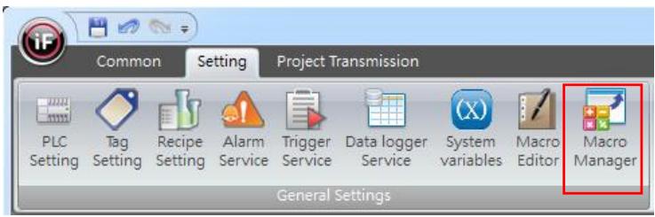
![Common Setting Project Transmission\nPLC Setting Tag Setting Recipe Setting Alarm Service Trigger Service Data logger Service System variables Macro Editor Macro Manager\nGeneral Settings](.iface-designer-user-manual-english/6fb12e93f261643cb8f7d064a441f51bc22f9ed6958dbfe21f79ae31999dcca2.jpg)

# 21.2.1 Macro Manager

![Macro Manager\nScreen Name	ID\nGlobal	N/A\nHome	1\nFX3U	3\nSystem information	6\nSystem Control	5\nAdd System Tag	7\nButton & Lamp	8\nIND & Lamp	9\nNumeric	10\nMeter	11\nAction Button	18\nList	12\nMessage	13\nStatic Picture	14\nGIF	15\nLine Chart	16\nXY Chart	17\nDatalog Table	20\nTrend	21\nAlarm Frequency Table	22\nCurrent Alarm Table	19\nAlarm History	23\nRecipe	24\nSecurity setting	25\nDisplay language	28\nTrigger	29\nMacro EXampie II	32\nMacro EXampie iii	33\nScreen	34\nOpen\nInitial\n#Backlight=20\n#Language_ID=0\n#Alarm2=100\n#Alarm4=100\nPreview: Initial	Edit\nLoop\nF\n100ms\nPreview:	Edit\nClose\nG\nPreview:	Edit\nOK	Cancel](.iface-designer-user-manual-english/6b12da53f4fc90df6821d454c13f44599c18134dae13c104dec1e0236dd94462.jpg)

D. Screen Name: display all the screens in the project.

【Global】: represents that the macro will run based on the set time condition no matter which screen it is on.
【Screen】: represents that the macro will only run based on the set time conditions when stayed on that screen.

Remark: Beside sub screens, every screen can set the condition for running macro.

E.【Open】: macro will only run once when the screen is opened. If 【Global】 is being set, then the macro will only run once when the project is being activated.
F.【Loop】: macro will run periodically when opening the screen based on the time

interval set below. If 【Global】 is being set, then macro will continue to run periodically after the project is being activated.

G. 【Close】: macro will only run once before closing the screen. If 【Global】 is being set, then macro will run once before the project is being closed.

# 21.2.2 Example of Macro Program-Default Parameter Setting

Based on the example exercises in previous chapter, such as the exercise for system control tags in chapter 3 and the exercise for alarm in chapter 13, they will create problems such as alarm messages or changing the backlight to dark when electricity was resent to HMI every time. You can ensure that start-up to be normal by using macro to initialize.

a. 【Tag Setting】: keep using the tags in the exercises of chapter 3 【System Control Tag】 and chapter 13 【Alarm Service】.
b. 【Macro Editor】: add a new macro. Set the macro name as 【Initial parameters】. The macro program is shown in the figure below:
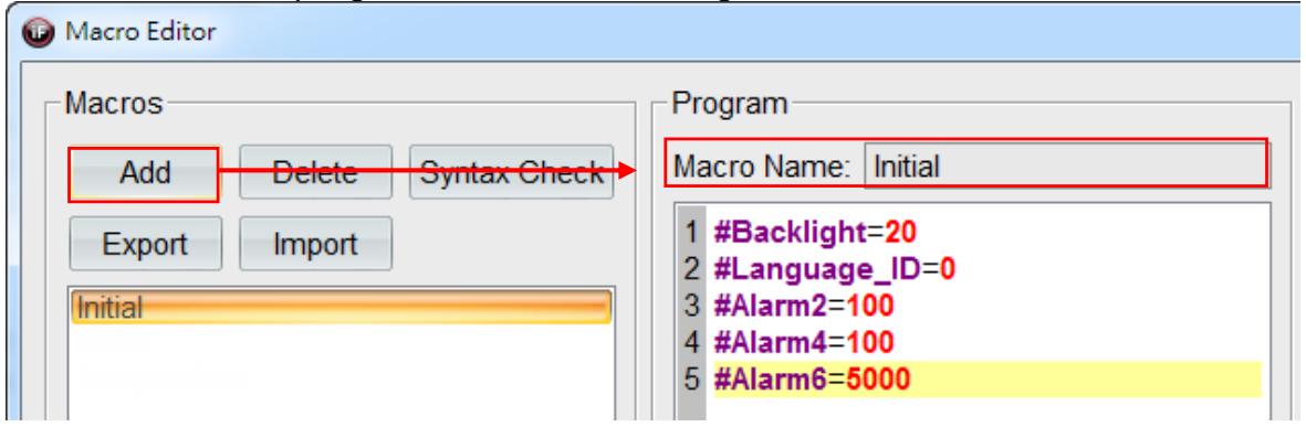
![Based on the provided image, here is the description of the annotated elements:\n\n**Labeled Blocks:**\n*   **Add** (A button in the 'Macros' section)\n*   **Macro Name: Initial** (A text field in the 'Program' section)\n\n**Connections:**\n*   A red arrow originates from the **'Add'** button and points directly to the **'Macro Name: Initial'** text field.](.iface-designer-user-manual-english/c7c3887117855622dd384c1a62b5fa48baf7fcc5b00a891673e3d9ca7d98c824.jpg)

c. 【Macro Manager】: set the screen name as【Global N/A】 and then select themacro name 【Initial parameters】 in 【Open】.
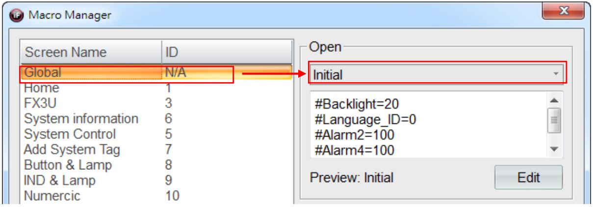
![Macro Manager\nScreen Name	ID\nGlobal	N/A\nHome	1\nFX3U	3\nSystem information	6\nSystem Control	5\nAdd System Tag	7\nButton & Lamp	8\nIND & Lamp	9\nNumeric	10\nOpen\nInitial\n#Backlight=20\n#Language_ID=0\n#Alarm2=100\n#Alarm4=100\nPreview: Initial	Edit](.iface-designer-user-manual-english/fc2006d007aaf296f46396d83adf466fb323b17f40894eb1128b5019fc6793e8.jpg)

# Simulation & Verification:

When macro is not being performed, the display language on the screen will be English when HMI runs the project every time after HMI is being powered on again. Since the trigger condition for the alarm is being satisfied, so it will create sub screens for the alarm.
![Connection COM1\nF\nList\nDatalog Table\nLanguage\nS\nTrend Chart\nTrigger\nButton and\nTable\nNumerical\nAction Button\nYX Chart\nSecurity Setting\n觸發 Alarm5!!\n觸發 Alarm7!!\n關閉\n2015/08/11 13:23](.iface-designer-user-manual-english/de46caa914f1369b658d87b3d11f90f6cbba0081cd080d9fd9c30b3557928d17.jpg)

After running the macro, , the display language on the screen will be 繁體中文 when HMI runs the project every time after HMI is being powered on again. Since the trigger condition for the alarm is not being satisfied, so it will not create sub screens for the alarm and the backlight will be displayed as the brightest.
![This image displays a grid of 19 light blue rectangular blocks arranged in a tool palette or menu interface. There are no visible lines or arrows connecting the blocks; they are arranged in a grid layout.\n\n**Labeled Blocks:**\n\n**Row 1:**\n*   Connection COM1 FX3U PLC\n*   List\n*   Datalog Table\n*   Language\n\n**Row 2:**\n*   System Tag\n*   Message Display\n*   Trend Chart\n*   Trigger\n\n**Row 3:**\n*   Button and indicator\n*   Static Picture\n*   Alarm Table\n*   Macro\n\n**Row 4:**\n*   Numerical\n*   Line Chart\n*   Recipe\n\n**Row 5:**\n*   Action Button\n*   YX Chart\n*   Security Setting\n\n**Connections:**\nThere are no visible connecting lines or flow arrows between any of the blocks. They appear as independent menu items.](.iface-designer-user-manual-english/da580c577710d85a5c9eb9f5495dd031a4165830bef793598f4f31ceb89599f7.jpg)

# 21.2.3 Example of Macro Program－Unit Conversion

Unit conversion has been commonly set as macro program. In this example, temperature in Celsius is converted to temperature in Fahrenheit.

a. In 【Tags】, add 2 tags with their names defined as 【Temperature in Celsius】 and 【Temperature in Fahrenheit】 and specify their corresponding addresses 【@70】 and 【@71】, respectively. Set type as INT (16).

<table><tr><td>Tags</td><td colspan="2">System Information Tags</td><td>System Control Tags</td><td colspan="2">Recipe Tags</td></tr><tr><td></td><td>Tag Name</td><td>Connector</td><td>Type</td><td>Address</td><td>Comment</td></tr><tr><td>57</td><td>Celsius</td><td>InternalMemory</td><td>INT(16)</td><td>@70</td><td></td></tr><tr><td>58</td><td>Fahrenheit</td><td>InternalMemory</td><td>INT(16)</td><td>@71</td><td></td></tr></table>

b. 【Macro Editor】: add a new macro Set the macro name as 【Convert Celsius to Fahrenheit】.

Original formula: Fahrenheit＝Celsius\*(9/5) + 32. If it was being calculated directly, then the obtained decimal will not be displayed. So, you must multiply the whole formula by 10 to calculate the temperature in Fahrenheit correctly.

The macro program is shown in the figure below:

![Macro Editor\nMacros\nAdd Delete Syntax Check\nExport Import\nInitial\nTemperature\nProgram\nMacro Name: Temperature\n1 #Fahrenheit=(#Celsius*10)*(90/50)+320](.iface-designer-user-manual-english/fbf43e026553d7adbc882d82cd7dfb65712d268f6608703b13ce393d4c842578.jpg)

c. 【Macro Manager】: set the screen name as 【Macro example 2】. Select the macroname 【Convert Celsius to Fahrenheit】 in 【Loop】 and set the time interval as1000ms.

![Macro Manager\nScreen Name	ID\nGlobal	N/A\nHome	1\nFX3U	3\nSystem information	6\nSystem Control	5\nAdd System Tag	7\nButton & Lamp	8\nIND & Lamp	9\nNumeric	10\nMeter	11\nAction Button	18\nList	12\nMessage	13\nStatic Picture	14\nGIF	15\nLine Chart	16\nXY Chart	17\nDatalog Table	20\nTrend	21\nAlarm Frequency Table	22\nCurrent Alarm Table	19\nAlarm History	23\nRecipe	24\nSecurity setting	25\nDisplay language	28\nTrigger	29\nOpen\nPreview: Edit\nLoop\nTemperature\n100ms\n#Fahrenheit=(#Celsius*10)*(90/50)+320\nPreview: Temperature Edit\nClose](.iface-designer-user-manual-english/e3ee1302ee9283a451db1b5cd7eef8db6e7ab0110409e91dc6c90ec33b9875e5.jpg)

d. Drag 2 【Numerical Widget】 from 【Widgets Library】 onto the screen. Connect them to the tags 【Temperature in Celsius】 and 【Temperature in Fahrenheit】. Remark: since we did first multiply 【Temperature in Celsius】 by 10, so we must set the decimal places as 1 to display the actual value of 【Temperature in Fahrenheit】correctly.

Simulation & Verification:

Temperature in Celsius 22 degrees = Temperature in Fahrenheit 71.6 degrees

![| Category | Value |\n|---|---|\n| temperature change | 22 |\n| Celsius | 71.6 |\n| Fahrenheit | 71.6 |\n| NEXT | 15:16 |\n2018/09/07](.iface-designer-user-manual-english/6c1a5ca0163a7bdb6ff735998e0fe678054cbf1e63db66a749c4bd90e125d76f.jpg)

# 21.2.4 Example of Macro Program-Conditional Determination

Design a button for triggering the conditions. When triggered, the value will start to add up. When the value has reached the value limit, then it will return to zero.

a. In 【Tags】, add 2 tags with their names defined as 【Motor trigger switch】 and 【Motor rotation speed】 and specify their corresponding addresses 【@72.0】 and 【@73】, respectively.

<table><tr><td colspan="2">Tags</td><td>System Information Tags</td><td>System Control Tags</td><td colspan="2">Recipe Tags</td></tr><tr><td></td><td>Tag Name</td><td>Connector</td><td>Type</td><td>Address</td><td>Comment</td></tr><tr><td>59</td><td>Motor_Key</td><td>InternalMemory</td><td>Bit</td><td>@72.0</td><td></td></tr><tr><td>60</td><td>Motor_running</td><td>InternalMemory</td><td>UINT(16)</td><td>@73</td><td></td></tr></table>

b. 【Macro Editor】: add a new macro. Set the macro name as 【Conditional determination】. The macro program is shown in the figure below:

![Macro Editor\nMacros\nAdd Delete Syntax Check\nExport Import\nInitial\nMotor\nTemperature\nProgram\nMacro Name: Motor\n1 if #Motor_Key ==1 then\n2 #Motor_running=#Motor_running+1\n3 if #Motor_running==100 then\n4 #Motor_running=0\n5 end\n6 end](.iface-designer-user-manual-english/828e4ccd5621f81cae6d6801ccee7602f30d8ca7e140e98e1308bd4143ad07d1.jpg)

【Micro Manager】: set the screen name as 【Macro example 3】. Select the macro name 【Conditional determination】 in 【Loop】 and set the time interval as 500ms.

![Macro Manager\nScreen Name	ID\nGlobal	N/A\nHome	1\nFX3U	3\nSystem information	6\nSystem Control	5\nAdd System Tag	7\nButton & Lamp	8\nIND & Lamp	9\nNumeric	10\nMeter	11\nAction Button	18\nList	12\nMessage	13\nStatic Picture	14\nGIF	15\nLine Chart	16\nXY Chart	17\nDatalog Table	20\nTrend	21\nAlarm Frequency Table	22\nCurrent Alarm Table	19\nAlarm History	23\nRecipe	24\nSecurity setting	25\nDisplay language	28\nTrigger	29\nMacro EXampie II	32\nMacro EXampie iii	33\nOpen\nPreview:	Edit\nLoop\nMotor\n50ms\nif #Motor_Key ==1 then\n#Motor_running=#Motor_running+1\nif #Motor_running==100 then\n#Motor_running=0\nPreview: Motor	Edit\nClose](.iface-designer-user-manual-english/2b699a53a87eb84dc291402dec4855dcce8fdf8bdf5dced95605db9cb88edb33.jpg)

c. Drag a 【Button】 widget and a 【Meter】 widget from 【Widgets Library】 on to thescreen. Connect them to the tags 【Motor trigger switch】 and 【Motor rotationspeed】, respectively.

Simulation & Verification:

When the button 【Motor trigger switch】 is being switched to ON state, the state value of the meter will add up from 0 to 100 in forward circulation.

![| Value |\n|-------|\n| 11    |](.iface-designer-user-manual-english/804434411f6ef2b1a14749c9255afb0f62d0eb069bbd29d32062253ffdd8aacd.jpg)

# 22. Periodic Interval

Periodic command is a brand-new communication method. It is different from the tradition polling communication method such that it adopts time as the basis for whether to make the communication or not. After each communication command is completed, the periodic command will check whether the current time has reached the set time interval and then make communication when time exceeds.

# 22.1 Periodic Interval

Select periodic interval as 【Global】 or 【Local】 in the item group 【Periodic Interval】under the tab 【Common】.

![Common\nSetting\nProject Transmission\nAction Button\nFormat\nBehavior\nCut\nCopy Paste\nAdd Screen\nScreen Name: macro Exampie iii\nScreen ID: 33\nStart-up Screen: HOME/Home\nColor Theme Background Screen\nQuick Style Background Border Frame Style\nLayer Alignment Group\nCommunication command setting\nGlobal G1 200 ms\nLocal G2 1000 ms\nClipBoard Screen Drawing Placement Periodic Interval](.iface-designer-user-manual-english/3b00647e5d837116b6360a57e9728c54a8db90d1b762b033dbcff18e375dc4d7.jpg)

Two sets of periodic command are provided for every screen. Users can set the periodic interval for each set of periodic command. Since the communication state of each screen is not the same in each project, we recommended you to take the baud rate for communication and the communication rate of the connected PLC or controller into account when setting the periodic interval.

For periodic interval 【Global G1】, the screens that have selected 【Global】 in periodic interval will be changed when the periodic interval 【Global】 is changed.

For periodic interval 【Local G2】, each screen can define its own periodic interval independently . Tick 【Local】 in periodic interval to match the needs of the screen. If you need to have a more accurate periodic interval for the state of the screen, select 【Local】 in periodic interval will be a good option for you.

![The diagram illustrates a flowchart based on a settings interface at the top.\n\n**Top Interface:**\nA dialog box with tabs labeled 'Common', 'Setting', and 'Project Transmis' (partially visible). Inside, under 'Communication command setting,' there is a 'Periodic Interval' section with two options:\n*   A selected radio button: 'Global G1 200 ms' (highlighted with a blue border).\n*   An unselected radio button: 'Local G2 1000 ms' (highlighted with a yellow border).\n\n**Blue Path (Global):**\n*   Blue arrows originate from the 'Global G1 200 ms' selection.\n*   One arrow points down to a blue-bordered block labeled **'G1 200ms'**.\n*   Another arrow points to the right and then down to a blue-bordered block labeled **'G1 200ms'**.\n*   From the left 'G1 200ms' block, a blue arrow points down to a block labeled **'Screen 1'**.\n*   From the right 'G1 200ms' block, a blue arrow points down to a block labeled **'Screen 4'**.\n\n**Yellow Path (Local):**\n*   A yellow arrow originates from the 'Local G2 1000 ms' selection and splits.\n*   The left branch points to a yellow-bordered block labeled **'G2 1000ms'**.\n*   The right branch points to a yellow-bordered block labeled **'G8 800ms'**.\n*   From the 'G2 1000ms' block, a yellow arrow points down to a block labeled **'Screen 2'**.\n*   From the 'G8 800ms' block, a yellow arrow points down to a block labeled **'Screen 3'**.](.iface-designer-user-manual-english/d128cebba6e2a7d2cee11682a9bf3c1550f70d03fb0388a1047cad5bb8fd279a.jpg)

# 22.2 Periodic Interval of a Widget

Set the periodic interval for reading based on the needs of a widget. Select 【Periodic Interval】 located at the bottom of the screen for the widget.

![Power consumption display\nRS phase 789 V ST phase 789 V TR phase 789 V\nR phase 789 A S phase 789 A T phase 789 A\nPOWER 78.9 KW\nPower consumption 456789 KWH\nAlarm Home\n2018/09/07 14:31\nCurrent Language English Periodic interval Normal Control Status 0 Zoom\nControl Status ( 0 ) Zoom](.iface-designer-user-manual-english/28cb01649a7738fecfc6e5f18e2f4a130c0e3afa72b1a074b28f8519d6f3aae5.jpg)

# 22.3 Communication Command Setting

We provide all kinds of services in iFace Designer to assist the users to complete the required function easily and rapidly. For example, the alarm service can provide alarm messages for handling incidental conditions; trigger service can handle specific work-based state value of tags; macro can help high-level users to design the more advanced and accurate actions in the project.

Most of these services requires reading the information of tag, so we provide

【Communication command setting】 for users to define the read action for these services more accurately.

Two sets of periodic interval (G1 and G2) can be set in the item group 【Periodic Interval】 under the tab 【Common】 first, then click on 【Communication command setting】 in the same item group for more advanced setting.

![Common\nSetting\nProject Transmission\nAction Button\nFormat\nBehavior\nCut\nCopy Paste\nAdd Screen\nScreen Name: macro EXampie iii\nScreen ID: 33\nStart-up Screen: HOME/Home\nColor Theme- Background Screen\nQuick Style - Background Border Frame Style - Layer Alignment Group - Communication command setting\nClipBoard Screen Drawing Placement Periodic Interval Global G1 200 ms Local G2 1000 ms](.iface-designer-user-manual-english/53a1726f923ed0f8d9c6c26e2cfdd5b390e54978a79fe89e00899d8d8f98ba5e.jpg)

# 22.3.1 Screen Tags Information

Browse through the periodic interval of global service tag information and screen tag information in every screen and make modifications to the periodic interval.

![Communication command setting dialog\nScreens\nName\nwait\npower on message\nMain Menu\n31\nPALLET CHG.\nTime Setting\nParameter Edit\nmachine memory\nI/O Page 1 30CH\nDGN. Page I/O CH\nDM IMG. Page DM10~24\nmulti job\nScreen52\nScreen102\nScreen116\nScreen124\nScreen132\nScreen144\nmon\nMenu Change (Main Menu)\nMenu Change (Manual)\nMenu Change (Multi job)\nMenu Change (Alarm)\nMenu Change (DGN.)\nMenu Change (Setting 2/2)\nHELP (Main Menu)\nHELP (Manual)\nHELP (Line Setting)\nHELP (Diagnose)\nHELP (Readiness)\nLink\nOmron C\nScreen Tags Information Block Command\nGlobal G1 200 ms Global G2 1000 ms Save Intervals\nGlobal Service Tag Information\nService Tag Name Address Periodic interval\n1 Cache S=NULL Normal\n2 Debu... S=NULL\n3 Syste... DM200 DM200 G1 (200ms)\nScreen Tag Information\nObject Name Reading Tag Address Periodic interval Active Tag\n7 kButton_84 HR3200 HR3200 Normal\n8 kButton_85 HR3201 HR3201 G1 (200ms)\n9 kButton_86 HR3202 HR3202 Normal\n10 kButton_87 HR3203 HR3203 G2 (1000ms)\n11 kButton_88 HR3204 HR3204 Normal\nOK Cancel\n【Global Service Tag Information】\nCheck the periodic of all screen alarms/data log/macro/trigger service, etc.\n【Screen Tag information】\nView the label and read periodic time interval of the selected page.](.iface-designer-user-manual-english/d9bafd79a1f41fe5d1c8ba97cea09e4e65d36ed69a1be3d6a56132e1e62acbe1.jpg)

# 22.3.2 Block Command

Browse the configuration of block command in every screen.

![Communication command setting dialog\nScreens\nName\nwait\npower on message\nMain Menu\n31\nPALLET CHG.\nTime Setting\nParameter Edit\nmachine memory\nI/O Page 1 30CH\nDGN. Page I/O CH\nDM IMG. Page DM10~24\nmulti job\nScreen52\nScreen102\nScreen116\nScreen124\nScreen132\nScreen144\nmon\nMenu Change (Main Menu)\nMenu Change (Manual)\nMenu Change (Multi job)\nMenu Change (Alarm)\nMenu Change (DGN.)\nMenu Change (Setting 2/2)\nHELP (Main Menu)\nHELP (Manual)\nHELP (Line Setting)\nHELP (Diagnose)\nHELP (Readiness)\nLink\nOmron C\nScreen Tags Information Block Command\nBlock commands\nPriority Block Command\nInterval Station ID Command Length Data size\n1 200ms DM200 1 2 W\n2 200s UP20 1 2 W\nNormal Block Command\nStation ID Command Length Data size Data type M\n1 AR15 1 2 Word Norm\n2 DM209 6 12 Word Norm\nByte Map\nB B B B B B B B B B B B B B B B B B B B B B B B B B B B B B B B B B B B B B B B B B B B B B B B B B B B B B B B B B B B B B B B B B B B B B B B B B B B B B B B B B B B B B B B B B B B B B B B B B B B B BB BB BB BB BB BB BB BB BB BB BB BB BB BB BB BB BB BB BB BB BB BB BB BB BB BB BB BB BB BB BB BB BB BB BB BB BB BB BB BB BB BB BB BB BB BB BB BB BB BB BB BB BB BB BB BB BB BB BB BB BB BB BB BB BB BB BB BB BB BB BB BB BB BB BB BB BB BB BB BB BB BB BB BB BB BB BB BB BB BB BB BB BB BB BB BB BB BB BB BB BA\nCommand Information\nAddress Type\nOK Cancel](.iface-designer-user-manual-english/3e46eaeb381ff11838ddd6395c285872734793f49f28212aae3aef7d7390c68f.jpg)

【Priority Block Command】 Widgets displayed in priority block command can enhance its speed by 【Periodic interval】.

【Normal Block Command】 The number of blocks composed by all the widgets on a screen can be seen here. If the discontinuity of the data is higher, then the number of blocks for the composition will increase, which will affect the communication rate.

# 23. Schedule Service

【Schedule Service】 is a tool for users to set actions in advance easily and conveniently. For example, turn off the power of devices that are not used for security during lunch break time every day and turn them back on during office hours automatically, etc.

Make good use of 【Schedule Service】 can greatly reduce these complicated and repeated actions run by PLC.

# 23.1 Schedule Service

To set schedule service, please click 【Schedule Service】 in the item group 【ApplicationSettings】 under the tab 【Setting】.

![Common Setting Project Transmission\nPLC Setting Tag Setting Recipe Setting Alarm Service Trigger Service Data logger Service System variables Macro Editor Macro Manager Schedule Service Security Setting Language Box Statusbar Setting Home Button Setting Outer Device Setting Project Properties FTP Setting Barcode Setting PDF Setting\nGeneral Settings Application Settings iFACE Designer 1.6.70](.iface-designer-user-manual-english/7b7f2deded5efba1d6c99308798698f148b56e9c8aef93f0dd3e9800697513cb.jpg)

The figure below shows the dialog for schedule service.

We must set all the possible schedule items one by one when editing the project. Once the project is running, you can only modify the date and time of the schedule type 【Dynamic】.

![Dialog\nSchedule Item\nAdd...\nDelete\nFilter\n□ Exact match\n● Key Word\nID Name Time Type Start Day Start Time Start Action End Day End Time End Action Enable by Bit Auto Run when Pow\nOK Cancel](.iface-designer-user-manual-english/c063d43b90641a63a5ef0658ce3305099db61f96d375bf10723a8a55070e5d00.jpg)

You can add or delete a 【Schedule Item】.

![Schedule Item\nA Add...\nB Delete](.iface-designer-user-manual-english/74dd362bdaa563d466d2990afbda12b40ab3a1213cdb4bbd74d75571463c5530.jpg)

A. 【Add】: you can add a schedule item. Currently, you can add up to 100 schedule items.
B. 【Delete】: you can delete all the selected schedule items.

After pressing 【Add】 in 【Schedule item】, it will invoke a 【Schedule Time Setting Dialog】, then we can start to design the required schedule items one by one.

![Schedule Time Setting Dialog\nSchedule Type ● Constant ○ Dynamic\nDate Type ● Weekly ○ Individually ○ Specified\n□ Use end time.\n□ Auto run when power on.\n□ Use Enable Bit HR3609\nTime Setting\nStart Time\n□ Sunday ✓ Monday □ Tuesday □ Wednesday\n□ Thursday □ Friday □ Saturday\n0 : 0 : 0\nEnd Time\n0 : 0 : 0\nOK Cancel](.iface-designer-user-manual-english/fd688e351bf00213ac0414c74ad9fbe4909c6cf9efc482c732a58ea0911cf6bc.jpg)

【Schedule Type】: set the schedule type, 【Constant】 or 【Dynamic】.

a. 【Constant】: set a constant time, such as a certain month or starting from a certain hour, minute, second to a certain hour, minute, second on certain days in a week, to perform the specified actions periodically.
b. 【Dynamic】: set a certain time setting at any time during the operation to perform the specified actions.

【Data Type】: set the date type for the schedule item, 【Weekly】, 【Individually】 or 【Specified】.

a. 【Weekly】: set a certain amount of time on certain days (may set number of days) each week to perform the specified actions.
b. 【Individually】: set a certain amount of time on a certain day (only one day) each week to perform the specified actions.
c. 【Specified】: set a certain amount of time on a certain day to perform the specified actions.

【Use end time】: if you tick this option, then you can enable 【End Time】 in time setting.

【Auto run when power on】: If that schedule time setting is being activated and kept running, then it will perform the specified actions automatically when being powered on again.

Remark: since trigger conditions for schedule items is the set 【Start time】, then it will perform the specified actions when reaching that moment (an upper differential pulse). Hence, the system will not perform the specified actions when power on if you did not tick that option.

【Use Enable Bit】: tick this option and set a tag, then the tag can be used as a specified indicator for triggering the schedule item. For example, if the state value of the tag is ON, then the schedule item will be triggered; if state value of the tag is OFF, then the schedule item will not be triggered. You can combine it with 【Alarm Service】 or 【Trigger Service】 in your project so that you can design with more flexibility.

# 23.2 【Constant/Weekly】

Time setting can be set as starting from a certain time to a certain time on certain days of a week to perform the specified actions. The period of the schedule is a week.

For example, after we add a schedule item, it will invoke 【Schedule Time Setting Dialog】.

Select 【Constant】 in 【Schedule Type】, select 【Weekly】 in 【Data Type】. We cantick the option 【Use end time】, 【Auto run when power on】 and 【Use Enable Bit】.

We must set the start time and end time in time setting.

Since we selected the schedule type/data type 【Constant/Weekly】, we can tick any certain days from 【Sunday】 to 【Saturday】 as in time setting. Then set the start time as a certain hour, minute, second using drop-down menu; if you have also ticked 【Use end time】, then you must set the end time as a certain hour, minute, second.

![Schedule Time Setting Dialog\nSchedule Type ● Constant ○ Dynamic\nDate Type ● Weekly ○ Individually ○ Specified\n✓ Use end time.\n✓ Auto run when power on.\n✓ Use Enable Bit Tag1\nTime Setting\nStart Time\n□ Sunday ✓ Monday ✓ Tuesday ✓ Wednesday\n✓ Thursday ✓ Friday ✓ Saturday\n8 : 30 : 0\nEnd Time\n17 : 30 : 0\nOK Cancel](.iface-designer-user-manual-english/f4d6ab6ab3f8b2f32ca0c61326ea11343a0e420eb106b8e36055e99ed65c1fb9.jpg)

After the setting is completed, press 【OK】, then it will add the set contents into the dialog for schedule service.

![Dialog\nSchedule Item\nAdd... Delete\nFilter\n□ Exact match\n● Key Word\nID Name Time Type Start Day Start Time Start Action End Day End Time End Action Enable by Bit Auto Run when Pc\n1 0 Schedule Constant Monday,Tue... 08:30:00 17:30:00 Tag1 Enable\nOK Cancel](.iface-designer-user-manual-english/b1139f3b26591d35d50f53725cdd8a54a416b06b46e2d355c03575995f7e8e7f.jpg)

Next, we can modify the 【Name】 of the schedule item and then click 【Start Action】 and【End Action】 to set the specified actions.

![Start Time	Start Action	End Day	End Time	End Action	Enable by Bit\n08:30:00			17:30:00			Tag1\nClick inside the red outline, then you can\nset the specified actions to be performed.](.iface-designer-user-manual-english/52d0f7ccd1f70b1543642597e6f38ade43e6df287040d06c18dbbcdbe4857193.jpg)

Please refer to chapter 6 【Action Button】 in this manual for how to set 【Action】

# 23.3 【Constant/Individually】

Time setting can be set as starting from a certain time in a certain 【Day】 in a week to a certain time in a certain 【Day】 in a week for the specified action to be performed. The period for the schedule item is a week.

For example, after we add a schedule item, it will invoke a 【Schedule Time Setting Dialog】.

Select 【Constant】 in 【Schedule Type】, select 【Individually】 in 【Data Type】. Wecan tick 【Use end time】, 【Auto run when power on】 and 【Use Enable Bit】.

We must set the start time and end time in time setting.

Since we selected the schedule type/data type of 【Constant/Individually】, we can set the start time as a certain hour, minute, second on a certain 【Day】 in week in the drop-down menu to perform the specified actions. If you have also ticked 【Use end time】, then you must set the end time as a certain hour, minute, second on a certain 【Day】 in a week to perform the specified actions for end time

![Schedule Time Setting Dialog\nSchedule Type  Constant  Dynamic\nDate Type  Weekly  Individually  Specified\n✓ Use end time.\n✓ Auto run when power on.\n✓ Use Enable Bit  Tag1\nTime Setting\nStart Time\nMonday\n10 : 0 : 0\nEnd Time\nMonday\n12 : 0 : 0\nAfter 0 day\nOK  Cancel](.iface-designer-user-manual-english/ead334a99021ffc11d835271986b996162987ddd62db8d09941e32be4250a9fe.jpg)

# 23.4 【Constant/Specified】

Time setting can be set as starting from start time to end time on a certain date during January to December to perform the specified actions. The period for the schedule item is a year.

For example, after we add a schedule item, it will invoke a 【Schedule Time Setting Dialog】.

Select 【Constant】 in 【Schedule Type】 and select 【Specified】 in 【Data Type】. Wecan tick 【Use end time】, 【Auto run when power on】 and 【Use Enable Bit】.

We must set the start time and end time in time setting.

Since we selected the schedule type/data type 【Constant/Specified】, we can set the start time as a certain hour, minute, second on a certain 【Day】 in a certain 【Month】 to perform the specified actions. If you have also ticked 【Use end time】, then you must set the end time as a certain hour, minute, second to perform the specified actions for end time.

It can be seen in the figure below.

![Schedule Time Setting Dialog\nSchedule Type  Constant  Dynamic\nDate Type  Weekly  Individually  Specified\n✓ Use end time.\n✓ Auto run when power on.\n✓ Use Enable Bit  Tag1\nTime Setting\nStart Time\nMonth: January  Date: 1\n10 : 0 : 0\nEnd Time\n12 : 0 : 0\nOK  Cancel](.iface-designer-user-manual-english/0f58ac90277c3d994c7fccb3cc2cbc72f1d7bc74a99006d298a09226c651c113.jpg)

After the setting is completed, press 【OK】 and then all the set contents will be added to the dialog for schedule service.

![Dialog\nSchedule Item\nAdd...\nDelete\nFilter\n□ Exact match\n□ Key Word\nID Name Time Type Start Day Start Time Start Action End Day End Time End Action Enable by Bit Auto Run when Power On\n1 0 Schedule Constant January 1st 10:00:00 12:00:00 Tag1 Enable\nOK Cancel](.iface-designer-user-manual-english/c298bee15fce5030126f979cebc2e63c403a6cc05f634af7304e5a0f97c35083.jpg)

# 23.5 【Dynamic/Weekly】

Dynamic means that it can be adjusted on PLC or HMI at any time. Time setting is specified in the state value of the tag. Each corresponding tag is specified with a start time (day, hour, minute, second) and an end time (day, hour, minute, second). Similarly, you must also specify the actions to be performed, respectively.

For example, after we add a schedule item, it will invoke a 【Schedule Time Setting Dialog】.

Select 【Dynamic】 in 【Schedule Type】, select 【Weekly】 in 【Data Type】. We cantick 【Use end time】, 【Auto run when power on】 and 【Use Enable Bit】.

We must set the start time and end time in time setting.

Since we selected the schedule type/data type 【Dynamic/Weekly】, we must input the appropriate tag based on the field.

d. 【Status】: display the state for the dynamic setting of the schedule item.

<table><tr><td>Dynamic setting_State</td><td>State Value</td></tr><tr><td>State value will display as 0</td><td>Schedule item is not being triggered.</td></tr><tr><td>State value will display as 1</td><td>Successfully read the dynamic address</td></tr><tr><td>State value will display as 2</td><td>Fail to read the dynamic address</td></tr><tr><td>State value will display as 3</td><td>Time or date read is invalid</td></tr></table>

e. 【Start Time (Day 1\~7)】: set the start time (day) of the schedule item. When the state value 1 of the corresponding tag represents Monday; the state value 7 represents Sunday.

f. 【Start Time (Hour)】: set the start time (hour) of the schedule item, which is within

the range 0-23.

g. 【Start Time (Minute)】: set the start time (minute) of the schedule item, which is within the range 0-59.
h. 【Start Time (Second)】: set the starting time (second) of the schedule item, which is within the range 0-59.
i. 【End Time (Hour)】: set the start time (hour) of the schedule item, which is within the range 0-23.
j. 【End Time (Minute)】: set the start time (minute) of the schedule item, which is within the range 0-59.
k. 【End Time (Second)】: set the start time (second) of the schedule item, which is within the range 0-59。

Remark: 【End time】 cannot be earlier than 【Start time】. If the setting is wrong, the state value will display as 【3】.

![Schedule Time Setting Dialog\nSchedule Type  Constant  Dynamic\nDate Type  Weekly  Individually  Specified\n✓ Use end time.\n✓ Auto run when power on.\n✓ Use Enable Bit  Tag1\nDynamic Setting\nStatus  Status\nStart Time(Day 1~7)  Start time_day\nStart Time(Hour)  Start time_Hour\nStart Time(Minute)  Start time_minutes\nStart Time(Second)  Start time_sec\nEnd Time(Hour)  End time_Hour\nEnd Time(Minute)  End time_minutes\nEnd Time(Second)  End time_sec\nOK  Cancel](.iface-designer-user-manual-english/34346da4363e4a873b0097b3e874922f4aba8994c4f66bc46f10b83f7eed544b.jpg)

After the setting is completed, press 【OK】 and then the set contents will be added to dialog for schedule service.

![Dialog\nSchedule Item\nAdd... Delete\nFilter\nExact match\nKey Word\nID Name Time Type Start Day Start Time Start Action End Day End Time End Action Enable by Bit Run when Powe\n1 0 Schedule Dynamic\nTag1 Enable\nOK Cancel](.iface-designer-user-manual-english/0747645935eb9bdfb5d63b22d8491bfa5f0a50be16b2580f5131ed14f63c31fc.jpg)

# 23.6 【Dynamic/Individually】

The settings for 【Dynamic/Individually】 is similar to 【Dynamic/Weekly】. Please refer to the previous section, we will not describe them here again.

# 23.7 【Dynamic/Specified】

You can specify a certain time to trigger schedule item by PLC or HMI. The time setting can be set as a certain day during January to December or set as a certain day in every month to perform the specified actions.

![Schedule Time Setting Dialog\nSchedule Type ○ Constant ○ Dynamic\nDate Type ○ Weekly ○ Individually ○ Specified\n✓ Use end time.\n✓ Auto run when power on.\n✓ Use Enable Bit Tag1\nDynamic Setting\nStatus Status\nStart Time(Month 1~12,\nAll 13) Start time_month\nStart Time(Day 1~31) Start time_day\nStart Time(Hour) Start time_Hour\nStart Time(Minute) Start time_minutes\nStart Time(Second) Start time_sec\nEnd Time(Hour) End time_Hour\nEnd Time(Minute) End time_minutes\nEnd Time(Second) End time_sec\nOK Cancel](.iface-designer-user-manual-english/0e29ef8000084f991f6ce2ba9cd281fa6d35a9a561d92b5c47e1d19d5627f189.jpg)

# 24. Project Transmission

Project transmission mainly contains all kinds of settings to be performed when downloading the project to HMI.

Before downloading the project every time, it is strongly recommended to save and compile first to ensure that the downloaded HMI project has the newest design.

# 24.1 Transfer Setting

Click 【Transfer Setting】 in the item group 【Download】 under the tab 【ProjectTransmission】.

![Common\nSetting\nProject Transmission\nTransfer Setting\nTransfer\nApplication\nRecipe\nCompile\nDownload\nUpload\nVerification\nOnline\nOffline\nPerformance\nSimulation](.iface-designer-user-manual-english/c8ee075dd6ec3b6f80a64c2041ac6af91e6c69ec6874abd05ff73de5cc01ec7d.jpg)

# 24.1.1 Download Function

![Download Setting\nDownload Setting\nDownload Function : Application\nTransfer Media : Removable Storage\nRemovable Storage Status\nAdvanced Settings OK Cancel Transfer ))](.iface-designer-user-manual-english/f90a628f71fa0c41add3199cb05e804d2e7241ea487781d7b627ec7b15057a39.jpg)

Download Function: the selected option will be downloaded and updated.

【Application】: only download the application This option is suitable for updating the settings or screens of projects on HMI.

【Firmware】: software version will correspond to firmware. This option is suitable for upgrading software version as well as updating the firmware.

After the firmware is downloaded, the HMI project must be downloaded again.

【Application w/ Firmware】: update both the application and the firmware. This option is suitable when old projects will be opened and compiled in new software version.

【QT Library】: only N series are required. Update internal QT version and turn on parts of the functions. For example, HMI display the screen with 90 degrees turn, VNC remote monitoring, etc.

# 24.1.2 Transfer Media – Removable Storage

【Removable Storage】 is the external storage device that PC connected to. For example, USB disk/SD card.

![Download Setting\nDownload Setting\nDownload Function : Application w/ Firmware\nTransfer Media : Removable Storage\nRemovable Storage Status\n(G:) 7664 MB\nAdvanced Settings OK Cancel Transfer ))](.iface-designer-user-manual-english/0ae0a314501881514321db7cae5d31ca86abecd30bc00b1a9139165dc93984a3.jpg)

a. Press 【Transfer >>】 to edit the project \*.KPC or convert and download the firmware \*.FMW based on selection in download function. Users can select the drive code of the storage and set the application name. (It is recommended to name the application in English, otherwise it will show garbled text)

![Transfer\nPress (Start) to proceed.\nDownload Application with Firmware\nTo Removable Storage\n0%\nSTART\nSelect Drive\nG: (7664MB)\nAPP Name DEMO\nOK Cancel](.iface-designer-user-manual-english/09a4534cb33a9e7810c5996aa838c9aa668e3e447fd812f7338987dd75b834f2.jpg)

b. Insert the USB disk that stored the transferred application to HMI USB Host port as shown in the figure below.

![Close-up of a blue plastic clip attached to a server rack with visible ports and labels (no readable text or symbols)](.iface-designer-user-manual-english/3d1447c3d9021a3db20b4602a24eb2d2f8f4b5a28c906b5e788fd862c296755d.jpg)

c. Switch to HMI System Menu and perform file transfer.

![Run Application\nSettings\nCOM Port\nEthernet\nFile Transfer\nBacklight\nDisplay\nCalibration\nRTC\nSystem Status\nMiscellaneous\nEnable USB Device Transfer](.iface-designer-user-manual-english/5a1dd06b0069e4ddac29379981f37009f4a0db14d940410d1155d6896cb76471.jpg)

![Cancel\nFile Transfer\nApplication\nFirmware\nFTP](.iface-designer-user-manual-english/a1ebc3dfffa68071636256dadaca816b465516515dc1a16e0e616d76bfea5177.jpg)

Select the firmware or application to be updated

Select the source directory of the updated data

(1) USB disk
(2) SD card
(3) FTP

![Cancel Select an application to copy to HMI OK ✓\nDEMO.kpc\nPrev 1 / 2 Next](.iface-designer-user-manual-english/1eebdc8f70b7c94eac25c645508609980d8c22ce1f741cd010b13f149d769703.jpg)

Select the application to be loaded to HMI on the screen. After completed, you can click the application and run it.

# 24.1.3 Transfer Media – Ethernet 1-1

a. Set the corresponding IP based on the IP of network HMI and transfer the updated application or firmware to it.

![Run Application\nSettings\nCOM Port\nEthernet\nFile Transfer\nBacklight\nDisplay\nCalibration\nRTC\nSystem Status\nMiscellaneous\nEnable USB Device Transfer\nCommunication\nDisable\nEnable\nIP Address\n192.168.0.133\nGateway\n192.168.0.1\nNetmask\n255.255.255.0\nPort\n800](.iface-designer-user-manual-english/bd16c9187902040ba678d0923eefb161ba4d11bd22e87f6d339a2120a357edce.jpg)

Click Ethernet on BIOS screen.

Communication: set as enabled to use the internet

Connect to the internet to upload or download the application, set the IP/gateway

b. Select Ethernet 1-1 in transfer media. Enter the IP address of HMI (In this example: 192.168.000.133) and press 【Add】. It can be seen in the following figure.

![Download Setting\nDownload Setting\nDownload Function : Application w/ Firmware\nTransfer Media : Ethernet 1-1\nEthernet Address\nIP Address : 192.168.000.133\nPort 60681 Custom port\nAdd Remove\nIP Port\n192.168.000.133 60681\nAdvanced Settings OK Cancel Transfer ))](.iface-designer-user-manual-english/88cf42ed45494e647abbeabd937cafe7c6d0f87d7432bea73a0cedefe6a98fa4.jpg)

c. Start the transfer: press 【Transfer >>】, it will start searching for the previously set IP address of HMI and connect to the internet.

![Query\nAdapters\nIP	Mask	Gateway	MAC	Type	Descri\n192.168.0.85	255.255.255.0	0.0.0.0	B8-70-F4-AF-A7-7F	Ethernet Broadc\nUse this adapter:	192.168.0.85 Use this port:	60680 Custom Port\nPre-configured HMI address\nIP	Port\n192.168.000.133 60681\nQuery Pre-configured HMIs\nSupported	IP	MAC	BIOS Version	FW Version\nYes	192.168.0.133 98-5d-ad-3...	0000.0001	0000.0680\nQuerying...\n✓ Auto start after query if HMI available	Start ))](.iface-designer-user-manual-english/b68cce8d9a986e382aa7506e16a34d22a87b1ad784c59c112a0e45d947f8ad5b.jpg)

d. After searching and detecting, it will start copying the firmware and the application to HMI.

![Transfer - Firmware(C:/NOVAKON/iFACE 1.6.70/firmware/Release1670.fmw)\nTask Queue\nRunning / Done List\nIP	MAC	Retry\nIP	MAC	Progress	Status\n192.168.0.133	98-5d-ad-3c-d4-ff	26%	Transfer\nClose](.iface-designer-user-manual-english/73d639d4a9f1d547e1c4772e5a9eb7e23035d7cfc2a1145f9bb7a9f00ff5be42.jpg)

Remark: after the firmware is being downloaded, you need to wait until HMI automatically restart to continue downloading the application.

# 24.1.4 Transfer Media – USB Device

a. Use the transmission cable for USB device to connect the USB port on personal computer to HMI USB device port.

![INTERTAINMENT/ORDER\nBASIL OF TYPICALS\nCOMS\n12345\nInternet\nUSB\nDevice](.iface-designer-user-manual-english/5990738556de4af30fc5ca4b77d07b953c5b8aa4e0f5da706a2d0348a0a50430.jpg)

b. Switch to HMI System Menu to perform file transfer.

![Click【Enable USB\nDevice Transfer】\nRun Application\nSettings\nCOM Port\nEthermet\nFile Transfer\nBacklight\nDisplay\nCalibration\nRTC\nSystem Status\nMiscellaneous\nEnable USB Device Transfer](.iface-designer-user-manual-english/3911b4db3ff4b5b3226b4b6c352c6dfa6424d09efeb597be48aca80c57897ac7.jpg)

HMI will stay on this screen.

At this time, you can operate your computer to get ready for downloading.

![Connect PC to HMI via a USB cable.\nReady for file transfer...\nDone and Reboot](.iface-designer-user-manual-english/47e33def52d4732b8a05de073c002f087bf0795f2ef252d52d764a8417f62a7d.jpg)

c. Please select 【USB Device】 in transfer media.

![Download Setting\nDownload Setting\nDownload Function : Application w/ Firmware\nTransfer Media : USB Device\nAdvanced Settings OK Cancel Transfer ))](.iface-designer-user-manual-english/20d5afd6d1cf573e853057c792eae17927fc4c7aed4cc51267ee2d86a220004f.jpg)

d. Start the transfer: download the firmware and the application to HMI through transmission cable for USB device. Wait until it is completed.

![Transfer\nPress (Start) to proceed.\nDownload Application with Firmware\nVia USB Device\n0%\nSTART\nTransfer\nPress (Start) to proceed.\nDownload Application with Firmware\nVia USB Device\nBegin packaging file\nPackaging file complete!\nBegin USBD transfer\nTransferring firmware\nwaiting for done\nTransferring project\nDone USBD transfer\n100%\nClose](.iface-designer-user-manual-english/8a3bfecee737d70b0f795146d59b0dd96f50d081cb254038a00ffd0b06fee6eb.jpg)

# 24.1.5 Transfer Media – Ethernet Probe

Know the number of HMIs connected to the current local network and then download the firmware and application to all HMI directly through Ethernet probe.

a. Select 【Ethernet Probe】 in transfer media.

![Download Setting\nDownload Setting\nDownload Function : Application w/ Firmware\nTransfer Media : Ethernet Probe\nAdvanced Settings OK Cancel Transfer )](.iface-designer-user-manual-english/05ce4e3b052e143a973580f82a7f4e44648a032c69519a9b665c882b15478422.jpg)

b. It can be seen in the figure below: the system will automatically search for IP address of the PC (In this example: 192.168.0.85). Then it will search for HMIs connected to the same local network (In this example: 192.168.0.XXX and it has found 1 of them).

![Two blue curved arrows pointing downward, no text or symbols present](.iface-designer-user-manual-english/7cf111d51ef2208165fbe52fe480c4df7f39d031d865140d1b46a31b742e61d7.jpg)

![Probing\nAdapters\nIP	Mask	Gateway	MAC	Type	Descn\n192.168.0.85	255.255.255.0	0.0.0.0	38-70-F4-AF-A7-7F	Ethernet Broad\nUse this adapter:	192.168.0.85 Use this port:	60680 Custom Port\nDynamic Probe HMIs\nSupported	IP	MAC	BIOS Version	FW Version\nYes	192.168.0.133	98-5d-ad-3...	0000.0001	0000.0680\nProbing...	/	/	/\n✓ Auto start after probe if HMI available	Start ))](.iface-designer-user-manual-english/3a1aa4ab60aa49c78c645c7f332c559d406cf52c168905132dba2fb9ffff96c1.jpg)

c. If tick the option 【Auto start after probe if HMI available】, then the system will automatically download the firmware and the application; if untick the option, it will not download automatically after the detection. But you can assign IP to download manually.

# 24.1.6 Transfer Media – Local Disk

You can save the firmware or application to the specified directory of local disk. The advantage of this option other than convenient management and use is that you can download to the disk and use directly and then sent the files to clients through Email or other methods.

a. Select 【Local Disk】 in transfer media.

![Download Setting\nDownload Setting\nDownload Function : Application w/ Firmware\nTransfer Media : Local Disk\n\nAdvanced Settings OK Cancel Transfer ))\n\nTransfer\n\nPress (Start) to proceed.\nDownload Application with Firmware\nTo Local Disk\n\n0%\n\nSTART](.iface-designer-user-manual-english/c9c00800171a36ab2e17c0ad10aff008ff81f4a17b373795010891b72ea6531e.jpg)

b. Specify the directory of the local disk and application name.

![Select File Save Location\n手冊貼圖英\n搜尋 手冊貼圖英\n組合管理\n新增資料夾\n我的最愛\nDropbox\n下載\n桌面\n最近的位置\n媒體櫃\n文件\n音機\n視訊\n審核\n1\n2\n3\n4\n5\n6\n7\n8\n9\n10\n檔案名稱(N): DEMO\n存檔類型(T): Application (*.kpc)\n隱藏資料夾\n存檔(S)\n取消](.iface-designer-user-manual-english/8668ebaf5c361cd8b311f8931b7ace959bd537969e6a838c43a3401b16358ded.jpg)

# 24.2 File Protection

File protection can provide users to protect their projects by password.

Every project supports two kinds of protection measures provided to users. By clicking the iF icon on the upper-left corner 【 】 , you can find the item 【File Protection】.

![Blue curved arrow pointing downward (no text or symbols)](.iface-designer-user-manual-english/3df91d069200ba701c1f49f870e1ac100dc59d46b5fe2f03caa14611f048e800.jpg)

![New Project... Ctrl+N\nOpen... Ctrl+O\nRecent Projects\nClose Ctrl+F4\nSave Ctrl+S\nSave(Compress)\nSave As...\nAbout Project\nFile Protection\nAdd Screen\nAdd Sub Screen\nDelete Screen\nPrint... Ctrl+P\nSave Image...\nQuit\nFile Protection Setting\nProject File Password\nUse Protection\nShow password\nmax. 24 characters (alpha-numeric characters)\ne.g. A5B2cde, XY234@#WqTxY45\nCompile File Password\nUse Protection\nShow password\nmax. 10 digits (only 0..9 for each digit)\ne.g. 12345, 0123456789\nLimit No. of retries\n3 Password retries are allowed.\nOK Cancel](.iface-designer-user-manual-english/747128fac9dfd82f67a950ea349459ea287ac505fa76d03e3c692276d86664d7.jpg)

# 24.2.1 Project File Password

Project file password setting is a protection mechanism that will invoke a dialog for input password when opening the project. After the file protection setting is saved, it will invoke a dialog for input password when the project is being opened once again.

![Project File Password\nA Use Protection C\nB Show password\nmax. 24 characters (alpha-numeric characters)\ne.g. A5B2cde, XY234@#WqTxY45](.iface-designer-user-manual-english/e224f008533f4b87b57e52436d0e050275e7c73e4d899f2100f2b979e495cb82.jpg)

A. 【Use Protection】: enable project file password protection. It will invoke a dialog for input password when opening the project next time. If the password is entered correctly, the project will be opened.

![Input Password\nOK Cancel](.iface-designer-user-manual-english/1c6c98cfaf3f76efd9ab24516f2bd2c95eeb9b7516d1266d353b074a3415b574.jpg)

B. 【Password】: Enter the password to be set. Password will have max. 24 characters, including uppercase and lowercase characters (uppercase and lowercase characters are considered as different character), numbers, special characters.
C. 【Show password】: show the entered password. If untick the option, then password will be shown as asterisk.

# 24.2.2 Compile File Password

Compile file password setting is a protection mechanism that will invoke a dialog for input password when uploading HMI application. After the compile file password setting is saved, it will invoke a dialog for input password when you wish to upload the application.

![Compile File Password\n✓ Use Protection\nShow password\nmax. 10 digits (only 0..9 for each digit)\ne.g. 12345, 0123456789\n✓ Limit No. of retries\n3 Password retries are allowed.](.iface-designer-user-manual-english/2988e37d5904eac96ec364a387972dc226c704fcab151f52718f1a5ede4187af.jpg)

D. 【Use Protection】: enable compile file password protection. It will invoke a dialog for input password when uploading the application through Ethernet or USB device. If the application will be uploaded to external devices through 【File Transfer】, then HMI will invoke a numerical panel for input password.

![1 2 3\n4 5 6\n7 8 9\n0 OK](.iface-designer-user-manual-english/53c47fd6c9a6e11afd45ad1b0822c5c5d5a3d9d74f58d30f9304379315d2c395.jpg)

If the password is entered correctly, then you can upload the application; if the password is wrong, then it is required to re-enter the correct password to upload the application.

E.【Password】: Enter the password to be set. Password has max. 10 digits.
F.【Show password】: show the entered password. If untick the option, then the password will be shown as asterisk.
G. 【Limit No. for retries】: set the allowed number of retries when the entered

password is wrong. If you cannot enter the correct password within the limit number, then it will cancel the upload until the upload program runs next time.

Remark: After the password is set, you need to save the project. For 【Compile File Password】, you must compile and download to HMI for it to take effect.

# 24.2.3 Compile – Restore Information

When the application is compiled for verification, the option 【Including restored

information】 will appear at bottom-left of the dialog. If untick the option, then it will not have an effect when uploading the application later.

![Common Setting Project Transmission\nTransfer Setting Transfer Application Recipe Compile Online Offline Performance\nDownload Upload Verification Simulation\nCompile\nPlease press Next to run validation process.\nProject was not saved. Please press Save to save all changes made.\nInclude restored information Save Next](.iface-designer-user-manual-english/2b417a25dc60772a8c63aa72a2dd87dda73a25a6e89fda3a2c890f79c5d35e40.jpg)

# 24.3 Upload Application

Application can be uploaded by using iFACE Designer or through external disk on HMI.

# 24.3.1 Upload Application by iFace Designer

Upload application invokes similar dialog as download. The application can be obtained from three kinds of sources. After uploading, it will perform restore action for users directly.

Click 【Application】 in the item group 【Upload】 under the tab 【Project Transmission】.

![Common\nSetting\nProject Transmission\nTransfer Setting\nTransfer Setting\nApplication\nRecipe\nCompile\nDownload\nUpload\nVerification\nOnline\nOffline\nPerformance\nSimulation](.iface-designer-user-manual-english/3b838ed41d238eed9e8f3f73ccbc2b39c3f188d59be8d6c1c376dbc8a27755fc.jpg)

# 24.3.2 Upload and Restore by Ethernet

When selecting Ethernet as the project source to transfer HMI application, it is required to enter the IP of HMI. After pressing 【Next】, it will ask you to specify the directory for the application and the application name. If you don’t want to enter, you can use the default directory and name.

![Upload\nSelect Media\nSpecify source media which contains your project.\nVia Ethernet\nIP: 192.168.000.133\nVia USB Device\nFrom Compiled Project\n( Back	Next )	Cancel\nUpload\nEPR Restore Location\nSpecify which file you wish to restore.\nD:/ethapp.kpr	Browse\n( Back	Next )	Cancel](.iface-designer-user-manual-english/529935a77816266521e867618fd7224843734538c8a272a4328c74c5a8ead645.jpg)

After pressing 【Next】, the system will start uploading. If 【Compile File Password】 in 【File Protection】 has been set for the application, it will invoke a dialog for input password when uploading the application. If not been set, then wait for the upload and restore to finish.

![【File Protection/Compile File Password】 has been set\n【File Protection/Compile File Password】 has not been set](.iface-designer-user-manual-english/385ddac204a00d21d01ae2ace50e924eab77c25373590ea87006d4befa32ba03.jpg)

After uploading is finished, you can find the restored application at the specified directory.

# 24.3.3 Upload and Restore by USB Device

When selecting USB device as project source to transfer HMI application, it is required to download the application through USB device based on method introduced previously. First, click the button 【Enable USB Device Transfer】 on HMI System Menu. Then wait until it stays on the waiting screen of 【Enable Transfer】.

After pressing 【Next】, it will ask you to specify the directory and application name. If you don’t want to enter, you can use the default directory and name.

![Upload\nSelect Media\nSpecify source media which contains your project.\nVia Ethernet\nVia USB Device\nFrom Compiled Project\n( Back	Next )	Cancel\nKPRs\nBrowse\nD:/demo/usbdapp.kpr	Browse\nPress 【Browse】 to assign the path and name to restore the project\n( Back	Next )	Cancel](.iface-designer-user-manual-english/a0c4af77a9b67b338c7e1538b7083582318671952b1a1b3a5592c76fceea4aea.jpg)

After pressing 【Next】, the system will start uploading. If 【Compile File Password】 in

【File Protection】 has been set for the application, it will invoke a dialog for input password when uploading the application. If not been set, then wait for the upload and restore to finish.

# 24.3.4 Restore from Application in Disk

When selecting compiled project as project source, the project source can come from 【Upload File Transfer】 or 【Local Disk】.

You can also upload the application by 【File Transfer】 and the method is described as follows:

![Run Application\nSettings\nCOM Port\nEthernet\nFile Transfer\nBacklight\nDisplay\nCalibration\nRTC\nSystem Status\nMiscellaneous\nEnable USB Device Transfer\nX Cancel\nFile Transfer\nApplication\nFirmware\nFTP](.iface-designer-user-manual-english/3112744a34b06902e78dfd349e6f335ee817e3d0a87bdaa76a7cce8890c278e4.jpg)

When using this method to transfer the application to an external device, it will save the application with the name application .kpc in root directory by default.

![Upload\nSelect Media\nSpecify source media which contains our project.\nVia Ethernet\nVia USB Device\nFrom Compiled Project\nFile: Browse\n( Back Next ) Cancel\nChoose source KPC\nabc 本機磁碟(D:) demo\n新增資料庫\n名稱 修改日期 類型 大小\ndemo 2018/9/10 下午 0... KPC File 797 KB\n檔案\n視訊\n圖片\n家用群組\n電腦\n本機磁碟(C:)\n本機磁碟(D:)\n網路\n檔案名稱(N): demo Compile Project (*.kpc)\n開啟審議(O) 取消](.iface-designer-user-manual-english/1887422209014d141eeb0d3bb23f31c5268724a50e6368efd291fa3d61392326.jpg)

After selecting 【From compiled project】 as project source, press 【Browse】 to specifythe directory and application name. After completed, press 【Open】.

Return to the dialog for project source selection and press 【Next】 and confirm the file to be restored and its directory. If you do not want to change, you can use the default directory and file name.

Similarly, after pressing 【Next】, the system will start the restore procedure. If 【Compile File Password】 in 【File Protection】 has been set for the application, it will invoke a dialog for input password when uploading the application. If not been set, then wait for the upload and restore to finish

# 25. Wi-Fi Application

Wi-Fi (Wi-Fi local network technology) is one of the earliest high-speed network technologies appeared. It is used not only in common electrical product for consumption, but also in applications of industry. IoT also shares data and information during production process through Wi-Fi network mobile communication.

# 25.1 Basic Setting

Before starting to use Wi-Fi, we need to insert the converter for Wi-Fi to HMI USB host port, then open HMI, go to HMI System Menu and press 【Miscellaneous】 to misc. Setting for Wi-Fi.

![Run Application\nSettings\nCOM Port\nEthermet\nFile Transfer\nBacklight\nDisplay\nCalibration\nRTC\nSystem Status\nMiscellaneous\nDownload Port\nEnable USB Device Transfer\nMisc Setting\nOK ✓\nBuzzer\nDisable\nEnable\nDebug Mode\nRun application\nBackup log\nWiFi Mode\nStation\nAp\nWiFi Setting\nStation\nAP](.iface-designer-user-manual-english/233e9448a45cf97f0b4fa7e21088e35741046d8fc0afb35b084411b5b82b8b2e.jpg)

# 25.2 WIFI Setting－Station

【Wi-Fi Mode】：you can select 【Station】 or 【AP】 mode. 【Station】 mode is the workstation mode. It can connect to AP itself but does not allow other Wi-Fi device to connect. 【AP】 mode allows other Wi-Fi device to connect for providing data communication.

# Remark:

(1) Activate Wi-Fi (Station & AP) function requires 40 seconds, please wait patiently.
(2) After shifting between Station or AP modes, system will request to save the setting and reboot HMI.

After entering the setting screen, it will invoke the dialog as in the following figure. The system will automatically search for the current Wi-Fi network name that are available to connect (SSID：Service Set Identifier).

![The image displays a software window for network configuration.\n\n**Top Menu:**\nFile Network Help\n\n**Left Panel:**\nCurrent WiFi\nNetwork:\n0: Default-WPA\nStatus:\nScanning\nIP address:\n\n**Right Panel:**\nSelect WiFi\n\n**List Headers:**\nSSID signal\n\n**List Content:**\nzettaplus_g 61 dBr\nhms_test 75 dBr\nfor-ibase-... 87 dBr\ndlink 83 dBr\nZyXFI61... 77 dBr\nNovakon1 55 dBr\nN56U 71 dBr\nIB_W 73 dBr\nGuest4F 65 dBr\nDIRECT-P... 73 dBr\nD-Link_DI... 75 dBr\n\n**Buttons:**\nScan Select\nApply Close Advanced...](.iface-designer-user-manual-english/913f991a52e13806a928a3e251b77c2b16d3d1804e490caac21c564331830645.jpg)

a. First, click on the SSID to be connected. We use 【Novakon1】 as example here.After clicking 【Novakon1】 on the screen, press 【Select】 to go to the detailsetting of 【Novakon1】.

If you cannot find the desired network name to connect, you can press 【Scan】 to search once again.

![Novakon1\nBasic Advanced WEP keys Optional\nSSID Novakon1\n********\nWPS Add Remove Cancel](.iface-designer-user-manual-english/0bb425cbefb2b852ace934366f12929afbdb1a3c64d82657c73ff93f28d4d47f.jpg)

b. Enter the password of Wi-Fi network in the field 【PSK】.

![Novakon1\nBasic Advanced WEP keys Optional\nAuthentication WPA2-Personal (PSK)\nEncryption TKIP\nEAP method MD5\nIdentity\nPassword\nCA certificate\nWPS Add Remove Cancel](.iface-designer-user-manual-english/ef403730ce99bdc4bbc2e093217d9f9c1df41c53663f755817d489f429dc9048.jpg)

c. The default encryption is 【TKIP】. If modification is required, you can go to 【Advanced】 to adjust advanced settings. After the setting is completed, press 【Add】 and save the set parameters in the system.

d. Press 【Cancel】 to exit this window.

![File Network Help\nCurrent WiFi\nNetwork:\n2: Novakon1\nStatus:\nCompleted (station)\nIP address:\nSending discover...\nSelect WiFi\nSSID ▼ signal\nzyxel 91 dBm\nzettaplus_g 69 dBm\nwinson 79 dBm\nZyXEL61... 79 dBm\nSCUS 75 dBm\nNovakon1 57 dBm\nN56U 77 dBm\nIR_W 75 dBm\nIB_W 73 dBm\nGuest4F 65 dBm\nDIRECT-X... 71 dBm\nD-Link_DI... 67 dBm\nScan Select\nFile Network Help\nCurrent WiFi\nNetwork:\n2: Novakon1\nStatus:\nCompleted (station)\nIP address:\n192.168.90.93\nSelect WiFi\nSSID ▼ signal\nzyxel 91 dBm\nzettaplus_g 69 dBm\nwinson 79 dBm\nZyXEL61... 79 dBm\nSCUS 75 dBm\nNovakon1 57 dBm\nN56U 77 dBm\nIR_W 75 dBm\nIB_W 73 dBm\nGuest4F 64 dBm\nDIRECT-X... 71 dBm\nD-Link_DI... 67 dBm\nScan Select\nApply Close Advanced...\nApply Close Advanced...](.iface-designer-user-manual-english/3c2693defc57b6fd3a715d7382b2be2d7f3cea0f6a71761cb3b655e29315f79b.jpg)

e. Start network connection: after connected, the current connected IP address will be shown on the screen.
f. Click 【Help】→【Change Mode】→【Advanced…】→【Current Status】 to seethe state of the current connection.

![File Network Help\nCurrent WiFi: Contents...\nNetwork: Index...\n0: Default-W About\nStatus: Change Mode ▶ Simple...\nScanning Advanced...\nFile Network Help\nAdapter: ra0\nNetwork: 2: Novakon1\nCurrent Status Manage Networks WPS IP\nStatus: Completed (station)\nLast message: - Connection to c8:be:19:58:1e:e0 comple\nAuthentication: WPA2-PSK\nEncryption: CCMP + TKIP\nSSID: Novakon1\nBSSID: c8:be:19:58:1e:e0\nConnect Disconnect Scan Get IP](.iface-designer-user-manual-english/b190f3dae8a7583ddfab8088f641b0943c0ec8e2328ff8a8ae4072be9f97d5aa.jpg)

![File Network Help\nAdapter: ra0\nNetwork: 2: Novakon1\nCurrent Status Manage Networks WPS IP\nIP address: 192.168.90.93\nGateway: 192.168.90.1 Set](.iface-designer-user-manual-english/e6a6a1c71479b6bdf85172f8c5b6d37b8480ca9eb7cf24636d42c34cfbdab629.jpg)

g. After pressing 【Get IP】, you can switch to the tab IP tab to view 【IP address】and 【Gateway】.

![Microsoft Windows (版本 6.1.7601)\nCopyright (c) 2009 Microsoft Corporation. All rights reserved.\nC:\Users\))ping 192.168.90.93\nPing 192.168.90.93 (使用 32 位元組的資料):\n回覆自 192.168.90.93: 位元組=32 時間=103ms TTL=64\n回覆自 192.168.90.93: 位元組=32 時間=11ms TTL=64\n回覆自 192.168.90.93: 位元組=32 時間=8ms TTL=64\n回覆自 192.168.90.93: 位元組=32 時間=3ms TTL=64\n192.168.90.93 的 Ping 統計資料:\n對包: 已傳送 = 4, 已收到 = 4, 已遺失 = 0 (0% 遺失),\n大約的來回時間 (毫秒):\n最小值 = 3ms, 最大值 = 103ms, 平均 = 31ms\nC:\Users\)](.iface-designer-user-manual-english/7551597e7f5c7744713671069f4be2b71252a81b284717b95a37964f9e60ea50.jpg)

h. Wi-Fi setting is done. When being powered on next time, it will use the set parameters to connect automatically. We can go to system manager to perform PING command and check whether it can make normal communication or download a simple application.

Remark: If you want to use Wi-Fi to download application, please untick the option 【Ethernet】 communication in HMI System Menu.

# 25.3 Wi-Fi Setting－AP

Other than 【Station】 mode,【AP】 mode is also being provided. 【AP】 mode allows other Wi-Fi devices to connect and provide data communication.

# Remark:

(1) Activate Wi-Fi (Station & AP) function requires 40 seconds, please wait patiently.
(2) After shifting between Station or AP modes, system will request to save the setting and reboot HMI.

![Configuration\nBasic Advanced Status\nSSID default123\nKEY 12345678\nGateway 192.168.10.1\nAP\nConnect Disconnect Save Close](.iface-designer-user-manual-english/c9f756b76996f94f92ed7574da045f3c215111aab316856b4a579011aa5873c2.jpg)

a. Go to HMI System Menu. Click 【AP】 mode in 【Wi-Fi Mode】 to go to AP setting screen. We can set SSID (network name) and KEY (network password) based on our custom. In this example, we will use the default value to test (SSID: 【default123】; KEY: 【12345678】).

![Configuration\nBasic Advanced Status\nStarting IP Address 192.168.10.20\nEnding IP Address 192.168.10.254\nDNS 8.8.8.8\nRouter 192.168.10.1\nSubnet 255.255.255.0\nLease time (Day) 10\nAuthMode WPAPSK\nEncrypType AES\nChannel 11\nAP\nConnect Disconnect Save Close](.iface-designer-user-manual-english/e4c1f57b6369add6e263610467817fef2f58e304ad97d2051070de74163b0076.jpg)

b. 【Advanced】 is the advanced setting of AP. If the users are not familiar with inner network setting, inappropriate modification can lead to unable to connect normally.

![Configuration\nBasic Advanced Status\nStatus\nUsing default ip for ra0\nConnect Disconnect Save Close\nConfiguration\nBasic Advanced Status\nStatus\nUsing default ip for ra0\nWiFi AP stop!\nWiFi AP starting...\nAP\nConnect Disconnect Save Close](.iface-designer-user-manual-english/8698d381dd59593bd9d2414acdfb84854302882de2f82774504e4b456a020ebd.jpg)

c. Press 【Connect】, then it will startthe connection; press 【Disconnect】 to stop the connection.

Remark: After the setting completes, please press 【Save】 and 【Close】. A popupwindow will be invoked, please press 【Ok】 then the system will reboot the HMI.

![目前連線到:\ndefault123\n網際網路存取\n無線網路連線\ndefault123 已經連線\nNovakon1\nwinson\nGuest4F\nN56U\nzettaplus_g\nD-Link_DIR-600M\nSCUS\n開歐網路和共用中心\n上午 11:21\n2018/8/15](.iface-designer-user-manual-english/b21b70547f8bfd47933b30f520c25424a72f1a92d68c7edb62cc4b1974d67546.jpg)

d. Detect the Wi-Fi network from computer. It detects 【default123】 and you can enter the password: 【12345678】to connect normally.

# 25.4 DHCP Setting

The system supports DHCP (obtain IP automatically) function. Its advantage is that it can avoid to accidentally set the same IP when setting IP causing connection problems to appear, which can reduce the trouble for network manager.

![| Category     | Value       |\n| ------------ | ----------- |\n| Communication | Disable    |\n| IP Address   | 192.168.088 |\n| Gateway      | 192.168.901 |\n| Netmask      | 255.255.255 |\n| Port         | 800         |\n| DHCP         | Disable     |\n| DHCP         | Enable      |](.iface-designer-user-manual-english/896df1075f54f6e08068033fd9f24f892a0080c1409ca00db2c2539e1a987db7.jpg)

a. To use DHCP, go to BIOS screen first. After pressing 【Ethernet】, go to Ethernet Setting. IP address will display the ex-factory default value and DHCP setting is 【Disable】.

![| Category       | Value     |\n| -------------- | --------- |\n| Communication  | Disable   |\n| IP Address     | 192.1680.88 |\n| Gateway        | 192.16890.1 |\n| Netmask        | 255.255255.0 |\n| Port           | 800       |\n| DHCP           | Disable   |\n| DHCP           | Enable    |](.iface-designer-user-manual-english/841654577005d58a26ec389744a0e25cc28abbacb48001a8bed9fe4368b79971.jpg)

b. Set 【DHCP】 as 【Enable】. Press 【OK】 after plugging in the internet cable.Return to HMI System Menu.

![Ethernet Setting\nCommunication Disable Enable\nIP Address\nGateway 192.168.90.1\nNetmask 255.255.255.0\nPort 800\nDHCP Disable Enable](.iface-designer-user-manual-english/6499bb5cda171721c112892140d8bbe6dd6387a8f3697ce85b7fa0c4a7f2df1d.jpg)

c. After pressing 【Ethernet】, it will go to Ethernet setting screen. Currently, IP address is blank.

![The image shows a digital interface titled 'Ethernet Setting' at the top center. In the top corners, it displays 'X Cancel' on the left and 'OK' with a checkmark on the right.\n\nThe main body lists the following settings and values:\n\n*   **Communication:** A toggle switch with 'Disable' on the left and 'Enable' (highlighted in orange) on the right.\n*   **IP Address:** Highlighted by a red rectangular border. The value is '192.168.90.91'.\n*   **Gateway:** The value is '192.168.90.1'.\n*   **Netmask:** The value is '255.255.255.0'.\n*   **Port:** The value is '800'.\n*   **DHCP:** A toggle switch with 'Disable' on the left and 'Enable' (highlighted in orange) on the right.](.iface-designer-user-manual-english/38c799c8f519ec0857e7de6d0773f79f7f8ce56b030a7e7604271e307a2badf4.jpg)

d. After pressing 【Cancel】 to exit, press 【Ethernet】 to go to Ethernet setting screen.At this time, it has obtained IP address automatically.

# 26. Rest API Application

Rest API means that information undergoes state transfer using a certain format (usually JSON format) on the network. HMI sends requests by JSON format through Rest API and receives the response from the cloud to satisfy the requirement of IoT application.

# 26.1 Rest API Setting

![Common Setting Project Transmission\nPLC Setting Tag Setting Recipe Setting Alarm Service Trigger Service Data logger Service System variables Macro Editor Macro Manager\nGeneral Settings Schedule Service Security Setting Language Box Statusbar Setting Home Button Setting Outer Device Setting Project Properties FTP Setting Barcode Setting PDF Setting\nApplication Settings](.iface-designer-user-manual-english/98a79007abf4fa5dfd5c421dd2c8fec776e04835c6ee2cfea599efa259bc4eca.jpg)

e. To activate Rest API setting, please click the tab 【Setting】→【Outer Device Setting】.

![Remote Device Setting\nCategory\nModBus Settings\nRest API Settings\nRest API Function\nAdd	Edit	Delete\nName Uril Number Method Data\nBackup Function\nBackup log stored for 30 days\nUse Tag to verify Input Tag\nBackup log path local\nOK Cancel](.iface-designer-user-manual-english/2d4a36bcc6841b5961edd008670ddc4c3907b1925ea3f73da89fe19af6cce9a5.jpg)

f. After selecting 【REST API Settings】, tick 【REST API Function】.

![REST API work\nWork Name RestWork1\nUrl Settings\nNumber of Urls 5\nUrl 1 Input Tag\nUrl 2 Input Tag\nUrl 3 Input Tag\nUrl 4 Input Tag\nUrl 5 Input Tag\nHTTP Method GET\nData Controls\nImport Tag list\nExport Tag list\nResend Time\nStart Input...\nEnd Input...\nOK Cancel](.iface-designer-user-manual-english/087c32691bf6e602ced19918d110d3db204fe75021579632d3bbbbf14e992156.jpg)

g. After pressing 【Add】, you will invoke a 【REST API Work】 dialog.

A. 【Work Name】: you can define the Work name. The default is set as 【RestWork1】.
B. 【URL Setting】: decide the quantity of used URL first, 5 at most. Then assign the tag used by URL1 - URL5 based on their used quantity. These tags are required to be strings. When performing actual operation, it will read the content of these tags as the target IP to send data.

Remark: 【http://】 or 【https://】 in front of the IP address cannot be omitted.

For example, we create 3 tags 【Tag1】 - 【Tag3】 first and specify the addresses

【@10】, 【@20】, 【@30】, respectively. Their types are all set as 【String】 with length 20. It is shown in the figure below.

<table><tr><td colspan="2">Tags</td><td>System Information Tags</td><td>System Control Tags</td><td colspan="2">Recipe Tags</td></tr><tr><td></td><td>Tag Name</td><td>Connector</td><td>Type</td><td>Address</td><td>Comment</td></tr><tr><td>1</td><td>Tag1</td><td>InternalMemory</td><td>Ascii</td><td>@10</td><td></td></tr><tr><td>2</td><td>Tag2</td><td>InternalMemory</td><td>Ascii</td><td>@20</td><td></td></tr><tr><td>3</td><td>Tag3</td><td>InternalMemory</td><td>Ascii</td><td>@30</td><td></td></tr></table>

Next, open 【REST API Work】 dialog to set URL quantity as 3 and specify the tags used by URL1 - URL3 as Tag1 - Tag3, respectively. It can be seen in the figure below.

![REST API work\nWork Name RestWork1\nUrl Settings\nNumber of Urls 3\nUrl 1 Tag1\nUrl 2 Tag2\nUrl 3 Tag3\nUrl 4 Input Tag\nUrl 5 Input Tag\nHTTP Method POST\nData Tags\nImport Tag list\nExport Tag list\nResend Time\nStart Input...\nEnd Input...\nOK Cancel](.iface-designer-user-manual-english/0ea81e048cc8aaa5b707d4952a0456f45e89788ce8269832871789b67618f143.jpg)

C. 【HTTP Method】: specify send data action for this job. It can be set as 【GET】, 【POST】, 【PUT】.

When 【HTTP Method】 is selected as 【POST】 or 【PUT】, 【Sending data】 can beset as the function 【Tags】 and 【Resend】.

i. 【Tags】: Pack the specific tag and its state value as JSON string and send, then read the reply contents. Next, it will analyze the reply contents and write the values contained into the tag. In addition, if it has turned on backup function, then the data send every time will produce log automatically to perform backup.

ii. 【Resend】： read the backup log as described above and pack the assigned time log as JSON array and send. It will not perform analysis or apply action to the replied contents.

D. 【Export Tag List】：Export the tag list of that job. If the tag list has not been set previously, then it will export the default text file.

For example, after pressing 【Export Tag List】, the file dialog will be invoked. After specifying the desired directory, enter the file name (for example: workTag1.TXT) and press save to complete the export action.

You can use notebook or excel to open the files. After opening, it will list the fields, Tag ID, Tag Name and Send.

【Tag ID】: id number of the tag. Please do not change this column.

【Tag Name】: tag name. please do not change this column.

【Send】: whether this tag is sent. If true, then it will make the delivery; if false, then it

will not make the delivery.

![workTag1.txt - 記事本\n檔案(F) 編輯(E) 格式(O) 檢視(V) 說明(H)\nTagID TagName Send\n1 Tag1 false\n2 Tag2 false\n3 Tag3 false](.iface-designer-user-manual-english/24a780a9111a08f04b1bdbcd61c453a7593516799e355a2a7f00919ef16d150c.jpg)

E.【Import Tag List】: import text files for the tag list of that job.

For example, change the 【Send】 content of 【Tag2】 in the text file we just exported from【false】 to 【true】 as in the figure below.

![workTag1.txt - 記事本\n檔案(F) 編輯(E) 格式(O) 檢視(\nTagID TagName Send\n1 Tag1 false\n2 Tag2 true\n3 Tag3 false](.iface-designer-user-manual-english/9dedb0d5f78368d3f39d4103cc7d7d927e0df6bfa5b3a8f7bc6cbb293be2637a.jpg)

When pressing 【Import Tag List】, the original file name is opened in file dialog. At this time, the system will make a hint saying that it will cover the previous tag list setting. Select 【OK】 to complete the importing action.

![Import Tag List\nAll the tags in the tag list will be overwritten.\nDo you want to proceed?\nOK Cancel](.iface-designer-user-manual-english/783573f27a1c1aa5d5d961f5823921a002b7f30d4e67f01290860d019cfee627.jpg)

h. After the setting is completed, press 【OK】, then it will exit the job setting dialog.

![Remote Device Setting\nCategory\nModBus Settings\nRest API Settings\nRest API Function\nAdd Edit Delete\nName Url Number Method Data\n1 RestWork1 3 POST Tags\nBackup Function\n● Backup log stored for 30 days\n○ Use Tag to verify Input Tag\nBackup log path local\nOK Cancel](.iface-designer-user-manual-english/146f5d013a041d71d836aedc38b53951911bbf722ff937a613f250fca15090b1.jpg)

i. 【Backup Function】 can set up data backup time. The default is 30 days; you can also use the tag to assign the number of days for backup. 【Backup log path】 can be set as 【Local end】, 【USB】, 【SD Card】 based on the requirement.
j. After the setting is completed, please press 【OK】.

According to the setting in our example, when performing this work later, it will send Tag2 and its state value.

# 26.2 Actions Related to REST API

Manage the actions related to REST API, including 【Call REST API】 or 【Website Connection Status Check】.

26.2.1 Call REST API
![Action List\nAction Group\nAlarm Table Control\nFtp Service\nCode Editor Control\nSystem Service\nTable Control\nAlarm History Table Control\nAlarm Service\nRecipe Service\nTrend Chart Control\nSecurity Service\nCommunication Service\nPLC Service\nActions\nBack to BIOS\nCall Screen Saver\nCall REST API\nChange Project\nChange Screen\nClose current sub-screen\nClose sub-screen\nRun External Process\nRun External Process with link suspended\nShow File System Dialog\nPrint Screen\nPrint Screen via LPD server\nNext Screen\nPrevious Screen\nRun Macro\nSet IP,Netmask,Gateway\nSet Wifi\nHelp\ncall REST API\nOK	Cancel\nAction Parameters\n↑ Call REST API\n↓\nMax. 3 actions\nHelp\nSelect a REST API work to take action.\nAdd Action	Delete Actions	OK	Cancel\nParameter	Setting\n1 REST API Works	RestWork1](.iface-designer-user-manual-english/53bf08cd4d3a3f93f050eb8d81d4ee2024abb924046fa0c58cc283d79678db27.jpg)

You can use any widget or service in previous chapter to call action and open 【Call REST API】 to assign job to be performed based on the requirement of actual case.

# 26.2.2 Website Connection Status Check

![Action List\nAction Group\nAlarm Table Control\nFtp Service\nCode Editor Control\nSystem Service\nTable Control\nAlarm History Table Control\nAlarm Service\nRecipe Service\nTrend Chart Control\nSecurity Service\nCommunication Service\nPLC Service\nActions\nRun Macro\nSet IP,Netmask,Gateway\nSet Wifi\nSet Backlight\nSet Language\nShutdown panel PC\nToggle Buzzer\nLink Suspend\nWebsite Connection Status Check\nSet Buzzer\nSet Date & Time\nSet Day\nRun Application at Full Screen\nSet Hour\nSet Minute\nSet Month\nSet Second\nHelp\nwebsite connection test\nOK	Cancel\nAction Management\nActions\nWebsite Connection Status Check\nMax. 3 actions\nAction Parameters\nParameter	Setting\n1 Google Tag Xi Input Tag\n2 Yahoo Tag Xi Input Tag\n3 Baidu Tag Xi Input Tag\n4 Custom URL Tag Xi Input Tag\n5 Custom Tag Xi Input Tag\nHelp\nSet a tag that shows the connection status with Google.\nAdd Action	Delete Actions	OK	Cancel](.iface-designer-user-manual-english/4cafaca16237366c0a5b0fae8e8319bd0d15b961c72cc2104ae58e3a273ce833.jpg)

When opening REST API, you can perform the action 【Website Connection Status Check】 to make sure that the network has normal communication. Set the tags used in every item. If the connection is successful, then that tag will return 0; if not successful, then that tag will return 1.

a. 【Google Tag】: use bit tag to return the results of connecting google to the assigned tag.
b. 【Yahoo Tag】: use bit tag to return the results of connecting yahoo to the assigned tag.
c. 【Baidu Tag】: use bit tag to return the results of connecting baidu to the assigned tag.
d. 【Custom URL Tag】: use string tag to specify self-defined URL.
e. 【Custom Tag】: use bit tag to return the results of connecting self-defined URL to the specified tag.
[🔗 Link to the original document](.iface-designer-user-manual-english/iface-designer-user-manual-english.pdf)