# IM/OM Series Industrial/Open-Frame Monitor User’s Manual

![Blank rectangular frame with gradient gray background, no text or symbols visible](.im-om-series-50m-p6000-1050-15/70840c66d97f035f7995558f517bd11ef52c67f88c5aef0756ddf7521cbd51be.jpg)

Manual Rev.: 1.5

Revision Date: June 4, 2025

Part Number: 50M-P6000-1050

Revision History

<table><tr><td>Revision</td><td>Description</td><td>Date</td></tr><tr><td>1.0</td><td>Initial release</td><td>2022-09-29</td></tr><tr><td>1.1</td><td>Add information for larger models</td><td>2023-03-28</td></tr><tr><td>1.2</td><td>Add Fullscreen and High-Brightness models</td><td>2023-11-24</td></tr><tr><td>1.3</td><td>Update specs</td><td>2024-03-14</td></tr><tr><td>1.4</td><td>Added weight and dimensions for additional models</td><td>2024-10-22</td></tr><tr><td>1.5</td><td>Specifications and on-screen display (OSD) Updated</td><td>2025-06-04</td></tr></table>

# Preface

# Copyright

Copyright © 2025 ADLINK Technology, Inc. This document contains proprietary information protected by copyright. All rights are reserved. No part of this manual may be reproduced by any mechanical, electronic, or other means in any form without prior written permission of the manufacturer.

# Disclaimer

The information in this document is subject to change without prior notice in order to improve reliability, design, and function and does not represent a commitment on the part of the manufacturer. In no event will the manufacturer be liable for direct, indirect, special, incidental, or consequential damages arising out of the use or inability to use the product or documentation, even if advised of the possibility of such damages.

# Environmental Responsibility

ADLINK is committed to fulfill its social responsibility to global environmental preservation through compliance with the European Union's Restriction of Hazardous Substances (RoHS) directive and Waste Electrical and Electronic Equipment (WEEE) directive. Environmental protection is a top priority for ADLINK. We have enforced measures to ensure that our products, manufacturing processes, components, and raw materials have as little impact on the environment as possible. When products are at their end of life, our customers are encouraged to dispose of them in accordance with the product disposal and/or recovery programs prescribed by their nation or company.

![Symbol of a trash bin crossed with a diagonal line and a horizontal bar below (no text or labels)](.im-om-series-50m-p6000-1050-15/2ebbb27143f211bc48bc9e40e01c30a626e28226d4ea299a92301b63c0cf2db5.jpg)

# California Proposition 65 Warning

![The image displays a standard warning symbol consisting of a yellow equilateral triangle with a thick black border. Inside the yellow field is a centered, black exclamation point.](.im-om-series-50m-p6000-1050-15/bcf125a0ea9fbef7a153b69c060b8503ee954355405d1c53711f8f0da17805ec.jpg)

WARNING: This product can expose you to chemicals including acrylamide, arsenic, benzene, cadmium, Tris(1,3-dichloro-2-propyl)phosphate (TDCPP), 1,4-Dioxane, formaldehyde, lead, DEHP, styrene, DINP, BBP, PVC, and vinyl materials, which are known to the State of California to cause cancer, and acrylamide, benzene, cadmium, lead, mercury, phthalates, toluene, DEHP, DIDP, DnHP,

DBP, BBP, PVC, and vinyl materials, which are known to the State of California to cause birth defects or other reproductive harm. For more information go to www.P65Warnings.ca.gov.

# Trademarks

Product names mentioned herein are used for identification purposes only and may be trademarks and/or registered trademarks of their respective companies.

# Conventions

Take note of the following conventions used throughout this manual to make sure that users perform certain tasks and instructions properly.

![The image displays a white document icon with a folded top-right corner. Faint horizontal gray lines appear near the bottom, and a large red checkmark is centered on the page, indicating approval or completion.](.im-om-series-50m-p6000-1050-15/8a2d017c2a49cfd865e8957637f4d6a210df46cd1cd1ba2b26924d4eb4aef9f8.jpg)
NOTE:

Additional information, aids, and tips that help users perform tasks.

![The image displays a standard warning symbol: a yellow triangle with a thick black border containing a large, black exclamation point in the center.](.im-om-series-50m-p6000-1050-15/28f0ef81ea8f5e90da39e5685e93a97c49208bced0ce785dec4318bf12233325.jpg)
CAUTION:

Information to prevent minor physical injury, component damage, data loss, and/or program corruption when trying to complete a task.

![The image displays a standard warning symbol: a red triangle with a thin white border. Inside the triangle is a large, white exclamation point centered vertically and horizontally.](.im-om-series-50m-p6000-1050-15/20f5eb68d9ffe24272b6a1b4d0124b54a6de64e72ce8c57a8a90563c6832fc36.jpg)
WARNING:

Information to prevent serious physical injury, component damage, data loss, and/or program corruption when trying to complete a specific task.

# Table of Contents

Revision History................

Preface ....

Table of Contents..............

List of Figures ....

List of Tables .......

1. Introduction....

1.1. Features.. .8

1.2. Applications.. .8

1.3. Package Contents.. .9

1.4. Optional Accessories . .9

2. Specifications ................ ..10

2.1. IM Series .. .. 10

2.2. OM Series (Fullscreen Models).. ..13

2.3. OM Series (Widescreen Models) . ..14

3. Mechanical Layout ......... ..18

3.1. I/O Connectors. ..18

3.2. Mechanical Dimensions . ..22

3.3. Mounting ..

4. On-screen Display (OSD) ............ ..41

4.1. OSD Buttons . ..41

4.2. OSD Menus.. .. 43

5. Troubleshooting .............. .53

Safety Instructions... .54

Getting Service............... .55

# List of Figures

Figure 1: IM-215-270/OM-070-270 I/O Connectors .. ...18

Figure 2: OM-320-430 I/O Connectors. ...18

Figure 3: IM-150 Mechanical Dimensions.. ..22

Figure 4: IM-170 Mechanical Dimensions.. ..22

Figure 5: IM-190 Mechanical Dimensions.. ..23

Figure 6: IM-215 Mechanical Dimensions.. ..23

Figure 7: IM-238 Mechanical Dimensions.. ...24

Figure 8: IM-270 Mechanical Dimensions.. ...24

Figure 9: OM-070 Mechanical Dimensions . ..25

Figure 10: OM-121 Mechanical Dimensions . ..25

Figure 11: OM-150 Mechanical Dimensions .. ..26

Figure 12: OM-170 Mechanical Dimensions . ...26

Figure 13: OM-190 Mechanical Dimensions .. ..27

Figure 14: OM-101 Mechanical Dimensions .. ..27

Figure 15: OM-156 Mechanical Dimensions .. ..28

Figure 16: OM-185 Mechanical Dimensions .. ..28

Figure 17: OM-215 Mechanical Dimensions .. ..29

Figure 18: OM-238 Mechanical Dimensions .. ..29

Figure 19: OM-270 Mechanical Dimensions .. ...30

Figure 20: OM-320 Mechanical Dimensions . ...30

Figure 21: OM-430 Mechanical Dimensions . ...31

Figure 22: Attaching a VESA Mounting Bracket for IM-215-270/OM-101-270 . ..32

Figure 23: VESA Mounting for OM-320.. ..33

Figure 24: VESA Mounting for OM-430.. ..33

Figure 25: OM-070 Cut Out Dimensions . ..34

Figure 26: OM-121 Cut Out Dimensions. ...35

Figure 27: OM-150 Cut Out Dimensions. ...35

Figure 28: OM-170 Cut Out Dimensions . ..35

Figure 29: OM-190 Cut Out Dimensions. ...36

Figure 30: OM-101 Cut Out Dimensions. ...36

Figure 31: OM-156 Cut Out Dimensions. ...36

Figure 32: OM-185 Cut Out Dimensions. ...37

Figure 33: OM-215/OM-215H Cut Out Dimensions . ..37

Figure 34: OM-238 Cut Out Dimensions. ..37

Figure 35: OM-270 Cut Out Dimensions. ..38

Figure 36: Insert Monitor into Cut Out . ..38

Figure 37: Secure Monitor with Mounting Clips .. ..39

Figure 38: Panel Mount for OM-320.. ...39

Figure 39: Panel Mount for OM-430.. ...40

Figure 40: IM/OM Rear Panel OSD Buttons .. ...41

Figure 41: OM-320-430 Rear Panel OSD Buttons.. ...42

# List of Tables

Table 1: IM-150-190 Specifications. ..10

Table 2: IM-215-270 Specifications.. ...10

Table 3: IM Series Specifications (Value-Added Models).. ..12

Table 4: OM-070-190 Series Specifications.. ..13

Table 5: OM-101-270 Series Specifications.. ..14

Table 6: OM-215H (High-Brightness) Series Specifications . ...15

Table 7: OM-320-430 Series Specifications.. ...16

Table 8: OM-320SHV Specifications . ..17

Table 9 IM-215-270/IM-215H/OM-070-270/OM-215H OSD Button Functions . ...41

Table 10: OM-320-430 OSD Button Functions . ..42

Table 11: OSD Menu Overview for OM-070/121/150/170/190/215H . ...43

Table 12: OSD Menu Overview for OM-101/156/185/215/238/270 and IM-215/238/270. ...48

Table 13: OSD Menu Overview for OM-320-430 . ..52

# 1. Introduction

The IM/OM series is ADLINK’s new industrial true-flat and open-frame touch monitor designed for quick and easy integration with a variety of applications, such as public signage, self-service kiosks, medical displays, and point-ofsale terminals.

# 1.1. Features

# IM Series

• 15"/17"/19" 4:3 LCD panel with LED backlight with up to 40,000 service life hours
• 21.5"/23.8"/27.0" 16:9 LCD panel with LED backlight with up to 40,000 service life hours
10-point PCAP touchscreen
• Anti-fingerprint surface treatment for ease of cleaning and enhanced readability
Wide viewing angle support for both portrait and landscape modes
• IP rating for water and dust protection
Up to $\mathsf { - } 2 0 \textdegree$ to $7 0 ^ { \circ } \mathsf { C }$ operating temperature range
• All new true-flat design with edge-to-edge front glass
• VESA Mount Holes: MIS-D 75mm x 75mm, 100mm x 100mm (Standard)

# OM Series

• 7"/12.1"/15"/17"/19" 5:3/4:3/5:4 LCD panel with LED backlight and up to 50,000 service life hours
10.1”/15.6”/21.5”/23.8"/27"/32”/43” 16:10/16:9 LCD panel with LED backlight and up to 50,000 service life hours
10-point PCAP touchscreen
• Anti-fingerprint surface treatment for ease of cleaning and enhanced readability
Wide viewing angle support for both portrait and landscape modes
• IP rating for water and dust protection
Up to -20°C to $7 0 ^ { \circ } \mathsf { C }$ operating temperature (see Table 4: OM-070-190 Series Specifications and Table 5: OM-101-270 Series Specifications)
VESA Mount Holes: MIS-D 75mm x 75mm, 100mm x 100mm (Standard, IM-215-121/OM-101-270). 200mm x 200mm (OM-320-430)
• Easy deployment with support for wall, panel, and VESA mounting

# 1.2. Applications

KIOSK / POI / Ticketing / ATM
Transportation
Public communication
Entertainment / Gaming / Slot machine
Human-Machine Interface equipment controller monitor

# 1.3. Package Contents

Please check that your package contains the items below. If you discover damaged or missing items, please contact your vendor.

IM-150/170/190/215/215H/238/270 and OM-101/121/150/156/185/170/190/215/215D/215H/215D/238/270:

• 1x DC power cable clamp
• 1x Screw M3 (for use with DC power cable clamp)

OM-320-430:

1x Power Cable
• 1x 24V 120W Power Adapter
1x USB cable
1x HDMI cable
1x Line Buckle w/M4 screw

# 1.4. Optional Accessories

12V 60W power adapter
• Panel mounting kit (OM Series only)

# 2. Specifications

# 2.1. IM Series

Table 1: IM-150-190 Specifications

<table><tr><td>Model</td><td>IM-150</td><td>IM-170</td><td>IM-190</td></tr><tr><td colspan="4">Display</td></tr><tr><td>Size</td><td>15"</td><td>17"</td><td>19"</td></tr><tr><td>Resolution</td><td>1024x768 (XGA)</td><td colspan="2">1280 x 1024</td></tr><tr><td>Aspect Ratio</td><td>4:3</td><td colspan="2">5:4</td></tr><tr><td>Color</td><td colspan="3">16.7M</td></tr><tr><td>Brightness (Nits w/touch)</td><td>400</td><td>300</td><td>300</td></tr><tr><td>Backlight Life (Hours)</td><td colspan="3">50,000</td></tr><tr><td>View Angle (U/D/R/L)</td><td>70/80/80/80</td><td colspan="2">80/80/85/85</td></tr><tr><td>Contrast Ratio</td><td>800:1</td><td colspan="2">1000:1</td></tr><tr><td>Touchscreen</td><td colspan="3">10-point, PCAP, Anti-fingerprint coating</td></tr><tr><td>Bonding</td><td colspan="3">Air bonding</td></tr><tr><td colspan="4">I/O</td></tr><tr><td>USB Port</td><td colspan="3">USB 2.0 Type-B (for touch)</td></tr><tr><td>Video</td><td colspan="3">HDMI x1, VGA x 1</td></tr><tr><td>Audio</td><td colspan="3">w/o Audio</td></tr><tr><td colspan="4">Environmental</td></tr><tr><td>Operating Temperature</td><td>0°C to 60°C</td><td>0°C to 50°C</td><td>-20°C to 60°C</td></tr><tr><td>Storage Temperature</td><td>-10°C to 60°C</td><td>-20°C to 60°C</td><td>-20°C to 70°C</td></tr><tr><td>Humidity</td><td colspan="3">10% to 80% @ 40°C (non-condensing)</td></tr><tr><td>Surface Hardness</td><td colspan="3">7H</td></tr><tr><td>Vibration</td><td colspan="3">Operating: 1G random 5 to 500Hz</td></tr><tr><td>Shock</td><td colspan="3">Operating: 20G acceleration part to part, 11ms</td></tr><tr><td>IP Rating</td><td colspan="3">Front IP65</td></tr><tr><td>Certifications &amp; Compliance</td><td colspan="3">CE/FCC</td></tr><tr><td>Power Input</td><td colspan="3">12V DC, 5A Max.</td></tr><tr><td>Power Consumption</td><td>8.1W</td><td>10.6W</td><td>11.6W</td></tr><tr><td>Power Adapter (Optional)</td><td colspan="3">This unit is intended to be supplied by listed equipment whose output meets ES1 and is rated at 12 V DC, 5A minimum, TMA rated 60°C minimum, altitude 5000m minimum and evaluated in accordance with UL/EN/IEC 60950-1 and/or UL/EN/IEC 62368-1, and CNS 14336-1 or CNS 15998-1.</td></tr><tr><td colspan="4">Mechanical</td></tr><tr><td>Net Weight / Gross Weight</td><td>3.3kg / 4.2kg</td><td>4.3kg / 5.4kg</td><td>5.1kg / 6.2kg</td></tr><tr><td>Packing Dimensions (H x W x D) (mm)</td><td>405 x 180 x 462</td><td>495 x 180 x 550</td><td>495 x 180 x 550</td></tr><tr><td>Mounting</td><td colspan="3">VESA Mount: MIS-D 75mm x 75mm, 100mm x 100mm (Standard)</td></tr><tr><td>Model</td><td>IM-215</td><td>IM-238</td><td>IM-270</td></tr><tr><td colspan="4">Display</td></tr><tr><td>Size</td><td>21.5"</td><td>23.8"</td><td>27"</td></tr><tr><td>Resolution</td><td colspan="3">1920x1080</td></tr><tr><td>Aspect Ratio</td><td colspan="3">16:9</td></tr><tr><td>Color</td><td colspan="3">16.7M</td></tr><tr><td>Brightness (Nits w/touch)</td><td>400 (215)1200 (215H)</td><td>200</td><td>240</td></tr><tr><td>Backlight Life (Hours)</td><td colspan="2">30,000</td><td>40,000</td></tr><tr><td>View Angle (U/D/R/L)</td><td>89/89/89/89</td><td colspan="2">85/85/85/85</td></tr><tr><td>Contrast Ratio</td><td>1000:1</td><td colspan="2">3000:1</td></tr><tr><td>Touchscreen</td><td colspan="3">10-point, PCAP, Anti-fingerprint coating</td></tr><tr><td>Bonding</td><td colspan="3">Air bonding</td></tr><tr><td colspan="4">I/O</td></tr><tr><td>USB Port</td><td colspan="3">USB 2.0 Type-B (for touch)</td></tr><tr><td>Video</td><td colspan="3">HDMI x1, VGA x 1</td></tr><tr><td>Audio</td><td colspan="3">w/o Audio</td></tr><tr><td colspan="4">Environmental</td></tr><tr><td>Operating Temperature</td><td>0°C to 60°C</td><td colspan="2">0°C to 50°C</td></tr><tr><td>Storage Temperature</td><td colspan="3">-20°C to 60°C</td></tr><tr><td>Humidity</td><td colspan="3">10% to 80% @ 40°C (non-condensing)</td></tr><tr><td>Surface Hardness</td><td colspan="3">7H</td></tr><tr><td>Vibration</td><td colspan="3">Operating: 1G random 5 to 500Hz</td></tr><tr><td>Shock</td><td colspan="3">Operating: 20G acceleration part to part, 11ms</td></tr><tr><td>IP Rating</td><td colspan="3">Front IP65</td></tr><tr><td>Certifications &amp; Compliance</td><td>CE/FCC/BSMI</td><td colspan="2">CE/FCC</td></tr><tr><td>Power Input</td><td colspan="3">12V DC, 5A Max.</td></tr><tr><td>Power Consumption</td><td>25.7W</td><td>16.3W</td><td>23.8W</td></tr><tr><td>Power Adapter (Optional)</td><td colspan="3">This unit is intended to be supplied by listed equipment whose output meets ES1 and is rated at 12 V DC, 5A minimum, TMA rated 60°C minimum, altitude 5000m minimum and evaluated in accordance with UL/EN/IEC 60950-1 and/or UL/EN/IEC 62368-1, and CNS 14336-1 or CNS 15998-1.</td></tr><tr><td colspan="4">Mechanical</td></tr><tr><td>Net Weight / Gross Weight</td><td>5.0kg / 6.2kg</td><td>6.3kg / 6.9kg</td><td>8.26kg / 8.86kg</td></tr><tr><td>Packing Dimensions (H x W x D) (mm)</td><td>640 x 176 x 440</td><td>700 x 170 x 493</td><td>775 x 538 x 180</td></tr><tr><td>Mounting</td><td colspan="3">VESA Mount: MIS-D 75mm x 75mm, 100mm x 100mm (Standard)</td></tr></table>

Table 2: IM-215-270 Specifications

Table 3: IM Series Specifications (Value-Added Models)

<table><tr><td>Model</td><td>IM-215H</td><td>IM-215D (DICOM-Standard)</td></tr><tr><td colspan="3">Display</td></tr><tr><td>Size</td><td colspan="2">21.5&quot;</td></tr><tr><td>Resolution</td><td colspan="2">1920x1080</td></tr><tr><td>Aspect Ratio</td><td colspan="2">16:9</td></tr><tr><td>Color</td><td colspan="2">16.7M</td></tr><tr><td>Brightness (Nits w/touch)</td><td>1200</td><td>400</td></tr><tr><td>Backlight Life (Hours)</td><td>30,000</td><td>50,000</td></tr><tr><td>View Angle (U/D/R/L)</td><td colspan="2">89/89/89/89</td></tr><tr><td>Contrast Ratio</td><td>3000:1</td><td>1000:1</td></tr><tr><td>Touchscreen</td><td colspan="2">10-point, PCAP, Anti-fingerprint coating</td></tr><tr><td>Bonding</td><td colspan="2">Air bonding</td></tr><tr><td colspan="3">I/O</td></tr><tr><td>USB Port</td><td colspan="2">USB 2.0 Type-B (for touch)</td></tr><tr><td>Video</td><td colspan="2">HDMI x1, VGA x 1</td></tr><tr><td>Audio</td><td colspan="2">w/o Audio</td></tr><tr><td colspan="2">Environmental</td><td></td></tr><tr><td>Operating Temperature</td><td>-20°C to 60°C</td><td>0°C to 50°C</td></tr><tr><td>Storage Temperature</td><td>-20°C to 60°C</td><td>-10°C to 50°C</td></tr><tr><td>Humidity</td><td colspan="2">10% to 80% @ 40°C (non-condensing)</td></tr><tr><td>Surface Hardness</td><td>7H</td><td>3H</td></tr><tr><td>Vibration</td><td colspan="2">Operating: 1G random 5 to 500Hz</td></tr><tr><td>Shock</td><td colspan="2">Operating: 20G acceleration part to part, 11ms</td></tr><tr><td>IP Rating</td><td colspan="2">Front IP65</td></tr><tr><td>Certifications &amp; Compliance</td><td colspan="2">CE/FCC</td></tr><tr><td>Power Input</td><td colspan="2">12V DC, 5A Max.</td></tr><tr><td>Power Consumption</td><td>41.2W</td><td>25.4W</td></tr><tr><td>Power Adapter (Optional)</td><td colspan="2">This unit is intended to be supplied by listed equipment whose output meets ES1 and is rated at 12 V DC, 5A minimum, TMA rated 60°C minimum, altitude 5000m minimum and evaluated in accordance with UL/EN/IEC 60950-1 and/or UL/EN/IEC 62368-1, and CNS 14336-1 or CNS 15998-1.</td></tr><tr><td colspan="3">Mechanical</td></tr><tr><td>Net Weight / Gross Weight</td><td colspan="2">5.4 kg /5.9 kg</td></tr><tr><td>Packing Dimensions (H x W x D) (mm)</td><td colspan="2">620 x 176 x 440</td></tr><tr><td>Mounting</td><td colspan="2">VESA Mount: MIS-D 75mm x 75mm, 100mm x 100mm (Standard)</td></tr></table>

# 2.2. OM Series (Fullscreen Models)

Table 4: OM-070-190 Series Specifications

<table><tr><td>Model</td><td>OM-070</td><td>OM-121</td><td>OM-150</td><td>OM-170</td><td>OM-190</td></tr><tr><td colspan="6">Display</td></tr><tr><td>Size</td><td>7.0&quot;</td><td>12.1&quot;</td><td>15.0&quot;</td><td>17.0&quot;</td><td>19.0&quot;</td></tr><tr><td>Resolution</td><td>800x480</td><td colspan="2">1024x768 (XGA)</td><td colspan="2">1280x1024</td></tr><tr><td>Aspect Ratio</td><td>5:3</td><td>4:3</td><td>4:3</td><td>5:4</td><td>4:3</td></tr><tr><td>Color</td><td colspan="5">16.7M</td></tr><tr><td>Brightness</td><td colspan="3">400 nits</td><td colspan="2">300 nits</td></tr><tr><td>Backlight Life (Hours)</td><td colspan="5">50,000</td></tr><tr><td>View Angle (U/D/R/L)</td><td>89/89/89/89</td><td>70/70/80/80</td><td>70/80/80/80</td><td colspan="2">80/80/85/85</td></tr><tr><td>Contrast Ratio</td><td>1300:1</td><td>700:1</td><td>800:1</td><td colspan="2">1000:1</td></tr><tr><td>Touchscreen</td><td colspan="5">10-point, PCAP, Anti-fingerprint coating</td></tr><tr><td>Bonding</td><td colspan="5">Air bonding</td></tr><tr><td colspan="6">I/O</td></tr><tr><td>USB Port</td><td colspan="5">USB Type-B (for touch)</td></tr><tr><td>Video</td><td colspan="5">HDMI x1, VGA x 1</td></tr><tr><td>Audio</td><td colspan="5">w/o Audio</td></tr><tr><td colspan="6">Environmental</td></tr><tr><td>Operating Temperature</td><td colspan="2">-20°C to 70°C</td><td>0°C to 60°C</td><td>0°C to 50°C</td><td>-20°C to 70°C</td></tr><tr><td>Storage Temperature</td><td colspan="2">-20°C to 70°C</td><td>-10°C to 60°C</td><td>-20°C to 60°C</td><td>-20°C to 70°C</td></tr><tr><td>Humidity</td><td colspan="5">10% to 80% @ 40°C (non-condensing)</td></tr><tr><td>Surface Hardness</td><td colspan="5">7H</td></tr><tr><td>Vibration</td><td colspan="5">Operating: 1G random 5 to 500Hz</td></tr><tr><td>Shock</td><td colspan="5">Operating: 20G acceleration part to part, 11ms</td></tr><tr><td>IP Rating</td><td colspan="5">Front IP65</td></tr><tr><td>Certifications &amp; Compliance</td><td colspan="5">CE/FCC</td></tr><tr><td>Power Input</td><td colspan="5">12V DC, 5A Max.</td></tr><tr><td>Power Consumption</td><td>3.7W</td><td>7.4W</td><td>8.1W</td><td>16W</td><td>16W</td></tr><tr><td colspan="6">Mechanical</td></tr><tr><td>Net Weight / Gross Weight</td><td>0.9kg / 1.4kg</td><td>2.02kg / 2.52kg</td><td>2.8kg / 3.3kg</td><td>3.5kg / 4.0kg</td><td>4.2kg / 4.7kg</td></tr><tr><td>Packing Dimensions (H x W x D) (mm)</td><td>375 x 180 x 243</td><td>415 x 180 x 383</td><td>465 x 180 x 418</td><td colspan="2">555 x 180 x 508</td></tr><tr><td>Mounting (mm)</td><td>Panel Mount</td><td colspan="4">VESA Mount (MIS-D 75mm x 75mm,100mm x 100mm) Panel, and Wall mount</td></tr></table>

# 2.3. OM Series (Widescreen Models)

Table 5: OM-101-270 Series Specifications

<table><tr><td>Model</td><td>OM-101</td><td>OM-156</td><td>OM-185</td><td>OM-215</td><td>OM-238</td><td>OM-270</td></tr><tr><td colspan="7">Display</td></tr><tr><td>Size</td><td>10.1&quot;</td><td>15.6&quot;</td><td>18.5&quot;</td><td>21.5&quot;</td><td>23.8&quot;</td><td>27.0&quot;</td></tr><tr><td>Resolution</td><td>1280x800</td><td colspan="5">1920x1080</td></tr><tr><td>Aspect Ratio</td><td>16:10</td><td colspan="5">16:9</td></tr><tr><td>Color</td><td colspan="6">16.7M</td></tr><tr><td>Brightness</td><td colspan="2">400 nits</td><td>300 nits</td><td>400 nits</td><td>200 nits</td><td>240 nits</td></tr><tr><td>Backlight Life (Hours)</td><td colspan="3">50,000</td><td colspan="2">30,000</td><td>40,000</td></tr><tr><td>View Angle (U/D/R/L)</td><td colspan="4">89/89/89/89</td><td colspan="2">85/85/85/85</td></tr><tr><td>Contrast Ratio</td><td>800:1</td><td colspan="3">1000:1</td><td colspan="2">3000:1</td></tr><tr><td>Touchscreen</td><td colspan="6">10-point, PCAP, Anti-fingerprint coating</td></tr><tr><td>Bonding</td><td colspan="6">Air bonding</td></tr><tr><td colspan="7">I/O</td></tr><tr><td>USB Port</td><td colspan="6">USB Type-B (for touch)</td></tr><tr><td>Video</td><td colspan="6">HDMI x1, VGA x 1</td></tr><tr><td>Audio</td><td colspan="6">w/o Audio</td></tr><tr><td colspan="7">Environmental</td></tr><tr><td>Operating Temperature</td><td colspan="2">-20°C to 70°C</td><td>0°C to 70°C</td><td>-20°C to 60°C</td><td colspan="2">0°C to 50°C</td></tr><tr><td>Storage Temperature</td><td colspan="3">-20°C to 70°C</td><td colspan="3">-20°C to 60°C</td></tr><tr><td>Humidity</td><td colspan="6">10% to 80% @ 40°C (non-condensing)</td></tr><tr><td>Surface Hardness</td><td colspan="6">7H</td></tr><tr><td>Vibration</td><td colspan="6">Operating: 1G random 5 to 500Hz</td></tr><tr><td>Shock</td><td colspan="6">Operating: 20G acceleration part to part, 11ms</td></tr><tr><td>IP Rating</td><td colspan="6">Front IP65</td></tr><tr><td>Certifications &amp; Compliance</td><td colspan="6">CE/FCC</td></tr><tr><td>Power Input</td><td colspan="6">12V DC, 5A Max.</td></tr><tr><td>Power Consumption</td><td>5.7W</td><td>13.9W</td><td>20W</td><td>25.4W</td><td>17.5W</td><td>23.8W</td></tr><tr><td colspan="7">Mechanical</td></tr><tr><td>Net Weight / Gross Weight</td><td>1.6kg / 2.1kg</td><td>2.9kg / 3.6kg</td><td>4.2kg / 5.2kg</td><td>4.8kg / 6.0kg</td><td>6.2kg / 7.5kg</td><td>7.5kg / 8.9kg</td></tr><tr><td>Packing Dimensions (H x W x D) (mm)</td><td>344 x 410 x 168</td><td>430 x 610 x 165</td><td>430 x 610 x 165</td><td>430 X 610 X 165</td><td>490 X 695 X 170</td><td>540 X 780 X 177</td></tr><tr><td>Mounting (mm)</td><td colspan="6">VESA Mount (MIS-D 75mm x 75mm,100mm x 100mm) Panel, and Wall mount</td></tr></table>

Table 6: OM-215H (High-Brightness) Series Specifications

<table><tr><td>Model</td><td>OM-215H</td></tr><tr><td colspan="2">Display</td></tr><tr><td>Size</td><td>21.5&quot;</td></tr><tr><td>Resolution</td><td>1920x1080</td></tr><tr><td>Aspect Ratio</td><td>16:9</td></tr><tr><td>Color</td><td>16.7M</td></tr><tr><td>Brightness (w/touch)</td><td>1200 nits</td></tr><tr><td>Backlight Life (Hours)</td><td>50,000</td></tr><tr><td>View Angle (U/D/R/L)</td><td>89/89/89/89</td></tr><tr><td>Contrast Ratio</td><td>3000:1</td></tr><tr><td>Touchscreen</td><td>10-point, PCAP, Anti-fingerprint coating</td></tr><tr><td>Bonding</td><td>Air bonding</td></tr><tr><td colspan="2">I/O</td></tr><tr><td>USB Port</td><td>USB Type-B (for touch)</td></tr><tr><td>Video</td><td>HDMI x1, VGA x 1</td></tr><tr><td>Audio</td><td>w/o Audio</td></tr><tr><td colspan="2">Environmental</td></tr><tr><td>Operating Temperature</td><td>-20°C to 60°C</td></tr><tr><td>Storage Temperature</td><td>-20°C to 60°C</td></tr><tr><td>Humidity</td><td>10% to 80% @ 40°C (non-condensing)</td></tr><tr><td>Surface Hardness</td><td>7H</td></tr><tr><td>Vibration</td><td>Operating: 1G random 5 to 500Hz</td></tr><tr><td>Shock</td><td>Operating: 20G acceleration part to part, 11ms</td></tr><tr><td>IP Rating</td><td>Front IP65</td></tr><tr><td>Certifications &amp; Compliance</td><td>CE/FCC</td></tr><tr><td>Power Input</td><td>12V DC, 5A Max.</td></tr><tr><td>Power Consumption</td><td>41.2W</td></tr><tr><td colspan="2">Mechanical</td></tr><tr><td>Net Weight / Gross Weight</td><td>5.1kg / 5.6kg</td></tr><tr><td>Packing Dimensions (H x W x D) (mm)</td><td>620 x 176 x 440</td></tr><tr><td>Mounting (mm)</td><td>VESA Mount (MIS-D 75mm x 75mm,100mm x 100mm) Panel, and Wall mount</td></tr></table>

Table 7: OM-320-430 Series Specifications

<table><tr><td>Model</td><td>OM-320</td><td>OM-430</td></tr><tr><td colspan="3">Display</td></tr><tr><td>Size</td><td>32&quot;</td><td>43&quot;</td></tr><tr><td>Resolution</td><td colspan="2">1920 x 1080</td></tr><tr><td>Aspect Ratio</td><td colspan="2">16:9</td></tr><tr><td>Color</td><td colspan="2">16.7M</td></tr><tr><td>Brightness (w/ touch)</td><td colspan="2">400 nits</td></tr><tr><td>Backlight Life (Hrs)</td><td colspan="2">50,000</td></tr><tr><td>Viewing Angle (U/D/R/L)</td><td colspan="2">89/89/89/89</td></tr><tr><td>Contrast Ratio</td><td colspan="2">4000:1</td></tr><tr><td>Touchscreen</td><td colspan="2">10-point, PCAP, Anti-fingerprint coating</td></tr><tr><td>Bonding</td><td colspan="2">Air bonding</td></tr><tr><td colspan="3">I/O</td></tr><tr><td>USB Port</td><td colspan="2">USB type B (for touch)</td></tr><tr><td>Video</td><td colspan="2">HDMI x1, VGA x1, DVI x1, DP 1.2 x1</td></tr><tr><td>Audio</td><td colspan="2">w/o Audio</td></tr><tr><td colspan="3">Environmental</td></tr><tr><td>Operating Temperature</td><td colspan="2">0°C to 40°C</td></tr><tr><td>Storage Temperature</td><td colspan="2">-20°C to 60°C</td></tr><tr><td>Humidity</td><td colspan="2">10% to 90% (non-condensing)</td></tr><tr><td>Surface Hardness</td><td colspan="2">≥6H</td></tr><tr><td>Vibration</td><td colspan="2">Operating: 1.5G random 10 to 200Hz</td></tr><tr><td>Shock</td><td colspan="2">NA</td></tr><tr><td>Certifications &amp; Compliance</td><td colspan="2">CE/FCC</td></tr><tr><td>IP Rating</td><td colspan="2">Front IP65</td></tr><tr><td>Power Input</td><td colspan="2">DC-24V 5A Max.</td></tr><tr><td>Power Consumption</td><td>38.4W</td><td>50.4W</td></tr><tr><td colspan="3">Mechanical</td></tr><tr><td>Net Weight/ Gross Weight</td><td>14.3kg / 15.1 kg</td><td>26kg / 26.9 kg</td></tr><tr><td>Packing Dimensions (H x W x D) (mm)</td><td>951 x 185 x 659</td><td>1200 x 214 x 821</td></tr><tr><td>Mounting</td><td>VESA Mount 200 x 200 mm (M6), M4 Rear mount x 12</td><td>VESA Mount 200 x 200 mm (M6), M4 Rear mount x 8</td></tr></table>

Table 8: OM-320SHV Specifications

<table><tr><td>Model</td><td>OM-320SHV</td></tr><tr><td colspan="2">Display</td></tr><tr><td>Size</td><td>32&quot;</td></tr><tr><td>Resolution</td><td>1920 x 1080</td></tr><tr><td>Aspect Ratio</td><td>16:9</td></tr><tr><td>Color</td><td>16.7M</td></tr><tr><td>Brightness (w/ touch)</td><td>800 nits</td></tr><tr><td>Backlight Life (Hrs)</td><td>50,000</td></tr><tr><td>Viewing Angle (U/D/R/L)</td><td>89/89/89/89</td></tr><tr><td>Contrast Ratio</td><td>1200:1</td></tr><tr><td>Touchscreen</td><td>10-point, PCAP, Anti-fingerprint coating</td></tr><tr><td>Bonding</td><td>Air bonding</td></tr><tr><td colspan="2">I/O</td></tr><tr><td>USB Port</td><td>USB type B (for touch)</td></tr><tr><td>Video</td><td>HDMI x1, VGA x1, DVI x1, DP 1.2 x1</td></tr><tr><td>Audio</td><td>w/o Audio</td></tr><tr><td colspan="2">Environmental</td></tr><tr><td>Operating Temperature</td><td>-10°C to 60°C</td></tr><tr><td>Storage Temperature</td><td>-20°C to 70°C</td></tr><tr><td>Humidity</td><td>10% to 80% (non-condensing)</td></tr><tr><td>Surface Hardness</td><td>3H</td></tr><tr><td>Vibration</td><td>Operating: 1G random 5 to 500Hz</td></tr><tr><td>Shock</td><td>Operating: 20G acceleration part to part, 11ms</td></tr><tr><td>IP Rating</td><td>Front IP65</td></tr><tr><td>ESD</td><td>Class A, Contact ±4KV, Air ±8KV</td></tr><tr><td>Power Input</td><td>DC-24V 5A Max.</td></tr><tr><td>Power Consumption</td><td>40.1W Max</td></tr><tr><td colspan="2">Mechanical</td></tr><tr><td>Net Weight/ Gross Weight</td><td>14.2kg</td></tr><tr><td>Packing Dimensions (H x W x D) (mm)</td><td>630 x 920 x 160</td></tr><tr><td>Mounting</td><td>VESA Mount 200 x 200 mm (M6), M4 Rear mount x 12</td></tr></table>

# 3. Mechanical Layout

# 3.1. I/O Connectors

![VGA\nHDMI\nUSB\nType-B\nDC\nInput](.im-om-series-50m-p6000-1050-15/4e8643fb4a7d6c8a02e005af1108659dc7ad3a0c720e15f6415f308581fdf190.jpg)

Figure 1: IM-215-270/OM-070-270 I/O Connectors
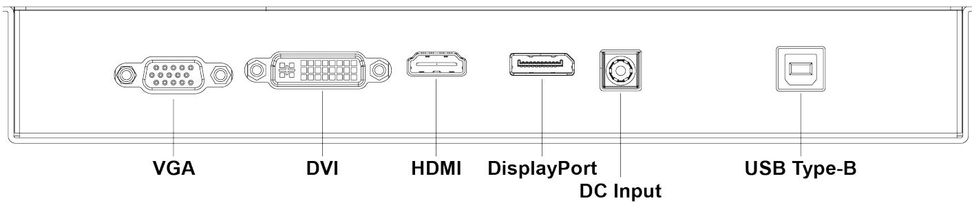
![VGA\nDVI\nHDMI\nDisplayPort\nDC Input\nUSB Type-B](.im-om-series-50m-p6000-1050-15/df50b32a5f8288e24caa37c5006d79eb67ad41913fdfac3ef0a186ea99ba86b1.jpg)

Figure 2: OM-320-430 I/O Connectors

# 3.1.1 VGA Connector

A 15-pin VGA connector is provided to connect the monitor to a computer.

<table><tr><td>Pin No.</td><td>Pin Name</td><td>Signal Type</td><td>Pin Assignment</td></tr><tr><td>1</td><td>RED</td><td>Analog In</td><td rowspan="15">&lt;img src="images/ab30e3d04b29c3ca3b757debc075e81bb6ce221c1a0479b203d0c3268278dfce.jpg"/&gt;</td></tr><tr><td>2</td><td>GREEN</td><td>Analog In</td></tr><tr><td>3</td><td>BLUE</td><td>Analog In</td></tr><tr><td>4</td><td>N/C</td><td></td></tr><tr><td>5</td><td>GND</td><td>GND *for cable detection</td></tr><tr><td>6</td><td>GND</td><td>GND</td></tr><tr><td>7</td><td>GND</td><td>GND</td></tr><tr><td>8</td><td>GND</td><td>GND</td></tr><tr><td>9</td><td>+5V Power</td><td>Power In</td></tr><tr><td>10</td><td>GND</td><td>GND</td></tr><tr><td>11</td><td>N/C</td><td></td></tr><tr><td>12</td><td>SDA</td><td>I/O</td></tr><tr><td>13</td><td>Horizontal Sync</td><td>In</td></tr><tr><td>14</td><td>Vertical Sync</td><td>In</td></tr><tr><td>15</td><td>SCL</td><td>In</td></tr></table>

# 3.1.2 DVI (OM-320-430 Only)

A DVI connector is provided to connect the monitor to a computer.

<table><tr><td>Pin No.</td><td>Signal</td><td>Pin No.</td><td>Signal</td><td></td></tr><tr><td>1</td><td>TMDS Data2-</td><td>16</td><td>Hot Plug Detect</td><td rowspan="15">&lt;img src="images/581b26fbcc9383d3d86d2777ab6ae994d02864e79fcbb1be544666ac5fa7cba5.jpg"/&gt;</td></tr><tr><td>2</td><td>TMDS Data2+</td><td>17</td><td>TMDS Data0-</td></tr><tr><td>3</td><td>GND</td><td>18</td><td>TMDSData0+</td></tr><tr><td>4</td><td>NC</td><td>19</td><td>GND</td></tr><tr><td>5</td><td>NC</td><td>20</td><td>NC</td></tr><tr><td>6</td><td>DDC Clock [SCL]</td><td>21</td><td>NC</td></tr><tr><td>7</td><td>DDC Data [SDA]</td><td>22</td><td>GND</td></tr><tr><td>8</td><td>Analog vertical sync</td><td>23</td><td>TMDS Clock +</td></tr><tr><td>9</td><td>TMDS Data1-</td><td>24</td><td>TMDS Clock -</td></tr><tr><td>10</td><td>TMDS Data1+</td><td>C1</td><td>Analog Red</td></tr><tr><td>11</td><td>GND</td><td>C2</td><td>Analog Green</td></tr><tr><td>12</td><td>NC</td><td>C3</td><td>Analog Blue</td></tr><tr><td>13</td><td>NC</td><td>C4</td><td>Analog Horizontal Sync</td></tr><tr><td>14</td><td>+5 V Power</td><td>C5</td><td>Analog GND Return</td></tr><tr><td>15</td><td>GND</td><td></td><td></td></tr></table>

# 3.1.3 HDMI Connector

An HDMI Type-A socket is provided to connect the monitor to a computer.

<table><tr><td>Pin No.</td><td>Pin Name</td><td>Signal Type</td><td>Pin Assignment</td></tr><tr><td>1</td><td>TMDS Data2+</td><td>In</td><td rowspan="19">&lt;img src="images/7a52c796b922779f59217dfa746d25dd04aa2bf4163484eae85f6105b623a399.jpg"/&gt;</td></tr><tr><td>2</td><td>TMDS Data2 Shield</td><td>GND</td></tr><tr><td>3</td><td>TMDS Data2-</td><td>In</td></tr><tr><td>4</td><td>TMDS Data1+</td><td>In</td></tr><tr><td>5</td><td>TMDS Data1 Shield</td><td>GND</td></tr><tr><td>6</td><td>TMDS Data1-</td><td>In</td></tr><tr><td>7</td><td>TMDS Data0+</td><td>In</td></tr><tr><td>8</td><td>TMDS Data0 Shield</td><td>GND</td></tr><tr><td>9</td><td>TMDS Data0-</td><td>In</td></tr><tr><td>10</td><td>TMDS Clock +</td><td>IN</td></tr><tr><td>11</td><td>TMDS Clock Shield</td><td>GND * Cable detection</td></tr><tr><td>12</td><td>TMDS Clock -</td><td>In</td></tr><tr><td>13</td><td>CEC</td><td>Not used</td></tr><tr><td>14</td><td>NC</td><td></td></tr><tr><td>15</td><td>DDC Clock</td><td>In</td></tr><tr><td>16</td><td>DDC Data</td><td>I/O</td></tr><tr><td>17</td><td>GND</td><td>GND</td></tr><tr><td>18</td><td>HDMI-HOT</td><td>+5V Power (in)</td></tr><tr><td>19</td><td>HDMI-PLUG</td><td>Out (Hot Plug Detection)</td></tr></table>

# 3.1.4 DisplayPort Connector

A DisplayPort Connector is provided to connect the monitor to a computer.

<table><tr><td>Pin</td><td>Signal</td><td>Pin</td><td>Signal</td><td>Pin Assignment</td></tr><tr><td>1</td><td>CON_DDI1_TX0_P</td><td>11</td><td>GND</td><td rowspan="10">&lt;img src="images/56fc881511fd6ac9263aee09b60c1b2c836304a499d74b9b9f5a35197b80d381.jpg"/&gt;</td></tr><tr><td>2</td><td>GND</td><td>12</td><td>CON_DDI1_TX3_N</td></tr><tr><td>3</td><td>CON_DDI1_TX0_N</td><td>13</td><td>CON_DDI1_DDC_AUX_SEL</td></tr><tr><td>4</td><td>CON_DDI1_TX1_P</td><td>14</td><td>CON_DDI1_CONFIG_2</td></tr><tr><td>5</td><td>GND</td><td>15</td><td>CON_DDI1_I2CCLK_AUX_P</td></tr><tr><td>6</td><td>CON_DDI1_TX1_N</td><td>16</td><td>GND</td></tr><tr><td>7</td><td>CON_DDI1_TX2_P</td><td>17</td><td>CON_DDI1_I2CCLK_AUX_N</td></tr><tr><td>8</td><td>GND</td><td>18</td><td>CON_DDI1_HPD</td></tr><tr><td>9</td><td>CON_DDI1_TX2_N</td><td>19</td><td>GND</td></tr><tr><td>10</td><td>CON_DDI1_TX3_P</td><td>20</td><td>P_+3V3_DP1</td></tr></table>

# 3.1.5 USB Connector

A USB 2.0 Type-B connector is provided for touch support.

<table><tr><td>Pin No.</td><td>Pin Name</td><td>Signal Type</td><td>Pin Assignment</td></tr><tr><td>1</td><td>+5V</td><td>In</td><td></td></tr><tr><td>2</td><td>USB-Data-</td><td>I/O</td><td>USB2.0 for touch</td></tr><tr><td>3</td><td>UDB-Data+</td><td>I/O</td><td>USB2.0 for touch</td></tr><tr><td>4</td><td>GND</td><td>GND</td><td></td></tr></table>

# 3.1.6 DC Power Connector (IM-215-270/OM-101-270)

A 2.5mm center pin DC barrel jack connector is provided for power input.

• UL 94V-0 Rated

<table><tr><td>Pin No.</td><td>Pin Name</td><td>Signal Type</td></tr><tr><td>1</td><td>Center Pin +12V @5A</td><td>Power</td></tr><tr><td>2</td><td>GND</td><td>GND</td></tr></table>

![Ø6.3\n9.0\nPIN DIA. +0\n-0.05\n4.5\n11.0\n6.5\n3.5\n2.4\n2.8\n7.7\n0.3\n4.8](.im-om-series-50m-p6000-1050-15/46025cdaf8f6b2c21c30bcc78f9abdda7ce07403cb2ebf526f53e2c4c4bd8fd3.jpg)

Use the cable clamp provided in the package contents to secure the DC power connector to the rear panel as shown below (IM Series shown, OM Series similar).

![Close-up of a black electronic device with labeled connectors (DC and C) and a red circle highlighting a small component, no readable text or symbols beyond labels.](.im-om-series-50m-p6000-1050-15/2affe41faf7a243c6cf94e0e0353aafea20c5875adb24eb0d3539505523d3d78.jpg)

# 3.1.7 DC Power Connector (OM-320-430)

A 2.5mm center pin DC barrel jack connector is provided for power input.

<table><tr><td>Pin No.</td><td>Pin Name</td><td>Signal Type</td></tr><tr><td>1</td><td>Center Pin +24V @5A</td><td>Power</td></tr><tr><td>2</td><td>GND</td><td>GND</td></tr></table>

![Ø6.3\n9.0\nPIN DIA. +0\n-0.05\n4.5\n11.0\n6.5\n3.5\n2.4\n2.8\n7.7\n0.3\n4.8](.im-om-series-50m-p6000-1050-15/cee011c61f41f847261f7d7904b4337763e30a6921731c49bacf740e416cc55d.jpg)

# 3.2. Mechanical Dimensions

All dimensions are in mm.

# 3.2.1 IM Series

IM-150
![59.02\n234.17\n59.02\n352.21 ± 2 (W)\n305.53 (VA)\n61.12\n153.48\n61.6\n229.5 (VA)\n276.2 ± 2 (H)\n48.15 ± 2 (D)\n19.25\n28.9](.im-om-series-50m-p6000-1050-15/de17a5add5b57dce7b6bd6c550abf39e75dd8cd49f310024c9cfa2a6223fca60.jpg)

Figure 3: IM-150 Mechanical Dimensions

IM-170
![76.8\n234.17\n76.8\n387.77 ± 2 (W)\n339.32 (VA)\n52.15 ± 2 (D)\n23.25\n28.9\n83.04\n153.48\n83.52\n271.74 (VA)\n320.04 ± 2 (H)](.im-om-series-50m-p6000-1050-15/2f70ff546b728a04fc0d89b9a65553a90cac00ed38a888ed64f064df6358d7ba.jpg)

Figure 4: IM-170 Mechanical Dimensions

IM-190
![The image is a technical engineering drawing displaying orthographic projections of a rectangular frame assembly with a central vent or grille.\n\n**Top View:**\nThree horizontal dimensions are listed: '94.11', '234.17', and '94.1'.\n\n**Front View (Center):**\n- Outer width: '422.38 ± 2 (W)'\n- Inner width: '377.72 (VA)'\n- Inner height: '302.46 (VA)'\n- Outer height: '346.95 ± 2 (H)'\n\n**Left Side View:**\nThree vertical dimensions are listed: '96.5', '153.48', and '96.97'.\n\n**Right Side View:**\n- Overall depth: '50.15 ± 2 (D)'\n- Upper width: '21.25'\n- Lower width: '28.9'](.im-om-series-50m-p6000-1050-15/10ff8982c43866573a4f7c32b6973d0ace2a8f47ca13e3083f5ae450074ae2d8.jpg)
Figure 5: IM-190 Mechanical Dimensions

IM-215 and IM-215H
![The image is a technical engineering drawing showing four orthographic projections of a monitor with dimensional measurements.\n\n**Front View (Center):**\n*   Top horizontal dimension: **523.91±1.00**\n*   Inner horizontal dimension (screen area): **477.46(TP VA)**\n*   Left vertical dimension: **315.5±1.0**\n*   Inner vertical dimension (screen area): **269.19(TP VA)**\n\n**Left Side View:**\n*   Total depth dimension: **(153.4)**\n*   Upper section depth dimension: **(80.8)**\n\n**Right Side View:**\n*   Upper section depth dimension: **48.7±0.5**\n*   Lower section depth dimension: **19.3±0.5**\n\n**Bottom View:**\n*   Left dimension: **(234.0)**\n*   Right dimension: **(144.9)**](.im-om-series-50m-p6000-1050-15/14f180abda27779f85606207ccf056b9c11eb7e29df803c110897095622683e5.jpg)
Figure 6: IM-215 Mechanical Dimensions

IM-238
![The image displays a technical engineering drawing featuring four distinct views of a rectangular object, likely a display panel or frame, with dimensional annotations.\n\n**Top View (Upper Center):**\nA horizontal profile showing a vented section.\n*   Dimensions: **233.59**, **171.71**\n\n**Front View (Center):**\nA large rectangular frame with an inner rectangle.\n*   Horizontal Dimensions: **577.01±1.5** (outer width), **530.44(VA)** (inner width).\n*   Vertical Dimensions (oriented vertically): **299.86(VA)** (inner height), **346.26±1.5** (outer height).\n\n**Left Side View (Far Left):**\nA vertical profile showing a vented section.\n*   Dimensions (oriented vertically): **153.25**, **96.38**\n\n**Right Side View (Far Right):**\nA vertical profile indicating the object's thickness/depth.\n*   Dimensions: **48.15±1.5** (total thickness), **19.25±1** (inner thickness).](.im-om-series-50m-p6000-1050-15/ff3776334008def667d856c30282dd884658c2297778362f7a2e788e0a12b233.jpg)
Figure 7: IM-238 Mechanical Dimensions

IM-270
![This image displays a technical engineering drawing of a flat-panel display device, featuring a top view, a front view, and two side views with dimensional annotations.\n\n**Top View:**\nShows the top profile with a central vent or grille.\n- Dimensions: **233.59** and **207.01**\n\n**Front View:**\nThe central view shows the screen and frame.\n- Outer Width: **647.61±2**\n- Inner Width (VA): **599.00(VA)**\n- Inner Height (VA): **337.55(VA)**\n- Outer Height: **385.95±2**\n\n**Left Side View:**\nShows the vertical side profile.\n- Total Height: **153.25**\n- Vent Section Height: **116.22**\n\n**Right Side View:**\nShows the depth/thickness profile.\n- Total Depth: **48.15±1.5**\n- Front Bezel Depth: **19.25±1**](.im-om-series-50m-p6000-1050-15/1560b8d0942a9789521ea803b46ad31a13f73a8809988061ad5680b0c62eb2ae.jpg)
Figure 8: IM-270 Mechanical Dimensions

# 3.2.2 OM Series (4:3)

# 3.2.2.1 OM-070

![175\n158.7\n1.5](.im-om-series-50m-p6000-1050-15/d016ac17bc81d2cdbd39ee3e99e40264d19730a8509ca5e47ec2cd946ea9ae90.jpg)

![| Dimension         | Value     |\n| ----------------- | --------- |\n| Width (±)         | 191.3 ± 2 (W) |\n| Height (±)        | 153.3 (VA) |\n| Width (±)         | 7.0'      |\n| Height (±)        | 92.34 (VA) |\n| Width (±)         | 130.34 ± 2 (H) |](.im-om-series-50m-p6000-1050-15/e425817887e88ab846fc4e63325c602607a3e17b0ec620013f19ab8b837a9a9e.jpg)

![49.24 ± 2 (D)\n27.24\n4.74\n22\n109.8\n118\n4.47](.im-om-series-50m-p6000-1050-15/7617973f895dd0b9285115223757f9fbd853c3c3b2ab046f6602b8a59050cec5.jpg)

Figure 9: OM-070 Mechanical Dimensions

# 3.2.2.2 OM-121

![| Dimension | Value |\n| --------- | ----- |\n| Total Length | 286 |\n| Left Segment | 219.6 |\n| Right Segment | 1.5 |](.im-om-series-50m-p6000-1050-15/52704a063bdce5d7a160e99064efb1b6eb47484f3c1599bf5585da8518263d4d.jpg)

![301 ± 2 (W)\n246.76 (VA)\nR2\n12.1'\n185.32 (VA)\n239.56 ± 2 (H)](.im-om-series-50m-p6000-1050-15/06464daf89f39bda408362535e15fb804b084751717bcd91fc4bf72e8c77c4bf.jpg)

![49.24 ± 2 (D)\n27.24\n4.74\n22\n1\n143.9\n217.28\n4.97](.im-om-series-50m-p6000-1050-15/b7422e7d045aa15a114c46ed8b560e65503bbf8d6d3ccc7e9b153df7e267fbcb.jpg)

Figure 10: OM-121 Mechanical Dimensions

# 3.2.2.3 OM-150

![The image displays a technical schematic of a rectangular device with three orthographic projections detailing its dimensions.\n\n**Top View (Top Left):**\n*   Top dimension: **332**\n*   Inner dimension: **219.6**\n*   Right edge dimension: **1.5**\n\n**Front View (Bottom Left):**\n*   Outer width: **347.53 ± 2 (W)**\n*   Inner width (Viewable Area): **305.53 (VA)**\n*   Diagonal measurement: **15.0'**\n*   Inner height: **229.5 (VA)**\n*   Outer height: **271.5 ± 2 (H)**\n\n**Side View (Right):**\n*   Total depth: **49.24 ± 2 (D)**\n*   Top margin depth: **4.74**\n*   Inner depth: **27.24**\n*   Inner width: **22**\n*   Small detail dimension: **1**\n*   Inner height: **143.9**\n*   Total body height: **261**\n*   Bottom margin thickness: **4.97**](.im-om-series-50m-p6000-1050-15/a8e22c872c1b1b61b6046663031cc4df2d20c4cdcfd21a8a2a715ed87aece6db.jpg)
Figure 11: OM-150 Mechanical Dimensions

# 3.2.2.4 OM-170

![The image is a technical line drawing showing three orthographic views of an object with dimensional annotations.\n\n**Top View:**\n*   367\n*   219.6\n*   33.44\n\n**Front View:**\n*   382.92 ± 2 (W)\n*   315.34 ± 2 (H)\n\n**Side View:**\n*   49.94 ± 2 (D)\n*   27.94\n*   22\n*   5.44\n*   304\n*   143.9\n*   4.97](.im-om-series-50m-p6000-1050-15/571827c6a3d9a1c0425361566596d1eb7164187a7e697d9330255a255057b7c5.jpg)
Figure 12: OM-170 Mechanical Dimensions

# 3.2.2.5 OM-190

![The image is a technical engineering drawing displaying three views of a rectangular device with dimensional annotations.\n\n**Top Section (Top View):**\n*   Top horizontal dimension: **403**\n*   Inner horizontal dimension: **219.6**\n*   Right vertical dimension: **33.44**\n\n**Bottom Left Section (Front View):**\n*   Top horizontal dimension: **417.72 ± 2 (W)**\n*   Right vertical dimension: **342.46 ± 2 (H)**\n*   Diagonal measurement across the square face: **19.0'**\n\n**Right Section (Side Profile):**\n*   Top horizontal dimension: **49.94 ± 2 (D)**\n*   Upper left horizontal sub-dimensions: **27.94** and **5.44**\n*   Upper right horizontal sub-dimension: **22**\n*   Right vertical dimension: **331.02**\n*   Middle vertical dimension: **143.9**\n*   Bottom vertical dimension: **4.97**](.im-om-series-50m-p6000-1050-15/870ac5a0ec8c9575e6e345a6017f908c6db1849beb124f5b75ee706a380c8c24.jpg)
Figure 13: OM-190 Mechanical Dimensions

# 3.2.3 OM Series (16:9)

# 3.2.3.1 OM-101

![| Dimension | Value   |\n| --------- | ------- |\n| Length    | 237.06  |\n| Width     | 219.6   |\n| Height    | 1.5     |](.im-om-series-50m-p6000-1050-15/a8029093368ba70b0ed2cc9d24cffad497c8db2f232b93b283d2fe6fed94a5d7.jpg)

![249.66\n10.1'\n168.3](.im-om-series-50m-p6000-1050-15/7a031465f7995f36d162800fc9f28bd0550f3efda3fec95b351da981949f7af4.jpg)

![49\n27 22\n4.5\n1\n143.9\n158.4\n4.97](.im-om-series-50m-p6000-1050-15/7207984c70f79b5c9b31d7b438f34a277f8cd83317034c7d375ab946b44d7a1d.jpg)

Figure 14: OM-101 Mechanical Dimensions

3.2.3.2 OM-156
![| Dimension | Value |\n| --------- | ----- |\n| Total Length | 370.8 |\n| Total Height | 219.6 |\n| Total Width | 1.5 |](.im-om-series-50m-p6000-1050-15/b2256691634b17950839c42ee5c84bc85477154ecdcbfd76961426867a7835a9.jpg)

![383.56\n15.6'\n232.99](.im-om-series-50m-p6000-1050-15/d75612c27d53ed21ae365fae1539a1a32649d4cd35ea48cb245b383b5638009d.jpg)

![49.7\n5.2\n27.7\n22\n143.9\n220.6\n4.97](.im-om-series-50m-p6000-1050-15/c40bbf0893b19ccbe1dda9b310601129825bf89e6becf1e49e6fba15c72f799a.jpg)

Figure 15: OM-156 Mechanical Dimensions

3.2.3.3 OM-185
![| Segment | Value |\n| ------- | ----- |\n| Top Left | 436.8 |\n| Middle Right | 219.6 |\n| Bottom Right | 108.6 |](.im-om-series-50m-p6000-1050-15/b19a26cb339d66fbb8d3b9c35bc902df8621e56615ca70119730cb942c2d4878.jpg)

![| Dimension | Value |\n| :--- | :--- |\n| Width (W) | 450.36 ± 2 (W) |\n| Height (VA) | 409.96 (VA) |\n| Base Diameter (H) | 271.29 ± 2 (H) |\n| Top Margin (VA) | 18.5' |\n| Bottom Margin (HA) | 231.04 (VA) |](.im-om-series-50m-p6000-1050-15/16a79c8e035bdb37b5d6ed1a01655f6f6198d80008614acc34686448a36d4c88.jpg)

![52.44 ± 2 (D)\n5.44\n30.44\n44.5\n143.9\n260.5\n4.6\n72.1](.im-om-series-50m-p6000-1050-15/43f251db52c66b78c0d9d686c4d1d4acd6d11345dbdb25bc6b7119af8c9cd19e.jpg)

Figure 16: OM-185 Mechanical Dimensions

# 3.2.3.4 OM-215 and OM-215H

![This image displays a technical line drawing of an electronic device, likely a monitor or TV, with three orthographic projections and corresponding dimension lines.\n\n**Top View (Top Left):**\n- A horizontal dimension line at the very top reads **504.6**.\n- A smaller inner dimension line reads **219.6**.\n- Below the shape, there are small symbols representing mounting points.\n\n**Front View (Bottom Left):**\n- A horizontal dimension line above the rectangle reads **517.46**.\n- A diagonal line inside the rectangle runs from the top-left to bottom-right corner, labeled **21.5'**.\n- A vertical dimension line on the right side of this view reads **309.19**.\n\n**Side View (Right):**\n- A horizontal dimension at the top reads **52.2**.\n- An inner horizontal dimension reads **30.2**.\n- A small horizontal offset dimension on the left reads **5.2**.\n- Vertical dimensions along the side profile include **1**, **22**, **143.9**, **296.9**, and a bottom offset of **4.97**.](.im-om-series-50m-p6000-1050-15/85760eef764f27113cb6d3b768a8fac00d687d785247532a51fb3dd4ddffa894.jpg)
Figure 17: OM-215 Mechanical Dimensions

# 3.2.3.5 OM-238

![This image is a technical drawing featuring three orthographic views with dimensional annotations.\n\n**Top View (Top Left):**\n*   **552.88** (Total width)\n*   **166.64**, **219.6**, **166.64** (Segmented width dimensions)\n*   **1.5** (Height/thickness dimension)\n\n**Front View (Bottom Left):**\n*   **570.44** (Outer width)\n*   **528.44** (Inner width)\n*   **339.86** (Outer height)\n*   **297.86** (Inner height)\n\n**Side View (Right):**\n*   **52.44** (Outer width)\n*   **30.44** (Inner width)\n*   **5.44** (Offset width)\n*   **22** (Top vertical section)\n*   **92.66** (Middle vertical section)\n*   **329.02** (Total height)\n*   **22** (Inner vertical section top)\n*   **143.9** (Inner vertical section middle)\n*   **92.46** (Inner vertical section bottom)\n*   **4.4** (Bottom offset vertical)](.im-om-series-50m-p6000-1050-15/4d3c8e34ebb64ed9f65a628c69be614f76d191ce0ef6d15c7b4e4c05bbcc2b49.jpg)
Figure 18: OM-238 Mechanical Dimensions

# 3.2.3.6 OM-270

![| Dimension | Value   |\n| --------- | ------- |\n| Top Left  | 203.42  |\n| Top Right | 626.44  |\n| Bottom Left | 599 |\n| Bottom Right | 379.55 |\n| Middle Left | 641 |\n| Middle Right | 53.44 |\n| Middle Right | 31.44 |\n| Bottom Right | 112.31 |\n| Bottom Left | 4.4   |\n| Bottom Right | 143.9 |\n| Bottom Left | 368.31 |\n| Top Right  | 2     |\n| Top Right  | 1     |\n| Top Right  | 0     |\n| Top Right  | 0     |\n| Top Right  | 0     |\n| Top Right  | 0     |\n| Top Right  | 0     |\n| Top Right  | 0     |\n| Top Right  | 0     |\n| Top Right  | 0     |\n| Top Right  | 0     |\n| Top Right  | 0     |\n| Top Right  | 0     |\n| Top Right  | 0      |\n| Top Right  | 0      |\n| Top Right  | 0      |\n| Top Right  | 0      |\n| Top Right  | 0      |\n| Top Right  | 0      |\n| Top Right  | 0      |\n| Top Right  | 0      |\n| Top Right  | 0      |\n| Top Right  | 0      |\n| Top Right  | 0      |\n| Top Right  | 0      |](.im-om-series-50m-p6000-1050-15/3e8240e79c460c39075bf5c90d4caef0d2d39c625e00bd88b15840c75721976d.jpg)

Figure 19: OM-270 Mechanical Dimensions

# 3.2.3.7 OM-320

![| Dimension         | Value       |\n| ----------------- | ----------- |\n| Top Section        | 251.3       |\n| Top Section        | 255.2       |\n| Top Section        | 251.1       |\n| Top Section        | 152.5       |\n| Top Section        | 152.3       |\n| Bottom Section     | 757.6±2.0(outline) |\n| Bottom Section     | 699.40(TP VA) |\n| Bottom Section     | 393.80(TP VA) |\n| Bottom Section     | 451.1±2.0(outline) |\n| Bottom Section     | 74.1±1.0     |\n| Bottom Section     | 37.4±1.0     |\n| Top Section (Bottom) | 98.1        |\n| Top Section (Bottom) | 255.0       |\n| Top Section (Bottom) | 98.1        |](.im-om-series-50m-p6000-1050-15/8f097fb7698891f328ea652c47e23942590ff5bb0affc9a9abf1acd51fdfcda4.jpg)

Figure 20: OM-320 Mechanical Dimensions

3.2.3.8 OM-430
![| Dimension         | Value     |\n| ----------------- | --------- |\n| Total Width       | 375.12    |\n| Total Height      | 302.50    |\n| Total Height      | 255.20    |\n| Total Height      | 374.92    |\n| Total Height      | 302.30    |\n| Total Width (L)   | 940.9     |\n| Total Width (TP)  | 941.9     |\n| Total Width (AA)  | 1005.2±1  |\n| Total Thickness   | 529.3     |\n| Total Thickness   | 530.3     |\n| Total Thickness   | 593.6±1   |\n| Total Thickness   | 31.7      |\n| Total Thickness   | 79.7±1.0  |\n| Total Thickness   | 42.7±1.0  |\n| Total Thickness   | 26.4±1.0  |\n| Total Thickness   | 169.29    |\n| Total Thickness   | 255.00    |\n| Total Thickness   | 169.29    |](.im-om-series-50m-p6000-1050-15/1b0c7d903e7a40b92eeef19075818734ef21a35cf2973ee535e5d19f3f7d8df1.jpg)

Figure 21: OM-430 Mechanical Dimensions

# 3.3. Mounting

This section includes details for VESA and panel mounting options.

![The image displays a red equilateral triangle pointing upwards. Centered inside the triangle is a white exclamation point. To the right of the red triangle, there is a black shape.](.im-om-series-50m-p6000-1050-15/dad5a8b6498fcf40d35b754e03b733807a6f1682ac4e461aaa47df7e803026ca.jpg)
WARNING:

Risk of physical injuries and/or property damage:

When mounting the device, use four M4 x 6mm screws (IM-215-270/OM-101-270) or four M6 x 7mm (OM-320-430) to mount the VESA bracket to the rear of the device. Tighten all four screws firmly to support the weight of the device. Make sure that the suspension system is capable of supporting the device!

![The image displays a yellow triangular warning sign with a black border. Centered inside the triangle is a black exclamation point.](.im-om-series-50m-p6000-1050-15/6caccf6b4f9da762de208a0a00d58dd9b2559ff4ad962554a4cd787d66d3823d.jpg)
CAUTION:

Risk of burns to the user caused by hot surfaces:

Turn off power and allow the device to cool down prior to performing any mounting or unmounting operations. Avoid prolonged contact with the enclosure (over 10 seconds) when the device is in operation or is still hot from previous use.

# 3.3.1 VESA Mounting (All Models)

Note: The VESA mounting hole pattern is shown in the figures below. For IM-215-270/OM-101-270, all I/O ports must face down. For OM-320-430, the ports may face any direction.

![POWER\nNEW\nSELECT\n+\n~\nVESA BRACKET\n(NOT PROVIDED)\n4x M4 SCREWS\n(NOT PROVIDED)](.im-om-series-50m-p6000-1050-15/574f3a5f05ba2c02449e85c57ce92bea8a711d6dcae263694efd1369a88a46c6.jpg)

Figure 22: Attaching a VESA Mounting Bracket for IM-215-270/OM-101-270

![Landscape\n200\n4 - M6 max depth 7mm\n3-M4 Mounting hole for cable clips\ndepth 6.5mm MAX\nVESM Mounting Hole\n4-M5 200X200 depth 7mm MAX\n200\nUSS\nDOW\nZS\nHOM\nBIV\nDAB\nUSS\nERR\nAUTO\nO12-M4 Mounting hole for depth 6.5mm MAX](.im-om-series-50m-p6000-1050-15/9783adf983516fb2ce509a574ca66c0a6dfe3636c70c1348851892caf3b6cf99.jpg)

Figure 23: VESA Mounting for OM-320

![Landscape\n200\n4 - M6 max depth 7mm\n4-445 200/200 depth 7mm MAX\nVEBA mount 1/8 hole\n200](.im-om-series-50m-p6000-1050-15/83c88c3f69b625c0d67e90d8af9e1fe8634b32de9ac20c68f49fd75903e988c8.jpg)

Figure 24: VESA Mounting for OM-430

# 3.3.2 Panel Mounting (OM-070-270 only)

The OM-070-270 can be panel-mounted with 14 mounting clips (not included). Make sure there is adequate space behind the panel for ventilation, and that the panel material and thickness can support the weight of the device.

![The image displays a graphic icon of a document or piece of paper with a folded top-right corner and horizontal lines representing text. Superimposed over the document is a large, bold red checkmark.](.im-om-series-50m-p6000-1050-15/07a4187901fbacc413761cdc401e5e87adc2244793633c953abb405ea0ec3e82.jpg)
NOTE:

The schematics in this section are provided for reference only.

Before you begin: Make sure you have the mounting clips for the model you intend to mount.

Panel Mount Clips by Model

<table><tr><td>Button</td><td>Remark</td></tr><tr><td>OM-070</td><td>8</td></tr><tr><td>OM-101</td><td>8</td></tr><tr><td>OM-121</td><td>12</td></tr><tr><td>OM-150</td><td>14</td></tr><tr><td>OM-156</td><td>14</td></tr><tr><td>OM-170</td><td>14</td></tr><tr><td>OM-185</td><td>16</td></tr><tr><td>OM-190</td><td>14</td></tr><tr><td>OM-215</td><td>17</td></tr><tr><td>OM-238</td><td>20</td></tr><tr><td>OM-270</td><td>20</td></tr></table>

Step 1: Cut the panel opening using the appropriate cutout dimensions. All dimensions are in mm unless otherwise specified.

![176 ± 0.5\nCUT OUT\n119 ± 0.5](.im-om-series-50m-p6000-1050-15/190a47dbc9676b7f8039edce8f83900794f534d1dc48e4a98b08d8c7676aee68.jpg)

Figure 25: OM-070 Cut Out Dimensions

![287 ± 0.5\nCUT OUT\n218.28 ± 0.5](.im-om-series-50m-p6000-1050-15/8a53011e2ebb55e01c1bb347f5e8fafe04bef035888bde208467be56c49b9397.jpg)

Figure 26: OM-121 Cut Out Dimensions

![333 ± 0.5\nCUT OUT\n262 ± 0.5](.im-om-series-50m-p6000-1050-15/4c444edda6922dd5c3bbb6efa9a4e74fc9fabe80ba3a858224b85180fbc800b0.jpg)

Figure 27: OM-150 Cut Out Dimensions

![368 ± 0.5\nCUT OUT\n305 ± 0.5](.im-om-series-50m-p6000-1050-15/06d7c8b068f18823836849a78501f34adad76bde6716e1ac93b2062c3f5e3bd9.jpg)

Figure 28: OM-170 Cut Out Dimensions

![404 ± 0.5\n332.02 ± 0.5\nCUT OUT](.im-om-series-50m-p6000-1050-15/4ee3554cca8f022e7986dae054bdeb591c0d6eb0fb10cf9a384ea5fdb14cb95b.jpg)

Figure 29: OM-190 Cut Out Dimensions

![238.06\nCUT OUT\n159.4](.im-om-series-50m-p6000-1050-15/c785f5f62101e1814a8e431686021820559ee6ce7a3b0c9d9dd9a738bed2d4d1.jpg)

Figure 30: OM-101 Cut Out Dimensions

![371.8\nCUT OUT\n221.6](.im-om-series-50m-p6000-1050-15/71668c57ad614fbea8e8c1b0fb24c90d4087f727d7abc0ad779ea6d7aa14ca75.jpg)

Figure 31: OM-156 Cut Out Dimensions

![437.81 ± 0.5\nCUT OUT\n261.5 ± 0.5](.im-om-series-50m-p6000-1050-15/733dc271289c2222d212187b55b396f4bcea5a072ec1a6df58472081d2c250ad.jpg)

Figure 32: OM-185 Cut Out Dimensions

![505.6\nCUT OUT\n297.9](.im-om-series-50m-p6000-1050-15/4a941ab9795003511b042a0014a2e2f7b176da2ac81037d2a526be820d6dfab6.jpg)

Figure 33: OM-215/OM-215H Cut Out Dimensions

![553.88\nCUT OUT\n330.02](.im-om-series-50m-p6000-1050-15/34e6c448815e12864180a25b95b193d737c1cd5dea4d7d557538dd46c2e91152.jpg)

Figure 34: OM-238 Cut Out Dimensions

![627.44\nCUT OUT\n369.31](.im-om-series-50m-p6000-1050-15/9905b637517f0cd075818d6b99ef707751ad6c3ef9d2f06cedcbee058f88588b.jpg)

Figure 35: OM-270 Cut Out Dimensions

Step 2: If rear access will be limited after installation, attach I/O cables to the device before installing into the panel (see I/O Connectors on page 18).

Step 3: Place the device into the panel cutout.

![Technical line drawing of two rectangular panels with internal cutouts and an arrow indicating direction (no text or symbols)](.im-om-series-50m-p6000-1050-15/fe54ad5ffa2ba5250cab2d49d7daff27319654105671395e5d1f0185c9a15cd2.jpg)

Figure 36: Insert Monitor into Cut Out

Step 4: Insert the mounting clips into the slots on the sides of the device as shown. Hand-tighten the mounting clips with a Phillips-head screwdriver to secure it to the panel. A video tutorial for this step is available here:

https://www.youtube.com/watch?v=AK2uVC1Cc-Y

![The image displays a standard safety warning sign. It features a yellow equilateral triangle with a black border containing a large black exclamation point in the center. Below the triangle is the word 'CAUTION:' printed in black, capital letters.](.im-om-series-50m-p6000-1050-15/27b34f9e7223ecfe88dc7c81587326b896f4f71b2ab59b4ed2c5d9e7ea9419f8.jpg)

Do not overtighten the clips to avoid damaging the device enclosure.

![124\n124\n124\nPOWER\nMIME\nSELECT\n+\n-\nDO-01 TR\nHDD\nHDD\nCLIP](.im-om-series-50m-p6000-1050-15/a975fb30bd425a576d0bea6acfe01749b79373698b16b33347fc469343dae050.jpg)

Figure 37: Secure Monitor with Mounting Clips

# 3.3.3 Panel Mounting (OM-320-430 only)

The OM-320-430 can be panel-mounted using the screw holes on the back of the device. For OM-320, 12 screw holes with a max depth of 7mm require a minimum of 8 screws (4 on each side) to support the weight of the device. For OM-430, 8 screw holes with a max depth of 7mm may be used. Make sure there is adequate space behind the panel for ventilation, and that the panel material and thickness can support the weight of the device.

![100 100 200 100 100\n↑ Landscape\n12 - M4 max depth 6.5mm\n400\n4-4-5 200X200 depth 7mm MAX\nVEGA Mounting Hole\nPOT-4-12\nO-R-48 Blended for be depth of 3mm MAX](.im-om-series-50m-p6000-1050-15/aa2a7997c3cd9cc5258addf7f306b6500f3d87d4b5cc071693c47ec956a87e04.jpg)

Figure 38: Panel Mount for OM-320

![270\n360\n270\n8 - M4 max depth 6.5mm\nLandscape\n500\n4-M4 200/200 depth 7mm MAX\nVEGA Mounting Hole\nVESA Mounting Hole](.im-om-series-50m-p6000-1050-15/b1721bbdab5bbf556afd52d9c17e66a8894df2049f3ce1921b96b2075065b0f9.jpg)

Figure 39: Panel Mount for OM-430

# 4. On-screen Display (OSD)

This chapter describes the IM/OM Series OSD features.

# 4.1. OSD Buttons

OSD buttons are located on the rear panel of the monitor.

# 4.1.1 IM-215-270/IM-215H/OM-070-270/OM-215H OSD Buttons

![POWER\nMENU\nSELECT\n+\n-](.im-om-series-50m-p6000-1050-15/bd4c62a6669289c53faff4341fc5d1b84bb9e024e38b379756ae455c4124e241.jpg)

Figure 40: IM/OM Rear Panel OSD Buttons

Table 9 IM-215-270/IM-215H/OM-070-270/OM-215H OSD Button Functions

<table><tr><td>Button</td><td>Function</td><td>Remark</td></tr><tr><td>Power</td><td>Power On/Off</td><td>Press to power the monitor on/off. Press at least 1 second for power off.</td></tr><tr><td rowspan="2">Menu</td><td>OSD menu On/Off</td><td>Press to turn the OSD menu on/off.</td></tr><tr><td>Leave OSD Submenu</td><td>Press to step out of a submenu.</td></tr><tr><td rowspan="2">Select</td><td>Step through menu</td><td>Press to step into a submenu.</td></tr><tr><td>Execute Autotune (VGA only)</td><td>Press to execute autotune after clicking the &quot;Auto&quot; key.</td></tr><tr><td rowspan="2">+</td><td>Move up to next item</td><td>Press to move the cursor up to the next menu item.</td></tr><tr><td>Increase value</td><td>Press to increase the value of an item.</td></tr><tr><td rowspan="2">-</td><td>Move down to next item</td><td>Press to move the cursor down to the next menu item.</td></tr><tr><td>Decrease value</td><td>Press to decrease the value of an item.</td></tr></table>

# 4.1.2 OM-320-430 OSD Buttons

AUTO
MENU

△
0 EXIT
LED
G

Figure 41: OM-320-430 Rear Panel OSD Buttons
Table 10: OM-320-430 OSD Button Functions

<table><tr><td>Button</td><td>Function</td><td>Remark</td></tr><tr><td>Auto</td><td>Execute Autotune (VGA only)</td><td>Press to execute autotune after clicking the &quot;Auto&quot; key.</td></tr><tr><td rowspan="2">Menu</td><td>OSD menu</td><td>Press to open the OSD menu.</td></tr><tr><td>Enter/select/deselect</td><td>Press to enter a submenu or select an item.</td></tr><tr><td rowspan="2">▶</td><td>Move down to next item</td><td>Press to move the cursor down to the next menu item.</td></tr><tr><td>Increase value</td><td>Press to increase the value of an item.</td></tr><tr><td rowspan="2">◀</td><td>Move up to next item</td><td>Press to move the cursor up to the next menu item.</td></tr><tr><td>Decrease value</td><td>Press to decrease the value of an item.</td></tr><tr><td>Exit</td><td>Press to exit</td><td></td></tr><tr><td>Power</td><td>Power On/Off</td><td>Press to power the monitor on/off.The monitor takes a few seconds to power on and off after pressing.</td></tr></table>

# 4.2. OSD Menus

# 4.2.1 OM-070/121/150/170/190/215H

The table below lists the OSD menu structure and items.

Table 11: OSD Menu Overview for OM-070/121/150/170/190/215H

<table><tr><td>Main Menu</td><td>Submenu</td><td>Item</td><td>Value/Range</td><td>Default Value</td><td>Comment</td></tr><tr><td rowspan="4">Picture</td><td>Auto Dimming</td><td>Toggle</td><td>Off/On</td><td>Off</td><td>Toggle Auto Dimming feature</td></tr><tr><td>Brightness</td><td>Slider</td><td>0-100</td><td>50</td><td>Adjust brightness</td></tr><tr><td>Contrast</td><td>Slider</td><td>0-100</td><td>50</td><td>Adjust contrast</td></tr><tr><td>Auto Color</td><td>Toggle</td><td></td><td></td><td>Auto tune color settings</td></tr><tr><td rowspan="4">Color</td><td>Temperature</td><td>Text</td><td>9300K6500K5800KUser</td><td>6500k</td><td>Select color temperature</td></tr><tr><td>Red</td><td>Slider</td><td>0-100</td><td>100</td><td>Adjust red level</td></tr><tr><td>Green</td><td>Slider</td><td>0-100</td><td>100</td><td>Adjust green level</td></tr><tr><td>Blue</td><td>Slider</td><td>0-100</td><td>100</td><td>Adjust blue level</td></tr><tr><td rowspan="9">Input</td><td>Auto Select</td><td></td><td></td><td></td><td>Auto select input source</td></tr><tr><td>VGA</td><td></td><td></td><td></td><td>Set input source as VGA</td></tr><tr><td>HDMI</td><td></td><td></td><td></td><td>Set input source as HDMI</td></tr><tr><td>HPosition</td><td>Slider</td><td>0-100</td><td>VGA adjustable</td><td>Adjust VGA screen horizontal position (VGA only)</td></tr><tr><td>VPostion</td><td>Slider</td><td>0-100</td><td>VGA adjustable</td><td>Adjust VGA screen vertical position (VGA only)</td></tr><tr><td>Clock</td><td>Slider</td><td>0-100</td><td>VGA adjustable</td><td>Adjust VGA signal clock latency (VGA only)</td></tr><tr><td>Phase</td><td>Slider</td><td>0-100</td><td>VGA adjustable</td><td>Adjust VGA signal clock phase (VGA only)</td></tr><tr><td>Aspect Ratio</td><td></td><td></td><td>Full</td><td>Select aspect ratio</td></tr><tr><td>Auto Adjust</td><td>Text</td><td></td><td></td><td>Auto adjust VGA screen (VGA only)</td></tr><tr><td>Language</td><td></td><td>Text</td><td>EnglishFrenchGermanItalianoSpanish中文簡中日文</td><td>English</td><td>Set OSD language</td></tr><tr><td rowspan="6">Other</td><td>Transparency</td><td>Slider</td><td>0-100</td><td>100</td><td>Set OSD menu transparency</td></tr><tr><td>Menu Time</td><td>Slider</td><td>0-100</td><td>100</td><td>Set OSD menu timeout</td></tr><tr><td>OSD H Pos</td><td>Slider</td><td>0-100</td><td>100</td><td>Set OSD menu horizontal position</td></tr><tr><td>OSD V Pos</td><td>Slider</td><td>0-100</td><td>100</td><td>Set OSD menu vertical position</td></tr><tr><td>OSD Rotation</td><td></td><td></td><td></td><td>Adjust OSD rotation</td></tr><tr><td>Reset</td><td></td><td></td><td></td><td>Reset OSD user setting</td></tr><tr><td>Information</td><td></td><td>Text</td><td></td><td></td><td>Display input source information</td></tr></table>

Picture Menu

<table><tr><td>Submenu</td><td>Auto Dimming</td><td>Brightness</td><td>Contrast</td><td>Auto Color</td></tr><tr><td>Description</td><td>Controls BLU to adjust luminance.Values: Off/On</td><td>Brightness controls gray level offset to affect screen darkness.Values: 0-100</td><td>Contrast controls gray level gain to affect screen brightness.Values: 0-100</td><td>Automatically adjust color.</td></tr></table>

![Picture\nColor\nInput Source\nDisplay\nOther\nLanguage\nInformation\nAuto Dimming\nBrightness\nContrast\nAuto Color\nOff\n100\n100](.im-om-series-50m-p6000-1050-15/2c25f99a378f7a465e8c4a2f46b604ea33beac68a2003c3f736cbf0654e0f0d0.jpg)

Color Menu

<table><tr><td>Submenu</td><td>Temperature</td><td>Red</td><td>Green</td><td>Blue</td></tr><tr><td>Description</td><td>Select color temperature.9300K is cool6500K is neutral5800K is warm.</td><td>Adjust red level.Values: 0-100</td><td>Adjust green level.Values: 0-100</td><td>Adjust blue level.Values: 0-100.</td></tr></table>

![Picture\nColor Temp.\nColor\nRed\nInput Source\nGreen\nDisplay\nBlue\nOther\nLanguage\nInformation\nUser Color\n100\n100\n100](.im-om-series-50m-p6000-1050-15/3eadcb322dd5801610343347c1531ac2fc542fec5480b039a5404ea8fc367622.jpg)

Input Menu

<table><tr><td>Submenu</td><td>Auto Select</td><td>VGA</td><td>HDMI</td></tr><tr><td>Description</td><td>Automatically selects available input source to display.</td><td>Input source is VGA.</td><td>Input source is HDMI.</td></tr></table>

![Picture\n• Auto Select\nColor\nVGA\nInput Source\nHDMI\nDisplay\nOther\nLanguage\nInformation](.im-om-series-50m-p6000-1050-15/06f63cdf3521107e9f73cc8241f8f692ab47c731ffaaed00185ba0e044deb70d.jpg)

Display Menu

<table><tr><td>Submenu</td><td>HPosition</td><td>VPosition</td><td>Clock</td><td>Phase</td><td>Aspect Ratio</td><td>Auto Adjust</td></tr><tr><td>Description</td><td>Adjust the horizontal position of screen when input source is VGA.</td><td>Adjust the vertical position of screen when input source is VGA.</td><td>Adjust VGA signal clock latency to affect the image aspect rate of the screen.</td><td>Adjust VGA signal clock phase to affect the image edge of the screen.</td><td>Sets the screen aspect ratio.</td><td>Automatically adjust screen position to center when input source is VGA.</td></tr></table>

![| Category | Value |\n|---|---|\n| Picture | H.Position |\n| Color | V.Position |\n| Input Source | Clock |\n| Display | Phase |\n| Other | Aspect Ratio |\n| Language | Auto Adjust |\n| Information | \n| Full | \n| 100 |](.im-om-series-50m-p6000-1050-15/534e7c4e9853a8bde192e80aa9d1b177eafb74109814b5f070f37e9bb7a7d20c.jpg)

Other Menu

<table><tr><td>Submenu</td><td>Transparency</td><td>Menu Time</td><td>OSD H Pos</td><td>OSD V Pos</td><td>OSD Timeout</td><td>OSD Rotation</td><td>Reset</td></tr><tr><td>Description</td><td>Adjusts the transparency of the OSD menu.</td><td>Controls OSD menu timeout.</td><td>Adjusts the horizontal position of the OSD menu.</td><td>Adjusts the vertical position of the OSD menu.</td><td>Adjusts the time before the OSD disappears.</td><td>Adjusts the roation of the OSD menu.</td><td>Resets OSD user setting to default.</td></tr></table>

![Picture	OSD Transparency	100\nColor	OSD H.Position	100\nInput Source	OSD V.Position	100\nDisplay	OSD Timeout	100\nOther	OSD Rotation	Rotate Off\nLanguage	Reset\nInformation](.im-om-series-50m-p6000-1050-15/d5c7dd93252a5b1deb25b82d3149a4b40aada72cd9c16eea4a79f056f2995487.jpg)

Language Menu

<table><tr><td>Submenu</td><td>English</td><td>French</td><td>German</td><td>Italiano</td><td>Spanish</td><td>繁體中文</td><td>簡中</td><td>日文</td></tr></table>

<table><tr><td>Picture</td><td>English</td></tr><tr><td>Color</td><td>Francais</td></tr><tr><td>Input Source</td><td>Deutsch</td></tr><tr><td>Display</td><td>Italiano</td></tr><tr><td>Other</td><td>Espanil</td></tr><tr><td>Language</td><td>繁體中文</td></tr><tr><td>Information</td><td>簡體中文</td></tr><tr><td></td><td>日文</td></tr></table>

# Information Menu

This menu displays the input source information.

![Picture	Resolution: 1920x1080\nColor	H.Freq: 67 KHz\nInput Source	V.Freq: 60 Hz\nDisplay\nOther\nLanguage\nInformation](.im-om-series-50m-p6000-1050-15/71637ea2f2c3e017862c392d1d23e1d120798f5a0a7acccc39c80fdd35f8f15b.jpg)

# 4.2.2 OM-101/156/185/215/238/270 and IM-215/238/270

The table below lists the OSD menu structure and items.

Table 12: OSD Menu Overview for OM-101/156/185/215/238/270 and IM-215/238/270

<table><tr><td>Main Menu</td><td>Submenu</td><td>Item</td><td>Value/Range</td><td>Default Value</td><td>Comment</td></tr><tr><td rowspan="4">Picture</td><td>Backlight</td><td>Slider</td><td>0-100</td><td>100</td><td>Adjust luminance</td></tr><tr><td>Brightness</td><td>Slider</td><td>0-100</td><td>50</td><td>Adjust brightness</td></tr><tr><td>Contrast</td><td>Slider</td><td>0-100</td><td>50</td><td>Adjust contrast</td></tr><tr><td>Sharpness</td><td>Slider</td><td>0-4</td><td>2</td><td>Adjust sharpness</td></tr><tr><td rowspan="5">Display</td><td>Auto Adjust</td><td>Text</td><td></td><td></td><td>Auto adjust VGA screen (VGA only)</td></tr><tr><td>HPosition</td><td>Slider</td><td>0-100</td><td>VGA adjustable</td><td>Adjust VGA screen horizontal position (VGA only)</td></tr><tr><td>VPostion</td><td>Slider</td><td>0-100</td><td>VGA adjustable</td><td>Adjust VGA screen vertical position (VGA only)</td></tr><tr><td>Clock</td><td>Slider</td><td>0-100</td><td>VGA adjustable</td><td>Adjust VGA signal clock latency (VGA only)</td></tr><tr><td>Phase</td><td>Slider</td><td>0-100</td><td>VGA adjustable</td><td>Adjust VGA signal clock phase (VGA only)</td></tr><tr><td rowspan="4">Color</td><td>Temperature</td><td>Text</td><td>9300K6500K5800KUser</td><td>6500k</td><td>Select color temperature</td></tr><tr><td>Hue</td><td>Slider</td><td>0-100</td><td>50</td><td>Adjust color hue</td></tr><tr><td>Saturation</td><td>Slider</td><td>0-100</td><td>50</td><td>Adjust color saturation</td></tr><tr><td>Auto Color</td><td>Text</td><td></td><td></td><td>Auto adjust color parameter on VGA</td></tr><tr><td rowspan="3">Advance</td><td>Aspect Ratio</td><td>Text</td><td>Full16:94:35:4</td><td>Full</td><td>Select the aspect ratio of the screen</td></tr><tr><td>Over Scan</td><td>Text</td><td>On/Off</td><td>On</td><td>Turn on/off over scan on screen</td></tr><tr><td>DDCCI</td><td>Text</td><td>On/Off</td><td>On</td><td>Turn on/off DDCCI communication function</td></tr><tr><td rowspan="3">Input</td><td>Auto Select</td><td></td><td></td><td></td><td>Auto select input source</td></tr><tr><td>VGA</td><td></td><td></td><td></td><td>Set input source as VGA</td></tr><tr><td>HDMI</td><td></td><td></td><td></td><td>Set input source as HDMI</td></tr><tr><td rowspan="6">Other</td><td>Reset</td><td></td><td></td><td></td><td>Reset OSD user setting</td></tr><tr><td>Menu Time</td><td>Slider</td><td>10-60</td><td>10</td><td>Set OSD menu timeout</td></tr><tr><td>OSD H Pos</td><td>Slider</td><td>0-100</td><td>50</td><td>Set OSD menu horizontal position</td></tr><tr><td>OSD V Pos</td><td>Slider</td><td>0-100</td><td>50</td><td>Set OSD menu vertical position</td></tr><tr><td>Language</td><td>Text</td><td>EnglishFrenchGermanItalianoSpanish中文簡中日文</td><td>English</td><td>Set OSD language</td></tr><tr><td>Transparency</td><td>Slider</td><td>0-7</td><td>0</td><td>Set OSD menu transparency</td></tr><tr><td>Information</td><td></td><td>Text</td><td></td><td></td><td>Display input source information</td></tr></table>

4.2.2.1 Picture Menu

<table><tr><td>Submenu</td><td>Backlight</td><td>Brightness</td><td>Contrast</td><td>Sharpness</td></tr><tr><td>Description</td><td>Controls BLU to adjust luminance.Values: 0-100</td><td>Brightness controls gray level offset to affect screen darkness.Values: 0-100</td><td>Contrast controls gray level gain to affect screen brightness.Values: 0-100</td><td>Adjusts image edge sharpness.Values: 0-4</td></tr></table>

![Picture\nDisplay\nColor\nAdvance](.im-om-series-50m-p6000-1050-15/094f6f9a804347c597fa6dd93e01708f3a65f803216896cab93520d2465f6ff3.jpg)

![The image displays a low-resolution icon on a solid blue background. It features a yellow circle representing a sun in the upper left corner and a large yellow triangular shape resembling a mountain behind it. In the foreground at the bottom right, there is a yellow rectangular illustration of a camera with a lens depicted by concentric circles.](.im-om-series-50m-p6000-1050-15/f31e1df53e34cb632b763a51bce0719ec7a8df4d763eb9b1729f8ae627a6a176.jpg)

![The image displays a blue square icon with rounded corners. Inside, there is a white outline of a picture frame containing a stylized landscape graphic. This graphic features a circle (representing a sun) in the upper left and a mountain range with three peaks in the center. In the bottom right corner, there are three small white dots arranged horizontally.](.im-om-series-50m-p6000-1050-15/4ee7a29c168119848d0567aed48ceb60f7a45e809664217712334d54acc7d513.jpg)

![A white paint palette is centered against a solid blue background. The palette features a handle on the left side and four circular indentations. Inside the top indentation is the letter 'B,' the middle-left indentation contains the letter 'G,' and the bottom-left indentation contains the letter 'R.' The fourth indentation on the right is empty.](.im-om-series-50m-p6000-1050-15/65c8c9fc939e96bb635857ee859b31d4c293209d608cf97971569209f7cb5c47.jpg)

![The image is a blue and white graphic illustration depicting a retro computer interface or schematic.\n\nOn the left side, there is a large rectangular window containing white abstract shapes on a blue background. Below this window is a long, thin horizontal rectangular bar.\n\nOn the right side, there is a vertical column of icons:\n*   **Top:** A grid of six circles arranged in two rows of three.\n*   **Middle:** A grid of six diamonds arranged in two rows of three.\n*   **Bottom:** A horizontal row of five small circles.\n\nThe entire interface is enclosed within a thick blue border with white internal lines separating the sections. There is no text present in the image.](.im-om-series-50m-p6000-1050-15/b5420474c8281f4623a257b50562d0e9a9fec340b482390c6245d95026a97709.jpg)

![The image displays a blue square containing two white triangles pointing to the right, separated by a small vertical gap, representing a fast-forward or skip icon.](.im-om-series-50m-p6000-1050-15/c7879e0f5eabd30b8694f702bc9d4a3e2cf639e2ea1a05bab4eb8e8f06545f92.jpg)

![A blue and white icon featuring a light bulb with a blue outline and a heart-shaped filament inside. The bulb is surrounded by radiating blue dashed lines representing light, sitting atop a solid blue base.](.im-om-series-50m-p6000-1050-15/96597072be117cad5230641fbd97b5da1d1cd05ac1fc9814747ea30c9b91177e.jpg)
Backlight

![The image displays a blue line drawing of a stylized sun icon on a white background. In the center, a circle is divided vertically; the left half is filled with solid blue, while the right half is an outline. Eight blue lines radiate outward from the central circle, representing sun rays.](.im-om-series-50m-p6000-1050-15/ec51029b3ad8e00235057f78f409ca6c0afbf7003370365d6fe9487a81580079.jpg)
Brightness

![The image displays the Champion logo, featuring a blue ring surrounding a circle. The inner circle is divided vertically, with the left half blue and the right half white.](.im-om-series-50m-p6000-1050-15/0628e8d90c88dfab210162402ef87fd69fefc7d592fbd1177726736b10fdc02f.jpg)
Contrast

![The image displays a blue-outlined icon resembling a computer monitor. Inside the screen area is a right-angled triangle composed of small squares arranged in a black and white vertical striped pattern. On the bottom right corner of the monitor frame, there are three small white squares.](.im-om-series-50m-p6000-1050-15/9f3a2984ad38c81dc55d8c535808dde1b06624e0cd197d23c2cfdb1345e52916.jpg)
Sharpness

![The image displays a blue arrow icon on a white background. The arrow points to the left. Its shaft extends horizontally to the right and then curves vertically upward, creating a shape similar to a backwards 'L'.](.im-om-series-50m-p6000-1050-15/9663e075900bb3d4a58b18b363d9a64d1ffede3d4e93e04101f5eef1d14488e5.jpg)

![A blue icon on a white background. It depicts a square outline that is open on the left side. Inside the outline, there is an arrow pointing to the left.](.im-om-series-50m-p6000-1050-15/aaa7052f009563d4b50ba2bd1449710bb0c65fed6f6d7096c62cf5a441b5aff9.jpg)

![The image displays a narrow vertical strip featuring a blue, left-pointing chevron or 'less than' symbol (() on the left side against a white background. The right side of the strip is empty white space. There is no text present.](.im-om-series-50m-p6000-1050-15/f8d4006340fc53c62492adabe8827e748db3390a020f4dd0cc50c1f7bd836715.jpg)

![The image displays a blue, right-pointing chevron or arrow symbol centered on a white background. Black vertical bars are visible on the far left and right edges.](.im-om-series-50m-p6000-1050-15/6517baac4fd6bb21873793edc87760deea48ca03ef0ed83a94a3c4add305c460.jpg)

4.2.2.2 Display Menu

<table><tr><td>Submenu</td><td>Auto Adjust</td><td>HPosition</td><td>VPostion</td><td>Clock</td><td>Phase</td></tr><tr><td>Description</td><td>Automatically adjust screen position to center when input source is VGA.</td><td>Adjust the horizontal position of screen when input source is VGA.</td><td>Adjust the vertical position of screen when input source is VGA.</td><td>Adjust VGA signal clock latency to affect the image aspect rate of the screen.</td><td>Adjust VGA signal clock phase to affect the image edge of the screen.</td></tr></table>

![Picture\nDisplay\nColor\nAdvance](.im-om-series-50m-p6000-1050-15/cc26cfefc82fb32dc6cf1e23df049aa591a59c0c55dacf49e626cbd181c51f91.jpg)

![The image displays a blue square icon containing white silhouettes. On the left, a white circle represents the sun above white triangular mountain peaks. In the lower right foreground, there is a white silhouette of a camera.](.im-om-series-50m-p6000-1050-15/7da1054b257ec9f65e635c1b2ff80e8cf336a3b99548d00f6dd21e14a94c6cf8.jpg)

![The image features a square icon set against a solid blue background. The icon itself is a yellow square with rounded corners. Inside the yellow square, there is a blue circle containing a yellow dot in the upper left (resembling a sun), two yellow triangles of varying heights in the center (resembling mountains), and three small white dots arranged horizontally in the bottom right corner.](.im-om-series-50m-p6000-1050-15/b3bad12ed24cecf76992f79c153eba5e2d06820a2ee67784ce3903836f174d0d.jpg)

![The image displays a white silhouette of an artist's paint palette against a blue background. Inside three of the circular depressions on the palette are the black capital letters 'G,' 'B,' and 'R.' Two other depressions on the right side are empty.](.im-om-series-50m-p6000-1050-15/66ee5356427fb252dd68601f454987d746ce7db67de79750b9a3719bb340395a.jpg)

![The image displays a blue square interface graphic, likely from a video game. On the left, a large pixelated sprite of a gun is visible. To the right, a vertical column contains a target symbol at the top, followed by a 3x3 grid of bullet icons, three small circles at the bottom, and the number '88' in the bottom right corner.](.im-om-series-50m-p6000-1050-15/7688ab466d879b954a99cdabd3d73558fdc21b394e93c8ff0fff88a75e4eddcf.jpg)

![The image displays a graphic icon on a blue background. It features two white shapes: a vertical rectangle on the left and a right-pointing triangle adjacent to it on the right. This arrangement typically resembles a 'Next' or 'Skip' button symbol.](.im-om-series-50m-p6000-1050-15/afca224efe17ee67dfefe8562fb2e32f1fa4fdafd723f6b5cf14551f045941b8.jpg)

![The image displays a square icon with a thick blue border. Inside, on a white background, four blue arrows point in the cardinal directions (up, down, left, right) surrounding the word 'AUTO' in blue capital letters.](.im-om-series-50m-p6000-1050-15/4e60c883de44379d2fa96877bbca149b40fed854f4e47d5ac40145c64a59f3a0.jpg)
AutoAdjust

![This is a blue line drawing icon of a computer monitor. Inside the screen area, there are two arrows pointing in opposite horizontal directions: one pointing left and one pointing right. At the bottom center of the monitor casing, just below the screen, is a row of five small dots.](.im-om-series-50m-p6000-1050-15/907f80966ba0e9570f6088ee96f63e997f320503919a7be09401e2a1487c6886.jpg)
HPosition

![This image displays a blue-outlined icon of a computer monitor. Inside the screen area, there are two vertical arrows: the top arrow points upward and the bottom arrow points downward. The monitor has a simple base and features small rectangular details along the bottom right edge of the frame.](.im-om-series-50m-p6000-1050-15/b4f4b8d98bbfc52376f2200fcb77a0b2c917fb6ed21f36ac5c63ebe627f56ba2.jpg)
VPosition

![A schematic diagram showing a control panel. On the left is a large rectangular display area containing a 'W'-shaped line drawing. On the right is a vertical column of controls featuring three blue diamond shapes at the top, a rectangular box in the middle, and three circles at the bottom, all outlined in blue.](.im-om-series-50m-p6000-1050-15/4598a4c3d4dbecf0ffe9034124ed0db0e39859903356b1ea6928accf6ba374bb.jpg)
Clock

![The image displays two blue directional icons arranged vertically. The top icon is an arrow pointing upwards, and the bottom icon is an arrow pointing to the left.](.im-om-series-50m-p6000-1050-15/9fd966d8179666fd60f6eeb50dc48a9a654567caa62db533e60b4f1c0fac1585.jpg)

![The image displays a blue icon on a white background. It depicts a square shape that is open on the left side, with an arrow pointing to the left emerging from that opening. This resembles a 'share' or 'export' symbol.](.im-om-series-50m-p6000-1050-15/212ea8680da6fb6c1e40c0f3229aaab149a8fe90f221b503209a200707479dac.jpg)

![The image features a graphic resembling a 'previous' or 'back' button icon. It consists of three distinct vertical elements arranged side-by-side: a thick black vertical bar on the left with a small gap at the top, a blue chevron pointing to the left in the center, and a solid thick black vertical bar on the right. There is no text present in the image.](.im-om-series-50m-p6000-1050-15/b822339eecf23e9e4af2ca2da34df780ddf6af796deb6c0e3fb9e42a6ab2f863.jpg)

![The image displays blue chevrons pointing to the right against a white background. Two complete chevrons are visible side-by-side, and a partial blue shape is visible on the far left edge.](.im-om-series-50m-p6000-1050-15/3e51233071cc63c66b698045c83ac6afe2568347e558435fb0dd5fe65e9bd3fd.jpg)

4.2.2.3 Color Menu

<table><tr><td>Submenu</td><td>Temperature</td><td>Hue</td><td>Saturation</td><td>Auto Color</td></tr><tr><td>Description</td><td>Select color temperature.9300K is cool6500K is neutral5800K is warm.</td><td>Adjust hue to affect image color.</td><td>Adjust saturation to affect image color.</td><td>Automatically tune the color parameter when input source is VGA.</td></tr></table>

![Picture\nDisplay\nColor\nAdvance\nTemperature\nHUE\nSAT\nSaturation\nAuto Color](.im-om-series-50m-p6000-1050-15/ceb86a80c959001a1ce0ba4eda00ead03b6489c29e6af648d467ff90c026d171.jpg)

4.2.2.4 Advance Menu

<table><tr><td>Submenu</td><td>Aspect Ratio</td><td>Over Scan</td><td>DDCCI</td></tr><tr><td>Description</td><td>Sets the screen aspect ratio.Fullfits the display to the current screen size.16:9,4:3and5:4adjust the display to fit the selected aspect ratio.</td><td>Adjusts image size to outside of the visible bounds of the screen, similar to a TV screen.</td><td>Enables DDC/CI protocol to communicate with host.</td></tr></table>

![Picture\nDisplay\nColor\nAdvance\nAspectRatio\nOverScan\nDDCCI](.im-om-series-50m-p6000-1050-15/6786107caa39fd25045e0565df64bdaacce3c935722e7acb7a4baff2269045cc.jpg)

4.2.2.5 Input Menu

<table><tr><td>Submenu</td><td>Auto Select</td><td>VGA</td><td>HDMI</td></tr><tr><td>Description</td><td>Automatically selects available input source to display.</td><td>Input source is VGA.</td><td>Input source is HDMI.</td></tr></table>

![Input\nOther\nInformation](.im-om-series-50m-p6000-1050-15/c3602afae33011b09c37490325929ba4a6f33a0af56fef21e297a9461b9fbce3.jpg)

![The image displays a logo featuring yellow arrows arranged in a clockwise circle. The word 'AUTO' is centered within the arrows. Below the circular arrows, the text 'Auto Select' is visible in a faint yellow font.](.im-om-series-50m-p6000-1050-15/34a63d4c5dfdcdcec4c53e6a8483766b99c4328a03ddbb06733de86da892cca7.jpg)

![The image displays a blue icon on a white background depicting a stylized computer tower or server. The icon has a rounded top with a small curved nub and a middle section featuring a grid pattern resembling a ventilation grille. Below the icon is the text 'A0: VGA' in blue.](.im-om-series-50m-p6000-1050-15/fe50e6db0949eb3324c8ee66c64050cbf9dd6f8c35a530fb1b9bd69d8ad2806e.jpg)

![The image displays a blue icon of a cable with a connector on the left end. Below the icon is the text 'D0: HDMI' in blue capital letters.](.im-om-series-50m-p6000-1050-15/9e90dadfdf50b66021282daa0ed37e4fbc6581696abc8c2b224059718ce8a8bc.jpg)

![The image displays a blue arrow symbol on a white background. The arrow is oriented vertically but features a unique shape: the top portion resembles an arrowhead pointing to the left, while the bottom portion extends horizontally to the right. It appears to be a stylized or distorted icon, possibly representing a 'return' or 'redirect' action, or a resized vertical arrow. The graphic is pixelated, indicating a low resolution.](.im-om-series-50m-p6000-1050-15/aaaafc5077ac9fa1e12139cef10c4eb1a423e03c029c25825bb7ea5c36b3791b.jpg)

![The image displays a blue icon on a white background. The icon consists of a square outline with an arrow pointing to the left, appearing to originate from within the square and point outward. There is no text present.](.im-om-series-50m-p6000-1050-15/4d8c22756440bf1e2ad08b1e8cced9771ec3388cbe4dc091dc5d90d1d06bcf04.jpg)

![The image displays a partial view of a blue chevron shape pointing to the left, situated next to vertical black lines against a white background. There is no text present.](.im-om-series-50m-p6000-1050-15/b465abf03f9280212188c62dcb4ae55432de3134f509f3691b90580b4dc15964.jpg)

![The image displays a blue right-pointing chevron (or arrow) centered on a white background. It is flanked by thin vertical black lines on both the left and right sides, resembling a 'next' or 'forward' button icon within a user interface. There is no text in the image.](.im-om-series-50m-p6000-1050-15/a12519ae6908052842f3fb4d415bec27b36368d6d5b8ab8722c682e911d20305.jpg)

4.2.2.6 Other Menu

<table><tr><td>Submenu</td><td>Reset</td><td>Menu Time</td><td>OSD H Pos</td><td>OSD V Pos</td><td>Language</td><td>Transparency</td></tr><tr><td>Description</td><td>Resets OSD user setting to default.</td><td>Controls OSD menu timeout.</td><td>Adjusts the horizontal position of the OSD menu.Values: 0-100.</td><td>Adjusts the vertical position of the OSD menu.Values: 0-100.</td><td>Selects the language of the OSD menu.</td><td>Adjusts the transparency of the OSD menu.</td></tr></table>

![Input\nOther\nInformation](.im-om-series-50m-p6000-1050-15/b4c918d4a78e6385fb1b66da050f51b9ef1aa7329e083ebd71a1c945761842b7.jpg)

![The image displays a blue, 3D cylindrical button icon. On its top surface, two curved arrows form a circle around the word 'Reset'. Beneath the button graphic, the word 'Reset' is written in blue text.](.im-om-series-50m-p6000-1050-15/87f3f733e49286dd3c7b8a7ae04848b7e311a110c2aac0a4da7c5568e89c1ea1.jpg)

![The image displays a blue icon of an alarm clock featuring two bells on top and a simple clock face with hands. Below the clock graphic, the text 'Menu Timer' appears in the same blue color.](.im-om-series-50m-p6000-1050-15/d1289b059ee1aacac99f2368b73cace9c008384778a1012281ac65a1f16d8139.jpg)

![The image displays a blue line-art icon featuring a rectangular shape with rounded corners. Inside the rectangle, the letters 'OSD' are centered between horizontal lines. Flanking the rectangle on the left and right are arrows pointing outward. Below the icon, the text reads 'OSD H Position'.](.im-om-series-50m-p6000-1050-15/8827299476397f478fa88f73d0218c1accb84a194361f94551cf6dbf8efe94cb.jpg)

![The image displays a blue graphic featuring a square icon with rounded corners containing three horizontal lines (resembling a document), centered between two vertical arrows pointing inward—one from the top and one from the bottom. Below the icon is the text 'OSD V Position'.](.im-om-series-50m-p6000-1050-15/940deb87e148398c185d254ea2395f66d9ca8a1f23161fbdb5671008344daf91.jpg)

![The image displays a blue graphic symbol on a white background. The symbol resembles the 'Enter' or 'Return' key icon found on computer keyboards. It features an arrowhead pointing to the left at the bottom, connected to a horizontal shaft that extends to the right and curves vertically upward, connecting to a top horizontal segment. The image contains no text.](.im-om-series-50m-p6000-1050-15/252cb0c6434bb40d9b33f967da23cb00d941cede9866eb5490ebdc086185fda1.jpg)

![The image displays a small, blue icon on a white background. It features a square shape that is open on the left side, with an arrow pointing to the left emerging from it. This is a standard symbol typically used to represent 'share' or 'export' actions in user interfaces.](.im-om-series-50m-p6000-1050-15/bdbd842b5e0790a793a3ace493064880ce0a89c81f101c53f7f8a76e942320d1.jpg)

![The image displays two blue, left-pointing arrow symbols positioned side-by-side on a white background. There is no text present.](.im-om-series-50m-p6000-1050-15/ba682ea15d6b35243d116ab233b4845cc5d20b44bbcd3d74f4d9b39fc30dc9a7.jpg)

# 4.2.2.7 Information Menu

This menu displays the input source information.

# 4.2.3 OSD Menus for OM-320-430

The table below lists the OSD menu structure and items.

Table 13: OSD Menu Overview for OM-320-430

<table><tr><td>Main Menu</td><td>Submenu</td><td>Item</td><td>Value/Range</td><td>Default Value</td><td>Comment</td></tr><tr><td rowspan="5">Image</td><td>Brightness</td><td>Slider</td><td>0-100</td><td>100</td><td>Adjust brightness</td></tr><tr><td>Contrast</td><td>Slider</td><td>0-100</td><td>50</td><td>Adjust contrast</td></tr><tr><td>Black level</td><td>Slider</td><td>0-100</td><td>50</td><td>Adjust black level</td></tr><tr><td>Mode</td><td>Selection</td><td>Mode 1/2/3/4</td><td>Mode 1</td><td>Adjust preset mode</td></tr><tr><td>ImageRatio</td><td>Selection</td><td>Wide / 4:3</td><td>Wide</td><td>Select the aspect ratio of the screen</td></tr><tr><td rowspan="4">Color</td><td>Color Temp</td><td>Toggle</td><td>User/Cool/Normal/Warm/Native</td><td>User</td><td>Select color profile</td></tr><tr><td>Red</td><td>Slider</td><td>0-100</td><td>50</td><td>Adjust red level (User only)</td></tr><tr><td>Green</td><td>Slider</td><td>0-100</td><td>50</td><td>Adjust green level (User only)</td></tr><tr><td>Blue</td><td>Slider</td><td>0-100</td><td>50</td><td>Adjust blue level (User only)</td></tr><tr><td rowspan="5">Source</td><td>Input Select</td><td>Selection</td><td>DVI/VGA/HDMI/DP</td><td></td><td>Change input</td></tr><tr><td>H.Position</td><td>Slider</td><td>0-100</td><td>50</td><td>Adjust VGA screen horizontal position (VGA only)</td></tr><tr><td>V.Position</td><td>Slider</td><td>0-100</td><td>50</td><td>Adjust VGA screen vertical position (VGA only)</td></tr><tr><td>Clock</td><td>Slider</td><td>0-100</td><td>50</td><td>Adjust VGA signal clock latency (VGA only)</td></tr><tr><td>Phase</td><td>Slider</td><td>0-100</td><td>50</td><td>Adjust VGA signal clock phase (VGA only)</td></tr><tr><td rowspan="5">Osd</td><td>Language</td><td>Selection</td><td>English/ Simplified Chinese / Traditional Chinese / Japanese</td><td>English</td><td>Select OSD language</td></tr><tr><td>H.Position</td><td>Slider</td><td>0-100</td><td>100</td><td>Adjust OSD horizontal position (0-100, left to right)</td></tr><tr><td>V.position</td><td>Slider</td><td>0-100</td><td>0</td><td>Adjust OSD vertical position (0-100, bottom to top)</td></tr><tr><td>Timeout</td><td>Slider</td><td>0-100</td><td>30</td><td>Adjust delay in seconds before OSD automatically closes</td></tr><tr><td>Transparence</td><td>Slider</td><td>0-100</td><td>0</td><td>Adjust OSD transparency (0 is opaque)</td></tr><tr><td rowspan="5">Misc</td><td>Sharpness</td><td>Slider</td><td>0-100</td><td>50</td><td>Adjust sharpness</td></tr><tr><td>DPMS</td><td>Selection</td><td>On/Off</td><td>Off</td><td>Toggle VESA Display Power Management Signaling</td></tr><tr><td>Auto Config</td><td>Toggle</td><td></td><td></td><td>Auto adjust VGA screen (VGA only)</td></tr><tr><td>Auto Color</td><td>Toggle</td><td></td><td></td><td>Auto adjust color parameter on VGA (VGA only)</td></tr><tr><td>Reset</td><td>Toggle</td><td></td><td></td><td>Factory reset</td></tr><tr><td>Info</td><td></td><td>Text</td><td></td><td></td><td>Display version information</td></tr></table>

# 5. Troubleshooting

In the event that you experience trouble with your monitor, check the following items before contacting the dealer from whom the monitor was purchased. The most common problems usually involve an incorrect connection from the graphics card to the monitor. We recommend that you also consult your graphics card user's manual during the troubleshooting procedure.

Do not exceed the maximum refresh rate recommended for the monitor.

<table><tr><td>Problem</td><td>Solution</td></tr><tr><td>Blank screen</td><td>1. Check that power cord of the computer or AV device has been plugged securely into a wall outlet.2. Check that the monitor has been turned on.3. Check that the video signal cable from the monitor has been securely and correctly connected.4. Check that the graphics card is firmly seated in the card slot of the computer motherboard.5. Check that the video input from the graphics card falls within the timing range of the monitor.</td></tr><tr><td>Abnormal image</td><td>1. Check that the video input from the graphics card falls within the timing range of the monitor.2. Check that the video signal cable from the monitor has been securely and correctly connected to the video connector of the computer.</td></tr><tr><td>Abnormal color</td><td>Check that the video cable from the display has been securely and correctly connected to the video connector of the computer.</td></tr><tr><td>Garbled image</td><td>1. OSD adjustment is incorrect. Refer to OSD screen adjustment procedures.2. Run autotuning from the OSD adjustment menu (VGA only).</td></tr><tr><td>Unresponsive touch</td><td>Verify the USB cable is correctly attached and functional.</td></tr></table>

# Safety Instructions

Read and follow all instructions marked on the product and in the documentation before you operate your system. Retain all safety and operating instructions for future use.

• Please read these safety instructions carefully.
• Please keep this User‘s Manual for later reference.
• Read the specifications section of this manual for detailed information on the operating environment of this equipment.
• Prior to installing/mounting or uninstalling/removing equipment, turn off the power and unplug any power cords/cables. Please observe the mounting instructions provided in this manual.
• If the device is still hot from previous use, allow the device to cool down prior to performing any mounting/unmounting operations.
• To avoid electrical shock and/or damage to equipment:

 Keep equipment away from water or liquid sources.
 Keep equipment away from high heat or high humidity.
 Keep equipment properly ventilated (do not block or cover ventilation openings).
 Make sure to use recommended voltage and power source settings.
 Always install and operate equipment near an easily accessible electrical socket-outlet.
 Ensure to connect the power adapter to an electrical outlet with a grounded connection.
 Secure the power cord (do not place any object on/over the power cord).
 Only install/attach and operate equipment on stable surfaces and/or recommended mountings.
 If the equipment will not be used for long periods of time, turn off and unplug the equipment from its power source.

• Never attempt to fix the equipment. Equipment should only be serviced by qualified personnel.

• Failure to comply with the instructions above could result in physical injuries and/or property damage.

# Getting Service

Ask an Expert: https://www.adlinktech.com/en/Askanexpert

# ADLINK Technology, Inc.

Address: No.66, Huaya 1st Rd., Guishan Dist, Taoyuan City 333411, Taiwan

Tel: +886-3-216-5088

Fax: +886-3-328-5722

Email: service@adlinktech.com

# Ampro ADLINK Technology, Inc.

Address: 6450 Via Del Oro, San Jose, CA 95119-1208, USA

Tel: +1-408-360-0200

Toll Free: +1-800-966-5200 (USA only)

Fax: +1-408-600-1189

Email: info@adlinktech.com

# ADLINK Technology (China) Co., Ltd.

Address: 300 Fang Chun Rd., Zhangjiang Hi-Tech Park, Pudong New Area, Shanghai, 201203 China

Tel: +86-21-5132-8988

Fax: +86-21-5132-3588

Email: market@adlinktech.com

# ADLINK Technology GmbH

Address: Hans-Thoma-Straße 8-10, 68163, Mannheim, Germany

Tel: +49-621-43214-0

Fax: +49-621 43214-30

Email: emea@adlinktech.com

Please visit the Contact page at www.adlinktech.com for information on how to contact the ADLINK regional office nearest you.
[🔗 Link to the original document](.im-om-series-50m-p6000-1050-15/im-om-series-50m-p6000-1050-15.pdf)
