# MCN-2610T
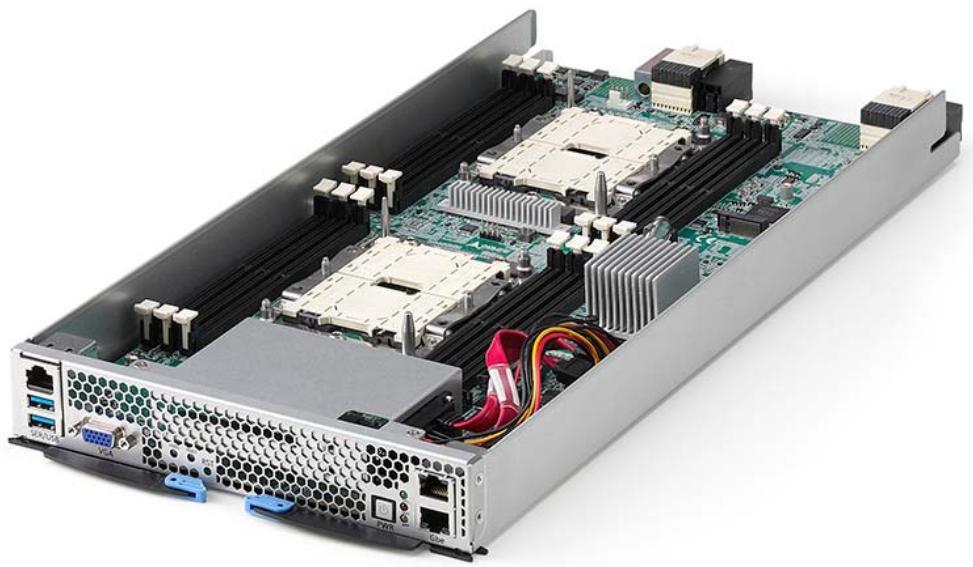
# Intel® Xeon® Scalable Processors CPU Sled
# User’s Manual
Manual Revision: 1.0
Revision Date: April 3, 2019
Part No.: 50-1Z259-1000
# Preface
# Copyright © 2019 ADLINK Technology, Inc.
This document contains proprietary information protected by copyright. All rights are reserved. No part of this manual may be reproduced by any mechanical, electronic, or other means in any form without prior written permission of the manufacturer.
# Disclaimer
The information in this document is subject to change without prior notice in order to improve reliability, design, and function and does not represent a commitment on the part of the manufacturer. In no event will the manufacturer be liable for direct, indirect, special, incidental, or consequential damages arising out of the use or inability to use the product or documentation, even if advised of the possibility of such damages.
# Environmental Responsibility
ADLINK is committed to fulfill its social responsibility to global environmental preservation through compliance with the European Union's Restriction of Hazardous Substances (RoHS) directive and Waste Electrical and Electronic Equipment (WEEE) directive. Environmental protection is a top priority for ADLINK. We have enforced measures to ensure that our products, manufacturing processes, components, and raw materials have as little impact on the environment as possible. When products are at their end of life, our customers are encouraged to dispose of them in accordance with the product disposal and/or recovery programs prescribed by their nation or company.


Battery Labels (for products with battery)


Li-ion


廢電池請回收
# California Proposition 65 Warning

WARNING: This product can expose you to chemicals including acrylamide, arsenic, benzene, cadmium, Tris(1,3-dichloro-2-propyl)phosphate (TDCPP), 1,4- Dioxane, formaldehyde, lead, DEHP, styrene, DINP, BBP, PVC, and vinyl materials, which are known to the State of California to cause cancer, and acrylamide, benzene, cadmium, lead, mercury, phthalates, toluene, DEHP, DIDP, DnHP, DBP, BBP, PVC, and vinyl materials, which are known to the State of California to cause birth defects or other reproductive harm. For more information go to www.P65Warnings.ca.gov.
# Trademarks
Product names mentioned herein are used for identification purposes only and may be trademarks and/or registered trademarks of their respective companies.
Revision History
| Revision | Release Date | Description of Change(s) |
| 1.0 | 2019-04-03 | Initial release |
# Table of Contents
# Preface ....
# 1 Overview .....
1.1 Introduction . . 6
1.2 Specifications. . 7
1.2.1 CPU Sled Specifications..
1.2.2 CPU Sled Layout . .9
1.2.3 DPDK Support . ..10
# 2 Getting Started... .11
2.1 Preparing the CPU Sled.. ..11
2.1.1 Installing the CPUs . .11
2.1.2 Installing Memory............ .....15
2.1.3 Installing a SATA Drive .......... .....16
2.1.4 Installing an M.2 SSD Module . 17
2.2 CPU Sled Front Panel.. . 18
2.3 Inserting and Removing the CPU Sled .. . 18
# 3 Powering Up the CPU Sled ..... . 19
3.1 Power-Up Behavior.. . 19
3.2 Health/Status Indicators .. . 19
# 4 Using the CPU Sled.... 20
4.1 Hot-Swapping the CPU Sled. .. 20
4.2 Using Serial Console . .. 21
4.3 Serial Over LAN via BMC . . 23
4.3.1 Configuring the BMC IP Address.. .23
4.3.2 Configuring BIOS for SOL . .24
4.3.3 Configuring OS for SOL...... ..24
4.3.4 Establishing SOL . .24
4.4 Firmware Upgrade . . 25
4.4.1 Updating the BIOS.. ..25
4.4.2 Updating the BMC ... ..25
# 5 BIOS Setup....................... 27
5.1 Entering BIOS Setup.. . 27
5.2 Setup Menu.... . 28
5.3 Navigation.. .. 29
5.4 Main Setup... . 32
5.4.1 BIOS Information . ..33
5.4.2 System Information........... ...33
5.4.3 System Date/System Time . .34
5.5 Advanced Menu.. .. 35
5.5.1 Network Stack Configuration ........... ....36
5.5.2 Serial Port Console Redirection . ..37
5.5.3 Console Redirection Settings ........... ....38
5.5.4 Trusted Computing ........ ..40
5.5.5 Intel© I210 Gigabit Network Connection . ..42
5.5.6 NIC Configuration .................. .....43
5.6 Chipset Menu.... . 44
5.6.1 CPU Configuration.. ..46
5.6.2 Memory Configuration . .47
5.6.3 Memory Topology .... ..49
5.6.4 UPI Configuration . .50
5.6.5 UPI Status ... ..52
5.6.6 Memory Error Enabling......... ....53
5.6.7 PCIe Error Enabling........... ....55
5.6.8 Server Mgmt . .57
5.7 Security Menu.. . 59
5.7.1 Secure Boot.. ..60
5.7.2 Key Management ...... ....61
5.8 Boot Menu... .. 62
5.9 Save & Exit Menu . . 64
Safety Instructions ................... . 65
Consignes de Sécurité Importantes ................ . 67
Getting Service ..... 69
# 1 Overview
# 1.1 Introduction
The ADLINK MCN-2610T is a high-performance CPU sled featuring dual Intel® Xeon® Scalable Processors, interconnected by dual redundant switch modules when installed in the CSA-7400 Network Appliance. It is ideally suited for building next generation highperformance firewalls and virtualized telecom elements.
The main features of the MCN-2610T are summarized as follows:
• Maximum of four MCN-2610T CPU sleds are supported in the CSA-7400
Dual redundant switch modules provide up to 2x50G data plane links to each MCN-2610T in the CSA-7400
Independent 1G control plane links that connect four MCN-2610T, two switch management CPUs (implemented by COMe module) and two Chassis Management Modules (CMM).
Supports IPMI 2.0 specification, provides web-based intelligent system management via CMM on switch sleds, and supports SOL on compute nodes
Optionally integrates Wind River® Titanium Server or OPNFV software to provide carrier grade NFV service
# 1.2 Specifications
# 1.2.1 CPU Sled Specifications
| Core System |
| CPU(2 per sled) | Intel® Xeon® Silver 4110 Processor 2.10Hz (8C/16T)Intel® Xeon® Silver 4114 Processor 2.20 GHz (10C/20T)Intel® Xeon® Gold 5120T Processor 2.20 GHz (14C/28T)Intel® Xeon® Gold 6130 Processor 2.10 GHz (16C/32T)Intel® Xeon® Gold 6138 Processor 2.00 GHz (20C/40T) |
| L2 Cache | 13.75MB/19.25MB/22MB/27.5MB dependent on CPU |
| Chipset | Intel® C621 Chipset |
| Memory | 12x DDR4-2133/2400/2666 DIMM sockets, ECC, up to 384GB |
| BIOS | AMI BIOS on SPI flash memory |
| Operating Systems | Window 7 64-bit, Wiindows 10 64-bit, Windows Server 2016, Linux Kernel 2.6 or above |
| I/O Interfaces |
| Ethernet | 2x RJ-45 10/100/1000BASE-T Ethernet ports on front panel2 x 1G Ethernet ports to two switch boards via mid-plane |
| Console | 1x RJ-45 serial port |
| USB | 2x USB 3.0 Type A ports |
| Graphics | 1x VGA connector |
| Storage | 2x 2.5” SATA drive bays (internal)1x M.2 SSD (internal) |
| Backplane | 2x PCIe x8 Gen3 to switch nodes |
| Control Buttons and LEDs |
| Power | 1x power button (front) |
| Reset | 1x reset button (front) |
| LEDs | Status (SYS), Custom (APP), Drive Activity (HDD) |
| Mechanical |
| Form Factor | 211.3mmx 40.5mm x 444.3mm (W x H x D) |
| Operating Temp. | 0°C to +40°C |
| Storage Temp. | -40°C to +70°C |
| Humidity | 10% to 80%, non-condensing |
| RoHS | RoHS compliant |
# 1.2.2 CPU Sled Layout
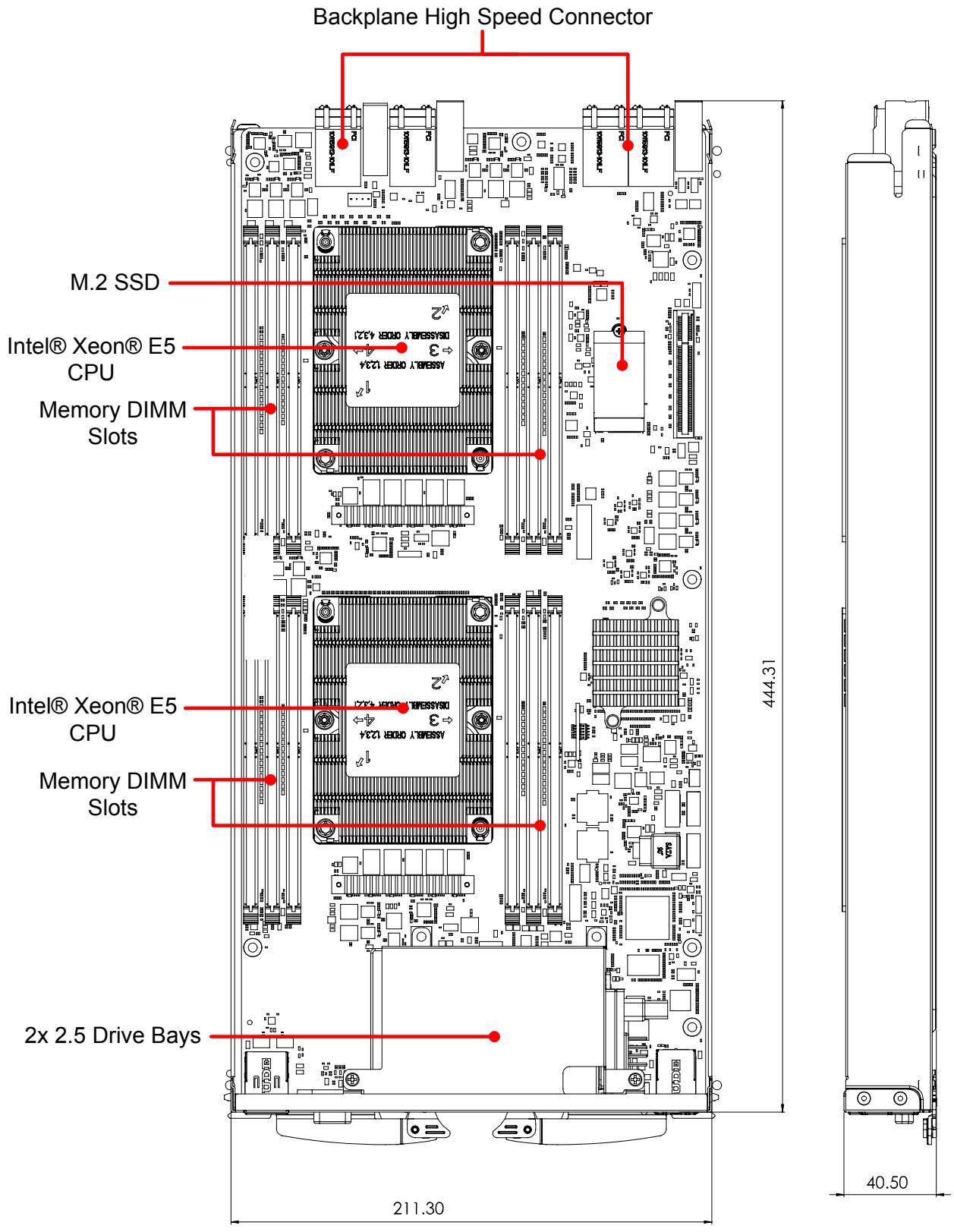
Dimensions in mm
# 1.2.3 DPDK Support
The Data Plane Development Kit (DPDK) is a set of libraries and drivers for fast packet processing, and it can improve packet processing performance by up to ten times. The MCN-2610T CPU sled is fully validated with DPDK and can provide a high throughput for data plane packet processing.
# 2 Getting Started
# 2.1 Preparing the CPU Sled
The MCN-2610T is a single-system dual Intel® Xeon® Scalable Processor compute node.
# 2.1.1 Installing the CPUs
1. Remove the protective covers from the sockets.
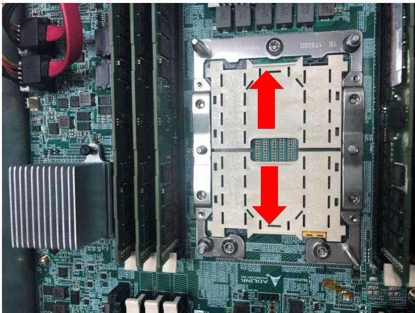
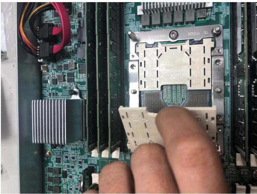
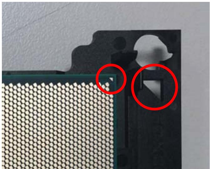
2. Install the CPU to the CPU carrier by aligning the triangle on the CPU with the triangle on bracket.
3. Insert the CPU into the carrier so that the tabs are aligned as shown. You may need to flex the carrier to complete the installation.
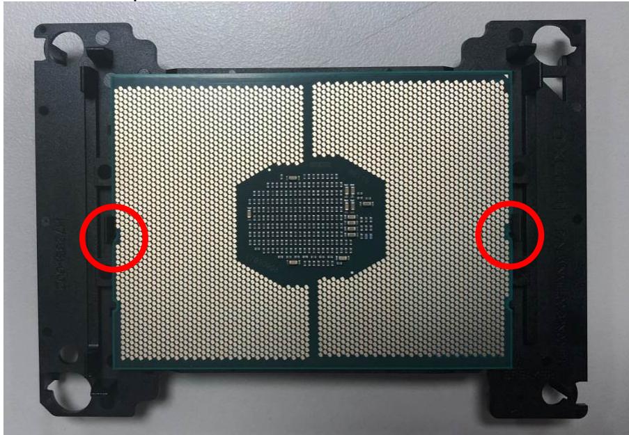
Note: Before continuing, record the information on the back of the CPU for warranty purposes,
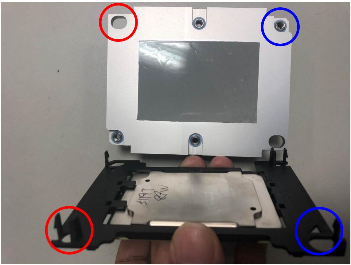
4. Install the heatsink onto the CPU carrier assembly by aligning the holes and tabs on the heatsink and bracket as marked in red and blue.
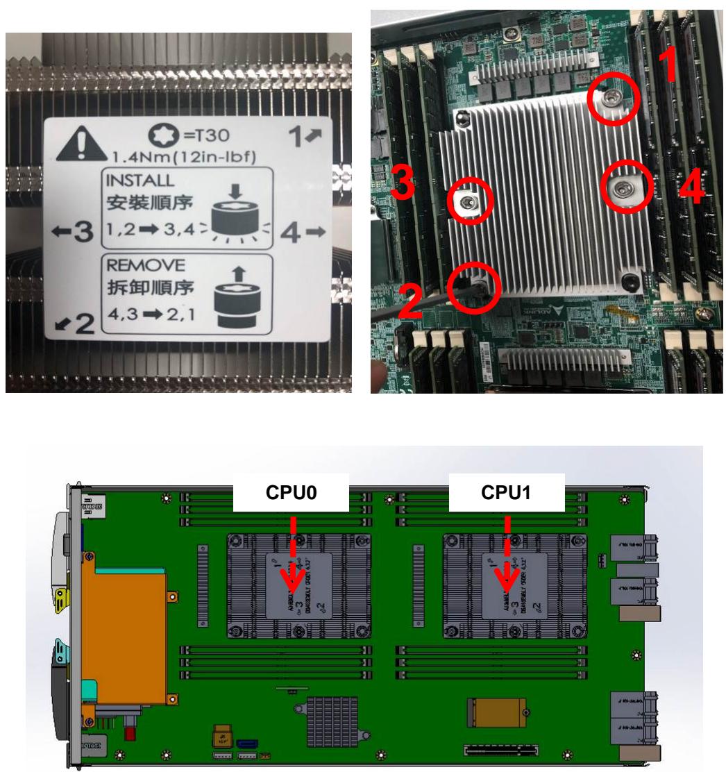
5. Install the CPU/heatsink assembly by aligning the triangle on the CPU carrier with the triangle and beveled edge of the socket, and carefully installing the CPU/heatsink assembly. Secure it by tightening the captive screws in the order shown. Use a T30 torx screwdriver and tighten to the torque value marked on the heatsink.
For a video of the CPU installation, go to:
https://www.intel.com/content/www/us/en/support/articles/000023869/processors/intelxeon-processors.html
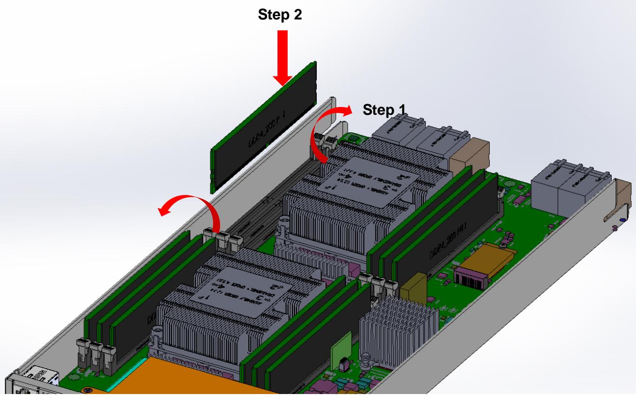
# 2.1.2 Installing Memory
1. Open the locking levers on both sides of each socket.
2. Align the memory module with the keys in the socket and press down firmly until both locking levers click into place.
# 2.1.3 Installing a SATA Drive
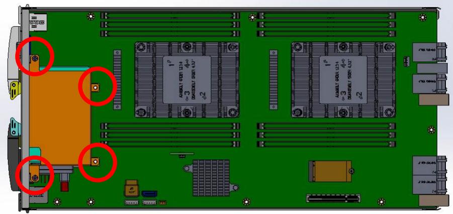
1. Uninstall the drive bay by removing the four screws as shown below.
2. Insert two $2 . 5 "$ SATA drives into the drive tray and secure them with 4 screws as shown.
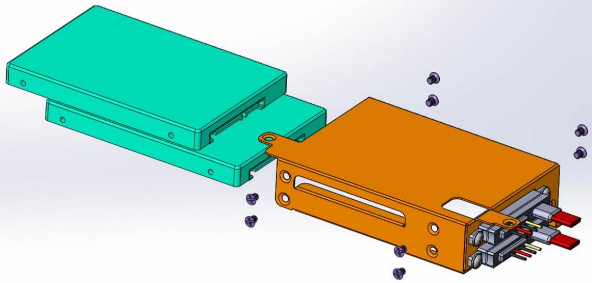
3. Re-install the drive bay by securing the four screws removed in step 1 above.
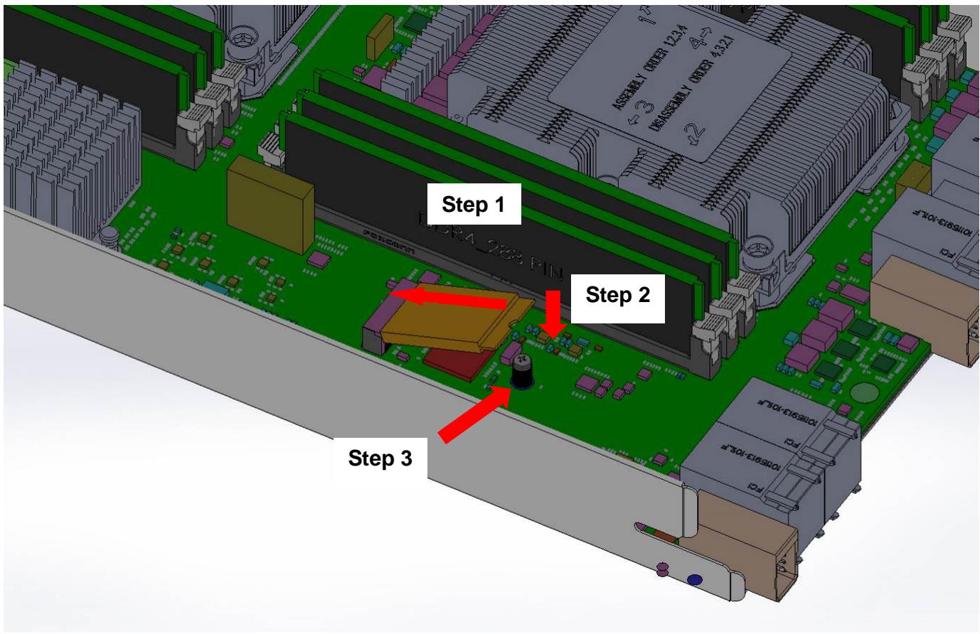
# 2.1.4 Installing an M.2 SSD Module
1. Insert the M.2 SSD module into the slot at a 15 degree angle to the board.
2. Gently press down on the module.
3. Use an M2.5 screw to secure the module to the board.
# 2.2 CPU Sled Front Panel
The MCN-2610T provides I/O connections from the front panel. There are two 1GbE RJ-45 LAN ports, two USB 3.0 Type A ports, one VGA connector, and one RJ-45 console port as shown below.
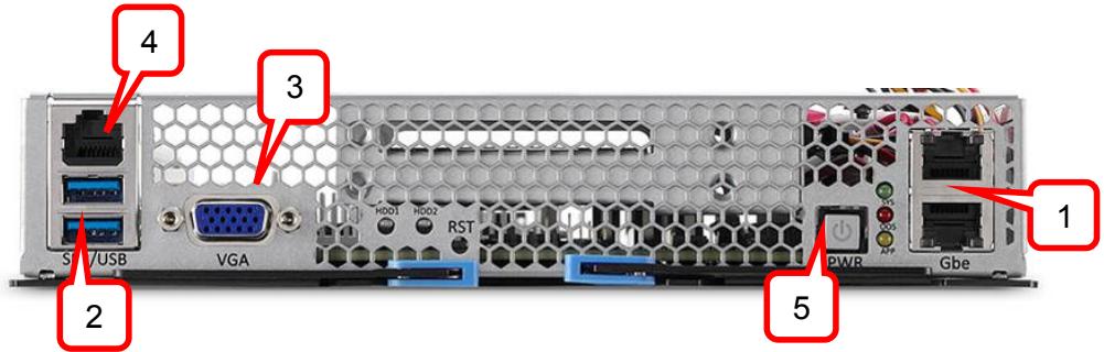
| I/O port | Description |
| 1 | Two 10/100/1000BASE-T Ethernet portsTop: Host; Bottom: Host & BMC |
| 2 | Two USB 3.0 Type A ports |
| 3 | VGA connector |
| 4 | RJ-45 console port |
| 5 | Power button |
# 2.3 Inserting and Removing the CPU Sled
Refer to the chapter "Assembling and Powering Up the CSA-7400” in the “CSA-7400 User’s Manual” for instructions on inserting and removing the CPU Sled.
# 3 Powering Up the CPU Sled
# 3.1 Power-Up Behavior
When power is supplied to the CSA-7400, all components will power up automatically. The behavior of the system when powered up is described below.
1. Cooling fans start speeding up as soon as power is applied to the system.
2. Power LEDs of both CPU and switch nodes turn ON (green).
3. CPU nodes start booting up: The status LED turns ON (red), indicating BIOS POST status. After BIOS POST is completed, the status LED changes from red to green, Indicating system status
Note: The BMC Watchdog timeout will turn off the status LED. If the BMC watchdog is not enabled, the green status LED will stay on.
4. After a few seconds, the switch node A/S LED turns ON (steady or blinking) indicating CM Active/Standby status.
Note: See 4.1 Hot-Swapping the CPU Sled for instructions on how to power down the CPU sled.
# 3.2 Health/Status Indicators
This section covers all of the LEDs on MCN-2600T, as show below.
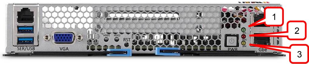
See the table below for LED descriptions.
| LED # | Description |
| 1 | Status LEDRed: BIOS POSTGreen: POST completed |
| 2 | APP LED (dependent on customer design) |
| 3 | SATA drive activity LED |
| Drive Status | LED (Green) |
| Read/Write | Blinking |
| Idle | On |
| Not Present | Off |
# 4 Using the CPU Sled
# 4.1 Hot-Swapping the CPU Sled
Before swapping the CPU Sled, the user must first shutdown the OS by executing a command from the OS or holding down the power button more than 4 seconds.
# 4.2 Using Serial Console
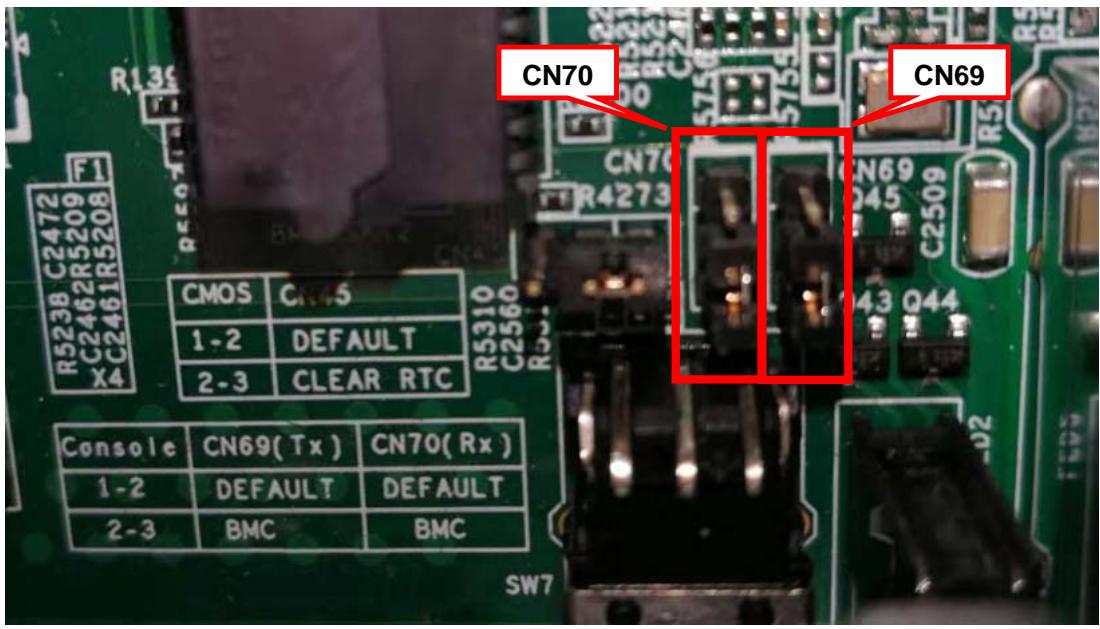
The MCN-2610T sled supports one serial console port, which is shared between the host and the BMC. Selection pins are located on jumpers CN69 & CN70 to control serial console operation.
To access the jumpers, remove the drive bay as described in 2.1.3 Installing a SATA Drive. The jumpers are located as shown below.

| Console Setting | CN69 (Tx) | CN70 (Rx) |
| Host (default) | 1-2 shorted | 1-2 shorted |
| BMC | 2-3 shorted | 2-3 shorted |
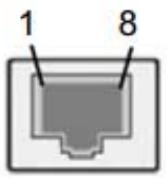
The serial console port is RJ45 form factor, and has a standard pin definition for the console port as below.
| LED # | Description |
| 1 | RTS |
| 2 | DTR |
| 3 | TXD |
| 4 | SG |
| 5 | SG |
| 6 | RXD |
| 7 | DSR |
| 8 | CTS |
The serial port is set with the following parameters
| Type | RS232 (COM) |
| Baud Rate | 115200 bps |
| Data Bits | 8 |
| Parity | None |
| Stop Bits | 1 |
| Flow Control | None |
# 4.3 Serial Over LAN via BMC
The CPU board BMC provides a text-based Serial Over LAN (SOL) console. With SOL redirection system administrators can remotely view the text-based host console from anywhere and perform any task that doesn’t require a GUI.
# 4.3.1 Configuring the BMC IP Address
The BMC IP address is dynamically assigned by DHCP. Users can change the IP address by using ipmitool on the host OS.
# Configure BMC IP Address via Host
```txt
Setting LAN IP Address
# ipmitool lan set 1 ipaddr xxx.xxx.xxx.xxx
Setting LAN Subnet Mask
# ipmitool lan set 1 netmask 255.255.255.0
Setting LAN Default Gateway IP
# ipmitool lan set 1 defgw ipaddr xxx.xxx.xxx.xxx
```
# 4.3.2 Configuring BIOS for SOL
# Serial Port Console Redirection
You can use this screen to select options for the serial port console redirection settings. Use the up and down < Arrow > keys to select an item. Use the < + > and < - > keys to change the value of the selected option. The Serial Port Console Redirection screen is shown below.
| Aptio Setup Utility - Copyright (C) 2016 American Megatrends, Inc.
Advanced |
| COM1
Console Redirection [Disabled]
► Console Redirection Settings | |
| COM2
Console Redirection [Disabled]
► Console Redirection Settings | |
| Legacy Console Redirection
► Legacy Console Redirection Settings | |
| Serial Port for Out-of-Band Management/
Windows Emergency Management Services (EMS)
Console Redirection [Disabled]
► Console Redirection Settings | |
| Console Redirection Enable or Disable. |
| +: Select Screen
↑↓: Select Item
Enter: Select
+/-: Change Opt.
F1: General Help
F2: Previous Values
F3: Optimized Defaults
F4: Save & Exit
ESC: Exit |
| Version 2.17.1249. Copyright (C) 2016 American Megatrends, Inc. |
COM2: console redirection enabled
This port is mapped to BMC vUART.
# 4.3.3 Configuring OS for SOL
vUART SOL with RHEL 5.6 32-bit
```tcl
# vim /etc/securetty -> Add "ttyS2"
# strace /sbin/agetty ttyS0 115200 vt100 {Enter}
```
# 4.3.4 Establishing SOL
Activate SOL from client IPMItool
```txt
# ipmitool -H <BMC IP Address> -I lanplus -U root -P superuser sol activate
```
# 4.4 Firmware Upgrade
# 4.4.1 Updating the BIOS
Users can update the BIOS over various interfaces (Gigabit LAN, KCS).
# Updating the BIOS via Network with BMC Tool
1. Connect the BMC to the LAN, and check its IP address( Ex: 192.168.2.101);
2. Setup a Host machine (with Linux installed), and connect it to the LAN;
3. Login to the host OS with root, and check the network connection with the BMC (ping 192.168.2.101);
4. Copy the upgrade tool & BIOS FW onto the host OS.
5. Update the BIOS over network with the command below:
Example:
```shell
$./up_bios.sh 192.168.2.101 MCN2610_BIOS_XX.BIN
```
# Updating BIOS via Host with BIOS Tool
1. Boot/Login to DOS/OS with root user permission
2. Update the BIOS over host with the command below:
Example:
```batch
AFUDOS.exe BIOS.ROM /x /n /b /p (If only updating BIOS part without ME)
AFUDOS.exe BIOS.BIN /x /n /b /p /me (Updating whole BIOS)
```
# 4.4.2 Updating the BMC
Use Yafuflash tool to update the BMC firmware.
# Updating BMC via Network
1. Plug the BMC into LAN, and check its IP address ( Ex: 192.168.2.101);
2. Setup a Host machine(with Linux installed), and plug into LAN;
3. Login the Host OS with root, and check the network connection with BMC (ping 192.168.2.101);
4. Copy the Yafuflash tool & BMC FW into Host OS.
5. Edit the Yafuflash config file.
```txt
$ vi conf.ini
-nw = YES
-ip = 192.168.2.101
# -kcs = YES
```
6. Update the BMC over network with the command below:
```txt
$ ./Yafuflash -ini conf.ini rom.ima
```
# Updating BMC via Host
1. Copy the Yafuflash tool & BMC FW into Host OS.
2. Edit the Yafuflash config file.
```txt
$ vi conf.ini
```
```txt
# -nw = YES
-kcs = YES
-ip = 192.168.2.101
```
3. Update the BMC via Host with the command below:
Note: Must be a root user
```txt
$ ./Yafuflash -ini conf.ini rom.ima
```
Use Yafuflash tool to update BMC firmware
• To upgrade bootloader, add -force-boot (recommended)
• To preserve config (/conf), add -preserve-config
# 5 BIOS Setup
# 5.1 Entering BIOS Setup
To enter the setup screen, follow these steps:
1. Power on the motherboard
2. Press the < Delete > key on your keyboard when you see the following text prompt: < Press DEL to enter Setup >
3. After you press the < Delete > key, the main BIOS setup menu displays. You can access the other setup screens from the main BIOS setup menu, such as Chipset and Power menus.

In most cases, the < Delete > key is used to invoke the setup screen. However, there are several cases that use other keys, such as $< \mathsf { F } 1 > , < \mathsf { F } 2 >$ , and so on.
# 5.2 Setup Menu
The Main BIOS setup menu is the first screen that you can navigate to. The Main BIOS setup menu screen has two main frames. The left frame displays all the options that can be configured. “Grayed” options cannot be configured, and “Blue” options can be. The right frame displays the key legend. Above the key legend is an area reserved for a text message. When an option is selected in the left frame, it is highlighted in white. Often a text message will accompany it.
Aptio Setup Utility – Copyright © 2018 American Megatrends, Inc.
| Main | Advanced | Chipset | Server Mgmt | Security | Boot | Save & Exit |
| BIOS Information | Set the Date. Use Tab to switch between Date elements. |
| BIOS Vendor | American Megatrends |
| Core Version | 5.12 |
| Compliancy | UEFI 2.5; PI 1.4 | Default Ranges: |
| BIOS Version | 0.60.10 | Year: 2005-2099 |
| Build Date | 04/17/2018 | Months: 1-12 |
| MRC Version | 154.R04 | Days: dependent on month |
| SPS FW Version | 0A:4.0.4.333 | |
| System Information | | |
| Project Name | MCN-2610T | |
| CPU Brand String | Intel(R) Xeon(R) Gold | |
| 6150 CPU @2.70GHz | |
| CPU Frequency | 2700 MHz | |
| Total Memory | 16384 MB (DDR4) | |
| Memory Frequency | 2132 MHz | |
| PCH SKU | LBG QS/PRQ - 1G(S0) | |
| System Date | [Thu 04/23/2018] | ><: Select Screen^v: Select ItemEnter: Select+/-: Change Opt.F1: General HelpF8: Previous ValuesF9: Optimized DefaultF10: Save & ExitESC: Exit |
| System Time | [12:00:00] |
| Access Level | Administrator |
Version 2.19.1268. Copyright © 2018 American Megatrends, Inc.
# 5.3 Navigation
The BIOS setup/utility uses a key-based navigation system called hot keys. Most of the BIOS setup utility hot keys can be used at any time during the setup navigation process. These keys include < F1 >, < F10 >, < Enter >, < ESC >, < Arrow > keys, and so on.
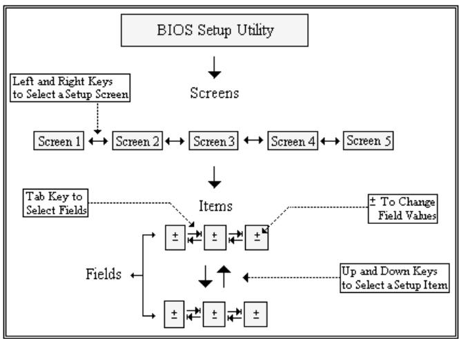

There is a hot key legend located in the right frame on most setup screens.
| →← | Left/Right. The Left and Right < Arrow > keys allow you to select a setup screen.For example: Main screen, Advanced screen, Chipset screen, and so on. |
| ↑↓ | Up/Down The Up and Down < Arrow > keys allow you to select a setup item or sub-screen. |
| +- | Plus/Minus The Plus and Minus < Arrow > keys allow you to change the field value of a particular setup item.For example: Date and Time. |
| Tab | The < Tab > key allows you to select setup fields. |
|
| Hot Key | Description |
| Enter | The < Enter > key allows you to display or change the setup option listed for a particular setup item. The < Enter > key can also allow you to display the setup sub-screens. |
F1 The < F1 > key allows you to display the General Help screen. Press the < F1 > key to open the General Help screen.
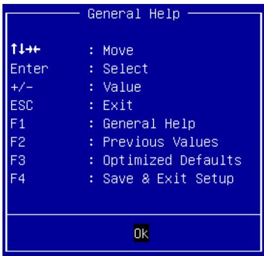
F2 The < F2 > key on your keyboard is the previous values key. It is not displayed on the key legend by default. To set the previous values settings of the BIOS, press the < F2 > key on your keyboard. It is located on the upper row of a standard 101 keyboard. The previous value settings allow the motherboard to boot up with the least amount of options set. This can lessen the probability of conflicting settings.
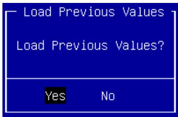
Press the < Enter > key to load previous values. You can also use the < Arrow > key to select Cancel and then press the < Enter > key to abort this function and return to the previous screen.
| F3 | The < F3 > key on your keyboard is the optimized defaults key. To set the optimized defaults settings of the BIOS, press the < F3 > key on your keyboard. It is located on the upper row of a standard 101 keyboard. The optimized defaults settings allow the motherboard to boot up with the optimized defaults of options set. This can lessen the probability of conflicting settings.<img src="images/b6e19badfd2c84c24d923058808a0c00ffc7b1b5da6b009352b656505f82c2d6.jpg"/>Press the < Enter > key to load optimized defaults. You can also use the < Arrow > key to select Cancel and then press the < Enter > key to abort this function and return to the previous screen. |
| F4 | The < F4 > key allows you to save any changes you have made and exit Setup. Press the < F4 > key to save your changes. The following screen will appear:<img src="images/52d9658442f5fa15044537a7b442e67933bbd133d84dc6995a20e56a44b61727.jpg"/>Press the < Enter > key to save the configuration and exit. You can also use the < Arrow > key to select Cancel and then press the < Enter > key to abort this function and return to the previous screen. |
| ESC | The < Esc > key allows you to discard any changes you have made and exit the Setup. Press the < Esc > key to exit the setup without saving your changes. The following screen will appear:<img src="images/f0262df0a2d09baa37b1ffb724edc854dfc1cd4e6a383e3ffe50275bc6edbc90.jpg"/>Press the < Enter > key to discard changes and exit. You can also use the < Arrow > key to select Cancel and then press the < Enter > key to abort this function and return to the previous screen. |
# 5.4 Main Setup
The Main Menu provides read-only information about system and also allows to set system’s date and time. Refer to the tables below.
Aptio Setup Utility – Copyright © 2018 American Megatrends, Inc.
| Main | Advanced | Chipset | Server Mgmt | Security | Boot | Save & Exit |
| BIOS Information | Set the Date. Use Tab to switch between Date elements. |
| BIOS Vendor | American Megatrends |
| Core Version | 5.12 |
| Compliancy | UEFI 2.5; PI 1.4 | Default Ranges: |
| BIOS Version | 0.60.10 | Year: 2005-2099 |
| Build Date | 04/17/2018 | Months: 1-12 |
| MRC Version | 154.R04 | Days: dependent on month |
| SPS FW Version | 0A:4.0.4.333 | |
| System Information | | |
| Project Name | MCN-2610T | |
| CPU Brand String | Intel(R) Xeon(R) Gold | |
| 6150 CPU @2.70GHz | |
| CPU Frequency | 2700 MHz | |
| Total Memory | 16384 MB (DDR4) | |
| Memory Frequency | 2132 MHz | |
| PCH SKU | LBG QS/PRQ - 1G(S0) | |
| System Date | [Thu 04/23/2018] | ><: Select Screen ^v: Select Item Enter: Select +/-: Change Opt. F1: General Help F8: Previous Values F9: Optimized Default F10: Save & Exit ESC: Exit |
| System Time | [12:00:00] |
| Access Level | Administrator |
Version 2.19.1268. Copyright © 2018 American Megatrends, Inc.
# 5.4.1 BIOS Information
| BIOS Item | Options | Description |
| BIOS Vendor | Info only.AmericanMegatrends | Display vendor name of system BIOS. |
| Core Version | Info only.x.yy | Displays the BIOS core version. |
| Compliancy | Info only.UEFI w.x; PI y.z | Displays the current UEFI Specification version. |
| BIOS Version | Info only.x.yy.zz | Display version of booting BIOS. |
| Build Date | Info only.MM/DD/YYYY | It shows the date that BIOS was built. |
| MRC Version | Info only.xxx.Ryy | Display the revision of MRC code which is implemented in BIOS. |
| SPS FW Version | Info only.ww:x.y.z.aaa | Display the version of Intel manageability firmware which is implemented in BIOS. |
# 5.4.2 System Information
| BIOS Item | Options | Description |
| Project Name | Info only.MCN-2610T | Displays the project name. |
| CPU Brand String | Info only.Intel(R) Xeon ... | It shows what CPU is booting the system. |
| CPU Frequency | Info only.XXXX MHz | It shows CPU's frequency. |
| Total Memory | Info only.XXXX MB (DDR4) | It shows total memory size used on the motherboard and memory type. |
| Memory Frequency | Info only.XXXX MHz | It shows memory's frequency. |
| PCH SKU | Info only.LBG xxxxx | It shows what PCH SKU is designed on motherboard. |
# 5.4.3 System Date/System Time
Use this option to change the system time and date. Highlight System Time or System Date using the < Arrow > keys. Enter new values using the keyboard. Press the < Tab > key or the < Arrow > keys to move between fields. The date must be entered in MM/DD/YY format. The time is entered in HH:MM:SS format.
| BIOS Item | Options | Description |
| System Date | MM/DD/YYYY | For configuring/showing system date. When setting the Date, usekey to switch between Date elements. |
| System Time | HH:MM:SS | For configuring/showing system time. When setting the Time, usekey to switch between Time elements. |
| Access Level | Info only.Administrator/User | It shows what access level is used to enter BIOS setup menu. |

The time is in 24-hour format. For example, 5:30 A.M. appears as 05:30:00, and 5:30 P.M. as 17:30:00.
# 5.5 Advanced Menu
This menu contains the settings for most of the user interfaces in the system.
Aptio Setup Utility – Copyright © 2018 American Megatrends, Inc.
| Main | Advanced | Chipset | Server Mgmt | Security | Boot | Save & Exit |
| Above 4G Decoding [Disabled] | Network Stack Settings |
| > Network Stack Configuration | |
| > Serial Port Console Redirection | |
| > Trusted Computing | |
| > Intel© I210 Gigabit network Connection – 00:E0:18:07:... | |
| > Intel© I210 Gigabit network Connection – 00:E0:18:07:... | |
| ><: Select Screen^v: Select ItemEnter: Select+/-: Change Opt.F1: General HelpF8: Previous ValuesF9: Optimized DefaultF10: Save & ExitESC: Exit |
Version 2.19.1268. Copyright © 2018 American Megatrends, Inc.
| BIOS Item | Options | Description |
| Above 4G Decoding | Disabled Enabled | To enable or disable memory mapped I/O for a 64-bit PCIe device to 4GB or greater address space |
| Network Stack Configuration | Submenu | For configuring Network Stack. |
| Serial Port Console Redirection | Submenu | For configuring serial console. |
| Trusted Computing | Submenu | For configuring trusted computing. |
| iSCSI Configuration | Submenu | For iSCSI configuration. |
| Intel© I210 Gigabit Network Connection | Submenu | Onboard Ethernet controller configuration loaded by EFI driver. The setup page is designed by Intel. When running the Ethernet EFI driver, this page will be shown. It is related to the “Network” setting on the Boot page. |
# 5.5.1 Network Stack Configuration
Aptio Setup Utility – Copyright © 2018 American Megatrends, Inc.
Advanced
| Network Stack Configuration | Enable/Disable UEFI |
| Network Stack |
| Network Stack | [Enabled] | |
| IPv4 PXE Support | [Enabled] | |
| IPv6 PXE Support | [Enabled] | |
| | ><: Select Screen^v: Select ItemEnter: Select+/-: Change Opt.F1: General HelpF8: Previous ValuesF9: Optimized DefaultF10: Save & ExitESC: Exit |
Version 2.19.1268. Copyright © 2018 American Megatrends, Inc.
| BIOS Item | Options | Description |
| Network Stack | DisabledEnabled | To enable or disable the network stack. |
| IPv4 PXE Support | DisabledEnabled | To enable or disable IPv4 PXE boot. |
| IPv6 PXE Support | DisabledEnabled | To enable or disable IPv6 PXE boot. |
# 5.5.2 Serial Port Console Redirection
Aptio Setup Utility – Copyright © 2018 American Megatrends, Inc.
Advanced
Serial Port Console Redirection
Console Redirection
> Console Redirection Settings
[Enabled]
Console Redirection Enable or Disable.
><: Select Screen
^v: Select Item
Enter: Select
+/-: Change Opt.
F1: General Help
F8: Previous Values
F9: Optimized Default
F10: Save & Exit
ESC: Exit
Version 2.19.1268. Copyright © 2018 American Megatrends, Inc.
<table>| BIOS Item | Options | Description |
| Console Redirection | EnabledDisabled | Enable or disable serial port console redirection function. |
| Console Redirection Settings | Submenu | For configuring serial port settings when console redirection function is enabled. |
# 5.5.3 Console Redirection Settings
Aptio Setup Utility – Copyright © 2018 American Megatrends, Inc.
Advanced
| Console Redirection Settings | Emulation: ANSI:Extended ASCII char |
| Terminal Type | [VT100+] | set. VT100: ASCII char |
| Bits per second | [115200] | set. VT100+: Extends |
| Data Bits | [8] | VT100 to support color, function keys, etc. |
| Parity | [None] | VT-UTF8: Uses UTF8 |
| Stop Bits | [1] | encoding to map Unicode |
| Flow Control | [None] | chars onto 1 or more |
| Legacy OS Redirection Resolution | [80x24] | |
| | <<: Select Screen^v: Select ItemEnter: Select+/-: Change Opt.F1: General HelpF8: Previous ValuesF9: Optimized DefaultF10: Save & ExitESC: Exit |
Version 2.19.1268. Copyright © 2018 American Megatrends, Inc.
| BIOS Item | Options | Description |
| Terminal Type | VT100VT100+VT-UTF8ANSI | Configure the type of console emulation.ANSI: Extended ASCII char set.VT100: ASCII char set.VT100+: Extends VT100 to support color, function keys, etc.VT-UTF8: Uses UTF8 encoding to map Unicode chars onto 1 or more bytes. |
| Bits per second | 9600192003840057600115200 | Selects serial port transmission speed.The speed must be matched on the other side. Long or noisy lines may require lower speed. |
| Data Bits | 78 | Configures the number of data bits in each transmitted or received serial character for both serial ports. |
| Parity | NoneEvenOddMarkSpace | Configures if parity bit is generated (transmit data) or checked.A parity bit can be sent with the data bits to detect some transmission errors. Even: parity bit is 0 if the num of 1's in the data bits is even.Odd: parity bit is 0 if num of 1's in the data bits is odd.Mark: parity bit is always 1.Space: Parity bit is always 0.Mark and Space Parity do not allow for error detection. They can be used as an additional data bit. |
| Stop Bits | 12 | Configures the number of stop bits transmitted and received in each serial character for both serial ports.Stop bits indicate the end of a serial data packet. (A start bit indicates the beginning). The standard setting is 1 stop bit. Communication with slow devices may require more than 1 stop bit. |
| Flow Control | NoneHardware RTS/CTS | Configures flow control for console redirection. Hardware flow control uses RTC/CTS. |
| Legacy OS Redirection Resolution | 80x2480x25 | Set console display resolution. |
# 5.5.4 Trusted Computing
Aptio Setup Utility – Copyright © 2018 American Megatrends, Inc.
Advanced
TPM20 Device Found
Vendor: IFX
Firmware Version: 7.61
Security Device
Active PCR banks
Available PCR banks
SHA-1 PCR Bank
SHA256 PCR Bank
Pending operation
Platform Hierarchy
Storage Hierarchy
Endorsement Hierarchy
TPM2.0 UEFI Spec
Physical Presence
[Enable]
SHA-1,SHA256
SHA-1,SHA256
[Enabled]
[Enabled]
[None]
[Enabled]
[Enabled]
[Enabled]
[TCG\_2]
[Spec 1.3]
Enables or Disables
BIOS support for
security device. O.S.
will not show Security
Device. TCG EFI
protocol and INT1A
interface will not be
available.
><: Select Screen
^v: Select Item
Enter: Select
+/-: Change Opt.
F1: General Help
F8: Previous Values
F9: Optimized Default
F10: Save & Exit
ESC: Exit
Version 2.19.1268. Copyright © 2018 American Megatrends, Inc.
<table>| BIOS Item | Options | Description |
| Security Device | Disable Enable | Enable or disable BIOS support for security device (TPM). |
| Active PCR banks | Info only | Information to indicate which PCR banks have been enabled by BIOS. The TCG log will be updated according to the Active PCR banks. For example, if SHA-256 and SHA-1 PCR banks are enabled. TCG2 will extend data to both SHA-256 and SHA-1 PCR banks. Furthermore the TCG log will generate a crypto agile log for both SHA-1 and SHA-256 digest data. |
| Available PCR banks | Info only | Indicates which PCR banks are supported and can be enabled in BIOS. |
| SHA-1 PCR bank | Disabled Enabled | Enables or disable the SHA-1 PCR bank. This option will only be displayed if the TPM supports SHA-1. |
| BIOS Item | Options | Description |
| SHA256 PCR bank | DisabledEnabled | Enables or disable the SHA-256 PCR bank. This option will only be displayed if the TPM supports SHA-256.Note: The TPM only supports SHA-1 and SHA-256. If TPM support SHA-384, SHA-512 or SM3, BIOS option will be shown for configuration. |
| Pending operation | NoneTPM Clear | This item exposes the ability to clear TPM 2.0 device. Once the TPM 2.0 device is cleared, the option goes to its default state. |
| Platform Hierarchy | DisabledEnabled | Allows a user to enable or disable TPM 2.0 platform hierarchy (PH). Regardless of the TPM state, BIOS will always randomize the PH before OS handoff. |
| Storage Hierarchy | DisabledEnabled | Allows user to enable or disable TPM 2.0 storage hierarchy. Once disabled, a TPM 2.0 aware OS may not be able to take ownership of the TPM. |
| Endorsement Hierarchy | DisabledEnabled | Allows user to enable or disable TPM 2.0 endorsement hierarchy. Once disabled, the TPM aware OS may not be able use certain features of the TPM. |
| TPM2.0 UEFI Spec | TCG_1_2TCG_2 | This item allows user to choose whether BIOS supports the old TCG EFI protocol version 1.22, or the TCG EFI protocol specification for TPM family 2.0. TCG_1_2 is for the old protocol and TCG_2 is for the new protocol. |
| Physical Presence | Spec 1.2Spec 1.3 | Allows a user to select the supported PPI version reported to the OS. |
# 5.5.5 Intel© I210 Gigabit Network Connection
This setup page is shown when the “Network” setting on the Boot page is set to “UEFI”. When BIOS boots, it will launch the onboard Ethernet Controller I210 UEFI driver. The driver provides a setup page to configure Ethernet parameters and shows information about the Ethernet controller. When the “Network” setting is not set to UEFI and the Ethernet UEFI driver is not executed, this setup page will not be shown.
Aptio Setup Utility – Copyright © 2018 American Megatrends, Inc.
Advanced
> NIC Configuration
| Blink LEDs | 0 |
| UEFI Driver | Intel© PRO/1000 6.7... |
| Adapter PBA | 000300-000 |
| Device Name | Intel© I210 Gigabit... |
| Chip Type | Intel i210 |
| PCI Device ID | 1533 |
| PCI Address | 03:00:00 |
| Link Status | [Disconnected] |
| MAC Address | 00:E0:18:07:18:00 |
| Virtual MAC Address | 00:00:00:00:00:00 |
Click to configure the network device port.
| ><: Select Screen |
| ^v: Select Item |
| Enter: Select |
| +/-: Change Opt. |
| F1: General Help |
| F8: Previous Values |
| F9: Optimized Default |
| F10: Save & Exit |
| ESC: Exit |
Version 2.19.1268. Copyright © 2018 American Megatrends, Inc.
| BIOS Item | Options | Description |
| NIC Configuration | Submenu | For configuring link speed and wake function. |
# 5.5.6 NIC Configuration
Aptio Setup Utility – Copyright © 2018 American Megatrends, Inc.
Advanced
| Link SpeedWake On LAN | [Auto Negotiated][Enabled] | Specifies the port speed used for the selected boot protocol. |
| | ><: Select Screen^v: Select ItemEnter: Select+/-: Change Opt.F1: General HelpF8: Previous ValuesF9: Optimized DefaultF10: Save & ExitESC: Exit |
Version 2.19.1268. Copyright © 2018 American Megatrends, Inc.
| BIOS Item | Options | Description |
| Link Speed | Auto Negotiated10 Mbps Half10 Mbps Full100 Mbps Half100 Mbps Full | For setting link speed of Ethernet. |
| Wake On LAN | EnabledDisabled | For enabling/disabling wake on LAN function. |
# 5.6 Chipset Menu
Aptio Setup Utility – Copyright © 2018 American Megatrends, Inc.
| Main | Advanced | Chipset | Server Mgmt | Security | Boot | Save & Exit |
| >CPU Configuration | CPU Configuration parameters |
| >Memory Configuration |
| >UPI Configuration |
| >Memory Error Enabling |
| >PCIe Error Enabling |
| SATA Controller | [Enable] | |
| sSATA Controller | [Enable] | |
| Configure SATA as | [AHCI] | |
| Configure sSATA as | [AHCI] | |
| SR-IOV Support | [Enable] | |
| Intel© VT for Directed I/O (VT-d) | [Enable] | |
| Automatic Board Power | [On] | |
| ><: Select Screen^v: Select ItemEnter: Select+/-: Change Opt.F1: General HelpF8: Previous ValuesF9: Optimized DefaultF10: Save & ExitESC: Exit |
Version 2.19.1268. Copyright © 2018 American Megatrends, Inc.
| BIOS Item | Options | Description |
| CPU Configuration | Submenu | For configuring CPU features/functions. |
| Memory Configuration | Submenu | For configuring memory features and functions. |
| UPI Configuration | Submenu | For configuring UPI features and functions. |
| Memory Error Enabling | Submenu | For configuring memory error assertion settings. |
| PCIe Error Enabling | Submenu | For configuring PCIe error assertion settings. |
| SATA Controller | Disable Enable | For controlling SATA controller's enabling/disabling. |
| sSATA Controller | Disable Enable | For controlling sSATA controller's enabling/disabling. |
| Configure SATA as | AHCI RAID | For SATA operating mode setting. |
| Configure sSATA as | AHCI RAID | For sSATA operating mode setting. |
| SR-IOV Support | Disable Enable | For enabling/disabling SR-IOV Support. |
| Intel© VT for Directed I/O (VT-d) | Disable Enable | For enabling/disabling Intel VT-d function. |
| Automatic Board Power | On Off | If “On” option is selected, the x86 shall be powered up automatically when the whole chassis is powered up or the board sled is inserted into the chassis. If “Off” option is selected, the automatic powering up is disabled. |
# 5.6.1 CPU Configuration
Aptio Setup Utility – Copyright © 2018 American Megatrends, Inc.
Chipset
| CPU Configuration | | Enables Hyper Threading(Software Method to Enable/Disable Logical Processor threads. |
| Hyper-Threading | [Enable] |
| Execute Disable Bit | [Enable] |
| VMX | [Enable] |
| Enable Intel(R) TXT | [Disable] |
| Numa | [Enable] |
| Hardware Prefetcher | [Enable] |
| SpeedStep (Pstates) | [Enable] |
| Turbo Mode | [Enable] |
| | ><: Select Screen^v: Select ItemEnter: Select+/-: Change Opt.F1: General HelpF8: Previous ValuesF9: Optimized DefaultF10: Save & ExitESC: Exit |
Version 2.19.1268. Copyright © 2018 American Megatrends, Inc.
| BIOS Item | Options | Description |
| Hyper-Threading | EnableDisable | To enable or disable hyper-threading function of CPU. |
| Execute Disable Bit | DisableEnable | Execute Disable Bit can help prevent certain classes of malicious buffer overflow attacks.OS and application installed must support this feature in order for it is enabled. |
| VMX | DisableEnable | To enable or disable Virtual-Machine Extensions of CPU. |
| Enable Intel(R) TXT | DisableEnable | Enable or disable Intel(R) TXT function. |
| Numa | DisableEnable | For enabling or disabling Numa function. |
| Hardware Prefetcher | DisableEnable | To enable or disable hardware prefetcher of CPU. |
| SpeedStep (P-states) | DisableEnable | To enable or disable Speedstep function of CPU. |
| Turbo Mode | DisableEnable | To enabled or disable Turbo Mode of CPU. |
# 5.6.2 Memory Configuration
Aptio Setup Utility – Copyright © 2018 American Megatrends, Inc.
Chipset
| Memory Configuration | | Displays memory topology with Dimm population information |
| > Memory Topology | | |
| Memory Frequency | [Auto] | |
| Channel Interleaving | [Auto] | |
| Rank Interleaving | [Auto] | |
| ADDDC Sparing | [Disable] | |
| Patrol Scrub | [Enable] | |
| Patrol Scrub Interval | 24 | |
| Patrol Scrub Address | [System Physical Addr] | |
| Data Scrambling | [Disable] | |
| Volatile Memory Mode | [1LM] | |
| | ><: Select Screen^v: Select ItemEnter: Select+/-: Change Opt.F1: General HelpF8: Previous ValuesF9: Optimized DefaultF10: Save & ExitESC: Exit |
Version 2.19.1268. Copyright © 2018 American Megatrends, Inc.
| BIOS Item | Options | Description |
| Memory Topology | Submenu | To display memory topology with DIMM population information. |
| Memory Frequency | Auto1866213324002666 | Use this item to set the maximum memory frequency for onboard memory modules. |
| Channel Interleaving | Auto1-way Interleave2-way Interleave3-way Interleave | Channel interleaving divides memory blocks and spreads contiguous portions of data across interleaved channels. It increases potential read bandwidth as requests for data can be made to all interleaved channels in an overlapped manner. Enabling channel interleaving may enhance memory performance. |
| Rank Interleaving | Auto1-way Interleave2-way Interleave4-way Interleave8-way Interleave | Interleaving is performed on rank to have different bandwidth. |
| ADDDC Sparing | DisableEnable | This option is to enable/disable ADDDC sparing.Note: This option can't be enabled when mirror mode is enabled or memory sparing is enabled. |
| Patrol Scrub | DisableEnable | When set to Enable, patrol scrub is initialized to read through all of memory at an interval in hours which is set by the “Patrol Scrub interval” option. Patrol scrub will correct any correctable error correction code (ECC) errors it encounters by writing back the corrected data to memory. |
| Patrol Scrub Interval | 24 | Sets the number of hours for the interval of patrol scrub.Note: this option will be hidden when “Patrol Scrub” is disabled. |
| Patrol Scrub Address | Reverse AddressSystem Physical Address | This is a feature for configuring the mode of patrol scrub. When “System Physical Address” is set, patrol runs in system address generation mode. If it is set to “Reverse Address”, patrol will run in legacy mode.Note: This option will be hidden when “Patrol Scrub” is disabled. |
| Data Scrambling | DisableEnableAuto | Enable it to enhance system performance and data integrity. |
| Volatile Memory Mode | 1LM2LMAuto | Configure “volatile memory mode” to one-level memory mode or two-level memory mode. |
# 5.6.3 Memory Topology
Aptio Setup Utility – Copyright © 2018 American Megatrends, Inc.
Chipset
| Socket0.ChD.Dimm0 :2132MT/s SRx4 16GB RDIMMSocket0.ChE.Dimm0 :2132MT/s SRx4 16GB RDIMMSocket0.ChF.Dimm0 :2132MT/s SRx4 16GB RDIMM | |
| <<: Select Screen^v: Select ItemEnter: Select+/-: Change Opt.F1: General HelpF8: Previous ValuesF9: Optimized DefaultF10: Save & ExitESC: Exit |
Version 2.19.1268. Copyright © 2018 American Megatrends, Inc.
| BIOS Item | Options | Description |
| SocketX.ChY.DimmZ: | Info only | The information is shown only when memory is present in the DIMM slot. Each populated DIMM slot location is indicated by X, Y and Z where:. X = 0/1 - CPU0/CPU1 Y = Channel A/B/C/D/E/F of CPU0 or Channel G/H/J/K/L/M of CPU1 Z will always be 0 because hardware design only supports one DIMM per channel. |
| [Memory Frequency] [Rank number] [Memory size] [Memory type] | Info only | This is the information of memory frequency, type and size which varies depending on the memory installed. |
# 5.6.4 UPI Configuration
Aptio Setup Utility – Copyright © 2018 American Megatrends, Inc.
Chipset
| UPI Configuration | | UPI Status Help |
| > UPI Status |
| Link Speed Mode | [Fast] | |
| Link Frequency Select | [Auto] | |
| KTI Prefetch | [Enable] | |
| Stale AtoS | [Disable] | |
| LLC dead line alloc | [Enable] | |
| | ><: Select Screen^v: Select ItemEnter: Select+/-: Change Opt.F1: General HelpF8: Previous ValuesF9: Optimized DefaultF10: Save & ExitESC: Exit |
Version 2.19.1268. Copyright © 2018 American Megatrends, Inc.
| BIOS Item | Options | Description |
| UPI Status | Submenu | To show the current UPI status including number of CPU, IIO and UPI link speed and frequency. |
| Link Speed Mode | SlowFast | For configuring UPI link speed. UPI speed mode should be ‘Slow’ when there only is one processor installed because UPI is not functional. Set to ‘Slow’ for multi-processor only when you want UPI to run at the boot speed of 50 MT/s. |
| Link Frequency Select | 9.6GT/s10.4GT/sAutoUse Per Link Setting | For selecting UPI link frequency. When there is only one processor, setting this item will not have any function and status of link frequency will be unknown or 1S configuration. |
| KTI Prefetch | DisableEnable | This is for enabling/disabling the KTI prefetch function. |
| Stale AtoS | DisableEnableAuto | The in-memory directory has three states: invalid (I), snoopAll (A), and Shared (S). The snoopAll (A) means the data may exist in another socket or modified state. Shared (S) state means the data may be shared across one or more socket's caches. When reading memory and directory line is in the A state, we must snoop all the other sockets because another socket may have the line in modified state. If this is the case, the snoop will return the modified data. However, it may be the case that all snoops come back a miss if another socket read the line earlier and then dropped it from its cache without modifying it.Disable – allows processing memory directory states as described above.Enable – where a line in A state returns only snoop misses, the line will be transition to S state. Subsequent reads to the line will encounter it in S state and not have to snoop, saving latency and snoop bandwidth. |
| LLC dead line alloc | DisableEnableAuto | In CPU cache scheme, mid-level cache (MLC) evictions are filled into last-level case (LLC). When lines are evicted from MLC, core can flag them as “dead”. This means that lines are not likely to be read again. This option allows dropping dead lines and never fills them into LLC if the option is disabled. When it is enabled, the LLC can opportunistically fill dead lines into LLC if space is available. |
# 5.6.5 UPI Status
Aptio Setup Utility – Copyright © 2018 American Megatrends, Inc.
Chipset
| UPI Status |
| Number of CPU | 1 |
| Number of IIO | 1 |
| UPI Link Speed | Slow or 1S |
| UPI Link Frequency | Unknown or 1S |
| |
| |
| |
| |
| |
Version 2.19.1268. Copyright © 2018 American Megatrends, Inc.
| BIOS Item | Options | Description |
| Number of CPU | Info only | Shows how many CPUs are in use on the system. |
| Number of IIO | Info only | Shows how many IIOs are in use on the system. |
| UPI Link Speed | Info only | Shows current UPI speed (fast/slow). |
| UPI Link Frequency | Info only | Shows current UPI link frequency (9.6 GT/s or 10.4 GT/s). |
# 5.6.6 Memory Error Enabling
Aptio Setup Utility – Copyright © 2018 American Megatrends, Inc.
Chipset
| Memory Error Enabling | Enable/Disable Memory Error |
| Memory Error | [Enable] | |
| Mem Corrected Error | [Enable] | |
| Error Threshold | 3e8 | |
| Leaky bucket low bit | 28 | |
| Leaky bucket high bit | 29 | |
| | <<: Select Screen^v: Select ItemEnter: Select+/-: Change Opt.F1: General HelpF8: Previous ValuesF9: Optimized DefaultF10: Save & ExitESC: Exit |
Version 2.19.1268. Copyright © 2018 American Megatrends, Inc.
| BIOS Item | Options | Description |
| Memory Error | DisableEnable | This is used to enable/disable memory error handling. |
| Mem Corrected Error | DisableEnable | This is used to enable/disable memory correctable error handling. |
| Error Threshold | 1000 | Rank sparing enables a failing rank to be replaced by an unused spare rank installed on the same DDR channel.The failure prediction is done viacorrected error threshold and a leaky bucket, both of which areprogrammable to allow the platform to “judge” when the right time is to spare a failing rank.The value set in this item will be set to correctable error threshold used for error handling. |
| Leaky bucket low bit | 40 | Value range: 1 – 41It is to set low bit for the leaky bucket algorithm which is used to check the data transmissions between CPU sockets and the memory controller. |
| Leaky bucket high bit | 41 | Value range: 1 – 41It is to set high bit for the leaky bucket algorithm which is used to check the data transmissions between CPU sockets and the memory controller. |
# 5.6.7 PCIe Error Enabling
Aptio Setup Utility – Copyright © 2018 American Megatrends, Inc.
Chipset
| PCIe Error Enabling | Enable & escalateCorrectable Errors to error pins. |
| Corrected Error | [Enable] |
| PCIE Corrected Error | [Enable] |
| Error Threshold Mask | 3f |
| Error Threshold | 1 |
| Uncorrected Error | [Enable] |
| Fatal Error Enable | [Enable] |
| AER Corrected Error | [Enable] |
| AER Advisory Nonfatal | [Enable] |
| AER NonFatal Error | [Enable] |
| AER Fatal Error | [Enable] |
| SERR Propagation | [Enable] |
| PERR Propagation | [Enable] | <<: Select Screen^v: Select ItemEnter: Select+/-: Change Opt.F1: General HelpF8: Previous ValuesF9: Optimized DefaultF10: Save & ExitESC: Exit |
| Signal to OS on SERR | [Enable] |
| Signal to OS on PERR | [Enable] |
Version 2.19.1268. Copyright © 2018 American Megatrends, Inc.
| BIOS Item | Options | Description |
| Corrected Error | Disable Enable | It is used to enable/disable PCIe correctable error monitoring and handling. |
| PCIE Corrected Error | Disable Enable | It is used to enable/disable PCIe correctable error counter. |
| Error Threshold Mask | 0x3F | This is for setting what errors will be included in error count. (Bit 0 – Bit 5)Bit 0 – receiver errorBit 1 – Bad TLPBit 2 – Bad DLLPBit 3 – replay num rolloverBit 4 – Replay Timer TimeoutBit 5 – Advisory non-fatal |
| Error Threshold | 1 | It is for setting the threshold of PCIe correctable error counter. |
| Uncorrected Error | Disable Enable | It is for enabling/disabling the escalation of uncorrectable event to error pins. |
| Fatal Error Enable | DisableEnable | It is for enabling/disable the escalation of PCIe fatal errors to error pins. |
| AER Corrected Error | DisableEnable | For enabling or disabling PCIE AER correctable error reporting. |
| AER Advisory Nonfatal | DisableEnable | For enabling or disabling PCIE AER Advisory Non-fatal error reporting. |
| AER NonFatal Error | DisableEnable | For enabling or disabling PCIE AER Non-fatal error reporting. |
| AER Fatal Error | DisableEnable | For enabling or disabling PCIE AER fatal error reporting. |
| SERR Propagation | DisableEnable | When PCI express root port detects an error, it will bring down the PCIe link associated with the affected root port within one cycle and then SMM handler restores the link. PCIe LER (live error recovery) prevents the transfer of associated corrupt data during process, trapping errors at a root port to prevent their propagation.This option is to enable/disable the prevention of SERR propagation. |
| PERR Propagation | DisableEnable | This option is to enable/disable the prevention of PERR propagation. |
| Signal to OS on SERR | DisableEnable | It is used for notifying OS on receiving SERR event. |
| Signal to OS on PERR | DisableEnable | It is used for notifying OS on receiving PERR event. |
# 5.6.8 Server Mgmt
This menu contains the settings for server management configuration in the system.
Aptio Setup Utility – Copyright © 2018 American Megatrends, Inc.
Server Mgmt
| PCIe Error Enabling | Enable & escalateCorrectable Errors to error pins. |
| BMC Self Test Status | PSAAED |
| BMC Device ID | 32 | |
| BMC Device Revision | 1 | |
| BMC Firmware Revision | 1.3 | |
| FRB-2 Timer | [Enable] | |
| FRB-2 Timer timeout | [3 minutes] | |
| FRB-2 Timer Policy | [Reset] | |
| OS Watchdog Timer | [Disable] | |
| OS Wdt Timer timeout | [5 minutes] | |
| OS Wdt Timer Policy | [Reset] | |
| | ><: Select Screen^v: Select ItemEnter: Select+/-: Change Opt.F1: General HelpF8: Previous ValuesF9: Optimized DefaultF10: Save & ExitESC: Exit |
Version 2.19.1268. Copyright © 2018 American Megatrends, Inc.
| BIOS Item | Options | Description |
| BMC Self Test Status | Info only | Shows BMC Self Test status |
| BMC Device ID | Info only | Shows how many CPUs are using on system. |
| BMC Device Revision | Info only | Shows how many IIOs are using on system. |
| BMC Firmware Revision | Info only | Shows current UPI speed (fast/slow). |
| FRB-2 Timer | Disable Enable | Enable/Disable FRB-2 Watchdog Timer. |
| FRB-2 Timer | 3 minutes4 minutes5 minutes6 minutes | Configures FRB-2 watchdog timer's timeout value. |
| FRB-2 Timer Policy | Do Nothing Reset | Configure how the system should respond if the FRB-2 Watchdog Timer expires. |
| OS Watchdog Timer | Disable Enable | Enable/Disable OS Load watchdog timer. |
| OS Wdt Timer timeout | 5 minutes10 minutes15 minutes20 minutes | Configures OS Load watchdog timer's timeout value. |
| OS Wdt Timer Policy | Do Nothing Reset | Configure how the system should respond if the OS Load watchdog timer expires. |
# 5.7 Security Menu
This menu contains the settings for security in the system.
Aptio Setup Utility – Copyright © 2018 American Megatrends, Inc.
Main Advanced Chipset Server Mgm Security Boot Save & Exit
Password Description
If ONLY the Administrator’s password is set, then this only limits access to Setup and is Only asked for when entering Setup. If ONLY the User’s password is set, then this is a power on password and must be entered to boot or enter Setup. In Setup the user will have Administrator rights. The password length must be in the following range: Minimum length 3 Maximum length 20
Administrator Password
User Password
> Secure Boot
><: Select Screen
^v: Select Item
Enter: Select
+/-: Change Opt.
F1: General Help
F8: Previous Values
F9: Optimized Default
F10: Save & Exit
ESC: Exit
Version 2.19.1268. Copyright © 2018 American Megatrends, Inc.
<table>| BIOS Item | Options | Description |
| Administrator Password | Enter to set password | Configure/Clear Administrator Password. After pressing enter, a menu will pop up for creating a new password. When a password has been previously set, pressing enter without inputting a password, will clear the password. |
| User Password | Enter to set password | Configure/Clear User Password. After pressing enter, a menu will pop up for creating new password. When a password has been previously set, pressing enter without inputting a password, will clear the password. |
| Secure Boot | Submenu | For secure boot configuration. |
# 5.7.1 Secure Boot
Aptio Setup Utility – Copyright © 2018 American Megatrends, Inc.
Security
| Secure Boot | | Secure Boot activated when |
| System Mode | User | Platform Key(PK) is enrolled, System mode is |
| Secure Boot | Not Active |
| Secure Boot Control | [Disabled] | User/Deployed, and CSM function is disabled |
| >Key Management | |
| | <<: Select Screen^v: Select ItemEnter: Select+/-: Change Opt.F1: General HelpF8: Previous ValuesF9: Optimized DefaultF10: Save & ExitESC: Exit |
Version 2.19.1268. Copyright © 2018 American Megatrends, Inc.
| BIOS Item | Options | Description |
| System Mode | Info only | Show current system mode. |
| Secure Boot | Info only | Show current state of secure boot function. |
| Secure Boot Control | DisabledEnabled | Secure Boot can be enabled if:1. System running in User mode with enrolled Platform Key (PK)2. CSM function is disabled. |
| Key Management | Submenu | For installing/appending/erasing secure boot databases and keys. |
# 5.7.2 Key Management
Aptio Setup Utility – Copyright © 2018 American Megatrends, Inc.
Security
| Key Management | Enroll Factory Defaults or load certificates from a file: |
| Secure Boot variable | Size | Key# | Key Source | 1.Public Key Certificate in: |
| > Platform Key(PK) | 0 | 0 | No Key | a)EFI_SIGNATURE_LIST |
| > Key Exchange Keys | 0 | 0 | No Key | b)EFI_CERT_X509 (DER encoded) |
| > Authorized Signatures | 0 | 0 | No Key |
| > Forbidden Signatures | 0 | 0 | No Key | c)EFI_CERT_RSA2048(bin)d)EFI_CERT_SHA256, 384, 5122.Authenticated UEFI Variable3.EFI PE/COFF Image |
| | | | ><: Select Screen^v: Select ItemEnter: Select+/-: Change Opt.F1: General HelpF8: Previous ValuesF9: Optimized DefaultF10: Save & ExitESC: Exit |
Version 2.19.1268. Copyright © 2018 American Megatrends, Inc.
| BIOS Item | Options | Description |
| Platform Key(PK) | Enter | For installing/saving/erasing PK. |
| Key Exchange Keys | Enter | For installing/saving/appending/erasing KEK. |
| Authorized Signatures | Enter | For installing/saving/appending/erasing db. |
| Forbidden Signatures | Enter | For installing/saving/appending/erasing dbx. |
# 5.8 Boot Menu
This menu contains the settings for bootable devices in the system.
Aptio Setup Utility – Copyright © 2018 American Megatrends, Inc.
| Main | Advanced | Chipset | Server Mgm | Security | Boot | Save & Exit |
| Boot Configuration | Select boot mode LEGACY /UEF |
| Boot mode select | [UEFI] | |
| CSM Support | [Enabled] | |
| Network | [Auto] | |
| Storage | [Auto] | |
| Boot Configuration | |
| Boot Option #1 | [Network] | |
| Boot Option #2 | [Hard Disk] | |
| Boot Option #3 | [CD/DVD] | |
| Boot Option #4 | [USB Hard Disk] | |
| Boot Option #5 | [USB Key] | ><: Select Screen |
| Boot Option #6 | [USB CD/DVD] | ^v: Select Item |
| Boot Option #7 | [UEFI AP:UEFI: Built...] | Enter: Select +/-: Change Opt. |
| >UEFI USB Key Drive BBS Priorities | F1: General Help |
| >UEFI Application Boot Priorities | F8: Previous Values |
| F9: Optimized Default |
| F10: Save & Exit |
| ESC: Exit |
Version 2.19.1268. Copyright © 2018 American Megatrends, Inc.
| BIOS Item | Options | Description |
| Boot mode select | LEGACYUEFI | Select boot mode, LEGACY/UEFI. |
| CSM Support | DisabledEnabled | Enable to support operating system that only support legacy mode. |
| Network | Do not launchAuto | Select the method of launch option ROM of network controller. Auto will execute EFI driver or hook legacy option ROM according to the setting (LEGACY/UEFI) of “Boot mode select” setup item. |
| Storage | Do not launchAuto | Select the method of launch option ROM of storage controller. Auto will execute EFI driver or hook legacy option ROM according to the setting (LEGACY/UEFI) of “Boot mode select” setup item. |
| Boot Option #1 ~ #7 | #1: Network#2: Hard Disk#3: CD/DVD#4: USB Hard Disk#5: USB Key#6: USB CD/DVD#7: Built-in EFI Shell | For boot priority setting. |
| XXXX Drive BBS Priorities | Submenu | When the bootable device is attached to system and found by BIOS, it will be listed at boot option#. If there are many devices with the same device type found, it can set priority among these devices through this Submenu. |
# 5.9 Save & Exit Menu
Aptio Setup Utility – Copyright © 2018 American Megatrends, Inc.
Main Advanced Chipset Server Mgm Security Boot Save & Exit
| Save Changes and ExitDiscard Changes and ExitSave Changes and ResetDiscard Changes and Reset | Exit system setup aftersaving the changes. |
| Save OptionsSave ChangesDiscard Changes | |
| Restore DefaultsSave as User DefaultsRestore User Defaults | |
| Boot OverrideLaunch EFI Shell from filesystem device | ><: Select Screen^v: Select ItemEnter: Select+/-: Change Opt.F1: General HelpF8: Previous ValuesF9: Optimized DefaultF10: Save & ExitESC: Exit |
Version 2.19.1268. Copyright © 2018 American Megatrends, Inc.
| BIOS Item | Options | Description |
| Save Changes and Exit | Enter | Save changed settings and exit BIOS setup utility. |
| Discard Changes and Exit | Enter | Skip changed setting and exit BIOS setup utility. |
| Save Changes and Reset | Enter | Save all changed settings and let system do reset to boot system. |
| Discard Changes and Reset | Enter | Discard all changed settings and let system do reset to boot system. |
| Save Changes | Enter | Save all changed settings. |
| Discard Changes | Enter | Discard changes done so far to any of the setup options. |
| Restore Default | Enter | Load the default made when BIOS was built. |
| Save as User Default | Enter | Save all changed done so far as User Defaults. |
| Restore User Default | Enter | Load the default that user save as user defaults. |
| Boot Override | Info only | |
# Safety Instructions
For user safety, please read and follow all instructions, WARNINGS, CAUTIONS, and NOTES marked in this manual and on the associated equipment before handling/operating the equipment.
1. Read these safety instructions carefully.
2. Keep this user’s manual for future reference.
3. Read the specifications section of this manual for detailed information on the operating environment of this equipment.
4. The equipment can be operated at an ambient temperature of $40 \textdegree$
5. When installing/mounting or uninstalling/removing equipment; or when removal of the chassis lid required for user servicing (Section 3.1-3.5):
• Turn off power and unplug any power cords/cables, and
• Reinstall the chassis lid before restoring power.
6. To avoid electrical shock and/or damage to equipment:
• Keep equipment away from water or liquid sources;
• Keep equipment away from high heat or high humidity;
Keep equipment properly ventilated (do not block or cover ventilation openings);
• Make sure to use recommended voltage and power source settings;
• Always install and operate equipment near an easily accessible electrical socketoutlet;
• Secure the power cord (do not place any object on/over the power cord);
Only install/attach and operate equipment on stable surfaces and/or recommended mountings;
If the equipment will not be used for long periods of time, turn off and unplug the equipment from its power source.
7. Never attempt to fix the equipment. Equipment should only be serviced by qualified personnel.
8. A Lithium-type battery may be provided for uninterrupted, backup or emergency power.
CAUTION! Risk of explosion if battery is replaced with one of an incorrect type. Please dispose of used batteries appropriately.
9. Equipment must be serviced by authorized technicians when:
The power cord or plug is damaged;
Liquid has penetrated the equipment;
It has been exposed to high humidity/moisture;
• It is not functioning or does not function according to the user’s manual;
• It has been dropped and/or damaged; and/or,
It has an obvious sign of breakage.
10. Please pay strict attention to all warnings and advisories appearing on the device, to avoid injury or damage.
11. The equipment may have more than one power supply input. To reduce the risk of electrical shock, trained personnel should disconnect all power supply inputs before servicing.
CAUTION! Disconnect all power supply inputs before servicing.
12. It is recommended that equipment be installed only in a server room or computer room where access is:
Restricted to qualified service personnel or users familiar with restrictions applied to the location, reasons therefor, and any precautions required;
Only afforded by the use of a tool or lock and key, or other means of security, and is controlled by the authority responsible for the location.
# Consignes de Sécurité Importantes
Pour assurer la sécurité de l’utilisateur, veuillez lire et suivre toutes les directives, ainsi que les AVERTISSEMENTS, MISES EN GARDE et REMARQUES de ce manuel et indiqués sur l’équipement associé avant de manipuler ou utiliser l’équipement.
1. Veuillez lire attentivement ces instructions de sécurité avec soin.
2. Veuillez conserver ce manuel pour référence future.
3. Veuillez lire la section des spécifications de ce manuel pour avoir des informations détaillées sur l’environnement d’exploitation de cet équipement.
4. L’équipement peut être utilisé à une température ambiante de 40 °C.
5. Lors de l’installation ou du montage et de la désinstallation ou de la dépose de l’équipement; ou lors de la dépose du couvercle du châssis pour procéder à l’entretien par l’utilisateur (Sections 3.1-3.5):
• Coupez l’alimentation et débranchez les cordons et les câbles d’alimentation, et
• Reposez le couvercle du châssis avant de remettre l’alimentation.
6. Pour éviter un risque d’électrocution et pour éviter d’endommager l’équipement :
• Éloignez l’équipement de l’eau et de toute source liquide;
• Éloignez l’équipement de toute source de chaleur ou d’humidité élevée;
Gardez l’équipement correctement ventilé (ne pas bloquer ou couvrir les ouvertures de ventilation);
Veillez à utiliser la tension recommandée et les réglages adéquats pour la source d’alimentation;
Veuillez toujours installer et exploiter l’équipement à proximité d’une prise de courant facilement accessible;
Assurez-vous que le cordon d’alimentation est acheminé de manière sécuritaire (ne déposez aucun objet dessus);
Installez, fixez et utilisez l’équipement sur des surfaces stables ou sur les fixations recommandées uniquement;
Si l’équipement n’est pas utilisé pendant une longue période, éteignez-le et débranchez-le de sa source d’alimentation.
7. N’essayez jamais de réparer l’équipement. L’équipement ne doit être réparé que par du personnel qualifié.
8. Une pile au lithium peut être installée pour assurer l’alimentation de secours ou d’urgence en continu.
ATTENTION! Risque d’explosion si la pile est remplacée par une autre de type incorrect. Veuillez jeter les piles usagées de façon appropriée.
9. L’équipement doit être entretenu par des techniciens agréés lorsque :
le cordon d’alimentation est endommagé ou lorsque la fiche électrique est endommagée;
du liquide a pénétré à l’intérieur de l’équipement;
• l’équipement a été exposé à un taux d’humidité élevé;
• l’équipement ne fonctionne pas ou ne fonctionne pas conformément au manuel de l’utilisateur;
• l’équipement est tombé ou lorsqu’il a été endommagé;
• l’équipement présente un signe évident de défaillance.
10. Veuillez porter une attention rigoureuse à tous les avertissements et à tous les avis figurant sur l’appareil, pour éviter des blessures ou des dommages.
11. ATTENTION! L’équipement peut avoir plus d’une entrée d’alimentation. Pour réduire le risque d’électrocution, le personnel qualifié devrait déconnecter toutes les entrées d’alimentation avant de procéder à l’entretien.
12. Il est recommandé que l'équipement soit installé que dans une salle de serveur ou de la salle informatique où:
L'accès est limité au personnel de maintenance qualifié ou utilisateurs familiers avec les restrictions appliquées à l'emplacement, motifs, et tout les précautions nécessaires, et;
• L'accès est uniquement assurée par l'utilisation d'un outil ou clé, ou d'autres moyens de sécurité, et est contrôlé par l'autorité responsable de l'emplacement.
# Getting Service
Ask an Expert: http://askanexpert.adlinktech.com
# ADLINK Technology, Inc.
Address: 9F, No.166 Jian Yi Road, Zhonghe District
New Taipei City 235, Taiwan
新北市中和區建一路 166 號 9 樓
Tel: +886-2-8226-5877
Fax: +886-2-8226-5717
Email: service@adlinktech.com
# Ampro ADLINK Technology, Inc.
Address: 5215 Hellyer Avenue, #110, San Jose, CA 95138, USA
Tel: +1-408-360-0200
Toll Free: +1-800-966-5200 (USA only)
Fax: +1-408-360-0222
Email: info@adlinktech.com
# ADLINK Technology (China) Co., Ltd.
Address: 上海市浦东新区张江高科技园区芳春路 300 号 (201203)
300 Fang Chun Rd., Zhangjiang Hi-Tech Park, Pudong New Area
Shanghai, 201203 China
Tel: +86-21-5132-8988
Fax: +86-21-5132-3588
Email: market@adlinktech.com
# ADLINK Technology GmbH
Address: Hans-Thoma-Strasse 11, D-68163, Mannheim, Germany
Tel: +49-621-43214-0
Fax: +49-621 43214-30
Email: emea@adlinktech.com
Please visit the Contact page at www.adlinktech.com for information on how to contact the ADLINK regional office nearest you.
[🔗 Link to the original document](.mcn-2610t-50-1z259-1000-10/mcn-2610t-50-1z259-1000-10.pdf)