# MECS-6120/6121

1U Edge Server

with Intel® Xeon® D-1700 Processor

# User’s Manual

![Line drawing of a server rack unit with multiple ports and connectors (no text or symbols)](.mecs-6120-50m-22807-1010-11/9db07e563155f0ee19f9058e3b3ca4e561c732b4e593aba1d1d4e373cc65278c.jpg)

Manual Rev.: Rev. 1.1

Revision Date: May 14, 2026

Part No.: 50M-22807-1010

# Preface

# Copyright © 2026 ADLINK Technology, Inc.

This document contains proprietary information protected by copyright. All rights are reserved. No part of this manual may be reproduced by any mechanical, electronic, or other means in any form without prior written permission of the manufacturer.

# Disclaimer

The information in this document is subject to change without prior notice in order to improve reliability, design, and function and does not represent a commitment on the part of the manufacturer.

In no event will the manufacturer be liable for direct, indirect, special, incidental, or consequential damages arising out of the use or inability to use the product or documentation, even if advised of the possibility of such damages.

# Environmental Responsibility

ADLINK is committed to fulfill its social responsibility to global environmental preservation through compliance with the European Union’s Restriction of Hazardous Substances (RoHS) directive and Waste Electrical and Electronic Equipment (WEEE) directive. Environmental protection is a top priority for ADLINK. We have enforced measures to ensure that our products, manufacturing processes, components, and raw materials have as little impact on the environment as possible. When products are at their end of life, our customers are encouraged to dispose of them in accordance with the product disposal and/or recovery programs prescribed by their nation or company.

![Symbol of a trash bin crossed out by two diagonal lines (no text or numbers present)](.mecs-6120-50m-22807-1010-11/29fbffab004bfd73ca83af0ea5e1eec314d60f9888d1842ecc426cdcbedc546a.jpg)

![This image displays a simple graphic design consisting of white horizontal lines on a black background. Two thick, parallel white lines run horizontally across the top and bottom edges of the frame. A single, thinner white line separates the upper black band from the lower, larger black rectangular area, creating a distinct two-part layout.](.mecs-6120-50m-22807-1010-11/a4132fb5c2235845b2b76d5fe6d284fdbf567e5e003cb0f7774a6dd76dcc50a3.jpg)

# Trademarks

Product names mentioned herein are used for identification purposes only and may be trademarks and/or registered trademarks of their respective companies.

Revision History

<table><tr><td>Revision</td><td>Release Date</td><td>Description of Change(s)</td></tr><tr><td>1.0</td><td>2024-06-14</td><td>Initial release</td></tr><tr><td>1.1</td><td>2026-05-14</td><td>Mechanical overview updated</td></tr></table>

# Conventions

![The image displays a standard yellow triangular warning sign containing a black exclamation point centered inside. Below the triangle, the text 'CAUTION:' is printed in black capital letters.](.mecs-6120-50m-22807-1010-11/a901cee3b775fbcc747a57d6b7161e754c7556cca6c782d6373527b4f0a5d607.jpg)

mise en garde

Information to prevent minor physical injury, component damage, data loss, and/or program corruption when trying to complete a task.

Informations destinées à prévenir les blessures corporelles mineures, les dommages aux composants, la perte de données et/ou la corruption de programme lors de l'exécution d'une tâche.

![A red triangular warning symbol containing a white exclamation point, with the text 'WARNING:' printed below it in black capital letters.](.mecs-6120-50m-22807-1010-11/5bb7ac1f8d559b502466daee6c8c2ef57f7861e9d15011dfbe4d395a9a44cd2e.jpg)

AVERTISSEME

Information to prevent serious physical injury, component damage, data loss, and/or program corruption when trying to complete a specific task. Informations destinées à prévenir les blessures corporelles graves, les dommages aux composants, la perte de données et/ou la corruption de programme lors de l'exécution d'une tâche spécifique.

# Table of Contents

# Preface .................

# Table of Contents .................

# 1 Overview .....

1.1 Introduction .. ..6
1.2 Block Diagram. .7
1.3 Mechanical Overview .. ..8

1.3.1 MECS-6120 Front Panel ..... ....8
1.3.2 MECS-6121 Front Panel . ...8
1.3.3 MECS-6120 Rear Panel . ..9
1.3.4 MECS-6121 Rear Panel . ..9
1.3.5 MECS-6120 Internal Layout . . 10
1.3.6 MECS-6121 Internal Layout .. ... 11

1.4 Mechanical Dimensions . .12

# 2 Specifications ..... . 13

2.1 MECS-6120 Specifications.. ..13

# 3 Getting Started .... . 15

3.1 Removing the Chassis Cover.. ..15
3.2 Installing Memory Modules.. ..16
3.3 PCIe Card Installation . ..17
3.4 PCIe Slot Secondary Power Supply . ..23
3.5 Rails Assembly and Rack Installation . ..24
3.6 Uninstalling the Rails from the Chassis .. .. 28
3.7 Connecting the System to Ground . ..31
3.8 System Power Cable Installation. ..32
3.9 Login to the BMC via Console Port . .. 33
3.10 Login to the BMC via Network.. ..35
3.11 BMC eth0 Default and Static IP Settings . ..37
3.12 BMC eth1 Default and Static IP Settings . ..38
3.13 BIOS Update..

3.13.1 Updating the BIOS via Network with BMC Tool...... .. 39
3.13.2 Updating BIOS via Host with BIOS Tool ....... .. 40

3.14 BMC Firmware Update via Network . ..41

3.15 BMC Firmware Update via Host with Yafuflash . .42
3.16 Enter BIOS Setup.. .43
3.17 Create a RAID Volume.. ..44
3.18 Clear CMOS.. ..46

# 4 System Interfaces............... . 47

4.1 Status LEDs .. ..47
4.2 LAN Ports... ..48
4.3 SFP+ Ports .. ..49
4.4 Dual USB 3.0 and RJ-45 Console Port.. .. 50
4.5 1PPS/TOD Connector... .51
4.6 HDD/User LED Jumper.. ..52
4.7 User LED Commands . ..53

4.7.1 OEM ADLINK Set LED Status .... . 53

4.7.2 OEM ADLINK Get LED Status.. . 54

4.8 Board Layout.. ..55

# 5 BIOS Setup..................... 57

5.1 BIOS Setup Menu . ..57

5.1.1 Menu Selection Bar .......... . 57
5.1.2 Menu Conventions.......... . 58

5.2 Main Menu .... ..58

5.2.1 BIOS Information .... . 59
5.2.2 System Information ............ . 59

5.3 Platform Configuration Menu.. ..60

5.3.1 PCH-IO Configuration... 61
5.3.2 Miscellaneous Configuration . . 64
5.3.3 Network Configuration .. . 65
5.3.4 System Event Log.. . 66

5.4 Advanced Menu . ..67

5.4.1 Serial Port Console Redirection . . 68
5.4.2 NVMe Configuration . 71
5.4.3 PCI Subsystem Settings. . 72
5.4.4 Network Stack Configuration . . 73
5.4.5 Advanced Power Management . . 74
5.4.6 Trusted Computing . . 80
5.4.7 Intel(R) I210 Gigabit Network Connection. . 81
5.4.8 Intel(R) Ethernet Connection E823-L for 10GbE.. . 82

5.5 Socket Configuration Menu . ..83

5.5.1 Processor Configuration . . 84
5.5.2 Common RefCode Configuration . . 85
5.5.3 Memory Configuration . . 86
5.5.4 IIO Configuration.. . 88

5.6 Server Mgmt Menu.. ..91

5.6.1 BMC Network Configuration . . 92

5.7 Security Menu .... ..93
5.8 Boot Menu...... .94
5.9 Save & Exit Menu..

# Important Safety Instructions........ ....... 96

# Consignes de Sécurité Importantes .. . 98

# Getting Service ..... . 100

# 1 Overview

# 1.1 Introduction

The ADLINK MECS-6120 is a 1U 19" rackmount edge computing server with Intel® Xeon ® D processor system-on-chip. The MECS-6120 features an IO intensive architecture with up to 1x PCIe x16 Gen3 & 1x PCIe x 8 Gen3 FHFL interfaces, 2x 2.5’’ SATA drive bays, 8x SFP+ ports. It also features IEEE 1588v2 Precision Time Protocol (PTP) and is an ideal platform for 5G mobile edge computing infrastructure deployment.

The main features of the MECS-6120 as follows:

• 1x Intel® Xeon® D-1700 family processor
• 3x DDR4-2667 RDIMM ECC REG up to 192GB
• 2x 2.5” SATA bays (only for MECS-6120) and 2x M.2 M Key interfaces
1x PCIe x16 Gen3 and 1x PCIe x8 Gen3 single-slot FHFL interfaces or 1x PCIe x16 Gen3 dual-slot FHFL interface
• 420mm depth 1U 19” rackmount form factor
Built-in Intel® QuickAssist Technology (QAT) support
• TPM 1.2/2.0 module
• Supports IEEE 1588v2, 2x RS-422 clock sync ports, and optional GPS clock module
• EMC grade: Class B
PSUs front accessible for small footprint deployment (MECS-6121 only)

# 1.2 Block Diagram

![The flowchart depicts a system architecture diagram centered around the **Intel® Xeon® D-1700** processor.\n\n**Left-Side Connections (Memory, Storage, Network):**\n*   **Memory:** Three blocks labeled **RDIMM** (text: 'Up to 2933 MHz DDR4 ECC') connect via **Channel A**, **Channel B**, and **Channel C**.\n*   **Networking (Optical):** Two **SFP+** blocks connect via **QUAD0** (text: 'SFP+ x4 (100G & 50G 10Gx4)') and **QUAD1** (text: 'SFP+ x4 (100G 10Gx4 / 50G 10Gx1)').\n*   **Management:** A block labeled **BMC NCSI** (text: 'MAC2 MAC1') connects directly.\n*   **Networking (Copper):** Two **RJ45** blocks connect via **GLAN** to **GbE LAN I210** blocks, which connect via **PCIe 3.0 x1** to **LANE16**.\n*   **Storage (M.2):** Two **M.2 SATA/NVME** blocks connect via **SATA x1 or PCIe x4** (**LANE8-11**) and **SATA x1 or PCIe x2** (**LANE12-13**).\n*   **Storage (SATA):** Two **SATA** blocks connect via **SATA x1** (**LANE14**) and **SATA x1** (**LANE15**).\n*   **Storage (SAS):** A **Mini-SAS** block connects via **SATA x4** (**LANE17/19/21/22**).\n*   **USB:** Two **USB** blocks connect via **USB3.0 + 2.0** (**LANE23**) and **USB2.0**.\n\n**Right-Side Connections (Expansion, Control, BMC):**\n*   **Expansion Slots:** A vertical block labeled **PCIe_SLOTX24** connects via **I10** (text: 'PEG GEN3 x16'), **LANE0-7** (text: 'PCIE GEN3 x8'), **USB2.0 X1**, and **UART1 (DIP SW)**.\n*   **Clock Board:** A vertical block labeled **CLOCK BD** connects via **UART0** (text: 'GPS'), **UART1** (text: 'DAPU'), **HOST_SMB**, and **I2C_MM7** (text: 'GPS').\n*   **BMC Controller:** A large block labeled **BMC AST2500** connects to the central processor via **LANE20** (text: 'PCIE x1', 'USB2.0 x1').\n    *   It connects to **DEBUG PORT** via **LPC**.\n    *   It connects to **HEADER** via **VGA**.\n    *   It connects to **TPM**, **MUX**, **BIOS 1**, and **BIOS 0** via **SPI**.\n    *   It connects to **CPLD 10M04S** via **JTAG** (through a **MUX**).\n    *   It connects to **RJ45 DEBUG** via **UART1/5**.\n    *   It connects to **HEADER** via **UART4**.\n    *   It connects to **RJ45 RS422 for TDI/PPS** via **UART2**.\n*   **BMC Backup:** Blocks labeled **BMC 1** and **BMC 2** connect towards the central processor.](.mecs-6120-50m-22807-1010-11/3625658d227a5153e52e17c93dcef61496b6fc1c148ef5b29c96096ce68fa2dd.jpg)

# 1.3 Mechanical Overview

# 1.3.1 MECS-6120 Front Panel

![SATA Bay x2\nLEDs\nUID Button\nRJ45 x2\nConsole Port\nPCIe Expansion Slots x2\nPower Button\nLEDs\nSFP+ x8\nUSB x2\nReset Button\n1PPS/TOD Port\n43.8](.mecs-6120-50m-22807-1010-11/dbbae961dcfc52d294ead255bec1ca0880df677a5cb74a96b3a1f090f1adeaa7.jpg)

# 1.3.2 MECS-6121 Front Panel

![UID\nButton\nLEDs\nRJ45 x2\nConsole\nPort\nPCIe Expansion Slots x2\nPower\nButton\nLEDs\nSFP+ x8\nUSB x2\nReset\nButton\n1PPS/TOD Port\nRedundant\nPower Supply](.mecs-6120-50m-22807-1010-11/a0c4c76c7f963f0c41f3a7bc8412551cee673ed058fd1d991c492d04add6ba5b.jpg)

# 1.3.3 MECS-6120 Rear Panel

![Redundant\nPower Supply\nFans\nGrounding\nStud\nVGA](.mecs-6120-50m-22807-1010-11/f784b35e1e0c3fda2432d4052bb09b5e323d59b44259738a188a981c4142310a.jpg)

# 1.3.4 MECS-6121 Rear Panel

![VGA\nFans\nGrounding\nStud](.mecs-6120-50m-22807-1010-11/6af102f1999c2b2be881f774c15598ae46fa08444a72157cebea2e63d4dd7ee1.jpg)

# 1.3.5 MECS-6120 Internal Layout

![PSU\nDDR4 DIMM x3\nFans\nPCIe 12V\nPower\nConn. x2\nPCIe x16\nGen3\nFHFL x2\nM.2 SATA\nSlot x2\nSATA Drive\nBay x2](.mecs-6120-50m-22807-1010-11/60ca1257946635b4d8cba4b1e42f002f505b5084672a7b55ec9eda8cd95dc09d.jpg)

See 3.1 Removing the Chassis Cover on page 15 for instructions on removing the cover.

# 1.3.6 MECS-6121 Internal Layout

![DDR4 DIMM x3\nFans\nPCIe 12V\nPower\nConn. x2\nPCIe x16\nGen3\nFHFL x2\nM.2 SATA\nSlot x2\nPSU](.mecs-6120-50m-22807-1010-11/adad033068414f20d3a4f82f9c1ec4aff63aef2dcd8f92510a6644deff7fbbf8.jpg)

See 3.1 Removing the Chassis Cover on page 15 for instructions on removing the cover.

# 1.4 Mechanical Dimensions

Units: mm

![438\n420,00](.mecs-6120-50m-22807-1010-11/6c1eb49b19445537bdd8574a27fcf2914b0d012e7bebbd6da9cc180cf6ac64bf.jpg)

![Front panel of a network device showing multiple ports and connectors (no readable text or symbols)](.mecs-6120-50m-22807-1010-11/0aaccc44aa33eb22f464c630a1eb1d42e223666dacdd7745f19f08cc2adc0df0.jpg)

# 2 Specifications

# 2.1 MECS-6120 Specifications

Main System

<table><tr><td>CPU</td><td>Intel® Xeon® D Processor SoC FC-BGA (formerly Ice Lake)• Intel® Xeon® D-1746TER, 10c 15MB cache, 67W• Intel® Xeon® D-1747NTE, 10c 15MB cache, 80W• Intel® Xeon® D-1749NT, 10c 15MB cache, 90W</td></tr><tr><td>Chipset</td><td>Integrated on Intel® Xeon® D SoC</td></tr><tr><td>Memory</td><td>3x DDR4 RDIMM memory sockets, up to 2667 MHz, max. 192GB</td></tr><tr><td>BIOS</td><td>AMI BIOS on SPI flash memory</td></tr><tr><td>Operating System</td><td>Microsoft Windows Server 2012/2016CentOS 8.2, Ubuntu 20.04Note: No OS installed by default</td></tr><tr><td>Hardware Acceleration</td><td>Built-in Intel® QAT: SSL (20G), Compression (15G)Intel® eASIC on expansion card (PCIe x16 Gen3)</td></tr><tr><td>Trusted Platform Module</td><td>TPM 1.2/2.0 internal header</td></tr><tr><td>Chassis Management</td><td>IPMI v2.0 compliant with iKVM and SOL support</td></tr><tr><td>Clock Sync</td><td>GPS/Beidou and clock retaining modules (optional)IEEE 1588 v2 slave and master</td></tr></table>

Interfaces

<table><tr><td>Expansion (SKU dependent)</td><td>1x PCIe x16 Gen3 single slot FHFL via riser card and 1x PCIe x8 Gen3 single slot FHFL via riser card or 1x PCIe x16 Gen3 dual-slot FHFL interface</td></tr><tr><td>Ethernet</td><td>8x 10G SFP+ Ethernet ports2x RJ-45 100/1000BASE-T Ethernet ports</td></tr><tr><td>Remote Console</td><td>1x RJ-45 serial port</td></tr><tr><td>USB</td><td>1x USB 3.0/2.0 + 1x USB 2.0</td></tr><tr><td>Other</td><td>2x RJ-45 1PPS+TOD port1x SMA port for GPS/Beidou signal</td></tr><tr><td>LEDs</td><td>Power, Alert, Drive Activity, Health Behavior, UID</td></tr><tr><td>Control Buttons</td><td>Power, reset, UID (front access)</td></tr><tr><td>Internal</td><td>1x COM port1x VGA header3x 1PPS SMA header1x 10M SMA header</td></tr></table>

Storage

<table><tr><td>Drive Bays</td><td>2x 2.5” SATA 6Gb/s (MECS-6120 only)</td></tr><tr><td>Internal</td><td>2x onboard M.2 NVME/SATA socket, 2242/2280 M-Key</td></tr></table>

Mechanical & Environmental

<table><tr><td>Form Factor</td><td>1U 19” rackmount 438mm x 43.8mm x 420mm (WxHxD)</td></tr><tr><td>Fans</td><td>6 fans, adaptive speed</td></tr><tr><td>Power</td><td>450W 1+1 redundant PSUsAC: 100V to 240V AC @50-60HzDC: -48V to -60V DC, 12A min., Tma = 55°C</td></tr><tr><td>Temperature</td><td>Operating temp.: -5°C 55°CStorage temp.: -40°C to 70°CNote: Not including SATA drives and PCIe cards.</td></tr><tr><td>Humidity</td><td>Operating: 10% to 95% RH @40°C, non-condensingStorage: 5% to 90% RH, non-condensing</td></tr><tr><td rowspan="2">Shock</td><td>Operating: half-sine 2G, 11ms pulse, 100 pulses on each of three axes</td></tr><tr><td>Non-operating: trapezoidal, 25G, 170 inches/sec delta V, three drops on each of three axes</td></tr><tr><td>Vibration</td><td>Non-operating: 2.2Grms, 10 minutes per axis on all three axes</td></tr><tr><td>Acoustic</td><td>Sound pressure &lt; 75 dBA @1m with all fans maximum speed</td></tr><tr><td>Certifications (TBC)</td><td>FCC, CE, CCC Class B, UL, CB and RoHS compliantNote: Certifications were passed with 450W PSU installed.</td></tr><tr><td>MTBF</td><td>150,000 hours</td></tr></table>

# Getting Started

# 2.2 Removing the Chassis Cover

Follow the instructions below to remove the chassis top cover.

![The image shows a standard safety sign featuring a yellow triangle with a black border and a black exclamation point in the center. Below the triangle, the word 'CAUTION' is printed in black capital letters.](.mecs-6120-50m-22807-1010-11/e99f05dfe3fc7521d4393cb1f1389290c4706a8d162aaab7763db1e50fa0f346.jpg)
mise en garde

All installation procedures are restricted to skilled personnel.

Toutes les procédures d'installation sont réservées au personnel qualifié.

1. Loosen the two captive screws at the rear of the cover (arrows).
2. Press down on the two depressions with your thumbs and slide the cover towards the rear of the chassis and remove the cover.
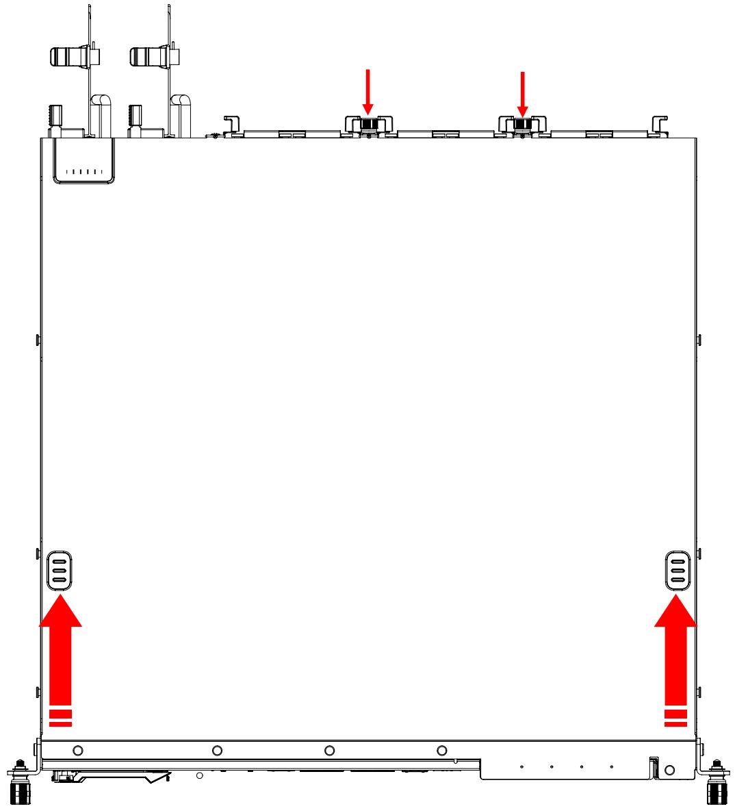
![Pure technical diagram of a mechanical assembly with no text, numbers, or symbols](.mecs-6120-50m-22807-1010-11/7dd57afb3ef09e73322a11da532d0aaee6c8f2408912f0b853e4f8dac59be2b2.jpg)

To reinstall the cover, slide it towards the front of the chassis, then tighten the screws loosened in Step 1.

# 2.3 Installing Memory Modules

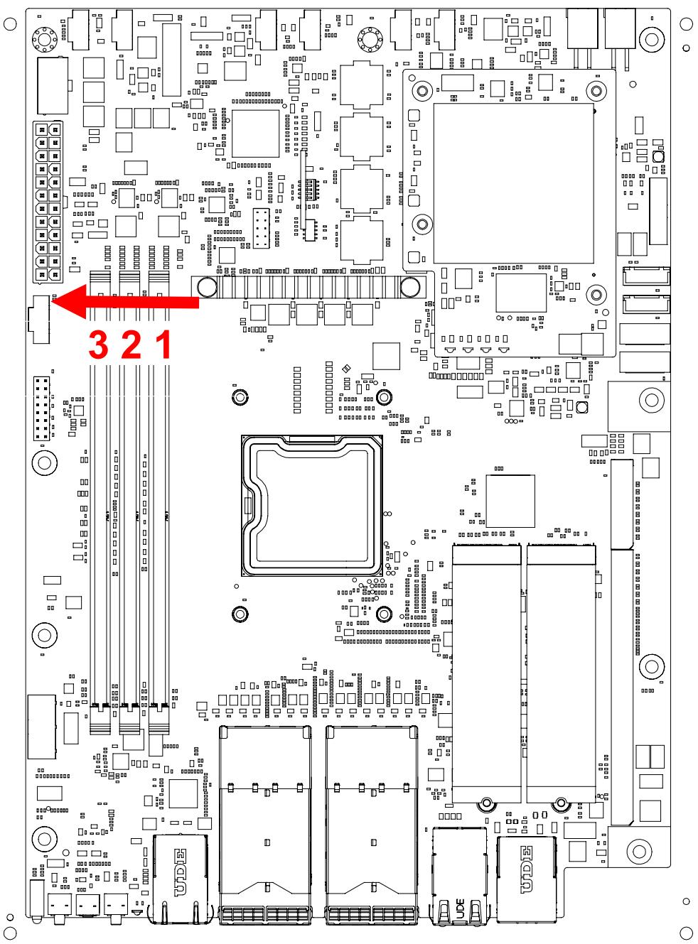
Memory modules must be populated from the right side as shown (slots 1 > 2 > 3).
![321](.mecs-6120-50m-22807-1010-11/ee96d116be71cce5c297b2cd5a9d350ddb21057e8793b82fcd25e9481435e5a8.jpg)

![A yellow triangular warning sign featuring a black exclamation mark in the center.](.mecs-6120-50m-22807-1010-11/e246b8dd012450eef855320a566c00d20fcbd0f3e58d1628ef4477e2eb184720.jpg)
CAUTION:
mise en garde

All installation procedures are restricted to skilled personnel.

Toutes les procédures d'installation sont réservées au personnel qualifié.

# 2.4 PCIe Card Installation

Sample installation instructions for FHFL PCIe expansion cards are described below. For detailed information on the specific installation procedures for your cards, please contact your ADLINK representative.

![A yellow triangular warning sign with a black border and a black exclamation point in the center. Below the triangle, the word 'CAUTION:' appears in black capital letters.](.mecs-6120-50m-22807-1010-11/f19fb1e4fb73de0c9bc4407af5c888fe13d705570f0cc513d3cdb5a32da4369e.jpg)
mise en garde

All installation procedures are restricted to skilled personnel. Only UL listed PCIe expansion cards or PCIe cards with openings less than 5 mm in any dimension are recommended

Toutes les procédures d'installation sont réservées au personnel qualifié. Seules les cartes d'extension PCIe répertoriées UL ou les cartes PCIe avec des ouvertures inférieures à 5 mm dans n'importe quelle dimension sont recommandées.

1. Remove the two screws from the front panel as shown.
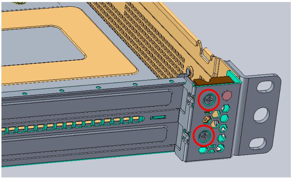
![3D CAD model of a mechanical assembly with labeled ports and connectors (no readable text or symbols)](.mecs-6120-50m-22807-1010-11/471c088f5f8ebb6b7872b9829c2062fc293e087bdd6e1cf9c18e58438f3be35e.jpg)

2. Remove the bracket securing the PCIe bracket blanking plates.
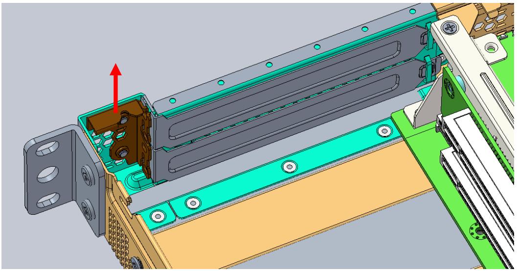
![3D CAD model of a mechanical assembly with highlighted internal components and a red arrow indicating direction (no text or symbols present)](.mecs-6120-50m-22807-1010-11/e296d6fb14d460b1ee29784983998f1b6250154d152bf0490d5b55dd2d9d1fbc.jpg)

3. Remove the PCIe bracket blanking plates.
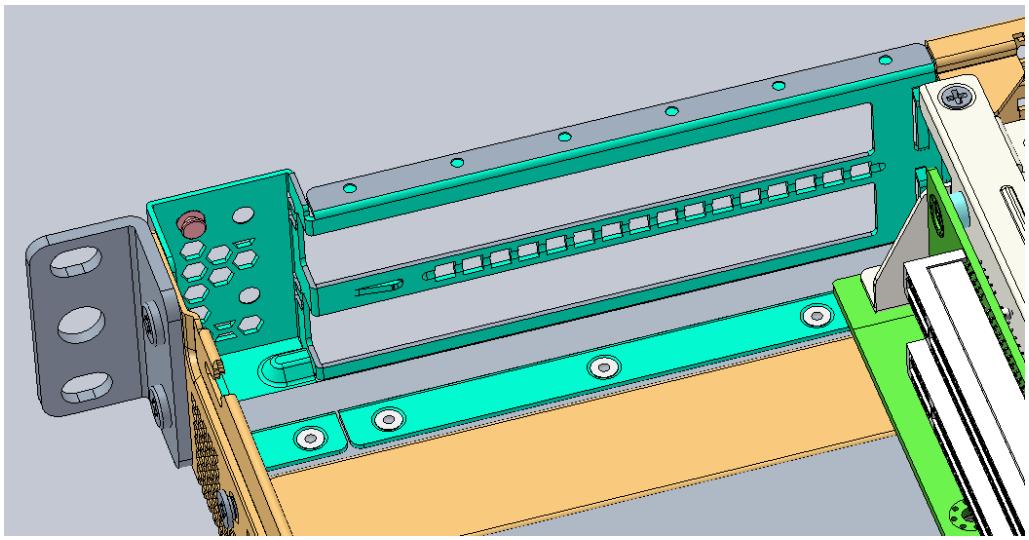
![3D CAD model of a mechanical assembly with green and cyan components (no visible text or symbols)](.mecs-6120-50m-22807-1010-11/a7c7ae0dd423ef4c28f2598df44bd5c2ae633fb649ee881edd8adc16c0bc4fa6.jpg)

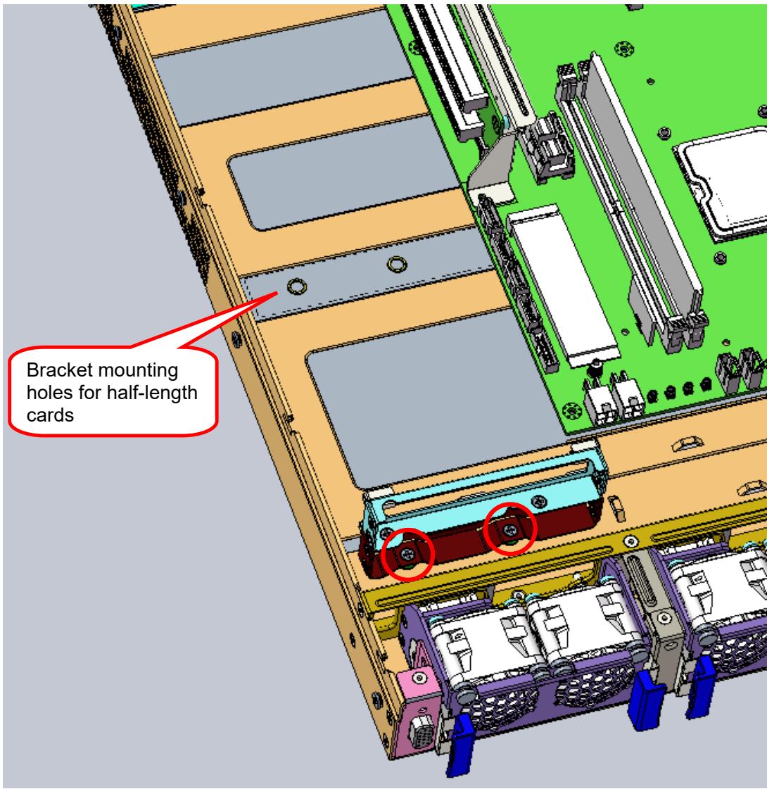
4. Loosen the two screws to remove the internal PCIe bracket used to secure the PCIe cards inside the chassis. The diagram shows the position of the bracket for full-length cards.
![Bracket mounting\nholes for half-length\ncards](.mecs-6120-50m-22807-1010-11/960a633c14aecab2881b92dab3eba33209f73e9ae2cc8d96a52dba39bb1feede.jpg)

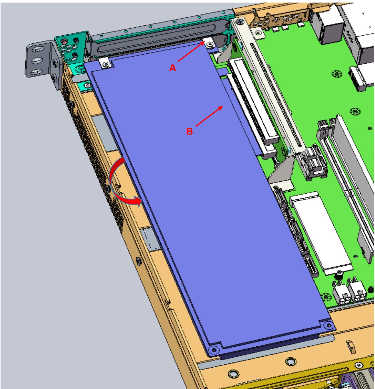
5. First install the lower PCIe expansion card. Align the tab on the bracket with the opening on the rear I/O panel (A), and insert the PCIe connector into the slot on the riser card (B). Make sure the connector is fully inserted into the PCIe slot.
![A\nB](.mecs-6120-50m-22807-1010-11/c83368da67782768241549d2ccd3ad36731122ea58e49a249fe59970ca8067b8.jpg)

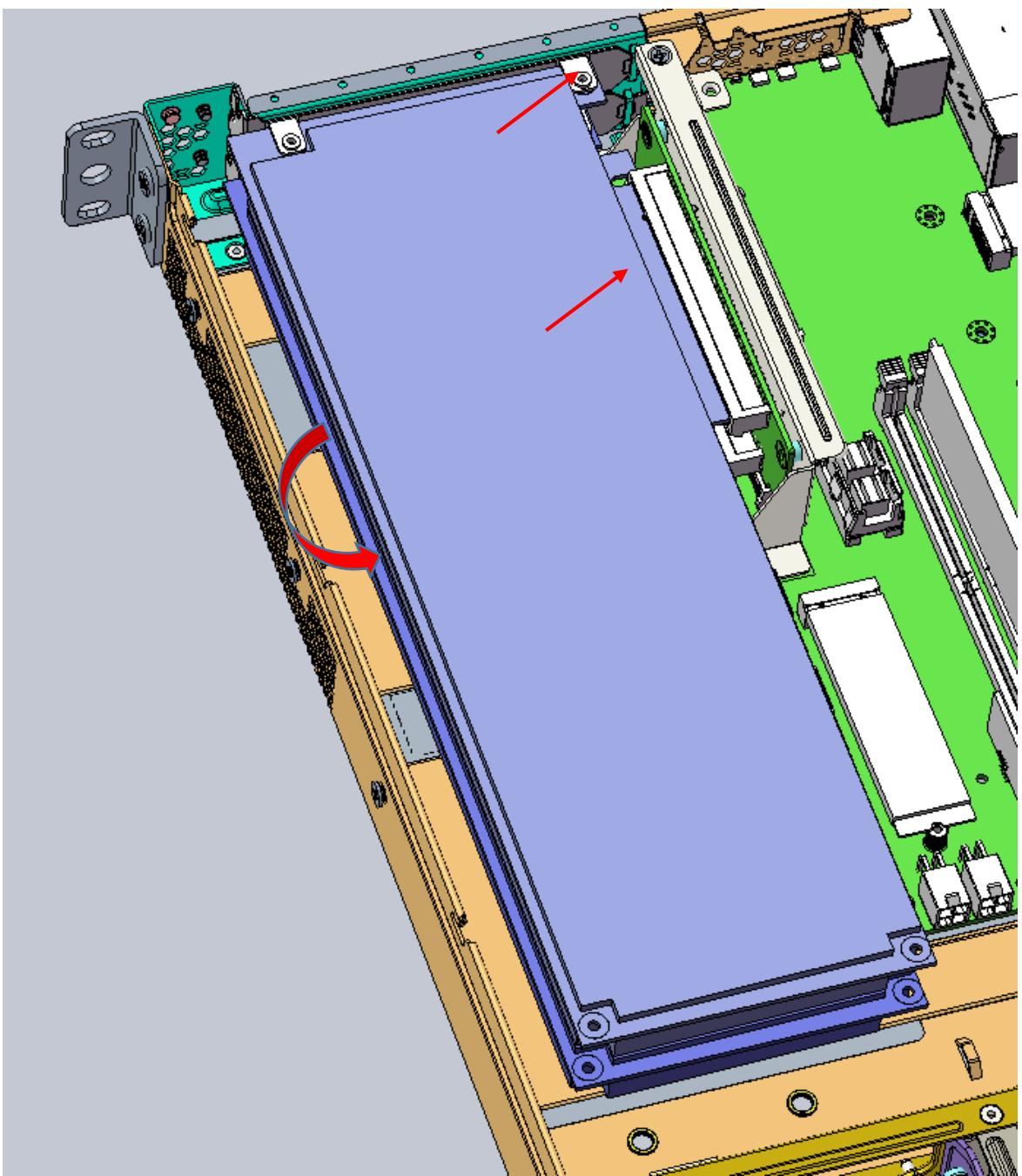
6. Then install the upper PCIe expansion card, if required
![3D CAD model of an electronic device with visible internal components and red arrows indicating motion or assembly (no text or symbols)](.mecs-6120-50m-22807-1010-11/1e2643d5b3ec689fc46e4fc23ddcd2b49d69f38a6914c50c7a023c1fa3d719bf.jpg)

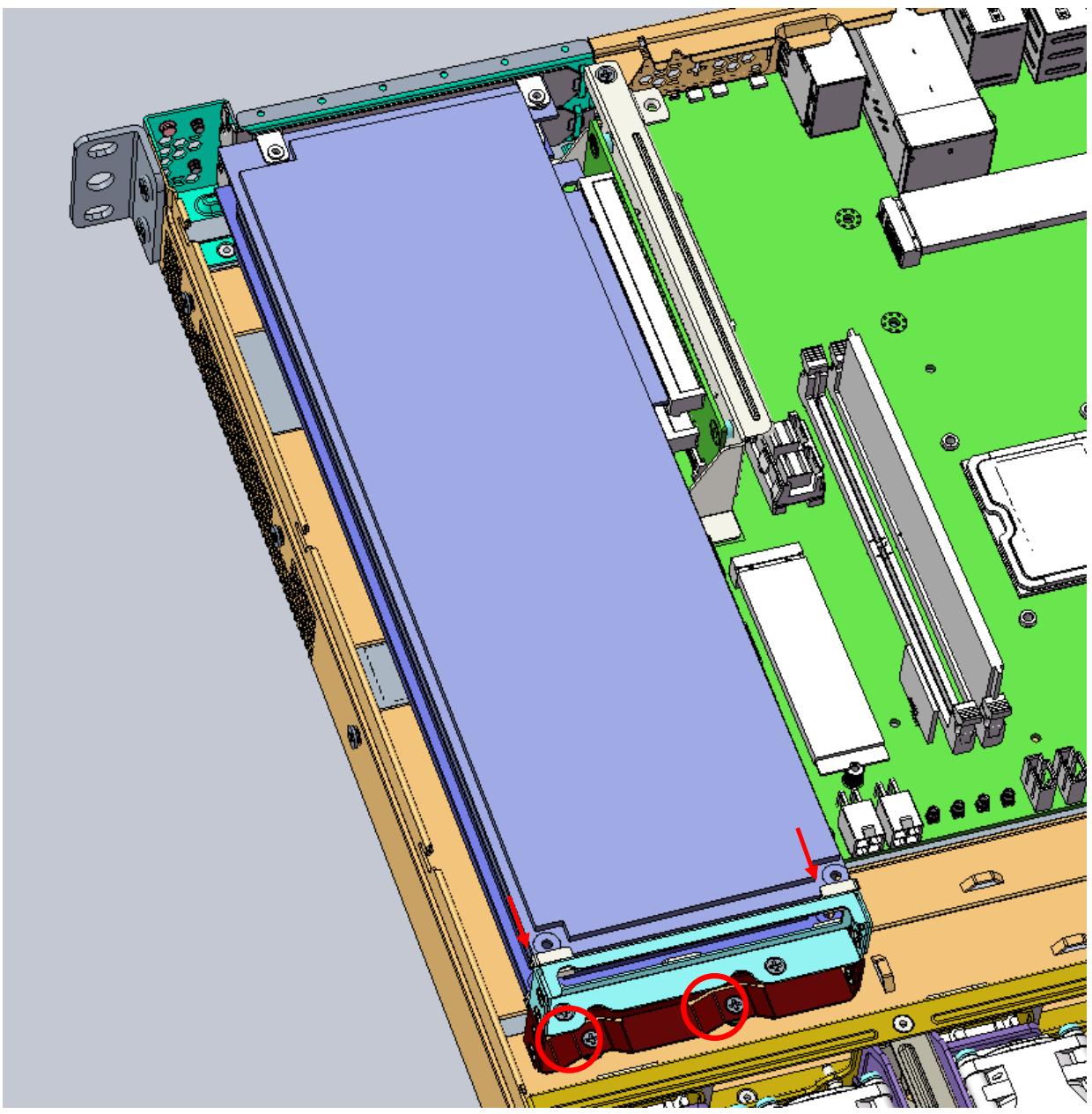
7. Replace the internal PCIe bracket, insert the PCIe cards into the slots (arrows), and tighten the two screws (circles) to secure the cards inside the chassis.
![3D CAD model of an electronic device with visible internal components and mounting points (no text or symbols)](.mecs-6120-50m-22807-1010-11/f8dff70bdab969a95849cb961ea708abf54e5b566f9d038a18c7fee221078965.jpg)

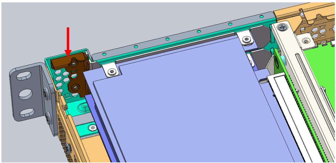
8. Replace the bracket to secure the PCIe I/O brackets to the chassis.
![3D CAD model of a mechanical assembly with colored components and a red arrow indicating a specific part (no text or symbols present)](.mecs-6120-50m-22807-1010-11/ecec8576f71ad183742cd569adbcf0a424773a0c6673eba56aba6b2c5db64959.jpg)

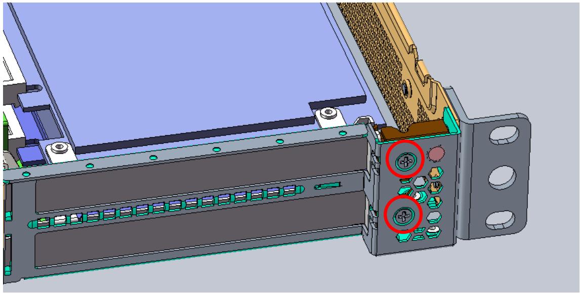
9. Secure the bracket with two screws as shown.
![3D CAD model of a mechanical device showing internal components and mounting holes (no text or symbols visible)](.mecs-6120-50m-22807-1010-11/bf430fe536621f94c5ced5d9de7b0fc9a5eaac8e86e711c7c792ab4b9339a41e.jpg)

# 2.5 PCIe Slot Secondary Power Supply

The MECS-6120 is equipped with two 4-pin ATX-type 12V power connectors on the mainboard (see 1.3.5 MECS-6120 Internal Layout on page 10) to provide secondary power for PCIe expansion cards if required. Two adapter cables are included. The pin definitions of the connectors and cables are described below.

![The image displays a yellow triangular warning sign with a black border containing a black exclamation point. Below the triangle, the text reads 'CAUTION:' in black capital letters. Directly beneath that, the French phrase 'mise en garde' appears in black lowercase letters.](.mecs-6120-50m-22807-1010-11/9e6779723eaa2261667a754ef044a6968eabdf6162504ab1839ff259e369f85d.jpg)

All installation procedures are restricted to skilled personnel.

Toutes les procédures d'installation sont réservées au personnel qualifié.

# 4-pin ATX-type 12V Power Connector Pinout

<table><tr><td>Pin #</td><td>Signal</td><td>Color</td></tr><tr><td>1</td><td>GND</td><td>black</td></tr><tr><td>2</td><td>GND</td><td>black</td></tr><tr><td>3</td><td>P12V</td><td>yellow</td></tr><tr><td>4</td><td>P12V</td><td>yellow</td></tr></table>

![The image displays a line drawing of a square container with a handle on top. Inside the container are four circular shapes arranged in a 2x2 grid, each depicting a small sprout or plant.\n\nSurrounding the container are numbers:\n- On the left side: The number **4** is positioned above the number **2**.\n- On the right side: The number **3** is positioned above the number **1**.](.mecs-6120-50m-22807-1010-11/3fc03e26fc5876f52a8051510ecc1cf656c25aa1a54e0dd7a26dec8d3b57043c.jpg)

# Adapter Cable Connector Pinout

![P1\n1 3\n2 4\n(30)\n300± 10\n(30)\nP2\n#1 #2\n3 6\n1 4](.mecs-6120-50m-22807-1010-11/ff0ef193b1591610288a25777e9bcc15546f18dc892441af372499600402ae15.jpg)

Pinout
![| Group | Black Line | Yellow Line |\n|-------|------------|-------------|\n| P1    | 1          | 3           |\n| P1    | 2          | 4           |\n| P1    | 3          | 5           |\n| P1    | 4          | 6           |\n| P2    | 1          | 4           |\n| P2    | 2          | 5           |\n| P2    | 3          | 6           |\n| P2    | #1         | 4           |\n| P2    | #2         | 5           |\n| P2    | #1         | 6           |](.mecs-6120-50m-22807-1010-11/5b5233d91353f472aa1c0b0e08d4193cc82252b8280f6fe50c7375b726e287f5.jpg)

# 2.6 Rails Assembly and Rack Installation

Note: Please check rack post type before proceeding. The pre-installed rail type is for square hole posts. If the rack post has round holes, please switch to the appropriate screws as shown below.

![Left\nRight](.mecs-6120-50m-22807-1010-11/f6ed088947701e450bd77f8af947d09594e8b379953303210db24e363d3c22f6.jpg)

To switch from round hole to square hole, remove the “A” type screws (pre-installed) and switch to “B” type screws.

![A 9.5 Square Hole\n(Pre-installed)](.mecs-6120-50m-22807-1010-11/186e80afafb75c9004b4e5bc2f77dfbee2381a383091f737a272922952e20929.jpg)

![⑧ 7.1 Round Hole](.mecs-6120-50m-22807-1010-11/1d6bdf02fd8c6e7d13aaafa1ea81a9b0b5df61facc57a655b0be3b1fda0dacb9.jpg)

# 1. Remove the inner rail.

![Based on the provided image, here is the description of the flowchart and block diagram:\n\n**Labeled Blocks and Text:**\n*   **Main Instruction:** A block labeled with the number **2** containing the text: 'Pull release button A or B to take out inner member.'\n*   **Inset Box A:** A box labeled with the number **2** and the letter **A**. Inside is an image of a component with an arrow pointing left labeled 'Pull'.\n*   **Inset Box B:** A box labeled with the number **2** and the letter **B**. Inside is an image of a component with an arrow pointing left labeled 'Pull'.\n*   **Rail Diagram:** A long track assembly.\n    *   One section is labeled **1** with the text 'Click!'.\n    *   Two dashed circles highlight specific points on the track.\n\n**Connections:**\n*   A thick black arrow connects **Inset Box A** to the left-most dashed circle on the rail assembly.\n*   A thick black arrow connects **Inset Box B** to the right-most dashed circle on the rail assembly.\n*   A large, hollow arrow points downward at the bottom center of the image.](.mecs-6120-50m-22807-1010-11/dd1a64b5365607fe01a01bb3477c911d37bc2793e7ba4c1f0183faa5a76dcca5.jpg)

![3 inner rail\nouter rail\nbracket](.mecs-6120-50m-22807-1010-11/9d34dee44e586c1c30c6fdb89fd252ffdaa0b2fa32376a19b9e5acde10acba99.jpg)

2. Install the inner rail onto the chassis.

![1U\n2U\n3\n4\nClick!\nM4x3.2or#6-32x5](.mecs-6120-50m-22807-1010-11/d1115f30a1d5aa22ad4832f1dc0b08469457e4d7d33aa32955e13fd904f70122.jpg)

3. Attach the outer rail/bracket assembly to the rack.

![The diagram illustrates a mechanical assembly process involving two long rails.\n\n*   **Top Section:** Two parallel rails are shown. Dashed circles highlight the ends of the rails, and dashed arrows point inward, indicating alignment.\n*   **Block 1:** Enclosed in a dotted oval labeled '**1**', a vertical bracket with three slots is shown being aligned with three cylindrical connectors protruding from the end of a rail.\n*   **Connection:** A solid white arrow points from Block 1 to Block 2.\n*   **Block 2:** Enclosed in a dotted oval labeled '**2**', the cylindrical connectors are inserted into the slots of the vertical bracket. The text '**Click!**' appears next to the bracket, indicating a successful lock.](.mecs-6120-50m-22807-1010-11/1d77e1b9ab2da8e0498ba9a1f38290446cc6b1256cc76be59e09c39e952afc1e.jpg)

Note: Front and rear bracket installation procedures are the same. The left and right sides of the rail are symmetrical. Repeat the installation steps for the other side.

4. Insert chassis with mounted inner rails to complete the installation.

Ensure the ball bearing retainer is located at the front of the rail.
Insert the chassis into the outer rails.
When the chassis is fully inserted, pull/push the release tab on the inner rails.
Secure the system to the rack using the captive screws located on the rack handles of the system.

![The flowchart illustrates a sequence of steps for installing a rack rail system, proceeding from left to right.\n\n**Labeled Blocks:**\n*   **1:** Points to the rail attachment point on the server chassis. An inset magnified view labeled '1' shows a mechanism with arrows indicating a snapping motion and the text **'Click!'**.\n*   **2:** A number located near the server chassis in the middle section.\n*   **3:** Points to a latch mechanism near the front of the assembly. An inset magnified view labeled '3' shows a latch with an arrow pointing left and the text **'Pull'**.\n*   **4:** Points to the locking latch on the rack rail. An inset magnified view shows the latch mechanism engaging, accompanied by the text **'locking'**.\n\n**Connections:**\n*   **Left to Middle:** A large white arrow connects the leftmost image (server with attached rail) to the middle image (server sliding onto the rack rail). Dashed lines indicate the sliding path.\n*   **Middle to Right:** A large white arrow connects the middle image to the rightmost image (server fully inserted).\n*   **Internal Movement:** In the middle section, a large black arrow on the server chassis points to the right, indicating the sliding motion.\n*   **Inset Arrows:**\n    *   Inset 1 contains arrows showing a snapping action.\n    *   Inset 3 contains an arrow indicating a pulling action.\n    *   Inset 4 contains an arrow indicating the locking action.](.mecs-6120-50m-22807-1010-11/c2f487b1dc1c5bd5a18ccfa3d8618390a4fd646d5dded0c64a4dee62891ec9c6.jpg)

# 2.7 Uninstalling the Rails from the Chassis

M4 x3.2 or #6-32 x5
Release the latch to detach the inner rail.

![Technical diagram showing a server rack with labeled components and steps to inspect or repair a device.](.mecs-6120-50m-22807-1010-11/079bbc780a0c4692ae9fbb88c186bb4dc95ed5a84064faa0d7c4b79658e5d5d2.jpg)

Detach the outer rail/bracket assembly from the rack.

![Based on the provided image, which functions as an instructional diagram rather than a traditional flowchart, here are the labeled blocks and connections:\n\n**Labeled Blocks**\n*   **Block 1:** A dotted circle containing the number **1** (in a white circle), the text **Pull**, and a curved arrow indicating an action.\n*   **Block 2:** A dotted circle containing the number **2** (in a white circle) and three small arrows pointing towards a bracket.\n\n**Connections**\n*   A solid white arrow connects the block labeled **1** to the block labeled **2**, indicating the sequence of operations.\n*   Dashed arrows are present on the main rail assemblies, indicating sliding motion (one pointing left on the top rail, one pointing right on the bottom rail).](.mecs-6120-50m-22807-1010-11/3d9198c951791231082aa37213e9b3763c5b052ea20a6ce057ca05315212a64f.jpg)

Note: Front and rear bracket detachment procedures are the same. The left and right sides of the rail are symmetrical. Repeat the steps for the other side.

Loosen the captive screws and then pull out the chassis.
Pull release button A or B to remove the chassis.

![This diagram illustrates a three-step process for removing a server blade from a rack.\n\n**Labeled Blocks:**\n*   **1** (appears twice in black circles)\n*   **Release**\n*   **2** (in a black circle)\n*   **B** (in a white circle)\n*   **A** (in a white circle)\n*   **Pull** (appears twice)\n\n**Connections and Flow:**\n1.  **Top Assembly:** A circled number **1** points diagonally down to a latch on the side of the server. A second circled **1** points to the same area. A dashed circle highlights a latch mechanism, accompanied by the text **Release**.\n2.  **Transition 1:** A large hollow arrow points to the right, connecting the top assembly to a middle assembly where the server is partially removed.\n3.  **Middle Assembly:** A circled number **2** points diagonally down to a latch area on the bottom edge of the server.\n4.  **Transition 2:** A large hollow arrow points to the right, connecting the middle assembly to a bottom assembly where the server is separated from the rails (indicated by dashed lines).\n5.  **Detail Insects:** Two inset boxes detail the latch operation below label **2**:\n    *   The left box shows a latch labeled **B**, a left-pointing arrow, and the text **Pull**.\n    *   The right box shows a latch labeled **A**, a left-pointing arrow, and the text **Pull**.](.mecs-6120-50m-22807-1010-11/38d6e20af3ac931758fb66ac203402e55b82aeca4ae74eac82e9b4e95a5bb455.jpg)

# 2.8 Connecting the System to Ground

# AC Version

The MECS-6120 is connected to ground by the ground pin of the 3-prong IEC power cord. Please use the power cord provided with the system for your region.

A grounding stud (M4 size) is provided on the rear of the chassis for additional connection to ground. The bonding wire shall be minimum 18 AWG and with green-and yellow insulation jacket.

![Grounding\nStud](.mecs-6120-50m-22807-1010-11/70f1bb6660207fae5ed9286ee4522477279f278dcf84e0e0a947254b599f6f17.jpg)

# DC Version

A grounding stud (M3.5, steel zinc plated) is provided on the rear of the chassis for connection to ground. The bonding wire shall be minimum 14 AWG and with green-and yellow insulation jacket.

![Grounding\nStud\nRTN -48V](.mecs-6120-50m-22807-1010-11/1e30035e92048f679f21e72c1d5f227fc2adcce1f1e0b29d6cf09a1772a078ae.jpg)

# 2.9 System Power Cable Installation

# AC PSU Input

3-prong IEC power cord

![Technical line drawing of a mechanical or electrical component with hexagonal lattice structure and internal components (no text or symbols)](.mecs-6120-50m-22807-1010-11/783c6f492e5290115206634cb7fee24473979064352bfcf8a1a0009f5f70a49c.jpg)

# DC PSU Input

DC Negative: connect to -48V

DC Positive: connect to RTN

![Technical line drawing of an electronic device casing with grid layout and labeled component 'RTN -48V' (no readable text or symbols beyond basic diagram)](.mecs-6120-50m-22807-1010-11/6ce143d67738994a7a6e0802041589a4bd6f064068ce298439b306dbfeeeeda1.jpg)

![A yellow triangular warning sign with a black border containing a large black exclamation mark. Below the triangle, the word 'CAUTION:' is printed in black capital letters.](.mecs-6120-50m-22807-1010-11/c8e603379903ce895f3e5971eb4050fef9915e155fd9171308177bf27b74e925.jpg)
mise en garde

All installation procedures are restricted to skilled personnel.

The terminal block is suitable for a minimum 14 AWG, minimum 60V, minimum 105 °C, VW-1 power cord. Torque value is 1.2 N·m.

Toutes les procédures d'installation sont réservées au personnel qualifié. Le bornier est adapté à un cordon d'alimentation VW-1 minimum de 14 AWG, minimum 60 V, minimum 105 °C. La valeur de couple est de 1,2 N·m.

# 2.10 Login to the BMC via Console Port

# Step 1

Set the Console Port to BMC mode using the 4-pole DIP Console Port Mode Switch (SW1) on the mother board inside the chassis (see 4.8 Board Layout on page 555).

<table><tr><td>Pin</td><td>Default</td><td>BMC Debug</td></tr><tr><td>1</td><td>On</td><td>Off</td></tr><tr><td>2</td><td>On</td><td>Off</td></tr><tr><td>3</td><td>Off</td><td>On</td></tr><tr><td>4</td><td>Off</td><td>On</td></tr></table>

# Step 2

Use the included RJ-45 to DB-9 console port adapter cable to connect the PC to the RJ-45 console port of the MECS-6120 (see 1.3.1 MECS-6120 Front Panel on page 8). See 4.4 Dual USB 3.0 and RJ-45 Console Port on page 50 for the adapter cable pin definition.

![Exterior view of a beige USB connector with multiple ports (no text or symbols visible)](.mecs-6120-50m-22807-1010-11/dcc1e0c802a2a7b9a3720092a232abd1cd99a017724378e4b2c4134ce7f8457b.jpg)

# Step 3

Open a serial port console tool (such as PuTTY), choose the higher COM port (it may be different depending on the computer), then set the baud rate to 115200.

![PuTTY Configuration\nCategory:\nSession\nLogging\nTerminal\nKeyboard\nBell\nFeatures\nWindow\nAppearance\nBehaviour\nTranslation\nSelection\nColours\nConnection\nData\nProxy\nTelnet\nRlogin\nSSH\nSerial\nBasic options for your PuTTY session\nSpecify the destination you want to connect to\nSerial line Speed\nCOM3 115200\nConnection type:\nRaw Telnet Rlogin SSH Serial\nLoad, save or delete a stored session\nSaved Sessions\nCOM3\nDefault Settings\n2600T\n2600_CPU_Server\n2610T\n2610T_board\nCOM3\nCSA-7400\nLoad\nSave\nDelete\nClose window on exit:\nAlways Never Only on clean exit\nAbout Help Open Cancel](.mecs-6120-50m-22807-1010-11/0e71ae9e766e275bc17149295691df6422f73c2ab41e040e8a3fc898b4361dd4.jpg)

# Step 3

Input the user name “sysadmin” and password “superuser” to login to the system.

![AMI00306425F122 login: sysadmin\nPassword:\nlogin(1773): pam_unix(login:account): account sysadmin has password changed in future\nlogin(1773): pam_unix(login:session): session opened for user sysadmin by LOGIN(uid=0)\n(1773 INFO)SERIAL Login from IP:127.0.0.1 user:sysadmin\n\nlogin(1773): (1773 INFO)SERIAL Login from IP:127.0.0.1 user:sysadmin\n\nlogin(1773): root login on 'ttyS4'\n~ #](.mecs-6120-50m-22807-1010-11/1f92f88861bbe035a0b459e96628a17e65a03903f7ac1b312081283702a9ff96.jpg)

# 2.11 Login to the BMC via Network

# Step 1

Use a LAN cable to connect eth1 of the MECS-6120 to the PC;

![eth1\neth0](.mecs-6120-50m-22807-1010-11/fba365103485b0db286a88b785d854f19d893715af6692a3b5d02f0a4835d960.jpg)

# Step 2

Open a serial port console tool (such as PuTTY) enter the IP address, and open a connection to the BMC (login using serial console first to check the IP address).

![PuTTY Configuration (Save mode : File)\nCategory:\nSession\nLogging\nTerminal\nKeyboard\nBell\nFeatures\nExtraPuTTY\nSettings\nStatusBar\nFilesTransfer\nWindow\nAppearance\nBehaviour\nTranslation\nBasic options for your PuTTY session\nSpecify the destination you want to connect to\nHost Name (or IP address)	Port\n10.0.0.7	22\nConnection type:\nRaw	Telnet	Rlogin	SSH	Serial\nCygtem\nLoad, save or delete a stored session\nSaved Sessions\nDefault Settings\n2080\ncom-30400\ncom-6150\nremote\nvm\nLoad\nClose window on exit:\nAlways	Never	Only on clean exit\nNever, Auto-Connect\nAbout	Open	Cancel](.mecs-6120-50m-22807-1010-11/88671ba8104c84b9b4c62cacd6d98ef8848acc501793217e05b6ee44c94abc33.jpg)

# Step 3

Input the user name “sysadmin” and password “superuser” to login to the system.

![login as: sysadmin\nsysadmin@10.0.0.7's password:\n~ #\n~ #](.mecs-6120-50m-22807-1010-11/e915b424684ed78afd1943e4c1840fc25116b096826b2cdf3972b3fc03488227.jpg)

# 2.12 BMC eth0 Default and Static IP Settings

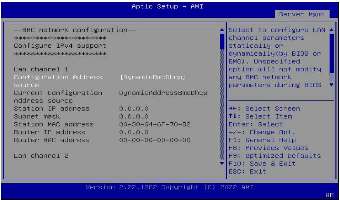
The default IP setting is DHCP. Users can login to the BMC to modify the IP.

# Static IP Settings:

Show the current LAN setting

 ipmitool lan print 1

Set the IP source to static

 ipmitool lan set 1 ipsrc static

Set the IP address

 ipmitool lan set 1 ipaddr xxx.xxx.xxx.xxx

Set the netmask address

 ipmitool lan set 1 netmask xxx.xxx.xxx.xxx

Set the gateway address

 ipmitool lan set 1 defgw ipaddr xxx.xxx.xxx.xxx

# Restore Default:

Set IP source to DHCP

 ipmitool lan set 1 ipsrc dhcp

Note: BMC IP can be set in the BIOS. See 5.6.1 BMC Network Configuration on page 92.

# 2.13 BMC eth1 Default and Static IP Settings

The default IP setting is DHCP. Users can login to the BMC to modify the IP.

# Static IP Settings:

Show the current LAN setting

 ipmitool lan print 8

Set the IP source to static

 ipmitool lan set 8 ipsrc static

Set the IP address

 ipmitool lan set 8 ipaddr xxx.xxx.xxx.xxx

Set the netmask address

 ipmitool lan set 8 netmask xxx.xxx.xxx.xxx

Set the gateway address

 ipmitool lan set 8 defgw ipaddr xxx.xxx.xxx.xxx

# Restore Default:

Set IP source to DHCP

 ipmitool lan set 8 ipsrc dhcp

Note: BMC IP can be set in the BIOS. See 5.6.1 BMC Network Configuration on page 92.

# 2.14 BIOS Update

Users can update the MECS-6120 system BIOS over various interfaces (Gigabit LAN, KCS, console port).

# 2.14.1 Updating the BIOS via Network with BMC Tool

1. Install a Linux distribution, such as Ubuntu 14, to the debug PC.
2. Install “expect” to your debug PC (ex: sudo apt-get install expect).
3. Copy the BMC FW package “BMC\_MECS-6120\_Release\_Vx.xx” to the debug PC;

# Upgrade Procedure:

1. Check the IP of the BMC of MECS-6120. Power on the MECS-6120, boot the BMC to Linux (username: sysadmin; Passwd: superuser), and type “ifconfig” check its IP address.

```txt
~ # ifconfig
eth0 Link encap:Ethernet HWaddr 00:30:64:DD:AA:AC
inet addr:11.0.0.11 Bcast:11.255.255.255 Mask:255.0.0.0
inet6 addr: fe80..230.64ff:fedd:aaac/64 Scope:Link
UP BROADCAST RUNNING MULTICAST MTU:1500 Metric:1
RX packets:232 errors:0 dropped:0 overruns:0 frame:0
TX packets:323 errors:0 dropped:0 overruns:0 carrier:0
collisions:0 txqueuelen:1000
RX bytes:17190 (16.7 KiB) TX bytes:18475 (18.0 KiB)
Interrupt:2
ethl Link encap:Ethernet HWaddr 00:30:64:DD:AA:AB
inet6 addr: fe80::230:64ff:fedd:aaab/64 Scope:Link
UP BROADCAST RUNNING MULTICAST MTU:1500 Metric:1
RX packets:114 errors:0 dropped:0 overruns:0 frame:0
TX packets:223 errors:0 dropped:0 overruns:0 carrier:0
collisions:0 txqueuelen:1000
RX bytes:7079 (6.9 KiB) TX bytes:18726 (18.2 KiB)
Interrupt:3
lo Link encap:Local Loopback
inet addr:127.0.0.1 Mask:255.0.0.0
inet6 addr: ::1/128 Scope:Host
UP LOOPBACK RUNNING MTU:65536 Metric:1
RX packets:328 errors:0 dropped:0 overruns:0 frame:0
TX packets:328 errors:0 dropped:0 overruns:0 carrier:0
collisions:0 txqueuelen:0
RX bytes:30462 (29.7 KiB) TX bytes:30462 (29.7 KiB)
```

2. On the debug PC, execute the following commands to perform the upgrade.

cd BMC\_MECS-6120\_Release\_Vx.xx

cd BIOS

./adlinktool.sh upgradebios1 BIOS\_xxxx.bin 11.0.0.11

Note: Only “bin” files are supported when updating the BIOS via Network.

# 2.14.2 Updating BIOS via Host with BIOS Tool

1. Boot/Login to Shell
2. Update the BIOS over host with the following commands.

Example:

AfuEfix64 BIOS.ROM /p /b /n /x (to update BIOS without ME)

```txt
FS1:\BIOSFLS\MECS-6120\MECS-6120_01110_FullImage\> dir
Directory of: FS1:\BIOSFLS\MECS-6120\MECS-6120_01110_FullImage\
04/18/2022 10:02 &lt;DIR&gt; 16,384 .
04/18/2022 10:02 &lt;DIR&gt; 16,384 ..
12/14/2021 09:19 568,144 AfuEfix64.efi
12/14/2021 09:20 7,376 HISTORY.txt
12/14/2021 09:19 67,108,864 MECS-6120_01110.BIN
12/14/2021 09:19 16,777,216 MECS-6120_01110.ROM
12/14/2021 09:19 399 pBIOS.nsh
5 File(s) 84,461,999 bytes
2 Dir(s)
FS1:\BIOSFLS\MECS-6120\MECS-6120_01110_FullImage\>
```

Note: Only “ROM” files are supported when updating the BIOS via Host.

# 2.15 BMC Firmware Update via Network

The MECS-6120 supports a BMC Chassis Management firmware, IPMI v2.0 compliant. To update the BMC firmware via network, perform the following steps.

1. Install a Linux distribution, such as Ubuntu 14, to the debug PC.
2. Install “expect” to your debug PC (ex: sudo apt-get install expect).
3. Copy the BMC FW package “BMC\_MECS-6120\_Release\_Vx.xx” to the debug PC;

# Upgrade Procedure:

1. Check the IP of the BMC of MECS-6120. Power on the MECS-6120, boot the BMC to Linux (username: sysadmin; Passwd: superuser), and type “ifconfig” check its IP address.

```txt
~ # ifconfig
eth0 Link encap:Ethernet HWaddr 00:30:64:DD:AA:AC
inet addr:11.0.0.11 cast:11.255.255.255 Mask:255.0.0.0
inet6 addr: fe80::230:64ff:fedd:aaac/64 Scope:Link
UP BROADCAST RUNNING MULTICAST MTU:1500 Metric:1
RX packets:232 errors:0 dropped:0 overruns:0 frame:0
TX packets:323 errors:0 dropped:0 overruns:0 carrier:0
collisions:0 txqueuelen:1000
RX bytes:17190 (16.7 KiB) TX bytes:18475 (18.0 KiB)
Interrupt:2
eth1 Link encap:Ethernet HWaddr 00:30:64:DD:AA:AB
inet6 addr: fe80::230:64ff:fedd:aaab/64 Scope:Link
UP BROADCAST RUNNING MULTICAST MTU:1500 Metric:1
RX packets:114 errors:0 dropped:0 overruns:0 frame:0
TX packets:223 errors:0 dropped:0 overruns:0 carrier:0
collisions:0 txqueuelen:1000
RX bytes:7079 (6.9 KiB) TX bytes:18726 (18.2 KiB)
Interrupt:3
lo Link encap:Local Loopback
inet addr:127.0.0.1 Mask:255.0.0.0
inet6 addr: ::1/128 Scope:Host
UP LOOPBACK RUNNING MTU:65536 Metric:1
RX packets:328 errors:0 dropped:0 overruns:0 frame:0
TX packets:328 errors:0 dropped:0 overruns:0 carrier:0
collisions:0 txqueuelen:0
RX bytes:30462 (29.7 KiB) TX bytes:30462 (29.7 KiB)
```

2. On the debug PC, execute the following commands to perform the upgrade.

cd BMC\_MECS-6120\_Release\_Vx.xx

cd FW

./adlinktool.sh bmc1 rom.ima 11.0.0.11

# 2.16 BMC Firmware Update via Host with Yafuflash

The MECS-6120 supports a BMC Chassis Management firmware, IPMI v2.0 compliant. To update the BMC firmware via host with Yafuflash, perform the following steps.

1. Login to the OS with root user permission.
2. Update the BMC over host using the commands below:

Example:

\$ sudo ./Yafuflash -kcs rom.ima

YAFUFlash - Firmware Upgrade Utility (Version 4.117.7)

(C)Copyright 2016, American Megatrends Inc. The Module root allocated size is different from the one in the Image So,Type (Y/y) to do Full Firmware Upgrade or (N/n) to exit Enter your Option : Y

\*\*\*\*\*\*\*\*\*\*\*\*\*\*\*\*\*\*\*\*\*\*\*\*\*\*\*\*\*\*\*\*\*\*\*\*\*\*\*\*\*\*\*\*\*\*\*\*\*\*\*\*\*\*\*\*\*\*\*\*\*\*\*\*\*\*\*\*\*\*\*\*\*\* WARNING!

FIRMWARE UPGRADE MUST NOT BE INTERRUPTED ONCE IT IS STARTED. PLEASE DO NOT USE THIS FLASH TOOL FROM THE REDIRECTION CONSOLE.

\*\*\*\*\*\*\*\*\*\*\*\*\*\*\*\*\*\*\*\*\*\*\*\*\*\*\*\*\*\*\*\*\*\*\*\*\*\*\*\*\*\*\*\*\*\*\*\*\*\*\*\*\*\*\*\*\*\*\*\*\*\*\*\*\*\*\*\*\*\*\*\*\*\*

```txt
Uploading Firmware Image : 100%... done
Skipping [boot] Module ....
Flashing [conf] Module ....
Flashing Firmware Image : 100%... done
Verifying Firmware Image : 100%... done
Flashing [root] Module ....
Flashing Firmware Image : 100%... done
Verifying Firmware Image : 100%... done
Flashing [osimage] Module ....
Flashing Firmware Image : 100%... done
Verifying Firmware Image : 100%... done
Flashing [www] Module ....
Flashing Firmware Image : 100%... done
Verifying Firmware Image : 100%... done
Flashing [testapps] Module ....
Flashing Firmware Image : 100%... done
Verifying Firmware Image : 100%... done
Flashing [ast2500e] Module ....
Flashing Firmware Image : 100%... done
Verifying Firmware Image : 100%... done
Resetting the firmware.....
```

Open IPMI Drivers

Loading Open IPMI Driver:ipmi\_devintf BMC is booting up, Please load ipmi\_si Open IPMI Driver after the BMC Boots up!!!! Loading Open IPMI Driver:ipmi\_msghandler

# 2.17 Enter BIOS Setup

To enter the BIOS setup screen, follow these steps:

1. Power on the MECS-6120.
2. Press the &lt;Delete&gt; or &lt;ESC&gt; key on your keyboard when you see the following text prompt: “Press DEL or ESC to enter Setup”.

(Note: If Quick Boot is enabled, the screen below will not display, but pressing the &lt;Delete&gt; or &lt;ESC&gt; key will still allow you to enter the BIOS setup screen.)

![ami™\nVersion 2.22.1282. Copyright (C) 2022 AMI\nMECS-6120 REV:0.11.10\nPress (DEL) or (ESC) to enter setup.\nEntering Setup...](.mecs-6120-50m-22807-1010-11/7f538b0edf188628d3675b7836a5be27298dca7c36e0dd5799d0042878adbff8.jpg)

3. After pressing the &lt;Delete&gt; or &lt;ESC&gt; key, the main BIOS setup menu will display. You can access the other setup screens from the main BIOS setup menu, such as Chipset and Power menus.

# 2.18 Create a RAID Volume

To create a RAID volume, the RAID option must be enabled in the BIOS so that the system loads the RAID option ROM code (see 5.3.1.2 SATA Configuration on page 63).

1. Go to Platform Configuration > PCH-IO Configuration > SATA Configuration > Controller 1 SATA Configuration.
2. Set SATA Mode Selection to RAID, save changes, and reboot the system.

![Aptio Setup - AMI\nPlatform Configuration\nController 1 SATA Configuration\nSATA Configuration (Enabled)\nSATA Mode Selection (AHCI)\nSATA Port 0 TS64GMTS400 - 64.0 GB\nPort 0 SATA Mode Selection\nHot Plug AHCI\nConfigured as eSATA RAID\nSATA Port 1 Select Screen\nPort 1 Select Item\nHot Plug (Disabled)\nConfigured as eSATA Hot Plug supported\nSATA Port 2 (Not Installed)\nPort 2 (Enabled)\nHot Plug (Disabled)\nConfigured as eSATA Hot Plug supported\nEnter: Select\n+/-: Change Opt.\nF1: General Help\nF8: Previous Values\nF9: Optimized Defaults\nF10: Save & Exit\nESC: Exit\nDetermines how SATA controller(s) operate.](.mecs-6120-50m-22807-1010-11/445ef5898fe2ed3259d32dbccb4b37e967416d6a9824355a48c8445ed41d1db4.jpg)

Version 2.22.1283 Copyright （C）2022 AMI

AB

# To create a RAID volume, go to the Advanced menu

![Aptio Setup - AMI\nMain Platform Configuration Advanced Socket Configuration Server Mgmt\nSerial Port Console Redirection\nNVMe Configuration\nPCI Subsystem Settings\nNetwork Stack Configuration\nAdvanced Power Management Configuration\nTrusted Computing\nPcie Delay support (Disabled)\nTls Auth Configuration\nAll Cpu Information\nEmulation Configuration\nRAM Disk Configuration\nIntel(R) VROC sSATA Controller\nIntel(R) I210 Gigabit Network Connection -\n00:30:64:6F:70:6C\nIntel(R) I210 Gigabit Network Connection -\n00:30:64:6F:70:6D\nThis formset allows the user to manage RAID volumes on the Intel(R) RAID Controller\n+:-: Select Screen\n↑↓: Select Item\nEnter: Select\n+/-: Change Opt.\nF1: General Help\nF8: Previous Values\nF9: Optimized Defaults\nF10: Save & Exit\nESC: Exit\nVersion 2.22.1285 Copyright (C) 2022 AMI\nAB](.mecs-6120-50m-22807-1010-11/1889a49b44b2ef7941ccfd9b01716f78af60af656adf7dda6b8688420542ae5a.jpg)

# Enter the Intel(R) VROC sSATA Controller submenu and click on Create RAID Volume.

<table><tr><td rowspan="2">Intel(R) VROC 7.7.0.1054 sSATA Driver
► Create RAID Volume
Non-RAID Physical
Disks:
► Port 6, TS256GSSD452K SN:G604260001, 238.47GB
► Port 7, ADATA SP580 SN:2L07292G472R, 223.57GB</td><td>This page allows you to create a RAID volume</td></tr><tr><td>+:-: Select Screen
↑↓: Select Item
Enter: Select
+/-: Change Opt.
F1: General Help
F8: Previous Values
F9: Optimized Defaults
F10: Save &amp; Exit
ESC: Exit</td></tr><tr><td colspan="2">Version 2.22.1283 Copyright (C) 2022 AMI</td></tr></table>

# 2.19 Clear CMOS

See 4.8 Board Layout on page 55 for the location of the Clear CMOS jumper (J1).

<table><tr><td>J1</td><td>Setting</td></tr><tr><td>1-2</td><td>default</td></tr><tr><td>2-3</td><td>Clear CMOS</td></tr></table>

# 3 System Interfaces

![GbE x2\nUID Button and\nLED\n1PPS/TOD\nPorts\nConsole\nPort\nPower LED\nAlert LED\nHDD LED\nPower\nButton\nReset\nButton\nHealth\nBehavior LED\nSFP+ x8\nUSB x2](.mecs-6120-50m-22807-1010-11/26cc04c4e626347a559ac9e5532c463e0603d5b0d766c9769011f386da22807c.jpg)

# 3.1 Status LEDs

# Power LED (green)

The Power LED will light when the system is booted up (S0 state).

# Alert LED (red)

Off: Indicates normal system operation. On: Indicates a critical alarm.

# Drive Activity (HDD) LED (yellow)

The Drive Activity (HDD) LED is controlled by SATALED# from the chipset. When SATA storage is active (read/write), the LED will blink.

Note: This LED can also be user defined. See 4.6 HDD/User LED Jumper and 4.7 User LED Commands on pages 52 and 53.

# UID Button and LED (blue)

The UID button/indicator is used to conveniently locate the server. The LED can be turned off or on manually by pressing the UID button or remotely controlled by management command.

# Health Behavior LED (green/red)

The Health Behavior LED has the following behavior.

Default: Green (blinking) indicates healthy BMC status.
Override: User can use the OEM LED command (LED1/LED2) to override the LED status to reflect the system health status.

# 3.2 LAN Ports

<table><tr><td>Pin #</td><td>Signal</td></tr><tr><td>1</td><td>TX1+</td></tr><tr><td>2</td><td>TX1-</td></tr><tr><td>3</td><td>TX2+</td></tr><tr><td>4</td><td>TX2-</td></tr><tr><td>5</td><td>TX3+</td></tr><tr><td>6</td><td>TX3-</td></tr><tr><td>7</td><td>TX4+</td></tr><tr><td>8</td><td>TX4-</td></tr></table>

![LED1\nLED2\n8\n1](.mecs-6120-50m-22807-1010-11/22a4687643a7ccefb4a480333f743a2c09a786008aff119dc8bb3500fe31572f.jpg)

# LAN LED Behaviour

The LAN LEDs are integrated into the RJ-45 connector. Their behavior is as follows:

The LED1 (Speed) indicates the speed of the LAN connection.

<table><tr><td colspan="2">LED1 (Speed)</td></tr><tr><td>10 Mbps</td><td>Off</td></tr><tr><td>100 Mbps</td><td>Green</td></tr><tr><td>1000 Mbps</td><td>Orange</td></tr></table>

The LED2 (Link/Activity) indicates that a link has been established by lighting orange. When data is transmitted the LED blinks orange.

<table><tr><td colspan="2">LED2 (Link/Activity)</td></tr><tr><td>Link with no activity</td><td>Steady</td></tr><tr><td>Link with activity</td><td>Blinking</td></tr></table>

# 3.3 SFP+ Ports

<table><tr><td>Pin</td><td>Signal Name</td></tr><tr><td>1</td><td>GND</td></tr><tr><td>2</td><td>TX_FAULT</td></tr><tr><td>3</td><td>TX_DSBL</td></tr><tr><td>4</td><td>SDA</td></tr><tr><td>5</td><td>SCL</td></tr><tr><td>6</td><td>MOD_ABS</td></tr><tr><td>7</td><td>RS0</td></tr><tr><td>8</td><td>RX_OS</td></tr><tr><td>9</td><td>RS1</td></tr><tr><td>10</td><td>GND</td></tr><tr><td>11</td><td>GND</td></tr><tr><td>12</td><td>RD-</td></tr><tr><td>13</td><td>RD+</td></tr><tr><td>14</td><td>GND</td></tr><tr><td>15</td><td>VCCR</td></tr><tr><td>16</td><td>VCCT</td></tr><tr><td>17</td><td>GND</td></tr><tr><td>18</td><td>TX+</td></tr><tr><td>19</td><td>TX-</td></tr><tr><td>20</td><td>GND</td></tr></table>

![20\n11\n1\n10](.mecs-6120-50m-22807-1010-11/9671c6716a12065602d822b9a862c1dfa25fcbd183a1d4acf45340741126d9ea.jpg)

# SFP+ LED Behaviour

![Link\nStatus\nLink\nActivity](.mecs-6120-50m-22807-1010-11/1614d524790ffc7f3f2963c0cb5b95161d7b25cd25108de91f8a70add3dd7693.jpg)

The LEDs point to the respective port.

<table><tr><td>LED</td><td>Status</td><td>Behavior</td></tr><tr><td rowspan="2">Link Status</td><td>Link up</td><td>Green (steady)</td></tr><tr><td>Link down</td><td>Off</td></tr><tr><td rowspan="2">Link Activity</td><td>Active</td><td>Green 1G / Orange 10G (blinking)</td></tr><tr><td>Not active</td><td>Off</td></tr></table>

# 3.4 Dual USB 3.0 and RJ-45 Console Port

<table><tr><td>Pin</td><td>Signal Name</td></tr><tr><td>R1</td><td>N/C</td></tr><tr><td>R2</td><td>N/C</td></tr><tr><td>R3</td><td>COM_TXD</td></tr><tr><td>R4</td><td>GND</td></tr><tr><td>R5</td><td>GND</td></tr><tr><td>R6</td><td>COM_RXD</td></tr><tr><td>R7</td><td>N/C</td></tr><tr><td>R8</td><td>N/C</td></tr><tr><td>U1</td><td>5V</td></tr><tr><td>U2</td><td>USB2_N</td></tr><tr><td>U3</td><td>USB2_P</td></tr><tr><td>U4</td><td>GND</td></tr><tr><td>U5</td><td>SSRX_N</td></tr><tr><td>U6</td><td>SSRX_P</td></tr><tr><td>U7</td><td>GND</td></tr><tr><td>U8</td><td>SSTX_N</td></tr><tr><td>U9</td><td>SSTX_P</td></tr><tr><td>U10</td><td>5V</td></tr><tr><td>U11</td><td>USB2_N</td></tr><tr><td>U12</td><td>USB2_P</td></tr><tr><td>U13</td><td>GND</td></tr><tr><td>U14</td><td>SSRX_N</td></tr><tr><td>U15</td><td>SSRX_P</td></tr><tr><td>U16</td><td>GND</td></tr><tr><td>U17</td><td>SSTX_N</td></tr><tr><td>U18</td><td>SSTX_P</td></tr></table>

![R8\nR1\nU18\nU14\nU10\nU13\nU9\nU5\nU1\nU4](.mecs-6120-50m-22807-1010-11/05b991905df5fe72e56b2fd1ab52254cd0c3895286579b5b3b93b4eb88b9c34b.jpg)

The MECS-6120 comes with an RJ-45 to DB-9 console port adapter cable.

<table><tr><td>DB-9 Pin</td><td>Signal</td></tr><tr><td>1</td><td>—</td></tr><tr><td>2</td><td>RXD</td></tr><tr><td>3</td><td>TXD</td></tr><tr><td>4</td><td>DTR</td></tr><tr><td>5</td><td>SG</td></tr><tr><td>6</td><td>DSR</td></tr><tr><td>7</td><td>RTS</td></tr><tr><td>8</td><td>CTS</td></tr><tr><td>9</td><td>—</td></tr></table>

![9\n1\nA\n8\nB\n1\nB向](.mecs-6120-50m-22807-1010-11/573ffa6d791871afef73a411cae373af841d561cc48539d56c127f85db133fb0.jpg)

# 3.5 1PPS/TOD Connector

<table><tr><td>Pin #</td><td>Signal (Upper)</td><td>Signal (Lower)</td></tr><tr><td>1</td><td>NC</td><td>NC</td></tr><tr><td>2</td><td>NC</td><td>NC</td></tr><tr><td>3</td><td>1PPS_TXD_N</td><td>1PPS_RXD_N</td></tr><tr><td>4</td><td>GND</td><td>GND</td></tr><tr><td>5</td><td>GND</td><td>GND</td></tr><tr><td>6</td><td>1PPS_TXD_P</td><td>1PPS_RXD_P</td></tr><tr><td>7</td><td>TOD_TXD_N</td><td>TOD_RXD_N</td></tr><tr><td>8</td><td>TOD_TXD_P</td><td>TOD_RXD_P</td></tr></table>

![1\n8](.mecs-6120-50m-22807-1010-11/29bcb6e7cf4bc52038f15dc46654fd93e7f3d770af64dba89335a7cd353ea7f6.jpg)

Vi SYN △O

# 3.6 HDD/User LED Jumper

The HDD/User LED Jumper (SW5, see 4.8 Board Layout on page 555) can be used to set the function of the Drive Activity LED (default is Drive Activity).

![1\n2\n3](.mecs-6120-50m-22807-1010-11/95fc020769eabfa092290c6b1aa2f4ce054b870a15d69235e7359c6889542a2c.jpg)

<table><tr><td>SW5</td><td>Setting</td></tr><tr><td>1-2</td><td>SATA Drive Activity (default)</td></tr><tr><td>2-3</td><td>User Defined</td></tr></table>

# 3.7 User LED Commands

# 3.7.1 OEM ADLINK Set LED Status

NetFn=2Eh, Cmd=10h

<table><tr><td>Byte</td><td>Data Field</td></tr><tr><td>1-3</td><td>ADLINK Manufacturer ID – 005F13h, LS byte first.</td></tr><tr><td>4</td><td>LED ID:01h= UID LED (blue)02h = USR LED (yellow, HDD shared)03h = Alert LED (red)04h = LED1 (green)05h = LED2 (red)Other values: reserved</td></tr><tr><td>5</td><td>LED Function:00h = LED OFF override.01h - 1Eh = LED BLINKING override. The off duration is specified by the value of this byte, and the on duration is specified by the value of byte 5. Both values specify the time in hundreds of milliseconds (100 ms-3 s).1Fh = LED state is restored to Local Control state20h-FEh ReservedFF = LED ON override</td></tr><tr><td>6</td><td>On-duration:The LED on-time in hundreds of milliseconds if (01h &lt;= Byte 6 &lt;= 1Eh) and ignored otherwise.Otherwise, this field is ignored and is set to 0h.</td></tr><tr><td></td><td>Response Field</td></tr><tr><td>1</td><td>Completion Code</td></tr><tr><td>2-4</td><td>ADLINK Manufacturer ID – 005F13h, LS byte first.</td></tr></table>

# 3.7.2 OEM ADLINK Get LED Status

NetFn=2Eh, Cmd=11h

<table><tr><td>Byte</td><td>Data Field</td></tr><tr><td>1-3</td><td>ADLINK Manufacturer ID - 005F13h, LS byte first.</td></tr><tr><td>4</td><td>LED ID:01h= UID LED (blue, UID led)02h = USR LED (yellow, HDD shared)03h = Alert LED (red)04h = LED1 (green, default blink)05h = LED2 (red, default off)Other values: reserved</td></tr><tr><td></td><td>Response Field</td></tr><tr><td>1</td><td>Completion Code</td></tr><tr><td>2-4</td><td>ADLINK Manufacturer ID D of ran, LS byte first.</td></tr><tr><td>5</td><td>LED ID:01h= UID LED (blue)02h = USR LED (yellow, HDD shared)03h = Alert LED (red)04h = LED1 (green, default blink)05h = LED2 (red)Other values: reserved</td></tr><tr><td>6</td><td>LED Function:00h = LED OFF override.01h - 1Eh = LED BLINKING override. The off duration is specified by the value of this byte, and the on duration is specified by the value of byte 7. Both values specify the time in hundreds of milliseconds (100 ms-3 s).1Fh = LED is in Local Control state20h-FEh ReservedFF = LED ON override</td></tr><tr><td>7</td><td>On-duration :The LED on-time in hundreds of milliseconds if (01h Byte 6 1Eh) and ignored otherwise set to 0h.</td></tr></table>

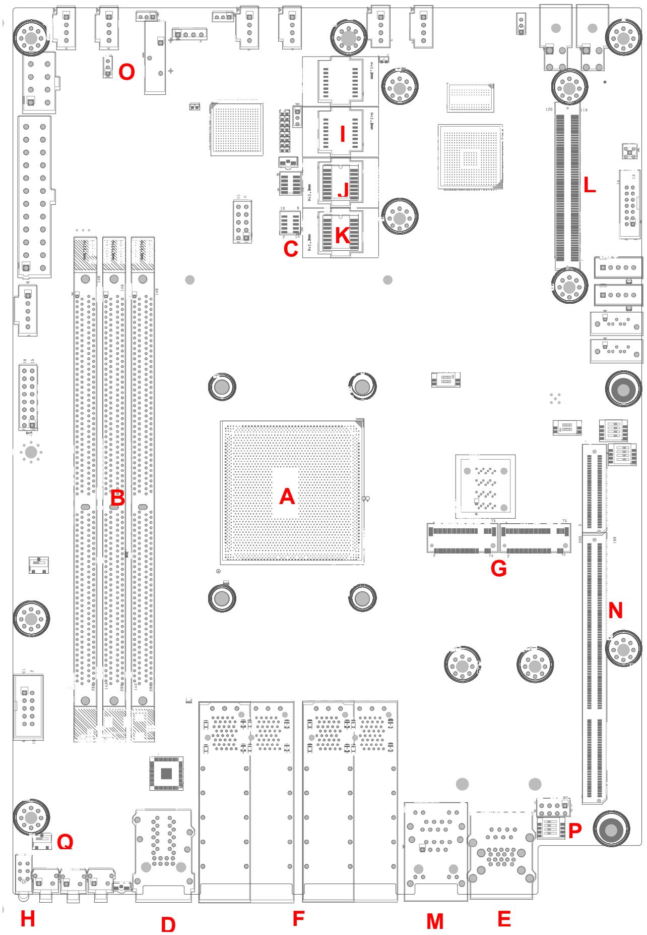
3.8 Board Layout
![O\nI\nJ\nK\nC\nL\nB\nA\nG\nN\nQ\nH\nD\nF\nM\nE\nP](.mecs-6120-50m-22807-1010-11/e0c7cd5570438864d5724df65dc0919e001af6584ed7a9e961693fb0ecbc3a2d.jpg)

<table><tr><td>A</td><td>Intel® Xeon® D Processor</td><td>J</td><td>Primary BIOS SPI Flash</td></tr><tr><td>B</td><td>DDR4 Socket</td><td>K</td><td>Secondary BIOS SPI Flash</td></tr><tr><td>C</td><td>Debug Port (Port 80)</td><td>L</td><td>OCP Connector</td></tr><tr><td>D</td><td>BMC/MECS-6120 LAN RJ-45</td><td>M</td><td>1PPS+TOD Ports</td></tr><tr><td>E</td><td>Console Port RJ-45 + USB 3.0</td><td>N</td><td>PCIe x32 Connector</td></tr><tr><td>F</td><td>SFP+ Connectors</td><td>O</td><td>Clear CMOS Jumper (J1)</td></tr><tr><td>G</td><td>M.2 Slot</td><td>P</td><td>BMC Mode Switch (SW1)</td></tr><tr><td>H</td><td>Status LEDs</td><td>Q</td><td>HDD/User LED Switch (SW5)</td></tr><tr><td>I</td><td>BMC SPI Flash</td><td colspan="2"></td></tr></table>

# 4 BIOS Setup

# 4.1 BIOS Setup Menu

The BIOS setup utility is invoked by pressing &lt;ESC&gt; or &lt;DEL&gt; keys. User can change BIOS settings during setup utility runs. A system reset is required for new settings to take effect.

In the BIOS setup utility, there are several hot keys are designed for specific purposes, as listed below.

&lt;F1&gt;: General help in setup menu
&lt;F8&gt;: Load previous BIOS values
&lt;F9&gt;: Load BIOS default in setup utility
&lt;F10&gt;: Save & Exit setup utility

To navigate through the BIOS setup menu, use the following.

<table><tr><td>→←</td><td>Left/Right. The Left and Right &lt; Arrow &gt; keys allow you to select a setup screen.For example: Main screen, Advanced screen, Chipset screen, and so on.</td></tr><tr><td>↑↓</td><td>Up/Down The Up and Down &lt; Arrow &gt; keys allow you to select a setup item or sub-screen.</td></tr><tr><td>+-</td><td>Plus/Minus The Plus and Minus &lt; Arrow &gt; keys allow you to change the field value of a particular setup item.For example: Date and Time.</td></tr><tr><td>Tab</td><td>The &lt; Tab &gt; key allows you to select setup fields.</td></tr></table>

# 4.1.1 Menu Selection Bar

The Menu Selection Bar is located at the top of the screen. It displays the top level available menus to the user:

Main Menu
Advanced Menu
Platform Configuration Menu
Server Mgmt
Security Menu
Boot Menu
Save & Exit Menu

# 4.1.2 Menu Conventions

The appearance of the setup menu listed in this chapter is a sample to describe the item list. It is shown on a VT100 terminal via serial console. The menu conventions are as follows.

# Using color

The mandatory BIOS setup fields are in black. The BIOS setup fields currently not used are in grey. The display only strings are in black.

# Using brackets

Editable menu options are marketed with squares ‘[‘ and ‘]’ to distinguish them from display only fields that can’t be modified.

# 4.2 Main Menu

The Main Menu provides read-only information about the system and also allows you to set the system date and time. The tables below show screen shots of the Main menu details, submenus and settings.

![Aptio Setup - AMI\nMain Platform Configuration Advanced Socket Configuration Server Mgmt\nBIOS Information\nBIOS Vendor American Megatrends\nBIOS Version 0.11.10\nBuild Date 04/13/2022\nRC Version 21.D01\nME FW Version 11:5.0.0.60\nSystem Information\nProject Name MECS-6120\nCPU Board Version A2\nCPU Brand String Intel (R)Xeon(R) D-1749\nCPU Frequency 3.00GHz\nTotal Memory 32768 MB (DDR4)\nMemory Frequency 2666 MHz\nPCH SKU CDF SKU\nSystem Date (Wed 04/13/2022)\nSystem Time (20:00:20)\nSet the Time. Use Tab\nto switch between Time\nelements.\n++: Select Screen\n↑↓: Select Item\nEnter: Select\n+/-: Change Opt.\nF1: General Help\nF8: Previous Values\nF9: Optimized Defaults\nF10: Save & Exit\nESC: Exit\nVersion 2.22.1282 Copyright (C) 2022 AMI\nAB](.mecs-6120-50m-22807-1010-11/627b125058c0a2975d58f51f942f7fded728695bab3ad97d15cd74ce49190d70.jpg)

# 4.2.1 BIOS Information

<table><tr><td>BIOS Item</td><td>Options</td><td>Description</td></tr><tr><td>BIOS Vendor</td><td>Info-only.American Megatrends</td><td>Display vendor name of system BIOS.</td></tr><tr><td>BIOS Version</td><td>Info-only.x.yy.zz</td><td>Display version of booting BIOS.</td></tr><tr><td>Build Date</td><td>Info-only.MM/DD/YYYY</td><td>It shows the date that BIOS was built.</td></tr><tr><td>MRC Version</td><td>Info-only.xxx.Ryy</td><td>Display the revision of MRC code which is implemented in BIOS.</td></tr><tr><td>ME FW Version</td><td>Info-only.ww:x.y.z.aaa</td><td>Display the version of Intel manageability firmware which is implemented in BIOS.</td></tr></table>

# 4.2.2 System Information

<table><tr><td>BIOS Item</td><td>Options</td><td>Description</td></tr><tr><td>Project Name</td><td>Info-only.</td><td>Shows Project Name</td></tr><tr><td>CPU Board Version</td><td>Info-only.</td><td>Shows Main Board Version</td></tr><tr><td>CPU Brand String</td><td>Info-only.Intel(R) Core, ...</td><td>Shows what CPU is booting the system.</td></tr><tr><td>CPU Frequency</td><td>Info-only.XXXX MHz</td><td>Shows CPU frequency.</td></tr><tr><td>Total Memory</td><td>Info-only.XXXX MB (DDR4)</td><td>Shows total memory size used on the motherboard and memory type.</td></tr><tr><td>Memory Frequency</td><td>Info-only.XXXX MHz</td><td>Shows memory frequency.</td></tr><tr><td>System Date</td><td>MM/DD/YYYY</td><td>For configuring/showing system date.When setting the Date, usekey to switch between Date elements.</td></tr><tr><td>System Time</td><td>HH:MM:SS</td><td>For configuring/showing system time.When setting the Time, usekey to switch between Time elements.</td></tr><tr><td>Access Level</td><td>Info-only.Administrator/User</td><td>It shows what access level is used to enter BIOS setup menu.</td></tr></table>

# 4.3 Platform Configuration Menu

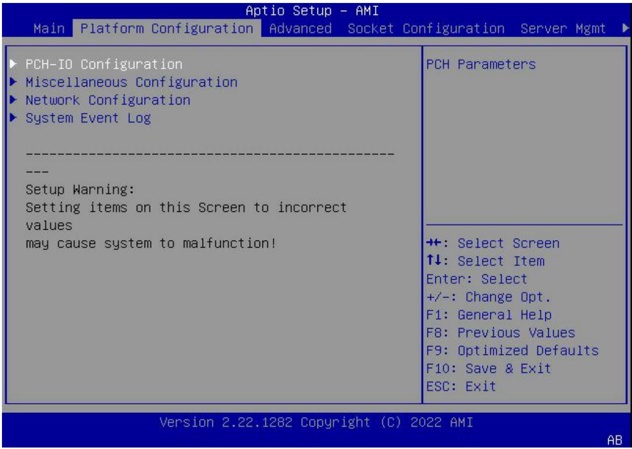
This menu contains the Platform Configuration settings.
![Aptio Setup - AMI\nMain Platform Configuration Advanced Socket Configuration Server Mgmt\n▶ PCH-IO Configuration\n▶ Miscellaneous Configuration\n▶ Network Configuration\n▶ System Event Log\n------------------\n------------------\nSetup Warning:\nSetting items on this Screen to incorrect\nvalues\nmay cause system to malfunction!\nPCH Parameters\n++: Select Screen\n↑↓: Select Item\nEnter: Select\n+/-: Change Opt.\nF1: General Help\nF8: Previous Values\nF9: Optimized Defaults\nF10: Save & Exit\nESC: Exit\nVersion 2.22.1282 Copyright (C) 2022 AMI\nAB](.mecs-6120-50m-22807-1010-11/3670450af800eaf7170e2f55d1351595731a673b22f4017c0d1b08bced9d9817.jpg)

<table><tr><td>BIOS Item</td><td>Options</td><td>Description</td></tr><tr><td>PCH-IO Configuration</td><td>Sub-Menu</td><td>For PCH-IO setting</td></tr><tr><td>Miscellaneous Configuration</td><td>Sub-Menu</td><td>For Miscellaneous Configuration</td></tr><tr><td>Network Configuration</td><td>Sub-Menu</td><td>For configuring Network.</td></tr><tr><td>System Event Log</td><td>Sub-Menu</td><td>System Event Log</td></tr></table>

# 4.3.1 PCH-IO Configuration

![Aptio Setup - AMI\nPlatform Configuration\nPCH-IO Configuration\n► PCI Express Configuration\n► SATA Configuration\nSerial IRQ Mode (Continuous)\nState After G3 (SO State)\nPCI Express\nConfiguration settings\n+: Select Screen\n↑↓: Select Item\nEnter: Select\n+/-: Change Opt.\nF1: General Help\nF8: Previous Values\nF9: Optimized Defaults\nF10: Save & Exit\nESC: Exit\nVersion 2.22.1282 Copyright (C) 2022 AMI\nAB](.mecs-6120-50m-22807-1010-11/9b8aad50c6429b7c8ad2de567fe7614c822ff8fcc57d0dc2f1a13164586a0873.jpg)

<table><tr><td>BIOS Item</td><td>Options</td><td>Description</td></tr><tr><td>PCI Express Configuration</td><td>Sub-Menu</td><td>PCI Express Configuration</td></tr><tr><td>SATA Configuration</td><td>Sub-Menu</td><td>SATA Configuration</td></tr><tr><td>Serial IRQ Mode</td><td>QuietContinuous</td><td>Configure Serial IRQ Mode.</td></tr><tr><td>State After G3</td><td>S0 StateS5 State</td><td>Specify what state to go to when power is re-applied after a power failure</td></tr></table>

# 4.3.1.1. PCI Express Configuration

![Aptio Setup - AMI\nPlatform Configuration\nPCI Express Configuration\n► PCI Express Root Port Cluster 0(x8)\n► PCI Express Root Port 9(I210)\n► PCI Express Root Port 10(I210)\nPCI Express Root Port Settings.](.mecs-6120-50m-22807-1010-11/13257fc54d31300d485a815a95bd629e9de430c28565007318832c36b340e93a.jpg)

<table><tr><td>BIOS Item</td><td>Options</td><td>Description</td></tr><tr><td>PCI Express Configuration</td><td>Sub-Menu</td><td>To enable or disable PCI-E Port.</td></tr></table>

# 4.3.1.2. SATA Configuration

![Aptio Setup - AMI\nPlatform Configuration\n► Controller 1 SATA Configuration\n► Controller 2 SATA Configuration\nSATA Controller 1\nDevice Options Settings](.mecs-6120-50m-22807-1010-11/5765ec44deaadc20552ed2247ebbd92e7cdfcf8c0eab1ccc247d3d9b54283c54.jpg)

![Aptio Setup - AMI\nPlatform Configuration\nController 1 SATA Configuration\nSATA Configuration (Enabled)\nSATA Mode Selection (AHCI)\nSATA Port 0 TS64GMTS400 - 64.0 GB\nPort 0 (Enabled)\nHot Plug (Disabled)\nConfigured as eSATA Hot Plug supported\nSATA Port 1 (Not Installed)\nPort 1 (Enabled)\nHot Plug (Disabled)\nConfigured as eSATA Hot Plug supported\nSATA Port 2 (Not Installed)\nPort 2 (Enabled)\nHot Plug (Disabled)\nConfigured as eSATA Hot Plug supported\nSATA test settings\n++: Select Screen\n↑↓: Select Item\nEnter: Select\n+/-: Change Opt.\nF1: General Help\nF8: Previous Values\nF9: Optimized Defaults\nF10: Save & Exit\nESC: Exit\nVersion 2.22.1282 Copyright (C) 2022 AMI\nAB](.mecs-6120-50m-22807-1010-11/b3b4bbc202fbaffd03d87bee1cbd22944b82affcb85b7d0b66f5a93093224926.jpg)

<table><tr><td>BIOS Item</td><td>Options</td><td>Description</td></tr><tr><td>SATA Configuration</td><td>DisabledEnabled</td><td>To enable or disable SATA Controller.</td></tr><tr><td>SATA Mode Selection</td><td>AHCIRAID</td><td>For SATA operating mode setting.</td></tr><tr><td>SATA Port X</td><td>Info Only</td><td>To show installed SATA info</td></tr><tr><td>Port X</td><td>EnableDisable</td><td>To enable or disable this SATA port</td></tr><tr><td>Hot Plug</td><td>EnableDisable</td><td>To enable or disable this port as Hot Pluggable</td></tr></table>

# 4.3.2 Miscellaneous Configuration

<table><tr><td>Miscellaneous Configuration
----
---
Wake On Lan Support [Disable]
Active Video [Auto]
RTC Wake system from [Disable]
S4/S5</td><td>Enable or Disable Wake
On Lan Support</td></tr><tr><td></td><td>+: Select Screen
↑↓: Select Item
Enter: Select
+/-: Change Opt.
F1: General Help
F8: Previous Values
F9: Optimized Defaults
F10: Save &amp; Exit
ESC: Exit</td></tr></table>

Version 2.22.1282Copyright(C）2022 AMI

AB

<table><tr><td>BIOS Item</td><td>Options</td><td>Description</td></tr><tr><td>Wake On LAN Support</td><td>DisabledEnabled</td><td>To enable or disable WOL</td></tr><tr><td>Active Video</td><td>AutoOnboard DevicePCIE Device</td><td>Select BIOS display device</td></tr><tr><td>RTC Wake system from S4/S5</td><td>DisabledEnabled</td><td>System will wake on the day::hr::min::sec specified</td></tr></table>

# 4.3.3 Network Configuration

![Aptio Setup - AMI\nPlatform Configuration\nLegacy Option ROMs (Disabled)\nsupport\nEFI Network (Disabled)\nEnable/Disable Legacy\nPXE Option ROM\nexecution for LANs.\n++: Select Screen\n↑↓: Select Item\nEnter: Select\n+/-: Change Opt.\nF1: General Help\nF8: Previous Values\nF9: Optimized Defaults\nF10: Save & Exit\nESC: Exit\nVersion 2.22.1282 Copyright (C) 2022 AMI\nAB](.mecs-6120-50m-22807-1010-11/35dd6657e64a21d44c63e77346a28234503afd32c2fb5df8694ea9ae8063364f.jpg)

<table><tr><td>BIOS Item</td><td>Options</td><td>Description</td></tr><tr><td>Legacy Option ROMs support</td><td>EnabledDisabled</td><td>Enable or disable Legacy PXEOption ROM</td></tr><tr><td>EFI Network</td><td>EnabledDisabled</td><td>Enable or disable EFI Network Driver</td></tr></table>

# 4.3.4 System Event Log

<table><tr><td rowspan="2">System Event Log
----
---
System Errors [Enable]
RAS Log Level [MIN (BASIC_FLOW)]</td><td>System Error
Enable/Disable setup
options.</td></tr><tr><td>+: Select Screen
↑↓: Select Item
Enter: Select
+/-: Change Opt.
F1: General Help
F8: Previous Values
F9: Optimized Defaults
F10: Save &amp; Exit
ESC: Exit</td></tr><tr><td colspan="2">Version 2.22.1282 Copyright (C) 2022 AMI AB</td></tr></table>

<table><tr><td>BIOS Item</td><td>Options</td><td>Description</td></tr><tr><td>System Errors</td><td>DisabledEnabled</td><td>To enable or disable system error log</td></tr><tr><td>RAS Log Level</td><td>MIN (BASIC_FLOW)MID (BASIC_FLOW, FUNC_FLOW)MAX(BASIC_FLOW, FUNC_FLOW, REG)</td><td>RAS Log setup options.</td></tr></table>

# 4.4 Advanced Menu

This menu contains the Advanced settings.

![Aptio Setup - AMI\nMain Platform Configuration Advanced Socket Configuration Server Mgmt\nSerial Port Console Redirection\nNVMe Configuration\nPCI Subsystem Settings\nNetwork Stack Configuration\nAdvanced Power Management Configuration\nTrusted Computing\nPcie Delay support (Enabled)\nDelay Time in seconds 0\nTls Auth Configuration\nAll Cpu Information\nEmulation Configuration\nRAM Disk Configuration\nIntel(R) I210 Gigabit Network Connection -\n00:30:64:6F:70:B2\nIntel(R) I210 Gigabit Network Connection -\n00:30:64:6F:70:B3\nPcie Delay support\nfunction, setting delay\ntime to scan PCIe card\n++: Select Screen\n↑↓: Select Item\nEnter: Select\n+/-: Change Opt.\nF1: General Help\nF8: Previous Values\nF9: Optimized Defaults\nF10: Save & Exit\nESC: Exit\nVersion 2.22.1282 Copyright (C) 2022 AMI\nAB](.mecs-6120-50m-22807-1010-11/b2fdc8cb38343e54b53a922ccc3a7c1c13f203bea5fd851578fe48cc94d1ccae.jpg)

<table><tr><td>BIOS Item</td><td>Options</td><td>Description</td></tr><tr><td>Serial Port Console Redirection</td><td>Sub-Menu</td><td>For configuring serial console.</td></tr><tr><td>NVME Configuration</td><td>Sub-Menu</td><td>For NVME devices</td></tr><tr><td>PCI Subsystem Settings</td><td>Sub-Menu</td><td>PCI settings</td></tr><tr><td>Network Stack Configuration</td><td>Sub-Menu</td><td>For configuring Network Stack.</td></tr><tr><td>Advanced Power Management Configuration</td><td>Sub-Menu</td><td>For Advanced Power Management</td></tr><tr><td>Trusted Computing</td><td>Sub-Menu</td><td>For TPM settings</td></tr><tr><td>PCIe Delay support</td><td>Disabled Enabled</td><td>PCIe Delay support function, setting delay time to scan PCIe card default is 0s,max is 10s</td></tr><tr><td>Tls Auth ConfigurationAll CPU InformationEmulation Configuration</td><td>No Detail</td><td>Dynamic page</td></tr><tr><td>Intel(R) I210 Gigabit Network Connection - ...Intel(R) Ethernet Connection E823-L 10GbE SFP+ ...</td><td>Sub-Menu</td><td>Onboard Ethernet controller configuration loaded by EFI driver. The setup page is designed by Intel and is shown when running the Ethernet EFI driver. It is related to the “Network” settings on the Boot setup page.</td></tr></table>

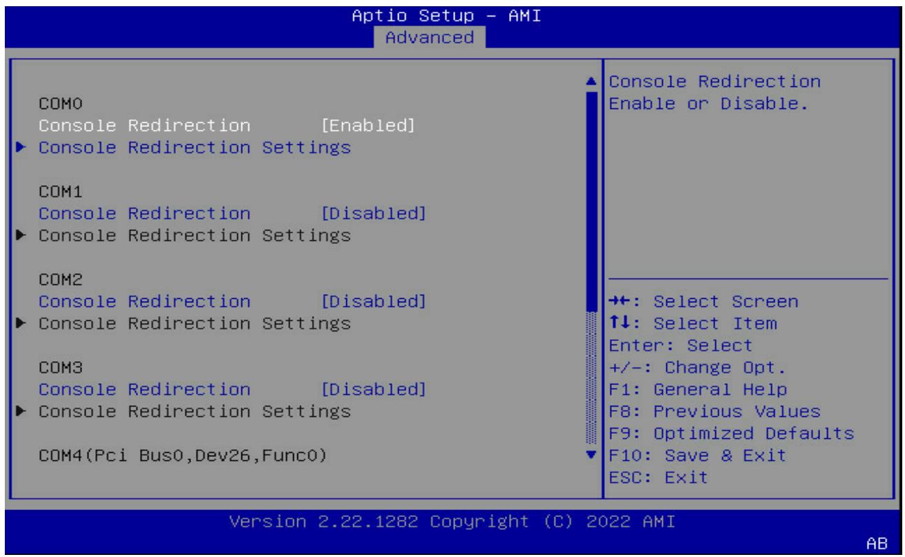
# 4.4.1 Serial Port Console Redirection
![Aptio Setup - AMI\nAdvanced\nCOMO\nConsole Redirection (Enabled)\n► Console Redirection Settings\nCOM1\nConsole Redirection (Disabled)\n► Console Redirection Settings\nCOM2\nConsole Redirection (Disabled)\n► Console Redirection Settings\nCOM3\nConsole Redirection (Disabled)\n► Console Redirection Settings\nCOM4(Pci Bus0,Dev26,Func0)\nConsole Redirection\nConsole Redirection\nConsole Redirection Settings\nConsole Redirection Settings\nConsole Redirection\nConsole Redirection\nConsole Redirection Settings\nConsole Redirection\nConsole Redirection\nConsole Redirection Settings\nConsole Redirection Settings\nConsole Redirection Settings\nConsole Redirection Settings\nConsole Redirection Settings\nConsole Redirection Settings\nConsole Redirection Settings\nConsole Redirection Settings\nConsole Redirection Settings\nConsole Redirection Settings\nConsole Redirection Settings\nConsole Redirection Settings\nConsole Redirection Settings\nConsole Redirection Settings\nConsole Redirection Settings\nConsole Redirection Settings\nConsole Redirection Settings\nConsole Redirection Settings\nConsole Redirection Settings\nConsole Redirection Settings\nConsole Redirection\nConsole Redirection\nConsole Redirection Settings\nConsole Redirection Settings\nConsole Redirection Settings\nConsole Redirection Settings\nConsole Redirection Settings\nConsole Redirection Settings\nConsole Redirection Settings\nConsole Redirection Settings\nConsole Redirection Settings\nConsole Redirection Settings\nConsole Redirection Settings\nConsole Redirection Settings\nConsole Redirection Settings\nConsole Redirection Settings\nConsole Redirection Settings\nConsole Redirection Settings\nConsole Redirection Settings\nSoftware 2.22.1282 Copyright (C) 2022 AMI\nVersion 2.22.1282 Copyright (C) 2022 AMI\nAB](.mecs-6120-50m-22807-1010-11/6f1507312f4bad804ac9537cb4aa5bd2d6b20f9a60505c9f281840825ff00c58.jpg)

<table><tr><td>BIOS Item</td><td>Options</td><td>Description</td></tr><tr><td>Console Redirection</td><td>EnabledDisabled</td><td>Enable or disable serial portconsole redirection function.</td></tr><tr><td>Console Redirection Settings</td><td>Sub-Menu</td><td>For configuring serial port settingswhen console redirection functionis enabled.</td></tr></table>

# 4.4.1.1. Serial Port Console Redirection > COM0

![Aptio Setup - AMI\nAdvanced\nCOMO\nConsole Redirection Settings\nTerminal Type (ANSI)\nBits per second (115200)\nData Bits (8)\nParity (None)\nStop Bits (1)\nFlow Control (None)\nVT-UTF8 Combo Key (Enabled)\nSupport\nRecorder Mode (Disabled)\nResolution 100x31 (Disabled)\nPutty KeyPad (VT100)\nEmulation: ANSI:\nExtended ASCII char\nset. VT100: ASCII char\nset. VT100Plus: Extends\nVT100 to support color,\nfunction keys, etc.\nVT-UTF8: Uses UTF8\nencoding to map Unicode\n+: Select Screen\n↑↓: Select Item\nEnter: Select\n+/-: Change Opt.\nF1: General Help\nF8: Previous Values\nF9: Optimized Defaults\nF10: Save & Exit\nESC: Exit\nVersion 2.22.1282 Copyright (C) 2022 AMI\nAB](.mecs-6120-50m-22807-1010-11/947b7c902626f0ae510d22161e9c8b34b108d2adf0a98b8bc17a321200c42da5.jpg)

<table><tr><td>BIOS Item</td><td>Options</td><td>Description</td></tr><tr><td>Terminal Type</td><td>VT100VT100+VT-UTF8ANSI</td><td>Configure type of console emulation.Emulation:ANSI: Extended ASCII char set.VT100: ASCII char set.VT100+: Extends VT100 to support color, function keys, etc.VT-UTF8: Uses UTF8 encoding to map Unicode chars onto 1 or more bytes.</td></tr><tr><td>Bits per second</td><td>9600192003840057600115200</td><td>Selects serial port transmission speed.The speed must be matched on the other side. Long or noisy lines may require lower speed.</td></tr><tr><td>Data Bits</td><td>78</td><td>Configure the number of data bits in each transmitted or received serial character for both serial ports.</td></tr><tr><td>Parity</td><td>NoneEvenOddMarkSpace</td><td>Configures if parity bit is generated (transmit data) or checked.A parity bit can be sent with the data bits to detect some transmission errors.Even: parity bit is 0 if the num of 1's in the data bits is even. Odd: parity bit is 0 if num of 1's in the data bits is odd.Mark: parity bit is always 1. Space: Parity bit is always 0. Mark and Space Parity do not allow for error detection.They can be used as an additional databit.</td></tr><tr><td>Stop Bits</td><td>12</td><td>Configures the number of stop bits transmitted and received in each serial character for both serial ports. Stop bits indicate the end of a serial data packet. (A start bit indicates the beginning). The standard setting is 1 stop bit. Communication with slow devices may require more than 1 stop bit.</td></tr><tr><td>Flow Control</td><td>NoneHardware RTS/CTS</td><td>Configures flow control for console redirection. Hardware flow control uses RTC/CTS.</td></tr><tr><td>VT-UTF8 Combo Key Support</td><td>DisabledEnabled</td><td>Enable VT-UTF8 Combination Key Support for ANSI/VT100 terminals</td></tr><tr><td>Recorder Mode</td><td>DisabledEnabled</td><td>This mode only text wil be sent</td></tr><tr><td>Resolution 100x31</td><td>DisabledEnabled</td><td>To enable or disable extended terminal resolution</td></tr><tr><td>Putty Keypad</td><td>VT100</td><td>Select Function Key and keypad on Putty</td></tr></table>

# 4.4.2 NVMe Configuration

Aptio Setup - AMI

Advanced

Seg:Bus:Dev:Func

Model Number

Total Size

Vendor ID

Device ID

00:02:00:00

TS256GMTE452T

256.0GB

126F

2263

Namespace:1

Device Self Test:

Self Test Action

Run Device Self Test

Short Device Selftest

Result

Extended Device

Selftest Result

Size:256.0 GB

[Controller Only Test]

[Not Available]

[Not Available]

Select either Short or Extended Self Test.

Short option will take couple of minutes and extended option will take several minutes to complete.

+: Select Screen

↑↓: Select Item

Enter: Select

+/-: Change Opt.

F1: General Help

F8: Previous Values

F9: Optimized Defaults

F10: Save & Exit

ESC:Exit

Version 2.22.1282 Copyright (C) 2022 AMI

AB

# 4.4.3 PCI Subsystem Settings

<table><tr><td>PCI Bus Driver Version A5.01.26
PCI Devices Common Settings:
Above 4G Decoding [Enabled]
SR-IOV Support [Enabled]</td><td>Enables or Disables
64bit capable Devices
to be Decoded in Above
4G Address Space (Only
if System Supports 64
bit PCI Decoding).</td></tr><tr><td></td><td>+: Select Screen
↑↓: Select Item
Enter: Select
+/-: Change Opt.
F1: General Help
F8: Previous Values
F9: Optimized Defaults
F10: Save &amp; Exit
ESC: Exit</td></tr></table>

Version 2.22.1282 Copyright (C) 2022 AMI

AB

<table><tr><td>BIOS Item</td><td>Options</td><td>Description</td></tr><tr><td>Above 4G Decoding</td><td>DisabledEnabled</td><td>To enable or disable decoded in above 4G address space.</td></tr><tr><td>SR-IOV Support</td><td>DisabledEnabled</td><td>Enable or disable Single Root IO virtualization support</td></tr></table>

# 4.4.4 Network Stack Configuration

<table><tr><td colspan="2">Aptio Setup - AMI Advanced</td></tr><tr><td>Network Stack [Disabled]</td><td>Enable/Disable UEFI Network Stack</td></tr><tr><td></td><td>+:-: Select Screen ↑↓: Select Item Enter: Select +/-: Change Opt. F1: General Help F8: Previous Values F9: Optimized Defaults F10: Save &amp; Exit ESC: Exit</td></tr><tr><td colspan="2">Version 2.22.1282 Copyright (C) 2022 AMI AB</td></tr></table>

<table><tr><td>BIOS Item</td><td>Options</td><td>Description</td></tr><tr><td>Network Stack</td><td>DisabledEnabled</td><td>To enable or disable network stack.</td></tr></table>

# 4.4.5 Advanced Power Management

<table><tr><td colspan="2">Aptio Setup - AMI Advanced</td></tr><tr><td>Advanced Power Management Configuration
------------------
►CPU P State Control
►Hardware PM State Control
►CPU C State Control
►Package C State Control
►CPU Thermal Management
►CPU - Advanced PM Tuning</td><td>P State Control
Configuration Sub Menu,
include Turbo, XE and
etc.</td></tr><tr><td></td><td>+: Select Screen
↑↓: Select Item
Enter: Select
+/-: Change Opt.
F1: General Help
F8: Previous Values
F9: Optimized Defaults
F10: Save &amp; Exit
ESC: Exit</td></tr><tr><td colspan="2">Version 2.22.1282 Copyright (C) 2022 AMI AB</td></tr></table>

<table><tr><td>BIOS Item</td><td>Options</td><td>Description</td></tr><tr><td>CPU P State Control</td><td>Sub-Menu</td><td>P State Control (Turbo, EIST and ETC.)</td></tr><tr><td>Hardware PM State Control</td><td>Sub-Menu</td><td>Hardware P-State settings</td></tr><tr><td>CPU C State Control</td><td>Sub-Menu</td><td>CPU C State settings</td></tr><tr><td>Package C State Control</td><td>Sub-Menu</td><td>Package C State settings</td></tr><tr><td>CPU Thermal Management</td><td>Sub-Menu</td><td>CPU Thermal related settings</td></tr><tr><td>CPU – Advanced PM Tuning</td><td>Sub-Menu</td><td>Advanced PM Tuning settings</td></tr></table>

# 4.4.5.1. CPU P State Control

<table><tr><td>CPU P State Control
SpeedStep (Pstates) [Enable]
Boot performance mode [Max Performance]
Energy Efficient Turbo [Enable]
Turbo Mode [Enable]</td><td>Enable/Disable EIST (P-States)</td></tr><tr><td></td><td>+: Select Screen
↑↓: Select Item
Enter: Select
+/-: Change Opt.
F1: General Help
F8: Previous Values
F9: Optimized Defaults
F10: Save &amp; Exit
ESC: Exit</td></tr><tr><td colspan="2">Version 2.22.1282 Copyright (C) 2022 AMI AB</td></tr></table>

<table><tr><td>BIOS Item</td><td>Options</td><td>Description</td></tr><tr><td>SpeedStep (Pstates)</td><td>DisableEnable</td><td>Enhanced Intel SpeedStep Technology</td></tr><tr><td>Boot performance mode</td><td>Max PerformanceMax EfficientSet by Intel Node Manager</td><td>Select the performance state that the BIOS will set before OS hand off.</td></tr><tr><td>Energy Efficient Turbo</td><td>DisableEnable</td><td>Energy Efficient Turbo Disable, MSR 0x1FC [19]</td></tr><tr><td>Turbo Mode</td><td>DisableEnable</td><td>Enable/Disable processor Turbo Mode</td></tr></table>

# 4.4.5.2. Hardware PM State Control

![Aptio Setup - AMI\nAdvanced\nHardware PM State Control\nHardware P-States (Native Mode)\nDisable: Hardware\nchooses a P-state based\non OS Request (Legacy\nP-States)\nNative Mode: Hardware\nchooses a P-state based\non OS guidance\nOut of Band\n+: Select Screen\n↑↓: Select Item\nEnter: Select\n+/-: Change Opt.\nF1: General Help\nF8: Previous Values\nF9: Optimized Defaults\nF10: Save & Exit\nESC: Exit\nVersion 2.22.1282 Copyright (C) 2022 AMI\nAB](.mecs-6120-50m-22807-1010-11/a2e67595ac3400ff471c7bdb71a60cb37bab492a5d0d21c8cfc36e82aea2df00.jpg)

<table><tr><td>BIOS Item</td><td>Options</td><td>Description</td></tr><tr><td>Hardware P-States</td><td>DisableNative ModeNative Mode with No Legacy Support</td><td>Disable: Legacy P-States.Native Mode: Hardware chooses a P-state based on OS guidance.Native Mode with No Legacy Support: Hardware autonomously chooses a P-state.</td></tr></table>

# 4.4.5.3. CPU C State Control

<table><tr><td>CPU C State Control
Enable Monitor MWAIT [Enable]
CPU C1 auto demotion [Enable]
CPU C1 auto undemotion [Enable]
CPU C6 report [Auto]
Enhanced Halt State [Enable]
(C1E)
OS ACPI Cx [ACPI C2]</td><td>Allows Monitor and
MWAIT instructions.</td></tr><tr><td></td><td>+: Select Screen
↑↓: Select Item
Enter: Select
+/-: Change Opt.
F1: General Help
F8: Previous Values
F9: Optimized Defaults
F10: Save &amp; Exit
ESC: Exit</td></tr><tr><td colspan="2">Version 2.22.1282 Copyright (C) 2022 AMI AB</td></tr></table>

<table><tr><td>BIOS Item</td><td>Options</td><td>Description</td></tr><tr><td>Enable Monitor MWAIT</td><td>Disable Enable</td><td>Allows Monitor and MWAIT instructions</td></tr><tr><td>CPU C1 auto demotion</td><td>Disable Enable</td><td>Allows CPU to automatically demote to C1. Takes effect after reboot</td></tr><tr><td>CPU C1 auto undemotion</td><td>Disable Enable</td><td>Allows CPU to automatically undemote from C1</td></tr><tr><td>CPU C6 report</td><td>Disable/Enable/Auto</td><td>Enable/Disable CPU C6(ACPI C3) report to OS</td></tr><tr><td>Enhanced Halt State (C1E)</td><td>Disable/Enable</td><td>Core C1E auto promotion Control.</td></tr><tr><td>OS ACPI Cx</td><td>ACPI C2 ACPI C3</td><td>Report CC3/CC6 to OS ACPI C2 or ACPI C3</td></tr></table>

# 4.4.5.4. Package C State Control

![Aptio Setup - AMI\nAdvanced\nPackage C State Control\nPackage C State (C0/C1 state)\nC2C3TT 0\nDynamic L1 (Enable)\nPKG C-state Lat. Neg. (Disable)\nLTR IIO Input (Ignore IIO LTR input.)\nPackage C State limit\n+: Select Screen\n↑↓: Select Item\nEnter: Select\n+/-: Change Opt.\nF1: General Help\nF8: Previous Values\nF9: Optimized Defaults\nF10: Save & Exit\nESC: Exit\nVersion 2.22.1282 Copyright (C) 2022 AMI\nAB](.mecs-6120-50m-22807-1010-11/bff91b1b369a397ad00005e240db66c90f4cc3075e4228e3ca13fd3232ef6142.jpg)

<table><tr><td>BIOS Item</td><td>Options</td><td>Description</td></tr><tr><td>Package C State Control</td><td>C0/C1 stateC2 stateC6 (non-retention) stateAuto</td><td>Package C State limit</td></tr><tr><td>C2C3TT</td><td>0</td><td>Default = 0, means [AUTO]</td></tr><tr><td>Dynamic L1</td><td>DisableEnable</td><td>PCU_MISC_CONFIG Bit[21] = dynamic L1 enable</td></tr><tr><td>PKG C-state Lat. Neg.</td><td>Disable/Enable</td><td>MSR 1FCh Bit[30]PCH_NEG_DISABLE</td></tr><tr><td>LTR IIO Input</td><td>Take IIO LTR input.Ignore IIO LTR input</td><td>MSR 1FCh Bit[29] =LTR_IIO_DISABLE.Disable = Ignore IIO LTR input</td></tr></table>

# 4.4.5.5. CPU Thermal Management

![Aptio Setup - AMI\nAdvanced\nCPU Thermal Management\n► CPU T State Control\nCPU T State setting](.mecs-6120-50m-22807-1010-11/cbc079c7092e348f3d17152d8fd9bcec7c83d0c41bdd720467c001865a3e5f1d.jpg)

<table><tr><td>BIOS Item</td><td>Options</td><td>Description</td></tr><tr><td>CPU T State Control</td><td>Sub-menu</td><td>CPU T State settings</td></tr></table>

![Aptio Setup - AMI\nAdvanced\nCPU T State Control\nSoftware Controlled (Disable)\nT-States\nEnable/Disable Software\nControlled T-States](.mecs-6120-50m-22807-1010-11/a98d625d7b9d7e618286a44b39996c84396812915a9159e84190f6c7ccf3e81e.jpg)

<table><tr><td>BIOS Item</td><td>Options</td><td>Description</td></tr><tr><td>Software Controlled T-States</td><td>Disable Enable</td><td>Software Controlled T State setting</td></tr></table>

# 4.4.5.6. CPU-Advanced PM Tuning

![Aptio Setup - AMI\nAdvanced\nCPU - Advanced PM Tuning\nUncore Freq Scaling (Enable)\nUncore Freq RAPL (Enable)\nIf disable, user can\ninput Uncore Frequency.](.mecs-6120-50m-22807-1010-11/6e8d4da9e0b164e349d8f6857466c09f8990f06d0da03f35e7aba3f2d67df49f.jpg)

<table><tr><td>BIOS Item</td><td>Options</td><td>Description</td></tr><tr><td>Uncore Freq Scaling</td><td>DisableEnable</td><td>If disable, user can input Uncore Frequency</td></tr></table>

# 4.4.6 Trusted Computing

<table><tr><td rowspan="2">Configuration
Security Device [Enable]
Support
Disable Block Sid [Disabled]
NO Security Device
Found</td><td>Enables or Disables
BIOS support for security device. O.S.
will not show Security Device. TCG EFI protocol and INT1A interface will not be available.</td></tr><tr><td>+: Select Screen
↑↓: Select Item
Enter: Select
+/-: Change Opt.
F1: General Help
F8: Previous Values
F9: Optimized Defaults
F10: Save &amp; Exit
ESC: Exit</td></tr><tr><td colspan="2">Version 2.22.1282 Copyright (C) 2022 AMI AB</td></tr></table>

<table><tr><td>BIOS Item</td><td>Options</td><td>Description</td></tr><tr><td>Security Device</td><td>DisabledEnabled</td><td>Enable or Disable security device, such as TPM</td></tr></table>

# 4.4.7 Intel(R) I210 Gigabit Network Connection

When the BIOS boots the system, it will launch the onboard Intel® Ethernet I210 controller’s UEFI driver. The driver provides a setup page for configuring Ethernet parameters and shows information about Ethernet controller. When EFI Network is disabled, the Ethernet UEFI driver is not executed and this setup page will not be shown (see 5.3.3 Network Configuration on page 655).

![Aptio Setup - AMI\nAdvanced\n► Firmware Image Properties\n► NIC Configuration\n► iSCSI Configuration\n► Device Level Configuration\nBlink LEDs 0\nUEFI Driver Intel(R) PRO/1000\n9.7.06 PCI-E\nAdapter PBA 000300-000\nDevice Name Intel(R) I210 Gigabit\nNetwork Connection\nChip Type Intel i210\nPCI Device ID 1533\nPCI Address 03:00:00\nLink Status (Disconnected)\nLink Speed Status (Auto Negotiated)\nView device firmware\nversion information.\n++: Select Screen\n↑↓: Select Item\nEnter: Select\n+/-: Change Opt.\nF1: General Help\nF8: Previous Values\nF9: Optimized Defaults\nF10: Save & Exit\nESC: Exit\nVersion 2.22.1282 Copyright (C) 2022 AMI\nAB](.mecs-6120-50m-22807-1010-11/939ee22edb40bc433fbd8cd27c75b4c0574cce947347a25433353e88e3383604.jpg)

<table><tr><td>BIOS Item</td><td>Options</td><td>Description</td></tr><tr><td>NIC Configuration</td><td></td><td>For configuring link speed and wake function.</td></tr></table>

# 4.4.8 Intel(R) Ethernet Connection E823-L for 10GbE

When the BIOS boots the system, it will launch the onboard Intel® Ethernet E823-L controller’s UEFI driver. The driver provides a setup page for configuring Ethernet parameters and shows information about Ethernet controller. When EFI Network is disabled, the Ethernet UEFI driver is not executed and this setup page will not be shown (see 5.3.3 Network Configuration on page 655).

![Aptio Setup - AMI\nAdvanced\n► Firmware Image Properties\n► NIC Configuration\nBlink LEDs 0\nUEFI Driver Intel(R) 100GbE 3.1.18\nAdapter PBA N/A\nDevice Name Intel(R) Ethernet\nConnection E823-L for\nSFP\nChip Type Intel E823-L\nPCI Device ID 124D\nPCI Address F4:00:01\nLink Status (Disconnected)\nMAC Address 00:00:00:00:01:01\nVirtual MAC Address 00:00:00:00:00:00\nView device firmware\nversion information.\n+: Select Screen\n↑↓: Select Item\nEnter: Select\n+/-: Change Opt.\nF1: General Help\nF8: Previous Values\nF9: Optimized Defaults\nF10: Save & Exit\nESC: Exit\nVersion 2.22.1282 Copyright (C) 2022 AMI\nAB](.mecs-6120-50m-22807-1010-11/6eea502749f9409d4f65776dddeafb33895390fd3f74b02b11dc027d7c6b6a8c.jpg)

<table><tr><td>BIOS Item</td><td>Options</td><td>Description</td></tr><tr><td>NIC Configuration</td><td></td><td>For configuring link speed and wake function.</td></tr></table>

# 4.5 Socket Configuration Menu

This menu contains the settings for Socket Configuration.

![Aptio Setup - AMI\nMain Platform Configuration Advanced Socket Configuration Server Mgmt\n► Processor Configuration\n► Common RefCode Configuration\n► Memory Configuration\n► IIO Configuration\nDisplays and provides option to change the Processor Settings\n+:-: Select Screen\n↑↓: Select Item\nEnter: Select\n+/-: Change Opt.\nF1: General Help\nF8: Previous Values\nF9: Optimized Defaults\nF10: Save & Exit\nESC: Exit\nVersion 2.22.1282 Copyright (C) 2022 AMI\nAB](.mecs-6120-50m-22807-1010-11/7d7279a1d366170e02026577085ef665e1209e23cd646b0f889a9d70ee515cc3.jpg)

<table><tr><td>BIOS Item</td><td>Options</td><td>Description</td></tr><tr><td>Processor Configuration</td><td>Sub-Menu</td><td>For CPU settings</td></tr><tr><td>Common RefCode Configuration</td><td>Sub-Menu</td><td>For RC settings</td></tr><tr><td>Memory Configuration</td><td>Sub-Menu</td><td>PCU_MISC_CONFIG Bit[21] = dynamic L1 enable</td></tr><tr><td>IIO Configuration</td><td>Sub-Menu</td><td>MSR 1FCh Bit[30]PCH_NEG_DISABLE</td></tr></table>

# 4.5.1 Processor Configuration

![Aptio Setup - AMI\nSocket Configuration\nProcessor BSP Revision 606C1 - ICX-D LCC B\nProcessor Socket Socket 0 Socket 1\nProcessor ID 000606C1*\nProcessor Frequency 3.000GHz\nProcessor Max Ratio 1EH\nProcessor Min Ratio 08H\nMicrocode Revision 01000132\nL1 Cache RAM(Per Core) 80KB\nL2 Cache RAM(Per Core) 1280KB\nL3 Cache RAM(Per 15360KB\nPackage)\nProcessor O Version Intel (R)Xeon(R) D-1749 NT CPU @ 3.00GHz\nHyper-Threading (ALL) (Enable)\nEnable Intel(R) TXT (Disable)\nVMX (Enable)\nEnables the Vanderpool\nTechnology, takes\neffect after reboot.\n++: Select Screen\n↑↓: Select Item\nEnter: Select\n+/-: Change Opt.\nF1: General Help\nF8: Previous Values\nF9: Optimized Defaults\nF10: Save & Exit\nESC: Exit\nVersion 2.22.1282 Copyright (C) 2022 AMI\nAB](.mecs-6120-50m-22807-1010-11/ca0c9a61b189f2a46f402f6b86a02d94c702ca66326021325183c693916061e8.jpg)

<table><tr><td>BIOS Item</td><td>Options</td><td>Description</td></tr><tr><td>CPU string</td><td>Info only</td><td>To show CPU info</td></tr><tr><td>Hyper-Threading [ALL]</td><td>DisableEnable</td><td>To enable or disable logical processor threads</td></tr><tr><td>Enable Intel(R) TXT</td><td>DisableEnable</td><td>Enables Intel(R) TXT</td></tr><tr><td>VMX</td><td>EnableDisable</td><td>To enable or disable the Vanderpool Technology(VTx)</td></tr></table>

# 4.5.2 Common RefCode Configuration

![Aptio Setup - AMI\nSocket Configuration\nCommon RefCode Configuration\n----\n---\nMMCFG Base (Auto)\nMMCFG Size (Auto)\nMMIO High Base (2T)\nMMIO High Granularity (64G)\nSize\nNuma (Enable)\nSelect MMCFG Base\n+: Select Screen\n↑↓: Select Item\nEnter: Select\n+/-: Change Opt.\nF1: General Help\nF8: Previous Values\nF9: Optimized Defaults\nF10: Save & Exit\nESC: Exit\nVersion 2.22.1282 Copyright (C) 2022 AMI\nAB](.mecs-6120-50m-22807-1010-11/985c93e8912a9f51a6302a0451be3a5986d1216bd6c54f6db203a3dfa7b07274.jpg)

<table><tr><td>BIOS Item</td><td>Options</td><td>Description</td></tr><tr><td>MMCFG Base</td><td>1G/1.5G/1.75G...Auto</td><td>Select MMCFG Base</td></tr><tr><td>MMCFG Size</td><td>1G/2G...Auto</td><td>Select MMCFG Size</td></tr><tr><td>MMIO High Base</td><td>2T/1T/512G</td><td>Select MMIO High Base</td></tr><tr><td>MMIO High Granularity Size</td><td>16G/64G/256G</td><td>Selects the allocation size used to assign mmioh resources</td></tr><tr><td>Numa</td><td>DisableEnable</td><td>Enable or Disable Non uniform Memory Access</td></tr></table>

# 4.5.3 Memory Configuration

![Aptio Setup - AMI\nSocket Configuration\n----.\n---.\nIntegrated Memory Controller (iMC)\n----\n---\nEnforce POR    (POR)\nEnforce Population POR    (Enforce Supported\nPopulations)\nMemory Frequency    (Auto)\nIMC BCLK    (Auto)\n► Memory Topology\n► Memory Timings Override\n\nEnable - Enforces Plan\nOf Record restrictions\nfor DDR4 frequency and\nvoltage programming.\nDisable - Disables this\nfeature and user is\nable to run at higher\nfrequencies, specified\n\n+:-: Select Screen\n↑↓: Select Item\nEnter: Select\n+/-: Change Opt.\nF1: General Help\nF8: Previous Values\nF9: Optimized Defaults\nF10: Save & Exit\nESC: Exit\n\nVersion 2.22.1282 Copyright (C) 2022 AMI\nAB](.mecs-6120-50m-22807-1010-11/8fad2c0976375f46626cb6e728c134bc4e737d3eef01e37df3e1bb0029e29fd5.jpg)

<table><tr><td>BIOS Item</td><td>Options</td><td>Description</td></tr><tr><td>Enforce POR</td><td></td><td></td></tr><tr><td>Enforce Population POR</td><td></td><td></td></tr><tr><td>Memory Frequency</td><td>Auto800100010661200......</td><td>To select maximum memory frequency</td></tr><tr><td>Attempt Fast Boot</td><td>AutoDisableEnable</td><td>To enable or disable skip memory reference code on warm boots, Auto is Enable now</td></tr><tr><td>Attempt Fast Cold Boot</td><td>AutoDisableEnable</td><td>To enable or disable skip memory reference code on cold boots, Auto is Enable now</td></tr></table>

# 4.5.3.1. Memory Topology

![Aptio Setup - AMI\nSocket Configuration\n\n---\n---Socket0.ChA.Dimm0: 2666MT/s Transcend SRx8\n16GB RDIMMSocket0.ChB.Dimm0: 2666MT/s Transcend SRx8\n16GB RDIMM\n\n---\n+: Select Screen\n↑↓: Select Item\nEnter: Select\n+/-: Change Opt.\nF1: General Help\nF8: Previous Values\nF9: Optimized Defaults\nF10: Save & Exit\nESC: Exit\n\nVersion 2.22.1282 Copyright (C) 2022 AMI\nAB](.mecs-6120-50m-22807-1010-11/ec92bb1ea8d40e567588cae1d4ae27aa9d4695bd6380908e4a321f439a4b49ce.jpg)

<table><tr><td>BIOS Item</td><td>Options</td><td>Description</td></tr><tr><td>SocketX.ChX.DimmX</td><td>Info only</td><td>To show channel /dimm spd info</td></tr></table>

# 4.5.3.2. Memory Timings Override

![Aptio Setup - AMI\nSocket Configuration\nXMP Profile (Disable) Selects the XMP profile to use](.mecs-6120-50m-22807-1010-11/e8abb1b3f6e1649f22d48d1505266c3d8e95e555ded885326f743d23ae77a911.jpg)

<table><tr><td>BIOS Item</td><td>Options</td><td>Description</td></tr><tr><td>XMP Profile</td><td>Disable Enable</td><td>To enable or disable Intel Extreme Memory Profiles to support memory over-clock</td></tr></table>

# 4.5.4 IIO Configuration

![Aptio Setup - AMI\nSocket Configuration\n\nIIO Configuration\n---\n► Socket0 Configuration\n► Intel® VT for Directed I/O (VT-d)\n\n+:-: Select Screen\n↑↓: Select Item\nEnter: Select\n+/-: Change Opt.\nF1: General Help\nF8: Previous Values\nF9: Optimized Defaults\nF10: Save & Exit\nESC: Exit\n\nVersion 2.22.1282 Copyright (C) 2022 AMI\nAB](.mecs-6120-50m-22807-1010-11/82b196911a80d558f85b4d9a41bc62c02488a7ffd8c85db3cfad788dcfc70642.jpg)

# 4.5.4.1. Sub-Menu: Socket0 Configuration

![Aptio Setup - AMI\nSocket Configuration\nIOU0 (IIO PCIe Port 1) (x16)\n► Port 1A\nSelects PCIe port\nBifurcation for\nselected slot(s)\n+: Select Screen\n↑↓: Select Item\nEnter: Select\n+/-: Change Opt.\nF1: General Help\nF8: Previous Values\nF9: Optimized Defaults\nF10: Save & Exit\nESC: Exit\nVersion 2.22.1282 Copyright (C) 2022 AMI\nAB](.mecs-6120-50m-22807-1010-11/fac7c2ae6fa0b0a8afbb93a1d67b12fc26e41843145339b90e64a6cbcf314c70.jpg)

<table><tr><td>BIOS Item</td><td>Options</td><td>Description</td></tr><tr><td>IOU0 (IIO PCIe Port 1)</td><td>X4x4x4x4 / X4x4x8X8x4x4 / X8x8 / X16</td><td>Selects PCIe port bifurcation for riser card upstream port</td></tr><tr><td>Port 1A</td><td>Sub Page</td><td>To show PCIe port link status</td></tr></table>

# Socket0 Configuration > Port 1A

![Aptio Setup - AMI\nSocket Configuration\nPort 1A\nIn auto mode the BIOS\nwill remove the EXP\nport if there is no\ndevice or errors on\nthat device and the\ndevice is not HP\ncapable.\nEnable/Disable is used\nPCI-E Port (Enable)\nLink Speed (Gen 3 (8 GT/s))\nOverride Max Link (x16)\nWidth\nPCI-E Port DeEmphasis (-3.5 dB)\nPCI-E Port Link Status Link Did Not Train\nPCI-E Port Link Max Max Width x16\nPCI-E Port Link Speed Link Did Not Train\n+: Select Screen\n↑↓: Select Item\nEnter: Select\n+/-: Change Opt.\nF1: General Help\nF8: Previous Values\nF9: Optimized Defaults\nF10: Save & Exit\nESC: Exit\nVersion 2.22.1282 Copyright (C) 2022 AMI\nAB](.mecs-6120-50m-22807-1010-11/91f595d8de9bef7b7c880117954691f6eee4e46273197d3df8479b5affe5dca1.jpg)

<table><tr><td>BIOS Item</td><td>Options</td><td>Description</td></tr><tr><td>PCI-E Port</td><td>Disable/Enable</td><td>To enable or disable PCI-E Port</td></tr><tr><td>Link Speed</td><td>Gen 1 (2.5 GT/s)Gen 2 (5 GT/s)Gen 3 (8 GT/s)</td><td>Choose Link Speed</td></tr><tr><td>Override Max Link Width</td><td>Auto/X1/X2/X4/X8/X16</td><td>Override the max link width that was set by bifurcation</td></tr><tr><td>PCI-E Port DeEmphasis</td><td>-3.5 dB / -6.0 dB</td><td>De-Emphasis control (LNKCON2[6])</td></tr><tr><td>PCI-E Port Link StatusPCI-E Port Link MaxPCI-E Port Link Speed</td><td>Info Only</td><td>To show PCIE-E Port link or lot; width; speed</td></tr></table>

# 4.5.4.2. Intel(R) VT for Directed I/O (vt-d)

![Aptio Setup - AMI\nSocket Configuration\nIntel® VT for Directed I/O (VT-d)\n----(Enable)\nIntel® VT for (Enable)\nDirected I/O\nEnable/Disable Intel®\nVirtualization\nTechnology for Directed\nI/O (VT-d) by reporting\nthe I/O device\nassignment to VMM\nthrough DMAR ACPI\nTables.\n++: Select Screen\n↑↓: Select Item\nEnter: Select\n+/-: Change Opt.\nF1: General Help\nF8: Previous Values\nF9: Optimized Defaults\nF10: Save & Exit\nESC: Exit\nVersion 2.22.1282 Copyright (C) 2022 AMI\nAB](.mecs-6120-50m-22807-1010-11/bc942f9f3ff72c65fa3c5d09671b16dd77228016586104d9727d9f0728dad807.jpg)

<table><tr><td>BIOS Item</td><td>Options</td><td>Description</td></tr><tr><td>Intel(R) VT for Directed I/O (VT-d)</td><td>Disable Enable</td><td>To enable or disable Intel Virtualization Technology for Directed I/O</td></tr></table>

# 4.6 Server Mgmt Menu

This menu contains the Server Management settings.

![Aptio Setup - AMI\nMain Platform Configuration Advanced Socket Configuration Server Mgmt\nBMC Self Test Status PASSED\nBMC Device ID 32\nBMC Device Revision 1\nBMC Firmware Revision 1.02\nIPMI Version 2.0\nIPMI BMC Interface KCS\nBMC Support (Enabled)\nWait For BMC (Enabled)\nTime Zone(UTC Offset) 0x07FF\nCurrent Time Zone +00:00\nPOST Watchdog Timer (Disabled)\nPOST Watchdog timeout (6 minutes)\nPOST Watchdog Timer (Do Nothing)\nPolicy\nOS Watchdog Timer (Disabled)\nOS Wtd Timer Timeout (10 minutes)\nOS Wtd Timer Policy (Reset)\nWait For BMC response\nfor specified time out.\nIn PILOTII, BMC starts\nat the same time when\nBIOS starts during AC\npower ON. It takes\naround 30 seconds to\ninitialize Host to BMC\n+: Select Screen\n↑↓: Select Item\nEnter: Select\n+/-: Change Opt.\nF1: General Help\nF8: Previous Values\nF9: Optimized Defaults\nF10: Save & Exit\nESC: Exit\nVersion 2.22.1282 Copyright (C) 2022 AMI\nAB](.mecs-6120-50m-22807-1010-11/836d57d5b96fae69116152ea634994d905e60d84c78bfec62772c03a8dd562b9.jpg)

<table><tr><td>BIOS Item</td><td>Options</td><td>Description</td></tr><tr><td>BMC Self Test Status</td><td>Info-only</td><td>To show BMC self test status</td></tr><tr><td>BMC Device ID</td><td>Info-only</td><td>To show BMC Device ID</td></tr><tr><td>BMC Device Revision</td><td>Info-only</td><td>To show BMC Device Revision</td></tr><tr><td>BMC Firmware Revision</td><td>Info-only</td><td>To show BMC Firmware version</td></tr><tr><td>IPMI Version</td><td>Info-only</td><td>To show IPMI version</td></tr><tr><td>BMC Interfaces(s)</td><td>Info-only</td><td>To show BMC interface such as KCS</td></tr><tr><td>BMC support</td><td>EnabledDisabled</td><td>To enable or disable communicate with BMC</td></tr><tr><td>Wait For BMC</td><td>EnabledDisabled</td><td>To enable or disable wait for BMC 30s before sending Self Test command</td></tr><tr><td>Time Zone (UTC Offset)Current Time Zone</td><td>0x7FFFInfo-only</td><td>Enter UTC Offset in hours, ox7FFF to consider BIOS time as local time</td></tr><tr><td>POST Watchdog Timer</td><td>EnabledDisabled</td><td>Enable or Disable POST Watchdog Timer(FRB-2 timer)</td></tr><tr><td>POST Watchdog timeout</td><td>3mins/4mins5mins/6mins</td><td>Select 3mins/4mins/5mins/6mins for POST Watchdog Timer Expiration value</td></tr><tr><td>POST Watchdog Timer Policy</td><td>Do NothingResetPower DownPower Cycle</td><td>Configure how the system should respond if the POST Watchdog Timer (FRB-2 Timer) expires. Not available if Timer is disabled.</td></tr><tr><td>OS Watchdog Timer</td><td>EnabledDisabled</td><td>If enabled, starts a BIOS timer which can only be shut off by Management Software after the OS loads. Helps determine that the OS successfully loaded or follows the OS Boot Watchdog Timer policy.</td></tr><tr><td>OS Watchdog timeout</td><td>5 minutes10 minutes15 minutes20 minutes</td><td>Select 5mins/10mins/15mins/20mins for OS Boot Watchdog Timer Expiration. Not available if OS Boot Watchdog Timer is disabled.</td></tr><tr><td>OS Watchdog Timer Policy</td><td>Do NothingResetPower DownPower Cycle</td><td>Configure how the system should respond if the OS Boot Watchdog Timer expires. Not available if OS Boot Watchdog Timer is disabled.</td></tr><tr><td>BMC network configuration</td><td>Sub-Menu</td><td>Configure BMC network parameters</td></tr></table>

# 4.6.1 BMC Network Configuration

![Aptio Setup - AMI\nServer Mgmt\n--BMC network configuration--\n******************\nConfigure IPv4 support\n******************\nLan channel 1\nConfiguration Address (DynamicBmcDhcp)\nsource\nCurrent Configuration DynamicAddressBmcDhcp\nAddress source\nStation IP address 0.0.0.0\nSubnet mask 0.0.0.0\nStation MAC address 00-30-64-6F-70-B2\nRouter IP address 0.0.0.0\nRouter MAC address 00-00-00-00-00-00\nLan channel 2\nSelect to configure LAN\nchannel parameters\nstatically or\ndynamically(by BIOS or\nBMC). Unspecified\noption will not modify\nany BMC network\nparameters during BIOS\n++: Select Screen\n↑↓: Select Item\nEnter: Select\n+/-: Change Opt.\nF1: General Help\nF8: Previous Values\nF9: Optimized Defaults\nF10: Save & Exit\nESC: Exit\nVersion 2.22.1282 Copyright (C) 2022 AMI\nAB](.mecs-6120-50m-22807-1010-11/7fb0419d2a87958fb21a6b6005a2f0075d3ec702067ed8b77bae7e14127e1481.jpg)

<table><tr><td>BIOS Item</td><td>Options</td><td>Description</td></tr><tr><td>Configure IPV4 support</td><td>Read only</td><td></td></tr><tr><td>Configuration Address source</td><td>StaticDynamicBmcDhcp</td><td>Select to configure LAN channel parameters statically or dynamically(by BIOS or BMC)</td></tr><tr><td>Configure IPV6 support</td><td>Read only</td><td></td></tr><tr><td>IPV6 Support</td><td>Disable / Enable</td><td>Enable or Disable LAN IPV6 Support</td></tr><tr><td>Configuration Address source</td><td>StaticDynamicBmcDhcp</td><td>To configure LAN Address source when IPV6 supported</td></tr></table>

# 4.7 Security Menu

This menu contains the Security settings.

![Aptio Setup - AMI\nSecurity Boot Save & Exit\nIf ONLY the User's password is set, then this\nis a power on password and must be entered to\nboot or enter Setup. In Setup the User will\nhave Administrator rights.\nThe password length must be\nin the following range:\nMinimum length 3\nMaximum length 20\nAdministrator Password\nUser Password\nSecure Boot\nSecure Boot\nconfiguration\n+: Select Screen\n↑↓: Select Item\nEnter: Select\n+/-: Change Opt.\nF1: General Help\nF8: Previous Values\nF9: Optimized Defaults\nF10: Save & Exit\nESC: Exit\nVersion 2.22.1282 Copyright (C) 2022 AMI\nAB](.mecs-6120-50m-22807-1010-11/c8cc7f2474db487e710d2a618033455a367dec5bd8e22fc085a6613d547b6d11.jpg)

<table><tr><td>BIOS Item</td><td>Options</td><td>Description</td></tr><tr><td>Administrator Password</td><td>Enter to set password</td><td>Configure/Clear Administrator Password.When pressing enter, a menu will be popped up for creating new password. When password installed, press enter without inputting password, it will clear password.</td></tr><tr><td>User Password</td><td>Enter to set password</td><td>Configure/Clear User Password.When pressing enter, a menu will be popped up for creating new password. When password installed, press enter without inputting password, it will clear password.</td></tr><tr><td>Secure Boot</td><td>Sub-Menu</td><td>Secure Boot Menu. Default is Disabled.</td></tr></table>

# 4.8 Boot Menu

This menu contains the settings for bootable devices in the system.

![Aptio Setup - AMI\nSecurity Boot Save & Exit\nBoot Configuration\nSetup Prompt Timeout 3\nBootup NumLock State (On)\nQuiet Boot (Enabled)\nBoot Configuration\nBoot Option #1 (Hard Disk:Windows\nBoot Manager (P0:\nTS64GMTS400))\nBoot Option #2 (NVME:ubuntu\n(TS256GMTE452T))\nBoot Option #3 (UEFI AP:UEFI:\nBuilt-in EFI Shell)\nBoot Option #4 (CD/DVD)\nBoot Option #5 (SD)\nBoot Option #6 (USB Hard Disk)\nNumber of seconds to\nwait for setup\nactivation key.\n65535(0xFFFF) means\nindefinite waiting.\n+: Select Screen\n↑↓: Select Item\nEnter: Select\n+/-: Change Opt.\nF1: General Help\nF8: Previous Values\nF9: Optimized Defaults\nF10: Save & Exit\nESC: Exit\nVersion 2.22.1282 Copyright (C) 2022 AMI\nAB](.mecs-6120-50m-22807-1010-11/cdf509ca523e33f36a366a944e381ebb6e8a50854ded06c4be571b155af86e25.jpg)

<table><tr><td>BIOS Item</td><td>Options</td><td>Description</td></tr><tr><td>Setup Prompt Timeout</td><td>3</td><td>Number of seconds to wait for setup activation</td></tr><tr><td>Bootup NumLock State</td><td>OnOff</td><td></td></tr><tr><td>Quiet Boot</td><td>EnabledDisabled</td><td></td></tr><tr><td>Boot Option #1 ~ #9</td><td>#1: Hard Disk#2: CD/DVD#3: SD#4: USB Hard Disk#5: USB CD/DVD#6: USB Key#7: USB Floppy#8: USB LAN#9: Network</td><td>For boot priority setting.</td></tr><tr><td>XXXX Drive BBS Priorities</td><td>Sub-Menu</td><td>When the bootable device is attached to system and found by BIOS, it will be listed at boot option#. If there are many devices with the same device type found, it can set priority among these devices through this sub-menu.</td></tr></table>

# 4.9 Save & Exit Menu

![Aptio Setup - AMI\nSecurity Boot Save & Exit\nSave Options\nSave Changes and Exit\nDiscard Changes and Exit\nSave Changes and Reset\nDiscard Changes and Reset\nSave Changes\nDiscard Changes\nDefault Options\nRestore Defaults\nSave as User Defaults\nRestore User Defaults\nBoot Override\nWindows Boot Manager (P0: TS64GMTS400)\nubuntu (TS256GMTE452T)\nExit system setup after\nsaving the changes.\n++: Select Screen\n↑↓: Select Item\nEnter: Select\n+/-: Change Opt.\nF1: General Help\nF8: Previous Values\nF9: Optimized Defaults\nF10: Save & Exit\nESC: Exit\nVersion 2.22.1282 Copyright (C) 2022 AMI\nAB](.mecs-6120-50m-22807-1010-11/1e1d2cd34c9d628722caadc211edeba8fa77b7c443170359c0cb509251fe6742.jpg)

<table><tr><td>BIOS Item</td><td>Options</td><td>Description</td></tr><tr><td>Save Changes and Exit</td><td>Enter</td><td>Save changed settings and exit BIOS setup utility.</td></tr><tr><td>Discard Changes and Exit</td><td>Enter</td><td>Skip changed setting and exit BIOS setup utility.</td></tr><tr><td>Save Changes and Reset</td><td>Enter</td><td>Save all changed settings and let system do reset to boot system.</td></tr><tr><td>Discard Changes and Reset</td><td>Enter</td><td>Discard all changed settings and let system do reset to boot system.</td></tr><tr><td>Save Changes</td><td>Enter</td><td>Save all changed settings.</td></tr><tr><td>Discard Changes</td><td>Enter</td><td>Discard changes done so far to any of the setup options.</td></tr><tr><td>Restore Default</td><td>Enter</td><td>Load the default made when BIOS was built.</td></tr><tr><td>Save as User Default</td><td>Enter</td><td>Save all changed done so far as User Defaults.</td></tr><tr><td>Restore User Default</td><td>Enter</td><td>Load the default that user save as user defaults.</td></tr><tr><td>Boot Override</td><td>Info-only</td><td></td></tr></table>

# Important Safety Instructions

For user safety, please read and follow all instructions, WARNINGS, CAUTIONS, and NOTES marked in this manual and on the associated equipment before handling/operating the equipment.

1. Read these safety instructions carefully.
2. Keep this user’s manual for future reference.
3. Read the specifications section of this manual for detailed information on the operating environment of this equipment.
4. The equipment can be operated at an ambient temperature of 55°C.
5. When installing/mounting or uninstalling/removing equipment; or when removal of the chassis lid required for user servicing (Section 3.1-3.5):
• Turn off power and unplug any power cords/cables, and
Reinstall the chassis lid before restoring power.

![The image displays a standard safety warning symbol: a red triangle with a white exclamation point in the center. Below the triangle, the text 'WARNING:' is written in black, uppercase letters.](.mecs-6120-50m-22807-1010-11/ea087613b43042584a5db8b9af001caf5aab9fbf68afc3fd63e31ab839f92c98.jpg)

Hazardous moving parts. Keep body parts out of the motion path.

![The image features a black outline of an equilateral triangle containing a symbol resembling a four-bladed fan or propeller with a central hub. The graphic is set against a white background, bordered by black bars at the very top and bottom edges. There is no text present.](.mecs-6120-50m-22807-1010-11/0a3a9b76dd4345d36cf1b7ef86354f3dfa236cf928609a8f1a1f9729f254dde2.jpg)

6. To avoid electrical shock and/or damage to equipment:

• Keep equipment away from water or liquid sources;
• Keep equipment away from high heat or high humidity;
• Keep equipment properly ventilated (do not block or cover ventilation openings);
• Make sure to use recommended voltage and power source settings;
• Always install and operate equipment near an easily accessible electrical socketoutlet;
• Secure the power cord (do not place any object on/over the power cord);
Only install/attach and operate equipment on stable surfaces and/or recommended mountings;
If the equipment will not be used for long periods of time, turn off and unplug the equipment from its power source.
• The power cord must be connected to a socket or outlet with a ground connection.

7. Never attempt to fix the equipment. Equipment should only be serviced by qualified personnel.

8. An RTC battery may be provided for uninterrupted, backup or emergency power.

![The image displays a standard warning sign. It consists of a yellow equilateral triangle with a thick black border. Centered inside the triangle is a large black exclamation mark. Below the triangle, the word 'CAUTION:' is printed in black capital letters.](.mecs-6120-50m-22807-1010-11/3c21c091fdaf1aa19b6dd31ab335a1b3cbc5d1ae397c9cd0aad8781c0a0df802.jpg)

Risk of explosion if battery is replaced with one of an incorrect type. Discard used batteries according to the manufacturer's instructions.

9. This equipment is not suitable for use in locations where children are likely to be present.

10.Equipment must be serviced by authorized technicians when:

• The power cord or plug is damaged;
Liquid has penetrated the equipment;
• It has been exposed to high humidity/moisture;
• It is not functioning or does not function according to the user’s manual;
• It has been dropped and/or damaged; and/or,
It has an obvious sign of breakage.

11.Please pay strict attention to all warnings and advisories appearing on the device, to avoid injury or damage.

12.The equipment may have more than one power supply input. To reduce the risk of electrical shock, trained personnel should disconnect all power supply inputs before servicing.

![The image displays a standard safety warning sign featuring a yellow equilateral triangle with a black border. Inside the triangle is a large black exclamation point. Below the triangle, the text 'CAUTION' is printed in black, uppercase letters.](.mecs-6120-50m-22807-1010-11/addf4e10bdd3097c686510cb734bbba0c404c321e76727a7957556245a7fd697.jpg)

Shock hazard! Disconnect all power supply inputs before servicing.
![The image features a yellow triangular warning sign with a black border containing a black lightning bolt symbol in the center. Below the sign, the text reads 'Shock hazard!'.](.mecs-6120-50m-22807-1010-11/000cd0525ab56728754d6f9173c4f7833db6a3f326b709f16bf7116e381d0e9d.jpg)

![Multiple power sources](.mecs-6120-50m-22807-1010-11/54f9b5efae275220cad3d6ccc8554d83c7dd955a5bd8d8047ddc3bd3a91f536d.jpg)

13.It is recommended that equipment be installed only in a server room or computer room where access is:

Restricted to qualified service personnel or users familiar with restrictions applied to the location, reasons therefor, and any precautions required;
Only afforded by the use of a tool or lock and key, or other means of security, and is controlled by the authority responsible for the location.

14.Suitable for installation in Information Technology Rooms in accordance with Article 645 of the National Electrical Code and NFPA 75.

15.This product is intended to be supplied by a certified DC power source providing reinforced/double insulation from AC mains with an output rating of -48V to -60V DC, 12A min., Tma = 55°C. All power connection wiring must be performed by a qualified electrician in accordance with National Electrical Code, ANSI/NFPA 70 and Canadian Electrical Code, Part I, CSA C22.1. The DC power supply should be well-grounded to ensure safe operation. The protective earthing conductor shall be minimum 14 AWG and having green-and-yellow insulation. The ground wire should be installed first (before "+" and "-") and then removed.

16.When using a Fiber Optic Small-Form Pluggable (SFP) module, ensure it is IEC 60825-1, IEC 60825-2 and IEC 60950-1 or IEC 62368-1 certified and a Class 1 Laser Product.

# Consignes de Sécurité Importantes

Pour assurer la sécurité de l’utilisateur, veuillez lire et suivre toutes les directives, ainsi que les AVERTISSEMENTS, MISES EN GARDE et REMARQUES de ce manuel et indiqués sur l’équipement associé avant de manipuler ou utiliser l’équipement.

1. Veuillez lire attentivement ces instructions de sécurité avec soin.
2. Veuillez conserver ce manuel pour référence future.
3. Veuillez lire la section des spécifications de ce manuel pour avoir des informations détaillées sur l’environnement d’exploitation de cet équipement.
4. L’équipement peut être utilisé à une température ambiante de 55 °C.
5. Lors de l’installation ou du montage et de la désinstallation ou de la dépose de l’équipement; ou lors de la dépose du couvercle du châssis pour procéder à l’entretien par l’utilisateur (Sections 3.1-3.5):

• Coupez l’alimentation et débranchez les cordons et les câbles d’alimentation, et
• Reposez le couvercle du châssis avant de remettre l’alimentation.

![The image displays a standard safety warning symbol. It features a red equilateral triangle with a white exclamation point in the center. Below the triangle, the word 'WARNING:' is printed in black, capital letters.](.mecs-6120-50m-22807-1010-11/dc9d31c3a87cd93a787865e6bdd3c36e15830a943dc1906855dac93e0aa92886.jpg)
AVERTISSEME AT

Pièces mobiles dangereuses. Gardez les parties du corps hors de la trajectoire.

![The image displays a black-and-white warning sign. It features a black outline of an equilateral triangle. Inside the triangle is a line drawing of a fan or propeller with four curved blades radiating from a central point. There is no text present in the image.](.mecs-6120-50m-22807-1010-11/29fee7fa4c9478e5e231533bd15750b3e89aeb976b8cf6505e35987aae51036f.jpg)

6. Pour éviter un risque d’électrocution et pour éviter d’endommager l’équipement :

• Éloignez l’équipement de l’eau et de toute source liquide;
• Éloignez l’équipement de toute source de chaleur ou d’humidité élevée;
Gardez l’équipement correctement ventilé (ne pas bloquer ou couvrir les ouvertures de ventilation);
Veillez à utiliser la tension recommandée et les réglages adéquats pour la source d’alimentation;
Veuillez toujours installer et exploiter l’équipement à proximité d’une prise de courant facilement accessible;
Assurez-vous que le cordon d’alimentation est acheminé de manière sécuritaire (ne déposez aucun objet dessus);
Installez, fixez et utilisez l’équipement sur des surfaces stables ou sur les fixations recommandées uniquement;
Si l’équipement n’est pas utilisé pendant une longue période, éteignez-le et débranchez-le de sa source d’alimentation.
• Le cordon d'alimentation doit être connecté à une prise ou à une prise de courant avec mise à la terre.

7. N’essayez jamais de réparer l’équipement. L’équipement ne doit être réparé que par du personnel qualifié.

8. Une pile au lithium peut être installée pour assurer l’alimentation de secours ou d’urgence en continu.

![The image shows a yellow triangular warning sign with a black exclamation point in the center. Below the triangle, the text reads 'CAUTION:' followed by 'mise en garde' underneath.](.mecs-6120-50m-22807-1010-11/ec120bdb32375d6ea14ea35f94fd5bdbef10de32cff0341a0b22e9259720b300.jpg)

Risque d'explosion si la batterie est remplacée par une batterie d'un type incorrect. Jetez les piles usagées conformément aux instructions du fabricant.

9. Cet équipement ne convient pas à une utilisation dans des lieux pouvant accueillir des enfants.
10.L’équipement doit être entretenu par des techniciens agréés lorsque :

le cordon d’alimentation est endommagé ou lorsque la fiche électrique est endommagée;
du liquide a pénétré à l’intérieur de l’équipement;
l’équipement a été exposé à un taux d’humidité élevé;
• l’équipement ne fonctionne pas ou ne fonctionne pas conformément au manuel de l’utilisateur;
• l’équipement est tombé ou lorsqu’il a été endommagé;
• l’équipement présente un signe évident de défaillance.

11.Veuillez porter une attention rigoureuse à tous les avertissements et à tous les avis figurant sur l’appareil, pour éviter des blessures ou des dommages.
12.L’équipement peut avoir plus d’une entrée d’alimentation. Pour réduire le risque d’électrocution, le personnel qualifié devrait déconnecter toutes les entrées d’alimentation avant de procéder à l’entretien.

![The image displays a yellow triangular warning sign with a black border and a black exclamation point in the center. Below the triangle, the text 'CAUTION:' is written in black capital letters.](.mecs-6120-50m-22807-1010-11/cdb905c1178f632e7b3a85761a8a29bc86c1a46bd47ce0be157abc753c3f9399.jpg)
mise en garde

Risque d'électrocution! Débranchez toutes les entrées d'alimentation avant de procéder à l'entretien.

![The image displays a yellow triangular warning sign with a thick black border. Inside the triangle is a black lightning bolt symbol, indicating electrical danger.](.mecs-6120-50m-22807-1010-11/f547f4fd2b52c49529f2cfe6c5b0d8e71659d2278a9c83d8763695f7bfed22b8.jpg)
Shock hazard!
Risque d'électrocution!
![The image displays a black and white schematic diagram. On the far left is a thick vertical line. To its right is a trapezoidal shape resembling a connector or plug, oriented vertically with its wider end at the top and three short vertical lines at the bottom edge. Connected to the right side of this shape is a zig-zag line resembling a spring. Above these elements is a horizontal line with an arrowhead pointing to the right.](.mecs-6120-50m-22807-1010-11/9d48cab629f4e472a2dbe177ea02834b1159bf3139a3ed0e471419ce82da3974.jpg)
Multiple power sources
Sources d'alimentation multiples

13.Il est recommandé que l'équipement soit installé que dans une salle de serveur ou de la salle informatique où:

L'accès est limité au personnel de maintenance qualifié ou utilisateurs familiers avec les restrictions appliquées à l'emplacement, motifs, et tout les précautions nécessaires, et;
L'accès est uniquement assurée par l'utilisation d'un outil ou clé, ou d'autres moyens de sécurité, et est contrôlé par l'autorité responsable de l'emplacement.

14.Peut être installé dans des salles de matériel de traitement de l’information conformément à l’article 645 du National Electrical Code et à la NFPA 75.
15.Ce produit est destiné à être alimenté par une source d'alimentation CC certifiée fournissant une isolation renforcée/double du secteur CA avec une puissance de sortie de -48 V à -60 V CC, 12 A min., Tma = 55°C. Tout le câblage de connexion d'alimentation doit être effectué par un électricien qualifié conformément au Code national de l'électricité, ANSI / NFPA 70 et au Code canadien de l'électricité, Partie I, CSA C22.1. L'alimentation CC doit être bien mise à la terre pour garantir un fonctionnement sûr. Le conducteur de mise à la terre de protection doit être au minimum 14 AWG et avoir une isolation verte et jaune. Le fil de terre doit être installé en premier (avant «+» et «-») puis retiré.

# Getting Service

Ask an Expert: https://www.adlinktech.com/en/Askanexpert

# ADLINK Technology, Inc.

Address: No. 66, Huaya 1st Rd., Guishan District

Taoyuan City 333411, Taiwan

333411 桃園市龜山區華亞一路66號

Tel: +886-3-216-5088

Fax: +886-3-328-5706

Email: service@adlinktech.com

# Ampro ADLINK Technology, Inc.

Address: 6450 Via Del Oro, San Jose, CA 95119-1208, USA

Tel: +1-408-360-0200

Toll Free: +1-800-966-5200 (USA only)

Fax: +1-408-600-1189

Email: info@adlinktech.com

# ADLINK Technology (China) Co., Ltd.

Address: 上海市浦东新区张江高科技园区芳春路 300 号 (201203)

300 Fang Chun Rd., Zhangjiang Hi-Tech Park, Pudong New Area

Shanghai, 201203 China

Tel: +86-21-5132-8988

Fax: +86-21-5132-3588

Email: market@adlinktech.com

# ADLINK Technology GmbH

Address: Hans-Thoma-Strasse 8-10, 68163 Mannheim, Germany

Tel: +49-621-43214-0

Fax: +49-621 43214-30

Email: emea@adlinktech.com

Please visit the Contact page at www.adlinktech.com for information on how to contact the ADLINK regional office nearest you.
[🔗 Link to the original document](.mecs-6120-50m-22807-1010-11/mecs-6120-50m-22807-1010-11.pdf)