# Medical Panel Computer

# MLC-AL/MLC-KL

![White electronic device with ADLINK logo on top screen (no visible text or symbols beyond branding)](.mlc-al-mlc-kl-50-1z325-2000-10/748f1ffb00473909c19cf57727d0a05c0384051a126a1aba8a45118070b52dac.jpg)

# User’s Manual

Revision: 1.0

Part No.: 50-1Z325-2000

Date: October 23, 2020

# 1 Contents

# 1 Contents.. 2

1.1 List of Figures . .4

# 2 Revision History . .5

# 3 General Information.. .. 6

3.1 About this Manual . ..6
3.2 Environmental Responsibility.. ..6
3.3 Trademarks.. ..6
3.4 Warranty Information ..
3.5 Support, Problems and Failure Analysis.

3.5.1 Recommended action on problems or failures..
3.5.2 Procedure for returning products.
3.5.3 Drivers . .8

3.6 Conventions Used in this Manual . .8

3.6.1 Conventions for signal words and symbols . ..8
3.6.2 Conventions for different user groups . .8

# 4 Safety ... .9

4.1 Intended Purpose .. .9

4.1.1 Intended purpose of MLC-1XX-XL used as part of third-party medical device systems.. .10

4.2 Safety and Warning Instructions.. Safety and Warning Instructions. ..11 ..11

4.2.1 General Electrical Hazards.. ..11
4.2.2 Specific hazards caused by electrical leakage currents in medical devices ...........13
4.2.3 Other hazards.... ....13
4.2.4 Hazards with regard to repair and maintenance . ..17

# 5 User Information.... .18

5.1 General Description .. ..18

5.2 Features.. ...18
5.3 Packing List .. ..18
5.4 Device Overview.. ..19

5.4.1 Interfaces. ..19

5.5 Operating the Device .. ..20

5.5.1 Installing the system .. ..20

5.5.2 Connecting Power and Patient Potential Equalization . ..20
5.5.3 Powering the System On/Off.. ..20

5.6 Cleaning and Disinfection .. ..21

5.6.1 Safety instructions for cleaning and disinfection of the device. ..22

# 6 Administrator Information .. .23

6.1 Functional Block Diagram. ..23
6.2 Technical Data of Main System Components.. ..26
6.3 Detailed System Components .. ..26
6.4 Maintenance and Service . ..27

6.4.1 General service intervals . ..27

# 7 Specifications .. .28

7.1 Mechanical Specifications ..... . 28

MLC-133-XL Dimensions.. ..29

7.1.1 MLC-156-XL Dimensions.. ..29
7.1.2 Weight.. ...30

7.2 Electrical Specifications.. .. 30

7.2.1 Power supply unit (optional) . ..30
7.2.2 Power consumption . ...31

7.3 Environmental Specifications . ..32
7.4 Classification . .. 32
7.5 Markings and Labels . .. 33

7.5.1 Part number and serial number labels.. ..33
7.5.2 Product identification label. ..33
7.5.3 Explanation of symbols. ..34

8 Certificates and Standards .36

8.1 Verification of Compliance – EN55032.. .36
8.2 Verification of Compliance – EN 60601-1-2 . ..37
8.3 Verification of Compliance – FCC Part 15 Class B . .. 39

9 Appendix.. .40

9.1 EN 60601-1-2 Tables .. ..40

9.1.1 Guidance and manufacturer’s declaration – electromagnetic emissions (IEC 60601-1-2:2007 Table 1)... ..40
9.1.2 Guidance and manufacturer’s declaration – electromagnetic immunity for all EQUIPMENT and SYSTEMS (IEC 60601-1-2:2007 Table 2). ..40
9.1.3 Guidance and manufacturer’s declaration — electromagnetic immunity – for EQUIPMENT and SYSTEM that are not LIFE-SUPPORTING (IEC 60601-1-2:2007 Table 4).. .41
9.1.4 Recommended separation distances between portable and mobile RF communications equipment and the EUT (IEC 60601-1-2:2007 Table 6) . ...42

10 Getting Service .. .43

# 1.1 List of Figures

Figure 1: Bottom view of connectors.. .. 19
Figure 2: Power supply unit .. ..20
Figure 3: Power supply unit connected to the Power 12VDC-In connector .... .. 20
Figure 4: MLC-1XX-KL functional block diagram. .23
Figure 5: MLC-1XX-AL functional block diagram ............ .. 24
Figure 6: MLC-1XX-AL USB3/PCIe\*/SATA Port Mapping ........ .. 25
Figure 7: Functional Block Diagram of I/O Board for MLC-1XX-XL . .. 25
Figure 8: VESA 100 mounting hole pattern . .28
Figure 9: MLC-133-XL dimensions . ..29
Figure 10: MLC-156-XL dimensions . .29
Figure 11: Part number label .. ..33
Figure 12: Serial number label. .. 33
Figure 13: Product identification label... ..33

2 Revision History

<table><tr><td>Revision</td><td>Changes</td><td>Date</td></tr><tr><td>1.0</td><td>Initial release</td><td>October 23, 2020</td></tr></table>

# 3 General Information

# 3.1 About this Manual

This user manual will assist you in optimizing the use of your device. The information contained will help prolong the lifetime of the device and avoid possible hazards.

Within this document the official name ADLINK Technology Inc. will hereafter be referred to as ADLINK.

This technical manual contains all relevant and necessary information for safe and best possible failurefree operation of the device. However, this documentation does not claim to provide gap-free completeness regarding every technical detail or equipment models, nor does it include and explain every imaginable installation situation, operating mode or servicing modality. In case any further information not covered by this document is needed, do not hesitate to contact your ADLINK representative.

For further documentation and the latest utilities and drivers, please visit the ADLINK website at www.adlinktech.com or contact your local ADLINK (sales) representative.

The content of this technical manual shall not become part of or modify any prior or existing agreement, commitment or relationship between ADLINK and the owner/user of the device. The sales contract only describes the entire obligations of ADLINK Technology Inc. The warranty contained in the contract between the parties is the sole warranty of ADLINK Technology Inc.

The information in this document has been checked carefully prior to release. However, no responsibility will be taken for unintended inaccuracies or unintended missing information. Furthermore, ADLINK reserves the right to change any part of this manual without prior notification. ADLINK does not assume any liability for damages, which refer directly or indirectly to the delivery, performance or use of this material.

This documentation is subject to copyright. Reproduction, transmission, and use of this document or its contents are not permitted without prior written approval of ADLINK.

Copyright © 2020 ADLINK Technology Inc. All rights reserved.

# 3.2 Environmental Responsibility

ADLINK is committed to fulfilling its social responsibility to global environmental preservation through compliance with the European Union's Restriction of Hazardous Substances (RoHS) directive and Waste Electrical and Electronic Equipment (WEEE) directive. Environmental protection is a top priority for ADLINK. We have enforced measures to ensure that our products, manufacturing processes, components, and raw materials have as little impact on the environment as possible. When products are at their end of life, our customers are encouraged to dispose of them in accordance with the product disposal and/or recovery programs prescribed by their nation or company.

![Simple line drawing of a trash bin with crossed lines and a blank rectangular base (no text or symbols)](.mlc-al-mlc-kl-50-1z325-2000-10/248fa245d27f879dcd7278d167ce228ca9432f931acf76c6957d327dec0d19ac.jpg)

# 3.3 Trademarks

Product names mentioned herein are used for identification purposes only and may be trademarks and/or registered trademarks of their respective companies.

# 3.4 Warranty Information

Your ADLINK product warranty covers material defects and workmanship for the warranty period, starting with the date of shipment. The medical panel computer has an expected service life of 15,000 hours. During the warranty period, ADLINK reserves the option to either repair or replace defective products.

Within the warranty period, repair is free of charge, provided that warranty conditions were observed. Due to high expenditures for test procedures, a test fee will be charged if no fault can be found. Repair services outside of the warranty period will be charged.

For further information regarding tests and measurements made in conjunction with warranty and/or repair services, please refer to section 3.5 below.

# 3.5 Support, Problems and Failure Analysis

A base knowledge of standard PC technology is required to use ADLINK products, and this information will not be further explained within this manual.

# 3.5.1 Recommended action on problems or failures

Each ADLINK product has been tested carefully and thoroughly prior to shipment. In the unlikely event that a problem occurs during operation, please check the BIOS and operating system settings of your system. These settings are often a cause of error due to resource conflicts.

Before contacting ADLINK, please visit the website of ADLINK or the websites of the respective hardand/or software manufactures. If the problem cannot be resolved with this documentation and/or updates alone, please contact ADLINK via e-mail or telephone.

Please be prepared to answer questions such as:

Which ADLINK product is experiencing a problem?
What is the serial number of the product?
Which BIOS version is installed on your device?
Which OS (version) is installed on your device?
• Has this problem already been reported (by whom, to whom)?
• When did the problem begin occurring?

# 3.5.2 Procedure for returning products

If you need to return your ADLINK device for servicing, please fill in the Return Material Authorization (RMA) form available on the ADLINK website before shipping. In order to repair your ADLINK device as fast as possible, the information requested on the form is required.

Repairs within the warranty period are free of charge provided that warranty conditions were observed. Due to high expenditures for test procedures, a test fee will be charged if no fault can be found. Repair services outside of the warranty period will be charged.

Your ADLINK product warranty covers material defects and workmanship for the warranty period starting with the date of shipment. During the warranty period, ADLINK reserves the option to either repair or replace defective products.

For warranty service or repair, the product must be returned to a service facility designated by ADLINK, prepaid by the customer.

# 3.5.3 Drivers

Drivers for your ADLINK device are available at http://www.adlinktech.com. If you experience any problems, always download and install the latest drivers for your system from this website before contacting ADLINK.

# 3.6 Conventions Used in this Manual

# 3.6.1 Conventions for signal words and symbols

![The image displays a black outline of a triangle with a black exclamation point in the center, set against a white background.](.mlc-al-mlc-kl-50-1z325-2000-10/21d80103700d63c9242a7a1305b2aca5caeec86469515a98bf9ef4e3b23edced.jpg)

# DANGER

Result and cause of the hazard

indicates a hazardous situation which, if not avoided, will result in death or serious injury.

![The image displays a standard warning symbol: a black-outlined triangle with a white interior containing a central black exclamation mark.](.mlc-al-mlc-kl-50-1z325-2000-10/be76ffd5414ba0bc66a44a511036d77d9140b69e995b87b6fee1fc6bc16781c7.jpg)

# WARNING

Result and cause of the hazard

indicates a hazardous situation which, if not avoided, may result in death or serious injury.

![The image displays a standard warning sign. It features a black outline of a triangle on a white background. Centered inside the triangle is a single black exclamation mark.](.mlc-al-mlc-kl-50-1z325-2000-10/88f26292bb3e3dba43a6f07070e6219cea760afd047758df9c5566fab8fff8d3.jpg)

# CAUTION

Result and cause of the hazard

indicates a hazardous situation which, if not avoided, could result in minor or moderate injury.

![The image displays a simple icon consisting of a thick black circle enclosing a centered, lowercase letter 'i' on a white background.](.mlc-al-mlc-kl-50-1z325-2000-10/ef63037aa9718eba596801da8cb047efaf618b9e1791b4a0ac84957d7a8b292c.jpg)

# NOTICE

is used to call special attention to important information related to the device, handling of the device or the respective part of the manual.

# 3.6.2 Conventions for different user groups

In this manual specific terms are used for two groups of users:

# User

The term “user” is applied in this document when a user/operator of the device is using the device according to its intended purpose.

# Administrator

The term “administrator” is applied in this document to a person who, in contrast to a common user, has an enhanced level of knowledge and/or has a broader level of operational authorization. For example, such a person may work as an IT administrator in a health care facility or be an authorized service technician, e.g. someone especially trained by ADLINK.

# 4 Safety

The MLC-AL/ MLC-KL (hereinafter also referred to as MLC-1XX-XL) devices are compliant with the market access regulations of the European Community respectively the equivalent regulations for the national transitions thereof. The devices are labelled with the relevant CE mark in accordance with the relevant provisions. Detailed compliance information and excerpts are contained in Chapters 8 and 9.

# 4.1 Intended Purpose

The All-in-One MLC-1XX-XL is a medical touch panel computer designed to display, monitor, and store accumulated data while processing medically relevant and/or patient data in medical environments such as:

surgical OR theatres,
intensive care units,
emergency care units, and
• further point-of-care sites

in health care facilities such as hospitals, outpatient care units, and other medical care units.

Handling and operation of the MLC-1XX-XL device shall only be performed by professional personnel of the above-mentioned entities such as medical staff (surgeons, anesthetists, physicians, etc.), nursing personnel and technical personnel working in health care facilities such as IT administrators, medical engineers, and technical service technicians.

The engineering design and constructional characteristics of the device especially considers requirements for usage within the above-mentioned medical environment or other hygiene-sensitive environments with respect to:

• hygienic conditions (e.g. fanless, internal cooling concept),
quality aspects for displayed / monitored patient data,
operational control abilities (e.g. with user’s hands double gloved),
• further technical design characteristics (e.g. isolated interface ports, etc.).

The MLC-1XX-XL device is intended for use in indoor environments in accordance with the usage environments described above. The device is not intended for outdoor use including use in mobile vehicles such as ambulance cars, helicopters, etc. or in other rough environmental conditions of non-domestic environments.

Any use not in compliance with the defined application purpose described above is not within the scope of the intended purpose.

Improper use, alterations made to the devices, or the use of (spare) parts not approved and released by ADLINK may result in unforeseeable damage. Any use of the device not in accordance with the intended purpose will result in loss of all warranty claims. The risks and possible damage resulting thereof are the full responsibility of the user/operator of the device.

# 4.1.1 Intended purpose of MLC-1XX-XL used as part of third-party medical device systems

Use in conformity with the intended purpose also includes applications of the MLC-1XX-XL in conjunction with and/or as an integral part of medical device systems such as anesthesia monitoring systems, respiratory monitoring systems, or various other medical system applications formed by a combination of the MLC-1XX-XL with specific medical software.

Medical systems which use an MLC-1XX-XL device as an integral part or a component are manufactured and placed on the market by third-party companies independently from ADLINK Technology Inc. The entire system configuration, technical architecture, etc. and the CE conformity procedure for the created system are then the full responsibility of the respective system manufacturer.

Consequently, the manufacturer of the created system determines the explicit intended use of the integrated MLC-1XX-XL device and/or of the entire medical system.

# 4.2 Safety and Warning Instructions

# 4.2.1 General Electrical Hazards

![This image features a standard warning symbol, depicted as a black triangle outline with a black exclamation point centered inside it against a white background. The image is framed by vertical black bars on the left and right sides.](.mlc-al-mlc-kl-50-1z325-2000-10/099047b64b63eff2d61c7c37998b01b15f068f189888c6a2e3159f78a4ba2957.jpg)

# DANGER

Risk of electrical shock to the user as well as risk of property damage and damage to the device caused by use of inappropriate mains supplies:

Use an original ADLINK mains supply only and preferably the standard power supply unit delivered with the device. In case another mains supply must be used, it must follow specifications which provide an equivalent safety level as the original mains supply, as well as technical compatibility to the technical specifications of the device. Use of a mains supply not authorized by ADLINK may, in addition to the potential hazards caused, result in a loss of warranty!

![A black and white warning symbol featuring a black outline of a triangle with a black exclamation mark centered inside.](.mlc-al-mlc-kl-50-1z325-2000-10/662da22d2ae24fd87a6f762b081badaada3c45f349d370716f5ab629c442f7de.jpg)

# DANGER

Risk of electrical shock to the user or others and risk of property damage caused by damaged mains connection components:

Never operate the device with a damaged mains supply cable. Damaged mains supply cables including damaged cable plugs must be withdrawn from use immediately. If the mains connection socket of the device is damaged, it must also be withdrawn from operation immediately and must be secured against any further use until the necessary repairs are performed by a trained service technician.

![The image displays a black-outlined equilateral triangle on a white background. Inside the triangle, centered horizontally and vertically, is a black exclamation point.](.mlc-al-mlc-kl-50-1z325-2000-10/449630aac5de174678efa03afb4d7fe898221bc3209887a98f8fc526f1d4e2b1.jpg)

# WARNING

Risk of electrical shock or other injuries to the user or others and risk of property damage caused by insufficient laid mains supply cables:

Take appropriate care in laying out mains supply cables in order to avoid any possible damage to the cable and to avoid any danger of stumbling over it.

![The image displays a standard warning symbol consisting of a black-outlined triangle pointing upwards on a white background, with a black exclamation point centered inside.](.mlc-al-mlc-kl-50-1z325-2000-10/476f1763dee978d3e760590c3eeb94055cc1dc43389f8768e4d2b2377c9634e8.jpg)

# WARNING

Risk of electrical shock or other injuries to the user or others and risk of property damage caused by inappropriate conditions of the mains supply socket:

Never use mains supply sockets which are damaged, dusty, or dirty. Make sure that proper connections are made between the mains connector and the mains outlet socket. Improper plug connections may result in injury caused by sparks and/or a fire hazard.

![The image displays a standard warning symbol consisting of a black triangle outline with a black exclamation point centered inside it on a white background.](.mlc-al-mlc-kl-50-1z325-2000-10/a1cf5005ac05ac7b60aa9b9273791668079a8218318915b1c8f296329db61b89.jpg)

# WARNING

Risk of electrical shock to the user or others and risk of property damage caused by insufficient (ground) protection line connection:

The device must only be operated at mains supply outlets with a protective ground connection. Intentional disruption of the ground protection line and operation of the device with damaged ground protection either in the connecting cable or the device itself are prohibited.

![The image displays a standard warning symbol consisting of a black equilateral triangle outline with a centered black exclamation point inside, set against a white background.](.mlc-al-mlc-kl-50-1z325-2000-10/e8342cabcad3a6c9d842797e51981fff3997f45be7cb0c251397efc12a4d3cca.jpg)

# WARNING

Risk of electrical shock to the user or others and risk of property damage caused by overloaded mains supply devices:

Any additional extension cables or multiple outlet sockets being used must be regularly checked to ensure proper condition and secure operation.

Do not overload outlet sockets, extension cables, and multiple outlet socket devices. Doing so may cause electrical shocks or fire hazards.

![The image features a black triangular outline containing a centered exclamation point (!) on a white background, flanked by thick black vertical bars on the left and right sides.](.mlc-al-mlc-kl-50-1z325-2000-10/b6b4295b17ecf584434d0505f46f8ecda3d3dcdcf0ca415015cf0bd270bdcec4.jpg)

# WARNING

Risk of electrical shock to the user as well as risk of property damage and damage to the device caused by overvoltage:

Appropriate overvoltage protection must be provided to avoid dangerous overvoltage to the device such as those caused by thunderstorms.

![The image displays a standard warning symbol featuring a black equilateral triangle outline with a white interior. Centered inside the triangle is a black exclamation mark.](.mlc-al-mlc-kl-50-1z325-2000-10/55eef317c1ed363008667724f154b9bd88ccac9668ab0f00d4475dc7b1e2af35.jpg)

# WARNING

Risk of electrical shock to the user as well as risk of property damage and damage to the device caused by ingress of fluids or foreign objects:

Although the device is designed with a high level of protection, it is not fully protected against ingress of fluids.

To ensure proper protection of the device housing from fluid ingress, never expose the device to excessive amounts of fluids (e.g. during cleaning) and especially ensure protection of housing openings (i.e. interface sockets) from fluids of any kind.

![The image displays a standard warning symbol consisting of a black outline of an equilateral triangle with its apex pointing upward. Inside the triangle is a bold, black exclamation mark centered vertically. The background within the triangle is white.](.mlc-al-mlc-kl-50-1z325-2000-10/c7b74800f90eaf855bbb9b30667e4f45cbb2b5185c84132b4c8384372b4b287c.jpg)

# WARNING

Risk of electrical shock to the user or others and as well as risk of property damage and damage to the device caused by inaccessible mains sockets:

The device does not provide a mains switch for disconnecting it from the mains supply; the mains disconnection element of the device consists of the power supply’s mains cable.

Due to this fact, the mains socket and/or the mains cable must be within easy reach for the user at all times. If the device must be integrated into cabinets or other objects, the operating institution must provide a disconnection switch device at the system level (i.e. operation via an all-lines disconnecting mains switch e.g. at the system).

![The image displays a standard warning symbol, featuring a black-outlined equilateral triangle with a bold black exclamation point centered inside it on a white background.](.mlc-al-mlc-kl-50-1z325-2000-10/b982ebe7cba9719f224386dbf516f940a3b5940566428bee0227349bd2d13742.jpg)

# WARNING

Risk of electrical shock or other injuries to the user or others and risk of property damage caused by insufficient electrical installations:

Electrical installations must be set up by qualified personnel only. For installation and operation of the device, the responsible operating institution must ensure that the chosen personnel is sufficiently qualified with regard to physical, psychological and emotional condition. It is the responsibility of the operating institution to choose qualified personnel for installation and operation of the device.

# 4.2.2 Specific hazards caused by electrical leakage currents in medical devices

![The image shows a black-outlined triangle with a white interior containing a centered black exclamation mark.](.mlc-al-mlc-kl-50-1z325-2000-10/ae182c419c076c1a5f322c34110bbf4ad56eeddc83a3da32942c1921b64011f8.jpg)

# WARNING

Risk of an unacceptable high leakage current to the patient, user or others caused by device interfaces not in use:

Never touch unused interfaces such as USB or COM ports and a patient at the same time!

![The image displays a standard warning symbol consisting of a black-outlined equilateral triangle with a black exclamation mark centered inside it on a white background.](.mlc-al-mlc-kl-50-1z325-2000-10/5d0a23b3d6fb26aea1454349832529b72cd9d2fe96ec3ee91abe102176f11733.jpg)

# WARNING

Risk of an unacceptable high leakage current to the patient caused by insufficient system configuration:

Accessories connected to analog or digital interfaces must be compliant with the respective European or international standards (e.g. EN 60601-1 for medical devices). Furthermore, all configurations for ME systems must be compliant with the EN 60601-1-1 standard. Users connecting additional devices to a signal input or output are configuring a medical system and are therefore responsible for the system being compliant with the applicable version of the system standard EN 60601-1-1.

In case of doubt, please contact the technical customer support or your local representative.

# 4.2.3 Other hazards

![The image displays a black exclamation point centered within a black triangular outline.](.mlc-al-mlc-kl-50-1z325-2000-10/505a16bf94868ca5b380c2abe380f1ab9cadd926ac98e7d479d29270dbfe3a5f.jpg)

# WARNING

Risk of injury to the user or others as well as risk of property damage and damage to the device caused by inappropriate operation conditions:

The device must only be operated within the operation conditions specified by ADLINK.

Never place the device onto heat emitting objects such as radiators or heating ventilators. The environmental temperature must not exceed the maximum temperatures indicated in this documentation. Never place the device into an enclosed housing unless it is ventilated enough to ensure an operational temperature below the allowed maximum.

![The image displays a standard warning symbol consisting of a black-bordered white triangle with a black exclamation point centered inside.](.mlc-al-mlc-kl-50-1z325-2000-10/14fcb283f118aaeadae7b02b106f16e0a629f22e6d1d755f3ccffef1aa25d238.jpg)

# WARNING

Risk of injury to the user or others caused by laser emissions in accessory components:

If your ADLINK device is being operated in combination with a product emitting laser light, (e.g. a barcode reader as accessory), never look into the laser beam. This may result in irreversible damage to the eye. Never use settings or functions other than those described in the documentation of the device and never try to repair or disassemble such accessory devices.

![The image shows a black outline of an upright triangle containing a centered exclamation point against a white background.](.mlc-al-mlc-kl-50-1z325-2000-10/344fc54f72d8ebf17b307bb0d769a7e963eade265df0387c22c2b5c736a9fedd.jpg)

# WARNING

Risk of injury to the patient caused by inappropriate handling of ceiling mounting equipment:

If the device is mounted to manually adjustable swiveling ceiling supports, always ensure that no collisions with other objects occur when adjustments are made. Harsh collisions may result in damage to the device housing surface by particles that get stripped off thus creating a potential hazard for a patient being present with an open wound.

![The image displays a standard warning symbol featuring a black outline of an equilateral triangle containing a centered black exclamation point, set against a white background.](.mlc-al-mlc-kl-50-1z325-2000-10/9fcdff6763b99f97cbe592d29b287bf6971c6fffed0e7677f2707cb04562efff.jpg)

# WARNING

Risk of injury to the user or others caused by substances hazardous to health:

Please note that the device may emit substances hazardous to health (gases, fluids) in case of a fire.

![The image displays a black triangular outline with an exclamation point centered inside it.](.mlc-al-mlc-kl-50-1z325-2000-10/71479b2573e0e9b359fb8e78b613d6bf531a523b453163af971c5d3f0ffd7b7a.jpg)

# WARNING

Risk of physical injury to the user or others and danger of damage of the device caused by insufficient mechanical mounting:

When mounting the device, use all four VESA 100 threads on the rear of the device with appropriate screws depending on the thickness of the counterpart. Tighten all four screws firmly to support the weight of the device. Make sure that the suspension system is capable of carrying the device!

![The image displays a generic warning symbol consisting of a black-outlined triangle with a white interior. Centered inside the triangle is a black exclamation point.](.mlc-al-mlc-kl-50-1z325-2000-10/5f9a1348f567f1fc45d6c597f61b50261512daab507cb37eabdcb05507a82449.jpg)

# CAUTION

Risk of burns to the user caused by hot surfaces:

Turn off power and allow the device to cool down prior to connecting/disconnecting peripheral devices or performing any mounting/demounting operations. Do not touch the enclosure for over 10 seconds when the device is in operation or is still hot from previous use.

![The image displays a generic warning symbol consisting of an equilateral triangle with a thick black border and a white interior. Centered inside the triangle is a single black exclamation mark. Vertical black bars frame the immediate left and right edges of the image.](.mlc-al-mlc-kl-50-1z325-2000-10/f600168e1c27c86f317a04f6b63cf701f59f93c0a6d7761be70677e736e52e0e.jpg)

# CAUTION

Risk of injury to the user or others, danger of damage to property and danger of damage of the device caused by insufficient mounting or operating places:

The user is responsible for ensuring safe mounting conditions of the device to or on transport devices as well as for observing the safety instructions for the transport vehicles itself. Improper handling may lead to injuries or property damage.

Ensure that the carts, trolleys, surfaces, vehicles, or tables the device is being attached to or onto are stable enough and are able to bear the applied weight.

Secure the device against accidental movement and from falling down.

Please contact your ADLINK partner for further information about appropriate mounting devices.

![The image displays a simple black outline of an upright triangle on a white background. Centered inside the triangle is a black exclamation mark. This is the universal symbol for a warning or caution.](.mlc-al-mlc-kl-50-1z325-2000-10/d0606287776f300d409f567bbc1549ba11dcebc9ffdfbc5c54879e44486b70bc.jpg)

# CAUTION

Risk of injury to the user or others as well as risk of damage to the device caused by lifting and manual transport of the device:

When lifting and transporting the device, consider the product’s weight. Move, carry, and put down the device carefully in order to avoid back or other injuries.

![A black outline of a triangle containing a centered black exclamation point.](.mlc-al-mlc-kl-50-1z325-2000-10/73b3423d2427f1eb1ae18bf54349bcfd96710be45f6621ad80905580291d133a.jpg)

# CAUTION

Health hazard to the user caused by allergenic substances:

As with all industrial products, the device may contain substances (e.g. nickel, aluminum) which may induce an allergic reaction. If you suspect an allergic reaction (i.e. skin reaction, frequent sneezing, red eyes, inhalation restrictions or any other similar symptom), immediately consult a physician to determine the cause.

![The image displays a black-outlined triangle pointing upward, containing a black exclamation mark in the center, set against a white background. This is a standard warning symbol.](.mlc-al-mlc-kl-50-1z325-2000-10/530dd71a48c1d3bc061aec7e92a39687b806373fc047abade39e200f48836e15.jpg)

# CAUTION

Risk of damage to the device caused by inappropriate usage aids:

If your device is equipped with a touchscreen display, operate this touchscreen only with your finger(s) or an input pen specifically designed for this purpose.

Never use hard, sharp, or tapered objects, e.g. pencils, ball pens, knives, etc. to avoid damage to the touchscreen.

![The image displays a black-outlined triangle pointing upwards, containing a single black exclamation point in its center.](.mlc-al-mlc-kl-50-1z325-2000-10/9bc811541d213e0918b595655a4e93a18e538083777fa03eb89f57fae1a83191.jpg)

# CAUTION

Risk of damage to the device caused by environmental influences:

Never expose your device to excessive vibration, heat or mechanical force. This may lead to damage of your device or parts of it.

![The image displays a black outline of a triangle centered on a white background. Inside the triangle is a single, bold black exclamation mark (!).](.mlc-al-mlc-kl-50-1z325-2000-10/26955b62f2fc4c377a9dc81c84cf4adf7fa39dcd9b76f503f7765ec0c9c56dce.jpg)

# CAUTION

Risk of damage to the device caused by aggressive chemical substances:

Although your device is resistant against many aggressive chemical substances, some substances such as acids, chlorine and chlorine dissipating solutions may damage the housing, seals and/or the display.

Please contact your ADLINK representative for further information.

![The image displays a black outline of an equilateral triangle containing a centered black exclamation point, commonly used as a general warning or hazard symbol.](.mlc-al-mlc-kl-50-1z325-2000-10/74e2dbb608753aea589048e73ae8ffe8c43af5a564c5b76d54c7f5f4c2978079.jpg)

# CAUTION

Risk of damage to the device caused by climatic influences:

Never operate your device under condensing conditions which may occur e.g. if the device is brought directly from a cold to a warm surrounding.

![A black outline of an upward-pointing equilateral triangle with a black exclamation point in the center.](.mlc-al-mlc-kl-50-1z325-2000-10/b956e3aeeb3e7f930c8509f2d068a7351ea37d2d1c30b261a714dd81bde3bef1.jpg)

# CAUTION

Risk of damage to the device itself or devices connected to it caused by influences of electromagnetic fields resulting in the device becoming inoperable:

The device is comprehensively protected against influences of electromagnetic fields by constructional measures (see Chapter 9 regarding electromagnetic immunity). However, the device is not capable of operating in close proximity to electromagnetic radiation sources which may emit especially high electromagnetic radiation, e.g. certain HF surgery devices, MR devices or cell phones. Ensure a minimum distance of 2 meters from these kinds of devices when operating the MLC-1XX-XL.

![The image displays a standard warning symbol consisting of a black outline of an isosceles triangle pointing upwards against a white background. Centered inside the triangle is a bold, black exclamation point.](.mlc-al-mlc-kl-50-1z325-2000-10/842916c54afa7743a32ddf284b66c31261d4d8da0fce31216c89a5ff8288b394.jpg)

# CAUTION

Risk of damage to the device itself or devices connected to it caused by incorrect handling of peripheral devices:

Before connecting your device to additional peripheral devices (e.g. additional monitor screens or other patient monitoring devices), the device must be switched off and disconnected from the mains supply! Disconnect the mains cable from the mains outlet before connecting peripheral devices to your MLC-1XX-XL computer.

After connection of peripheral devices, the system must only be operated with appropriate potential equalization. Connect the potential equalization pins provided, both the one belonging to the MLC-1XX-XL, as well as those of the peripheral devices with the potential equalization of the room in which the system is operated in.

![The image displays a black triangle with a vertical exclamation point centered inside it, set against a white background, serving as a general warning symbol.](.mlc-al-mlc-kl-50-1z325-2000-10/4b8ea6224f42b2a18faf6035fb1df4deb0d720d9744e52ed57cab61e794422e7.jpg)

# CAUTION

Risk of property damage and damage to the device caused by inappropriate system configuration:

Inappropriate changes to the device settings may damage the device or peripheral devices connected to it and may cause the devices or the entire system to function incorrectly. All damage caused by inappropriate settings and/or system configurations will not be covered by warranty!

![The image displays a black-outlined triangle containing a centered vertical exclamation point, representing a standard warning or caution symbol.](.mlc-al-mlc-kl-50-1z325-2000-10/a8d48fa0ca6ed54bffe23fa2cd59bf565586fa8a51ff6d298aede4ca08c84829.jpg)

# CAUTION

Risk of property damage respectively environmental damage caused by inappropriate disposal methods:

At the end of the life span of the device it must not be discarded into the general waste, as electronic elements of the device may cause environmental damage if disposed of inappropriately. Please observe the relevant national disposal restrictions valid for your region.

Please contact your local ADLINK partner for further information about device disposal.

![A yellow triangular warning sign with a black border and a black exclamation point in the center.](.mlc-al-mlc-kl-50-1z325-2000-10/0510ce53a9da90abd8f68e936fd94177d51f9a5bcb689f3b9430b1667675c044.jpg)

# California Proposition 65 Warning

This product can expose you to chemicals including acrylamide, arsenic, benzene, cadmium, Tris(1,3- dichloro-2-propyl)phosphate (TDCPP), 1,4-Dioxane, formaldehyde, lead, DEHP, styrene, DINP, BBP, PVC, and vinyl materials, which are known to the State of California to cause cancer, and acrylamide, benzene, cadmium, lead, mercury, phthalates, toluene, DEHP, DIDP, DnHP, DBP, BBP, PVC, and vinyl materials, which are known to the State of California to cause birth defects or other reproductive harm. For more information go to www.P65Warnings.ca.gov.

# 4.2.4 Hazards with regard to repair and maintenance

![The image displays a standard warning symbol: a black triangle outline containing a single exclamation mark (!) centered within it, set against a white background.](.mlc-al-mlc-kl-50-1z325-2000-10/77c892e59eb1526987739f643f23fcde53ff1c4258cd266c80256c443bfa4064.jpg)

# DANGER

Risk of electrical shock to the user or others as well as risk of property damage and damage to the device caused by dangerous currents:

Hazardous currents are present during operation of the device. Improper operation or maintenance may result in death, severe injuries, or significant damage to property. Strictly observe all instructions being given in this chapter.

![The image displays a standard warning symbol: a triangle with a black outline and white interior containing a centered black exclamation point.](.mlc-al-mlc-kl-50-1z325-2000-10/6d327ebedd4de251ca03955b59da241f7c07d95c54683e651ae0f5051b33eb2b.jpg)

# WARNING

Risk of electrical shock to the user, patient or others caused by inappropriate repair methods or maintenance:

All repair or maintenance actions must be performed by qualified, ADLINK authorized personnel only! Local respectively national safety regulations and accident prevention regulations must be strictly observed for all servicing activities.

Every change to the device performed by the user or other, not authorized third parties are not allowed and will lead furthermore to loss of device warranty.

![The image displays a black outline of an upward-pointing triangle on a white background. Inside the triangle is a centered black exclamation point.](.mlc-al-mlc-kl-50-1z325-2000-10/c63eca64c60bbf5ee82e8e1e6ae98713b4ecec929e74e339fbf274ceeda99b6a.jpg)

# WARNING

Risk of electrical shock to the user or others as well as risk of property damage and damage to the device caused by insufficient preparation for repair or maintenance:

Before starting any repair or maintenance procedures, the device must always be disconnected from the mains supply and must be connected to ground.

![A black triangle containing a black exclamation point on a white background.](.mlc-al-mlc-kl-50-1z325-2000-10/6ef16ce74df00c66a4de463d696e4091882b6de9fe8b116b4505bc9a27878016.jpg)

# CAUTION

Risk of electrical shock to the user or others as well as risk of property damage and damage to the device caused by inappropriate spare components:

For any kind of repair or changes to the device (e.g. for post-manufacture upgrades) original spare parts or ADLINK authorized spare parts or components must be used.

![The image displays a standard warning symbol consisting of a black triangle outline with a vertical exclamation point (!) centered inside it against a white background.](.mlc-al-mlc-kl-50-1z325-2000-10/60784fc6aed841f0e993c87192a5468bf14560272f7b0b530c0dc328c2afa9b4.jpg)

# CAUTION

Risk of damage to device caused by electrostatic discharge:

Medical computers, monitors, and their components are highly delicate devices. ESD (electrostatic discharges) and incorrect handling may seriously damage your device.

Only qualified service personnel may handle the device hardware. Connect yourself to ground before opening the device or before touching internal parts!

# 5 User Information

All information in this chapter is addressed to the user (operator) of the device. It describes all system characteristics, components, and control actions including the maintenance of the device that can be performed by the user.

Additional information addressed to administrators is provided in Chapter 6 Administrator Information“.

# 5.1 General Description

The MLC-AL/ MLC-KL is a medical touch panel computer based on the Intel® Atom® x5-E3930 processor and the Intel® Core™ i3-7100U processor. It can be used to display and record medical information in a variety of clinical settings. Patient and surgery data can be stored locally or exported to external systems.

The MLC-AL/ MLC-KL series is available in two sizes all equipped with a multi-touch projected capacitive touchscreen panel with safety glass and anti-glare coating. The effective diagonal dimensions of MLC-133- XL and MLC-156-XL models are 13.3" and 15.6" respectively. The projected capacitive touchscreens support multi-touch operation to provide easy operations such as turning, swiping, and zooming of elements on the display, as found on modern smart phones (dependent on software support).

The touchscreen display’s sensitivity is sufficient to provide operation of the touch functionality for a user wearing protective gloves as commonly used in medical environments.

The mains supply of the device is provided by an external ‘medical grade’ power supply unit suitable for all mains voltages worldwide. ADLINK supplies the corresponding desktop medical grade power supply unit with standard mains cable at primary side and adapted connection cable at secondary side (for further electrical specifications, refer to Section 7.2.1).

At the rear of the device housing, there is a VESA 100 interface allowing the device to be mounted to support units such as pedestals (accessory not included as standard equipment) or ceiling support units, etc.

# 5.2 Features

• Intel® Atom® x5-E3930 @ 1.8GHz / Intel® Core™ i3-7100U @ 2.4GHz processors
Multi-touch projected capacitive touchscreen
Screw-less design for easy cleaning
Compliant with the relevant medical safety standards
• 1x USB 3.0 port and 1x USB 2.0 port
• 1x Gigabit Ethernet (isolated)
• 1x RS232/422/485 (isolated)
Onboard SSD via M.2
Windows 10 IoT Enterprise 64-bit

# 5.3 Packing List

• MLC-AL/ MLC-KL device
• Power adapter (optional)
• Power cord (optional)

# 5.4 Device Overview

# 5.4.1 Interfaces

At the bottom of the device, there are power and I/O interfaces allowing connections with other systems/devices via respective cables and/or connectors.

![1\n2\n3\n4\n5\n6\n7\n8\n9](.mlc-al-mlc-kl-50-1z325-2000-10/033c8232a33b5997f505f8428313b7121e71613d8e7214f2787b8c2e9c64e55d.jpg)

Figure 1: Bottom view of connectors

1. Power-On switch
2. Audio
3. Potential equalization connecting pin (∅ 6mm), according to DIN 42801 with color coding yellow/green for connecting a potential equalization cable
4. HDMI
5. USB 3.0 port (blue)
6. USB 2.0 port
7. COM interface, galv. isolated up to 4 kV
8. GbE network interface, galv. isolated up to 4 kV (RJ45 connector)
9. DC-In connector

![The image shows a standard information icon consisting of a lowercase letter 'i' centered inside a black circular outline.](.mlc-al-mlc-kl-50-1z325-2000-10/e680469a8698810f6e9128795c972998736355969003c3910044b935a34f613a.jpg)

# NOTICE

The equalization pin of the device must be connected to the potential equalization panel of the respective OR theatre (see IEC 60601-1/EN 60601-1 or the respective national standards).

![The image displays a standard warning symbol, consisting of a black triangle outline with an exclamation mark (!) centered inside it.](.mlc-al-mlc-kl-50-1z325-2000-10/4de251e9b7f06ee8edac70a2effc1f4bd8283821839cc93368584c92d1e0f46f.jpg)

# CAUTION

Risk of burns to the user caused by hot surfaces:

Turn off power and allow the device to cool down prior to connecting or disconnecting peripheral devices. Do not touch the enclosure for over 10 seconds when the device is in operation or is still hot from previous use.

# 5.5 Operating the Device

# 5.5.1 Installing the system

Install the device using the VESA mounting holes shown in Section 7.1 Mechanical Specifications.

# 5.5.2 Connecting Power and Patient Potential Equalization

Connect the power supply unit (power cord and power adapter) to the Power VDC-In connector (9) of the device and then to the mains supply.

![Electric power adapter with black cable and connector, no visible text or symbols on body](.mlc-al-mlc-kl-50-1z325-2000-10/bec53f4c217bc6ce2df55f37597113bca8eda5e9ad5304ae457c2ef0ed539129.jpg)

Figure 2: Power supply unit

![Close-up of a white electronic device with a black connector inserted, showing a screen and antenna (no visible text or symbols)](.mlc-al-mlc-kl-50-1z325-2000-10/cc5c84e88831bed9ee440814ab43222a8b2916ee1386e35d7c0338fce94437dc.jpg)

Figure 3: Power supply unit connected to the Power 12VDC-In connector

Connect the patient potential equalization connecting pin (3) to the potential equalization of the room in which the system is operated (in acc. with IEC 60601-1).

Power supply units:

<table><tr><td>Vendor</td><td>Model name</td><td>Rating</td></tr><tr><td>Sinpro</td><td>MPU60A-105-P66W101-E3A033-12V00 (M3.1),(L5) V2.0</td><td>63W, Medical Adapter, 12V/5.25A, M8 4P</td></tr><tr><td>FSP</td><td>FSP, FSP065M-DBA(9NA0656405)</td><td>65W, Medical Adapter, 19V/3.43A, M8 4P</td></tr></table>

# 5.5.3 Powering the System On/Off

# Turning On the System

To turn on the device, press the Power-On switch (1) for approx. 2 seconds until the Power LED lights up green. The device will begin the boot routine.

# Turning Off the System

To turn off the device, use the shutdown procedure of the operating system (for Windows select the “Start” button and click on “Shut Down”).

#  NOTICE

Pressing the Power-On switch for more than 5 seconds while in operation, a hard shutdown of the device is forced. This may cause a loss of data if it hasn’t been saved or finished processing before shut down.

# 5.6 Cleaning and Disinfection

ADLINK recommends product cleaning and disinfecting according to the guidelines and specifications of the Robert Koch-Institute (RKI) in Germany. These guidelines apply to the device. For cables, sensors and other peripheral items, follow the cleaning instructions in the Directions for Use document that accompany these accessories.

The following germicidal products are ADLINK-approved disinfectants for use on your ADLINK product, especially for the touchscreen or glass front panel:

Incidin Plus
Skinman soft
Cutasept G & F
Sterilium
Aseptoman

In general, disinfectants based on alcohol, aldehydes, guanidine derivatives or quaternary compounds are suitable for use as surface disinfectants.

Disinfectants based on chlorine, chlorine-releasing substances, or peroxide compounds must not be used for device decontamination, as these ingredients can lead to material damage of the device, especially if the surface has prior damage (e.g. an accidentally caused scratch) and/or especially over long-term use of these type of disinfectant solutions.

While there are many other products available for disinfection, their effectiveness has not been tested on your ADLINK product. If you use a product or method other than those recommended substances above, this should be documented accordingly in your hygiene protocol.

For a wipe disinfection, use a spray applicator to apply any of the approved liquids from the list above and use a soft, lint-free cloth to clean the screen. Thoroughly follow the specifications and usage guidelines of the manufacturers of the disinfecting solutions for cleaning your device.

If due to the nature of the device application or its location a cleaning of the device should be sufficient, please use a soft, damp and lint-free cloth only to clean the device’s surface. If the device was lightly soiled only, it would be best to refrain completely from water and use a dry cloth providing anti-static characteristics instead.

For cleaning the glass/touch front of the device, a simple household glass cleaner available in consumer markets may be used. After spray application of the glass cleaner, use a soft, lint-free cloth to wipe the device front until all liquid films are removed.

As a general safety precaution, your ADLINK product should undergo decontamination before returning the device to ADLINK for service, repair, inspection, or disposal.

#  NOTICE

Contaminated items must not be returned without prior written agreement.

# 5.6.1 Safety instructions for cleaning and disinfection of the device

![The image displays a black-bordered triangle on a black background. Inside the white interior of the triangle is a black exclamation mark.](.mlc-al-mlc-kl-50-1z325-2000-10/fb018abda3d118b10f4857371f501ce1e7f28668d324840f396759b7f6b6c8d7.jpg)

# WARNING

Risk of electrical shock to the user caused by presence of potentially conductive liquids:

Prior to any cleaning and disinfection procedure, the mains cable must be disconnected from the mains supply at all times.

![The image displays a standard warning symbol featuring a white triangle with a black outline. Inside the triangle, centered, is a black exclamation point.](.mlc-al-mlc-kl-50-1z325-2000-10/c5440e081fbb3f5ab91e9ff656bd1fe98e80e300202b778dc86dcd995ef980e7.jpg)

# WARNING

Risk of unintended operation of the device due to touchscreen functionality:

Before cleaning and/or disinfecting your device, turn off the device.

![The image displays a standard warning symbol consisting of a black triangle outline containing a single black exclamation point in the center, set against a white background.](.mlc-al-mlc-kl-50-1z325-2000-10/3ddcfb18765400c37a662b725a2441fd5652d1bc0c5ead70f355f01a559031e7.jpg)

# WARNING

Risk of electrical shock to the user and risk of damage to the device caused by inappropriate processing procedures:

The device is not suited for any kind of mechanical and/or thermal decontamination procedures such as autoclaving, steam sterilization, etc.

![The image shows a standard warning symbol: a black triangle with a black exclamation mark inside, centered on a white background.](.mlc-al-mlc-kl-50-1z325-2000-10/503422b024d6701bc185c60eaceb8808a33222cde020a0c3a26ad162532787fa.jpg)

# WARNING

Risk of electrical shock to the user and risk of damage to the device caused by overdosed amounts of liquids:

Never apply heavy amounts of liquids to your device nor immerse it into liquids of any substance. Be conservative with all cleaning and disinfection solutions used to clean the device and never apply liquids into given openings such as I/O interface ports.

![The image displays a black triangular outline containing a centered exclamation point on a white background. At the bottom edge, the word 'Warning' is partially visible.](.mlc-al-mlc-kl-50-1z325-2000-10/04c64880aa356fe81bf2ca54c60826c6c2df6b3d756b809e60b5021a5160fd60.jpg)

# CAUTION

Risk of damage to the device caused by usage of abrasive materials:

Your ADLINK device provides a surface finishing that is sufficiently protected during use within the intended purpose. However, do not use any abrasive materials for cleaning processes, e.g. brushes, sponges, or other objects with hard and/or rough characteristics. Doing so may lead to damage to the front side, the touch surface or the housing surface. Never use e.g. sponges made of metal grafts or similar, nor any sharp or hard objects like knives, pencils etc. for cleaning purposes. Thoroughly follow all instructions provided in this chapter.

# 6 Administrator Information

The information in this chapter is directed to administrators (e.g. employees in the IT department) requiring broader technical information beyond the simple operation/handling of the device.

6.1 Functional Block Diagram
![The diagram is a block diagram centered around an **Intel® Core™ i3-7100U 15W** processor.\n\n**Upward Connections (Blue Arrows):**\n*   **Memory:** **CH0** connects to **DDR3L SO-DIMM**. **eMMC** connects to **eMMC**.\n*   **Expansion:** **PCIe_6** and **USB2_7** connect to **mPcie**. **PCIe0~3** connects to **PCIex4 golden finger**.\n*   **Storage:** **SATA_1** connects to **BOM Option**, then to **SATA_1**, then to **M.2 B key SATA Only**. **SATA_0** connects to **2.5' HDD**. **SD** connects to **MicroSD**.\n*   **Audio:** **HDA** connects to **Codec ALC269**, which connects to **SPK** and **Mic-In** (both via **Wafer** blocks).\n*   **USB & Touch:** **USB3_1, USB2_1** connect to **USB3.0 typeA** and **USB2.0 typeA**. **USB2_9** connects to **BOM Option**, then to **PM6000**, then via **5-wire** to **resistive touch pand** and **capacitive touch pand**. **USB2_8**, **I2C0**, and **I2C1** each connect to a **Wafer** block.\n*   **LPC / EC / TPM / COM:** **LPC** connects to **EC IT8528** (which outputs **GPIO*36** to **Wafer** and **PWM** to **LVDS BL CN**). **LPC** connects to **TPM SLB9665**. **LPC** connects to **COM IC NTC5104D**, which connects via **SP339E** to two **COM Port 232/422/485** blocks.\n*   **BMC / Sensors:** **SMBUS** connects to **BMC TI TM4C123**, which connects to **Thermal sensor x2** and **FAN CONN**.\n*   **Buzzer:** **4DI** and **4DO** connect to **Buzzer CONN**.\n\n**Downward Connections (Green Arrows + Blue):**\n*   **Display:** **DDI1** connects to **DP1 CN**. **eDP** connects to **eDP CN**, then to **eDP to LVDS PTN3460**, then to **LVDS CN**.\n*   **SPI:** **SPI0** connects to **Dual BIOS** and **DB40**. **G SPI0** connects to **BOM Option**, which connects via a green line labeled **SPI** to **B2B CONN**.\n*   **B2B CONN (Green Lines):**\n    *   **DDI2** connects to **BOM Option**, then to **DP2 CN**.\n    *   **USB2_5**, **USB2_6**, **USB2_3, USB3_3**, **USB2_4, USB3_4**, **PCIe_11**, **LPC**, **I2C2, I2C3**, **SMBUS**, and **I2S** all connect directly to **B2B CONN**.\n    *   **PCIe_12** connects to **I210**, then to **RJ45**, then to **B2B CONN**.\n    *   **PCIe_9** connects to **0 ohm option**, then to **I210**, then to **RJ45**, then to **B2B CONN**.\n    *   **PCIe_10** connects to **0 ohm option**, then to **I210**, then to **RJ45**, then to **B2B CONN**.](.mlc-al-mlc-kl-50-1z325-2000-10/6fe8e6e4835f60a2954548c2c70397afd3085b310960c6fbff1969a68706b4e5.jpg)

Figure 4: MLC-1XX-KL functional block diagram

![The block diagram centers around the **Intel® Atom® X5-E3930** processor. The diagram is organized into a top side and a bottom side, showing connections to various peripherals and controllers.\n\n**Central Block:**\n*   Intel® Atom® X5-E3930\n\n**Top Side Connections:**\n*   DDR3_1600 (Max. 8GB SO-DIMM) (-) CH1 MEM\n*   eMMC 5.0 (Max. 64GB) (-) eMMC\n*   DP++ CN (-) DP\n*   Audio Codec ALC295 (-) HDA\n*   DP to LVDS PTN3405 (-) LVDS\n*   eDP CN (-) LVDS CN\n*   LVDS CN (-) LVDS\n*   eDP CN (-) DP\n*   EC ITHC08 (-) LPC\n*   I2C (-) I2C\n*   GPIO36 (-) GPIO36\n*   PWML (-) PWML\n*   SMT bus (-) SMT bus\n*   UART (-) UART\n*   RS-232/485/422 TRANSCEIVER SP339 (-) RS-232/485/422\n*   DB-9 CN (-) DB-9 CN\n*   0-Ohm resistor array (-) USB2.0\n*   USB2.0 Port (-) USB2.0 Port\n*   n-PCIe slot (-) PCIe x1\n*   SIM CN (-) SIM CN\n*   M.2 Slot (Support storage only) (-) SATA\n*   2.5' SSD/ HDD (-) SATA\n*   Wafer (-) I2C\n*   Wafer (-) GPIO1*6\n*   SEMA BMC T1 TMMC125 (-) SWI bus\n*   Buffer for SPI_CS (-) SPI_CS_EN\n*   Temperature Sensor *2 (-) I2C\n*   DSIO: debug port (-) DSIO: debug port\n*   SPI_CS (-) SPI_CS\n*   SPI socket SPI1 (-) SPI socket SPI1\n*   SPI on board SPI0 (-) SPI on board SPI0\n*   SPI_DATA (-) SPI_DATA\n*   Dm MUX PTB3257 (-) SPI_DATA(S0 mode)\n*   Dm MUX PTB3257 (-) SPI_DATA(SPI mode)\n\n**Bottom Side Connections:**\n*   VGA CN (-) VGA\n*   DP to VGA CH7517 (-) DDI\n*   Super I/O NCT610D (-) LPC\n*   Super I/O NCT610D (Part 1) (-) RS-232\n*   Super I/O NCT610D (Part 2) (-) RS-232\n*   Super I/O NCT610D (Part 3) (-) UART\n*   Super I/O NCT610D (Part 4) (-) UART\n*   RS-232 (-) RS-232/485/422 TRANSCEIVER EXAR SP339\n*   UART (-) RS-232/485/422 TRANSCEIVER EXAR SP339\n*   RS-232/485/422 TRANSCEIVER EXAR SP339 (-) DB-9 CN\n*   USB3.0/USB2.0 (-) USB3.0/USB2.0\n*   USB3.0 Port (-) USB3.0 Port\n*   USB2.0 Port (-) USB2.0 Port\n*   0-Ohm resistor array (-) USB2.0\n*   I2C (-) I2C\n*   SM bus (-) SM bus\n*   Jumper (-) Jumper\n*   PCIe x1 (-) PCIe x1\n*   Intel® I210 (-) Intel® I210\n*   RJ45 CN (-) RJ45 CN\n*   LAN0_MD0 (-) LAN0_MD0\n*   LAN1_MD0 (-) LAN1_MD0\n*   mPCIe w/o USB (-) mPCIe w/o USB\n*   PCIe *1 slot (-) PCIe *1 slot\n*   PCIe Switch (-) PCIe x1\n*   PCIE x1 (-) PCIE x1\n*   RTC CN (-) RTC CN](.mlc-al-mlc-kl-50-1z325-2000-10/f62e363c1b9748758d99d6ee3954f20ac4b7ff821869c224e11a33315c4a2d4f.jpg)

Figure 5: MLC-1XX-AL functional block diagram

USB3/PCIe\*/SATA Port Mapping
![**Labeled Blocks:**\n\n*   **Top Row:**\n    *   Green block: 'SATA' (containing numbers '0' and '1')\n    *   Purple block: 'PCIe' (containing numbers '0', '1', '2', '3')\n    *   Purple block: 'PCIe' (containing numbers '4', '5')\n    *   Blue block: 'USB XHCI' (containing numbers '5', '4', '3', '2', '1', '0')\n*   **Main Grid (Bottom Section):**\n    *   **Left Area:** White block, Green block '0', Green block '1', Blue block '5'\n    *   **Middle Top Row:** Blue blocks labeled '4', '3', '2', '1', '0 Dual Role'\n    *   **Middle Bottom Row:** Purple blocks labeled '0', '1', '2', '3', '4', '5'\n    *   **Right Area:** Unlabeled white blocks\n*   **Side Labels:** 'USB 3.0', 'SATA', 'PCIe 2.0'\n*   **Legend Box:** 'Flexible I/O Lane'\n*   **Bottom Text:** 'SATA0 M.2', 'SATA1 SATA', 'PCIe0 SW FM_A', 'PCIe1 SW FM_A', 'PCIe2 GBE2& FM_B', 'PCIe3 GBE1& FM_B', 'PCIe4 mPCIe', 'USBP2 FM_B', 'USBP1 CONN', 'USBP0 FM_A'\n\n**Connections:**\n\n*   **SATA Connections (Dashed Lines):**\n    *   'SATA 0' connects to the top-left white block.\n    *   'SATA 1' connects to the green block labeled '1'.\n*   **PCIe Connections:**\n    *   'PCIe 0' connects to the purple block labeled '0' (feature: yellow tray shape on line).\n    *   'PCIe 1' connects to the purple block labeled '1'.\n    *   'PCIe 2' connects to the purple block labeled '2'.\n    *   'PCIe 3' connects to the blue block labeled '4' (feature: yellow tray shape on line).\n    *   'PCIe 4' connects to the blue block labeled '3' (feature: yellow tray shape on line).\n    *   'PCIe 5' connects to the blue block labeled '2' (feature: yellow tray shape on line).\n*   **USB XHCI Connections:**\n    *   'USB XHCI 5' connects to the blue block labeled '1'.\n    *   'USB XHCI 4' connects to the blue block labeled '0 Dual Role'.\n    *   'USB XHCI 3', 'USB XHCI 2', 'USB XHCI 1', and 'USB XHCI 0' connect to the unlabeled white blocks on the far right.](.mlc-al-mlc-kl-50-1z325-2000-10/1da8002f581b6621ab087a6067090f1f41aeb0bc985fc5ac65923f01540564aa.jpg)

<table><tr><td>U2P0U2P1U2P2</td><td>U3 port</td></tr><tr><td>U2P3</td><td>U2 CONN &amp;FM_B</td></tr><tr><td>U2P4</td><td>Touch (PCT/Res)</td></tr><tr><td>U2P5</td><td>Header (Camera)</td></tr><tr><td>U2P6</td><td>mPCIe</td></tr><tr><td>U2P7</td><td>FM_A</td></tr></table>

Figure 6: MLC-1XX-AL USB3/PCIe\*/SATA Port Mapping
![**Top Block:**\n*   `FM Board (Board to Board Connector)`\n\n**Left Cluster (Touch & MCU):**\n*   **From FM Board:** Connection `USB 2.0 Port 4` leads to `Touch Panel CONN.`\n*   **From Touch Panel CONN.:** Dotted connection `On/Off` leads to `MCU AT90USB646`\n*   **From FM Board:** Connection `USB 2.0 Port 3` leads to `MCU AT90USB646`\n*   **From MCU AT90USB646:** Connection `I2C` leads to `Touch Key CONN.`\n\n**Center-Left Cluster (USB & HDMI):**\n*   **From FM Board:** Connection `USB 3.0 Port 1` leads to `USB3.0 TYPE A`\n*   **From FM Board:** Connection `USB 2.0 Port 1` leads to `USB3.0 TYPE A`\n*   **From FM Board:** Connection `DPI` leads to `Level Shift PTN3360DBS`\n*   **From Level Shift PTN3360DBS:** Connection `HDMI` leads to `HDMI1 CONN.`\n\n**Center Cluster (LPC/UART/COM):**\n*   **From FM Board:** Connection `LPC` leads to `LPC to UART NCT5104D`\n*   **From LPC to UART NCT5104D:** Connection `UART` leads to `Isolation`\n*   **From Isolation:** Connection `UART` leads to `RS232/422/485 Transceiver EXAR XR34350`\n*   **From RS232/422/485 Transceiver EXAR XR34350:** Connection `COM` leads to `COM Port RS232/422/485`\n\n**Center-Right Cluster (LAN):**\n*   **From FM Board:** Connection `PCIe0` leads to `LAN Intel i211`\n*   **From LAN Intel i211:** Connection `MDI` leads to `Isolation UDE L21N001`\n*   **From Isolation UDE L21N001:** Connection `MDI` leads to `RJ45 CONN.`\n\n**Right Cluster (WiFi & USB Hub):**\n*   **From FM Board:** Connection `PCIe1` leads to `WIFI/BT mPCIE CONN.`\n*   **From FM Board:** Connection `USB 2.0 Port 2` leads to `USB2.0 HUB USB2514BI_SMSC`\n*   **From USB2.0 HUB USB2514BI_SMSC:**\n    *   Connection `HUB USB 2.0 Port 1` leads to `USB 2.0 internal CONN.`\n    *   Connection `HUB USB 2.0 Port 2` leads to `USB 2.0 internal CONN.`\n    *   Connection `HUB USB 2.0 Port 3` leads to `USB2.0 TYPE A`\n    *   Connection `HUB USB 2.0 Port 4` leads to `USB2.0 TYPE A`](.mlc-al-mlc-kl-50-1z325-2000-10/f076a085944130eb9ba71a0b88efd6995b806676a6eb86e08f09a39448258d2c.jpg)

Figure 7: Functional Block Diagram of I/O Board for MLC-1XX-XL

# 6.2 Technical Data of Main System Components

<table><tr><td>Component</td><td>Technical Data</td></tr><tr><td>Processor (AL)</td><td>Intel® Atom® x5-E3930 @ 1.8GHz, dual-core, 2 MB cache</td></tr><tr><td>Processor (KL)</td><td>Intel® CoreTM i3-7100U @ 2.4GHz, dual-core, 3 MB cache</td></tr><tr><td>Memory</td><td>One SO-DIMM slot to support 4GB DDR3L non-ECC 1866MHz (up to 8GB)</td></tr><tr><td>Graphics</td><td>Intel® HD Graphics</td></tr><tr><td>Mass Storage</td><td>SSD via internal M.2 2280 slot</td></tr><tr><td>Operating System</td><td>Windows 10 IoT Enterprise 64-bit</td></tr></table>

# 6.3 Detailed System Components

<table><tr><td colspan="2">Device Features</td></tr><tr><td>Display</td><td>MLC-133-AL/KLMax. resolution 1920 x 1080, brightness 360 cd/m2, dimensions 13.3” (338 mm), viewing angle v/h 178°/ 178°MLC-156-AL/KLMax. resolution 1920 x 1080, brightness 270 cd/m2, dimensions 15.6” (396 mm), viewing angle v/h 178°/ 178°</td></tr><tr><td>Touchscreen</td><td>Multi-touch projected capacitive (PCAP) touchscreen with safety glass and anti-glare coating</td></tr><tr><td>Power Supply (optional)</td><td>Medical power supply (FSP Technology Int. / FSP065M-DBA(9NA0656405))Input: AC 100V to 240V, 47-63Hz; Output: DC 19V, 3.43AMeets the following certifications:IEC 60601-1: 2005 + CORR.EN 60601-1: 2006 + A11: 2011 + A1: 2013 + A12: 2014ANSI/AAMI ES60601-1 (2005/(R)2012 + A1:2012, C1:2009/(R)2012 + A2:2010/(R)2012)CAN/CSA-C22.2 No. 60601-1:14</td></tr><tr><td>Power Supply Connector</td><td>Pins 1, 2: GroundPins 3, 4: +19V&lt;img src="images/e42deb05354446b1e561e0d7fee23931675bcb13586864bcf9d8ef5bce808a6b.jpg"/&gt;</td></tr><tr><td>Power Supply Cord</td><td>A power supply cord meeting the following specifications must be used (such as the one provided with the device):Listed, Detachable, Type SJT or above. 125/250 V minimum, 18 AWG/3C mini-mum, 3.0 m long maximum. Mains end terminates in 250 V, 10 A with cold-device connector IEC 60320 type C13; the other end with mains plug, e.g. type F, CEE 7/4 or an equivalent type of mains plug.</td></tr><tr><td colspan="2">Interfaces</td></tr><tr><td>USB 3.0 Port</td><td>1x USB 3.0, type A, OCP, 1600 mA, SuperSpeed (5Gbit/s) interfaces (blue), compatible with USB 1.1 low (1.5Mbit/s) and full (12Mbit/s), and USB 2.0 high speed (480Mbit/s)</td></tr><tr><td>USB 2.0 Port</td><td>1x USB 2.0, type A, OCP, 1000 mA, high speed (480Mbit/s), compatible with USB 1.1 low (1.5Mbit/s) and full (12Mbit/s)</td></tr><tr><td>Network</td><td>1x Gigabit Ethernet, 10/100/1000Mbit/s (10/100/1000BASE-T), RJ-45, galvanic isolation up to 4 kV</td></tr><tr><td>COM</td><td>1x RS232/422/485galvanic isolation up to 4 kV</td></tr><tr><td>HDMI</td><td>1x HDMI type A support HDMI1.4</td></tr><tr><td>Switch</td><td>Power-On switch</td></tr><tr><td>Audio</td><td>Audio Connector supporting:• 1x Mic-In• 1x Speaker-Out</td></tr></table>

# 6.4 Maintenance and Service

# 6.4.1 General service intervals

ADLINK devices do not require servicing or maintenance at regular intervals due to the usage of highquality industrial standard components. Devices, medical panel computers, or monitors rarely require servicing when used for their intended purpose.

If your ADLINK system does not operate properly and needs to be returned for servicing, please refer to the instructions in the Sections 3.5.2 and 5.6 above.

# 7 Specifications

# 7.1 Mechanical Specifications

![This image shows a standard warning symbol consisting of a black triangle outline with a black exclamation point centered inside it, set against a white background.](.mlc-al-mlc-kl-50-1z325-2000-10/487a7bd423bd9be6e820753eee750464d987c65990237b2b2bdbba752a6db26b.jpg)

# WARNING

Risk of physical injuries and/or property damage:

When mounting the device, use four M4 x 6mm screws to mount the VESA bracket to the rear of the device. Tighten all four screws firmly to support the weight of the device. Make sure that the suspension system is capable of carrying the device!

Note: The VESA 100 mounting hole pattern is shown in the Figure 8 below (all dimensions are in millimeters). All I/O ports must face down.

Note: It is recommended to mount the device not higher than 2 m above floor level.
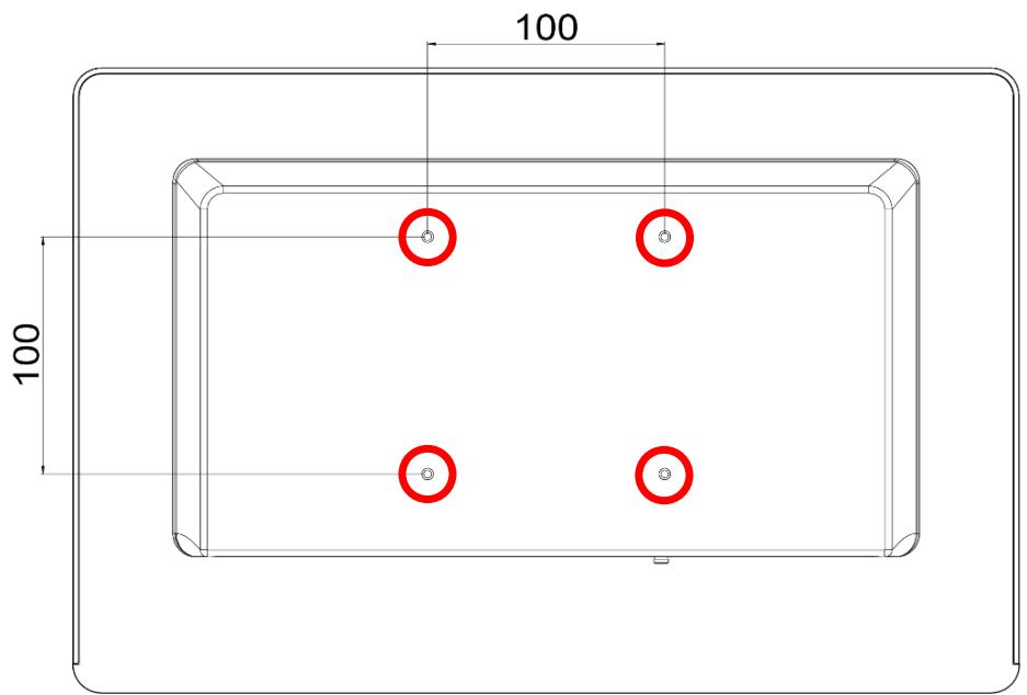
![100\n100](.mlc-al-mlc-kl-50-1z325-2000-10/95b42d0314a26ac583ce9a27175cdd583d919e9fe1911ac4ad52d1bda6acea96.jpg)

Figure 8: VESA 100 mounting hole pattern

![The image features a black-outlined triangle centered on a white background. Inside the triangle is a black exclamation point. This is the standard warning or caution symbol.](.mlc-al-mlc-kl-50-1z325-2000-10/eb027ec9215aa3ed00153dafb01088ecb108e44eee8c5f378c88f6014c502397.jpg)

# CAUTION

Risk of burns to the user caused by hot surfaces:

Turn off power and allow the device to cool down prior to performing any mounting or demounting operations. Do not touch the enclosure for over 10 seconds when the device is in operation or is still hot from previous use.

MLC-133-XL Dimensions
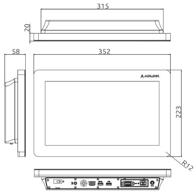
![315\n20\n58\n352\nAADLINK\n223\nR12](.mlc-al-mlc-kl-50-1z325-2000-10/46d94df1291335fba07fb2fcf5d2cac0cee17b3921f141d2297c33954aa4858e.jpg)

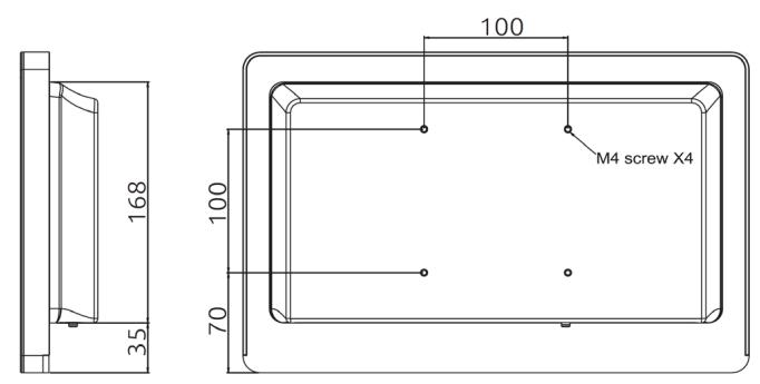
![168\n35\n100\nM4 screw X4\n100\n70](.mlc-al-mlc-kl-50-1z325-2000-10/2407fc9d3f9b249e318ee765ddb1fa4cb60c5da144b1a311d5de41a7b49a1740.jpg)

Figure 9: MLC-133-XL dimensions

All dimensions above are in millimeters.

7.1.1 MLC-156-XL Dimensions
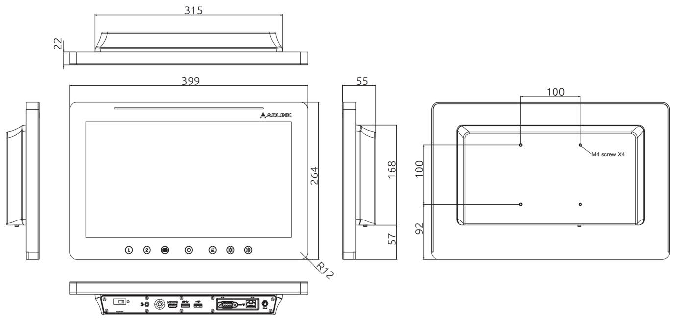
![315\n22\n399\n55\n168\nR12\n100\nM4 screw X4\n100\n92](.mlc-al-mlc-kl-50-1z325-2000-10/006694549001609d7e074e469f4393037454f98604c4a16896f75a789a51ec69.jpg)

Figure 10: MLC-156-XL dimensions

All dimensions above are in millimeters.

# 7.1.2 Weight

Maximum weight without optional components:

<table><tr><td>Device version</td><td>[kg]</td><td>[lbs]</td></tr><tr><td>MLC-133-XL</td><td>3.2</td><td>7</td></tr><tr><td>MLC-156-XL</td><td>4.3</td><td>9.5</td></tr></table>

# 7.2 Electrical Specifications

# 7.2.1 Power supply unit (optional)

<table><tr><td>Input voltage</td><td>100...240 V~</td></tr><tr><td>Input frequency</td><td>47/63 Hz</td></tr><tr><td>Output voltage</td><td>+ 19 V ==</td></tr></table>

# 7.2.2 Power consumption

Test configuration:

Intel® Atom® x5-E3930, clock speed 1.8GHz, 4GB RAM, 64GB mSATA, 1x USB 2.0 port, either open or loaded with 0.5A ceramic resistor and 1x USB 3.0 port either open or loaded with 0.9A ceramic resistor;

Intel ® Core™ i3-7100U, clock speed 2.4GHz, 4GB RAM, 64GB mSATA, 1x USB 2.0 port, either open or loaded with 0.5A ceramic resistor and 1x USB 3.0 port either open or loaded with 0.9A ceramic resistor;

OS Windows 10 IoT Enterprise, 64bit, Intel HD Graphics;

if applicable, ‘High Performance’ power plan means display brightness set to 100%;

if applicable, BurnIn means usage of test SW ‘PassMark BurnIn Test Pro 8.1

MLC-1XX-AL:

<table><tr><td rowspan="2">Test #</td><td rowspan="2">System Condition</td><td colspan="2"> $P_{avg}$  [W]</td><td rowspan="2">Description</td></tr><tr><td>13.3&quot;</td><td>15.6&quot;</td></tr><tr><td>1</td><td>power off (S5)</td><td>1.9</td><td>1.9</td><td>standby power: m.2 SSD</td></tr><tr><td>2</td><td>hibernate (S4)</td><td>1.9</td><td>1.9</td><td>power plan: High Performance config: m.2 SSDSW: None</td></tr><tr><td>3</td><td>sleep (S3)</td><td>2.0</td><td>2.0</td><td>power plan: High Performance config: m.2 SSDSW: None</td></tr><tr><td>4</td><td>idle (S0)</td><td>22.3</td><td>23.1</td><td>power plan: High Performance config: m.2 SSDSW: None</td></tr><tr><td>5</td><td>loading (S0)</td><td>27.9</td><td>29.3</td><td>power plan: High Performance config: m.2 SSDSW: BurnIn test:CPU+RAM+2D+3D+video+disk tests</td></tr><tr><td>6</td><td>loading (S0)</td><td>37.2</td><td>39.8</td><td>power plan: High Performance config: m.2 SSD +1*0.5A ceramic resistor (USB 2.0 interface) + 1* 0.9A ceramic resistor (USB 3.0 interface)SW: BurnIn test:CPU+RAM+2D+3D+video+disk tests</td></tr></table>

MLC-1XX-KL:

<table><tr><td rowspan="2">Test #</td><td rowspan="2">System Condition</td><td colspan="2"> $P_{avg}$  [W]</td><td rowspan="2">Description</td></tr><tr><td>13.3”</td><td>15.6”</td></tr><tr><td>1</td><td>power off (S5)</td><td>1.7</td><td>2.1</td><td>standby power: m.2 SSD</td></tr><tr><td>2</td><td>hibernate (S4)</td><td>2.0</td><td>2.0</td><td>power plan: High Performance config: m.2 SSDSW: None</td></tr><tr><td>3</td><td>sleep (S3)</td><td>2.3</td><td>2.4</td><td>power plan: High Performance config: m.2 SSDSW: None</td></tr><tr><td>4</td><td>idle (S0)</td><td>21.2</td><td>21.4</td><td>power plan: High Performance config: m.2 SSDSW: None</td></tr><tr><td>5</td><td>loading (S0)</td><td>41.5</td><td>41.7</td><td>power plan: High Performance config: m.2 SSDSW: BurnIn test:CPU+RAM+2D+3D+video+disk tests</td></tr><tr><td>6</td><td>loading (S0)</td><td>50.1</td><td>51.5</td><td>power plan: High Performance config: m.2 SSD + 1*0.5A ceramic resistor (USB 2.0 interface) + 1* 0.9A ce-ramic resistor (USB 3.0 interface)SW: BurnIn test:CPU+RAM+2D+3D+video+disk tests</td></tr></table>

# 7.3 Environmental Specifications

![The image displays a standard warning symbol consisting of a black-outlined triangle pointing upward. Inside the triangle is a single black exclamation mark.](.mlc-al-mlc-kl-50-1z325-2000-10/b5211427d075c44a62af96f632134215e165b834e8dea06b38a5156ca84652ae.jpg)

# CAUTION

Risk of device malfunctioning caused by violation of environmental specification limits:

Your ADLINK device is specified for proper operation within the environmental conditions mentioned below. Exceeding these limits can lead to unexpected device behavior and malfunctions.

Always make sure that you operate the device within the environmental conditions specified in this section.

<table><tr><td>Ambient temperature range for operation</td><td>0°C...+35°C</td></tr><tr><td>Ambient temperature range for storage and transport</td><td>-20°C...+60°C</td></tr><tr><td>Ambient humidity range for operation</td><td>5...90%@35°C (non-condensing)</td></tr><tr><td>Ambient humidity range for storage and transport</td><td>5...90%@35°C (non-condensing)</td></tr><tr><td>Ambient air pressure for operation, storage and transport</td><td>700...1013 hPa</td></tr></table>

# 7.4 Classification

1. Type of protection against electric shock: Class I equipment
2. Class I: No applicable parts, not AP/APG-compliant

# 7.5 Markings and Labels

# 7.5.1 Part number and serial number labels

The part number and the serial number of the device are provided on separate labels attached to the rear of the device. The following figures provide generic examples of the part number and serial number labels. The textual content may differ depending on the respective device characteristics.

![MLC-156-KL\n15.6' Full HD Display with multitouch,\nIntel Core i3-dual core, 4GB RAM,\n64GB SSD\n\n93-D1505-000E\nMADE IN TAIWAN](.mlc-al-mlc-kl-50-1z325-2000-10/1aac5197dee7b68db586d1bc09eed8b414e9af7feee5df53e244d5dc9a24ea18.jpg)

Figure 11: Part number label

![K520ZS6001](.mlc-al-mlc-kl-50-1z325-2000-10/0d0336925348767c06df6e4a6590b18d062719b18f273ddc9adbe2f98231086a.jpg)

Figure 12: Serial number label

# 7.5.2 Product identification label

The product identification label is attached to the rear of the device and contains main technical data about the device. The following figure provides a generic example of the product identification label. The textual content may differ depending of the respective device characteristics.

![ADLINK Technology, Inc.\nAll-In-One PC\nMLC-133-KL\nInput Rating:12 Vdc, 5.25 A or 19 Vdc, 3.43 A\nCEFC MADE IN TAIWAN\nhttp://www.adlinktech.com](.mlc-al-mlc-kl-50-1z325-2000-10/a1ac7089d2f428fa8ad206a810b7dafb0344ce49cdf696bc8b13e6c409ebca61.jpg)

![ADLINK Technology, Inc.\nAll-In-One PC\nMLC-156-AL\nInput Rating:12 Vdc, 5.25 A or 19 Vdc, 3.43 A\nCEFC MADE IN TAIWAN\nhttp://www.adlinktech.com](.mlc-al-mlc-kl-50-1z325-2000-10/4b4df3b534d3436d928fb75ce49f1f7735b0a43490f54de458e5516dd51f2ffe.jpg)

Figure 13: Product identification label

# 7.5.3 Explanation of symbols

# 7.5.3.1 Explanation of symbols used on labels

<table><tr><td>Symbol</td><td>Meaning</td></tr><tr><td>&lt;img src="images/bbf3345737b1deaf5ec8e5e21bec253fa373513f4bad56352729b0c8eb74e35e.jpg"/&gt;</td><td>Read the user&#x27;s manual and follow all handling and safety instructions.</td></tr><tr><td>&lt;img src="images/2750e84eabf16f08c543c76e0e8d1ba4ccbce0792ad1e77a87e9e62a83e9d8a4.jpg"/&gt;</td><td>CE labelling: the CE symbol confirms compliance with all relevant guidelines and regulations</td></tr><tr><td>&lt;img src="images/2490ba46c58ad87cdf0e471bcf8c9c820a69c40f27f78e7e5135b538405c3329.jpg"/&gt;</td><td>Do not dispose of this device or its parts with conventional domestic waste. Observe your national regulations regarding disposal of electrical and electronic devices. For further information, refer to: DIRECTIVE 2012/19/EC OF THE EUROPEAN PARLIAMENT AND OF THE COUNCIL of 4 July 2012 on waste electrical and electronic equipment (WEEE)</td></tr><tr><td>&lt;img src="images/fa439ed7101993117f59f96dc8617d463e3bd005567911ab7a5256769027ee7b.jpg"/&gt;</td><td>Medical – General Medical Equipment as to Electrical Shock, Fire and Mechanical Hazards only in Accordance with ANSI/AAMI ES60601-1 (2005) + AMD (2012) and CAN/CSA-C22.2 No. 60601-1 (2008) + (2014).</td></tr><tr><td>&lt;img src="images/9e0f2af2187daaabc5cac6533bb71233ceaaddea992eef4256f97ee7d8116dae.jpg"/&gt;</td><td>FCC labelling: the FCC symbol confirms compliance with all relevant communication requirementsThis device complies with Part 15 FCC Rules. Operation is subject to the following two conditions: (1) this device may not cause harmful interference, and (2) this device must accept any interference received including interference that may cause undesired operation.</td></tr><tr><td>&lt;img src="images/ede4e047cc8e27ee2d187d3b3d04a9529c60e21b6336982eb04bde859da511f7.jpg"/&gt;</td><td>Do not use at an altitude exceeding 2000m above sea level.</td></tr></table>

# 7.5.3.2 Explanation of symbols used on the device

<table><tr><td>Symbol</td><td>Meaning</td></tr><tr><td>&lt;img src="images/f8924ff4f8e98d73b1a62f521cc24da15d1f4a255c4623c59f2fde950840942a.jpg"/&gt;</td><td>Power-On Switch</td></tr><tr><td>&lt;img src="images/c84f3cfe08d1154978f50e03ce937ffbdf4311e7a57d4f1f3a981864b229fa40.jpg"/&gt;</td><td>USB 2.0 port</td></tr><tr><td>&lt;img src="images/84d5b6b440242889ce369ebdb25705a68d25e5238109c2ef44dfcf596618d22c.jpg"/&gt;</td><td>USB 3.0 port</td></tr><tr><td>&lt;img src="images/1b7210a77aa4de98f1a64fb9fd4a03b51d4be7080783c90c63973324d08b2a3e.jpg"/&gt;</td><td>GbE network port</td></tr><tr><td>&lt;img src="images/72b737fce2ab1709c58b9594472259e57f89a13de50ca3b31de9e5617d6405db.jpg"/&gt;</td><td>ESD warning symbol</td></tr><tr><td>&lt;img src="images/58dc658bf5f637cbafbb7ba8ff9b915853e49a5701603f546a207c1dcc1be67f.jpg"/&gt;</td><td>Connector pin for potential equalization</td></tr></table>

# 7.5.3.3 Explanation of symbols used on the packaging

<table><tr><td>Symbol</td><td>Meaning</td></tr><tr><td>&lt;img src="images/e69581e3fb353506556033f8189ec9723684d4c1c4c4afa55513ce11650a1de3.jpg"/&gt;</td><td>Upright position</td></tr><tr><td>&lt;img src="images/d3650dbf5cbd4222ebbc8bf2ec6624f3554df2fae1569387c157ec54ec4ac2c8.jpg"/&gt;</td><td>Fragile, handle with care</td></tr><tr><td>&lt;img src="images/83e2f410024fe7013801e4af060fe482690d7349b792898327559541a13e8b52.jpg"/&gt;</td><td>Keep away from rain</td></tr><tr><td>·1013 hPa&lt;img src="images/b9ad15f11b0e7d29c5fed99023e080139b6ff6f0b6cabacc006516b09bea0cbc.jpg"/&gt;700 hPa-</td><td>Atmospheric pressure limitation for storage and transport (700 to 1013 hPa)</td></tr><tr><td>&lt;img src="images/ec3653f936c9f2cb41ebdab81c346ce21ef14367db2afbf4831d1e883491aee6.jpg"/&gt;5% -</td><td>Humidity limitation for storage and transport (5 to 95%)</td></tr><tr><td>&lt;img src="images/48797976267f53d9f042aae8eb7f2bcbfc2953c6f11da2ef66b3604d59f6e74d.jpg"/&gt;-10°I</td><td>Temperature limitation for storage and transport (-10°C to 60°C)</td></tr></table>

# 8 Certificates and Standards

# 8.1 Verification of Compliance – EN55032

SGS

CESRF

Ref.No.VXD0516A/2020

Page: 1 of 1

# VERIFICATIONOFCOMPLIANCE

<table><tr><td>Issue Date:</td><td>August 4, 2020</td></tr><tr><td>Applicant:</td><td>ADLINK TECHNOLOGY INC.</td></tr><tr><td>Address:</td><td>9F, No.166, Jian Yi Rd., Zhonghe Dist., New Taipei City, 235 Taiwan</td></tr><tr><td>Manufacturer:</td><td>ADLINK TECHNOLOGY INC.</td></tr><tr><td>Address:</td><td>9F, No.166, Jian Yi Rd., Zhonghe Dist., New Taipei City, 235 Taiwan</td></tr><tr><td>Contact Information:</td><td>Web: https://www.adlinktech.com/en/indexTEL#: 02-8226-5877#8361E-mail#: sean.ba@adlinktech.com</td></tr><tr><td>Product:</td><td>All in one PC</td></tr><tr><td>Brand Name/Trade Mark:</td><td>ADLINKS</td></tr><tr><td>Model/Type:</td><td>MLC-156-KL</td></tr><tr><td>Added Model(s):</td><td>MLC-133-AL; MLC-133-KL; MLC-156-AL</td></tr><tr><td>Applicable Standards:</td><td>EN 55032: 2015 / AC: 2016CISPR 32: 2015 (Ed 2.0) / C1: 2016EN 61000-3-2: 2014EN 61000-3-3: 2013EN 55035: 2017IEC 61000-4-2: 2008; IEC 61000-4-3: 2006 + A1: 2007 + A2: 2010;IEC 61000-4-4: 2012; IEC 61000-4-5: 2014 + A1: 2017;IEC 61000-4-6: 2013 + COR1: 2015; IEC 61000-4-8: 2009;IEC 61000-4-11: 2004 + A1: 2017</td></tr></table>

<table><tr><td>Test Laboratory:</td><td>Compliance Certification Services Inc.</td></tr><tr><td></td><td>Xindian Lab</td></tr><tr><td></td><td>No. 163-1, Jhongsheng Rd., Xindian Dist., New Taipei City, Taiwan</td></tr></table>

<table><tr><td>Test Report No.:</td><td>T200701D07-E, dated on August 4, 2020</td></tr></table>

<table><tr><td>Conclusion: Based upon a review of the Test Report(s), the tested sample of the product mentioned above is deemed to comply with the requirements of the above standards.</td></tr></table>

Note: This verifieation is only valid for the produet and configuration deseribed and in conjunction with the test report as detailed above.

Authorised Signatory:

Compllanoe Certiostlon Servloec Ino.

Sam Hu

Acclctant Manager

FM-023A-R01

Itdarthluby etdb bos:kd ta ptdtet lt nnot ntt a3Ru et cam db Tnd Ctn D: D nnon  d tden: d dt hhs  Ta ce xutt bt Clrt dtdan dunt ptb ud t gtg tsat T E th t c

No.163-1, Jhongsheng Rd., XindlenDlt, New Talpel Cty,Talwan/新处市靳店B中 生路 163-1號

t (535-2) 2217-0894 f: (885-2) 2217-1029 www.2gs.c0m.tw www.cc2r.com

Merter et ta SGa Grup

# 8.2 Verification of Compliance – EN 60601-1-2

<table><tr><td rowspan="2">IEC</td><td rowspan="2">IECEE
CB
SCHEME</td><td rowspan="2"></td><td>Ref. Certif. No.</td></tr><tr><td>SG PSB-MD-00415</td></tr></table>

<table><tr><td colspan="2">IEC SYSTEM FOR MUTUAL RECOGNITION OF TEST CERTIFICATES FOR ELECTRICAL EQUIPMENT (IECEE) CB SCHEME</td></tr><tr><td colspan="2">CB TEST CERTIFICATE</td></tr><tr><td>Product</td><td>Other IT and business equipment
(All-In-One PC)</td></tr><tr><td>Name and address of the applicant</td><td>ADLINK Technology, Inc.
9F., No.166, Jian YI Rd.
Zhonghe Dist.
235 New Taipei City
TAIWAN</td></tr><tr><td>Name and address of the manufacturer</td><td>ADLINK Technology, Inc.
9F., No.166, Jian YI Rd., Zhonghe Dist., 235 New Taipei City, TAIWAN</td></tr><tr><td>Name and address of the factory</td><td>ADLINK Technology Inc. Jian YI Factory
4F and 15F., No.166, Jian YI Rd., Zhonghe Dist., 235 New Taipei City, TAIWAN</td></tr><tr><td>Ratings and principal characteristics</td><td>Rated Input voltage:
Power Adapter
I/P: 100-240 V~, 47-63 Hz, 1.62-0.72 A or 100-240 V~, 50-60 Hz, 2.0-1.0 A
OIP: 12 Vdc, 5.25 A or 19 Vdc, 3.43 A
All-In-One PC
I/P: 12 Vdc, 5.25 A or 19 Vdc, 3.43 A
Protection class: I</td></tr><tr><td>Trade mark</td><td>ADLINK</td></tr><tr><td>Model/type Ref.</td><td>MLC-133-AL, MLC-133-KL, MLC-156-AL, MLC-156-KL</td></tr><tr><td>Additional Information (If necessary)</td><td>All applicable Clauses of IEC 62366 have been addressed. See test report for details.</td></tr><tr><td>A sample of the product was tested and found to be in conformity with</td><td>IEC 60601-1:2005
IEC 60601-1:2005/AMD1:2012
IEC 60601-1-6:2010
IEC 60601-1-6:2010/AMD1:2013</td></tr><tr><td>as shown in the Test Report Ref. No. which forms part of this certificate</td><td>081-200918-000</td></tr><tr><td colspan="2">This CB Test Certificate is issued by the National Certification Body</td></tr><tr><td colspan="2">CBS 075377 0021 Rev. 00
Date, 2020-10-14</td></tr><tr><td colspan="2">Page 1 of 2
TÜV SÜD PGB Pte Ltd · 1 Science Park Drive · Singapore 118221</td></tr></table>

![The image features a blue rectangular background containing the white text 'IEC' in a serif font at the top. Below the letters are three horizontal white lines of decreasing length, with a small white square positioned at the right end of the bottom line.](.mlc-al-mlc-kl-50-1z325-2000-10/feafa6d722306a6fcd6f63d27211c7168946044458852593d67b8d23358f9399.jpg)

![The image displays a blue rectangular graphic containing white text. The text is arranged in three lines and reads:\n\nIECEE\nCB\nSCHEME](.mlc-al-mlc-kl-50-1z325-2000-10/a4dcac2ae1e1227fb399b2025f129773f11678933aea0e312ba6aee001c40d25.jpg)

Ref. Certif. No.

SG PSB-MD-00415

IEC SYSTEM FOR MUTUAL RECOGNITION OF TEST CERTIFICATES FOR ELECTRICAL EQUIPMENT[IECEE) CB SCHEME

Name and address of ue trlor (contnued)

AOLINK Technolopy (Chino] Go., LId. No. 30o, Fong Chun Roud, China (Bhanghall Flot Free Trade Zone, 20I2OE SNOONI. FEOPLEB REPUBLIC OF CHINA

# Brief description of the test sample:

- The produet I5 an AlH-One PC Intended for transter, store, convert tomats and dleplay medeal devee data I hpiaema [ded nad an adt:aa gaee
- The EUT power suppled by extemal Power Adapter: SInpro Electronlcs Co.,Ltd. type MPU6OA-105, whlch h3s LeenappuaL Tuurnandng t IE GG-1 n5 A1 2noPP pudebeienpag drut and seconday dirut, cetned as Class i equlpmentin TUv iRh cB report.
The EUT alematre ower suppledby exdemel Power Adapter FSP Group Inc type FSPDE5M-DA, Whlch haG Lnappo D TunrnatangbEe Gui-Gn1 2noPPponedein enpna drutand secondary clrcult, cerdined as Class I equlpmentIn TUv IRh CB report.
- The equlpment provides Means of Patlent Protecilon (MOPP)
- The eguipment Is evaluated tor operating In aitlude up to 2,000 m.

Thls CB Test Certinlceale ls Issued by the Natlonal Certimlcatlon ody

Osle. 2020-10-14

![The image displays handwritten text in black ink on a white background, reading 'Web yy'.](.mlc-al-mlc-kl-50-1z325-2000-10/fce2835e85c01b2ff2b83bf95e554074e319dcaa2b1c2c72c73422d51365a006.jpg)

( Wakon Yano )

Pue 2 0t2

Uv s0o Pss Fl LId0acence Ft Orue+ Sbosooe du8221

![The image displays an octagonal logo featuring a blue background with a white border. In the center is a white octagon containing the black text 'TUV' in large, bold letters on the top line, and 'SUD' in smaller letters centered directly below it.](.mlc-al-mlc-kl-50-1z325-2000-10/ba26d91a2087c0380daa35b327055f705049909592fa9e22bb384f3ad5fce39f.jpg)

PSB Singatore

# 8.3 Verification of Compliance – FCC Part 15 Class B

SGS

CESRF

Ref.No.VXD0514A/2020

Page: 1 of 1

# VERIFICATIONOFCOMPLIANCE

<table><tr><td>Issue Date:</td><td>August 4, 2020</td></tr><tr><td>Applicant:</td><td>ADLINK TECHNOLOGY INC.</td></tr><tr><td>Address:</td><td>9F, No.166, Jian Yi Rd., Zhonghe Dist., New Taipei City, 235 Taiwan</td></tr><tr><td>Manufacturer:</td><td>ADLINK TECHNOLOGY INC.</td></tr><tr><td>Address:</td><td>9F, No.166, Jian Yi Rd., Zhonghe Dist., New Taipei City, 235 Taiwan</td></tr><tr><td>Contact Information:</td><td>Web: https://www.adlinktech.com/en/indexTEL#: 02-8226-5877#8361E-mail#: sean.ba@adlinktech.com</td></tr><tr><td>Product:</td><td>All in one PC</td></tr><tr><td>Brand Name/Trade Mark:</td><td>ADLINK</td></tr><tr><td>Model/Type:</td><td>MLC-156-KL</td></tr><tr><td>Added Model(s):</td><td>MLC-133-AL; MLC-133-KL; MLC-156-AL</td></tr><tr><td>Applicable Standards:</td><td>FCC 47 CFR Part 15 Subpart BANSI C63.4: 2014ISED ICES-003 (Issue 6)</td></tr></table>

<table><tr><td>Test Laboratory:</td><td>Compliance Certification Services Inc. Xindian Lab No. 163-1, Jhongsheng Rd., Xindian Dist., New Taipei City, Taiwan</td></tr></table>

<table><tr><td>Test Report No.:</td><td>T200701D07-D, dated on August 4, 2020</td></tr></table>

Conclusion: Based upon a review of the Test Report(s). the tested sample of the product mentioned above is deemed to comply with the requirements of the above standards.

Note: This verification is only valid for the product and configuration described and in conjunction vith the test report as detailed above.

Authorised Signatory:

![The image displays a handwritten signature in black ink on a white background. The text reads:\n\nSam Hun](.mlc-al-mlc-kl-50-1z325-2000-10/4d09b3407e75eb258751724b927671dc1e5578dada7985d495760c74dfbbd2b0.jpg)

Compllsnoe Certiostton Servlosc Ino.

Sam Hu

Acclctant Manager

FM-023A-R01

pth deedCed tteenen erh ard wh teIntuel certe hutgten rt doenot eooneruteratleatoturceenfrom elihg all tah rott nd obigatora udar hout prier wittan apptoval cf tha ompany Ary uruteead ttwtn tagay eteetenet ta orant putdtot

No.163-1,Jhongsheng Rd， Xindan Dbt，New Talpel Cty，Talwan/断t市析店B中 生路 163-1號t: (886-2)2217-0894 f:(885-2)2217-1029 www.5g5.c0m.tw www.ccsrf.com

Merter af ta SGs Grup

# 9 Appendix

# 9.1 EN 60601-1-2 Tables

# 9.1.1 Guidance and manufacturer’s declaration – electromagnetic emissions (IEC 60601-1-2:2007 Table 1)

<table><tr><td colspan="3">The MLC-1XX-XL is intended for use in the electromagnetic environment specified below. The customer or the user of the device should ensure that it is used in such an environment.</td></tr><tr><td>Emissions test</td><td>Compliance</td><td>Electromagnetic environment – guidance</td></tr><tr><td>RF emissionsCISPR 11</td><td>Group 1</td><td>The device uses RF energy only for its internal function. Therefore,its RF emissions are very low and are not likely to cause any interference in nearby electronic equipment.</td></tr><tr><td>RF emissionsCISPR 11</td><td>Class B</td><td rowspan="3">The device is suitable for use in all establishments, including domestic establishments and those directly connected to the public low-voltage power supply network that supplies buildings used for domestic purposes.</td></tr><tr><td>Harmonic emissionsIEC 61000-3-2</td><td>Class A</td></tr><tr><td>Voltage fluctuations/flicker emissionsIEC 61000-3-3</td><td>Complies</td></tr></table>

# 9.1.2 Guidance and manufacturer’s declaration – electromagnetic immunity for all EQUIPMENT and SYSTEMS (IEC 60601-1-2:2007 Table 2)

<table><tr><td colspan="4">The MLC-1XX-XL is intended for use in the electromagnetic environment specified below. The customer or the user of the device should ensure that it is used in such an environment.</td></tr><tr><td>Immunity test</td><td>IEC 60601test level</td><td>Compliance level</td><td>Electromagnetic environment – guidance</td></tr><tr><td>Electrostatic discharge (ESD)IEC 61000-4-2</td><td>±8 kV contact±15 kV air</td><td>±8 kV contact±15 kV air</td><td>Floors should be wood, concrete or ceramic tile. If floors are covered with synthetic material, the relative humidity should be at least 30%.</td></tr><tr><td>Electrical fast transient/burstIEC 61000-4-4</td><td>±2 kV for power supply lines±1 kV for input/output lines</td><td>±2 kV for power supply lines±1 kV for input/output lines</td><td>Mains power quality should be that of a typical commercial or hospital environment.</td></tr><tr><td>SurgeIEC 61000-4-5</td><td>±1 kV line(s) to line(s)±2 kV line(s) to earth</td><td>±1 kV line(s) to line(s)±2 kV line(s) to earth</td><td>Mains power quality should be that of a typical commercial or hospital environment.</td></tr><tr><td>Interruptions and voltage variations on power supply input linesIEC 61000-4-11</td><td>&lt;5% UT(&gt;95% dip in UT)for 0.5 cycle40% UT(60% dip in UT)for 5 cycles70% UT(30% dip in UT)for 25 cycles&lt;5% UT(&gt;95% dip in UT)for 5 sec</td><td>&lt;5% UT(&gt;95% dip in UT)for 0,5 cycle40% UT(60% dip in UT)for 5 cycles70% UT(30% dip in UT)for 25 cycles&lt;5% UT(&gt;95% dip in UT)for 5 sec</td><td>Mains power quality should be that of a typical commercial or hospital environment. If the user of the device requires continued operation during power mains interruptions, it is recommended that the device be powered from an uninterruptible power supply or a battery.</td></tr><tr><td>Power frequency (50/60 Hz)magnetic fieldIEC 61000-4-8</td><td>3 A/m</td><td>3 A/m</td><td>Power frequency magnetic fields should be at levels characteristic of a typical location in a typical commercial or hospital environment.</td></tr><tr><td colspan="4">NOTE: UT is the A.C. mains voltage prior to application of the test level.</td></tr></table>

# 9.1.3 Guidance and manufacturer’s declaration — electromagnetic immunity – for EQUIPMENT and SYSTEM that are not LIFE-SUPPORTING (IEC 60601-1-2:2007 Table 4)

<table><tr><td colspan="4">The MLC-1XX-XL is intended for use in the electromagnetic environment specified below. The customer or the user of the device should ensure that it is used in such an environment.</td></tr><tr><td>Immunity test</td><td>IEC 60601 test level</td><td>Compliance level</td><td>Electromagnetic environment – guidance</td></tr><tr><td>Conducted RFIEC 61000-4-6Radiated RFIEC 61000-4-3</td><td>3 Vrms150 kHz to 80 MHz3 V/m80 MHz to 2.5 GHz</td><td>3 Vrms3 V/m</td><td>Portable and mobile RF communications equipment should be used no closer to any part of the device, including cables, than the recommended separation distance calculated from the equation applicable to the frequency of the transmitter.Recommended separation distance $d = 1.2\sqrt{P}$  $d = 1.2\sqrt{P}$  80 MHz to 800 MHz $d = 2.3\sqrt{P}$  800 MHz to 2.5 GHzwhere  $P$  is the maximum output power rating of the transmitter in watts (W) according to the transmitter manufacturer and  $d$  is the recommended separation distance in meters (m).Field strengths from fixed RF transmitters, as determined by an electromagnetic site survey, $^a$ should be less than the compliance level in each frequency range. $^b$ Interference may occur in the vicinity of equipment marked with the following symbol:[IMAGE]</td></tr><tr><td colspan="4">NOTE 1: At 80 MHz and 800 MHz, the higher frequency range applies.NOTE 2: These guidelines may not apply in all situations. Electromagnetic propagation is affected by absorption and reflection from structures, objects and people.</td></tr><tr><td colspan="4"> $^a$  Field strengths from fixed transmitters, such as base stations for radio (cellular/cordless) telephones and land mobile radios, amateur radio, AM and FM radio broadcast and TV broadcast cannot be predicted theoretically with accuracy. To assess the electromagnetic environment due to fixed RF transmitters, an electromagnetic site survey should be considered. If the measured field strength in the location in which the device is used exceeds the applicable RF compliance level above, the device should be observed to verify normal operation. If abnormal performance is observed, additional measures may be necessary, such as reorienting or relocating the device. $^b$  Over the frequency range 150 kHz to 80 MHz, field strengths should be less than 3 V/m.</td></tr></table>

# 9.1.4 Recommended separation distances between portable and mobile RF communications equipment and the EUT (IEC 60601-1-2:2007 Table 6)

<table><tr><td colspan="4">The MLC-1XX-XL is intended for use in an electromagnetic environment in which radiated RF disturbances are controlled. The customer or the user of the device can help prevent electromagnetic interference by maintaining a minimum distance between portable and mobile RF communications equipment (transmitters) and the device as recommended below, according to the maximum output power of the communications equipment.</td></tr><tr><td rowspan="2">Rated maximum output power of transmitter W</td><td colspan="3">Separation distance according to frequency of transmitter m</td></tr><tr><td>150 kHz to 80 MHz $d = 1.2\sqrt{P}$ </td><td>80 MHz to 800 MHz $d = 1.2\sqrt{P}$ </td><td>800 MHz to 2.5 GHz $d = 2.3\sqrt{P}$ </td></tr><tr><td>0.01</td><td>0.12</td><td>0.12</td><td>0.23</td></tr><tr><td>0.1</td><td>0.38</td><td>0.38</td><td>0.73</td></tr><tr><td>1</td><td>1.2</td><td>1.2</td><td>2.3</td></tr><tr><td>10</td><td>3.8</td><td>3.8</td><td>7.3</td></tr><tr><td>100</td><td>12</td><td>12</td><td>23</td></tr><tr><td colspan="4">For transmitters rated at a maximum output power not listed above, the recommended separation distance  $d$  in metres (m) can be estimated using the equation applicable to the frequency of the transmitter, where  $P$  is the maximum output power rating of the transmitter in watts (W) according to the transmitter manufacturer.NOTE 1: At 80 MHz and 800 MHz, the separation distance for the higher frequency range applies.NOTE 2: These guidelines may not apply in all situations. Electromagnetic propagation is affected by absorption and re-flection from structures, objects and people.</td></tr></table>

# 10 Getting Service

Ask an Expert: http://askanexpert.adlinktech.com

# ADLINK Technology, Inc.

9F, No.166 Jian Yi Road, Zhonghe District

New Taipei City 235, Taiwan

Tel: +886-2-8226-5877

Fax: +886-2-8226-5717

E-mail: service@adlinktech.com

# Ampro ADLINK Technology, Inc.

5215 Hellyer Avenue, #110

San Jose, CA 95138, USA

Tel: +1-408-360-0200

Toll Free: +1-800-966-5200 (USA only)

Fax: +1-408-360-0222

E-mail: info@adlinktech.com

# ADLINK Technology (China) Co., Ltd.

300 Fang Chun Rd., Zhangjiang Hi-Tech Park

Pudong New Area, Shanghai, 201203 China

Tel: +86-21-5132-8988

Fax: +86-21-5132-3588

E-mail: market@adlinktech.com

# ADLINK Technology GmbH

# (Healthcare Business Center- EMEA)

Ulrichsberger Str. 17

D-94469 Deggendorf, Germany

Tel: +49-991-290-94-10

Fax: +49-991-290-94-29

E-mail: support.deg@adlinktech.com

info.deg@adlinktech.com

Please visit the Contact page at www.adlinktech.com for information on how to contact the ADLINK regional office nearest you.
[🔗 Link to the original document](.mlc-al-mlc-kl-50-1z325-2000-10/mlc-al-mlc-kl-50-1z325-2000-10.pdf)