# MLC-M

# Medical Panel Computer

# User’s Manual

![White tablet device with a dark screen and control buttons at the bottom (no visible text or symbols on screen)](.mlc-m-50m-d2102-1010-11/6ea0000732f560e12890df70546bb4849ffe2e94a80848a78c425b0cdf1df4d1.jpg)

Manual Rev.: 1.1

Revision Date: June 19, 2023

Part No: 50M-D2102-1010

Revision History

<table><tr><td>Revision</td><td>Release Date</td><td>Description of Change(s)</td></tr><tr><td>1.0</td><td>2023-03-29</td><td>Initial release</td></tr><tr><td>1.1</td><td>2023-06-19</td><td>Update P/N and format</td></tr></table>

# Preface

# Copyright © 2023 ADLINK Technology Inc.

This document contains proprietary information protected by copyright. All rights are reserved. No part of this manual may be reproduced by any mechanical, electronic, or other means in any form without prior written permission of the manufacturer.

# Disclaimer

The information in this document is subject to change without prior notice in order to improve reliability, design, and function and does not represent a commitment on the part of the manufacturer.

In no event will the manufacturer be liable for direct, indirect, special, incidental, or consequential damages arising out of the use or inability to use the product or documentation, even if advised of the possibility of such damages.

# Environmental Responsibility

ADLINK is committed to fulfill its social responsibility to global environmental preservation through compliance with the European Union's Restriction of Hazardous Substances (RoHS) directive and Waste Electrical and Electronic Equipment (WEEE) directive. Environmental protection is a top priority for ADLINK. We have enforced measures to ensure that our products, manufacturing processes, components, and raw materials have as little impact on the environment as possible. When products are at their end of life, our customers are encouraged to dispose of them in accordance with the product disposal and/or recovery programs prescribed by their nation or company.

![Symbol of a trash bin crossed with a diagonal line and a horizontal bar below (no text or labels)](.mlc-m-50m-d2102-1010-11/cc2da6fb41d418e7e667de9d9e1754c38d997618fe2e8063f3111364b21b0699.jpg)

Battery Labels (for products with battery)

![Simple line drawing of a trash bin with two crossed lines (no text or symbols)](.mlc-m-50m-d2102-1010-11/f3111d179b36d0082629a583a965a10c57365b178678aa1dcbfce255bad8beae.jpg)

![Recycling symbol icon with three chasing arrows inside a square frame (no text or labels)](.mlc-m-50m-d2102-1010-11/5fcae9ea1977086d4ccb0cec516e25ed24b312bb6682d191c719599b6d1eb660.jpg)

Li-ion

![RECYCLE\nRBRC\nLi-ion\n1-800.822.8837](.mlc-m-50m-d2102-1010-11/ed3996182c736f078564929b8e5ad26424dd325c76ab182a84ed3c9c8368d5e0.jpg)

![Abstract geometric pattern with interlocking black and white shapes (no text or symbols)](.mlc-m-50m-d2102-1010-11/480126a391fb108db0855470ac170314cdb0840247213f110a550d9972c8f6f8.jpg)

ᘄ㟁ụㄳᅇᨲ

# California Proposition 65 Warning

![A yellow triangle with a black border containing a black exclamation point.](.mlc-m-50m-d2102-1010-11/a0369454618a0e4be0a1a3b878252ced28ead9b63b58d6c9b278bd77f9e470de.jpg)

WARNING: This product can expose you to chemicals including acrylamide, arsenic, benzene, cadmium, Tris(1,3-dichloro-2-propyl) phosphate (TDCPP), 1,4- Dioxane, formaldehyde, lead, DEHP, styrene, DINP, BBP, PVC, and vinyl materials, which are known to the State of California to cause cancer, and acrylamide, benzene, cadmium, lead, mercury, phthalates, toluene, DEHP, DIDP, DnHP, DBP, BBP, PVC, and vinyl materials, which are known to the State of California to cause birth defects or other reproductive harm. For more information go to www.P65Warnings.ca.gov.

# Trademarks

Product names mentioned herein are used for identification purposes only and may be trademarks and/or registered trademarks of their respective companies.

# Conventions

Take note of the following conventions used throughout this manual to make sure that users perform certain tasks and instructions properly.

![The image displays a white document icon featuring blue horizontal lines. A large red check mark is positioned on the left side, and the top right corner is folded down.](.mlc-m-50m-d2102-1010-11/ffa59082b39f8eb8c0291b925b450d9e7be63418e23a7b367dcfe738bd7dd11a.jpg)
NOTE:

Additional information, aids, and tips that help users perform tasks.

![A yellow triangle with a black outline containing a black exclamation mark in the center.](.mlc-m-50m-d2102-1010-11/5086c0fd0280c7938840aa5759176bbb47b1bb48bd4ef56b5029278161f80a0c.jpg)
CAUTION:

Information to prevent minor physical injury, component damage, data loss, and/or program corruption when trying to complete a task.

ATTENTION: Informations destinées à prévenir les blessures corporelles mineures, les dommages aux composants, la perte de données et/ou la corruption de programme lors de l'exécution d'une tâche.

![The image shows a triangular warning sign. It features a solid red background with a white border and a large white exclamation point centered inside. There is no other text visible.](.mlc-m-50m-d2102-1010-11/d9baf92da8f9efdf19e3398a91250396d7ad86e449d1d92c9586a410d679ef28.jpg)
WARNING:

Information to prevent serious physical injury, component damage, data loss, and/or program corruption when trying to complete a specific task.

AVERTISSEMENT: Informations destinées à prévenir les blessures corporelles graves, les dommages aux composants, la perte de données et/ou la corruption de programme lors de l'exécution d'une tâche spécifique.

# Table of Contents

# Preface ............ iii

# List of Tables......... ... vii

# List of Figures ......... ix

# 1 Introduction .......

1.1 Overview...... 1
1.2 Features.... 1

# 2 Specifications ........... 3

2.1 MLC-M Specifications.... 3
2.2 Power... 5
2.3 Mechanical Dimensions.... 9
2.4 Mounting ....... . 11

# 3 System Layout..... 15

3.1 Interface Buttons... . 15
3.2 External I/O Connectors . . 17

# 4 BIOS Setup............. . 21

4.1 Restoring Default Settings ... . 21
4.2 Enabling PXE / Network Boot ... 22

# 5 Getting Started .. 25

5.1 Initial Device Installation and Cable Cover Handling ......... 25
5.2 Cleaning and Disinfection .. . 28

# Important Safety Instructions ......... 29

# Consignes de Sécurité Importante........ 31

EMC Compliance ....... .. 34

Getting Service ........ .. 35

# List of Tables

Table 2-1: MLC-M Series Specifications... 3
Table 3-1: External I/O Legend.. . 17
Table 3-2: DC Connector Pin Definition.. . 19

This page intentionally left blank.

# List of Figures

Figure 2-1: Removing fuse bracket.. 6

Figure 2-2: Unlocking fuses .. . 6

Figure 2-3: Removing unlocked fuses.. 6

Figure 2-4: Replacing fuses . 7

Figure 2-5: Locking fuses into place . 7

Figure 2-6: Re-inserting the fuse bracket.. 8

Figure 2-7: MLC-M 21.5” Dimensions... . 9

Figure 2-8: MLC-M 23.8” Dimensions... . 10

Figure 2-9: MLC-M 21.5” VESA mounting ...... .. 12

Figure 2-10: MLC-M 23.8” VESA mounting . . 13

Figure 3-1: MLC-M External I/O.. . 17

Figure 3-2: Potential Equalization Connecting Pin.. . 18

Figure 3-3: DC Connector Pin Definition.. . 19

Figure 5-1: Device Cover .. .. 25

Figure 5-2: Threading Cables through Gaskets.. .. 26

Figure 5-3: Attaching Gaskets to Rubber Frame . .. 26

Figure 5-4: Attaching Frame to Mounting Plate .. 27

Figure 5-5: Attaching Grounding Cable... .. 27

This page intentionally left blank.

# 1 Introduction

# 1.1 Overview

The MLC-M series of touch computers are designed for hygienic and other applications in harsh environments requiring an IP54- compliant anti-bacterial casing with projected capacitive multitouch display and touch buttons. The front panel includes full IP65-compliance for easy cleaning. Devices support galvenic isolation and optional external DC power supply support. Typical applications include hygiene-sensitive settings.

# 1.2 Features

 Powerful 11th Gen Intel® Core™ i3 / i5 / i7 processors
21.5" or 23.8" Full HD display with PCAP multi-touch touchscreen and anti-glare coated safety glass for unsurpassed visualization capabilities
 4 illuminated soft-touch function keys on the front glass
Screwless design allows for fast-and-easy cleaning and disinfection procedures
Fully sealed aluminum housing and fanless design for high hygienic standards with IP54 rated ingress protection and 360 degree anti-bacterial treatment
Numerous IO ports: 2x USB 2.0, 2x USB 3.1 (up to x6), 1x HDMI (optional x1 DisplayPort), AC-in. Isolated (4kV) RJ45 & RS232 connectors for mixed environments (2 MOPP), optional additional IO.
 2 internal expansion slots for storage, networking and processing cards

This page intentionally left blank.

# 2 Specifications

# 2.1 MLC-M Specifications

<table><tr><td>Model</td><td colspan="2">MLC-M</td></tr><tr><td colspan="3">System</td></tr><tr><td>Processor</td><td colspan="2">Intel® CoreTM i3-1115G4E,2.2(3.9)GHz,6MB,15W (2C) Intel® CoreTM i5-1145G7E,1.5(4.1)GHz,8MB,15W (4C) Intel® CoreTM i7-1185G7E,1.8(4.4)GHz,12MB,15W (4C)</td></tr><tr><td>Memory</td><td colspan="2">Up to 64 GB DDR4-3200, (2 SODIMM slots)</td></tr><tr><td>Storage</td><td colspan="2">M.2 SATA SSD and/or 2.5” SSD / HDD at SATA 6Gb/s128 GB SSD (Standard)Contact your ADLINK representative for other capacities</td></tr><tr><td colspan="3">Display</td></tr><tr><td>Size</td><td>21.5”</td><td>23.8”</td></tr><tr><td>Resolution</td><td colspan="2">1920 x 1080</td></tr><tr><td>Brightness</td><td>250 cd/m2 (typ.)</td><td>400 cd/m2 (typ.)</td></tr><tr><td>Viewing Angle (U/D/R/L)</td><td colspan="2">89°/89°/89°/89°</td></tr><tr><td>Touchscreen</td><td colspan="2">10-point, PCAP, anti-glare coating</td></tr><tr><td colspan="3">I/O</td></tr><tr><td>Ethernet</td><td colspan="2">1x GbE LAN, RJ45, 4kV isolation</td></tr><tr><td>Serial</td><td colspan="2">1x RS232 4kV Isolated</td></tr><tr><td>USB Port</td><td colspan="2">2x USB 2.0, Type-A2x USB 3.1, Type-A (Standard; Optional up to 6x)</td></tr><tr><td>Expansion</td><td colspan="2">1x Mini PCIe card with PCIe and USB interface1x M.2 2230 card PCIe and USB interface</td></tr><tr><td>Wi-Fi and Bluetooth</td><td colspan="2">Wi-Fi 5 and Bluetooth 5 combo module (optional)Wi-Fi 6E and Bluetooth 5.2 combo module (optional)</td></tr><tr><td>Video</td><td colspan="2">1x HDMI1x DisplayPort (optional)</td></tr></table>

Table 2-1: MLC-M Series Specifications

<table><tr><td>Model</td><td colspan="2">MLC-M</td></tr><tr><td>Audio</td><td colspan="2">1x 3.5mm headphone jack</td></tr><tr><td colspan="3">Environmental</td></tr><tr><td>Operating Temperature</td><td colspan="2">0°C to 40°C</td></tr><tr><td>Storage Temperature</td><td colspan="2">-10°C to 60°C</td></tr><tr><td>Humidity</td><td colspan="2">5% to 95% (non-condensing)</td></tr><tr><td>IP Rating</td><td colspan="2">Front IP65, case with cover IP54</td></tr><tr><td>Certifications &amp; Compliance</td><td colspan="2">CE/FCCIEC 62368-1:2014; EN 62368-1:2014+A11:2017Compliant with IEC 60601-1 Ed. 3.1 &amp; IEC 60601-1-2:2014+AMD1:2020, EN 60601-1-2: 2015+A1:2021</td></tr><tr><td>Power Input</td><td colspan="2">Standard: Internal 100~240V AC, 50/60 Hz,Optional: 12V DC 4A input with support for external power supply</td></tr><tr><td colspan="3">Software</td></tr><tr><td>Operating System</td><td colspan="2">Windows 10Windows 11 (with TPM2.0)</td></tr><tr><td>Dimensions (HxWxD) (mm)</td><td>520x335x61</td><td>570x364x61</td></tr><tr><td>Net Weight</td><td>6.9 kg</td><td>7.9 kg</td></tr><tr><td>Mounting</td><td colspan="2">VESA Mount, MIS-D 100mm x 100mm</td></tr></table>

Table 2-1: MLC-M Series Specifications

# 2.2 Power

Power supply options:

 Standard: AC internal power supply
Optional: Support for external DC power supply, replaces internal power supply

# 2.2.1 DC Input Options

The internal AC power supply can be replaced prior to shipping with a 7-pin 12V DC port. For details, see Section 3.2.2: DC IN (Optional) on page 19.

# 2.2.2 AC Fuse Replacement

The AC internal power supply includes 2x 5x20mm T 2.0A H 250 V fuses. Only use fuses with the same rating and type, and carefully observe all labeling.

![The image displays a warning symbol consisting of a red equilateral triangle containing a white exclamation point. Below the triangle, the word 'WARNING' is written in black, uppercase letters.](.mlc-m-50m-d2102-1010-11/1d11678492cecd5a2615e7cc3103d540c1f2cddabb61997dd750a97bd1c4a673.jpg)

Risk of electric shock:

Make sure that the device has been fully disconnected from AC power.

![The image shows a triangular warning sign with a yellow background and a black border. Inside the triangle is a large black exclamation point. Below the triangle, the word 'CAUTION:' appears in black capital letters.](.mlc-m-50m-d2102-1010-11/1c13040773980fde704497a11ba3084627f22780c72ccb7538e129aa64f08201.jpg)

Risk of device damage:

Only use fuses of the same rating and type.

To replace the fuses:

1. Remove the cable cover and unplug the AC power cable from the back of the device.

2. Use a small screw driver to gently pry out the fuse bracket, and then gently remove it.
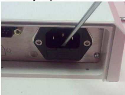
![Close-up of a black electrical socket with screw holes and a metal screwdriver inserted, no visible text or symbols](.mlc-m-50m-d2102-1010-11/5c9cded87a110fc025433b29b904b076c3cb2c474e212ef7ce05ce9ea5f0774b.jpg)

Figure 2-1: Removing fuse bracket

3. Flip the fuses outward, toward the sides of the bracket, so that they rest at approximately 30 degrees.
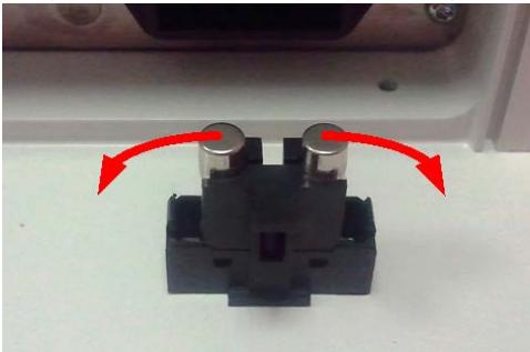
![Close-up of a black electrical connector with two metallic pins, shown with red arrows indicating rotation (no text or symbols visible)](.mlc-m-50m-d2102-1010-11/a7dd2c3d9e45e29d02f1088f5289358da4bf9dd46d4f77feda96bf74d2a61b6e.jpg)

Figure 2-2: Unlocking fuses

4. Gently remove the fuses.
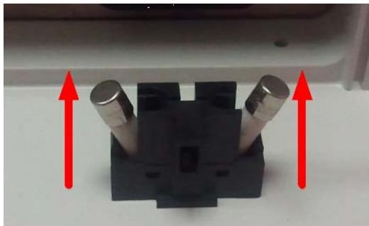
![Close-up of a black mechanical component with two metallic cylindrical pins, each supported by red upward arrows (no text or symbols visible)](.mlc-m-50m-d2102-1010-11/da335875075575295eda202c211997f00753c27d61ff17c22131ac9a35a0335a.jpg)

Figure 2-3: Removing unlocked fuses

5. Replace the fuses with new, identical fuses.
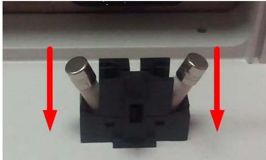
![Close-up of a black mechanical component with two metallic cylindrical pins, marked by red arrows (no text or symbols visible)](.mlc-m-50m-d2102-1010-11/972ac763f02ac0ba9c7a8999af9ec2af5af128a61c102c5ca2540755643afff7.jpg)

Figure 2-4: Replacing fuses

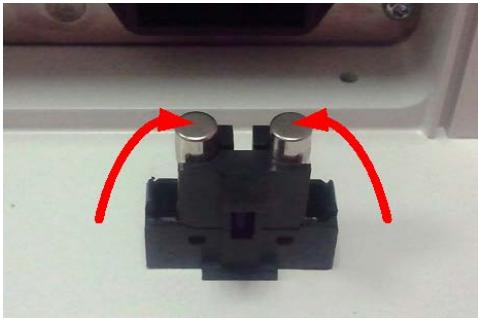
6. Flip the ends of the fuses toward the center of the bracket. They will lock into place.
![Close-up of a black electrical connector with two cylindrical pins and red arrows indicating rotation (no text or symbols)](.mlc-m-50m-d2102-1010-11/d887123b4611c0fdb47ce0bf88278fd2ea9dc5332600f369f13b86c2f11841aa.jpg)

Figure 2-5: Locking fuses into place

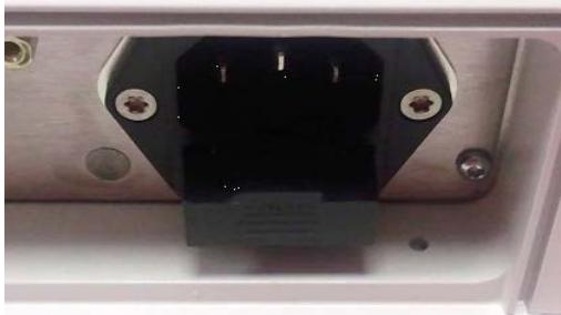
7. Re-insert the fuse back into the power supply assembly, and then gently push it in until it snaps into place.
![Close-up of a black electrical socket with mounting holes and a small rectangular component (no visible text or symbols)](.mlc-m-50m-d2102-1010-11/16fb58f96ec1d935d431ca47efdb585dc8baa5b2418969e337b6efd79cf8f670.jpg)

Figure 2-6: Re-inserting the fuse bracket

8. Reattach the power and cable cover.

# 2.3 Mechanical Dimensions

![The image displays a graphic icon of a white document or piece of paper with a folded top-right corner. Faint gray horizontal lines run across the page. Superimposed over the document is a large, bold red checkmark that slants upwards from the bottom left to the top right.](.mlc-m-50m-d2102-1010-11/3671c4916114fee15773f1c22062837f57be13894dca39cda61e533166392371.jpg)
NOTE:

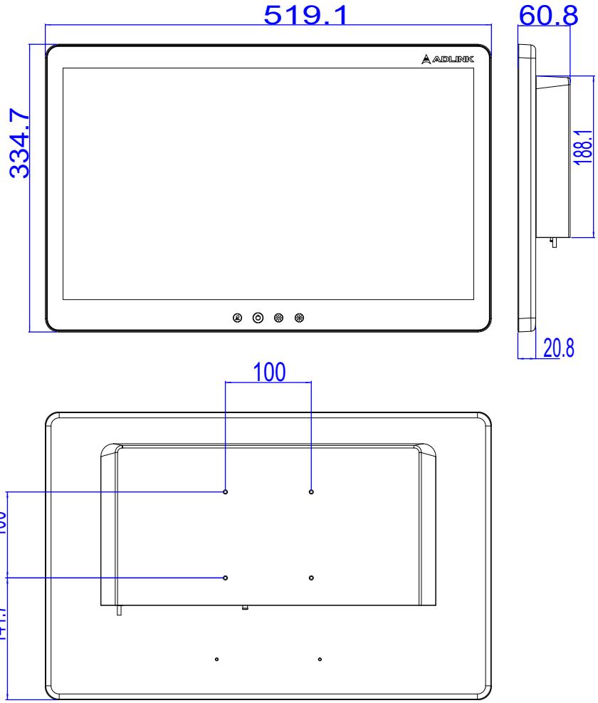
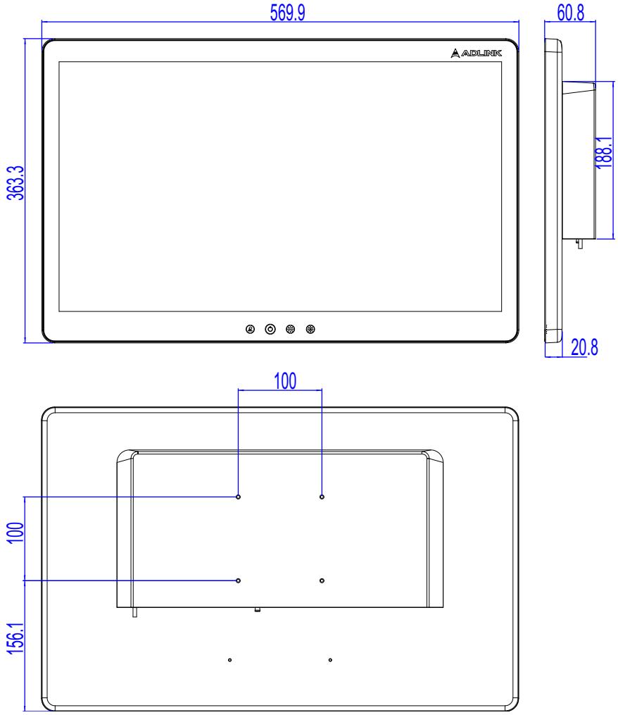
All dimensions are in millimeters, unless noted.

2.3.1 MLC-M 21.5” Dimensions
![This image is a technical engineering drawing of an electronic device, likely a monitor or panel PC, presented in three views: front, side, and rear.\n\n**Front View (Top Left):**\n*   Shows the front outline of the device with rounded corners.\n*   **Dimensions:** Width is **519.1** and height is **334.7**.\n*   **Text:** The brand name '**AADLINK**' is visible in the top right corner of the bezel.\n*   **Features:** Four small circular icons or ports are aligned horizontally at the bottom center.\n\n**Side View (Top Right):**\n*   Shows the side profile of the device.\n*   **Dimensions:**\n    *   Horizontal depth at the top: **60.8**.\n    *   Vertical dimension on the right: **188.1**.\n    *   Lower vertical dimension: **20.8**.\n\n**Rear View (Bottom):**\n*   Shows the back of the device with mounting hole positions indicated by dots.\n*   **Dimensions:**\n    *   Horizontal spacing between upper holes: **100**.\n    *   Vertical spacing between upper and lower hole rows: **100**.\n    *   Vertical distance from the bottom edge to the lower hole row: **111**.](.mlc-m-50m-d2102-1010-11/f20efe518d06590665c91a831521718ee39a45381af4b7e945bc082346f18a82.jpg)
Figure 2-7: MLC-M 21.5” Dimensions

2.3.2 MLC-M 23.8” Dimensions
![The image displays a technical engineering drawing of a display device, featuring front, side, and rear views with dimensional annotations in blue.\n\n**Front View (Top Left):**\n*   **Width:** 569.9\n*   **Height:** 363.3\n*   **Logo:** 'ADLINK' in the top right corner.\n*   **Controls:** Four circular buttons are aligned horizontally at the bottom center.\n\n**Side View (Top Right):**\n*   **Top Thickness:** 60.8\n*   **Bezel Depth:** 188.1\n*   **Bottom Thickness:** 20.8\n\n**Rear View (Bottom):**\n*   **Mounting Hole Width:** 100\n*   **Mounting Hole Vertical Spacing:** 100\n*   **Distance from bottom edge to lower holes:** 156.1](.mlc-m-50m-d2102-1010-11/2a32d8116f8fcbe5daaef0a819b4e5e1efef3d187854dffff876241b9800f776.jpg)
Figure 2-8: MLC-M 23.8” Dimensions

# 2.4 Mounting

This section includes details for panel and VESA mounting options.

![The image features a triangular warning sign. The triangle is dark red or maroon and contains a white exclamation point in the center. Beneath the triangle, the word 'WARNING' is written in white, uppercase letters.](.mlc-m-50m-d2102-1010-11/bfaaf53296d17de55fa42370f75a4abebf48b4e4d4903cfdcaa3782cee687959.jpg)

Risk of physical injuries and / or property damage:

When mounting the device, use the screws to mount the VESA bracket to the rear of the device. Tighten all four screws firmly to support the weight of the device. Make sure that the suspension system is capable of carrying the device!

![The image displays a standard safety warning sign featuring a yellow triangle with a black border. Inside the triangle is a large black exclamation mark. Below the triangle, the text 'CAUTION:' is printed in black capital letters.](.mlc-m-50m-d2102-1010-11/42ac111bb4df30c0d9dc1d391b3227d55be22d24a02f90fa9a8c6a45bec51e7c.jpg)

Risk of burns to the user caused by hot surfaces:

Turn off power and allow the device to cool down prior to performing any mounting or demounting operations. Do not touch the enclosure while the device is in operation or is still hot from previous use unless it has already cooled.

![The image displays a white document icon featuring faint horizontal lines of text and a large, red checkmark superimposed diagonally across it. Below the icon is the text 'NOTE:'.](.mlc-m-50m-d2102-1010-11/d0303885b2a9305253367d4078282ae9eeccdc257f936dd1654e65e2b188ff12.jpg)

All dimensions are in millimeters, unless noted.

# 2.4.1 VESA Mounting

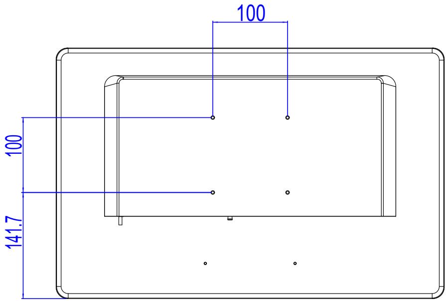
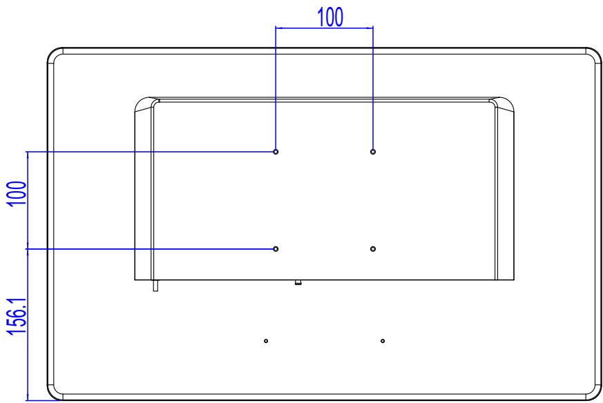
The MLC-M can be VESA mounted from the back panel as shown.

![The image displays an icon of a white document sheet with a folded top-left corner and faint horizontal lines running across it. Superimposed diagonally over the document is a large, bold red checkmark.](.mlc-m-50m-d2102-1010-11/a0d13c5f13f4387468f280c445304db985bf7a1ecac604eee4464f7c5961e71f.jpg)
NOTE:

All I/O ports must face down.

All dimensions are in millimeters, unless noted.
![100\n100\n141.7](.mlc-m-50m-d2102-1010-11/d13dbbe16d511968831724a5f0249b5e82066c290fe8d03ab8b32552e2c3327c.jpg)

Figure 2-9: MLC-M 21.5” VESA mounting
![100\n100\n156.1](.mlc-m-50m-d2102-1010-11/6b98daac34a1ca7c60b2f8b4212e50593127cdc2a59c2f509b24da465946f48b.jpg)

Figure 2-10: MLC-M 23.8” VESA mounting

This page intentionally left blank.

# 3 System Layout

# 3.1 Interface Buttons

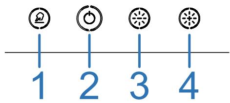
The MLC-M provides the following capacitive touch buttons:
![1\n2\n3\n4](.mlc-m-50m-d2102-1010-11/1f2d2a3167701cc2c24d45a81947cca1240e1ab9e68c6279dba620cc289b0dc4.jpg)

<table><tr><td>Button</td><td>Name</td><td>Description</td><td>Illumination</td></tr><tr><td>1</td><td>Enable/Disable Touchscreen and Buttons</td><td>Touch and hold for 3 seconds to toggle touch functionality (for cleaning). This disables both the touch screen AND other buttons.</td><td>White</td></tr><tr><td>2</td><td>Standby (On/Off)</td><td>Power on: Touch and hold for 2 secondsTrigger OS shutdown: Touch and hold for 2 secondsForce restart: Touch and hold for 7 seconds</td><td>Orange(Standby)Blue (On)</td></tr><tr><td>3</td><td>Decrease Brightness</td><td>Push or hold to decrease brightness (minimum 10%)</td><td>White</td></tr><tr><td>4</td><td>Increase Brightness</td><td>Push or hold to increase brightness</td><td>White</td></tr></table>

![The image displays a standard warning sign consisting of a yellow triangle with a thick black border. Inside the triangle is a large black exclamation point. Below the triangle, the text 'CAUTION:' is printed in black capital letters.](.mlc-m-50m-d2102-1010-11/e3d779ada95b7157eb5d34d5679d9289b19d278d2d00cdff75187a74b4f7a12f.jpg)

# Risk of data loss:

While switching off the device via the Standby (On / Off) button, do not hold for more than \~7 seconds. Doing so forces a hard shutdown of the device, followed by a restart / boot routine. This may cause a loss of data if it has not been saved or finished processing before shutdown.

![The image displays a yellow triangular warning sign with a black border. Inside the triangle is a large black exclamation point. Below the triangle, the text 'CAUTION:' is printed in black capital letters.](.mlc-m-50m-d2102-1010-11/5a2ebeae5c6699f95de5d21f1ec4bf4a1ffe85a5e94d0d34037e966c5a34d819.jpg)

Completely powering off the device requires disconnecting the AC power cable. To prevent data loss, disconnect only after the device is in standby mode (orange indicator).

# 3.2 External I/O Connectors

The MLC-M provides the following external I/O connectors.

![1\n2 3 4 5 6 7 8 9 10 11](.mlc-m-50m-d2102-1010-11/166d61cfed70234a90ee6366fc0639c56308fa0c23d198fac7a715b72d086635.jpg)

Figure 3-1: MLC-M External I/O

<table><tr><td>1</td><td>1x AC In</td></tr><tr><td>2</td><td>1x Cable cover grounding pin</td></tr><tr><td>3</td><td>1x Fuse bracket with 5x20mm 2.0A 250V</td></tr><tr><td>4</td><td>1x RJ45 GbE LAN, galvanically isolated up to 4 kV</td></tr><tr><td>5</td><td>1x DB-9P COM1 port supports RS-232 with galvanic isolation up to 4 kV</td></tr><tr><td>6</td><td>1x Potential equalization connecting pin (6mm)</td></tr><tr><td>7</td><td>1x 3.5mm Line Out</td></tr><tr><td>8</td><td>1x HDMI</td></tr><tr><td>9</td><td>1x DisplayPort (Optional)</td></tr><tr><td>10</td><td>2x USB 2.0 Type-A</td></tr><tr><td>11</td><td>2x USB 3.1 Type-A (Optional up to 6x)</td></tr></table>

Table 3-1: External I/O Legend

# 3.2.1 Potential Equalization Connecting Pin

The potential equalization connecting pin (6mm), follows DIN 42801 color coding (yellow/green) for connecting a potential equalization cable

The equalization pin of the device must be connected to the potential equalization panel of the respective facility in accordance with local standards.

![Pure geometric diagram with concentric circles and crosshairs, no text or symbols present](.mlc-m-50m-d2102-1010-11/ea73b8fa0bcadb5d95e48d7775d5ab03f5184ea532b5c96dc498b605926e7d6b.jpg)

Figure 3-2: Potential Equalization Connecting Pin

# 3.2.2 DC IN (Optional)

The MLC-M can be equipped with a 7-pin 12V 4A DC power port to support an external DC power supply. This port replaces the standard internal power supply. The port is described below.

![3\n4\n2\n7\n5\n1\n6](.mlc-m-50m-d2102-1010-11/b0f691349d6610fc6675760edbe7fff1ff1d9404a2f64de817fbe53ffa6055f6.jpg)

Figure 3-3: DC Connector Pin Definition

<table><tr><td>Pin</td><td>Signal</td></tr><tr><td>1, 2, 3</td><td>12V+</td></tr><tr><td>4, 5, 6</td><td>GND</td></tr><tr><td>7</td><td>N/A</td></tr></table>

Table 3-2: DC Connector Pin Definition

This page intentionally left blank.

# 4 BIOS Setup

The Basic Input/Output System (BIOS) is a program that provides a basic level of communication between the processor and peripherals. In addition, the BIOS also contains codes for various advanced features applied to the device. The BIOS setup program includes menus for configuring settings and enabling device features. Most users do not need to use the BIOS setup program, as the device ships with default settings that work well for most configurations.

![The image displays a white document icon featuring horizontal lines and a folded top-right corner. A large, bold red checkmark is superimposed over the center of the document.](.mlc-m-50m-d2102-1010-11/c85a084ded972e74e0ed9ce0afe62fb082c85cdc14bd827b61de24de8f1f80e1.jpg)
NOTE:

BIOS options used in this manual are for reference only, and are subject to change. Users can download the latest BIOS version from the ADLINK website.

![The image displays a red triangular warning sign with rounded corners. Inside the red triangle, centered, is a white exclamation mark (!). The background surrounding the triangle is white.](.mlc-m-50m-d2102-1010-11/529dd6f847d93a0c16e8ecd5cbf0826d467ef2b782bb1e19bfb9e5161883e847.jpg)
WARNING:

Changing BIOS settings may lead to unexpected system behavior and the possible inability to boot.

The procedures described in this chapter outline the most common operations performed with the system BIOS.

# 4.1 Restoring Default Settings

Restoring the BIOS to default settings can sometimes revolve unexpected behavior or misconfiguration.

![The image displays a white document icon with a folded top-left corner. Faint horizontal gray lines run across the page, resembling text or a list. A large, bold red checkmark is superimposed on the left side of the document.](.mlc-m-50m-d2102-1010-11/3e7ee6a9b2aad4e6406245fe819fc4908484315f0116d9d6582e3258c167dca4.jpg)
NOTE:

This procedure will also work if the display stays dark and the BIOS itself is not corrupted.

To restore default settings, do the following.

1. Power on the device and press the &lt;DEL&gt; key once the POST / boot logo screen appears. The BIOS setup menu will appear on screen. If the BIOS does not respond, make sure to wait to press &lt;DEL&gt; until the keyboard is initialized (indicated by flashing keyboard LEDs).

2. Press &lt;F9&gt;, and then press &lt;ENTER&gt; key to restore default settings.
3. Press &lt;F10&gt;, and then press &lt;ENTER&gt; to save your settings and exit.

The device will reboot with the BIOS default settings.

# 4.2 Enabling PXE / Network Boot

Some configurations may require booting the device from a network. The device supports Preboot Execution (PXE) ROM from the integrated Ethernet interface.

![The image displays a digital icon of a white document or paper sheet with a folded top-right corner. Faint gray horizontal lines run across the lower portion of the page. A large, bold red checkmark is superimposed over the center of the document. There is no text present.](.mlc-m-50m-d2102-1010-11/ddc091917adb1bed357d789ffe149a480ef0284f4416b82b79536a1587722453.jpg)
NOTE:

Ensure connection of necessary services and servers to your network before initiating a network boot.

To enable network book in the system BIOS:

1. Power on the device and press the &lt;DEL&gt; key once the POST / boot logo screen appears. The BIOS setup menu will appear on screen. If the BIOS does not respond, make sure to wait to press &lt;DEL&gt; until the keyboard is initialized (indicated by flashing keyboard LEDs).

2. Navigate to the Advanced screen.
3. Select Network Stack Configuration, and then press &lt;ENTER&gt; twice.
4. Select Enabled, and then press &lt;ENTER&gt;.
5. Configure network settings, and then press &lt;ENTER&gt;.
6. Select Enabled, and then press &lt;ENTER&gt;.
7. Press &lt;ESC&gt; to return to the main menu.
8. Navigate to the Boot screen.
9. Select Boot Option #1, and then press &lt;ENTER&gt;.
10.Select Network, and then press &lt;ENTER&gt;.
11.Set all other boot devices to Disabled.
12.Press &lt;F10&gt;, and then press &lt;ENTER&gt; to save your settings and to reboot the device

The device will reboot and attempt to boot from the network with your settings.

This page intentionally left blank.

# 5 Getting Started

# 5.1 Initial Device Installation and Cable Cover Handling

The device ships with the cable cover preinstalled. Cables must be fed through the cover to connect them to the device to retain the IP rating. This includes the power cable and grounding cable, as well as any peripherals.

To connect cables to the device:

1. Place the MLC M device with the front side facing down onto a stable working platform protected by a soft surface. Remove the cable cover by pulling it down. The cover is magnetized.

![Technical line drawing of an electronic device rear panel with ports and connectors (no text or symbols)](.mlc-m-50m-d2102-1010-11/53d4f714cd0dc783d26c10ff30998406d016ce06132958d19257ff973d150c7e.jpg)

Figure 5-1: Device Cover

2. Feed the cables through their respective gaskets. Make sure to choose gasket sizes suitable for the cables. For gaskets without cables, make sure to use gaskets without holes.

![Simple line drawing of a red cable passing through a square block (no text or symbols)](.mlc-m-50m-d2102-1010-11/b3b0429ca72ad17dc572d49232b1d647e4f2c0cf2e912c76cc314cda4dbb1475.jpg)

Figure 5-2: Threading Cables through Gaskets

3. Feed the cables with their gaskets through the rubber frame, and seat the gaskets within the rubber frame.

![Technical diagram of a mechanical assembly with multiple components and red arrows indicating motion or force (no text or symbols present)](.mlc-m-50m-d2102-1010-11/791ed42a4ce7bd8efba4ead4ff5979a31deef8c8699903056b0aba0b919a1fe7.jpg)

Figure 5-3: Attaching Gaskets to Rubber Frame

4. Attach the rubber frame over the mounting plate by inserting the tabs of plate into the slots of the frame.

![Technical line drawing of a computer chassis with labeled ports and connectors (no text or symbols)](.mlc-m-50m-d2102-1010-11/197cf62bbc718ff3640a7a3d0c1d2ec2b6a880fd9e7a0d7e490381494350292a.jpg)

Figure 5-4: Attaching Frame to Mounting Plate

5. Make sure that the green/yellow grounding cable between the cover and the device is attached securely to the device.

![Technical line drawing of a device rear panel with cable and connector (no text or symbols)](.mlc-m-50m-d2102-1010-11/a71b75e0da3c050e27e293c56142421cf474aff4b89a1378258897ef3ab87416.jpg)

Figure 5-5: Attaching Grounding Cable

6. Replace the cover. Make sure the cover fits snuggly around the rubber frame.

# 5.2 Cleaning and Disinfection

![The image displays a standard warning sign featuring a yellow triangle with a black border and a black exclamation point in the center. Below the triangle, the word 'CAUTION:' is printed in black capital letters on a white background.](.mlc-m-50m-d2102-1010-11/992f5ba96c35db9559380ba9ef78e0fe2c81b20cb5b1d4ef7d80396b6c7a7da6.jpg)

Risk of data loss or accidental operation:

Make sure device is in stand-by mode or touch functionality is disabled before cleaning to avoid accidental operation. To disable touch functionality, press and hold Enable/Disable Touchscreen and Buttons for 3 seconds.

In general, disinfectants based on alcohol, aldehydes, guanidine derivatives, or quaternary compounds are suitable for use as surface disinfectants.

Avoid disinfectants based on chlorine, chlorine-releasing substances, or peroxide compounds. These ingredients can lead to damage to the device, especially if the surface has prior damage (e.g. a scratch), particularly long-term use of these type of disinfectant solutions.

For disinfection, use a spray applicator to apply any of the approved liquids and use a soft, lint-free cloth to clean the screen. Thoroughly follow the disinfection manufacturer's guidelines for cleaning your device.

Where a simple wipe-down of the device is sufficient, use a soft, damp, and lint-free cloth only to wipe the surface of the device. If the device is only lightly soiled, use a dry anti-static cloth instead.

For cleaning the glass / touch-sensitive surfaces of the device, a simple household glass cleaner available in consumer markets may be used. After spray application of the glass cleaner, use a soft, lint-free cloth to wipe the device front until all liquid films are removed.

As a general safety precaution, your ADLINK product should undergo decontamination before returning the device to ADLINK for service, repair, inspection, or disposal.

![The image displays a white icon resembling a notepad sheet with a folded top-right corner and faint horizontal lines. A large red checkmark is drawn over the center of the paper. Below the graphic, the text 'NOTE:' appears in black, uppercase letters.](.mlc-m-50m-d2102-1010-11/41fb1170ef0eb6a135b41485b3496033667dec637ca8ef556f12b21065ec9cbe.jpg)

Contaminated items must not be returned without prior written agreement.

# Important Safety Instructions

For user safety, please read and follow all instructions, Warnings, Cautions, and Notes marked in this manual and on the associated device before handling/operating the device, to avoid injury or damage.

 Read these safety instructions carefully.
 Keep the User’s Manual for future reference.
 Read the Specifications section of this manual for detailed information on the recommended operating environment.
It is recommended that the device be installed in Information Technology Rooms that are in accordance with Article 645 of the National Electrical Code and NFPA 75.

 When installing/mounting or uninstalling/removing device is required:

 Turn off power and unplug any power cords/cables.
 Reinstall all chassis covers before restoring power.

 To avoid electrical shock and/or damage to device:

 Keep device away from high heat or humidity.
 Keep device properly ventilated (do not block or cover ventilation openings).
 Always use recommended voltage and power source settings.
 Always install and operate device near an easily accessible electrical outlet.
 Secure the power cord (do not place any object on/over the power cord).
 Only install/attach and operate device on stable surfaces and/or recommended mountings.
 The device is powered by an adapter or DC source. Ensure that the adapter or DC source is properly grounded.

? If the device will not be used for long periods of time, turn off and unplug from its power source.
 Never attempt to repair the device, which should only be serviced by qualified technical personnel using suitable tools.

 A Lithium-type battery may be provided for uninterrupted backup or emergency power.

![The image displays a standard warning sign featuring a yellow equilateral triangle with a black border. Inside the triangle is a large black exclamation point. Below the triangle is a white rectangular label with the text 'CAUTION:' printed in black, uppercase letters.](.mlc-m-50m-d2102-1010-11/d5067a9df867e079586af25f5fb9a7acaac94efd9cf9bfd75466d984dde85be8.jpg)

Risk of explosion if battery is replaced with one of an incorrect type; please dispose of used batteries appropriately.

 The device must be serviced by authorized technicians when:

 The power cord or plug is damaged
 Liquid has entered the device interior
 The device has been exposed to high humidity and/or moisture
 The device is not functioning or does not function according to the User’s Manual
 The device has been dropped and/or damaged and/or shows obvious signs of breakage

Disconnect the power supply cord before loosening the thumbscrews and always fasten the thumbscrews with a screwdriver before starting the system up.

 It is recommended that the device be installed only in a server room or computer room where access is:

 Restricted to qualified service personnel or users familiar with restrictions applied to the location, reasons therefor, and any precautions required
 Only afforded by the use of a tool or lock and key, or other means of security, and controlled by the authority responsible for the location.

![Yellow triangular warning sign with black smoke symbol indicating hot weather](.mlc-m-50m-d2102-1010-11/77cf8fb1ec822a57c9bfe005cda18828600608b7de344725600cadddd26271ce.jpg)

# BURN HAZARD

Touching this surface could result in bodily injury. To reduce risk, allow the surface to cool before touching.

# Consignes de Sécurité Importante

Pour la sécurité de l'utilisateur, veuillez lire et suivre toutes les instructions, avertissements, mises en garde et notes marqués dans ce manuel et sur l'appareil associé avant de manipuler/d'utiliser l'appareil, afin d'éviter toute blessure ou tout dommage.

 Lisez attentivement ces consignes de sécurité
? Conservez le manuel de l'utilisateur pour pouvoir le consulter ultérieurement
Lisez la section Spécifications de ce manuel pour des informations détaillées sur l'environnement d'exploitation recommandé
? Il est recommandé d'installer l'appareil dans Information Salles technologiques conformes à l'article 645 du Code national de l'électricité et NFPA 75.

Lorsque l'installation/le montage ou la désinstallation/le retrait du périphérique est requis:

 Mettez l'appareil hors tension et débranchez tous les cordons/câbles d'alimentation
 Réinstallez tous les couvercles de châssis avant de rétablir l'alimentation

 Pour éviter les chocs électriques et/ou d’endommager l’appareil:

 Tenez l'appareil à l'écart d'une forte chaleur ou d'une humidité élevée.
 Maintenez l'appareil correctement ventilé (n'obstruer ou ne couvrez pas les ouvertures de ventilation).
 Utilisez toujours les réglages de tension et de source d'alimentation recommandés.
 Installez et utilisez toujours l'appareil près d'une prise de courant facilement accessible.
 Fixez le cordon d'alimentation (ne placez aucun objet sur le cordon d'alimentation).
 Installez/fixez et utilisez l'appareil uniquement sur des surfaces stables et/ou sur les fixations recommandées.

 L'ordinateur Smart Touch est alimenté par un adaptateur ou une source CC. Veuillez vous assurer que l'adaptateur ou la source CC doit conserver la connexion à la terre s'il est doté d'une protection.

Si l'appareil ne doit pas être utilisé pendant de longues périodes, éteignez-le et débranchez-le de sa source d'alimentation
 N'essayez jamais de réparer l'appareil, qui ne doit être réparé que par un personnel technique qualifié à l'aide d'outils appropriés
 Une batterie de type Lithium peut être fournie pour une alimentation de secours ininterrompue ou d'urgence.

![The image shows a yellow triangular warning sign with a black border and a black exclamation point in the center. Below the triangle, the text 'CAUTION:' is printed in black capital letters.](.mlc-m-50m-d2102-1010-11/2be4475f66ba8c2444d96bf7b0d00435918ac564ad41754e82a487041e7a9c2c.jpg)

ATTENTION: Risque d’explosion si la pile est remplacée par une autre de type incorrect. Veuillez jeter les piles usagées de façon appropriée.

 L'appareil doit être entretenu par des techniciens agrees lorsque:

 Le cordon d’alimentation ou la prise est endommagé(e)
 Un liquide a pénétré à l'intérieur de l'appareil.
 L'appareil a été exposé à une forte humidité et/ou de la buée.
 L'appareil ne fonctionne pas ou ne fonctionne pas selon le manuel de l'utilisateur.
 L'appareil est tombé et/ou a été endommagé et/ou présente des signes évidents de dommage.

Débranchez le cordon d'alimentation avant de desserrer les vis à oreilles et serrez toujours les vis à oreilles avec un tournevis avant de mettre le système en marche.

 Il est recommandé d'installer l'appareil uniquement dans une salle de serveurs ou une salle informatique où l'accès est:

 Réservé au personnel de service qualifié ou aux utilisateurs familiarisés avec les restrictions appliquées à l'emplacement, aux raisons de ces restrictions et toutes les précautions requises

 Uniquement autorisé par l'utilisation d'un outil, d'une serrure et d'une clé, ou d'un autre moyen de sécurité, et contrôlé par l'autorité responsable de l'emplacement.

![Yellow triangular warning sign with black smoke symbol indicating hot weather](.mlc-m-50m-d2102-1010-11/538be1aa9161a0dd715245cfda4ce86a306630cf8452ee72a42b16d09077ea92.jpg)

# RISQUE DE BRÛLURES

Partie chaude! Ne touchez pas cette surface, cela pourrait entraîner des blessures. Pour éviter tout danger, laissez la surface refroidir avant de la toucher.

# EMC Compliance

# CE Warning

This is a Class B product. In a domestic environment, this product may cause radio interference, in which case the user may be required to take adequate measures.

# FCC Warning

This equipment has been tested and found to comply with the limits for a Class B digital device, pursuant to part 15 of the FCC Rules. These limits are designed to provide reasonable protection against harmful interference in a residential installation. This equipment generates, uses and can radiate radio frequency energy and, if not installed and used in accordance with the instructions, may cause harmful interference to radio communications. However, there is no guarantee that interference will not occur in a particular installation. If this equipment does cause harmful interference to radio or television reception, which can be determined by turning the equipment off and on, the user is encouraged to try to correct the interference by one or more of the following measures:

 Reorient or relocate the receiving antenna.
 Increase the separation between the equipment and receiver.
 Connect the equipment into an outlet on a circuit different from that to which the receiver is connected.
 Consult the dealer or an experienced radio/TV technician for help.

# Getting Service

Ask an Expert: http://askanexpert.adlinktech.com

# ADLINK Technology, Inc.

No. 66, Huaya 1st Rd., Guishan District, Taoyuan City 333411, Taiwan

Tel: +886-3-216-5088

Fax: +886-3-328-5706

Email: service@adlinktech.com

# Ampro ADLINK Technology, Inc.

6450 Via Del Oro

San Jose, CA 95119-1208, USA

Tel: +1-408-360-0200

Toll Free: +1-800-966-5200 (USA only)

Fax: +1-408-600-1189

Email: info@adlinktech.com

# ADLINK Technology GmbH

Ulrichsberger Straße 17

94469 Deggendorf, Germany

Tel: +49-991-29094-10

Email: info.deg@adlinktech.com

Please visit the Contact page at www.adlinktech.com for information on how to contact the ADLINK regional office nearest you.
[🔗 Link to the original document](.mlc-m-50m-d2102-1010-11/mlc-m-50m-d2102-1010-11.pdf)
