# All-in-One Panel Computer

# MLC-S Series

User’s Manual

![ADLINK](.mlc-s-series-50m-1z363-1010-11/a39eff067dfe630446f34f50ad7c3949a1e1a7ee429a6b8050afdff3798ef1f5.jpg)

Revision: 1.1

Part No.: 50M-1Z363-1010

Date: January 8, 2025

This page is intentionally left blank.

# 1. Contents

# 1. Contents.. . 3

1.1 List of Figures . . 5

# 2. Revision History . . 6

# 3. General Information.. 7

3.1 About this Manual ..
3.2 Trademarks.. .. 8
3.3 Warranty Information .. .. 8
3.4 Support, Problems and Failure Analysis. . 8

3.4.1 Recommended action on problems or failures..... . 8
3.4.2 Procedure for returning products.. . 9
3.4.3 Drivers ..... 9

3.5 Conventions Used in this Manual . . 9

3.5.1 Conventions for signal words and symbols . . 9
3.5.2 Categories of persons ..... ....10

# 4. Safety . .11

4.1 Intended Purpose ... ..11

4.1.1 Intended purpose of MLC-S used as stand-alone device . ..11
4.1.2 Intended purpose of MLC-S combined with compatible devices . ..12

4.2 Safety and Warning Instructions.. ..13

4.2.1 General electrical hazards. ..13
4.2.2 Specific hazards caused by electrical leakage currents in devices...... ....18
4.2.3 Other hazards. ....19
4.2.4 Hazards regarding repair and maintenance.... ..26

# 5. User Information.. . 29

5.1 General Description . ..29

5.1.1 MLC-S models ...... ...30
5.1.2 MLC-S configurations .. ..30

5.2 Device Overview.. ..32

5.2.1 Interfaces ...... ..32
5.2.2 Operational elements ..34
5.2.3 Overview front panel buttons... ..35
5.2.4 Functions of the front panel buttons . ..35
5.2.5 Package contents ..... ..39

5.3 Cleaning and Disinfection .. ..40

5.3.1 Safety instructions for cleaning and disinfection of the device.. ..41

# 6. Specialized Staff Information... .43

6.1 Functional Block Diagram. ..43

Technical Data of Main System Components.. ..44
Detailed System Components . ..44

6.4 Optional Built-In Components. ..46

6.4.1 Serial ports with galvanic isolation....... ...46
6.4.2 WLAN / Bluetooth module.. ...46
6.4.3 USB 2.0 ports with galvanic isolation . ..47
6.4.4 Device configuration with display in portrait orientation (rotation kit) . ..47

6.4.5 PCIe Riser Card.. ..48
6.4.6 RFID . ..48

# 6.5 Maintenance and Service . ..48

6.5.1 General service intervals . ..48
6.5.2 Initial device installation/cable cover handling . ..48
6.5.3 Fuse replacement for the internal power supply (AC mains supply). ..51

# 7. BIOS Configuration . . 54

7.1 Default Settings .. ..54
7.2 Enabling PXE/Network Boot .. ..54
7.3 Changing the Boot Sequence. ..55

# 8. Specifications . .56

8.1 Mechanical Specifications . ..56

8.1.1 Front and side dimensions MLC-S . ..56
8.1.2 Rear dimensions MLC-S . ..57
8.1.3 Weight.. ..57

8.2 Electrical Specifications .. ..58

8.2.1 Mains voltage input.. ..58
8.2.2 Power consumption .. ..58

8.3 Environmental Specifications.. ..59

8.4 Markings and Labels.. ..60

8.4.1 Product identification label.. ..60
8.4.2 Mains input fuse label.. ..60
8.4.3 Explanation of label symbols.. ..61

# 9. Appendix . . 62

9.1 EMC requirements.. ..62
9.2 EN 60601-1-2 tables for MLC-S12-21, and MLC-S12-23 . ..65

9.2.1 Guidance and manufacturers declaration – electromagnetic EMISSION .. ...65
9.2.2 Guidance and manufacturers declaration – electromagnetic IMMUNITY.. ...66
9.2.3 Guidance and manufacturers declaration – electromagnetic IMMUNITY – continued . ..67
9.2.4 Recommended separation distances between portable and mobile RF communications equipment and the MLC-S ..68

# 1.1 List of Figures

Figure 1: MLC-S all-in-one panel computer .. . 30

Figure 2: Bottom view with cable cover mounted . . 32

Figure 3: Bottom view illustrating device interfaces (cable cover removed) .... . 33

Figure 4: Capacitive touch buttons .... . 34

Figure 5: MLC-S in operation; front touch buttons backlit. . 34

Figure 6: Front touch buttons overview.... . 35

Figure 7: Standby status indication. . 36

Figure 8: Power-on status indication.. . 36

Figure 9: Display brightness indicator... 37

Figure 10: Touchscreen disabled indicator ... . 38

Figure 11: All front touch buttons disabled except for the Touchscreen Enable/Disable button..... 38

Figure 12: Onscreen keyboard activated .. . 39

Figure 13: MLC-S series functional block diagram . . 43

Figure 14: Bottom view illustrating device interfaces .. 44

Figure 15: Optional components, two COM ports. . 46

Figure 16: Marking label of galvanically isolated USB 2.0 ports with USB symbol and inscription. 47

Figure 17: MLC-S in portrait orientation .. 47

Figure 18: Cable cover installation... . 49

Figure 19: Protective earth strap.. . 50

Figure 20: Protective earth strap, I/O interface bezel mounting point... . 50

Figure 21: Protective earth strap, cable cover mounting point.. . 50

Figure 22: MLC-S12-xx front and side dimensions in [mm] . 56

Figure 23: MLC-S12-xx VESA 100 interface & rear dimensions in [mm].. 57

Figure 24: Product identification label for MLC-S12-XX device ..... . 60

Figure 25: Mains input fuse label . . 60

# 2. Revision History

<table><tr><td>Revision</td><td>Changes</td><td>Date</td></tr><tr><td>1.0</td><td>Initial release</td><td>August 9, 2024</td></tr><tr><td>1.1</td><td>Address and contact updated</td><td>January 8, 2025</td></tr></table>

# 3. General Information

# 3.1 About this Manual

Please read this manual very carefully and assure compliance to all safety instruction and requirements regarding the operation and care of the device. The information contained, will help to prolong the lifetime of the device and to avoid possible hazards.

This manual contains all relevant and necessary information for safe and best possible failure-free operation of the device. However, this manual does not claim to provide gap-free completeness regarding every technical detail or equipment configuration, nor does it include and explain every imaginable installation situation, operating mode or servicing modality. In case any further information not covered by this document is needed, do not hesitate to contact your ADLINK representative.

For further documentation and the latest utilities and drivers, please visit the ADLINK website at www.adlinktech.com or contact your local ADLINK (sales) representative.

The content of this manual shall not become part of or modify any prior or existing agreement, commitment or relationship between ADLINK and the owner / user of the device. The sales contract only describes the entire obligations of ADLINK. The warranty contained in the contract between the parties is the sole warranty of ADLINK.

The information in this document has been checked carefully prior to release. However, no responsibility will be taken for unintended inaccuracies or unintended missing information. Furthermore, ADLINK reserves the right to change any part of this manual without prior notification. ADLINK does not assume any liability for damages, which refer directly or indirectly to the delivery, performance or use of this material.

This documentation is subject to copyright. Reproduction, transmission and use of this document or its contents are not permitted without prior written approval of ADLINK.

Manufacturer

![The image displays a black silhouette icon of a factory building. On the left side, there is a structure with a jagged, sawtooth roofline featuring three peaks. On the right side, a tall, rectangular smokestack extends upward. At the very top right edge of the black shape, there is a small white lowercase letter 'c'.](.mlc-s-series-50m-1z363-1010-11/d90172b48c745362af514b8d22f74950fceed10707a458e05628c3f05fcc8df0.jpg)

ADLINK Technology Inc

No. 66 Huaya 1st Rd., Guishan Dist.,

Taoyuan City 333411, Taiwan

Email: service@adlinktech.com

Phone: +886-3-216-5088

Internet: www.adlinktech.com

Copyright © 2024, 2025 ADLINK Technology GmbH. All rights reserved. ADLINK will be used as a synonym for ADLINK Technology GmbH in this manual.

# 3.2 Trademarks

Product names mentioned herein are used for identification purposes only and may be trademarks and/or registered trademarks of their respective companies.

# 3.3 Warranty Information

Make sure that the device is used exclusively for the intended purpose and is operated and maintained in accordance with the provisions of this manual. Any use beyond the intended purpose is considered non-intended use. The ADLINK product warranty prohibits any modifications to the device.

Your ADLINK product warranty covers material defects and workmanship for the warranty period, starting with the date of shipment. During the warranty period, ADLINK reserves the option to either repair or replace defective products.

Within the warranty period, repair is free of charge if warranty conditions were observed. Due to high expenditures for test procedures, a test fee will be charged if no fault can be found. Repair services outside of the warranty period will be charged.

For further information regarding tests and measurements made in conjunction with warranty and/or repair services, please refer to Section 3.4 below.

# 3.4 Support, Problems and Failure Analysis

The use of this all-in-one panel computer requires basic IT knowledge, which implies the operation of the system, correct connection of equipment or devices with the available standard interfaces and the handling of the operating system and software.

# 3.4.1 Recommended action on problems or failures

Each ADLINK product has been tested carefully and thoroughly prior to shipment. In the unlikely event that a problem occurs during operation, please check the BIOS and operating system settings of your system. These settings are often a cause of error due to resource conflicts.

Before contacting ADLINK, please visit the website of ADLINK or the websites of the respective hard- and/or software manufacturers. If the problem cannot be resolved with this documentation and/or updates alone, please contact ADLINK via e-mail or telephone.

Please be prepared to provide the following information:

• Product name, model number and serial number (SN) - see label on the back of the device
• BIOS version - see the version in the BIOS menu or OSD
• Version of the operating system (OS) installed on the device
Operational environment and system configuration
• Fault description regarding current behavior and expected result
• Report date if the error has been reported already
• The date when the error occurred for the first time

# 3.4.2 Procedure for returning products

If you need to return your ADLINK device for servicing, please fill in the Return Material Authorization (RMA) form before shipping; the RMA form is available on the ADLINK website at https://www.adlinktech.com/en/Medical\_Healthcare\_Service\_and\_Support.

Repairs within the warranty period are free of charge if warranty conditions were observed. Due to high expenditures for test procedures, a test fee will be charged if no fault can be found. Repair services outside of the warranty period will be charged.

Your ADLINK product warranty covers material defects and workmanship for the warranty period starting with the date of shipment. During the warranty period, ADLINK reserves the option to either repair or replace defective products.

For warranty service or repair, the product must be returned to a service facility designated by ADLINK, prepaid by the customer.

# 3.4.3 Drivers

Drivers for your ADLINK device are available at http://www.adlinktech.com. Be sure to keep your devices up-to-date with the latest driver and firmware before contacting ADLINK.

# 3.5 Conventions Used in this Manual

# 3.5.1 Conventions for signal words and symbols

![The image displays a standard warning symbol: a black-bordered triangle with a white background containing a large, black exclamation mark in the center.](.mlc-s-series-50m-1z363-1010-11/b724a5a08826f48ad0d5c6940432918f33ee8a4b05fe01a5d6235af901d88eeb.jpg)

# DANGER

Result and cause of the hazard

indicates a hazardous situation which, if not avoided, will result in death or serious injury.

![The image displays a standard warning symbol consisting of a black-outlined equilateral triangle on a white background, with a black exclamation point centered inside it.](.mlc-s-series-50m-1z363-1010-11/446c72991b5c43178fb5225d53d59cb3e7745386ee0d7d2b42ae2d3f0ea845aa.jpg)

# WARNING

Result and cause of the hazard

indicates a hazardous situation which, if not avoided, may result in death or serious injury.

![The image displays a white equilateral triangle with a black outline. Centered inside the triangle is a black exclamation point. The background surrounding the triangle is black.](.mlc-s-series-50m-1z363-1010-11/db43328116edf7b8221fcd3e9beab80ae20fddb34573f8002b615820f8594034.jpg)

# CAUTION

Result and cause of the hazard

indicates a hazardous situation which, if not avoided, could result in minor or moderate injury and may result in damage to property.

![The image displays a black outline of a circle containing a lowercase letter 'i' in black against a white background. The 'i' consists of a solid black dot above a vertical black stem. The verbatim text is: **i**](.mlc-s-series-50m-1z363-1010-11/b25437c2e353f3d3c1344c861e3dacf58dbe79063e73a46ec622e75c68119ee8.jpg)

# NOTICE

is used to call special attention to important information related to the device, handling of the device or the respective part of the manual.

# 3.5.2 Categories of persons

In this manual, the following groups of individuals are categorized:

Operator
User
Specialized staff

# Operator

An operator is defined as a natural or legal person, for example, a hospital that owns and has use of the device on whose behalf it is used.

The operator is responsible for providing a safe device and giving users appropriate instructions about the use of the device.

# User

Users are professional individuals who meet the training and qualification requirements to operate and work with the device.

It is the user’s responsibility to ensure safe use of the device in accordance with the intended use.

# Specialized staff

Specialized staff (e.g., an IT administrator employed by the operator or an authorized service technician especially trained by ADLINK) are individuals with adequate training records who have acquired their knowledge through technical education.

# 4. Safety

ADLINK MLC-S series devices are labelled with the relevant CE mark in accordance with the relevant provisions.

The MLC-S device is manufactured and distributed by ADLINK.

# 4.1 Intended Purpose

# 4.1.1 Intended purpose of MLC-S used as stand-alone device

The all-in-one panel computers of the MLC-S series are devices specifically designed to display, monitor and store accumulated data, but not intended to display images on the panel that required accurate color or contrast display, while processing relevant and / or patient data in environments such as:

surgical OR theatres,
intensive care units,
emergency care units, and
further point-of-care sites

in healthcare facilities such as hospitals, outpatient care units, and other care units.

Handling and operation of the MLC-S series devices shall only be performed by professional personnel of the above-mentioned entities such as medical staff (surgeons, anaesthetists, physicians, etc.), nursing personnel and technical personnel working in healthcare facilities such as IT administrators, engineers, and technical service technicians.

The engineering design and constructional characteristics of the device especially considers requirements for usage within the above-mentioned environment or other hygiene-sensitive environments with respect to:

• hygienic conditions (e.g. fanless, internal cooling concept, screwless housing design),
quality aspects for displayed / monitored patient data,
operational control abilities (e.g. with user’s hands double gloved),
• processing speed and quality (e.g. endoscopy visualization, etc.), and
• further technical design characteristics (e.g. isolated interface ports, etc.).

The MLC-S series devices are intended for use in indoor environments in accordance with the usage environments described above. The devices are not intended for outdoor use including use in mobile vehicles such as ambulance cars, helicopters, etc. or in other rough environmental conditions of nondomestic environments.

Please refer to the environmental specification defined for safe operation (see Section 8.3).

The described application should not be used for any purpose other than that defined above.

Improper use, alterations made to the devices, or the use of (spare) parts not approved and released by ADLINK may result in unforeseeable damage. Any use of the device not in accordance with the intended purpose will result in loss of all warranty claims. The risks and possible damage resulting thereof are the full responsibility of the user / operator of the device.

# 4.1.2 Intended purpose of MLC-S combined with compatible devices

Use in conformity with the intended purpose also includes applications of the MLC-S in conjunction with and/or as an integral part of device systems such as anesthesia monitoring systems, respiratory monitoring systems, or various other system applications formed by a combination of the MLC-S with specific software.

Systems which use an MLC-S series device as an integral part or a component are manufactured and placed on the market by third-party companies independently from ADLINK Technology GmbH. The entire system configuration, technical architecture, etc. and the CE conformity procedure for the created system are then the full responsibility of the respective system manufacturer.

Consequently, the manufacturer of the created system determines the explicit intended use of the integrated MLC-S device and/or of the entire system.

# 4.2 Safety and Warning Instructions

# 4.2.1 General electrical hazards

![The image shows a black triangle outline on a white background containing a single black exclamation mark in the center.](.mlc-s-series-50m-1z363-1010-11/160f102e8ddd4b6e41f85a6c1c3808acbc6c11f71a2aca28e8735f81066ceeb1.jpg)

# DANGER

Risk of electrical shock to the user as well as risk of property damage and damage to the device caused by use of inappropriate mains supplies:

Use an original ADLINK mains supply only and preferably the standard internal mains supply only. In case another mains supply must be used, it must follow specifications which provide an equivalent safety level as the original mains supply, as well as technical compatibility to the technical specifications of the device.

Use of a mains supply not authorized by ADLINK may, in addition to the potential hazards caused, result in a loss of warranty!

# DANGER

Risque de choc électrique pour l'utilisateur ainsi que risque de dommages matériels et d'endommagement de l'appareil causés par l'utilisation d'une alimentation secteur inappropriée :

N'utilisez que l'alimentation secteur originale d'ADLINK et, de préférence, l'alimentation secteur interne standard. Si une autre alimentation doit être utilisée, elle doit répondre à des spécifications qui assurent un niveau de sécurité équivalent à celui de l'alimentation d'origine, ainsi qu'une compatibilité technique avec les spécifications techniques de l'appareil.

L'utilisation d'une alimentation secteur non autorisée par ADLINK peut, en plus des risques potentiels, entraîner la perte de la garantie !

![The image displays a standard warning symbol consisting of a black triangle outline containing a centered black exclamation point on a white background.](.mlc-s-series-50m-1z363-1010-11/1aefc45e0b80a2d85968c5178b29184e754a1b3930b9885aee9954b9d5ed1679.jpg)

# DANGER

Risk of electrical shock to the user or others and risk of property damage caused by damaged mains connection components:

Never operate the device with a damaged mains supply cable. Damaged mains supply cables including damaged cable plugs must be withdrawn from use immediately. If the mains connection socket of the device is damaged, it must also be withdrawn from operation immediately and must be secured against any further use until the necessary repairs are performed by a trained service technician.

# DANGER

Risque de choc électrique pour l'utilisateur ou d'autres personnes et risque de dommages matériels causés par des composants de raccordement au réseau endommagés :

Ne jamais utiliser l'appareil avec un câble d'alimentation endommagé. Les câbles d'alimentation endommagés, y compris les connecteurs de câble endommagés, doivent être immédiatement mis hors service. Si la prise de raccordement au réseau de l'appareil est endommagée, elle doit également être mise hors service immédiatement et protégée contre toute utilisation ultérieure jusqu'à ce que les réparations nécessaires soient effectuées par un technicien de service qualifié.

![The image displays a black outline of an equilateral triangle centered on a white background. Inside the triangle is a single, bold black exclamation point. The image is framed by thick black vertical bars on the far left and right sides.](.mlc-s-series-50m-1z363-1010-11/ecbb763610f5831a472f4c68626831d30d22118bdc1ddd4b178774841ab89b71.jpg)

# WARNING

Risk of electrical shock or other injuries to the user or others and risk of property damage caused by insufficiently laid mains supply cables:

Take appropriate care in laying out mains supply cables to avoid any possible damage to the cable and to avoid any danger of stumbling over it.

# AVERTISSEMENT

Risque de choc électrique ou d'autres blessures pour l'utilisateur ou d'autres personnes et risque de dommages matériels causés par des câbles d'alimentation insuffisamment posés :

La pose des câbles d'alimentation doit être effectuée avec le plus grand soin afin d'éviter tout endommagement du câble et tout risque de trébuchement.

![The image displays a black outline of an equilateral triangle pointing upwards, containing a centered black exclamation mark, set against a white background.](.mlc-s-series-50m-1z363-1010-11/ec07aaa54f64d03fb0536776695edca42c723caf3929da1c16ed0faed09c24e8.jpg)

# WARNING

Risk of electrical shock or other injuries to the user or others and risk of property damage caused by inappropriate conditions of the mains supply socket:

Never use mains supply sockets which are damaged, dusty, or dirty. Make sure that proper connections are made between the mains connector and the mains outlet socket. Improper plug connections may result in injury caused by sparks and/or a fire hazard.

# AVERTISSEMENT

Risque de choc électrique ou d'autres blessures pour l'utilisateur ou d'autres personnes et risque de dommages matériels causés par des conditions inappropriées de la prise d'alimentation secteur :

N'utilisez jamais de prises de courant endommagées, poussiéreuses ou sales. Veillez à ce que les connexions entre le connecteur d'alimentation et la prise de courant soient correctes. Des connexions incorrectes peuvent entraîner des blessures causées par des étincelles et/ou un risque d'incendie.

![The image shows a black outline of an upright triangle on a white background. Centered inside the triangle is a black exclamation point.](.mlc-s-series-50m-1z363-1010-11/cdd1c946f565cf9a41a5edb129a7245fb7a6fe2a762ddd8b6f3249f43541731c.jpg)

# WARNING

Risk of electrical shock to the user or others and risk of property damage caused by insufficient (ground) protection line connection:

The device must only be operated at mains supply outlets with a protective ground connection. Intentional disruption of the ground protection line and operation of the device with damaged ground protection either in the connecting cable or the device itself are prohibited.

# AVERTISSEMENT

Risque de choc électrique pour l'utilisateur ou d'autres personnes et risque de dommages matériels causés par une connexion insuffisante de la ligne de protection (terre) :

L'appareil ne doit être utilisé que sur des prises de courant dotées d'une mise à la terre. Il est interdit de perturber intentionnellement la ligne de protection de la terre et d'utiliser l'appareil lorsque la protection de la terre est endommagée, que ce soit dans le câble de raccordement ou dans l'appareil luimême.

![The image displays a black exclamation point centered inside a white triangle with a black outline. To the left of the triangle is a solid black vertical bar.](.mlc-s-series-50m-1z363-1010-11/541aad175a3820109a96bcdfcdf7f15d3775b0e7c5adf4c61d0ac4e522852c1b.jpg)

# WARNING

Risk of electrical shock to the user or others and risk of property damage caused by overloaded mains supply devices:

Any additional extension cables or multiple outlet sockets being used must be regularly checked to ensure proper condition and secure operation.

Do not overload outlet sockets, extension cables, and multiple outlet socket devices. Doing so may cause electrical shocks or fire hazards.

# AVERTISSEMENT

Risque de choc électrique pour l'utilisateur ou d'autres personnes et risque de dommages matériels causés par des dispositifs d'alimentation secteur surchargés :

Toute rallonge supplémentaire ou prise multiple utilisée doit être régulièrement vérifiée pour s'assurer qu'elle est en bon état et qu'elle fonctionne correctement.

Ne surchargez pas les prises de courant, les câbles de rallonge et les prises multiples. Cela pourrait provoquer des chocs électriques ou des risques d'incendie.

![The image displays a black outline of an upright triangle on a white background. Centered inside the triangle is a black exclamation mark.](.mlc-s-series-50m-1z363-1010-11/acfd443b3432d468cb81b9bf51cc3d9f54455df5f388a576795383ab9748171b.jpg)

# WARNING

Risk of electrical shock to the user as well as risk of property damage and damage to the device caused by overvoltage:

Appropriate overvoltage protection must be provided to avoid dangerous overvoltage to the device such as those caused by thunderstorms.

# AVERTISSEMENT

Risque de choc électrique pour l'utilisateur ainsi que risque de dommages matériels et d'endommagement de l'appareil causés par une surtension :

Une protection appropriée contre les surtensions doit être prévue pour éviter que l'appareil ne subisse des surtensions dangereuses, telles que celles provoquées par les orages.

![The image displays a white triangle with a black outline. In the center of the triangle is a black exclamation point.](.mlc-s-series-50m-1z363-1010-11/0a506e0fef6dc4f440d18fafca1dc1bfdc4c2a2a3e6522aa6f69a92668eed790.jpg)

# WARNING

Risk of electrical shock to the user as well as risk of property damage and damage to the device caused by ingress of fluids or foreign objects:

Although the device is designed with a high level of protection (up to IP54), the device is not fully protected against ingress of fluids. This is the case especially if the device is operated without the protective cable cover at the rear/bottom of the device (over the I/O interface bezel).

To ensure proper protection of the device’s housing from fluid ingress, never put any inappropriate objects such as tools, pencils, etc. into openings of the housing (i.e. interface sockets).

# AVERTISSEMENT

Risque de choc électrique pour l'utilisateur ainsi que risque de dommages matériels et d'endommagement de l'appareil causés par la pénétration de liquides ou de corps étrangers :

Bien que l'appareil soit conçu avec un niveau de protection élevé (jusqu'à IP54), il n'est pas entièrement protégé contre la pénétration de liquides. C'est notamment le cas si l'appareil est utilisé sans le cache-câble de protection situé à l'arrière/en bas de l'appareil (au-dessus de la lunette de l'interface E/S).

Pour garantir une protection adéquate du boîtier de l'appareil contre la pénétration de liquides, ne mettez jamais d'objets inappropriés tels que des outils, des crayons, etc. dans les ouvertures du boîtier (c'est-à-dire les prises d'interface).

![The image shows a black outline of an equilateral triangle containing a black exclamation point, centered against a white background. This is a standard warning symbol.](.mlc-s-series-50m-1z363-1010-11/92278d89aaf7041d51a983de63fdb161e8c4dac69b11f3dcac4190dabf72bc89.jpg)

# WARNING

Risk of electrical shock to the user or others and as well as risk of property damage and damage to the device caused by inaccessible mains sockets:

The device does not provide a mains switch for disconnecting it from the mains supply; the mains disconnection element of the device consists of the mains cable.

Due to this fact, the mains socket and/or the mains cable must always be within easy reach for the user. If the device must be integrated into cabinets or other objects, the operating institution must provide a disconnection switch device at the system level (i.e. operation via an all-lines disconnecting mains switch e.g. at the system).

# AVERTISSEMENT

Risque de choc électrique pour l'utilisateur ou d'autres personnes, ainsi que risque de dommages matériels et d'endommagement de l'appareil en raison de l'inaccessibilité des prises de courant :

L'appareil n'est pas équipé d'un interrupteur permettant de le déconnecter du réseau électrique ; l'élément de déconnexion du réseau électrique de l'appareil est constitué par le câble d'alimentation. De ce fait, la prise secteur et/ou le câble secteur doivent toujours être à portée de main de l'utilisateur. Si l'appareil doit être intégré dans des armoires ou d'autres objets, l'institution exploitante doit prévoir un dispositif d'interrupteur de déconnexion au niveau du système (c'est-à-dire un fonctionnement par l'intermédiaire d'un interrupteur de déconnexion du réseau sur toutes les lignes, par exemple au niveau du système).

![The image displays a standard warning symbol featuring a black triangle outline on a white background, with a black exclamation point centered inside it.](.mlc-s-series-50m-1z363-1010-11/7436625d23d3d01074b17c09984075349efb61fe00d5513da70dfe211c71adf2.jpg)

# WARNING

Risk of electrical shock or other injuries to the user or others and risk of property damage caused by insufficient electrical installations:

Electrical installations must be set up by qualified personnel only. For installation and operation of the device, the responsible operating institution must ensure that the chosen personnel is sufficiently qualified with regard to physical, psychological and emotional condition. It is the responsibility of the operating institution to choose qualified personnel for installation and operation of the device.

# AVERTISSEMENT

Risque de choc électrique ou d'autres blessures pour l'utilisateur ou d'autres personnes et risque de dommages matériels causés par des installations électriques insuffisantes :

Les installations électriques ne doivent être réalisées que par du personnel qualifié. Pour l'installation et l'utilisation de l'appareil, l'institution responsable de l'exploitation doit s'assurer que le personnel choisi est suffisamment qualifié sur le plan physique, psychologique et émotionnel. Il incombe à l'institution exploitante de choisir un personnel qualifié pour l'installation et l'utilisation de l'appareil.

# 4.2.2 Specific hazards caused by electrical leakage currents in devices

![The image displays a standard warning symbol. It features a large, black-outlined triangle pointing upward on a white background. Centered inside the triangle is a single black exclamation point.](.mlc-s-series-50m-1z363-1010-11/eaa4dfcd268a0615bc2cf7b396429faef3e2dc05e33c4df67c97803b85279fe2.jpg)

# WARNING

Risk of an unacceptable high leakage current to the patient, user or others caused by device interfaces not in use:

Never touch unused interfaces such as USB or COM ports and a patient at the same time!

Secure unused interfaces by using appropriate covers, especially the rear/bottom cover delivered with the device and use galvanically isolated interfaces to connect your ADLINK device to other devices.

# AVERTISSEMENT

Risque de courant de fuite élevé et inacceptable pour le patient, l'utilisateur ou d'autres personnes, causé par des interfaces d'appareil non utilisées :

Ne touchez jamais des interfaces inutilisées telles que les ports USB ou COM et un patient en même temps !

Sécurisez les interfaces inutilisées en utilisant des couvercles appropriés, en particulier le couvercle arrière / inférieur fourni avec l'appareil, et utilisez des interfaces isolées galvaniquement pour connecter votre appareil ADLINK à d'autres appareils.

![The image displays a standard warning symbol featuring a black triangular outline with a centered black exclamation point inside it, set against a white background.](.mlc-s-series-50m-1z363-1010-11/56135da529db864473674aa94dadfd671c86566d4a955fb47c49a53ef9fece11.jpg)

# WARNING

Risk of an unacceptable high leakage current to the patient caused by insufficient system configuration:

Accessories connected to analog or digital interfaces must be compliant with the respective European or international standards (e.g. EN 62368-1 for data processing devices and EN 60601-1 for medical devices). Furthermore, all configurations for ME systems must be compliant with the EN 60601-1 standard. Users connecting additional devices to a signal input or output are configuring a medical system and are therefore responsible for the system being compliant with the applicable version of the system standard EN 60601-1.

In case of doubt, please contact the technical customer support or your local representative.

# AVERTISSEMENT

Risque de courant de fuite élevé et inacceptable pour le patient en raison d'une configuration insuffisante du système :

Les accessoires connectés aux interfaces analogiques ou numériques doivent être conformes aux normes européennes ou internationales respectives (par exemple, EN 62368-1 pour les dispositifs de traitement des données et EN 60601-1 pour les dispositifs). En outre, toutes les configurations des systèmes ME doivent être conformes à la norme EN 60601-1-1. Les utilisateurs qui connectent des appareils supplémentaires à une entrée ou une sortie de signal configurent un système et sont donc responsables de la conformité du système avec la version applicable de la norme EN 60601-1-1.

En cas de doute, veuillez contacter le service d'assistance technique ou votre représentant local.

# 4.2.3 Other hazards

![The image displays a black-outlined triangle on a white background containing a centered black exclamation point, serving as a general warning or caution symbol.](.mlc-s-series-50m-1z363-1010-11/6cb771a10bdaeb2db3364adc5155addd457cb11a91df1641e7af016d2ed2de03.jpg)

# WARNING

Risk of injury to the user or others as well as risk of property damage and damage to the device caused by inappropriate operation conditions:

The device must only be operated within the operation conditions specified by ADLINK.

Never place the device onto heat emitting objects such as radiators or heating ventilators. The environmental temperature must not exceed the maximum temperatures indicated in this documentation. Never place the device into an enclosed housing unless it is ventilated enough to ensure an operational temperature below the allowed maximum.

# AVERTISSEMENT

Risque de blessure pour l'utilisateur ou d'autres personnes ainsi que risque de dommages matériels et d'endommagement de l'appareil causés par des conditions de fonctionnement inappropriées :

L'appareil ne doit être utilisé que dans les conditions d'utilisation spécifiées par ADLINK.

Ne jamais placer l'appareil sur des objets dégageant de la chaleur tels que des radiateurs ou des ventilateurs de chauffage. La température ambiante ne doit pas dépasser les températures maximales indiquées dans cette documentation. Ne jamais placer l'appareil dans un boîtier fermé, à moins qu'il ne soit suffisamment ventilé pour garantir une température de fonctionnement inférieure à la tempé- rature maximale autorisée.

![The image displays a standard warning symbol consisting of a white triangle with a black border pointing upward, containing a single black exclamation mark in its center.](.mlc-s-series-50m-1z363-1010-11/41f8d2b2d28578d08519c7f9743df1a297b5efd9971b71b5c70cf1a36325fbc5.jpg)

# WARNING

Risk of injury to the user or others as well as risk of property damage and damage to the device caused by inappropriate operation areas:

The device is not intended to be used in surroundings with presence of anaesthetics mixture with air, oxygen or nitrous oxide.

Ensure to install the device locally in an area avoiding these inappropriate surrounding conditions.

# AVERTISSEMENT

Risque de blessure pour l'utilisateur ou d'autres personnes ainsi que risque de dommages matériels et d'endommagement de l'appareil causés par des zones d'utilisation inappropriées :

L'appareil n'est pas destiné à être utilisé dans un environnement où des anesthésiques sont mélangés à l'air, à l'oxygène ou à l'oxyde nitreux.

Veillez à installer l'appareil localement dans une zone évitant ces conditions ambiantes inappropriées.

![The image displays a black outline of a triangle centered on a white background. Inside the triangle is a single black exclamation point. This is a standard warning symbol.](.mlc-s-series-50m-1z363-1010-11/abe8d7ca8b69c93b4e0c8b7710c7e50e414678ea171df9ea4cda382a8643a3d9.jpg)

# WARNING

Risk of injury to the user or others caused by laser emissions in accessory components:

If your ADLINK device is being operated in combination with a product emitting laser light, (e.g. a barcode reader as accessory), never look into the laser beam. This may result in irreversible damage to the eye. Never use settings or functions other than those described in the documentation of the device and never try to repair or disassemble such accessory devices.

# AVERTISSEMENT

Risque de blessure pour l'utilisateur ou d'autres personnes en raison des émissions laser dans les composants accessoires :

Si votre appareil ADLINK est utilisé en combinaison avec un produit émettant une lumière laser (par exemple, un lecteur de code-barres en tant qu'accessoire), ne regardez jamais dans le faisceau laser. Cela pourrait entraîner des lésions irréversibles de l'œil. N'utilisez jamais de réglages ou de fonctions autres que ceux décrits dans la documentation de l'appareil et n'essayez jamais de réparer ou de démonter de tels accessoires.

![The image displays a black triangle with a white interior. Centered within the triangle is a black exclamation point. The background surrounding the triangle is black.](.mlc-s-series-50m-1z363-1010-11/59377013fa53a21eec90b9fd849ae10cafed243998ee72d6fb91929263b09c21.jpg)

# WARNING

Risk of injury to the patient caused by inappropriate handling of ceiling mounting equipment:

If the device is mounted to manually adjustable swiveling ceiling supports, always ensure that no collisions with other objects occur when adjustments are made. Harsh collisions may result in damage to the device housing surface by particles that get stripped off thus creating a potential hazard for a patient being present with an open wound.

# AVERTISSEMENT

Risque de blessure du patient dû à une manipulation inappropriée du matériel de montage au plafond :

Si l'appareil est monté sur des supports de plafond pivotants à réglage manuel, veillez toujours à ce qu'il n'y ait pas de collision avec d'autres objets lors des réglages. Les collisions violentes peuvent endommager la surface du boîtier de l'appareil en raison des particules qui s'en détachent, créant ainsi un risque potentiel pour le patient qui présente une plaie ouverte.

![The image displays a black triangular outline with a solid black exclamation point centered inside it, resembling a standard warning symbol.](.mlc-s-series-50m-1z363-1010-11/49ac05ece6a8075829bb8318cab79b476bbba19e7b22fec3103c74e9fff2721f.jpg)

# WARNING

Risk of injury to the user or others caused by substances hazardous to health:

Please note that the device may emit substances hazardous to health (gases, fluids) in case of a fire.

# AVERTISSEMENT

Risque de blessure de l'utilisateur ou d'autres personnes par des substances dangereuses pour la santé :

Veuillez noter que l'appareil peut émettre des substances dangereuses pour la santé (gaz, fluides) en cas d'incendie.

![The image displays a black-outlined triangle on a white background containing a centered black exclamation point.](.mlc-s-series-50m-1z363-1010-11/a6ddad367dbdde3a8b8145072f4e82bc01ce8a29818485e4bd59bdbc232061d0.jpg)

# WARNING

Risk of physical injury to the user or others and danger of damage of the device caused by insufficient mechanical mounting:

When mounting the device, use all four VESA 100 threads on the rear of the device with appropriate screws depending on the thickness of the counterpart. Tighten all four screws firmly to support the weight of the device. Make sure that the suspension system can carry the device!

# AVERTISSEMENT

Risque de blessure physique pour l'utilisateur ou d'autres personnes et risque d'endommagement de l'appareil en raison d'une fixation mécanique insuffisante :

Lors du montage de l'appareil, utilisez les quatre filetages VESA 100 à l'arrière de l'appareil avec des vis appropriées en fonction de l'épaisseur de la contrepartie. Serrez fermement les quatre vis pour supporter le poids de l'appareil. Assurez-vous que le système de suspension peut supporter l'appareil !

![The image displays a white equilateral triangle with a thick black border. Centered within the triangle is a black exclamation point. The background surrounding the triangle is black.](.mlc-s-series-50m-1z363-1010-11/e88e582890f63174392c3502920fda9966e5ccbd237bf0b3e4798d0c2bd59c7a.jpg)

# CAUTION

Risk of injury to the user or others, danger of damage to property and danger of damage of the device caused by insufficient mounting or operating places:

The user is responsible for ensuring safe mounting conditions of the device to or on transport devices as well as for observing the safety instructions for the transport vehicles itself. Improper handling may lead to injuries or property damage.

Ensure that the carts, trolleys, surfaces, vehicles, or tables the device is being attached to or onto are stable enough and can bear the applied weight.

Secure the device against accidental movement and from falling.

Please contact your ADLINK partner for further information about appropriate mounting devices.

# ATTENTION

Risque de blessure pour l'utilisateur ou d'autres personnes, risque de dommages matériels et risque d'endommagement de l'appareil dû à des emplacements de montage ou d'utilisation insuffisants :

L'utilisateur est responsable de la sécurité des conditions de montage de l'appareil sur ou dans les véhicules de transport, ainsi que du respect des consignes de sécurité relatives aux véhicules de transport eux-mêmes. Une mauvaise manipulation peut entraîner des blessures ou des dommages matériels.

Assurez-vous que les chariots, les surfaces, les véhicules ou les tables sur lesquels l'appareil est fixé sont suffisamment stables et peuvent supporter le poids appliqué.

Sécurisez l'appareil pour éviter qu'il ne se déplace accidentellement ou qu'il ne tombe.

Veuillez contacter votre partenaire ADLINK pour de plus amples informations sur les dispositifs de montage appropriés.

![A black outline of a triangle with a black exclamation point in its center.](.mlc-s-series-50m-1z363-1010-11/45c2c1f96b68517d15448c1dea0e75d3280dbf8b2991de0af2d72e878daa2d5d.jpg)

# CAUTION

Risk of injury to the user or others as well as risk of damage to the device caused by lifting and manual transport of the device:

When lifting and transporting the device, consider the product’s weight. Move, carry, and put down the device carefully to avoid back or other injuries.

# ATTENTION

Risque de blessure pour l'utilisateur ou d'autres personnes, ainsi que risque d'endommagement de l'appareil causé par le levage et le transport manuel de l'appareil :

Lorsque vous soulevez et transportez l'appareil, tenez compte de son poids. Déplacez, transportez et déposez l'appareil avec précaution pour éviter les blessures au dos ou autres.

![The image displays a black outline of an equilateral triangle pointing upward. Centered within the triangle is a black exclamation point.](.mlc-s-series-50m-1z363-1010-11/7d313b0681d917ddb22ba02628f20fe397f30266ea95fba42131f6823c4d7e9f.jpg)

# CAUTION

Health hazard to the user caused by allergenic substances:

As with all industrial products, the device may contain substances (e.g. nickel, aluminum) which may induce an allergic reaction. If you suspect an allergic reaction (i.e. skin reaction, frequent sneezing, red eyes, inhalation restrictions or any other similar symptom), immediately consult a physician to determine the cause.

# ATTENTION

Risque pour la santé de l'utilisateur dû à des substances allergènes :

Comme tous les produits industriels, l'appareil peut contenir des substances (par exemple, du nickel, de l'aluminium) susceptibles de provoquer une réaction allergique. Si vous suspectez une réaction allergique (c'est-à-dire une réaction cutanée, des éternuements fréquents, des yeux rouges, des restrictions d'inhalation ou tout autre symptôme similaire), consultez immédiatement un médecin pour en déterminer la cause.

![A black outline of an equilateral triangle containing a single exclamation mark in the center.](.mlc-s-series-50m-1z363-1010-11/353bebebe542ae51b90018fd8b36cfd906c018c4a3ddb6cf70bf722dce5923b2.jpg)

# CAUTION

Risk of damage to the device caused by inappropriate usage aids:

If your device is equipped with a touchscreen display, operate this touchscreen only with your finger(s) or an input pen specifically designed for this purpose.

Never use hard, sharp, or tapered objects, e.g. pencils, ball pens, knives, etc. to avoid damage to the touchscreen.

# ATTENTION

Risque d'endommagement de l'appareil en cas d'utilisation inappropriée des aides :

Si votre appareil est équipé d'un écran tactile, n'utilisez cet écran tactile qu'avec vos doigts ou un stylo de saisie spécialement conçu à cet effet.

N'utilisez jamais d'objets durs, pointus ou effilés, tels que des crayons, des stylos à bille, des couteaux, etc. pour éviter d'endommager l'écran tactile.

![The image displays a standard warning symbol: a triangle with a thick black outline pointing upwards. Inside the white interior of the triangle is a large, black exclamation point. Vertical black bars frame the left and right sides of the graphic.](.mlc-s-series-50m-1z363-1010-11/33f298a9c39c51f9ba59f9c847ca88692cef2d440feeb1014fbf3df9f023bc04.jpg)

# CAUTION

Risk of damage to the device caused by environmental influences:

Never expose your device to excessive vibration, heat or mechanical force. This may lead to damage of your device or parts of it.

# ATTENTION

Risque d'endommagement de l'appareil dû à des influences environnementales :

N'exposez jamais votre appareil à des vibrations, à une chaleur ou à une force mécanique excessives. Cela pourrait endommager l'appareil ou certaines de ses parties.

![The image displays a black outline of an equilateral triangle set against a white background. Centered inside the triangle is a black exclamation mark.](.mlc-s-series-50m-1z363-1010-11/ffd95488221ca57d3b9287b1b5329c11b3dd29b52dfe934c12cfd4e676988378.jpg)

# CAUTION

Risk of damage to the device caused by aggressive chemical substances:

Although your device is resistant against many aggressive chemical substances, some substances such as acids, chlorine and chlorine dissipating solutions may damage the housing, seals and/or the display.

Please contact your ADLINK representative for further information.

# ATTENTION

Risque d'endommagement de l'appareil par des substances chimiques agressives :

Bien que votre appareil soit résistant à de nombreuses substances chimiques agressives, certaines substances telles que les acides, le chlore et les solutions dissipatrices de chlore peuvent endommager le boîtier, les joints et/ou l'écran.

Veuillez contacter votre représentant ADLINK pour de plus amples informations.

![A black-outlined white triangle containing a black exclamation mark in the center, set against a black background.](.mlc-s-series-50m-1z363-1010-11/66f859e221cb3486e444a906ece0f4611afeace075cdbfcc47675befa9e95f6b.jpg)

# CAUTION

Risk of damage to the device caused by climatic influences:

Never operate your device under condensing conditions which may occur e.g. if the device is brought directly from a cold to a warm surrounding.

# ATTENTION

Risque d'endommagement de l'appareil dû aux influences climatiques :

N'utilisez jamais votre appareil dans des conditions de condensation qui peuvent se produire, par exemple, si l'appareil est transporté directement d'un environnement froid à un environnement chaud.

![The image displays a black-outlined white triangle pointing upward, containing a centered black exclamation mark inside.](.mlc-s-series-50m-1z363-1010-11/d385f0acb825c7f61a7c75948d9b0cc5f06c119772d9ac02b796251e379d0497.jpg)

# CAUTION

Risk of damage to the device itself or devices connected to it caused by influences of electromagnetic fields resulting in the device becoming inoperable:

The device is comprehensively protected against influences of electromagnetic fields by constructional measures (see Section 9.2 regarding electromagnetic immunity). This, however, requires operation of the device only with the cable cover belonging to the device being attached over the I/O interfaces bezel (see Section 5.2.1).

The device is not capable of operating in close proximity to electromagnetic radiation sources which may emit especially high electromagnetic radiation, e.g. certain HF surgery devices, MR devices or cell phones. Ensure a minimum distance of 2 meters from these kinds of devices when operating the MLC-S.

# ATTENTION

Risque d'endommagement de l'appareil lui-même ou des appareils qui lui sont raccordés en raison d'influences de champs électromagnétiques, ce qui rend l'appareil inutilisable :

L'appareil est entièrement protégé contre les influences des champs électromagnétiques par des mesures constructives (voir section 9.2 concernant l'immunité électromagnétique). Toutefois, l'appareil ne peut fonctionner que si le cache-câble de l'appareil est fixé sur le cadre des interfaces E/S (voir chapitre 5.2.1).

L'appareil ne peut pas fonctionner à proximité de sources de rayonnement électromagnétique susceptibles d'émettre un rayonnement électromagnétique particulièrement élevé, par exemple certains appareils de chirurgie à haute fréquence, appareils à résonance magnétique ou téléphones portables. Veillez à respecter une distance minimale de 2 mètres par rapport à ces types d'appareils lorsque vous utilisez le MLC-S.

![The image displays a black outline of an equilateral triangle pointing upwards on a white background. Centered inside the triangle is a black exclamation mark.](.mlc-s-series-50m-1z363-1010-11/e38340ea97eeb239898bc0068ff9f6da721294fb17b8c10761b3a014badb4ec4.jpg)

# CAUTION

Risk of damage to the device itself or devices connected to it caused by incorrect handling of peripheral devices:

Before connecting your device to additional peripheral devices (e.g. additional monitor screens or other patient monitoring devices), the device must be switched off and disconnected from the mains supply! Disconnect the mains cable from the mains outlet before connecting peripheral devices to your MLC-S computer.

After connection of peripheral devices, the system must only be operated with appropriate potential equalization. Connect the potential equalization pins provided, both the one belonging to the MLC-S, as well as those of the peripheral devices with the potential equalization of the room in which the system is operated in.

# ATTENTION

Risque d'endommagement de l'appareil lui-même ou des appareils qui lui sont raccordés en cas de manipulation incorrecte des appareils périphériques :

Avant de connecter votre appareil à des périphériques supplémentaires (par exemple, des écrans de contrôle supplémentaires ou d'autres appareils de surveillance des patients), l'appareil doit être éteint et déconnecté du réseau électrique ! Débranchez le câble d'alimentation de la prise secteur avant de connecter des périphériques à votre ordinateur MLC-S.

Après le raccordement d'appareils périphériques, le système ne doit être utilisé qu'avec une compensation de potentiel appropriée. Connectez les broches de compensation de potentiel fournies, aussi bien celle du MLC-S que celles des appareils périphériques, à la compensation de potentiel de la pièce dans laquelle le système est utilisé.

![The image displays a black outline of an upright triangle centered on a white background. Inside the triangle is a single, vertical black exclamation point. Vertical black bars run along the extreme left and right edges of the frame.](.mlc-s-series-50m-1z363-1010-11/af98a4181d9b719a829021c22e7866d5f2b580c8f60b4f8afd35a65e2eb3a18f.jpg)

# CAUTION

Risk of property damage and damage to the device caused by inappropriate system configuration:

Inappropriate changes to the device settings may damage the device or peripheral devices connected to it and may cause the devices or the entire system to function incorrectly. All damage caused by inappropriate settings and/or system configurations will not be covered by warranty!

# ATTENTION

Risque de dommages matériels et d'endommagement de l'appareil en cas de configuration inappropriée du système :

Toute modification inappropriée des paramètres de l'appareil peut endommager l'appareil ou les périphériques qui y sont raccordés et peut entraîner un dysfonctionnement des appareils ou de l'ensemble du système. Tous les dommages causés par des réglages et/ou des configurations inappropriés du système ne sont pas couverts par la garantie !

![The image displays a black outline of an equilateral triangle on a white background. Inside the triangle, centered, is a black exclamation point. This is a standard warning or caution symbol.](.mlc-s-series-50m-1z363-1010-11/f3e3180c4b83c1e70c379e865c1534702c7cf75c09a58f33e28b1ea6617232cb.jpg)

# CAUTION

Risk of property damage respectively environmental damage caused by inappropriate disposal methods:

At the end of the life span of the device it must not be discarded into the general waste, as electronic elements of the device may cause environmental damage if disposed of inappropriately. Please observe the relevant national disposal restrictions valid for your region.

Please contact your local ADLINK partner for further information about device disposal.

# ATTENTION

Risque de dommages matériels ou environnementaux causés par des méthodes d'élimination inappropriées :

À la fin de sa durée de vie, l'appareil ne doit pas être jeté dans les ordures ménagères, car les éléments électroniques de l'appareil peuvent causer des dommages à l'environnement s'ils sont éliminés de manière inappropriée. Veuillez respecter les restrictions nationales en matière d'élimination en vigueur dans votre région.

Veuillez contacter votre partenaire ADLINK local pour de plus amples informations sur la mise au rebut des appareils.

![The image displays a black circle containing a lowercase black letter 'i' in the center, forming a standard information icon.](.mlc-s-series-50m-1z363-1010-11/b7a66a337b54223b120be48a981cfb56caf6877beefb459cf9d39c1b27f725d8.jpg)

# NOTICE

Obligation for the user to report incidents:

If the user and/or patient experiences any serious incident that has occurred in relation to the device should be reported to the manufacturer and the competent authority of the Member State in which the user and/or patient is established.

![The image shows a standard warning symbol featuring a black-outlined equilateral triangle pointing upward on a white background. Inside the triangle, centered, is a black exclamation point.](.mlc-s-series-50m-1z363-1010-11/d98576a2a8c59bc53e82720edd6c23d37a06859e93c84c4503d5850a26c19899.jpg)

# CAUTION

Risk of damage to the device caused by installation of unapproved function modules:

Installation of function modules via the onboard PCI Express x16, M.2, MiniPCI Express, and 2.5” SATA slots require prior approval by ADLINK and must be installed at an ADLINK production facility. Please contact your ADLINK representative for further details.

# ATTENTION

Risque d'endommagement de l'appareil dû à l'installation de modules de fonction non approuvés :

L'installation de modules de fonction via les emplacements PCI Express x16, M.2, MiniPCI Express et SATA 2,5" intégrés nécessite l'approbation préalable d'ADLINK et doit être effectuée dans un centre de production ADLINK. Veuillez contacter votre représentant ADLINK pour plus de détails.

# 4.2.4 Hazards regarding repair and maintenance

![The image displays a standard warning symbol consisting of a black-outlined triangle on a white background. Inside the triangle is a centered, black exclamation point.](.mlc-s-series-50m-1z363-1010-11/c96163167f76b1e82052f366ac4daaccff0057c5654e31cdf10110b3f3dcea9f.jpg)

# DANGER

Risk of electrical shock to the user or others as well as risk of property damage and damage to the device caused by dangerous currents:

Hazardous currents are present during operation of the device. Improper operation or maintenance may result in death, severe injuries, or significant damage to property. Strictly observe all instructions being given in this chapter.

# DANGER

Risque de choc électrique pour l'utilisateur ou d'autres personnes, ainsi que risque de dommages matériels et de dommages à l'appareil causés par des courants dangereux :

Des courants dangereux sont présents pendant le fonctionnement de l'appareil. Une utilisation ou un entretien inappropriés peuvent entraîner la mort, des blessures graves ou des dommages maté- riels importants. Respectez scrupuleusement toutes les instructions données dans ce chapitre.

![The image displays a standard warning symbol consisting of a black exclamation point centered inside a black-outlined white triangle, set against a solid black background.](.mlc-s-series-50m-1z363-1010-11/3bca945268cb0ebd95d4f569a9bb72532cd833f7f686736251431b63568f33b6.jpg)

# WARNING

Risk of electrical shock to the user, patient or others caused by inappropriate repair methods or maintenance:

All repair or maintenance actions must be performed by qualified, ADLINK authorized personnel only! Local respectively national safety regulations and accident prevention regulations must be strictly observed for all servicing activities.

Every change to the device performed by the user or other, not authorized third parties are not allowed and will lead furthermore to loss of device warranty.

# AVERTISSEMENT

Risque de choc électrique pour l'utilisateur, le patient ou d'autres personnes en raison de méthodes de réparation ou d'entretien inappropriées :

Toutes les opérations de réparation ou d'entretien doivent être effectuées uniquement par du personnel qualifié et autorisé par ADLINK !

Les réglementations locales ou nationales en matière de sécurité et de prévention des accidents doivent être strictement respectées pour toutes les activités d'entretien.

Toute modification de l'appareil effectuée par l'utilisateur ou par des tiers non autorisés n'est pas autorisée et entraînera en outre la perte de la garantie de l'appareil.

![The image displays a standard warning symbol: a black-outlined triangle pointing upwards, containing a black exclamation point in the center on a white background.](.mlc-s-series-50m-1z363-1010-11/f3fa4359ee7a00dab7e0e2e11714536a358b2753b8ec25d069a81849c04915fa.jpg)

# WARNING

Risk of electrical shock to the user or others as well as risk of property damage and damage to the device caused by insufficient preparation for repair or maintenance:

Before starting any repair or maintenance procedures, the device must always be disconnected from the mains supply and must be connected to ground.

# AVERTISSEMENT

Risque de choc électrique pour l'utilisateur ou d'autres personnes, ainsi que risque de dommages matériels et de dommages à l'appareil causés par une préparation insuffisante à la réparation ou à l'entretien :

Avant d'entamer toute procédure de réparation ou d'entretien, l'appareil doit toujours être déconnecté du réseau électrique et doit être relié à la terre.

![The image displays a standard warning symbol. It consists of a black triangle outline on a white background. Inside the triangle is a large, black exclamation mark centered within it.](.mlc-s-series-50m-1z363-1010-11/3e766117b7f3d8b4e7d53a84a541752ee813ca54ae7b51b380164fbd98aa78e1.jpg)

# CAUTION

Risk of electrical shock to the user or others as well as risk of property damage and damage to the device caused by inappropriate spare components:

For any kind of repair or changes to the device (e.g. for post-manufacture upgrades) original spare parts or ADLINK authorized spare parts or components must be used.

# ATTENTION

Risque de choc électrique pour l'utilisateur ou d'autres personnes ainsi que risque de dommages matériels et de dommages à l'appareil causés par des composants de rechange inappropriés :

Pour tout type de réparation ou de modification de l'appareil (par exemple pour des mises à niveau après fabrication), il faut utiliser des pièces de rechange d'origine ou des pièces de rechange ou composants autorisés par ADLINK.

![The image displays a standard warning sign featuring a white triangle with a thick black border. Inside the triangle, centered, is a black exclamation point.](.mlc-s-series-50m-1z363-1010-11/80d35bed989f0d0e99f3559fe45d6db951002a5df0dc177c8745f317b6f59989.jpg)

# CAUTION

Risk of damage to device caused by electrostatic discharge:

The computers, monitors, and their components are highly delicate devices. ESD (electrostatic discharges) and incorrect handling may seriously damage your device.

Only qualified service personnel may handle the device hardware. Connect yourself to ground before opening the device or before touching internal parts!

# ATTENTION

Risque d'endommagement de l'appareil par une décharge électrostatique :

Les ordinateurs, les moniteurs et leurs composants sont des appareils très délicats. Les décharges électrostatiques (ESD) et une manipulation incorrecte peuvent sérieusement endommager votre appareil.

Seul un personnel qualifié est autorisé à manipuler le matériel de l'appareil. Reliez-vous à la terre avant d'ouvrir l'appareil ou de toucher les pièces internes !

# 5. User Information

All information in this chapter is addressed to the user and operator of the device. It describes all system characteristics, components, and control actions including the maintenance of the device that can be performed by the operator.

Additional information addressed to specialized staff is provided in Chapter 6 “Specialized Staff Information“.

# 5.1 General Description

The MLC-S series consists of various all-in-one panel computers models which differ in their functional characteristics and, depending on the model, provide different functional elements for operating the devices.

The devices of the MLC-S series are all-in-one panel computers with the enclosure containing the computing elements and the front display combined into a single unit. The operation of computer functions is enabled via the touchscreen interface or via connected peripheral accessories (keyboard, mouse). There are additional functional buttons provided which are described in Section 5.2.2.

The aluminium enclosure is powder-coated with antibacterial paint.

The MLC-S all-in-one panel computer is based on the high-performance 12th generation Intel® Core™ processor family. These devices are best suited for displaying and processing data and operating peripheral devices in applications such as in surgical ORs, intensive care or emergency departments of hospitals and outpatient centers.

The power supply interface of the device is provided by an internal power supply unit,

The VESA 100 interface, located on the back of the device housing, enables mounting of the device onto pedestals or ceiling support units.

# 5.1.1 MLC-S models

The MLC-S series includes several models. The general product identifier includes a two-digit code, which represents the size of the display diagonal in inch.

<table><tr><td>Model</td><td>Short description</td></tr><tr><td>MLC-S12-21</td><td>Device with 21.5”Full HD LCD display</td></tr><tr><td>MLC-S12-23</td><td>Device with 23.8” Full HD LCD display</td></tr></table>

# 5.1.2 MLC-S configurations

![Front view of a modern tablet device with ADLINK logo and control buttons (no readable text or symbols on screen)](.mlc-s-series-50m-1z363-1010-11/34574aed57819096b197997d898bec061ee3b1ad41da3dfcbcd37ebf8985e4ce.jpg)

Figure 1: MLC-S all-in-one panel computer

The MLC-S series is available in several models, all of which have a security glass pane with an optical “antiglare” coating on the front. This helps minimize unwanted reflections for the user.

The PCAP touchscreen provides easy operation for turning, swiping, zooming and other multi-touch functions like those on modern smart phones (if the software application supports these functions). The touchscreen’s sensitivity is sufficient to provide operation of the touch functionality for a user wearing protective gloves as commonly used in the respective environments.

MLC-S devices are available with different panel sizes (21.5” or 23.8”) and Intel® i-core CPU (i3, i5 ,i7, i9), see table below. For further information about equipment options that may be provided with your device, refer to Section 6.4 below.

<table><tr><td colspan="2">Panel Size</td><td>21.5&quot;</td><td>23.8&quot;</td></tr><tr><td rowspan="4">Computing System</td><td>CPU</td><td colspan="2">Intel® CoreTM i3-12100TE, 2.10GHz, max 4.00GHz, 4 cores with HTT, 12MB Smart CacheIntel® CoreTM i5-12500TE, 1.90GHz, max 4.30GHz, 6 cores with HTT, 18MB Smart CacheIntel® CoreTM i7-12700TE, 1.40GHz, max 4.60GHz, 12 cores with HTT, 25MB Smart CacheIntel® CoreTM i9-12900TE, 1.10GHz, max 4.80GHz, 16 cores with HTT, 30MB Smart Cache</td></tr><tr><td>Chipset</td><td colspan="2">Intel® Q670E Chipset</td></tr><tr><td>Graphics</td><td colspan="2">Intel® UHD Graphics 770 1.45 GHz</td></tr><tr><td>Memory</td><td colspan="2">Up to 64 GB DDR5 4800 SODIMM in 2 sockets</td></tr><tr><td rowspan="5">Display Characteristics</td><td>Resolution</td><td colspan="2">FHD 1920 x 1080</td></tr><tr><td>Max. Colors</td><td colspan="2">16.7M</td></tr><tr><td>Viewing Angle</td><td colspan="2">V/H: 89°/89°</td></tr><tr><td>Touch menu</td><td colspan="2">Optional rotation kit that automatically positions the touch function keys to the bottom of your screen, and your LED bar up when you turn it between landscape and portrait mode.</td></tr><tr><td>Luminance (cd/m2)</td><td>500</td><td>625</td></tr><tr><td rowspan="2">Storage</td><td>SSD</td><td colspan="2">M.2 SSD and / or 2.5&quot; SATA SSD, capacity upon request</td></tr><tr><td>HDD</td><td colspan="2">Optional, capacity upon request</td></tr><tr><td rowspan="8">I/O Ports</td><td>Serial</td><td colspan="2">Up to 6x RS232, 4kV isolated</td></tr><tr><td>USB</td><td colspan="2">2x USB 2.0 (4 kV isolated optional)3x USB 3.0</td></tr><tr><td>DisplayPort</td><td colspan="2">2x DisplayPort, max. resolution 4096 x 2304 @60 Hz</td></tr><tr><td>WLAN / Blue-tooth</td><td colspan="2">Optional WLAN / Bluetooth module</td></tr><tr><td>LAN</td><td colspan="2">1x 10/100/1000 Mb/s, 4kV isolated1x 10/100/1000/2500 Mb/s</td></tr><tr><td>Audio</td><td colspan="2">1x digital microphone</td></tr><tr><td>RFID</td><td colspan="2">Optional RFID reader</td></tr><tr><td>Expansion Slot</td><td colspan="2">1x M.2 (2230) slot to support PCIe x1 and USB 2.01x M.2 (2280) slot to support PCIe x41x miniPCIe (PCIe x1 and USB 2.0)1x PCIe x16 Gen 3.0 slot</td></tr><tr><td>Electricity</td><td>Power Supply</td><td colspan="2">100-240V~5A 47-63Hz</td></tr></table>

Note: Underlined text indicates selectable or optional configuration.

![The image displays a simple black and white icon consisting of a black outline of a circle. Centered inside the circle is a lowercase black letter 'i' with a dot above it. This is the standard symbol for information.](.mlc-s-series-50m-1z363-1010-11/88118a70d2f2e1dd995a5f1edc5abc3ce715cdefa62a7e3927d905cd9840d90b.jpg)

# NOTICE

All of the above listed configurations must be installed at ADLINK’s production facilities preferably during the system assembly process. Upgrades after delivery might be possible, please contact ADLINK for further details.

# 5.2 Device Overview

# 5.2.1 Interfaces

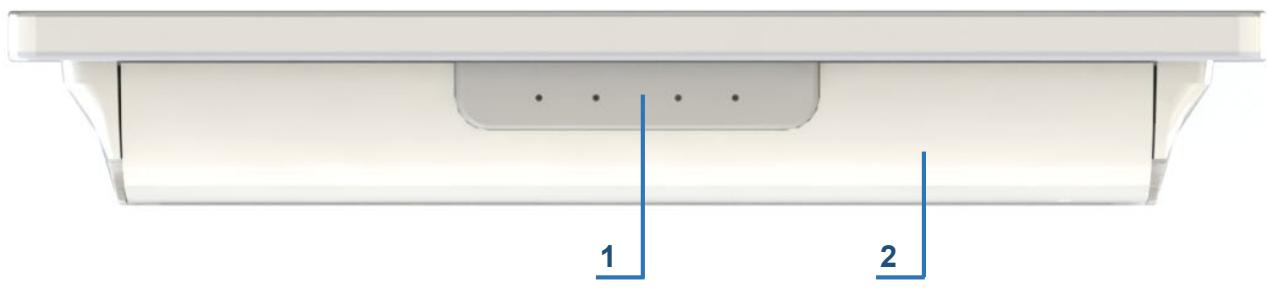
At the bottom of the device, behind a cover, there are various I/O interfaces allowing connections of the device towards other systems/devices via respective cables and/or connectors. The cable cover protects the interfaces behind it against fluid ingression and, if mounted correctly, provides IP54 ingress protection (against dust ingress and spray water from any angle). The grey plastic elements in the cover allow cables to pass through while maintaining the ingress rating.
![1\n2](.mlc-s-series-50m-1z363-1010-11/05817014859612f68c5be1827ad60578b3b43605f7792eae8fe9aa1aeb4b8978.jpg)

Figure 2: Bottom view with cable cover mounted

1. Cable pass-through
2. Cable cover

![The image shows a black circle containing a black lowercase letter 'i' in the center. The letter is composed of a vertical stem and a circular dot above it.](.mlc-s-series-50m-1z363-1010-11/0a71358153ef6b7148bec5762f9c4d9310ddc9b75dad237d1b1e08cbfdd3b9b5.jpg)

# NOTICE

To operate the device, the cable cover must always be installed to ensure protection against fluid ingress and disturbance by electromagnetic emissions. Please observe the safety instructions in Section 4.2.3.

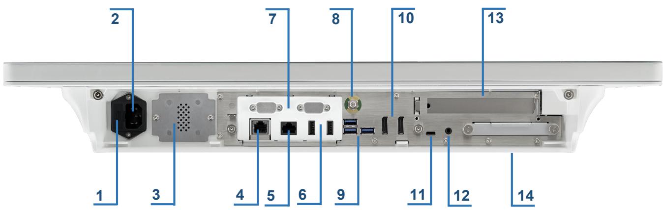
Underneath the cable cover you will find the device interface ports (see Figure 3 below). These interfaces are identical on all models of the MLC-S series.
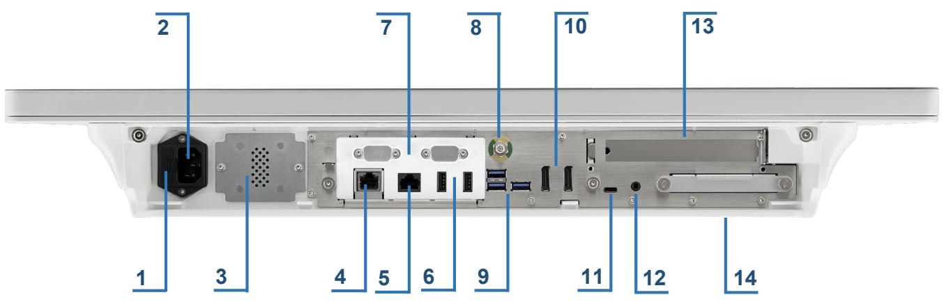
![2\n7\n8\n10\n13\n1\n3\n4\n5\n6\n9\n11\n12\n14](.mlc-s-series-50m-1z363-1010-11/9cb6dad4670bdde94286c51ad1e9a44cd072b763379b90a4f98a6b8b8ef30947.jpg)

Figure 3: Bottom view illustrating device interfaces (cable cover removed)

1. Fuse bracket with 2 fuses (5x20mm 2.0A 250V (T), see Section 6.5.3 for details)
2. Mains connector (for non-heating device, socket conforms to IEC 60320-1 type C14) for AC mains supply
3. Speaker
4. GbE network interface, galvanically isolated up to 4 kV (RJ45 connector)
5. 2.5G network interface (not isolated)
6. 2x USB 2.0 (galvanically isolated version, optional)
7. Optional: 2x serial ports COM1/COM2, galvanically isolated up to 4 kV (D-Sub connector 9 pins)
8. Potential equalization connecting pin (∅ 6mm)
9. 3x USB 3.0 (blue)
10. 2x DisplayPort (for connection to external displays/monitors)
11. USB Type-C connector with Intel® Thunderbolt™ support
12. Digital microphone; input interface for external digital microphone
13. PCIe card expansion slot (If you’d like to change your configuration, please contact your ADLINK representative for options)
14. Cover for removable 2.5” SSD (128 GB standard, other capacities or HDD optional)

#  NOTICE

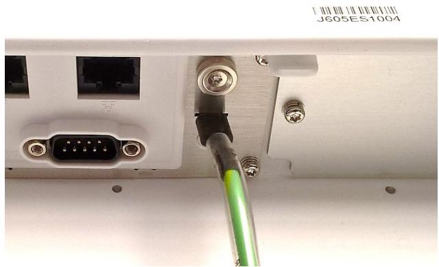
(Pos. 8) Potential equalization connecting pin (∅ 6mm), according to DIN 42801 with color coding yellow/green for connecting a potential equalization cable

The equalization pin of the device must be connected to the potential equalization panel of the respective OR theatre (see IEC 60601-1/EN 60601-1 or the respective national standards).

# 5.2.2 Operational elements

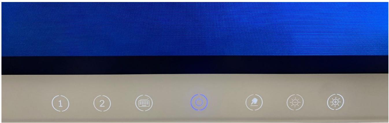
All MLC-S series devices have a row of capacitive touch buttons at the lower side, under the display’s front, with seven function buttons enabling direct control of some device functions.
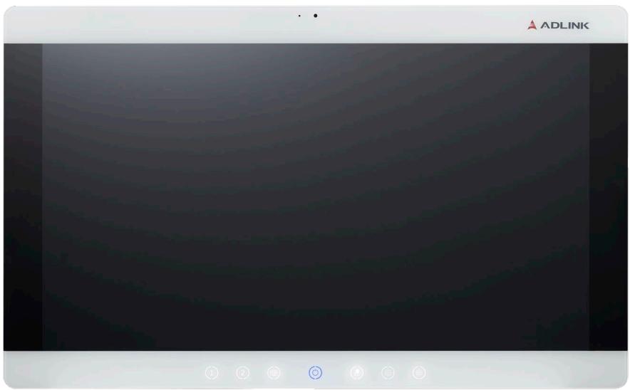
![ADLINK](.mlc-s-series-50m-1z363-1010-11/9a8a9a267e41b2ad7ec48d31b0f2395ea1104e7e674a95bbc2fa6da427536d1e.jpg)

Figure 4: Capacitive touch buttons

The functional buttons on the front panel of the device are capacitive touch buttons and are activated by the user’s finger touching one of the backlit areas. There is no mechanical action with these capacitive touch buttons.
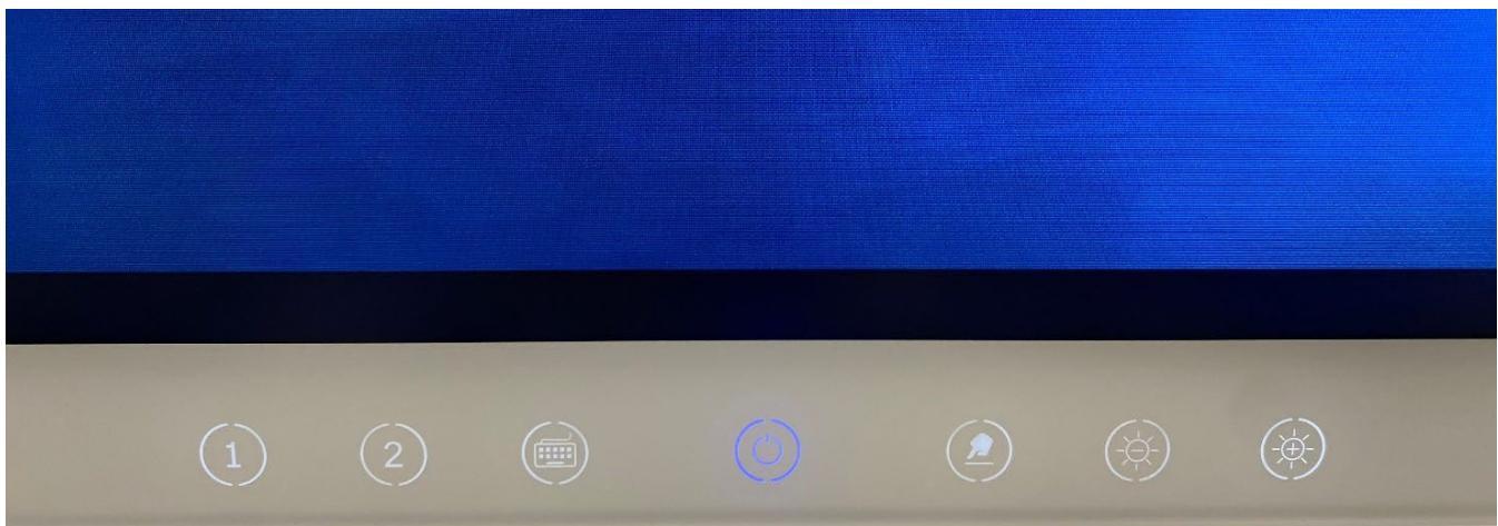
![①\n②\n③\n④\n⑤\n⑥](.mlc-s-series-50m-1z363-1010-11/6dbead648076a42272cc0b6f06e708383ac6158772fa59398de6169fe7777922.jpg)

Figure 5: MLC-S in operation; front touch buttons backlit

When the device is powered on, the front panel touch buttons are backlit to indicate the touch-sensitive areas. There are six function buttons backlit in white and the Standby (On/Off) button at the row’s center is backlit blue or orange, depending on the operating mode of the device.

# 5.2.3 Overview front panel buttons
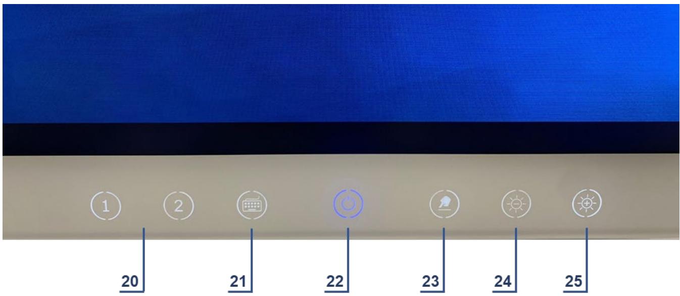
![| Category | Value |\n|---|---|\n| 1 | 20 |\n| 2 | 21 |\n| | 22 |\n| | 23 |\n| | 24 |\n| | 25 |](.mlc-s-series-50m-1z363-1010-11/e8e98e2fb71d26558a40ada08984a64142995e685c7f311271c7c8f292e7fcc3.jpg)

Figure 6: Front touch buttons overview

20. 2x function buttons reserved for future use
21. Call Onscreen Keyboard
22. Standby (On / Off) button for turning on / off the device
23. Touchscreen Enable / Disable button (for cleaning)
24. Display Brightness Decrease button
25. Display Brightness Increase button

When the device is powered on, the front panel touch buttons are backlit to indicate the touch-sensitive areas. There are six function buttons backlit in white and the Standby (On / Off) button at the row’s center is backlit blue or orange, depending on the operating mode of the device.

# 5.2.4 Functions of the front panel buttons

# Standby (On / Off) button (22) and status indication

When the device is supplied with power via the mains cable, the Standby (On / Off) button (22) in the center of the front row is illuminated orange to indicate standby status. To turn on the device, touch the Standby (On / Off) button (22) for at least 2 seconds until it illuminates blue and the device will begin the boot routine.
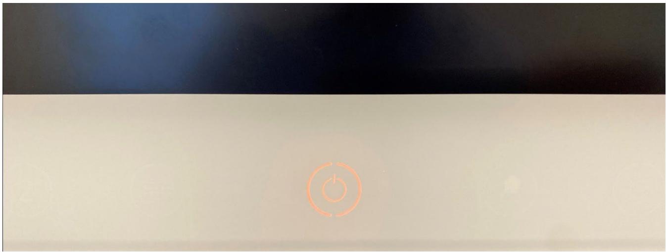
![Pure electrical circuit lines without any symbols](.mlc-s-series-50m-1z363-1010-11/9d488faff08cf99f00009b41c54a825cf304b985b2bef38af4177893ccbcf65b.jpg)

Figure 7: Standby status indication

![①\n②\n③\n④\n⑤\n⑥](.mlc-s-series-50m-1z363-1010-11/07269cd1125a8eae09a3fdaaded0d2c591119898819b4d957491cab4193886b4.jpg)

Figure 8: Power-on status indication

To turn off the device, either:

use the shutdown procedure of the operating system, or
• touch the Standby (On/Off) button (22) for at least 2 seconds.

In both cases, the device is set into standby mode; the blue indication of the Standby (On/Off) button (22) turns off and changes to orange indication.

![The image displays a black circle containing a lowercase black letter 'i' centered within it on a white background.](.mlc-s-series-50m-1z363-1010-11/bc9993ca168359db0d48a7bf9a202e74e3ef50927f5a3488cbebaf23d1845808.jpg)

# NOTICE

While switching off the device via the Standby (On / Off) button (22), do not touch it for more than approx. 7 seconds. Doing so forces a hard shutdown of the device, followed by a restart / boot routine. This may cause a loss of data if it has not been saved or finished processing before shutdown.

![The image shows a black circle containing a bold, lowercase letter 'i'. It is the standard symbol for information.](.mlc-s-series-50m-1z363-1010-11/e6944a9e2f6cb2ea796a13b181e554ba1fb0466a84e9184b345814ac3bcd85ca.jpg)

# NOTICE

To switch off the device completely, it must be disconnected from the mains supply by disconnecting the mains cable. To prevent any data loss, this disconnecting should be done only with the device already in standby mode, i.e. the orange indication is illuminated and the blue indication is off.

# Display Brightness Increase (25) and Decrease (24) buttons

If the device is turned on, the brightness of the display can be increased or decreased by touching the Brightness Increase (25) or Decrease (24) buttons continuously or briefly several times until the desired brightness of the display is achieved.

When the display brightness is being adjusted, a green segmented indicator bar is displayed in the lower right corner of the display, on top of the operating system and program application graphics (see figure below). The green indicator bar shows the display brightness setting graphically as well as a percentage value.

![91%\n4:39 PM\n3/4/2021](.mlc-s-series-50m-1z363-1010-11/b6e1524c52f75d64f819617820df87757f909d0ecb43dd51cc55a517472d5a33.jpg)

Figure 9: Display brightness indicator

To increase the display brightness again, the Brightness Increase button (25) must be activated briefly several times or continuously until the desired display brightness is achieved.

![The image displays a black circle enclosing a black lowercase letter 'i' in the center.](.mlc-s-series-50m-1z363-1010-11/51cf553b561fbb97fcfee435eab00af94808a8a4addabf94071c858e5f431b91.jpg)

# NOTICE

The Display Brightness Decrease button (24) can only decrease the brightness down to 3% of the maximum brightness to avoid the user assuming by mistake the device being switched off when setting it to a very low brightness level. With the display dimmed to the lowest 3% brightness level, minor contour shadows will remain visible.

# Touchscreen Enable / Disable button (23)

This function is especially helpful for cleaning and disinfecting the front side of the device while it is in operation. Activating the Touchscreen Enable / Disable button (23) turns the touchscreen off and on again, allowing the device’s front panel to be cleaned without interrupting active applications.

To disable the touchscreen function, the Touchscreen Enable / Disable button (23) must be touched for at least 5 seconds until a red symbol appears in the lower right corner of the display (see figure below). This 5-second time delay prevents the user from deactivating the touchscreen unintentionally.
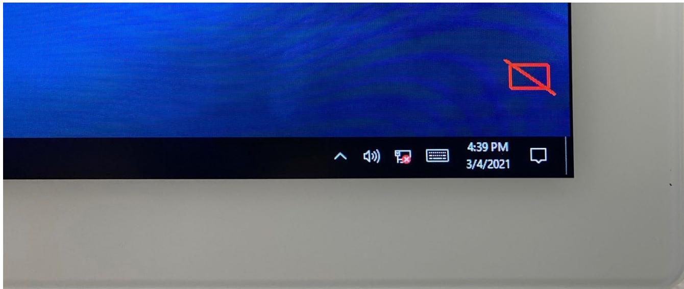
![4:39 PM\n3/4/2021](.mlc-s-series-50m-1z363-1010-11/9aaa52c50447ab2d361a4d50d6f3d0763102ac809b9a89525f66f1f494cc8051.jpg)

Figure 10: Touchscreen disabled indicator

To reactivate the touchscreen functionality, the Touchscreen Enable/Disable button (23) must be activated for at least 5 seconds until the red symbol in the lower right corner of the display is no longer visible, after which a blue confirmation rectangle appears in the same location for a brief period of time.
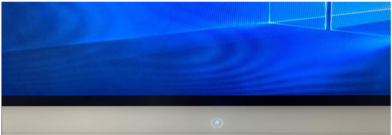
![Blue abstract geometric pattern with diagonal lines and a small circular icon at the bottom (no text or symbols)](.mlc-s-series-50m-1z363-1010-11/f81035057df1142ae91b27d882cf3609a43e630dbb5e913d01f9e9245b0bdd83.jpg)

Figure 11: All front touch buttons disabled except for the Touchscreen Enable/Disable button

Because of all front panel function buttons are capacitive touch type, all other front panel touch buttons are disabled when the touchscreen is disabled to avoid undesired activation of functions while cleaning the device. The backlight illumination of the other touch buttons (20) to (22) and (24) and (25) are also turned off to indicate that these keys are disabled for the user, until the touchscreen is enabled again.

# Call Onscreen Keyboard button (21)

The MLC-S device features an onscreen keyboard for text input via the touchscreen without the need for an external hardware keyboard. The touchscreen keyboard is displayed on top of applications in process.
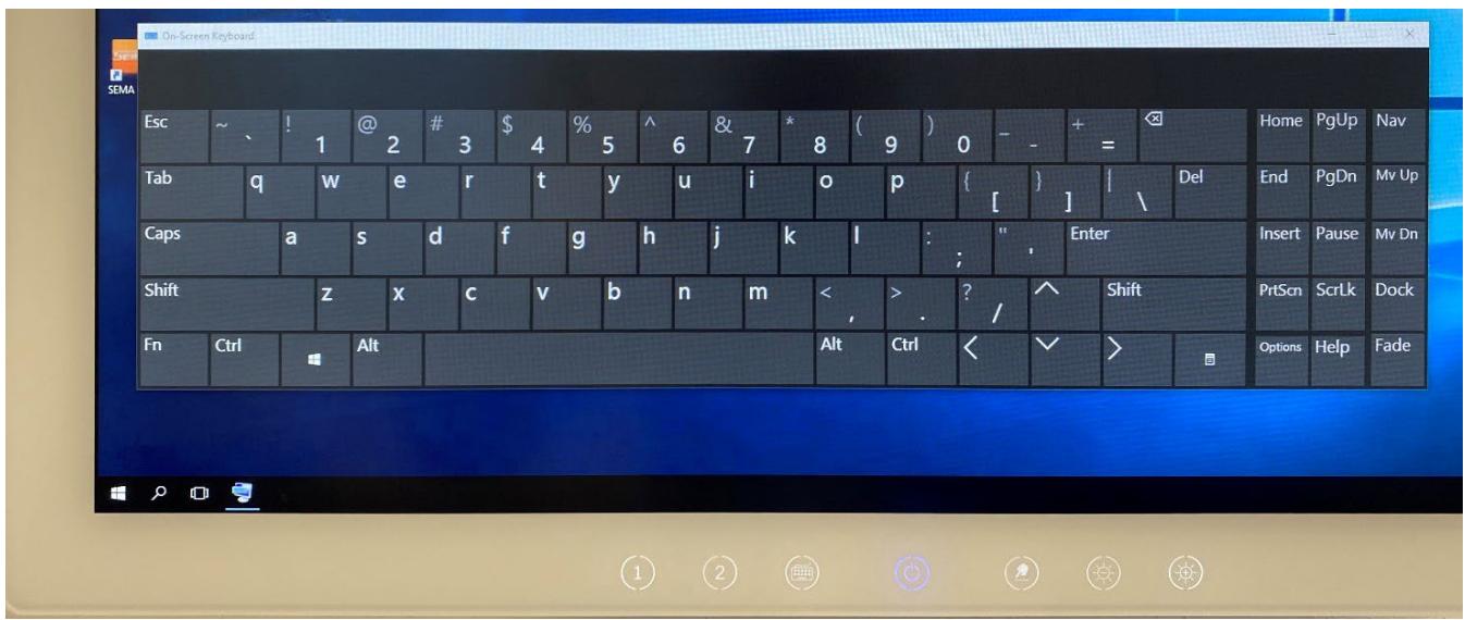
![Esc ~ 1 @ 2 # 3 \$ 4 % 5 ^ 6 & 7 * 8 ( 9 ) 0 - - + = Home PgUp Nav\nTab q w e r t y u i o p { } | Del End PgDn Mv Up\nCaps a s d f g h j k l : ' , Enter Insert Pause Mv Dn\nShift z x c v b n m ( , ) ? / ^ Shift PrtScn Scrlk Dock\nFn Ctrl Alt Alt Ctrl ( ✓ ) Options Help Fade](.mlc-s-series-50m-1z363-1010-11/8542acfe919890f2562231bd037e99e99bc3b9371f56c77e8e98325c2bf2ece5.jpg)

Figure 12: Onscreen keyboard activated

In the Windows OS, the onscreen keyboard can be called up by swiping the small tab at the left edge of the display onto the screen with a finger. For users wearing a double layer of protective gloves who may find this swipe motion inconvenient or difficult, the Call Onscreen Keyboard button (21) can be activated to display the onscreen keyboard.

Activating the Call Onscreen Keyboard button (21) again will close the keyboard again. Depending on the OS being used, tapping the “close window” function (upper right corner of the window) on the touchscreen of the display is a possible alternative.

# Function buttons reserved for future use (20)

These two front panel touch buttons (20) marked as “1” and “2” have no function by default at delivery.

By customer request, these touch buttons can be programmed for specific functions before shipment of the device. Please contact your ADLINK representative for further information (note: possible configurable functions for these keys are highly dependent on the OS and the specific device configuration).

Examples of possible programming of these buttons (if supported by OS and device configuration):

• One button is programmed as a direct “shortcut” to the Windows F1 function, i.e. calls Windows user help.
• One button is programmed to activate a key combination triggering the Windows function for “lock computer”

![The image displays a black, lowercase letter 'i' centered inside a black circle on a white background.](.mlc-s-series-50m-1z363-1010-11/e792eb12411b193c66b72f7eefd2d0e981edc086599caed8ba975f816652fe79.jpg)

# NOTICE

The customer-specific requirement to individually program the free functional buttons (20) must be specified before ordering the device and must be approved by ADLINK’s MLC-S product manager.

# 5.2.5 Package contents

Please verify that the following item is included in the package:

• MLC-S device

# 5.3 Cleaning and Disinfection

It is very important that you regularly clean and disinfect your MLC S device with a suitable cleaning or disinfecting agent. The cleaning and disinfection of the device may only be performed by a hygiene specialist or a person instructed by the hygiene specialist. Only ADLINK-tested and approved cleaning agents may be used for cleaning or disinfection. If an agent is not listed in this manual, it should NOT be used as other components could be changed or damaged.

ADLINK recommends periodic product cleaning and disinfection. The following applies to your MLC-S device only. For cables, sensors and other peripheral items, follow the corresponding cleaning instructions of these accessories.

Gently wipe off any dirt on the cabinet or panel surface with a soft cloth soaked in a small amount of deionized water or one of the chemicals listed below. Use a soft, lint-free cloth to wipe the device front until all liquid films are removed. If required, exposure times must be observed for disinfection.

For cleaning the glass / touch front of the device, a simple household glass cleaner available in consumer markets may be used. Use a soft, lint-free cloth to wipe the device front until all liquid films are removed.

Cleaning agents that may be used for disinfection (concentration information per g cleaning solution):

Glutaraldehyde (max. 2,5 mg/g Glutaral)
• Biguanide (max. 2 mg/g Glucoprotamine)
• Aldehyde (max. 3.75 mg/g Glyoxal / 4.75 mg/g Glutaral)
• Peroxides (max. 4 mg/g Peracetic acid)
Quaternary ammonium (max. 5 mg/g Benzalkonium chloride / 2.5 mg/g didecyldimthylammonium chloride)
• 2-Propanol (60%)

Thoroughly follow the specifications and usage guidelines of the manufacturers of the disinfecting solutions for cleaning your device.

Disinfectants and other agents can lead to material damage of the device, especially if the surface has prior damage (e.g. an accidentally caused scratch) and / or especially over long-term use of these type of disinfectant solutions.

![The image displays a black circle containing a centered, black lowercase letter 'i'.](.mlc-s-series-50m-1z363-1010-11/5600ba68d99aa8e58eb3c70eb60d86e0f7c8222f19511355c0dce921b6e65c5a.jpg)

# NOTICE

Contaminated items must not be returned without prior written agreement.

# 5.3.1 Safety instructions for cleaning and disinfection of the device

![The image displays a standard warning symbol featuring a black outline of a triangle on a white background. Inside the triangle is a black exclamation point.](.mlc-s-series-50m-1z363-1010-11/ba6b58816a24370597d80ecaaec3df8b7fd48b060c4e79da68fb9d85f3552a0e.jpg)

# WARNING

Risk of electrical shock to the user caused by presence of potentially conductive liquids:

Prior to any cleaning and disinfection procedure, the mains cable must be disconnected from the mains supply at all times.

# AVERTISSEMENT

Risque de choc électrique pour l'utilisateur en raison de la présence de liquides potentiellement conducteurs :

Avant toute procédure de nettoyage et de désinfection, le câble d'alimentation doit toujours être déconnecté du réseau électrique.

![The image displays a standard warning symbol: a black equilateral triangle containing a centered, vertical black exclamation mark against a white background.](.mlc-s-series-50m-1z363-1010-11/979e7a7faf40b58a3450b95e791dd447a74f4165a4761615ee22ff2960ee81d6.jpg)

# WARNING

Risk of unintended operation of the device if equipped with touchscreen:

Before cleaning and/or disinfecting your device, turn off the touchscreen via the Touchscreen Enable/Disable button (23) (see Section 5.2.2 Operational elements).

# AVERTISSEMENT

Risque de fonctionnement involontaire de l'appareil s'il est équipé d'un écran tactile :

Avant de nettoyer et/ou de désinfecter votre appareil, désactivez l'écran tactile à l'aide du bouton d'activation/désactivation de l'écran tactile (23) (voir section 5.2.2 Éléments opérationnels).

![The image displays a black outline of an upward-pointing triangle. Inside the triangle, centered, is a black exclamation mark.](.mlc-s-series-50m-1z363-1010-11/a45f7487c3f2f2725e2c3c649afe4195b0ce38dea89fe5b2cf858e096e672439.jpg)

# WARNING

Risk of electrical shock to the user and risk of damage to the device caused by inappropriate processing procedures:

The device is not suited for any kind of mechanical and/or thermal decontamination procedures such as autoclaving, steam sterilization, etc.

# AVERTISSEMENT

Risque de choc électrique pour l'utilisateur et risque d'endommagement de l'appareil causé par des procédures de traitement inappropriées :

L'appareil n'est pas adapté aux procédures de décontamination mécanique et/ou thermique telles que l'autoclavage, la stérilisation à la vapeur, etc.

![The image displays a black-outlined triangle pointing upwards on a white background. Inside the triangle is a black exclamation mark. The symbol is framed by thick black vertical bars on the left and right sides.](.mlc-s-series-50m-1z363-1010-11/8ee74c0d8da1a5e866a3a215d59ca1e54cbb68b37547b517cffbfc9d756bf5e9.jpg)

# WARNING

Risk of electrical shock to the user and risk of damage to the device caused by overdosed amounts of liquids:

Never apply heavy amounts of liquids to your device nor immerse it into liquids of any substance. Be conservative with all cleaning and disinfection solutions used to clean the device and never apply liquids into given openings such as I/O interface ports.

# AVERTISSEMENT

Risque de choc électrique pour l'utilisateur et risque d'endommagement de l'appareil causé par des quantités excessives de liquides :

N'appliquez jamais de grandes quantités de liquides sur votre appareil et ne l'immergez pas dans des liquides de quelque substance que ce soit. Soyez prudent avec toutes les solutions de nettoyage et de désinfection utilisées pour nettoyer l'appareil et n'appliquez jamais de liquides dans les ouvertures telles que les ports d'interface E/S.

![The image displays a black-outlined triangle pointing upwards. Inside the triangle is a large, black exclamation point centered vertically and horizontally against a white background.](.mlc-s-series-50m-1z363-1010-11/1f17ac5c333b8216fc03b12062ffd89d1c7402031d63f8e4a2dda412b8017df1.jpg)

# CAUTION

Risk of damage to the device caused by usage of abrasive materials:

Your ADLINK device provides a surface finishing that is sufficiently protected during use within the intended purpose. However, do not use any abrasive materials for cleaning processes, e.g. brushes, sponges, or other objects with hard and/or rough characteristics. Doing so may lead to damage to the front side, the touch surface or the housing surface. Never use e.g. sponges made of metal grafts or similar, nor any sharp or hard objects like knives, pencils etc. for cleaning purposes. Thoroughly follow all instructions provided in this section.

# ATTENTION

Risque d'endommagement de l'appareil dû à l'utilisation de matériaux abrasifs :

Votre appareil ADLINK présente une finition de surface qui est suffisamment protégée lors d'une utilisation conforme à l'usage prévu. Toutefois, n'utilisez pas de matériaux abrasifs pour le nettoyage, par exemple des brosses, des éponges ou d'autres objets aux caractéristiques dures et/ou rugueuses. Vous risqueriez d'endommager la face avant, la surface tactile ou la surface du boîtier. N'utilisez jamais d'éponges en métal ou similaires, ni d'objets pointus ou durs tels que des couteaux, des crayons, etc. pour le nettoyage. Suivez scrupuleusement toutes les instructions fournies dans ce chapitre.

# 6. Specialized Staff Information

The information in this chapter is directed to specialized staff (e.g. IT administrator or employees in the IT department) requiring broader technical information beyond the simple operation / handling of the device.

6.1 Functional Block Diagram
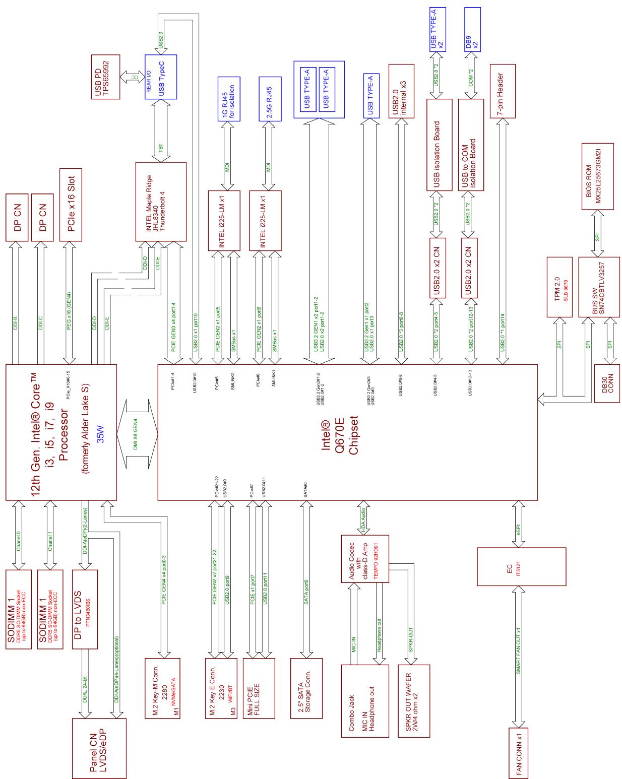
![Flowchart](.mlc-s-series-50m-1z363-1010-11/5f1fb68c17d89970bfa161ab5af033b1c91aff938fa4ecf13fd7593448239643.jpg)

Figure 13: MLC-S series functional block diagram

# 6.2 Technical Data of Main System Components

<table><tr><td>Component</td><td>Technical Data</td></tr><tr><td>Processor</td><td>Intel® CoreTM i3-12100TE, 2.10GHz, max 4.00GHz, 4 cores with HTT, 12MB Smart Cache Intel® CoreTM i5-12500TE, 1.90GHz, max 4.30GHz, 6 cores with HTT, 18MB Smart Cache Intel® CoreTM i7-12700TE, 1.40GHz, max 4.60GHz, 12 cores with HTT, 25MB Smart Cache Intel® CoreTM i9-12900TE, 1.10GHz, max 4.80GHz, 16 cores with HTT, 30MB Smart Cache</td></tr><tr><td>Chipset</td><td>Intel® Q670E Chipset</td></tr><tr><td>Memory</td><td>Up to 64 GB DDR5 4800 SODIMM in 2 sockets</td></tr><tr><td>Graphics</td><td>Intel® UHD Graphics 770 1.45 GHz</td></tr><tr><td>Mass Storage</td><td>M.2 NVME SSD and/or 2.5” SSD/HDD at SATA 6Gb/s128 GB SSD is standard equipment (please contact your ADLINK representative for other capacities)2.5” SSD/HDD drive bay is externally accessible by administrator</td></tr><tr><td>Audio Codec</td><td>Intel® HD Audio</td></tr><tr><td>OS Compatibility</td><td>Intel® x64 micro architecture conform</td></tr></table>

# 6.3 Detailed System Components

![2\n7\n8\n10\n13\n1\n3\n4\n5\n6\n9\n11\n12\n14](.mlc-s-series-50m-1z363-1010-11/cc7e02ee1baf1b6a5a3e0acf053f50f2c463cc266f39ef5898114bfd7b01c1ef.jpg)

Figure 14: Bottom view illustrating device interfaces

<table><tr><td colspan="2">Device Features</td></tr><tr><td>Display</td><td>Full HD (1920x1080, 16:9), 16.7M colors,brightness 21.5" with 500 cd/m2 (typ.); 23.8" with 600 cd/m2 (typ.) from panelviewing angle v/h 178°/ 178°</td></tr><tr><td>Touchscreen</td><td>21.5"/23.8" 10-point, multi-touch Projected Capacitive (PCAP)</td></tr><tr><td colspan="2">Device Features (cont'd)</td></tr><tr><td>Functional buttons, LEDs</td><td>Seven PCAP-type functional buttons at the lower side of the front panel consisting of the Standby (On/Off) button with blue/orange backlight and six functional buttons with white backlight (pos. 21-25 in Figure 6) for - display brightness increase/decrease - touchscreen enable/disable (for front cleaning purpose) - calling the onscreen keyboard - two customizable functions</td></tr><tr><td>AC mains supply</td><td>Internal, wide-range power supply (100...240V~, 50/60Hz); Device protection: fuse bracket with 2 fuses 5x20mm T 2.0A H 250 V, (pos. 1)</td></tr><tr><td colspan="2">Interfaces</td></tr><tr><td>Expansion slot</td><td>Slot for PCIe x16 add-on cards (pos. 12) Please contact your ADLINK representative for available options.</td></tr><tr><td>Mass storage slot</td><td>Covered slot for removable 2.5" SSD/HDD (pos. 14)</td></tr><tr><td>Audio</td><td>1x digital microphone (pos. 12) 1x speaker (pos. 3)</td></tr><tr><td>Display outputs</td><td>2x DisplayPort outputs; transferable resolution max. 4096x2304, 60Hz (pos. 10)</td></tr><tr><td>USB type-C</td><td>USB type-C connector with Intel® ThunderboltTM support</td></tr><tr><td>USB 3.0 ports</td><td>3x USB 3.0 SuperSpeed (5Gbit/s) interfaces (blue), compatible with USB 1.1 low (1.5Mbit/s), full (12Mbit/s) and USB 2.0 high speed (480Mbit/s) (pos. 9)</td></tr><tr><td>USB 2.0 ports</td><td>2x USB 2.0 high speed (480Mbit/s), compatible with USB 1.1 low (1.5Mbit/s) and full speed (12Mbit/s); optional galvanic isolation up to 4 kV (pos. 6)</td></tr><tr><td>Network</td><td>1x GbE 10/100/1000 Mb/s, 4kV isolated (pos. 4) 1x 2.5G 10/100/1000/2500 Mb/s (pos. 5)</td></tr><tr><td>COM serial ports (optional)</td><td>COM1 &amp; 2: 2x RS-232 serial ports, max. 256kbps transfer rate; galvanic isolation up to 4 kV (pos. 7) available as optional equipment; on demand, up to 6 serial ports with galvanic isolation are possible as optional equipment if ordered prior to delivery.</td></tr><tr><td colspan="2">Miscellaneous</td></tr><tr><td>Device display configuration</td><td>Standard display orientation in landscape orientation; on customer request, display in landscape and portrait orientation available; in both orientation configurations, the functional buttons for directly accessible device functions (see section below) are located at the bottom side of the display and are being automatically activated by rotating the MLC-S device</td></tr></table>

# 6.4 Optional Built-In Components

Devices may be ordered with several built-in components options. Retrofit and update of devices already delivered on site is generally not possible. For information about possible retrofit or update, please contact your ADLINK representative.

# 6.4.1 Serial ports with galvanic isolation

For configurations including two, four, or six COM serial ports, all serial ports have a galvanically isolated design for isolation of up to 4kV.
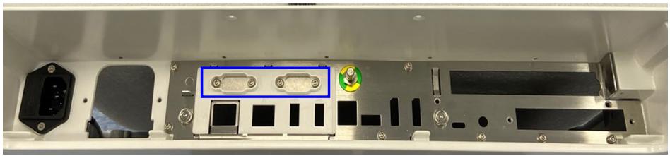
![Interior view of a device chassis showing internal components and a blue highlight on the front panel (no text or symbols visible)](.mlc-s-series-50m-1z363-1010-11/b3b6cdbb0f68b93497b23305125870db260cd9678eed7d3f598cce19ed825987.jpg)

Figure 15: Optional components, two COM ports

Both serial ports (D-Sub 9 sockets) and the surrounding bracket are mounted into the isolating element also carrying the isolated Ethernet ports.

On demand, up to 3 pairs of 2 RS232 serial ports each with 4kV galvanic isolation are possible as optional equipment, if ordered prior to delivery.

![The image features a black lowercase letter 'i' centered inside a black circle. This symbol is set against a white background and is flanked by thick vertical black bars on the left and right sides.](.mlc-s-series-50m-1z363-1010-11/e5d124543731cb39468f980f1c3f40aa8a5d6b1dad1f10d9cac395e83d6ca423.jpg)

# NOTICE

COM 1 and COM 2 cannot be ordered in conjunction with the isolation option of the USB 2.0 ports (see Section 6.4.3). COM 3 and COM 4 cannot be used in conjunction with the PCIe riser card option (see Section 6.4.5).

# 6.4.2 WLAN/Bluetooth module

If ordered prior to delivery, the devices can be optionally equipped with an IEEE 802.11ac, Dual Band, 2x2 Wi-Fi (PCIe) + Bluetooth 4.0 (USB) module with external antenna(s). The module itself is inserted into an interface on the mainboard.

The used radio frequency bands are 2.4 GHz and 5 GHz depending on settings. Derived from these settings, the bandwidth is 20/40/80 or 160 MHz. Additionally, the transmit power is max. 100mW for the 2.4 GHz band and max. 200mW for the 5 GHz band.

For detailed specifications, please contact your ADLINK representative.

# 6.4.3 USB 2.0 ports with galvanic isolation

If required, the USB 2.0 ports (pos. 6 in Section 6.3) on the device can be ordered ex-works to provide galvanic isolation up to 4kV. To provide these isolated USB 2.0 ports, an additional circuit board, containing all necessary components is mounted onto the mainboard. These ports cannot be visually distinguished from standard USB 2.0 ports. Therefore, these ports are then marked with a label as shown in the following figure:
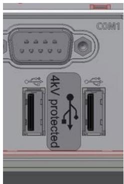
![COM1\n4kV\nprotected](.mlc-s-series-50m-1z363-1010-11/fcb06576346d758e15bd7b492848f5586b4224259da93faa37899663bf3165ab.jpg)

Figure 16: Marking label of galvanically isolated USB 2.0 ports with USB symbol and inscription

# 6.4.4 Device configuration with display in portrait orientation (rotation kit)

If required and ordered in advance, the device can be configured to support the display in portrait orientation in addition to landscape orientation. Then, the front panel function buttons will be automatically activated at the bottom side of the display when rotating the MLC-S.
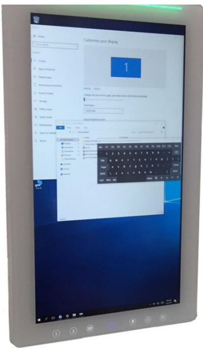
![Customize your display\n1\nName: \nSize: 25%\nDescription: \nChange the size of user, app, and other items. SMS Recommendation\nDescription: \nAdd user to\nAbout ***** level\nMicrosoft\nApple for setting\nAdd\nAdd User\nAdd User\nAdd User\nAdd User\nAdd User\nAdd User\nAdd User\nAdd User\nAdd User\nAdd User\nAdd User\nAdd User\nAdd User\nAdd User\nAdd User\nAdd User\nAdd User\nAdd User\nAdd User\nAdd User\nAdd User\nAdd User\nAdd User\nAdd User\nAdd User\nAdd User\nAdd User\nAdd User\nAdd User\nAdd User\nAdd User\nAdd User\nAdd User\nAdd User](.mlc-s-series-50m-1z363-1010-11/94afb2da34ac314bb7419ab10cf442d3478d16d9d90daf02d7e27ece0672ea49.jpg)

Figure 17: MLC-S in portrait orientation

# 6.4.5 PCIe Riser Card

The PCIe x16 slot of the MLC-S CPU board can be used to install a PCIe add-on card in combination with a PCIe riser card. This configuration requires prior approval by ADLINK and must be installed at an ADLINK production facility.

Please contact your ADLINK representative for further details.

# 6.4.6 RFID

The MLC-S can be equipped with an RFID reader supporting standard ISO 15693 transponders. Please contact your ADLINK representative for further information.

# 6.5 Maintenance and Service

# 6.5.1 General service intervals

ADLINK devices do not require servicing or maintenance at regular intervals due to the usage of high-quality industrial standard components. Devices, panel computers, or monitors rarely require servicing when used for their intended purpose.

If your ADLINK system does not operate properly and needs to be returned for servicing, please refer to the instructions in the Sections 3.4.2 and 5.3 above.

In the following Sections 6.5.2 to 6.5.4 you will find instructions for initial device installation and replacing components by specialized staff, if necessary.

# 6.5.2 Initial device installation/cable cover handling

The device is delivered with the cable cover preinstalled at the rear/bottom of the device. For the initial installation, the mains supply cable and, if required, cables for further external accessory components (e.g. keyboard, mouse), must be fed through the cable cover to connect them to the device.

To connect cables to the device, proceed as follows:

1. Place the MLC-S device with the front side facing down onto a stable working platform protected by a soft layer. Remove the cable cover (Pos.1) at the bottom of the device. The cable cover is fixed by strong magnets located at several points in the bottom side of the device housing. To remove the cable cover, simply grasp it laterally at the housing cutouts left and right, or at the cover’s upper edge and pull the cover down from the housing.
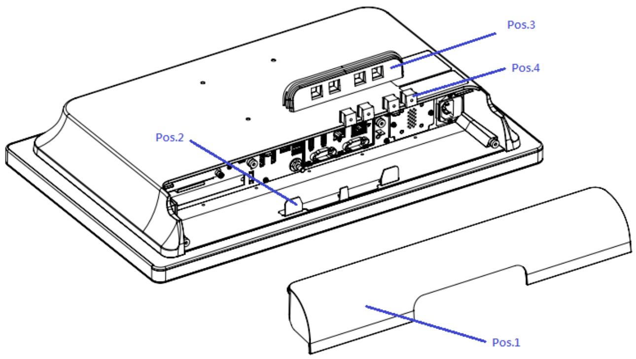
![Pos.1\nPos.2\nPos.3\nPos.4](.mlc-s-series-50m-1z363-1010-11/6415ae22daf267f05c9e5422925c71f967753fce86d93963a1b9192732fbb5ed.jpg)

Figure 18: Cable cover installation

2. Feed the cables to be connected through the insert pieces (Pos.4) and connect the cables to the respective connectors in the I/O bezel. Please make sure that you choose the suitable insert piece with the appropriate opening diameter for each cable (the bushing set includes a selection of different insert pieces).
3. Insert the pieces with the cables into the cable bushing (Pos.3). Fill a gap which is not used for a cable with an insert without opening.
4. Now push the completed bushing over the mounting plate of the device (Pos.2).
5. Connect the mains supply cable to the mains connector of the device.
6. If the yellow/green protective earth cable inside of the cable cover has been disconnected during installation, reconnect it to the contact provided at the I/O interface bezel of the MLC-S device as shown in Figure 19 to Figure 21 below.
7. Finally, fix the cable cover to the device with “hooking” the cover’s upper edge to the housing first and then tilt the cover towards the housing, until the magnets catch it safely.
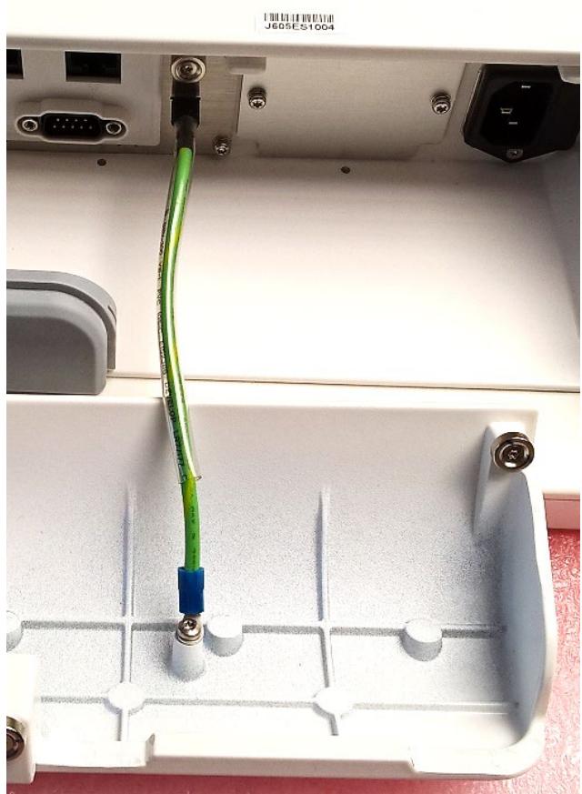
![Close-up of a white electronic device's internal components, showing a green cable inserted into a plastic tray with metal contacts (no text or symbols visible)](.mlc-s-series-50m-1z363-1010-11/203d6455ab6c75ee04c573107f76bdde6bddb1058e4051a4ed55039ef26e054d.jpg)

Figure 19: Protective earth strap

![Close-up of a device rear panel showing an RJ605ES1004 cable inserted into a port, with no visible text or symbols on the main components.](.mlc-s-series-50m-1z363-1010-11/baf78c1c9fdf1f7001ae2b657215540805fc4c3b2730f6ed8cf33db1e54a6297.jpg)

Figure 20: Protective earth strap, I/O interface bezel mounting point
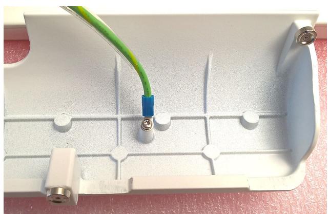
![Close-up of a white electronic device casing with a green cable inserted into the top panel, showing no text or symbols.](.mlc-s-series-50m-1z363-1010-11/ec77ea69d16b6dfc05d4161aa65e1c481a90a8c54dc329d11ff9e46174111137.jpg)

Figure 21: Protective earth strap, cable cover mounting point

# 6.5.3 Fuse replacement for the internal power supply (AC mains supply)

![A black-outlined triangle containing a large exclamation point in the center, serving as a generic warning or caution symbol.](.mlc-s-series-50m-1z363-1010-11/189981a0f78bb26223239c9c8bcc81850a5f7e9d04ea412719b47f8c93e47806.jpg)

# DANGER

Risk of electrical shock to the user, patient or others as well as risk of property damage and damage to the device caused by hazardous voltage:

Prior to replacing the internal power supply fuses, the device must be disconnected from the mains supply by unplugging the mains cable from the mains outlet.

# DANGER

Risque de choc électrique pour l'utilisateur, le patient ou d'autres personnes, ainsi que risque de dommages matériels et d'endommagement de l'appareil en raison d'une tension dangereuse :

Avant de remplacer les fusibles internes de l'alimentation électrique, l'appareil doit être déconnecté du réseau électrique en débranchant le câble d'alimentation de la prise secteur.

![A black-bordered white triangle centered on a black background, containing a black exclamation point.](.mlc-s-series-50m-1z363-1010-11/29dd61576f0a48f452e628291583b31a3d06eb6c25c069556c8ea4457a1df256.jpg)

# WARNING

Risk of fire and/or risk of damage to the device caused by inappropriate fuse rating:

The device fuses must only be replaced with fuses of the same rating and type. Carefully observe the device labelling and see also Section 8.4.2.

# AVERTISSEMENT

Risque d'incendie et/ou risque d'endommagement de l'appareil en raison d'un calibre de fusible inapproprié :

Les fusibles de l'appareil ne doivent être remplacés que par des fusibles de même calibre et de même type. Observez attentivement l'étiquetage de l'appareil et consultez également la section 8.4.2.

To replace the internal power supply device fuses, follow the steps below:

<table><tr><td>Step</td><td>Illustration</td><td>Description</td></tr><tr><td>1</td><td>N/A</td><td>Disconnect the device from the mains supply completely by unplugging the mains connector.</td></tr><tr><td>2</td><td>&lt;img src="images/65079d5e90f0361915a9026504c5f324f0aca722387798a2b2871ee9ac368f74.jpg"/&gt;</td><td>Remove the cable cover at the rear/bottom of the device covering the I/O interfaces.Insert a small screw driver or similar object into the notch of the fuse bracket.Pull out the fuse bracket carefully.</td></tr><tr><td>3</td><td>&lt;img src="images/1bdd1d17ceb77a0bea476ec64c6267efc7519fa2bd3066924fac04b2c3535b0e.jpg"/&gt;</td><td>Turn both fuses towards the sides of the fuse bracket.</td></tr><tr><td>4</td><td>&lt;img src="images/f1f1bcc072596706ff8dec8e66c3d01a5ab8ef46ff04157fcc87ae48434e6787.jpg"/&gt;</td><td>Pull out the defective fuses.</td></tr><tr><td>5</td><td>&lt;img src="images/e78731f92dd0996c8d338a61d510eb89375d4ceb753a00a684752a106aef6731.jpg"/&gt;</td><td>Insert new, identical fuses.</td></tr><tr><td>6</td><td>&lt;img src="images/de5a35367684c7d033b82ce71746c5c1674032b9041132c48ed47f3c6f76a1c3.jpg"/&gt;</td><td>Push the fuses into place as shown.</td></tr><tr><td>7</td><td>&lt;img src="images/d91a3440e245a46cabc824d24eba4e463a5f9ded2b000ca9039e3d2046129073.jpg"/&gt;</td><td>Insert the fuse bracket and push it into the socket until it snaps into place.</td></tr><tr><td>8</td><td>N/A</td><td>Fix the cable cover to the device.</td></tr></table>

![The image features a black circle enclosing a lowercase letter 'i', resembling a standard information icon, set against a white background.](.mlc-s-series-50m-1z363-1010-11/49fa3dd9411e63f0846e67408b421259d4c3fc029ca081de2a482b4ee39b81a3.jpg)

# NOTICE:

The fuses of the power supply may blow for different reasons, but this often indicates an internal defect in the device (or a failure of the power supply itself). In case the fuses blow again within a short period after replacement, have your device checked by ADLINK or an authorized ADLINK service technician.

# 7. BIOS Configuration

# 7.1 Default Settings

If the BIOS configuration has been set incorrectly and / or the device behaves abnormally, reset the BIOS to its default settings by proceeding as follows:

1. Boot the device and press the &lt;DEL&gt; key when the POST / boot logo screen appears shortly after the keyboard has been initialized (indicated by flashing keyboard LEDs). The BIOS setup menu will appear on screen.
2. Press the &lt;F9&gt; key
3. Press the &lt;ENTER&gt; key
4. Press the &lt;F10&gt; key
5. Press the &lt;ENTER&gt; key

The device will reboot with the BIOS default settings.

Note: This procedure will also work if the display stays dark and the BIOS itself is not corrupted.

# 7.2 Enabling PXE / Network Boot

In some cases it may be required to boot the device via a network. To enable the Preboot Execution (PXE) ROM of the integrated Ethernet interface and the correct boot sequence, proceed as follows:

1. Boot the device and press the &lt;DEL&gt; key when the POST / boot logo screen appears shortly after the keyboard has been initialized (indicated by flashing keyboard LEDs). The BIOS setup menu will appear on screen.
2. Set the cursor to the option Advanced
3. Toggle down to the option Network Stack Configuration and press the &lt;ENTER&gt; key twice
4. Select Enabled and press the &lt;ENTER&gt; key
5. Depending on the local network (IP) requirements, toggle to the appropriate setting and press the &lt;ENTER&gt; key
6. Select Enabled and press the &lt;ENTER&gt; key
7. Press the &lt;ESC&gt; key to get back to the main menu
8. Set the cursor to the option Boot
9. Set the cursor to the option Boot Option #1 and press the &lt;ENTER&gt; key
10. Set the cursor to the option Network and press the &lt;ENTER&gt; key
11. Set all other listed boot devices to status Disabled as described above at point 9
12. Press the &lt;F10&gt; key
13. Press the &lt;ENTER&gt; key to save the settings and to reboot the device

The device will reboot and connect to the network.

Note: Ensure that all necessary services and servers are connected to the network environment.

# 7.3 Changing the Boot Sequence

As standard setting, the integrated storage medium is the primary boot source. It may be required to boot from another device such as a USB flash drive or external CD/DVD drive to install an operating system (OS) or perform maintenance work. To enable this, the boot sequence can be changed:

1. Connect the required boot source to the device
2. Boot the device and press the &lt;DEL&gt; key when the POST/boot logo screen appears shortly after the keyboard has been initialized (indicated by flashing keyboard LEDs). The BIOS setup menu will appear on screen.
3. Set the cursor to option Boot
4. Set the cursor to option Boot Option #1 and press the &lt;ENTER&gt; key
5. Choose one of the boot devices listed via the cursor keys and press the &lt;ENTER&gt; key
6. If the boot device is not listed, press the &lt;ENTER&gt; key
7. Set the cursor to option Hard Drive BBS Priorities and press the &lt;ENTER&gt; key
8. Set the cursor to option Boot Option #1 and press the &lt;ENTER&gt; key
9. Choose one of the boot devices listed via the cursor keys and press the &lt;ENTER&gt; key
10. Press the &lt;ESC&gt; key and check if Boot Option #1 chooses the correct boot source
11. Press the &lt;F10&gt; key
12. Press the &lt;ENTER&gt; key to save the settings and to reboot the device

The device reboots from the previously selected boot source.

Note: If the device cannot boot from the selected boot source, it will attempt to boot from the next boot source in the BIOS start list. To return to booting from the internal storage media, simply disconnect all externally connected boot sources and follow the procedure mentioned above to reinstall the internal storage media as Boot Option # 1.

# 8. Specifications

# 8.1 Mechanical Specifications

![A black-outlined triangle centered on a white background, containing a black exclamation point. The image is framed by thick black horizontal bars at the top and bottom.](.mlc-s-series-50m-1z363-1010-11/0ad9493f3a0ac17d3983b6b301d8b683516cb14bcf4cfaa386e8c34584fa2652.jpg)

# WARNING

Risk of physical injuries and / or property damage:

When mounting the device, use all four VESA 100 threads on the rear of the device with appropriate screws depending on the thickness of the counterpart. Tighten all four screws firmly to support the weight of the device. Make sure that the suspension system is capable of carrying the device!

# AVERTISSEMENT

Risque de blessures physiques et/ou de dommages matériels :

Pendant le montage du dispositif, utiliser les quatre pas de vis VESA 100 à l'arrière du dispositif avec des vis adaptées à l'épaisseur du support. Bien serrer les quatre vis de manière à ce que l'assemblage puisse supporter le poids du dispositif. S'assurer que la charge admissible du système de suspension est adaptée au poids du dispositif !

# 8.1.1 Front and side dimensions MLC-S
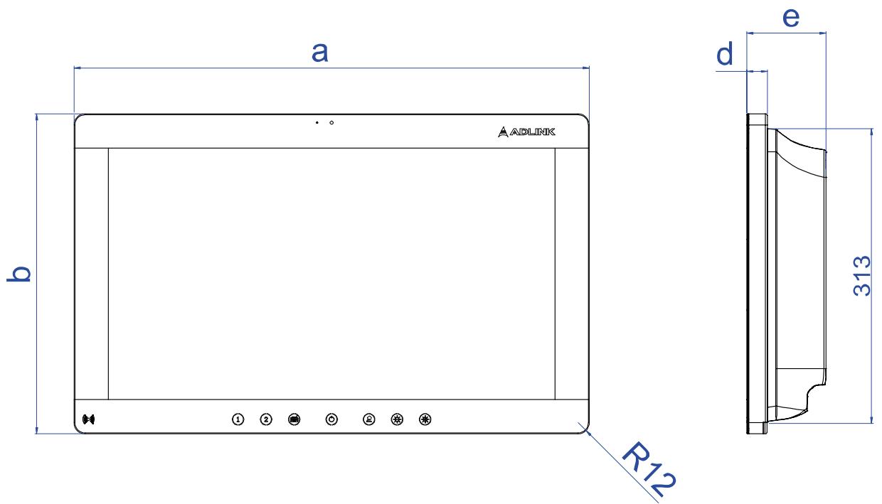
![AADLINK\na\nb\nR12\nd\ne\n313](.mlc-s-series-50m-1z363-1010-11/a49f4f6d317ef862dfb4bc26114598cd18f252d471d21ea80b96f38fb9fdcca4.jpg)

Figure 22: MLC-S12-xx front and side dimensions in [mm]

<table><tr><td>Device</td><td>a</td><td>b</td><td>c</td><td>d</td><td>e</td></tr><tr><td>MLC-S12-21</td><td>551</td><td>342</td><td>152</td><td>22</td><td>85</td></tr><tr><td>MLC-S12-23</td><td>602</td><td>371</td><td>166</td><td>22</td><td>85</td></tr></table>

Note: All dimensions in [mm].

# 8.1.2 Rear dimensions MLC-S

![100\nØ4 x M4\n100\nc](.mlc-s-series-50m-1z363-1010-11/68a771bf02da9f95093fe97dda2ff42558c95ba33227d8916161edea31c2f13c.jpg)

Figure 23: MLC-S12-xx VESA 100 interface & rear dimensions in [mm]

Note: For dimension of “c” refer to the previous table.

It is recommended to use M4 screws with a length of 8 mm.

The wall mounting is oriented with the IO side facing down.

# 8.1.3 Weight

Maximum weight without optional components:

<table><tr><td>Device version</td><td>[kg]</td><td>[lbs]</td></tr><tr><td>MLC-S12-21</td><td>8.9</td><td>19.6</td></tr><tr><td>MLC-S12-23</td><td>10.2</td><td>22.5</td></tr></table>

# 8.2 Electrical Specifications

# 8.2.1 Mains voltage input

<table><tr><td>Input voltage</td><td>100-240 V</td></tr><tr><td>Input frequency</td><td>50-60 Hz</td></tr><tr><td>Max. power consumption*</td><td>1.5A-0.75A</td></tr><tr><td>Fuse (2 pieces):</td><td>T 2.0A H 250 V</td></tr></table>

\*Max. power consumption: The documented power values reflect the apparent power measured at the AC input of the PSU.

# 8.2.2 Power consumption

Test configuration for MLC-S12-23:

Intel® Core™ i7-8700T, clock speed 2.40GHz, 2x 8GB RAM, 128GB M.2 SATA, M.2 2230 frame grabber module, miniPCIe RFID module, 2x galvanically isolated RS-232 ports, 2x galvanically isolated Ethernet ports.

Test configuration for MLC-S-21: as above, but using Intel® Core™ i3-8100T, clock speed 3.10GHz

<table><tr><td>Model</td><td> $P_{avg} / P_{max} [W]$ (load grade 50)*</td><td> $P_{avg} / P_{max} [W]$ (load grade 100)**</td></tr><tr><td>MLC-S12-21</td><td>40 / 44</td><td>48 / 50</td></tr><tr><td>MLC-S12-23</td><td>48 / 72</td><td>76 / 80</td></tr></table>

\*load grade 50: Windows® 10 x64 benchmark (10% load for CPU & GPGPU / RAM / 2x SATA / 2D graphics / RFID off), 52% LCD panel brightness; corresponds to a load grade, which represents common average in practical use

\*\*load grade 100: analogous to load grade 50, but respective components under full (100%) load, i.e. Windows® 10 x64 benchmark (100% load for CPU & GPGPU / RAM / 2x SATA / 2D graphics / RFID off), max. LCD panel brightness (100%)

# 8.3 Environmental Specifications

![The image features a black-outlined equilateral triangle. Inside the triangle is a single black exclamation point.](.mlc-s-series-50m-1z363-1010-11/33e93fb59085581344f2539c887d44c04e92595691cdf3e6501e52a2924b0751.jpg)

# CAUTION

Risk of device malfunctioning caused by violation of environmental specification limits:

Your ADLINK device is specified for proper operation within the environmental conditions mentioned below. Exceeding these limits can lead to unexpected device behavior and malfunctions.

Always make sure that you operate the device within the environmental conditions specified in this section.

# ATTENTION

Risque de dysfonctionnement de l'appareil dû à la violation des limites des spécifications environnementales :

Votre appareil ADLINK est spécifié pour fonctionner correctement dans les conditions environnementales mentionnées ci-dessous. Le dépassement de ces limites peut entraîner un comportement inattendu de l'appareil et des dysfonctionnements.

Toujours veiller à utiliser le dispositif dans les conditions environnementales stipulées dans cette section.

<table><tr><td>Ambient temperature range for operation</td><td>0°C...+35°C</td></tr><tr><td>Ambient temperature range for storage and transport</td><td>-10°C...+60°C</td></tr><tr><td>Ambient humidity range for operation</td><td>10 % ... 90 % (non-condensing)</td></tr><tr><td>Ambient humidity range for storage and transport</td><td>5 % ... 95 % (non-condensing)</td></tr><tr><td>Ambient air pressure for operation, storage and transport</td><td>700 hPa ... 1060 hPa</td></tr></table>

# 8.4 Markings and Labels

# 8.4.1 Product identification label

The product identification label is attached to the rear of the device and contains the model and the serial number of the device. The number following “REF” represents the ADLINK product number. The number following “SN“ represents the individual serial number of the device.

The following figure shows a generic example of an MLC-S series product identification label. The textual content may differ depending on the respective device characteristics.

![Model: MLC-S12-21\nMLC-S (All in one panel PC)\nREF\nSN\nInput Rating: 100-240V, 1.5A-0.75A, 50-60Hz\nFC\nCE\nC US\nLISTED\nI. T. E\nE239251\nMADE IN TAIWAN](.mlc-s-series-50m-1z363-1010-11/162ccb7fdbb039cb64cf20dac5acb7c7c4461576dd350c5b4aa38f67d0b15025.jpg)

![Model: MLC-S12-23\nMLC-S (All in one panel PC)\nREF\nSN\nInput Rating: 100-240V, 1.5A-0.75A, 50-60Hz\nFC\nCE\ncULUS\nLISTED\nI.T.E\nE239251\nMADE IN TAIWAN](.mlc-s-series-50m-1z363-1010-11/c7a61294f4929fa68e9ee9a34cc0793747ccaeb1e9a331f700323cbfc4c9d668.jpg)

Figure 24: Product identification label for MLC-S12-XX device

# 8.4.2 Mains input fuse label

The label for the mains input fuses is attached at the rear of the device near the mains input socket of the internal power supply.

![T 2.0A H 250V](.mlc-s-series-50m-1z363-1010-11/1fe37e43c45496c20b99d73161636cccce7e5da208aa953517573109ef1b943a.jpg)

Figure 25: Mains input fuse label

# 8.4.3 Explanation of label symbols

<table><tr><td>Symbol</td><td>Meaning</td></tr><tr><td>&lt;img src="images/e2e5e39035f1079bf247af77cc13460d72501e18f92aaebb8a188ec2525ab226.jpg"/&gt;</td><td>Read the user&#x27;s manual and follow all handling and safety instructions.</td></tr><tr><td>&lt;img src="images/785d60da2a8d8cae541704f2b36cc0bdc1280664c0635625f9ae6b6d382b3758.jpg"/&gt;</td><td>Do not dispose of this device or its parts with conventional domestic waste. Observe your national regulations regarding disposal of electrical and electronic devices. For further information, refer to: DIRECTIVE 2012/19/EC OF THE EUROPEAN PARLIAMENT AND OF THE COUNCIL of 4 July 2012 on waste electrical and electronic equipment (WEEE)</td></tr><tr><td>&lt;img src="images/9a6b5b2ac2be78508645930c123a3a2b5d0145c4379f22b0aeadebdb52624b59.jpg"/&gt;</td><td>CE marking: the CE symbol confirms compliance with all relevant guidelines and regulations</td></tr><tr><td>&lt;img src="images/a2229ef9369b08e096ac34d5ae7f4b2b872b124860619d711facf389e47036e4.jpg"/&gt;</td><td rowspan="2">Year (YYYY) and month (MM) of manufacture</td></tr><tr><td>YYYY-MM</td></tr><tr><td>&lt;img src="images/180bad3df85ae86522647185a6a8590928aa99b0cbda9e3d714811aa591ac8fd.jpg"/&gt;</td><td>Manufacturer</td></tr><tr><td>&lt;img src="images/69a0f4ac92396519b8476bb6e7253b448f049d32a01eb793cd698d929111c561.jpg"/&gt;</td><td>Catalogue number</td></tr><tr><td>&lt;img src="images/bba42cf6bcb6a2a7c5c13f6ae0a68131b4790a5669002832b62cb08885d76522.jpg"/&gt;</td><td>Serial number</td></tr><tr><td>IP54</td><td>Ingress Protection Code</td></tr></table>

# 9. Appendix

# 9.1 EMC requirements

![The image displays a black triangle outline on a white background containing a black exclamation mark (!).](.mlc-s-series-50m-1z363-1010-11/34b507dbb6a1c6061d24a35c8e5176782f320bd73f8a45307f1f7fc40f17b196.jpg)

# CAUTION

Adverse events caused by mutual influences between MLC-S and other electrical/electronical equipment:

Although compliant with given EMC standards, the MLC-S might cause adverse events by emission or susceptibility to emissions from other electrical/electronical equipment. Follow the recommendations and information documented in the following EMC-related chapters to avoid or at least mitigate such events. If a mitigation of adverse events is not acceptable, increase the separation distance or relocate the concerned devices.

# ATTENTION

Événements indésirables causés par des influences mutuelles entre le MLC-S et d'autres équipements électriques/électroniques :

Bien qu'il soit conforme aux normes CEM en vigueur, le MLC-S peut provoquer des événements indésirables en raison des émissions ou de la sensibilité aux émissions d'autres équipements électriques/électroniques. Suivez les recommandations et les informations documentées dans les chapitres suivants relatifs à la CEM afin d'éviter ou au moins d'atténuer ces événements. Si l'atté- nuation des événements indésirables n'est pas acceptable, augmentez la distance de séparation ou déplacez les appareils concernés.

![The image displays a black circle enclosing a black lowercase letter 'i'.](.mlc-s-series-50m-1z363-1010-11/a51213680b17006c9de23ca3b65adfec4231fa7d5fecd0c2703a29499149ad6d.jpg)

# NOTICE

To avoid or mitigate unintended emissions and / or irradiations by attached cables use shielded cables with high quality shields. Please observe the recommended bend radius as well. The bend radius is specified by the cable vendor/manufacturer.

![The image displays a standard warning sign consisting of a black triangular outline pointing upwards on a white background. Centered inside the triangle is a black exclamation mark.](.mlc-s-series-50m-1z363-1010-11/bc56a9216bfeffb8141e9a5d2fc5f7b3c7a102e3bacf17b602930a44bf73a960.jpg)

# CAUTION

Unintended influence of other electrical/electronical equipment due to MLC-S electromagnetic emissions:

The emission characteristics of this equipment make it suitable for use in industrial areas and hospitals (CISPR 11 class A). If it is used in a residential environment (for which CISPR 11 class B is normally required), this equipment might not offer adequate protection to radio-frequency communication services. The user might need to take mitigation measures, such as relocating or re-orienting the equipment.

# ATTENTION

Influence involontaire d'autres équipements électriques/électroniques en raison des émissions électromagnétiques du MLC-S :

Les caractéristiques d'émission de cet équipement lui permettent d'être utilisé dans les zones industrielles et les hôpitaux (CISPR 11 classe A). S'il est utilisé dans un environnement résidentiel (pour lequel la classe B du CISPR 11 est normalement requise), cet équipement peut ne pas offrir une protection adéquate aux services de communication par radiofréquence. L'utilisateur peut être amené à prendre des mesures d'atténuation, telles que le déplacement ou la réorientation de l'équipement.

![The image displays a solid white triangle centered against a black background. Inside the triangle is a black exclamation mark, which is vertically and horizontally centered within the shape.](.mlc-s-series-50m-1z363-1010-11/3ff9cf402934c70bd09f2ef36fac6dab9a18f2dfbde6db5fb649509390e35e6c.jpg)

# CAUTION

Unintended behavior of MLC-S due to emissions of other electrical/electronical equipment such as HF surgical equipment or magnetic resonance imaging equipment:

The operation of equipment or systems with high emission intensity in the vicinity of the MLC-S or attached cables could lead to unintended behavior of the MLC-S. The operation of such devices near the MLC-S is therefore not recommended and is excluded from the electromagnetic environment specified below.

# ATTENTION

Comportement imprévu du MLC-S dû aux émissions d'autres équipements électriques/électroniques tels que les équipements chirurgicaux HF ou les équipements d'imagerie par résonance magnétique :

Le fonctionnement d'équipements ou de systèmes à forte intensité d'émission à proximité du MLC-S ou des câbles connectés peut entraîner un comportement imprévu du MLC-S. Le fonctionnement de ces appareils à proximité du MLC-S n'est donc pas recommandé. Le fonctionnement de ces appareils à proximité du MLC-S n'est donc pas recommandé et est exclu de l'environnement électromagnétique spécifié ci-dessous.

![The image displays a black-outlined triangle pointing upwards with a black exclamation mark centered inside it.](.mlc-s-series-50m-1z363-1010-11/6a38c9cd1714cfde95a670f92b7d40c3528ccf691e131e5d7ec515228e4586e7.jpg)

# CAUTION

Unintended behavior of MLC-S due to emissions of nearby AM/FM/TV or radar broadcast antennas:

Known RF sources with high emission intensity could cause unexpected or adverse behavior of the MLC-S device. Consider additional shielding measures or contact qualified personnel to solve such issues if relocation or increased separation distance is not sufficient.

# ATTENTION

Comportement inattendu du MLC-S dû aux émissions des antennes AM/FM/TV ou de radiodiffusion situées à proximité :

Les sources RF connues à forte intensité d'émission peuvent provoquer un comportement inattendu ou indésirable du dispositif MLC-S. Envisager des mesures de blindage supplémentaires ou contacter du personnel qualifié pour résoudre ces problèmes si le déplacement ou l'augmentation de la distance de séparation n'est pas suffisant.

![A black outline of an upward-pointing triangle on a white background. Inside the triangle is a black exclamation mark.](.mlc-s-series-50m-1z363-1010-11/6d80812eb7f60a948549abf1c68d7ba38a92e5fd4b8145413b83ad7c1f498551.jpg)

# CAUTION

Unintended behavior of MLC-S due to emissions of portable RF communications equipment

Portable RF communications equipment (including peripherals such as antenna cables and external antennas) should be used no closer than 30 cm (12 inches) to any part of the MLC-S, including cables. Otherwise, performance degradation or loss could result.

# ATTENTION

Comportement inattendu du MLC-S dû aux émissions d'un équipement de communication RF portable :

Les équipements de communication RF portables (y compris les périphériques tels que les câbles d'antenne et les antennes externes) ne doivent pas être utilisés à moins de 30 cm de toute partie du MLC-S, y compris les câbles. Dans le cas contraire, il pourrait en résulter une dégradation ou une perte de performance.

![The image features a black outline of an equilateral triangle containing a centered black exclamation point.](.mlc-s-series-50m-1z363-1010-11/b15bcd7d7faec20eaa1527f2c1ca040eb0bfa3d1baf6c738dcb59e4db423f095.jpg)

# CAUTION

Device is not tested in a stacked configuration with other equipment:

Use of this equipment adjacent to or stacked with other equipment should be avoided because it could result in improper operation. If such use is necessary, this equipment and the other equipment should be observed to verify that they are operating normally.

# ATTENTION

L'appareil n'a pas été testé dans une configuration empilée avec d'autres équipements :

L'utilisation de cet appareil à côté ou empilé avec d'autres appareils doit être évitée car elle pourrait entraîner un mauvais fonctionnement. Si une telle utilisation est nécessaire, il convient d'observer cet équipement et l'autre équipement pour vérifier qu'ils fonctionnent normalement.

![The image shows a black circle with a lowercase letter 'i' centered inside it, resembling an information icon.](.mlc-s-series-50m-1z363-1010-11/780b3a98a31464be13c25e02ceb171311af449152fb17c7e0fb5691812ad1404.jpg)

# NOTICE

The MLC-S does not need any EMC-related maintenance. All used EMC components such as shields, ground connects and seals are not expected to degrade over the devices lifetime. The tested EM compliance shall be kept therefor.

# 9.2 EN 60601-1-2 tables for MLC-S12-21, and MLC-S12-23

# 9.2.1 Guidance and manufacturers declaration – electromagnetic EMISSION

<table><tr><td colspan="3">The MLC-S is intended for use in the electromagnetic environment (for professional healthcare) specified below. The customer or the user of the MLC-S should assure that it is used in such an environment.</td></tr><tr><td>Emission test</td><td>Device complies to IEC 60601-1-2:2014 EN 60601-1-2:2015 (4th edition)</td><td>Electromagnetic environment Guidance (for professional healthcare environment)</td></tr><tr><td>RF Emissions CISPR 11</td><td>Group 1</td><td>The MLC-S uses RF energy only for its internal function. Therefore, its RF emissions are very low and are not likely to cause any interference in nearby electronic equipment.</td></tr><tr><td>RF Emissions Conducted CISPR 11</td><td>Class A</td><td rowspan="4">The MLC-S is suitable for use in all establishments other than domestic and those directly connected to the public low-voltage power supply network that supplies buildings used for domestic purposes.</td></tr><tr><td>RF Emissions Radiated CISPR 11</td><td>Class B</td></tr><tr><td>Harmonic emissions IEC 61000-3-2</td><td>Class A</td></tr><tr><td>Voltage fluctuations/flicker emissions IEC 61000-3-3</td><td>Compliant</td></tr></table>

# 9.2.2 Guidance and manufacturers declaration – electromagnetic IMMUNITY

<table><tr><td colspan="4">The MLC-S is intended for use in the electromagnetic environment (for professional healthcare) specified below. The customer or the user of the MLC-S should assure that it is used in such an environment.</td></tr><tr><td>Immunity test</td><td>IEC 60601-1-2:2014EN 60601-1-2:2015(4th ed.) test level</td><td>Compliance level</td><td>Electromagnetic environment - guidance (for professional healthcare environment)</td></tr><tr><td>Electrostatic discharge (ESD)IEC 61000-4-2</td><td>Contact: ±8 kVAir: ±2 kV, ±4 kV, ±8 kV, ±15 kV</td><td>Contact: ±8 kVAir: ±2 kV, ±4 kV, ±8 kV, ±15 kV</td><td>Floors should be wood, concrete or ceramic tile. If floors are covered with synthetic material, the relative humidity should be at least 30%.</td></tr><tr><td>Electrical fast transients/burstIEC 61000-4-4</td><td>±2 kV for power supply lines±1 kV for input/output lines</td><td>±2 kV for power supply lines±1 kV for input/output lines</td><td>Mains power quality should be that of a typical professional healthcare environment.</td></tr><tr><td>SurgeIEC 61000-4-5</td><td>±0.5 kV, ±1 kV line(s) to line(s)±0.5 kV, ±1 kV, ±2 kV line(s) to earth</td><td>±0.5 kV, ±1 kV line(s) to line(s)±0.5 kV, ±1 kV, ±2 kV line(s) to earth</td><td>Mains power quality should be that of a typical professional healthcare environment.</td></tr><tr><td>Power frequency (50, 60 Hz) magnetic fieldIEC 61000-4-8</td><td>30 A/m50 Hz or 60 Hz</td><td>30 A/m50 Hz or 60 Hz</td><td>The MLC-S power frequency magnetic fields should be at levels characteristic of a typical location in a typical professional healthcare environment.</td></tr><tr><td>Voltage dips, short interruptions and voltage variations on power supply input linesIEC 61000-4-11</td><td>Voltage dips:0% UT; 0.5 cycle0% UT; 1 cycle70% UT; 25/30 cyclesVoltage interruptions:0% UT; 250 (50Hz)300 cycles (60Hz)</td><td>Voltage dips:0% UT; 0.5 cycle0% UT; 1 cycle70% UT; 25/30 cyclesVoltage interruptions:0% UT; 250 (50Hz)300 cycles (60Hz)</td><td>Mains power quality should be that of a typical professional healthcare environment. If the user of the MLC-S requires continued operation during power mains interruptions, it is recommended that the MLC-S is powered from an uninterruptible power supply or a battery.</td></tr><tr><td colspan="4">NOTE: UT is the AC mains voltage prior to application of test level.</td></tr></table>

# 9.2.3 Guidance and manufacturers declaration – electromagnetic IMMUNITY – continued

<table><tr><td colspan="4">The MLC-S is intended for use in the electromagnetic environment (for professional healthcare) specified below. The customer or the user of the MLC-S should assure that it is used in such an environment.</td></tr><tr><td>Immunity test</td><td>IEC 60601-1-2:2014 EN 60601-1-2:2015 (4th ed.) test level</td><td>Compliance level</td><td>Electromagnetic environment - guidance (for professional healthcare environment)</td></tr><tr><td>Radiated RF IEC 61000-4-3</td><td>3 V/m80 MHz – 2.7 GHz80 % AM at 1 kHz</td><td>3 V/m80 MHz – 2.7 GHz80 % AM at 1 kHz</td><td>Recommended separation distance: $d = 1.2 \times \sqrt{P}$  $d = 1.2 \times \sqrt{P}$  from 80 MHz to 800 MHz $d = 2.3 \times \sqrt{P}$  from 800 MHz to 2.7 GHz where P is the maximum output power rating of the transmitter in watts (W) according to the transmitter manufacturer and d is the recommended separation distance in meters (m).Field strengths from fixed RF transmitters, as determined by an electromagnetic site survey [a], should be less than the compliance level in each frequency range [b].Interference may occur in the vicinity of equipment marked with the following symbol:&lt;img src="images/bf7a3e7258d646a71749e94693665dc465fbff7450903299d359d6cfcfca73b1.jpg"/&gt;</td></tr><tr><td>Conducted RF IEC 61000-4-6</td><td>3 Vrms: 0.15 MHz – 80 MHz outside ISM bands6 Vrms: in ISM bands between 0.15 MHz and 80 MHz80 % AM at 1 kHz</td><td>3 Vrms: 0.15 MHz – 80 MHz outside ISM bands6 Vrms: in ISM bands between 0.15 MHz and 80 MHz80 % AM at 1 kHz</td><td>Portable and mobile RF communications equipment should be used no closer to any part of the MLC-S including cables, than the recommended separation distance calculated from the equation applicable to the frequency of the transmitter.</td></tr><tr><td colspan="4">NOTE 1: At 80 MHz and 800 MHz, the higher frequency range applies.NOTE 2: These guidelines may not apply in all situations. Electromagnetic propagation is affected by absorption and reflection from structures, objects and people.</td></tr><tr><td colspan="4">[a] Field strengths from fixed transmitters, such as base stations for radio (cellular/cordless) telephones and land mobile radios, amateur radio, AM and FM radio broadcast and TV broadcast cannot be predicted theoretically with accuracy. To assess the electromagnetic environment due to fixed RF transmitters, an electromagnetic site survey should be considered. If the measured field strength in the location in which the MLC-S is used exceeds the applicable RF compliance level above, the MLC-S should be observed to verify normal operation. If abnormal performance is observed, additional measures may be necessary, such as re-orienting or relocating the MLC-S.[b] Over the frequency range 150 kHz to 80 MHz, field strengths should be less than 3 V/m.</td></tr></table>

# 9.2.4 Recommended separation distances between portable and mobile RF communications equipment and the MLC-S

<table><tr><td colspan="4">The MLC-S is intended for use in an electromagnetic environment (for professional healthcare) in which radiated RF disturbances are controlled. The user of the MLC-S can help prevent electromagnetic interference by maintaining a minimum distance between portable and mobile RF communications equipment (transmitters) and the MLC-S as recommended below, according to the maximum output power of the communications equipment.</td></tr><tr><td rowspan="2">Rated maximum output power of transmitter [W]</td><td colspan="3">Separation distance according to frequency of transmitter [m]</td></tr><tr><td>150 kHz to 80 MHz $d = 1.2 \times \sqrt{P}$ </td><td>80 MHz to 800 MHz $d = 1.2 \times \sqrt{P}$ </td><td>800 MHz to 2.7GHz $d = 2.3 \times \sqrt{P}$ </td></tr><tr><td>0.01</td><td>0.12</td><td>0.12</td><td>0.23</td></tr><tr><td>0.1</td><td>0.38</td><td>0.38</td><td>0.73</td></tr><tr><td>1</td><td>1.20</td><td>1.20</td><td>2.30</td></tr><tr><td>10</td><td>3.79</td><td>3.79</td><td>7.27</td></tr><tr><td>100</td><td>12.00</td><td>12.00</td><td>23.00</td></tr><tr><td colspan="4">For transmitters rated at a maximum output power not listed above, the recommended separation distance d in meters [m] can be estimated using the equation applicable to the frequency of the transmitter, where P is the maximum output power rating of the transmitter in watts [W] according to the transmitter manufacturer.NOTE 1: At 80 MHz and 800 MHz, the higher frequency range applies.NOTE 2: These guidelines may not apply in all situations. Electromagnetic propagation is affected by absorption and reflection from structures, objects and people.</td></tr></table>
[🔗 Link to the original document](.mlc-s-series-50m-1z363-1010-11/mlc-s-series-50m-1z363-1010-11.pdf)