# Motion Creator Pro 2

# User’s Manual

Manual Rev.: 0.1

Revision Date: Dec. 30, 2022

Part No.: 50M-00100-1000

# Preface

# Copyright © 2022 ADLINK Technology, Inc.

This document contains proprietary information protected by copyright. All rights are reserved. No part of this manual may be reproduced by any mechanical, electronic, or other means in any form without prior written permission of the manufacturer.

# Disclaimer

The information in this document is subject to change without prior notice in order to improve reliability, design, and function and does not represent a commitment on the part of the manufacturer.

In no event will the manufacturer be liable for direct, indirect, special, incidental, or consequential damages arising out of the use or inability to use the product or documentation, even if advised of the possibility of such damages.

# Environmental Responsibility

ADLINK is committed to fulfill its social responsibility to global environmental preservation through compliance with the European Union's Restriction of Hazardous Substances (RoHS) directive and Waste Electrical and Electronic Equipment (WEEE) directive. Environmental protection is a top priority for ADLINK. We have enforced measures to ensure that our products, manufacturing processes, components, and raw materials have as little impact on the environment as possible. When products are at their end of life, our customers are encouraged to dispose of them in accordance with the product disposal and/or recovery programs prescribed by their nation or company.

![Symbol of a trash bin crossed out by two diagonal lines (no text or numbers present)](.motion-creator-pro-2-functional-user-manual-english-v0-1/980bccda25da5e233a653fac733383e47ee2b9573a8909586558fbec28d0ba7f.jpg)

![The image displays four horizontal black lines running across the full width of a white background. Two lines are positioned closely together near the top edge. Two other lines are positioned closely together near the bottom edge. A large vertical gap separates the upper pair of lines from the lower pair.](.motion-creator-pro-2-functional-user-manual-english-v0-1/bc590352c5899050d2d5381025091ce545abbfff3f126bfc4db793ad41252eb3.jpg)

# Trademarks

Product names mentioned herein are used for identification purposes only and may be trademarks and/or registered trademarks of their respective companies.

Revision History

<table><tr><td>Revision</td><td>Release Date</td><td>Description of Change(s)</td></tr><tr><td>0.1</td><td>2022-12-30</td><td>Preliminary release</td></tr><tr><td></td><td></td><td></td></tr><tr><td></td><td></td><td></td></tr></table>

# Table of Contents

# Preface ........................

# 1 Overview .....

1.1 User Interface.. .. 6
1.2 Menus .. .7

1.2.1 File->Exit.. .7
1.2.2 View->Project Tree ...... ...8
1.2.3 Initial Options->xxx Mode . .9
1.2.4 Initial Options->Appearance ..... 10
1.2.5 Initial Options->ProFiNetSpeed up Start.. .11
1.2.6 About->Motion Creator Pro 2.. 12
1.2.7 About->Error Code Data Query ......... . 13

1.3 Function .... .. 14
1.4 Icon Bar... .17

# 2 Installation...................... . 18

# 3 MCP2 Function list .................... . 19

3.1 Parameter Manager.. ..19

3.1.1 Parameter Configuration ...... 20
3.1.2 Save Axis Parameter .... 22
3.1.3 Apply All .. 23

3.2 Homing.. ..24
3.3 Single Move... .. 28

3.3.1 Position/Command Status ... . 29
3.3.2 Move Operation .. . 30
3.3.3 Status View ..... . 31

3.4 Interpolation... .. 35
3.5 Sampling .. .. 40

3.5.1 Drawing Area ... . 41
3.5.2 Sampling Settings... 42
3.5.3 16CH Sampling... 43

3.6 Setup Wizard.. .45

3.6.1 Control Mode .... 45
3.6.2 Safety Protection . 47
3.6.3 Motion IO Check ..... 48
3.6.4 Encoder Check . 50
3.6.5 Output Test .... 51
3.6.6 Auto Tuning....... . 53

3.7 E-GEAR . .. 54

3.8 DIO... ..57
3.9 AIO ... . 58
3.10 PDO . ..59
3.11 SDO... ... 61
3.12 Field module.. .. 66

3.12.1 ADLINK Slave Axis . 66
3.12.2 ADLINK Slave IO . 68

3.13 Axis Info ... .. 69

3.14 Advanced Point Table. .71

3.14.1 Drawing Area ... ... 72
3.14.2 Configuration Area.. . 73
3.14.3 Operation Area... . 74

3.15 Manual Settings Slave ID (Manual ID).. .75

3.16 DSP/Kernel Performance . .77

3.16.1 DSP Performance... ... 78
3.16.2 Kernel Performance.. . 78
3.16.3 How to set EtherCAT Cycle time .... . 79

3.17 Compare Trigger.. .81
3.18 Latch .. .87
3.19 OPT Device OD.. .90
3.20 IO Mapping.. . 93

3.20.1 Ether CAT . ... 93
3.20.2 ProFiNet... . 100

3.21 CST Mode .. ..103

3.22 Compensation .. ..106

1D Compensation ....... . 107
2D Compensation ........ . 108

3.23 Connect Quality... .109

3.22.1 Connection Quality ... ...110
3.22.2 State Control .. ... 111

# 1 Overview

Motion Creator Pro 2 (MCP2) software is a user interface specifically developed for ADLINK motion control products. In a standard Windows environment, MCP2 provides simple configuration, testing, and verification functions without end users' writing code, reducing testing time and accelerating device development.

MCP2 software supports all ADLINK motion control products, including pulse control cards and EtherCAT control card, and provides basic motion control functions such as single-axis motion, tween motion, and homing. Functions such as axis status and IO status on the user interface can also be monitored in real time.

# Notes:

 The MCP2 software execution path is: Start>Assembly>ADLINK>PCIe-8338>Motion Creator Pro 2.
 MCP2 software is best viewed with a minimum screen resolution of 1920X1080.

# 1.1 User Interface

This section describes the elements of the MCP2 user interface. There are four main elements to the MCP2 user interface.

 A: Menus
B: icon bar
 C: Device tree
 D: Function pages

![Motion Creator Pro 2\nFile View Initial Options Function About\nAxis/Board Para DIO Control Kernel Performance\nADLINK\nPCIe-7856\nCard No 0\nHSL BusNo 0\n(ID1) Error Count = :\n(ID62) Error Count =\nMNET BusNo 1\nPCIe-8338\nCard No 1\nEtherCAT Axis\n(Slave 0 ) ADLINK EC\nAxis 0 Alarm\nAxis 1 Alarm\nAxis 2 Alarm\nAxis 3 Alarm\n(Slave 1 ) Yaskawa ?\nAxis 4 Alarm\nEtherCAT IO\nPCIe-8334\nCard No 2\nEtherCAT Axis\nEtherCAT IO\nAMP-304C\nCard No 3\nMotion\nAxis96 ServoOff\nAxis97 ServoOff\nAxis98 ServoOff\nB\nD](.motion-creator-pro-2-functional-user-manual-english-v0-1/efab73060120a48e386dfef24ccc994cfde154e3f6161b96756a31d99aad5815.jpg)

# 1.2 Menus

This area includes the following menus: File, View, Initial Options, Function, and About.

Note: The Function menu can is displayed only after clicking a Card No. on the device tree view.

# 1.2.1 File->Exit

Click to exit MCP2.

![Motion Creator Pro 2\nFile View Initial Options Function About\nExit\nField Disconnect Process Data Connect Quality\nADLINK\nPCIe-7856\nCard No 0\nHSL BusNo 0\n(ID1) HSL-DI32\n(ID62) HSL-DO32\nMNET BusNo 1\nPCIe-8338\nCard No 1\nEtherCAT Axis\n(Slave 0 ) ADLINK ECA\nAxis 0 Alarm\nAxis 1 Alarm\nAxis 2 Alarm\nAxis 3 Alarm\n(Slave 1 ) Yaskawa Sla\nAxis 4 Alarm\nEtherCAT IO\nPCIe-8334\nCard No 2\nEtherCAT Axis\nEtherCAT IO\nAMP-304C\nCard No 3\nMotion\nAxis96 ServoOff\nAxis97 ServoOff\nAxis98 ServoOff\nAxis99 ServoOff](.motion-creator-pro-2-functional-user-manual-english-v0-1/60cc9f01c5d98768e30efec71076f99d31be13a1e101652e4d315741960cef8f.jpg)

# 1.2.2 View->Project Tree

Used to open/close the device tree panel.

![Motion Creator Pro 2\nFile View Initial Options Function About\n✓ Product Tree\nPDO\nField Disconnect Process Data Connect Quality\nADLINK\nPCIe-7856\nCard No 0\nHSL BusNo 0\n(ID1) HSL-DI32\n(ID62) HSL-DO32\nMNET BusNo 1\nPCIe-8338\nCard No 1\nEtherCAT Axis\n(Slave 0 ) ADLINK ECA\nAxis 0 Alarm\nAxis 1 Alarm\nAxis 2 Alarm\nAxis 3 Alarm\n(Slave 1 ) Yaskawa Sla\nAxis 4 Alarm\nEtherCAT IO\nPCIe-8334\nCard No 2\nEtherCAT Axis\nEtherCAT IO\nAMP-304C\nCard No 3\nMotion\nAxis96 ServoOff\nAxis97 ServoOff\nAxis98 ServoOff\nAxis99 ServoOff](.motion-creator-pro-2-functional-user-manual-english-v0-1/a3e7abd9a5fdf89a046e674afd9555856023c2fd8ca73ba935da425c0ba925ff.jpg)

# 1.2.3 Initial Options->xxx Mode

This menu lists the control card initialization options. Once the settings in this menu are changed, restart MCP2 to complete the changes.

Some parameters correspond to APS\_initial(I32 \*BoardID\_InBits, I32 Mode). For details, see the APS function library.

![Motion Creator Pro 2\nFile View Initial Options Function About\n✓ Auto Card ID\nManual Card ID\n✓ AxisNo Auto Mode\nAxisNo Fixed Mode\n✓ Field Bus AxisNo Auto Mode\nField Bus AxisNo Fixed Mode\n✓ Field Bus SlaveNo Auto Mode\nField Bus SlaveNo Fixed Mode\n✓ According to Boot Mode\nLoad From Default Table\nLoad From Flash\n✓ Mnet Polling Mode\nMnet Interrupt Mode\nEnable EMX Series Register\n✓ Disable EMX Series Register\nAppearance\nProFiNet Speed up Start\nCard No 2\nEtherCAT Axis\nEtherCAT IO\nAMP-304C\nCard No 3\nMotion\nAxis96 ServoOff\nAxis97 ServoOff\nAxis98 ServoOff\nAxis99 ServoOff](.motion-creator-pro-2-functional-user-manual-english-v0-1/768eb41d2c8b13a2d28d10c7de975d041c2791e81126ff56b40c26a47a01e301.jpg)

# 1.2.4 Initial Options->Appearance

Use these options to change the appearance of MCP2. Once the settings in this menu are changed, restart MCP2 to complete the changes.

![Motion Creator Pro 2\nFile View Initial Options Function About\n✓ Auto Card ID\nManual Card ID\n✓ AxisNo Auto Mode\nAxisNo Fixed Mode\n✓ Field Bus AxisNo Auto Mode\nField Bus AxisNo Fixed Mode\n✓ Field Bus SlaveNo Auto Mode\nField Bus SlaveNo Fixed Mode\n✓ According to Boot Mode\nLoad From Default Table\nLoad From Flash\n✓ Mnet Polling Mode\nMnet Interrupt Mode\nEnable EMX Series Register\n✓ Disable EMX Series Register\nAppearance\n✓ Clear Day\nCyan Dusk\nCopper\nSky\nCard No 2\nEtherCAT Axis\nEtherCAT IO\nAMP-304C\nCard No 3\nMotion\nAxis96 ServoOff\nAxis97 ServoOff\nAxis98 ServoOff\nAxis99 ServoOff](.motion-creator-pro-2-functional-user-manual-english-v0-1/c9c71680081504e32b604e1e5e7d1f4c3e9759609424b017fa5bd1fc1cae6633.jpg)

# 1.2.5 Initial Options->ProFiNetSpeed up Start

Slave connection for fast startup of card after initial connection.

![Motion Creator Pro 2\nFile View Initial Options Function About\n✓ Auto Card ID\nManual Card ID\n✓ AxisNo Auto Mode\nAxisNo Fixed Mode\n✓ Field Bus AxisNo Auto Mode\nField Bus AxisNo Fixed Mode\n✓ Field Bus SlaveNo Auto Mode\nField Bus SlaveNo Fixed Mode\n✓ According to Boot Mode\nLoad From Default Table\nLoad From Flash\n✓ Mnet Polling Mode\nMnet Interrupt Mode\nEnable EMX Series Register\n✓ Disable EMX Series Register\nAppearance\nProFiNet Speed up Start\nCard No 2\nEtherCAT Axis\nEtherCAT IO\nAMP-304C\nCard No 3\nMotion\nAxis96 ServoOff\nAxis97 ServoOff\nAxis98 ServoOff](.motion-creator-pro-2-functional-user-manual-english-v0-1/21deeff30a2b4bdd221bacb53b0153794dce0191dce67aba5d38766aa4204403.jpg)

# 1.2.6 About->Motion Creator Pro 2

This menu item lists the MCP2 version information and supported hardware.

![Motion Creator Pro 2\nFile View Initial Options About\nMotion Creator Pro 2\nError Code Data Query\nADLINK\nPCIe-7856\nCard No 0\nHSL BusNo 0\n(ID1) HSL-DI32\n(ID62) HSL-DO32\nMNET BusNo 1\nPCIe-8338\nCard No 1\nEtherCAT Axis\n(Slave 0 ) ADLINK EC\nAxis 0 Alarm\nAxis 1 Alarm\nAxis 2 Alarm\nAxis 3 Alarm\n(Slave 1 ) Yaskawa ?\nAxis 4 Alarm\nEtherCAT IO\nPCIe-8334\nCard No 2\nEtherCAT Axis\nEtherCAT IO\nAMP-304C\nCard No 3\nMotion\nAxis96 ServoOff\nAxis97 ServoOff\nAxis98 ServoOff\nMotion Creator Pro 2 Version\nADLINK\nLEADING EDGE COMPUTING\nMotion Creator Pro 2 Version : 3.5.25.220801\nDataBase Version:20220725\nCopyright ADLINK Technology Inc.\nSupport Products\nSoftMotion V1.0:\nPCI-8144\nPCI(e)-7856\nPCI-8102\nDPAC-1X00\nDPAC-3X00\nPCI-8254/8\nAMP-204/8C\nPCI-C154+\nPCI(e)-8154/8\nEMX-100\nPCIe-8338/4/2\nAMP-104C\nAMP-304C\nPCIe-8364RS\nOK](.motion-creator-pro-2-functional-user-manual-english-v0-1/53509556f49f8349cf382901a3293ef622807f466611e240b68636f6c6c12293.jpg)

# 1.2.7 About->Error Code Data Query

Enter an error code to show its definition and description.

![Motion Creator Pro 2\nFile View Initial Options About\nMotion Creator Pro 2\nError Code Data Query\nADLINK\nPCIe-7856\nCard No 0\nHSL BusNo 0\n(ID1) HSL-DI32\n(ID62) HSL-DO32\nMNET BusNo 1\nPCIe-8338\nCard No 1\nEtherCAT Axis\n(Slave 0 ) ADLINK EC\nAxis 0 Alarm\nAxis 1 Alarm\nAxis 2 Alarm\nAxis 3 Alarm\n(Slave 1 ) Yaskawa :\nAxis 4 Alarm\nEtherCAT IO\nPCIe-8334\nCard No 2\nEtherCAT Axis\nEtherCAT IO\nAMP-304C\nCard No 3\nMotion\nAxis96 ServoOff\nAxis97 ServoOff\nAxis98 ServoOff\nError Code Data Query\nADLINK\nLEADING EDGE COMPUTING\nEnter Code Number : - 13\nError Define :\nERR_FunctionNotAvailable\nError Description :\nFunction is not available in this step](.motion-creator-pro-2-functional-user-manual-english-v0-1/3b8b9f790993285bc29884666bceeddfee4c7d7070cdb4531661bfe3d67e2fd4.jpg)

# 1.3 Function

This menu corresponds to the feature category selected in the device tree view. The relevant features are listed below. The following figures illustrate the respective available options in the Function menu when Card\_No, Slave, and Axis are selected in the device tree.

1. Click Card No->Function
2. The following figure shows the various hardware or system related functions.

![Motion Creator Pro 2\nFile View Initial Options Function About\nAxis/Board Para\nClick Here (2)\nSetting\nDIO\nKernel Performance\nTreeView Display\nADLINK\nPCIe-7856\nCard No 0\nHSL BusNo 0\n(ID1) HSL-DI32\n(ID62) HSL-DO32\nMNET BusNo 1\nPCIe-8338\nCard No 1\nEtherCAT Axis\n(Slave 0 ) ADLINK EC\nAxis 0 Alarm\nAxis 1 Alarm\nAxis 2 Alarm\nAxis 3 Alarm\n(Slave 1 ) Yaskawa\nAxis 4 Alarm\nEtherCAT IO\nPCIe-8334\nCard No 2\nEtherCAT Axis\nEtherCAT IO\nAMP-304C\nCard No 3\nMotion\nAxis96 ServoOff\nAxis97 ServoOff\nAxis98 ServoOff](.motion-creator-pro-2-functional-user-manual-english-v0-1/236a9b83cf0cad61d3c5b09de68d311e8cab1c4e37e8d8ceaab4ceed0746396a.jpg)

1. Click Motion\EtherCAT\ProfiNet\HSL\MNET->Function
2. The menu displays as shown below, including functions such as multi-axis motion control, sampling and parameter setting.

![Motion Creator Pro 2\nFile View Initial Options Function About\nSetting\nMulti Axes Function\nLinear Interpolation\nCompare Trigger\nClick Here(2)\nAxis/Board Para In\nADLINK\nPCIe-7856\nCard No 0\nHSL BusNo 0\n(ID1) HSL-DI32\n(ID62) HSL-DO32\nMNET BusNo 1\nPCIe-8338\nCard No 1\nEtherCAT Axis\n(Slave 0 ) ADLINK EC\nAxis 0 Alarm\nAxis 1 Alarm\nAxis 2 Alarm\nAxis 3 Alarm\n(Slave 1 ) Yaskawa S\nAxis 4 Alarm\nEtherCAT IO\nPCIe-8334\nCard No 2\nEtherCAT Axis\nEtherCAT IO\nAMP-304C\nCard No 3\nMotion\nAxis96 ServoOff\nAxis97 ServoOff\nAxis98 ServoOff\nClick Here(1)](.motion-creator-pro-2-functional-user-manual-english-v0-1/de74a5ba9a7593f1fae9f75f7333988efddb365af3c8e749772df19e13bffbc9.jpg)

![Motion Creator Pro 2\nFile View Initial Options Function About\nPDO\nConnection Quality\nField Disconnect P\nADLINK\nPCIe-7856\nCard No 0\nHSL BusNo 0\n(ID1) HSL-DI32\n(ID62) HSL-DO32\nMNET BusNo 1\nPCIe-8338\nCard No 1\nEtherCAT Axis\n(Slave 0 ) ADLINK EC\nAxis 0 Alarm\nAxis 1 Alarm\nAxis 2 Alarm\nAxis 3 Alarm\n(Slave 1 ) Yaskawa S\nAxis 4 Alarm\nEtherCAT IO\nPCIe-8334\nCard No 2\nEtherCAT Axis\nEtherCAT IO\nAMP-304C\nCard No 3\nMotion\nAxis96 ServoOff\nAxis97 ServoOff\nAxis98 ServoOff](.motion-creator-pro-2-functional-user-manual-english-v0-1/4ee9fcb2aa0f12c2df6d6ff47280d7b09b4546a022cdd4b2393caf776e77a58e.jpg)

1. Click Slave No. ->Function
2. The menu displays as shown below, including functions for single-axis motion control, point-to-point movement and return to origin.

![Motion Creator Pro 2\nFile View Initial Options Function About\nSetting\nMulti Axes Function\nSampling\nMulti Axes Info\nSDO\nOptSDO\nAdvanced Point Table\nManual ID\nADLINK\nPCIe-7856\nCard No 0\nHSL Bus\n(ID1)\n(ID62) HSL-DO32\nMNET BusNo 1\nPCIe-8338\nCard No 1\nEtherCAT Axis\n(Slave 0 ) ADLINK EC\nAxis 0 Alarm\nAxis 1 Alarm\nAxis 2 Alarm\nAxis 3 Alarm\n(Slave 1-) Yaskawa ?\nAxis 4 Alarm\nEtherCAT IO\nPCIe-8334\nCard No 2\nEtherCAT Axis\nEtherCAT IO\nAMP-304C\nCard No 3\nMotion\nAxis96 ServoOff\nAxis97 ServoOff\nAxis98 ServoOff\nClick Here(2)\nClick Here(1)](.motion-creator-pro-2-functional-user-manual-english-v0-1/25a112610273987678cbcb68fe4d6f7ba7df7b5c85dcc869ca43892c2f159569.jpg)

# 1.4 Icon Bar

The icon bar is where frequently used functions can be put for quick selection. For example, the Function Menu will display different function icons according to whether the user selects Card No, Motion, Axis and Slave in the device tree view.

The following three diagrams illustrate the diagrams that appear when different items are clicked. Click Card No 0 in the following device tree view to display DIO, DSP Performance and other icons.

STEIN - ADD MISSING PICTURES

# 2 Installation

STEIN - ADD MISSING INFORMATION

# 3 MCP2 Function list

# 3.1 Parameter Manager

The control card axis parameters and system parameters can be unified by the parameter management, including operation mode, acceleration rate, deceleration rate, acceleration, motion I/O logic, etc. See the APS Function Library parameter table for definitions and detailed descriptions.

To open the parameter manager page, follow these steps:

Step 1. Click “Card” or “Slave” or “Axis” in the device tree.

Step 2. Click Axis/Board Para on the icon bar.

![Motion Creator Pro 2\nFile View Initial Options Function About\nAxis/Board Para Single Move CmpTrg Home Move Field Module Latch\nADLINK Click Here(2)\nPCIe-7856 PCte-7856\nCard No 0 HSL BusNo 0 MNET BusNo 1\nPCIe-8338 Card No 1 EtherCAT Axis (Slave 0) ADLINK ECA Axis 0 Alarm Axis 1 Alarm Axis 2 Alarm Axis 3 Alarm (Slave 1) Yaskawa Sla Axis 4 Alarm EtherCAT IO\nPCIe-8334 Card No 2 EtherCAT Axis EtherCAT IO\nAMP-304C Card No 3 Motion Axis96 ServoOff Axis97 ServoOff Axis98 ServoOff Axis99 ServoOff\nParameter PCIe-8338 EtherCAT CardNo 1\nBoard Configuration Axis Configuration\nAxisNo0 AxisNo1 AxisNo2 AxisNo3\nEL_MODE Dec Stop Dec Stop Dec Stop Dec Stop\nMDM_CONDI Cmd Done Cmd Done Cmd Done Cmd Done\nSD_DEC 100000000 100000000 100000000 100000000\nSPEL_EN Disable Disable Disable Disable\nSMEL_EN Disable Disable Disable Disable\nSPEL_POS 100000 100000 100000 100000\nSMEL_POS -100000 -100000 -100000 -100000\nHOME_MODE Home 0 Home 0 Home 0 Home 0\nHOME_DIR Positive Dir. Positive Dir. Positive Dir. Positive Dir.\nHOME_CURVE 0.5 0.5 0.5 0.5\nHOME_ACC 10000 10000 10000 10000\nHOME_VS 0 0 0 0\nHOME_VM 1000 1000 1000 1000\nHOME_SHIFT 0 0 0 0\nHOME_EZA Disable Disable Disable Disable\nHOME_VO 200 200 200 200\nHOME_POS 0 0 0 0\nHOME_TOROVE 12 12 12 12\nSet To Card Save To Flash Save To File Load Default\nLoad From Card Load From Flash Load From File](.motion-creator-pro-2-functional-user-manual-english-v0-1/ca0e5331bb205df896c3db704b4d264f410001c0f72bea769f1e4840f6bb1c3c.jpg)

# 3.1.1 Parameter Configuration

For board configuration, refer to the APS Function Library manual Table definition-> Board Parameter table. The following example shows a PCI-8338 board.

<table><tr><td>Board Configuration</td><td>Axis Configuration</td></tr><tr><td>Board Parameter</td><td>Board Parameter Value</td></tr><tr><td>EMG_LOGIC</td><td>Normal Open</td></tr><tr><td>DO_LOGIC</td><td>No Invert</td></tr><tr><td>DI_LOGIC</td><td>No Invert</td></tr><tr><td>IO_ACCESS_SEL</td><td>Mode 0</td></tr><tr><td>ECAT_SYNC_MODE</td><td>DC Mode</td></tr><tr><td>OP_RETRY_COUNT</td><td>0</td></tr><tr><td>SERVO_ON_MODE</td><td>Standard mode</td></tr><tr><td>SERVO_ON_NO_RESET_ALARM</td><td>Reset Alarm With Servo On Process</td></tr><tr><td>ECAT_SYNC_OFFSET</td><td>66</td></tr><tr><td>MAN_SLAVE_ID_SRC_1ST_GR</td><td>0</td></tr><tr><td>MAN_SLAVE_ID_SRC_2ND_GR</td><td>0</td></tr><tr><td>ECAT_CONTI_FRAME_LOSS_CNT</td><td>0</td></tr><tr><td>SAMPLING_SRC_AXIS_TYPE</td><td>Axis Number</td></tr><tr><td>EMG_MODE</td><td>Servo off directly</td></tr><tr><td>ECAT_RESTORE_OUTPUT</td><td>Restore</td></tr><tr><td>DI_EMG_FILTER_ENABLE</td><td>Enable</td></tr><tr><td>DI_EMG_FILTER_RANGE</td><td>5 us</td></tr><tr><td>PULSER_FILTER_RANGE</td><td>5 us</td></tr></table>

The board configuration page is available under Table definition->A. Board Parameter table->PCIe-833x board parameter table as shown below.

![PCIe-833x board parameter table\nPCIe-833x Board parameter table\nNO.	Define	Description	Parameter data meaning	Defau lt\n00h	PRB_EMG_LOGIC	EMG Logic	0 : Not inverse 1 : Inverse	0\n14h	PRB_DO_LOGIC	DO logic	0 : no invert; 1 : invert	0\n15h	PRB_DI_LOGIC	DI logic	0 : no invert; 1 : invert	0\n16h	PRB_IO_ACCESS_SEL	IO access selection	0 : Mode 0 1 : Reserved 2 : Mode 2 3 : Mode 3 (*Note 1)	0\n17h	PRB_ECAT_SYNC_MODE	EtherCAT synchronization mode selection	0 : DC mode (Default) 1 : Free run	0\n18h	PRB_OP_RETRY_COUNT	EtherCAT retry OP state count.	0\n19h	PRB_ECAT_SERVO_ON_MODE	EtherCAT servo on mode selection	0 : Standard mode(Default) 1 : Fast mode, no check status word	0\n1Ah	PRB_ECAT_SERVO_ON_NO_RESET_ALARM	EtherCAT servo on bypass reset alarm	0 : No bypass reset alarm while servo on (Default) 1 : Bypass reset alarm while row	0](.motion-creator-pro-2-functional-user-manual-english-v0-1/7d765193af81f2f1312ee32ac67f02b14f5e373f05ced3007c167de2a9dc804a.jpg)

Axis Configuration is described in the APS Function Library manual under Table definition-> Axis Parameter table. The following figure shows the PCI-8338 board information.

<table><tr><td>Board Configuration</td><td>Axis Configuration</td><td colspan="4"></td></tr><tr><td></td><td>AxisNo12</td><td>AxisNo13</td><td>AxisNo14</td><td>AxisNo15</td><td></td></tr><tr><td>EL_MODE</td><td>Dec Stop</td><td>Dec Stop</td><td>Dec Stop</td><td>Dec Stop</td><td></td></tr><tr><td>MDM_CONDI</td><td>Cmd Done</td><td>Cmd Done</td><td>Cmd Done</td><td>Cmd Done</td><td></td></tr><tr><td>SD_DEC</td><td>100000000</td><td>100000000</td><td>100000000</td><td>100000000</td><td></td></tr><tr><td>SPEL_EN</td><td>Disable</td><td>Disable</td><td>Disable</td><td>Disable</td><td></td></tr><tr><td>SMEL_EN</td><td>Disable</td><td>Disable</td><td>Disable</td><td>Disable</td><td></td></tr><tr><td>SPEL_POS</td><td>100000</td><td>100000</td><td>100000</td><td>100000</td><td></td></tr><tr><td>SMEL_POS</td><td>-100000</td><td>-100000</td><td>-100000</td><td>-100000</td><td></td></tr><tr><td>HOME_MODE</td><td>Home 0</td><td>Home 0</td><td>Home 0</td><td>Home 0</td><td></td></tr><tr><td>HOME_DIR</td><td>Positive Dir.</td><td>Positive Dir.</td><td>Positive Dir.</td><td>Positive Dir.</td><td></td></tr><tr><td>HOME_CURVE</td><td>0.5</td><td>0.5</td><td>0.5</td><td>0.5</td><td></td></tr><tr><td>HOME_ACC</td><td>10000</td><td>10000</td><td>10000</td><td>10000</td><td></td></tr><tr><td>HOME_VS</td><td>0</td><td>0</td><td>0</td><td>0</td><td></td></tr><tr><td>HOME_VM</td><td>1000</td><td>1000</td><td>1000</td><td>1000</td><td></td></tr><tr><td>HOME_SHIFT</td><td>0</td><td>0</td><td>0</td><td>0</td><td></td></tr><tr><td>HOME_EZA</td><td>Disable</td><td>Disable</td><td>Disable</td><td>Disable</td><td></td></tr><tr><td>HOME_VO</td><td>200</td><td>200</td><td>200</td><td>200</td><td></td></tr><tr><td>HOME_POS</td><td>0</td><td>0</td><td>0</td><td>0</td><td></td></tr><tr><td>HOME_TOROVE</td><td>10</td><td>10</td><td>10</td><td>10</td><td></td></tr></table>

Axis configuration is available under Table definition->A. Board Parameter table->PCIe-833x Axis parameter table, as shown below.

<table><tr><td colspan="6">PCIe-833x axis parameter table</td></tr><tr><td>NO.</td><td>Define</td><td>Description</td><td>Value</td><td>Default</td><td>Type</td></tr><tr><td>02h (2)</td><td>PRA_EL_MODE</td><td>Stop mode when EL turns on. Note : Deceleration profile is given according to PRA_SD_DEC.</td><td>0 : Deceleration stop 1: Stop immediately</td><td>0</td><td>I32</td></tr><tr><td>03h (3)</td><td>PRA_MDM_CONDI</td><td>Motion done condition ( Affective with motion stats NSTP bit)</td><td>0 : Command done; 1: Command done with INP</td><td>0</td><td>I32</td></tr><tr><td>07h (7)</td><td>PRA_SD_DEC</td><td>Stop deceleration including EL stop, stop function and multi-stop).</td><td>Unit : pulse/sec2</td><td>10000000 0.0</td><td>F64</td></tr><tr><td>08h (8)</td><td>PRA_SPEL_EN</td><td>Soft PEL enable</td><td>0 : Disable 1: Reserved 2: Soft-Limit (SPEL)</td><td>0</td><td>I32</td></tr><tr><td>09h (9)</td><td>PRA_SMEL_EN</td><td>Soft MEL enable</td><td>0 : Disable 1: Reserved 2: Soft-Limit (SMEL)</td><td>0</td><td>I32</td></tr><tr><td>0Ah (10)</td><td>PRA_SPEL_POS</td><td>Soft-end-limit for positive end [ F64 ]</td><td>Unit : pulse</td><td>100000.0</td><td>F64</td></tr><tr><td>0Bh (11)</td><td>PRA_SMEL_POS</td><td>Soft-end-limit for negative end [ F64 ]</td><td>Unit : pulse</td><td>-100000.0</td><td>F64</td></tr><tr><td></td><td></td><td>Home mode setting *If user uses EtherCAT home</td><td>0 : home mode 0 (ORG) 1: home mode 1(FE)</td><td>0</td><td>I32</td></tr></table>

# 3.1.2 Save Axis Parameter

There are several buttons for parameter operations at the bottom of the page. After setting parameters according to system settings, you can select the following storage/loading methods:

<table><tr><td>Set To Card</td><td>Save To Flash</td><td>Save To File</td><td>Load Default</td></tr><tr><td>Load From Card</td><td>Load From Flash</td><td>Load From File</td><td></td></tr></table>

 Set To Card: The parameter set value is directly written to the control card for use.
 Load From Card: Read parameters from the control card to the page display.
 Save To Flash: Writes parameters to non-volatile memory in the control card.
 Load From Flash: Read parameters from non-volatile memory of control card to page display.
 Save To File: Writes the parameter to the specified file (xml).
 Load From File: Read parameters from the specified file to the page display (xml).
 Load Default: Load the factory default value to the page display.

# 3.1.3 Apply All

In a motion control system, there may be multiple axis parameters that are similar or exactly the same. MCP2 provides a copy of the parameter set value to the multi-axis function, saving the need to enter each axis parameter setting each time.

Click the right mouse button on the setting axis parameter setting page to select one of the following options:

 Apply all (Single Parameter): Copy only the set values of this column to other axes.
 Apply all (All Parameter): Copies all parameter values for this axis to other axes.

![Parameter PCIe-8338 EtherCAT CardNo 1\nBoard Configuration	Axis Configuration\nRight Click\nAxisNo0	AxisNo1	AxisNo2	AxisNo3\nEL_MODE	Dec Stop	Dec Stop	Dec Stop	Dec Stop\nMDM_CONDI	Cmd Done	Apply all (Single Parameter) Care	Cmd Done\nSD_DEC	100000000	Apply all (All Parameter) 00	100000000\nSPEL_ENDisable	Disable	Disable	Disable\nSMEL_ENDisable	Disable	Disable	Disable\nSPEL_POS	100000	100000	100000	100000\nSMEL_POS	-100000	-100000	-100000	-100000\nHOME_MODE Homel 0 Homel 0 Homel 0 Home 0\nHOME_DIR Positive Dir. Positive Dir. Positive Dir. Positive Dir.\nHOME_CURVE 0.5 0.5 0.5 0.5\nHOME_ACC 10000 10000 10000 10000\nHOME_VS 0 0 0 0\nHOME_VM 1000 1000 1000 1000\nHOME_SHIFT 0 0 0 0\nHOME_EZA Disable Disable Disable\nHOME_VO 200 200 200 200\nHOME_POS 0 0 0 0\nHOME_TARAVE 16 16 16 16\nSet To Card	Save To Flash	Save To FileLoad Default\nLoad From CardLoad From FlashLoad From File](.motion-creator-pro-2-functional-user-manual-english-v0-1/b951a36fa8cb89e3aba4f3f45dbfe4121d2f494978c94a1d0638a56401356979.jpg)

# 3.2 Homing

The Homing page is used for the origin of the startup axis (ORG or DOG, etc.) position. Through the axis parameter settings, you can select n modes, and real-time monitoring of command, displacement, and various motion status information.

The steps to open the return to origin page are shown below. First, click Axis0 in the device tree, then click the Home Move icon.

![Motion Creator Pro 2\nFile View Initial Options Function About\nAxis/Board Para Single Move CmpTrq Home Move Field Module Latch\nClick Here(2)\nHoming Movement PCIe-8338 EtherCAT CardID2 AxisNo 12\nADLINK\nPCIe-8158\nCard No 0\nMotion\nAxis0 ServoOff\nAxis1 ServoOff\nAxis2 ServoOff\nAxis3 ServoOff\nAxis4 ServoOff\nAxis5 ServoOff\nAxis6 ServoOff\nAxis7 ServoOff\nPCI-8254\nCard No 1\nMotion\nAxis8 Alarm\nAxis9 Alarm\nAxis10 Alarm\nAxis11 Alarm\nPCIe-8338\nCard No 2\nEtherCAT Axis\n(Slave 0 ) ADLINK ECA*\nAxis 12 ServoOn\nAxis 13 ServoOff\nAxis 14 ServoOff\nAxis 15 ServoOff\nEtherCAT IO\n(Slave 1 ) ADLINK Slav\nEU-1108-DI\nEU-1008-DI\nEU-1108-DI\nEU-2008-DO\nEU-2108-DO\nEU-2008-DO\nEU-2108-DO\nEU-2008-DO\nEU-3104-AI\nEU-3304-AI\nEU-4104-AO\nEU-4304-AO\nAMP-304C\nCard No 3\nMotion\nAxis76 ServoOff\nAxis77 ServoOff\nAxis78 ServoOff\nAxis79 ServoOff\nHome Acc: 10000\nHome VS: 0\nHome VM: 1000\nHome VO: 200\nHome Shift: 0\nHome EZ Direction: 0 : Original EZ search\nCommand: 0\nFeedback: 0\nTorque value: 0\nSelect Mode: 0\nHome Direction: Positive\nHome EZA: Disable\nHome Curve: 0.5\nHome Position: 0\nHome Torque: 10\nStart Stop Set Param To Card Load Param From Card\nTM HMV MDN DIR DEC ACC VM CSTP\nGER POSTD PRED BLD ASTP JOG PTB WAIT\nSMEL SPEL SCL RDY SVON INP EZ EMG ORG MEL PEL ALM\nClick Here(1) Home mode 0, Positive, EZA disable\nMEL VM ORG Case A PEL\nSpeed VO VO Case B\nSpeed Initial position Home position VM\nSpeed Home position VM Initial position Case C VM\nSpeed VO VM](.motion-creator-pro-2-functional-user-manual-english-v0-1/f3737baf65a1027637b23b664476876421e83555644b5d1c69476f987eede01f.jpg)

The return to origin page has four areas:

(1) Various return to origin parameter settings
(2) Start/stop button and set/load parameters
(3) Status display area
(4) Display of the current way back to the origin

![Homing Movement PCIe-8338 EtherCAT CardID2 AxisNo 12\n(1) Home Acc : 10000\nHome VS : 0\nHome VM : 1000\nHome VO : 200\nHome Shift : 0\nHome EZ Direction : 0 : Original EZ search\nSelect Mode : 0\nHome Direction : Positive\nHome EZA : Disable\nHome Curve : 0.5\nHome Position : 0\nHome Torque : 10\nCommand : 0\nFeedback : 0\nTorque value : 0\nStart Stop\nSet Param To Card\nLoad Param From Card\n(2)\n(3)\nTM HMV MDN DIR DEC ACC VM CSTP\nGER POSTD PRED BLD ASTP JOG PTB WAIT\nSMEL SPEL SCL RDY SVON INP EZ EMG ORG MEL PEL ALM\n(4) Home mode 0, Positive, EZA disable\nMEL VO\nSpeed VO\nSpeed VO\nSpeed VO\nSpeed VO\nSpeed VO\nSpeed VO\nSpeed VO\nSpeed VO\nSpeed VO\nSpeed VO\nSpeed VO\nSpeed VO\nSpeed VO\nSpeed VO\nSpeed VO\nSpeed VO\nSpeed VO\nSpeed VO\nSpeed VO\nSpeed VO\nSpeed VO\nSpeed VO\nSpeed VO\nSpeed VO\nSpeed VO\nSpeed VO\nSpeed VO\nSpeed VO\nSpeed VO\nSpeed VO](.motion-creator-pro-2-functional-user-manual-english-v0-1/0f98146783760ba442a5f977418e430073f112f26a45e3810b7dccf413596f78.jpg)

For motion status, refer to Table definition-> Motion status definition tables in the APS Function Library. For example, the following figure shows PCI-8338 Motion Status 38. Table definition-> F. Motion status definition table -> PCIe-833x Motion status definition table, as shown below.

<table><tr><td colspan="9">Motion status definition table</td></tr><tr><td>BitNo</td><td>7</td><td>6</td><td>5</td><td>4</td><td>3</td><td>2</td><td>1</td><td>0</td></tr><tr><td></td><td>TM</td><td>HMV</td><td>MDN</td><td>DIR</td><td>DEC</td><td>ACC</td><td>VM</td><td>CSTP</td></tr><tr><td>BitNo</td><td>15</td><td>14</td><td>13</td><td>12</td><td>11</td><td>10</td><td>9</td><td>8</td></tr><tr><td></td><td>JOG</td><td>--</td><td>--</td><td>--</td><td>PTB</td><td>WAIT</td><td>--</td><td>--</td></tr><tr><td>BitNo</td><td>23</td><td>22</td><td>21</td><td>20</td><td>19</td><td>18</td><td>17</td><td>16</td></tr><tr><td></td><td>ASYNCERR</td><td>--</td><td>--</td><td>--</td><td>POSTD</td><td>PRED</td><td>BLD</td><td>ASTP</td></tr><tr><td>BitNo</td><td>31</td><td>30</td><td>29</td><td>28</td><td>27</td><td>26</td><td>25</td><td>24</td></tr><tr><td></td><td>--</td><td>GRY</td><td>PSR</td><td>GER</td><td>BACKLASH</td><td>--</td><td>--</td><td>--</td></tr></table>

For Motion IO Status definitions, see Table definition->Motion IO status and motion status definitions in the APS Function Library. For the example above, the PCIe - 8338 Motion path for IO Status reference content is shown as 38. Table definition-> E. Motion IO status and motion status definitions -> PCIe-833x motion IO status table, as below.

![PCle-833x motion IO status table\nPCle-833x motion IO status table\nBit No	7	6	5	4	3	2	1	0\nSVON	INP	EZ	EMG	ORG	MEL	PEL	ALM\nADLINK | Leading Edge Computing\n1116\nPCle-833x motion IO status table\nBit No	15	14	13	12	11	10	9	8\nSMEL	SPEL	SCL	RDY\nBit No	23	22	21	20	19	18	17	16\nBit No	31	30	29	28	27	26	25	24\nOP\nPCle-833x Motion IO status table\nMotion IO status description table\nBit	Define	Description\n0	ALM	Servo alarm\nPCle-833x Motion IO status table\nW: 210.0mm	X:\nH: 297.0mm	Y:\nADLINK LEADING EDGE COMPUTING\n725項 1編號的項目](.motion-creator-pro-2-functional-user-manual-english-v0-1/9de061d42af1e5ff678b726c9b6a7a99d63478182881cb102fd5a2e6544c1016.jpg)

# 3.3 Single Move

The single-axis operation function can control a single axis to do absolute motion, relative motion, speed motion and inch motion and other functions, and can monitor the command, displacement, speed and various motion state information in real time.

The steps of opening the single-axis operation page are as shown below. First, click Axis x on the device tree, and then click the Single Move icon.

![Motion Creator Pro 2\nFile View Initial Options Function About\nAxis/Board Para Single Move CmpTrg Home Move Field Module Latch\nADLINK\nPCIe-8158\nCard No 0\nMotion\nAxis0 ServoOff\nAxis1 ServoOff\nAxis2 ServoOff\nAxis3 ServoOff\nAxis4 ServoOff\nAxis5 ServoOff\nAxis6 ServoOff\nAxis7 ServoOff\nPCI-8254\nCard No 1\nMotion\nAxis8 Alarm\nAxis9 Alarm\nAxis10 Alarm\nAxis11 Alarm\nPCIe-8338\nCard No 2\nEtherCAT Axis\n(Slave 0 ) ADLINK ECA*\nAxis 12 ServoOn\nAxis 13 ServoOff\nAxis 14 ServoOff\nAxis 15 ServoOff\nEtherCAT IO\n(Slave 1 ) ADLINK Slav\nEU-1108-DI\nClick Here(2)\nCommand: 0\nPosition: 0\nCmd Vel: 0\nFBK Vel: 0\nErr Pos: 0\nTargetPos: 0\nSet Pos: 0\nMaxVel: 100000\nABS MOVE Position 1 Position 2 Forward Backward 0 0\nREL MOVE Forward Backward 0 0\nVEL MOVE Forward Backward Forward Backward 0 0\nJOG MOVE Forward Backward Forward Backward 0 0\nSTOP DelayTime: 1000\nRepeat Mode Stop 1000 0 Cont. Mode 1000\nInterrupt List\nIALM IPEL IMEL IORG IINP IEMG ICSTP IVM IACC IDEC IMDN IASTP ISPEL ISMEI ISCL\nTM HMV MDN DIR DEC ACC VM CSTP\nGER POSTD PRED BLD ASTP JOG PTB WAIT\nSMEL SPEL SCL RDY SVON INP EZ EMG ORG MEL PEL ALM\nIPTB3IPTB2IPTB1ISCL ISMELISPILIASTPIMDN IDEC IACC IVM ICSTPIEMG IINP IORG IMEL IPEL IALM](.motion-creator-pro-2-functional-user-manual-english-v0-1/72d106f8449213cbc01fc1d50ed2a81661e4d449e2fafc0050a852fefaf801f4.jpg)

![Motion Creator Pro 2\nFile View Initial Options Function About\nAxis/Board Para Single Move CmpTrg Home Move SetupWizard\nADLINK\nPCIe-8158\nCard No 0\nMotion\nAxis0 ServoOff\nAxis1 ServoOff\nAxis2 ServoOff\nAxis3 ServoOff\nAxis4 ServoOff\nAxis5 ServoOff\nAxis6 ServoOff\nAxis7 ServoOff\nPCI-8254\nCard No 1\nMotion\nAxis8 Alarm\nAxis9 Alarm\nAxis10 Alarm\nAxis11 Alarm\nPCIe-8338\nCard No 2\nEtherCAT Axis\n(Slave 0 ) ADLINK ECA*\nAxis 12 ServoOff\nAxis 13 ServoOff\nAxis 14 ServoOff\nAxis 15 ServoOff\nEtherCAT IO\n(Slave 1 ) ADLINK Slav\nEU-1108-DI\nEU-1008-DI\nEU-1108-DI\nEU-2008-DO\nClick Here(2)\nCommand : 0\nPosition : 0\nCmd Vel : 0\nFBK Vel : 0\nErr Pos : 0\nTargetPos : 0\nSet Pos : 0\nMaxVel : 0\nEMG STOP Repeat Mode STOP\nDelayTime: 1000\nABS MOVE Position 1 Position 2\nForward Backward\nVEL MOVE Forward Backward\n0 0\n0 0\n0 0\nSpeed Profile Preview Preview\nInterrupt List\nINSTP IACCS IACCE IDECS IDECE ISPEL ISMEL ICOMP ICLRC IORGC ISD\nVS CIP LIP SMV HMV NSTP DEC ACC VM CSTP SMELS SPELS ECES MELS PELS WANS ALMS EMGS ASTP RDY SVON INP EZ EMG ORG MEL PEL ALM EPAB EEAB EPCO EPBO ESIP EPES ESD EEMG EALM EMEL EPEL EGCM ENSL EPSL ISD IORGC ICLRC ICOMP ISMEL ISPEL IDECE IDECS IACCIE IACCS INSTP](.motion-creator-pro-2-functional-user-manual-english-v0-1/c5828225badae9107b794332d961149a4a4b83b34e1f021a40a5ed161bd750b9.jpg)

# 3.3.1 Position/Command Status

This area displays the following information:

Command: Current command location
 Position: Current feedback location
 Cmd Vel: Current command speed
 FBK Vel: Current feedback speed
Err Pos: Displacement error value
 TargetPos: Target position
 Set Pos: Set the command position and the feedback position at the same time
MaxVel: Set point to point maximum velocity

<table><tr><td>Command :</td><td>0</td></tr><tr><td>Position :</td><td>0</td></tr><tr><td>Cmd Vel :</td><td>0</td></tr><tr><td>FBK Vel :</td><td>0</td></tr><tr><td>Err Pos :</td><td>0</td></tr><tr><td>TargetPos :</td><td>0</td></tr><tr><td>Set Pos</td><td>0</td></tr><tr><td>MaxVel :</td><td>100000</td></tr></table>

# 3.3.2 Move Operation

Motion operation can be divided into four operation modes, the input displacement is in Pulse units.

(1) ABS MOVE: Absolute position movement, you can enter the absolute position
(2) REL MOVE: Relative position movement, you can enter the relative position
(3) VEL MOVE: Speed movement, speed can be entered
(4) JOG MOVE: Move in inches, click Free or Step mode. (Step mode must set displacement)

![(1)\nABS MOVE\nPosition 1 Position 2\n1000 0](.motion-creator-pro-2-functional-user-manual-english-v0-1/a86ef0b52867aee1700bcdc727d3730b39f5b4592b415c2dd82d480decb3700c.jpg)

![(2) REL MOVE\nForward	Backward\n0	0](.motion-creator-pro-2-functional-user-manual-english-v0-1/d6368606deda6bfee90d526b24c9da1a5f54b02e1f2638f126d6489e8629004b.jpg)

![(3) VEL MOVE\nForward	Backward\n1000	0](.motion-creator-pro-2-functional-user-manual-english-v0-1/ba72b71b7e71346aa5c2672dc82b0fcd9170fad2edd4a14844e90ca8f49e504d.jpg)

![(4) JOG MOVE\nForward	Backward\nCont. Mode	1000](.motion-creator-pro-2-functional-user-manual-english-v0-1/72e0784fa7f087c6865dae9c254ff37f1569dbc5b1c2e72656944fd324dbb5ae.jpg)

Note: The increase or decrease rate can be set in 3.1 Parameter Management.

If it is necessary to perform reciprocating movement between two displacements, check Repeat Move and set the Delay Time interval before the movement operation is performed.

![The image displays a user interface layout divided into two main sections connected by a red arrow.\n\n**Left Section:**\n*   **Block:** Contains 'EMG STOP' above a blue square button and 'STOP' above a red square button.\n*   **Connection:** A central highlighted box contains a checked 'Repeat Mode' checkbox and a field labeled 'DelayTime: 1000'.\n*   **Connection:** A large red arrow points from this section to the right section.\n\n**Right Section (Control Panel):**\nThis area is divided into four labeled blocks:\n\n*   **Top Left Block:**\n    *   **Header:** 'ABS MOVE'\n    *   **Sub-blocks:** 'Position 1' and 'Position 2'\n    *   **Elements:** Below 'Position 1' is a blue button and an input field reading '1000'. Below 'Position 2' is a blue button and an input field (partially obscured).\n    *   **Annotation:** A red arrow labeled 'Click' points to the 'Position 1' button.\n\n*   **Top Right Block:**\n    *   **Header:** 'REL MOVE'\n    *   **Sub-blocks:** 'Forward' and 'Backward'\n    *   **Elements:** Below 'Forward' is a blue button and an input field reading '0'. Below 'Backward' is a blue button and an input field reading '0'.\n\n*   **Bottom Left Block:**\n    *   **Header:** 'VEL MOVE'\n    *   **Sub-blocks:** 'Forward' and 'Backward'\n    *   **Elements:** Below 'Forward' is a blue button and an input field reading '1000'. Below 'Backward' is a blue button and an input field reading '0'.\n\n*   **Bottom Right Block:**\n    *   **Header:** 'JOG MOVE'\n    *   **Sub-blocks:** 'Forward' and 'Backward'\n    *   **Elements:** Below 'Forward' is a blue button and an input field reading 'Cont. Mode'. Below 'Backward' is a blue button and an input field reading '1000'.](.motion-creator-pro-2-functional-user-manual-english-v0-1/812ec5e6896e51e2822ef6be24895143d9d6ea0946f2a05c390086bae491e1c3.jpg)

# 3.3.3 Status View

The Status display area provides real-time feedback to the controller, including Motion Status, Motion IO, Interrupt, and Interrupt Error blocks.

![TM\nHMV\nMDN\nDIR\nDEC\nACC\nVM\nCSTP\nGER\nPOSTD\nPRED\nBLD\nASTP\nJOG\nPTB\nWAIT\nSMEL\nSPEL\nSCL\nRDY\nSVON\nINP\nEZ\nEMG\nORG\nMEL\nPEL\nALM\nIPTB3IPTB2IPTB1ISCL ISMELISPELIASTPIMDN IDEC IACC IVM ICSTPIEMG IINP IORG IMEL IPEL IALM\nInterrupt](.motion-creator-pro-2-functional-user-manual-english-v0-1/430706ef6085e135fd914bba28d4e059439147394c809c605f9e7f4726c80cb7.jpg)

# Motion Status

Refer to the APS Function Library manual Table definition-> Motion status definition tables. For PCIe-8338 Motion Status, refer to 38. Table definition-> F. Motion status definition table -> PCIe-833x Motion status definition table, as shown below.

<table><tr><td colspan="9">Motion status definition table</td></tr><tr><td>BitNo</td><td>7</td><td>6</td><td>5</td><td>4</td><td>3</td><td>2</td><td>1</td><td>0</td></tr><tr><td></td><td>TM</td><td>HMV</td><td>MDN</td><td>DIR</td><td>DEC</td><td>ACC</td><td>VM</td><td>CSTP</td></tr><tr><td>BitNo</td><td>15</td><td>14</td><td>13</td><td>12</td><td>11</td><td>10</td><td>9</td><td>8</td></tr><tr><td></td><td>JOG</td><td>--</td><td>--</td><td>--</td><td>PTB</td><td>WAIT</td><td>--</td><td>--</td></tr><tr><td>BitNo</td><td>23</td><td>22</td><td>21</td><td>20</td><td>19</td><td>18</td><td>17</td><td>16</td></tr><tr><td></td><td>ASYNCERR</td><td>--</td><td>--</td><td>--</td><td>POSTD</td><td>PRED</td><td>BLD</td><td>ASTP</td></tr><tr><td>BitNo</td><td>31</td><td>30</td><td>29</td><td>28</td><td>27</td><td>26</td><td>25</td><td>24</td></tr><tr><td></td><td>--</td><td>GRY</td><td>PSR</td><td>GER</td><td>BACKLASH</td><td>--</td><td>--</td><td>--</td></tr></table>

如有伺服異常停止的情況，Soft motion系列軸卡可點選”ASTP”查得停止的原因。

![TM\nGER\nHMV\nPOSTD\nMDN\nPRED\nDIR\nBLD\nDEC\nASTP\nACC\nJOG\nPTB\nVM\nCSTP\nClick Here\nInformation\nStop code:Stop normally\nOK](.motion-creator-pro-2-functional-user-manual-english-v0-1/b2601908f2e17e78df286fa4cdf770eb36999523fb9ff6386bc1e2c0df8f9a79.jpg)

# Motion IO Status

![TM\nHMV\nMDN\nDIR\nDEC\nACC\nVM\nCSTP\nGER\nPOSTD\nPRED\nBLD\nASTP\nJOG\nPTB\nWAIT\nSMEL\nSPEL\nSCL\nRDY\nSVON\nINP\nEZ\nEMG\nORG\nMEL\nPEL\nALM\nIPTB3IPTB2IPTB1ISCL ISMELISPELIASTPIMDN IDEC IACC IVM ICSTPIEMG IINP IORG IMEL IPEL IALM\nMotion Status\nMotion IO Status\nInterrupt](.motion-creator-pro-2-functional-user-manual-english-v0-1/65a35862bb1574ddca571193eb69ca4cc6818d33d5fee9a4ba1690f63c8d93ed.jpg)

Refer to APS Function Library manual Table definition->Motion IO status and motion status definitions. For PCIe-8338 Motion path IO Status, refer to 38. Table definition-> E. Motion IO status and motion status definitions -> PCIe-833x motion IO status table, as shown below.

![PCle-833x motion IO status table\nPCle-833x motion IO status table\nBit No	7	6	5	4	3	2	1	0\nSVON	INP	EZ	EMG	ORG	MEL	PEL	ALM\nADLINK | Leading Edge Computing\n1116\nPCle-833x motion IO status table\nBit No	15	14	13	12	11	10	9	8\nSMEL	SPEL	SCL	RDY\nBit No	23	22	21	20	19	18	17	16\nBit No	31	30	29	28	27	26	25	24\nOP\nPCle-833x Motion IO status table\nMotion IO status description table\nBit	Define	Description\n0	ALM	Servo alarm\nW: 210.0mm\nH: 297.0mm\n125%\n1117/1270\n125%](.motion-creator-pro-2-functional-user-manual-english-v0-1/4960d5a7d70f96528ff3f35621d7e08bb80ba8374e670660cb39125990b77de5.jpg)

# Interrupt

![TM\nHMV\nMDN\nDIR\nDEC\nACC\nVM\nCSTP\nGER\nPOSTD\nPRED\nBLD\nASTP\nJOG\nPTB\nWAIT\nSMEL\nSPEL\nSCL\nRDY\nSVON\nINP\nEZ\nEMG\nORG\nMEL\nPEL\nALM\nIPTB3IPTB2IPTB1ISCL ISMELISPELIASTPIMDN IDEC IACC IVM ICSTPIEMG IINP IORG IMEL IPEL IALM\nMotion Status\nMotion IO Status\nInterrupt](.motion-creator-pro-2-functional-user-manual-english-v0-1/4c9f73b1759974451b24d3375a0a3fcbbb4e927fb93e4b9ed1dd975278cd5178.jpg)

Refer to the APS Function Library manual Table definition-> Interrupt factor table. For the Interrupt reference content path for the PCIe-8338, refer to 38. Table definition-> G. Interrupt factor table -> PCIe-833x Interrupt Item Definition Table, as shown below.

![PCle-833x Interrupt Item Definition Table\nPCle-8332 Interrupt Item Definition Table\nInterrupt Item Definition Table\nItem\nNo.	Description\n0~15	Axes interrupts (16 axes)\n64	System interrupts\n65	DI – Rising edge interrupts\n66	DI- Falling edge interrupts\nPCle-8334 Interrupt Item Definition Table\nInterrupt Item Definition Table\nItem\nNo.	Description\n0~31	Axes interrupts (32 axes)\n64	System interrupts\n65	DI – Rising edge interrupts\n66	DI- Falling edge interrupts\nPCle-8338 Interrupt Item Definition Table\nInterrupt Item Definition Table\nItem\nNo.	Description\n0~63	Axes interrupts (64 axes)\n64	System interrupts\n65	DI – Rising edge interrupts\nW: 210.0mm	X: 19.3mm\nH: 297.0mm	Y: 157.3mm](.motion-creator-pro-2-functional-user-manual-english-v0-1/87706bb07b34d0e1c29c9e5d1385cd199f7816b9878ff81b6d89e4f3f237fb2b.jpg)

# Interrupt Error (Pulse type Axis card only)

![VS CIP LIP SMV HMV NSTP DEC ACC VM CSTP\nSMELS SPELS ECES MELS PELS WANS ALMS EMGS ASTP\nRDY SVON INP EZ EMG ORG MEL PEL ALM\nEPAB EEAB EPCO EPBO ESIP EPES ESD EEMG EALM EMEL EPEL EGCM ENSL EPSL\nISD IORGC ICLRC ICOMP ISMEL ISPEL IDECE IDECS IACCE IACCS INSTP\nInterrupt Error](.motion-creator-pro-2-functional-user-manual-english-v0-1/e70bd7b028e3272560392babad928350a2389c13a97c636f4aff79c32330f05a.jpg)

Refer to the APS Function Library manual Table definition-> Interrupt factor table-> Interrupt Item Definition Table-> Axes error for the corresponding interrupt definitions. For the PCIe-8158 error interrupt reference path, refer to 38. Table definition-> G. Interrupt factor table -> PCI(e)-8154/8158, PCI-8102 Axes error interrupt definition of Items, as shown below.

![11\nICOMP4\nGeneral comparator is ON\n12\nICOMP5\nTrigger comparator or comparator 5 is ON\n13\nICLRRC\nCounter is reset by CLR input\n14\nReserved\nReserved\n15\nIORGC\nCounter is latched by ORG input\n16\nISD\nSD input turns on\n17\nReserved\nReserved\n18\nReserved\nReserved\n19\nICSTA\nCSTA input or APS_start_simultaneous_move\nturn on\n20~\nReserved\nReserved(Always set to 0)\nPCI(e)-8154/8158, PCI-8102 Axes error interrupt definition of Items : (Return Code)\nThe error interrupt sources are non-maskable but the error number of situation could be get from\nAPS_wait_error_int()’s return code if it is not timeout.\nReturn Code\nInterrupt condition description\nNote\n0\n+Soft Limit is on and axis is stopped\n1\n-Soft Limit is on and axis is stopped\n2\nError Comparator or comparator 3 is ON and axis is stopped\n3\nGeneral Comparator is on and axis is stopped\n4\nTrigger Comparator or comparator 5 is ON and axis is\nstopped\n5\n+End Limit is on and axis is stopped\n6\n-End Limit is on and axis is stopped\nPCI(e)-8154/8158, PCI-8102 Axes\ninterrupt definition of items : (Return\nCode)\nPCI(e)-8154/8158, PCI-8102 Axes error\ninterrupt definition of items : (Return\nCode)\nADLINK | Leading Edge Computing\n1149](.motion-creator-pro-2-functional-user-manual-english-v0-1/05545f8a8a0f40a4b699a0254c9622799be04b8d718d91541ac674e6117079d3.jpg)

# 3.4 Interpolation

Interpolation is suitable for use in motion control systems where there is an interaction between the displacement of more than one axis, for example, 2 axis, 2 axis arc, 3 axis, etc. The tween function is divided into two settings for pulse type axis cards and soft motion axis cards, and their corresponding setting parameters are also slightly different.

Click Slave or Motion in the device tree according to the card type, and then click the Interpolation icon, as shown below.

![Motion Creator Pro 2\nFile View Initial Options Function About\nAxis/Board Para Interpolation\nClick Here(2)\nADLINK\nPCIe-8158\nCard No 0\nMotion\nClick Here(1)\nInterpolation PCIe-8158 CardNo 0\nLinear 2D Arc\nLinear Speed 0\nSelect Axis No Position\nAxis X None 0\nAxis Y None 0\nAxis Z None 0\nAxis U None 0\nAbs Move\nStart\nStop\nPCIe-8254\nCard No 1\nMotion\nAxis8 Alarm\nAxis9 Alarm\nAxis10 Alarm\nAxis11 Alarm\nPCIe-8338\nCard No 2\nEtherCAT Axis\n(Slave 0 ) ADLINK ECA\nAxis 12 ServoOff\nAxis 13 ServoOff\nAxis 14 ServoOff](.motion-creator-pro-2-functional-user-manual-english-v0-1/a67050f58cb96f82914f3f4ba947d2f7261264c8179abff60d0e70e76d029ec1.jpg)

![Motion Creator Pro 2\nFile View Initial Options Function About\nAxis/Board Para Interpolation\nOPT Device OD Sampling CmpTrg Field Module Compensation Egear Axes Info\nADLINK PCIe-8158 Click Here(2) Interpolation PCie-8338 EtherCAT CardNo 2\nCard No 0 Interpolation Type\n2DLinear\nChoose Axis\nX Axis 19\nY Axis13\nz\nu\nv\nW\nPCIe-8254 Click Here(1)\nCard No 1 Motion\nAxis8 Alarm\nAxis9 Alarm\nAxis10 Alarm\nAxis11 Alarm\nPCIe-8338\nCard No 2 EtherCAT Axis\n(Slave 0) ADLINK ECA\nAxis 12 ServoOff\nAxis 13 ServoOff\nAxis 14 ServoOff\nAxis 15 ServoOff\nEtherCAT IO\n(Slave 1) ADLINK Slav\nEU-1108-DI EU-1008-DI EU-1108-DI EU-2008-DO EU-2108-DO EU-2008-DO EU-2108-DO EU-3104-AI EU-3304-AI EU-4104-AO EU-4304-AO\nMove Setting\nAbsolute Relative Info..\nPosition X Position1 Position2 User input\nPosition Y 1000 1000\nPosition Y 2000 2000\nParameter Source\nRepeat Mode DelayTime: 1000 Speed Parameter\nStart Velocity(p/s) 0 Max Velocity(p/s) 0 End Velocity(p/s) 0 Acceleration(p/s^2) 0 Deceleration(p/s^2) 0 S-Factor(%) 0\nPosition1 Position2 EMG Stop Slow Stop\nStop and blend\nE1\nV Abort\nI II T](.motion-creator-pro-2-functional-user-manual-english-v0-1/92faab073cc604e36f3c80642969932f69a67a2a068b4ce18936abd095f6a7bb.jpg)

# Pulse type Axis card page

The setting functions are divided into two pages.

Linear page
![Interpolation PCIe-8158 CardNo 0\nLinear 2D Arc\nLinear Speed 100 (1)\nSelect Axis No Distance\nAxis X AxisNo 0 100\nAxis Y AxisNo 3 200\nAxis Z None 0\nAxis U None 0\nCommand X Command Y Command Z Command U\n100 200 0 0\nFeedback X Feedback Y Feedback Z Feedback U\n100 200 0 0\nReset\n(3)](.motion-creator-pro-2-functional-user-manual-english-v0-1/45fc52eec6e72db7adcc0a139a6ee4b943bf17f6c68f61ba2c5b7bd012f2fda7.jpg)

(1) Select the axis number and displacement quantity to perform the tween movement.
(2) Abs Mode/Rel Mode: Set absolute or relative motion and the amount of displacement.
Start/Stop: Start command and stop command
(3) Monitor the command and reply of each axis.

2D Arc page
![Interpolation PCIe-8158 CardNo 0\nLinear 2D Arc\nDirection: CW (1)\nArc Speed: 10\nAxisNo 0\nStart\nCenter X 0\nCenter Y 0\nArc Angle\n90\nAxisNo 1\nCommand X Command Y Command Z Command U\n100 100 0 0\nFeedback X Feedback Y Feedback Z Feedback U\n100 100 0 0 (3)\nReset](.motion-creator-pro-2-functional-user-manual-english-v0-1/906e4e1df6eb1b694242271a676b98ccc2c0e336fb90660a03a77b7376cb7782.jpg)

(1) Select the axis number, rotation amount, center point, speed and steering for 2D Arc movement.

(2) Abs /Rel: Set absolute or relative motion. Start/Stop: Start command and stop command.

(3) Monitor the commands and feedback of each axis.

# Soft motion axis card page

![Motion Creator Pro 2\nFile View Initial Options Function About\nAxis/Board Para Interpolation OPT Device OD Sampling CmpTrg Field Module Compensation Egear Axes Info\nADLINK PCIE-8158 Click Here(2) Interpolation PCIe-8338 EtherCAT CardNo 2\nInterpolation Type\n2DLinear\nMove Setting\nParameter Source\nAbsolute Relative Info..\nPosition X Position1 Position2\nPosition Y 1000 1000\nPosition Y 2000 2000\nChoose Axis\nX Axis12\nY Axis13\nZ\nU\nV\nW\nRepeat Mode\nDelayTime: 1000\nSpeed Parameter\nStart Velocity(p/s) 0\nMax Velocity(p/s) 0\nEnd Velocity(p/s) 0\nAcceleration(p/s^2) 0\nDeceleration(p/s^2) 0\nS-Factor(%) 0\nPostion1 Position2\nEMG Stop Slow Stop\nClick Here(1)\nPCI-8254 PCIE-8338 Card No 1 Motion\nAxis8 Alarm Axis9 Alarm Axis10 Alarm Axis11 Alarm\nPCIe-8338 Card No 2 EtherCAT Axis (Slave 0 ) ADLINK ECA\nAxis 12 ServoOff Axis 13 ServoOff Axis 14 ServoOff Axis 15 ServoOff\nEtherCAT IO (Slave 1 ) ADLINK Slav EU-1108-DI EU-1008-DI EU-1108-DI EU-2008-DO EU-2108-DO EU-2008-DO EU-2108-DO EU-3104-AI EU-3304-AI EU-4104-AO EU-4304-AO\nStop and blend E1 V Abort I II T\nS1 E2](.motion-creator-pro-2-functional-user-manual-english-v0-1/6d7e76e8610e1c1005d604fc7f1bc04725e10ff43497c784312d83ab74bff279.jpg)

The tween function of a soft motion axis card can be roughly divided into eight areas.

![Interpolation PCIe-8338 EtherCAT CardNo 2\nInterpolation Type\n2DLinear\nChoose Axis\nX Axis12 (2)\nY Axis13\nZ\nU\nV\nW\nMove Setting\nAbsolute Relative Info..\nPosition X Position1 Position2\nPosition Y 1000 1000\nPosition Y 2000 2000\nParameter Source (4)\nUser input\n(5)\nRepeat Mode\nDelayTime: 1000\nSpeed Parameter (6)\nStart Velocity(p/s) 0\nMax Velocity(p/s) 0\nEnd Velocity(p/s) 0\nAcceleration(p/s^2) 0\nDeceleration(p/s^2) 0\nS-Factor(%) 0\nPostion1 Position2 (7)\nEMG Stop Slow Stop\nStop and blend (8)\nAbort\nE1\nE2\nI II T](.motion-creator-pro-2-functional-user-manual-english-v0-1/b40c1ae74b32a19b6fc68d8ca4f099c8b26bb7b3c8f4e462fa6e4b19933881e8.jpg)

(1) Interpolation Type: The API for selecting the exercise type among the eleven tween types is as follows.

<table><tr><td>Interpolation Type</td><td></td></tr><tr><td>2DLinear</td><td>APS_line_all</td></tr><tr><td>3DLinear</td><td>APS_line_all</td></tr><tr><td>4DLinear</td><td>APS_line_all</td></tr><tr><td>5DLinear</td><td>APS_line_all</td></tr><tr><td>6DLinear</td><td>APS_line_all</td></tr><tr><td>2DARC_A</td><td>APS_arc2_ca_all</td></tr><tr><td>2DARC_E</td><td>APS_arc2_ce_all</td></tr><tr><td>3DARC_A</td><td>APS_arc3_ca_all</td></tr><tr><td>3DARC_E</td><td>APS_arc3_ce_all</td></tr><tr><td>3DSPH_A</td><td>APS_spiral_ca_all</td></tr><tr><td>3DSPH_E</td><td>APS_spiral_ce_all</td></tr></table>

(2) Choose Axis: Select the axis number for the tween motion.
(3) Absolute/Relative: Set absolute or relative motion and the amount of displacement.
(4) Parameter Source: Select the source of the speed parameter.

<table><tr><td>Parameter Source</td><td>Description</td></tr><tr><td>User input</td><td>Use the velocity parameter in block (6)</td></tr><tr><td>Axis parameter</td><td>Use current axis parameter Settings (for axis parameter pages, please refer to 3.1 and APS manual Settings)</td></tr><tr><td>Only Vmax</td><td>Use the speed parameters in Block (6), but the maximum speed should be set according to 3.1 and APS manual</td></tr></table>

(5) If it is necessary to perform reciprocating and back movement between two displacements, you can select Repeat Move and set the Delay Time before performing the movement operation.
(6) Speed Parameter: Enter each speed set. If the parameter selected in block (4) is from user input, the operation in block (7) will use the setting here.
(7) Start and stop movement operation control.
(8) Schematic diagram of the selected mode.

# 3.5 Sampling

The sampling page function can collect command, position, speed and other data and display them on the motion control process chart, help with machine adjustment or analysis.

Follow the steps in the image below. Click Slave or Motion in the device tree, and then click the Sampling icon.

![Motion Creator Pro 2\nFile View Initial Options Function About\nAxis/Board Para Interpolation OPT Device OD Sampling CmpTrg Field Module Compensation Egear Axes Info S\nADLINK\nPCIe-8158\nCard No 0\nMotion\nAxis0 ServoOff\nAxis1 ServoOff\nAxis2 ServoOff\nAxis3 ServoOff\nAxis4 ServoOff\nAxis5 ServoOff\nAxis6 ServoOff\nAxis7 ServoOff\nPCI-8254\nCard No 1\nMotion\nAxis8 Alarm\nAxis9 ServoOn\nAxis10 Alarm\nAxis11 Alarm\nPCIe-8338\nCard No 2\nEtherCAT Axis\n(Slave 0 ) ADLINK EC\nAxis 12 ServoOff\nAxis 13 ServoOff\nAxis 14 ServoOff\nAxis 15 ServoOff\n(Slave 1 ) Yaskawa S\nAxis 16 ServoOff\nEtherCAT IO\n(Slave 2 ) ADLINK SI\nEU-1108-DI\nEU-1008-DI\nEU-1108-DI\nEU-2008-DO\nEU-2108-DO\nEU-2008-DO\nEU-2108-DO\nEU-2008-DO\nEU-2108-DO\nEU-3104-AI\nEU-3304-AI\nEU-4104-AO\nEU-4304-AO\nAMP-304C\nCard No 3\nMotion\nAxis76 ServoOff\nAxis77 ServoOff\nClick Here(2)\nSampling PCI-8254 CardNo 1 Click Here(2)\nSampling Status :\nShow or Hide\nChannel 1 ✓\nChannel 2 ✓\nChannel 3 ✓\nChannel 4 ✓\nAuto Fit\nChannel 1 Fit\nChannel 2 Fit\nChannel 3 Fit\nChannel 4 Fit\nTime Axis Fit\nAlign\nRef Channel1 ✓\nChannel 1 Align\nChannel 2 Align\nChannel 3 Align\nChannel 4 Align\nSampling Setting\nChannel1 SAMP_COM_POS Axis 8 Sampling Rate 1 (ms) Pre-Trigger Points 0 (%) ✓\nChannel2 SAMP_COM_POS Axis 8 Total Points 100 Trigger Level 10000 ✓\nChannel3 SAMP_COM_POS Axis 8 Trigger Channel CH 1 ✓\nChannel4 SAMP_COM_POS Axis 8 Trigger Edge Rising ✓\nSelect Sampling Mode :\nSINGLE Start Sampling Stop Sampling Sampling Clear Data Export Data Import 2D Plot](.motion-creator-pro-2-functional-user-manual-english-v0-1/b4d96f6ddf1f31aa905204b877f646084db3f6b555c3d3115f000ebe956b1615.jpg)

# 3.5.1 Drawing Area

The sampling function collects multiple varying data points. For example, the channel values in the left part of the drawing area (1) are scaled independently while the time in the graph section displays as milliseconds.

Items highlighted in (2) control the data display mode settings as follows.

Show or Hide: Select whether to display the channel
Auto Fit: Automatically adjust the data to fill the drawing area
Align: Align the Y-coordinate axis of the data of each channel to a specified channel for display.

![| Channel | Value |\n|---------|-------|\n| Channel 1 | 100.00 |\n| Channel 2 | 100.00 |\n| Channel 3 | 100.00 |\n| Channel 4 | 100.00 |\n| PPS     | 60.00 |\n| Ch1     | 60.00 |\n| Ch2     | 60.00 |\n| Ch3     | 60.00 |\n| Ch4     | 60.00 |](.motion-creator-pro-2-functional-user-manual-english-v0-1/574d3d437221fd0e8dc4297c372748ee79bbb501df1e79c945bae2134513c084.jpg)

# 3.5.2 Sampling Settings

Sampling settings can be organized into three sections:

(1) Decide which axis of motion to sample and the type of data to sample, such as position and velocity, etc.
(2) Set the sampling speed, points and options to trigger the sampling channel.
(3) Single or Repeat trigger modes can be displayed after setting.

Start Sampling: Start taking samples

Stop Sampling: Click to stop sampling

Sampling Clear: Clear drawing area data

Data Export: Output sampling data to file (\*.csv format)

Data Import: Input sample data file (\*.csv format)

![Sampling Setting\n(1)\nChannel1 SAML_COM_POS Axis 8\nChannel2 SAMP_CMD_VEL Axis 8\nChannel3 SAMP_MIO Axis 8\nChannel4 SAMP_MSTS_MV Axis 8\nSelect Sampling Mode:\nSINGLE Start Sampling Stop Sampling Sampling Clear Data Export Data Import 2D Plot\nSampling Rate 1 (ms) Pre-Trigger Points 0 (%) \nTotal Points 100 Trigger Level 10000\nTrigger Channel CH 1 (2)\nTrigger Edge Rising \n(3)](.motion-creator-pro-2-functional-user-manual-english-v0-1/c0691b6e21fabe0000e6054af2a72f9919594ce297cab27bc79de4e1d74ba597.jpg)

# 3.5.3 16CH Sampling

The 16CH sampling function can simultaneously collect 4, 8, or 16 different kinds of data as shown in the figure below. The unit and numerical scale may be different for different data types. Currently, only the Ether Cat series is supported.

# Sampling Option

Please choice the number of sampling channel .

4 Channel

8 Channel

16 Channel

In the following figure, the Y-axis in the left part of the drawing areas are scaled independently, while the transverse X-axis is fixed as the time axis, with a minimum unit of millisecond.

![Sampling PCIe-8338 EtherCAT CardNo 2\n(1)\nShow or Hide\nChannel 1\nChannel 2\nChannel 3\nChannel 4\nAuto Fit\nCH1Fit CH3Fit\nCH2Fit CH4Fit\nTimeFit\nAlign Ref CH1\nAlignCH1\nAlignCH2\nAlignCH3\nAlignCH4\n(2)\nShow or Hide\nChannel 9\nChannel 10\nChannel 11\nChannel 12\nAuto Fit\nCH9Fit CH11Fit\nCH10Fit CH12Fit\nTimeFit\nAlign Ref CH9\nAlignCH9\nAlignCH10\nAlignCH11\nAlignCH12\n(1)\nSampling Source Select\nCOM_POS Axis 12 COM_POS Axis 12\nCOM_POS Axis 12 COM_POS Axis 12\n(2)\nSampling Source Select\nCOM_POS Axis 12 COM_POS Axis 12\nCOM_POS Axis 12 COM_POS Axis 12\n(1)\nSampling Source Select\nCOM_POS Axis 12 COM_POS Axis 12\nCOM_POS Axis 12 COM_POS Axis 12\n(2)\nSampling Source Select\nCOM_POS Axis 12 COM_POS Axis 12\nCOM_POS Axis 12 COM_POS Axis 12\n(1)\nSampling Source Select\nCOM_POS Axis 12 COM_POS Axis 12\nCOM_POS Axis 12 COM_POS Axis 7](.motion-creator-pro-2-functional-user-manual-english-v0-1/aeca8bfb751cd9236c4570f243ec97ba792d013c6b795617f0d9d7eb08c736ba.jpg)

Sampling setting can be divided into three steps:

(1) Decide which axis of motion to sample and the type of data to sample, such as position and velocity, etc.
(2) Set the sampling speed, points and options to trigger the sampling channel.
(3) Single or Repeat trigger mode can be displayed after setting.

Start Sampling: Start taking samples

Stop Sampling: Click to stop sampling

Sampling Clear: Clear drawing area data

Data Export: Output sampling data to file (\*.csv format)

Data Import: Input the sample data file (\*.csv format)

Image Export: Capture images

![| Channel | Time (ms) | Pulse (Hz) | Pulse (ms) | Pulse (ms) |\n|---------|-----------|------------|------------|------------|\n| Channel 1 | 0.0 | 0.0 | 0.0 | 0.0 |\n| Channel 2 | 0.0 | 0.0 | 0.0 | 0.0 |\n| Channel 3 | 0.0 | 0.0 | 0.0 | 0.0 |\n| Channel 4 | 0.0 | 0.0 | 0.0 | 0.0 |\n| Auto Fit | 200.0 | 200.0 | 200.0 | 200.0 |\n| CH1Fit | 200.0 | 200.0 | 200.0 | 200.0 |\n| CH2Fit | 200.0 | 200.0 | 200.0 | 200.0 |\n| CH3Fit | 200.0 | 200.0 | 200.0 | 200.0 |\n| CH4Fit | 200.0 | 200.0 | 200.0 | 200.0 |\n| TimeFit | 200.0 | 200.0 | 200.0 | 200.0 |\n| Align Ref | 200.0 | 200.0 | 200.0 | 200.0 |\n| Com_POS | 12.5 | 12.5 | 12.5 | 12.5 |\n| Com_POS | 12.5 | 12.5 | 12.5 | 12.5 |\n| Com_POS | 12.5 | 12.5 | 12.5 | 12.5 |\n| Com_POS | 12.5 | 12.5 | 12.5 | 12.5 |\n| Com_POS | 12.5 | 12.75 | 12.75 | 12.75 |\n| Com_POS | 12.5 | 12.75 | 12.75 | 12.75 |\n| Com_POS | 12.5 | 12.75 | 12.75 | 12.75 |\n| Com_POS | 12.5 | 13.75 | 13.75 | 13.75 |\n| Com_POS | 13.75 | 13.75 | 13.75 | 13.75 |\n| Ch12 | 244.44 | -344.44 | -344.44 | -344.44 |\n| Ch11 | -344.44 | -344.44 | -344.44 | -344.44 |\n| Ch10 | -344.44 | -344.44 | -344.44 | -344.44 |\n| Ch9 | -344.44 | -344.44 | -344.44 | -344.44 |\n| Ch9Fit | -344.44 | -344.44 | -344.44 | -344.44 |\n| Ch9Fit+CH11Fit | -344.44 | -344.44 | -344.44 | -344.44 |\n| Ch9Fit+CH12Fit | -344.44 | -344.44 | -344.44 | -344.44 |\n| Ch9Fit+CH9+CH16Fit+CH16Fit+CH16Fit+CH16Fit+CH16Fit+CH16Fit+CH16Fit+CH16Fit+CH16Fit+CH16Fit+CH16Fit+CH16Fit+CH16Fit+CH16Fit+CH16Fit+CH16Fit+CH16Fit+CH16Fit+CH16Fit+CH16Fit+CH16F\n| End: Total Points: CH1, CH2, CH3, CH4, CH5, CH6, CH7, CH8, CH9, CH1, CH2, CH3, CH4, CH5, CH6, CH7, CH8, CH9, CH1, CH2, CH3, CH4, CH5, CH6, CH7, CH8, CH9, CH1, CH2, CH3, CH4, CH5, CH6, CH7, CH8, CH9, CH1, CH2, CH3, CH4, CH5, CH6, H\n| Sample Mode: SINGLE (ms) / Sampling Status: Start Sampling / Stop Sampling / Sampling Clear / Data Export / Data Import / Image Export\nSampling Rate: 2 (ms) / Total Points: 100 / Trigger Channel: CH1 / Trigger Edge: Rising / Pre-Trigger Points: 0 (%) / Trigger Level: 10000\nSampling Source Select: COM_POS / COM_POS / COM_POS / COM_POS / COM_POS / COM_POS / COM_POS / COM_POS / COM_POS / COM_POS / COM_POS / COM_POS / COM_POS / COM_POS / COM_POS / COM_POS / COM_POS / COM_POS / COM_POS / COM_POS / COM_POS / COM_POS / COM_POS / COM_POS / COM_POS / COM_POS / COM_POS / COM_POS / COM_POS / COM_POS / COM_POS / COM_POS / COM_POS / COM_POS / Com_POS / COM_POS / COM_POS / COM_POS / COM_POS / COM_POS / COM_POS / COM_POS / COM_POS / COM_POS / COM_POS / COM_POS / COM_POS / COM_POS / COM_POS / COM_POS / COM_POS / COM_POS / COM_POS / COM_POS / COM_POS / COM_POS / COM_POS / COM_POS / COM_POS / COM_POS / COM_POS / COM_POS / COM_POS / COM_POS / COM_POS / COM_POS / COM_POS / COM POS |\n| Sampling Source Select: COM_POS/COM_POS/Com_POS/Com_POS/Com_POS/Com_POS/Com_POS/Com Pos/Com Pos/Com Pos/Com Pos/Com Pos/Com Pos/Com Pos/Com Pos/Com Pos/Com Pos/Com Pos/Com Pos/Com Pos/Com Pos/Com Pos/Com Pos/Com Pos/Com Pos/Com Pos/Com Pos/Com Pos/Com Pos/Com Pos/Com Pos/Com Pos/Com Pos/Com Pos/Com Pos/Com Pos/Com Pos/Com Pos/Com Pos/Com Pos/Com Pos/H\nSampling Source Select: COM_POS/COM_POS/COM_POS/COM_POS/COM_POS/COM_POS/COM_POS/COM_POS/COM POS/H\nSampling Source Select: COM_POS/COM_POS/COM_POS/COM POS/H\nSampling Source Select: COM_POS/COM_POS/COM POS/H\nSampling Source Select: COM_POS/COM_POS/COM POS/H\nSampling Source Select: COM_POS/COM_POS/COM POS/H\nSampling Source Select: COM_POS/COM_POS/COM POS/H\nSampling Source Select: COM POS/COM POS/COM POS/H\nSampling Source Select: COM POS/COM POS/COM POS/H\nSampling Source Select: COM POS/COM POS/COM POS/H\nSampling Source Select: COM POS/COM POS/COM POS/H\nSampling Source Select: COM POS/COM POS/COM POS/H\nSampling Source Select: COM POS/COM POS/COM POS/H\nSampling Source Select: COM POS/COM POS/COM POS/H\nSampling Source Select: COM POS/COM POS/OMPOS/Axis 12/Axis 12/Axis 12/Axis 12/Axis 12/Axis 12/Axis 12/Axis 12/Axis 12/Axis 12/Axis 12/Axis 12/Axis 12/Axis 12/Axis 12/Axis 12/Axis 12/Axis 12/Axis 12/Axis 12/Axis 13/Axis Axis Axis Axis Axis Axis Axis Axis Axis Axis Axis Axis Axis Axis Axis Axis Axis Axis Axis Axis Axis Axis Axis Axis Axis Axis Axis Axis Axis Axis Axis Axis Axis Axis Axis Axis Axis Axis Axis Axis Axis Axis Axis Axis Axis Axis Axis Axis Axis Axis Axis B\nSampling Source Select: COM_POS/COM_POS/COM_POS/COM POS/H\nSampling Source Select: COM_POS/COM_POS/COM POS/H\nSampling Source Select: COM POS/COM POS/COM POS/H\nSampling Source Select: COM POS/COM POS/COM POS/H\nSampling Source Select: COM POS/COM POS/COM POS/H\nSampling Source Select: COM POS/COM POS/COM POS/H\nSampling Source Select: COM POS/COM POS/COM POS/H\nSampling Source Select: COM POS/MOS/Axis B\nSampling Source Select: COM POS/MOS/Axis B\nSampling Source Select: COM POS/MOS/Axis B\nSampling Source Select: COM POS/MOS/Axis B\nSampling Source Select: COM POS/MOS/Axis B\nSampling Source Select: COM POS/MOS/Axis B\nSampling Source Select: COM POS/MOS/Axis B\nSampling Source Select: COM POS/MOS/Axis B\nSampling Source Select: COM POS/MOS/Axis B\nSampling Source Selection:\n| Sample Mode : SINGLE (ms) / Sampling Status : Start Sampling : Stop Sampling : Sampling Clear : Data Export : Data Import : Image Export : Sampling Rate : 2 (ms) / Total Points : 100 : Trigger Channel : CH1 : Trigger Edge : Rising : Pre-Trigger Points : 0 (%) : Trigger Level : 10000 :](.motion-creator-pro-2-functional-user-manual-english-v0-1/251b42d7c7a23e6b2b5be1c81f821cc164daef9a42f4a44cb4a8e6a80ebb5d2f.jpg)

# 3.6 Setup Wizard

Setup Wizard is a tool that lets you quickly set parameters for an axis, helping you to easily and efficiently complete system setup by walking through the page step by step. We recommend that you perform this function as a first step before performing any motion control operations (at the beginning of using this control card). Setup Wizard can achieve the following:

 Control card basic parameter setting including control mode, servo cycle, safety setting, etc.
 Wiring check for I/O, Encoder, etc.
 Servo tuning machine (analogical, closed-loop control mode) provides Auto tuning function to help users find out a set of stable servo parameters with certain performance.

To open the Setup Wizard page, click Axis x in the setup tree, and then click the Setup Wizard icon.

# 3.6.1 Control Mode

Set the control mode of each axis to Analog Type or Pulse Type, and then click Change. A new page will appear for you to set the output signal type of each axis. After changing the settings, click Save/Reboot. It might take some time to save and reset the control card. When the action is complete, click Exit.

![Setup Wizard PCI-8254 CardNo 1 AxisId 9\nSetup Wizard: Axis 9, Analog Mode, Servo update rate 250 us\nControl Mode\nSafety Protection\nMotion IO Check\nEncoder Check\nOutput Test\nAuto Tuning\nStep1:Control Mode\nControl Mode: Analog\nChange\nServo Loop Update Rate: 250 us\nChange\nClick Here\nSW Output Mode SI-8254 CardNo 1\nPulse	Analog	Step\nAxis8	●	○	○\nAxis9	○	●	○\nAxis10	○	●	○\nAxis11	○	●	○\nSave/Reboot		Exit\nSave To File	Load From File](.motion-creator-pro-2-functional-user-manual-english-v0-1/9130177f19eedab1ab57ae253384d2276eea32ee8e5389b9384d45ac384c9d56.jpg)

Open the Servo settings window to control the update rate speed as shown in the figure below. Fill in the appropriate Servo Loop Update Rate setting, click Save/Reboot, and then wait for the control card to reset.

![Setup Wizard PCI-8254 CardNo 1 AxisId 9\nSetup Wizard: Axis 9, Analog Mode, Servo update rate 250 us\nControl Mode\nStep1:Control Mode\nSafety Protection\nControl Mode: Analog Change\nMotion IO Check\nServo Loop Update Rate: 250 us Change\nDSP Performance PCI-8254 CardNo 1\nSystem Monitor System Configuration\nServo Loop Update Rate 250 (us)\nMotion Loop Update Rate 1000 (us)\nHost Loop Update Rate 1:2 ( Motin Loop : Host Loop )\n(us) Reload\nSave/Reboot](.motion-creator-pro-2-functional-user-manual-english-v0-1/a452bcc26aa945a0bd116d8f6653f6859d46cf3c23a158201d384d53343bedaf.jpg)

# 3.6.2 Safety Protection

Safety Protection includes protection settings for Error-Check-Level and soft-limits. Set whether to enable the function and parameters. The Set button is marked with an asterisk (\*) to remind you that you need to click it in order to write the set parameters to the hardware.

![Setup Wizard PCI-8254 CardNo 1 AxisId 9\nSetup Wizard: Axis 9, Analog Mode, Servo update rate 250 us\nControl Mode\nSafety Protection\nMotion IO Check\nEncoder Check\nOutput Test\nAuto Tuning\nStep2:Safety Protection\nEnable/Disable Condition\nError-Check-Level (*1) Enable ✓ 90000\nSPEL (*2) Disable ✓ 100000\nSMEL (*2) Disable ✓ -100000\nEL Stop Mode Immediately stop ✓\n*Set\nClick Here\n*1. Servo off when error position ) Error-Check-Level\nError position = | Command Position - Feedback\nPosition |\n0:Disable error check level.\n*2. Stop motion when command position achieves](.motion-creator-pro-2-functional-user-manual-english-v0-1/82b55895be4f2a6d71d9edc441071d16c83e431e5ec83cc10d2da64545e19b0a.jpg)

# 3.6.3 Motion IO Check

These settings configure the Motion IO forward and reverse signals. The real-time status of each IO is shown by the LED light and the logic is set by the corresponding fields.

![Based on the provided image, here is the accurate description of the flowchart and labeled blocks:\n\n**Header and Step Information**\n*   **Top Bar:** 'Setup Wizard: Axis 9, Analog Mode, Servo update rate 250 us'\n*   **Step Label:** 'Step3:Motion IO Check'\n*   **Sidebar Menu:** 'Control Mode', 'Safety Protection', 'Motion IO Check' (highlighted), 'Encoder Check', 'Output Test', 'Auto Tuning'\n\n**Diagram Blocks (Red Icons)**\nA row of seven red circular icons labeled:\n1.  **ALM**\n2.  **PEL**\n3.  **MEL**\n4.  **ORG**\n5.  **EZ**\n6.  **INP**\n7.  **EMG(*1)**\n\n**Diagram Blocks (Dropdown Menus & Values)**\nBelow the icons are labeled dropdown menus with their current selections:\n*   **ALM Logic:** 'Low active'\n*   **P/MEL Logic:** 'Not inverse'\n*   **ORG Logic:** 'Not inverse'\n*   **EZ Logic:** 'Low active'\n*   **INP Logic:** 'Low active'\n*   **EMG Logic:** 'Normal Close'\n*   **Button:** 'Set'\n*   **Footer Text:** '*1. EMG is applied to board'\n\n**Connections (Blue Arrows)**\nBlue arrows connect each red icon to its corresponding logic setting:\n*   **ALM** connects to **ALM Logic** ('Low active')\n*   **PEL** connects to **P/MEL Logic** ('Not inverse')\n*   **MEL** connects to **P/MEL Logic** ('Not inverse')\n*   **ORG** connects to **ORG Logic** ('Not inverse')\n*   **EZ** connects to **EZ Logic** ('Low active')\n*   **INP** connects to **INP Logic** ('Low active')\n*   **EMG(*1)** connects to **EMG Logic** ('Normal Close')](.motion-creator-pro-2-functional-user-manual-english-v0-1/cde111b580165ab0637296c6e7188c1a2328a8a0b7da82a2d9e2aff2572c0331.jpg)

Set the relevant logic signals until all IO LED lights turn off, as shown below.

![Setup Wizard PCI-8254 CardNo 1 AxisId 9\nSetup Wizard: Axis 9, Analog Mode, Servo update rate 250 us\nControl Mode\nSafety Protection\nMotion IO Check\nEncoder Check\nOutput Test\nAuto Tuning\nStep3:Motion IO Check\nALM	PEL	MEL	ORG	EZ	INP	EMG(*1)\nALM Logic	EZ Logic\nHigh active	High active\nP/MEL Logic	INP Logic\ninverse	High active\nORG Logic	EMG Logic\ninverse	Normal Open	Set\n*1. EMG is applied to board](.motion-creator-pro-2-functional-user-manual-english-v0-1/ecb8ee5d0cc7385ec5bddafb69ca7f5bbf0b1d5033459dadcd21c66d6ab07d50.jpg)

# 3.6.4 Encoder Check

After setting Encoder Mode and Encoder Direction, click Set to write the set values to the hardware.

![Setup Wizard PCI-8254 CardNo 1 AxisId 9\nSetup Wizard: Axis 9, Analog Mode, Servo update rate 250 us\nControl Mode\nSafety Protection\nMotion IO Check\nEncoder Check\nOutput Test\nAuto Tuning\nStep4:Encoder Check\nPlease turn the motor and select the\nconfiguration of\nencoder.\nFeedback Position 0 Reset\nEncoder Mode OUT/DIR mode0\nEncoder Direction Negative\n*Set Click Here](.motion-creator-pro-2-functional-user-manual-english-v0-1/92458b3e8c99f4ac15dcead6989e935987e0ca366cbb3244fe044e049a5403b8.jpg)

# 3.6.5 Output Test

When switching to the output test page, you will be automatically asked whether to clear parameters such as PID and Filter. Click Yes to clear all the settings. The PID parameter of the axis is set to 0 (Disable), and the filter parameter is set to no function (bypass). If you select "No", no configuration is performed.

![Based on the provided image, here is the accurate and concise description of the flowchart/block diagram:\n\n**Window and Header Information:**\n*   **Title Bar:** 'Setup Wizard PCI-8254 CardNo 1 AxisId 9'\n*   **Main Header:** 'Setup Wizard: Axis 9, Analog Mode, Servo update rate 250 us'\n\n**Sidebar Menu (Left):**\n*   'Control Mode'\n*   'Safety Protection'\n*   'Motion Check'\n*   'Encoder Check'\n*   'Output Test' (Selected/Highlighted)\n*   'Auto Tuning'\n\n**Main Content Area (Step 5):**\n*   **Section Header:** 'Step5:Output Test'\n\n**Top Row Blocks (Signal Processing Chain):**\n1.  **Block 1:** Labeled 'PID' with status 'Disable'.\n    *   **Values:** 'Kp:0', 'Ki:0', 'Kd:0', 'Kvff:0', 'Kiff:0'\n    *   **Connection:** A green arrow points from the left into this block, and another green arrow points from this block to the right, connecting to the next block.\n2.  **Block 2:** Labeled 'Filter1' with status 'Bypass'.\n    *   **Values:** 'A1:0', 'A2:0', 'B0:1', 'B1:0', 'B2:0', 'DIV:1'\n    *   **Connection:** A green arrow points from this block to the right, connecting to the next block.\n3.  **Block 3:** Labeled 'Filter2' with status 'Bypass'.\n    *   **Values:** 'A1:0', 'A2:0', 'B0:1', 'B1:0', 'B2:0', 'DIV:1'\n    *   **Connection:** A green arrow points from the right side of this block. A line extends downwards from the right edge.\n\n**Bottom Row Blocks (Output Configuration):**\n1.  **Block 4:** Labeled 'V-Offset'.\n    *   **Value:** '0.000 (V)'\n    *   **Connection:** A green arrow points from the left into this block. A green arrow points from this block to the right, connecting to the next block.\n2.  **Block 5:** Labeled 'V-Limit' with status 'Set'.\n    *   **Value:** '± 9.99 (V)'\n    *   **Connection:** A green arrow points from this block to the right, connecting to the next block.\n3.  **Block 6:** Labeled 'Aout' with status 'Set'.\n    *   **Value:** 'Not inver' (Dropdown menu)\n    *   **Connection:** A green arrow points from the right side of this block.\n\n**Overlaying Dialog Box:**\n*   **Header:** 'Confirm'\n*   **Message:** 'Do you want to disable PID and bypass the filter ?'\n*   **Buttons:** 'Yes' (Highlighted blue) and 'No' (Greyed out).\n*   **Annotation:** Red text 'Click Here' with a red arrow pointing to the 'Yes' button.](.motion-creator-pro-2-functional-user-manual-english-v0-1/5c97417144a0f45ba5c78ee70e16557677e28c6fe435133193c6ee63262ae6e4.jpg)

After Servo On is selected, the part selected by the dashed red box [please add red box] in the following figure is used to set the V-Offset value. First, select the scale size of a single shift from scale as 1V, 0.1V or 0.003V, and then use the mouse wheel or the left and right keyboard keys to adjust the V-Offset to an appropriate value.

![The diagram illustrates a signal processing chain with the following labeled blocks and connections:\n\n**Top Row:**\n*   A block labeled **PID** (sub-label **Disable**) lists parameters: **Kp:0**, **Ki:0**, **Kd:0**, **Kvff:0**, **Kiff:0**.\n*   A green arrow points right to a block labeled **Filter1** (sub-label **Bypass**) listing parameters: **A1:0**, **A2:0**, **B0:1**, **B1:0**, **B2:0**, **DIV:1**.\n*   A green arrow points right to a block labeled **Filter2** (sub-label **Bypass**) listing parameters: **A1:0**, **A2:0**, **B0:1**, **B1:0**, **B2:0**, **DIV:1**.\n*   A green arrow points right and down from the Filter2 section.\n\n**Middle Row:**\n*   A green arrow points right to a block labeled **V-Offset** displaying **0.000 (V)**.\n*   A green arrow points right to a block labeled **V-Limit** (sub-label **Set**) displaying **±9.99 (V)**.\n*   A green arrow points right to a block labeled **Aout** (sub-label **Set**) displaying **Not inver**.\n*   A green arrow points right.\n\n**Bottom Section:**\n*   A green arrow points down from **V-Offset** to a slider scale marked: **-10 -8 -6 -4 -2 0 2 4 6 8 10**.\n*   To the right is a block labeled **Scale** displaying **0.003** and a button labeled **Reset**.\n*   To the right is a block labeled **Encoder** displaying **0.00**. A green arrow points left towards this block.\n*   Below that is a button labeled **Servo Off** with a green arrow pointing right.](.motion-creator-pro-2-functional-user-manual-english-v0-1/e388ab819f05a7bc94e922adb9e4975d6ade923d7109450d013e338594c92cd6.jpg)

# 3.6.6 Auto Tuning

After the settings in sections 2.1 to 2.5 [put in correct section numbers] are complete, you will enter the auto-tuning function, which will automatically calculate a set of appropriate PID values according to your motion control system.

(1) Confirm whether the shaft number is correct.
(2) Select the Start Tuning button to start the tuning action (it might take some time).
(3) Adjust the vibration of the axis (Amplitude of vibration). If the vibration amplitude is too small, the Auto-tuning program cannot calculate the PID value.
(4) Repeat steps 2 and 3 to find a set of PID values. Results are displayed in the Result fields. Fluctuation indicates the calculation convergence (smaller is better).
(5) When the program is complete, you must click Set Final to write the PID value into the control card and complete auto-tuning.

![Setup Wizard PCI-8254 CardNo 1 AxisId 9\nSetup Wizard: Axis 9, Analog Mode, Servo update rate 250 us\nPID auto tuning PCI-8254 CardNo 1\nTuning Start/Step Test Advance Setting Click Here\nTuning Condition\nDeviation Limit 2000\nAmplitude (V) 1.0\nAxis Axis9\nResult\nFinal Value Fluctuation(%)\nKp\nKi\nKd\nSet to card\nIdle...\nScale Reset Encoder\n0.003 0.00\nServo Off](.motion-creator-pro-2-functional-user-manual-english-v0-1/ba0b5991f35789519ba1780f18b80dce564b906daa3c21c49249de6c623f79d3.jpg)

After completing the Setup Wizard, you can carry out a single-axis movement operation or positioning movement operation (homing). You can also go to 3.1.1 Parameter Configuration to view the axis parameter settings or save the parameters.

# 3.7 E-GEAR

Electronic gear functions are divided into two modes: Standard and Gantry. In Standard mode, gear ratios can be set in the master/driven shaft. The controller will output different displacements in the master/driven shaft according to the gear ratio set. The gear ratio of the master/driven shaft in Gantry mode is fixed at 1:1, which is suitable for situations where the master/driven shaft needs to move at the same time and the displacement is the same, like a gantry control system.

Click Slave or Motion in the device tree according to the coaxial card used, and then click the Egear icon. A warning message will pop up to remind you of the things you should pay attention to before using the electronic gear.

![Motion Creator Pro 2\nFile View Initial Options Function About\nAxis/Board Para Interpolation OPT Device OD Sampling CmpTrg Field Module Compensation Egear Axes Info\nADLINK PC1e-8158 Card No 0 Motion Axis0 ServoOn Axis1 ServoOn Axis2 ServoOn Axis3 ServoOn Axis4 ServoOn Axis5 ServoOn Axis6 ServoOn Axis7 ServoOn\nPCI-8254 Card No 1 Motion Axis8 Alarm Axis9 Alarm Axis10 Alarm Axis11 Alarm\nPCIe-8338 Card No 2 EtherCAT Axis (Slave 0) ADLINK ECA Axis 12 ServoOff Axis 13 ServoOff Axis 14 ServoOff Axis 15 ServoOff\nEtherCAT IO (Slave 1) ADLINK Slav EU-1108-DI EU-1008-DI EU-1108-DI EU-2008-DO\nClick Here(1)\nWarning!!!\nsituation of platform.\n※ Notice2:\nIf you select 'Gantry Mode', please remember to set the 'Deviation Protect' to protect your gantry platform.\nDeviation protect level:\nLevel1: Stop Move, 0:Disable\nLevel2: Servo Off, 0:Disable\nOK\nClick Here(3)\nMotion Creator Pro 2\nFile View Initial Options Function About\nAxis/Board Para Interpolation OPT Device OD Sampling CmpTrg Field Module Compensation Egear\nADLINK PC1e-8158 Card No 0 Motion Axis0 ServoOff Axis1 ServoOff Axis2 ServoOff Axis3 ServoOff Axis4 ServoOff Axis5 ServoOff Axis6 ServoOff Axis7 ServoOff\nPCI-8254 Card No 1 Motion Axis8 Alarm Axis9 Alarm Axis10 Alarm Axis11 Alarm\nEGEAR PCIe-8338 EtherCAT CardNo 2\nDescription Electronic Gearing Gear Ratio action Sketch\nMode Standard Change gear ratio\nSlave(S) Master(M) (S/M) Ratio Ratio 1\nGear ratio (S/M) (S/M) Ratio Ratio 2\nStandard Mode Enable gear Time\nSlave Axis Mode Master List Gear Parameter Reset Config Enable\nStandard Gantry Master List Gear Parameter Reset Config Enable\nAxis 12 Axis 13 Command Position Ratio 1.0 Ratio 1.0 EngageRate *Set\nAxis 13 Axis 12 Command Position Ratio 1.0 Ratio 1.0 EngageRate *Set\nAxis 14 Axis 12 Command Position Ratio 1.0 Ratio 1.0 EngageRate *Set\nAxis 15 Axis 12 Command Position Ratio 1.0 Ratio 1.0 EngageRate *Set\nPC1e-8338 Card No 2 EtherCAT Axis (Slave 0) ADLINK ECA Axis 12 ServoOff Axis 13 ServoOff Axis 14 ServoOff Axis 15 ServoOff\nEtherCAT IO (Slave 1) ADLINK Slav EU-1108-DI\nEgear Function Test EMG STOP STOP ABS Move REL Move\nMaster Axis Axis 12 Position1 Position2 Forward Backward\nMax Speed 1000.0 Repeat Mode 1000.0 0.0 1000.0 1000.0](.motion-creator-pro-2-functional-user-manual-english-v0-1/c7a58588d61dede03fea03ec846da885b53ad0827f1527246f98091133d31e34.jpg)

# Set the electronic gear.

![EGEAR PCIe-8338 EtherCAT CardNo 2\nEgear Sketch\nMode Standard\nSlave(S) Master(M)\nGear ratio (S/M)\nStandard Mode\nDescription Electronic Gearing\nGear Ratio action Sketch\nChange gear ratio\nRatio 1\nRatio 2\nEngage Rate\nEnable gear\nTime\n(1) Slave Axis Mode\nStandard Gantr\nAxis 12\nAxis 13\nAxis 14\nAxis 15\n(2) Master List\nAxis 13 Command Position\nAxis 12 Command Position\nAxis 12 Command Position\nAxis 12 Command Position\n(3) Gear Parameter Reset Config\n1.0 Ratio 1.0 EngageRate *Set\n1.0 Ratio 1.0 EngageRate *Set\n1.0 Ratio 1.0 EngageRate *Set\n1.0 Ratio 1.0 EngageRate *Set\n(4) Enable\nEgear Function Test EMG STOP STOP ABS Move REL Move\nMaster Axis Axis 12\nMax Speed 1000.0\nSet Pos 0 DelayTime: 1000 Position1 Position2 Forward Backward\n1000.0 0.0 1000.0 1000.0](.motion-creator-pro-2-functional-user-manual-english-v0-1/f9e3521762bc99c2f31ca54a67aa468f00b158e045451aca35c7750f10683079.jpg)

(1) Set the axis to Standard or Gantry mode
(2) Select the spindle number and signal source
(3) Set gear ratio parameters:
In Standard mode, set Ratio and Engage Rate

![The image displays a cropped section of a user interface featuring two metrics side-by-side. On the left, a box contains the number '1.0' followed by the text 'Ratio'. On the right, a box contains the number '1.0' followed by the text 'EngageRate'.](.motion-creator-pro-2-functional-user-manual-english-v0-1/045569a864be2d430e9af6a3c4f674a017c961a172227f422c3a999288d0a57a.jpg)

Set the protection amount of Deviation in Gantry mode

Level1: Stop Move

Level2: Servo Off

![The image displays a horizontal header row consisting of four rectangular cells separated by thin vertical lines. From left to right, the text within the cells reads: '0', 'Level1', '0', and 'Level2'. The text is black, sans-serif, and centered within the light grey background of each cell.](.motion-creator-pro-2-functional-user-manual-english-v0-1/43765e1d23eb4f676e194d77e8d58e0d39096feffe4bd34e9f5c4c64c958087e.jpg)

(4) Write parameter values into the controller and set whether to start

![EGEAR PCI-8254 CardNo 1\nEgear Sketch\nMode Standard\nSlave(S) Master(M)\nGear ratio\n(S/M)\nStandard Mode\nDescription\nElectronic Gearing\nGear Ratio action Sketch\n(S/M)\nRatio Change gear ratio\nRatio 1\nEngage Rate\nRatio 2\nEnable gear\nTime\nSlave Axis Mode\nStandard Gantry\nMaster List Gear Parameter Reset Config Enable\nAxis 8 Axis 9 Command Position 1.0 Ratio 1.0 EngageRate *Set\nAxis 9 Axis 8 Command Position 1.0 Ratio 1.0 EngageRate *Set\nAxis 10 Axis 8 Command Position 1.0 Ratio 1.0 EngageRate *Set\nAxis 11 Axis 8 Command Position 1.0 Ratio 1.0 EngageRate *Set\nEgear Function Test\nMaster Axis Axis 8\nMax Speed 1000.0\nSet Pos 0 (5)\nEMG STOP STOP\n(6)\nRepeat Mode\nDelayTime: 1000\nABS Move Position1 Position2\nPosition1 Position2\n1000.0 0.0\n(7)\nREL Move Forward Backward\n1000.0 1000.0](.motion-creator-pro-2-functional-user-manual-english-v0-1/bd1aa3432fee401e68d2d2baf7201241bb8eb12841f06bc01ea30866e10e026a.jpg)

(5) Set the maximum speed and position of the spindle
(6) If it is necessary to perform reciprocating movement between two displacements, you can select Repeat Move and set the interval Delay Time before performing the movement operation
(7) ABS MOVE: Enter absolute position movement values

REL MOVE: Enter relative position movement values

# 3.8 DIO

The number of DIO groups supported varies depending on the axis card used. Click Card No x in the device tree, and then click the DIO Control icon to view DIO information.

![Motion Creator Pro 2\nFile View Initial Options Function About\nDIO Control Click Here(2)\nClick Here(2)\nCard No 0\nMotion\nAxis0 ServOff\nAxis1 ServOff\nAxis2 ServOff\nAxis3 ServOff\nAxis4 ServOff\nAxis5 ServOff\nAxis6 ServOff\nAxis7 ServOff\nPCI-8254\nCard No 1\nMotion\nAxis8 Alarm\nAxis9 Alarm\nAxis10 Alarm\nAxis11 Alarm\nPCIe-8338\nCard No 2\nEtherCAT Axis\n(Slave 0) ADLINK EC\nAxis 12 ServOff\nAxis 13 ServOff\nAxis 14 ServOff\nAxis 15 ServOff\n(Slave 1) Yaskawa :\nAxis 16 ServOff\nEtherCAT IO\n(Slave 2) ADLINK SI:\nEU-1108-DI\nEU-1008-DI\nEU-1108-DI\nEU-2008-DO\nEU-2108-DO\nEU-3304-AI\nEU-4104-AO\nEU-4304-AO\nAMP-3D4C\nCard No 3\nMotion\nAxis76 ServOff\nAxis77 ServOff\nAxis78 ServOff\nAxis79 ServOff\nClick Here(1)\nClick Here(1)\nType:GPIO/Connector:P1(0-15)&CN(16-31)\nType:GPIO/Connector:P1_A(0-3) & P2(8-23)\nType:GPIO/Connector:CN2\nType:GPIO/Connector:CNS\nPCI-8254 DIO Pin definition\nDI pin definition Do pin definition\nBitNo Board Din-825-\nConnector GP4 Connector Din-825-\nGP4\n0 P1_A_#48 J2_#2 P1_A_#47 J6_#1\n1 P1_A_#50 J2_#6 P1_A_#49 J6_#2\n2 P1_A_#98 J1_#2 P1_A_#97 J6_#3\n3 P1_A_#100 J1_#6 P1_A_#99 J6_#4\n8'23 P2_#21'36 IOIF1, P2_#21'36 IOIF3,\nIOIF2 IOIF4](.motion-creator-pro-2-functional-user-manual-english-v0-1/863449eed88d0790a34fbf1ef3bcb11ddf7c0bfc5281fa54c03ddb2b47b67ff6.jpg)

To set the digital output value, click the corresponding switch.

![Type:GPIO/Connector:P1(0-15)&CN(16-31)\n| Category | GPIO/Connector |\n| :--- | :--- |\n| 7 | 0 DI |\n| 15 | 8 |\n| 23 | 16 |\n| 31 | 24 |\n| 7 | 0 DO |\n| 15 | 8 |\n| 23 | 16 |\n| 31 | 24 |\nClick Here](.motion-creator-pro-2-functional-user-manual-english-v0-1/920020db231ee62a9337dcd6488de4b225eb21e4b85122ece1d33dfda63af8e1.jpg)

# 3.9 AIO

Different cards support different numbers of AIO groups. The analog output can be set using reel pull or direct input voltage value.

Click Card No x in the device tree, and then click the AIO Control icon to view AIO information.

![Motion Creator Pro 2\nFile View Initial Options Function About\nDIO Control AIO Control DSP Performance\nADLINK PCIe-8158 Card No 0 Motion\nAxis0 ServoOff Axis1 ServoOff Axis2 ServoOff Axis3 ServoOff Axis4 ServoOff Axis5 ServoOff Axis6 ServoOff Axis7 ServoOff\nPCI-8254 Card No 1 Motion\nAxis8 Alarm Axis9 ServoOn Axis10 Alarm Axis11 Alarm\nPCIe-8338 Card No 2 EtherCAT Axis EtherCAT IO AMP-304C Card No 3 Motion\nAxis76 ServoOff Axis77 ServoOff Axis78 ServoOff Axis79 ServoOff\nClick Here(2)\nClick Here(1)\nPCI-8254 AIO Control CardNo = 1\nRead AO Unit: ( V ) Range: -10 --) +10\nAIO Ch 0 ( ) 0 Set\nAIO Ch 1 ( ) 0 Set\nAIO Ch 2 ( ) 0 Set\nAIO Ch 3 ( ) 0 Set\nRead AI Unit: ( V ) Range: -10 --) +10 AO Output Unit: ( V ) Range: -10 --) +10\n-2.4795 0\n-2.3883 0\n-2.3117 0\n-2.3211 0](.motion-creator-pro-2-functional-user-manual-english-v0-1/4c935ea247c90154b62708910628dbb0feb9363b9033369930d832a03023c774.jpg)

Setting analog output values by scrolling in the field with a mouse, or by direct entering a value, and then clicking Set.

![PCI-8254 AIO Control CardNo = 1\nRead AO Unit: ( V )\nRange: -10 --) +10\nAIO Ch 0 ( ) -5.6411 Set\nAIO Ch 1 ( ) 5.8975 Set\nAIO Ch 2 ( ) 0 Set\nAIO Ch 3 ( ) 0 Set\nRead AI Unit: ( V )\nRange: -10 --) +10 AO Output Unit: ( V )\nRange: -10 --) +10\n-2.4789 0\n-2.3864 0\n-2.3117 0\n-2.3199 0](.motion-creator-pro-2-functional-user-manual-english-v0-1/529bbff64453fcd3b3f2c712ee612f75a7f9eef9ea0ea3b94815c06e3e90604e.jpg)

# 3.10 PDO

The Process Data (PDO) page can display the read and write exchange of a process data object (PDO).

Click Ether Cat Axis or Ether Cat Axis IO in the device tree, and then click the PDO icon to view process data information.

![Motion Creator Pro 2\nFile View Initial Options Function About\nField Disconnect\nPDO\nProcess Data Connect Quality\nADLINK\nPCIe-8158\nCard No 0\nMotion\nAxis0 ServoOff\nAxis1 ServoOff\nAxis2 ServoOff\nAxis3 ServoOff\nAxis4 ServoOff\nAxis5 ServoOff\nAxis6 ServoOff\nAxis7 ServoOff\nPCI-8254\nCard No 1\nMotion\nAxis8 Alarm\nAxis9 Alarm\nAxis10 Alarm\nAxis11 Alarm\nPCIe-8338\nCard No 2\nEtherCAT Axis\n(Slave 0) ADLINK EC\nAxis 12 ServoOff\nAxis 13 ServoOff\nAxis 14 ServoOff\nAxis 15 ServoOff\n(Slave 2) /Faskawa\nAxis 16 ServoOff\nEtherCAT IO\n(Slave 1) ADLINK SI:\nEU-1108-DI\nEU-1008-DI\nEU-1108-DI\nEU-2008-DO\nEU-2108-DO\nEU-2008-DO\nEU-2108-DO\nEU-2108-DO\nEU-3104-AI\nEU-3304-AI\nEU-4104-AO\nEU-4304-AO\nAMP-304C\nCard No 3\nClick Here(2)\nPDO PCIe-8338 EtherCAT CardNo 2\nTransmit PDO Mapping (TxPDO)\nIndex Name Offset (Byte) Size (Byte)\n0x6040 Slave_0.Outputs_Axis0.Control Word0 0 2\n0x607A Slave_0.Outputs_Axis0.TargetPosition0 2 4\n0x60B8 Slave_0.Outputs_Axis0.TouchProbeControl0 6 2\n0x60FE Slave_0.Outputs_Axis0.MotionOutput0 8 4\n0x3200 Slave_0.Outputs_Axis0.CMPCtrl0 12 4\n0x3201 Slave_0.Outputs_Axis0.LatchCtrl0 16 4\n0x3202 Slave_0.Outputs_Axis0.TC0Data1 20 4\n0x3203 Slave_0.Outputs_Axis0.TC0Data2 24 4\n0x3204 Slave_0.Outputs_Axis0.TC0Data3 28 4\n0x3205 Slave_0.Outputs_Axis0.TC0Data4 32 4\nTxPDO Configuration\nOffset Size Value Write\nRecieve PDO Mapping (RxPDO)\nIndex Name Offset (Byte) Size (Byte) Value\n0x603F Slave_0.Inputs_Axis0ErrorCode0 0 2 2\n0x6041 Slave_0.Inputs_Axis0.Status Word0 2 2 5712\n0x6064 Slave_0.Inputs_Axis0.ActualPosition0 4 4 0\n0x60B9 Slave_0.Inputs_Axis0.TouchProbeResponse0 8 2 0\n0x60BA Slave_0.Inputs_Axis0.TouchProbePositiveEdge0 10 4 0\n0x60FD Slave_0.Inputs_Axis0.MotionInput0 14 4 16777216\n0x6061 Slave_0.Inputs_Axis0.ModeOfOperationDisplay0 18 1 8\n0x3208 Slave_0.Inputs_Axis0.CMPStatus0 19 4 65601280\n0x3209 Slave_0.Inputs_Axis0.CMPCurrentPos0 23 4 0\n0x32OA Slave_0.Inputs_Axis0.LatchStatus0 27 4 536870912\nRxPDO Configuration\nOffset Size Value Read](.motion-creator-pro-2-functional-user-manual-english-v0-1/4339fc7ed2d27ef13863b3dfd4063893a92dd09ce582076f64b07f64eb0b6404.jpg)

Users can enter requirements for what the PDO needs.

 TxPDO: Salve A program data object (PDO) sent from the station. The user can fill the offset, Value (Size is the size of the byte of Value, which will be automatically entered into the system after filling in the offset) into the edit field and press the Write button to write. You can also enter the offset Value for the desired value and press the Read button to read it.
 RxPDO: Slave A program data object (PDO) received from the slave. Press the Read button to read the offset Value of the input value to obtain the value and the corresponding Size.

<table><tr><td colspan="5">Transmit PDO Mapping (TxPDO)</td></tr><tr><td>Index</td><td>Name</td><td>Offset (Byte)</td><td>Size (Byte)</td><td rowspan="11"></td></tr><tr><td>0x6040</td><td>Slave_0.Outputs_Axis0.Control Word0</td><td>0</td><td>2</td></tr><tr><td>0x607A</td><td>Slave_0.Outputs_Axis0.TargetPosition0</td><td>2</td><td>4</td></tr><tr><td>0x60B8</td><td>Slave_0.Outputs_Axis0.TouchProbeControl0</td><td>6</td><td>2</td></tr><tr><td>0x60FE</td><td>Slave_0.Outputs_Axis0.MotionOutput0</td><td>8</td><td>4</td></tr><tr><td>0x3200</td><td>Slave_0.Outputs_Axis0.CMPCtrl0</td><td>12</td><td>4</td></tr><tr><td>0x3201</td><td>Slave_0.Outputs_Axis0.LatchCtrl0</td><td>16</td><td>4</td></tr><tr><td>0x3202</td><td>Slave_0.Outputs_Axis0.TC0Data1</td><td>20</td><td>4</td></tr><tr><td>0x3203</td><td>Slave_0.Outputs_Axis0.TC0Data2</td><td>24</td><td>4</td></tr><tr><td>0x3204</td><td>Slave_0.Outputs_Axis0.TC0Data3</td><td>28</td><td>4</td></tr><tr><td>0x3205</td><td>Slave_0.Outputs_Axis0.TC0Data4</td><td>32</td><td>4</td></tr><tr><td colspan="5">TxPDO Configuration</td></tr><tr><td colspan="5">Offset Size Value Write</td></tr><tr><td colspan="5">Recieve PDO Mapping (RxPDO)</td></tr><tr><td>Index</td><td>Name</td><td>Offset (Byte)</td><td>Size (Byte)</td><td>Value</td></tr><tr><td>0x603F</td><td>Slave_0.Inputs_Axis0ErrorCode0</td><td>0</td><td>2</td><td>2</td></tr><tr><td>0x6041</td><td>Slave_0.Inputs_Axis0.Status Word0</td><td>2</td><td>2</td><td>5640</td></tr><tr><td>0x6064</td><td>Slave_0.Inputs_Axis0.ActualPosition0</td><td>4</td><td>4</td><td>0</td></tr><tr><td>0x60B9</td><td>Slave_0.Inputs_Axis0.TouchProbeResponse0</td><td>8</td><td>2</td><td>0</td></tr><tr><td>0x60BA</td><td>Slave_0.Inputs_Axis0.TouchProbeOPositiveEdge0</td><td>10</td><td>4</td><td>0</td></tr><tr><td>0x60FD</td><td>Slave_0.Inputs_Axis0.MotionInput0</td><td>14</td><td>4</td><td>150994952</td></tr><tr><td>0x6061</td><td>Slave_0.Inputs_Axis0.ModeOfOperationDisplay0</td><td>18</td><td>1</td><td>8</td></tr><tr><td>0x3208</td><td>Slave_0.Inputs_Axis0.CMPStatus0</td><td>19</td><td>4</td><td>65601280</td></tr><tr><td>0x3209</td><td>Slave_0.Inputs_Axis0.CMPCurrentPos0</td><td>23</td><td>4</td><td>0</td></tr><tr><td>0x320A</td><td>Slave_0.Inputs_Axis0.LatchStatus0</td><td>27</td><td>4</td><td>536870912</td></tr></table>

# 3.11 SDO

The SDO (Process Data) page can read and write OD (Object Dictionary) data through SDO communication to obtain the slave-specific data. SDO additionally supports parameter configuration and status monitoring.

Click (Slave x) xxxxx xxxx in the device tree and then click the SO icon.
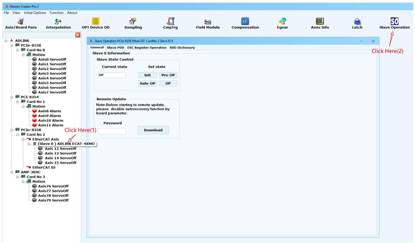
![Motion Creator Pro 2\nFile View Initial Options Function About\nAxis/Board Para Interpolation OPT Device OD Sampling CmpTrg Field Module Compensation Egear Axes Info Latch Slave Operation\nADLINK PC1e-8158 Card No 0 Motion Axis0 ServoOff Axis1 ServoOff Axis2 ServoOff Axis3 ServoOff Axis4 ServoOff Axis5 ServoOff Axis6 ServoOff Axis7 ServoOff\nPCI-8254 Card No 1 Motion Axis8 Alarm Axis9 Alarm Axis10 Alarm Axis11 Alarm\nPCIe-8338 Card No 2 EtherCAT Axis (Slave 0 ) ADLINK ECAT-4XMO Axis 12 ServoOff Axis 13 ServoOff Axis 14 ServoOff Axis 15 ServoOff\nEtherCAT IO AMP-304C Card No 3 Motion Axis76 ServoOff Axis77 ServoOff Axis78 ServoOff Axis79 ServoOff\nSlave Operation PCIe-8338 EtherCAT CardNo 2 Slave ID 0 General Slave PDO ESC Register Operation SDO Dictionary\nSlave State Control\nCurrent state Set state\nOP Init Pre-OP\nSafe-OP OP\nRemote Update\nNote: Before starting to remote update, please disable autorecovery function by board parameter.\nPassword Download](.motion-creator-pro-2-functional-user-manual-english-v0-1/85cee24c5ed3aca027843619946fa713268c69ba5ecd3488fee21c16de2eb36b.jpg)

The SDO Mapping Editor page has four sub-pages.

# General
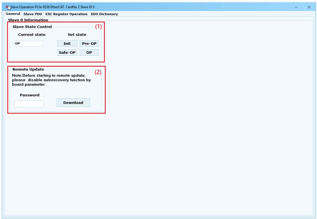
![Slave Operation PCIe-8338 EtherCAT CardNo 2 Slave ID 0\nGeneral Slave PDO ESC Register Operation SDO Dictionary\nSlave 0 Information\nSlave State Control (1)\nCurrent state Set state\nOP Init Pre-OP\nSafe-OP OP\nRemote Update (2)\nNote: Before starting to remote update,\nplease disable autorecovery function by\nboard parameter.\nPassword Download](.motion-creator-pro-2-functional-user-manual-english-v0-1/3a48efc69c29cda6140f10383928dfc91efc3c459c793bfea68f62ebbb28f9ff.jpg)

(1) Slave State Control: Set EtherCAT slave state.
(2) Remote Update: Update file over EtherCAT. (Contact ADLINK for details.)

# Slave PDO

Slave PDO lists the object dictionaries that the slave can operate through the PDO, using the Read and Write buttons.
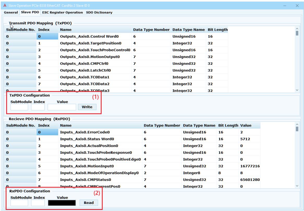
![Slave Operation PCIe-8338 EtherCAT CardNo 2 Slave ID 0\nGeneral Slave PDO ESC Register Operation SDO Dictionary\nTransmit PDO Mapping (TxPDO)\nSubModule No. Index Name Data Type Number Data Type Name Bit Length\n0 0 Outputs_Axis0.Control Word0 6 Unsigned16 16\n0 1 Outputs_Axis0.TargetPosition0 4 Integer32 32\n0 2 Outputs_Axis0.TouchProbeControl0 6 Unsigned16 16\n0 3 Outputs_Axis0.MotionOutput0 7 Unsigned32 32\n0 4 Outputs_Axis0.CMPCtrl0 7 Unsigned32 32\n0 5 Outputs_Axis0.LatchCtrl0 7 Unsigned32 32\n0 6 Outputs_Axis0.TC0Data1 4 Integer32 32\n0 7 Outputs_Axis0.TC0Data2 4 Integer32 32\n0 8 Outputs_Axis0.TC0Data3 4 Integer32 32\nTxPDO Configuration (1)\nSubModule Index Value Write\nRecieve PDO Mapping (RxPDO)\nSubModule No. Index Name Data Type Number Data Type Name Bit Length Value\n0 0 Inputs_Axis0ErrorCode0 6 Unsigned16 16 2\n0 1 Inputs_Axis0.Status Word0 6 Unsigned16 16 5712\n0 2 Inputs_Axis0.ActualPosition0 4 Integer32 32 0\n0 3 Inputs_Axis0.TouchProbeResponse0 6 Unsigned16 16 0\n0 4 Inputs_Axis0.TouchProbePositiveEdge0 4 Integer32 32 0\n0 5 Inputs_Axis0.MotionInput0 7 Unsigned32 32 16777216\n0 6 Inputs_Axis0.ModeOfOperationDisplay0 2 Integer8 8 8\n0 7 Inputs_Axis0.CMPStatus0 7 Unsigned32 32 65601280\n0 8 Inputs_Axis0.CMPCurrentPos0 4 Integer32 32 0\nRxPDO Configuration (2)\nSubModule Index Value Read](.motion-creator-pro-2-functional-user-manual-english-v0-1/7c8b7aefced513241107ef02c5a4938b58c35ab3489d7f3d95934c17dd398cb8.jpg)

(1) Write: Input the SubModule and Index of the operation Name OD in TxPDO table, and enter the corresponding Value by referring to Data Type Name and Bit Length, and then click Write.
(2) Read: Input the SubModule of the operation name OD in the RxPDO table, Index and then click Read to get its value.

# ESC Register Operation
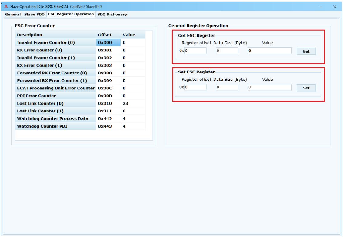
![Slave Operation PCIe-8338 EtherCAT CardNo 2 Slave ID 0\nGeneral Slave PDO ESC Register Operation SDO Dictionary\nESC Error Counter\nDescription Offset Value\nInvalid Frame Counter (0) 0x300 0\nRX Error Counter (0) 0x301 0\nInvalid Frame Counter (1) 0x302 0\nRX Error Counter (1) 0x303 0\nForwarded RX Error Counter (0) 0x308 0\nForwarded RX Error Counter (1) 0x309 0\nECAT Processing Unit Error Counter 0x30C 0\nPDI Error Counter 0x30D 0\nLost Link Counter (0) 0x310 23\nLost Link Counter (1) 0x311 6\nWatchdog Counter Process Data 0x442 4\nWatchdog Counter PDI 0x443 4\nGeneral Register Operation\nGet ESC Register\nRegister offset Data Size (Byte) Value\n0x0 0 0 Get\nSet ESC Register\nRegister offset Data Size (Byte) Value\n0x0 0 0 Set](.motion-creator-pro-2-functional-user-manual-english-v0-1/f4c988326bf0d4bd15546767b77f108cd02bfa54dcf5fbb7b23b1cca947cf5f7.jpg)

Read and write information pages for EtherCAT Slave Controller.

# SDO Dictionary

The SDO Dictionary page lists all the service data objects the user can manipulate.
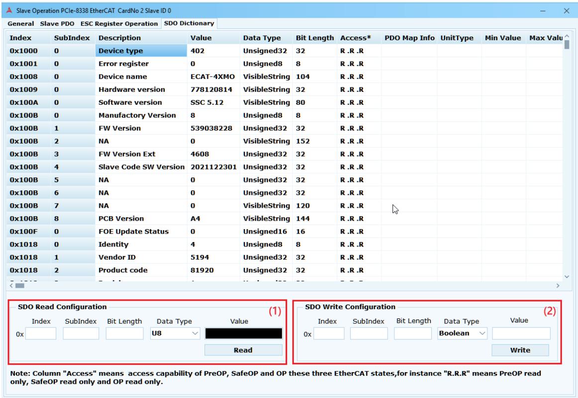
![Slave Operation PCIe-8338 EtherCAT CardNo 2 Slave ID 0\nGeneral Slave PDO ESC Register Operation SDO Dictionary\nIndex SubIndex Description Value Data Type Bit Length Access* PDO Map Info UnitType Min Value Max Valu\n0x1000 0 Device type 402 Unsigned32 32 R.R.R\n0x1001 0 Error register 0 Unsigned8 8 R.R.R\n0x1008 0 Device name ECAT-4XMO VisibleString 104 R.R.R\n0x1009 0 Hardware version 778120814 VisibleString 32 R.R.R\n0x100A 0 Software version SSC 5.12 VisibleString 80 R.R.R\n0x100B 0 Manufactory Version 8 Unsigned8 8 R.R.R\n0x100B 1 FW Version 539038228 Unsigned32 32 R.R.R\n0x100B 2 NA 0 VisibleString 152 R.R.R\n0x100B 3 FW Version Ext 4608 Unsigned32 32 R.R.R\n0x100B 4 Slave Code SW Version 2021122301 Unsigned32 32 R.R.R\n0x100B 5 NA 0 Unsigned32 32 R.R.R\n0x100B 6 NA 0 Unsigned32 32 R.R.R\n0x100B 7 NA 0 VisibleString 120 R.R.R\n0x100B 8 PCB Version A4 VisibleString 144 R.R.R\n0x100F 0 FOE Update Status 0 Unsigned16 16 R.R.R\n0x1018 0 Identity 4 Unsigned8 8 R.R.R\n0x1018 1 Vendor ID 5194 Unsigned32 32 R.R.R\n0x1018 2 Product code 81920 Unsigned32 32 R.R.R\nSDO Read Configuration (1)\nIndex SubIndex Bit Length Data Type Value\n0x U8 Read SDO Write Configuration (2)\nIndex SubIndex Bit Length Data Type Value\n0x Boolean Write\nNote: Column 'Access' means access capability of PreOP, SafeOP and OP these three EtherCAT states,for instance 'R.R.R' means PreOP read only, SafeOP read only and OP read only.](.motion-creator-pro-2-functional-user-manual-english-v0-1/b22eb2b920eb3cdbc743d30e0ac014bc89652bce8f088ce73c1cd065a63c335a.jpg)

(1) Read: Enter Index and SubIndex, and click Read to display the desired Value in the value field.
(2) Write: Enter Index, SubIndex,Value and click Write to set the desired values.

# 3.12 Field module

ADLINK Slave-specific pages, depending on Slave Axis or Slave IO, have different rendering functions.

# 3.12.1 ADLINK Slave Axis

To open the Field module page, click Slave x on the device tree, and then click the Field module icon.
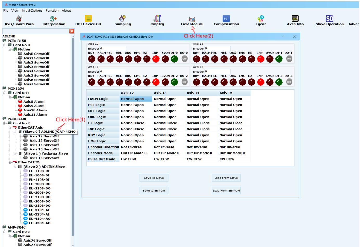
![Motion Creator Pro 2\nFile View Initial Options Function About\nAxis/Board Para Interpolation OPT Device OD Sampling CmpTrg Field Module Compensation Egear Axes Info Slave Operation Advar\nADLINK PC1e-8158 Card No 0 Motion\nAxis0 ServoOff Axis1 ServoOff Axis2 ServoOff Axis3 ServoOff Axis4 ServoOff Axis5 ServoOff Axis6 ServoOff Axis7 ServoOff\nPCI-8254 Card No 1 Motion\nAxis8 Alarm Axis9 Alarm Axis10 Alarm Axis11 Alarm\nPC1e-8338 Card No 2 EtherCAT Axis (Slave 0 ) ADLINK CAT-4XMO\nAxis 12 ServoOff Axis 13 ServoOff\nAxis 14 ServoOff Axis 15 ServoOff\n axes Logic Normal Open Normal Open Normal Open Normal Open\nPEL Logic Normal Open Normal Open Normal Open Normal Open\nMEL Logic Normal Open Normal Open Normal Open Normal Open\nORG Logic Normal Open Normal Open Normal Open Normal Open\nEZ Logic Normal Close Normal Close Normal Close Normal Close\nINP Logic Normal Close Normal Close Normal Close Normal Close\nRDY Logic Normal Open Normal Open Normal Open Normal Open Normal Open\nEMG Logic Normal Open Normal Open Normal Open Normal Open\nEncoder Direction Not Inverse Not Inverse Not Inverse Not Inverse\nEncoder Mode Out Dir Mode 0 Out Dir Mode 0 Out Dir Mode 0 Out Dir Mode 0\nPulse Out Mode CW CCW CW CCW CW CCW CW CCW\nClick Here(1)\nSave To Slave Load From Slave\nSave to EEPROM Load From EEPROM\nAMP-304C Card No 3 Motion\nAxis76 ServoOff Axis77 ServoOff](.motion-creator-pro-2-functional-user-manual-english-v0-1/1db677de0884ae6d0f5b86724bbb94580e894a021d99d52b03ff1b1209e07455.jpg)

Using an ECAT-4XMO, for example, the information is divided into two areas.
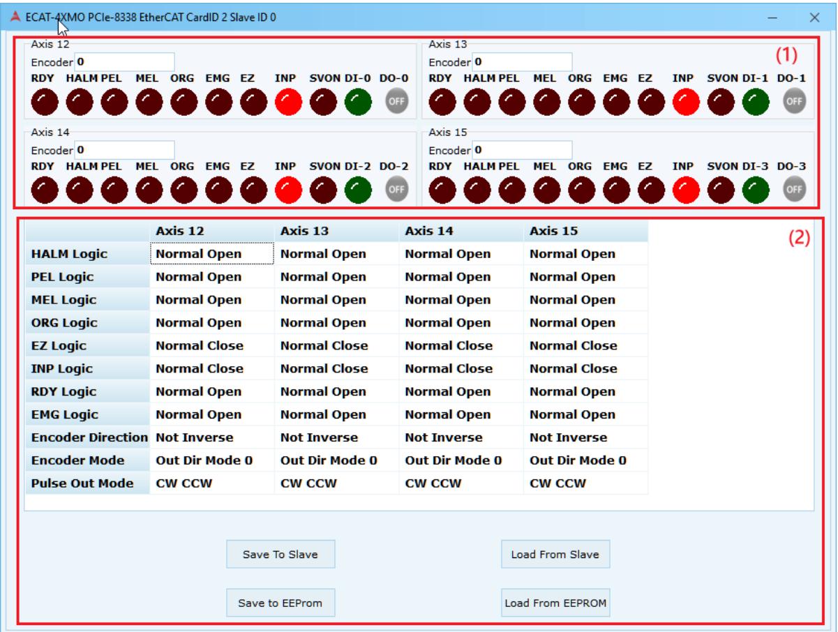
![ECAT-4XMO PCIe-8338 EtherCAT CardID 2 Slave ID 0\nAxis 12\nEncoder 0\nRDY HALM PEL MEL ORG EMG EZ INP SVON DI-0 DO-0 OFF\nAxis 13\nEncoder 0\nRDY HALM PEL MEL ORG EMG EZ INP SVON DI-1 DO-1 OFF\nAxis 14\nEncoder 0\nRDY HALM PEL MEL ORG EMG EZ INP SVON DI-2 DO-2 OFF\nAxis 15\nEncoder 0\nRDY HALM PEL MEL ORG EMG EZ INP SVON DI-3 DO-3 OFF\nAxis 12	Axis 13	Axis 14	Axis 15	(2)\nHALM Logic	Normal Open	Normal Open	Normal Open	Normal Open\nPEL Logic	Normal Open	Normal Open	Normal Open	Normal Open\nMEL Logic	Normal Open	Normal Open	Normal Open	Normal Open\nORG Logic	Normal Open	Normal Open	Normal Open	Normal Open\nEZ Logic	Normal Close	Normal Close	Normal Close	Normal Close\nINP Logic	Normal Close	Normal Close	Normal Close	Normal Close\nRDY Logic	Normal Open	Normal Open	Normal Open	Normal Open\nEMG Logic	Normal Open	Normal Open	Normal Open	Normal Open\nEncoder Direction	Not Inverse	Not Inverse	Not Inverse	Not Inverse\nEncoder Mode	Out Dir Mode 0	Out Dir Mode 0	Out Dir Mode 0	Out Dir Mode 0\nPulse Out Mode	CW CCW	CW CCW	CW CCW\nSave To SlaveLoad From Slave\nSave to EEPROMLoad From EEPROM](.motion-creator-pro-2-functional-user-manual-english-v0-1/8e5ad3e021ed0dfcdaf48548eb61bbc7e2cda4af36c0073316f785e4808312b4.jpg)

(1) Displays the status of each axis.
(2) Common SDO configuration support settings for an ADLINK slave.

# 3.12.2 ADLINK Slave IO

Click DIO or AIO in the device tree, and then click the Field Module icon.
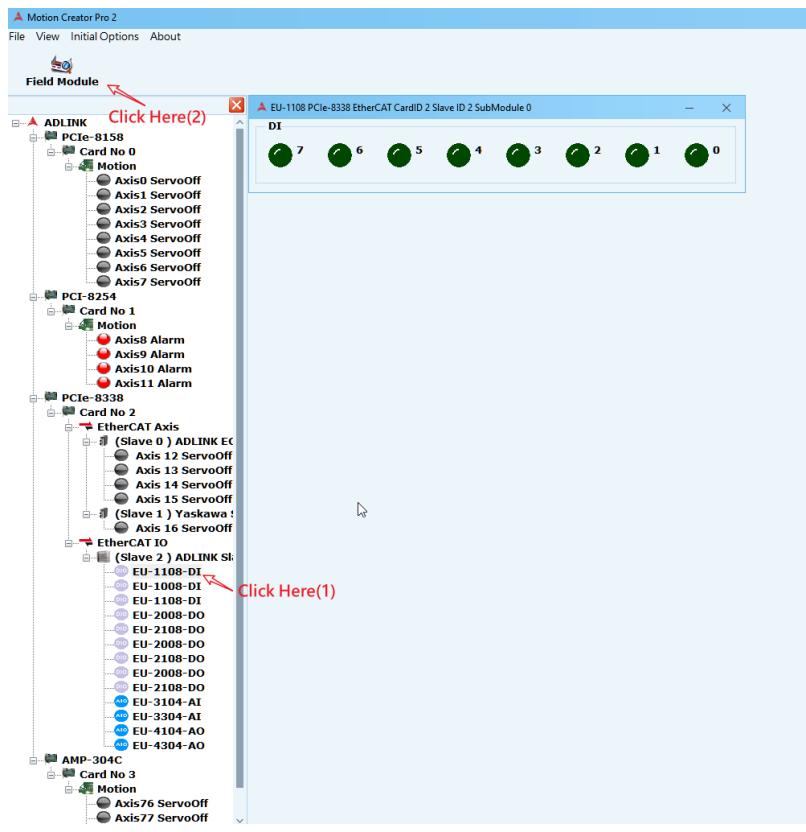
![Motion Creator Pro 2\nFile View Initial Options About\nField Module\nClick Here(2)\nADLINK\nPCIe-8158\nCard No 0\nMotion\nAxis0 ServoOff\nAxis1 ServoOff\nAxis2 ServoOff\nAxis3 ServoOff\nAxis4 ServoOff\nAxis5 ServoOff\nAxis6 ServoOff\nAxis7 ServoOff\nPCI-8254\nCard No 1\nMotion\nAxis8 Alarm\nAxis9 Alarm\nAxis10 Alarm\nAxis11 Alarm\nPCIe-8338\nCard No 2\nEtherCAT Axis\n(Slave 0 ) ADLINK EC\nAxis 12 ServoOff\nAxis 13 ServoOff\nAxis 14 ServoOff\nAxis 15 ServoOff\n(Slave 1 ) Yaskawa :\nAxis 16 ServoOff\nEtherCAT IO\n(Slave 2 ) ADLINK SI\nEU-1108-DI\nEU-1008-DI\nEU-1108-DI\nEU-2008-DO\nEU-2108-DO\nEU-2008-DO\nEU-2108-DO\nEU-2008-DO\nEU-2108-DO\nEU-3104-AI\nEU-3304-AI\nEU-4104-AO\nEU-4304-AO\nAMP-304C\nCard No 3\nMotion\nAxis76 ServoOff\nAxis77 ServoOff\nEU-1108 PCIe-8338 EtherCAT CardID 2 Slave ID 2 SubModule 0\nDI\n7 6 5 4 3 2 1 0\nClick Here(1)](.motion-creator-pro-2-functional-user-manual-english-v0-1/dcee9a09976a9f20e2fcbcca5cf246d182cea7eeb3ee519ea254ea8af0f83979.jpg)

Using an EU-6000, for example, the information is divided into four different DIO and AIO settings.
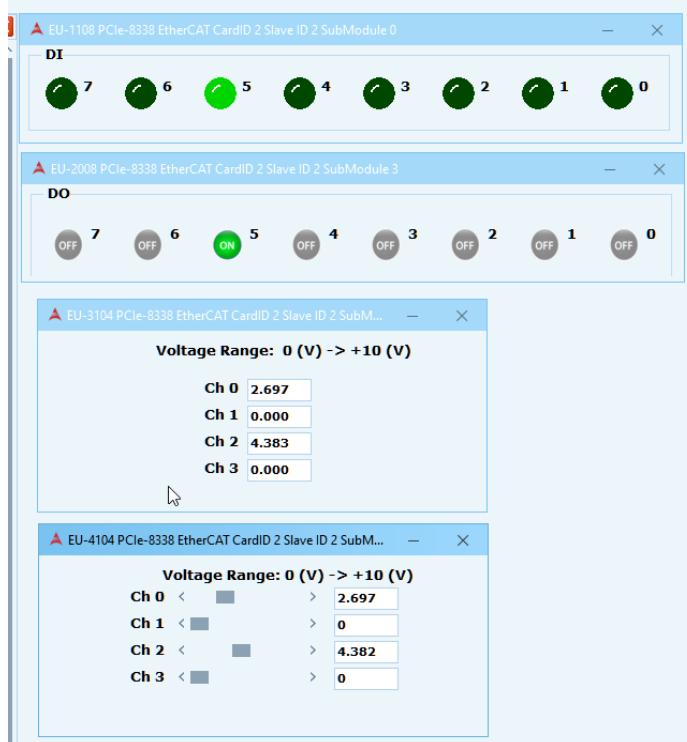
![EU-1108 PCIe-8338 EtherCAT CardID 2 Slave ID 2 SubModule 0\nDI\n7 6 5 4 3 2 1 0\nEU-2008 PCIe-8338 EtherCAT CardID 2 Slave ID 2 SubModule 3\nDO\nOFF 7 OFF 6 ON 5 OFF 4 OFF 3 OFF 2 OFF 1 OFF 0\nEU-3104 PCIe-8338 EtherCAT CardID 2 Slave ID 2 SubM...\nVoltage Range: 0 (V) -) +10 (V)\nCh 0 2.697\nCh 1 0.000\nCh 2 4.383\nCh 3 0.000\nEU-4104 PCIe-8338 EtherCAT CardID 2 Slave ID 2 SubM...\nVoltage Range: 0 (V) -) +10 (V)\nCh 0 ( ) 2.697\nCh 1 ( ) 0\nCh 2 ( ) 4.382\nCh 3 ( ) 0](.motion-creator-pro-2-functional-user-manual-english-v0-1/1ea161ba9b054b69b0e7651b6457011171da860b7dcb303068293162c837fcdf.jpg)

# 3.13 Axis Info

The Axis info page monitors new or removed custom multi-axis motion states, commands, feedback, speed, acceleration, etc. for data monitoring.

To open the multi-axis information page, click Slave x or Motion on the device tree, and then click the Axes Info icon.
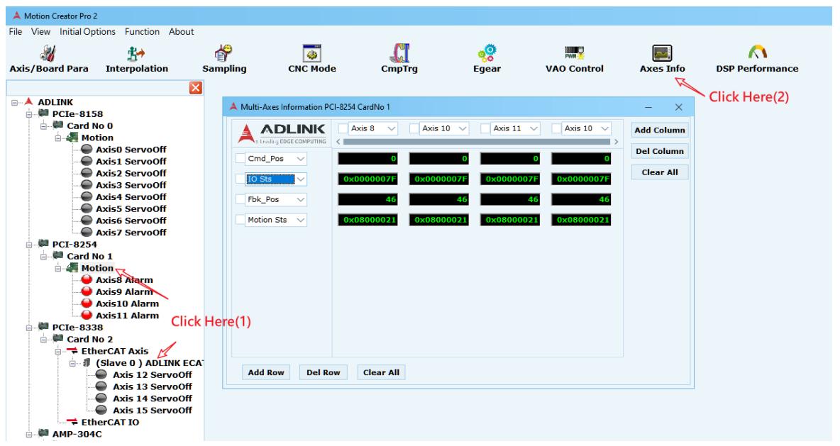
![Motion Creator Pro 2\nFile View Initial Options Function About\nAxis/Board Para Interpolation Sampling CNC Mode CmpTrg Egear VAO Control Axes Info DSP Performance\nADLINK PCIe-8158 Card No 0 Motion Axis0 ServoOff Axis1 ServoOff Axis2 ServoOff Axis3 ServoOff Axis4 ServoOff Axis5 ServoOff Axis6 ServoOff Axis7 ServoOff\nPCI-8254 Card No 1 Motion Axis8 Alarm Axis9 Alarm Axis10 Alarm Axis11 Alarm\nPCIe-8338 Card No 2 EtherCAT Axis (Slave 0) ADLINK ECA Axis 12 ServoOff Axis 13 ServoOff Axis 14 ServoOff Axis 15 ServoOff EtherCAT IO\nAMP-304C\nMulti-Axes Information PCI-8254 CardNo 1\nADLINK\nLinking EDGE COMPUTING\nClick Here(1)\nAdd Column\nDel Column\nClear All\nAdd Row Del Row Clear All\n0x0000007F 0x0000007F 0x0000007F 0x0000007F\n0x08000021 0x08000021 0x08000021 0x08000021\nCmd_Pos 0 0 0 0 0\nIO Sts 46 46 46 46\nFbk_Pos 46 46 46\nMotion Sts 46 46 46\nClick Here(2)](.motion-creator-pro-2-functional-user-manual-english-v0-1/f74b2a6c331d2aa9c8ab9d1b1281eed4b9adc919821f446869045dc25448a18a.jpg)

The multi-axis information page content is as follows.
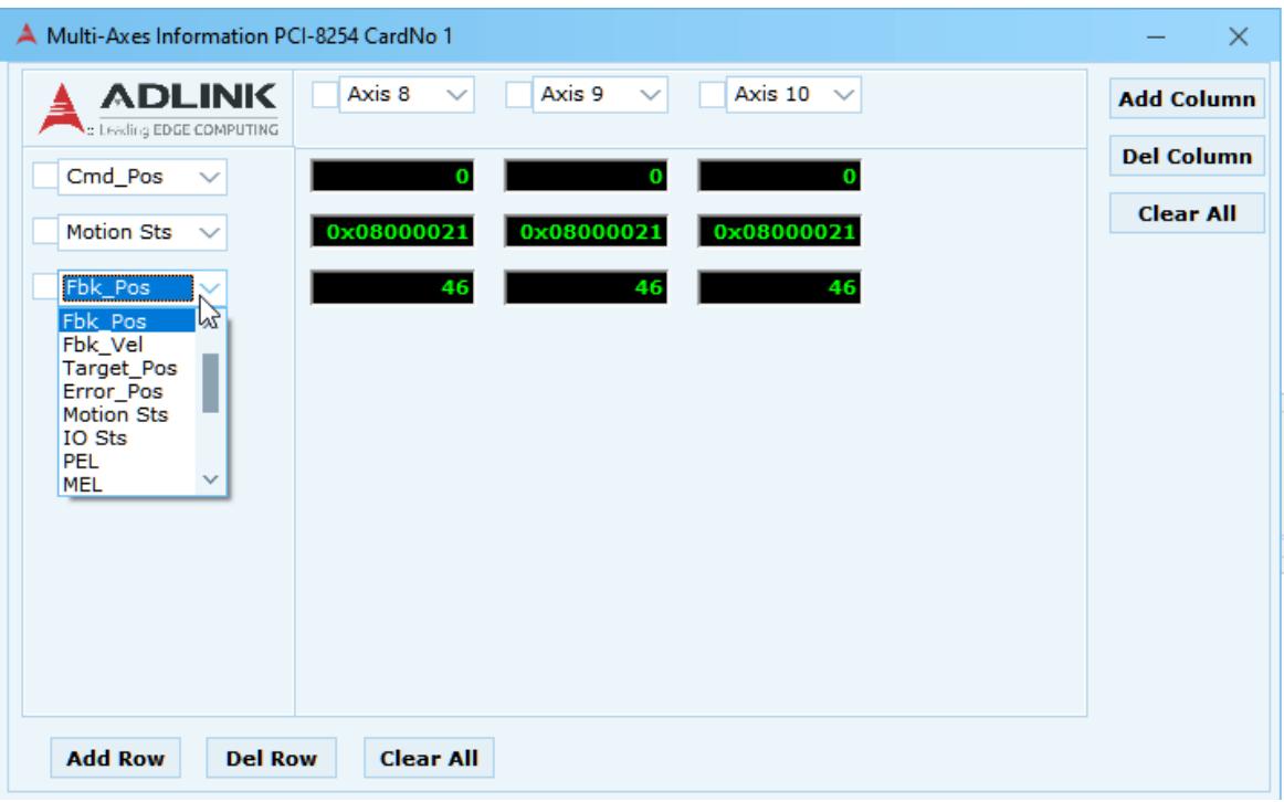
![Multi-Axes Information PCI-8254 CardNo 1\nADLINK\n: Leading EDGE COMPUTING\nAxis 8	Axis 9	Axis 10\nCmd_Pos	0	0	0\nMotion Sts	0x08000021	0x08000021	0x08000021\nFbk_Pos	46	46	46\nFbk_Pos\nFbk_Vel\nTarget_Pos\nError_Pos\nMotion Sts\nIO Sts\nPEL\nMEL\nAdd Row	Del Row	Clear All](.motion-creator-pro-2-functional-user-manual-english-v0-1/1a8ce6afc8dda9bf2467d455160279ff76bebf8124db5d11e709409fc0ca6905.jpg)

Add Row: Add columns from multiple monitoring sources, such as Cmd\_Pos, Cmd\_Vel, Fbk\_Pos, Fbk\_Vel and other monitoring sources.
 Del Row: Deletes the selected monitoring source column.
Clear All: Deletes all monitoring source columns.
Add Column: Adds a row with multiple monitoring axes. You can select the axis number to be monitored from the drop-down list.
 Del Column: Deletes the selected monitoring axis.
Clear All: Deletes all monitoring axes.

# 3.14 Advanced Point Table

The advanced point table provides the function of two-dimensional multi-point continuous motion planned by the user and displays the motion trajectory on the chart. The motion content includes absolute linear motion, circular motion or relative linear motion, and circular motion. Users can set the basic parameters of each point motion and save the file for later use.

To open APT page, click Slave x on the device tree, and then click the APT icon.
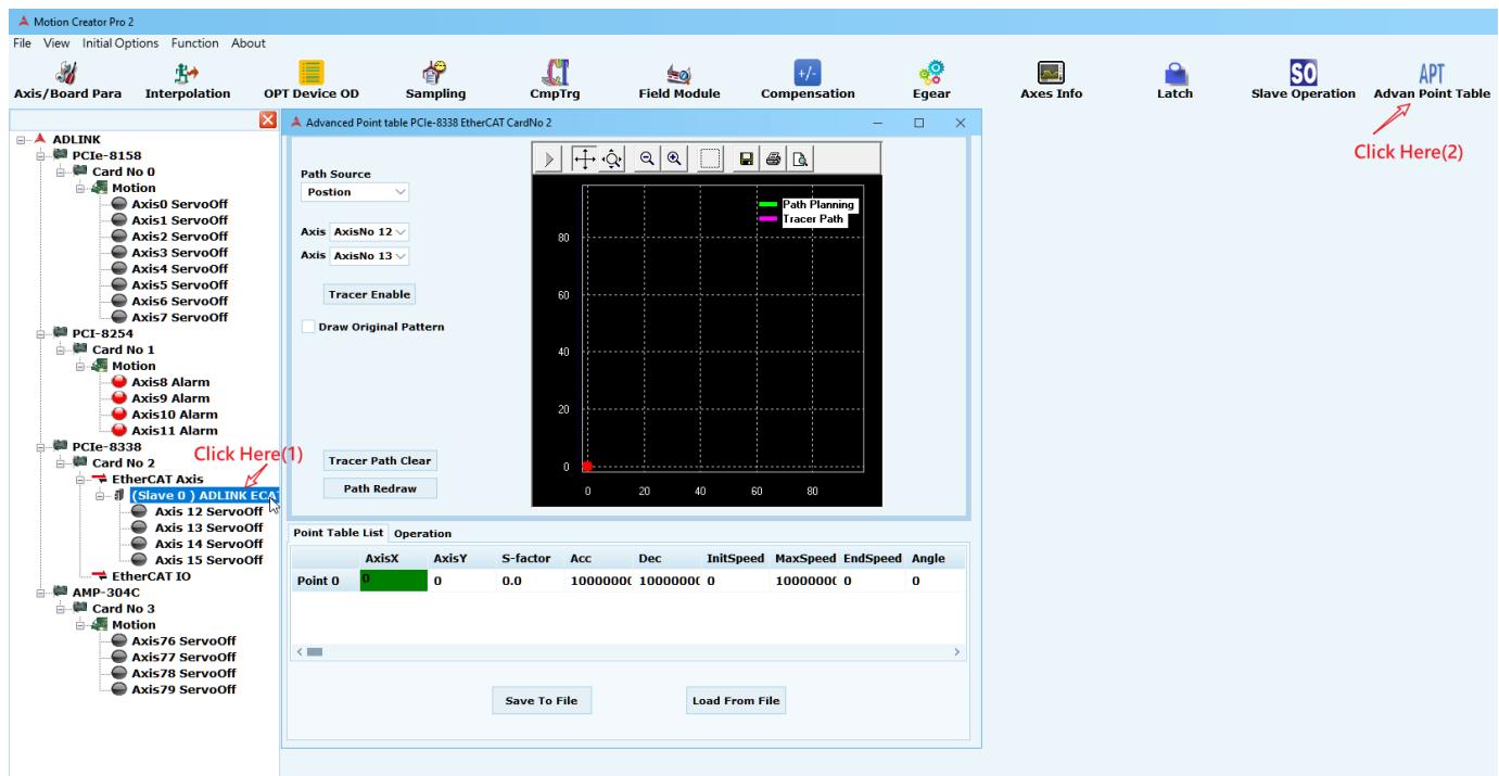
![Motion Creator Pro 2\nFile View Initial Options Function About\nAxis/Board Para Interpolation OPT Device OD Sampling CmpTrg Field Module Compensation Egear Axes Info Latch Slave Operation APT\nAdvanced Point table PCIe-8338 EtherCAT CardNo 2\nADLINK\nPCIe-8158\nCard No 0\nMotion\nAxis0 ServoOff\nAxis1 ServoOff\nAxis2 ServoOff\nAxis3 ServoOff\nAxis4 ServoOff\nAxis5 ServoOff\nAxis6 ServoOff\nAxis7 ServoOff\nPCI-8254\nCard No 1\nMotion\nAxis8 Alarm\nAxis9 Alarm\nAxis10 Alarm\nAxis11 Alarm\nPCIe-8338\nCard No 2\nEtherCAT Axis\n(Slave 0) ADLINK ECA\nAxis 12 ServoOff\nAxis 13 ServoOff\nAxis 14 ServoOff\nAxis 15 ServoOff\nEtherCAT IO\nAMP-304C\nCard No 3\nMotion\nAxis76 ServoOff\nAxis77 ServoOff\nAxis78 ServoOff\nAxis79 ServoOff\nClick Here(1)\nPath Source\nPosition\nPath Planning\nTracer Path\nAxis AxisNo 12\nAxis AxisNo 13\nTracer Enable\nDraw Original Pattern\nTracer Path Clear\nPath Redraw\nPoint Table List Operation\nAxisX AxisY S-factor Acc Dec InitSpeed MaxSpeed EndSpeed Angle\nPoint 0 0 0.0 1000000€ 1000000€ 0 1000000€ 0 0\nSave To File Load From File](.motion-creator-pro-2-functional-user-manual-english-v0-1/49c138eadc5cb70e168483a78189956f5279f8c0ac8a95a4d5ec05a48b4becf0.jpg)

# 3.14.1 Drawing Area

The two-dimensional point movement track set by the user can be displayed in area (1). The green line (Path Planning) is the trajectory of the control command, and the pink line (Tracer Path) is the trajectory of the actual movement.

The drawing function (2) is set as follows:

 Path Source: Actual motion position or command position
 Axis X,Y: Selects the axis ID of the 2D motion
 Tracer Path Clear: Clears the actual path from the drawing area
 Path Redraw: Redraws the control command trajectory
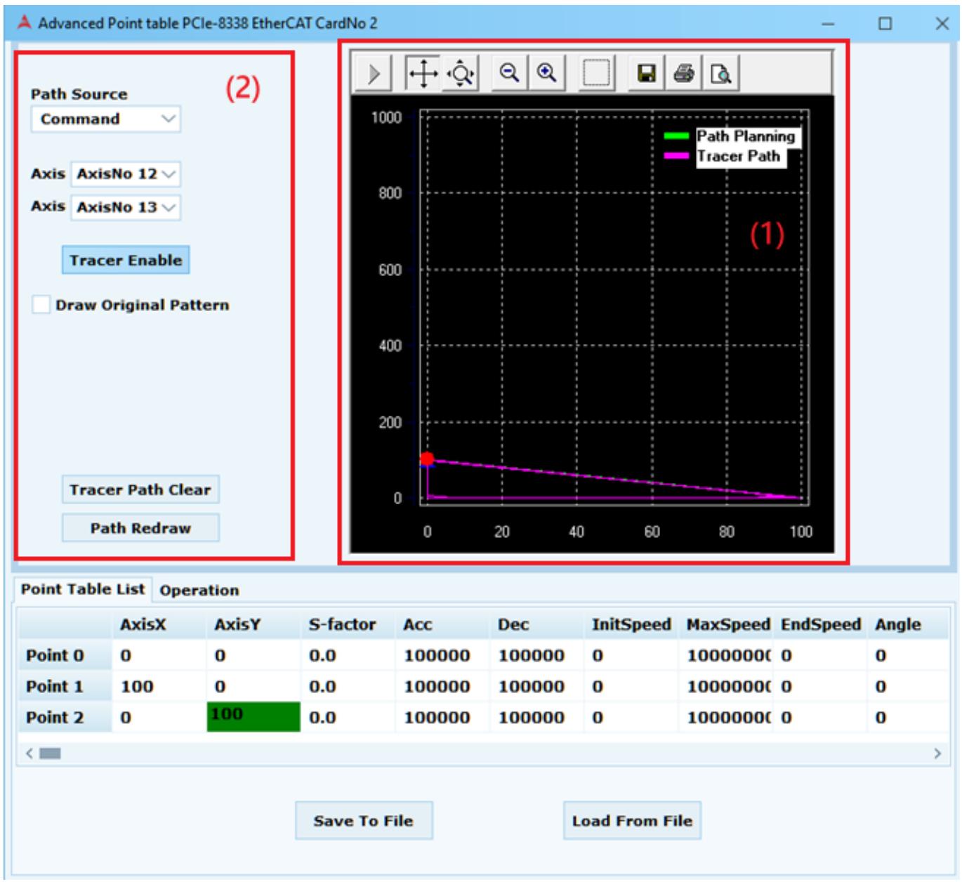
![| Point | S-factor | Acc   | Dec   | InitSpeed | MaxSpeed | EndSpeed | Angle |\n|-------|----------|-------|-------|-----------|----------|----------|-------|\n| Point 0 | 0        | 0     | 100000 | 0         | 1000000  | 0        | 0     |\n| Point 1 | 100      | 0     | 100000 | 0         | 1000000  | 0        | 0     |\n| Point 2 | 100      | 0     | 100000 | 0         | 1000000  | 0        | 0     |](.motion-creator-pro-2-functional-user-manual-english-v0-1/a4a5a7be92159f019642803e81efb92e906e00c5ebdf23ba93f847613d57bfe2.jpg)

# 3.14.2 Configuration Area

Right-click on the Point Table List to add or delete point movements.
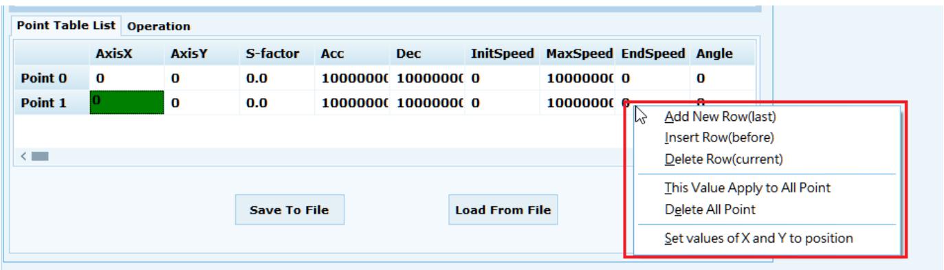
![Point Table List Operation\nAxisX	AxisY	S-factor	Acc	Dec	InitSpeed	MaxSpeed	EndSpeed	Angle\nPoint 0	0	0.0	10000000	10000000	0	10000000	0	0\nPoint 1	0	0.0	10000000	10000000	0	10000000\nSave To File	Load From File\nAdd New Row(last)\nInsert Row(before)\nDelete Row(current)\nThis Value Apply to All Point\nDelete All Point\nSet values of X and Y to position](.motion-creator-pro-2-functional-user-manual-english-v0-1/c7bc431ee46609e628da9cb27089baeca6118e99c0f632d89064525ed5dc6589.jpg)

Click in the grid to edit the information of the motion command. For example, the position of Point 0, Axis X, is 100000.
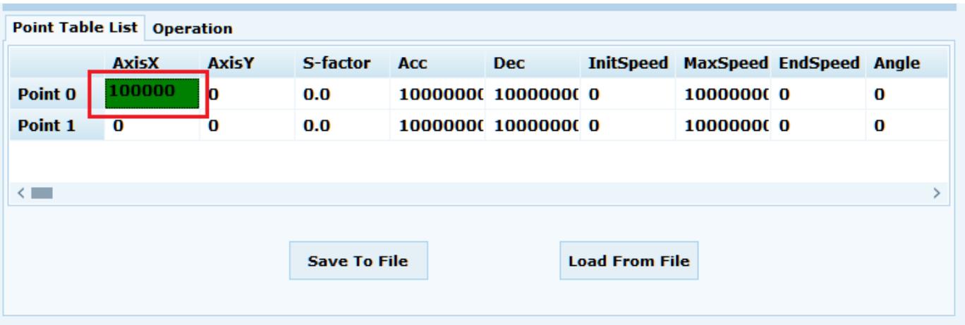
![Point Table List Operation\nAxisX AxisY S-factor Acc Dec InitSpeed MaxSpeed EndSpeed Angle\nPoint 0 100000 0 0.0 10000000 10000000 0 10000000 0 0\nPoint 1 0 0 0.0 10000000 10000000 0 10000000 0 0\nSave To File Load From File](.motion-creator-pro-2-functional-user-manual-english-v0-1/ff986a3d05937e0bab97d1ccd0156e399132ee8700896c03517882cc6c5707da.jpg)

Right-click in an Option cell to access advanced configuration options, such as Abs (absolute motion), Rel (relative motion), Linear (linear), Arc (Arc), etc.
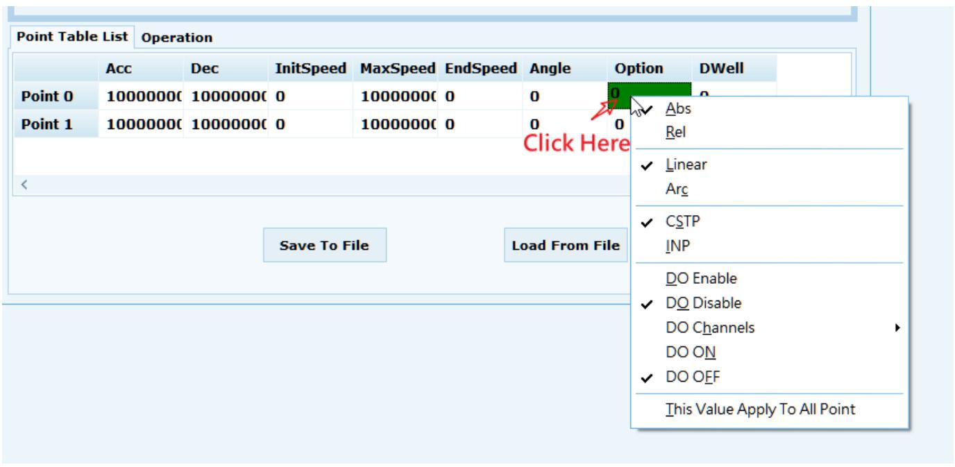
![Point Table List Operation\nAcc Dec InitSpeed MaxSpeed EndSpeed Angle Option DWell\nPoint 0 10000000 10000000 0 10000000 0 0\nPoint 1 10000000 10000000 0 10000000 0 0\nClick Here\n✓ Linear\nArc\n✓ CSTP\nINP\nDO Enable\n✓ DO Disable\nDO Channels\nDO ON\n✓ DO OFF\nThis Value Apply To All Point\nSave To File Load From File](.motion-creator-pro-2-functional-user-manual-english-v0-1/889cde6ef0c715bd9a895447229b6f5894d04c4aeddc71e83d09b9f1fd8ceb4f.jpg)

# 3.14.3 Operation Area

Click the Operation tab to see the following options.

(1) Use these values to monitor the command and feedback position of the two axes.
(2) Use these values to monitor the current point to which the command has been executed, the buffer status of the point table, and which point table to select.
(3) Use these values to monitor the execution time, feeder status and buffer status of the dot filler. Additional functions include:

 Start: Start point table motion.
 Stop: Stop point table motion.
 Pause: Pause point table motion.
 Rollback: In Pause state, use the speed set by VRback to return to the previous motion position.
Resume: Resume from pause.
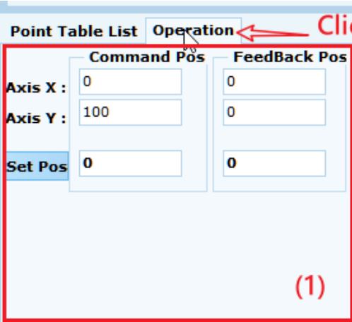
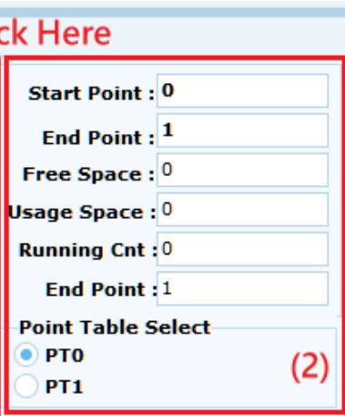
![Point Table List Operation\nClick\nCommand Pos Feedback Pos\nAxis X : 0\nAxis Y : 100\nSet Pos 0\n(1)](.motion-creator-pro-2-functional-user-manual-english-v0-1/8e77ff721b02811c924d3f588882e595fab2ec3435936302d1c23e10390de7b2.jpg)

![ck Here\nStart Point : 0\nEnd Point : 1\nFree Space : 0\nUsage Space : 0\nRunning Cnt : 0\nEnd Point : 1\nPoint Table Select\nPT0\nPT1\n(2)](.motion-creator-pro-2-functional-user-manual-english-v0-1/0df477d5142fc6fb6eab3bcac0ff3319827f8dc47d022d6604084de3f10172fe.jpg)

![Start Stop Pause\nExecution Time(s) Rollback VRback\n0.0 10000\nFeeder Status Resume\nStopped\nBuffer Status\n0\n(3)](.motion-creator-pro-2-functional-user-manual-english-v0-1/bde4fc70a5d67cbcb49af9f1b24e9ebeac737f7500a9724eeb14e1a176ce3512.jpg)

# 3.15 Manual Settings Slave ID (Manual ID)

Manual ID allows the user to set the ID of each Slave.

To open the Manual ID page, click Slave x in the device tree, and then click the Manual ID icon.
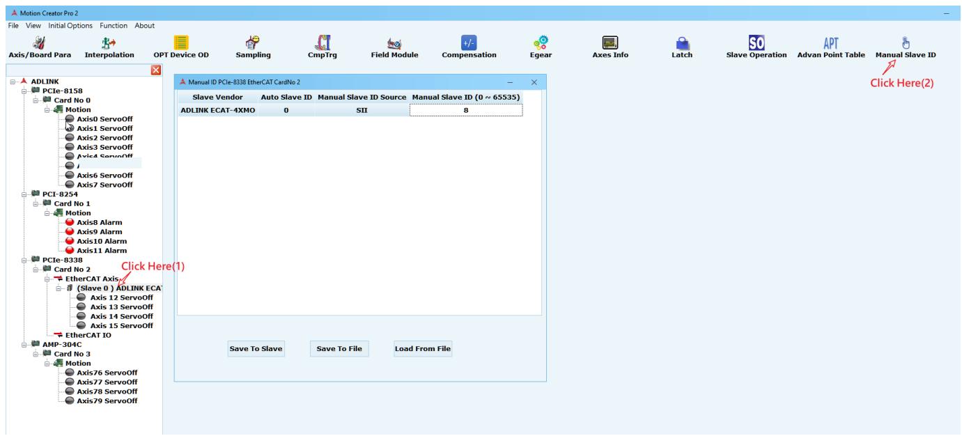
![Motion Creator Pro 2\nFile View Initial Options Function About\nAxis/Board Para Interpolation OPT Device OD Sampling CmpTrg Field Module Compensation Egear Axes Info Latch Slave Operation APT Manual Slave ID\nADLINK PCie-8158\nCard No 0\nMotion\nAxis0 ServoOff\nAxis1 ServoOff\nAxis2 ServoOff\nAxis3 ServoOff\nAxis4 ServoOff\nAxis6 ServoOff\nAxis7 ServoOff\nPCI-8254\nCard No 1\nMotion\nAxis8 Alarm\nAxis9 Alarm\nAxis10 Alarm\nAxis11 Alarm\nPCIe-8338\nCard No 2\nEtherCAT Axis\n(Slave 0) ADLINK ECAT\nAxis 12 ServoOff\nAxis 13 ServoOff\nAxis 14 ServoOff\nAxis 15 ServoOff\nEtherCAT IO\nAMP-304C\nCard No 3\nMotion\nAxis76 ServoOff\nAxis77 ServoOff\nAxis78 ServoOff\nAxis79 ServoOff\nClick Here(1)\nManual ID PCIe-8338 EtherCAT CardNo 2\nSlave Vendor Auto Slave ID Manual Slave ID Source Manual Slave ID (0 ~ 65535)\nADLINK ECAT-4XMO 0 SII 8\nSave To Slave Save To File Load From File\nClick Here(2)](.motion-creator-pro-2-functional-user-manual-english-v0-1/8f93b5502ec19a73d51296945abd13527b6a200cccf6010ba1ffdc69cf125869.jpg)

Information about the Manual ID includes:

 Auto Slave ID: Slave IDs that are automatically sorted from 0 to 63335 are listed in this table.
Manual Slave ID Source: Currently, PCI-833X is configured to read from the ESC Configured Station Alias Register and is defined as SII. The other mode gets the information for the ID-Selector by reading the AL Status Code defined as AL Control. This information needs to be combined with board parameter to select different reading modes to read ID information. For these settings, refer to the APS Function Library manual.
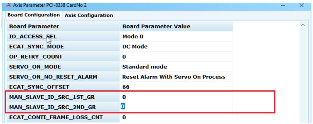
![Axis Parameter PCI-8338 CardNo 2\nBoard Configuration	Axis Configuration\nBoard Parameter	Board Parameter Value\nIO_ACCESS_SEL	Mode 0\nECAT_SYNC_MODE	DC Mode\nOP_RETRY_COUNT	0\nSERVO_ON_MODE	Standard mode\nSERVO_ON_NO_RESET_ALARM	Reset Alarm With Servo On Process\nECAT_SYNC_OFFSET	66\nMAN_SLAVE_ID_SRC_1ST_GR	0\nMAN_SLAVE_ID_SRC_2ND_GR	0\nECAT_CONTI_FRAME_LOSS_CNT	0](.motion-creator-pro-2-functional-user-manual-english-v0-1/e179ebfcd1fc7c351c438be242e571f334569c105eaef38a51aa4e655acb1c8b.jpg)

 Manual Slave ID: Editable Slave ID.
 Save to Slave: Writes the configured Slave ID to the EEPROM of the Slave.
 Save to File: Saves configuration as an xml file.
 Load From File: Loads an xml file and displays it in the table.
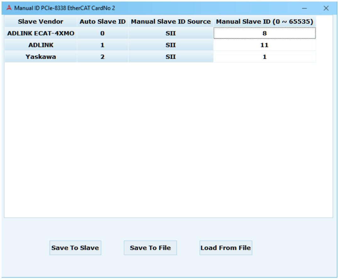
![Manual ID PCIe-8338 EtherCAT CardNo 2\nSlave Vendor Auto Slave ID Manual Slave ID Source Manual Slave ID (0 ~ 65535)\nADLINK ECAT-4XMO 0 SII 8\nADLINK 1 SII 11\nYaskawa 2 SII 1\nSave To Slave Save To File Load From File](.motion-creator-pro-2-functional-user-manual-english-v0-1/f0f45e92c3cffaf7958d42113f38fa9e68211873c002443397afc2ddf01d97dc.jpg)

# 3.16 DSP/Kernel Performance

DSP/Kernel Performance provides the user's current EtherCAT cycle time and motion cycle time, consumption time, and load, as well as the user's settings for changing the current cycle time.

To open the DSP/Kernel Performance, click Card No x on the device tree, and then click the DSP Performance or Kernel Performance icon as necessary.
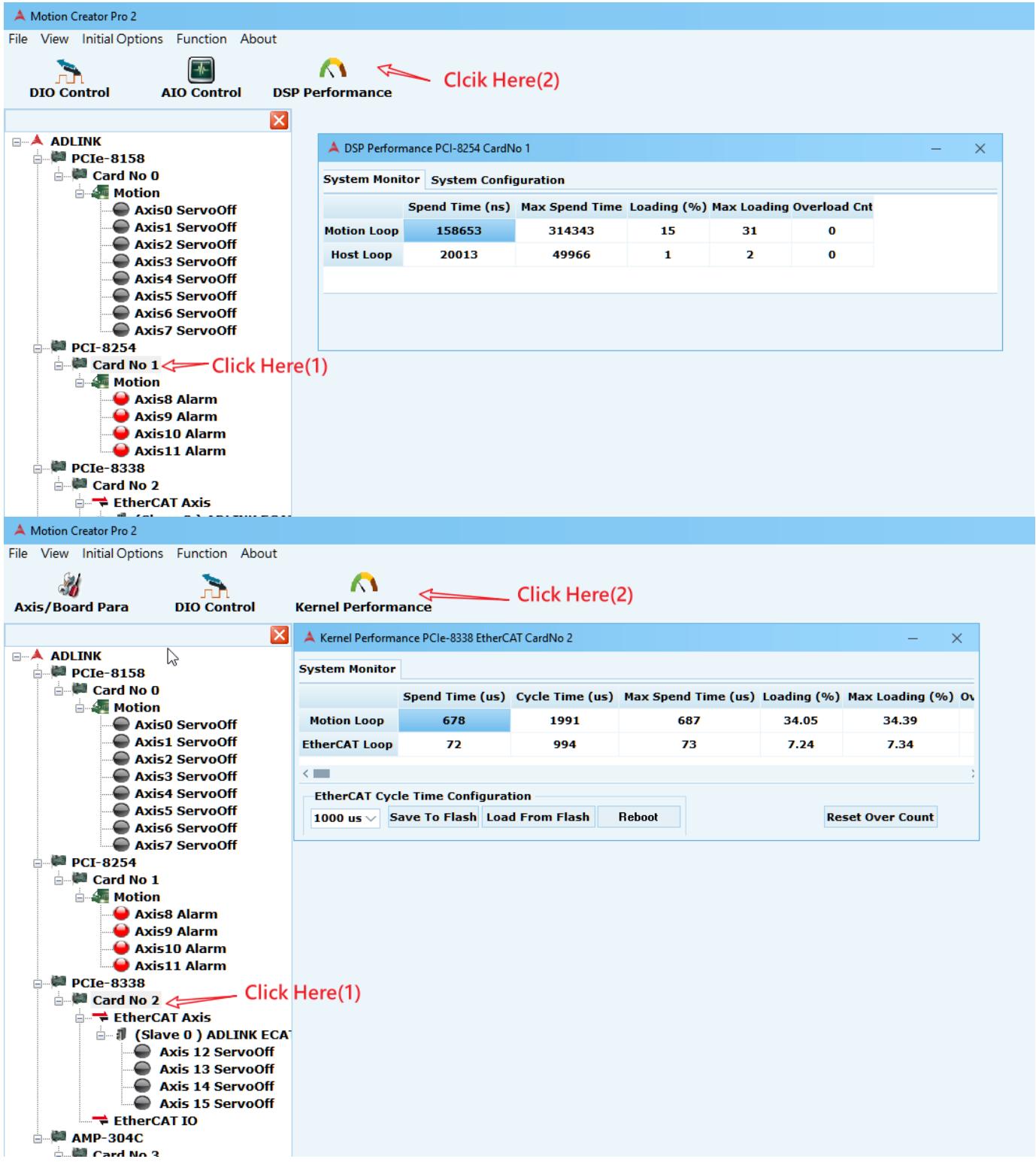
![Motion Creator Pro 2\nFile View Initial Options Function About\nDIO Control AIO Control DSP Performance\nClick Here(2)\nADLINK\nPCIe-8158\nCard No 0\nMotion\nAxis0 ServoOff\nAxis1 ServoOff\nAxis2 ServoOff\nAxis3 ServoOff\nAxis4 ServoOff\nAxis5 ServoOff\nAxis6 ServoOff\nAxis7 ServoOff\nPCI-8254\nCard No 1\nMotion\nAxis8 Alarm\nAxis9 Alarm\nAxis10 Alarm\nAxis11 Alarm\nPCIe-8338\nCard No 2\nEtherCAT Axis\nClick Here(1)\nMotion Creator Pro 2\nFile View Initial Options Function About\nAxis/Board Para DIO Control Kernel Performance Click Here(2)\nADLINK\nPCIe-8158\nCard No 0\nMotion\nAxis0 ServoOff\nAxis1 ServoOff\nAxis2 ServoOff\nAxis3 ServoOff\nAxis4 ServoOff\nAxis5 ServoOff\nAxis6 ServoOff\nAxis7 ServoOff\nPCI-8254\nCard No 1\nMotion\nAxis8 Alarm\nAxis9 Alarm\nAxis10 Alarm\nAxis10 Alarm\nPCIe-8338\nCard No 2\nEtherCAT Axis\n(Slave 0 ) ADLINK ECA-\nAxis 12 ServoOff\nAxis 13 ServoOff\nAxis 14 ServoOff\nAxis 15 ServoOff\nEtherCAT IO\nAMP-304C\nCard No 3](.motion-creator-pro-2-functional-user-manual-english-v0-1/ab80c8a0566929baa84e7670afae45b9d26d2c65a8e91ca5b43759f34344473b.jpg)

# 3.16.1 DSP Performance

<table><tr><td colspan="6">DSP Performance PCI-8254 CardNo 1</td></tr><tr><td colspan="6">System Monitor System Configuration</td></tr><tr><td></td><td>Spend Time (us)</td><td>Max Spend Time</td><td>Loading (%)</td><td>Max Loading</td><td>Overload Cnt</td></tr><tr><td>Motion Loop</td><td>158940</td><td>305896</td><td>15</td><td>30</td><td>0</td></tr><tr><td>Host Loop</td><td>20040</td><td>561386</td><td>1</td><td>28</td><td>0</td></tr></table>

 Spend Time: Time consumed per cycle of the current operation in nanoseconds
 Max Spend Time: Maximum time taken so far in nanoseconds
 Loading: Proportion in current cycle (work proportion) (100%)
 Max Loading: Recorded maximum DSP workload (100%)
 Overload Cnt: Cumulative number of overloading

# 3.16.2 Kernel Performance

![Kernel Performance PCIe-8338 EtherCAT CardNo 2\nSystem Monitor\nSpend Time (us)    Cycle Time (us)    Max Spend Time (us)    Loading (%)    Max Loading (%)    On\nMotion Loop    679    1992    689    34.09    34.50\nEtherCAT Loop    73    995    75    7.34    7.54\nEtherCAT Cycle Time Configuration\n1000 us ▼ Save To Flash Load From Flash Reboot Reset Over Count](.motion-creator-pro-2-functional-user-manual-english-v0-1/3978cd493860e6ee5d3fbc1c237e75cbccb70b8dd56bda6c8d1f5d5b79a10b33.jpg)

 Spend Time: Actual system consume time in microseconds
 Cycle Time: Actual system cycle time in microseconds
Max Spend Time: MCP2 estimates the system’s biggest consumption time in microseconds
 Loading: MCP2 estimates the percentage of the system’s current computational load (%).
 Max Loading: MCP2 estimated system current maximum load percentage (%)
 Overload Cnt: Cumulative number of overloading

# 3.16.3 How to set EtherCAT Cycle time

# 1. Select cycle time from the drop-down list.

![Kernel Performance PCIe-8338 EtherCAT CardNo 2\nSystem Monitor\nSpend Time (us)	Cycle Time (us)	Max Spend Time (us)	Loading (%)	Max Loading (%)	Over\nMotion Loop	680	1994	686	34.10	34.28\nEtherCAT Loop	78	999	79	7.81	7.94\nEtherCAT Cycle Time Configuration\n1000 us	Save To FlashLoad From Flash	Reboot	Reset Over Count\n250 us\n500 us\n1000 us\n2000 us\n4000 us](.motion-creator-pro-2-functional-user-manual-english-v0-1/7d05c02032a6fe5f13706666c0746aea505409827e916ba3013fb12c227de90c.jpg)

2. Click Save To Flash.
3. Click Reboot. A pop-up window will appear.

Note: Ensure that Field Bus is disconnected before performing this operation.

![Hint!\nAlarm! We strongly recommend you disconnect EtherCAT fisrt then reboot system !\nDo you still reboot the system ?\n是(Y)\n否(N)\n取消](.motion-creator-pro-2-functional-user-manual-english-v0-1/51da69fa018211da08b3239116bfd14ca79a744fce6a689e25c334df662ce25f.jpg)

4. While waiting, the function button will turn white until the system is reset.

![Kernel Performance PCIe-8338 EtherCAT CardNo 2\nSystem Monitor\nSpend Time (us)	Cycle Time (us)	Max Spend Time (us)	Loading (%)	Max Loading (%)	Over\nMotion Loop	649	1995	689	32.53	34.52\nEtherCAT Loop	1	998	81	0.10	8.14\nEtherCAT Cycle Time Configuration\n1000 us Save To Flash Load From Flash Reboot Reset Over Count](.motion-creator-pro-2-functional-user-manual-english-v0-1/4061dbc3c69279127b7e79ab2237cf5994169420a872d9047273ea72ca173d97.jpg)

5. Click Card No x, and then click Axis/Board Para fast to open the page. Click Save to Flash.

![Parameter PCIe-8338 EtherCAT CardNo 2\nBoard Configuration\nBoard Parameter	Board Parameter Value\nEMG_LOGIC	Normal Open\nDO_LOGIC	No Invert\nDI_LOGIC	No Invert\nIO_ACCESS_SEL	Mode 0\nECAT_SYNC_MODE	DC Mode\nOP_RETRY_COUNT	0\nSERVO_ON_MODE	Standard mode\nSERVO_ON_NO_RESET_ALARM	Reset Alarm With Servo On Process\nECAT_SYNC_OFFSET	66\nMAN_SLAVE_ID_SRC_1ST_GR	0\nMAN_SLAVE_ID_SRC_2ND_GR	0\nECAT_CONTI_FRAME_LOSS_CNT	0\nSAMPLING_SRC_AXIS_TYPE	Axis Number\nEMG_MODE	Servo off directly\nECAT_RESTORE_OUTPUT	Restore\nDI_EMG_FILTER_ENABLE	Enable\nDI_EMG_FILTER_RANGE	5 us\nPULSER_FILTER_RANGE	5 us\nSet To Card	Save To Flash	Save To FileLoad Default\nLoad From CardLoad From FlashLoad From File](.motion-creator-pro-2-functional-user-manual-english-v0-1/de32c85de95289b03037fa6c141848024dd5cf3774a35ee513a3dab3d757da4f.jpg)

# 3.17 Compare Trigger

The comparison trigger functions are divided into Linear Compare and Table Compare, which take corresponding actions when the conditions set by the user are compared.

To open the compare trigger function page, click Slave x or Motion on different axis cards in the device tree, and then click the CmpTrg icon.

![Motion Creator Pro 2\nFile View Initial Options Function About\nAxis/Board Para Interpolation CmpTrg Click Here(2)\nADLINK PCIe-8158 Card No 0 Motion Axis0 ServoOff Axis1 ServoOff Axis2 ServoOff Axis3 ServoOff Axis4 ServoOff Axis5 ServoOff Axis6 ServoOff Axis7 ServoOff\nPCI-8254 Card No 1 Motion Axis8 Alarm Axis9 Alarm Axis10 Alarm Axis11 Alarm\nPCIe-8338 Card No 2 EtherCAT Axis (Slave 0 ) ADLINK ECA Axis 12 ServoOff Axis 13 ServoOff Axis 14 ServoOff Axis 15 ServoOff (Slave 1 ) Yaskawa Sla Axis 16 ServoOff EtherCAT IO AMP-304C Card No 3 Motion Axis76 ServoOff Axis77 ServoOff Axis78 ServoOff Axis79 ServoOff Click Here(1)\nSelect trigger source Trigger Count Reset Manual\nTRG CH0 MT, L0 0\nTRG CH1 No Select 0\nTRG CH2 No Select 0\nTRG CH3 No Select 0\nTrigger Parameter Linear Comparator Setting Table Comparator Setting TimerSe )\nTRG CH0 TRG CH1 TRG CH2 TRG CH3\nEnable/Disable Enable Disable Disable Disable\nPulse Width 17 17 17 17\nLogic Not inverse Not inverse Not inverse Not inverse\nOutput Mode Pulse Out Pulse Out Pulse Out Pulse Out\nDO Output (in E 0 0 0 0\nPulse Width/Logic/Output Mode/DO Output can't be set when the channel(TRG CH0~3) is Enable.\nSet To Card Load From Card](.motion-creator-pro-2-functional-user-manual-english-v0-1/d4826ae3230475f715dde1a0031ee61445ce5dc13148c01c6c99a08254c1fda6.jpg)

The comparison trigger functions are described below.

![Compare Trigger AMP-304C CardNo 3\n(1) Select trigger source\nTRG CH0 MT, L0\nTRG CH1 No Select\nTRG CH2 No Select\nTRG CH3 No Select\nTrigger Count (2)\n0\n0\n0\n0\nReset (3) Manual\nTrigger Parameter Linear Comparator Setting Table Comparator Setting TimerSe\n(4) (5) (6) (7)\nEnable/Disable Enable Disable Disable Disable\nPulse Width 17 17 17 17\nLogic Not inverse Not inverse Not inverse Not inverse\nOutput Mode Pulse Out Pulse Out Pulse Out Pulse Out\nDO Output (in E 0 0 0 0\nPulse Width/Logic/Output Mode/DO Output can't be set when the channel(TRG CH0~3) is Enable.\nSet To Card Load From Card](.motion-creator-pro-2-functional-user-manual-english-v0-1/85816d1d54cf7b8214cfe5350939ee96d09a18ad2a5b623fef89fe82a439a9d1.jpg)

(1) Select trigger source: Selects the trigger source signal of each channel
(2) Trigger Count: Displays the number of triggered channels
(3) Reset: Clears the trigger count Manual: Triggers the signal manually

(4) Trigger Parameter: Compares the trigger setting parameters. Different axis cards have different settings. Refer to the APS Function Library manual Table definition-> Trigger parameter table for more information. This example is for ADLINK's AMP-304C, so the corresponding manual content is shown below.

<table><tr><td colspan="5">AMP-304C Trigger parameter table</td></tr><tr><td>NO</td><td>Define</td><td>Description</td><td>Value</td><td>Default :</td></tr><tr><td>0x00</td><td>TGR_LCMP0_SRC</td><td>Linear compare 0 (LCMP0) source</td><td>0 ~ 3 : Pulse counter 0~3
8 : Timer 0 counter
9 : Disable</td><td>9</td></tr><tr><td>0x01</td><td>TGR_LCMP1_SRC</td><td>Linear compare 1 (LCMP1) source</td><td>0 ~ 3 : Pulse counter 0~3
8 : Timer 0 counter
9 : Disable</td><td>9</td></tr><tr><td>0x02</td><td>TGR_TCMP0_SRC</td><td>Table compare 0 (TCMP0) source</td><td>0 ~ 3 : Pulse counter 0~3
8 : Timer 0 counter
9 : Disable</td><td>9</td></tr><tr><td>0x03</td><td>TGR_TCMP1_SRC</td><td>Table compare 1 (TCMP1) source</td><td>0 ~ 3 : Pulse counter 0~3
8 : Timer 0 counter
9 : Disable</td><td>9</td></tr><tr><td>0x04</td><td>TGR_TCMP0_DIR</td><td>Table compare 0 (TCMP0) direction</td><td>0 : Negative direction
1 : Positive direction
2 : Bi-direction(No direction)</td><td>1</td></tr><tr><td>0x05</td><td>TGR_TCMP1_DIR</td><td>Table compare 1 (TCMP1) direction</td><td>0 : Negative direction
1 : Positive direction
2 : Bi-direction(No direction)</td><td>1</td></tr><tr><td>0x06</td><td>TGR_TRG_EN</td><td>TRG 0 ~ 3 enable by bit</td><td>Bit x : (0 : disable, 1 : enable)
Bit 0 : TRG0 enable,</td><td>0</td></tr></table>

# (5) Linear Comparator Setting: [ADD CONTENT]
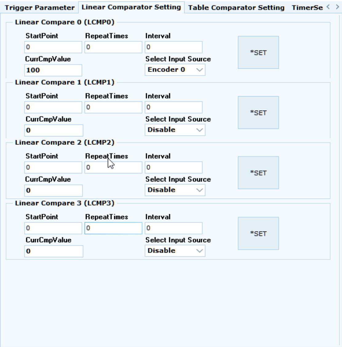
![Trigger Parameter\nLinear Comparator Setting\nTable Comparator Setting\nTimerSe ( )\nLinear Compare 0 (LCMP0)\nStartPoint\nRepeatTimes\nInterval\n0\n0\n0\nCurrCmpValue\nSelect Input Source\n100\nEncoder 0\n*SET\nLinear Compare 1 (LCMP1)\nStartPoint\nRepeatTimes\nInterval\n0\n0\n0\nCurrCmpValue\nSelect Input Source\n0\nDisable\n*SET\nLinear Compare 2 (LCMP2)\nStartPoint\nRepeatTimes\nInterval\n0\n0\n0\nCurrCmpValue\nSelect Input Source\n0\nDisable\n*SET\nLinear Compare 3 (LCMP3)\nStartPoint\nRepeatTimes\nInterval\n0\n0\n0\nCurrCmpValue\nSelect Input Source\n0\nDisable\n*SET](.motion-creator-pro-2-functional-user-manual-english-v0-1/bb1749b9a7b61a1e0ffe7b728a9f00eab57473d385861a8f25eafeebcc66aea0.jpg)

(6) Table Comparator Setting: Sets the table comparator values.
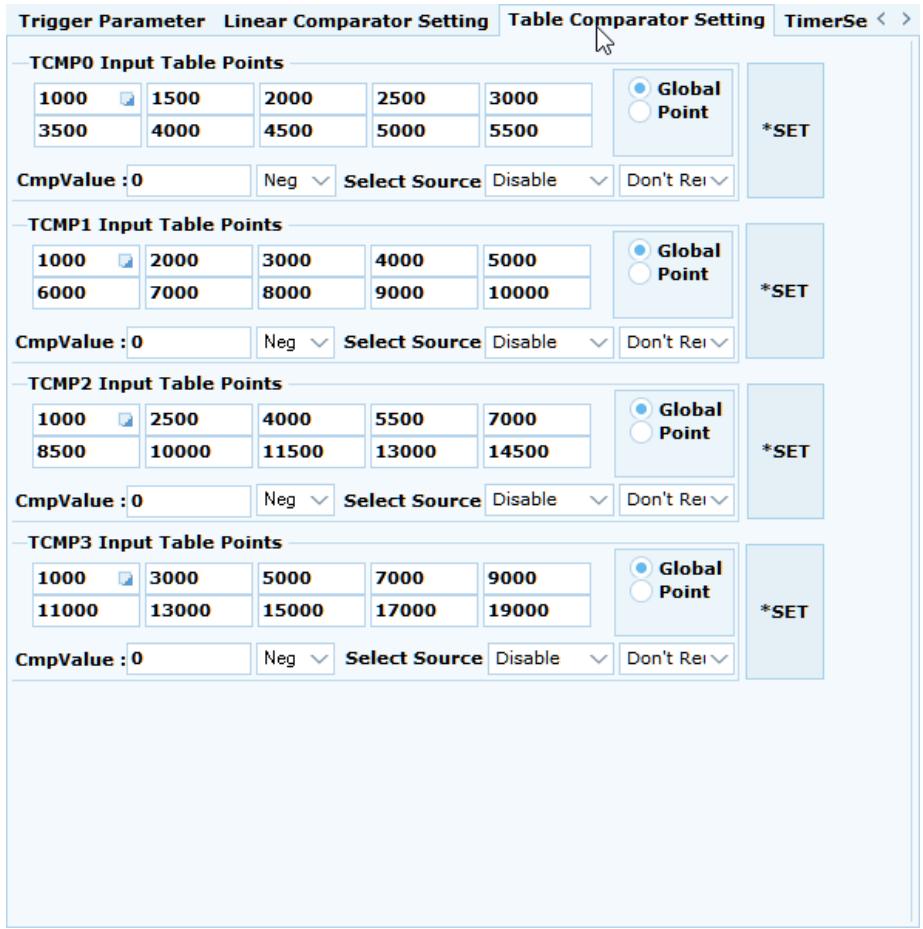
![Trigger Parameter Linear Comparator Setting Table Comparator Setting TimerSe )\nTCMP0 Input Table Points\n1000 1500 2000 2500 3000\n3500 4000 4500 5000 5500\nGlobal\nPoint\n*SET\nCmpValue : 0 Neg Select Source Disable Don't Rei\nTCMP1 Input Table Points\n1000 2000 3000 4000 5000\n6000 7000 8000 9000 10000\nGlobal\nPoint\n*SET\nCmpValue : 0 Neg Select Source Disable Don't Rei\nTCMP2 Input Table Points\n1000 2500 4000 5500 7000\n8500 10000 11500 13000 14500\nGlobal\nPoint\n*SET\nCmpValue : 0 Neg Select Source Disable Don't Rei\nTCMP3 Input Table Points\n1000 3000 5000 7000 9000\n11000 13000 15000 17000 19000\nGlobal\nPoint\n*SET\nCmpValue : 0 Neg Select Source Disable Don't Rei](.motion-creator-pro-2-functional-user-manual-english-v0-1/bc4076d56af554de88248c14adad2500f8360684c7465fb22784a246a53695e0.jpg)

# (7) Timer Setting: 計時器設定

![Based on the provided image, here is the description of the labeled blocks and their connections:\n\n**Labeled Blocks:**\n*   **Timer**: A circular block.\n*   **Compare Value**: A rectangular block.\n*   **Timer Counter**: A rectangular block containing the text '-20224'.\n*   **Comparator**: A triangular block.\n\n**Connections:**\n*   An arrow points from the **Timer** block to the **Timer Counter** block.\n*   An arrow points from the **Compare Value** block to the top input of the **Comparator** block.\n*   An arrow points from the **Timer Counter** block to the bottom input of the **Comparator** block.\n*   An arrow points from the output tip of the **Comparator** block to a terminal labeled **TRG_CHx**.](.motion-creator-pro-2-functional-user-manual-english-v0-1/736940b2b27888f0ce5de8fd9091defc75deb6ca335cc050d0d1e93604073146.jpg)

# 3.18 Latch

The position latch function allows the user to latch an instant position and then make a corresponding signal output or motion response to the position.

To open the Latch page, click Axis x on the device tree column, then click the Latch icon.
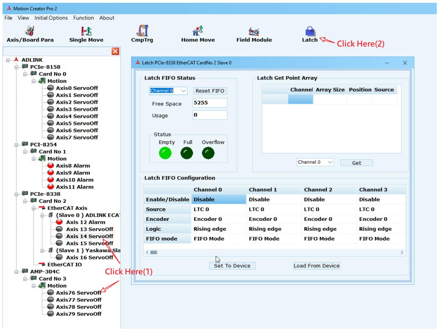
![Motion Creator Pro 2\nFile View Initial Options Function About\nAxis/Board Para Single Move CmpTrg Home Move Field Module Latch Click Here(2)\nADLINK PCIe-8158 Card No 0\nMotion\nAxis0 ServoOff\nAxis1 ServoOff\nAxis2 ServoOff\nAxis3 ServoOff\nAxis4 ServoOff\nAxis5 ServoOff\nAxis6 ServoOff\nAxis7 ServoOff\nPCI-8254 Card No 1\nMotion\nAxis8 Alarm\nAxis9 Alarm\nAxis10 Alarm\nAxis11 Alarm\nPCIe-8338 Card No 2\nEtherCAT Axis\n(Slave 0 ) ADLINK ECA\nAxis 12 Alarm\nAxis 13 ServoOff\nAxis 14 ServoOff\nAxis 15 ServoOff\n(Slave 1 ) Yaskawa Sla\nAxis 16 ServoOff\nEtherCAT IO\nAMP-304C Card No 3\nMotion\nAxis76 ServoOff\nAxis77 ServoOff\nAxis78 ServoOff\nAxis79 ServoOff\nLatch PCIe-8338 EtherCAT CardNo 2 Slave 0\nLatch FIFO Status Channel 0 Reset FIFO Free Space 5255 Usage 0 Status Empty Full Overflow Latch Get Point Array Channel Array Size Position Source Channel 0 Get Channel 0 Get Latch FIFO Configuration Channel 0 Channel 1 Channel 2 Channel 3 Enable/Disable Disable Disable Disable\nSource LTC 0 LTC 0 LTC 0 LTC 0 Encoder Encoder 0 Encoder 0 Encoder 0 Logic Rising edge Rising edge Rising edge FIFO mode FIFO Mode FIFO Mode FIFO Mode FIFO Mode Set To Device Load From Device Click Here(1)](.motion-creator-pro-2-functional-user-manual-english-v0-1/dbb1a26d86cd1fa2fb8026683601a37d8b0942bfc5f6f848dfd898dff7b5d5ea.jpg)

Latch configuration options are shown below.
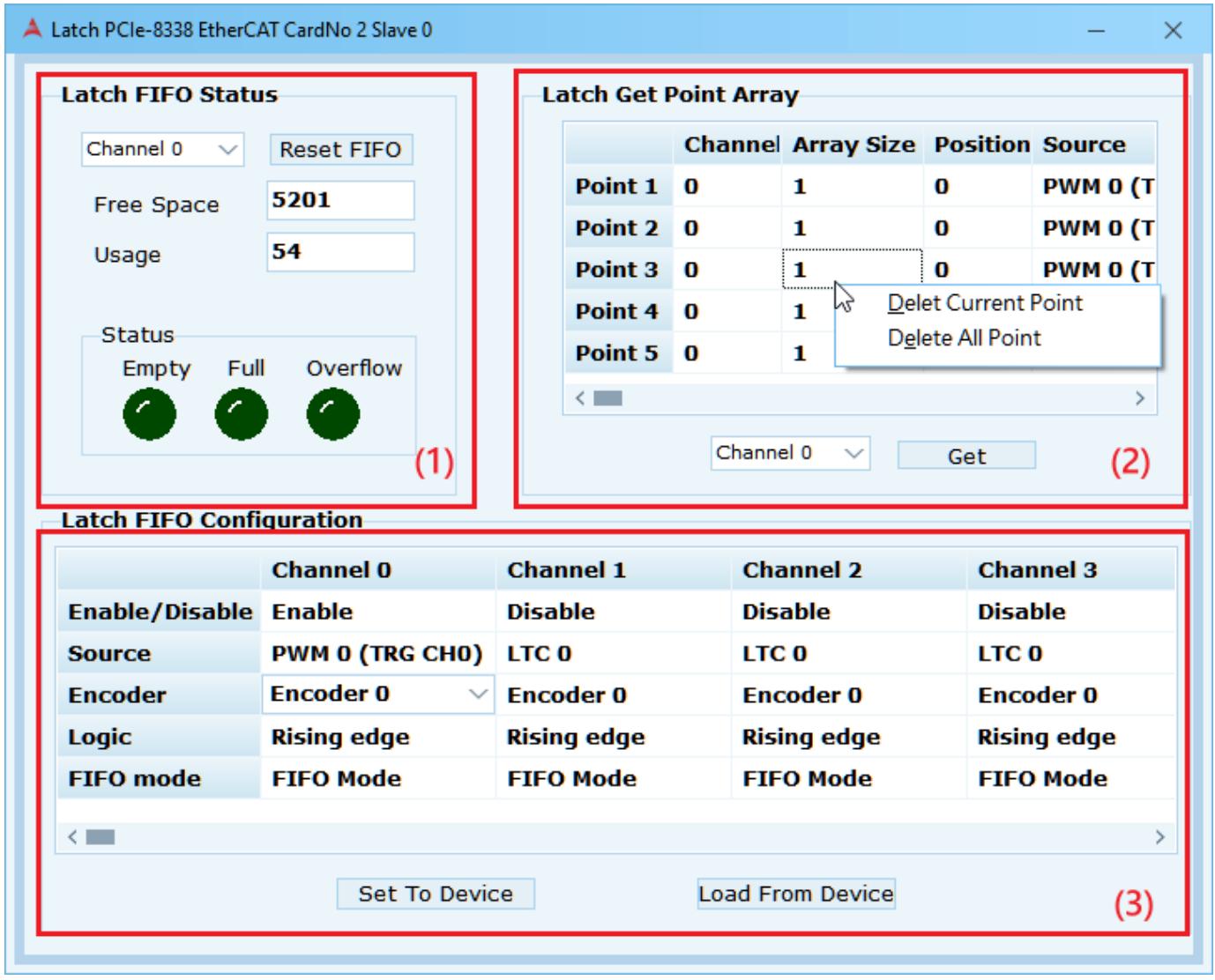
![Latch PCIe-8338 EtherCAT CardNo 2 Slave 0\nLatch FIFO Status\nChannel 0 √ Reset FIFO\nFree Space 5201\nUsage 54\nStatus\nEmpty Full Overflow\n(1)\nLatch Get Point Array\nChannel Array Size Position Source\nPoint 1 0 1 0 PWM 0 (T)\nPoint 2 0 1 0 PWM 0 (T)\nPoint 3 0 1 0 PWM 0 (T)\nPoint 4 0 1 Delet Current Point\nDelete All Point\nPoint 5 0 1\nChannel 0 √ Get (2)\nLatch FIFO Configuration\nEnable/Disable Enable Disable Disable Channel 3\nSource PWM 0 (TRG CHO) LTC 0 LTC 0 LTC 0\nEncoder Encoder 0 Encoder 0 Encoder 0 Encoder 0\nLogic Rising edge Rising edge Rising edge\nFIFO mode FIFO Mode FIFO Mode FIFO Mode FIFO Mode\nSet To Device Load From Device (3)](.motion-creator-pro-2-functional-user-manual-english-v0-1/4e1f3cdc795656e5eb18da1ec54e40cc4462df2025e44d62dae644b3584aa3d8.jpg)

(1) Latch FIFO status: Regularly updates the FIFO status of channels selected by users, and resets and usage the status.
(2) Latch Get Point Array: Obtains the FIFO point information of the channel selected by the user, including the location and source of the latch. When not in use, right-click to select a single point or delete all the information.

(3) Latch FIFO Configuration: Sets parameters related to Latch, such as latch channel number, source, latch encoder number and latch logical conditions, etc., and can be enabled after configuration is complete. For setting parameters, refer to the APS Function Library manual Table definition-> Latch parameter table. This example is for ADLINK's 4XMO, so the corresponding manual content is shown below.
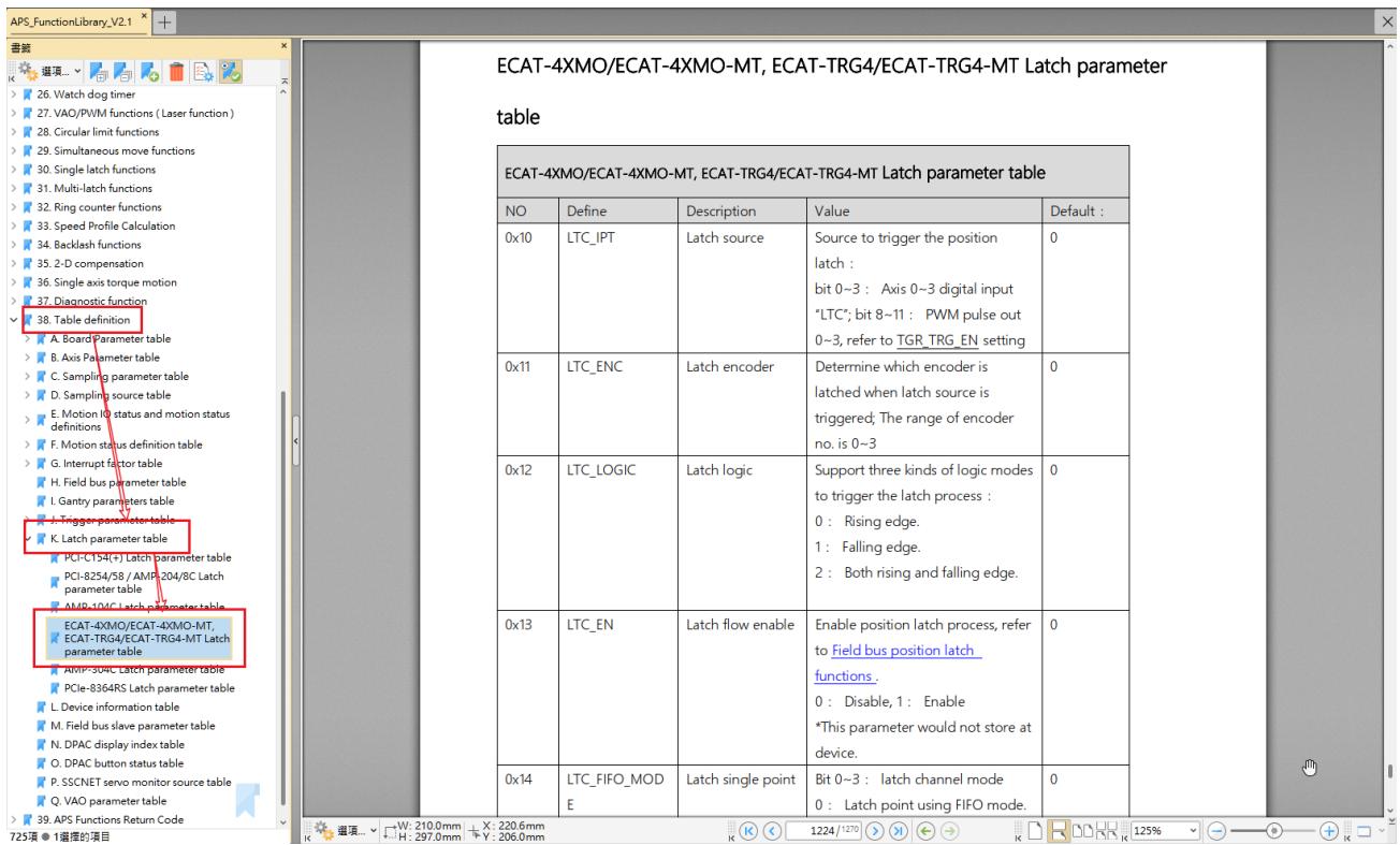
![ECAT-4XMO/ECAT-4XMO-MT, ECAT-TRG4/ECAT-TRG4-MT Latch parameter\ntable\nECAT-4XMO/ECAT-4XMO-MT, ECAT-TRG4/ECAT-TRG4-MT Latch parameter table\nNO	Define	Description	Value	Default : \n0x10	LTC_IPT	Latch source Somcet to trigger the position\nlatch :\nbit 0~3:Axis 0~3 digital input\n'LTC'; bit 8~11: PWM pulse out\n0~3, refer to TGR_TRG_EN setting	0\n0x11	LTC_ENC	Latch encoder	Determine which encoder is\nlatched when latch source is\ntriggered; The range of encoder\nno. is 0~3	0\n0x12	LTC_LOGIC	Latch logic	Support three kinds of logic modes\nto trigger the latch process :\n0: Rising edge.\n1: Falling edge.\n2: Both rising and falling edge.\n0x13	LTC_EN	Latch flow enable	Enable position latch process, refer\nto Field bus position latch\nfunctions.\n0: Disable, 1: Enable\n*This parameter would not store at\ndevice.\n0x14	LTC_FIFO_MODE	Latch single point	Bit 0~3: latch channel mode\n0: Latch point using FIFO mode.\nW: 210.0mm	X: 220.6mm\nH: 297.0mm	Y: 206.0mm\n26. Watch dog timer\n27. VAO/PWM functions ( Laser function )\n28. Circular limit functions\n29. Simultaneous move functions\n30. Single latch functions\n31. Multi-latch functions\n32. Ring counter functions\n33. Speed Profile Calculation\n34. Backlash functions\n35. 2-D compensation\n36. Single axis torque motion\n37. Diagnostic function\n38. Table definition\nA. Board Parameter table\nB. Axis Parameter table\nC. Sampling parameter table\nD. Sampling source table\nE. Motion IO status and motion status\ndefinitions\nF. Motion status definition table\nG. Interrupt factor table\nH. Field bus parameter table\nI. Gantry parameters table\nJ. Trigger parameter table\nK. Latch parameter table\nPCI-C154(+) Latch parameter table\nPCI-8254/58 / AMP-204/8C Latch\nparameter table\nAMP-104C Latch parameter table\nECAT-4XMO/ECAT-4XMO-MT,\nECAT-TRG4/ECAT-TRG4-MT Latch\nparameter table\nAMP-304C Latch parameter table\nPCIe-8364RS Latch parameter table\nL. Device information table\nM. Field bus slave parameter table\nN. DPAC display index table\nO. DPAC button status table\nP. SSCNET servo monitor source table\nQ. VAO parameter table\n39. APS Functions Return Code\n725项 ①连接的项目](.motion-creator-pro-2-functional-user-manual-english-v0-1/22782a8196a5dbc43e1c608245497da48422738b2133b1cb11b7b1b393d25c10.jpg)

# 3.19 OPT Device OD

The OPT Device OD page is an extension of the SDO page. Users can choose to read and write the Object Dictionary (OD) data of the SDO to obtain the specific data of the Slave and monitor it.

To open the OPT Device OD, click Slave x in the device tree column, and then click the OPT Device OD icon.
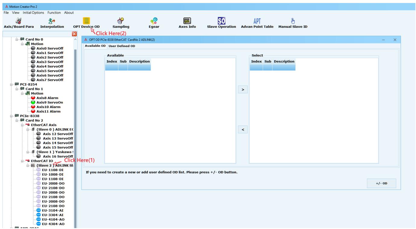
![Motion Creator Pro 2\nFile View Initial Options Function About\nAxis/Board Para Interpolation OPT Device OD Sampling Egear Axes Info Slave Operation APT Manual Slave ID\nCard No 0\nMotion\nAxis0 ServoOff\nAxis1 ServoOff\nAxis2 ServoOff\nAxis3 ServoOff\nAxis4 ServoOff\nAxis5 ServoOff\nAxis6 ServoOff\nAxis7 ServoOff\nPCI-8254\nCard No 1\nMotion\nAxis8 Alarm\nAxis9 ServoOn\nAxis10 Alarm\nAxis11 Alarm\nPCIe-8338\nCard No 2\nEtherCAT Axis\n(Slave 0 ) ADLINK EC\nAxis 12 ServoOff\nAxis 13 ServoOff\nAxis 14 ServoOff\nAxis 15 ServoOff\n(Slave 1 ) Yaskawa :\nAxis 16 ServoOff\nEtherCAT IO Click Here(1)\n(Slave 2 ) ADLINK SI\nEU-1108-DI\nEU-1008-DI\nEU-1108-DI\nEU-2008-DO\nEU-2108-DO\nEU-2008-DO\nEU-2108-DO\nEU-2008-DO\nEU-3104-AI\nEU-3304-AI\nEU-4104-AO\nEU-4304-AO\nClick Here(2)\nOPT OD PCIe-8338 EtherCAT CardNo 2 ADLINK(2)\nAvailable OD User Defined OD\nAvailable\nIndex Sub Description\nSelect\nIndex Sub Description\nIf you need to create a new or add user defined OD list. Please press +/- OD button.\n+/- OD](.motion-creator-pro-2-functional-user-manual-english-v0-1/32f27f2e96abd08f8374ef2cf9691013a122d586c609e70de0988b67613313df.jpg)

OPT Device OD function settings are shown below.

(1) +/ -OD is the SLAVE SDO that generates the selection.
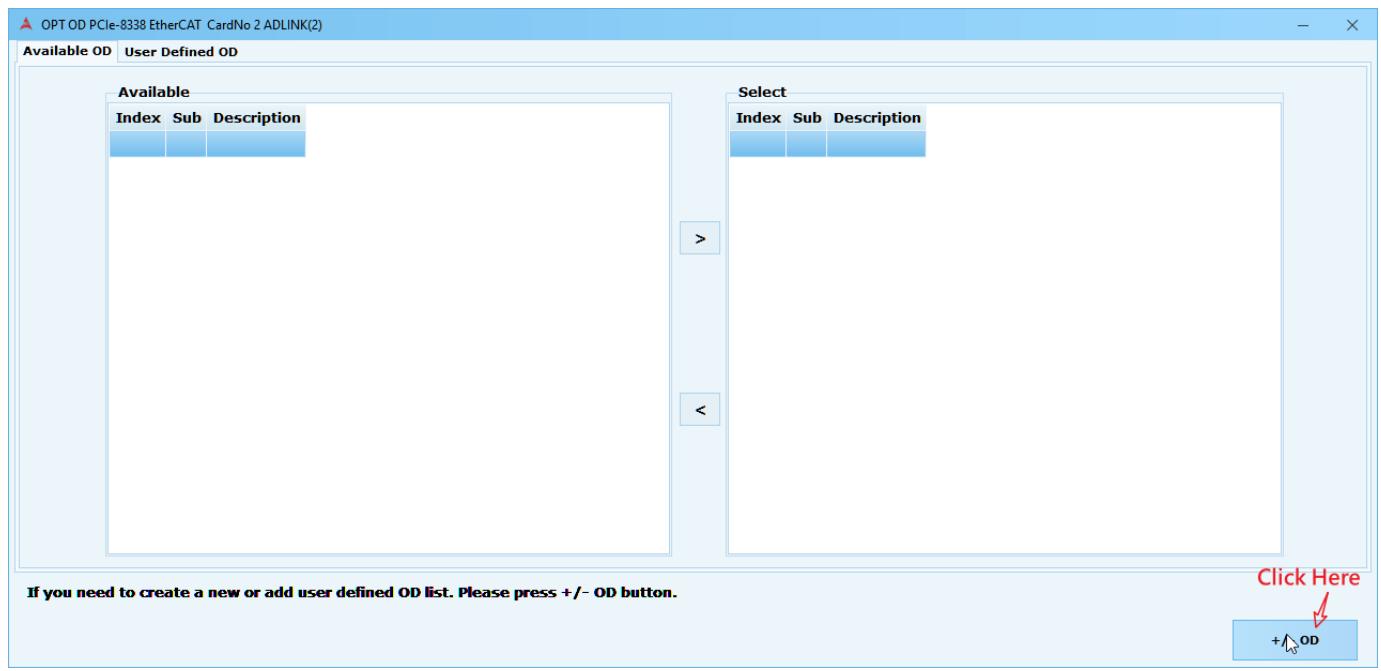
![OPT OD PCIe-8338 EtherCAT CardNo 2 ADLINK(2)\nAvailable OD User Defined OD\nAvailable\nIndex Sub Description\nSelect\nIndex Sub Description\n)\n(\nClick Here\n+/- OD\nIf you need to create a new or add user defined OD list. Please press +/- OD button.](.motion-creator-pro-2-functional-user-manual-english-v0-1/821805bd21258806bd5bbb75732daa33e753d3cacb52da4de2e05f9d80dcff14.jpg)

(2) The generated OD Data will be displayed under Available. Double-click a project or use the right arrow button in the middle of the window to select the desired OD Data.
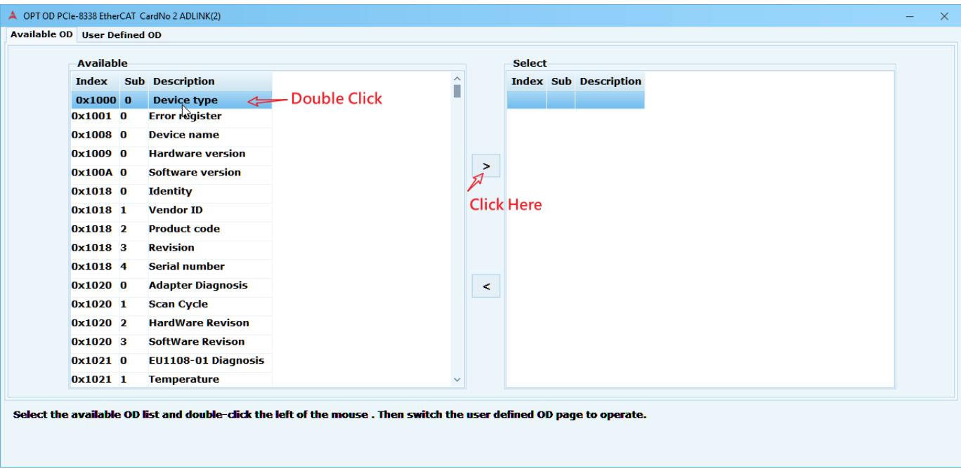
![OPT OD PCIe-8338 EtherCAT CardNo 2 ADLINK(2)\nAvailable OD User Defined OD\nAvailable\nIndex Sub Description\n0x1000 0 Device type\n0x1001 0 Error register\n0x1008 0 Device name\n0x1009 0 Hardware version\n0x100A 0 Software version\n0x1018 0 Identity\n0x1018 1 Vendor ID\n0x1018 2 Product code\n0x1018 3 Revision\n0x1018 4 Serial number\n0x1020 0 Adapter Diagnosis\n0x1020 1 Scan Cycle\n0x1020 2 Hardware Revision\n0x1020 3 Software Revision\n0x1021 0 EU1108-01 Diagnosis\n0x1021 1 Temperature\nSelect\nIndex Sub Description\n) \nClick Here\n(\nSelect the available OD list and double-click the left of the mouse . Then switch the user defined OD page to operate.](.motion-creator-pro-2-functional-user-manual-english-v0-1/ed5f1be45070e8f2796070b30f082596aebec3f208cc16d98e5a51efd6d350a7.jpg)

(3) The selection results display in the User Defined OD tab.
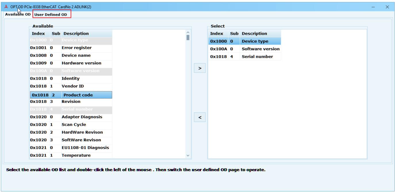
![OPT,OD PCIe-8338 EtherCAT CardNo 2 ADLINK(2)\nAvailable OD User Defined OD\nAvailable\nIndex Sub Description\n0x1000 0 Device type\n0x1001 0 Error register\n0x1008 0 Device name\n0x1009 0 Hardware version\n0x100A 0 Software version\n0x1018 0 Identity\n0x1018 1 Vendor ID\n0x1018 2 Product code\n0x1018 3 Revision\n0x1018 4 Serial number\n0x1020 0 Adapter Diagnosis\n0x1020 1 Scan Cycle\n0x1020 2 Hardware Revision\n0x1020 3 Software Revision\n0x1021 0 EU1108-01 Diagnosis\n0x1021 1 Temperature\nSelect\nIndex Sub Description\n0x1000 0 Device type\n0x100A 0 Software version\n0x1018 4 Serial number\nSelect the available OD list and double-click the left of the mouse. Then switch the user defined OD page to operate.](.motion-creator-pro-2-functional-user-manual-english-v0-1/bf3e06be72216d5af559a872481465ed628b85e7dd8edbc5ec4c52deb2b7ff9e.jpg)

(4) The page displays the OD information. If there is no information in the right panel, click Write to write the OD Data.
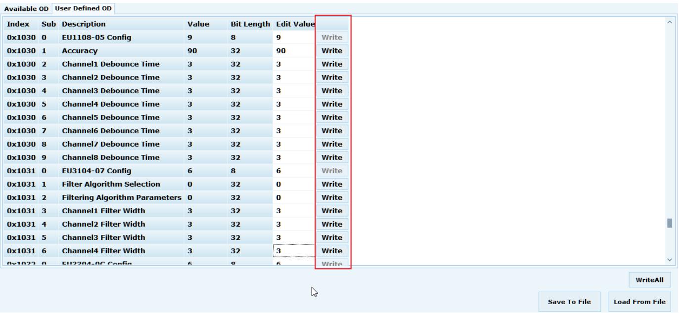
![Available OD User Defined OD\nIndex Sub Description Value Bit Length Edit Value\n0x1030 0 EU1108-05 Config 9 8 9 Write\n0x1030 1 Accuracy 90 32 90 Write\n0x1030 2 Channel1 Debounce Time 3 32 3 Write\n0x1030 3 Channel2 Debounce Time 3 32 3 Write\n0x1030 4 Channel3 Debounce Time 3 32 3 Write\n0x1030 5 Channel4 Debounce Time 3 32 3 Write\n0x1030 6 Channel5 Debounce Time 3 32 3 Write\n0x1030 7 Channel6 Debounce Time 3 32 3 Write\n0x1030 8 Channel7 Debounce Time 3 32 3 Write\n0x1030 9 Channel8 Debounce Time 3 32 3 Write\n0x1031 0 EU3104-07 Config 6 8 6 Write\n0x1031 1 Filter Algorithm Selection 0 32 0 Write\n0x1031 2 Filtering Algorithm Parameters 0 32 0 Write\n0x1031 3 Channel1 Filter Width 3 32 3 Write\n0x1031 4 Channel2 Filter Width 3 32 3 Write\n0x1031 5 Channel3 Filter Width 3 32 3 Write\n0x1031 6 Channel4 Filter Width 3 32 3 Write\n0x1031 7 EU2204-06 Config 6 8 6 Write\nWriteAll\nSave To File Load From File](.motion-creator-pro-2-functional-user-manual-english-v0-1/88e46c2489026621b0dc6f30f4e67745efc551a21de794f814595cc2d4c2b325.jpg)

(5) Additional functions include:

WriteALL: Writes all OD Data at once
 Save To File: Saves user defined OD Data (\*.csv format)
 Load From File: Imports custom OD Data (\*.csv format)
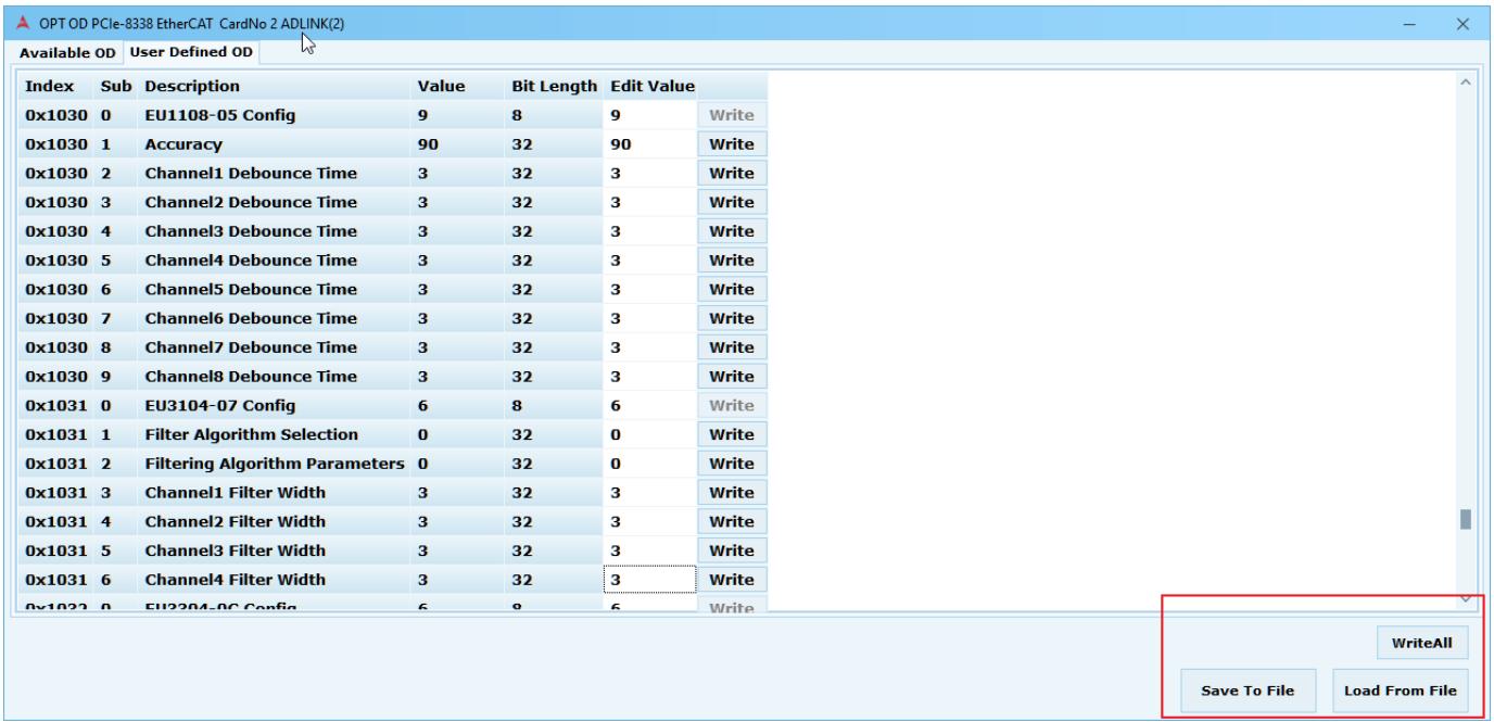
![OPT OD PCIe-8338 EtherCAT CardNo 2 ADLINK(2)\nAvailable OD User Defined OD\nIndex Sub Description Value Bit Length Edit Value\n0x1030 0 EU1108-05 Config 9 8 9 Write\n0x1030 1 Accuracy 90 32 90 Write\n0x1030 2 Channel1 Debounce Time 3 32 3 Write\n0x1030 3 Channel2 Debounce Time 3 32 3 Write\n0x1030 4 Channel3 Debounce Time 3 32 3 Write\n0x1030 5 Channel4 Debounce Time 3 32 3 Write\n0x1030 6 Channel5 Debounce Time 3 32 3 Write\n0x1030 7 Channel6 Debounce Time 3 32 3 Write\n0x1030 8 Channel7 Debounce Time 3 32 3 Write\n0x1030 9 Channel8 Debounce Time 3 32 3 Write\n0x1031 0 EU3104-07 Config 6 8 6 Write\n0x1031 1 Filter Algorithm Selection 0 32 0 Write\n0x1031 2 Filtering Algorithm Parameters 0 32 0 Write\n0x1031 3 Channel1 Filter Width 3 32 3 Write\n0x1031 4 Channel2 Filter Width 3 32 3 Write\n0x1031 5 Channel3 Filter Width 3 32 3 Write\n0x1031 6 Channel4 Filter Width 3 32 3 Write\n0x1032 0 EU2204-06 Config 6 8 6 Write\nWriteAll\nSave To File Load From File](.motion-creator-pro-2-functional-user-manual-english-v0-1/7ab0254ddb8c22bddc22916a00c70f229deb18fd98b67fe864d8b975057429a4.jpg)

# 3.20 IO Mapping

# 3.20.1 Ether CAT

Use the MCP2 IO-mapping form to perform mapping and checking operations. The maximum number of software port in slave is 32 for each IO type.

# Notes:

1. Manually changing the contents of the IO mapping configuration file is not recommended.
2. The IO mapping GUI is only available via MCP2. Users should download the configuration file API from ADLINK. [PROVIDE DOWNLOAD LINK]
3. Configuration file can be save to "CSV" file by MCP2 IO-mapping form.
4. No need to map module that ADLINK had integrated.

# Step-by-step instructions to set up IO mapping using MCP2.

Step 1: Update kernel version in C: \Program Files (x86)\ADLINK\PCIe-833x\Kernel Update. The kernel version must be 2022050503\_833x\_kernel or later.
Step 2: After connecting the field bus and selecting EtherCAT IO in the tree view (1), click the IO Mapping icon (2) to start setting up IO mapping.
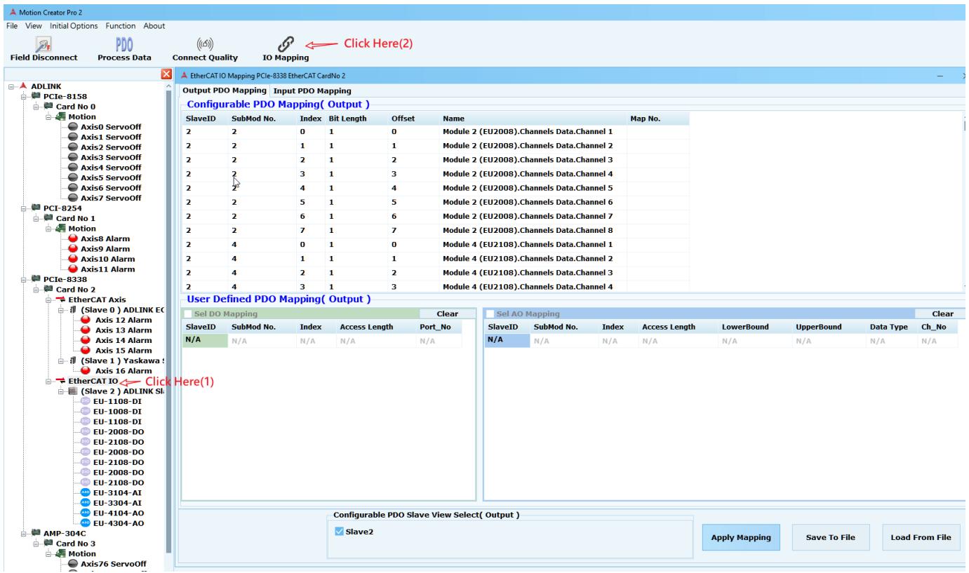
![Motion Creator Pro 2\nFile View Initial Options Function About\nField Disconnect Process Data Connect Quality IO Mapping Click Here(2)\nADLINK\nPCIe-81S8\nCard No 0\nMotion\nAxis0 ServoOff\nAxis1 ServoOff\nAxis2 ServoOff\nAxis3 ServoOff\nAxis4 ServoOff\nAxis5 ServoOff\nAxis6 ServoOff\nAxis7 ServoOff\nPCI-8254\nCard No 1\nMotion\nAxis8 Alarm\nAxis9 Alarm\nAxis10 Alarm\nAxis11 Alarm\nPCIe-8338\nCard No 2\nEtherCAT Axis\n(Slave 0) ADLINK EC\nAxis 12 Alarm\nAxis 13 Alarm\nAxis 14 Alarm\nAxis 15 Alarm\n(Slave 1) Yaskawa\nAxis 16 Alarm\nEtherCAT IO Click Here(1)\n(Slave 2) ADLINK SI\nEU-1108-DI\nEU-1008-DI\nEU-1108-DI\nEU-2008-DO\nEU-2108-DO\nEU-2008-DO\nEU-2008-DO\nEU-2108-DO\nEU-3104-AI\nEU-3304-AI\nEU-4104-AO\nEU-4304-AO\nAMP-304C\nCard No 3\nMotion\nAxis76 ServoOff\nOutput PDO Mapping Input PDO Mapping\nConfigurable PDO Mapping( Output )\nSlaveID SubMod No. Index Bit Length Offset Name Map No.\n2 2 0 1 0 Module 2 (EU2008).Channels Data.Channel 1\n2 2 1 1 1 Module 2 (EU2008).Channels Data.Channel 2\n2 2 2 1 2 Module 2 (EU2008).Channels Data.Channel 3\n2 2 3 1 3 Module 2 (EU2008).Channels Data.Channel 4\n2 2 4 1 4 Module 2 (EU2008).Channels Data.Channel 5\n2 2 5 1 5 Module 2 (EU2008).Channels Data.Channel 6\n2 2 6 1 6 Module 2 (EU2008).Channels Data.Channel 7\n2 2 7 1 7 Module 2 (EU2008).Channels Data.Channel 8\n2 4 0 1 0 Module 4 (EU2108).Channels Data.Channel 1\n2 4 1 1 1 Module 4 (EU2108).Channels Data.Channel 2\n2 4 2 1 2 Module 4 (EU2108).Channels Data.Channel 3\n2 4 3 1 3 Module 4 (EU2108).Channels Data.Channel 4\nUser Defined PDO Mapping( Output )\nSel DO Mapping Clear\nSlaveID SubMod No. Index Access Length Port_No\nN/A N/A N/A N/A N/A\nSel AO Mapping Clear\nSlaveID SubMod No. Index Access Length LowerBound UpperBound Data Type Ch_No\nN/A N/A N/A N/A N/A N/A N/A N/A N/A N/A N/A N/A N/A N/A N/A N/A N/A N/A N/A N/A N/A N/A N/A N/A N/A N/A N/A N/A N/A N/A N/A N/A N/A N/A N/A N/A N/A N/A N/A N/A N/A N/A N/A N/A N/A N/A N/A N/A N/A N/A N/A(nl)Configurable PDO Slave View Select( Output )\nSlave2 Apply Mapping Save To File Load From File](.motion-creator-pro-2-functional-user-manual-english-v0-1/8466815bf179de20f435f4c331d964877f06e2b4673a55cb0179d29f74a08b29.jpg)

Step 2-1 (Select DIO mapping): Select the slave IO for mapping. Refer to Configurable PDO view and input the corresponding parameters.
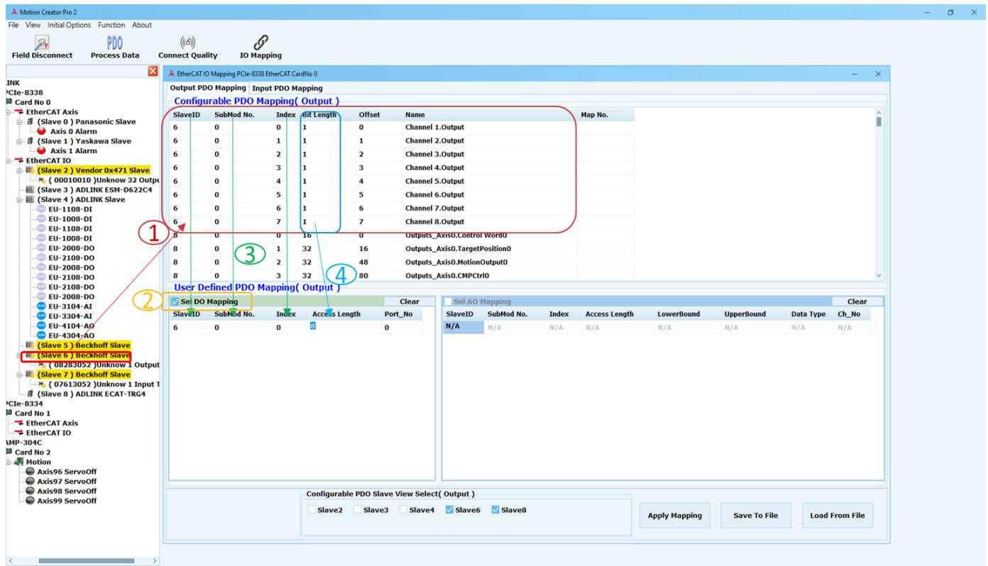
![Motion Creator Pro 2\nFile View Initial Options Function About\nField Disconnect Process Data Connect Quality IO Mapping\nINK\nPCle-8338 EtherCAT IO Mapping PCIe-8338 EtherCAT CardNo 0\nOutput PDO Mapping Input PDO Mapping\nConfigurable PDO Mapping( Output )\nSlaveID SubMod No. Index bit Length Offset Name Map No.\n6 0 0 1 0 Channel 1.Output\n6 0 1 1 1 Channel 2.Output\n6 0 2 1 2 Channel 3.Output\n6 0 3 1 3 Channel 4.Output\n6 0 4 1 4 Channel 5.Output\n6 0 5 1 5 Channel 6.Output\n6 0 6 1 6 Channel 7.Output\n6 0 7 1 7 Channel 8.Output\nUser Defined PDO Mapping( Output )\n✓ Se DO Mapping Clear\nSlaveID SubMod No. Index Access Length Port_No Clear\n6 0 0 0\nN/A N/A N/A N/A N/A N/A N/A N/A\nClie-8334 Card No 1\nEtherCAT Axis EtherCAT IO\nCMP-304C Card No 2 Motion\nAxis96 ServoOff Axis97 ServoOff Axis98 ServoOff Axis99 ServoOff\nConfigurable PDO Slave View Select( Output )\nSlave2 Slave3 Slave4 Slave6 Slave8 Apply Mapping Save To File Load From File](.motion-creator-pro-2-functional-user-manual-english-v0-1/58a02aecbb90ddac8d18c24f28638e0d36e63d07cd0d9cefe145fd4c28fdefa8.jpg)

○1 Select the slave IO for mapping and refer Configurable PDO view.
○2 Select the IO type that needs to be set.
○3 Enter SlaveID data for mapping slave IO. Fill in the corresponding SubMod No. Refer to SubMod No. in Configurable PDO View. Fill in the starting index. Refer to Index in Configurable PDO View.
○4 Fill in the Access Length to define the IO-bit required by the port.

# DIO mapping parameters:

SlaveID: Mapping of slave IO.
SubMod No.: Configurable PDO view
Index: Access start index according to index in Configurable PDO view.
Access Length: Access port length according to Bit Length in configurable PDO view content.

Maximum: 32 bits
Minimum: 1 bit

Port\_No: Automatically generated.

Step 2-2 (Select AIO mapping ): Select the slave IO for mapping. Refer to Configurable PDO view and input corresponding parameters.

![Motion Creator Pro 2\nFile View Initial Options About\nField Module\nDLINK\nPCIe-8338 EtherCAT IO Mapping PCIe-8338 EtherCAT CardNo 0\nOutput PDO Mapping Input PDO Mapping\nConfigurable PDO Mapping( Output )\nSlaveID SubMod No. Index Bit Length Offset Name Map No.\n4 12 0 1 0 Module 12 (EU2008).Channels Data.Channel 1\n4 12 1 1 1 Module 12 (EU2008).Channels Data.Channel 2\n4 12 2 1 2 Module 12 (EU2008).Channels Data.Channel 3\n4 12 3 1 3 Module 12 (EU2008).Channels Data.Channel 4\n4 12 4 1 4 Module 12 (EU2008).Channels Data.Channel 5\n4 12 5 1 5 Module 12 (EU2008).Channels Data.Channel 6\n4 12 6 1 6 Module 12 (EU2008).Channels Data.Channel 7\n4 12 7 1 7 Module 12 (EU2008).Channels Data.Channel 8\n4 13 0 16 0 Module 13 (EU4304).Channels Data.Channel 1\n4 13 1 16 Module 13 (EU4304).Channels Data.Channel 2\n4 13 2 16 Module 13 (EU4304).Channels Data.Channel 3\n4 13 3 16 Module 13 (EU4304).Channels Data.Channel 4\nUser Defined PDO Mapping( Output )\nSel DO Mapping Clear Sel AO Mapping Clear\nSlaveID SubMod No. Index Access Length Port_No SlaveID SubMod No. Index Access Length LowerBound UpperBound Data Type Ch_No\n6 0 0 8 0 4 13 0 16 0\n4 13 1 16\n4 13 2 16 -5 5 0\n4 13\n3\n5\nApply Mapping Save To File Load From File\nPCIe-8334\nCard No 1 EtherCAT Axis EtherCAT IO\nAxis96 ServoOff Axis97 ServoOff Axis98 ServoOff Axis99 ServoOff\nAMP-304C\nCard No 2 Motion\nAxis96 ServoOff Axis97 ServoOff Axis98 ServoOff Axis99 ServoOff\nConfigurable PDO Slave View Select( Output )\nSlave2 Slave3 Slave4 Slave6 Slave8\nApply Mapping Save To File Load From File](.motion-creator-pro-2-functional-user-manual-english-v0-1/0b6672e602660f35c10357f026d6cfce9eb0f683b6313af04aa04acebf166962.jpg)

○1 Select slave IO for mapping. Refer to Configurable PDO view.
○2 Select the IO type that needs to be set.
○3 Fill in SlaveID fill for mapping slave IO. Fill in the corresponding SubMod No. Refer to SubMod No in Configurable PDO View. Index fills in the starting index. Refer to Index in Configurable PDO View.
○4 Fill in Access Length to define the IO-bit required by the port.
○5 Fill in LowerBound physical lower limit. Fill in UpperBound physical upper limit. Fill in Data type Representation type:

0: Unsigned integer

1: Signed integer

2: Absolute value with MSB as sign

3: Raw data)

# AIO mapping parameters:

SlaveID: Mapping of slave IO.
SubMod No.: Configurable PDO view
Index: Access start index according to index in configurable PDO view content.
Access Length: Access channel length according to Bit Length in configurable PDO view. Note: need correct length.
LowerBound: Physical lower limit.
UpperBound: Physical upper limit.

Data type: Representation type

Type 0 (Unsigned integer) E.g., for 16 bits = 0 to +65535
Type 1 (Signed integer) E.g., for 16 bits = -32768 to +32767
Type 2 (Absolute value with MSB as sign) E.g., for 16 bits = -32767 to +32767
Type 3 (Raw data)

Ch\_No: Automatically generated.

# Step 2-3 (User Defined PDO Mapping): Adding and deleting rows can be done with two methods:

1. Right-click on the table.

![SlaveID SubMod No. Index Access Length Port_No\n6 0 0 8 0\nAdd New Row(last)\nDelete Row(current)](.motion-creator-pro-2-functional-user-manual-english-v0-1/a402bae8e639df2901484c73f4ff158acecdb2f21fc7c4767b0d10e3f64c0d6c.jpg)

2. Use the keyboard to Add (Ctrl+Enter), or Delete (Ctrl+Delete).

<table><tr><td>SlaveID</td><td>SubMod No.</td><td>Index</td><td>Access Length</td><td>Port_No</td></tr><tr><td>6</td><td>0</td><td>0</td><td>8</td><td>0</td></tr><tr><td>6</td><td>0</td><td>0</td><td>8</td><td>1</td></tr><tr><td>6</td><td>0</td><td>0</td><td>8</td><td>2</td></tr></table>

Hint: Move the mouse over the table and a hint will appear.

![✓ Sel DO Mapping\nClear\nSlaveID SubMod No. Index Access Length Port_No\nN/A N/A N/A N/A\nPlease refer to the SubMod No. column in the PDO view table.](.motion-creator-pro-2-functional-user-manual-english-v0-1/bbad95d125fd991f3bf7746780d44b3fc3566f9ddf3e879e6f94458d1fe26476.jpg)

![✓ Sel DI Mapping\nClear\nSlaveID SubMod No. Index Access Length Port_No\nN/A N/F N/A 5/14\nPlease refer to the SubMod No. column in the PDO view table.](.motion-creator-pro-2-functional-user-manual-english-v0-1/6dabb607fbbf083165d35f6d3eb44647867049191987faa9aa430ed259b7a319.jpg)

<table><tr><td colspan="7">✓ Sel AO Mapping</td><td>Clear</td></tr><tr><td>SlaveID</td><td>SubMod No.</td><td>Index</td><td>Access Length</td><td>LowerBound</td><td>UpperBound</td><td>Data Type</td><td>Ch_No</td></tr><tr><td>N/A</td><td>N/A</td><td>N/A</td><td>N/A</td><td>N/A</td><td>N/A</td><td>N/A</td><td>N/A</td></tr><tr><td></td><td></td><td></td><td></td><td colspan="2">Please set a physical lower limit.</td><td></td><td></td></tr></table>

<table><tr><td colspan="7">✓ Sel AI Mapping</td><td>Clear</td></tr><tr><td>SlaveID</td><td>SubMod No.</td><td>Index</td><td>Access Length</td><td>LowerBound</td><td>UpperBound</td><td>Data Type</td><td>Ch_No</td></tr><tr><td>N/A</td><td>N/A</td><td>N/A</td><td>N/A</td><td>N/A</td><td>N/A</td><td>N/A</td><td>N/A</td></tr><tr><td></td><td></td><td></td><td></td><td></td><td colspan="3">0: Unsigned integer with N-bit resolution without sign, therefore polarity detection is no longer possible.
Example : Range for 16 bits = 0 to +65535
1: Signed integer(2&#x27;s complement(negated + 1)).
Example :Range for 16 bits = -32768 to +32767 dec.
2: Absolute value with MSB=1 (highest bit) as sign of negative values.
Example : Range for 16 bits = -32767 to +32767 dec.
3: Raw data has no transformation between physical value and raw data.</td></tr></table>

User Defiend AIO mapping hint

Step 3: Click Apply Mapping. The Configurable PDO view will show the mapping results. The tree view will show the software defined Port No. or Channel No.
![Motion Creator Pro 2\nFile View Initial Options Function About\nAxis/Board Para DIO Control Kernel Performance\nADLINK\nPCIe-8338\nCard No 0\nEtherCAT Axis\n(Slave 0 ) Panasonic Sl\nAxis 0 Alarm\n(Slave 1 ) Yaskawa Sl\nAxis 1 Alarm\nEtherCAT IO\n(Slave 2 ) Vendor 0x4\n(00010010) Unknown\n(Slave 3 ) ADLINK ESM\n(Slave 4 ) ADLINK Slav\nEU-1108-DI\nEU-1008-DI\nEU-1108-DI\nEU-2008-DI\nEU-2108-DO\nEU-2108-DO\nEU-2108-DO\nEU-2008-DO\nEU-3104-AI\nEU-3304-AI\nEU-4104-AO\nEU-4304-AO\n(Slave 5 ) Beckhoff Sla\n(Slave 6 ) Beckoff Sla\nPort 0-DO\n(Slave 7 ) Beckoff Sla\n(Slave 8 ) ADLINK ECA\nPCIe-8334\nCard No 1\nEtherCAT Axis\nEtherCAT IO\nAMP-304C\nCard No 2\nMotion\nAxis96 ServoOff\nAxis97 ServoOff\nAxis98 ServoOff\nAxis99 ServoOff\nOutput PDO Mapping Input PDO Mapping\nConfigurable PDO Mapping( Output )\nSlaveID SubMod No. Index Bit Length Offset Name Map No.\n6 0 0 1 0 Channel 1.Output Port_No 0,\n6 0 1 1 1 Channel 2.Output Port_No 0,\n6 0 2 1 2 Channel 3.Output Port_No 0,\n6 0 3 1 3 Channel 4.Output Port_No 0,\n6 0 4 1 4 Channel 5.Output Port_No 0,\n6 0 5 1 5 Channel 6.Output Port_No 0,\n6 0 6 1 6 Channel 7.Output Port_No 0,\n6 0 7 1 7 Channel 8.Output Port_No 0,\n8 0 5 15 Outputs_Axis0.TargetPosition0\n8 0 1 32 16 Outputs_Axis0.MotionOutput0\n8 0 2 32 48 Outputs_Axis0.CMPCtrl0\n8 0 3 32 80 Outputs_Axis0.CMPCtrl0\nUser Defined PDO Mapping( Output )\nSel DO Mapping Clear\nSlaveID SubMod No. Index Access Length Port_No Clear\n6 0 0 8 N/A N/A N/A N/A N/A N/A N/A N/A N/A N/A N/A N/A N/A N/A N/A N/A N/A N/A N/A N/A N/A N/A N/A N/A N/A N/A N/A N/A N/A N/A N/A N/A N/A N/A N/A N/A N/A N/A N/A N/A N/A N/A N/A N/A N/A N/A N/A N/A N/A N/A N/AAAABAAABAAABAAABAAABAAABAAABAAABAAABAAABAAABAAABAAABAAABAAABAAABAAABAAABAAABAAABAAABAAABAAABAAABAAABAAABAAABAAABAAABAAABAAABAAABAAABAAABAAABAAABAAABAAABAAABAAABAAABAAABAAABAAABAAABAAABAAABAAABAAABAAABAAABBAACCAACCAACCAACCAACCAACCAACCAACCAACCAACCAACCAACCAACCAACCAACCAACCAACCAACCAACCAACCAACCAACCAACCAACCAACCAACCAACCAACCAACCAACCAACCAACCAACCAACCAACCAACCAACCAACCAACCAACCAACCAACCAACCAACCAACCAACCAACCAACCAACCAACCAACCCACCACCACCACCACCACCACCACCACCACCACCACCACCACCACCACCACCACCACCACCACCACCACCACCACCACCACCACCACCACCACCACCACCACCACCACCACCACCACCACCACCACCACCACCACCACCACCACCACCACCACCACCACCACCACCACCACCACCACCACCACCACCACCACCACCACCACCACCACCACCATTCCCTCCCTCCCTCCCTCCCTCCCTCCCTCCCTCCCTCCCTCCCTCCCTCCCTCCCTCCCTCCCTCCCTCCCTCCCTCCCTCCCTCCCTCCCTCCCTCCCTCCCTCCCTCCCTCCCTCCCTCCCTCCCTCCCTCCCTCCCTCCCTCCCTCCCTCCCTCCCTCCCTCCCTCCCTCCCTCCCTCCCTCCCTCCCTCCCTCCCTCCACTTCCCCTTCCCCTTCCCCTTCCCCTTCCCCTTCCCCTTCCCCTTCCCCTTCCCCTTCCCCTTCCCCTTCCCCTTCCCCTTCCCCTTCCCCTTCCCCTTCCCCTTCCCCTTCCCCTTCCCCTTCCCCTTCCCCTTCCCCTTCCCCTTCCCCTTCCCCTTCCCCTTCCCCTTCCCCTTCCCCTTCCCCTTCCCCTTCCCCTTCCCCTTTCCCCTTTCCCCTTTCCCCTTTCCCCTTTCCCCTTTCCCCTTTCCCCTTTCCCCTTTCCCCTTTCCCCTTTCCCCTTTCCCCTTTCCCCTTTCCCCTTTCCCCTTTCCCCTTTCCCCTTTCCCCTTTCCCCTTTCCCCTTTCCCCTTTCCCCTTTCCCCTTTCCCCTTTCCCCTTTCCCCTTTCCCCTTTCCCCTTTCCCCTTTCCCCTTTCCCCTTTCCCCTTTCCCCTTTCCCCCTTTCCCCTTTCCCCTTTCCCCTTTCCCCTTTCCCCTTTCCCCTTTCCCCTTTCCCCTTTCCCCTTTCCCCTTTCCCCTTTCCCCTTTCCCCTTTCCCCTTTCCCCTTTCCCCTTTCCCCTTTCCCCTTTCCCCTTTCCCCTTTCCCCTTTCCCCTTTCCCCTTTCCCCTTTCCCCTTTCCCCTTTCCCCTTTCCCCTTTCCCCTTTCCCCTTTCCCCTTTCCCCTTTCCCSTTCATTCATTCATTCATTCATTCATTCATTCATTCATTCATTCATTCATTCATTCATTCATTCATTCATTCATTCATTCATTCATTCATTCATTCATTCATTCATTCATTCATTCATTCATTCATTCATTCATTCATTCATTCATTCATTCATTCATTCATTCATTCATTCATTCATTCATTCATTCATTCATTCATTCATTCATAAAGAAGAAGAAGAAGAAGAAGAAGAAGAAGAAGAAGAAGAAGAAGAAGAAGAAGAAGAAGAAGAAGAAGAAGAAGAAGAAGAAGAAGAAGAAGAAGAAGAAGAAGAAGAAGAAGAAGAAGAAGAAGAAGAAGAAGAAGAAGAAGAAGAAGAUGGCGGCGGCGGCGGCGGCGGCGGCGGCGGCGGCGGCGGCGGCGGCGGCGGCGGCGGCGGCGGCGGCGGCGGCGGCGGCGGCGGCGGCGGCGGCGGCGGCGGCGGCGGCGGCGGCGGCGGCGGCGGCGGCGGCGGCGGCGGCGGCGGCGGCGGCSGTGGGGGGGGGGGGGGGGGGGGGGGGGGGGGGGGGGGGGGGGGGGGGGGGGGGGGGGGGGGGGGGGGGGGGGGGGGGGGGGGGGGGGGGGGGGGGGGGGGGGGGGGGGGGGGGGGGGGGGGGGGGGGGGGGGGGGGGGGGGGGGGGGGGGGGGGGGGGGGGGGGGGGGGGGGGGGGGGGGGGGGGGGGGGGGggggggggggggggggggggggggggggggggggggggggggggggggggggggggggggggggggggggggggggggggggggggggggggggggggggggggggggggggggggggggggggggggggggggggggggggggggggggggggggggggggggtttcccttcccttcccttcccttcccttcccttcccttcccttcccttcccttcccttcccttcccttcccttcccttcccttcccttcccttcccttcccttcccttcccttcccttcccttcccttcccttcccttcccttcccttcccttcccttcccttcccttcccttcccgtttcgtttcgtttcgtttcgtttcgtttcgtttcgtttcgtttcgtttcgtttcgtttcgtttcgtttcgtttcgtttcgtttcgtttcgtttcgtttcgtttcgtttcgtttcgtttcgtttcgtttcgtttcgtttcgtttcgtttcgtttcgtttcgtttcgtttcgcgtttcgtttcgtttcgtttcgtttcgtttcgtttcgtttcgtttcgtttcgtttcgtttcgtttcgtttcgtttcgtttcgtttcgtttcgtttcgtttcgtttcgtttcgtttcgtttcgtttcgtttcgtttcgtttcgtttcgtttcgtttcgtttcgtttccttcccttcccttcccttcccttcccttcccttcccttcccttcccttcccttcccttcccttcccttcccttcccttcccttcccttcccttcccttcccttcccttcccttcccttcccttcccttcccttcccttcccttcccttcccttcccttcccttccacttcacttcacttcacttcacttcacttcacttcacttcacttcacttcacttcacttcacttcacttcacttcacttcacttcacttcacttcacttcacttcacttcacttcacttcacttcacttcacttcacttcacttcacttcacttcacttcacttcacttcacttcacttcacttcacttcacttcacttcacttcacttcacttcacttcacttcacttcacttcacttcacttcacttcacttgacagacagacagacagacagacagacagacagacagacagacagacagacagacagacagacagacagacagacagacagacagacagacagacagacagacagacagacagacagacagacagacagacagacagacagacagacagacagacagacagacagacagacagacagacagacagacagacagacagacagacaggaaaggaaaggaaaggaaaggaaaggaaaggaaaggaaaggaaaggaaaggaaaggaaaggaaaggaaaggaaaggaaaggaaaggaaaggaaaggaaaggaaaggaaaggaaaggaaaggaaaggaaaggaaaggaaaggaaaggaaaggaaaggaaaggaaaggaaaggaaaggaaaggaaaggaaaggaaaggaaaggaaaggaaaggaaaggaaaggaaaggaaaggaaaggaaaggaaaggaaaggaaaaggaaaggaaaggaaaggaaaggaaaggaaaggaaaggaaaggaaaggaaaggaaaggaaaggaaaggaaaggaaaggaaaggaaaggaaaggaaaggaaaggaaaggaaaggaaaggaaaggaaaggaaaggaaaggaaaggaaaggaaaggaaaggaaaggaaaggaaaggaaaggaaaggaaaggaaaggaaaggaaaggaaaggaaaggaaaggaaaggaaaggaaaggaaaggaaaggaaagggaattgatgatgatgatgatgatgatgatgatgatgatgatgatgatgatgatgatgatgatgatgatgatgatgatgatgatgatgatgatgatgatgatgatgatgatgatgatgatgatgatgatgatgatgatgatgatgatgatgatgatgatagatgatgatgatgatgatgatgatgatgatgatgatgatgatgatgatgatgatgatgatgatgatgatgatgatgatgatgatgatgatgatgatgatgatgatgatgatgatgatgatgatgatatgata gata gata gata gata gata gata gata gata gata gata gata gata gata gata gata gata gata gata gata gata gata gata gata gata gata gata gata gata gata gata gata gata gata gata gata gata gata gata gata gata gata gata gata gata gata gata gata gata gata gata cca atcgtaaattcgtaaattcgtaaattcgtaaattcgtaaattcgtaaattcgtaaattcgtaaattcgtaaattcgtaaattcgtaaattcgtaaattcgtaaattcgtaaattcgtaaattcgtaaattcgtaaattcgtaaattcgtaaattcgtaaattcgtaaattcgtaaattcgtaaattcgtaaattcgtaaattcgtaaATTcgtaaattcgtaaATTcgtaaATTcgtaaATTcgtaaATTcgtaaATTcgtaaATTcgtaaATTcgtaaATTcgtaaATTcgtaaATTcgtaaATTcgtaaATTcgtaaATTcgtaaATTcgtaaATTcgtaaATTcgtaaATTcgtaaATTcgtaaATTcgtaaATTcgtaaATTcgtaaATTcgtaaATTcgtaaATTcgtaaATTcgtaaATCGTAUATTcgTAUATTcgTAUATTcgTAUATTcgTAUATTcgTAUATTcgTAUATTcgTAUATTcgTAUATTcgTAUATTcgTAUATTcgTAUATTcgTAUATTcgTAUATTcgTAUATTcgTAUATTcgTAUATTcgTAUATTcgTAUATTcgTAUATTcgTAUATTcgTAUATTcgTAUATTcgTAUATTcgTAUATTcgTAUATTCGTAUATTCGTAUATTCGTAUATTCGTAUATTCGTAUATTCGTAUATTCGTAUATTCGTAUATTCGTAUATTCGTAUATTCGTAUATTCGTAUATTCGTAUATTCGTAUATTCGTAUATTCGTAUATTCGTAUATTCGTAUATTCGTAUATTCGTAUATTCGTAUATTCGTAUATTCGTAUATTCGTAUATTCGTAUATT CGTAUATT CGTAUATT CGTAUATT CGTAUATT CGTAUATT CGTAUATT CGTAUATT CGTAUATT CGTAUATT CGTAUATT CGTAUATT CGTAUATT CGTAUATT CGTAUATT CGTAUATT CGTAUATT CGTAUATT CGTAUATT CGTAUATT CGTAUATT CGTAUATT CGTAUATT CGTAUATT CGTAUATT CGTAUATT CCAUCDC CCAUCDC CCAUCDC CCAUCDC CCAUCDC CCAUCDC CCAUCDC CCAUCDC CCAUCDC CCAUCDC CCAUCDC CCAUCDC CCAUCDC CCAUCDC CCAUCDC CCAUCDC CCAUCDC CCAUCDC CCAUCDC CCAUCDC CCAUCDC CCAUCDC CCAUCDC CCAUCDC CCAUCDC CCAUCD CC A U T O A T O A T O A T O A T O A T O A T O A T O A T O A T O A T O A T O A T O A T O A T O A T O A T O A T O A T O A T O A T O A T O A T O A T O A T O A T O A T O A T O A T O A T O A T O A T O A T O A T O A U T O A U T O A U T O A U T O A U T O A U T O A U T O A U T O A U T O A U T O A U T O A U T O A U T O A U T O A U T O A U T O A U T O A U T O A U T O A U T O A U T O A U T O A U T O A U T O A U T O A V U U U U U U U U U U U U U U U U U U U U U U U U U U U U U U U U U U U U U U U U U U U U U U U U U U U U U U U U U U U U U U U U U U U U U U U U U U U U U U U U U U U U U U U U U U U U U U U U U U U U V G G G G G G G G G G G G G G G G G G G G G G G G G G G G G G G G G G G G G G G G G G G G G G G G G G G G G G G G G G G G G G G G G G G G G G G G G G G G G G G G G G G G G G G G G G G G G G G G G G G G S CAUCDC CAUCDC CAUCDC CAUCDC CAUCDC CAUCDC CAUCDC CAUCDC CAUCDC CAUCDC CAUCDC CAUCDC CAUCDC CAUCDC CAUCDC CAUCDC CAUCDC CAUCDC CAUCDC CAUCDC CAUCDC CAUCDC CAUCDC CAUCDC CAUCDC CAUCDC CAUCDC CAUCDC CAUCDC CAUCDC CAUCDC CAUCDC CAUCDC CAUCDC ATC ATC ATC ATC ATC ATC ATC ATC ATC ATC ATC ATC ATC ATC ATC ATC ATC ATC ATC ATC ATC ATC ATC ATC ATC ATC ATC ATC ATC ATC ATC ATC ATC ATC ATC ATC ATC ATC ATC ATC ATC ATC ATC ATC ATC ATC ATC ATC ATC ATC ATP AGGGAAGGAAGGAAGGAAGGAAGGAAGGAAGGAAGGAAGGAAGGAAGGAAGGAAGGAAGGAAGGAAGGAAGGAAGGAAGGAAGGAAGGAAGGAAGGAAGGAAGGAAGGAAGGAAGGAAGGAAGGAAGGAAGGAAGGAAGGAAGGAAGGAAGGAAGGAAGGAAGGAAGGAAGGAAGGAAGGAAGGAAGGAAGGAAGGAAGGAAGGAUGGAUGGAUGGAUGGAUGGAUGGAUGGAUGGAUGGAUGGAUGGAUGGAUGGAUGGAUGGAUGGAUGGAUGGAUGGAUGGAUGGAUGGAUGGAUGGAUGGAUGGAUGGAUGGAUGGAUGGAUGGAUGGAUGGAUGGAUGGAUGGAUGGAUGGAUGGAUGGAUGGAUGGAUGGAUGGAUGGAUGGAUGGAUGGAUGGAUG GAUG GAUG GAUG GAUG GAUG GAUG GAUG GAUG GAUG GAUG GAUG GAUG GAUG GAUG GAUG GAUG GAUG GAUG GAUG GAUG GAUG GAUG GAUG GAUG GAUG GAUG GAUG GAUG GAUG GAUG GAUG GAUG GAUG GAUG GAUG GAUG GAUG GAUG GAUG GAUG GAUG GAUG GAUG GAUG GAUG GAUG GAUG GAUG GAUG GAUG TAUGC TAUGC TAUGC TAUGC TAUGC TAUGC TAUGC TAUGC TAUGC TAUGC TAUGC TAUGC TAUGC TAUGC TAUGC TAUGC TAUGC TAUGC TAUGC TAUGC TAUGC TAUGC TAUGC TAUGC TAUGC TAUGC TAUGC TAUGC TAUGC TAUGC TAUGC TAUGC TAUGC TAUGC TAUGC TAUGC TAUGC TAUGC TAUGC TAUGC TAUGC TAUGC TAUGC TAUGC TAUGC TAUGC TAUGC TAUGC TAUGC TAUGC TAUS TAUGC TAUGC TAUGC TAUGC TAUGC TAUGC TAUGC TAUGC TAUGC TAUGC TAUGC TAUGC TAUGC TAUGC TAUGC TAUGC TAUGC TAUGC TAUGC TAUGC TAUGC TAUGC TAUGC TAUGC TAUGC TAUGC TAUGC TAUGC TAUGC TAUGC TAUGC TAUGC TAUGC TAUGC TAUGC TAUGC TAUGC TAUGC TAUGC TAUGC TAUGC TAUGC TAUGC TAUGC TAUGC TAUGC TAUGC TAUGC TAUGC TA USC TA USC TA USC TA USC TA USC TA USC TA USC TA USC TA USC TA USC TA USC TA USC TA USC TA USC TA USC TA USC TA USC TA USC TA USC TA USC TA USC TA USC TA USC TA USC TA USC TA USC TA USC TA USC TA USC TA USC TA USC TA USC TA USC TA USC TA USC TA USC TA USC TA USC TA USC TA USC TA USC TA USC TA USC TA USC TA USC TA USC TA USC TA USC TA USC TA USC TA US ATA SC TC TC TC TC TC TC TC TC TC TC TC TC TC TC TC TC TC TC TC TC TC TC TC TC TC TC TC TC TC TC TC TC TC TC TC TC TC TC TC TC TC TC TC TC TC TC TC TC TC TC TC TC TC TC TC TC TC TC TC TC TC TC TC TC TC TC TC TC TC TC TC TC TC TC TC TC TC TC TC TC TC TC TC TC TC TC TC TC TC TC TC TC TC TC TC TC TC TC TC TC AC CC CC CC CC CC CC CC CC CC CC CC CC CC CC CC CC CC CC CC CC CC CC CC CC CC CC CC CC CC CC CC CC CC CC CC CC CC CC CC CC CC CC CC CC CC CC CC CC CC CC CC CC CC CC CC CC CC CC CC CC CC CC CC CC CC CC CC CC CC CC CC CC CC CC CC CC CC CC CC CC CC CC CC CC CC CC CC CC CC CC CC CC CC CC CC CC CC CC CC CC C C C C C C C C C C C C C C C C C C C C C C C C C C C C C C C C C C C C C C C C C C C C C C C C C C C C C C C C C C C C C C C C C C C C C C C C C C C C C C C C C C C C C C C C C C C C C C C C C C/C AC CCTTGC TGATGATGATGATGATGATGATGATGATGATGATGATGATGATGATGATGATGATGATGATGATGATGATGATGATGATGATGATGATGATGATGATGATGATGATGATGATGATGATGATGATGATGATGATGATGATGATGATGATGATGATK TGATK TGATK TGATK TGATK TGATK TGATK TGATK TGATK TGATK TGATK TGATK TGATK TGATK TGATK TGATK TGATK TGATK TGATK TGATK TGATK TGATK TGATK TGATK TGATK TGATK TGATK TGATK TGATK TGATK TGATK TGATK TGATK TGATK TGAMSSCKCKCKCKCKCKCKCKCKCKCKCKCKCKCKCKCKCKCKCKCKCKCKCKCKCKCKCKCKCKCKCKCKCKCKCKCKCKCKCKCKCKCKCKCKCKCKCKCKCKCKCKCKCKCKCKCKCKCKCKCKCKCKCKCKCKCKCKCKCKCKCKCKCKCKCKCKCKCKCKCKCKCKCKCKCKCKCKCKCKCKCKCKCKCKCKCKCKCKCKckkckckckckckckckckckckckckckckckckckckckckckckckckckckckckckckckckckckckckckckckckckckckckckckckckckckckckckckckckckckckckckckckckckckckckckckckckckckckckckckckckckckckckckckckckckckckckckckckckckckckckkssce#sg##sg##sg##sg##sg##sg##sg##sg##sg##sg##sg##sg##sg##sg##sg##sg##sg##sg##sg##sg##sg##sg##sg##sg##sg##sg##sg##sg##sg##sg##sg##sg##sg##sg##sg##sg##sg##sg##sg##sg##sg##sg##sg##sg##sg###sce#sg##sg##sg##sg#####sce#sg####sce#sg####sce#sg####sce#sg####sce#sg####sce#sg####sce#sg####sce#sg####sce#sg####sce#sg####sce#sg####sce#sg####sce#sg####sce#sg####sce#sg####sce#sg####sce#sg####sce#sg####sce#sg####sce#sg####sce#sg#####sce#sg####sce#sg####sce#sg####sce#sg####sce#sg####sce#sg####sce#sg####sce#sg####sce#sg####sce#sg####sce#sg####sce#sg####sce#sg####sce#sg####sce#sg####sce#sg####sce#sg####sce#sg####sce#sg####sce: #sp##\n+ Apply Mapping Save To File Load to Load to Load to Load to Load to Load to Load to Load to Load to Load to Load to Load to Load to Load to Load to Load to Load to Load to Load to Load to Load to Load to Load to Load to Load to Load to Load to Load to Load to Load to Load to Load to Load to Load to Load to Load to Load to Load to Load to Load to Load to Load to Load to Load to Load to Load to Load to Load to Load to Load to Load in the load of the load of the load of the load of the load of the load of the load of the load of the load of the load of the load of the load of the load of the load of the load of the load of the load of the load of the load of the load of the load of the load of the load of the load of the load of the load of the load of the load of the load of the load of the load of the load of the load of the load of(nl)](.motion-creator-pro-2-functional-user-manual-english-v0-1/b52c5e26774cdbd81f7da3fcf6d12b55994043a62972d211912a943d28d172f5.jpg)

DIO mapping showing software defined Port No.

![Motion Creator Pro 2\nFile View Initial Options Function About\nAxis/Board Para DIO Control Kernel Performance\nADLINK\nPCIe-8338\nCard No 0\nEtherCAT Axis\n(Slave 0 ) Panasonic Sl\nAxis 0 Alarm\n(Slave 1 ) Yaskawa Sla\nAxis 1 Alarm\nEtherCAT IO\n(Slave 2 ) Vendor 0x4\n( 00010010 )Unknown\n( Slave 3 ) ADLINK ESM\n( Slave 4 ) ADLINK Slav\nEU-1108-DI\nEU-1008-DI\nEU-1108-DI\nEU-1008-DI\nEU-2008-DO\nEU-2108-DO\nEU-2008-DO\nEU-2108-DO\nEU-2108-DO\nEU-2008-DO\nEU-3104-AI\nChannel 0-AO\nChannel 1-AO\nChannel 2-AO\n(Slave 5 ) Beckhoff Sla\n(Slave 6 ) Beckhoff Sla\nPort 0-DI\n(Slave 7 ) Beckhoff Sla\nPort 0-DI\n(Slave 8 ) ADLINK ECA\nPCIe-8334\nCard No 1\nEtherCAT Axis\nEtherCAT IO\nAMP-304C\nCard No 2\nMotion\nAxis96 ServoOff\nAxis97 ServoOff\nAxis98 ServoOff\nAxis99 ServoOff\nOutput PDO Mapping Input PDO Mapping\nConfigurable PDO Mapping ( Output )\nSlaveID SubMod No. Index Bit Length Offset Name Map No.\n1 12 6 1 6 Module 12 (EU200B).Channels Data.Channel 7\n4 12 7 1 7 Module 12 (EU200B).Channels Data.Channel 8\n4 13 0 16 0 Module 13 (EU4304).Channels Data.Channel 1 Ch_No 0,\n4 13 1 16 Module 13 (EU4304).Channels Data.Channel 2 Ch_No 1,\n4 13 2 16 Module 13 (EU4304).Channels Data.Channel 3 Ch_No 2,\n4 13 3 16 48 Module 13 (EU4304).Channels Data.Channel 4\n6 0 0 1 0 Channel 1.Output Port_No 0,\n6 0 1 1 1 Channel 2.Output Port_No 0,\n6 0 2 1 2 Channel 3.Output Port_No 0,\n6 0 3 1 3 Channel 4.Output Port_No 0,\n6 0 4 1 4 Channel 5.Output Port_No 0,\n6 0 5 1 5 Channel 6.Output Port_No 0,\nUser Defined PDO Mapping ( Output )\nSel DO Mapping Clear\nSlaveID SubMod No. Index Access Length Port_No\n6 0 0 8 0\nSel AO Mapping Clear\nSlaveID SubMod No. Index Access Length LowerBound UpperBound Data Type Ch_No\n4 13 0 16 0 10 0 0\n4 13 1 16 5 5 0 1\n4 13 2 16 -5 5 0 2\nConfigurable PDO Slave View Select ( Output )\nSlave2 Slave3 Slave4 Slave6 Slave8 Apply Mapping Save To File Load From File](.motion-creator-pro-2-functional-user-manual-english-v0-1/60fb028c01c274b91d7c0e8499a87d6a69ddbbdb812149be6eb972c6abcf815c.jpg)

AIO mapping showing software defined Channel No.

Step 4: Selecting a software defined Port No. in tree view will enable the Field Module icon. Click Field Module to start DO/DI port control (default 32 DO/DI view). DO/DI control bits follow the user-defined length. An error code is returned if the DIO bits controlled by the user settings are exceeded.

![Motion Creator Pro-2\nFile View Initial Options About\nField Module\nADLINK\nPCIe-8338 EtherCAT CardID 0 Slave ID 6 DO Port 0\nDO\n7 OFF 6 OFF 5 OFF 4 OFF 3 OFF 2 OFF 1 ON\nOFF 15 OFF 14 OFF 13 OFF 12 OFF 11 OFF 10 OFF 9 OFF 8\nOFF 23 OFF 22 OFF 21 OFF 20 OFF 19 OFF 18 OFF 17 OFF 16\nOFF 31 OFF 30 OFF 29 OFF 28 OFF 27 OFF 26 OFF 25 OFF 24\nMap No.\nPort_No 0,\nPort_No 0,\nPort_No 0,\nPort_No 0,\nPort_No 0,\nPort_No 0,\nPort_No 0,\nPort_No 0,\nPort_No 0,\nPort_No 0,\nPort_No 0,\nPort_No 0,\nPort_No 0,\nPort_No 0,\nPort_No 0,\nPort_No 0,\nPort_No 0,\nPort_No 0,\nPort_No 0,\nPort_No 0,\nPort_No 0, Control Word0\nOutputs_Axis0.TargetPosition0\nOutputs_Axis0.MotionOutput0\nOutputs_Axis0.CMPCtrl0\nUser Defined PDO Mapping( Output )\nSel DO Mapping Clear\nSlaveID SubMod No. Index Access Length Port_No\n6 0 0 8 0\nSel AO Mapping Clear\nSlaveID SubMod No. Index Access Length LowerBound UpperBound Data Type Ch_No\nN/A N/A N/A N/A N/A N/A N/A N/A\nN/A N/A N/A N/A N/A N/A N/A N/A\nConfigurable PDO Slave View Select( Output )\nSlave2 Slave3 Slave4 Slave6 Slave8\nApply Mapping Save To File Load From File](.motion-creator-pro-2-functional-user-manual-english-v0-1/6edc5be4d5488d73246077e4541f91bd5873952350e5127c230961b6ded4480f.jpg)

Selecting a software defined Channel No. in tree view will enable the Field Module icon. Click Field Module to start AO/AI channel control (default 1 channel).

![Motion Creator Pro 2\nAbout\nField Module\nADLINK\nPCIe-833B EtherCAT CardID 0 Slave ID 4 AO Channel 0\nPCIe-833B EtherCAT CardID 0 Slave ID 4 AO Channel 1\nPCIe-833B EtherCAT CardID 0 Slave ID 4 AO Channel 2\nRange: 0 -) 10\nRange: 0 -) 5\nRange: -5 -) 5\nCh 0 ( ) 0\nCh 1 ( ) 0\nCh 2 ( ) -5\n4 13 0 16 0\nModule 13 (EU4304).Channels Data.Channel 1\nCh_No 0,\n4 13 1 16 16\nModule 13 (EU4304).Channels Data.Channel 2\nCh_No 1,\n4 13 2 16 32\nModule 13 (EU4304).Channels Data.Channel 3\nCh_No 2,\n4 13 3 16 48\nModule 13 (EU4304).Channels Data.Channel 4\n6 0 0 1 0\nChannel 1.Output\nPort_No 0,\n6 0 1 1 1\nChannel 2.Output\nPort_No 0,\n6 0 2 1 2\nChannel 3.Output\nPort_No 0,\n6 0 3 1 3\nChannel 4.Output\nPort_No 0,\n6 0 4 1 4\nChannel 5.Output\nPort_No 0,\n6 0 5 1 5\nChannel 6.Output\nPort_No 0,\n6 0 6 1 6\nChannel 7.Output\nPort_No 0,\nUser Defined PDO Mapping( Output )\n✓ Sel DO Mapping           Clear\nSlaveID SubMod No. Index Access Length Port_No\n6 0 0 8 0\n✓ Sel AO Mapping           Clear\nSlaveID SubMod No. Index Access Length LowerBound UpperBound Data Type Ch_No\n4 13 0 16 0 10 0 0\n4 13 1 16 0 5 0 1\n4 13 2 16 -5 5 0 2\nConfigurable PDO Slave View Select( Output )\nSlave2 Slave3 ✓ Slave4 ✓ Slave6 ✓ Slave8\nApply Mapping Save To File Load From File](.motion-creator-pro-2-functional-user-manual-english-v0-1/3643f95954f0e212921e31a39cc389b1ad6dceed2af8af467a3b108f1b046c86.jpg)

# Save/Load file and apply mapping instructions

Step 1: Click Save to File to export the IO map data to a file.

![Motion Creator Pro 2\nFile View Initial Options About\nField Module\nADLINK\nPCIe-8338\nCard No 0\nEtherCAT Axis\n(Slave 0) Panasonic Si\nAxis 0 Alarm\n(Slave 1) Yaskawa Sla\nAxis 1 Alarm\nEtherCAT IO\n(Slave 2) Vendor 0x1\n(00010010) Jinknon\n(Slave 3) ADLINK ESM\n(Slave 4) ADLINK Slav\nEU-1108-DI\nEU-1008-DI\nEU-1108-DI\nEU-1008-DI\nEU-2008-DO\nEU-2108-DO\nEU-2008-DO\nEU-3104-AI\nEU-3304-AI\nChannel 0-AO\nChannel 1-AO\nChannel 2-AO\n(Slave 5) Beckhoff Sla\n(Slave 6) Beckhoff Sla\nPort 0-DO\n(Slave 7) Beckhoff Sla\nPort 0-DI\n(Slave 8) ADLINK ECA\nPCIe-8334\nCard No 1\nEtherCAT Axis\nEtherCAT IO\nAMP-304C.\nCard No 2\nMotion\nAxis96 ServoOff\nAxis97 ServoOff\nAxis98 ServoOff\nAxis99 ServoOff\nEtherCAT IO Mapping PCIe-8338 EtherCAT CardNo 0\nOutput PDO Mapping Input PDO Mapping\nConfigurable PDO Mapping( Output )\nSlaveID SubMod No. Index Bit Length Offset Name Map No.\n4 12 7 1 7 Module 12 (EU2008).Channels Data.Channel 8\n4 13 0 16 0 Module 13 (EU4304).Channels Data.Channel 1 Ch_No 0,\n4 13 1 16 Module 13 (EU4304).Channels Data.Channel 2 Ch_No 1,\n4 13 2 16 Module 13 (EU4304).Channels Data.Channel 3 Ch_No 2,\n4 13 3 16 Module 13 (EU4304).Channels Data.Channel 4\n6 0 0 1 0 Channel 1.Output Port_No_0,\n6 0 1 1 1 Channel 2.Output Port_No_0,\n6 0 2 1 2 Channel 3.Output Port_No_0,\n6 0 3 1 3 Channel 4.Output Port_No_0,\n6 0 4 1 4 Channel 5.Output Port_No_0,\n6 0 5 1 5 Channel 6.Output Port_No_0,\n6 0 6 1 6 Channel 7.Output Port_No_0,\nUser Defined PDO Mapping( Output )\nSel DO Mapping Clear\nSlaveID SubMod No. Index Access Length Port_No\n6 0 0 8 0\nSel AO Mapping Clear\nSlaveID SubMod No. Index Access Length LowerBound UpperBound Data Type Ch_No\n4 13 0 16 0 10 0\n4 13 1 16 0 5 0\n4 13 2 16 -5 5 0\nConfigurable PDO Slave View Select( Output )\nSlave2 Slave3 Slave4 Slave6 Slave8 Apply Mapping Save To File Load From File](.motion-creator-pro-2-functional-user-manual-english-v0-1/bb5af754ac0126d2d492f5c507195323fdb882d37c929804308398166d078a63.jpg)

Step 2: Click Load from file to import and check the file contents.
![Motion Creator Pro 2\nFile View Initial Options Function About\nAxis/Board Para DIO Control Kernel Performance\nADLINK\nPCIe-8338 EtherCAT CardNo 0\nOutput PDO Mapping Input PDO Mapping\nConfigurable PDO Mapping( Output )\nSlaveID SubMod No. Index Bit Length Offset Name Map No.\n4 2 0 1 0 Module 2 (EU2008).Channels Data.Channel 1\n4 2 1 1 1 Module 2 (EU2008).Channels Data.Channel 2\n4 2 2 1 2 Module 2 (EU2008).Channels Data.Channel 3\n4 2 3 1 3 Module 2 (EU2008).Channels Data.Channel 4\n4 2 4 1 4 Module 2 (EU2008).Channels Data.Channel 5\n4 2 5 1 5 Module 2 (EU2008).Channels Data.Channel 6\n4 2 6 1 6 Module 2 (EU2008).Channels Data.Channel 7\n4 2 7 1 7 Module 2 (EU2008).Channels Data.Channel 8\n4 4 0 1 0 Module 4 (EU210B).Channels Data.Channel 1\n4 4 1 1 1 Module 4 (EU210B).Channels Data.Channel 2\n4 4 2 1 2 Module 4 (EU210B).Channels Data.Channel 3\n4 4 3 1 3 Module 4 (EU210B).Channels Data.Channel 4\nUser Defined PDO Mapping( Output )\nSel DO Mapping Clear\nSlaveID SubMod No. Index Access Length Port_No Clear\nN/A N/A N/A N/A N/A\nSel AO Mapping Clear\nSlaveID SubMod No. Index Access Length LowerBound UpperBound Data Type Ch_No\nN/A N/A N/A N/A N/A N/A N/A N/A\nConfigurable PDO Slave View Select( Output )\nSlave2 Slave3 Slave4 Slave6 Slave8 Apply Mapping Save To File Load From File\n按图位置(0): 点面\n本机\n快速存款\n煤壁槽\n桌面\nPaul (J)\n剩余60.1 GB 共114 GB\n煤壁槽\n网络\n172.30.80.52\n搜框\nPCle-8338 EtherCAT CardNo 0 ECATIONMapping.csv\nMicrosoft Excel 驱动分隔值框架\n框架名框(0): PCIe-8 EtherCAT CatNo 0 ECATIONMapping.csv 阻散(O)\n框架模型(T): *csv 取消](.motion-creator-pro-2-functional-user-manual-english-v0-1/452d24d7395b504d105d3be5046318c8266197633438b69ea0cb8da51e984bfe.jpg)

# 3.20.2 ProFiNet

The Motion IO of the ProFiNet Slave Device uses the Slave IO as the Mapping. Therefore, I/O mapping is required for its corresponding Motion IO.

To open the IO Mapping page, click "Card No x" in the device tree column, and then click the IO Mapping icon.

![Motion Creator Pro 2\nFile View Initial Options Function About\nAxis/Board Para CmpTrg DIO Control Kernel Performance Latch IO Mapping Click Here(2)\nADLINK PCle-8364RS\nCard No 0 Click Here(1)\nPROFINET Axis\n(Device 0 ) SINAMICS V90\nAxisNo = 0 ServoOff\n(Device 1 ) SINAMICS V90\nAxisNo = 1 ServoOff\n(Device 2 ) SINAMICS V90\nAxisNo = 2 ServoOff\nPROFINET IO\n(Device 3 ) SINAMICS ET20\nDO-ST-16x24V\nDI-ST-16x24V\nAO-ST-4xUI\nAI-ST-4xUI\n(Device 4 ) SINAMICS ET20\nDO-ST-16x24V\nDI-ST-16x24V\nDO-ST-16x24V\nDI-ST-16x24V\nDevice IOMapping Trigger IOMapping\nAxis Device ID Axis Module Index Axis IO Index IO Device ID IO Module Index IO Channel\nV90(0) Axis0(0) MEL ET200SP(3) DI16x24V(1) BIT(0)\nV90(0) Axis0(0) PEL ET200SP(4) DI16x24V(3) BIT(3)\nV90(0) Axis0(0) ORG ET200SP(4) NULL NULL\nV90(1) Axis1(0) MEL NULL NULL NULL\nV90(1) Axis1(0) PEL NULL NULL NULL\nV90(1) Axis1(0) ORG NULL NULL NULL\nV90(2) Axis2(0) MEL NULL NULL NULL\nV90(2) Axis2(0) PEL NULL NULL NULL\nV90(2) Axis2(0) ORG NULL NULL NULL\nSet To Card Save To File Load From File](.motion-creator-pro-2-functional-user-manual-english-v0-1/6906f146cc622a1f99f11555cb2a97f2ba196b190df85c92dea315bd88162470.jpg)

ProFiNet IO Mapping is divided into two tabs.

 Device IOMapping: maps the desired Axis Motion IO to the Device DI and sets it to the ProFiNet card.

![ADLINK\nPCIe-8364RS\nCard No 0\nPROFINET Axis\n(Device 0 ) SINAMICS V90\nAxisNo = 0 ServoOff\n(Device 1 ) SINAMICS V90\nAxisNo = 1 ServoOff\n(Device 2 ) SINAMICS V90\nAxisNo = 2 ServoOff\nPROFINET IO\n(Device 3 ) SINAMICS ET20\nDO-ST-16x24V\nDI-ST-16x24V\nAO-ST-4xUI\nAI-ST-4xUI\n(Device 4 ) SINAMICS ET20\nDO-ST-16x24V\nDI-ST-16x24V\nDO-ST-16x24V\nDI-ST-16x24V\nDevice IOMapping Trigger IOMapping\nAxis Device ID Axis Module Index Axis IO Index IO Device ID IO Module Index IO Channel\nV90(0) Axis0(0) MEL ET200SP(3) DI16x24V(1) BIT(0)\nV90(0) Axis0(0) PEL ET200SP(4) DI16x24V(3) BIT(3)\nV90(0) Axis0(0) ORG ET200SP(4) NULL NULL NULL\nV90(1) Axis1(0) MEL NULL NULL NULL NULL\nV90(1) Axis1(0) PEL NULL NULL NULL NULL\nV90(1) Axis1(0) ORG NULL NULL NULL NULL\nV90(2) Axis2(0) MEL NULL NULL NULL NULL\nV90(2) Axis2(0) PEL NULL NULL NULL NULL\nV90(2) Axis2(0) ORG NULL NULL NULL NULL\n(2) Set To Card Save To File Load From File](.motion-creator-pro-2-functional-user-manual-english-v0-1/f4fd102eebe01302e601e22892ac70fd702dbb70fa8c743817d7502c4d73be92.jpg)

(1) Set the Device DI mapping to Axis Motion IO table.
(2) Set to Card: Set values to the ProFiNet card.

Save To File: Writes parameters to a specified file (\*csv).

Load From File: Reads parameters from the specified file to the page display (\*csv).

Trigger Mapping: maps the required Trigger Output to the Device DO and sets it to the ProFiNet card.

![PROFINet IO Mapping PCIe- 8364RS PROFINET CardNo 0\nADLINK\nPCIe-8364RS\nCard No 0\nPROFINET Axis\n(Device 0 ) SINAMICS V90\nAxisNo = 0 ServoOff\n(Device 1 ) SINAMICS V90\nAxisNo = 1 ServoOff\n(Device 2 ) SINAMICS V90\nAxisNo = 2 ServoOff\nPROFINET IO\n(Device 3 ) SINAMICS ET20\nDO-ST-16x24V\nDI-ST-16x24V\nAO-ST-4xUI\nAI-ST-4xUI\n(Device 4 ) SINAMICS ET20\nDO-ST-16x24V\nDI-ST-16x24V\nDO-ST-16x24V\nDI-ST-16x24V\nMEL\nPEL\nORG\nDev1 IO0\nDev0 IO1\nDev1 IO2\nIO Dev0\nIO Dev1\nDevice IOMapping Trigger IOMapping\nTrigger Channel IO Device ID IO Module Index IO Channel\nChannel 2 ET200SP(3) DO16x24V(0) BIT(3)\nChannel 3 ET200SP(4) DO16x24V(0) BIT(3)\nChannel 4 NULL NULL NULL\nChannel 5 NULL NULL NULL\n(2)\nSet To Card Save To File Load From File](.motion-creator-pro-2-functional-user-manual-english-v0-1/512d59028c9728fc7d5e8a5215c2d5fd90bf2fb23e30ea283840f699d34d0ce4.jpg)

(1) Set the Device DO mapping to the Trigger Output table.
(2) Set to Card: Sets values to the ProFiNet card.

Save To File: Writes parameters to a specified file (\*csv).

Load From File: Reads parameters from the specified file to the page display (\*csv).

# 3.21 CST Mode

In Cyclic Synchronous Torque (CST) mode, the trace generator is located in the control unit instead of the servo drive. It provides the target torque to the drive device in a cyclic and synchronous manner, and the drive device performs torque control.

To open the CST Mode page, click Axis x on the device tree column, and then click the CST Mode icon.

![Motion Creator Pro 2\nFile View Initial Options Function About\nAxis/Board Para Single Move Home Move CST Mode Click Here(2)\nDLINK\nPCIe-8158\nCard No 0\nMotion\nAxis0 ServoOff\nAxis1 ServoOff\nAxis2 ServoOff\nAxis3 ServoOff\nAxis4 ServoOff\nAxis5 ServoOff\nAxis6 ServoOff\nAxis7 ServoOff\nPCI-8254\nCard No 1\nMotion\nAxis8 Alarm\nAxis9 ServoOff\nAxis10 Alarm\nAxis11 Alarm\nPCIe-8338\nCard No 2\nEtherCAT Axis\n(Slave 0 ) ADLINK ECAT-4XM0\nAxis 12 ServoOff\nAxis 13 ServoOff\nAxis 14 ServoOff\nAxis 15 ServoOff\n(Slave 1 ) Yaskawa Slave\nAxis 16 ServoOff\nEtherCAT IO\n(Slave 2 ) ADLINK Slave\nEU-1108-DI\nEU-1008-DI\nClick Here(1)\nCST Mode PCIe-8338 EtherCAT CardID2 AxisNo 16\nOption Initial Torque Pattern\nSet User Torque (0.1%) 0\nSet Actual Torque(0.1%) 0\nOption Target Torque Time Pattern\nSlope Reach Time (ms)\nSlope / Time : 0\nSet Torque Parameter\nTorque Stop Time (ms) 0\nInformation Display\nTarget Torque(0.1%) : 0\nActual Torque(0.1%) : 0\nFeedback Position : 0\nCommand Control Mode\nCSP Mode CST Mode\nMode Type : CSP Mode\nPlease Servo ON first!!\nMotion Control\nTorque Move\nTorque Move Cmd(0.1%) 0\nStop Button\nEMG STOP STOP](.motion-creator-pro-2-functional-user-manual-english-v0-1/098ef24f373870d5a4c45e7ad684bf8ab6cf7188ec98a6bc83ffe4a68b47b940.jpg)

CST Mode options are shown below.

![CST Mode PCIe-8338 EtherCAT CardID2 AxisNo 16\nOption Initial Torque Pattern (1)\nSet User Torque (0.1%) 0\nSet Actual Torque(0.1%) 0\nOption Target Torque Time Pattern\nSlope Reach Time (ms)\nSlope / Time : 0\nSet Torque Parameter\nTorque Stop Time (ms) 0\nInformation Display (3)\nTarget Torque(0.1%) : 0\nActual Torque(0.1%) : 0\nFeedback Position : 0\nCommand Control Mode (4)\nCSP Mode CST Mode\nMode Type : CSP Mode\nPlease Servo ON first!!\nMotion Control\nTorque Move (2)\nTorque Move Cmd(0.1%) 0\nStop Button\nEMG STOP STOP](.motion-creator-pro-2-functional-user-manual-english-v0-1/ca684b459849733e22b774d6f771eef69544d0264404fe276e3183e15822864d.jpg)

(1) CST Mode parameter setting and selection.

![Option Initial Torque Pattern 1\nSet User Torque (0.1%) 10\nSet Actual Torque(0.1%) 10\nOption Target Torque Time Pattern 2\nSlope Reach Time (ms)\nSlope / Time : 10\nSet Torque Parameter 3\nTorque Stop Time (ms) 100](.motion-creator-pro-2-functional-user-manual-english-v0-1/5dbb8a6d4fc182f0663da21b43df2145cfb36a8371a818778034acd612f072b8.jpg)

1.Option Initial Torque Pattern: Select (user \ actual Torque) to set the initial torque value when switching to CST mode.
2. Option Target Torque Time Pattern: Select Slope\reach time mode and parameters to achieve the target torque.
3. Set Torque Parameter: Torque Stop time value in milliseconds.

# (2) Motion control

![Motion Control\nTorque Move 1\nTorque Move Cmd(0.1%) 10\nStop Button 2\nEMG STOP STOP](.motion-creator-pro-2-functional-user-manual-english-v0-1/858dfd675a3cee0097920d2cc588109f6ce3cb143a4345ae45adee15f4d9eec1.jpg)

1. Torque Move: Torque command parameter setting.
2. Stop Button: STOP decreases the torque to 0 according to the set value of torque Stop time. The relevant settings are located in the axis parameters. EMG STOP indicates the immediate stop mode.

<table><tr><td>Board Configuration</td><td>Axis Configuration</td><td></td><td></td><td></td></tr><tr><td></td><td>AxisNo12</td><td>AxisNo13</td><td>AxisNo14</td><td>AxisNo15</td></tr><tr><td>EGEAR_SOURCE</td><td>Cmd position devi</td><td>Cmd position devi</td><td>Cmd position devi</td><td>Cmd positio</td></tr><tr><td>POS_UNIT_FACTOR</td><td>1</td><td>1</td><td>1</td><td>1</td></tr><tr><td>MOVE_RATIO</td><td>1</td><td>1</td><td>1</td><td>1</td></tr><tr><td>ABSENC_FIXOFFSET</td><td>0</td><td>0</td><td>0</td><td>0</td></tr><tr><td>ERR_C_LEVEL</td><td>0</td><td>0</td><td>0</td><td>0</td></tr><tr><td>BKL_DIST</td><td>0</td><td>0</td><td>0</td><td>0</td></tr><tr><td>BKL_CNSP</td><td>0</td><td>0</td><td>0</td><td>0</td></tr><tr><td>CMD_PSF</td><td>0</td><td>0</td><td>0</td><td>0</td></tr><tr><td>PSR_IPT_MODE</td><td>1x AB</td><td>1x AB</td><td>1x AB</td><td>1x AB</td></tr><tr><td>PSR_IPT_LOGIC</td><td colspan="4">EAinV = 0 , EBinv = EAinV = 0 , EBinv = EAinV = 0 , EBinv = EAinV = 0 ,</td></tr><tr><td>PSR_IPT_DIR</td><td>No Inverse</td><td>No Inverse</td><td>No Inverse</td><td>No Inverse</td></tr><tr><td>PSR_RATIO_VALUE</td><td>1</td><td>1</td><td>1</td><td>1</td></tr><tr><td>PSR_ACC</td><td>1000000</td><td>1000000</td><td>1000000</td><td>1000000</td></tr><tr><td>PSR_JERK</td><td>1000000000</td><td>1000000000</td><td>1000000000</td><td>100000000</td></tr><tr><td>INIT_TRQ</td><td>0</td><td>0</td><td>0</td><td>0</td></tr><tr><td>TRQ_STP_TIME</td><td>0</td><td>0</td><td>0</td><td>0</td></tr><tr><td>MODE_CHANGE_STABLE_CN_</td><td>100</td><td>100</td><td>100</td><td>100</td></tr></table>

(3) Status display area: Displays target torque value, actual torque value and feedback position.

![Information Display\nTarget Torque(0.1%) : 10\nActual Torque(0.1%) : 10\nFeedback Position : 188679983](.motion-creator-pro-2-functional-user-manual-english-v0-1/6f723943df3712e6a4e84afbe2cf35bfc4c32885e64dcf1c3a499cfcf587e305.jpg)

(4) CSP/CST Mode selection and setting: Switches mode setting.

![Command Control Mode\n○ CSP Mode ○ CST Mode\nMode Type : CST Mode](.motion-creator-pro-2-functional-user-manual-english-v0-1/fca4b557eb09d2bad30c09c5c043b71961b5d89c033fd028b586955b229488b2.jpg)

# 3.22 Compensation

Compensation provides 1D and 2D motion compensation table settings and can export files.

To open the Compensation page, click Slave x on the device tree column, and then click the Compensation icon.

![Motion Creator Pro 2\nFile View Initial Options Function About\nAxis/Board Para Interpolation OPT Device OD Sampling CmpTrg Field Module Compensation\nADLINK PCIe-8158 Card No 0 Motion Axis0 ServoOff Axis1 ServoOff Axis2 ServoOff Axis3 ServoOff Axis4 ServoOff Axis5 ServoOff Axis6 ServoOff Axis7 ServoOff\nPCI-8254 Card No 1 Motion Axis8 Alarm Axis9 ServoOff Axis10 Alarm Axis11 Alarm\nPCIe-8338 Card No 2 EtherCAT Axis (Slave 0 ) ADLINK EC Axis 12 ServoOff Axis 13 ServoOff Axis 14 ServoOff Axis 15 ServoOff (Slave 1 ) Yaskawa Axis 16 ServoOff\nEtherCAT IO (Slave 2 ) ADLINK Sl EU-1108-DI EU-1008-DI EU-1108-DI EU-2008-DO EU-2108-DO EU-2008-DO EU-2108-DO EU-2108-DO EU-2108-DO EU-3104-AI EU-3304-AI EU-4104-AO EU-4204-AO\nClick Here(1)\nCompensation PCIe-8338 EtherCAT CardNo 2 Click Here(2)\n1D Compensation 2D Compensation\nDimension X\nCompensation Axis Axis12 Index Position Compensation\nCompensation Type Linear 0 0 0\nTotal Points 1\nMinPostion 0\nInterval 0\nDisable *Set Table Data Export Data Import](.motion-creator-pro-2-functional-user-manual-english-v0-1/633ddb5dd036267937a4a63dbde520fea984cf7e9c24eef67ea77eead370d5e7.jpg)

# 1D Compensation

![The image displays a software interface window titled '1D Compensation' and '2D Compensation' at the top. It features three sections outlined in red and labeled with numbers.\n\n**Section (1)** is a configuration panel under the header 'Dimension X':\n*   Compensation Axis: Axis12\n*   Compensation Type: Linear\n*   Total Points: 10\n*   StartPosition: 10\n*   Interval: 10\n*   Label: (1)\n\n**Section (2)** is a data table with columns 'Index', 'Position', and 'Compensation':\n*   0, 10, 0\n*   1, 20, 0\n*   2, 30, 0\n*   3, 40, 0\n*   4, 50, 0\n*   5, 60, 0\n*   6, 70, 0\n*   7, 80, 0\n*   8, 90, 0\n*   9, 100, 0\n*   Label: (2)\n\n**Section (3)** at the bottom contains:\n*   A red circle icon\n*   Label: (3)\n*   Button: Disable\n*   Button: *Set Table\n*   Button: Data Export\n*   Button: Data Import](.motion-creator-pro-2-functional-user-manual-english-v0-1/7c0bd8ec220f74d7bc5ef12a476a06de661123154c9068745e8fb43179ba210c.jpg)

(1) Setting parameters

 Compensation Axis: The axis that sets compensation
 Compensation Type: Linear or Constant
 Total Points: How many points are compensated
 Start Position: Compensation starting point
 Interval: Compensation for point spacing

(2) Input compensation amount

(3) Other functions

 Set Table: Sets table after compensation parameters are configured
 Disable/Enable: Enables compensation
 Data Export: Stores compensated data (\*csv)
 Data Import: Compensation data import (\*csv)

# 2D Compensation

![| Dimension | PositionX | PositionY | CompensationX | CompensationY |\n| :--- | :--- | :--- | :--- | :--- |\n| 0 | 10 | 30 | 0 | 0 |\n| 1 | 30 | 30 | 0 | 0 |\n| 2 | 50 | 30 | 0 | 0 |\n| 3 | 70 | 30 | 0 | 0 |\n| 4 | 90 | 30 | 0 | 0 |\n| 5 | 10 | 36 | 0 | 0 |\n| 6 | 30 | 36 | 0 | 0 |\n| 7 | 50 | 36 | 0 | 0 |\n| 8 | 70 | 36 | 0 | 0 |\n| 9 | 90 | 36 | 0 | 0 |\n| 10 | 10 | 42 | 0 | 0 |\n| 11 | 30 | 42 | 0 | 0 |\n| 12 | 50 | 42 | 0 | 0 |\n| 13 | 70 | 42 | 0 | 0 |\n| 14 | 90 | 42 | 0 | 0 |\n| 15 | 10 | 48 | 0 | 0 |\n| 16 | 30 | 48 | 0 | 0 |\nThe table is a table representing the index of the compensation (Dimension X) and the corresponding compensation axis (Dimension Y). The first row contains the dimension (Dimension X), the second row contains the dimension (Dimension Y), and the third row contains the index (Index). The table is labeled with the index number and the corresponding compensation value.](.motion-creator-pro-2-functional-user-manual-english-v0-1/0c771d86214e7e6ca4584019dc61f1519e6d4c46ca3ac209db2c0d91b3e4d721.jpg)

(1) Setting parameters

 Compensation Axis: An axis that sets 2D compensation
 Total Points: How many points are compensated in 2D
 Start Position: 2D compensation starting point
 Interval: Compensating for point spacing

(2) Input 2D compensation

(3) Other functions

 Set Table: Sets table after compensation parameters are configured
 Disable/Enable: Enables compensation
 Data Export: Stores 2D compensation data (\*csv)
 Data Import: 2D compensation data import (\*csv)

# 3.23 Connect Quality

The Connect Quality page is used to monitor the connection quality and confirm the Slave connection quality.

To open the Connect Quality page, click EtherCAT Axis or EtherCAT IO on the device tree, then click the Connect Quality icon.

![Motion Creator Pro 2\nFile View Initial Options Function About\nField Disconnect Process Data Connect Quality Click Here(2)\nADLINK PCIe-8158 Card No 0\nMotion Axis0 ServoOff Axis1 ServoOff Axis2 ServoOff Axis3 ServoOff Axis4 ServoOff Axis5 ServoOff Axis6 ServoOff Axis7 ServoOff\nPCI-8254 Card No 1\nMotion Axis8 Alarm Axis9 Alarm Axis10 Alarm Axis11 Alarm\nPCIe-8338 Card No 2\nClick Here(1)\nEtherCAT Axis\n(Slave 0 ) ADLINK EC\nAxis 12 Alarm Axis 13 Alarm Axis 14 Alarm Axis 15 Alarm (Slave 1 ) Yaskawa\nAxis 16 Alarm\nEtherCAT IO\n(Slave 2 ) ADLINK SI\nEU-1108-DI EU-1008-DI EU-1108-DI EU-2008-DO EU-2108-DO EU-2008-DO EU-2108-DO EU-2008-DO EU-2108-DO EU-3104-AI EU-3304-AI EU-4104-AO EU-4304-AO\nAMP-304C\nEtherCAT Connection Quality PCIe-8338 EtherCAT CardNo 2\nConnection Quality State Control\nMonitor Condition Configuration\nUpdate Rate 1s Monitor\nESC Register\nInvalid Frame Counter (port 0)\nRX Error Counter (port 0)\nForward Error Counter (port 0)\nInvalid Frame Counter (port 1)\nRX Error Counter (port 1)\nForward Error Counter (port 1)\nECAT Process Unit Error Counter\nQuality Definition\nPerfect (MCN = 0)\nGood (MCN = 1 - 85)\nPoor (MCN = 86 - 170)\nBad (MCN = 171 - 255)\nAbbreviation\nMCN : Maximum counter number (0-255), this value is determined by maximum value of ESC registers that user chooses.](.motion-creator-pro-2-functional-user-manual-english-v0-1/1076bdc068061d0ee9ca4523bd0617aa2b1230f6438ed2b9addedb422f1ee473.jpg)

# 3.22.1 Connection Quality

![EtherCAT Connection Quality PCIe-8338 EtherCAT CardNo 2\nConnection Quality State Control\nMonitor Condition Configuration (1)\nUpdate Rate 1s Stop\nESC Register\n✓ Invalid Frame Counter (port 0)\n✓ RX Error Counter (port 0)\n□ Forward Error Counter (port 0)\n□ Invalid Frame Counter (port 1)\n□ RX Error Counter (port 1)\n□ Forward Error Counter (port 1)\n□ ECAT Process Unit Error Counter\nSlave ID Vendor MCN\nNo.0 0 ADLINK ECAT-4XMO 0\nNo.1 1 Yaskawa 0\nNo.2 2 ADLINK 0\nQuality Definition (2)\nPerfect (MCN = 0)\nGood (MCN = 1 - 85)\nPoor (MCN = 86 - 170)\nBad (MCN = 171 - 255)\nAbbreviation\nMCN : Maximum counter number (0-255), this value is determined by maximum value of ESC registers that user chooses.](.motion-creator-pro-2-functional-user-manual-english-v0-1/bdc587d7dc94d8d6f5692ba223830e9ca799ab43e0d8127d7dddf53828563ad7.jpg)

(1) Monitor Condition Configuration: Checks the quality monitoring parameters and update rate.
(2) Quality Definition: Connection quality level classification.
(3) Quality status monitoring.

# 3.22.2 State Control

![EtherCAT Connection Quality PCIe-8338 EtherCAT CardNo 2\nConnection Quality State Control\nMaster\nState OP\n(1)\nSlave State Control\nSlave ID State Set State\nNo.0 0 OP OP\nNo.1 1 OP OP\nNo.2 2 OP OP\n(2)](.motion-creator-pro-2-functional-user-manual-english-v0-1/01e674a7f9ea09b5df056a119c4b2871f2065615ccb616f4195b3a1af186b084.jpg)

(1) EtherCAT Master current status.
(2) Slave State Control: EtherCAT Slave current status and switching setting options.
[🔗 Link to the original document](.motion-creator-pro-2-functional-user-manual-english-v0-1/motion-creator-pro-2-functional-user-manual-english-v0-1.pdf)